EP2713918B1 - Assemblies for aligning a bone fixation plate - Google Patents
Assemblies for aligning a bone fixation plateDownload PDFInfo
- Publication number
- EP2713918B1 EP2713918B1EP11736236.8AEP11736236AEP2713918B1EP 2713918 B1EP2713918 B1EP 2713918B1EP 11736236 AEP11736236 AEP 11736236AEP 2713918 B1EP2713918 B1EP 2713918B1
- Authority
- EP
- European Patent Office
- Prior art keywords
- bone
- bone fixation
- wire
- fixation
- plate
- Prior art date
- Legal status (The legal status is an assumption and is not a legal conclusion. Google has not performed a legal analysis and makes no representation as to the accuracy of the status listed.)
- Active
Links
Images


Classifications
- A—HUMAN NECESSITIES
- A61—MEDICAL OR VETERINARY SCIENCE; HYGIENE
- A61B—DIAGNOSIS; SURGERY; IDENTIFICATION
- A61B17/00—Surgical instruments, devices or methods
- A61B17/56—Surgical instruments or methods for treatment of bones or joints; Devices specially adapted therefor
- A61B17/58—Surgical instruments or methods for treatment of bones or joints; Devices specially adapted therefor for osteosynthesis, e.g. bone plates, screws or setting implements
- A61B17/68—Internal fixation devices, including fasteners and spinal fixators, even if a part thereof projects from the skin
- A61B17/80—Cortical plates, i.e. bone plates; Instruments for holding or positioning cortical plates, or for compressing bones attached to cortical plates
- A61B17/808—Instruments for holding or positioning bone plates, or for adjusting screw-to-plate locking mechanisms
- A—HUMAN NECESSITIES
- A61—MEDICAL OR VETERINARY SCIENCE; HYGIENE
- A61B—DIAGNOSIS; SURGERY; IDENTIFICATION
- A61B17/00—Surgical instruments, devices or methods
- A61B17/56—Surgical instruments or methods for treatment of bones or joints; Devices specially adapted therefor
- A61B17/58—Surgical instruments or methods for treatment of bones or joints; Devices specially adapted therefor for osteosynthesis, e.g. bone plates, screws or setting implements
- A61B17/68—Internal fixation devices, including fasteners and spinal fixators, even if a part thereof projects from the skin
- A61B17/84—Fasteners therefor or fasteners being internal fixation devices
- A61B17/86—Pins or screws or threaded wires; nuts therefor
- A61B17/8605—Heads, i.e. proximal ends projecting from bone
- A—HUMAN NECESSITIES
- A61—MEDICAL OR VETERINARY SCIENCE; HYGIENE
- A61B—DIAGNOSIS; SURGERY; IDENTIFICATION
- A61B17/00—Surgical instruments, devices or methods
- A61B17/56—Surgical instruments or methods for treatment of bones or joints; Devices specially adapted therefor
- A61B17/58—Surgical instruments or methods for treatment of bones or joints; Devices specially adapted therefor for osteosynthesis, e.g. bone plates, screws or setting implements
- A61B17/68—Internal fixation devices, including fasteners and spinal fixators, even if a part thereof projects from the skin
- A61B17/80—Cortical plates, i.e. bone plates; Instruments for holding or positioning cortical plates, or for compressing bones attached to cortical plates
- A61B17/8052—Cortical plates, i.e. bone plates; Instruments for holding or positioning cortical plates, or for compressing bones attached to cortical plates immobilised relative to screws by interlocking form of the heads and plate holes, e.g. conical or threaded
- A61B17/8057—Cortical plates, i.e. bone plates; Instruments for holding or positioning cortical plates, or for compressing bones attached to cortical plates immobilised relative to screws by interlocking form of the heads and plate holes, e.g. conical or threaded the interlocking form comprising a thread
- A—HUMAN NECESSITIES
- A61—MEDICAL OR VETERINARY SCIENCE; HYGIENE
- A61B—DIAGNOSIS; SURGERY; IDENTIFICATION
- A61B17/00—Surgical instruments, devices or methods
- A61B17/56—Surgical instruments or methods for treatment of bones or joints; Devices specially adapted therefor
- A61B17/58—Surgical instruments or methods for treatment of bones or joints; Devices specially adapted therefor for osteosynthesis, e.g. bone plates, screws or setting implements
- A61B17/68—Internal fixation devices, including fasteners and spinal fixators, even if a part thereof projects from the skin
- A61B17/80—Cortical plates, i.e. bone plates; Instruments for holding or positioning cortical plates, or for compressing bones attached to cortical plates
- A61B17/8061—Cortical plates, i.e. bone plates; Instruments for holding or positioning cortical plates, or for compressing bones attached to cortical plates specially adapted for particular bones
Definitions
- fixation devicesfor the reduction of bone or bone fragments are well known. Some fractures, including wrist fractures, can be difficult to align and treat. Alignment and fixation have been typically performed by one of several methods, including casting, external fixation, and interosseous wiring. Casting is noninvasive, but may not be able to maintain alignment of the fracture where many bone fragments exist. Therefore, as an alternative, external fixators may be used. External fixators utilize a method known as ligamentotaxis, which provides distraction forces across the joint and permits the fracture to be aligned based upon the tension placed on the surrounding ligaments. However, while external fixators can maintain position, it may nevertheless be difficult in certain fractures to first properly align the bones. In addition, external fixators are often not suitable for fractures resulting in multiple bone fragments.
- fixation of fracturesincluding those of the wrist have more recently been performed using bone fixation plates.
- Attachment of a bone fixation plate to a fractured boneis accomplished by first reducing the fracture fragment(s) and subsequently attaching the bone fixation plate to the bone on opposite sides of the fracture site(s) using bone screws or the like. It is therefore important in many instances to ensure that the bone fixation plate is properly positioned on the bone to ensure that the bone fragment(s) are adequately reduced.
- the bone fixation plateis temporarily affixed to the bone, and a medical image (e.g., X-ray) determines whether the fracture site is adequately reduced before the bone fixation plate is permanently affixed to the bone.
- a medical imagee.g., X-ray
- a K-wireis screwed or otherwise driven through the screw holes of the plate on opposite sides of the fracture.
- the K-wireis smaller in diameter than the screw holes, and is thus positioned so as to bear against opposing edges of the respective screw holes so as to prevent movement of the plate during imaging.
- the process of accurately positioning the K-wire so as to prevent movement of the bone fixation platehas proven difficult and tedious, as any space between the K-wire and the outer edge of the screw hole will allow movement.
- holesare pre-drilled in the bone, and a cortex (e.g., non-locking) screw is inserted through the screw hole and into the pre-drilled hole in the bone.
- a cortexe.g., non-locking
- holding clampsattach to the bone fixation plate and are invasively fitted around the bone.
- WO 97/20514 A1discloses a fixation plate for fixing the position of a fractured bone.
- the fixation platehas a plurality of first apertures that arranged and sized to receive threaded fasteners for fastening the plate to the bone.
- the fixation platealso includes a plurality of second apertures, which are smaller than the first apertures and arranged and sized to receive tacks to temporarily attach the plate to the bone.
- US 2009/0281543 A1discloses a system including a formable bone plate and a clamping apparatus for small bone reconstruction.
- the formable bone plateincludes a plate body having a plurality of nodes. Each node includes a hole formed therein for receiving a bone fixation screw.
- a K-wiremay be inserted through a node of the bone plate into a bone as a temporary anchor.
- a buttonis attached to the K-wire and a self-drilling tip is formed at the end of the K-wire. The button fits the contour of the surface of a hole while allowing a portion of the K-wire to pass through the hole. The button is intended to prevent the K-wire from penetrating the bone more than necessary for achieving temporary anchoring.
- US 2008/0065070 A1discloses a spinal plate system including a spinal compression plate.
- a guide post having an insertion endmay be inserted through an opening in the plate and may be used to temporarily couple the spinal compression plate to a vertebra.
- the insertion endmay be pointed for penetrating the bone.
- EP 1 878 394 A2discloses guide for temporary fixation to a fastener hole in a bone plate including a bottom threaded portion, a top portion, and a central passage for guiding an orthopedic device, such as a drill bit or K-wire.
- the top portionis provided with tool engagement structure for coupling to a guide driver.
- the length of the devicepermits multiple guides to be pre-assembled to the plate without obscuring and crowding the area of interest.
- US 2005/0033294 A1discloses systems for stabilizing the spine and facilitating placement of stabilization devices on the spine include one or more holding elements positionable in corresponding ones of one or more cannulated auxiliary elements of the stabilization device.
- An intermediate portion of a holding elementincludes a frusto-conically tapered body portion extending distally from a tool engaging portion to a distally oriented engagement surface configured to engage a tool receiving portion of a fastener.
- the present inventionrelates to a bone fixation assembly as claimed hereafter.
- Preferred embodiments of the inventionare set forth in the dependent claims.
- a bone fixation assemblyincludes a bone fixation plate having at least one first aperture, and at least one second aperture having a dimension greater than the at least one first aperture.
- the second apertureis configured to receive a bone screw having a screw shaft and a screw head.
- the bone fixation assemblyfurther includes a temporary fixation wire having a proximal end, a distal end, and an abutment member disposed between the proximal and distal ends.
- the abutment memberhas a cross-sectional dimension greater than that of the distal end, and greater than that of at least a portion of one of the first and second apertures, such that a single temporary fixation wire can be inserted into one of the apertures, and the abutment member of the single temporary fixation wire temporarily compresses the bone fixation plate against the underlying bone to thereby prevent movement of the bone fixation plate relative to the bone prior to inserting any bone screws into the one or more second apertures.
- a bone fixation assemblyin another embodiment, includes a bone fixation plate having a plurality of apertures. At least some of the plurality of apertures are configured to receive respective bone fixation members, and at least one of the plurality of apertures includes an outer region and an inner region. The outer region having a cross-sectional dimension greater than that of the inner region.
- the assemblyfurther includes a temporary fixation wire having a proximal end, a distal end, and an abutment member disposed between the proximal and distal ends.
- the abutment memberhas a cross-sectional dimension greater than that of the distal end and greater than that of the inner region of the at least one aperture such that when inserted into the at least one aperture, at least a portion of the abutment member is disposed within at least the outer region of the at least one aperture so as to temporarily compress the bone fixation plate against the underlying bone to thereby prevent movement of the bone fixation plate relative to the bone prior to inserting any fixation members into the apertures of the bone fixation plate.
- a bone fixation assemblyin another embodiment, includes a bone fixation plate defining at least one first aperture, and at least one second aperture having a cross-sectional dimension greater than a cross-sectional dimension of the at least one first aperture.
- the at least one second apertureis configured to receive a bone screw having a screw shaft and a screw head.
- the assemblyfurther includes a temporary fixation wire including a proximal end, a distal end, and an abutment member disposed between the proximal and distal ends.
- the distal endhas a cross-sectional dimension substantially equal to that of the at least one first aperture.
- the abutment memberhas a cross-sectional dimension greater than that of the distal end and greater than that of the at least one first aperture, such that when the temporary fixation wire is inserted into the at least one first aperture, the abutment member temporarily compresses the bone fixation plate against the underlying bone to thereby prevent movement of the bone fixation plate relative to the bone prior to inserting any bone screws into the apertures of the bone fixation plate.
- a method, not claimed, of aligning and affixing a bone fixation plate to an underlying boneincludes aligning a bone fixation plate to an underlying bone, the bone fixation plate defining at least one first aperture, and at least one second aperture having a dimension greater than a dimension of the at least one first aperture.
- a temporary fixation wire having a wire body and an abutment member extending out from the wire bodyis inserted into one of the first and second apertures such that the abutment member compresses against the bone fixation plate and prevents movement of the bone fixation plate relative to the underlying bone.
- a permanent fixation memberis then inserted into the at least one second aperture to thereby permanently affix the bone fixation plate to the underlying bone.
- the temporary fixation wiremay then be removed.
- a bone fixation assembly 10includes a bone fixation plate 14, and one or more temporary fixation wires (such as temporary fixation wire 24) that temporarily fix the bone fixation plate 14 to an underlying bone 22, such as a radius as illustrated, so that the alignment of the bone fixation plate 14 can be examined.
- the bone fixation assembly 10can further include a plurality of permanent bone fixation members 317, illustrated as screws, that can permanently attach the bone fixation plate 14 to the underlying bone 22 once the bone fixation plate 14 has been properly aligned.
- the term "permanently"is used herein as a duration of time sufficient to allow the bone fracture to heal. Thus, once the fracture has been repaired, the bone fixation plate 14 can be removed from the underlying bone 22 if desired.
- the bone fixation plate 14, and the temporary fixation wiresmay be configured such that only a single temporary fixation wire may be inserted through the bone fixation plate 14 and into the underlying bone 22 to thereby temporarily prevent movement of the bone fixation plate 14 relative to the underlying bone 22. It should be understood, however, that more that one temporary fixation wire may be inserted through the bone fixation plate 14, and into the underlying bone 22, as desired. As will be described, the temporary fixation wire may be constructed in accordance with several embodiments.
- a temporary fixation wire 24includes a wire body 26 that is longitudinally elongate along a longitudinal axis L1.
- the temporary fixation wire 24may be a stainless steel wire or any wire or ligature suitable for reduction of a bone fracture, and can have a length that extends along the longitudinal axis of any distance as desired, such as approximately 150 mm.
- the wire body 26defines a proximal end 28 and an opposing distal end 30.
- the temporary fixation wire 24includes an abutment member 32 that is attached to the wire body 26 and separates the distal end 30 from the proximal end 28.
- the proximal and distal ends 28 and 30 and the abutment member 32can all be cylindrical in shape as illustrated, or can assume any suitable alternative shape as desired.
- the distal end 30 of the temporary fixation wire 24defines a temporary fixation member 34 configured to be inserted into the underlying bone 22.
- the proximal end 28 of the temporary fixation wire 24is configured to be engaged by an insertion tool.
- the temporary fixation member 34includes helical threads 36 and a tapered or pointed driving end or tip 37 that can present one or more cutting flutes.
- the tip 37is thus configured to be driven into the underlying bone 22 to a depth such that rotation of the temporary fixation wire 24 causes the threads 36 to engage the bone as the temporary fixation wire 24 is driven into the bone 22.
- the threads 36extend proximally from the tip 37 to a location distal of the abutment member 32.
- the threads 36can extend to the abutment member 32, or can terminate at a location spaced distally from the abutment member 32. Accordingly, the temporary fixation wire 24 can be driven into underlying bone to a depth that causes the abutment member 32 to apply compression against the bone fixation plate 14.
- the wire body 26can be sized and shaped as desired, and in accordance with the illustrated embodiment is dimensioned such that the diameter or thickness of the proximal end 28 and the outer diameter or thickness of the threads 36 are both approximately 1.25 mm, though it should be appreciated that the diameter of the proximal end 28 and the outer diameter threads 36 can be sized as desired, for instance at approximately 1.6 mm, any distance between approximately 1.25 mm and approximately 1.6 mm, or any distance less than approximately 1.25 mm or greater than approximately 1.6 mm. In this regard, it should be appreciated that the outer diameter of the threads 36 can be substantially equal to, greater than, or less than the diameter of the proximal end 28.
- the abutment member 32can be provided as an annular washer that is welded at both ends (for instance laser welded) onto the wire body 26 at a location proximal of the threads 36.
- the abutment member 32can be attached to the wire body 26 using any suitable attachment, or can be constructed integrally with the wire body 26.
- the abutment member 32includes a proximal end 38 that defines a corresponding proximal surface 39 extending transversely out from the proximal end 28 of the wire body 26, and a distal end 40 that defines a distal surface 41 extending transversely out from the distal end 30 of the wire body 26.
- the distal surface 41 of the abutment member 32can be spaced from the tip 37 any distance as desired, such as between approximately 5 mm and 15 mm. In particular the distal surface 41 can be spaced from the tip 37 by approximately 8 mm.
- the abutment member 32can further include an intermediate portion 42 that defines an intermediate surface 43 extending longitudinally between the proximal end 38 and the distal end 40. It should be appreciated that the proximal and distal surfaces 39 and 41 of the abutment member 32 can extend in a purely transverse direction, or in a direction having both transverse and longitudinal directional components. Likewise, it should be appreciated that the intermediate surface 43 can extend in a pure longitudinal direction, or in a direction having both longitudinal and transverse directional components.
- the abutment member 32includes a tapered or curved interface 45 between the distal end 40 and the intermediate portion 42.
- the interface 45is tapered such that the diameter of the abutment member 32 is reduced along a distal longitudinal direction from the intermediate surface 43 toward the distal surface 41.
- the interface 45can be straight, curved, or can include a combination of straight and curved portions.
- the distal surface 41can extend in a purely transverse direction, or can extend in a direction that includes both transverse and longitudinal directional components.
- the distal surface 41 and the interface 45can be combined into a single continuous surface.
- the distal surface 41defines a diameter less than that of the intermediate surface 43, and greater than that of the distal end 30 of the wire body 26.
- the intermediate surface 43defines a diameter that is greater than the diameter of the distal end 30, and can further be greater than the diameter of the proximal end 28.
- the intermediate sectioncan define a diameter or cross-sectional dimension as desired, such as in the range of approximately 1.25 mm and approximately 2.5 mm, and in one embodiment is approximately 1.25 mm. It should thus be appreciated that the diameter of the intermediate surface 43 is greater than the outer diameter of the threads 36, and greater than the outer diameter of any unthreaded region that may exist, for instance, between the threads 36 and the abutment member 32.
- a temporary fixation wire 124 in accordance with another embodimentis illustrated as including reference numerals corresponding to like structure of the temporary fixation wire 24 described above with respect to Figs. 2A and 2B .
- the temporary fixation wire 124is constructed substantially identically with respect to the temporary fixation wire 24.
- the temporary fixation wire 124includes an abutment member 132 defining an intermediate surface 143 that has a diameter greater than that of the intermediate surface 43, and further has a diameter greater than its longitudinal length.
- the abutment member 132can have a diameter (or transverse cross-sectional dimension) as desired, for instance between approximately 6.0 mm and 8.0 mm.
- the abutment member 132defines a distal surface 141 that can be spaced from the tip 137 any distance as desired, such as between approximately 5 mm and 20 mm. In particular the distal surface 141 can be spaced from the tip 137 by approximately 8 mm.
- a temporary fixation wire 224according to another embodiment is illustrated as including reference numerals corresponding to like structure of the temporary fixation wire 124 described above with respect to Figs. 3A and 3B incremented by 100.
- the temporary fixation wire 224is constructed substantially identically with respect to the temporary fixation wire 124.
- the temporary fixation wire 224includes an abutment member 232 that is bullet shaped, having a distal end 240 that is tapered inwardly along a distal direction.
- the abutment memberdefines a distal surface 241 that is convex with respect to a vantage point along the longitudinal direction L1 from the distal end 230 of the wire body 226, though the distal surface 241 could alternatively assume any shape as described above with respect to the distal surface 41.
- the proximal surface 239is substantially flat in the transverse direction.
- the distal surface 241 of the abutment member 232can be spaced from the tip 237 any distance as desired, such as between approximately 5 mm and 20 mm. In particular the distal surface 241 can be spaced from the tip 237 by approximately 8 mm.
- the bone fixation plate 14includes a body 302 having an upper surface 304 and an opposing bone contacting surface 306.
- the bone contacting surface 306can be placed on a plate engaging surface, such as the volar surface of the distal radius.
- the body 302includes a head portion 316 and a shaft portion 318 that extends proximally from the head portion 316 along a longitudinal axis L2.
- the bone fixation plate body 302can include an opening 315 extending through the head portion 316 that separates the head portion 316 into a medial section 320 and a lateral section 322.
- the head portion 316further includes a distal section 319 connected between the medial and lateral sections 320 and 322 at a location distal of the opening 315.
- the bone fixation plate body 302thus defines a medial edge 312 and a lateral edge 314 that flare away from each other in a direction from the shaft portion toward the head portion 316, such that the head portion is sized and shaped to conform to the metaphysic of the distal radius.
- the bone fixation plate 14 illustrated in Figs. 5A-5Cis configured to conform to the distal radius of a right arm, and that the bone fixation plate 14 can also be constructed to conform to the distal radius of the left arm.
- the bone fixation plate 14has been described and illustrated in accordance with one embodiment, and the temporary fixation wires of the type described above are intended to be usable in combination with any bone fixation plate, for instance the bone fixation plate illustrated in Fig. 7 , so as to temporarily align the bone fixation plate with fractured bone segments of any bone, such as for instance the tibia, fibula, or any other type of bone such as of the foot and hand, as desired prior to permanent bone plate fixation using permanent bone screws.
- the bone fixation plate 14defines a plurality of apertures extending through the bone fixation plate body 302.
- the bone fixation plate 14includes a first plurality (or one or more) of small temporary fixation wire apertures 324 having a first diameter, and a second plurality of large temporary fixation wire apertures 326 having a second diameter greater than that of the first plurality of apertures 324.
- Both apertures 324 and 326define a diameter that is greater than that of the wire body of any of the temporary fixation wires described above, and smaller than that of the corresponding abutment member.
- the apertures 324can be sized to correspond to the smaller temporary fixation wire 24, while the apertures 326 can be sized to correspond to the larger temporary fixation wires 124 and 224.
- One or more of the apertures 324 and 326can be disposed on the medial section 320 of the head, the lateral section 322 of the head, the distal section 319 of the head, or on the shaft 318.
- the apertures 324can thus extend through the shaft portion 318, the head portion 316, or at both the head and shaft portions.
- a pair of apertures 324can be positioned in alignment at the opposed medial and lateral sections 320 and 322, and can also be positioned at the distal section 319.
- the diameter of the apertures 324can be sized substantially equal to, or slightly greater than, that of the distal end 30 of the wire body 26, and less than that of the abutment member 32. Accordingly, as illustrated in Fig.
- the distal end of the wire body 26can be inserted into one of the apertures 324 and driven (for instance screwed) into the underlying bone until the distal surface 41 of the abutment member 32 is brought against the upper surface 304 of the bone fixation plate body 302, thereby compressing the bone fixation plate body 302 against the bone and temporarily fixing the position of the bone fixation plate 14 on the bone. Furthermore, because the diameter of the distal end 30 corresponds to that of the aperture 324, the bone fixation plate 14 is unable to be translated relative to the temporary fixation wire 24 (and thus the underlying bone) once the temporary fixation wire 24 has been inserted into the aperture 324 and driven into the underlying bone.
- the temporary fixation wire 24can be removed from the underlying bone.
- the residual hole created in the bone from the temporary fixation wireis smaller than the residual hole that would be produced by a permanent bone fixation member used to temporarily fix the bone fixation plate 14 to the underlying bone.
- the temporary fixation wire 24can again be inserted into the same aperture 324 or a different aperture 324 to again temporarily fix the position of the bone fixation plate 14.
- the plate 14can be repositioned and temporarily fixed as many times as needed before it is determined that the plate 14 is accurately positioned, and can then be permanently affixed using permanent bone fixation members 317. Once the plate 14 has been affixed to the underlying bone with the bone permanent bone fixation member 317, the temporary fixation wire 24 can then be removed.
- the diameter of the apertures 324is sized to receive the wire body 26, the diameter of the apertures 324 can also be sized substantially equal to, or slightly greater than, that of the distal ends 130 and 230 of the wire bodies 126 and 226 such that the temporary fixation wires 124 and 224 can be inserted into the apertures 324 to temporarily fix the position of the bone fixation plate 14 as described above with respect to the temporary fixation wire 24.
- the apertures 326have a diameter greater than that of the distal ends of the temporary fixation wires 124 and 224, but smaller than that of the abutment members 132 and 232.
- the apertures 326can include one or more apertures 326' that are substantially cylindrical, and one or more apertures 326" that are longitudinally elongate. Both types of apertures 326' and 326" are dimensioned so as to receive a permanent bone fixation member 317 therein.
- One or more, up to all, of the apertures 326can include threads 328 that mate with complementary threads on the head of a permanent bone fixation member 317 as desired.
- the permanent bone fixation member 317further includes a screw shaft 323 (which can be threaded) extending down from the head.
- the shaft 323has a thickness that is perpendicular to the central axis of the permanent bone fixation member and passes through the central axis.
- the permanent bone fixation member 317can have several distinguishing features with respect to a temporary fixation wire.
- the permanent fixation member 317is intended to permanently affix the bone fixation plate 14 to the underlying bone.
- the thickness of the shaft of the permanent bone fixation member 317is greater than the thickness of the distal end of the temporary fixation wire.
- the permanent bone fixation member 317does not include a wire extending from the permanent bone fixation member head in an opposite direction of the permanent bone fixation member shaft 323.
- the permanent bone fixation member headcan be threaded as desired.
- the threads 328 of the apertures 326'can be disposed on circumferentially spaced downwardly extending fingers 329, so that a permanent bone fixation member 317 having complementary threads on the screw head can be locked at variable angles inside the screw aperture 326'.
- the apertures 326' and 326"can be unthreaded, such that the screw head compresses the bone fixation plate body 302 against the underlying bone when the permanent bone fixation member 317 is driven into the underlying bone using any suitable driving tool.
- the cylindrical apertures 326'can include an upper or outer unthreaded region 330 and a lower or inner threaded region 332.
- the apertures 326'can be tapered inwardly along a direction from the upper surface 304 toward the bone-contacting surface 306, such that the threaded region 332 has a diameter less than that of the upper unthreaded region 330.
- the upper end of the outer unthreaded region 330 of the apertures 326'can have a diameter that is greater than that of the distal surface of the abutment member of the corresponding temporary fixation wire, and the lower end of the outer unthreaded region 330 can have a diameter that is less than that of the distal surface of the abutment member of the corresponding temporary fixation wire. Accordingly, when the temporary fixation wire is inserted through one of the apertures 326', the abutment member 132 or 232 compresses against the upper unthreaded region 330, and not the threaded region 332 so as to avoid damaging the threads 328 of the threaded region 332.
- the bone fixation plate 14is unable to be translated relative to the temporary fixation wire (and thus the underlying bone) once the temporary fixation wire has been inserted into the aperture 326' and driven into the underlying bone.
- the apertures 326"are longitudinally elongate, and have a first portion 334 and a second portion 336.
- the first portion 334is longitudinally elongate, and has a transverse dimension substantially equal to that of the head of a permanent bone fixation member 317 (and the abutment member of the complementary temporary fixation wire).
- the transverse dimension of the first portion 334flares inwardly along a direction from the top surface 304 of the plate body 302 toward the bone contacting surface 306.
- the abutment member of the corresponding temporary fixation wire 124, 224can nest in the first portion 334, and apply compression against the bone fixation plate 14 when driven into the underlying bone that prevents the bone fixation plate 14 from moving relative to the temporary fixation wire.
- the second portion 336can be substantially cylindrical, having an open portion that is continuous with the first portion 334.
- the second portion 336can be unthreaded or threaded in the manner described above, or can be threaded continuously from the upper surface 304 to the bone contacting surface 306, as the second portion 336 does not receive a temporary fixation wire.
- the alignment of the bone fixation plate 14can be determined using X-ray or other suitable imaging. If it is determined that the bone fixation plate 14 should be repositioned, the temporary fixation wire 124, 224 can be removed from the underlying bone.
- the residual hole created in the boneis reduced with respect to the hole that would have remained if a permanent bone fixation member were used to temporarily fix the plate 14 to the underlying bone instead of the temporary fixation wire.
- the temporary fixation wirecan again be inserted into the same aperture 326' or a different aperture 326' to again temporarily fix the position of the bone fixation plate 14.
- the plate 14can be repositioned and temporarily fixed as many times as needed before it is determined that the plate 14 is accurately positioned, and can then be permanently affixed using bone screws 317. Once the plate 14 has been affixed to the underlying bone with the bone permanent bone fixation member, the temporary fixation wire can then be removed.
- the diameter of the apertures 326', or transverse dimension of the apertures 326"can be sized greater than that of the abutment member 32 such that the wire 24 is not able to be used with the apertures 326. If one were to attempt to temporary fix the bone fixation plate 14 to the underlying bone using the wire 24, the diameter of the abutment member 32 would be visibly smaller than that of the apertures 326', and the transverse dimension of the apertures 326", and thus too small to provide compression against the plate 14.
- a kitcan be provided that includes one or more bone fixation plates 14, or one or more temporary fixation wires 24, 124, 224, or one or more bone screws 317, or alternatively constructed plates and temporary fixation wires, or a combination of any or all of the same.
- the bone fixation plate 14can be temporarily fixed against the bone using a single temporary fixation wire 24, 124, or 224.
- the installation of the temporary fixation wiredoes not prevent one or more bone screws from permanently affixing the bone fixation plate 14 to the underlying bone.
- a bone fixation plate 414is illustrated having reference numerals corresponding to like elements of the bone plate 14 incremented by 100 for the purposes of form and clarity.
- the bone fixation plate 414includes a body 402 having an upper surface 404 and an opposed bone contacting lower surface.
- the bone fixation plate 14When the bone fixation plate 14 is used to reduce a fracture of a long bone, such as a distal radius, the bone contacting surface can be placed on a plate engaging surface of the underlying bone.
- the plate body 402extends substantially linearly along the central axis L2, and can be configured to be fixed onto a long bone
- the bone fixation plate 414defines a plurality of apertures extending through the bone fixation plate body 402.
- the bone fixation plate 414is illustrated as including a first plurality of small temporary fixation wire apertures 424, and a second plurality of large fixation wire apertures 426 each including a first portion 434 and a second portion 436 extending through the plate body 402.
- the portions 434 and 436are open to each other along the central axis L2 of the bone plate 414.
- the distal end of a temporary wire bodycan be inserted into one of the aperture portions 424 and 426 of the plate body 402 and driven (for instance screwed) into the underlying bone until the distal surface of the abutment member is brought against the upper surface 404 of the bone fixation plate body 402, thereby compressing the bone fixation plate body 402 against the bone and temporarily fixing the position of the bone fixation plate 414 on the bone.
- the bone fixation plate 414is unable to be translated relative to the temporary fixation wire (and thus the underlying bone) once the temporary fixation wire has been inserted into the aperture and driven into the underlying bone. Once the plate 414 has achieved proper alignment and has been permanently affixed to the underlying bone with the bone screws, the temporary fixation wire 24 can then be removed.
Landscapes
- Health & Medical Sciences (AREA)
- Orthopedic Medicine & Surgery (AREA)
- Surgery (AREA)
- Life Sciences & Earth Sciences (AREA)
- Heart & Thoracic Surgery (AREA)
- Nuclear Medicine, Radiotherapy & Molecular Imaging (AREA)
- Engineering & Computer Science (AREA)
- Biomedical Technology (AREA)
- Neurology (AREA)
- Medical Informatics (AREA)
- Molecular Biology (AREA)
- Animal Behavior & Ethology (AREA)
- General Health & Medical Sciences (AREA)
- Public Health (AREA)
- Veterinary Medicine (AREA)
- Surgical Instruments (AREA)
Description
- A variety of fixation devices for the reduction of bone or bone fragments are well known. Some fractures, including wrist fractures, can be difficult to align and treat. Alignment and fixation have been typically performed by one of several methods, including casting, external fixation, and interosseous wiring. Casting is noninvasive, but may not be able to maintain alignment of the fracture where many bone fragments exist. Therefore, as an alternative, external fixators may be used. External fixators utilize a method known as ligamentotaxis, which provides distraction forces across the joint and permits the fracture to be aligned based upon the tension placed on the surrounding ligaments. However, while external fixators can maintain position, it may nevertheless be difficult in certain fractures to first properly align the bones. In addition, external fixators are often not suitable for fractures resulting in multiple bone fragments. In addition, external fixation is associated with reflex sympathetic dystrophy, stiffness, and pin complications. Moreover, with some fractures, movement helps to facilitate rehabilitation, and this movement is prevented by external fixation. Interosseous wiring is an invasive procedure whereby screws are positioned into the various fragments and the screws are then wired together as bracing. This is a difficult and time consuming procedure. Moreover, unless the bracing is quite complex, the fracture may not be properly stabilized.
- As a result, fixation of fractures, including those of the wrist have more recently been performed using bone fixation plates. Attachment of a bone fixation plate to a fractured bone is accomplished by first reducing the fracture fragment(s) and subsequently attaching the bone fixation plate to the bone on opposite sides of the fracture site(s) using bone screws or the like. It is therefore important in many instances to ensure that the bone fixation plate is properly positioned on the bone to ensure that the bone fragment(s) are adequately reduced. Thus, the bone fixation plate is temporarily affixed to the bone, and a medical image (e.g., X-ray) determines whether the fracture site is adequately reduced before the bone fixation plate is permanently affixed to the bone.
- Several systems are being used to temporarily affix a bone fixation plate to an underlying fracture bone to determine proper reduction prior to permanent plate fixation. For instance, in one system, a K-wire is screwed or otherwise driven through the screw holes of the plate on opposite sides of the fracture. The K-wire is smaller in diameter than the screw holes, and is thus positioned so as to bear against opposing edges of the respective screw holes so as to prevent movement of the plate during imaging. The process of accurately positioning the K-wire so as to prevent movement of the bone fixation plate has proven difficult and tedious, as any space between the K-wire and the outer edge of the screw hole will allow movement. In another system, holes are pre-drilled in the bone, and a cortex (e.g., non-locking) screw is inserted through the screw hole and into the pre-drilled hole in the bone. Unfortunately, several unnecessary holes are drilled in the bone as the bone fixation plate is repositioned. In yet another system, holding clamps attach to the bone fixation plate and are invasively fitted around the bone.
WO 97/20514 A1 US 2009/0281543 A1 discloses a system including a formable bone plate and a clamping apparatus for small bone reconstruction. The formable bone plate includes a plate body having a plurality of nodes. Each node includes a hole formed therein for receiving a bone fixation screw. A K-wire may be inserted through a node of the bone plate into a bone as a temporary anchor. A button is attached to the K-wire and a self-drilling tip is formed at the end of the K-wire. The button fits the contour of the surface of a hole while allowing a portion of the K-wire to pass through the hole. The button is intended to prevent the K-wire from penetrating the bone more than necessary for achieving temporary anchoring.US 2008/0065070 A1 discloses a spinal plate system including a spinal compression plate. A guide post having an insertion end may be inserted through an opening in the plate and may be used to temporarily couple the spinal compression plate to a vertebra. The insertion end may be pointed for penetrating the bone.EP 1 878 394 A2US 2005/0033294 A1 discloses systems for stabilizing the spine and facilitating placement of stabilization devices on the spine include one or more holding elements positionable in corresponding ones of one or more cannulated auxiliary elements of the stabilization device. An intermediate portion of a holding element includes a frusto-conically
tapered body portion extending distally from a tool engaging portion to a distally oriented engagement surface configured to engage a tool receiving portion of a fastener.- The present invention relates to a bone fixation assembly as claimed hereafter. Preferred embodiments of the invention are set forth in the dependent claims.
- In accordance with one embodiment, a bone fixation assembly includes a bone fixation plate having at least one first aperture, and at least one second aperture having a dimension greater than the at least one first aperture. The second aperture is configured to receive a bone screw having a screw shaft and a screw head. The bone fixation assembly further includes a temporary fixation wire having a proximal end, a distal end, and an abutment member disposed between the proximal and distal ends. The abutment member has a cross-sectional dimension greater than that of the distal end, and greater than that of at least a portion of one of the first and second apertures, such that a single temporary fixation wire can be inserted into one of the apertures, and the abutment member of the single temporary fixation wire temporarily compresses the bone fixation plate against the underlying bone to thereby prevent movement of the bone fixation plate relative to the bone prior to inserting any bone screws into the one or more second apertures.
- In another embodiment, a bone fixation assembly includes a bone fixation plate having a plurality of apertures. At least some of the plurality of apertures are configured to receive respective bone fixation members, and at least one of the plurality of apertures includes an outer region and an inner region. The outer region having a cross-sectional dimension greater than that of the inner region. The assembly further includes a temporary fixation wire having a proximal end, a distal end, and an abutment member disposed between the proximal and distal
ends. The abutment member has a cross-sectional dimension greater than that of the distal end and greater than that of the inner region of the at least one aperture such that when inserted into the at least one aperture, at least a portion of the abutment member is disposed within at least the outer region of the at least one aperture so as to temporarily compress the bone fixation plate against the underlying bone to thereby prevent movement of the bone fixation plate relative to the bone prior to inserting any fixation members into the apertures of the bone fixation plate. - In another embodiment, a bone fixation assembly includes a bone fixation plate defining at least one first aperture, and at least one second aperture having a cross-sectional dimension greater than a cross-sectional dimension of the at least one first aperture. The at least one second aperture is configured to receive a bone screw having a screw shaft and a screw head. The assembly further includes a temporary fixation wire including a proximal end, a distal end, and an abutment member disposed between the proximal and distal ends. The distal end has a cross-sectional dimension substantially equal to that of the at least one first aperture. The abutment member has a cross-sectional dimension greater than that of the distal end and greater than that of the at least one first aperture, such that when the temporary fixation wire is inserted into the at least one first aperture, the abutment member temporarily compresses the bone fixation plate against the underlying bone to thereby prevent movement of the bone fixation plate relative to the bone prior to inserting any bone screws into the apertures of the bone fixation plate.
- A method, not claimed, of aligning and affixing a bone fixation plate to an underlying bone is also described. The method includes aligning a bone fixation plate to an underlying bone, the bone fixation plate defining at least one first aperture, and at least one second aperture having a dimension greater than a dimension of the at least one first aperture. A temporary fixation wire having a wire body and an abutment member extending out from the wire body is inserted into one of the first and second apertures such that the abutment member compresses against the bone fixation plate and prevents movement of the bone fixation plate relative to the underlying bone. A permanent fixation member is then inserted into the at least one second aperture to thereby permanently affix the bone fixation plate to the underlying bone. The temporary fixation wire may then be removed.
- The foregoing summary, as well as the following detailed description of the preferred embodiments of the application, will be better understood when read in conjunction with the appended drawings. For the purposes of illustrating the bone fixation assembly, there are shown in the drawings preferred embodiments. It should be understood, however, that the application is not limited to the precise arrangements and instrumentalities illustrated in the drawings, in which:
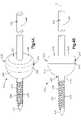
Fig. 1 is a side perspective view of a bone fixation assembly including a bone fixation plate and a temporary fixation wire temporarily affixing the bone fixation plate to an underlying bone;Fig. 2A is a perspective view of the temporary fixation wire shown inFig. 1 ;Fig. 2B is a side elevation view of the temporary fixation wire shown inFig. 2A ;Fig. 3A is a perspective view of a temporary fixation wire constructed in accordance with an alternative embodiment;Fig. 3B is a side elevation view of the temporary fixation wire shown inFig. 3A ;Fig. 4A is a perspective view of a temporary fixation wire constructed in accordance with another alternative embodiment;Fig. 4B is a side elevation view of the temporary fixation wire shown inFig. 4A ;Fig. 5A is a perspective view of the bone fixation plate shown inFig. 1 , the bone fixation plate having a plurality of permanent bone fixation holes, and temporary fixation wire holes;Fig. 5B is a top plan view of the bone fixation plate shown inFig. 5A ;Fig. 5C is a side elevation view of the bone fixation plate shown inFig. 5A ;Fig. 6A is a side sectional view of a bone fixation assembly including the temporary fixation wire shown inFig. 2A extending through a temporary fixation wire hole of the bone fixation plate shown inFig. 5A ;Fig. 6B is a side sectional view of a bone fixation assembly including the temporary fixation wire shown inFig. 3A extending through a temporary fixation wire hole of the bone fixation plate shown inFig. 5A ;Fig. 6C is a side sectional view of a bone fixation assembly including the temporary fixation wire shown inFig. 4A extending through a temporary fixation wire hole of the bone fixation plate shown inFig. 5A ; andFig. 7 is a top plan view of a bone fixation plate constructed in accordance with an alternative embodiment, the bone fixation plate including a plurality of permanent bone fixation holes, and temporary fixation wire holes.- Referring to
Fig. 1 , abone fixation assembly 10 includes abone fixation plate 14, and one or more temporary fixation wires (such as temporary fixation wire 24) that temporarily fix thebone fixation plate 14 to anunderlying bone 22, such as a radius as illustrated, so that the alignment of thebone fixation plate 14 can be examined. Thebone fixation assembly 10 can further include a plurality of permanentbone fixation members 317, illustrated as screws, that can permanently attach thebone fixation plate 14 to theunderlying bone 22 once thebone fixation plate 14 has been properly aligned. The term "permanently" is used herein as a duration of time sufficient to allow the bone fracture to heal. Thus, once the fracture has been repaired, thebone fixation plate 14 can be removed from the underlyingbone 22 if desired. - The
bone fixation plate 14, and the temporary fixation wires may be configured such that only a single temporary fixation wire may be inserted through thebone fixation plate 14 and into theunderlying bone 22 to thereby temporarily prevent movement of thebone fixation plate 14 relative to theunderlying bone 22. It should be understood, however, that more that one temporary fixation wire may be inserted through thebone fixation plate 14, and into theunderlying bone 22, as desired. As will be described, the temporary fixation wire may be constructed in accordance with several embodiments. - Referring to
Figs. 2A and 2B , according to one embodiment atemporary fixation wire 24 includes awire body 26 that is longitudinally elongate along a longitudinal axis L1. Thetemporary fixation wire 24 may be a stainless steel wire or any wire or ligature suitable for reduction of a bone fracture, and can have a length that extends along the longitudinal axis of any distance as desired, such as approximately 150 mm. Thewire body 26 defines aproximal end 28 and an opposingdistal end 30. Thetemporary fixation wire 24 includes anabutment member 32 that is attached to thewire body 26 and separates thedistal end 30 from theproximal end 28. The proximal anddistal ends abutment member 32 can all be cylindrical in shape as illustrated, or can assume any suitable alternative shape as desired. Thedistal end 30 of thetemporary fixation wire 24 defines atemporary fixation member 34 configured to be inserted into theunderlying bone 22. Theproximal end 28 of thetemporary fixation wire 24 is configured to be engaged by an insertion tool. - As shown in
Figs. 2A and 2B , thetemporary fixation member 34 includeshelical threads 36 and a tapered or pointed driving end ortip 37 that can present one or more cutting flutes. In this regard, it should be appreciated that thetemporary fixation member 34 can be self-tapping if desired. Thetip 37 is thus configured to be driven into theunderlying bone 22 to a depth such that rotation of thetemporary fixation wire 24 causes thethreads 36 to engage the bone as thetemporary fixation wire 24 is driven into thebone 22. Thethreads 36 extend proximally from thetip 37 to a location distal of theabutment member 32. Thethreads 36 can extend to theabutment member 32, or can terminate at a location spaced distally from theabutment member 32. Accordingly, thetemporary fixation wire 24 can be driven into underlying bone to a depth that causes theabutment member 32 to apply compression against thebone fixation plate 14. - The
wire body 26 can be sized and shaped as desired, and in accordance with the illustrated embodiment is dimensioned such that the diameter or thickness of theproximal end 28 and the outer diameter or thickness of thethreads 36 are both approximately 1.25 mm, though it should be appreciated that the diameter of theproximal end 28 and theouter diameter threads 36 can be sized as desired, for instance at approximately 1.6 mm, any distance between approximately 1.25 mm and approximately 1.6 mm, or any distance less than approximately 1.25 mm or greater than approximately 1.6 mm. In this regard, it should be appreciated that the outer diameter of thethreads 36 can be substantially equal to, greater than, or less than the diameter of theproximal end 28. It should be appreciated throughout this disclosure while that various structure is illustrated as round or cylindrical, defining a diameter, that the structure can be alternatively shaped as desired, and thus unless otherwise indicated, the diameters of all structure described herein can alternatively be referred to as a cross-sectional dimension or thickness that extends along a transverse direction T that is perpendicular with respect to the longitudinal axis L1. - With continuing reference to
Figs. 2A and 2B , theabutment member 32 can be provided as an annular washer that is welded at both ends (for instance laser welded) onto thewire body 26 at a location proximal of thethreads 36. Alternatively, theabutment member 32 can be attached to thewire body 26 using any suitable attachment, or can be constructed integrally with thewire body 26. - As shown in
Fig. 2B , theabutment member 32 includes aproximal end 38 that defines a correspondingproximal surface 39 extending transversely out from theproximal end 28 of thewire body 26, and adistal end 40 that defines adistal surface 41 extending transversely out from thedistal end 30 of thewire body 26. Thedistal surface 41 of theabutment member 32 can be spaced from thetip 37 any distance as desired, such as between approximately 5 mm and 15 mm. In particular thedistal surface 41 can be spaced from thetip 37 by approximately 8 mm. - The
abutment member 32 can further include anintermediate portion 42 that defines anintermediate surface 43 extending longitudinally between theproximal end 38 and thedistal end 40. It should be appreciated that the proximal anddistal surfaces abutment member 32 can extend in a purely transverse direction, or in a direction having both transverse and longitudinal directional components. Likewise, it should be appreciated that theintermediate surface 43 can extend in a pure longitudinal direction, or in a direction having both longitudinal and transverse directional components. - In accordance with the embodiment illustrated in
Fig. 2B , theabutment member 32 includes a tapered orcurved interface 45 between thedistal end 40 and theintermediate portion 42. Theinterface 45 is tapered such that the diameter of theabutment member 32 is reduced along a distal longitudinal direction from theintermediate surface 43 toward thedistal surface 41. Theinterface 45 can be straight, curved, or can include a combination of straight and curved portions. Thedistal surface 41 can extend in a purely transverse direction, or can extend in a direction that includes both transverse and longitudinal directional components. Thedistal surface 41 and theinterface 45 can be combined into a single continuous surface. As illustrated, thedistal surface 41 defines a diameter less than that of theintermediate surface 43, and greater than that of thedistal end 30 of thewire body 26. Theintermediate surface 43 defines a diameter that is greater than the diameter of thedistal end 30, and can further be greater than the diameter of theproximal end 28. In accordance with one embodiment, the intermediate section can define a diameter or cross-sectional dimension as desired, such as in the range of approximately 1.25 mm and approximately 2.5 mm, and in one embodiment is approximately 1.25 mm. It should thus be appreciated that the diameter of theintermediate surface 43 is greater than the outer diameter of thethreads 36, and greater than the outer diameter of any unthreaded region that may exist, for instance, between thethreads 36 and theabutment member 32. - Referring now to
Figs. 3A and 3B , atemporary fixation wire 124 in accordance with another embodiment is illustrated as including reference numerals corresponding to like structure of thetemporary fixation wire 24 described above with respect toFigs. 2A and 2B . Thus, unless otherwise indicated, thetemporary fixation wire 124 is constructed substantially identically with respect to thetemporary fixation wire 24. As illustrated, thetemporary fixation wire 124 includes anabutment member 132 defining anintermediate surface 143 that has a diameter greater than that of theintermediate surface 43, and further has a diameter greater than its longitudinal length. For instance, theabutment member 132 can have a diameter (or transverse cross-sectional dimension) as desired, for instance between approximately 6.0 mm and 8.0 mm. Theabutment member 132 defines adistal surface 141 that can be spaced from thetip 137 any distance as desired, such as between approximately 5 mm and 20 mm. In particular thedistal surface 141 can be spaced from thetip 137 by approximately 8 mm. - Referring now to
Figs. 4A and 4B , atemporary fixation wire 224 according to another embodiment is illustrated as including reference numerals corresponding to like structure of thetemporary fixation wire 124 described above with respect toFigs. 3A and 3B incremented by 100. Thus, unless otherwise indicated, thetemporary fixation wire 224 is constructed substantially identically with respect to thetemporary fixation wire 124. As illustrated, thetemporary fixation wire 224 includes anabutment member 232 that is bullet shaped, having adistal end 240 that is tapered inwardly along a distal direction. The abutment member defines adistal surface 241 that is convex with respect to a vantage point along the longitudinal direction L1 from thedistal end 230 of thewire body 226, though thedistal surface 241 could alternatively assume any shape as described above with respect to thedistal surface 41. Theproximal surface 239 is substantially flat in the transverse direction. Thedistal surface 241 of theabutment member 232 can be spaced from thetip 237 any distance as desired, such as between approximately 5 mm and 20 mm. In particular thedistal surface 241 can be spaced from thetip 237 by approximately 8 mm. - As shown in
Figs. 5A-5C , thebone fixation plate 14 includes a body 302 having anupper surface 304 and an opposingbone contacting surface 306. When thebone fixation plate 14 is used to reduce a fracture of a long bone, such as a distal radius, thebone contacting surface 306 can be placed on a plate engaging surface, such as the volar surface of the distal radius. The body 302 includes ahead portion 316 and ashaft portion 318 that extends proximally from thehead portion 316 along a longitudinal axis L2. The bone fixation plate body 302 can include anopening 315 extending through thehead portion 316 that separates thehead portion 316 into amedial section 320 and alateral section 322. Thehead portion 316 further includes adistal section 319 connected between the medial andlateral sections opening 315. The bone fixation plate body 302 thus defines amedial edge 312 and alateral edge 314 that flare away from each other in a direction from the shaft portion toward thehead portion 316, such that the head portion is sized and shaped to conform to the metaphysic of the distal radius. - It should be appreciated that the
bone fixation plate 14 illustrated inFigs. 5A-5C is configured to conform to the distal radius of a right arm, and that thebone fixation plate 14 can also be constructed to conform to the distal radius of the left arm. Furthermore, thebone fixation plate 14 has been described and illustrated in accordance with one embodiment, and the temporary fixation wires of the type described above are intended to be usable in combination with any bone fixation plate, for instance the bone fixation plate illustrated inFig. 7 , so as to temporarily align the bone fixation plate with fractured bone segments of any bone, such as for instance the tibia, fibula, or any other type of bone such as of the foot and hand, as desired prior to permanent bone plate fixation using permanent bone screws. - With continued reference to
Figs. 5A-5C , thebone fixation plate 14 defines a plurality of apertures extending through the bone fixation plate body 302. In particular, thebone fixation plate 14 includes a first plurality (or one or more) of small temporaryfixation wire apertures 324 having a first diameter, and a second plurality of large temporaryfixation wire apertures 326 having a second diameter greater than that of the first plurality ofapertures 324. Bothapertures apertures 324 can be sized to correspond to the smallertemporary fixation wire 24, while theapertures 326 can be sized to correspond to the largertemporary fixation wires apertures medial section 320 of the head, thelateral section 322 of the head, thedistal section 319 of the head, or on theshaft 318. - The
apertures 324 can thus extend through theshaft portion 318, thehead portion 316, or at both the head and shaft portions. A pair ofapertures 324 can be positioned in alignment at the opposed medial andlateral sections distal section 319. The diameter of theapertures 324 can be sized substantially equal to, or slightly greater than, that of thedistal end 30 of thewire body 26, and less than that of theabutment member 32. Accordingly, as illustrated inFig. 6A , the distal end of thewire body 26 can be inserted into one of theapertures 324 and driven (for instance screwed) into the underlying bone until thedistal surface 41 of theabutment member 32 is brought against theupper surface 304 of the bone fixation plate body 302, thereby compressing the bone fixation plate body 302 against the bone and temporarily fixing the position of thebone fixation plate 14 on the bone. Furthermore, because the diameter of thedistal end 30 corresponds to that of theaperture 324, thebone fixation plate 14 is unable to be translated relative to the temporary fixation wire 24 (and thus the underlying bone) once thetemporary fixation wire 24 has been inserted into theaperture 324 and driven into the underlying bone. - If it is determined that the
bone fixation plate 14 should be repositioned, thetemporary fixation wire 24 can be removed from the underlying bone. Advantageously, the residual hole created in the bone from the temporary fixation wire is smaller than the residual hole that would be produced by a permanent bone fixation member used to temporarily fix thebone fixation plate 14 to the underlying bone. Once thebone fixation plate 14 has been repositioned, thetemporary fixation wire 24 can again be inserted into thesame aperture 324 or adifferent aperture 324 to again temporarily fix the position of thebone fixation plate 14. Theplate 14 can be repositioned and temporarily fixed as many times as needed before it is determined that theplate 14 is accurately positioned, and can then be permanently affixed using permanentbone fixation members 317. Once theplate 14 has been affixed to the underlying bone with the bone permanentbone fixation member 317, thetemporary fixation wire 24 can then be removed. - It should be appreciated that while the diameter of the
apertures 324 is sized to receive thewire body 26, the diameter of theapertures 324 can also be sized substantially equal to, or slightly greater than, that of the distal ends 130 and 230 of thewire bodies temporary fixation wires apertures 324 to temporarily fix the position of thebone fixation plate 14 as described above with respect to thetemporary fixation wire 24. - Now referring to
Figs. 5A-5C ,6B and6C , theapertures 326 have a diameter greater than that of the distal ends of thetemporary fixation wires abutment members apertures 326 can include one or more apertures 326' that are substantially cylindrical, and one ormore apertures 326" that are longitudinally elongate. Both types ofapertures 326' and 326" are dimensioned so as to receive a permanentbone fixation member 317 therein. One or more, up to all, of theapertures 326 can includethreads 328 that mate with complementary threads on the head of a permanentbone fixation member 317 as desired. The permanentbone fixation member 317 further includes a screw shaft 323 (which can be threaded) extending down from the head. Theshaft 323 has a thickness that is perpendicular to the central axis of the permanent bone fixation member and passes through the central axis. The permanentbone fixation member 317 can have several distinguishing features with respect to a temporary fixation wire. For instance, thepermanent fixation member 317 is intended to permanently affix thebone fixation plate 14 to the underlying bone. Moreover, the thickness of the shaft of the permanentbone fixation member 317 is greater than the thickness of the distal end of the temporary fixation wire. In one embodiment, the permanentbone fixation member 317 does not include a wire extending from the permanent bone fixation member head in an opposite direction of the permanent bonefixation member shaft 323. Furthermore, in one embodiment, the permanent bone fixation member head can be threaded as desired. - The
threads 328 of the apertures 326' can be disposed on circumferentially spaced downwardly extendingfingers 329, so that a permanentbone fixation member 317 having complementary threads on the screw head can be locked at variable angles inside the screw aperture 326'. Alternatively, theapertures 326' and 326" can be unthreaded, such that the screw head compresses the bone fixation plate body 302 against the underlying bone when the permanentbone fixation member 317 is driven into the underlying bone using any suitable driving tool. The cylindrical apertures 326' can include an upper or outerunthreaded region 330 and a lower or inner threadedregion 332. The apertures 326' can be tapered inwardly along a direction from theupper surface 304 toward the bone-contactingsurface 306, such that the threadedregion 332 has a diameter less than that of the upperunthreaded region 330. - The upper end of the outer
unthreaded region 330 of the apertures 326' can have a diameter that is greater than that of the distal surface of the abutment member of the corresponding temporary fixation wire, and the lower end of the outerunthreaded region 330 can have a diameter that is less than that of the distal surface of the abutment member of the corresponding temporary fixation wire. Accordingly, when the temporary fixation wire is inserted through one of the apertures 326', theabutment member unthreaded region 330, and not the threadedregion 332 so as to avoid damaging thethreads 328 of the threadedregion 332. Because a portion of the abutment member has a diameter substantially equal to a portion of the unthreadedregion 330, thebone fixation plate 14 is unable to be translated relative to the temporary fixation wire (and thus the underlying bone) once the temporary fixation wire has been inserted into the aperture 326' and driven into the underlying bone. - The
apertures 326" are longitudinally elongate, and have afirst portion 334 and asecond portion 336. Thefirst portion 334 is longitudinally elongate, and has a transverse dimension substantially equal to that of the head of a permanent bone fixation member 317 (and the abutment member of the complementary temporary fixation wire). The transverse dimension of thefirst portion 334 flares inwardly along a direction from thetop surface 304 of the plate body 302 toward thebone contacting surface 306. Thus, the abutment member of the correspondingtemporary fixation wire first portion 334, and apply compression against thebone fixation plate 14 when driven into the underlying bone that prevents thebone fixation plate 14 from moving relative to the temporary fixation wire. Thesecond portion 336 can be substantially cylindrical, having an open portion that is continuous with thefirst portion 334. Thesecond portion 336 can be unthreaded or threaded in the manner described above, or can be threaded continuously from theupper surface 304 to thebone contacting surface 306, as thesecond portion 336 does not receive a temporary fixation wire. - Once the
temporary fixation wire apertures 326 and driven sufficiently deep so as to compress theplate 14 against the underlying bone, the alignment of thebone fixation plate 14 can be determined using X-ray or other suitable imaging. If it is determined that thebone fixation plate 14 should be repositioned, thetemporary fixation wire plate 14 to the underlying bone instead of the temporary fixation wire. Once thebone fixation plate 14 has been repositioned, the temporary fixation wire can again be inserted into the same aperture 326' or a different aperture 326' to again temporarily fix the position of thebone fixation plate 14. Theplate 14 can be repositioned and temporarily fixed as many times as needed before it is determined that theplate 14 is accurately positioned, and can then be permanently affixed using bone screws 317. Once theplate 14 has been affixed to the underlying bone with the bone permanent bone fixation member, the temporary fixation wire can then be removed. - It should be appreciated that the diameter of the apertures 326', or transverse dimension of the
apertures 326" can be sized greater than that of theabutment member 32 such that thewire 24 is not able to be used with theapertures 326. If one were to attempt to temporary fix thebone fixation plate 14 to the underlying bone using thewire 24, the diameter of theabutment member 32 would be visibly smaller than that of the apertures 326', and the transverse dimension of theapertures 326", and thus too small to provide compression against theplate 14. - It should be further appreciated that a kit can be provided that includes one or more
bone fixation plates 14, or one or moretemporary fixation wires bone fixation plate 14 can be temporarily fixed against the bone using a singletemporary fixation wire bone fixation plate 14 to the underlying bone. - While the underlying bone has been illustrated as a wrist in
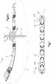
Figs. 6A-6C , such that thebone fixation plate 14 is sized and shaped to conform to the wrist, the bone fixation plate can be alternatively constructed as desired so as to conform to any underlying bone as desired. For instance, referring now toFig. 7 , abone fixation plate 414 is illustrated having reference numerals corresponding to like elements of thebone plate 14 incremented by 100 for the purposes of form and clarity. Thebone fixation plate 414 includes abody 402 having anupper surface 404 and an opposed bone contacting lower surface. When thebone fixation plate 14 is used to reduce a fracture of a long bone, such as a distal radius, the bone contacting surface can be placed on a plate engaging surface of the underlying bone. Theplate body 402 extends substantially linearly along the central axis L2, and can be configured to be fixed onto a long bone - The
bone fixation plate 414 defines a plurality of apertures extending through the bonefixation plate body 402. In particular, thebone fixation plate 414 is illustrated as including a first plurality of small temporaryfixation wire apertures 424, and a second plurality of largefixation wire apertures 426 each including afirst portion 434 and asecond portion 436 extending through theplate body 402. Theportions bone plate 414. As described above, the distal end of a temporary wire body can be inserted into one of theaperture portions plate body 402 and driven (for instance screwed) into the underlying bone until the distal surface of the abutment member is brought against theupper surface 404 of the bonefixation plate body 402, thereby compressing the bonefixation plate body 402 against the bone and temporarily fixing the position of thebone fixation plate 414 on the bone. Furthermore, because the diameter of the distal end of the temporary fixation wire corresponds to that of the aperture into which thetemporary fixation wire 24 is inserted, thebone fixation plate 414 is unable to be translated relative to the temporary fixation wire (and thus the underlying bone) once the temporary fixation wire has been inserted into the aperture and driven into the underlying bone. Once theplate 414 has achieved proper alignment and has been permanently affixed to the underlying bone with the bone screws, thetemporary fixation wire 24 can then be removed. - Although the invention has been described with reference to preferred embodiments, it is understood that the words which have been used herein are words of description and illustration, rather than words of limitation. For instance, it should be appreciated that the structures and features of the bone fixation plates and temporary fixation wires can be used in combination with other temporary fixation wires and bone fixation plates, respectively, unless otherwise indicated. Furthermore, although the invention has been described herein with reference to particular structure and embodiments, the invention is not intended to be limited to the particulars disclosed herein, as the invention extends to all structures that are within the scope of the present invention. The features of various embodiments described herein can further be incorporated into the other embodiments described herein as desired. Those skilled in the relevant art, having the benefit of the teachings of this specification, may effect numerous modifications to the invention as described herein, and changes may be made without departing from the scope of the invention.
Claims (11)
- A bone fixation assembly (10) comprising:a bone fixation plate (14) defining at least two apertures (326'), each aperture including an outer unthreaded region (330) and an inner threaded region (332), the outer unthreaded regions (330) defining a cross-sectional dimension that is greater than a cross-sectional dimension of the inner threaded regions (332);at least one permanent bone fixation member (317) having a cross-sectional dimension such that the permanent bone fixation member (317) is configured to be driven into one of the at least two apertures (326') and into an underlying bone (22) so as to permanently affix the bone fixation plate (14) to the underlying bone (22);a temporary fixation wire (24; 124; 224) that is longitudinally elongate along a longitudinal axis, the temporary fixation wire (24; 124; 224) including a wire body (26; 126; 226) that has a cross-sectional dimension less than the cross-sectional dimension less of the permanent bone fixation member (317),characterized in that the temporary fixation wire (24; 124; 224) further includes an abutment member (32; 132; 232) that extends out from the wire body (126; 226) such that the abutment member (32; 132; 232) defines a distal surface (41; 141; 241) that extends out from the wire body (26; 126; 226) along a transverse direction that is perpendicular with respect to the longitudinal axis, a proximal surface (39; 139; 239) that extends out from the wire body (26; 126; 226) along the transverse direction, and an intermediate surface (43; 143; 243) extending longitudinally between the proximal surface (39; 139; 239) and the distal surface (41; 141; 241), a portion of the intermediate surface (43; 143; 243) having a cross-sectional dimension that is equal to the cross-sectional dimension of the outer unthreaded regions (330),wherein insertion of the temporary fixation wire (24; 124; 224) into a select one of the at least two apertures (326') causes the abutment member (32; 132; 232) to temporarily compress the bone fixation plate (14) against the underlying bone (22), such that the temporary fixation wire (24; 124; 224) prevents movement of the bone fixation plate (14) relative to the underlying bone (22) prior to subsequent permanent fixation of the bone fixation plate (14) to the underlying bone (22).
- The bone fixation assembly of claim 1, wherein the bone fixation plate (14) includes at least one aperture (324) that has a cross-sectional diameter that is substantially equal to a cross-sectional diameter of a distal end of the wire body (26; 126; 226).
- The bone fixation assembly of claim 1 or 2, wherein the bone fixation plate (14) defines an upper surface (304) and an opposing bone-contacting surface (306), the at least one second aperture being tapered along a direction from the upper surface (304) toward the bone-contacting surface (306).
- The bone fixation assembly of any one of claims 1 to 3, wherein the bone fixation plate (14) includes a head portion (316) and a shaft portion (318), and defines a medial edge (320) and a lateral edge (322) that flare away from each other in a direction from the shaft portion (318) toward the head portion (316).
- The bone fixation assembly of any one of claims 1 to 4, wherein a distal end (30; 130; 230) of the wire body (26; 126; 226) is threaded.
- The bone fixation assembly of any one of claims 1 to 5, wherein a distal end (30; 130; 230) of the wire body (26; 126; 226) defines a tip (37; 137; 237) and the abutment member (32; 132; 232) defines a distal surface (41; 141; 241) that is spaced apart from the tip (37; 137; 237) by a distance between about 5 mm and about 15 mm.
- The bone fixation assembly of any one of claims 1 to 6, wherein the abutment member (32; 132; 232) defines a tapered interface (45; 145; 245) between the distal surface (41; 141; 241) and the intermediate surface (43; 143; 243), wherein preferably the tapered interface (45; 145; 245) is curved.
- The bone fixation assembly of any one of claims 1 to 7, wherein the distance between the proximal surface (139) and the distal surface (141) is less than the cross-sectional dimension of the abutment member (132).
- The bone fixation assembly of any one of claims 1 to 8, wherein the cross-sectional dimension of the abutment member (32; 132; 232) is a diameter.
- The bone fixation assembly of any one of claims 1 to 9, wherein at least one second aperture (326") of the bone fixation plate (14) is longitudinally elongate and defines a first portion (334) and a second portion (336), wherein preferably the first portion (334) is longitudinally elongate and is configured to receive the temporary fixation wire (24; 124; 224).
- The bone fixation assembly of any one of claims 1 to 10, wherein the bone fixation plate (14) is configured to be affixed to a volar surface of a distal radius.
Applications Claiming Priority (2)
| Application Number | Priority Date | Filing Date | Title |
|---|---|---|---|
| US36423210P | 2010-07-14 | 2010-07-14 | |
| PCT/US2011/043968WO2012009511A1 (en) | 2010-07-14 | 2011-07-14 | Assemblies for aligning a bone fixation plate |
Publications (2)
| Publication Number | Publication Date |
|---|---|
| EP2713918A1 EP2713918A1 (en) | 2014-04-09 |
| EP2713918B1true EP2713918B1 (en) | 2022-06-01 |
Family
ID=44504187
Family Applications (1)
| Application Number | Title | Priority Date | Filing Date |
|---|---|---|---|
| EP11736236.8AActiveEP2713918B1 (en) | 2010-07-14 | 2011-07-14 | Assemblies for aligning a bone fixation plate |
Country Status (4)
| Country | Link |
|---|---|
| US (1) | US8906075B2 (en) |
| EP (1) | EP2713918B1 (en) |
| CA (1) | CA2805109C (en) |
| WO (1) | WO2012009511A1 (en) |
Families Citing this family (23)
| Publication number | Priority date | Publication date | Assignee | Title |
|---|---|---|---|---|
| US8382807B2 (en) | 2005-07-25 | 2013-02-26 | Smith & Nephew, Inc. | Systems and methods for using polyaxial plates |
| CA2616798C (en) | 2005-07-25 | 2014-01-28 | Smith & Nephew, Inc. | Systems and methods for using polyaxial plates |
| AU2012271441B2 (en) | 2011-06-15 | 2017-02-02 | Smith & Nephew, Inc. | Variable angle locking implant |
| WO2013036362A1 (en) | 2011-09-06 | 2013-03-14 | Synthes Usa, Llc | Pancarpal arthrodesis bone plate |
| US9480515B2 (en) | 2012-07-12 | 2016-11-01 | Exsomed International IP, LLC | Metacarpal bone stabilization device |
| WO2015050895A1 (en) | 2013-10-02 | 2015-04-09 | Exsomed Holding Company Llc | Full wrist fusion device |
| CN104083201B (en)* | 2014-07-28 | 2016-01-20 | 苏州市康力骨科器械有限公司 | A kind of distal radius supports locking steel plate |
| RU2564080C1 (en)* | 2014-12-16 | 2015-09-27 | Елена Вячеславовна Помогаева | Method for temporal fixation of intra-articular fractures of distal shin bones |
| US20160278824A1 (en)* | 2015-03-25 | 2016-09-29 | Medartis Holding Ag | Method for treating fractures of a bone |
| WO2016186847A1 (en)* | 2015-05-19 | 2016-11-24 | Exsomed International IP, LLC | Distal radius plate |
| GB2557840B (en) | 2015-09-18 | 2021-07-21 | Smith & Nephew Inc | Bone plate |
| US10245091B2 (en) | 2015-12-30 | 2019-04-02 | Exsomed Holding Company, Llc | Dip fusion spike screw |
| US11147604B2 (en) | 2016-01-12 | 2021-10-19 | ExsoMed Corporation | Bone stabilization device |
| US10194923B2 (en) | 2016-05-10 | 2019-02-05 | Exsomed International IP, LLC | Tool for percutaneous joint cartilage destruction and preparation for joint fusion |
| US10869702B2 (en) | 2017-05-12 | 2020-12-22 | Nextremity Solutions, Inc. | Compression force magnifier |
| JP2020532407A (en) | 2017-09-05 | 2020-11-12 | エクソームド コーポレーションExsomed Corporation | Threaded intramedullary nail for radial cortex fixation |
| US11147681B2 (en) | 2017-09-05 | 2021-10-19 | ExsoMed Corporation | Small bone angled compression screw |
| US11191645B2 (en) | 2017-09-05 | 2021-12-07 | ExsoMed Corporation | Small bone tapered compression screw |
| JP2021506559A (en) | 2017-12-20 | 2021-02-22 | グレンハースト ラブス エルエルシー | Multi-faceted fixation plate for fracture repair |
| WO2020114589A1 (en)* | 2018-12-05 | 2020-06-11 | Medartis Holding Ag | Spacer for a bone screw, surgical system and method |
| US11202664B2 (en) | 2018-12-17 | 2021-12-21 | Nextremity Solutions, Inc. | Compression force magnifier |
| FR3092744B1 (en)* | 2019-02-14 | 2021-02-26 | Newclip Int | Plate osteosynthesis device with a tapped hole for receiving a locked fixing screw |
| CN111166455A (en)* | 2020-02-25 | 2020-05-19 | 山东大学齐鲁医院(青岛) | Angle regulator for radius far-end fracture |
Citations (2)
| Publication number | Priority date | Publication date | Assignee | Title |
|---|---|---|---|---|
| US20050033294A1 (en)* | 2003-08-06 | 2005-02-10 | Benjamin Garden | Systems and techniques for stabilizing the spine and placing stabilization systems |
| US20060195104A1 (en)* | 2003-08-08 | 2006-08-31 | Christoph Schlafli | Clamping device |
Family Cites Families (38)
| Publication number | Priority date | Publication date | Assignee | Title |
|---|---|---|---|---|
| US1105105A (en) | 1912-02-10 | 1914-07-28 | William O'n Sherman | Surgical appliance. |
| US2526959A (en) | 1947-07-01 | 1950-10-24 | Frank A Lorenzo | Fracture reduction apparatus |
| CH645264A5 (en) | 1980-05-28 | 1984-09-28 | Straumann Inst Ag | FITTING WITH A PLATE AND SCREWS THAT FIX IT TO A BONE. |
| US5006120A (en) | 1989-10-10 | 1991-04-09 | Carter Peter R | Distal radial fracture set and method for repairing distal radial fractures |
| DE3942326A1 (en) | 1989-12-21 | 1991-06-27 | Haerle Anton | SCREW AS AN OSTEOSYNTHESIS TOOL |
| US5015248A (en) | 1990-06-11 | 1991-05-14 | New York Society For The Relief Of The Ruptured & Crippled, Maintaining The Hospital For Special Surgery | Bone fracture fixation device |
| US6464713B2 (en) | 1990-06-28 | 2002-10-15 | Peter M. Bonutti | Body tissue fastening |
| ES2117968T3 (en) | 1991-03-27 | 1998-09-01 | Smith & Nephew Inc | DEVICE FOR THE FIXATION OF BONES. |
| US5201733A (en) | 1992-01-21 | 1993-04-13 | Etheredge Iii James L | Method and apparatus for internal fixation of fractures |
| US5171279A (en) | 1992-03-17 | 1992-12-15 | Danek Medical | Method for subcutaneous suprafascial pedicular internal fixation |
| DE4406374C2 (en) | 1993-03-25 | 1995-07-13 | Pennig Dietmar | Fixation pin for osteosynthesis work |
| US5709687A (en)* | 1994-03-16 | 1998-01-20 | Pennig; Dietmar | Fixation pin for small-bone fragments |
| US5690633A (en) | 1994-09-23 | 1997-11-25 | Smith & Nephew Richards, Inc. | Orthopedic fracture fixation device |
| US5601553A (en) | 1994-10-03 | 1997-02-11 | Synthes (U.S.A.) | Locking plate and bone screw |
| IT1271079B (en) | 1994-11-22 | 1997-05-26 | Lucio Martinotti | RETINA FOR ORTHOPEDIC-TRAUMATOLOGICAL SURGERY |
| CA2189744C (en) | 1995-03-27 | 2003-09-16 | Gilbert Talos | Bone plate |
| US5676667A (en)* | 1995-12-08 | 1997-10-14 | Hausman; Michael | Bone fixation apparatus and method |
| US5968046A (en) | 1998-06-04 | 1999-10-19 | Smith & Nephew, Inc. | Provisional fixation pin |
| US5989255A (en) | 1998-08-06 | 1999-11-23 | Smith & Nephew | Orthopaedic done screw apparatus |
| CN1172634C (en) | 1999-09-13 | 2004-10-27 | 库尔斯恩蒂斯股份公司 | Bone plating system |
| US6375657B1 (en) | 2000-03-14 | 2002-04-23 | Hammill Manufacturing Co. | Bonescrew |
| WO2003024344A1 (en) | 2001-09-14 | 2003-03-27 | The Regents Of The University Of California | System and method for fusing spinal vertebrae |
| AU2002360783A1 (en) | 2001-12-27 | 2003-07-24 | Osteotech Inc. | Orthopedic/neurosurgical system and method for securing vertebral bone facets |
| US20040019353A1 (en)* | 2002-02-01 | 2004-01-29 | Freid James M. | Spinal plate system for stabilizing a portion of a spine |
| US6875215B2 (en) | 2002-02-15 | 2005-04-05 | John Stanley Taras | Distraction pin for fracture fixation |
| US7641677B2 (en) | 2002-11-20 | 2010-01-05 | Orthopediatrics Corp. | Compression bone fragment wire |
| US7517350B2 (en) | 2002-11-20 | 2009-04-14 | Orthopediatrics Corp. | Convertible threaded compression device and method of use |
| DE10319781B3 (en) | 2003-04-30 | 2004-08-26 | Biedermann Motech Gmbh | Bone anchor, to attach a component to the bone, has a head to hold the component and a shaft with screw thread sections and thread-free sections along the shaft length |
| US20050085818A1 (en)* | 2003-10-17 | 2005-04-21 | Huebner Randall J. | Systems for distal radius fixation |
| US7699852B2 (en) | 2003-11-19 | 2010-04-20 | Zimmer Spine, Inc. | Fenestrated bone tap and method |
| DE102004009429A1 (en) | 2004-02-24 | 2005-09-22 | Biedermann Motech Gmbh | Bone anchoring element |
| US7837717B2 (en) | 2006-03-24 | 2010-11-23 | Depuy Products, Inc. | Fastening system for internal fixation |
| US20080015591A1 (en) | 2006-07-13 | 2008-01-17 | Castaneda Javier E | Threaded Guide for an Orthopedic Fixation Plate |
| US8556944B2 (en) | 2007-07-31 | 2013-10-15 | Stryker Spine | System and method for vertebral body plating |
| US8551171B2 (en) | 2007-10-12 | 2013-10-08 | Globus Medical, Inc. | Methods of stabilizing the sacroiliac joint |
| DE202007017159U1 (en) | 2007-12-08 | 2008-05-08 | Ferber, Ottfried, Dr.med. | Tension screw system for the treatment of fractures particularly suitable for stability-reduced bones |
| DE202008000914U1 (en) | 2008-01-22 | 2008-03-20 | Stryker Trauma Gmbh | Kirschner wire clamp |
| EP2313016B1 (en) | 2008-05-09 | 2016-11-09 | Skeletal Dynamics, LLC | Formable bone plate, clamping apparatus and osteotomy system |
- 2011
- 2011-07-14EPEP11736236.8Apatent/EP2713918B1/enactiveActive
- 2011-07-14USUS13/182,505patent/US8906075B2/enactiveActive
- 2011-07-14CACA2805109Apatent/CA2805109C/enactiveActive
- 2011-07-14WOPCT/US2011/043968patent/WO2012009511A1/enactiveApplication Filing
Patent Citations (2)
| Publication number | Priority date | Publication date | Assignee | Title |
|---|---|---|---|---|
| US20050033294A1 (en)* | 2003-08-06 | 2005-02-10 | Benjamin Garden | Systems and techniques for stabilizing the spine and placing stabilization systems |
| US20060195104A1 (en)* | 2003-08-08 | 2006-08-31 | Christoph Schlafli | Clamping device |
Also Published As
| Publication number | Publication date |
|---|---|
| CA2805109A1 (en) | 2012-01-19 |
| WO2012009511A1 (en) | 2012-01-19 |
| US8906075B2 (en) | 2014-12-09 |
| CA2805109C (en) | 2018-05-29 |
| EP2713918A1 (en) | 2014-04-09 |
| US20120265253A1 (en) | 2012-10-18 |
Similar Documents
| Publication | Publication Date | Title |
|---|---|---|
| EP2713918B1 (en) | Assemblies for aligning a bone fixation plate | |
| US20230044584A1 (en) | Fracture fixation plate and system | |
| US11432859B2 (en) | Hook plate and hook plate system | |
| US8821580B2 (en) | System for making a bone repair | |
| JP4913067B2 (en) | Intraosseous nail | |
| US7896886B2 (en) | Nail plate and implantation jig therefor | |
| EP1713410B1 (en) | Proximal humeral fracture fixation system comprising a plate including a post rotationally locked in a post hole, and a rigid cross support | |
| KR101524518B1 (en) | Bone plates and bone plate assemblies | |
| US9050151B2 (en) | Bone plate and aiming block | |
| US8216238B2 (en) | Method of using an intramedullary implant for fracture fixation | |
| US7785326B2 (en) | System for intramedullary rod fixation and method therefor | |
| US7938850B2 (en) | Nail plate | |
| US9247963B2 (en) | Bone compression device and methods | |
| US20150320451A1 (en) | Sacral fixation system | |
| US20120010667A1 (en) | Fracture-specific distal radius plates | |
| JP2007252930A (en) | Fastening system for internal fixation | |
| US12023053B2 (en) | Syndesmosis fixation and reconstruction system and method of using the same | |
| JP2007252929A (en) | Fastening system for internal fixation | |
| US8668693B2 (en) | Fixation device for proximal elbow fractures and method of using same | |
| US11317903B2 (en) | Implant devices and systems for stabilized fixation of bone and soft tissue | |
| US20060264932A1 (en) | Attachment to bone | |
| US12232749B2 (en) | Drill guide for orthopedic device |
Legal Events
| Date | Code | Title | Description |
|---|---|---|---|
| PUAI | Public reference made under article 153(3) epc to a published international application that has entered the european phase | Free format text:ORIGINAL CODE: 0009012 | |
| 17P | Request for examination filed | Effective date:20130207 | |
| AK | Designated contracting states | Kind code of ref document:A1 Designated state(s):AL AT BE BG CH CY CZ DE DK EE ES FI FR GB GR HR HU IE IS IT LI LT LU LV MC MK MT NL NO PL PT RO RS SE SI SK SM TR | |
| STAA | Information on the status of an ep patent application or granted ep patent | Free format text:STATUS: EXAMINATION IS IN PROGRESS | |
| 17Q | First examination report despatched | Effective date:20180202 | |
| GRAP | Despatch of communication of intention to grant a patent | Free format text:ORIGINAL CODE: EPIDOSNIGR1 | |
| STAA | Information on the status of an ep patent application or granted ep patent | Free format text:STATUS: GRANT OF PATENT IS INTENDED | |
| INTG | Intention to grant announced | Effective date:20211004 | |
| GRAJ | Information related to disapproval of communication of intention to grant by the applicant or resumption of examination proceedings by the epo deleted | Free format text:ORIGINAL CODE: EPIDOSDIGR1 | |
| STAA | Information on the status of an ep patent application or granted ep patent | Free format text:STATUS: EXAMINATION IS IN PROGRESS | |
| INTC | Intention to grant announced (deleted) | ||
| GRAP | Despatch of communication of intention to grant a patent | Free format text:ORIGINAL CODE: EPIDOSNIGR1 | |
| STAA | Information on the status of an ep patent application or granted ep patent | Free format text:STATUS: GRANT OF PATENT IS INTENDED | |
| GRAJ | Information related to disapproval of communication of intention to grant by the applicant or resumption of examination proceedings by the epo deleted | Free format text:ORIGINAL CODE: EPIDOSDIGR1 | |
| STAA | Information on the status of an ep patent application or granted ep patent | Free format text:STATUS: EXAMINATION IS IN PROGRESS | |
| INTG | Intention to grant announced | Effective date:20220105 | |
| INTC | Intention to grant announced (deleted) | ||
| GRAP | Despatch of communication of intention to grant a patent | Free format text:ORIGINAL CODE: EPIDOSNIGR1 | |
| STAA | Information on the status of an ep patent application or granted ep patent | Free format text:STATUS: GRANT OF PATENT IS INTENDED | |
| INTG | Intention to grant announced | Effective date:20220318 | |
| GRAS | Grant fee paid | Free format text:ORIGINAL CODE: EPIDOSNIGR3 | |
| GRAA | (expected) grant | Free format text:ORIGINAL CODE: 0009210 | |
| STAA | Information on the status of an ep patent application or granted ep patent | Free format text:STATUS: THE PATENT HAS BEEN GRANTED | |
| AK | Designated contracting states | Kind code of ref document:B1 Designated state(s):AL AT BE BG CH CY CZ DE DK EE ES FI FR GB GR HR HU IE IS IT LI LT LU LV MC MK MT NL NO PL PT RO RS SE SI SK SM TR | |
| REG | Reference to a national code | Ref country code:GB Ref legal event code:FG4D | |
| REG | Reference to a national code | Ref country code:FR Ref legal event code:PLFP Year of fee payment:12 | |
| REG | Reference to a national code | Ref country code:AT Ref legal event code:REF Ref document number:1494873 Country of ref document:AT Kind code of ref document:T Effective date:20220615 Ref country code:CH Ref legal event code:EP Ref country code:DE Ref legal event code:R096 Ref document number:602011072953 Country of ref document:DE | |
| REG | Reference to a national code | Ref country code:IE Ref legal event code:FG4D | |
| REG | Reference to a national code | Ref country code:LT Ref legal event code:MG9D | |
| REG | Reference to a national code | Ref country code:NL Ref legal event code:MP Effective date:20220601 | |
| PG25 | Lapsed in a contracting state [announced via postgrant information from national office to epo] | Ref country code:SE Free format text:LAPSE BECAUSE OF FAILURE TO SUBMIT A TRANSLATION OF THE DESCRIPTION OR TO PAY THE FEE WITHIN THE PRESCRIBED TIME-LIMIT Effective date:20220601 Ref country code:NO Free format text:LAPSE BECAUSE OF FAILURE TO SUBMIT A TRANSLATION OF THE DESCRIPTION OR TO PAY THE FEE WITHIN THE PRESCRIBED TIME-LIMIT Effective date:20220901 Ref country code:LT Free format text:LAPSE BECAUSE OF FAILURE TO SUBMIT A TRANSLATION OF THE DESCRIPTION OR TO PAY THE FEE WITHIN THE PRESCRIBED TIME-LIMIT Effective date:20220601 Ref country code:HR Free format text:LAPSE BECAUSE OF FAILURE TO SUBMIT A TRANSLATION OF THE DESCRIPTION OR TO PAY THE FEE WITHIN THE PRESCRIBED TIME-LIMIT Effective date:20220601 Ref country code:GR Free format text:LAPSE BECAUSE OF FAILURE TO SUBMIT A TRANSLATION OF THE DESCRIPTION OR TO PAY THE FEE WITHIN THE PRESCRIBED TIME-LIMIT Effective date:20220902 Ref country code:FI Free format text:LAPSE BECAUSE OF FAILURE TO SUBMIT A TRANSLATION OF THE DESCRIPTION OR TO PAY THE FEE WITHIN THE PRESCRIBED TIME-LIMIT Effective date:20220601 Ref country code:ES Free format text:LAPSE BECAUSE OF FAILURE TO SUBMIT A TRANSLATION OF THE DESCRIPTION OR TO PAY THE FEE WITHIN THE PRESCRIBED TIME-LIMIT Effective date:20220601 Ref country code:BG Free format text:LAPSE BECAUSE OF FAILURE TO SUBMIT A TRANSLATION OF THE DESCRIPTION OR TO PAY THE FEE WITHIN THE PRESCRIBED TIME-LIMIT Effective date:20220901 | |
| REG | Reference to a national code | Ref country code:AT Ref legal event code:MK05 Ref document number:1494873 Country of ref document:AT Kind code of ref document:T Effective date:20220601 | |
| PG25 | Lapsed in a contracting state [announced via postgrant information from national office to epo] | Ref country code:RS Free format text:LAPSE BECAUSE OF FAILURE TO SUBMIT A TRANSLATION OF THE DESCRIPTION OR TO PAY THE FEE WITHIN THE PRESCRIBED TIME-LIMIT Effective date:20220601 Ref country code:PL Free format text:LAPSE BECAUSE OF FAILURE TO SUBMIT A TRANSLATION OF THE DESCRIPTION OR TO PAY THE FEE WITHIN THE PRESCRIBED TIME-LIMIT Effective date:20220601 Ref country code:LV Free format text:LAPSE BECAUSE OF FAILURE TO SUBMIT A TRANSLATION OF THE DESCRIPTION OR TO PAY THE FEE WITHIN THE PRESCRIBED TIME-LIMIT Effective date:20220601 | |
| PG25 | Lapsed in a contracting state [announced via postgrant information from national office to epo] | Ref country code:NL Free format text:LAPSE BECAUSE OF FAILURE TO SUBMIT A TRANSLATION OF THE DESCRIPTION OR TO PAY THE FEE WITHIN THE PRESCRIBED TIME-LIMIT Effective date:20220601 | |
| PG25 | Lapsed in a contracting state [announced via postgrant information from national office to epo] | Ref country code:SM Free format text:LAPSE BECAUSE OF FAILURE TO SUBMIT A TRANSLATION OF THE DESCRIPTION OR TO PAY THE FEE WITHIN THE PRESCRIBED TIME-LIMIT Effective date:20220601 Ref country code:SK Free format text:LAPSE BECAUSE OF FAILURE TO SUBMIT A TRANSLATION OF THE DESCRIPTION OR TO PAY THE FEE WITHIN THE PRESCRIBED TIME-LIMIT Effective date:20220601 Ref country code:RO Free format text:LAPSE BECAUSE OF FAILURE TO SUBMIT A TRANSLATION OF THE DESCRIPTION OR TO PAY THE FEE WITHIN THE PRESCRIBED TIME-LIMIT Effective date:20220601 Ref country code:PT Free format text:LAPSE BECAUSE OF FAILURE TO SUBMIT A TRANSLATION OF THE DESCRIPTION OR TO PAY THE FEE WITHIN THE PRESCRIBED TIME-LIMIT Effective date:20221003 Ref country code:EE Free format text:LAPSE BECAUSE OF FAILURE TO SUBMIT A TRANSLATION OF THE DESCRIPTION OR TO PAY THE FEE WITHIN THE PRESCRIBED TIME-LIMIT Effective date:20220601 Ref country code:CZ Free format text:LAPSE BECAUSE OF FAILURE TO SUBMIT A TRANSLATION OF THE DESCRIPTION OR TO PAY THE FEE WITHIN THE PRESCRIBED TIME-LIMIT Effective date:20220601 Ref country code:AT Free format text:LAPSE BECAUSE OF FAILURE TO SUBMIT A TRANSLATION OF THE DESCRIPTION OR TO PAY THE FEE WITHIN THE PRESCRIBED TIME-LIMIT Effective date:20220601 | |
| PG25 | Lapsed in a contracting state [announced via postgrant information from national office to epo] | Ref country code:MC Free format text:LAPSE BECAUSE OF FAILURE TO SUBMIT A TRANSLATION OF THE DESCRIPTION OR TO PAY THE FEE WITHIN THE PRESCRIBED TIME-LIMIT Effective date:20220601 Ref country code:IS Free format text:LAPSE BECAUSE OF FAILURE TO SUBMIT A TRANSLATION OF THE DESCRIPTION OR TO PAY THE FEE WITHIN THE PRESCRIBED TIME-LIMIT Effective date:20221001 | |
| REG | Reference to a national code | Ref country code:DE Ref legal event code:R097 Ref document number:602011072953 Country of ref document:DE | |
| REG | Reference to a national code | Ref country code:BE Ref legal event code:MM Effective date:20220731 | |
| PG25 | Lapsed in a contracting state [announced via postgrant information from national office to epo] | Ref country code:AL Free format text:LAPSE BECAUSE OF FAILURE TO SUBMIT A TRANSLATION OF THE DESCRIPTION OR TO PAY THE FEE WITHIN THE PRESCRIBED TIME-LIMIT Effective date:20220601 | |
| PLBE | No opposition filed within time limit | Free format text:ORIGINAL CODE: 0009261 | |
| STAA | Information on the status of an ep patent application or granted ep patent | Free format text:STATUS: NO OPPOSITION FILED WITHIN TIME LIMIT | |
| PG25 | Lapsed in a contracting state [announced via postgrant information from national office to epo] | Ref country code:LU Free format text:LAPSE BECAUSE OF NON-PAYMENT OF DUE FEES Effective date:20220714 Ref country code:DK Free format text:LAPSE BECAUSE OF FAILURE TO SUBMIT A TRANSLATION OF THE DESCRIPTION OR TO PAY THE FEE WITHIN THE PRESCRIBED TIME-LIMIT Effective date:20220601 | |
| 26N | No opposition filed | Effective date:20230302 | |
| PG25 | Lapsed in a contracting state [announced via postgrant information from national office to epo] | Ref country code:SI Free format text:LAPSE BECAUSE OF FAILURE TO SUBMIT A TRANSLATION OF THE DESCRIPTION OR TO PAY THE FEE WITHIN THE PRESCRIBED TIME-LIMIT Effective date:20220601 Ref country code:BE Free format text:LAPSE BECAUSE OF NON-PAYMENT OF DUE FEES Effective date:20220731 | |
| PG25 | Lapsed in a contracting state [announced via postgrant information from national office to epo] | Ref country code:IE Free format text:LAPSE BECAUSE OF NON-PAYMENT OF DUE FEES Effective date:20220714 | |
| PG25 | Lapsed in a contracting state [announced via postgrant information from national office to epo] | Ref country code:HU Free format text:LAPSE BECAUSE OF FAILURE TO SUBMIT A TRANSLATION OF THE DESCRIPTION OR TO PAY THE FEE WITHIN THE PRESCRIBED TIME-LIMIT; INVALID AB INITIO Effective date:20110714 | |
| PG25 | Lapsed in a contracting state [announced via postgrant information from national office to epo] | Ref country code:MK Free format text:LAPSE BECAUSE OF FAILURE TO SUBMIT A TRANSLATION OF THE DESCRIPTION OR TO PAY THE FEE WITHIN THE PRESCRIBED TIME-LIMIT Effective date:20220601 Ref country code:CY Free format text:LAPSE BECAUSE OF FAILURE TO SUBMIT A TRANSLATION OF THE DESCRIPTION OR TO PAY THE FEE WITHIN THE PRESCRIBED TIME-LIMIT Effective date:20220601 | |
| PG25 | Lapsed in a contracting state [announced via postgrant information from national office to epo] | Ref country code:MT Free format text:LAPSE BECAUSE OF FAILURE TO SUBMIT A TRANSLATION OF THE DESCRIPTION OR TO PAY THE FEE WITHIN THE PRESCRIBED TIME-LIMIT Effective date:20220601 | |
| PGFP | Annual fee paid to national office [announced via postgrant information from national office to epo] | Ref country code:IT Payment date:20240612 Year of fee payment:14 | |
| PGFP | Annual fee paid to national office [announced via postgrant information from national office to epo] | Ref country code:DE Payment date:20240529 Year of fee payment:14 | |
| PGFP | Annual fee paid to national office [announced via postgrant information from national office to epo] | Ref country code:CH Payment date:20240801 Year of fee payment:14 | |
| PG25 | Lapsed in a contracting state [announced via postgrant information from national office to epo] | Ref country code:BG Free format text:LAPSE BECAUSE OF FAILURE TO SUBMIT A TRANSLATION OF THE DESCRIPTION OR TO PAY THE FEE WITHIN THE PRESCRIBED TIME-LIMIT Effective date:20220601 | |
| PG25 | Lapsed in a contracting state [announced via postgrant information from national office to epo] | Ref country code:BG Free format text:LAPSE BECAUSE OF FAILURE TO SUBMIT A TRANSLATION OF THE DESCRIPTION OR TO PAY THE FEE WITHIN THE PRESCRIBED TIME-LIMIT Effective date:20220601 | |
| PGFP | Annual fee paid to national office [announced via postgrant information from national office to epo] | Ref country code:GB Payment date:20250529 Year of fee payment:15 | |
| PGFP | Annual fee paid to national office [announced via postgrant information from national office to epo] | Ref country code:FR Payment date:20250610 Year of fee payment:15 |