EP2713879B1 - Analyte sensor devices, connections, and methods - Google Patents
Analyte sensor devices, connections, and methodsDownload PDFInfo
- Publication number
- EP2713879B1 EP2713879B1EP12857506.5AEP12857506AEP2713879B1EP 2713879 B1EP2713879 B1EP 2713879B1EP 12857506 AEP12857506 AEP 12857506AEP 2713879 B1EP2713879 B1EP 2713879B1
- Authority
- EP
- European Patent Office
- Prior art keywords
- assembly
- sensor
- applicator
- applicator assembly
- electronics
- Prior art date
- Legal status (The legal status is an assumption and is not a legal conclusion. Google has not performed a legal analysis and makes no representation as to the accuracy of the status listed.)
- Active
Links
- 238000000034methodMethods0.000titleclaimsdescription44
- 239000012491analyteSubstances0.000titledescription14
- 230000004044responseEffects0.000claimsdescription17
- 230000001954sterilising effectEffects0.000claimsdescription16
- 238000004659sterilization and disinfectionMethods0.000claimsdescription16
- 238000004891communicationMethods0.000claimsdescription10
- 238000013519translationMethods0.000claimsdescription6
- 230000006835compressionEffects0.000claimsdescription3
- 238000007906compressionMethods0.000claimsdescription3
- 238000013459approachMethods0.000description34
- 239000000853adhesiveSubstances0.000description27
- 230000001070adhesive effectEffects0.000description27
- 239000008280bloodSubstances0.000description16
- 210000004369bloodAnatomy0.000description16
- 238000003780insertionMethods0.000description16
- 230000037431insertionEffects0.000description16
- 230000008878couplingEffects0.000description14
- 238000010168coupling processMethods0.000description14
- 238000005859coupling reactionMethods0.000description14
- WQZGKKKJIJFFOK-GASJEMHNSA-NGlucoseNatural productsOC[C@H]1OC(O)[C@H](O)[C@@H](O)[C@@H]1OWQZGKKKJIJFFOK-GASJEMHNSA-N0.000description13
- 239000008103glucoseSubstances0.000description13
- 239000000463materialSubstances0.000description12
- 238000007789sealingMethods0.000description12
- 230000009471actionEffects0.000description10
- NOESYZHRGYRDHS-UHFFFAOYSA-NinsulinChemical compoundN1C(=O)C(NC(=O)C(CCC(N)=O)NC(=O)C(CCC(O)=O)NC(=O)C(C(C)C)NC(=O)C(NC(=O)CN)C(C)CC)CSSCC(C(NC(CO)C(=O)NC(CC(C)C)C(=O)NC(CC=2C=CC(O)=CC=2)C(=O)NC(CCC(N)=O)C(=O)NC(CC(C)C)C(=O)NC(CCC(O)=O)C(=O)NC(CC(N)=O)C(=O)NC(CC=2C=CC(O)=CC=2)C(=O)NC(CSSCC(NC(=O)C(C(C)C)NC(=O)C(CC(C)C)NC(=O)C(CC=2C=CC(O)=CC=2)NC(=O)C(CC(C)C)NC(=O)C(C)NC(=O)C(CCC(O)=O)NC(=O)C(C(C)C)NC(=O)C(CC(C)C)NC(=O)C(CC=2NC=NC=2)NC(=O)C(CO)NC(=O)CNC2=O)C(=O)NCC(=O)NC(CCC(O)=O)C(=O)NC(CCCNC(N)=N)C(=O)NCC(=O)NC(CC=3C=CC=CC=3)C(=O)NC(CC=3C=CC=CC=3)C(=O)NC(CC=3C=CC(O)=CC=3)C(=O)NC(C(C)O)C(=O)N3C(CCC3)C(=O)NC(CCCCN)C(=O)NC(C)C(O)=O)C(=O)NC(CC(N)=O)C(O)=O)=O)NC(=O)C(C(C)CC)NC(=O)C(CO)NC(=O)C(C(C)O)NC(=O)C1CSSCC2NC(=O)C(CC(C)C)NC(=O)C(NC(=O)C(CCC(N)=O)NC(=O)C(CC(N)=O)NC(=O)C(NC(=O)C(N)CC=1C=CC=CC=1)C(C)C)CC1=CN=CN1NOESYZHRGYRDHS-UHFFFAOYSA-N0.000description10
- 238000012544monitoring processMethods0.000description10
- 230000008569processEffects0.000description10
- 239000002274desiccantSubstances0.000description8
- 230000000694effectsEffects0.000description8
- 230000008901benefitEffects0.000description7
- 238000013461designMethods0.000description7
- 238000004806packaging method and processMethods0.000description7
- 239000000758substrateSubstances0.000description7
- KFZMGEQAYNKOFK-UHFFFAOYSA-NIsopropanolChemical compoundCC(C)OKFZMGEQAYNKOFK-UHFFFAOYSA-N0.000description6
- 238000010276constructionMethods0.000description6
- 230000014759maintenance of locationEffects0.000description6
- 238000012986modificationMethods0.000description6
- 230000004048modificationEffects0.000description6
- 102000004877InsulinHuman genes0.000description5
- 108090001061InsulinProteins0.000description5
- 210000003722extracellular fluidAnatomy0.000description5
- 230000036512infertilityEffects0.000description5
- 229940125396insulinDrugs0.000description5
- 230000007246mechanismEffects0.000description5
- 238000002360preparation methodMethods0.000description5
- IAYPIBMASNFSPL-UHFFFAOYSA-NEthylene oxideChemical compoundC1CO1IAYPIBMASNFSPL-UHFFFAOYSA-N0.000description4
- 206010012601diabetes mellitusDiseases0.000description4
- 238000001727in vivoMethods0.000description4
- 238000004519manufacturing processMethods0.000description4
- 230000013011matingEffects0.000description4
- 229920001296polysiloxanePolymers0.000description4
- 238000012360testing methodMethods0.000description4
- 239000002253acidSubstances0.000description3
- 150000001875compoundsChemical class0.000description3
- 239000012530fluidSubstances0.000description3
- 230000006870functionEffects0.000description3
- OKTJSMMVPCPJKN-UHFFFAOYSA-NCarbonChemical compound[C]OKTJSMMVPCPJKN-UHFFFAOYSA-N0.000description2
- 241000237983TrochidaeSpecies0.000description2
- 230000004075alterationEffects0.000description2
- 230000004888barrier functionEffects0.000description2
- 229910052799carbonInorganic materials0.000description2
- 239000000470constituentSubstances0.000description2
- 239000003989dielectric materialSubstances0.000description2
- 239000011888foilSubstances0.000description2
- 238000000338in vitroMethods0.000description2
- 238000010348incorporationMethods0.000description2
- 238000009434installationMethods0.000description2
- 230000003993interactionEffects0.000description2
- 230000000670limiting effectEffects0.000description2
- 239000002184metalSubstances0.000description2
- 229910052751metalInorganic materials0.000description2
- 238000000465mouldingMethods0.000description2
- 210000000496pancreasAnatomy0.000description2
- 230000036961partial effectEffects0.000description2
- 238000004382pottingMethods0.000description2
- 230000002829reductive effectEffects0.000description2
- 238000012552reviewMethods0.000description2
- 238000005096rolling processMethods0.000description2
- YGSDEFSMJLZEOE-UHFFFAOYSA-Nsalicylic acidChemical compoundOC(=O)C1=CC=CC=C1OYGSDEFSMJLZEOE-UHFFFAOYSA-N0.000description2
- 230000035807sensationEffects0.000description2
- 230000000007visual effectEffects0.000description2
- 235000011437Amygdalus communisNutrition0.000description1
- 201000001320AtherosclerosisDiseases0.000description1
- 201000004569BlindnessDiseases0.000description1
- 208000024172Cardiovascular diseaseDiseases0.000description1
- 208000017667Chronic DiseaseDiseases0.000description1
- 102000004190EnzymesHuman genes0.000description1
- 108090000790EnzymesProteins0.000description1
- 239000004593EpoxySubstances0.000description1
- 229920001410MicrofiberPolymers0.000description1
- 208000028389Nerve injuryDiseases0.000description1
- 239000004952PolyamideSubstances0.000description1
- 235000009827Prunus armeniacaNutrition0.000description1
- 244000018633Prunus armeniacaSpecies0.000description1
- 241000220304Prunus dulcisSpecies0.000description1
- 208000001647Renal InsufficiencyDiseases0.000description1
- 229910021607Silver chlorideInorganic materials0.000description1
- 206010067584Type 1 diabetes mellitusDiseases0.000description1
- 239000004775TyvekSubstances0.000description1
- 229920000690TyvekPolymers0.000description1
- 150000007513acidsChemical class0.000description1
- 230000006978adaptationEffects0.000description1
- 239000002390adhesive tapeSubstances0.000description1
- 235000020224almondNutrition0.000description1
- -1alpha hydroxyl acidChemical class0.000description1
- 210000001367arteryAnatomy0.000description1
- 239000011324beadSubstances0.000description1
- 230000002146bilateral effectEffects0.000description1
- 210000004027cellAnatomy0.000description1
- 229910010293ceramic materialInorganic materials0.000description1
- 238000001311chemical methods and processMethods0.000description1
- 238000013037co-moldingMethods0.000description1
- 239000011248coating agentSubstances0.000description1
- 238000000576coating methodMethods0.000description1
- 230000000052comparative effectEffects0.000description1
- 230000000295complement effectEffects0.000description1
- 239000004020conductorSubstances0.000description1
- 239000000356contaminantSubstances0.000description1
- 238000011109contaminationMethods0.000description1
- 208000029078coronary artery diseaseDiseases0.000description1
- 230000000994depressogenic effectEffects0.000description1
- 201000010099diseaseDiseases0.000description1
- 208000037265diseases, disorders, signs and symptomsDiseases0.000description1
- 235000013399edible fruitsNutrition0.000description1
- 230000002500effect on skinEffects0.000description1
- 239000013013elastic materialSubstances0.000description1
- 229920001971elastomerPolymers0.000description1
- 239000000806elastomerSubstances0.000description1
- 239000013536elastomeric materialSubstances0.000description1
- 230000008030eliminationEffects0.000description1
- 238000003379elimination reactionMethods0.000description1
- 238000010304firingMethods0.000description1
- PCHJSUWPFVWCPO-UHFFFAOYSA-NgoldChemical compound[Au]PCHJSUWPFVWCPO-UHFFFAOYSA-N0.000description1
- 229910052737goldInorganic materials0.000description1
- 239000010931goldSubstances0.000description1
- 229940088597hormoneDrugs0.000description1
- 239000005556hormoneSubstances0.000description1
- 239000012943hotmeltSubstances0.000description1
- 125000002887hydroxy groupChemical group[H]O*0.000description1
- 201000001421hyperglycemiaDiseases0.000description1
- 229910052500inorganic mineralInorganic materials0.000description1
- 238000005304joiningMethods0.000description1
- 201000006370kidney failureDiseases0.000description1
- 230000007774longtermEffects0.000description1
- 238000012423maintenanceMethods0.000description1
- 235000012054mealsNutrition0.000description1
- 239000003658microfiberSubstances0.000description1
- 239000011707mineralSubstances0.000description1
- 239000000203mixtureSubstances0.000description1
- 238000012806monitoring deviceMethods0.000description1
- 230000008764nerve damageEffects0.000description1
- FJKROLUGYXJWQN-UHFFFAOYSA-Npapa-hydroxy-benzoic acidNatural productsOC(=O)C1=CC=C(O)C=C1FJKROLUGYXJWQN-UHFFFAOYSA-N0.000description1
- 239000004033plasticSubstances0.000description1
- 229920002647polyamidePolymers0.000description1
- 229920006267polyester filmPolymers0.000description1
- 229920000642polymerPolymers0.000description1
- 230000036316preloadEffects0.000description1
- 238000012545processingMethods0.000description1
- 239000008262pumiceSubstances0.000description1
- 230000005855radiationEffects0.000description1
- 230000000717retained effectEffects0.000description1
- 230000002441reversible effectEffects0.000description1
- 229960004889salicylic acidDrugs0.000description1
- 150000003839saltsChemical class0.000description1
- 238000009991scouringMethods0.000description1
- HKZLPVFGJNLROG-UHFFFAOYSA-Msilver monochlorideChemical compound[Cl-].[Ag+]HKZLPVFGJNLROG-UHFFFAOYSA-M0.000description1
- 230000000087stabilizing effectEffects0.000description1
- 238000003860storageMethods0.000description1
- 239000000126substanceSubstances0.000description1
- 229920001169thermoplasticPolymers0.000description1
- 239000012815thermoplastic materialSubstances0.000description1
- 239000004416thermosoftening plasticSubstances0.000description1
- 230000001960triggered effectEffects0.000description1
- 208000001072type 2 diabetes mellitusDiseases0.000description1
- 238000003466weldingMethods0.000description1
- 230000003245working effectEffects0.000description1
Images


Classifications
- A—HUMAN NECESSITIES
- A61—MEDICAL OR VETERINARY SCIENCE; HYGIENE
- A61B—DIAGNOSIS; SURGERY; IDENTIFICATION
- A61B5/00—Measuring for diagnostic purposes; Identification of persons
- A61B5/145—Measuring characteristics of blood in vivo, e.g. gas concentration or pH-value ; Measuring characteristics of body fluids or tissues, e.g. interstitial fluid or cerebral tissue
- A61B5/14503—Measuring characteristics of blood in vivo, e.g. gas concentration or pH-value ; Measuring characteristics of body fluids or tissues, e.g. interstitial fluid or cerebral tissue invasive, e.g. introduced into the body by a catheter or needle or using implanted sensors
- A—HUMAN NECESSITIES
- A61—MEDICAL OR VETERINARY SCIENCE; HYGIENE
- A61B—DIAGNOSIS; SURGERY; IDENTIFICATION
- A61B5/00—Measuring for diagnostic purposes; Identification of persons
- A61B5/0002—Remote monitoring of patients using telemetry, e.g. transmission of vital signals via a communication network
- A61B5/0004—Remote monitoring of patients using telemetry, e.g. transmission of vital signals via a communication network characterised by the type of physiological signal transmitted
- A—HUMAN NECESSITIES
- A61—MEDICAL OR VETERINARY SCIENCE; HYGIENE
- A61B—DIAGNOSIS; SURGERY; IDENTIFICATION
- A61B5/00—Measuring for diagnostic purposes; Identification of persons
- A61B5/14—Devices for taking samples of blood ; Measuring characteristics of blood in vivo, e.g. gas concentration within the blood, pH-value of blood
- A61B5/1405—Devices for taking blood samples
- A61B5/1411—Devices for taking blood samples by percutaneous method, e.g. by lancet
- A—HUMAN NECESSITIES
- A61—MEDICAL OR VETERINARY SCIENCE; HYGIENE
- A61B—DIAGNOSIS; SURGERY; IDENTIFICATION
- A61B5/00—Measuring for diagnostic purposes; Identification of persons
- A61B5/145—Measuring characteristics of blood in vivo, e.g. gas concentration or pH-value ; Measuring characteristics of body fluids or tissues, e.g. interstitial fluid or cerebral tissue
- A61B5/14507—Measuring characteristics of blood in vivo, e.g. gas concentration or pH-value ; Measuring characteristics of body fluids or tissues, e.g. interstitial fluid or cerebral tissue specially adapted for measuring characteristics of body fluids other than blood
- A61B5/1451—Measuring characteristics of blood in vivo, e.g. gas concentration or pH-value ; Measuring characteristics of body fluids or tissues, e.g. interstitial fluid or cerebral tissue specially adapted for measuring characteristics of body fluids other than blood for interstitial fluid
- A—HUMAN NECESSITIES
- A61—MEDICAL OR VETERINARY SCIENCE; HYGIENE
- A61B—DIAGNOSIS; SURGERY; IDENTIFICATION
- A61B5/00—Measuring for diagnostic purposes; Identification of persons
- A61B5/145—Measuring characteristics of blood in vivo, e.g. gas concentration or pH-value ; Measuring characteristics of body fluids or tissues, e.g. interstitial fluid or cerebral tissue
- A61B5/14532—Measuring characteristics of blood in vivo, e.g. gas concentration or pH-value ; Measuring characteristics of body fluids or tissues, e.g. interstitial fluid or cerebral tissue for measuring glucose, e.g. by tissue impedance measurement
- A—HUMAN NECESSITIES
- A61—MEDICAL OR VETERINARY SCIENCE; HYGIENE
- A61B—DIAGNOSIS; SURGERY; IDENTIFICATION
- A61B5/00—Measuring for diagnostic purposes; Identification of persons
- A61B5/15—Devices for taking samples of blood
- A61B5/150007—Details
- A61B5/150015—Source of blood
- A61B5/150022—Source of blood for capillary blood or interstitial fluid
- A—HUMAN NECESSITIES
- A61—MEDICAL OR VETERINARY SCIENCE; HYGIENE
- A61B—DIAGNOSIS; SURGERY; IDENTIFICATION
- A61B5/00—Measuring for diagnostic purposes; Identification of persons
- A61B5/15—Devices for taking samples of blood
- A61B5/150007—Details
- A61B5/150206—Construction or design features not otherwise provided for; manufacturing or production; packages; sterilisation of piercing element, piercing device or sampling device
- A61B5/150305—Packages specially adapted for piercing devices or blood sampling devices
- A—HUMAN NECESSITIES
- A61—MEDICAL OR VETERINARY SCIENCE; HYGIENE
- A61B—DIAGNOSIS; SURGERY; IDENTIFICATION
- A61B5/00—Measuring for diagnostic purposes; Identification of persons
- A61B5/15—Devices for taking samples of blood
- A61B5/150007—Details
- A61B5/150206—Construction or design features not otherwise provided for; manufacturing or production; packages; sterilisation of piercing element, piercing device or sampling device
- A61B5/150312—Sterilisation of piercing elements, piercing devices or sampling devices
- A61B5/150335—Sterilisation of piercing elements, piercing devices or sampling devices by radiation
- A—HUMAN NECESSITIES
- A61—MEDICAL OR VETERINARY SCIENCE; HYGIENE
- A61B—DIAGNOSIS; SURGERY; IDENTIFICATION
- A61B5/00—Measuring for diagnostic purposes; Identification of persons
- A61B5/15—Devices for taking samples of blood
- A61B5/150007—Details
- A61B5/150358—Strips for collecting blood, e.g. absorbent
- A—HUMAN NECESSITIES
- A61—MEDICAL OR VETERINARY SCIENCE; HYGIENE
- A61B—DIAGNOSIS; SURGERY; IDENTIFICATION
- A61B5/00—Measuring for diagnostic purposes; Identification of persons
- A61B5/15—Devices for taking samples of blood
- A61B5/150007—Details
- A61B5/150374—Details of piercing elements or protective means for preventing accidental injuries by such piercing elements
- A61B5/150381—Design of piercing elements
- A61B5/150389—Hollow piercing elements, e.g. canulas, needles, for piercing the skin
- A—HUMAN NECESSITIES
- A61—MEDICAL OR VETERINARY SCIENCE; HYGIENE
- A61B—DIAGNOSIS; SURGERY; IDENTIFICATION
- A61B5/00—Measuring for diagnostic purposes; Identification of persons
- A61B5/15—Devices for taking samples of blood
- A61B5/150007—Details
- A61B5/150374—Details of piercing elements or protective means for preventing accidental injuries by such piercing elements
- A61B5/150381—Design of piercing elements
- A61B5/150503—Single-ended needles
- A—HUMAN NECESSITIES
- A61—MEDICAL OR VETERINARY SCIENCE; HYGIENE
- A61B—DIAGNOSIS; SURGERY; IDENTIFICATION
- A61B5/00—Measuring for diagnostic purposes; Identification of persons
- A61B5/15—Devices for taking samples of blood
- A61B5/150007—Details
- A61B5/150748—Having means for aiding positioning of the piercing device at a location where the body is to be pierced
- A—HUMAN NECESSITIES
- A61—MEDICAL OR VETERINARY SCIENCE; HYGIENE
- A61B—DIAGNOSIS; SURGERY; IDENTIFICATION
- A61B5/00—Measuring for diagnostic purposes; Identification of persons
- A61B5/15—Devices for taking samples of blood
- A61B5/150007—Details
- A61B5/150847—Communication to or from blood sampling device
- A61B5/15087—Communication to or from blood sampling device short range, e.g. between console and disposable
- A—HUMAN NECESSITIES
- A61—MEDICAL OR VETERINARY SCIENCE; HYGIENE
- A61B—DIAGNOSIS; SURGERY; IDENTIFICATION
- A61B5/00—Measuring for diagnostic purposes; Identification of persons
- A61B5/15—Devices for taking samples of blood
- A61B5/150007—Details
- A61B5/150847—Communication to or from blood sampling device
- A61B5/150877—Communication to or from blood sampling device with implanted devices
- A—HUMAN NECESSITIES
- A61—MEDICAL OR VETERINARY SCIENCE; HYGIENE
- A61B—DIAGNOSIS; SURGERY; IDENTIFICATION
- A61B5/00—Measuring for diagnostic purposes; Identification of persons
- A61B5/15—Devices for taking samples of blood
- A61B5/151—Devices specially adapted for taking samples of capillary blood, e.g. by lancets, needles or blades
- A61B5/15101—Details
- A61B5/15103—Piercing procedure
- A61B5/15105—Purely manual piercing, i.e. the user pierces the skin without the assistance of any driving means or driving devices
- A—HUMAN NECESSITIES
- A61—MEDICAL OR VETERINARY SCIENCE; HYGIENE
- A61B—DIAGNOSIS; SURGERY; IDENTIFICATION
- A61B5/00—Measuring for diagnostic purposes; Identification of persons
- A61B5/15—Devices for taking samples of blood
- A61B5/151—Devices specially adapted for taking samples of capillary blood, e.g. by lancets, needles or blades
- A61B5/15142—Devices intended for single use, i.e. disposable
- A61B5/15144—Devices intended for single use, i.e. disposable comprising driving means, e.g. a spring, for retracting the piercing unit into the housing
- A—HUMAN NECESSITIES
- A61—MEDICAL OR VETERINARY SCIENCE; HYGIENE
- A61B—DIAGNOSIS; SURGERY; IDENTIFICATION
- A61B5/00—Measuring for diagnostic purposes; Identification of persons
- A61B5/15—Devices for taking samples of blood
- A61B5/157—Devices characterised by integrated means for measuring characteristics of blood
- A—HUMAN NECESSITIES
- A61—MEDICAL OR VETERINARY SCIENCE; HYGIENE
- A61B—DIAGNOSIS; SURGERY; IDENTIFICATION
- A61B5/00—Measuring for diagnostic purposes; Identification of persons
- A61B5/68—Arrangements of detecting, measuring or recording means, e.g. sensors, in relation to patient
- A61B5/6846—Arrangements of detecting, measuring or recording means, e.g. sensors, in relation to patient specially adapted to be brought in contact with an internal body part, i.e. invasive
- A61B5/6847—Arrangements of detecting, measuring or recording means, e.g. sensors, in relation to patient specially adapted to be brought in contact with an internal body part, i.e. invasive mounted on an invasive device
- A61B5/6848—Needles
- A61B5/6849—Needles in combination with a needle set
- A—HUMAN NECESSITIES
- A61—MEDICAL OR VETERINARY SCIENCE; HYGIENE
- A61B—DIAGNOSIS; SURGERY; IDENTIFICATION
- A61B50/00—Containers, covers, furniture or holders specially adapted for surgical or diagnostic appliances or instruments, e.g. sterile covers
- A61B50/30—Containers specially adapted for packaging, protecting, dispensing, collecting or disposing of surgical or diagnostic appliances or instruments
- A61B50/3001—Containers specially adapted for packaging, protecting, dispensing, collecting or disposing of surgical or diagnostic appliances or instruments for sharps
- H—ELECTRICITY
- H04—ELECTRIC COMMUNICATION TECHNIQUE
- H04L—TRANSMISSION OF DIGITAL INFORMATION, e.g. TELEGRAPHIC COMMUNICATION
- H04L67/00—Network arrangements or protocols for supporting network services or applications
- H04L67/01—Protocols
- H04L67/12—Protocols specially adapted for proprietary or special-purpose networking environments, e.g. medical networks, sensor networks, networks in vehicles or remote metering networks
- A—HUMAN NECESSITIES
- A61—MEDICAL OR VETERINARY SCIENCE; HYGIENE
- A61B—DIAGNOSIS; SURGERY; IDENTIFICATION
- A61B2560/00—Constructional details of operational features of apparatus; Accessories for medical measuring apparatus
- A61B2560/04—Constructional details of apparatus
- A61B2560/0406—Constructional details of apparatus specially shaped apparatus housings
- A—HUMAN NECESSITIES
- A61—MEDICAL OR VETERINARY SCIENCE; HYGIENE
- A61B—DIAGNOSIS; SURGERY; IDENTIFICATION
- A61B2560/00—Constructional details of operational features of apparatus; Accessories for medical measuring apparatus
- A61B2560/04—Constructional details of apparatus
- A61B2560/0443—Modular apparatus
- A—HUMAN NECESSITIES
- A61—MEDICAL OR VETERINARY SCIENCE; HYGIENE
- A61B—DIAGNOSIS; SURGERY; IDENTIFICATION
- A61B2560/00—Constructional details of operational features of apparatus; Accessories for medical measuring apparatus
- A61B2560/06—Accessories for medical measuring apparatus
- A61B2560/063—Devices specially adapted for delivering implantable medical measuring apparatus
- A—HUMAN NECESSITIES
- A61—MEDICAL OR VETERINARY SCIENCE; HYGIENE
- A61B—DIAGNOSIS; SURGERY; IDENTIFICATION
- A61B2562/00—Details of sensors; Constructional details of sensor housings or probes; Accessories for sensors
- A61B2562/16—Details of sensor housings or probes; Details of structural supports for sensors
- A—HUMAN NECESSITIES
- A61—MEDICAL OR VETERINARY SCIENCE; HYGIENE
- A61B—DIAGNOSIS; SURGERY; IDENTIFICATION
- A61B2562/00—Details of sensors; Constructional details of sensor housings or probes; Accessories for sensors
- A61B2562/22—Arrangements of medical sensors with cables or leads; Connectors or couplings specifically adapted for medical sensors
- A61B2562/225—Connectors or couplings
- A61B2562/227—Sensors with electrical connectors
- A—HUMAN NECESSITIES
- A61—MEDICAL OR VETERINARY SCIENCE; HYGIENE
- A61B—DIAGNOSIS; SURGERY; IDENTIFICATION
- A61B2562/00—Details of sensors; Constructional details of sensor housings or probes; Accessories for sensors
- A61B2562/24—Hygienic packaging for medical sensors; Maintaining apparatus for sensor hygiene
- A61B2562/242—Packaging, i.e. for packaging the sensor or apparatus before use
Definitions
- Diabetes Mellitusis an incurable chronic disease in which the body does not produce or properly utilize insulin.
- Insulinis a hormone produced by the pancreas that regulates blood sugar (glucose).
- glucoseblood sugar
- the pancreasdoes not produce sufficient insulin (a condition known as Type 1 Diabetes) or does not properly utilize insulin (a condition known as Type II Diabetes)
- the blood glucoseremains in the blood resulting in hyperglycemia or abnormally high blood sugar levels.
- diabetesThe vast and uncontrolled fluctuations in blood glucose levels in people suffering from diabetes cause long-term, serious complications. Some of these complications include blindness, kidney failure, and nerve damage. Additionally, it is known that diabetes is a factor in accelerating cardiovascular diseases such as atherosclerosis (hardening of the arteries), leading to stroke, coronary heart disease, and other diseases. Accordingly, one important and universal strategy in managing diabetes is to control blood glucose levels.
- One element of managing blood glucose levelsis the monitoring of blood glucose levels.
- Conventional in vitro techniquessuch as drawing blood samples, applying the blood to a test strip, and determining the blood glucose level using colorimetric, electrochemical, or photometric test meters, may be employed.
- Another technique for monitoring glucose levelsuses an in vivo analyte monitoring system, which measures and stores sensor data representative of glucose levels automatically over time.
- in vivo analyte monitoring systemsuse an insertable or implantable in vivo sensor that is positioned to be in contact with interstitial fluid of a user for a period of time to detect and monitor glucose levels.
- an in vivo sensorPrior to use of an in vivo sensor, at least a portion of the sensor is positioned under the skin.
- An applicator assemblycan be employed to insert the sensor into the body of the user. For insertion of the sensor, a sharp engaged with the sensor, pierces the skin of the user and is then removed from the body of the user leaving the sensor in place.
- the in vivo-positioned sensorcan be connected to other system components such as sensor electronics contained in a unit that can be held onto the skin.
- an on-body deviceincludes an electronics assembly and a sensor assembly.
- the sensor assemblyincludes a sensor and may include a connector for coupling the sensor to the electronics assembly.
- a sharpis provided that supports the sensor and may allow a distal end of the sensor to be placed under a user's skin.
- the inventionincludes the connection of electrochemical analyte sensors to and/or within associated other monitoring components such as system devices that are configured to be held in place on body.
- the approachesvariously involve the use of unique sensor and unique ancillary element arrangements to facilitate assembly of separate on-body devices and sensor assembly units that are kept apart until the user brings them together. Methods associated with such use do not form part of the inventive subject matter.
- an analyte sensore.g., a glucose sensor
- an applicator assemblyto position a portion of the sensor beneath a skin surface
- methods of positioning at least a portion of the sensor and methods of analyte testing or monitoringinclude the manner of preparing the applicator assembly. Namely, such acts associated with user assembly and mating of the component parts of a monitoring system.
- such a monitoring systemmay include an electronics assembly adapted to adhere to a skin of a subject, a sensor assembly coupled to the electronics assembly to form an on-body device, and an insertion sharp having a longitudinal body including a longitudinal opening to receive at least a portion of the sensor body.
- the details of the sensormay vary. Exemplary chemistries and constructions are described in any of US Patent Nos. 5,593,852 , 6,284,478 , and 6,329,161 . Exemplary form-factors or configurations (e.g., for associated use with an insertion "sharp") are described in any of US Patent Nos. 6,175,752 , 6,565,509 , 6,134,461 and 6,990,366 and in US Publication No. 2010/0230285 .
- the details of the on-body devicemay vary.
- the on-body devicemay include sensor electronics and other adaptation to communicate with a monitoring device.
- communications facilitiese.g ., wireless transmitters, transponders, etc.
- US Publication Nos. 2010/0198034 and 2011/0213225are described in detail in US Publication Nos. 2010/0198034 and 2011/0213225 .
- systems and methodsare provided for assembling and applying the on-body device including assembling the sensor assembly to the electronics assembly and inserting a portion of the sensor under the skin of a user.
- the sensor assemblyincludes a sensor that may have a distal portion for operative contact with a fluid of the user.
- the on-body devicemay also include an electronics assembly including a housing defining a distal surface adapted for attachment to the skin of the user and a circuit coupleable to the sensor for detecting electrical signals from the sensor.
- the systemalso includes an applicator assembly that may have a sleeve defining a distal surface for placement on the skin of the subject, a handle for a user interface, and various internal support, coupling, guide, grasping, stop and detent features as well as driver elements.
- the systemmay also include a container that stores one or more of the sensor, the sharp, and/or the mount/electronics assembly in a sealed environment within. The container is configured to releasably interface with the applicator assembly for the purpose of loading one or more of the sensor, the sharp, and/or the electronics assembly into the applicator assembly, and readying the applicator assembly for use.
- the present disclosureincludes the subject systems, devices, kits in which they are included, and methods of use and manufacture. Further details can be appreciated in reference to the figures and/or associated description.
- a flowchart depicting an example method 100 of using various systems of the present inventionis provided.
- a userstarts with unpacking the container (102) and unpacking the applicator (104).
- Unpacking the container (102)can include removing a cover that provides a sterile seal to the container contents and unpacking the applicator (104) can include removing an end cap that provides a sterile seal to the internal portion of the applicator.
- an assembly operation(106) the applicator is inserted into the container to merge or connect the sensor assembly and the electronics assembly together to form an on-body device and an insertion needle or sharp.
- the userunlocks the applicator or removes a locking element to ready the applicator for use.
- the process of the assembly operation (106) and the constituent componentsare described in detail below.
- an on-body device application operation (108)is performed.
- the userplaces the applicator on the skin of the insertion site and then applies a force to install the on-body device.
- the applicatoris driven to insert the distal end of the sensor through the user's skin, adhere the on-body device to the skin surface, and retract the sharp into the applicator for disposal.
- the userperforms the application operation (108) by applying force to the applicator where the force applied is a single, continuous pushing motion along the longitudinal axis of the applicator that once started, causes the applicator to perform the application operation (108) such that the applicator does not stop operation until completion.
- the applicatoris configured to relay action/audible cues to the user so that all three of the above listed actions happen automatically in response to applying the force to the applicator causing it to trigger.
- an adhesive of the on-body devicedoes not contact the user until the application operation (108) is performed. So, the even after the applicator has been placed on the skin, the applicator can be moved to a different location up until the application operation (108) is performed without damage to the apparatus or other system components.
- a post application stage (110)use of the sensor for monitoring the user's analyte level occurs during wear followed by appropriate disposal.
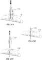
- FIG. 2Aone of the highlighted application sites 202, 204 on a user 200 is selected. In some embodiments, other application sites may be used. In some embodiments, a site preparation operation may optionally be performed.
- the application site 202, 204may be shaved, exfoliated, cleaned, or otherwise treated to better adhere the on-body device. More specifically, the skin at the site of the user's body where the on-body device will be adhered may be prepared to receive the on-body device. For example, the skin may be shaved with a razor, cleaned with isopropyl alcohol (IPA), and exfoliated with an abrasive.
- IPAisopropyl alcohol
- a mechanically exfoliating elementcan be used to remove an outer layer of dead skin and expose newer skin below.
- These elementsinclude: microfiber exfoliating cloths; pumice or other abrasive mineral; metal-stamped components of a rasp/file type configuration; synthetic scouring material, e.g ., Scotch-Brite®; an alternate adhesive tape or patch to be applied and stripped off to remove dead skin; and organic abrasive elements such as salt, crushed almond shells, apricot kernels, etc.
- a chemically exfoliating elementmay be used to prepare the site, including: mild acids such as alpha hydroxyl acid, beta-hydroxyl acid and salicylic acid; and fruit enzymes.
- Such chemically abrasive element(s)may be incorporated in a preparation pad, towelette, swab or be supplied otherwise.
- the end cap of the applicatormay include one or more exfoliating elements.
- the end capmay be textured or otherwise formed to provide a surface that can be used to exfoliate the skin of the site where the on-body device will be adhered. Exfoliating away an outer layer of dead skin before application may allow the on-body device to better adhere to the skin for a longer period of time.
- FIG. 2Billustrates loader or container 206 preparation, including removing cover 208 from a casing 210.
- the container 206includes the casing 210 which holds the sensor assembly and a sharp (or in some embodiments, the electronics assembly).
- FIG. 2Cillustrates applicator 212 preparation including separating a removable applicator end cap 214 from applicator assembly 216.
- container 206 and applicator 212can initially be packaged connected together to simplify packaging and shipping.
- the removable applicator end cap 214may include a boss or other feature that couples or snaps to a corresponding feature on the exterior of the container 206. This connection is only operative to hold the two pieces together for shipping purposes and not for operation of the system.
- the container 206 and applicator 212are separated from each other.
- the user assembly operation 106( FIG. 1 ) is achieved by pushing the applicator assembly 216 firmly into the container 206 to retrieve a sensor and a sharp from the container and to unlock a guide sleeve of the applicator assembly 216.
- the assembled and unlocked applicator assembly 216is placed on the application site 204 (or 202) and pushed down firmly to effect on-body device application 108 ( FIG. 1 ).
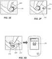
- FIG. 2Fupon used applicator assembly 216 removal from the application site 204, on-body device 222 is adhered to the user. In some embodiments, as illustrated in FIG.
- analyte levels detected by the sensor of the on-body device 222can be retrieved over a wireless communication link 224 via a communications facility (e.g., a transmitter, a transponder, etc. ) within the on-body device 222 by a receiver unit 226 (referred to alternatively as a "reader unit” or “receiver device”, or in some contexts, depending on the usage, as a “display unit,” “handheld unit,” or “meter”). Relevant information (e.g ., analyte level trend data, graphs, etc. ) is presented on the receiver unit's display 228.
- a communications facilitye.g., a transmitter, a transponder, etc.
- Relevant informatione.g ., analyte level trend data, graphs, etc.
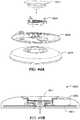
- FIGS. 3 and 4The applicator 212, container 206, and associated components shown in FIGS. 2A to 2G are illustrated in more detail in FIGS. 3 and 4 .
- numerous other variationsare described in detail below. These alternative embodiments may operate differently insofar as their internal workings, but may present no difference concerning user activity.
- applicator 212includes a removable cap 214 and applicator assembly 216.
- the removable cap 214can be secured to the applicator assembly 216 via complimentary threadings 306, 306'.
- End Cap 214fits with the applicator 216 to create a sterile packaging for interior of the applicator 216. Therefore, no additional packaging is required to maintain sterility of the interior of the applicator 216.
- the end (not visible) of the removable end cap 214can include one or more openings, which can be sealed by a sterile barrier material such as DuPontTM Tyvek ® , or other suitable material, to form seal 308.
- ETOethylene oxide
- the openings in the removable cap 214may not be present and the removable cap 214 may be made from a sterile process- permeable material so that the interior of the applicator can be sterilized when the cap is mated to it, but that maintains sterility of the interior of the cap after exposure to the sterility process.
- ETO sterilizationis compatible with the electronics within the electronics assembly 310 and with the associated adhesive patch 312, both of which can be releasably retained within the applicator assembly 216 until applied to the user.
- the applicator assembly 216includes a housing 314 including integrally formed grip features 316 and a translating sheath or guide sleeve 318.
- the container 206includes a cover 402 ( e.g., made of a removable material such as foil) and casing 404.
- a desiccant body 412Housed within the casing 404 is a desiccant body 412 and a table or platform 408.
- the desiccant body 412can have an annular shape so that the desiccant body 412 can be disposed within the casing 404 and a sensor assembly support (not visible in FIG. 4 but see 512 in FIGS. 5A and 5B ) can extend up through the desiccant body 412. This arrangement allows the container 206 to include a desiccant without requiring any additional height to accommodate the desiccant.
- a sensor assembly 410is snap-fit or otherwise held by the sensor assembly support 512.
- the sensor assembly 410can also be snap-fit or otherwise held by the platform 408 ( e.g., using fingers 414).
- the container 206With the cover 402 sealed, the container 206 can be subjected to gamma or radiation (e.g., e-beam) sterilization, an approach compatible with the chemistry of the sensor included in the sensor assembly 410.
- the container 206is its own sterile packaging so that no additional packaging, other than the casing 404 and the cover 402, is required to maintain sterility of the interior of the casing.
- the container 206 and the applicator 212may be sterilized by different sterilization approaches.
- a sensor contained in a container 206may require one type of sterilization process and the contents of an applicator 212 - for example, electronics contained within the interior of the applicator 212 - may require another type of sterilization process.
- the utility of a two-piece separable but combinable systemi.e., the container 206 and the applicator 212) enables the respective sterilization of the two pieces and sterility maintenance before the two are connected together for use. In other words, separately sealing the container 206 and the applicator 212 facilitates the use of otherwise incompatible sterilization methods for these two components.
- one type of sterilization which could damage the chemistry of the sensorcan be used to sterilize the applicator 212 including the electronics assembly 310 including the adhesive patch 312.
- another sterilization process which could damage the electronics in the electronics assembly 310 (and/or the adhesive patch 312 used to adhere the electronics assembly 310 to the user's skin)can be used to sterilize the container 206 including the sensor therein.
- Still other advantagesmay exist, given different shelf-life attributes for the active (i.e., electronic, chemical, etc. ) elements.
- all componentscan be sterilized using the same sterilization technique, such as, but not limited to ETO and e-beam sterilization, etc.
- the platform 408 in the container 206functions as an anti-tamper barrier for the sensor assembly 410 and prevents direct handling of the sensor assembly 410 by the user. More specifically, the platform 408 is disposed to protect and assist in the retention of the sensor, a sharp, and an associated connector. In some embodiments, the platform 408 is locked in place within the casing 404 until released by a longitudinally directed force from the applicator assembly 216 during the user assembly operation 106 ( FIG. 1 ). In other words, as the guide sleeve 318 of the applicator assembly 216 is inserted down against the platform 408, the sleeve 318 releases a locking mechanism (e.g., a catch) and allows the platform to translate deeper into the casing 404.
- a locking mechanisme.g., a catch
- features of the casing 404can be employed to unlock a guide sleeve lock feature of the applicator assembly 216.
- the platform 408 in the container 206can only be unlocked if the guide sleeve 318 of the applicator assembly 216 is inserted into the container 206 with alignment marks on the applicator assembly 216 and the container 206 properly aligned. (See FIG. 10C and associated text below).
- FIG. 5Ais an isometric, cross-sectional view of the casing 404 of FIG. 4 .
- FIG. 5Bis an assembled, isometric, cross-sectional view of the container 206 of FIG. 4 including the component parts.
- platform 408is surrounded by multiple locking features 502 (at least one is advantageously provided in some embodiments).
- Each of locking features 502includes a cantilevered arm 504 with a tongue 506 received in a slot or groove 508. So disposed, the platform 408 is locked in place.
- the locking feature(s) 502are released and the platform 408 can translate in direction B along a longitudinal axis of the combined applicator assembly 216 interfaced with the container 206.
- the translation of the platform 408 into the casing 404provides access to sensor assembly 410 by the applicator assembly 216. Until the platform 408 is unlocked and driven down into the casing 404, the sensor assembly 410 is otherwise isolated from being touched or otherwise handled/accessed by a user.
- additional detent ramp featurescan be provided to hold the platform 408 until depressed with force applied by a user.
- various key-and-way or slot-and-groove guidance featurescan be provided to control such motion and ensure that it is smooth and linear ( i.e., to avoid platform canting, binding, etc. )
- the sleeve/ramp interface with associated locksrelies only on detent features to maintain the platform's position. So configured, inadvertent handling of the sensor assembly can be avoided.
- the detent(s)can be tuned to require deliberate action to clear the platform 408.
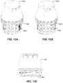
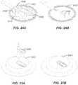
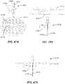
- FIGS. 6 and 7depict an alternative container 600 embodiment including an alternative platform 602 arrangement.
- a collapsible armature or linkage 604supports the platform 602.
- This linkage 604is integrally guided and spring-loaded by virtue of the living hinge design of the linkage 604.
- a coil springcould be employed along with guides for the platform 602.
- the container 600includes a casing 610 and can also include a desiccant ring 612 to protect the sensor assembly 608 from moisture.
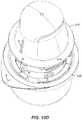
- FIG. 8Another embodiment for sensor storage and protection is illustrated in FIG. 8 with container 800. As with the prior embodiments, this embodiment can also include an annular desiccant ring 612. Casing 802 is provided in connection with a support base 804. The support base 804 receives sensor assembly 608 and a frame 806. The frame 806 includes a pivoting door 808. As shown, the support base 804 incorporates three channels 810 for receipt of frame legs 812 to serve as guidance. In its up/closed position shown in FIG. 9A , door 808 protects the sensor assembly 608 from contact by the user. Spiral ramp features interacting between the support base 804 and the frame 806 cause the door 808 to swing open as the frame 806 is moved down as shown in Fig 9B . Likewise, features of the frame 806 can hold the sensor assembly 608 against the support base 804 until the frame 806 is pushed down by user activity.
- the frame 806 in container 800can be locked in place and released by applicator sleeve introduction.
- a support ring 902may lock against boss or tang 814 until the boss 814 is urged inward by the action of an applicator sleeve along angled interface surface 904 of each leg 812.
- the legs 812can be biased outward with a preload but in other embodiments, the locking/unlocking function can operate without such biasing.
- FIG. 9Aillustrates the locked configuration
- FIG. 9Billustrates unlocked/translated relation of components.
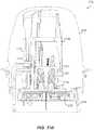
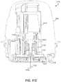
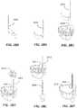
- FIGS. 10A to 10Nillustrate example details of embodiments of the internal device mechanics of preparing the applicator 212 for use, using the container 206. All together, these drawings represent an example sequence of assembling an on-body device 222 by connecting a sensor assembly 410 stored in the container 206 with an electronics assembly 310 stored in the applicator 212. In addition, the sequence prepares the applicator 212 to apply the assembled on-body device 222 to the user. Modification of such activity for use with the alternative container embodiments (as described above or others) can be appreciated in reference to the same by those with skill in the art.
- FIGS. 10A and 10Bshow container 206 and applicator 212 with their constituent parts, along with arrows indicating the manner of cover 402 and cap 214 removal, respectively.
- the platform 408 withinis locked, thus protecting the sensor assembly 410 (not visible but see FIG. 4 ) which includes a sensor, a sensor support (also referred to as a plug), a connector, and a sharp. (These components are discussed in detail below.)
- the applicator 212is locked upon removal of cap 214 from the applicator assembly 216.
- a guide sleeve 318(not visible but see FIG. 3 ) cannot be collapsed into the applicator's housing 314.
- applicator assembly 216is set within container 206.
- the two components 206, 216are rotated and advanced until mechanical alignment features M and M' engage, allowing the applicator assembly 216 to register and sit level within the container 206.
- Visual alignment indicators A and A'assist or guide the user to quickly find the proper alignment position.
- the platform 408cannot be unlocked to translate into the container 206 unless the alignment features M and M' are properly aligned.
- FIG. 10Ddepicts the components 206, 216 with the mechanical alignment features M, M' engaged.
- Sleeve 318passes over platform 408, with the platform 408 nested concentrically inside the inner diameter of sleeve 318.
- FIGS. 10E and 10Fillustrate the relationship of parts overviewed in FIGS. 10C and 10D .
- platform locking features 502 disposed around the platform 408 on locking ribs 1002are unlocked to allow the platform 408 to translate along a longitudinal axis (labeled "Z") of the interfaced components 206, 216. More specifically, a portion of platform 408 bends and platform locking arms 504 are displaced inward as indicated by arrow P to clear locking grooves 508 in the locking ribs 1002 of casing 404, thus unlocking the platform 408.
- the platform 408is held in place by guide ribs 1004 each providing a detent feature 1006 between the platform 408 and the guide ribs 1004 that can be overcome by further downward pressure applied by the user upon further depression of the applicator assembly 216 in the direction of the longitudinal axis Z.
- FIG. 10Gdepicts further depression of the applicator assembly 216 in the direction of the longitudinal axis Z.
- the force from the sleeve 318causes inward, radial deflection of a portion of the platform 408.
- the effectis that detent arms 1008 are flexed down, inward and away from the detent feature 1006 of guide ribs 1004 as shown. This action releases the platform 418 and the applicator assembly 216 into freefall into the container 206.
- the force to flex detent arms 1008, or in other words, the force to overcome the resistance from the detent features 1006,is selected to create a predetermined amount of momentum sufficient to ultimately properly mate the electronics assembly 310 with the sensor assembly 410 and unlock the sleeve 318.
- the force to overcome the resistance from the detent features 1006is from approximately 1 N to approximately 23 N. Other practicable values are possible.
- a relieve or undercut 1010 in each of the guide ribs 1004provides increased clearance for the platform 418 to reduce sliding friction as the sleeve 318 and platform 418 slide or telescope further into the container's casing 404 along the longitudinal axis Z ( FIG. 10F ).
- one or more flexible grasping arms 1012 previously in contact with the sensor assembly 410, particularly through sharp boss 1014,are moved from a stabilizing configuration in FIG. 10G to a freed state or configuration in FIG. 10H .
- the sharp boss 1014 of the sensor assembly 4IOprotrudes through a central opening in the platform 418 and pushes the flexible grasping arms I012 out of the way.
- FIGs. 10I and 1OJa cross-sectional view depicting a slightly different cut plane than the prior views is provided to illustrate additional features.
- sleeve lock armsare shown engaged with a sleeve lock ledge 1018. This engagement locks the applicator assembly 216 and prevents the sleeve 318 from being able to be retracted or pushed into the housing 314 of the applicator assembly 216.
- FIG. 1OIas the applicator assembly 216 is further advanced into the container 206 along the longitudinal axis Z (FIG.
- sleeve unlock featurescontact and bend the sleeve lock arms 1016 clear of the sleeve lock ledge 1018 thereby unlocking the applicator assembly 216.
- the sleeve lock ledge 1018is formed in a carrier I022 of the electronics assembly 3IO.
- the sleeve 318 of the applicator assembly 216is fully unlocked/released and ready to move.
- the sleeve lock arms I016are shown flexing outward to unlock, in some embodiments, the sleeve lock arms 1016 can be oriented to flex radially inward to free the elements. The same may hold true for the various locking/unlocking features of the present invention.
- the present arrangementoffers advantages in terms of a coordinated whole providing an advantageous form factor and minimized container casing size (a factor that affects the user experience) in which the carrier 1022 of the electronics assembly 310 is coaxially arranged.
- the carrier 1022it is advantageously designed with unique carrier arm features as detailed in, for example, U.S. Patent Application Serial No. 13/071,461 .
- the sensor assembly 410is forced into an opening in the electronics assembly 310 which couples the sensor to the electronics and completes assembly of the on-body device 222 ( FIG. 2F ).
- mating snap features on the sensor assembly 410 and the electronics assembly 310can be used to compel the components to remain locked and compressed together to insure a sealed, reliable connection.
- the sensor assembly 410 and the electronics assembly 310may be coupled by a light press fit or other connection method.
- the positive interaction and lock of snap featuresis an advantage. So too is the minimal force used to deflect fine locking features that spring back for engagement.
- a sharp retraction assembly 1024also continues to descend into the container 206 along the longitudinal axis Z ( FIG. 10F ) and is forced to receive the sharp boss 1014 of the sensor assembly 410.
- the conical head of the sharp boss 1014is pushed past a radial arrangement of flexible arms 1026 of the sharp retraction assembly 1024.
- the flexible arms 1026bend outwardly, as they are forced to ride against the passing conical surface of the head of the sharp boss 1014.
- FIG 10Killustrates the arrangement immediately before the above three actions have completed and FIG. 10L illustrates the resulting arrangement immediately after the actions have completed.
- connection features between the sharp boss 1014 of the sensor assembly 410 and the sharp retraction assembly 1024can be otherwise configured.
- the sharp retraction assembly 1024can include a conical channel formed from a radial arrangement of inwardly biased flexible finger members configured to receive the head of sharp boss 1014 such that once the head has passed through the channel, the flexible fingers conform to the narrowed neck of the sharp boss 1014. With the fingers so conformed, the sharp boss 1014 is captured by the sharp retraction assembly 1024. Retention force is limited only by material strength because the self-energizing lock is not prone to slip between the pieces.
- FIG. 10Ma slightly rotated view, relative to FIG. 10L , is shown.
- the sensor assembly 410is coupled to the electronics assembly 310 completing assembly of the on-body-device 222, and the sleeve 318 is unlocked, platform locking arms 504 and detent arms 1008 have engaged undercut grooves 1028 in the container 206, thereby locking the platform 418 in the casing 404.
- This engagement between the platform 418 and the casing 404marks the final position of the container 206 from which the loaded applicator assembly 216 is withdrawn for use to apply the on-body device 222 to the user.
- the applicator assembly 216is ready to "fire” as illustrated in FIG. 10N .
- the applicator assembly 216is ready to use as in application 108 described in connection with FIG. 2E .
- the applicator assembly 216has already been unlocked by interaction with the container 206, and the sensor assembly 410 is coupled to the electronics assembly 310.
- the sharp 1030extends from the on-body device 222 which is held in the sleeve 318 of the applicator assembly 216 as shown.
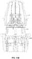
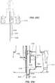
- FIGS. 11A to 11Fillustrate example details of embodiments of the internal device mechanics of "firing" the applicator assembly 216 to apply the on-body device 222 to a user and including retracting the sharp 1030 safely back into the used applicator assembly 216.
- FIGS. 11A to 11Frepresent an example sequence of driving the sharp 1030 (supporting a sensor coupled to the on-body device 222) into the skin of a user, withdrawing the sharp while leaving the sensor behind in operative contact with interstitial fluid of the user, and adhering the on-body device to the skin of the user with an adhesive. Modification of such activity for use with the alternative applicator assembly embodiments and components can be appreciated in reference to the same by those with skill in the art.
- a sensor 1102is supported within sharp 1030, just above the skin 1104 of the user.
- Rails 1106 (optionally three of them) of an upper guide section 1108may be provided to control applicator assembly 216 motion relative to the sleeve 318.
- the sleeve 318is held by detent features 1110 within the applicator assembly 216 such that appropriate downward force along the longitudinal axis of the applicator assembly 216 will cause the resistance provided by the detent features 1110 to be overcome so that the sharp 1030 and on-body device 222 can translate along the longitudinal axis into (and onto) the skin 1104 of the user.
- catch arms 1112 of carrier 1022engage the sharp retraction assembly 1024 to maintain the sharp 1030 in a position relative to the on-body device 222.
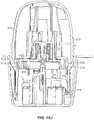
- FIG. 11Buser force is applied to overcome or override detent features 1110 and sleeve 318 collapses into housing 314 driving the on-body device 222 (with associated parts) to translate down as indicated by the arrow L along the longitudinal axis.
- An inner diameter of the upper guide section 1108 of the sleeve 318constrains the position of carrier arms 1112 through the full stroke of the sensor/sharp insertion process.
- the retention of the stop surfaces 1114 of carrier arms 1112 against the complimentary faces 1116 of the sharp retraction assembly 1024maintains the position of the members with return spring 1118 fully energized.
- sensor 1102 and sharp 1030have reached full insertion depth.
- the carrier arms 1112clear the upper guide section 1108 inner diameter.
- the compressed force of the coil return spring 1118drives angled stop surfaces 1114 radially outward, releasing force to drive the sharp carrier 1120 of the sharp retraction assembly 1024 to pull the (slotted or otherwise configured) sharp 1030 out of the user and off of the sensor 1102 as indicated by the arrow R in FIG. 11D .
- the upper guide section 1108 of the sleeve 318is set with a final locking feature 1120.
- FIG. 11Fthe spent applicator assembly 216 is removed from the insertion site, leaving behind the on-body device 222, and with the sharp 1030 secured safely inside the applicator assembly 216.
- the spent applicator assembly 216is now ready for disposal.
- Operation of the applicator 216 when applying the on-body device 222is designed to provide the user with a sensation that both the insertion and retraction of the sharp 1030 is performed automatically by the internal mechanisms of the applicator 216.
- the present inventionavoids the user experiencing the sensation that he is manually driving the sharp 1030 into his skin.
- the resulting actions of the applicator 216are perceived to be an automated response to the applicator being "triggered.”
- the userdoes not perceive that he is supplying additional force to drive the sharp 1030 to pierce his skin despite that all the driving force is provided by the user and no additional biasing/driving means are used to insert the sharp 1030.
- the retraction of the sharp 1030is automated by the coil return spring 1118 of the applicator 216.
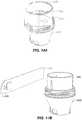
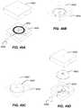
- FIGS. 12A to 12Dan alternative applicator/container set approach is now described.
- the container 1200holds the electronics assembly 1202. This is in contrast to the above embodiments wherein the relationship between the sensor assembly and the electronics assembly was reversed.
- the applicator 1204is inserted in the container 1200.
- FIG. 12Bthe units are merged.
- FIG. 12Cthe parts are separated.
- the applicator 1204is unlocked (e.g., in some embodiments by twisting the sleeve 1206 within the applicator 1204, in some embodiments by the act of loading the electronics assembly 1202 into the applicator 1204, or in some embodiment by the act ofremoving a locking strip from the sleeve 1206) and ready for use with the assembled on-body device (not visible) including the sensor assembly loaded therein.
- FIG. 13A to 15Fare illustrated in FIG. 13A to 15F .
- FIGS. 13A to 13Cvariously illustrate use of the applicator 1204 of FIGS. 12A to 12D in connection with a locking-sleeve feature 1206.
- FIG. 13Ashows the sleeve 1206 locked as indicated by the closed window 1208.
- a visual indicatione.g., open window 1208'
- FIG. 13CUpon use, as shown in FIG. 13C , the unit is compressed with the sleeve 1206 collapsed into the applicator 1204.
- FIGS. 14A and 14Billustrate an alternative applicator 1400 embodiment with a removable locking strip 1402.
- the strip 1402includes a pull-tab 1404 and adhesive or other fastening member to keep it in place until removed and the applicator 1400 is ready for use.
- FIGS. 15A to 15Fillustrate preparation of the applicator 1400 of FIGS. 14A and 14B for use with a container 1500.
- the applicator 1400is inserted into container 1500 to load the electronics assembly 1504 into the applicator 1400 and mate the sensor assembly (not shown) with the electronics assembly 1504 as shown in FIGS. 15B and 15C .
- the applicator 1400is removed from the container 1500 as shown in FIG. 15D .
- FIG. 15Eshows the applicator 1400 loaded with the assembled on-body device 222 and ready for sensor/sharp insertion.
- FIG. 15Fillustrates the system after such action has been taken in transferring the on-body device 222 from the applicator 1400 onto the skin of a user.
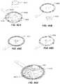
- FIGS. 16A and 16Bare sectional and detail views, respectively, of features of the container 1500 in FIGS. 15A-15F .
- the on-body device 1604is shown in the container 1500 with an adhesive patch 1602 and its backing 1606.
- the backing 1606is spiral-cut and attached to a boss so that when the on-body device 1604 is transferred from the container 1500, the peel-away backing 1606 is left behind. In this fashion, the adhesive patch 1602 remains covered by the backing 1606 so it does not inadvertently adhere to the container 1500.
- FIGS. 17A and 17Bare perspective assembly views illustrating alternative container 1702 configurations for capturing separate peel-off "butterfly" wings or bilateral liner panels from the adhesive-backed patch of the on-body device 1706.
- a two-part base 1704is provided for gripping the peel-away backing liner pieces.
- the base 1704is adapted to fit in the container casing.
- the container 1702can be configured differently.
- traction/tread 1708is provided to assist with grip of the backing.
- ramps 1710are provided to assist in removing the backing.
- the basecan be a one-piece molding incorporating a living hinge in a "clamshell" arrangement.
- the backing liner piece(s)may be captured along a center line or at an offset location.
- the base 1704may snap into place with complementary band and rib interface features associated with each of the base 1704 and container 1702, snaps, or capture the adhesive 5010 squeezed out but also provides additional surface area for a thicker layer of adhesive 5010 to seal the joint.
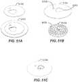
- FIGS. 51A-51CAn exemplary approach is illustrated in FIGS. 51A-51C .
- a double-sided adhesive patch 5104has the inner liner 5102 removed. This exposed adhesive is set over the on-body device body 5106 (with the temperature sensor 4806 folded to seat within a complimentary pocket) and adhered with a first window 5108 aligned for temperature sensing and second window 5110 for sensor assembly receipt. As such, it is ready for placement in an applicator assembly upon removal of the outer release liner, or alternatively ready for placement in a container with or without the outer liner in place, depending on the presence or absence of any liner- puller features provided therein.
- FIGS. 21A-21Cillustrate an alternative hand-off approach.
- a sensor assembly gripper 2106with a light snap fit, grabs and orients the sensor assembly 2104 for connection to the electronics assembly 2102. After the sensor assembly 2104 is firmly snapped into the electronics assembly 2102, the sensor assembly gripper 2106 is retracted with an amount of force that overcomes its grip.
- Such an approachoffers simplicity by reducing the number of parts required (given that the snap features may be incorporated in the sharp hub/boss).
- Sensor assembly configurationdepends on the mechanism selected for establishing electrical contact between the sensor assembly and the electronics assembly, as well as the method used to seal the contacts.
- FIGS. 22 through 48A number of advantageous alternative embodiments are illustrated in FIGS. 22 through 48 .
- FIG. 22A first example is presented in FIG. 22 .
- a sensor 2202is provided with an elongate "tail" section. The distal portion of the tail is to be inserted through the skin surface guided by a sharp.
- the proximal portion of the sensor 2202includes a "flag" type connector region.
- Three carbon-doped (for conductivity) silicone electrical connectors 2204are provided to interface with the electrical contacts of the sensor 2202.
- a split "V" portion of each connector 2204receives the electrical contacts of the sensor 2202.
- a flexible nubbin on the opposite side of each connector 2204is provided for electrical contact with the circuit board incorporated in the electronics assembly.
- Epoxy, a UV cure or another type of dielectric (non-conductive) compoundmay be used.
- the compound selectedis of such viscosity that it is able to flow around features and fully seal the sensor 2202 within its housing 2210 to avoid leakage. Such an approach avoids contamination and/or current leakage due to fluid intrusion.
- FIGS. 23A and 23Bare perspective assembly and final-assembly cross-sectional views, respectively of the sensor components of FIG. 22 .
- the tail of the sensor 2202is supported within the sharp 2206 and the sharp 2206 extends through the connector housing 2210.
- the electrical contacts of the sensor 2202are seated in the connector 2204 and the assembly is sealed within the housing 2210 including the housing top 2208.
- FIGS. 24A and 24Bare top and bottom perspective views, respectively of circuit board components to be used with the sensor assembly 2300 of FIGS. 23A and 23B .
- a custom printed circuit board (PCB) 2402is shown.
- the PCB 2402includes a battery 2406 with mount 2408, an application specific integrated circuit (ASIC) 2410, or other appropriate processing unit, and various other circuitry, including a thermocouple.
- ASICapplication specific integrated circuit
- the PCB 2402includes a housing 2404 with snap features for receiving the sensor assembly 2300 of FIGS. 23A and 23B .
- heat stakes 2412show the mode of attaching the housing 2404.
- the on-body device 2502is formed by over molding with a polymer "macromelt" (e.g., a thermoplastic hot-melt based on polyamide) or other compound and then affixing an adhesive patch with a releasable liner thereto.
- a completed on-body device 2502is provided once fitted with a complimentary sensor assembly 2300, as illustrated in FIGS. 25A and 25B .
- a seal or gasket 2604As shown in cross section, in FIG. 27A , and magnified in FIG. 27B , the gasket 2604 advantageously includes discrete ring/rim elements to compress and ensure sealing in critical areas, including around each circuit connection/nubbin.
- FIGS. 28A-28Fillustrate another advantageous sensor 2802 and sensor mount or connector 2804 arrangement.
- This embodimentresembles the previous approach, but is configured with a bend and a curve imparted to the sensor connection "flag.”
- FIG. 28Adepicts the sensor 2802 before it is shaped to fit within the connector 2804.
- FIG. 28Bdepicts the bent and curved sensor connection "flag.”
- FIG. 28Cdepicts the relative orientation of the sensor 2802 as it is inserted into the connector 2804.
- FIG. 28Ddepicts a wedge 2806 that is press-fit into the connector 2804 to retain the sensor 2802 and press the connector's electrical contacts against the electrical contacts of the sensor 2802.
- FIG. 28Edepicts the relative orientation of the sharp 2808 as it is inserted into the connector 2804 and
- FIG. 28Fdepicts the completed sensor assembly including potting 2810 (e.g., UV potting) used to seal the electrical contacts.
- potting 2810e.g., UV potting
- FIGS. 29A-29DAn alternative embodiment is contemplated in connection with the sensor approach illustrated in FIGS. 29A-29D .
- coupling 2904is configured to snap into connector block 2908 which is attached to PCB 2914.
- Connector block 2908includes a connector socket 2910 to receive the contacts portion of the sensor 2902.
- Connector block 2908also includes a coupling feature 2912 to receive snap-fit tab 2906 on the coupling 2904 which retains the sensor 2902 in the connector socket 2910.
- FIGS. 30A-30CAnother alternative embodiment is contemplated in connection with the sensor approach illustrated in FIGS. 30A-30C .
- a designis provided that eliminates a connection element and the need for separate spring contacts (be they metal or elastomeric as above).
- the approachoffers the advantage of effectively converting a sensor with contacts on two sides into a sensor with contacts on a single side after folding.
- the sensor 3004 shown in FIG. 30Ainitially has two electrical contacts facing a first direction on the split contact area and one contact facing in a second, opposite direction (obscured by the view). When folded and optionally clamped, glued or otherwise affixed in the orientation shown in FIG. 30B , all of the electrical contacts lie in a single plane, facing the same direction (e.g., downward in the drawing).
- the sensor 3004is coupled to electrical contacts on the PCB 3002 as shown in FIG. 30C .
- Such an approach in some embodimentsincludes a thinner (e.g., lower profile) on-body device relative to the on-body device 3102 variation shown in FIG. 31 .
- the reduced thickness dimensionis represented by height H.
- a flag type sensoris shown in a housing with separate electrical connectors.
- the "stack height" in FIG. 31includes these connectors as well as the housing.
- the approach shown in FIG. 30enables eliminating the connector height above the sensor 3004. Thus, elements are eliminated without losing functionality.
- the elimination of partsreduces cost, and impedance (relative at least to the inclusion of elastomeric connectors as shown in FIG. 22 , etc.) between the sensor 3004 and the PCB.
- Another useful aspectis allowing a sensor with contacts on two sides to connect to the PCB without requiring vias or holes in the sensor, thereby helping with sealing considerations and ease of electrical connection.
- FIGS. 32A and 32Billustrate two additional sensor configurations.
- sensors 3202, 3212 with contacts on two sidesare split and bent in opposite directions to orient the electrical contacts 3204, 3214 onto a single face or plane.
- orienting the electrical contacts 3204, 3214 onto a single planefacilitates ease of sealing the electrical connections.
- overall sensor assembly heightcan be reduced relative to other approaches. Any of conductive adhesives, conductive films and/or mechanical contacts may be used to electrically connect with the sensor contacts so arranged.
- FIGS. 33A-33Gdepict a low-profile multilayer sensor configuration with the electrical contacts all on one side and some details of its construction.
- FIGS. 33A and 33Billustrate the two sides of this embodiment of a sensor 3300 and its overall shape.
- the example sensor 3300includes a tail portion 3302 that is initially supported by a sharp and then disposed within the user's interstitial fluid or dermal space below the skin upon application of the on-body device.
- the tail portion 3302includes electrodes 3304, 3306, 3308 that are used to contact the interstitial fluid and to sense (e.g., transmit and receive) the electrical signals used to measure the analyte concentration within the interstitial fluid.
- the sensor 3300also includes an electrical contacts portion 3310 which includes electrical contacts 3312, 3314, 3316 that are disposed all on one side of the sensor 3300 and are in electrical communication with the electrodes 3304, 3306, 3308 via conductive traces (not visible in FIGS. 33A and 33B but see FIG. 33F ).
- the electrical contacts portion 3310is shaped to facilitate being securely held and sealed into a connector support that will be described below.
- the electrical contacts portion 3310includes securement features that hold the sensor to be secured to the connector support by friction fit, interference fit, etc., herein shown as tabs 3310A and notches 3310B that allow the electrical contacts portion 3310 to be held securely in the connector support which includes mating features.
- the sensor 3300also includes a bendable portion 3318 that allows the electrical contacts portion 3310 to be arranged parallel to the circuit board of the electronics assembly to facilitate a relatively flat or low profile within the electronics assembly.
- the bendable portion 3318also allows the tail portion 3302 to extend down from the electronics assembly so that it can be inserted below the skin of the user while the electrical contacts portion 3310 lays parallel to the circuit board.
- the sensor 3300includes an armature portion 3320 that allows the sensor 3300 to be held securely to the connector support of the sensor assembly.
- the armature portion 3320also provides a leverage point to apply a biasing force to compel the tail portion 3302 into a channel of the sharp as described below in FIG. 35D and the associated text.
- FIG. 33Cdepicts a side view of the sensor 3300.
- the encircled portion labeled Dis shown in more detail in FIG. 33D.
- FIG. 33Dprovides a magnified side view of the distal most part of the tail portion 3302 of the sensor 3300.
- the encircled portion labeled Eis shown in more detail in FIG. 33E.
- FIG. 33Eprovides an even further magnified view of the electrodes 3304, 3306, 3308 of the tail portion 3302.
- the electrodes 3304, 3306, 3308are formed as layers on a substrate 3322.
- the substrate 3322is made of a flexible, non-conductive dielectric material.
- a clear, high-gloss, heat stabilized polyester filmmay be used for the substrate 3322 and conductive carbon ink can be used to create the trace layers used for the electrodes 3304, 3306, 3308.
- conductive carbon inkcan be used to create the trace layers used for the electrodes 3304, 3306, 3308.
- other materialsmay be used for the substrate 3322 such as polymeric or plastic materials and ceramic materials and for the trace layers such as carbon or gold.
- Dielectric layers 3324, 3326, 3328are disposed between and upon the electrodes 3304, 3306, 3308 to insulate the electrodes 3304, 3306, 3308 from each other.
- an ultraviolet (UV) light curable dielectric materialmay be used for the dielectric layers 3324, 3326, 3328.
- other practicable materialsmay be used.
- electrode 3304is a counter electrode
- electrode 3306is a working electrode
- electrode 3308is a reference electrode.
- reference electrode 3308also includes a secondary conductive layer 3330, e.g., an Ag/AgCl layer.
- the lateral surface of the secondary conducive layer 3330is covered by a dielectric layer 3328 resulting in only the side edges the secondary conductive layer 3330, which extend along the side edges of the substrate 3322, being uncovered by dielectric layer 3328 and, as such, are exposed to the environment when in operative use.
- dielectric layer 3328covers the entire lateral surface of the secondary conducive layer 3330, i.e., 100% of the lateral surface of the secondary conducive layer 3330 is covered by dielectric layer 3328.
- dielectric layer 3328has at least the same lateral width and at least the same length as conductive layer 3330.
- FIG. 33Fdepicts a view of the sensor 3300 of FIGS. 33A and 33B including hidden lines representing different layers of electrically conductive trace lines 3332, 3334, 3336 connecting the electrical contacts 3312, 3314, 3316 to the electrodes 3304, 3306, 3308.
- the electrical contacts 3314, 3316 for the electrodes on the opposite side of the sensor 3300are coupled to the respective conductive traces 3334, 3336 using vias 3338, 3340 (only two labeled).
- FIG. 33Gis a cross-sectional view of the sensor 3300 taken along line GG of FIG. 33F .
- conductive trace 3332 covered by dielectric layer 3324is on one side of the substrate 3322 while conductive traces 3334, 3336 separated by dielectric layer 3326 and covered by dielectric layer 3328 is on the opposite side on the substrate 3322.
- the electrical contacts 3314, 3316are accessible via openings in the dielectric layer 3328.
- FIGS. 33H to 33Jdepict three alternative sensor designs 3342, 3344, 3300 side by side for comparison.
- sensor 3342includes an aperture 3346 to receive a rivet or other fastener for physical attachment to the PCB of the electronics assembly. Details of sensor 3342 are provided in U.S. Patent Application No. 13/526,136 , entitled “Connectors For Making Connections Between Analyte Sensors And Other Devices," which was filed June 18,2012. Sensors 3344 and 3300 are suitable for use with the alternative connector arrangements described below with respect to FIGS. 34A-35D .
- FIGS. 34A-35Dan alternative connector arrangement for connecting a circuit board to a sensor 3300 such as depicted in FIGS. 33A, 33B , and 33J is described.
- a flexible one-piece seal or connector 3402is molded in silicone or other practicable elastic material. Separate doped silicone conductive elements are set therein which provide electrical contacts 3410 for connection to a circuit board. In some embodiments, the conductive elements can alternatively be over molded or insert-molded into place. The result is a generally malleable/flexible hybrid connection and sealing unit or connector 3402 incorporating a living hinge joining two (as-shown) symmetrical sections. Alternatively, a two-piece design is possible.
- the arrangementcan be neatly secured using a single catch boss or post 3412 opposite the hinged section.
- two or more postscan be used to secure the connector 3402 folded around and sealing both sides of the contacts portion of the sensor 3300.
- the connector 3402insures that the sensor contacts 3312, 3314, 3316 are protected from moisture or any contaminants.
- the one-piece designalso facilitates assembly as illustrated, in which the flexible connector 3402 is set in a rigid or semi-rigid housing or connector support 3404 with one side located on the post 3412.
- a sensor 3300is inserted, and bent approximately ninety degrees at the bendable portion 3318 of the sensor 3300. Once bent, the sensor 3300 is then captured with the upper part of the connector 3402 by folding over the connector 3402 as indicated by arrow S in FIG. 34C .
- the connector 3402is illustrated as bilaterally symmetrical, however, the connector 3402 can be formed in a direction-specific orientation because in some embodiments, certain of the electrical contacts 3410 may not be necessary. In some embodiments, all the sensor's electrical contacts 3312, 3314, 3316 can be provided on a single side of the sensor 3300 or, in other embodiments, both sides of the sensor 3300.
- the top surface of the connector 3402includes a raised lip 3418 disposed at the top surface edge of the connector 3402 that encircles the electrical contacts 3410 of the connector 3402.
- the raised lip 3418can be integrally formed in the elastomeric material that forms the connector 3402 and is thus compressible when the sensor assembly is inserted into the electronics assembly.
- the raised lipcan be embodied as gasket or o-ring on the top surface of the connector 3402.
- the raised lip 3418functions to ensure that a seal is formed around the electrical contacts 3410 of the connector 3402 and the electrical contacts of the PCB before any electrical connectivity between the sensor and the electronics assembly is established.
- the raised lip 3418provides a failsafe against a short by insuring the order of assembly includes creating a seal and then creating electrical connectivity as the sensor assembly is mated with the electronics assembly.
- FIG. 35Aillustrates the orientation of the sharp 3408 prior to the insertion of the sharp 3408 into the connector support 3404.
- FIGS. 35B and 35Cprovide a cross-sectional overview of the relationship of the sharp 3408 to the sensor 3300.
- the sharp 3408surrounds and supports the tail portion 3302 of the sensor 3300.
- FIG. 35Dfurther details of the sensor configuration are visible. Particularly, biasing features are shown that abut surfaces of the connector support 3404 in order to center and bias the sensor 3300 into the channel of the sharp 3408.
- armature portion 3320abuts the surface at arrow 3502 of the connector support 3404 which causes the biasing feature 3508 to act as a fulcrum at arrow 3504 to push the tail portion 3302 of the sensor 3300 into the sharp 3408 at arrow 3506.
- the curved section 3508 of the sensor 3300can overlie a corresponding surface of the connector support 3404 to help limit the insertion depth (i.e., provide a depth stop) for the sensor 3300.
- Sensor 3300 vertical placement, including insertion depth,is also controlled based on the relationship between the seal 3402 halves.
- the sensor assembly of FIG. 35Ccan also include various clip or snap features for its precise associations with a socket in the electronics assembly within the on-body device.
- FIGS. 36 to 38A related arrangement to that described in connection with FIGS. 34A-34D and 35A-35D is presented in FIGS. 36 to 38 .
- a sensor 3300 with all electrical contacts on the same sideis shown with a sharp 3602 for insertion in a connector support 3604.
- the connector support 3604includes an elastomeric (e.g., silicone) seal backing.
- the sensor assemblycan be coupled to the sensor electronics to form an on-body device 222.
- the sensor assembly 3702is shaped to fit within a socket 3704 that includes a second elastomeric unit with electrical contacts in the elastomer body of the socket 3704. Note that in FIG.
- the socket 3704is affixed to a circuit board 3706 via any practicable method.
- the socket 3704 and/or the connector support 3604can include various coupling features (e.g., a snap fit lip and hook arrangement) to ensure that the electrical contacts are pressed tightly together and sealed within the socket 3704 and sensor assembly 3702.
- the on-body devicee.g., with the complete over-mold enclosure around the circuit board 3706 and adhesive patch 3802 as shown in FIG. 38 ) is ready for use.
- the electrical contacts/connector approaches described aboveare "directional." In other words, before the sensor assembly is mated with the electronics assembly, the two are aligned relative to each other both longitudinally and rotationally.
- the coupling arrangementis "non-directional" and the sensor assembly can be mated with the electronics assembly without aligning the two rotationally.
- the sensor assembly construction shown in FIGS. 39A and 39Boffers such an approach.
- Separate conductive (e.g., optionally metal) bands 3904 mounted on a core support 3906connect to sensor electrical contacts 3908 as shown in FIGS. 39A and 39B .
- the assembled uniti.e., the sensor assembly 3910
- sharp 3902in place, is received in the socket of an electronics assembly 4002 to form an on-body device as illustrated in FIG. 40 .
- brush-type connectors 4004 on the circuit board in the electronics assembly 4002reach up to the individual levels of the conductive bands 3904.
- Such a sensor assembly 3910can be inserted into the socket of the electronics assembly 4002 in any radial/rotational orientation.
- the circuit board 4102includes a socket connector 4104 that has an arrangement of stacked conductive elastomeric O-rings 4106 disposed within the inner diameter of the socket connector 4104.
- a sensor support 4108is adapted to hold the electrical contacts 4110 of the sensor 4112 in a corresponding stack facing radially outward.
- the conductive elastomeric O-rings 4106align vertically with the electrical contacts of the sensor as shown in FIG 41B (with the socket connector 4104 not shown so that the conductive elastomeric O-rings 4106 are more clearly visible) and in the cross-sectional view of FIG.
- the electrical contacts 4110 of the sensor 4112can be formed by rolling up a sensor with contacts all on the same side or using the oppositely directed folding/rolling approach shown in connection with FIG. 40 - but oriented vertically. Other approaches may be utilized as well. In any case, the electrical contacts of the sensor subtend less than 360 degrees while the conductive elastomeric O-rings on the circuit board provide a multilevel encircling relationship. As with the approach associated with FIGS. 39A to 40 , such a sensor assembly 4100 can be inserted into the socket connector 4104 of the electronics assembly 4102 in any radial/rotational orientation.
- the sensor connections associated with the circuit board 4404 in the embodiment shown in FIGS. 42 to 44are arranged in concentric rings.
- the sensor 4202includes electrical contacts 4204 held within housing member 4206 and base 4208.
- the electrical contacts 4204include "micro-spring" wireform connectors. These springs provide compliance as well as a discrete top loop.
- Each electrical contact 4204is disposed at a different radial distance from the center corresponding to a different concentric conductive track 4304 on a circuit board coupling 4302.
- the electrical contacts 4204 of the sensor 4202align with the correct concentric conductive tracks 4304.
- Very fine wirecan be used for the springs, thus producing an easily miniaturized system.
- FIGS. 45A and 45Banother non-directional sensor assembly connection approach that can be employed with a concentric electronics assembly connection is depicted.
- a sensor 4504 bent approximately ninety degrees with contacts positioned along different radial paths or arcsconnects with conductive elastomeric contacts 4508 supported by two opposing discs 4502, 4506.
- Two of the elastomeric contacts 4508are set on one disc 4506, and a third, configured to pass through a sensor via, is set on the other disc 4502.
- a sensor 4504bent approximately ninety degrees with contacts positioned along different radial paths or arcs, connects with conductive elastomeric contacts 4508 supported by two opposing discs 4502, 4506.
- Two of the elastomeric contacts 4508are set on one disc 4506, and a third, configured to pass through a sensor via, is set on the other disc 4502.
- this sensor assembly 4500can then be received by a circuit board coupling 4604 which includes concentric tracks for connecting the radially disposed conductive elastomeric contacts 4508 of the sensor assembly 4500 to the circuit board 4606.
- the enclosure 4608snap fits or is otherwise adhered to (e.g., using adhesive/welding) a base supporting the circuit board 4606.
- the as-assembled on-body device 4600is depicted in FIG. 46B .
- the sensor assembly 4702includes sensor 4704, connector support 4706, and sharp 4708.
- sensor assembly 4702does not include a separate connector or seal to enclose the sensor's connectors within the connector support 4706 as in the embodiment depicted in FIGS. 34A to 34D (i.e., no seal 3402).
- a recess 4710 formed directly in the enclosure of the electronics assembly 4712includes an elastomeric sealing member 4714 (including conductive material coupled to the circuit board and aligned with the electrical contacts of the sensor 4704).
- the on-body device 4714 depicted in FIG. 47Cis formed.
- This embodimentprovides an integrated connector for the sensor assembly 4702 within the electronics assembly 4712.
- FIGS. 48A-48Dprovide top ( FIG. 48A ) and bottom ( FIG. 48B-48D ) construction views of an exemplary on-body device subassembly.
- a socket 4802 or mountis fit through vias in a printed circuit board 4800 along with other associated components including a processor 4804 (e.g., an ASIC including a communications facility), thermistor/thermocouple 4806, a battery mount 4808, etc.
- the socket 4802is adhered to the circuit board 4800 (e.g., using heat stakes).
- the circuit board 4800 as shown in FIG. 48Eis prepared for incorporation into an on-body device.
- the circuit board 4800is ready for an over-mold process or other sealing method.
- the circuit board 4800is first set in the two-piece mold 4902, 4904. With the mold slide 4906 inserted and mold 4902, 4904 closed as shown in FIG. 49B .
- a thermoplastic materialis injected into the mold 4902, 4904, encasing the circuit board 4800.
- the mold 4902, 4904is opened and the near-final part ejected as shown in FIG. 49D .
- the enclosure of the electronics assembly of the on-body device 222may include elements snap-fit (or welded/adhered) together as illustrated in the assembly view of FIG. 50A , the as-assembled view of FIG. 50B , and in cross-sectional perspective view of FIG. 50C .
- An enclosure including a top shell 5002 and a mounting base 5004can be used to sealably enclose and protect the circuit board 4800.
- various interference or snap fit elementse.g., annular rims 5006
- such an approachmay benefit from additional O-ring sealing elements to avoid fluid intrusion.
- adhesive set at the snap junction(s)may be used to ensure good sealing, especially in connection with continuous annular snap-fit features 5006.
- a trough 5008 or other featurescan be provided to insure that adhesive 5010 that may be squeezed out during assembly is not forced into areas that could interfere with operation or assembly of the on-body device 222.
- the trough 5008not only provides space to capture the adhesive 5010 squeezed out but also provides additional surface area for a thicker layer of adhesive 5010 to seal the joint.
- FIGS. 51A-51CAn exemplary approach is illustrated in FIGS. 51A-51C .
- a double-sided adhesive patch 5104has the inner liner 5102 removed. This exposed adhesive is set over the on-body device body 5106 (with the temperature sensor 4806 folded to seat within a complimentary pocket) and adhered with a first window 5108 aligned for temperature sensing and second window 5110 for sensor assembly receipt. As such, it is ready for placement in an applicator assembly upon removal of the outer release liner, or alternatively ready for placement in a container with or without the outer liner in place, depending on the presence or absence of any liner-puller features provided therein.
Landscapes
- Health & Medical Sciences (AREA)
- Life Sciences & Earth Sciences (AREA)
- Engineering & Computer Science (AREA)
- Physics & Mathematics (AREA)
- Surgery (AREA)
- Medical Informatics (AREA)
- General Health & Medical Sciences (AREA)
- Public Health (AREA)
- Heart & Thoracic Surgery (AREA)
- Biomedical Technology (AREA)
- Molecular Biology (AREA)
- Animal Behavior & Ethology (AREA)
- Veterinary Medicine (AREA)
- Pathology (AREA)
- Biophysics (AREA)
- Hematology (AREA)
- Optics & Photonics (AREA)
- Manufacturing & Machinery (AREA)
- Computer Networks & Wireless Communication (AREA)
- Emergency Medicine (AREA)
- Vascular Medicine (AREA)
- Dermatology (AREA)
- Diabetes (AREA)
- Nuclear Medicine, Radiotherapy & Molecular Imaging (AREA)
- Physiology (AREA)
- Signal Processing (AREA)
- Computing Systems (AREA)
- Measurement Of The Respiration, Hearing Ability, Form, And Blood Characteristics Of Living Organisms (AREA)
- Media Introduction/Drainage Providing Device (AREA)
- Investigating Or Analyzing Materials By The Use Of Electric Means (AREA)
- Sampling And Sample Adjustment (AREA)
Description
- Diabetes Mellitus is an incurable chronic disease in which the body does not produce or properly utilize insulin. Insulin is a hormone produced by the pancreas that regulates blood sugar (glucose). In particular, when blood sugar levels rise,e.g., after a meal, insulin lowers the blood sugar levels by facilitating blood glucose to move from the blood into the body cells. Thus, when the pancreas does not produce sufficient insulin (a condition known as Type 1 Diabetes) or does not properly utilize insulin (a condition known as Type II Diabetes), the blood glucose remains in the blood resulting in hyperglycemia or abnormally high blood sugar levels.
- The vast and uncontrolled fluctuations in blood glucose levels in people suffering from diabetes cause long-term, serious complications. Some of these complications include blindness, kidney failure, and nerve damage. Additionally, it is known that diabetes is a factor in accelerating cardiovascular diseases such as atherosclerosis (hardening of the arteries), leading to stroke, coronary heart disease, and other diseases. Accordingly, one important and universal strategy in managing diabetes is to control blood glucose levels.
- One element of managing blood glucose levels is the monitoring of blood glucose levels. Conventionalin vitro techniques, such as drawing blood samples, applying the blood to a test strip, and determining the blood glucose level using colorimetric, electrochemical, or photometric test meters, may be employed. Another technique for monitoring glucose levels uses anin vivo analyte monitoring system, which measures and stores sensor data representative of glucose levels automatically over time.
- Unlike conventionalin vitro blood glucose monitoring approaches,in vivo analyte monitoring systems use an insertable or implantablein vivo sensor that is positioned to be in contact with interstitial fluid of a user for a period of time to detect and monitor glucose levels. Prior to use of anin vivo sensor, at least a portion of the sensor is positioned under the skin. An applicator assembly can be employed to insert the sensor into the body of the user. For insertion of the sensor, a sharp engaged with the sensor, pierces the skin of the user and is then removed from the body of the user leaving the sensor in place. Thein vivo-positioned sensor can be connected to other system components such as sensor electronics contained in a unit that can be held onto the skin.
- To realize fully the advantages associated with such systems, what is needed are applicator systems configured to handle insertion, as well as packaging and user interface issues, that are easy-to-use, reliable and minimize both user inconvenience and pain. The present invention provides such solutions and additional or alternative advantages as described below and/or as may be appreciated by those of skill in the art upon review of the subject disclosure.
- The present invention is defined by the appended claims. The present invention includes packaging, loading systems, applicators, and elements of the on-body devices themselves. According to embodiments of the present invention, an on-body device includes an electronics assembly and a sensor assembly. The sensor assembly includes a sensor and may include a connector for coupling the sensor to the electronics assembly. In addition, a sharp is provided that supports the sensor and may allow a distal end of the sensor to be placed under a user's skin. In some embodiments, the invention includes the connection of electrochemical analyte sensors to and/or within associated other monitoring components such as system devices that are configured to be held in place on body. The approaches variously involve the use of unique sensor and unique ancillary element arrangements to facilitate assembly of separate on-body devices and sensor assembly units that are kept apart until the user brings them together. Methods associated with such use do not form part of the inventive subject matter.
- Certain embodiments are described that include an analyte sensor (e.g., a glucose sensor) and an applicator assembly to position a portion of the sensor beneath a skin surface, as well as methods of positioning at least a portion of the sensor and methods of analyte testing or monitoring. Further methods include the manner of preparing the applicator assembly. Namely, such acts associated with user assembly and mating of the component parts of a monitoring system.
- As mentioned above, such a monitoring system may include an electronics assembly adapted to adhere to a skin of a subject, a sensor assembly coupled to the electronics assembly to form an on-body device, and an insertion sharp having a longitudinal body including a longitudinal opening to receive at least a portion of the sensor body. The details of the sensor may vary. Exemplary chemistries and constructions are described in any of
US Patent Nos. 5,593,852 ,6,284,478 , and6,329,161 . Exemplary form-factors or configurations (e.g., for associated use with an insertion "sharp") are described in any ofUS Patent Nos.6,175,752 ,6,565,509 ,6,134,461 and6,990,366 and inUS Publication No. 2010/0230285 . - Likewise, the details of the on-body device may vary. For instance, the on-body device may include sensor electronics and other adaptation to communicate with a monitoring device. Various options for communications facilities (e.g., wireless transmitters, transponders,etc.) are described in detail in
US Publication Nos. 2010/0198034 and2011/0213225 . - In some embodiments, systems and methods are provided for assembling and applying the on-body device including assembling the sensor assembly to the electronics assembly and inserting a portion of the sensor under the skin of a user. Thus, the sensor assembly includes a sensor that may have a distal portion for operative contact with a fluid of the user. The on-body device may also include an electronics assembly including a housing defining a distal surface adapted for attachment to the skin of the user and a circuit coupleable to the sensor for detecting electrical signals from the sensor. In some
embodiments, the system also includes an applicator assembly that may have a sleeve defining a distal surface for placement on the skin of the subject, a handle for a user interface, and various internal support, coupling, guide, grasping, stop and detent features as well as driver elements. In some embodiments, the system may also include a container that stores one or more of the sensor, the sharp, and/or the mount/electronics assembly in a sealed environment within. The container is configured to releasably interface with the applicator assembly for the purpose of loading one or more of the sensor, the sharp, and/or the electronics assembly into the applicator assembly, and readying the applicator assembly for use. - The present disclosure includes the subject systems, devices, kits in which they are included, and methods of use and manufacture. Further details can be appreciated in reference to the figures and/or associated description.
- Example apparatus are described in the following clauses:
- 1. An apparatus for arranging in position a sensor for an analyte, the apparatus comprising:
- a first assembly including a first portion of an on-body device;
- a second assembly including a second portion of the on-body device,
- an applicator assembly releasably coupled to the first assembly,
- 2. The apparatus of clause 1 further comprising a container for the second assembly, whereby the container is releasably coupled to the second assembly.
- 3. The apparatus of clause 2 wherein the applicator assembly is driveable into the container to release and retrieve the second assembly from the container and couple the first assembly to the second assembly to form the on-body device.
- 4. The apparatus according to any of the preceding clauses further comprising a sharp which is insertable into a user of the sensor when the on-body device is arranged in position.
- 5. The apparatus according to clause 4 wherein the sharp is comprised in the second assembly.
- 6. The apparatus according to any of the preceding clauses wherein the first assembly is an electronics assembly including electronics for a sensor.
- 7. The apparatus according to any of the preceding clauses wherein the second assembly is a sensor assembly including a sensor.
- 8. The apparatus according to clause 7 wherein the sensor is supported on the sharp.
- 9. The apparatus according to any of the preceding clauses 4-8, whereby in response to force applied to the applicator assembly along a longitudinal axis, the applicator assembly is collapsible along the longitudinal axis to drive the sharp supporting the sensor of the on-body device through skin of the user in a direction along the longitudinal axis.
- 10. The apparatus according to clause 9 whereby collapsing of the applicator assembly enables release of the on-body device from the applicator assembly.
- 11. The apparatus according to clauses 9 or 10 whereby collapsing of the applicator assembly enables adherence of the on-body device to the skin of the user.
- 12. The apparatus according to any of the clauses 9-11 whereby collapsing of the applicator assembly enables retraction of the sharp into the applicator assembly, to leave the sensor in the user.
- 13. The apparatus according to any of the preceding clauses 8-12 wherein the applicator assembly includes an isolated inner space defined by an enclosure and a carrier of the first assembly, and wherein the sharp is entirely contained in the inner space when retracted into the applicator assembly.
- 14. The apparatus of any of the preceding clauses 6-13 wherein the first assembly is an electronics assembly including the sensor electronics and an enclosure surrounding the sensor electronics, the sensor electronics including a processor and a communications facility; and wherein the second assembly includes the sensor, the sharp supporting the sensor, a support structure, and a connector coupled to the sensor and couplable to the sensor electronics, the support structure supporting the connector and sensor, and releasably supporting the sharp.
- 15. The apparatus according to any of the preceding clauses wherein the applicator assembly is lockable in an extended position and collapsible along a longitudinal axis of the applicator assembly to an unlocked retracted position.
- 16. The apparatus according to clause 15 wherein the container includes an applicator assembly unlock mechanism to unlock the applicator assembly.
- 17. The apparatus according to clause 16 wherein in response to force applied to the applicator assembly along the longitudinal axis that drives the extended, locked applicator assembly into the container, the applicator assembly releases and retrieves the sensor assembly from the container, couples the electronics assembly to the sensor assembly to form an on-body device releasably held within the applicator assembly, and unlocks the applicator assembly.
- 18. The apparatus of any of the preceding clauses 6-17 wherein the container includes a platform for the second assembly, which platform is translatable between an initial and a compressed position.
- 19. The apparatus of clause 18 wherein the platform is lockable in the initial position and is operable to be unlocked by the applicator assembly, to translate to the compressed position in response to the force applied to the applicator assembly along the longitudinal axis that drives the extended, locked applicator assembly into the container, and to release the sensor assembly upon reaching the compressed position.
- 20. The apparatus of clauses 18 or 19 wherein the platform includes a sensor assembly guide feature operative to direct the sensor assembly into the electronics assembly independent of an overall orientation of the apparatus.
- 21. The apparatus of any of the clauses 14-20 wherein the sensor disposed within a support structure includes a biasing feature operative to bias the sensor into the sharp while the sharp and the sensor are driven through the skin of the user.
- 22. The apparatus of any of the clauses 6-21 wherein the sensor electronics include at least one electronic contact and the sensor assembly includes a support structure that includes a compression feature operative to compress and seal a connector of the sensor assembly to the at least one electronic contact.
- 23. The apparatus of any of the preceding clauses 9-22 wherein the container includes guide features to control movement of the applicator assembly into the container and a detent feature which provides an amount of resistance to the force applied to the applicator assembly along the longitudinal axis that drives the applicator assembly into the container to insure that once overcome, the sensor assembly is driven into and seated in the electronics assembly by a resulting translation of the electronics assembly in the applicator assembly.
- 24. The apparatus of any of the clauses 9-23 wherein the applicator assembly includes guide features to allow the applicator assembly to collapse along the longitudinal axis and a detent feature which provides an amount of resistance to the force applied to the applicator assembly along the longitudinal axis with the applicator assembly held against a user to insure that once overcome, the sharp and sensor are driven into the user by a resulting translation of the on-body device in the applicator assembly.
- 25. The apparatus of any of the preceding clauses 6-24 wherein the electronics assembly is sterilized using a first method, the sensor assembly is sterilized using a second method, the electronics assembly is incompatible with the second method of sterilization, and the sensor assembly is incompatible with the first method of sterilization.
- 26. Apparatus according to any of the preceding clauses wherein the applicator assembly includes a guide sleeve lockable in an extended position and translatable along a longitudinal axis of the applicator assembly to a retracted position when unlocked and wherein the container includes a guide sleeve unlock feature disposed to unlock the guide sleeve of the applicator assembly.
- 27. The apparatus of clause 26 wherein the platform is lockable in the initial position and is operable to be unlocked by the guide sleeve of the applicator assembly to translate to the compressed position in response to the force applied to the applicator assembly along the longitudinal axis that drives the extended, locked guide sleeve into the container, and to release the sensor assembly upon reaching the compressed position.
- 28. The apparatus of clause 27 wherein the platform includes a sensor assembly guide feature operative to direct the sensor assembly into the electronics assembly independent of an overall orientation of the apparatus.
- 29. The apparatus of any of the clauses 14-28 wherein the sensor electronics include at least one electronic contact and the support structure includes a compression feature operative to compress and seal the connector to the at least one electronic contact.
- 30. The apparatus of any of the clauses 26-29 wherein the container includes guide features to control translation of the guide sleeve.
- 31. The apparatus of any of the clauses 26-30 wherein the applicator assembly includes guide features to allow the guide sleeve to translate into the applicator assembly.
- 32. An on-body device, arrangeable in position by way of the apparatus according to any of the preceding clause, the on body device comprising:
- a first assembly including a first portion of the on-body device, the first portion preferably being an electronics assembly including sensor electronics and preferably further comprising an enclosure surrounding the sensor electronics, the sensor electronics including a processor and a communications facility; and
- a second assembly including a second portion of the on-body device, the second portion preferably being a sensor assembly including a sensor, and preferably further comprising a sharp supporting the sensor, a support structure, and a connector coupled to the sensor and coupleable to the sensor electronics, the support structure supporting the connector and sensor, and releasably supporting the sharp.
- 33. The on-body device according to clause 32 wherein the electronics assembly is releasably coupleable to an applicator assembly that preferably includes a guide sleeve lockable in an extended position and operative to translate along a longitudinal axis of the applicator assembly to a retracted position when unlocked, the guide sleeve including an electronics assembly decouple feature disposed to release the electronics assembly from the applicator assembly when the guide sleeve is in the retracted position,
wherein the sensor assembly is releasably coupled to a container and includes a guide sleeve unlock feature disposed to unlock the guide sleeve of the applicator assembly,
wherein in response to a first force to the applicator assembly along the longitudinal axis that drives the extended, locked guide sleeve into the container, the applicator assembly is operable to release and retrieve the sensor assembly from the container, couple the electronics assembly to the sensor assembly to form the on-body device releasably held within the applicator assembly, seal the sealable enclosure with the support structure, and unlock the guide sleeve, and
wherein in response to a second force to the applicator assembly along the longitudinal axis with the extended, unlocked guide sleeve held against a user, the applicator assembly is operable to allow the extended, unlocked guide sleeve to translate along the longitudinal axis to the retracted position, drive the sharp and the sensor of the on-body device through skin of the user in a direction along the longitudinal axis, release the on-body device from the applicator assembly upon the guide sleeve reaching the retracted position; adhere the on-body device to the skin of the user, and retract the sharp into the applicator assembly leaving the sensor in the user and the on-body device sealed from moisture. - 34. The on-body device according to clauses 32 or 33 which is assemblable within an applicator in response to a force exerted on the applicator, and which is applicable to a user in response to a subsequent force applied to the applicator.
- 35. An applicator assembly as referred to in any of the clauses 1- 31 for an on-body device, preferably the on-body device of any of the preceding clauses 32-42, the applicator comprising:
- a housing including integrally formed grip features;
- a removable cap coupleable to the housing and operative to seal the applicator;
- an electronics assembly retention support coupled to the housing and operative to releasably retain an electronics assembly including sensor electronics,
- a guide sleeve lockable in an extended position partially within the housing and operative to translate along a longitudinal axis of the applicator to a retracted position when unlocked, the guide sleeve including an electronics assembly decouple feature disposed to release the electronics assembly from the applicator when the guide sleeve is in the retracted position; and
- a sharp retraction assembly contained within the housing and operative to remove a sharp from a sensor assembly when the guide sleeve reaches the retracted position.
- 36. The applicator assembly of clause 35 wherein the guide sleeve includes a proximate end and a distal end, the distal end defining a first distal plane,
wherein the electronics assembly retention support defines a second distal plane, and
wherein the second distal plane is closer to the proximate end of the guide sleeve than the first distal plane when the guide sleeve is in the extended position. - 37. The applicator assembly of clauses 35 or 36 wherein in response to a force applied to the applicator along the longitudinal axis that drives the extended, locked guide sleeve into a container releasably holding the sensor assembly, the applicator is operable to release and retrieve the sensor assembly from the container, couple the electronics assembly to the sensor assembly to form an on-body device releasably held within the applicator, seal the sealable enclosure with the support structure, and unlock the guide sleeve using a guide sleeve unlock feature disposed within the container.
- 38. The applicator assembly of clause 37 wherein in response to a subsequent force applied to the applicator along the longitudinal axis with the extended, unlocked guide sleeve held against a user, the applicator is operable to allow the guide sleeve to translate along the longitudinal axis to the retracted position, drive the sharp and the sensor of the on-body device through skin of the user in a direction along the longitudinal axis, release the on-body device from the applicator upon the guide sleeve reaching the retracted position, adhere the on-body device to the skin of the user, and retract the sharp into the applicator leaving the sensor in the user and the on-body device sealed from moisture.
- 39. The applicator assembly of
clause 38 wherein the first distal plane is closer to the proximate end of the guide sleeve than the second distal plane when the guide sleeve is in the retracted position. - 40. A container as referred to in any of the clauses 1- 31, the container comprising a sensor assembly including a sensor, configured for use with an applicator according to any of the clauses 35-39.
- 41. A method for arranging a sensor, such as an analyte sensor in place on a subject, using an apparatus according to any of the preceding clauses 1-31.
- 42. Method according to clause 41 comprising the steps of:
- applying a force to an applicator assembly along a longitudinal axis of the applicator assembly to drive a guide sleeve of the applicator assembly into a container that releasably holds a sensor assembly, the sensor assembly including a sensor, a sharp supporting the sensor, a support structure, and a connector coupled to the sensor, the support structure supporting the connector and sensor, and releasably supporting the sharp;
- engaging a platform retaining the sensor assembly in the container with the guide sleeve to release the sensor assembly;
- coupling an electronics assembly releasably held within the applicator assembly to the sensor assembly to form an on-body device;
- sealing an enclosure surrounding sensor electronics within the electronics assembly with the support structure of the sensor assembly, the sensor electronics including a processor and a communications facility;
- unlocking the guide sleeve of the applicator assembly using a guide sleeve unlock feature disposed within the container to allow the guide sleeve to be translated along the longitudinal axis of the applicator assembly from an extended position to a retracted position, the guide sleeve including an electronics assembly decouple feature disposed to release the electronics assembly from the applicator assembly when the guide sleeve is in the retracted position;
- removing the applicator assembly including the on-body device from the container;
- applying a second force to the applicator assembly along the longitudinal axis with the extended, unlocked guide sleeve held against a user;
- urging the extended, unlocked guide sleeve to translate along the longitudinal axis to the retracted position;
- driving the sharp and the sensor of the on-body device through skin of the user in a direction along the longitudinal axis;
- releasing the on-body device from the applicator assembly upon the guide sleeve reaching the retracted position;
- adhering the on-body device to the skin of the user; and
- retracting the sharp into the applicator assembly leaving the sensor in the user and the on-body device sealed from moisture.
- 43. The method of clause 42 wherein coupling the electronics assembly within the applicator assembly to the sensor assembly includes coupling the connector to the sensor electronics.
- A detailed description of various aspects, features, and embodiments of the subject matter described herein is provided with reference to the accompanying drawings, which are briefly described below. The drawings are illustrative and may or may not be drawn to scale, with the possibility of some components and features being exaggerated for clarity. Similar components may be numbered identically or not. The drawings illustrate various aspects and features of the present subject matter and may illustrate one or more embodiment(s) or example(s) of the present subject matter in whole or in part.
FIG. 1 is a flowchart, indicating user activity in handling the subject devices;FIGS. 2A-2G illustrate such activity with additional detail;FIG. 3 is an assembly view of an applicator or inserter;FIG. 4 is an assembly view of a sensor container or loader;FIGS. 5A and5B are section views of the container inFIG. 4 ;FIG. 6 is an assembly view of an alternative container;FIG. 7 is a section view of the assembly ofFIG. 6 ;FIGS. 8 is an assembly view of yet another sensor container set or loader;FIGS. 9A and 9B are top and section views, respectively, of the container set assembly ofFIG. 8 in stages of operation;FIGS. 10A-10N variously illustrate the mechanics of preparing the applicator for use;FIGS. 11A-11F illustrate the mechanics of applicator use;FIGS. 12A-12D are perspectives illustrating another applicator/container set approach in which the container holds the electronics assembly;FIGS. 13A-13C variously illustrate use of the applicator inFIGS. 12A-12D in connection with a locking-sleeve feature;FIGS. 14A and 14B illustrate an applicator with a removable locking strip;FIGS. 15A-15F variously illustrate use of the applicator inFIGS. 14A and 14B ;FIGS. 16A and 16B are sectional and detail to views, respectively, of features of the container inFIGS. 15A-15D ;FIGS. 17A and 17B are perspective assembly views illustrating alternative container configurations to that illustrated inFIG. 16A and 16B ;FIG. 18 is a side-section view illustrating the features of the applicator and container sets variously shown inFIGS. 15A-15F ;FIGS. 19A and 19B are perspective views of a sensor assembly incorporated in the system shown inFIG. 18 ;FIGS. 20A and 20B are perspective views of the operation of a sensor assembly retention unit incorporated in the system shown inFIG. 18 ;FIGS. 21A-21C are perspective section views illustrating sensor assembly receipt by the sensor mount and sharp withdrawal from the assembled complex;FIG. 22 is a perspective assembly view of advantageous sensor and sensor connector elements;FIGS. 23A and23B are perspective assembly and final-assembly views, respectively of the sensor components inFIG. 22 ;FIGS. 24A and 24B are top and bottom perspective views, respectively of circuit board components to be used with the assembly shown inFIGS. 23A and23B ;FIGS. 25A and 25B are perspective views illustrating assembly of the subject components in stages;FIG. 26 is an assembly view of the on-body/sensor mount unit inFIGS. 25A and 25B illustrating an advantageous seal element;FIGS. 27A and 27B are section views further illustrating the seal element and its relation to the mount inFIG. 26 ;Figs 28A-F are perspective views of another advantageous sensor and sensor element arrangement;Figs 29A-D are perspective views of another advantageous sensor and sensor connector arrangement;FIGS. 30A-30C are perspective views illustrating yet another advantageous sensor approach with the sensor as originally produced, modified for use, and shown coupled to a PCB, respectively;FIG. 30 is a perspective view illustrating the sensor as configured inFIG. 29B in contact with a circuit board assembly;FIG. 31 is a side-section view showing a comparative approach, in a final on-body sensor assembly;FIGS. 32A and 32B are perspective views of still other advantageous sensor configurations, these figures illustrating split-sensor approaches;FIGS. 33A-33G are plane, side, magnified, and sectional views of an additional sensor configuration;FIGS. 33H-33J are plane views of various sensor designs;FIGS. 34A-34D are perspective views illustrating combination electrical connector and sensor isolator in yet another advantageous sensor arrangement;FIGS. 35A and 35B are side assembly and section views, respectively, of the system shown inFIGS. 34A-34D ;FIG. 35C is an end-section view, with detail view,FIG. 35D , illustrating additional sensor features;FIG. 36 is a perspective assembly view illustrating a sensor connection approach related to that inFIGS. 34A-34D for a sensor with contacts on a single side;FIG. 37 is a perspective partial assembly view illustrating a mount-and-socket interface for the sensor assembly employing the components inFIG. 36 ;FIG. 38 is a complete assembly view of that illustrated inFig 37 ;FIGS. 39A and 39B are perspective assembly and as-assembled views of a stacked non-directional sensor connect arrangement;FIG. 40 is a side partial-sectional view of the sensor inFIG. 39 received within an on-body device;FIGS. 41A and 41B are partial perspective assembly views of another stacked non-directional sensor connection arrangement;FIG. 41C is a section view of the complete assembly of the components variously illustrated inFIGS. 41A and 41B ;FIG. 42 is an assembly view of an advantageous radial arrangement sensor connector assembly;FIGS. 43A and 43B are reversed perspective views of the mount-side sensor connection component for use with an assembly as shown inFIG. 42 ;FIG. 44 is a section view of the complete assembly of the components variously illustrated inFIGS. 42, 43A and 43B ;FIGS. 45A and 45B are reversed assembly views of an alternative advantageous sensor connection assembly that can be used like that inFIG. 42 ;FIGS. 46A and 46B are assembly and sectional views, respectively of a complete on-body device employing the sensor and connection elements illustrated inFIGS. 45A and 45B ;FIG. 47A-47C are assembly and cross-sectional views of an on-body device including an integrated connector for the sensor assembly;FIGS. 48A-48D are construction views of an on-body subassembly;FIG. 48E is a perspective view of a complete on-body electronics subassembly;FIGS. 49A-49D illustrate the process of co-molding/overmolding the assembly inFIG. 48E ;FIGS. 50A-50C are assembly and sectional views of an alternative snap-together approach with the assembly inFIG. 48E ; andFIGS. 51A-51B are assembly views illustrating adhesive backing application in producing a final on-body device ready for use as shown in perspective-viewFIG. 51C .- Before the present disclosure is further described, it is to be understood that this disclosure is not limited to the particular embodiments described, as such may, of course, vary. It is also to be understood that the terminology used herein is for the purpose of describing particular embodiments only, and is not intended to be limiting, since the scope of the present disclosure will be limited only by the appended claims.
- As will be apparent to those of skill in the art upon reading this disclosure, each of the individual embodiments described and illustrated herein includes discrete components and features which may be readily separated from or combined with the features of any of the other several embodiments without departing from the scope of the present disclosure.
- Where a range of values is provided, it is understood that each intervening value, to the tenth of the unit of the lower limit unless the context clearly dictates otherwise, between the upper and lower limit of that range and any other stated or intervening value in that stated range, is encompassed within the disclosure. The upper and lower limits of these smaller ranges may independently be included in the smaller ranges, and are also encompassed within the disclosure, subject to any specifically excluded limit in the stated range. Where the stated range includes one or both of the limits, ranges excluding either or both of those included limits are also included in the disclosure.
- Unless defined otherwise, all technical and scientific terms used herein have the same meaning as commonly understood by one of ordinary skill in the art to which this disclosure belongs. Although any methods and materials similar or equivalent to those described herein can also be used in the practice or testing of the present disclosure, exemplary methods and materials are now described.
- As used herein and in the appended claims, the singular forms "a," "an," and "the" include plural referents unless the context clearly dictates otherwise. It is further noted that the claims may be drafted to exclude any optional element. As such, this statement is intended to serve as antecedent basis for use of such exclusive terminology as "solely," "only" and the like in connection with the recitation of claim elements, or use of a "negative" limitation.
- The publications discussed herein are provided solely for their disclosure prior to the filing date of the present application. Nothing herein is to be construed as an admission that the present disclosure is not entitled to antedate such publication by virtue of prior disclosure. Further, the dates of publication provided may be different from the actual publication dates which may need to be independently confirmed.
- Various exemplary embodiments of the disclosure are described below. Reference is made to these examples in a non-limiting sense. They are provided to illustrate more broadly applicable aspects of the present disclosure. Various changes may be made to the disclosure described and equivalents may be substituted without departing from the true scope of the disclosure. In addition, many modifications may be made to adapt a particular situation, material, composition of matter, process, process act(s) or step(s) to the objective(s)scope of the present disclosure. All such modifications are intended to be within the scope of the claims made herein.
- Turning to
FIG. 1 , a flowchart depicting anexample method 100 of using various systems of the present invention is provided. In some embodiments, a user starts with unpacking the container (102) and unpacking the applicator (104). Unpacking the container (102) can include removing a cover that provides a sterile seal to the container contents and unpacking the applicator (104) can include removing an end cap that provides a sterile seal to the internal portion of the applicator. Next, in an assembly operation (106), the applicator is inserted into the container to merge or connect the sensor assembly and the electronics assembly together to form an on-body device and an insertion needle or sharp. In some embodiments, the user unlocks the applicator or removes a locking element to ready the applicator for use. The process of the assembly operation (106) and the constituent components are described in detail below. - Next, once the user has chosen an application site, an on-body device application operation (108) is performed. In the application operation (108), the user places the applicator on the skin of the insertion site and then applies a force to install the on-body device. The applicator is driven to insert the distal end of the sensor through the user's skin, adhere the on-body device to the skin surface, and retract the sharp into the applicator for disposal. In some embodiments, the user performs the application operation (108) by applying force to the applicator where the force applied is a single, continuous pushing motion along the longitudinal axis of the applicator that once started, causes the applicator to perform the application operation (108) such that the applicator does not stop operation until completion. The applicator is configured to relay action/audible cues to the user so that all three of the above listed actions happen automatically in response to applying the force to the applicator causing it to trigger. Advantageously, an adhesive of the on-body device does not contact the user until the application operation (108) is performed. So, the even after the applicator has been placed on the skin, the applicator can be moved to a different location up until the application operation (108) is performed without damage to the apparatus or other system components. In a post application stage (110), use of the sensor for monitoring the user's analyte level occurs during wear followed by appropriate disposal.
- Details of
method 100 are illustrated in the sequence of drawings shown inFIGS. 2A to 2G . InFIG. 2A , one of the highlightedapplication sites user 200 is selected. In some embodiments, other application sites may be used. In some embodiments, a site preparation operation may optionally be performed. Theapplication site FIG. 2B illustrates loader orcontainer 206 preparation, including removingcover 208 from acasing 210. Thecontainer 206 includes thecasing 210 which holds the sensor assembly and a sharp (or in some embodiments, the electronics assembly).FIG. 2C illustratesapplicator 212 preparation including separating a removableapplicator end cap 214 fromapplicator assembly 216. In some embodiments,container 206 andapplicator 212 can initially be packaged connected together to simplify packaging and shipping. For example, the removableapplicator end cap 214 may include a boss or other feature that couples or snaps to a corresponding feature on the exterior of thecontainer 206. This connection is only operative to hold the two pieces together for shipping purposes and not for operation of the system. Thus, in some embodiments, before removing thecover 208 from thecasing 210 and separating theremovable end cap 214 from theapplicator assembly 216, in an initial unpacking step, thecontainer 206 andapplicator 212 are separated from each other.- As shown in
FIG. 2D , oncealignment indicators FIG. 1 ) is achieved by pushing theapplicator assembly 216 firmly into thecontainer 206 to retrieve a sensor and a sharp from the container and to unlock a guide sleeve of theapplicator assembly 216. InFIG. 2E , the assembled andunlocked applicator assembly 216 is placed on the application site 204 (or 202) and pushed down firmly to effect on-body device application 108 (FIG. 1 ). As shown inFIG. 2F , upon usedapplicator assembly 216 removal from theapplication site 204, on-body device 222 is adhered to the user. In some embodiments, as illustrated inFIG. 2G , analyte levels detected by the sensor of the on-body device 222 can be retrieved over awireless communication link 224 via a communications facility (e.g., a transmitter, a transponder,etc.) within the on-body device 222 by a receiver unit 226 (referred to alternatively as a "reader unit" or "receiver device", or in some contexts, depending on the usage, as a "display unit," "handheld unit," or "meter"). Relevant information (e.g., analyte level trend data, graphs,etc.) is presented on the receiver unit'sdisplay 228. - The
applicator 212,container 206, and associated components shown inFIGS. 2A to 2G are illustrated in more detail inFIGS. 3 and4 . In addition, numerous other variations are described in detail below. These alternative embodiments may operate differently insofar as their internal workings, but may present no difference concerning user activity. - Turning to
FIG. 3 ,applicator 212 includes aremovable cap 214 andapplicator assembly 216. Theremovable cap 214 can be secured to theapplicator assembly 216 viacomplimentary threadings 306, 306'.End Cap 214 fits with theapplicator 216 to create a sterile packaging for interior of theapplicator 216. Therefore, no additional packaging is required to maintain sterility of the interior of theapplicator 216. In some embodiments, the end (not visible) of theremovable end cap 214 can include one or more openings, which can be sealed by a sterile barrier material such as DuPont™ Tyvek®, or other suitable material, to formseal 308. Such provision allows for ethylene oxide (ETO) sterilization of theapplicator 212 through theseal 308 when closed. In some embodiments, the openings in theremovable cap 214 may not be present and theremovable cap 214 may be made from a sterile process- permeable material so that the interior of the applicator can be sterilized when the cap is mated to it, but that maintains sterility of the interior of the cap after exposure to the sterility process. In some embodiments, ETO sterilization is compatible with the electronics within theelectronics assembly 310 and with the associatedadhesive patch 312, both of which can be releasably retained within theapplicator assembly 216 until applied to the user. As shown, theapplicator assembly 216 includes ahousing 314 including integrally formed grip features 316 and a translating sheath or guidesleeve 318. - In reference to
FIG. 4 , thecontainer 206 includes a cover 402 (e.g., made of a removable material such as foil) andcasing 404. Housed within thecasing 404 is adesiccant body 412 and a table orplatform 408. In some embodiments, thedesiccant body 412 can have an annular shape so that thedesiccant body 412 can be disposed within thecasing 404 and a sensor assembly support (not visible inFIG. 4 but see 512 inFIGS. 5A and5B ) can extend up through thedesiccant body 412. This arrangement allows thecontainer 206 to include a desiccant without requiring any additional height to accommodate the desiccant. Asensor assembly 410 is snap-fit or otherwise held by thesensor assembly support 512. Thesensor assembly 410 can also be snap-fit or otherwise held by the platform 408 (e.g., using fingers 414). With thecover 402 sealed, thecontainer 206 can be subjected to gamma or radiation (e.g., e-beam) sterilization, an approach compatible with the chemistry of the sensor included in thesensor assembly 410. Like theapplicator 212, thecontainer 206 is its own sterile packaging so that no additional packaging, other than thecasing 404 and thecover 402, is required to maintain sterility of the interior of the casing. - The
container 206 and theapplicator 212 may be sterilized by different sterilization approaches. For example, a sensor contained in acontainer 206 may require one type of sterilization process and the contents of an applicator 212 - for example, electronics contained within the interior of the applicator 212 - may require another type of sterilization process. The utility of a two-piece separable but combinable system (i.e., thecontainer 206 and the applicator 212) enables the respective sterilization of the two pieces and sterility maintenance before the two are connected together for use. In other words, separately sealing thecontainer 206 and theapplicator 212 facilitates the use of otherwise incompatible sterilization methods for these two components. For example, one type of sterilization which could damage the chemistry of the sensor can be used to sterilize theapplicator 212 including theelectronics assembly 310 including theadhesive patch 312. Likewise, another sterilization process which could damage the electronics in the electronics assembly 310 (and/or theadhesive patch 312 used to adhere theelectronics assembly 310 to the user's skin) can be used to sterilize thecontainer 206 including the sensor therein. Still other advantages may exist, given different shelf-life attributes for the active (i.e., electronic, chemical,etc.) elements. In some embodiments, all components can be sterilized using the same sterilization technique, such as, but not limited to ETO and e-beam sterilization,etc. - In some embodiments, the
platform 408 in thecontainer 206 functions as an anti-tamper barrier for thesensor assembly 410 and prevents direct handling of thesensor assembly 410 by the user. More specifically, theplatform 408 is disposed to protect and assist in the retention of the sensor, a sharp, and an associated connector. In some embodiments, theplatform 408 is locked in place within thecasing 404 until released by a longitudinally directed force from theapplicator assembly 216 during the user assembly operation 106 (FIG. 1 ). In other words, as theguide sleeve 318 of theapplicator assembly 216 is inserted down against theplatform 408, thesleeve 318 releases a locking mechanism (e.g., a catch) and allows the platform to translate deeper into thecasing 404. Additionally, features of thecasing 404 can be employed to unlock a guide sleeve lock feature of theapplicator assembly 216. In some embodiments, theplatform 408 in thecontainer 206 can only be unlocked if theguide sleeve 318 of theapplicator assembly 216 is inserted into thecontainer 206 with alignment marks on theapplicator assembly 216 and thecontainer 206 properly aligned. (SeeFIG. 10C and associated text below). FIG. 5A is an isometric, cross-sectional view of thecasing 404 ofFIG. 4 .FIG. 5B is an assembled, isometric, cross-sectional view of thecontainer 206 ofFIG. 4 including the component parts. As can be seen inFigs 5A and5B ,platform 408 is surrounded by multiple locking features 502 (at least one is advantageously provided in some embodiments). Each of locking features 502 includes acantilevered arm 504 with atongue 506 received in a slot orgroove 508. So disposed, theplatform 408 is locked in place. When the arm(s) 504 are urged inward, in the direction represented by arrows P and P', from a concentrically disposed sleeve 318 (not shown) of theapplicator assembly 216 riding over ramp(s) 510, the locking feature(s) 502 are released and theplatform 408 can translate in direction B along a longitudinal axis of the combinedapplicator assembly 216 interfaced with thecontainer 206. The translation of theplatform 408 into thecasing 404 provides access tosensor assembly 410 by theapplicator assembly 216. Until theplatform 408 is unlocked and driven down into thecasing 404, thesensor assembly 410 is otherwise isolated from being touched or otherwise handled/accessed by a user. In some embodiments, additional detent ramp features can be provided to hold theplatform 408 until depressed with force applied by a user. In addition, various key-and-way or slot-and-groove guidance features can be provided to control such motion and ensure that it is smooth and linear (i.e., to avoid platform canting, binding,etc.)- In some embodiments, the sleeve/ramp interface with associated locks relies only on detent features to maintain the platform's position. So configured, inadvertent handling of the sensor assembly can be avoided. The detent(s) can be tuned to require deliberate action to clear the
platform 408. - In some embodiments, alternative mechanisms and arrangements may be employed to provide a
platform 408 that collapses upon application of force via theapplicator assembly 216 by the user. For example,FIGS. 6 and 7 depict analternative container 600 embodiment including analternative platform 602 arrangement. Here, a collapsible armature orlinkage 604 supports theplatform 602. Thislinkage 604 is integrally guided and spring-loaded by virtue of the living hinge design of thelinkage 604. Alternatively, a coil spring could be employed along with guides for theplatform 602. A sleeve 318 (FIG. 3) (FIG. 3 ) of anapplicator 216 or the base ofsensor mount unit 606 itself, can be used to translate theplatform 602 to provide clearance forsensor assembly 608 access and pick-up by theapplicator 216 and incorporation as a complete assembled on-body device 222. Thecontainer 600 includes acasing 610 and can also include adesiccant ring 612 to protect thesensor assembly 608 from moisture. - Another embodiment for sensor storage and protection is illustrated in
FIG. 8 withcontainer 800. As with the prior embodiments, this embodiment can also include anannular desiccant ring 612. Casing 802 is provided in connection with asupport base 804. Thesupport base 804 receivessensor assembly 608 and aframe 806. Theframe 806 includes a pivotingdoor 808. As shown, thesupport base 804 incorporates threechannels 810 for receipt offrame legs 812 to serve as guidance. In its up/closed position shown inFIG. 9A ,door 808 protects thesensor assembly 608 from contact by the user. Spiral ramp features interacting between thesupport base 804 and theframe 806 cause thedoor 808 to swing open as theframe 806 is moved down as shown inFig 9B . Likewise, features of theframe 806 can hold thesensor assembly 608 against thesupport base 804 until theframe 806 is pushed down by user activity. - Similar to the
container embodiment 206 shown inFIGS. 5A and5B , theframe 806 incontainer 800 can be locked in place and released by applicator sleeve introduction. Asupport ring 902 may lock against boss ortang 814 until theboss 814 is urged inward by the action of an applicator sleeve alongangled interface surface 904 of eachleg 812. In some embodiments, thelegs 812 can be biased outward with a preload but in other embodiments, the locking/unlocking function can operate without such biasing.FIG. 9A illustrates the locked configuration, whereasFIG. 9B illustrates unlocked/translated relation of components. FIGS. 10A to 10N illustrate example details of embodiments of the internal device mechanics of preparing theapplicator 212 for use, using thecontainer 206. All together, these drawings represent an example sequence of assembling an on-body device 222 by connecting asensor assembly 410 stored in thecontainer 206 with anelectronics assembly 310 stored in theapplicator 212. In addition, the sequence prepares theapplicator 212 to apply the assembled on-body device 222 to the user. Modification of such activity for use with the alternative container embodiments (as described above or others) can be appreciated in reference to the same by those with skill in the art.FIGS. 10A and 10B show container 206 andapplicator 212 with their constituent parts, along with arrows indicating the manner ofcover 402 andcap 214 removal, respectively. Upon peeling offfoil cover 402 from thecasing 404, theplatform 408 within is locked, thus protecting the sensor assembly 410 (not visible but seeFIG. 4 ) which includes a sensor, a sensor support (also referred to as a plug), a connector, and a sharp. (These components are discussed in detail below.) Likewise, upon removal ofcap 214 from theapplicator assembly 216, theapplicator 212 is locked. As a result of being locked, a guide sleeve 318 (not visible but seeFIG. 3 ) cannot be collapsed into the applicator'shousing 314.- In
FIG. 10C ,applicator assembly 216 is set withincontainer 206. The twocomponents applicator assembly 216 to register and sit level within thecontainer 206. Visual alignment indicators A and A' assist or guide the user to quickly find the proper alignment position. Note that in some embodiments, theplatform 408 cannot be unlocked to translate into thecontainer 206 unless the alignment features M and M' are properly aligned.FIG. 10D depicts thecomponents Sleeve 318 passes overplatform 408, with theplatform 408 nested concentrically inside the inner diameter ofsleeve 318. - Cross-sectional views
FIGS. 10E and10F illustrate the relationship of parts overviewed inFIGS. 10C and10D . When thesleeve 318 ofapplicator assembly 216 is seated onto theplatform 408 of thecontainer 206 and pushed downward, platform locking features 502 disposed around theplatform 408 on lockingribs 1002 are unlocked to allow theplatform 408 to translate along a longitudinal axis (labeled "Z") of the interfacedcomponents platform 408 bends andplatform locking arms 504 are displaced inward as indicated by arrow P to clear lockinggrooves 508 in thelocking ribs 1002 ofcasing 404, thus unlocking theplatform 408. At this point, theplatform 408 is held in place byguide ribs 1004 each providing adetent feature 1006 between theplatform 408 and theguide ribs 1004 that can be overcome by further downward pressure applied by the user upon further depression of theapplicator assembly 216 in the direction of the longitudinal axis Z. - Turning now to
FIGs. 10G and10H , the dropping of theunlocked platform 418 is illustrated.FIG. 10G depicts further depression of theapplicator assembly 216 in the direction of the longitudinal axis Z. The force from thesleeve 318 causes inward, radial deflection of a portion of theplatform 408. The effect is thatdetent arms 1008 are flexed down, inward and away from thedetent feature 1006 ofguide ribs 1004 as shown. This action releases theplatform 418 and theapplicator assembly 216 into freefall into thecontainer 206. In some embodiments, the force to flexdetent arms 1008, or in other words, the force to overcome the resistance from the detent features 1006, is selected to create a predetermined amount of momentum sufficient to ultimately properly mate theelectronics assembly 310 with thesensor assembly 410 and unlock thesleeve 318. In some embodiments, the force to overcome the resistance from the detent features 1006 is from approximately 1 N to approximately 23 N. Other practicable values are possible. - In
FIG. 10H , once detentarms 1008 of theplatform 418 are past the detent features 1006, a relieve or undercut 1010 in each of theguide ribs 1004 provides increased clearance for theplatform 418 to reduce sliding friction as thesleeve 318 andplatform 418 slide or telescope further into the container'scasing 404 along the longitudinal axis Z (FIG. 10F ). Also, one or more flexiblegrasping arms 1012 previously in contact with thesensor assembly 410, particularly throughsharp boss 1014, are moved from a stabilizing configuration inFIG. 10G to a freed state or configuration inFIG. 10H . In other words, as theplatform 418 translates further into thecontainer 206, thesharp boss 1014 of the sensor assembly 4IO protrudes through a central opening in theplatform 418 and pushes the flexible grasping arms I012 out of the way. - Turning now to
FIGs. 10I and 1OJ , a cross-sectional view depicting a slightly different cut plane than the prior views is provided to illustrate additional features. InFIG. 10I , sleeve lock arms are shown engaged with asleeve lock ledge 1018. This engagement locks theapplicator assembly 216 and prevents thesleeve 318 from being able to be retracted or pushed into thehousing 314 of theapplicator assembly 216. InFIG. 1OI as theapplicator assembly 216 is further advanced into thecontainer 206 along the longitudinal axis Z (FIG. IOF), sleeve unlock features contact and bend thesleeve lock arms 1016 clear of thesleeve lock ledge 1018 thereby unlocking theapplicator assembly 216. Note that in the particular example embodiment depicted inFIGs 1OI and 1OJ , thesleeve lock ledge 1018 is formed in a carrier I022 of the electronics assembly 3IO. - When the
platform 418 bottoms-out in thecontainer 206 as shown in FIG.IOI, thesleeve 318 of theapplicator assembly 216 is fully unlocked/released and ready to move. Note that while the sleeve lock arms I016 are shown flexing outward to unlock, in some embodiments, thesleeve lock arms 1016 can be oriented to flex radially inward to free the elements. The same may hold true for the various locking/unlocking features of the present invention. However, the present arrangement offers advantages in terms of a coordinated whole providing an advantageous form factor and minimized container casing size (a factor that affects the user experience) in which thecarrier 1022 of theelectronics assembly 310 is coaxially arranged. Regarding thecarrier 1022, it is advantageously designed with unique carrier arm features as detailed in, for example,U.S. Patent Application Serial No. 13/071,461 . - In
FIGS. 1OK and 1OL , now that thesleeve 318 of theapplicator assembly 216 is fully unlocked, the momentum along the longitudinal axis Z (FIG. 1OF ) from the force used to overcome the resistance of the detent features I006 (FIG. 1OH ) causes three additional concurrent actions. First, even though thesleeve 318 cannot descend any further into the container 206 (since it is in contact with theplatform 418 which is bottomed-out), thehousing 314 of theapplicator assembly 216, the carrier I022, and theelectronics assembly 310 are free to continue to descend into thecontainer 206, now that thesleeve 318 is unlocked as shown inFIG. 10L . - Second, as the
electronics assembly 310 descends further along the longitudinal axis Z (FIG. 10F ), thesensor assembly 410 is forced into an opening in theelectronics assembly 310 which couples the sensor to the electronics and completes assembly of the on-body device 222 (FIG. 2F ). In some embodiments, mating snap features on thesensor assembly 410 and theelectronics assembly 310 can be used to compel the components to remain locked and compressed together to insure a sealed, reliable connection. As an alternative to mating snap features, in some embodiments, thesensor assembly 410 and theelectronics assembly 310 may be coupled by a light press fit or other connection method. However, the positive interaction and lock of snap features is an advantage. So too is the minimal force used to deflect fine locking features that spring back for engagement. - Third, along with the
housing 314, thecarrier 1022, and theelectronics assembly 310, asharp retraction assembly 1024 also continues to descend into thecontainer 206 along the longitudinal axis Z (FIG. 10F ) and is forced to receive thesharp boss 1014 of thesensor assembly 410. The conical head of thesharp boss 1014 is pushed past a radial arrangement offlexible arms 1026 of thesharp retraction assembly 1024. Theflexible arms 1026 bend outwardly, as they are forced to ride against the passing conical surface of the head of thesharp boss 1014. The sharp is thus thereby engaged by thesharp retraction assembly 1024 as theflexible arms 1026 snap back into place once the head of thesharp boss 1014 has passed by, securely grasping the head at the narrowed neck portion of thesharp boss 1014. Note that a base of thesharp boss 1014 may be included to limit insertion into thesharp retraction assembly 1024 through interference with a stop limit or shoulder of theflexible arms 1026.FIG 10K illustrates the arrangement immediately before the above three actions have completed andFIG. 10L illustrates the resulting arrangement immediately after the actions have completed. - In some embodiments, the connection features between the
sharp boss 1014 of thesensor assembly 410 and thesharp retraction assembly 1024 can be otherwise configured. For example, thesharp retraction assembly 1024 can include a conical channel formed from a radial arrangement of inwardly biased flexible finger members configured to receive the head ofsharp boss 1014 such that once the head has passed through the channel, the flexible fingers conform to the narrowed neck of thesharp boss 1014. With the fingers so conformed, thesharp boss 1014 is captured by thesharp retraction assembly 1024. Retention force is limited only by material strength because the self-energizing lock is not prone to slip between the pieces. - Turning to
FIG. 10M , a slightly rotated view, relative toFIG. 10L , is shown. When thesharp boss 1014 is engaged in thesharp retraction assembly 1024, thesensor assembly 410 is coupled to theelectronics assembly 310 completing assembly of the on-body-device 222, and thesleeve 318 is unlocked,platform locking arms 504 anddetent arms 1008 have engaged undercutgrooves 1028 in thecontainer 206, thereby locking theplatform 418 in thecasing 404. This engagement between theplatform 418 and thecasing 404 marks the final position of thecontainer 206 from which the loadedapplicator assembly 216 is withdrawn for use to apply the on-body device 222 to the user. - Now, once removed from the
container 206, theapplicator assembly 216 is ready to "fire" as illustrated inFIG. 10N . As such, theapplicator assembly 216 is ready to use as inapplication 108 described in connection withFIG. 2E . Here, theapplicator assembly 216 has already been unlocked by interaction with thecontainer 206, and thesensor assembly 410 is coupled to theelectronics assembly 310. The sharp 1030 extends from the on-body device 222 which is held in thesleeve 318 of theapplicator assembly 216 as shown. FIGS. 11A to 11F illustrate example details of embodiments of the internal device mechanics of "firing" theapplicator assembly 216 to apply the on-body device 222 to a user and including retracting the sharp 1030 safely back into the usedapplicator assembly 216. All together, these drawings represent an example sequence of driving the sharp 1030 (supporting a sensor coupled to the on-body device 222) into the skin of a user, withdrawing the sharp while leaving the sensor behind in operative contact with interstitial fluid of the user, and adhering the on-body device to the skin of the user with an adhesive. Modification of such activity for use with the alternative applicator assembly embodiments and components can be appreciated in reference to the same by those with skill in the art.- Turning now to
FIG. 11A , asensor 1102 is supported within sharp 1030, just above theskin 1104 of the user. Rails 1106 (optionally three of them) of anupper guide section 1108 may be provided to controlapplicator assembly 216 motion relative to thesleeve 318. Thesleeve 318 is held bydetent features 1110 within theapplicator assembly 216 such that appropriate downward force along the longitudinal axis of theapplicator assembly 216 will cause the resistance provided by the detent features 1110 to be overcome so that the sharp 1030 and on-body device 222 can translate along the longitudinal axis into (and onto) theskin 1104 of the user. In addition, catcharms 1112 ofcarrier 1022 engage thesharp retraction assembly 1024 to maintain the sharp 1030 in a position relative to the on-body device 222. - In
FIG. 11B , user force is applied to overcome or override detent features 1110 andsleeve 318 collapses intohousing 314 driving the on-body device 222 (with associated parts) to translate down as indicated by the arrow L along the longitudinal axis. An inner diameter of theupper guide section 1108 of thesleeve 318 constrains the position ofcarrier arms 1112 through the full stroke of the sensor/sharp insertion process. The retention of the stop surfaces 1114 ofcarrier arms 1112 against thecomplimentary faces 1116 of thesharp retraction assembly 1024 maintains the position of the members withreturn spring 1118 fully energized. - In
FIG. 11C ,sensor 1102 and sharp 1030 have reached full insertion depth. In so doing, thecarrier arms 1112 clear theupper guide section 1108 inner diameter. Then, the compressed force of thecoil return spring 1118 drives angledstop surfaces 1114 radially outward, releasing force to drive thesharp carrier 1120 of thesharp retraction assembly 1024 to pull the (slotted or otherwise configured) sharp 1030 out of the user and off of thesensor 1102 as indicated by the arrow R inFIG. 11D . - With the sharp 1030 fully retracted as shown in
FIG. 11E , theupper guide section 1108 of thesleeve 318 is set with afinal locking feature 1120. As shown inFIG. 11F , the spentapplicator assembly 216 is removed from the insertion site, leaving behind the on-body device 222, and with the sharp 1030 secured safely inside theapplicator assembly 216. The spentapplicator assembly 216 is now ready for disposal. - Operation of the
applicator 216 when applying the on-body device 222 is designed to provide the user with a sensation that both the insertion and retraction of the sharp 1030 is performed automatically by the internal mechanisms of theapplicator 216. In other words, the present invention avoids the user experiencing the sensation that he is manually driving the sharp 1030 into his skin. Thus, once the user applies sufficient force to overcome the resistance from the detent features of theapplicator 216, the resulting actions of theapplicator 216 are perceived to be an automated response to the applicator being "triggered." The user does not perceive that he is supplying additional force to drive the sharp 1030 to pierce his skin despite that all the driving force is provided by the user and no additional biasing/driving means are used to insert the sharp 1030. As detailed above inFIG. 11C , the retraction of the sharp 1030 is automated by thecoil return spring 1118 of theapplicator 216. - As for further details of the operation, alternative embodiments may be appreciated in view of related approaches discussed below, others appreciated by those with skill in the art based upon further review of the figures which depict actual hardware produced according to various aspects of the subject disclosure.
- Turning to
FIGS. 12A to 12D an alternative applicator/container set approach is now described. As shown inFIG. 12A , thecontainer 1200 holds theelectronics assembly 1202. This is in contrast to the above embodiments wherein the relationship between the sensor assembly and the electronics assembly was reversed. Upon aligning markers M and M', theapplicator 1204 is inserted in thecontainer 1200. InFIG. 12B , the units are merged. InFIG. 12C , the parts are separated. Finally, inFIG. 12D theapplicator 1204 is unlocked (e.g., in some embodiments by twisting thesleeve 1206 within theapplicator 1204, in some embodiments by the act of loading theelectronics assembly 1202 into theapplicator 1204, or in some embodiment by the act ofremoving a locking strip from the sleeve 1206) and ready for use with the assembled on-body device (not visible) including the sensor assembly loaded therein. These various alternative embodiments are illustrated inFIG. 13A to 15F . FIGS. 13A to 13C variously illustrate use of theapplicator 1204 ofFIGS. 12A to 12D in connection with a locking-sleeve feature 1206.FIG. 13A shows thesleeve 1206 locked as indicated by theclosed window 1208. After twisting thesleeve 1206 relative to the rest of theapplicator 1204 to unlock thesleeve 1206, a visual indication (e.g., open window 1208') is seen when theapplicator 1204 is ready for use as presented inFIG. 13B . Upon use, as shown inFIG. 13C , the unit is compressed with thesleeve 1206 collapsed into theapplicator 1204.FIGS. 14A and 14B illustrate analternative applicator 1400 embodiment with aremovable locking strip 1402. With thelocking strip 1402 in place around thesleeve 1406, thesleeve 1406 cannot be pushed into theapplicator 1400. Thestrip 1402 includes a pull-tab 1404 and adhesive or other fastening member to keep it in place until removed and theapplicator 1400 is ready for use.FIGS. 15A to 15F illustrate preparation of theapplicator 1400 ofFIGS. 14A and 14B for use with acontainer 1500. Once thecover 1502 has been removed from thecontainer 1500 and thecap 1506 removed from theapplicator 1400, theapplicator 1400 is inserted intocontainer 1500 to load theelectronics assembly 1504 into theapplicator 1400 and mate the sensor assembly (not shown) with theelectronics assembly 1504 as shown inFIGS. 15B and 15C . Once loaded, theapplicator 1400 is removed from thecontainer 1500 as shown inFIG. 15D .FIG. 15E shows theapplicator 1400 loaded with the assembled on-body device 222 and ready for sensor/sharp insertion. Thelocking strip 1402 is removed from thesleeve 1406 and the open ready indicator 1208' signals that theapplicator 1400 is ready to be used.FIG. 15F illustrates the system after such action has been taken in transferring the on-body device 222 from theapplicator 1400 onto the skin of a user.FIGS. 16A and 16B are sectional and detail views, respectively, of features of thecontainer 1500 inFIGS. 15A-15F . Specifically, the on-body device 1604 is shown in thecontainer 1500 with anadhesive patch 1602 and itsbacking 1606. Thebacking 1606 is spiral-cut and attached to a boss so that when the on-body device 1604 is transferred from thecontainer 1500, the peel-away backing 1606 is left behind. In this fashion, theadhesive patch 1602 remains covered by thebacking 1606 so it does not inadvertently adhere to thecontainer 1500.- As an alternative to the spiral peel-around backing approach of
FIGS. 16A and 16B ,FIGS. 17A and 17B are perspective assembly views illustratingalternative container 1702 configurations for capturing separate peel-off "butterfly" wings or bilateral liner panels from the adhesive-backed patch of the on-body device 1706. In each case, a two-part base 1704 is provided for gripping the peel-away backing liner pieces. Naturally, thebase 1704 is adapted to fit in the container casing. In some embodiments, thecontainer 1702 can be configured differently. In the version depicted inFIG. 17A , traction/tread 1708 is provided to assist with grip of the backing. In the version depicted inFIG. 17B ,ramps 1710 are provided to assist in removing the backing. In another version, the base can be a one-piece molding incorporating a living hinge in a "clamshell" arrangement. The backing liner piece(s) may be captured along a center line or at an offset location. However configured, thebase 1704 may snap into place with complementary band and rib interface features associated with each of thebase 1704 andcontainer 1702, snaps, or capture the adhesive 5010 squeezed out but also provides additional surface area for a thicker layer of adhesive 5010 to seal the joint. - However constructed, final assembly of the electronics assembly of on-
body device 222 involves adhesive patch installation. An exemplary approach is illustrated inFIGS. 51A-51C . First, a double-sided adhesive patch 5104 has theinner liner 5102 removed. This exposed adhesive is set over the on-body device body 5106 (with thetemperature sensor 4806 folded to seat within a complimentary pocket) and adhered with afirst window 5108 aligned for temperature sensing andsecond window 5110 for sensor assembly receipt. As such, it is ready for placement in an applicator assembly upon removal of the outer release liner, or alternatively ready for placement in a container with or without the outer liner in place, depending on the presence or absence of any liner- puller features provided therein. - Various other modifications and alterations in the structure and method of operation of the embodiments of the present disclosure will be apparent to those skilled in the art without departing from the scope of the present disclosure. Although the present disclosure has been described in connection with certain embodiments, it should be understood that the present disclosure as claimed should not be unduly limited to such embodiments. It is intended that the following claims define the scope of the present disclosure and that structures and methods within the scope of these claims and their equivalents be covered thereby brought together, lever
arms 2010 contact the on-body device 2004, causing the associated spring armatures (or "spring arms") to twist and rotate the connection away from the lip of the sensor assembly, thereby releasing the sensor assembly. A chamfer on the sensor assembly boss can help ensure alignment and proper actuation of the one or more (e.g., three)torqueing spring armatures 2008. FIGS. 21A-21C illustrate an alternative hand-off approach. In this embodiment, asensor assembly gripper 2106, with a light snap fit, grabs and orients thesensor assembly 2104 for connection to theelectronics assembly 2102. After thesensor assembly 2104 is firmly snapped into theelectronics assembly 2102, thesensor assembly gripper 2106 is retracted with an amount of force that overcomes its grip. Such an approach offers simplicity by reducing the number of parts required (given that the snap features may be incorporated in the sharp hub/boss).- The selection of various hardware options from the above alternative embodiments will depend, at least in part, on the sensor assembly configuration. Sensor assembly configuration, in turn, depends on the mechanism selected for establishing electrical contact between the sensor assembly and the electronics assembly, as well as the method used to seal the contacts. A number of advantageous alternative embodiments are illustrated in
FIGS. 22 through 48 . - A first example is presented in
FIG. 22 . Here asensor 2202 is provided with an elongate "tail" section. The distal portion of the tail is to be inserted through the skin surface guided by a sharp. The proximal portion of thesensor 2202 includes a "flag" type connector region. Three carbon-doped (for conductivity) siliconeelectrical connectors 2204 are provided to interface with the electrical contacts of thesensor 2202. A split "V" portion of eachconnector 2204 receives the electrical contacts of thesensor 2202. A flexible nubbin on the opposite side of eachconnector 2204 is provided for electrical contact with the circuit board incorporated in the electronics assembly. When inserted in ahousing 2210, thesensor 2202 and theconnector 2204 are advantageously sealed, encased or potted with an adhesive. Epoxy, a UV cure or another type of dielectric (non-conductive) compound may be used. Generally, the compound selected is of such viscosity that it is able to flow around features and fully seal thesensor 2202 within itshousing 2210 to avoid leakage. Such an approach avoids contamination and/or current leakage due to fluid intrusion.FIGS. 23A and23B are perspective assembly and final-assembly cross-sectional views, respectively of the sensor components ofFIG. 22 . The tail of thesensor 2202 is supported within the sharp 2206 and the sharp 2206 extends through theconnector housing 2210. The electrical contacts of thesensor 2202 are seated in theconnector 2204 and the assembly is sealed within thehousing 2210 including thehousing top 2208. FIGS. 24A and 24B are top and bottom perspective views, respectively of circuit board components to be used with thesensor assembly 2300 ofFIGS. 23A and23B . In each, a custom printed circuit board (PCB) 2402 is shown. ThePCB 2402 includes abattery 2406 withmount 2408, an application specific integrated circuit (ASIC) 2410, or other appropriate processing unit, and various other circuitry, including a thermocouple. On its face, thePCB 2402 includes ahousing 2404 with snap features for receiving thesensor assembly 2300 ofFIGS. 23A and23B . On the reverse side of thePCB 2402,heat stakes 2412 show the mode of attaching thehousing 2404.- Turning to
FIGS. 25A and 25B , in some embodiments, the on-body device 2502 is formed by over molding with a polymer "macromelt" (e.g., a thermoplastic hot-melt based on polyamide) or other compound and then affixing an adhesive patch with a releasable liner thereto. A completed on-body device 2502 is provided once fitted with acomplimentary sensor assembly 2300, as illustrated inFIGS. 25A and 25B . Internal to such assembly, it may be desirable to include a seal orgasket 2604 as shown in assembly viewFIG. 26 . As shown in cross section, inFIG. 27A , and magnified inFIG. 27B , thegasket 2604 advantageously includes discrete ring/rim elements to compress and ensure sealing in critical areas, including around each circuit connection/nubbin. FIGS. 28A-28F illustrate anotheradvantageous sensor 2802 and sensor mount orconnector 2804 arrangement. This embodiment resembles the previous approach, but is configured with a bend and a curve imparted to the sensor connection "flag." This permits package and sealing within in a roughly triangular envelope to shorten the length of the connector. Doing so results in a generally more compact sensor assembly body and the ability to downsize all associated components. Yet, it does not significantly complicate manufacture.FIG. 28A depicts thesensor 2802 before it is shaped to fit within theconnector 2804.FIG. 28B depicts the bent and curved sensor connection "flag."FIG. 28C depicts the relative orientation of thesensor 2802 as it is inserted into theconnector 2804.FIG. 28D depicts awedge 2806 that is press-fit into theconnector 2804 to retain thesensor 2802 and press the connector's electrical contacts against the electrical contacts of thesensor 2802.FIG. 28E depicts the relative orientation of the sharp 2808 as it is inserted into theconnector 2804 andFIG. 28F depicts the completed sensor assembly including potting 2810 (e.g., UV potting) used to seal the electrical contacts.- An alternative embodiment is contemplated in connection with the sensor approach illustrated in
FIGS. 29A-29D . Using asensor 2902 with a vertically disposed "flag" connector portion that is supported bycoupling 2904,coupling 2904 is configured to snap intoconnector block 2908 which is attached toPCB 2914.Connector block 2908 includes aconnector socket 2910 to receive the contacts portion of thesensor 2902.Connector block 2908 also includes acoupling feature 2912 to receive snap-fit tab 2906 on thecoupling 2904 which retains thesensor 2902 in theconnector socket 2910. - Another alternative embodiment is contemplated in connection with the sensor approach illustrated in
FIGS. 30A-30C . Here, a design is provided that eliminates a connection element and the need for separate spring contacts (be they metal or elastomeric as above). In addition, the approach offers the advantage of effectively converting a sensor with contacts on two sides into a sensor with contacts on a single side after folding. Thesensor 3004 shown inFIG. 30A initially has two electrical contacts facing a first direction on the split contact area and one contact facing in a second, opposite direction (obscured by the view). When folded and optionally clamped, glued or otherwise affixed in the orientation shown inFIG. 30B , all of the electrical contacts lie in a single plane, facing the same direction (e.g., downward in the drawing). Set within a housing (not shown) to restrain and/or seal thesensor 3004, thesensor 3004 is coupled to electrical contacts on thePCB 3002 as shown inFIG. 30C . - Such an approach in some embodiments includes a thinner (e.g., lower profile) on-body device relative to the on-
body device 3102 variation shown inFIG. 31 . The reduced thickness dimension is represented by height H. InFIG. 31 , a flag type sensor is shown in a housing with separate electrical connectors. The "stack height" inFIG. 31 includes these connectors as well as the housing. The approach shown inFIG. 30 enables eliminating the connector height above thesensor 3004. Thus, elements are eliminated without losing functionality. Moreover, the elimination of parts reduces cost, and impedance (relative at least to the inclusion of elastomeric connectors as shown inFIG. 22 , etc.) between thesensor 3004 and the PCB. Another useful aspect is allowing a sensor with contacts on two sides to connect to the PCB without requiring vias or holes in the sensor, thereby helping with sealing considerations and ease of electrical connection. FIGS. 32A and 32B illustrate two additional sensor configurations. In these embodiments,sensors electrical contacts electrical contacts FIGS. 33A-33G depict a low-profile multilayer sensor configuration with the electrical contacts all on one side and some details of its construction.FIGS. 33A and 33B illustrate the two sides of this embodiment of asensor 3300 and its overall shape. Theexample sensor 3300 includes atail portion 3302 that is initially supported by a sharp and then disposed within the user's interstitial fluid or dermal space below the skin upon application of the on-body device. Thetail portion 3302 includeselectrodes sensor 3300 also includes anelectrical contacts portion 3310 which includeselectrical contacts sensor 3300 and are in electrical communication with theelectrodes FIGS. 33A and 33B but seeFIG. 33F ). Note also that theelectrical contacts portion 3310 is shaped to facilitate being securely held and sealed into a connector support that will be described below. For example, theelectrical contacts portion 3310 includes securement features that hold the sensor to be secured to the connector support by friction fit, interference fit, etc., herein shown astabs 3310A andnotches 3310B that allow theelectrical contacts portion 3310 to be held securely in the connector support which includes mating features.- The
sensor 3300 also includes abendable portion 3318 that allows theelectrical contacts portion 3310 to be arranged parallel to the circuit board of the electronics assembly to facilitate a relatively flat or low profile within the electronics assembly. Thebendable portion 3318 also allows thetail portion 3302 to extend down from the electronics assembly so that it can be inserted below the skin of the user while theelectrical contacts portion 3310 lays parallel to the circuit board. Lastly, thesensor 3300 includes anarmature portion 3320 that allows thesensor 3300 to be held securely to the connector support of the sensor assembly. Thearmature portion 3320 also provides a leverage point to apply a biasing force to compel thetail portion 3302 into a channel of the sharp as described below inFIG. 35D and the associated text. FIG. 33C depicts a side view of thesensor 3300. The encircled portion labeled D is shown in more detail inFIG. 33D. FIG. 33D provides a magnified side view of the distal most part of thetail portion 3302 of thesensor 3300. The encircled portion labeled E is shown in more detail inFIG. 33E. FIG. 33E provides an even further magnified view of theelectrodes tail portion 3302. As can be seen inFIG. 33E , theelectrodes substrate 3322. Thesubstrate 3322 is made of a flexible, non-conductive dielectric material. In some embodiments, a clear, high-gloss, heat stabilized polyester film may be used for thesubstrate 3322 and conductive carbon ink can be used to create the trace layers used for theelectrodes substrate 3322 such as polymeric or plastic materials and ceramic materials and for the trace layers such as carbon or gold.Dielectric layers electrodes electrodes dielectric layers electrode 3304 is a counter electrode,electrode 3306 is a working electrode, andelectrode 3308 is a reference electrode. Note thatreference electrode 3308 also includes a secondaryconductive layer 3330, e.g., an Ag/AgCl layer. In certain embodiments, the lateral surface of the secondaryconducive layer 3330 is covered by adielectric layer 3328 resulting in only the side edges the secondaryconductive layer 3330, which extend along the side edges of thesubstrate 3322, being uncovered bydielectric layer 3328 and, as such, are exposed to the environment when in operative use. In such embodiments,dielectric layer 3328 covers the entire lateral surface of the secondaryconducive layer 3330, i.e., 100% of the lateral surface of the secondaryconducive layer 3330 is covered bydielectric layer 3328. As such,dielectric layer 3328 has at least the same lateral width and at least the same length asconductive layer 3330.- Further details of the arrangement, dimensions, chemistry, and manufacturing methods of the
sensor 3300 may be found inU.S. Patent Application No. 13/526,136 FIG. 33F depicts a view of thesensor 3300 ofFIGS. 33A and 33B including hidden lines representing different layers of electricallyconductive trace lines electrical contacts electrodes electrical contacts sensor 3300 are coupled to the respectiveconductive traces vias 3338, 3340 (only two labeled).FIG. 33G is a cross-sectional view of thesensor 3300 taken along line GG ofFIG. 33F . As can be seen,conductive trace 3332 covered bydielectric layer 3324 is on one side of thesubstrate 3322 whileconductive traces dielectric layer 3326 and covered bydielectric layer 3328 is on the opposite side on thesubstrate 3322. Theelectrical contacts dielectric layer 3328.FIGS. 33H to 33J depict threealternative sensor designs sensor 3342 includes anaperture 3346 to receive a rivet or other fastener for physical attachment to the PCB of the electronics assembly. Details ofsensor 3342 are provided inU.S. Patent Application No.13/526,136 Sensors FIGS. 34A-35D .- Turning now to
FIGS. 34A-35D , an alternative connector arrangement for connecting a circuit board to asensor 3300 such as depicted inFIGS. 33A, 33B , and33J is described. As shown inFIG. 34A , a flexible one-piece seal orconnector 3402 is molded in silicone or other practicable elastic material. Separate doped silicone conductive elements are set therein which provideelectrical contacts 3410 for connection to a circuit board. In some embodiments, the conductive elements can alternatively be over molded or insert-molded into place. The result is a generally malleable/flexible hybrid connection and sealing unit orconnector 3402 incorporating a living hinge joining two (as-shown) symmetrical sections. Alternatively, a two-piece design is possible. Yet, with the unitary design, the arrangement can be neatly secured using a single catch boss orpost 3412 opposite the hinged section. In some embodiments, two or more posts can be used to secure theconnector 3402 folded around and sealing both sides of the contacts portion of thesensor 3300. Thus, even if a dielectric coating on thesensor 3300 fails (e.g., pinhole leaks), theconnector 3402 insures that thesensor contacts flexible connector 3402 is set in a rigid or semi-rigid housing orconnector support 3404 with one side located on thepost 3412. Then asensor 3300 is inserted, and bent approximately ninety degrees at thebendable portion 3318 of thesensor 3300. Once bent, thesensor 3300 is then captured with the upper part of theconnector 3402 by folding over theconnector 3402 as indicated by arrow S inFIG. 34C . Theconnector 3402 is illustrated as bilaterally symmetrical, however, theconnector 3402 can be formed in a direction-specific orientation because in some embodiments, certain of theelectrical contacts 3410 may not be necessary. In some embodiments, all the sensor'selectrical contacts sensor 3300 or, in other embodiments, both sides of thesensor 3300. - As shown in
FIG. 34D , in some embodiments, the top surface of theconnector 3402 includes a raisedlip 3418 disposed at the top surface edge of theconnector 3402 that encircles theelectrical contacts 3410 of theconnector 3402. The raisedlip 3418 can be integrally formed in the elastomeric material that forms theconnector 3402 and is thus compressible when the sensor assembly is inserted into the electronics assembly. Alternatively, the raised lip can be embodied as gasket or o-ring on the top surface of theconnector 3402. The raisedlip 3418 functions to ensure that a seal is formed around theelectrical contacts 3410 of theconnector 3402 and the electrical contacts of the PCB before any electrical connectivity between the sensor and the electronics assembly is established. Thus, the raisedlip 3418 provides a failsafe against a short by insuring the order of assembly includes creating a seal and then creating electrical connectivity as the sensor assembly is mated with the electronics assembly. - In any case, with the
sensor 3300 captured within theseal 3402, a sharp 3408 is then introduced, with itshub 3414 contacting theconnector support 3404 as shown inFIG. 34D .FIG. 35A illustrates the orientation of the sharp 3408 prior to the insertion of the sharp 3408 into theconnector support 3404.FIGS. 35B and35C provide a cross-sectional overview of the relationship of the sharp 3408 to thesensor 3300. Notably, once inserted in theconnector support 3404, the sharp 3408 surrounds and supports thetail portion 3302 of thesensor 3300. InFIG. 35D , further details of the sensor configuration are visible. Particularly, biasing features are shown that abut surfaces of theconnector support 3404 in order to center and bias thesensor 3300 into the channel of the sharp 3408. Specifically,armature portion 3320 abuts the surface atarrow 3502 of theconnector support 3404 which causes thebiasing feature 3508 to act as a fulcrum atarrow 3504 to push thetail portion 3302 of thesensor 3300 into the sharp 3408 atarrow 3506. - In some embodiments, the
curved section 3508 of thesensor 3300 can overlie a corresponding surface of theconnector support 3404 to help limit the insertion depth (i.e., provide a depth stop) for thesensor 3300.Sensor 3300 vertical placement, including insertion depth, is also controlled based on the relationship between theseal 3402 halves. As noted with respect to the other sensor assembly housings/supports discussed herein, the sensor assembly ofFIG. 35C can also include various clip or snap features for its precise associations with a socket in the electronics assembly within the on-body device. - A related arrangement to that described in connection with
FIGS. 34A-34D and 35A-35D is presented inFIGS. 36 to 38 . InFIG. 36 , asensor 3300 with all electrical contacts on the same side is shown with a sharp 3602 for insertion in aconnector support 3604. Theconnector support 3604 includes an elastomeric (e.g., silicone) seal backing. Once such a sensor assembly set is in a container (or alternatively in an applicator), the sensor assembly can be coupled to the sensor electronics to form an on-body device 222. As shown inFIG. 37 , thesensor assembly 3702 is shaped to fit within asocket 3704 that includes a second elastomeric unit with electrical contacts in the elastomer body of thesocket 3704. Note that inFIG. 37 , the enclosure of the electronics assembly is not shown so that the socket can be more clearly displayed. Thesocket 3704 is affixed to acircuit board 3706 via any practicable method. Thesocket 3704 and/or theconnector support 3604 can include various coupling features (e.g., a snap fit lip and hook arrangement) to ensure that the electrical contacts are pressed tightly together and sealed within thesocket 3704 andsensor assembly 3702. Once thesensor assembly 3702 is received within thesocket 3704, the on-body device (e.g., with the complete over-mold enclosure around thecircuit board 3706 andadhesive patch 3802 as shown inFIG. 38 ) is ready for use. - The electrical contacts/connector approaches described above are "directional." In other words, before the sensor assembly is mated with the electronics assembly, the two are aligned relative to each other both longitudinally and rotationally. In some embodiments, the coupling arrangement is "non-directional" and the sensor assembly can be mated with the electronics assembly without aligning the two rotationally. For example, the sensor assembly construction shown in
FIGS. 39A and 39B offers such an approach. Separate conductive (e.g., optionally metal)bands 3904 mounted on acore support 3906 connect to sensorelectrical contacts 3908 as shown inFIGS. 39A and 39B . The assembled unit (i.e., the sensor assembly 3910), with sharp 3902 in place, is received in the socket of anelectronics assembly 4002 to form an on-body device as illustrated inFIG. 40 . In some embodiments, brush-type connectors 4004 on the circuit board in theelectronics assembly 4002 reach up to the individual levels of theconductive bands 3904. Such asensor assembly 3910 can be inserted into the socket of theelectronics assembly 4002 in any radial/rotational orientation. - A "reversed" approach is illustrated in the
sensor assembly 4100 ofFIGS. 41A-41C . Here, thecircuit board 4102 includes asocket connector 4104 that has an arrangement of stacked conductive elastomeric O-rings 4106 disposed within the inner diameter of thesocket connector 4104. Asensor support 4108 is adapted to hold theelectrical contacts 4110 of thesensor 4112 in a corresponding stack facing radially outward. When thesensor support 4108 is inserted into thesocket connector 4104, the conductive elastomeric O-rings 4106 align vertically with the electrical contacts of the sensor as shown inFIG 41B (with thesocket connector 4104 not shown so that the conductive elastomeric O-rings 4106 are more clearly visible) and in the cross-sectional view ofFIG. 41C . In some embodiments, theelectrical contacts 4110 of thesensor 4112 can be formed by rolling up a sensor with contacts all on the same side or using the oppositely directed folding/rolling approach shown in connection withFIG. 40 - but oriented vertically. Other approaches may be utilized as well. In any case, the electrical contacts of the sensor subtend less than 360 degrees while the conductive elastomeric O-rings on the circuit board provide a multilevel encircling relationship. As with the approach associated withFIGS. 39A to 40 , such asensor assembly 4100 can be inserted into thesocket connector 4104 of theelectronics assembly 4102 in any radial/rotational orientation. - The sensor connections associated with the
circuit board 4404 in the embodiment shown inFIGS. 42 to 44 are arranged in concentric rings. Thesensor 4202 includeselectrical contacts 4204 held withinhousing member 4206 andbase 4208. Theelectrical contacts 4204 include "micro-spring" wireform connectors. These springs provide compliance as well as a discrete top loop. Eachelectrical contact 4204 is disposed at a different radial distance from the center corresponding to a different concentricconductive track 4304 on acircuit board coupling 4302. Thus, no matter the rotational orientation of thesensor assembly 4200 relative to thecircuit board coupling 4302, theelectrical contacts 4204 of thesensor 4202 align with the correct concentricconductive tracks 4304. Very fine wire can be used for the springs, thus producing an easily miniaturized system. - Turning now to
FIGS. 45A and 45B , another non-directional sensor assembly connection approach that can be employed with a concentric electronics assembly connection is depicted. As illustrated in the isometric top and bottom views ofFIGS. 45A and 45B , asensor 4504 bent approximately ninety degrees with contacts positioned along different radial paths or arcs, connects with conductiveelastomeric contacts 4508 supported by two opposingdiscs elastomeric contacts 4508 are set on onedisc 4506, and a third, configured to pass through a sensor via, is set on theother disc 4502. As shown inFIG. 46A , thissensor assembly 4500 can then be received by acircuit board coupling 4604 which includes concentric tracks for connecting the radially disposed conductiveelastomeric contacts 4508 of thesensor assembly 4500 to thecircuit board 4606. Theenclosure 4608 snap fits or is otherwise adhered to (e.g., using adhesive/welding) a base supporting thecircuit board 4606. The as-assembled on-body device 4600 is depicted inFIG. 46B . - Turning now to
FIGS. 47A to 47C , an alternative sensor assembly/electronics assembly connection approach is illustrated. As shown, thesensor assembly 4702 includessensor 4704,connector support 4706, and sharp 4708. Notably,sensor assembly 4702 does not include a separate connector or seal to enclose the sensor's connectors within theconnector support 4706 as in the embodiment depicted inFIGS. 34A to 34D (i.e., no seal 3402). Instead, arecess 4710 formed directly in the enclosure of theelectronics assembly 4712 includes an elastomeric sealing member 4714 (including conductive material coupled to the circuit board and aligned with the electrical contacts of the sensor 4704). Thus, when thesensor assembly 4702 is snap fit or otherwise adhered to theelectronics assembly 4712 by driving thesensor assembly 4702 into the integrally formedrecess 4710 in theelectronics assembly 4712, the on-body device 4714 depicted inFIG. 47C is formed. This embodiment provides an integrated connector for thesensor assembly 4702 within theelectronics assembly 4712. - Certain elements of the on-body device fabrication may apply to any or all of the above electrical connection configurations.
FIGS. 48A-48D provide top (FIG. 48A ) and bottom (FIG. 48B-48D ) construction views of an exemplary on-body device subassembly. Asocket 4802 or mount is fit through vias in a printedcircuit board 4800 along with other associated components including a processor 4804 (e.g., an ASIC including a communications facility), thermistor/thermocouple 4806, abattery mount 4808, etc. Once thecircuit board 4800 has been populated with these components as shown inFIGS. 48C , thesocket 4802 is adhered to the circuit board 4800 (e.g., using heat stakes). Once abattery 4810 is set in place, thecircuit board 4800 as shown inFIG. 48E is prepared for incorporation into an on-body device. - The
circuit board 4800 is ready for an over-mold process or other sealing method. As illustrated inFIGS. 49A-49D , thecircuit board 4800 is first set in the two-piece mold mold slide 4906 inserted andmold FIG. 49B . As depicted inFIG. 49C , a thermoplastic material is injected into themold circuit board 4800. Themold FIG. 49D . - Alternatively, the enclosure of the electronics assembly of the on-
body device 222 may include elements snap-fit (or welded/adhered) together as illustrated in the assembly view ofFIG. 50A , the as-assembled view ofFIG. 50B , and in cross-sectional perspective view ofFIG. 50C . An enclosure including atop shell 5002 and a mountingbase 5004 can be used to sealably enclose and protect thecircuit board 4800. When snap-fit, various interference or snap fit elements (e.g., annular rims 5006) may be provided around the entirety of the periphery of the enclosure or as discrete snap-fit connectors (not shown). Notably, such an approach may benefit from additional O-ring sealing elements to avoid fluid intrusion. Alternatively or additionally, adhesive set at the snap junction(s) may be used to ensure good sealing, especially in connection with continuous annular snap-fit features 5006. As seen inFIG. 50C , atrough 5008 or other features can be provided to insure that adhesive 5010 that may be squeezed out during assembly is not forced into areas that could interfere with operation or assembly of the on-body device 222. In some embodiments, when the atop shell 5002 and a mountingbase 5004 are fit together with a bead of adhesive 5010 in place as shown, thetrough 5008 not only provides space to capture the adhesive 5010 squeezed out but also provides additional surface area for a thicker layer of adhesive 5010 to seal the joint. - However constructed, final assembly of the electronics assembly of on-
body device 222 involves adhesive patch installation. An exemplary approach is illustrated inFIGS. 51A-51C . First, a double-sided adhesive patch 5104 has theinner liner 5102 removed. This exposed adhesive is set over the on-body device body 5106 (with thetemperature sensor 4806 folded to seat within a complimentary pocket) and adhered with afirst window 5108 aligned for temperature sensing andsecond window 5110 for sensor assembly receipt. As such, it is ready for placement in an applicator assembly upon removal of the outer release liner, or alternatively ready for placement in a container with or without the outer liner in place, depending on the presence or absence of any liner-puller features provided therein. - Various other modifications and alterations in the structure and method of operation of the embodiments of the present disclosure will be apparent to those skilled in the art without departing from the scope of the present disclosure. Although the present disclosure has been described in connection with certain embodiments, it should be understood that the present disclosure as claimed should not be unduly limited to such embodiments. It is intended that the following claims define the scope of the present disclosure and that structures and methods within the scope of these claims and their equivalents be covered thereby.
Claims (15)
- An apparatus comprising:a first assembly (310, 1202, 1504, 2004, 2102, 4002, 4102, 4712, 410, 608, 1902, 2006, 2104, 2300, 3702, 3910, 4100, 4200, 4500, 4702) including a portion of an on-body device (222, 1604, 1706, 1808, 2004, 2502, 3102, 4600, 4714);a second assembly (310, 1202, 1504, 2004, 2102, 4002, 4102, 4712, 410, 608, 1902, 2006, 2104, 2300, 3702, 3910, 4100, 4200, 4500, 4702) coupleable to the first assembly to form the on-body device and comprising a sharp (1030, 2808, 3408, 3602, 4708) supporting a sensor (1102, 2202, 2802, 2902, 3004, 3202, 3212, 3300, 4202) of the on-body device;an applicator assembly (216) releasably coupled to the first assembly; anda container (206, 1200, 1500, 1702, 1806) releasably coupled to the second assembly,wherein in response to force applied to the applicator assembly along a longitudinal axis (Z) that drives the applicator assembly into the container, the applicator assembly releases and retrieves the second assembly from the container and couples the first assembly to the second assembly to form the on-body device releasably held within the applicator assembly, andwherein the on-body device once held within the applicator assembly is ready to be applied.
- The apparatus of claim 1 wherein in response to a force applied to the applicator assembly (216) along the longitudinal axis (Z) with the applicator assembly loaded with the on-body device (222, 1604, 1706, 1808, 2004, 2502, 3102, 4600, 4714) and held against a user (200), the applicator assembly collapses along the longitudinal axis, drives the sharp (1030, 2808, 3408, 3602, 4708) supporting the sensor (1102, 2202, 2802, 2902, 3004, 3202, 3212, 3300, 4202) of the on-body device through skin (1104) of the user in a direction along the longitudinal axis, releases the on-body device from the applicator assembly upon the applicator assembly reaching a fully collapsed position, adheres the on-body device to the skin of the user, and retracts the sharp into the applicator assembly leaving the sensor in the user.
- The apparatus of claim 2 wherein the applicator assembly (216) includes an isolated inner space defined by an enclosure and a carrier (1022, 1120) of the first assembly, and wherein the sharp is entirely contained in the inner space when retracted into the applicator assembly.
- The apparatus of any one of the preceding claims wherein:the first assembly is an electronics assembly (310, 1202, 1504, 2004, 2102, 4002, 4102, 4712) including sensor electronics and an enclosure surrounding the sensor electronics, the sensor electronics including a processor and a communications facility; and wherein the second assembly is a sensor assembly (410, 608, 1902, 2006, 2104, 2300, 3702, 3910, 4100, 4200, 4500, 4702) including a sensor (1102, 2202, 2802, 2902, 3004, 3202, 3212, 3300, 4202), a sharp (1030, 2808, 3408, 3602, 4708) supporting the sensor, a support structure, and a connector coupled to the sensor and coupleable to the sensor electronics, the support structure supporting the connector and sensor, and releasably supporting the sharp; orthe second assembly is an electronics assembly (310, 1202, 1504, 2004, 2102, 4002, 4102, 4712) including sensor electronics and an enclosure surrounding the sensor electronics, the sensor electronics including a processor and a communications facility; and wherein the first assembly is a sensor assembly (410, 608, 1902, 2006, 2104, 2300, 3702, 3910, 4100, 4200, 4500, 4702) including a sensor (1102, 2202, 2802, 2902, 3004, 3202, 3212, 3300, 4202), a sharp (1030, 2808, 3408, 3602, 4708) supporting the sensor, a support structure, and a connector coupled to the sensor and coupleable to the sensor electronics, the support structure supporting the connector and sensor, and releasably supporting the sharp.
- An apparatus as claimed in claim 1,wherein the first assembly is an electronics assembly (310, 1202, 1504, 2004, 2102, 4002, 4102, 4712) including sensor electronics forming the portion of the on body device;wherein the second assembly is a sensor assembly (410, 608, 1902, 2006, 2104, 2300, 3702, 3910, 4100, 4200, 4500, 4702) comprising the sharp supporting the sensor (1102, 2202, 2802, 2902, 3004, 3202, 3212, 3300, 4202), wherein the sensor is coupleable to the sensor electronics;the applicator assembly being lockable in an extended position and collapsible along a longitudinal axis (Z) of the applicator assembly to a retracted position when unlocked; andthe container (206, 1200, 1500, 1702, 1806) including an applicator assembly unlock feature (408, 418) disposed to unlock the applicator assembly,wherein in response to force applied to the applicator assembly along the longitudinal axis that drives the extended, locked applicator assembly into the container, the applicator assembly releases and retrieves the sensor assembly from the container, couples the electronics assembly to the sensor assembly to form an on-body device (222, 1604, 1706, 1808, 2004, 2502, 3102, 4600, 4714) releasably held within the applicator assembly, and unlocks the applicator assembly.
- The apparatus of claim 5 wherein in response to a force applied to the applicator assembly (216) along the longitudinal axis (Z) with the extended, unlocked applicator assembly held against a user (200), the applicator assembly is enabled to collapse along the longitudinal axis to the retracted position, drive the sharp (1030, 2808, 3408, 3602, 4708) supporting the sensor (1102, 2202, 2802, 2902, 3004, 3202, 3212, 3300, 4202) of the on-body device (222, 1604, 1706, 1808, 2004, 2502, 3102, 4600, 4714) through skin (1104) of the user in a direction along the longitudinal axis, release the on-body device from the applicator assembly upon the applicator assembly reaching the retracted position, adhere the on-body device to the skin of the user, and retract the sharp into the applicator assembly leaving the sensor in the user.
- The apparatus of claim 6 wherein the applicator assembly (216) includes an isolated inner space defined by an enclosure and a carrier (1022, 1120) of the electronics assembly (310, 1202, 1504, 2004, 2102, 4002, 4102, 4712), and wherein the sharp (1030, 2808, 3408, 3602, 4708) is entirely contained in the inner space when retracted into the applicator assembly.
- The apparatus of any one of claims 6 and 7 wherein the container (206, 1200, 1500, 1702, 1806) further includes a platform (408, 412, 602) disposed to protect and releasably retain the sensor assembly (410, 608, 1902, 2006, 2104, 2300, 3702, 3910, 4100, 4200, 4500, 4702) in the container (206, 1200, 1500, 1702, 1806) and operative to translate between an initial position and a compressed position.
- The apparatus of claim 8 wherein the platform (408, 418, 602) is lockable in the initial position and is operable to be unlocked by the applicator assembly (216), to translate to the compressed position in response to the force applied to the applicator assembly along the longitudinal axis (Z) that drives the extended, locked applicator assembly into the container (206, 1200, 1500, 1702, 1806), and to release the sensor assembly (410, 608, 1902, 2006, 2104, 2300, 3702, 3910, 4100, 4200, 4500, 4702) upon reaching the compressed position.
- The apparatus of any one of claims 8 and 9 wherein the platform (408, 418, 602) includes a sensor assembly guide feature (318, 1004) operative to direct the sensor assembly (410, 608, 1902, 2006, 2104, 2300, 3702, 3910, 4100, 4200, 4500, 4702) into the electronics assembly (310, 1202, 1504, 2004, 2102, 4002, 4102, 4712) independent of an overall orientation of the apparatus.
- The apparatus of claim 6 wherein the sensor (1102, 2202, 2802, 2902, 3004, 3202, 3212, 3300, 4202) disposed within a support structure includes a biasing feature operative to bias the sensor into the sharp (1030, 2808, 3408, 3602, 4708) while the sharp and the sensor are driven through the skin (1104) of the user (200).
- The apparatus of any one of claims 5 to 11 wherein the sensor electronics include at least one electronic contact (3204, 3214, 3312, 3314, 3316) and the sensor assembly includes a support structure that includes a compression feature operative to compress and seal a connector of the sensor assembly (410, 608, 1902, 2006, 2104, 2300, 3702, 3910, 4100, 4200, 4500, 4702) to the at least one electronic contact.
- The apparatus of any one of claims 5 to 12 wherein the container (206, 1200, 1500, 1702, 1806) includes guide features (1004) to control movement of the applicator assembly (216) into the container and a detent feature (1006) which provides an amount of resistance to the force applied to the locked applicator assembly along the longitudinal axis (Z) that drives the locked applicator assembly into the container to insure that once overcome, the sensor assembly (410, 608, 1902, 2006, 2104, 2300, 3702, 3910, 4100, 4200, 4500, 4702) is driven into and seated in the electronics assembly (310, 1202, 1504, 2004, 2102, 4002, 4102, 4712) by a resulting translation of the electronics assembly in the applicator assembly and that the applicator assembly is unlocked by the applicator assembly unlock feature in the container.
- The apparatus of claim 6 wherein the applicator assembly (216) includes guide features (1004) to allow the unlocked applicator assembly to collapse along the longitudinal axis (Z) and a detent feature (1006) which provides an amount of resistance to the force applied to the applicator assembly along the longitudinal axis with the unlocked applicator assembly held against a user (200) to insure that once overcome, the sharp (1030, 2808, 3408, 3602, 4708) and sensor (1102, 2202, 2802, 2902, 3004, 3202, 3212, 3300, 4202) are driven into the user by a resulting translation of the on-body device (222, 1604, 1706, 1808, 2004, 2502, 3102, 4600, 4714) in the applicator assembly.
- The apparatus of any one of claims 5 to 14 wherein the electronics assembly (310, 1202, 1504, 2004, 2102, 4002, 4102, 4712) is sterilized using a first method, the sensor assembly (410, 608, 1902, 2006, 2104, 2300, 3702, 3910, 4100, 4200, 4500, 4702) is sterilized using a second method, the electronics assembly is incompatible with the second method of sterilization, and the sensor assembly is incompatible with the first method of sterilization.
Priority Applications (4)
| Application Number | Priority Date | Filing Date | Title |
|---|---|---|---|
| EP22168031.7AEP4056105B1 (en) | 2011-12-11 | 2012-12-11 | Analyte sensor devices |
| EP17182379.2AEP3300658B1 (en) | 2011-12-11 | 2012-12-11 | Analyte sensor methods |
| EP21152231.3AEP3831283B1 (en) | 2011-12-11 | 2012-12-11 | Analyte sensor devices, connections, and methods |
| EP24152079.0AEP4344633B1 (en) | 2011-12-11 | 2012-12-11 | Analyte sensor assemblies |
Applications Claiming Priority (2)
| Application Number | Priority Date | Filing Date | Title |
|---|---|---|---|
| US201161569287P | 2011-12-11 | 2011-12-11 | |
| PCT/US2012/068839WO2013090215A2 (en) | 2011-12-11 | 2012-12-11 | Analyte sensor devices, connections, and methods |
Related Child Applications (4)
| Application Number | Title | Priority Date | Filing Date |
|---|---|---|---|
| EP17182379.2ADivisionEP3300658B1 (en) | 2011-12-11 | 2012-12-11 | Analyte sensor methods |
| EP24152079.0ADivisionEP4344633B1 (en) | 2011-12-11 | 2012-12-11 | Analyte sensor assemblies |
| EP21152231.3ADivisionEP3831283B1 (en) | 2011-12-11 | 2012-12-11 | Analyte sensor devices, connections, and methods |
| EP22168031.7ADivisionEP4056105B1 (en) | 2011-12-11 | 2012-12-11 | Analyte sensor devices |
Publications (3)
| Publication Number | Publication Date |
|---|---|
| EP2713879A2 EP2713879A2 (en) | 2014-04-09 |
| EP2713879A4 EP2713879A4 (en) | 2016-05-18 |
| EP2713879B1true EP2713879B1 (en) | 2017-07-26 |
Family
ID=47891854
Family Applications (5)
| Application Number | Title | Priority Date | Filing Date |
|---|---|---|---|
| EP12857506.5AActiveEP2713879B1 (en) | 2011-12-11 | 2012-12-11 | Analyte sensor devices, connections, and methods |
| EP24152079.0AActiveEP4344633B1 (en) | 2011-12-11 | 2012-12-11 | Analyte sensor assemblies |
| EP21152231.3AActiveEP3831283B1 (en) | 2011-12-11 | 2012-12-11 | Analyte sensor devices, connections, and methods |
| EP22168031.7AActiveEP4056105B1 (en) | 2011-12-11 | 2012-12-11 | Analyte sensor devices |
| EP17182379.2AActiveEP3300658B1 (en) | 2011-12-11 | 2012-12-11 | Analyte sensor methods |
Family Applications After (4)
| Application Number | Title | Priority Date | Filing Date |
|---|---|---|---|
| EP24152079.0AActiveEP4344633B1 (en) | 2011-12-11 | 2012-12-11 | Analyte sensor assemblies |
| EP21152231.3AActiveEP3831283B1 (en) | 2011-12-11 | 2012-12-11 | Analyte sensor devices, connections, and methods |
| EP22168031.7AActiveEP4056105B1 (en) | 2011-12-11 | 2012-12-11 | Analyte sensor devices |
| EP17182379.2AActiveEP3300658B1 (en) | 2011-12-11 | 2012-12-11 | Analyte sensor methods |
Country Status (13)
| Country | Link |
|---|---|
| US (17) | US9402570B2 (en) |
| EP (5) | EP2713879B1 (en) |
| JP (1) | JP6211529B2 (en) |
| AU (2) | AU2012352560B2 (en) |
| CA (4) | CA3118810A1 (en) |
| DE (2) | DE202012013757U1 (en) |
| DK (2) | DK3831283T3 (en) |
| ES (4) | ES2964045T3 (en) |
| FI (3) | FI4056105T3 (en) |
| LT (2) | LT3831283T (en) |
| NL (1) | NL2009963C2 (en) |
| PL (1) | PL4344633T3 (en) |
| WO (1) | WO2013090215A2 (en) |
Cited By (6)
| Publication number | Priority date | Publication date | Assignee | Title |
|---|---|---|---|---|
| US11027869B2 (en) | 2015-11-19 | 2021-06-08 | Roche Diabetes Care, Inc. | Method for separate sterilization and aseptic assembly |
| US12315630B2 (en) | 2009-08-31 | 2025-05-27 | Abbott Diabetes Care Inc. | Medical devices and methods |
| US12350042B2 (en) | 2009-07-23 | 2025-07-08 | Abbott Diabetes Care Inc. | Continuous analyte measurement systems and systems and methods for implanting them |
| US12369821B2 (en) | 2018-06-07 | 2025-07-29 | Abbott Diabetes Care Inc. | Focused sterilization and sterilized sub-assemblies for analyte monitoring systems |
| US12414713B2 (en) | 2017-12-05 | 2025-09-16 | Abbott Diabetes Care Inc. | Medical devices having a dynamic surface profile and methods for production and use thereof |
| US12436127B2 (en) | 2014-10-23 | 2025-10-07 | Abbott Diabetes Care Inc. | Electrodes having at least one sensing structure and methods for making and using the same |
Families Citing this family (179)
| Publication number | Priority date | Publication date | Assignee | Title |
|---|---|---|---|---|
| US20190357827A1 (en) | 2003-08-01 | 2019-11-28 | Dexcom, Inc. | Analyte sensor |
| WO2009048462A1 (en) | 2007-10-09 | 2009-04-16 | Dexcom, Inc. | Integrated insulin delivery system with continuous glucose sensor |
| US8029441B2 (en) | 2006-02-28 | 2011-10-04 | Abbott Diabetes Care Inc. | Analyte sensor transmitter unit configuration for a data monitoring and management system |
| US9788771B2 (en) | 2006-10-23 | 2017-10-17 | Abbott Diabetes Care Inc. | Variable speed sensor insertion devices and methods of use |
| US8512243B2 (en) | 2005-09-30 | 2013-08-20 | Abbott Diabetes Care Inc. | Integrated introducer and transmitter assembly and methods of use |
| US9402544B2 (en) | 2009-02-03 | 2016-08-02 | Abbott Diabetes Care Inc. | Analyte sensor and apparatus for insertion of the sensor |
| USD924406S1 (en) | 2010-02-01 | 2021-07-06 | Abbott Diabetes Care Inc. | Analyte sensor inserter |
| LT3622883T (en) | 2010-03-24 | 2021-08-25 | Abbott Diabetes Care, Inc. | Medical device inserters and processes of inserting and using medical devices |
| WO2011149857A1 (en) | 2010-05-24 | 2011-12-01 | Abbott Diabetes Care Inc. | Method and system for updating a medical device |
| EP2697650B1 (en) | 2011-04-15 | 2020-09-30 | Dexcom, Inc. | Advanced analyte sensor calibration and error detection |
| EP2713879B1 (en) | 2011-12-11 | 2017-07-26 | Abbott Diabetes Care, Inc. | Analyte sensor devices, connections, and methods |
| US9931065B2 (en)* | 2012-04-04 | 2018-04-03 | Dexcom, Inc. | Transcutaneous analyte sensors, applicators therefor, and associated methods |
| AU2014260023B2 (en) | 2013-04-30 | 2018-12-06 | Abbott Diabetes Care Inc. | Systems, devices, and methods for energy efficient electrical device activation |
| WO2015122964A1 (en)* | 2014-02-11 | 2015-08-20 | Dexcom, Inc. | Packaging system for analyte sensors |
| US20150257687A1 (en) | 2014-03-13 | 2015-09-17 | Sano Intelligence, Inc. | System for monitoring body chemistry |
| US10595754B2 (en) | 2014-03-13 | 2020-03-24 | Sano Intelligence, Inc. | System for monitoring body chemistry |
| DE102014108424B3 (en)* | 2014-06-16 | 2015-06-11 | Johann Wolfgang Goethe-Universität | Non-invasive substance analysis |
| SI2982303T1 (en)* | 2014-08-06 | 2017-05-31 | F. Hoffmann-La Roche Ag | Medical device and method for producing a medical device |
| EP3207871B1 (en)* | 2014-10-27 | 2021-07-21 | Glutalor Medical Inc | Continuous glucose collecting apparatus |
| WO2016153313A1 (en)* | 2015-03-25 | 2016-09-29 | Samsung Electronics Co., Ltd. | Wearable electronic device |
| US10531831B2 (en) | 2015-05-14 | 2020-01-14 | Abbott Diabetes Care Inc. | Non-rigid wearable devices |
| WO2016183493A1 (en) | 2015-05-14 | 2016-11-17 | Abbott Diabetes Care Inc. | Compact medical device inserters and related systems and methods |
| US10213139B2 (en) | 2015-05-14 | 2019-02-26 | Abbott Diabetes Care Inc. | Systems, devices, and methods for assembling an applicator and sensor control device |
| WO2016196516A1 (en) | 2015-06-03 | 2016-12-08 | William Kenneth Ward | Measurement of glucose in an insulin delivery catheter by minimizing the adverse effects of insulin preservatives |
| USD794201S1 (en) | 2015-07-09 | 2017-08-08 | Dexcom, Inc. | Medical device electronic module |
| USD794800S1 (en) | 2015-07-09 | 2017-08-15 | Dexcom, Inc. | Medical device inserter |
| USD794801S1 (en) | 2015-07-09 | 2017-08-15 | Dexcom, Inc. | Base for medical device electronic module |
| US10827959B2 (en)* | 2015-11-11 | 2020-11-10 | Medtronic Minimed, Inc. | Sensor set |
| US10602932B2 (en) | 2015-12-16 | 2020-03-31 | Siren Care, Inc. | System and method for detecting inflammation in a foot |
| EP4026488B1 (en) | 2015-12-30 | 2023-07-19 | Dexcom, Inc. | Transcutaneous analyte sensor systems and methods |
| EP3195891B1 (en) | 2016-01-25 | 2021-10-06 | Roche Diabetes Care GmbH | Medical device and process for manufacturing |
| HRP20241610T1 (en) | 2016-02-05 | 2025-01-31 | F. Hoffmann - La Roche Ag | MEDICAL DEVICE FOR DETECTING AT LEAST ONE ANALYTE IN A BODY FLUID |
| SMT202400362T1 (en) | 2016-02-05 | 2024-11-15 | Hoffmann La Roche | Medical device for detecting at least one analyte in a body fluid |
| US20170290535A1 (en)* | 2016-04-08 | 2017-10-12 | Medtronic Minimed, Inc. | Analyte sensor with indicators |
| US12419547B2 (en) | 2016-04-08 | 2025-09-23 | Medtronic Minimed, Inc. | Sensor and transmitter product |
| US10765348B2 (en)* | 2016-04-08 | 2020-09-08 | Medtronic Minimed, Inc. | Sensor and transmitter product |
| US10631787B2 (en) | 2016-04-08 | 2020-04-28 | Medtronic Minimed, Inc. | Sensor and transmitter product |
| US10765369B2 (en)* | 2016-04-08 | 2020-09-08 | Medtronic Minimed, Inc. | Analyte sensor |
| WO2017187943A1 (en) | 2016-04-27 | 2017-11-02 | パナソニックヘルスケアホールディングス株式会社 | Sensor insertion device and biosensor |
| US11241174B2 (en)* | 2016-06-07 | 2022-02-08 | International Business Machines Corporation | Wearable device for monitoring bodily fluids |
| US10480104B2 (en) | 2016-09-27 | 2019-11-19 | Siren Care, Inc. | Smart yarn and method for manufacturing a yarn containing an electronic device |
| US10827958B2 (en)* | 2016-11-29 | 2020-11-10 | Dexcom, Inc. | Sensor holder device for invasive biosensors |
| US20180172664A1 (en)* | 2016-12-20 | 2018-06-21 | Abbott Diabetes Care Inc. | Systems, devices, and methods for wireless communications in analyte monitoring systems |
| US10334515B2 (en) | 2017-01-13 | 2019-06-25 | ENK Wireless, Inc. | Conveying information via auxiliary device selection |
| US11071478B2 (en) | 2017-01-23 | 2021-07-27 | Abbott Diabetes Care Inc. | Systems, devices and methods for analyte sensor insertion |
| US12109032B1 (en) | 2017-03-11 | 2024-10-08 | Biolinq Incorporated | Methods for achieving an isolated electrical interface between an anterior surface of a microneedle structure and a posterior surface of a support structure |
| US10182750B1 (en)* | 2017-04-27 | 2019-01-22 | Verily Life Sciences Llc | Electrically-isolated and moisture-resistant designs for wearable devices |
| US11045142B1 (en) | 2017-04-29 | 2021-06-29 | Biolinq, Inc. | Heterogeneous integration of silicon-fabricated solid microneedle sensors and CMOS circuitry |
| EP3621522B1 (en)* | 2017-05-09 | 2024-10-09 | Ascensia Diabetes Care Holdings AG | Sensor assembly apparatus and methods for continuous glucose monitors |
| EP4477148A3 (en)* | 2017-06-02 | 2025-03-26 | i-Sens, Inc. | Sensor applicator assembly for continuous glucose monitoring system |
| DK4154802T3 (en) | 2017-06-19 | 2024-03-25 | Dexcom Inc | APPLICATORS FOR THE PLACEMENT OF TRANSCUTANEOUS ANALYTE SENSORS |
| EP4111949B1 (en) | 2017-06-23 | 2023-07-26 | Dexcom, Inc. | Transcutaneous analyte sensors, applicators therefor, and needle hub comprising anti-rotation feature |
| US20190120785A1 (en) | 2017-10-24 | 2019-04-25 | Dexcom, Inc. | Pre-connected analyte sensors |
| US11331022B2 (en) | 2017-10-24 | 2022-05-17 | Dexcom, Inc. | Pre-connected analyte sensors |
| CN111601540B (en)* | 2017-10-27 | 2023-08-08 | 豪夫迈·罗氏有限公司 | Apparatus and method for detecting at least one analyte in a user's bodily fluid |
| HRP20250147T1 (en) | 2017-12-21 | 2025-03-28 | F. Hoffmann - La Roche Ag | Medical system and method of manufacturing thereof |
| SE541788C2 (en)* | 2017-12-22 | 2019-12-17 | Brighter Ab Publ | Skin patch for diagnosis comprising an evaporation layer |
| DE102018101283A1 (en)* | 2018-01-22 | 2019-07-25 | Eyesense Gmbh | Injector for transcutaneously introducing a sensor into a patient |
| DE102018101313B3 (en) | 2018-01-22 | 2019-05-02 | Eyesense Gmbh | Device for analyzing a patient by means of a transcutaneous sensor |
| DE102018101275A1 (en) | 2018-01-22 | 2019-07-25 | Eyesense Gmbh | Injector for transcutaneously introducing a sensor into a patient |
| US11291389B2 (en) | 2018-03-13 | 2022-04-05 | Phc Holdings Corporation | Sensor insertion device |
| EP3769680B1 (en) | 2018-03-23 | 2024-04-10 | PHC Holdings Corporation | Sensor insertion device |
| CN112074231A (en)* | 2018-03-28 | 2020-12-11 | 德克斯康公司 | Sensor cable support device comprising a mechanical connector |
| CA3096483A1 (en)* | 2018-04-13 | 2019-10-17 | Ascensia Diabetes Care Holdings Ag | Sensor assembly apparatus and methods for continuous glucose monitors |
| US11850045B2 (en) | 2018-05-04 | 2023-12-26 | Dexcom, Inc. | Systems and methods relating to an analyte sensor system having a battery located within a disposable base |
| CN112423664B (en)* | 2018-06-07 | 2025-01-21 | 雅培糖尿病护理公司 | Focused sterilization and sterilized sub-assemblies for analyte monitoring systems |
| USD888252S1 (en) | 2018-06-18 | 2020-06-23 | Dexcom, Inc. | Transcutaneous analyte sensor applicator |
| USD926325S1 (en) | 2018-06-22 | 2021-07-27 | Dexcom, Inc. | Wearable medical monitoring device |
| CN110755088B (en)* | 2018-07-27 | 2022-07-26 | 华广生技股份有限公司 | Elastic physiological paster |
| KR102222044B1 (en)* | 2018-07-31 | 2021-03-04 | 주식회사 아이센스 | Sensor unit for continuous glucose monitoring system |
| US12016821B2 (en) | 2018-08-23 | 2024-06-25 | Abbott Diabetes Care Inc. | Needle assemblies containing oriented acupuncture needles and methods for production thereof |
| CN112601492B (en) | 2018-09-05 | 2024-04-26 | 普和希控股公司 | Biological information measuring device and biological information measuring system |
| KR102094837B1 (en)* | 2018-09-27 | 2020-03-30 | 주식회사 아이센스 | Sensor for continuous glucose monitoring system |
| KR102200142B1 (en)* | 2018-09-27 | 2021-01-11 | 주식회사 아이센스 | Sensor unit for continuous glucose monitoring system |
| WO2020118694A1 (en) | 2018-12-14 | 2020-06-18 | Siren Care, Inc. | Temperature-sensing garment and method for making same |
| WO2020118696A1 (en)* | 2018-12-14 | 2020-06-18 | Siren Care, Inc. | Method for registration and activation of temperature-sensing garments |
| WO2020131159A1 (en)* | 2018-12-21 | 2020-06-25 | Abbott Diabetes Care Inc. | Systems, devices, and methods for analyte sensor insertion |
| EP3943006B1 (en) | 2019-03-20 | 2024-02-14 | PHC Holdings Corporation | Sensor insertion device |
| CN218852699U (en) | 2019-04-22 | 2023-04-14 | 德克斯康公司 | Analyte sensing device |
| MX2021013925A (en) | 2019-05-14 | 2022-10-27 | Sanvita Medical Corp | Subcutaneous analyte sensor applicator and continuous monitoring system. |
| USD950492S1 (en)* | 2019-05-20 | 2022-05-03 | Biointellisense, Inc. | Multi-lobe sensor |
| TWI699189B (en) | 2019-05-29 | 2020-07-21 | 華廣生技股份有限公司 | Biological sensing device and method for starting biological sensing device |
| USD937422S1 (en)* | 2019-06-06 | 2021-11-30 | Bionime Corporation | Medical device inserter |
| USD1002852S1 (en) | 2019-06-06 | 2023-10-24 | Abbott Diabetes Care Inc. | Analyte sensor device |
| EP3982829A4 (en)* | 2019-06-14 | 2023-08-02 | Pacific Diabetes Technologies Inc. | INFUSION DEVICE FOR CONTINUOUS GLUCOSE MONITORING |
| CA3104716C (en) | 2019-08-02 | 2023-07-18 | Bionime Corporation | Physiological signal monitoring device |
| CN112294301B (en)* | 2019-08-02 | 2024-12-31 | 华广生技股份有限公司 | Physiological signal sensor device |
| EP3771407B1 (en)* | 2019-08-02 | 2024-10-23 | Bionime Corporation | Physiological signal monitoring device |
| CA3230184A1 (en)* | 2019-08-02 | 2021-02-02 | Bionime Corporation | Physiological signal monitoring device |
| CA3088608A1 (en)* | 2019-08-02 | 2021-02-02 | Bionime Corporation | Physiological signal monitoring device with an electrostatic-discharge protective mechanism |
| EP3771451B1 (en) | 2019-08-02 | 2025-10-08 | Bionime Corporation | A container for carrying a sensor |
| US20210030360A1 (en)* | 2019-08-02 | 2021-02-04 | Bionime Corporation | Physiological signal monitoring device |
| US12343172B2 (en) | 2019-08-02 | 2025-07-01 | Bionime Corporation | Insertion device for a biosensor |
| CN112294307B (en)* | 2019-08-02 | 2024-08-20 | 华广生技股份有限公司 | Physiological signal sensing device |
| US11707213B2 (en) | 2019-08-02 | 2023-07-25 | Bionime Corporation | Physiological signal monitoring device |
| US11707297B2 (en) | 2019-08-20 | 2023-07-25 | Ascensia Diabetes Care Holdings Ag | Continuous analyte monitor inserter apparatus and methods |
| US11602373B2 (en) | 2019-08-20 | 2023-03-14 | Ascensia Diabetes Care Holdings Ag | Biosensor inserter apparatus and methods |
| EP3851037A1 (en)* | 2020-01-14 | 2021-07-21 | Bionime Corporation | Charging device for a physiological signal transmitter and a charging method for the same |
| CN115103626A (en)* | 2020-02-20 | 2022-09-23 | 雅培糖尿病护理公司 | Antibacterial and bacteriostatic sensor system |
| USD960742S1 (en)* | 2020-05-19 | 2022-08-16 | Abl Ip Holding Llc | Sensor |
| US11272884B2 (en)* | 2020-06-04 | 2022-03-15 | Medtronic Minimed, Inc. | Liner for adhesive skin patch |
| US12213782B2 (en) | 2020-06-04 | 2025-02-04 | Medtronic Minimed, Inc. | Physiological characteristic sensor system |
| US12433538B2 (en) | 2020-06-04 | 2025-10-07 | Medtronic Minimed, Inc. | Liner for adhesive skin patch |
| CH717521A2 (en)* | 2020-06-12 | 2021-12-15 | Sensible Holding B V | Portable device for the continuous analysis of a patient's bodily fluid. |
| SE2251496A1 (en) | 2020-07-29 | 2022-12-20 | Biolinq Incorporated | Continuous analyte monitoring system with microneedle array |
| JP2023538960A (en)* | 2020-08-26 | 2023-09-12 | ティンゴ・メディカル・リミテッド | Systems, devices and methods for glucose sensing and related methods |
| AU2021332055A1 (en)* | 2020-08-31 | 2023-02-23 | Abbott Diabetes Care Inc. | Systems, devices, and methods for analyte sensor applicators |
| CA3188510A1 (en) | 2020-08-31 | 2022-03-03 | Vivek S. RAO | Systems, devices, and methods for analyte sensor insertion |
| KR20230062816A (en)* | 2020-09-07 | 2023-05-09 | 어센시아 다이어비티즈 케어 홀딩스 아게 | Methods and apparatus enabling coupling of an electronic unit to a base unit of a continuous analyte monitoring device |
| AU2021344214A1 (en) | 2020-09-15 | 2023-03-23 | Abbott Diabetes Care Inc. | Systems, devices, and methods for analyte monitoring |
| WO2022060677A1 (en) | 2020-09-15 | 2022-03-24 | Abbott Diabetes Care Inc. | Systems, devices, and methods for an analyte sensor |
| AU2021343529A1 (en) | 2020-09-15 | 2023-02-16 | Abbott Diabetes Care Inc. | System, apparatus, and devices for analyte monitoring |
| EP3973870A1 (en)* | 2020-09-25 | 2022-03-30 | Roche Diabetes Care GmbH | Insertion device and method for inserting a medical device |
| EP4011420A1 (en)* | 2020-12-09 | 2022-06-15 | Ypsomed AG | Electrically conductive fixation and method for fixating a printed circuit board in a medical device |
| MX2023006880A (en) | 2020-12-10 | 2023-06-23 | Abbott Diabetes Care Inc | Analyte sensors for sensing ketones and methods of using the same. |
| CA3197412A1 (en) | 2020-12-10 | 2022-06-16 | Yi Wang | Systems, devices, and methods for analyte sensor insertion |
| JP2023554367A (en) | 2020-12-15 | 2023-12-27 | アボット ダイアベティス ケア インコーポレイテッド | NAD(P) depot for NAD(P)-dependent enzyme-based sensors |
| WO2022133313A1 (en) | 2020-12-18 | 2022-06-23 | Abbott Diabetes Care Inc. | Systems and methods for analyte detection |
| WO2022133308A1 (en) | 2020-12-18 | 2022-06-23 | Abbott Diabetes Care Inc. | Systems and methods for analyte detection |
| USD999913S1 (en)* | 2020-12-21 | 2023-09-26 | Abbott Diabetes Care Inc | Analyte sensor inserter |
| WO2022140695A1 (en) | 2020-12-23 | 2022-06-30 | Abbott Diabetes Care Inc. | Continuous potassium sensors and methods of use thereof |
| EP4267752A1 (en) | 2020-12-23 | 2023-11-01 | Abbott Diabetes Care, Inc. | Analyte sensors for sensing glutamate and methods of using the same |
| JP2024501962A (en) | 2020-12-30 | 2024-01-17 | アボット ダイアベティス ケア インコーポレイテッド | Device for analyte monitoring |
| WO2022146888A1 (en) | 2020-12-30 | 2022-07-07 | Abbott Diabetes Care Inc. | Analyte sensors for detecting asparagine and aspartate and methods of use thereof |
| CN116997293A (en) | 2020-12-31 | 2023-11-03 | 雅培糖尿病护理公司 | Analyte sensor and sharp element for delivering a therapeutic agent in close proximity to the analyte sensor and method therefor |
| EP4271826A1 (en) | 2020-12-31 | 2023-11-08 | Abbott Diabetes Care, Inc. | Analyte sensors and methods of use thereof |
| CN116723796A (en) | 2020-12-31 | 2023-09-08 | 雅培糖尿病护理公司 | Systems, devices and methods for analyte monitoring |
| EP4271272A4 (en)* | 2020-12-31 | 2024-11-06 | Dexcom, Inc. | Reusable applicators for transcutaneous analyte sensors, and associated methods |
| JP2024503316A (en) | 2020-12-31 | 2024-01-25 | アボット ダイアベティス ケア インコーポレイテッド | Analyte sensors containing metal-containing redox mediators and methods of use thereof |
| WO2022157289A1 (en) | 2021-01-21 | 2022-07-28 | Ascensia Diabetes Care Holdings Ag | Wearable continuous analyte measurement devices, biosensor inserters, and methods of use |
| TWI890917B (en) | 2021-01-21 | 2025-07-21 | 瑞士商安晟信醫療科技控股公司 | Biosensor inserters and methods with reduced medical waste |
| EP4043047A1 (en)* | 2021-02-15 | 2022-08-17 | Roche Diabetes Care GmbH | Insertion system and method for inserting a medical device |
| USD985774S1 (en)* | 2021-03-30 | 2023-05-09 | Ascensia Diabetes Care Holdings Ag | Aanalyte monitoring device |
| USD1076079S1 (en) | 2021-04-21 | 2025-05-20 | One Health Biosensing Inc. | Applicator assembly |
| USD1086030S1 (en) | 2021-04-21 | 2025-07-29 | One Health Biosensing Inc. | Charging station |
| USD988882S1 (en) | 2021-04-21 | 2023-06-13 | Informed Data Systems Inc. | Sensor assembly |
| CA3184224A1 (en) | 2021-05-08 | 2022-11-17 | Joshua Ray Windmiller | Fault detection for microneedle array based continuous analyte monitoring device |
| CN117396973A (en) | 2021-06-03 | 2024-01-12 | 雅培糖尿病护理公司 | Systems, devices and methods for physiological parameter analysis and related graphical user interfaces |
| USD1067078S1 (en)* | 2021-06-29 | 2025-03-18 | Medtrum Technologies Inc. | Analyte detection device |
| WO2023288063A1 (en) | 2021-07-16 | 2023-01-19 | Abbott Diabetes Care Inc. | Systems, devices, and methods for analyte monitoring |
| JP7731431B2 (en) | 2021-08-31 | 2025-08-29 | テルモ株式会社 | Needle assembly and puncture device |
| JP2024535833A (en) | 2021-09-15 | 2024-10-02 | アボット ダイアベティス ケア インコーポレイテッド | Modular Analyte Connectivity System for Scalable Communication with Different Types of Physiological Sensors - Patent application |
| WO2023049509A1 (en) | 2021-09-27 | 2023-03-30 | Abbott Diabetes Care Inc. | Adaptive sensor sensitivity for analyte monitoring systems |
| SE545876C2 (en) | 2021-09-28 | 2024-02-27 | Biolinq Incorporated | Microneedle enclosure and applicator device for microneedle array based continuous analyte monitoring device |
| AU2022358350A1 (en) | 2021-09-29 | 2024-03-14 | Abbott Diabetes Care Inc. | Mobile application updates for analyte data receiving devices |
| CA3231562A1 (en) | 2021-10-11 | 2023-04-20 | Abbott Diabetes Care Inc. | Systems, devices, and methods for communication between an analyte sensor and external devices |
| US20250221636A1 (en) | 2021-10-29 | 2025-07-10 | Abbott Diabetes Care Inc. | Systems, devices, and methods for analyte monitoring |
| USD1013544S1 (en) | 2022-04-29 | 2024-02-06 | Biolinq Incorporated | Wearable sensor |
| CN114391834A (en)* | 2021-11-27 | 2022-04-26 | 苏州百孝医疗科技有限公司 | Body surface attachment unit |
| CN116195994A (en)* | 2021-11-30 | 2023-06-02 | 上海微创生命科技有限公司 | Sterilization box assembly, implanter and implantation system |
| USD1033641S1 (en) | 2021-12-17 | 2024-07-02 | Biolinq Incorporated | Microneedle array sensor applicator device |
| KR20240125666A (en) | 2021-12-30 | 2024-08-19 | 애보트 다이어비티스 케어 인크. | Methods and systems for detecting multiple analytes |
| KR20240124398A (en) | 2021-12-31 | 2024-08-16 | 애보트 다이어비티스 케어 인크. | Systems and methods for monitoring analytical materials |
| WO2023133102A1 (en) | 2022-01-04 | 2023-07-13 | Abbott Diabetes Care Inc. | Systems, devices, and methods for analyte monitoring |
| CN118647314A (en) | 2022-02-04 | 2024-09-13 | 雅培糖尿病护理公司 | Systems, devices and methods for analyte sensors |
| AU2023223239A1 (en) | 2022-02-22 | 2024-09-26 | Abbott Diabetes Care Inc. | Systems, devices, and methods for an analyte sensor |
| EP4493058A1 (en) | 2022-03-16 | 2025-01-22 | Abbott Diabetes Care, Inc. | Systems, devices, and methods for analyte monitoring |
| USD1057153S1 (en) | 2022-04-29 | 2025-01-07 | Biolinq Incorporated | Microneedle array sensor applicator device |
| EP4554473A1 (en) | 2022-07-11 | 2025-05-21 | Abbott Diabetes Care, Inc. | Systems, devices, and methods for analyte monitoring |
| US20240065586A1 (en) | 2022-08-31 | 2024-02-29 | Abbott Diabetes Care Inc. | System, apparatus, and devices for analyte monitoring |
| WO2024091412A1 (en) | 2022-10-24 | 2024-05-02 | Abbott Diabetes Care Inc. | Facilitating persistent connection to remote analyte monitoring systems |
| GB2623784A (en)* | 2022-10-26 | 2024-05-01 | Glucorx Tech Limited | Analyte sensor |
| CN115399757B (en)* | 2022-10-31 | 2023-01-24 | 深圳刷新生物传感科技有限公司 | High-reliability implantation device of implantable biosensor |
| WO2024118647A1 (en) | 2022-11-28 | 2024-06-06 | Abbott Diabetes Care, Inc. | Universal sensing system |
| WO2024145693A1 (en) | 2022-12-30 | 2024-07-04 | Abbott Diabetes Care Inc. | Drug delivery compositions and methods of controlling drug delivery rates of subcutaneous sensors |
| WO2024155661A1 (en) | 2023-01-18 | 2024-07-25 | Abbott Diabetes Care Inc. | Systems, devices, and methods for analyte monitoring |
| WO2024159012A1 (en) | 2023-01-25 | 2024-08-02 | Abbott Biabetes Care Inc. | Systems, devices, and methods for analyte monitoring |
| US12336816B2 (en) | 2023-02-02 | 2025-06-24 | Biolinq Incorporated | Method for improved sensor sensitivity of a microneedle-based continuous analyte monitoring system |
| USD1035004S1 (en)* | 2023-02-28 | 2024-07-09 | Biolinq Incorporated | Wearable sensor |
| USD1083977S1 (en) | 2023-02-28 | 2025-07-15 | Biolinq Incorporated | Display with graphical user interface for a wearable sensor |
| WO2024215095A1 (en)* | 2023-04-14 | 2024-10-17 | 주식회사 아이센스 | Sensing device and applicator assembly |
| WO2024237984A1 (en) | 2023-05-12 | 2024-11-21 | Abbott Diabetes Care Inc. | Multi-antenna wireless communication system |
| USD1083640S1 (en) | 2023-05-16 | 2025-07-15 | Biolinq Incorporated | Wearable sensor |
| WO2024243577A1 (en) | 2023-05-24 | 2024-11-28 | Abbott Diabetes Care Inc. | Methods for incorporating therapeutic agents into analyte sensors |
| WO2025106332A1 (en) | 2023-11-13 | 2025-05-22 | Abbott Diabetes Care Inc. | Improved sharp for insertion of analyte sensor |
| US20250194964A1 (en) | 2023-12-19 | 2025-06-19 | Abbott Diabetes Care, Inc. | Glucose oxidase sensors with improved stability |
| CN119302046A (en)* | 2023-12-29 | 2025-01-10 | 深圳木芯科技有限公司 | Detectors and sterilization systems |
| WO2025165935A1 (en) | 2024-02-02 | 2025-08-07 | Abbott Diabetes Care Inc. | Recyclable analyte monitoring devices |
| TWD239984S (en) | 2024-02-27 | 2025-08-21 | 德商羅氏糖尿病護理有限公司 (德國) | Analyte sensor assembly for continuous monitoring of analytes in a body of a user |
Family Cites Families (900)
| Publication number | Priority date | Publication date | Assignee | Title |
|---|---|---|---|---|
| US3123790A (en) | 1964-03-03 | tyler | ||
| US3132123A (en) | 1960-11-25 | 1964-05-05 | Du Pont | Polymers of perfluoroalkoxy perfluorovinyl ethers |
| US3260656A (en) | 1962-09-27 | 1966-07-12 | Corning Glass Works | Method and apparatus for electrolytically determining a species in a fluid |
| GB1191363A (en) | 1968-02-19 | 1970-05-13 | Pavelle Ltd | Improvements in or relating to Electronic Thermostats. |
| US3522807A (en) | 1968-10-02 | 1970-08-04 | Bluma Millenbach | Fecal receptacle |
| US3653841A (en) | 1969-12-19 | 1972-04-04 | Hoffmann La Roche | Methods and compositions for determining glucose in blood |
| US3670727A (en) | 1970-04-16 | 1972-06-20 | American Hospital Supply Corp | Medical infusion set |
| US3776832A (en) | 1970-11-10 | 1973-12-04 | Energetics Science | Electrochemical detection cell |
| US3719564A (en) | 1971-05-10 | 1973-03-06 | Philip Morris Inc | Method of determining a reducible gas concentration and sensor therefor |
| US3837339A (en) | 1972-02-03 | 1974-09-24 | Whittaker Corp | Blood glucose level monitoring-alarm system and method therefor |
| US3949388A (en) | 1972-11-13 | 1976-04-06 | Monitron Industries, Inc. | Physiological sensor and transmitter |
| US3908657A (en) | 1973-01-15 | 1975-09-30 | Univ Johns Hopkins | System for continuous withdrawal of blood |
| US4100048A (en) | 1973-09-20 | 1978-07-11 | U.S. Philips Corporation | Polarographic cell |
| US3926760A (en) | 1973-09-28 | 1975-12-16 | Du Pont | Process for electrophoretic deposition of polymer |
| US3972320A (en) | 1974-08-12 | 1976-08-03 | Gabor Ujhelyi Kalman | Patient monitoring system |
| US4245634A (en) | 1975-01-22 | 1981-01-20 | Hospital For Sick Children | Artificial beta cell |
| US4036749A (en) | 1975-04-30 | 1977-07-19 | Anderson Donald R | Purification of saline water |
| US3979274A (en) | 1975-09-24 | 1976-09-07 | The Yellow Springs Instrument Company, Inc. | Membrane for enzyme electrodes |
| DE2645048A1 (en) | 1975-10-08 | 1977-04-21 | Gen Electric | PLANTABLE ELECTROCHEMICAL SENSOR |
| US4016866A (en) | 1975-12-18 | 1977-04-12 | General Electric Company | Implantable electrochemical sensor |
| US4055175A (en) | 1976-05-07 | 1977-10-25 | Miles Laboratories, Inc. | Blood glucose control apparatus |
| DE2625834B2 (en) | 1976-06-09 | 1978-10-12 | Boehringer Mannheim Gmbh, 6800 Mannheim | Method for the determination of substrates or enzyme activities |
| US4059406A (en) | 1976-07-12 | 1977-11-22 | E D T Supplies Limited | Electrochemical detector system |
| US4076596A (en) | 1976-10-07 | 1978-02-28 | Leeds & Northrup Company | Apparatus for electrolytically determining a species in a fluid and method of use |
| US4129128A (en) | 1977-02-23 | 1978-12-12 | Mcfarlane Richard H | Securing device for catheter placement assembly |
| FR2387659A1 (en) | 1977-04-21 | 1978-11-17 | Armines | GLYCEMIA CONTROL AND REGULATION DEVICE |
| US4098574A (en) | 1977-08-01 | 1978-07-04 | Eastman Kodak Company | Glucose detection system free from fluoride-ion interference |
| US4178916A (en) | 1977-09-26 | 1979-12-18 | Mcnamara Elger W | Diabetic insulin alarm system |
| JPS5912135B2 (en) | 1977-09-28 | 1984-03-21 | 松下電器産業株式会社 | enzyme electrode |
| US4151845A (en) | 1977-11-25 | 1979-05-01 | Miles Laboratories, Inc. | Blood glucose control apparatus |
| DK151000C (en) | 1978-02-17 | 1988-06-13 | Radiometer As | PROCEDURE AND APPARATUS FOR DETERMINING A PATIENT'S IN VIVO PLASMA-PH VALUE |
| FR2420331A1 (en) | 1978-03-23 | 1979-10-19 | Claude Bernard | COMBINED MEASURING HEAD, INTENDED TO BE PLACED ON OR IN BODY PARTS, ALLOWING THE SIMULTANEOUS OBTAINING OF MEASUREMENT SIGNALS RELATING TO AN ELECTRICAL ACTIVITY ON THE ONE HAND AND AN IONIC ACTIVITY ON THE OTHER HAND |
| US4172770A (en) | 1978-03-27 | 1979-10-30 | Technicon Instruments Corporation | Flow-through electrochemical system analytical method |
| DE2817363C2 (en) | 1978-04-20 | 1984-01-26 | Siemens AG, 1000 Berlin und 8000 München | Method for determining the concentration of sugar and a suitable electrocatalytic sugar sensor |
| US4344438A (en) | 1978-08-02 | 1982-08-17 | The United States Of America As Represented By The Department Of Health, Education And Welfare | Optical sensor of plasma constituents |
| HU177369B (en) | 1978-09-08 | 1981-09-28 | Radelkis Electrokemiai | Industrial molecule-selective sensing device and method for producing same |
| US4240438A (en) | 1978-10-02 | 1980-12-23 | Wisconsin Alumni Research Foundation | Method for monitoring blood glucose levels and elements |
| AU530979B2 (en) | 1978-12-07 | 1983-08-04 | Aus. Training Aids Pty. Ltd., | Detecting position of bullet fired at target |
| US4247297A (en) | 1979-02-23 | 1981-01-27 | Miles Laboratories, Inc. | Test means and method for interference resistant determination of oxidizing substances |
| US4573994A (en) | 1979-04-27 | 1986-03-04 | The Johns Hopkins University | Refillable medication infusion apparatus |
| US4373527B1 (en) | 1979-04-27 | 1995-06-27 | Univ Johns Hopkins | Implantable programmable medication infusion system |
| US4365637A (en) | 1979-07-05 | 1982-12-28 | Dia-Med, Inc. | Perspiration indicating alarm for diabetics |
| US4401122A (en) | 1979-08-02 | 1983-08-30 | Children's Hospital Medical Center | Cutaneous methods of measuring body substances |
| US4458686A (en) | 1979-08-02 | 1984-07-10 | Children's Hospital Medical Center | Cutaneous methods of measuring body substances |
| US4450842A (en) | 1980-04-25 | 1984-05-29 | Cordis Corporation | Solid state reference electrode |
| US4340458A (en) | 1980-06-02 | 1982-07-20 | Joslin Diabetes Center, Inc. | Glucose sensor |
| US4356074A (en) | 1980-08-25 | 1982-10-26 | The Yellow Springs Instrument Company, Inc. | Substrate specific galactose oxidase enzyme electrodes |
| US4404066A (en) | 1980-08-25 | 1983-09-13 | The Yellow Springs Instrument Company | Method for quantitatively determining a particular substrate catalyzed by a multisubstrate enzyme |
| USRE32947E (en) | 1980-09-30 | 1989-06-13 | Baptist Medical Center Of Oklahoma, Inc. | Magnetic transcutaneous mount for external device of an associated implant |
| US4352960A (en) | 1980-09-30 | 1982-10-05 | Baptist Medical Center Of Oklahoma, Inc. | Magnetic transcutaneous mount for external device of an associated implant |
| US4425920A (en) | 1980-10-24 | 1984-01-17 | Purdue Research Foundation | Apparatus and method for measurement and control of blood pressure |
| US4327725A (en) | 1980-11-25 | 1982-05-04 | Alza Corporation | Osmotic device with hydrogel driving member |
| US4390621A (en) | 1980-12-15 | 1983-06-28 | Miles Laboratories, Inc. | Method and device for detecting glucose concentration |
| US4353888A (en) | 1980-12-23 | 1982-10-12 | Sefton Michael V | Encapsulation of live animal cells |
| US4436094A (en) | 1981-03-09 | 1984-03-13 | Evreka, Inc. | Monitor for continuous in vivo measurement of glucose concentration |
| US4427004A (en) | 1981-03-16 | 1984-01-24 | Viridan Inc. | Annular flow entrainment nebulizer |
| AT369254B (en) | 1981-05-07 | 1982-12-27 | Otto Dipl Ing Dr Tech Prohaska | MEDICAL PROBE |
| FR2508305B1 (en) | 1981-06-25 | 1986-04-11 | Slama Gerard | DEVICE FOR CAUSING A LITTLE BITE TO COLLECT A BLOOD DROP |
| US4440175A (en) | 1981-08-10 | 1984-04-03 | University Patents, Inc. | Membrane electrode for non-ionic species |
| DE3138194A1 (en) | 1981-09-25 | 1983-04-14 | Basf Ag, 6700 Ludwigshafen | WATER-INSOLUBLE POROESES PROTEIN MATERIAL, THEIR PRODUCTION AND USE |
| EP0078636B2 (en) | 1981-10-23 | 1997-04-02 | MediSense, Inc. | Sensor for components of a liquid mixture |
| US4431004A (en) | 1981-10-27 | 1984-02-14 | Bessman Samuel P | Implantable glucose sensor |
| US4418148A (en) | 1981-11-05 | 1983-11-29 | Miles Laboratories, Inc. | Multilayer enzyme electrode membrane |
| US4494950A (en) | 1982-01-19 | 1985-01-22 | The Johns Hopkins University | Plural module medication delivery system |
| JPS58153154A (en) | 1982-03-09 | 1983-09-12 | Ajinomoto Co Inc | Qualified electrode |
| US4581336A (en) | 1982-04-26 | 1986-04-08 | Uop Inc. | Surface-modified electrodes |
| FI831399L (en) | 1982-04-29 | 1983-10-30 | Agripat Sa | KONTAKTLINS AV HAERDAD POLYVINYL ALCOHOL |
| DE3221339A1 (en) | 1982-06-05 | 1983-12-08 | Basf Ag, 6700 Ludwigshafen | METHOD FOR THE ELECTROCHEMICAL HYDRATION OF NICOTINAMIDADENINE-DINUCLEOTIDE |
| US4427770A (en) | 1982-06-14 | 1984-01-24 | Miles Laboratories, Inc. | High glucose-determining analytical element |
| US4509531A (en) | 1982-07-28 | 1985-04-09 | Teledyne Industries, Inc. | Personal physiological monitor |
| US4534356A (en) | 1982-07-30 | 1985-08-13 | Diamond Shamrock Chemicals Company | Solid state transcutaneous blood gas sensors |
| DE3228551A1 (en) | 1982-07-30 | 1984-02-02 | Siemens AG, 1000 Berlin und 8000 München | METHOD FOR DETERMINING SUGAR CONCENTRATION |
| US4571292A (en) | 1982-08-12 | 1986-02-18 | Case Western Reserve University | Apparatus for electrochemical measurements |
| US4552840A (en) | 1982-12-02 | 1985-11-12 | California And Hawaiian Sugar Company | Enzyme electrode and method for dextran analysis |
| US4527240A (en) | 1982-12-29 | 1985-07-02 | Kvitash Vadim I | Balascopy method for detecting and rapidly evaluating multiple imbalances within multi-parametric systems |
| US4461691A (en) | 1983-02-10 | 1984-07-24 | The United States Of America As Represented By The United States Department Of Energy | Organic conductive films for semiconductor electrodes |
| US4679562A (en) | 1983-02-16 | 1987-07-14 | Cardiac Pacemakers, Inc. | Glucose sensor |
| IT1170375B (en) | 1983-04-19 | 1987-06-03 | Giuseppe Bombardieri | Implantable device for measuring body fluid parameters |
| CA1218704A (en) | 1983-05-05 | 1987-03-03 | Graham Davis | Assay systems using more than one enzyme |
| CA1219040A (en) | 1983-05-05 | 1987-03-10 | Elliot V. Plotkin | Measurement of enzyme-catalysed reactions |
| US5509410A (en) | 1983-06-06 | 1996-04-23 | Medisense, Inc. | Strip electrode including screen printing of a single layer |
| US5682884A (en) | 1983-05-05 | 1997-11-04 | Medisense, Inc. | Strip electrode with screen printing |
| US4650547A (en) | 1983-05-19 | 1987-03-17 | The Regents Of The University Of California | Method and membrane applicable to implantable sensor |
| US4484987A (en) | 1983-05-19 | 1984-11-27 | The Regents Of The University Of California | Method and membrane applicable to implantable sensor |
| WO1985000463A1 (en) | 1983-07-05 | 1985-01-31 | Matsushita Electric Industrial Co., Ltd. | Aluminum electrolytic capacitor and method of manufacture thereof |
| US4524114A (en) | 1983-07-05 | 1985-06-18 | Allied Corporation | Bifunctional air electrode |
| US4538616A (en) | 1983-07-25 | 1985-09-03 | Robert Rogoff | Blood sugar level sensing and monitoring transducer |
| US4655880A (en) | 1983-08-01 | 1987-04-07 | Case Western Reserve University | Apparatus and method for sensing species, substances and substrates using oxidase |
| US4543955A (en) | 1983-08-01 | 1985-10-01 | Cordis Corporation | System for controlling body implantable action device |
| SE8305704D0 (en) | 1983-10-18 | 1983-10-18 | Leo Ab | Cuvette |
| US4560534A (en) | 1983-11-02 | 1985-12-24 | Miles Laboratories, Inc. | Polymer catalyst transducers |
| US4522690A (en) | 1983-12-01 | 1985-06-11 | Honeywell Inc. | Electrochemical sensing of carbon monoxide |
| US6017335A (en) | 1983-12-12 | 2000-01-25 | Burnham; Warren R. | Method for making a tubular product, especially a catheter, and article made thereby |
| WO1985002627A1 (en) | 1983-12-16 | 1985-06-20 | Genetics International, Inc. | Assay for nucleic acids |
| EP0179823B1 (en) | 1984-04-30 | 1989-07-12 | Stiftung, R. E. | Process for the sensitization of an oxidoreduction photocalatyst, and photocatalyst thus obtained |
| US5141868A (en) | 1984-06-13 | 1992-08-25 | Internationale Octrooi Maatschappij "Octropa" Bv | Device for use in chemical test procedures |
| DK8601218A (en) | 1984-07-18 | 1986-03-17 | ||
| DE3429596A1 (en) | 1984-08-10 | 1986-02-20 | Siemens AG, 1000 Berlin und 8000 München | DEVICE FOR THE PHYSIOLOGICAL FREQUENCY CONTROL OF A PACEMAKER PROVIDED WITH A PICTURE ELECTRODE |
| US4820399A (en) | 1984-08-31 | 1989-04-11 | Shimadzu Corporation | Enzyme electrodes |
| CA1254091A (en) | 1984-09-28 | 1989-05-16 | Vladimir Feingold | Implantable medication infusion system |
| JPS61111428A (en) | 1984-11-06 | 1986-05-29 | Terumo Corp | Electronic clinical thermometer |
| US4627842A (en) | 1984-11-19 | 1986-12-09 | William Katz | Intravenous needle assembly |
| US4717673A (en) | 1984-11-23 | 1988-01-05 | Massachusetts Institute Of Technology | Microelectrochemical devices |
| US4721601A (en) | 1984-11-23 | 1988-01-26 | Massachusetts Institute Of Technology | Molecule-based microelectronic devices |
| JPH0617889B2 (en) | 1984-11-27 | 1994-03-09 | 株式会社日立製作所 | Biochemical sensor |
| DE3585915T2 (en) | 1984-12-28 | 1993-04-15 | Terumo Corp | ION SENSOR. |
| GB8500729D0 (en) | 1985-01-11 | 1985-02-13 | Hill H A O | Surface-modified electrode |
| DE3502913C1 (en) | 1985-01-29 | 1986-07-03 | Günter Prof. Dr.rer.nat. 5100 Aachen Rau | Sensor for non-invasive detection of electrophysiological values |
| EP0200321A3 (en) | 1985-03-20 | 1987-03-11 | Ingeborg J. Hochmair | Transcutaneous signal transmission system |
| US4627445A (en) | 1985-04-08 | 1986-12-09 | Garid, Inc. | Glucose medical monitoring system |
| US5279294A (en) | 1985-04-08 | 1994-01-18 | Cascade Medical, Inc. | Medical diagnostic system |
| US4781798A (en) | 1985-04-19 | 1988-11-01 | The Regents Of The University Of California | Transparent multi-oxygen sensor array and method of using same |
| US4671288A (en) | 1985-06-13 | 1987-06-09 | The Regents Of The University Of California | Electrochemical cell sensor for continuous short-term use in tissues and blood |
| US4897173A (en) | 1985-06-21 | 1990-01-30 | Matsushita Electric Industrial Co., Ltd. | Biosensor and method for making the same |
| US4938860A (en) | 1985-06-28 | 1990-07-03 | Miles Inc. | Electrode for electrochemical sensors |
| US4796634A (en) | 1985-08-09 | 1989-01-10 | Lawrence Medical Systems, Inc. | Methods and apparatus for monitoring cardiac output |
| US4805624A (en) | 1985-09-09 | 1989-02-21 | The Montefiore Hospital Association Of Western Pa | Low-potential electrochemical redox sensors |
| US4680268A (en) | 1985-09-18 | 1987-07-14 | Children's Hospital Medical Center | Implantable gas-containing biosensor and method for measuring an analyte such as glucose |
| US4890620A (en) | 1985-09-20 | 1990-01-02 | The Regents Of The University Of California | Two-dimensional diffusion glucose substrate sensing electrode |
| US4627908A (en) | 1985-10-24 | 1986-12-09 | Chevron Research Company | Process for stabilizing lube base stocks derived from bright stock |
| CA1254616A (en) | 1985-11-11 | 1989-05-23 | Calum J. Mcneil | Electrochemical enzymic assay procedures |
| GB8529300D0 (en) | 1985-11-28 | 1986-01-02 | Ici Plc | Membrane |
| US4755173A (en) | 1986-02-25 | 1988-07-05 | Pacesetter Infusion, Ltd. | Soft cannula subcutaneous injection set |
| US4776944A (en) | 1986-03-20 | 1988-10-11 | Jiri Janata | Chemical selective sensors utilizing admittance modulated membranes |
| US4685463A (en) | 1986-04-03 | 1987-08-11 | Williams R Bruce | Device for continuous in vivo measurement of blood glucose concentrations |
| US4726378A (en) | 1986-04-11 | 1988-02-23 | Minnesota Mining And Manufacturing Company | Adjustable magnetic supercutaneous device and transcutaneous coupling apparatus |
| US4994167A (en) | 1986-04-15 | 1991-02-19 | Markwell Medical Institute, Inc. | Biological fluid measuring device |
| US4757022A (en) | 1986-04-15 | 1988-07-12 | Markwell Medical Institute, Inc. | Biological fluid measuring device |
| US4711247A (en) | 1986-04-18 | 1987-12-08 | Henry Fishman | Allergy testing method and apparatus |
| US4909908A (en) | 1986-04-24 | 1990-03-20 | Pepi Ross | Electrochemical cncentration detector method |
| DE3614821A1 (en) | 1986-05-02 | 1987-11-05 | Siemens Ag | IMPLANTABLE, CALIBRABLE MEASURING DEVICE FOR A BODY SUBSTANCE AND CALIBRATION METHOD |
| US4703756A (en) | 1986-05-06 | 1987-11-03 | The Regents Of The University Of California | Complete glucose monitoring system with an implantable, telemetered sensor module |
| US4731726A (en) | 1986-05-19 | 1988-03-15 | Healthware Corporation | Patient-operated glucose monitor and diabetes management system |
| GB8612861D0 (en) | 1986-05-27 | 1986-07-02 | Cambridge Life Sciences | Immobilised enzyme biosensors |
| US4698057A (en) | 1986-06-09 | 1987-10-06 | Joishy Suresh K | Built in assembly for stabilizing and securing intravascular needle or catheter like device |
| US4969468A (en) | 1986-06-17 | 1990-11-13 | Alfred E. Mann Foundation For Scientific Research | Electrode array for use in connection with a living body and method of manufacture |
| US4911794A (en) | 1986-06-20 | 1990-03-27 | Molecular Devices Corporation | Measuring with zero volume cell |
| US5001054A (en) | 1986-06-26 | 1991-03-19 | Becton, Dickinson And Company | Method for monitoring glucose |
| JPS636451A (en) | 1986-06-27 | 1988-01-12 | Terumo Corp | Enzyme sensor |
| DE3721799C2 (en) | 1986-07-01 | 1993-12-23 | Mitsubishi Electric Corp | Integrated redox component circuit and method of manufacture |
| US4917800A (en) | 1986-07-07 | 1990-04-17 | Bend Research, Inc. | Functional, photochemically active, and chemically asymmetric membranes by interfacial polymerization of derivatized multifunctional prepolymers |
| US4784736A (en) | 1986-07-07 | 1988-11-15 | Bend Research, Inc. | Functional, photochemically active, and chemically asymmetric membranes by interfacial polymerization of derivatized multifunctional prepolymers |
| US4726716A (en) | 1986-07-21 | 1988-02-23 | Mcguire Thomas V | Fastener for catheter |
| US4894137A (en) | 1986-09-12 | 1990-01-16 | Omron Tateisi Electronics Co. | Enzyme electrode |
| US5055171A (en) | 1986-10-06 | 1991-10-08 | T And G Corporation | Ionic semiconductor materials and applications thereof |
| US4897162A (en) | 1986-11-14 | 1990-01-30 | The Cleveland Clinic Foundation | Pulse voltammetry |
| DE3700119A1 (en) | 1987-01-03 | 1988-07-14 | Inst Diabetestechnologie Gemei | IMPLANTABLE ELECTROCHEMICAL SENSOR |
| US4934369A (en) | 1987-01-30 | 1990-06-19 | Minnesota Mining And Manufacturing Company | Intravascular blood parameter measurement system |
| GB2201248B (en) | 1987-02-24 | 1991-04-17 | Ici Plc | Enzyme electrode sensors |
| US4777953A (en) | 1987-02-25 | 1988-10-18 | Ash Medical Systems, Inc. | Capillary filtration and collection method for long-term monitoring of blood constituents |
| US4854322A (en) | 1987-02-25 | 1989-08-08 | Ash Medical Systems, Inc. | Capillary filtration and collection device for long-term monitoring of blood constituents |
| US4848351A (en) | 1987-03-04 | 1989-07-18 | Sentry Medical Products, Inc. | Medical electrode assembly |
| US4923586A (en) | 1987-03-31 | 1990-05-08 | Daikin Industries, Ltd. | Enzyme electrode unit |
| US4935345A (en) | 1987-04-07 | 1990-06-19 | Arizona Board Of Regents | Implantable microelectronic biochemical sensor incorporating thin film thermopile |
| US5352348A (en) | 1987-04-09 | 1994-10-04 | Nova Biomedical Corporation | Method of using enzyme electrode |
| US4759828A (en) | 1987-04-09 | 1988-07-26 | Nova Biomedical Corporation | Glucose electrode and method of determining glucose |
| US4749985A (en) | 1987-04-13 | 1988-06-07 | United States Of America As Represented By The United States Department Of Energy | Functional relationship-based alarm processing |
| US4781683A (en) | 1987-04-22 | 1988-11-01 | The Johns Hopkins University | Single-use, self-annulling injection syringe |
| EP0290683A3 (en) | 1987-05-01 | 1988-12-14 | Diva Medical Systems B.V. | Diabetes management system and apparatus |
| US5286364A (en) | 1987-06-08 | 1994-02-15 | Rutgers University | Surface-modified electochemical biosensor |
| US4822337A (en) | 1987-06-22 | 1989-04-18 | Stanley Newhouse | Insulin delivery method and apparatus |
| JPH07122624B2 (en) | 1987-07-06 | 1995-12-25 | ダイキン工業株式会社 | Biosensor |
| US4874500A (en) | 1987-07-15 | 1989-10-17 | Sri International | Microelectrochemical sensor and sensor array |
| GB8718430D0 (en) | 1987-08-04 | 1987-09-09 | Ici Plc | Sensor |
| JPS6423155A (en) | 1987-07-17 | 1989-01-25 | Daikin Ind Ltd | Electrode refreshing device for biosensor |
| WO1989001310A1 (en) | 1987-08-11 | 1989-02-23 | Terumo Kabushiki Kaisha | Automatic sphygmomanometer |
| US4974929A (en) | 1987-09-22 | 1990-12-04 | Baxter International, Inc. | Fiber optical probe connector for physiologic measurement devices |
| NL8702370A (en) | 1987-10-05 | 1989-05-01 | Groningen Science Park | METHOD AND SYSTEM FOR GLUCOSE DETERMINATION AND USEABLE MEASURING CELL ASSEMBLY. |
| US4815469A (en) | 1987-10-08 | 1989-03-28 | Siemens-Pacesetter, Inc. | Implantable blood oxygen sensor and method of use |
| GB8725936D0 (en) | 1987-11-05 | 1987-12-09 | Genetics Int Inc | Sensing system |
| JPH01140054A (en) | 1987-11-26 | 1989-06-01 | Nec Corp | Glucose sensor |
| US4813424A (en) | 1987-12-23 | 1989-03-21 | University Of New Mexico | Long-life membrane electrode for non-ionic species |
| US5108564A (en) | 1988-03-15 | 1992-04-28 | Tall Oak Ventures | Method and apparatus for amperometric diagnostic analysis |
| DE68924026T3 (en) | 1988-03-31 | 2008-01-10 | Matsushita Electric Industrial Co., Ltd., Kadoma | BIOSENSOR AND ITS MANUFACTURE. |
| US4921199A (en) | 1988-04-25 | 1990-05-01 | Villaveces James W | Device for aiding in preparation of intravenous therapy |
| GB8817421D0 (en) | 1988-07-21 | 1988-08-24 | Medisense Inc | Bioelectrochemical electrodes |
| US4954129A (en) | 1988-07-25 | 1990-09-04 | Abbott Laboratories | Hydrodynamic clot flushing |
| US4925268A (en) | 1988-07-25 | 1990-05-15 | Abbott Laboratories | Fiber-optic physiological probes |
| EP0353328A1 (en) | 1988-08-03 | 1990-02-07 | Dräger Nederland B.V. | A polarographic-amperometric three-electrode sensor |
| US5340722A (en) | 1988-08-24 | 1994-08-23 | Avl Medical Instruments Ag | Method for the determination of the concentration of an enzyme substrate and a sensor for carrying out the method |
| US5264106A (en) | 1988-10-07 | 1993-11-23 | Medisense, Inc. | Enhanced amperometric sensor |
| US5108889A (en) | 1988-10-12 | 1992-04-28 | Thorne, Smith, Astill Technologies, Inc. | Assay for determining analyte using mercury release followed by detection via interaction with aluminum |
| US4890622A (en) | 1988-10-27 | 1990-01-02 | Ferrari Robert K | Disposable biomedical electrode |
| US4895147A (en) | 1988-10-28 | 1990-01-23 | Sherwood Medical Company | Lancet injector |
| US5360404A (en) | 1988-12-14 | 1994-11-01 | Inviro Medical Devices Ltd. | Needle guard and needle assembly for syringe |
| EP0384504A1 (en) | 1989-02-24 | 1990-08-29 | Duphar International Research B.V | Detection strip for detecting and identifying chemical air contaminants, and portable detection kit comprising said strips |
| DE69027233T2 (en) | 1989-03-03 | 1996-10-10 | Edward W Stark | Signal processing method and apparatus |
| US5205920A (en) | 1989-03-03 | 1993-04-27 | Noboru Oyama | Enzyme sensor and method of manufacturing the same |
| JPH02298855A (en) | 1989-03-20 | 1990-12-11 | Assoc Univ Inc | Electrochemical biosensor using immobilized enzyme and redox polymer |
| US5089112A (en) | 1989-03-20 | 1992-02-18 | Associated Universities, Inc. | Electrochemical biosensor based on immobilized enzymes and redox polymers |
| US4953552A (en) | 1989-04-21 | 1990-09-04 | Demarzo Arthur P | Blood glucose monitoring system |
| EP0396788A1 (en) | 1989-05-08 | 1990-11-14 | Dräger Nederland B.V. | Process and sensor for measuring the glucose content of glucosecontaining fluids |
| US4988341A (en) | 1989-06-05 | 1991-01-29 | Eastman Kodak Company | Sterilizing dressing device and method for skin puncture |
| US5198367A (en) | 1989-06-09 | 1993-03-30 | Masuo Aizawa | Homogeneous amperometric immunoassay |
| FR2648353B1 (en) | 1989-06-16 | 1992-03-27 | Europhor Sa | MICRODIALYSIS PROBE |
| CH677149A5 (en) | 1989-07-07 | 1991-04-15 | Disetronic Ag | |
| US5431160A (en) | 1989-07-19 | 1995-07-11 | University Of New Mexico | Miniature implantable refillable glucose sensor and material therefor |
| US4986271A (en) | 1989-07-19 | 1991-01-22 | The University Of New Mexico | Vivo refillable glucose sensor |
| US5013161A (en) | 1989-07-28 | 1991-05-07 | Becton, Dickinson And Company | Electronic clinical thermometer |
| US5262035A (en) | 1989-08-02 | 1993-11-16 | E. Heller And Company | Enzyme electrodes |
| US5264105A (en) | 1989-08-02 | 1993-11-23 | Gregg Brian A | Enzyme electrodes |
| US5264104A (en) | 1989-08-02 | 1993-11-23 | Gregg Brian A | Enzyme electrodes |
| US5320725A (en) | 1989-08-02 | 1994-06-14 | E. Heller & Company | Electrode and method for the detection of hydrogen peroxide |
| US4944299A (en) | 1989-08-08 | 1990-07-31 | Siemens-Pacesetter, Inc. | High speed digital telemetry system for implantable device |
| US5190041A (en) | 1989-08-11 | 1993-03-02 | Palti Yoram Prof | System for monitoring and controlling blood glucose |
| US5101814A (en) | 1989-08-11 | 1992-04-07 | Palti Yoram Prof | System for monitoring and controlling blood glucose |
| US5095904A (en) | 1989-09-08 | 1992-03-17 | Cochlear Pty. Ltd. | Multi-peak speech procession |
| US5050612A (en) | 1989-09-12 | 1991-09-24 | Matsumura Kenneth N | Device for computer-assisted monitoring of the body |
| FR2652736A1 (en) | 1989-10-06 | 1991-04-12 | Neftel Frederic | IMPLANTABLE DEVICE FOR EVALUATING THE RATE OF GLUCOSE. |
| DE69025134T2 (en) | 1989-11-24 | 1996-08-14 | Matsushita Electric Ind Co Ltd | Method of manufacturing a biosensor |
| US5036860A (en) | 1989-11-24 | 1991-08-06 | Medical Device Technologies, Inc. | Disposable soft tissue biopsy apparatus |
| US5082550A (en) | 1989-12-11 | 1992-01-21 | The United States Of America As Represented By The Department Of Energy | Enzyme electrochemical sensor electrode and method of making it |
| US5140985A (en) | 1989-12-11 | 1992-08-25 | Schroeder Jon M | Noninvasive blood glucose measuring device |
| US5342789A (en) | 1989-12-14 | 1994-08-30 | Sensor Technologies, Inc. | Method and device for detecting and quantifying glucose in body fluids |
| EP0505494B1 (en) | 1989-12-15 | 1995-07-12 | Boehringer Mannheim Corporation | Redox mediator reagent and biosensor |
| US5286362A (en) | 1990-02-03 | 1994-02-15 | Boehringer Mannheim Gmbh | Method and sensor electrode system for the electrochemical determination of an analyte or an oxidoreductase as well as the use of suitable compounds therefor |
| US5109850A (en) | 1990-02-09 | 1992-05-05 | Massachusetts Institute Of Technology | Automatic blood monitoring for medication delivery method and apparatus |
| US5161532A (en) | 1990-04-19 | 1992-11-10 | Teknekron Sensor Development Corporation | Integral interstitial fluid sensor |
| US5165407A (en) | 1990-04-19 | 1992-11-24 | The University Of Kansas | Implantable glucose sensor |
| US5202261A (en) | 1990-07-19 | 1993-04-13 | Miles Inc. | Conductive sensors and their use in diagnostic assays |
| US5250439A (en) | 1990-07-19 | 1993-10-05 | Miles Inc. | Use of conductive sensors in diagnostic assays |
| EP0550641B1 (en) | 1990-09-28 | 1994-05-25 | Pfizer Inc. | Dispensing device containing a hydrophobic medium |
| US5058592A (en) | 1990-11-02 | 1991-10-22 | Whisler G Douglas | Adjustable mountable doppler ultrasound transducer device |
| CA2098313C (en) | 1990-12-12 | 2001-06-19 | Gary J. O'hara | Infrared thermometer utilizing calibration mapping |
| US5527288A (en) | 1990-12-13 | 1996-06-18 | Elan Medical Technologies Limited | Intradermal drug delivery device and method for intradermal delivery of drugs |
| AU1356792A (en) | 1991-01-25 | 1992-08-27 | Markwell Medical Institute, Inc. | Implantable biological fluid measuring device |
| FR2673289B1 (en) | 1991-02-21 | 1994-06-17 | Asulab Sa | SENSOR FOR MEASURING THE QUANTITY OF A COMPONENT IN SOLUTION. |
| US5262305A (en) | 1991-03-04 | 1993-11-16 | E. Heller & Company | Interferant eliminating biosensors |
| JPH04278450A (en) | 1991-03-04 | 1992-10-05 | Adam Heller | Biosensor and method for analyzing subject |
| US5593852A (en) | 1993-12-02 | 1997-01-14 | Heller; Adam | Subcutaneous glucose electrode |
| US5469855A (en) | 1991-03-08 | 1995-11-28 | Exergen Corporation | Continuous temperature monitor |
| US5238729A (en) | 1991-04-05 | 1993-08-24 | Minnesota Mining And Manufacturing Company | Sensors based on nanosstructured composite films |
| US5208154A (en) | 1991-04-08 | 1993-05-04 | The United States Of America As Represented By The Department Of Energy | Reversibly immobilized biological materials in monolayer films on electrodes |
| US5192416A (en) | 1991-04-09 | 1993-03-09 | New Mexico State University Technology Transfer Corporation | Method and apparatus for batch injection analysis |
| US5293546A (en) | 1991-04-17 | 1994-03-08 | Martin Marietta Corporation | Oxide coated metal grid electrode structure in display devices |
| US5122925A (en) | 1991-04-22 | 1992-06-16 | Control Products, Inc. | Package for electronic components |
| JP3118015B2 (en) | 1991-05-17 | 2000-12-18 | アークレイ株式会社 | Biosensor and separation and quantification method using the same |
| US5209229A (en) | 1991-05-20 | 1993-05-11 | Telectronics Pacing Systems, Inc. | Apparatus and method employing plural electrode configurations for cardioversion of atrial fibrillation in an arrhythmia control system |
| FI88223C (en) | 1991-05-22 | 1993-04-13 | Polar Electro Oy | Telemetric transmitter unit |
| JP2816262B2 (en) | 1991-07-09 | 1998-10-27 | 工業技術院長 | Carbon microsensor electrode and method of manufacturing the same |
| US5284156A (en) | 1991-08-30 | 1994-02-08 | M3 Systems, Inc. | Automatic tissue sampling apparatus |
| GB9120144D0 (en) | 1991-09-20 | 1991-11-06 | Imperial College | A dialysis electrode device |
| US5234835A (en) | 1991-09-26 | 1993-08-10 | C.R. Bard, Inc. | Precalibrated fiber optic sensing method |
| US5322063A (en) | 1991-10-04 | 1994-06-21 | Eli Lilly And Company | Hydrophilic polyurethane membranes for electrochemical glucose sensors |
| US5264103A (en) | 1991-10-18 | 1993-11-23 | Matsushita Electric Industrial Co., Ltd. | Biosensor and a method for measuring a concentration of a substrate in a sample |
| US5217595A (en) | 1991-10-25 | 1993-06-08 | The Yellow Springs Instrument Company, Inc. | Electrochemical gas sensor |
| US5415164A (en) | 1991-11-04 | 1995-05-16 | Biofield Corp. | Apparatus and method for screening and diagnosing trauma or disease in body tissues |
| DE4139122C1 (en) | 1991-11-28 | 1993-04-08 | Fenzlein, Paul-Gerhard, 8500 Nuernberg, De | |
| US5372427A (en) | 1991-12-19 | 1994-12-13 | Texas Instruments Incorporated | Temperature sensor |
| US5271815A (en) | 1991-12-26 | 1993-12-21 | Via Medical Corporation | Method for measuring glucose |
| US5285792A (en) | 1992-01-10 | 1994-02-15 | Physio-Control Corporation | System for producing prioritized alarm messages in a medical instrument |
| US5246867A (en) | 1992-01-17 | 1993-09-21 | University Of Maryland At Baltimore | Determination and quantification of saccharides by luminescence lifetimes and energy transfer |
| NL9200207A (en) | 1992-02-05 | 1993-09-01 | Nedap Nv | IMPLANTABLE BIOMEDICAL SENSOR DEVICE, IN PARTICULAR FOR MEASUREMENT OF THE GLUCOSE CONCENTRATION. |
| US5328927A (en) | 1992-03-03 | 1994-07-12 | Merck Sharpe & Dohme, Ltd. | Hetercyclic compounds, processes for their preparation and pharmaceutical compositions containing them |
| US5711001A (en) | 1992-05-08 | 1998-01-20 | Motorola, Inc. | Method and circuit for acquisition by a radio receiver |
| GB9211402D0 (en) | 1992-05-29 | 1992-07-15 | Univ Manchester | Sensor devices |
| US6283761B1 (en) | 1992-09-08 | 2001-09-04 | Raymond Anthony Joao | Apparatus and method for processing and/or for providing healthcare information and/or healthcare-related information |
| US5400782A (en) | 1992-10-07 | 1995-03-28 | Graphic Controls Corporation | Integral medical electrode including a fusible conductive substrate |
| US5421816A (en) | 1992-10-14 | 1995-06-06 | Endodermic Medical Technologies Company | Ultrasonic transdermal drug delivery system |
| US5387327A (en) | 1992-10-19 | 1995-02-07 | Duquesne University Of The Holy Ghost | Implantable non-enzymatic electrochemical glucose sensor |
| US5320098A (en) | 1992-10-20 | 1994-06-14 | Sun Microsystems, Inc. | Optical transdermal link |
| WO1994010553A1 (en) | 1992-10-23 | 1994-05-11 | Optex Biomedical, Inc. | Fibre-optic probe for the measurement of fluid parameters |
| US5601435A (en) | 1994-11-04 | 1997-02-11 | Intercare | Method and apparatus for interactively monitoring a physiological condition and for interactively providing health related information |
| US5956501A (en) | 1997-01-10 | 1999-09-21 | Health Hero Network, Inc. | Disease simulation system and method |
| US5899855A (en) | 1992-11-17 | 1999-05-04 | Health Hero Network, Inc. | Modular microprocessor-based health monitoring system |
| ZA938555B (en) | 1992-11-23 | 1994-08-02 | Lilly Co Eli | Technique to improve the performance of electrochemical sensors |
| DK148592D0 (en) | 1992-12-10 | 1992-12-10 | Novo Nordisk As | APPARATUS |
| US5299571A (en) | 1993-01-22 | 1994-04-05 | Eli Lilly And Company | Apparatus and method for implantation of sensors |
| FR2701117B1 (en) | 1993-02-04 | 1995-03-10 | Asulab Sa | Electrochemical measurement system with multizone sensor, and its application to glucose measurement. |
| GB9304306D0 (en) | 1993-03-03 | 1993-04-21 | Univ Alberta | Glucose sensor |
| DE59410388D1 (en) | 1993-04-23 | 2004-10-21 | Roche Diagnostics Gmbh | Floppy disk with test elements arranged in a circle |
| US5540664A (en) | 1993-05-27 | 1996-07-30 | Washington Biotech Corporation | Reloadable automatic or manual emergency injection system |
| DE4318519C2 (en) | 1993-06-03 | 1996-11-28 | Fraunhofer Ges Forschung | Electrochemical sensor |
| US5575563A (en) | 1993-07-15 | 1996-11-19 | Chiu; Job | Multiusage thermometer |
| DE4329898A1 (en) | 1993-09-04 | 1995-04-06 | Marcus Dr Besson | Wireless medical diagnostic and monitoring device |
| US5582184A (en) | 1993-10-13 | 1996-12-10 | Integ Incorporated | Interstitial fluid collection and constituent measurement |
| US5885211A (en) | 1993-11-15 | 1999-03-23 | Spectrix, Inc. | Microporation of human skin for monitoring the concentration of an analyte |
| US5997501A (en) | 1993-11-18 | 1999-12-07 | Elan Corporation, Plc | Intradermal drug delivery device |
| US5497772A (en) | 1993-11-19 | 1996-03-12 | Alfred E. Mann Foundation For Scientific Research | Glucose monitoring system |
| US5791344A (en) | 1993-11-19 | 1998-08-11 | Alfred E. Mann Foundation For Scientific Research | Patient monitoring system |
| US5724968A (en) | 1993-12-29 | 1998-03-10 | First Opinion Corporation | Computerized medical diagnostic system including meta function |
| US5589326A (en) | 1993-12-30 | 1996-12-31 | Boehringer Mannheim Corporation | Osmium-containing redox mediator |
| DE4401400A1 (en) | 1994-01-19 | 1995-07-20 | Ernst Prof Dr Pfeiffer | Method and arrangement for continuously monitoring the concentration of a metabolite |
| US5437999A (en) | 1994-02-22 | 1995-08-01 | Boehringer Mannheim Corporation | Electrochemical sensor |
| US5506458A (en) | 1994-03-04 | 1996-04-09 | Quantum Corporation | Low cost permanent magnet disk spindle motor |
| US5536249A (en) | 1994-03-09 | 1996-07-16 | Visionary Medical Products, Inc. | Pen-type injector with a microprocessor and blood characteristic monitor |
| US5390671A (en) | 1994-03-15 | 1995-02-21 | Minimed Inc. | Transcutaneous sensor insertion set |
| US5391250A (en) | 1994-03-15 | 1995-02-21 | Minimed Inc. | Method of fabricating thin film sensors |
| US5609575A (en) | 1994-04-11 | 1997-03-11 | Graseby Medical Limited | Infusion pump and method with dose-rate calculation |
| US5569186A (en) | 1994-04-25 | 1996-10-29 | Minimed Inc. | Closed loop infusion pump system with removable glucose sensor |
| JP3061351B2 (en) | 1994-04-25 | 2000-07-10 | 松下電器産業株式会社 | Method and apparatus for quantifying specific compounds |
| DE4415896A1 (en) | 1994-05-05 | 1995-11-09 | Boehringer Mannheim Gmbh | Analysis system for monitoring the concentration of an analyte in the blood of a patient |
| US5545191A (en) | 1994-05-06 | 1996-08-13 | Alfred E. Mann Foundation For Scientific Research | Method for optimally positioning and securing the external unit of a transcutaneous transducer of the skin of a living body |
| US5472317A (en) | 1994-06-03 | 1995-12-05 | Minimed Inc. | Mounting clip for a medication infusion pump |
| US5494562A (en) | 1994-06-27 | 1996-02-27 | Ciba Corning Diagnostics Corp. | Electrochemical sensors |
| JP3496278B2 (en) | 1994-07-21 | 2004-02-09 | 住友電気工業株式会社 | Anti-lock brake control device |
| US5549568A (en) | 1994-08-22 | 1996-08-27 | Shields; Jack W. | Elastomeric needle shield and hub-cap |
| CA2159052C (en) | 1994-10-28 | 2007-03-06 | Rainer Alex | Injection device |
| IE72524B1 (en) | 1994-11-04 | 1997-04-23 | Elan Med Tech | Analyte-controlled liquid delivery device and analyte monitor |
| US5632557A (en) | 1994-12-16 | 1997-05-27 | Weed Instrument Company, Inc. | Modular temperature sensing apparatus |
| US5562713A (en) | 1995-01-18 | 1996-10-08 | Pacesetter, Inc. | Bidirectional telemetry apparatus and method for implantable device |
| US5551427A (en) | 1995-02-13 | 1996-09-03 | Altman; Peter A. | Implantable device for the effective elimination of cardiac arrhythmogenic sites |
| US5586553A (en) | 1995-02-16 | 1996-12-24 | Minimed Inc. | Transcutaneous sensor insertion set |
| US5568806A (en) | 1995-02-16 | 1996-10-29 | Minimed Inc. | Transcutaneous sensor insertion set |
| US5651869A (en) | 1995-02-28 | 1997-07-29 | Matsushita Electric Industrial Co., Ltd. | Biosensor |
| US5596150A (en) | 1995-03-08 | 1997-01-21 | The United States Of America As Represented By The Administrator Of The National Aeronautics And Space Administration | Capacitance probe for fluid flow and volume measurements |
| JPH08247987A (en) | 1995-03-15 | 1996-09-27 | Omron Corp | Portable measuring instrument |
| US5582697A (en) | 1995-03-17 | 1996-12-10 | Matsushita Electric Industrial Co., Ltd. | Biosensor, and a method and a device for quantifying a substrate in a sample liquid using the same |
| US5788833A (en) | 1995-03-27 | 1998-08-04 | California Institute Of Technology | Sensors for detecting analytes in fluids |
| DE19511508C2 (en)* | 1995-03-29 | 1998-07-09 | Siemens Ag | Electrical circuit board connector |
| US5628310A (en) | 1995-05-19 | 1997-05-13 | Joseph R. Lakowicz | Method and apparatus to perform trans-cutaneous analyte monitoring |
| US5584813A (en) | 1995-06-07 | 1996-12-17 | Minimed Inc. | Subcutaneous injection set |
| US5638832A (en) | 1995-06-07 | 1997-06-17 | Interval Research Corporation | Programmable subcutaneous visible implant |
| US5567302A (en) | 1995-06-07 | 1996-10-22 | Molecular Devices Corporation | Electrochemical system for rapid detection of biochemical agents that catalyze a redox potential change |
| US5995860A (en) | 1995-07-06 | 1999-11-30 | Thomas Jefferson University | Implantable sensor and system for measurement and control of blood constituent levels |
| US6001065A (en) | 1995-08-02 | 1999-12-14 | Ibva Technologies, Inc. | Method and apparatus for measuring and analyzing physiological signals for active or passive control of physical and virtual spaces and the contents therein |
| US5766131A (en) | 1995-08-04 | 1998-06-16 | Seiko Epson Corporation | Pulse-wave measuring apparatus |
| US5749656A (en) | 1995-08-11 | 1998-05-12 | General Motors Corporation | Thermal probe assembly with mold-over crimp sensor packaging |
| DE19530376C2 (en) | 1995-08-18 | 1999-09-02 | Fresenius Ag | Biosensor |
| US5682233A (en) | 1995-09-08 | 1997-10-28 | Integ, Inc. | Interstitial fluid sampler |
| IE77523B1 (en) | 1995-09-11 | 1997-12-17 | Elan Med Tech | Medicament delivery device |
| US5735273A (en) | 1995-09-12 | 1998-04-07 | Cygnus, Inc. | Chemical signal-impermeable mask |
| DE19534887B4 (en) | 1995-09-20 | 2004-04-15 | Robert Bosch Gmbh | temperature sensor |
| US5628890A (en) | 1995-09-27 | 1997-05-13 | Medisense, Inc. | Electrochemical sensor |
| ES2121525B1 (en) | 1995-10-11 | 1999-09-16 | Krebs & Co Ag Krebs & Co Sa Kr | SALT PRODUCTION SYSTEM BY FORCED EVAPORATION. |
| US5665222A (en) | 1995-10-11 | 1997-09-09 | E. Heller & Company | Soybean peroxidase electrochemical sensor |
| US5972199A (en) | 1995-10-11 | 1999-10-26 | E. Heller & Company | Electrochemical analyte sensors using thermostable peroxidase |
| US5741211A (en) | 1995-10-26 | 1998-04-21 | Medtronic, Inc. | System and method for continuous monitoring of diabetes-related blood constituents |
| US5711861A (en) | 1995-11-22 | 1998-01-27 | Ward; W. Kenneth | Device for monitoring changes in analyte concentration |
| ZA9610374B (en) | 1995-12-11 | 1997-06-23 | Elan Med Tech | Cartridge-based drug delivery device |
| US5827184A (en) | 1995-12-29 | 1998-10-27 | Minnesota Mining And Manufacturing Company | Self-packaging bioelectrodes |
| US5746697A (en) | 1996-02-09 | 1998-05-05 | Nellcor Puritan Bennett Incorporated | Medical diagnostic apparatus with sleep mode |
| FI960636A7 (en) | 1996-02-12 | 1997-08-13 | Nokia Corp | Method for monitoring patient health status |
| FI118509B (en) | 1996-02-12 | 2007-12-14 | Nokia Oyj | Method and apparatus for predicting glucose levels in the blood of a patient |
| US5708247A (en) | 1996-02-14 | 1998-01-13 | Selfcare, Inc. | Disposable glucose test strips, and methods and compositions for making same |
| US6790178B1 (en) | 1999-09-24 | 2004-09-14 | Healthetech, Inc. | Physiological monitor and associated computation, display and communication unit |
| AU2345997A (en) | 1996-04-08 | 1997-10-29 | Medtronic, Inc. | Method of fixing a physiologic mitral valve bioprosthesis |
| DE19618597B4 (en) | 1996-05-09 | 2005-07-21 | Institut für Diabetestechnologie Gemeinnützige Forschungs- und Entwicklungsgesellschaft mbH an der Universität Ulm | Method for determining the concentration of tissue glucose |
| US5954685A (en) | 1996-05-24 | 1999-09-21 | Cygnus, Inc. | Electrochemical sensor with dual purpose electrode |
| US5735285A (en) | 1996-06-04 | 1998-04-07 | Data Critical Corp. | Method and hand-held apparatus for demodulating and viewing frequency modulated biomedical signals |
| US5613978A (en) | 1996-06-04 | 1997-03-25 | Palco Laboratories | Adjustable tip for lancet device |
| US6230051B1 (en) | 1996-06-18 | 2001-05-08 | Alza Corporation | Device for enhancing transdermal agent delivery or sampling |
| EP0923335B1 (en) | 1996-07-08 | 2006-08-23 | Animas Corporation | Implantable sensor and system for in vivo measurement and control of fluid constituent levels |
| US5771001A (en) | 1996-11-18 | 1998-06-23 | Cobb; Marlon J. | Personal alarm system |
| US6004278A (en) | 1996-12-05 | 1999-12-21 | Mdc Investment Holdings, Inc. | Fluid collection device with retractable needle |
| US6027459A (en) | 1996-12-06 | 2000-02-22 | Abbott Laboratories | Method and apparatus for obtaining blood for diagnostic tests |
| US5964993A (en) | 1996-12-19 | 1999-10-12 | Implanted Biosystems Inc. | Glucose sensor |
| US6122351A (en) | 1997-01-21 | 2000-09-19 | Med Graph, Inc. | Method and system aiding medical diagnosis and treatment |
| US7329239B2 (en) | 1997-02-05 | 2008-02-12 | Medtronic Minimed, Inc. | Insertion device for an insertion set and method of using the same |
| US6607509B2 (en) | 1997-12-31 | 2003-08-19 | Medtronic Minimed, Inc. | Insertion device for an insertion set and method of using the same |
| US5851197A (en) | 1997-02-05 | 1998-12-22 | Minimed Inc. | Injector for a subcutaneous infusion set |
| US6093172A (en) | 1997-02-05 | 2000-07-25 | Minimed Inc. | Injector for a subcutaneous insertion set |
| US20070142776A9 (en) | 1997-02-05 | 2007-06-21 | Medtronic Minimed, Inc. | Insertion device for an insertion set and method of using the same |
| AU6157898A (en) | 1997-02-06 | 1998-08-26 | E. Heller & Company | Small volume (in vitro) analyte sensor |
| EP1011426A1 (en) | 1997-02-26 | 2000-06-28 | Diasense, Inc. | Individual calibration of blood glucose for supporting noninvasive self-monitoring blood glucose |
| US6159147A (en) | 1997-02-28 | 2000-12-12 | Qrs Diagnostics, Llc | Personal computer card for collection of real-time biological data |
| US9155496B2 (en) | 1997-03-04 | 2015-10-13 | Dexcom, Inc. | Low oxygen in vivo analyte sensor |
| US20050033132A1 (en) | 1997-03-04 | 2005-02-10 | Shults Mark C. | Analyte measuring device |
| US6001067A (en) | 1997-03-04 | 1999-12-14 | Shults; Mark C. | Device and method for determining analyte levels |
| US7657297B2 (en) | 2004-05-03 | 2010-02-02 | Dexcom, Inc. | Implantable analyte sensor |
| US7192450B2 (en) | 2003-05-21 | 2007-03-20 | Dexcom, Inc. | Porous membranes for use with implantable devices |
| US6741877B1 (en) | 1997-03-04 | 2004-05-25 | Dexcom, Inc. | Device and method for determining analyte levels |
| US6558321B1 (en) | 1997-03-04 | 2003-05-06 | Dexcom, Inc. | Systems and methods for remote monitoring and modulation of medical devices |
| US6862465B2 (en) | 1997-03-04 | 2005-03-01 | Dexcom, Inc. | Device and method for determining analyte levels |
| US7899511B2 (en) | 2004-07-13 | 2011-03-01 | Dexcom, Inc. | Low oxygen in vivo analyte sensor |
| US6026321A (en) | 1997-04-02 | 2000-02-15 | Suzuki Motor Corporation | Apparatus and system for measuring electrical potential variations in human body |
| US6129666A (en)* | 1997-04-04 | 2000-10-10 | Altec, Inc. | Biomedical electrode |
| US5961451A (en) | 1997-04-07 | 1999-10-05 | Motorola, Inc. | Noninvasive apparatus having a retaining member to retain a removable biosensor |
| US5987353A (en) | 1997-04-10 | 1999-11-16 | Khatchatrian; Robert G. | Diagnostic complex for measurement of the condition of biological tissues and liquids |
| US6186982B1 (en) | 1998-05-05 | 2001-02-13 | Elan Corporation, Plc | Subcutaneous drug delivery device with improved filling system |
| US5779665A (en) | 1997-05-08 | 1998-07-14 | Minimed Inc. | Transdermal introducer assembly |
| US5954643A (en) | 1997-06-09 | 1999-09-21 | Minimid Inc. | Insertion set for a transcutaneous sensor |
| US7267665B2 (en) | 1999-06-03 | 2007-09-11 | Medtronic Minimed, Inc. | Closed loop system for controlling insulin infusion |
| JP2002505008A (en) | 1997-06-16 | 2002-02-12 | エラン コーポレーション ピーエルシー | Methods for calibrating and testing sensors for in vivo measurement of analytes and devices for use in such methods |
| US5865804A (en) | 1997-07-16 | 1999-02-02 | Bachynsky; Nicholas | Rotary cam syringe |
| US6232950B1 (en) | 1997-08-28 | 2001-05-15 | E Ink Corporation | Rear electrode structures for displays |
| US6117290A (en) | 1997-09-26 | 2000-09-12 | Pepex Biomedical, Llc | System and method for measuring a bioanalyte such as lactate |
| US20020013538A1 (en) | 1997-09-30 | 2002-01-31 | David Teller | Method and apparatus for health signs monitoring |
| US5904671A (en) | 1997-10-03 | 1999-05-18 | Navot; Nir | Tampon wetness detection system |
| US6088608A (en) | 1997-10-20 | 2000-07-11 | Alfred E. Mann Foundation | Electrochemical sensor and integrity tests therefor |
| US6119028A (en) | 1997-10-20 | 2000-09-12 | Alfred E. Mann Foundation | Implantable enzyme-based monitoring systems having improved longevity due to improved exterior surfaces |
| FI107080B (en) | 1997-10-27 | 2001-05-31 | Nokia Mobile Phones Ltd | measuring device |
| EP1037553B1 (en) | 1997-11-12 | 2007-01-24 | Lightouch Medical, Inc. | Method for non-invasive measurement of an analyte |
| US6068399A (en) | 1997-11-12 | 2000-05-30 | K-Jump Health Co., Ltd. | Cost-effective electronic thermometer |
| US6482176B1 (en) | 1997-11-27 | 2002-11-19 | Disetronic Licensing Ag | Method and device for controlling the introduction depth of an injection needle |
| US6036924A (en) | 1997-12-04 | 2000-03-14 | Hewlett-Packard Company | Cassette of lancet cartridges for sampling blood |
| US6579690B1 (en) | 1997-12-05 | 2003-06-17 | Therasense, Inc. | Blood analyte monitoring through subcutaneous measurement |
| EP1037687B8 (en) | 1997-12-11 | 2008-10-22 | Alza Corporation | Device for enhancing transdermal agent flux |
| DK1743667T3 (en) | 1997-12-31 | 2012-06-18 | Medtronic Minimed Inc | Insertion device for an insertion set |
| WO1999033504A1 (en) | 1997-12-31 | 1999-07-08 | Minimed Inc. | Insertion device for an insertion set and method of using the same |
| US6134461A (en) | 1998-03-04 | 2000-10-17 | E. Heller & Company | Electrochemical analyte |
| US6056718A (en) | 1998-03-04 | 2000-05-02 | Minimed Inc. | Medication infusion set |
| US6103033A (en) | 1998-03-04 | 2000-08-15 | Therasense, Inc. | Process for producing an electrochemical biosensor |
| US6024699A (en) | 1998-03-13 | 2000-02-15 | Healthware Corporation | Systems, methods and computer program products for monitoring, diagnosing and treating medical conditions of remotely located patients |
| US6091975A (en) | 1998-04-01 | 2000-07-18 | Alza Corporation | Minimally invasive detecting device |
| US6728560B2 (en) | 1998-04-06 | 2004-04-27 | The General Hospital Corporation | Non-invasive tissue glucose level monitoring |
| JPH11296598A (en) | 1998-04-07 | 1999-10-29 | Seizaburo Arita | System and method for predicting blood-sugar level and record medium where same method is recorded |
| US8974386B2 (en) | 1998-04-30 | 2015-03-10 | Abbott Diabetes Care Inc. | Analyte monitoring device and methods of use |
| US6175752B1 (en) | 1998-04-30 | 2001-01-16 | Therasense, Inc. | Analyte monitoring device and methods of use |
| US6949816B2 (en) | 2003-04-21 | 2005-09-27 | Motorola, Inc. | Semiconductor component having first surface area for electrically coupling to a semiconductor chip and second surface area for electrically coupling to a substrate, and method of manufacturing same |
| WO1999058050A1 (en) | 1998-05-13 | 1999-11-18 | Cygnus, Inc. | Signal processing for measurement of physiological analytes |
| US6121611A (en) | 1998-05-20 | 2000-09-19 | Molecular Imaging Corporation | Force sensing probe for scanning probe microscopy |
| TW406018B (en) | 1998-05-21 | 2000-09-21 | Elan Corp Plc | Improved adhesive system for medical devices |
| US6837885B2 (en) | 1998-05-22 | 2005-01-04 | Scimed Life Systems, Inc. | Surgical probe for supporting inflatable therapeutic devices in contact with tissue in or around body orifices and within tumors |
| GB9812472D0 (en) | 1998-06-11 | 1998-08-05 | Owen Mumford Ltd | A dose setting device for medical injectors |
| US6554798B1 (en) | 1998-08-18 | 2003-04-29 | Medtronic Minimed, Inc. | External infusion device with remote programming, bolus estimator and/or vibration alarm capabilities |
| US5993423A (en) | 1998-08-18 | 1999-11-30 | Choi; Soo Bong | Portable automatic syringe device and injection needle unit thereof |
| US6248067B1 (en) | 1999-02-05 | 2001-06-19 | Minimed Inc. | Analyte sensor and holter-type monitor system and method of using the same |
| US6558320B1 (en) | 2000-01-20 | 2003-05-06 | Medtronic Minimed, Inc. | Handheld personal data assistant (PDA) with a medical device and method of using the same |
| US6254586B1 (en) | 1998-09-25 | 2001-07-03 | Minimed Inc. | Method and kit for supplying a fluid to a subcutaneous placement site |
| US5951521A (en) | 1998-09-25 | 1999-09-14 | Minimed Inc. | Subcutaneous implantable sensor set having the capability to remove deliver fluids to an insertion site |
| ATE241933T1 (en) | 1998-09-30 | 2003-06-15 | Cygnus Therapeutic Systems | METHOD AND DEVICE FOR PREDICTING PHYSIOLOGICAL MEASUREMENT VALUES |
| US6591125B1 (en) | 2000-06-27 | 2003-07-08 | Therasense, Inc. | Small volume in vitro analyte sensor with diffusible or non-leachable redox mediator |
| CA2345043C (en) | 1998-10-08 | 2009-08-11 | Minimed, Inc. | Telemetered characteristic monitor system |
| US6338790B1 (en) | 1998-10-08 | 2002-01-15 | Therasense, Inc. | Small volume in vitro analyte sensor with diffusible or non-leachable redox mediator |
| US5948006A (en) | 1998-10-14 | 1999-09-07 | Advanced Bionics Corporation | Transcutaneous transmission patch |
| US6366794B1 (en) | 1998-11-20 | 2002-04-02 | The University Of Connecticut | Generic integrated implantable potentiostat telemetry unit for electrochemical sensors |
| US6022368A (en) | 1998-11-30 | 2000-02-08 | Gavronsky; Stas | Acupuncture method and device |
| US6433728B1 (en) | 1999-01-22 | 2002-08-13 | Lear Automotive Dearborn, Inc. | Integrally molded remote entry transmitter |
| WO2000047109A1 (en) | 1999-02-12 | 2000-08-17 | Cygnus, Inc. | Devices and methods for frequent measurement of an analyte present in a biological system |
| US6360888B1 (en) | 1999-02-25 | 2002-03-26 | Minimed Inc. | Glucose sensor package system |
| WO2000049942A2 (en) | 1999-02-25 | 2000-08-31 | Minimed, Inc. | Test plug and cable for a glucose monitor |
| US6424847B1 (en) | 1999-02-25 | 2002-07-23 | Medtronic Minimed, Inc. | Glucose monitor calibration methods |
| US6959211B2 (en) | 1999-03-10 | 2005-10-25 | Optiscan Biomedical Corp. | Device for capturing thermal spectra from tissue |
| GB9907815D0 (en) | 1999-04-06 | 1999-06-02 | Univ Cambridge Tech | Implantable sensor |
| US6285897B1 (en) | 1999-04-07 | 2001-09-04 | Endonetics, Inc. | Remote physiological monitoring system |
| US6200265B1 (en) | 1999-04-16 | 2001-03-13 | Medtronic, Inc. | Peripheral memory patch and access method for use with an implantable medical device |
| FR2793021B1 (en) | 1999-04-30 | 2001-08-03 | Siemens Automotive Sa | TEMPERATURE SENSOR AND METHOD FOR MANUFACTURING SUCH A SENSOR |
| US6669663B1 (en) | 1999-04-30 | 2003-12-30 | Medtronic, Inc. | Closed loop medicament pump |
| US6359444B1 (en) | 1999-05-28 | 2002-03-19 | University Of Kentucky Research Foundation | Remote resonant-circuit analyte sensing apparatus with sensing structure and associated method of sensing |
| US6256533B1 (en) | 1999-06-09 | 2001-07-03 | The Procter & Gamble Company | Apparatus and method for using an intracutaneous microneedle array |
| US6423035B1 (en) | 1999-06-18 | 2002-07-23 | Animas Corporation | Infusion pump with a sealed drive mechanism and improved method of occlusion detection |
| EP1192269A2 (en) | 1999-06-18 | 2002-04-03 | Therasense, Inc. | MASS TRANSPORT LIMITED i IN VIVO /i ANALYTE SENSOR |
| US6368274B1 (en) | 1999-07-01 | 2002-04-09 | Medtronic Minimed, Inc. | Reusable analyte sensor site and method of using the same |
| US6413393B1 (en) | 1999-07-07 | 2002-07-02 | Minimed, Inc. | Sensor including UV-absorbing polymer and method of manufacture |
| US7113821B1 (en) | 1999-08-25 | 2006-09-26 | Johnson & Johnson Consumer Companies, Inc. | Tissue electroperforation for enhanced drug delivery |
| US6102896A (en) | 1999-09-08 | 2000-08-15 | Cambridge Biostability Limited | Disposable injector device |
| AT408182B (en) | 1999-09-17 | 2001-09-25 | Schaupp Lukas Dipl Ing Dr Tech | DEVICE FOR VIVO MEASURING SIZES IN LIVING ORGANISMS |
| US6478736B1 (en) | 1999-10-08 | 2002-11-12 | Healthetech, Inc. | Integrated calorie management system |
| DE19948759A1 (en) | 1999-10-09 | 2001-04-12 | Roche Diagnostics Gmbh | Blood lancet device for drawing blood for diagnostic purposes |
| US6283982B1 (en) | 1999-10-19 | 2001-09-04 | Facet Technologies, Inc. | Lancing device and method of sample collection |
| US6593356B2 (en) | 1999-10-20 | 2003-07-15 | Bristol-Myers Squibb Pharma Company | Acylsemicarbazides as cyclin dependent kinase inhibitors useful as anti-cancer and anti-proliferative agents |
| US6616819B1 (en) | 1999-11-04 | 2003-09-09 | Therasense, Inc. | Small volume in vitro analyte sensor and methods |
| JP3985022B2 (en) | 1999-11-08 | 2007-10-03 | アークレイ株式会社 | Body fluid measuring device and insertion body used by being inserted into the body fluid measuring device |
| EP1230248B1 (en) | 1999-11-15 | 2007-06-06 | Therasense, Inc. | Transition metal complexes attached to a polymer via a flexible chain |
| US6522927B1 (en) | 1999-12-01 | 2003-02-18 | Vertis Neuroscience, Inc. | Electrode assembly for a percutaneous electrical therapy system |
| AU1889001A (en) | 1999-12-13 | 2001-06-18 | Arkray, Inc. | Body fluid measuring apparatus with lancet and lancet holder used for the measuring apparatus |
| US6577899B2 (en) | 2000-01-21 | 2003-06-10 | Medtronic Minimed, Inc. | Microprocessor controlled ambulatory medical apparatus with hand held communication device |
| US7369635B2 (en) | 2000-01-21 | 2008-05-06 | Medtronic Minimed, Inc. | Rapid discrimination preambles and methods for using the same |
| DK1248661T3 (en) | 2000-01-21 | 2012-11-26 | Medtronic Minimed Inc | Medical device for outpatient use and method of control software that can be modified by telemetry |
| ATE552869T1 (en) | 2000-01-21 | 2012-04-15 | Medtronic Minimed Inc | MICROPROCESSOR-CONTROLLED, AMBULATORY MEDICAL DEVICE WITH HAND-HOLD COMMUNICATION DEVICE |
| US7003336B2 (en) | 2000-02-10 | 2006-02-21 | Medtronic Minimed, Inc. | Analyte sensor method of making the same |
| US6484045B1 (en) | 2000-02-10 | 2002-11-19 | Medtronic Minimed, Inc. | Analyte sensor and method of making the same |
| US6895263B2 (en) | 2000-02-23 | 2005-05-17 | Medtronic Minimed, Inc. | Real time self-adjusting calibration algorithm |
| US6706159B2 (en) | 2000-03-02 | 2004-03-16 | Diabetes Diagnostics | Combined lancet and electrochemical analyte-testing apparatus |
| DE10010587A1 (en) | 2000-03-03 | 2001-09-06 | Roche Diagnostics Gmbh | System for the determination of analyte concentrations in body fluids |
| US6610012B2 (en) | 2000-04-10 | 2003-08-26 | Healthetech, Inc. | System and method for remote pregnancy monitoring |
| US6440068B1 (en) | 2000-04-28 | 2002-08-27 | International Business Machines Corporation | Measuring user health as measured by multiple diverse health measurement devices utilizing a personal storage device |
| US7404815B2 (en) | 2000-05-01 | 2008-07-29 | Lifescan, Inc. | Tissue ablation by shear force for sampling biological fluids and delivering active agents |
| WO2001088524A1 (en) | 2000-05-12 | 2001-11-22 | Therasense, Inc. | Electrodes with multilayer membranes and methods of using and making the electrodes |
| US7181261B2 (en) | 2000-05-15 | 2007-02-20 | Silver James H | Implantable, retrievable, thrombus minimizing sensors |
| US6442413B1 (en) | 2000-05-15 | 2002-08-27 | James H. Silver | Implantable sensor |
| US6699188B2 (en) | 2000-06-22 | 2004-03-02 | Guidance Interactive Technologies | Interactive reward devices and methods |
| US6540675B2 (en) | 2000-06-27 | 2003-04-01 | Rosedale Medical, Inc. | Analyte monitor |
| US7530964B2 (en) | 2000-06-30 | 2009-05-12 | Elan Pharma International Limited | Needle device and method thereof |
| US6589229B1 (en) | 2000-07-31 | 2003-07-08 | Becton, Dickinson And Company | Wearable, self-contained drug infusion device |
| CA2408338C (en) | 2000-08-18 | 2009-09-08 | Cygnus, Inc. | Methods and devices for prediction of hypoglycemic events |
| US6633772B2 (en) | 2000-08-18 | 2003-10-14 | Cygnus, Inc. | Formulation and manipulation of databases of analyte and associated values |
| US7297128B2 (en)* | 2000-08-21 | 2007-11-20 | Gelzone, Inc. | Arm suspension sleeve |
| US6675030B2 (en) | 2000-08-21 | 2004-01-06 | Euro-Celtique, S.A. | Near infrared blood glucose monitoring system |
| US6827899B2 (en) | 2000-08-30 | 2004-12-07 | Hypoguard Limited | Test device |
| CA2421133C (en) | 2000-09-08 | 2012-06-26 | Insulet Corporation | Devices, systems and methods for patient infusion |
| US20020124017A1 (en) | 2000-09-22 | 2002-09-05 | Mault James R. | Personal digital assistant with food scale accessory |
| JP2004512127A (en) | 2000-11-01 | 2004-04-22 | スリーエム イノベイティブ プロパティズ カンパニー | Electrical detection and / or signal application device |
| US6695860B1 (en) | 2000-11-13 | 2004-02-24 | Isense Corp. | Transcutaneous sensor insertion device |
| AU2002241567A1 (en) | 2000-11-30 | 2002-07-24 | Biovalve Technologies, Inc. | Fluid delivery and measurement systems and methods |
| US6439446B1 (en) | 2000-12-01 | 2002-08-27 | Stephen J. Perry | Safety lockout for actuator shaft |
| US7052483B2 (en) | 2000-12-19 | 2006-05-30 | Animas Corporation | Transcutaneous inserter for low-profile infusion sets |
| GB0030929D0 (en) | 2000-12-19 | 2001-01-31 | Inverness Medical Ltd | Analyte measurement |
| US6416332B1 (en) | 2000-12-20 | 2002-07-09 | Nortel Networks Limited | Direct BGA socket for high speed use |
| WO2002065901A2 (en) | 2000-12-29 | 2002-08-29 | Ares Medical, Inc. | Sleep apnea risk evaluation |
| US6560471B1 (en) | 2001-01-02 | 2003-05-06 | Therasense, Inc. | Analyte monitoring device and methods of use |
| CN101366633B (en) | 2001-01-19 | 2011-03-30 | 松下电器产业株式会社 | Lancet-integrated sensor, measurement device, and biosensor case |
| US6926670B2 (en) | 2001-01-22 | 2005-08-09 | Integrated Sensing Systems, Inc. | Wireless MEMS capacitive sensor for physiologic parameter measurement |
| WO2002056751A2 (en) | 2001-01-22 | 2002-07-25 | Roche Diagnostics Gmbh | Lancet device having capillary action |
| ITMI20010253A1 (en) | 2001-02-08 | 2002-08-08 | Negri Bossi Spa | INJECTION GROUP FOR INJECTION PRESSES OF PLASTIC MATERIALS |
| US7014610B2 (en) | 2001-02-09 | 2006-03-21 | Medtronic, Inc. | Echogenic devices and methods of making and using such devices |
| WO2002073503A2 (en) | 2001-03-14 | 2002-09-19 | Baxter International Inc. | Internet based therapy management system |
| US6968294B2 (en) | 2001-03-15 | 2005-11-22 | Koninklijke Philips Electronics N.V. | Automatic system for monitoring person requiring care and his/her caretaker |
| EP1397068A2 (en) | 2001-04-02 | 2004-03-17 | Therasense, Inc. | Blood glucose tracking apparatus and methods |
| EP1383560B2 (en) | 2001-04-06 | 2023-04-26 | F. Hoffmann-La Roche AG | Infusion set |
| SE0101379D0 (en) | 2001-04-18 | 2001-04-18 | Diabact Ab | Composition that inhibits gastric acid secretion |
| US6535764B2 (en) | 2001-05-01 | 2003-03-18 | Intrapace, Inc. | Gastric treatment and diagnosis device and method |
| US6985764B2 (en) | 2001-05-03 | 2006-01-10 | Masimo Corporation | Flex circuit shielded optical sensor |
| US6613379B2 (en) | 2001-05-08 | 2003-09-02 | Isense Corp. | Implantable analyte sensor |
| US6932894B2 (en) | 2001-05-15 | 2005-08-23 | Therasense, Inc. | Biosensor membranes composed of polymers containing heterocyclic nitrogens |
| US7041068B2 (en) | 2001-06-12 | 2006-05-09 | Pelikan Technologies, Inc. | Sampling module device and method |
| US6837988B2 (en) | 2001-06-12 | 2005-01-04 | Lifescan, Inc. | Biological fluid sampling and analyte measurement devices and methods |
| US7179226B2 (en) | 2001-06-21 | 2007-02-20 | Animas Corporation | System and method for managing diabetes |
| CN1332632C (en) | 2001-07-11 | 2007-08-22 | 爱科来株式会社 | Lancets and Piercing Devices |
| US20030032874A1 (en) | 2001-07-27 | 2003-02-13 | Dexcom, Inc. | Sensor head for use with implantable devices |
| US6702857B2 (en) | 2001-07-27 | 2004-03-09 | Dexcom, Inc. | Membrane for use with implantable devices |
| US6827718B2 (en) | 2001-08-14 | 2004-12-07 | Scimed Life Systems, Inc. | Method of and apparatus for positioning and maintaining the position of endoscopic instruments |
| JP2004538078A (en) | 2001-08-20 | 2004-12-24 | インバネス・メディカル・リミテッド | Wireless diabetes management device and method of using wireless diabetes management device |
| US6740072B2 (en) | 2001-09-07 | 2004-05-25 | Medtronic Minimed, Inc. | System and method for providing closed loop infusion formulation delivery |
| US7025760B2 (en) | 2001-09-07 | 2006-04-11 | Medtronic Minimed, Inc. | Method and system for non-vascular sensor implantation |
| US7052591B2 (en) | 2001-09-21 | 2006-05-30 | Therasense, Inc. | Electrodeposition of redox polymers and co-electrodeposition of enzymes by coordinative crosslinking |
| CN1202872C (en) | 2001-09-24 | 2005-05-25 | 崔秀峯 | Portable automatic insulin injector with blood sugar detection function |
| US6830562B2 (en) | 2001-09-27 | 2004-12-14 | Unomedical A/S | Injector device for placing a subcutaneous infusion set |
| US20030069510A1 (en) | 2001-10-04 | 2003-04-10 | Semler Herbert J. | Disposable vital signs monitor |
| US6613015B2 (en) | 2001-10-04 | 2003-09-02 | Deltec, Inc. | Right angle safety needle |
| US6748254B2 (en) | 2001-10-12 | 2004-06-08 | Nellcor Puritan Bennett Incorporated | Stacked adhesive optical sensor |
| WO2003041763A2 (en) | 2001-11-14 | 2003-05-22 | Medical Instill Technologies, Inc. | Intradermal delivery device and method |
| ITTO20011228A1 (en) | 2001-12-28 | 2003-06-28 | Cane Srl | DISPOSABLE NEEDLE CONTAINER. |
| US20030145062A1 (en) | 2002-01-14 | 2003-07-31 | Dipanshu Sharma | Data conversion server for voice browsing system |
| US20030155656A1 (en) | 2002-01-18 | 2003-08-21 | Chiu Cindy Chia-Wen | Anisotropically conductive film |
| US8010174B2 (en) | 2003-08-22 | 2011-08-30 | Dexcom, Inc. | Systems and methods for replacing signal artifacts in a glucose sensor data stream |
| US8364229B2 (en) | 2003-07-25 | 2013-01-29 | Dexcom, Inc. | Analyte sensors having a signal-to-noise ratio substantially unaffected by non-constant noise |
| US9282925B2 (en) | 2002-02-12 | 2016-03-15 | Dexcom, Inc. | Systems and methods for replacing signal artifacts in a glucose sensor data stream |
| US7613491B2 (en) | 2002-05-22 | 2009-11-03 | Dexcom, Inc. | Silicone based membranes for use in implantable glucose sensors |
| US7379765B2 (en) | 2003-07-25 | 2008-05-27 | Dexcom, Inc. | Oxygen enhancing membrane systems for implantable devices |
| US8260393B2 (en) | 2003-07-25 | 2012-09-04 | Dexcom, Inc. | Systems and methods for replacing signal data artifacts in a glucose sensor data stream |
| DE20213607U1 (en) | 2002-02-21 | 2003-07-03 | Paul Hartmann AG, 89522 Heidenheim | Blood analyzer for the determination of an analyte |
| US20030212379A1 (en) | 2002-02-26 | 2003-11-13 | Bylund Adam David | Systems and methods for remotely controlling medication infusion and analyte monitoring |
| WO2003072164A2 (en) | 2002-02-26 | 2003-09-04 | Sterling Medivations, Inc. | Insertion device for an insertion set and method of using the same |
| WO2003073936A2 (en) | 2002-03-06 | 2003-09-12 | 'htl Strefa' Sp. Z O.O. | A device for puncturing patient's skin |
| JP2003325397A (en) | 2002-03-08 | 2003-11-18 | Matsushita Electric Corp Of America | Vacuum cleaner with reversible rotary agitator |
| US6998247B2 (en) | 2002-03-08 | 2006-02-14 | Sensys Medical, Inc. | Method and apparatus using alternative site glucose determinations to calibrate and maintain noninvasive and implantable analyzers |
| US6936006B2 (en) | 2002-03-22 | 2005-08-30 | Novo Nordisk, A/S | Atraumatic insertion of a subcutaneous device |
| JP2003285671A (en) | 2002-03-29 | 2003-10-07 | Nissan Diesel Motor Co Ltd | Hybrid vehicle |
| GB2388898B (en) | 2002-04-02 | 2005-10-05 | Inverness Medical Ltd | Integrated sample testing meter |
| US7485128B2 (en) | 2002-04-19 | 2009-02-03 | Pelikan Technologies, Inc. | Method and apparatus for penetrating tissue |
| US7708701B2 (en) | 2002-04-19 | 2010-05-04 | Pelikan Technologies, Inc. | Method and apparatus for a multi-use body fluid sampling device |
| US7410468B2 (en) | 2002-04-19 | 2008-08-12 | Pelikan Technologies, Inc. | Method and apparatus for penetrating tissue |
| US7141058B2 (en) | 2002-04-19 | 2006-11-28 | Pelikan Technologies, Inc. | Method and apparatus for a body fluid sampling device using illumination |
| US9314194B2 (en) | 2002-04-19 | 2016-04-19 | Sanofi-Aventis Deutschland Gmbh | Tissue penetration device |
| US7226978B2 (en) | 2002-05-22 | 2007-06-05 | Dexcom, Inc. | Techniques to improve polyurethane membranes for implantable glucose sensors |
| US8641715B2 (en) | 2002-05-31 | 2014-02-04 | Vidacare Corporation | Manual intraosseous device |
| US20040002382A1 (en) | 2002-06-27 | 2004-01-01 | Inventec Appliances Corp. | Method enabling mobile telephone game playing capability on wireless networks |
| WO2004002312A1 (en)* | 2002-07-01 | 2004-01-08 | Terumo Kabushiki Kaisha | Body fluid sampling device |
| JP4308483B2 (en) | 2002-07-02 | 2009-08-05 | アークレイ株式会社 | Puncture unit and puncture device |
| US6865454B2 (en) | 2002-07-02 | 2005-03-08 | Quantum Engineering Inc. | Train control system and method of controlling a train or trains |
| EP1671584B1 (en) | 2002-07-02 | 2015-10-14 | ARKRAY, Inc. | Lancing unit and lancing apparatus |
| US20040010207A1 (en) | 2002-07-15 | 2004-01-15 | Flaherty J. Christopher | Self-contained, automatic transcutaneous physiologic sensing system |
| CA2492959A1 (en) | 2002-07-19 | 2004-07-15 | Smiths Detection-Pasadena, Inc. | Non-specific sensor array detectors |
| US7278983B2 (en) | 2002-07-24 | 2007-10-09 | Medtronic Minimed, Inc. | Physiological monitoring device for controlling a medication infusion device |
| WO2004012602A2 (en) | 2002-08-01 | 2004-02-12 | Abbott Laboratories Vascular Enterprises, Limited | Autologous wound sealing apparatus |
| CN1723053A (en) | 2002-09-12 | 2006-01-18 | 儿童医院医疗中心 | Method and device for painless drug injection |
| US7736309B2 (en) | 2002-09-27 | 2010-06-15 | Medtronic Minimed, Inc. | Implantable sensor method and system |
| US7192405B2 (en) | 2002-09-30 | 2007-03-20 | Becton, Dickinson And Company | Integrated lancet and bodily fluid sensor |
| TW557352B (en) | 2002-10-07 | 2003-10-11 | Actherm Inc | Electronic clinical thermometer with rapid response |
| US7014625B2 (en) | 2002-10-07 | 2006-03-21 | Novo Nordick A/S | Needle insertion device |
| CN1703163A (en) | 2002-10-09 | 2005-11-30 | Csp技术公司 | Lancet system including test strips and cassettes |
| ES2328806T3 (en) | 2002-10-11 | 2009-11-18 | Becton, Dickinson And Company | INSULIN RELEASE SYSTEM WITH SENSOR. |
| US7381184B2 (en) | 2002-11-05 | 2008-06-03 | Abbott Diabetes Care Inc. | Sensor inserter assembly |
| US7572237B2 (en) | 2002-11-06 | 2009-08-11 | Abbott Diabetes Care Inc. | Automatic biological analyte testing meter with integrated lancing device and methods of use |
| US6676290B1 (en) | 2002-11-15 | 2004-01-13 | Hsueh-Yu Lu | Electronic clinical thermometer |
| US7340309B2 (en) | 2002-12-16 | 2008-03-04 | Meagan Medical, Inc. | Method and apparatus for controlling the depth of percutaneous applications |
| US20040116866A1 (en) | 2002-12-17 | 2004-06-17 | William Gorman | Skin attachment apparatus and method for patient infusion device |
| US20040122353A1 (en) | 2002-12-19 | 2004-06-24 | Medtronic Minimed, Inc. | Relay device for transferring information between a sensor system and a fluid delivery system |
| US7395117B2 (en) | 2002-12-23 | 2008-07-01 | Cardiac Pacemakers, Inc. | Implantable medical device having long-term wireless capabilities |
| US20040127818A1 (en) | 2002-12-27 | 2004-07-01 | Roe Steven N. | Precision depth control lancing tip |
| US7811231B2 (en) | 2002-12-31 | 2010-10-12 | Abbott Diabetes Care Inc. | Continuous glucose monitoring system and methods of use |
| US20040138544A1 (en) | 2003-01-13 | 2004-07-15 | Ward W. Kenneth | Body fluid trap anlyte sensor |
| US20040171910A1 (en) | 2003-02-27 | 2004-09-02 | Moore-Steele Robin B. | Sexually stimulating panty insert |
| CN100360088C (en) | 2003-03-17 | 2008-01-09 | 爱科来株式会社 | Puncture device |
| US20040186373A1 (en) | 2003-03-21 | 2004-09-23 | Dunfield John Stephen | Method and device for targeted epithelial delivery of medicinal and related agents |
| US20050070819A1 (en) | 2003-03-31 | 2005-03-31 | Rosedale Medical, Inc. | Body fluid sampling constructions and techniques |
| US7134999B2 (en) | 2003-04-04 | 2006-11-14 | Dexcom, Inc. | Optimized sensor geometry for an implantable glucose sensor |
| EP1614382B1 (en) | 2003-04-11 | 2012-07-11 | ARKRAY, Inc. | Needle insertion device |
| US6797877B1 (en) | 2003-04-28 | 2004-09-28 | Jonn Maneely Company | Electrical metallic tube, coupling, and connector apparatus and method |
| JP4509100B2 (en) | 2003-05-08 | 2010-07-21 | ノボ・ノルデイスク・エー/エス | Infusion device attachable to skin with removable needle insertion actuation |
| US6926694B2 (en) | 2003-05-09 | 2005-08-09 | Medsolve Technologies, Llc | Apparatus and method for delivery of therapeutic and/or diagnostic agents |
| US7875293B2 (en) | 2003-05-21 | 2011-01-25 | Dexcom, Inc. | Biointerface membranes incorporating bioactive agents |
| WO2004103170A1 (en) | 2003-05-22 | 2004-12-02 | Novo Nordisk A/S | A glucose measuring device |
| KR100502713B1 (en) | 2003-05-29 | 2005-07-20 | 주식회사 헬스피아 | Battery pack and system for self-diagnosis |
| US8460243B2 (en) | 2003-06-10 | 2013-06-11 | Abbott Diabetes Care Inc. | Glucose measuring module and insulin pump combination |
| US8066639B2 (en) | 2003-06-10 | 2011-11-29 | Abbott Diabetes Care Inc. | Glucose measuring device for use in personal area network |
| US20040254433A1 (en) | 2003-06-12 | 2004-12-16 | Bandis Steven D. | Sensor introducer system, apparatus and method |
| EP1635700B1 (en) | 2003-06-13 | 2016-03-09 | Sanofi-Aventis Deutschland GmbH | Apparatus for a point of care device |
| JP4041018B2 (en) | 2003-06-25 | 2008-01-30 | Tdk株式会社 | Temperature sensor |
| US7510564B2 (en) | 2003-06-27 | 2009-03-31 | Abbott Diabetes Care Inc. | Lancing device |
| WO2007120442A2 (en) | 2003-07-25 | 2007-10-25 | Dexcom, Inc. | Dual electrode system for a continuous analyte sensor |
| US7467003B2 (en) | 2003-12-05 | 2008-12-16 | Dexcom, Inc. | Dual electrode system for a continuous analyte sensor |
| US7651596B2 (en) | 2005-04-08 | 2010-01-26 | Dexcom, Inc. | Cellulosic-based interference domain for an analyte sensor |
| WO2005019795A2 (en) | 2003-07-25 | 2005-03-03 | Dexcom, Inc. | Electrochemical sensors including electrode systems with increased oxygen generation |
| US8423113B2 (en) | 2003-07-25 | 2013-04-16 | Dexcom, Inc. | Systems and methods for processing sensor data |
| US7074307B2 (en) | 2003-07-25 | 2006-07-11 | Dexcom, Inc. | Electrode systems for electrochemical sensors |
| US7424318B2 (en) | 2003-12-05 | 2008-09-09 | Dexcom, Inc. | Dual electrode system for a continuous analyte sensor |
| US7366556B2 (en) | 2003-12-05 | 2008-04-29 | Dexcom, Inc. | Dual electrode system for a continuous analyte sensor |
| US7460898B2 (en) | 2003-12-05 | 2008-12-02 | Dexcom, Inc. | Dual electrode system for a continuous analyte sensor |
| US20050176136A1 (en) | 2003-11-19 | 2005-08-11 | Dexcom, Inc. | Afinity domain for analyte sensor |
| US20080119703A1 (en) | 2006-10-04 | 2008-05-22 | Mark Brister | Analyte sensor |
| US20070208245A1 (en)* | 2003-08-01 | 2007-09-06 | Brauker James H | Transcutaneous analyte sensor |
| US8369919B2 (en) | 2003-08-01 | 2013-02-05 | Dexcom, Inc. | Systems and methods for processing sensor data |
| US7774145B2 (en) | 2003-08-01 | 2010-08-10 | Dexcom, Inc. | Transcutaneous analyte sensor |
| US7986986B2 (en) | 2003-08-01 | 2011-07-26 | Dexcom, Inc. | System and methods for processing analyte sensor data |
| US8626257B2 (en) | 2003-08-01 | 2014-01-07 | Dexcom, Inc. | Analyte sensor |
| EP1502613A1 (en) | 2003-08-01 | 2005-02-02 | Novo Nordisk A/S | Needle device with retraction means |
| US20100168657A1 (en) | 2003-08-01 | 2010-07-01 | Dexcom, Inc. | System and methods for processing analyte sensor data |
| US7591801B2 (en) | 2004-02-26 | 2009-09-22 | Dexcom, Inc. | Integrated delivery device for continuous glucose sensor |
| US8886273B2 (en) | 2003-08-01 | 2014-11-11 | Dexcom, Inc. | Analyte sensor |
| US8275437B2 (en) | 2003-08-01 | 2012-09-25 | Dexcom, Inc. | Transcutaneous analyte sensor |
| US8060173B2 (en) | 2003-08-01 | 2011-11-15 | Dexcom, Inc. | System and methods for processing analyte sensor data |
| US9135402B2 (en) | 2007-12-17 | 2015-09-15 | Dexcom, Inc. | Systems and methods for processing sensor data |
| US7519408B2 (en) | 2003-11-19 | 2009-04-14 | Dexcom, Inc. | Integrated receiver for continuous analyte sensor |
| DE10336933B4 (en) | 2003-08-07 | 2007-04-26 | Roche Diagnostics Gmbh | Blood Collection system |
| US7920906B2 (en) | 2005-03-10 | 2011-04-05 | Dexcom, Inc. | System and methods for processing analyte sensor data for sensor calibration |
| US7097637B2 (en) | 2003-08-27 | 2006-08-29 | C. R. Bard, Inc. | Safety needle with positive flush |
| CA2537796C (en) | 2003-09-03 | 2013-12-03 | Life Patch International, Inc. | Personal diagnostic devices and related methods |
| JP4356088B2 (en) | 2003-09-26 | 2009-11-04 | 日本光電工業株式会社 | Telemeter system for multi-channel biological signals |
| US20050090725A1 (en) | 2003-10-28 | 2005-04-28 | Joseph Page | Disposable couplings for biometric instruments |
| US20050090607A1 (en) | 2003-10-28 | 2005-04-28 | Dexcom, Inc. | Silicone composition for biocompatible membrane |
| US6928380B2 (en) | 2003-10-30 | 2005-08-09 | International Business Machines Corporation | Thermal measurements of electronic devices during operation |
| US7299082B2 (en) | 2003-10-31 | 2007-11-20 | Abbott Diabetes Care, Inc. | Method of calibrating an analyte-measurement device, and associated methods, devices and systems |
| US7699807B2 (en) | 2003-11-10 | 2010-04-20 | Smiths Medical Asd, Inc. | Device and method for insertion of a cannula of an infusion device |
| EP1684634A2 (en) | 2003-11-12 | 2006-08-02 | Facet Technologies, LLC | Lancing device and multi-lancet cartridge |
| US7577470B2 (en) | 2003-11-13 | 2009-08-18 | Medtronic Minimed, Inc. | Long term analyte sensor array |
| US8425417B2 (en) | 2003-12-05 | 2013-04-23 | Dexcom, Inc. | Integrated device for continuous in vivo analyte detection and simultaneous control of an infusion device |
| US8364230B2 (en) | 2006-10-04 | 2013-01-29 | Dexcom, Inc. | Analyte sensor |
| US8425416B2 (en) | 2006-10-04 | 2013-04-23 | Dexcom, Inc. | Analyte sensor |
| US8364231B2 (en) | 2006-10-04 | 2013-01-29 | Dexcom, Inc. | Analyte sensor |
| US20100185071A1 (en) | 2003-12-05 | 2010-07-22 | Dexcom, Inc. | Dual electrode system for a continuous analyte sensor |
| US8287453B2 (en) | 2003-12-05 | 2012-10-16 | Dexcom, Inc. | Analyte sensor |
| US20080200788A1 (en) | 2006-10-04 | 2008-08-21 | Dexcorn, Inc. | Analyte sensor |
| US20080197024A1 (en) | 2003-12-05 | 2008-08-21 | Dexcom, Inc. | Analyte sensor |
| ATE480761T1 (en) | 2003-12-05 | 2010-09-15 | Dexcom Inc | CALIBRATION METHODS FOR A CONTINUOUSLY WORKING ANALYTICAL SENSOR |
| US8423114B2 (en) | 2006-10-04 | 2013-04-16 | Dexcom, Inc. | Dual electrode system for a continuous analyte sensor |
| DE602004028164D1 (en) | 2003-12-08 | 2010-08-26 | Dexcom Inc | SYSTEMS AND METHOD FOR IMPROVING ELECTROCHEMICAL ANALYTIC SENSORS |
| EP2301428B1 (en) | 2003-12-09 | 2016-11-30 | Dexcom, Inc. | Signal processing for continuous analyte sensor |
| US7763042B2 (en) | 2003-12-16 | 2010-07-27 | Panasonic Corporation | Lancet for blood collection and puncture needle unit |
| US7822454B1 (en) | 2005-01-03 | 2010-10-26 | Pelikan Technologies, Inc. | Fluid sampling device with improved analyte detecting member configuration |
| US7637868B2 (en) | 2004-01-12 | 2009-12-29 | Dexcom, Inc. | Composite material for implantable device |
| EP1704889B1 (en) | 2004-01-16 | 2010-03-17 | Kabushiki Kaisha Top | Indwelling needle |
| US8465696B2 (en) | 2004-02-03 | 2013-06-18 | Polymer Technology Systems, Inc. | Dry test strip with controlled flow and method of manufacturing same |
| US8165651B2 (en) | 2004-02-09 | 2012-04-24 | Abbott Diabetes Care Inc. | Analyte sensor, and associated system and method employing a catalytic agent |
| US7699964B2 (en) | 2004-02-09 | 2010-04-20 | Abbott Diabetes Care Inc. | Membrane suitable for use in an analyte sensor, analyte sensor, and associated method |
| US7364592B2 (en) | 2004-02-12 | 2008-04-29 | Dexcom, Inc. | Biointerface membrane with macro-and micro-architecture |
| WO2005089103A2 (en) | 2004-02-17 | 2005-09-29 | Therasense, Inc. | Method and system for providing data communication in continuous glucose monitoring and management system |
| US7601546B2 (en) | 2004-02-23 | 2009-10-13 | Systagenix Wound Management (Us), Inc. | Diagnostic test devices |
| US20050197554A1 (en) | 2004-02-26 | 2005-09-08 | Michael Polcha | Composite thin-film glucose sensor |
| US8808228B2 (en) | 2004-02-26 | 2014-08-19 | Dexcom, Inc. | Integrated medicament delivery device for use with continuous analyte sensor |
| WO2005084557A1 (en) | 2004-03-02 | 2005-09-15 | Facet Technologies, Llc | Compact multi-use lancing device |
| US6971274B2 (en) | 2004-04-02 | 2005-12-06 | Sierra Instruments, Inc. | Immersible thermal mass flow meter |
| US20050222518A1 (en) | 2004-04-06 | 2005-10-06 | Genocell, Llc | Biopsy and injection catheters |
| US20060009727A1 (en) | 2004-04-08 | 2006-01-12 | Chf Solutions Inc. | Method and apparatus for an extracorporeal control of blood glucose |
| TWI283524B (en) | 2004-04-09 | 2007-07-01 | Lite On Technology Corp | Method to control and manage an authentication mechanism using an active identification device |
| US9101302B2 (en) | 2004-05-03 | 2015-08-11 | Abbott Diabetes Care Inc. | Analyte test device |
| US8277713B2 (en) | 2004-05-03 | 2012-10-02 | Dexcom, Inc. | Implantable analyte sensor |
| US8792955B2 (en)* | 2004-05-03 | 2014-07-29 | Dexcom, Inc. | Transcutaneous analyte sensor |
| US20050245799A1 (en) | 2004-05-03 | 2005-11-03 | Dexcom, Inc. | Implantable analyte sensor |
| US9380975B2 (en) | 2004-05-07 | 2016-07-05 | Becton, Dickinson And Company | Contact activated lancet device |
| US7727147B1 (en) | 2004-05-14 | 2010-06-01 | Flint Hills Scientific Llc | Method and system for implantable glucose monitoring and control of a glycemic state of a subject |
| US20050267440A1 (en) | 2004-06-01 | 2005-12-01 | Herman Stephen J | Devices and methods for measuring and enhancing drug or analyte transport to/from medical implant |
| EP1810185A4 (en) | 2004-06-04 | 2010-01-06 | Therasense Inc | Diabetes care host-client architecture and data management system |
| US7299081B2 (en) | 2004-06-15 | 2007-11-20 | Abbott Laboratories | Analyte test device |
| US7585287B2 (en) | 2004-06-16 | 2009-09-08 | Smiths Medical Md, Inc. | Device and method for insertion of a cannula of an infusion device |
| KR20120131245A (en) | 2004-06-18 | 2012-12-04 | 노파르티스 아게 | Methods of Treatment of Endobronchial Infections |
| US8343074B2 (en) | 2004-06-30 | 2013-01-01 | Lifescan Scotland Limited | Fluid handling devices |
| US20060001538A1 (en) | 2004-06-30 | 2006-01-05 | Ulrich Kraft | Methods of monitoring the concentration of an analyte |
| US20060015020A1 (en) | 2004-07-06 | 2006-01-19 | Dexcom, Inc. | Systems and methods for manufacture of an analyte-measuring device including a membrane system |
| US20070045902A1 (en) | 2004-07-13 | 2007-03-01 | Brauker James H | Analyte sensor |
| US20080242961A1 (en) | 2004-07-13 | 2008-10-02 | Dexcom, Inc. | Transcutaneous analyte sensor |
| JP4870075B2 (en) | 2004-07-13 | 2012-02-08 | デックスコム・インコーポレーテッド | Transcutaneous analyte sensor |
| US7783333B2 (en) | 2004-07-13 | 2010-08-24 | Dexcom, Inc. | Transcutaneous medical device with variable stiffness |
| US20060016700A1 (en) | 2004-07-13 | 2006-01-26 | Dexcom, Inc. | Transcutaneous analyte sensor |
| US8886272B2 (en) | 2004-07-13 | 2014-11-11 | Dexcom, Inc. | Analyte sensor |
| US8452368B2 (en) | 2004-07-13 | 2013-05-28 | Dexcom, Inc. | Transcutaneous analyte sensor |
| US7654956B2 (en) | 2004-07-13 | 2010-02-02 | Dexcom, Inc. | Transcutaneous analyte sensor |
| US8565848B2 (en)* | 2004-07-13 | 2013-10-22 | Dexcom, Inc. | Transcutaneous analyte sensor |
| JP2006028398A (en) | 2004-07-20 | 2006-02-02 | Nichias Corp | Sheet-like gasket and manufacturing method thereof |
| WO2006013641A1 (en) | 2004-08-04 | 2006-02-09 | Hitachi, Ltd. | Integrated circuit device and signal transmission system |
| CN101026994A (en)* | 2004-08-10 | 2007-08-29 | 诺和诺德公司 | A method of forming a sterilised sensor package and a sterilised sensor package |
| US20080312859A1 (en) | 2004-09-03 | 2008-12-18 | Novo Nordisk A/S | Method of Calibrating a System for Measuring the Concentration of Substances in Body and an Apparatus for Exercising the Method |
| EP1827208A2 (en) | 2004-10-18 | 2007-09-05 | Novo Nordisk A/S | A sensor film for transcutaneous insertion and a method for making the sensor film |
| WO2006057636A1 (en) | 2004-11-22 | 2006-06-01 | Intelliject, Llc | Devices, systems, and methods for medicament delivery |
| DE102004059491B4 (en) | 2004-12-10 | 2008-11-06 | Roche Diagnostics Gmbh | Lancet device for creating a puncture wound and lancet drive assembly |
| US20110190603A1 (en) | 2009-09-29 | 2011-08-04 | Stafford Gary A | Sensor Inserter Having Introducer |
| US8571624B2 (en) | 2004-12-29 | 2013-10-29 | Abbott Diabetes Care Inc. | Method and apparatus for mounting a data transmission device in a communication system |
| US9398882B2 (en) | 2005-09-30 | 2016-07-26 | Abbott Diabetes Care Inc. | Method and apparatus for providing analyte sensor and data processing device |
| US8333714B2 (en)* | 2006-09-10 | 2012-12-18 | Abbott Diabetes Care Inc. | Method and system for providing an integrated analyte sensor insertion device and data processing unit |
| US7731657B2 (en) | 2005-08-30 | 2010-06-08 | Abbott Diabetes Care Inc. | Analyte sensor introducer and methods of use |
| US7883464B2 (en) | 2005-09-30 | 2011-02-08 | Abbott Diabetes Care Inc. | Integrated transmitter unit and sensor introducer mechanism and methods of use |
| US9259175B2 (en) | 2006-10-23 | 2016-02-16 | Abbott Diabetes Care, Inc. | Flexible patch for fluid delivery and monitoring body analytes |
| US8512243B2 (en) | 2005-09-30 | 2013-08-20 | Abbott Diabetes Care Inc. | Integrated introducer and transmitter assembly and methods of use |
| US20090082693A1 (en) | 2004-12-29 | 2009-03-26 | Therasense, Inc. | Method and apparatus for providing temperature sensor module in a data communication system |
| US20070027381A1 (en) | 2005-07-29 | 2007-02-01 | Therasense, Inc. | Inserter and methods of use |
| US9636450B2 (en) | 2007-02-19 | 2017-05-02 | Udo Hoss | Pump system modular components for delivering medication and analyte sensing at seperate insertion sites |
| US9572534B2 (en) | 2010-06-29 | 2017-02-21 | Abbott Diabetes Care Inc. | Devices, systems and methods for on-skin or on-body mounting of medical devices |
| US8029441B2 (en) | 2006-02-28 | 2011-10-04 | Abbott Diabetes Care Inc. | Analyte sensor transmitter unit configuration for a data monitoring and management system |
| US7697967B2 (en) | 2005-12-28 | 2010-04-13 | Abbott Diabetes Care Inc. | Method and apparatus for providing analyte sensor insertion |
| US9788771B2 (en) | 2006-10-23 | 2017-10-17 | Abbott Diabetes Care Inc. | Variable speed sensor insertion devices and methods of use |
| US20110073475A1 (en) | 2009-08-29 | 2011-03-31 | Abbott Diabetes Care Inc. | Analyte Sensor |
| US20090105569A1 (en)* | 2006-04-28 | 2009-04-23 | Abbott Diabetes Care, Inc. | Introducer Assembly and Methods of Use |
| US7470237B2 (en) | 2005-01-10 | 2008-12-30 | Ethicon Endo-Surgery, Inc. | Biopsy instrument with improved needle penetration |
| US8167841B2 (en) | 2005-01-24 | 2012-05-01 | Novo Nordisk A/S | Transcutaneous device assembly |
| US20060166629A1 (en) | 2005-01-24 | 2006-07-27 | Therasense, Inc. | Method and apparatus for providing EMC Class-B compliant RF transmitter for data monitoring an detection systems |
| US7545272B2 (en) | 2005-02-08 | 2009-06-09 | Therasense, Inc. | RF tag on test strips, test strip vials and boxes |
| EP1698279A1 (en) | 2005-03-04 | 2006-09-06 | Disetronic Licensing AG | Sequential insertion of main-penetrators |
| US20090076360A1 (en) | 2007-09-13 | 2009-03-19 | Dexcom, Inc. | Transcutaneous analyte sensor |
| PL2425776T3 (en) | 2005-04-07 | 2013-12-31 | Becton Dickinson Co | Lancet device |
| WO2006108809A1 (en) | 2005-04-13 | 2006-10-19 | Novo Nordisk A/S | Medical skin mountable device and system |
| US8060174B2 (en) | 2005-04-15 | 2011-11-15 | Dexcom, Inc. | Analyte sensing biointerface |
| US8112240B2 (en) | 2005-04-29 | 2012-02-07 | Abbott Diabetes Care Inc. | Method and apparatus for providing leak detection in data monitoring and management systems |
| US7905868B2 (en) | 2006-08-23 | 2011-03-15 | Medtronic Minimed, Inc. | Infusion medium delivery device and method with drive device for driving plunger in reservoir |
| US7699833B2 (en) | 2005-05-06 | 2010-04-20 | Moberg Sheldon B | Pump assembly and method for infusion device |
| US20060282042A1 (en) | 2005-06-08 | 2006-12-14 | Sensors For Medicine And Science, Inc. | Insertion device and method |
| EP2260759B1 (en) | 2005-06-17 | 2015-05-06 | F. Hoffmann-La Roche AG | Sensor system, arrangement and method for monitoring a compound, in particular glucose in body tissue. |
| EP1764126B1 (en) | 2005-09-15 | 2010-07-14 | F.Hoffmann-La Roche Ag | Injection head with handle |
| DE502005009907D1 (en) | 2005-09-15 | 2010-08-26 | Roche Diagnostics Gmbh | Insertion head with handle |
| US9072476B2 (en) | 2005-09-23 | 2015-07-07 | Medtronic Minimed, Inc. | Flexible sensor apparatus |
| US7761165B1 (en) | 2005-09-29 | 2010-07-20 | Boston Scientific Neuromodulation Corporation | Implantable stimulator with integrated plastic housing/metal contacts and manufacture and use |
| US8880138B2 (en) | 2005-09-30 | 2014-11-04 | Abbott Diabetes Care Inc. | Device for channeling fluid and methods of use |
| US9521968B2 (en) | 2005-09-30 | 2016-12-20 | Abbott Diabetes Care Inc. | Analyte sensor retention mechanism and methods of use |
| US7550053B2 (en) | 2006-01-26 | 2009-06-23 | Ilh, Llc | Catheters with lubricious linings and methods for making and using them |
| IL178557A0 (en) | 2005-10-19 | 2007-02-11 | Animas Corp | Safety infusion set |
| US8182444B2 (en) | 2005-11-04 | 2012-05-22 | Medrad, Inc. | Delivery of agents such as cells to tissue |
| US7766829B2 (en) | 2005-11-04 | 2010-08-03 | Abbott Diabetes Care Inc. | Method and system for providing basal profile modification in analyte monitoring and management systems |
| US8475408B2 (en) | 2005-11-08 | 2013-07-02 | Asante Solutions, Inc. | Infusion pump system |
| US20070173706A1 (en) | 2005-11-11 | 2007-07-26 | Isense Corporation | Method and apparatus for insertion of a sensor |
| US8815175B2 (en) | 2005-11-30 | 2014-08-26 | Abbott Diabetes Care Inc. | Integrated meter for analyzing biological samples |
| US7922971B2 (en) | 2005-11-30 | 2011-04-12 | Abbott Diabetes Care Inc. | Integrated meter for analyzing biological samples |
| JPWO2007063948A1 (en) | 2005-12-01 | 2009-05-07 | アークレイ株式会社 | Sensor-lancet integrated device and body fluid collecting method using the same |
| EP1960018A1 (en)* | 2005-12-08 | 2008-08-27 | Novo Nordisk A/S | Medical system comprising a sensor device |
| CA2636034A1 (en) | 2005-12-28 | 2007-10-25 | Abbott Diabetes Care Inc. | Medical device insertion |
| US8515518B2 (en) | 2005-12-28 | 2013-08-20 | Abbott Diabetes Care Inc. | Analyte monitoring |
| EP2004796B1 (en)* | 2006-01-18 | 2015-04-08 | DexCom, Inc. | Membranes for an analyte sensor |
| WO2007089738A2 (en) | 2006-01-26 | 2007-08-09 | The Regents Of The University Of Michigan | Microelectrode with laterally extending platform for reduction of tissue encapsulation |
| US7736310B2 (en) | 2006-01-30 | 2010-06-15 | Abbott Diabetes Care Inc. | On-body medical device securement |
| US10010669B2 (en)* | 2006-02-09 | 2018-07-03 | Deka Products Limited Partnership | Systems and methods for fluid delivery |
| US7826879B2 (en) | 2006-02-28 | 2010-11-02 | Abbott Diabetes Care Inc. | Analyte sensors and methods of use |
| WO2007102842A2 (en) | 2006-03-09 | 2007-09-13 | Dexcom, Inc. | Systems and methods for processing analyte sensor data |
| US7801582B2 (en) | 2006-03-31 | 2010-09-21 | Abbott Diabetes Care Inc. | Analyte monitoring and management system and methods therefor |
| US7653425B2 (en) | 2006-08-09 | 2010-01-26 | Abbott Diabetes Care Inc. | Method and system for providing calibration of an analyte sensor in an analyte monitoring system |
| US7559899B2 (en) | 2006-04-12 | 2009-07-14 | Salutron, Inc. | Power saving techniques for continuous heart rate monitoring |
| EP1857129B8 (en) | 2006-05-19 | 2009-09-02 | Roche Diagnostics GmbH | Adapter device for sticking a medical instrument to the skin surface |
| CA2653631A1 (en)* | 2006-06-07 | 2007-12-13 | Unomedical A/S | Inserter |
| WO2007143225A2 (en) | 2006-06-07 | 2007-12-13 | Abbott Diabetes Care, Inc. | Analyte monitoring system and method |
| US7909842B2 (en) | 2006-06-15 | 2011-03-22 | Abbott Diabetes Care Inc. | Lancing devices having depth adjustment assembly |
| GB0612834D0 (en)* | 2006-06-28 | 2006-08-09 | Glysure Ltd | Sensor calibration |
| US8114023B2 (en) | 2006-07-28 | 2012-02-14 | Legacy Emanuel Hospital & Health Center | Analyte sensing and response system |
| CA2659077A1 (en) | 2006-08-02 | 2008-02-07 | Unomedical A/S | Insertion device |
| US7682338B2 (en) | 2006-08-23 | 2010-03-23 | Medtronic Minimed, Inc. | Infusion medium delivery system, device and method with needle inserter and needle inserter device and method |
| JP2010501211A (en) | 2006-08-24 | 2010-01-21 | エフ.ホフマン−ラ ロシュ アーゲー | Puncture device for puncturing a puncture head such as an infusion set |
| US8234706B2 (en) | 2006-09-08 | 2012-07-31 | Microsoft Corporation | Enabling access to aggregated software security information |
| US8275438B2 (en) | 2006-10-04 | 2012-09-25 | Dexcom, Inc. | Analyte sensor |
| US8562528B2 (en) | 2006-10-04 | 2013-10-22 | Dexcom, Inc. | Analyte sensor |
| US8449464B2 (en) | 2006-10-04 | 2013-05-28 | Dexcom, Inc. | Analyte sensor |
| US8478377B2 (en) | 2006-10-04 | 2013-07-02 | Dexcom, Inc. | Analyte sensor |
| US8447376B2 (en) | 2006-10-04 | 2013-05-21 | Dexcom, Inc. | Analyte sensor |
| US7831287B2 (en) | 2006-10-04 | 2010-11-09 | Dexcom, Inc. | Dual electrode system for a continuous analyte sensor |
| US8298142B2 (en) | 2006-10-04 | 2012-10-30 | Dexcom, Inc. | Analyte sensor |
| FR2909001B1 (en) | 2006-11-24 | 2009-12-18 | Bernard Perriere | MINIATURIZED AND AUTOMATIC INJECTION AND SAMPLING DEVICE FOR MEDICAL USE. |
| US8696570B2 (en) | 2006-11-28 | 2014-04-15 | Roche Diagnostics Operations Inc. | Insertion device and method for inserting a subcutaneously insertable element into body |
| US20080139903A1 (en) | 2006-12-08 | 2008-06-12 | Isense Corporation | Method and apparatus for insertion of a sensor using an introducer |
| US7946985B2 (en) | 2006-12-29 | 2011-05-24 | Medtronic Minimed, Inc. | Method and system for providing sensor redundancy |
| WO2008105768A1 (en) | 2007-03-01 | 2008-09-04 | Dexcom, Inc. | Analyte sensor |
| ATE485858T1 (en) | 2007-03-14 | 2010-11-15 | Hoffmann La Roche | INSERTION HEAD FOR MEDICAL OR PHARMACEUTICAL APPLICATIONS |
| RU2466676C2 (en) | 2007-03-15 | 2012-11-20 | Конинклейке Филипс Электроникс Н.В. | Methods and devices for core temperature measurement |
| US20100113897A1 (en) | 2007-03-19 | 2010-05-06 | Bayer Health Care Llc | Continuous analyte monitoring assembly and methods of using the same |
| CA2680841A1 (en) | 2007-04-04 | 2008-10-16 | Isense Corporation | Analyte sensing device having one or more sensing electrodes |
| US20080269673A1 (en) | 2007-04-27 | 2008-10-30 | Animas Corporation | Cellular-Enabled Medical Monitoring and Infusion System |
| JP5102350B2 (en) | 2007-04-30 | 2012-12-19 | メドトロニック ミニメド インコーポレイテッド | Reservoir filling / bubble management / infusion medium delivery system and method using the system |
| US20100152674A1 (en) | 2007-04-30 | 2010-06-17 | Medtronic Minimed, Inc | Needle inserting and fluid flow connection for infusion medium delivery system |
| US20080303800A1 (en) | 2007-05-22 | 2008-12-11 | Elwell James K | Touch-based input device providing a reconfigurable user interface |
| DE102007026083A1 (en) | 2007-05-25 | 2008-11-27 | Haselmeier S.A.R.L. | injection device |
| WO2008150917A1 (en) | 2007-05-31 | 2008-12-11 | Abbott Diabetes Care, Inc. | Insertion devices and methods |
| WO2008154312A1 (en) | 2007-06-08 | 2008-12-18 | Dexcom, Inc. | Integrated medicament delivery device for use with continuous analyte sensor |
| CN101325801B (en) | 2007-06-12 | 2013-05-01 | 北京三星通信技术研究有限公司 | Method and apparatus for locating business authentication and authorization examination in Winax network |
| US20080319327A1 (en) | 2007-06-25 | 2008-12-25 | Triage Wireless, Inc. | Body-worn sensor featuring a low-power processor and multi-sensor array for measuring blood pressure |
| US8002752B2 (en) | 2007-06-25 | 2011-08-23 | Medingo, Ltd. | Protector apparatus |
| US8641618B2 (en) | 2007-06-27 | 2014-02-04 | Abbott Diabetes Care Inc. | Method and structure for securing a monitoring device element |
| DE602008005153D1 (en) | 2007-07-10 | 2011-04-07 | Unomedical As | INSERT WITH TWO SPRINGS |
| AU2008277763B2 (en) | 2007-07-18 | 2011-11-10 | Unomedical A/S | Insertion device with pivoting action |
| WO2009016638A1 (en) | 2007-08-01 | 2009-02-05 | Medingo Ltd. | Device for facilitating infusion of therapeutic fluids and sensing of bodily analytes |
| US8303545B2 (en) | 2007-09-07 | 2012-11-06 | Stat Medical Devices, Inc. | Infusion device and method of using and making the same |
| EP2037651A1 (en) | 2007-09-12 | 2009-03-18 | ABB Technology AG | Method and system for accessing devices in a secure manner |
| EP2200677A1 (en) | 2007-09-17 | 2010-06-30 | ICU Medical, Inc. | Insertion devices for infusion devices |
| US8417312B2 (en) | 2007-10-25 | 2013-04-09 | Dexcom, Inc. | Systems and methods for processing sensor data |
| EP2060284A1 (en) | 2007-11-13 | 2009-05-20 | F.Hoffmann-La Roche Ag | Medical injection device having data input means and a pivotable display |
| WO2009068661A1 (en) | 2007-11-29 | 2009-06-04 | Universiteit Maastricht | Device for thoracostomy |
| US8290559B2 (en) | 2007-12-17 | 2012-10-16 | Dexcom, Inc. | Systems and methods for processing sensor data |
| WO2009097450A1 (en) | 2008-01-30 | 2009-08-06 | Dexcom. Inc. | Continuous cardiac marker sensor system |
| KR20100132495A (en) | 2008-02-08 | 2010-12-17 | 우노메디컬 에이/에스 | Injector assembly |
| WO2009098291A1 (en) | 2008-02-08 | 2009-08-13 | Unomedical A/S | Assembly comprising inserter, cannula part and base part |
| EP2244761A2 (en) | 2008-02-20 | 2010-11-03 | Dexcom, Inc. | Continous medicament sensor system for in vivo use |
| EP2252196A4 (en) | 2008-02-21 | 2013-05-15 | Dexcom Inc | Systems and methods for processing, transmitting and displaying sensor data |
| US8122783B2 (en) | 2008-02-22 | 2012-02-28 | Sauer-Danfoss Inc. | Joystick and method of manufacturing the same |
| AU2009219678A1 (en) | 2008-02-27 | 2009-09-03 | Mon4D Ltd. | Device, system and method for modular analyte monitoring |
| US20090242399A1 (en) | 2008-03-25 | 2009-10-01 | Dexcom, Inc. | Analyte sensor |
| US8396528B2 (en) | 2008-03-25 | 2013-03-12 | Dexcom, Inc. | Analyte sensor |
| WO2009121026A1 (en) | 2008-03-28 | 2009-10-01 | Dexcom, Inc. | Polymer membranes for continuous analyte sensors |
| US8682408B2 (en) | 2008-03-28 | 2014-03-25 | Dexcom, Inc. | Polymer membranes for continuous analyte sensors |
| US8583204B2 (en) | 2008-03-28 | 2013-11-12 | Dexcom, Inc. | Polymer membranes for continuous analyte sensors |
| US20090259118A1 (en) | 2008-03-31 | 2009-10-15 | Abbott Diabetes Care Inc. | Shallow Implantable Analyte Sensor with Rapid Physiological Response |
| US9924898B2 (en) | 2008-04-15 | 2018-03-27 | Becton, Dickinson And Company | Flash activated passive shielding needle assembly |
| USD618337S1 (en) | 2008-05-02 | 2010-06-22 | KCI Licensing, Inc, | Reduced pressure treatment apparatus |
| US9295786B2 (en) | 2008-05-28 | 2016-03-29 | Medtronic Minimed, Inc. | Needle protective device for subcutaneous sensors |
| EP2293831A1 (en) | 2008-07-07 | 2011-03-16 | Unomedical A/S | Inserter for transcutaneous device |
| EP4227675B1 (en) | 2008-09-19 | 2024-12-11 | DexCom, Inc. | Particle-containing membrane and particulate electrode for analyte sensors |
| US20100331644A1 (en) | 2008-11-07 | 2010-12-30 | Dexcom, Inc. | Housing for an intravascular sensor |
| KR100921418B1 (en)* | 2008-11-20 | 2009-10-14 | (주)엠지플라매직 | Prefab Coin Lock Locker |
| US20100145377A1 (en) | 2008-12-04 | 2010-06-10 | Venture Corporation Limited | Lancing Device For Minimizing Pain |
| US20100186070A1 (en) | 2009-01-22 | 2010-07-22 | Mcalear James A | System, device and method for secure provision of key credential information |
| US20100186072A1 (en) | 2009-01-21 | 2010-07-22 | Akshay Kumar | Distributed secure telework |
| TW201029424A (en) | 2009-01-22 | 2010-08-01 | Chunghwa Telecom Co Ltd | System and method of network authentication |
| US9402544B2 (en) | 2009-02-03 | 2016-08-02 | Abbott Diabetes Care Inc. | Analyte sensor and apparatus for insertion of the sensor |
| US20100198033A1 (en) | 2009-02-05 | 2010-08-05 | Peter Krulevitch | Flexible indwelling biosensor, flexible indwelling biosensor insertion device, and related methods |
| LT3912551T (en) | 2009-02-26 | 2023-12-11 | Abbott Diabetes Care, Inc. | Method of calibrating an analyte sensor |
| US9446194B2 (en) | 2009-03-27 | 2016-09-20 | Dexcom, Inc. | Methods and systems for promoting glucose management |
| EP2272553A1 (en) | 2009-06-29 | 2011-01-12 | Unomedical A/S | Inserter Assembly |
| EP2424435B1 (en) | 2009-04-30 | 2021-06-02 | Dexcom, Inc. | Performance reports associated with continuous sensor data from multiple analysis time periods |
| US8613892B2 (en) | 2009-06-30 | 2013-12-24 | Abbott Diabetes Care Inc. | Analyte meter with a moveable head and methods of using the same |
| US10376213B2 (en) | 2009-06-30 | 2019-08-13 | Waveform Technologies, Inc. | System, method and apparatus for sensor insertion |
| EP2448486B1 (en) | 2009-07-02 | 2021-08-25 | Dexcom, Inc. | Analyte sensors and methods of manufacturing same |
| DK3689237T3 (en) | 2009-07-23 | 2021-08-16 | Abbott Diabetes Care Inc | Method of preparation and system for continuous analyte measurement |
| KR20120047896A (en)* | 2009-08-07 | 2012-05-14 | 우노메디컬 에이/에스 | Delivery device with sensor and one or more cannulas |
| WO2011026149A1 (en) | 2009-08-31 | 2011-03-03 | Abbott Diabetes Care Inc. | Mounting unit having a sensor and associated circuitry |
| WO2011026130A1 (en) | 2009-08-31 | 2011-03-03 | Abbott Diabetes Care Inc. | Inserter device including rotor subassembly |
| EP3001194B1 (en)* | 2009-08-31 | 2019-04-17 | Abbott Diabetes Care, Inc. | Medical devices and methods |
| WO2011026150A1 (en) | 2009-08-31 | 2011-03-03 | Abbott Diabetes Care Inc. | Flexible mounting unit and cover for a medical device |
| US8932256B2 (en) | 2009-09-02 | 2015-01-13 | Medtronic Minimed, Inc. | Insertion device systems and methods |
| EP2482724A2 (en) | 2009-09-30 | 2012-08-08 | Dexcom, Inc. | Transcutaneous analyte sensor |
| WO2011041531A1 (en) | 2009-09-30 | 2011-04-07 | Abbott Diabetes Care Inc. | Interconnect for on-body analyte monitoring device |
| US20110082484A1 (en) | 2009-10-07 | 2011-04-07 | Heber Saravia | Sensor inserter assembly having rotatable trigger |
| US8734391B2 (en) | 2009-10-30 | 2014-05-27 | Roche Diagnostics Operations, Inc. | Systems, methods and devices for adjusting the insertion depth of a cannula associated with a portable therapeutic device |
| EP2335565A1 (en) | 2009-12-18 | 2011-06-22 | Roche Diagnostics GmbH | Protective container for holding reusable diagnostic components |
| EP3150114B1 (en) | 2009-12-23 | 2022-11-09 | Braemar Manufacturing, LLC | Monitoring device for attachment to the skin surface |
| US8474335B2 (en) | 2010-01-12 | 2013-07-02 | Veltek Associates, Inc. | Microbial air sampler |
| US20110184265A1 (en) | 2010-01-22 | 2011-07-28 | Abbott Diabetes Care Inc. | Method and Apparatus for Providing Notification in Analyte Monitoring Systems |
| US20110184258A1 (en) | 2010-01-28 | 2011-07-28 | Abbott Diabetes Care Inc. | Balloon Catheter Analyte Measurement Sensors and Methods for Using the Same |
| US9041730B2 (en) | 2010-02-12 | 2015-05-26 | Dexcom, Inc. | Receivers for analyzing and displaying sensor data |
| EP2537032A1 (en) | 2010-02-19 | 2012-12-26 | Lightship Medical Limited | Subcutaneous glucose sensor |
| GB201003581D0 (en) | 2010-03-04 | 2010-04-21 | Bacon Raymond J | Medicament dispenser |
| US10448872B2 (en) | 2010-03-16 | 2019-10-22 | Medtronic Minimed, Inc. | Analyte sensor apparatuses having improved electrode configurations and methods for making and using them |
| LT3622883T (en)* | 2010-03-24 | 2021-08-25 | Abbott Diabetes Care, Inc. | Medical device inserters and processes of inserting and using medical devices |
| KR20130018783A (en) | 2010-03-30 | 2013-02-25 | 우노메디컬 에이/에스 | Medical device |
| RU2012146350A (en) | 2010-03-31 | 2014-05-10 | Энимас Корпорейшн | METHOD AND SYSTEM OF DISPLAYING DATA OF ANALYTICAL SENSOR |
| EP2555670B1 (en) | 2010-04-05 | 2021-11-10 | KAZ Europe SA | Medical probe with insertion detector and corresponding method |
| CN103037757A (en) | 2010-06-01 | 2013-04-10 | 艾德普顿斯公司 | Systems and methods for networked wearable medical sensors |
| WO2011163519A2 (en) | 2010-06-25 | 2011-12-29 | Dexcom, Inc. | Systems and methods for communicating sensor data between communication devices |
| US20110319738A1 (en) | 2010-06-29 | 2011-12-29 | Abbott Diabetes Care Inc. | Medical Devices and Insertion Systems and Methods |
| US11064921B2 (en) | 2010-06-29 | 2021-07-20 | Abbott Diabetes Care Inc. | Devices, systems and methods for on-skin or on-body mounting of medical devices |
| EP2415395A1 (en) | 2010-08-04 | 2012-02-08 | Roche Diagnostics GmbH | Medical device with receptacle channel for bodily fluids |
| DK2621339T3 (en) | 2010-09-29 | 2020-02-24 | Dexcom Inc | ADVANCED SYSTEM FOR CONTINUOUS ANALYTICAL MONITORING |
| US9241631B2 (en) | 2010-10-27 | 2016-01-26 | Dexcom, Inc. | Continuous analyte monitor data recording device operable in a blinded mode |
| US20120143064A1 (en)* | 2010-11-05 | 2012-06-07 | Charles Dean Cyphery | Muscle function evaluating system |
| US8784383B2 (en) | 2010-11-30 | 2014-07-22 | Becton, Dickinson And Company | Insulin pump dermal infusion set having partially integrated mechanized cannula insertion with disposable activation portion |
| USD668164S1 (en) | 2011-02-04 | 2012-10-02 | Crestron Electronics Inc. | Battery powered occupancy sensor |
| WO2012118872A2 (en) | 2011-02-28 | 2012-09-07 | Abbott Diabetes Care Inc. | Medical device inserters and processes of inserting and using medical devices |
| USD694397S1 (en) | 2011-02-28 | 2013-11-26 | Abbott Diabetes Care Inc. | Medical device inserter |
| US10136845B2 (en)* | 2011-02-28 | 2018-11-27 | Abbott Diabetes Care Inc. | Devices, systems, and methods associated with analyte monitoring devices and devices incorporating the same |
| US20120226122A1 (en)* | 2011-03-04 | 2012-09-06 | Arturo Meuniot | Inserter for in-vitro analyte sensor |
| WO2012125425A2 (en) | 2011-03-11 | 2012-09-20 | Proteus Biomedical, Inc. | Wearable personal body associated device with various physical configurations |
| EP2693945B1 (en) | 2011-04-08 | 2019-03-13 | Dexcom, Inc. | Systems and methods for processing and transmitting sensor data |
| USD691710S1 (en) | 2011-05-23 | 2013-10-15 | Abbott Diabetes Care Inc. | Medical device inserter |
| EP2720610B1 (en) | 2011-06-17 | 2025-07-16 | Abbott Diabetes Care Inc. | Stacked analyte sensor having a first electrode narrower than a second electrode of the sensor |
| EP2713879B1 (en) | 2011-12-11 | 2017-07-26 | Abbott Diabetes Care, Inc. | Analyte sensor devices, connections, and methods |
| USD683636S1 (en)* | 2012-02-16 | 2013-06-04 | Janne Levanen | Tracking device |
| US8930028B2 (en) | 2012-07-27 | 2015-01-06 | Roche Diagnostics Operations, Inc. | Handheld medical device functionality without battery |
| USD719267S1 (en)* | 2013-05-21 | 2014-12-09 | Echo Therapeutics, Inc. | Analyte sensor |
| USD731334S1 (en) | 2013-08-20 | 2015-06-09 | Fibar Group sp. z o.o. | Flood sensor |
| EP3624475B1 (en)* | 2014-05-21 | 2024-03-20 | Abbott Diabetes Care, Inc. | Management of multiple devices within an analyte monitoring environment |
| US11219413B2 (en)* | 2014-08-26 | 2022-01-11 | Dexcom, Inc. | Systems and methods for securing a continuous analyte sensor to a host |
| CA162350S (en) | 2014-11-14 | 2016-08-29 | Farmshed Labs Ltd | Sensing device |
| US10251565B2 (en)* | 2015-04-30 | 2019-04-09 | Dna Medicine Institute, Inc. | Multi-channel vitals device |
| US10531831B2 (en)* | 2015-05-14 | 2020-01-14 | Abbott Diabetes Care Inc. | Non-rigid wearable devices |
| WO2016183493A1 (en)* | 2015-05-14 | 2016-11-17 | Abbott Diabetes Care Inc. | Compact medical device inserters and related systems and methods |
| USD794801S1 (en)* | 2015-07-09 | 2017-08-15 | Dexcom, Inc. | Base for medical device electronic module |
| USD775987S1 (en) | 2015-09-08 | 2017-01-10 | Nix Sensor Ltd. | Egg cover |
| CA169914S (en) | 2015-09-30 | 2016-11-01 | Misfit Inc | Activity monitoring device |
| USD806254S1 (en) | 2015-12-07 | 2017-12-26 | Samsung Electronics Co., Ltd. | Apparatus for medical diagnosis |
| EP4026488B1 (en)* | 2015-12-30 | 2023-07-19 | Dexcom, Inc. | Transcutaneous analyte sensor systems and methods |
| HRP20241610T1 (en)* | 2016-02-05 | 2025-01-31 | F. Hoffmann - La Roche Ag | MEDICAL DEVICE FOR DETECTING AT LEAST ONE ANALYTE IN A BODY FLUID |
| SMT202400362T1 (en)* | 2016-02-05 | 2024-11-15 | Hoffmann La Roche | Medical device for detecting at least one analyte in a body fluid |
| USD821571S1 (en)* | 2016-02-10 | 2018-06-26 | Amgen Inc. | On-body injector for drug delivery |
| US10765348B2 (en)* | 2016-04-08 | 2020-09-08 | Medtronic Minimed, Inc. | Sensor and transmitter product |
| US10765369B2 (en) | 2016-04-08 | 2020-09-08 | Medtronic Minimed, Inc. | Analyte sensor |
| USD810952S1 (en) | 2016-11-25 | 2018-02-20 | Raymond Hsu | Transcutaneous electrical nerve stimulation or TENS device |
| US10856741B2 (en)* | 2016-12-14 | 2020-12-08 | Vital Connect, Inc. | Core body temperature detection device |
| USD824034S1 (en) | 2016-12-15 | 2018-07-24 | Sano Intelligence, Inc. | Biomonitoring interface device |
| USD815289S1 (en)* | 2016-12-22 | 2018-04-10 | Verily Life Sciences Llc | Glucose monitor |
| WO2018195286A1 (en)* | 2017-04-19 | 2018-10-25 | Metronom Health, Inc. | Inserter for an analyte sensors |
| USD842996S1 (en)* | 2017-07-31 | 2019-03-12 | Verily Life Sciences Llc | Glucose monitoring skin patch |
| US11179106B2 (en)* | 2018-03-16 | 2021-11-23 | Cardiac Pacemakers, Inc. | Wearable device to disposable patch connection via conductive adhesive |
| CA3101966A1 (en)* | 2018-05-29 | 2019-12-05 | Morningside Venture Investments Limited | Drug delivery methods and systems |
| USD1002852S1 (en)* | 2019-06-06 | 2023-10-24 | Abbott Diabetes Care Inc. | Analyte sensor device |
| US11559624B2 (en)* | 2019-11-21 | 2023-01-24 | Medtronic Minimed, Inc. | Systems for wearable infusion port and associated pump |
| US11244753B2 (en)* | 2020-01-30 | 2022-02-08 | Medtronic Minimed, Inc. | Activity monitoring systems and methods |
| EP4096752A4 (en)* | 2020-01-30 | 2024-06-12 | Willow Laboratories, Inc. | Redundant staggered glucose sensor disease management system |
| US20220133184A1 (en)* | 2020-10-30 | 2022-05-05 | Medtronic Minimed, Inc. | Low-profile wearable medical device |
| USD985774S1 (en)* | 2021-03-30 | 2023-05-09 | Ascensia Diabetes Care Holdings Ag | Aanalyte monitoring device |
| USD988882S1 (en)* | 2021-04-21 | 2023-06-13 | Informed Data Systems Inc. | Sensor assembly |
| USD978357S1 (en)* | 2021-04-23 | 2023-02-14 | Rhaeos, Inc. | Flow sensor |
| US11529459B1 (en)* | 2021-04-30 | 2022-12-20 | Fresenius Kabi Deutschland Gmbh | Wearable injector with adhesive module |
| US11904146B2 (en)* | 2021-06-08 | 2024-02-20 | Medtronic Minimed, Inc. | Medicine injection devices, systems, and methods for medicine administration and tracking |
| USD1010106S1 (en)* | 2021-09-27 | 2024-01-02 | Medtrum Technologies Inc. | Drug infusion device |
| USD1004105S1 (en)* | 2021-11-12 | 2023-11-07 | Rhaeos, Inc. | Flow sensor |
| USD1012744S1 (en)* | 2022-05-16 | 2024-01-30 | Biolinq Incorporated | Wearable sensor with illuminated display |
| USD990700S1 (en)* | 2022-09-15 | 2023-06-27 | ANUME s.r.o. | Biometric sensor |
- 2012
- 2012-12-11EPEP12857506.5Apatent/EP2713879B1/enactiveActive
- 2012-12-11WOPCT/US2012/068839patent/WO2013090215A2/enactiveApplication Filing
- 2012-12-11ESES17182379Tpatent/ES2964045T3/enactiveActive
- 2012-12-11ESES24152079Tpatent/ES3032225T3/enactiveActive
- 2012-12-11USUS13/710,460patent/US9402570B2/enactiveActive
- 2012-12-11NLNL2009963Apatent/NL2009963C2/enactive
- 2012-12-11DEDE202012013757.3Upatent/DE202012013757U1/ennot_activeExpired - Lifetime
- 2012-12-11ESES21152231Tpatent/ES2951067T3/enactiveActive
- 2012-12-11LTLTEP21152231.3Tpatent/LT3831283T/enunknown
- 2012-12-11CACA3118810Apatent/CA3118810A1/enactivePending
- 2012-12-11DEDE202012013761.1Upatent/DE202012013761U1/ennot_activeExpired - Lifetime
- 2012-12-11DKDK21152231.3Tpatent/DK3831283T3/enactive
- 2012-12-11LTLTEP22168031.7Tpatent/LT4056105T/enunknown
- 2012-12-11AUAU2012352560Apatent/AU2012352560B2/enactiveActive
- 2012-12-11DKDK22168031.7Tpatent/DK4056105T3/enactive
- 2012-12-11CACA3182961Apatent/CA3182961A1/enactivePending
- 2012-12-11EPEP24152079.0Apatent/EP4344633B1/enactiveActive
- 2012-12-11PLPL24152079.0Tpatent/PL4344633T3/enunknown
- 2012-12-11CACA3118828Apatent/CA3118828C/enactiveActive
- 2012-12-11FIFIEP22168031.7Tpatent/FI4056105T3/enactive
- 2012-12-11FIFIEP21152231.3Tpatent/FI3831283T3/enactive
- 2012-12-11EPEP21152231.3Apatent/EP3831283B1/enactiveActive
- 2012-12-11JPJP2014546183Apatent/JP6211529B2/enactiveActive
- 2012-12-11EPEP22168031.7Apatent/EP4056105B1/enactiveActive
- 2012-12-11ESES22168031Tpatent/ES2967952T3/enactiveActive
- 2012-12-11FIFIEP17182379.2Tpatent/FI3300658T3/enactive
- 2012-12-11EPEP17182379.2Apatent/EP3300658B1/enactiveActive
- 2012-12-11CACA2840642Apatent/CA2840642C/enactiveActive
- 2016
- 2016-06-27USUS15/193,499patent/US9693713B2/enactiveActive
- 2017
- 2017-04-18AUAU2017202517Apatent/AU2017202517B2/enactiveActive
- 2017-05-31USUS15/610,334patent/US9931066B2/enactiveActive
- 2018
- 2018-02-28USUS15/908,616patent/US11179068B2/enactiveActive
- 2019
- 2019-01-25USUS29/678,184patent/USD903877S1/enactiveActive
- 2019-03-01USUS29/682,111patent/USD915602S1/enactiveActive
- 2019-03-01USUS29/682,108patent/USD915601S1/enactiveActive
- 2020
- 2020-11-18USUS16/951,629patent/US11051724B2/enactiveActive
- 2020-11-18USUS16/951,656patent/US11051725B2/enactiveActive
- 2021
- 2021-04-06USUS29/777,416patent/USD1051397S1/enactiveActive
- 2021-04-06USUS29/777,400patent/USD1036674S1/enactiveActive
- 2021-06-24USUS17/357,499patent/US20210315493A1/ennot_activeAbandoned
- 2021-11-19USUS17/531,265patent/US20220071518A1/enactivePending
- 2022
- 2022-01-19USUS17/578,801patent/US20220133180A1/enactivePending
- 2022-03-16USUS17/696,667patent/US20230210406A1/enactivePending
- 2022-11-02USUS17/979,330patent/US20230046619A1/enactivePending
- 2025
- 2025-02-03USUS19/043,661patent/US20250176863A1/enactivePending
Non-Patent Citations (1)
| Title |
|---|
| None* |
Cited By (6)
| Publication number | Priority date | Publication date | Assignee | Title |
|---|---|---|---|---|
| US12350042B2 (en) | 2009-07-23 | 2025-07-08 | Abbott Diabetes Care Inc. | Continuous analyte measurement systems and systems and methods for implanting them |
| US12315630B2 (en) | 2009-08-31 | 2025-05-27 | Abbott Diabetes Care Inc. | Medical devices and methods |
| US12436127B2 (en) | 2014-10-23 | 2025-10-07 | Abbott Diabetes Care Inc. | Electrodes having at least one sensing structure and methods for making and using the same |
| US11027869B2 (en) | 2015-11-19 | 2021-06-08 | Roche Diabetes Care, Inc. | Method for separate sterilization and aseptic assembly |
| US12414713B2 (en) | 2017-12-05 | 2025-09-16 | Abbott Diabetes Care Inc. | Medical devices having a dynamic surface profile and methods for production and use thereof |
| US12369821B2 (en) | 2018-06-07 | 2025-07-29 | Abbott Diabetes Care Inc. | Focused sterilization and sterilized sub-assemblies for analyte monitoring systems |
Also Published As
Similar Documents
| Publication | Publication Date | Title |
|---|---|---|
| US11051724B2 (en) | Analyte sensor devices, connections, and methods | |
| JP2015509011A5 (en) | ||
| EP4203786A1 (en) | Systems, devices, and methods for analyte sensor applicators |
Legal Events
| Date | Code | Title | Description |
|---|---|---|---|
| PUAI | Public reference made under article 153(3) epc to a published international application that has entered the european phase | Free format text:ORIGINAL CODE: 0009012 | |
| 17P | Request for examination filed | Effective date:20131230 | |
| AK | Designated contracting states | Kind code of ref document:A2 Designated state(s):AL AT BE BG CH CY CZ DE DK EE ES FI FR GB GR HR HU IE IS IT LI LT LU LV MC MK MT NL NO PL PT RO RS SE SI SK SM TR | |
| R17D | Deferred search report published (corrected) | Effective date:20141218 | |
| DAX | Request for extension of the european patent (deleted) | ||
| REG | Reference to a national code | Ref country code:DE Ref legal event code:R079 Ref document number:602012035152 Country of ref document:DE Free format text:PREVIOUS MAIN CLASS: A61B0005145000 Ipc:A61B0005000000 | |
| A4 | Supplementary search report drawn up and despatched | Effective date:20160414 | |
| RIC1 | Information provided on ipc code assigned before grant | Ipc:A61B 5/155 20060101ALI20160408BHEP Ipc:A61B 5/145 20060101ALI20160408BHEP Ipc:A61B 5/00 20060101AFI20160408BHEP | |
| GRAP | Despatch of communication of intention to grant a patent | Free format text:ORIGINAL CODE: EPIDOSNIGR1 | |
| STAA | Information on the status of an ep patent application or granted ep patent | Free format text:STATUS: GRANT OF PATENT IS INTENDED | |
| INTG | Intention to grant announced | Effective date:20170215 | |
| GRAS | Grant fee paid | Free format text:ORIGINAL CODE: EPIDOSNIGR3 | |
| GRAA | (expected) grant | Free format text:ORIGINAL CODE: 0009210 | |
| STAA | Information on the status of an ep patent application or granted ep patent | Free format text:STATUS: THE PATENT HAS BEEN GRANTED | |
| AK | Designated contracting states | Kind code of ref document:B1 Designated state(s):AL AT BE BG CH CY CZ DE DK EE ES FI FR GB GR HR HU IE IS IT LI LT LU LV MC MK MT NL NO PL PT RO RS SE SI SK SM TR | |
| REG | Reference to a national code | Ref country code:GB Ref legal event code:FG4D | |
| REG | Reference to a national code | Ref country code:CH Ref legal event code:EP | |
| REG | Reference to a national code | Ref country code:AT Ref legal event code:REF Ref document number:911711 Country of ref document:AT Kind code of ref document:T Effective date:20170815 | |
| REG | Reference to a national code | Ref country code:IE Ref legal event code:FG4D | |
| REG | Reference to a national code | Ref country code:DE Ref legal event code:R096 Ref document number:602012035152 Country of ref document:DE | |
| REG | Reference to a national code | Ref country code:NL Ref legal event code:FP | |
| REG | Reference to a national code | Ref country code:FR Ref legal event code:PLFP Year of fee payment:6 | |
| REG | Reference to a national code | Ref country code:LT Ref legal event code:MG4D | |
| REG | Reference to a national code | Ref country code:AT Ref legal event code:MK05 Ref document number:911711 Country of ref document:AT Kind code of ref document:T Effective date:20170726 | |
| PG25 | Lapsed in a contracting state [announced via postgrant information from national office to epo] | Ref country code:SE Free format text:LAPSE BECAUSE OF FAILURE TO SUBMIT A TRANSLATION OF THE DESCRIPTION OR TO PAY THE FEE WITHIN THE PRESCRIBED TIME-LIMIT Effective date:20170726 Ref country code:AT Free format text:LAPSE BECAUSE OF FAILURE TO SUBMIT A TRANSLATION OF THE DESCRIPTION OR TO PAY THE FEE WITHIN THE PRESCRIBED TIME-LIMIT Effective date:20170726 Ref country code:FI Free format text:LAPSE BECAUSE OF FAILURE TO SUBMIT A TRANSLATION OF THE DESCRIPTION OR TO PAY THE FEE WITHIN THE PRESCRIBED TIME-LIMIT Effective date:20170726 Ref country code:LT Free format text:LAPSE BECAUSE OF FAILURE TO SUBMIT A TRANSLATION OF THE DESCRIPTION OR TO PAY THE FEE WITHIN THE PRESCRIBED TIME-LIMIT Effective date:20170726 Ref country code:HR Free format text:LAPSE BECAUSE OF FAILURE TO SUBMIT A TRANSLATION OF THE DESCRIPTION OR TO PAY THE FEE WITHIN THE PRESCRIBED TIME-LIMIT Effective date:20170726 Ref country code:NO Free format text:LAPSE BECAUSE OF FAILURE TO SUBMIT A TRANSLATION OF THE DESCRIPTION OR TO PAY THE FEE WITHIN THE PRESCRIBED TIME-LIMIT Effective date:20171026 | |
| PG25 | Lapsed in a contracting state [announced via postgrant information from national office to epo] | Ref country code:PL Free format text:LAPSE BECAUSE OF FAILURE TO SUBMIT A TRANSLATION OF THE DESCRIPTION OR TO PAY THE FEE WITHIN THE PRESCRIBED TIME-LIMIT Effective date:20170726 Ref country code:IS Free format text:LAPSE BECAUSE OF FAILURE TO SUBMIT A TRANSLATION OF THE DESCRIPTION OR TO PAY THE FEE WITHIN THE PRESCRIBED TIME-LIMIT Effective date:20171126 Ref country code:LV Free format text:LAPSE BECAUSE OF FAILURE TO SUBMIT A TRANSLATION OF THE DESCRIPTION OR TO PAY THE FEE WITHIN THE PRESCRIBED TIME-LIMIT Effective date:20170726 Ref country code:RS Free format text:LAPSE BECAUSE OF FAILURE TO SUBMIT A TRANSLATION OF THE DESCRIPTION OR TO PAY THE FEE WITHIN THE PRESCRIBED TIME-LIMIT Effective date:20170726 Ref country code:GR Free format text:LAPSE BECAUSE OF FAILURE TO SUBMIT A TRANSLATION OF THE DESCRIPTION OR TO PAY THE FEE WITHIN THE PRESCRIBED TIME-LIMIT Effective date:20171027 Ref country code:BG Free format text:LAPSE BECAUSE OF FAILURE TO SUBMIT A TRANSLATION OF THE DESCRIPTION OR TO PAY THE FEE WITHIN THE PRESCRIBED TIME-LIMIT Effective date:20171026 Ref country code:ES Free format text:LAPSE BECAUSE OF FAILURE TO SUBMIT A TRANSLATION OF THE DESCRIPTION OR TO PAY THE FEE WITHIN THE PRESCRIBED TIME-LIMIT Effective date:20170726 | |
| PG25 | Lapsed in a contracting state [announced via postgrant information from national office to epo] | Ref country code:CZ Free format text:LAPSE BECAUSE OF FAILURE TO SUBMIT A TRANSLATION OF THE DESCRIPTION OR TO PAY THE FEE WITHIN THE PRESCRIBED TIME-LIMIT Effective date:20170726 Ref country code:DK Free format text:LAPSE BECAUSE OF FAILURE TO SUBMIT A TRANSLATION OF THE DESCRIPTION OR TO PAY THE FEE WITHIN THE PRESCRIBED TIME-LIMIT Effective date:20170726 Ref country code:RO Free format text:LAPSE BECAUSE OF FAILURE TO SUBMIT A TRANSLATION OF THE DESCRIPTION OR TO PAY THE FEE WITHIN THE PRESCRIBED TIME-LIMIT Effective date:20170726 | |
| REG | Reference to a national code | Ref country code:DE Ref legal event code:R097 Ref document number:602012035152 Country of ref document:DE | |
| PG25 | Lapsed in a contracting state [announced via postgrant information from national office to epo] | Ref country code:SM Free format text:LAPSE BECAUSE OF FAILURE TO SUBMIT A TRANSLATION OF THE DESCRIPTION OR TO PAY THE FEE WITHIN THE PRESCRIBED TIME-LIMIT Effective date:20170726 Ref country code:SK Free format text:LAPSE BECAUSE OF FAILURE TO SUBMIT A TRANSLATION OF THE DESCRIPTION OR TO PAY THE FEE WITHIN THE PRESCRIBED TIME-LIMIT Effective date:20170726 Ref country code:EE Free format text:LAPSE BECAUSE OF FAILURE TO SUBMIT A TRANSLATION OF THE DESCRIPTION OR TO PAY THE FEE WITHIN THE PRESCRIBED TIME-LIMIT Effective date:20170726 Ref country code:IT Free format text:LAPSE BECAUSE OF FAILURE TO SUBMIT A TRANSLATION OF THE DESCRIPTION OR TO PAY THE FEE WITHIN THE PRESCRIBED TIME-LIMIT Effective date:20170726 | |
| PLBE | No opposition filed within time limit | Free format text:ORIGINAL CODE: 0009261 | |
| STAA | Information on the status of an ep patent application or granted ep patent | Free format text:STATUS: NO OPPOSITION FILED WITHIN TIME LIMIT | |
| 26N | No opposition filed | Effective date:20180430 | |
| REG | Reference to a national code | Ref country code:CH Ref legal event code:PL | |
| PG25 | Lapsed in a contracting state [announced via postgrant information from national office to epo] | Ref country code:SI Free format text:LAPSE BECAUSE OF FAILURE TO SUBMIT A TRANSLATION OF THE DESCRIPTION OR TO PAY THE FEE WITHIN THE PRESCRIBED TIME-LIMIT Effective date:20170726 | |
| PG25 | Lapsed in a contracting state [announced via postgrant information from national office to epo] | Ref country code:LU Free format text:LAPSE BECAUSE OF NON-PAYMENT OF DUE FEES Effective date:20171211 Ref country code:MT Free format text:LAPSE BECAUSE OF NON-PAYMENT OF DUE FEES Effective date:20171211 | |
| REG | Reference to a national code | Ref country code:BE Ref legal event code:MM Effective date:20171231 | |
| PG25 | Lapsed in a contracting state [announced via postgrant information from national office to epo] | Ref country code:CH Free format text:LAPSE BECAUSE OF NON-PAYMENT OF DUE FEES Effective date:20171231 Ref country code:BE Free format text:LAPSE BECAUSE OF NON-PAYMENT OF DUE FEES Effective date:20171231 Ref country code:LI Free format text:LAPSE BECAUSE OF NON-PAYMENT OF DUE FEES Effective date:20171231 | |
| PG25 | Lapsed in a contracting state [announced via postgrant information from national office to epo] | Ref country code:MC Free format text:LAPSE BECAUSE OF FAILURE TO SUBMIT A TRANSLATION OF THE DESCRIPTION OR TO PAY THE FEE WITHIN THE PRESCRIBED TIME-LIMIT Effective date:20170726 Ref country code:HU Free format text:LAPSE BECAUSE OF FAILURE TO SUBMIT A TRANSLATION OF THE DESCRIPTION OR TO PAY THE FEE WITHIN THE PRESCRIBED TIME-LIMIT; INVALID AB INITIO Effective date:20121211 | |
| PG25 | Lapsed in a contracting state [announced via postgrant information from national office to epo] | Ref country code:CY Free format text:LAPSE BECAUSE OF NON-PAYMENT OF DUE FEES Effective date:20170726 | |
| PG25 | Lapsed in a contracting state [announced via postgrant information from national office to epo] | Ref country code:MK Free format text:LAPSE BECAUSE OF FAILURE TO SUBMIT A TRANSLATION OF THE DESCRIPTION OR TO PAY THE FEE WITHIN THE PRESCRIBED TIME-LIMIT Effective date:20170726 | |
| PG25 | Lapsed in a contracting state [announced via postgrant information from national office to epo] | Ref country code:TR Free format text:LAPSE BECAUSE OF FAILURE TO SUBMIT A TRANSLATION OF THE DESCRIPTION OR TO PAY THE FEE WITHIN THE PRESCRIBED TIME-LIMIT Effective date:20170726 | |
| PG25 | Lapsed in a contracting state [announced via postgrant information from national office to epo] | Ref country code:PT Free format text:LAPSE BECAUSE OF FAILURE TO SUBMIT A TRANSLATION OF THE DESCRIPTION OR TO PAY THE FEE WITHIN THE PRESCRIBED TIME-LIMIT Effective date:20170726 | |
| PG25 | Lapsed in a contracting state [announced via postgrant information from national office to epo] | Ref country code:AL Free format text:LAPSE BECAUSE OF FAILURE TO SUBMIT A TRANSLATION OF THE DESCRIPTION OR TO PAY THE FEE WITHIN THE PRESCRIBED TIME-LIMIT Effective date:20170726 | |
| REG | Reference to a national code | Ref country code:GB Ref legal event code:732E Free format text:REGISTERED BETWEEN 20210930 AND 20211006 | |
| P01 | Opt-out of the competence of the unified patent court (upc) registered | Effective date:20230530 | |
| P04 | Withdrawal of opt-out of the competence of the unified patent court (upc) registered | Effective date:20240315 | |
| PGFP | Annual fee paid to national office [announced via postgrant information from national office to epo] | Ref country code:NL Payment date:20241114 Year of fee payment:13 | |
| PGFP | Annual fee paid to national office [announced via postgrant information from national office to epo] | Ref country code:DE Payment date:20241111 Year of fee payment:13 | |
| PGFP | Annual fee paid to national office [announced via postgrant information from national office to epo] | Ref country code:GB Payment date:20241114 Year of fee payment:13 | |
| PGFP | Annual fee paid to national office [announced via postgrant information from national office to epo] | Ref country code:FR Payment date:20241111 Year of fee payment:13 | |
| PGFP | Annual fee paid to national office [announced via postgrant information from national office to epo] | Ref country code:IE Payment date:20241125 Year of fee payment:13 |