EP2713146B1 - System and method for vibration severity assessment independently of vibration frequency - Google Patents
System and method for vibration severity assessment independently of vibration frequencyDownload PDFInfo
- Publication number
- EP2713146B1 EP2713146B1EP12191328.9AEP12191328AEP2713146B1EP 2713146 B1EP2713146 B1EP 2713146B1EP 12191328 AEP12191328 AEP 12191328AEP 2713146 B1EP2713146 B1EP 2713146B1
- Authority
- EP
- European Patent Office
- Prior art keywords
- frequency bandwidth
- bandwidth
- vibrations
- vibration
- amplitude
- Prior art date
- Legal status (The legal status is an assumption and is not a legal conclusion. Google has not performed a legal analysis and makes no representation as to the accuracy of the status listed.)
- Active
Links
- 238000000034methodMethods0.000titleclaimsdescription31
- 238000006073displacement reactionMethods0.000claimsdescription53
- 230000001133accelerationEffects0.000claimsdescription52
- 230000006870functionEffects0.000claimsdescription35
- 238000012546transferMethods0.000claimsdescription13
- 230000001681protective effectEffects0.000claimsdescription11
- 230000001419dependent effectEffects0.000claimsdescription9
- 230000003213activating effectEffects0.000claimsdescription8
- 238000013500data storageMethods0.000claimsdescription7
- 230000010354integrationEffects0.000claimsdescription6
- 238000012545processingMethods0.000claimsdescription4
- 238000004458analytical methodMethods0.000description42
- 238000005259measurementMethods0.000description11
- 238000001228spectrumMethods0.000description6
- 238000006243chemical reactionMethods0.000description3
- ZZUFCTLCJUWOSV-UHFFFAOYSA-NfurosemideChemical compoundC1=C(Cl)C(S(=O)(=O)N)=CC(C(O)=O)=C1NCC1=CC=CO1ZZUFCTLCJUWOSV-UHFFFAOYSA-N0.000description2
- 230000008569processEffects0.000description2
- 238000013519translationMethods0.000description2
- 230000001960triggered effectEffects0.000description2
- 230000009471actionEffects0.000description1
- 238000013459approachMethods0.000description1
- 238000001514detection methodMethods0.000description1
- 238000010586diagramMethods0.000description1
- 230000004069differentiationEffects0.000description1
- 230000000694effectsEffects0.000description1
- 238000012544monitoring processMethods0.000description1
- 230000007704transitionEffects0.000description1
- 239000013598vectorSubstances0.000description1
Images


Classifications
- G—PHYSICS
- G08—SIGNALLING
- G08B—SIGNALLING OR CALLING SYSTEMS; ORDER TELEGRAPHS; ALARM SYSTEMS
- G08B21/00—Alarms responsive to a single specified undesired or abnormal condition and not otherwise provided for
- G08B21/18—Status alarms
- G08B21/182—Level alarms, e.g. alarms responsive to variables exceeding a threshold
- G—PHYSICS
- G01—MEASURING; TESTING
- G01H—MEASUREMENT OF MECHANICAL VIBRATIONS OR ULTRASONIC, SONIC OR INFRASONIC WAVES
- G01H1/00—Measuring characteristics of vibrations in solids by using direct conduction to the detector
- G—PHYSICS
- G01—MEASURING; TESTING
- G01H—MEASUREMENT OF MECHANICAL VIBRATIONS OR ULTRASONIC, SONIC OR INFRASONIC WAVES
- G01H1/00—Measuring characteristics of vibrations in solids by using direct conduction to the detector
- G01H1/003—Measuring characteristics of vibrations in solids by using direct conduction to the detector of rotating machines
Definitions
- the improvementsgenerally relate to the field of vibration severity analysis of fixed, moving and rotary components of machines and more particularly, the described method and system automatically provides a uniform vibration severity assessment independently of the frequency of the vibrations.
- Vibration analysis of machinesis generally dependent upon the bandwidth within which the vibrations occur - this is reflected by "vibration severity charts" such as those from international standard organizations such as ISO.
- a low frequency bandwidthe.g. ⁇ 10Hz
- a given vibration severityis associated with a constant amplitude of displacement across the low frequency bandwidth, i.e. by the maximum displacements of the component that are caused by such vibrations.
- an operator detecting a displacement amplitude exceeding a given level at any frequency within the low frequency bandwidthcan trigger an alarm or the like.
- a given vibration severityis generally indicated by constant acceleration values across the bandwidth, rather than constant displacement values.
- intermediate bandwidthssay between 10Hz and 1,000 Hz
- a given vibration severityis indicated by constant velocity values across the bandwidth.
- the object of the inventionis achieved by a method according to claim 1 and a system according to claim 11.
- the system and method described hereincan automatically attribute a uniform vibration severity indication, such as an alarm level, or a single value in a synthetic unit representative of vibration severity, independently of the bandwidth in which the severe vibration occurs.
- VSMVehicle Severity Measurement
- a synthetic unitwill be defined herein as VSM (Vibration Severity Measurement) to quantify the dimensional vectors: (displacement, frequency) at low frequencies, (velocity, frequency) at medium frequencies, or (acceleration, frequency) at high frequencies into associated unified indications of vibration severity, e.g. 1.0 VSM being associated with a lesser vibration severity than 5.0 VSM, for instance.
- VSMVehicle-Voltage Measurement
- Such VSM valuescan be displayed as comfort or discomfort zones, via a transfer function which can be made part of an electronic circuit (controller) located between the accelerometer and an alarm module.
- the method or systemcan convert a real-time output signal of a vibration sensor (e.g. an accelerometer) into the synthetic severity alarm number in both of two or more monitored frequency bandwidths, and thereby take protective action if needed, independently of the frequency of a severe vibration, and optionally provide a value in the single synthetic unit which is indicative of the severity of the vibration, allowing operators to work with unified severity units independently of the frequency range.
- a vibration sensore.g. an accelerometer
- a method for providing a vibration severity indication of a machine componentcomprising : receiving a real-time signal containing information pertaining to amplitude and frequency of vibrations of the component over a frequency spectrum including a first analysis bandwidth and a second analysis bandwidth, and using the real-time signal to determine values indicative of the severity of vibrations occurring at frequencies in the first analysis bandwidth in a first unit of one of displacement, velocity, and acceleration, and determine values indicative of the severity of vibrations occurring at frequencies in the second analysis bandwidth in a second unit of one of displacement, velocity and acceleration, the second unit being different from the first unit; associating the determined values for both the first analysis bandwidth and the second analysis bandwidth to values in a common unit representing comparable severity of vibrations in the first analysis bandwidth and the second analysis bandwidth; and generating a unique signal indicative of the determined values reaching a given value in the common unit independently of whether the given value is reached in the first bandwidth or the second bandwidth.
- a system for providing a vibration severity indication of a machine componentcomprising : a vibration sensor located on or adjacent to the component, providing a real-time signal containing information pertaining to amplitude and frequency of vibrations of the component over a spectrum including at least a first analysis bandwidth and a second analysis bandwidth during use, a controller connectable to receive the real-time signal from the vibration sensor, the controller having a function to determine values indicative of the severity of vibrations occurring at frequencies in the first analysis bandwidth in a first unit of one of displacement, velocity, and acceleration, and values indicative of the severity of vibrations occurring at frequencies in the second analysis bandwidth in a second unit of one of displacement, velocity and acceleration, the second unit being different from the first unit; a function to associate the values of both the first analysis bandwidth and the second analysis bandwidth to values in a common unit representing comparable severity of vibrations in the first analysis bandwidth and the second analysis bandwidth, and a function to generate a signal indicative of a given level of severity of vibrations being reached based on the association
- a vibration severity analysis methodby which a real time output of an accelerometer is processed through an electronic circuitry or the like that contains: a function that translates the real time output at given frequency into either one of at least two of : a) constant displacement value at low frequencies, b) constant velocity value at medium frequencies, c) constant acceleration value at high frequencies; a function that compares said translated value to one predetermined synthetic alarm level number that represents a protection level independently of the frequency.
- a vibration severity analysis systemcomprising : a processor for receiving an acceleration signal from at least one accelerometer, said acceleration signal being indicative of vibrations, further having at least two of the following functions : for vibrations established in a low frequency range, converting the acceleration measurement output into a maximum displacement indication, for vibrations in a medium frequency range, converting the acceleration measurement output into a maximum velocity indication, for vibrations in a high frequency range, converting the acceleration measurement output into a maximum acceleration indication, and further having a function of attributing a severity alarm level to the converted acceleration measurement, the severity alarm level being representative of vibration severity independently of the effected conversion.
- a method for providing a vibration severity indicationcomprising : receiving a real-time signal containing information pertaining to amplitude of one of displacement, velocity and acceleration of vibrations over a frequency spectrum including a first bandwidth and an adjacent second bandwidth, and using the real-time signal to determine values indicative of the severity of vibrations occurring at frequencies in the first bandwidth in a corresponding first unit of one of displacement, velocity, and acceleration, and determine values indicative of the severity of vibrations occurring at frequencies in the second bandwidth in a corresponding second unit of one of displacement, velocity and acceleration, the second unit being different from the first unit; associating the determined values for both the first bandwidth and the second bandwidth to values in a common unit representing comparable severity of vibrations in the first bandwidth and the second bandwidth; and generating a unique signal indicative of the determined values reaching a given value in the common unit independently of whether the given value is reached in the first bandwidth or the second bandwidth.
- the common unitcan be a synthetic unit derived from a vibration severity chart, and the first and second bandwidths are also derived from the vibration severity chart.
- the methodcan further comprise displaying the given value of the common unit based on the generated signal.
- the methodcan further comprise comparing the determined values to threshold values of at least one vibration severity level in the corresponding bandwidths, and performing said generating upon any one of the threshold values being reached by the determined values, independently of the bandwidth of occurence.
- Said comparingcan be done using the common units.
- Said associatingcan include performing said comparing based on the first unit and second unit with associated threshold values.
- the using the real time signalcan include processing the real-time signal in a first-in-first-out memory spanning a given period of time, further comprising storing the data in the first-in-first-out memory onto a computer readable medium upon said generating.
- the methodcan further comprise constructing and displaying a graph representing the amplitude of vibration over the frequency spectrum using the data stored in the computer readable medium, with a curve representing the threshold values superposed thereto.
- the the graphcan display values in a unit of displacement for instance.
- the real-time signalcan be provided in units of acceleration, and the values in the at least one of velocity and displacement units are obtained by performing a corresponding one of simple integration and double integration to the real-time signal over the corresponding bandwidth.
- the frequency spectrumfurther can further include a third bandwidth, further comprising determining values indicative of the severity of vibrations occurring at frequencies in the third bandwidth in a corresponding third unit of one of displacement, velocity and acceleration using the real-time signal, the third unit being different from both the first unit and the second unit, and wherein said associating further includes associating the determined values for the third bandwidth to values in the common unit representing comparable severity of vibrations in all three bandwidths.
- a system for providing a vibration severity indication of a machine componentcomprising : a vibration sensor positioned to sense the vibration of the machine component, providing a real-time signal containing information pertaining to amplitude and frequency of vibrations of the component over a spectrum including at least a first analysis bandwidth and a second analysis bandwidth during use, an electronic circuit connectable to receive the real-time signal from the vibration sensor, the electronic circuit having a function to determine values indicative of the severity of vibrations occurring at frequencies in the first analysis bandwidth in a first unit of one of displacement, velocity, and acceleration, and values indicative of the severity of vibrations occurring at frequencies in the second analysis bandwidth in a second unit of one of displacement, velocity and acceleration, the second unit being different from the first unit; a function to associate the values of both the first analysis bandwidth and the second analysis bandwidth to values in a common unit representing comparable severity of vibrations in the first analysis bandwidth and the second analysis bandwidth, and a function to generate a signal indicative of a given level of severity of vibrations being reached
- the vibration sensorcan be an accelerometer.
- the systemcan further comprise a memory for storing data concerning at least one severity level of a comparable severity of vibrations occurring in both the first analysis bandwidth and the second analysis bandwidth, the function to associate being based on the stored data concerning the at least one severity level.
- a method of analyzing severity using a real time output of an accelerometercomprising: - translating the real time output into at least two of : a) displacement values at low frequencies, b) velocity values at intermediate frequencies, and c) acceleration values at high frequencies; -determining an overall vibration severity level independently of frequency of occurrence of vibrations, by comparing said translated values a corresponding at least two of : a) a constant displacement value across the low frequency bandwidth associated with the overall severity level, b) a constant velocity value across the intermediate frequency bandwidth associated with the overall severity level, and c) a constant acceleration value across the high frequency bandwidth associated with the overall severity level.
- the methodcan further comprise associating the overall vibration severity level to a value of a synthetic vibration severity unit.
- the methodcan further comprise activating an alarm of at least one alarm level when the synthetic vibration severity value exceeds a corresponding at least one threshold value.
- the methodcan be effected by a unitary electronic circuit.
- the low frequenciescan correspond to frequencies under 10Hz, medium frequencies correspond to frequencies between 10 and 1,000 Hz, and high frequencies correspond to frequencies above 1,000 Hz.
- the processorcan position a real time output of the accelerometer as a multiple or a fraction of the synthetic alarm level number.
- An inferior frequency limit 12is set, delimiting a low frequency bandwidth 14 from an intermediate frequency bandwidth 16.
- the low frequency bandwidth 14is characterized by the fact that a given vibration severity is best indicated in this bandwidth using a constant value in units of displacement (e.g. micrometers - ⁇ m). Henceforth, a given alarm level associated to a given severity of vibrations in this bandwidth can be set by a constant displacement curve 18.
- a superior frequency limit 20is also set, delimiting the intermediate frequency bandwidth 16 from a high frequency bandwidth 22.
- the intermediate frequency bandwidth 16is characterized by the fact that vibration severity is best indicated in this bandwidth using values in units of velocity (e.g. mm/sec), and an alarm level corresponding in severity to the constant displacement curve 18 plotted in the low frequency bandwidth 14 can be set here as a constant velocity curve 24.
- a first vibration severity alarm levelwas set at a displacement of 100 ⁇ m in the low frequency bandwidth, vibrations having a peak-to-peak displacement below that threshold value in the low frequency bandwidth being considered unalarming, or attributed a "Very Good" status for instance.
- a comparable severity alarm level in the intermediate frequency bandwidthcan be set at 3 mm/sec, for instance.
- a first exampleis to associate velocity values to values of displacement, e.g. a 3 mm/sec value in the intermediate bandwidth can be "translated" into its equivalent in the low frequency bandwidth - i.e. 100 ⁇ m - and the equivalent displacement value which can be considered more intuitive to grasp by a user can be provided to the user, rather than displaying a velocity value for instance.
- a displacement valueis thus used as a common reference unit. In this manner, acceleration values of comparable severity in the high frequency range, e.g. 2 G, can also be translated into the equivalent displacement value of 100 ⁇ m.
- This techniquecan also be used in embodiments where the value is not displayed numerically to the operator/user, but rather used to trigger an alarm of a corresponding severity level which is interfaced to the user in any suitable manner - e.g. the user sets an alarm at a vibration severity level of 100 ⁇ m of displacement, and the alarm is triggered independently of whether the value of 100 ⁇ m is reached in the low frequency bandwidth, a value of 3 mm/sec is reached in the intermediate frequency bandwidth, or a value of 2 G acceleration is reached in the high frequency bandwidth. Further, as will be detailed below, more than one threshold level can be set to trigger actions or alarms associated to increasing severity.
- a second examplecan be to associate velocity, displacement, or acceleration units to a new reference unit which will be referred to herein as a synthetic unit indicative of vibration severity independently of the bandwidth or original units.
- the numeral 1 of such a synthetic unitcan correspond to the afore-mentioned upper limit of a comfort zone, in one example.
- VSMVehicle Severity Measurement
- a value of 1 VSMis associated to the upper limit of a comfort zone within which vibrations are considered minimal or non stressful for the machine.
- VSMvalue of 1 VSM corresponds to a constant displacement of 100 microns ( ⁇ m - peak to peak) between 1 and 10 Hz, a constant peak velocity of 3,1416 mm per second between 10 and 1,000 Hz, and a constant peak acceleration of 2,012 G (19.73 m/s 2 ) over the upper frequency limit of 1,000 Hz.
- the operators of such machinemay then want, for instance, to set a first "mild” alarm at the vibration severity values associated to 5 VSM, and a “strong” alarm at vibration severity values associated to 10 VSM, whatever the frequencies of the vibrations.
- a first "mild” alarmat the vibration severity values associated to 5 VSM
- a "strong” alarmat vibration severity values associated to 10 VSM, whatever the frequencies of the vibrations.
- Corresponding alarmscan be associated to corresponding protective actions, as will be detailed below.
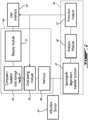
- FIG. 2An example of a system is illustrated in Fig. 2 .
- the systemuses a real-time signal provided by a vibration sensor 30.
- the vibration sensor 30is an accelerometer and the real-time signal is in the form of values in units of acceleration amplitude which fluctuate as a function of time.
- the accelerometermay be mounted on a fixed component adjacent to a rotary component, for instance.
- the vibration sensor 30can be a displacement sensor outputting a real-time signal in the form of values in units of displacement amplitude which fluctuate as a function of time, a velocity sensor, or a combination of sensor units, to name a few examples.
- the signal from the vibration sensoris processed in a bandwidth-dependent transfer function 42 which can be embodied by a simple electronic circuit.
- the bandwidth-dependent transfer function 42processes the real-time signal differently depending on the frequency bandwidth. More particularly, it converts, or translates, the amplitude units of in at least one of at least two different bandwidths into units with which vibration severity analysis can be carried out for that bandwidth. For instance, referring to Fig. 3 , in the case of a an accelerometer signal spanning a low frequency bandwidth 14 and an intermediate frequency bandwidth 16, the acceleration amplitude values will be doubly integrated in the low frequency bandwidth 16 to yield frequency dependent displacement amplitude values for that bandwidth, whereas the acceleration amplitude values will be simply integrated in the intermediate frequency bandwidth 14 to yield frequency dependent velocity amplitude values for the intermediate frequency bandwidth 14. If signals in the high frequency bandwidth 22 are to also be taken into account, the acceleration amplitude values in that bandwidth 22 can be left unaltered by the transfer function.
- frequencies in bandwidths 34 and 36, below and above the bandwidths of interest 14, 16, 22are considered filtered zones treated by a corresponding one of a low-pass filter and a high-pass filter, and are separated from the bandwidths of interest 14, 16, 22 by corresponding transition zones 38, 40.
- a simple differentiating functioncan be set for the intermediate frequency bandwidth, and a double differentiating function can be set for the high frequency bandwidth.
- At least one vibration severity levelis associated to corresponding, constant, maximum amplitude values in each of the bandwidths, independently of the units used in the individual bandwidths, as detailed above.
- the signalis processed through an analysis module 60, or function.
- the analysis module 60can determine a maximum amplitude value in each bandwidth, and in parallel, compare the maximum amplitude values in each of the bandwidths to the constant amplitude value in the unit of the bandwidth which was previously associated to the given vibration severity level.
- a single alarm signal, associated to the given vibration severity level,is generated when in this manner, the maximum amplitude values are determined to have reached or exceeded a given vibration severity level, independently of the bandwidth where the given vibration severity has occurred, and of the units used in that bandwidth.
- corresponding constant maximum amplitude values in each of the bandwidthscan be associated to corresponding vibration severity values in the synthethic unit by multiplication by a predetermined bandwidth-dependent constant, the vibration severity values of the at least two bandwidths be compared to one another, and the analysis module can output a single vibration severity level value, in the synthetic unit, corresponding to the maximum vibration severity value detected across the two or more bandwidths.
- the single vibration severity level value outputcan be directly made accessible to an operator, for instance, to allow the operator to obtain a quick grasp of overall vibration severity by consulting a single value, and without having to independently analyze vibrations in different frequency bandwidths using different analysis methods.
- the step of translating, or associating, detected vibrations in the unit ( ⁇ m, mm/sec, G) corresponding to the associated frequency bandwidthcan be undertaken by the transfer function 42 which can be referred to as an associator and made part of an electronic circuit 44 of the system.
- This function 42can determine for each specific output from the accelerometer the VSM value to be attributed to such output.
- the signal generated by the system following the association with the common unitscan take different forms and have different effects.
- a protection module 62is also provided to trigger protective actions based on the overall previously obtained vibration severity indication.
- the protection module 62can be provided with more than one severity level threshold, and trigger protective actions associated with the severity level threshold detected. For instance, for overall vibration severity detected above a first value in the synthetic unit, an alarm signal can be indicated at a user interface 64, whereas when vibration severity is determined to reach a second, higher value in the synthetic unit, the protection module can automatically trigger a shut-down sequence for the machine, for instance.
- a unitary electronic circuitcan protect a machine in more than one frequency range, in real time.
- the choice of a protection levelcan be reduced to one VSM value, which is very simple and efficient for a machine operator.
- the illustrated embodimentincludes an additional, and optional, data storage subsystem 66 for storing information concerning vibrations at given periods in time which can be later accessed by the operator via a display.
- the data storage subsystem in this embodimentuses a 1 st -in-1 st -out memory 68 which stores the vibration signal. In this embodiment, it was chosen to process the raw data from vibration sensor through this memory 68, prior to any signal treatment.
- a data saving module 70is also provided to trigger the storage of the instantaneous contents of the 1 st -in-1 st -out memory 68 into a computer-readable data storage medium 46.
- the data saving module 70can be activated via the protection module 62, for instance, to save the contents of the 1 st -in-1 st -out memory 68 upon occurrence of a given alarm level, for instance, or can be activated periodically to build trend or history data.
- the data stored in the computer-readable data storage medium 46 upon the detection of a given alarm levelcan be accessed by a user via the user interface 66.
- the operatorwill wish to access the detail of the vibrations to obtain more information about what triggered the alarm.
- the display modulecan include a transfer function which doubly integrates an accelerometer signal over all the bandwidths of interest, for instance, and proceed with a Fourier transform to display the data on a graph such as illustratively provided at Fig. 4 . Curves representing one or more incrementing alarm levels across two or more different bandwidths can also be displayed on the graph for the user to be able to identify the frequency(ies) which caused the alarm(s) with a single glance.
- the graph shown in Fig. 4is associated to an example of a system adapted for a slow rotating hydro turbine-generator the VSM values corresponding to 5 zones ranging from "Very Good” to "Very Rough" derived from an ISO displacement severity chart.
- a hydro turbine-generatormay not require monitoring in the high frequency ranges, and so an example embodiment can include only a conversion function for a first bandwidth referred to as a low frequency bandwidth corresponding to ⁇ 2.5 Hz (such as double integration for instance), and a conversion function for a second bandwidth referred to as an intermediate bandwidth corresponding to > 2.5 Hz, (such as single integration for instance), instead of having three different bandwidths.
- the VSM scale values of the transfer functioncan reflect a translation upward of the VSM curves by a certain factor, following the manufacturer's or operator's request for such machines.
- a turbo generator machine typically operating in higher frequency rangesembodiments therefore can omit a translation function in the lower frequency ranges, for instance, having transfer functions only for a first bandwidth in the intermediate frequency range and a second bandwidth in the high(er) frequency range. In such a case, and if an accelerometer is used as the vibration sensor, the transfer function can simply leave the signal in the high frequency bandwidth unaffected.
- acceleration data provided by an accelerometercan be substituted by velocity data provided by a velocimeter or by displacement data provided by a proximeter.
- the transfer function of the electronic circuitrywill be adapted to reflect the nature of the primary input, i.e. velocity measurement or displacement measurement by appropriate differentiation or integration functions.
Landscapes
- Physics & Mathematics (AREA)
- General Physics & Mathematics (AREA)
- Business, Economics & Management (AREA)
- Emergency Management (AREA)
- Measurement Of Mechanical Vibrations Or Ultrasonic Waves (AREA)
Description
- The improvements generally relate to the field of vibration severity analysis of fixed, moving and rotary components of machines and more particularly, the described method and system automatically provides a uniform vibration severity assessment independently of the frequency of the vibrations.
- Vibration analysis of machines is generally dependent upon the bandwidth within which the vibrations occur - this is reflected by "vibration severity charts" such as those from international standard organizations such as ISO. In a low frequency bandwidth (e.g. < 10Hz), a given vibration severity is associated with a constant amplitude of displacement across the low frequency bandwidth, i.e. by the maximum displacements of the component that are caused by such vibrations. In this manner, an operator detecting a displacement amplitude exceeding a given level at any frequency within the low frequency bandwidth can trigger an alarm or the like. However, in much higher bandwidths (say over 1,000 Hz), a given vibration severity is generally indicated by constant acceleration values across the bandwidth, rather than constant displacement values. Again, in intermediate bandwidths (say between 10Hz and 1,000 Hz), a given vibration severity is indicated by constant velocity values across the bandwidth.
- It can thus be understood that some machine components are submitted vibrations in a bandwidth for which the analysis is characterized by displacement measurement (in the case of low frequency bandwidth), whereas others are associated with velocity measurement (for intermediate frequency bandwidths), and others still are associated with acceleration measurement (high frequency bandwidths). However, some components may require a vibration analysis which overlaps two or more adjacent bandwidths which makes it complicated, counter-intuitive, and time-consuming for operators to assess the severity of the vibrations in the different bandwidths, particularly in complex machinery having a plurality of components and vibration harmonics. The article "Azima DLI vibration reference", retrieved from the internet athttp://www.azimadly.com/vibman/default.htm, the patent
US6386040 and the patentUS 5875420 provide related solutions, but do not provide or suggest a solution for automatically attributing a uniform vibration indication, independently of the frequency bandwidth in which the sever vibration occurs.
Accordingly, there remains a need to simplify vibration severity analysis for machine operators. - The object of the invention is achieved by a method according to
claim 1 and a system according to claim 11. The system and method described herein can automatically attribute a uniform vibration severity indication, such as an alarm level, or a single value in a synthetic unit representative of vibration severity, independently of the bandwidth in which the severe vibration occurs. - For illustrative purposes such a synthetic unit will be defined herein as VSM (Vibration Severity Measurement) to quantify the dimensional vectors: (displacement, frequency) at low frequencies, (velocity, frequency) at medium frequencies, or (acceleration, frequency) at high frequencies into associated unified indications of vibration severity, e.g. 1.0 VSM being associated with a lesser vibration severity than 5.0 VSM, for instance. Such VSM values can be displayed as comfort or discomfort zones, via a transfer function which can be made part of an electronic circuit (controller) located between the accelerometer and an alarm module.
- The method or system can convert a real-time output signal of a vibration sensor (e.g. an accelerometer) into the synthetic severity alarm number in both of two or more monitored frequency bandwidths, and thereby take protective action if needed, independently of the frequency of a severe vibration, and optionally provide a value in the single synthetic unit which is indicative of the severity of the vibration, allowing operators to work with unified severity units independently of the frequency range.
- In accordance with another aspect, there is provided a method for providing a vibration severity indication of a machine component, the system comprising : receiving a real-time signal containing information pertaining to amplitude and frequency of vibrations of the component over a frequency spectrum including a first analysis bandwidth and a second analysis bandwidth, and using the real-time signal to determine values indicative of the severity of vibrations occurring at frequencies in the first analysis bandwidth in a first unit of one of displacement, velocity, and acceleration, and determine values indicative of the severity of vibrations occurring at frequencies in the second analysis bandwidth in a second unit of one of displacement, velocity and acceleration, the second unit being different from the first unit; associating the determined values for both the first analysis bandwidth and the second analysis bandwidth to values in a common unit representing comparable severity of vibrations in the first analysis bandwidth and the second analysis bandwidth; and generating a unique signal indicative of the determined values reaching a given value in the common unit independently of whether the given value is reached in the first bandwidth or the second bandwidth.
- In accordance with another aspect, there is provided a system for providing a vibration severity indication of a machine component, the system comprising : a vibration sensor located on or adjacent to the component, providing a real-time signal containing information pertaining to amplitude and frequency of vibrations of the component over a spectrum including at least a first analysis bandwidth and a second analysis bandwidth during use, a controller connectable to receive the real-time signal from the vibration sensor, the controller having a function to determine values indicative of the severity of vibrations occurring at frequencies in the first analysis bandwidth in a first unit of one of displacement, velocity, and acceleration, and values indicative of the severity of vibrations occurring at frequencies in the second analysis bandwidth in a second unit of one of displacement, velocity and acceleration, the second unit being different from the first unit; a function to associate the values of both the first analysis bandwidth and the second analysis bandwidth to values in a common unit representing comparable severity of vibrations in the first analysis bandwidth and the second analysis bandwidth, and a function to generate a signal indicative of a given level of severity of vibrations being reached based on the association.
- In accordance with another aspect, there is provided a vibration severity analysis method by which a real time output of an accelerometer is processed through an electronic circuitry or the like that contains: a function that translates the real time output at given frequency into either one of at least two of : a) constant displacement value at low frequencies, b) constant velocity value at medium frequencies, c) constant acceleration value at high frequencies; a function that compares said translated value to one predetermined synthetic alarm level number that represents a protection level independently of the frequency.
- In accordance with another aspect, there is provided a vibration severity analysis system comprising : a processor for receiving an acceleration signal from at least one accelerometer, said acceleration signal being indicative of vibrations, further having at least two of the following functions : for vibrations established in a low frequency range, converting the acceleration measurement output into a maximum displacement indication, for vibrations in a medium frequency range, converting the acceleration measurement output into a maximum velocity indication, for vibrations in a high frequency range, converting the acceleration measurement output into a maximum acceleration indication, and further having a function of attributing a severity alarm level to the converted acceleration measurement, the severity alarm level being representative of vibration severity independently of the effected conversion.
- In accordance with another aspect, there is provided a method for providing a vibration severity indication, the method comprising : receiving a real-time signal containing information pertaining to amplitude of one of displacement, velocity and acceleration of vibrations over a frequency spectrum including a first bandwidth and an adjacent second bandwidth, and using the real-time signal to determine values indicative of the severity of vibrations occurring at frequencies in the first bandwidth in a corresponding first unit of one of displacement, velocity, and acceleration, and determine values indicative of the severity of vibrations occurring at frequencies in the second bandwidth in a corresponding second unit of one of displacement, velocity and acceleration, the second unit being different from the first unit; associating the determined values for both the first bandwidth and the second bandwidth to values in a common unit representing comparable severity of vibrations in the first bandwidth and the second bandwidth; and generating a unique signal indicative of the determined values reaching a given value in the common unit independently of whether the given value is reached in the first bandwidth or the second bandwidth.
- The common unit can be a synthetic unit derived from a vibration severity chart, and the first and second bandwidths are also derived from the vibration severity chart.
- The method can further comprise displaying the given value of the common unit based on the generated signal.
- The method can further comprise comparing the determined values to threshold values of at least one vibration severity level in the corresponding bandwidths, and performing said generating upon any one of the threshold values being reached by the determined values, independently of the bandwidth of occurence.
- Said comparing can be done using the common units.
- Said associating can include performing said comparing based on the first unit and second unit with associated threshold values.
- The using the real time signal can include processing the real-time signal in a first-in-first-out memory spanning a given period of time, further comprising storing the data in the first-in-first-out memory onto a computer readable medium upon said generating.
- The method can further comprise constructing and displaying a graph representing the amplitude of vibration over the frequency spectrum using the data stored in the computer readable medium, with a curve representing the threshold values superposed thereto. The the graph can display values in a unit of displacement for instance.
- The real-time signal can be provided in units of acceleration, and the values in the at least one of velocity and displacement units are obtained by performing a corresponding one of simple integration and double integration to the real-time signal over the corresponding bandwidth.
- The frequency spectrum further can further include a third bandwidth, further comprising determining values indicative of the severity of vibrations occurring at frequencies in the third bandwidth in a corresponding third unit of one of displacement, velocity and acceleration using the real-time signal, the third unit being different from both the first unit and the second unit, and wherein said associating further includes associating the determined values for the third bandwidth to values in the common unit representing comparable severity of vibrations in all three bandwidths.
- In accordance with another aspect, there is provided a system for providing a vibration severity indication of a machine component, the system comprising : a vibration sensor positioned to sense the vibration of the machine component, providing a real-time signal containing information pertaining to amplitude and frequency of vibrations of the component over a spectrum including at least a first analysis bandwidth and a second analysis bandwidth during use, an electronic circuit connectable to receive the real-time signal from the vibration sensor, the electronic circuit having a function to determine values indicative of the severity of vibrations occurring at frequencies in the first analysis bandwidth in a first unit of one of displacement, velocity, and acceleration, and values indicative of the severity of vibrations occurring at frequencies in the second analysis bandwidth in a second unit of one of displacement, velocity and acceleration, the second unit being different from the first unit; a function to associate the values of both the first analysis bandwidth and the second analysis bandwidth to values in a common unit representing comparable severity of vibrations in the first analysis bandwidth and the second analysis bandwidth, and a function to generate a signal indicative of a given level of severity of vibrations being reached based on the association.
- The vibration sensor can be an accelerometer.
- The system can further comprise a memory for storing data concerning at least one severity level of a comparable severity of vibrations occurring in both the first analysis bandwidth and the second analysis bandwidth, the function to associate being based on the stored data concerning the at least one severity level.
- In accordance with another aspect, there is provided a method of analyzing severity using a real time output of an accelerometer, the method comprising: -
translating the real time output into at least two of : a) displacement values at low frequencies, b) velocity values at intermediate frequencies, and c) acceleration values at high frequencies; -determining an overall vibration severity level independently of frequency of occurrence of vibrations, by comparing said translated values a corresponding at least two of : a) a constant displacement value across the low frequency bandwidth associated with the overall severity level, b) a constant velocity value across the intermediate frequency bandwidth associated with the overall severity level, and c) a constant acceleration value across the high frequency bandwidth associated with the overall severity level. - The method can further comprise associating the overall vibration severity level to a value of a synthetic vibration severity unit.
- The method can further comprise activating an alarm of at least one alarm level when the synthetic vibration severity value exceeds a corresponding at least one threshold value.
- The method can be effected by a unitary electronic circuit.
- The low frequencies can correspond to frequencies under 10Hz, medium frequencies correspond to frequencies between 10 and 1,000 Hz, and high frequencies correspond to frequencies above 1,000 Hz.
- The processor can position a real time output of the accelerometer as a multiple or a fraction of the synthetic alarm level number.
- Many further features and combinations thereof concerning the present improvements will appear to those skilled in the art following a reading of the instant disclosure.
- In the figures,
Fig. 1 is a chart showing different vibration severity thresholds in different frequency ranges;Fig. 2 is a bloc diagram showing an example of a system for uniform vibration severity analysis;Fig. 3 is a chart showing different signal treatment bandwidths for the system ofFig. 2 ; andFig. 4 is an exemplary graphical representation of vibrations at a given time period and four alarm thresholds.Fig.1 shows a graph illustrating values of displacement, velocity, and acceleration of a rotary component, plotted against RPM values which are representative of frequency in therelation 60 RPM = 1 Hz (sec-1).- An
inferior frequency limit 12 is set, delimiting alow frequency bandwidth 14 from anintermediate frequency bandwidth 16. Thelow frequency bandwidth 14 is characterized by the fact that a given vibration severity is best indicated in this bandwidth using a constant value in units of displacement (e.g. micrometers - µm). Henceforth, a given alarm level associated to a given severity of vibrations in this bandwidth can be set by aconstant displacement curve 18. - In this example, a
superior frequency limit 20 is also set, delimiting theintermediate frequency bandwidth 16 from ahigh frequency bandwidth 22. Theintermediate frequency bandwidth 16 is characterized by the fact that vibration severity is best indicated in this bandwidth using values in units of velocity (e.g. mm/sec), and an alarm level corresponding in severity to theconstant displacement curve 18 plotted in thelow frequency bandwidth 14 can be set here as aconstant velocity curve 24. Thehigh frequency bandwidth 22 is characterized by the fact that vibration severity is best indicated in this bandwidth using values in units of acceleration (e.g. gravitational acceleration G where 1 G = 9.8 m/sec2). In these high frequencies, an alarm level corresponding in severity to the alarm levels set in the intermediate frequency and low frequency bandwidths (16, 14) can be set here as aconstant acceleration curve 26. - It will also be understood that machines having rotary components will only rarely have vibrations spanning three different bandwidths, many of interest being satisfactorily analyzed using only two different bandwidths. In the light of this information, it will be understood that even the fact of having two
frequency limits bandwidths inferior frequency limit 12 is illustratively set at 10Hz (600 RPM), and thesuperior frequency limit 20 at 1KHz (60 000 RPM). - In this exemplary embodiment, a first vibration severity alarm level was set at a displacement of 100 µm in the low frequency bandwidth, vibrations having a peak-to-peak displacement below that threshold value in the low frequency bandwidth being considered unalarming, or attributed a "Very Good" status for instance. A comparable severity alarm level in the intermediate frequency bandwidth can be set at 3 mm/sec, for instance. Below, two examples of how common units can be achieved to unify these two different analysis methods are detailed.
- A first example is to associate velocity values to values of displacement, e.g. a 3 mm/sec value in the intermediate bandwidth can be "translated" into its equivalent in the low frequency bandwidth - i.e. 100 µm - and the equivalent displacement value which can be considered more intuitive to grasp by a user can be provided to the user, rather than displaying a velocity value for instance. A displacement value is thus used as a common reference unit. In this manner, acceleration values of comparable severity in the high frequency range, e.g. 2 G, can also be translated into the equivalent displacement value of 100 µm. This technique can also be used in embodiments where the value is not displayed numerically to the operator/user, but rather used to trigger an alarm of a corresponding severity level which is interfaced to the user in any suitable manner - e.g. the user sets an alarm at a vibration severity level of 100 µm of displacement, and the alarm is triggered independently of whether the value of 100 µm is reached in the low frequency bandwidth, a value of 3 mm/sec is reached in the intermediate frequency bandwidth, or a value of 2 G acceleration is reached in the high frequency bandwidth. Further, as will be detailed below, more than one threshold level can be set to trigger actions or alarms associated to increasing severity.
- A second example can be to associate velocity, displacement, or acceleration units to a new reference unit which will be referred to herein as a synthetic unit indicative of vibration severity independently of the bandwidth or original units. The
numeral 1 of such a synthetic unit can correspond to the afore-mentioned upper limit of a comfort zone, in one example. This approach is detailed below where the synthetic unit is referred to as the unit of VSM (Vibration Severity Measurement) and a value of 1 VSM is associated to the upper limit of a comfort zone within which vibrations are considered minimal or non stressful for the machine. - Henceforth, in the following example, we will consider that a value of 1 VSM corresponds to a constant displacement of 100 microns (µm - peak to peak) between 1 and 10 Hz, a constant peak velocity of 3,1416 mm per second between 10 and 1,000 Hz, and a constant peak acceleration of 2,012 G (19.73 m/s2) over the upper frequency limit of 1,000 Hz.
- The operators of such machine may then want, for instance, to set a first "mild" alarm at the vibration severity values associated to 5 VSM, and a "strong" alarm at vibration severity values associated to 10 VSM, whatever the frequencies of the vibrations. Corresponding alarms can be associated to corresponding protective actions, as will be detailed below.
- An example of a system is illustrated in
Fig. 2 . The system uses a real-time signal provided by avibration sensor 30. In the illustrated example, thevibration sensor 30 is an accelerometer and the real-time signal is in the form of values in units of acceleration amplitude which fluctuate as a function of time. The accelerometer may be mounted on a fixed component adjacent to a rotary component, for instance. In alternate embodiments, thevibration sensor 30 can be a displacement sensor outputting a real-time signal in the form of values in units of displacement amplitude which fluctuate as a function of time, a velocity sensor, or a combination of sensor units, to name a few examples. - The signal from the vibration sensor is processed in a bandwidth-
dependent transfer function 42 which can be embodied by a simple electronic circuit. The bandwidth-dependent transfer function 42 processes the real-time signal differently depending on the frequency bandwidth. More particularly, it converts, or translates, the amplitude units of in at least one of at least two different bandwidths into units with which vibration severity analysis can be carried out for that bandwidth. For instance, referring toFig. 3 , in the case of a an accelerometer signal spanning alow frequency bandwidth 14 and anintermediate frequency bandwidth 16, the acceleration amplitude values will be doubly integrated in thelow frequency bandwidth 16 to yield frequency dependent displacement amplitude values for that bandwidth, whereas the acceleration amplitude values will be simply integrated in theintermediate frequency bandwidth 14 to yield frequency dependent velocity amplitude values for theintermediate frequency bandwidth 14. If signals in thehigh frequency bandwidth 22 are to also be taken into account, the acceleration amplitude values in thatbandwidth 22 can be left unaltered by the transfer function. - Typically values at frequencies being out of range from the bandwidths under analysis can be eliminated by way of filters or the like. For instance, as shown in
Fig. 3 , frequencies inbandwidths interest interest transition zones - Alternately, in the case where the vibration sensor detects displacement rather than acceleration, for instance, a simple differentiating function can be set for the intermediate frequency bandwidth, and a double differentiating function can be set for the high frequency bandwidth.
- At least one vibration severity level is associated to corresponding, constant, maximum amplitude values in each of the bandwidths, independently of the units used in the individual bandwidths, as detailed above.
- In a next step, the signal is processed through an
analysis module 60, or function. - According to one embodiment, the
analysis module 60 can determine a maximum amplitude value in each bandwidth, and in parallel, compare the maximum amplitude values in each of the bandwidths to the constant amplitude value in the unit of the bandwidth which was previously associated to the given vibration severity level. A single alarm signal, associated to the given vibration severity level, is generated when in this manner, the maximum amplitude values are determined to have reached or exceeded a given vibration severity level, independently of the bandwidth where the given vibration severity has occurred, and of the units used in that bandwidth. - According to another embodiment, rather than outputting an alarm indication upon the vibration severity reaching a given threshold as detailed above, corresponding constant maximum amplitude values in each of the bandwidths can be associated to corresponding vibration severity values in the synthethic unit by multiplication by a predetermined bandwidth-dependent constant, the vibration severity values of the at least two bandwidths be compared to one another, and the analysis module can output a single vibration severity level value, in the synthetic unit, corresponding to the maximum vibration severity value detected across the two or more bandwidths. In such an embodiment, the single vibration severity level value output can be directly made accessible to an operator, for instance, to allow the operator to obtain a quick grasp of overall vibration severity by consulting a single value, and without having to independently analyze vibrations in different frequency bandwidths using different analysis methods.
- For example, referring to
Fig. 2 , the step of translating, or associating, detected vibrations in the unit (µm, mm/sec, G) corresponding to the associated frequency bandwidth can be undertaken by thetransfer function 42 which can be referred to as an associator and made part of an electronic circuit 44 of the system. Thisfunction 42 can determine for each specific output from the accelerometer the VSM value to be attributed to such output. - (i) For frequencies in the low frequency bandwidth (e.g. <10Hz), the acceleration output can be doubly integrated in time, for instance, to give a displacement value that can thereafter be translated into a VSM value. For instance, if that value is 75 microns, and if the chosen 1 VSM corresponds to a displacement of 100 microns, the VSM value of the output for a given frequency can be 0,75 (in the "Very Good" zone).
- (ii) For frequencies in the intermediate frequency bandwidth (e.g. between 10 and 1,000 Hz), the acceleration output can be simply integrated in time, for instance, to give a velocity value that will be translated in a VSM value. For instance, if the chosen 1 VSM value corresponds to a velocity of 3.1416 mm/second, and if the computed velocity is under 2 mm/second, the VSM value of the measure will be less than 1.
- (iii) For frequencies over 1,000 Hz, the acceleration output can be taken as such, without additional treatment. For instance, if the measured acceleration is less than 2 G, and if the chosen 1.0 VSM value is 2G, the VSM value will be less than 1.
- Henceforth, the signal generated by the system following the association with the common units can take different forms and have different effects.
- In the example embodiment shown in
Fig. 2 , aprotection module 62 is also provided to trigger protective actions based on the overall previously obtained vibration severity indication. In accordance with one embodiment, theprotection module 62 can be provided with more than one severity level threshold, and trigger protective actions associated with the severity level threshold detected. For instance, for overall vibration severity detected above a first value in the synthetic unit, an alarm signal can be indicated at auser interface 64, whereas when vibration severity is determined to reach a second, higher value in the synthetic unit, the protection module can automatically trigger a shut-down sequence for the machine, for instance. - The requirement of frequency analysis by the operator can thus be avoided, and the operator instead being presented a simple alarm. Henceforth, a unitary electronic circuit can protect a machine in more than one frequency range, in real time. The choice of a protection level can be reduced to one VSM value, which is very simple and efficient for a machine operator.
- Still referring to the example embodiment shown in
Fig. 2 , it will be understood that the illustrated embodiment includes an additional, and optional,data storage subsystem 66 for storing information concerning vibrations at given periods in time which can be later accessed by the operator via a display. - The data storage subsystem in this embodiment uses a 1st-in-1st-
out memory 68 which stores the vibration signal. In this embodiment, it was chosen to process the raw data from vibration sensor through thismemory 68, prior to any signal treatment. Adata saving module 70 is also provided to trigger the storage of the instantaneous contents of the 1st-in-1st-out memory 68 into a computer-readabledata storage medium 46. Thedata saving module 70 can be activated via theprotection module 62, for instance, to save the contents of the 1st-in-1st-out memory 68 upon occurrence of a given alarm level, for instance, or can be activated periodically to build trend or history data. - In the specific embodiment depicted in
Fig. 2 , the data stored in the computer-readabledata storage medium 46 upon the detection of a given alarm level can be accessed by a user via theuser interface 66. For example, in some applications, the operator will wish to access the detail of the vibrations to obtain more information about what triggered the alarm. In the case of operators who prefer reasoning in terms of displacement amplitude, the display module can include a transfer function which doubly integrates an accelerometer signal over all the bandwidths of interest, for instance, and proceed with a Fourier transform to display the data on a graph such as illustratively provided atFig. 4 . Curves representing one or more incrementing alarm levels across two or more different bandwidths can also be displayed on the graph for the user to be able to identify the frequency(ies) which caused the alarm(s) with a single glance. - More particularly, the graph shown in
Fig. 4 is associated to an example of a system adapted for a slow rotating hydro turbine-generator the VSM values corresponding to 5 zones ranging from "Very Good" to "Very Rough" derived from an ISO displacement severity chart. Such a hydro turbine-generator may not require monitoring in the high frequency ranges, and so an example embodiment can include only a conversion function for a first bandwidth referred to as a low frequency bandwidth corresponding to < 2.5 Hz (such as double integration for instance), and a conversion function for a second bandwidth referred to as an intermediate bandwidth corresponding to > 2.5 Hz, (such as single integration for instance), instead of having three different bandwidths. In the graph shown, two peaks of vibration are observed, afirst peak 50 around 5.5 Hz triggering the vibration severity threshold level of 1.9 VSM, in a "Fair Zone", and thesecond peak 52 around 70Hz, triggering the vibration severity threshold level of 9.8 VSM, into a "Rough Good Zone". - For a turbogenerator machine using the same kind of ISO vibration severity chart, the VSM scale values of the transfer function can reflect a translation upward of the VSM curves by a certain factor, following the manufacturer's or operator's request for such machines. A turbo generator machine typically operating in higher frequency ranges, embodiments therefore can omit a translation function in the lower frequency ranges, for instance, having transfer functions only for a first bandwidth in the intermediate frequency range and a second bandwidth in the high(er) frequency range. In such a case, and if an accelerometer is used as the vibration sensor, the transfer function can simply leave the signal in the high frequency bandwidth unaffected.
- In alternate embodiments, it will thus also be understood that acceleration data provided by an accelerometer can be substituted by velocity data provided by a velocimeter or by displacement data provided by a proximeter. In such case, the transfer function of the electronic circuitry will be adapted to reflect the nature of the primary input, i.e. velocity measurement or displacement measurement by appropriate differentiation or integration functions.
- As can be seen therefore, the examples described above and illustrated are intended to be exemplary only. The scope is indicated by the appended claims.
Claims (15)
- A method of activating a protective measure in a machine comprising vibrating components generating vibrations, the method comprising :obtaining a vibration signal of said vibrations at frequencies spanning at least two adjacent frequency bandwidths amongsta low frequency bandwidth (14), an intermediate frequency bandwidth (16), adjacent to the low frequency bandwidth, anda high frequency bandwidth (22), adjacent to the intermediate frequency bandwidth,characterized in that the method further comprises the steps of:effecting a bandwidth-dependent transfer function (42) on said vibration signaland producing an output in which, independently of original units of the vibration signal, the corresponding at least two ofvibrations spanning the low frequency bandwidth are represented in units of displacement amplitude,vibrations spanning the intermediate frequency bandwidth are represented in units of velocity amplitude, andvibrations spanning the high frequency bandwidth are represented in units of acceleration amplitude;using the output, comparing the corresponding at least two ofdisplacement amplitude unit representation across the low frequency bandwidth to a constant displacement amplitude value across the low frequency bandwidth;velocity amplitude unit representation across the intermediate frequency bandwidth to a constant velocity amplitude value across the intermediate frequency bandwidth; andacceleration amplitude unit representation across the high frequency bandwidth to a constant acceleration amplitude value across the high frequency bandwidth;wherein said corresponding at least two of constant acceleration amplitude value, constant velocity amplitude value, and constant acceleration amplitude value are associated to a same vibration severity level; andactivating the protective measure upon determining from said comparison that said vibrations at least reach said vibration severity level at any frequency within said corresponding bandwidths.
- The method of claim 1 wherein the protective measure includes activating an indicator indicative of vibration severity.
- The method of claim 2 wherein the indicator displays a value in a synthetic unit, said synthetic unit value corresponding to maximum severity of vibrations reached independently of bandwidth.
- The method of claim 1 wherein said activating includes activating a selected one of a plurality of protective measures associated to a corresponding one of a plurality of vibration severity level thresholds.
- The method of claim 1 further comprising processing the vibration signal through a memory.
- The method of claim 5 wherein the protective measure includes storing the contents of the memory into a computer-readable data storage medium.
- The method of claim 6 further comprising obtaining previously stored contents of the memory from the computer-readable data storage medium, processing the contents through a Fourier transform, and displaying a graphical representation of the processed contents as amplitude vs. frequency of vibrations over the corresponding bandwidths.
- The method of claim 7 further comprising processing the obtained contents through a double integration over all the corresponding bandwidths, and displaying the contents as displacement amplitude vs. frequency of vibrations over the corresponding bandwidths.
- The method of claim 7 further comprising superimposing at least one curve to the graphical representation, said at least one curve representing a corresponding at least one vibration severity level.
- The method of claim 5 further comprising periodically storing the contents of the memory into a computer-readable data storage medium.
- A system for activating a protective measure in a machine comprising vibrating components generating vibrations, the system comprising :
at least one vibration sensor (30) generating a vibration signal indicative of an amplitude of said vibrations when submitted thereto, the vibration signal spanning at least two adjacent frequency bandwidths amongsta low frequency bandwidth,an intermediate frequency bandwidth, adjacent to the low frequency bandwidth andan high frequency bandwidth, adjacent to the intermediate frequency bandwidth,characterized in that the system further comprises:a bandwidth-dependent transfer function module (42), said module being configured for, upon receiving the vibration signal, outputting a converted signal in which, independently of original amplitude units of the vibration signal, the corresponding at least two ofvibrations spanning the low frequency bandwidth are represented in units of displacement amplitude,vibrations spanning the intermediate frequency bandwidth are represented in units of velocity amplitude, andvibrations spanning the high frequency bandwidth are represented in units of acceleration amplitude;a comparator function module (60), configured for comparing the corresponding at least two ofdisplacement amplitude unit representation across the low frequency bandwidth to a constant displacement amplitude value across the low frequency bandwidth;velocity amplitude unit representation across the intermediate frequency bandwidth to a constant velocity amplitude value across the intermediate frequency bandwidth; andacceleration amplitude unit representation across the high frequency bandwidth to a constant acceleration amplitude value across the high frequency bandwidth;wherein said corresponding at least two of said constant displacement amplitude value, said constant velocity amplitude value, and said constant acceleration amplitude value are associated to a same vibration severity level independently of the bandwidth; anda protection module (62) activating the protective measure upon determining based on said comparison that said vibrations at least reach said vibration severity level at any frequency within said corresponding bandwidths. - The system of claim 11 wherein the at least one vibration sensor is an accelerometer, and the original vibration amplitude units are units of acceleration.
- The system of claim 12, wherein said bandwidth-dependent transfer function is contained in an electronic circuit.
- The system of claim 11 wherein the vibration signal spans the low frequency bandwidth, the intermediate frequency bandwidth, and the high frequency bandwidth.
- The system of claim 11 further comprising an indicator activatable by the protection module to display an indication of said vibration severity level, the indication preferably being a numerical value in a synthetic unit corresponding to a maximum severity of vibrations reached independently of bandwidth of occurrence.
Applications Claiming Priority (1)
| Application Number | Priority Date | Filing Date | Title |
|---|---|---|---|
| PCT/CA2012/050673WO2014047714A1 (en) | 2012-09-26 | 2012-09-26 | System and method for vibration severity assessment independently of vibration frequency |
Publications (3)
| Publication Number | Publication Date |
|---|---|
| EP2713146A2 EP2713146A2 (en) | 2014-04-02 |
| EP2713146A3 EP2713146A3 (en) | 2016-06-29 |
| EP2713146B1true EP2713146B1 (en) | 2018-06-27 |
Family
ID=47632674
Family Applications (1)
| Application Number | Title | Priority Date | Filing Date |
|---|---|---|---|
| EP12191328.9AActiveEP2713146B1 (en) | 2012-09-26 | 2012-11-05 | System and method for vibration severity assessment independently of vibration frequency |
Country Status (4)
| Country | Link |
|---|---|
| US (1) | US9595179B2 (en) |
| EP (1) | EP2713146B1 (en) |
| CA (1) | CA2829662C (en) |
| WO (1) | WO2014047714A1 (en) |
Families Citing this family (12)
| Publication number | Priority date | Publication date | Assignee | Title |
|---|---|---|---|---|
| JP2015210110A (en)* | 2014-04-24 | 2015-11-24 | 株式会社小野測器 | FFT analyzer |
| DE102015217831A1 (en)* | 2015-09-17 | 2017-03-23 | Siemens Aktiengesellschaft | Method for determining a vibration of a component, computing device and sensor device |
| US12276420B2 (en) | 2016-02-03 | 2025-04-15 | Strong Force Iot Portfolio 2016, Llc | Industrial internet of things smart heating systems and methods that produce and use hydrogen fuel |
| KR102660280B1 (en) | 2017-10-06 | 2024-04-23 | 더 리서치 인스티튜트 앳 네이션와이드 칠드런스 하스피탈 | Use of infant and toddler-activated audio players |
| PL235633B1 (en)* | 2017-11-07 | 2020-09-21 | Instytut Transp Samochodowego | Method for measuring frequency of vibrations |
| US20200133254A1 (en) | 2018-05-07 | 2020-04-30 | Strong Force Iot Portfolio 2016, Llc | Methods and systems for data collection, learning, and streaming of machine signals for part identification and operating characteristics determination using the industrial internet of things |
| CN109269628B (en)* | 2018-08-01 | 2021-12-24 | 瑞声科技(新加坡)有限公司 | Method for monitoring motor vibration, terminal device and computer readable storage medium |
| CN109163794B (en)* | 2018-08-15 | 2021-11-12 | 瑞声科技(新加坡)有限公司 | Method for detecting bandwidth of linear vibration motor |
| JP6845192B2 (en)* | 2018-08-31 | 2021-03-17 | ファナック株式会社 | Processing environment measuring device |
| CA3126601A1 (en) | 2019-01-13 | 2020-07-16 | Strong Force Iot Portfolio 2016, Llc | Methods, systems, kits and apparatuses for monitoring and managing industrial settings |
| CN111089695B (en)* | 2019-12-27 | 2022-10-25 | 上海文倍测控科技有限公司 | Automatic modal testing method |
| CN113706840B (en)* | 2021-08-12 | 2023-08-08 | 广东电网有限责任公司广州供电局 | Partial discharge ultrahigh frequency monitoring and grading alarm circuit and alarm device and method thereof |
Citations (1)
| Publication number | Priority date | Publication date | Assignee | Title |
|---|---|---|---|---|
| US5875420A (en)* | 1997-06-13 | 1999-02-23 | Csi Technology, Inc. | Determining machine operating conditioning based on severity of vibration spectra deviation from an acceptable state |
Family Cites Families (16)
| Publication number | Priority date | Publication date | Assignee | Title |
|---|---|---|---|---|
| US4302977A (en)* | 1980-04-04 | 1981-12-01 | Ird Mechanalysis, Inc. | Vibration severity indicator |
| US4408285A (en)* | 1981-02-02 | 1983-10-04 | Ird Mechanalysis, Inc. | Vibration analyzing apparatus and method |
| US4513622A (en)* | 1983-08-22 | 1985-04-30 | Kazansky Aviatsionny Institut Imeni A. N. Tupoleva | Method of forming random vibration spectrum and device therefor |
| CA1315868C (en) | 1988-05-30 | 1993-04-06 | Rene Schmidt | Blast recorder and method of displaying blast energy |
| US5895857A (en) | 1995-11-08 | 1999-04-20 | Csi Technology, Inc. | Machine fault detection using vibration signal peak detector |
| US5864718A (en) | 1997-01-08 | 1999-01-26 | Eastman Kodak Company | One-time use camera with multi-lamp flash |
| DE19705922A1 (en) | 1997-02-17 | 1998-08-20 | Asea Brown Boveri | Method for determining the strength of winding heads of electrical machines and arrangement for carrying out the method |
| US6820026B1 (en)* | 1997-10-24 | 2004-11-16 | The Minster Machine Company | Console mounted vibration severity monitor |
| US6257066B1 (en) | 1998-05-21 | 2001-07-10 | Reid Asset Management Company | Portable vibration monitoring device |
| US6289735B1 (en) | 1998-09-29 | 2001-09-18 | Reliance Electric Technologies, Llc | Machine diagnostic system and method for vibration analysis |
| EP1054243B1 (en) | 1999-05-19 | 2006-01-04 | Vibro-Meter Sa | Method and means for combined vibration measurement |
| US6789030B1 (en)* | 2000-06-23 | 2004-09-07 | Bently Nevada, Llc | Portable data collector and analyzer: apparatus and method |
| US6915235B2 (en) | 2003-03-13 | 2005-07-05 | Csi Technology, Inc. | Generation of data indicative of machine operational condition |
| US6810741B1 (en)* | 2003-04-30 | 2004-11-02 | CENTRE DE RECHERCHE INDUSTRIELLE DU QUéBEC | Method for determining a vibratory excitation spectrum tailored to physical characteristics of a structure |
| US20090070069A1 (en) | 2007-09-07 | 2009-03-12 | Csi Technology, Inc. | Apparatus and method for optimizing measurement reporting in a field device |
| KR101081982B1 (en) | 2008-10-23 | 2011-11-10 | 한국전력공사 | Vibration Monitering and Diagnostic System for Large Power Transformer |
- 2012
- 2012-09-26USUS14/430,013patent/US9595179B2/enactiveActive
- 2012-09-26WOPCT/CA2012/050673patent/WO2014047714A1/enactiveApplication Filing
- 2012-09-26CACA2829662Apatent/CA2829662C/enactiveActive
- 2012-11-05EPEP12191328.9Apatent/EP2713146B1/enactiveActive
Patent Citations (1)
| Publication number | Priority date | Publication date | Assignee | Title |
|---|---|---|---|---|
| US5875420A (en)* | 1997-06-13 | 1999-02-23 | Csi Technology, Inc. | Determining machine operating conditioning based on severity of vibration spectra deviation from an acceptable state |
Also Published As
| Publication number | Publication date |
|---|---|
| US20150248828A1 (en) | 2015-09-03 |
| WO2014047714A1 (en) | 2014-04-03 |
| CA2829662A1 (en) | 2014-01-23 |
| EP2713146A3 (en) | 2016-06-29 |
| EP2713146A2 (en) | 2014-04-02 |
| US9595179B2 (en) | 2017-03-14 |
| CA2829662C (en) | 2015-08-25 |
Similar Documents
| Publication | Publication Date | Title |
|---|---|---|
| EP2713146B1 (en) | System and method for vibration severity assessment independently of vibration frequency | |
| JP5669933B2 (en) | Machine vibration monitoring | |
| CN107884214B (en) | A kind of train EEF bogie unit failure multi-parameter comprehensive decision-making technique and device | |
| JP5293300B2 (en) | Vibration monitoring device and vibration monitoring method for rotating machine | |
| JP6945371B2 (en) | Diagnostic equipment for rotating machine systems, power converters, rotating machine systems, and diagnostic methods for rotating machine systems. | |
| CA2712158A1 (en) | Wind turbine generator fault diagnostic and prognostic device and method | |
| SE1251203A1 (en) | Inspection system and method for correlating data from sensors and display means | |
| JP7528035B2 (en) | Vibration monitoring device for machinery and equipment | |
| CN103733034A (en) | Method and apparatus for monitoring winding head vibrations of a generator | |
| Geraei et al. | A noise invariant method for bearing fault detection and diagnosis using adapted local binary pattern (ALBP) and short-time Fourier transform (STFT) | |
| JP2005326416A (en) | Frequency regulation system, device and method therefor | |
| US20120130607A1 (en) | Method for early detection of damage in a motor vehicle transmission | |
| Wegerich | Similarity‐based modeling of vibration features for fault detection and identification | |
| JP3693644B2 (en) | Equipment operating state acoustic monitoring method and equipment operating state acoustic monitoring apparatus | |
| Babu et al. | Predictive analysis of induction motor using current, vibration and acoustic signals | |
| EP3015866A1 (en) | A method of automatic determination of rotational speed of a shaft in a rotating machine | |
| EP3557346B1 (en) | State identification device, state identification method and mechanical device | |
| CN117825947A (en) | Driving motor fault detection method, driving motor fault detection device, computer equipment and storage medium | |
| JP2022525963A (en) | Equipment for equipment monitoring | |
| US8880364B2 (en) | Method and apparatus for detection of short stress waves | |
| CN116735989A (en) | Ship frequency converter testing system and method based on real ship | |
| US11156983B2 (en) | Noise monitoring device | |
| Siddiqui et al. | Multi-band infinite impulse response filtering using microcontrollers for e-Monitoring applications | |
| JP4661853B2 (en) | Fault analysis system, method, and program | |
| JP7000764B2 (en) | Change point detection server, change point detection device, change point detection system and change point detection program |
Legal Events
| Date | Code | Title | Description |
|---|---|---|---|
| PUAI | Public reference made under article 153(3) epc to a published international application that has entered the european phase | Free format text:ORIGINAL CODE: 0009012 | |
| AK | Designated contracting states | Kind code of ref document:A2 Designated state(s):AL AT BE BG CH CY CZ DE DK EE ES FI FR GB GR HR HU IE IS IT LI LT LU LV MC MK MT NL NO PL PT RO RS SE SI SK SM TR | |
| AX | Request for extension of the european patent | Extension state:BA ME | |
| PUAL | Search report despatched | Free format text:ORIGINAL CODE: 0009013 | |
| AK | Designated contracting states | Kind code of ref document:A3 Designated state(s):AL AT BE BG CH CY CZ DE DK EE ES FI FR GB GR HR HU IE IS IT LI LT LU LV MC MK MT NL NO PL PT RO RS SE SI SK SM TR | |
| AX | Request for extension of the european patent | Extension state:BA ME | |
| RIC1 | Information provided on ipc code assigned before grant | Ipc:G01H 1/00 20060101AFI20160526BHEP | |
| 17P | Request for examination filed | Effective date:20161222 | |
| RBV | Designated contracting states (corrected) | Designated state(s):AL AT BE BG CH CY CZ DE DK EE ES FI FR GB GR HR HU IE IS IT LI LT LU LV MC MK MT NL NO PL PT RO RS SE SI SK SM TR | |
| 17Q | First examination report despatched | Effective date:20170410 | |
| GRAP | Despatch of communication of intention to grant a patent | Free format text:ORIGINAL CODE: EPIDOSNIGR1 | |
| INTG | Intention to grant announced | Effective date:20180220 | |
| GRAS | Grant fee paid | Free format text:ORIGINAL CODE: EPIDOSNIGR3 | |
| GRAA | (expected) grant | Free format text:ORIGINAL CODE: 0009210 | |
| AK | Designated contracting states | Kind code of ref document:B1 Designated state(s):AL AT BE BG CH CY CZ DE DK EE ES FI FR GB GR HR HU IE IS IT LI LT LU LV MC MK MT NL NO PL PT RO RS SE SI SK SM TR | |
| REG | Reference to a national code | Ref country code:GB Ref legal event code:FG4D | |
| REG | Reference to a national code | Ref country code:AT Ref legal event code:REF Ref document number:1012736 Country of ref document:AT Kind code of ref document:T Effective date:20180715 | |
| REG | Reference to a national code | Ref country code:IE Ref legal event code:FG4D | |
| REG | Reference to a national code | Ref country code:DE Ref legal event code:R096 Ref document number:602012047786 Country of ref document:DE | |
| PG25 | Lapsed in a contracting state [announced via postgrant information from national office to epo] | Ref country code:BG Free format text:LAPSE BECAUSE OF FAILURE TO SUBMIT A TRANSLATION OF THE DESCRIPTION OR TO PAY THE FEE WITHIN THE PRESCRIBED TIME-LIMIT Effective date:20180927 Ref country code:FI Free format text:LAPSE BECAUSE OF FAILURE TO SUBMIT A TRANSLATION OF THE DESCRIPTION OR TO PAY THE FEE WITHIN THE PRESCRIBED TIME-LIMIT Effective date:20180627 Ref country code:NO Free format text:LAPSE BECAUSE OF FAILURE TO SUBMIT A TRANSLATION OF THE DESCRIPTION OR TO PAY THE FEE WITHIN THE PRESCRIBED TIME-LIMIT Effective date:20180927 Ref country code:SE Free format text:LAPSE BECAUSE OF FAILURE TO SUBMIT A TRANSLATION OF THE DESCRIPTION OR TO PAY THE FEE WITHIN THE PRESCRIBED TIME-LIMIT Effective date:20180627 Ref country code:LT Free format text:LAPSE BECAUSE OF FAILURE TO SUBMIT A TRANSLATION OF THE DESCRIPTION OR TO PAY THE FEE WITHIN THE PRESCRIBED TIME-LIMIT Effective date:20180627 | |
| REG | Reference to a national code | Ref country code:NL Ref legal event code:MP Effective date:20180627 | |
| REG | Reference to a national code | Ref country code:LT Ref legal event code:MG4D | |
| PG25 | Lapsed in a contracting state [announced via postgrant information from national office to epo] | Ref country code:LV Free format text:LAPSE BECAUSE OF FAILURE TO SUBMIT A TRANSLATION OF THE DESCRIPTION OR TO PAY THE FEE WITHIN THE PRESCRIBED TIME-LIMIT Effective date:20180627 Ref country code:HR Free format text:LAPSE BECAUSE OF FAILURE TO SUBMIT A TRANSLATION OF THE DESCRIPTION OR TO PAY THE FEE WITHIN THE PRESCRIBED TIME-LIMIT Effective date:20180627 Ref country code:GR Free format text:LAPSE BECAUSE OF FAILURE TO SUBMIT A TRANSLATION OF THE DESCRIPTION OR TO PAY THE FEE WITHIN THE PRESCRIBED TIME-LIMIT Effective date:20180928 Ref country code:RS Free format text:LAPSE BECAUSE OF FAILURE TO SUBMIT A TRANSLATION OF THE DESCRIPTION OR TO PAY THE FEE WITHIN THE PRESCRIBED TIME-LIMIT Effective date:20180627 | |
| REG | Reference to a national code | Ref country code:AT Ref legal event code:MK05 Ref document number:1012736 Country of ref document:AT Kind code of ref document:T Effective date:20180627 | |
| PG25 | Lapsed in a contracting state [announced via postgrant information from national office to epo] | Ref country code:NL Free format text:LAPSE BECAUSE OF FAILURE TO SUBMIT A TRANSLATION OF THE DESCRIPTION OR TO PAY THE FEE WITHIN THE PRESCRIBED TIME-LIMIT Effective date:20180627 | |
| PG25 | Lapsed in a contracting state [announced via postgrant information from national office to epo] | Ref country code:PL Free format text:LAPSE BECAUSE OF FAILURE TO SUBMIT A TRANSLATION OF THE DESCRIPTION OR TO PAY THE FEE WITHIN THE PRESCRIBED TIME-LIMIT Effective date:20180627 Ref country code:IS Free format text:LAPSE BECAUSE OF FAILURE TO SUBMIT A TRANSLATION OF THE DESCRIPTION OR TO PAY THE FEE WITHIN THE PRESCRIBED TIME-LIMIT Effective date:20181027 Ref country code:AT Free format text:LAPSE BECAUSE OF FAILURE TO SUBMIT A TRANSLATION OF THE DESCRIPTION OR TO PAY THE FEE WITHIN THE PRESCRIBED TIME-LIMIT Effective date:20180627 Ref country code:EE Free format text:LAPSE BECAUSE OF FAILURE TO SUBMIT A TRANSLATION OF THE DESCRIPTION OR TO PAY THE FEE WITHIN THE PRESCRIBED TIME-LIMIT Effective date:20180627 Ref country code:RO Free format text:LAPSE BECAUSE OF FAILURE TO SUBMIT A TRANSLATION OF THE DESCRIPTION OR TO PAY THE FEE WITHIN THE PRESCRIBED TIME-LIMIT Effective date:20180627 Ref country code:CZ Free format text:LAPSE BECAUSE OF FAILURE TO SUBMIT A TRANSLATION OF THE DESCRIPTION OR TO PAY THE FEE WITHIN THE PRESCRIBED TIME-LIMIT Effective date:20180627 Ref country code:SK Free format text:LAPSE BECAUSE OF FAILURE TO SUBMIT A TRANSLATION OF THE DESCRIPTION OR TO PAY THE FEE WITHIN THE PRESCRIBED TIME-LIMIT Effective date:20180627 | |
| PG25 | Lapsed in a contracting state [announced via postgrant information from national office to epo] | Ref country code:SM Free format text:LAPSE BECAUSE OF FAILURE TO SUBMIT A TRANSLATION OF THE DESCRIPTION OR TO PAY THE FEE WITHIN THE PRESCRIBED TIME-LIMIT Effective date:20180627 Ref country code:IT Free format text:LAPSE BECAUSE OF FAILURE TO SUBMIT A TRANSLATION OF THE DESCRIPTION OR TO PAY THE FEE WITHIN THE PRESCRIBED TIME-LIMIT Effective date:20180627 Ref country code:ES Free format text:LAPSE BECAUSE OF FAILURE TO SUBMIT A TRANSLATION OF THE DESCRIPTION OR TO PAY THE FEE WITHIN THE PRESCRIBED TIME-LIMIT Effective date:20180627 | |
| REG | Reference to a national code | Ref country code:DE Ref legal event code:R097 Ref document number:602012047786 Country of ref document:DE | |
| PLBE | No opposition filed within time limit | Free format text:ORIGINAL CODE: 0009261 | |
| STAA | Information on the status of an ep patent application or granted ep patent | Free format text:STATUS: NO OPPOSITION FILED WITHIN TIME LIMIT | |
| PG25 | Lapsed in a contracting state [announced via postgrant information from national office to epo] | Ref country code:DK Free format text:LAPSE BECAUSE OF FAILURE TO SUBMIT A TRANSLATION OF THE DESCRIPTION OR TO PAY THE FEE WITHIN THE PRESCRIBED TIME-LIMIT Effective date:20180627 | |
| 26N | No opposition filed | Effective date:20190328 | |
| REG | Reference to a national code | Ref country code:CH Ref legal event code:PL | |
| GBPC | Gb: european patent ceased through non-payment of renewal fee | Effective date:20181105 | |
| PG25 | Lapsed in a contracting state [announced via postgrant information from national office to epo] | Ref country code:LU Free format text:LAPSE BECAUSE OF NON-PAYMENT OF DUE FEES Effective date:20181105 Ref country code:MC Free format text:LAPSE BECAUSE OF FAILURE TO SUBMIT A TRANSLATION OF THE DESCRIPTION OR TO PAY THE FEE WITHIN THE PRESCRIBED TIME-LIMIT Effective date:20180627 | |
| REG | Reference to a national code | Ref country code:BE Ref legal event code:MM Effective date:20181130 | |
| REG | Reference to a national code | Ref country code:IE Ref legal event code:MM4A | |
| PG25 | Lapsed in a contracting state [announced via postgrant information from national office to epo] | Ref country code:CH Free format text:LAPSE BECAUSE OF NON-PAYMENT OF DUE FEES Effective date:20181130 Ref country code:LI Free format text:LAPSE BECAUSE OF NON-PAYMENT OF DUE FEES Effective date:20181130 Ref country code:SI Free format text:LAPSE BECAUSE OF FAILURE TO SUBMIT A TRANSLATION OF THE DESCRIPTION OR TO PAY THE FEE WITHIN THE PRESCRIBED TIME-LIMIT Effective date:20180627 | |
| PG25 | Lapsed in a contracting state [announced via postgrant information from national office to epo] | Ref country code:IE Free format text:LAPSE BECAUSE OF NON-PAYMENT OF DUE FEES Effective date:20181105 | |
| PG25 | Lapsed in a contracting state [announced via postgrant information from national office to epo] | Ref country code:BE Free format text:LAPSE BECAUSE OF NON-PAYMENT OF DUE FEES Effective date:20181130 Ref country code:AL Free format text:LAPSE BECAUSE OF FAILURE TO SUBMIT A TRANSLATION OF THE DESCRIPTION OR TO PAY THE FEE WITHIN THE PRESCRIBED TIME-LIMIT Effective date:20180627 | |
| PG25 | Lapsed in a contracting state [announced via postgrant information from national office to epo] | Ref country code:GB Free format text:LAPSE BECAUSE OF NON-PAYMENT OF DUE FEES Effective date:20181105 | |
| PG25 | Lapsed in a contracting state [announced via postgrant information from national office to epo] | Ref country code:MT Free format text:LAPSE BECAUSE OF NON-PAYMENT OF DUE FEES Effective date:20181105 | |
| PG25 | Lapsed in a contracting state [announced via postgrant information from national office to epo] | Ref country code:TR Free format text:LAPSE BECAUSE OF FAILURE TO SUBMIT A TRANSLATION OF THE DESCRIPTION OR TO PAY THE FEE WITHIN THE PRESCRIBED TIME-LIMIT Effective date:20180627 | |
| PG25 | Lapsed in a contracting state [announced via postgrant information from national office to epo] | Ref country code:PT Free format text:LAPSE BECAUSE OF FAILURE TO SUBMIT A TRANSLATION OF THE DESCRIPTION OR TO PAY THE FEE WITHIN THE PRESCRIBED TIME-LIMIT Effective date:20180627 | |
| PG25 | Lapsed in a contracting state [announced via postgrant information from national office to epo] | Ref country code:HU Free format text:LAPSE BECAUSE OF FAILURE TO SUBMIT A TRANSLATION OF THE DESCRIPTION OR TO PAY THE FEE WITHIN THE PRESCRIBED TIME-LIMIT; INVALID AB INITIO Effective date:20121105 Ref country code:CY Free format text:LAPSE BECAUSE OF FAILURE TO SUBMIT A TRANSLATION OF THE DESCRIPTION OR TO PAY THE FEE WITHIN THE PRESCRIBED TIME-LIMIT Effective date:20180627 Ref country code:MK Free format text:LAPSE BECAUSE OF NON-PAYMENT OF DUE FEES Effective date:20180627 | |
| PGFP | Annual fee paid to national office [announced via postgrant information from national office to epo] | Ref country code:DE Payment date:20241023 Year of fee payment:13 | |
| PGFP | Annual fee paid to national office [announced via postgrant information from national office to epo] | Ref country code:FR Payment date:20241111 Year of fee payment:13 |