EP2711566B1 - Adjustable compression staple and method for stapling with adjustable compression - Google Patents
Adjustable compression staple and method for stapling with adjustable compressionDownload PDFInfo
- Publication number
- EP2711566B1 EP2711566B1EP13191390.7AEP13191390AEP2711566B1EP 2711566 B1EP2711566 B1EP 2711566B1EP 13191390 AEP13191390 AEP 13191390AEP 2711566 B1EP2711566 B1EP 2711566B1
- Authority
- EP
- European Patent Office
- Prior art keywords
- legs
- staple
- compression
- bridge
- otc
- Prior art date
- Legal status (The legal status is an assumption and is not a legal conclusion. Google has not performed a legal analysis and makes no representation as to the accuracy of the status listed.)
- Active
Links
Images


Classifications
- A—HUMAN NECESSITIES
- A61—MEDICAL OR VETERINARY SCIENCE; HYGIENE
- A61B—DIAGNOSIS; SURGERY; IDENTIFICATION
- A61B17/00—Surgical instruments, devices or methods
- A61B17/064—Surgical staples, i.e. penetrating the tissue
- A61B17/0644—Surgical staples, i.e. penetrating the tissue penetrating the tissue, deformable to closed position
- A—HUMAN NECESSITIES
- A61—MEDICAL OR VETERINARY SCIENCE; HYGIENE
- A61B—DIAGNOSIS; SURGERY; IDENTIFICATION
- A61B17/00—Surgical instruments, devices or methods
- A61B17/064—Surgical staples, i.e. penetrating the tissue
- F—MECHANICAL ENGINEERING; LIGHTING; HEATING; WEAPONS; BLASTING
- F16—ENGINEERING ELEMENTS AND UNITS; GENERAL MEASURES FOR PRODUCING AND MAINTAINING EFFECTIVE FUNCTIONING OF MACHINES OR INSTALLATIONS; THERMAL INSULATION IN GENERAL
- F16B—DEVICES FOR FASTENING OR SECURING CONSTRUCTIONAL ELEMENTS OR MACHINE PARTS TOGETHER, e.g. NAILS, BOLTS, CIRCLIPS, CLAMPS, CLIPS OR WEDGES; JOINTS OR JOINTING
- F16B15/00—Nails; Staples
- F16B15/0015—Staples
- A—HUMAN NECESSITIES
- A61—MEDICAL OR VETERINARY SCIENCE; HYGIENE
- A61B—DIAGNOSIS; SURGERY; IDENTIFICATION
- A61B17/00—Surgical instruments, devices or methods
- A61B17/064—Surgical staples, i.e. penetrating the tissue
- A61B2017/0645—Surgical staples, i.e. penetrating the tissue being elastically deformed for insertion
Definitions
- the present inventionlies in the field of staple fastening, in particular, staples and instruments capable of applying a single or a plurality of staples to a material and processes therefor. More particularly, the present invention relates to a staple capable of placing a load-bearing force against the material being stapled and improvements in processes for stapling material.
- the devicecan be used, particularly, in the medical field for stapling tissue during surgical procedures, whether open, endoscopic, or laparoscopic.
- Conventional staplesare, typically, U-shaped and require a staple cartridge and anvil to fasten the staple onto a material.
- the U-shape of the staplecan be considered relatively square-cornered because of the sharp angle at which the legs extend from the bridge.
- the staple legsare advanced forward so that they penetrate a material on both sides of a slit or opening.
- the legs of the staplebend around the anvil causing the tips of the legs to advance along an arcuate path toward each other so that the staple ultimately assumes a generally rectangular shape, thereby compressing the material that has been trapped between the staple legs, which is tissue in surgical applications.
- This compression of the materialis the mechanism by which a closure is effected.
- a series of stapleswill be delivered along its length, which can ensure a blood tight closure in surgical procedures.
- the staplehas two legs that pierce the material, they are well suited for fastening two or more layers of material together when used with the opposing anvil.
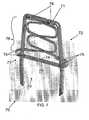
- most staples 1have similar shapes - a bridge 2 connecting two relatively parallel legs 4, which legs are disposed approximately orthogonal to the bridge 2, which, depending on the material of the staple, results in a square-cornered U-shape.
- the staple illustrated in FIG. 1is representative of conventional surgical staples. Such staples are compressed against an anvil to bend the tips of the legs 4 inward.
- the final stapled configurationhas a stapling range from a "least” acceptable orientation to a "greatest” acceptable orientation.
- the "least” acceptable staple rangeis a position where the tangent defined by the tip of each leg 4 is at a negative angle to a line parallel to the bridge 2 and touching the lower portions of both legs 4.
- the "greatest” acceptable staple rangeis a position where the legs 4 are bent into a shape similar to the letter "B.”
- the staple 1 of FIG. 1is shown in an orientation where the tips of the legs 4 are bent slightly by an anvil on the way towards a final stapled form. (This slightly bent orientation is also present with respect to the staples illustrated hereafter.)
- the legs 4 of such slightly bent stapleshave three different portions:
- Document US 2006/0291981 A1discloses a staple having an expandable backspan and a pair of spaced legs wherein the expandable backspan is configured to expend or deform to accommodate tissues of varying thicknesses.
- the backspanmay include a deformable pad or spacer.
- One common feature associated with conventional staplesis that there is no controllable way of adjusting the compressive force that is applied by the staple to the material being stapled. While items such as paper and cardboard can withstand a wide range of stapler compressive force without breaking or puncturing, living tissue, such as the tissue to be fastened in a surgical procedure, has a limited range of compressive force and cannot withstand force greater than a upper limit within that range without causing tissue damage. In fact, the range of optimal stapling force for a given surgical stapling procedure is relatively small and varies substantially with the type of tissue being stapled.
- the distance between the bending point of the legs and the bridgecan be increased to impart less force on material within the staple, this characteristic does not apply when living tissue having varying degrees of hardness, composition, and flexibility is the material being stapled. Even if the staple leg bending distance 12 is increased, if more or less or harder or softer tissue than expected is actually captured within the staple, the force applied to the captured tissue will not be controlled and will not be optimal for that tissue.
- tissueWhen one, two, or more layers of tissue are being stapled, it is desirable for the tissue to be at a desired compressive state so that a desirous medical change can occur, but not to be at an undesired compressive state sufficient to cause tissue necrosis. Because there is no way to precisely control the tissue that is being placed within the staple, it is not possible to ensure that the tissue is stapled within an optimal tissue compression range, referred to as an OTC range. Therefore, ruling out of tissue necrosis is difficult or not possible. Further, tissue presented within one staple may not be the same tissue that is presented within an adjacent staple or is within another staple that is fired during the same stapling procedure. Thus, while one or a few of a set of staples could actually fasten within the OTC range, it is quite possible for many other staples in the same stapling procedure to fasten outside the OTC range.
- the OTC range of the tissueis a compression range in which liquid is removed from the tissue (i.e., desiccates the tissue) without damaging or necrosing the tissue.
- the compressive force that is being imposed upon the tissuenaturally reduces - because less mass is between the opposing staple portions. In some instances, this reduction can allow the imparted tissue compression to exit the OTC range.
- Staples according to the present inventioneach have a self-adjusting, pre-tensioned compression device that keeps compression force on the interposed tissue within the OTC compression range even after being desiccated.
- the prior art staple of FIG. 1has a stapling range that is illustrated in FIG. 17 .
- the final stapled configuration of the OTC staples of the present inventionhas a stapling range that is illustrated, for example, in FIGS. 18 to 20 .
- a "least” acceptable staple rangeis a position where the tangent T defined by the tip of each leg 4 is at a negative angle ⁇ to a line L parallel to the bridge 2. This orientation is illustrated with the left half of the staple in FIG. 17 merely for reasons of clarity. See also FIGS. 18 to 20 .
- a "greatest” acceptable staple rangeis a position where the legs 4 are bent 180 degrees into a shape similar to the letter "B" (see the exemplary orientation illustrated in the right-half of FIG.
- the tips of the legs 4 of the staples according to the inventionreach only up to a compressing portion and not further than this compressing portion as shown in FIG. 20 , for example. In such an orientation, the stapled tips of the legs do not interfere with the OTC device present in the staples according to the invention.
- the OTC devices for staples according to the inventiontake many forms.
- the OTC devicecan be integral with the legs of the staple and project into a central area or can be attached to the staple to project into the central area.
- the OTC devicecan be sinusoidal in shape with a compressing portion at the end of the OTC device or can be have multiple cycles of bends between the bridge of the staple with the compressing portion at the end of the OTC device.
- the bending portioncan be single or double, the double bends being in cycle, out of cycle, mirror-symmetrical, to name a few.
- the bendscan be double-sinusoidal as shown in FIGS.
- the OTC devicecan be contained entirely between the two legs of the staple or can encircle one or both of the legs and, thereby, use the legs as a guide, for example, a sliding guide.
- the leg encirclement by the OTC devicecan be single or multiple. Travel of the OTC device can be limited, for example, by a star washer.
- the OTC devicecan be a compression spring(s) and a plate(s), with the plate encircling the legs and sliding thereon.
- the OTC devicecan be a compressible material secured on the legs. This material can be in the shape of a plate or a pillow.
- a compression-self-adjusting stapleincludes a substantially U-shaped staple body and a compression device.
- the bodyhas a bridge and two legs extending from the bridge at an angle thereto.
- Each of the legshas a base end integral with the bridge and a deformable distal end defining a stapling point shaped to pierce material to be stapled.
- the compression deviceis at least partly disposed between the legs and has a bias portion with a compression surface movably disposed between the legs and a compression resistor which is formed as a compression spring.
- the compression resistoris connected to the bridge and integral with the compression surface and is formed to resist movement of the compression surface towards the bridge with a force.
- a compression-self-adjusting stapleincluding a substantially U-shaped staple having an internally disposed compression device capable of regulating compressive force imposed on material stapled therein independent of a magnitude of staple firing.
- a compression-self-adjusting stapleincluding a substantially U-shaped staple having an internally disposed compression device capable of placing a substantially constant compressive force against material stapled therein independent of a magnitude of staple firing.
- the bridgeis substantially rod-shaped with ends and the base end of each the legs is integral with a respective one of the ends.
- the bridge and legsdefine a bridge-leg plane and the legs extend from the bridge at an angle of between 80 and 100 degrees in the bridge-leg plane.
- the deformable distal endsare capable of bending to approximately 180 degrees in the bridge-leg plane.
- the compression surfacedefines two orifices and each of the legs extends through one of the two orifices.
- the compression resistordefines at least one orifice pair the compression surface defines two orifices, and each of the legs extends through one of the two orifices and one of the at least one orifice pair.
- the compression resistordefines a plurality of orifice pairs
- the compression surfacedefines two orifices
- each of the legsextends through one of the two orifices and one of each of the orifice pairs.
- the compression surfaceis at a distance from the bridge.
- the compression surfaceis parallel to the bridge.
- the bridge and the legsdefine a compression axis and the compression surface is movably disposed between the legs along the compression axis.
- the compression deviceis connected to the bridge.
- the compression resistorconnects the bridge to the compression surface.
- the bridge, the legs, the compression resistor, and the compression surfaceare integral.
- the compression resistoris separate from the bridge and fixed to the bridge between the legs.
- the compression resistoris at least partly disposed between the legs.
- the compression resistoris disposed between the bridge and the compression surface.
- the compression resistoris formed to resist movement of the compression surface towards the bridge with a pre-defined opposing force.
- the compression resistoris formed to resist movement of the compression surface towards the bridge with a substantially constant force.
- the compression resistoris formed to resist movement of the compression surface towards the bridge with a linearly increasing force.
- the compression resistorhas an anti-compressive spring constant imparting a substantially constant anti-compressive force over a pre-defined compression range.
- the staple body and the compression deviceare of a biocompatible material, in particular, at least one of titanium, a titanium alloy, nitinol, and stainless steel.
- the compression surface and the legsdefine a central compression region in which is to be disposed a material to be compressed between the compression surface and the stapling points when the distal ends are deformed, and, when the distal ends are deformed in a staple closing direction into the central compression region, the bias portion resists movement of the compression surface in the staple closing direction with a pre-defined, substantially constant force.
- the compression surface and the bias portionare shaped to impart a pre-defined, substantially constant bias force upon material disposed between the compression surface and the stapling points when the stapling points are deformed.
- the compression resistoris sinusoidal.
- the compression resistoris sinusoidal in the bridge-leg plane.
- the compression resistoris double-sinusoidal in the bridge-leg plane.
- the compression resistoris a single sinusoidal-shaped body.
- the compression resistorhas a first portion and a second portion and the second portion is a mirror image of the first portion.
- the compression surfaceis a C-beam defining two orifices
- the compression resistoris a conical spring with a lower end connected to the compression surface, and each of the legs slidably rests within a respective one of the two orifices.
- the compression surfaceis a C-beam defining two orifices
- the compression resistoris a pair of springs each surrounding a portion of a respective one of the legs and each having a lower end connected to the compression surface, and each of the legs slidably rests within a respective one of the two orifices.
- the compression surfaceis a C-beam defining two orifices
- the compression resistoris a pair of springs each having an upper end connected to the bridge and a lower end connected to the compression surface, and each of the legs slidably rests within a respective one of the two orifices.
- the bias portionis a cushion of a compressible material defining two orifices and each of the legs slidably rests within a respective one of the two orifices.
- the term “about” or “approximately”applies to all numeric values, whether or not explicitly indicated. These terms generally refer to a range of numbers that one of skill in the art would consider equivalent to the recited values (i.e., having the same function or result). In many instances these terms may include numbers that are rounded to the nearest significant figure.
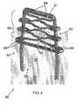
- the bridge 21has a center bridge portion 22 and an extension 23 that substantially increases the overall length of the bridge 21 -- as compared to the bridge 2 of the staple 1 of FIG. 1 .
- the extension 23As the upper bridge portion 22 transitions into the extension 23, it curves into and within the central region 24 of the staple 20.
- This extension 23can be in any shape or of any material so long as it delivers a pre-set compressive force to the tissue at a compressing portion 25, and as long as it allows for absorption (within the area between the compressing portion 25 and the upper bridge portion 22) of forces greater than this pre-set force. Therefore, the shape can be trapezoidal, triangular, sinusoidal, or any other configuration. An exemplary embodiment of relatively sinusoidal curves is shown in FIG. 2 . These curves traverse two periods in the illustrated embodiment, however, the number of wave periods can be varied (smaller or larger).
- the extension 23has two mirror-symmetrical portions each starting from the upper bridge portion 22 and ending at respective ends of the compressing portion 25. Further, it is noted that neither the extension 23 nor the compressing portion 25 directly contacts the legs 26 in this exemplary configuration.
- the extension 26 and the compressing portion 29are integral with the bridge 22 and the legs 26.
- the legs 26are shown as relatively circular in cross-section.
- the bridge 21 and all of the compressing components 22, 23, 25can also be circular in cross-section.
- any portion of the extension 23 and/or the compressing portion 25can have different cross-sectional shapes, such as ovular, rectangular, or polygonal.
- the cross-section of the extension 23 after the first curve away from the upper bridge portion 22is shaped in a "racetrack" form (two relatively straight sides with two curved ends connecting each end of the sides).
- the upper bridge portion 22can also have a different cross-sectional shape.
- the extension 23 and compressing portion 25are, in this embodiment, even in cross-sectional area. Different portions of these parts can, however, have varying cross-sectional areas (i.e., varying thicknesses) as desired.
- the overall effectis to create an OTC device having a given spring coefficient.
- the OTC devicemaintains the preset compressive force within the stapled area even after tissue expands due to swelling and after tissue contracts during desiccation.
- Variation of the cross-section of any portion of the upper bridge 22, the extension 23, and the compressing portion 25will allow for different OTC spring coefficients and, therefore, allows for adjustment of the compressive and reactive force constants of the OTC device within the staple 20.
- Variation of the material making up all of the staple 20 or any of its portionsalso permits adjustment of the OTC force.
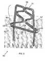
- FIG. 3illustrates a second exemplary embodiment of the OTC staple 30 according to the invention.
- the OTC portionis not integral with the bridge 31 and the legs 32. Instead, the OTC device 33 is separate therefrom and is connected to these staple portions.
- the OTC device 33has a compressing portion 34 that directly contacts the tissue being compressed and an extension 36 for providing the load-bearing force when tissue is compressed within the central region 37 of the staple 30.
- the OTC device 33also has a connecting portion 35 for attaching the OTC device 33 to the bridge 31.
- the extension 36connects the upper and lower portions 34, 35 of the OTC device 33.
- the extension 33 and the compressing portion 34are, in this embodiment, different in cross-sectional area.
- the cross-sectional area of the compressing portion 34is wider than the extension 36. Any portions of the extension 33 or the compressing portion 34 can be varied to have same or varying cross-sectional areas (i.e., varying thicknesses).
- connection of the OTC device 33 to the staple, for example, at the bridge 31,can occur by any fastening measure.
- One exemplary connection methodis spot welding, which is indicated in FIG. 3 by reference numeral 38.
- Other exemplary methods of attaching suitable materials togetherinclude soldering and brazing.
- the type or types of material of the staple portions 31, 32 and the OTC device 33will direct a preferable attachment method.
- other attachment methodscan be used such as crimping and adhesive bonding.
- Featurescan be added to one or both of the two components to facilitate the crimp or bond. These features could be configured to have the components snap together.
- preferred attachment measuresinclude crimping, adhesive bonding, or snapping.
- the OTC device 33behaves similar to the OTC portions of the embodiment of FIG. 2 and can be shaped with the same variations of cross-section and other spatial characteristics and can be formed with the same variations in material composition. Variation of any attribute of the OTC device 33 allows for adjustment of the compressive and reactive force constants thereof on the compressed tissue.
- the extension 36can be any shape or material so long as it delivers a pre-set compressive force to the tissue at the compressing portion 34 and as long as it allows for absorption of forces greater than this pre-set force.
- An exemplary embodiment selected for this exemplary OTC device 33is a relatively sinusoidal set of curves traversing less than two periods.
- the extension 36has two mirror-symmetrical portions each starting from the bridge 31 and ending at respective ends of the compressing portion 34.
- neither the extension 36 nor the compressing portion 34directly contacts the legs 32.
- Most of the cross-section of the OTC device 33has a racetrack form.
- the cross-sectioncan be varied in any desired way to deliver the pre-set compressive force to the tissue and to absorb forces greater than this pre-set force.
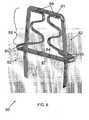
- FIG. 4illustrates a third exemplary embodiment of the OTC staple 40 according to the invention.
- the OTC portion 43is not symmetrical with respect to the bridge 41 or the legs 42.
- the OTC portionis not integral with either the bridge 41 or the legs 42.
- the OTC device 43is a separate part from the bridge 41 and the legs 42 and is fixedly connected to the bridge 41 at a connection location (for example, with a spot weld 48; other fixation/connection processes can be used).
- a connecting portion 45 of the OTC device 43fixedly secures the OTC device 43 to the bridge 41.
- An extension 46 of the OTC device 43provides the load-bearing force when tissue is compressed within the central region 47 of the staple 40 and a compressing portion 44 directly contacts the tissue being compressed.
- the compressing portion 44is provided with ports 49 having a shape substantially corresponding to the cross-sectional shape of the upper portion of the staple legs 42 but slightly larger. The legs 42 pass through these ports 49. In such a configuration, movement of the OTC device 43 out of the bridge-legs plane is substantially prevented.
- the extension 46acts as a compression spring in the bridge-legs plane as the compressing portion 44 moves up and down along the upper portion of the legs 42 (up being defined as the direction towards the bridge 41 from the piercing tips of the legs 42).
- the OTC device 43 of the third embodimentbehaves different from the OTC devices of FIGS. 2 and 3 because of the form-locking and sliding connection between the connecting portion 44 and the legs 42.
- a form-locking connectionis one that connects two elements together due to the shape of the elements themselves, as opposed to a force-locking connection, which locks the elements together by force external to the elements.
- the OTC device 43can be shaped with variations in cross-section and other spatial characteristics and can be formed with a variety of material compositions.
- the extension 46 and compressing portion 44are, in this embodiment, different in cross-sectional area.
- the cross-sectional area of the compressing portion 44is wider than the extension 46.
- Any portions of the extension 46 or the compressing portion 44can be varied to have same or varying cross-sectional areas (i.e., varying thicknesses).
- the extension 46can be any shape or material so long as it delivers the pre-set compressive force to the tissue at the compressing portion 44 and as long as it allows for absorption of forces greater than this pre-set force.
- An exemplary embodiment selected for this OTC device 43is a relatively sinusoidal curve traversing approximately one sinusoidal period. Virtually all of the cross-section of the OTC device 43 has a racetrack form, but can be changed as desired to other shapes (e.g., circular, ovular, polygonal, etc.). As described above, variation of any attribute of the OTC device 43 allows for adjustment of the compressive and reactive force constants thereof on the compressed tissue in the central region 47.
- FIG. 5illustrates a fourth exemplary embodiment of the OTC staple 50 according to the invention.
- This variationhas some of the features of the above embodiments.
- the OTC portionis symmetrical with respect to the bridge 51 and the legs 52 and the OTC device 53 is integral with the bridge 51.
- the compressing portion 54has a width greater than the separation distance of the two legs 52 and has ports 55 with a shape substantially corresponding to the cross-sectional shape of the upper portion of the legs 52, but slightly larger. The legs 52 pass through these ports 55. In this configuration, movement of the OTC device 53 out of the bridge-legs plane is substantially prevented.
- the extension 56 of the OTC device 53traverses from the bridge 51 to the compressing portion 54. Because the ports 55 are shaped to be slightly larger than the cross-section of the legs 52, the extension 56 acts as a compression spring in the bridge-legs plane as the compressing portion 54 moves up and down along the upper portion of the legs 52. It is the extension 56 that provides the load-bearing force when tissue is compressed within the central region 57 of the staple 50. Because of the form-locking and sliding connection between the compressing portion 54 and the legs 52, the OTC device 53 of the fourth embodiment behaves similar to the OTC devices of FIG. 4 .
- the OTC device 53is integral with the legs 52, the bridge 51, and the compressing portion 54. Because the two sides of the bridge 51 are not integral, they can separate from one another when the staple 50 is subjected to a twisting force. If desired, to substantially prevent such separation, the central portions of the bridge 51 can be fixedly connected to one another at a connection location (for example, with a spot weld 58; other connection processes can be used as well).
- the OTC device 53can be shaped with variations in cross-section and other spatial characteristics and can be formed with a variety of material compositions. Any portions of the extension 56 or the compressing portion 54 can be varied to have the same or varying cross-sectional areas (i.e., varying thicknesses).
- the extension 56 and compressing portion 54are, in this embodiment, different in cross-sectional areas.
- the cross-sectional area of the upper majority of the extension 56is narrower than the lower portion of the extension 56 and the cross-section of the lower portion of the extension 56 gradually increases in width until it is equal to the cross-section of the compressing portion 54.
- the extension 56can be any shape or material so long as it delivers the pre-set compressive force to the tissue at the compressing portion 54 and as long as it allows for absorption of forces greater than this pre-set force.
- An exemplary embodiment selected for this OTC device 53is a relatively sinusoidal curve traversing more than one sinusoidal period. Again, only for illustrative purposes, the cross-section of the OTC device 53 has a racetrack shape, but can be changed as desired to other shapes (e.g., circular, ovular, polygonal, etc.). As described above, variation of any attribute of the OTC device 53 allows for adjustment of the compressive and reactive force constants thereof on the compressed tissue in the central region 57.
- FIG. 6illustrates a fifth exemplary embodiment of the OTC staple 60 according to the invention.
- This variationhas some of the features of the above embodiments.
- the OTC portionis symmetrical with respect to the bridge 61 and the legs 62 and the OTC device 63 is a separate part from the bridge 61 and legs 62 of the staple 60.
- the compressing portion 64has a width greater than the separation distance of the two legs 62 and has ports 65 with a shape substantially corresponding to the cross-sectional shape of the upper portion of the legs 62, but slightly larger. The legs 62 pass through these ports 65. In this configuration, movement of the OTC device 63 out of the bridge-legs plane is substantially prevented.
- the extension 66 of the OTC device 63traverses from the bridge 61 to the compressing portion 64. Because the ports 65 are shaped to be slightly larger than the cross-section of the legs 62, the extension 66 acts as a compression spring in the bridge-legs plane as the compressing portion 64 moves up and down along the upper portion of the legs 62. It is the extension 66 that provides the load-bearing force when tissue is compressed within the central region 67 of the staple 60. Because of the form-locking and sliding connection between the compressing portion 64 and the legs 62, the OTC device 63 of the fifth embodiment behaves similar to the OTC devices of FIGS. 4 and 5 .
- connection of the OTC device 63 to the staple 60, for example, at the bridge 61,can occur by any fastening measure.
- One exemplary connection methodis spot welding, which is indicated in FIG. 6 by reference numeral 68.
- the type or types of material of the staple portions 61, 62 and the OTC device 63will direct a preferable attachment method.
- other attachment methodscan be used such as crimping and adhesive bonding.
- Featurescan be added to one or both of the two components to facilitate the crimp or bond. These features could be configured to have the components snap together.
- preferred attachment measuresinclude crimping, adhesive bonding, or snapping.
- the OTC device 63can be shaped with variations in cross-section and other spatial characteristics and can be formed with a variety of material compositions. Any portions of the extension 66 or the compressing portion 64 can be varied to have the same or different cross-sectional areas (i.e., varying thicknesses).
- the extension 66 and compressing portion 64are, in this embodiment, different in cross-sectional areas.
- the cross-sectional area of most of the extension 66is narrower than the lowermost portion of the extension 66 and the cross-section of this lowermost portion of the extension 66 gradually increases in width until it is equal to the cross-section of the compressing portion 64, which is substantially wider.
- the extension 66can be any shape or material so long as it delivers the pre-set compressive force to the tissue at the compressing portion 64 and as long as it allows for absorption of forces greater than this pre-set force.
- An exemplary embodiment selected for this OTC device 63is a relatively sinusoidal curve traversing more than one sinusoidal period. Again, only for illustrative purposes, the cross-section of the OTC device 63 has a racetrack shape, but can be changed as desired to other shapes (e.g., circular, ovular, polygonal, etc.). As described above, variation of any attribute of the OTC device 63 allows for adjustment of the compressive and reactive force constants thereof on the compressed tissue in the central region 67.
- FIG. 7illustrates a sixth exemplary embodiment of the OTC staple 70 according to the invention.
- This variationhas some of the features of the above embodiments.
- the OTC portionis symmetrical with respect to the bridge 71 and the legs 72 and the OTC device 73 is a separate part from the bridge 71 and legs 72 of the staple 70.
- the compressing portion 74has a width greater than the separation distance of the two legs 72 and has ports 75 with a shape substantially corresponding to the cross-sectional shape of the upper portion of the legs 72, but slightly larger. The legs 72 pass through these ports 75. In this configuration, movement of the OTC device 73 out of the bridge-legs plane is substantially prevented.
- the extension 76 of the OTC device 73traverses from the bridge 71 to the compressing portion 74. Because the ports 75 are shaped to be slightly larger than the cross-section of the legs 72, the extension 76 acts as a compression spring in the bridge-legs plane as the compressing portion 74 moves up and down along the upper portion of the legs 72. It is the extension 76 that provides the load-bearing force when tissue is compressed within the central region 77 of the staple 70. Because of the form-locking and sliding connection between the compressing portion 74 and the legs 72, the OTC device 73 of the sixth embodiment behaves similar to the OTC devices of FIGS. 4 to 6 .
- connection of the OTC device 73 to the staple 70, for example, at the bridge 71,can occur by any fastening measure.
- One exemplary connection methodis spot welding, which is indicated in FIG. 7 by reference numeral 78.
- the type or types of material of the staple portions 71, 72 and the OTC device 73will direct a preferable attachment method.
- other attachment methodscan be used such as crimping and adhesive bonding.
- Featurescan be added to one or both of the two components to facilitate the crimp or bond. These features could be configured to have the components snap together.
- preferred attachment measuresinclude crimping, adhesive bonding, or snapping.
- extensionsi.e., springs
- the extensions 76 in each of FIGS. 2 , 3 , 5 , and 6are in the same plane, which can be the bridge-legs plane (as shown) or out of that plane.
- the extension 76has the springs residing in different planes (i.e., one next to the other.
- the OTC device 73can be shaped with variations in cross-section and other spatial characteristics and can be formed with a variety of material compositions. Any portions of the extension 76 or the compressing portion 74 can be varied to have the same or varying cross-sectional areas (i.e., varying thicknesses).
- the extension 76 and the compressing portion 74are, in this embodiment, different in cross-sectional areas.
- the cross-sectional area of most of the extension 76is narrower than the lowermost portion of the extension 76 and the cross-section of this lowermost portion of the extension 76 gradually increases in width until it is equal to the cross-section of the compressing portion 74, which is substantially wider.
- the extension 76can be any shape or material so long as it delivers the pre-set compressive force to the tissue at the compressing portion 74 and as long as it allows for absorption of forces greater than this pre-set force.
- An exemplary embodiment selected for this OTC device 73is a relatively sinusoidal curve traversing more than one sinusoidal period. Again, only for illustrative purposes, the cross-section of the OTC device 73 has a racetrack shape, but can be changed as desired to other shapes (e.g., circular, ovular, polygonal, etc.). As described above, variation of any attribute of the OTC device 73 allows for adjustment of the compressive and reactive force constants thereof on the compressed tissue in the central region 77.
- FIG. 8illustrates a seventh exemplary embodiment of the OTC staple 80 according to the invention.
- This variationhas some of the features of the above embodiments.
- the OTC portionis symmetrical with respect to the bridge 81 and the legs 82, and the OTC device 83 is a separate part from the bridge 81 and legs 82 of the staple 80.
- the compressing portion 84has a width greater than the separation distance of the two legs 82 and has ports 85 with a shape substantially corresponding to the cross-sectional shape of the upper portion of the legs 82, but slightly larger. The legs 82 pass through these ports 85.
- the extension 86 of the OTC device 83traverses from the bridge 81 to the compressing portion 84. Because the ports 85 are shaped to be slightly larger than the cross-section of the legs 82, the extension 86 acts as a compression spring in the bridge-legs plane as the compressing portion 84 moves up and down along the upper portion of the legs 82. It is the extension 86 that provides the load-bearing force when tissue is compressed within the central region 87 of the staple 80. Because of the form-locking and sliding connection between the compressing portion 84 and the legs 82, the OTC device 83 of the seventh embodiment behaves similar to the OTC devices of FIGS. 4 to 7 .
- the OTC device 83can be shaped with variations in cross-section and other spatial characteristics and can be formed with a variety of material compositions. Any portions of the extension 86 or the compressing portion 84 can be varied to have the same or varying cross-sectional areas (i.e., varying thicknesses).
- the extension 86 and the compressing portion 84are, in this embodiment, different in cross-sectional areas.
- the cross-sectional area of most of the extension 86is smaller and narrower than the lowermost portion of the extension 86 and the cross-section of this lowermost portion gradually increases in width until it is equal to the cross-section of the compressing portion 84, which is substantially wider.
- the cross-sectional area of this extension 86is smaller than previous embodiments (but it need not be).
- the extension 86can be any shape or material so long as it delivers the pre-set compressive force to the tissue at the compressing portion 84 and as long as it allows for absorption of forces greater than this pre-set force.
- An exemplary embodiment selected for this OTC device 83is a relatively sinusoidal curve traversing a more than two periods and also having a second "interior" curve that traverses sinusoidal periods.
- the OTC device 83has an uppermost portion that is, in contrast to the embodiments of FIGS. 3 , 6 , and 7 a single bar extending along a majority of the bridge 81.
- connection of the OTC device 83 to the staple 80, for example, at the bridge 81can occur by any fastening measure.
- One exemplary connection methodis spot welding, which is indicated in FIG. 8 by reference numeral 88. Because there is contact over most of the bridge 81, the OTC device 83 can be welded over the entire length thereof.
- the type or types of material of the staple portions 81, 82 and the OTC device 83will direct a preferable attachment method.
- other attachment methodscan be used such as crimping and adhesive bonding.
- crimping and adhesive bondingcan be added to one or both of the two components to facilitate the crimp or bond. These features could be configured to have the components snap together.
- preferred attachment measuresinclude crimping, adhesive bonding, or snapping.
- the cross-section of the OTC device 83has a racetrack shape, but can be changed as desired to other shapes (e.g., circular, ovular, polygonal, etc.). As described above, variation of any attribute of the OTC device 83 allows for adjustment of the compressive and reactive force constants thereof on the compressed tissue in the central region 87.
- FIG. 9illustrates an eighth exemplary embodiment of the OTC staple 90 according to the invention.
- This variationhas some of the features of the above embodiments.
- the OTC portionis symmetrical with respect to the bridge 91 and the legs 92, and the OTC device 93 is a separate part from the bridge 91 and legs 92 of the staple 90.
- the compressing portion 94has a width greater than the separation distance of the two legs 92 and has ports 95 with a shape substantially corresponding to the cross-sectional shape of the upper portion of the legs 92, but slightly larger. The legs 92 pass through these ports 95.
- the extension 96 of the OTC device 93traverses from the bridge 91 to the compressing portion 94. Because the ports 95 are shaped to be slightly larger than the cross-section of the legs 92, the extension 96 acts as a compression spring in the bridge-legs plane as the compressing portion 94 moves up and down along the upper portion of the legs 92. It is the extension 96 that provides the load-bearing force when tissue is compressed within the central region 97 of the staple 90. Because of the form-locking and sliding connection between the compressing portion 94 and the legs 92, the OTC device 93 of the eighth embodiment behaves similar to the OTC devices of FIGS. 4 to 8 .
- the OTC device 93can be shaped with variations in cross-section and other spatial characteristics and can be formed with a variety of material compositions. Any portion(s) of the extension 96 or the compressing portion 94 can be varied to have the same or varying cross-sectional areas (i.e., varying thicknesses).
- the extension 96 and the compressing portion 94are, in this embodiment, different in cross-sectional areas.
- the cross-sectional area of most of the extension 96is smaller and narrower than the lowermost portion of the extension 96 and the cross-section of this lowermost portion gradually increases in width until it is equal to the cross-section of the compressing portion 94, which is substantially wider.
- this extension 96is smaller than previous embodiments (but need not be). With such a relatively smaller cross-sectional shape, the curves of the extension 96 might tend to deform or move out of the bridge-legs plane, which tendency can increase or decrease depending upon the material of the extension 96.
- a plurality of guiding tabs 99are disposed at one or more of the outside ends of each periodic curve adjacent the legs 92. These guiding tabs 99 are shaped in a similar manner to the ends of the compressing portion 94, in that they have ports with a cross-sectional shape substantially corresponding to the cross-sectional shape of the upper portion of the legs 92 but slightly larger. The embodiment illustrated in FIG.
- each guiding tab 99with two relatively parallel plates each having one of the two ports through which the respective leg 92 is disposed.
- the cross-sectional area of the extensiongradually increases in width until it is equal to the larger cross-section of the plate of the guiding tab 99.
- Another alternative of the guiding tab 99is to have only a single plate with a single port. In such an embodiment (assuming the material was the same as a dual-plate embodiment), the curves of the extension 96 would be slightly stiffer because of the absence of the exterior curve of the guiding tab 99.
- the extension 96can be any shape or material so long as it delivers the pre-set compressive force to the tissue at the compressing portion 94 and as long as it allows for absorption of forces greater than this pre-set force.
- An exemplary embodiment selected for this OTC device 93is a relatively sinusoidal curve having a second interior curve that traverses a few sinusoidal periods and, in this embodiment, has an uppermost portion that is, like the embodiment of FIG. 8 , a single bar extending along a majority of the bridge 91. Connection of the OTC device 93 to the staple 90, for example, at the bridge 91, can occur by any fastening measure.
- One exemplary connection methodis spot welding, which is indicated in FIG. 9 by reference numeral 98.
- the weldcan be over the entire span contacting the bridge 91.
- the type or types of material of the staple portions 91, 92 and the OTC device 93will direct a preferable attachment method.
- other attachment methodscan be used such as crimping and adhesive bonding.
- Featurescan be added to one or both of the two components to facilitate the crimp or bond. These features could be configured to have the components snap together.
- preferred attachment measuresinclude crimping, adhesive bonding, or snapping.
- the cross-section of the OTC device 93has a racetrack shape, but can be changed as desired to other shapes (e.g., circular, ovular, polygonal, etc.). As described above, variation of any attribute of the OTC device 93 allows for adjustment of the compressive and reactive force constants thereof on the compressed tissue in the central region 97.
- FIG. 10illustrates a ninth exemplary embodiment of the OTC staple 100 according to the invention.
- This variationhas some of the features of the above embodiments.
- the OTC portionis symmetrical with respect to the bridge 101 and the legs 102, and the OTC device 103 is a separate part from the bridge 101 and legs 102 of the staple 100.
- the compressing portion 104is unlike all of the previous embodiments.
- the compressing portion 104is formed from two compressing plates, each of these plates being attached to a respective lower end of two halves of the OTC device 103.
- the shape of the compressing portion 104need not be a plate. It can be cylindrical, for example.
- the lowermost end of the extension 106gradually increases in cross-section until it is equal to the compressing portion 104.
- Each compressing platethen, extends towards a respective one of the legs 102 and defines a respective port 105 for receiving therein the leg 102.
- the port 105has a shape substantially corresponding to the cross-sectional shape of the upper portion of the legs 102, but is slightly larger.
- the legs 102pass through each port 105 to form the OTC device 103. In this configuration, movement of the OTC device 103 out of the bridge-legs plane is substantially prevented.
- the extension 106 of the OTC device 103traverses from the bridge 101 to the plates of the compressing portion 104.
- the extension 106acts as a compression spring in the bridge-legs plane as the compressing portion 104 moves up and down along the upper portion of the legs 102. It is the extension 106 that provides the load-bearing force when tissue is compressed within the central region 107 of the staple 100.
- the two sides of the OTC device 103move independent from one another.
- tissuevaries in any characteristic within the central portion 107 (e.g., hardness, thickness, density)
- the optimal tissue compression forcecan be delivered independently and differently for each of the two differing tissue segments contacting the respective one of the sides of the OTC device 103.
- connection of the OTC device 103 to the staple 100, for example, at the bridge 101can occur by any fastening measure.
- One exemplary connection methodis spot welding, which is indicated in FIG. 10 by reference numeral 108. As the upper portion contacts almost all of the bridge 101, the weld 108, instead, can span any amount of the bridge 101.
- the type or types of material of the staple portions 101, 102 and the OTC device 103will direct a preferable attachment method. In the case of attaching two materials together that are not suited to be welded, soldered or brazed, other attachment methods can be used such as crimping and adhesive bonding. Features can be added to one or both of the two components to facilitate the crimp or bond. These features could be configured to have the components snap together. In the case of dissimilar materials, for example, if the staple material is stainless steel and the OTC device 103 is of nickel titanium alloy, then preferred attachment measures include crimping, adhesive bonding, or snapping.
- the OTC device 103can be shaped with variations in cross-section and other spatial characteristics and can be formed with a variety of material compositions. Any portions of the extension 106 or the compressing portion 104 can be varied to have the same or varying cross-sectional areas (i.e., varying thicknesses).
- the extension 106 and the plates of the compressing portion 104are, in this embodiment, different in cross-sectional areas.
- the cross-sectional area of most of the extension 106is smaller and narrower than the lowermost portion of the extension 86 and the cross-section of this lowermost portion gradually increases in width until it is equal to the cross-section of the respective plate of the compressing portion 104, which is substantially wider.
- the extension 106can be any shape or material so long as it delivers the pre-set compressive force to the tissue at the compressing portion 104 and as long as it allows for absorption of forces greater than this pre-set force.
- An exemplary embodiment selected for this OTC device 103is a relatively sinusoidal curve having almost two sinusoidal periods and, in this embodiment, has an uppermost portion that is (like the embodiments of FIGS. 8 and 9 ) a single bar extending along a majority of the bridge 101.
- the cross-section of the OTC device 103has an ovular shape, but can be changed as desired to other shapes (e.g., circular, racetrack, polygonal, etc.). As described above, variation of any attribute of the OTC device 103 allows for adjustment of the compressive and reactive force constants thereof on the compressed tissue in the central region 107.
- FIGS. 11 and 11Aillustrate a tenth exemplary embodiment of the OTC staple 110 according to the invention.
- This variationhas some of the features of the above embodiments.
- the OTC portionis symmetrical with respect to the bridge 111 and the legs 112, and the OTC device 113 is a separate part from the bridge 111 and legs 112 of the staple 110.
- the compressing portion 114is like the embodiment of FIG. 10 - it is formed from two compressing plates, each of these plates being attached to a respective lower end of two halves of the OTC device 113.
- the lowermost end of the extension 116gradually increases in cross-section until it is equal in area to the compressing portion 114.
- Each compressing platethen, extends towards a respective one of the legs 112 and defines a respective port 115 for receiving therein one of the legs 112.
- the ports 115cannot be seen because of the presence of one-way washers 119 (described below), but the port 115 is visible in FIG. 11A .
- each port 115has a shape substantially corresponding to the cross-sectional shape of the upper portion of the legs 112 but is slightly larger.
- the legs 112pass through each port 115 to form the OTC device 113.
- the extension 116acts as a compression spring in the bridge-legs plane as the compressing portion 114 moves up and down along the upper portion of the legs 112. In this configuration, movement of the OTC device 113 out of the bridge-legs plane is substantially prevented. It is the extension 116 that provides the load-bearing force when tissue is compressed within the central region 117 of the staple 110. In this embodiment (like the embodiment of FIG.
- the two sides of the OTC device 113move independent from one another.
- tissuevaries in any characteristic within the central portion 117 (e.g., hardness, thickness, density)
- the optimal tissue compression forcecan be delivered independently and differently for each of the two differing tissue segments contacting the two plates of the compressing portion 114.
- one-way devices 119(one exemplary embodiment being a star washer that is illustrated in FIGS. 11 and 11A ) disposed on the leg 112 between the bridge 111 and the compressing portion 114. These devices 119 are shaped to freely move on the leg 112 upwards towards the bridge 111 but not to move in the opposite direction.
- tissueis being compressed within the central region 117 as the distal ends of the legs 112 are curved in the stapling action, the tissue presses against the compressing portion 114 and moves the compressing portion 114 up towards the bridge 111.
- the tissuewill most likely not press the washers 119 any further without any additionally supplied outside force.
- the washers 119limit further movement of the compressing portion 114 from the then-current location of the washers 119 towards the first bend of the legs 112. These washers also add some friction when the first stapling movement occurs, which friction may be used to add to and make up the compression coefficients of the OTC device 113. If the stapled tissue swells, it is possible for the washers 119 to be moved if the force is sufficient. After such swelling ends and desiccation of the tissue occurs, the compressing portions 114 will be limited in further compression by these washers 119.
- the OTC device 113can be shaped with variations in cross-section and other spatial characteristics and can be formed with a variety of material compositions. Any portions of the extension 116 or the compressing portion 114 can be varied to have the same or varying cross-sectional areas (i.e., varying thicknesses).
- the extension 116 and the plates of the compressing portion 114are, in this embodiment, different in cross-sectional areas.
- the cross-sectional area of most of the extension 116is smaller and narrower than the lowermost portion of the extension 116 and the cross-section of this lowermost portion gradually increases in width until it is equal to the cross-section of the respective plate of the compressing portion 114, which is substantially wider.
- the extension 116can be any shape or material so long as it delivers the pre-set compressive force to the tissue at the compressing portion 114 and as long as it allows for absorption of forces greater than this pre-set force.
- An exemplary embodiment selected for this OTC device 113is a relatively sinusoidal curve traversing more than two sinusoidal periods and having a second "interior" curve.
- the OTC device 113has an uppermost portion that is (like the embodiments of FIGS. 8 to 10 ) a single bar extending along a majority of the bridge 111. Connection of the OTC device 113 to the staple 110, for example, at the bridge 111, can occur by any fastening measure.
- One exemplary connection methodis spot welding, which is indicated in FIG. 11 by reference numeral 118.
- the type or types of material of the staple portions 111, 112 and the OTC device 113will direct a preferable attachment method.
- other attachment methodscan be used such as crimping and adhesive bonding.
- Featurescan be added to one or both of the two components to facilitate the crimp or bond. These features could be configured to have the components snap together.
- preferred attachment measuresinclude crimping, adhesive bonding, or snapping.
- the cross-section of the OTC device 113has a racetrack shape, but can be changed as desired to other shapes (e.g., circular, ovular, polygonal, etc.). As described above, variation of any attribute of the OTC device 113 allows for adjustment of the compressive and reactive force constants thereof on the compressed tissue in the central region 117.
- FIG. 12illustrates an eleventh exemplary embodiment of the OTC staple 120.
- the OTC device 123is, as above, a separate part from the bridge 121 and legs 122 of the staple 120.
- the compressing portion 124is a C-beam having ports 125 that permit passage of a respective one of the legs 122 therethrough.
- Each port 125has a shape substantially corresponding to the cross-sectional shape of the upper portion of the legs 122 but is slightly larger.
- the legs 122pass through each port 125 to form the OTC device 123. In this configuration, movement of the OTC device 123 out of the bridge-legs plane is substantially prevented.
- the C-beam shapeis useful for a variety of reasons.
- the C-shapeprovides a central cavity in which a distal end of a compression device 126 can be held or fastened.
- the C-shapealso increases resistance to bending forces as compared to a simple rectangular plate, as is known in construction.
- orienting the open portion of the "C" away from the tissuepresents a flat compressing plate to the tissue to be compressed. With such a shape, the tissue can be compressed evenly, with no singular pressure points.
- the C-shapeis not the only possible cross-sectional shape.
- the compressing portion 124can be a rectangular plate, an I-beam, an L-beam, or any other desired shape.
- the compression device 126can take any form (see, e.g., FIG. 13 ).
- the exemplary embodiment of FIG. 12illustrates the compression device 126 as a conically expanding compression spring. Connection of the spring 126 and compressing portion 124 to the staple 120, for example, at the bridge 121, can occur by any fastening measure.
- the illustrated exemplary proximal connection methodis a ring of the spring material wrapping around the bridge 121. This proximal end is secured at the center of the bridge 121 and held in place there by placing protuberances 128 on the bridge 121. These protuberances prevent lateral movement of the proximal ring towards either of the two legs 122.
- this ringcan be welded or fastened to the bridge 121 by any fastening process.
- the distal end of the springis a relatively circular coil lying in the same plane as the interior cavity of the C-beam and having an outer diameter just slightly less than the interior diameter of the C-shaped cavity of the compressing portion 124.
- the ends of the C-shapecan be used to retain the distal end of the spring 126 within the cavity.
- other fastening measurescan be used to secure the spring distal ends to the compressing portion 124.
- the OTC device 123can be shaped with variations in cross-section, winding, and other spatial characteristics and can be formed with a variety of material compositions. Any portions of the spring 126 or the compressing portion 124 can be varied. In particular, the spring 126 can be any shape or material so long as it delivers the pre-set compressive force to the tissue through the compressing portion 124 and as long as it allows for absorption of forces greater than this pre-set force. As described above, variation of any attribute of the OTC device 123 allows for adjustment of the compressive and reactive force constants thereof on the compressed tissue in the central region 127.
- FIG. 13illustrates a twelfth exemplary embodiment of the OTC staple 130. This variation is similar to the embodiment of FIG. 12 .
- the OTC device 133is, as above, a separate part from the bridge 131 and legs 132 of the staple 130 and the compressing portion 134 is a C-beam having ports 135 that permit passage of a respective one of the legs 132 therethrough.
- Each port 135has a shape substantially corresponding to the cross-sectional shape of the upper portion of the legs 132 but is slightly larger.
- the legs 132pass through each port 135 to form the OTC device 133. In this configuration, movement of the OTC device 133 out of the bridge-legs plane is substantially prevented.
- the C-beam shapehas the same benefits as described in the eleventh embodiment of FIG. 12 .
- the C-shapeis not required; the compressing portion 134 can be a rectangular plate, an I-beam, an L-beam, or any other desired shape.
- the compression device 136can take any form.
- the compression device 136is a pair of compression springs 136. Connection of these springs 136 and the compressing portion 134 to the staple 130, for example, at the bridge 131, can occur by any fastening measure.
- the illustrated exemplary proximal connection methodis a narrowing of the spring diameter to be equal or less than the diameter of the legs 132 at the connection point to the bridge 131.
- the springs 136can be held by the force imparted on the legs 132 by press-fitting the narrower spring rings onto a desired location on the legs 132.
- the almost ninety degree bend at the legs-bridge intersectionforms a stop preventing further upward movement of the distal ends of each spring 136.
- the upper ring(s)can be fastened to the staple 130 by any measure, such as welding, crimping, etc.
- the distal end of the springs 136 in FIG. 13is formed by a relatively circular coil lying in the same plane as the interior cavity of the C-beam and having an outer diameter just slightly less than the interior diameter of the C-shaped cavity of the compressing portion 134.
- the coilscan be welded to the C-beam, for example.
- other fastening measures and coil configurationscan be used to secure the distal ends of the springs 136 to the compressing portion 134.
- the OTC device 133can be shaped with variations in cross-section and other spatial characteristics and can be formed with a variety of material compositions. Any portions of the springs 136 or the compressing portion 134 can be varied. In particular, the spring 136 can be any shape or material so long as it delivers the pre-set compressive force to the tissue through the compressing portion 134 and as long as it allows for absorption of forces greater than this pre-set force. As described above, variation of any attribute of the OTC device 133 allows for adjustment of the compressive and reactive force constants thereof on the compressed tissue in the central region 137.
- the spring 136 shown in FIG. 12floats between the legs 132 and does not touch either leg 132.
- the springs 135 of FIG. 13wrap around the legs throughout the entire length. This orientation presents the possibility of resistance (i.e., friction) imparted upon the springs 136 by the legs 132 when the springs 136 are compressed. This resistance may be desirable depending upon the desired OTC device compression coefficient. If resistance is to be reduced, then sleeves 138 can be inserted onto the legs 132 such that they "lubricate" or reduce resistance of spring compression. These sleeves 138 can be made of polytetrafluoroethylene (PTFE), for example.
- PTFEpolytetrafluoroethylene
- FIG. 14illustrates a thirteenth exemplary embodiment of the OTC staple 140. This variation is similar to the embodiments of FIGS. 12 and 13 .
- the OTC device 143is, as above, a separate part from the bridge 141 and legs 142 of the staple 140 and the compressing portion 144 is a C-beam having non-illustrated ports that permit passage of a respective one of the legs 142 therethrough (in the view of FIG. 14 , the ports are blocked from view by the C-beam).
- Each porthas a shape substantially corresponding to the cross-sectional shape of the upper portion of the legs 142 but is slightly larger.
- the legs 142pass through each port to form the OTC device 143. In this configuration, movement of the OTC device 143 out of the bridge-legs plane is substantially prevented.
- the C-beam shapehas the same benefits as described in the eleventh embodiment of FIG. 12 .
- the C-shapeis not required; the compressing portion 144 can be a rectangular plate, an I-beam, an L-beam, or any other desired shape.
- the compression device 146can take any form.
- the exemplary embodiment of FIG. 14is a pair of compression springs 146. Like the single spring 136 shown in FIG. 12 , the compression springs 146 of this embodiment float between the legs 142 and do not touch either leg 142. Connection of these springs 146 to the staple 140, for example, at the bridge 141, can occur by any fastening measure.
- the illustrated exemplary proximal connection methodis a second C-beam disposed against the bridge 141 and connected thereto by any fastening measure, such as spot welds 148, for example.
- each of the springs 146can be formed with a relatively circular coil lying in the same plane as the interior cavity of each C-beam and having an outer diameter just slightly less than the interior diameter of the respective C-shaped cavity of the compressing portion 144.
- the ends of the C-shapecan be used to retain the distal end of the spring 146 within the cavity.
- These end coilscan be press-fit or slid into the C-beam cavity for connection thereto.
- these lower and upper loopscan be fastened to the beams by welding, crimping, etc.
- the respective interior cavities of the two C-beamscan be of different or of equal size.
- the OTC device 143can be shaped with variations in cross-section, winding, and other spatial characteristics and can be formed with a variety of material compositions. Any portions of the springs 146 or the compressing portion 144 can be varied. In particular, the spring 146 can be any shape or winding or of any material so long as it delivers the pre-set compressive force to the tissue through the compressing portion 144 and as long as it allows for absorption of forces greater than this pre-set force. As described above, variation of any attribute of the OTC device 143 allows for adjustment of the compressive and reactive force constants thereof on the compressed tissue in the central region 147.
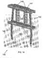
- FIG. 15illustrates a fourteenth exemplary embodiment of the OTC staple 150.
- the OTC device 153is, as above, a separate part from the bridge 151 and legs 152 of the staple 150.
- this variationdiffers from the previous embodiments because the OTC device 153 is a cushion made of a compressible material. Examples of such material include, but are not limited to, closed cell polyethylene foam, expanded polytetrafluoroethylene (PTFE), silicone rubber, silicone rubber foam, urethane, and electro-spun thermoplastic elastomers.
- This cushion 153defines two channels 154 for receiving therethrough a respective one of the legs 152.
- the staple legs 152taper inwards slightly in a direction from the intermediate portion 155 of the staple 150 to the ends of the bridge 151 (although this taper is not a requirement), the cross-sectional area of the channels 154 are larger than the cross-section of a portion of the legs 152 disposed inside the channels 154.
- the OTC device 143can be shaped with variations in cross-section and other spatial characteristics and can be formed with a variety of material compositions.
- the exemplary embodiment illustrated in FIG. 15is a pillow having a racetrack cross-sectional shape in the transverse direction.
- the pillowcan be circular, ovular, rectangular, and polygonal in its outer transverse shape.
- any portion of the pillow 153can be varied so long as it delivers the pre-set compressive force to the tissue at the distal end of the pillow 153 and as long as it allows for absorption of forces greater than this pre-set force.
- variation of any attribute of the OTC device 153allows for adjustment of the compressive and reactive force constants thereof on the compressed tissue in the central region 157.
- FIG. 16illustrates a fifteenth exemplary embodiment of the OTC staple 160. This variation is different from the previous embodiments.
- the OTC device 163is, as above, a separate part from the bridge 161 and legs 162 of the staple 160.
- the OTC deviceis a plate 163 made of a semi-compressible material having properties that will be described in detail below. Examples of such a material include, but are not limited to, polyurethane and silicone rubber.
- the plate 163defines two channels 164 for receiving therethrough a respective one of the legs 162.
- the cross-sectional area of each of the channels 164 in the bridge-legs planeis larger than the cross-section of the legs 162 that are to be disposed inside the channels 164. This larger area is defined by a hole that is longer in the bridge-legs plane than in the plane orthogonal thereto along the axis of the leg 162.
- the cross-sectional shape of the channels 164are ovular or racetrack shaped.
- the staple 160 shown in FIG. 16is different from the prior art staple of FIG. 1 .
- the connecting portion 166 of the legs 162tapers in width outwardly in the direction beginning from the intermediate portion towards the bridge 161 in a plane that is orthogonal to the bridge-legs plane.
- the channels 164have a fixed width in the plane of the widening (which plane is orthogonal to the bridge-legs plane), and due to the fact that the fixed width is close in size to the lower-most portion of the connecting portion 166 (nearest to the intermediate portion 165), the plate 163 will not be able to move upwards towards the bridge 161 unless the material of the plate 163 is semi-compressible.
- Knowledge about the material's ability to compress and the resistance it provides to upward movement as the plate 163 progresses upward along the outwards taper of the leg wideningcan be used to set or adjust the compressive and reactive force constants thereof on the compressed tissue in the central region 167. Any portion of the plate 163 and of the upper leg taper can be varied so long as the OTC system (plate 163 and taper of the legs 162) delivers the pre-set compressive force to the tissue at the distal end of the plate 163 and as long as it allows for absorption of forces greater than this pre-set force.
- the OTC device of this embodimentcan be shaped with variations in cross-section, taper, and other spatial characteristics and can be formed with a variety of material compositions.
- the exemplary embodiment illustrated in FIG. 16is a plate 163 having a racetrack cross-sectional shape in the transverse direction.
- the pillowcan be circular, ovular, rectangular, and polygonal in its outer transverse shape, for example.
- the OTC staple according to the inventionis applied in the same manner as a conventional staple, that is:
- the captured materialpartially compresses the OTC device inside the staple to, thereby, effect the optimal tissue compression feature.
- the OTC deviceis imparting a pre-set compressive force against the compressed material.
- the OTC deviceis able to move while the material is going through its compression and expansion cycle(s) until it finally reaches a steady state size. Even after reaching the steady state, the OTC device imparts the desired compressive force (within an acceptable minimum range) so that the material is not permanently damaged due to overcompression.
- the materialis human tissue
- tissuewhen tissue is stapled, liquid is forced out of the tissue.
- the tissuecompresses further and further.
- the OTC devicecompensates by enlarging to follow the tissue compression.
- the tissuebegins to swell (due to the puncturing and compressing forces imparted thereon).
- the OTC devicecompensates by reducing to follow the tissue swelling.
Landscapes
- Health & Medical Sciences (AREA)
- Surgery (AREA)
- Life Sciences & Earth Sciences (AREA)
- Engineering & Computer Science (AREA)
- Heart & Thoracic Surgery (AREA)
- Nuclear Medicine, Radiotherapy & Molecular Imaging (AREA)
- Biomedical Technology (AREA)
- Medical Informatics (AREA)
- Molecular Biology (AREA)
- Animal Behavior & Ethology (AREA)
- General Health & Medical Sciences (AREA)
- Public Health (AREA)
- Veterinary Medicine (AREA)
- General Engineering & Computer Science (AREA)
- Mechanical Engineering (AREA)
- Surgical Instruments (AREA)
- Portable Nailing Machines And Staplers (AREA)
Description
- The present invention lies in the field of staple fastening, in particular, staples and instruments capable of applying a single or a plurality of staples to a material and processes therefor. More particularly, the present invention relates to a staple capable of placing a load-bearing force against the material being stapled and improvements in processes for stapling material. The device can be used, particularly, in the medical field for stapling tissue during surgical procedures, whether open, endoscopic, or laparoscopic.
- Conventional staples are, typically, U-shaped and require a staple cartridge and anvil to fasten the staple onto a material. The U-shape of the staple can be considered relatively square-cornered because of the sharp angle at which the legs extend from the bridge. On activation of a stapling device, the staple legs are advanced forward so that they penetrate a material on both sides of a slit or opening. As a staple former is advanced further, the legs of the staple bend around the anvil causing the tips of the legs to advance along an arcuate path toward each other so that the staple ultimately assumes a generally rectangular shape, thereby compressing the material that has been trapped between the staple legs, which is tissue in surgical applications. This compression of the material is the mechanism by which a closure is effected. Depending on the length of the incision or opening, a series of staples will be delivered along its length, which can ensure a blood tight closure in surgical procedures.
- Because the staple has two legs that pierce the material, they are well suited for fastening two or more layers of material together when used with the opposing anvil. Whether used in an office or during a surgical procedure,
most staples 1 have similar shapes - abridge 2 connecting two relativelyparallel legs 4, which legs are disposed approximately orthogonal to thebridge 2, which, depending on the material of the staple, results in a square-cornered U-shape. In surgical stapling devices, it is beneficial to start thelegs 4 in a slight outward orientation to assist retention of the staples within the cartridge. The staple illustrated inFIG. 1 is representative of conventional surgical staples. Such staples are compressed against an anvil to bend the tips of thelegs 4 inward. For purposes sufficient in surgery, the final stapled configuration has a stapling range from a "least" acceptable orientation to a "greatest" acceptable orientation. The "least" acceptable staple range is a position where the tangent defined by the tip of eachleg 4 is at a negative angle to a line parallel to thebridge 2 and touching the lower portions of bothlegs 4. The "greatest" acceptable staple range is a position where thelegs 4 are bent into a shape similar to the letter "B." - The
staple 1 ofFIG. 1 is shown in an orientation where the tips of thelegs 4 are bent slightly by an anvil on the way towards a final stapled form. (This slightly bent orientation is also present with respect to the staples illustrated hereafter.) Thelegs 4 of such slightly bent staples have three different portions: - a connecting portion 6 (at which the
legs 4 are connected to the bridge 2); - an intermediate portion 8 (at which the staple is bent; of course it is also possible for the
connection portion 6 to be bent for various fastening purposes); and - a piercing portion 10 (for projecting through the material to be fastened; this portion, too, is bent when fastening).
- Many stapling devices exist to deploy such staples. Some surgical stapling instruments are described in
U.S. Patent No. 5,465,895 to Knodel et al. , andU.S. Patent Nos. 6,644,532 and6,250,532 to Green et al. When thestaple 1 is bent for fastening, the polygon formed by the interior sides of thebent staple 1 defines an envelope or acentral region 14. The material to be fastened by thestaple 1 resides in and is compressed within thecentral region 14 when stapling occurs. When the final staple orientation is B-shaped, there can be two regions in which the tissue is held and compressed. - Document
US 2006/0291981 A1 discloses a staple having an expandable backspan and a pair of spaced legs wherein the expandable backspan is configured to expend or deform to accommodate tissues of varying thicknesses. The backspan may include a deformable pad or spacer. - Document
US 4.532.927 A discloses a two-piece tissue fastener which includes an open loop fastening member and a receiver adapted to receive the legs of the fastening member, Each fastening member leg extends through the receiver and the distal end of the leg bent back into a base structure of the receiver to effect engagement of the fastening member and receiver. - One common feature associated with conventional staples is that there is no controllable way of adjusting the compressive force that is applied by the staple to the material being stapled. While items such as paper and cardboard can withstand a wide range of stapler compressive force without breaking or puncturing, living tissue, such as the tissue to be fastened in a surgical procedure, has a limited range of compressive force and cannot withstand force greater than a upper limit within that range without causing tissue damage. In fact, the range of optimal stapling force for a given surgical stapling procedure is relatively small and varies substantially with the type of tissue being stapled.
- While it may be true that the distance between the bending point of the legs and the bridge (see, e.g.,
span 12 inFIG. 1 ) can be increased to impart less force on material within the staple, this characteristic does not apply when living tissue having varying degrees of hardness, composition, and flexibility is the material being stapled. Even if the stapleleg bending distance 12 is increased, if more or less or harder or softer tissue than expected is actually captured within the staple, the force applied to the captured tissue will not be controlled and will not be optimal for that tissue. - When one, two, or more layers of tissue are being stapled, it is desirable for the tissue to be at a desired compressive state so that a desirous medical change can occur, but not to be at an undesired compressive state sufficient to cause tissue necrosis. Because there is no way to precisely control the tissue that is being placed within the staple, it is not possible to ensure that the tissue is stapled within an optimal tissue compression range, referred to as an OTC range. Therefore, ruling out of tissue necrosis is difficult or not possible. Further, tissue presented within one staple may not be the same tissue that is presented within an adjacent staple or is within another staple that is fired during the same stapling procedure. Thus, while one or a few of a set of staples could actually fasten within the OTC range, it is quite possible for many other staples in the same stapling procedure to fasten outside the OTC range.
- What is needed, therefore, is an improved staple and improved methods of stapling that allow automatic control of the staple compression force imparted upon the material being stapled so that compression of the material remains within a desired OTC range. While prior art surgical stapling instruments have utility, and may be successfully employed in many medical procedures, it is desirable to enhance their operation with the ability to deliver a staple that can automatically tailor the compression force delivered to the tissue without external mechanics or operations.
- It is accordingly an object of the invention to provide an adjustable compression staple and methods for stapling with adjustable compression that overcome the hereinafore-mentioned disadvantages of the heretofore-known devices and methods of this general type and that automatically tailors the compression force delivered to the tissue.
- When tissue is stapled, liquid is forced out of the tissue. The OTC range of the tissue is a compression range in which liquid is removed from the tissue (i.e., desiccates the tissue) without damaging or necrosing the tissue. As the liquid from the tissue exits the tissue due to compression exerted upon the tissue by the staple, however, the compressive force that is being imposed upon the tissue naturally reduces - because less mass is between the opposing staple portions. In some instances, this reduction can allow the imparted tissue compression to exit the OTC range. Staples according to the present invention each have a self-adjusting, pre-tensioned compression device that keeps compression force on the interposed tissue within the OTC compression range even after being desiccated.
- The prior art staple of
FIG. 1 has a stapling range that is illustrated inFIG. 17 . For purposes sufficient in surgery, the final stapled configuration of the OTC staples of the present invention has a stapling range that is illustrated, for example, inFIGS. 18 to 20 . A "least" acceptable staple range is a position where the tangent T defined by the tip of eachleg 4 is at a negative angle α to a line L parallel to thebridge 2. This orientation is illustrated with the left half of the staple inFIG. 17 merely for reasons of clarity. See alsoFIGS. 18 to 20 . A "greatest" acceptable staple range is a position where thelegs 4 are bent 180 degrees into a shape similar to the letter "B" (see the exemplary orientation illustrated in the right-half ofFIG. 17 ) but, in comparison to the prior art staple range ofFIG. 17 , as described below in detail, the tips of thelegs 4 of the staples according to the invention reach only up to a compressing portion and not further than this compressing portion as shown inFIG. 20 , for example. In such an orientation, the stapled tips of the legs do not interfere with the OTC device present in the staples according to the invention. - The OTC devices for staples according to the invention take many forms. The OTC device can be integral with the legs of the staple and project into a central area or can be attached to the staple to project into the central area. The OTC device can be sinusoidal in shape with a compressing portion at the end of the OTC device or can be have multiple cycles of bends between the bridge of the staple with the compressing portion at the end of the OTC device. The bending portion can be single or double, the double bends being in cycle, out of cycle, mirror-symmetrical, to name a few. The bends can be double-sinusoidal as shown in
FIGS. 8 ,9 , and11 The OTC device can be contained entirely between the two legs of the staple or can encircle one or both of the legs and, thereby, use the legs as a guide, for example, a sliding guide. The leg encirclement by the OTC device can be single or multiple. Travel of the OTC device can be limited, for example, by a star washer. The OTC device can be a compression spring(s) and a plate(s), with the plate encircling the legs and sliding thereon. The OTC device can be a compressible material secured on the legs. This material can be in the shape of a plate or a pillow. - With the foregoing and other objects in view, there is provided, in accordance with the invention, a compression-self-adjusting staple includes a substantially U-shaped staple body and a compression device. The body has a bridge and two legs extending from the bridge at an angle thereto. Each of the legs has a base end integral with the bridge and a deformable distal end defining a stapling point shaped to pierce material to be stapled. The compression device is at least partly disposed between the legs and has a bias portion with a compression surface movably disposed between the legs and a compression resistor which is formed as a compression spring. The compression resistor is connected to the bridge and integral with the compression surface and is formed to resist movement of the compression surface towards the bridge with a force.
- With the objects of the invention in view, there is also provided a compression-self-adjusting staple including a substantially U-shaped staple having an internally disposed compression device capable of regulating compressive force imposed on material stapled therein independent of a magnitude of staple firing.
- With the objects of the invention in view, there is also provided a compression-self-adjusting staple including a substantially U-shaped staple having an internally disposed compression device capable of placing a substantially constant compressive force against material stapled therein independent of a magnitude of staple firing.
- In accordance with another feature of the invention, the bridge is substantially rod-shaped with ends and the base end of each the legs is integral with a respective one of the ends.
- In accordance with a further feature of the invention, the bridge and legs define a bridge-leg plane and the legs extend from the bridge at an angle of between 80 and 100 degrees in the bridge-leg plane.
- In accordance with an added feature of the invention, the deformable distal ends are capable of bending to approximately 180 degrees in the bridge-leg plane.
- In accordance with an additional feature of the invention, the compression surface defines two orifices and each of the legs extends through one of the two orifices.
- In accordance with yet another feature of the invention, the compression resistor defines at least one orifice pair the compression surface defines two orifices, and each of the legs extends through one of the two orifices and one of the at least one orifice pair.
- In accordance with yet a further feature of the invention, the compression resistor defines a plurality of orifice pairs, the compression surface defines two orifices, and each of the legs extends through one of the two orifices and one of each of the orifice pairs.
- In accordance with yet an added feature of the invention, the compression surface is at a distance from the bridge.
- In accordance with yet an additional feature of the invention, the compression surface is parallel to the bridge.
- In accordance with again another feature of the invention, the bridge and the legs define a compression axis and the compression surface is movably disposed between the legs along the compression axis.
- In accordance with again a further feature of the invention, the compression device is connected to the bridge.
- In accordance with again an added feature of the invention, the compression resistor connects the bridge to the compression surface.
- In accordance with again an additional feature of the invention, the bridge, the legs, the compression resistor, and the compression surface are integral.
- In accordance with still another feature of the invention, the compression resistor is separate from the bridge and fixed to the bridge between the legs.
- In accordance with still a further feature of the invention, the compression resistor is at least partly disposed between the legs.
- In accordance with still an added feature of the invention, the compression resistor is disposed between the bridge and the compression surface.
- In accordance with still an additional feature of the invention, the compression resistor is formed to resist movement of the compression surface towards the bridge with a pre-defined opposing force.
- In accordance with another feature of the invention, the compression resistor is formed to resist movement of the compression surface towards the bridge with a substantially constant force.
- In accordance with a further feature of the invention, the compression resistor is formed to resist movement of the compression surface towards the bridge with a linearly increasing force.
- In accordance with an added feature of the invention, the compression resistor has an anti-compressive spring constant imparting a substantially constant anti-compressive force over a pre-defined compression range.
- In accordance with an additional feature of the invention, the staple body and the compression device are of a biocompatible material, in particular, at least one of titanium, a titanium alloy, nitinol, and stainless steel.
- In accordance with yet another feature of the invention, the compression surface and the legs define a central compression region in which is to be disposed a material to be compressed between the compression surface and the stapling points when the distal ends are deformed, and, when the distal ends are deformed in a staple closing direction into the central compression region, the bias portion resists movement of the compression surface in the staple closing direction with a pre-defined, substantially constant force.
- In accordance with yet a further feature of the invention, the compression surface and the bias portion are shaped to impart a pre-defined, substantially constant bias force upon material disposed between the compression surface and the stapling points when the stapling points are deformed.
- In accordance with yet an added feature of the invention, when the stapling points are deformed toward one another, material disposed between the compression surface and the stapling points is compressed between the stapling points and the compression surface, and the compression resistor maintains a substantially constant compressive force on the material within a pre-defined range independent of a degree of compression between the stapling points and the compression surface.
- In accordance with yet an additional feature of the invention, the compression resistor is sinusoidal.
- In accordance with again another feature of the invention, the compression resistor is sinusoidal in the bridge-leg plane.
- In accordance with again a further feature of the invention, the compression resistor is double-sinusoidal in the bridge-leg plane.
- In accordance with again an added feature of the invention, the compression resistor is a single sinusoidal-shaped body.
- In accordance with an embodiment, the compression resistor has a first portion and a second portion and the second portion is a mirror image of the first portion.
- In accordance with an embodiment, the compression surface is a C-beam defining two orifices, the compression resistor is a conical spring with a lower end connected to the compression surface, and each of the legs slidably rests within a respective one of the two orifices.
- In accordance with an embodiment, the compression surface is a C-beam defining two orifices, the compression resistor is a pair of springs each surrounding a portion of a respective one of the legs and each having a lower end connected to the compression surface, and each of the legs slidably rests within a respective one of the two orifices.
- In accordance with an embodiment, the compression surface is a C-beam defining two orifices, the compression resistor is a pair of springs each having an upper end connected to the bridge and a lower end connected to the compression surface, and each of the legs slidably rests within a respective one of the two orifices.
- In accordance with an embodiment, the bias portion is a cushion of a compressible material defining two orifices and each of the legs slidably rests within a respective one of the two orifices.
- Although the invention is illustrated and described herein as embodied in an adjustable compression staple and method for stapling with adjustable compression, it is, nevertheless, not intended to be limited to the details shown because various modifications and structural changes may be made therein without departing from the spirit of the invention and within the scope and range of equivalents of the claims. Additionally, well-known elements of exemplary embodiments of the invention will not be described in detail or will be omitted so as not to obscure the relevant details of the invention.
- Other features that are considered as characteristic for the invention are set forth in the appended claims. As required, detailed embodiments of the present invention are disclosed herein; however, it is to be understood that the disclosed embodiments are merely exemplary of the invention, which can be embodied in various forms. Therefore, specific structural and functional details disclosed herein are not to be interpreted as limiting, but merely as a basis for the claims and as a representative basis for teaching one of ordinary skill in the art to variously employ the present invention in virtually any appropriately detailed structure. Further, the terms and phrases used herein are not intended to be limiting; but rather, to provide an understandable description of the invention. While the specification concludes with claims defining the features of the invention that are regarded as novel, it is believed that the invention will be better understood from a consideration of the following description in conjunction with the drawing figures. The figures of the drawings are not drawn to scale.
- Before the present invention is disclosed and described, it is to be understood that the terminology used herein is for the purpose of describing particular embodiments only and is not intended to be limiting. The terms "a" or "an", as used herein, are defined as one or more than one. The term "plurality," as used herein, is defined as two or more than two. The term "another," as used herein, is defined as at least a second or more. The terms "including" and/or "having," as used herein, are defined as comprising (i.e., open language). The term "coupled," as used herein, is defined as connected, although not necessarily directly, and not necessarily mechanically.
- As used herein, the term "about" or "approximately" applies to all numeric values, whether or not explicitly indicated. These terms generally refer to a range of numbers that one of skill in the art would consider equivalent to the recited values (i.e., having the same function or result). In many instances these terms may include numbers that are rounded to the nearest significant figure.
- Advantages of the embodiments of the present invention will be apparent from the following detailed description of the preferred embodiments thereof, which description should be considered in conjunction with the accompanying drawings in which:
FIG. 1 is a perspective view from above a side of an exemplary prior art surgical staple;FIG. 2 is a perspective view from above a side of a first exemplary embodiment of an OTC staple according to the invention;FIG. 3 is a perspective view from above a side of a second exemplary embodiment of an OTC staple according to the invention;FIG. 4 is a perspective view from above a side of a third exemplary embodiment of an OTC staple according to the invention;FIG. 5 is a perspective view from above a side of a fourth exemplary embodiment of an OTC staple according to the invention;FIG. 6 is a perspective view from above a side of a fifth exemplary embodiment of an OTC staple according to the invention;FIG. 7 is a perspective view from above a side of a sixth exemplary embodiment of an OTC staple according to the invention;FIG. 8 is a perspective view from above a side of a seventh exemplary embodiment of an OTC staple according to the invention;FIG. 9 is a perspective view from above a side of an eighth exemplary embodiment of an OTC staple according to the invention;FIG. 10 is a perspective view from above a side of a ninth exemplary embodiment of an OTC staple according to the invention;FIG. 11 is a perspective view from above a side of a tenth exemplary embodiment of an OTC staple according to the invention;FIG. 11A is a fragmentary, enlarged perspective view from below a side of the OTC staple ofFIG. 11 ;FIG. 12 is a perspective view from above a side of an eleventh exemplary embodiment of an OTC staple;FIG. 13 is a perspective view from above a side of a twelfth exemplary embodiment of an OTC staple;FIG. 14 is a perspective view from above a side of a thirteenth exemplary embodiment of an OTC staple;FIG. 15 is a perspective view from above a side of a fourteenth exemplary embodiment of an OTC staple;FIG. 16 is a perspective view from above a side of a fifteenth exemplary embodiment of an OTC staple;FIG. 17 is a side elevational view of the prior art surgical staple ofFIG. 1 with the staple tips illustrating an exemplary range of stapling;FIG. 18 is a side elevational view of the staple ofFIG. 6 with the staple tips in a first intermediate position of an exemplary stapling range;FIG. 19 is a side elevational view of the staple ofFIG. 6 with the staple tips in a second intermediate position of an exemplary stapling range; andFIG. 20 is a side elevational view of the staple ofFIG. 6 with the staple tips in a third intermediate position of an exemplary stapling range.- Herein various embodiment of the present invention are described. In many of the different embodiments, features are similar. Therefore, to avoid redundancy, repetitive description of these similar features may not be made in some circumstances. It shall be understood, however, that description of a first-appearing feature applies to the later described similar feature and each respective description, therefore, is to be incorporated therein without such repetition.
- Referring now to the figures of the drawings in detail and first, particularly to
FIG. 2 thereof, there is shown a first exemplary embodiment of an automatic optimal tissue compression (OTC) staple 20 according to the invention. In this first embodiment, thebridge 21 has acenter bridge portion 22 and anextension 23 that substantially increases the overall length of thebridge 21 -- as compared to thebridge 2 of thestaple 1 ofFIG. 1 . As theupper bridge portion 22 transitions into theextension 23, it curves into and within thecentral region 24 of the staple 20. Thisextension 23 can be in any shape or of any material so long as it delivers a pre-set compressive force to the tissue at a compressingportion 25, and as long as it allows for absorption (within the area between the compressingportion 25 and the upper bridge portion 22) of forces greater than this pre-set force. Therefore, the shape can be trapezoidal, triangular, sinusoidal, or any other configuration. An exemplary embodiment of relatively sinusoidal curves is shown inFIG. 2 . These curves traverse two periods in the illustrated embodiment, however, the number of wave periods can be varied (smaller or larger). Theextension 23 has two mirror-symmetrical portions each starting from theupper bridge portion 22 and ending at respective ends of the compressingportion 25. Further, it is noted that neither theextension 23 nor the compressingportion 25 directly contacts thelegs 26 in this exemplary configuration. - In the embodiment of
FIG. 2 , theextension 26 and the compressing portion 29 are integral with thebridge 22 and thelegs 26. Thelegs 26 are shown as relatively circular in cross-section. Thebridge 21 and all of the compressingcomponents FIG. 2 , any portion of theextension 23 and/or the compressingportion 25 can have different cross-sectional shapes, such as ovular, rectangular, or polygonal. In the embodiment shown, the cross-section of theextension 23 after the first curve away from theupper bridge portion 22 is shaped in a "racetrack" form (two relatively straight sides with two curved ends connecting each end of the sides). Theupper bridge portion 22 can also have a different cross-sectional shape. Theextension 23 and compressingportion 25 are, in this embodiment, even in cross-sectional area. Different portions of these parts can, however, have varying cross-sectional areas (i.e., varying thicknesses) as desired. - When the
upper bridge 22, theextension 23, and the compressingportion 25 are shaped to deliver the pre-set compressive force to the tissue and to absorb forces greater than this pre-set force, the overall effect is to create an OTC device having a given spring coefficient. In other words, the OTC device maintains the preset compressive force within the stapled area even after tissue expands due to swelling and after tissue contracts during desiccation. Variation of the cross-section of any portion of theupper bridge 22, theextension 23, and the compressingportion 25 will allow for different OTC spring coefficients and, therefore, allows for adjustment of the compressive and reactive force constants of the OTC device within the staple 20. Variation of the material making up all of the staple 20 or any of its portions also permits adjustment of the OTC force. FIG. 3 illustrates a second exemplary embodiment of theOTC staple 30 according to the invention. In this variation, as compared to the embodiment ofFIG. 2 , the OTC portion is not integral with thebridge 31 and thelegs 32. Instead, theOTC device 33 is separate therefrom and is connected to these staple portions. Specifically, theOTC device 33 has a compressingportion 34 that directly contacts the tissue being compressed and anextension 36 for providing the load-bearing force when tissue is compressed within thecentral region 37 of thestaple 30. TheOTC device 33 also has a connectingportion 35 for attaching theOTC device 33 to thebridge 31. Theextension 36 connects the upper andlower portions OTC device 33. Theextension 33 and the compressingportion 34 are, in this embodiment, different in cross-sectional area. Here, the cross-sectional area of the compressingportion 34 is wider than theextension 36. Any portions of theextension 33 or the compressingportion 34 can be varied to have same or varying cross-sectional areas (i.e., varying thicknesses).- Connection of the
OTC device 33 to the staple, for example, at thebridge 31, can occur by any fastening measure. One exemplary connection method is spot welding, which is indicated inFIG. 3 byreference numeral 38. Other exemplary methods of attaching suitable materials together include soldering and brazing. The type or types of material of thestaple portions OTC device 33 will direct a preferable attachment method. In the case of attaching two materials together that are not suited to be welded, soldered or brazed, other attachment methods can be used such as crimping and adhesive bonding. Features can be added to one or both of the two components to facilitate the crimp or bond. These features could be configured to have the components snap together. In the case of dissimilar materials, for example, if the staple material is stainless steel and theOTC device 33 is of nickel titanium alloy, then preferred attachment measures include crimping, adhesive bonding, or snapping. - In this second embodiment, the
OTC device 33 behaves similar to the OTC portions of the embodiment ofFIG. 2 and can be shaped with the same variations of cross-section and other spatial characteristics and can be formed with the same variations in material composition. Variation of any attribute of theOTC device 33 allows for adjustment of the compressive and reactive force constants thereof on the compressed tissue. Theextension 36 can be any shape or material so long as it delivers a pre-set compressive force to the tissue at the compressingportion 34 and as long as it allows for absorption of forces greater than this pre-set force. An exemplary embodiment selected for thisexemplary OTC device 33 is a relatively sinusoidal set of curves traversing less than two periods. Theextension 36 has two mirror-symmetrical portions each starting from thebridge 31 and ending at respective ends of the compressingportion 34. In this exemplary embodiment, neither theextension 36 nor the compressingportion 34 directly contacts thelegs 32. Most of the cross-section of theOTC device 33 has a racetrack form. Like the embodiment ofFIG. 2 , the cross-section can be varied in any desired way to deliver the pre-set compressive force to the tissue and to absorb forces greater than this pre-set force. FIG. 4 illustrates a third exemplary embodiment of theOTC staple 40 according to the invention. In this variation, as compared to the embodiments ofFIGS. 2 and3 , theOTC portion 43 is not symmetrical with respect to thebridge 41 or thelegs 42. Also, like the embodiment ofFIG. 3 , the OTC portion is not integral with either thebridge 41 or thelegs 42. TheOTC device 43 is a separate part from thebridge 41 and thelegs 42 and is fixedly connected to thebridge 41 at a connection location (for example, with aspot weld 48; other fixation/connection processes can be used). In particular, a connectingportion 45 of theOTC device 43 fixedly secures theOTC device 43 to thebridge 41. Anextension 46 of theOTC device 43 provides the load-bearing force when tissue is compressed within thecentral region 47 of the staple 40 and a compressingportion 44 directly contacts the tissue being compressed.- Notably different from the embodiments of
FIGS. 2 and3 is the compressingportion 44. Here, the width of the compressing portion 44 (defined along the line between the twolegs 42 of the staple 40) is greater than the separation distance of the twolegs 42. The compressingportion 44 is provided withports 49 having a shape substantially corresponding to the cross-sectional shape of the upper portion of thestaple legs 42 but slightly larger. Thelegs 42 pass through theseports 49. In such a configuration, movement of theOTC device 43 out of the bridge-legs plane is substantially prevented. Because theports 49 are shaped to be slightly larger than the cross-section of thelegs 42, theextension 46 acts as a compression spring in the bridge-legs plane as the compressingportion 44 moves up and down along the upper portion of the legs 42 (up being defined as the direction towards thebridge 41 from the piercing tips of the legs 42). Thus, theOTC device 43 of the third embodiment behaves different from the OTC devices ofFIGS. 2 and3 because of the form-locking and sliding connection between the connectingportion 44 and thelegs 42. A form-locking connection is one that connects two elements together due to the shape of the elements themselves, as opposed to a force-locking connection, which locks the elements together by force external to the elements. - Like the previous embodiments, the
OTC device 43 can be shaped with variations in cross-section and other spatial characteristics and can be formed with a variety of material compositions. Theextension 46 and compressingportion 44 are, in this embodiment, different in cross-sectional area. Here, the cross-sectional area of the compressingportion 44 is wider than theextension 46. Any portions of theextension 46 or the compressingportion 44 can be varied to have same or varying cross-sectional areas (i.e., varying thicknesses). Theextension 46 can be any shape or material so long as it delivers the pre-set compressive force to the tissue at the compressingportion 44 and as long as it allows for absorption of forces greater than this pre-set force. An exemplary embodiment selected for thisOTC device 43 is a relatively sinusoidal curve traversing approximately one sinusoidal period. Virtually all of the cross-section of theOTC device 43 has a racetrack form, but can be changed as desired to other shapes (e.g., circular, ovular, polygonal, etc.). As described above, variation of any attribute of theOTC device 43 allows for adjustment of the compressive and reactive force constants thereof on the compressed tissue in thecentral region 47. FIG. 5 illustrates a fourth exemplary embodiment of theOTC staple 50 according to the invention. This variation has some of the features of the above embodiments. In this variant, like the embodiment ofFIG. 2 , the OTC portion is symmetrical with respect to thebridge 51 and thelegs 52 and theOTC device 53 is integral with thebridge 51. Like the embodiment ofFIG. 4 , the compressingportion 54 has a width greater than the separation distance of the twolegs 52 and hasports 55 with a shape substantially corresponding to the cross-sectional shape of the upper portion of thelegs 52, but slightly larger. Thelegs 52 pass through theseports 55. In this configuration, movement of theOTC device 53 out of the bridge-legs plane is substantially prevented. Theextension 56 of theOTC device 53 traverses from thebridge 51 to the compressingportion 54. Because theports 55 are shaped to be slightly larger than the cross-section of thelegs 52, theextension 56 acts as a compression spring in the bridge-legs plane as the compressingportion 54 moves up and down along the upper portion of thelegs 52. It is theextension 56 that provides the load-bearing force when tissue is compressed within thecentral region 57 of thestaple 50. Because of the form-locking and sliding connection between the compressingportion 54 and thelegs 52, theOTC device 53 of the fourth embodiment behaves similar to the OTC devices ofFIG. 4 .- Here, the
OTC device 53 is integral with thelegs 52, thebridge 51, and the compressingportion 54. Because the two sides of thebridge 51 are not integral, they can separate from one another when the staple 50 is subjected to a twisting force. If desired, to substantially prevent such separation, the central portions of thebridge 51 can be fixedly connected to one another at a connection location (for example, with aspot weld 58; other connection processes can be used as well). - Like the previous embodiments, the
OTC device 53 can be shaped with variations in cross-section and other spatial characteristics and can be formed with a variety of material compositions. Any portions of theextension 56 or the compressingportion 54 can be varied to have the same or varying cross-sectional areas (i.e., varying thicknesses). Theextension 56 and compressingportion 54 are, in this embodiment, different in cross-sectional areas. Here, the cross-sectional area of the upper majority of theextension 56 is narrower than the lower portion of theextension 56 and the cross-section of the lower portion of theextension 56 gradually increases in width until it is equal to the cross-section of the compressingportion 54. - The
extension 56 can be any shape or material so long as it delivers the pre-set compressive force to the tissue at the compressingportion 54 and as long as it allows for absorption of forces greater than this pre-set force. An exemplary embodiment selected for thisOTC device 53 is a relatively sinusoidal curve traversing more than one sinusoidal period. Again, only for illustrative purposes, the cross-section of theOTC device 53 has a racetrack shape, but can be changed as desired to other shapes (e.g., circular, ovular, polygonal, etc.). As described above, variation of any attribute of theOTC device 53 allows for adjustment of the compressive and reactive force constants thereof on the compressed tissue in thecentral region 57. FIG. 6 illustrates a fifth exemplary embodiment of theOTC staple 60 according to the invention. This variation has some of the features of the above embodiments. In this variant, like the embodiment ofFIG. 3 , the OTC portion is symmetrical with respect to thebridge 61 and thelegs 62 and theOTC device 63 is a separate part from thebridge 61 andlegs 62 of thestaple 60. Like the embodiment ofFIGS. 4 and5 , the compressingportion 64 has a width greater than the separation distance of the twolegs 62 and hasports 65 with a shape substantially corresponding to the cross-sectional shape of the upper portion of thelegs 62, but slightly larger. Thelegs 62 pass through theseports 65. In this configuration, movement of theOTC device 63 out of the bridge-legs plane is substantially prevented. Theextension 66 of theOTC device 63 traverses from thebridge 61 to the compressingportion 64. Because theports 65 are shaped to be slightly larger than the cross-section of thelegs 62, theextension 66 acts as a compression spring in the bridge-legs plane as the compressingportion 64 moves up and down along the upper portion of thelegs 62. It is theextension 66 that provides the load-bearing force when tissue is compressed within thecentral region 67 of thestaple 60. Because of the form-locking and sliding connection between the compressingportion 64 and thelegs 62, theOTC device 63 of the fifth embodiment behaves similar to the OTC devices ofFIGS. 4 and5 .- Connection of the
OTC device 63 to thestaple 60, for example, at thebridge 61, can occur by any fastening measure. One exemplary connection method is spot welding, which is indicated inFIG. 6 byreference numeral 68. The type or types of material of thestaple portions OTC device 63 will direct a preferable attachment method. In the case of attaching two materials together that are not suited to be welded, soldered or brazed, other attachment methods can be used such as crimping and adhesive bonding. Features can be added to one or both of the two components to facilitate the crimp or bond. These features could be configured to have the components snap together. In the case of dissimilar materials, for example, if the staple material is stainless steel and theOTC device 63 is of nickel titanium alloy, then preferred attachment measures include crimping, adhesive bonding, or snapping. - Like the previous embodiments, the
OTC device 63 can be shaped with variations in cross-section and other spatial characteristics and can be formed with a variety of material compositions. Any portions of theextension 66 or the compressingportion 64 can be varied to have the same or different cross-sectional areas (i.e., varying thicknesses). Theextension 66 and compressingportion 64 are, in this embodiment, different in cross-sectional areas. Here, the cross-sectional area of most of theextension 66 is narrower than the lowermost portion of theextension 66 and the cross-section of this lowermost portion of theextension 66 gradually increases in width until it is equal to the cross-section of the compressingportion 64, which is substantially wider. - The
extension 66 can be any shape or material so long as it delivers the pre-set compressive force to the tissue at the compressingportion 64 and as long as it allows for absorption of forces greater than this pre-set force. An exemplary embodiment selected for thisOTC device 63 is a relatively sinusoidal curve traversing more than one sinusoidal period. Again, only for illustrative purposes, the cross-section of theOTC device 63 has a racetrack shape, but can be changed as desired to other shapes (e.g., circular, ovular, polygonal, etc.). As described above, variation of any attribute of theOTC device 63 allows for adjustment of the compressive and reactive force constants thereof on the compressed tissue in thecentral region 67. FIG. 7 illustrates a sixth exemplary embodiment of theOTC staple 70 according to the invention. This variation has some of the features of the above embodiments. In this variant, like the embodiment ofFIG. 3 , the OTC portion is symmetrical with respect to thebridge 71 and thelegs 72 and theOTC device 73 is a separate part from thebridge 71 andlegs 72 of thestaple 70. Like the embodiment ofFIGS. 4 to 6 , the compressingportion 74 has a width greater than the separation distance of the twolegs 72 and hasports 75 with a shape substantially corresponding to the cross-sectional shape of the upper portion of thelegs 72, but slightly larger. Thelegs 72 pass through theseports 75. In this configuration, movement of theOTC device 73 out of the bridge-legs plane is substantially prevented. Theextension 76 of theOTC device 73 traverses from thebridge 71 to the compressingportion 74. Because theports 75 are shaped to be slightly larger than the cross-section of thelegs 72, theextension 76 acts as a compression spring in the bridge-legs plane as the compressingportion 74 moves up and down along the upper portion of thelegs 72. It is theextension 76 that provides the load-bearing force when tissue is compressed within thecentral region 77 of thestaple 70. Because of the form-locking and sliding connection between the compressingportion 74 and thelegs 72, theOTC device 73 of the sixth embodiment behaves similar to the OTC devices ofFIGS. 4 to 6 .- Connection of the
OTC device 73 to thestaple 70, for example, at thebridge 71, can occur by any fastening measure. One exemplary connection method is spot welding, which is indicated inFIG. 7 byreference numeral 78. The type or types of material of thestaple portions OTC device 73 will direct a preferable attachment method. In the case of attaching two materials together that are not suited to be welded, soldered or brazed, other attachment methods can be used such as crimping and adhesive bonding. Features can be added to one or both of the two components to facilitate the crimp or bond. These features could be configured to have the components snap together. In the case of dissimilar materials, for example, if the staple material is stainless steel and theOTC device 73 is of nickel titanium alloy, then preferred attachment measures include crimping, adhesive bonding, or snapping. - It is noted that the extensions (i.e., springs) in each of
FIGS. 2 ,3 ,5 , and6 are in the same plane, which can be the bridge-legs plane (as shown) or out of that plane. In comparison to these embodiments, theextension 76 has the springs residing in different planes (i.e., one next to the other. - Like the previous embodiments, the
OTC device 73 can be shaped with variations in cross-section and other spatial characteristics and can be formed with a variety of material compositions. Any portions of theextension 76 or the compressingportion 74 can be varied to have the same or varying cross-sectional areas (i.e., varying thicknesses). Theextension 76 and the compressingportion 74 are, in this embodiment, different in cross-sectional areas. Here, the cross-sectional area of most of theextension 76 is narrower than the lowermost portion of theextension 76 and the cross-section of this lowermost portion of theextension 76 gradually increases in width until it is equal to the cross-section of the compressingportion 74, which is substantially wider. - The
extension 76 can be any shape or material so long as it delivers the pre-set compressive force to the tissue at the compressingportion 74 and as long as it allows for absorption of forces greater than this pre-set force. An exemplary embodiment selected for thisOTC device 73 is a relatively sinusoidal curve traversing more than one sinusoidal period. Again, only for illustrative purposes, the cross-section of theOTC device 73 has a racetrack shape, but can be changed as desired to other shapes (e.g., circular, ovular, polygonal, etc.). As described above, variation of any attribute of theOTC device 73 allows for adjustment of the compressive and reactive force constants thereof on the compressed tissue in thecentral region 77. FIG. 8 illustrates a seventh exemplary embodiment of theOTC staple 80 according to the invention. This variation has some of the features of the above embodiments. In this variant, like the embodiment ofFIG. 3 , the OTC portion is symmetrical with respect to thebridge 81 and thelegs 82, and theOTC device 83 is a separate part from thebridge 81 andlegs 82 of thestaple 80. Like the embodiment ofFIGS. 4 to 7 , the compressingportion 84 has a width greater than the separation distance of the twolegs 82 and hasports 85 with a shape substantially corresponding to the cross-sectional shape of the upper portion of thelegs 82, but slightly larger. Thelegs 82 pass through theseports 85. In this configuration, movement of theOTC device 83 out of the bridge-legs plane is substantially prevented. Theextension 86 of theOTC device 83 traverses from thebridge 81 to the compressingportion 84. Because theports 85 are shaped to be slightly larger than the cross-section of thelegs 82, theextension 86 acts as a compression spring in the bridge-legs plane as the compressingportion 84 moves up and down along the upper portion of thelegs 82. It is theextension 86 that provides the load-bearing force when tissue is compressed within thecentral region 87 of thestaple 80. Because of the form-locking and sliding connection between the compressingportion 84 and thelegs 82, theOTC device 83 of the seventh embodiment behaves similar to the OTC devices ofFIGS. 4 to 7 .- Like the previous embodiments, the
OTC device 83 can be shaped with variations in cross-section and other spatial characteristics and can be formed with a variety of material compositions. Any portions of theextension 86 or the compressingportion 84 can be varied to have the same or varying cross-sectional areas (i.e., varying thicknesses). Theextension 86 and the compressingportion 84 are, in this embodiment, different in cross-sectional areas. Here, the cross-sectional area of most of theextension 86 is smaller and narrower than the lowermost portion of theextension 86 and the cross-section of this lowermost portion gradually increases in width until it is equal to the cross-section of the compressingportion 84, which is substantially wider. Also, the cross-sectional area of thisextension 86 is smaller than previous embodiments (but it need not be). - The
extension 86 can be any shape or material so long as it delivers the pre-set compressive force to the tissue at the compressingportion 84 and as long as it allows for absorption of forces greater than this pre-set force. An exemplary embodiment selected for thisOTC device 83 is a relatively sinusoidal curve traversing a more than two periods and also having a second "interior" curve that traverses sinusoidal periods. In this embodiment, theOTC device 83 has an uppermost portion that is, in contrast to the embodiments ofFIGS. 3 ,6 , and7 a single bar extending along a majority of thebridge 81. - Connection of the
OTC device 83 to thestaple 80, for example, at thebridge 81, can occur by any fastening measure. One exemplary connection method is spot welding, which is indicated inFIG. 8 byreference numeral 88. Because there is contact over most of thebridge 81, theOTC device 83 can be welded over the entire length thereof. The type or types of material of thestaple portions OTC device 83 will direct a preferable attachment method. In the case of attaching two materials together that are not suited to be welded, soldered or brazed, other attachment methods can be used such as crimping and adhesive bonding. Features can be added to one or both of the two components to facilitate the crimp or bond. These features could be configured to have the components snap together. In the case of dissimilar materials, for example, if the staple material is stainless steel and theOTC device 83 is of nickel titanium alloy, then preferred attachment measures include crimping, adhesive bonding, or snapping. - Only for illustrative purposes, the cross-section of the
OTC device 83 has a racetrack shape, but can be changed as desired to other shapes (e.g., circular, ovular, polygonal, etc.). As described above, variation of any attribute of theOTC device 83 allows for adjustment of the compressive and reactive force constants thereof on the compressed tissue in thecentral region 87. FIG. 9 illustrates an eighth exemplary embodiment of theOTC staple 90 according to the invention. This variation has some of the features of the above embodiments. In this variant, like the embodiment ofFIG. 3 , the OTC portion is symmetrical with respect to thebridge 91 and thelegs 92, and theOTC device 93 is a separate part from thebridge 91 andlegs 92 of thestaple 90. Like the embodiment ofFIGS. 4 to 8 , the compressingportion 94 has a width greater than the separation distance of the twolegs 92 and hasports 95 with a shape substantially corresponding to the cross-sectional shape of the upper portion of thelegs 92, but slightly larger. Thelegs 92 pass through theseports 95. In this configuration, movement of theOTC device 93 out of the bridge-legs plane is substantially prevented. Theextension 96 of theOTC device 93 traverses from thebridge 91 to the compressingportion 94. Because theports 95 are shaped to be slightly larger than the cross-section of thelegs 92, theextension 96 acts as a compression spring in the bridge-legs plane as the compressingportion 94 moves up and down along the upper portion of thelegs 92. It is theextension 96 that provides the load-bearing force when tissue is compressed within thecentral region 97 of thestaple 90. Because of the form-locking and sliding connection between the compressingportion 94 and thelegs 92, theOTC device 93 of the eighth embodiment behaves similar to the OTC devices ofFIGS. 4 to 8 .- Like the previous embodiments, the
OTC device 93 can be shaped with variations in cross-section and other spatial characteristics and can be formed with a variety of material compositions. Any portion(s) of theextension 96 or the compressingportion 94 can be varied to have the same or varying cross-sectional areas (i.e., varying thicknesses). Theextension 96 and the compressingportion 94 are, in this embodiment, different in cross-sectional areas. Here, the cross-sectional area of most of theextension 96 is smaller and narrower than the lowermost portion of theextension 96 and the cross-section of this lowermost portion gradually increases in width until it is equal to the cross-section of the compressingportion 94, which is substantially wider. Also, the cross-sectional area of thisextension 96 is smaller than previous embodiments (but need not be). With such a relatively smaller cross-sectional shape, the curves of theextension 96 might tend to deform or move out of the bridge-legs plane, which tendency can increase or decrease depending upon the material of theextension 96. To prevent such deformation and/or movement, a plurality of guiding tabs 99 are disposed at one or more of the outside ends of each periodic curve adjacent thelegs 92. These guiding tabs 99 are shaped in a similar manner to the ends of the compressingportion 94, in that they have ports with a cross-sectional shape substantially corresponding to the cross-sectional shape of the upper portion of thelegs 92 but slightly larger. The embodiment illustrated inFIG. 9 provides each guiding tab 99 with two relatively parallel plates each having one of the two ports through which therespective leg 92 is disposed. Like the lower portion of theextension 96, the cross-sectional area of the extension gradually increases in width until it is equal to the larger cross-section of the plate of the guiding tab 99. Another alternative of the guiding tab 99 is to have only a single plate with a single port. In such an embodiment (assuming the material was the same as a dual-plate embodiment), the curves of theextension 96 would be slightly stiffer because of the absence of the exterior curve of the guiding tab 99. - The
extension 96 can be any shape or material so long as it delivers the pre-set compressive force to the tissue at the compressingportion 94 and as long as it allows for absorption of forces greater than this pre-set force. An exemplary embodiment selected for thisOTC device 93 is a relatively sinusoidal curve having a second interior curve that traverses a few sinusoidal periods and, in this embodiment, has an uppermost portion that is, like the embodiment ofFIG. 8 , a single bar extending along a majority of thebridge 91. Connection of theOTC device 93 to thestaple 90, for example, at thebridge 91, can occur by any fastening measure. One exemplary connection method is spot welding, which is indicated inFIG. 9 by reference numeral 98. Alternatively, the weld can be over the entire span contacting thebridge 91. The type or types of material of thestaple portions OTC device 93 will direct a preferable attachment method. In the case of attaching two materials together that are not suited to be welded, soldered or brazed, other attachment methods can be used such as crimping and adhesive bonding. Features can be added to one or both of the two components to facilitate the crimp or bond. These features could be configured to have the components snap together. In the case of dissimilar materials, for example, if the staple material is stainless steel and theOTC device 93 is of nickel titanium alloy, then preferred attachment measures include crimping, adhesive bonding, or snapping. - Again, only for illustrative purposes, the cross-section of the
OTC device 93 has a racetrack shape, but can be changed as desired to other shapes (e.g., circular, ovular, polygonal, etc.). As described above, variation of any attribute of theOTC device 93 allows for adjustment of the compressive and reactive force constants thereof on the compressed tissue in thecentral region 97. FIG. 10 illustrates a ninth exemplary embodiment of theOTC staple 100 according to the invention. This variation has some of the features of the above embodiments. In this variant, like the embodiment ofFIG. 3 , the OTC portion is symmetrical with respect to thebridge 101 and thelegs 102, and theOTC device 103 is a separate part from thebridge 101 andlegs 102 of thestaple 100. The compressingportion 104, however, is unlike all of the previous embodiments. Here, the compressingportion 104 is formed from two compressing plates, each of these plates being attached to a respective lower end of two halves of theOTC device 103. The shape of the compressingportion 104 need not be a plate. It can be cylindrical, for example. Like previous embodiments, the lowermost end of theextension 106 gradually increases in cross-section until it is equal to the compressingportion 104. Each compressing plate, then, extends towards a respective one of thelegs 102 and defines arespective port 105 for receiving therein theleg 102. Theport 105 has a shape substantially corresponding to the cross-sectional shape of the upper portion of thelegs 102, but is slightly larger. Thelegs 102 pass through eachport 105 to form theOTC device 103. In this configuration, movement of theOTC device 103 out of the bridge-legs plane is substantially prevented. Theextension 106 of theOTC device 103 traverses from thebridge 101 to the plates of the compressingportion 104. Because theports 105 are shaped to be slightly larger than the cross-section of thelegs 102, theextension 106 acts as a compression spring in the bridge-legs plane as the compressingportion 104 moves up and down along the upper portion of thelegs 102. It is theextension 106 that provides the load-bearing force when tissue is compressed within thecentral region 107 of thestaple 100.- In this embodiment, as compared to previous OTC device embodiments, the two sides of the
OTC device 103 move independent from one another. Thus, if tissue varies in any characteristic within the central portion 107 (e.g., hardness, thickness, density), the optimal tissue compression force can be delivered independently and differently for each of the two differing tissue segments contacting the respective one of the sides of theOTC device 103. - Connection of the
OTC device 103 to thestaple 100, for example, at thebridge 101, can occur by any fastening measure. One exemplary connection method is spot welding, which is indicated inFIG. 10 byreference numeral 108. As the upper portion contacts almost all of thebridge 101, theweld 108, instead, can span any amount of thebridge 101. The type or types of material of thestaple portions OTC device 103 will direct a preferable attachment method. In the case of attaching two materials together that are not suited to be welded, soldered or brazed, other attachment methods can be used such as crimping and adhesive bonding. Features can be added to one or both of the two components to facilitate the crimp or bond. These features could be configured to have the components snap together. In the case of dissimilar materials, for example, if the staple material is stainless steel and theOTC device 103 is of nickel titanium alloy, then preferred attachment measures include crimping, adhesive bonding, or snapping. - Like the previous embodiments, the
OTC device 103 can be shaped with variations in cross-section and other spatial characteristics and can be formed with a variety of material compositions. Any portions of theextension 106 or the compressingportion 104 can be varied to have the same or varying cross-sectional areas (i.e., varying thicknesses). Theextension 106 and the plates of the compressingportion 104 are, in this embodiment, different in cross-sectional areas. Here, the cross-sectional area of most of theextension 106 is smaller and narrower than the lowermost portion of theextension 86 and the cross-section of this lowermost portion gradually increases in width until it is equal to the cross-section of the respective plate of the compressingportion 104, which is substantially wider. - The
extension 106 can be any shape or material so long as it delivers the pre-set compressive force to the tissue at the compressingportion 104 and as long as it allows for absorption of forces greater than this pre-set force. An exemplary embodiment selected for thisOTC device 103 is a relatively sinusoidal curve having almost two sinusoidal periods and, in this embodiment, has an uppermost portion that is (like the embodiments ofFIGS. 8 and9 ) a single bar extending along a majority of thebridge 101. For illustrative purposes, the cross-section of theOTC device 103 has an ovular shape, but can be changed as desired to other shapes (e.g., circular, racetrack, polygonal, etc.). As described above, variation of any attribute of theOTC device 103 allows for adjustment of the compressive and reactive force constants thereof on the compressed tissue in thecentral region 107. FIGS. 11 and11A illustrate a tenth exemplary embodiment of theOTC staple 110 according to the invention. This variation has some of the features of the above embodiments. In this variant, like the embodiment ofFIG. 3 , the OTC portion is symmetrical with respect to thebridge 111 and thelegs 112, and theOTC device 113 is a separate part from thebridge 111 andlegs 112 of thestaple 110. The compressingportion 114 is like the embodiment ofFIG. 10 - it is formed from two compressing plates, each of these plates being attached to a respective lower end of two halves of theOTC device 113. The lowermost end of theextension 116 gradually increases in cross-section until it is equal in area to the compressingportion 114. Each compressing plate, then, extends towards a respective one of thelegs 112 and defines arespective port 115 for receiving therein one of thelegs 112. InFIG. 11 , theports 115 cannot be seen because of the presence of one-way washers 119 (described below), but theport 115 is visible inFIG. 11A .- As set forth above, each
port 115 has a shape substantially corresponding to the cross-sectional shape of the upper portion of thelegs 112 but is slightly larger. Thelegs 112 pass through eachport 115 to form theOTC device 113. Because theports 115 are shaped to be slightly larger than the cross-section of thelegs 112, theextension 116 acts as a compression spring in the bridge-legs plane as the compressingportion 114 moves up and down along the upper portion of thelegs 112. In this configuration, movement of theOTC device 113 out of the bridge-legs plane is substantially prevented. It is theextension 116 that provides the load-bearing force when tissue is compressed within thecentral region 117 of thestaple 110. In this embodiment (like the embodiment ofFIG. 10 ), the two sides of theOTC device 113 move independent from one another. Thus, if tissue varies in any characteristic within the central portion 117 (e.g., hardness, thickness, density), the optimal tissue compression force can be delivered independently and differently for each of the two differing tissue segments contacting the two plates of the compressingportion 114. - Introduced for the first time in this embodiment are one-way devices 119 (one exemplary embodiment being a star washer that is illustrated in
FIGS. 11 and11A ) disposed on theleg 112 between thebridge 111 and the compressingportion 114. Thesedevices 119 are shaped to freely move on theleg 112 upwards towards thebridge 111 but not to move in the opposite direction. Thus, as tissue is being compressed within thecentral region 117 as the distal ends of thelegs 112 are curved in the stapling action, the tissue presses against the compressingportion 114 and moves the compressingportion 114 up towards thebridge 111. Once the stapling force is removed from the staple 110 (after stapling is complete), the tissue will most likely not press thewashers 119 any further without any additionally supplied outside force. Thus, thewashers 119 limit further movement of the compressingportion 114 from the then-current location of thewashers 119 towards the first bend of thelegs 112. These washers also add some friction when the first stapling movement occurs, which friction may be used to add to and make up the compression coefficients of theOTC device 113. If the stapled tissue swells, it is possible for thewashers 119 to be moved if the force is sufficient. After such swelling ends and desiccation of the tissue occurs, the compressingportions 114 will be limited in further compression by thesewashers 119. - Like the previous embodiments, the
OTC device 113 can be shaped with variations in cross-section and other spatial characteristics and can be formed with a variety of material compositions. Any portions of theextension 116 or the compressingportion 114 can be varied to have the same or varying cross-sectional areas (i.e., varying thicknesses). Theextension 116 and the plates of the compressingportion 114 are, in this embodiment, different in cross-sectional areas. Here, the cross-sectional area of most of theextension 116 is smaller and narrower than the lowermost portion of theextension 116 and the cross-section of this lowermost portion gradually increases in width until it is equal to the cross-section of the respective plate of the compressingportion 114, which is substantially wider. - The
extension 116 can be any shape or material so long as it delivers the pre-set compressive force to the tissue at the compressingportion 114 and as long as it allows for absorption of forces greater than this pre-set force. An exemplary embodiment selected for thisOTC device 113 is a relatively sinusoidal curve traversing more than two sinusoidal periods and having a second "interior" curve. In this embodiment, theOTC device 113 has an uppermost portion that is (like the embodiments ofFIGS. 8 to 10 ) a single bar extending along a majority of thebridge 111. Connection of theOTC device 113 to thestaple 110, for example, at thebridge 111, can occur by any fastening measure. One exemplary connection method is spot welding, which is indicated inFIG. 11 byreference numeral 118. This process can be changed if desired. The type or types of material of thestaple portions OTC device 113 will direct a preferable attachment method. In the case of attaching two materials together that are not suited to be welded, soldered or brazed, other attachment methods can be used such as crimping and adhesive bonding. Features can be added to one or both of the two components to facilitate the crimp or bond. These features could be configured to have the components snap together. In the case of dissimilar materials, for example, if the staple material is stainless steel and theOTC device 113 is of nickel titanium alloy, then preferred attachment measures include crimping, adhesive bonding, or snapping. - For illustrative purposes, the cross-section of the
OTC device 113 has a racetrack shape, but can be changed as desired to other shapes (e.g., circular, ovular, polygonal, etc.). As described above, variation of any attribute of theOTC device 113 allows for adjustment of the compressive and reactive force constants thereof on the compressed tissue in thecentral region 117. FIG. 12 illustrates an eleventh exemplary embodiment of theOTC staple 120. This variation is significantly different from the above embodiments. TheOTC device 123 is, as above, a separate part from thebridge 121 andlegs 122 of thestaple 120. Here, however, the compressingportion 124 is a C-beam having ports 125 that permit passage of a respective one of thelegs 122 therethrough. Eachport 125 has a shape substantially corresponding to the cross-sectional shape of the upper portion of thelegs 122 but is slightly larger. Thelegs 122 pass through eachport 125 to form theOTC device 123. In this configuration, movement of theOTC device 123 out of the bridge-legs plane is substantially prevented.- The C-beam shape is useful for a variety of reasons. First, the C-shape provides a central cavity in which a distal end of a
compression device 126 can be held or fastened. Next, the C-shape also increases resistance to bending forces as compared to a simple rectangular plate, as is known in construction. Finally, orienting the open portion of the "C" away from the tissue presents a flat compressing plate to the tissue to be compressed. With such a shape, the tissue can be compressed evenly, with no singular pressure points. Of course, the C-shape is not the only possible cross-sectional shape. The compressingportion 124 can be a rectangular plate, an I-beam, an L-beam, or any other desired shape. - The
compression device 126 can take any form (see, e.g.,FIG. 13 ). The exemplary embodiment ofFIG. 12 illustrates thecompression device 126 as a conically expanding compression spring. Connection of thespring 126 and compressingportion 124 to thestaple 120, for example, at thebridge 121, can occur by any fastening measure. The illustrated exemplary proximal connection method is a ring of the spring material wrapping around thebridge 121. This proximal end is secured at the center of thebridge 121 and held in place there by placingprotuberances 128 on thebridge 121. These protuberances prevent lateral movement of the proximal ring towards either of the twolegs 122. Of course, this ring can be welded or fastened to thebridge 121 by any fastening process. The distal end of the spring is a relatively circular coil lying in the same plane as the interior cavity of the C-beam and having an outer diameter just slightly less than the interior diameter of the C-shaped cavity of the compressingportion 124. Thus, the ends of the C-shape can be used to retain the distal end of thespring 126 within the cavity. Of course, other fastening measures can be used to secure the spring distal ends to the compressingportion 124. - It is the
spring 126 that provides the load-bearing force when tissue is compressed within thecentral region 127 of thestaple 120. Like the previous embodiments, theOTC device 123 can be shaped with variations in cross-section, winding, and other spatial characteristics and can be formed with a variety of material compositions. Any portions of thespring 126 or the compressingportion 124 can be varied. In particular, thespring 126 can be any shape or material so long as it delivers the pre-set compressive force to the tissue through the compressingportion 124 and as long as it allows for absorption of forces greater than this pre-set force. As described above, variation of any attribute of theOTC device 123 allows for adjustment of the compressive and reactive force constants thereof on the compressed tissue in thecentral region 127. FIG. 13 illustrates a twelfth exemplary embodiment of theOTC staple 130. This variation is similar to the embodiment ofFIG. 12 . TheOTC device 133 is, as above, a separate part from thebridge 131 andlegs 132 of thestaple 130 and the compressingportion 134 is a C-beam having ports 135 that permit passage of a respective one of thelegs 132 therethrough. Eachport 135 has a shape substantially corresponding to the cross-sectional shape of the upper portion of thelegs 132 but is slightly larger. Thelegs 132 pass through eachport 135 to form theOTC device 133. In this configuration, movement of theOTC device 133 out of the bridge-legs plane is substantially prevented.- The C-beam shape has the same benefits as described in the eleventh embodiment of
FIG. 12 . Like that embodiment, the C-shape is not required; the compressingportion 134 can be a rectangular plate, an I-beam, an L-beam, or any other desired shape. - The
compression device 136 can take any form. In the exemplary embodiment ofFIG. 13 , thecompression device 136 is a pair of compression springs 136. Connection of thesesprings 136 and the compressingportion 134 to thestaple 130, for example, at thebridge 131, can occur by any fastening measure. The illustrated exemplary proximal connection method is a narrowing of the spring diameter to be equal or less than the diameter of thelegs 132 at the connection point to thebridge 131. Thus, thesprings 136 can be held by the force imparted on thelegs 132 by press-fitting the narrower spring rings onto a desired location on thelegs 132. Alternatively and/or additionally, the almost ninety degree bend at the legs-bridge intersection forms a stop preventing further upward movement of the distal ends of eachspring 136. Of course, the upper ring(s) can be fastened to thestaple 130 by any measure, such as welding, crimping, etc. - Like the embodiment of
FIG. 12 , the distal end of thesprings 136 inFIG. 13 is formed by a relatively circular coil lying in the same plane as the interior cavity of the C-beam and having an outer diameter just slightly less than the interior diameter of the C-shaped cavity of the compressingportion 134. Thus, the ends of the C-shape can be used to retain the distal end of thespring 136 within the cavity. The coils can be welded to the C-beam, for example. Of course, other fastening measures and coil configurations can be used to secure the distal ends of thesprings 136 to the compressingportion 134. - It is the
springs 136 that provide the load-bearing force when tissue is compressed within thecentral region 137 of thestaple 130. Like the previous embodiments, theOTC device 133 can be shaped with variations in cross-section and other spatial characteristics and can be formed with a variety of material compositions. Any portions of thesprings 136 or the compressingportion 134 can be varied. In particular, thespring 136 can be any shape or material so long as it delivers the pre-set compressive force to the tissue through the compressingportion 134 and as long as it allows for absorption of forces greater than this pre-set force. As described above, variation of any attribute of theOTC device 133 allows for adjustment of the compressive and reactive force constants thereof on the compressed tissue in thecentral region 137. - The
spring 136 shown inFIG. 12 floats between thelegs 132 and does not touch eitherleg 132. In contrast, thesprings 135 ofFIG. 13 wrap around the legs throughout the entire length. This orientation presents the possibility of resistance (i.e., friction) imparted upon thesprings 136 by thelegs 132 when thesprings 136 are compressed. This resistance may be desirable depending upon the desired OTC device compression coefficient. If resistance is to be reduced, thensleeves 138 can be inserted onto thelegs 132 such that they "lubricate" or reduce resistance of spring compression. Thesesleeves 138 can be made of polytetrafluoroethylene (PTFE), for example. FIG. 14 illustrates a thirteenth exemplary embodiment of theOTC staple 140. This variation is similar to the embodiments ofFIGS. 12 and13 . TheOTC device 143 is, as above, a separate part from thebridge 141 andlegs 142 of thestaple 140 and the compressingportion 144 is a C-beam having non-illustrated ports that permit passage of a respective one of thelegs 142 therethrough (in the view ofFIG. 14 , the ports are blocked from view by the C-beam). Each port has a shape substantially corresponding to the cross-sectional shape of the upper portion of thelegs 142 but is slightly larger. Thelegs 142 pass through each port to form theOTC device 143. In this configuration, movement of theOTC device 143 out of the bridge-legs plane is substantially prevented.- The C-beam shape has the same benefits as described in the eleventh embodiment of
FIG. 12 . Like that embodiment, the C-shape is not required; the compressingportion 144 can be a rectangular plate, an I-beam, an L-beam, or any other desired shape. - The
compression device 146 can take any form. The exemplary embodiment ofFIG. 14 is a pair of compression springs 146. Like thesingle spring 136 shown inFIG. 12 , the compression springs 146 of this embodiment float between thelegs 142 and do not touch eitherleg 142. Connection of thesesprings 146 to thestaple 140, for example, at thebridge 141, can occur by any fastening measure. The illustrated exemplary proximal connection method is a second C-beam disposed against thebridge 141 and connected thereto by any fastening measure, such asspot welds 148, for example. With such a connection configuration, each of thesprings 146 can be formed with a relatively circular coil lying in the same plane as the interior cavity of each C-beam and having an outer diameter just slightly less than the interior diameter of the respective C-shaped cavity of the compressingportion 144. Thus, the ends of the C-shape can be used to retain the distal end of thespring 146 within the cavity. These end coils can be press-fit or slid into the C-beam cavity for connection thereto. Alternatively and/or additionally, these lower and upper loops can be fastened to the beams by welding, crimping, etc. The respective interior cavities of the two C-beams can be of different or of equal size. - It is the
springs 146 that provide the load-bearing force when tissue is compressed within thecentral region 147 of thestaple 140. Like the previous embodiments, theOTC device 143 can be shaped with variations in cross-section, winding, and other spatial characteristics and can be formed with a variety of material compositions. Any portions of thesprings 146 or the compressingportion 144 can be varied. In particular, thespring 146 can be any shape or winding or of any material so long as it delivers the pre-set compressive force to the tissue through the compressingportion 144 and as long as it allows for absorption of forces greater than this pre-set force. As described above, variation of any attribute of theOTC device 143 allows for adjustment of the compressive and reactive force constants thereof on the compressed tissue in thecentral region 147. FIG. 15 illustrates a fourteenth exemplary embodiment of theOTC staple 150. TheOTC device 153 is, as above, a separate part from thebridge 151 andlegs 152 of thestaple 150. Here, however, this variation differs from the previous embodiments because theOTC device 153 is a cushion made of a compressible material. Examples of such material include, but are not limited to, closed cell polyethylene foam, expanded polytetrafluoroethylene (PTFE), silicone rubber, silicone rubber foam, urethane, and electro-spun thermoplastic elastomers. Thiscushion 153 defines twochannels 154 for receiving therethrough a respective one of thelegs 152. Because thestaple legs 152 taper inwards slightly in a direction from theintermediate portion 155 of the staple 150 to the ends of the bridge 151 (although this taper is not a requirement), the cross-sectional area of thechannels 154 are larger than the cross-section of a portion of thelegs 152 disposed inside thechannels 154. By passing thelegs 152 through eachchannel 154, theOTC device 153 is formed.- It is this
pillow 153 that provides the load-bearing force when tissue is compressed within thecentral region 157 of thestaple 150. Like the previous embodiments, theOTC device 143 can be shaped with variations in cross-section and other spatial characteristics and can be formed with a variety of material compositions. The exemplary embodiment illustrated inFIG. 15 is a pillow having a racetrack cross-sectional shape in the transverse direction. However, the pillow can be circular, ovular, rectangular, and polygonal in its outer transverse shape. - Any portion of the
pillow 153 can be varied so long as it delivers the pre-set compressive force to the tissue at the distal end of thepillow 153 and as long as it allows for absorption of forces greater than this pre-set force. As described above, variation of any attribute of theOTC device 153 allows for adjustment of the compressive and reactive force constants thereof on the compressed tissue in thecentral region 157. FIG. 16 illustrates a fifteenth exemplary embodiment of theOTC staple 160. This variation is different from the previous embodiments. TheOTC device 163 is, as above, a separate part from thebridge 161 andlegs 162 of thestaple 160. The OTC device is aplate 163 made of a semi-compressible material having properties that will be described in detail below. Examples of such a material include, but are not limited to, polyurethane and silicone rubber. Theplate 163 defines twochannels 164 for receiving therethrough a respective one of thelegs 162. Because thelegs 162 taper inwards slightly in the bridge-legs plane in a direction from theintermediate portion 165 of the staple 160 to the ends of the bridge 161 (although this taper is not a requirement), the cross-sectional area of each of thechannels 164 in the bridge-legs plane is larger than the cross-section of thelegs 162 that are to be disposed inside thechannels 164. This larger area is defined by a hole that is longer in the bridge-legs plane than in the plane orthogonal thereto along the axis of theleg 162. In the exemplary embodiment shown inFIG. 16 , the cross-sectional shape of thechannels 164 are ovular or racetrack shaped. By passing thelegs 162 through eachchannel 164, theOTC device 163 is formed.- It is noted that the staple 160 shown in
FIG. 16 is different from the prior art staple ofFIG. 1 . Specifically, the connectingportion 166 of thelegs 162 tapers in width outwardly in the direction beginning from the intermediate portion towards thebridge 161 in a plane that is orthogonal to the bridge-legs plane. Because thechannels 164 have a fixed width in the plane of the widening (which plane is orthogonal to the bridge-legs plane), and due to the fact that the fixed width is close in size to the lower-most portion of the connecting portion 166 (nearest to the intermediate portion 165), theplate 163 will not be able to move upwards towards thebridge 161 unless the material of theplate 163 is semi-compressible. Knowledge about the material's ability to compress and the resistance it provides to upward movement as theplate 163 progresses upward along the outwards taper of the leg widening can be used to set or adjust the compressive and reactive force constants thereof on the compressed tissue in thecentral region 167. Any portion of theplate 163 and of the upper leg taper can be varied so long as the OTC system (plate 163 and taper of the legs 162) delivers the pre-set compressive force to the tissue at the distal end of theplate 163 and as long as it allows for absorption of forces greater than this pre-set force. - The OTC device of this embodiment can be shaped with variations in cross-section, taper, and other spatial characteristics and can be formed with a variety of material compositions. The exemplary embodiment illustrated in
FIG. 16 is aplate 163 having a racetrack cross-sectional shape in the transverse direction. However, the pillow can be circular, ovular, rectangular, and polygonal in its outer transverse shape, for example. - The OTC staple according to the invention is applied in the same manner as a conventional staple, that is:
- the staple is loaded into a staple cartridge;
- material to be stapled with the staple is placed between the staple cartridge and an anvil; and
- the anvil and staple are brought together to press the lower portion of the legs against the anvil and bend the lower portions inward to capture the material in the central region and compress it between the bent portions and the compressing portion of the staple.
- Because the material to be stapled has a length less than the distance between the bent lower portions and the bridge, the captured material partially compresses the OTC device inside the staple to, thereby, effect the optimal tissue compression feature. When the staple and material are released from the staple cartridge and anvil, the OTC device is imparting a pre-set compressive force against the compressed material. Significantly, the OTC device is able to move while the material is going through its compression and expansion cycle(s) until it finally reaches a steady state size. Even after reaching the steady state, the OTC device imparts the desired compressive force (within an acceptable minimum range) so that the material is not permanently damaged due to overcompression.
- For example, if the material is human tissue, when tissue is stapled, liquid is forced out of the tissue. During the desiccation period, the tissue compresses further and further. The OTC device compensates by enlarging to follow the tissue compression. At some point in time, the tissue begins to swell (due to the puncturing and compressing forces imparted thereon). During the swelling period, the OTC device compensates by reducing to follow the tissue swelling.
- The foregoing description and accompanying drawings illustrate the principles, preferred embodiments and modes of operation of the invention. However, the invention should not be construed as being limited to the particular embodiments discussed above. Additional variations of the embodiments discussed above will be appreciated by those skilled in the art.
- Therefore, the above-described embodiments should be regarded as illustrative rather than restrictive. Accordingly, it should be appreciated that variations to those embodiments can be made by those skilled in the art without departing from the scope of the invention as defined by the following claims.
Claims (15)
- A compression-self-adjusting staple, comprising:a substantially U-shaped staple (20, 30, 40, 50, 60, 70, 80, 90, 100, 110) having:legs (26, 32, 42, 52, 62, 72, 82, 92, 102, 112);a bridge (21, 31, 41, 51, 61, 71, 81, 91, 101, 111) connecting the legs; andan internally disposed compression device having a bias portion (25, 34, 44, 54, 64, 74, 84, 94, 104, 114) with:a compression surface movably disposed between the legs (26, 32, 42, 52, 62, 72, 82, 92, 102, 112);characterized in that the bias portion (25, 34, 44, 54, 64, 74, 84, 94, 104, 114) further comprises:a compression spring (23, 36, 46, 56, 66, 76, 86, 96, 106, 116):connected to the bridge (21, 31, 41, 51, 61, 71, 81, 91, 101, 111) and integral with the compression surface; andbeing formed to resist movement of the compression surface towards the bridge (21, 31, 41, 51, 61, 71, 81, 91, 101, 111) with a force.
- The staple according to claim 1, wherein:the bridge (21, 31, 41, 51, 61, 71, 81, 91, 101, 111) is substantially rod-shaped with ends; anda base end of each said legs (26, 32, 42, 52, 62, 72, 82, 92, 102, 112) is integral with a respective one of said ends.
- The staple according to claim 1, wherein:said bridge (21, 31, 41, 51, 61, 71, 81, 91, 101, 111) and legs (26, 32, 42, 52, 62, 72, 82, 92, 102, 112) define a bridge-leg plane; andsaid legs (26, 32, 42, 52, 62, 72, 82, 92, 102, 112) extend from said bridge (21, 31, 41, 51, 61, 71, 81, 91, 101, 111) at an angle of between 80 and 100 degrees in said bridge-leg plane.
- The staple according to claim 1, wherein:said compression surface defines two orifices; andeach of said legs (26, 32, 42, 52, 62, 72, 82, 92, 102, 112) extends through one of said two orifices.
- The staple according to claim 4, wherein:said compression spring (23, 36, 46, 56, 66, 76, 86, 96, 106, 116) defines at least one orifice pair, particularly a plurality of orifice pairs;each of said legs (26, 32, 42, 52, 62, 72, 82, 92, 102, 112) extends through one of said at least one orifice pair.
- The staple according to claim 1, wherein:said bridge (21, 31, 41, 51, 61, 71, 81, 91, 101, 111) and said legs (26, 32, 42, 52, 62, 72, 82, 92, 102, 112) define a compression axis; andsaid compression surface is movably disposed between said legs (26, 32, 42, 52, 62, 72, 82, 92, 102, 112) along said compression axis.
- The staple according to claim 1, wherein said compression device is connected to said bridge (21, 31, 41, 51, 61, 71, 81, 91, 101, 111), in particular, wherein said compression spring (23, 36, 46, 56, 66, 76, 86, 96, 106, 116) connects said bridge (21, 31, 41, 51, 61, 71, 81, 91, 101, 111) to said compression surface, or, in particular, wherein said bridge (21, 31, 41, 51, 61, 71, 81, 91, 101, 111), said legs (26, 32, 42, 52, 62, 72, 82, 92, 102, 112), said compression spring (23, 36, 46, 56, 66, 76, 86, 96, 106, 116), and said compression surface are integral.
- The staple according to claim 1, wherein said compression spring (23, 36, 46, 56, 66, 76, 86, 96, 106, 116) is at least partly disposed between said legs (26, 32, 42, 52, 62, 72, 82, 92, 102, 112).
- The staple according to claim 1, wherein said compression spring (23, 36, 46, 56, 66, 76, 86, 96, 106, 116) is disposed between said bridge (21, 31, 41, 51, 61, 71, 81, 91, 101, 111) and said compression surface.
- The staple according to claim 1, wherein the force comprises one of a pre-defined opposing force, a substantially constant force, and a linearly increasing force.
- The staple according to claim 1, wherein said compression spring (23, 36, 46, 56, 66, 76, 86, 96, 106, 116) has an anti-compressive spring constant imparting a substantially constant anti-compressive force over a pre-defined compression range.
- The staple according to claim 1, wherein said staple and said compression device are of a biocompatible material.
- The staple according to claim 1, wherein:said compression surface and said legs (26, 32, 42, 52, 62, 72, 82, 92, 102, 112) define a central compression region in which is to be disposed a material to be compressed between said compression surface and stapling points when distal ends of the staple legs (26, 32, 42, 52, 62, 72, 82, 92, 102, 112) are deformed; andwhen said distal ends are deformed in a staple closing direction into said central compression region, said bias portion (25, 34, 44, 54, 64, 74, 84, 94, 104, 114) resists movement of said compression surface in said staple closing direction with a pre-defined, substantially constant force.
- The staple according to claim 1, wherein said compression surface and said bias portion (25, 34, 44, 54, 64, 74, 84, 94, 104, 114) are shaped to impart a pre-defined, substantially constant bias force upon material disposed between said compression surface and stapling points when said stapling points are deformed.
- The staple according to claim 1, wherein:when stapling points are deformed toward one another, material disposed between said compression surface and said stapling points is compressed between said stapling points and said compression surface; andsaid compression spring (23, 36, 46, 56, 66, 76, 86, 96, 106, 116) maintains a substantially constant compressive force on the material within a pre-defined range independent of a degree of compression between said stapling points and said compression surface.
Priority Applications (2)
| Application Number | Priority Date | Filing Date | Title |
|---|---|---|---|
| EP16185670.3AEP3115628B1 (en) | 2007-01-12 | 2008-01-11 | Adjustable compression staple and method for stapling with adjustable compression |
| EP18165766.9AEP3385549B1 (en) | 2007-01-12 | 2008-01-11 | Adjustable compression staple |
Applications Claiming Priority (3)
| Application Number | Priority Date | Filing Date | Title |
|---|---|---|---|
| US88014607P | 2007-01-12 | 2007-01-12 | |
| US11/971,998US8679154B2 (en) | 2007-01-12 | 2008-01-10 | Adjustable compression staple and method for stapling with adjustable compression |
| EP08727577.2AEP2102511B1 (en) | 2007-01-12 | 2008-01-11 | Adjustable compression staple and method for stapling with adjustable compression |
Related Parent Applications (2)
| Application Number | Title | Priority Date | Filing Date |
|---|---|---|---|
| EP08727577.2ADivisionEP2102511B1 (en) | 2007-01-12 | 2008-01-11 | Adjustable compression staple and method for stapling with adjustable compression |
| EP08727577.2ADivision-IntoEP2102511B1 (en) | 2007-01-12 | 2008-01-11 | Adjustable compression staple and method for stapling with adjustable compression |
Related Child Applications (3)
| Application Number | Title | Priority Date | Filing Date |
|---|---|---|---|
| EP16185670.3ADivisionEP3115628B1 (en) | 2007-01-12 | 2008-01-11 | Adjustable compression staple and method for stapling with adjustable compression |
| EP16185670.3ADivision-IntoEP3115628B1 (en) | 2007-01-12 | 2008-01-11 | Adjustable compression staple and method for stapling with adjustable compression |
| EP18165766.9ADivisionEP3385549B1 (en) | 2007-01-12 | 2008-01-11 | Adjustable compression staple |
Publications (2)
| Publication Number | Publication Date |
|---|---|
| EP2711566A1 EP2711566A1 (en) | 2014-03-26 |
| EP2711566B1true EP2711566B1 (en) | 2016-10-05 |
Family
ID=39618365
Family Applications (4)
| Application Number | Title | Priority Date | Filing Date |
|---|---|---|---|
| EP16185670.3AActiveEP3115628B1 (en) | 2007-01-12 | 2008-01-11 | Adjustable compression staple and method for stapling with adjustable compression |
| EP08727577.2AActiveEP2102511B1 (en) | 2007-01-12 | 2008-01-11 | Adjustable compression staple and method for stapling with adjustable compression |
| EP18165766.9AActiveEP3385549B1 (en) | 2007-01-12 | 2008-01-11 | Adjustable compression staple |
| EP13191390.7AActiveEP2711566B1 (en) | 2007-01-12 | 2008-01-11 | Adjustable compression staple and method for stapling with adjustable compression |
Family Applications Before (3)
| Application Number | Title | Priority Date | Filing Date |
|---|---|---|---|
| EP16185670.3AActiveEP3115628B1 (en) | 2007-01-12 | 2008-01-11 | Adjustable compression staple and method for stapling with adjustable compression |
| EP08727577.2AActiveEP2102511B1 (en) | 2007-01-12 | 2008-01-11 | Adjustable compression staple and method for stapling with adjustable compression |
| EP18165766.9AActiveEP3385549B1 (en) | 2007-01-12 | 2008-01-11 | Adjustable compression staple |
Country Status (9)
| Country | Link |
|---|---|
| US (6) | US8679154B2 (en) |
| EP (4) | EP3115628B1 (en) |
| JP (5) | JP5390398B2 (en) |
| CN (2) | CN104905832A (en) |
| AU (1) | AU2008206439B2 (en) |
| BR (1) | BRPI0807498A2 (en) |
| CA (1) | CA2674586C (en) |
| PL (1) | PL2102511T3 (en) |
| WO (1) | WO2008089050A2 (en) |
Families Citing this family (596)
| Publication number | Priority date | Publication date | Assignee | Title |
|---|---|---|---|---|
| US20070084897A1 (en) | 2003-05-20 | 2007-04-19 | Shelton Frederick E Iv | Articulating surgical stapling instrument incorporating a two-piece e-beam firing mechanism |
| US9060770B2 (en) | 2003-05-20 | 2015-06-23 | Ethicon Endo-Surgery, Inc. | Robotically-driven surgical instrument with E-beam driver |
| US8215531B2 (en) | 2004-07-28 | 2012-07-10 | Ethicon Endo-Surgery, Inc. | Surgical stapling instrument having a medical substance dispenser |
| US8905977B2 (en) | 2004-07-28 | 2014-12-09 | Ethicon Endo-Surgery, Inc. | Surgical stapling instrument having an electroactive polymer actuated medical substance dispenser |
| US9072535B2 (en) | 2011-05-27 | 2015-07-07 | Ethicon Endo-Surgery, Inc. | Surgical stapling instruments with rotatable staple deployment arrangements |
| US11998198B2 (en) | 2004-07-28 | 2024-06-04 | Cilag Gmbh International | Surgical stapling instrument incorporating a two-piece E-beam firing mechanism |
| US11890012B2 (en) | 2004-07-28 | 2024-02-06 | Cilag Gmbh International | Staple cartridge comprising cartridge body and attached support |
| US11751873B2 (en) | 2005-07-26 | 2023-09-12 | Cilag Gmbh International | Electrically powered surgical instrument with manual release |
| US8679154B2 (en)* | 2007-01-12 | 2014-03-25 | Ethicon Endo-Surgery, Inc. | Adjustable compression staple and method for stapling with adjustable compression |
| US7479608B2 (en) | 2006-05-19 | 2009-01-20 | Ethicon Endo-Surgery, Inc. | Force switch |
| US10314583B2 (en) | 2005-07-26 | 2019-06-11 | Ethicon Llc | Electrically self-powered surgical instrument with manual release |
| US8579176B2 (en) | 2005-07-26 | 2013-11-12 | Ethicon Endo-Surgery, Inc. | Surgical stapling and cutting device and method for using the device |
| US8573462B2 (en) | 2006-05-19 | 2013-11-05 | Ethicon Endo-Surgery, Inc. | Electrical surgical instrument with optimized power supply and drive |
| US11484312B2 (en) | 2005-08-31 | 2022-11-01 | Cilag Gmbh International | Staple cartridge comprising a staple driver arrangement |
| US10159482B2 (en) | 2005-08-31 | 2018-12-25 | Ethicon Llc | Fastener cartridge assembly comprising a fixed anvil and different staple heights |
| US8800838B2 (en) | 2005-08-31 | 2014-08-12 | Ethicon Endo-Surgery, Inc. | Robotically-controlled cable-based surgical end effectors |
| US9237891B2 (en) | 2005-08-31 | 2016-01-19 | Ethicon Endo-Surgery, Inc. | Robotically-controlled surgical stapling devices that produce formed staples having different lengths |
| US7934630B2 (en) | 2005-08-31 | 2011-05-03 | Ethicon Endo-Surgery, Inc. | Staple cartridges for forming staples having differing formed staple heights |
| US7669746B2 (en) | 2005-08-31 | 2010-03-02 | Ethicon Endo-Surgery, Inc. | Staple cartridges for forming staples having differing formed staple heights |
| US11246590B2 (en) | 2005-08-31 | 2022-02-15 | Cilag Gmbh International | Staple cartridge including staple drivers having different unfired heights |
| US7673781B2 (en) | 2005-08-31 | 2010-03-09 | Ethicon Endo-Surgery, Inc. | Surgical stapling device with staple driver that supports multiple wire diameter staples |
| US20070106317A1 (en) | 2005-11-09 | 2007-05-10 | Shelton Frederick E Iv | Hydraulically and electrically actuated articulation joints for surgical instruments |
| US20110024477A1 (en) | 2009-02-06 | 2011-02-03 | Hall Steven G | Driven Surgical Stapler Improvements |
| US7845537B2 (en) | 2006-01-31 | 2010-12-07 | Ethicon Endo-Surgery, Inc. | Surgical instrument having recording capabilities |
| US8186555B2 (en) | 2006-01-31 | 2012-05-29 | Ethicon Endo-Surgery, Inc. | Motor-driven surgical cutting and fastening instrument with mechanical closure system |
| US11793518B2 (en) | 2006-01-31 | 2023-10-24 | Cilag Gmbh International | Powered surgical instruments with firing system lockout arrangements |
| US11224427B2 (en) | 2006-01-31 | 2022-01-18 | Cilag Gmbh International | Surgical stapling system including a console and retraction assembly |
| US8763879B2 (en) | 2006-01-31 | 2014-07-01 | Ethicon Endo-Surgery, Inc. | Accessing data stored in a memory of surgical instrument |
| US9861359B2 (en) | 2006-01-31 | 2018-01-09 | Ethicon Llc | Powered surgical instruments with firing system lockout arrangements |
| US8708213B2 (en) | 2006-01-31 | 2014-04-29 | Ethicon Endo-Surgery, Inc. | Surgical instrument having a feedback system |
| US8820603B2 (en) | 2006-01-31 | 2014-09-02 | Ethicon Endo-Surgery, Inc. | Accessing data stored in a memory of a surgical instrument |
| US20110295295A1 (en) | 2006-01-31 | 2011-12-01 | Ethicon Endo-Surgery, Inc. | Robotically-controlled surgical instrument having recording capabilities |
| US8161977B2 (en) | 2006-01-31 | 2012-04-24 | Ethicon Endo-Surgery, Inc. | Accessing data stored in a memory of a surgical instrument |
| US11278279B2 (en) | 2006-01-31 | 2022-03-22 | Cilag Gmbh International | Surgical instrument assembly |
| US20120292367A1 (en) | 2006-01-31 | 2012-11-22 | Ethicon Endo-Surgery, Inc. | Robotically-controlled end effector |
| US7753904B2 (en) | 2006-01-31 | 2010-07-13 | Ethicon Endo-Surgery, Inc. | Endoscopic surgical instrument with a handle that can articulate with respect to the shaft |
| US8236010B2 (en) | 2006-03-23 | 2012-08-07 | Ethicon Endo-Surgery, Inc. | Surgical fastener and cutter with mimicking end effector |
| US8992422B2 (en) | 2006-03-23 | 2015-03-31 | Ethicon Endo-Surgery, Inc. | Robotically-controlled endoscopic accessory channel |
| US8322455B2 (en) | 2006-06-27 | 2012-12-04 | Ethicon Endo-Surgery, Inc. | Manually driven surgical cutting and fastening instrument |
| US10130359B2 (en) | 2006-09-29 | 2018-11-20 | Ethicon Llc | Method for forming a staple |
| US20110087276A1 (en)* | 2009-10-09 | 2011-04-14 | Ethicon Endo-Surgery, Inc. | Method for forming a staple |
| US7506791B2 (en) | 2006-09-29 | 2009-03-24 | Ethicon Endo-Surgery, Inc. | Surgical stapling instrument with mechanical mechanism for limiting maximum tissue compression |
| US10568652B2 (en) | 2006-09-29 | 2020-02-25 | Ethicon Llc | Surgical staples having attached drivers of different heights and stapling instruments for deploying the same |
| US11980366B2 (en) | 2006-10-03 | 2024-05-14 | Cilag Gmbh International | Surgical instrument |
| ATE514382T1 (en) | 2006-11-30 | 2011-07-15 | Wilson Cook Medical Inc | FABRIC ANCHOR FOR SEAM CLOSURE OF PERFORATIONS |
| US8459520B2 (en) | 2007-01-10 | 2013-06-11 | Ethicon Endo-Surgery, Inc. | Surgical instrument with wireless communication between control unit and remote sensor |
| US8684253B2 (en) | 2007-01-10 | 2014-04-01 | Ethicon Endo-Surgery, Inc. | Surgical instrument with wireless communication between a control unit of a robotic system and remote sensor |
| US8632535B2 (en) | 2007-01-10 | 2014-01-21 | Ethicon Endo-Surgery, Inc. | Interlock and surgical instrument including same |
| US11291441B2 (en) | 2007-01-10 | 2022-04-05 | Cilag Gmbh International | Surgical instrument with wireless communication between control unit and remote sensor |
| US8652120B2 (en) | 2007-01-10 | 2014-02-18 | Ethicon Endo-Surgery, Inc. | Surgical instrument with wireless communication between control unit and sensor transponders |
| US11039836B2 (en) | 2007-01-11 | 2021-06-22 | Cilag Gmbh International | Staple cartridge for use with a surgical stapling instrument |
| US20080169333A1 (en) | 2007-01-11 | 2008-07-17 | Shelton Frederick E | Surgical stapler end effector with tapered distal end |
| US7673782B2 (en) | 2007-03-15 | 2010-03-09 | Ethicon Endo-Surgery, Inc. | Surgical stapling instrument having a releasable buttress material |
| US8893946B2 (en) | 2007-03-28 | 2014-11-25 | Ethicon Endo-Surgery, Inc. | Laparoscopic tissue thickness and clamp load measuring devices |
| US9636111B2 (en) | 2007-05-07 | 2017-05-02 | Covidien Lp | Method of stapling tissues with a staple assembly |
| US8740937B2 (en) | 2007-05-31 | 2014-06-03 | Cook Medical Technologies Llc | Suture lock |
| US8931682B2 (en) | 2007-06-04 | 2015-01-13 | Ethicon Endo-Surgery, Inc. | Robotically-controlled shaft based rotary drive systems for surgical instruments |
| US7832408B2 (en) | 2007-06-04 | 2010-11-16 | Ethicon Endo-Surgery, Inc. | Surgical instrument having a directional switching mechanism |
| US8534528B2 (en) | 2007-06-04 | 2013-09-17 | Ethicon Endo-Surgery, Inc. | Surgical instrument having a multiple rate directional switching mechanism |
| US11564682B2 (en) | 2007-06-04 | 2023-01-31 | Cilag Gmbh International | Surgical stapler device |
| US7753245B2 (en) | 2007-06-22 | 2010-07-13 | Ethicon Endo-Surgery, Inc. | Surgical stapling instruments |
| US8408439B2 (en) | 2007-06-22 | 2013-04-02 | Ethicon Endo-Surgery, Inc. | Surgical stapling instrument with an articulatable end effector |
| US11849941B2 (en) | 2007-06-29 | 2023-12-26 | Cilag Gmbh International | Staple cartridge having staple cavities extending at a transverse angle relative to a longitudinal cartridge axis |
| US8348972B2 (en)* | 2007-07-11 | 2013-01-08 | Covidien Lp | Surgical staple with augmented compression area |
| EP2187822B1 (en)* | 2007-08-17 | 2016-04-13 | Cook Medical Technologies LLC | Visceral staples for purse-string closure of perforations |
| US8070036B1 (en) | 2007-09-06 | 2011-12-06 | Cardica, Inc | True multi-fire surgical stapler configured to fire staples of different sizes |
| US7988026B2 (en) | 2007-09-06 | 2011-08-02 | Cardica, Inc. | Endocutter with staple feed |
| US9168039B1 (en) | 2007-09-06 | 2015-10-27 | Cardica, Inc. | Surgical stapler with staples of different sizes |
| JP5226792B2 (en)* | 2007-09-25 | 2013-07-03 | クック メディカル テクノロジーズ エルエルシー | Medical instruments, devices and methods for using tissue anchors |
| WO2009082596A1 (en)* | 2007-12-18 | 2009-07-02 | Wilson-Cook Medical, Inc. | Device and method for placement of tissue anchors |
| AU2009204417B2 (en)* | 2008-01-03 | 2013-05-09 | Cook Medical Technologies Llc | Medical systems and devices for endoscopically suturing perforations |
| US8453908B2 (en) | 2008-02-13 | 2013-06-04 | Ethicon Endo-Surgery, Inc. | Surgical stapling instrument with improved firing trigger arrangement |
| US7766209B2 (en) | 2008-02-13 | 2010-08-03 | Ethicon Endo-Surgery, Inc. | Surgical stapling instrument with improved firing trigger arrangement |
| US8540133B2 (en) | 2008-09-19 | 2013-09-24 | Ethicon Endo-Surgery, Inc. | Staple cartridge |
| US8561870B2 (en) | 2008-02-13 | 2013-10-22 | Ethicon Endo-Surgery, Inc. | Surgical stapling instrument |
| US8636736B2 (en) | 2008-02-14 | 2014-01-28 | Ethicon Endo-Surgery, Inc. | Motorized surgical cutting and fastening instrument |
| US9179912B2 (en) | 2008-02-14 | 2015-11-10 | Ethicon Endo-Surgery, Inc. | Robotically-controlled motorized surgical cutting and fastening instrument |
| US8657174B2 (en) | 2008-02-14 | 2014-02-25 | Ethicon Endo-Surgery, Inc. | Motorized surgical cutting and fastening instrument having handle based power source |
| US8758391B2 (en) | 2008-02-14 | 2014-06-24 | Ethicon Endo-Surgery, Inc. | Interchangeable tools for surgical instruments |
| US8752749B2 (en) | 2008-02-14 | 2014-06-17 | Ethicon Endo-Surgery, Inc. | Robotically-controlled disposable motor-driven loading unit |
| US7866527B2 (en) | 2008-02-14 | 2011-01-11 | Ethicon Endo-Surgery, Inc. | Surgical stapling apparatus with interlockable firing system |
| US7793812B2 (en) | 2008-02-14 | 2010-09-14 | Ethicon Endo-Surgery, Inc. | Disposable motor-driven loading unit for use with a surgical cutting and stapling apparatus |
| US7819298B2 (en) | 2008-02-14 | 2010-10-26 | Ethicon Endo-Surgery, Inc. | Surgical stapling apparatus with control features operable with one hand |
| US8459525B2 (en) | 2008-02-14 | 2013-06-11 | Ethicon Endo-Sugery, Inc. | Motorized surgical cutting and fastening instrument having a magnetic drive train torque limiting device |
| US8622274B2 (en) | 2008-02-14 | 2014-01-07 | Ethicon Endo-Surgery, Inc. | Motorized cutting and fastening instrument having control circuit for optimizing battery usage |
| US11986183B2 (en) | 2008-02-14 | 2024-05-21 | Cilag Gmbh International | Surgical cutting and fastening instrument comprising a plurality of sensors to measure an electrical parameter |
| JP5410110B2 (en) | 2008-02-14 | 2014-02-05 | エシコン・エンド−サージェリィ・インコーポレイテッド | Surgical cutting / fixing instrument with RF electrode |
| US8573465B2 (en) | 2008-02-14 | 2013-11-05 | Ethicon Endo-Surgery, Inc. | Robotically-controlled surgical end effector system with rotary actuated closure systems |
| US8584919B2 (en) | 2008-02-14 | 2013-11-19 | Ethicon Endo-Sugery, Inc. | Surgical stapling apparatus with load-sensitive firing mechanism |
| US11272927B2 (en) | 2008-02-15 | 2022-03-15 | Cilag Gmbh International | Layer arrangements for surgical staple cartridges |
| US9585657B2 (en) | 2008-02-15 | 2017-03-07 | Ethicon Endo-Surgery, Llc | Actuator for releasing a layer of material from a surgical end effector |
| US7926691B2 (en) | 2008-04-14 | 2011-04-19 | Tyco Healthcare Group, L.P. | Variable compression surgical fastener cartridge |
| US8231041B2 (en)* | 2008-04-14 | 2012-07-31 | Tyco Healthcare Group Lp | Variable compression surgical fastener cartridge |
| US8186556B2 (en) | 2008-05-09 | 2012-05-29 | Tyco Healthcare Group Lp | Variable compression surgical fastener apparatus |
| US8967446B2 (en) | 2008-05-09 | 2015-03-03 | Covidien Lp | Variable compression surgical fastener cartridge |
| US8464922B2 (en) | 2008-05-09 | 2013-06-18 | Covidien Lp | Variable compression surgical fastener cartridge |
| US9016541B2 (en) | 2008-05-09 | 2015-04-28 | Covidien Lp | Varying tissue compression with an anvil configuration |
| WO2010022060A1 (en) | 2008-08-19 | 2010-02-25 | Wilson-Cook Medical Inc. | Apparatus for removing lymph nodes or anchoring into tissue during a translumenal procedure |
| US8192461B2 (en) | 2008-09-11 | 2012-06-05 | Cook Medical Technologies Llc | Methods for facilitating closure of a bodily opening using one or more tacking devices |
| US7954686B2 (en) | 2008-09-19 | 2011-06-07 | Ethicon Endo-Surgery, Inc. | Surgical stapler with apparatus for adjusting staple height |
| PL3476312T3 (en) | 2008-09-19 | 2024-03-11 | Ethicon Llc | Surgical stapler with apparatus for adjusting staple height |
| US11648005B2 (en) | 2008-09-23 | 2023-05-16 | Cilag Gmbh International | Robotically-controlled motorized surgical instrument with an end effector |
| US9050083B2 (en) | 2008-09-23 | 2015-06-09 | Ethicon Endo-Surgery, Inc. | Motorized surgical instrument |
| US9386983B2 (en) | 2008-09-23 | 2016-07-12 | Ethicon Endo-Surgery, Llc | Robotically-controlled motorized surgical instrument |
| US9005230B2 (en) | 2008-09-23 | 2015-04-14 | Ethicon Endo-Surgery, Inc. | Motorized surgical instrument |
| US8210411B2 (en) | 2008-09-23 | 2012-07-03 | Ethicon Endo-Surgery, Inc. | Motor-driven surgical cutting instrument |
| US8608045B2 (en) | 2008-10-10 | 2013-12-17 | Ethicon Endo-Sugery, Inc. | Powered surgical cutting and stapling apparatus with manually retractable firing system |
| US8377095B2 (en)* | 2008-12-05 | 2013-02-19 | Cook Medical Technologies, LLC | Tissue anchors for purse-string closure of perforations |
| AU2009324819B2 (en) | 2008-12-09 | 2014-04-17 | Cook Medical Technologies Llc | Retractable tacking device |
| EP2389122B1 (en)* | 2008-12-19 | 2015-03-04 | Cook Medical Technologies LLC | Clip devices |
| US20100221088A1 (en)* | 2009-01-01 | 2010-09-02 | Nitzan Chamiel | System and Method for a Flexible Pin |
| US8397971B2 (en) | 2009-02-05 | 2013-03-19 | Ethicon Endo-Surgery, Inc. | Sterilizable surgical instrument |
| US8517239B2 (en) | 2009-02-05 | 2013-08-27 | Ethicon Endo-Surgery, Inc. | Surgical stapling instrument comprising a magnetic element driver |
| US8414577B2 (en) | 2009-02-05 | 2013-04-09 | Ethicon Endo-Surgery, Inc. | Surgical instruments and components for use in sterile environments |
| RU2525225C2 (en) | 2009-02-06 | 2014-08-10 | Этикон Эндо-Серджери, Инк. | Improvement of drive surgical suturing instrument |
| US8444036B2 (en) | 2009-02-06 | 2013-05-21 | Ethicon Endo-Surgery, Inc. | Motor driven surgical fastener device with mechanisms for adjusting a tissue gap within the end effector |
| US8453907B2 (en) | 2009-02-06 | 2013-06-04 | Ethicon Endo-Surgery, Inc. | Motor driven surgical fastener device with cutting member reversing mechanism |
| EP2413809B1 (en)* | 2009-04-03 | 2014-10-08 | Cook Medical Technologies LLC | Medical devices for rapid deployment and fixation of tissue anchors |
| CA2757554A1 (en) | 2009-04-03 | 2010-10-07 | Cook Medical Technologies Llc | Tissue anchors and medical devices for rapid deployment of tissue anchors |
| EP2429374B1 (en)* | 2009-05-01 | 2013-09-25 | Cook Medical Technologies LLC | Medical device for suturing perforations |
| US8631992B1 (en)* | 2009-05-03 | 2014-01-21 | Cardica, Inc. | Feeder belt with padded staples for true multi-fire surgical stapler |
| US8894669B2 (en) | 2009-05-12 | 2014-11-25 | Ethicon, Inc. | Surgical fasteners, applicator instruments, and methods for deploying surgical fasteners |
| JP2012527970A (en) | 2009-05-28 | 2012-11-12 | クック メディカル テクノロジーズ エルエルシー | Hail-fastening device and hail-fastening device deployment method |
| US8387848B2 (en)* | 2009-08-20 | 2013-03-05 | Covidien Lp | Surgical staple |
| US20110114697A1 (en) | 2009-11-19 | 2011-05-19 | Ethicon Endo-Surgery, Inc. | Circular stapler introducer with multi-lumen sheath |
| US8851354B2 (en) | 2009-12-24 | 2014-10-07 | Ethicon Endo-Surgery, Inc. | Surgical cutting instrument that analyzes tissue thickness |
| US8220688B2 (en) | 2009-12-24 | 2012-07-17 | Ethicon Endo-Surgery, Inc. | Motor-driven surgical cutting instrument with electric actuator directional control assembly |
| US8801734B2 (en) | 2010-07-30 | 2014-08-12 | Ethicon Endo-Surgery, Inc. | Circular stapling instruments with secondary cutting arrangements and methods of using same |
| US8783543B2 (en) | 2010-07-30 | 2014-07-22 | Ethicon Endo-Surgery, Inc. | Tissue acquisition arrangements and methods for surgical stapling devices |
| US8789740B2 (en) | 2010-07-30 | 2014-07-29 | Ethicon Endo-Surgery, Inc. | Linear cutting and stapling device with selectively disengageable cutting member |
| US8360296B2 (en) | 2010-09-09 | 2013-01-29 | Ethicon Endo-Surgery, Inc. | Surgical stapling head assembly with firing lockout for a surgical stapler |
| US20120078244A1 (en) | 2010-09-24 | 2012-03-29 | Worrell Barry C | Control features for articulating surgical device |
| US8733613B2 (en) | 2010-09-29 | 2014-05-27 | Ethicon Endo-Surgery, Inc. | Staple cartridge |
| US11298125B2 (en) | 2010-09-30 | 2022-04-12 | Cilag Gmbh International | Tissue stapler having a thickness compensator |
| US9386988B2 (en) | 2010-09-30 | 2016-07-12 | Ethicon End-Surgery, LLC | Retainer assembly including a tissue thickness compensator |
| US9055941B2 (en) | 2011-09-23 | 2015-06-16 | Ethicon Endo-Surgery, Inc. | Staple cartridge including collapsible deck |
| US8893949B2 (en) | 2010-09-30 | 2014-11-25 | Ethicon Endo-Surgery, Inc. | Surgical stapler with floating anvil |
| US12213666B2 (en) | 2010-09-30 | 2025-02-04 | Cilag Gmbh International | Tissue thickness compensator comprising layers |
| US9277919B2 (en) | 2010-09-30 | 2016-03-08 | Ethicon Endo-Surgery, Llc | Tissue thickness compensator comprising fibers to produce a resilient load |
| US9332974B2 (en) | 2010-09-30 | 2016-05-10 | Ethicon Endo-Surgery, Llc | Layered tissue thickness compensator |
| US9629814B2 (en) | 2010-09-30 | 2017-04-25 | Ethicon Endo-Surgery, Llc | Tissue thickness compensator configured to redistribute compressive forces |
| US9307989B2 (en) | 2012-03-28 | 2016-04-12 | Ethicon Endo-Surgery, Llc | Tissue stapler having a thickness compensator incorportating a hydrophobic agent |
| US9301752B2 (en) | 2010-09-30 | 2016-04-05 | Ethicon Endo-Surgery, Llc | Tissue thickness compensator comprising a plurality of capsules |
| US11812965B2 (en) | 2010-09-30 | 2023-11-14 | Cilag Gmbh International | Layer of material for a surgical end effector |
| US10945731B2 (en) | 2010-09-30 | 2021-03-16 | Ethicon Llc | Tissue thickness compensator comprising controlled release and expansion |
| US9351730B2 (en) | 2011-04-29 | 2016-05-31 | Ethicon Endo-Surgery, Llc | Tissue thickness compensator comprising channels |
| US9314246B2 (en) | 2010-09-30 | 2016-04-19 | Ethicon Endo-Surgery, Llc | Tissue stapler having a thickness compensator incorporating an anti-inflammatory agent |
| US9220501B2 (en) | 2010-09-30 | 2015-12-29 | Ethicon Endo-Surgery, Inc. | Tissue thickness compensators |
| US9113862B2 (en) | 2010-09-30 | 2015-08-25 | Ethicon Endo-Surgery, Inc. | Surgical stapling instrument with a variable staple forming system |
| US9016542B2 (en)* | 2010-09-30 | 2015-04-28 | Ethicon Endo-Surgery, Inc. | Staple cartridge comprising compressible distortion resistant components |
| US11925354B2 (en) | 2010-09-30 | 2024-03-12 | Cilag Gmbh International | Staple cartridge comprising staples positioned within a compressible portion thereof |
| US9364233B2 (en) | 2010-09-30 | 2016-06-14 | Ethicon Endo-Surgery, Llc | Tissue thickness compensators for circular surgical staplers |
| RU2013119928A (en) | 2010-09-30 | 2014-11-10 | Этикон Эндо-Серджери, Инк. | A STAPLING SYSTEM CONTAINING A RETAINING MATRIX AND A LEVELING MATRIX |
| US9788834B2 (en) | 2010-09-30 | 2017-10-17 | Ethicon Llc | Layer comprising deployable attachment members |
| US9301753B2 (en) | 2010-09-30 | 2016-04-05 | Ethicon Endo-Surgery, Llc | Expandable tissue thickness compensator |
| US9232941B2 (en) | 2010-09-30 | 2016-01-12 | Ethicon Endo-Surgery, Inc. | Tissue thickness compensator comprising a reservoir |
| US8695866B2 (en) | 2010-10-01 | 2014-04-15 | Ethicon Endo-Surgery, Inc. | Surgical instrument having a power control circuit |
| DE102012100086A1 (en)* | 2011-01-07 | 2012-08-02 | Z-Medical Gmbh & Co. Kg | Surgical instrument |
| US9211122B2 (en) | 2011-03-14 | 2015-12-15 | Ethicon Endo-Surgery, Inc. | Surgical access devices with anvil introduction and specimen retrieval structures |
| US8800841B2 (en) | 2011-03-15 | 2014-08-12 | Ethicon Endo-Surgery, Inc. | Surgical staple cartridges |
| AU2012250197B2 (en) | 2011-04-29 | 2017-08-10 | Ethicon Endo-Surgery, Inc. | Staple cartridge comprising staples positioned within a compressible portion thereof |
| US11207064B2 (en) | 2011-05-27 | 2021-12-28 | Cilag Gmbh International | Automated end effector component reloading system for use with a robotic system |
| ES2633746T3 (en)* | 2011-07-18 | 2017-09-25 | Woodwelding Ag | Implant to stabilize each other separate bone portions |
| US8833632B2 (en) | 2011-09-06 | 2014-09-16 | Ethicon Endo-Surgery, Inc. | Firing member displacement system for a stapling instrument |
| US9050084B2 (en) | 2011-09-23 | 2015-06-09 | Ethicon Endo-Surgery, Inc. | Staple cartridge including collapsible deck arrangement |
| CN102393691B (en)* | 2011-09-27 | 2013-12-11 | 宜宾海丝特纤维有限责任公司 | Automatic control system in production of short fiber stock solution viscose |
| US9044230B2 (en) | 2012-02-13 | 2015-06-02 | Ethicon Endo-Surgery, Inc. | Surgical cutting and fastening instrument with apparatus for determining cartridge and firing motion status |
| US9078653B2 (en) | 2012-03-26 | 2015-07-14 | Ethicon Endo-Surgery, Inc. | Surgical stapling device with lockout system for preventing actuation in the absence of an installed staple cartridge |
| BR112014024098B1 (en) | 2012-03-28 | 2021-05-25 | Ethicon Endo-Surgery, Inc. | staple cartridge |
| US9198662B2 (en) | 2012-03-28 | 2015-12-01 | Ethicon Endo-Surgery, Inc. | Tissue thickness compensator having improved visibility |
| JP6224070B2 (en) | 2012-03-28 | 2017-11-01 | エシコン・エンド−サージェリィ・インコーポレイテッドEthicon Endo−Surgery,Inc. | Retainer assembly including tissue thickness compensator |
| MX358135B (en) | 2012-03-28 | 2018-08-06 | Ethicon Endo Surgery Inc | Tissue thickness compensator comprising a plurality of layers. |
| US9101358B2 (en) | 2012-06-15 | 2015-08-11 | Ethicon Endo-Surgery, Inc. | Articulatable surgical instrument comprising a firing drive |
| US9119657B2 (en) | 2012-06-28 | 2015-09-01 | Ethicon Endo-Surgery, Inc. | Rotary actuatable closure arrangement for surgical end effector |
| US9125662B2 (en) | 2012-06-28 | 2015-09-08 | Ethicon Endo-Surgery, Inc. | Multi-axis articulating and rotating surgical tools |
| US9289256B2 (en) | 2012-06-28 | 2016-03-22 | Ethicon Endo-Surgery, Llc | Surgical end effectors having angled tissue-contacting surfaces |
| BR112014032776B1 (en) | 2012-06-28 | 2021-09-08 | Ethicon Endo-Surgery, Inc | SURGICAL INSTRUMENT SYSTEM AND SURGICAL KIT FOR USE WITH A SURGICAL INSTRUMENT SYSTEM |
| US9282974B2 (en) | 2012-06-28 | 2016-03-15 | Ethicon Endo-Surgery, Llc | Empty clip cartridge lockout |
| US11278284B2 (en) | 2012-06-28 | 2022-03-22 | Cilag Gmbh International | Rotary drive arrangements for surgical instruments |
| JP6290201B2 (en) | 2012-06-28 | 2018-03-07 | エシコン・エンド−サージェリィ・インコーポレイテッドEthicon Endo−Surgery,Inc. | Lockout for empty clip cartridge |
| US9101385B2 (en) | 2012-06-28 | 2015-08-11 | Ethicon Endo-Surgery, Inc. | Electrode connections for rotary driven surgical tools |
| US12383267B2 (en) | 2012-06-28 | 2025-08-12 | Cilag Gmbh International | Robotically powered surgical device with manually-actuatable reversing system |
| US9408606B2 (en) | 2012-06-28 | 2016-08-09 | Ethicon Endo-Surgery, Llc | Robotically powered surgical device with manually-actuatable reversing system |
| US9072536B2 (en) | 2012-06-28 | 2015-07-07 | Ethicon Endo-Surgery, Inc. | Differential locking arrangements for rotary powered surgical instruments |
| US20140001231A1 (en) | 2012-06-28 | 2014-01-02 | Ethicon Endo-Surgery, Inc. | Firing system lockout arrangements for surgical instruments |
| US9561038B2 (en) | 2012-06-28 | 2017-02-07 | Ethicon Endo-Surgery, Llc | Interchangeable clip applier |
| US9028494B2 (en) | 2012-06-28 | 2015-05-12 | Ethicon Endo-Surgery, Inc. | Interchangeable end effector coupling arrangement |
| US20140005718A1 (en) | 2012-06-28 | 2014-01-02 | Ethicon Endo-Surgery, Inc. | Multi-functional powered surgical device with external dissection features |
| US8747238B2 (en) | 2012-06-28 | 2014-06-10 | Ethicon Endo-Surgery, Inc. | Rotary drive shaft assemblies for surgical instruments with articulatable end effectors |
| US9386984B2 (en) | 2013-02-08 | 2016-07-12 | Ethicon Endo-Surgery, Llc | Staple cartridge comprising a releasable cover |
| US10092292B2 (en) | 2013-02-28 | 2018-10-09 | Ethicon Llc | Staple forming features for surgical stapling instrument |
| BR112015021082B1 (en) | 2013-03-01 | 2022-05-10 | Ethicon Endo-Surgery, Inc | surgical instrument |
| RU2672520C2 (en) | 2013-03-01 | 2018-11-15 | Этикон Эндо-Серджери, Инк. | Hingedly turnable surgical instruments with conducting ways for signal transfer |
| US9468438B2 (en) | 2013-03-01 | 2016-10-18 | Eticon Endo-Surgery, LLC | Sensor straightened end effector during removal through trocar |
| CN105025811B (en)* | 2013-03-09 | 2018-06-22 | 伊西康有限责任公司 | Surgical fastener with actuated articulation joints and deflectable end |
| US9345481B2 (en) | 2013-03-13 | 2016-05-24 | Ethicon Endo-Surgery, Llc | Staple cartridge tissue thickness sensor system |
| US9629629B2 (en) | 2013-03-14 | 2017-04-25 | Ethicon Endo-Surgey, LLC | Control systems for surgical instruments |
| US9808244B2 (en) | 2013-03-14 | 2017-11-07 | Ethicon Llc | Sensor arrangements for absolute positioning system for surgical instruments |
| US9572577B2 (en) | 2013-03-27 | 2017-02-21 | Ethicon Endo-Surgery, Llc | Fastener cartridge comprising a tissue thickness compensator including openings therein |
| US9795384B2 (en) | 2013-03-27 | 2017-10-24 | Ethicon Llc | Fastener cartridge comprising a tissue thickness compensator and a gap setting element |
| US9332984B2 (en) | 2013-03-27 | 2016-05-10 | Ethicon Endo-Surgery, Llc | Fastener cartridge assemblies |
| US9826976B2 (en) | 2013-04-16 | 2017-11-28 | Ethicon Llc | Motor driven surgical instruments with lockable dual drive shafts |
| BR112015026109B1 (en) | 2013-04-16 | 2022-02-22 | Ethicon Endo-Surgery, Inc | surgical instrument |
| US9574644B2 (en) | 2013-05-30 | 2017-02-21 | Ethicon Endo-Surgery, Llc | Power module for use with a surgical instrument |
| CN103300902B (en)* | 2013-06-05 | 2015-01-07 | 中国科学院深圳先进技术研究院 | staples |
| CN103405264A (en)* | 2013-08-09 | 2013-11-27 | 江西源生狼和医疗器械有限公司 | Characteristic suturing nail for circumcision |
| US9775609B2 (en) | 2013-08-23 | 2017-10-03 | Ethicon Llc | Tamper proof circuit for surgical instrument battery pack |
| MX369362B (en) | 2013-08-23 | 2019-11-06 | Ethicon Endo Surgery Llc | Firing member retraction devices for powered surgical instruments. |
| US20140171986A1 (en) | 2013-09-13 | 2014-06-19 | Ethicon Endo-Surgery, Inc. | Surgical Clip Having Comliant Portion |
| US10052105B2 (en)* | 2013-11-18 | 2018-08-21 | Ethicon, Inc. | Recessed surgical fastening devices |
| US9724092B2 (en) | 2013-12-23 | 2017-08-08 | Ethicon Llc | Modular surgical instruments |
| US9839428B2 (en) | 2013-12-23 | 2017-12-12 | Ethicon Llc | Surgical cutting and stapling instruments with independent jaw control features |
| US9681870B2 (en) | 2013-12-23 | 2017-06-20 | Ethicon Llc | Articulatable surgical instruments with separate and distinct closing and firing systems |
| US9642620B2 (en) | 2013-12-23 | 2017-05-09 | Ethicon Endo-Surgery, Llc | Surgical cutting and stapling instruments with articulatable end effectors |
| US20150173756A1 (en) | 2013-12-23 | 2015-06-25 | Ethicon Endo-Surgery, Inc. | Surgical cutting and stapling methods |
| US20150173749A1 (en) | 2013-12-23 | 2015-06-25 | Ethicon Endo-Surgery, Inc. | Surgical staples and staple cartridges |
| US9962161B2 (en) | 2014-02-12 | 2018-05-08 | Ethicon Llc | Deliverable surgical instrument |
| JP6462004B2 (en) | 2014-02-24 | 2019-01-30 | エシコン エルエルシー | Fastening system with launcher lockout |
| US20140166724A1 (en) | 2014-02-24 | 2014-06-19 | Ethicon Endo-Surgery, Inc. | Staple cartridge including a barbed staple |
| US10013049B2 (en) | 2014-03-26 | 2018-07-03 | Ethicon Llc | Power management through sleep options of segmented circuit and wake up control |
| US20150272580A1 (en) | 2014-03-26 | 2015-10-01 | Ethicon Endo-Surgery, Inc. | Verification of number of battery exchanges/procedure count |
| US9913642B2 (en) | 2014-03-26 | 2018-03-13 | Ethicon Llc | Surgical instrument comprising a sensor system |
| BR112016021943B1 (en) | 2014-03-26 | 2022-06-14 | Ethicon Endo-Surgery, Llc | SURGICAL INSTRUMENT FOR USE BY AN OPERATOR IN A SURGICAL PROCEDURE |
| US12232723B2 (en) | 2014-03-26 | 2025-02-25 | Cilag Gmbh International | Systems and methods for controlling a segmented circuit |
| US10004497B2 (en) | 2014-03-26 | 2018-06-26 | Ethicon Llc | Interface systems for use with surgical instruments |
| CN106456176B (en) | 2014-04-16 | 2019-06-28 | 伊西康内外科有限责任公司 | Fastener Cartridge Including Extensions With Different Configurations |
| BR112016023825B1 (en) | 2014-04-16 | 2022-08-02 | Ethicon Endo-Surgery, Llc | STAPLE CARTRIDGE FOR USE WITH A SURGICAL STAPLER AND STAPLE CARTRIDGE FOR USE WITH A SURGICAL INSTRUMENT |
| US10470768B2 (en) | 2014-04-16 | 2019-11-12 | Ethicon Llc | Fastener cartridge including a layer attached thereto |
| US20150297225A1 (en) | 2014-04-16 | 2015-10-22 | Ethicon Endo-Surgery, Inc. | Fastener cartridges including extensions having different configurations |
| US10327764B2 (en) | 2014-09-26 | 2019-06-25 | Ethicon Llc | Method for creating a flexible staple line |
| CN106456159B (en) | 2014-04-16 | 2019-03-08 | 伊西康内外科有限责任公司 | Fastener Cartridge Assembly and Nail Retainer Cover Arrangement |
| CN105212992B (en)* | 2014-06-04 | 2018-06-01 | 温州冠美医疗科技有限公司 | A kind of suturing nail of circumcision apparatus |
| US10045781B2 (en) | 2014-06-13 | 2018-08-14 | Ethicon Llc | Closure lockout systems for surgical instruments |
| US11311294B2 (en) | 2014-09-05 | 2022-04-26 | Cilag Gmbh International | Powered medical device including measurement of closure state of jaws |
| US10135242B2 (en) | 2014-09-05 | 2018-11-20 | Ethicon Llc | Smart cartridge wake up operation and data retention |
| BR112017004361B1 (en) | 2014-09-05 | 2023-04-11 | Ethicon Llc | ELECTRONIC SYSTEM FOR A SURGICAL INSTRUMENT |
| US10105142B2 (en) | 2014-09-18 | 2018-10-23 | Ethicon Llc | Surgical stapler with plurality of cutting elements |
| US11523821B2 (en) | 2014-09-26 | 2022-12-13 | Cilag Gmbh International | Method for creating a flexible staple line |
| CN107427300B (en) | 2014-09-26 | 2020-12-04 | 伊西康有限责任公司 | Surgical suture buttresses and auxiliary materials |
| US10076325B2 (en) | 2014-10-13 | 2018-09-18 | Ethicon Llc | Surgical stapling apparatus comprising a tissue stop |
| US9924944B2 (en) | 2014-10-16 | 2018-03-27 | Ethicon Llc | Staple cartridge comprising an adjunct material |
| US11141153B2 (en) | 2014-10-29 | 2021-10-12 | Cilag Gmbh International | Staple cartridges comprising driver arrangements |
| US10517594B2 (en) | 2014-10-29 | 2019-12-31 | Ethicon Llc | Cartridge assemblies for surgical staplers |
| US9844376B2 (en) | 2014-11-06 | 2017-12-19 | Ethicon Llc | Staple cartridge comprising a releasable adjunct material |
| US10736636B2 (en) | 2014-12-10 | 2020-08-11 | Ethicon Llc | Articulatable surgical instrument system |
| US9943309B2 (en) | 2014-12-18 | 2018-04-17 | Ethicon Llc | Surgical instruments with articulatable end effectors and movable firing beam support arrangements |
| US10085748B2 (en) | 2014-12-18 | 2018-10-02 | Ethicon Llc | Locking arrangements for detachable shaft assemblies with articulatable surgical end effectors |
| US9987000B2 (en) | 2014-12-18 | 2018-06-05 | Ethicon Llc | Surgical instrument assembly comprising a flexible articulation system |
| US10117649B2 (en) | 2014-12-18 | 2018-11-06 | Ethicon Llc | Surgical instrument assembly comprising a lockable articulation system |
| US9844375B2 (en) | 2014-12-18 | 2017-12-19 | Ethicon Llc | Drive arrangements for articulatable surgical instruments |
| US9844374B2 (en) | 2014-12-18 | 2017-12-19 | Ethicon Llc | Surgical instrument systems comprising an articulatable end effector and means for adjusting the firing stroke of a firing member |
| US10188385B2 (en) | 2014-12-18 | 2019-01-29 | Ethicon Llc | Surgical instrument system comprising lockable systems |
| MX389118B (en) | 2014-12-18 | 2025-03-20 | Ethicon Llc | SURGICAL INSTRUMENT WITH AN ANVIL THAT CAN BE SELECTIVELY MOVED ON A DISCRETE, NON-MOBILE AXIS RELATIVE TO A STAPLE CARTRIDGE. |
| US11154301B2 (en) | 2015-02-27 | 2021-10-26 | Cilag Gmbh International | Modular stapling assembly |
| US10180463B2 (en) | 2015-02-27 | 2019-01-15 | Ethicon Llc | Surgical apparatus configured to assess whether a performance parameter of the surgical apparatus is within an acceptable performance band |
| US9993258B2 (en) | 2015-02-27 | 2018-06-12 | Ethicon Llc | Adaptable surgical instrument handle |
| US10159483B2 (en) | 2015-02-27 | 2018-12-25 | Ethicon Llc | Surgical apparatus configured to track an end-of-life parameter |
| US9901342B2 (en) | 2015-03-06 | 2018-02-27 | Ethicon Endo-Surgery, Llc | Signal and power communication system positioned on a rotatable shaft |
| US10045776B2 (en) | 2015-03-06 | 2018-08-14 | Ethicon Llc | Control techniques and sub-processor contained within modular shaft with select control processing from handle |
| JP2020121162A (en) | 2015-03-06 | 2020-08-13 | エシコン エルエルシーEthicon LLC | Time dependent evaluation of sensor data to determine stability element, creep element and viscoelastic element of measurement |
| US9924961B2 (en) | 2015-03-06 | 2018-03-27 | Ethicon Endo-Surgery, Llc | Interactive feedback system for powered surgical instruments |
| US10617412B2 (en) | 2015-03-06 | 2020-04-14 | Ethicon Llc | System for detecting the mis-insertion of a staple cartridge into a surgical stapler |
| US9808246B2 (en) | 2015-03-06 | 2017-11-07 | Ethicon Endo-Surgery, Llc | Method of operating a powered surgical instrument |
| US10245033B2 (en) | 2015-03-06 | 2019-04-02 | Ethicon Llc | Surgical instrument comprising a lockable battery housing |
| US9993248B2 (en) | 2015-03-06 | 2018-06-12 | Ethicon Endo-Surgery, Llc | Smart sensors with local signal processing |
| US10441279B2 (en) | 2015-03-06 | 2019-10-15 | Ethicon Llc | Multiple level thresholds to modify operation of powered surgical instruments |
| US10687806B2 (en) | 2015-03-06 | 2020-06-23 | Ethicon Llc | Adaptive tissue compression techniques to adjust closure rates for multiple tissue types |
| US9895148B2 (en) | 2015-03-06 | 2018-02-20 | Ethicon Endo-Surgery, Llc | Monitoring speed control and precision incrementing of motor for powered surgical instruments |
| US10548504B2 (en) | 2015-03-06 | 2020-02-04 | Ethicon Llc | Overlaid multi sensor radio frequency (RF) electrode system to measure tissue compression |
| US10433844B2 (en) | 2015-03-31 | 2019-10-08 | Ethicon Llc | Surgical instrument with selectively disengageable threaded drive systems |
| US10154841B2 (en) | 2015-06-18 | 2018-12-18 | Ethicon Llc | Surgical stapling instruments with lockout arrangements for preventing firing system actuation when a cartridge is spent or missing |
| US10463360B2 (en) | 2015-07-17 | 2019-11-05 | Suturegard Medical, Inc. | Suture locks |
| US10835249B2 (en) | 2015-08-17 | 2020-11-17 | Ethicon Llc | Implantable layers for a surgical instrument |
| RU2725081C2 (en) | 2015-08-26 | 2020-06-29 | ЭТИКОН ЭлЭлСи | Strips with surgical staples allowing the presence of staples with variable properties and providing simple loading of the cartridge |
| US10980538B2 (en) | 2015-08-26 | 2021-04-20 | Ethicon Llc | Surgical stapling configurations for curved and circular stapling instruments |
| MX2018002392A (en) | 2015-08-26 | 2018-08-01 | Ethicon Llc | Staple cartridge assembly comprising various tissue compression gaps and staple forming gaps. |
| MX2022009705A (en) | 2015-08-26 | 2022-11-07 | Ethicon Llc | Surgical staples comprising hardness variations for improved fastening of tissue. |
| RU2725293C2 (en)* | 2015-08-26 | 2020-06-30 | ЭТИКОН ЭлЭлСи | Staples configured to support an implantable auxiliary member |
| US10238390B2 (en) | 2015-09-02 | 2019-03-26 | Ethicon Llc | Surgical staple cartridges with driver arrangements for establishing herringbone staple patterns |
| MX2022006189A (en) | 2015-09-02 | 2022-06-16 | Ethicon Llc | Surgical staple configurations with camming surfaces located between portions supporting surgical staples. |
| US10076326B2 (en) | 2015-09-23 | 2018-09-18 | Ethicon Llc | Surgical stapler having current mirror-based motor control |
| US10238386B2 (en) | 2015-09-23 | 2019-03-26 | Ethicon Llc | Surgical stapler having motor control based on an electrical parameter related to a motor current |
| US10085751B2 (en) | 2015-09-23 | 2018-10-02 | Ethicon Llc | Surgical stapler having temperature-based motor control |
| US10327769B2 (en) | 2015-09-23 | 2019-06-25 | Ethicon Llc | Surgical stapler having motor control based on a drive system component |
| US10363036B2 (en) | 2015-09-23 | 2019-07-30 | Ethicon Llc | Surgical stapler having force-based motor control |
| US10105139B2 (en) | 2015-09-23 | 2018-10-23 | Ethicon Llc | Surgical stapler having downstream current-based motor control |
| US10299878B2 (en) | 2015-09-25 | 2019-05-28 | Ethicon Llc | Implantable adjunct systems for determining adjunct skew |
| US10980539B2 (en) | 2015-09-30 | 2021-04-20 | Ethicon Llc | Implantable adjunct comprising bonded layers |
| US10478188B2 (en) | 2015-09-30 | 2019-11-19 | Ethicon Llc | Implantable layer comprising a constricted configuration |
| US10433846B2 (en) | 2015-09-30 | 2019-10-08 | Ethicon Llc | Compressible adjunct with crossing spacer fibers |
| US11890015B2 (en) | 2015-09-30 | 2024-02-06 | Cilag Gmbh International | Compressible adjunct with crossing spacer fibers |
| US9913650B2 (en)* | 2015-12-09 | 2018-03-13 | Dean Pick | Anchor for shape memory alloy wire and actuator |
| US10265068B2 (en) | 2015-12-30 | 2019-04-23 | Ethicon Llc | Surgical instruments with separable motors and motor control circuits |
| US10292704B2 (en) | 2015-12-30 | 2019-05-21 | Ethicon Llc | Mechanisms for compensating for battery pack failure in powered surgical instruments |
| US10368865B2 (en) | 2015-12-30 | 2019-08-06 | Ethicon Llc | Mechanisms for compensating for drivetrain failure in powered surgical instruments |
| US11213293B2 (en) | 2016-02-09 | 2022-01-04 | Cilag Gmbh International | Articulatable surgical instruments with single articulation link arrangements |
| BR112018016098B1 (en) | 2016-02-09 | 2023-02-23 | Ethicon Llc | SURGICAL INSTRUMENT |
| US10413291B2 (en) | 2016-02-09 | 2019-09-17 | Ethicon Llc | Surgical instrument articulation mechanism with slotted secondary constraint |
| US10448948B2 (en) | 2016-02-12 | 2019-10-22 | Ethicon Llc | Mechanisms for compensating for drivetrain failure in powered surgical instruments |
| US11224426B2 (en) | 2016-02-12 | 2022-01-18 | Cilag Gmbh International | Mechanisms for compensating for drivetrain failure in powered surgical instruments |
| US10258331B2 (en) | 2016-02-12 | 2019-04-16 | Ethicon Llc | Mechanisms for compensating for drivetrain failure in powered surgical instruments |
| US10531874B2 (en) | 2016-04-01 | 2020-01-14 | Ethicon Llc | Surgical cutting and stapling end effector with anvil concentric drive member |
| US11284890B2 (en) | 2016-04-01 | 2022-03-29 | Cilag Gmbh International | Circular stapling system comprising an incisable tissue support |
| US10420552B2 (en) | 2016-04-01 | 2019-09-24 | Ethicon Llc | Surgical stapling system configured to provide selective cutting of tissue |
| JP7010838B2 (en) | 2016-04-01 | 2022-01-26 | エシコン エルエルシー | Surgical staple fasteners |
| US10413297B2 (en) | 2016-04-01 | 2019-09-17 | Ethicon Llc | Surgical stapling system configured to apply annular rows of staples having different heights |
| US10617413B2 (en) | 2016-04-01 | 2020-04-14 | Ethicon Llc | Closure system arrangements for surgical cutting and stapling devices with separate and distinct firing shafts |
| US10426467B2 (en) | 2016-04-15 | 2019-10-01 | Ethicon Llc | Surgical instrument with detection sensors |
| US10405859B2 (en) | 2016-04-15 | 2019-09-10 | Ethicon Llc | Surgical instrument with adjustable stop/start control during a firing motion |
| US10828028B2 (en) | 2016-04-15 | 2020-11-10 | Ethicon Llc | Surgical instrument with multiple program responses during a firing motion |
| US11607239B2 (en) | 2016-04-15 | 2023-03-21 | Cilag Gmbh International | Systems and methods for controlling a surgical stapling and cutting instrument |
| US10357247B2 (en) | 2016-04-15 | 2019-07-23 | Ethicon Llc | Surgical instrument with multiple program responses during a firing motion |
| US10456137B2 (en) | 2016-04-15 | 2019-10-29 | Ethicon Llc | Staple formation detection mechanisms |
| US10335145B2 (en) | 2016-04-15 | 2019-07-02 | Ethicon Llc | Modular surgical instrument with configurable operating mode |
| US11179150B2 (en) | 2016-04-15 | 2021-11-23 | Cilag Gmbh International | Systems and methods for controlling a surgical stapling and cutting instrument |
| US10492783B2 (en) | 2016-04-15 | 2019-12-03 | Ethicon, Llc | Surgical instrument with improved stop/start control during a firing motion |
| US11317917B2 (en) | 2016-04-18 | 2022-05-03 | Cilag Gmbh International | Surgical stapling system comprising a lockable firing assembly |
| US20170296173A1 (en) | 2016-04-18 | 2017-10-19 | Ethicon Endo-Surgery, Llc | Method for operating a surgical instrument |
| US10363037B2 (en) | 2016-04-18 | 2019-07-30 | Ethicon Llc | Surgical instrument system comprising a magnetic lockout |
| USD847989S1 (en) | 2016-06-24 | 2019-05-07 | Ethicon Llc | Surgical fastener cartridge |
| USD822206S1 (en) | 2016-06-24 | 2018-07-03 | Ethicon Llc | Surgical fastener |
| USD850617S1 (en) | 2016-06-24 | 2019-06-04 | Ethicon Llc | Surgical fastener cartridge |
| JP6980705B2 (en) | 2016-06-24 | 2021-12-15 | エシコン エルエルシーEthicon LLC | Stapling system for use with wire staples and punched staples |
| US10893863B2 (en) | 2016-06-24 | 2021-01-19 | Ethicon Llc | Staple cartridge comprising offset longitudinal staple rows |
| USD826405S1 (en) | 2016-06-24 | 2018-08-21 | Ethicon Llc | Surgical fastener |
| JP6957532B2 (en) | 2016-06-24 | 2021-11-02 | エシコン エルエルシーEthicon LLC | Staple cartridges including wire staples and punched staples |
| US10500000B2 (en) | 2016-08-16 | 2019-12-10 | Ethicon Llc | Surgical tool with manual control of end effector jaws |
| JP2020501815A (en) | 2016-12-21 | 2020-01-23 | エシコン エルエルシーEthicon LLC | Surgical stapling system |
| US10813638B2 (en) | 2016-12-21 | 2020-10-27 | Ethicon Llc | Surgical end effectors with expandable tissue stop arrangements |
| US10426471B2 (en) | 2016-12-21 | 2019-10-01 | Ethicon Llc | Surgical instrument with multiple failure response modes |
| US11134942B2 (en) | 2016-12-21 | 2021-10-05 | Cilag Gmbh International | Surgical stapling instruments and staple-forming anvils |
| US10973516B2 (en) | 2016-12-21 | 2021-04-13 | Ethicon Llc | Surgical end effectors and adaptable firing members therefor |
| US10980536B2 (en) | 2016-12-21 | 2021-04-20 | Ethicon Llc | No-cartridge and spent cartridge lockout arrangements for surgical staplers |
| JP7010956B2 (en) | 2016-12-21 | 2022-01-26 | エシコン エルエルシー | How to staple tissue |
| CN110087565A (en) | 2016-12-21 | 2019-08-02 | 爱惜康有限责任公司 | Surgical stapling system |
| US11684367B2 (en) | 2016-12-21 | 2023-06-27 | Cilag Gmbh International | Stepped assembly having and end-of-life indicator |
| US10695055B2 (en) | 2016-12-21 | 2020-06-30 | Ethicon Llc | Firing assembly comprising a lockout |
| US10485543B2 (en) | 2016-12-21 | 2019-11-26 | Ethicon Llc | Anvil having a knife slot width |
| US11419606B2 (en) | 2016-12-21 | 2022-08-23 | Cilag Gmbh International | Shaft assembly comprising a clutch configured to adapt the output of a rotary firing member to two different systems |
| JP7010957B2 (en) | 2016-12-21 | 2022-01-26 | エシコン エルエルシー | Shaft assembly with lockout |
| JP6983893B2 (en) | 2016-12-21 | 2021-12-17 | エシコン エルエルシーEthicon LLC | Lockout configuration for surgical end effectors and replaceable tool assemblies |
| US10542982B2 (en) | 2016-12-21 | 2020-01-28 | Ethicon Llc | Shaft assembly comprising first and second articulation lockouts |
| US10582928B2 (en) | 2016-12-21 | 2020-03-10 | Ethicon Llc | Articulation lock arrangements for locking an end effector in an articulated position in response to actuation of a jaw closure system |
| US10945727B2 (en) | 2016-12-21 | 2021-03-16 | Ethicon Llc | Staple cartridge with deformable driver retention features |
| US10568625B2 (en) | 2016-12-21 | 2020-02-25 | Ethicon Llc | Staple cartridges and arrangements of staples and staple cavities therein |
| US20180168615A1 (en) | 2016-12-21 | 2018-06-21 | Ethicon Endo-Surgery, Llc | Method of deforming staples from two different types of staple cartridges with the same surgical stapling instrument |
| US10758229B2 (en) | 2016-12-21 | 2020-09-01 | Ethicon Llc | Surgical instrument comprising improved jaw control |
| US20180168648A1 (en) | 2016-12-21 | 2018-06-21 | Ethicon Endo-Surgery, Llc | Durability features for end effectors and firing assemblies of surgical stapling instruments |
| US10898186B2 (en) | 2016-12-21 | 2021-01-26 | Ethicon Llc | Staple forming pocket arrangements comprising primary sidewalls and pocket sidewalls |
| MX2019007295A (en) | 2016-12-21 | 2019-10-15 | Ethicon Llc | Surgical instrument system comprising an end effector lockout and a firing assembly lockout. |
| US10993715B2 (en) | 2016-12-21 | 2021-05-04 | Ethicon Llc | Staple cartridge comprising staples with different clamping breadths |
| US10687810B2 (en) | 2016-12-21 | 2020-06-23 | Ethicon Llc | Stepped staple cartridge with tissue retention and gap setting features |
| US20180168625A1 (en) | 2016-12-21 | 2018-06-21 | Ethicon Endo-Surgery, Llc | Surgical stapling instruments with smart staple cartridges |
| US11090048B2 (en) | 2016-12-21 | 2021-08-17 | Cilag Gmbh International | Method for resetting a fuse of a surgical instrument shaft |
| US11103239B2 (en)* | 2017-04-21 | 2021-08-31 | Biomet Manufacturing, Llc | Ratchet staple |
| US10524784B2 (en) | 2017-05-05 | 2020-01-07 | Covidien Lp | Surgical staples with expandable backspan |
| US10881399B2 (en) | 2017-06-20 | 2021-01-05 | Ethicon Llc | Techniques for adaptive control of motor velocity of a surgical stapling and cutting instrument |
| US11071554B2 (en) | 2017-06-20 | 2021-07-27 | Cilag Gmbh International | Closed loop feedback control of motor velocity of a surgical stapling and cutting instrument based on magnitude of velocity error measurements |
| US11653914B2 (en) | 2017-06-20 | 2023-05-23 | Cilag Gmbh International | Systems and methods for controlling motor velocity of a surgical stapling and cutting instrument according to articulation angle of end effector |
| US10368864B2 (en) | 2017-06-20 | 2019-08-06 | Ethicon Llc | Systems and methods for controlling displaying motor velocity for a surgical instrument |
| US10307170B2 (en) | 2017-06-20 | 2019-06-04 | Ethicon Llc | Method for closed loop control of motor velocity of a surgical stapling and cutting instrument |
| USD890784S1 (en) | 2017-06-20 | 2020-07-21 | Ethicon Llc | Display panel with changeable graphical user interface |
| US10390841B2 (en) | 2017-06-20 | 2019-08-27 | Ethicon Llc | Control of motor velocity of a surgical stapling and cutting instrument based on angle of articulation |
| US10327767B2 (en) | 2017-06-20 | 2019-06-25 | Ethicon Llc | Control of motor velocity of a surgical stapling and cutting instrument based on angle of articulation |
| US10646220B2 (en) | 2017-06-20 | 2020-05-12 | Ethicon Llc | Systems and methods for controlling displacement member velocity for a surgical instrument |
| US10888321B2 (en) | 2017-06-20 | 2021-01-12 | Ethicon Llc | Systems and methods for controlling velocity of a displacement member of a surgical stapling and cutting instrument |
| US11090046B2 (en) | 2017-06-20 | 2021-08-17 | Cilag Gmbh International | Systems and methods for controlling displacement member motion of a surgical stapling and cutting instrument |
| US11517325B2 (en) | 2017-06-20 | 2022-12-06 | Cilag Gmbh International | Closed loop feedback control of motor velocity of a surgical stapling and cutting instrument based on measured displacement distance traveled over a specified time interval |
| US10779820B2 (en) | 2017-06-20 | 2020-09-22 | Ethicon Llc | Systems and methods for controlling motor speed according to user input for a surgical instrument |
| US10980537B2 (en) | 2017-06-20 | 2021-04-20 | Ethicon Llc | Closed loop feedback control of motor velocity of a surgical stapling and cutting instrument based on measured time over a specified number of shaft rotations |
| US10624633B2 (en) | 2017-06-20 | 2020-04-21 | Ethicon Llc | Systems and methods for controlling motor velocity of a surgical stapling and cutting instrument |
| USD879809S1 (en) | 2017-06-20 | 2020-03-31 | Ethicon Llc | Display panel with changeable graphical user interface |
| US11382638B2 (en) | 2017-06-20 | 2022-07-12 | Cilag Gmbh International | Closed loop feedback control of motor velocity of a surgical stapling and cutting instrument based on measured time over a specified displacement distance |
| US10881396B2 (en) | 2017-06-20 | 2021-01-05 | Ethicon Llc | Surgical instrument with variable duration trigger arrangement |
| USD879808S1 (en) | 2017-06-20 | 2020-03-31 | Ethicon Llc | Display panel with graphical user interface |
| US10813639B2 (en) | 2017-06-20 | 2020-10-27 | Ethicon Llc | Closed loop feedback control of motor velocity of a surgical stapling and cutting instrument based on system conditions |
| US10993716B2 (en) | 2017-06-27 | 2021-05-04 | Ethicon Llc | Surgical anvil arrangements |
| US10772629B2 (en) | 2017-06-27 | 2020-09-15 | Ethicon Llc | Surgical anvil arrangements |
| US10856869B2 (en) | 2017-06-27 | 2020-12-08 | Ethicon Llc | Surgical anvil arrangements |
| US11266405B2 (en) | 2017-06-27 | 2022-03-08 | Cilag Gmbh International | Surgical anvil manufacturing methods |
| US11090049B2 (en) | 2017-06-27 | 2021-08-17 | Cilag Gmbh International | Staple forming pocket arrangements |
| US11324503B2 (en) | 2017-06-27 | 2022-05-10 | Cilag Gmbh International | Surgical firing member arrangements |
| US11484310B2 (en) | 2017-06-28 | 2022-11-01 | Cilag Gmbh International | Surgical instrument comprising a shaft including a closure tube profile |
| US10903685B2 (en) | 2017-06-28 | 2021-01-26 | Ethicon Llc | Surgical shaft assemblies with slip ring assemblies forming capacitive channels |
| US11246592B2 (en) | 2017-06-28 | 2022-02-15 | Cilag Gmbh International | Surgical instrument comprising an articulation system lockable to a frame |
| EP3420947B1 (en) | 2017-06-28 | 2022-05-25 | Cilag GmbH International | Surgical instrument comprising selectively actuatable rotatable couplers |
| USD869655S1 (en) | 2017-06-28 | 2019-12-10 | Ethicon Llc | Surgical fastener cartridge |
| US10758232B2 (en) | 2017-06-28 | 2020-09-01 | Ethicon Llc | Surgical instrument with positive jaw opening features |
| USD906355S1 (en) | 2017-06-28 | 2020-12-29 | Ethicon Llc | Display screen or portion thereof with a graphical user interface for a surgical instrument |
| US11564686B2 (en) | 2017-06-28 | 2023-01-31 | Cilag Gmbh International | Surgical shaft assemblies with flexible interfaces |
| US10716614B2 (en) | 2017-06-28 | 2020-07-21 | Ethicon Llc | Surgical shaft assemblies with slip ring assemblies with increased contact pressure |
| US11259805B2 (en) | 2017-06-28 | 2022-03-01 | Cilag Gmbh International | Surgical instrument comprising firing member supports |
| USD851762S1 (en) | 2017-06-28 | 2019-06-18 | Ethicon Llc | Anvil |
| US10211586B2 (en) | 2017-06-28 | 2019-02-19 | Ethicon Llc | Surgical shaft assemblies with watertight housings |
| USD854151S1 (en) | 2017-06-28 | 2019-07-16 | Ethicon Llc | Surgical instrument shaft |
| US10765427B2 (en) | 2017-06-28 | 2020-09-08 | Ethicon Llc | Method for articulating a surgical instrument |
| US10258418B2 (en) | 2017-06-29 | 2019-04-16 | Ethicon Llc | System for controlling articulation forces |
| US10932772B2 (en) | 2017-06-29 | 2021-03-02 | Ethicon Llc | Methods for closed loop velocity control for robotic surgical instrument |
| US10398434B2 (en) | 2017-06-29 | 2019-09-03 | Ethicon Llc | Closed loop velocity control of closure member for robotic surgical instrument |
| US11007022B2 (en) | 2017-06-29 | 2021-05-18 | Ethicon Llc | Closed loop velocity control techniques based on sensed tissue parameters for robotic surgical instrument |
| US10898183B2 (en) | 2017-06-29 | 2021-01-26 | Ethicon Llc | Robotic surgical instrument with closed loop feedback techniques for advancement of closure member during firing |
| CN107413994B (en)* | 2017-07-13 | 2019-11-22 | 沈萍萍 | A kind of bending apparatus for clip production |
| US11471155B2 (en) | 2017-08-03 | 2022-10-18 | Cilag Gmbh International | Surgical system bailout |
| US11974742B2 (en) | 2017-08-03 | 2024-05-07 | Cilag Gmbh International | Surgical system comprising an articulation bailout |
| US11304695B2 (en) | 2017-08-03 | 2022-04-19 | Cilag Gmbh International | Surgical system shaft interconnection |
| US11944300B2 (en) | 2017-08-03 | 2024-04-02 | Cilag Gmbh International | Method for operating a surgical system bailout |
| US10765429B2 (en) | 2017-09-29 | 2020-09-08 | Ethicon Llc | Systems and methods for providing alerts according to the operational state of a surgical instrument |
| US10796471B2 (en) | 2017-09-29 | 2020-10-06 | Ethicon Llc | Systems and methods of displaying a knife position for a surgical instrument |
| USD907648S1 (en) | 2017-09-29 | 2021-01-12 | Ethicon Llc | Display screen or portion thereof with animated graphical user interface |
| US11399829B2 (en) | 2017-09-29 | 2022-08-02 | Cilag Gmbh International | Systems and methods of initiating a power shutdown mode for a surgical instrument |
| US10743872B2 (en) | 2017-09-29 | 2020-08-18 | Ethicon Llc | System and methods for controlling a display of a surgical instrument |
| USD907647S1 (en) | 2017-09-29 | 2021-01-12 | Ethicon Llc | Display screen or portion thereof with animated graphical user interface |
| USD917500S1 (en) | 2017-09-29 | 2021-04-27 | Ethicon Llc | Display screen or portion thereof with graphical user interface |
| US10729501B2 (en) | 2017-09-29 | 2020-08-04 | Ethicon Llc | Systems and methods for language selection of a surgical instrument |
| US11134944B2 (en) | 2017-10-30 | 2021-10-05 | Cilag Gmbh International | Surgical stapler knife motion controls |
| US11090075B2 (en) | 2017-10-30 | 2021-08-17 | Cilag Gmbh International | Articulation features for surgical end effector |
| US10779903B2 (en) | 2017-10-31 | 2020-09-22 | Ethicon Llc | Positive shaft rotation lock activated by jaw closure |
| US10842490B2 (en) | 2017-10-31 | 2020-11-24 | Ethicon Llc | Cartridge body design with force reduction based on firing completion |
| EP3482695B1 (en)* | 2017-11-09 | 2023-03-22 | Covidien LP | Surgical staples with expandable backspan |
| US11033267B2 (en) | 2017-12-15 | 2021-06-15 | Ethicon Llc | Systems and methods of controlling a clamping member firing rate of a surgical instrument |
| US11071543B2 (en) | 2017-12-15 | 2021-07-27 | Cilag Gmbh International | Surgical end effectors with clamping assemblies configured to increase jaw aperture ranges |
| US10828033B2 (en) | 2017-12-15 | 2020-11-10 | Ethicon Llc | Handheld electromechanical surgical instruments with improved motor control arrangements for positioning components of an adapter coupled thereto |
| US10687813B2 (en) | 2017-12-15 | 2020-06-23 | Ethicon Llc | Adapters with firing stroke sensing arrangements for use in connection with electromechanical surgical instruments |
| US10966718B2 (en) | 2017-12-15 | 2021-04-06 | Ethicon Llc | Dynamic clamping assemblies with improved wear characteristics for use in connection with electromechanical surgical instruments |
| US10779825B2 (en) | 2017-12-15 | 2020-09-22 | Ethicon Llc | Adapters with end effector position sensing and control arrangements for use in connection with electromechanical surgical instruments |
| US10779826B2 (en) | 2017-12-15 | 2020-09-22 | Ethicon Llc | Methods of operating surgical end effectors |
| US11197670B2 (en) | 2017-12-15 | 2021-12-14 | Cilag Gmbh International | Surgical end effectors with pivotal jaws configured to touch at their respective distal ends when fully closed |
| US11006955B2 (en) | 2017-12-15 | 2021-05-18 | Ethicon Llc | End effectors with positive jaw opening features for use with adapters for electromechanical surgical instruments |
| US10869666B2 (en) | 2017-12-15 | 2020-12-22 | Ethicon Llc | Adapters with control systems for controlling multiple motors of an electromechanical surgical instrument |
| US10743874B2 (en) | 2017-12-15 | 2020-08-18 | Ethicon Llc | Sealed adapters for use with electromechanical surgical instruments |
| US10743875B2 (en) | 2017-12-15 | 2020-08-18 | Ethicon Llc | Surgical end effectors with jaw stiffener arrangements configured to permit monitoring of firing member |
| US10835330B2 (en) | 2017-12-19 | 2020-11-17 | Ethicon Llc | Method for determining the position of a rotatable jaw of a surgical instrument attachment assembly |
| US10729509B2 (en) | 2017-12-19 | 2020-08-04 | Ethicon Llc | Surgical instrument comprising closure and firing locking mechanism |
| US11020112B2 (en) | 2017-12-19 | 2021-06-01 | Ethicon Llc | Surgical tools configured for interchangeable use with different controller interfaces |
| US10716565B2 (en) | 2017-12-19 | 2020-07-21 | Ethicon Llc | Surgical instruments with dual articulation drivers |
| USD910847S1 (en) | 2017-12-19 | 2021-02-16 | Ethicon Llc | Surgical instrument assembly |
| US11045270B2 (en) | 2017-12-19 | 2021-06-29 | Cilag Gmbh International | Robotic attachment comprising exterior drive actuator |
| US11179151B2 (en) | 2017-12-21 | 2021-11-23 | Cilag Gmbh International | Surgical instrument comprising a display |
| US11076853B2 (en) | 2017-12-21 | 2021-08-03 | Cilag Gmbh International | Systems and methods of displaying a knife position during transection for a surgical instrument |
| US11129680B2 (en) | 2017-12-21 | 2021-09-28 | Cilag Gmbh International | Surgical instrument comprising a projector |
| US11311290B2 (en) | 2017-12-21 | 2022-04-26 | Cilag Gmbh International | Surgical instrument comprising an end effector dampener |
| US12336705B2 (en) | 2017-12-21 | 2025-06-24 | Cilag Gmbh International | Continuous use self-propelled stapling instrument |
| CA179470S (en)* | 2018-02-02 | 2018-11-21 | Komarnicky Dr Gerald S | Eye exercise tool |
| US10874398B2 (en) | 2018-02-06 | 2020-12-29 | Ethicon Llc | Firing lever assembly for linear surgical stapler |
| US10898197B2 (en) | 2018-02-06 | 2021-01-26 | Ethicon Llc | Releasable coupling features for proximal portions of linear surgical stapler |
| US10932781B2 (en) | 2018-02-06 | 2021-03-02 | Ethicon Llc | Features to align and close linear surgical stapler |
| US10631866B2 (en) | 2018-02-06 | 2020-04-28 | Ethicon Llc | Release mechanism for linear surgical stapler |
| US10687819B2 (en) | 2018-02-06 | 2020-06-23 | Ethicon Llc | Clamping mechanism for linear surgical stapler |
| US10667818B2 (en) | 2018-02-06 | 2020-06-02 | Ethicon Llc | Lockout assembly for linear surgical stapler |
| CN108771562B (en)* | 2018-06-01 | 2020-04-14 | 温州医科大学附属第二医院、温州医科大学附属育英儿童医院 | Small Fragment Fixation U-shaped Nails |
| US11253256B2 (en) | 2018-08-20 | 2022-02-22 | Cilag Gmbh International | Articulatable motor powered surgical instruments with dedicated articulation motor arrangements |
| US10779821B2 (en) | 2018-08-20 | 2020-09-22 | Ethicon Llc | Surgical stapler anvils with tissue stop features configured to avoid tissue pinch |
| US11083458B2 (en) | 2018-08-20 | 2021-08-10 | Cilag Gmbh International | Powered surgical instruments with clutching arrangements to convert linear drive motions to rotary drive motions |
| US11324501B2 (en) | 2018-08-20 | 2022-05-10 | Cilag Gmbh International | Surgical stapling devices with improved closure members |
| US11291440B2 (en) | 2018-08-20 | 2022-04-05 | Cilag Gmbh International | Method for operating a powered articulatable surgical instrument |
| US10856870B2 (en) | 2018-08-20 | 2020-12-08 | Ethicon Llc | Switching arrangements for motor powered articulatable surgical instruments |
| US11039834B2 (en) | 2018-08-20 | 2021-06-22 | Cilag Gmbh International | Surgical stapler anvils with staple directing protrusions and tissue stability features |
| US11207065B2 (en) | 2018-08-20 | 2021-12-28 | Cilag Gmbh International | Method for fabricating surgical stapler anvils |
| US11045192B2 (en) | 2018-08-20 | 2021-06-29 | Cilag Gmbh International | Fabricating techniques for surgical stapler anvils |
| US10842492B2 (en) | 2018-08-20 | 2020-11-24 | Ethicon Llc | Powered articulatable surgical instruments with clutching and locking arrangements for linking an articulation drive system to a firing drive system |
| US20200054321A1 (en) | 2018-08-20 | 2020-02-20 | Ethicon Llc | Surgical instruments with progressive jaw closure arrangements |
| US10912559B2 (en) | 2018-08-20 | 2021-02-09 | Ethicon Llc | Reinforced deformable anvil tip for surgical stapler anvil |
| USD914878S1 (en) | 2018-08-20 | 2021-03-30 | Ethicon Llc | Surgical instrument anvil |
| US11278277B2 (en)* | 2019-01-17 | 2022-03-22 | Acumed Llc | Bone clip with resilient arm for proximal compression |
| US11147553B2 (en) | 2019-03-25 | 2021-10-19 | Cilag Gmbh International | Firing drive arrangements for surgical systems |
| US11147551B2 (en) | 2019-03-25 | 2021-10-19 | Cilag Gmbh International | Firing drive arrangements for surgical systems |
| US11172929B2 (en) | 2019-03-25 | 2021-11-16 | Cilag Gmbh International | Articulation drive arrangements for surgical systems |
| US11696761B2 (en) | 2019-03-25 | 2023-07-11 | Cilag Gmbh International | Firing drive arrangements for surgical systems |
| US11253254B2 (en) | 2019-04-30 | 2022-02-22 | Cilag Gmbh International | Shaft rotation actuator on a surgical instrument |
| US11426251B2 (en) | 2019-04-30 | 2022-08-30 | Cilag Gmbh International | Articulation directional lights on a surgical instrument |
| US11903581B2 (en) | 2019-04-30 | 2024-02-20 | Cilag Gmbh International | Methods for stapling tissue using a surgical instrument |
| US11432816B2 (en) | 2019-04-30 | 2022-09-06 | Cilag Gmbh International | Articulation pin for a surgical instrument |
| US11471157B2 (en) | 2019-04-30 | 2022-10-18 | Cilag Gmbh International | Articulation control mapping for a surgical instrument |
| US11648009B2 (en) | 2019-04-30 | 2023-05-16 | Cilag Gmbh International | Rotatable jaw tip for a surgical instrument |
| US11452528B2 (en) | 2019-04-30 | 2022-09-27 | Cilag Gmbh International | Articulation actuators for a surgical instrument |
| US11478241B2 (en) | 2019-06-28 | 2022-10-25 | Cilag Gmbh International | Staple cartridge including projections |
| US11771419B2 (en) | 2019-06-28 | 2023-10-03 | Cilag Gmbh International | Packaging for a replaceable component of a surgical stapling system |
| US11660163B2 (en) | 2019-06-28 | 2023-05-30 | Cilag Gmbh International | Surgical system with RFID tags for updating motor assembly parameters |
| US11298127B2 (en) | 2019-06-28 | 2022-04-12 | Cilag GmbH Interational | Surgical stapling system having a lockout mechanism for an incompatible cartridge |
| US11051807B2 (en) | 2019-06-28 | 2021-07-06 | Cilag Gmbh International | Packaging assembly including a particulate trap |
| US11426167B2 (en) | 2019-06-28 | 2022-08-30 | Cilag Gmbh International | Mechanisms for proper anvil attachment surgical stapling head assembly |
| US11523822B2 (en) | 2019-06-28 | 2022-12-13 | Cilag Gmbh International | Battery pack including a circuit interrupter |
| US11399837B2 (en) | 2019-06-28 | 2022-08-02 | Cilag Gmbh International | Mechanisms for motor control adjustments of a motorized surgical instrument |
| US11497492B2 (en) | 2019-06-28 | 2022-11-15 | Cilag Gmbh International | Surgical instrument including an articulation lock |
| US11638587B2 (en) | 2019-06-28 | 2023-05-02 | Cilag Gmbh International | RFID identification systems for surgical instruments |
| US11259803B2 (en) | 2019-06-28 | 2022-03-01 | Cilag Gmbh International | Surgical stapling system having an information encryption protocol |
| US12004740B2 (en) | 2019-06-28 | 2024-06-11 | Cilag Gmbh International | Surgical stapling system having an information decryption protocol |
| US11246678B2 (en) | 2019-06-28 | 2022-02-15 | Cilag Gmbh International | Surgical stapling system having a frangible RFID tag |
| US11224497B2 (en) | 2019-06-28 | 2022-01-18 | Cilag Gmbh International | Surgical systems with multiple RFID tags |
| US11219455B2 (en) | 2019-06-28 | 2022-01-11 | Cilag Gmbh International | Surgical instrument including a lockout key |
| US11241235B2 (en) | 2019-06-28 | 2022-02-08 | Cilag Gmbh International | Method of using multiple RFID chips with a surgical assembly |
| US11291451B2 (en) | 2019-06-28 | 2022-04-05 | Cilag Gmbh International | Surgical instrument with battery compatibility verification functionality |
| US11553971B2 (en) | 2019-06-28 | 2023-01-17 | Cilag Gmbh International | Surgical RFID assemblies for display and communication |
| US11464601B2 (en) | 2019-06-28 | 2022-10-11 | Cilag Gmbh International | Surgical instrument comprising an RFID system for tracking a movable component |
| US11684434B2 (en) | 2019-06-28 | 2023-06-27 | Cilag Gmbh International | Surgical RFID assemblies for instrument operational setting control |
| US11298132B2 (en) | 2019-06-28 | 2022-04-12 | Cilag GmbH Inlernational | Staple cartridge including a honeycomb extension |
| US11376098B2 (en) | 2019-06-28 | 2022-07-05 | Cilag Gmbh International | Surgical instrument system comprising an RFID system |
| US11627959B2 (en) | 2019-06-28 | 2023-04-18 | Cilag Gmbh International | Surgical instruments including manual and powered system lockouts |
| US12035913B2 (en) | 2019-12-19 | 2024-07-16 | Cilag Gmbh International | Staple cartridge comprising a deployable knife |
| US11559304B2 (en) | 2019-12-19 | 2023-01-24 | Cilag Gmbh International | Surgical instrument comprising a rapid closure mechanism |
| US11234698B2 (en) | 2019-12-19 | 2022-02-01 | Cilag Gmbh International | Stapling system comprising a clamp lockout and a firing lockout |
| US11304696B2 (en) | 2019-12-19 | 2022-04-19 | Cilag Gmbh International | Surgical instrument comprising a powered articulation system |
| US11529139B2 (en) | 2019-12-19 | 2022-12-20 | Cilag Gmbh International | Motor driven surgical instrument |
| US11529137B2 (en) | 2019-12-19 | 2022-12-20 | Cilag Gmbh International | Staple cartridge comprising driver retention members |
| US11576672B2 (en) | 2019-12-19 | 2023-02-14 | Cilag Gmbh International | Surgical instrument comprising a closure system including a closure member and an opening member driven by a drive screw |
| US11607219B2 (en) | 2019-12-19 | 2023-03-21 | Cilag Gmbh International | Staple cartridge comprising a detachable tissue cutting knife |
| US11504122B2 (en) | 2019-12-19 | 2022-11-22 | Cilag Gmbh International | Surgical instrument comprising a nested firing member |
| US11446029B2 (en) | 2019-12-19 | 2022-09-20 | Cilag Gmbh International | Staple cartridge comprising projections extending from a curved deck surface |
| US11291447B2 (en) | 2019-12-19 | 2022-04-05 | Cilag Gmbh International | Stapling instrument comprising independent jaw closing and staple firing systems |
| US11701111B2 (en) | 2019-12-19 | 2023-07-18 | Cilag Gmbh International | Method for operating a surgical stapling instrument |
| US11464512B2 (en) | 2019-12-19 | 2022-10-11 | Cilag Gmbh International | Staple cartridge comprising a curved deck surface |
| US11931033B2 (en) | 2019-12-19 | 2024-03-19 | Cilag Gmbh International | Staple cartridge comprising a latch lockout |
| US11911032B2 (en) | 2019-12-19 | 2024-02-27 | Cilag Gmbh International | Staple cartridge comprising a seating cam |
| US11844520B2 (en) | 2019-12-19 | 2023-12-19 | Cilag Gmbh International | Staple cartridge comprising driver retention members |
| USD967421S1 (en) | 2020-06-02 | 2022-10-18 | Cilag Gmbh International | Staple cartridge |
| USD975850S1 (en) | 2020-06-02 | 2023-01-17 | Cilag Gmbh International | Staple cartridge |
| USD966512S1 (en) | 2020-06-02 | 2022-10-11 | Cilag Gmbh International | Staple cartridge |
| USD974560S1 (en) | 2020-06-02 | 2023-01-03 | Cilag Gmbh International | Staple cartridge |
| USD976401S1 (en) | 2020-06-02 | 2023-01-24 | Cilag Gmbh International | Staple cartridge |
| USD975851S1 (en) | 2020-06-02 | 2023-01-17 | Cilag Gmbh International | Staple cartridge |
| USD975278S1 (en) | 2020-06-02 | 2023-01-10 | Cilag Gmbh International | Staple cartridge |
| US11871925B2 (en) | 2020-07-28 | 2024-01-16 | Cilag Gmbh International | Surgical instruments with dual spherical articulation joint arrangements |
| US11896217B2 (en) | 2020-10-29 | 2024-02-13 | Cilag Gmbh International | Surgical instrument comprising an articulation lock |
| US11844518B2 (en) | 2020-10-29 | 2023-12-19 | Cilag Gmbh International | Method for operating a surgical instrument |
| US12053175B2 (en) | 2020-10-29 | 2024-08-06 | Cilag Gmbh International | Surgical instrument comprising a stowed closure actuator stop |
| USD1013170S1 (en) | 2020-10-29 | 2024-01-30 | Cilag Gmbh International | Surgical instrument assembly |
| US11617577B2 (en) | 2020-10-29 | 2023-04-04 | Cilag Gmbh International | Surgical instrument comprising a sensor configured to sense whether an articulation drive of the surgical instrument is actuatable |
| US11931025B2 (en) | 2020-10-29 | 2024-03-19 | Cilag Gmbh International | Surgical instrument comprising a releasable closure drive lock |
| US11717289B2 (en) | 2020-10-29 | 2023-08-08 | Cilag Gmbh International | Surgical instrument comprising an indicator which indicates that an articulation drive is actuatable |
| US11517390B2 (en) | 2020-10-29 | 2022-12-06 | Cilag Gmbh International | Surgical instrument comprising a limited travel switch |
| US11534259B2 (en) | 2020-10-29 | 2022-12-27 | Cilag Gmbh International | Surgical instrument comprising an articulation indicator |
| US11779330B2 (en) | 2020-10-29 | 2023-10-10 | Cilag Gmbh International | Surgical instrument comprising a jaw alignment system |
| USD980425S1 (en) | 2020-10-29 | 2023-03-07 | Cilag Gmbh International | Surgical instrument assembly |
| US11452526B2 (en) | 2020-10-29 | 2022-09-27 | Cilag Gmbh International | Surgical instrument comprising a staged voltage regulation start-up system |
| CN112587188A (en)* | 2020-11-18 | 2021-04-02 | 美科特医疗科技(苏州)有限公司 | Thick tissue suturing anastomosis nail and anastomat |
| US11944296B2 (en) | 2020-12-02 | 2024-04-02 | Cilag Gmbh International | Powered surgical instruments with external connectors |
| US11678882B2 (en) | 2020-12-02 | 2023-06-20 | Cilag Gmbh International | Surgical instruments with interactive features to remedy incidental sled movements |
| US11737751B2 (en) | 2020-12-02 | 2023-08-29 | Cilag Gmbh International | Devices and methods of managing energy dissipated within sterile barriers of surgical instrument housings |
| US11627960B2 (en) | 2020-12-02 | 2023-04-18 | Cilag Gmbh International | Powered surgical instruments with smart reload with separately attachable exteriorly mounted wiring connections |
| US11653915B2 (en) | 2020-12-02 | 2023-05-23 | Cilag Gmbh International | Surgical instruments with sled location detection and adjustment features |
| US11849943B2 (en) | 2020-12-02 | 2023-12-26 | Cilag Gmbh International | Surgical instrument with cartridge release mechanisms |
| US11890010B2 (en) | 2020-12-02 | 2024-02-06 | Cllag GmbH International | Dual-sided reinforced reload for surgical instruments |
| US11744581B2 (en) | 2020-12-02 | 2023-09-05 | Cilag Gmbh International | Powered surgical instruments with multi-phase tissue treatment |
| US11653920B2 (en) | 2020-12-02 | 2023-05-23 | Cilag Gmbh International | Powered surgical instruments with communication interfaces through sterile barrier |
| US11730473B2 (en) | 2021-02-26 | 2023-08-22 | Cilag Gmbh International | Monitoring of manufacturing life-cycle |
| US11950779B2 (en) | 2021-02-26 | 2024-04-09 | Cilag Gmbh International | Method of powering and communicating with a staple cartridge |
| US11793514B2 (en) | 2021-02-26 | 2023-10-24 | Cilag Gmbh International | Staple cartridge comprising sensor array which may be embedded in cartridge body |
| US12324580B2 (en) | 2021-02-26 | 2025-06-10 | Cilag Gmbh International | Method of powering and communicating with a staple cartridge |
| US11701113B2 (en) | 2021-02-26 | 2023-07-18 | Cilag Gmbh International | Stapling instrument comprising a separate power antenna and a data transfer antenna |
| US11751869B2 (en) | 2021-02-26 | 2023-09-12 | Cilag Gmbh International | Monitoring of multiple sensors over time to detect moving characteristics of tissue |
| US12108951B2 (en) | 2021-02-26 | 2024-10-08 | Cilag Gmbh International | Staple cartridge comprising a sensing array and a temperature control system |
| US11749877B2 (en) | 2021-02-26 | 2023-09-05 | Cilag Gmbh International | Stapling instrument comprising a signal antenna |
| US11925349B2 (en) | 2021-02-26 | 2024-03-12 | Cilag Gmbh International | Adjustment to transfer parameters to improve available power |
| US11696757B2 (en) | 2021-02-26 | 2023-07-11 | Cilag Gmbh International | Monitoring of internal systems to detect and track cartridge motion status |
| US11950777B2 (en) | 2021-02-26 | 2024-04-09 | Cilag Gmbh International | Staple cartridge comprising an information access control system |
| US11980362B2 (en) | 2021-02-26 | 2024-05-14 | Cilag Gmbh International | Surgical instrument system comprising a power transfer coil |
| US11812964B2 (en) | 2021-02-26 | 2023-11-14 | Cilag Gmbh International | Staple cartridge comprising a power management circuit |
| US11723657B2 (en) | 2021-02-26 | 2023-08-15 | Cilag Gmbh International | Adjustable communication based on available bandwidth and power capacity |
| US11744583B2 (en) | 2021-02-26 | 2023-09-05 | Cilag Gmbh International | Distal communication array to tune frequency of RF systems |
| US11759202B2 (en) | 2021-03-22 | 2023-09-19 | Cilag Gmbh International | Staple cartridge comprising an implantable layer |
| US11717291B2 (en) | 2021-03-22 | 2023-08-08 | Cilag Gmbh International | Staple cartridge comprising staples configured to apply different tissue compression |
| US11806011B2 (en) | 2021-03-22 | 2023-11-07 | Cilag Gmbh International | Stapling instrument comprising tissue compression systems |
| US11826012B2 (en) | 2021-03-22 | 2023-11-28 | Cilag Gmbh International | Stapling instrument comprising a pulsed motor-driven firing rack |
| US11723658B2 (en) | 2021-03-22 | 2023-08-15 | Cilag Gmbh International | Staple cartridge comprising a firing lockout |
| US11826042B2 (en) | 2021-03-22 | 2023-11-28 | Cilag Gmbh International | Surgical instrument comprising a firing drive including a selectable leverage mechanism |
| US11737749B2 (en) | 2021-03-22 | 2023-08-29 | Cilag Gmbh International | Surgical stapling instrument comprising a retraction system |
| US11903582B2 (en) | 2021-03-24 | 2024-02-20 | Cilag Gmbh International | Leveraging surfaces for cartridge installation |
| US11849944B2 (en) | 2021-03-24 | 2023-12-26 | Cilag Gmbh International | Drivers for fastener cartridge assemblies having rotary drive screws |
| US11896219B2 (en) | 2021-03-24 | 2024-02-13 | Cilag Gmbh International | Mating features between drivers and underside of a cartridge deck |
| US11786243B2 (en) | 2021-03-24 | 2023-10-17 | Cilag Gmbh International | Firing members having flexible portions for adapting to a load during a surgical firing stroke |
| US11832816B2 (en) | 2021-03-24 | 2023-12-05 | Cilag Gmbh International | Surgical stapling assembly comprising nonplanar staples and planar staples |
| US11896218B2 (en) | 2021-03-24 | 2024-02-13 | Cilag Gmbh International | Method of using a powered stapling device |
| US11793516B2 (en) | 2021-03-24 | 2023-10-24 | Cilag Gmbh International | Surgical staple cartridge comprising longitudinal support beam |
| US11857183B2 (en) | 2021-03-24 | 2024-01-02 | Cilag Gmbh International | Stapling assembly components having metal substrates and plastic bodies |
| US12102323B2 (en) | 2021-03-24 | 2024-10-01 | Cilag Gmbh International | Rotary-driven surgical stapling assembly comprising a floatable component |
| US11849945B2 (en) | 2021-03-24 | 2023-12-26 | Cilag Gmbh International | Rotary-driven surgical stapling assembly comprising eccentrically driven firing member |
| US11744603B2 (en) | 2021-03-24 | 2023-09-05 | Cilag Gmbh International | Multi-axis pivot joints for surgical instruments and methods for manufacturing same |
| US11944336B2 (en) | 2021-03-24 | 2024-04-02 | Cilag Gmbh International | Joint arrangements for multi-planar alignment and support of operational drive shafts in articulatable surgical instruments |
| US11786239B2 (en) | 2021-03-24 | 2023-10-17 | Cilag Gmbh International | Surgical instrument articulation joint arrangements comprising multiple moving linkage features |
| US11826047B2 (en) | 2021-05-28 | 2023-11-28 | Cilag Gmbh International | Stapling instrument comprising jaw mounts |
| US12220123B2 (en) | 2021-08-19 | 2025-02-11 | Medline Industries, Lp | Apparatus and methods for joining bones |
| US12295625B2 (en) | 2021-08-19 | 2025-05-13 | Medline Industries, Lp | Apparatus and methods for joining bones |
| USD1003436S1 (en) | 2021-08-19 | 2023-10-31 | Medline Industries, Lp | Surgical staple |
| USD1004088S1 (en) | 2021-08-19 | 2023-11-07 | Medline Industries, Lp | Surgical staple |
| US12279845B2 (en) | 2021-10-18 | 2025-04-22 | Cilag Gmbh International | Cable-driven actuation system for robotic surgical tool attachment |
| US11957337B2 (en) | 2021-10-18 | 2024-04-16 | Cilag Gmbh International | Surgical stapling assembly with offset ramped drive surfaces |
| US11877745B2 (en) | 2021-10-18 | 2024-01-23 | Cilag Gmbh International | Surgical stapling assembly having longitudinally-repeating staple leg clusters |
| US12239317B2 (en) | 2021-10-18 | 2025-03-04 | Cilag Gmbh International | Anvil comprising an arrangement of forming pockets proximal to tissue stop |
| US11980363B2 (en) | 2021-10-18 | 2024-05-14 | Cilag Gmbh International | Row-to-row staple array variations |
| US12251105B2 (en) | 2021-10-20 | 2025-03-18 | Cilag Gmbh International | Lockout arrangements for surgical instruments |
| US12089841B2 (en) | 2021-10-28 | 2024-09-17 | Cilag CmbH International | Staple cartridge identification systems |
| US11937816B2 (en) | 2021-10-28 | 2024-03-26 | Cilag Gmbh International | Electrical lead arrangements for surgical instruments |
| US12432790B2 (en) | 2021-10-28 | 2025-09-30 | Cilag Gmbh International | Method and device for transmitting UART communications over a security short range wireless communication |
| TWI839064B (en)* | 2023-01-05 | 2024-04-11 | 啟碁科技股份有限公司 | Air baffle fixing structure and air guiding device |
| US12336704B2 (en) | 2023-01-13 | 2025-06-24 | Medline Industries, Lp | Apparatus and methods for joining bones |
| US12376850B2 (en) | 2023-06-22 | 2025-08-05 | Medline Industries, Lp | Surgical staple |
Family Cites Families (42)
| Publication number | Priority date | Publication date | Assignee | Title |
|---|---|---|---|---|
| JPS5289782U (en)* | 1975-12-27 | 1977-07-05 | ||
| US4278091A (en) | 1980-02-01 | 1981-07-14 | Howmedica, Inc. | Soft tissue retainer for use with bone implants, especially bone staples |
| US4532927A (en) | 1983-06-20 | 1985-08-06 | Ethicon, Inc. | Two-piece tissue fastener with non-reentry bent leg staple and retaining receiver |
| US4887601A (en) | 1987-11-06 | 1989-12-19 | Ophthalmic Ventures Limited Partnership | Adjustable surgical staple and method of using the same |
| US5222961A (en) | 1989-12-26 | 1993-06-29 | Naomi Nakao | Endoscopic stapling device and related staple |
| US6250532B1 (en) | 1991-10-18 | 2001-06-26 | United States Surgical Corporation | Surgical stapling apparatus |
| US5356064A (en) | 1991-10-18 | 1994-10-18 | United States Surgical Corporation | Apparatus and method for applying surgical staples to attach an object to body tissue |
| US5484451A (en) | 1992-05-08 | 1996-01-16 | Ethicon, Inc. | Endoscopic surgical instrument and staples for applying purse string sutures |
| US5540375A (en) | 1993-04-20 | 1996-07-30 | United States Surgical Corporation | Endoscopic stapler |
| US5393184A (en)* | 1993-09-20 | 1995-02-28 | Beeuwkes, Iii; Reinier | Self retained stapled construction |
| JP3414455B2 (en)* | 1993-11-02 | 2003-06-09 | オリンパス光学工業株式会社 | Suture device |
| US5465895A (en) | 1994-02-03 | 1995-11-14 | Ethicon Endo-Surgery, Inc. | Surgical stapler instrument |
| US5715987A (en)* | 1994-04-05 | 1998-02-10 | Tracor Incorporated | Constant width, adjustable grip, staple apparatus and method |
| US5628446A (en) | 1994-05-05 | 1997-05-13 | United States Surgical Corporation | Self-contained powered surgical apparatus |
| US6015417A (en) | 1996-01-25 | 2000-01-18 | Reynolds, Jr.; Walker | Surgical fastener |
| US5947999A (en)* | 1996-12-03 | 1999-09-07 | Groiso; Jorge A. | Surgical clip and method |
| IL119911A (en) | 1996-12-25 | 2001-03-19 | Niti Alloys Tech Ltd | Surgical clip |
| DE19858581C2 (en)* | 1998-12-18 | 2001-03-08 | Aesculap Ag & Co Kg | Vascular clip |
| US20030069603A1 (en)* | 2001-10-10 | 2003-04-10 | Little James S. | Medical tack with a variable effective length |
| US9295581B2 (en) | 1999-01-05 | 2016-03-29 | Second Sight Medical Products, Inc. | Medical tack with a variable effective length |
| US6059787A (en)* | 1999-04-26 | 2000-05-09 | Allen; Drew | Compression bone staple apparatus and method |
| US6981941B2 (en) | 1999-06-02 | 2006-01-03 | Power Medical Interventions | Electro-mechanical surgical device |
| US6443973B1 (en) | 1999-06-02 | 2002-09-03 | Power Medical Interventions, Inc. | Electromechanical driver device for use with anastomosing, stapling, and resecting instruments |
| US6896684B2 (en) | 2000-06-12 | 2005-05-24 | Niti Medical Technologies Ltd. | Surgical clip applicator device |
| IL136702A (en) | 2000-06-12 | 2005-11-20 | Niti Alloys Tech Ltd | Surgical clip |
| IES20010547A2 (en) | 2001-06-07 | 2002-12-11 | Christy Cummins | Surgical Staple |
| US7464847B2 (en) | 2005-06-03 | 2008-12-16 | Tyco Healthcare Group Lp | Surgical stapler with timer and feedback display |
| US6802848B2 (en) | 2002-03-12 | 2004-10-12 | Novare Surgical Systems, Inc. | Surgical clip with adjustable biasing force |
| US20060155309A1 (en) | 2002-09-25 | 2006-07-13 | By-Pass, Inc | Sliding surgical clip |
| US20050256452A1 (en) | 2002-11-15 | 2005-11-17 | Demarchi Thomas | Steerable vascular sheath |
| CA2514633A1 (en) | 2003-02-18 | 2004-09-02 | Applied Medical Resources Corporation | Surgical clip and method for making same |
| US20050143759A1 (en) | 2003-12-30 | 2005-06-30 | Kelly William D. | Curved cutter stapler shaped for male pelvis |
| WO2005086793A2 (en) | 2004-03-08 | 2005-09-22 | Lutheran Medical Center | Surgical dynamic compression staple |
| US7202671B2 (en)* | 2004-08-05 | 2007-04-10 | Kjt Enterprises, Inc. | Method and apparatus for measuring formation conductivities from within cased wellbores by combined measurement of casing current leakage and electromagnetic response |
| US7784663B2 (en) | 2005-03-17 | 2010-08-31 | Ethicon Endo-Surgery, Inc. | Surgical stapling instrument having load sensing control circuitry |
| JP2006334112A (en) | 2005-06-01 | 2006-12-14 | Pentax Corp | White balance adjuster for electronic endoscope |
| US20060291981A1 (en)* | 2005-06-02 | 2006-12-28 | Viola Frank J | Expandable backspan staple |
| US20060282084A1 (en)* | 2005-06-03 | 2006-12-14 | Ken Blier | System and method for sealing tissue |
| JP2006344112A (en) | 2005-06-10 | 2006-12-21 | Matsushita Electric Ind Co Ltd | Security apparatus and security method for information processing apparatus |
| US8679154B2 (en) | 2007-01-12 | 2014-03-25 | Ethicon Endo-Surgery, Inc. | Adjustable compression staple and method for stapling with adjustable compression |
| US7892244B2 (en)* | 2006-03-09 | 2011-02-22 | Niti Surgical Solutions Ltd. | Surgical compression clips |
| US7506791B2 (en)* | 2006-09-29 | 2009-03-24 | Ethicon Endo-Surgery, Inc. | Surgical stapling instrument with mechanical mechanism for limiting maximum tissue compression |
- 2008
- 2008-01-10USUS11/971,998patent/US8679154B2/enactiveActive
- 2008-01-11BRBRPI0807498-4Apatent/BRPI0807498A2/ennot_activeApplication Discontinuation
- 2008-01-11EPEP16185670.3Apatent/EP3115628B1/enactiveActive
- 2008-01-11CNCN201510248868.8Apatent/CN104905832A/enactivePending
- 2008-01-11JPJP2009545698Apatent/JP5390398B2/enactiveActive
- 2008-01-11CACA2674586Apatent/CA2674586C/enactiveActive
- 2008-01-11EPEP08727577.2Apatent/EP2102511B1/enactiveActive
- 2008-01-11PLPL08727577Tpatent/PL2102511T3/enunknown
- 2008-01-11WOPCT/US2008/050829patent/WO2008089050A2/enactiveApplication Filing
- 2008-01-11EPEP18165766.9Apatent/EP3385549B1/enactiveActive
- 2008-01-11EPEP13191390.7Apatent/EP2711566B1/enactiveActive
- 2008-01-11CNCN200880001983Apatent/CN101677818A/enactivePending
- 2008-01-11AUAU2008206439Apatent/AU2008206439B2/enactiveActive
- 2011
- 2011-08-31USUS13/222,758patent/US8679156B2/enactiveActive
- 2013
- 2013-10-10JPJP2013212687Apatent/JP5819379B2/enactiveActive
- 2014
- 2014-01-27USUS14/164,748patent/US9700306B2/enactiveActive
- 2014-01-29USUS14/167,135patent/US9474525B2/enactiveActive
- 2015
- 2015-09-30JPJP2015192457Apatent/JP6158883B2/enactiveActive
- 2017
- 2017-06-06USUS15/614,666patent/US10568620B2/enactiveActive
- 2017-06-08JPJP2017113125Apatent/JP2017192747A/enactivePending
- 2019
- 2019-01-04JPJP2019000255Apatent/JP6711930B2/enactiveActive
- 2020
- 2020-01-09USUS16/738,771patent/US11877742B2/enactiveActive
Also Published As
Similar Documents
| Publication | Publication Date | Title |
|---|---|---|
| US11877742B2 (en) | Adjustable compression staple and method for stapling with adjustable compression | |
| AU2011218702B2 (en) | Adjustable compression staple and method for stapling with adjustable compression | |
| US11147546B2 (en) | Surgical fastener | |
| EP1333762B1 (en) | Surgical staple | |
| AU2002309204A1 (en) | Surgical staple |
Legal Events
| Date | Code | Title | Description |
|---|---|---|---|
| PUAI | Public reference made under article 153(3) epc to a published international application that has entered the european phase | Free format text:ORIGINAL CODE: 0009012 | |
| AC | Divisional application: reference to earlier application | Ref document number:2102511 Country of ref document:EP Kind code of ref document:P | |
| AK | Designated contracting states | Kind code of ref document:A1 Designated state(s):AT BE BG CH CY CZ DE DK EE ES FI FR GB GR HR HU IE IS IT LI LT LU LV MC MT NL NO PL PT RO SE SI SK TR | |
| 17P | Request for examination filed | Effective date:20140926 | |
| RBV | Designated contracting states (corrected) | Designated state(s):AT BE BG CH CY CZ DE DK EE ES FI FR GB GR HR HU IE IS IT LI LT LU LV MC MT NL NO PL PT RO SE SI SK TR | |
| GRAP | Despatch of communication of intention to grant a patent | Free format text:ORIGINAL CODE: EPIDOSNIGR1 | |
| INTG | Intention to grant announced | Effective date:20160426 | |
| GRAS | Grant fee paid | Free format text:ORIGINAL CODE: EPIDOSNIGR3 | |
| GRAA | (expected) grant | Free format text:ORIGINAL CODE: 0009210 | |
| AC | Divisional application: reference to earlier application | Ref document number:2102511 Country of ref document:EP Kind code of ref document:P | |
| AK | Designated contracting states | Kind code of ref document:B1 Designated state(s):AT BE BG CH CY CZ DE DK EE ES FI FR GB GR HR HU IE IS IT LI LT LU LV MC MT NL NO PL PT RO SE SI SK TR | |
| REG | Reference to a national code | Ref country code:GB Ref legal event code:FG4D | |
| REG | Reference to a national code | Ref country code:CH Ref legal event code:EP | |
| REG | Reference to a national code | Ref country code:AT Ref legal event code:REF Ref document number:834933 Country of ref document:AT Kind code of ref document:T Effective date:20161015 | |
| REG | Reference to a national code | Ref country code:IE Ref legal event code:FG4D | |
| REG | Reference to a national code | Ref country code:DE Ref legal event code:R096 Ref document number:602008046738 Country of ref document:DE | |
| REG | Reference to a national code | Ref country code:FR Ref legal event code:PLFP Year of fee payment:10 | |
| REG | Reference to a national code | Ref country code:NL Ref legal event code:MP Effective date:20161005 | |
| REG | Reference to a national code | Ref country code:LT Ref legal event code:MG4D | |
| PG25 | Lapsed in a contracting state [announced via postgrant information from national office to epo] | Ref country code:LV Free format text:LAPSE BECAUSE OF FAILURE TO SUBMIT A TRANSLATION OF THE DESCRIPTION OR TO PAY THE FEE WITHIN THE PRESCRIBED TIME-LIMIT Effective date:20161005 | |
| REG | Reference to a national code | Ref country code:AT Ref legal event code:MK05 Ref document number:834933 Country of ref document:AT Kind code of ref document:T Effective date:20161005 | |
| PG25 | Lapsed in a contracting state [announced via postgrant information from national office to epo] | Ref country code:NO Free format text:LAPSE BECAUSE OF FAILURE TO SUBMIT A TRANSLATION OF THE DESCRIPTION OR TO PAY THE FEE WITHIN THE PRESCRIBED TIME-LIMIT Effective date:20170105 Ref country code:LT Free format text:LAPSE BECAUSE OF FAILURE TO SUBMIT A TRANSLATION OF THE DESCRIPTION OR TO PAY THE FEE WITHIN THE PRESCRIBED TIME-LIMIT Effective date:20161005 Ref country code:SE Free format text:LAPSE BECAUSE OF FAILURE TO SUBMIT A TRANSLATION OF THE DESCRIPTION OR TO PAY THE FEE WITHIN THE PRESCRIBED TIME-LIMIT Effective date:20161005 Ref country code:GR Free format text:LAPSE BECAUSE OF FAILURE TO SUBMIT A TRANSLATION OF THE DESCRIPTION OR TO PAY THE FEE WITHIN THE PRESCRIBED TIME-LIMIT Effective date:20170106 | |
| PG25 | Lapsed in a contracting state [announced via postgrant information from national office to epo] | Ref country code:ES Free format text:LAPSE BECAUSE OF FAILURE TO SUBMIT A TRANSLATION OF THE DESCRIPTION OR TO PAY THE FEE WITHIN THE PRESCRIBED TIME-LIMIT Effective date:20161005 Ref country code:AT Free format text:LAPSE BECAUSE OF FAILURE TO SUBMIT A TRANSLATION OF THE DESCRIPTION OR TO PAY THE FEE WITHIN THE PRESCRIBED TIME-LIMIT Effective date:20161005 Ref country code:NL Free format text:LAPSE BECAUSE OF FAILURE TO SUBMIT A TRANSLATION OF THE DESCRIPTION OR TO PAY THE FEE WITHIN THE PRESCRIBED TIME-LIMIT Effective date:20161005 Ref country code:PL Free format text:LAPSE BECAUSE OF FAILURE TO SUBMIT A TRANSLATION OF THE DESCRIPTION OR TO PAY THE FEE WITHIN THE PRESCRIBED TIME-LIMIT Effective date:20161005 Ref country code:FI Free format text:LAPSE BECAUSE OF FAILURE TO SUBMIT A TRANSLATION OF THE DESCRIPTION OR TO PAY THE FEE WITHIN THE PRESCRIBED TIME-LIMIT Effective date:20161005 Ref country code:HR Free format text:LAPSE BECAUSE OF FAILURE TO SUBMIT A TRANSLATION OF THE DESCRIPTION OR TO PAY THE FEE WITHIN THE PRESCRIBED TIME-LIMIT Effective date:20161005 Ref country code:BE Free format text:LAPSE BECAUSE OF FAILURE TO SUBMIT A TRANSLATION OF THE DESCRIPTION OR TO PAY THE FEE WITHIN THE PRESCRIBED TIME-LIMIT Effective date:20161005 Ref country code:PT Free format text:LAPSE BECAUSE OF FAILURE TO SUBMIT A TRANSLATION OF THE DESCRIPTION OR TO PAY THE FEE WITHIN THE PRESCRIBED TIME-LIMIT Effective date:20170206 Ref country code:IS Free format text:LAPSE BECAUSE OF FAILURE TO SUBMIT A TRANSLATION OF THE DESCRIPTION OR TO PAY THE FEE WITHIN THE PRESCRIBED TIME-LIMIT Effective date:20170205 | |
| REG | Reference to a national code | Ref country code:DE Ref legal event code:R097 Ref document number:602008046738 Country of ref document:DE | |
| PG25 | Lapsed in a contracting state [announced via postgrant information from national office to epo] | Ref country code:CZ Free format text:LAPSE BECAUSE OF FAILURE TO SUBMIT A TRANSLATION OF THE DESCRIPTION OR TO PAY THE FEE WITHIN THE PRESCRIBED TIME-LIMIT Effective date:20161005 Ref country code:SK Free format text:LAPSE BECAUSE OF FAILURE TO SUBMIT A TRANSLATION OF THE DESCRIPTION OR TO PAY THE FEE WITHIN THE PRESCRIBED TIME-LIMIT Effective date:20161005 Ref country code:DK Free format text:LAPSE BECAUSE OF FAILURE TO SUBMIT A TRANSLATION OF THE DESCRIPTION OR TO PAY THE FEE WITHIN THE PRESCRIBED TIME-LIMIT Effective date:20161005 Ref country code:RO Free format text:LAPSE BECAUSE OF FAILURE TO SUBMIT A TRANSLATION OF THE DESCRIPTION OR TO PAY THE FEE WITHIN THE PRESCRIBED TIME-LIMIT Effective date:20161005 Ref country code:EE Free format text:LAPSE BECAUSE OF FAILURE TO SUBMIT A TRANSLATION OF THE DESCRIPTION OR TO PAY THE FEE WITHIN THE PRESCRIBED TIME-LIMIT Effective date:20161005 | |
| PLBE | No opposition filed within time limit | Free format text:ORIGINAL CODE: 0009261 | |
| STAA | Information on the status of an ep patent application or granted ep patent | Free format text:STATUS: NO OPPOSITION FILED WITHIN TIME LIMIT | |
| PG25 | Lapsed in a contracting state [announced via postgrant information from national office to epo] | Ref country code:BG Free format text:LAPSE BECAUSE OF FAILURE TO SUBMIT A TRANSLATION OF THE DESCRIPTION OR TO PAY THE FEE WITHIN THE PRESCRIBED TIME-LIMIT Effective date:20170105 | |
| REG | Reference to a national code | Ref country code:CH Ref legal event code:PL | |
| 26N | No opposition filed | Effective date:20170706 | |
| PG25 | Lapsed in a contracting state [announced via postgrant information from national office to epo] | Ref country code:MC Free format text:LAPSE BECAUSE OF FAILURE TO SUBMIT A TRANSLATION OF THE DESCRIPTION OR TO PAY THE FEE WITHIN THE PRESCRIBED TIME-LIMIT Effective date:20161005 | |
| PG25 | Lapsed in a contracting state [announced via postgrant information from national office to epo] | Ref country code:CH Free format text:LAPSE BECAUSE OF NON-PAYMENT OF DUE FEES Effective date:20170131 Ref country code:LI Free format text:LAPSE BECAUSE OF NON-PAYMENT OF DUE FEES Effective date:20170131 | |
| REG | Reference to a national code | Ref country code:IE Ref legal event code:MM4A | |
| PG25 | Lapsed in a contracting state [announced via postgrant information from national office to epo] | Ref country code:SI Free format text:LAPSE BECAUSE OF FAILURE TO SUBMIT A TRANSLATION OF THE DESCRIPTION OR TO PAY THE FEE WITHIN THE PRESCRIBED TIME-LIMIT Effective date:20161005 Ref country code:LU Free format text:LAPSE BECAUSE OF NON-PAYMENT OF DUE FEES Effective date:20170111 | |
| REG | Reference to a national code | Ref country code:FR Ref legal event code:PLFP Year of fee payment:11 | |
| PG25 | Lapsed in a contracting state [announced via postgrant information from national office to epo] | Ref country code:IE Free format text:LAPSE BECAUSE OF NON-PAYMENT OF DUE FEES Effective date:20170111 | |
| PG25 | Lapsed in a contracting state [announced via postgrant information from national office to epo] | Ref country code:MT Free format text:LAPSE BECAUSE OF NON-PAYMENT OF DUE FEES Effective date:20170111 | |
| PG25 | Lapsed in a contracting state [announced via postgrant information from national office to epo] | Ref country code:HU Free format text:LAPSE BECAUSE OF FAILURE TO SUBMIT A TRANSLATION OF THE DESCRIPTION OR TO PAY THE FEE WITHIN THE PRESCRIBED TIME-LIMIT; INVALID AB INITIO Effective date:20080111 | |
| PG25 | Lapsed in a contracting state [announced via postgrant information from national office to epo] | Ref country code:CY Free format text:LAPSE BECAUSE OF NON-PAYMENT OF DUE FEES Effective date:20161005 | |
| PG25 | Lapsed in a contracting state [announced via postgrant information from national office to epo] | Ref country code:TR Free format text:LAPSE BECAUSE OF FAILURE TO SUBMIT A TRANSLATION OF THE DESCRIPTION OR TO PAY THE FEE WITHIN THE PRESCRIBED TIME-LIMIT Effective date:20161005 | |
| PGFP | Annual fee paid to national office [announced via postgrant information from national office to epo] | Ref country code:DE Payment date:20250129 Year of fee payment:18 | |
| PGFP | Annual fee paid to national office [announced via postgrant information from national office to epo] | Ref country code:FR Payment date:20250127 Year of fee payment:18 | |
| PGFP | Annual fee paid to national office [announced via postgrant information from national office to epo] | Ref country code:IT Payment date:20250121 Year of fee payment:18 Ref country code:GB Payment date:20250127 Year of fee payment:18 |