EP2711206B1 - Apparatus for servicing vehicle wheels - Google Patents
Apparatus for servicing vehicle wheelsDownload PDFInfo
- Publication number
- EP2711206B1 EP2711206B1EP12185892.2AEP12185892AEP2711206B1EP 2711206 B1EP2711206 B1EP 2711206B1EP 12185892 AEP12185892 AEP 12185892AEP 2711206 B1EP2711206 B1EP 2711206B1
- Authority
- EP
- European Patent Office
- Prior art keywords
- tire
- spindle
- unbalance
- machine frame
- shaft
- Prior art date
- Legal status (The legal status is an assumption and is not a legal conclusion. Google has not performed a legal analysis and makes no representation as to the accuracy of the status listed.)
- Active
Links
Images


Classifications
- B—PERFORMING OPERATIONS; TRANSPORTING
- B60—VEHICLES IN GENERAL
- B60C—VEHICLE TYRES; TYRE INFLATION; TYRE CHANGING; CONNECTING VALVES TO INFLATABLE ELASTIC BODIES IN GENERAL; DEVICES OR ARRANGEMENTS RELATED TO TYRES
- B60C25/00—Apparatus or tools adapted for mounting, removing or inspecting tyres
- B60C25/01—Apparatus or tools adapted for mounting, removing or inspecting tyres for removing tyres from or mounting tyres on wheels
- B60C25/05—Machines
- B60C25/0548—Machines equipped with sensing means, e.g. for positioning, measuring or controlling
- B60C25/056—Machines equipped with sensing means, e.g. for positioning, measuring or controlling measuring speed, acceleration or forces
- B—PERFORMING OPERATIONS; TRANSPORTING
- B60—VEHICLES IN GENERAL
- B60C—VEHICLE TYRES; TYRE INFLATION; TYRE CHANGING; CONNECTING VALVES TO INFLATABLE ELASTIC BODIES IN GENERAL; DEVICES OR ARRANGEMENTS RELATED TO TYRES
- B60C25/00—Apparatus or tools adapted for mounting, removing or inspecting tyres
- B60C25/01—Apparatus or tools adapted for mounting, removing or inspecting tyres for removing tyres from or mounting tyres on wheels
- B60C25/05—Machines
- B60C25/132—Machines for removing and mounting tyres
- B60C25/135—Machines for removing and mounting tyres having a tyre support or a tool, movable along wheel axis
- B60C25/138—Machines for removing and mounting tyres having a tyre support or a tool, movable along wheel axis with rotary motion of tool or tyre support
- G—PHYSICS
- G01—MEASURING; TESTING
- G01M—TESTING STATIC OR DYNAMIC BALANCE OF MACHINES OR STRUCTURES; TESTING OF STRUCTURES OR APPARATUS, NOT OTHERWISE PROVIDED FOR
- G01M1/00—Testing static or dynamic balance of machines or structures
- G01M1/02—Details of balancing machines or devices
- G01M1/04—Adaptation of bearing support assemblies for receiving the body to be tested
- G01M1/045—Adaptation of bearing support assemblies for receiving the body to be tested the body being a vehicle wheel
- G—PHYSICS
- G01—MEASURING; TESTING
- G01M—TESTING STATIC OR DYNAMIC BALANCE OF MACHINES OR STRUCTURES; TESTING OF STRUCTURES OR APPARATUS, NOT OTHERWISE PROVIDED FOR
- G01M1/00—Testing static or dynamic balance of machines or structures
- G01M1/14—Determining imbalance
- G01M1/16—Determining imbalance by oscillating or rotating the body to be tested
- G01M1/28—Determining imbalance by oscillating or rotating the body to be tested with special adaptations for determining imbalance of the body in situ, e.g. of vehicle wheels
Definitions
- the inventionconcerns an apparatus for servicing vehicle wheels including a wheel balancing device and a tire changing device.
- Such an apparatusis known from US Pat. No. 5,385,045 .
- the known apparatushas a spindle shaft which is used to assemble and disassemble a tire by means of tire changer tools and to measure forces created by an unbalance of the vehicle wheel.
- the unbalance measuring meansinclude force transducers which are operatively connected to the spindle shaft.
- the vehicle wheelis driven by hand or by an additional motor, for instance by a frictional motor.
- the transducers which measure the forces created by an unbalance of the vehicle wheelare operatively connected to the spindle shaft and therefore the forces applied during the assembling and disassembling of the tire can act onto the force transducers via the spindle shaft and influence the transducer sensitivity.
- German laid open document 10 2004 056 367discloses a method and an apparatus for determining unbalances and non-uniformities of rotating bodies, like a vehicle wheel.
- the apparatusincludes a shaft for rotatably accommodating the vehicle wheel.
- the shaftis supported by a carrier plate which is pivotable about an axis perpendicular to the axis of rotation of the shaft.
- Sensorsare provided for detecting oscillation of the shaft and the supporting plate. On the basis of the counter-forces generated by said oscillation, imbalances and non-uniformities of the vehicle wheel may be determined.
- the inventionprovides an apparatus for servicing vehicle wheels including a wheel balancing device and a tire changing device.
- the apparatuscomprises a spindle shaft which is rotatably supported on a machine frame.
- the spindle shaftis adapted for mounting and dismounting a tire/rim assembly or a wheel rim of a vehicle wheel on it or from it.
- Unbalance measuring meansare operatively connected to the spindle shaft and the unbalance measuring means have an unbalance measuring direction in which forces created by an unbalance of the tire/rim assembly or by the wheel rim are detected.
- Tire changer toolsare supported on the machine frame and adapted to assemble a tire onto a rim and to disassemble the tire from the rim, wherein the rim is mounted on the spindle shaft.
- Spindle supporting meanssupport the spindle shaft on the machine frame with a rigid structure in a force acting range in which forces are created between the respective tire changer tool and the tire during the assembling or the disassembling of the tire onto the wheel rim or from the wheel rim.
- Tool supporting meanssupport the tire changer tools on the machine frame within said force acting range which is arranged outside of said unbalance measuring direction.
- Drive meansare designed to drive the spindle shaft within a range of rotational speed and with a torque adapted for assembling and disassembling the tire and for measuring the forces created by an unbalance of the tire/rim assembly or of the wheel rim as well.
- the inventionprovides an apparatus in which the sensitivity of the force transducers which measure the forces created by an unbalance are not influenced, because the force acting range of forces acting during the assembling and disassembling of the tire on the spindle shaft is outside of the spatial unbalance measuring area within which the force transducers are sensitive for the detection of unbalance forces which are considerably smaller than the forces applied by the tire changer tools. Furthermore, the invention provides drive means for the spindle shaft and control means for controlling the drive means to provide a low speed, for instance 5 to 10, especially 7 rpm, and an appropriate torque, for instance 1500Nm, for the tire assembling and disassembling operation, and a higher speed, for instance 60 to 80 rpm, especially 70 rpm, for the unbalance measurement.
- the spatial unbalance measuring areacan be the measuring direction of at least one force measuring transducer, a plane within which the measuring directions of at least two force transducers are placed, wherein the measuring direction are parallel or angular, especially perpendicular to each other, or a projection of such a plane in an equatorial plane of the tire/rim assembly or of the rim.
- the spindle supporting meanscan include spring elements which are connected with its one ends to the machine frame and with its other ends to a spindle bearing in which the spindle shaft is rotatably supported.
- the spindle shaftis supported on the machine frame via the force transducers which measure the forces created by an unbalance of the tire/rim assembly or by the wheel rim.
- the unbalance measuring direction and the direction of forces created between the tire changer tool and the tirecan extend along lines which cross the spindle shaft.
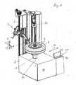
- the apparatus shown in Figure 1includes a tire changing device 7 provided with tire changer tools including mounting/demounting tools 5 and 6 and debeading tools (one debeading tool 44 is shown) which are supported movably on a pillar which is a part of a machine frame 2.
- the movements of the tire changer tools 5, 6 and 44are controlled in a known manner during the assembling and disassembling of a tire 8 onto or from a wheel rim 9.
- the tire changer tools 5, 6 and 44can be controlled to perform substantially movements perpendicularly and parallel with respect to a shaft axis 25, as will be explained below in conjunction with Figure 11 .
- the tire/rim assemblyforms a vehicle wheel.
- the vehicle wheel or the wheel rim 9can be mounted on a spindle shaft 1 or can be dismounted from the spindle shaft 1.
- the spindle shaft 1is rotatably supported in a housing 11 which can be another part of the machine frame 2 or on a part of the machine frame placed within the housing 11.
- the spindle shaft 1is supported by spindle supporting means 10 within the housing 11. Appropriate spindle supporting means are shown in the Figures 2 to 6 which will be explained below.
- Unbalance measuring meanswhich include preferably force transducers 3, 4 ( Fig. 2 to 9 ) are arranged within the housing 11.
- the unbalance measuring meansare operatively connected to the spindle shaft 1 for detecting forces which are created by an unbalance of the vehicle wheel or of the wheel rim 9.
- the measuring directioni.e. the detecting sensitivity of the force transducers 3, 4 is different to or outside of a force acting range within which forces are generated from the tire changer tools 5, 6 and 44 working on the tire 8 during the tire assembling or disassembling process, as will be explained in detail in conjunction with the explanation of the embodiments illustrated in the Figures 2 to 9 .
- the measuring direction of the unbalance measuring meansis shown schematically by the arrow 12 and the force acting range of the tire changer tools is shown schematically by the arrows 13 in the Figures 1 and 11 .
- the angle between these directionscan be 80° to 100°, especially about 90°.
- the force range of the forces acting during the tire changing producecan include force directions within the angle range of 80° to 100° or larger range.
- the forces which are applied by the tire changer tools 5, 6 and 44can extend substantially parallel and perpendicularly with respect to the shaft axis 25, as shown by arrows 13.
- the schematic plan viewillustrates sectors I and III (force acting range) within which directions of forces acting during the tire changing procedure between the tire changing tools 5,6 and 44 and the tire 8 extend.
- the imbalance measuring direction (arrows 12)extends outside of said force acting range 13 and is positioned within the sectors II and IV,
- the apparatus of Figure 1may be equipped additionally with a panel 17 including display means 42 and a key set 41.
- An electric control device according to the block diagram of Figure 10can be provided within the panel housing or without the housing 11.
- the spindle supporting means 10can include spring elements in form of a pair of flat springs 14, 15 which supports the spindle shaft 1 in a vertical arrangement. That flat springs 14, 15 are arranged parallel to each other and with respect to the shaft axis 25.
- the lower horizontal ends of the vertically extending flat springs 14, 15are fixed to the machine frame 2 and the upper horizontal ends of the flat springs 14, 15 are fixed to a spindle bearing 18 which supports rotatably the spindle shaft 1.
- the spindle shaft 1is driven by an electric motor 16 which can be fixed to the spindle bearing 18.
- the electric motor 16can be driven in controlled manner for performing tire assembling and disassembling or for unbalance measurement, as recited before.
- One or two force transducers 3, 4are supported on the machine frame 2 for the detection of forces created by an unbalance of the tire/rim assembly 8, 9 or of the wheel rim 9.
- the measuring direction (arrow 12) of the force transducer 3(4)extends perpendicularly with respect to the surfaces of the flat springs 14, 15. In the measuring direction of the transducer, the flat springs 14, 15 have elastic properties which allow a force measurement of the transducer 3(4).
- the flat springs 14, 15In a direction parallel to its surfaces, especially in a horizontal direction, the flat springs 14, 15 have rigid properties. Forces which are applied by the tire changer tools 5, 6 and 44 onto the tire 8 and/or the wheel rim 9 during the tire assembling and disassembling procedure are acting on the spindle shaft 1 and the spindle bearing 18 mainly parallel (arrow 13) to the surfaces of the flat springs 14, 15 and are guided via the flat springs 14, 15 into the machine frame 2 without influencing the force transducer 3(4).
- the measuring direction (arrows 12) of the transducer 3(4)is outside the force acting range (arrows 13) of the tire changer tools.
- the spindle supporting means 10contain a spindle bearing 18 which constitutes a rotary bearing for the spindle shaft 1 which is driven by the electric motor 16.
- the spindle bearing 18is supported by means of plate like spring elements 14, 15 on the machine frame 2.
- the spindle bearing and the spindle shaft 1are positioned vertically.
- the one vertical ends of the spring elements 14, 15are fixedly connected to the machine frame 2 and the other vertical ends of the spring elements 14, 15 are fixedly connected to the spindle bearing 18.
- the force transducers 3, 4are arranged between the machine frame 2 and the spindle bearing 18.
- the elastic properties of the spring elements 14, 15permit a force measurement of the force transducer 3, in a horizontal measuring direction (arrow 12a) perpendicular with respect to the shaft axis 25 and a force measurement of the force transducer 4 in a measuring direction substantially parallel to the shaft axis 25 (arrow 12b) during the unbalance measurement.
- the platelike spring elements 14, 15extend parallel to each other, and in the embodiment of Figure 4 , the platelike spring elements 14, 15 extend in alignment to each other.
- the tire changer tools 5, 6 and 44 of the tire changing device 7can be mounted on the machine frame 2 in the same manner as shown in Figure 1 .
- the force acting range of the tire changer tools 5, 6 and 44extends with respect to the spindle axis 25 in an angle range which does not include the measuring directions of the force transducers 3, 4.
- the flat springs 14, 15In a direction parallel to its surfaces, especially in a horizontal direction, the flat springs 14, 15 have rigid properties. Forces which are applied by the tire changer tool 5, 6 and 44 onto the tire 8 and/or the wheel rim 9 during the tire assembling and disassembling procedure are acting on the spindle shaft 1 and the spindle bearing 18 mainly parallel (arrows 13) to the surfaces of the platelike springs 14, 15 and are guided via the platelike springs 14, 15 into the machine frame 2 without influencing the force transducers 3, 4. The measuring directions (arrows 12a, 12b) of the transducers 3, 4 are outside the force acting range (arrows 13) of the tire changer tools 5, 6 and 44.
- the embodiments illustrated in the figures 1 to 8show vertical machine types with verticals arranged spindle shafts 1.
- the vehicle wheelmay be mounted on the spindle shaft 1 with the inner wheel side in upward position to facilitate the placement of balancing procedure. It is possible to realize the invention on a horizontal machine type with horizontal spindle shaft as well.
- the spindle supporting means 10have platelike or flat spring elements 14, 15 with which the spindle bearing 18 is supported on the machine frame 2. It is possible, however, to use spring elements in the shape of a rectangle frame, wherein respective opposite frame pieces are fixedly connected to the machine frame 2 and to the spindle bearing 18. Such spring elements are known from DE 37 16 210 C2 .
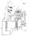
- the embodiment shown in the Figuresis 7 to 9 includes a measuring device for measuring forces, especially centrifugal forces which are generated by an imbalance of a rotor 9 and the tire changing device 7, which are mounted on the machine frame 2.
- the Figuresshow parts of the machine frame 2 or parts which are rigidly connected to the machine frame 2. Those parts are provided with the reference sign "2".
- the figure 8is a sectional view along the section line A-A in Figure 7 and Figure 9 is an explosive view showing the component of the measuring device.
- the measuring devicecomprises a first bearing 4 in form of a tube which establishes the spindle bearing 18 shaft 1 rotatably mounted about its shaft axis 25.
- the spindle shaft 1is supported by means of roller bearings 50 within the tube-shaped spindle bearing 18.
- the spindle shaft 1has in the region of its free end mounting means 48 which can be designed in known manner for attachment of the rotor, especially the vehicle wheel.
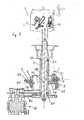
- a second bearing 52 for the spindle shaft 1has a rigid frame structure and supports pivotally the spindle bearing 18 about a pivot axis 51 ( Figures 8 ).
- the pivot axis 51is generated by spring means consisting of two torsion springs 53.
- the torsion springs 53are formed on mounting bolts 54 which are rigidly connected to the first spindle bearing 18 and to the second bearing 52.
- the mounting bolts 54extend diametrically from the surface of the tubular spindle bearing 2. The one ends (inner ends) of the mounting bolts 54 are connected to the spindle bearing 18 and the other ends (outer ends) of the mounting bolts 54 are connected to the second bearing 52.
- the torsion springs 53are established by reduced diameters of the mounting bolts 54 between the inner and the outer ends of the mounting bolts 54.
- the torsion springs 53are arranged with respect to the spindle shaft 1 such that the shaft axis 25 extends in the middle between the torsion springs 53 and the pivot axis 51 intersects the shaft axis 25 in a perpendicular angle.
- the second bearing 52is supported on the machine frame 2 in a manner that a force measurement between the spindle shaft 1, particularly the second bearing and the machine frame 2 is possible.
- the second bearing 52 of the spindle shaft 1is supported preferably by means of spring means which have the configuration of plate springs 55.
- the plate springs 55are placed on both sides of the shaft 1 and extend parallel to each other and perpendicularly with respect to the shaft axis 8.
- the plate springs on the both sides of the spindle shaft 1have equal distance from the shaft axis 25.
- the both ends of the plate spring 55are rigidly, for instance by means of screw connections, connected to the frame structure of the second bearing 52.
- the plate springs 55are rigidly, for instance by means of screw connections, connected in the middle of the extensions to the machine frame 2 or to respective parts of the stationary frame.
- the specific arrangement of the spring means 53 and 55enables that the spindle shaft 1 can perform displacements in two degrees of freedom, namely a rotation about the pivot axis 51 and a translatory motion with respect to the machine frame 2.
- the directions of the two displacementsextend in one plane which passes through the shaft axis 25.
- the rotary and translatory displacements of the spindle shaft 1are measured by force sensors having measuring directions within the one plane in which extend the displacement directions of the spindle shaft 1.
- the force sensor transducer 4forces generated by unbalance of the rotating rotor 9 and acting about the pivot axis 12.
- the other force transducer 3measures forces generated by the unbalance of the rotating rotor and acting on the spindle shaft 1 and on the second bearing 52 in a direction intersecting the shaft axis 25.
- the force transducer 4is positioned and tensioned between the spindle bearing 18 and the second bearing 52.
- the measuring direction of the force transducer 4is inclined with a specific angle ⁇ with respect to a direction perpendicular to the shaft axis 25, wherein the angle ⁇ is determined in a range from 80° to 100°, preferably from 85° to 95°. In the illustrated embodiment, the angle ⁇ is determined to about 90°, namely, in the illustrated embodiment the measuring direction of the force transducer 4 extends parallel to the shaft axis 25.
- the rotary displacements of the spindle shaft 1are transmitted by a lever 46 which is rigidly fixed to the tubular spindle bearing 18.
- the rotary displacement of the spindle shaft 1is transmitted via the roller bearings 50 which are positioned at the ends of the spindle bearing 18 to the first bearing 2 and via the lever 46 onto the one end of the force transducer 4.
- the lever 46rotates about the pivot axis 51.
- the lever 46extends along the one plane in which the measuring directions of the force transducers 3, 4 lie and extend perpendicularly with respect to the shaft axis 25.
- the other end of the force transducer 4is rigidly supported on the second bearing 52 by means of a support plate 22 screwed with the second bearing 52.
- the force transducer 3is at its one end in force transmitting manner connected to a middle side portion 45 of the second bearing 52.
- the middle side portion 45extends parallel to the plate springs 55 on the same side of the second bearing 52.
- the other end of the force transducer 3is supported on a support bracket 57 which is rigidly connected, preferably by means of screw connections with the machine frame 2 or a respective part of the machine frame.
- the measuring direction of the force transducer 3is inclined by a specific angle ⁇ with respect to the shaft axis 25.
- the angle ⁇can be determined in a range from 60° to 120°, for example from 65° to 115°, especially 70° to 110°. In the illustrated embodiment, the angle ⁇ is determined to about 75°.
- a support member 49is rigidly connected to the spindle bearing 18.
- the support member 49supports the electric motor 16, and a belt drive 26 ( Fig.8 ) which transmits the motor torque onto the spindle shaft 1.
- the measuring directions of the force transducers 3, 4extends substantially in a plane which goes through the shaft axis 25 of the spindle shaft1.
- the tire changer tools 5, 6can be arranged in the apparatus as illustrated in Figure 1 and extends perpendicularly with respect to the drawing plane of the Figure 7 and parallel to the drawing plane of the Figure 7 and 8 .
- the force acting range of the tire changer toolsextends outside of the measuring directions of the force transducers 3, 4 and can have around the shaft axis 25 an angle of 80° to 100°, especially 90° with respect to the plane within which the measuring directions of the force transducers 3, 4 are placed.
- the drive means for driving the spindle shaft 1includes the electric motor 16 which can include an integrated gear transmission to provide the respective speed and torque for performing the unbalance measurement and the tire changing process, but the electric motor 16 can apply the torque to the spindle shaft via a separate gear transmission as well.
- the drive meanscan include the belt drive 26, as shown in the Figure 8 for transmitting the torque of the motor 16 to the spindle shaft 1.
- the power supplied to the electric motor 16can be controlled to provide the needed torques and speeds for performing the unbalance measurement and the tire changing procedure.
- FIG. 10A block diagram of an electric / electronical device for controlling the electric motor 16 and the movements of the tire changer tools 5, 6 and 44 is shown in Figure 10 .
- the control deviceincludes a control processing unit 40 which controls the electric current which is delivered to the electric motor 16 from a power source 43 in dependence of the operation which the apparatus of the Figure 1 should perform.
- the control processing unit 40controls the movement and the operation of the respective tire changer tool 5, 6 and 44 , wherein the needed power is delivered from the power source 43.
- the force transducers 3, 4delivers the measured force data to the control processing unit for the calculation of the balancing weights applied to the vehicle wheel (tire/rim assembly 8, 9).
- the respective operation of the apparatuscan be adjusted by means of the key set 41 connected to the control processing unit 40 and by the display means 42, which are connected as well to the control processing unit 40. The operation can be over-viewed and the results of the operations can be illustrated.
Landscapes
- Engineering & Computer Science (AREA)
- Mechanical Engineering (AREA)
- Physics & Mathematics (AREA)
- General Physics & Mathematics (AREA)
- Testing Of Balance (AREA)
Description
- The invention concerns an apparatus for servicing vehicle wheels including a wheel balancing device and a tire changing device.
- Such an apparatus is known from
US Pat. No. 5,385,045 . The known apparatus has a spindle shaft which is used to assemble and disassemble a tire by means of tire changer tools and to measure forces created by an unbalance of the vehicle wheel. The unbalance measuring means include force transducers which are operatively connected to the spindle shaft. The vehicle wheel is driven by hand or by an additional motor, for instance by a frictional motor. During the assembling of the tire to the wheel rim and the disassembling of the tire from the wheel rim, strong forces are applied to the tire and the wheel rim which are mounted on the spindle shaft. The transducers which measure the forces created by an unbalance of the vehicle wheel are operatively connected to the spindle shaft and therefore the forces applied during the assembling and disassembling of the tire can act onto the force transducers via the spindle shaft and influence the transducer sensitivity. - German laid
open document 10 2004 056 367 discloses a method and an apparatus for determining unbalances and non-uniformities of rotating bodies, like a vehicle wheel. The apparatus includes a shaft for rotatably accommodating the vehicle wheel. The shaft is supported by a carrier plate which is pivotable about an axis perpendicular to the axis of rotation of the shaft. Sensors are provided for detecting oscillation of the shaft and the supporting plate. On the basis of the counter-forces generated by said oscillation, imbalances and non-uniformities of the vehicle wheel may be determined. - It is an object of the invention to provide an apparatus for servicing vehicle wheels including a wheel balancing device and a tire changing device where the forces applied by the tire changer tools do not interfere with the function of the unbalance measuring means.
- The problem is solved by an apparatus comprising the features of claim 1. The appendant claims recite advantageous modifications of the invention.
- The invention provides an apparatus for servicing vehicle wheels including a wheel balancing device and a tire changing device. The apparatus comprises a spindle shaft which is rotatably supported on a machine frame. The spindle shaft is adapted for mounting and dismounting a tire/rim assembly or a wheel rim of a vehicle wheel on it or from it. Unbalance measuring means are operatively connected to the spindle shaft and the unbalance measuring means have an unbalance measuring direction in which forces created by an unbalance of the tire/rim assembly or by the wheel rim are detected.
- Tire changer tools are supported on the machine frame and adapted to assemble a tire onto a rim and to disassemble the tire from the rim, wherein the rim is mounted on the spindle shaft. Spindle supporting means support the spindle shaft on the machine frame with a rigid structure in a force acting range in which forces are created between the respective tire changer tool and the tire during the assembling or the disassembling of the tire onto the wheel rim or from the wheel rim. Tool supporting means support the tire changer tools on the machine frame within said force acting range which is arranged outside of said unbalance measuring direction.
- Drive means are designed to drive the spindle shaft within a range of rotational speed and with a torque adapted for assembling and disassembling the tire and for measuring the forces created by an unbalance of the tire/rim assembly or of the wheel rim as well.
- The invention provides an apparatus in which the sensitivity of the force transducers which measure the forces created by an unbalance are not influenced, because the force acting range of forces acting during the assembling and disassembling of the tire on the spindle shaft is outside of the spatial unbalance measuring area within which the force transducers are sensitive for the detection of unbalance forces which are considerably smaller than the forces applied by the tire changer tools. Furthermore, the invention provides drive means for the spindle shaft and control means for controlling the drive means to provide a low speed, for
instance 5 to 10, especially 7 rpm, and an appropriate torque, for instance 1500Nm, for the tire assembling and disassembling operation, and a higher speed, for instance 60 to 80 rpm, especially 70 rpm, for the unbalance measurement. The spatial unbalance measuring area can be the measuring direction of at least one force measuring transducer, a plane within which the measuring directions of at least two force transducers are placed, wherein the measuring direction are parallel or angular, especially perpendicular to each other, or a projection of such a plane in an equatorial plane of the tire/rim assembly or of the rim. - According to an embodiment of the invention, the spindle supporting means can include spring elements which are connected with its one ends to the machine frame and with its other ends to a spindle bearing in which the spindle shaft is rotatably supported.
- According to another embodiment, the spindle shaft is supported on the machine frame via the force transducers which measure the forces created by an unbalance of the tire/rim assembly or by the wheel rim.
- The unbalance measuring direction and the direction of forces created between the tire changer tool and the tire can extend along lines which cross the spindle shaft.
- The invention will be explained furthermore by the description of the embodiments which are shown in the drawings.
- Figure 1
- shows a general view of an inventive embodiment;
- Figures 2 to 9
- show different embodiments of spindle supporting means which can be used in the inventive apparatus, especially in the embodiment of
Figure 1 . - Figure 10
- shows a block diagram of the electric control circuit for controlling the electric motor of the embodiments, and the movement of the tire changer tools; and
- Figure 11
- shows in a schematic plan view the force acting range within the directions of forces created between the tire changer tools and the vehicle wheel extend and the imbalance measuring direction.
- The apparatus shown in
Figure 1 includes atire changing device 7 provided with tire changer tools including mounting/demounting tools 5 and 6 and debeading tools (onedebeading tool 44 is shown) which are supported movably on a pillar which is a part of amachine frame 2. The movements of thetire changer tools tire 8 onto or from awheel rim 9. Thetire changer tools shaft axis 25, as will be explained below in conjunction withFigure 11 . - The tire/rim assembly forms a vehicle wheel. The vehicle wheel or the
wheel rim 9 can be mounted on a spindle shaft 1 or can be dismounted from the spindle shaft 1. The spindle shaft 1 is rotatably supported in a housing 11 which can be another part of themachine frame 2 or on a part of the machine frame placed within the housing 11. The spindle shaft 1 is supported by spindle supporting means 10 within the housing 11. Appropriate spindle supporting means are shown in theFigures 2 to 6 which will be explained below. - Unbalance measuring means which include preferably
force transducers 3, 4 (Fig. 2 to 9 ) are arranged within the housing 11. The unbalance measuring means are operatively connected to the spindle shaft 1 for detecting forces which are created by an unbalance of the vehicle wheel or of thewheel rim 9. The measuring direction, i.e. the detecting sensitivity of theforce transducers tire changer tools tire 8 during the tire assembling or disassembling process, as will be explained in detail in conjunction with the explanation of the embodiments illustrated in theFigures 2 to 9 . - The measuring direction of the unbalance measuring means is shown schematically by the
arrow 12 and the force acting range of the tire changer tools is shown schematically by thearrows 13 in theFigures 1 and11 . The angle between these directions can be 80° to 100°, especially about 90°. The force range of the forces acting during the tire changing produce can include force directions within the angle range of 80° to 100° or larger range. The forces which are applied by thetire changer tools shaft axis 25, as shown byarrows 13. The schematic plan view illustrates sectors I and III (force acting range) within which directions of forces acting during the tire changing procedure between thetire changing tools tire 8 extend. The imbalance measuring direction (arrows 12) extends outside of saidforce acting range 13 and is positioned within the sectors II and IV, - The apparatus of
Figure 1 may be equipped additionally with a panel 17 including display means 42 and akey set 41. An electric control device according to the block diagram ofFigure 10 can be provided within the panel housing or without the housing 11. - In
Figure 2 , the spindle supporting means 10 can include spring elements in form of a pair offlat springs flat springs shaft axis 25. The lower horizontal ends of the vertically extendingflat springs machine frame 2 and the upper horizontal ends of theflat springs electric motor 16 which can be fixed to the spindle bearing 18. Theelectric motor 16 can be driven in controlled manner for performing tire assembling and disassembling or for unbalance measurement, as recited before. One or twoforce transducers machine frame 2 for the detection of forces created by an unbalance of the tire/rim assembly wheel rim 9. The measuring direction (arrow 12) of the force transducer 3(4) extends perpendicularly with respect to the surfaces of theflat springs flat springs - In a direction parallel to its surfaces, especially in a horizontal direction, the
flat springs tire changer tools tire 8 and/or thewheel rim 9 during the tire assembling and disassembling procedure are acting on the spindle shaft 1 and the spindle bearing 18 mainly parallel (arrow 13) to the surfaces of theflat springs flat springs machine frame 2 without influencing the force transducer 3(4). The measuring direction (arrows 12) of the transducer 3(4) is outside the force acting range (arrows 13) of the tire changer tools. - In the embodiments of the
Figure 3 and4 , the spindle supporting means 10 contain a spindle bearing 18 which constitutes a rotary bearing for the spindle shaft 1 which is driven by theelectric motor 16. Thespindle bearing 18 is supported by means of plate likespring elements machine frame 2. The spindle bearing and the spindle shaft 1 are positioned vertically. The one vertical ends of thespring elements machine frame 2 and the other vertical ends of thespring elements spindle bearing 18. Theforce transducers machine frame 2 and thespindle bearing 18. The elastic properties of thespring elements force transducer 3, in a horizontal measuring direction (arrow 12a) perpendicular with respect to theshaft axis 25 and a force measurement of theforce transducer 4 in a measuring direction substantially parallel to the shaft axis 25 (arrow 12b) during the unbalance measurement. In the embodiment ofFigure 3 , theplatelike spring elements Figure 4 , theplatelike spring elements - The
tire changer tools tire changing device 7 can be mounted on themachine frame 2 in the same manner as shown inFigure 1 . The force acting range of thetire changer tools spindle axis 25 in an angle range which does not include the measuring directions of theforce transducers arrows 13 illustrated schematically the force acting range of thetire changer tools - In a direction parallel to its surfaces, especially in a horizontal direction, the
flat springs tire changer tool tire 8 and/or thewheel rim 9 during the tire assembling and disassembling procedure are acting on the spindle shaft 1 and the spindle bearing 18 mainly parallel (arrows 13) to the surfaces of the platelike springs 14, 15 and are guided via the platelike springs 14, 15 into themachine frame 2 without influencing theforce transducers transducers tire changer tools - The embodiments illustrated in the
figures 1 to 8 show vertical machine types with verticals arranged spindle shafts 1. The vehicle wheel may be mounted on the spindle shaft 1 with the inner wheel side in upward position to facilitate the placement of balancing procedure. It is possible to realize the invention on a horizontal machine type with horizontal spindle shaft as well. - In the embodiments of the
Figures 2 to 6 , the spindle supporting means 10 have platelike orflat spring elements machine frame 2. It is possible, however, to use spring elements in the shape of a rectangle frame, wherein respective opposite frame pieces are fixedly connected to themachine frame 2 and to thespindle bearing 18. Such spring elements are known fromDE 37 16 210 C2 . - The embodiment shown in the Figures is 7 to 9 includes a measuring device for measuring forces, especially centrifugal forces which are generated by an imbalance of a
rotor 9 and thetire changing device 7, which are mounted on themachine frame 2. The Figures show parts of themachine frame 2 or parts which are rigidly connected to themachine frame 2. Those parts are provided with the reference sign "2". Thefigure 8 is a sectional view along the section line A-A inFigure 7 andFigure 9 is an explosive view showing the component of the measuring device. - The measuring device comprises a
first bearing 4 in form of a tube which establishes the spindle bearing 18 shaft 1 rotatably mounted about itsshaft axis 25. For this, the spindle shaft 1 is supported by means ofroller bearings 50 within the tube-shapedspindle bearing 18. The spindle shaft 1 has in the region of its free end mounting means 48 which can be designed in known manner for attachment of the rotor, especially the vehicle wheel. - A
second bearing 52 for the spindle shaft 1 has a rigid frame structure and supports pivotally the spindle bearing 18 about a pivot axis 51 (Figures 8 ). The pivot axis 51 is generated by spring means consisting of two torsion springs 53. The torsion springs 53 are formed on mountingbolts 54 which are rigidly connected to the first spindle bearing 18 and to thesecond bearing 52. The mountingbolts 54 extend diametrically from the surface of thetubular spindle bearing 2. The one ends (inner ends) of the mountingbolts 54 are connected to thespindle bearing 18 and the other ends (outer ends) of the mountingbolts 54 are connected to thesecond bearing 52. The torsion springs 53 are established by reduced diameters of the mountingbolts 54 between the inner and the outer ends of the mountingbolts 54. The torsion springs 53 are arranged with respect to the spindle shaft 1 such that theshaft axis 25 extends in the middle between the torsion springs 53 and the pivot axis 51 intersects theshaft axis 25 in a perpendicular angle. - The
second bearing 52 is supported on themachine frame 2 in a manner that a force measurement between the spindle shaft 1, particularly the second bearing and themachine frame 2 is possible. For this, thesecond bearing 52 of the spindle shaft 1 is supported preferably by means of spring means which have the configuration of plate springs 55. The plate springs 55 are placed on both sides of the shaft 1 and extend parallel to each other and perpendicularly with respect to theshaft axis 8. The plate springs on the both sides of the spindle shaft 1 have equal distance from theshaft axis 25. The both ends of theplate spring 55 are rigidly, for instance by means of screw connections, connected to the frame structure of thesecond bearing 52. The plate springs 55 are rigidly, for instance by means of screw connections, connected in the middle of the extensions to themachine frame 2 or to respective parts of the stationary frame. - The specific arrangement of the spring means 53 and 55 enables that the spindle shaft 1 can perform displacements in two degrees of freedom, namely a rotation about the pivot axis 51 and a translatory motion with respect to the
machine frame 2. The directions of the two displacements extend in one plane which passes through theshaft axis 25. - The rotary and translatory displacements of the spindle shaft 1 are measured by force sensors having measuring directions within the one plane in which extend the displacement directions of the spindle shaft 1. The
force sensor transducer 4 forces generated by unbalance of therotating rotor 9 and acting about thepivot axis 12. Theother force transducer 3 measures forces generated by the unbalance of the rotating rotor and acting on the spindle shaft 1 and on thesecond bearing 52 in a direction intersecting theshaft axis 25. - The
force transducer 4 is positioned and tensioned between thespindle bearing 18 and thesecond bearing 52. The measuring direction of theforce transducer 4 is inclined with a specific angle β with respect to a direction perpendicular to theshaft axis 25, wherein the angle β is determined in a range from 80° to 100°, preferably from 85° to 95°. In the illustrated embodiment, the angle β is determined to about 90°, namely, in the illustrated embodiment the measuring direction of theforce transducer 4 extends parallel to theshaft axis 25. The rotary displacements of the spindle shaft 1 are transmitted by alever 46 which is rigidly fixed to thetubular spindle bearing 18. The rotary displacement of the spindle shaft 1 is transmitted via theroller bearings 50 which are positioned at the ends of the spindle bearing 18 to thefirst bearing 2 and via thelever 46 onto the one end of theforce transducer 4. For this transmitting movement thelever 46 rotates about the pivot axis 51. Thelever 46 extends along the one plane in which the measuring directions of theforce transducers shaft axis 25. The other end of theforce transducer 4 is rigidly supported on thesecond bearing 52 by means of a support plate 22 screwed with thesecond bearing 52. - The
force transducer 3 is at its one end in force transmitting manner connected to amiddle side portion 45 of thesecond bearing 52. Themiddle side portion 45 extends parallel to the plate springs 55 on the same side of thesecond bearing 52. The other end of theforce transducer 3 is supported on a support bracket 57 which is rigidly connected, preferably by means of screw connections with themachine frame 2 or a respective part of the machine frame. The measuring direction of theforce transducer 3 is inclined by a specific angle α with respect to theshaft axis 25. The angle α can be determined in a range from 60° to 120°, for example from 65° to 115°, especially 70° to 110°. In the illustrated embodiment, the angle α is determined to about 75°. - A
support member 49 is rigidly connected to thespindle bearing 18. Thesupport member 49 supports theelectric motor 16, and a belt drive 26 (Fig.8 ) which transmits the motor torque onto the spindle shaft 1. - The measuring directions of the
force transducers shaft axis 25 of the spindle shaft1. - The
tire changer tools 5, 6 can be arranged in the apparatus as illustrated inFigure 1 and extends perpendicularly with respect to the drawing plane of theFigure 7 and parallel to the drawing plane of theFigure 7 and8 . The force acting range of the tire changer tools extends outside of the measuring directions of theforce transducers shaft axis 25 an angle of 80° to 100°, especially 90° with respect to the plane within which the measuring directions of theforce transducers - The drive means for driving the spindle shaft 1 includes the
electric motor 16 which can include an integrated gear transmission to provide the respective speed and torque for performing the unbalance measurement and the tire changing process, but theelectric motor 16 can apply the torque to the spindle shaft via a separate gear transmission as well. The drive means can include thebelt drive 26, as shown in theFigure 8 for transmitting the torque of themotor 16 to the spindle shaft 1. Furthermore, the power supplied to theelectric motor 16 can be controlled to provide the needed torques and speeds for performing the unbalance measurement and the tire changing procedure. - A block diagram of an electric / electronical device for controlling the
electric motor 16 and the movements of thetire changer tools Figure 10 . The control device includes acontrol processing unit 40 which controls the electric current which is delivered to theelectric motor 16 from apower source 43 in dependence of the operation which the apparatus of theFigure 1 should perform. During the tire changing process, the movement and the operation of the respectivetire changer tool control processing unit 40, wherein the needed power is delivered from thepower source 43. During the unbalance measurement, theforce transducers rim assembly 8, 9). The respective operation of the apparatus can be adjusted by means of the key set 41 connected to thecontrol processing unit 40 and by the display means 42, which are connected as well to thecontrol processing unit 40. The operation can be over-viewed and the results of the operations can be illustrated. - 1
- spindle shaft
- 2
- machine frame
- 3
- force transducer
- 4
- force transducer
- 5
- mounting/demounting
- 6
- mounting/demounting
- 7
- tire changing device
- 8
- tire
- 9
- wheel rim
- 10
- spindle supporting means
- 11
- housing
- 12
- unbalance measuring direction
- 13
- force acting range
- 14
- spring element
- 15
- spring element
- 16
- electric motor
- 17
- panel
- 18
- spindle bearing
- 19
- roller bearing
- 20
- roller bearing
- 21
- frame element
- 22
- frame element
- 23
- tensioning member
- 24
- tensioning member
- 25
- shaft axis
- 26
- belt drive
- 27
- intermediate frame
- 28
- support lever
- 29
- support lever
- 30, 31
- flexible end joints
- 32, 33
- flexible end joints
- 34.
- support lever
- 35.
- support lever
- 36, 37
- flexible end joints
- 38, 39
- flexible end joints
- 40
- central processing unit
- 41
- Key set
- 42
- display means
- 43
- power source
- 44
- debeading tool
- 45
- middle side portion
- 46
- lever
- 47
- support plate
- 48
- mounting means
- 49
- support member
- 50
- roller bearings
- 51
- pivot axis
- 52
- second bearing
- 53
- torsion spring
- 54
- mounting bolts
- 55
- plate springs
- 56
- support plate
- 57
- support bracket
Claims (11)
- Apparatus for servicing vehicle wheels including a wheel balancing device and a tire changing device, comprising:- a spindle shaft (1) rotatably supported on a machine frame (2),
wherein the spindle shaft (1) is adapted for mounting and dismounting a tire/rim assembly or a wheel rim of a vehicle wheel on it or from it;- unbalance measuring means (3, 4) operatively connected to the spindle shaft (1),
wherein the unbalance measuring means (3, 4) have at least one unbalance measuring direction (12, 12a, 12b) in which forces created by an unbalance of the tire/rim assembly (8, 9) or by the wheel rim (9) are detected;- tire changer tools (5, 6 and 44) supported on the machine frame (2) and arranged to assemble a tire onto a rim and to disassemble the tire from the rim, wherein the rim is mounted on the spindle shaft (1);- drive means designed to drive the spindle shaft (1) within a range of rotational speed and torque adapted for assembling and disassembling the tire or for measuring forces created by an unbalance of the tire/rim assembly or of the wheel rim;
characterized by- spindle supporting means (10) supporting the spindle shaft (1) on the machine frame (2) and having rigid properties in a force acting range (13), within which forces are created between the respective tire changer tools (5, 6, 44) and the tire during the assembling or the disassembling of the tire onto the wheel rim or from the wheel rim, and elastic properties in the at least one unbalance measuring direction (12, 12a, 12b);- tool supporting means (7) support the tire changer tools (5, 6, 44) on the machine frame (2) within said force acting range (13) which is arranged outside of a spatial unbalance measuring area within which the measuring directions (12, 12a, 12b) of the unbalance measuring means (3, 4) extend. - The apparatus according to claim 1, wherein the unbalance measuring directions (12a, 12b) extend within a angle of 80° to 100° with respect to the force acting range (13) of the tire changer tools (5, 6 and 44).
- The apparatus according to claim 1 or 2, wherein a longitudinal axis (25) of the spindle shaft (1) extends within said spatial unbalance measuring area.
- The apparatus according to one of the claims 1 to 3, wherein the spindle supporting means (10) include spring elements (14, 15; 53, 55) connected with their one ends to the machine frame (2) and with their other ends with a spindle bearing (18) in which the spindle shaft (1) is placed rotatably.
- The apparatus according to one of the claims 1 to 4, wherein the spindle supporting means (10) include spring elements (14, 15) and the directions (13) of the forces applied by the tire changer tools (5, 6, 44) extend substantially parallel to the surfaces of the spring elements (14, 15).
- The apparatus according to one of the claims 1 to 5, wherein the unbalance measuring means (3, 4) has at least one unbalance measuring direction (12a) intersecting the shaft axis (25).
- The apparatus according to one of the claims 1 to 3, wherein the unbalance measuring means (3, 4) has unbalance measuring directions (12a, 12b) lying on the same plane.
- The apparatus according to claim 7, wherein the unbalance measuring directions (12a, 12b) extend substantially parallel or substantially perpendicular to each other.
- The apparatus according to one of the claims 1 to 8, wherein the spindle bearing (18) is pivotally supported about a pivot axis (51) extending perpendicular with respect to the shaft axis (25) on a second bearing (52) which is supported via springs (55) on the machine frame (2), and wherein one force transducer (3) is placed between the second bearing (52) and the machine frame (2) and another force transducer (4) is placed between the spindle bearing (18) and the second bearing (52).
- The apparatus according to any one of the claims 1 to 8, wherein the surfaces of the flat spring elements (14, 15) extend parallel to each other and parallel to the shaft axis (25).
- Apparatus according to any one of the claims 1 to 6, wherein the spindle shaft (1) is supported on the machine frame (2) via force transducers (3, 4) which measure the forces created by an unbalance of the tire/rim assembly (8, 9) or by the wheel rim (9).
Priority Applications (3)
| Application Number | Priority Date | Filing Date | Title |
|---|---|---|---|
| EP12185892.2AEP2711206B1 (en) | 2012-09-25 | 2012-09-25 | Apparatus for servicing vehicle wheels |
| RU2013141796ARU2615839C2 (en) | 2012-09-25 | 2013-09-11 | Installation for vehicle wheels service |
| CN201310447260.9ACN103660814B (en) | 2012-09-25 | 2013-09-24 | For keeping in repair the equipment of wheel |
Applications Claiming Priority (1)
| Application Number | Priority Date | Filing Date | Title |
|---|---|---|---|
| EP12185892.2AEP2711206B1 (en) | 2012-09-25 | 2012-09-25 | Apparatus for servicing vehicle wheels |
Publications (2)
| Publication Number | Publication Date |
|---|---|
| EP2711206A1 EP2711206A1 (en) | 2014-03-26 |
| EP2711206B1true EP2711206B1 (en) | 2015-08-26 |
Family
ID=46970080
Family Applications (1)
| Application Number | Title | Priority Date | Filing Date |
|---|---|---|---|
| EP12185892.2AActiveEP2711206B1 (en) | 2012-09-25 | 2012-09-25 | Apparatus for servicing vehicle wheels |
Country Status (3)
| Country | Link |
|---|---|
| EP (1) | EP2711206B1 (en) |
| CN (1) | CN103660814B (en) |
| RU (1) | RU2615839C2 (en) |
Cited By (2)
| Publication number | Priority date | Publication date | Assignee | Title |
|---|---|---|---|---|
| CN108466527A (en)* | 2017-02-23 | 2018-08-31 | 长沙智通知识产权服务有限公司 | A kind of low-loss tire press-loading device |
| EP3677455A1 (en) | 2018-12-18 | 2020-07-08 | NEXION S.p.A. | Vehicle wheel service apparatus |
Families Citing this family (8)
| Publication number | Priority date | Publication date | Assignee | Title |
|---|---|---|---|---|
| EP3160777B1 (en)* | 2014-06-25 | 2018-08-15 | M&B Engineering S.r.l. | Tire-changing machine for motor vehicles |
| CN104527345A (en)* | 2014-12-19 | 2015-04-22 | 上海巴兰仕汽车检测设备股份有限公司 | Integrated tire dismounting and balancing machine |
| IT201600111370A1 (en)* | 2016-11-04 | 2018-05-04 | Nexion Spa | APPARATUS FOR MOUNTING AND DISASSEMBLING A TIRE |
| CN106525338B (en)* | 2016-12-28 | 2019-03-12 | 营口大力汽保设备科技有限公司 | Vehicle-mounted balancing machine |
| WO2019210390A1 (en)* | 2018-05-03 | 2019-11-07 | Hongcai Wen | Apparatus and methods for robotically servicing a vehicle wheel |
| CN109304995B (en)* | 2018-10-23 | 2022-02-01 | 章志鹏 | Special tire stripping off device of storage battery car |
| IT201900002183A1 (en)* | 2019-02-14 | 2020-08-14 | Imt Intermato S P A | SYSTEM AND METHOD FOR BALANCING RAILWAY WHEELS |
| CN118209252B (en)* | 2024-03-15 | 2025-01-24 | 机科发展科技股份有限公司 | A wheel hub dynamic balancing measuring device and wheel hub measuring equipment |
Family Cites Families (7)
| Publication number | Priority date | Publication date | Assignee | Title |
|---|---|---|---|---|
| DE3716210A1 (en)* | 1987-05-14 | 1988-12-08 | Hofmann Gmbh & Co Kg Maschinen | DEVICE FOR VIBRATING SUPPORT FOR A ROTOR BEARING FOR A ROTOR TO BE BALANCED IN A BALANCING MACHINE |
| US5385045A (en) | 1992-07-15 | 1995-01-31 | Fmc Corporation | Tire changing and balancing machine |
| DE4342667C2 (en)* | 1993-12-14 | 1996-04-11 | Hofmann Maschinenbau Gmbh | Device for the oscillatory support of a rotor bearing for a rotor to be balanced in a balancing machine |
| DE102004056367B4 (en)* | 2004-11-22 | 2015-07-02 | Schenck Rotec Gmbh | Bearing device for a device for determining the imbalance and the nonuniformity of a rotating body |
| CN101424578B (en)* | 2007-11-02 | 2011-10-19 | 焦建飞 | Tyre dismounting and balancing integration machine |
| CN101474948B (en)* | 2008-01-03 | 2013-09-11 | 焦建飞 | Tyre-disassembling and balancing integrated machin |
| CN101612868B (en)* | 2009-07-27 | 2011-04-20 | 科星(中山)汽车设备有限公司 | Tire dismounting and balancing test combined machine and manufacturing and using methods |
- 2012
- 2012-09-25EPEP12185892.2Apatent/EP2711206B1/enactiveActive
- 2013
- 2013-09-11RURU2013141796Apatent/RU2615839C2/enactive
- 2013-09-24CNCN201310447260.9Apatent/CN103660814B/enactiveActive
Cited By (2)
| Publication number | Priority date | Publication date | Assignee | Title |
|---|---|---|---|---|
| CN108466527A (en)* | 2017-02-23 | 2018-08-31 | 长沙智通知识产权服务有限公司 | A kind of low-loss tire press-loading device |
| EP3677455A1 (en) | 2018-12-18 | 2020-07-08 | NEXION S.p.A. | Vehicle wheel service apparatus |
Also Published As
| Publication number | Publication date |
|---|---|
| CN103660814A (en) | 2014-03-26 |
| EP2711206A1 (en) | 2014-03-26 |
| RU2013141796A (en) | 2015-03-20 |
| RU2615839C2 (en) | 2017-04-11 |
| CN103660814B (en) | 2017-03-01 |
Similar Documents
| Publication | Publication Date | Title |
|---|---|---|
| EP2711206B1 (en) | Apparatus for servicing vehicle wheels | |
| JP6937363B2 (en) | A method for calculating ground compression rollers having a sensor device on the rollers and ground rigidity | |
| US8899296B2 (en) | Apparatus for servicing vehicle wheels | |
| EP2503313B1 (en) | Device for measuring forces generated by an unbalance | |
| EP1257800B1 (en) | Spindle assembly for a tire or wheel testing machine | |
| US6360593B1 (en) | Method and apparatus for reducing vibrations transmitted to a vehicle from a wheel unit | |
| JP2014182128A (en) | Dynamic balance detecting device | |
| KR940007379Y1 (en) | Tire endurance testing machine | |
| EP2151678A2 (en) | A method of considering the dynamic behaviour of a movable member of a machine for performing a wheel fatigue test | |
| EP2141474B1 (en) | Apparatus for measuring forces which are produced by an unbalance of a rotary member | |
| US8899111B2 (en) | Device for measuring forces generated by an unbalance | |
| CN106370348B (en) | Measuring unit and measuring assembly for measuring an unbalance force | |
| JP5117079B2 (en) | Vehicle test equipment | |
| US8347712B2 (en) | Balancing machine for rotating bodies, particularly for motor vehicle wheels | |
| EP2604990A1 (en) | Method and system for determining and improving running characteristics of a pneumatic tyre of a vehicle wheel | |
| JPH06129953A (en) | Device for measuring stiffness of tire | |
| EP1406075B1 (en) | (Wheel ) Balancing machine with coplanar leaf springs | |
| JP4525415B2 (en) | Engine balance measuring apparatus and method | |
| JP4821156B2 (en) | Connecting device for engine balance measurement | |
| JP4022455B2 (en) | Balance testing machine | |
| KR102215291B1 (en) | Portable runout measuring device | |
| JP5432829B2 (en) | Wheel balance measuring device | |
| RU2155944C1 (en) | Method of and device for wheel balancing | |
| RU1795336C (en) | Pneumatic tyre dynamic test stand | |
| CN120721295A (en) | Balancing machine with load measurement wheel assembly radial non-uniformity and diagnosis function |
Legal Events
| Date | Code | Title | Description |
|---|---|---|---|
| PUAI | Public reference made under article 153(3) epc to a published international application that has entered the european phase | Free format text:ORIGINAL CODE: 0009012 | |
| AK | Designated contracting states | Kind code of ref document:A1 Designated state(s):AL AT BE BG CH CY CZ DE DK EE ES FI FR GB GR HR HU IE IS IT LI LT LU LV MC MK MT NL NO PL PT RO RS SE SI SK SM TR | |
| AX | Request for extension of the european patent | Extension state:BA ME | |
| 17P | Request for examination filed | Effective date:20140926 | |
| RBV | Designated contracting states (corrected) | Designated state(s):AL AT BE BG CH CY CZ DE DK EE ES FI FR GB GR HR HU IE IS IT LI LT LU LV MC MK MT NL NO PL PT RO RS SE SI SK SM TR | |
| GRAP | Despatch of communication of intention to grant a patent | Free format text:ORIGINAL CODE: EPIDOSNIGR1 | |
| RIC1 | Information provided on ipc code assigned before grant | Ipc:G01M 1/04 20060101ALI20150202BHEP Ipc:G01M 1/28 20060101ALI20150202BHEP Ipc:F16C 27/00 20060101ALI20150202BHEP Ipc:B60C 25/05 20060101ALI20150202BHEP Ipc:B60C 25/138 20060101AFI20150202BHEP | |
| INTG | Intention to grant announced | Effective date:20150303 | |
| GRAS | Grant fee paid | Free format text:ORIGINAL CODE: EPIDOSNIGR3 | |
| GRAA | (expected) grant | Free format text:ORIGINAL CODE: 0009210 | |
| AK | Designated contracting states | Kind code of ref document:B1 Designated state(s):AL AT BE BG CH CY CZ DE DK EE ES FI FR GB GR HR HU IE IS IT LI LT LU LV MC MK MT NL NO PL PT RO RS SE SI SK SM TR | |
| REG | Reference to a national code | Ref country code:GB Ref legal event code:FG4D | |
| RIN1 | Information on inventor provided before grant (corrected) | Inventor name:SOTGIU, PAOLO | |
| REG | Reference to a national code | Ref country code:CH Ref legal event code:EP | |
| REG | Reference to a national code | Ref country code:AT Ref legal event code:REF Ref document number:744957 Country of ref document:AT Kind code of ref document:T Effective date:20150915 | |
| REG | Reference to a national code | Ref country code:IE Ref legal event code:FG4D | |
| REG | Reference to a national code | Ref country code:FR Ref legal event code:PLFP Year of fee payment:4 | |
| REG | Reference to a national code | Ref country code:DE Ref legal event code:R096 Ref document number:602012009942 Country of ref document:DE | |
| REG | Reference to a national code | Ref country code:AT Ref legal event code:MK05 Ref document number:744957 Country of ref document:AT Kind code of ref document:T Effective date:20150826 | |
| REG | Reference to a national code | Ref country code:LT Ref legal event code:MG4D | |
| PG25 | Lapsed in a contracting state [announced via postgrant information from national office to epo] | Ref country code:LV Free format text:LAPSE BECAUSE OF FAILURE TO SUBMIT A TRANSLATION OF THE DESCRIPTION OR TO PAY THE FEE WITHIN THE PRESCRIBED TIME-LIMIT Effective date:20150826 Ref country code:GR Free format text:LAPSE BECAUSE OF FAILURE TO SUBMIT A TRANSLATION OF THE DESCRIPTION OR TO PAY THE FEE WITHIN THE PRESCRIBED TIME-LIMIT Effective date:20151127 Ref country code:NO Free format text:LAPSE BECAUSE OF FAILURE TO SUBMIT A TRANSLATION OF THE DESCRIPTION OR TO PAY THE FEE WITHIN THE PRESCRIBED TIME-LIMIT Effective date:20151126 Ref country code:FI Free format text:LAPSE BECAUSE OF FAILURE TO SUBMIT A TRANSLATION OF THE DESCRIPTION OR TO PAY THE FEE WITHIN THE PRESCRIBED TIME-LIMIT Effective date:20150826 Ref country code:LT Free format text:LAPSE BECAUSE OF FAILURE TO SUBMIT A TRANSLATION OF THE DESCRIPTION OR TO PAY THE FEE WITHIN THE PRESCRIBED TIME-LIMIT Effective date:20150826 | |
| REG | Reference to a national code | Ref country code:NL Ref legal event code:MP Effective date:20150826 | |
| PG25 | Lapsed in a contracting state [announced via postgrant information from national office to epo] | Ref country code:PT Free format text:LAPSE BECAUSE OF FAILURE TO SUBMIT A TRANSLATION OF THE DESCRIPTION OR TO PAY THE FEE WITHIN THE PRESCRIBED TIME-LIMIT Effective date:20151228 Ref country code:AT Free format text:LAPSE BECAUSE OF FAILURE TO SUBMIT A TRANSLATION OF THE DESCRIPTION OR TO PAY THE FEE WITHIN THE PRESCRIBED TIME-LIMIT Effective date:20150826 Ref country code:SE Free format text:LAPSE BECAUSE OF FAILURE TO SUBMIT A TRANSLATION OF THE DESCRIPTION OR TO PAY THE FEE WITHIN THE PRESCRIBED TIME-LIMIT Effective date:20150826 Ref country code:RS Free format text:LAPSE BECAUSE OF FAILURE TO SUBMIT A TRANSLATION OF THE DESCRIPTION OR TO PAY THE FEE WITHIN THE PRESCRIBED TIME-LIMIT Effective date:20150826 Ref country code:IS Free format text:LAPSE BECAUSE OF FAILURE TO SUBMIT A TRANSLATION OF THE DESCRIPTION OR TO PAY THE FEE WITHIN THE PRESCRIBED TIME-LIMIT Effective date:20151226 Ref country code:HR Free format text:LAPSE BECAUSE OF FAILURE TO SUBMIT A TRANSLATION OF THE DESCRIPTION OR TO PAY THE FEE WITHIN THE PRESCRIBED TIME-LIMIT Effective date:20150826 Ref country code:ES Free format text:LAPSE BECAUSE OF FAILURE TO SUBMIT A TRANSLATION OF THE DESCRIPTION OR TO PAY THE FEE WITHIN THE PRESCRIBED TIME-LIMIT Effective date:20150826 Ref country code:PL Free format text:LAPSE BECAUSE OF FAILURE TO SUBMIT A TRANSLATION OF THE DESCRIPTION OR TO PAY THE FEE WITHIN THE PRESCRIBED TIME-LIMIT Effective date:20150826 | |
| PG25 | Lapsed in a contracting state [announced via postgrant information from national office to epo] | Ref country code:NL Free format text:LAPSE BECAUSE OF FAILURE TO SUBMIT A TRANSLATION OF THE DESCRIPTION OR TO PAY THE FEE WITHIN THE PRESCRIBED TIME-LIMIT Effective date:20150826 | |
| PG25 | Lapsed in a contracting state [announced via postgrant information from national office to epo] | Ref country code:SK Free format text:LAPSE BECAUSE OF FAILURE TO SUBMIT A TRANSLATION OF THE DESCRIPTION OR TO PAY THE FEE WITHIN THE PRESCRIBED TIME-LIMIT Effective date:20150826 Ref country code:CZ Free format text:LAPSE BECAUSE OF FAILURE TO SUBMIT A TRANSLATION OF THE DESCRIPTION OR TO PAY THE FEE WITHIN THE PRESCRIBED TIME-LIMIT Effective date:20150826 Ref country code:DK Free format text:LAPSE BECAUSE OF FAILURE TO SUBMIT A TRANSLATION OF THE DESCRIPTION OR TO PAY THE FEE WITHIN THE PRESCRIBED TIME-LIMIT Effective date:20150826 Ref country code:EE Free format text:LAPSE BECAUSE OF FAILURE TO SUBMIT A TRANSLATION OF THE DESCRIPTION OR TO PAY THE FEE WITHIN THE PRESCRIBED TIME-LIMIT Effective date:20150826 | |
| REG | Reference to a national code | Ref country code:CH Ref legal event code:PL | |
| REG | Reference to a national code | Ref country code:DE Ref legal event code:R097 Ref document number:602012009942 Country of ref document:DE | |
| PG25 | Lapsed in a contracting state [announced via postgrant information from national office to epo] | Ref country code:MC Free format text:LAPSE BECAUSE OF FAILURE TO SUBMIT A TRANSLATION OF THE DESCRIPTION OR TO PAY THE FEE WITHIN THE PRESCRIBED TIME-LIMIT Effective date:20150826 Ref country code:RO Free format text:LAPSE BECAUSE OF FAILURE TO SUBMIT A TRANSLATION OF THE DESCRIPTION OR TO PAY THE FEE WITHIN THE PRESCRIBED TIME-LIMIT Effective date:20150826 | |
| REG | Reference to a national code | Ref country code:IE Ref legal event code:MM4A | |
| PLBE | No opposition filed within time limit | Free format text:ORIGINAL CODE: 0009261 | |
| STAA | Information on the status of an ep patent application or granted ep patent | Free format text:STATUS: NO OPPOSITION FILED WITHIN TIME LIMIT | |
| PG25 | Lapsed in a contracting state [announced via postgrant information from national office to epo] | Ref country code:LI Free format text:LAPSE BECAUSE OF NON-PAYMENT OF DUE FEES Effective date:20150930 Ref country code:CH Free format text:LAPSE BECAUSE OF NON-PAYMENT OF DUE FEES Effective date:20150930 Ref country code:IE Free format text:LAPSE BECAUSE OF NON-PAYMENT OF DUE FEES Effective date:20150925 | |
| 26N | No opposition filed | Effective date:20160530 | |
| PG25 | Lapsed in a contracting state [announced via postgrant information from national office to epo] | Ref country code:SI Free format text:LAPSE BECAUSE OF FAILURE TO SUBMIT A TRANSLATION OF THE DESCRIPTION OR TO PAY THE FEE WITHIN THE PRESCRIBED TIME-LIMIT Effective date:20150826 | |
| REG | Reference to a national code | Ref country code:FR Ref legal event code:PLFP Year of fee payment:5 | |
| PG25 | Lapsed in a contracting state [announced via postgrant information from national office to epo] | Ref country code:BE Free format text:LAPSE BECAUSE OF FAILURE TO SUBMIT A TRANSLATION OF THE DESCRIPTION OR TO PAY THE FEE WITHIN THE PRESCRIBED TIME-LIMIT Effective date:20150826 | |
| PG25 | Lapsed in a contracting state [announced via postgrant information from national office to epo] | Ref country code:MT Free format text:LAPSE BECAUSE OF FAILURE TO SUBMIT A TRANSLATION OF THE DESCRIPTION OR TO PAY THE FEE WITHIN THE PRESCRIBED TIME-LIMIT Effective date:20150826 | |
| PG25 | Lapsed in a contracting state [announced via postgrant information from national office to epo] | Ref country code:HU Free format text:LAPSE BECAUSE OF FAILURE TO SUBMIT A TRANSLATION OF THE DESCRIPTION OR TO PAY THE FEE WITHIN THE PRESCRIBED TIME-LIMIT; INVALID AB INITIO Effective date:20120925 Ref country code:BG Free format text:LAPSE BECAUSE OF FAILURE TO SUBMIT A TRANSLATION OF THE DESCRIPTION OR TO PAY THE FEE WITHIN THE PRESCRIBED TIME-LIMIT Effective date:20150826 Ref country code:SM Free format text:LAPSE BECAUSE OF FAILURE TO SUBMIT A TRANSLATION OF THE DESCRIPTION OR TO PAY THE FEE WITHIN THE PRESCRIBED TIME-LIMIT Effective date:20150826 | |
| PG25 | Lapsed in a contracting state [announced via postgrant information from national office to epo] | Ref country code:CY Free format text:LAPSE BECAUSE OF FAILURE TO SUBMIT A TRANSLATION OF THE DESCRIPTION OR TO PAY THE FEE WITHIN THE PRESCRIBED TIME-LIMIT Effective date:20150826 | |
| REG | Reference to a national code | Ref country code:FR Ref legal event code:PLFP Year of fee payment:6 | |
| PGFP | Annual fee paid to national office [announced via postgrant information from national office to epo] | Ref country code:GB Payment date:20170925 Year of fee payment:6 Ref country code:FR Payment date:20170925 Year of fee payment:6 | |
| PG25 | Lapsed in a contracting state [announced via postgrant information from national office to epo] | Ref country code:LU Free format text:LAPSE BECAUSE OF NON-PAYMENT OF DUE FEES Effective date:20150925 | |
| PG25 | Lapsed in a contracting state [announced via postgrant information from national office to epo] | Ref country code:MK Free format text:LAPSE BECAUSE OF FAILURE TO SUBMIT A TRANSLATION OF THE DESCRIPTION OR TO PAY THE FEE WITHIN THE PRESCRIBED TIME-LIMIT Effective date:20150826 Ref country code:TR Free format text:LAPSE BECAUSE OF FAILURE TO SUBMIT A TRANSLATION OF THE DESCRIPTION OR TO PAY THE FEE WITHIN THE PRESCRIBED TIME-LIMIT Effective date:20150826 | |
| PG25 | Lapsed in a contracting state [announced via postgrant information from national office to epo] | Ref country code:AL Free format text:LAPSE BECAUSE OF FAILURE TO SUBMIT A TRANSLATION OF THE DESCRIPTION OR TO PAY THE FEE WITHIN THE PRESCRIBED TIME-LIMIT Effective date:20150826 | |
| GBPC | Gb: european patent ceased through non-payment of renewal fee | Effective date:20180925 | |
| PG25 | Lapsed in a contracting state [announced via postgrant information from national office to epo] | Ref country code:FR Free format text:LAPSE BECAUSE OF NON-PAYMENT OF DUE FEES Effective date:20180930 | |
| PG25 | Lapsed in a contracting state [announced via postgrant information from national office to epo] | Ref country code:GB Free format text:LAPSE BECAUSE OF NON-PAYMENT OF DUE FEES Effective date:20180925 | |
| P01 | Opt-out of the competence of the unified patent court (upc) registered | Effective date:20230517 | |
| PGFP | Annual fee paid to national office [announced via postgrant information from national office to epo] | Ref country code:DE Payment date:20240927 Year of fee payment:13 | |
| PGFP | Annual fee paid to national office [announced via postgrant information from national office to epo] | Ref country code:IT Payment date:20240919 Year of fee payment:13 |