EP2710979B1 - Modular knee prosthesis system - Google Patents
Modular knee prosthesis systemDownload PDFInfo
- Publication number
- EP2710979B1 EP2710979B1EP13185424.2AEP13185424AEP2710979B1EP 2710979 B1EP2710979 B1EP 2710979B1EP 13185424 AEP13185424 AEP 13185424AEP 2710979 B1EP2710979 B1EP 2710979B1
- Authority
- EP
- European Patent Office
- Prior art keywords
- distal
- stem
- femoral component
- distal femoral
- proximal
- Prior art date
- Legal status (The legal status is an assumption and is not a legal conclusion. Google has not performed a legal analysis and makes no representation as to the accuracy of the status listed.)
- Active
Links
- 210000003127kneeAnatomy0.000titleclaimsdescription46
- 239000007943implantSubstances0.000description23
- 210000000988bone and boneAnatomy0.000description17
- 210000000689upper legAnatomy0.000description10
- 230000004323axial lengthEffects0.000description9
- 238000003786synthesis reactionMethods0.000description9
- 210000000629knee jointAnatomy0.000description5
- 230000007547defectEffects0.000description4
- 208000014674injuryDiseases0.000description4
- 238000001356surgical procedureMethods0.000description4
- 230000008733traumaEffects0.000description4
- RTAQQCXQSZGOHL-UHFFFAOYSA-NTitaniumChemical compound[Ti]RTAQQCXQSZGOHL-UHFFFAOYSA-N0.000description3
- 210000003484anatomyAnatomy0.000description3
- 201000010099diseaseDiseases0.000description3
- 208000037265diseases, disorders, signs and symptomsDiseases0.000description3
- 239000006260foamSubstances0.000description3
- 210000004417patellaAnatomy0.000description3
- 210000002303tibiaAnatomy0.000description3
- 239000010936titaniumSubstances0.000description3
- 229910052719titaniumInorganic materials0.000description3
- 229920000642polymerPolymers0.000description2
- 210000002435tendonAnatomy0.000description2
- 206010058029ArthrofibrosisDiseases0.000description1
- 206010065687Bone lossDiseases0.000description1
- 229910000684Cobalt-chromeInorganic materials0.000description1
- 208000003076OsteolysisDiseases0.000description1
- 229910001069Ti alloyInorganic materials0.000description1
- 239000004699Ultra-high molecular weight polyethyleneSubstances0.000description1
- WAIPAZQMEIHHTJ-UHFFFAOYSA-N[Cr].[Co]Chemical compound[Cr].[Co]WAIPAZQMEIHHTJ-UHFFFAOYSA-N0.000description1
- 230000002411adverseEffects0.000description1
- 238000011882arthroplastyMethods0.000description1
- 230000000712assemblyEffects0.000description1
- 238000000429assemblyMethods0.000description1
- 239000010952cobalt-chromeSubstances0.000description1
- 210000004439collateral ligamentAnatomy0.000description1
- 230000000295complement effectEffects0.000description1
- 210000002414legAnatomy0.000description1
- 208000029791lytic metastatic bone lesionDiseases0.000description1
- 230000013011matingEffects0.000description1
- 229910052751metalInorganic materials0.000description1
- 239000002184metalSubstances0.000description1
- 150000002739metalsChemical class0.000description1
- 238000000034methodMethods0.000description1
- 210000003205muscleAnatomy0.000description1
- 238000005457optimizationMethods0.000description1
- 238000002360preparation methodMethods0.000description1
- 210000000824sesamoid boneAnatomy0.000description1
- 239000007787solidSubstances0.000description1
- 239000010421standard materialSubstances0.000description1
- 210000001519tissueAnatomy0.000description1
- 238000011883total knee arthroplastyMethods0.000description1
- 229920000785ultra high molecular weight polyethylenePolymers0.000description1
Images


Classifications
- A—HUMAN NECESSITIES
- A61—MEDICAL OR VETERINARY SCIENCE; HYGIENE
- A61F—FILTERS IMPLANTABLE INTO BLOOD VESSELS; PROSTHESES; DEVICES PROVIDING PATENCY TO, OR PREVENTING COLLAPSING OF, TUBULAR STRUCTURES OF THE BODY, e.g. STENTS; ORTHOPAEDIC, NURSING OR CONTRACEPTIVE DEVICES; FOMENTATION; TREATMENT OR PROTECTION OF EYES OR EARS; BANDAGES, DRESSINGS OR ABSORBENT PADS; FIRST-AID KITS
- A61F2/00—Filters implantable into blood vessels; Prostheses, i.e. artificial substitutes or replacements for parts of the body; Appliances for connecting them with the body; Devices providing patency to, or preventing collapsing of, tubular structures of the body, e.g. stents
- A61F2/02—Prostheses implantable into the body
- A61F2/30—Joints
- A61F2/38—Joints for elbows or knees
- A61F2/3886—Joints for elbows or knees for stabilising knees against anterior or lateral dislocations
- A—HUMAN NECESSITIES
- A61—MEDICAL OR VETERINARY SCIENCE; HYGIENE
- A61F—FILTERS IMPLANTABLE INTO BLOOD VESSELS; PROSTHESES; DEVICES PROVIDING PATENCY TO, OR PREVENTING COLLAPSING OF, TUBULAR STRUCTURES OF THE BODY, e.g. STENTS; ORTHOPAEDIC, NURSING OR CONTRACEPTIVE DEVICES; FOMENTATION; TREATMENT OR PROTECTION OF EYES OR EARS; BANDAGES, DRESSINGS OR ABSORBENT PADS; FIRST-AID KITS
- A61F2/00—Filters implantable into blood vessels; Prostheses, i.e. artificial substitutes or replacements for parts of the body; Appliances for connecting them with the body; Devices providing patency to, or preventing collapsing of, tubular structures of the body, e.g. stents
- A61F2/02—Prostheses implantable into the body
- A61F2/30—Joints
- A61F2/30721—Accessories
- A61F2/30734—Modular inserts, sleeves or augments, e.g. placed on proximal part of stem for fixation purposes or wedges for bridging a bone defect
- A—HUMAN NECESSITIES
- A61—MEDICAL OR VETERINARY SCIENCE; HYGIENE
- A61F—FILTERS IMPLANTABLE INTO BLOOD VESSELS; PROSTHESES; DEVICES PROVIDING PATENCY TO, OR PREVENTING COLLAPSING OF, TUBULAR STRUCTURES OF THE BODY, e.g. STENTS; ORTHOPAEDIC, NURSING OR CONTRACEPTIVE DEVICES; FOMENTATION; TREATMENT OR PROTECTION OF EYES OR EARS; BANDAGES, DRESSINGS OR ABSORBENT PADS; FIRST-AID KITS
- A61F2/00—Filters implantable into blood vessels; Prostheses, i.e. artificial substitutes or replacements for parts of the body; Appliances for connecting them with the body; Devices providing patency to, or preventing collapsing of, tubular structures of the body, e.g. stents
- A61F2/02—Prostheses implantable into the body
- A61F2/30—Joints
- A61F2002/30001—Additional features of subject-matter classified in A61F2/28, A61F2/30 and subgroups thereof
- A61F2002/30316—The prosthesis having different structural features at different locations within the same prosthesis; Connections between prosthetic parts; Special structural features of bone or joint prostheses not otherwise provided for
- A61F2002/30329—Connections or couplings between prosthetic parts, e.g. between modular parts; Connecting elements
- A61F2002/30331—Connections or couplings between prosthetic parts, e.g. between modular parts; Connecting elements made by longitudinally pushing a protrusion into a complementarily-shaped recess, e.g. held by friction fit
- A61F2002/30332—Conically- or frustoconically-shaped protrusion and recess
- A61F2002/30334—Cone of elliptical or oval basis
- A—HUMAN NECESSITIES
- A61—MEDICAL OR VETERINARY SCIENCE; HYGIENE
- A61F—FILTERS IMPLANTABLE INTO BLOOD VESSELS; PROSTHESES; DEVICES PROVIDING PATENCY TO, OR PREVENTING COLLAPSING OF, TUBULAR STRUCTURES OF THE BODY, e.g. STENTS; ORTHOPAEDIC, NURSING OR CONTRACEPTIVE DEVICES; FOMENTATION; TREATMENT OR PROTECTION OF EYES OR EARS; BANDAGES, DRESSINGS OR ABSORBENT PADS; FIRST-AID KITS
- A61F2/00—Filters implantable into blood vessels; Prostheses, i.e. artificial substitutes or replacements for parts of the body; Appliances for connecting them with the body; Devices providing patency to, or preventing collapsing of, tubular structures of the body, e.g. stents
- A61F2/02—Prostheses implantable into the body
- A61F2/30—Joints
- A61F2002/30001—Additional features of subject-matter classified in A61F2/28, A61F2/30 and subgroups thereof
- A61F2002/30316—The prosthesis having different structural features at different locations within the same prosthesis; Connections between prosthetic parts; Special structural features of bone or joint prostheses not otherwise provided for
- A61F2002/30329—Connections or couplings between prosthetic parts, e.g. between modular parts; Connecting elements
- A61F2002/30331—Connections or couplings between prosthetic parts, e.g. between modular parts; Connecting elements made by longitudinally pushing a protrusion into a complementarily-shaped recess, e.g. held by friction fit
- A61F2002/30332—Conically- or frustoconically-shaped protrusion and recess
- A61F2002/30339—Double cones, i.e. connecting element having two conical connections, one at each of its opposite ends
- A—HUMAN NECESSITIES
- A61—MEDICAL OR VETERINARY SCIENCE; HYGIENE
- A61F—FILTERS IMPLANTABLE INTO BLOOD VESSELS; PROSTHESES; DEVICES PROVIDING PATENCY TO, OR PREVENTING COLLAPSING OF, TUBULAR STRUCTURES OF THE BODY, e.g. STENTS; ORTHOPAEDIC, NURSING OR CONTRACEPTIVE DEVICES; FOMENTATION; TREATMENT OR PROTECTION OF EYES OR EARS; BANDAGES, DRESSINGS OR ABSORBENT PADS; FIRST-AID KITS
- A61F2/00—Filters implantable into blood vessels; Prostheses, i.e. artificial substitutes or replacements for parts of the body; Appliances for connecting them with the body; Devices providing patency to, or preventing collapsing of, tubular structures of the body, e.g. stents
- A61F2/02—Prostheses implantable into the body
- A61F2/30—Joints
- A61F2002/30001—Additional features of subject-matter classified in A61F2/28, A61F2/30 and subgroups thereof
- A61F2002/30316—The prosthesis having different structural features at different locations within the same prosthesis; Connections between prosthetic parts; Special structural features of bone or joint prostheses not otherwise provided for
- A61F2002/30535—Special structural features of bone or joint prostheses not otherwise provided for
- A61F2002/30604—Special structural features of bone or joint prostheses not otherwise provided for modular
- A61F2002/30616—Sets comprising a plurality of prosthetic parts of different sizes or orientations
- A—HUMAN NECESSITIES
- A61—MEDICAL OR VETERINARY SCIENCE; HYGIENE
- A61F—FILTERS IMPLANTABLE INTO BLOOD VESSELS; PROSTHESES; DEVICES PROVIDING PATENCY TO, OR PREVENTING COLLAPSING OF, TUBULAR STRUCTURES OF THE BODY, e.g. STENTS; ORTHOPAEDIC, NURSING OR CONTRACEPTIVE DEVICES; FOMENTATION; TREATMENT OR PROTECTION OF EYES OR EARS; BANDAGES, DRESSINGS OR ABSORBENT PADS; FIRST-AID KITS
- A61F2/00—Filters implantable into blood vessels; Prostheses, i.e. artificial substitutes or replacements for parts of the body; Appliances for connecting them with the body; Devices providing patency to, or preventing collapsing of, tubular structures of the body, e.g. stents
- A61F2/02—Prostheses implantable into the body
- A61F2/30—Joints
- A61F2/30721—Accessories
- A61F2/30734—Modular inserts, sleeves or augments, e.g. placed on proximal part of stem for fixation purposes or wedges for bridging a bone defect
- A61F2002/30738—Sleeves
Definitions
- the present inventionrelates generally to prosthetic joints, and more particularly to a modular prosthetic knee joint system that includes a metaphyseal sleeve component.
- the knee jointbasically consists of the bone interface of the distal end of the femur and the proximal end of the tibia. Appearing to cover or at least partially protect this interface is the patella, which is a sesamoid bone within the tendon of the long muscle (quadriceps) on the front of the thigh. This tendon inserts into the tibial tuberosity and the posterior surface of the patella is smooth and glides over the femur.
- the femuris configured with two knob like processes (the medial condyle and the lateral condyle) which are substantially smooth and which articulate with the medial plateau and the lateral plateau of the tibia, respectively.
- the plateaus of the tibiaare substantially smooth and slightly cupped thereby providing a slight receptacle for receipt of the femoral condyles.
- a prosthetic replacement of the damaged jointmay be necessary to relieve pain and to restore normal use to the joint.
- the entire knee jointis replaced by means of a surgical procedure that involves removal of the surfaces of the corresponding damaged bones and replacement of these surfaces with prosthetic implants.
- This replacement of a native joint with a prosthetic jointis referred to as a primary total-knee arthroplasty.
- the primary knee prosthesesfails. Failure can result from many causes, including wear, aseptic loosening, osteolysis, ligamentous instability, arthrofibrosis and patellofemoral complications.
- revision knee surgerymay be necessary.
- the primary knee prosthesisis removed and replaced with components of a revision prosthetic knee system.
- Knee implant systems for both primary and revision applicationsare available from a variety of manufacturers, including DePuy Synthes Products, LLC.
- DePuy Synthes and othersoffer several different systems for both primary and revision applications.
- DePuy Synthesoffers systems under the trade marks PFC SIGMA, LCS and S-ROM.
- PFC SIGMA, LCS and S-ROMare examples of systems for both primary and revision applications.
- DePuy Synthesalso offers other orthopaedic implant systems for other applications.
- One such systemis the system sold under the trade mark LPS.
- LPS systemis provided for use in cases of severe trauma and disease. In such cases, the trauma
- DePuy Synthesalso offers other orthopaedic implant systems for other applications.
- One such systemis the system sold under the trade mark LPS.
- the LPS systemis provided for use in cases of severe trauma and disease. In such cases, the trauma or disease can lead to significant amounts of bone loss.
- the LPS systemprovides components that can replace all or significant portions of a particular bone, such as the femur.
- the DePuy Synthes LPS systemis described more fully in EP-A-1358860 .
- the metaphysis of the bone near the jointpresents cavitary defects that are not completely filled by standard knee implants.
- the presence of such metaphyseal defectscan result in loosening of the prosthetic implant over time, compromising the stability of the prosthetic implant and frequently requiring revision of the prosthetic implant.
- knee systems with modular metaphyseal sleeveshave been provided.
- Such sleevesare disclosed in, for example, US-A-2010/114323 , US-A-2006/030945 , US-7799085 , US-7291174 , US-6171342 , US-5824097 , US-5782921 and US-4634444 .
- Such sleeveshave been used in commercially available prosthetic knee implant systems, such as those sold under the trade marks PFC SIGMA, LCS, S-ROM and LPS.
- Modular sleeveshave also been used in hip implant systems, as disclosed in, for example, US-6264699 , US-4790852 . Such hip sleeves have been used in commercially available prosthetic hip implant systems, such as the S-ROM hip systems, available from DePuy Synthes Sales, Inc. of Warsaw, Indiana.
- the conventional shape of many of the sleevesis generally an elliptical cone with a large ellipse profile close to the joint line tapering down to a smaller elliptical or circular profile at the termination of the component distal to the joint line.
- the sleeveshave a terraced or stepped outer surface and an inner channel for frictional fixation to another component. This geometry fills cavitary defects in the metaphysis, allows for a wider surface area for load transfer through the joint and provides rotational stability for the articulating components of the prosthesis.
- the outer surface of the sleeveis supported by solid bony structure or the bone bed.
- patient anatomy and the condition of the boneparticularly in a revision surgery, may require that the distal femur be resected to a more Elevation of the joint line may adversely affect performance of the prosthetic knee system: the positions of the collateral ligament attachments to the femur relative to the joint line may impact knee kinematics, the articulation of the patella against the femoral component will be impacted, and the function of the extensor mechanism will also be impacted.
- Prosthetic knee implant systemshave commonly included femoral augments for use on the distal and posterior bone-facing surfaces of the femoral implant components. Examples of such augments are disclosed in US-6005018 and US-5984969 . Such components serve to augment the inferior and posterior portions of the femoral component to add additional thickness to compensate for the lack of sufficient boney tissue, allowing the joint line to be distalized. However, with the femoral component so distalized, the metaphyseal sleeve used with the femoral component may no longer be optimally seated on a healthy bone bed. To compensate, surgeons may sometimes opt to use a larger size of metaphyseal sleeve.
- US-5194066discloses a modular femoral component of a knee joint prosthesis, in which a distal base has a pair of spaced apart curved distal condylar surfaces, and a tapered distal stem part which is formed integrally with the base. A proximal stem part can be fitted on to the proximal end of the distal stem part.
- a need exists for a knee prosthesis systemthat allows the surgeon the flexibility to optimize the position of the joint line while also allowing for a metaphyseal sleeve to be optimally sized and optimally positioned on a healthy bone bed.
- the present inventionprovides a modular knee implant system that allows the surgeon to use an optimally sized metaphyseal sleeve with a distal femoral component while also allowing for optimization of the joint line.
- a first modular knee implant system provided by the inventionis defined in claim 1.
- the second metaphyseal membercomprises an assembly of a sleeve and a first shim.
- the sleevehas an outer surface that defines the outer surface of the second metaphyseal member and an inner surface defining a tapered bore sized and shaped to be mountable on the stem of the distal femoral component and to create a frictional lock between the stem of the distal femoral component and the sleeve.
- the tapered borehas a maximum inner diameter at a distal end and a smaller inner diameter at a second more proximal position.
- the size and shape of the tapered bore of the sleeveare substantially the same as the size and shape of the tapered bore of the first metaphyseal member.
- the first shimcomprises a tapered tube having an outer surface sized and shaped to be received within and frictionally lock with the tapered bore of the sleeve and an inner surface defining a tapered bore sized and shaped to be mountable on the stem of the distal femoral component and to create a frictional lock between the stem of the distal femoral component and the first shim.
- the tapered bore of the first shimhas a maximum inner diameter at a distal end and a second inner diameter at a second more proximal position. The maximum inner diameter of the first shim defines the maximum inner diameter of the second metaphyseal member when the first shim and sleeve are assembled.
- a distal portion of the stemis exposed when the sleeve and first shim are frictionally locked on the stem.
- the outer surfaces of the first metaphyseal member and the sleevehave the same size and shape.
- the stemhas a distal end and the tapered bores of the first and second metaphyseal members have central longitudinal axes.
- the central longitudinal axis of each tapered boreintersects a plane at the distal end of the stem of the distal femoral component when the respective metaphyseal member is mounted on the stem of the distal femoral component.
- the first metaphyseal memberWith the first metaphyseal member, the distal end of the tapered bore and the plane are spaced a first distance.
- the second metaphyseal memberWith the second metaphyseal member, the distal end of the tapered bore and the plane are spaced at a second distance. The second distance is greater than the first distance and the difference between the first distance and the second distance defines a distal offset of the distal femoral component.
- the distal femoral componenthas a distal bone-facing surface and the system further comprises a distal femoral augment having a thickness.
- the thickness of the distal femoral augmentis substantially the same as the distal offset provided by the second metaphyseal member.
- the systemalso includes a tibial member having an articulating surface to receive and articulate with the distal articulating surfaces of the distal femoral component.
- the contact between the articulating surfaces of the tibial member and the distal femoral componentdefine a joint line.
- the tibial member and an assembly of the distal femoral component and the first metaphyseal memberdefines a first joint line and the tibial member and an assembly of the distal femoral component and the second metaphyseal member defines a second joint line; the second joint line is more distal than the first joint line.
- a second modular knee implant system provided by the inventionis defined in claim 9.
- the distal femoral componentWhen the first stem adapter is mounted on the distal femoral component and the first metaphyseal member is locked on the first stem adapter the distal femoral component is in a first proximal-distal position with respect to the bore of the first metaphyseal member.
- the second stem adapterWhen the second stem adapter is mounted on the distal femoral component and the first metaphyseal member is locked on the second stem adapter the distal femoral component is in a second proximal-distal position with respect to the bore of the first metaphyseal member.
- the second proximal-distal position of the distal femoral componentis more distal than the first proximal-distal position of the distal femoral component.
- the difference between the first proximal-distal position of the distal femoral component and the second proximal-distal position of the distal femoral componentcorresponds with a distal offset of the distal femoral component.
- the distal femoral componenthas a distal bone-facing surface and
- the systemmay include a distal femoral augment having a thickness.
- the thickness of the distal femoral augmentmay be substantially the same as the distal offset of the distal femoral component.
- anatomical referencessuch as anterior and posterior, proximal, distal, superior and inferior, may be used throughout this document to refer to the orthopaedic implants described herein as well as to refer to the patient's natural anatomy. Such terms have well-understood meanings in both the study of anatomy and the field of orthopaedics. Use of such anatomical reference terms in the this document is intended to be consistent with their well-understood meanings unless noted otherwise.
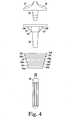
- FIGS. 1 to 3show three femoral components of modular knee prosthesis systems.
- Each of the femoral componentsis a distal femoral component 10 having distal curved convex condylar surfaces 12, 14.
- the distal femoral componentsare posterior stabilized components.
- Each componentincludes at least one femoral stem 16, along with a collar 18 for placement between the stem 16 and the distal femoral component 10 and a bolt 20 so that the stem 16 and collar 18 may be selectively mounted on the distal femoral component.
- Each stem 16has a frusto-conical outer surface that is smooth and tapers from a maximum outer diameter at the distal end to smaller outer diameters at positions proximal to the distal end.
- Stem extensions 22are also provided. All of the above components may be standard parts of the system sold under the trade mark PFC SIGMA.
- Each of the stems 16is an adapter with features like those in the device disclosed in US-A-2006/030945 .
- the stems 16may also have features like those in the device disclosed in US-6171342 , US-5824097 and US-5782921 .
- the stem extensionmay have features other than those shown in FIG. 1 . It should be understood that these components are described for purposes of illustration only; the present invention is not limited to any particular type of distal femoral component or stem or any other particular component unless expressly called out in the claims.
- the femoral component 10may have an integral stem 16 instead of the stem adapter 16, collar 18 and bolt 20.
- the femoral components of the systeminclude two types of metaphyseal members or sleeves 24, 26.
- the exterior surfaces of the two types of metaphyseal sleeves 24, 26may be substantially the same, the sleeves 24, 26 differing in the sizes of the interior channels that mount on the stem 16 of the femoral component 10. It should be understood that multiple sizes of distal femoral components 10, metaphyseal sleeves 24, 26 and stem extensions 22 would typically be included in the modular knee prosthesis system.
- the femoral components of the systeminclude a shim 19 with a single type of stem adapter 16 (or integral distal femoral component and stem) and a single type of metaphyseal sleeve.
- the shim 19is designed to fit over the exterior surface of the stem 16 to effectively increase the stem outer diameter that is received within the metaphyseal sleeve 24.
- the shim 19would be designed to fit over the exterior surface of the stem of the distal femoral component 10.
- the femoral components of the systeminclude two types of stem adapters 16, 17 and a single type of metaphyseal sleeve 24.
- the stem adapters 16, 17are similar, but differ in outer diameter.
- different femoral componentsmay be provided with stems having different outer diameters.
- the surgeonis provided with the opportunity to distalize the distal femoral component 10, to selectively increase the distance between the distal articulation surface plane 21 of the distal femoral component and the distal ends 56, 58 of the metaphyseal sleeves 24, 26.
- the kitincludes a tibial tray component 30, a tibial bearing insert 32 and a stem extension 34.
- the illustrated tibial tray component 30is a commercial revision tibial tray sold by DePuy Synthes Sales, Inc under the trade mark MBT.
- the tray component 30has an integral stem portion 36 with a bore (not shown) with internal threads to which the stem extension 34 may be attached.
- the outer surface of the stem portion 36has a smooth finish, tapers away from the joint motion surface and is connected to the inferior surface of the tibial tray component 30 through keels 31, 33.
- the stem portion 36extends distally from a platform 38, which has a proximal surface on which the tibial bearing insert 32 rests.
- the tibial componentsmay also include one or more types or sizes of metaphyseal sleeves, such as sleeve 40 that has a tapered bore (not shown) sized and shaped to frictionally lock with the tapered stem portion 36 of the tibial tray component 30.
- sleeve 40that has a tapered bore (not shown) sized and shaped to frictionally lock with the tapered stem portion 36 of the tibial tray component 30.
- Different designs of tibial componentsmight be used.
- the tibial componentmay comprise a unitary, all-polymer component or a fixed bearing system, such as those disclosed in US-7628818 and US-8128703 .
- the juncture of the curved convex condyles 12, 14 of the distal femoral component 10 and the curved concave condylar surfaces of the tibial bearing insert 32(the curved concave condylar surfaces of the tibial bearing insert being shown in FIG. 4 in phantom at 37, 39) define the articulation of the femoral and tibial components as the knee flexes and extends.
- the contact between the curved convex condyles 12, 14 and concave condylar surfaces 37, 39corresponds with a distal joint line.
- the distal femoral component 10 and tibial bearing insert 32move with respect to each other so that the joint line at full flexion (when the posterior surfaces of the femoral condyles contact the bearing surface) may vary somewhat from the distal joint line.
- the plane of the joint line, tangential to the point of contact of the condylar surfaces of the distal femoral component on the tibial insert,is shown at 21 in FIGS. 1 to 3 and 9 and at 21A in FIG. 10 .
- the metaphyseal sleeves 24, 26, 40are designed for use in a bone wherein the condition of the bone requires additional support or fixation in the metaphysis of the bone. All of these sleeves 24, 26, 40 have outer surfaces that have a plurality of adjacent steps or terraces, shown at 50a, 50b, 50c and 50d for the sleeve 24, at 52a, 52b, 52c and 52d for the sleeve 26 and at 54a, 54b, 54c, 54d, 54e, 54F, 54g, 54h, 54i, 54j and 54k for the sleeve 40.
- the outer surfacestaper proximally: the steps 50a, 52a at the distal ends 56, 58 have the largest anterior-posterior and medial-lateral dimensions and the steps 50d, 52d at the proximal ends 60, 62 have the smallest anterior-posterior and medial-lateral dimensions; the intermediate steps 50b, 50c, 52b, 52c gradually become smaller from the distal ends 56, 58 toward the proximal ends 60, 62.
- the outer surfacetapers distally: the most distal step 54a has the smallest anterior-posterior and medial-lateral dimensions and the most proximal step 54k has the largest anterior-posterior and medial-lateral dimensions; the intermediate steps 54b, 54c, 54d, 54e, 54f, 54g, 54h, 54i and 54j gradually become smaller from the proximal end toward the distal end.
- the number and size of the steps 50a, 50b, 50c 50d, 52a, 52b, 52c 52d, 54a, 54b, 54c, 54d, 54e, 54f, 54g, 54h, 54i, 54j and 54kmay vary.
- the outer surfaces of the metaphyseal sleeves 24, 26, 40may have steps and be shaped like standard commercially available metaphyseal sleeves sold by DePuy Synthes Sales, Inc., and may be configured like the sleeves disclosed in the prior art, such as, for example, US-7799085 .
- the shapes of the individual stepsmay be like those known from existing products, for example as disclosed in US-7799085 .
- the outer surfaces of the sleeves 24, 26, 40may also be porous coated to promote bone ingrowth, as known.
- Each of the femoral sleeves 24, 26has an interior surface 64, 66 defining a proximal bore 68, 70 and a distal bore 72, 74.
- the proximal and distal bores 68, 70, 72, 74 in each femoral sleevemay be connected and aligned along central longitudinal axes 76, 78 of the bores.
- the proximal bores 68, 70 of each femoral sleeveare sized and shaped to receive a distal end 79 of a stem extension 22. Accordingly, for a stem extension having a Morse taper post at its distal end, the proximal bore would comprise a Morse taper bore sized and shaped to receive and frictionally lock with the Morse taper post. Alternatively, for a stem extension having a threaded distal end, the proximal bore may be threaded to receive and lock to the threaded distal end of the stem extension. An adapter to allow for use of different types of stem extensions may also be used, as disclosed in US-7799085 .
- the distal bores 72, 74 of the femoral metaphyseal sleeves 24, 26are frusto-conical Morse taper bores, tapering from the distal ends 56, 58 of the sleeves 24, 26 toward the proximal ends 60, 62 of the sleeves 24, 26.
- These distal bores 72, 74are sized, shaped and finished to be mountable on the stem or adapter 16 of the distal femoral component 10 and to create a frictional lock between the stem of the distal femoral component and the metaphyseal sleeve, the stem or adapter 16 defining a Morse taper post.
- Morse taperrefers to locking tapers between mating components.
- Morse taper posts and boreshave frusto-conical shapes, substantially the same taper angle and have complementary outer and inner diameters at some point along their length to allow for tight frictional engagement between the posts and the walls defining the bores.
- Standard taper angles and standard surface finishes for such locking tapersmay be used in the present invention.
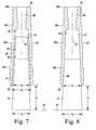
- the distal bore 72 of the first type of sleeve 24has a maximum inner diameter shown at d 1 in FIG. 5 .
- This maximum inner diameteris at the distal end of the distal bore 72 and substantially corresponds with the maximum outer diameter of the tapered frusto-conical outer surface 75 of the stem or adapter 16 of the distal femoral component 10, shown at d 2 in FIGS. 5 to 7 at the distal end of each stem or adapter 16.
- Both the distal bore 72 of the sleeve 24 and the tapered frusto-conical outer surface 75 of the stem or adapter 16taper in the proximal direction at substantially the same taper angle so that relative axial movement of the sleeve 24 and stem or adapter 16 locks the two together in the position shown in FIG. 5 when the interior surface 64 of the sleeve 24 engages and frictionally locks with the tapered frusto-conical outer surface 75 of the stem or adapter 16.
- the distal bore 74 of the sleeve 26 and the tapered frusto-conical outer surface 75 of the stem or adapter 16taper in the proximal direction at substantially the same taper angle so that relative axial movement of the sleeve 26 and stem or adapter 16 locks the two together in the position shown in FIG. 6 when the interior surface 66 of the sleeve 26 engages and frictionally locks with the outer surface 75 of the stem or adapter 16.
- the distal bore 74 of the sleeve 26has a smaller maximum inner diameter d 3 than the maximum inner diameter d, of the distal bore 72 of the sleeve 24.
- This maximum inner diameter d 3 of the distal bore 74is also less than the maximum outer diameter of the stem or adapter 16 of the distal femoral component 10 so that when the sleeve 26 is mounted and frictionally-locked to the stem or adapter 16, a portion of the stem or adapter 16 is exposed beyond the distal end of the distal bore 74.
- the overall axial length of the constructis thus increased, thereby distalizing the femoral component 10 when implanted.
- the distance between d 2 and d 3is the axial or distal offset provided when using the second sleeve 26, shown at o 1 in FIG. 6 .
- the overall axial lengths and the sizes and shapes of the outer surfaces of the two sleeves 24, 26are the same so that preparation of the distal femur to receive either of the two sleeves 24, 26 is the same. No additional bone must be removed to distalize the femoral component 10.
- the shim 19comprises a frusto-conical tube, with a tapered outer surface 80 and a tapered through-bore 82 defined by an inner wall 84.
- the outer surface 80 of the shim 19is sized and shaped to be received within and frictionally lock with the metaphyseal sleeve 24.
- the tapered through-bore 82 and inner wall 84are sized and shaped to receive and frictionally lock with the stem or adapter 16.
- the outer surface 80 of the shim 19defines a Morse taper post and the tapered through-bore 82 defines a Morse taper bore.
- the through-bore 82 of the shim 19has a maximum inner diameter at its distal end, shown at d 4 .
- the outer surface 80 of the shim 19has a maximum outer diameter shown at d 5 in FIG. 7 .
- the maximum outer diameter d 5 of the shim 19is substantially the same as the maximum outer diameter d 2 of the stem or adapter 16 and the maximum inner diameter d 4 of the through-bore 82 is less than the maximum outer diameter d 2 of the stem or adapter 16 and less than the maximum inner diameter d 1 of the first sleeve 24.
- the outer surface 80 of the shim 19has smaller outer diameters at more proximal positions and the through-bore 82 has smaller inner diameters at more proximal positions.
- the shim 19 and the sleeve 24may be assembled by placing the proximal end of the shim in the distal end of the sleeve distal bore 72 and moving the components 19, 24 axially until the outer surface 80 of the shim 19 and interior surface 64 of the sleeve engage and frictionally lock together as a Morse taper lock.
- This assemblymay then be mounted on the stem or adapter 16 by placing the proximal end of the stem or adapter 16 into the distal end of the through-bore 82 of the shim/sleeve assembly and moving the components axially until the tapered interior surface 84 of the shim 19 engages and frictionally locks with the matching tapered frusto-conical outer surface 75 of the stem or adapter 16.
- the shim 19may be mounted on the stem or adapter 16 and then the sleeve mounted on the assembly of the shim and stem or adapter.
- the shim/sleeve assembly and the stem or adapter 16engage and lock together with a portion of the stem or adapter 16 exposed beyond the distal end of the distal bore 82 of the shim 19.
- the overall axial length of the constructis thus increased, thereby distalizing the femoral component 10 when implanted.
- the distance between d 2 and d 4is the axial or distal offset provided when using the shim/sleeve assembly, shown at o 2 in FIG. 7 .
- the shim/stem assemblyengages and locks together with the sleeve such that a portion of the shim/stem assembly is exposed beyond the distal end of the distal bore of the sleeve and the overall axial length of the construct is increased, thereby distalizing the femoral component 10 when implanted and providing the offset o 2 .
- the overall axial length and the size and shape of the outer surface of the first sleeve 24remains the same, both without the shim as shown in FIG. 5 and with the shim 19 as shown in FIG. 7 .
- the femoral component 10may be distalized while using the same bone cavity to receive the sleeve.
- the second stem adapter 17has a frusto-conical tapered outer surface 90 set at the same taper angle as the first stem adapter 16, and has substantially the same length as the first stem adapter 16, but has a greater maximum outer diameter d 6 than the first stem adapter 16.
- the outer surface 90tapers to a position where its outer diameter d 7 is the same as the maximum inner diameter d 1 of the distal bore 72 of the first type of sleeve 24 and the same as the maximum outer diameter d 2 of the first stem adapter 16.
- the outer diameter d 7is spaced axially in a proximal direction from the distal end of the second stem adapter 17.
- the surgeonhas the option of assembling the distal femoral component with either stem adapter 16, 17. If the first stem adapter 16 is selected, when the sleeve 24 is mounted and frictionally-locked to the assembly the axial position of the sleeve relative to the stem 16 would be as shown in FIG. 5 . If the second stem adapter 17 is selected, when the first sleeve 24 is mounted and frictionally-locked to the assembly the axial position of the sleeve relative to the stem 17 would be as shown in FIG. 8 .
- the sleeve 24 and the stem adapter 17engage and lock together with a portion of the stem adapter 17 exposed beyond the distal end of the distal bore 72 of the sleeve 24 and the overall axial length of the construct is increased, thereby distalizing the femoral component 10 when implanted.
- the distance between d 6 and d 7is the axial or distal offset provided when using the second stem adapter 17, shown at o 3 in FIG. 8 .
- the central longitudinal axes 76, 78 of the tapered bores 72, 74intersect planes at the distal ends of the stems 16, 17. These planes are shown in FIGS. 5 to 7 at 97.
- the distal end of the bore 72may lie in plane 97.
- the distal end of the bore 74is spaced from the plane 97 by the offset distance o 1 .
- the distal end of the bore 72is spaced from the plane 97 by the offset distance o 2 .
- the distal end of the bore 72is spaced from the plane 97 by the offset distance o 3 .
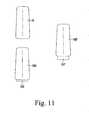
- a standard stem adapter defining a Morse taper postcould be provided, along with additional stem adapters having the same Morse taper post at the proximal ends but with greater overall lengths.
- FIG. 11shows such an alternative, where the standard stem adapter is shown at 16 and the additional stem adapters are shown at 16A and 16B.
- Stem adapters 16A and 16Binclude distal extensions 105, 107 that extend the overall axial lengths of the stem adapters by defined increments, such as by 5 mm increments. Thus, the surgeon may adjust the distal offset to meet the needs of the individual patient.
- the options available to the surgeonmay be increased by increasing the number of components in the system.
- additional sleeveshaving the same exterior geometry and different diameters of Morse taper bores could be provided.
- additional shims 19could be provided, each having a Morse taper bore of the same shape but with tapered outer surfaces having different outer diameters.
- additional stem adapterscould be provided, each having a different maximum outer diameter.
- FIGS. 9 and 10are side views of assemblies of the femoral components similar to those shown in FIG. 1 in combination with the tibial components shown in FIG. 4 .
- the femoral sleeves 100, 102 of FIGS. 9 and 10are similar to the femoral components 24, 26 described above except that the exterior surfaces are more like those described in US-7799085 .
- the sleeves 100, 102 of FIGS. 9 and 10differ in that the maximum inner diameter of the Morse taper bore of the sleeve 102 of FIG. 10 is smaller than the maximum inner diameter of the Morse taper bore of the sleeve 100 of FIG. 9 .
- the distal ends 104, 106 of the sleeves 100, 102lie in the same plane 108, showing that the position of the sleeves 100, 102 with respect to the distal femur (not shown) is the same, when either of the sleeves 100, 102 is used.
- using the second sleeve 102distalizes the joint line 21 to the position 21A by the offset distance o 1 .
- this offset distance o 1also corresponds with the axial length of the portion of the stem or adapter 16 exposed distal to the distal end 106 of the sleeve 102. Substantially the same results would be obtained using the devices shown in FIG. 2 and FIG. 3 .
- FIG. 10shows the femoral components used in conjunction with a standard distal femoral augment 110, shown mounted on a distal bone-facing surface 109 of the distal femoral component.
- the distal femoral augment 110has a thickness t, shown in FIG. 10 ; this thickness t, corresponds with the distal offset o 1 , although it should be understood that an implant system or kit may include multiple sizes of distal augments having varying thicknesses.
- the distal femoral augmentsmay have standard features, such as those disclosed in US-6005018 and US-5984969 .
- FIGS. 9 and 10also show that the overall length of each femoral implant assembly can be selectively adjusted to meet patients' needs.
- the overall length of the femoral implant assembly from the proximal end 112 of the sleeve 100 to the joint line 21, shown at 11,is less than the overall length of the femoral implant assembly shown in FIG. 10 at 12 (from the proximal end 114 of the sleeve 102 to the joint line 21A).
- the difference between 11 and 12is the distal offset o 1 .
- a standard kit using components as described abovemay include multiple components to provide the surgeon with a variety of distal offset choices to meet the needs of the individual patient.
- the kitcould provide the surgeon with sufficient components to intraoperatively select distal offsets o 1 of, for example, 0 mm, 5 mm or 10mm.
- the inventionmay also be applied to the tibial components of the knee implant system, such as the tibial sleeve 40 shown in FIG. 4 .
- a systemcould allow the surgeon to select components to provide a proximal offset to the tibial tray platform 38.
- such a systemcould include shims for mounting on the tibial stem 36, metaphyseal sleeves with the same outer size and shape but different bores, or metaphyseal sleeves with the same anterior-posterior and medial-lateral dimensions but different axial lengths.
- the surgeonmay prepare the bone to receive an optimally-sized the sleeve using, for example, standard broaches. If the surgeon determines that the needs of the individual patient are best served by distallizing the joint line, the surgeon can use the metaphyseal sleeve members of any of the components described herein using the same opening in the bone created by broaching. Thus, the surgeon may use an optimally sized metaphyseal sleeve with a distal femoral component and optimize of the joint line without the need for additional broaching.
- All of the components of the implant systemmay be made of standard materials, such as a standard polymer (UHMWPE, for example) for the tibial bearing insert 32 and standard metals, such as cobalt-chromium and titanium alloys, for the remaining components.
- UHMWPEstandard polymer
- the sleeves 24, 26, 40, 100, 102, 120may be porous coated, or could comprise titanium foam as disclosed in US-8382849 and US-A-2010/076565 .
- Titanium foam sleevessuch as those disclosed in US-8382849 and US-A-2010/076565 may be provided with adapters having different maximum internal diameters to define sleeve/adapter constructs like the metaphyseal members or sleeves 24, 26 shown in FIG. 1 , with the same outer surface but different internal mounting bores.
- the titanium foam sleeve/adapter constructsmight be provided with one or more shims (such as shim 19 of the component shown in FIG. 2 ) in the system with internal bores having different maximum internal diameters.
Landscapes
- Health & Medical Sciences (AREA)
- Orthopedic Medicine & Surgery (AREA)
- Cardiology (AREA)
- Oral & Maxillofacial Surgery (AREA)
- Transplantation (AREA)
- Engineering & Computer Science (AREA)
- Biomedical Technology (AREA)
- Heart & Thoracic Surgery (AREA)
- Vascular Medicine (AREA)
- Life Sciences & Earth Sciences (AREA)
- Animal Behavior & Ethology (AREA)
- General Health & Medical Sciences (AREA)
- Public Health (AREA)
- Veterinary Medicine (AREA)
- Physical Education & Sports Medicine (AREA)
- Prostheses (AREA)
Description
- The present invention relates generally to prosthetic joints, and more particularly to a modular prosthetic knee joint system that includes a metaphyseal sleeve component.
- The knee joint basically consists of the bone interface of the distal end of the femur and the proximal end of the tibia. Appearing to cover or at least partially protect this interface is the patella, which is a sesamoid bone within the tendon of the long muscle (quadriceps) on the front of the thigh. This tendon inserts into the tibial tuberosity and the posterior surface of the patella is smooth and glides over the femur.
- The femur is configured with two knob like processes (the medial condyle and the lateral condyle) which are substantially smooth and which articulate with the medial plateau and the lateral plateau of the tibia, respectively. The plateaus of the tibia are substantially smooth and slightly cupped thereby providing a slight receptacle for receipt of the femoral condyles.
- When the knee joint is damaged whether as a result of an accident or illness, a prosthetic replacement of the damaged joint may be necessary to relieve pain and to restore normal use to the joint. Typically the entire knee joint is replaced by means of a surgical procedure that involves removal of the surfaces of the corresponding damaged bones and replacement of these surfaces with prosthetic implants. This replacement of a native joint with a prosthetic joint is referred to as a primary total-knee arthroplasty.
- On occasion, the primary knee prostheses fails. Failure can result from many causes, including wear, aseptic loosening, osteolysis, ligamentous instability, arthrofibrosis and patellofemoral complications. When the failure is debilitating, revision knee surgery may be necessary. In a revision, the primary knee prosthesis is removed and replaced with components of a revision prosthetic knee system.
- Knee implant systems for both primary and revision applications are available from a variety of manufacturers, including DePuy Synthes Products, LLC. DePuy Synthes and others offer several different systems for both primary and revision applications. For example, DePuy Synthes offers systems under the trade marks PFC SIGMA, LCS and S-ROM. These orthopaedic knee systems includes several components, some appropriate for use in primary knee arthroplasty and some appropriate for use in revision surgery.
- DePuy Synthes also offers other orthopaedic implant systems for other applications. One such system is the system sold under the trade mark LPS. The LPS system is provided for use in cases of severe trauma and disease. In such cases, the trauma
- DePuy Synthes also offers other orthopaedic implant systems for other applications. One such system is the system sold under the trade mark LPS. The LPS system is provided for use in cases of severe trauma and disease. In such cases, the trauma or disease can lead to significant amounts of bone loss. The LPS system provides components that can replace all or significant portions of a particular bone, such as the femur. The DePuy Synthes LPS system is described more fully in
EP-A-1358860 . - In some patients, the metaphysis of the bone near the joint presents cavitary defects that are not completely filled by standard knee implants. The presence of such metaphyseal defects can result in loosening of the prosthetic implant over time, compromising the stability of the prosthetic implant and frequently requiring revision of the prosthetic implant.
- To fill metaphyseal cavitary defects, knee systems with modular metaphyseal sleeves have been provided. Such sleeves are disclosed in, for example,
US-A-2010/114323 ,US-A-2006/030945 ,US-7799085 ,US-7291174 ,US-6171342 ,US-5824097 ,US-5782921 andUS-4634444 . Such sleeves have been used in commercially available prosthetic knee implant systems, such as those sold under the trade marks PFC SIGMA, LCS, S-ROM and LPS. - Modular sleeves have also been used in hip implant systems, as disclosed in, for example,
US-6264699 ,US-4790852 . Such hip sleeves have been used in commercially available prosthetic hip implant systems, such as the S-ROM hip systems, available from DePuy Synthes Sales, Inc. of Warsaw, Indiana. - In knee systems with modular metaphyseal sleeves, the conventional shape of many of the sleeves is generally an elliptical cone with a large ellipse profile close to the joint line tapering down to a smaller elliptical or circular profile at the termination of the component distal to the joint line. Generally, the sleeves have a terraced or stepped outer surface and an inner channel for frictional fixation to another component. This geometry fills cavitary defects in the metaphysis, allows for a wider surface area for load transfer through the joint and provides rotational stability for the articulating components of the prosthesis.
- The outer surface of the sleeve is supported by solid bony structure or the bone bed. In the case of the distal femur, patient anatomy and the condition of the bone, particularly in a revision surgery, may require that the distal femur be resected to a more Elevation of the joint line may adversely affect performance of the prosthetic knee system: the positions of the collateral ligament attachments to the femur relative to the joint line may impact knee kinematics, the articulation of the patella against the femoral component will be impacted, and the function of the extensor mechanism will also be impacted.
- Prosthetic knee implant systems have commonly included femoral augments for use on the distal and posterior bone-facing surfaces of the femoral implant components. Examples of such augments are disclosed in
US-6005018 andUS-5984969 . Such components serve to augment the inferior and posterior portions of the femoral component to add additional thickness to compensate for the lack of sufficient boney tissue, allowing the joint line to be distalized. However, with the femoral component so distalized, the metaphyseal sleeve used with the femoral component may no longer be optimally seated on a healthy bone bed. To compensate, surgeons may sometimes opt to use a larger size of metaphyseal sleeve. US-5194066 discloses a modular femoral component of a knee joint prosthesis, in which a distal base has a pair of spaced apart curved distal condylar surfaces, and a tapered distal stem part which is formed integrally with the base. A proximal stem part can be fitted on to the proximal end of the distal stem part.- Accordingly, a need exists for a knee prosthesis system that allows the surgeon the flexibility to optimize the position of the joint line while also allowing for a metaphyseal sleeve to be optimally sized and optimally positioned on a healthy bone bed.
- The present invention provides a modular knee implant system that allows the surgeon to use an optimally sized metaphyseal sleeve with a distal femoral component while also allowing for optimization of the joint line.
- A first modular knee implant system provided by the invention is defined in
claim 1. - Optionally, the second metaphyseal member comprises an assembly of a sleeve and a first shim. The sleeve has an outer surface that defines the outer surface of the second metaphyseal member and an inner surface defining a tapered bore sized and shaped to be mountable on the stem of the distal femoral component and to create a frictional lock between the stem of the distal femoral component and the sleeve. The tapered bore has a maximum inner diameter at a distal end and a smaller inner diameter at a second more proximal position. The size and shape of the tapered bore of the sleeve are substantially the same as the size and shape of the tapered bore of the first metaphyseal member. The first shim comprises a tapered tube having an outer surface sized and shaped to be received within and frictionally lock with the tapered bore of the sleeve and an inner surface defining a tapered bore sized and shaped to be mountable on the stem of the distal femoral component and to create a frictional lock between the stem of the distal femoral component and the first shim. The tapered bore of the first shim has a maximum inner diameter at a distal end and a second inner diameter at a second more proximal position. The maximum inner diameter of the first shim defines the maximum inner diameter of the second metaphyseal member when the first shim and sleeve are assembled.
- Optionally, a distal portion of the stem is exposed when the sleeve and first shim are frictionally locked on the stem.
- Optionally, the outer surfaces of the first metaphyseal member and the sleeve have the same size and shape.
- Optionally, the stem has a distal end and the tapered bores of the first and second metaphyseal members have central longitudinal axes. The central longitudinal axis of each tapered bore intersects a plane at the distal end of the stem of the distal femoral component when the respective metaphyseal member is mounted on the stem of the distal femoral component. With the first metaphyseal member, the distal end of the tapered bore and the plane are spaced a first distance. With the second metaphyseal member, the distal end of the tapered bore and the plane are spaced at a second distance. The second distance is greater than the first distance and the difference between the first distance and the second distance defines a distal offset of the distal femoral component.
- Optionally, the distal femoral component has a distal bone-facing surface and the system further comprises a distal femoral augment having a thickness. The thickness of the distal femoral augment is substantially the same as the distal offset provided by the second metaphyseal member.
- Optionally, the system also includes a tibial member having an articulating surface to receive and articulate with the distal articulating surfaces of the distal femoral component. The contact between the articulating surfaces of the tibial member and the distal femoral component define a joint line. The tibial member and an assembly of the distal femoral component and the first metaphyseal member defines a first joint line and the tibial member and an assembly of the distal femoral component and the second metaphyseal member defines a second joint line; the second joint line is more distal than the first joint line.
- A second modular knee implant system provided by the invention is defined in claim 9.
- When the first stem adapter is mounted on the distal femoral component and the first metaphyseal member is locked on the first stem adapter the distal femoral component is in a first proximal-distal position with respect to the bore of the first metaphyseal member. When the second stem adapter is mounted on the distal femoral component and the first metaphyseal member is locked on the second stem adapter the distal femoral component is in a second proximal-distal position with respect to the bore of the first metaphyseal member. The second proximal-distal position of the distal femoral component is more distal than the first proximal-distal position of the distal femoral component.
- Optionally, the difference between the first proximal-distal position of the distal femoral component and the second proximal-distal position of the distal femoral component corresponds with a distal offset of the distal femoral component. The distal femoral component has a distal bone-facing surface and
- The system may include a distal femoral augment having a thickness. The thickness of the distal femoral augment may be substantially the same as the distal offset of the distal femoral component.
- The invention is described below by way of example with reference to the accompanying drawings, in which:
FIG. 1 is a view of the femoral components of a modular knee prosthesis system.FIG. 2 is a view of other femoral components of a modular knee prosthesis system.FIG. 3 is a view of other femoral components of a modular knee prosthesis system.FIG. 4 is a view of the tibial components of a modular knee prosthesis system.FIG. 5 is a cross-sectional view of one of the metaphyseal sleeves of the modular knee prosthesis system ofFIG. 1 , shown mounted on the stem ofFIG. 1 (the stem shown in side view).FIG. 6 is a cross-sectional view of the other metaphyseal sleeve of the modular knee prosthesis system ofFIG. 1 , shown mounted on the stem ofFIG. 1 (the stem shown in side view).FIG. 7 is a cross-sectional view of the shim and metaphyseal sleeve of the modular knee prosthesis system ofFIG. 2 , shown mounted on the stem ofFIG. 2 (the stem shown in side view).FIG. 8 a cross-sectional view of the metaphyseal sleeve of the modular knee prosthesis system ofFIG. 3 , shown mounted on the thicker stem ofFIG. 3 (the stem shown in side view).FIG. 9 is a side view of a modular knee prosthesis system using a standard femoral stem and femoral sleeve.FIG. 10 is a side view of a modular knee prosthesis system similar toFIG. 9 but shown with a femoral sleeve having a more narrow bore, as in the component shown inFIG. 1 .FIG. 11 is a side view of an alternative set of stem adapters that may be used with the modular knee prosthesis system ofFIG. 3 .- Terms representing anatomical references, such as anterior and posterior, proximal, distal, superior and inferior, may be used throughout this document to refer to the orthopaedic implants described herein as well as to refer to the patient's natural anatomy. Such terms have well-understood meanings in both the study of anatomy and the field of orthopaedics. Use of such anatomical reference terms in the this document is intended to be consistent with their well-understood meanings unless noted otherwise.
- Referring to the drawings,
FIGS. 1 to 3 show three femoral components of modular knee prosthesis systems. Each of the femoral components is a distalfemoral component 10 having distal curved convex condylar surfaces 12, 14. The distal femoral components are posterior stabilized components. Each component includes at least onefemoral stem 16, along with acollar 18 for placement between thestem 16 and the distalfemoral component 10 and abolt 20 so that thestem 16 andcollar 18 may be selectively mounted on the distal femoral component. Each stem 16 has a frusto-conical outer surface that is smooth and tapers from a maximum outer diameter at the distal end to smaller outer diameters at positions proximal to the distal end.Stem extensions 22 are also provided. All of the above components may be standard parts of the system sold under the trade mark PFC SIGMA. Each of the stems 16 is an adapter with features like those in the device disclosed inUS-A-2006/030945 . The stems 16 may also have features like those in the device disclosed inUS-6171342 ,US-5824097 andUS-5782921 . Also, as disclosed inUS-A-2006/030945 , the stem extension may have features other than those shown inFIG. 1 . It should be understood that these components are described for purposes of illustration only; the present invention is not limited to any particular type of distal femoral component or stem or any other particular component unless expressly called out in the claims. For example, thefemoral component 10 may have anintegral stem 16 instead of thestem adapter 16,collar 18 andbolt 20. - In the device shown in
FIG. 1 , the femoral components of the system include two types of metaphyseal members orsleeves metaphyseal sleeves sleeves stem 16 of thefemoral component 10. It should be understood that multiple sizes of distalfemoral components 10,metaphyseal sleeves extensions 22 would typically be included in the modular knee prosthesis system. - In the device shown in
FIG. 2 , the femoral components of the system include ashim 19 with a single type of stem adapter 16 (or integral distal femoral component and stem) and a single type of metaphyseal sleeve. As described in more detail below, theshim 19 is designed to fit over the exterior surface of thestem 16 to effectively increase the stem outer diameter that is received within themetaphyseal sleeve 24. Alternatively, for distalfemoral components 10 with integral stems instead of adapters, theshim 19 would be designed to fit over the exterior surface of the stem of the distalfemoral component 10. - In the device shown in
FIG. 3 , the femoral components of the system include two types ofstem adapters metaphyseal sleeve 24. As described in more detail below, thestem adapters femoral components 10 with integral stems instead of stem adapters, different femoral components may be provided with stems having different outer diameters. - With all three of the devices shown in
FIGS. 1 to 3 , the surgeon is provided with the opportunity to distalize the distalfemoral component 10, to selectively increase the distance between the distalarticulation surface plane 21 of the distal femoral component and the distal ends 56, 58 of themetaphyseal sleeves - As shown in
FIG. 4 , on the tibial side, the kit includes atibial tray component 30, atibial bearing insert 32 and astem extension 34. The illustratedtibial tray component 30 is a commercial revision tibial tray sold by DePuy Synthes Sales, Inc under the trade mark MBT. Thetray component 30 has anintegral stem portion 36 with a bore (not shown) with internal threads to which thestem extension 34 may be attached. The outer surface of thestem portion 36 has a smooth finish, tapers away from the joint motion surface and is connected to the inferior surface of thetibial tray component 30 throughkeels stem portion 36 extends distally from a platform 38, which has a proximal surface on which thetibial bearing insert 32 rests. The tibial components may also include one or more types or sizes of metaphyseal sleeves, such assleeve 40 that has a tapered bore (not shown) sized and shaped to frictionally lock with the taperedstem portion 36 of thetibial tray component 30. Different designs of tibial components might be used. For example, the tibial component may comprise a unitary, all-polymer component or a fixed bearing system, such as those disclosed inUS-7628818 andUS-8128703 . - The juncture of the curved
convex condyles femoral component 10 and the curved concave condylar surfaces of the tibial bearing insert 32 (the curved concave condylar surfaces of the tibial bearing insert being shown inFIG. 4 in phantom at 37, 39) define the articulation of the femoral and tibial components as the knee flexes and extends. When the patient's leg is in extension, the contact between the curvedconvex condyles femoral component 10 and tibial bearing insert 32 move with respect to each other so that the joint line at full flexion (when the posterior surfaces of the femoral condyles contact the bearing surface) may vary somewhat from the distal joint line. The plane of the joint line, tangential to the point of contact of the condylar surfaces of the distal femoral component on the tibial insert, is shown at 21 inFIGS. 1 to 3 and9 and at 21A inFIG. 10 . - The
metaphyseal sleeves sleeves sleeve 24, at 52a, 52b, 52c and 52d for thesleeve 26 and at 54a, 54b, 54c, 54d, 54e, 54F, 54g, 54h, 54i, 54j and 54k for thesleeve 40. For the femoral sleeves, the outer surfaces taper proximally: thesteps steps intermediate steps tibial sleeve 40, the outer surface tapers distally: the mostdistal step 54a has the smallest anterior-posterior and medial-lateral dimensions and the mostproximal step 54k has the largest anterior-posterior and medial-lateral dimensions; theintermediate steps - It should be understood that the number and size of the
steps 50c 52c metaphyseal sleeves US-7799085 . It should also be understood that the shapes of the individual steps may be like those known from existing products, for example as disclosed inUS-7799085 . The outer surfaces of thesleeves - Each of the
femoral sleeves interior surface proximal bore distal bore distal bores longitudinal axes - The proximal bores 68, 70 of each femoral sleeve are sized and shaped to receive a distal end 79 of a
stem extension 22. Accordingly, for a stem extension having a Morse taper post at its distal end, the proximal bore would comprise a Morse taper bore sized and shaped to receive and frictionally lock with the Morse taper post. Alternatively, for a stem extension having a threaded distal end, the proximal bore may be threaded to receive and lock to the threaded distal end of the stem extension. An adapter to allow for use of different types of stem extensions may also be used, as disclosed inUS-7799085 . - The distal bores 72, 74 of the femoral
metaphyseal sleeves sleeves sleeves distal bores adapter 16 of the distalfemoral component 10 and to create a frictional lock between the stem of the distal femoral component and the metaphyseal sleeve, the stem oradapter 16 defining a Morse taper post. - As used herein, "Morse taper" refers to locking tapers between mating components. Generally, Morse taper posts and bores have frusto-conical shapes, substantially the same taper angle and have complementary outer and inner diameters at some point along their length to allow for tight frictional engagement between the posts and the walls defining the bores. Standard taper angles and standard surface finishes for such locking tapers may be used in the present invention.
- In the component shown in
FIG. 1 , thedistal bore 72 of the first type ofsleeve 24 has a maximum inner diameter shown at d1 inFIG. 5 . This maximum inner diameter is at the distal end of thedistal bore 72 and substantially corresponds with the maximum outer diameter of the tapered frusto-conicalouter surface 75 of the stem oradapter 16 of the distalfemoral component 10, shown at d2 inFIGS. 5 to 7 at the distal end of each stem oradapter 16. Both thedistal bore 72 of thesleeve 24 and the tapered frusto-conicalouter surface 75 of the stem oradapter 16 taper in the proximal direction at substantially the same taper angle so that relative axial movement of thesleeve 24 and stem oradapter 16 locks the two together in the position shown inFIG. 5 when theinterior surface 64 of thesleeve 24 engages and frictionally locks with the tapered frusto-conicalouter surface 75 of the stem oradapter 16. Similarly, thedistal bore 74 of thesleeve 26 and the tapered frusto-conicalouter surface 75 of the stem oradapter 16 taper in the proximal direction at substantially the same taper angle so that relative axial movement of thesleeve 26 and stem oradapter 16 locks the two together in the position shown inFIG. 6 when theinterior surface 66 of thesleeve 26 engages and frictionally locks with theouter surface 75 of the stem oradapter 16. - As shown in
FIGS. 5 and 6 , thedistal bore 74 of thesleeve 26 has a smaller maximum inner diameter d3 than the maximum inner diameter d, of thedistal bore 72 of thesleeve 24. This maximum inner diameter d3 of thedistal bore 74 is also less than the maximum outer diameter of the stem oradapter 16 of the distalfemoral component 10 so that when thesleeve 26 is mounted and frictionally-locked to the stem oradapter 16, a portion of the stem oradapter 16 is exposed beyond the distal end of thedistal bore 74. The overall axial length of the construct is thus increased, thereby distalizing thefemoral component 10 when implanted. The distance between d2 and d3 is the axial or distal offset provided when using thesecond sleeve 26, shown at o1 inFIG. 6 . - In this device, the overall axial lengths and the sizes and shapes of the outer surfaces of the two
sleeves sleeves femoral component 10. - In the component shown in
FIG. 2 , theshim 19 comprises a frusto-conical tube, with a taperedouter surface 80 and a tapered through-bore 82 defined by aninner wall 84. As shown inFIG. 7 , theouter surface 80 of theshim 19 is sized and shaped to be received within and frictionally lock with themetaphyseal sleeve 24. The tapered through-bore 82 andinner wall 84 are sized and shaped to receive and frictionally lock with the stem oradapter 16. Thus, theouter surface 80 of theshim 19 defines a Morse taper post and the tapered through-bore 82 defines a Morse taper bore. - As shown in
FIG. 7 , the through-bore 82 of theshim 19 has a maximum inner diameter at its distal end, shown at d4. Theouter surface 80 of theshim 19 has a maximum outer diameter shown at d5 inFIG. 7 . The maximum outer diameter d5 of theshim 19 is substantially the same as the maximum outer diameter d2 of the stem oradapter 16 and the maximum inner diameter d4 of the through-bore 82 is less than the maximum outer diameter d2 of the stem oradapter 16 and less than the maximum inner diameter d1 of thefirst sleeve 24. Theouter surface 80 of theshim 19 has smaller outer diameters at more proximal positions and the through-bore 82 has smaller inner diameters at more proximal positions. - The
shim 19 and thesleeve 24 may be assembled by placing the proximal end of the shim in the distal end of the sleeve distal bore 72 and moving thecomponents outer surface 80 of theshim 19 andinterior surface 64 of the sleeve engage and frictionally lock together as a Morse taper lock. This assembly may then be mounted on the stem oradapter 16 by placing the proximal end of the stem oradapter 16 into the distal end of the through-bore 82 of the shim/sleeve assembly and moving the components axially until the taperedinterior surface 84 of theshim 19 engages and frictionally locks with the matching tapered frusto-conicalouter surface 75 of the stem oradapter 16. Alternatively, theshim 19 may be mounted on the stem oradapter 16 and then the sleeve mounted on the assembly of the shim and stem or adapter. - Since the maximum inner diameter d4 of the shim/sleeve assembly is less than the maximum outer diameter d2 of the stem or
adapter 16, the shim/sleeve assembly and the stem oradapter 16 engage and lock together with a portion of the stem oradapter 16 exposed beyond the distal end of thedistal bore 82 of theshim 19. The overall axial length of the construct is thus increased, thereby distalizing thefemoral component 10 when implanted. The distance between d2 and d4 is the axial or distal offset provided when using the shim/sleeve assembly, shown at o2 inFIG. 7 . Stated another way, since the maximum outer diameter of the stem or adapter and shim assembly is greater than the maximum inner diameter of the sleeve, the shim/stem assembly engages and locks together with the sleeve such that a portion of the shim/stem assembly is exposed beyond the distal end of the distal bore of the sleeve and the overall axial length of the construct is increased, thereby distalizing thefemoral component 10 when implanted and providing the offset o2. - As in the component shown in
FIG. 1 , the overall axial length and the size and shape of the outer surface of thefirst sleeve 24 remains the same, both without the shim as shown inFIG. 5 and with theshim 19 as shown inFIG. 7 . Thus, as in the component shown inFIG. 1 , thefemoral component 10 may be distalized while using the same bone cavity to receive the sleeve. - In the component shown in
FIG. 3 , thesecond stem adapter 17 has a frusto-conical taperedouter surface 90 set at the same taper angle as thefirst stem adapter 16, and has substantially the same length as thefirst stem adapter 16, but has a greater maximum outer diameter d6 than thefirst stem adapter 16. As shown inFIG. 8 , theouter surface 90 tapers to a position where its outer diameter d7 is the same as the maximum inner diameter d1 of thedistal bore 72 of the first type ofsleeve 24 and the same as the maximum outer diameter d2 of thefirst stem adapter 16. The outer diameter d7 is spaced axially in a proximal direction from the distal end of thesecond stem adapter 17. - In the component shown in
FIG. 3 , the surgeon has the option of assembling the distal femoral component with eitherstem adapter first stem adapter 16 is selected, when thesleeve 24 is mounted and frictionally-locked to the assembly the axial position of the sleeve relative to thestem 16 would be as shown inFIG. 5 . If thesecond stem adapter 17 is selected, when thefirst sleeve 24 is mounted and frictionally-locked to the assembly the axial position of the sleeve relative to thestem 17 would be as shown inFIG. 8 . - Since the maximum outer diameter d6 of the
second stem adapter 17 is greater than the maximum outer diameter d2 of thefirst stem adapter 16, thesleeve 24 and thestem adapter 17 engage and lock together with a portion of thestem adapter 17 exposed beyond the distal end of thedistal bore 72 of thesleeve 24 and the overall axial length of the construct is increased, thereby distalizing thefemoral component 10 when implanted. The distance between d6 and d7 is the axial or distal offset provided when using thesecond stem adapter 17, shown at o3 inFIG. 8 . - As shown in
FIGS. 5 to 7 , the centrallongitudinal axes FIGS. 5 to 7 at 97. With thestandard metaphyseal member 24 and stem 16 shown inFIG. 5 , the distal end of thebore 72 may lie inplane 97. As shown inFIG. 6 , the distal end of thebore 74 is spaced from theplane 97 by the offset distance o1. As shown inFIG. 7 , the distal end of thebore 72 is spaced from theplane 97 by the offset distance o2. As shown inFIG. 8 , the distal end of thebore 72 is spaced from theplane 97 by the offset distance o3. - Other options may be provided for a system including multiple stem adapters to selectively offset the distal femoral component. For example, a standard stem adapter defining a Morse taper post could be provided, along with additional stem adapters having the same Morse taper post at the proximal ends but with greater overall lengths.
FIG. 11 shows such an alternative, where the standard stem adapter is shown at 16 and the additional stem adapters are shown at 16A and 16B.Stem adapters distal extensions - The options available to the surgeon may be increased by increasing the number of components in the system. For example, in the component shown in
FIG. 1 , additional sleeves having the same exterior geometry and different diameters of Morse taper bores could be provided. In the component shown inFIG. 2 ,additional shims 19 could be provided, each having a Morse taper bore of the same shape but with tapered outer surfaces having different outer diameters. In the component shown inFIG. 3 , additional stem adapters could be provided, each having a different maximum outer diameter. FIGS. 9 and 10 are side views of assemblies of the femoral components similar to those shown inFIG. 1 in combination with the tibial components shown inFIG. 4 . Thefemoral sleeves FIGS. 9 and 10 are similar to thefemoral components US-7799085 . However, like thesleeves FIGS. 1 ,5 and 6 , thesleeves FIGS. 9 and 10 differ in that the maximum inner diameter of the Morse taper bore of thesleeve 102 ofFIG. 10 is smaller than the maximum inner diameter of the Morse taper bore of thesleeve 100 ofFIG. 9 .- As can be seen from a comparison of
FIGS. 9 and 10 , the distal ends 104, 106 of thesleeves same plane 108, showing that the position of thesleeves sleeves FIGS. 9 and 10 , using thesecond sleeve 102 distalizes thejoint line 21 to theposition 21A by the offset distance o1. As shown inFIG. 10 , this offset distance o1 also corresponds with the axial length of the portion of the stem oradapter 16 exposed distal to thedistal end 106 of thesleeve 102. Substantially the same results would be obtained using the devices shown inFIG. 2 andFIG. 3 . FIG. 10 shows the femoral components used in conjunction with a standard distal femoral augment 110, shown mounted on a distal bone-facingsurface 109 of the distal femoral component. The distal femoral augment 110 has a thickness t, shown inFIG. 10 ; this thickness t, corresponds with the distal offset o1, although it should be understood that an implant system or kit may include multiple sizes of distal augments having varying thicknesses. The distal femoral augments may have standard features, such as those disclosed inUS-6005018 andUS-5984969 .FIGS. 9 and 10 also show that the overall length of each femoral implant assembly can be selectively adjusted to meet patients' needs. InFIG. 9 , the overall length of the femoral implant assembly from the proximal end 112 of thesleeve 100 to thejoint line 21, shown at 11, is less than the overall length of the femoral implant assembly shown inFIG. 10 at 12 (from the proximal end 114 of thesleeve 102 to thejoint line 21A). The difference between 11 and 12 is the distal offset o1.- As discussed above, it should be appreciated that a standard kit using components as described above may include multiple components to provide the surgeon with a variety of distal offset choices to meet the needs of the individual patient. For example, the kit could provide the surgeon with sufficient components to intraoperatively select distal offsets o1 of, for example, 0 mm, 5 mm or 10mm.
- The invention may also be applied to the tibial components of the knee implant system, such as the
tibial sleeve 40 shown inFIG. 4 . Such a system could allow the surgeon to select components to provide a proximal offset to the tibial tray platform 38. For example, such a system could include shims for mounting on thetibial stem 36, metaphyseal sleeves with the same outer size and shape but different bores, or metaphyseal sleeves with the same anterior-posterior and medial-lateral dimensions but different axial lengths. - The surgeon may prepare the bone to receive an optimally-sized the sleeve using, for example, standard broaches. If the surgeon determines that the needs of the individual patient are best served by distallizing the joint line, the surgeon can use the metaphyseal sleeve members of any of the components described herein using the same opening in the bone created by broaching. Thus, the surgeon may use an optimally sized metaphyseal sleeve with a distal femoral component and optimize of the joint line without the need for additional broaching.
- All of the components of the implant system may be made of standard materials, such as a standard polymer (UHMWPE, for example) for the
tibial bearing insert 32 and standard metals, such as cobalt-chromium and titanium alloys, for the remaining components. To promote bone ingrowth, thesleeves US-8382849 andUS-A-2010/076565 . - Titanium foam sleeves such as those disclosed in
US-8382849 andUS-A-2010/076565 may be provided with adapters having different maximum internal diameters to define sleeve/adapter constructs like the metaphyseal members orsleeves FIG. 1 , with the same outer surface but different internal mounting bores. The titanium foam sleeve/adapter constructs might be provided with one or more shims (such asshim 19 of the component shown inFIG. 2 ) in the system with internal bores having different maximum internal diameters. - An alternative system providing the option of distalizing the joint line is disclosed in
EP-A-2710980 .
Claims (11)
- A modular knee prosthesis system comprising:a distal femoral component (10) having a pair of spaced, curved distal condylar surfaces (12, 14) and a stem (16) having an outer surface tapering from a distal end in the proximal direction, the outer surface of the stem having a maximum outer diameter at the distal end and a smaller outer diameter at a second position proximal to the distal end,characterisedin that the system includes:a first metaphyseal member (24) having an outer surface that tapers in a proximal direction and an inner surface defining a tapered bore (68, 72) sized and shaped to be mountable on the stem of the distal femoral component and to create a frictional lock between the stem of the distal femoral component and the first metaphyseal member, the tapered bore having a maximum inner diameter at a distal end, the maximum inner diameter corresponding with the maximum outer diameter of the stem of the distal femoral component, anda second metaphyseal member (26) having an outer surface that tapers in a proximal direction and an inner surface defining a tapered bore (70, 74) sized and shaped to be mountable on the stem of the distal femoral component and to create a frictional lock between the stem of the distal femoral component and the second metaphyseal member, the tapered bore having a maximum inner diameter at a distal end, the maximum inner diameter corresponding with the outer diameter of the stem of the distal femoral component at the second position so that the first metaphyseal member and the second metaphyseal member are mountable on the stem of the distal femoral component to create frictional locks at different positions in the proximal-distal direction on the stem of the distal femoral component.
- The modular knee prosthesis system of claim 1 in which the second metaphyseal member (26) comprises an assembly of a sleeve (24) and a first shim (19), in which:the sleeve has an outer surface that defines the outer surface of the second metaphyseal member and an inner surface defining a tapered bore sized and shaped to be mountable on the stem of the distal femoral component and to create a frictional lock between the stem of the distal femoral component and the first metaphyseal member, the tapered bore having a maximum inner diameter at a distal end and a smaller inner diameter at a second more proximal position, the size and shape of the tapered bore of the sleeve being substantially the same as the size and shape of the tapered bore of the first metaphyseal member, andthe first shim comprises a tapered tube having an outer surface sized and shaped to be received within and frictionally lock with the tapered bore of the sleeve and an inner surface defining a tapered bore sized and shaped to be mountable on the stem of the distal femoral component and to create a frictional lock between the stem of the distal femoral component and the first shim, the tapered bore of the first shim having a maximum inner diameter at a distal end and a second inner diameter at a second more proximal position, the maximum inner diameter of the first shim defining the maximum inner diameter of the second metaphyseal member when the first shim and sleeve are assembled.
- The modular knee prosthesis system of claim 2 in which a distal portion of the stem (16) is exposed when the sleeve (24) and first shim (19) are frictionally locked on the stem.
- The modular knee prosthesis system of claim 2 in which the outer surfaces of the first metaphyseal member and the sleeve have the same size and shape.
- The modular knee prosthesis system of claim 1 in which:the stem (16) has a distal end,the tapered bore (68, 72) of the first metaphyseal member (24) has a central longitudinal axis (76) that intersects a plane at the distal end of the stem (16) of the distal femoral component (10) when the first metaphyseal member is mounted on the stem of the distal femoral component, the distal end of the tapered bore and the plane being at a first distance,the tapered bore (70, 74) of the second metaphyseal member (26) has a central longitudinal axis (78) that intersects a plane at the distal end of the stem of the distal femoral component when the second metaphyseal member is mounted on the stem of the distal femoral component, the distal end of the tapered bore and the plane being at a second distance,the second distance is greater than the first distance, andthe difference between the first distance and the second distance defines a distal offset (o1) of the distal femoral component.
- The modular knee prosthesis system of claim 5 in which:the distal femoral component (10) has a distal bone-facing surface (109), andthe system further comprises a distal femoral augment (110) having a thickness, the thickness of the distal femoral augment being substantially the same as the distal offset (o1) provided by the second metaphyseal member (26).
- The modular knee prosthesis system of claim 1 which includes a tibial member (30, 32) having an articulating surface (37, 39) to receive and articulate with the distal articulating surfaces (12, 14) of the distal femoral component (10), the contact between the articulating surfaces of the tibial member and the distal femoral component defining a joint line (21).
- The modular knee prosthesis system of claim 7 in which:the tibial member (30, 32) and an assembly of the distal femoral component (10) and the first metaphyseal member (24) defines a first joint line and the tibial member and an assembly of the distal femoral component and the second metaphyseal member (26) defines a second joint line, andthe second joint line is more distal than the first joint line.
- A modular knee prosthesis system comprising:a distal femoral component (10) having a pair of spaced, curved distal condylar surfaces (12, 14), and having a first stem adapter (16) which has an outer surface tapering from a distal end in the proximal direction, the outer surface of the stem adapter having a maximum outer diameter at a distal end and a smaller outer diameter at a second position proximal to the distal end,characterisedby the first stem adapter being selectively mountable on the distal femoral component, and the system also including:a first metaphyseal member (24) having an outer surface that tapers in a proximal direction and an inner surface defining a bore tapering from a maximum inner diameter at a distal end to a smaller inner diameter at a second more proximal position, anda second stem adapter (17) selectively mountable on the distal femoral component and having an outer surface tapering from a distal end in the proximal direction, the outer surface of the stem having a maximum outer diameter at a distal end and a smaller outer diameter at a second position proximal to the distal end,in which the maximum outer diameter of the second stem adapter is greater than the maximum outer diameter of the first stem adapter,in which the bore of the first metaphyseal member is sized and shaped to be mountable on the first stem adapter and to create a frictional lock between the first metaphyseal member and the first stem adapter,in which the bore of the first metaphyseal member is sized and shaped to be mountable on the second stem adapter and to create a frictional lock between the first metaphyseal member and the second stem adapter,in which when the first metaphyseal member and first stem adapter are locked together the distal end of the first stem adapter is in a proximal-distal position with respect to the bore of the first metaphyseal member,in which when the first metaphyseal member and second stem adapter are locked together the distal end of the second stem adapter is in a proximal-distal position with respect to the bore of the first metaphyseal member, andin which the locked proximal-distal position of the first stem adapter is more proximal than the locked proximal-distal position of the second stem adapter with respect to the first metaphyseal member.
- The modular knee prosthesis system of claim 9 further comprising a tibial member (30, 32) having an articulating surface (37, 39) to receive and articulate with the distal articulating surfaces (12, 14) of the distal femoral component (10), the contact between the articulating surfaces of the tibial member and the distal femoral component defining a joint line (21),
in which:the tibial member and an assembly of the femoral component, the first metaphyseal member (24) and the first stem adapter (16) define a first joint line at the contact between the articulating surfaces of the tibial member and the distal femoral component,the tibial member and an assembly of the femoral component, the first metaphyseal member and the second stem (17) adapter define a second joint line at the contact between the articulating surfaces of the tibial member and the distal femoral component, andthe second joint line is more distal than the first joint line. - The modular knee prosthesis system of claim 9 in which:the difference between the first proximal-distal position of the distal femoral component and the second proximal-distal position of the distal femoral component corresponds with a distal offset (o1) of the distal femoral component,the distal femoral component (10) has a distal bone-facing surface (109), andthe system further comprises a distal femoral augment (110) having a thickness, the thickness of the distal femoral augment being substantially the same as the distal offset (o1) of the distal femoral component.
Applications Claiming Priority (2)
| Application Number | Priority Date | Filing Date | Title |
|---|---|---|---|
| US201261703412P | 2012-09-20 | 2012-09-20 | |
| US13/832,424US8998996B2 (en) | 2012-09-20 | 2013-03-15 | Knee prosthesis system with standard and distal offset joint line |
Publications (2)
| Publication Number | Publication Date |
|---|---|
| EP2710979A1 EP2710979A1 (en) | 2014-03-26 |
| EP2710979B1true EP2710979B1 (en) | 2015-03-25 |
Family
ID=49301269
Family Applications (1)
| Application Number | Title | Priority Date | Filing Date |
|---|---|---|---|
| EP13185424.2AActiveEP2710979B1 (en) | 2012-09-20 | 2013-09-20 | Modular knee prosthesis system |
Country Status (5)
| Country | Link |
|---|---|
| US (1) | US8998996B2 (en) |
| EP (1) | EP2710979B1 (en) |
| JP (1) | JP6309231B2 (en) |
| CN (1) | CN103655008B (en) |
| AU (3) | AU2013231132A1 (en) |
Families Citing this family (16)
| Publication number | Priority date | Publication date | Assignee | Title |
|---|---|---|---|---|
| US9320603B2 (en) | 2012-09-20 | 2016-04-26 | Depuy (Ireland) | Surgical instrument system with multiple lengths of broaches sharing a common geometry |
| US9532879B2 (en) | 2012-09-20 | 2017-01-03 | Depuy Ireland Unlimited Company | Femoral knee prosthesis system with augments and multiple lengths of sleeves sharing a common geometry |
| US9452056B2 (en)* | 2014-09-29 | 2016-09-27 | Biomet C.V. | Implants for fixation of the distal tibia |
| US9943413B2 (en) | 2015-01-30 | 2018-04-17 | Russell Nevins | Revision stepped tibial implant |
| AU2018225123C1 (en) | 2017-02-21 | 2020-03-19 | Biomet Manufacturing, Llc | Implants for bridging osseous defects |
| US20190015212A1 (en)* | 2017-07-17 | 2019-01-17 | Aaron MARLOW | Tapered fixation device for a knee replacement |
| US10603180B2 (en)* | 2017-07-17 | 2020-03-31 | Aaron MARLOW | Tapered fixation device for a knee replacement |
| WO2019075066A1 (en) | 2017-10-11 | 2019-04-18 | Zimmer, Inc. | Impaction cradle |
| CN111212616B (en) | 2017-10-13 | 2022-04-12 | 捷迈有限公司 | Revision knee arthroplasty methods and instruments |
| US11678990B2 (en)* | 2018-07-10 | 2023-06-20 | Adler Ortho S.P.A. | Device for facilitating the formation of new bone tissue |
| US10966838B2 (en)* | 2019-02-28 | 2021-04-06 | Oxford Performance Materials, Inc. | Articulating knee spacer and method of manufacture |
| CN111839815B (en)* | 2020-08-14 | 2025-02-18 | 北京爱康宜诚医疗器材有限公司 | A 3D printed limb-extending bone prosthesis system |
| CN112957160A (en)* | 2021-03-17 | 2021-06-15 | 北京爱康宜诚医疗器材有限公司 | Knee joint prosthesis |
| CN113440320B (en)* | 2021-07-06 | 2022-06-24 | 四川大学华西医院 | Artificial ligament bionic fixed type femur distal tumor type half knee joint prosthesis |
| KR102829191B1 (en) | 2021-09-13 | 2025-07-09 | 주식회사 헤라켐테크놀러지 | transistor array, method for forming same, and flat panel display device including same |
| US12115084B2 (en) | 2021-12-21 | 2024-10-15 | Depuy Ireland Unlimited Company | Method of installing a knee cone augment in an orthopaedic surgical procedure |
Family Cites Families (78)
| Publication number | Priority date | Publication date | Assignee | Title |
|---|---|---|---|---|
| US3605123A (en) | 1969-04-29 | 1971-09-20 | Melpar Inc | Bone implant |
| CA962806A (en) | 1970-06-04 | 1975-02-18 | Ontario Research Foundation | Surgical prosthetic device |
| US3848272A (en) | 1972-01-13 | 1974-11-19 | United States Surgical Corp | Artificial hip joint |
| US4301553A (en) | 1975-08-15 | 1981-11-24 | United States Surgical Corporation | Prosthetic knee joint |
| US4219893A (en) | 1977-09-01 | 1980-09-02 | United States Surgical Corporation | Prosthetic knee joint |
| US4549319A (en) | 1982-08-03 | 1985-10-29 | United States Medical Corporation | Artificial joint fixation to bone |
| US4536894A (en) | 1983-08-04 | 1985-08-27 | Galante Jorge O | Hip prosthesis with flared porous bony ingrowth pads |
| US4846839A (en) | 1984-02-09 | 1989-07-11 | Joint Medical Products Corporation | Apparatus for affixing a prosthesis to bone |
| US4634444A (en) | 1984-02-09 | 1987-01-06 | Joint Medical Products Corporation | Semi-constrained artificial joint |
| US5080685A (en) | 1986-08-15 | 1992-01-14 | Boehringer Mannheim Corporation | Modular hip prosthesis |
| EP0257359B1 (en) | 1986-08-15 | 1991-11-27 | Boehringer Mannheim Corporation | Modular hip prosthesis |
| US4790852A (en) | 1986-09-15 | 1988-12-13 | Joint Medical Products Corporation | Sleeves for affixing artificial joints to bone |
| US4822366A (en) | 1986-10-16 | 1989-04-18 | Boehringer Mannheim Corporation | Modular knee prosthesis |
| US4854496A (en) | 1987-01-16 | 1989-08-08 | Dynamet, Inc. | Porous metal coated implant and method for producing same |
| US5194066A (en)* | 1988-01-11 | 1993-03-16 | Boehringer Mannheim Corporation | Modular joint prosthesis |
| US5061271A (en) | 1989-02-27 | 1991-10-29 | Boehringer Mannheim Corporation | Tool for separating components of a modular joint prosthesis |
| US5133760A (en) | 1990-02-12 | 1992-07-28 | Alvarado Orthopedic Research, Inc. | Universal modular prosthesis stem extension |
| ES2064805T3 (en) | 1990-05-18 | 1995-02-01 | Intraplant Ag | PROSTHESIS OF FEMUR. |
| CA2084095C (en) | 1990-06-01 | 2002-04-02 | David Clark Kelman | Metal/composite hybrid orthopedic implants |
| US5658349A (en) | 1991-07-29 | 1997-08-19 | Joint Medical Products Corporation | Prosthetic joint system for bone replacement |
| US5330534A (en) | 1992-02-10 | 1994-07-19 | Biomet, Inc. | Knee joint prosthesis with interchangeable components |
| US5182921A (en) | 1992-04-10 | 1993-02-02 | Industrial Technology Research Institute | Solar dehumidifier |
| US5290313A (en) | 1992-11-23 | 1994-03-01 | Zimmer, Inc. | Offset prosthetic stem extension |
| US5944756A (en) | 1994-02-22 | 1999-08-31 | Johnson & Johnson Professional, Inc. | Modular prosthesis with offset attachment mechanism |
| US5593449A (en) | 1994-03-04 | 1997-01-14 | Smith & Nephew Richards Inc. | Dual taper stem extension for knee prosthesis |
| US5653765A (en) | 1994-07-01 | 1997-08-05 | Ortho Development Corporation | Modular prosthesis |
| US5556433A (en) | 1994-12-01 | 1996-09-17 | Johnson & Johnson Professional, Inc. | Modular knee prosthesis |
| FR2733411B1 (en) | 1995-04-28 | 1997-10-31 | Howmedica France | TIBIAL ELEMENT FOR KNEE PROSTHESIS |
| US5984969A (en) | 1995-06-01 | 1999-11-16 | Johnson & Johnson Professional, Inc. | Joint prosthesis augmentation system |
| AU701181B2 (en) | 1995-06-01 | 1999-01-21 | Depuy Orthopaedics, Inc. | Augmentation device for joint prostheses |
| US5683472A (en) | 1995-12-29 | 1997-11-04 | Johnson & Johnson Professional, Inc. | Femoral stem attachment for a modular knee prosthesis |
| US5879341A (en) | 1996-03-29 | 1999-03-09 | Kimberly-Clark Worldwide, Inc. | Absorbent article having a breathability gradient |
| US5824097A (en) | 1996-07-23 | 1998-10-20 | Johnson & Johnson Professional, Inc. | Medical fastening system |
| US6171342B1 (en) | 1996-07-23 | 2001-01-09 | Depuy Orthopaedics, Inc. | Medical fastening system |
| US5782921A (en) | 1996-07-23 | 1998-07-21 | Johnson & Johnson Professional, Inc. | Modular knee prosthesis |
| US5906644A (en) | 1996-08-30 | 1999-05-25 | Powell; Douglas Hunter | Adjustable modular orthopedic implant |
| US5876459A (en) | 1996-08-30 | 1999-03-02 | Powell; Douglas Hunter | Adjustable modular orthopedic implant |
| US5879391A (en) | 1996-09-30 | 1999-03-09 | Johnson & Johnson Professional, Inc. | Modular prosthesis |
| US5782920A (en) | 1996-11-14 | 1998-07-21 | Johnson & Johnson Professional, Inc. | Offset coupling for joint prosthesis |
| US6053945A (en)* | 1997-09-25 | 2000-04-25 | Johnson & Johnson Professional, Inc. | Joint prosthesis having controlled rotation |
| US6428578B2 (en) | 1998-03-18 | 2002-08-06 | Sct Incorporated | Modular prosthesis and connector therefor |
| US6149687A (en) | 1998-07-10 | 2000-11-21 | Sulzer Orthopedics Inc. | Offset trial stem |
| US6071311A (en)* | 1998-08-14 | 2000-06-06 | Johnson & Johnson Professional, Inc. | Cylindrical box femoral stem |
| US6527807B1 (en) | 1998-09-09 | 2003-03-04 | Johnson & Johnson Professional, Inc. | Femoral stem attachment for a modular knee prosthesis |
| US6126693A (en) | 1998-09-18 | 2000-10-03 | Depuy Orthopaedics, Inc. | Tapped box femoral stem attachment for a modular knee prosthesis |
| US6443991B1 (en) | 1998-09-21 | 2002-09-03 | Depuy Orthopaedics, Inc. | Posterior stabilized mobile bearing knee |
| US6264699B1 (en) | 1998-11-23 | 2001-07-24 | Depuy Orthopaedics, Inc. | Modular stem and sleeve prosthesis |
| US6214052B1 (en) | 1999-01-19 | 2001-04-10 | Sulzer Orthopedics Inc. | Tibial component with a reversible, adjustable stem |
| US6400173B1 (en) | 1999-11-19 | 2002-06-04 | Hitachi, Ltd. | Test system and manufacturing of semiconductor device |
| US6613092B1 (en) | 2000-07-19 | 2003-09-02 | Centerpulse Orthopedics Inc. | Stem taper adapter |
| US6447549B1 (en)* | 2000-10-06 | 2002-09-10 | Sulzer Orthopedics Inc. | Modular knee prosthesis system |
| US6706072B2 (en) | 2000-11-08 | 2004-03-16 | Depuy Orthopaedics, Inc. | Modular prosthesis having a stem component with a counterbored cavity defined therein and associated method |
| US20020120340A1 (en) | 2001-02-23 | 2002-08-29 | Metzger Robert G. | Knee joint prosthesis |
| US6616697B2 (en) | 2001-03-13 | 2003-09-09 | Nicholas G. Sotereanos | Hip implant assembly |
| US6953479B2 (en) | 2001-07-16 | 2005-10-11 | Smith & Nephew, Inc. | Orthopedic implant extension |
| AUPS038802A0 (en) | 2002-02-08 | 2002-02-28 | Portland Orthopaedics Pty Limited | Modulear prosthesis with adjustable taper |
| US20030204268A1 (en)* | 2002-04-25 | 2003-10-30 | Medicinelodge, Inc. | Binary attachment mechanism and method for a modular prosthesis |
| US6875239B2 (en) | 2002-04-25 | 2005-04-05 | Medicinelodge, Inc. | Modular prosthesis for replacing bone and method |
| US6902583B2 (en) | 2002-04-25 | 2005-06-07 | Medicinelodge, Inc. | Tripartite attachment mechanism and method for a modular prosthesis |
| US20030204267A1 (en) | 2002-04-30 | 2003-10-30 | Hazebrouck Stephen A. | Modular limb preservation system |
| US7291174B2 (en) | 2002-09-09 | 2007-11-06 | Depuy Products, Inc. | Prosthetic tibial component with modular sleeve |
| US20040049285A1 (en) | 2002-09-09 | 2004-03-11 | Brian Haas | Duo-fixation prosthetic joints |
| US7799085B2 (en)* | 2003-11-18 | 2010-09-21 | Depuy Products, Inc. | Modular implant system with fully porous coated sleeve |
| US8366782B2 (en)* | 2004-08-05 | 2013-02-05 | Depuy Products, Inc. | Modular orthopaedic implant system with multi-use stems |
| US20090149963A1 (en) | 2005-11-14 | 2009-06-11 | Ronald Sekel | Prosthesis assembly including angle and position adaptors |
| US8562616B2 (en) | 2007-10-10 | 2013-10-22 | Biomet Manufacturing, Llc | Knee joint prosthesis system and method for implantation |
| US20080234830A1 (en)* | 2007-03-01 | 2008-09-25 | Biomet Manufacturing Corp. | Femoral Head Having A Spherical Backside Surface |
| US7628818B2 (en) | 2007-09-28 | 2009-12-08 | Depuy Products, Inc. | Fixed-bearing knee prosthesis having interchangeable components |
| US8128703B2 (en) | 2007-09-28 | 2012-03-06 | Depuy Products, Inc. | Fixed-bearing knee prosthesis having interchangeable components |
| US20090088862A1 (en) | 2007-09-27 | 2009-04-02 | Kyle Thomas | Stem extension and adaptor for use with a knee orthopaedic implant |
| WO2009111459A2 (en)* | 2008-03-03 | 2009-09-11 | Smith & Nephew, Inc. | System and method for performing a modular revision hip prosthesis |
| ES2455090T3 (en) | 2008-06-03 | 2014-04-14 | Depuy (Ireland) | Porous tibial titanium sleeves |
| EP2130518B1 (en) | 2008-06-03 | 2013-05-15 | DePuy Products, Inc. | Porous titanium femoral sleeves |
| US20100114323A1 (en)* | 2008-10-31 | 2010-05-06 | Depuy Products, Inc. | Knee prosthesis kit with winged sleeves and milling guide |
| EP2394606A1 (en)* | 2010-06-11 | 2011-12-14 | WALDEMAR LINK GmbH & Co. KG | Prosthetic for partial replacement of a long bone |
| US8932364B2 (en) | 2010-07-14 | 2015-01-13 | Howmedica Osteonics Corp. | Prosthetic knee void filers with splined fixation |
| US20140081410A1 (en) | 2012-09-20 | 2014-03-20 | Jay R. Lieberman | Modular knee prosthesis system with multiple lengths of sleeves sharing a common geometry |
| US9532879B2 (en) | 2012-09-20 | 2017-01-03 | Depuy Ireland Unlimited Company | Femoral knee prosthesis system with augments and multiple lengths of sleeves sharing a common geometry |
- 2013
- 2013-03-15USUS13/832,424patent/US8998996B2/enactiveActive
- 2013-09-20AUAU2013231132Apatent/AU2013231132A1/ennot_activeAbandoned
- 2013-09-20EPEP13185424.2Apatent/EP2710979B1/enactiveActive
- 2013-09-20JPJP2013195219Apatent/JP6309231B2/enactiveActive
- 2013-09-23CNCN201310435606.3Apatent/CN103655008B/enactiveActive
- 2018
- 2018-06-05AUAU2018203963Apatent/AU2018203963B9/enactiveActive
- 2020
- 2020-01-28AUAU2020200583Apatent/AU2020200583B2/enactiveActive
Also Published As
| Publication number | Publication date |
|---|---|
| AU2018203963A1 (en) | 2018-06-21 |
| US8998996B2 (en) | 2015-04-07 |
| AU2020200583B2 (en) | 2021-10-21 |
| JP2014061384A (en) | 2014-04-10 |
| AU2018203963B2 (en) | 2019-10-31 |
| CN103655008A (en) | 2014-03-26 |
| EP2710979A1 (en) | 2014-03-26 |
| AU2018203963B9 (en) | 2021-02-18 |
| US20140081409A1 (en) | 2014-03-20 |
| CN103655008B (en) | 2017-04-12 |
| AU2013231132A1 (en) | 2014-04-03 |
| JP6309231B2 (en) | 2018-04-11 |
| AU2020200583A1 (en) | 2020-02-13 |
Similar Documents
| Publication | Publication Date | Title |
|---|---|---|
| AU2020200583B2 (en) | Knee prosthesis system with standard and distal offset joint line | |
| US11648127B2 (en) | Method and system including sleeves and broaches for surgically preparing the patient's bone | |
| AU2018204287B2 (en) | Femoral knee prosthesis system with augments and multiple lengths of sleeves sharing common geometry | |
| US8366782B2 (en) | Modular orthopaedic implant system with multi-use stems | |
| AU2018204289B2 (en) | Modular knee prosthesis with multiple lengths of sleeves sharing a common geometry | |
| EP1396240B1 (en) | Prosthetic tibial component with modular sleeve | |
| EP1430856B1 (en) | Modular prosthetic knee implant system comprising femoral stem augment | |
| EP2664301B1 (en) | Prosthesis kit with finned sleeve | |
| US20140277527A1 (en) | Modular knee prosthesis system for use with different load requirements |
Legal Events
| Date | Code | Title | Description |
|---|---|---|---|
| PUAI | Public reference made under article 153(3) epc to a published international application that has entered the european phase | Free format text:ORIGINAL CODE: 0009012 | |
| AK | Designated contracting states | Kind code of ref document:A1 Designated state(s):AL AT BE BG CH CY CZ DE DK EE ES FI FR GB GR HR HU IE IS IT LI LT LU LV MC MK MT NL NO PL PT RO RS SE SI SK SM TR | |
| AX | Request for extension of the european patent | Extension state:BA ME | |
| 17P | Request for examination filed | Effective date:20140905 | |
| RBV | Designated contracting states (corrected) | Designated state(s):AL AT BE BG CH CY CZ DE DK EE ES FI FR GB GR HR HU IE IS IT LI LT LU LV MC MK MT NL NO PL PT RO RS SE SI SK SM TR | |
| GRAP | Despatch of communication of intention to grant a patent | Free format text:ORIGINAL CODE: EPIDOSNIGR1 | |
| RIC1 | Information provided on ipc code assigned before grant | Ipc:A61F 2/30 20060101AFI20140929BHEP Ipc:A61F 2/38 20060101ALI20140929BHEP | |
| INTG | Intention to grant announced | Effective date:20141028 | |
| GRAS | Grant fee paid | Free format text:ORIGINAL CODE: EPIDOSNIGR3 | |
| GRAA | (expected) grant | Free format text:ORIGINAL CODE: 0009210 | |
| AK | Designated contracting states | Kind code of ref document:B1 Designated state(s):AL AT BE BG CH CY CZ DE DK EE ES FI FR GB GR HR HU IE IS IT LI LT LU LV MC MK MT NL NO PL PT RO RS SE SI SK SM TR | |
| REG | Reference to a national code | Ref country code:GB Ref legal event code:FG4D | |
| REG | Reference to a national code | Ref country code:CH Ref legal event code:NV Representative=s name:E. BLUM AND CO. AG PATENT- UND MARKENANWAELTE , CH Ref country code:CH Ref legal event code:EP | |
| REG | Reference to a national code | Ref country code:IE Ref legal event code:FG4D | |
| REG | Reference to a national code | Ref country code:DE Ref legal event code:R096 Ref document number:602013001305 Country of ref document:DE Effective date:20150507 | |
| REG | Reference to a national code | Ref country code:AT Ref legal event code:REF Ref document number:717393 Country of ref document:AT Kind code of ref document:T Effective date:20150515 | |
| PG25 | Lapsed in a contracting state [announced via postgrant information from national office to epo] | Ref country code:SE Free format text:LAPSE BECAUSE OF FAILURE TO SUBMIT A TRANSLATION OF THE DESCRIPTION OR TO PAY THE FEE WITHIN THE PRESCRIBED TIME-LIMIT Effective date:20150325 Ref country code:HR Free format text:LAPSE BECAUSE OF FAILURE TO SUBMIT A TRANSLATION OF THE DESCRIPTION OR TO PAY THE FEE WITHIN THE PRESCRIBED TIME-LIMIT Effective date:20150325 Ref country code:LT Free format text:LAPSE BECAUSE OF FAILURE TO SUBMIT A TRANSLATION OF THE DESCRIPTION OR TO PAY THE FEE WITHIN THE PRESCRIBED TIME-LIMIT Effective date:20150325 Ref country code:FI Free format text:LAPSE BECAUSE OF FAILURE TO SUBMIT A TRANSLATION OF THE DESCRIPTION OR TO PAY THE FEE WITHIN THE PRESCRIBED TIME-LIMIT Effective date:20150325 | |
| REG | Reference to a national code | Ref country code:AT Ref legal event code:MK05 Ref document number:717393 Country of ref document:AT Kind code of ref document:T Effective date:20150325 | |
| REG | Reference to a national code | Ref country code:LT Ref legal event code:MG4D | |
| PG25 | Lapsed in a contracting state [announced via postgrant information from national office to epo] | Ref country code:LV Free format text:LAPSE BECAUSE OF FAILURE TO SUBMIT A TRANSLATION OF THE DESCRIPTION OR TO PAY THE FEE WITHIN THE PRESCRIBED TIME-LIMIT Effective date:20150325 Ref country code:RS Free format text:LAPSE BECAUSE OF FAILURE TO SUBMIT A TRANSLATION OF THE DESCRIPTION OR TO PAY THE FEE WITHIN THE PRESCRIBED TIME-LIMIT Effective date:20150325 Ref country code:GR Free format text:LAPSE BECAUSE OF FAILURE TO SUBMIT A TRANSLATION OF THE DESCRIPTION OR TO PAY THE FEE WITHIN THE PRESCRIBED TIME-LIMIT Effective date:20150626 | |
| PG25 | Lapsed in a contracting state [announced via postgrant information from national office to epo] | Ref country code:NL Free format text:LAPSE BECAUSE OF FAILURE TO SUBMIT A TRANSLATION OF THE DESCRIPTION OR TO PAY THE FEE WITHIN THE PRESCRIBED TIME-LIMIT Effective date:20150325 | |
| PG25 | Lapsed in a contracting state [announced via postgrant information from national office to epo] | Ref country code:EE Free format text:LAPSE BECAUSE OF FAILURE TO SUBMIT A TRANSLATION OF THE DESCRIPTION OR TO PAY THE FEE WITHIN THE PRESCRIBED TIME-LIMIT Effective date:20150325 Ref country code:ES Free format text:LAPSE BECAUSE OF FAILURE TO SUBMIT A TRANSLATION OF THE DESCRIPTION OR TO PAY THE FEE WITHIN THE PRESCRIBED TIME-LIMIT Effective date:20150325 Ref country code:RO Free format text:LAPSE BECAUSE OF FAILURE TO SUBMIT A TRANSLATION OF THE DESCRIPTION OR TO PAY THE FEE WITHIN THE PRESCRIBED TIME-LIMIT Effective date:20150325 Ref country code:CZ Free format text:LAPSE BECAUSE OF FAILURE TO SUBMIT A TRANSLATION OF THE DESCRIPTION OR TO PAY THE FEE WITHIN THE PRESCRIBED TIME-LIMIT Effective date:20150325 Ref country code:SK Free format text:LAPSE BECAUSE OF FAILURE TO SUBMIT A TRANSLATION OF THE DESCRIPTION OR TO PAY THE FEE WITHIN THE PRESCRIBED TIME-LIMIT Effective date:20150325 Ref country code:PT Free format text:LAPSE BECAUSE OF FAILURE TO SUBMIT A TRANSLATION OF THE DESCRIPTION OR TO PAY THE FEE WITHIN THE PRESCRIBED TIME-LIMIT Effective date:20150727 | |
| PG25 | Lapsed in a contracting state [announced via postgrant information from national office to epo] | Ref country code:IS Free format text:LAPSE BECAUSE OF FAILURE TO SUBMIT A TRANSLATION OF THE DESCRIPTION OR TO PAY THE FEE WITHIN THE PRESCRIBED TIME-LIMIT Effective date:20150725 Ref country code:PL Free format text:LAPSE BECAUSE OF FAILURE TO SUBMIT A TRANSLATION OF THE DESCRIPTION OR TO PAY THE FEE WITHIN THE PRESCRIBED TIME-LIMIT Effective date:20150325 Ref country code:AT Free format text:LAPSE BECAUSE OF FAILURE TO SUBMIT A TRANSLATION OF THE DESCRIPTION OR TO PAY THE FEE WITHIN THE PRESCRIBED TIME-LIMIT Effective date:20150325 | |
| REG | Reference to a national code | Ref country code:DE Ref legal event code:R097 Ref document number:602013001305 Country of ref document:DE | |
| PG25 | Lapsed in a contracting state [announced via postgrant information from national office to epo] | Ref country code:DK Free format text:LAPSE BECAUSE OF FAILURE TO SUBMIT A TRANSLATION OF THE DESCRIPTION OR TO PAY THE FEE WITHIN THE PRESCRIBED TIME-LIMIT Effective date:20150325 | |
| PLBE | No opposition filed within time limit | Free format text:ORIGINAL CODE: 0009261 | |
| STAA | Information on the status of an ep patent application or granted ep patent | Free format text:STATUS: NO OPPOSITION FILED WITHIN TIME LIMIT | |
| 26N | No opposition filed | Effective date:20160105 | |
| PG25 | Lapsed in a contracting state [announced via postgrant information from national office to epo] | Ref country code:LU Free format text:LAPSE BECAUSE OF FAILURE TO SUBMIT A TRANSLATION OF THE DESCRIPTION OR TO PAY THE FEE WITHIN THE PRESCRIBED TIME-LIMIT Effective date:20150920 Ref country code:IT Free format text:LAPSE BECAUSE OF FAILURE TO SUBMIT A TRANSLATION OF THE DESCRIPTION OR TO PAY THE FEE WITHIN THE PRESCRIBED TIME-LIMIT Effective date:20150325 Ref country code:MC Free format text:LAPSE BECAUSE OF FAILURE TO SUBMIT A TRANSLATION OF THE DESCRIPTION OR TO PAY THE FEE WITHIN THE PRESCRIBED TIME-LIMIT Effective date:20150325 | |
| PG25 | Lapsed in a contracting state [announced via postgrant information from national office to epo] | Ref country code:SI Free format text:LAPSE BECAUSE OF FAILURE TO SUBMIT A TRANSLATION OF THE DESCRIPTION OR TO PAY THE FEE WITHIN THE PRESCRIBED TIME-LIMIT Effective date:20150325 | |
| REG | Reference to a national code | Ref country code:FR Ref legal event code:PLFP Year of fee payment:4 | |
| PG25 | Lapsed in a contracting state [announced via postgrant information from national office to epo] | Ref country code:BE Free format text:LAPSE BECAUSE OF FAILURE TO SUBMIT A TRANSLATION OF THE DESCRIPTION OR TO PAY THE FEE WITHIN THE PRESCRIBED TIME-LIMIT Effective date:20150325 | |
| PG25 | Lapsed in a contracting state [announced via postgrant information from national office to epo] | Ref country code:MT Free format text:LAPSE BECAUSE OF FAILURE TO SUBMIT A TRANSLATION OF THE DESCRIPTION OR TO PAY THE FEE WITHIN THE PRESCRIBED TIME-LIMIT Effective date:20150325 | |
| PG25 | Lapsed in a contracting state [announced via postgrant information from national office to epo] | Ref country code:HU Free format text:LAPSE BECAUSE OF FAILURE TO SUBMIT A TRANSLATION OF THE DESCRIPTION OR TO PAY THE FEE WITHIN THE PRESCRIBED TIME-LIMIT; INVALID AB INITIO Effective date:20130920 Ref country code:BG Free format text:LAPSE BECAUSE OF FAILURE TO SUBMIT A TRANSLATION OF THE DESCRIPTION OR TO PAY THE FEE WITHIN THE PRESCRIBED TIME-LIMIT Effective date:20150325 Ref country code:NO Free format text:LAPSE BECAUSE OF FAILURE TO SUBMIT A TRANSLATION OF THE DESCRIPTION OR TO PAY THE FEE WITHIN THE PRESCRIBED TIME-LIMIT Effective date:20150625 | |
| PG25 | Lapsed in a contracting state [announced via postgrant information from national office to epo] | Ref country code:CY Free format text:LAPSE BECAUSE OF FAILURE TO SUBMIT A TRANSLATION OF THE DESCRIPTION OR TO PAY THE FEE WITHIN THE PRESCRIBED TIME-LIMIT Effective date:20150325 | |
| REG | Reference to a national code | Ref country code:FR Ref legal event code:PLFP Year of fee payment:5 | |
| PG25 | Lapsed in a contracting state [announced via postgrant information from national office to epo] | Ref country code:SM Free format text:LAPSE BECAUSE OF FAILURE TO SUBMIT A TRANSLATION OF THE DESCRIPTION OR TO PAY THE FEE WITHIN THE PRESCRIBED TIME-LIMIT Effective date:20150325 | |
| PG25 | Lapsed in a contracting state [announced via postgrant information from national office to epo] | Ref country code:TR Free format text:LAPSE BECAUSE OF FAILURE TO SUBMIT A TRANSLATION OF THE DESCRIPTION OR TO PAY THE FEE WITHIN THE PRESCRIBED TIME-LIMIT Effective date:20150325 Ref country code:MK Free format text:LAPSE BECAUSE OF FAILURE TO SUBMIT A TRANSLATION OF THE DESCRIPTION OR TO PAY THE FEE WITHIN THE PRESCRIBED TIME-LIMIT Effective date:20150325 | |
| REG | Reference to a national code | Ref country code:FR Ref legal event code:PLFP Year of fee payment:6 | |
| PG25 | Lapsed in a contracting state [announced via postgrant information from national office to epo] | Ref country code:AL Free format text:LAPSE BECAUSE OF FAILURE TO SUBMIT A TRANSLATION OF THE DESCRIPTION OR TO PAY THE FEE WITHIN THE PRESCRIBED TIME-LIMIT Effective date:20150325 | |
| PGFP | Annual fee paid to national office [announced via postgrant information from national office to epo] | Ref country code:FR Payment date:20220808 Year of fee payment:10 | |
| PG25 | Lapsed in a contracting state [announced via postgrant information from national office to epo] | Ref country code:FR Free format text:LAPSE BECAUSE OF NON-PAYMENT OF DUE FEES Effective date:20230930 | |
| PGFP | Annual fee paid to national office [announced via postgrant information from national office to epo] | Ref country code:DE Payment date:20240730 Year of fee payment:12 Ref country code:IE Payment date:20240812 Year of fee payment:12 | |
| PGFP | Annual fee paid to national office [announced via postgrant information from national office to epo] | Ref country code:GB Payment date:20240801 Year of fee payment:12 | |
| PGFP | Annual fee paid to national office [announced via postgrant information from national office to epo] | Ref country code:CH Payment date:20241001 Year of fee payment:12 |