EP2708867B1 - Pressure sensor - Google Patents
Pressure sensorDownload PDFInfo
- Publication number
- EP2708867B1 EP2708867B1EP13184453.2AEP13184453AEP2708867B1EP 2708867 B1EP2708867 B1EP 2708867B1EP 13184453 AEP13184453 AEP 13184453AEP 2708867 B1EP2708867 B1EP 2708867B1
- Authority
- EP
- European Patent Office
- Prior art keywords
- pedestal member
- fluid
- mounting frame
- pressure sensor
- thermal expansion
- Prior art date
- Legal status (The legal status is an assumption and is not a legal conclusion. Google has not performed a legal analysis and makes no representation as to the accuracy of the status listed.)
- Active
Links
Images

Classifications
- G—PHYSICS
- G01—MEASURING; TESTING
- G01L—MEASURING FORCE, STRESS, TORQUE, WORK, MECHANICAL POWER, MECHANICAL EFFICIENCY, OR FLUID PRESSURE
- G01L19/00—Details of, or accessories for, apparatus for measuring steady or quasi-steady pressure of a fluent medium insofar as such details or accessories are not special to particular types of pressure gauges
- G01L19/14—Housings
- G01L19/145—Housings with stress relieving means
- G—PHYSICS
- G01—MEASURING; TESTING
- G01L—MEASURING FORCE, STRESS, TORQUE, WORK, MECHANICAL POWER, MECHANICAL EFFICIENCY, OR FLUID PRESSURE
- G01L19/00—Details of, or accessories for, apparatus for measuring steady or quasi-steady pressure of a fluent medium insofar as such details or accessories are not special to particular types of pressure gauges
- G01L19/14—Housings
- G01L19/148—Details about the circuit board integration, e.g. integrated with the diaphragm surface or encapsulation
Definitions
- the present disclosurerelates to pressure sensor devices, and particularly to devices that identify changes in fluid pressure.
- Pressure sensorstypically measure absolute or relative pressure of fluids such as gasses or liquids. Measurement of fluids enables accurate control and monitoring of various devices and systems.
- sensor devicesusing any of multiple available mechanisms of action for measuring pressure.
- given sensor devicescan use piezoelectric, piezoresistive, optical, electromagnetic, and other technologies for measuring pressure.
- Some pressure sensorsare being manufactured at very small sizes.
- microelectromechanical systemsare now being used as pressure sensors. The main function of a MEMS sensor is to transfer a pressure signal into an electrical output signal based on an absolute or differential pressure input combined with offering an electrical base signal. Such relatively small pressure sensors are useful in systems where size and weight are valid considerations.
- US 2009/0071260 A1discloses a pressure sensor having a MEMS device mounted on the end of a central column of a housing.
- the central columnextends upwardly from the centre of the body of the housing.
- the body of the housingis attached to a circuit board with the central column passing into a hole in the circuit board.
- An optional supportis provided between the MEMS device and the central column.
- a holepasses through the body and central column of the housing to expose the MEMS device to the pressure of the fluid.
- EP 1862543 A2discloses a pressure sensor mounted on a base.
- a MEMS sensor elementis mounted on a Pyrex member, which in turn is mounted on the base via thin linking members, which relieve stress on the MEMS sensor.
- a ventpasses through the base and the linking and Pyrex members to expose the diaphragm of the base to the pressure of the fluid.
- US-B-6,845,664discloses methods of bulk manufacturing high temperature sensor sub-assembly packages. Sensors are sandwiched between a top cover and a bottom cover so as to enable the peripheries of the top covers, sensors and bottom covers to be sealed and bound securely together. Sensors are placed on the bottom covers leaving the periphery of the bottom cover exposed. Likewise, top covers are placed on the sensors leaving the periphery of the sensor exposed. Individual sensor subassemblies are inserted into final packaging elements. Reference cavities are formed in some embodiments where top covers are not employed.
- MEMS technology in pressure sensing technologiescan be beneficial because of the small footprint of MEMS devices relative to conventional pressure sensing technologies.
- MEMS devicesare suitable for applications having size constraints such as automotive transmissions including dual clutch transmission (DCT) systems.
- DCTdual clutch transmission
- a challenge with MEMS pressure sensing devices, however,is creating a cost-efficient as well as a robust assembly or package.
- Conventional MEMS pressure sensorscan be relatively expensive and lose accuracy or even fail under certain operating conditions including high temperature, thermal expansion, and chemical deterioration.
- conventional MEMS pressure sensorsare costly due to the number and type of parts, and the use of precious metals such as gold for improving bonding capabilities.
- a MEMS sensing elementshould be sealed chemically from a sensed media (such as fluid or oil pressure).
- CTEcoefficients of thermal expansion
- MEMS pressure sensing elementsOne challenge with using MEMS pressure sensing elements is determining how to attach a MEMS die to a substrate to result in a sufficiently strong connection (physical attachment), but while enabling accurate pressure readings.
- a strong connection and good accuracycan be competing interests. With a strong connection there is always a corresponding level of stress that can be undesirable. For example, relatively high temperatures can induce stress through a MEMS die attachment bond. A strong connection translates these stresses to the die, affecting accuracy of pressure measurement.
- Conventional pressure sensorsuse metal alloy pedestals bonded to a MEMS die using a strong and stiff epoxy. Such metal alloy use is expensive and can compromise accuracy because of a significant difference in coefficient of thermal expansion values between the metal alloy material and the MEMS die.
- Conventional MEMS diescan also be manufactured with an integrated glass pedestal attached to the MEMS die during the wafer fabrication process. Such integrated glass pedestals are relatively expensive, and are conventionally bonded to a metal alloy base
- Techniques disclosed hereinprovide a strong connection of the MEMS die to a pressure sensor but while decoupling thermal expansion stress from the MEMS die. With such decoupling techniques, pressure sensing accuracy can exceed 99%.
- techniques hereincan use a glass pedestal having a tube or defining a fluid conduit.
- the glass pedestal hereinis held in place mechanically using a physical structure of a mounting frame. A portion of the glass pedestal is accessible from an exterior side of the mounting frame, or, alternatively, a portion of the glass pedestal protrudes from the mounting frame to enable MEMS die attachment.
- the MEMS diecan then be attached to the glass pedestal using a glass paste.
- This glass pasteforms a strong connection that is thermal expansion matched to the glass pedestal and MEMS die.
- thermal expansion of the mounting frameis not a concern and thus the mounting frame does not need to be selected from a material with a similar coefficient of thermal expansion of the MEMs die.
- the glass pedestalcan be inserted from below the mounting frame to form a compression seal.
- the MEMS diecan be affixed either before or after such insertion in or partially through the mounting frame.
- conventional sensorsbond a metal alloy pedestal above a mounting plate and over an opening.
- the mounting frame structureitself keeps the glass pedestal in position either by use of flanges, narrowing opening, or otherwise, and the glass pedestal is essentially below the mounting frame instead of being affixed above a mounting plate.
- a sealant used to keep a fluid medium out of the pressure sensorcan be selected to have chemically robust properties, and can also be relatively flexible because this sealant does not need to withstand mechanical forces of the fluid medium.
- a pressure sensor device and a corresponding assembling method in claim 16 for measuring pressure of a fluidcomprising:
- the pedestal member, MEMS die and a bonding material between the pedestal member and the MEMS dieall have an approximately matched coefficient of thermal expansion.
- a rigid sealcomprising solder glass is disposed between the pedestal member and the MEMS die.
- the rigid sealhas an opening such that the fluid contacts a portion of the MEMS die and the rigid seal preventing fluid from exiting the pressure sensor.
- Pressure sensors hereincan be used for measuring various types of fluid media including, but not limited to, air, oil, water, fuel, etc.
- Embodiments hereinare especially useful for measuring oil pressure in automotive transmissions including dual clutch transmissions (DCT).
- DCTdual clutch transmissions
- this disclosurewill primarily reference a sensor device for used with a DCT.
- pressure sensors hereincan apply to other applications as well, especially to applications where size of the sensor is a valid consideration.
- a DCTthere are several pressure sensors, and accurate pressure measurement at the clutches improves the smoothness of shifting and the driving experience.
- a relatively small pressure sensoris very beneficial, as are other aspects such as functionality, robustness and price.
- the inherently small footprint of a microelectromechanical systems (MEMS) dieis beneficial to achieve a reduced-size sensor.
- MEMSmicroelectromechanical systems
- Conventional pressure sensors using a MEMS sensing elementtypically use either a glass to metal solder bond or an epoxy to connect the MEMS element to a supporting assembly.
- Techniques disclosed hereinconnect a backside exposed MEMS element to a glass material mechanically held by a port/flange of a mounting frame and also sealed using an adhesive bond. A matched glass seal bonds a MEMS element to a borosilicate tube or other glass pedestal member.
- a relatively low-cost borosilicate glass tubes or blocks having conduitsare used as an interface between the MEMS die and a metal mounting frame.
- the configuration of the mounting frameseparates functions of chemical and mechanical strength as much as possible.
- a chemically resistant epoxy or other adhesivecan provide a sufficient seal for transmission applications.
- Other bonding and/or sealing agentscan be selected for harsher media such as fuels.
- the metallic mounting frameforms or defines a mechanical interface with a glass tube or pedestal component. A hole in the mounting frame enables the MEMS die to protrude (or be exposed) while the mounting frame supports the glass pedestal around the MEMS die.
- a bond strength of a sealant between the glass pedestal and the mounting frameis less dependent on the mechanical properties of the epoxy or other adhesive material, which means that a given bond can be optimized for chemical robustness instead of mechanical strength.
- the adhesiveis not exposed to a tensile force, the adhesive is primarily used for sealing the glass tube or glass pedestal member to a metal flange or other resistive structure of the mounting frame.
- Such a mechanical interfacealso lowers a possibility of a bond failing due to chemical degradation of the bond from aging and chemical effects.
- Such techniquesresult in a pressure sensor that is more reliable than conventional pressure sensors (having a MEMS directly attached with epoxy to the port).
- Another advantage of such techniquesis that adhesive selection can compensate for the mismatches in coefficients of thermal expansion between the pedestal member and the mounting frame.
- the use of a metal or metal alloy mounting frame materialis advantageous because such material selection can be completely matched with a material counterpart or base plate of a given automotive transmission housing at a pressure point attachment location.
- the seal layercan have a sufficient thickness to affect other components.
- a coefficient of thermal expansion of the seal layercan be matched with that of the MEMS die, a rigid seal, and pedestal member. With the mounting frame mechanically holding a pedestal member, a glass seal can be used for bonding the pedestal member and a MEMS die.
- the glass seal, the pedestal member and the MEMS diecan all be thermally matched (i.e., having similar coefficient of thermal expansion values). This is a significant benefit because conventional metal alloy pedestals can have a coefficient of thermal expansion value that differs from the MEMS die by more than 50%.
- a mounting frame 105is attachable to a pressure port of a fluid-containing enclosure.
- the fluid-containing enclosure and corresponding pressure portare not shown.
- the fluid containing enclosurecan be an automotive transmission housing, fluid tank, etc.
- Exemplary mediacan be gasses or liquids including oils.
- the mounting frame 105has an interior portion or interior side 107 for facing the fluid-containing enclosure.
- the mounting frame 105has an exterior side 109 that faces away from the fluid-containing enclosure (or port of the fluid containing enclosure) when the pressure sensor device 100 is mounted to the-fluid containing enclosure.
- the mounting frame 105defines an opening 111 that extends from the interior side 107 to the exterior side 109. As shown in Figure 1 , the opening 111 is defined as part of a recessed portion of mounting frame 105. Note that such a configuration is not limiting and the opening can be flush or inline with the mounting frame 105, that is, with no recessed portion. In alternative embodiments, the mounting frame 105 can include a support structure that extends above the interior side 107 to form a bracket or socket or lateral support.
- the mounting frame being attachable to a pressure portcan be either directly attached or indirectly attached.
- the pressure sensor device 100can include a threaded section and/or be contained or nested within a housing that physically attaches to the pressure port or fluid-containing enclosure, while the pressure sensor device 100 fits within the housing.
- a pedestal member 120is positioned at the opening 111 and is in contact with a portion of interior side 107 of the mounting frame 105 such that the mounting frame 105 prevents the pedestal member 120 from completely passing through the opening as if traveling from the interior side 107 towards to the exterior side 109.
- the pedestal member 120defines a fluid conduit 121 extending completely through the pedestal member 120.
- the pedestal member 120is positioned such that the fluid conduit 121 and a surface area 124 of the pedestal member-through which the fluid conduit exits-are accessible from the exterior side 109 of the mounting frame 105.
- the pedestal member 120can be created from one or more materials having a coefficient of thermal expansion that is close to a coefficient of thermal expansion of a MEMS die.
- pedestal member 120can be made of glass and shaped with various geometries depending on a particular application.
- the pedestal member 120has as a cylindrical shape with an upper portion 129.
- Other geometriesare possible that still provide sufficient material to define a fluid conduit 121 that can extend through the opening 111 when pedestal member 120 is in contact with mounting frame 105.
- a microelectromechanical system (MEMS) die 130is attached to the pedestal member 120 at the surface area 124 of the pedestal member 120 such that when the fluid conduit 121 is filled with fluid from the fluid-containing enclosure (originating from the interior side 107), the fluid presses against the MEMS die 130. With fluid pressed against the MEMS die 130, the pressure sensor device 100 can monitor and detect changes in fluid pressure.
- the MEMS dieis attached to the pedestal member using a rigid seal 140.
- the rigid seal 140includes an opening 141 ( FIG. 2 ) where fluid can pass through and reach a portion of the MEMS die. The rigid seal 140 prevents fluid escaping around the MEMS die and preventing fluid from exiting the pressure sensor device 100 on the exterior side 109 thereby preventing contamination.
- the rigid seal 140can have a first coefficient of thermal expansion and the MEMS die can have a second coefficient of thermal expansion. These coefficients of thermal expansion can both have a value within a predetermined range of coefficient of thermal expansion values, thereby having similar thermal expansion properties.
- the rigid seal 140can be created from either solder glass, eutectic bonding, anodic bonding, fusion bonding, epoxy bonding, or similar techniques. In one embodiment using solder glass, the rigid seal 140 can be set by heating the components to around 450 degrees Celsius, which is much lower than the maximum temperature that the MEMS die 130 can withstand.
- the solder glasscan be applied using a paste and/or dispensing or by screen printing.
- a silicon MEMS die 130can be directly attached to this tube or pedestal member, thereby eliminating a need for a relatively costly glass pedestal fused on the die level during wafer fabrication.
- the MEMS die 130can include an optional glass pedestal (not shown) fused on the die level to lower forces caused by a small coefficient of thermal expansion mismatch between the solder glass and the silicon.
- the pedestal member 120can be attached to the mounting frame 105 using an adhesive seal 116.
- This adhesive seal 116can be flexible relative to the rigid seal 140 that attaches the MEMS die 130 to the pedestal member 120.
- Coefficients of thermal expansion of the pedestal member 120, MEMS die 130, and rigid seal 140can all be within a predetermined range of coefficient of thermal expansion values. For example, materials can be selected such that the CTE difference between the MEMS die and the pedestal member is less than about 2.0 ppm/ (degrees) K. When the seal layer is thicker than 200um, the CTE of the seal is a factor. In this case, the CTE of MEMS die 130, rigid seal 140 and pedestal member 120 should have a maximum difference of 2.0 ppm/K.
- the CTE value of the rigid seal 140is about 3.0 ppm/K
- the pedestal member 120is Pyrex® 7740 borosilicate glass with a CTE of about 3.25
- the MEMS die CTEis about 2.5.
- the maximum CTE difference between the componentsis about .75 ppm/K or about 30%.
- Alloy 42has a CTE of about 4.9 ppm/K and a more expensive metal like Kovar has a CTE of about 4.5 ppm/K with differences of about 2.4 ppm/K and 2 ppm/K and percentage differences of about 96% and about 80%, respectively.
- fluid pressure within an enclosure pressing on the glass pedestaldoes not transfer this pressure to the MEMS die, but instead only fluid pressure through the fluid conduit 121 creates pressure on the MEMS die 130.
- Fluid pressure on the pedestal member120is received by the mounting frame 105 or flanges of the mounting frame, and that force is transferred to the mounting frame 105.
- the mounting frame 105defines a recessed opening, that is, recessed relative to the interior side 107 such that the recessed opening protrudes on/above the exterior side 109.
- the mounting frame 105can include flange 114 that physically or mechanically holds the pedestal member 120 via pedestal member 120 shoulder 127. In other words, the flange 114 contacts the shoulder 127 such that fluid pressure cannot force the pedestal member 120 through the opening 111.
- the mounting frame 105mechanically prevents the pedestal member 120 from passing through (completely through) the opening 111.
- other embodimentscan have a mounting frame with a gradually narrowing opening that prevents pedestal member passage.
- the pedestal membercan be positioned on a generally flat interior side 107, with the mounting frame defining a ridge or other support structure partially surrounding the pedestal member 120 to prevent lateral movement of the pedestal member 120.
- the pedestal member 120includes a portion that protrudes through the opening 111, as shown in Figure 1 , such that the MEMS die 130 is attached outside of the opening 111.
- the MEMS die 130is attached to the pedestal member 120 such that the MEMS die130 is positioned slightly above the exterior side 109.
- the pedestal member 120does not protrude through the opening 111, and instead the MEMS die 130 is positioned at least partially within the opening 111.
- the pressure sensor device 100can also include a printed circuit board (PCB) 150 connected to the MEMS die 130, as well as a support member 155 that attaches the printed circuit board 150, and associated structures, to the mounting frame 105.
- the PCB 150can be used for signal processing and can include components to implement signal processing. Wire bonds or links can to electrically connect MEMS die 130 to PCB 150.
- the mounting frame 105can be comprised of a metallic material such as metal or a metal alloy, and can be selected to match an enclosure material of a fluid-containing enclosure.
- the mounting frame 105can be configured to attach to an automotive transmission, and the MEMS die 130 can be configured to monitor oil pressure within the automotive transmission.
- the MEMS die 130 and printed circuit board 150can be calibrated to monitor changes in oil pressure from a dual clutch transmission system.
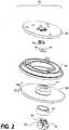
- FIG. 2shows an exploded perspective view of the components from Figure 1 .
- Such an exploded viewcan show an example assembly arrangement.
- Techniques hereincan include a method for assembling a pressure sensor for measuring pressure of a fluid, and a method for measuring pressure using such a pressure sensor.
- An example method for assemblyincludes providing a mounting frame 105 attachable to a pressure port of a fluid-containing enclosure.
- the mounting frame 105has an interior side 107 for facing the fluid-containing enclosure.
- the mounting frame 105has an exterior side 109 for facing away from the fluid-containing enclosure.
- the mounting frame 105defines an opening 111 that extends from the interior side 107 to the exterior side 109.
- a pedestal member 120is positioned at the opening 111 such that the pedestal member contacts a portion of interior side 107 of the mounting frame 105 such that the mounting frame 105 prevents the pedestal member 120 from completely passing through the opening 111 from the interior side 107 to the exterior side 109.
- the pedestal memberdefines a fluid conduit 121 extending completely through the pedestal member 120.
- the pedestal member 120is positioned such that the fluid conduit 121 and a surface area 124 of the pedestal member 120, through which the fluid conduit exits, are accessible from the exterior side 109 of the mounting frame 105.
- the pedestal member 120is assembled below the mounting frame 105, that is, the pedestal member rests on the interior or oil facing side of the mounting frame 105, in other words, being inserted from the bottom.
- the pedestal memberis a metal alloy affixed to the exterior side of a mounting plate, requiring strong adhesive to keep the pedestal member from detaching from the mounting frame.
- a microelectromechanical system (MEMS) die 130is attached to the pedestal member 120 at the surface area 124 of the pedestal member 120 such that when the fluid conduit 121 is filled with fluid from the fluid-containing enclosure, the fluid presses against the MEMS die 130.
- the pressure sensor device 100can then monitor changes in fluid pressure and signal associated control systems, such as signaling a pump to increase pressure within the fluid-containing enclosure, or signaling a valve to release excess pressure. Attaching the pedestal member 120 to the mounting frame 105 can be accomplished using a rigid seal 140 that prevents fluid from directly contacting the MEMs die 130 and prevents fluid from exiting the pressure sensor device 100. Such a bonding process can be executed within an oven when using solder glass or paste.
- the rigid seal 140can include the thermal expansion properties as explained above.
- An adhesive seal 116 or other sealant or epoxycan be used to affix the pedestal member 120 within the recessed opening.
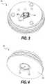
- Figure 3shows a top perspective view of a pressure sensor device 100. Visible from this view is the MEMS die 130.
- Figure 4shows a bottom view of the pressure sensor device 100. Visible from this view is the fluid conduit 121 through which fluid enters to press against the MEMs die 130. Note that while the pressure sensor device 100 is shown as being generally cylindrical, various geometries can be selected depending on application and design considerations.
- a pressure sensor devicefor measuring pressure of a fluid, the pressure sensor device comprising:
Landscapes
- Physics & Mathematics (AREA)
- General Physics & Mathematics (AREA)
- Health & Medical Sciences (AREA)
- Child & Adolescent Psychology (AREA)
- Measuring Fluid Pressure (AREA)
Description
- This application is related to United States Patent Application entitled "HEREMETICALLY GLASS SEALED PRESSURE SENSOR," (Attorney Docket No. SEN12-20(42843)) filed on the same date herewith. The entire teachings and contents of this Patent Application is hereby incorporated by reference herein in its entirety.
- The present disclosure relates to pressure sensor devices, and particularly to devices that identify changes in fluid pressure.
- Pressure sensors typically measure absolute or relative pressure of fluids such as gasses or liquids. Measurement of fluids enables accurate control and monitoring of various devices and systems. There are various sensor devices using any of multiple available mechanisms of action for measuring pressure. For example, given sensor devices can use piezoelectric, piezoresistive, optical, electromagnetic, and other technologies for measuring pressure. Some pressure sensors are being manufactured at very small sizes. For example, microelectromechanical systems (MEMS) are now being used as pressure sensors. The main function of a MEMS sensor is to transfer a pressure signal into an electrical output signal based on an absolute or differential pressure input combined with offering an electrical base signal. Such relatively small pressure sensors are useful in systems where size and weight are valid considerations.
US 2009/0071260 A1 discloses a pressure sensor having a MEMS device mounted on the end of a central column of a housing. The central column extends upwardly from the centre of the body of the housing. The body of the housing is attached to a circuit board with the central column passing into a hole in the circuit board. An optional support is provided between the MEMS device and the central column. A hole passes through the body and central column of the housing to expose the MEMS device to the pressure of the fluid.EP 1862543 A2 discloses a pressure sensor mounted on a base. A MEMS sensor element is mounted on a Pyrex member, which in turn is mounted on the base via thin linking members, which relieve stress on the MEMS sensor. A vent passes through the base and the linking and Pyrex members to expose the diaphragm of the base to the pressure of the fluid.- United States patent no.
US-B-6,845,664 discloses methods of bulk manufacturing high temperature sensor sub-assembly packages. Sensors are sandwiched between a top cover and a bottom cover so as to enable the peripheries of the top covers, sensors and bottom covers to be sealed and bound securely together. Sensors are placed on the bottom covers leaving the periphery of the bottom cover exposed. Likewise, top covers are placed on the sensors leaving the periphery of the sensor exposed. Individual sensor subassemblies are inserted into final packaging elements. Reference cavities are formed in some embodiments where top covers are not employed. - Using MEMS technology in pressure sensing technologies can be beneficial because of the small footprint of MEMS devices relative to conventional pressure sensing technologies. As such, MEMS devices are suitable for applications having size constraints such as automotive transmissions including dual clutch transmission (DCT) systems. A challenge with MEMS pressure sensing devices, however, is creating a cost-efficient as well as a robust assembly or package. Conventional MEMS pressure sensors can be relatively expensive and lose accuracy or even fail under certain operating conditions including high temperature, thermal expansion, and chemical deterioration. For example, conventional MEMS pressure sensors are costly due to the number and type of parts, and the use of precious metals such as gold for improving bonding capabilities. A MEMS sensing element should be sealed chemically from a sensed media (such as fluid or oil pressure). Also, with conventional components made of varied materials, there is a mismatch in coefficients of thermal expansion (CTE). The result of such a mismatch is that thermal conditions can break down a chemical seal due to thermal stress build-up and/or apply excessive expansive stress to a MEMS sensing element.
- One challenge with using MEMS pressure sensing elements is determining how to attach a MEMS die to a substrate to result in a sufficiently strong connection (physical attachment), but while enabling accurate pressure readings. A strong connection and good accuracy can be competing interests. With a strong connection there is always a corresponding level of stress that can be undesirable. For example, relatively high temperatures can induce stress through a MEMS die attachment bond. A strong connection translates these stresses to the die, affecting accuracy of pressure measurement. Conventional pressure sensors use metal alloy pedestals bonded to a MEMS die using a strong and stiff epoxy. Such metal alloy use is expensive and can compromise accuracy because of a significant difference in coefficient of thermal expansion values between the metal alloy material and the MEMS die. Conventional MEMS dies can also be manufactured with an integrated glass pedestal attached to the MEMS die during the wafer fabrication process. Such integrated glass pedestals are relatively expensive, and are conventionally bonded to a metal alloy base
- Techniques disclosed herein provide a strong connection of the MEMS die to a pressure sensor but while decoupling thermal expansion stress from the MEMS die. With such decoupling techniques, pressure sensing accuracy can exceed 99%. For example, techniques herein can use a glass pedestal having a tube or defining a fluid conduit. Moreover, instead of chemically bonding a metal pedestal to a mounting plate, the glass pedestal herein is held in place mechanically using a physical structure of a mounting frame. A portion of the glass pedestal is accessible from an exterior side of the mounting frame, or, alternatively, a portion of the glass pedestal protrudes from the mounting frame to enable MEMS die attachment. The MEMS die can then be attached to the glass pedestal using a glass paste. This glass paste forms a strong connection that is thermal expansion matched to the glass pedestal and MEMS die. With such a configuration, thermal expansion of the mounting frame is not a concern and thus the mounting frame does not need to be selected from a material with a similar coefficient of thermal expansion of the MEMs die. With some techniques, the glass pedestal can be inserted from below the mounting frame to form a compression seal. The MEMS die can be affixed either before or after such insertion in or partially through the mounting frame. In contrast, conventional sensors bond a metal alloy pedestal above a mounting plate and over an opening. With techniques herein, however, the mounting frame structure itself keeps the glass pedestal in position either by use of flanges, narrowing opening, or otherwise, and the glass pedestal is essentially below the mounting frame instead of being affixed above a mounting plate. With the glass pedestal held mechanically, as disclosed herein, a sealant used to keep a fluid medium out of the pressure sensor can be selected to have chemically robust properties, and can also be relatively flexible because this sealant does not need to withstand mechanical forces of the fluid medium.
- According to the present invention in claim 1 there is provided a pressure sensor device and a corresponding assembling method in claim 16 for measuring pressure of a fluid, the pressure sensor device comprising:
- a mounting frame attachable to a pressure port of a fluid-containing enclosure, the mounting frame having an interior side for facing the fluid-containing enclosure, the mounting frame having an exterior side for facing away from the fluid-containing enclosure, the mounting frame including a flange defining an opening that extends from the interior side to the exterior side;
- a pedestal member positioned at the opening and being in contact with a portion of interior side of the mounting frame such that the mounting frame prevents the pedestal member from completely passing through the opening when pressure is exerted on the pedestal member originating from the interior side and pressing the pedestal member towards the exterior side, the pedestal member defining a fluid conduit extending through the pedestal member, the pedestal member positioned such that the fluid conduit and a surface area of the pedestal member, through which the fluid conduit exits, are accessible from the exterior side of the mounting frame; and
- a microelectromechanical system (MEMS) die attached to the pedestal member at the surface area of the pedestal member such that when the fluid conduit is filled with fluid from the fluid-containing enclosure, the fluid presses against the MEMS die,
- characterised in that:
- the MEMS die is attached to the pedestal member using a rigid seal, the rigid seal having an opening such that the fluid contacts a portion of the MEMS die and preventing fluid from exiting the pressure sensor; and
- the pedestal member includes a shoulder positioned at the opening, the shoulder in contact with the flange on an interior side of the mounting frame such that the mounting frame mechanically prevents the pedestal member from completely passing through the opening when pressure is exerted on the pedestal member originating from the interior side and pressing the pedestal member towards the exterior side.
- In other embodiments, the pedestal member, MEMS die and a bonding material between the pedestal member and the MEMS die all have an approximately matched coefficient of thermal expansion.
- In another embodiment, a rigid seal comprising solder glass is disposed between the pedestal member and the MEMS die. The rigid seal has an opening such that the fluid contacts a portion of the MEMS die and the rigid seal preventing fluid from exiting the pressure sensor.
- Additionally, although each of the different features, techniques, configurations, etc. herein may be discussed in different places of this disclosure, it is intended that each of the concepts can be executed independently of each other or in combination with each other. Accordingly, the present invention can be embodied and viewed in many different ways.
- Note that this summary section herein does not specify every embodiment and/or incrementally novel aspect of the present disclosure or claimed invention. Instead, this summary only provides a preliminary discussion of different embodiments and corresponding points of novelty over conventional techniques. For additional details and/or possible perspectives of the invention and embodiments, the reader is directed to the Detailed Description section and corresponding figures of the present disclosure as further discussed below.
- The foregoing and other objects, features, and advantages of the invention will be apparent from the following more particular description of preferred embodiments herein as illustrated in the accompanying drawings in which like reference characters refer to the same parts throughout the different views. The drawings are not necessarily to scale, with emphasis instead being placed upon illustrating the embodiments, principles and concepts.
FIG. 1 is a cross-sectional side view of a pressure sensor according to embodiments herein.FIG. 2 is a perspective exploded view of example components of a pressure sensor according to embodiments herein.FIG. 3 is a top perspective view of a pressure sensor according to embodiments herein.FIG. 4 is a bottom perspective view of a pressure sensor according to embodiments herein.- Techniques disclosed herein include systems and methods for a pressure sensor. Pressure sensors herein can be used for measuring various types of fluid media including, but not limited to, air, oil, water, fuel, etc. Embodiments herein are especially useful for measuring oil pressure in automotive transmissions including dual clutch transmissions (DCT). For convenience in explaining the various embodiments herein, this disclosure will primarily reference a sensor device for used with a DCT. Such an application, however, is not limiting and pressure sensors herein can apply to other applications as well, especially to applications where size of the sensor is a valid consideration. In a DCT, there are several pressure sensors, and accurate pressure measurement at the clutches improves the smoothness of shifting and the driving experience.
- For dual clutch transmission (DCT) applications, a relatively small pressure sensor is very beneficial, as are other aspects such as functionality, robustness and price. The inherently small footprint of a microelectromechanical systems (MEMS) die (electronic circuit) is beneficial to achieve a reduced-size sensor. For a very small (2x2 mm or smaller) sensing element, a significant challenge is to design and manufacture a robust assembly/package. Conventional pressure sensors using a MEMS sensing element typically use either a glass to metal solder bond or an epoxy to connect the MEMS element to a supporting assembly. Techniques disclosed herein connect a backside exposed MEMS element to a glass material mechanically held by a port/flange of a mounting frame and also sealed using an adhesive bond. A matched glass seal bonds a MEMS element to a borosilicate tube or other glass pedestal member.
- In some embodiments, a relatively low-cost borosilicate glass tubes or blocks having conduits are used as an interface between the MEMS die and a metal mounting frame. The configuration of the mounting frame separates functions of chemical and mechanical strength as much as possible. A chemically resistant epoxy or other adhesive can provide a sufficient seal for transmission applications. Other bonding and/or sealing agents can be selected for harsher media such as fuels. The metallic mounting frame forms or defines a mechanical interface with a glass tube or pedestal component. A hole in the mounting frame enables the MEMS die to protrude (or be exposed) while the mounting frame supports the glass pedestal around the MEMS die. In such a configuration, a bond strength of a sealant between the glass pedestal and the mounting frame is less dependent on the mechanical properties of the epoxy or other adhesive material, which means that a given bond can be optimized for chemical robustness instead of mechanical strength. Because the adhesive is not exposed to a tensile force, the adhesive is primarily used for sealing the glass tube or glass pedestal member to a metal flange or other resistive structure of the mounting frame. Such a mechanical interface also lowers a possibility of a bond failing due to chemical degradation of the bond from aging and chemical effects. Such techniques result in a pressure sensor that is more reliable than conventional pressure sensors (having a MEMS directly attached with epoxy to the port). Another advantage of such techniques is that adhesive selection can compensate for the mismatches in coefficients of thermal expansion between the pedestal member and the mounting frame. The use of a metal or metal alloy mounting frame material is advantageous because such material selection can be completely matched with a material counterpart or base plate of a given automotive transmission housing at a pressure point attachment location. In some embodiments, however, the seal layer can have a sufficient thickness to affect other components. In such embodiments, a coefficient of thermal expansion of the seal layer can be matched with that of the MEMS die, a rigid seal, and pedestal member. With the mounting frame mechanically holding a pedestal member, a glass seal can be used for bonding the pedestal member and a MEMS die. The glass seal, the pedestal member and the MEMS die can all be thermally matched (i.e., having similar coefficient of thermal expansion values). This is a significant benefit because conventional metal alloy pedestals can have a coefficient of thermal expansion value that differs from the MEMS die by more than 50%.
- Referring now to
FIG. 1 , a cross-sectional side view of an examplepressure sensor device 100 for measuring pressure of a fluid is shown. A mountingframe 105 is attachable to a pressure port of a fluid-containing enclosure. The fluid-containing enclosure and corresponding pressure port are not shown. The fluid containing enclosure can be an automotive transmission housing, fluid tank, etc. Exemplary media can be gasses or liquids including oils. The mountingframe 105 has an interior portion orinterior side 107 for facing the fluid-containing enclosure. The mountingframe 105 has anexterior side 109 that faces away from the fluid-containing enclosure (or port of the fluid containing enclosure) when thepressure sensor device 100 is mounted to the-fluid containing enclosure. The mountingframe 105 defines anopening 111 that extends from theinterior side 107 to theexterior side 109. As shown inFigure 1 , theopening 111 is defined as part of a recessed portion of mountingframe 105. Note that such a configuration is not limiting and the opening can be flush or inline with the mountingframe 105, that is, with no recessed portion. In alternative embodiments, the mountingframe 105 can include a support structure that extends above theinterior side 107 to form a bracket or socket or lateral support. - Note that the mounting frame being attachable to a pressure port can be either directly attached or indirectly attached. For example, the
pressure sensor device 100 can include a threaded section and/or be contained or nested within a housing that physically attaches to the pressure port or fluid-containing enclosure, while thepressure sensor device 100 fits within the housing. - A
pedestal member 120 is positioned at theopening 111 and is in contact with a portion ofinterior side 107 of the mountingframe 105 such that the mountingframe 105 prevents thepedestal member 120 from completely passing through the opening as if traveling from theinterior side 107 towards to theexterior side 109. Thepedestal member 120 defines afluid conduit 121 extending completely through thepedestal member 120. Thepedestal member 120 is positioned such that thefluid conduit 121 and asurface area 124 of the pedestal member-through which the fluid conduit exits-are accessible from theexterior side 109 of the mountingframe 105. Thepedestal member 120 can be created from one or more materials having a coefficient of thermal expansion that is close to a coefficient of thermal expansion of a MEMS die. By way of a nonlimiting example,pedestal member 120 can be made of glass and shaped with various geometries depending on a particular application. In one embodiment, thepedestal member 120 has as a cylindrical shape with anupper portion 129. Other geometries are possible that still provide sufficient material to define afluid conduit 121 that can extend through theopening 111 whenpedestal member 120 is in contact with mountingframe 105. - A microelectromechanical system (MEMS) die 130 is attached to the
pedestal member 120 at thesurface area 124 of thepedestal member 120 such that when thefluid conduit 121 is filled with fluid from the fluid-containing enclosure (originating from the interior side 107), the fluid presses against the MEMS die 130. With fluid pressed against the MEMS die 130, thepressure sensor device 100 can monitor and detect changes in fluid pressure. The MEMS die is attached to the pedestal member using arigid seal 140. Therigid seal 140 includes an opening 141 (FIG. 2 ) where fluid can pass through and reach a portion of the MEMS die. Therigid seal 140 prevents fluid escaping around the MEMS die and preventing fluid from exiting thepressure sensor device 100 on theexterior side 109 thereby preventing contamination. Therigid seal 140 can have a first coefficient of thermal expansion and the MEMS die can have a second coefficient of thermal expansion. These coefficients of thermal expansion can both have a value within a predetermined range of coefficient of thermal expansion values, thereby having similar thermal expansion properties. Therigid seal 140 can be created from either solder glass, eutectic bonding, anodic bonding, fusion bonding, epoxy bonding, or similar techniques. In one embodiment using solder glass, therigid seal 140 can be set by heating the components to around 450 degrees Celsius, which is much lower than the maximum temperature that the MEMS die 130 can withstand. The solder glass can be applied using a paste and/or dispensing or by screen printing. By using a borosilicateglass pedestal member 120, a silicon MEMS die 130 can be directly attached to this tube or pedestal member, thereby eliminating a need for a relatively costly glass pedestal fused on the die level during wafer fabrication. In alternative embodiments, such as in applications having very high accuracy demands, the MEMS die 130 can include an optional glass pedestal (not shown) fused on the die level to lower forces caused by a small coefficient of thermal expansion mismatch between the solder glass and the silicon. - The
pedestal member 120 can be attached to the mountingframe 105 using anadhesive seal 116. Thisadhesive seal 116 can be flexible relative to therigid seal 140 that attaches the MEMS die 130 to thepedestal member 120. Coefficients of thermal expansion of thepedestal member 120, MEMS die 130, andrigid seal 140 can all be within a predetermined range of coefficient of thermal expansion values. For example, materials can be selected such that the CTE difference between the MEMS die and the pedestal member is less than about 2.0 ppm/ (degrees) K. When the seal layer is thicker than 200um, the CTE of the seal is a factor. In this case, the CTE of MEMS die 130,rigid seal 140 andpedestal member 120 should have a maximum difference of 2.0 ppm/K. For example, in one embodiment with a thicker seal layer, the CTE value of therigid seal 140 is about 3.0 ppm/K, thepedestal member 120 is Pyrex® 7740 borosilicate glass with a CTE of about 3.25 and the MEMS die CTE is about 2.5. In this example the maximum CTE difference between the components is about .75 ppm/K or about 30%. - In contrast, Alloy 42 has a CTE of about 4.9 ppm/K and a more expensive metal like Kovar has a CTE of about 4.5 ppm/K with differences of about 2.4 ppm/K and 2 ppm/K and percentage differences of about 96% and about 80%, respectively.
- With such techniques, fluid pressure within an enclosure pressing on the glass pedestal does not transfer this pressure to the MEMS die, but instead only fluid pressure through the
fluid conduit 121 creates pressure on the MEMS die 130. Fluid pressure on the pedestal member120 is received by the mountingframe 105 or flanges of the mounting frame, and that force is transferred to the mountingframe 105. - In some embodiments, the mounting
frame 105 defines a recessed opening, that is, recessed relative to theinterior side 107 such that the recessed opening protrudes on/above theexterior side 109. The mountingframe 105 can includeflange 114 that physically or mechanically holds thepedestal member 120 viapedestal member 120shoulder 127. In other words, theflange 114 contacts theshoulder 127 such that fluid pressure cannot force thepedestal member 120 through theopening 111. Note that other physical structures or configurations can be used such that the mountingframe 105 mechanically prevents thepedestal member 120 from passing through (completely through) theopening 111. For example, other embodiments can have a mounting frame with a gradually narrowing opening that prevents pedestal member passage. In other embodiments, the pedestal member can be positioned on a generally flatinterior side 107, with the mounting frame defining a ridge or other support structure partially surrounding thepedestal member 120 to prevent lateral movement of thepedestal member 120. - In some embodiment, the
pedestal member 120 includes a portion that protrudes through theopening 111, as shown inFigure 1 , such that the MEMS die 130 is attached outside of theopening 111. In other words, the MEMS die 130 is attached to thepedestal member 120 such that the MEMS die130 is positioned slightly above theexterior side 109. In other embodiments, thepedestal member 120 does not protrude through theopening 111, and instead the MEMS die 130 is positioned at least partially within theopening 111. - The
pressure sensor device 100 can also include a printed circuit board (PCB) 150 connected to the MEMS die 130, as well as asupport member 155 that attaches the printedcircuit board 150, and associated structures, to the mountingframe 105. ThePCB 150 can be used for signal processing and can include components to implement signal processing. Wire bonds or links can to electrically connect MEMS die 130 toPCB 150. The mountingframe 105 can be comprised of a metallic material such as metal or a metal alloy, and can be selected to match an enclosure material of a fluid-containing enclosure. The mountingframe 105 can be configured to attach to an automotive transmission, and the MEMS die 130 can be configured to monitor oil pressure within the automotive transmission. The MEMS die 130 and printedcircuit board 150 can be calibrated to monitor changes in oil pressure from a dual clutch transmission system. FIG. 2 shows an exploded perspective view of the components fromFigure 1 . Such an exploded view can show an example assembly arrangement. Techniques herein can include a method for assembling a pressure sensor for measuring pressure of a fluid, and a method for measuring pressure using such a pressure sensor. An example method for assembly includes providing a mountingframe 105 attachable to a pressure port of a fluid-containing enclosure. The mountingframe 105 has aninterior side 107 for facing the fluid-containing enclosure. The mountingframe 105 has anexterior side 109 for facing away from the fluid-containing enclosure. The mountingframe 105 defines anopening 111 that extends from theinterior side 107 to theexterior side 109. Apedestal member 120 is positioned at theopening 111 such that the pedestal member contacts a portion ofinterior side 107 of the mountingframe 105 such that the mountingframe 105 prevents thepedestal member 120 from completely passing through the opening 111 from theinterior side 107 to theexterior side 109. The pedestal member defines afluid conduit 121 extending completely through thepedestal member 120. Thepedestal member 120 is positioned such that thefluid conduit 121 and asurface area 124 of thepedestal member 120, through which the fluid conduit exits, are accessible from theexterior side 109 of the mountingframe 105. Note in the exploded view that thepedestal member 120 is assembled below the mountingframe 105, that is, the pedestal member rests on the interior or oil facing side of the mountingframe 105, in other words, being inserted from the bottom. In conventional pressure sensors, the pedestal member is a metal alloy affixed to the exterior side of a mounting plate, requiring strong adhesive to keep the pedestal member from detaching from the mounting frame.- Either before or after the
pedestal member 120 is attached to the mountingframe 105, a microelectromechanical system (MEMS) die 130 is attached to thepedestal member 120 at thesurface area 124 of thepedestal member 120 such that when thefluid conduit 121 is filled with fluid from the fluid-containing enclosure, the fluid presses against the MEMS die 130. Thepressure sensor device 100 can then monitor changes in fluid pressure and signal associated control systems, such as signaling a pump to increase pressure within the fluid-containing enclosure, or signaling a valve to release excess pressure. Attaching thepedestal member 120 to the mountingframe 105 can be accomplished using arigid seal 140 that prevents fluid from directly contacting the MEMs die 130 and prevents fluid from exiting thepressure sensor device 100. Such a bonding process can be executed within an oven when using solder glass or paste. Therigid seal 140 can include the thermal expansion properties as explained above. Anadhesive seal 116 or other sealant or epoxy can be used to affix thepedestal member 120 within the recessed opening. - Referring now to
FIGS. 3 and 4, Figure 3 shows a top perspective view of apressure sensor device 100. Visible from this view is the MEMS die 130.Figure 4 shows a bottom view of thepressure sensor device 100. Visible from this view is thefluid conduit 121 through which fluid enters to press against the MEMs die 130. Note that while thepressure sensor device 100 is shown as being generally cylindrical, various geometries can be selected depending on application and design considerations. - Those skilled in the art will also understand that there can be many variations made to the operations of the techniques explained above while still achieving the same objectives of the invention. Such variations are intended to be covered by the scope of this invention. As such, the foregoing descriptions of embodiments of the invention are not intended to be limiting. Rather, any limitations to embodiments of the invention are presented in the following claims.
- Further there is also disclosed a pressure sensor device for measuring pressure of a fluid, the pressure sensor device comprising:
- a mounting frame attachable to a pressure port of a fluid-containing enclosure, the mounting frame having an interior side for facing the fluid-containing enclosure, the mounting frame having an exterior side for facing away from the fluid-containing enclosure, the mounting frame defining an opening that extends from the interior side to the exterior side;
- a pedestal member positioned at the opening , the pedestal member defining a fluid conduit extending through the pedestal member, the pedestal member positioned such that the fluid conduit and a surface area of the pedestal member, through which the fluid conduit exits, are accessible from the exterior side of the mounting frame; and
- a microelectromechanical system (MEMS) die attached to the pedestal member at the surface area of the pedestal member such that when the fluid conduit is filled with fluid from the fluid-containing enclosure, the fluid presses against the MEMS die; and
- a rigid seal comprising solder glass disposed between the pedestal member and the MEMS die, the rigid seal having an opening such that the fluid contacts a portion of the MEMS die and the rigid seal preventing fluid from exiting the pressure sensor.
Claims (18)
- A pressure sensor device (100) for measuring pressure of a fluid, the pressure sensor device comprising:a mounting frame (105) attachable to a pressure port of a fluid-containing enclosure, the mounting frame having an interior side (107) for facing the fluid-containing enclosure, the mounting frame having an exterior side (109) for facing away from the fluid-containing enclosure, the mounting frame including a flange (114) defining an opening (111) that extends from the interior side to the exterior side;a pedestal member (120) defining a fluid conduit (121) extending through the pedestal member, the pedestal member positioned such that the fluid conduit and a surface area of the pedestal member, through which the fluid conduit exits, are accessible from the exterior side of the mounting frame; anda microelectromechanical system (MEMS) die (130) attached to the pedestal member at the surface area of the pedestal member such that when the fluid conduit is filled with fluid from the fluid-containing enclosure, the fluid presses against the MEMS die,characterised in that:the MEMS die is attached to the pedestal member using a rigid seal (140), the rigid seal having an opening (141) such that the fluid contacts a portion of the MEMS die and preventing fluid from exiting the pressure sensor; andthe pedestal member includes a shoulder (127) positioned at the opening (111), the shoulder in contact with the flange on an interior side of the mounting frame such that the mounting frame mechanically prevents the pedestal member from completely passing through the opening (111) when pressure is exerted on the pedestal member originating from the interior side and pressing the pedestal member towards the exterior side.
- The pressure sensor device of claim 1, wherein the rigid seal (140) has a first coefficient of thermal expansion and the MEMS die (130) has a second coefficient of thermal expansion, wherein the first coefficient of thermal expansion and the second coefficient of thermal expansion are within about .75 ppm/K of each other.
- The pressure sensor device of claim 1, wherein the rigid seal (140) forms a bond selected from the group consisting of solder glass bond, eutectic bond, anodic bond, fusion bond, and epoxy bond.
- The pressure sensor device of claim 1, wherein the rigid seal (140) has a first coefficient of thermal expansion and the MEMS die (130) has a second coefficient of thermal expansion, wherein the first coefficient of thermal expansion and the second coefficient of thermal expansion are within about 2.0 ppm/K of each other.
- The pressure sensor device of claim 1, wherein the pedestal member (120) is comprised of glass.
- The pressure sensor device of claim 5, wherein the glass pedestal member (120) is comprised of borosilicate glass.
- The pressure sensor device of claim 1, wherein the pedestal member (120) is attached to the mounting frame with an adhesive seal.
- The pressure sensor device of claim 7, wherein the adhesive seal is flexible relative to the rigid seal that attaches the MEMS die to the pedestal member.
- The pressure sensor device of claim 1, wherein the mounting frame (105) further defines a recessed opening relative to the interior side (107) wherein the recessed opening protrudes on the exterior side (109).
- The pressure sensor device of claim 1, wherein the pedestal member includes a portion (129) that protrudes through the opening such that the MEMS die is attached outside of the opening.
- The pressure sensor device of claim 1, further comprising:a printed circuit board (150) connected to the MEMS die; anda support member (155) that attaches the printed circuit board to the mounting frame.
- The pressure sensor device of claim 1, wherein coefficients of thermal expansion of the pedestal member (120), the MEMS die (130), and the rigid seal (140) are all within about .75 ppm/K of each other.
- The pressure sensor device of claim 12, wherein the mounting frame (105) is comprised of a metallic material.
- The pressure sensor device of claim 12, wherein the MEMS die (130) further includes a fused glass pedestal.
- The pressure sensor device of claim 1, wherein coefficients of thermal expansion of the pedestal member, the MEMS die, and the rigid seal are within about 2.0 ppm/K of each other.
- A method for assembling a pressure sensor (100) for measuring pressure of a fluid, the method comprising:providing a mounting frame (105) attachable to a pressure port of a fluid-containing enclosure, the mounting frame having an interior side (107) for facing the fluid-containing enclosure, the mounting frame having an exterior side (109) for facing away from the fluid-containing enclosure, the mounting frame including a flange (114) defining an opening (111) that extends from the interior side to the exterior side;providing a pedestal member (120) defining a fluid conduit (121) extending completely through the pedestal member, the pedestal member positioned such that the fluid conduit and a surface area of the pedestal member, through which the fluid conduit exits, are accessible from the exterior side of the mounting frame; andattaching a microelectromechanical system (MEMS) die (130) to the pedestal member at the surface area of the pedestal member such that when the fluid conduit is filled with fluid from the fluid-containing enclosure, the fluid presses against the MEMS die,characterised in that:the MEMS die is attached to the pedestal member using a rigid seal (140), the rigid seal preventing fluid from directly contacting the MEMS die and preventing fluid from exiting the pressure sensor; andthe pedestal member (120) includes a shoulder (127) positioned at the opening (111), the shoulder in contact with the flange on an interior side of the mounting frame such that the mounting frame mechanically prevents the pedestal member from completely passing through the opening (111) when pressure is exerted on the pedestal member originating from the interior side and pressing the pedestal member towards the exterior side.
- The method of claim 16, wherein the rigid seal (140) has a first coefficient of thermal expansion, the MEMS die (130) has a second coefficient of thermal expansion, and the pedestal member (120) has a third coefficient of thermal expansion, wherein the first coefficient of thermal expansion and the second coefficient of thermal expansion and the third coefficient of thermal expansion have values within a predetermined range of coefficient of thermal expansion values.
- The method of claim 17, wherein the mounting frame (105) further defines a recessed opening relative to the interior side (107) wherein the recessed opening protrudes on the exterior side (109).
Applications Claiming Priority (1)
| Application Number | Priority Date | Filing Date | Title |
|---|---|---|---|
| US13/615,783US8820170B2 (en) | 2012-09-14 | 2012-09-14 | Pressure sensor |
Publications (2)
| Publication Number | Publication Date |
|---|---|
| EP2708867A1 EP2708867A1 (en) | 2014-03-19 |
| EP2708867B1true EP2708867B1 (en) | 2019-06-26 |
Family
ID=49170609
Family Applications (1)
| Application Number | Title | Priority Date | Filing Date |
|---|---|---|---|
| EP13184453.2AActiveEP2708867B1 (en) | 2012-09-14 | 2013-09-13 | Pressure sensor |
Country Status (3)
| Country | Link |
|---|---|
| US (1) | US8820170B2 (en) |
| EP (1) | EP2708867B1 (en) |
| CN (1) | CN103674395B (en) |
Families Citing this family (15)
| Publication number | Priority date | Publication date | Assignee | Title |
|---|---|---|---|---|
| JP6228790B2 (en)* | 2013-09-18 | 2017-11-08 | アルプス電気株式会社 | Pressure detecting device and intake pressure measuring device using the same |
| DE102013111778B3 (en)* | 2013-10-25 | 2015-04-30 | Bürkert Werke GmbH | Microfluidic device unit |
| DE102015001988A1 (en)* | 2015-02-16 | 2016-08-18 | Lucas Automotive Gmbh | Hydraulic pressure sensor for a vehicle |
| US9963341B2 (en) | 2015-05-19 | 2018-05-08 | Rosemount Aerospace, Inc. | Pressure sensor package with stress isolation features |
| DE102015117736A1 (en)* | 2015-10-19 | 2017-04-20 | Endress+Hauser Gmbh+Co. Kg | Pressure measuring device |
| EP3196952B1 (en)* | 2016-01-21 | 2019-06-19 | AT & S Austria Technologie & Systemtechnik Aktiengesellschaft | Mems piezoelectric transducer formed at a pcb support structure |
| US9945748B2 (en)* | 2016-02-10 | 2018-04-17 | Minebea Mitsumi Inc. | Pressure sensor and apparatus |
| CN107764459B (en)* | 2016-08-17 | 2020-04-21 | 苏州明皜传感科技有限公司 | Pressure sensor and method for manufacturing the same |
| FR3075358B1 (en)* | 2017-12-14 | 2020-10-09 | Coutier Moulage Gen Ind | DEVICE FOR MEASURING A PHYSICAL PARAMETER OF A FLUID IN A MOTOR VEHICLE CIRCUIT |
| US10823753B2 (en) | 2018-12-14 | 2020-11-03 | Rosemount Aerospace Inc. | Air data probe with optical pressure integration |
| CN209326840U (en) | 2018-12-27 | 2019-08-30 | 热敏碟公司 | Pressure sensor and pressure transmitter |
| US11118992B2 (en)* | 2019-06-06 | 2021-09-14 | Measurement Specialties, Inc. | Pressure sensor assemblies with protective pressure feature |
| TWI705236B (en)* | 2019-06-28 | 2020-09-21 | 欽瑞工業股份有限公司 | Assembly structure of diaphragm pressure gauge |
| DE102019129311B4 (en)* | 2019-10-30 | 2021-08-12 | Schaeffler Technologies AG & Co. KG | Hydraulic actuator with space-saving integration of a pressure sensor |
| CN115752872B (en)* | 2022-11-21 | 2024-07-26 | 华北水利水电大学 | High-robustness gas pressure sensor |
Citations (1)
| Publication number | Priority date | Publication date | Assignee | Title |
|---|---|---|---|---|
| US6845664B1 (en)* | 2002-10-03 | 2005-01-25 | The United States Of America As Represented By The Administrator Of National Aeronautics And Space Administration | MEMS direct chip attach packaging methodologies and apparatuses for harsh environments |
Family Cites Families (8)
| Publication number | Priority date | Publication date | Assignee | Title |
|---|---|---|---|---|
| US7475597B2 (en) | 2006-02-27 | 2009-01-13 | Auxitrol S.A. | Stress isolated pressure sensing die |
| US7726197B2 (en)* | 2006-04-26 | 2010-06-01 | Honeywell International Inc. | Force sensor package and method of forming same |
| US20080222884A1 (en) | 2007-03-14 | 2008-09-18 | Honeywell International Inc. | Packaging for chip-on-board pressure sensor |
| DE102008025045A1 (en)* | 2007-06-02 | 2008-12-04 | Marquardt Gmbh | sensor |
| US7647835B2 (en) | 2007-09-19 | 2010-01-19 | Honeywell International Inc. | Pressure sensor stress isolation pedestal |
| US7775119B1 (en)* | 2009-03-03 | 2010-08-17 | S3C, Inc. | Media-compatible electrically isolated pressure sensor for high temperature applications |
| CN102341684B (en)* | 2009-03-06 | 2014-11-26 | 德怀尔仪器公司 | Pressure gage with magnetically coupled diaphragm |
| US8215176B2 (en)* | 2009-05-27 | 2012-07-10 | Continental Automotive Systems, Inc. | Pressure sensor for harsh media sensing and flexible packaging |
- 2012
- 2012-09-14USUS13/615,783patent/US8820170B2/enactiveActive
- 2013
- 2013-09-13CNCN201310491438.XApatent/CN103674395B/enactiveActive
- 2013-09-13EPEP13184453.2Apatent/EP2708867B1/enactiveActive
Patent Citations (1)
| Publication number | Priority date | Publication date | Assignee | Title |
|---|---|---|---|---|
| US6845664B1 (en)* | 2002-10-03 | 2005-01-25 | The United States Of America As Represented By The Administrator Of National Aeronautics And Space Administration | MEMS direct chip attach packaging methodologies and apparatuses for harsh environments |
Also Published As
| Publication number | Publication date |
|---|---|
| US20140076057A1 (en) | 2014-03-20 |
| CN103674395B (en) | 2018-03-30 |
| EP2708867A1 (en) | 2014-03-19 |
| CN103674395A (en) | 2014-03-26 |
| US8820170B2 (en) | 2014-09-02 |
Similar Documents
| Publication | Publication Date | Title |
|---|---|---|
| EP2708867B1 (en) | Pressure sensor | |
| EP2708866B1 (en) | Hermetically Glass Sealed Pressure Sensor | |
| CN109696268B (en) | Pressure sensor assembly | |
| EP2474819B1 (en) | Media isolated pressure sensor | |
| EP3111182B1 (en) | Differential pressure sensor | |
| EP2316008B1 (en) | Sensor device packaging and corresponding method | |
| EP3111184B1 (en) | Differential pressure sensing die | |
| US8499642B2 (en) | Hermetically sealed pressure sensing device | |
| EP2474820B1 (en) | Pressure sensor with low cost packaging | |
| US9593995B2 (en) | Package for a differential pressure sensing die | |
| AU2011254029A1 (en) | Force sensor | |
| WO2001053789A1 (en) | Isolation technique for pressure sensing structure | |
| EP1562030B1 (en) | Pressure sensor with metal diaphragm | |
| CN114295281A (en) | Differential pressure sensor and method of use |
Legal Events
| Date | Code | Title | Description |
|---|---|---|---|
| PUAI | Public reference made under article 153(3) epc to a published international application that has entered the european phase | Free format text:ORIGINAL CODE: 0009012 | |
| AK | Designated contracting states | Kind code of ref document:A1 Designated state(s):AL AT BE BG CH CY CZ DE DK EE ES FI FR GB GR HR HU IE IS IT LI LT LU LV MC MK MT NL NO PL PT RO RS SE SI SK SM TR | |
| AX | Request for extension of the european patent | Extension state:BA ME | |
| 17P | Request for examination filed | Effective date:20140918 | |
| RBV | Designated contracting states (corrected) | Designated state(s):AL AT BE BG CH CY CZ DE DK EE ES FI FR GB GR HR HU IE IS IT LI LT LU LV MC MK MT NL NO PL PT RO RS SE SI SK SM TR | |
| RAP1 | Party data changed (applicant data changed or rights of an application transferred) | Owner name:SENSATA TECHNOLOGIES, INC. | |
| STAA | Information on the status of an ep patent application or granted ep patent | Free format text:STATUS: EXAMINATION IS IN PROGRESS | |
| 17Q | First examination report despatched | Effective date:20171121 | |
| GRAP | Despatch of communication of intention to grant a patent | Free format text:ORIGINAL CODE: EPIDOSNIGR1 | |
| STAA | Information on the status of an ep patent application or granted ep patent | Free format text:STATUS: GRANT OF PATENT IS INTENDED | |
| INTG | Intention to grant announced | Effective date:20190107 | |
| GRAS | Grant fee paid | Free format text:ORIGINAL CODE: EPIDOSNIGR3 | |
| GRAA | (expected) grant | Free format text:ORIGINAL CODE: 0009210 | |
| STAA | Information on the status of an ep patent application or granted ep patent | Free format text:STATUS: THE PATENT HAS BEEN GRANTED | |
| AK | Designated contracting states | Kind code of ref document:B1 Designated state(s):AL AT BE BG CH CY CZ DE DK EE ES FI FR GB GR HR HU IE IS IT LI LT LU LV MC MK MT NL NO PL PT RO RS SE SI SK SM TR | |
| REG | Reference to a national code | Ref country code:GB Ref legal event code:FG4D | |
| REG | Reference to a national code | Ref country code:CH Ref legal event code:EP | |
| REG | Reference to a national code | Ref country code:AT Ref legal event code:REF Ref document number:1148847 Country of ref document:AT Kind code of ref document:T Effective date:20190715 | |
| REG | Reference to a national code | Ref country code:DE Ref legal event code:R096 Ref document number:602013057025 Country of ref document:DE | |
| REG | Reference to a national code | Ref country code:IE Ref legal event code:FG4D | |
| REG | Reference to a national code | Ref country code:NL Ref legal event code:MP Effective date:20190626 | |
| PG25 | Lapsed in a contracting state [announced via postgrant information from national office to epo] | Ref country code:AL Free format text:LAPSE BECAUSE OF FAILURE TO SUBMIT A TRANSLATION OF THE DESCRIPTION OR TO PAY THE FEE WITHIN THE PRESCRIBED TIME-LIMIT Effective date:20190626 Ref country code:SE Free format text:LAPSE BECAUSE OF FAILURE TO SUBMIT A TRANSLATION OF THE DESCRIPTION OR TO PAY THE FEE WITHIN THE PRESCRIBED TIME-LIMIT Effective date:20190626 Ref country code:NO Free format text:LAPSE BECAUSE OF FAILURE TO SUBMIT A TRANSLATION OF THE DESCRIPTION OR TO PAY THE FEE WITHIN THE PRESCRIBED TIME-LIMIT Effective date:20190926 Ref country code:FI Free format text:LAPSE BECAUSE OF FAILURE TO SUBMIT A TRANSLATION OF THE DESCRIPTION OR TO PAY THE FEE WITHIN THE PRESCRIBED TIME-LIMIT Effective date:20190626 Ref country code:LT Free format text:LAPSE BECAUSE OF FAILURE TO SUBMIT A TRANSLATION OF THE DESCRIPTION OR TO PAY THE FEE WITHIN THE PRESCRIBED TIME-LIMIT Effective date:20190626 Ref country code:HR Free format text:LAPSE BECAUSE OF FAILURE TO SUBMIT A TRANSLATION OF THE DESCRIPTION OR TO PAY THE FEE WITHIN THE PRESCRIBED TIME-LIMIT Effective date:20190626 | |
| REG | Reference to a national code | Ref country code:LT Ref legal event code:MG4D | |
| PG25 | Lapsed in a contracting state [announced via postgrant information from national office to epo] | Ref country code:RS Free format text:LAPSE BECAUSE OF FAILURE TO SUBMIT A TRANSLATION OF THE DESCRIPTION OR TO PAY THE FEE WITHIN THE PRESCRIBED TIME-LIMIT Effective date:20190626 Ref country code:GR Free format text:LAPSE BECAUSE OF FAILURE TO SUBMIT A TRANSLATION OF THE DESCRIPTION OR TO PAY THE FEE WITHIN THE PRESCRIBED TIME-LIMIT Effective date:20190927 Ref country code:BG Free format text:LAPSE BECAUSE OF FAILURE TO SUBMIT A TRANSLATION OF THE DESCRIPTION OR TO PAY THE FEE WITHIN THE PRESCRIBED TIME-LIMIT Effective date:20190926 Ref country code:LV Free format text:LAPSE BECAUSE OF FAILURE TO SUBMIT A TRANSLATION OF THE DESCRIPTION OR TO PAY THE FEE WITHIN THE PRESCRIBED TIME-LIMIT Effective date:20190626 | |
| REG | Reference to a national code | Ref country code:AT Ref legal event code:MK05 Ref document number:1148847 Country of ref document:AT Kind code of ref document:T Effective date:20190626 | |
| PG25 | Lapsed in a contracting state [announced via postgrant information from national office to epo] | Ref country code:PT Free format text:LAPSE BECAUSE OF FAILURE TO SUBMIT A TRANSLATION OF THE DESCRIPTION OR TO PAY THE FEE WITHIN THE PRESCRIBED TIME-LIMIT Effective date:20191028 Ref country code:NL Free format text:LAPSE BECAUSE OF FAILURE TO SUBMIT A TRANSLATION OF THE DESCRIPTION OR TO PAY THE FEE WITHIN THE PRESCRIBED TIME-LIMIT Effective date:20190626 Ref country code:CZ Free format text:LAPSE BECAUSE OF FAILURE TO SUBMIT A TRANSLATION OF THE DESCRIPTION OR TO PAY THE FEE WITHIN THE PRESCRIBED TIME-LIMIT Effective date:20190626 Ref country code:AT Free format text:LAPSE BECAUSE OF FAILURE TO SUBMIT A TRANSLATION OF THE DESCRIPTION OR TO PAY THE FEE WITHIN THE PRESCRIBED TIME-LIMIT Effective date:20190626 Ref country code:EE Free format text:LAPSE BECAUSE OF FAILURE TO SUBMIT A TRANSLATION OF THE DESCRIPTION OR TO PAY THE FEE WITHIN THE PRESCRIBED TIME-LIMIT Effective date:20190626 Ref country code:RO Free format text:LAPSE BECAUSE OF FAILURE TO SUBMIT A TRANSLATION OF THE DESCRIPTION OR TO PAY THE FEE WITHIN THE PRESCRIBED TIME-LIMIT Effective date:20190626 Ref country code:SK Free format text:LAPSE BECAUSE OF FAILURE TO SUBMIT A TRANSLATION OF THE DESCRIPTION OR TO PAY THE FEE WITHIN THE PRESCRIBED TIME-LIMIT Effective date:20190626 | |
| PG25 | Lapsed in a contracting state [announced via postgrant information from national office to epo] | Ref country code:ES Free format text:LAPSE BECAUSE OF FAILURE TO SUBMIT A TRANSLATION OF THE DESCRIPTION OR TO PAY THE FEE WITHIN THE PRESCRIBED TIME-LIMIT Effective date:20190626 Ref country code:SM Free format text:LAPSE BECAUSE OF FAILURE TO SUBMIT A TRANSLATION OF THE DESCRIPTION OR TO PAY THE FEE WITHIN THE PRESCRIBED TIME-LIMIT Effective date:20190626 Ref country code:IS Free format text:LAPSE BECAUSE OF FAILURE TO SUBMIT A TRANSLATION OF THE DESCRIPTION OR TO PAY THE FEE WITHIN THE PRESCRIBED TIME-LIMIT Effective date:20191026 Ref country code:IT Free format text:LAPSE BECAUSE OF FAILURE TO SUBMIT A TRANSLATION OF THE DESCRIPTION OR TO PAY THE FEE WITHIN THE PRESCRIBED TIME-LIMIT Effective date:20190626 | |
| PG25 | Lapsed in a contracting state [announced via postgrant information from national office to epo] | Ref country code:TR Free format text:LAPSE BECAUSE OF FAILURE TO SUBMIT A TRANSLATION OF THE DESCRIPTION OR TO PAY THE FEE WITHIN THE PRESCRIBED TIME-LIMIT Effective date:20190626 | |
| PG25 | Lapsed in a contracting state [announced via postgrant information from national office to epo] | Ref country code:DK Free format text:LAPSE BECAUSE OF FAILURE TO SUBMIT A TRANSLATION OF THE DESCRIPTION OR TO PAY THE FEE WITHIN THE PRESCRIBED TIME-LIMIT Effective date:20190626 Ref country code:PL Free format text:LAPSE BECAUSE OF FAILURE TO SUBMIT A TRANSLATION OF THE DESCRIPTION OR TO PAY THE FEE WITHIN THE PRESCRIBED TIME-LIMIT Effective date:20190626 | |
| PG25 | Lapsed in a contracting state [announced via postgrant information from national office to epo] | Ref country code:MC Free format text:LAPSE BECAUSE OF FAILURE TO SUBMIT A TRANSLATION OF THE DESCRIPTION OR TO PAY THE FEE WITHIN THE PRESCRIBED TIME-LIMIT Effective date:20190626 Ref country code:IS Free format text:LAPSE BECAUSE OF FAILURE TO SUBMIT A TRANSLATION OF THE DESCRIPTION OR TO PAY THE FEE WITHIN THE PRESCRIBED TIME-LIMIT Effective date:20200224 | |
| REG | Reference to a national code | Ref country code:CH Ref legal event code:PL | |
| REG | Reference to a national code | Ref country code:DE Ref legal event code:R097 Ref document number:602013057025 Country of ref document:DE | |
| PLBE | No opposition filed within time limit | Free format text:ORIGINAL CODE: 0009261 | |
| STAA | Information on the status of an ep patent application or granted ep patent | Free format text:STATUS: NO OPPOSITION FILED WITHIN TIME LIMIT | |
| PG2D | Information on lapse in contracting state deleted | Ref country code:IS | |
| PG25 | Lapsed in a contracting state [announced via postgrant information from national office to epo] | Ref country code:LU Free format text:LAPSE BECAUSE OF NON-PAYMENT OF DUE FEES Effective date:20190913 Ref country code:LI Free format text:LAPSE BECAUSE OF NON-PAYMENT OF DUE FEES Effective date:20190930 Ref country code:IE Free format text:LAPSE BECAUSE OF NON-PAYMENT OF DUE FEES Effective date:20190913 Ref country code:CH Free format text:LAPSE BECAUSE OF NON-PAYMENT OF DUE FEES Effective date:20190930 | |
| 26N | No opposition filed | Effective date:20200603 | |
| REG | Reference to a national code | Ref country code:BE Ref legal event code:MM Effective date:20190930 | |
| PG25 | Lapsed in a contracting state [announced via postgrant information from national office to epo] | Ref country code:BE Free format text:LAPSE BECAUSE OF NON-PAYMENT OF DUE FEES Effective date:20190930 Ref country code:SI Free format text:LAPSE BECAUSE OF FAILURE TO SUBMIT A TRANSLATION OF THE DESCRIPTION OR TO PAY THE FEE WITHIN THE PRESCRIBED TIME-LIMIT Effective date:20190626 | |
| PG25 | Lapsed in a contracting state [announced via postgrant information from national office to epo] | Ref country code:FR Free format text:LAPSE BECAUSE OF NON-PAYMENT OF DUE FEES Effective date:20190930 | |
| PG25 | Lapsed in a contracting state [announced via postgrant information from national office to epo] | Ref country code:CY Free format text:LAPSE BECAUSE OF FAILURE TO SUBMIT A TRANSLATION OF THE DESCRIPTION OR TO PAY THE FEE WITHIN THE PRESCRIBED TIME-LIMIT Effective date:20190626 | |
| PG25 | Lapsed in a contracting state [announced via postgrant information from national office to epo] | Ref country code:MT Free format text:LAPSE BECAUSE OF FAILURE TO SUBMIT A TRANSLATION OF THE DESCRIPTION OR TO PAY THE FEE WITHIN THE PRESCRIBED TIME-LIMIT Effective date:20190626 Ref country code:HU Free format text:LAPSE BECAUSE OF FAILURE TO SUBMIT A TRANSLATION OF THE DESCRIPTION OR TO PAY THE FEE WITHIN THE PRESCRIBED TIME-LIMIT; INVALID AB INITIO Effective date:20130913 | |
| PG25 | Lapsed in a contracting state [announced via postgrant information from national office to epo] | Ref country code:MK Free format text:LAPSE BECAUSE OF FAILURE TO SUBMIT A TRANSLATION OF THE DESCRIPTION OR TO PAY THE FEE WITHIN THE PRESCRIBED TIME-LIMIT Effective date:20190626 | |
| P01 | Opt-out of the competence of the unified patent court (upc) registered | Effective date:20230529 | |
| PGFP | Annual fee paid to national office [announced via postgrant information from national office to epo] | Ref country code:DE Payment date:20240927 Year of fee payment:12 | |
| PGFP | Annual fee paid to national office [announced via postgrant information from national office to epo] | Ref country code:GB Payment date:20240927 Year of fee payment:12 |