EP2707749B1 - System for determination of a container's position in a vehicle and/or in its trailer to be loaded with containers - Google Patents
System for determination of a container's position in a vehicle and/or in its trailer to be loaded with containersDownload PDFInfo
- Publication number
- EP2707749B1 EP2707749B1EP12781941.5AEP12781941AEP2707749B1EP 2707749 B1EP2707749 B1EP 2707749B1EP 12781941 AEP12781941 AEP 12781941AEP 2707749 B1EP2707749 B1EP 2707749B1
- Authority
- EP
- European Patent Office
- Prior art keywords
- container
- trailer
- crane
- vehicle
- containers
- Prior art date
- Legal status (The legal status is an assumption and is not a legal conclusion. Google has not performed a legal analysis and makes no representation as to the accuracy of the status listed.)
- Active
Links
Images


Classifications
- B—PERFORMING OPERATIONS; TRANSPORTING
- B66—HOISTING; LIFTING; HAULING
- B66C—CRANES; LOAD-ENGAGING ELEMENTS OR DEVICES FOR CRANES, CAPSTANS, WINCHES, OR TACKLES
- B66C13/00—Other constructional features or details
- B66C13/18—Control systems or devices
- B66C13/46—Position indicators for suspended loads or for crane elements
- G—PHYSICS
- G01—MEASURING; TESTING
- G01B—MEASURING LENGTH, THICKNESS OR SIMILAR LINEAR DIMENSIONS; MEASURING ANGLES; MEASURING AREAS; MEASURING IRREGULARITIES OF SURFACES OR CONTOURS
- G01B11/00—Measuring arrangements characterised by the use of optical techniques
- G01B11/14—Measuring arrangements characterised by the use of optical techniques for measuring distance or clearance between spaced objects or spaced apertures
- G—PHYSICS
- G01—MEASURING; TESTING
- G01S—RADIO DIRECTION-FINDING; RADIO NAVIGATION; DETERMINING DISTANCE OR VELOCITY BY USE OF RADIO WAVES; LOCATING OR PRESENCE-DETECTING BY USE OF THE REFLECTION OR RERADIATION OF RADIO WAVES; ANALOGOUS ARRANGEMENTS USING OTHER WAVES
- G01S17/00—Systems using the reflection or reradiation of electromagnetic waves other than radio waves, e.g. lidar systems
- G01S17/02—Systems using the reflection of electromagnetic waves other than radio waves
- G01S17/06—Systems determining position data of a target
- G01S17/42—Simultaneous measurement of distance and other co-ordinates
Definitions
- the inventionrelates to loading of containers into vehicles for use in road transportation, especially into trailer lorries intended for container transportation, and to unloading of containers from these.
- the inventionconcerns a system for determination of the container's position in the vehicle to be loaded with containers and/or in its trailer in the container loading area, such as a container freight terminal, where the container or containers are loaded into the vehicle and/or its trailer and are correspondingly unloaded from it/them by a container crane handling the containers and moving in the loading area above the traffic lane or traffic lanes equipped with a container spreader gripping the containers from above and with a positioning system for the container crane and the container spreader, whereby the vehicle and thus also its trailer are equipped with lock pins locking into pin holes in the corners of the container, whereby the system has laser scanners for determining the position of the lock pins in the vehicle and/or its trailer and thus for determining the container's position depending on the pins.
- the loading and unloading of road trailer lorries transporting containersis an important part of the operations in almost all container freight terminals.
- the unloading of trailer lorrieshardly differs at all from a situation in which the container is picked up in a container depot area, because in both cases the empty container spreader is lowered on to the top of the container, whereupon the container is locked to the spreader with the aid of locking pins.
- the containerIn automatic container crane systems the container can be lifted automatically from the lorry, for example, with the aid of measuring systems based on laser scanners. However, in most terminals the unloading of containers is a manual operation due to safety provisions.
- JP2005239343A printed patent specificationconcerns a system for determination of the positions of trailer lorries to be loaded or unloaded in relation to the crane handling the containers.
- the systemuses laser scanners located in the crane body.
- the containercan be lifted automatically from the trailer lorry, for example, with the aid of measuring systems based on laser scanners.
- EP1337454A1 printed patent specificationpresents a system for determination of the position of a trailer lorry to be loaded or unloaded in relation to a crane handling the containers.
- the systemuses sensors located in the crane body at the level of the trailer lorry's platform.
- EP 0 820 957 Adiscloses a system according to the preamble of claim 1.
- the present inventionaims at providing a new kind of solution for determination of the container's position in a vehicle to be loaded with containers and/or in its trailer.
- the inventionis mainly characterized in that a laser scanner /laser scanners are installed in the loading area into a fixed structure and are arranged to determine the positions in relation to the ground of locking pins in a vehicle parked in the loading area and/or in its trailer, and in that the system is arranged to relay the position information determined by the laser scanner to a crane, whereby the crane's positioning system based on the crane's and container spreader's position information is adapted to calculate the position of the locking pins in relation to the crane.
- the laser scanner/laser scannersare preferably installed beside a traffic lane/traffic lanes.
- the laser scanner in questionis arranged to determine the positions of locking pins in a vehicle parked in the traffic lane and/or in its trailer.
- one laser scanneris arranged to determine the positions of locking pins in 1 - 4 vehicles parked in the traffic lane and/or in their trailers.
- At least two locking pinsare turned to be in sight in the vehicle and/or its trailer for each container to be loaded.
- the container's position on the lorry's platformis determined by determining the position of locking pins on the platform with the aid of a laser scanner. Owing to this, the reliability of the system is considerably better compared, for example, with camera-based systems. Besides a higher reliability, the accuracy of the system is also better than in solutions of the prior art.
- FIG. 1 in the drawingis a schematic side view of a container crane by way of example, with which the system according to the invention can be applied.
- the container craneis indicated by the general reference number 10 and it is of the so-called STS (Ship-to-Shore) crane type, which is arranged on a quay 11 to travel along rails 12.
- STSChip-to-Shore
- the container crane 10is arranged to move containers 13 from a container carrier ship 14 on to transportation pallets 15 or other such trailers 17 pulled by a vehicle 16, and the other way round, during the loading and unloading of the carrier ship 14.
- the container crane 10has a vertical body, which comprises legs 18, 19 and which supports a horizontal beam 20, along which a lift bogie 21 is adapted to travel.
- the lift bogie 21carries a container spreader 23, which is used to grip a container 13 from the top.
- the operator's cabinis connected to the lift bogie 21 and it is indicated by reference number 24, and the crane's electrically operated power machine is indicated by reference number 25.
- FIG 2is a schematic view of a gantry crane 10a, which is used in a container freight terminal and with which the system according to the invention can also be applied.
- the gantry crane 10acan be a gantry crane travelling on rails (RMG, Rail Mounted Gantry Crane) or, as is shown in Figure 2 , a rubber tyred gantry crane (RTG, Rubber Tyred Gantry Crane).
- RMGRail Mounted Gantry Crane
- RMGRubber Tyred Gantry Crane
- the gantry crane 10ais intended for transferring containers 13 from transportation pallets 15 or other such trailers pulled by a vehicle and to stack the containers 13 in container rows located in a container field, and the other way round.
- the gantry crane 10ahas a vertical body, which comprises legs 18a, 19a and which supports a horizontal bridge 20a, along which a lift bogie 21a is adapted to travel. Through lift ropes 22a the lift bogie 21a carries a container spreader 23a, which is used to grip the container 13 from the top.
- the container rowsremain in between the gantry crane's 10a legs 18a, 19a, and in between the legs there is also a traffic lane 26a, along which vehicle-trailer-combinations drive under the crane in order to transfer containers 13 from the trailer into container rows, or the other way round.
- FIGs 3 and 4are schematic views of an automatic stacking crane 10b (ASC, Automatic Stacking Crane), which is used in a container freight terminal and with which the system according to the invention can also be applied.
- the automatic stacking crane 10bhas a structure resembling that of the gantry crane 10a shown in Figure 2 and it is intended in a similar way to transfer containers 13 from vehicles 16 and from trailers 17 pulled by these and to stack the containers 13 in container rows located in a container field, and the other way round.
- the crane 10b according to Figures 3 and 4is designed to work automatically, that is, without an operator.
- the structure of the automatic stacking crane 10bis largely similar to that of the gantry crane 10a of Figure 2 , and thus it is equipped with a vertical body, which comprises legs 18b, 19b and which carries a horizontal bridge 20b, along which a lift bogie 21b is adapted to travel. Through lift ropes 22b the lift bogie 21b carries a container spreader 23b, which is used for gripping the container 13 from above.
- the automatic stacking crane 10b of Figures 3 and 4operates, for example, in a container freight terminal or, correspondingly, in a port in a container interchange area (LS, Landside interchange area), where traffic lanes 26b are arranged for vehicles 16 and their trailers 17.
- LScontainer interchange area
- This area comprising traffic lanes 12bfunctions as a loading area, in the case of Figures 3 and 4 especially as an automated loading area, where loading and unloading of the containers take place.
- the rows formed by containers 13 as well as the traffic lanes 26bremain in between the crane's 10b legs 18b, 19b.
- there are 6 traffic lanes 26b and their middle linesare indicated by reference mark 27b.
- the loading of containers 13 into a vehicle 16 and/or its trailer 17is done in such a way that the vehicle 16 and its trailer 17 are first reversed into a vacant traffic lane 26b and are parked there.
- the driver of vehicle 16then prepares the vehicle 16 and/or its trailer 17 for loading by lifting up and in sight the container's locking pins 1, whereupon he/she leaves the automated loading area.
- For loadingthere should preferably be 2-4 locking pins 1 in sight for each container 13, for the loading to succeed.
- In one container 13there are always four pin holes, but all four pins need not hereby be in sight for the loading.
- crane 10bautomatically performs the loading of vehicle 16 and/or trailer.
- the crane 10bmoves the container/containers 13 away from the vehicle and/or trailer after the locking pins 1 have been opened and the operator has left the loading area for a safe area.
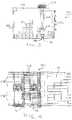
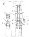
- FIGs 5 and 6thus are schematic views of a vehicle 16 and a combined vehicle 16 and trailer 17 located on two parallel traffic lanes 26.
- said vehicle 16 and said combination formed by vehicle 16 and trailer 17are empty and they have thus been driven on to the traffic lanes 26 to be loaded.
- Containers 13are loaded into the vehicle 16 and into the combination formed by vehicle 16 and trailer 17, and, correspondingly, in an unloading situation they are unloaded by a container crane 10 travelling above the traffic lanes 26, a gantry crane 10a or, correspondingly, by an automatically stacking crane 10b, which has a container spreader 23, 23a, 23b gripping the containers 13 from above.
- the vehicle 16 and similarly its trailer 17have locking pins 1, which lock into pin holes in the corners of the container 13.
- the container crane 10, gantry crane 10a or correspondingly the automatically stacking crane 10bare provided with a positioning system, which senses the crane's position in relation to the coordinate system of the container field and, on the other hand, the position of the container spreader 23, 23a, 23b in relation to the crane.
- the system according to the invention for determination of a container's position in a vehicle 16 to be loaded with containers and/or in its trailer 17is equipped with laser scanners for determination of the position of locking pins 1 in the vehicle 16 and/or in its trailer 17 and for determination of the container's position depending on these.
- the laser scanneris indicated by reference number 2 and in the presentation in the figures it is placed into a fixed structure located in the loading area, as in a column 3 as shown in Figures 5 and 6 .
- the laser scanner 2is located in a fixed structure, its position in relation to the ground and to the coordinate system of the container field is known and it is always known exactly.
- In the loading areathere may also be several laser scanners 2, especially in a case where there are several traffic lanes 26 in parallel.
- Each traffic lanemay then have its own scanner or, correspondingly, in certain cases the arrangement may be such that one laser scanner attends to 1-4 traffic lanes 26.
- the laser scanners 2are arranged to determine the positions in relation to the ground of the locking pins 1 in a vehicle 16 and in its trailer 17 parked in the traffic lane 26.
- the systemrelays the position information determined by laser scanners 2 to the cranes 10, 10a, 10b, and based on the crane's 10, 10a, 10b and the container spreader's 23, 23a, 23b position information the crane's positioning system calculates the position of the locking pins 1 in relation to the crane 10, 10a, 10b.
Landscapes
- Engineering & Computer Science (AREA)
- Physics & Mathematics (AREA)
- Electromagnetism (AREA)
- General Physics & Mathematics (AREA)
- Mechanical Engineering (AREA)
- Automation & Control Theory (AREA)
- Remote Sensing (AREA)
- Radar, Positioning & Navigation (AREA)
- Computer Networks & Wireless Communication (AREA)
- Control And Safety Of Cranes (AREA)
- Forklifts And Lifting Vehicles (AREA)
- Loading Or Unloading Of Vehicles (AREA)
- Ship Loading And Unloading (AREA)
Description
- The invention relates to loading of containers into vehicles for use in road transportation, especially into trailer lorries intended for container transportation, and to unloading of containers from these. In greater detail, the invention concerns a system for determination of the container's position in the vehicle to be loaded with containers and/or in its trailer in the container loading area, such as a container freight terminal, where the container or containers are loaded into the vehicle and/or its trailer and are correspondingly unloaded from it/them by a container crane handling the containers and moving in the loading area above the traffic lane or traffic lanes equipped with a container spreader gripping the containers from above and with a positioning system for the container crane and the container spreader, whereby the vehicle and thus also its trailer are equipped with lock pins locking into pin holes in the corners of the container, whereby the system has laser scanners for determining the position of the lock pins in the vehicle and/or its trailer and thus for determining the container's position depending on the pins.
- The loading and unloading of road trailer lorries transporting containers is an important part of the operations in almost all container freight terminals. As an operation, the unloading of trailer lorries hardly differs at all from a situation in which the container is picked up in a container depot area, because in both cases the empty container spreader is lowered on to the top of the container, whereupon the container is locked to the spreader with the aid of locking pins.
- In automatic container crane systems the container can be lifted automatically from the lorry, for example, with the aid of measuring systems based on laser scanners. However, in most terminals the unloading of containers is a manual operation due to safety provisions.
- The loading of trailer lorries is a much more challenging task than unloading. In the trailer of road lorries transporting containers there are usually locking pins making sure that the container will remain in its position during the transportation. Lowering the container with sufficient accuracy, so that the pin holes of the lowered container will come together with the locking pins with sufficient accuracy, is an operation demanding precision. The crane operator's range of visibility is restricted by the container hanging from the container spreader and preventing the operator from seeing the locking pins in the lorry in the late stage of lowering.
- Various systems are used to make handling of trailers easier. For example, there are systems where with the aid of a measuring system based on a laser scanner the lorry driver is helped to stop in relation to the crane, so that there is no need to run the primary motions of the crane. Primary motions are those moving the entire portal or lift bogie.
- Of prior art solutions representing the laser scanner technology the
CN201161875Y printed patent specification is taken as an example, which presents a system for determination of the positions in relation to the crane of the container crane's container spreader and of the trailer lorry to be loaded or unloaded and especially of the locking pins on its platform (or of the container's locking holes). From the information produced by the laser scanners used in the system the type of the lorry to be loaded and/or the type of the container to be lifted off the lorry is also concluded. - A second example of solutions using laser scanner technology is presented in the
CN1884034A printed patent specification, which concerns a system for determination of the positions in relation to the crane of a trailer lorry to be loaded or unloaded by a container crane and of containers located on its platform. From the information produced by the laser scanners used in the system the type of the lorry to be loaded and/or the type of the container to be lifted off the lorry is also concluded. - As a third example of solutions representing this technology the
JP2005239343A - The container can be lifted automatically from the trailer lorry, for example, with the aid of measuring systems based on laser scanners.
- There are also systems based on cameras, which with the aid of computer vision aim at identifying the place of the container determined by locking pins in the trailer. One such solution is presented in the
DE3606363A1 printed patent specification, which concerns a system for determination of the position of a trailer lorry to be loaded or unloaded in relation to a crane handling the containers. The system uses cameras located in the crane body at the level of the trailer lorry's platform. The problem with camera-based computer vision systems is their modest reliability due to environmental conditions. Changing lighting, in particular, will cause wrong interpretations. Reliability is very important when controlling the crane's container spreader on the basis of information from the measuring system. Material damages can be caused by false measuring information. - As one more example of the state of the art reference is made to the
EP1337454A1 printed patent specification, which presents a system for determination of the position of a trailer lorry to be loaded or unloaded in relation to a crane handling the containers. The system uses sensors located in the crane body at the level of the trailer lorry's platform. EP 0 820 957 A discloses a system according to the preamble ofclaim 1.- The present invention aims at providing a new kind of solution for determination of the container's position in a vehicle to be loaded with containers and/or in its trailer. To achieve this aim the invention is mainly characterized in that a laser scanner /laser scanners are installed in the loading area into a fixed structure and are arranged to determine the positions in relation to the ground of locking pins in a vehicle parked in the loading area and/or in its trailer, and in that the system is arranged to relay the position information determined by the laser scanner to a crane, whereby the crane's positioning system based on the crane's and container spreader's position information is adapted to calculate the position of the locking pins in relation to the crane.
- The laser scanner/laser scanners are preferably installed beside a traffic lane/traffic lanes.
- According to one embodiment of the invention, there is a separate laser scanner for each traffic lane, so that the laser scanner in question is arranged to determine the positions of locking pins in a vehicle parked in the traffic lane and/or in its trailer. Alternatively, one laser scanner is arranged to determine the positions of locking pins in 1 - 4 vehicles parked in the traffic lane and/or in their trailers.
- For loading each vehicle and/or its trailer with a container/containers, at least two locking pins are turned to be in sight in the vehicle and/or its trailer for each container to be loaded.
- The invention provides significant advantages over the state of the art. In the system according to the invention, the container's position on the lorry's platform is determined by determining the position of locking pins on the platform with the aid of a laser scanner. Owing to this, the reliability of the system is considerably better compared, for example, with camera-based systems. Besides a higher reliability, the accuracy of the system is also better than in solutions of the prior art.
- Other advantages and characteristic features of the invention will emerge from the following description in greater detail of the invention, in which the invention is explained by referring to figures in the appended drawing, to the details of which the invention is not exclusively restricted.
Figure 1 is a schematic view of a container crane, which is used in a port and in which the system according to the invention can be applied.Figure 2 is a schematic view of a gantry crane, which is used in a container freight terminal and in which the system according to the invention can also be applied.Figure 3 is a schematic view seen from the front, that is, from the direction of arrival of vehicles, of a stacking crane, which is used in a container freight terminal and in which the system according to the invention can be applied.Figure 4 is similar toFigure 3 seen from above.Figure 5 is a schematic view from above of a vehicle and a combination of a vehicle and a trailer in two parallel traffic lanes.Figure 6 is similar to the view inFigure 5 seen from the direction of arrival of vehicles.Figure 1 in the drawing is a schematic side view of a container crane by way of example, with which the system according to the invention can be applied. InFigure 1 , the container crane is indicated by thegeneral reference number 10 and it is of the so-called STS (Ship-to-Shore) crane type, which is arranged on a quay 11 to travel alongrails 12. Thecontainer crane 10 is arranged to movecontainers 13 from acontainer carrier ship 14 on totransportation pallets 15 or othersuch trailers 17 pulled by avehicle 16, and the other way round, during the loading and unloading of thecarrier ship 14. Thecontainer crane 10 has a vertical body, which compriseslegs 18, 19 and which supports ahorizontal beam 20, along which alift bogie 21 is adapted to travel. Through lift ropes 22 thelift bogie 21 carries acontainer spreader 23, which is used to grip acontainer 13 from the top. The operator's cabin is connected to thelift bogie 21 and it is indicated byreference number 24, and the crane's electrically operated power machine is indicated byreference number 25. Under the crane there aretraffic lanes 26, along which vehicle-trailer-combinations drive under the crane in order to transfercontainers 13 from the trailer into thecontainer carrier ship 14, or the other way round.Figure 2 is a schematic view of agantry crane 10a, which is used in a container freight terminal and with which the system according to the invention can also be applied. Thegantry crane 10a can be a gantry crane travelling on rails (RMG, Rail Mounted Gantry Crane) or, as is shown inFigure 2 , a rubber tyred gantry crane (RTG, Rubber Tyred Gantry Crane). Thegantry crane 10a is intended for transferringcontainers 13 fromtransportation pallets 15 or other such trailers pulled by a vehicle and to stack thecontainers 13 in container rows located in a container field, and the other way round. Thegantry crane 10a has a vertical body, which compriseslegs horizontal bridge 20a, along which alift bogie 21a is adapted to travel. Through lift ropes 22a thelift bogie 21a carries acontainer spreader 23a, which is used to grip thecontainer 13 from the top. The container rows remain in between the gantry crane's10a legs traffic lane 26a, along which vehicle-trailer-combinations drive under the crane in order to transfercontainers 13 from the trailer into container rows, or the other way round.Figures 3 and 4 are schematic views of an automatic stackingcrane 10b (ASC, Automatic Stacking Crane), which is used in a container freight terminal and with which the system according to the invention can also be applied. The automatic stackingcrane 10b has a structure resembling that of thegantry crane 10a shown inFigure 2 and it is intended in a similar way to transfercontainers 13 fromvehicles 16 and fromtrailers 17 pulled by these and to stack thecontainers 13 in container rows located in a container field, and the other way round. Thecrane 10b according toFigures 3 and 4 is designed to work automatically, that is, without an operator. Thus, the structure of the automatic stackingcrane 10b is largely similar to that of thegantry crane 10a ofFigure 2 , and thus it is equipped with a vertical body, which compriseslegs 18b, 19b and which carries a horizontal bridge 20b, along which a lift bogie 21b is adapted to travel. Throughlift ropes 22b the lift bogie 21b carries a container spreader 23b, which is used for gripping thecontainer 13 from above. The automatic stackingcrane 10b ofFigures 3 and 4 operates, for example, in a container freight terminal or, correspondingly, in a port in a container interchange area (LS, Landside interchange area), wheretraffic lanes 26b are arranged forvehicles 16 and theirtrailers 17. This area comprising traffic lanes 12b functions as a loading area, in the case ofFigures 3 and 4 especially as an automated loading area, where loading and unloading of the containers take place. The rows formed bycontainers 13 as well as thetraffic lanes 26b remain in between the crane's10b legs 18b, 19b. In the case ofFigures 3 and 4 there are 6traffic lanes 26b and their middle lines are indicated by reference mark 27b.- The loading of
containers 13 into avehicle 16 and/or itstrailer 17 is done in such a way that thevehicle 16 and itstrailer 17 are first reversed into avacant traffic lane 26b and are parked there. The driver ofvehicle 16 then prepares thevehicle 16 and/or itstrailer 17 for loading by lifting up and in sight the container's locking pins 1, whereupon he/she leaves the automated loading area. For loading, there should preferably be 2-4locking pins 1 in sight for eachcontainer 13, for the loading to succeed. In onecontainer 13 there are always four pin holes, but all four pins need not hereby be in sight for the loading. When the operator has left the loading area for a safe area,crane 10b automatically performs the loading ofvehicle 16 and/or trailer. Similarly, in an unloading situation of the load thecrane 10b moves the container/containers 13 away from the vehicle and/or trailer after the locking pins 1 have been opened and the operator has left the loading area for a safe area. Figures 5 and6 thus are schematic views of avehicle 16 and a combinedvehicle 16 andtrailer 17 located on twoparallel traffic lanes 26. In the view shown inFigures 5 and6 , saidvehicle 16 and said combination formed byvehicle 16 andtrailer 17 are empty and they have thus been driven on to thetraffic lanes 26 to be loaded.Containers 13 are loaded into thevehicle 16 and into the combination formed byvehicle 16 andtrailer 17, and, correspondingly, in an unloading situation they are unloaded by acontainer crane 10 travelling above thetraffic lanes 26, agantry crane 10a or, correspondingly, by an automatically stackingcrane 10b, which has acontainer spreader containers 13 from above. Thevehicle 16 and similarly itstrailer 17 have lockingpins 1, which lock into pin holes in the corners of thecontainer 13. Thecontainer crane 10,gantry crane 10a or correspondingly the automatically stackingcrane 10b are provided with a positioning system, which senses the crane's position in relation to the coordinate system of the container field and, on the other hand, the position of thecontainer spreader - The system according to the invention for determination of a container's position in a
vehicle 16 to be loaded with containers and/or in itstrailer 17 is equipped with laser scanners for determination of the position of lockingpins 1 in thevehicle 16 and/or in itstrailer 17 and for determination of the container's position depending on these. InFigures 5 and6 the laser scanner is indicated byreference number 2 and in the presentation in the figures it is placed into a fixed structure located in the loading area, as in a column 3 as shown inFigures 5 and6 . When thelaser scanner 2 is located in a fixed structure, its position in relation to the ground and to the coordinate system of the container field is known and it is always known exactly. In the loading area there may also beseveral laser scanners 2, especially in a case where there areseveral traffic lanes 26 in parallel. Each traffic lane may then have its own scanner or, correspondingly, in certain cases the arrangement may be such that one laser scanner attends to 1-4traffic lanes 26. Thelaser scanners 2 are arranged to determine the positions in relation to the ground of the locking pins 1 in avehicle 16 and in itstrailer 17 parked in thetraffic lane 26. In accordance with the invention, the system relays the position information determined bylaser scanners 2 to thecranes crane - The invention was described above by way of example by referring to the figures in the enclosed drawing. However, the invention is not intended only to concern the examples shown in the figures, but different embodiments of the invention may vary within the scope of the inventive idea defined in the appended claims.
Claims (5)
- System for determination of a container's position in a vehicle and/or its trailer to be loaded with containers in a loading area for containers (13), such as a container freight terminal, where a container or containers (13) are loaded into a vehicle (16) and/or its trailer (17) and, correspondingly, they are unloaded from this/these by a crane (10, 10a, 10b), which handles containers and travels in the loading area above a traffic lane or traffic lanes (26, 26a, 26b), and which is equipped with a container spreader (23, 23a, 23b) gripping the containers (13) from above and with a positioning system for the crane (10, 10a, 10b) and the container spreader (23, 23a, 23b), whereby the vehicle (16) and similarly its trailer (17) have locking pins (1) locking into pin holes in the corners of the container (13), whereby the system has laser scanners (2) for determination of the position of the locking pins (1) in the vehicle (16) and/or in its trailer (17) and for determination of the container's position depending on these,characterized in that the laser scanner/laser scanners (2) are installed in the loading area into a fixed structure (3) and they are arranged to determine the positions in relation to the ground of the locking pins (1) in the vehicle (16) and/or in its trailer (17) parked in the loading area, and that the system is arranged to relay the position information determined by the laser scanner (2) to the crane (10, 10a, 10b), whereby based on the crane's (10, 10a, 10b) and the container spreader's (23, 23a, 23b) position information the crane's positioning system is adapted to calculate the position of the locking pins (1) in relation to the crane (10, 10a, 10b).
- System according to claim 1,characterized in that the laser scanner/laser scanners (2) are installed beside the traffic lane/traffic lanes (26, 26a, 26b).
- System according to claim 1 or 2,characterized in that for each traffic lane (26, 26a, 26b) there is its own laser scanner (2), so that said laser scanner is arranged to determine the positions of the locking pins (1) in the vehicle (16) and/or its trailer (17) parked in the traffic lane.
- System according to claim 1 or 2,characterized in that one laser scanner (2) is arranged to determine the positions of locking pins (1) in 1 - 4 vehicles (16) and/or their trailers (17) parked in the traffic lane (26, 26a, 26b).
- System according to some preceding claim,characterized in that for loading each vehicle (16) and/or its trailer (17) with a container/containers (13) at least two locking pins (1) are turned to be in sight in the vehicle (16) and/or its trailer (17) for each container (13) to be loaded.
Applications Claiming Priority (2)
| Application Number | Priority Date | Filing Date | Title |
|---|---|---|---|
| FI20110159AFI122666B (en) | 2011-05-10 | 2011-05-10 | System for determining the location of a container in a vehicle and / or its trailer being loaded |
| PCT/FI2012/050331WO2012152984A1 (en) | 2011-05-10 | 2012-04-02 | System for determination of a container's position in a vehicle and/or in its trailer to be loaded with containers |
Publications (3)
| Publication Number | Publication Date |
|---|---|
| EP2707749A1 EP2707749A1 (en) | 2014-03-19 |
| EP2707749A4 EP2707749A4 (en) | 2015-02-18 |
| EP2707749B1true EP2707749B1 (en) | 2016-06-08 |
Family
ID=44071519
Family Applications (1)
| Application Number | Title | Priority Date | Filing Date |
|---|---|---|---|
| EP12781941.5AActiveEP2707749B1 (en) | 2011-05-10 | 2012-04-02 | System for determination of a container's position in a vehicle and/or in its trailer to be loaded with containers |
Country Status (9)
| Country | Link |
|---|---|
| US (1) | US9181068B2 (en) |
| EP (1) | EP2707749B1 (en) |
| AU (1) | AU2012252262B2 (en) |
| ES (1) | ES2600083T3 (en) |
| FI (1) | FI122666B (en) |
| MY (1) | MY164063A (en) |
| PT (1) | PT2707749T (en) |
| SG (1) | SG194657A1 (en) |
| WO (1) | WO2012152984A1 (en) |
Families Citing this family (12)
| Publication number | Priority date | Publication date | Assignee | Title |
|---|---|---|---|---|
| FI130426B (en)* | 2014-06-30 | 2023-08-23 | Konecranes Oyj | Cargo transport using a cargo handling device |
| CN104528531B (en)* | 2014-12-31 | 2016-06-01 | 北京国泰星云科技有限公司 | Under terminal of containers RTG, RMG, truck contraposition guides system and method |
| US10370201B2 (en)* | 2015-11-13 | 2019-08-06 | Kabushiki Kaisha Toshiba | Transporting apparatus and transporting method |
| FI129963B (en) | 2017-03-16 | 2022-11-30 | Konecranes Global Oy | Monitoring of a container mover when a container is placed on a transport bed or lifted from a transport bed and an optical identification device for monitoring a container mover |
| JP7052675B2 (en)* | 2018-10-31 | 2022-04-12 | 株式会社豊田自動織機 | Automated guided vehicle |
| EP3699136A1 (en)* | 2019-02-25 | 2020-08-26 | ABB Schweiz AG | Container crane comprising reference marker |
| CN109795953A (en)* | 2019-03-04 | 2019-05-24 | 青岛港国际股份有限公司 | Landside automatic operation system of automated container terminal yard and its control method |
| FI130196B (en)* | 2019-10-04 | 2023-04-17 | Cargotec Finland Oy | Spreader position control |
| CN113376651B (en)* | 2020-03-09 | 2022-11-29 | 长沙智能驾驶研究院有限公司 | Three-dimensional laser-based method and device for detecting lifting prevention of container truck and computer equipment |
| CN113376654B (en)* | 2020-03-09 | 2023-05-26 | 长沙智能驾驶研究院有限公司 | Method and device for detecting anti-smashing of integrated card based on three-dimensional laser and computer equipment |
| EP4323302A4 (en) | 2021-04-12 | 2025-02-26 | Structural Services, Inc. | SYSTEMS AND METHODS FOR SUPPORTING A CRANE OPERATOR |
| US12195306B2 (en) | 2021-04-12 | 2025-01-14 | Structural Services, Inc. | Systems and methods for identifying and locating building material objects |
Citations (7)
| Publication number | Priority date | Publication date | Assignee | Title |
|---|---|---|---|---|
| EP0820957A1 (en) | 1996-07-24 | 1998-01-28 | Framatome | Method and device for handling containers |
| JP2002255476A (en) | 2001-02-26 | 2002-09-11 | Mitsui Eng & Shipbuild Co Ltd | A position / posture detection system for containers of container handling cranes or container transport vehicles. |
| DE10212590A1 (en) | 2002-03-15 | 2003-10-09 | Demag Mobile Cranes Gmbh | Optical device for the automatic loading and unloading of containers on vehicles |
| US20040125985A1 (en) | 2001-10-26 | 2004-07-01 | Claes Heidenback | Chassis alignment system |
| CN1884034A (en) | 2006-07-06 | 2006-12-27 | 上海交通大学 | Double laser radar positioning method for aligning sling and container truck |
| DE102008014125A1 (en) | 2007-08-14 | 2009-02-26 | Siemens Aktiengesellschaft | Computer-aided object i.e. trailer, localization method, involves extracting and locating partial structure determined in one extraction step from partial structures determined in preceding extraction steps |
| US20100243593A1 (en) | 2009-03-26 | 2010-09-30 | Henry King | Method and apparatus for crane topple/collision prevention |
Family Cites Families (10)
| Publication number | Priority date | Publication date | Assignee | Title |
|---|---|---|---|---|
| US5819962A (en)* | 1993-03-05 | 1998-10-13 | Mitsubishi Jukogyo Kabushiki Kaisha | Apparatus for stopping the oscillation of hoisted cargo |
| US6135301A (en)* | 1994-03-28 | 2000-10-24 | Mitsubishi Jukogyo Kabushiki Kaisha | Swaying hoisted load-piece damping control apparatus |
| JP3262734B2 (en)* | 1997-03-14 | 2002-03-04 | 俊弘 津村 | Cargo handling equipment |
| US6351720B1 (en)* | 1997-10-24 | 2002-02-26 | Mitsubishi Heavy Industries, Ltd. | Trolley camera position detecting apparatus |
| DE19916999A1 (en)* | 1999-04-15 | 2000-10-19 | Noell Stahl Und Maschinenbau G | Positioning system for container stacking trucks uses laser scanner to avoid adjusting crane |
| DE10251910B4 (en)* | 2002-11-07 | 2013-03-14 | Siemens Aktiengesellschaft | container crane |
| DE102007055316A1 (en)* | 2007-08-02 | 2009-02-05 | Siemens Ag | Computer-assisted system to establish load bearing points of a load, e.g. a container, on a load carrier has a number of three-dimensional measurement points in a reference co-ordinate layout in sensitive zones |
| US8451139B2 (en)* | 2010-02-22 | 2013-05-28 | Cnh America Llc | System and method for coordinating harvester and transport vehicle unloading operations |
| EP2531434B1 (en)* | 2011-04-13 | 2015-05-20 | TMEIC Corporation | Container handler alignment system and method |
| FI123746B (en)* | 2011-11-22 | 2013-10-15 | Cargotec Finland Oy | System for detecting and measuring the location of a container in a vehicle and / or its container loaded with containers |
- 2011
- 2011-05-10FIFI20110159Apatent/FI122666B/enactiveIP Right Grant
- 2012
- 2012-04-02EPEP12781941.5Apatent/EP2707749B1/enactiveActive
- 2012-04-02ESES12781941.5Tpatent/ES2600083T3/enactiveActive
- 2012-04-02PTPT127819415Tpatent/PT2707749T/enunknown
- 2012-04-02MYMYPI2013702119Apatent/MY164063A/enunknown
- 2012-04-02WOPCT/FI2012/050331patent/WO2012152984A1/enactiveApplication Filing
- 2012-04-02USUS14/117,316patent/US9181068B2/enactiveActive
- 2012-04-02AUAU2012252262Apatent/AU2012252262B2/enactiveActive
- 2012-04-02SGSG2013079769Apatent/SG194657A1/enunknown
Patent Citations (8)
| Publication number | Priority date | Publication date | Assignee | Title |
|---|---|---|---|---|
| EP0820957A1 (en) | 1996-07-24 | 1998-01-28 | Framatome | Method and device for handling containers |
| JP2002255476A (en) | 2001-02-26 | 2002-09-11 | Mitsui Eng & Shipbuild Co Ltd | A position / posture detection system for containers of container handling cranes or container transport vehicles. |
| US20040125985A1 (en) | 2001-10-26 | 2004-07-01 | Claes Heidenback | Chassis alignment system |
| DE10212590A1 (en) | 2002-03-15 | 2003-10-09 | Demag Mobile Cranes Gmbh | Optical device for the automatic loading and unloading of containers on vehicles |
| US20050192702A1 (en) | 2002-03-15 | 2005-09-01 | Jannis Moutsokapas | Optical device for the automatic loading and unloading of containers onto vehicles |
| CN1884034A (en) | 2006-07-06 | 2006-12-27 | 上海交通大学 | Double laser radar positioning method for aligning sling and container truck |
| DE102008014125A1 (en) | 2007-08-14 | 2009-02-26 | Siemens Aktiengesellschaft | Computer-aided object i.e. trailer, localization method, involves extracting and locating partial structure determined in one extraction step from partial structures determined in preceding extraction steps |
| US20100243593A1 (en) | 2009-03-26 | 2010-09-30 | Henry King | Method and apparatus for crane topple/collision prevention |
Non-Patent Citations (3)
| Title |
|---|
| "3D scanner", WIKIPEDIA, THE FREE ENCYCLOPEDIA, 11 April 2008 (2008-04-11), XP055363419, Retrieved from the Internet <URL:http://web.archive.org/web/20080501225212/https://en.wikipedia.org/wiki/Laser_scanning> |
| "Laser measurement systems for container harbour", LASE, 5 December 2007 (2007-12-05), pages 1 - 68, XP055363414 |
| GIOVANNA SANSONI ET AL.: "State-of-The-Art and Applications of 3D Imaging Sensors in Industry, Cultural Heritage, Medicine, and Criminal Investigation", SENSORS, vol. 9, no. 1, 20 January 2009 (2009-01-20), Branze 38, Brescia 1-25123, Italy, pages 568 - 601, XP055363410, [retrieved on 20090000] |
Also Published As
| Publication number | Publication date |
|---|---|
| MY164063A (en) | 2017-11-15 |
| FI20110159A0 (en) | 2011-05-10 |
| ES2600083T3 (en) | 2017-02-07 |
| EP2707749A4 (en) | 2015-02-18 |
| AU2012252262A1 (en) | 2013-11-28 |
| FI122666B (en) | 2012-05-15 |
| SG194657A1 (en) | 2013-12-30 |
| US9181068B2 (en) | 2015-11-10 |
| AU2012252262B2 (en) | 2017-02-02 |
| AU2012252262A8 (en) | 2014-04-03 |
| WO2012152984A1 (en) | 2012-11-15 |
| EP2707749A1 (en) | 2014-03-19 |
| US20150191333A1 (en) | 2015-07-09 |
| PT2707749T (en) | 2016-10-06 |
Similar Documents
| Publication | Publication Date | Title |
|---|---|---|
| EP2707749B1 (en) | System for determination of a container's position in a vehicle and/or in its trailer to be loaded with containers | |
| EP2782863B1 (en) | System for indicating and measuring the position of a container in a vehicle and/or trailer loaded with containers | |
| JP5905867B2 (en) | Container transshipment system | |
| AU2018332246B2 (en) | Method for controlling travel within a transfer zone for containers of transport vehicles in a terminal for containers, control system for same, and terminal comprising a control system of this kind | |
| US20200156627A1 (en) | Automatically guided transportation vehicle for containers and method for operating the same and also system with an automatically driven transportation vehicle | |
| US11702323B2 (en) | Automatically guided lifting gantry device for containers and method for operating such a lifting gantry device | |
| US6602036B2 (en) | Buffer bridge crane for cargo container handling operations | |
| CN106029547B (en) | A stacking crane with an intermediate storage area for containers | |
| KR20140015236A (en) | A system for handling cargo | |
| CN108545666A (en) | A kind of fork truck | |
| KR100970818B1 (en) | Buffer Straddle Crane | |
| US6685418B2 (en) | Buffer jib crane for cargo container handling operations | |
| KR101037262B1 (en) | Method for handling cargo containers by dockside buffer jib crane in cooperation with key crane | |
| KR20150048143A (en) | System for the contactless inspection of containers, particularly iso containers, within a loading and unloading plant | |
| US20090317213A1 (en) | Buffer crane for facilitating simultaneous multiple cargo container handling | |
| JP2014196152A (en) | Container terminal and operation method of container terminal | |
| RU83063U1 (en) | COMPLEX FOR LOADING-UNLOADING GOODS |
Legal Events
| Date | Code | Title | Description |
|---|---|---|---|
| PUAI | Public reference made under article 153(3) epc to a published international application that has entered the european phase | Free format text:ORIGINAL CODE: 0009012 | |
| 17P | Request for examination filed | Effective date:20131104 | |
| AK | Designated contracting states | Kind code of ref document:A1 Designated state(s):AL AT BE BG CH CY CZ DE DK EE ES FI FR GB GR HR HU IE IS IT LI LT LU LV MC MK MT NL NO PL PT RO RS SE SI SK SM TR | |
| DAX | Request for extension of the european patent (deleted) | ||
| A4 | Supplementary search report drawn up and despatched | Effective date:20150121 | |
| RIC1 | Information provided on ipc code assigned before grant | Ipc:B66C 13/46 20060101ALI20150115BHEP Ipc:G01S 17/42 20060101AFI20150115BHEP | |
| GRAP | Despatch of communication of intention to grant a patent | Free format text:ORIGINAL CODE: EPIDOSNIGR1 | |
| INTG | Intention to grant announced | Effective date:20151118 | |
| GRAS | Grant fee paid | Free format text:ORIGINAL CODE: EPIDOSNIGR3 | |
| GRAA | (expected) grant | Free format text:ORIGINAL CODE: 0009210 | |
| AK | Designated contracting states | Kind code of ref document:B1 Designated state(s):AL AT BE BG CH CY CZ DE DK EE ES FI FR GB GR HR HU IE IS IT LI LT LU LV MC MK MT NL NO PL PT RO RS SE SI SK SM TR | |
| REG | Reference to a national code | Ref country code:GB Ref legal event code:FG4D | |
| REG | Reference to a national code | Ref country code:CH Ref legal event code:EP | |
| REG | Reference to a national code | Ref country code:IE Ref legal event code:FG4D | |
| REG | Reference to a national code | Ref country code:AT Ref legal event code:REF Ref document number:805628 Country of ref document:AT Kind code of ref document:T Effective date:20160715 | |
| REG | Reference to a national code | Ref country code:DE Ref legal event code:R096 Ref document number:602012019432 Country of ref document:DE | |
| REG | Reference to a national code | Ref country code:NL Ref legal event code:FP | |
| REG | Reference to a national code | Ref country code:SE Ref legal event code:TRGR | |
| REG | Reference to a national code | Ref country code:PT Ref legal event code:SC4A Ref document number:2707749 Country of ref document:PT Date of ref document:20161006 Kind code of ref document:T Free format text:AVAILABILITY OF NATIONAL TRANSLATION Effective date:20160928 | |
| REG | Reference to a national code | Ref country code:LT Ref legal event code:MG4D | |
| PG25 | Lapsed in a contracting state [announced via postgrant information from national office to epo] | Ref country code:NO Free format text:LAPSE BECAUSE OF FAILURE TO SUBMIT A TRANSLATION OF THE DESCRIPTION OR TO PAY THE FEE WITHIN THE PRESCRIBED TIME-LIMIT Effective date:20160908 Ref country code:LT Free format text:LAPSE BECAUSE OF FAILURE TO SUBMIT A TRANSLATION OF THE DESCRIPTION OR TO PAY THE FEE WITHIN THE PRESCRIBED TIME-LIMIT Effective date:20160608 Ref country code:FI Free format text:LAPSE BECAUSE OF FAILURE TO SUBMIT A TRANSLATION OF THE DESCRIPTION OR TO PAY THE FEE WITHIN THE PRESCRIBED TIME-LIMIT Effective date:20160608 | |
| REG | Reference to a national code | Ref country code:AT Ref legal event code:MK05 Ref document number:805628 Country of ref document:AT Kind code of ref document:T Effective date:20160608 | |
| PG25 | Lapsed in a contracting state [announced via postgrant information from national office to epo] | Ref country code:HR Free format text:LAPSE BECAUSE OF FAILURE TO SUBMIT A TRANSLATION OF THE DESCRIPTION OR TO PAY THE FEE WITHIN THE PRESCRIBED TIME-LIMIT Effective date:20160608 Ref country code:RS Free format text:LAPSE BECAUSE OF FAILURE TO SUBMIT A TRANSLATION OF THE DESCRIPTION OR TO PAY THE FEE WITHIN THE PRESCRIBED TIME-LIMIT Effective date:20160608 Ref country code:LV Free format text:LAPSE BECAUSE OF FAILURE TO SUBMIT A TRANSLATION OF THE DESCRIPTION OR TO PAY THE FEE WITHIN THE PRESCRIBED TIME-LIMIT Effective date:20160608 Ref country code:GR Free format text:LAPSE BECAUSE OF FAILURE TO SUBMIT A TRANSLATION OF THE DESCRIPTION OR TO PAY THE FEE WITHIN THE PRESCRIBED TIME-LIMIT Effective date:20160909 | |
| PG25 | Lapsed in a contracting state [announced via postgrant information from national office to epo] | Ref country code:EE Free format text:LAPSE BECAUSE OF FAILURE TO SUBMIT A TRANSLATION OF THE DESCRIPTION OR TO PAY THE FEE WITHIN THE PRESCRIBED TIME-LIMIT Effective date:20160608 Ref country code:RO Free format text:LAPSE BECAUSE OF FAILURE TO SUBMIT A TRANSLATION OF THE DESCRIPTION OR TO PAY THE FEE WITHIN THE PRESCRIBED TIME-LIMIT Effective date:20160608 Ref country code:CZ Free format text:LAPSE BECAUSE OF FAILURE TO SUBMIT A TRANSLATION OF THE DESCRIPTION OR TO PAY THE FEE WITHIN THE PRESCRIBED TIME-LIMIT Effective date:20160608 Ref country code:IS Free format text:LAPSE BECAUSE OF FAILURE TO SUBMIT A TRANSLATION OF THE DESCRIPTION OR TO PAY THE FEE WITHIN THE PRESCRIBED TIME-LIMIT Effective date:20161008 Ref country code:SK Free format text:LAPSE BECAUSE OF FAILURE TO SUBMIT A TRANSLATION OF THE DESCRIPTION OR TO PAY THE FEE WITHIN THE PRESCRIBED TIME-LIMIT Effective date:20160608 | |
| REG | Reference to a national code | Ref country code:ES Ref legal event code:FG2A Ref document number:2600083 Country of ref document:ES Kind code of ref document:T3 Effective date:20170207 | |
| PG25 | Lapsed in a contracting state [announced via postgrant information from national office to epo] | Ref country code:PL Free format text:LAPSE BECAUSE OF FAILURE TO SUBMIT A TRANSLATION OF THE DESCRIPTION OR TO PAY THE FEE WITHIN THE PRESCRIBED TIME-LIMIT Effective date:20160608 Ref country code:SM Free format text:LAPSE BECAUSE OF FAILURE TO SUBMIT A TRANSLATION OF THE DESCRIPTION OR TO PAY THE FEE WITHIN THE PRESCRIBED TIME-LIMIT Effective date:20160608 Ref country code:AT Free format text:LAPSE BECAUSE OF FAILURE TO SUBMIT A TRANSLATION OF THE DESCRIPTION OR TO PAY THE FEE WITHIN THE PRESCRIBED TIME-LIMIT Effective date:20160608 | |
| REG | Reference to a national code | Ref country code:DE Ref legal event code:R026 Ref document number:602012019432 Country of ref document:DE | |
| PLBI | Opposition filed | Free format text:ORIGINAL CODE: 0009260 | |
| PLBI | Opposition filed | Free format text:ORIGINAL CODE: 0009260 | |
| 26 | Opposition filed | Opponent name:SIEMENS AKTIENGESELLSCHAFT Effective date:20170301 | |
| PLAX | Notice of opposition and request to file observation + time limit sent | Free format text:ORIGINAL CODE: EPIDOSNOBS2 | |
| 26 | Opposition filed | Opponent name:KONECRANES GLOBAL OY Effective date:20170308 | |
| REG | Reference to a national code | Ref country code:FR Ref legal event code:PLFP Year of fee payment:6 | |
| PG25 | Lapsed in a contracting state [announced via postgrant information from national office to epo] | Ref country code:DK Free format text:LAPSE BECAUSE OF FAILURE TO SUBMIT A TRANSLATION OF THE DESCRIPTION OR TO PAY THE FEE WITHIN THE PRESCRIBED TIME-LIMIT Effective date:20160608 Ref country code:SI Free format text:LAPSE BECAUSE OF FAILURE TO SUBMIT A TRANSLATION OF THE DESCRIPTION OR TO PAY THE FEE WITHIN THE PRESCRIBED TIME-LIMIT Effective date:20160608 | |
| PLBB | Reply of patent proprietor to notice(s) of opposition received | Free format text:ORIGINAL CODE: EPIDOSNOBS3 | |
| PLAB | Opposition data, opponent's data or that of the opponent's representative modified | Free format text:ORIGINAL CODE: 0009299OPPO | |
| R26 | Opposition filed (corrected) | Opponent name:SIEMENS AKTIENGESELLSCHAFT Effective date:20170301 | |
| REG | Reference to a national code | Ref country code:CH Ref legal event code:PL | |
| PG25 | Lapsed in a contracting state [announced via postgrant information from national office to epo] | Ref country code:MC Free format text:LAPSE BECAUSE OF FAILURE TO SUBMIT A TRANSLATION OF THE DESCRIPTION OR TO PAY THE FEE WITHIN THE PRESCRIBED TIME-LIMIT Effective date:20160608 | |
| PG25 | Lapsed in a contracting state [announced via postgrant information from national office to epo] | Ref country code:LI Free format text:LAPSE BECAUSE OF NON-PAYMENT OF DUE FEES Effective date:20170430 Ref country code:LU Free format text:LAPSE BECAUSE OF NON-PAYMENT OF DUE FEES Effective date:20170402 Ref country code:CH Free format text:LAPSE BECAUSE OF NON-PAYMENT OF DUE FEES Effective date:20170430 | |
| REG | Reference to a national code | Ref country code:FR Ref legal event code:PLFP Year of fee payment:7 | |
| PG25 | Lapsed in a contracting state [announced via postgrant information from national office to epo] | Ref country code:MT Free format text:LAPSE BECAUSE OF NON-PAYMENT OF DUE FEES Effective date:20170402 | |
| PG25 | Lapsed in a contracting state [announced via postgrant information from national office to epo] | Ref country code:AL Free format text:LAPSE BECAUSE OF FAILURE TO SUBMIT A TRANSLATION OF THE DESCRIPTION OR TO PAY THE FEE WITHIN THE PRESCRIBED TIME-LIMIT Effective date:20160608 | |
| PLCK | Communication despatched that opposition was rejected | Free format text:ORIGINAL CODE: EPIDOSNREJ1 | |
| STAA | Information on the status of an ep patent application or granted ep patent | Free format text:STATUS: THE PATENT HAS BEEN GRANTED | |
| APBM | Appeal reference recorded | Free format text:ORIGINAL CODE: EPIDOSNREFNO | |
| APBP | Date of receipt of notice of appeal recorded | Free format text:ORIGINAL CODE: EPIDOSNNOA2O | |
| APAH | Appeal reference modified | Free format text:ORIGINAL CODE: EPIDOSCREFNO | |
| APBM | Appeal reference recorded | Free format text:ORIGINAL CODE: EPIDOSNREFNO | |
| APBP | Date of receipt of notice of appeal recorded | Free format text:ORIGINAL CODE: EPIDOSNNOA2O | |
| PG25 | Lapsed in a contracting state [announced via postgrant information from national office to epo] | Ref country code:HU Free format text:LAPSE BECAUSE OF FAILURE TO SUBMIT A TRANSLATION OF THE DESCRIPTION OR TO PAY THE FEE WITHIN THE PRESCRIBED TIME-LIMIT; INVALID AB INITIO Effective date:20120402 | |
| PG25 | Lapsed in a contracting state [announced via postgrant information from national office to epo] | Ref country code:BG Free format text:LAPSE BECAUSE OF FAILURE TO SUBMIT A TRANSLATION OF THE DESCRIPTION OR TO PAY THE FEE WITHIN THE PRESCRIBED TIME-LIMIT Effective date:20160608 | |
| PG25 | Lapsed in a contracting state [announced via postgrant information from national office to epo] | Ref country code:CY Free format text:LAPSE BECAUSE OF NON-PAYMENT OF DUE FEES Effective date:20160608 | |
| APBQ | Date of receipt of statement of grounds of appeal recorded | Free format text:ORIGINAL CODE: EPIDOSNNOA3O | |
| PG25 | Lapsed in a contracting state [announced via postgrant information from national office to epo] | Ref country code:MK Free format text:LAPSE BECAUSE OF FAILURE TO SUBMIT A TRANSLATION OF THE DESCRIPTION OR TO PAY THE FEE WITHIN THE PRESCRIBED TIME-LIMIT Effective date:20160608 | |
| PG25 | Lapsed in a contracting state [announced via postgrant information from national office to epo] | Ref country code:TR Free format text:LAPSE BECAUSE OF FAILURE TO SUBMIT A TRANSLATION OF THE DESCRIPTION OR TO PAY THE FEE WITHIN THE PRESCRIBED TIME-LIMIT Effective date:20160608 | |
| REG | Reference to a national code | Ref country code:DE Ref legal event code:R100 Ref document number:602012019432 Country of ref document:DE | |
| APBU | Appeal procedure closed | Free format text:ORIGINAL CODE: EPIDOSNNOA9O | |
| PLBN | Opposition rejected | Free format text:ORIGINAL CODE: 0009273 | |
| STAA | Information on the status of an ep patent application or granted ep patent | Free format text:STATUS: OPPOSITION REJECTED | |
| 27O | Opposition rejected | Effective date:20230420 | |
| P01 | Opt-out of the competence of the unified patent court (upc) registered | Effective date:20230529 | |
| PGFP | Annual fee paid to national office [announced via postgrant information from national office to epo] | Ref country code:PT Payment date:20250331 Year of fee payment:14 | |
| PGFP | Annual fee paid to national office [announced via postgrant information from national office to epo] | Ref country code:NL Payment date:20250418 Year of fee payment:14 | |
| REG | Reference to a national code | Ref country code:DE Ref legal event code:R081 Ref document number:602012019432 Country of ref document:DE Owner name:KALMAR FINLAND OY, FI Free format text:FORMER OWNER: CARGOTEC FINLAND OY, TAMPERE, FI | |
| PGFP | Annual fee paid to national office [announced via postgrant information from national office to epo] | Ref country code:DE Payment date:20250422 Year of fee payment:14 | |
| PGFP | Annual fee paid to national office [announced via postgrant information from national office to epo] | Ref country code:GB Payment date:20250423 Year of fee payment:14 Ref country code:ES Payment date:20250529 Year of fee payment:14 | |
| PGFP | Annual fee paid to national office [announced via postgrant information from national office to epo] | Ref country code:IT Payment date:20250424 Year of fee payment:14 Ref country code:BE Payment date:20250418 Year of fee payment:14 | |
| PGFP | Annual fee paid to national office [announced via postgrant information from national office to epo] | Ref country code:FR Payment date:20250425 Year of fee payment:14 | |
| PGFP | Annual fee paid to national office [announced via postgrant information from national office to epo] | Ref country code:IE Payment date:20250422 Year of fee payment:14 | |
| PGFP | Annual fee paid to national office [announced via postgrant information from national office to epo] | Ref country code:SE Payment date:20250429 Year of fee payment:14 |