EP2707096B1 - Apparatus for measurement of neural response - Google Patents
Apparatus for measurement of neural responseDownload PDFInfo
- Publication number
- EP2707096B1 EP2707096B1EP12785669.8AEP12785669AEP2707096B1EP 2707096 B1EP2707096 B1EP 2707096B1EP 12785669 AEP12785669 AEP 12785669AEP 2707096 B1EP2707096 B1EP 2707096B1
- Authority
- EP
- European Patent Office
- Prior art keywords
- stimulus
- measurement
- electrodes
- electrode
- amplifier
- Prior art date
- Legal status (The legal status is an assumption and is not a legal conclusion. Google has not performed a legal analysis and makes no representation as to the accuracy of the status listed.)
- Active
Links
Images


Classifications
- A—HUMAN NECESSITIES
- A61—MEDICAL OR VETERINARY SCIENCE; HYGIENE
- A61B—DIAGNOSIS; SURGERY; IDENTIFICATION
- A61B5/00—Measuring for diagnostic purposes; Identification of persons
- A61B5/24—Detecting, measuring or recording bioelectric or biomagnetic signals of the body or parts thereof
- A—HUMAN NECESSITIES
- A61—MEDICAL OR VETERINARY SCIENCE; HYGIENE
- A61B—DIAGNOSIS; SURGERY; IDENTIFICATION
- A61B5/00—Measuring for diagnostic purposes; Identification of persons
- A61B5/48—Other medical applications
- A61B5/4848—Monitoring or testing the effects of treatment, e.g. of medication
- A—HUMAN NECESSITIES
- A61—MEDICAL OR VETERINARY SCIENCE; HYGIENE
- A61B—DIAGNOSIS; SURGERY; IDENTIFICATION
- A61B5/00—Measuring for diagnostic purposes; Identification of persons
- A61B5/68—Arrangements of detecting, measuring or recording means, e.g. sensors, in relation to patient
- A61B5/6846—Arrangements of detecting, measuring or recording means, e.g. sensors, in relation to patient specially adapted to be brought in contact with an internal body part, i.e. invasive
- A—HUMAN NECESSITIES
- A61—MEDICAL OR VETERINARY SCIENCE; HYGIENE
- A61B—DIAGNOSIS; SURGERY; IDENTIFICATION
- A61B5/00—Measuring for diagnostic purposes; Identification of persons
- A61B5/72—Signal processing specially adapted for physiological signals or for diagnostic purposes
- A61B5/7271—Specific aspects of physiological measurement analysis
- A61B5/7285—Specific aspects of physiological measurement analysis for synchronizing or triggering a physiological measurement or image acquisition with a physiological event or waveform, e.g. an ECG signal
- A—HUMAN NECESSITIES
- A61—MEDICAL OR VETERINARY SCIENCE; HYGIENE
- A61M—DEVICES FOR INTRODUCING MEDIA INTO, OR ONTO, THE BODY; DEVICES FOR TRANSDUCING BODY MEDIA OR FOR TAKING MEDIA FROM THE BODY; DEVICES FOR PRODUCING OR ENDING SLEEP OR STUPOR
- A61M5/00—Devices for bringing media into the body in a subcutaneous, intra-vascular or intramuscular way; Accessories therefor, e.g. filling or cleaning devices, arm-rests
- A61M5/14—Infusion devices, e.g. infusing by gravity; Blood infusion; Accessories therefor
- A61M5/168—Means for controlling media flow to the body or for metering media to the body, e.g. drip meters, counters ; Monitoring media flow to the body
- A61M5/172—Means for controlling media flow to the body or for metering media to the body, e.g. drip meters, counters ; Monitoring media flow to the body electrical or electronic
- A61M5/1723—Means for controlling media flow to the body or for metering media to the body, e.g. drip meters, counters ; Monitoring media flow to the body electrical or electronic using feedback of body parameters, e.g. blood-sugar, pressure
- A—HUMAN NECESSITIES
- A61—MEDICAL OR VETERINARY SCIENCE; HYGIENE
- A61N—ELECTROTHERAPY; MAGNETOTHERAPY; RADIATION THERAPY; ULTRASOUND THERAPY
- A61N1/00—Electrotherapy; Circuits therefor
- A61N1/18—Applying electric currents by contact electrodes
- A61N1/32—Applying electric currents by contact electrodes alternating or intermittent currents
- A61N1/36—Applying electric currents by contact electrodes alternating or intermittent currents for stimulation
- A61N1/3605—Implantable neurostimulators for stimulating central or peripheral nerve system
- A61N1/3606—Implantable neurostimulators for stimulating central or peripheral nerve system adapted for a particular treatment
- A61N1/36071—Pain
- A—HUMAN NECESSITIES
- A61—MEDICAL OR VETERINARY SCIENCE; HYGIENE
- A61N—ELECTROTHERAPY; MAGNETOTHERAPY; RADIATION THERAPY; ULTRASOUND THERAPY
- A61N1/00—Electrotherapy; Circuits therefor
- A61N1/18—Applying electric currents by contact electrodes
- A61N1/32—Applying electric currents by contact electrodes alternating or intermittent currents
- A61N1/36—Applying electric currents by contact electrodes alternating or intermittent currents for stimulation
- A61N1/3605—Implantable neurostimulators for stimulating central or peripheral nerve system
- A61N1/36125—Details of circuitry or electric components
- A—HUMAN NECESSITIES
- A61—MEDICAL OR VETERINARY SCIENCE; HYGIENE
- A61N—ELECTROTHERAPY; MAGNETOTHERAPY; RADIATION THERAPY; ULTRASOUND THERAPY
- A61N1/00—Electrotherapy; Circuits therefor
- A61N1/18—Applying electric currents by contact electrodes
- A61N1/32—Applying electric currents by contact electrodes alternating or intermittent currents
- A61N1/36—Applying electric currents by contact electrodes alternating or intermittent currents for stimulation
- A61N1/3605—Implantable neurostimulators for stimulating central or peripheral nerve system
- A61N1/36128—Control systems
- A61N1/36135—Control systems using physiological parameters
- A—HUMAN NECESSITIES
- A61—MEDICAL OR VETERINARY SCIENCE; HYGIENE
- A61N—ELECTROTHERAPY; MAGNETOTHERAPY; RADIATION THERAPY; ULTRASOUND THERAPY
- A61N1/00—Electrotherapy; Circuits therefor
- A61N1/18—Applying electric currents by contact electrodes
- A61N1/32—Applying electric currents by contact electrodes alternating or intermittent currents
- A61N1/36—Applying electric currents by contact electrodes alternating or intermittent currents for stimulation
- A61N1/3605—Implantable neurostimulators for stimulating central or peripheral nerve system
- A61N1/36128—Control systems
- A61N1/36146—Control systems specified by the stimulation parameters
- A—HUMAN NECESSITIES
- A61—MEDICAL OR VETERINARY SCIENCE; HYGIENE
- A61B—DIAGNOSIS; SURGERY; IDENTIFICATION
- A61B5/00—Measuring for diagnostic purposes; Identification of persons
- A61B5/72—Signal processing specially adapted for physiological signals or for diagnostic purposes
- A61B5/7203—Signal processing specially adapted for physiological signals or for diagnostic purposes for noise prevention, reduction or removal
- A—HUMAN NECESSITIES
- A61—MEDICAL OR VETERINARY SCIENCE; HYGIENE
- A61M—DEVICES FOR INTRODUCING MEDIA INTO, OR ONTO, THE BODY; DEVICES FOR TRANSDUCING BODY MEDIA OR FOR TAKING MEDIA FROM THE BODY; DEVICES FOR PRODUCING OR ENDING SLEEP OR STUPOR
- A61M2230/00—Measuring parameters of the user
- A61M2230/08—Other bio-electrical signals
Definitions
- the present inventionrelates to measurement of a neural response to a stimulus, and in particular relates to measurement of a compound action potential by using one or more electrodes implanted proximal to the neural pathway.
- Neuromodulationis used to treat a variety of disorders including chronic pain, Parkinson's disease, and migraine.
- a neuromodulation systemapplies an electrical pulse to tissue in order to generate a therapeutic effect.
- the electrical pulseis applied to the dorsal column (DC) of the spinal cord or dorsal root ganglion (DRG).
- DCdorsal column
- DRGdorsal root ganglion
- Such a systemtypically comprises an implanted electrical pulse generator, and a power source such as a battery that may be rechargeable by transcutaneous inductive transfer.
- An electrode arrayis connected to the pulse generator, and is positioned in the dorsal epidural space above the dorsal column.
- An electrical pulse applied to the dorsal column by an electrodecauses the depolarisation of neurons, and generation of propagating action potentials.
- the fibres being stimulated in this wayinhibit the transmission of pain from that segment in the spinal cord to the brain.
- the DCis the target of the electrical stimulation, as it contains the afferent A ⁇ fibres of interest.
- a ⁇ fibresmediate sensations of touch, vibration and pressure from the skin.
- the prevailing viewis that SCS stimulates only a small number of A ⁇ fibres in the DC.
- the pain relief mechanisms of SCSare thought to include evoked antidromic activity of A ⁇ fibres having an inhibitory effect, and evoked orthodromic activity of A ⁇ fibres playing a role in pain suppression. It is also thought that SCS recruits A ⁇ nerve fibres primarily in the DC, with antidromic propagation of the evoked response from the DC into the dorsal horn thought to synapse to wide dynamic range neurons in an inhibitory manner.
- Neuromodulationmay also be used to stimulate efferent fibres, for example to induce motor functions.
- the electrical stimulus generated in a neuromodulation systemtriggers a neural action potential which then has either an inhibitory or excitatory effect.
- Inhibitory effectscan be used to modulate an undesired process such as the transmission of pain, or to cause a desired effect such as the contraction of a muscle.
- the action potentials generated among a large number of fibressum to form a compound action potential (CAP).
- the CAPis the sum of responses from a large number of single fibre action potentials.
- the CAP recordedis the result of a large number of different fibres depolarising.
- the propagation velocityis determined largely by the fibre diameter and for large myelinated fibres as found in the dorsal root entry zone (DREZ) and nearby dorsal column the velocity can be over 60 ms -1 .
- the CAP generated from the firing of a group of similar fibresis measured as a positive peak potential PI, then a negative peak N1, followed by a second positive peak P2. This is caused by the region of activation passing the recording electrode as the action potentials propagate along the individual fibres.
- CAPneuromodulation
- Electrode artefactusually results from the stimulus, and manifests as a decaying output of several millivolts throughout the time that the CAP occurs, presenting a significant obstacle to isolating the CAP of interest.
- Some neuromodulatorsuse monophasic pulses and have capacitors to ensure there is no DC flow to the tissue.
- NygardUS Patent No. 5,785,651 measures the evoked CAP upon an auditory nerve in the cochlea, and aims to deal with artefacts by a sequence which comprises: (1) equilibrating electrodes by short circuiting stimulus electrodes and a sense electrode to each other; (2) applying a stimulus via the stimulus electrodes, with the sense electrode being open circuited from both the stimulus electrodes and from the measurement circuitry; (3) a delay, in which the stimulus electrodes are switched to open circuit and the sense electrode remains open circuited; and (4) measuring, by switching the sense electrode into the measurement circuitry.
- Nygardalso teaches a method of nulling the amplifier following the stimulus. This sets a bias point for the amplifier during the period following stimulus, when the electrode is not in equilibrium. As the bias point is reset each cycle, it is susceptible to noise.
- the Nygard measurement amplifieris a differentiator during the nulling phase which makes it susceptible to pickup from noise and input transients when a non-ideal amplifier with finite gain and bandwidth is used for implementation.
- Daly( US Patent Application No. 2007/0225767 ) utilizes a biphasic stimulus plus a third phase "compensatory" stimulus which is refined via feedback to counter stimulus artefact. As for Nygard, Daly's focus is the cochlea.
- Daly's measurement sequencecomprises (1) a quiescent phase where stimulus and sense electrodes are switched to V dd ; (2) applying the stimulus and then the compensatory phase, while the sense electrodes are open circuited from both the stimulus electrodes and from the measurement circuitry; (3) a load settling phase of about 1 ⁇ s in which the stimulus electrodes and sense electrodes are shorted to V dd ; and (4) measurement, with stimulus electrodes open circuited from V dd and from the current source, and with sense electrodes switched to the measurement circuitry.
- a 1 ⁇ s load settling periodis too short for equilibration of electrodes which typically have a time constant of around 100 ⁇ s.
- WO 2004/021885discloses a method and device for measuring an evoked neural response comprising a sensor for obtaining a sensed signal representing the evoked neural response, a high gain amplifier having a signal input for receiving the sensed signal and having a reference input, and means for altering or setting a reference voltage at the reference input to prevent the amplifier saturating with variations of the sensed signal.
- Evoked responsesare less difficult to detect when they appear later in time than the artifact, or when the signal-to-noise ratio is sufficiently high.
- the artifactis often restricted to a time of 1 - 2 ms after the stimulus and so, provided the neural response is detected after this time window, data can be obtained. This is the case in surgical monitoring where there are large distances between the stimulating and recording electrodes so that the propagation time from the stimulus site to the recording electrodes exceeds 2 ms.
- cochlear implantsuse small stimulation currents relative to the tens of mA sometimes required for SCS, and thus measured signals in cochlear systems present a relatively lower artifact.
- high stimulation currents and close proximity between electrodesare required, and therefore the measurement process must overcome artifact directly, in contrast to existing "surgical monitoring" techniques.
- This disclosureprovides a method for measuring a neural response to a stimulus, however, this and other methods disclosed herein do not form part of the invention.
- the present inventionprovides an implantable device for measuring a neural response to a stimulus, the device comprising:
- open circuiting of an electrodeinvolves ensuring that the electrode is disconnected from other electrodes, the stimulus source, the measurement circuitry and from voltage rails. Ensuring that the sense electrode is disconnected from the stimulus electrodes during the delay period avoids charge transfer onto the sense electrode(s) and associated artefact.
- the present inventionrecognizes that connecting the sense electrodes to the stimulus electrodes during a post-stimulus delay period can undesirably give rise to such charge transfer and associated artefact, particularly if the delay is short relative to the time constant of the stimulus electrodes, the latter typically being around 100 ⁇ s.
- the sense electrodeis preferably open circuited during the post-stimulus delay so as to be disconnected from all other electrodes of the array, to prevent such charge transfer to the sense electrode from other non-stimulus electrodes.
- the present inventionrecognizes that in the spinal cord, the stimulation electrodes may never reach equilibrium at the stimulation rates used for chronic pain, so that connecting them to the stimulating electrodes at any time would increase artefact. This lack of equilibrium is due to the nature of the Helmholtz layer which causes fractional pole variation in the electrode impedance with frequency, with time constants as long as tens of milliseconds.
- the present inventionrecognizes that it is beneficial to provide for pre-stimulus settling of the measurement circuitry towards a bio-electrically defined steady state. This ensures that charge recovery occurs in the settling stage prior to the stimulus and not during or immediately after the stimulus and thus does not give rise to artefact during or immediately after the stimulus.
- the present inventioncaptures the bio-electrically defined steady state as reference point voltage at the end of the measurement cycle, when the system is in its most stable state. The system then amplifies the difference between the captured voltage and the reference point voltage. Where repeated measurement cycles are undertaken, the present invention further permits the measurement amplifier to accumulate a bias point over multiple cycles rather than re-setting the bias point each cycle.
- the settle periodis preferably sufficiently long to permit the electrodes and circuitry to reach an equilibrium, and for example the settle period may be around 1 ms or greater, as permitted by a stimulus rate. For example if therapeutic stimuli are applied to a dorsal column at about 100 Hz and do not give rise to a slow neural response, then after the approximately 2 ms duration of an evoked fast response up to about 8 ms would be available for the settling period. However, this is generally longer than required and the settling period may be substantially less than 8 ms.
- the delaymay be in the range of substantially zero to 1 ms, and for example may be about 0.3 ms. Such embodiments permit onset of the neural response to be observed, this typically occurring about 0.3 ms after the stimulus for an electrode 3 cm away from the stimulus site.
- the delaymay be set to a smaller value for example in the range of 50 - 200 ⁇ s.
- the delayis preferably set to a value which ensures the measurement amplifier is not saturated and therefore performs linearly at all times when connected without experiencing clipping, and for example a feedback loop may be implemented to determine a suitable delay which avoids amplifier saturation for a given stimulus.
- the signal from the or each sense electrodeis passed to a sample-and-hold circuit at the input of a measurement amplifier.
- measurements of a single evoked responsemay be obtained from a plurality of sense electrodes, even if the measurement circuitry of each electrode is connected to the control unit only by a two wire bus or the like, as is commonly required in implanted electrode arrays.
- a buffer or follower amplifieris preferably provided in some embodiments, between the sense electrode and the measurement amplifier.
- the bufferis preferably connected to the sense electrode without interposed switches, so that the high reverse impedance of the buffer effectively prevents switching transients from being conveyed to the sense electrode, thereby avoiding artefact which may arise upon the sense electrode if subjected to such transients.
- the buffer amplifieris also preferably configured to give current gain to drive a storage capacitor of a sample and hold circuit. A series capacitor may be interposed between the sense electrode and the buffer to avoid DC transfer with the tissue in the event where the amplifier malfunctions. This capacitor also allows the bias voltage of the amplifier to equilibrate as the electrode voltage can drift over time periods of several tens of seconds..
- the stimulus and sense electrodesare selected from an implanted electrode array.
- the electrode arraymay for example comprise a linear array of electrodes arranged in a single column along the array.
- the electrode arraymay comprise a two dimensional array having two or more columns of electrodes arranged along the array.
- each electrode of the electrode arrayis provided with an associated measurement amplifier, to avoid the need to switch the sense electrode(s) to a shared measurement amplifier, as such switching can add to measurement artefact.
- Providing a dedicated measurement amplifier for each sense electrodeis further advantageous in permitting recordings to be obtained from multiple sense electrodes simultaneously.
- the measurementmay be a single-ended measurement obtained by passing a signal from a single sense electrode to a single-ended amplifier.
- the measurementmay be a differential measurement obtained by passing signals from two sense electrodes to a differential amplifier.
- Embodiments of the inventionmay prove beneficial in obtaining a CAP measurement which has lower dynamic range and simpler morphology as compared to systems more susceptible to artefact. Such embodiments of the present invention may thus reduce the dynamic range requirements of implanted amplifiers, and may avoid or reduce the complexity of signal processing systems for feature extraction, simplifying and miniaturizing an implanted integrated circuit. Such embodiments may thus be particularly applicable for an automated implanted evoked response feedback system for stimulus control.
- the present inventionprovides a method for feedback control of a neural stimulus, the method comprising an implanted control unit obtaining a CAP measurement in accordance with the method of the first aspect, and the implanted control unit using the obtained CAP measurement to control the delivery of subsequent neural stimuli by the implant.
- an averaged CAP measurementmay be obtained by (i) delivering a first biphasic stimulus which starts with a pulse of a first polarity and then delivers a pulse of a second polarity opposite to the first polarity, and obtaining a first measurement of a CAP evoked by the first stimulus; (ii) delivering a second biphasic stimulus which starts with a pulse of the second polarity and then delivers a pulse of the first polarity, and obtaining a second measurement of a CAP evoked by the second stimulus; and (iii) taking an average of the first measurement and the second measurement to obtain an averaged measurement.
- artefact polarityusually reflects the stimulus polarity
- CAP polarityis independent of the stimulus polarity and is instead determined by the anatomy and physiology of the spinal cord membrane, so that averaging the first and second measurements will tend to selectively cancel out artefact.
- an "anodic first" biphasic stimulususually has a lower stimulus threshold for neural recruitment than a "cathodic first” biphasic stimulus
- the averaged measurementmay have a morphology of either (i) a typical CAP of half amplitude if only the anodic-first stimulus exceeds the stimulus threshold; (ii) the average of two CAPs of different amplitude if both stimuli exceed the stimulus threshold but the cathodic first stimulus does not cause saturation recruitment; or (iii) a typical CAP if both stimuli exceed saturation recruitment.
- Some embodimentsmay therefore obtain a curve of the averaged measurement vs. stimulus amplitude in order to obtain information regarding the recruitment effected by each stimulus, and such information may be used for feedback control by the implant.
- the methodmay be applied contemporaneously with administration of a drug, in order to gauge efficacy of drug delivery.
- the implantmay comprise or be operatively connected to a drug reservoir and drug delivery pump, with the pump being controlled by feedback based on CAP measurements.
- the present inventionprovides a computer program product as defined in claim 12.
- the present inventionrecognises that when considering spinal cord stimulation, obtaining information about the activity within the spinal segment where stimulation is occurring is highly desirable. Observing the activity and extent of propagation both above (rostrally of) and below (caudally of) the level of stimulation is also highly desirable.
- the present inventionrecognises that in order to record the evoked activity within the same spinal segment as the stimulus requires an evoked potential recording system which is capable of recording an SCP within approximately 3cm of its source, i.e.
- an evoked potential recording systemwhich is capable of recording an SCP within approximately 7 cm of its source, i.e. within approximately 0.7 ms of the stimulus.
- the stimuluscomprises a bi-phasic pulse, and the stimulus electrodes have no capacitors.
- the stimulus electrodesIn contrast to a monophasic pulse and capacitor arrangement, such embodiments permit the stimulus electrode current to be interrupted, or forced to zero, at those times where it would interfere with measurement. Omitting capacitors is also desirable in order to minimise the size of the implanted device.
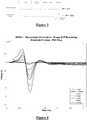
- Figure 1shows the currents and voltages that contribute to SCP measurements.
- These signalsinclude the stimulus current 102 applied by two stimulus electrodes, which is a charge-balanced biphasic pulse to provide low artefact.
- Alternative embodimentsmay instead use three electrodes to apply a tripolar charge balanced stimulus.
- the stimulus currents 102 used to provide paraesthesia and pain relieftypically consist of pulses in the range of 3-30 mA amplitude, with pulse width typically in the range of 100-400 ⁇ s, or alternatively may be paraesthesia-free such as neuro or escalator style stimuli.
- the stimulican comprise monophasic or biphasic pulses.
- the stimulus 102induces a voltage on adjacent electrodes, referred to as stimulus crosstalk 104.
- the stimuli 102are SCP stimuli they typically induce a voltage 104 in the range of about 1-5 V on a SCP sense electrode.
- the stimulus 102also induces electrode artefact, which is a residual voltage on an electrode resulting from uneven charge distribution on its surface.
- the electrode artefactis indicated in the voltage waveform 104 after cessation of stimulus crosstalk.
- the stimulus 102disturbs the galvanic interface between the sense electrode and the tissue, so that after stimulus crosstalk in voltage 104 concludes, a voltage known as the electrode artefact continues on the electrode, as indicated in waveform 104 in Figure 1 .
- Electrode artefactis very difficult to measure, and depends on factors such as the stimulation pulse, the geometry of the electrodes and the bio-electrical nature of the tissue surrounding the electrodes. Electrode artefact can have a typical value of 500 ⁇ V at a time 50 ⁇ s after stimulation ceases. Electrode artefact is difficult to measure because it is indistinguishable from electrical artefact, the latter being caused by the amplifier's exposure to the high stimulation voltages. Further, the causes of electrical artefact can be subtle, and therefore hard to identify and eliminate.
- an appropriate stimulus 102will also induce nerves to fire, and thereby produces an evoked neural response 106.
- the neural response 106has two major components: a fast response lasting ⁇ 2 ms and a slow response lasting ⁇ 15 ms.
- the slow responseonly appears at stimulation amplitudes which are larger than the minimum stimulus required to elicit a fast response.
- the amplitude of the evoked response seen by epidural electrodesis typically no more than hundreds of microvolts, but in some clinical situations can be only tens of microvolts.
- a measurement amplifier used to measure the evoked responsedoes not have infinite bandwidth, and will normally have infinite impulse response filter poles, and so the stimulus crosstalk 104 will produce an output 108 during the evoked response 106, this output being referred to as electrical artefact.
- Electrical artefactcan be in the hundreds of millivolts as compared to a SCP of interest in the tens of microvolts. Electrical artefact can however be reduced by suitable choice of a high-pass filter pole frequency.
- the measurement amplifier output 110will therefore contain the sum of these various contributions 102-108.
- Separating the evoked response of interest (106) from the artefacts 104 and 108is a major technical challenge. For example, to resolve a 10 ⁇ V SCP with 1 ⁇ V resolution, and have at the input a 5V stimulus, requires an amplifier with a dynamic range of 134dB. As the response can overlap the stimulus this represents a difficult challenge of amplifier design.
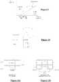
- FIGS 2a - 2eare schematic diagrams of the five phases of operation of a sample and hold (S/H) measurement amplifier in accordance with one embodiment of the present invention.
- the stimulus and measurement circuitry 200comprises a buffer amplifier 206 that is always connected to the sense electrode 202 such that there is no switch between the sense electrode 202 and the buffer amplifier 206.
- the output of the buffer amplifier 206drives a sample and hold circuit 208, followed by a high gain amplifier 210 with unity gain at DC.
- the front-end amplifier 206has sufficiently wide bandwidth that it can follow the voltage induced on the sense electrodes 202 by the stimulus pulse, and settle before the SCP begins.
- a current source 212can be selectively connected to stimulus electrodes 204 to deliver a stimulus.
- the stimulus electrodes 204 and sense electrode 202are in the same electrode array of a single implanted device.
- the stimulus and measurement circuitry 200operates to obtain a SC measurement using five phases.
- the first phase shown in Figure 2aopen circuits the stimulus electrodes 204 and connects the sense electrode 202 to the measurement amplifier 210 by setting the sample and hold circuit to "sample”.
- the first phase shown in Figure 2aallows the amplifier chain 206, 210 to settle, with no disturbance from the stimulating electrodes 204.
- the stimulus electrodes 204are short circuited to each other. This allows the stimulating electrodes 204 to recover charge, so as to avoid DC injection to the tissue as is required for electrical implants.
- the sample-and-hold 208is set to "hold" so that charge transfer on the stimulus electrodes 204 does not disrupt the measurement amplifier 210.
- the stimulationis applied.
- the stimulus electrodes 204are switched to the current source 212, and the sample-and-hold 208 is set to "hold" so that the large stimulus crosstalk seen on electrode 202 is not presented to the measurement amplifier 210.
- the fourth phase shown in Figure 2dprovides for a post-stimulus delay.
- the stimulus electrodes 204are open circuited, and the sample-and-hold remains in the "hold” position, to allow the electrodes 202, 204 settle towards equilibrium, as defined by bio-electrical conditions.
- the SCP present at sense electrode 202is measured by switching the sample-hold 208 to "sample".
- Figure 3shows idealised waveforms arising during the SCP measurement process of Figure2 .
- Figure 3illustrates the current 302 of stimulus electrodes 204, and the output voltage 304 of amplifier 210, during each of the five phases of the measurement cycle.
- phase 1permits the amplifier bias point to settle to a steady state as defined by bio-electrical conditions at the sense electrode, while phases 2-4 do not disrupt the amplifier 210 bias point.
- An advantage of this circuitis that in the phase 2 equilibration, the circuitry around amplifier 210 is a low-pass filter, and is therefore relatively immune to noise and input transients. This also allows the amplifier 210 to accumulate its bias point over successive measurement cycles, as it does not need to be reset for each cycle. Moreover, because of the buffer 206 before the sample/hold 208, the input-referred effect (i.e. the effect upon sense electrode 202) of the charge injection into the sample/hold 208 is lower.
- the sense electrode 202is never shorted to the stimulus electrodes 204, recognising that this creates dis-equilibrium in the sense electrodes and adds artefact, rather than having the effect of creating equilibrium as previously thought.
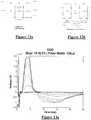
- Figure 4is a plot of 22 separate measurements of ovine SCP made using the embodiment of Figure 2 .
- the measurementswere obtained sequentially for differing stimuli, the stimuli comprising biphasic current pulses of 40 ⁇ s pulse width and a current amplitude which varied from 0-10 mA.
- the measurementswere then plotted on a single chart to produce Figure 4 .
- the recorded signalsconsist of the neural response and a small electrode artefact.
- the neural responseis tri-phasic, consisting of a positive PI peak followed by a negative N1 peak and then a secondary positive P2 peak.
- the neural response morphology in Figure 4is characteristic of extracellular recordings of axonal compound action potentials.
- the first phase PIis dominated by the capacitive current due to the initial membrane depolarization.
- Phase 2is dominated by Na + ion current and is negative due to the influx of Na + ions during the neuronal membrane action potential.
- the third phaseis positive due to the K + i
- the waveforms of Figure 4have lower dynamic range and simpler morphology than measurements produced by previous approaches, due to the absence of stimulus crosstalk and reduced artefact.
- wide dynamic range amplifiersare difficult to design, as are signal processing systems for feature extraction.
- the nature of the measured waveforms shown in Figure 4permits, for example, a circuit for extracting the peak-to-peak SCP amplitude to have fewer components than would be required to operate upon the waveform produced by previous approaches.
- the techniques of the present invention for artefact reductiongreatly assist in building a practical implanted, evoked response feedback system.
- the measurement systemis settled and ready to record prior to onset of the evoked CAP.
- the sense electrodewas less than 50mm from the stimulus electrode, and a post-stimulus delay of 50 ⁇ s was observed before the measurement amplifier was switched in to obtain the recordings shown in Figure 4 .
- the largest peak to peak responsewas about 2.4 mV, significantly less than the voltage present when applying a 10 mA stimulus.
- the epidural spaceis much smaller in sheep than in humans, and so the electrode is expected to be closer to the ovine neural tissue and the magnitude of the sensed tri-phasic potentials is correspondingly higher in the sheep than is expected for humans, emphasizing the difficulty of making such recordings.
- Figure 5illustrates the circuitry of an alternative embodiment of the invention in which a differential measurement amplifier is used, and charge recovery is via a voltage rail V dd .
- the measurement phasesare carried out in a corresponding manner despite the use of different hardware.
- artefactcan cause the high-gain measurement amplifier 210 to clip, and the amplifier can subsequently be slow to recover.
- the sample pointbeing the transition from the "stimulate" to "measure” phases, is delayed, allowing clipping to be avoided.
- Figure 6illustrates the manner of determining a suitable delay 602, which is often in the range of 50-200 ⁇ s, noting that the fast response typically concludes within about 2 ms.
- Such embodimentsmay permit use of a higher amplifier gain than would otherwise be the case.
- a variable delay and increased amplifier gainmay be particularly apt in circumstances where high-gain is desired, and parts of the SCP of interest do not immediately follow the stimulation. Thus, delaying the start of measurement will avoid the side effects of clipping.
- a method to eliminate artefact from an SCP measurementis to alternate the phase of stimulus waveforms and take an average of obtained measurements.
- This methodis effective when the stimulus electrodes have different area.
- a central electrodeis driven anodically in the first phase and consists of a single electrode of the array, whereas the electrode driven cathodically in the first phase consists of two electrodes of the array connected in parallel.
- the electrodes in parallelwould usually be on either side of the other stimulating electrode.
- monopolara mode of stimulation referred to as "monopolar" stimulation is obtained.
- Figure 7shows the stimulus current for a positive "anodic-first" stimulus 702, and the stimulus current for a negative "cathodic first” stimulus 704. In this embodiment these are applied in succession with respective CAP measurements obtained after each stimulus. The respective measurement electrode voltages 706 and 708 arising from each such stimulus are also shown. It will be observed where indicated in waveforms 706, 708 that the artefacts from each of the two stimuli are of substantially identical magnitude, but opposite sign. In most situations it will be found that the artefact polarity depends on the stimulus polarity. An example of this would be electrical artefact caused by the high-pass poles of the front-end amplifier 206. Clearly, either phase could be used for stimulating nervous tissue, though their effects will differ.
- the positive and negative phase stimuli 702, 704produce SCPs of differing amplitudes, but approximately similar shape and importantly of similar polarity, as this is determined by the anatomy and physiology of the spinal cord nerve fibre membranes.
- the opposite phase stimulation artefactssubstantially cancel, leaving the SCP or a combination of the two SCPs 710. Note that in practical situations, the artefact can have much higher amplitude than the SCP, making it much harder to detect the SCP than is apparent from Fig 7 .
- the response of the spinal cord to these two polarities of stimulationare referred to as the "anodic” and “cathodic” SCP responses, as referred to the electrode considered to be that closest to the recording electrode.
- anodic tripolar stimulationmakes the central stimulating electrode anodic in the first phase of stimulus.
- cathodic stimulationhas a lower threshold for neural activation than is the case for anodic stimulation.
- the SCP polarityis independent of whether the stimulus is anodic 702 or cathodic 704.
- Figure 8aillustrates spinal cord measurements obtained in response to anodic and cathodic monophasic stimulations, respectively, the stimuli being of equal amplitude. Note that the measurement obtained in response to the anodic stimulation lacks the characteristic P1-N1-P2 form, indicating that the anodic stimulation did not evoke a neural response in this case. In contrast, the measurement obtained in response to the cathodic stimulus exhibits a significant evoked neural response.
- Figure 8bshows an average of the two responses in Fig. 10a .
- the artefactis essentially removed as stimuli of opposite polarity and equal amplitude produce artefact of opposite polarity and equal amplitude, which cancel when averaged.
- Figure 9illustrates SCP growth curves against stimulus amplitude, for both anodic and cathodic monophasic stimuli.
- Figure 9also shows the growth behaviour of the average SCP against stimulus amplitude. It can be seen from Fig 9 that the threshold of the average response is identical to the threshold of the more sensitive response for cathodic stimulation.
- the averaged SCP waveformWhen the stimulus amplitude is in the range 902 such that only the cathodic stimulus produces an SCP, then the averaged SCP waveform would have a normal SCP morphology but would be half the amplitude compared to a true cathodic SCP due to the averaging. In the region 904 where both the anodic and cathodic responses contribute to the averaged SCP, the resultant averaged SCP waveform will have morphology in between the two measurements. It would not directly represent an SCP, but rather the average of two different SCPs. Nevertheless, this waveform could still be valuable for example in implementing an automatic control loop for stimulation adjustment, as it gives a value proportional to neural recruitment.
- some embodimentsmay stimulate with a tripolar arrangement having a centre electrode operating as a cathode and having two edge electrodes, being those immediately to each side of the centre electrode, operating as anodes.
- This tripolar arrangementmeans that the recovery charge is shared between the two edge electrodes.
- the cathodic charge on the 2nd phaseis shared between two electrodes and thus is half that on the first phase.
- the principle shown in Figure 9is true for tripolar stimulation, at least up to the point where the current is twice the threshold current at which point the edge electrodes' currents are each at the threshold and will thus start to generate action potentials.
- Some embodiments of the inventionmay use differential amplifiers so as to detect the voltage difference between two sense electrodes.
- Differential amplifierssimplify the task of separating electrode artefact. If they are connected to electrodes with similar area, and separated from the stimulation electrodes in a similar manner, then they receive similar levels of electrode artefact and this will be removed when their difference voltage is obtained. However, in such a system the voltage recorded by the amplifier is the difference between the voltages at two points along a bundle of neurons, and can thus be difficult to interpret.
- the difference between the voltages on the adjacent electrodeswill be quite small and significantly smaller than the peak to peak amplitude of the SCP, and thus more susceptible to electrical noise generated by the amplifier.
- the output of the amplifierwill approximate the differential of the SCP, and thus be harder to interpret than a simple measure of the SCP itself. If measuring evoked SCPs with a micro-package stimulator design, for example in a system using a two-wire bus, differential measurements between non-adjacent electrodes are not possible. Further, if wishing to measure the slow response of the SCP, which has a period of about 6 ms and correspondingly reduced signal gradients, differential measurements are even more difficult to effect. Thus it will be appreciated that single-ended measurements are preferable, as long as artefact can be kept at a sufficiently low level.
- the artefactis reduced so that some embodiments may instead use a single-ended amplifier, even in situations where previously they would have suffered from too much electrode artefact.
- trials to dateshow that recording can be initiated with an extremely short time interval from cessation of the stimulus, permitting the same electrode array to be used for recording and stimulation, and even permitting recordings to be made on the electrode immediately adjacent to the stimulus electrode in an electrode array with electrode spacings of less than 10 mm.
- Single ended amplifiershave the further advantage that they consist of fewer capacitors and amplifier components than differential amplifiers, so will take up less space on a silicon chip, which is a significant benefit when intended for use in an implanted system with many electrodes and where the silicon area for each amplifier is limited.
- Preferred embodiments of the inventionmay comprise a separate amplifier chain (e.g. 206, 208, 210, see Fig 2 ) for every electrode, organised in parallel manner, permitting simultaneous recording of a single CAP from multiple sense electrodes in parallel, and also eliminating the switching noise arising in systems which switch the sense electrode to a shared measurement amplifier.
- a separate amplifier chaine.g. 206, 208, 210, see Fig 2
- FIG. 11A conductive solution can be modelled as a mesh of resistors. Where a conductive solution meets a piece of metal of finite dimensions, the metal provides an alternative conduction path to the solution. This charges the electrode-to-tissue capacitances at the "ends" of the electrodes, with opposite polarities.
- the electrodedoes not acquire net charge, but it does cease to be in equilibrium. After the external current ceases, then the electrode will pass current through the solution as it re-equilibrates for a short time after the stimulus. This current will affect the potential of another electrode in the solution, and in the case of multi-electrode arrays a unique such current will arise at every electrode in response to local conditions experienced at that electrode. The cumulative impact of such re-equilibration currents is seen by a sense electrode as electrode artefact.
- Figure 11predicts that using smaller electrodes will reduce artefact. However, smaller electrodes will have higher noise when used as measurement electrodes, and higher resistance and lower current carrying capacity when used as stimulus electrodes.
- Two means to reduce artefact without sacrificing noise, impedance or current carrying capacityare shown in Figures 12a and 12b .
- the electrode configuration of Figure 12areduces artefact induced in a single metallic electrode; the electrode is composed of two or more smaller electrodes that can be disconnected during a stimulation phase, and reconnected during a measurement phase.
- an electrodeis segmented, and individual current sources are provided for each segment. This forces the current in the segments to match, and so reduces artefact.
- the evoked response telemetry of the present inventionmay in some embodiments be used to monitor the effect of a delivered compound.
- the administration of compounds (drugs or other chemical therapeutics) to effect a change in the nervous systemis common for treatment of a wide number of diseases and disorders.
- Anaesthetics of various typesare administered to the spinal cord for the relief of pain. Perhaps the most common form is administration of anaesthetics in the epidural space for pain relief during child birth.
- a catheter comprising a drug delivery tubemay be fitted with electrode elements and configured to obtain neural response measurements in accordance with the present invention in order to monitor drug-induced effects on the neural response.
- an electrode arraymay be temporarily or permanently implanted and used to apply neural stimuli and monitor the neural response.
- the neural response measurementsmay be obtained repeatedly during administration of the drug in order to directly measure the effect of the administered drug and control the dosage delivered.
- Figures 15a and 15billustrate the effect of administration of anaesthetic to the spinal cord, with a neural response being present prior to administration and largely being absent subsequent to administration.
- a "partial block"may be effected by ceasing administration of the anaesthetic once the neural response amplitude reduces to a desired level.
- the technology described hereinis suitable for full implantation within the body of a subject and as a result the evoked potential monitoring could be used in the administration of an active compound to produce a therapeutic benefit.
- the systemcould be integrated within an implantable pump to control the administration of the compound.
- Figure 14shows two plots which compare the artefact arising when electrode shorting is performed, to the artefact arising when the sense electrode is disconnected from the measurement circuitry and from the stimulus electrodes after the stimulus.
- the plots of Figure 14were obtained from an array placed in a saline bath, and were taken under the following conditions.
- a stimulationcomprising a biphasic pulse of amplitude 10mA and duration 400 ⁇ s was applied using a tripolar configuration, with electrodes E1 and E3 grounded and electrode E2 stimulating, at a stimulus rate of 40Hz.
- the artefact measurement of interest(1502, 1512) was obtained on electrode 4 for each plot. Measurements were also obtained on electrodes 5 to 7 using the method of the present invention in both plots, these measurements indicated collectively at 1504, 1512.
- the measurement parameters for each plotincluded recovering charge on the stimulus electrodes by short circuiting the stimulus electrodes to each other for 100 ⁇ s before stimulation.
Landscapes
- Health & Medical Sciences (AREA)
- Life Sciences & Earth Sciences (AREA)
- Engineering & Computer Science (AREA)
- General Health & Medical Sciences (AREA)
- Animal Behavior & Ethology (AREA)
- Biomedical Technology (AREA)
- Veterinary Medicine (AREA)
- Public Health (AREA)
- Biophysics (AREA)
- Neurology (AREA)
- Neurosurgery (AREA)
- Radiology & Medical Imaging (AREA)
- Nuclear Medicine, Radiotherapy & Molecular Imaging (AREA)
- Heart & Thoracic Surgery (AREA)
- Molecular Biology (AREA)
- Medical Informatics (AREA)
- Pathology (AREA)
- Physics & Mathematics (AREA)
- Surgery (AREA)
- Physiology (AREA)
- Psychiatry (AREA)
- Computer Vision & Pattern Recognition (AREA)
- Signal Processing (AREA)
- Artificial Intelligence (AREA)
- Hematology (AREA)
- Anesthesiology (AREA)
- Vascular Medicine (AREA)
- Diabetes (AREA)
- Pain & Pain Management (AREA)
- Measurement And Recording Of Electrical Phenomena And Electrical Characteristics Of The Living Body (AREA)
- Electrotherapy Devices (AREA)
Description
- The present invention relates to measurement of a neural response to a stimulus, and in particular relates to measurement of a compound action potential by using one or more electrodes implanted proximal to the neural pathway.
- Neuromodulation is used to treat a variety of disorders including chronic pain, Parkinson's disease, and migraine. A neuromodulation system applies an electrical pulse to tissue in order to generate a therapeutic effect. When used to relieve chronic pain, the electrical pulse is applied to the dorsal column (DC) of the spinal cord or dorsal root ganglion (DRG). Such a system typically comprises an implanted electrical pulse generator, and a power source such as a battery that may be rechargeable by transcutaneous inductive transfer. An electrode array is connected to the pulse generator, and is positioned in the dorsal epidural space above the dorsal column. An electrical pulse applied to the dorsal column by an electrode causes the depolarisation of neurons, and generation of propagating action potentials. The fibres being stimulated in this way inhibit the transmission of pain from that segment in the spinal cord to the brain.
- While the clinical effect of spinal cord stimulation (SCS) is well established, the precise mechanisms involved are poorly understood. The DC is the target of the electrical stimulation, as it contains the afferent Aβ fibres of interest. Aβ fibres mediate sensations of touch, vibration and pressure from the skin. The prevailing view is that SCS stimulates only a small number of Aβ fibres in the DC. The pain relief mechanisms of SCS are thought to include evoked antidromic activity of Aβ fibres having an inhibitory effect, and evoked orthodromic activity of Aβ fibres playing a role in pain suppression. It is also thought that SCS recruits Aβ nerve fibres primarily in the DC, with antidromic propagation of the evoked response from the DC into the dorsal horn thought to synapse to wide dynamic range neurons in an inhibitory manner.
- Neuromodulation may also be used to stimulate efferent fibres, for example to induce motor functions. In general, the electrical stimulus generated in a neuromodulation system triggers a neural action potential which then has either an inhibitory or excitatory effect. Inhibitory effects can be used to modulate an undesired process such as the transmission of pain, or to cause a desired effect such as the contraction of a muscle.
- The action potentials generated among a large number of fibres sum to form a compound action potential (CAP). The CAP is the sum of responses from a large number of single fibre action potentials. The CAP recorded is the result of a large number of different fibres depolarising. The propagation velocity is determined largely by the fibre diameter and for large myelinated fibres as found in the dorsal root entry zone (DREZ) and nearby dorsal column the velocity can be over 60 ms-1. The CAP generated from the firing of a group of similar fibres is measured as a positive peak potential PI, then a negative peak N1, followed by a second positive peak P2. This is caused by the region of activation passing the recording electrode as the action potentials propagate along the individual fibres.
- To better understand the effects of neuromodulation and/or other neural stimuli, it is desirable to record a CAP resulting from the stimulus. However, this can be a difficult task as an observed CAP signal will typically have a maximum amplitude in the range of microvolts, whereas a stimulus applied to evoke the CAP is typically several volts. Electrode artefact usually results from the stimulus, and manifests as a decaying output of several millivolts throughout the time that the CAP occurs, presenting a significant obstacle to isolating the CAP of interest. Some neuromodulators use monophasic pulses and have capacitors to ensure there is no DC flow to the tissue. In such a design, current flows through the electrodes at all times, either stimulation current or equilibration current, hindering spinal cord potential (SCP) measurement attempts. Moreover, high-pass filter poles in measurement circuitry generate increased electrical artefact with mono-phasic pulses. The capacitor recovers charge at the highest rate immediately after the stimulus, undesirably causing greatest artefact at the same time that the evoked response occurs.
- To resolve a 10uV SCP with 1uV resolution in the presence of an input 5V stimulus, for example, requires an amplifier with a dynamic range of 134dB, which is impractical in implant systems. As the neural response can be contemporaneous with the stimulus and/or the stimulus artefact, CAP measurements present a difficult challenge of amplifier design. In practice, many non-ideal aspects of a circuit lead to artefact, and as these mostly have a decaying exponential appearance that can be of positive or negative polarity, their identification and elimination can be laborious.
- A number of approaches have been proposed for recording a CAP. King (
US Patent No. 5,913,882 ) measures the spinal cord potential (SCP) using electrodes which are physically spaced apart from the stimulus site. To avoid amplifier saturation during the stimulus artefact period, recording starts at least 1 - 2.5 ms after the stimulus. At typical neural conduction velocities, this requires that the measurement electrodes be spaced around 10 cm or more away from the stimulus site, which is undesirable as the measurement then necessarily occurs in a different spinal segment and may be of reduced amplitude. - Nygard (
US Patent No. 5,785,651 ) measures the evoked CAP upon an auditory nerve in the cochlea, and aims to deal with artefacts by a sequence which comprises: (1) equilibrating electrodes by short circuiting stimulus electrodes and a sense electrode to each other; (2) applying a stimulus via the stimulus electrodes, with the sense electrode being open circuited from both the stimulus electrodes and from the measurement circuitry; (3) a delay, in which the stimulus electrodes are switched to open circuit and the sense electrode remains open circuited; and (4) measuring, by switching the sense electrode into the measurement circuitry. Nygard also teaches a method of nulling the amplifier following the stimulus. This sets a bias point for the amplifier during the period following stimulus, when the electrode is not in equilibrium. As the bias point is reset each cycle, it is susceptible to noise. The Nygard measurement amplifier is a differentiator during the nulling phase which makes it susceptible to pickup from noise and input transients when a non-ideal amplifier with finite gain and bandwidth is used for implementation. - Daly (
US Patent Application No. 2007/0225767 ) utilizes a biphasic stimulus plus a third phase "compensatory" stimulus which is refined via feedback to counter stimulus artefact. As for Nygard, Daly's focus is the cochlea. Daly's measurement sequence comprises (1) a quiescent phase where stimulus and sense electrodes are switched toVdd; (2) applying the stimulus and then the compensatory phase, while the sense electrodes are open circuited from both the stimulus electrodes and from the measurement circuitry; (3) a load settling phase of about 1 µs in which the stimulus electrodes and sense electrodes are shorted toVdd; and (4) measurement, with stimulus electrodes open circuited fromVdd and from the current source, and with sense electrodes switched to the measurement circuitry. However a 1 µs load settling period is too short for equilibration of electrodes which typically have a time constant of around 100 µs. WO 2004/021885 discloses a method and device for measuring an evoked neural response comprising a sensor for obtaining a sensed signal representing the evoked neural response, a high gain amplifier having a signal input for receiving the sensed signal and having a reference input, and means for altering or setting a reference voltage at the reference input to prevent the amplifier saturating with variations of the sensed signal.- Further, connecting the sense electrodes toVdd pushes charge onto the sense electrodes, exacerbating the very problem the circuit is designed to address.
- Evoked responses are less difficult to detect when they appear later in time than the artifact, or when the signal-to-noise ratio is sufficiently high. The artifact is often restricted to a time of 1 - 2 ms after the stimulus and so, provided the neural response is detected after this time window, data can be obtained. This is the case in surgical monitoring where there are large distances between the stimulating and recording electrodes so that the propagation time from the stimulus site to the recording electrodes exceeds 2 ms. Because of the unique anatomy and tighter coupling in the cochlea, cochlear implants use small stimulation currents relative to the tens of mA sometimes required for SCS, and thus measured signals in cochlear systems present a relatively lower artifact. However to characterize the responses from the dorsal columns, high stimulation currents and close proximity between electrodes are required, and therefore the measurement process must overcome artifact directly, in contrast to existing "surgical monitoring" techniques.
- Any discussion of documents, acts, materials, devices, articles or the like which has been included in the present specification is solely for the purpose of providing a context for the present invention. It is not to be taken as an admission that any or all of these matters form part of the prior art base or were common general knowledge in the field relevant to the present invention as it existed before the priority date of each claim of this application.
- Throughout this specification the word "comprise", or variations such as "comprises" or "comprising", will be understood to imply the inclusion of a stated element, integer or step, or group of elements, integers or steps, but not the exclusion of any other element, integer or step, or group of elements, integers or steps.
- This disclosure provides a method for measuring a neural response to a stimulus, however, this and other methods disclosed herein do not form part of the invention.
- According to a first aspect the present invention provides an implantable device for measuring a neural response to a stimulus, the device comprising:
- a plurality of electrodes including one or more nominal stimulus electrodes and one or more nominal sense electrodes;
- a stimulus source for providing a stimulus to be delivered from the one or more stimulus electrodes to neural tissue;
- measurement circuitry for amplifying a neural signal sensed at the one or more sense electrodes; and
- a control unit configured to control application of a stimulus to the neural tissue and measurement of an evoked neural response, the control unit configured to settle the measurement circuitry prior to a stimulus by connecting the or each sense electrode to the measurement circuitry to allow the measurement circuitry to settle towards a bio-electrically defined steady state, the control unit further configured to recover charge on the stimulus electrodes by short circuiting the stimulus electrodes to each other, the control unit further configured to cause the stimulus source to apply an electrical stimulus from the stimulus electrodes to neural tissue while keeping the or each sense electrode disconnected from the measurement circuitry, the control unit further configured to impose a delay during which the stimulus electrodes are open circuited and the sense electrode is disconnected from the measurement circuitry and from the stimulus electrodes, and the control unit further configured to measure a neural response signal present at the sense electrode by connecting the or each sense electrode to the measurement circuitry after the delay.
- It is to be understood herein that open circuiting of an electrode involves ensuring that the electrode is disconnected from other electrodes, the stimulus source, the measurement circuitry and from voltage rails. Ensuring that the sense electrode is disconnected from the stimulus electrodes during the delay period avoids charge transfer onto the sense electrode(s) and associated artefact. The present invention recognizes that connecting the sense electrodes to the stimulus electrodes during a post-stimulus delay period can undesirably give rise to such charge transfer and associated artefact, particularly if the delay is short relative to the time constant of the stimulus electrodes, the latter typically being around 100 µs. The sense electrode is preferably open circuited during the post-stimulus delay so as to be disconnected from all other electrodes of the array, to prevent such charge transfer to the sense electrode from other non-stimulus electrodes. With particular regard to the case of spinal cord response measurement, the present invention recognizes that in the spinal cord, the stimulation electrodes may never reach equilibrium at the stimulation rates used for chronic pain, so that connecting them to the stimulating electrodes at any time would increase artefact. This lack of equilibrium is due to the nature of the Helmholtz layer which causes fractional pole variation in the electrode impedance with frequency, with time constants as long as tens of milliseconds.
- The present invention recognizes that it is beneficial to provide for pre-stimulus settling of the measurement circuitry towards a bio-electrically defined steady state. This ensures that charge recovery occurs in the settling stage prior to the stimulus and not during or immediately after the stimulus and thus does not give rise to artefact during or immediately after the stimulus. Thus, the present invention captures the bio-electrically defined steady state as reference point voltage at the end of the measurement cycle, when the system is in its most stable state. The system then amplifies the difference between the captured voltage and the reference point voltage. Where repeated measurement cycles are undertaken, the present invention further permits the measurement amplifier to accumulate a bias point over multiple cycles rather than re-setting the bias point each cycle. The settle period is preferably sufficiently long to permit the electrodes and circuitry to reach an equilibrium, and for example the settle period may be around 1 ms or greater, as permitted by a stimulus rate. For example if therapeutic stimuli are applied to a dorsal column at about 100 Hz and do not give rise to a slow neural response, then after the approximately 2 ms duration of an evoked fast response up to about 8 ms would be available for the settling period. However, this is generally longer than required and the settling period may be substantially less than 8 ms.
- The delay may be in the range of substantially zero to 1 ms, and for example may be about 0.3 ms. Such embodiments permit onset of the neural response to be observed, this typically occurring about 0.3 ms after the stimulus for an
electrode 3 cm away from the stimulus site. In embodiments in which an amplifier of the measurement circuitry has a very high dynamic range, and/or if using a measurement electrode closer to the stimulus electrode, the delay may be set to a smaller value for example in the range of 50 - 200 µs. The delay is preferably set to a value which ensures the measurement amplifier is not saturated and therefore performs linearly at all times when connected without experiencing clipping, and for example a feedback loop may be implemented to determine a suitable delay which avoids amplifier saturation for a given stimulus. - In preferred embodiments of the invention, the signal from the or each sense electrode is passed to a sample-and-hold circuit at the input of a measurement amplifier. In such embodiments measurements of a single evoked response may be obtained from a plurality of sense electrodes, even if the measurement circuitry of each electrode is connected to the control unit only by a two wire bus or the like, as is commonly required in implanted electrode arrays.
- Additionally or alternatively, a buffer or follower amplifier is preferably provided in some embodiments, between the sense electrode and the measurement amplifier. The buffer is preferably connected to the sense electrode without interposed switches, so that the high reverse impedance of the buffer effectively prevents switching transients from being conveyed to the sense electrode, thereby avoiding artefact which may arise upon the sense electrode if subjected to such transients. The buffer amplifier is also preferably configured to give current gain to drive a storage capacitor of a sample and hold circuit. A series capacitor may be interposed between the sense electrode and the buffer to avoid DC transfer with the tissue in the event where the amplifier malfunctions. This capacitor also allows the bias voltage of the amplifier to equilibrate as the electrode voltage can drift over time periods of several tens of seconds..
- In preferred embodiments of the invention, the stimulus and sense electrodes are selected from an implanted electrode array. The electrode array may for example comprise a linear array of electrodes arranged in a single column along the array. Alternatively the electrode array may comprise a two dimensional array having two or more columns of electrodes arranged along the array. Preferably, each electrode of the electrode array is provided with an associated measurement amplifier, to avoid the need to switch the sense electrode(s) to a shared measurement amplifier, as such switching can add to measurement artefact. Providing a dedicated measurement amplifier for each sense electrode is further advantageous in permitting recordings to be obtained from multiple sense electrodes simultaneously.
- The measurement may be a single-ended measurement obtained by passing a signal from a single sense electrode to a single-ended amplifier. Alternatively, the measurement may be a differential measurement obtained by passing signals from two sense electrodes to a differential amplifier.
- While recovering charge by short circuiting the stimulus electrodes together, it may in some embodiments be advantageous to disconnect the sense electrode from the measurement circuitry, for example by setting a sample-and-hold circuit to "hold".
- Embodiments of the invention may prove beneficial in obtaining a CAP measurement which has lower dynamic range and simpler morphology as compared to systems more susceptible to artefact. Such embodiments of the present invention may thus reduce the dynamic range requirements of implanted amplifiers, and may avoid or reduce the complexity of signal processing systems for feature extraction, simplifying and miniaturizing an implanted integrated circuit. Such embodiments may thus be particularly applicable for an automated implanted evoked response feedback system for stimulus control. Thus, in a further aspect, the present invention provides a method for feedback control of a neural stimulus, the method comprising an implanted control unit obtaining a CAP measurement in accordance with the method of the first aspect, and the implanted control unit using the obtained CAP measurement to control the delivery of subsequent neural stimuli by the implant.
- In some embodiments of the invention, an averaged CAP measurement may be obtained by (i) delivering a first biphasic stimulus which starts with a pulse of a first polarity and then delivers a pulse of a second polarity opposite to the first polarity, and obtaining a first measurement of a CAP evoked by the first stimulus; (ii) delivering a second biphasic stimulus which starts with a pulse of the second polarity and then delivers a pulse of the first polarity, and obtaining a second measurement of a CAP evoked by the second stimulus; and (iii) taking an average of the first measurement and the second measurement to obtain an averaged measurement. Such embodiments exploit the observation that artefact polarity usually reflects the stimulus polarity, whereas the CAP polarity is independent of the stimulus polarity and is instead determined by the anatomy and physiology of the spinal cord membrane, so that averaging the first and second measurements will tend to selectively cancel out artefact. Further noting that for some electrode polarity configurations, such as monopolar, an "anodic first" biphasic stimulus usually has a lower stimulus threshold for neural recruitment than a "cathodic first" biphasic stimulus, the averaged measurement may have a morphology of either (i) a typical CAP of half amplitude if only the anodic-first stimulus exceeds the stimulus threshold; (ii) the average of two CAPs of different amplitude if both stimuli exceed the stimulus threshold but the cathodic first stimulus does not cause saturation recruitment; or (iii) a typical CAP if both stimuli exceed saturation recruitment. Some embodiments may therefore obtain a curve of the averaged measurement vs. stimulus amplitude in order to obtain information regarding the recruitment effected by each stimulus, and such information may be used for feedback control by the implant.
- In some embodiments, the method may be applied contemporaneously with administration of a drug, in order to gauge efficacy of drug delivery. For example, the implant may comprise or be operatively connected to a drug reservoir and drug delivery pump, with the pump being controlled by feedback based on CAP measurements.
- According to another aspect the present invention provides a computer program product as defined in
claim 12. The present invention recognises that when considering spinal cord stimulation, obtaining information about the activity within the spinal segment where stimulation is occurring is highly desirable. Observing the activity and extent of propagation both above (rostrally of) and below (caudally of) the level of stimulation is also highly desirable. The present invention recognises that in order to record the evoked activity within the same spinal segment as the stimulus requires an evoked potential recording system which is capable of recording an SCP within approximately 3cm of its source, i.e. within approximately 0.3 ms of the stimulus, and further recognises that in order to record the evoked activity using the same electrode array as applied the stimulus requires an evoked potential recording system which is capable of recording an SCP within approximately 7 cm of its source, i.e. within approximately 0.7 ms of the stimulus. - In preferred embodiments the stimulus comprises a bi-phasic pulse, and the stimulus electrodes have no capacitors. In contrast to a monophasic pulse and capacitor arrangement, such embodiments permit the stimulus electrode current to be interrupted, or forced to zero, at those times where it would interfere with measurement. Omitting capacitors is also desirable in order to minimise the size of the implanted device.
- An example of the invention will now be described with reference to the accompanying drawings, in which:
Figure 1 illustrates currents and voltages which can contribute to SCP measurements;Figure 2 illustrates the circuitry of one embodiment of the present invention, throughout five phases of a measurement cycle;Figure 3 illustrates idealised waveforms arising in the circuit ofFigure 2 during each phase of the measurement cycle;Figure 4 illustrates SCP measurements made using the embodiment ofFigure 2 ;Figure 5 illustrates the circuitry of an alternative embodiment of the invention implementing differential CAP measurements;Figure 6 illustrates delayed activation of a measurement amplifier to avoid clipping;Figure 7 illustrates an embodiment in which alternate phased stimuli are used to obtain an averaged CAP measurement;Figure 8a illustrates the "anodic first" and "cathodic first" CAP responses induced by the method ofFigure 7 , whileFigure 8b illustrates the averaged measurement obtained therefrom;Figure 9 illustrates the CAP response to anodic-first and cathodic-first stimuli, respectively, with increasing stimulus amplitude;Figure 10 illustrates the nature of differential CAP measurements in the spinal cord;Figure 11 illustrates a model of a metal electrode in a conductive solution;Figure 12 illustrates segmented electrodes which may be used to reduce artefact without sacrificing noise, impedance or current carrying capacity;Figures 13a and13b illustrate the effect of epidural administration of Lignocaine on suppression of the spinal evoked responses; andFigure 14a is a plot showing the artefact arising when electrode shorting is performed, andFigure 14b is a plot showing the artefact arising when the sense electrode is disconnected from the measurement circuitry and from the stimulus electrodes after the stimulus.Figure 1 shows the currents and voltages that contribute to SCP measurements. These signals include the stimulus current 102 applied by two stimulus electrodes, which is a charge-balanced biphasic pulse to provide low artefact. Alternative embodiments may instead use three electrodes to apply a tripolar charge balanced stimulus. In the case of spinal cord stimulation, thestimulus currents 102 used to provide paraesthesia and pain relief typically consist of pulses in the range of 3-30 mA amplitude, with pulse width typically in the range of 100-400 µs, or alternatively may be paraesthesia-free such as neuro or escalator style stimuli. The stimuli can comprise monophasic or biphasic pulses.- The
stimulus 102 induces a voltage on adjacent electrodes, referred to asstimulus crosstalk 104. Where thestimuli 102 are SCP stimuli they typically induce avoltage 104 in the range of about 1-5 V on a SCP sense electrode. - The
stimulus 102 also induces electrode artefact, which is a residual voltage on an electrode resulting from uneven charge distribution on its surface. The electrode artefact is indicated in thevoltage waveform 104 after cessation of stimulus crosstalk. Thestimulus 102 disturbs the galvanic interface between the sense electrode and the tissue, so that after stimulus crosstalk involtage 104 concludes, a voltage known as the electrode artefact continues on the electrode, as indicated inwaveform 104 inFigure 1 . Electrode artefact is very difficult to measure, and depends on factors such as the stimulation pulse, the geometry of the electrodes and the bio-electrical nature of the tissue surrounding the electrodes. Electrode artefact can have a typical value of 500 µV at a time 50 µs after stimulation ceases. Electrode artefact is difficult to measure because it is indistinguishable from electrical artefact, the latter being caused by the amplifier's exposure to the high stimulation voltages. Further, the causes of electrical artefact can be subtle, and therefore hard to identify and eliminate. - An
appropriate stimulus 102 will also induce nerves to fire, and thereby produces an evokedneural response 106. In the spinal cord, theneural response 106 has two major components: a fast response lasting ∼2 ms and a slow response lasting ∼15 ms. The slow response only appears at stimulation amplitudes which are larger than the minimum stimulus required to elicit a fast response. The amplitude of the evoked response seen by epidural electrodes is typically no more than hundreds of microvolts, but in some clinical situations can be only tens of microvolts. - In practical implementation a measurement amplifier used to measure the evoked response does not have infinite bandwidth, and will normally have infinite impulse response filter poles, and so the
stimulus crosstalk 104 will produce anoutput 108 during the evokedresponse 106, this output being referred to as electrical artefact. - Electrical artefact can be in the hundreds of millivolts as compared to a SCP of interest in the tens of microvolts. Electrical artefact can however be reduced by suitable choice of a high-pass filter pole frequency.
- The
measurement amplifier output 110 will therefore contain the sum of these various contributions 102-108. Separating the evoked response of interest (106) from theartefacts Figures 2a - 2e are schematic diagrams of the five phases of operation of a sample and hold (S/H) measurement amplifier in accordance with one embodiment of the present invention. The stimulus andmeasurement circuitry 200 comprises abuffer amplifier 206 that is always connected to thesense electrode 202 such that there is no switch between thesense electrode 202 and thebuffer amplifier 206. The output of thebuffer amplifier 206 drives a sample and holdcircuit 208, followed by ahigh gain amplifier 210 with unity gain at DC. The front-end amplifier 206 has sufficiently wide bandwidth that it can follow the voltage induced on thesense electrodes 202 by the stimulus pulse, and settle before the SCP begins. Acurrent source 212 can be selectively connected to stimulus electrodes 204 to deliver a stimulus. The stimulus electrodes 204 andsense electrode 202 are in the same electrode array of a single implanted device.- The stimulus and
measurement circuitry 200 operates to obtain a SC measurement using five phases. The first phase shown inFigure 2a open circuits the stimulus electrodes 204 and connects thesense electrode 202 to themeasurement amplifier 210 by setting the sample and hold circuit to "sample". The first phase shown inFigure 2a allows theamplifier chain - In the second phase shown in
Fig 2b , the stimulus electrodes 204 are short circuited to each other. This allows the stimulating electrodes 204 to recover charge, so as to avoid DC injection to the tissue as is required for electrical implants. During this phase, the sample-and-hold 208 is set to "hold" so that charge transfer on the stimulus electrodes 204 does not disrupt themeasurement amplifier 210. - In the third phase shown in
Figure 2c , the stimulation is applied. The stimulus electrodes 204 are switched to thecurrent source 212, and the sample-and-hold 208 is set to "hold" so that the large stimulus crosstalk seen onelectrode 202 is not presented to themeasurement amplifier 210. - The fourth phase shown in
Figure 2d provides for a post-stimulus delay. In this phase the stimulus electrodes 204 are open circuited, and the sample-and-hold remains in the "hold" position, to allow theelectrodes 202, 204 settle towards equilibrium, as defined by bio-electrical conditions. - Finally, in the fifth phase shown in
Figure 2e , the SCP present atsense electrode 202 is measured by switching the sample-hold 208 to "sample". - When performing repeated measurement cycles in this fashion, it is noted that the switch positions are the same in the
phase 1 "settling" and thephase 5 "measuring" states. Thus, the state ofphase 5 is maintained, by virtue of asubsequent phase 1, until the electrodes and circuitry are in equilibrium, even after the time that useful SCP data is no longer present or being captured. Such embodiments thus provide a greater length of the "settle" state. Figure 3 shows idealised waveforms arising during the SCP measurement process ofFigure2 .Figure 3 illustrates the current 302 of stimulus electrodes 204, and theoutput voltage 304 ofamplifier 210, during each of the five phases of the measurement cycle. Importantly, it can be seen thatphase 1 permits the amplifier bias point to settle to a steady state as defined by bio-electrical conditions at the sense electrode, while phases 2-4 do not disrupt theamplifier 210 bias point.- An advantage of this circuit is that in the
phase 2 equilibration, the circuitry aroundamplifier 210 is a low-pass filter, and is therefore relatively immune to noise and input transients. This also allows theamplifier 210 to accumulate its bias point over successive measurement cycles, as it does not need to be reset for each cycle. Moreover, because of thebuffer 206 before the sample/hold 208, the input-referred effect (i.e. the effect upon sense electrode 202) of the charge injection into the sample/hold 208 is lower. - In the embodiment of
Figure 2 , thesense electrode 202 is never shorted to the stimulus electrodes 204, recognising that this creates dis-equilibrium in the sense electrodes and adds artefact, rather than having the effect of creating equilibrium as previously thought. In some embodiments, it may be possible to overlap the "settle" (equilibrate) phase ofFigure 2a , and the "charge recovery" phase ofFig 2b , although it would be expected that the artefact would be higher, and the time taken to reach equilibrium longer. Figure 4 is a plot of 22 separate measurements of ovine SCP made using the embodiment ofFigure 2 . The measurements were obtained sequentially for differing stimuli, the stimuli comprising biphasic current pulses of 40 µs pulse width and a current amplitude which varied from 0-10 mA. The measurements were then plotted on a single chart to produceFigure 4 . The recorded signals consist of the neural response and a small electrode artefact. The neural response is tri-phasic, consisting of a positive PI peak followed by a negative N1 peak and then a secondary positive P2 peak. The neural response morphology inFigure 4 is characteristic of extracellular recordings of axonal compound action potentials. The first phase PI is dominated by the capacitive current due to the initial membrane depolarization.Phase 2 is dominated by Na+ ion current and is negative due to the influx of Na+ ions during the neuronal membrane action potential. The third phase is positive due to the K+ ion conduction during repolarization.- The waveforms of
Figure 4 have lower dynamic range and simpler morphology than measurements produced by previous approaches, due to the absence of stimulus crosstalk and reduced artefact. When wishing to provide a system built on an implanted integrated circuit, wide dynamic range amplifiers are difficult to design, as are signal processing systems for feature extraction. Beneficially, the nature of the measured waveforms shown inFigure 4 permits, for example, a circuit for extracting the peak-to-peak SCP amplitude to have fewer components than would be required to operate upon the waveform produced by previous approaches. Thus the techniques of the present invention for artefact reduction greatly assist in building a practical implanted, evoked response feedback system. - Moreover, it is notable that in this case of a 40 µs pulse width the measurement system is settled and ready to record prior to onset of the evoked CAP. The sense electrode was less than 50mm from the stimulus electrode, and a post-stimulus delay of 50 µs was observed before the measurement amplifier was switched in to obtain the recordings shown in
Figure 4 . As can be seen inFigure 4 the largest peak to peak response was about 2.4 mV, significantly less than the voltage present when applying a 10 mA stimulus. Moreover, the epidural space is much smaller in sheep than in humans, and so the electrode is expected to be closer to the ovine neural tissue and the magnitude of the sensed tri-phasic potentials is correspondingly higher in the sheep than is expected for humans, emphasizing the difficulty of making such recordings. Figure 5 illustrates the circuitry of an alternative embodiment of the invention in which a differential measurement amplifier is used, and charge recovery is via a voltage railVdd. As can be seen, in accordance with the present invention the measurement phases are carried out in a corresponding manner despite the use of different hardware.- In the embodiments of either
figure 2 orfigure 5 , artefact can cause the high-gain measurement amplifier 210 to clip, and the amplifier can subsequently be slow to recover. However, in preferred embodiments the sample point, being the transition from the "stimulate" to "measure" phases, is delayed, allowing clipping to be avoided.Figure 6 illustrates the manner of determining asuitable delay 602, which is often in the range of 50-200 µs, noting that the fast response typically concludes within about 2 ms. Such embodiments may permit use of a higher amplifier gain than would otherwise be the case. In particular, a variable delay and increased amplifier gain may be particularly apt in circumstances where high-gain is desired, and parts of the SCP of interest do not immediately follow the stimulation. Thus, delaying the start of measurement will avoid the side effects of clipping. - In another embodiment of the invention shown in
figure 7 , a method to eliminate artefact from an SCP measurement is to alternate the phase of stimulus waveforms and take an average of obtained measurements. This method is effective when the stimulus electrodes have different area. For example, in tripolar stimulation a central electrode is driven anodically in the first phase and consists of a single electrode of the array, whereas the electrode driven cathodically in the first phase consists of two electrodes of the array connected in parallel. The electrodes in parallel would usually be on either side of the other stimulating electrode. Similarly, if stimulation were between one electrode in the epidural space and one electrode elsewhere, such as being attached to an implant body, then a mode of stimulation referred to as "monopolar" stimulation is obtained. Figure 7 shows the stimulus current for a positive "anodic-first"stimulus 702, and the stimulus current for a negative "cathodic first"stimulus 704. In this embodiment these are applied in succession with respective CAP measurements obtained after each stimulus. The respectivemeasurement electrode voltages waveforms end amplifier 206. Clearly, either phase could be used for stimulating nervous tissue, though their effects will differ.- In contrast, the positive and
negative phase stimuli voltages negative phase stimuli SCPs 710. Note that in practical situations, the artefact can have much higher amplitude than the SCP, making it much harder to detect the SCP than is apparent fromFig 7 . - The response of the spinal cord to these two polarities of stimulation are referred to as the "anodic" and "cathodic" SCP responses, as referred to the electrode considered to be that closest to the recording electrode. I.e. anodic tripolar stimulation makes the central stimulating electrode anodic in the first phase of stimulus. Usually cathodic stimulation has a lower threshold for neural activation than is the case for anodic stimulation. Nevertheless, the SCP polarity is independent of whether the stimulus is anodic 702 or
cathodic 704. Figure 8a illustrates spinal cord measurements obtained in response to anodic and cathodic monophasic stimulations, respectively, the stimuli being of equal amplitude. Note that the measurement obtained in response to the anodic stimulation lacks the characteristic P1-N1-P2 form, indicating that the anodic stimulation did not evoke a neural response in this case. In contrast, the measurement obtained in response to the cathodic stimulus exhibits a significant evoked neural response.Figure 8b shows an average of the two responses inFig. 10a . As can be seen, while the characteristic form of the SCP has been altered, the artefact is essentially removed as stimuli of opposite polarity and equal amplitude produce artefact of opposite polarity and equal amplitude, which cancel when averaged.- This embodiment of the invention further recognises that the averaged waveform of
Figure 8b can be used to obtain a range of information despite the atypical SCP form. In this regard,Figure 9 illustrates SCP growth curves against stimulus amplitude, for both anodic and cathodic monophasic stimuli.Figure 9 also shows the growth behaviour of the average SCP against stimulus amplitude. It can be seen fromFig 9 that the threshold of the average response is identical to the threshold of the more sensitive response for cathodic stimulation. - When the stimulus amplitude is in the
range 902 such that only the cathodic stimulus produces an SCP, then the averaged SCP waveform would have a normal SCP morphology but would be half the amplitude compared to a true cathodic SCP due to the averaging. In theregion 904 where both the anodic and cathodic responses contribute to the averaged SCP, the resultant averaged SCP waveform will have morphology in between the two measurements. It would not directly represent an SCP, but rather the average of two different SCPs. Nevertheless, this waveform could still be valuable for example in implementing an automatic control loop for stimulation adjustment, as it gives a value proportional to neural recruitment. - It is further to be noted that the principle portrayed by
Figure 9 applies in a similar manner to other stimulus polarities. For example, some embodiments may stimulate with a tripolar arrangement having a centre electrode operating as a cathode and having two edge electrodes, being those immediately to each side of the centre electrode, operating as anodes. This tripolar arrangement means that the recovery charge is shared between the two edge electrodes. For a biphasic tripolar stimulus the cathodic charge on the 2nd phase is shared between two electrodes and thus is half that on the first phase. Thus the principle shown inFigure 9 is true for tripolar stimulation, at least up to the point where the current is twice the threshold current at which point the edge electrodes' currents are each at the threshold and will thus start to generate action potentials. - Some embodiments of the invention, such as the embodiment of
Figure 5 , may use differential amplifiers so as to detect the voltage difference between two sense electrodes. Differential amplifiers simplify the task of separating electrode artefact. If they are connected to electrodes with similar area, and separated from the stimulation electrodes in a similar manner, then they receive similar levels of electrode artefact and this will be removed when their difference voltage is obtained. However, in such a system the voltage recorded by the amplifier is the difference between the voltages at two points along a bundle of neurons, and can thus be difficult to interpret. When making SCP measurements, it is preferable to use single-ended amplifiers as they more accurately measure the SCP, and they are more sensitive in measuring the SCP. - Differential amplifiers are often used because they provide a means to reduce electrode artefact, when other means have been insufficient. However,
Figure 10 illustrates a problem of measuring SCPs with differential amplifiers. It shows a spinal cord potential. As this potential travels along the spine at a velocity, which can be as high as 80 m.s-1, it can also be considered as a spatial wave. Given that a peak-to-peak cycle of the fast response of an SCP typically lasts for 1 ms, the wave will travel 8 cm in this time. Using this 1 ms = 8 cm scale, a 5cm electrode array is drawn alongside the SCP inFigure 10 . Connected to this electrode array are two amplifiers configured to make differential SCP measurements from separate pairs of sense electrodes. As can be seen fromFigure 10 , the difference between the voltages on the adjacent electrodes will be quite small and significantly smaller than the peak to peak amplitude of the SCP, and thus more susceptible to electrical noise generated by the amplifier. The output of the amplifier will approximate the differential of the SCP, and thus be harder to interpret than a simple measure of the SCP itself. If measuring evoked SCPs with a micro-package stimulator design, for example in a system using a two-wire bus, differential measurements between non-adjacent electrodes are not possible. Further, if wishing to measure the slow response of the SCP, which has a period of about 6 ms and correspondingly reduced signal gradients, differential measurements are even more difficult to effect. Thus it will be appreciated that single-ended measurements are preferable, as long as artefact can be kept at a sufficiently low level. - With the measurement sequence of the present invention, the artefact is reduced so that some embodiments may instead use a single-ended amplifier, even in situations where previously they would have suffered from too much electrode artefact. Moreover, trials to date show that recording can be initiated with an extremely short time interval from cessation of the stimulus, permitting the same electrode array to be used for recording and stimulation, and even permitting recordings to be made on the electrode immediately adjacent to the stimulus electrode in an electrode array with electrode spacings of less than 10 mm.
- Single ended amplifiers have the further advantage that they consist of fewer capacitors and amplifier components than differential amplifiers, so will take up less space on a silicon chip, which is a significant benefit when intended for use in an implanted system with many electrodes and where the silicon area for each amplifier is limited.
- Preferred embodiments of the invention may comprise a separate amplifier chain (e.g. 206, 208, 210, see
Fig 2 ) for every electrode, organised in parallel manner, permitting simultaneous recording of a single CAP from multiple sense electrodes in parallel, and also eliminating the switching noise arising in systems which switch the sense electrode to a shared measurement amplifier. - Further embodiments of the invention may employ divisible electrodes, as discussed below with reference to
Figures 11 and12 . When considering electrode artefact in particular, the sources of electrode artefact are relatively poorly understood. The surface of a metal electrode can be modelled as an RC network. For an accurate model, an infinite-phase element is required, but for the explanation of artefact a simple RC model will suffice, as shown inFigure 11a . A conductive solution can be modelled as a mesh of resistors. Where a conductive solution meets a piece of metal of finite dimensions, the metal provides an alternative conduction path to the solution. This charges the electrode-to-tissue capacitances at the "ends" of the electrodes, with opposite polarities. The electrode does not acquire net charge, but it does cease to be in equilibrium. After the external current ceases, then the electrode will pass current through the solution as it re-equilibrates for a short time after the stimulus. This current will affect the potential of another electrode in the solution, and in the case of multi-electrode arrays a unique such current will arise at every electrode in response to local conditions experienced at that electrode. The cumulative impact of such re-equilibration currents is seen by a sense electrode as electrode artefact. - A similar effect happens when current flows between two electrodes, as shown in
Figure 11b . During application of a stimulus, the current preferentially flows between the parts of the electrodes where they are closest. When the current is interrupted, the charge on the surface of the electrodes must re-equilibrate; this also leads to a residual current and contributes to electrode artefact seen by a sense electrode. - The model of
Figure 11 predicts that using smaller electrodes will reduce artefact. However, smaller electrodes will have higher noise when used as measurement electrodes, and higher resistance and lower current carrying capacity when used as stimulus electrodes. Two means to reduce artefact without sacrificing noise, impedance or current carrying capacity are shown inFigures 12a and 12b . The electrode configuration ofFigure 12a reduces artefact induced in a single metallic electrode; the electrode is composed of two or more smaller electrodes that can be disconnected during a stimulation phase, and reconnected during a measurement phase. In the configuration ofFigure 12b , an electrode is segmented, and individual current sources are provided for each segment. This forces the current in the segments to match, and so reduces artefact. - The evoked response telemetry of the present invention may in some embodiments be used to monitor the effect of a delivered compound. The administration of compounds (drugs or other chemical therapeutics) to effect a change in the nervous system is common for treatment of a wide number of diseases and disorders. Anaesthetics of various types are administered to the spinal cord for the relief of pain. Perhaps the most common form is administration of anaesthetics in the epidural space for pain relief during child birth.
- In such embodiments, a catheter comprising a drug delivery tube may be fitted with electrode elements and configured to obtain neural response measurements in accordance with the present invention in order to monitor drug-induced effects on the neural response. Alternatively an electrode array may be temporarily or permanently implanted and used to apply neural stimuli and monitor the neural response. The neural response measurements may be obtained repeatedly during administration of the drug in order to directly measure the effect of the administered drug and control the dosage delivered.
- Figures 15a and 15b illustrate the effect of administration of anaesthetic to the spinal cord, with a neural response being present prior to administration and largely being absent subsequent to administration. As can be seen, there is a direct correlation between the measured evoked response and the dosage of the anaesthetic. A "partial block" may be effected by ceasing administration of the anaesthetic once the neural response amplitude reduces to a desired level. The technology described herein is suitable for full implantation within the body of a subject and as a result the evoked potential monitoring could be used in the administration of an active compound to produce a therapeutic benefit. The system could be integrated within an implantable pump to control the administration of the compound.
Figure 14 shows two plots which compare the artefact arising when electrode shorting is performed, to the artefact arising when the sense electrode is disconnected from the measurement circuitry and from the stimulus electrodes after the stimulus.- The plots of
Figure 14 were obtained from an array placed in a saline bath, and were taken under the following conditions. A stimulation comprising a biphasic pulse of amplitude 10mA and duration 400 µs was applied using a tripolar configuration, with electrodes E1 and E3 grounded and electrode E2 stimulating, at a stimulus rate of 40Hz. The artefact measurement of interest (1502, 1512) was obtained onelectrode 4 for each plot. Measurements were also obtained onelectrodes 5 to 7 using the method of the present invention in both plots, these measurements indicated collectively at 1504, 1512. The measurement parameters for each plot included recovering charge on the stimulus electrodes by short circuiting the stimulus electrodes to each other for 100 µs before stimulation. As shown inFigure 14a , when the sense electrodes were shorted as taught by prior art methods, the artefact in themeasurement 1502 was considerably larger than the artefact present inmeasurements 1504. In contrast, when the sense electrode E4 was disconnected from the measurement circuitry and from the stimulus electrodes after the stimulus, as taught by the present invention, the artefact in themeasurement 1512 from electrode E4 was considerably reduced. The effect of this benefit in preferred embodiments is that an evoked response can be recorded in a single measurement with sufficient signal to noise ratio to permit analysis of the individual evoked response measurement. Moreover, such "single shot" measurements can in some embodiments be obtained in response to normal therapeutic stimuli. This avoids wasting battery power to deliver a train of high power stimuli having parameters which are well outside normal therapeutic settings and thus not of therapeutic benefit, to enable an averaged response to be extracted over a large number of measurements, as is required in systems having poor artefact performance. - It will be appreciated by persons skilled in the art that numerous variations and/or modifications may be made to the invention as shown in the specific embodiments without departing from the scope of the invention as defined by the appended claims. For example in the measurements stages of charge recovery (
Figure 2b ), stimulate (Figure 2c ) and delay (Figure 2d ), the sense electrodes are described as being disconnected from the sense circuitry. In the embodiment ofFigure 2 this is effected by setting the sample and hold 208 to "hold", and it is noted that in alternative embodiments the sample and hold 208 may be positioned elsewhere in the measurement chain. Such embodiments are all to be understood to be within the scope of the phrase "disconnecting the sense electrode from the measurement circuitry" or similar as used herein. The present embodiments are, therefore, to be considered in all respects as illustrative and not restrictive.
Claims (15)
- An implantable device for measuring a neural response to a stimulus, the device comprising:a plurality of electrodes including one or more nominal stimulus electrodes and one or more nominal sense electrodes;a stimulus source for providing a stimulus to be delivered from the one or more stimulus electrodes to neural tissue;measurement circuitry for amplifying a neural signal sensed at the one or more sense electrodes; and a control unit configured to control application of a stimulus to the neural tissue and measurement of an evoked neural response, the control unit further configured to recover charge on the stimulus electrodes by short circuiting the stimulus electrodes to each other, the control unit further configured to cause the stimulus source to apply an electrical stimulus from the stimulus electrodes to neural tissue while keeping the or each sense electrode disconnected from the measurement circuitry, the control unit further configured to impose a delay during which the stimulus electrodes are open circuited and the sense electrode is disconnected from the measurement circuitry and from the stimulus electrodes, and the control unit further configured to measure a neural response signal present at the sense electrode by connecting the or each sense electrode to the measurement circuitry after the delay;characterized in that the control unit is further configured to settle the measurement circuitry prior to a stimulus by connecting the or each sense electrode to the measurement circuitry to allow the measurement circuitry to settle towards a bio-electrically defined steady state.
- The device of claim 1, wherein the plurality of electrodes form an implantable electrode array.
- The device of claim 2, wherein the electrode array comprises a linear array of electrodes arranged in a single column along the array, or comprises a two-dimensional array having two or more columns of electrodes arranged along the array.
- The device of claim 2 or claim 3, wherein the sense electrodes are configured to be open circuited during the post-stimulus delay so as to be disconnected from all other electrodes of the array, to prevent charge transfer to the sense electrode from other non-stimulus electrodes.
- The device of any one of claims 1 to 4, adapted to undertake repeated measurement cycles, and comprising a measurement amplifier adapted to allow for accumulation of a bio-electrically defined steady state bias point over multiple cycles without re-setting the bias point each cycle.
- The device of any one of claims 1 to 5, wherein a feedback loop is implemented to determine a suitable minimum delay which avoids amplifier saturation for a given stimulus.
- The device of any one of claims 5 to 6, wherein a buffer or follower amplifier is provided between the sense electrode and the measurement amplifier, so that the high reverse impedance of the buffer effectively prevents switching transients from being conveyed to the sense electrode, thereby avoiding artefact which may arise upon the sense electrode if subjected to such transients.
- The device of any one of claims 5 to 7 comprising a buffer amplifier configured to give current gain to drive a storage capacitor of a sample and hold circuit at the input of the measurement amplifier.
- The device of any one of claims 1 to 8, wherein each electrode is provided with an associated measurement amplifier, configured so as to avoid the need to switch the sense electrode(s) to a shared measurement amplifier.
- The device of any one of claims 1 to 9, wherein the implant comprises or is configured to operatively connect to a drug reservoir and drug delivery pump, with the pump being controllable by feedback based on CAP measurements.
- The implantable device of any one of claims 1 to 10 wherein the control unit is configured to obtain a CAP measurement and to use the obtained CAP measurement to control the delivery of subsequent neural stimuli by the implantable device.
- A computer program product comprising computer program code configured to cause the implantable device of claim 1 to execute a procedure for measuring a neural response stimulus, wherein the procedure comprising:settling measurement circuitry prior to a stimulus, by connecting a sense electrode to the measurement circuitry to allow the measurement circuitry to settle towards a bio-electrically defined steady state; recovering charge on stimulus electrodes by short circuiting the stimulus electrodes to each other;applying an electrical stimulus from the stimulus electrodes to neural tissue, while keeping the sense electrode disconnected from the measurement circuitry; imposing a delay during which the stimulus electrodes are open circuited and the sense electrode is disconnected from the measurement circuitry and from the stimulus electrodes; andafter the delay, measuring a neural response signal present at the sense electrode by connecting the sense electrode to the measurement circuitry.
- The computer program product of claim 12, wherein the procedure further comprises obtaining an averaged CAP measurement by (i) delivering a first stimulus of a first polarity, and obtaining a first measurement of a CAP evoked by the first stimulus; (ii) delivering a second stimulus of a second polarity opposite to the first polarity, and obtaining a second measurement of a CAP evoked by the second stimulus; and (iii) taking an average of the first measurement and the second measurement to obtain an averaged measurement.
- The computer program product of claim 13, wherein the procedure further compsrises obtaining a curve of the averaged measurement vs stimulus amplitude in order to obtain information regarding recruitment affected by each stimulus.
- The computer program product of claim 14, wherein the recruitment information is used for feedback control by the implantable device.
Applications Claiming Priority (2)
| Application Number | Priority Date | Filing Date | Title |
|---|---|---|---|
| AU2011901817AAU2011901817A0 (en) | 2011-05-13 | Method and apparatus for measurement of neural response - A | |
| PCT/AU2012/000511WO2012155183A1 (en) | 2011-05-13 | 2012-05-11 | Method and apparatus for measurement of neural response - a |
Publications (3)
| Publication Number | Publication Date |
|---|---|
| EP2707096A1 EP2707096A1 (en) | 2014-03-19 |
| EP2707096A4 EP2707096A4 (en) | 2014-10-29 |
| EP2707096B1true EP2707096B1 (en) | 2018-08-22 |
Family
ID=47176028
Family Applications (1)
| Application Number | Title | Priority Date | Filing Date |
|---|---|---|---|
| EP12785669.8AActiveEP2707096B1 (en) | 2011-05-13 | 2012-05-11 | Apparatus for measurement of neural response |
Country Status (9)
| Country | Link |
|---|---|
| US (7) | US9386934B2 (en) |
| EP (1) | EP2707096B1 (en) |
| JP (1) | JP6096759B2 (en) |
| CN (1) | CN103648583B (en) |
| AU (1) | AU2012255671B2 (en) |
| CA (1) | CA2835486C (en) |
| DK (1) | DK2707096T3 (en) |
| ES (1) | ES2694156T3 (en) |
| WO (1) | WO2012155183A1 (en) |
Families Citing this family (106)
| Publication number | Priority date | Publication date | Assignee | Title |
|---|---|---|---|---|
| US8972022B2 (en) | 2010-06-18 | 2015-03-03 | Cardiac Pacemakers, Inc. | Methods and apparatus for controlling neurostimulation using evoked responses |
| ES2698902T3 (en) | 2011-05-13 | 2019-02-06 | Saluda Medical Pty Ltd | Apparatus for application of a neuronal stimulus |
| WO2012155185A1 (en) | 2011-05-13 | 2012-11-22 | National Ict Australia Ltd | Method and apparatus for measurement of neural response |
| CN103648583B (en) | 2011-05-13 | 2016-01-20 | 萨鲁达医疗有限公司 | For measuring method and the instrument of nerves reaction-A |
| US9872990B2 (en) | 2011-05-13 | 2018-01-23 | Saluda Medical Pty Limited | Method and apparatus for application of a neural stimulus |
| WO2012155189A1 (en) | 2011-05-13 | 2012-11-22 | National Ict Australia Ltd | Method and apparatus for estimating neural recruitment - f |
| US10588524B2 (en) | 2011-05-13 | 2020-03-17 | Saluda Medical Pty Ltd | Method and apparatus for measurement of neural response |
| US9381356B2 (en) | 2011-05-13 | 2016-07-05 | Saluda Medical Pty Ltd. | Method and apparatus for controlling a neural stimulus |
| EP2908905B1 (en) | 2012-11-06 | 2020-09-23 | Saluda Medical Pty Limited | System for controlling electrical conditions of tissue |
| US10206596B2 (en) | 2012-11-06 | 2019-02-19 | Saluda Medical Pty Ltd | Method and system for controlling electrical conditions of tissue |
| CN105358214B (en)* | 2013-06-28 | 2017-05-17 | 波士顿科学神经调制公司 | Electrode selection for sub-threshold modulation therapy |
| JP6730185B2 (en) | 2013-11-15 | 2020-07-29 | サルーダ・メディカル・ピーティーワイ・リミテッド | Cerebral nerve potential monitoring |
| CA2929874C (en)* | 2013-11-22 | 2023-06-13 | Saluda Medical Pty Ltd | Method and device for detecting a neural response in a neural measurement |
| US9763586B2 (en)* | 2013-12-19 | 2017-09-19 | Cardiac Pacemakers, Inc. | System and method for locating neural tissue |
| EP3122247B1 (en) | 2014-03-28 | 2025-05-07 | Saluda Medical Pty Ltd | Assessing neural state from action potentials |
| ES2801348T3 (en)* | 2014-05-05 | 2021-01-11 | Saluda Medical Pty Ltd | Improved neurological measurement |
| WO2016011512A1 (en) | 2014-07-25 | 2016-01-28 | Saluda Medical Pty Ltd | Neural stimulation dosing |
| US12419575B2 (en) | 2014-08-08 | 2025-09-23 | Medtronic Xomed, Inc. | System and method for evoking a reflex to monitor the nerves of the larynx |
| CA2958210C (en) | 2014-08-15 | 2023-09-26 | Axonics Modulation Technologies, Inc. | Integrated electromyographic clinician programmer for use with an implantable neurostimulator |
| AU2015301401B2 (en) | 2014-08-15 | 2020-01-16 | Axonics Modulation Technologies, Inc. | Electromyographic lead positioning and stimulation titration in a nerve stimulation system for treatment of overactive bladder |
| ES2782556T3 (en) | 2014-08-15 | 2020-09-15 | Axonics Modulation Tech Inc | System for neurostimulation electrode configurations based on neuronal location |
| AU2015349614B2 (en) | 2014-11-17 | 2020-10-22 | Saluda Medical Pty Ltd | Method and device for detecting a neural response in neural measurements |
| US9956404B2 (en) | 2014-11-19 | 2018-05-01 | Medtronic, Inc. | Electrical stimulation to inhibit bladder and/or bowel contraction |
| KR102243635B1 (en)* | 2014-11-21 | 2021-04-26 | 엘지디스플레이 주식회사 | Touch sensing circuit, display device using the touch sensor circuit, and touch sensing method |
| WO2016090436A1 (en) | 2014-12-11 | 2016-06-16 | Saluda Medical Pty Ltd | Method and device for feedback control of neural stimulation |
| EP3229890B1 (en) | 2014-12-11 | 2020-05-27 | Saluda Medical Pty Limited | Implantable electrode positioning |
| US10918872B2 (en) | 2015-01-19 | 2021-02-16 | Saluda Medical Pty Ltd | Method and device for neural implant communication |
| US10894158B2 (en) | 2015-04-09 | 2021-01-19 | Saluda Medical Pty Ltd | Electrode to nerve distance estimation |
| WO2016191808A1 (en) | 2015-05-31 | 2016-12-08 | Saluda Medical Pty Ltd | Monitoring brain neural activity |
| CN107614055B (en)* | 2015-05-31 | 2022-02-25 | 闭环医疗私人有限公司 | Brain nerve stimulator electrode assembly |
| WO2016191815A1 (en) | 2015-06-01 | 2016-12-08 | Saluda Medical Pty Ltd | Motor fibre neuromodulation |
| US11083896B2 (en) | 2015-12-18 | 2021-08-10 | Medtronic, Inc. | High duty cycle electrical stimulation therapy |
| US10786674B2 (en) | 2016-03-08 | 2020-09-29 | Medtronic, Inc. | Medical therapy target definition |
| ES2888773T3 (en) | 2016-04-05 | 2022-01-07 | Saluda Medical Pty Ltd | Improved neuromodulation feedback control |
| EP3589356B1 (en) | 2016-04-11 | 2023-07-26 | Monash University | Transcranial stimulation with real-time monitoring |
| US10406368B2 (en) | 2016-04-19 | 2019-09-10 | Boston Scientific Neuromodulation Corporation | Pulse generator system for promoting desynchronized firing of recruited neural populations |
| EP3474747A4 (en)* | 2016-06-24 | 2020-01-22 | Saluda Medical Pty Ltd | NERVOUS STIMULATION FOR REDUCED ARTIFACT |
| EP3269421B1 (en)* | 2016-07-15 | 2023-08-30 | PRECISIS GmbH | Neurostimulation using ac and/or dc stimulation pulses |
| US11395917B2 (en) | 2016-07-15 | 2022-07-26 | Precisis Gmbh | Neurostimulation using AC and/or DC stimulation pulses |
| US10525268B2 (en) | 2016-08-23 | 2020-01-07 | Medtronic, Inc. | Delivery of independent interleaved programs to produce higher-frequency electrical stimulation therapy |
| US10569088B2 (en) | 2016-09-16 | 2020-02-25 | Medtronic, Inc. | Dorsal spinal column characterization with evoked potentials |
| EP3532152B1 (en) | 2016-10-28 | 2020-11-25 | Medtronic, Inc. | High frequency stimulation based on low frequency titration gauge |
| US10314507B2 (en) | 2016-11-14 | 2019-06-11 | Biosense Webster (Israel) Ltd. | ASIC with switching noise reduction |
| US10099057B2 (en)* | 2016-11-18 | 2018-10-16 | Pacesetter, Inc. | System and method for determining neuronal system response |
| US11045650B2 (en) | 2016-12-06 | 2021-06-29 | Medtronic, Inc. | High frequency neurostimulation for pelvic symptom control |
| US10471259B2 (en) | 2017-02-28 | 2019-11-12 | Medtronic, Inc. | Devices and methods for sensing physiological signals during stimulation therapy |
| WO2018187734A1 (en) | 2017-04-07 | 2018-10-11 | Medtronic, Inc. | Complex variation of electrical stimulation therapy parameters |
| US11083392B2 (en)* | 2017-07-13 | 2021-08-10 | Samsung Electronics Co., Ltd. | Bio-processor, bio-signal detecting system, and operation method of bio-processor |
| US12090324B2 (en) | 2017-08-11 | 2024-09-17 | Boston Scientific Neuromodulation Corporation | Spinal cord stimulation for dorsal column recruitment or suppression using anodic and cathodic pulses |
| US11612751B2 (en) | 2017-08-11 | 2023-03-28 | Boston Scientific Neuromodulation Corporation | Stimulation configuration variation to control evoked temporal patterns |
| US11241195B2 (en)* | 2017-08-22 | 2022-02-08 | Medtronic Xomed, Inc. | System and method for evoking a reflex to monitor the nerves of the larynx |
| EP3691744B1 (en) | 2017-10-04 | 2021-07-28 | Boston Scientific Neuromodulation Corporation | Adjustment of stimulation in a stimulator using detected evoked compound action potentials |
| US10987515B2 (en) | 2017-10-10 | 2021-04-27 | Medtronic, Inc. | Management of electrical stimulation therapy |
| EP3737457A1 (en) | 2018-01-08 | 2020-11-18 | Boston Scientific Neuromodulation Corporation | Automatic adjustment of sub-perception therapy in an implantable stimulator using detected compound action potentials |
| EP3765145B1 (en) | 2018-03-12 | 2024-04-24 | Boston Scientific Neuromodulation Corporation | Neural stimulation with decomposition of evoked compound action potentials |
| US10974042B2 (en) | 2018-03-26 | 2021-04-13 | Boston Scientific Neuromodulation Corporation | System and methods for heart rate and electrocardiogram extraction from a spinal cord stimulation system |
| US11040202B2 (en) | 2018-03-30 | 2021-06-22 | Boston Scientific Neuromodulation Corporation | Circuitry to assist with neural sensing in an implantable stimulator device |
| US10258284B1 (en)* | 2018-04-05 | 2019-04-16 | Tufts Medical Center, Inc. | Implant in middle meningial-artery |
| EP4434461A3 (en) | 2018-04-27 | 2025-03-05 | Saluda Medical Pty Ltd | Neurostimulation of mixed nerves |
| WO2019232544A1 (en) | 2018-06-01 | 2019-12-05 | University Of Iowa Research Foundation | Transdural electrode device for stimulation of the spinal cord |
| AU2019276972B2 (en) | 2018-06-01 | 2022-02-10 | Boston Scientific Neuromodulation Corporation | Artifact reduction in a sensed neural response |
| JP7344231B2 (en) | 2018-06-21 | 2023-09-13 | メドトロニック,インコーポレイテッド | Control of electrical stimulation therapy by ECAP |
| CN119951005A (en) | 2018-06-21 | 2025-05-09 | 美敦力公司 | ECAP-Based Control of Electrical Stimulation Therapy |
| CZ308124B6 (en)* | 2018-07-09 | 2020-01-15 | Deymed Diagnostic S.R.O. | Registration electrode for measuring an electrophysiological signal |
| US11684780B2 (en)* | 2018-10-17 | 2023-06-27 | University Of Southern California | Closed-loop multi-channel asynchronous neurostimulator to mimic neural code for cognitive prosthesis |
| EP3870273B1 (en) | 2018-10-23 | 2023-09-06 | Saluda Medical Pty Ltd | Current source for neurostimulation |
| EP3870274B1 (en) | 2018-10-23 | 2023-09-13 | Saluda Medical Pty Ltd | Device for controlled neural stimulation |
| JP2022505633A (en) | 2018-10-23 | 2022-01-14 | サルーダ・メディカル・ピーティーワイ・リミテッド | Minimize artifacts in neurostimulation therapy |
| US12097366B2 (en) | 2018-10-26 | 2024-09-24 | Monash University | Systems and methods for monitoring neural activity |
| AU2019373097B2 (en) | 2018-11-02 | 2025-06-12 | Saluda Medical Pty Ltd | Characterisation of neurostimulation therapeutic efficacy |
| AU2019408264B2 (en)* | 2018-12-17 | 2025-08-14 | Saluda Medical Pty Ltd | Improved detection of action potentials |
| EP4368244A3 (en)* | 2019-02-08 | 2024-07-24 | Boston Scientific Neuromodulation Corporation | Spinal cord stimulation for dorsal column recruitment or suppression using anodic and cathodic pulses |
| AU2020253768B2 (en) | 2019-03-29 | 2023-02-09 | Boston Scientific Neuromodulation Corporation | Circuitry to assist with neural sensing in an implantable stimulator device in the presence of stimulation artifacts |
| EP4458268A3 (en)* | 2019-03-29 | 2024-12-25 | Boston Scientific Neuromodulation Corporation | Neural sensing in an implantable stimulator device during the provision of active stimulation |
| US11439829B2 (en) | 2019-05-24 | 2022-09-13 | Axonics, Inc. | Clinician programmer methods and systems for maintaining target operating temperatures |
| WO2020242900A1 (en) | 2019-05-24 | 2020-12-03 | Axonics Modulation Technologies, Inc. | Trainer device for a neurostimulator programmer and associated methods of use with a neurostimulation system |
| EP3976170A1 (en) | 2019-05-30 | 2022-04-06 | Boston Scientific Neuromodulation Corporation | Methods and systems for discrete measurement of electrical characteristics |
| WO2020257705A1 (en) | 2019-06-20 | 2020-12-24 | Boston Scientific Neuromodulation Corporation | Methods and systems for interleaving waveforms for electrical stimulation and measurement |
| AU2020323899B2 (en) | 2019-07-26 | 2023-06-01 | Boston Scientific Neuromodulation Corporation | Methods and systems for making electrical stimulation adjustments based on patient-specific factors |
| AU2020323478B2 (en) | 2019-07-26 | 2023-09-28 | Boston Scientific Neuromodulation Corporation | Methods and systems for storage, retrieval, and visualization of signals and signal features |
| EP3990106B1 (en) | 2019-08-06 | 2025-06-18 | Boston Scientific Neuromodulation Corporation | Neural sensing in an implantable stimulator device during passive charge recovery |
| US12257435B2 (en) | 2019-10-21 | 2025-03-25 | Boston Scientific Neuromodulation Corporation | Assessment and adjustment of time-varying pulse patterns in a spinal cord stimulator system |
| US12357830B2 (en) | 2019-10-25 | 2025-07-15 | Medtronic, Inc. | Sub-threshold stimulation based on ECAP detection |
| US11931582B2 (en) | 2019-10-25 | 2024-03-19 | Medtronic, Inc. | Managing transient overstimulation based on ECAPs |
| US11547855B2 (en) | 2019-10-25 | 2023-01-10 | Medtronic, Inc. | ECAP sensing for high frequency neurostimulation |
| US12128235B2 (en) | 2020-03-06 | 2024-10-29 | Medtronic, Inc. | Controlling electrical stimulation based on a sensed stimulation signal |
| AU2021277095A1 (en)* | 2020-05-18 | 2022-12-15 | Saluda Medical Pty Ltd | Neural recording with stimulus crosstalk compensation |
| US11857793B2 (en) | 2020-06-10 | 2024-01-02 | Medtronic, Inc. | Managing storage of sensed information |
| US12097373B2 (en) | 2020-06-10 | 2024-09-24 | Medtronic, Inc. | Control policy settings for electrical stimulation therapy |
| WO2022040757A1 (en) | 2020-08-28 | 2022-03-03 | Saluda Medical Pty Ltd | Neurostimulation responsive to posture |
| US11707626B2 (en) | 2020-09-02 | 2023-07-25 | Medtronic, Inc. | Analyzing ECAP signals |
| KR102766551B1 (en) | 2020-09-09 | 2025-02-12 | 삼성전자주식회사 | Apparatus and method for relaying power wirelessly |
| CN114363132A (en) | 2020-10-13 | 2022-04-15 | 三星电子株式会社 | communication method |
| US11896828B2 (en) | 2020-10-30 | 2024-02-13 | Medtronic, Inc. | Implantable lead location using ECAP |
| US20240033522A1 (en) | 2021-02-09 | 2024-02-01 | Saluda Medical Pty Ltd | Intra-Stimulus Recruitment Control |
| WO2022217322A1 (en) | 2021-04-16 | 2022-10-20 | Saluda Medical Pty Ltd | Methods and apparatus for improved measurement of compound action potentials |
| US12329971B2 (en) | 2021-07-16 | 2025-06-17 | Saluda Medical Pty Ltd | Adaptation of neurostimulation therapy to age-related physiological changes |
| EP4398788A1 (en) | 2021-09-10 | 2024-07-17 | Saluda Medical Pty Ltd | Improved programming of neuromodulation therapy |
| US12403317B2 (en) | 2021-09-28 | 2025-09-02 | Saluda Medical Pty Limited | Programming of neuromodulation therapy |
| AU2022402994B2 (en) | 2021-12-02 | 2025-06-26 | Boston Scientific Neuromodulation Corporation | Circuitry to assist with neural sensing in an implantable stimulator device in the presence of stimulation artifacts |
| US20250114612A1 (en) | 2021-12-23 | 2025-04-10 | Saluda Medical Pty Ltd | Assisted programming system for neural stimulation therapy |
| WO2023115145A1 (en) | 2021-12-23 | 2023-06-29 | Saluda Medical Pty Ltd | Assisted programming system for neural stimulation therapy |
| US12208269B2 (en) | 2022-03-14 | 2025-01-28 | Medtronic, Inc. | Calibration for ECAP sensing |
| US20230414946A1 (en)* | 2022-06-22 | 2023-12-28 | Medtronic, Inc. | Systems and methods for controlling and optimizing closed-loop neuromodulation therapy |
| WO2025015371A1 (en)* | 2023-07-14 | 2025-01-23 | Saluda Medical Pty Ltd | Improved analysis of mixed electrophysiological responses to neural stimulation |
| US20250249253A1 (en)* | 2024-02-05 | 2025-08-07 | Boston Scientific Neuromodulation Corporation | Evoked response scanning with error correction |
Family Cites Families (346)
| Publication number | Priority date | Publication date | Assignee | Title |
|---|---|---|---|---|
| US3724467A (en) | 1971-04-23 | 1973-04-03 | Avery Labor Inc | Electrode implant for the neuro-stimulation of the spinal cord |
| US3736434A (en) | 1971-06-07 | 1973-05-29 | Westinghouse Air Brake Co | Fail-safe electronic comparator circuit |
| US3817254A (en) | 1972-05-08 | 1974-06-18 | Medtronic Inc | Transcutaneous stimulator and stimulation method |
| US3898472A (en) | 1973-10-23 | 1975-08-05 | Fairchild Camera Instr Co | Occupancy detector apparatus for automotive safety system |
| US4158196A (en) | 1977-04-11 | 1979-06-12 | Crawford George E Jr | Man-machine interface system |
| FR2419720A1 (en) | 1978-03-14 | 1979-10-12 | Cardiofrance Co | IMPLANTABLE HEART STIMULATOR WITH THERAPEUTIC AND DIAGNOSTIC FUNCTIONS |
| US4474186A (en) | 1979-07-17 | 1984-10-02 | Georgetown University | Computerized electro-oculographic (CEOG) system with feedback control of stimuli |
| US4807643A (en) | 1982-08-16 | 1989-02-28 | University Of Iowa Research Foundation | Digital electroneurometer |
| US4628934A (en) | 1984-08-07 | 1986-12-16 | Cordis Corporation | Method and means of electrode selection for pacemaker with multielectrode leads |
| CA1279101C (en) | 1985-10-10 | 1991-01-15 | Christopher Van Den Honert | Multichannel electrical stimulator with improved channel isolation |
| US4817628A (en) | 1985-10-18 | 1989-04-04 | David L. Zealear | System and method for evaluating neurological function controlling muscular movements |
| DE3831809A1 (en) | 1988-09-19 | 1990-03-22 | Funke Hermann | DEVICE DETERMINED AT LEAST PARTLY IN THE LIVING BODY |
| US5143081A (en) | 1990-07-27 | 1992-09-01 | New York University | Randomized double pulse stimulus and paired event analysis |
| US5172690A (en) | 1990-10-26 | 1992-12-22 | Telectronics Pacing Systems, Inc. | Automatic stimulus artifact reduction for accurate analysis of the heart's stimulated response |
| US5188106A (en) | 1991-03-08 | 1993-02-23 | Telectronics Pacing Systems, Inc. | Method and apparatus for chronically monitoring the hemodynamic state of a patient using doppler ultrasound |
| US5184615A (en) | 1991-03-08 | 1993-02-09 | Telectronics Pacing Systems, Inc. | Apparatus and method for detecting abnormal cardiac rhythms using evoked potential measurements in an arrhythmia control system |
| US5139020A (en) | 1991-03-08 | 1992-08-18 | Telectronics Pacing Systems, Inc. | Method and apparatus for controlling the hemodynamic state of a patient based on systolic time interval measurements detecting using doppler ultrasound techniques |
| US5156154A (en) | 1991-03-08 | 1992-10-20 | Telectronics Pacing Systems, Inc. | Monitoring the hemodynamic state of a patient from measurements of myocardial contractility using doppler ultrasound techniques |
| US5215100A (en) | 1991-04-29 | 1993-06-01 | Occupational Preventive Diagnostic, Inc. | Nerve condition monitoring system and electrode supporting structure |
| WO1993001863A1 (en) | 1991-07-15 | 1993-02-04 | Medtronic, Inc. | Medical stimulator with operational amplifier output circuit |
| US5324311A (en) | 1992-09-04 | 1994-06-28 | Siemens Pacesetter, Inc. | Coaxial bipolar connector assembly for implantable medical device |
| US5497781A (en) | 1992-10-30 | 1996-03-12 | Chen; Yunquan | Recording biological signals using Hilbert transforms |
| DE69328194T2 (en)* | 1992-12-22 | 2000-09-21 | Cochlear Pty Ltd | DEVICE AND SYSTEM FOR TELEMETRY |
| GB9302335D0 (en) | 1993-02-05 | 1993-03-24 | Macdonald Alexander J R | Electrotherapeutic apparatus |
| US5417719A (en) | 1993-08-25 | 1995-05-23 | Medtronic, Inc. | Method of using a spinal cord stimulation lead |
| US5431693A (en) | 1993-12-10 | 1995-07-11 | Intermedics, Inc. | Method of verifying capture of the heart by a pacemaker |
| US5476486A (en) | 1994-03-04 | 1995-12-19 | Telectronics Pacing Systems, Inc. | Automatic atrial pacing pulse threshold determination utilizing an external programmer and a V-sense electrode |
| US5458623A (en) | 1994-03-04 | 1995-10-17 | Telectronics Pacing Systems, Inc. | Automatic atrial pacing threshold determination utilizing an external programmer and a surface electrogram |
| JP2596372B2 (en) | 1994-04-21 | 1997-04-02 | 日本電気株式会社 | Evoked potential measurement device |
| AUPM883794A0 (en) | 1994-10-17 | 1994-11-10 | University Of Melbourne, The | Multiple pulse stimulation |
| US5785651A (en) | 1995-06-07 | 1998-07-28 | Keravision, Inc. | Distance measuring confocal microscope |
| US6066163A (en) | 1996-02-02 | 2000-05-23 | John; Michael Sasha | Adaptive brain stimulation method and system |
| US6463328B1 (en) | 1996-02-02 | 2002-10-08 | Michael Sasha John | Adaptive brain stimulation method and system |
| AU714617B2 (en) | 1996-04-04 | 2000-01-06 | Medtronic, Inc. | Living tissue stimulation and recording techniques |
| US5702429A (en) | 1996-04-04 | 1997-12-30 | Medtronic, Inc. | Neural stimulation techniques with feedback |
| FR2796562B1 (en) | 1996-04-04 | 2005-06-24 | Medtronic Inc | TECHNIQUES FOR STIMULATING LIVING TISSUE AND RECORDING WITH LOCAL CONTROL OF ACTIVE SITES |
| US6493576B1 (en) | 1996-06-17 | 2002-12-10 | Erich Jaeger Gmbh | Method and apparatus for measuring stimulus-evoked potentials of the brain |
| ES2214627T3 (en) | 1996-06-20 | 2004-09-16 | Advanced Bionics Corporation | SELF-ADJUSTABLE COCLEAR IMPLANT SYSTEM. |
| US6246912B1 (en) | 1996-06-27 | 2001-06-12 | Sherwood Services Ag | Modulated high frequency tissue modification |
| US5792212A (en) | 1997-03-07 | 1998-08-11 | Medtronic, Inc. | Nerve evoked potential measurement system using chaotic sequences for noise rejection |
| US5895416A (en) | 1997-03-12 | 1999-04-20 | Medtronic, Inc. | Method and apparatus for controlling and steering an electric field |
| US5873898A (en) | 1997-04-29 | 1999-02-23 | Medtronic, Inc. | Microprocessor capture detection circuit and method |
| US5851191A (en) | 1997-07-01 | 1998-12-22 | Neurometrix, Inc. | Apparatus and methods for assessment of neuromuscular function |
| US7628761B2 (en) | 1997-07-01 | 2009-12-08 | Neurometrix, Inc. | Apparatus and method for performing nerve conduction studies with localization of evoked responses |
| US5999848A (en) | 1997-09-12 | 1999-12-07 | Alfred E. Mann Foundation | Daisy chainable sensors and stimulators for implantation in living tissue |
| US6522932B1 (en) | 1998-02-10 | 2003-02-18 | Advanced Bionics Corporation | Implantable, expandable, multicontact electrodes and tools for use therewith |
| CA2223668C (en) | 1998-02-23 | 2000-07-11 | James Stanley Podger | The strengthened quad antenna structure |
| US6421566B1 (en) | 1998-04-30 | 2002-07-16 | Medtronic, Inc. | Selective dorsal column stimulation in SCS, using conditioning pulses |
| US6027456A (en) | 1998-07-10 | 2000-02-22 | Advanced Neuromodulation Systems, Inc. | Apparatus and method for positioning spinal cord stimulation leads |
| US7231254B2 (en) | 1998-08-05 | 2007-06-12 | Bioneuronics Corporation | Closed-loop feedback-driven neuromodulation |
| US7277758B2 (en) | 1998-08-05 | 2007-10-02 | Neurovista Corporation | Methods and systems for predicting future symptomatology in a patient suffering from a neurological or psychiatric disorder |
| US6212431B1 (en) | 1998-09-08 | 2001-04-03 | Advanced Bionics Corporation | Power transfer circuit for implanted devices |
| US20060217782A1 (en) | 1998-10-26 | 2006-09-28 | Boveja Birinder R | Method and system for cortical stimulation to provide adjunct (ADD-ON) therapy for stroke, tinnitus and other medical disorders using implantable and external components |
| US6253109B1 (en) | 1998-11-05 | 2001-06-26 | Medtronic Inc. | System for optimized brain stimulation |
| US6114164A (en) | 1998-12-07 | 2000-09-05 | The Regents Of The University Of Michigan | System and method for emulating an in vivo environment of a muscle tissue specimen |
| US6898582B2 (en) | 1998-12-30 | 2005-05-24 | Algodyne, Ltd. | Method and apparatus for extracting low SNR transient signals from noise |
| US6909917B2 (en) | 1999-01-07 | 2005-06-21 | Advanced Bionics Corporation | Implantable generator having current steering means |
| EP2291005B1 (en) | 1999-07-21 | 2016-09-07 | MED-EL Elektromedizinische Geräte GmbH | Multichannel cochlea implant having neural telemetry reaction |
| US6516227B1 (en) | 1999-07-27 | 2003-02-04 | Advanced Bionics Corporation | Rechargeable spinal cord stimulator system |
| US6381496B1 (en) | 1999-10-01 | 2002-04-30 | Advanced Bionics Corporation | Parameter context switching for an implanted device |
| CA2397607A1 (en) | 1999-12-17 | 2001-06-21 | Carla M. Mann | Magnitude programming for implantable electrical stimulator |
| US6473649B1 (en)* | 1999-12-22 | 2002-10-29 | Cardiac Pacemakers, Inc. | Rate management during automatic capture verification |
| US20020055688A1 (en) | 2000-05-18 | 2002-05-09 | Jefferson Jacob Katims | Nervous tissue stimulation device and method |
| WO2001097906A2 (en) | 2000-06-20 | 2001-12-27 | Advanced Bionics Corporation | Apparatus for treatment of mood and/or anxiety disorders by electrical brain stimulation and/or drug infusion |
| US7831305B2 (en) | 2001-10-15 | 2010-11-09 | Advanced Neuromodulation Systems, Inc. | Neural stimulation system and method responsive to collateral neural activity |
| US7305268B2 (en) | 2000-07-13 | 2007-12-04 | Northstar Neurscience, Inc. | Systems and methods for automatically optimizing stimulus parameters and electrode configurations for neuro-stimulators |
| AU2001237911A1 (en) | 2000-10-30 | 2002-05-21 | Neuropace, Inc. | System and method for determining stimulation parameters for the treatment of epileptic seizures |
| US7089059B1 (en) | 2000-11-03 | 2006-08-08 | Pless Benjamin D | Predicting susceptibility to neurological dysfunction based on measured neural electrophysiology |
| CA2409815A1 (en) | 2000-11-29 | 2002-06-06 | Cochlear Limited | Pre-curved cochlear implant electrode array |
| US6594524B2 (en) | 2000-12-12 | 2003-07-15 | The Trustees Of The University Of Pennsylvania | Adaptive method and apparatus for forecasting and controlling neurological disturbances under a multi-level control |
| US6600954B2 (en) | 2001-01-25 | 2003-07-29 | Biocontrol Medical Bcm Ltd. | Method and apparatus for selective control of nerve fibers |
| US8060208B2 (en) | 2001-02-20 | 2011-11-15 | Case Western Reserve University | Action potential conduction prevention |
| US20050101878A1 (en)* | 2001-04-18 | 2005-05-12 | Daly Christopher N. | Method and apparatus for measurement of evoked neural response |
| US6658293B2 (en) | 2001-04-27 | 2003-12-02 | Medtronic, Inc. | Method and system for atrial capture detection based on far-field R-wave sensing |
| WO2002096288A1 (en) | 2001-05-29 | 2002-12-05 | Reproductive Health Technologies, Inc. | System for detection and analysis of material uterine, maternal and fetal cardiac and fetal brain activity |
| US6936012B2 (en) | 2001-06-18 | 2005-08-30 | Neurometrix, Inc. | Method and apparatus for identifying constituent signal components from a plurality of evoked physiological composite signals |
| EP1417000B1 (en)* | 2001-07-11 | 2018-07-11 | Nuvasive, Inc. | System for determining nerve proximity during surgery |
| EP1414343B1 (en) | 2001-07-11 | 2009-06-03 | CNS Response, Inc. | Method for predicting outcome of treatments |
| US6449512B1 (en) | 2001-08-29 | 2002-09-10 | Birinder R. Boveja | Apparatus and method for treatment of urological disorders using programmerless implantable pulse generator system |
| US7778703B2 (en) | 2001-08-31 | 2010-08-17 | Bio Control Medical (B.C.M.) Ltd. | Selective nerve fiber stimulation for treating heart conditions |
| US8571653B2 (en) | 2001-08-31 | 2013-10-29 | Bio Control Medical (B.C.M.) Ltd. | Nerve stimulation techniques |
| US7778711B2 (en) | 2001-08-31 | 2010-08-17 | Bio Control Medical (B.C.M.) Ltd. | Reduction of heart rate variability by parasympathetic stimulation |
| IL145700A0 (en) | 2001-09-30 | 2002-06-30 | Younis Imad | Electrode system for neural applications |
| DE10151020A1 (en) | 2001-10-16 | 2003-04-30 | Infineon Technologies Ag | Circuit arrangement, sensor array and biosensor array |
| US7493157B2 (en) | 2001-10-24 | 2009-02-17 | Gozani Shai N | Devices and methods for the non-invasive detection of spontaneous myoelectrical activity |
| US7286876B2 (en) | 2001-10-26 | 2007-10-23 | Cardiac Pacemakers, Inc. | Template-based capture verification for multi-site pacing |
| US20050171579A1 (en) | 2001-11-09 | 2005-08-04 | Claudia Tasche | Stimulating device |
| US7286878B2 (en) | 2001-11-09 | 2007-10-23 | Medtronic, Inc. | Multiplexed electrode array extension |
| AUPR879201A0 (en) | 2001-11-09 | 2001-12-06 | Cochlear Limited | Subthreshold stimulation of a cochlea |
| US6993384B2 (en) | 2001-12-04 | 2006-01-31 | Advanced Bionics Corporation | Apparatus and method for determining the relative position and orientation of neurostimulation leads |
| US7881805B2 (en) | 2002-02-04 | 2011-02-01 | Boston Scientific Neuromodulation Corporation | Method for optimizing search for spinal cord stimulation parameter settings |
| US20030153959A1 (en) | 2002-02-12 | 2003-08-14 | Thacker James R. | Neural stimulation system providing auto adjustment of stimulus output as a function of sensed coupling efficiency |
| US7317948B1 (en) | 2002-02-12 | 2008-01-08 | Boston Scientific Scimed, Inc. | Neural stimulation system providing auto adjustment of stimulus output as a function of sensed impedance |
| US6931281B2 (en) | 2002-04-12 | 2005-08-16 | Pacesetter, Inc. | Method and apparatus for monitoring myocardial conduction velocity for diagnostics of therapy optimization |
| AU2003231354A1 (en) | 2002-06-05 | 2003-12-22 | Nervetrack Ltd. | Method and apparatus for measuring nerve signals in nerve fibers |
| US7203548B2 (en) | 2002-06-20 | 2007-04-10 | Advanced Bionics Corporation | Cavernous nerve stimulation via unidirectional propagation of action potentials |
| AU2003254488A1 (en) | 2002-07-17 | 2004-02-02 | Remedi (Uk) Limited | Apparatus for the application of electrical pulses to the human body |
| AU2002951218A0 (en) | 2002-09-04 | 2002-09-19 | Cochlear Limited | Method and apparatus for measurement of evoked neural response |
| US7328068B2 (en) | 2003-03-31 | 2008-02-05 | Medtronic, Inc. | Method, system and device for treating disorders of the pelvic floor by means of electrical stimulation of the pudendal and associated nerves, and the optional delivery of drugs in association therewith |
| US7415307B2 (en) | 2002-10-31 | 2008-08-19 | Medtronic, Inc. | Ischemia detection based on cardiac conduction time |
| WO2004041069A2 (en) | 2002-11-01 | 2004-05-21 | George Mason Intellectual Properties, Inc. | Methods and devices for determining brain state |
| US7206640B1 (en) | 2002-11-08 | 2007-04-17 | Advanced Bionics Corporation | Method and system for generating a cochlear implant program using multi-electrode stimulation to elicit the electrically-evoked compound action potential |
| US20040122482A1 (en) | 2002-12-20 | 2004-06-24 | James Tung | Nerve proximity method and device |
| US7283877B1 (en)* | 2002-12-20 | 2007-10-16 | Advanced Bionics Corporation | Method of measuring neural responses |
| US7171261B1 (en) | 2002-12-20 | 2007-01-30 | Advanced Bionics Corporation | Forward masking method for estimating neural response |
| WO2004087256A1 (en) | 2003-04-02 | 2004-10-14 | Neurostream Technologies Inc. | Implantable nerve signal sensing and stimulation device for treating foot drop and other neurological disorders |
| DE10318071A1 (en) | 2003-04-17 | 2004-11-25 | Forschungszentrum Jülich GmbH | Device for desynchronizing neuronal brain activity |
| US20040254494A1 (en) | 2003-06-11 | 2004-12-16 | Spokoyny Eleonora S. | Method and appartaus for use in nerve conduction studies |
| US7582062B2 (en) | 2003-09-12 | 2009-09-01 | Medical Research Council | Methods of neural centre location and electrode placement in the central nervous system |
| US20050107674A1 (en) | 2003-09-30 | 2005-05-19 | Jayant Parthasarathy | DC offset cancellation techniques |
| US7930037B2 (en) | 2003-09-30 | 2011-04-19 | Medtronic, Inc. | Field steerable electrical stimulation paddle, lead system, and medical device incorporating the same |
| US8489196B2 (en) | 2003-10-03 | 2013-07-16 | Medtronic, Inc. | System, apparatus and method for interacting with a targeted tissue of a patient |
| US7236834B2 (en) | 2003-12-19 | 2007-06-26 | Medtronic, Inc. | Electrical lead body including an in-line hermetic electronic package and implantable medical device using the same |
| US7412287B2 (en) | 2003-12-22 | 2008-08-12 | Cardiac Pacemakers, Inc. | Automatic sensing vector selection for morphology-based capture verification |
| US20080015659A1 (en)* | 2003-12-24 | 2008-01-17 | Yi Zhang | Neurostimulation systems and methods for cardiac conditions |
| US7295881B2 (en) | 2003-12-29 | 2007-11-13 | Biocontrol Medical Ltd. | Nerve-branch-specific action-potential activation, inhibition, and monitoring |
| US20060020291A1 (en) | 2004-03-09 | 2006-01-26 | Gozani Shai N | Apparatus and method for performing nerve conduction studies with multiple neuromuscular electrodes |
| US20050203600A1 (en) | 2004-03-12 | 2005-09-15 | Scimed Life Systems, Inc. | Collapsible/expandable tubular electrode leads |
| GB0409806D0 (en) | 2004-04-30 | 2004-06-09 | Univ Brunel | Nerve blocking method and system |
| US8224459B1 (en) | 2004-04-30 | 2012-07-17 | Boston Scientific Neuromodulation Corporation | Insertion tool for paddle-style electrode |
| US7369900B2 (en) | 2004-05-08 | 2008-05-06 | Bojan Zdravkovic | Neural bridge devices and methods for restoring and modulating neural activity |
| US8078284B2 (en) | 2004-05-25 | 2011-12-13 | Second Sight Medical Products, Inc. | Retinal prosthesis with a new configuration |
| US7993906B2 (en) | 2004-05-28 | 2011-08-09 | The Board Of Trustees Of The Leland Stanford Junior University | Closed-loop electrical stimulation system for cell cultures |
| JP5548336B2 (en) | 2004-06-15 | 2014-07-16 | コクレア リミテッド | Automatic determination of evoked neural response threshold |
| US8249698B2 (en) | 2004-08-31 | 2012-08-21 | The University Of Akron | General diagnostic and real-time applications of discrete hermite functions to digital data |
| US8239029B2 (en) | 2004-10-21 | 2012-08-07 | Advanced Neuromodulation Systems, Inc. | Stimulation of the amygdalohippocampal complex to treat neurological conditions |
| US8332047B2 (en) | 2004-11-18 | 2012-12-11 | Cardiac Pacemakers, Inc. | System and method for closed-loop neural stimulation |
| US8103352B2 (en) | 2004-12-03 | 2012-01-24 | Second Sight Medical Products, Inc. | Mimicking neural coding in retinal ganglion cells with short pulse electrical stimulation |
| US10537741B2 (en) | 2004-12-03 | 2020-01-21 | Boston Scientific Neuromodulation Corporation | System and method for choosing electrodes in an implanted stimulator device |
| US20110307030A1 (en) | 2005-03-24 | 2011-12-15 | Michael Sasha John | Methods for Evaluating and Selecting Electrode Sites of a Brain Network to Treat Brain Disorders |
| US7702502B2 (en) | 2005-02-23 | 2010-04-20 | Digital Intelligence, L.L.C. | Apparatus for signal decomposition, analysis and reconstruction |
| US20070185409A1 (en) | 2005-04-20 | 2007-08-09 | Jianping Wu | Method and system for determining an operable stimulus intensity for nerve conduction testing |
| US20060264752A1 (en) | 2005-04-27 | 2006-11-23 | The Regents Of The University Of California | Electroporation controlled with real time imaging |
| US7818052B2 (en) | 2005-06-01 | 2010-10-19 | Advanced Bionics, Llc | Methods and systems for automatically identifying whether a neural recording signal includes a neural response signal |
| US7447549B2 (en) | 2005-06-01 | 2008-11-04 | Advanced Bionioics, Llc | Methods and systems for denoising a neural recording signal |
| US7450992B1 (en) | 2005-08-18 | 2008-11-11 | Advanced Neuromodulation Systems, Inc. | Method for controlling or regulating therapeutic nerve stimulation using electrical feedback |
| US8639329B2 (en) | 2005-08-30 | 2014-01-28 | Georgia Tech Research Corporation | Circuits and methods for artifact elimination |
| US20070073354A1 (en) | 2005-09-26 | 2007-03-29 | Knudson Mark B | Neural blocking therapy |
| US9168383B2 (en) | 2005-10-14 | 2015-10-27 | Pacesetter, Inc. | Leadless cardiac pacemaker with conducted communication |
| US7616990B2 (en) | 2005-10-24 | 2009-11-10 | Cardiac Pacemakers, Inc. | Implantable and rechargeable neural stimulator |
| US7957796B2 (en) | 2005-10-28 | 2011-06-07 | Cyberonics, Inc. | Using physiological sensor data with an implantable medical device |
| US7853322B2 (en) | 2005-12-02 | 2010-12-14 | Medtronic, Inc. | Closed-loop therapy adjustment |
| WO2007087560A2 (en) | 2006-01-26 | 2007-08-02 | The Board Of Trustees Of The University Of Illinois | Stroke inducing and monitoring system and method for using the same |
| US20070287931A1 (en) | 2006-02-14 | 2007-12-13 | Dilorenzo Daniel J | Methods and systems for administering an appropriate pharmacological treatment to a patient for managing epilepsy and other neurological disorders |
| US7894905B2 (en) | 2006-03-13 | 2011-02-22 | Neuropace, Inc. | Implantable system enabling responsive therapy for pain |
| US7689289B2 (en) | 2006-03-22 | 2010-03-30 | Medtronic, Inc. | Technique for adjusting the locus of excitation of electrically excitable tissue with paired pulses |
| US8190251B2 (en) | 2006-03-24 | 2012-05-29 | Medtronic, Inc. | Method and apparatus for the treatment of movement disorders |
| US7835804B2 (en) | 2006-04-18 | 2010-11-16 | Advanced Bionics, Llc | Removing artifact in evoked compound action potential recordings in neural stimulators |
| DE102006018851A1 (en) | 2006-04-22 | 2007-10-25 | Biotronik Crm Patent Ag | Active medical device implant with at least two diagnostic and / or therapeutic functions |
| US7792584B2 (en) | 2006-04-25 | 2010-09-07 | Medtronic, Inc. | System and method for characterization of atrial wall using digital signal processing |
| US7515968B2 (en) | 2006-04-28 | 2009-04-07 | Medtronic, Inc. | Assembly method for spinal cord stimulation lead |
| US9084901B2 (en) | 2006-04-28 | 2015-07-21 | Medtronic, Inc. | Cranial implant |
| US8099172B2 (en) | 2006-04-28 | 2012-01-17 | Advanced Neuromodulation Systems, Inc. | Spinal cord stimulation paddle lead and method of making the same |
| US20080051647A1 (en) | 2006-05-11 | 2008-02-28 | Changwang Wu | Non-invasive acquisition of large nerve action potentials (NAPs) with closely spaced surface electrodes and reduced stimulus artifacts |
| US20070282217A1 (en) | 2006-06-01 | 2007-12-06 | Mcginnis William J | Methods & systems for intraoperatively monitoring nerve & muscle frequency latency and amplitude |
| WO2008004204A1 (en) | 2006-07-06 | 2008-01-10 | University Of Limerick | An electrical stimulation device for nerves or muscles |
| US8532741B2 (en) | 2006-09-08 | 2013-09-10 | Medtronic, Inc. | Method and apparatus to optimize electrode placement for neurological stimulation |
| US9162051B2 (en) | 2006-09-21 | 2015-10-20 | Neuropace, Inc. | Treatment of language, behavior and social disorders |
| CA2661118A1 (en) | 2006-10-06 | 2008-05-02 | Victhom Human Bionics Inc. | Implantable pulse generator |
| US7881803B2 (en) | 2006-10-18 | 2011-02-01 | Boston Scientific Neuromodulation Corporation | Multi-electrode implantable stimulator device with a single current path decoupling capacitor |
| US8280514B2 (en) | 2006-10-31 | 2012-10-02 | Advanced Neuromodulation Systems, Inc. | Identifying areas of the brain by examining the neuronal signals |
| EP1935449B1 (en) | 2006-12-19 | 2011-10-19 | Greatbatch Ltd. | Braided electrical lead |
| US8057390B2 (en) | 2007-01-26 | 2011-11-15 | The Regents Of The University Of Michigan | High-resolution mapping of bio-electric fields |
| US8224453B2 (en) | 2007-03-15 | 2012-07-17 | Advanced Neuromodulation Systems, Inc. | Spinal cord stimulation to treat pain |
| US8406877B2 (en) | 2007-03-19 | 2013-03-26 | Cardiac Pacemakers, Inc. | Selective nerve stimulation with optionally closed-loop capabilities |
| US8083685B2 (en) | 2007-05-08 | 2011-12-27 | Propep, Llc | System and method for laparoscopic nerve detection |
| US9042978B2 (en) | 2007-05-11 | 2015-05-26 | Neurometrix, Inc. | Method and apparatus for quantitative nerve localization |
| US7742810B2 (en) | 2007-05-23 | 2010-06-22 | Boston Scientific Neuromodulation Corporation | Short duration pre-pulsing to reduce stimulation-evoked side-effects |
| US7634315B2 (en) | 2007-05-31 | 2009-12-15 | Pacesetter, Inc. | Techniques to monitor and trend nerve damage and recovery |
| CN101720201B (en)* | 2007-05-31 | 2013-03-27 | 莫拿什大学 | A neural response system |
| KR100897528B1 (en) | 2007-06-22 | 2009-05-15 | 주식회사 사이버메드 | Determination method of the position of the electrodes |
| US8649858B2 (en) | 2007-06-25 | 2014-02-11 | Boston Scientific Neuromodulation Corporation | Architectures for an implantable medical device system |
| US8417342B1 (en) | 2007-07-03 | 2013-04-09 | University Of Mississippi Medical Center | Gastrointestinal electrical stimulation device and method for treating gastrointestinal disorders |
| US8391993B2 (en) | 2007-07-13 | 2013-03-05 | Cochlear Limited | Using interaction to measure neural excitation |
| US8533042B2 (en)* | 2007-07-30 | 2013-09-10 | The Nielsen Company (Us), Llc | Neuro-response stimulus and stimulus attribute resonance estimator |
| US8063770B2 (en) | 2007-08-01 | 2011-11-22 | Peter Costantino | System and method for facial nerve monitoring |
| WO2009026625A1 (en) | 2007-08-29 | 2009-03-05 | Cochlear Limited | Method and device for intracochlea impedance measurement |
| US20090063193A1 (en) | 2007-08-31 | 2009-03-05 | Mike Barton | Dashboard diagnostics for wireless patient communicator |
| CN101848677B (en) | 2007-09-26 | 2014-09-17 | 麦德托尼克公司 | Frequency selective monitoring of physiological signals |
| US9248274B2 (en) | 2007-10-10 | 2016-02-02 | Sorin Crm Sas | Neurostimulator and method for regulating same |
| DE102007051847B4 (en) | 2007-10-30 | 2014-07-17 | Forschungszentrum Jülich GmbH | Device for stimulating neurons with a pathologically synchronous and oscillatory neuronal activity |
| WO2009064858A1 (en) | 2007-11-14 | 2009-05-22 | Med-El Elektromedizinische Geraete Gmbh | Cochlear implant stimulation artifacts |
| US8195287B2 (en) | 2007-12-05 | 2012-06-05 | The Invention Science Fund I, Llc | Method for electrical modulation of neural conduction |
| US20090157155A1 (en) | 2007-12-18 | 2009-06-18 | Advanced Bionics Corporation | Graphical display of environmental measurements for implantable therapies |
| GB0800797D0 (en) | 2008-01-16 | 2008-02-27 | Cambridge Entpr Ltd | Neural interface |
| WO2009119236A1 (en) | 2008-03-26 | 2009-10-01 | テルモ株式会社 | Treatment apparatus |
| US8216287B2 (en) | 2008-03-31 | 2012-07-10 | Cochlear Limited | Tangential force resistant coupling for a prosthetic device |
| GR1006568B (en) | 2008-04-22 | 2009-10-13 | Αλεξανδρος Μπερης | Method and system for recording of, and aiding in, the regeneration of a peripheral nerve. |
| US9492655B2 (en) | 2008-04-25 | 2016-11-15 | Boston Scientific Neuromodulation Corporation | Stimulation system with percutaneously deliverable paddle lead and methods of making and using |
| US8958870B2 (en) | 2008-04-29 | 2015-02-17 | Medtronic, Inc. | Therapy program modification |
| US8315703B2 (en) | 2008-04-30 | 2012-11-20 | Advanced Neuromodulation Systems, Inc. | Methods for targeting deep brain sites to treat mood and/or anxiety disorders |
| US7890182B2 (en) | 2008-05-15 | 2011-02-15 | Boston Scientific Neuromodulation Corporation | Current steering for an implantable stimulator device involving fractionalized stimulation pulses |
| US20090287277A1 (en) | 2008-05-19 | 2009-11-19 | Otologics, Llc | Implantable neurostimulation electrode interface |
| WO2009146427A1 (en) | 2008-05-29 | 2009-12-03 | Neurometrix, Inc. | Method and apparatus for quantitative nerve localization |
| US8346368B2 (en) | 2008-05-30 | 2013-01-01 | Cochlear Limited | Sound processing method and system |
| US20090306491A1 (en) | 2008-05-30 | 2009-12-10 | Marcus Haggers | Implantable neural prosthetic device and methods of use |
| US8315710B2 (en) | 2008-07-11 | 2012-11-20 | Medtronic, Inc. | Associating therapy adjustments with patient posture states |
| US8751011B2 (en) | 2008-07-11 | 2014-06-10 | Medtronic, Inc. | Defining therapy parameter values for posture states |
| WO2010013170A1 (en) | 2008-07-29 | 2010-02-04 | Koninklijke Philips Electronics N.V. | System and method for communicating information between implantable devices |
| US8954153B2 (en) | 2008-12-05 | 2015-02-10 | Ndi Medical, Llc | Systems and methods to place one or more leads in tissue to electrically stimulate nerves of passage to treat pain |
| US7941713B2 (en) | 2008-08-27 | 2011-05-10 | Taiwan Semiconductor Manufacturing Company, Ltd. | Programmable self-test for random access memories |
| AU2009293506B2 (en) | 2008-09-17 | 2015-10-22 | Saluda Medical Pty Limited | Knitted electrode assembly and integrated connector for an active implantable medical device |
| CN102164537B (en) | 2008-09-17 | 2015-04-15 | Med-El电气医疗器械有限公司 | Stimulus artifact removal for neuronal recordings |
| US8428733B2 (en) | 2008-10-16 | 2013-04-23 | Medtronic, Inc. | Stimulation electrode selection |
| EP2351467A1 (en) | 2008-10-27 | 2011-08-03 | Philips Intellectual Property & Standards GmbH | Method of driving a short-arc discharge lamp |
| US9987493B2 (en) | 2008-10-28 | 2018-06-05 | Medtronic, Inc. | Medical devices and methods for delivery of current-based electrical stimulation therapy |
| US20100114237A1 (en) | 2008-10-31 | 2010-05-06 | Medtronic, Inc. | Mood circuit monitoring to control therapy delivery |
| US8688210B2 (en) | 2008-10-31 | 2014-04-01 | Medtronic, Inc. | Implantable medical device crosstalk evaluation and mitigation |
| US8301263B2 (en) | 2008-10-31 | 2012-10-30 | Medtronic, Inc. | Therapy module crosstalk mitigation |
| US8560060B2 (en) | 2008-10-31 | 2013-10-15 | Medtronic, Inc. | Isolation of sensing and stimulation circuitry |
| US8255057B2 (en) | 2009-01-29 | 2012-08-28 | Nevro Corporation | Systems and methods for producing asynchronous neural responses to treat pain and/or other patient conditions |
| US7974705B2 (en) | 2008-11-13 | 2011-07-05 | Proteus Biomedical, Inc. | Multiplexed multi-electrode neurostimulation devices |
| US9463321B2 (en) | 2008-11-14 | 2016-10-11 | Boston Scientific Neuromodulation Corporation | System and method for adjusting automatic pulse parameters to selectively activate nerve fibers |
| US8504160B2 (en) | 2008-11-14 | 2013-08-06 | Boston Scientific Neuromodulation Corporation | System and method for modulating action potential propagation during spinal cord stimulation |
| US9084551B2 (en) | 2008-12-08 | 2015-07-21 | Medtronic Xomed, Inc. | Method and system for monitoring a nerve |
| US20100179626A1 (en) | 2009-01-09 | 2010-07-15 | Medtronic, Inc. | System and method for implanting a paddle lead |
| US20100185249A1 (en)* | 2009-01-22 | 2010-07-22 | Wingeier Brett M | Method and Devices for Adrenal Stimulation |
| US20100222858A1 (en) | 2009-02-27 | 2010-09-02 | Meloy T Stuart | Method and system for neurally augmenting sexual function during sexual activity |
| EP2405823A4 (en) | 2009-03-13 | 2012-07-04 | Baxano Inc | Flexible neural localization devices and methods |
| US10252074B2 (en) | 2009-03-20 | 2019-04-09 | ElectroCore, LLC | Nerve stimulation methods for averting imminent onset or episode of a disease |
| US10286212B2 (en) | 2009-03-20 | 2019-05-14 | Electrocore, Inc. | Nerve stimulation methods for averting imminent onset or episode of a disease |
| US8504154B2 (en) | 2009-03-30 | 2013-08-06 | Medtronic, Inc. | Physiological signal amplifier with voltage protection and fast signal recovery |
| EP2416841B1 (en) | 2009-04-08 | 2015-09-23 | Saluda Medical Pty Limited | Electronics package for an active implantable medical device |
| US9089714B2 (en) | 2009-04-08 | 2015-07-28 | Saluda Medical Pty Limited | Stitched components of an active implantable medical device |
| US20100258342A1 (en) | 2009-04-08 | 2010-10-14 | National Ict Australia Limited (Nicta) | Bonded hermetic feed through for an active implantable medical device |
| EP3228350B1 (en) | 2009-04-22 | 2025-09-24 | Nevro Corporation | Device for selective high frequency spinal cord modulation for inhibiting pain with reduced side effects, and associated systems and methods |
| US8744588B2 (en) | 2009-05-07 | 2014-06-03 | Hani Midani | Method and system for connecting an impaired nervous system to a muscle or a group of muscles based on template matching and intelligent end points |
| WO2010138915A1 (en) | 2009-05-29 | 2010-12-02 | University Of Washington | Vestibular implant |
| US20100331926A1 (en) | 2009-06-24 | 2010-12-30 | Boston Scientific Neuromodulation Corporation | Reversing recruitment order by anode intensification |
| US9399132B2 (en) | 2009-06-30 | 2016-07-26 | Boston Scientific Neuromodulation Corporation | Method and device for acquiring physiological data during tissue stimulation procedure |
| EP2456515A4 (en) | 2009-07-20 | 2013-01-23 | Nat Ict Australia Ltd | NEURO-STIMULATION |
| US8498710B2 (en) | 2009-07-28 | 2013-07-30 | Nevro Corporation | Linked area parameter adjustment for spinal cord stimulation and associated systems and methods |
| US20110028859A1 (en) | 2009-07-31 | 2011-02-03 | Neuropace, Inc. | Methods, Systems and Devices for Monitoring a Target in a Neural System and Facilitating or Controlling a Cell Therapy |
| KR102691488B1 (en) | 2009-08-14 | 2024-08-05 | 데이비드 버톤 | Apparatus for monitoring physiological signal of a subject |
| US20110093042A1 (en) | 2009-10-21 | 2011-04-21 | Medtronic, Inc. | Stimulation with utilization of case electrode |
| US11045221B2 (en) | 2009-10-30 | 2021-06-29 | Medtronic, Inc. | Steerable percutaneous paddle stimulation lead |
| JP2013512129A (en) | 2009-11-26 | 2013-04-11 | ナショナル・アイシーティ・オーストラリア・リミテッド | Forming feedthroughs for hermetic housings using two-material powder injection molding |
| CN101773701A (en)* | 2010-01-11 | 2010-07-14 | 杭州诺尔康神经电子科技有限公司 | Nerve stimulator |
| US8886323B2 (en) | 2010-02-05 | 2014-11-11 | Medtronic, Inc. | Electrical brain stimulation in gamma band |
| EP2544759B1 (en) | 2010-03-11 | 2017-05-31 | Mainstay Medical Limited | Modular stimulator for treatment of back pain, implantable rf ablation system |
| US9888864B2 (en) | 2010-03-12 | 2018-02-13 | Inspire Medical Systems, Inc. | Method and system for identifying a location for nerve stimulation |
| KR101866252B1 (en) | 2010-03-22 | 2018-06-11 | 리서치 파운데이션 오브 더 시티 유니버시티 오브 뉴욕 | Charge-enhanced neural electric stimulation system |
| US9814885B2 (en) | 2010-04-27 | 2017-11-14 | Medtronic, Inc. | Stimulation electrode selection |
| US8888699B2 (en) | 2010-04-29 | 2014-11-18 | Medtronic, Inc. | Therapy using perturbation and effect of physiological systems |
| JP5464072B2 (en) | 2010-06-16 | 2014-04-09 | ソニー株式会社 | Muscle activity diagnosis apparatus and method, and program |
| US8972022B2 (en) | 2010-06-18 | 2015-03-03 | Cardiac Pacemakers, Inc. | Methods and apparatus for controlling neurostimulation using evoked responses |
| AU2013277009B2 (en) | 2010-06-18 | 2016-01-07 | Cardiac Pacemakers, Inc. | Neurostimulation system with control using evoked responses |
| US8768448B2 (en) | 2010-07-29 | 2014-07-01 | Med-El Elektromedizinische Geraete Gmbh | Electrically evoked brainstem response measurements via implant prothesis |
| EP2608845A2 (en) | 2010-08-23 | 2013-07-03 | Rafael Development Corporation Ltd. | Synchronizing defibrillation pulse delivery with the breathing cycle |
| AU2011295633A1 (en) | 2010-08-31 | 2013-04-18 | Saluda Medical Pty Limited | Distributed implant systems |
| EP2443995A3 (en) | 2010-10-21 | 2013-02-27 | Syncrophi Systems Ltd. | An ECG apparatus with lead-off detection |
| US9420960B2 (en) | 2010-10-21 | 2016-08-23 | Medtronic, Inc. | Stereo data representation of biomedical signals along a lead |
| US8805697B2 (en) | 2010-10-25 | 2014-08-12 | Qualcomm Incorporated | Decomposition of music signals using basis functions with time-evolution information |
| WO2012056882A1 (en) | 2010-10-27 | 2012-05-03 | 株式会社村田製作所 | Detection circuit |
| US9155503B2 (en) | 2010-10-27 | 2015-10-13 | Cadwell Labs | Apparatus, system, and method for mapping the location of a nerve |
| US8788047B2 (en) | 2010-11-11 | 2014-07-22 | Spr Therapeutics, Llc | Systems and methods for the treatment of pain through neural fiber stimulation |
| KR101198515B1 (en) | 2010-12-15 | 2012-11-06 | 에스케이하이닉스 주식회사 | Operating method of semiconductor memory device |
| US9326698B2 (en) | 2011-02-18 | 2016-05-03 | The Trustees Of The University Of Pennsylvania | Method for automatic, unsupervised classification of high-frequency oscillations in physiological recordings |
| KR101241943B1 (en) | 2011-03-29 | 2013-03-11 | 한국과학기술연구원 | Artificial Nerve Networking System and Method for Functional Recovery of Damaged Nerve |
| US9155879B2 (en) | 2011-04-08 | 2015-10-13 | University Of Utah Research Foundation | Virtual electrodes for high-density electrode arrays |
| US8515545B2 (en) | 2011-04-29 | 2013-08-20 | Greatbatch Ltd. | Current steering neurostimulator device with unidirectional current sources |
| US10448889B2 (en) | 2011-04-29 | 2019-10-22 | Medtronic, Inc. | Determining nerve location relative to electrodes |
| US9789307B2 (en) | 2011-04-29 | 2017-10-17 | Medtronic, Inc. | Dual prophylactic and abortive electrical stimulation |
| ES2698902T3 (en) | 2011-05-13 | 2019-02-06 | Saluda Medical Pty Ltd | Apparatus for application of a neuronal stimulus |
| US9381356B2 (en) | 2011-05-13 | 2016-07-05 | Saluda Medical Pty Ltd. | Method and apparatus for controlling a neural stimulus |
| CN103648583B (en) | 2011-05-13 | 2016-01-20 | 萨鲁达医疗有限公司 | For measuring method and the instrument of nerves reaction-A |
| US10588524B2 (en) | 2011-05-13 | 2020-03-17 | Saluda Medical Pty Ltd | Method and apparatus for measurement of neural response |
| WO2012155189A1 (en) | 2011-05-13 | 2012-11-22 | National Ict Australia Ltd | Method and apparatus for estimating neural recruitment - f |
| WO2012155185A1 (en) | 2011-05-13 | 2012-11-22 | National Ict Australia Ltd | Method and apparatus for measurement of neural response |
| US9872990B2 (en) | 2011-05-13 | 2018-01-23 | Saluda Medical Pty Limited | Method and apparatus for application of a neural stimulus |
| CN103636234B (en) | 2011-05-24 | 2016-08-24 | Med-El电气医疗器械有限公司 | Progressive parameter scanning for cochlear implant |
| US20130172774A1 (en) | 2011-07-01 | 2013-07-04 | Neuropace, Inc. | Systems and Methods for Assessing the Effectiveness of a Therapy Including a Drug Regimen Using an Implantable Medical Device |
| EP2739345A4 (en) | 2011-08-04 | 2015-04-15 | Univ Ramot | Il-1 receptor antagonist-coated electrode and uses thereof |
| US9888861B2 (en) | 2011-08-25 | 2018-02-13 | Medtronic, Inc. | Method and apparatus for detecting a biomarker in the presence of electrical stimulation |
| US8483836B2 (en) | 2011-09-07 | 2013-07-09 | Greatbatch Ltd. | Automated search to identify a location for electrical stimulation to treat a patient |
| WO2013063111A1 (en) | 2011-10-24 | 2013-05-02 | Purdue Research Foundation | Method and apparatus for closed-loop control of nerve activation |
| WO2013075171A1 (en) | 2011-11-24 | 2013-05-30 | National Ict Australia Ltd | Electrode assembly for an active implantable medical device |
| WO2013116161A1 (en) | 2012-01-30 | 2013-08-08 | The Regents Of The University Of California | System and methods for closed-loop cochlear implant |
| FR2988996B1 (en) | 2012-04-06 | 2015-01-23 | Uromems | METHOD AND DEVICE FOR CONTROLLING AN IMPLANTABLE DEVICE |
| JP6070828B2 (en) | 2012-04-27 | 2017-02-01 | ボストン サイエンティフィック ニューロモデュレイション コーポレイション | Timing channel circuit for generating pulses in an implantable stimulation device |
| WO2013173551A1 (en) | 2012-05-16 | 2013-11-21 | University Of Utah Research Foundation | Charge steering high density electrode array |
| EP2861297B1 (en) | 2012-06-15 | 2017-04-12 | Case Western Reserve University | Implantable cuff for functional electrical stimulation and monitoring |
| KR102234778B1 (en) | 2012-06-21 | 2021-03-31 | 뉴로나노 아베 | Medical microelectrode |
| TWI498101B (en) | 2012-08-30 | 2015-09-01 | Univ Nat Chiao Tung | Method of analyzing nerve fiber distribution and measuring standardized induced compound motion electric potential |
| DE102012218057A1 (en) | 2012-10-02 | 2014-04-03 | Forschungszentrum Jülich GmbH | DEVICE AND METHOD FOR INVESTIGATING A NARROW INTERACTION BETWEEN DIFFERENT BRAIN SIZES |
| US10206596B2 (en) | 2012-11-06 | 2019-02-19 | Saluda Medical Pty Ltd | Method and system for controlling electrical conditions of tissue |
| EP2908905B1 (en) | 2012-11-06 | 2020-09-23 | Saluda Medical Pty Limited | System for controlling electrical conditions of tissue |
| US9533148B2 (en) | 2013-02-22 | 2017-01-03 | Boston Scientific Neuromodulation Corporation | Neurostimulation system and method for automatically adjusting stimulation and reducing energy requirements using evoked action potential |
| US20140276925A1 (en) | 2013-03-12 | 2014-09-18 | Spinal Modulation, Inc. | Methods and systems for use in guiding implantation of a neuromodulation lead |
| US10105091B2 (en) | 2013-03-12 | 2018-10-23 | The Cleveland Clinic Foundation | Methods of using nerve evoked potentials to monitor a surgical procedure |
| US9446235B2 (en) | 2013-03-14 | 2016-09-20 | Medtronic, Inc. | Low frequency electrical stimulation therapy for pelvic floor disorders |
| US20140277267A1 (en) | 2013-03-15 | 2014-09-18 | Boston Scientific Neuromodulation Corporation | Neuromodulation system and method for transitioning between programming modes |
| AU2014237614B2 (en) | 2013-03-15 | 2017-03-30 | Boston Scientific Neuromodulation Corporation | Techniques for current steering directional programming in a neurostimulation system |
| US9610444B2 (en) | 2013-03-15 | 2017-04-04 | Pacesetter, Inc. | Erythropoeitin production by electrical stimulation |
| US9427581B2 (en) | 2013-04-28 | 2016-08-30 | ElectroCore, LLC | Devices and methods for treating medical disorders with evoked potentials and vagus nerve stimulation |
| AU2014268697A1 (en) | 2013-05-21 | 2016-01-21 | Duke University | Devices, systems and methods for deep brain stimulation parameters |
| US11083402B2 (en) | 2013-06-04 | 2021-08-10 | Medtronic, Inc. | Patient state determination based on one or more spectral characteristics of a bioelectrical brain signal |
| US9545516B2 (en) | 2013-07-19 | 2017-01-17 | Med-El Elektromedizinische Geraete Gmbh | Triphasic pulses to reduce undesirable side-effects in cochlear implants |
| EP3777963B1 (en) | 2013-07-19 | 2023-08-30 | MED-EL Elektromedizinische Geräte GmbH | Triphasic pulses to reduce undesirable side-effects in cochlear implants |
| CA2928201A1 (en) | 2013-11-01 | 2015-05-07 | Medtronic Xomed, Inc. | Foley catheter with ring electrodes |
| JP6730185B2 (en) | 2013-11-15 | 2020-07-29 | サルーダ・メディカル・ピーティーワイ・リミテッド | Cerebral nerve potential monitoring |
| CA2929874C (en) | 2013-11-22 | 2023-06-13 | Saluda Medical Pty Ltd | Method and device for detecting a neural response in a neural measurement |
| US10016606B2 (en) | 2014-01-17 | 2018-07-10 | Medtronic, Inc. | Movement disorder symptom control |
| EP3122247B1 (en) | 2014-03-28 | 2025-05-07 | Saluda Medical Pty Ltd | Assessing neural state from action potentials |
| ES2801348T3 (en) | 2014-05-05 | 2021-01-11 | Saluda Medical Pty Ltd | Improved neurological measurement |
| US9302112B2 (en) | 2014-06-13 | 2016-04-05 | Pacesetter, Inc. | Method and system for non-linear feedback control of spinal cord stimulation |
| WO2016011512A1 (en) | 2014-07-25 | 2016-01-28 | Saluda Medical Pty Ltd | Neural stimulation dosing |
| JP6564851B2 (en) | 2014-09-23 | 2019-08-21 | ボストン サイエンティフィック ニューロモデュレイション コーポレイション | Short pulse width stimulation |
| WO2016048756A1 (en) | 2014-09-23 | 2016-03-31 | Boston Scientific Neuromodulation Corporation | System for calibrating dorsal horn stimulation |
| WO2016048968A2 (en) | 2014-09-23 | 2016-03-31 | Boston Scientific Neuromodulation Corporation | Systems and methods for receiving user-provided selection of electrode lists |
| EP3206745A1 (en) | 2014-10-13 | 2017-08-23 | Cardiac Pacemakers, Inc. | Systems and methods for delivering vagal therapy |
| US10471268B2 (en) | 2014-10-16 | 2019-11-12 | Mainstay Medical Limited | Systems and methods for monitoring muscle rehabilitation |
| US9597507B2 (en) | 2014-10-31 | 2017-03-21 | Medtronic, Inc. | Paired stimulation pulses based on sensed compound action potential |
| US9610448B2 (en) | 2014-11-12 | 2017-04-04 | Pacesetter, Inc. | System and method to control a non-paresthesia stimulation based on sensory action potentials |
| AU2015349614B2 (en) | 2014-11-17 | 2020-10-22 | Saluda Medical Pty Ltd | Method and device for detecting a neural response in neural measurements |
| US10603484B2 (en) | 2014-11-25 | 2020-03-31 | Medtronic Bakken Research Center B.V. | System and method for neurostimulation and/or neurorecording |
| WO2016090436A1 (en) | 2014-12-11 | 2016-06-16 | Saluda Medical Pty Ltd | Method and device for feedback control of neural stimulation |
| US20160166164A1 (en) | 2014-12-11 | 2016-06-16 | Saluda Medical Pty Limited | Method and Apparatus for Detecting Neural Injury |
| EP3229890B1 (en) | 2014-12-11 | 2020-05-27 | Saluda Medical Pty Limited | Implantable electrode positioning |
| US9387325B1 (en) | 2014-12-19 | 2016-07-12 | Pacesetter, Inc. | System and method to control dorsal root stimulation parameters based on frequency decomposition |
| US10918872B2 (en) | 2015-01-19 | 2021-02-16 | Saluda Medical Pty Ltd | Method and device for neural implant communication |
| US10894158B2 (en) | 2015-04-09 | 2021-01-19 | Saluda Medical Pty Ltd | Electrode to nerve distance estimation |
| AU2016249420A1 (en) | 2015-04-17 | 2017-11-09 | Micron Devices Llc | Flexible circuit for an implantable device |
| WO2016191808A1 (en) | 2015-05-31 | 2016-12-08 | Saluda Medical Pty Ltd | Monitoring brain neural activity |
| CN107614055B (en) | 2015-05-31 | 2022-02-25 | 闭环医疗私人有限公司 | Brain nerve stimulator electrode assembly |
| WO2016191815A1 (en) | 2015-06-01 | 2016-12-08 | Saluda Medical Pty Ltd | Motor fibre neuromodulation |
| WO2017053504A1 (en) | 2015-09-22 | 2017-03-30 | Cardiac Pacemakers, Inc. | Systems and methods for monitoring autonomic health |
| US9925379B2 (en) | 2015-12-22 | 2018-03-27 | Pacesetter, Inc. | System and method for managing stimulation of select A-beta fiber components |
| EP4483943A3 (en) | 2016-02-19 | 2025-03-12 | Nalu Medical, Inc. | Apparatus with enhanced stimulation waveforms |
| ES2888773T3 (en) | 2016-04-05 | 2022-01-07 | Saluda Medical Pty Ltd | Improved neuromodulation feedback control |
| WO2017210352A1 (en) | 2016-05-31 | 2017-12-07 | The Regents Of The University Of California | Systems and methods for reducing noise caused by stimulation artifacts in neural signals received by neuro-modulation devices |
| EP3474747A4 (en) | 2016-06-24 | 2020-01-22 | Saluda Medical Pty Ltd | NERVOUS STIMULATION FOR REDUCED ARTIFACT |
| US10576265B2 (en) | 2016-09-10 | 2020-03-03 | Boston Scientific Neuromodulation Corporation | Pulse definition circuitry for creating stimulation waveforms in an implantable pulse generator |
| US20180104493A1 (en) | 2016-10-19 | 2018-04-19 | Boston Scientific Neuromodulation Corporation | Methods to program sub-perception spinal cord stimulation |
| US11351378B2 (en) | 2016-12-21 | 2022-06-07 | Duke University | Method to design temporal patterns of nervous system stimulation |
| WO2018160992A1 (en) | 2017-03-02 | 2018-09-07 | Cornell University | A sensory evoked diagnostic for the assessment of cognitive brain function |
| EP3434321A1 (en) | 2017-07-26 | 2019-01-30 | BIOTRONIK SE & Co. KG | Neural stimulation and recording, particularly for neuromodulation closed-loop control |
| JP7247211B2 (en) | 2018-03-23 | 2023-03-28 | サルーダ・メディカル・ピーティーワイ・リミテッド | clinical data management system |
| EP4434461A3 (en) | 2018-04-27 | 2025-03-05 | Saluda Medical Pty Ltd | Neurostimulation of mixed nerves |
| AU2019276972B2 (en) | 2018-06-01 | 2022-02-10 | Boston Scientific Neuromodulation Corporation | Artifact reduction in a sensed neural response |
| JP2022505633A (en) | 2018-10-23 | 2022-01-14 | サルーダ・メディカル・ピーティーワイ・リミテッド | Minimize artifacts in neurostimulation therapy |
| EP3870274B1 (en) | 2018-10-23 | 2023-09-13 | Saluda Medical Pty Ltd | Device for controlled neural stimulation |
| EP3870273B1 (en) | 2018-10-23 | 2023-09-06 | Saluda Medical Pty Ltd | Current source for neurostimulation |
| WO2020087123A1 (en) | 2018-10-30 | 2020-05-07 | Saluda Medical Pty Ltd | Automated neural conduction velocity estimation |
| AU2019373097B2 (en) | 2018-11-02 | 2025-06-12 | Saluda Medical Pty Ltd | Characterisation of neurostimulation therapeutic efficacy |
| AU2019408264B2 (en) | 2018-12-17 | 2025-08-14 | Saluda Medical Pty Ltd | Improved detection of action potentials |
- 2012
- 2012-05-11CNCN201280033909.6Apatent/CN103648583B/enactiveActive
- 2012-05-11EPEP12785669.8Apatent/EP2707096B1/enactiveActive
- 2012-05-11ESES12785669.8Tpatent/ES2694156T3/enactiveActive
- 2012-05-11USUS14/117,144patent/US9386934B2/enactiveActive
- 2012-05-11WOPCT/AU2012/000511patent/WO2012155183A1/enactiveApplication Filing
- 2012-05-11AUAU2012255671Apatent/AU2012255671B2/enactiveActive
- 2012-05-11DKDK12785669.8Tpatent/DK2707096T3/enactive
- 2012-05-11CACA2835486Apatent/CA2835486C/enactiveActive
- 2012-05-11JPJP2014509565Apatent/JP6096759B2/enactiveActive
- 2016
- 2016-06-16USUS15/184,787patent/US10278600B2/enactiveActive
- 2019
- 2019-04-22USUS16/391,181patent/US11324427B2/enactiveActive
- 2022
- 2022-04-26USUS17/729,158patent/US20220248999A1/enactivePending
- 2024
- 2024-06-10USUS18/738,925patent/US12257056B2/enactiveActive
- 2024-06-10USUS18/738,858patent/US12279872B2/enactiveActive
- 2024-12-30USUS19/005,750patent/US20250241573A1/enactivePending
Non-Patent Citations (1)
| Title |
|---|
| None* |
Also Published As
| Publication number | Publication date |
|---|---|
| US20240358305A1 (en) | 2024-10-31 |
| US20190307341A1 (en) | 2019-10-10 |
| US20240324928A1 (en) | 2024-10-03 |
| US10278600B2 (en) | 2019-05-07 |
| US12279872B2 (en) | 2025-04-22 |
| EP2707096A4 (en) | 2014-10-29 |
| CA2835486C (en) | 2022-07-19 |
| CN103648583A (en) | 2014-03-19 |
| US20150164354A1 (en) | 2015-06-18 |
| ES2694156T3 (en) | 2018-12-18 |
| DK2707096T3 (en) | 2018-12-03 |
| AU2012255671A1 (en) | 2013-12-19 |
| CN103648583B (en) | 2016-01-20 |
| US20220248999A1 (en) | 2022-08-11 |
| WO2012155183A1 (en) | 2012-11-22 |
| US12257056B2 (en) | 2025-03-25 |
| US9386934B2 (en) | 2016-07-12 |
| EP2707096A1 (en) | 2014-03-19 |
| CA2835486A1 (en) | 2012-11-22 |
| US20170071490A1 (en) | 2017-03-16 |
| JP2014522261A (en) | 2014-09-04 |
| JP6096759B2 (en) | 2017-03-15 |
| US11324427B2 (en) | 2022-05-10 |
| AU2012255671B2 (en) | 2016-10-06 |
| US20250241573A1 (en) | 2025-07-31 |
Similar Documents
| Publication | Publication Date | Title |
|---|---|---|
| US12257056B2 (en) | Method and apparatus for measurement of neural response | |
| US11944440B2 (en) | Method and apparatus for estimating neural recruitment | |
| US12343147B2 (en) | Method and system for controlling electrical conditions of tissue II | |
| US11944439B2 (en) | Method and system for controlling electrical conditions of tissue | |
| CN113226449B (en) | Method and apparatus for controlled neural stimulation | |
| US20240033522A1 (en) | Intra-Stimulus Recruitment Control |
Legal Events
| Date | Code | Title | Description |
|---|---|---|---|
| PUAI | Public reference made under article 153(3) epc to a published international application that has entered the european phase | Free format text:ORIGINAL CODE: 0009012 | |
| 17P | Request for examination filed | Effective date:20131204 | |
| AK | Designated contracting states | Kind code of ref document:A1 Designated state(s):AL AT BE BG CH CY CZ DE DK EE ES FI FR GB GR HR HU IE IS IT LI LT LU LV MC MK MT NL NO PL PT RO RS SE SI SK SM TR | |
| DAX | Request for extension of the european patent (deleted) | ||
| A4 | Supplementary search report drawn up and despatched | Effective date:20140929 | |
| RIC1 | Information provided on ipc code assigned before grant | Ipc:A61B 5/04 20060101ALI20140923BHEP Ipc:A61N 1/36 20060101AFI20140923BHEP | |
| STAA | Information on the status of an ep patent application or granted ep patent | Free format text:STATUS: EXAMINATION IS IN PROGRESS | |
| 17Q | First examination report despatched | Effective date:20170420 | |
| GRAP | Despatch of communication of intention to grant a patent | Free format text:ORIGINAL CODE: EPIDOSNIGR1 | |
| STAA | Information on the status of an ep patent application or granted ep patent | Free format text:STATUS: GRANT OF PATENT IS INTENDED | |
| RIC1 | Information provided on ipc code assigned before grant | Ipc:A61N 1/36 20060101AFI20180126BHEP Ipc:A61B 5/04 20060101ALI20180126BHEP Ipc:A61B 5/00 20060101ALN20180126BHEP | |
| INTG | Intention to grant announced | Effective date:20180306 | |
| GRAS | Grant fee paid | Free format text:ORIGINAL CODE: EPIDOSNIGR3 | |
| GRAA | (expected) grant | Free format text:ORIGINAL CODE: 0009210 | |
| STAA | Information on the status of an ep patent application or granted ep patent | Free format text:STATUS: THE PATENT HAS BEEN GRANTED | |
| AK | Designated contracting states | Kind code of ref document:B1 Designated state(s):AL AT BE BG CH CY CZ DE DK EE ES FI FR GB GR HR HU IE IS IT LI LT LU LV MC MK MT NL NO PL PT RO RS SE SI SK SM TR | |
| REG | Reference to a national code | Ref country code:GB Ref legal event code:FG4D | |
| REG | Reference to a national code | Ref country code:CH Ref legal event code:EP | |
| REG | Reference to a national code | Ref country code:DE Ref legal event code:R096 Ref document number:602012050155 Country of ref document:DE | |
| REG | Reference to a national code | Ref country code:AT Ref legal event code:REF Ref document number:1031769 Country of ref document:AT Kind code of ref document:T Effective date:20180915 | |
| REG | Reference to a national code | Ref country code:IE Ref legal event code:FG4D | |
| REG | Reference to a national code | Ref country code:NL Ref legal event code:FP | |
| REG | Reference to a national code | Ref country code:DK Ref legal event code:T3 Effective date:20181126 | |
| REG | Reference to a national code | Ref country code:SE Ref legal event code:TRGR | |
| REG | Reference to a national code | Ref country code:ES Ref legal event code:FG2A Ref document number:2694156 Country of ref document:ES Kind code of ref document:T3 Effective date:20181218 | |
| REG | Reference to a national code | Ref country code:LT Ref legal event code:MG4D | |
| PG25 | Lapsed in a contracting state [announced via postgrant information from national office to epo] | Ref country code:NO Free format text:LAPSE BECAUSE OF FAILURE TO SUBMIT A TRANSLATION OF THE DESCRIPTION OR TO PAY THE FEE WITHIN THE PRESCRIBED TIME-LIMIT Effective date:20181122 Ref country code:GR Free format text:LAPSE BECAUSE OF FAILURE TO SUBMIT A TRANSLATION OF THE DESCRIPTION OR TO PAY THE FEE WITHIN THE PRESCRIBED TIME-LIMIT Effective date:20181123 Ref country code:LT Free format text:LAPSE BECAUSE OF FAILURE TO SUBMIT A TRANSLATION OF THE DESCRIPTION OR TO PAY THE FEE WITHIN THE PRESCRIBED TIME-LIMIT Effective date:20180822 Ref country code:RS Free format text:LAPSE BECAUSE OF FAILURE TO SUBMIT A TRANSLATION OF THE DESCRIPTION OR TO PAY THE FEE WITHIN THE PRESCRIBED TIME-LIMIT Effective date:20180822 Ref country code:IS Free format text:LAPSE BECAUSE OF FAILURE TO SUBMIT A TRANSLATION OF THE DESCRIPTION OR TO PAY THE FEE WITHIN THE PRESCRIBED TIME-LIMIT Effective date:20181222 Ref country code:BG Free format text:LAPSE BECAUSE OF FAILURE TO SUBMIT A TRANSLATION OF THE DESCRIPTION OR TO PAY THE FEE WITHIN THE PRESCRIBED TIME-LIMIT Effective date:20181122 | |
| PG25 | Lapsed in a contracting state [announced via postgrant information from national office to epo] | Ref country code:AL Free format text:LAPSE BECAUSE OF FAILURE TO SUBMIT A TRANSLATION OF THE DESCRIPTION OR TO PAY THE FEE WITHIN THE PRESCRIBED TIME-LIMIT Effective date:20180822 Ref country code:LV Free format text:LAPSE BECAUSE OF FAILURE TO SUBMIT A TRANSLATION OF THE DESCRIPTION OR TO PAY THE FEE WITHIN THE PRESCRIBED TIME-LIMIT Effective date:20180822 Ref country code:HR Free format text:LAPSE BECAUSE OF FAILURE TO SUBMIT A TRANSLATION OF THE DESCRIPTION OR TO PAY THE FEE WITHIN THE PRESCRIBED TIME-LIMIT Effective date:20180822 | |
| PG25 | Lapsed in a contracting state [announced via postgrant information from national office to epo] | Ref country code:EE Free format text:LAPSE BECAUSE OF FAILURE TO SUBMIT A TRANSLATION OF THE DESCRIPTION OR TO PAY THE FEE WITHIN THE PRESCRIBED TIME-LIMIT Effective date:20180822 Ref country code:PL Free format text:LAPSE BECAUSE OF FAILURE TO SUBMIT A TRANSLATION OF THE DESCRIPTION OR TO PAY THE FEE WITHIN THE PRESCRIBED TIME-LIMIT Effective date:20180822 Ref country code:CZ Free format text:LAPSE BECAUSE OF FAILURE TO SUBMIT A TRANSLATION OF THE DESCRIPTION OR TO PAY THE FEE WITHIN THE PRESCRIBED TIME-LIMIT Effective date:20180822 Ref country code:RO Free format text:LAPSE BECAUSE OF FAILURE TO SUBMIT A TRANSLATION OF THE DESCRIPTION OR TO PAY THE FEE WITHIN THE PRESCRIBED TIME-LIMIT Effective date:20180822 | |
| REG | Reference to a national code | Ref country code:DE Ref legal event code:R097 Ref document number:602012050155 Country of ref document:DE | |
| PG25 | Lapsed in a contracting state [announced via postgrant information from national office to epo] | Ref country code:SM Free format text:LAPSE BECAUSE OF FAILURE TO SUBMIT A TRANSLATION OF THE DESCRIPTION OR TO PAY THE FEE WITHIN THE PRESCRIBED TIME-LIMIT Effective date:20180822 Ref country code:SK Free format text:LAPSE BECAUSE OF FAILURE TO SUBMIT A TRANSLATION OF THE DESCRIPTION OR TO PAY THE FEE WITHIN THE PRESCRIBED TIME-LIMIT Effective date:20180822 | |
| PLBE | No opposition filed within time limit | Free format text:ORIGINAL CODE: 0009261 | |
| STAA | Information on the status of an ep patent application or granted ep patent | Free format text:STATUS: NO OPPOSITION FILED WITHIN TIME LIMIT | |
| 26N | No opposition filed | Effective date:20190523 | |
| PG25 | Lapsed in a contracting state [announced via postgrant information from national office to epo] | Ref country code:SI Free format text:LAPSE BECAUSE OF FAILURE TO SUBMIT A TRANSLATION OF THE DESCRIPTION OR TO PAY THE FEE WITHIN THE PRESCRIBED TIME-LIMIT Effective date:20180822 | |
| PG25 | Lapsed in a contracting state [announced via postgrant information from national office to epo] | Ref country code:MC Free format text:LAPSE BECAUSE OF FAILURE TO SUBMIT A TRANSLATION OF THE DESCRIPTION OR TO PAY THE FEE WITHIN THE PRESCRIBED TIME-LIMIT Effective date:20180822 | |
| PG25 | Lapsed in a contracting state [announced via postgrant information from national office to epo] | Ref country code:LU Free format text:LAPSE BECAUSE OF NON-PAYMENT OF DUE FEES Effective date:20190511 | |
| PG25 | Lapsed in a contracting state [announced via postgrant information from national office to epo] | Ref country code:TR Free format text:LAPSE BECAUSE OF FAILURE TO SUBMIT A TRANSLATION OF THE DESCRIPTION OR TO PAY THE FEE WITHIN THE PRESCRIBED TIME-LIMIT Effective date:20180822 | |
| PG25 | Lapsed in a contracting state [announced via postgrant information from national office to epo] | Ref country code:PT Free format text:LAPSE BECAUSE OF FAILURE TO SUBMIT A TRANSLATION OF THE DESCRIPTION OR TO PAY THE FEE WITHIN THE PRESCRIBED TIME-LIMIT Effective date:20181222 | |
| REG | Reference to a national code | Ref country code:AT Ref legal event code:UEP Ref document number:1031769 Country of ref document:AT Kind code of ref document:T Effective date:20180822 | |
| PG25 | Lapsed in a contracting state [announced via postgrant information from national office to epo] | Ref country code:CY Free format text:LAPSE BECAUSE OF FAILURE TO SUBMIT A TRANSLATION OF THE DESCRIPTION OR TO PAY THE FEE WITHIN THE PRESCRIBED TIME-LIMIT Effective date:20180822 | |
| PG25 | Lapsed in a contracting state [announced via postgrant information from national office to epo] | Ref country code:MT Free format text:LAPSE BECAUSE OF FAILURE TO SUBMIT A TRANSLATION OF THE DESCRIPTION OR TO PAY THE FEE WITHIN THE PRESCRIBED TIME-LIMIT Effective date:20180822 Ref country code:HU Free format text:LAPSE BECAUSE OF FAILURE TO SUBMIT A TRANSLATION OF THE DESCRIPTION OR TO PAY THE FEE WITHIN THE PRESCRIBED TIME-LIMIT; INVALID AB INITIO Effective date:20120511 | |
| PG25 | Lapsed in a contracting state [announced via postgrant information from national office to epo] | Ref country code:MK Free format text:LAPSE BECAUSE OF FAILURE TO SUBMIT A TRANSLATION OF THE DESCRIPTION OR TO PAY THE FEE WITHIN THE PRESCRIBED TIME-LIMIT Effective date:20180822 | |
| P01 | Opt-out of the competence of the unified patent court (upc) registered | Effective date:20230308 | |
| PGFP | Annual fee paid to national office [announced via postgrant information from national office to epo] | Ref country code:NL Payment date:20250521 Year of fee payment:14 | |
| PGFP | Annual fee paid to national office [announced via postgrant information from national office to epo] | Ref country code:FI Payment date:20250526 Year of fee payment:14 | |
| PGFP | Annual fee paid to national office [announced via postgrant information from national office to epo] | Ref country code:DE Payment date:20250521 Year of fee payment:14 | |
| PGFP | Annual fee paid to national office [announced via postgrant information from national office to epo] | Ref country code:GB Payment date:20250521 Year of fee payment:14 Ref country code:ES Payment date:20250627 Year of fee payment:14 Ref country code:DK Payment date:20250526 Year of fee payment:14 | |
| PGFP | Annual fee paid to national office [announced via postgrant information from national office to epo] | Ref country code:IT Payment date:20250527 Year of fee payment:14 Ref country code:BE Payment date:20250521 Year of fee payment:14 | |
| PGFP | Annual fee paid to national office [announced via postgrant information from national office to epo] | Ref country code:FR Payment date:20250528 Year of fee payment:14 | |
| PGFP | Annual fee paid to national office [announced via postgrant information from national office to epo] | Ref country code:CH Payment date:20250601 Year of fee payment:14 | |
| PGFP | Annual fee paid to national office [announced via postgrant information from national office to epo] | Ref country code:AT Payment date:20250522 Year of fee payment:14 | |
| PGFP | Annual fee paid to national office [announced via postgrant information from national office to epo] | Ref country code:IE Payment date:20250521 Year of fee payment:14 | |
| PGFP | Annual fee paid to national office [announced via postgrant information from national office to epo] | Ref country code:SE Payment date:20250521 Year of fee payment:14 |