EP2706923B1 - Wound retractor - Google Patents
Wound retractorDownload PDFInfo
- Publication number
- EP2706923B1 EP2706923B1EP12723014.2AEP12723014AEP2706923B1EP 2706923 B1EP2706923 B1EP 2706923B1EP 12723014 AEP12723014 AEP 12723014AEP 2706923 B1EP2706923 B1EP 2706923B1
- Authority
- EP
- European Patent Office
- Prior art keywords
- ring
- retraction device
- rings
- distal
- sheath
- Prior art date
- Legal status (The legal status is an assumption and is not a legal conclusion. Google has not performed a legal analysis and makes no representation as to the accuracy of the status listed.)
- Not-in-force
Links
- 238000003780insertionMethods0.000claimsdescription31
- 230000037431insertionEffects0.000claimsdescription31
- 239000000463materialSubstances0.000claimsdescription20
- 230000007246mechanismEffects0.000claimsdescription9
- 230000007935neutral effectEffects0.000claimsdescription6
- 239000013536elastomeric materialSubstances0.000claimsdescription5
- 230000008878couplingEffects0.000claims6
- 238000010168coupling processMethods0.000claims6
- 238000005859coupling reactionMethods0.000claims6
- 230000014759maintenance of locationEffects0.000description41
- 206010052428WoundDiseases0.000description12
- 208000027418Wounds and injuryDiseases0.000description12
- 239000012528membraneSubstances0.000description10
- 239000002184metalSubstances0.000description7
- 229910052751metalInorganic materials0.000description7
- 230000007704transitionEffects0.000description6
- 208000002847Surgical WoundDiseases0.000description5
- 239000004033plasticSubstances0.000description5
- 229920003023plasticPolymers0.000description5
- 210000003815abdominal wallAnatomy0.000description4
- 239000013013elastic materialSubstances0.000description4
- 238000001356surgical procedureMethods0.000description4
- 230000006835compressionEffects0.000description3
- 238000007906compressionMethods0.000description3
- 238000010276constructionMethods0.000description3
- 238000000034methodMethods0.000description3
- 229910001000nickel titaniumInorganic materials0.000description3
- 238000004873anchoringMethods0.000description2
- 230000004888barrier functionEffects0.000description2
- 230000007547defectEffects0.000description2
- 239000004744fabricSubstances0.000description2
- 239000012530fluidSubstances0.000description2
- 238000012986modificationMethods0.000description2
- 230000004048modificationEffects0.000description2
- 238000007789sealingMethods0.000description2
- 229920002799BoPETPolymers0.000description1
- 239000005041Mylar™Substances0.000description1
- 239000004698PolyethyleneSubstances0.000description1
- 229910000639Spring steelInorganic materials0.000description1
- 229910000831SteelInorganic materials0.000description1
- 210000000683abdominal cavityAnatomy0.000description1
- 230000003187abdominal effectEffects0.000description1
- 230000004323axial lengthEffects0.000description1
- 239000000560biocompatible materialSubstances0.000description1
- 230000008859changeEffects0.000description1
- 239000002131composite materialSubstances0.000description1
- 230000003247decreasing effectEffects0.000description1
- 239000005457ice waterSubstances0.000description1
- 230000003993interactionEffects0.000description1
- 238000002357laparoscopic surgeryMethods0.000description1
- 239000004816latexSubstances0.000description1
- 229920000126latexPolymers0.000description1
- 239000007769metal materialSubstances0.000description1
- 229920000728polyesterPolymers0.000description1
- -1polyethylenePolymers0.000description1
- 229920000573polyethylenePolymers0.000description1
- 229920001195polyisoprenePolymers0.000description1
- 229920001296polysiloxanePolymers0.000description1
- 229920002635polyurethanePolymers0.000description1
- 239000004814polyurethaneSubstances0.000description1
- 230000003014reinforcing effectEffects0.000description1
- 230000004044responseEffects0.000description1
- 239000012781shape memory materialSubstances0.000description1
- 230000007480spreadingEffects0.000description1
- 239000010959steelSubstances0.000description1
- 125000000391vinyl groupChemical group[H]C([*])=C([H])[H]0.000description1
- 229920002554vinyl polymerPolymers0.000description1
Images


Classifications
- A—HUMAN NECESSITIES
- A61—MEDICAL OR VETERINARY SCIENCE; HYGIENE
- A61B—DIAGNOSIS; SURGERY; IDENTIFICATION
- A61B17/00—Surgical instruments, devices or methods
- A61B17/02—Surgical instruments, devices or methods for holding wounds open, e.g. retractors; Tractors
- A61B17/0293—Surgical instruments, devices or methods for holding wounds open, e.g. retractors; Tractors with ring member to support retractor elements
- A—HUMAN NECESSITIES
- A61—MEDICAL OR VETERINARY SCIENCE; HYGIENE
- A61B—DIAGNOSIS; SURGERY; IDENTIFICATION
- A61B17/00—Surgical instruments, devices or methods
- A61B17/02—Surgical instruments, devices or methods for holding wounds open, e.g. retractors; Tractors
- A61B17/0218—Surgical instruments, devices or methods for holding wounds open, e.g. retractors; Tractors for minimally invasive surgery
- A—HUMAN NECESSITIES
- A61—MEDICAL OR VETERINARY SCIENCE; HYGIENE
- A61B—DIAGNOSIS; SURGERY; IDENTIFICATION
- A61B17/00—Surgical instruments, devices or methods
- A61B17/34—Trocars; Puncturing needles
- A61B17/3417—Details of tips or shafts, e.g. grooves, expandable, bendable; Multiple coaxial sliding cannulas, e.g. for dilating
- A61B17/3421—Cannulas
- A61B17/3423—Access ports, e.g. toroid shape introducers for instruments or hands
- A—HUMAN NECESSITIES
- A61—MEDICAL OR VETERINARY SCIENCE; HYGIENE
- A61B—DIAGNOSIS; SURGERY; IDENTIFICATION
- A61B17/00—Surgical instruments, devices or methods
- A61B2017/00831—Material properties
- A61B2017/00946—Material properties malleable
- A—HUMAN NECESSITIES
- A61—MEDICAL OR VETERINARY SCIENCE; HYGIENE
- A61B—DIAGNOSIS; SURGERY; IDENTIFICATION
- A61B17/00—Surgical instruments, devices or methods
- A61B17/02—Surgical instruments, devices or methods for holding wounds open, e.g. retractors; Tractors
- A61B17/0218—Surgical instruments, devices or methods for holding wounds open, e.g. retractors; Tractors for minimally invasive surgery
- A61B2017/0225—Surgical instruments, devices or methods for holding wounds open, e.g. retractors; Tractors for minimally invasive surgery flexible, e.g. fabrics, meshes, or membranes
- A—HUMAN NECESSITIES
- A61—MEDICAL OR VETERINARY SCIENCE; HYGIENE
- A61B—DIAGNOSIS; SURGERY; IDENTIFICATION
- A61B17/00—Surgical instruments, devices or methods
- A61B17/02—Surgical instruments, devices or methods for holding wounds open, e.g. retractors; Tractors
- A61B2017/0287—Surgical instruments, devices or methods for holding wounds open, e.g. retractors; Tractors with elastic retracting members connectable to a frame, e.g. hooked elastic wires
Definitions
- First end portions of each of the first half ring and the second half ringmay overlap and second end portions of each of the first half ring and the second half ring may overlap.
- the first end portion of the first half ringis positioned between the distal ring and the first end portion of the second half ring
- the second end portion of the first half ringis positioned between the distal ring and the second end portion of the second half ring
- the first and second half ringsare adapted to rotate past each other as the first and second half rings are rotated about the first and second hinges.
- the distal ringmay be adapted to abut against an inner surface of the body wall.
- FIGURES 1 and 2depict a hand assisted laparoscopic surgery 50 where an abdominal cavity 52 is created within an abdominal region 54 of a body by the introduction of a pressurized gas.
- a retraction device 56is shown having a human hand 58 therethrough.
- a surgical incision 62is made through the abdominal wall and the retraction device is inserted and subsequently deployed to retract and enlarge the incision.
- the retraction device 56may include a first, outer retention member, a second, inner retention member, and a membrane or sleeve coupled between the first retention member and the second retention member.
- the retraction device 56may be shapeable 64 to facilitate placement through a small incision 62.
- a retraction device 100having a first, outer ring 102 and a second, inner ring 104 that are substantially concentric with each other.
- the first and second rings 102, 104may be semi-rigid and hinged along a common axis 106 that forms a first hinge 108 and a second hinge 110 that couple the first ring 102 and the second ring 104 together with the hinges being positioned substantially opposite each other on the circumference of the first and second rings.
- the retraction device 100may transition from a first, concentric state ( FIG. 3 ) to a second, angular state ( FIGS.
- a gastight tubular membrane or sheath 114( FIGS. 6-8 ) is coupled around the circumference of the first ring 102 and around the circumference of the second ring 104 such that when the first and second rings are in the second, angular state, the sheath is substantially cylindrical.
- the retraction device 100is unfolded and deployed so that the membrane or sleeve 114 is stretched within the incision 62.
- the membrane or sleeve 114places retracting tension upon the tissue surrounding the membrane or sleeve.
- the first ring 102 and the second ring 104now traverse the incision 62 and the extending portions of the rings abut the outer surface of the body wall 60 and the inner surface 66 of the body wall. This arrangement maintains the retraction device 100 in place within the incision 62 and also retracts and enlarges the incision.
- the profile of the retraction devicemay be reduced and deformed to facilitate placement through a small surgical incision 62 by rotating the retracting portions 122, 124 toward each other across the proximal 138 and distal 140 opening planes such that the first and second rings become substantially concentric.
- the elastomeric sheath 126is subsequently stretched longitudinally between the proximal end 138 and the distal end 140, thereby placing the sheath in tension, with the opening of the lumen 136 being reduced and substantially occluded and the retraction device becoming substantially flat (see FIGS. 13-18 ).
- the elastomeric material of which the sheath 126 is mademay be chosen to provide a range of retracting forces. For instance, a light weight, thin-walled, more elastic material yields a light retraction force in comparison to a thick-walled, less elastic material.
- Various diameters of retraction rings 122, 124may be combined with various qualities of elastomeric material to yield retraction devices that accommodate a wide range of body wall conditions or types.
- the present inventionalso contemplates the use of rigid or semi-rigid plastic or spring metal for the construction of the first and second retracting portions or rings 122, 124.
- a retraction device 150may include a distal continuous ring 152, a first half ring 154 hinged to the distal continuous ring, a second half ring 156 hinged to the distal continuous ring, and a gastight, circumferential elastomeric sheath 158 coupled between the distal ring and the first and second half rings.
- the sheath 158may also be coupled directly between the first and second half rings 154, 156.
- first and second half rings 154, 156may be positioned along the outer surface 160 of the distal continuous ring 152 and hinged along a common axis 162, thereby forming a first hinge 164 and a second hinge 166 that couple the first and second half rings to each other and to the distal continuous ring with the hinges being positioned substantially opposite each other on the circumference of the distal continuous ring ( FIG. 19 ).
- first and second half rings 154, 156may be positioned along the inner surface of the distal continuous ring 152 ( FIGS. 20-25 ). In a first, neutral condition ( FIG.
- the first half ring 154is positioned on a first side 168 of the axis 162, proximal the distal continuous ring 152, and the second half ring 156 is positioned on a second, opposite side 170 of the axis proximal the distal continuous ring.
- Preparing the retraction device 150 for insertion into an incision 62 in a body wall 60includes transitioning the retraction device from the first, neutral condition to a second, tensioned condition.
- the transition from the first, neutral condition ( FIG. 19 ) to the second, tensioned condition ( FIG. 21 )includes the first half ring 154 being rotated about the hinges 164, 166 in a first direction 180 to a position on the second side 170 of the axis 162 and proximal the distal continuous ring 152, thereby placing the portion of the sheath 158 that is coupled between the distal ring and the first half ring in tension ( FIGS. 20 and 21 ).
- an exemplary retraction device 200having a first, distal retention ring 202, a second, proximal retention ring 204, a circumferential, tubular sheath 206 coupled to the first and second retention rings, a plurality of tensioning straps 208 and a proximal lock ring 210.
- the distal retention ring 202may be made from a shapeable or malleable material that may be deformed for easy insertion through a small body wall incision and subsequently allowed to assume a generally circular condition.
- the proximal retention ring 204may be made from a material more rigid than the distal retention ring 202.
- Each of the plurality of straps 208is coupled to the distal retention ring 202 and extends proximally through a lumen of the sheath 206 and the proximal retention ring 204.
- the proximal lock ring 210is sized and configured to capture the straps 208 between an inner surface 212 of the proximal retention ring 204 and an outer surface 214 of the lock ring 210. At least one of the inner surface 212 of the proximal retention ring 204 and the outer surface 214 of the lock ring 210 may be beveled.
- the use of a strong, thin, non-elastic material, such as a fabric, for the construction of the straps 208,may be contemplated.
- the distal retention ring 202is deformed and inserted into a body cavity 52 through an incision 62 in a body wall 60.
- the proximal retention ring 204is allowed to rest upon the outer surface of the body wall 60.
- the lock ring 210is placed within a lumen of the proximal retention ring 204 with the straps 208 exiting between the proximal retention ring and the lock ring.
- the straps 208may be pulled proximally to achieve the appropriate tension and subsequent retraction of the incision.
- the lock ring 210responds to the tension of the straps 208 by wedging against the inner surface 212 of the proximal retention ring 204 and substantially preventing the straps from slipping distally between the lock ring and the proximal retention ring. Removal of the retraction device 200 is accomplished by pulling at least one of the straps 208 proximally slightly to release the lock ring 210 from the proximal ring 204 and removing the lock ring to release the tension on the straps. With the tension of the straps 208 removed, the distal ring 202 may be removed from the body cavity 52 through the incision.
- an exemplary wound retraction device 220includes a proximal retention ring 222 and a plurality of shapeable, distally extending, retraction elements 224 coupled to the proximal retention ring and extending distally therefrom.
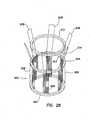
- the extending, retraction elements 224are configured to transition from a first, low-profile, insertion condition 226 ( FIG. 27 ) to a second, expanded, high-profile retention condition 228 in which distal ends of the extending elements extend radially outwardly ( FIG. 28 ).
- the retention ring 222may be sized and configured to hold the extending elements 224 in a generally perpendicular position to the plane of the retention ring.
- the extending elements 224may extend radially inwardly to facilitate insertion or the retraction device 220 into the incision 62.
- the extending elements 224may be malleable so as to be shaped into a retracted state within an incision or they may be sized and configured to snap between a first, inwardly disposed condition to the second, outwardly disposed condition 228 in a détente relationship.
- a circumferential sheathmay be associated with the retraction device 220 and positioned either between the extending elements 224 and adjacent tissue or within a lumen of the retraction device as a separate component.
- the extending elements 224are inserted into a surgical incision 62 ( FIGS. 1 and 2 ) in a body wall 60 and advanced distally until the proximal retention ring 222 is substantially abutted against an outer surface of the body wall. A surgeon may then insert his hand distally through the retention ring 222 and bend a distal portion 230 of each of the extending elements 224 radially outwardly such that the distal portions of the extending elements are placed against an inner surface 66 of the body wall 60.
- the extending elements 224may be made of thin strips of sheet metal, such as spring steel, having a cupped or axially semicircular cross section resembling a steel tape measure or a slat of a venetian blind. Each of the extending elements 224 is oriented with the outer curve 232 of the semicircular cross section positioned radially outwardly.
- the extending elements 224easily exist in the first, straight, insertion condition 226. However, once bent inwardly on the outer semicircular surface 232, the extensions transform to the second, curved, high-profile condition 228 for retention in the incision.
- the extensions 224may be made of a shape-memory material, such as nickel-titanium alloy.
- the extending elements 224 made of nickel-titanium alloymay be in a first, substantially straight condition 226, and when placed in an environment having a second, higher temperature, the extensions transform to a second, curved condition 228 with the distal ends of the extending elements extending radially outwardly.
- the device 220may be held in a relatively cold environment, such as in ice water, and subsequently inserted into a warm environment where the temperature is higher, such as in a live body.
- the shape of nickel-titanium alloy extending elements 224changes according to a preset condition.
- the wound retraction device 220may include a plurality of pull wires 234 with each pull wire corresponding with a respective extending element 224.
- Each of the pull wires 234is coupled to a distal portion 230 of a respective extending element 224 and configured such that when the pull wire is pulled proximally, the distal portion of the respective extending element deflects radially outwardly.
- Each pull wire 234forces the distal portion 230 of the respective extending element 224 to exhibit a shape that is determined by the tension of the pull wire.
- the pull wires 234may be deployed collectively or individually to bend the extending elements 224.
- Each of the pull wires 234may traverse through a pull wire retainer 236 that is positioned along the length of the outer surface 238 of a respective extending element 224.
- Each pull wire retainer 236may include at least one eyelet 240, tube 242 or other similarly functioning device.
- the pull wire retainers 236function to limit the distance that the pull wires 234 deviate from the outer surface 238 of the extending elements 224 when the pull wires are pulled proximally to deflect the distal portions 230 of the extending elements.
- the pull wire retainers 236may be longitudinally aligned along the length of the outer surface 238 of the extending element 224.
- an exemplary wound retraction device 250includes an outer ring 252 having a substantially annular shape with an adjustable circumference and a substantially tubular structure 254 extending distally from the outer ring.
- the outer ring 252is divided into a plurality of curved ring segments 256 with adjacent curved ring segments being coupled together by means for adjusting the circumference, such as a ratcheting mechanism 258, to form the annular shape.
- Each of the curved ring segments 256includes a first, proximal side 260, a second, distal side 262, a first end 264 about the circumference of the outer ring 252 and a second end 266 about the circumference of the outer ring.
- the curved ring segments 256may be flexible to maintain a substantially circumferential shape of the outer ring 252 as the diameter of the outer ring is adjusted.
- the ratcheting mechanism 258may include a groove 268 in the proximal surface 260 of each of the curved ring segments 256.
- the groove 268substantially follows the curve of the curved ring segment 256 and is opened to the first end 264 of the curved ring segment.
- the groove 268includes a plurality of ratchet teeth 270 positioned, for example, on a first, outer curved surface 272 of the groove.
- the ratchet teeth 270may be positioned on a second, inner curved surface 274 of the groove 268 or on the distal surface 276 of the groove.
- the groove 268may also include a retention channel 278 in at least one of the outer and inner curved surfaces 272, 274 of the groove.
- Each of the curved ring segments 256also includes a flexible, elongate protuberance 280 extending from the second end 266 of the curved ring segment adapted to mate with the groove 268 in an adjacent curved ring segment.
- the elongate protuberance 280includes at least one ratchet tooth 282 that interacts with the ratchet teeth 270 in the groove 268 of the curved ring segment 256 adjacent the elongate protuberance.
- Forming the outer ring 252includes aligning the curved ring segments 256 together circumferentially with the first end 264 of each of the curved ring segments positioned adjacent the second end 266 of an adjacent curved ring segment and inserting the elongate protuberance 280 of each of the curved ring segments into the groove 268 of the other adjacent curved ring segment such that the at least one ratchet tooth 282 on the elongate protuberance interacts with the ratchet teeth 270 in the groove.
- the elongate protuberancemay include a lip 284 ( FIG. 32 ) extending longitudinally along the length of the elongate protuberance and adapted to interact with the retention channel 278 in the groove of the adjacent curved ring segment.
- the diameter of the outer ring 252is adjusted by inserting and retracting the elongate protuberances 280 within the grooves 268 of the adjacent curved ring segments 256. The diameter of the outer ring 252 is increased as the curved ring segments 256 are moved further apart and the diameter is decreased as the curved ring segments are moved closer together.
- the substantially tubular structure 254is also divided into a plurality of elongate tube segments 286 with each of the tube segments being coupled to a respective curved ring segment 256 and extending distally from the respective curved ring segment.
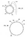
- the tube segments 286may each extend circumferentially between the first end 264 and the second end 266 of the curved ring segment 256 to which the respective tube segment is coupled ( FIG. 30 ) such that there is no overlap between adjacent tube segments.
- each of the tube segments 286may extend circumferentially beyond at least one of the first and second ends 264, 266 of the curved ring segment to which the respective tube segment is coupled ( FIG. 31 ) such that adjacent tube segments may overlap each other.
- the profile of the tube segments 286may substantially follow the curve of the curved ring segment 256 to which the respective tube segment is coupled.
- the tube segments 286may be flexible so as to follow any change of the curve of the curved ring segments 256 to which the respective tube segments are coupled.
- the tube segments 286may be made of a biocompatible material, such as a metallic or polymeric material.
- the exemplary retraction ring 250may include an inner ring 288 that is substantially opposite to the outer ring 252 to maintain the diameter of the tubular structure 254 at the distal end 290 of the tubular structure substantially the same as the diameter at the proximal end 292 of the tubular structure.
- the inner ring 288includes the ratcheting mechanism 258, but with the groove 268 positioned on the distal surface of the curved ring segments 256.
- the distal end 262 of the wound retraction device 250including the inner ring, may be inserted through a small incision 62 ( FIGS.
- the inner ring 288may be expanded to a larger diameter to deploy the inner ring in the form of a distal retention member. With the inner ring 288 deployed, the outer ring 252 may be adjusted to a larger diameter to provide tension upon the tube segments 286, thereby providing circumferential retraction of the incision.
- the distal ends 290 of the tube segments 286may be inserted into the incision 62 and into the body cavity 52.
- the outer ring 252may be adjusted to a larger diameter to provide tension upon the tube segments 286, thereby providing circumferential retraction of the incision 62.
- the tube segments 286are sufficiently strong to maintain retraction of the incision 62 without substantially deflecting the tube sections.
- an exemplary circumferential surgical retraction device 300includes a first, substantially annular, outer ring 302 and a second, substantially annular, inner ring 304.
- the first and second rings 302, 304are separated by a substantially gastight cylindrical sleeve 306.
- the first and second rings 302, 304may be made of a substantially flexible material, such as a polymeric material, and may be reinforced with a first and second biasing member 308, 310, respectively, such as a spring-like core positioned in each of the first and second rings, that biases the first and second rings radially outwardly.
- the cylindrical sleeve 306is coupled to the first and second rings 302, 304.
- the cylindrical sleeve 306may include a bellows 312, or radial folds, that allow the cylindrical sleeve to transition between a first, axially compressed state ( FIG. 33 ) and a second, axially extended state ( FIG. 34 ).
- the outer ring 302is pulled proximally through the incision, thereby pulling the inner ring 304 into sealing contact with the inner surface 66 of the body wall 60 and stretching the bellows 312 of the cylindrical sleeve 306.
- the outer ring 302is pulled proximally until the outer ring is outside the incision 62 and the retraction device is in the second, axially extended state ( FIG. 34 ).
- the first biasing member 308 in the outer ring 302biases the outer ring radially outward and into sealing contact with the outer surface of the body wall 60.
- an exemplary wound retraction device 320includes a gastight, tubular membrane or sheath 322 having a first, proximal end 324 and a second, distal end 326.
- the sheath 322is sufficiently long to fit completely through a body wall, such as an abdominal wall 60 ( FIGS. 1 and 2 ).
- the sheath 322includes a malleable, generally circular member 328 that assumes a first circumference ( FIG. 35 ) when compressed to a first, folded condition 330 and a second, larger circumference ( FIG. 36 ) when unfolded to a second, unfolded condition 332.
- the sheath 322is biased toward the second, unfolded condition 332.
- the folded and unfolded conditions of the sheath 322may represent a détente relationship where the first, folded, condition ( FIG. 35 ) is a relaxed, non-tensioned condition or a compressed condition and where the second, unfolded, condition ( FIG. 36 ) is a fixed, over-centered, condition having sufficient hoop strength to resist compression or refolding.
- the sheath 322 in the second unfolded condition 332may include means to prevent the sheath from shifting position within the retracted wound, such as undulations or protrusions on the outer surface of the sheath. Alternate embodiments may include midpoint conditions between a first, folded condition and a second, unfolded condition.
- the exemplary wound retraction device 320 of FIGS. 35 and 36may include means for compressing the sheath 322 into the first, folded condition 330.
- Such meansmay include a drawstring 336.
- the drawstring 336may include a flexible string 338 that is threaded through the undulations 334 of the sheath 322.
- the string 338may include cord, twine, cable, thread, or similar materials that are well known in the art.
- the drawstring 336is pulled radially away from the sheath.
- the drawstring 336is released ( FIG. 38 )
- the sheath 322assumes the second unfolded condition 332.
- the cylindrical sleeve 356may include a bellows 358, or radial folds, that allow the cylindrical sleeve to transition between a first, axially compressed state ( FIG. 39 ) and a second, axially extended state ( FIG. 40 ).
- the second, inner retention ring 354may be compressed radially at opposing points along its circumference to transform the circular second retention ring into an elongate, oval shape to facilitate insertion into an incision 62 ( FIGS. 1 and 2 ).
- the second ring 354is advanced through the incision 62 until it is completely within the body cavity 52.
- the radial compressionis released from the second ring 354 and the second ring is permitted to assume its substantially circular configuration.
- the first ring 352includes a substantially hollow, inflatable structure 360 that may be enlarged by pressurization with gas or fluid.
- the first, outer ring 352may be inflated ( FIG. 40 ), thereby placing increasing tension on the gastight sleeve 356. Since the second, inner ring 354 cannot be drawn into the incision, the increasing tension on the sleeve 356 retracts and enlarges the incision through which it extends.
Landscapes
- Health & Medical Sciences (AREA)
- Life Sciences & Earth Sciences (AREA)
- Surgery (AREA)
- Molecular Biology (AREA)
- General Health & Medical Sciences (AREA)
- Biomedical Technology (AREA)
- Heart & Thoracic Surgery (AREA)
- Medical Informatics (AREA)
- Nuclear Medicine, Radiotherapy & Molecular Imaging (AREA)
- Animal Behavior & Ethology (AREA)
- Engineering & Computer Science (AREA)
- Public Health (AREA)
- Veterinary Medicine (AREA)
- Pathology (AREA)
- Surgical Instruments (AREA)
- Continuous Casting (AREA)
- Winding Filamentary Materials (AREA)
- Secondary Cells (AREA)
Description
- Tissue retraction during surgery is commonly accomplished by placing opposed instruments within an incision and spreading the incision open with the instruments. Another method includes the use of circumferentially expandable plates or segments that expand to enlarge an incision. The enlarged incision is held open by the expanded device. Additionally, the retraction device may be configured to isolate the incised walls so that they are not contaminated as a surgery proceeds.
- Other retraction devices according to the prior art, such as for example
WO 2008/011358 A1 ;US 2006/149137 A1 ; andUS 2006/149137 A1 , include a pair of opposed, flexible rings where a first ring is placed on one side of the body wall, a second ring is placed on the opposite side of the body wall, and a film of waterproof material is stretched between the two rings. Some of these devices can be difficult to place and require the use of an assistant to attain proper tensioning. - Documents
US 2004/049099 A1 ;US 2007/270654 A1 ;US 2008/103366 A1 ;US 2010/305407 ;WO 2006/057982 A1 andEP 1 609 429 A2 ; disclose other known retractor devices adapted to dilate a wound to a desired diameter. - There remains a need for an easily placed and easily adjustable retraction device for maintaining retraction of an incision during a surgical procedure.
- The present invention provides a device that may be inserted into a surgical incision in a first condition and subsequently expanded or reshaped to retract the incision. The invention also contemplates the use of an impermeable film or sheet associated with the tissue-contacting-portions to provide a fluid tight and gastight barrier that is sized and configured to prevent transfer of biological components.
- A retraction device of the present invention is adapted to retract an incision in a body wall. The retraction device, according to independent claim 1, includes a first, outer ring, a second, inner ring, a first hinge that couples the first to the second ring, and a second hinge that couples the first ring to the second ring. The first and second hinges are positioned along a common axis and substantially opposite each other on the circumference of the first and second rings. The retraction device also includes a tubular sheath that is coupled around the circumference of the first ring and around the circumference of the second ring. In a first, concentric state, the first and second rings are substantially concentric with each other, while in a second, angular state, the first and second rings are rotated about the axis and form an angle between the planes of the first and second rings. The retraction device also includes means for maintaining the retraction device in the second, angular state. The sheath is substantially cylindrical when the first and second rings are in the second, angular state.
- In one aspect, the sheath is substantially not tensioned when the retraction device is in the first, concentric state. In the first, concentric state, the retraction device may be further streamlined by compressing the first and second rings along the axis between the first and second hinges to facilitate insertion of the retraction device into the incision in the body wall. The maintaining means may include a ratchet mechanism positioned proximate at least one of the first and second hinges. The ratchet mechanism may be positioned proximate each of the first and second hinges. In another aspect, the maintaining means may include a valve structure mounted onto the retraction device external the body wall. The sheath may be formed from an elastomeric material. In another aspect, the sheath may be formed from a non-distensible material.
- In another embodiment of the invention, the retraction device, according to independent claim 9, includes a first ring, a second ring, a first hinge that couples the first ring to the second ring, a second hinge that couples the first ring to the second ring, and a stretchable, tubular sheath that is coupled to each of the first and second rings. The first and second hinges are positioned along a common axis and substantially opposite each other on the circumference of the first and second rings. In a first, relaxed state in which an angle is formed between the planes of the first and second rings, the sheath is substantially relaxed and forms a substantially through lumen between a proximal end and a distal end of the retraction device. In a second, tensioned state in which the first and second rings are rotated toward each other across the proximal and distal opening planes, the first and second rings are substantially concentric with the sheath being tensioned between the first and second rings. When the retraction device is in the second, tensioned state, release of the tension upon the elastomeric sheath allows the retraction device to assume the first, relaxed state.
- In one aspect, when the retraction device is in the second, tensioned state, the lumen of the sheath is reduced and substantially occluded and the retraction device is substantially flat. In the second, tensioned state, the retraction device may be streamlined further by compressing the first and second rings along the axis between the first and second hinges to facilitate insertion of the retraction device into the incision in the body wall.
- In another embodiment of the invention, the retraction device, according to independent claim 12, includes a distal continuous ring, a first half ring, a second half ring, a first hinge that couples the distal ring, the first half ring and the second half ring together, a second hinge that couples the distal ring, the first half ring and the second half ring together, and a circumferential, elastomeric sheath that is coupled between the distal ring and the first and second half rings. The first and second hinges are positioned along a common axis and substantially opposite each other on the circumference of the distal ring. In a first, neutral condition, the first half ring is positioned on a first side of the axis, proximal the distal ring, and the second half ring is positioned on a second, opposite side of the axis proximal the distal ring. In a second, tensioned condition, the first half ring is rotated about the first and second hinges in a first direction to a position on the second side of the axis and proximal the distal ring, thereby placing the portion of the sheath that is coupled between the distal ring and the first half ring in tension. The second half ring is rotated about the first and second hinges in a second, opposite direction to a position on the first side of the axis and proximal the distal ring, thereby placing the portion of the sheath that is coupled between the distal ring and the second half ring in tension.
- The first and second half rings may be rotated further about the axis until they are substantially concentric with the distal ring. In the second, tensioned condition, the retraction device may be further streamlined by compressing the distal ring and the first and second half rings along the axis between the first and second hinges to facilitate insertion of the retraction device into the incision in the body wall. The sheath may be further coupled between the first and second half rings. At least one of the first and second half rings may be positioned along an outer surface of the distal ring. Alternatively, at least one of the first and second half rings may be positioned along an inner surface of the distal ring. First end portions of each of the first half ring and the second half ring may overlap and second end portions of each of the first half ring and the second half ring may overlap. In one aspect, the first end portion of the first half ring is positioned between the distal ring and the first end portion of the second half ring, the second end portion of the first half ring is positioned between the distal ring and the second end portion of the second half ring, and the first and second half rings are adapted to rotate past each other as the first and second half rings are rotated about the first and second hinges. The distal ring may be adapted to abut against an inner surface of the body wall.
- These and other features of the invention will become more apparent with a discussion of the various embodiments in reference to the associated drawings.
FIGURE 1 is a side view of a hand assisted laparoscopic procedure where a retraction device is in place;FIG. 2 is a side view of a hand assisted laparoscopic procedure showing the placement of a retraction device;FIG. 3 is a perspective view of a frame for a hinged retraction device in a folded, low profile, insertion condition;FIG. 4 is a perspective view of the frame for the hinged retraction device ofFIG. 3 in a low profile, mid-deployment condition;FIG. 5 is a perspective view of the frame for the hinged retraction device ofFIG. 3 in an open condition;FIG. 6 is a side view of a hinged retraction device in a folded, low profile condition suitable for insertion into an incision;FIG. 7 is a side view of the hinged retraction device ofFIG. 6 in a folded, low profile condition fully inserted into the incision and into a body cavity;FIG. 8 is a side view of the hinged retraction device ofFIG. 6 fully inserted into the incision and fully deployed within the body cavity to retract the incision;FIG. 9 is a side view of a cross-ring retraction device in a non-tensioned condition prior to insertion into an incision in a body wall;FIG. 10 is a side view of the cross-ring retraction device ofFIG. 9 in a fully tensioned, folded, low profile condition suitable for insertion through the incision in the body wall;FIG. 11 is a side view of the insertion step of the cross-ring retraction device ofFIG. 9 through the incision in the body wall;FIG. 12 is a side view of the deployment step of the cross-ring retraction device ofFIG. 9 where the cross-ring retraction device is allowed to assume a preset tension to retract the incision in the body wall;FIG. 13 is a perspective view of the cross-ring retraction device ofFIG. 9 in a stored condition;FIG. 14 is a perspective view of the cross-ring retraction device ofFIG. 9 as it is prepared for tensioning prior to insertion through the incision in the body wall;FIG. 15 is a perspective view of the cross-ring retraction device ofFIG. 9 partially tensioned prior to insertion through the incision in the body wall;FIG. 16 is a perspective view of the cross-ring retraction device ofFIG. 9 partially tensioned prior to insertion through the incision in the body wall;FIG. 17 is a perspective view of the cross-ring retraction device ofFIG. 9 partially tensioned prior to insertion through the incision in the body wall prior to the step of reducing the insertion profile by compressing the cross-ring along the folding axis into an oval shape;FIG. 18 is a perspective view of the cross-ring retraction device ofFIG. 9 fully tensioned prior to insertion through the incision in the body wall and further prepared by compressing the cross-ring along the folding axis into an oval shape;FIG. 19 is a perspective view of a cross-ring retraction device that comprises a first rigid ring and a plurality of folding portions;FIG. 20 is a side view of the cross-ring retraction device ofFIG. 19 in a stored condition, prior to tensioning;FIG. 21 is a side view of the cross-ring retraction device ofFIG. 19 prepared for use by rotating the folding members;FIG. 22 is a side view of the cross-ring retraction device ofFIG. 19 as it is inserted into the incision in the body wall;FIG. 23 is a side view of the cross-ring retraction device ofFIG. 19 as it is further inserted into the incision in the body wall on its way to being fully inserted through the incision and completely into the body cavity;FIG. 24 is a side view of the cross-ring retraction device ofFIG. 19 rotated into the deployed position with the rigid ring against the inner surface of the body wall and the folding portions rotated partially back toward the stored condition and extending through the incision in the body wall;FIG. 25 is a side view of the cross-ring retraction device ofFIG. 19 as it is fully inserted through a body wall and allowed to assume a deployed condition as it attempts to assume the stored condition;FIG. 26 is a perspective view of an exemplary wound retraction device having a plurality of straps for providing tension between a first retention ring and a second retention ring;FIG. 27 is a perspective view of an exemplary ring-shaped retraction device having a plurality of shapeable extensions in a first condition;FIG. 28 is a perspective view of the ring-shaped retraction device ofFIG. 27 having the plurality of shapeable extensions in a second, deployed condition;FIG. 29 is a perspective view of a ring-shaped retraction device, similar to the ring-shaped retraction device ofFIG. 27 , including pull wires for changing the shape of the extensions;FIG. 30 is a perspective view of an exemplary ring-shaped retraction device having a plurality of adjustable retracting portions that allow adjustment of the ring diameter;FIG. 31 is a perspective view of an exemplary ring-shaped retraction device having a plurality of adjustable retracting portions that allow adjustment of the ring diameter and having overlapping extensions;FIG. 32 is a section view taken from line 32-32 inFIG. 31 and depicted at a larger scale;FIG. 33 is a side view of an exemplary adjustable wound retraction device having two rings and a sheath comprising bellows in a low profile, insertion condition;FIG. 34 is a side view of the adjustable wound retraction device ofFIG. 33 in a deployed, retracting condition;FIG. 35 is a perspective view of an exemplary malleable retraction ring in a closed condition for insertion into an incision;FIG. 36 is a perspective view of the malleable retraction ring ofFIG. 35 in a fully open, deployed condition;FIG. 37 is a plan view of the malleable retraction ring ofFIG. 35 in a closed condition for insertion into an incision with the retraction ring being held closed by a drawstring;FIG. 38 is a perspective view of the malleable retraction ring ofFIG. 37 in a fully open, deployed condition;FIG. 39 illustrates an exemplary expandable and retractable anchoring ring having inflatable portions in a low profile, uninflated, insertion condition; andFIG. 40 illustrates the expandable and retractable anchoring ring ofFIG. 39 in an inflated, deployed condition.- With reference to the drawings,
FIGURES 1 and2 depict a hand assistedlaparoscopic surgery 50 where anabdominal cavity 52 is created within anabdominal region 54 of a body by the introduction of a pressurized gas. Aretraction device 56 is shown having ahuman hand 58 therethrough. To deploy theretraction device 56 within a patient'sabdominal wall 60, asurgical incision 62 is made through the abdominal wall and the retraction device is inserted and subsequently deployed to retract and enlarge the incision. Theretraction device 56 may include a first, outer retention member, a second, inner retention member, and a membrane or sleeve coupled between the first retention member and the second retention member. Theretraction device 56 may be shapeable 64 to facilitate placement through asmall incision 62. Theretraction device 56 may be held by a hand in a low profile shape andcondition 64 as it is inserted through theincision 62 and subsequently released so that the first, outer retention member and the second, inner retention member stretch the membrane between an outer surface of thebody wall 60 and aninner surface 66 of the body wall. - Referring to
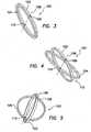
FIGS. 3-8 , aretraction device 100 is shown having a first,outer ring 102 and a second,inner ring 104 that are substantially concentric with each other. The first andsecond rings common axis 106 that forms afirst hinge 108 and asecond hinge 110 that couple thefirst ring 102 and thesecond ring 104 together with the hinges being positioned substantially opposite each other on the circumference of the first and second rings. Theretraction device 100 may transition from a first, concentric state (FIG. 3 ) to a second, angular state (FIGS. 4, 5 and8 ) 112 where the first andsecond rings axis 106 and form an angle between the planes of the first and second rings. The form of theretraction device 100 generally resembles a collapsible gyroscope. A gastight tubular membrane or sheath 114 (FIGS. 6-8 ) is coupled around the circumference of thefirst ring 102 and around the circumference of thesecond ring 104 such that when the first and second rings are in the second, angular state, the sheath is substantially cylindrical. - The first and
second rings FIGS. 6 and 7 ) where the wall of the membrane orsheath 114 is either not tensioned or only lightly tensioned. The compressed, concentric structure may be further streamlined by compressing the first andsecond rings second hinges retraction device 100 into theincision 62 in thebody wall 60. The further streamlining along the axis significantly elongates theretraction device 100 so that it can slide through asmall incision 62. Once theretraction device 100 has been inserted into theincision 62 to about the midpoint of the device, with the axis between the first andsecond hinges abdominal wall 60 and parallel to the incision, the retraction device is unfolded and deployed so that the membrane orsleeve 114 is stretched within theincision 62. As the tworings device 100 are rotated about theaxis 106 between the first andsecond hinges sleeve 114 places retracting tension upon the tissue surrounding the membrane or sleeve. Thefirst ring 102 and thesecond ring 104 now traverse theincision 62 and the extending portions of the rings abut the outer surface of thebody wall 60 and theinner surface 66 of the body wall. This arrangement maintains theretraction device 100 in place within theincision 62 and also retracts and enlarges the incision. - The
retraction device 100 includes means for maintaining the retraction device in the second, angular state 105. Such maintaining means may include a ratchet mechanism that is positioned proximate at least one of the first andsecond hinges second hinges body wall 60. Other means for maintaining theretraction device 100 in the open, deployed condition include any suitable mechanical means that is well known in the art. - The first and
second rings second rings rings rings second rings first ring 102 may be made of a more rigid material than thesecond ring 104. For example, thefirst ring 102 may be made of a semi-rigid metal or plastic and thesecond ring 104 may be made of a plastic or other material less rigid than the material of which the first ring is made. When the first andsecond rings FIG. 3 ), the circumference of the second ring is collapsed to fit within the circumference of the first ring. - The membrane or
sheath 114 may be formed from an elastomeric material or a thin, non-distensible material. The elastomeric materials may include silicone, polyisoprene, latex, vinyl and polyurethane. The non-elastic materials may include polyester, Mylar, polyethylene, and the like. These materials may be reinforced with a fabric or woven material to increase strength and durability. - Referring to
FIGS. 9 through 18 , a cross-ringwound retraction device 120 includes first and second retracting portions or rings 122, 124 and a gastight, stretchable, tubular membrane, orsheath 126, that may be tensioned between the retracting portions. The first and second retractingportions portions common axis 128, thereby forming first andsecond hinges portions sheath 126 is coupled to each of the first and second retractingportions - The
cross-ring retraction device 120 may be supplied in a first, relaxed state 134 (FIG. 9 ) where the circumferentialelastomeric sheath 126 is substantially non-tensioned or relaxed. In the first,relaxed state 134, an angle is formed between the planes of the first andsecond rings lumen 136 between theproximal end 138 and thedistal end 140 of theretraction device 120. To place theretraction device 120 in a second, tensionedstate 142, the profile of the retraction device may be reduced and deformed to facilitate placement through a smallsurgical incision 62 by rotating the retractingportions elastomeric sheath 126 is subsequently stretched longitudinally between theproximal end 138 and thedistal end 140, thereby placing the sheath in tension, with the opening of thelumen 136 being reduced and substantially occluded and the retraction device becoming substantially flat (seeFIGS. 13-18 ). Additionally, once theretraction device 120 has been thus flattened, it may be streamlined further into an oval shape (FIG. 18 ) by compressing therings axis 128 of the first andsecond hinges retraction device 120, in the flattened, streamlined condition (FIG. 18 ) will fit through a muchsmaller incision 62 than is the case when the device is atrest 134. Theretraction device 120 may be urged through a surgical defect, such as an incision 62 (FIGS. 1 and2 ), in abody wall 60 and subsequently allowed to assume the firstrelaxed state 134 in response to the release of the tension upon theelastomeric sheath 126. Thelumen 136, including the proximal anddistal openings retraction device 120 assumes an open, deployed condition (FIG. 12 ). Theelastomeric sheath 126 forms a continuous,gastight barrier lumen 136 of theretraction device 120 and the tissue of the retracted incision ordefect 62. - The elastomeric material of which the
sheath 126 is made may be chosen to provide a range of retracting forces. For instance, a light weight, thin-walled, more elastic material yields a light retraction force in comparison to a thick-walled, less elastic material. Various diameters of retraction rings 122, 124 may be combined with various qualities of elastomeric material to yield retraction devices that accommodate a wide range of body wall conditions or types. The present invention also contemplates the use of rigid or semi-rigid plastic or spring metal for the construction of the first and second retracting portions or rings 122, 124. - Referring to
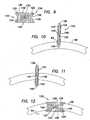
FIGS. 19 through 25 , aretraction device 150 may include a distalcontinuous ring 152, afirst half ring 154 hinged to the distal continuous ring, asecond half ring 156 hinged to the distal continuous ring, and a gastight, circumferentialelastomeric sheath 158 coupled between the distal ring and the first and second half rings. Thesheath 158 may also be coupled directly between the first and second half rings 154, 156. - One or both of the first and second half rings 154, 156 may be positioned along the
outer surface 160 of the distalcontinuous ring 152 and hinged along acommon axis 162, thereby forming afirst hinge 164 and asecond hinge 166 that couple the first and second half rings to each other and to the distal continuous ring with the hinges being positioned substantially opposite each other on the circumference of the distal continuous ring (FIG. 19 ). Alternatively, one or both of the first and second half rings 154, 156 may be positioned along the inner surface of the distal continuous ring 152 (FIGS. 20-25 ). In a first, neutral condition (FIG. 19 ), thefirst half ring 154 is positioned on afirst side 168 of theaxis 162, proximal the distalcontinuous ring 152, and thesecond half ring 156 is positioned on a second,opposite side 170 of the axis proximal the distal continuous ring. - A
first end portion 172 of thefirst half ring 154 and afirst end portion 174 of thesecond half ring 156 overlap each other and asecond end portion 176 of the first half ring and asecond end portion 178 of the second half ring overlap each other. The first andsecond end portions first half ring 154 may be positioned between the distalcontinuous ring 152 and the first andsecond end portions second half ring 156, respectively, so that the first and second half rings may rotate past each other. The retraction device may transition to a second, tensioned condition (FIG. 21 ) by folding thefirst half ring 154 and thesecond half ring 156 flat and in alignment with the distalcontinuous ring 152. In the second, tensioned condition, the first half ring, the second half ring and the distal continuous ring may be substantially concentric. - Preparing the
retraction device 150 for insertion into anincision 62 in abody wall 60 includes transitioning the retraction device from the first, neutral condition to a second, tensioned condition. The transition from the first, neutral condition (FIG. 19 ) to the second, tensioned condition (FIG. 21 ) includes thefirst half ring 154 being rotated about thehinges first direction 180 to a position on thesecond side 170 of theaxis 162 and proximal the distalcontinuous ring 152, thereby placing the portion of thesheath 158 that is coupled between the distal ring and the first half ring in tension (FIGS. 20 and 21 ). Thesecond half ring 156 is rotated about thehinges opposite direction 182 to a position on thefirst side 168 of theaxis 162 and proximal the distalcontinuous ring 152, thereby placing the portion of thesheath 158 that is coupled between the distal ring and the second half ring in tension (FIGS. 20 and 21 ). The first and second half rings 154, 156 may be rotated about thehinges continuous ring 152. Theretraction device 150 may be further streamlined by compressing the distalcontinuous ring 152 and the first and second half rings 154, 156 along theaxis 162 between the first andsecond hinges retraction device 150 to facilitate insertion of the retraction device into theincision 62 more easily (FIGS. 22 and23 ). - The
retraction device 150 is inserted completely through theincision 62 and completely into thebody cavity 52. With theretraction device 150 positioned completely within thebody cavity 52, thesecond half ring 156 is rotated back in thefirst direction 180 and thefirst half ring 154 is rotated back in thesecond direction 182 until the first and second half rings are substantially perpendicular to the distalcontinuous ring 152, substantially parallel to each other and proximal to the distal continuous ring (seeFIG. 24 ). The first andsecond half ring incision 62 until the distalcontinuous ring 152 abuts against theinner surface 66 of thebody wall 60 and the first and second half ring are partially protruding from the incision. The first andsecond half ring FIG. 25 ), thereby circumferentially retracting theincision 62. - With reference to
FIG. 26 , anexemplary retraction device 200 is shown having a first,distal retention ring 202, a second,proximal retention ring 204, a circumferential,tubular sheath 206 coupled to the first and second retention rings, a plurality of tensioningstraps 208 and aproximal lock ring 210. Thedistal retention ring 202 may be made from a shapeable or malleable material that may be deformed for easy insertion through a small body wall incision and subsequently allowed to assume a generally circular condition. Theproximal retention ring 204 may be made from a material more rigid than thedistal retention ring 202. Each of the plurality ofstraps 208 is coupled to thedistal retention ring 202 and extends proximally through a lumen of thesheath 206 and theproximal retention ring 204. Theproximal lock ring 210 is sized and configured to capture thestraps 208 between aninner surface 212 of theproximal retention ring 204 and anouter surface 214 of thelock ring 210. At least one of theinner surface 212 of theproximal retention ring 204 and theouter surface 214 of thelock ring 210 may be beveled. The use of a strong, thin, non-elastic material, such as a fabric, for the construction of thestraps 208, may be contemplated. - In use, the
distal retention ring 202 is deformed and inserted into abody cavity 52 through anincision 62 in abody wall 60. Theproximal retention ring 204 is allowed to rest upon the outer surface of thebody wall 60. Thelock ring 210 is placed within a lumen of theproximal retention ring 204 with thestraps 208 exiting between the proximal retention ring and the lock ring. Thestraps 208 may be pulled proximally to achieve the appropriate tension and subsequent retraction of the incision. Thelock ring 210 responds to the tension of thestraps 208 by wedging against theinner surface 212 of theproximal retention ring 204 and substantially preventing the straps from slipping distally between the lock ring and the proximal retention ring. Removal of theretraction device 200 is accomplished by pulling at least one of thestraps 208 proximally slightly to release thelock ring 210 from theproximal ring 204 and removing the lock ring to release the tension on the straps. With the tension of thestraps 208 removed, thedistal ring 202 may be removed from thebody cavity 52 through the incision. - Referring to
FIGS. 27-29 , an exemplarywound retraction device 220 includes aproximal retention ring 222 and a plurality of shapeable, distally extending,retraction elements 224 coupled to the proximal retention ring and extending distally therefrom. The extending,retraction elements 224 are configured to transition from a first, low-profile, insertion condition 226 (FIG. 27 ) to a second, expanded, high-profile retention condition 228 in which distal ends of the extending elements extend radially outwardly (FIG. 28 ). Theretention ring 222 may be sized and configured to hold the extendingelements 224 in a generally perpendicular position to the plane of the retention ring. Alternatively, the extendingelements 224 may extend radially inwardly to facilitate insertion or theretraction device 220 into theincision 62. The extendingelements 224 may be malleable so as to be shaped into a retracted state within an incision or they may be sized and configured to snap between a first, inwardly disposed condition to the second, outwardlydisposed condition 228 in a détente relationship. A circumferential sheath may be associated with theretraction device 220 and positioned either between the extendingelements 224 and adjacent tissue or within a lumen of the retraction device as a separate component. - In use, the extending
elements 224 are inserted into a surgical incision 62 (FIGS. 1 and2 ) in abody wall 60 and advanced distally until theproximal retention ring 222 is substantially abutted against an outer surface of the body wall. A surgeon may then insert his hand distally through theretention ring 222 and bend adistal portion 230 of each of the extendingelements 224 radially outwardly such that the distal portions of the extending elements are placed against aninner surface 66 of thebody wall 60. - The extending
elements 224 may be made of thin strips of sheet metal, such as spring steel, having a cupped or axially semicircular cross section resembling a steel tape measure or a slat of a venetian blind. Each of the extendingelements 224 is oriented with theouter curve 232 of the semicircular cross section positioned radially outwardly. The extendingelements 224 easily exist in the first, straight,insertion condition 226. However, once bent inwardly on the outersemicircular surface 232, the extensions transform to the second, curved, high-profile condition 228 for retention in the incision. - The
extensions 224 may be made of a shape-memory material, such as nickel-titanium alloy. At a first temperature, the extendingelements 224 made of nickel-titanium alloy may be in a first, substantiallystraight condition 226, and when placed in an environment having a second, higher temperature, the extensions transform to a second,curved condition 228 with the distal ends of the extending elements extending radially outwardly. For example, thedevice 220 may be held in a relatively cold environment, such as in ice water, and subsequently inserted into a warm environment where the temperature is higher, such as in a live body. The shape of nickel-titaniumalloy extending elements 224 changes according to a preset condition. - Referring to
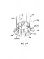
FIG. 29 , thewound retraction device 220 may include a plurality ofpull wires 234 with each pull wire corresponding with a respective extendingelement 224. Each of thepull wires 234 is coupled to adistal portion 230 of a respective extendingelement 224 and configured such that when the pull wire is pulled proximally, the distal portion of the respective extending element deflects radially outwardly. Eachpull wire 234 forces thedistal portion 230 of the respective extendingelement 224 to exhibit a shape that is determined by the tension of the pull wire. Thepull wires 234 may be deployed collectively or individually to bend the extendingelements 224. Each of thepull wires 234 may traverse through a pull wire retainer 236 that is positioned along the length of theouter surface 238 of a respective extendingelement 224. Each pull wire retainer 236 may include at least one eyelet 240, tube 242 or other similarly functioning device. The pull wire retainers 236 function to limit the distance that thepull wires 234 deviate from theouter surface 238 of the extendingelements 224 when the pull wires are pulled proximally to deflect thedistal portions 230 of the extending elements. The pull wire retainers 236 may be longitudinally aligned along the length of theouter surface 238 of the extendingelement 224. - Referring to
FIGS. 30-32 , an exemplarywound retraction device 250 includes anouter ring 252 having a substantially annular shape with an adjustable circumference and a substantiallytubular structure 254 extending distally from the outer ring. Theouter ring 252 is divided into a plurality ofcurved ring segments 256 with adjacent curved ring segments being coupled together by means for adjusting the circumference, such as aratcheting mechanism 258, to form the annular shape. Each of thecurved ring segments 256 includes a first,proximal side 260, a second,distal side 262, afirst end 264 about the circumference of theouter ring 252 and asecond end 266 about the circumference of the outer ring. Thecurved ring segments 256 may be flexible to maintain a substantially circumferential shape of theouter ring 252 as the diameter of the outer ring is adjusted. - The
ratcheting mechanism 258 may include a groove 268 in theproximal surface 260 of each of thecurved ring segments 256. The groove 268 substantially follows the curve of thecurved ring segment 256 and is opened to thefirst end 264 of the curved ring segment. The groove 268 includes a plurality ofratchet teeth 270 positioned, for example, on a first, outercurved surface 272 of the groove. Alternatively, theratchet teeth 270 may be positioned on a second, innercurved surface 274 of the groove 268 or on thedistal surface 276 of the groove. The groove 268 may also include aretention channel 278 in at least one of the outer and innercurved surfaces - Each of the
curved ring segments 256 also includes a flexible,elongate protuberance 280 extending from thesecond end 266 of the curved ring segment adapted to mate with the groove 268 in an adjacent curved ring segment. Theelongate protuberance 280 includes at least oneratchet tooth 282 that interacts with theratchet teeth 270 in the groove 268 of thecurved ring segment 256 adjacent the elongate protuberance. Forming theouter ring 252 includes aligning thecurved ring segments 256 together circumferentially with thefirst end 264 of each of the curved ring segments positioned adjacent thesecond end 266 of an adjacent curved ring segment and inserting theelongate protuberance 280 of each of the curved ring segments into the groove 268 of the other adjacent curved ring segment such that the at least oneratchet tooth 282 on the elongate protuberance interacts with theratchet teeth 270 in the groove. - To substantially prevent the
elongate protuberance 280 of onecurved ring segment 256 from inadvertently slipping out of the groove 268 of the adjacent curved ring segment, the elongate protuberance may include a lip 284 (FIG. 32 ) extending longitudinally along the length of the elongate protuberance and adapted to interact with theretention channel 278 in the groove of the adjacent curved ring segment. The diameter of theouter ring 252 is adjusted by inserting and retracting theelongate protuberances 280 within the grooves 268 of the adjacentcurved ring segments 256. The diameter of theouter ring 252 is increased as thecurved ring segments 256 are moved further apart and the diameter is decreased as the curved ring segments are moved closer together. - As with the
outer ring 252, the substantiallytubular structure 254 is also divided into a plurality ofelongate tube segments 286 with each of the tube segments being coupled to a respectivecurved ring segment 256 and extending distally from the respective curved ring segment. Thetube segments 286 may each extend circumferentially between thefirst end 264 and thesecond end 266 of thecurved ring segment 256 to which the respective tube segment is coupled (FIG. 30 ) such that there is no overlap between adjacent tube segments. Alternatively, each of thetube segments 286 may extend circumferentially beyond at least one of the first and second ends 264, 266 of the curved ring segment to which the respective tube segment is coupled (FIG. 31 ) such that adjacent tube segments may overlap each other. The profile of thetube segments 286 may substantially follow the curve of thecurved ring segment 256 to which the respective tube segment is coupled. Thetube segments 286 may be flexible so as to follow any change of the curve of thecurved ring segments 256 to which the respective tube segments are coupled. Thetube segments 286 may be made of a biocompatible material, such as a metallic or polymeric material. - Referring to
FIG. 31 , theexemplary retraction ring 250 may include aninner ring 288 that is substantially opposite to theouter ring 252 to maintain the diameter of thetubular structure 254 at thedistal end 290 of the tubular structure substantially the same as the diameter at theproximal end 292 of the tubular structure. Theinner ring 288 includes theratcheting mechanism 258, but with the groove 268 positioned on the distal surface of thecurved ring segments 256. In use, with both theouter ring 252 and theinner ring 288 retracted to their smallest respective diameters, thedistal end 262 of thewound retraction device 250, including the inner ring, may be inserted through a small incision 62 (FIGS. 1 and2 ) in abody wall 60 and into abody cavity 52. Theinner ring 288 may be expanded to a larger diameter to deploy the inner ring in the form of a distal retention member. With theinner ring 288 deployed, theouter ring 252 may be adjusted to a larger diameter to provide tension upon thetube segments 286, thereby providing circumferential retraction of the incision. - For retraction rings 250 that do not include the
inner ring 288, the distal ends 290 of thetube segments 286 may be inserted into theincision 62 and into thebody cavity 52. Theouter ring 252 may be adjusted to a larger diameter to provide tension upon thetube segments 286, thereby providing circumferential retraction of theincision 62. Thetube segments 286 are sufficiently strong to maintain retraction of theincision 62 without substantially deflecting the tube sections. - Referring to
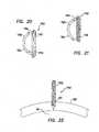
FIGS. 33 and 34 an exemplary circumferentialsurgical retraction device 300 includes a first, substantially annular,outer ring 302 and a second, substantially annular,inner ring 304. The first andsecond rings cylindrical sleeve 306. The first andsecond rings member second rings retraction device 300 toward a shorter axial length. Thecylindrical sleeve 306 is coupled to the first andsecond rings cylindrical sleeve 306 may include abellows 312, or radial folds, that allow the cylindrical sleeve to transition between a first, axially compressed state (FIG. 33 ) and a second, axially extended state (FIG. 34 ). - With the
retraction device 300 in the first, axially compressed state (FIG. 33 ), the retraction device may be further compressed radially at opposing points along the inner andouter rings FIGS. 1 and2 ). Theretraction device 300 is advanced through theincision 62 until the inner .ring 304 is completely within thebody cavity 52. The radial compression is released from theinner ring 304 and the inner ring is permitted to assume its substantially circular configuration. Theouter ring 302 is pulled proximally through the incision, thereby pulling theinner ring 304 into sealing contact with theinner surface 66 of thebody wall 60 and stretching thebellows 312 of thecylindrical sleeve 306. Theouter ring 302 is pulled proximally until the outer ring is outside theincision 62 and the retraction device is in the second, axially extended state (FIG. 34 ). Thefirst biasing member 308 in theouter ring 302 biases the outer ring radially outward and into sealing contact with the outer surface of thebody wall 60. With the biasingmember inner rings cylindrical sleeve 306 is placed in tension and retracts theincision 62. Following the surgical procedure, removal of theretraction device 300 is accomplished by reaching into thebody cavity 52 and pulling theinner ring 304 proximally through theincision 62, thereby removing thecylindrical sleeve 306 from the incision. - Referring to
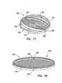
FIGS. 35 and 36 , an exemplarywound retraction device 320 includes a gastight, tubular membrane orsheath 322 having a first,proximal end 324 and a second,distal end 326. Thesheath 322 is sufficiently long to fit completely through a body wall, such as an abdominal wall 60 (FIGS. 1 and2 ). Thesheath 322 includes a malleable, generallycircular member 328 that assumes a first circumference (FIG. 35 ) when compressed to a first, foldedcondition 330 and a second, larger circumference (FIG. 36 ) when unfolded to a second, unfoldedcondition 332. Thesheath 322 is biased toward the second, unfoldedcondition 332. Thesheath 322 may be compressed to the first, foldedcondition 330 by means of a circularly retracting tool or even by a surgeon's hands. In the first, foldedcondition 330, thesheath 322 may includeundulations 334 about its circumference. When the force holding thesheath 322 in the foldedcondition 330 is removed, the sheath opens to the second, unfoldedcondition 332. - In use, the
sheath 322 is compressed to the first, foldedcondition 330 and inserted into anincision 62 in abody wall 60. When thesheath 322 is positioned completely across thebody wall 60, the force holding the sheath in the folded condition is removed and the sheath expands to the second, unfoldedcondition 332 and retracts the incision through which it is placed. - The folded and unfolded conditions of the
sheath 322 may represent a détente relationship where the first, folded, condition (FIG. 35 ) is a relaxed, non-tensioned condition or a compressed condition and where the second, unfolded, condition (FIG. 36 ) is a fixed, over-centered, condition having sufficient hoop strength to resist compression or refolding. Thesheath 322 in the second unfoldedcondition 332 may include means to prevent the sheath from shifting position within the retracted wound, such as undulations or protrusions on the outer surface of the sheath. Alternate embodiments may include midpoint conditions between a first, folded condition and a second, unfolded condition. - Referring to
FIG. 37 , the exemplarywound retraction device 320 ofFIGS. 35 and 36 may include means for compressing thesheath 322 into the first, foldedcondition 330. Such means may include adrawstring 336. Thedrawstring 336 may include aflexible string 338 that is threaded through theundulations 334 of thesheath 322. Thestring 338 may include cord, twine, cable, thread, or similar materials that are well known in the art. To compress thesheath 322 into the first, foldedcondition 330, thedrawstring 336 is pulled radially away from the sheath. When thedrawstring 336 is released (FIG. 38 ), thesheath 322 assumes the second unfoldedcondition 332. - Referring to
FIGS. 39 and 40 , an exemplarycircumferential retraction device 350 includes a first,outer retention ring 352, a second, inner, flexible orshapeable retention ring 354 and a gastight, substantiallycylindrical sleeve 356 coupled to the first and second rings. Theouter retention ring 352 is sized and configured to remain outside abody cavity 52. Theinner retention ring 354 is sized and configured for insertion into and through asurgical incision 62 in abody wall 60 and into thebody cavity 52. Thecylindrical sleeve 356 is configured to be tensioned between thefirst ring 352 and thesecond ring 354 to retract theincision 62 in thebody wall 60. Thecylindrical sleeve 356 may include abellows 358, or radial folds, that allow the cylindrical sleeve to transition between a first, axially compressed state (FIG. 39 ) and a second, axially extended state (FIG. 40 ). - With the
retraction device 350 in the first, axially compressed state (FIG. 39 ), the second,inner retention ring 354 may be compressed radially at opposing points along its circumference to transform the circular second retention ring into an elongate, oval shape to facilitate insertion into an incision 62 (FIGS. 1 and2 ). Thesecond ring 354 is advanced through theincision 62 until it is completely within thebody cavity 52. The radial compression is released from thesecond ring 354 and the second ring is permitted to assume its substantially circular configuration. Thefirst ring 352 includes a substantially hollow,inflatable structure 360 that may be enlarged by pressurization with gas or fluid. With theretraction device 350 positioned in theincision 62, the first,outer ring 352 may be inflated (FIG. 40 ), thereby placing increasing tension on thegastight sleeve 356. Since the second,inner ring 354 cannot be drawn into the incision, the increasing tension on thesleeve 356 retracts and enlarges the incision through which it extends. - It will be understood that many modifications can be made to the disclosed embodiments without departing from the scope of the invention. For example, various sizes of the surgical device are contemplated as well as various types of constructions and materials. It will also be apparent that many modifications can be made to the configuration of parts as well as their interaction. For these reasons, the above description should not be construed as limiting the invention, but should be interpreted as merely exemplary of the embodiments, without departing from the scope of the attached claims.
Claims (20)
- A retraction device (100) for retracting an incision in a body wall, the retraction device comprising:a first, outer ring (102);a second, inner ring (104);a first hinge (108) coupling the first, outer ring (102) to the second, inner ring (104);a second hinge (110) coupling the first, outer ring (102) to the second, inner ring (104), the first and second hinges (108, 110) being positioned along a common axis (106) and substantially opposite each other on the circumference of the first and second rings (102, 104);a tubular sheath (114) coupled around the circumference of the first, outer ring (102) and around the circumference of the second, inner ring (104);a first, concentric state in which the first, outer ring (102) and the second, inner ring (104) are substantially concentric with each other;a second, angular state in which the first, outer ring (102) and second, inner ring (104) are rotated about the axis (106) and form an angle between the planes of the first and second rings (102, 104); andmeans for maintaining the retraction device (100) in the second, angular state,wherein the sheath (114) is substantially cylindrical when the first and second rings (102, 104) are in the second, angular state.
- The retraction device (100) of Claim 1, wherein in the first, concentric state, the sheath (114) is substantially not tensioned.
- The retraction device (100) of Claim 1, wherein in the first, concentric state, the retraction device (100) may be further streamlined by compressing the first and second rings (102, 104) along the axis (106) between the first and second hinges (108, 110) to facilitate insertion of the retraction device (100) into the incision in the body wall.
- The retraction (100) device of Claim 1, wherein the maintaining means include a ratchet mechanism positioned proximate at least one of the first and second hinges (108, 110).
- The retraction device (100) of Claim 4, wherein the ratchet mechanism is positioned proximate each of the first and second hinges (108, 110).
- The retraction device (100) of Claim 1, wherein the maintaining means include a valve structure mounted onto the retraction device (100) external the body wall.
- The retraction device (100) of Claim 1, wherein the sheath (114) is formed from an elastomeric material.
- The retraction device (110) of Claim 1, wherein the sheath (114) is formed from a non-distensible material
- A retraction device (120) for retracting an incision in a body wall, the retraction device (120) comprising:a first ring (122);a second ring (124),a first hinge (130) coupling the first ring (122) to the second ring (124);a second hinge (132) coupling the first ring (122) to the second ring (124), the first and second hinges (130, 132) being positioned along a common axis (128) and substantially opposite each other on the circumference of the first and second rings (122, 124);a stretchable, tubular sheath (126) coupled to each of the first and second rings (122, 124);a first, relaxed state (134) in which an angle is formed between the planes of the first and second rings (122, 124), the sheath (134) being substantially relaxed and forming a substantially through lumen (136) between a proximal end (138) and a distal end (140) of the retraction device (120), anda second, tensioned state (142) in which the first and second rings (122, 124) are rotated toward each other across the proximal and distal opening planes (138, 140), the first and second rings (122, 124) being substantially concentric, and the sheath (126) being tensioned between the first and second rings (122, 124),wherein when the retraction device (120) is in the second, tensioned state (142), release of the tension upon the elastomeric sheath (126) allows the retraction device (120) to assume the first, relaxed state (134).
- The retraction device (120) of Claim 9, wherein in the second, tensioned state (142), the lumen (134) of the sheath (126) is reduced and substantially occluded and the retraction device (120) is substantially flat.
- The retraction device (120) of Claim 9, wherein in the second, tensioned state (142), the retraction device (120) may be streamlined further by compressing the first and second rings (122, 124) along the axis (128) between the first and second hinges (130, 132) to facilitate insertion of the retraction device (120) into the incision in the body wall.
- A retraction device (150) for retracting an incision in a body wall, the retraction device (150) comprising:a distal continuous ring (152);a first half ring (154);a second half ring (156);a first hinge (164) coupling the distal ring (152), the first half ring (154) and the second half ring (156) together;a second hinge (166) coupling the distal ring (152), the first half ring (154) and the second half ring (156) together, the first and second hinges (164, 166) being positioned along a common axis (162) and substantially opposite each other on the circumference of the distal ring (152);a circumferential, elastomeric sheath (158) coupled between the distal ring (152) and the first and second half rings (154, 156);a first, neutral condition in which the first half ring (154) is positioned on a first side (168) of the axis (162), proximal the distal ring (152), and the second half ring (156) is positioned on a second, opposite side (170) of the axis (162) proximal the distal ring (152); anda second, tensioned condition in which the first half ring (154) is rotated about the first and second hinges (164, 166) in a first direction (180) to a position on the second side (170) of the axis (162) and proximal the distal ring (152), thereby placing the portion of the sheath (158) that is coupled between the distal ring (152) and the first half ring (154) in tension, and the second half ring (156) is rotated about the first and second hinges (164, 166) in a second, opposite direction to a position on the first side (168) of the axis (162) and proximal the distal ring (152), thereby placing the portion of the sheath (158) that is coupled between the distal ring (152) and the second half ring (156) in tension.
- The retraction device (150) of Claim 12, wherein the first and second half rings (154, 156) may be rotated further about the axis (162) until they are substantially concentric with the distal ring (152).
- The retraction device (150) of Claim 12, wherein in the second, tensioned condition, the retraction device (150) may be further streamlined by compressing the distal ring (152) and the first and second half rings (154, 156) along the axis (162) between the first and second hinges (164, 166) to facilitate insertion of the retraction device (150) into the incision in the body wall.
- The retraction (150) device of Claim 12, wherein in the sheath (154) being further coupled between the first and second half rings (154, 156).
- The retraction device (150) of Claim 12, wherein at least one of the first and second half rings (154, 156) being positioned along an outer surface of the distal ring (152).
- The retraction device (150) of Claim 12, wherein at least one of the first and second half rings (154, 156) being positioned along an inner surface of the distal ring (152).
- The retraction device (150) of Claim 12, wherein a first end portion of the first half ring (154) and a first end portion of the second half ring (156) overlap and a second end portion of the first half ring (154) and a second end portion of the second half ring (156) overlap.
- The retraction device (150) of Claim 18, wherein:the first end portion of the first half ring (154) being positioned between the distal ring (152) and the first end portion of the second half ring (156);the second end portion of the first half ring (154) being positioned between the distal ring (152) and the second end portion of the second half ring (156); andthe first and second half rings (154, 156) being adapted to rotate past each other as the first and second half rings (154, 156) are rotated about the first and second hinges (164, 166).
- The retraction device (150) of Claim 12, wherein the distal ring (152) is adapted to abut against an inner surface of the body wall.
Priority Applications (5)
| Application Number | Priority Date | Filing Date | Title |
|---|---|---|---|
| EP18207981.4AEP3461423B1 (en) | 2011-05-10 | 2012-05-09 | Wound retractor |
| EP16167739.8AEP3075324B1 (en) | 2011-05-10 | 2012-05-09 | Wound retractor |
| EP22189941.2AEP4104774B1 (en) | 2011-05-10 | 2012-05-09 | Wound retractor |
| EP15173370.6AEP2939603B1 (en) | 2011-05-10 | 2012-05-09 | Wound retractor |
| EP20169466.8AEP3711682B1 (en) | 2011-05-10 | 2012-05-09 | Wound retractor |
Applications Claiming Priority (2)
| Application Number | Priority Date | Filing Date | Title |
|---|---|---|---|
| US201161484362P | 2011-05-10 | 2011-05-10 | |
| PCT/US2012/037111WO2012154845A1 (en) | 2011-05-10 | 2012-05-09 | Wound retractor |
Related Child Applications (6)
| Application Number | Title | Priority Date | Filing Date |
|---|---|---|---|
| EP20169466.8ADivisionEP3711682B1 (en) | 2011-05-10 | 2012-05-09 | Wound retractor |
| EP22189941.2ADivisionEP4104774B1 (en) | 2011-05-10 | 2012-05-09 | Wound retractor |
| EP16167739.8ADivisionEP3075324B1 (en) | 2011-05-10 | 2012-05-09 | Wound retractor |
| EP18207981.4ADivisionEP3461423B1 (en) | 2011-05-10 | 2012-05-09 | Wound retractor |
| EP15173370.6ADivisionEP2939603B1 (en) | 2011-05-10 | 2012-05-09 | Wound retractor |
| EP15173370.6ADivision-IntoEP2939603B1 (en) | 2011-05-10 | 2012-05-09 | Wound retractor |
Publications (2)
| Publication Number | Publication Date |
|---|---|
| EP2706923A1 EP2706923A1 (en) | 2014-03-19 |
| EP2706923B1true EP2706923B1 (en) | 2015-08-05 |
Family
ID=46147742
Family Applications (6)
| Application Number | Title | Priority Date | Filing Date |
|---|---|---|---|
| EP12723014.2ANot-in-forceEP2706923B1 (en) | 2011-05-10 | 2012-05-09 | Wound retractor |
| EP18207981.4AActiveEP3461423B1 (en) | 2011-05-10 | 2012-05-09 | Wound retractor |
| EP22189941.2AActiveEP4104774B1 (en) | 2011-05-10 | 2012-05-09 | Wound retractor |
| EP16167739.8AActiveEP3075324B1 (en) | 2011-05-10 | 2012-05-09 | Wound retractor |
| EP15173370.6AActiveEP2939603B1 (en) | 2011-05-10 | 2012-05-09 | Wound retractor |
| EP20169466.8AActiveEP3711682B1 (en) | 2011-05-10 | 2012-05-09 | Wound retractor |
Family Applications After (5)
| Application Number | Title | Priority Date | Filing Date |
|---|---|---|---|
| EP18207981.4AActiveEP3461423B1 (en) | 2011-05-10 | 2012-05-09 | Wound retractor |
| EP22189941.2AActiveEP4104774B1 (en) | 2011-05-10 | 2012-05-09 | Wound retractor |
| EP16167739.8AActiveEP3075324B1 (en) | 2011-05-10 | 2012-05-09 | Wound retractor |
| EP15173370.6AActiveEP2939603B1 (en) | 2011-05-10 | 2012-05-09 | Wound retractor |
| EP20169466.8AActiveEP3711682B1 (en) | 2011-05-10 | 2012-05-09 | Wound retractor |
Country Status (7)
| Country | Link |
|---|---|
| US (5) | US8758236B2 (en) |
| EP (6) | EP2706923B1 (en) |
| JP (6) | JP6005143B2 (en) |
| KR (5) | KR102423785B1 (en) |
| AU (1) | AU2012253555B2 (en) |
| ES (3) | ES2822115T3 (en) |
| WO (1) | WO2012154845A1 (en) |
Families Citing this family (44)
| Publication number | Priority date | Publication date | Assignee | Title |
|---|---|---|---|---|
| EP2343032B1 (en) | 2002-06-05 | 2012-05-09 | Applied Medical Resources Corporation | Wound retractor |
| US20170049474A1 (en)* | 2004-07-21 | 2017-02-23 | Covidien Lp | Surgical port assembly |
| US8992558B2 (en) | 2008-12-18 | 2015-03-31 | Osteomed, Llc | Lateral access system for the lumbar spine |
| US9149265B2 (en) | 2011-02-26 | 2015-10-06 | Abbott Cardiovascular Systems, Inc. | Hinged tissue support device |
| US9549758B2 (en)* | 2011-03-23 | 2017-01-24 | Covidien Lp | Surgical access assembly with adapter |
| WO2013106347A1 (en) | 2012-01-10 | 2013-07-18 | The Board Of Trustees Of The Leland Stanford Junior University | Methods and devices for the prevention of surgical site infections |
| US9486200B2 (en)* | 2013-01-09 | 2016-11-08 | Cook Medical Technologies Llc | Abdominal retractor |
| US9486132B2 (en)* | 2013-01-17 | 2016-11-08 | Abbott Cardiovascular Systems, Inc. | Access device for accessing tissue |
| US9402612B2 (en)* | 2013-03-14 | 2016-08-02 | Precient Surgical, Inc. | Methods and devices for the prevention of incisional surgical site infections |
| JP6388914B2 (en)* | 2013-04-17 | 2018-09-12 | デピュイ・シンセス・プロダクツ・インコーポレイテッド | Extendable dilator |
| GB2518859B (en)* | 2013-10-02 | 2018-12-12 | Salts Healthcare Ltd | Wound management device |
| US9492153B2 (en)* | 2013-10-25 | 2016-11-15 | Vlv Associates, Inc. | Wound protector |
| WO2015138317A1 (en) | 2014-03-10 | 2015-09-17 | Stryker Corporation | Limb positioning system |
| EP4218629B1 (en)* | 2014-04-23 | 2024-11-20 | Applied Medical Resources Corporation | System for tissue removal |
| KR20240172766A (en) | 2014-08-15 | 2024-12-10 | 어플라이드 메디컬 리소시스 코포레이션 | Natural orifice surgery system |
| CA2967766C (en)* | 2014-11-13 | 2023-10-17 | Applied Medical Resources Corporation | Systems and methods for tissue removal |
| WO2016085930A2 (en) | 2014-11-25 | 2016-06-02 | Applied Medical Resources Corporation | Circumferential wound retraction with support and guidance structures |
| JP6292141B2 (en) | 2015-01-29 | 2018-03-14 | 独立行政法人国立病院機構 | Retractor |
| WO2016142749A1 (en)* | 2015-03-12 | 2016-09-15 | Synaptive Medical (Barbados) Inc. | System and method for guided port insertion to minimize trauma |
| US9951904B2 (en) | 2015-03-24 | 2018-04-24 | Stryker Corporation | Rotatable seat clamps for rail clamp |
| KR101592975B1 (en)* | 2015-08-19 | 2016-02-12 | 위캔메디케어 주식회사 | Surgical retractor |
| JP2018525083A (en)* | 2015-08-27 | 2018-09-06 | アプライド メディカル リソーシーズ コーポレイション | Wound retractor with inner ring that is non-circular, non-coplanar or non-parallel |
| WO2017062850A2 (en) | 2015-10-07 | 2017-04-13 | Applied Medical Resources Corporation | Wound retractor with multi-segment outer ring |
| AU2017209092B2 (en)* | 2016-01-21 | 2019-12-05 | The Cleveland Clinic Foundation | System and apparatus for assisting with submucosal dissections |
| EP3405126A1 (en)* | 2016-01-21 | 2018-11-28 | Boston Scientific Scimed, Inc. | Medical devices and related methods of use |
| WO2018039228A1 (en) | 2016-08-23 | 2018-03-01 | Stryker European Holdings I, Llc | Instrumentation for the implantation of spinal implants |
| US10213194B2 (en) | 2016-09-27 | 2019-02-26 | Ethicon, Inc. | Surgical retraction systems including sternal retractors and hemostatic inserts |
| USD832436S1 (en)* | 2017-02-16 | 2018-10-30 | Ergosurg Gmbh | Electromagnetic localizer |
| JP6889431B2 (en)* | 2017-07-11 | 2021-06-18 | 国立研究開発法人国立がん研究センター | Minimally invasive surgical instruments |
| EP3664874B1 (en)* | 2017-08-11 | 2023-10-04 | West Pharmaceutical Services, Inc. | Expandable and automatically retractable collar and method of use thereof |
| WO2019094502A1 (en) | 2017-11-07 | 2019-05-16 | Prescient Surgical, Inc. | Methods and apparatus for prevention of surgical site infection |
| EP3545857B1 (en) | 2018-03-30 | 2024-01-03 | Stryker European Operations Holdings LLC | Lateral access retractor and core insertion |
| CN112020333B (en)* | 2018-04-26 | 2024-06-25 | 奥林巴斯株式会社 | Treatment system and distention device |
| US11413029B2 (en) | 2018-10-24 | 2022-08-16 | Stryker European Operations Holdings Llc | Anterior to psoas instrumentation |
| US11690679B2 (en) | 2019-01-08 | 2023-07-04 | Covidien Lp | Localization systems and methods of use |
| KR102179518B1 (en) | 2019-03-29 | 2020-11-17 | 주식회사 혜안 | Manufacturing method of inorganic binder |
| US11426203B2 (en) | 2019-05-23 | 2022-08-30 | Covidien Lp | Tissue guards and systems incorporating the same for tissue specimen removal procedures and other surgical procedures |
| US11564674B2 (en) | 2019-11-27 | 2023-01-31 | K2M, Inc. | Lateral access system and method of use |
| US11058459B2 (en)* | 2019-12-12 | 2021-07-13 | Covidien Lp | Two-piece cutting guard with evacuation ports |
| US11931067B2 (en) | 2020-08-15 | 2024-03-19 | Covidien Lp | Insertable cutting guards |
| KR102601515B1 (en)* | 2021-04-14 | 2023-11-14 | 가톨릭대학교산학협력단 | Assistive device for vaginal natural orifice tranlumminal endoscopis surgery |
| US11712237B1 (en) | 2022-07-20 | 2023-08-01 | Samothrace Medical Innovations, Inc. | Anatomical tissue anchor and related methods |
| WO2024019794A1 (en)* | 2022-07-20 | 2024-01-25 | Samothrace Medical Innovations, Inc. | Anatomical tissue anchor and related methods |
| AU2024240140A1 (en)* | 2023-03-21 | 2025-10-09 | Lsi Solutions, Inc. | Surgical retractor assembly |
Family Cites Families (810)
| Publication number | Priority date | Publication date | Assignee | Title |
|---|---|---|---|---|
| US52104A (en) | 1866-01-16 | Improvement in sulky-plows | ||
| US447761A (en) | 1891-03-10 | Speculum | ||
| US52014A (en) | 1866-01-16 | Improvement in specula for uterine diseases | ||
| US202813A (en) | 1878-04-23 | Improvement in speculums | ||
| US558364A (en) | 1896-04-14 | Pipe-coupling | ||
| US758535A (en) | 1903-09-12 | 1904-04-26 | George F Cutter | Embroidery hoop or ring. |
| US929583A (en) | 1909-03-16 | 1909-07-27 | Sylvester W Gibbs | Embroidery-frame. |
| US1056966A (en) | 1911-11-15 | 1913-03-25 | Charles E Belding | Embroidery-hoop. |
| US1157202A (en) | 1913-10-14 | 1915-10-19 | Uri C Bates | Surgical apparatus. |
| US1180466A (en) | 1914-04-02 | 1916-04-25 | England J Barker | Type-writer. |
| US1242972A (en) | 1915-04-20 | 1917-10-16 | John H Pettit | Embroidery-holder. |
| US1221123A (en) | 1916-06-15 | 1917-04-03 | Evelyn M Westhaver | Embroidery-hoop. |
| US1598284A (en) | 1925-11-03 | 1926-08-31 | Justus R Kinney | Draining device |
| US1690995A (en) | 1927-12-28 | 1928-11-06 | Monte Lloyd Corp | Anorectal dilator |
| US1810466A (en) | 1928-05-25 | 1931-06-16 | Deutsch Josef | Device for giving access to cavities of the animal and human body |
| US2219564A (en) | 1937-06-14 | 1940-10-29 | James A Reyniers | Surgical operating device |
| US2305289A (en) | 1939-06-17 | 1942-12-15 | Coburg Hermann | Surgical appliance |
| US2313164A (en)* | 1939-11-13 | 1943-03-09 | Walfred A Nelson | Self-retaining surgical retractor |
| US2478586A (en) | 1946-12-12 | 1949-08-09 | John T Krapp | Coupling |
| US2695608A (en) | 1950-11-06 | 1954-11-30 | Philadelphia Children Hospital | Adjustable closure device for special purpose chambers |
| US2669991A (en) | 1951-12-27 | 1954-02-23 | Curutchet Pedro Domingo | Tetradigital grip for long lever pivoted surgical instruments |
| US2812758A (en) | 1955-07-26 | 1957-11-12 | John C Blumenschein | Surgical retractor |
| US2853075A (en) | 1956-07-10 | 1958-09-23 | Roy D Hoffman | Rumen trocar extricator |
| US2835253A (en) | 1956-08-14 | 1958-05-20 | Florence W Borgeson | Surgical appliance |
| US2841148A (en)* | 1957-06-21 | 1958-07-01 | Godfrey J Kadavy | Viscera retainer for use in abdominal operations |
| US3057350A (en) | 1958-06-27 | 1962-10-09 | Baxter Don Inc | Administration set |
| US3039468A (en) | 1959-01-07 | 1962-06-19 | Joseph L Price | Trocar and method of treating bloat |
| US3111943A (en) | 1961-08-02 | 1963-11-26 | John R Orndorff | Aseptic surgical wound protector |
| US3195934A (en) | 1962-05-31 | 1965-07-20 | Reuel C Parrish | Coupling for fluid conduits |
| US3129706A (en) | 1962-11-13 | 1964-04-21 | Jr Walker Reynolds | Surgical retractor |
| US3253594A (en) | 1963-07-30 | 1966-05-31 | Frank E Matthews | Peritoneal cannula |
| US3313299A (en) | 1964-02-05 | 1967-04-11 | Richard G Spademan | Intravascular catheter with coaxial puncturing means |
| US3244169A (en) | 1964-02-17 | 1966-04-05 | Surgical Devices | Viscera pouch |
| FR1456623A (en) | 1964-07-24 | 1966-07-08 | Device moving without friction by continuous turning | |
| US3447533A (en) | 1964-09-14 | 1969-06-03 | Richard J Spicer | Closure means for artificial body openings |
| US3347226A (en) | 1964-12-11 | 1967-10-17 | Harold W Harrower | Adjustable wound edge protector |
| US3347227A (en) | 1964-12-11 | 1967-10-17 | Harold W Harrower | Wound edge protector |
| US3329390A (en) | 1965-02-18 | 1967-07-04 | Eldon E Hulsey | Variable orifice valve |
| US3332417A (en) | 1965-04-22 | 1967-07-25 | Parke Davis & Co | Adjustable wound protector |
| US3397692A (en) | 1966-02-24 | 1968-08-20 | Parke Davis & Co | Protector for incised wounds |
| US3402710A (en) | 1966-06-27 | 1968-09-24 | Hydra Power Corp | Self-closing valve device for implantation in the human body |
| US3522800A (en) | 1966-07-19 | 1970-08-04 | Arthur J Lesser | Disposable wound retractor and drape and method of using same |
| GB1151993A (en) | 1966-08-12 | 1969-05-14 | Johnson & Johnson | Wound Edge Protector |
| US3416520A (en) | 1966-11-22 | 1968-12-17 | Parke Davis & Co | Surgical drape |
| US3523534A (en) | 1967-04-05 | 1970-08-11 | Hollister Inc | Closure for drainage pouch |
| US3570475A (en) | 1968-11-14 | 1971-03-16 | Mandel Weinstein | Surgical retractor |
| US3553862A (en) | 1969-01-17 | 1971-01-12 | Kaino J Hamu | Adjustable stretch frame for biaxially stressing sheet material |
| US3656485A (en) | 1970-04-27 | 1972-04-18 | Jack R Robertson | Method of and apparatus for viewing the interior of the bladder through a suprapubic incision |
| US3685786A (en) | 1970-08-31 | 1972-08-22 | Riley D Woodson | Elastic valve element having variable orifice |
| US3717883A (en) | 1970-11-23 | 1973-02-27 | Techno Corp | Cardiac valve replacement |
| US3703896A (en) | 1970-12-29 | 1972-11-28 | Abcor Inc | Intrauterine contraceptive device |
| US3729045A (en) | 1971-01-13 | 1973-04-24 | Adrian Inc | Molded screen frame |
| US3831583A (en) | 1971-03-05 | 1974-08-27 | Univ California | Implantable bulb for inflation of surgical implements |
| US3717151A (en) | 1971-03-11 | 1973-02-20 | R Collett | Flesh penetrating apparatus |
| US3729006A (en) | 1971-05-27 | 1973-04-24 | M Kanbar | Disposable surgical retractors |
| US3774596A (en) | 1971-06-29 | 1973-11-27 | G Cook | Compliable cavity speculum |
| US3729027A (en) | 1972-01-26 | 1973-04-24 | H Bare | Flexible tubing with integral end clamps |
| CS159428B1 (en) | 1972-02-01 | 1975-01-31 | ||
| GB1355611A (en) | 1972-02-25 | 1974-06-05 | Mucon Eng Co Ltd | Waste disposal containers |
| US3807393A (en) | 1972-03-01 | 1974-04-30 | Donald B Mc | Surgical retractor |
| GB1407023A (en) | 1972-03-16 | 1975-09-24 | Mucon Eng Co Ltd | Flow control valves |
| GB1379772A (en) | 1972-04-21 | 1975-01-08 | Mucon Eng Co Ltd | Flow control vavles |
| US3799166A (en) | 1972-05-22 | 1974-03-26 | A Marsan | Starch type gel seals for ostomy patients |
| FR2188437A5 (en) | 1972-06-05 | 1974-01-18 | Calhene | |
| US3789852A (en)* | 1972-06-12 | 1974-02-05 | S Kim | Expandable trochar, especially for medical purposes |
| US3788318A (en)* | 1972-06-12 | 1974-01-29 | S Kim | Expandable cannular, especially for medical purposes |
| US3797478A (en) | 1972-07-11 | 1974-03-19 | M Walsh | Multi-functional valve for use in the urethra |
| US3782370A (en)* | 1972-07-12 | 1974-01-01 | B Mcdonald | Surgical retractor |
| US3762080A (en) | 1972-08-24 | 1973-10-02 | C Poole | Frame |
| GB1400808A (en) | 1972-12-21 | 1975-07-23 | Mucon Eng Co Ltd | Vacuum conveying systems |
| US3828764A (en) | 1973-01-22 | 1974-08-13 | Well Saver Inc | Non-migrating reversible make sterilization coupler |
| US3853127A (en) | 1973-04-03 | 1974-12-10 | R Spademan | Elastic sealing member |
| GB1372491A (en) | 1973-05-08 | 1974-10-30 | Mucon Eng Co Ltd | Waste disposal containers |
| US3860274A (en) | 1973-07-02 | 1975-01-14 | Richard L Ledstrom | Pipe coupling |
| US3856021A (en) | 1973-10-01 | 1974-12-24 | A Mcintosh | Device for treatment of bloat of ruminants |
| US3853126A (en) | 1973-11-15 | 1974-12-10 | Heyer Schulte Corp | Artery-to-vein shunt |
| US3841332A (en) | 1973-11-19 | 1974-10-15 | D Treacle | Enterostomy drainage appliance |
| US3907389A (en) | 1973-12-12 | 1975-09-23 | Marion E Cox | Glove box chamber |
| US3863639A (en) | 1974-04-04 | 1975-02-04 | Richard N Kleaveland | Disposable visceral retainer |
| US3915171A (en) | 1974-06-06 | 1975-10-28 | Dennis William Shermeta | Gastrostomy tube |
| US3996623A (en) | 1974-07-30 | 1976-12-14 | Kaster Robert L | Method of implanting a prosthetic device and suturing member therefor |
| US3970089A (en) | 1974-08-05 | 1976-07-20 | Saice Dwayne D | Cardiovascular catheter seal device |
| GB1482857A (en) | 1974-09-10 | 1977-08-17 | Wolf Gmbh Richard | Trocar guides |
| US3965890A (en) | 1974-10-18 | 1976-06-29 | William Kohlmann Gauthier | Surgical retractor |
| US4030500A (en) | 1974-12-16 | 1977-06-21 | Hadar Yngve Ronnquist | Fecal matter collector |
| GB1496696A (en) | 1975-02-07 | 1977-12-30 | Mucon Eng Co Ltd | Valves for fluids and/or particulate material |
| DE2527706A1 (en) | 1975-06-21 | 1976-12-30 | Hanfried Dr Med Weigand | DEVICE FOR THE INTRODUCTION OF CONTRAST AGENTS INTO AN ARTIFICIAL INTESTINAL OUTLET |
| US4016884A (en) | 1975-07-02 | 1977-04-12 | Kwan Gett Clifford S | Atriotomy access device |
| US4000739A (en) | 1975-07-09 | 1977-01-04 | Cordis Corporation | Hemostasis cannula |
| US4069913A (en) | 1975-08-11 | 1978-01-24 | Harrigan Roy Major | Surgical glove package and fixture |
| US4082005A (en) | 1975-08-28 | 1978-04-04 | Teledyne Industries, Inc. | Spin coupled, angular rate sensitive inertial sensors with mounting structure and method of fabricating and mounting same |
| US4117847A (en) | 1976-02-05 | 1978-10-03 | Clayton Ralph S | Colon catheter |
| DE2605148B2 (en) | 1976-02-10 | 1977-11-24 | Rechenberg, Cornelius, 8204 Brannenburg | CHEST PROSTHESIS |
| US4024872A (en) | 1976-06-01 | 1977-05-24 | Muldoon James P | Colostomy device and method |
| US4043328A (en) | 1976-06-01 | 1977-08-23 | American Hospital Supply Corporation | Urological drape |
| US4183357A (en) | 1976-08-02 | 1980-01-15 | Bentley Laboratories, Inc. | Chronic transcutaneous implant assembly for enterostomies |
| US4083370A (en) | 1976-11-03 | 1978-04-11 | Taylor John D | Bloat relief tube and holder |
| US4130113A (en) | 1976-12-15 | 1978-12-19 | Richards Manufacturing Co., Inc. | Retractor |
| US4112932A (en) | 1977-02-24 | 1978-09-12 | Chiulli Robert D | Laparoscopic cannula |
| US5334646B1 (en) | 1977-03-17 | 1998-09-08 | Applied Elastomerics Inc | Thermoplastic elastomer gelatinous articles |
| US5508334A (en) | 1977-03-17 | 1996-04-16 | Applied Elastomerics, Inc. | Thermoplastic elastomer gelatinous compositions and articles |
| US5336708A (en) | 1977-03-17 | 1994-08-09 | Applied Elastomerics, Inc. | Gelatinous elastomer articles |
| US5262468A (en) | 1977-03-17 | 1993-11-16 | Applied Elastomerics, Inc. | Thermoplastic elastomer gelatinous compositions |
| US4369284A (en) | 1977-03-17 | 1983-01-18 | Applied Elastomerics, Incorporated | Thermoplastic elastomer gelatinous compositions |
| US4141364A (en) | 1977-03-18 | 1979-02-27 | Jorge Schultze | Expandable endotracheal or urethral tube |
| JPS6034241Y2 (en) | 1977-04-25 | 1985-10-12 | オリンパス光学工業株式会社 | Endoscope passage sealing device |
| SE402050B (en) | 1977-08-26 | 1978-06-19 | Triplus Sjukvardsprod Ab | OPERATING CLOTH INTENDED TO PROTECT THE SARCANTS AROUND AN INCISION |
| IE47372B1 (en) | 1977-09-23 | 1984-03-07 | Rhys Davies N C | Exsanguinating device |
| US4177814A (en) | 1978-01-18 | 1979-12-11 | KLI, Incorporated | Self-sealing cannula |
| US4189880A (en) | 1978-06-16 | 1980-02-26 | Gene Ballin | Combination mounting frame and film for a window |
| US4187849A (en) | 1978-07-28 | 1980-02-12 | Stim Edward M | Suction curettage device with valve control and support means for differing diameter tubes |
| US4306562A (en) | 1978-12-01 | 1981-12-22 | Cook, Inc. | Tear apart cannula |
| US4222126A (en) | 1978-12-14 | 1980-09-16 | The United States Of America As Represented By The Secretary Of The Department Of Health, Education & Welfare | Unitized three leaflet heart valve |
| US4217664A (en) | 1979-02-02 | 1980-08-19 | Faso Joseph M | Prosthesis and method for creating a stoma |
| US4331138A (en) | 1979-03-21 | 1982-05-25 | Jessen John W | Method of performing an emergency cricothyrotomy |
| US4428364A (en) | 1979-04-11 | 1984-01-31 | Dow Corning Corporation | Self-sealing injection button and method of making same |
| US4254973A (en) | 1979-04-30 | 1981-03-10 | Celanese Corporation | Fluid coupling seal |
| US4253201A (en) | 1979-05-24 | 1981-03-03 | Ross David A | Prosthesis with self-sealing valve |
| US4239036A (en) | 1979-05-29 | 1980-12-16 | Krieger Abbott J | Surgical retractor |
| US4321915A (en) | 1979-06-26 | 1982-03-30 | The United States Of America As Represented By The Department Of Health And Human Services | Everting tube device with relative advance control |
| DE2936256A1 (en) | 1979-09-07 | 1981-03-19 | H. Guido Dr. 8000 München Mutke | INSULATION DEVICE |
| US4338934A (en) | 1980-02-19 | 1982-07-13 | Spademan Richard George | Intravascular catheter apparatus |
| GB2071502A (en) | 1980-03-14 | 1981-09-23 | Nat Res Dev | Surgical retractors |
| US4399816A (en) | 1980-03-17 | 1983-08-23 | Spangler George M | Wound protector with transparent cover |
| US4776843A (en) | 1980-11-21 | 1988-10-11 | Minntech Corporation | Blood access systems |
| US4421296A (en) | 1980-07-17 | 1983-12-20 | Medical Valve Corporation | Disposable plastic reciprocating valve |
| US4338937A (en) | 1980-12-05 | 1982-07-13 | Lerman Sheldon H | Mechanical continent ileostomy or colostomy |
| US4430081A (en) | 1981-01-06 | 1984-02-07 | Cook, Inc. | Hemostasis sheath |
| US4436519A (en) | 1981-05-28 | 1984-03-13 | Argon Medical Corp. | Removable hemostasis valve |
| US4424833A (en) | 1981-10-02 | 1984-01-10 | C. R. Bard, Inc. | Self sealing gasket assembly |
| US4402683A (en) | 1981-12-28 | 1983-09-06 | Kopman Ercument A | Cannula introducer |
| US4454873A (en) | 1982-02-26 | 1984-06-19 | Hexcel Corporation | Separator medium for orthopedic cast material |
| US4434791A (en) | 1982-03-15 | 1984-03-06 | Humboldt Products Corp. | Surgical retractor array system |
| US4411659A (en) | 1982-03-16 | 1983-10-25 | Hollister Incorporated | Drainable collection pouch and filter assembly therefor |
| US4473067A (en) | 1982-04-28 | 1984-09-25 | Peter Schiff | Introducer assembly for intra-aortic balloons and the like incorporating a sliding, blood-tight seal |
| US4475548A (en) | 1982-06-01 | 1984-10-09 | Rudolph Muto | Fitting for endotracheal tube apparatus and method of making the fitting |
| US4488877A (en) | 1982-08-23 | 1984-12-18 | Renal Systems, Inc. | Percutaneous implant for peritoneal dialysis |
| US5308336A (en) | 1982-09-28 | 1994-05-03 | Applied Medical Resources | Seal protection mechanism |
| EP0113520A2 (en) | 1982-12-06 | 1984-07-18 | Vance Products Incorporated | Nephroscopy cannula |
| US4610665A (en) | 1983-01-18 | 1986-09-09 | Terumo Kabushiki Kaisha | Medical instrument |
| US4550713A (en) | 1983-03-10 | 1985-11-05 | Hyman Frederic E Dr | Method and apparatus for opposing deformity, displacement, and expulsion of the ocular tissues during open eye surgery |
| US4485490A (en) | 1983-06-06 | 1984-12-04 | Calspan Corporation | Apparatus for treating casualties in a contaminated area |
| US4553537A (en) | 1983-06-09 | 1985-11-19 | Max Rosenberg | Surgical barrier |
| US4714749A (en) | 1983-07-07 | 1987-12-22 | Exxon Research & Engineering Co. | Fully saturated petroleum resin and hot melt pressure sensitive adhesive formulations utilizing same as tackifier |
| US4556996A (en) | 1983-08-04 | 1985-12-10 | Robert S. Wallace | Heart valve |
| US4601710B1 (en) | 1983-08-24 | 1998-05-05 | United States Surgical Corp | Trocar assembly |
| DE3336279C2 (en) | 1983-10-05 | 1986-01-09 | Kunststofftechnik Degler GmbH, 8217 Grassau | Breast prosthesis and process for their manufacture |
| US4553967A (en) | 1983-10-14 | 1985-11-19 | E. R. Squibb & Sons, Inc. | Wound care and drainage system having hand access port |
| US4655752A (en) | 1983-10-24 | 1987-04-07 | Acufex Microsurgical, Inc. | Surgical cannula |
| US4543088A (en) | 1983-11-07 | 1985-09-24 | American Hospital Supply Corporation | Self-sealing subcutaneous injection site |
| US4555242A (en) | 1984-01-19 | 1985-11-26 | Saudagar Abdul S | Urinary drainage appliance |
| US4627436A (en) | 1984-03-01 | 1986-12-09 | Innoventions Biomedical Inc. | Angioplasty catheter and method for use thereof |
| US4634424A (en) | 1984-04-23 | 1987-01-06 | Windsor Medical, Inc. | Multiple re-entry implantable septum and method of using same |
| US4897081A (en) | 1984-05-25 | 1990-01-30 | Thermedics Inc. | Percutaneous access device |
| GB2161389B (en) | 1984-07-05 | 1988-06-08 | Wolf Gmbh Richard | Instrument insert for a uretero-renoscope |
| US4777943A (en) | 1984-11-10 | 1988-10-18 | Malliner Laboratories Inc. | Use of transparent membranes made of hydrogel polymers as a cover for various organs during surgery |
| JPS61154679A (en) | 1984-12-28 | 1986-07-14 | テルモ株式会社 | Medical instrument |
| EP0224505B1 (en) | 1985-04-23 | 1994-06-01 | Lone Star Medical Products, Inc. | Isolator for use in surgery |
| US4950222A (en) | 1985-04-23 | 1990-08-21 | Lone Star Medical Products, Inc. | Isolator for use in surgery or as a clean room and method of using the same |
| EP0225370A4 (en) | 1985-05-02 | 1987-07-23 | Raychem Corp | Sealing element and method of making same. |
| US4634432A (en) | 1985-05-13 | 1987-01-06 | Nuri Kocak | Introducer sheath assembly |
| US4738666A (en) | 1985-06-11 | 1988-04-19 | Genus Catheter Technologies, Inc. | Variable diameter catheter |
| US4929235A (en) | 1985-07-31 | 1990-05-29 | Universal Medical Instrument Corp. | Self-sealing percutaneous tube introducer |
| US4808168A (en) | 1986-05-05 | 1989-02-28 | Endotherapeutics | Pneumoneedle |
| US4626245A (en) | 1985-08-30 | 1986-12-02 | Cordis Corporation | Hemostatis valve comprising an elastomeric partition having opposed intersecting slits |
| GB8522037D0 (en) | 1985-09-05 | 1985-10-09 | Trimark R & D Ltd | Closure device |
| US4644951A (en) | 1985-09-16 | 1987-02-24 | Concept, Inc. | Vacuum sleeve for a surgical appliance |
| US4760933A (en) | 1985-10-07 | 1988-08-02 | Christner Susan A | Fuel tank tube vapor/fuel seal |
| US4863438A (en) | 1985-11-29 | 1989-09-05 | Applied Medical Technology, Inc. | Low profile gastrostomy device |
| DE3641107A1 (en) | 1985-12-03 | 1987-06-11 | Vladimir Feingold | SUBCUTANEOUS INPUT DEVICE |
| SU1342485A1 (en) | 1985-12-03 | 1987-10-07 | Львовский государственный медицинский институт | Wound retractor |
| US4649904A (en) | 1986-01-02 | 1987-03-17 | Welch Allyn, Inc. | Biopsy seal |
| US4673394A (en) | 1986-01-17 | 1987-06-16 | Strato Medical Corporation | Implantable treatment reservoir |
| US4654030A (en) | 1986-02-24 | 1987-03-31 | Endotherapeutics | Trocar |
| US4691942A (en) | 1986-08-13 | 1987-09-08 | Ford Michael B | Hose quick coupling apparatus |
| US5009224A (en) | 1986-09-30 | 1991-04-23 | Minnesota Mining And Manufacturing Company | Method for attaching a pressure-sensitive film article having high moisture vapor transmission rate |
| US4809679A (en) | 1986-11-19 | 1989-03-07 | Olympus Optical Co., Ltd. | Forceps plug for endoscopes |
| US4755170A (en) | 1986-12-03 | 1988-07-05 | Golden Theodore A | Venipuncture and cutaneous sealing device and method |
| GB2199498B (en) | 1987-01-06 | 1990-07-04 | John Garth Jessamine | Surgical isolation drapes |
| US4856502A (en) | 1987-05-05 | 1989-08-15 | Minnesota Mining And Manufacturing Company | Curable resin coated sheets having reduced tack |
| US4796629A (en) | 1987-06-03 | 1989-01-10 | Joseph Grayzel | Stiffened dilation balloon catheter device |
| JPH0768389B2 (en) | 1987-07-07 | 1995-07-26 | 東レ・ダウコーニング・シリコーン株式会社 | Non-adhesive silicone gel molding |
| US4863430A (en) | 1987-08-26 | 1989-09-05 | Surgical Dynamics, Inc. | Introduction set with flexible trocar with curved cannula |
| US4895565A (en) | 1987-09-21 | 1990-01-23 | Cordis Corporation | Medical instrument valve |
| US4798594A (en) | 1987-09-21 | 1989-01-17 | Cordis Corporation | Medical instrument valve |
| US4802694A (en) | 1987-10-26 | 1989-02-07 | Central Machine And Tool Co. | Quick-disconnect coupling |
| DE3737121A1 (en) | 1987-11-02 | 1989-05-11 | Alexander Staeblein | Controllable sealing system for catheter and instrument insertion kits |
| DE3739532C1 (en) | 1987-11-19 | 1988-12-08 | Ekkehard Prof Dr Med Zerbst | Turn-out tube |
| US4828554A (en) | 1987-11-25 | 1989-05-09 | Griffin Raymond E | One-way valve for leg urinals or the like |
| US5129885A (en) | 1990-02-13 | 1992-07-14 | United States Surgical Corporation | Safety device for trocars and surgical instruments therefor |
| US4889107A (en) | 1988-02-10 | 1989-12-26 | Kaufman Jack W | Surgical retractor |
| US4848575A (en) | 1988-03-02 | 1989-07-18 | Eluci Company Inc. | Resealable dispenser-container for wet tissues |
| US5632979A (en) | 1988-05-31 | 1997-05-27 | University Of Florida Research Foundation, Inc. | Method and composition for preventing surgical adhesions |
| US4842931A (en) | 1988-07-19 | 1989-06-27 | Zook Gerald P | Affixable padding material using gelatinous viscoelastic polymer |
| US4944732A (en) | 1988-08-15 | 1990-07-31 | Sandoz Nutrition Corporation | Gastrostomy feeding port |
| US4926882A (en) | 1988-09-06 | 1990-05-22 | Lawrence Sharon K | Transparent shielding device for use with autopsy saw |
| US5000745A (en) | 1988-11-18 | 1991-03-19 | Edward Weck Incorporated | Hemostatis valve |
| US5045070A (en) | 1988-12-22 | 1991-09-03 | Pentotech, Ltd. | Body cavity probe with everting tube |
| FR2641692A1 (en) | 1989-01-17 | 1990-07-20 | Nippon Zeon Co | Plug for closing an opening for a medical application, and device for the closure plug making use thereof |
| US4915132A (en) | 1989-01-23 | 1990-04-10 | The Boc Group, Inc. | Gas regulator selector valve |
| US5176697A (en) | 1989-04-06 | 1993-01-05 | Hasson Harrith M | Laparoscopic cannula |
| US5074878A (en) | 1989-04-24 | 1991-12-24 | Medical Engineering Corporation | Tissue expander and method |
| US5019101A (en) | 1989-05-31 | 1991-05-28 | Purkait Bobby K | Self-sealing valve for implantable device |
| US5015228A (en) | 1989-06-05 | 1991-05-14 | Eastman Kodak Company | Sterilizing dressing device and method for skin puncture |
| USD320658S (en) | 1989-06-07 | 1991-10-08 | Adept-Med International, Inc. | Surgical retractor |
| US4991593A (en) | 1989-06-13 | 1991-02-12 | Minnesota Scientific, Inc. | Flexible bag for storing body organs |
| US5620420A (en) | 1989-06-16 | 1997-04-15 | Kriesel; Marshall S. | Fluid delivery apparatus |
| US4998538A (en) | 1989-08-25 | 1991-03-12 | Charowsky Deborah A | Medical drape for laser surgery |
| US5149327A (en) | 1989-09-05 | 1992-09-22 | Terumo Kabushiki Kaisha | Medical valve, catheter with valve, and catheter assembly |
| US4984564A (en) | 1989-09-27 | 1991-01-15 | Frank Yuen | Surgical retractor device |
| US5127626A (en) | 1989-10-31 | 1992-07-07 | Applied Vascular Devices, Inc. | Apparatus for sealing around members extending therethrough |
| US5092846A (en) | 1989-11-07 | 1992-03-03 | Sumitomo Bakelite Company Limited | Introducer for medical tube |
| US5330497A (en) | 1989-11-22 | 1994-07-19 | Dexide, Inc. | Locking trocar sleeve |
| US5041095A (en) | 1989-12-22 | 1991-08-20 | Cordis Corporation | Hemostasis valve |
| US5180365A (en) | 1990-03-01 | 1993-01-19 | Ensminger William D | Implantable infusion device |
| US5514153A (en) | 1990-03-02 | 1996-05-07 | General Surgical Innovations, Inc. | Method of dissecting tissue layers |
| US5331975A (en) | 1990-03-02 | 1994-07-26 | Bonutti Peter M | Fluid operated retractors |
| US5454365A (en) | 1990-11-05 | 1995-10-03 | Bonutti; Peter M. | Mechanically expandable arthroscopic retractors |
| US5071411A (en) | 1990-03-26 | 1991-12-10 | Cordis Corporation | Pressure-actuated valve for sealing flow conduit |
| US5273449A (en) | 1990-03-26 | 1993-12-28 | Raychem Corporation | Modular telecommunications terminal block |
| US5207656A (en) | 1990-04-19 | 1993-05-04 | Cordis Corporation | Medical instrument valve having foam partition member |
| US5125897A (en) | 1990-04-27 | 1992-06-30 | Corpak, Inc. | Gastrostomy device with one-way valve and cuff pin |
| US5241968A (en) | 1990-05-10 | 1993-09-07 | Symbiosis Corporation | Single acting endoscopic instruments |
| US5884639A (en) | 1996-03-08 | 1999-03-23 | Applied Elastomerics, Inc. | Crystal gels with improved properties |
| US5962572A (en) | 1994-04-19 | 1999-10-05 | Applied Elastomerics, Inc. | Oriented gel and oriented gel articles |
| US6552109B1 (en) | 1994-04-19 | 2003-04-22 | Applied Elastomerics, Inc. | Gelatinous elastomer compositions and articles |
| US6050871A (en) | 1994-04-19 | 2000-04-18 | Applied Elastomerics, Inc. | Crystal gel airfoils with improved tear resistance and gel airfoils with profiles capable of exhibiting time delay recovery from deformation |
| US5760117A (en) | 1990-05-21 | 1998-06-02 | Applied Elastomerics, Inc. | Gelatinous composition and articles |
| US5037379A (en) | 1990-06-22 | 1991-08-06 | Vance Products Incorporated | Surgical tissue bag and method for percutaneously debulking tissue |
| US5429609A (en) | 1990-07-26 | 1995-07-04 | Yoon; Inbae | Endoscopic portal for use in endoscopic procedures and methods therefor |
| US5389080A (en) | 1990-07-26 | 1995-02-14 | Yoon; Inbae | Endoscopic portal for use in endoscopic procedures and methods therefor |
| US5161773A (en) | 1990-08-01 | 1992-11-10 | Numed, Inc. | Method and apparatus for controlling fluid flow |
| US5086763A (en) | 1990-08-06 | 1992-02-11 | Hathman Johnnie L | Protective reclosable wound dressing |
| US5176662A (en) | 1990-08-23 | 1993-01-05 | Minimed Technologies, Ltd. | Subcutaneous injection set with improved cannula mounting arrangement |
| US5990382A (en) | 1990-08-29 | 1999-11-23 | Biomedical Enterprises, Inc. | Method and implant for surgical manipulation of bone |
| US5073169A (en) | 1990-10-02 | 1991-12-17 | Steve Raiken | Trocar support |
| US5125396A (en) | 1990-10-05 | 1992-06-30 | Ray R Charles | Surgical retractor |
| US5213114A (en) | 1990-10-25 | 1993-05-25 | Bailey Jr Paul F | Ophthalmologic drape and method |
| US5261883A (en) | 1990-10-26 | 1993-11-16 | Alcon Surgical, Inc. | Portable apparatus for controlling fluid flow to a surgical site |
| DE4034705A1 (en) | 1990-10-31 | 1992-05-07 | Martin Neumann | WOUND CLOSURE |
| JPH04170966A (en) | 1990-11-01 | 1992-06-18 | Nippon Sherwood Kk | Valvular body for catheter introducer blood stop valve |
| US5159921A (en) | 1990-11-27 | 1992-11-03 | Hoover Rocklin L | Surgical retractor |
| US5082005A (en) | 1990-12-18 | 1992-01-21 | New England Deaconess Hospital | Surgical access device |
| US5158553A (en) | 1990-12-26 | 1992-10-27 | Cardiopulmonics | Rotatably actuated constricting catheter valve |
| US5108420A (en) | 1991-02-01 | 1992-04-28 | Temple University | Aperture occlusion device |
| US5342385A (en) | 1991-02-05 | 1994-08-30 | Norelli Robert A | Fluid-expandable surgical retractor |
| US5156617A (en) | 1991-02-21 | 1992-10-20 | Reid Toi L | Pacifier cover |
| GB2255019A (en) | 1991-04-04 | 1992-10-28 | Neil William Rasburn | Pressure sleeve for reduction of digital swelling |
| US5520632A (en) | 1991-04-11 | 1996-05-28 | Robert Leveen | Ascites valve |
| US5242409A (en) | 1991-05-16 | 1993-09-07 | Applied Medical Resources Corporation | Flexible access device |
| JP3307392B2 (en) | 1991-05-29 | 2002-07-24 | オリジン・メドシステムズ・インク | Endoscope retraction device for surgery |
| US5836871A (en) | 1991-05-29 | 1998-11-17 | Origin Medsystems, Inc. | Method for lifting a body wall using an inflatable lifting apparatus |
| US5865728A (en) | 1991-05-29 | 1999-02-02 | Origin Medsystems, Inc. | Method of using an endoscopic inflatable lifting apparatus to create an anatomic working space |
| US5370134A (en) | 1991-05-29 | 1994-12-06 | Orgin Medsystems, Inc. | Method and apparatus for body structure manipulation and dissection |
| US5468248A (en) | 1991-05-29 | 1995-11-21 | Origin Medsystems, Inc. | Endoscopic inflatable retraction devices for separating layers of tissue |
| US5820555A (en) | 1991-05-29 | 1998-10-13 | Watkins, Iii; Frank T. | Method for selectively creating and altering the shape of a body cavity |
| US5231974A (en)* | 1991-05-31 | 1993-08-03 | Giglio Steven R | Self retaining retractor |
| US5520610A (en)* | 1991-05-31 | 1996-05-28 | Giglio; Steven R. | Self retaining retractor |
| US5180373A (en) | 1991-06-07 | 1993-01-19 | United States Surgical Corporation | Valve system for introducing objects into anatomical body portions |
| US5104389A (en) | 1991-06-27 | 1992-04-14 | Cordis Corporation | Medical instrument valve with foam partition member having vapor permeable skin |
| US5188595A (en) | 1991-06-28 | 1993-02-23 | Laserscope | Method for enhanced retention of balloon catheter in body cavity |
| US5269763A (en) | 1991-07-18 | 1993-12-14 | Vernay Laboratories, Inc. | Self-sealing cannula cap |
| US5385553A (en) | 1991-07-18 | 1995-01-31 | Applied Medical Resources Corporation | Trocar with floating septum seal |
| US5263922A (en) | 1991-08-26 | 1993-11-23 | Plasco, Inc. | Valved bandage |
| EP0600895B1 (en) | 1991-08-30 | 1999-08-04 | Origin Medsystems, Inc. | Trocar with multiple converters and detachable obturator |
| US5141498A (en) | 1991-09-10 | 1992-08-25 | Unisurge, Incorporated | Flexible valve and device incorporating the same |
| US5299582A (en) | 1991-09-16 | 1994-04-05 | Little Rapids Corporation | Surgical isolation apparatus |
| US5273545A (en) | 1991-10-15 | 1993-12-28 | Apple Medical Corporation | Endoscopic cannula with tricuspid leaf valve |
| US5197955A (en) | 1991-10-18 | 1993-03-30 | Ethicon, Inc. | Universal seal for trocar assembly |
| CA2079278A1 (en) | 1991-10-18 | 1993-04-19 | H. Jonathan Tovey | External laparoscopic sealing means |
| US5364345A (en) | 1991-10-18 | 1994-11-15 | Imagyn Medical, Inc. | Method of tubal recanalization and catheter system therefor |
| US6569120B1 (en) | 1991-10-18 | 2003-05-27 | United States Surgical Corporation | Seal assembly |
| US5167636A (en) | 1991-10-24 | 1992-12-01 | Mectra Labs, Inc. | Cannula sealing mechanism |
| US5290310A (en) | 1991-10-30 | 1994-03-01 | Howmedica, Inc. | Hemostatic implant introducer |
| US5188607A (en) | 1991-11-12 | 1993-02-23 | Thomas Wu | Valve catheter connector assembly |
| US5226890A (en) | 1991-11-13 | 1993-07-13 | United States Surgical Corporation | Tissue gripping device |
| US5336192A (en) | 1991-11-27 | 1994-08-09 | Palestrant Aubrey M | Self-sealing valve device for angiographic catheters |
| DE4140156C2 (en) | 1991-12-05 | 1995-07-06 | Guenter Dr Med Schaller | Aid for laparoscopic operations |
| US5242400A (en) | 1991-12-06 | 1993-09-07 | The Medtech Group, Inc. | Disposable pre-filled syringe with retractable needle |
| US5395349A (en) | 1991-12-13 | 1995-03-07 | Endovascular Technologies, Inc. | Dual valve reinforced sheath and method |
| US5256150A (en) | 1991-12-13 | 1993-10-26 | Endovascular Technologies, Inc. | Large-diameter expandable sheath and method |
| US5176648A (en) | 1991-12-13 | 1993-01-05 | Unisurge, Inc. | Introducer assembly and instrument for use therewith |
| US5211370A (en) | 1992-01-06 | 1993-05-18 | Powers Ronald J | Variable orifice sealing valve |
| USD343236S (en) | 1992-01-10 | 1994-01-11 | Adept-Med International, Inc. | Surgical retractor blade |
| US5242412A (en) | 1992-01-21 | 1993-09-07 | Blake Joseph W Iii | Trocar tube subassembly having sealing ring and duckbill sealing tube having planar, truncate, diverging sealing bills |
| US5353786A (en) | 1992-01-24 | 1994-10-11 | Wilk Peter J | Surgical lighting method |
| US5269772A (en) | 1992-01-24 | 1993-12-14 | Wilk Peter J | Laparoscopic cannula assembly and associated method |
| US5183471A (en) | 1992-01-24 | 1993-02-02 | Wilk Peter J | Laparoscopic cannula |
| US5257973A (en) | 1992-02-05 | 1993-11-02 | Raul Villasuso | Sealing sleeve and method for laparoscopy |
| US5571115A (en) | 1992-02-12 | 1996-11-05 | United States Surgical Corporation | Manipulator apparatus |
| US5514157A (en) | 1992-02-12 | 1996-05-07 | United States Surgical Corporation | Articulating endoscopic surgical apparatus |
| US5234455A (en) | 1992-02-20 | 1993-08-10 | Arkansas Knee Clinic, P.A. | Lipped cannula and methods of introducing surgical instruments in arthroscopic surgical procedures |
| US5178162A (en) | 1992-04-14 | 1993-01-12 | Bose William J | Splash and spill resistant extremity irrigation and debridement surgical drape |
| DE4312147C2 (en) | 1992-04-14 | 1996-01-25 | Olympus Optical Co | Trocar |
| US5334143A (en) | 1992-04-17 | 1994-08-02 | Carroll Brendon J | Method to remove common bile duct stones |
| CA2093748C (en) | 1992-04-24 | 1996-11-12 | Roy D. Gravener | Valve assembly for introducing instruments into body cavities |
| US5303486A (en) | 1992-05-04 | 1994-04-19 | Dell Gay D | Quilting hoop |
| US5248304A (en) | 1992-05-29 | 1993-09-28 | Michael Vigdorchik | Single use intrauterine injector |
| US5540711A (en) | 1992-06-02 | 1996-07-30 | General Surgical Innovations, Inc. | Apparatus and method for developing an anatomic space for laparoscopic procedures with laparoscopic visualization |
| US5607443A (en) | 1992-06-02 | 1997-03-04 | General Surgical Innovations, Inc. | Expansible tunneling apparatus for creating an anatomic working space with laparoscopic observation |
| US5407427A (en) | 1992-06-16 | 1995-04-18 | Loma Linda University Medical Center | Trocar facilitator for endoscopic surgery |
| US5211633A (en) | 1992-06-24 | 1993-05-18 | Stouder Jr Albert E | Selectable seal cannula |
| GR930100244A (en) | 1992-06-30 | 1994-02-28 | Ethicon Inc | Flexible endoscopic surgical port |
| US5443452A (en) | 1992-07-02 | 1995-08-22 | Applied Medical Resources | Seal assembly for access device |
| US5368606A (en) | 1992-07-02 | 1994-11-29 | Marlow Surgical Technologies, Inc. | Endoscopic instrument system |
| US5496280A (en) | 1992-07-02 | 1996-03-05 | Applied Medical Resources Corporation | Trocar valve assembly |
| US5413571A (en) | 1992-07-16 | 1995-05-09 | Sherwood Medical Company | Device for sealing hemostatic incisions |
| US5511564A (en) | 1992-07-29 | 1996-04-30 | Valleylab Inc. | Laparoscopic stretching instrument and associated method |
| US5312391A (en) | 1992-07-29 | 1994-05-17 | Wilk Peter J | Laparoscopic instrument assembly |
| US5395367A (en) | 1992-07-29 | 1995-03-07 | Wilk; Peter J. | Laparoscopic instrument with bendable shaft and removable actuator |
| US5300034A (en) | 1992-07-29 | 1994-04-05 | Minnesota Mining And Manufacturing Company | Iv injection site for the reception of a blunt cannula |
| US5330486A (en) | 1992-07-29 | 1994-07-19 | Wilk Peter J | Laparoscopic or endoscopic anastomosis technique and associated instruments |
| US5279575A (en) | 1992-08-13 | 1994-01-18 | Brigham & Women's Hospital | Locking pivotal surgical orifice |
| US5242415A (en) | 1992-08-14 | 1993-09-07 | L-Vad Technology, Inc. | Percutaneous access device |
| US5257975A (en) | 1992-08-14 | 1993-11-02 | Edward Weck Incorporated | Cannula retention device |
| US5540648A (en) | 1992-08-17 | 1996-07-30 | Yoon; Inbae | Medical instrument stabilizer with anchoring system and methods |
| US5375588A (en) | 1992-08-17 | 1994-12-27 | Yoon; Inbae | Method and apparatus for use in endoscopic procedures |
| US5366473A (en) | 1992-08-18 | 1994-11-22 | Ultrasonic Sensing And Monitoring Systems, Inc. | Method and apparatus for applying vascular grafts |
| US20030004253A1 (en) | 2001-06-30 | 2003-01-02 | Chen John Y. | Extraction of hydrocarbons and articles made therefrom |
| US6420475B1 (en) | 1994-04-19 | 2002-07-16 | Applied Elastomerics, Inc. | Tear resistant elastic crystal gels gel composites and their uses |
| US6909220B2 (en) | 1994-04-19 | 2005-06-21 | Applied Elastomerics, Inc. | High strain tear resistant gels and gel composites for use as artificial muscle actuators |
| US6794440B2 (en) | 1994-04-19 | 2004-09-21 | Applied Elastomerics, Inc. | Tear resistant gelatinous elastomer compositions and articles for use as fishing bait |
| US6867253B1 (en) | 1994-04-19 | 2005-03-15 | Applied Elastomerics, Inc. | Tear resistant, crystalline midblock copolymer gels and articles |
| US7193002B2 (en) | 1992-08-24 | 2007-03-20 | Applied Elastomerics, Inc. | Adherent gels, composites, and articles |
| US6627275B1 (en) | 1994-04-19 | 2003-09-30 | Applied Elastomerics, Incorporated | Tear resistant elastic crystal gels suitable for inflatable restraint cushions and other uses |
| DE4229873C1 (en) | 1992-09-04 | 1994-03-24 | Ethicon Gmbh | Endoscopic test-seal for guide - has guide formed of sleeve with holed flange at proximal end distal end is capable of being cut to desired length |
| USD346022S (en) | 1992-09-08 | 1994-04-12 | Adept-Med International, Inc. | Abdominal retractor |
| US5658272A (en) | 1992-09-15 | 1997-08-19 | Hasson; Harrith M. | Surgical instrument support and method of using the same |
| DE4234452C2 (en) | 1992-10-13 | 1994-08-18 | Ethicon Gmbh | Reducer for trocar sleeves |
| DE4234990C2 (en) | 1992-10-16 | 1995-02-16 | Ethicon Gmbh | Trocar sleeve |
| US5580344A (en) | 1992-10-22 | 1996-12-03 | Hasson; Harrith M. | Incision converter & method of using the same |
| DE4236210C1 (en) | 1992-10-27 | 1994-04-14 | Olympus Optical Europ | Tubular implant for use in percutaneous feeding |
| US5259366A (en) | 1992-11-03 | 1993-11-09 | Boris Reydel | Method of using a catheter-sleeve assembly for an endoscope |
| US5476475A (en) | 1992-11-23 | 1995-12-19 | Applied Medical Resources | Trocar with universal seal protector |
| US5743884A (en) | 1992-12-17 | 1998-04-28 | Hasson; Harrith M. | Sealing structure for medical instrument |
| US5338313A (en) | 1992-12-17 | 1994-08-16 | Thomas J. Fogarty, M.D. | Adjustable valve having a radially compressible sealing body |
| US5314417A (en) | 1992-12-22 | 1994-05-24 | Ethicon, Inc. | Safety trocar |
| US5316541A (en) | 1993-01-19 | 1994-05-31 | Fischer William B | Enclosure for surgical procedures |
| CA2114330A1 (en) | 1993-01-29 | 1994-07-30 | Smith & Nephew Endoscopy, Inc. | Rotatable curved instrument |
| US5320611A (en) | 1993-02-04 | 1994-06-14 | Peter M. Bonutti | Expandable cannula having longitudinal wire and method of use |
| US5411483A (en) | 1993-02-10 | 1995-05-02 | Origin Medsystems, Inc. | Gas-tight seal accommodating surgical instruments with a wide range of diameters |
| US5407433A (en) | 1993-02-10 | 1995-04-18 | Origin Medsystems, Inc. | Gas-tight seal accommodating surgical instruments with a wide range of diameters |
| US5354280A (en) | 1993-02-19 | 1994-10-11 | Habley Medical Technology Corporation | Trocar and seal arrangement |
| US6346074B1 (en) | 1993-02-22 | 2002-02-12 | Heartport, Inc. | Devices for less invasive intracardiac interventions |
| GB2275420B (en) | 1993-02-22 | 1996-10-09 | David Ramon Gaunt | Organ access systems and trocar assemblies |
| US5797960A (en) | 1993-02-22 | 1998-08-25 | Stevens; John H. | Method and apparatus for thoracoscopic intracardiac procedures |
| US5431676A (en) | 1993-03-05 | 1995-07-11 | Innerdyne Medical, Inc. | Trocar system having expandable port |
| US5554124A (en) | 1993-03-08 | 1996-09-10 | Alvarado; Alfredo | Universal gasket for laparoscopic cannula |
| US5385552A (en) | 1993-03-11 | 1995-01-31 | Habley Medical Technology Corporation | Trocar with overlapping seal elements |
| US5364372A (en) | 1993-03-29 | 1994-11-15 | Endoscopic Concepts, Inc. | Trocar and cannula |
| US5380288A (en) | 1993-03-30 | 1995-01-10 | Innovasive Devices, Inc. | Surgical cannula and trocar system and method of using the same |
| US5391153A (en) | 1993-04-09 | 1995-02-21 | Habley Medical Technology Corporation | Trocar with linear movement seal |
| US5342315A (en) | 1993-04-12 | 1994-08-30 | Ethicon, Inc. | Trocar seal/protector assemblies |
| US5456284A (en) | 1993-05-10 | 1995-10-10 | Applied Medical Resources Corporation | Elastomeric valve assembly |
| EP0699053B1 (en) | 1993-05-14 | 1999-03-17 | Sri International | Surgical apparatus |
| US5389081A (en) | 1993-05-18 | 1995-02-14 | United States Surgical Corporation | Stabilizer for a valve assembly for introducing instruments into body cavities |
| US5657963A (en) | 1993-06-16 | 1997-08-19 | United States Surgical Corporation | Seal assembly for accommodating introduction of surgical instruments |
| US5492304A (en) | 1993-06-16 | 1996-02-20 | United States Surgical Corporation | Seal assembly for accommodating introduction of surgical instruments |
| CH687604A5 (en) | 1993-06-29 | 1997-01-15 | H U Grunig Ag | Stretcher for holding tensioned an arcuate material and method for mounting of this material. |
| US5795290A (en) | 1993-07-09 | 1998-08-18 | Bioplexus Corporation | Apparatus for holding intestines out of an operative field |
| US5366478A (en) | 1993-07-27 | 1994-11-22 | Ethicon, Inc. | Endoscopic surgical sealing device |
| US5507758A (en) | 1993-08-25 | 1996-04-16 | Inlet Medical, Inc. | Insertable suture grasping probe guide, and methodology for using same |
| US5526536A (en) | 1993-09-03 | 1996-06-18 | Ethicon, Inc. | Endo-surgery glove and seal |
| WO1995007056A2 (en) | 1993-09-06 | 1995-03-16 | Encoret Limited | Apparatus for use in surgery and a valve |
| US5578048A (en) | 1993-09-15 | 1996-11-26 | United States Surgical Corporation | Manipulator apparatus |
| US5403336A (en) | 1993-09-20 | 1995-04-04 | General Surgical Innovations, Inc. | Skin seal device and assembly thereof |
| US5486426A (en) | 1993-10-04 | 1996-01-23 | Mobil Oil Corporation | Cold sealable cohesive polymer coated polyolefin substrate |
| US5330437A (en) | 1993-11-12 | 1994-07-19 | Ethicon Endo-Surgery | Self sealing flexible elastomeric valve and trocar assembly for incorporating same |
| US5366446A (en) | 1993-11-17 | 1994-11-22 | Unisurge, Inc. | Introducer assembly |
| US5522824A (en) | 1994-01-24 | 1996-06-04 | Applied Medical Resources Corporation | Valvulotome and method for making and using same |
| US5538509A (en) | 1994-01-31 | 1996-07-23 | Richard-Allan Medical Industries, Inc. | Trocar assembly |
| IES950055A2 (en) | 1995-01-25 | 1996-08-07 | Gaya Ltd | Improvements in and relating to surgical instruments |
| IES940150A2 (en) | 1994-02-18 | 1995-10-04 | Gaya Ltd | Access port |
| AU695770B2 (en) | 1994-02-18 | 1998-08-20 | Gaya Limited | Surgical apparatus |
| IES940613A2 (en) | 1994-08-05 | 1995-10-04 | Gaya Ltd | Access device |
| US5707703A (en) | 1994-03-10 | 1998-01-13 | Minnesota Mining And Manufacturing Company | Refastenable tube and cable restraint for medical use |
| US5480410A (en) | 1994-03-14 | 1996-01-02 | Advanced Surgical, Inc. | Extracorporeal pneumoperitoneum access bubble |
| US5531758A (en) | 1994-03-25 | 1996-07-02 | Ethicon Endo-Surgery, Inc. | Sliding reducer seal for surgical trocar |
| US5562688A (en) | 1994-03-25 | 1996-10-08 | Riza; Erol D. | Apparatus facilitating suturing in laparoscopic surgery |
| WO1995026163A1 (en) | 1994-03-26 | 1995-10-05 | 3I Group Plc | Gas-tight seal for surgical trocars |
| AU2240395A (en) | 1994-04-08 | 1995-10-30 | Medical Creative Technologies, Inc. | Apparatus and method for use in surgery |
| US5813409A (en) | 1994-09-02 | 1998-09-29 | Medical Creative Technologies, Inc. | Surgical apparatus |
| US5640977A (en) | 1994-04-08 | 1997-06-24 | Medical Creative Technologies, Inc. | Apparatus and method for use in surgery |
| US7067583B2 (en) | 1994-04-19 | 2006-06-27 | Applied Elastomerics, Inc. | Tear resistant adherent gels, composites, and articles |
| US7222380B2 (en) | 1994-04-19 | 2007-05-29 | Applied Elastomerics, Inc. | Tear resistant gels, composites, and cushion articles |
| US7093599B2 (en) | 1994-04-19 | 2006-08-22 | Applied Elastomerics, Inc. | Gels, composites, and health care articles |
| US7134929B2 (en) | 1994-04-19 | 2006-11-14 | Applied Elastomerics, Inc. | Tear resistant gels, composites, and diving apparel articles |
| US7661164B2 (en) | 1997-05-27 | 2010-02-16 | Applied Elastomerics, Inc. | Collapsible gel articles |
| US7226484B2 (en) | 1994-04-19 | 2007-06-05 | Applied Elastomerics, Inc. | Tear resistant gels and articles for every uses |
| US7930782B2 (en) | 1994-04-19 | 2011-04-26 | Applied Elastomerics, Inc. | Gels, gel composites, and gel articles |
| US7105607B2 (en) | 1994-04-19 | 2006-09-12 | Applied Elastomerics, Inc. | Tear resistant gels, composites, and articles |
| US7234560B2 (en) | 1994-04-19 | 2007-06-26 | Applied Elastomerics, Inc. | Inflatable restraint cushions and other uses |
| US7290367B2 (en) | 1994-04-19 | 2007-11-06 | Applied Elastomerics, Inc. | Tear resistant gel articles for various uses |
| US7093316B2 (en) | 1994-04-19 | 2006-08-22 | Applied Elastomerics, Inc. | Gels for force gauging |
| US7344568B2 (en) | 1994-04-19 | 2008-03-18 | Applied Elastomerics, Inc. | Tear resistant gels, composites, and liner articles |
| US5460616A (en) | 1994-04-19 | 1995-10-24 | Cordis Corporation | Catheter introducer with fluid chamber valve |
| US5545150A (en) | 1994-05-06 | 1996-08-13 | Endoscopic Concepts, Inc. | Trocar |
| US5993839A (en) | 1994-05-09 | 1999-11-30 | Phoenix Medical Technology, Inc. | Antimicrobial gloves and a method of manufacture thereof |
| US5453095A (en) | 1994-06-07 | 1995-09-26 | Cordis Corporation | One piece self-aligning, self-lubricating catheter valve |
| IL113691A0 (en) | 1994-06-10 | 1995-08-31 | Johnson & Johnson Vision Prod | Low oxygen molding of soft contact lenses |
| US5503112A (en) | 1994-06-22 | 1996-04-02 | Land O'lakes, Inc. | Method for selecting ruminant feed composition using abomasal infusion |
| US5658306A (en) | 1994-07-01 | 1997-08-19 | Archimedes Surgical, Inc. | Method for making additional incisions in laparoscopic surgery |
| US5569205A (en) | 1994-07-14 | 1996-10-29 | Hart; Charles C. | Multiport trocar |
| US6162196A (en) | 1994-07-14 | 2000-12-19 | Applied Medical Resources Corporation | Multiport access device |
| US5603702A (en) | 1994-08-08 | 1997-02-18 | United States Surgical Corporation | Valve system for cannula assembly |
| US5439455A (en) | 1994-08-11 | 1995-08-08 | General Surgical Innovations, Inc. | Combination introducer cannula and reducer for use therein |
| US5460170A (en)* | 1994-08-23 | 1995-10-24 | Hammerslag; Julius G. | Adjustable surgical retractor |
| US5514133A (en)* | 1994-08-26 | 1996-05-07 | Golub; Robert | Access device for endoscopic surgery |
| US5522791A (en) | 1994-08-31 | 1996-06-04 | Leyva; Horacio A. | Apparatus for retracting an incision and inflating an abdominal cavity |
| US5803923A (en) | 1994-09-15 | 1998-09-08 | Jugvir I. Singh-Derewa | Presbyopia correction using a protected space pattern, methods and apparatus |
| US5672168A (en) | 1994-10-07 | 1997-09-30 | De La Torre; Roger A. | Laparoscopic access port for surgical instruments or the hand |
| US5653705A (en) | 1994-10-07 | 1997-08-05 | General Surgical Innovations, Inc. | Laparoscopic access port for surgical instruments or the hand |
| US5549563A (en) | 1994-10-11 | 1996-08-27 | Kronner; Richard F. | Reinforcing insert for uterine manipulator |
| US5651771A (en) | 1994-11-07 | 1997-07-29 | Applied Medical Resources Corporation | Adjustable surgical clamp |
| US5549637A (en) | 1994-11-10 | 1996-08-27 | Crainich; Lawrence | Articulated medical instrument |
| US5601579A (en) | 1994-12-29 | 1997-02-11 | Medex, Inc. | Method for the treatment of bowel adhesions |
| US5555653A (en) | 1995-01-27 | 1996-09-17 | Morgan; Robert E. | Craft hoop assembly |
| US5634936A (en) | 1995-02-06 | 1997-06-03 | Scimed Life Systems, Inc. | Device for closing a septal defect |
| US5518278A (en) | 1995-02-13 | 1996-05-21 | Sampson; Gerald A. | Coupling |
| US6110187A (en) | 1995-02-24 | 2000-08-29 | Heartport, Inc. | Device and method for minimizing heart displacements during a beating heart surgical procedure |
| US5636645A (en) | 1995-02-28 | 1997-06-10 | Ou; Honzen | Method and surgical glove for performing laparoscopic-assisted mini laparotomy |
| US6025067A (en) | 1995-03-08 | 2000-02-15 | Fay; John Nicholas | Soft elastomeric composite composition |
| US5713869A (en) | 1995-03-08 | 1998-02-03 | Morejon; Orlando | Trocar assembly |
| US5681341A (en) | 1995-03-14 | 1997-10-28 | Origin Medsystems, Inc. | Flexible lifting apparatus |
| GB2298906A (en) | 1995-03-15 | 1996-09-18 | Microsurgical Equipment Ltd | Modular seal system for trocars |
| US5697914A (en) | 1995-03-16 | 1997-12-16 | Becton Dickinson And Company | Control forward/flashback forward one hand introducer needle and catheter assembly |
| US5738628A (en) | 1995-03-24 | 1998-04-14 | Ethicon Endo-Surgery, Inc. | Surgical dissector and method for its use |
| US5575799A (en) | 1995-03-30 | 1996-11-19 | United States Surgical Corporation | Articulating surgical apparatus |
| US5713858A (en) | 1995-04-28 | 1998-02-03 | Medtronic, Inc. | Permanently implantable guiding catheter |
| US5741298A (en) | 1995-04-28 | 1998-04-21 | Macleod; Cathel | Method and devices for video-assisted surgical techniques |
| US6589211B1 (en) | 1995-04-28 | 2003-07-08 | Macleod Cathel | Modified trocar and methods of use |
| IES960196A2 (en) | 1996-03-01 | 1997-08-27 | Gaya Ltd | Improved hand access port |
| US5899208A (en) | 1995-05-08 | 1999-05-04 | Gaya Limited | Hand access port |
| US5601581A (en) | 1995-05-19 | 1997-02-11 | General Surgical Innovations, Inc. | Methods and devices for blood vessel harvesting |
| US5964781A (en) | 1995-05-19 | 1999-10-12 | General Surgical Innovations, Inc. | Skin seal with inflatable membrane |
| US5997515A (en) | 1995-05-19 | 1999-12-07 | General Surgical Innovations, Inc. | Screw-type skin seal with inflatable membrane |
| US5634911A (en) | 1995-05-19 | 1997-06-03 | General Surgical Innovations, Inc. | Screw-type skin seal with inflatable membrane |
| US5634937A (en) | 1995-05-19 | 1997-06-03 | General Surgical Innovations, Inc. | Skin seal with inflatable membrane |
| US5584850A (en) | 1995-05-25 | 1996-12-17 | Applied Medical Resources Corporation | Trocar having an anti-inversion seal |
| US5643301A (en) | 1995-06-07 | 1997-07-01 | General Surgical Innovations, Inc. | Cannula assembly with squeeze operated valve |
| US5524644A (en) | 1995-06-09 | 1996-06-11 | Medical Creative Technologies, Inc. | Incrementally adjustable incision liner and retractor |
| US5683378A (en) | 1995-06-27 | 1997-11-04 | Christy; William J. | Endoscopic wound access and anchoring device method |
| US6605063B2 (en) | 1998-09-21 | 2003-08-12 | Gerald G. Bousquet | Transcutaneous access device |
| US5545179A (en) | 1995-07-21 | 1996-08-13 | Ethicon Endo-Surgery, Inc. | Endoscopic access assembly |
| US5662615A (en) | 1995-09-01 | 1997-09-02 | Blake, Iii; Joseph W. | Valve and valve cartridge for trocar |
| US5720730A (en) | 1995-09-01 | 1998-02-24 | Blake, Iii; Joseph W. | Lubricated trocar valve |
| US6397847B1 (en) | 1995-09-08 | 2002-06-04 | Respironics, Inc. | Customizable seal, mask with customizable seal and method of using such a seal |
| US5860995A (en) | 1995-09-22 | 1999-01-19 | Misener Medical Co. Inc. | Laparoscopic endoscopic surgical instrument |
| US5957888A (en) | 1995-10-10 | 1999-09-28 | United States Surgical Corporation | Surgical cannula having a variable length |
| US6035559A (en) | 1995-10-11 | 2000-03-14 | Rotasole Pty. Ltd. | Shoe with circular pad in the sole to relieve twisting stresses on the ankle |
| US5749882A (en) | 1995-10-18 | 1998-05-12 | Applied Medical Resources Corporation | Apparatus for disrupting vein valves |
| US5882344A (en) | 1995-10-18 | 1999-03-16 | Stouder, Jr.; Albert E. | Adjustable length cannula and trocar |
| US5755660A (en) | 1995-10-31 | 1998-05-26 | Tyagi; Narendra S. | Combination surgical retractor, light source, spreader, and suction apparatus |
| US5807350A (en) | 1995-11-03 | 1998-09-15 | Cordis Corporation | Kink resistant catheter sheath introducer |
| US5782817A (en) | 1995-11-06 | 1998-07-21 | Cordis Corporation | Catheter introducer having toroidal valve |
| EP0950385A3 (en)* | 1995-12-14 | 1999-10-27 | Prograft Medical, Inc. | Stent-graft deployment apparatus and method |
| US5628732A (en) | 1996-01-19 | 1997-05-13 | Ethicon Endo-Surgery, Inc. | Trocar with improved universal seal |
| DE29600939U1 (en) | 1996-01-20 | 1996-05-09 | Dunsch-Herzberg, Renate, 22880 Wedel | Device for abdominal mirroring or for the extraction of organs or organ parts |
| DE19604817C2 (en) | 1996-02-09 | 2003-06-12 | Pfm Prod Fuer Die Med Ag | Device for closing defect openings in the human or animal body |
| US6797765B2 (en) | 1996-02-14 | 2004-09-28 | Edizone, Lc | Gelatinous elastomer |
| US5994450A (en) | 1996-07-01 | 1999-11-30 | Teksource, Lc | Gelatinous elastomer and methods of making and using the same and articles made therefrom |
| US5749111A (en) | 1996-02-14 | 1998-05-12 | Teksource, Lc | Gelatinous cushions with buckling columns |
| US5894843A (en) | 1996-02-20 | 1999-04-20 | Cardiothoracic Systems, Inc. | Surgical method for stabilizing the beating heart during coronary artery bypass graft surgery |
| US5725536A (en) | 1996-02-20 | 1998-03-10 | Richard-Allen Medical Industries, Inc. | Articulated surgical instrument with improved articulation control mechanism |
| US5649550A (en) | 1996-02-26 | 1997-07-22 | Medical Creative Technologies, Inc. | Surgical retractor liner and integral drape assembly |
| DE19607123C2 (en) | 1996-02-26 | 1998-07-16 | Aesculap Ag & Co Kg | Drilling machine for surgical purposes |
| US5951588A (en) | 1996-02-29 | 1999-09-14 | Moenning; Stephen P. | Apparatus and method for protecting a port site opening in the wall of a body cavity |
| US6048309A (en) | 1996-03-04 | 2000-04-11 | Heartport, Inc. | Soft tissue retractor and delivery device therefor |
| IL117344A0 (en) | 1996-03-04 | 1996-07-23 | Lerner Alexander | Endoscopic device |
| AU2064797A (en) | 1996-03-04 | 1997-09-22 | Heartport, Inc. | Retractor for providing surgical access and suture organizer |
| US6814700B1 (en) | 1996-03-04 | 2004-11-09 | Heartport, Inc. | Soft tissue retractor and method for providing surgical access |
| US5810721A (en) | 1996-03-04 | 1998-09-22 | Heartport, Inc. | Soft tissue retractor and method for providing surgical access |
| US5817062A (en) | 1996-03-12 | 1998-10-06 | Heartport, Inc. | Trocar |
| US5814026A (en) | 1996-03-19 | 1998-09-29 | Yoon; Inbae | Endoscopic portal having a universal seal and methods for introducing instruments therethrough |
| US5685857A (en) | 1996-03-22 | 1997-11-11 | Plc Medical Systems, Inc. | Thoracoscopic cannula system |
| US5788676A (en) | 1996-03-25 | 1998-08-04 | Yoon; Inbae | Endoscopic portal having multiple universal seals and method of introducing instruments therethrough |
| US5841298A (en) | 1996-04-25 | 1998-11-24 | Industrial Technology Research Institute | Locally asynchronous, pipeline-able logic circuits for true-single-phase synchronous logic circuit |
| US5967973A (en)* | 1996-04-26 | 1999-10-19 | United States Surgical | Surgical retractor and method of surgery |
| PE69897A1 (en) | 1996-05-02 | 1997-11-05 | Raychem Sa Nv | CLOSE TO SEAL AN OPENING |
| EP0900051A1 (en) | 1996-05-08 | 1999-03-10 | Salviac Limited | An occluder device |
| DE69735146T2 (en) | 1996-05-09 | 2006-09-28 | Olympus Corporation | Surgical tool for holding a cavity |
| DE69634385D1 (en) | 1996-05-10 | 2005-03-31 | Emmanuil Giannadakis | SYSTEM FOR LAPAROSCOPIC AND ENDOSCOPIC SURGERY |
| US5820600A (en) | 1996-05-14 | 1998-10-13 | Innerdyne, Inc. | Adjustable introducer valve |
| US5842971A (en) | 1996-05-22 | 1998-12-01 | Yoon; Inbae | Optical endoscopic portals and methods of using the same to establish passages through cavity walls |
| US5632284A (en) | 1996-05-22 | 1997-05-27 | Graether; John M. | Barrier eye drape and method of using same |
| US6163949A (en) | 1996-06-05 | 2000-12-26 | L.H. Carbide Corporation | Method for manufacturing long, slender lamina stack from nonuniform laminae |
| US6066117A (en) | 1996-06-11 | 2000-05-23 | Endolap, Inc. | Cannula flapper valve assembly |
| US5820606A (en) | 1996-06-11 | 1998-10-13 | Origin Medsystems, Inc. | Reusable cannula with disposable seal |
| IL119813A (en) | 1996-06-13 | 2000-07-26 | One Way Ocular Technology Ltd | Surgical sealing sleeve |
| US5769783A (en) | 1996-06-27 | 1998-06-23 | Lone Star Medical Products, Inc. | Surgical retractor stay apparatus |
| US5741234A (en) | 1996-07-16 | 1998-04-21 | Aboul-Hosn; Walid Nagib | Anatomical cavity access sealing condit |
| US5728103A (en) | 1996-08-23 | 1998-03-17 | Applied Medical Technology, Inc. | Implantable subcutaneous access device and method of using same |
| IL119131A (en) | 1996-08-26 | 2002-04-21 | Oridion Medical Ltd | Multiple channel sample port for airway adaptor |
| US6488692B1 (en) | 1996-09-16 | 2002-12-03 | Origin Medsystems, Inc. | Access and cannulation device and method for rapidly placing same and for rapidly closing same in minimally invasive surgery |
| US5810712A (en) | 1996-09-27 | 1998-09-22 | Ohio Medical Instrument Company, Inc. | Surgical endoscope support and pivot |
| JP2957134B2 (en) | 1996-10-08 | 1999-10-04 | 株式会社八光電機製作所 | Valve and valved trocar mantle |
| US5993471A (en) | 1996-10-22 | 1999-11-30 | Erol D. Riza | Trocar assembly |
| AUPO339196A0 (en) | 1996-11-01 | 1996-11-28 | Chem Form Pty Limited | Apparatus & process for the production of solid surface material articles |
| US6276661B1 (en) | 1996-11-06 | 2001-08-21 | Medtronic, Inc. | Pressure actuated introducer valve |
| EP0849517B1 (en) | 1996-12-18 | 2001-10-10 | Volkswagen Aktiengesellschaft | Clamping band |
| US5961539A (en) | 1997-01-17 | 1999-10-05 | Segmed, Inc. | Method and apparatus for sizing, stabilizing and/or reducing the circumference of an anatomical structure |
| US5735791A (en) | 1997-01-31 | 1998-04-07 | Research Medical, Inc. | Inflatable heart elevation apparatus and method |
| US5853395A (en) | 1997-02-18 | 1998-12-29 | Dexterity, Inc. | Extracorporeal pneumoperitoneum enclosure and method of use |
| ATE258767T1 (en) | 1997-02-24 | 2004-02-15 | Cook Urological Inc | MEDICAL COLLAPSIBLE FILTER BASKET |
| US5848992A (en) | 1997-03-07 | 1998-12-15 | Hart; Charles C. | Superfascial surgical access device |
| EP1009291B8 (en) | 1997-03-20 | 2006-01-11 | Genzyme Corporation | Biodegradable tissue retractor |
| CH692240A5 (en) | 1997-03-26 | 2002-04-15 | Disetronic Licensing Ag | Catheter system for transdermal passage devices. |
| CH691726A5 (en) | 1997-03-26 | 2001-09-28 | Disetronic Licensing Ag | A connecting system for medical applications. |
| US5865817A (en) | 1997-04-29 | 1999-02-02 | Moenning; Stephen P. | Apparatus and method for securing a medical instrument to a cannula of a trocar assembly |
| US5906577A (en) | 1997-04-30 | 1999-05-25 | University Of Massachusetts | Device, surgical access port, and method of retracting an incision into an opening and providing a channel through the incision |
| US6440063B1 (en) | 1997-04-30 | 2002-08-27 | University Of Massachusetts | Surgical access port and laparoscopic surgical method |
| ES2333616T3 (en) | 1997-05-02 | 2010-02-24 | Tyco Healthcare Group Lp | CANULA ASSEMBLY |
| EP2111884A1 (en) | 1997-05-28 | 2009-10-28 | United States Surgical Corporation | Trocar seal system |
| US6053934A (en) | 1997-06-02 | 2000-04-25 | Cook Urological, Incorporated | Replaceable, medical device handle |
| US5832925A (en) | 1997-06-09 | 1998-11-10 | Minnesota Mining And Manufacturing Company | Surgical drape having improved sealing apparatus |
| ATE260126T1 (en) | 1997-06-25 | 2004-03-15 | Biotap As | TRANSCUTANE IMPLANT DEVICE |
| US6382211B1 (en) | 1997-07-21 | 2002-05-07 | Medical Creative Technologies, Inc. | Surgical retractor liner appliance |
| JPH1199156A (en) | 1997-07-29 | 1999-04-13 | Olympus Optical Co Ltd | Access device for surgical treatment |
| US5916198A (en) | 1997-08-05 | 1999-06-29 | Femrx, Inc. | Non-binding surgical valve |
| US6241768B1 (en) | 1997-08-27 | 2001-06-05 | Ethicon, Inc. | Prosthetic device for the repair of a hernia |
| US6325384B1 (en) | 1997-09-10 | 2001-12-04 | Transportation Leasing Corporation | Tank piston with improved seal and wiper |
| US6099506A (en) | 1997-09-26 | 2000-08-08 | Macoviak; John A. | Introducer and perfusion cannula |
| US5919476A (en) | 1997-09-29 | 1999-07-06 | Pmt Corporation | Reinforced gel sheeting for scar treatment |
| US6589167B1 (en) | 1997-10-08 | 2003-07-08 | Hakko Electric Machine Works Co., Ltd. | Valve and valved trocar jacket tube |
| US6485467B1 (en) | 1997-10-08 | 2002-11-26 | Medical Creative Technologies, Inc. | Extracorporeal pneumoperitoneum enclosure and method of use |
| US5916232A (en) | 1997-10-10 | 1999-06-29 | Applied Medical Resources Corporation | Asymmetrical obturator |
| US5865729A (en) | 1997-10-10 | 1999-02-02 | Olympus America, Inc. | Apparatus for facilitating gynecological examinations and procedures |
| US5951518A (en) | 1997-10-31 | 1999-09-14 | Teleflex, Incorporated | Introducing device with flared sheath end |
| CA2309934C (en) | 1997-11-14 | 2007-04-03 | Gaya Limited | Surgical hand access device |
| US5944017A (en) | 1997-11-17 | 1999-08-31 | Tweedle; Jack A. | Wound protecting device |
| IT1296196B1 (en) | 1997-11-21 | 1999-06-11 | Campagnolo Srl | DEVICE TO SUPPORT A BICYCLE WHEEL HUB IN ROTATION. |
| NL1007751C2 (en) | 1997-12-09 | 1999-06-22 | Surgical Innovations Vof | Surgical device. |
| US6004303A (en) | 1997-12-10 | 1999-12-21 | Phillips Plastics Corporation | Choker catheter |
| US6197002B1 (en) | 1997-12-10 | 2001-03-06 | Phillips Plastics Corporation | Laparoscopic tool and method |
| US6042573A (en) | 1997-12-11 | 2000-03-28 | Smith & Nephew, Inc. | Surgical valve |
| US5976174A (en) | 1997-12-15 | 1999-11-02 | Ruiz; Carlos E. | Medical hole closure device and methods of use |
| US6162206A (en) | 1997-12-23 | 2000-12-19 | Baxter International Inc. | Resealable access site |
| US6149642A (en) | 1998-01-16 | 2000-11-21 | Medical Creative Technologies Inc. | Surgical instrument and method for use in hand-assisted laparoscopy |
| US6464686B1 (en) | 1998-01-21 | 2002-10-15 | Abbott Laboratories | Polyurethane feeding tube and associated adaptors |
| US6162172A (en) | 1998-01-30 | 2000-12-19 | Edwards Lifesciences Corporation | Methods and apparatus for retracting tissue |
| US5993485A (en) | 1998-02-12 | 1999-11-30 | Beckers; Michael B. | Bladder portal |
| US6290731B1 (en) | 1998-03-30 | 2001-09-18 | Cordis Corporation | Aortic graft having a precursor gasket for repairing an abdominal aortic aneurysm |
| DE19815598B4 (en) | 1998-04-07 | 2007-01-18 | Stm Medizintechnik Starnberg Gmbh | Flexible access tube with everting tube system |
| JP3019150B2 (en) | 1998-04-07 | 2000-03-13 | 株式会社八光メディカル | Trocar mantle with valve |
| US5951466A (en) | 1998-04-13 | 1999-09-14 | Viamedics, Llc | Self-seating surgical access device and method of gaining surgical access to a body cavity |
| JP2002503140A (en) | 1998-04-23 | 2002-01-29 | サイムド ライフ システムズ,インコーポレイテッド | Non-traumatic medical recovery device |
| US6076560A (en) | 1998-04-30 | 2000-06-20 | Corrupipe Cc | Pool cleaner hose weight |
| DE19828099A1 (en) | 1998-06-24 | 1999-12-30 | Rudolf Gmbh Medizintechnik | Surgical instrument, especially rectuscope or trocar |
| US6554798B1 (en) | 1998-08-18 | 2003-04-29 | Medtronic Minimed, Inc. | External infusion device with remote programming, bolus estimator and/or vibration alarm capabilities |
| US6187000B1 (en) | 1998-08-20 | 2001-02-13 | Endius Incorporated | Cannula for receiving surgical instruments |
| JP2002523136A (en) | 1998-08-21 | 2002-07-30 | プロビデンス ヘルス システム−オレゴン | Insertable stent and method of making and using the stent |
| US6454783B1 (en) | 1998-09-15 | 2002-09-24 | Gregory Piskun | Laparoscopic instruments and trocar systems for trans-umbilical laproscopic surgery |
| US7344547B2 (en) | 1998-09-15 | 2008-03-18 | Phavel Systems, Inc. | Laparoscopic instruments and trocar systems and related surgical method |
| US6007523A (en) | 1998-09-28 | 1999-12-28 | Embol-X, Inc. | Suction support and method of use |
| US7559893B2 (en) | 1998-12-01 | 2009-07-14 | Atropos Limited | Wound retractor device |
| US20050192483A1 (en) | 1998-12-01 | 2005-09-01 | Frank Bonadio | Device |
| US7998068B2 (en) | 1998-12-01 | 2011-08-16 | Atropos Limited | Instrument access device |
| AU1405400A (en) | 1998-12-01 | 2000-06-19 | Atropos Limited | A medical device comprising an evertable sleeve |
| IE991012A1 (en) | 1998-12-01 | 2000-06-28 | Atropos Ltd | An Exsanguinator |
| US20070004968A1 (en) | 1998-12-01 | 2007-01-04 | Frank Bonadio | Seal for a cannula |
| US20020002324A1 (en) | 1998-12-01 | 2002-01-03 | Mcmanus Ronan Bernard | Device for use in surgery |
| US7537564B2 (en) | 1998-12-01 | 2009-05-26 | Atropos Limited | Wound retractor device |
| DE69937466T2 (en) | 1998-12-01 | 2008-11-13 | Atropos Ltd., Bray | Laparoscopic sealed access device |
| US7195590B2 (en) | 1998-12-01 | 2007-03-27 | Atropos Limited | Surgical device |
| US6254534B1 (en) | 1999-10-14 | 2001-07-03 | Atropos Limited | Retractor |
| CN100512766C (en) | 1998-12-01 | 2009-07-15 | 阿特波斯有限公司 | A surgical device for retracting and/or sealing an incision |
| EP1125552A1 (en) | 2000-02-18 | 2001-08-22 | Atropos Limited | Surgical retractor |
| US6024755A (en) | 1998-12-11 | 2000-02-15 | Embol-X, Inc. | Suture-free clamp and sealing port and methods of use |
| US6086603A (en) | 1998-12-14 | 2000-07-11 | Syntheon, Llc | Luminal port device having internal and external sealing mechanisms |
| DE19902036C1 (en) | 1999-01-20 | 2000-03-16 | Storz Karl Gmbh & Co Kg | Device to hold trocar tube aligned in various spaces; is designed to fasten trocar tube in different adjustable in situ positions on patient |
| US6217590B1 (en) | 1999-01-22 | 2001-04-17 | Scion International, Inc. | Surgical instrument for applying multiple staples and cutting blood vessels and organic structures and method therefor |
| US6033428A (en) | 1999-01-26 | 2000-03-07 | Sardella; William V. | Laparoscopic surgery device |
| US6866861B1 (en) | 1999-01-29 | 2005-03-15 | Land O'lakes, Inc. | Method and composition for enhancing milk component concentrations |
| NL1011903C2 (en) | 1999-02-05 | 2000-08-08 | Surgical Innovations Vof | Removable stent. |
| SE9900454D0 (en) | 1999-02-10 | 1999-02-10 | Safe Conduct Ab | trocar |
| IES990220A2 (en) | 1999-03-18 | 2000-11-15 | Gaya Ltd | A surgical device |
| IES990218A2 (en) | 1999-03-18 | 2000-11-15 | Gaya Ltd | A surgical device |
| IES990219A2 (en) | 1999-03-18 | 2000-11-15 | Gaya Ltd | A surgical device |
| US5951467A (en) | 1999-03-23 | 1999-09-14 | Applied Medical Technology, Inc. | Reconfigurable and self-retaining surgical retractor |
| US6258065B1 (en) | 1999-03-26 | 2001-07-10 | Core Dynamics, Inc. | Surgical instrument seal assembly |
| DE19920869A1 (en) | 1999-05-06 | 2000-12-07 | Storz Karl Gmbh & Co Kg | Retractor for use in endoscopic surgery, medical instrument for inserting a retractor, and method for using a retractor in endoscopic surgery |
| US6090043A (en) | 1999-05-17 | 2000-07-18 | Applied Medical Technology, Inc. | Tissue retractor retention band |
| US6423036B1 (en) | 1999-06-07 | 2002-07-23 | Gibbons Surgical Corporation | Cannula anchoring port |
| JP2006272018A (en) | 1999-06-08 | 2006-10-12 | Sumitomo Bakelite Co Ltd | Medical treatment instrument |
| US6533734B1 (en) | 1999-06-11 | 2003-03-18 | The Board Of Trustees Of The University Of Illinois | Time-integrated sampler of bodily fluid |
| MXPA01013402A (en) | 1999-06-22 | 2004-03-10 | E Blanco Ernesto | Safety trocar with progressive cutting tip guards and gas jet tissue deflector. |
| US7637905B2 (en) | 2003-01-15 | 2009-12-29 | Usgi Medical, Inc. | Endoluminal tool deployment system |
| US6171282B1 (en) | 1999-07-23 | 2001-01-09 | Edgar K. Ragsdale | Soft cannula and methods for use |
| IE990795A1 (en) | 1999-07-30 | 2001-03-07 | Gaya Ltd | Hand Access Port Device |
| IES990659A2 (en) | 1999-07-30 | 2001-02-21 | Gaya Ltd | A surgical device |
| US6154991A (en) | 1999-08-18 | 2000-12-05 | Duncan; Janet F. | Fabric workpiece holder |
| JP4302246B2 (en) | 1999-08-25 | 2009-07-22 | 住友ベークライト株式会社 | Medical treatment instrument insertion tool |
| EP1210014A1 (en) | 1999-09-07 | 2002-06-05 | Microvena Corporation | Retrievable septal defect closure device |
| US6287280B1 (en) | 1999-09-07 | 2001-09-11 | Merit Medical Systems, Inc. | Hemostasis valve apparatus with integral introducer |
| US6322541B2 (en) | 1999-09-10 | 2001-11-27 | Scimed Life Systems, Inc. | Vascular introducer sheath and hemostasis valve for use therewith |
| US20050203346A1 (en) | 1999-10-14 | 2005-09-15 | Frank Bonadio | Wound retractor device |
| WO2001026560A1 (en) | 1999-10-14 | 2001-04-19 | Atropos Limited | A viscera retainer |
| US7540839B2 (en) | 1999-10-14 | 2009-06-02 | Atropos Limited | Wound retractor |
| US6383162B1 (en) | 1999-11-12 | 2002-05-07 | Paul H. Sugarbaker | Apparatus and method for abdomino-pelvic chemotherapy perfusion and lavage |
| WO2001040747A1 (en) | 1999-12-01 | 2001-06-07 | Ryer Damond V | Spectral instrument using multiple non-interfering optical beam paths and elements for use therewith |
| WO2001045568A1 (en) | 1999-12-20 | 2001-06-28 | Dexterity Surgical, Inc. | Adjustable surgical wound protector and retractor |
| WO2001049363A1 (en) | 1999-12-30 | 2001-07-12 | Cook Vascular Incorporated | Splittable medical valve |
| US7101353B2 (en) | 1999-12-30 | 2006-09-05 | Cook Vascular Incorporated | Splittable medical valve |
| FR2803853B1 (en) | 2000-01-17 | 2004-10-22 | Farzin Sarem | CELL AND TISSUE CULTURE DEVICE WITH IMPROVED CIRCULATION OF CULTURE FLUID |
| US6447489B1 (en) | 2000-01-18 | 2002-09-10 | Ethicon Endo-Surgey, Inc. | Laparoscopic access tool with gas seal |
| US6328720B1 (en) | 2000-02-18 | 2001-12-11 | Zevex, Inc. | Low-profile enterostomy device |
| US6725080B2 (en) | 2000-03-01 | 2004-04-20 | Surgical Navigation Technologies, Inc. | Multiple cannula image guided tool for image guided procedures |
| EP1265522A1 (en) | 2000-03-23 | 2002-12-18 | Atropos Limited | An insertion device for an endoscope |
| US6440061B1 (en) | 2000-03-24 | 2002-08-27 | Donald E. Wenner | Laparoscopic instrument system for real-time biliary exploration and stone removal |
| DE20005818U1 (en) | 2000-03-29 | 2001-08-02 | König + Neurath AG, 61184 Karben | Seat and / or backrest covering of a chair |
| US7344546B2 (en) | 2000-04-05 | 2008-03-18 | Pathway Medical Technologies | Intralumenal material removal using a cutting device for differential cutting |
| US7660621B2 (en) | 2000-04-07 | 2010-02-09 | Medtronic, Inc. | Medical device introducer |
| US6551344B2 (en) | 2000-04-26 | 2003-04-22 | Ev3 Inc. | Septal defect occluder |
| US6884253B1 (en) | 2000-05-16 | 2005-04-26 | Taut, Inc. | Penetrating tip for trocar assembly |
| US6663598B1 (en) | 2000-05-17 | 2003-12-16 | Scimed Life Systems, Inc. | Fluid seal for endoscope |
| AU2001264184A1 (en) | 2000-06-01 | 2001-12-11 | Atropos Limited | An invaginator apparatus |
| US6254533B1 (en) | 2000-07-07 | 2001-07-03 | Dexterity Surgical, Inc. | Retractor assembly and method for surgical procedures |
| JP2002028163A (en) | 2000-07-17 | 2002-01-29 | Hakko Medical:Kk | Incision holding device |
| JP2002325769A (en)* | 2000-07-18 | 2002-11-12 | Sumitomo Bakelite Co Ltd | Tool for medical treatment |
| EP1303222A1 (en) | 2000-07-21 | 2003-04-23 | Atropos Limited | A cannula |
| AU2002224519A1 (en) | 2000-07-21 | 2002-02-05 | Atropos Limited | A surgical instrument |
| US7056321B2 (en) | 2000-08-01 | 2006-06-06 | Endius, Incorporated | Method of securing vertebrae |
| AU2001285071A1 (en) | 2000-08-17 | 2002-02-25 | John David | Trajectory guide with instrument immobilizer |
| US6811546B1 (en) | 2000-08-25 | 2004-11-02 | Origin Medsystems, Inc. | Endoscopic surgical access port and method |
| US6551270B1 (en) | 2000-08-30 | 2003-04-22 | Snowden Pencer, Inc. | Dual lumen access port |
| CA2441883A1 (en) | 2000-09-01 | 2002-03-07 | Onux Medical, Inc. | Multi-fastener surgical apparatus and method |
| US6579281B2 (en) | 2000-10-11 | 2003-06-17 | Popcab, Llc | Instrument stabilizer for through-a-port surgery |
| US6485435B1 (en) | 2000-10-18 | 2002-11-26 | The United States Of America As Represented By The Secretary Of The Interior | Fistula device and method for in-vivo evaluation of fish egg development |
| JP5190169B2 (en) | 2000-10-19 | 2013-04-24 | アプライド メディカル リソーシーズ コーポレイション | Surgical access instruments and methods |
| US20020188287A1 (en) | 2001-05-21 | 2002-12-12 | Roni Zvuloni | Apparatus and method for cryosurgery within a body cavity |
| US6890295B2 (en) | 2002-10-31 | 2005-05-10 | Medtronic, Inc. | Anatomical space access tools and methods |
| US6958069B2 (en) | 2001-01-17 | 2005-10-25 | Mark LoGuidice | Instruments and methods for use in laparoscopic surgery |
| US6793621B2 (en) | 2001-03-08 | 2004-09-21 | Atropos Limited | Colonic overtube |
| WO2002085187A2 (en) | 2001-04-20 | 2002-10-31 | Ohio Medical Instrument Company, Inc. | Radiolucent retractor and related components |
| US6560782B2 (en) | 2001-06-11 | 2003-05-13 | Playtex Products, Inc. | Antimicrobial glove and method of making same |
| US6817974B2 (en) | 2001-06-29 | 2004-11-16 | Intuitive Surgical, Inc. | Surgical tool having positively positionable tendon-actuated multi-disk wrist joint |
| US6607504B2 (en) | 2001-06-29 | 2003-08-19 | Scimed Life Systems, Inc. | Percutaneous access |
| EP1407715B1 (en) | 2001-07-18 | 2010-09-29 | Sumitomo Bakelite Company Limited | Medical treating instrument |
| US6929600B2 (en) | 2001-07-24 | 2005-08-16 | Stephen D. Hill | Apparatus for intubation |
| DE10135979B4 (en) | 2001-07-24 | 2004-02-19 | Karl Storz Gmbh & Co. Kg | Medical instrument |
| US7879267B2 (en) | 2001-08-02 | 2011-02-01 | J&J Vision Care, Inc. | Method for coating articles by mold transfer |
| EP2422829B1 (en) | 2001-08-14 | 2013-03-06 | Applied Medical Resources Corporation | Surgical access sealing apparatus |
| US20040260244A1 (en) | 2001-08-31 | 2004-12-23 | Piechowicz Michael E. | Seals for trocars |
| US6821529B2 (en) | 2001-09-05 | 2004-11-23 | Deanna Jean Nelson | Oligo(ethylene glycoll)-terminated 1,2-dithiolanes and their conjugates useful for preparing self-assembled monolayers |
| JP4287273B2 (en) | 2001-09-24 | 2009-07-01 | アプライド メディカル リソーシーズ コーポレイション | Bladeless obturator |
| US6913609B2 (en) | 2001-09-28 | 2005-07-05 | Cardica, Inc. | Access port system for anastomosis |
| US6450983B1 (en) | 2001-10-03 | 2002-09-17 | Robert D. Rambo | O-ring for incrementally adjustable incision liner and retractor |
| US20030192553A1 (en) | 2001-10-03 | 2003-10-16 | Robert Rambo | O-ring for incrementally adjustable incision liner and retractor |
| US7041056B2 (en) | 2001-10-09 | 2006-05-09 | Deslauriers Richard J | Inflatable speculums |
| US6939296B2 (en) | 2001-10-17 | 2005-09-06 | Applied Medical Resources Corp. | Laparoscopic illumination apparatus and method |
| JP2005505371A (en) | 2001-10-17 | 2005-02-24 | アプライド メディカル リソーシーズ コーポレイション | Laparoscopic illumination apparatus and method |
| US6958037B2 (en) | 2001-10-20 | 2005-10-25 | Applied Medical Resources Corporation | Wound retraction apparatus and method |
| EP1441636B1 (en)* | 2001-10-20 | 2012-01-11 | Applied Medical Resources Corporation | Sealed surgical access device |
| US7052454B2 (en) | 2001-10-20 | 2006-05-30 | Applied Medical Resources Corporation | Sealed surgical access device |
| WO2003061480A1 (en) | 2001-10-20 | 2003-07-31 | Applied Medical Resources Corporation | Wound retraction apparatus and method |
| JP4082952B2 (en)* | 2001-11-02 | 2008-04-30 | 住友ベークライト株式会社 | Medical treatment tool |
| US7192436B2 (en) | 2001-11-08 | 2007-03-20 | Sub-Q, Inc. | Pledget-handling system and method for delivering hemostasis promoting material to a blood vessel puncture site by fluid pressure |
| US6830578B2 (en) | 2001-11-26 | 2004-12-14 | Neosurg Technologies, Inc. | Trocar |
| DE60211942T2 (en) | 2001-12-04 | 2007-01-25 | Cook Inc., Bloomington | ACCESS VALVE |
| AU2002348697A1 (en) | 2001-12-04 | 2003-06-17 | Atropos Limited | Eversible tube |
| US6723088B2 (en) | 2001-12-20 | 2004-04-20 | Board Of Regents, The University Of Texas | Laparoscopic porting |
| JP2003199755A (en) | 2001-12-28 | 2003-07-15 | Olympus Optical Co Ltd | Trocar for operation under endoscope |
| JP2003204920A (en) | 2002-01-11 | 2003-07-22 | Olympus Optical Co Ltd | Insertion assisting tool |
| US6878110B2 (en) | 2002-01-14 | 2005-04-12 | Seung Choul Yang | Surgical instruments and method for creating anatomic working space in minilaparotomy procedure |
| US7235062B2 (en) | 2002-01-24 | 2007-06-26 | Applied Medical Resources Corporation | Surgical access device with floating gel seal |
| JP2005516686A (en) | 2002-02-08 | 2005-06-09 | タウト インコーポレイテッド | Introduction assembly for medical instruments |
| JP2003235879A (en) | 2002-02-19 | 2003-08-26 | Meiji Univ | Veterinary fistula |
| US6929637B2 (en) | 2002-02-21 | 2005-08-16 | Spiration, Inc. | Device and method for intra-bronchial provision of a therapeutic agent |
| AU2003220124A1 (en) | 2002-03-08 | 2003-09-22 | Emphasys Medical, Inc. | Methods and devices for inducing collapse in lung regions fed by collateral pathways |
| US6723044B2 (en)* | 2002-03-14 | 2004-04-20 | Apple Medical Corporation | Abdominal retractor |
| US7261688B2 (en) | 2002-04-05 | 2007-08-28 | Warsaw Orthopedic, Inc. | Devices and methods for percutaneous tissue retraction and surgery |
| EP1503714A4 (en) | 2002-04-22 | 2007-01-24 | Philadelphia Children Hospital | COMBINED DEVICE WITH LOW PROFILE USED IN GASTROSTOMY OR JEJUNOSTOMY APPLICATIONS AND HAVING ANTI-GRANULOME CHARACTERISTICS |
| US20030225392A1 (en) | 2002-05-31 | 2003-12-04 | Kimberly-Clark Worldwide, Inc. | Low profile transpyloric jejunostomy system and method to enable |
| EP2343032B1 (en) | 2002-06-05 | 2012-05-09 | Applied Medical Resources Corporation | Wound retractor |
| WO2004012590A1 (en) | 2002-08-06 | 2004-02-12 | Atropos Limited | Evertable insertion tube for colonoscope |
| US9271753B2 (en) | 2002-08-08 | 2016-03-01 | Atropos Limited | Surgical device |
| US6979324B2 (en) | 2002-09-13 | 2005-12-27 | Neogen Technologies, Inc. | Closed wound drainage system |
| DE60314464T2 (en) | 2002-09-19 | 2008-02-14 | Atropos Ltd., Bray | SURGICAL WOUND RETRACTOR |
| US7217277B2 (en) | 2002-09-30 | 2007-05-15 | Ethicon, Inc. | Device for providing intracardiac access in an open chest |
| CA2499835A1 (en) | 2002-10-04 | 2004-04-15 | John Butler | A wound retractor device |
| US7083626B2 (en) | 2002-10-04 | 2006-08-01 | Applied Medical Resources Corporation | Surgical access device with pendent valve |
| US7105009B2 (en) | 2002-10-16 | 2006-09-12 | Applied Medical Resources Corporation | Access device maintenance apparatus and method |
| US20040111061A1 (en) | 2002-11-12 | 2004-06-10 | Diana Curran | Trocar having an inflatable cuff for maintaining an insufflated abdominal cavity during an open laparaoscopy procedure |
| US7390317B2 (en) | 2002-12-02 | 2008-06-24 | Applied Medical Resources Corporation | Universal access seal |
| ATE372824T1 (en) | 2002-12-06 | 2007-09-15 | Mixpac Systems Ag | STATIC MIXER AND METHOD |
| DE60315188T2 (en) | 2002-12-16 | 2008-04-03 | Atropos Ltd., Bray | SURGICAL DEVICE |
| SE0203762L (en) | 2002-12-18 | 2004-04-20 | Vsm Group Ab | Device at an embroidery bow and method of clamping and stretching a textile material |
| JP2004195037A (en) | 2002-12-20 | 2004-07-15 | Hakko Co Ltd | Insertion port of medical treatment instrument |
| US6951553B2 (en) | 2002-12-31 | 2005-10-04 | Kci Licensing, Inc | Tissue closure treatment system and method with externally-applied patient interface |
| US6887194B2 (en) | 2003-01-17 | 2005-05-03 | Applied Medical Resources Corporation | Surgical access apparatus and method |
| EP1585437B1 (en) | 2003-01-24 | 2014-01-01 | Applied Medical Resources Corporation | Internal tissue retractor |
| US7896889B2 (en) | 2003-02-20 | 2011-03-01 | Medtronic, Inc. | Trajectory guide with angled or patterned lumens or height adjustment |
| WO2004075730A2 (en) | 2003-02-25 | 2004-09-10 | Applied Medical Resources Corporation | Sealed surgical access device |
| WO2004075741A2 (en) | 2003-02-25 | 2004-09-10 | Applied Medical Resources Corporation | Wound retractor for use in hand assisted laparoscopic surgery |
| US20050020884A1 (en) | 2003-02-25 | 2005-01-27 | Hart Charles C. | Surgical access system |
| WO2004075930A2 (en) | 2003-02-25 | 2004-09-10 | Applied Medical Resources Corporation | Apparatus and method for illuminating a peritoneal cavity during laparoscopic surgery |
| US9486241B2 (en) | 2003-03-21 | 2016-11-08 | Ethicon Endo-Surgery, Llc | Trocar seal assembly |
| US7338473B2 (en) | 2003-04-08 | 2008-03-04 | Surgiquest, Incorporated | Pneumoseal trocar arrangement |
| JP4460576B2 (en) | 2003-04-25 | 2010-05-12 | タイコ ヘルスケア グループ リミテッド パートナーシップ | Surgical hand access device |
| US7645232B2 (en) | 2003-05-16 | 2010-01-12 | Zimmer Spine, Inc. | Access device for minimally invasive surgery |
| US6916310B2 (en) | 2003-05-30 | 2005-07-12 | Codman & Shurtleff, Inc. | Percutaneous access device |
| CA2533204A1 (en) | 2003-08-06 | 2005-02-17 | Applied Medical Resources Corporation | Surgical device with tack-free gel and method of manufacture |
| US7163510B2 (en) | 2003-09-17 | 2007-01-16 | Applied Medical Resources Corporation | Surgical instrument access device |
| US7182729B2 (en)* | 2003-09-18 | 2007-02-27 | Stryker Spine | Surgical retractor with removable scissor arms |
| US7753901B2 (en) | 2004-07-21 | 2010-07-13 | Tyco Healthcare Group Lp | Laparoscopic instrument and cannula assembly and related surgical method |
| JP2007506527A (en) | 2003-09-24 | 2007-03-22 | アプライド メディカル リソーシーズ コーポレイション | Anti-inversion trocar seal |
| EP2545862B1 (en) | 2003-10-03 | 2015-09-30 | Applied Medical Resources Corporation | Bladeless optical obturator with a lock for an optical instrument |
| US20060161050A1 (en) | 2003-10-15 | 2006-07-20 | John Butler | A surgical sealing device |
| WO2005034766A2 (en) | 2003-10-15 | 2005-04-21 | Atropos Limited | A surgical sealing device |
| US8262622B2 (en) | 2003-10-28 | 2012-09-11 | Applied Medical Resources Corporation | Surgical gel seal |
| US20050096695A1 (en) | 2003-11-03 | 2005-05-05 | Olich Jack M. | Flexible foam seal assembly |
| US20050155611A1 (en) | 2003-11-05 | 2005-07-21 | Trevor Vaugh | Surgical sealing device |
| US7294103B2 (en) | 2003-11-12 | 2007-11-13 | Endoscopic Technologies, Inc. | Retractor with inflatable blades |
| WO2005060844A1 (en) | 2003-12-12 | 2005-07-07 | Applied Medical Resources Corporation | Shielded septum trocar seal |
| US8038611B2 (en) | 2003-12-18 | 2011-10-18 | Depuy Spine, Inc. | Surgical methods and surgical kits |
| US20060047293A1 (en) | 2004-01-23 | 2006-03-02 | Haberland Gary W | Trocar having planar fixed septum seal and related methods |
| US7344495B2 (en) | 2004-01-27 | 2008-03-18 | Arvik Enterprises, Llc | Surgical retractor apparatus for use with a surgical port |
| US7195592B2 (en) | 2004-01-27 | 2007-03-27 | Sundaram Ravikumar | Surgical retractor apparatus for use with a surgical port |
| EP2022417B1 (en) | 2004-02-27 | 2010-04-07 | Applied Medical Resources Corporation | System for actuating a laparoscopic surgical instrument |
| US7118528B1 (en) | 2004-03-16 | 2006-10-10 | Gregory Piskun | Hemorrhoids treatment method and associated instrument assembly including anoscope and cofunctioning tissue occlusion device |
| US8100822B2 (en) | 2004-03-16 | 2012-01-24 | Macroplata Systems, Llc | Anoscope for treating hemorrhoids without the trauma of cutting or the use of an endoscope |
| EP1727476A1 (en) | 2004-03-23 | 2006-12-06 | Atropos Limited | A wound retractor device |
| WO2005089661A1 (en) | 2004-03-23 | 2005-09-29 | Atropos Limited | A wound retractor device |
| WO2005097234A2 (en) | 2004-04-05 | 2005-10-20 | Tyco Healthcare Group Lp | Surgical hand access apparatus |
| EP2407091B1 (en) | 2004-04-05 | 2013-08-28 | Covidien LP | Surgical hand access apparatus |
| US20060041270A1 (en) | 2004-05-07 | 2006-02-23 | Jay Lenker | Medical access sheath |
| US7951117B2 (en)* | 2008-06-25 | 2011-05-31 | Tyco Healthcare Group Lp | Multi-lumen access port |
| US20050277946A1 (en) | 2004-06-15 | 2005-12-15 | Secant Medical, Llc | Access port for laparoscopic surgery |
| US8857440B2 (en)* | 2004-06-22 | 2014-10-14 | DePuy Synthes Products, LLC | Devices and methods for protecting tissue at a surgical site |
| US20050288634A1 (en) | 2004-06-28 | 2005-12-29 | O'heeron Peter T | Universal seal |
| US7727225B2 (en) | 2004-07-28 | 2010-06-01 | University Of Virginia Patent Foundation | Coaxial catheter systems for transference of medium |
| US8241251B2 (en) | 2004-08-25 | 2012-08-14 | Tyco Healthcare Group Lp | Gel seal for a surgical trocar apparatus |
| US7223257B2 (en) | 2004-08-31 | 2007-05-29 | Igor Shubayev | Percutaneous vascular access device |
| US20060106402A1 (en) | 2004-11-18 | 2006-05-18 | Mclucas Bruce | Endovascular surgical method |
| WO2006057982A2 (en) | 2004-11-24 | 2006-06-01 | Edrich Health Technologies, Inc. | Gel based laparoscopic trocar |
| US20060149137A1 (en) | 2005-01-05 | 2006-07-06 | Applied Medical Resources Corporation | Easily placeable and removable wound retractor |
| EP1848350B1 (en) | 2005-02-04 | 2017-03-01 | Atropos Limited | An apparatus for inserting a surgical device at least partially through a wound opening |
| WO2006100658A2 (en) | 2005-03-22 | 2006-09-28 | Atropos Limited | A surgical instrument |
| US7766824B2 (en) | 2005-03-31 | 2010-08-03 | Tyco Healthcare Group Lp | Surgical hand access apparatus |
| US20060247678A1 (en) | 2005-04-08 | 2006-11-02 | Weisenburgh William B Ii | Surgical instrument system |
| US20060241651A1 (en) | 2005-04-22 | 2006-10-26 | Wilk Patent, Llc | Surgical port device and associated method |
| JP2009501045A (en)* | 2005-07-15 | 2009-01-15 | アトロポス・リミテッド | Wound retractor |
| JP2007044395A (en) | 2005-08-12 | 2007-02-22 | Hakko Co Ltd | Wound retractor |
| US20070051375A1 (en) | 2005-09-06 | 2007-03-08 | Milliman Keith L | Instrument introducer |
| DE102005052226B4 (en)* | 2005-09-30 | 2014-09-11 | Michael Friebe | Stent for insertion into human body cavities, especially in blood vessels |
| US7811251B2 (en) | 2005-10-13 | 2010-10-12 | Tyco Healthcare Group Lp | Trocar anchor |
| AU2006304141B2 (en) | 2005-10-14 | 2012-07-05 | Applied Medical Resources Corporation | Gel cap for wound retractor |
| US8157833B2 (en)* | 2005-11-09 | 2012-04-17 | Applied Medical Resources Corporation | Trocars with advanced fixation |
| JP4896504B2 (en)* | 2005-11-25 | 2012-03-14 | 株式会社八光 | System device consisting of a retractor and a retractor assisting device |
| US7758501B2 (en)* | 2006-01-04 | 2010-07-20 | Depuy Spine, Inc. | Surgical reactors and methods of minimally invasive surgery |
| US7955257B2 (en) | 2006-01-05 | 2011-06-07 | Depuy Spine, Inc. | Non-rigid surgical retractor |
| WO2007083305A2 (en) | 2006-01-17 | 2007-07-26 | Ez Surgical Ltd. | Access enabling device for surgical procedures |
| US9820771B2 (en) | 2006-03-03 | 2017-11-21 | Axcess Instruments Inc. | Apparatus and method for minimally invasive surgery |
| US9011319B2 (en) | 2006-03-03 | 2015-04-21 | Axcess Instruments, Inc. | Conical laparoscopic apparatus for minimally invasive surgery |
| US8357085B2 (en) | 2009-03-31 | 2013-01-22 | Ethicon Endo-Surgery, Inc. | Devices and methods for providing access into a body cavity |
| US8425410B2 (en) | 2008-09-30 | 2013-04-23 | Ethicon Endo-Surgery, Inc. | Surgical access device with protective element |
| US8485970B2 (en) | 2008-09-30 | 2013-07-16 | Ethicon Endo-Surgery, Inc. | Surgical access device |
| US8926506B2 (en) | 2009-03-06 | 2015-01-06 | Ethicon Endo-Surgery, Inc. | Methods and devices for providing access into a body cavity |
| US8251900B2 (en) | 2009-03-06 | 2012-08-28 | Ethicon Endo-Surgery, Inc. | Surgical access devices and methods providing seal movement in predefined paths |
| US8961406B2 (en) | 2009-03-06 | 2015-02-24 | Ethicon Endo-Surgery, Inc. | Surgical access devices and methods providing seal movement in predefined movement regions |
| US20070255219A1 (en) | 2006-04-19 | 2007-11-01 | Trevor Vaugh | Instrument access device |
| US8518024B2 (en) | 2006-04-24 | 2013-08-27 | Transenterix, Inc. | System and method for multi-instrument surgical access using a single access port |
| BRPI0711615A2 (en) | 2006-05-18 | 2011-12-06 | Aponos Medical Corp | introducer to access a site on a mammal's body, and method of making a high-torsion folding tubular introducer |
| US20070270654A1 (en)* | 2006-05-19 | 2007-11-22 | Acorn Cardiovascular, Inc. | Pericardium management tool for intra-pericardial surgical procedures |
| US20080021360A1 (en)* | 2006-07-18 | 2008-01-24 | Fihe Carrie I | Roll-up wound protector |
| WO2008012787A2 (en) | 2006-07-27 | 2008-01-31 | Atropos Limited | An apparatus for inserting a surgical device at least partially through a wound opening |
| EP2056922B1 (en) | 2006-08-04 | 2018-03-28 | Northgate Technologies, Inc. | In-dwelling port for access into a body |
| JP4148973B2 (en)* | 2006-08-07 | 2008-09-10 | アプライド メディカル リソーシーズ コーポレイション | Hermetic surgical access device |
| US20080048011A1 (en) | 2006-08-24 | 2008-02-28 | Weller Kip D | Shrink tubing jacket construction, and method |
| US7909761B2 (en) | 2006-10-26 | 2011-03-22 | Endoscopic Technologies, Inc. | Atraumatic tissue retraction device |
| WO2008093313A1 (en) | 2007-02-01 | 2008-08-07 | Atropos Limited | An instrument insertion device |
| AU2008233166B2 (en) | 2007-03-30 | 2013-05-16 | Covidien Lp | Laparoscopic port assembly |
| EP2146644A4 (en) | 2007-05-11 | 2012-07-18 | Applied Med Resources | Surgical retractor |
| WO2008141291A1 (en) | 2007-05-11 | 2008-11-20 | Applied Medical Resources Corporation | Surgical retractor with gel pad |
| US20100217087A1 (en) | 2007-06-05 | 2010-08-26 | Frank Bonadio | Instrument access system |
| WO2008149332A1 (en) | 2007-06-05 | 2008-12-11 | Atropos Limited | An instrument access device |
| US20090069837A1 (en) | 2007-08-20 | 2009-03-12 | Atropos Limited | Hand and instrument access device |
| WO2009035663A2 (en) | 2007-09-12 | 2009-03-19 | Synecor, Llc | Multi-instrument access devices and systems |
| US20100100043A1 (en) | 2007-10-05 | 2010-04-22 | Racenet Danyel J | Flexible Access Device For Use In Surgical Procedure |
| US20090093683A1 (en) | 2007-10-05 | 2009-04-09 | Tyco Healthcare Group Lp | Surgical portal kit for use in single incision surgery |
| US20090093752A1 (en) | 2007-10-05 | 2009-04-09 | Tyco Healthcare Group Lp | Seal anchor for use in surgical procedures |
| US20090149714A1 (en) | 2007-12-05 | 2009-06-11 | Frank Bonadio | Surgical devices and methods |
| US8162893B2 (en) | 2008-01-15 | 2012-04-24 | Applied Medical Resources Corporation | Trocar stability assembly |
| CA2711116C (en) | 2008-01-22 | 2017-08-29 | Applied Medical Resources Corporation | Surgical instrument access device |
| US7850667B2 (en) | 2008-06-27 | 2010-12-14 | Tyco Healthcare Group Lp | Low profile instrument access device |
| US8328761B2 (en) | 2008-09-30 | 2012-12-11 | Ethicon Endo-Surgery, Inc. | Variable surgical access device |
| CA2739910C (en) | 2008-10-13 | 2017-06-06 | Applied Medical Resources Corporation | Single port access system |
| US8147405B2 (en) | 2008-10-30 | 2012-04-03 | Ethicon Endo-Surgery, Inc. | Surgical access port with multilayered tortuous path seal |
| KR100909672B1 (en) | 2009-01-16 | 2009-07-29 | (주)다림써지넷 | Multichannel trocar with detachable sealing member |
| US9737334B2 (en) | 2009-03-06 | 2017-08-22 | Ethicon Llc | Methods and devices for accessing a body cavity |
| KR100913743B1 (en) | 2009-03-13 | 2009-08-24 | (주)다림써지넷 | Multichannel Trocar |
| US8574153B2 (en) | 2009-03-20 | 2013-11-05 | Covidien Lp | Flexible port seal |
| US8323184B2 (en) | 2009-03-31 | 2012-12-04 | Covidien Lp | Surgical access port and associated introducer mechanism |
| US8317690B2 (en) | 2009-03-31 | 2012-11-27 | Covidien Lp | Foam port and introducer assembly |
| KR100936926B1 (en) | 2009-03-31 | 2010-01-18 | 주식회사 래보 | Trocar for single port surgery |
| US20100261972A1 (en) | 2009-04-08 | 2010-10-14 | Ethicon Endo-Surgery, Inc. | Surgical Access Device with One Time Seal |
| US8257251B2 (en)* | 2009-04-08 | 2012-09-04 | Ethicon Endo-Surgery, Inc. | Methods and devices for providing access into a body cavity |
| US8968189B2 (en) | 2009-05-07 | 2015-03-03 | Covidien Lp | Flexible access assembly with multiple ports |
| US8129601B2 (en) | 2009-05-13 | 2012-03-06 | Monsanto Technology Llc | Plants and seeds of hybrid corn variety CH538919 |
| US20100298646A1 (en) | 2009-05-19 | 2010-11-25 | Tyco Healthcare Group Lp | Flexible access assembly with reinforced lumen |
| US20100305407A1 (en)* | 2009-06-02 | 2010-12-02 | Farley Daniel K | Malleable Port Retractor |
| US9173677B2 (en) | 2009-07-08 | 2015-11-03 | Covidien Lp | Apparatus and method for transvaginal surgery |
| EP4154824B1 (en)* | 2009-07-21 | 2024-09-04 | Applied Medical Resources Corporation | Surgical access device comprising internal retractor |
| US20110021877A1 (en) | 2009-07-24 | 2011-01-27 | Tyco Healthcare Group Lp | Surgical port and frangible introducer assembly |
| US8585632B2 (en) | 2009-07-31 | 2013-11-19 | Covidien LLP | Single port device having integral filter/vent |
| US8845528B2 (en) | 2009-08-06 | 2014-09-30 | Covidien Lp | Surgical device having non-circular cross-section |
| US8454502B2 (en) | 2009-08-06 | 2013-06-04 | Covidien Lp | Surgical device having a port with an undercut |
| US8398667B2 (en) | 2009-08-06 | 2013-03-19 | Covidien Lp | Surgical device having indicia for cutting to size |
| US9247955B2 (en)* | 2010-08-12 | 2016-02-02 | Covidien Lp | Thoracic access port |
| JP6396657B2 (en) | 2010-10-01 | 2018-09-26 | アプライド メディカル リソーシーズ コーポレイション | Natural orifice surgery system |
- 2012
- 2012-05-09USUS13/467,825patent/US8758236B2/enactiveActive
- 2012-05-09EPEP12723014.2Apatent/EP2706923B1/ennot_activeNot-in-force
- 2012-05-09ESES18207981Tpatent/ES2822115T3/enactiveActive
- 2012-05-09ESES12723014.2Tpatent/ES2550784T3/enactiveActive
- 2012-05-09WOPCT/US2012/037111patent/WO2012154845A1/enactiveApplication Filing
- 2012-05-09ESES16167739Tpatent/ES2720785T3/enactiveActive
- 2012-05-09KRKR1020217023165Apatent/KR102423785B1/enactiveActive
- 2012-05-09KRKR1020227024214Apatent/KR102480917B1/enactiveActive
- 2012-05-09EPEP18207981.4Apatent/EP3461423B1/enactiveActive
- 2012-05-09EPEP22189941.2Apatent/EP4104774B1/enactiveActive
- 2012-05-09KRKR1020207000223Apatent/KR20200006622A/ennot_activeCeased
- 2012-05-09KRKR1020227043188Apatent/KR102641182B1/enactiveActive
- 2012-05-09KRKR1020137032331Apatent/KR102064782B1/enactiveActive
- 2012-05-09EPEP16167739.8Apatent/EP3075324B1/enactiveActive
- 2012-05-09AUAU2012253555Apatent/AU2012253555B2/ennot_activeCeased
- 2012-05-09EPEP15173370.6Apatent/EP2939603B1/enactiveActive
- 2012-05-09EPEP20169466.8Apatent/EP3711682B1/enactiveActive
- 2012-05-09JPJP2014510439Apatent/JP6005143B2/enactiveActive
- 2014
- 2014-05-23USUS14/286,588patent/US9192366B2/enactiveActive
- 2014-06-19USUS14/309,043patent/US9241697B2/enactiveActive
- 2014-06-19USUS14/309,594patent/US9307975B2/enactiveActive
- 2016
- 2016-02-29USUS15/056,056patent/US20160174960A1/ennot_activeAbandoned
- 2016-09-06JPJP2016173887Apatent/JP6199460B2/enactiveActive
- 2017
- 2017-08-23JPJP2017160141Apatent/JP6411598B2/enactiveActive
- 2018
- 2018-09-26JPJP2018180036Apatent/JP6734336B2/enactiveActive
- 2020
- 2020-07-09JPJP2020118379Apatent/JP7053726B2/enactiveActive
- 2022
- 2022-03-31JPJP2022058912Apatent/JP7490010B2/enactiveActive
Also Published As
Similar Documents
| Publication | Publication Date | Title |
|---|---|---|
| EP2706923B1 (en) | Wound retractor | |
| JP6643125B2 (en) | Multi-function surgical access system | |
| JP2020022805A (en) | Anchoring mechanism and system for endoluminal device |
Legal Events
| Date | Code | Title | Description |
|---|---|---|---|
| PUAI | Public reference made under article 153(3) epc to a published international application that has entered the european phase | Free format text:ORIGINAL CODE: 0009012 | |
| 17P | Request for examination filed | Effective date:20131107 | |
| AK | Designated contracting states | Kind code of ref document:A1 Designated state(s):AL AT BE BG CH CY CZ DE DK EE ES FI FR GB GR HR HU IE IS IT LI LT LU LV MC MK MT NL NO PL PT RO RS SE SI SK SM TR | |
| GRAP | Despatch of communication of intention to grant a patent | Free format text:ORIGINAL CODE: EPIDOSNIGR1 | |
| INTG | Intention to grant announced | Effective date:20150306 | |
| RAP1 | Party data changed (applicant data changed or rights of an application transferred) | Owner name:APPLIED MEDICAL RESOURCES CORPORATION | |
| GRAS | Grant fee paid | Free format text:ORIGINAL CODE: EPIDOSNIGR3 | |
| GRAA | (expected) grant | Free format text:ORIGINAL CODE: 0009210 | |
| AK | Designated contracting states | Kind code of ref document:B1 Designated state(s):AL AT BE BG CH CY CZ DE DK EE ES FI FR GB GR HR HU IE IS IT LI LT LU LV MC MK MT NL NO PL PT RO RS SE SI SK SM TR | |
| REG | Reference to a national code | Ref country code:GB Ref legal event code:FG4D | |
| REG | Reference to a national code | Ref country code:CH Ref legal event code:EP | |
| REG | Reference to a national code | Ref country code:AT Ref legal event code:REF Ref document number:740215 Country of ref document:AT Kind code of ref document:T Effective date:20150815 | |
| REG | Reference to a national code | Ref country code:IE Ref legal event code:FG4D | |
| REG | Reference to a national code | Ref country code:DE Ref legal event code:R096 Ref document number:602012009336 Country of ref document:DE | |
| REG | Reference to a national code | Ref country code:ES Ref legal event code:FG2A Ref document number:2550784 Country of ref document:ES Kind code of ref document:T3 Effective date:20151112 | |
| REG | Reference to a national code | Ref country code:AT Ref legal event code:MK05 Ref document number:740215 Country of ref document:AT Kind code of ref document:T Effective date:20150805 | |
| REG | Reference to a national code | Ref country code:LT Ref legal event code:MG4D | |
| REG | Reference to a national code | Ref country code:NL Ref legal event code:MP Effective date:20150805 | |
| PG25 | Lapsed in a contracting state [announced via postgrant information from national office to epo] | Ref country code:NO Free format text:LAPSE BECAUSE OF FAILURE TO SUBMIT A TRANSLATION OF THE DESCRIPTION OR TO PAY THE FEE WITHIN THE PRESCRIBED TIME-LIMIT Effective date:20151105 Ref country code:LV Free format text:LAPSE BECAUSE OF FAILURE TO SUBMIT A TRANSLATION OF THE DESCRIPTION OR TO PAY THE FEE WITHIN THE PRESCRIBED TIME-LIMIT Effective date:20150805 Ref country code:GR Free format text:LAPSE BECAUSE OF FAILURE TO SUBMIT A TRANSLATION OF THE DESCRIPTION OR TO PAY THE FEE WITHIN THE PRESCRIBED TIME-LIMIT Effective date:20151106 Ref country code:FI Free format text:LAPSE BECAUSE OF FAILURE TO SUBMIT A TRANSLATION OF THE DESCRIPTION OR TO PAY THE FEE WITHIN THE PRESCRIBED TIME-LIMIT Effective date:20150805 Ref country code:LT Free format text:LAPSE BECAUSE OF FAILURE TO SUBMIT A TRANSLATION OF THE DESCRIPTION OR TO PAY THE FEE WITHIN THE PRESCRIBED TIME-LIMIT Effective date:20150805 | |
| PG25 | Lapsed in a contracting state [announced via postgrant information from national office to epo] | Ref country code:AT Free format text:LAPSE BECAUSE OF FAILURE TO SUBMIT A TRANSLATION OF THE DESCRIPTION OR TO PAY THE FEE WITHIN THE PRESCRIBED TIME-LIMIT Effective date:20150805 Ref country code:RS Free format text:LAPSE BECAUSE OF FAILURE TO SUBMIT A TRANSLATION OF THE DESCRIPTION OR TO PAY THE FEE WITHIN THE PRESCRIBED TIME-LIMIT Effective date:20150805 Ref country code:PT Free format text:LAPSE BECAUSE OF FAILURE TO SUBMIT A TRANSLATION OF THE DESCRIPTION OR TO PAY THE FEE WITHIN THE PRESCRIBED TIME-LIMIT Effective date:20151207 Ref country code:SE Free format text:LAPSE BECAUSE OF FAILURE TO SUBMIT A TRANSLATION OF THE DESCRIPTION OR TO PAY THE FEE WITHIN THE PRESCRIBED TIME-LIMIT Effective date:20150805 Ref country code:HR Free format text:LAPSE BECAUSE OF FAILURE TO SUBMIT A TRANSLATION OF THE DESCRIPTION OR TO PAY THE FEE WITHIN THE PRESCRIBED TIME-LIMIT Effective date:20150805 Ref country code:IS Free format text:LAPSE BECAUSE OF FAILURE TO SUBMIT A TRANSLATION OF THE DESCRIPTION OR TO PAY THE FEE WITHIN THE PRESCRIBED TIME-LIMIT Effective date:20151205 Ref country code:PL Free format text:LAPSE BECAUSE OF FAILURE TO SUBMIT A TRANSLATION OF THE DESCRIPTION OR TO PAY THE FEE WITHIN THE PRESCRIBED TIME-LIMIT Effective date:20150805 | |
| PG25 | Lapsed in a contracting state [announced via postgrant information from national office to epo] | Ref country code:NL Free format text:LAPSE BECAUSE OF FAILURE TO SUBMIT A TRANSLATION OF THE DESCRIPTION OR TO PAY THE FEE WITHIN THE PRESCRIBED TIME-LIMIT Effective date:20150805 | |
| PG25 | Lapsed in a contracting state [announced via postgrant information from national office to epo] | Ref country code:CZ Free format text:LAPSE BECAUSE OF FAILURE TO SUBMIT A TRANSLATION OF THE DESCRIPTION OR TO PAY THE FEE WITHIN THE PRESCRIBED TIME-LIMIT Effective date:20150805 Ref country code:DK Free format text:LAPSE BECAUSE OF FAILURE TO SUBMIT A TRANSLATION OF THE DESCRIPTION OR TO PAY THE FEE WITHIN THE PRESCRIBED TIME-LIMIT Effective date:20150805 Ref country code:SK Free format text:LAPSE BECAUSE OF FAILURE TO SUBMIT A TRANSLATION OF THE DESCRIPTION OR TO PAY THE FEE WITHIN THE PRESCRIBED TIME-LIMIT Effective date:20150805 Ref country code:IT Free format text:LAPSE BECAUSE OF FAILURE TO SUBMIT A TRANSLATION OF THE DESCRIPTION OR TO PAY THE FEE WITHIN THE PRESCRIBED TIME-LIMIT Effective date:20150805 Ref country code:EE Free format text:LAPSE BECAUSE OF FAILURE TO SUBMIT A TRANSLATION OF THE DESCRIPTION OR TO PAY THE FEE WITHIN THE PRESCRIBED TIME-LIMIT Effective date:20150805 | |
| REG | Reference to a national code | Ref country code:DE Ref legal event code:R097 Ref document number:602012009336 Country of ref document:DE | |
| REG | Reference to a national code | Ref country code:FR Ref legal event code:PLFP Year of fee payment:5 | |
| PG25 | Lapsed in a contracting state [announced via postgrant information from national office to epo] | Ref country code:RO Free format text:LAPSE BECAUSE OF FAILURE TO SUBMIT A TRANSLATION OF THE DESCRIPTION OR TO PAY THE FEE WITHIN THE PRESCRIBED TIME-LIMIT Effective date:20150805 | |
| PLBE | No opposition filed within time limit | Free format text:ORIGINAL CODE: 0009261 | |
| STAA | Information on the status of an ep patent application or granted ep patent | Free format text:STATUS: NO OPPOSITION FILED WITHIN TIME LIMIT | |
| 26N | No opposition filed | Effective date:20160509 | |
| PG25 | Lapsed in a contracting state [announced via postgrant information from national office to epo] | Ref country code:SI Free format text:LAPSE BECAUSE OF FAILURE TO SUBMIT A TRANSLATION OF THE DESCRIPTION OR TO PAY THE FEE WITHIN THE PRESCRIBED TIME-LIMIT Effective date:20150805 Ref country code:BE Free format text:LAPSE BECAUSE OF NON-PAYMENT OF DUE FEES Effective date:20160531 | |
| PG25 | Lapsed in a contracting state [announced via postgrant information from national office to epo] | Ref country code:BE Free format text:LAPSE BECAUSE OF FAILURE TO SUBMIT A TRANSLATION OF THE DESCRIPTION OR TO PAY THE FEE WITHIN THE PRESCRIBED TIME-LIMIT Effective date:20150805 Ref country code:LU Free format text:LAPSE BECAUSE OF FAILURE TO SUBMIT A TRANSLATION OF THE DESCRIPTION OR TO PAY THE FEE WITHIN THE PRESCRIBED TIME-LIMIT Effective date:20160509 | |
| REG | Reference to a national code | Ref country code:CH Ref legal event code:PL | |
| PG25 | Lapsed in a contracting state [announced via postgrant information from national office to epo] | Ref country code:CH Free format text:LAPSE BECAUSE OF NON-PAYMENT OF DUE FEES Effective date:20160531 Ref country code:LI Free format text:LAPSE BECAUSE OF NON-PAYMENT OF DUE FEES Effective date:20160531 | |
| REG | Reference to a national code | Ref country code:FR Ref legal event code:PLFP Year of fee payment:6 | |
| REG | Reference to a national code | Ref country code:FR Ref legal event code:PLFP Year of fee payment:7 | |
| PG25 | Lapsed in a contracting state [announced via postgrant information from national office to epo] | Ref country code:CY Free format text:LAPSE BECAUSE OF FAILURE TO SUBMIT A TRANSLATION OF THE DESCRIPTION OR TO PAY THE FEE WITHIN THE PRESCRIBED TIME-LIMIT Effective date:20150805 Ref country code:SM Free format text:LAPSE BECAUSE OF FAILURE TO SUBMIT A TRANSLATION OF THE DESCRIPTION OR TO PAY THE FEE WITHIN THE PRESCRIBED TIME-LIMIT Effective date:20150805 Ref country code:HU Free format text:LAPSE BECAUSE OF FAILURE TO SUBMIT A TRANSLATION OF THE DESCRIPTION OR TO PAY THE FEE WITHIN THE PRESCRIBED TIME-LIMIT; INVALID AB INITIO Effective date:20120509 | |
| PG25 | Lapsed in a contracting state [announced via postgrant information from national office to epo] | Ref country code:MT Free format text:LAPSE BECAUSE OF NON-PAYMENT OF DUE FEES Effective date:20160531 Ref country code:MC Free format text:LAPSE BECAUSE OF FAILURE TO SUBMIT A TRANSLATION OF THE DESCRIPTION OR TO PAY THE FEE WITHIN THE PRESCRIBED TIME-LIMIT Effective date:20150805 Ref country code:MK Free format text:LAPSE BECAUSE OF FAILURE TO SUBMIT A TRANSLATION OF THE DESCRIPTION OR TO PAY THE FEE WITHIN THE PRESCRIBED TIME-LIMIT Effective date:20150805 Ref country code:TR Free format text:LAPSE BECAUSE OF FAILURE TO SUBMIT A TRANSLATION OF THE DESCRIPTION OR TO PAY THE FEE WITHIN THE PRESCRIBED TIME-LIMIT Effective date:20150805 | |
| PG25 | Lapsed in a contracting state [announced via postgrant information from national office to epo] | Ref country code:BG Free format text:LAPSE BECAUSE OF FAILURE TO SUBMIT A TRANSLATION OF THE DESCRIPTION OR TO PAY THE FEE WITHIN THE PRESCRIBED TIME-LIMIT Effective date:20150805 | |
| PG25 | Lapsed in a contracting state [announced via postgrant information from national office to epo] | Ref country code:AL Free format text:LAPSE BECAUSE OF FAILURE TO SUBMIT A TRANSLATION OF THE DESCRIPTION OR TO PAY THE FEE WITHIN THE PRESCRIBED TIME-LIMIT Effective date:20150805 | |
| PGFP | Annual fee paid to national office [announced via postgrant information from national office to epo] | Ref country code:DE Payment date:20210527 Year of fee payment:10 Ref country code:FR Payment date:20210525 Year of fee payment:10 | |
| PGFP | Annual fee paid to national office [announced via postgrant information from national office to epo] | Ref country code:GB Payment date:20210527 Year of fee payment:10 Ref country code:ES Payment date:20210601 Year of fee payment:10 Ref country code:IE Payment date:20210527 Year of fee payment:10 | |
| REG | Reference to a national code | Ref country code:DE Ref legal event code:R119 Ref document number:602012009336 Country of ref document:DE | |
| GBPC | Gb: european patent ceased through non-payment of renewal fee | Effective date:20220509 | |
| PG25 | Lapsed in a contracting state [announced via postgrant information from national office to epo] | Ref country code:IE Free format text:LAPSE BECAUSE OF NON-PAYMENT OF DUE FEES Effective date:20220509 Ref country code:FR Free format text:LAPSE BECAUSE OF NON-PAYMENT OF DUE FEES Effective date:20220531 | |
| PG25 | Lapsed in a contracting state [announced via postgrant information from national office to epo] | Ref country code:GB Free format text:LAPSE BECAUSE OF NON-PAYMENT OF DUE FEES Effective date:20220509 Ref country code:DE Free format text:LAPSE BECAUSE OF NON-PAYMENT OF DUE FEES Effective date:20221201 | |
| P01 | Opt-out of the competence of the unified patent court (upc) registered | Effective date:20230523 | |
| REG | Reference to a national code | Ref country code:ES Ref legal event code:FD2A Effective date:20230705 | |
| PG25 | Lapsed in a contracting state [announced via postgrant information from national office to epo] | Ref country code:ES Free format text:LAPSE BECAUSE OF NON-PAYMENT OF DUE FEES Effective date:20220510 |