EP2706676B1 - Method for charaterizing a transmission antenna of a satellite on orbit and system therefor. - Google Patents
Method for charaterizing a transmission antenna of a satellite on orbit and system therefor.Download PDFInfo
- Publication number
- EP2706676B1 EP2706676B1EP13182555.6AEP13182555AEP2706676B1EP 2706676 B1EP2706676 B1EP 2706676B1EP 13182555 AEP13182555 AEP 13182555AEP 2706676 B1EP2706676 B1EP 2706676B1
- Authority
- EP
- European Patent Office
- Prior art keywords
- satellite
- transmission antenna
- antenna
- signal
- amplification means
- Prior art date
- Legal status (The legal status is an assumption and is not a legal conclusion. Google has not performed a legal analysis and makes no representation as to the accuracy of the status listed.)
- Active
Links
Images


Classifications
- G—PHYSICS
- G01—MEASURING; TESTING
- G01R—MEASURING ELECTRIC VARIABLES; MEASURING MAGNETIC VARIABLES
- G01R29/00—Arrangements for measuring or indicating electric quantities not covered by groups G01R19/00 - G01R27/00
- G01R29/08—Measuring electromagnetic field characteristics
- H—ELECTRICITY
- H04—ELECTRIC COMMUNICATION TECHNIQUE
- H04B—TRANSMISSION
- H04B7/00—Radio transmission systems, i.e. using radiation field
- H04B7/14—Relay systems
- H04B7/15—Active relay systems
- H04B7/185—Space-based or airborne stations; Stations for satellite systems
- H04B7/1851—Systems using a satellite or space-based relay
- H04B7/18519—Operations control, administration or maintenance
- G—PHYSICS
- G01—MEASURING; TESTING
- G01R—MEASURING ELECTRIC VARIABLES; MEASURING MAGNETIC VARIABLES
- G01R29/00—Arrangements for measuring or indicating electric quantities not covered by groups G01R19/00 - G01R27/00
- G01R29/08—Measuring electromagnetic field characteristics
- G01R29/10—Radiation diagrams of antennas
- H—ELECTRICITY
- H04—ELECTRIC COMMUNICATION TECHNIQUE
- H04B—TRANSMISSION
- H04B7/00—Radio transmission systems, i.e. using radiation field
- H04B7/14—Relay systems
- H04B7/15—Active relay systems
- H04B7/185—Space-based or airborne stations; Stations for satellite systems
- H—ELECTRICITY
- H04—ELECTRIC COMMUNICATION TECHNIQUE
- H04B—TRANSMISSION
- H04B7/00—Radio transmission systems, i.e. using radiation field
- H04B7/14—Relay systems
- H04B7/15—Active relay systems
- H04B7/185—Space-based or airborne stations; Stations for satellite systems
- H04B7/1851—Systems using a satellite or space-based relay
- H04B7/18513—Transmission in a satellite or space-based system
Definitions
- the inventionrelates to a method and a system for testing the payload of a satellite in orbit. More specifically, the invention relates to the characterization of the transmission antenna of a satellite in orbit.
- the field of the inventionis that of the methods and systems for testing the nominal operation of a transmission antenna of a satellite in orbit, that is to say to characterize the antenna radiation pattern and of compare it to expected operating specifications.
- the inventionapplies in particular for the test in orbit of a telecommunication satellite but also of any satellite whose payload is composed of at least one repeater and a transmission antenna to a downlink.
- the known methods for testing the payload of a satellite in orbitare most often based on the use of an unmodulated carrier test signal which is generated and transmitted on the uplink of the satellite in orbit by a station. ground coupled to the test device.
- the satellitereceives this test signal via a receiving antenna, the signal is propagated through a repeater and retransmitted to the ground station via a transmitting antenna. From measurements made on the signal transmitted on the downlink of the satellite, it is possible to characterize the response of the satellite transmission antenna.
- test methods based on the use of specific test signalsare multiple.
- the transmission antenna testis limited to a portion of the coverage area of the receiving antenna. Indeed, for the test method to be implemented, the ground station, which operates both the transmission of the test signal on the uplink and the acquisition of the signal retransmitted by the satellite on the downlink shall be positioned in the area of intersection of the coverage areas of the receiving antenna and the satellite transmission antenna. Thus, it is not possible to test the transmission antenna in all its angular coverage.
- the extraction of the only contribution of the transmission antennarequires the implementation of an automatic gain loop to compensate for the gain variations of the receiving antenna.
- This loopensures a constant level at the input interface of the transmission antenna, which allows ground measurement only variations of the transmission antenna.
- the radiation pattern of the receiving antennais generally more directional than that of the transmission antenna, it follows that the measurement dynamic under test of the transmission antenna is limited to the dynamics available in the loop. automatic gain control.
- the isolation measurementsie the characterization of the transmission antenna for coverage areas for which the gain of the antenna is very low, are also limited by the low reception level. on the receiving antenna.
- test signalsAnother problem related to the use of test signals is that when it is desired to test the operation of a multibeam transmission antenna or a multi-frequency transmission antenna, this requires the generation of multi-carrier test signals. and therefore a device for generating such signals, which increases the complexity of the test system.
- test carriercan interfere with other adjacent satellites which requires a global coordination in frequency.
- the present inventionprovides a method and system for characterizing the transmission antenna of a satellite in orbit in all its dynamics and coverage area, regardless of the characteristics of the receiving antenna.
- the inventiondoes not require the use of unmodulated carrier test signals and thus eliminates the drawbacks associated with their use.
- the inventionmakes it possible to test the transmission antenna of a satellite with several beams and / or at several different frequencies without requiring modification of the test equipment and thus of increasing the complexity.
- the amplification meansare configured to operate at saturation.
- the amplification meansmay also comprise a first intermediate amplification means and a second high power amplification means, said intermediate amplification means being configured for amplifying the signal at a predetermined level at the input of the second high power amplifying means, said level being determined such that the level of the output signal of the second high power amplifying means is greater than the noise level generated by the antenna of the ground station.
- the payloadcomprises at least one reception antenna and one reception channel and in which the reception channel is disconnected from the reception antenna to limit the influence of the noise coming from the satellite uplink.
- the figures 1,2 and 3illustrate on several diagrams and diagrams, the principle of a known method of testing the transmission antenna of a satellite in orbit and its disadvantages as already mentioned in the introductory part of the present application.
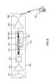
- the figure 1illustrates, in a diagram, the principle of a known method of testing the transmission antenna 102 of a satellite 100 in orbit.
- a test station 104coupled to an antenna 103, is used to generate an unmodulated carrier test signal and transmit it on the uplink of the satellite 100.
- the test signalis received by the satellite receiving antenna 101. 100 and then retransmitted by the transmission antenna 102 of the satellite 100 via the downlink.
- the signalis received by the antenna 103 of the test station 104 which carries out on it measurements for characterizing the antenna pattern of the transmission antenna 102.
- testable coverage areais limited to the intersection area 130 between the coverage area 110 of the receiving antenna 101 and the coverage area 120 of the antenna transmission 102.
- the figure 2represents, on a diagram, the relative antenna gain 201, expressed in decibels, as a function of the angular bias 202 printed by the satellite with respect to a reference pointing direction.
- the respective gain curves of the receiving antenna 210 and the transmission antenna 220 of the satelliteare shown.
- the receiving antennais generally more directive than the transmitting antenna which causes a faster attenuation of the antenna gain when the angular bias increases.
- an automatic gain control loopis operated in the satellite payload in order to bring the input signal of the transmission antenna back to a constant level 211. This way , the ground station can measure on the signal received via the downlink only the variations of the gain of the transmission antenna.
- the automatic gain control loophas a limited input operating dynamics. In the example of the figure 2 , it only works up to an input level of the order of -20 dB. Thus, for angular bias greater than a given value, of the order of 1.5 ° on the example of the figure 2 the variations of the gain of the receiving antenna are no longer compensated, which implies that the angular excursions 230 beyond a certain threshold can not be tested.
- the figure 3illustrates the need for a frequency coordination plan for the uplink of the satellite under test 100.
- An unmodulated carrier test signal 310is transmitted by the antenna 103 of the test station 104 on the uplink of the satellite 100
- the test station 104retrieves, by filtering, the unmodulated carrier retransmitted on the downlink of the satellite 100.
- the transmission of an unmodulated carrier 310 on the uplinkmay cause interference 301 on one or more adjacent satellites 300.
- a frequency coordination planeis necessary to avoid disturbing frequencies otherwise exploited by others. satellites.
- the figure 4illustrates the implementation of the method according to the invention for characterizing the transmission antenna 102 of a satellite in orbit 100 without generating or transmitting test signal on the satellite uplink.
- the method according to the inventionconsists in generating, on board the payload of the satellite, a thermal noise of sufficient power to ensure the input interface of the transmission antenna 102, the presence of a broadband noise of substantially constant level and independent of the angular excursions of the satellite.
- the signal transmitted by the transmission antenna 102 on the downlinkis acquired by the antenna 103 of the test station 104 and then analyzed to characterize the antenna gain throughout the coverage area 120 which does not. is more limited at the intersection with the coverage area of the receiving antenna 101.
- the noise 400 generated at the input interface of the antenna 102is filtered by the test station 104 in a predetermined frequency analysis band.
- the figure 5represents, in a simplified diagram, an example of a payload 500 of a satellite which comprises a reception antenna 501, a reception channel 502, a channel filter 503, an intermediate amplification channel 504, a high-power amplifier 505 and a transmission antenna 506.
- the payload 500thus constituted performs a repeater function, that is to say that the signal received on the reception channel 502 is retransmitted on the downlink of the satellite via the transmission antenna. 506.
- a single repeateris shown, but a payload can contain several repeaters associated with several different receive and / or transmit frequencies.
- the payload 500When no signal is received by the receiving antenna 501, the payload 500 however generates a noise that has two main components, a first noise component from the Earth's radiation, transmitted to the payload by the receiving antenna 501 and potentially containing interference from adjacent satellite systems, and a second component of thermal noise generated by the repeater itself, in particular by the reception channel 502.
- the intermediate amplifier channel 504 510By configuring the intermediate amplifier channel 504 510 so as to make it operate in saturation and thus cause saturation of the high-power amplifier 505, it is possible to obtain a sufficient noise level at the input interface of FIG. the transmission antenna 506 to be able to characterize its antenna pattern.
- the noise level generated at the output of the high-power amplifier 505must be greater than the noise level generated by the antenna 103 of the ground test station.
- the amplification chain 504comprises at least a first amplifier 541 which makes it possible to adjust the signal level at the output of the channel filter 503 so that it is compatible with the dynamics of the signal loop.
- automatic gain control 542placed at the output of the first amplifier 541.
- the automatic gain control loop 542makes it possible to obtain a constant level signal at the input of a second amplifier 543 which is able to amplify the signal to reach the desired operation at the input of the high power amplifier 505.
- a third amplifier 544is present at the output of the second amplifier 543 to compensate for the nonlinearities of the high power amplifier 505.
- amplification chain 504 described in figure 5is given as an illustration and not a limitation.
- other amplifiers arranged in cascadecan be included.
- the automatic gain control loop 542may be optional.
- the first and second amplifiers 541, 543are configured to amplify the input signal with a maximum gain with the objective of achieving saturation operation.
- the third amplifier 544is configured to obtain the saturation of the high-power amplifier or to obtain a sufficient operational level which depends on the link budget of the transmission antenna and the link budget of the antenna of the ground station 103.
- the level of noise thus generatedalso has a high temporal stability, which makes it possible to obtain a signal acquisition on the downlink for a time sufficient to carry out the measurements necessary for the characterization of the transmission antenna 506.
- the reception channel 502 of the payloadcan be disconnected from the receiving antenna 501 of the satellite, for example by connecting its input to the input of another reception channel (not shown). In this way, the noise received by the receiving antenna 501 is suppressed and only the thermal noise generated by the repeater itself is used.
- the use of the payload amplification chain in saturation operationmakes it possible to replace the test signal usually generated on the satellite's uplink. In this way, the test method does not require any specific signal and does not depend on the characteristics and operation of the receiving antenna 501 of the satellite.
- test method according to the inventionconsists in performing the following steps.
- the test station 104which comprises means for acquiring the signal transmitted on the downlink of the satellite and means for measuring and spectral analysis of this signal, is connected to the downlink of the satellite.
- the intermediate amplification channel 504 aboard the satellite payloadis configured to amplify the repeater noise so as to reach a saturation level of the high power amplifier 505 or a sufficient operational noise level at the interface of the satellite.
- the input of the transmission antenna 506.The configuration of the payload of the satellite is performed by a control center of the remote satellite of the test station.
- the spectral analysis of the signalis for example carried out by a spectrum analyzer configured to carry out a low-pass filtering of the received signal in order to smooth the signal level by eliminating the high frequency components. Several successive measurement points are made during a time scan.
- an angular biasis imparted to the satellite with respect to its reference pointing direction, to permit characterization of the antenna throughout its coverage area and to observe variations in antenna gain as a function of time.
- the satellite pointing controlis also performed from a remote control center via a remote control and telemetry link.
- Signal processing means acquired by the test station 104which may be included in the test station or deportee, are then executed to produce a measurement of the antenna pattern of the antenna. Satellite transmission.
- the Figures 6a, 6b , 6c, 6dillustrate the treatments performed on the acquired signal.
- the figure 6arepresents, on a diagram, the measurement of the level of the signal acquired by the test station, in milliWatt decibels (dBm), as a function of time t.
- the figure 6brepresents, on the same time scale as the figure 6a , the variation of the angular bias, expressed in degrees, of the pointing direction of the satellite.
- the figure 6dillustrates, the last step of the method according to the invention, of comparing the variations of the antenna gain 603 reconstituted over a given range of angular variation with a specified template of the satellite transmission antenna pattern.
- a specified templateconsists for example of a maximum gain curve 601 and a minimum gain curve 602 between which the measured gain must vary.
Landscapes
- Engineering & Computer Science (AREA)
- Physics & Mathematics (AREA)
- General Physics & Mathematics (AREA)
- Astronomy & Astrophysics (AREA)
- Aviation & Aerospace Engineering (AREA)
- Computer Networks & Wireless Communication (AREA)
- Signal Processing (AREA)
- Electromagnetism (AREA)
- Radio Relay Systems (AREA)
- Variable-Direction Aerials And Aerial Arrays (AREA)
Description
Translated fromFrenchL'invention concerne une méthode et un système de test de la charge utile d'un satellite en orbite. Plus précisément l'invention concerne la caractérisation de l'antenne de transmission d'un satellite en orbite.The invention relates to a method and a system for testing the payload of a satellite in orbit. More specifically, the invention relates to the characterization of the transmission antenna of a satellite in orbit.
Le domaine de l'invention est celui des méthodes et systèmes permettant de tester le fonctionnement nominal d'une antenne de transmission d'un satellite en orbite, c'est-à-dire de caractériser le diagramme de rayonnement de l'antenne et de le comparer à des spécifications de fonctionnement attendu.The field of the invention is that of the methods and systems for testing the nominal operation of a transmission antenna of a satellite in orbit, that is to say to characterize the antenna radiation pattern and of compare it to expected operating specifications.
L'invention s'applique notamment pour le test en orbite d'un satellite de télécommunication mais également de tout satellite dont la charge utile est composée d'au moins un répéteur et d'une antenne de transmission vers une liaison descendante.The invention applies in particular for the test in orbit of a telecommunication satellite but also of any satellite whose payload is composed of at least one repeater and a transmission antenna to a downlink.
Les méthodes connues de test de la charge utile d'un satellite en orbite sont le plus souvent basées sur l'emploi d'un signal de test sur porteuse non modulée qui est généré et transmis sur la liaison montante du satellite en orbite par une station sol couplée au dispositif de test. Le satellite réceptionne ce signal de test via une antenne de réception, le signal est propagé à travers un répéteur et retransmit à la station sol via une antenne de transmission. A partir de mesures réalisées sur le signal transmis sur la liaison descendante du satellite, il est possible de caractériser la réponse de l'antenne de transmission du satellite.The known methods for testing the payload of a satellite in orbit are most often based on the use of an unmodulated carrier test signal which is generated and transmitted on the uplink of the satellite in orbit by a station. ground coupled to the test device. The satellite receives this test signal via a receiving antenna, the signal is propagated through a repeater and retransmitted to the ground station via a transmitting antenna. From measurements made on the signal transmitted on the downlink of the satellite, it is possible to characterize the response of the satellite transmission antenna.
Les inconvénients des méthodes de test basées sur l'emploi de signaux de test spécifiques sont multiples.The disadvantages of test methods based on the use of specific test signals are multiple.
Le test de l'antenne de transmission est limité à une partie de la zone de couverture de l'antenne de réception. En effet, pour que la méthode de test puisse être mise en oeuvre, la station sol, qui opère à la fois la transmission du signal de test sur la liaison montante et l'acquisition du signal retransmis par le satellite sur la liaison descendante, doit être positionnée dans la zone d'intersection des zones de couverture de l'antenne de réception et de l'antenne de transmission du satellite. Ainsi, il n'est pas possible de tester l'antenne de transmission dans toute sa couverture angulaire.The transmission antenna test is limited to a portion of the coverage area of the receiving antenna. Indeed, for the test method to be implemented, the ground station, which operates both the transmission of the test signal on the uplink and the acquisition of the signal retransmitted by the satellite on the downlink shall be positioned in the area of intersection of the coverage areas of the receiving antenna and the satellite transmission antenna. Thus, it is not possible to test the transmission antenna in all its angular coverage.
En outre, l'extraction de la seule contribution de l'antenne de transmission nécessite la mise en oeuvre d'une boucle automatique de gain pour compenser les variations de gain de l'antenne de réception. Cette boucle assure un niveau constant à l'interface d'entrée de l'antenne de transmission, ce qui permet de mesurer au sol uniquement les variations de l'antenne de transmission. Cependant, le diagramme de rayonnement de l'antenne de réception étant généralement plus directif que celui de l'antenne de transmission, il en résulte que la dynamique de mesure sous test de l'antenne de transmission est limitée à la dynamique disponible dans la boucle de contrôle automatique de gain.In addition, the extraction of the only contribution of the transmission antenna requires the implementation of an automatic gain loop to compensate for the gain variations of the receiving antenna. This loop ensures a constant level at the input interface of the transmission antenna, which allows ground measurement only variations of the transmission antenna. However, since the radiation pattern of the receiving antenna is generally more directional than that of the transmission antenna, it follows that the measurement dynamic under test of the transmission antenna is limited to the dynamics available in the loop. automatic gain control.
De plus, les mesures d'isolation, c'est-à-dire la caractérisation de l'antenne de transmission pour des zones de couverture pour lesquelles le gain de l'antenne est très faible, sont également limitées par le niveau de réception faible sur l'antenne de réception.In addition, the isolation measurements, ie the characterization of the transmission antenna for coverage areas for which the gain of the antenna is very low, are also limited by the low reception level. on the receiving antenna.
Un autre problème lié à l'emploi de signaux de test est que lorsqu'on souhaite tester le fonctionnement d'une antenne de transmission multifaisceaux ou d'une antenne de transmission à plusieurs fréquences, cela nécessite la génération de signaux de test multi-porteuses et donc d'un dispositif de génération de tels signaux, ce qui accroit la complexité du système de test.Another problem related to the use of test signals is that when it is desired to test the operation of a multibeam transmission antenna or a multi-frequency transmission antenna, this requires the generation of multi-carrier test signals. and therefore a device for generating such signals, which increases the complexity of the test system.
Enfin, la génération d'une porteuse de test peut interférer avec d'autres satellites adjacents ce qui nécessite une coordination globale en fréquence.Finally, the generation of a test carrier can interfere with other adjacent satellites which requires a global coordination in frequency.
Voir
La présente invention propose une méthode et un système qui permettent de caractériser l'antenne de transmission d'un satellite en orbite dans toute sa dynamique et toute sa zone de couverture, indépendamment des caractéristiques de l'antenne de réception.The present invention provides a method and system for characterizing the transmission antenna of a satellite in orbit in all its dynamics and coverage area, regardless of the characteristics of the receiving antenna.
L'invention ne nécessite pas l'emploi de signaux de test sur porteuse non modulée et donc permet de supprimer les inconvénients liés à leur utilisation.The invention does not require the use of unmodulated carrier test signals and thus eliminates the drawbacks associated with their use.
En outre, l'invention permet de tester l'antenne de transmission d'un satellite à plusieurs faisceaux et/ou à plusieurs fréquences distinctes sans nécessiter de modifier les équipements de test et ainsi d'augmenter la complexité.In addition, the invention makes it possible to test the transmission antenna of a satellite with several beams and / or at several different frequencies without requiring modification of the test equipment and thus of increasing the complexity.
L'invention a ainsi pour objet une méthode de caractérisation d'une antenne de transmission d'un satellite en orbite comprenant une charge utile comprenant des moyens d'amplification de signal, ladite méthode consistant à:
- Configurer lesdits moyens d'amplification pour générer un bruit thermique en entrée de l'antenne de transmission,
- Acquérir, au moyen d'une station au sol, le signal transmis par l'antenne de transmission sur la liaison descendante du satellite pendant une durée prédéterminée,
- Pendant ladite durée prédéterminée, commander ledit satellite en orbite pour lui imprimer un biais angulaire de variation prédéterminée et enregistrer cette variation,
- Corréler la mesure du signal transmis sur la liaison descendante et la variation de biais angulaire du satellite pour en déduire les variations de gain de l'antenne de transmission en fonction du biais angulaire du satellite.
- Configuring said amplification means to generate thermal noise at the input of the transmission antenna,
- Acquiring, by means of a station on the ground, the signal transmitted by the transmission antenna on the downlink of the satellite for a predetermined duration,
- During said predetermined duration, commanding said satellite into orbit to impart to it an angular bias of predetermined variation and record this variation,
- Correlate the measurement of the downlink transmitted signal and the variation of satellite angular bias to deduce the transmission antenna gain variations as a function of the satellite angular bias.
Avantageusement, les moyens d'amplification sont configurés pour fonctionner à saturation.Advantageously, the amplification means are configured to operate at saturation.
Les moyens d'amplification peuvent également comporter un premier moyen d'amplification intermédiaire et un second moyen d'amplification haute puissance, ledit moyen d'amplification intermédiaire étant configuré pour amplifier le signal à un niveau prédéterminé en entrée du second moyen d'amplification haute puissance, ledit niveau étant déterminé de sorte que le niveau du signal de sortie du second moyen d'amplification haute puissance est supérieur au niveau de bruit généré par l'antenne de la station au sol.The amplification means may also comprise a first intermediate amplification means and a second high power amplification means, said intermediate amplification means being configured for amplifying the signal at a predetermined level at the input of the second high power amplifying means, said level being determined such that the level of the output signal of the second high power amplifying means is greater than the noise level generated by the antenna of the ground station.
Selon un mode particulier de réalisation de l'invention, la charge utile comporte au moins une antenne de réception et une voie de réception et dans laquelle la voie de réception est déconnectée de l'antenne de réception pour limiter l'influence du bruit issu de la liaison montante du satellite.According to one particular embodiment of the invention, the payload comprises at least one reception antenna and one reception channel and in which the reception channel is disconnected from the reception antenna to limit the influence of the noise coming from the satellite uplink.
L'invention a également pour objet un système pour la caractérisation d'une antenne de transmission d'un satellite en orbite comprenant une charge utile comprenant des moyens d'amplification de signal, ledit système comprenant :
- Des moyens de configuration desdits moyens d'amplification pour générer un bruit thermique en entrée de l'antenne de transmission,
- Des moyens d'acquisition du signal transmis par l'antenne de transmission sur la liaison descendante du satellite pendant une durée prédéterminée,
- Des moyens de commande du satellite en orbite, pendant ladite durée prédéterminée, pour lui imprimer un biais angulaire de variation prédéterminée et des moyens d'enregistrement de cette variation,
- Des moyens pour corréler la mesure du signal transmis sur la liaison descendante et la variation de biais angulaire du satellite afin d'en déduire les variations de gain de l'antenne de transmission en fonction du biais angulaire du satellite.
- Means for configuring said amplification means to generate thermal noise at the input of the transmission antenna,
- Means for acquiring the signal transmitted by the transmission antenna on the downlink of the satellite for a predetermined duration,
- Control means of the satellite in orbit, during said predetermined duration, to give it a predetermined angular bias of variation and means for recording this variation,
- Means for correlating the measurement of the downlink transmitted signal and the variation of satellite angular bias to derive the transmission antenna gain variations as a function of the satellite angular bias.
D'autres caractéristiques et avantages de la présente invention apparaîtront mieux à la lecture de la description qui suit en relation aux dessins annexés qui représentent :
- La
figure 1 , un synoptique illustrant une méthode de test de l'antenne de transmission d'un satellite en orbite selon l'art antérieur, - La
figure 2 , un diagramme illustrant la limitation, induite par la méthode de test décrite à lafigure 1 , sur la dynamique angulaire de dépointage de l'antenne de transmission qui peut être testée, - La
figure 3 , un synoptique illustrant certains inconvénients de la méthode de test décrite à lafigure 1 , - La
figure 4 , un synoptique illustrant la méthode de test selon l'invention, - La
figure 5 , un schéma de la charge utile d'un satellite à tester et en particulier de la chaine d'amplification à bord, - La
figure 6a , un diagramme du gain du signal mesuré sur la liaison descendante du satellite en fonction du temps, - La
figure 6b , un diagramme du biais angulaire imprimé par le satellite pendant l'acquisition du signal sur la liaison descendante en fonction du même intervalle de temps qu'à lafigure 6a , - La
figure 6c , une illustration d'un exemple du diagramme d'antenne obtenu en combinant les mesures illustrées auxfigures 6a et 6b , - La
figure 6d , une illustration de la comparaison du diagramme d'antenne obtenu avec les spécifications de l'antenne de transmission du satellite.
- The
figure 1 , a block diagram illustrating a method of testing the transmission antenna of a satellite in orbit according to the prior art, - The
figure 2 , a diagram illustrating the limitation, induced by the test method described infigure 1 , on the angular dynamics of misalignment of the transmitting antenna which can be tested, - The
figure 3 , a block diagram illustrating certain disadvantages of the test method described infigure 1 , - The
figure 4 , a block diagram illustrating the test method according to the invention, - The
figure 5 , a diagram of the payload of a satellite to be tested and in particular of the amplification chain on board, - The
figure 6a a diagram of the signal gain measured on the satellite downlink as a function of time, - The
figure 6b , a diagram of the angular bias printed by the satellite during the acquisition of the signal on the downlink according to the same time interval as in thefigure 6a , - The
Figure 6c , an illustration of an example of the antenna pattern obtained by combining the measurements illustrated with theFigures 6a and 6b , - The
figure 6d , an illustration of the comparison of the antenna pattern obtained with the specifications of the satellite transmission antenna.
Les
La
Une station de test 104, couplée à une antenne 103, est utilisée pour générer un signal de test sur porteuse non modulée et le transmettre sur la liaison montante du satellite 100. Le signal de test est reçu par l'antenne de réception 101 du satellite 100 puis retransmis par l'antenne de transmission 102 du satellite 100 via la liaison descendante. Le signal est reçu par l'antenne 103 de la station de test 104 qui effectue sur celui-ci des mesures permettant de caractériser le diagramme d'antenne de l'antenne de transmission 102.A
Comme explicité ci-dessus, un inconvénient de cette méthode est que la zone de couverture testable est limitée à la zone d'intersection 130 entre la zone de couverture 110 de l'antenne de réception 101 et la zone de couverture 120 de l'antenne de transmission 102.As explained above, a disadvantage of this method is that the testable coverage area is limited to the
La
Pour compenser les variations du gain de l'antenne de réception, une boucle de contrôle automatique de gain est actionnée dans la charge utile du satellite afin de ramener le signal en entrée de l'antenne de transmission à un niveau constant 211. De cette façon, la station sol peut mesurer sur le signal reçu via la voie descendante uniquement les variations du gain de l'antenne de transmission.To compensate for variations in the gain of the receiving antenna, an automatic gain control loop is operated in the satellite payload in order to bring the input signal of the transmission antenna back to a
La boucle de contrôle automatique de gain présente une dynamique de fonctionnement d'entrée limitée. Dans l'exemple de la
La
L'émission d'une porteuse non modulée 310 sur la liaison montante peut engendrer des interférences 301 sur un ou plusieurs satellites adjacents 300. Ainsi, un plan de coordination de fréquence est nécessaire pour éviter de perturber des fréquences par ailleurs exploitées par d'autres satellites.The transmission of an
La
La méthode selon l'invention consiste à générer, à bord de la charge utile du satellite, un bruit thermique de puissance suffisante pour assurer à l'interface d'entrée de l'antenne de transmission 102, la présence d'un bruit large bande de niveau sensiblement constant et indépendant des excursions angulaires du satellite. De cette façon, le signal transmis par l'antenne de transmission 102 sur la liaison descendante est acquis par l'antenne 103 de la station de test 104 puis analysé pour caractériser le gain d'antenne dans toute la zone de couverture 120 qui n'est plus limitée à l'intersection avec la zone de couverture de l'antenne de réception 101.The method according to the invention consists in generating, on board the payload of the satellite, a thermal noise of sufficient power to ensure the input interface of the
Le bruit 400 généré à l'interface d'entrée de l'antenne 102 est filtré par la station de test 104 dans une bande d'analyse fréquentielle prédéterminée.The
La
Lorsqu'aucun signal n'est reçu par l'antenne de réception 501, la charge utile 500 génère cependant un bruit qui présente deux composantes principales, une première composante de bruit issu du rayonnement de la Terre, transmis à la charge utile par l'antenne de réception 501 et contenant potentiellement des interférences issues des systèmes satellites adjacents, et une seconde composante de bruit thermique généré par le répéteur lui même, en particulier par la chaîne de réception 502.When no signal is received by the receiving
En configurant 510 la chaine d'amplification intermédiaire 504 de sorte à la faire fonctionner en saturation et ainsi provoquer la saturation de l'amplificateur haute puissance 505, il est possible d'obtenir un niveau de bruit suffisant à l'interface d'entrée de l'antenne de transmission 506 pour pouvoir caractériser son diagramme d'antenne. Le niveau de bruit généré en sortie de l'amplificateur haute puissance 505 doit être supérieur au niveau de bruit généré par l'antenne 103 de la station de test au sol.By configuring the
On décrit à présent plus en détail un exemple de réalisation de la chaine d'amplification intermédiaire 504 et la configuration associée pour obtenir l'effet souhaité pour permettre la caractérisation de l'antenne de transmission 506.An embodiment of the
La chaine d'amplification 504 comporte au moins un premier amplificateur 541 qui permet d'ajuster le niveau de signal en sortie du filtre de canal 503 pour qu'il soit compatible de la dynamique de la boucle de contrôle automatique de gain 542 placée en sortie du premier amplificateur 541. La boucle de contrôle automatique de gain 542 permet d'obtenir un signal de niveau constant en entrée d'un second amplificateur 543 qui est apte à amplifier le signal pour atteindre le point de fonctionnement souhaité en entrée de l'amplificateur haute puissance 505. Un troisième amplificateur 544 est présent en sortie du deuxième amplificateur 543 pour compenser les non linéarités de l'amplificateur haute puissance 505.The
L'exemple de chaine d'amplification 504 décrit à la
Pour obtenir un niveau de bruit suffisant en entrée de l'antenne de transmission 506, les premier et second amplificateurs 541,543 sont configurés pour amplifier le signal d'entrée avec un gain maximum avec l'objectif d'atteindre un fonctionnement en saturation. Le troisième amplificateur 544 est configuré pour obtenir la saturation de l'amplificateur haute puissance ou pour obtenir un niveau opérationnel suffisant qui dépend du bilan de liaison de l'antenne de transmission et du bilan de liaison de l'antenne de la station sol 103. Le niveau de bruit ainsi généré présente également une forte stabilité temporelle ce qui permet de réaliser une acquisition du signal sur la voie descendante pendant une durée suffisante pour réaliser les mesures nécessaires à la caractérisation de l'antenne de transmission 506.To obtain a sufficient noise level at the input of the
Dans une variante de réalisation de l'invention, la voie de réception 502 de la charge utile peut être déconnectée de l'antenne de réception 501 du satellite, par exemple en reliant son entrée à l'entrée d'une autre voie de réception (non représentée). De cette façon, le bruit reçu par l'antenne de réception 501 est supprimé et seul le bruit thermique généré par le répéteur lui-même est utilisé.In an alternative embodiment of the invention, the
L'utilisation de la chaine d'amplification de la charge utile dans un fonctionnement en saturation permet de remplacer le signal de test habituellement généré sur la voie montante du satellite. De cette façon, la méthode de test ne nécessite aucun signal spécifique et ne dépend pas des caractéristiques et du fonctionnement de l'antenne de réception 501 du satellite.The use of the payload amplification chain in saturation operation makes it possible to replace the test signal usually generated on the satellite's uplink. In this way, the test method does not require any specific signal and does not depend on the characteristics and operation of the receiving
La méthode de test selon l'invention consiste en l'exécution des étapes suivantes.The test method according to the invention consists in performing the following steps.
La station de test 104, qui comporte des moyens d'acquisition du signal émis sur la voie descendante du satellite et des moyens de mesure et d'analyse spectrale de ce signal, est connectée sur la voie descendante du satellite.The
La chaine d'amplification intermédiaire 504 à bord de la charge utile du satellite est configurée pour amplifier le bruit du répéteur de sorte à atteindre un niveau de saturation de l'amplificateur haute puissance 505 ou un niveau de bruit opérationnel suffisant à l'interface d'entrée de l'antenne de transmission 506. La configuration de la charge utile du satellite est réalisée par un centre de contrôle du satellite déporté de la station de test.The
L'analyse spectrale du signal est par exemple réalisée par un analyseur de spectre configuré pour réaliser un filtrage passe-bas du signal reçu afin de lisser le niveau du signal en supprimant les composantes hautes fréquences. Plusieurs points de mesure successifs sont réalisés au cours d'un balayage temporel.The spectral analysis of the signal is for example carried out by a spectrum analyzer configured to carry out a low-pass filtering of the received signal in order to smooth the signal level by eliminating the high frequency components. Several successive measurement points are made during a time scan.
En outre, un biais angulaire est imprimé au satellite par rapport à sa direction de pointage de référence, afin de permettre la caractérisation de l'antenne dans toute sa zone de couverture et d'observer les variations du gain de l'antenne en fonction du temps. La commande de pointage du satellite est également réalisée depuis un centre de contrôle déporté via une liaison de télécommande et télémétrie.In addition, an angular bias is imparted to the satellite with respect to its reference pointing direction, to permit characterization of the antenna throughout its coverage area and to observe variations in antenna gain as a function of time. The satellite pointing control is also performed from a remote control center via a remote control and telemetry link.
Des moyens de traitement du signal acquis par la station de test 104, qui peuvent être inclus dans la station de test ou déportés, sont ensuite exécutés pour produire une mesure du diagramme de l'antenne de transmission du satellite. Les
La
La
En corrélant les diagrammes des
La
Claims (5)
- A method for characterising a transmission antenna (102, 506) of a satellite in orbit (100) comprising a payload (500) that comprises signal amplification means (504, 505), said method beingcharacterised in that it comprises:- configuiing said amplification means (504, 505) to generate thermal noise at the input of said transmission antenna (102, 506);- acquiring, by means of a ground station (103, 104), the signal transmitted by said transmission antenna (102, 506) on the downlink of said satellite (100) for a predetermined duration;- controlling said satellite in orbit (100), during said predetermined duration, so as to impose an angular bias of predetermined variation to said satellite, and logging said variation;- correlating the measurement of the signal transmitted on the downlink and the variation of angular bias of said satellite so as to deduce the gain variations of said transmission antenna (102, 506) as a function of the angular bias of said satellite.
- The characterisation method according to claim 1, wherein said amplification means (504, 505) are configured to operate to saturation.
- The characterisation method according to claim 1, wherein said amplification means (504, 505) comprise a first intermediate amplification means (504) and a second high-power amplification means (505), said intermediate amplification means (504) being configured to amplify the signal to a predetermined level at the input of said second high-power amplification means (505), said level being determined so that the level of the output signal of said second high-power amplification means (505) is higher than the noise level generated by the antenna of said ground station (103).
- The characterisation method according to any one of the preceding claims, wherein said payload (500) comprises at least one reception antenna (501) and one reception channel (502) and wherein said reception channel (502) is disconnected from said reception antenna (501) so as to limit the influence of the noise coming from the uplink of said satellite.
- A system for characterising a transmission antenna (102, 506) of a satellite in orbit (100) comprising a payload (500) that comprises signal amplification means (504, 505), said system comprising:- means for configuring said amplification means (504, 505) so as to generate thermal noise at the input of said transmission antenna (102, 506);- means (103, 104) for acquiring the signal transmitted by said transmission antenna (102, 506) on the downlink of said satellite (100) for a predetermined duration;- means for controlling said satellite in orbit (100), during said predetermined duration, so as to impose an angular bias of predetermined variation to said satellite, and means for logging said variation;- means for correlating the measurement of the signal transmitted on the downlink and the variation of angular bias of said satellite so as to deduce the gain variations of said transmission antenna (102, 506) as a function of the angular bias of said satellite.
Applications Claiming Priority (1)
| Application Number | Priority Date | Filing Date | Title |
|---|---|---|---|
| FR1202393AFR2995478B1 (en) | 2012-09-07 | 2012-09-07 | METHOD FOR CHARACTERIZING A TRANSMISSION ANTENNA OF A SATELLITE IN ORBIT AND ASSOCIATED SYSTEM |
Publications (2)
| Publication Number | Publication Date |
|---|---|
| EP2706676A1 EP2706676A1 (en) | 2014-03-12 |
| EP2706676B1true EP2706676B1 (en) | 2015-04-01 |
Family
ID=47594816
Family Applications (1)
| Application Number | Title | Priority Date | Filing Date |
|---|---|---|---|
| EP13182555.6AActiveEP2706676B1 (en) | 2012-09-07 | 2013-09-02 | Method for charaterizing a transmission antenna of a satellite on orbit and system therefor. |
Country Status (7)
| Country | Link |
|---|---|
| US (1) | US9065529B2 (en) |
| EP (1) | EP2706676B1 (en) |
| JP (1) | JP6199127B2 (en) |
| KR (1) | KR102054525B1 (en) |
| ES (1) | ES2540983T3 (en) |
| FR (1) | FR2995478B1 (en) |
| RU (1) | RU2627297C2 (en) |
Families Citing this family (7)
| Publication number | Priority date | Publication date | Assignee | Title |
|---|---|---|---|---|
| FR3024128B1 (en)* | 2014-07-25 | 2016-07-22 | Thales Sa | METHOD OF POSTING A SATELLITE AND TESTING ORBIT OF ITS USEFUL LOAD |
| FR3043513B1 (en)* | 2015-11-10 | 2017-12-22 | Thales Sa | METHOD OF CHARACTERIZING THE PERFORMANCE OF A PAYLOAD OF A SATELLITE IN ORBIT AND ASSOCIATED IOT TEST SYSTEM |
| CA2913564A1 (en)* | 2015-11-27 | 2017-05-27 | Telesat Canada | Satellite communications subsystem in-orbit verification system and methodologies |
| EP3282598A1 (en)* | 2016-08-12 | 2018-02-14 | Fraunhofer-Gesellschaft zur Förderung der angewandten Forschung e.V. | Communication system and transmitter |
| FR3094589B1 (en) | 2019-03-28 | 2021-02-19 | Thales Sa | SYSTEM AND METHOD FOR ESTIMATING A SATELLITE ANTENNA POINTING ERROR |
| CN111654335B (en)* | 2019-11-26 | 2021-12-07 | 航天东方红卫星有限公司 | Wireless test method of relay data transmission system under whole satellite near field |
| DE102023112705A1 (en)* | 2023-05-15 | 2024-11-21 | Deutsches Zentrum für Luft- und Raumfahrt e.V. | Method for measuring an antenna pattern of an antenna on a first flying object by means of a second flying object |
Family Cites Families (21)
| Publication number | Priority date | Publication date | Assignee | Title |
|---|---|---|---|---|
| US4071211A (en)* | 1976-09-23 | 1978-01-31 | Rca Corporation | Momentum biased active three-axis satellite attitude control system |
| DE3885883D1 (en)* | 1987-09-16 | 1994-01-05 | Deutsche Aerospace | DEVICE FOR SETPOINT CONTROL AND / OR STABILIZATION OF MOVABLE BODIES WITH STORED TWIST. |
| CA2080612A1 (en)* | 1991-11-27 | 1993-05-28 | Douglas J. Bender | Method and apparatus for compensating for magnetic disturbance torques on a satellite |
| US5758260A (en)* | 1995-08-23 | 1998-05-26 | Globalstar L.P. | Satellite beam steering reference using terrestrial beam steering terminals |
| FR2741159B1 (en)* | 1995-11-14 | 1998-01-23 | Centre Nat Etd Spatiales | GLOBAL SPATIAL RADIO-LOCATION AND RADIONAVIGATION SYSTEM, BEACON, AND RECEIVER USED IN SUCH A SYSTEM |
| JPH10160775A (en)* | 1996-11-26 | 1998-06-19 | Jisedai Eisei Tsushin Hoso Syst Kenkyusho:Kk | How to measure satellite-borne antenna patterns |
| DE69711408T2 (en)* | 1997-12-18 | 2002-11-21 | Societe Europeenne Des Satellites S.A., Chateau De Betzdorf | Method and apparatus for determining the characteristic values of components of a communication channel under load |
| JPH11295366A (en)* | 1998-04-14 | 1999-10-29 | Jisedai Eisei Tsushin Hoso System Kenkyusho:Kk | A method for measuring the direction of an antenna pattern mounted on a satellite or the like using a multi-beam or a method for estimating the position of a mobile ground station |
| US6231011B1 (en)* | 1998-11-02 | 2001-05-15 | University Of Houston System | Satellite angular momentum control system using magnet-superconductor flywheels |
| EP0999128A1 (en)* | 1998-11-06 | 2000-05-10 | Société Européenne des Satellites | Method for determining the yaw angle of a satellite |
| US6628921B1 (en)* | 2000-10-13 | 2003-09-30 | Globalstar L.P. | Return link channel loading of multiple satellites with multiple spread spectrum user terminals |
| US7209760B2 (en)* | 2001-05-08 | 2007-04-24 | Lucent Technologies Inc. | Methods and apparatus for mitigating the effects of solar noise and the like on a wireless communication system |
| US7603117B2 (en)* | 2001-09-14 | 2009-10-13 | Atc Technologies, Llc | Systems and methods for terrestrial use of cellular satellite frequency spectrum |
| JP2003124865A (en)* | 2001-10-11 | 2003-04-25 | Mitsubishi Electric Corp | Satellite-borne antenna pattern measurement system, earth station and multi-beam communication satellite in satellite-borne antenna pattern measurement system |
| KR100588702B1 (en)* | 2003-05-26 | 2006-06-12 | 기아자동차주식회사 | Shadow Area Control Method of Mobile Satellite Tracking Antenna System |
| US6989786B1 (en)* | 2004-06-30 | 2006-01-24 | Intelsat Global Service Corporation | Satellite antenna station keeping |
| US8576118B2 (en)* | 2008-01-29 | 2013-11-05 | Viasat, Inc. | Satellite performance monitoring |
| JP4535145B2 (en)* | 2008-02-26 | 2010-09-01 | ソニー株式会社 | Communication device, noise removal method, and program |
| US9673917B2 (en)* | 2008-05-30 | 2017-06-06 | Qualcomm Incorporated | Calibration using noise power |
| EP2396852A4 (en)* | 2009-02-16 | 2013-12-11 | B T I Company | Wireless communication systems and methods with source localization and self-calibration |
| JP5326793B2 (en)* | 2009-05-14 | 2013-10-30 | ソニー株式会社 | Vein imaging device, vein image interpolation method and program |
- 2012
- 2012-09-07FRFR1202393Apatent/FR2995478B1/ennot_activeExpired - Fee Related
- 2013
- 2013-09-02ESES13182555.6Tpatent/ES2540983T3/enactiveActive
- 2013-09-02EPEP13182555.6Apatent/EP2706676B1/enactiveActive
- 2013-09-06USUS14/020,514patent/US9065529B2/enactiveActive
- 2013-09-06KRKR1020130107588Apatent/KR102054525B1/ennot_activeExpired - Fee Related
- 2013-09-06RURU2013141143Apatent/RU2627297C2/enactive
- 2013-09-06JPJP2013184962Apatent/JP6199127B2/ennot_activeExpired - Fee Related
Also Published As
| Publication number | Publication date |
|---|---|
| KR20140032922A (en) | 2014-03-17 |
| KR102054525B1 (en) | 2019-12-10 |
| US9065529B2 (en) | 2015-06-23 |
| FR2995478B1 (en) | 2014-09-26 |
| ES2540983T3 (en) | 2015-07-15 |
| US20140073239A1 (en) | 2014-03-13 |
| JP2014060710A (en) | 2014-04-03 |
| FR2995478A1 (en) | 2014-03-14 |
| JP6199127B2 (en) | 2017-09-20 |
| EP2706676A1 (en) | 2014-03-12 |
| RU2013141143A (en) | 2015-03-20 |
| RU2627297C2 (en) | 2017-08-07 |
Similar Documents
| Publication | Publication Date | Title |
|---|---|---|
| EP2706676B1 (en) | Method for charaterizing a transmission antenna of a satellite on orbit and system therefor. | |
| EP3169003B1 (en) | Method for characterising the performance of a payload of a satellite in orbit and associated iot testing system | |
| EP3026453B1 (en) | Method for generating a map of transmission or reception coverage of an antenna of a ground station for satellite links | |
| FR2916538A1 (en) | INTERFERENCE PROCESSING OF A RADIO FREQUENCY SIGNAL BY POWER INVERSION | |
| EP2469707B1 (en) | Automatic gain control device for satellite positioning receivers | |
| EP0080927B1 (en) | Receiver for a terrestrial environment probe | |
| CA2439563A1 (en) | Device and method for the suppression of pulsed wireless signals | |
| EP3286851B1 (en) | Generation by a satellite of a signal of a second type of polarization by two transponders adapted to process signals polarized according to a first type of polarization. | |
| EP0778678B1 (en) | Differential receiver for direct sequence spread spectrum signals | |
| EP3835811B1 (en) | Method for uncoupling of signals in transmitting/receiving systems | |
| EP2629439B1 (en) | Method for generating an emitting or receiving membrane of a satellite antenna | |
| FR2999839A1 (en) | RADIO FREQUENCY SIGNAL RECEIVER INTENDED TO BE INSTALLED ON A SATELLITE | |
| EP3646045B1 (en) | Reflectometry system for analysing faults in a transmission line | |
| FR3042663B1 (en) | SETTING THE REINJECTION OF A TRANSMIT SIGNAL IN A RECEIVING CHAIN OF AN ON-LINE CURRENT DATA TRANSMISSION EQUIPMENT | |
| CA2864579A1 (en) | Communication device for rail vehicle, rail vehicle equipped with such a device | |
| EP0293287B1 (en) | Spread spectrum phase demodulator test system | |
| EP4300821B1 (en) | Communication device comprising a power amplifier and method of operation | |
| FR2803705A1 (en) | METHOD FOR GENERATING A BASEBAND SIGNAL REPRESENTATIVE OF THE TRANSMITTED RADIO FREQUENCY POWER, CORRESPONDING DEVICE AND TRANSMITTING STATION | |
| WO2006027427A1 (en) | Device for amplification of a receiving antenna signal | |
| EP2196788B1 (en) | Radiometer and method for measuring radiometric field temperature in pulsed mode |
Legal Events
| Date | Code | Title | Description |
|---|---|---|---|
| PUAI | Public reference made under article 153(3) epc to a published international application that has entered the european phase | Free format text:ORIGINAL CODE: 0009012 | |
| AK | Designated contracting states | Kind code of ref document:A1 Designated state(s):AL AT BE BG CH CY CZ DE DK EE ES FI FR GB GR HR HU IE IS IT LI LT LU LV MC MK MT NL NO PL PT RO RS SE SI SK SM TR | |
| AX | Request for extension of the european patent | Extension state:BA ME | |
| 17P | Request for examination filed | Effective date:20140813 | |
| RBV | Designated contracting states (corrected) | Designated state(s):AL AT BE BG CH CY CZ DE DK EE ES FI FR GB GR HR HU IE IS IT LI LT LU LV MC MK MT NL NO PL PT RO RS SE SI SK SM TR | |
| GRAP | Despatch of communication of intention to grant a patent | Free format text:ORIGINAL CODE: EPIDOSNIGR1 | |
| INTG | Intention to grant announced | Effective date:20141216 | |
| GRAS | Grant fee paid | Free format text:ORIGINAL CODE: EPIDOSNIGR3 | |
| GRAA | (expected) grant | Free format text:ORIGINAL CODE: 0009210 | |
| AK | Designated contracting states | Kind code of ref document:B1 Designated state(s):AL AT BE BG CH CY CZ DE DK EE ES FI FR GB GR HR HU IE IS IT LI LT LU LV MC MK MT NL NO PL PT RO RS SE SI SK SM TR | |
| REG | Reference to a national code | Ref country code:GB Ref legal event code:FG4D Free format text:NOT ENGLISH | |
| REG | Reference to a national code | Ref country code:CH Ref legal event code:EP | |
| REG | Reference to a national code | Ref country code:IE Ref legal event code:FG4D Free format text:LANGUAGE OF EP DOCUMENT: FRENCH | |
| REG | Reference to a national code | Ref country code:DE Ref legal event code:R096 Ref document number:602013001363 Country of ref document:DE Effective date:20150513 | |
| REG | Reference to a national code | Ref country code:AT Ref legal event code:REF Ref document number:719624 Country of ref document:AT Kind code of ref document:T Effective date:20150515 | |
| REG | Reference to a national code | Ref country code:NL Ref legal event code:T3 Ref country code:ES Ref legal event code:FG2A Ref document number:2540983 Country of ref document:ES Kind code of ref document:T3 Effective date:20150715 | |
| REG | Reference to a national code | Ref country code:AT Ref legal event code:MK05 Ref document number:719624 Country of ref document:AT Kind code of ref document:T Effective date:20150401 | |
| REG | Reference to a national code | Ref country code:LT Ref legal event code:MG4D | |
| PG25 | Lapsed in a contracting state [announced via postgrant information from national office to epo] | Ref country code:HR Free format text:LAPSE BECAUSE OF FAILURE TO SUBMIT A TRANSLATION OF THE DESCRIPTION OR TO PAY THE FEE WITHIN THE PRESCRIBED TIME-LIMIT Effective date:20150401 Ref country code:LT Free format text:LAPSE BECAUSE OF FAILURE TO SUBMIT A TRANSLATION OF THE DESCRIPTION OR TO PAY THE FEE WITHIN THE PRESCRIBED TIME-LIMIT Effective date:20150401 Ref country code:CZ Free format text:LAPSE BECAUSE OF FAILURE TO SUBMIT A TRANSLATION OF THE DESCRIPTION OR TO PAY THE FEE WITHIN THE PRESCRIBED TIME-LIMIT Effective date:20150401 Ref country code:PT Free format text:LAPSE BECAUSE OF FAILURE TO SUBMIT A TRANSLATION OF THE DESCRIPTION OR TO PAY THE FEE WITHIN THE PRESCRIBED TIME-LIMIT Effective date:20150803 Ref country code:NO Free format text:LAPSE BECAUSE OF FAILURE TO SUBMIT A TRANSLATION OF THE DESCRIPTION OR TO PAY THE FEE WITHIN THE PRESCRIBED TIME-LIMIT Effective date:20150701 Ref country code:FI Free format text:LAPSE BECAUSE OF FAILURE TO SUBMIT A TRANSLATION OF THE DESCRIPTION OR TO PAY THE FEE WITHIN THE PRESCRIBED TIME-LIMIT Effective date:20150401 | |
| PG25 | Lapsed in a contracting state [announced via postgrant information from national office to epo] | Ref country code:GR Free format text:LAPSE BECAUSE OF FAILURE TO SUBMIT A TRANSLATION OF THE DESCRIPTION OR TO PAY THE FEE WITHIN THE PRESCRIBED TIME-LIMIT Effective date:20150702 Ref country code:LV Free format text:LAPSE BECAUSE OF FAILURE TO SUBMIT A TRANSLATION OF THE DESCRIPTION OR TO PAY THE FEE WITHIN THE PRESCRIBED TIME-LIMIT Effective date:20150401 Ref country code:RS Free format text:LAPSE BECAUSE OF FAILURE TO SUBMIT A TRANSLATION OF THE DESCRIPTION OR TO PAY THE FEE WITHIN THE PRESCRIBED TIME-LIMIT Effective date:20150401 Ref country code:AT Free format text:LAPSE BECAUSE OF FAILURE TO SUBMIT A TRANSLATION OF THE DESCRIPTION OR TO PAY THE FEE WITHIN THE PRESCRIBED TIME-LIMIT Effective date:20150401 Ref country code:IS Free format text:LAPSE BECAUSE OF FAILURE TO SUBMIT A TRANSLATION OF THE DESCRIPTION OR TO PAY THE FEE WITHIN THE PRESCRIBED TIME-LIMIT Effective date:20150801 | |
| REG | Reference to a national code | Ref country code:DE Ref legal event code:R097 Ref document number:602013001363 Country of ref document:DE | |
| PG25 | Lapsed in a contracting state [announced via postgrant information from national office to epo] | Ref country code:DK Free format text:LAPSE BECAUSE OF FAILURE TO SUBMIT A TRANSLATION OF THE DESCRIPTION OR TO PAY THE FEE WITHIN THE PRESCRIBED TIME-LIMIT Effective date:20150401 Ref country code:EE Free format text:LAPSE BECAUSE OF FAILURE TO SUBMIT A TRANSLATION OF THE DESCRIPTION OR TO PAY THE FEE WITHIN THE PRESCRIBED TIME-LIMIT Effective date:20150401 | |
| PLBE | No opposition filed within time limit | Free format text:ORIGINAL CODE: 0009261 | |
| STAA | Information on the status of an ep patent application or granted ep patent | Free format text:STATUS: NO OPPOSITION FILED WITHIN TIME LIMIT | |
| PG25 | Lapsed in a contracting state [announced via postgrant information from national office to epo] | Ref country code:SK Free format text:LAPSE BECAUSE OF FAILURE TO SUBMIT A TRANSLATION OF THE DESCRIPTION OR TO PAY THE FEE WITHIN THE PRESCRIBED TIME-LIMIT Effective date:20150401 Ref country code:RO Free format text:LAPSE BECAUSE OF NON-PAYMENT OF DUE FEES Effective date:20150401 Ref country code:PL Free format text:LAPSE BECAUSE OF FAILURE TO SUBMIT A TRANSLATION OF THE DESCRIPTION OR TO PAY THE FEE WITHIN THE PRESCRIBED TIME-LIMIT Effective date:20150401 | |
| 26N | No opposition filed | Effective date:20160105 | |
| PG25 | Lapsed in a contracting state [announced via postgrant information from national office to epo] | Ref country code:MC Free format text:LAPSE BECAUSE OF FAILURE TO SUBMIT A TRANSLATION OF THE DESCRIPTION OR TO PAY THE FEE WITHIN THE PRESCRIBED TIME-LIMIT Effective date:20150401 Ref country code:LU Free format text:LAPSE BECAUSE OF FAILURE TO SUBMIT A TRANSLATION OF THE DESCRIPTION OR TO PAY THE FEE WITHIN THE PRESCRIBED TIME-LIMIT Effective date:20150902 | |
| PG25 | Lapsed in a contracting state [announced via postgrant information from national office to epo] | Ref country code:SI Free format text:LAPSE BECAUSE OF FAILURE TO SUBMIT A TRANSLATION OF THE DESCRIPTION OR TO PAY THE FEE WITHIN THE PRESCRIBED TIME-LIMIT Effective date:20150401 | |
| REG | Reference to a national code | Ref country code:IE Ref legal event code:MM4A | |
| PG25 | Lapsed in a contracting state [announced via postgrant information from national office to epo] | Ref country code:IE Free format text:LAPSE BECAUSE OF NON-PAYMENT OF DUE FEES Effective date:20150902 | |
| REG | Reference to a national code | Ref country code:FR Ref legal event code:PLFP Year of fee payment:4 | |
| PG25 | Lapsed in a contracting state [announced via postgrant information from national office to epo] | Ref country code:MT Free format text:LAPSE BECAUSE OF FAILURE TO SUBMIT A TRANSLATION OF THE DESCRIPTION OR TO PAY THE FEE WITHIN THE PRESCRIBED TIME-LIMIT Effective date:20150401 | |
| REG | Reference to a national code | Ref country code:CH Ref legal event code:PL | |
| PG25 | Lapsed in a contracting state [announced via postgrant information from national office to epo] | Ref country code:HU Free format text:LAPSE BECAUSE OF FAILURE TO SUBMIT A TRANSLATION OF THE DESCRIPTION OR TO PAY THE FEE WITHIN THE PRESCRIBED TIME-LIMIT; INVALID AB INITIO Effective date:20130902 Ref country code:BG Free format text:LAPSE BECAUSE OF FAILURE TO SUBMIT A TRANSLATION OF THE DESCRIPTION OR TO PAY THE FEE WITHIN THE PRESCRIBED TIME-LIMIT Effective date:20150401 | |
| PG25 | Lapsed in a contracting state [announced via postgrant information from national office to epo] | Ref country code:SE Free format text:LAPSE BECAUSE OF FAILURE TO SUBMIT A TRANSLATION OF THE DESCRIPTION OR TO PAY THE FEE WITHIN THE PRESCRIBED TIME-LIMIT Effective date:20150401 Ref country code:CY Free format text:LAPSE BECAUSE OF FAILURE TO SUBMIT A TRANSLATION OF THE DESCRIPTION OR TO PAY THE FEE WITHIN THE PRESCRIBED TIME-LIMIT Effective date:20150401 | |
| PG25 | Lapsed in a contracting state [announced via postgrant information from national office to epo] | Ref country code:LI Free format text:LAPSE BECAUSE OF NON-PAYMENT OF DUE FEES Effective date:20160930 Ref country code:CH Free format text:LAPSE BECAUSE OF NON-PAYMENT OF DUE FEES Effective date:20160930 | |
| REG | Reference to a national code | Ref country code:FR Ref legal event code:PLFP Year of fee payment:5 | |
| PG25 | Lapsed in a contracting state [announced via postgrant information from national office to epo] | Ref country code:SM Free format text:LAPSE BECAUSE OF FAILURE TO SUBMIT A TRANSLATION OF THE DESCRIPTION OR TO PAY THE FEE WITHIN THE PRESCRIBED TIME-LIMIT Effective date:20150401 | |
| PG25 | Lapsed in a contracting state [announced via postgrant information from national office to epo] | Ref country code:MK Free format text:LAPSE BECAUSE OF FAILURE TO SUBMIT A TRANSLATION OF THE DESCRIPTION OR TO PAY THE FEE WITHIN THE PRESCRIBED TIME-LIMIT Effective date:20150401 Ref country code:TR Free format text:LAPSE BECAUSE OF FAILURE TO SUBMIT A TRANSLATION OF THE DESCRIPTION OR TO PAY THE FEE WITHIN THE PRESCRIBED TIME-LIMIT Effective date:20150401 | |
| REG | Reference to a national code | Ref country code:FR Ref legal event code:PLFP Year of fee payment:6 | |
| PG25 | Lapsed in a contracting state [announced via postgrant information from national office to epo] | Ref country code:AL Free format text:LAPSE BECAUSE OF FAILURE TO SUBMIT A TRANSLATION OF THE DESCRIPTION OR TO PAY THE FEE WITHIN THE PRESCRIBED TIME-LIMIT Effective date:20150401 | |
| PGFP | Annual fee paid to national office [announced via postgrant information from national office to epo] | Ref country code:NL Payment date:20230825 Year of fee payment:11 | |
| PGFP | Annual fee paid to national office [announced via postgrant information from national office to epo] | Ref country code:IT Payment date:20230829 Year of fee payment:11 | |
| PGFP | Annual fee paid to national office [announced via postgrant information from national office to epo] | Ref country code:DE Payment date:20240814 Year of fee payment:12 | |
| PGFP | Annual fee paid to national office [announced via postgrant information from national office to epo] | Ref country code:GB Payment date:20240815 Year of fee payment:12 | |
| PGFP | Annual fee paid to national office [announced via postgrant information from national office to epo] | Ref country code:BE Payment date:20240816 Year of fee payment:12 | |
| PGFP | Annual fee paid to national office [announced via postgrant information from national office to epo] | Ref country code:FR Payment date:20240821 Year of fee payment:12 | |
| PGFP | Annual fee paid to national office [announced via postgrant information from national office to epo] | Ref country code:ES Payment date:20241003 Year of fee payment:12 | |
| REG | Reference to a national code | Ref country code:NL Ref legal event code:MM Effective date:20241001 | |
| PG25 | Lapsed in a contracting state [announced via postgrant information from national office to epo] | Ref country code:NL Free format text:LAPSE BECAUSE OF NON-PAYMENT OF DUE FEES Effective date:20241001 | |
| PG25 | Lapsed in a contracting state [announced via postgrant information from national office to epo] | Ref country code:IT Free format text:LAPSE BECAUSE OF NON-PAYMENT OF DUE FEES Effective date:20240902 |