EP2705811B1 - Apparatus for improved breathing - Google Patents
Apparatus for improved breathingDownload PDFInfo
- Publication number
- EP2705811B1 EP2705811B1EP13005701.1AEP13005701AEP2705811B1EP 2705811 B1EP2705811 B1EP 2705811B1EP 13005701 AEP13005701 AEP 13005701AEP 2705811 B1EP2705811 B1EP 2705811B1
- Authority
- EP
- European Patent Office
- Prior art keywords
- user
- arched frame
- mask
- dental
- moldable tray
- Prior art date
- Legal status (The legal status is an assumption and is not a legal conclusion. Google has not performed a legal analysis and makes no representation as to the accuracy of the status listed.)
- Active
Links
Images


Classifications
- A—HUMAN NECESSITIES
- A61—MEDICAL OR VETERINARY SCIENCE; HYGIENE
- A61F—FILTERS IMPLANTABLE INTO BLOOD VESSELS; PROSTHESES; DEVICES PROVIDING PATENCY TO, OR PREVENTING COLLAPSING OF, TUBULAR STRUCTURES OF THE BODY, e.g. STENTS; ORTHOPAEDIC, NURSING OR CONTRACEPTIVE DEVICES; FOMENTATION; TREATMENT OR PROTECTION OF EYES OR EARS; BANDAGES, DRESSINGS OR ABSORBENT PADS; FIRST-AID KITS
- A61F5/00—Orthopaedic methods or devices for non-surgical treatment of bones or joints; Nursing devices ; Anti-rape devices
- A61F5/56—Devices for preventing snoring
- A61F5/566—Intra-oral devices
- A—HUMAN NECESSITIES
- A61—MEDICAL OR VETERINARY SCIENCE; HYGIENE
- A61M—DEVICES FOR INTRODUCING MEDIA INTO, OR ONTO, THE BODY; DEVICES FOR TRANSDUCING BODY MEDIA OR FOR TAKING MEDIA FROM THE BODY; DEVICES FOR PRODUCING OR ENDING SLEEP OR STUPOR
- A61M16/00—Devices for influencing the respiratory system of patients by gas treatment, e.g. ventilators; Tracheal tubes
- A61M16/0057—Pumps therefor
- A—HUMAN NECESSITIES
- A61—MEDICAL OR VETERINARY SCIENCE; HYGIENE
- A61M—DEVICES FOR INTRODUCING MEDIA INTO, OR ONTO, THE BODY; DEVICES FOR TRANSDUCING BODY MEDIA OR FOR TAKING MEDIA FROM THE BODY; DEVICES FOR PRODUCING OR ENDING SLEEP OR STUPOR
- A61M16/00—Devices for influencing the respiratory system of patients by gas treatment, e.g. ventilators; Tracheal tubes
- A61M16/04—Tracheal tubes
- A61M16/0488—Mouthpieces; Means for guiding, securing or introducing the tubes
- A—HUMAN NECESSITIES
- A61—MEDICAL OR VETERINARY SCIENCE; HYGIENE
- A61M—DEVICES FOR INTRODUCING MEDIA INTO, OR ONTO, THE BODY; DEVICES FOR TRANSDUCING BODY MEDIA OR FOR TAKING MEDIA FROM THE BODY; DEVICES FOR PRODUCING OR ENDING SLEEP OR STUPOR
- A61M16/00—Devices for influencing the respiratory system of patients by gas treatment, e.g. ventilators; Tracheal tubes
- A61M16/06—Respiratory or anaesthetic masks
- A61M16/0605—Means for improving the adaptation of the mask to the patient
- A—HUMAN NECESSITIES
- A61—MEDICAL OR VETERINARY SCIENCE; HYGIENE
- A61M—DEVICES FOR INTRODUCING MEDIA INTO, OR ONTO, THE BODY; DEVICES FOR TRANSDUCING BODY MEDIA OR FOR TAKING MEDIA FROM THE BODY; DEVICES FOR PRODUCING OR ENDING SLEEP OR STUPOR
- A61M16/00—Devices for influencing the respiratory system of patients by gas treatment, e.g. ventilators; Tracheal tubes
- A61M16/06—Respiratory or anaesthetic masks
- A61M16/0666—Nasal cannulas or tubing
- A—HUMAN NECESSITIES
- A61—MEDICAL OR VETERINARY SCIENCE; HYGIENE
- A61M—DEVICES FOR INTRODUCING MEDIA INTO, OR ONTO, THE BODY; DEVICES FOR TRANSDUCING BODY MEDIA OR FOR TAKING MEDIA FROM THE BODY; DEVICES FOR PRODUCING OR ENDING SLEEP OR STUPOR
- A61M16/00—Devices for influencing the respiratory system of patients by gas treatment, e.g. ventilators; Tracheal tubes
- A61M16/06—Respiratory or anaesthetic masks
- A61M16/0683—Holding devices therefor
- B—PERFORMING OPERATIONS; TRANSPORTING
- B29—WORKING OF PLASTICS; WORKING OF SUBSTANCES IN A PLASTIC STATE IN GENERAL
- B29B—PREPARATION OR PRETREATMENT OF THE MATERIAL TO BE SHAPED; MAKING GRANULES OR PREFORMS; RECOVERY OF PLASTICS OR OTHER CONSTITUENTS OF WASTE MATERIAL CONTAINING PLASTICS
- B29B13/00—Conditioning or physical treatment of the material to be shaped
- B29B13/02—Conditioning or physical treatment of the material to be shaped by heating
- B—PERFORMING OPERATIONS; TRANSPORTING
- B29—WORKING OF PLASTICS; WORKING OF SUBSTANCES IN A PLASTIC STATE IN GENERAL
- B29B—PREPARATION OR PRETREATMENT OF THE MATERIAL TO BE SHAPED; MAKING GRANULES OR PREFORMS; RECOVERY OF PLASTICS OR OTHER CONSTITUENTS OF WASTE MATERIAL CONTAINING PLASTICS
- B29B13/00—Conditioning or physical treatment of the material to be shaped
- B29B13/08—Conditioning or physical treatment of the material to be shaped by using wave energy or particle radiation
- B—PERFORMING OPERATIONS; TRANSPORTING
- B29—WORKING OF PLASTICS; WORKING OF SUBSTANCES IN A PLASTIC STATE IN GENERAL
- B29C—SHAPING OR JOINING OF PLASTICS; SHAPING OF MATERIAL IN A PLASTIC STATE, NOT OTHERWISE PROVIDED FOR; AFTER-TREATMENT OF THE SHAPED PRODUCTS, e.g. REPAIRING
- B29C65/00—Joining or sealing of preformed parts, e.g. welding of plastics materials; Apparatus therefor
- B29C65/56—Joining or sealing of preformed parts, e.g. welding of plastics materials; Apparatus therefor using mechanical means or mechanical connections, e.g. form-fits
- B29C65/562—Joining or sealing of preformed parts, e.g. welding of plastics materials; Apparatus therefor using mechanical means or mechanical connections, e.g. form-fits using extra joining elements, i.e. which are not integral with the parts to be joined
- B—PERFORMING OPERATIONS; TRANSPORTING
- B29—WORKING OF PLASTICS; WORKING OF SUBSTANCES IN A PLASTIC STATE IN GENERAL
- B29K—INDEXING SCHEME ASSOCIATED WITH SUBCLASSES B29B, B29C OR B29D, RELATING TO MOULDING MATERIALS OR TO MATERIALS FOR MOULDS, REINFORCEMENTS, FILLERS OR PREFORMED PARTS, e.g. INSERTS
- B29K2667/00—Use of polyesters or derivatives thereof for preformed parts, e.g. for inserts
- B—PERFORMING OPERATIONS; TRANSPORTING
- B29—WORKING OF PLASTICS; WORKING OF SUBSTANCES IN A PLASTIC STATE IN GENERAL
- B29L—INDEXING SCHEME ASSOCIATED WITH SUBCLASS B29C, RELATING TO PARTICULAR ARTICLES
- B29L2031/00—Other particular articles
- B29L2031/753—Medical equipment; Accessories therefor
Definitions
- This inventionrelates to an apparatus for improving a user's breathing according to claim 1.
- One treatment for sleep breathing disordersinvolves the use of dental devices for extending forward the lower jaw of the patient. These devices operate to more fully open the breathing passageway, thereby allowing for easier breathing, whether that breathing be through the nose or through the mouth. Furthermore, many people suffer from degraded teeth or jaw pain arising from bruxing or the grinding of teeth during sleep.
- One treatment for grindinginvolves the use of dental devices that put pressure on a patient's front teeth to relax and unclench the patient's jaw.
- These dental devicesmay be created in labs after a dentist sends in a patient's dental impressions. This procedure can cost the patient substantial time and money because the dentist creates a dental impression and then the lab creates the dental device after the dentist sends in the dental impression. Also, these lab-created dental devices are often designed to target particular problems. For example, a device for treating snoring may not help a patient who grinds his teeth.
- People who suffer from sleep problemsmay seek help from a sleep laboratory. Doctors at the laboratory may perform tests on patients as they sleep. Doctors may further test the effectiveness of various dental devices on the patients as treatment options. During tests, doctors may need quick access inside a patient's mouth, and dental devices that hook or attach inside the patient's mouth may hinder the doctors' ability to gain quick access inside the mouth. This scenario may also occur during surgery when a patient is unconscious, and a dental device is inserted into the mouth to maintain the patient's airway.
- Another treatment for sleep breathing disordersinvolves the use of masks to deliver air to users. These masks may also be used to deliver oxygen or other gases to a user.
- One difficulty with these masksis that they often move while the user is sleeping or they are uncomfortable to the user when worn.
- WO 00/13751 A1discloses a breathing device with a mouthpiece and a mask.
- the maskis coupled to the mouthpiece via a hinge joint to allow pivotal movement between the mask and the mouthpiece.
- US 5,954,048 Adiscloses a breathing device having a mouthpiece that is connected via a connecting apparatus with a mask.
- the connecting apparatuscomprises several swivel collars and connecting posts, thereby rendering the connecting apparatus complex and difficult to adjust.
- US 6,405,729 B1discloses a device having an oral appliance comprising an extended arm that supports a nasal flange having nasal pillars.
- the position of the nasal flangemay vary along the extended arm, in order to adjust the breathing device individually.
- US 2010/0261133 A1discloses a mandibular repositioning system comprising a pair of fixation element premolds, a pressure molding cap and an adjustment mechanism.
- the present inventionprovides a breathing device according to claim 1. may be coupled to the second arched frame and may engage the plurality of apertures.
- the second moldable traymay comprise a second channel configured to engage at least some of the teeth of the user's mandibular arch.
- the hookmay engage the receiving mechanism, and the threaded adjustor may adjust the forward position of the arched frame relative to the second arched frame.
- a dental devicemay include an arched frame configured to be positioned proximate to the occlusal surface of a user's dental arch such that the arched frame extends beyond the cuspids of the user's dental arch.
- the arched framemay define a plurality of apertures.
- the dental devicemay further include an adjustment mechanism coupled to the arched frame.
- the dental devicemay further include a moldable tray coupled to the arched frame. The moldable tray may engage the plurality of apertures and may comprise a channel configured to engage at least some of the teeth of the user's dental arch.
- a dental devicemay include an arched frame configured to be positioned proximate to the occlusal surface of a user's maxillary arch such that the arched frame extends beyond the cuspids of the user's maxillary arch.
- the arched framemay define a plurality of apertures.
- the dental devicemay further include an adjustment mechanism coupled to the arched frame.
- the adjustment mechanismmay comprise a hook and a threaded adjustor.
- the dental devicemay further include a moldable tray coupled to the arched frame. The moldable tray may engage the plurality of apertures and may comprise a channel configured to engage at least some of the teeth of the user's maxillary arch.
- the dental devicemay further include a second arched frame configured to be positioned proximate to the occlusal surface of a user's mandibular arch such that the arched frame extends beyond the cuspids of the user's mandibular arch.
- the second arched framemay define a second plurality of apertures.
- the dental devicemay further include a receiving mechanism coupled to the lingual portion of the second arched frame and a second moldable tray coupled to the second arched frame.
- the second moldable traymay engage the second plurality of apertures and may comprise a second channel configured to engage at least some of the teeth of the user's mandibular arch.
- the hookmay engage the receiving mechanism and the threaded adjustor may adjust the forward position of the arched frame relative to the second arched frame.
- a universal oral appliancecomprising an arched frame.
- the arched framemay be configured to be positioned proximate to the occlusal surface of a user's dental arch such that the arched frame extends beyond the cuspids of the user's dental arch when the universal oral appliance is inserted in the user's mouth.
- the arched framemay have a midline that aligns substantially with the anterior midline of the user's mouth when the universal oral appliance is inserted in the user's mouth.
- the arched framemay define a plurality of apertures and may comprise a universal coupler configured to removably engage a dental attachment.
- the universal couplermay comprise a substantially planar surface proximate to and extending across the midline of the arched frame.
- the universal couplermay be configured to be positioned proximate to the occlusal surface of a user's incisors when the universal oral appliance is inserted in the user's mouth.
- the universal couplermay further comprise a first rail coupled to a first end of the substantially planar surface and a second rail coupled to a second end of the substantially planar surface.
- the first rail, second rail, and substantially planar surfacemay define a slot.
- a kit for use in constructing a universal oral appliancemay comprise an arched frame and a plurality of dental attachments.
- the arched framemay be configured to be positioned proximate to the occlusal surface of a user's dental arch such that the arched frame extends beyond the cuspids of the user's dental arch when the universal oral appliance is inserted in the user's mouth.
- the arched framemay have a midline that aligns substantially with the anterior midline of the user's mouth when the universal oral appliance is inserted in the user's mouth.
- the arched framemay define a plurality of apertures and may comprise a universal coupler.
- the universal couplermay comprise a substantially planar surface proximate to and extending across the midline of the arched frame.
- the substantially planar surfacemay be configured to be positioned proximate to the occlusal surface of a user's incisors when the universal oral appliance is inserted in the user's mouth.
- the universal couplermay further comprise a first rail coupled to a first end of the substantially planar surface and a second rail coupled to a second end of the substantially planar surface.
- the first rail, second rail, and substantially planar surfacemay define a slot.
- the kitmay further comprise a plurality of dental attachments comprising a rounded projection configured to be the point of contact between the user's upper and lower dental arches to prevent the user from clenching his jaw.
- the plurality of dental attachmentsmay further comprise a hook configured to engage a receiving mechanism such that the forward position of a second arched frame may be adjusted relative to the position of the arched frame.
- a universal oral appliancecomprising an arched frame, a moldable tray, and a plurality of dental attachments.
- the arched framemay be configured to be positioned proximate to the occlusal surface of a user's dental arch such that the arched frame extends beyond the cuspids of the user's dental arch when the universal oral appliance is inserted in the user's mouth.
- the arched framemay have a midline that aligns substantially with the anterior midline of the user's mouth when the universal oral appliance is inserted in the user's mouth.
- the arched framemay define a plurality of apertures and may comprise a universal coupler.
- the universal couplermay comprise a substantially planar surface proximate to and extending across the midline of the arched frame.
- the substantially planar surfacemay be configured to be positioned proximate to the occlusal surface of a user's incisors when the universal oral appliance is inserted in the user's mouth.
- the universal couplermay further comprise a first rail coupled to a first end of the substantially planar surface and a second rail coupled to a second end of the substantially planar surface.
- the first rail, second rail, and substantially planar surfacemay define a slot.
- the moldable traymay be coupled to the arched frame and may comprise a channel configured to engage at least some of the teeth of the user's dental arch.
- the dental attachmentmay include a substantially rounded projection configured to be the point of contact between the user's upper and lower dental arches to prevent the user from clenching his jaw.
- the dental attachmentmay be an adjustable hook configured to engage the receiving mechanism such that the forward position of the arched frame is adjustable relative to the position of a second arched frame.
- the dental attachmentmay be a handle.
- a dental devicecomprising an arch, a dental attachment with an anchoring element, a second arch with a second anchoring element, and a tension element.
- the archmay be configured to engage at least some of the teeth of a user's dental arch and may have a midline that aligns substantially with the anterior midline of the user's mouth when the arch is inserted in the user's mouth.
- the dental attachmentmay be configured to engage the arch along the midline of the arch.
- the dental attachmentmay comprise an anchoring element configured to be outside the user's mouth when the arch is inserted in the user's mouth.
- the second archmay be configured to engage at least some of the teeth of a user's second dental arch.
- the second archmay have a midline that aligns substantially with the anterior midline of the user's mouth when the second arch is inserted in the user's mouth.
- the second anchoring elementmay be coupled to the second arch along the midline of the second arch.
- the tension elementmay be configured to engage the second anchoring element.
- the tension elementmay be further configured to couple to the anchoring element outside the user's mouth when the arch is inserted in the user's mouth.
- a kit for constructing a dental devicemay comprise an arch, a dental attachment with an anchoring element, a second arch with a second anchoring element, and a tension element.
- the archmay be configured to engage at least some of the teeth of a user's dental arch and may have a midline that aligns substantially with the anterior midline of the user's mouth when the arch is inserted in the user's mouth.
- the dental attachmentmay be configured to engage the arch along the midline of the arch.
- the dental attachmentmay comprise an anchoring element configured to be outside the user's mouth when the arch is inserted in the user's mouth.
- the second archmay be configured to engage at least some of the teeth of a user's second dental arch.
- the second archmay have a midline that aligns substantially with the anterior midline of the user's mouth when the second arch is inserted in the user's mouth.
- the second anchoring elementmay be coupled to the second arch along the midline of the second arch.
- the tension elementmay be configured to engage the second anchoring element.
- the tension elementmay be further configured to couple to the anchoring element outside the user's mouth when the second arch is inserted in the user's mouth.
- a dental devicecomprising an arched frame, a moldable tray, a dental attachment with an anchoring element, a second arched frame with a second anchoring element, a second moldable tray, and a tension element.
- the arched framemay be configured to be positioned proximate to the occlusal surface of a user's maxillary arch such that the arched frame extends beyond the cuspids of the user's maxillary arch.
- the arched framemay define a plurality of apertures.
- the moldable traymay be coupled to the arched frame and may engage the plurality of apertures.
- the moldable traymay comprise a channel configured to engage at least some of the teeth of the user's maxillary arch.
- the dental attachmentmay be configured to removably engage the arch along the midline of the arch.
- the dental attachmentmay comprise an anchoring element configured to be outside the user's mouth when the arch is inserted in the user's mouth.
- the second arched framemay be configured to be positioned proximate to the occlusal surface of a user's mandibular arch such that the second arched frame extends beyond the cuspids of the user's mandibular arch.
- the second arched framemay define a second plurality of apertures.
- the second moldable traymay be coupled to the second arched frame and may engage the second plurality of apertures.
- the second moldable traymay comprise a channel configured to engage at least some of the teeth of the user's mandibular arch.
- the second anchoring elementmay be coupled to the second arch along the midline of the second arch.
- the tension elementmay be configured to removably engage the second anchoring element.
- the tension elementmay be configured to couple to the anchoring element outside the user's mouth when the second arch is inserted in the user's mouth.
- the dental attachmentmay comprise a post and a buckle coupled to a first end of the post. A second end of the post may engage the arch.
- the tension elementmay comprise a coupler and a strap coupled to the coupler.
- the couplermay engage the second anchoring element.
- a length of the strapmay be configured to engage the buckle.
- the bucklemay be configured to substantially secure the length of the strap engaging it. By increasing the length of the strap engaging the buckle, the forward position of the arched frame relative to the second arched frame may be adjusted.
- a couplerin another embodiment, includes a support structure, at least one flange, and an elongated fastener.
- the support structureincludes a first channel and a slot passing through the first channel and being substantially orthogonal to the first channel.
- the flangeis partially within the first channel and the flange has a slot disposed through the flange.
- the elongated fasteneris disposed within the slot of the support structure and passes through the slot of the flange to engage the flange, such that the flange is adjustably positioned within the first channel.
- the coupleris attached to an oral appliance having an occlusal surface and to a mask configured to deliver gas to a user, such that the orientation of the mask to the oral appliance is adjustable by rotating the flange about the fastener and adjustable in a direction substantially orthogonal to the occlusal surface of the oral appliance.
- an apparatus for use in forming a dental deviceincludes a substantially rigid arched frame configured to be positioned proximate to the occlusal surface of a user's dental arch, such that the arched frame extends beyond the cuspids of the user's dental arch.
- the arched frameincludes a first occlusal surface, a second occlusal surface, and a flange.
- the first occlusal surfaceis configured to be positioned proximate to the occlusal surface of the user's left molars.
- the second occlusal surfaceis configured to be positioned proximate to the occlusal surface of the user's right molars.
- the second occlusal surfaceis separated from the first occlusal surface.
- the flangeconnects the first and second occlusal surfaces, the flange extends in a direction substantially orthogonal to the first and second occlusal surfaces, and the flange is configured to be positioned labial to the user's
- a dental devicein another embodiment, includes a substantially rigid arched frame and a thermoplastic material.
- the substantially rigid arched frameis configured to be positioned proximate to the occlusal surface of a user's dental arch, such that the arched frame extends beyond the cuspids of the user's dental arch.
- the arched frameincludes an occlusal surface configured to be positioned proximate to the occlusal surface of the user's dentition.
- the thermoplastic materialencloses at least a portion of the arched frame, such that occlusal surface of the arched frame is substantially enclosed by the thermoplastic material.
- an improved breathing devicein another embodiment, includes a mask, an oral appliance, and a tension element.
- the maskincludes an opening configured to be positioned in front of the user's mouth when the mask is positioned on the user's face.
- the maskfurther includes a coupling element proximate to the opening.
- the oral applianceincludes a maxillary arch with an anchor point proximate to the midline of the maxillary arch.
- the tension elementis configured to couple to the a dental device at the anchor point and to couple to the mask at the coupling element. In certain embodiments, the tension element may be adjusted to pull the mask towards the oral appliance.
- the coupling elementis a strap that extends across a portion of the opening and includes one or more apertures through which the tension element may extend, the tension element includes a hook and a threaded knob, and the anchor point includes a loop, such that the mask is pulled toward the oral appliance as the threaded knob is turned while hook is coupled to the loop and extends through an aperture in the strap.
- Previous dental devicesmay be constructed in labs independent of a dentist's office. Labs could not construct custom dental devices for particular patients without first having the patients' dental impressions. Labs may also charge patients an extra fee for constructing the dental devices.
- the dental devicemay be constructed at the dentist's office without sending dental impressions to a lab, thus saving patients time and money.
- previous dental devicesmay be created to treat only one disorder (such as, for example, snoring or jaw-clenching).
- the dental devicemay be customized to treat multiple dental problems.
- the dental devicemay comprise a universal coupler configured to engage various dental attachments. Each dental attachment may be designed to treat a different disorder.
- previous dental devicesmay limit the lower jaw's range of motion when the dental devices were inserted in the user's mouth. Previous dental devices may also limit a third party's access to the user's mouth when the dental device is in the user's mouth.
- the dental devicemay comprise a tension element
- Fig. 1illustrates an example arched frame 100.
- Arched frame 100may comprise an arched body 105 that defines a plurality of apertures 1 10 through arched frame 100.
- arched frame 100may be configured to be positioned proximate to the occlusal surface of a user's dental arch.
- arched frame 100may extend beyond the cuspids of the user's dental arch when arched frame 100 is inserted in the user's mouth.
- arched frame 100may have a consistent thickness between 1.5 and 2 millimeters.
- Fig. 2Aillustrates an example arched frame comprising an adjustment mechanism. As shown in Fig.
- an arched frame 100comprising an arched body 105 defining a plurality of apertures 110 and an adjustment mechanism 115.
- arched body 105may define a plurality of grooves, or a slot.
- Adjustment mechanism 115may be coupled to arched body 105 along the midline of arched frame 100.
- Adjustment mechanism 115may comprise a hook 120 and a threaded adjustor 125.
- Figs. 2B and 2Cillustrate arched frames each comprising a receiving mechanism.
- an arched frame 100is provided comprising an arched body 105 defining a plurality of apertures 110 and a receiving mechanism 130.
- receiving mechanism 130may be a bar spanning a portion of the arch of arched body 105. In other embodiments, receiving mechanism 130 may be a surface coupled to the lingual portion of arched frame 100. In some embodiments, the surface may be rounded.
- arched frame 100may be formed from any material suitable for dental uses, for example, a hard plastic.
- Arched frame 100may be formed from methyl methacrylate or a polycarbonate resin thermoplastic such as that sold under the Registered Trademark Lexan. Such materials are known to those familiar with dental devices, and other suitable materials may be used to form arched frame 100.
- Figs. 3A and 3Cillustrate example arched frames each comprising an adjustment mechanism and example moldable trays.
- an arched frame 100 and a moldable tray 135are provided.
- Arched frame 100may comprise an arched body 105 defining a plurality of apertures 110 and an adjustment mechanism 115.
- Moldable tray 135may be coupled to arched frame 100 and may engage the plurality of apertures 110.
- moldable tray 135may form through plurality of apertures 110 to couple to two sides of arched body 105.
- moldable tray 135may form into a plurality of grooves defined by arched body 105.
- moldable tray 135may be secured to arched frame 100 by forming through a slot defined by arched body 105. Moldable tray 135 may further comprise a channel 140 that is configured to engage at least some of a user's dental arch.
- channel 140may engage the incisors and cuspids of the user's dental arch.
- channel 140may engage the incisors, cuspids, and some of the molars of the user's dental arch.
- channel 140may engage the incisors, cuspids, and all the molars of the user's dental arch.
- channel 140may be shaped to conform to a generic user's teeth. In other embodiments, channel 140 may be a smooth channel that covers a user's teeth. In particular embodiments, channel 140 may be further shaped to conform to a particular user's teeth.
- moldable tray 135may comprise a polycaprolactone polymer or other aliphatic polyester.
- polycaprolactone polymersmay have the formula: where R is an aliphatic hydrocarbon and n may range from approximately 300 to approximately 650.
- Certain embodimentsmay utilize polycaprolactone polymers using other suitable formulas.
- One particular embodimentmay utilize Nylon.
- Moldable tray 135may include any suitable polycaprolactone polymer or other aliphatic polyester, for example, and not by way of limitation, the TONE P 700, TONE P 767, or TONE P 787 polycaprolactone polymers manufactured by Union Carbide Corporation, taken singly or in any combination.
- a suitable light cured material, another polymer, or any other suitable material, such as a filler, coloring agent, stabilizer, antioxidant, or antimicrobial agent,may be used to replace or combine with one or more of the polycaprolactone polymers in forming a deformable material 20 having any number of characteristics, properties, or uses.
- TONE polycaprolactone polymersare described in U.S. Patent Nos. 5,112,225 and 4,784,123 , and in literature distributed by Union Carbide Corporation, as homopolymers, block copolymers, graft copolymers, or other polymers that contain epsilon caprolactone. Polymerization may be initiated using one or more diols, for example, and not by way of limitation, ethylene glycol; diethylene glycol; neopentyl glycol; butane diol; hexane diol; or any other suitable diol.
- moldable tray 135may be custom molded to a user's teeth.
- moldable tray 135may comprise a material that is moldable when heated. Once heated, the material may be pressed around a user's dental arch to form a moldable tray 135 that conforms to the user's teeth.
- moldable tray 135may be used with arched frame 100 to form a custom dental device.
- arched frame 100may comprise a hard plastic material. When moldable tray 135 is forming around a user's teeth, arched frame 100 may be pressed against moldable tray 135, so that mold tray 135 forms through plurality of apertures 110 defined by arched body 105.
- moldable tray 135may couple to arched frame 100 through plurality of apertures 110.
- moldable tray 135may couple to arched frame 100 through a slot or by forming into a plurality of grooves.
- arched frame 100may provide structural support for moldable tray 135 as moldable tray 135 engages the user's teeth. For example, as moldable tray 135 engages the user's teeth, arched frame 100 may prevent moldable tray 135 from deforming or shifting under the stresses caused by movement of the user's mouth.
- a custom dental devicemay comprise arched frame 100 and moldable tray 135.
- a dentistmay be able to construct the custom dental device for a patient without having to send the patient's dental impressions to a lab.
- the dentistmay heat moldable tray 135 and press moldable tray 135 around the user's teeth.
- the dentistmay then press arched frame 100 against moldable tray 135 to construct the custom dental device.
- the patientmay not have to wait for the lab to create the dental device, nor does the patient have to pay an extra fee charged by the lab.
- FIG. 3B and 3Dillustrate example arched frames each comprising a receiving mechanism, and example moldable trays.
- an arched frame 100 and a moldable tray 135are provided.
- Arched frame 100may comprise an arched body 105 defining a plurality of apertures 110 and a receiving mechanism 130.
- Receiving mechanism 130may be coupled to arched body 105.
- receiving mechanism 130may be a bar that spans a portion of the arch of arched body 105.
- Moldable tray 135may comprise a channel 140 that is configured to engage at least some of the teeth of a user's dental arch.
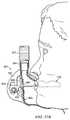
- Fig. 4illustrates an example dental device in a user's mouth.
- a dental deviceis provided that comprises an arched frame 100, a moldable tray 135, a second arched frame 200, and a second moldable tray 235.
- Arched frame 100may comprise an adjustment mechanism 115 that comprises a hook 120 and a threaded adjustor 125.
- Moldable tray 135may be coupled to arched frame 100.
- Moldable tray 100may comprise a channel 140.
- channel 140may be shaped to conform to a generic user's maxillary arch 305.
- channel 140may be a smooth channel that covers some of teeth of a user's maxillary arch 305.
- channel 140may be further shaped to conform to a particular user's maxillary arch 305.
- Second arched frame 200may comprise a second arched body 205 defining a second plurality of apertures 210.
- Second arched frame 200may further comprise a receiving mechanism 130 coupled to the lingual portion of second arched body 205.
- receiving mechanism 130may be a bar that spans a portion of the arch of second arched body 205.
- Second moldable tray 235may be coupled to second arched frame 200 and may engage second plurality of apertures 210. Second moldable tray 235 may be configured to engage some of the teeth of the user's mandibular arch 300.
- hook 120may engage receiving mechanism 130.
- Threaded adjustor 125may be used to adjust the forward position of arched frame 100 relative to second arched frame 200.
- the relative positions of the two arched frames 100 and 200may adjust the position of the user's maxillary arch 305 relative to the user's mandibular arch 300.
- the relative position of the user's maxillary and mandibular archesmay help to improve a user's breathing and/or prevent the user from snoring while sleeping.
- Figs. 5A and 5Beach illustrate an example universal oral appliance comprising a universal coupler.
- a universal oral applianceis provided comprising an arched frame 100 and a moldable tray 135 coupled to arched frame 100.
- Arched frame 100may comprise an arched body 105 defining a plurality of apertures 110.
- arched frame 100may be configured to be positioned proximate to the occlusal surface of a user's dental arch such that arched frame 100 extends beyond the cuspids of the user's dental arch when arched frame 100 is inserted in the user's mouth.
- Arched frame 100may have a midline that aligns substantially with the anterior midline of the user's mouth when arched frame 100 is inserted in the user's mouth.
- Arched frame 100may further comprise a universal coupler.
- the universal couplermay comprise a substantially planar surface 145, a first rail 146, and a second rail 147.
- Substantially planar surface 145may be proximate to and extend across the midline of arched frame 100.
- substantially planar surface 145may be configured to be positioned proximate to the occlusal surface of a user's incisors when the universal oral appliance is inserted in the user's mouth.
- First rail 146may be coupled to a first end of substantially planar surface 145.
- first rail 146may be distal to the midline of arched frame 100. In other embodiments, first rail 146 may be anterior to arched frame 100. Second rail 147 may be coupled to a second end of substantially planar surface 145. In particular embodiments, second rail 147 may be distal to the midline of arched frame 100. In other embodiments, second rail 147 may be posterior to arched frame 100. First rail 146 and second rail 147 may form an acute angle with substantially planar surface 145. In particular embodiments, first rail 146, second rail 147, and substantially planar surface 145 may define a slot. In particular embodiments, a dental attachment may slide into the slot and engage arched frame 100.
- the universal couplermay comprise a locking mechanism (such as, for example, a screw, a tab, or a groove).
- the screwmay secure a dental attachment to the universal coupler by screwing through the dental attachment and into the universal coupler.
- the tabmay secure the dental attachment by engaging the exterior of the dental attachment or by engaging a slot in the dental attachment.
- the groovemay secure the dental attachment by frictionally engaging the dental attachment.
- the universal couplermay further comprise a stop 148 coupled to substantially planar surface 145. Stop 148 may be coupled to the labial or lingual ends of substantially planar surface 145. Alternatively, stop 148 may be coupled to a distal end of substantially planar surface 145.
- Fig. 5Cillustrates an example universal oral appliance comprising a universal coupler.
- a universal oral applianceis provided comprising an arched frame 100 and a moldable tray 135 coupled to arched frame 100.
- Arched frame 100may comprise a universal coupler comprising a substantially planar surface 145, a first rail 146, a second rail 147, and a stop 148.
- each rail 146 and 147may comprise a first segment 149 and a second segment 150.
- First segment 149may be coupled at a first end to substantially planar surface 145, and second segment 150 may be coupled to a second end of first segment 149.
- first segment 149 and second segment 150may be substantially perpendicular to each other.
- Fig. 5Dillustrates an example universal oral appliance comprising a universal coupler comprising a guided channel.
- a universal oral appliancecomprising an arched frame 100 and a moldable tray 135.
- Arched frame 100may comprise a universal coupler comprising a substantially planar surface 145, a first rail 146, a second rail 147, and a stop 148.
- First rail 146, second rail 147, and substantially planar surface 145may define a slot.
- the universal couplermay further comprise a guided channel 151. Guided channel 151 may be configured to guide a dental attachment through the slot.
- Fig. 5Eillustrates an example universal oral appliance comprising a universal coupler comprising a raised surface 152.
- a universal oral appliancecomprising an arched frame 100 and a moldable tray 135.
- Arched frame 100may comprise a universal coupler comprising a substantially planar surface 145, a first rail 146, a second rail 147, and a stop 148.
- First rail 146, second rail 147, and substantially planar surface 145may define a slot.
- the universal couplermay further comprise a raised surface 152.
- Raised surface 152may be configured to guide a dental attachment through the slot.
- raised surface 152may be further configured to secure or lock the dental attachment.
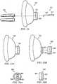
- Fig. 6illustrates an example universal oral appliance comprising a universal coupler, and an example plurality of dental attachments 400.
- an example universal oral applianceis provided that comprises an arched frame 100 and a moldable tray 135.
- Arched frame 100comprises an arched body 105 that defines a plurality of apertures 110.
- Arched frame 100further comprises a universal coupler.
- the universal couplermay comprise a substantially planar surface 145, a first rail 146, a second rail 147, and a stop 148.
- first rail 146, second rail 147, and substantially planar surface 145may define a slot.
- Fig. 6also illustrates a plurality of dental attachments 400.
- the plurality of dental attachments 400may comprise dental attachments configured to treat different disorders.
- the plurality of dental attachments 400may include a hook 405, a substantially rounded projection 415, and an adjustable hook 420.
- Other attachmentsmay include a handle or any other appropriate attachment configured for use with an oral appliance.
- a user or a medical professionalmay choose which dental attachment to use without having to hire a lab to construct a new oral appliance.
- dental attachments 400may be configured to engage the slot.
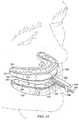
- Fig. 7illustrates an example dental device in a user's mouth.
- a dental deviceis provided that comprises an arched frame 100, a moldable tray 135 coupled to arched frame 100, a second arched frame 200, and a second moldable tray 235 coupled to arched frame 200.
- Arched frame 100may comprise a universal coupler.
- the universal couplermay comprise a stop 148.
- Moldable tray 135may comprise a channel 140 that is configured to engage at least some of the teeth of the user's maxillary arch 305.
- Second arched frame 200may comprise a second arched body 205 that defines a second plurality of apertures 210.
- Second arched frame 200may further comprise a receiving mechanism 130 that spans the lingual portion of second arched frame 200.
- receiving mechanism 130may be a bar.
- Second moldable tray 235may engage second plurality of apertures 210.
- the dental devicefurther comprises a dental attachment that is configured to engage the universal coupler.
- the dental attachmentmay be an adjustable hook 420 that comprises a hook 120 and a threaded adjustor 125. Hook 120 may engage receiving mechanism 130.
- Threaded adjustor 125may be used to adjust the forward position of second arched frame 200 relative to arched frame 100. This adjustment may adjust the forward position of the user's mandibular arch 300 relative to the position of the user's maxillary arch 305. In some embodiments, this adjustment may help to prevent the user from snoring while sleeping.
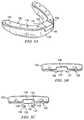
- Fig. 8Aillustrates an example arched frame 700.
- Arched frame 700may include an occlusal surface 702 and a flange 706.
- arched frame 700may be configured to be positioned proximate to a user's dental arch, with occlusal surface 702 positioned proximate to the occlusal surface of the user's dental arch.
- occlusal surface 702may be contiguous throughout the length of arched frame 700.
- occlusal surface 702may not be contiguous throughout the length of arched frame 700.
- occlusal surface 702may have a first portion configured to be positioned proximate to the user's left bicuspid and first molar; and have a second portion configured to be positioned proximate to the user's right bicuspid and first molar. As shown in Fig. 8A , in certain embodiments, occlusal surface 702 may not extend to the area proximate to the user's incisors. Certain embodiments in which the occlusal surface 702 is not contiguous throughout the length of arched frame 700 may allow for improved flexibility of arched frame 700.
- arched frame 700may be capable of flexing inward and/or outward, allowing arched frame 700 to conform to a wider variety of dental arch shapes and sizes. Such embodiments may also improve the ability of arched frame 700 to accommodate the overlap of the user's maxillary and mandibular incisors, allowing the user's jaw to close more fully.
- occlusal surface 702may have a thickness of approximately 1.5 millimeters, although other thicknesses may be used.
- Flange 706may run along the labial edge of arched frame 700. In certain embodiments, flange 706 may be contiguous throughout the length of arched frame 700. In alternative embodiments, as shown in Fig. 8A , flange 706 may not be contiguous throughout the length of the arched frame. For example, flange 706 may include a distal flange portion 708 and a mesial flange portion 710, separated by a flange recess 712.
- flange 706may be pushed outward by the labial surface of the user's dental arch when arched frame 700 is inserted into the user's mouth during the molding process, allowing arched frame 700 to automatically flex and align with the user's dental arch, which may improve the ability of arched frame 700 to accommodate different dental arch sizes and shapes.
- flange recesses 712may allow for improved flexibility of arched frame 700.
- flange recesses 712may allow the deformable material to form an improved mold of the user's teeth.
- flange recess 712may improve the user's ability to press moldable material against their teeth during the molding process, which allow for improved dental molds.
- mesial flange portion 710may allow for an improved mold when arched frame 700 is pressed toward the user's teeth during fitting.
- mesial flange portion 710may have a thickness greater than that of distal flange portion 708.
- mesial flange portion 710may have a thickness of approximately 3 millimeters and distal flange portion 708 may have a thickness of approximately 1.5 millimeters, although other thicknesses may be used.
- the greater thickness of mesial flange portion 710may improve the stability of arched frame 700 during flexion and may provide a more secure anchor point for other attached structures, such as anterior structure 716 shown in Fig. 8B .
- Fig. 8Billustrates another example arched frame 700 having occlusal surface 702, flange 706, and an anterior structure 716.
- occlusal surface 702may include an occlusal surface recess 704.
- occlusal surface recess 704may allow the deformable material to form a closer mold of the user's teeth.
- certain embodimentsmay include anterior structure 716 which extends forward from mesial flange portion 710 in an anterior direction.
- anterior structure 716may be fixed to arched frame 700, while in other embodiments anterior structure 716 may removeably coupled to arched frame 700.
- Figs. 8C and 8Dillustrate side views of example arched frames 700 having occlusal surface 702 and flange 706 with distal flange portion 708, flange recess 712, and anterior structure 710.
- Fig. 8Eillustrates an isometric view of an example arched frame 700.
- arched frame 700may include anterior structure 710, occlusal surface 702 that is not contiguous throughout the length of arched frame 700, and flange 706 that includes a distal flange portion 708, a flange recess 712, a mesial flange portion 710, and a mesial flange recess 714.
- flange 706may include mesial flange recess 714 located approximately at the midline of the arched frame.
- mesial flange recess 714may allow for improved conformity with the shape of the user's mouth.
- the distal ends of arched frame 700may extend approximately to the user's first molar when the frame is inserted into the user's mouth. In alternative embodiments, arched frame 700 may extend to the user's second molar or to the user's third molar.
- Figs. 9A through 9Dillustrate example moldable trays 730.
- moldable tray 730may include an occlusal surface 732, an outer rim 734, an inner rim 736, and recesses 738.
- Occlusal surface 732may be configured to be placed proximate to the occlusal surface of a user's dental arch.
- Outer rim 734may be configured to be positioned proximate to the labial surface of a user's dental arch.
- inner rim 736may be configured to be positioned proximate to the lingual surface of a user's dental arch.
- inner rim 736may lie mostly flat relative to the plane of occlusal surface 732 or may angle upward slightly. Such embodiments may make moldable tray 730 easier to slide into the user's mouth. In certain embodiments, inner rim 736 may be capable of being pushed upward or downward to engage with the lingual surface of the user's dental arch during the molding process.
- outer rim 734may have a thickness greater than that of inner rim 736.
- outer rim 734may have a thickness of approximately 3 millimeters, while inner rim 736 may have a thickness of approximately 2 millimeters, although these dimensions are not required.
- Reduced thickness of inner rim 736may allow moldable tray 730 to take up less space in the inner mouth area behind the teeth, which may allow the user to breath, swallow, and speak more easily and experience greater comfort. Reduced thickness of inner rim 736 may also help obviate any need to offer multiple sizes of moldable tray 730 and arched frame 700.
- inner rim 736may allow other medical and/or dental devices to be more easily inserted into the user's mouth.
- inner rim 736may be shorter than outer rim 734.
- a shorter inner rim 736may allow for easier insertion of moldable tray 730 into the user's mouth.
- a shorter inner rim 736may also reduce the amount of moldable material in the inner mouth area, which may provide additional advantages as described above.
- distal portions of moldable tray 730may have a reduced height, which may improve the fit of moldable tray 730 in the user's mouth.
- occlusal surface 732may have one or more recesses 738, which may result from clamping or otherwise holding in place arched frame 700 during an overmolding process.
- arched frame 700 illustrated in Figs. 8A through 8Emay have a corresponding recess, which may allow for improved clamping and alignment during the manufacturing process.
- Fig. 9Bshows another example moldable tray 730 having occlusal surface 732, outer rim 734, and inner rim 736. As shown in Fig. 9B , in certain embodiments moldable tray 730 may further include an anterior structure 740. It should be appreciated that in certain embodiments the optional anterior structure 740 may be fixed to moldable tray 730 or it may be removeably coupled to moldable tray 730.
- moldable tray 730may be composed of a material that can be heated to a temperature at which the material softens and becomes capable of being molded to a different shape.
- the materialcan be heated in hot water.
- the temperature range at which the material softensmay be approximately 40 - 80 degrees Celsius, although materials with other softening ranges may be used.
- the target softening temperaturemay be approximately 60 degrees Celsius.
- this materialmay be a thermoplastic. Such thermoplastic materials may be heated to a temperature at which the thermoplastic becomes soft and moldable, at which point it may be molded to the shape of at least a portion of a user's dental arch and become at least temporarily fixed in that shape.
- moldable tray 730may comprise a polycaprolactone polymer or other aliphatic polyester, as discussed above in reference to moldable tray 135.
- the thermoplastic materialmay comprise a cross-linked polycaprolactone reinforced with an aramid fiber such as the short length aramid fiber sold by Dupont under the brand name Kevlar®.
- using polycaprolacton combined with Kevlar®may allow moldable tray 730 to soften at low temperatures and set hard at temperatures of approximately 60 degrees Celsius.
- using polycaprolacton combined with Kevlar®may improve the hardness of moldable tray 730 following the molding process, which may improve the ability of moldable tray 730 to hold its shape when being used to adjust the user's jaw position and/or hold a mask or other breathing device in place. In certain embodiments, this increased hardness may also improve the ability of moldable tray 730 to hold its shape for longer periods of time. For example, in certain embodiments, this may allow moldable tray 730 to substantially hold its shape for periods longer than approximately 1 month, though such period is not required. Using polycaprolacton combined with Kevlar® may also allow for thinner embodiments of moldable tray 730, which may allow moldable tray 730 to take up less space in the user's mouth.
- thermoplastic materialmay be cross-linked by radiation, which may create cross-linking of certain molecules to improve the material's shape retention characteristics and/or make the material better able to return to its original shape after reheating.
- radiationmay be applied after moldable tray 730 has been overmolded with arched frame 700, but before being molded to the user, though this is not required. Cross-linking by radiation is further described in U.S. Patent No. 5,415,623 .
- the materialmay exhibit slight shrinkage after being molded to the user's dental arch. In particular embodiments, such shrinkage may be less than 1%. Slight shrinkage of the material following the molding process may allow for improved fit with the user's dental arch. In some embodiments, slight shrinkage of the material following the molding process may allow moldable tray 730 to have a "snap" fit with the user's dental arch.
- arched frame 700may be primarily composed of a substantially rigid material, such as Nylon or any other material providing substantial rigidity while allowing moderate flexion.
- arched frame 700may be composed of a material whose form does not substantially changed when heated to the temperature required to soften the moldable material of moldable tray 730.
- arched frame 700may be composed of a material that substaintially maintains its shape when heated up to at least 100 degrees Celsius. Such materials may include polycarbonate, Nylon, acrylonitrile butadiene styrene (ABS), or polyethylene.
- arched frame 700may be composed of a semi-flexible material, for example liquid silicone rubber (LSR), approximately having a Shore 30 - 90 hardness, although this particular hardness is not required.
- LSRliquid silicone rubber
- Figs. 10A through 10Cillustrate an example moldable tray 730 substantially surrounding an example arched frame 700.
- example moldable tray 730may include occlusal surface 732, outer rim 734, and inner rim 736; and arched frame 700 may include occlusal surface 702 and flange 706.
- the labial edge of outer rim 734may extend outward beyond the labial edge of flange 706.
- the lingual edge of inner rim 736may also extend inward beyond the labial edge of occlusal surface 702. As seen in Fig.
- the distal end of moldable tray 730may extend distally beyond the distal end of arched frame 700.
- the distal end of arched frame 700may extend approximately to the user's first molar, while the distal end of moldable tray 730 extends approximately to the user's second or third molar.
- the distal end of arched frame 700may extend approximately to the user's second molar, while the distal end of moldable tray 730 extends approximately to the user's third molar.
- the distal ends of arched frame 700 and moldable tray 730may be approximately coextensive.
- the superior surface of outer rim 734may extend beyond the superior surface of flange 706 by approximately 2.5 millimeters while the inferior surface of moldable tray 730 may extend below the inferior surface of arched frame 700 by approximately 1.5 millimeters, although these dimensions are not required.
- moldable tray 730may extend outward beyond the labial edge of arched frame 700 by approximately 1.5 millimeters, though other dimensions are possible.
- moldable tray 730may extend inward beyond the lingual edge of arched frame 700 by approximately 1.5 millimeters, though other dimensions are possible.
- flange 706may help maintain the shape of outer rim 734.
- Moldable trays that substantially surround an arched framemay allow for reduced bulk between a user's incisors when the tray(s) are inserted into the user's mouth. By providing moldable trays with less material between the user's incisors, certain embodiments may allow users to close their mouths further with the trays inserted, which may improve comfort and/or effectiveness.
- moldable trays that substantially surround arched framemay allow for mouth pieces where only the moldable material touches the inner surfaces of the user's mouth, such as the user's gums, lips, and tongue. Such moldable trays may also allow for improved molding to the user's front teeth.
- arched frame 700 substantially surrounded by moldable tray 730may also reduce the chances of damage to arched frame 700 and may help hold any broken pieces of arched frame 700 in place, preventing any such broken pieces from contacting the user's mouth or entering the user's airway.
- arched frame 700may include apertures in occlusal surface 702 and/or flange 706, though such apertures are not required. Such apertures may allow the moldable material to flow through arched frame 700 during the molding process, which may provide greater stiffness following the molding process and may allow for improved alignment of arched frame 700 with moldable tray 730.
- Fig. 11Aillustrates another example moldable tray 730 having occlusal surface 732, outer rim 734, inner rim 736, and notches 742.
- moldable tray 730is attached to a post 802 having slot 804, channels 806, and tension element channel 834.
- Fig. 11Balso illustrates a lower isometric view of the same embodiment showing outer rim 734, notch 742, and a lower surface 744.
- moldable tray 730may be custom molded to fit a particular user's dental arch.
- moldable tray 730may include one or more notches 742 which may facilitate grasping the moldable tray for improved insertion into and removal from the user's mouth.
- lower surface 744 of the moldable tray 730may also be molded to fit the user's second dental arch.
- molding lower surface 744 to the user's mandibular dental archmay be performed with the user's mandibular dental arch placed in a particular position relative to the user's maxillary dental arch.
- the user's mandibular dental archmay be extended in the anterior direction, which may help open a user's airway allowing for improved breathing. Molding lower surface 744 to the user's mandibular dental arch may also help hold the user's jaw in a desired position, such as, for example, when upward force is applied to the user's mandible by a chin strap or other device.
- a second moldlable tray configured to engage with the user's second dental archmay be fused with moldable tray 730, locating the user's mandibular arch in a particular position relative to the user's maxilary arch.
- the second moldable traymay be fused to moldable tray 730 prior to forming a mold of the user's dentition.
- the second moldable traymay form a separate piece prior to being molded to the user's dentition.
- the second moldable tray and moldable tray 730may be heated and fused together during the molding process.
- a custom-made traymay be pre-fitted and then molded from a substantially rigid material, such as, for example, acrylic.
- Certain embodimentsmay have two separate custom-made trays coupled together via an adjustment mechanism, such as, for example, those described in U.S. Patent No. 7,748,386 , which is incorporated herein by reference.
- such an adjustment mechanismmay have wedges in the side that interact to move the user's lower jaw forward.
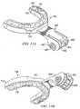
- Fig. 12illustrates two moldable trays 730, a mask 850, and a coupler 800.
- Fig. 13illustrates a side view of the components shown in Fig. 12 .
- moldable trays 730include occlusal surface 732, outer rim 734, and inner rim 736.
- Mask 850is a device for directing the flow of air and/or other gases to a user.
- Coupler 800adjustably couples mask 850 to at least one moldable tray 730.
- two moldable trays 730cooperate to form an adjustable oral appliance configured to adjustably position the lower arch of a user relative to the user's upper arch.
- upper moldable tray 730includes post 802 that extends anterior to the user's mouth when upper moldable tray 730 is positioned proximate to the user's maxillary dentition.
- lower moldable tray 730includes tension element 830 that extends anterior to the user's mouth when lower moldable tray 730 is positioned proximate to the user's mandibular dentition.
- post 802includes a tension element channel 834 to receive tension element 830.
- tension element 830may be threaded and may be coupled to adjustment knob 832, which may be turned to adjust the position of lower moldable tray 730 relative to upper moldable tray 730.
- tension element 830is described as being threaded, other configurations may be used to adjust the relative positions of upper and lower moldable trays 730.
- tension element 830may attach to an adjustable oral appliance, such as the oral appliance described in U.S. Patent No. 7,748,386 .
- upper moldable tray 730 and lower moldable tray 730may be used with or without a mask.
- moldable trays 730may function as an oral appliance only or may be used during surgery or post-surgery to maintain the user's airway during the administering of anaesthetics or during ventilation, or they may be in place in the event that resuscitation becomes necessary.
- Mask 850includes one or more flanges 822, with each flange 822 including a slot 824.
- Flange 822may be fixed to or integrally formed with mask 850; or flange 822 may be removably coupled to mask 850.
- flange 822may be fixed to or integrally formed with other mask types, or flange 822 may be removably coupled to and/or interchangeable with other mask types.
- flange 822may have a thickness of between 10 - 22 millimeters, though such dimensions are not required. In other embodiments, flange 822 may have a thickness of between 12 - 18 millimeters.
- flange 822may have a thickness of approximately 14 millimeters. In embodiments having multiple flanges 822, each flange 822 may have a thickness of between 1 - 4 millimeters, though this range is not required. In a particular embodiment having a multiple flanges 822, one or more of the flanges 822 may have a thickness of approximately 3 millimeters. In certain embodiments having multiple flanges 822, when the mask is oriented to the user's face, the distance between the right edge of the rightmost flange 822 and the left edge of the leftmost flange 822 may be similar to the ranges described above for a single flange 822.
- the span between the inner edges of the flangesmay be approximately 6 millimeters and the span between the outer edges of the flanges may be approximately 14 millimeters, though other dimensions may be used.
- Such embodimentsmay improve the ability of coupler 800 to prevent deformation outside of the sagittal plane.
- mask 850is a pillow mask with nasal inserts 852 that may be configured to seal against the user's nostrils.
- nasal inserts 852may be fitted independently to mask 850 and may be capable of rotating independently to the angle of the user's nostrils.
- nasal inserts 852may be removeably coupled to mask 850 and may be interchangeable with different sizes of nasal inserts 852.
- the usermay select different sizes of nasal inserts 852 for each nostril.
- nasal inserts 852may be formed together as a pair and attached as one unit to mask 850. In other embodiments, nasal inserts 852 may be fixed permanently to mask 850.
- mask 850may have an inlet that is fixed on the top of the frame for delivering air and/or other gases to mask 850.
- mask 850may have a ball joint, elbow, or a combination thereof delivering air and/or other gases to mask 850.
- air and/or other gasesmay be delivered in the side or the bottom of mask 850.
- air and/or other gasesmay be delivered through several different tubes.
- the usermay be able to select one or more connection points for delivery of air and/or other gases and plug or otherwise disable other connection points.
- a main hosemay attach directly to mask 850 or to an elbow joint or a ball joint.
- mask 850may have a length of flexible tubing that may connect with a main hose.
- the optional flexible tubingmay be approximately 50 - 300 millimeters long, though this is not required.
- mask 850may have a 250 millimeter-long flexible tube.
- such tubingmay be light, flexible, and have a smaller diameter than the main hose.
- the flexible tubingmay have a diameter of approximately 12 - 19 millimeters, while the main hose may have a diameter of approximately 22 millimeters, though these dimensions are not required.
- the flexible tubingmay have an internal diameter of approximately 17 millimeters.
- a connectorbetween the short flexible tube and the main tube, and in some embodiments this connector may be capable of swivelling.
- the connectormay be a ball joint or a straight connector.
- optional headgearmay be supplied that attaches to mask 850, coupler 800, and/or moldable tray 730. Such headgear may pass along the side of the user's face and may be capable of holding the main hose or other air-delivery device in a particular position. For example, in certain embodiments, such headgear may hold the main hose in place on top of the user's head or to one or both sides of the user's head.
- such headgearmay also be configured to help hold moldable tray 730, or any other oral appliance, in the user's mouth.
- such headgearmay be adjustable at a connection point on mask 850 and/or at one or more places around the user's head.
- the headgearmay be formed from a stretchable material and may require little or no manual adjustment.
- the headgearmay be at least partially made from Breath-o-prene®, which is a soft, breathable laminate.
- the headgearmay be at least partially made from silicone or a molded thermoplastic/fabric composite.
- the headgearmay be formed from a combination of these materials, or from a combination of these and other materials.
- a chin strapmay attach to mask 850, headgear, or moldable tray 730 or any other oral appliance.
- mask 850may have bias flow (vent holes) to flush out the user's exhaled breath.
- mask 850may have a plurality of holes to enable bias flow.
- mask 850may have approximately 10 - 50 holes, though this is not required.
- mask 850may have approximately 35 holes. In these embodiments, the holes may be approximately .75 millimeters in diameter, though these dimensions are not required.
- the holesmay have non-uniform cross-sectional shapes throughout the length of the holes.
- one or more of the holesmay be rounded and have an opening diameter of approximately 1.2 millimeters, the diameter of the hole falling to approximately .75 millimeters when moving through the hole and then expanding again to a diameter greater than .75 millimeters when moving through to the other end of the hole.
- the holesmay be tapered from one side or the other, or the holes may be straight throughout.
- having many small holesmay slow the flow of gas and may reduce the draft and noise of such flow.
- mask 850may have no holes, which may enable closed-loop ventilation.
- mask 850may be first formed in two or more distinct pieces and then joined, for example, by welding, gluing, clipping, screwing, latching, strapping, or otherwise fixing the pieces together. In other embodiments, the mask may initially be formed as a single piece.
- the headgear, tubes, bias holes, chin straps, attachments, assembly features, and other aspects described abovemay also apply to other masks described herein.
- Post 802may include one or more channels 806 and a slot 804.
- coupler 800is formed by two flanges 822 engaging two channels 806.
- the movement of flanges 822 relative to channels 806is limited by fastener 805 in slot 804.
- Fastener 805may represent any structure that can restrict the movement of flanges 822 relative to channels 806.
- fastener 805may be a pin, screw, or bolt.
- fastener 805is a threaded hex-head bolt that engages a hex-head counter sink 807 on one side of post 802 and a tightening knob 808 on the other side of post 802.
- a hex-head (or other appropriately shaped) countersinkmay prevent rotation of fastener 805 while tightening knob 808 or other appropriate structure is fixing the position of fastener 805.
- both sides of post 802may include a countersink, such that a user may select to position tightening knob 808 on either side of post 802. This flexibility may make the use of tightening knob 808 equally convenient to left-handed and right-handed users.
- post 802may include an additional tightening knob opposite tightening knob 808, enabling adjustment from either side of post 802.
- Fig. 14Aillustrates the anterior end of an example post 802 and Fig. 14B illustrates an example anterior view of an example arched frame 700 with a tension element 830.
- the tension elementmay be threaded, and the threaded portion may engage with the tension element adjustor 832.
- post 802includes D-shaped slot 834 and tension element 830 has a corresponding D-shaped cross-section.
- the D-shaped slot 834 and tension element 830may substantially prevent tension element 830 from rotating when adjustment knob 832 is used to adjust tension element 830.
- slot 834may have a "key" structure that corresponds with a channel in tension element 830.
- Figs. 15A and 15Billustrate example flanges 822.
- flange 822may include a slot 824.
- Fig. 15Bdepicts two distinct flanges 822, alternative emobidments may have a single flange, multiple flanges, or any other structure which may be secured in place relative to post 802 by fastener 805.
- slot 824may have various shapes, sizes, and orientations.
- flanges 822may be formed and/or molded as one part. In other embodiments, flanges 822 may be formed from multiple parts that may be assembled, clipped, screwed, or overmolded. In various embodiments, flanges 822 may consist of plastic and/or metal such as stainless steel.
- Figs. 16A and 16Billustrate an example post 802 having a fastener 805, channels 806, countersink 807, tightening knob 808, and a tension element channel 834.
- an end of fastener 805may be configured to engage with countersink 807.
- at least a portion of fastener 805may be threaded.
- slot 804(not shown) may cross laterally through post 802, allowing fastener 805 to pass laterally through post 802 across channels 806.
- slots 824may substantially align with slot 804, allowing fastener 805 to pass through both slot 804 and slots 824.
- tightening knob 808may be adjusted to increase or decrease lateral force exerted along the long axis of fastener 808. Adjusting tightening knob 808 in such an embodiment may operate to secure flanges 822 in place relative to post 802.
- an attached mask or breathing devicemay be moved into the desired position relative to the user's face and then fixed into that position by adjusting tightening knob 808.
- post 802may be formed and/or molded as one part. In other embodiments, post 802 may be formed from multiple parts that may be assembled, clipped, screwed, or overmolded. In various embodiments, post 802 may consist of plastic and/or metal such as stainless steel.
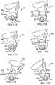
- Figs. 17A through 17Fillustrate various positions of an example coupler 800.
- coupler 800may include a flange 822 with slot 824 and a post 802 having a fastener 805 and countersink 807.
- flange 822may be capable of moving in the supierior-inferior direction relative to post 802, moving in the anterior-positerior direction relative to post 802, and rotating around fastener 805.
- flange 822may be capable of moving in the supierior-inferior direction relative to post 802 and rotating around fastener 805.
- flange 822may be limited to adjustment, rotation, and/or movement within the sagittal plane.
- post 802may include an additional joint that may provide adjustment, rotation, and/or movement in one or more additional directions.
- flange 822may be adjusted vertically approximately +/- 10mm, though other ranges may be used.
- flange 822may be adjusted in the anterior-posterior direction approximately +/-5mm, though other ranges may be used.
- other embodimentsmay have horizontal adjustment ranges of between +/- 3mm and +/- 8mm.
- tightening knob 808may be adjusted to secure flange 822 in place relative to post 802.
- Fig. 18illustrates another example post 882 having a fastener 805, plates 884, channels 806, tightening knob 808, and plate 886.
- plates 884may define channels 806, which are configured to receive flanges 822.
- post 882may be cylindrical and hollow.
- post 882may consist of metal, such as stainless steal.
- post 882may have various structures, shapes, and densities and can be made from a wide variety of rigid materials.
- plate 886may be attached at the posterior end of post 882. Plate 886 may be configured to couple to the front of an oral appliance such as those described, for example, in US Patent No. 7,748,386 , which is incorporated herein by reference.
- Fig. 19Aillustrates an example mask 890 having flanges 822 with slots 824 and a hose coupler 854 coupled to a hose 870.
- Fig. 19Billustrates a side view of mask 890, showing opening 856 and flanges 822.
- flanges 822may be fixed to or integrally formed with mask 890.
- flanges 822may be removably coupled to the anterior surface of mask 890.
- opening 856may allow structures, such as post 802 or post 882, to pass through the front of mask 890 and couple with flanges 824.
- opening 856may be sized to accommodate various positions and orientations of post 802 relative to mask 890.
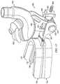
- Fig. 20illustrates an example mask 892 coupled to an example post 802.
- mask 892includes a seal 860, opening 856, flanges 822, and a hose coupler 854.
- post 802is attached to moldable tray 730 inside the user's mouth, allowing mask 892 to be adjustably oriented to the user's face.
- mask 892may be adjusted vertically, adjusted in the anterior-posterior direction, and/or rotated in the sagittal plane.
- seal 860may include flexible gasket 862 which may be configured to allow post 802 to pass through it and couple with flanges 824, forming an air-tight seal around post 802.
- Flexible gasket 862may also allow mask 892 to be adjusted to various positions and orientations relative to the user's face without significantly disturbing post 802 or breaking the airtight seal of seal 860.
- flexible gasket 862may incorporate or be surrounded by creases, which may improve the ability of flexible gasket 862 to accommodate various positions of post 802, though such creases are not required.
- post 802, or another suitable post such as post 882may attach to various oral appliances, allowing for various combinations of oral appliances, posts, and masks.
- flanges 822may be contained within a mask, providing the substantially similar movement and adjustment to mask 892.
- fastener 805may pass through a gasket in the mask's seal to a position outside the mask where it could be operated by a user.
- mask 892 secured to the user's oral appliancemay obviate the need for the user to wear stabilizing headgear. Such straps may shift accidentally, may be uncomfortable for the user, may leave marks on the user's face, and may irritate the user's face and scalp. Furthermore, since having mask 892 secured to the user's oral appliance may prevent substantial movement of mask 892 relative to the user's face and prevent leakage, these embodiments may reduce the need to tighten the mask to the user's face, which may result in reduced pressure on the user's face and reduced pressure sores. These embodiments may also provide greater mask stability during sleep for users who exhibit substantial movement during sleep. It should be appreciated that all such embodiments and advantages described with respect to mask 892 may also apply to other mask described herein, such as, for example, masks 850 and/or 894.
- mask 892may be held in place by a tension element attached to an oral appliance, with the tension element pulling mask 892 toward the oral appliance and the user's face.
- the pull of the tension elementmay be adjusted by a screw, tightening knob, or other adjustment mechanism.
- mask 892may be secured via a fastener, such as a hook.
- FIG. 20shows mask 892 as a full face mask covering the user's nose and mouth
- Figs. 21A and 21Billustrate an alternative mask 894 covering the user's mouth and delivering air and/or other gases to the user's nose via nasal inserts 852.
- seal 860may extend below the user's chin.
- Masks with portions that extend below a user's chinmay improve the function of the mask by preventing and/or reducing the occurrence of the user opening their mouth while using the mask.
- Still other embodiments incorporating different types of maskswill be apparent to those skilled in the art.
- flanges 822 of mask 894are disposed in channels 806 of post 802
- movement of mask 894 outside of the sagittal planeis strongly resisted, which may help prevent mask leakage if a user lays on his or her side, pushing mask 894 laterally against a surface such as a pillow.
- certain embodimentsmay use pillow masks, which seal against the user's nostrils; nasal masks, which cover the user's nose; full face masks, which cover both the user's mouth and nose; hybrid masks, which have one portion covering a user's mouth and another portion covering the user's nose or sealing against the user's nostrils; or oral masks, which cover the user's mouth.
- Such masksmay be used for the delivery of pressurized air, oxygen, aerosols, gasses, or medication; and the masks may be vented or non-vented.
- Masks included in various embodimentsmay be used for continuous positive airway pressure treatment (CPAP), auto-CPAP, or bilevel or closed-loop ventilation; and masks may be custom-fitted to a particular user or they may be non-custom masks that conform to different face shapes.
- CPAPcontinuous positive airway pressure treatment
- auto-CPAPauto-CPAP
- bilevel or closed-loop ventilationmasks may be custom-fitted to a particular user or they may be non-custom masks that conform to different face shapes.
- a venting sealmay be combined with the masks and/or oral appliances disclosed herein.
- the venting sealmay be fixed or detachable.
- the venting sealmay be positioned outside the user's mouth next to the user's lips or the venting seal may be positioned behind the user's lips next to the user's teeth.
- the venting sealmay reduce or eliminate the venting of air or other gases from the user's mouth, such as for example when air or other gases are being supplied to the user's nose.
- An example venting sealis disclosed in U.S. Patent No. 6,675,802 .
- the venting sealmay be attached to post 802, post 882, or other appropriate structure, either removably or permanently.
- Figs. 22A and 22B and Figs. 23illustrate an example mask 900 having a hose coupler 902 and a strap 904 with a plurality of apertures 906.
- hose coupler 902may be configured to attach to a hose 910 which may deliver air and/or other gases to mask 900.
- strap 904may span the opening of hose coupler 902.
- strap 904may have a plurality of apertures along its length.
- a tension element 920may pass through one of the plurality of apertures 906 and attach to oral appliance 930, which may be any mouthpiece configured to couple to tension element 920.
- Fig. 24illustrates an example oral appliance 930, mask 900, and tension element 920.
- tension element 920has a threaded knob 924 and a hook 922.
- Oral appliance 930includes a receiver to engage tension element 920 to pull mask 900 towards oral appliance 930.
- the receiver in oral appliance 930may be a loop, a latch, or a slot.
- tension element 920includes hook 922 and threaded knob 924.
- tension element 920may include one or more alternative structures to pull mask 900 towards oral appliance 930.
- Figs. 25A and 25Billustrate an example mask 950 and adapter 960.
- adapter 960may include a hose coupler 962, a strap 904 having a plurality of apertures 906, and a mask coupler 968.
- hose coupler 902may be configured to couple with a hose 910.
- mask coupler 968may be configured to couple with hose coupler 952 of mask 950, allowing adapter 960 to couple with mask 950.
- adapter 960When adapter 960 is coupled to mask 950, adapter 960 may allow mask 950 to interact with hose 910 and tension element 920 as described in the above description of mask 900.
- Fig. 27illustrates an example dental device comprising a universal coupler and an example dental attachment.
- a dental deviceis provided comprising an arched frame 100, a moldable tray 135, a second arched frame 200, and a second moldable tray 235.
- Arched frame 100may comprise a universal coupler comprising a substantially planar surface 145.
- a hook 405may be configured to engage the universal coupler.
- second arched frame 200may comprise a receiving mechanism 130 coupled to the lingual portion of second arched frame 200.
- Receiving mechanism 130may be a bar that spans the lingual portion of second arched frame 200.
- hook 405may engage receiving mechanism 130 to adjust the forward position of arched frame 100 relative to second arched frame 200. In certain embodiments, this adjustment may help to prevent a user from snoring when the dental device is inserted in the user's mouth.
- Fig. 28illustrates an example dental device comprising a universal coupler and an example dental attachment.
- a dental deviceis provided comprising an arched frame 100, a moldable tray 135, a second arched frame 200, and a second moldable tray 235.
- Arched frame 100may comprise a universal coupler comprising a substantially planar surface 145.
- a substantially rounded projection 415may be configured to engage the universal coupler.
- rounded projection 415may be the only point of contact between the user's upper and lower dental arches to prevent a user from clenching his jaw when the dental device is inserted in the user's mouth.
- rounded projection 415may contact an opposing arch or may contact one or more incisors of the opposing dental arch to prevent a user from clenching his jaw when the dental device is inserted in the user's mouth.
- the opposing archmay have a contact surface that may be planar.
- the universal oral appliance comprising a universal couplermay provide several advantages for a user.
- a universal oral appliance comprising a universal couplermay offer more use options to a user.
- a user's appliancemay be fitted with several different dental attachment options. The user may choose which dental attachment is best suited for his situation without having to hire a lab to construct another appliance.
- a particular usermay also adjust the dental attachment to better suit the shape and size of the user's mouth.
- This disclosurecontemplates the universal oral appliance being created from parts in a kit. A user may purchase the kit instead of a dental device created in a laboratory.
- Fig. 29illustrates an example arch comprising a dental attachment.
- an archis provided that comprises an arched frame 100 and a moldable tray 135 coupled to arched frame 100.
- Arched frame 100comprises an arched body 105 that defines a plurality of apertures 110.
- the archmay further comprise a dental attachment configured to engage arched frame 100.
- the dental attachmentis configured to engage arched frame 100 along the midline of arched frame 100.
- the dental attachmentmay comprise a post 500 and an anchoring element 505.
- Post 500may be coupled at a first end to anchoring element 505.
- a second end of post 500may engage arched frame 100.
- post 500may be configured to removably engage arched frame 100.
- anchoring element 505may include a buckle, a slot, a clasp, a clamp, and/or any other appropriate element to anchor a tension element.
- anchoring element 505may be configured to be outside a user's mouth when the arch is inserted in the user's mouth.
- the dental attachmentmay further comprise a release mechanism 510.
- release mechanism 510may be a button or a latch.
- Fig. 30illustrates an example arch comprising a second anchoring element and a tension element.
- an archis provided that comprises an arched frame 200 and a moldable tray 235 coupled to arched frame 200.
- Arched frame 200comprises an arched body 205 that defines a plurality of apertures 210.
- the archmay further comprise a second anchoring element 245.
- second anchoring element 245may be coupled to the arch along the midline of the arch.
- the archmay further comprise a tension element 515.
- tension element 515may be flexible and may be configured to engage second anchoring element 245.
- tension element 515may be further configured to couple to an anchoring element outside a user's mouth when the arch is inserted in the user's mouth.
- tension element 515may comprise a strap 520 and a coupler 516.
- Coupler 516may be configured to engage the second anchoring element.
- coupler 516may be configured to removably engage the second anchoring element.
- Strap 520may be coupled to coupler 516.
- strap 520may be configured to engage the anchoring element outside the user's mouth when the arch is inserted in the user's mouth.
- strap 520may comprise a hard plastic, leather, or metal.
- strap 520may be a zip tie.
- strap 520may be a wire, belt, string, or any other appropriate element to engage the anchoring element.
- this disclosuredescribes an arch comprising arched frame 200, moldable tray 235, and tension element 515, this disclosure contemplates a one-piece arch comprising tension element 515.
- Fig. 31illustrates an example dental device comprising a dental attachment, a second anchoring element, and a tension element.
- a dental deviceis provided that comprises an arched frame 100 and a second arched frame 200.
- the dental devicefurther comprises a moldable tray 135 coupled to arched frame 100 and a second moldable tray 235 coupled to second arched frame 200.
- the dental devicemay further comprise a dental attachment configured to engage arched frame 100.
- the dental attachmentmay comprise a post 500 and an anchoring element 505.
- the dental devicemay further comprise a second anchoring element 245.
- Second anchoring element 245may be coupled to second arched frame 200.
- the dental devicemay further comprise a tension element 515.
- Tension element 515may be configured to engage second anchoring element 245.
- tension element 515may comprise a coupler 516 and a strap 520.
- strap 520may be configured to engage anchoring element 505 outside the user's mouth when the dental device is inserted in the user's mouth.
- Anchoring element 505may be configured to secure substantially the length of strap 520 engaged to anchoring element 505.
- increasing the length of strap 520 engaged to anchoring element 505will adjust the forward position of arched frame 100 relative to second arched frame 200.
- the dental attachmentmay further comprise a release mechanism 510.
- Fig. 32illustrates an example dental attachment and tension element.
- a dental attachmentis provided comprising a post 500 and an anchoring element 505.
- Anchoring element 505may be coupled to an end of post 500.
- a tension elementis also provided comprising a strap 520. Strap 520 may be configured to engage anchoring element 505.
- Anchoring element 505may be configured to secure the length of strap 520 engaged to anchoring element 505.
- the dental attachmentmay comprise a release mechanism 510. Release mechanism 510 may be configured to release strap 520 from anchoring element 505.
- Fig. 33illustrates an example dental device in a user's mouth.
- a dental deviceis provided that comprises an arched frame 100, a second arched frame 200, a moldable tray 135 coupled to arched frame 100, and a second moldable tray 235 coupled to second arched frame 200.
- Moldable tray 135may comprise a channel 140 configured to engage at least some of the teeth of the user's maxillary arch 305.
- Second arched framemay comprise a second arched body 205 that defines a second plurality of apertures 210.
- the dental devicemay further comprise a dental attachment.
- the dental attachmentmay comprise a post 500 and an anchoring element 505.
- Anchoring element 505may be coupled to an end of post 500, and a second end of post 500 may be configured to engage arched frame 100.
- Anchoring element 505may be configured to be outside the user's mouth when the dental device is inserted in the user's mouth.
- the dental devicemay further comprise a second anchoring element 245 coupled to second arched frame 200.
- the dental devicemay further comprise a tension element comprising a coupler 516 and a strap 520.
- Coupler 516may be configured to engage second anchoring element 245.
- Strap 520may be coupled to coupler 516 and may be configured to engage anchoring element 520 outside the user's mouth when the dental device is inserted in the user's mouth.
- Anchoring element 505may be configured to secure substantially the length of strap 520 engaged to anchoring element 505.
- increasing the length of strap 520 engaged to anchoring element 505may adjust the forward position of arched frame 100 relative to second arched frame 200.
- adjusting the forward position of arched frame 100 relative to second arched frame 200may adjust the forward position of the user's maxillary arch 305 relative to the user's mandibular arch 300.
- adjusting the forward position of the user's maxillary arch 305 relative to the position of the user's mandibular arch 300may help to improve the user's breathing and/or prevent the user from snoring.
- the dental device comprising a dental attachment and a tension elementmay allow a third party faster access to a user's mouth and airway. For example, if the user is a patient sleeping in a sleep laboratory, a doctor in the laboratory may quickly pull on the tension element to open an airway that closed while the patient slept. As another example, if the user is a patient undergoing surgery in a hospital, a surgeon may quickly release the tension element to open the patient's mouth for intubation or for insertion of an instrument while the patient is sedated. In particular embodiments, the dental device comprising a dental attachment and a tension element may pull the user's lower jaw forward without locking the lower jaw in place.
- the dental devicecomprising a dental attachment and a tension element being created from a kit.
- a patient, doctor, or surgeonmay purchase the kit and create the dental device quickly.
- the dental devicemay be a disposable device that may be thrown out after one or more uses.
- Fig. 34illustrates an example process for creating a dental device.
- an arched frameis formed.
- the arched framemay be configured to be positioned proximate to the occlusal surface of a user's dental arch such that the arched frame extends beyond the cuspids of the user's dental arch.
- the arched framemay define a plurality of apertures.
- an adjustment mechanismis coupled to the arched frame.
- the adjustment mechanismmay comprise a hook and a threaded adjustor.
- a moldable trayis formed.
- the moldable traymay comprise a channel configured to engage at least some of the teeth of the user's dental arch.
- the channelmay be shaped to conform to the teeth of a generic user's dental arch. In other embodiments, the channel may be a smooth channel configured to cover some of the teeth of the user's dental arch. In particular examples, the channel may be further shaped to conform to a particular user's dental arch.
- the moldable trayis coupled to the arched frame. In particular examples, the moldable tray may engage the plurality of apertures. In particular examples the process may be repeated to form a second arched frame and a second moldable tray.
- the arched framemay comprise kevlar polycarbon, acryllic, polycarbonate resin thermoplastic, or any other suitable hard plastic polymer.
- the moldable traymay comprise polycaprolactone.
- the process illustrated in Fig. 34may lead to faster creation and production of dental devices. Users may avoid sending dental impressions to a laboratory to create dental devices thus saving time and money.
- step 605coupling an adjustment mechanism to the arched frame, may be performed after step 610, forming a moldable tray.
- step 605coupling an adjustment mechanism to the arched frame
- step 610forming a moldable tray
- step 605coupling an adjustment mechanism to the arched frame
- step 610forming a moldable tray
Landscapes
- Health & Medical Sciences (AREA)
- Engineering & Computer Science (AREA)
- Pulmonology (AREA)
- Veterinary Medicine (AREA)
- Biomedical Technology (AREA)
- Heart & Thoracic Surgery (AREA)
- Life Sciences & Earth Sciences (AREA)
- Animal Behavior & Ethology (AREA)
- General Health & Medical Sciences (AREA)
- Public Health (AREA)
- Hematology (AREA)
- Emergency Medicine (AREA)
- Anesthesiology (AREA)
- Otolaryngology (AREA)
- Mechanical Engineering (AREA)
- Vascular Medicine (AREA)
- Nursing (AREA)
- Orthopedic Medicine & Surgery (AREA)
- Thermal Sciences (AREA)
- Physics & Mathematics (AREA)
- Toxicology (AREA)
- Dental Tools And Instruments Or Auxiliary Dental Instruments (AREA)
- Orthopedics, Nursing, And Contraception (AREA)
- Respiratory Apparatuses And Protective Means (AREA)
Description
- This invention relates to an apparatus for improving a user's breathing according to claim 1.
- Many people experience difficulty in sleeping because of breathing problems. These problems may result in snoring, or the more serious condition of sleep apnea. One treatment for sleep breathing disorders involves the use of dental devices for extending forward the lower jaw of the patient. These devices operate to more fully open the breathing passageway, thereby allowing for easier breathing, whether that breathing be through the nose or through the mouth. Furthermore, many people suffer from degraded teeth or jaw pain arising from bruxing or the grinding of teeth during sleep. One treatment for grinding involves the use of dental devices that put pressure on a patient's front teeth to relax and unclench the patient's jaw.
- These dental devices may be created in labs after a dentist sends in a patient's dental impressions. This procedure can cost the patient substantial time and money because the dentist creates a dental impression and then the lab creates the dental device after the dentist sends in the dental impression. Also, these lab-created dental devices are often designed to target particular problems. For example, a device for treating snoring may not help a patient who grinds his teeth.
- People who suffer from sleep problems may seek help from a sleep laboratory. Doctors at the laboratory may perform tests on patients as they sleep. Doctors may further test the effectiveness of various dental devices on the patients as treatment options. During tests, doctors may need quick access inside a patient's mouth, and dental devices that hook or attach inside the patient's mouth may hinder the doctors' ability to gain quick access inside the mouth. This scenario may also occur during surgery when a patient is unconscious, and a dental device is inserted into the mouth to maintain the patient's airway.
- Another treatment for sleep breathing disorders involves the use of masks to deliver air to users. These masks may also be used to deliver oxygen or other gases to a user. One difficulty with these masks is that they often move while the user is sleeping or they are uncomfortable to the user when worn.
WO 00/13751 A1 US 5,954,048 A discloses a breathing device having a mouthpiece that is connected via a connecting apparatus with a mask. The connecting apparatus comprises several swivel collars and connecting posts, thereby rendering the connecting apparatus complex and difficult to adjust.US 6,405,729 B1 discloses a device having an oral appliance comprising an extended arm that supports a nasal flange having nasal pillars. The position of the nasal flange may vary along the extended arm, in order to adjust the breathing device individually.US 2010/0261133 A1 discloses a mandibular repositioning system comprising a pair of fixation element premolds, a pressure molding cap and an adjustment mechanism.- It is the object of the present invention to provide a breathing device that reduces or eliminates disadvantages of the prior art devices.
- This object can be solved with a breathing device according to claim 1. Improved embodiments of the invention are provided by the dependent claims. The present invention provides a breathing device according to claim 1. may be coupled to the second arched frame and may engage the plurality of apertures. The second moldable tray may comprise a second channel configured to engage at least some of the teeth of the user's mandibular arch. The hook may engage the receiving mechanism, and the threaded adjustor may adjust the forward position of the arched frame relative to the second arched frame.
- In another embodiment, a dental device may include an arched frame configured to be positioned proximate to the occlusal surface of a user's dental arch such that the arched frame extends beyond the cuspids of the user's dental arch. The arched frame may define a plurality of apertures. The dental device may further include an adjustment mechanism coupled to the arched frame. The dental device may further include a moldable tray coupled to the arched frame. The moldable tray may engage the plurality of apertures and may comprise a channel configured to engage at least some of the teeth of the user's dental arch.
- In another embodiment, a dental device may include an arched frame configured to be positioned proximate to the occlusal surface of a user's maxillary arch such that the arched frame extends beyond the cuspids of the user's maxillary arch. The arched frame may define a plurality of apertures. The dental device may further include an adjustment mechanism coupled to the arched frame. The adjustment mechanism may comprise a hook and a threaded adjustor. The dental device may further include a moldable tray coupled to the arched frame. The moldable tray may engage the plurality of apertures and may comprise a channel configured to engage at least some of the teeth of the user's maxillary arch. The dental device may further include a second arched frame configured to be positioned proximate to the occlusal surface of a user's mandibular arch such that the arched frame extends beyond the cuspids of the user's mandibular arch. The second arched frame may define a second plurality of apertures. The dental device may further include a receiving mechanism coupled to the lingual portion of the second arched frame and a second moldable tray coupled to the second arched frame. The second moldable tray may engage the second plurality of apertures and may comprise a second channel configured to engage at least some of the teeth of the user's mandibular arch. The hook may engage the receiving mechanism and the threaded adjustor may adjust the forward position of the arched frame relative to the second arched frame.
- In another embodiment, a universal oral appliance is provided comprising an arched frame. The arched frame may be configured to be positioned proximate to the occlusal surface of a user's dental arch such that the arched frame extends beyond the cuspids of the user's dental arch when the universal oral appliance is inserted in the user's mouth. The arched frame may have a midline that aligns substantially with the anterior midline of the user's mouth when the universal oral appliance is inserted in the user's mouth. The arched frame may define a plurality of apertures and may comprise a universal coupler configured to removably engage a dental attachment. The universal coupler may comprise a substantially planar surface proximate to and extending across the midline of the arched frame. The universal coupler may be configured to be positioned proximate to the occlusal surface of a user's incisors when the universal oral appliance is inserted in the user's mouth. The universal coupler may further comprise a first rail coupled to a first end of the substantially planar surface and a second rail coupled to a second end of the substantially planar surface. The first rail, second rail, and substantially planar surface may define a slot.
- In another embodiment, a kit for use in constructing a universal oral appliance is provided. The kit may comprise an arched frame and a plurality of dental attachments. The arched frame may be configured to be positioned proximate to the occlusal surface of a user's dental arch such that the arched frame extends beyond the cuspids of the user's dental arch when the universal oral appliance is inserted in the user's mouth. The arched frame may have a midline that aligns substantially with the anterior midline of the user's mouth when the universal oral appliance is inserted in the user's mouth. The arched frame may define a plurality of apertures and may comprise a universal coupler. The universal coupler may comprise a substantially planar surface proximate to and extending across the midline of the arched frame. The substantially planar surface may be configured to be positioned proximate to the occlusal surface of a user's incisors when the universal oral appliance is inserted in the user's mouth. The universal coupler may further comprise a first rail coupled to a first end of the substantially planar surface and a second rail coupled to a second end of the substantially planar surface. The first rail, second rail, and substantially planar surface may define a slot. The kit may further comprise a plurality of dental attachments comprising a rounded projection configured to be the point of contact between the user's upper and lower dental arches to prevent the user from clenching his jaw. The plurality of dental attachments may further comprise a hook configured to engage a receiving mechanism such that the forward position of a second arched frame may be adjusted relative to the position of the arched frame.
- In another embodiment, a universal oral appliance is provided comprising an arched frame, a moldable tray, and a plurality of dental attachments. The arched frame may be configured to be positioned proximate to the occlusal surface of a user's dental arch such that the arched frame extends beyond the cuspids of the user's dental arch when the universal oral appliance is inserted in the user's mouth. The arched frame may have a midline that aligns substantially with the anterior midline of the user's mouth when the universal oral appliance is inserted in the user's mouth. The arched frame may define a plurality of apertures and may comprise a universal coupler. The universal coupler may comprise a substantially planar surface proximate to and extending across the midline of the arched frame. The substantially planar surface may be configured to be positioned proximate to the occlusal surface of a user's incisors when the universal oral appliance is inserted in the user's mouth. The universal coupler may further comprise a first rail coupled to a first end of the substantially planar surface and a second rail coupled to a second end of the substantially planar surface. The first rail, second rail, and substantially planar surface may define a slot. The moldable tray may be coupled to the arched frame and may comprise a channel configured to engage at least some of the teeth of the user's dental arch. The dental attachment may include a substantially rounded projection configured to be the point of contact between the user's upper and lower dental arches to prevent the user from clenching his jaw. The dental attachment may be an adjustable hook configured to engage the receiving mechanism such that the forward position of the arched frame is adjustable relative to the position of a second arched frame. The dental attachment may be a handle.
- In another embodiment, a dental device is provided comprising an arch, a dental attachment with an anchoring element, a second arch with a second anchoring element, and a tension element. The arch may be configured to engage at least some of the teeth of a user's dental arch and may have a midline that aligns substantially with the anterior midline of the user's mouth when the arch is inserted in the user's mouth. The dental attachment may be configured to engage the arch along the midline of the arch. The dental attachment may comprise an anchoring element configured to be outside the user's mouth when the arch is inserted in the user's mouth. The second arch may be configured to engage at least some of the teeth of a user's second dental arch. The second arch may have a midline that aligns substantially with the anterior midline of the user's mouth when the second arch is inserted in the user's mouth. The second anchoring element may be coupled to the second arch along the midline of the second arch. The tension element may be configured to engage the second anchoring element. The tension element may be further configured to couple to the anchoring element outside the user's mouth when the arch is inserted in the user's mouth.
- In another embodiment, a kit for constructing a dental device is provided. The kit may comprise an arch, a dental attachment with an anchoring element, a second arch with a second anchoring element, and a tension element. The arch may be configured to engage at least some of the teeth of a user's dental arch and may have a midline that aligns substantially with the anterior midline of the user's mouth when the arch is inserted in the user's mouth. The dental attachment may be configured to engage the arch along the midline of the arch. The dental attachment may comprise an anchoring element configured to be outside the user's mouth when the arch is inserted in the user's mouth. The second arch may be configured to engage at least some of the teeth of a user's second dental arch. The second arch may have a midline that aligns substantially with the anterior midline of the user's mouth when the second arch is inserted in the user's mouth. The second anchoring element may be coupled to the second arch along the midline of the second arch. The tension element may be configured to engage the second anchoring element. The tension element may be further configured to couple to the anchoring element outside the user's mouth when the second arch is inserted in the user's mouth.
- In another embodiment, a dental device is provided comprising an arched frame, a moldable tray, a dental attachment with an anchoring element, a second arched frame with a second anchoring element, a second moldable tray, and a tension element. The arched frame may be configured to be positioned proximate to the occlusal surface of a user's maxillary arch such that the arched frame extends beyond the cuspids of the user's maxillary arch. The arched frame may define a plurality of apertures. The moldable tray may be coupled to the arched frame and may engage the plurality of apertures. The moldable tray may comprise a channel configured to engage at least some of the teeth of the user's maxillary arch. The dental attachment may be configured to removably engage the arch along the midline of the arch. The dental attachment may comprise an anchoring element configured to be outside the user's mouth when the arch is inserted in the user's mouth. The second arched frame may be configured to be positioned proximate to the occlusal surface of a user's mandibular arch such that the second arched frame extends beyond the cuspids of the user's mandibular arch. The second arched frame may define a second plurality of apertures. The second moldable tray may be coupled to the second arched frame and may engage the second plurality of apertures. The second moldable tray may comprise a channel configured to engage at least some of the teeth of the user's mandibular arch. The second anchoring element may be coupled to the second arch along the midline of the second arch. The tension element may be configured to removably engage the second anchoring element. The tension element may be configured to couple to the anchoring element outside the user's mouth when the second arch is inserted in the user's mouth. The dental attachment may comprise a post and a buckle coupled to a first end of the post. A second end of the post may engage the arch. The tension element may comprise a coupler and a strap coupled to the coupler. The coupler may engage the second anchoring element. A length of the strap may be configured to engage the buckle. The buckle may be configured to substantially secure the length of the strap engaging it. By increasing the length of the strap engaging the buckle, the forward position of the arched frame relative to the second arched frame may be adjusted.
- In another embodiment, a coupler includes a support structure, at least one flange, and an elongated fastener. The support structure includes a first channel and a slot passing through the first channel and being substantially orthogonal to the first channel. The flange is partially within the first channel and the flange has a slot disposed through the flange. The elongated fastener is disposed within the slot of the support structure and passes through the slot of the flange to engage the flange, such that the flange is adjustably positioned within the first channel. The coupler is attached to an oral appliance having an occlusal surface and to a mask configured to deliver gas to a user, such that the orientation of the mask to the oral appliance is adjustable by rotating the flange about the fastener and adjustable in a direction substantially orthogonal to the occlusal surface of the oral appliance.
- In another embodiment, an apparatus for use in forming a dental device includes a substantially rigid arched frame configured to be positioned proximate to the occlusal surface of a user's dental arch, such that the arched frame extends beyond the cuspids of the user's dental arch. The arched frame includes a first occlusal surface, a second occlusal surface, and a flange. The first occlusal surface is configured to be positioned proximate to the occlusal surface of the user's left molars. The second occlusal surface is configured to be positioned proximate to the occlusal surface of the user's right molars. The second occlusal surface is separated from the first occlusal surface. The flange connects the first and second occlusal surfaces, the flange extends in a direction substantially orthogonal to the first and second occlusal surfaces, and the flange is configured to be positioned labial to the user's dental arch.
- In another embodiment, a dental device includes a substantially rigid arched frame and a thermoplastic material. The substantially rigid arched frame is configured to be positioned proximate to the occlusal surface of a user's dental arch, such that the arched frame extends beyond the cuspids of the user's dental arch. The arched frame includes an occlusal surface configured to be positioned proximate to the occlusal surface of the user's dentition. The thermoplastic material encloses at least a portion of the arched frame, such that occlusal surface of the arched frame is substantially enclosed by the thermoplastic material.
- In another embodiment, an improved breathing device includes a mask, an oral appliance, and a tension element. The mask includes an opening configured to be positioned in front of the user's mouth when the mask is positioned on the user's face. The mask further includes a coupling element proximate to the opening. The oral appliance includes a maxillary arch with an anchor point proximate to the midline of the maxillary arch. The tension element is configured to couple to the a dental device at the anchor point and to couple to the mask at the coupling element. In certain embodiments, the tension element may be adjusted to pull the mask towards the oral appliance. In a particular embodiment, the coupling element is a strap that extends across a portion of the opening and includes one or more apertures through which the tension element may extend, the tension element includes a hook and a threaded knob, and the anchor point includes a loop, such that the mask is pulled toward the oral appliance as the threaded knob is turned while hook is coupled to the loop and extends through an aperture in the strap.
- Previous dental devices may be constructed in labs independent of a dentist's office. Labs could not construct custom dental devices for particular patients without first having the patients' dental impressions. Labs may also charge patients an extra fee for constructing the dental devices. In particular embodiments, the dental device may be constructed at the dentist's office without sending dental impressions to a lab, thus saving patients time and money. Furthermore, previous dental devices may be created to treat only one disorder (such as, for example, snoring or jaw-clenching). In particular embodiments, the dental device may be customized to treat multiple dental problems. As an example, and not by way of limitation, the dental device may comprise a universal coupler configured to engage various dental attachments. Each dental attachment may be designed to treat a different disorder. Additionally, previous dental devices may limit the lower jaw's range of motion when the dental devices were inserted in the user's mouth. Previous dental devices may also limit a third party's access to the user's mouth when the dental device is in the user's mouth. In particular embodiments, the dental device may comprise a tension element
- Figures that illustrate example oral appliances:
Fig. 1 illustrates an example arched frame.Fig. 2A illustrates an example arched frame comprising an adjustment mechanism.Fig. 2B illustrates an example arched frame comprising a receiving mechanism.Fig. 2C illustrates an example arched frame comprising a receiving mechanism.Fig. 3A illustrates an example arched frame comprising an adjustment mechanism, and an example moldable tray.Fig. 3B illustrates an example arched frame comprising a receiving mechanism, and an example moldable tray.Fig. 3C illustrates an example arched frame comprising an adjustment mechanism, and an example moldable tray.Fig. 3D illustrates an example arched frame comprising a receiving mechanism, and an example moldable tray.Fig. 4 illustrates an example dental device in a user's mouth.Fig. 5A illustrates an example universal oral appliance comprising a universal coupler.Fig. 5B illustrates an example universal oral appliance comprising a universal coupler.Fig. 5C illustrates an example universal oral appliance comprising a universal coupler.Fig. 5D illustrates an example universal oral appliance comprising a universal coupler comprising a guided channel.Fig. 5E illustrates an example universal oral appliance comprising a universal coupler comprising a raised surface.Fig. 6 illustrates an example universal oral appliance comprising a universal coupler, and an example plurality of dental attachments.Fig. 7 illustrates an example dental device in a user's mouth.Figs. 8A through 8E illustrate an example arched frame.Figs. 9A through 9D illustrate an example moldable tray.Figs. 10A through 10C illustrate an example arched frame disposed within an example moldable tray.Figures 11A-14A illustrate embodiments of the invention:Figs. 11 A and 11 B illustrate a moldable tray and a post.Fig. 12 illustrates moldable trays, a post, and a mask.Fig. 13 illustrates moldable trays, a post, and a mask.Fig. 14A illustrates a post.Fig. 14B illustrates an example of an arched frame and tension element.Figs. 15A-21B illustrate embodiments of the invention.Figs. 15A and 15B illustrate flanges.Figs. 16A and 16B illustrate a post.Figs. 17A through 17F illustrate flanges engaged with a post.Fig. 18 illustrates a post.Figs. 19A and19B illustrate a mask.Fig. 20 illustrates a mask, post, and oral appliance.Fig. 21 A illustrates a mask and post.Fig. 21B illustrates a mask, post, and oral appliance.
- Figures that illustrate example oral appliances:
Fig. 22A illustrates an example mask including a strap.Fig. 22B illustrates an example tension element, oral appliance, and mask.Figs. 23A and 23B illustrate an example mask comprising a strap.Fig. 24 illustrates an example tension element, oral appliance, and mask.Figs. 25A and 25B illustrate an example mask and adapter.Figs. 26A and 26B illustrate an example adapter.Fig. 27 illustrates an example dental device comprising a universal coupler and an example dental attachment.Fig. 28 illustrates an example dental device comprising a universal coupler and an example dental attachment.Fig. 29 illustrates an example arch comprising a dental attachment.Fig. 30 illustrates an example arch comprising a tension element.Fig. 31 illustrates an example dental device comprising a dental attachment and a tension element.Fig. 32 illustrates an example dental attachment and tension element.Fig. 33 illustrates an example dental device in a user's mouth.Fig. 34 illustrates an example process for creating a dental device.
Fig. 1 illustrates an examplearched frame 100.Arched frame 100 may comprise anarched body 105 that defines a plurality of apertures 1 10 througharched frame 100. In particular embodiments,arched frame 100 may be configured to be positioned proximate to the occlusal surface of a user's dental arch. In some embodiments,arched frame 100 may extend beyond the cuspids of the user's dental arch whenarched frame 100 is inserted in the user's mouth. In some embodiments,arched frame 100 may have a consistent thickness between 1.5 and 2 millimeters.Fig. 2A illustrates an example arched frame comprising an adjustment mechanism. As shown inFig. 2A , anarched frame 100 is provided comprising anarched body 105 defining a plurality ofapertures 110 and anadjustment mechanism 115. In particular embodiments,arched body 105 may define a plurality of grooves, or a slot.Adjustment mechanism 115 may be coupled toarched body 105 along the midline ofarched frame 100. In certain embodiments,Adjustment mechanism 115 may comprise ahook 120 and a threadedadjustor 125.Figs. 2B and 2C illustrate arched frames each comprising a receiving mechanism. As shown inFigs. 2B and 2C , anarched frame 100 is provided comprising anarched body 105 defining a plurality ofapertures 110 and areceiving mechanism 130. In particular embodiments, receivingmechanism 130 may be a bar spanning a portion of the arch ofarched body 105. In other embodiments, receivingmechanism 130 may be a surface coupled to the lingual portion ofarched frame 100. In some embodiments, the surface may be rounded.- In particular embodiments,
arched frame 100 may be formed from any material suitable for dental uses, for example, a hard plastic.Arched frame 100 may be formed from methyl methacrylate or a polycarbonate resin thermoplastic such as that sold under the Registered Trademark Lexan. Such materials are known to those familiar with dental devices, and other suitable materials may be used to formarched frame 100. Figs. 3A and 3C illustrate example arched frames each comprising an adjustment mechanism and example moldable trays. As shown inFigs. 3A and 3C , anarched frame 100 and amoldable tray 135 are provided.Arched frame 100 may comprise anarched body 105 defining a plurality ofapertures 110 and anadjustment mechanism 115.Moldable tray 135 may be coupled toarched frame 100 and may engage the plurality ofapertures 110. In particular embodiments,moldable tray 135 may form through plurality ofapertures 110 to couple to two sides ofarched body 105. In some embodiments,moldable tray 135 may form into a plurality of grooves defined byarched body 105. In some embodiments,moldable tray 135 may be secured toarched frame 100 by forming through a slot defined byarched body 105.Moldable tray 135 may further comprise achannel 140 that is configured to engage at least some of a user's dental arch. In particular embodiments,channel 140 may engage the incisors and cuspids of the user's dental arch. In some embodiments,channel 140 may engage the incisors, cuspids, and some of the molars of the user's dental arch. In some embodiments,channel 140 may engage the incisors, cuspids, and all the molars of the user's dental arch. In particular embodiments,channel 140 may be shaped to conform to a generic user's teeth. In other embodiments,channel 140 may be a smooth channel that covers a user's teeth. In particular embodiments,channel 140 may be further shaped to conform to a particular user's teeth.- In particular embodiments,
moldable tray 135 may comprise a polycaprolactone polymer or other aliphatic polyester. One or more of the polycaprolactone polymers may have the formula:
Moldable tray 135 may include any suitable polycaprolactone polymer or other aliphatic polyester, for example, and not by way of limitation, theTONE P 700, TONE P 767, or TONE P 787 polycaprolactone polymers manufactured by Union Carbide Corporation, taken singly or in any combination. A suitable light cured material, another polymer, or any other suitable material, such as a filler, coloring agent, stabilizer, antioxidant, or antimicrobial agent, may be used to replace or combine with one or more of the polycaprolactone polymers in forming a deformable material 20 having any number of characteristics, properties, or uses.- The TONE polycaprolactone polymers are described in
U.S. Patent Nos. 5,112,225 and4,784,123 , and in literature distributed by Union Carbide Corporation, as homopolymers, block copolymers, graft copolymers, or other polymers that contain epsilon caprolactone. Polymerization may be initiated using one or more diols, for example, and not by way of limitation, ethylene glycol; diethylene glycol; neopentyl glycol; butane diol; hexane diol; or any other suitable diol. - In particular embodiments,
moldable tray 135 may be custom molded to a user's teeth. For example,moldable tray 135 may comprise a material that is moldable when heated. Once heated, the material may be pressed around a user's dental arch to form amoldable tray 135 that conforms to the user's teeth. In particular embodiments,moldable tray 135 may be used witharched frame 100 to form a custom dental device. For example,arched frame 100 may comprise a hard plastic material. Whenmoldable tray 135 is forming around a user's teeth,arched frame 100 may be pressed againstmoldable tray 135, so thatmold tray 135 forms through plurality ofapertures 110 defined byarched body 105. Asmoldable tray 135 cools and hardens,moldable tray 135 may couple toarched frame 100 through plurality ofapertures 110. In some embodiments,moldable tray 135 may couple toarched frame 100 through a slot or by forming into a plurality of grooves. In particular embodiments,arched frame 100 may provide structural support formoldable tray 135 asmoldable tray 135 engages the user's teeth. For example, asmoldable tray 135 engages the user's teeth,arched frame 100 may preventmoldable tray 135 from deforming or shifting under the stresses caused by movement of the user's mouth. - In particular embodiments, a custom dental device may comprise
arched frame 100 andmoldable tray 135. A dentist may be able to construct the custom dental device for a patient without having to send the patient's dental impressions to a lab. The dentist may heatmoldable tray 135 and pressmoldable tray 135 around the user's teeth. The dentist may then pressarched frame 100 againstmoldable tray 135 to construct the custom dental device. As a result, the patient may not have to wait for the lab to create the dental device, nor does the patient have to pay an extra fee charged by the lab. Fig. 3B and 3D illustrate example arched frames each comprising a receiving mechanism, and example moldable trays. As shown inFigs. 3B and 3D , anarched frame 100 and amoldable tray 135 are provided.Arched frame 100 may comprise anarched body 105 defining a plurality ofapertures 110 and areceiving mechanism 130.Receiving mechanism 130 may be coupled toarched body 105. In particular embodiments, receivingmechanism 130 may be a bar that spans a portion of the arch ofarched body 105.Moldable tray 135 may comprise achannel 140 that is configured to engage at least some of the teeth of a user's dental arch.Fig. 4 illustrates an example dental device in a user's mouth. As shown inFig. 4 , a dental device is provided that comprises anarched frame 100, amoldable tray 135, a secondarched frame 200, and a secondmoldable tray 235.Arched frame 100 may comprise anadjustment mechanism 115 that comprises ahook 120 and a threadedadjustor 125.Moldable tray 135 may be coupled toarched frame 100.Moldable tray 100 may comprise achannel 140. In some embodiments,channel 140 may be shaped to conform to a generic user'smaxillary arch 305. In other embodiments,channel 140 may be a smooth channel that covers some of teeth of a user'smaxillary arch 305. In particular embodiments,channel 140 may be further shaped to conform to a particular user'smaxillary arch 305. Secondarched frame 200 may comprise a secondarched body 205 defining a second plurality ofapertures 210. Secondarched frame 200 may further comprise areceiving mechanism 130 coupled to the lingual portion of secondarched body 205. In some embodiments, receivingmechanism 130 may be a bar that spans a portion of the arch of secondarched body 205. Secondmoldable tray 235 may be coupled to secondarched frame 200 and may engage second plurality ofapertures 210. Secondmoldable tray 235 may be configured to engage some of the teeth of the user'smandibular arch 300. In particular embodiments,hook 120 may engage receivingmechanism 130. Threadedadjustor 125 may be used to adjust the forward position ofarched frame 100 relative to secondarched frame 200. The relative positions of the twoarched frames maxillary arch 305 relative to the user'smandibular arch 300. In some embodiments, the relative position of the user's maxillary and mandibular arches may help to improve a user's breathing and/or prevent the user from snoring while sleeping.Figs. 5A and 5B each illustrate an example universal oral appliance comprising a universal coupler. As shown inFig. 5A and 5B , a universal oral appliance is provided comprising anarched frame 100 and amoldable tray 135 coupled toarched frame 100.Arched frame 100 may comprise anarched body 105 defining a plurality ofapertures 110. In particular embodiments,arched frame 100 may be configured to be positioned proximate to the occlusal surface of a user's dental arch such thatarched frame 100 extends beyond the cuspids of the user's dental arch whenarched frame 100 is inserted in the user's mouth.Arched frame 100 may have a midline that aligns substantially with the anterior midline of the user's mouth whenarched frame 100 is inserted in the user's mouth.Arched frame 100 may further comprise a universal coupler. In particular embodiments, the universal coupler may comprise a substantiallyplanar surface 145, afirst rail 146, and asecond rail 147. Substantiallyplanar surface 145 may be proximate to and extend across the midline ofarched frame 100. In particular embodiments, substantiallyplanar surface 145 may be configured to be positioned proximate to the occlusal surface of a user's incisors when the universal oral appliance is inserted in the user's mouth.First rail 146 may be coupled to a first end of substantiallyplanar surface 145. In particular embodiments,first rail 146 may be distal to the midline ofarched frame 100. In other embodiments,first rail 146 may be anterior toarched frame 100.Second rail 147 may be coupled to a second end of substantiallyplanar surface 145. In particular embodiments,second rail 147 may be distal to the midline ofarched frame 100. In other embodiments,second rail 147 may be posterior toarched frame 100.First rail 146 andsecond rail 147 may form an acute angle with substantiallyplanar surface 145. In particular embodiments,first rail 146,second rail 147, and substantiallyplanar surface 145 may define a slot. In particular embodiments, a dental attachment may slide into the slot and engagearched frame 100. In some embodiments, the universal coupler may comprise a locking mechanism (such as, for example, a screw, a tab, or a groove). The screw may secure a dental attachment to the universal coupler by screwing through the dental attachment and into the universal coupler. The tab may secure the dental attachment by engaging the exterior of the dental attachment or by engaging a slot in the dental attachment. The groove may secure the dental attachment by frictionally engaging the dental attachment. In particular embodiments, the universal coupler may further comprise astop 148 coupled to substantiallyplanar surface 145. Stop 148 may be coupled to the labial or lingual ends of substantiallyplanar surface 145. Alternatively, stop 148 may be coupled to a distal end of substantiallyplanar surface 145. Although this disclosure describes a universal oral appliance comprisingarched frame 100,moldable tray 135, and a universal coupler coupled toarched frame 100, this disclosure contemplates a one-piece universal oral appliance and a universal coupler coupled to the universal oral appliance.Fig. 5C illustrates an example universal oral appliance comprising a universal coupler. As shown inFig. 5C , a universal oral appliance is provided comprising anarched frame 100 and amoldable tray 135 coupled toarched frame 100.Arched frame 100 may comprise a universal coupler comprising a substantiallyplanar surface 145, afirst rail 146, asecond rail 147, and astop 148. In particular embodiments, eachrail first segment 149 and asecond segment 150.First segment 149 may be coupled at a first end to substantiallyplanar surface 145, andsecond segment 150 may be coupled to a second end offirst segment 149. In particular embodiments,first segment 149 andsecond segment 150 may be substantially perpendicular to each other.Fig. 5D illustrates an example universal oral appliance comprising a universal coupler comprising a guided channel. As shown inFig. 5D , a universal oral appliance is provided comprising anarched frame 100 and amoldable tray 135.Arched frame 100 may comprise a universal coupler comprising a substantiallyplanar surface 145, afirst rail 146, asecond rail 147, and astop 148.First rail 146,second rail 147, and substantiallyplanar surface 145 may define a slot. In particular embodiments, the universal coupler may further comprise a guidedchannel 151. Guidedchannel 151 may be configured to guide a dental attachment through the slot.Fig. 5E illustrates an example universal oral appliance comprising a universal coupler comprising a raisedsurface 152. As shown inFig. 5E , a universal oral appliance is provided comprising anarched frame 100 and amoldable tray 135.Arched frame 100 may comprise a universal coupler comprising a substantiallyplanar surface 145, afirst rail 146, asecond rail 147, and astop 148.First rail 146,second rail 147, and substantiallyplanar surface 145 may define a slot. In particular embodiments, the universal coupler may further comprise a raisedsurface 152. Raisedsurface 152 may be configured to guide a dental attachment through the slot. In particular embodiments, raisedsurface 152 may be further configured to secure or lock the dental attachment.Fig. 6 illustrates an example universal oral appliance comprising a universal coupler, and an example plurality ofdental attachments 400. As shown inFig. 6 , an example universal oral appliance is provided that comprises anarched frame 100 and amoldable tray 135.Arched frame 100 comprises anarched body 105 that defines a plurality ofapertures 110.Arched frame 100 further comprises a universal coupler. The universal coupler may comprise a substantiallyplanar surface 145, afirst rail 146, asecond rail 147, and astop 148. In particular embodiments,first rail 146,second rail 147, and substantiallyplanar surface 145 may define a slot.Fig. 6 also illustrates a plurality ofdental attachments 400. In particular embodiments, the plurality ofdental attachments 400 may comprise dental attachments configured to treat different disorders. For example, the plurality ofdental attachments 400 may include ahook 405, a substantially roundedprojection 415, and anadjustable hook 420. Other attachments may include a handle or any other appropriate attachment configured for use with an oral appliance. A user or a medical professional may choose which dental attachment to use without having to hire a lab to construct a new oral appliance. In some embodiments,dental attachments 400 may be configured to engage the slot.Fig. 7 illustrates an example dental device in a user's mouth. As shown inFig. 7 , a dental device is provided that comprises anarched frame 100, amoldable tray 135 coupled toarched frame 100, a secondarched frame 200, and a secondmoldable tray 235 coupled toarched frame 200.Arched frame 100 may comprise a universal coupler. The universal coupler may comprise astop 148.Moldable tray 135 may comprise achannel 140 that is configured to engage at least some of the teeth of the user'smaxillary arch 305. Secondarched frame 200 may comprise a secondarched body 205 that defines a second plurality ofapertures 210. Secondarched frame 200 may further comprise areceiving mechanism 130 that spans the lingual portion of secondarched frame 200. In particular embodiments, receivingmechanism 130 may be a bar. Secondmoldable tray 235 may engage second plurality ofapertures 210. The dental device further comprises a dental attachment that is configured to engage the universal coupler. In some embodiments, the dental attachment may be anadjustable hook 420 that comprises ahook 120 and a threadedadjustor 125.Hook 120 may engage receivingmechanism 130. Threadedadjustor 125 may be used to adjust the forward position of secondarched frame 200 relative toarched frame 100. This adjustment may adjust the forward position of the user'smandibular arch 300 relative to the position of the user'smaxillary arch 305. In some embodiments, this adjustment may help to prevent the user from snoring while sleeping.Fig. 8A illustrates an examplearched frame 700.Arched frame 700 may include anocclusal surface 702 and aflange 706. In particular embodiments archedframe 700 may be configured to be positioned proximate to a user's dental arch, withocclusal surface 702 positioned proximate to the occlusal surface of the user's dental arch. In certain embodiments,occlusal surface 702 may be contiguous throughout the length ofarched frame 700. In alternative embodiments, as shown inFIG. 8A ,occlusal surface 702 may not be contiguous throughout the length ofarched frame 700. For example,occlusal surface 702 may have a first portion configured to be positioned proximate to the user's left bicuspid and first molar; and have a second portion configured to be positioned proximate to the user's right bicuspid and first molar. As shown inFig. 8A , in certain embodiments,occlusal surface 702 may not extend to the area proximate to the user's incisors. Certain embodiments in which theocclusal surface 702 is not contiguous throughout the length ofarched frame 700 may allow for improved flexibility ofarched frame 700. In certain embodiments,arched frame 700 may be capable of flexing inward and/or outward, allowingarched frame 700 to conform to a wider variety of dental arch shapes and sizes. Such embodiments may also improve the ability ofarched frame 700 to accommodate the overlap of the user's maxillary and mandibular incisors, allowing the user's jaw to close more fully. In certain embodiments,occlusal surface 702 may have a thickness of approximately 1.5 millimeters, although other thicknesses may be used.Flange 706 may run along the labial edge ofarched frame 700. In certain embodiments,flange 706 may be contiguous throughout the length ofarched frame 700. In alternative embodiments, as shown inFig. 8A ,flange 706 may not be contiguous throughout the length of the arched frame. For example,flange 706 may include adistal flange portion 708 and amesial flange portion 710, separated by aflange recess 712. In certain embodiments, becauseflange 706 is positioned proximate to the labial surface of the user's dental arch, it may be pushed outward by the labial surface of the user's dental arch whenarched frame 700 is inserted into the user's mouth during the molding process, allowingarched frame 700 to automatically flex and align with the user's dental arch, which may improve the ability ofarched frame 700 to accommodate different dental arch sizes and shapes. In certain embodiments, flange recesses 712 may allow for improved flexibility ofarched frame 700. In addition, whenarched frame 700 is used with deformable material, flange recesses 712 may allow the deformable material to form an improved mold of the user's teeth. In some embodiments,flange recess 712 may improve the user's ability to press moldable material against their teeth during the molding process, which allow for improved dental molds. In certain embodiments,mesial flange portion 710 may allow for an improved mold whenarched frame 700 is pressed toward the user's teeth during fitting. As shown inFig. 8A , in certain embodimentsmesial flange portion 710 may have a thickness greater than that ofdistal flange portion 708. For example,mesial flange portion 710 may have a thickness of approximately 3 millimeters anddistal flange portion 708 may have a thickness of approximately 1.5 millimeters, although other thicknesses may be used. In such embodiments, the greater thickness ofmesial flange portion 710 may improve the stability ofarched frame 700 during flexion and may provide a more secure anchor point for other attached structures, such asanterior structure 716 shown inFig. 8B .Fig. 8B illustrates another examplearched frame 700 havingocclusal surface 702,flange 706, and ananterior structure 716. As shown inFig. 8B , in certain embodimentsocclusal surface 702 may include anocclusal surface recess 704. Whenarched frame 700 is used with deformable material,occlusal surface recess 704 may allow the deformable material to form a closer mold of the user's teeth. As shown inFig. 8B , certain embodiments may includeanterior structure 716 which extends forward frommesial flange portion 710 in an anterior direction. In certain embodiments,anterior structure 716 may be fixed toarched frame 700, while in other embodimentsanterior structure 716 may removeably coupled toarched frame 700.Figs. 8C and 8D illustrate side views of examplearched frames 700 havingocclusal surface 702 andflange 706 withdistal flange portion 708,flange recess 712, andanterior structure 710.Fig. 8E illustrates an isometric view of an examplearched frame 700. As shown inFig. 8E ,arched frame 700 may includeanterior structure 710,occlusal surface 702 that is not contiguous throughout the length ofarched frame 700, andflange 706 that includes adistal flange portion 708, aflange recess 712, amesial flange portion 710, and amesial flange recess 714. As shown inFig. 8E ,flange 706 may includemesial flange recess 714 located approximately at the midline of the arched frame. In such embodiments,mesial flange recess 714 may allow for improved conformity with the shape of the user's mouth. In certain embodiments, the distal ends ofarched frame 700 may extend approximately to the user's first molar when the frame is inserted into the user's mouth. In alternative embodiments,arched frame 700 may extend to the user's second molar or to the user's third molar.Figs. 9A through 9D illustrate examplemoldable trays 730. As shown inFig. 9A ,moldable tray 730 may include anocclusal surface 732, anouter rim 734, aninner rim 736, and recesses 738.Occlusal surface 732 may be configured to be placed proximate to the occlusal surface of a user's dental arch.Outer rim 734 may be configured to be positioned proximate to the labial surface of a user's dental arch. In certain embodiments,inner rim 736 may be configured to be positioned proximate to the lingual surface of a user's dental arch. In certain embodiments,inner rim 736 may lie mostly flat relative to the plane ofocclusal surface 732 or may angle upward slightly. Such embodiments may makemoldable tray 730 easier to slide into the user's mouth. In certain embodiments,inner rim 736 may be capable of being pushed upward or downward to engage with the lingual surface of the user's dental arch during the molding process.- As shown in
Fig. 9A , in certain embodimentsouter rim 734 may have a thickness greater than that ofinner rim 736. For example, in certain embodiments,outer rim 734 may have a thickness of approximately 3 millimeters, whileinner rim 736 may have a thickness of approximately 2 millimeters, although these dimensions are not required. Reduced thickness ofinner rim 736 may allowmoldable tray 730 to take up less space in the inner mouth area behind the teeth, which may allow the user to breath, swallow, and speak more easily and experience greater comfort. Reduced thickness ofinner rim 736 may also help obviate any need to offer multiple sizes ofmoldable tray 730 andarched frame 700. In certain embodiments, reduced thickness ofinner rim 736 may allow other medical and/or dental devices to be more easily inserted into the user's mouth. In certain embodiments, as shown inFig. 9D ,inner rim 736 may be shorter thanouter rim 734. A shorterinner rim 736 may allow for easier insertion ofmoldable tray 730 into the user's mouth. A shorterinner rim 736 may also reduce the amount of moldable material in the inner mouth area, which may provide additional advantages as described above. In certain embodiments, distal portions ofmoldable tray 730 may have a reduced height, which may improve the fit ofmoldable tray 730 in the user's mouth. - As shown in
Fig. 9A , in certain embodimentsocclusal surface 732 may have one ormore recesses 738, which may result from clamping or otherwise holding in placearched frame 700 during an overmolding process. In certain embodiments,arched frame 700 illustrated inFigs. 8A through 8E may have a corresponding recess, which may allow for improved clamping and alignment during the manufacturing process. Fig. 9B shows another examplemoldable tray 730 havingocclusal surface 732,outer rim 734, andinner rim 736. As shown inFig. 9B , in certain embodimentsmoldable tray 730 may further include ananterior structure 740. It should be appreciated that in certain embodiments the optionalanterior structure 740 may be fixed tomoldable tray 730 or it may be removeably coupled tomoldable tray 730.- In certain embodiments,
moldable tray 730 may be composed of a material that can be heated to a temperature at which the material softens and becomes capable of being molded to a different shape. In certain embodiments, the material can be heated in hot water. In some embodiments, the temperature range at which the material softens may be approximately 40 - 80 degrees Celsius, although materials with other softening ranges may be used. In a particular embodiment, the target softening temperature may be approximately 60 degrees Celsius. In certain embodiments, this material may be a thermoplastic. Such thermoplastic materials may be heated to a temperature at which the thermoplastic becomes soft and moldable, at which point it may be molded to the shape of at least a portion of a user's dental arch and become at least temporarily fixed in that shape. As one example,moldable tray 730 may comprise a polycaprolactone polymer or other aliphatic polyester, as discussed above in reference tomoldable tray 135. In particular embodiments, the thermoplastic material may comprise a cross-linked polycaprolactone reinforced with an aramid fiber such as the short length aramid fiber sold by Dupont under the brand name Kevlar®. In certain embodiments, using polycaprolacton combined with Kevlar® may allowmoldable tray 730 to soften at low temperatures and set hard at temperatures of approximately 60 degrees Celsius. In certain embodiments, using polycaprolacton combined with Kevlar® may improve the hardness ofmoldable tray 730 following the molding process, which may improve the ability ofmoldable tray 730 to hold its shape when being used to adjust the user's jaw position and/or hold a mask or other breathing device in place. In certain embodiments, this increased hardness may also improve the ability ofmoldable tray 730 to hold its shape for longer periods of time. For example, in certain embodiments, this may allowmoldable tray 730 to substantially hold its shape for periods longer than approximately 1 month, though such period is not required. Using polycaprolacton combined with Kevlar® may also allow for thinner embodiments ofmoldable tray 730, which may allowmoldable tray 730 to take up less space in the user's mouth. Examples of polycaprolactone combined with an aramid fiber, including Kevlar® and a variety of other fibers, are described inU.S. Application 11/368,991 , publication numberU.S. 2007/0004993 A1 . Such embodiments may provide an improved moldable material that better maintains its form when heated, providing increased viscosity which may prevent the material from flowing excessively around the user's teeth and/or getting stuck on the user's teeth during the molding process. Such embodiments may also possess increased strength after molding. In certain embodiments, the thermoplastic material may be cross-linked by radiation, which may create cross-linking of certain molecules to improve the material's shape retention characteristics and/or make the material better able to return to its original shape after reheating. In certain embodiments, radiation may be applied aftermoldable tray 730 has been overmolded witharched frame 700, but before being molded to the user, though this is not required. Cross-linking by radiation is further described inU.S. Patent No. 5,415,623 . In certain embodiments, the material may exhibit slight shrinkage after being molded to the user's dental arch. In particular embodiments, such shrinkage may be less than 1%. Slight shrinkage of the material following the molding process may allow for improved fit with the user's dental arch. In some embodiments, slight shrinkage of the material following the molding process may allowmoldable tray 730 to have a "snap" fit with the user's dental arch. - In some embodiments,
arched frame 700 may be primarily composed of a substantially rigid material, such as Nylon or any other material providing substantial rigidity while allowing moderate flexion. In certain embodiments,arched frame 700 may be composed of a material whose form does not substantially changed when heated to the temperature required to soften the moldable material ofmoldable tray 730. For example, in some embodiments,arched frame 700 may be composed of a material that substaintially maintains its shape when heated up to at least 100 degrees Celsius. Such materials may include polycarbonate, Nylon, acrylonitrile butadiene styrene (ABS), or polyethylene. In certain embodiments,arched frame 700 may be composed of a semi-flexible material, for example liquid silicone rubber (LSR), approximately having a Shore 30 - 90 hardness, although this particular hardness is not required. Figs. 10A through 10C illustrate an examplemoldable tray 730 substantially surrounding an examplearched frame 700. As shown inFig. 10A , examplemoldable tray 730 may includeocclusal surface 732,outer rim 734, andinner rim 736; andarched frame 700 may includeocclusal surface 702 andflange 706. As shown inFig. 10A , in certain embodiments the labial edge ofouter rim 734 may extend outward beyond the labial edge offlange 706. The lingual edge ofinner rim 736 may also extend inward beyond the labial edge ofocclusal surface 702. As seen inFig. 10B , in certain embodiments the distal end ofmoldable tray 730 may extend distally beyond the distal end ofarched frame 700. In certain embodiments, the distal end ofarched frame 700 may extend approximately to the user's first molar, while the distal end ofmoldable tray 730 extends approximately to the user's second or third molar. In alternative embodiments, the distal end ofarched frame 700 may extend approximately to the user's second molar, while the distal end ofmoldable tray 730 extends approximately to the user's third molar. In still other embodiments, the distal ends ofarched frame 700 andmoldable tray 730 may be approximately coextensive.- In certain embodiments, when
moldable tray 730 is oriented for placement on, for example, a user's maxillary arch, the superior surface ofouter rim 734 may extend beyond the superior surface offlange 706 by approximately 2.5 millimeters while the inferior surface ofmoldable tray 730 may extend below the inferior surface ofarched frame 700 by approximately 1.5 millimeters, although these dimensions are not required. In certain embodiments,moldable tray 730 may extend outward beyond the labial edge ofarched frame 700 by approximately 1.5 millimeters, though other dimensions are possible. In certain embodiments,moldable tray 730 may extend inward beyond the lingual edge ofarched frame 700 by approximately 1.5 millimeters, though other dimensions are possible. - In certain embodiments,
flange 706 may help maintain the shape ofouter rim 734. Moldable trays that substantially surround an arched frame may allow for reduced bulk between a user's incisors when the tray(s) are inserted into the user's mouth. By providing moldable trays with less material between the user's incisors, certain embodiments may allow users to close their mouths further with the trays inserted, which may improve comfort and/or effectiveness. Furthermore, moldable trays that substantially surround arched frame may allow for mouth pieces where only the moldable material touches the inner surfaces of the user's mouth, such as the user's gums, lips, and tongue. Such moldable trays may also allow for improved molding to the user's front teeth. Havingarched frame 700 substantially surrounded bymoldable tray 730 may also reduce the chances of damage toarched frame 700 and may help hold any broken pieces ofarched frame 700 in place, preventing any such broken pieces from contacting the user's mouth or entering the user's airway. - In certain embodiments,
arched frame 700 may include apertures inocclusal surface 702 and/orflange 706, though such apertures are not required. Such apertures may allow the moldable material to flow througharched frame 700 during the molding process, which may provide greater stiffness following the molding process and may allow for improved alignment ofarched frame 700 withmoldable tray 730. Fig. 11A illustrates another examplemoldable tray 730 havingocclusal surface 732,outer rim 734,inner rim 736, andnotches 742. In this embodiment,moldable tray 730 is attached to apost 802 havingslot 804,channels 806, andtension element channel 834.Fig. 11B also illustrates a lower isometric view of the same embodiment showingouter rim 734,notch 742, and alower surface 744. As shown inFig. 11A , in certain embodimentsmoldable tray 730 may be custom molded to fit a particular user's dental arch. In particular embodimentsmoldable tray 730 may include one ormore notches 742 which may facilitate grasping the moldable tray for improved insertion into and removal from the user's mouth. As shown inFig. 11B , in certain embodimentslower surface 744 of themoldable tray 730 may also be molded to fit the user's second dental arch. In certain embodiments, moldinglower surface 744 to the user's mandibular dental arch may be performed with the user's mandibular dental arch placed in a particular position relative to the user's maxillary dental arch. For example, the user's mandibular dental arch may be extended in the anterior direction, which may help open a user's airway allowing for improved breathing. Moldinglower surface 744 to the user's mandibular dental arch may also help hold the user's jaw in a desired position, such as, for example, when upward force is applied to the user's mandible by a chin strap or other device.- In certain embodiments, a second moldlable tray configured to engage with the user's second dental arch may be fused with
moldable tray 730, locating the user's mandibular arch in a particular position relative to the user's maxilary arch. In such embodiments, the second moldable tray may be fused tomoldable tray 730 prior to forming a mold of the user's dentition. In alternative embodiments, the second moldable tray may form a separate piece prior to being molded to the user's dentition. In such embodiments, the second moldable tray andmoldable tray 730 may be heated and fused together during the molding process. - Alternative embodiments may utilize a custom-made tray rather than a moldable tray. In some embodiments, a custom-made tray may be pre-fitted and then molded from a substantially rigid material, such as, for example, acrylic. Certain embodiments may have two separate custom-made trays coupled together via an adjustment mechanism, such as, for example, those described in
U.S. Patent No. 7,748,386 , which is incorporated herein by reference. In certain embodiments, such an adjustment mechanism may have wedges in the side that interact to move the user's lower jaw forward. Fig. 12 illustrates twomoldable trays 730, amask 850, and acoupler 800.Fig. 13 illustrates a side view of the components shown inFig. 12 . As shown,moldable trays 730 includeocclusal surface 732,outer rim 734, andinner rim 736.Mask 850 is a device for directing the flow of air and/or other gases to a user.Coupler 800 adjustably couples mask 850 to at least onemoldable tray 730. In the embodiment shown, twomoldable trays 730 cooperate to form an adjustable oral appliance configured to adjustably position the lower arch of a user relative to the user's upper arch. As shown, uppermoldable tray 730, includespost 802 that extends anterior to the user's mouth when uppermoldable tray 730 is positioned proximate to the user's maxillary dentition. Similarly, lowermoldable tray 730 includestension element 830 that extends anterior to the user's mouth when lowermoldable tray 730 is positioned proximate to the user's mandibular dentition. In this embodiment, post 802 includes atension element channel 834 to receivetension element 830. In certain embodiments,tension element 830 may be threaded and may be coupled toadjustment knob 832, which may be turned to adjust the position of lowermoldable tray 730 relative to uppermoldable tray 730. Althoughtension element 830 is described as being threaded, other configurations may be used to adjust the relative positions of upper and lowermoldable trays 730. In alternative embodiments,tension element 830 may attach to an adjustable oral appliance, such as the oral appliance described inU.S. Patent No. 7,748,386 . In certain embodiments, uppermoldable tray 730 and lowermoldable tray 730 may be used with or without a mask. In these embodiments,moldable trays 730 may function as an oral appliance only or may be used during surgery or post-surgery to maintain the user's airway during the administering of anaesthetics or during ventilation, or they may be in place in the event that resuscitation becomes necessary.Mask 850 includes one ormore flanges 822, with eachflange 822 including aslot 824.Flange 822 may be fixed to or integrally formed withmask 850; orflange 822 may be removably coupled tomask 850. However, it should be appreciated thatflange 822 may be fixed to or integrally formed with other mask types, orflange 822 may be removably coupled to and/or interchangeable with other mask types. In embodiments in which asingle flange 822 is used,flange 822 may have a thickness of between 10 - 22 millimeters, though such dimensions are not required. In other embodiments,flange 822 may have a thickness of between 12 - 18 millimeters. In a particular embodiment,flange 822 may have a thickness of approximately 14 millimeters. In embodiments havingmultiple flanges 822, eachflange 822 may have a thickness of between 1 - 4 millimeters, though this range is not required. In a particular embodiment having amultiple flanges 822, one or more of theflanges 822 may have a thickness of approximately 3 millimeters. In certain embodiments havingmultiple flanges 822, when the mask is oriented to the user's face, the distance between the right edge of therightmost flange 822 and the left edge of theleftmost flange 822 may be similar to the ranges described above for asingle flange 822. For example, in a particular embodiment having twoflanges 822, the span between the inner edges of the flanges may be approximately 6 millimeters and the span between the outer edges of the flanges may be approximately 14 millimeters, though other dimensions may be used. Such embodiments may improve the ability ofcoupler 800 to prevent deformation outside of the sagittal plane.- As shown in
Fig. 12 ,mask 850 is a pillow mask withnasal inserts 852 that may be configured to seal against the user's nostrils. In certain embodiments,nasal inserts 852 may be fitted independently to mask 850 and may be capable of rotating independently to the angle of the user's nostrils. In certain embodiments,nasal inserts 852 may be removeably coupled tomask 850 and may be interchangeable with different sizes of nasal inserts 852. In some embodiments, the user may select different sizes ofnasal inserts 852 for each nostril. In alternative embodiments,nasal inserts 852 may be formed together as a pair and attached as one unit to mask 850. In other embodiments,nasal inserts 852 may be fixed permanently to mask 850. In certain embodiments,mask 850 may have an inlet that is fixed on the top of the frame for delivering air and/or other gases to mask 850. In some embodiments,mask 850 may have a ball joint, elbow, or a combination thereof delivering air and/or other gases to mask 850. In alternative embodiments, air and/or other gases may be delivered in the side or the bottom ofmask 850. In certain embodiments, air and/or other gases may be delivered through several different tubes. In certain embodiments, the user may be able to select one or more connection points for delivery of air and/or other gases and plug or otherwise disable other connection points. In other embodiments, a main hose may attach directly to mask 850 or to an elbow joint or a ball joint. In certain embodiments,mask 850 may have a length of flexible tubing that may connect with a main hose. In certain embodiments, the optional flexible tubing may be approximately 50 - 300 millimeters long, though this is not required. In one example embodiment,mask 850 may have a 250 millimeter-long flexible tube. In certain embodiments, such tubing may be light, flexible, and have a smaller diameter than the main hose. In some embodiments, the flexible tubing may have a diameter of approximately 12 - 19 millimeters, while the main hose may have a diameter of approximately 22 millimeters, though these dimensions are not required. In one example embodiment, the flexible tubing may have an internal diameter of approximately 17 millimeters. In certain embodiments, there may be a connector between the short flexible tube and the main tube, and in some embodiments this connector may be capable of swivelling. In particular embodiments, the connector may be a ball joint or a straight connector. In certain embodiments, optional headgear may be supplied that attaches to mask 850,coupler 800, and/ormoldable tray 730. Such headgear may pass along the side of the user's face and may be capable of holding the main hose or other air-delivery device in a particular position. For example, in certain embodiments, such headgear may hold the main hose in place on top of the user's head or to one or both sides of the user's head. In certain embodiments, such headgear may also be configured to help holdmoldable tray 730, or any other oral appliance, in the user's mouth. In some embodiments, such headgear may be adjustable at a connection point onmask 850 and/or at one or more places around the user's head. In alternative embodiments, the headgear may be formed from a stretchable material and may require little or no manual adjustment. In one example embodiment, the headgear may be at least partially made from Breath-o-prene®, which is a soft, breathable laminate. In another example embodiment, the headgear may be at least partially made from silicone or a molded thermoplastic/fabric composite. In other embodiments, the headgear may be formed from a combination of these materials, or from a combination of these and other materials. In certain embodiments, a chin strap may attach to mask 850, headgear, ormoldable tray 730 or any other oral appliance. In some embodiments,mask 850 may have bias flow (vent holes) to flush out the user's exhaled breath. In such embodiments,mask 850 may have a plurality of holes to enable bias flow. In certain embodiments,mask 850 may have approximately 10 - 50 holes, though this is not required. In one example embodiment,mask 850 may have approximately 35 holes. In these embodiments, the holes may be approximately .75 millimeters in diameter, though these dimensions are not required. In certain embodiments, the holes may have non-uniform cross-sectional shapes throughout the length of the holes. In one example embodiment, one or more of the holes may be rounded and have an opening diameter of approximately 1.2 millimeters, the diameter of the hole falling to approximately .75 millimeters when moving through the hole and then expanding again to a diameter greater than .75 millimeters when moving through to the other end of the hole. In alternative embodiments, the holes may be tapered from one side or the other, or the holes may be straight throughout. In certain embodiments, having many small holes may slow the flow of gas and may reduce the draft and noise of such flow. In other embodiments,mask 850 may have no holes, which may enable closed-loop ventilation. In certain embodiments,mask 850 may be first formed in two or more distinct pieces and then joined, for example, by welding, gluing, clipping, screwing, latching, strapping, or otherwise fixing the pieces together. In other embodiments, the mask may initially be formed as a single piece. Furthermore, those skilled in the art will appreciate that the headgear, tubes, bias holes, chin straps, attachments, assembly features, and other aspects described above may also apply to other masks described herein. Post 802 may include one ormore channels 806 and aslot 804. In the embodiment shown,coupler 800 is formed by twoflanges 822 engaging twochannels 806. The movement offlanges 822 relative tochannels 806 is limited byfastener 805 inslot 804.Fastener 805 may represent any structure that can restrict the movement offlanges 822 relative tochannels 806. In certain embodiments,fastener 805 may be a pin, screw, or bolt. In the embodiment shown,fastener 805 is a threaded hex-head bolt that engages a hex-head counter sink 807 on one side ofpost 802 and a tighteningknob 808 on the other side ofpost 802. In certain embodiments, a hex-head (or other appropriately shaped) countersink may prevent rotation offastener 805 while tighteningknob 808 or other appropriate structure is fixing the position offastener 805. In a particular embodiment, both sides ofpost 802 may include a countersink, such that a user may select to position tighteningknob 808 on either side ofpost 802. This flexibility may make the use of tighteningknob 808 equally convenient to left-handed and right-handed users. In alternative embodiments, post 802 may include an additional tightening knob opposite tighteningknob 808, enabling adjustment from either side ofpost 802.Fig. 14A illustrates the anterior end of anexample post 802 andFig. 14B illustrates an example anterior view of an examplearched frame 700 with atension element 830. As shown inFig. 14B , in certain embodiments at least a portion of the tension element may be threaded, and the threaded portion may engage with thetension element adjustor 832. In the embodiments shown,post 802 includes D-shapedslot 834 andtension element 830 has a corresponding D-shaped cross-section. In certain embodiments, the D-shapedslot 834 andtension element 830 may substantially preventtension element 830 from rotating whenadjustment knob 832 is used to adjusttension element 830. Although a D-shape is illustrated, other cross-sections may be used to prevent the rotation oftension element 830 inslot 834. As one example, slot 834 may have a "key" structure that corresponds with a channel intension element 830.Figs. 15A and 15B illustrateexample flanges 822. As shown inFig. 15A ,flange 822 may include aslot 824. WhileFig. 15B depicts twodistinct flanges 822, alternative emobidments may have a single flange, multiple flanges, or any other structure which may be secured in place relative to post 802 byfastener 805. In alternative embodiments,slot 824 may have various shapes, sizes, and orientations. In certain embodiments,flanges 822 may be formed and/or molded as one part. In other embodiments,flanges 822 may be formed from multiple parts that may be assembled, clipped, screwed, or overmolded. In various embodiments,flanges 822 may consist of plastic and/or metal such as stainless steel.Figs. 16A and 16B illustrate anexample post 802 having afastener 805,channels 806, countersink 807, tighteningknob 808, and atension element channel 834. As shown inFig. 16A , an end offastener 805 may be configured to engage withcountersink 807. In certain embodiments, as shown inFig. 16B , at least a portion offastener 805 may be threaded. As shown inFig. 16B , in some embodiments slot 804 (not shown) may cross laterally throughpost 802, allowingfastener 805 to pass laterally throughpost 802 acrosschannels 806. In some embodiments, whenflanges 822 are disposed inchannel 806,slots 824 may substantially align withslot 804, allowingfastener 805 to pass through bothslot 804 andslots 824. In such an embodiment, tighteningknob 808 may be adjusted to increase or decrease lateral force exerted along the long axis offastener 808. Adjusting tighteningknob 808 in such an embodiment may operate to secureflanges 822 in place relative to post 802. In certain embodiments, an attached mask or breathing device may be moved into the desired position relative to the user's face and then fixed into that position by adjusting tighteningknob 808.- In certain embodiments, post 802 may be formed and/or molded as one part. In other embodiments, post 802 may be formed from multiple parts that may be assembled, clipped, screwed, or overmolded. In various embodiments, post 802 may consist of plastic and/or metal such as stainless steel.
Figs. 17A through 17F illustrate various positions of anexample coupler 800. As shown inFig. 17A ,coupler 800 may include aflange 822 withslot 824 and apost 802 having afastener 805 and countersink 807. As shown inFigs. 17A through 17F , in certain embodiments,flange 822 may be capable of moving in the supierior-inferior direction relative to post 802, moving in the anterior-positerior direction relative to post 802, and rotating aroundfastener 805. In alternative embodiments,flange 822 may be capable of moving in the supierior-inferior direction relative to post 802 and rotating aroundfastener 805. In certain embodiments,flange 822 may be limited to adjustment, rotation, and/or movement within the sagittal plane. In some embodiments, post 802 may include an additional joint that may provide adjustment, rotation, and/or movement in one or more additional directions. In certain embodiments,flange 822 may be adjusted vertically approximately +/- 10mm, though other ranges may be used. For example, other embodiments may have vertical adjustment ranges of between +/- 7mm and +/- 14mm. In certain embodiments,flange 822 may be adjusted in the anterior-posterior direction approximately +/-5mm, though other ranges may be used. For example, other embodiments may have horizontal adjustment ranges of between +/- 3mm and +/- 8mm. In certain embodiments, whenflange 822 has a desired position and orientation, tighteningknob 808 may be adjusted to secureflange 822 in place relative to post 802.Fig. 18 illustrates anotherexample post 882 having afastener 805,plates 884,channels 806, tighteningknob 808, andplate 886. In particular embodiments,plates 884 may definechannels 806, which are configured to receiveflanges 822. As shown inFig. 18 ,post 882 may be cylindrical and hollow. In a particular embodiment, post 882 may consist of metal, such as stainless steal. In alternative embodiments, post 882 may have various structures, shapes, and densities and can be made from a wide variety of rigid materials. In some embodiments,plate 886 may be attached at the posterior end ofpost 882.Plate 886 may be configured to couple to the front of an oral appliance such as those described, for example, inUS Patent No. 7,748,386 , which is incorporated herein by reference.Fig. 19A illustrates anexample mask 890 havingflanges 822 withslots 824 and ahose coupler 854 coupled to ahose 870.Fig. 19B illustrates a side view ofmask 890, showingopening 856 andflanges 822. In certain embodiments, as shown inFig. 19B ,flanges 822 may be fixed to or integrally formed withmask 890. In alternative embodiments,flanges 822 may be removably coupled to the anterior surface ofmask 890. In some embodiments, opening 856 may allow structures, such aspost 802 or post 882, to pass through the front ofmask 890 and couple withflanges 824. In certain embodiments, opening 856 may be sized to accommodate various positions and orientations ofpost 802 relative to mask 890.Fig. 20 illustrates anexample mask 892 coupled to anexample post 802. As shown,mask 892 includes aseal 860, opening 856,flanges 822, and ahose coupler 854. As shown,post 802 is attached tomoldable tray 730 inside the user's mouth, allowingmask 892 to be adjustably oriented to the user's face. In certain embodiments,mask 892 may be adjusted vertically, adjusted in the anterior-posterior direction, and/or rotated in the sagittal plane. In certain embodiments, as shown inFig. 20 ,seal 860 may includeflexible gasket 862 which may be configured to allowpost 802 to pass through it and couple withflanges 824, forming an air-tight seal aroundpost 802.Flexible gasket 862 may also allowmask 892 to be adjusted to various positions and orientations relative to the user's face without significantlydisturbing post 802 or breaking the airtight seal ofseal 860. In some embodiments, as shown inFig. 20 ,flexible gasket 862 may incorporate or be surrounded by creases, which may improve the ability offlexible gasket 862 to accommodate various positions ofpost 802, though such creases are not required. In certain embodiments,post 802, or another suitable post such aspost 882, may attach to various oral appliances, allowing for various combinations of oral appliances, posts, and masks. In alternative embodiments,flanges 822 may be contained within a mask, providing the substantially similar movement and adjustment to mask 892. In such embodiments,fastener 805 may pass through a gasket in the mask's seal to a position outside the mask where it could be operated by a user.- Having
mask 892 secured to the user's oral appliance may obviate the need for the user to wear stabilizing headgear. Such straps may shift accidentally, may be uncomfortable for the user, may leave marks on the user's face, and may irritate the user's face and scalp. Furthermore, since havingmask 892 secured to the user's oral appliance may prevent substantial movement ofmask 892 relative to the user's face and prevent leakage, these embodiments may reduce the need to tighten the mask to the user's face, which may result in reduced pressure on the user's face and reduced pressure sores. These embodiments may also provide greater mask stability during sleep for users who exhibit substantial movement during sleep. It should be appreciated that all such embodiments and advantages described with respect to mask 892 may also apply to other mask described herein, such as, for example, masks 850 and/or 894. - In alternative embodiments,
mask 892 may be held in place by a tension element attached to an oral appliance, with the tensionelement pulling mask 892 toward the oral appliance and the user's face. In certain embodiments, the pull of the tension element may be adjusted by a screw, tightening knob, or other adjustment mechanism. Following adjustment, in certain embodiments mask 892 may be secured via a fastener, such as a hook. - While
Fig. 20 shows mask 892 as a full face mask covering the user's nose and mouth,Figs. 21A and21B illustrate analternative mask 894 covering the user's mouth and delivering air and/or other gases to the user's nose via nasal inserts 852. In certain embodiments, as shown inFig. 21B ,seal 860 may extend below the user's chin. Masks with portions that extend below a user's chin may improve the function of the mask by preventing and/or reducing the occurrence of the user opening their mouth while using the mask. Still other embodiments incorporating different types of masks will be apparent to those skilled in the art. In certain embodiments, whenflanges 822 ofmask 894 are disposed inchannels 806 ofpost 802, movement ofmask 894 outside of the sagittal plane is strongly resisted, which may help prevent mask leakage if a user lays on his or her side, pushingmask 894 laterally against a surface such as a pillow. - Various types of masks may be used in other embodiments. For example, certain embodiments may use pillow masks, which seal against the user's nostrils; nasal masks, which cover the user's nose; full face masks, which cover both the user's mouth and nose; hybrid masks, which have one portion covering a user's mouth and another portion covering the user's nose or sealing against the user's nostrils; or oral masks, which cover the user's mouth. Such masks may be used for the delivery of pressurized air, oxygen, aerosols, gasses, or medication; and the masks may be vented or non-vented. Masks included in various embodiments may be used for continuous positive airway pressure treatment (CPAP), auto-CPAP, or bilevel or closed-loop ventilation; and masks may be custom-fitted to a particular user or they may be non-custom masks that conform to different face shapes.
- In certain embodiments, a venting seal may be combined with the masks and/or oral appliances disclosed herein. In certain embodiments, the venting seal may be fixed or detachable. The venting seal may be positioned outside the user's mouth next to the user's lips or the venting seal may be positioned behind the user's lips next to the user's teeth. In certain embodiments, the venting seal may reduce or eliminate the venting of air or other gases from the user's mouth, such as for example when air or other gases are being supplied to the user's nose. An example venting seal is disclosed in
U.S. Patent No. 6,675,802 . In certain embodiments, the venting seal may be attached to post 802,post 882, or other appropriate structure, either removably or permanently. Figs. 22A and 22B and Figs. 23 illustrate anexample mask 900 having ahose coupler 902 and astrap 904 with a plurality ofapertures 906. As shown inFig. 22A ,hose coupler 902 may be configured to attach to ahose 910 which may deliver air and/or other gases to mask 900. In certain embodiments, as shown inFig. 23A ,strap 904 may span the opening ofhose coupler 902. As shown inFig. 23A ,strap 904 may have a plurality of apertures along its length. In certain embodiments, as shown inFig. 22B , atension element 920 may pass through one of the plurality ofapertures 906 and attach tooral appliance 930, which may be any mouthpiece configured to couple totension element 920.Fig. 24 illustrates an exampleoral appliance 930,mask 900, andtension element 920. As shown inFig. 24 ,tension element 920 has a threadedknob 924 and ahook 922.Oral appliance 930 includes a receiver to engagetension element 920 to pullmask 900 towardsoral appliance 930. In certain embodiments, the receiver inoral appliance 930 may be a loop, a latch, or a slot. In a particular embodiment,tension element 920 includeshook 922 and threadedknob 924. In alternative embodiments,tension element 920 may include one or more alternative structures to pullmask 900 towardsoral appliance 930.Figs. 25A and 25B illustrate anexample mask 950 andadapter 960. As shown inFigs. 26A and 26B , incertain embodiments adapter 960 may include ahose coupler 962, astrap 904 having a plurality ofapertures 906, and amask coupler 968. In some embodiments,hose coupler 902 may be configured to couple with ahose 910. As shown inFigs. 25A and 25B ,mask coupler 968 may be configured to couple withhose coupler 952 ofmask 950, allowingadapter 960 to couple withmask 950. Whenadapter 960 is coupled tomask 950,adapter 960 may allowmask 950 to interact withhose 910 andtension element 920 as described in the above description ofmask 900.Fig. 27 illustrates an example dental device comprising a universal coupler and an example dental attachment. As shown inFig. 27 , a dental device is provided comprising anarched frame 100, amoldable tray 135, a secondarched frame 200, and a secondmoldable tray 235.Arched frame 100 may comprise a universal coupler comprising a substantiallyplanar surface 145. In particular embodiments, ahook 405 may be configured to engage the universal coupler. In particular embodiments, secondarched frame 200 may comprise areceiving mechanism 130 coupled to the lingual portion of secondarched frame 200.Receiving mechanism 130 may be a bar that spans the lingual portion of secondarched frame 200. In particular embodiments,hook 405 may engage receivingmechanism 130 to adjust the forward position ofarched frame 100 relative to secondarched frame 200. In certain embodiments, this adjustment may help to prevent a user from snoring when the dental device is inserted in the user's mouth.Fig. 28 illustrates an example dental device comprising a universal coupler and an example dental attachment. As shown inFig. 28 , a dental device is provided comprising anarched frame 100, amoldable tray 135, a secondarched frame 200, and a secondmoldable tray 235.Arched frame 100 may comprise a universal coupler comprising a substantiallyplanar surface 145. In particular embodiments, a substantially roundedprojection 415 may be configured to engage the universal coupler. In particular embodiments,rounded projection 415 may be the only point of contact between the user's upper and lower dental arches to prevent a user from clenching his jaw when the dental device is inserted in the user's mouth. In particular embodiments,rounded projection 415 may contact an opposing arch or may contact one or more incisors of the opposing dental arch to prevent a user from clenching his jaw when the dental device is inserted in the user's mouth. The opposing arch may have a contact surface that may be planar.- The universal oral appliance comprising a universal coupler may provide several advantages for a user. In particular embodiments, a universal oral appliance comprising a universal coupler may offer more use options to a user. For example, a user's appliance may be fitted with several different dental attachment options. The user may choose which dental attachment is best suited for his situation without having to hire a lab to construct another appliance. In particular embodiments, a particular user may also adjust the dental attachment to better suit the shape and size of the user's mouth. This disclosure contemplates the universal oral appliance being created from parts in a kit. A user may purchase the kit instead of a dental device created in a laboratory.
Fig. 29 illustrates an example arch comprising a dental attachment. As shown inFig. 29 , an arch is provided that comprises anarched frame 100 and amoldable tray 135 coupled toarched frame 100.Arched frame 100 comprises anarched body 105 that defines a plurality ofapertures 110. The arch may further comprise a dental attachment configured to engagearched frame 100. In particular embodiments, the dental attachment is configured to engagearched frame 100 along the midline ofarched frame 100. In particular embodiments, the dental attachment may comprise apost 500 and ananchoring element 505.Post 500 may be coupled at a first end to anchoringelement 505. In particular embodiments, a second end ofpost 500 may engagearched frame 100. In some embodiments, post 500 may be configured to removably engagearched frame 100. In particular embodiments, anchoringelement 505 may include a buckle, a slot, a clasp, a clamp, and/or any other appropriate element to anchor a tension element. In some embodiments, anchoringelement 505 may be configured to be outside a user's mouth when the arch is inserted in the user's mouth. In some embodiments, the dental attachment may further comprise arelease mechanism 510. As an example and not by way of limitation,release mechanism 510 may be a button or a latch. Although this disclosure describes certain types ofrelease mechanisms 510, this disclosure contemplates anysuitable release mechanism 510. Although this disclosure describes an arch comprisingarched frame 100,moldable tray 135, and a dental attachment, this disclosure contemplates a one-piece arch comprising a dental attachment.Fig. 30 illustrates an example arch comprising a second anchoring element and a tension element. As shown inFig. 30 , an arch is provided that comprises anarched frame 200 and amoldable tray 235 coupled toarched frame 200.Arched frame 200 comprises anarched body 205 that defines a plurality ofapertures 210. The arch may further comprise asecond anchoring element 245. In particular embodiments,second anchoring element 245 may be coupled to the arch along the midline of the arch. The arch may further comprise atension element 515. In particular embodiments,tension element 515 may be flexible and may be configured to engagesecond anchoring element 245. In particular embodiments,tension element 515 may be further configured to couple to an anchoring element outside a user's mouth when the arch is inserted in the user's mouth. In some embodiments,tension element 515 may comprise astrap 520 and acoupler 516.Coupler 516 may be configured to engage the second anchoring element. In particular embodiments,coupler 516 may be configured to removably engage the second anchoring element.Strap 520 may be coupled tocoupler 516. In particular embodiments,strap 520 may be configured to engage the anchoring element outside the user's mouth when the arch is inserted in the user's mouth. In particular embodiments,strap 520 may comprise a hard plastic, leather, or metal. In certain embodiments,strap 520 may be a zip tie. In other embodiments,strap 520 may be a wire, belt, string, or any other appropriate element to engage the anchoring element. Although this disclosure describes an arch comprisingarched frame 200,moldable tray 235, andtension element 515, this disclosure contemplates a one-piece arch comprisingtension element 515.Fig. 31 illustrates an example dental device comprising a dental attachment, a second anchoring element, and a tension element. As shown inFig. 31 , a dental device is provided that comprises anarched frame 100 and a secondarched frame 200. The dental device further comprises amoldable tray 135 coupled toarched frame 100 and a secondmoldable tray 235 coupled to secondarched frame 200. The dental device may further comprise a dental attachment configured to engagearched frame 100. In particular embodiments, the dental attachment may comprise apost 500 and ananchoring element 505. The dental device may further comprise asecond anchoring element 245.Second anchoring element 245 may be coupled to secondarched frame 200. The dental device may further comprise atension element 515.Tension element 515 may be configured to engagesecond anchoring element 245. In particular embodiments,tension element 515 may comprise acoupler 516 and astrap 520. In particular embodiments,strap 520 may be configured to engage anchoringelement 505 outside the user's mouth when the dental device is inserted in the user's mouth. Anchoringelement 505 may be configured to secure substantially the length ofstrap 520 engaged to anchoringelement 505. In particular embodiments, increasing the length ofstrap 520 engaged to anchoringelement 505 will adjust the forward position ofarched frame 100 relative to secondarched frame 200. In particular embodiments, the dental attachment may further comprise arelease mechanism 510.Fig. 32 illustrates an example dental attachment and tension element. As shown inFig. 32 , a dental attachment is provided comprising apost 500 and ananchoring element 505. Anchoringelement 505 may be coupled to an end ofpost 500. A tension element is also provided comprising astrap 520.Strap 520 may be configured to engage anchoringelement 505. Anchoringelement 505 may be configured to secure the length ofstrap 520 engaged to anchoringelement 505. In particular embodiments, the dental attachment may comprise arelease mechanism 510.Release mechanism 510 may be configured to releasestrap 520 from anchoringelement 505.Fig. 33 illustrates an example dental device in a user's mouth. As shown inFig. 33 , a dental device is provided that comprises anarched frame 100, a secondarched frame 200, amoldable tray 135 coupled toarched frame 100, and a secondmoldable tray 235 coupled to secondarched frame 200.Moldable tray 135 may comprise achannel 140 configured to engage at least some of the teeth of the user'smaxillary arch 305. Second arched frame may comprise a secondarched body 205 that defines a second plurality ofapertures 210. The dental device may further comprise a dental attachment. The dental attachment may comprise apost 500 and ananchoring element 505. Anchoringelement 505 may be coupled to an end ofpost 500, and a second end ofpost 500 may be configured to engagearched frame 100. Anchoringelement 505 may be configured to be outside the user's mouth when the dental device is inserted in the user's mouth. The dental device may further comprise asecond anchoring element 245 coupled to secondarched frame 200. The dental device may further comprise a tension element comprising acoupler 516 and astrap 520.Coupler 516 may be configured to engagesecond anchoring element 245.Strap 520 may be coupled tocoupler 516 and may be configured to engage anchoringelement 520 outside the user's mouth when the dental device is inserted in the user's mouth. Anchoringelement 505 may be configured to secure substantially the length ofstrap 520 engaged to anchoringelement 505. In particular embodiments, increasing the length ofstrap 520 engaged to anchoringelement 505 may adjust the forward position ofarched frame 100 relative to secondarched frame 200. In particular embodiments, adjusting the forward position ofarched frame 100 relative to secondarched frame 200 may adjust the forward position of the user'smaxillary arch 305 relative to the user'smandibular arch 300. In particular embodiments, adjusting the forward position of the user'smaxillary arch 305 relative to the position of the user'smandibular arch 300 may help to improve the user's breathing and/or prevent the user from snoring.- In particular embodiments, the dental device comprising a dental attachment and a tension element may allow a third party faster access to a user's mouth and airway. For example, if the user is a patient sleeping in a sleep laboratory, a doctor in the laboratory may quickly pull on the tension element to open an airway that closed while the patient slept. As another example, if the user is a patient undergoing surgery in a hospital, a surgeon may quickly release the tension element to open the patient's mouth for intubation or for insertion of an instrument while the patient is sedated. In particular embodiments, the dental device comprising a dental attachment and a tension element may pull the user's lower jaw forward without locking the lower jaw in place. The user's lower jaw will maintain a certain range of lateral motion while the dental device is inserted in the user's mouth. This disclosure contemplates the dental device comprising a dental attachment and a tension element being created from a kit. A patient, doctor, or surgeon may purchase the kit and create the dental device quickly. In particular embodiments, the dental device may be a disposable device that may be thrown out after one or more uses.
Fig. 34 illustrates an example process for creating a dental device. Atstep 600, an arched frame is formed. In particular embodiments, the arched frame may be configured to be positioned proximate to the occlusal surface of a user's dental arch such that the arched frame extends beyond the cuspids of the user's dental arch. The arched frame may define a plurality of apertures. Atstep 605, an adjustment mechanism is coupled to the arched frame. In particular embodiments, the adjustment mechanism may comprise a hook and a threaded adjustor. Atstep 610, a moldable tray is formed. In particular embodiments, the moldable tray may comprise a channel configured to engage at least some of the teeth of the user's dental arch. In some embodiments, the channel may be shaped to conform to the teeth of a generic user's dental arch. In other embodiments, the channel may be a smooth channel configured to cover some of the teeth of the user's dental arch. In particular examples, the channel may be further shaped to conform to a particular user's dental arch. Atstep 615, the moldable tray is coupled to the arched frame. In particular examples, the moldable tray may engage the plurality of apertures. In particular examples the process may be repeated to form a second arched frame and a second moldable tray. In particular examples, the arched frame may comprise kevlar polycarbon, acryllic, polycarbonate resin thermoplastic, or any other suitable hard plastic polymer. In particular examples, the moldable tray may comprise polycaprolactone.- In particular examples, the process illustrated in
Fig. 34 may lead to faster creation and production of dental devices. Users may avoid sending dental impressions to a laboratory to create dental devices thus saving time and money. - Although example steps are illustrated and described, the process contemplates two or more steps taking place substantially simultaneously or in a different order. For example,
step 605, coupling an adjustment mechanism to the arched frame, may be performed afterstep 610, forming a moldable tray. In addition, the process contemplates using methods with additional steps, fewer steps, or different steps, so long as the steps remain appropriate for creating a dental device.

Claims (7)
- A breathing device comprising:a thermoplastic moldable tray (730) configured to be positioned proximate to the occlusal surface of a user's maxillary dental arch such that the thermoplastic moldable tray (730) extends beyond the cuspids of the user's maxillary dental arch, the thermoplastic moldable tray (730) coupled to a post (802) configured to extend out of the user's mouth when the thermoplastic moldable tray (730) is positioned proximate to the occlusal surface of the user's maxillary dental arch;the moldable tray (730) configured to engage at least some of the teeth of the user's maxillary dental arch;a mask (850, 890, 892, 894) configured to engage the post (802) to couple the mask (850, 890, 892, 894) to the thermoplastic moldable tray (730), such that a coupler (800) allows for adjustment of the mask (850, 890, 892, 894) relative to the thermoplastic moldable tray (730), wherein the coupler (800) is configured to allow for the mask (850, 890, 892, 894) to be rotated in a substantially sagittal plane,characterized in thatthe post (802) defines at least one vertical channel (806) proximate to the anterior end of the post (802);the coupler (800) comprises a flange (822) configured to engage the at least one vertical channel (806), to adjustably couple the mask (850, 890, 892, 894) to the thermoplastic moldable tray (730); andthe coupler (800) is configured to allow for the mask (850, 890, 892, 894) to be adjusted in the anterior-posterior direction, and adjusted in the superior-inferior direction.
- The breathing device of Claim 1, wherein the mask (850, 890, 892, 894) is a nasal mask comprising a pair of nasal inserts (852) configured to seal against the user's nostrils.
- The breathing device of Claim 2, wherein the nasal inserts (852) are each configured to rotate independent of each other.
- The breathing device of Claim 1, wherein the mask (850, 890, 892, 894) comprises a flexible gasket (862) configured to receive the post (802) and create a seal (860) around the post (802).
- The breathing device of Claim 1, wherein the moldable tray (730) comprises irradiated polycaprolactone.
- The breathing device of Claim 1, wherein the moldable tray (730) comprises cross-linked thermoplastic.
- The breathing device of Claim 1, wherein the moldable tray (730) comprises polycaprolactone reinforced with an aramid fiber.
Applications Claiming Priority (4)
| Application Number | Priority Date | Filing Date | Title |
|---|---|---|---|
| US13/080,050US8671946B2 (en) | 2011-04-05 | 2011-04-05 | Custom dental appliance and method of creating a custom dental appliance |
| US13/080,103US8783261B2 (en) | 2011-04-05 | 2011-04-05 | Apparatus for prevention of snoring and improved breathing |
| US13/080,167US8662084B2 (en) | 2011-04-05 | 2011-04-05 | Universal oral appliance with a universal coupler |
| EP12714192.7AEP2693994A1 (en) | 2011-04-05 | 2012-04-05 | Apparatus for improved breathing |
Related Parent Applications (2)
| Application Number | Title | Priority Date | Filing Date |
|---|---|---|---|
| EP12714192.7ADivision-IntoEP2693994A1 (en) | 2011-04-05 | 2012-04-05 | Apparatus for improved breathing |
| EP12714192.7ADivisionEP2693994A1 (en) | 2011-04-05 | 2012-04-05 | Apparatus for improved breathing |
Publications (3)
| Publication Number | Publication Date |
|---|---|
| EP2705811A2 EP2705811A2 (en) | 2014-03-12 |
| EP2705811A3 EP2705811A3 (en) | 2014-04-02 |
| EP2705811B1true EP2705811B1 (en) | 2016-08-10 |
Family
ID=45926917
Family Applications (2)
| Application Number | Title | Priority Date | Filing Date |
|---|---|---|---|
| EP13005701.1AActiveEP2705811B1 (en) | 2011-04-05 | 2012-04-05 | Apparatus for improved breathing |
| EP12714192.7APendingEP2693994A1 (en) | 2011-04-05 | 2012-04-05 | Apparatus for improved breathing |
Family Applications After (1)
| Application Number | Title | Priority Date | Filing Date |
|---|---|---|---|
| EP12714192.7APendingEP2693994A1 (en) | 2011-04-05 | 2012-04-05 | Apparatus for improved breathing |
Country Status (7)
| Country | Link |
|---|---|
| US (4) | US10596026B2 (en) |
| EP (2) | EP2705811B1 (en) |
| CN (2) | CN103596525B (en) |
| AU (1) | AU2012240097B2 (en) |
| BR (1) | BR112013025738B1 (en) |
| CA (3) | CA3040441C (en) |
| WO (2) | WO2012138459A1 (en) |
Families Citing this family (23)
| Publication number | Priority date | Publication date | Assignee | Title |
|---|---|---|---|---|
| EP2744553A1 (en)* | 2011-11-15 | 2014-06-25 | Koninklijke Philips N.V. | Patient interface device with tilt angle adjusting mechanism |
| MY172914A (en)* | 2013-01-11 | 2019-12-13 | Somnics Inc | Oral device to eliminate air space in oral cavity |
| US10376408B2 (en) | 2014-08-25 | 2019-08-13 | Airway Technologies, Llc | Oral appliance |
| US20160051398A1 (en)* | 2014-08-25 | 2016-02-25 | Airway Technologies, Llc | Oral appliance |
| US11426304B2 (en) | 2014-08-25 | 2022-08-30 | Airway Technologies, Llc | Oral appliance |
| US20160220340A1 (en)* | 2015-02-02 | 2016-08-04 | Roberto Jose Carrillo Gonzalez | Device for obtaining a bite registration impression |
| US20160354231A1 (en)* | 2015-06-08 | 2016-12-08 | Airway Technologies, Llc | Device and system for improved breathing |
| JP6637732B2 (en)* | 2015-11-12 | 2020-01-29 | 高島産業株式会社 | Adjustment device and airway securing device for airway securing device |
| JP6903343B2 (en)* | 2015-11-30 | 2021-07-14 | セラン プロダクツ, インコーポレイテッドSelane Products, Inc. | Adjustable sleep apnea oral device |
| EP3474959A4 (en)* | 2016-03-30 | 2020-03-25 | P3 Athletics Inc. | Additive printing of an airway and oxygen enhancement mouthpiece |
| US10632274B2 (en)* | 2016-04-28 | 2020-04-28 | Jeffrey Norsted | CPAP mask attachment system |
| JP7182792B2 (en)* | 2016-07-08 | 2022-12-05 | タング ラボ ヨーロッパ リミテッド | Dental instruments for sleep apnea, snoring, and tongue and oral cavity reconstruction |
| CN107096105A (en)* | 2017-05-27 | 2017-08-29 | 四川省肿瘤医院 | Multi-functional compound mask |
| AU2018346588A1 (en)* | 2017-10-06 | 2020-04-02 | Airway Technologies, Llc | Methods for manufacturing an oral appliance |
| US11123219B2 (en)* | 2018-04-05 | 2021-09-21 | Oscar TAMEZ | Mouth appliance and a method to improve breathing during sleep and exercise |
| AU2019333935B2 (en) | 2018-09-05 | 2024-08-01 | Smilesonica Inc. | Mouthpiece apparatus for intraoral therapy and related system and method |
| US11419751B2 (en) | 2018-11-13 | 2022-08-23 | Frantz Design Incorporated | Thermoplastic dental appliance system and method |
| KR101997238B1 (en)* | 2019-01-14 | 2019-07-05 | 김희윤 | Device for snoring prevention |
| CN110547904A (en)* | 2019-10-05 | 2019-12-10 | 扬州市君瑞企业管理有限公司 | Simple snore preventing device for hospital physiotherapy and rehabilitation |
| CN112140560A (en)* | 2020-08-09 | 2020-12-29 | 吴献华 | Mask production line |
| US20230310130A1 (en)* | 2020-09-30 | 2023-10-05 | Airway Technologies, Llc | Oral appliance assembly using custom and non-custom techniques |
| WO2022261695A1 (en)* | 2021-06-14 | 2022-12-22 | Opsel Pty Ltd | Breathing assistance apparatus |
| WO2025117971A1 (en)* | 2023-12-01 | 2025-06-05 | The Regents Of The University Of California | Protector for preventing oral injuries during intubation |
Family Cites Families (322)
| Publication number | Priority date | Publication date | Assignee | Title |
|---|---|---|---|---|
| DE156627C (en) | ||||
| US3124129A (en) | 1964-03-10 | Teeth protector | ||
| US690663A (en) | 1901-08-16 | 1902-01-07 | Harry Pratt | Appliance for swimmers. |
| US746869A (en) | 1903-08-05 | 1903-12-15 | Stillman Augustus Moulton | Device for preventing snoring. |
| US781516A (en) | 1904-02-03 | 1905-01-31 | George N Guthrie Jr | Respirator and inhaler. |
| US774446A (en) | 1904-05-19 | 1904-11-08 | Stillman Augustus Moulton | Device for preventing snoring. |
| US911476A (en) | 1905-03-03 | 1909-02-02 | Roy Earl Cheesman | Fireman's mask. |
| US885196A (en) | 1906-10-08 | 1908-04-21 | Henry Steil | Antisnoring-shield. |
| US893213A (en) | 1908-03-14 | 1908-07-14 | William T Whiteway | Respirator. |
| US955562A (en) | 1909-05-06 | 1910-04-19 | Gertrude W Thomas | Chin-mask. |
| US996783A (en) | 1910-08-22 | 1911-07-04 | Hector L Moreau | Process of making sculptors' molds. |
| US1077272A (en) | 1912-12-16 | 1913-11-04 | Henry C Graybill | Face-mask. |
| US1076534A (en) | 1913-01-23 | 1913-10-21 | Firman Tullock Wallen | Dental instrument. |
| US1146264A (en) | 1914-07-08 | 1915-07-13 | Will S Kelly | Dental splint. |
| US1592345A (en) | 1915-12-15 | 1926-07-13 | Drager Alexander Bernhard | Mouthpiece for respiratory apparatus |
| US1483694A (en) | 1921-02-02 | 1924-02-12 | Albert F Stukey | Breathing corrector |
| US1675202A (en) | 1926-02-08 | 1928-06-26 | Flavius J Sanders | Method of making plastic casts |
| US1649664A (en) | 1927-01-06 | 1927-11-15 | Moscow B Carter | Bite meter |
| US1679748A (en) | 1927-02-23 | 1928-08-07 | Ray A Stratton | Dental appliance for indicating the outline of the face |
| US1674336A (en) | 1927-10-27 | 1928-06-19 | King Edward John | Respirator |
| US2178128A (en) | 1937-03-20 | 1939-10-31 | Warren A Casey | Antisnoring device |
| US2171695A (en) | 1939-02-08 | 1939-09-05 | Robert N Harper | Method and apparatus for procuring impressions of the surfaces of the anterior teeth or dental work |
| US2383649A (en) | 1941-08-23 | 1945-08-28 | Air Reduction | Breathing mask for parachute escape devices |
| US2387522A (en) | 1943-12-29 | 1945-10-23 | Frank W Maurer | Goggle |
| US2424533A (en) | 1945-07-21 | 1947-07-22 | Faires William Jay | Antisnore device |
| US2531222A (en) | 1946-11-25 | 1950-11-21 | Harold D Kesling | Tooth positioning appliance |
| US2505028A (en) | 1947-11-17 | 1950-04-25 | Surgident Ltd | Syringe for applying heat-fluent impression composition to dental inlay preparationsand the like, and impression-material cartridge for use therein |
| US2574623A (en) | 1948-01-31 | 1951-11-13 | Clyde Martin | Antisnoring device |
| US2521039A (en) | 1949-03-16 | 1950-09-05 | Victor H Carpenter | Tooth guard |
| US2521084A (en) | 1949-09-01 | 1950-09-05 | William T Oberto | Mandible cushion for oxygen masks |
| US2590118A (en) | 1949-10-01 | 1952-03-25 | Jr Vincent J Oddo | Mouthpiece |
| US2627268A (en) | 1951-03-02 | 1953-02-03 | Elsa L Leppich | Antisnoring device |
| US2671446A (en) | 1952-10-28 | 1954-03-09 | Ann S V Mann | Beauty mask |
| US2833278A (en) | 1956-04-05 | 1958-05-06 | Harold M Ross | Protective mouthpiece |
| US2922418A (en) | 1956-12-24 | 1960-01-26 | Johnson & Johnson | Air-permeable product and method of making the same |
| US2882893A (en) | 1957-05-23 | 1959-04-21 | Nicholas A C Godfroy | Combination mouth piece and air-way |
| US2867212A (en) | 1957-12-27 | 1959-01-06 | Jr William A Nunn | Snore stopping mouthpiece and process of making same |
| US2977636A (en) | 1958-08-05 | 1961-04-04 | Robert D Mcguire | Method of molding a hollow rubber article |
| US2917045A (en) | 1958-12-10 | 1959-12-15 | Air Reduction | Face mask and similar devices having body-conforming means |
| US3037501A (en) | 1959-02-02 | 1962-06-05 | Scott Aviation Corp | Quick-donning breathing mask |
| US3064354A (en) | 1959-12-03 | 1962-11-20 | Irving Kayton | Devices and methods for dental bites and impressions |
| US3132647A (en) | 1962-04-19 | 1964-05-12 | Corniello Giuseppe | Anti-snoring device |
| US3107668A (en) | 1962-07-17 | 1963-10-22 | Junior W Thompson | Method of forming a tooth protector |
| US3219033A (en) | 1963-06-06 | 1965-11-23 | Wallshein Melvin | Thumb-sucking and tongue-thrusting deterring device |
| US3312216A (en) | 1963-07-22 | 1967-04-04 | Wallshein Melvin | Tongue-thrusting inhibiting devices |
| US3321832A (en) | 1963-08-26 | 1967-05-30 | Dentists Supply Co | Dental articulator analogs and method and apparatus for constructing same |
| US3360860A (en) | 1963-09-23 | 1968-01-02 | John H. Roland | Apparatus for preparing impressions of the mandibular dentition |
| US3330274A (en) | 1964-10-15 | 1967-07-11 | Puritan Compressed Gas Corp | Oro-nasal face mask with improved pneumatic sealing cuff |
| US3277892A (en) | 1966-01-06 | 1966-10-11 | Tepper Harry William | Apparatus for correcting tongue thrust problems |
| US3434470A (en) | 1966-05-27 | 1969-03-25 | James C Strickland | Snore inhibiting device |
| US3457916A (en) | 1966-12-30 | 1969-07-29 | Personalized Equipment Inc | Protective mouthpiece |
| US3513838A (en) | 1967-10-11 | 1970-05-26 | John W Foderick | Teeth protector |
| US3522805A (en) | 1968-03-04 | 1970-08-04 | Melvin Wallshein | Dental appliances for inhibiting tonguethrusting and thumb-sucking |
| US3532091A (en)* | 1969-05-29 | 1970-10-06 | Martin D Lerman | Mouthpiece |
| US3658058A (en) | 1970-04-06 | 1972-04-25 | Mine Safety Appliances Co | Breathing apparatus nose-closing device |
| US3845768A (en) | 1970-09-21 | 1974-11-05 | R Garrahan | Form fit vertical flow diving head gear |
| US3695265A (en) | 1970-10-26 | 1972-10-03 | Elmer Lawrence Brevik | Face mask |
| US3690004A (en) | 1971-03-08 | 1972-09-12 | John P Frush | Impression tray and method for making impressions |
| SE368333B (en) | 1972-04-05 | 1974-07-01 | G Carlson | |
| US3854208A (en) | 1973-01-19 | 1974-12-17 | G Arant | Dental face bow assembly |
| JPS5048785A (en) | 1973-03-06 | 1975-05-01 | ||
| DE2320501C3 (en) | 1973-04-21 | 1978-08-24 | Hugo Dr.Med.Dent. 7000 Stuttgart Stockfisch | Device for reducing the sound of breathing during sleep |
| US3871370A (en) | 1973-07-05 | 1975-03-18 | Lee E Mcdonald | Tongue-thrust correction appliance |
| US3884226A (en) | 1973-09-13 | 1975-05-20 | Harry W Tepper | Apparatus for correcting tongue thrust |
| US4050457A (en) | 1974-09-23 | 1977-09-27 | Davidson Stacy D | Sanitary mouth-to-mouth shield |
| DE2454216B2 (en) | 1974-11-15 | 1977-02-24 | Bayer Ag, 5090 Leverkusen | IMPRESSION SPOON FOR DENTAL PURPOSES |
| US4026024A (en) | 1975-10-20 | 1977-05-31 | Michael Tradowsky | Vise for transfer of check-bites |
| US4114614A (en) | 1976-11-19 | 1978-09-19 | Kesling Peter C | Athletic mouthguard |
| US4227877A (en) | 1977-10-20 | 1980-10-14 | Black Knight Investments, Limited | Anatomical intra-orally moldable dental impression tray and method |
| US4182312A (en) | 1977-05-20 | 1980-01-08 | Mushabac David R | Dental probe |
| GB1569129A (en) | 1977-07-19 | 1980-06-11 | Rata M A | Anti-snoring device |
| US4304227A (en) | 1978-03-03 | 1981-12-08 | Samelson Charles F | Device for treatment of snoring, bruxism or for avoidance of sleep apnea |
| US4169473A (en) | 1978-03-03 | 1979-10-02 | Samelson Charles F | Anti-snoring and anti-bruxism device |
| US4233972A (en) | 1978-05-08 | 1980-11-18 | Wolfgang Hauff | Portable air filtering and breathing assist device |
| US4345593A (en) | 1978-07-19 | 1982-08-24 | A-T-O Inc. | Pressure-demand breathing apparatus with automatic air shut-off |
| US4258710A (en) | 1978-08-16 | 1981-03-31 | Reber Fred L | Mask-type respirator |
| US4294243A (en) | 1978-12-08 | 1981-10-13 | The United States Of America As Represented By The Secretary Of The Air Force | Respirators |
| US4240415A (en)* | 1978-12-18 | 1980-12-23 | WFR/Aquaplast Corp. | Orthopedic cast |
| NL169820C (en) | 1979-05-09 | 1982-09-01 | Gaba Bv | DEVICE FOR TREATING A TOOTH. |
| US4289127A (en) | 1979-10-29 | 1981-09-15 | Nelson Byron G | Breathing apparatus stabilizer |
| DE2950651A1 (en) | 1979-12-15 | 1981-06-19 | Deutsche Babcock Ag, 4200 Oberhausen | Tubular grating bolted mounting - has clamping parts with symmetrical widening recesses on opposite sides of each tube |
| GB2072567B (en) | 1980-03-25 | 1984-05-16 | Butler M P | Forms for investment casting and products produced therefrom |
| US4941212A (en) | 1980-04-25 | 1990-07-17 | Liff Lawrence J | Method of making a face mask and applying the face mask to the head |
| US4345592A (en) | 1980-09-10 | 1982-08-24 | A-T-O Inc. | Pressure demand regulator with automatic shut-off |
| US4439147A (en) | 1981-01-02 | 1984-03-27 | Magill Thomas S | Bite-taking device |
| US4419992A (en) | 1981-02-12 | 1983-12-13 | Chorbajian Peter M | Occlusal splints and the method of manufacturing the same |
| US4397701A (en) | 1981-02-20 | 1983-08-09 | International Mask Research Foundation | Method of making masks |
| US4392490A (en) | 1981-02-23 | 1983-07-12 | Mattingly Glen R | Multiple outlet connecting means for self-contained positive pressure or demand regulated breathing apparatus |
| US4433956A (en) | 1981-07-27 | 1984-02-28 | Witzig John W | Orthopedic corrector and method of correction of Class II malocclusion |
| DE3202870C2 (en) | 1982-01-29 | 1985-03-21 | Drägerwerk AG, 2400 Lübeck | Breathing connection with mouthpiece for breathing apparatus |
| US4495945A (en) | 1982-03-29 | 1985-01-29 | Liegner Kenneth B | Bite block |
| US4382783A (en) | 1982-06-28 | 1983-05-10 | Rosenberg Farel A | Intraoral dental appliance to correct retrusive mandibles orthopedically in the treatment of Class II malocclusions |
| US4439149A (en) | 1982-09-16 | 1984-03-27 | John Devincenzo | Vertically-indexed posterior bite plates |
| DE3238816A1 (en) | 1982-10-20 | 1984-04-26 | geb. Schlüter Frauke Freifrau von Nostitz 8000 München Hofacker | DENTAL FUNCTIONAL IMPRESSION SPOON, METHOD AND USE OF THE SAME FOR THE PRODUCTION OF A FUNCTIONAL MODEL FROM THE UPPER OR Lower jaw and a stencil |
| JPS59101133A (en) | 1982-11-29 | 1984-06-11 | 日本アビオニクス株式会社 | Apparatus for measuring three-dimensional position and posture |
| US4530662A (en) | 1983-04-26 | 1985-07-23 | Andersson A E Bror | Impression tray for dental purposes |
| US4568280A (en) | 1983-06-13 | 1986-02-04 | Ahlin Jeffrey H | Craniomandibular appliance |
| US4454090A (en) | 1983-09-26 | 1984-06-12 | International Flavors & Fragrances Inc. | Method of forming the bridge portion in a frame for eyeglasses |
| US4655213A (en) | 1983-10-06 | 1987-04-07 | New York University | Method and apparatus for the treatment of obstructive sleep apnea |
| US4505672A (en) | 1983-11-14 | 1985-03-19 | Kurz Craven H | Two-piece gnathologic orthodontic positioner |
| US4553549A (en) | 1984-10-09 | 1985-11-19 | Pope Bryan M | Oral orthopedic/orthodontic appliance for treating neuromuscular imbalance |
| US4593686A (en) | 1984-11-13 | 1986-06-10 | Lloyd Stephen R | Monitor for an anti-apnea device |
| US4602905A (en) | 1985-03-26 | 1986-07-29 | Keefe Iii John T O | Dental impression registration device |
| US4725323A (en)* | 1985-05-22 | 1988-02-16 | Cuno Incorporated | Filter element |
| US4676240A (en) | 1985-09-09 | 1987-06-30 | Gardy Victor R | Tongue locking device to minimize effects of sleep apnea and to reduce snoring |
| US4669459A (en) | 1985-11-29 | 1987-06-02 | Spiewak Martin H | Anti-snoring device |
| DE3543931A1 (en) | 1985-12-12 | 1987-06-19 | Ruediger Dr Dinse | Breathing mask |
| US4706683A (en) | 1985-12-20 | 1987-11-17 | Bowman Gray School Of Medicine, Wake Forest University | Method and apparatus for bolus delivery of gases and aerosols and insufflations |
| US4784123A (en) | 1986-01-03 | 1988-11-15 | Union Carbide Corporation | Orthopedic/orthotic splint materials |
| US4668188A (en) | 1986-01-29 | 1987-05-26 | Wolfenson Gilbert B | Oral impression tray for forming a mouthguard |
| US4858605A (en) | 1986-04-25 | 1989-08-22 | Jay Danziger | Oral artificial ventilation apparatus |
| US4715368A (en) | 1986-08-06 | 1987-12-29 | George Peter T | Nocturnal airway-patency appliance |
| USRE33442E (en) | 1986-08-06 | 1990-11-20 | Nocturnal airway-patency appliance | |
| US4799500A (en) | 1986-09-17 | 1989-01-24 | Newbury Renton D | Method of and apparatus for treatment of muscle imbalance |
| US4741696A (en) | 1986-09-25 | 1988-05-03 | Gac International, Inc. | Orthodontic appliances for dental arch expansion |
| GB8624230D0 (en) | 1986-10-09 | 1987-02-04 | Normalair Garrett Ltd | Aircrew breathing systems |
| DE3707952A1 (en) | 1987-03-12 | 1988-09-22 | Ernst Dipl Ing Hoermann | Breathing mask for long-term operation |
| US4901737A (en) | 1987-04-13 | 1990-02-20 | Toone Kent J | Method and therapeutic apparatus for reducing snoring |
| DE3719009A1 (en) | 1987-06-06 | 1988-12-22 | Ernst Dipl Ing Hoermann | Ventilation mask with adjustable mouthpiece and nose moulding |
| US5199424A (en) | 1987-06-26 | 1993-04-06 | Sullivan Colin E | Device for monitoring breathing during sleep and control of CPAP treatment that is patient controlled |
| NZ225194A (en) | 1987-07-08 | 1990-07-26 | David William Robert Wright | Snore inhibiting device |
| US4870962A (en) | 1987-09-14 | 1989-10-03 | Lee Sitnik | Disposable self-inflating manual resuscitator bag |
| US4862903A (en) | 1987-10-09 | 1989-09-05 | U.S. Divers Company, Inc. | Breathing mouthpiece for contacting upper palate and lower jaw of user's mouth |
| AU617694B2 (en) | 1987-10-13 | 1991-12-05 | Hays & Meade Inc. | Silencer |
| US5092346A (en) | 1987-10-13 | 1992-03-03 | Hays & Meade, Inc. | Dental orthosis for alleviation of snoring |
| US4773853A (en) | 1987-11-09 | 1988-09-27 | Leon Kussick | Oral orthopedic appliance |
| US5062421A (en) | 1987-11-16 | 1991-11-05 | Minnesota Mining And Manufacturing Company | Respiratory mask having a soft, compliant facepiece and a thin, rigid insert and method of making |
| US4796621A (en) | 1987-12-09 | 1989-01-10 | Louis Barle | Protective surgical face mask |
| US5065756A (en) | 1987-12-22 | 1991-11-19 | New York University | Method and apparatus for the treatment of obstructive sleep apnea |
| JPH0646997B2 (en) | 1988-01-25 | 1994-06-22 | 中国歯研株式会社 | Jaw position determining device |
| US4892478A (en) | 1988-03-21 | 1990-01-09 | Dentsply Research & Development Corp. | Method of preparing dental appliances |
| GB2215615B (en) | 1988-03-21 | 1991-12-18 | Sabre Safety Ltd | Breathing apparatus |
| US4955393A (en) | 1988-03-30 | 1990-09-11 | Trident Laboratories, Inc. | Mouthguard with conformable arch liners |
| US5042478A (en) | 1988-08-26 | 1991-08-27 | University Technologies International, Inc. | Method of ventilation using nares seal |
| US4919128A (en) | 1988-08-26 | 1990-04-24 | University Technologies International Inc. | Nasal adaptor device and seal |
| JPH062174B2 (en) | 1988-09-08 | 1994-01-12 | サンスター株式会社 | Mouthpiece |
| US5055039A (en) | 1988-10-06 | 1991-10-08 | Great Lakes Orthodontics, Ltd. | Orthodontic positioner and methods of making and using same |
| SE462614B (en) | 1988-12-06 | 1990-07-30 | Conny Peder Gunnar Moa | DEVICE TO GENERATE CONTINUOUS POSITIVE AIR PRESSURE IN SPONTANEOUS THROUGH EJECTOR EFFECTS |
| US4906234A (en) | 1989-01-09 | 1990-03-06 | Voychehovski Tomasz H | Medical tube holder |
| CA1332905C (en) | 1989-03-10 | 1994-11-08 | John A. Murchie | Method and apparatus for treatment of snoring |
| US5028232A (en) | 1989-05-03 | 1991-07-02 | Snow Michael D | Apparatus and method for calibrating physiologic dental occlusion and determining optimal individual orthodontic appliance prescription |
| US5052409A (en) | 1989-05-08 | 1991-10-01 | Tepper Harry W | Oral appliance for tongue thrust correction |
| US5011407A (en) | 1989-05-22 | 1991-04-30 | Joseph Pelerin | Custom dental impression tray |
| US5018533A (en) | 1989-05-25 | 1991-05-28 | Hawkins Richard H | Apparatus for the reduction of apnaa in the edentulous |
| US5265595A (en) | 1989-06-19 | 1993-11-30 | Hans Rudolph, Inc. | Mask for breath analysis |
| US5003994A (en) | 1989-10-10 | 1991-04-02 | Cook George W | Oral appliance for improving breathing and methods of using and making same |
| US5042506A (en) | 1989-11-02 | 1991-08-27 | Liberati Salvator P | Antisnoring training device |
| US5103838A (en) | 1990-02-09 | 1992-04-14 | Yousif Edward N | Dental night guard |
| US5026278A (en) | 1990-02-23 | 1991-06-25 | Minnesota Mining And Manufacturing Company | Dental impression tray with flange |
| DK0443269T3 (en)* | 1990-02-23 | 1993-12-27 | Minnesota Mining & Mfg | Semi-thermoplastic molding material with heat-stable memory of individually adapted shape |
| US5040976A (en) | 1990-02-23 | 1991-08-20 | Minnesota Mining And Manufacturing Company | Expandable dental impression tray |
| US5709548A (en)* | 1990-02-23 | 1998-01-20 | Minnesota Mining And Manufacturing Company | Dental crown liner composition and methods of preparing provisional applications |
| DE69100750T2 (en) | 1990-02-23 | 1994-04-07 | Minnesota Mining & Mfg | THERMOPLASTIC IMPRESSION SPOON FOR TOOTH TREATMENT WITH A HIGH ELASTICITY MODULE IN A WARMED CONDITION. |
| US5066231A (en) | 1990-02-23 | 1991-11-19 | Minnesota Mining And Manufacturing Company | Dental impression process using polycaprolactone molding composition |
| FR2658725B1 (en) | 1990-02-26 | 1992-07-03 | Barthou Gilles | METHOD FOR MANUFACTURING A NASAL ORTHESIS AND NASAL MASK COMPRISING SUCH AN ORTHESIS. |
| US5213498A (en) | 1990-05-01 | 1993-05-25 | Advantage Dental Products, Inc. | Method for making a custom impression tray |
| DE4014975C1 (en) | 1990-05-10 | 1991-10-24 | Girrbach Dental Gmbh, 7530 Pforzheim, De | |
| US5243971A (en) | 1990-05-21 | 1993-09-14 | The University Of Sydney | Nasal mask for CPAP having ballooning/moulding seal with wearer's nose and facial contours |
| US5078600A (en) | 1990-06-25 | 1992-01-07 | Austin David G | Multifunction mandibular movement measuring device |
| AU646892B2 (en) | 1990-10-03 | 1994-03-10 | Ernest Truffer | Snoring prevention device |
| US5117816A (en) | 1991-01-03 | 1992-06-02 | Shapiro Norman A | Anti-snore device |
| US5064371A (en) | 1991-03-26 | 1991-11-12 | Smeltzer Marsha F | Dental impression tray |
| GB9106960D0 (en) | 1991-04-03 | 1991-05-22 | Bnos Electronics Ltd | Breathing apparatus |
| DE4202676C2 (en) | 1991-05-17 | 1995-02-23 | Schreinemakers Josephus | Process for making an impression of a toothed human jaw |
| US5458137A (en) | 1991-06-14 | 1995-10-17 | Respironics, Inc. | Method and apparatus for controlling sleep disorder breathing |
| US5154609A (en) | 1991-07-16 | 1992-10-13 | George Peter T | Instrument for registration of the dental bite |
| US5183057A (en) | 1991-07-30 | 1993-02-02 | Syrop Steven B | Fluid motion device (FMD) for exercising the temporomandibular joint |
| US5112225A (en) | 1991-08-02 | 1992-05-12 | Michael Diesso | Custom dental tray |
| US5415623A (en) | 1991-09-06 | 1995-05-16 | Nicole A. Cherubini | Polymeric orthotic devices |
| US5154184A (en) | 1991-09-16 | 1992-10-13 | Alvarez Ramiro M | Adjustable anti-snoring apparatus |
| US5293880A (en)* | 1991-10-02 | 1994-03-15 | Levitt Steven J | Athletic mouthguard |
| US5687715A (en) | 1991-10-29 | 1997-11-18 | Airways Ltd Inc | Nasal positive airway pressure apparatus and method |
| US5320533A (en) | 1992-02-12 | 1994-06-14 | Lee Robert L | Fixed prosthodontic tool kit and method for placing and fitting crowns and inlays |
| US5233978A (en) | 1992-04-03 | 1993-08-10 | Medway | Nasal oxygen mask |
| US5267557A (en) | 1992-08-17 | 1993-12-07 | Her Mou Lin | Nose mask with a filtering device |
| US5277202A (en) | 1992-08-26 | 1994-01-11 | Mb Hays, Inc. | Easy fit anti-snoring device |
| US5477850A (en) | 1992-10-06 | 1995-12-26 | Rockwell International Corp. | Integrated buoyancy suit crew protection system with +/-GZ protection |
| US5313960A (en) | 1992-11-04 | 1994-05-24 | Marc S. Bernstein | Apparatus and method for reducing snoring and method of making same |
| US5284161A (en) | 1992-11-12 | 1994-02-08 | Karell Manuel L | Snopper-the snoring stopper anti-snoring mouth device |
| US5517983A (en) | 1992-12-09 | 1996-05-21 | Puritan Bennett Corporation | Compliance meter for respiratory therapy |
| US5267862A (en) | 1993-01-08 | 1993-12-07 | Parker Jonathan A | Intraoral appliance |
| US5365945A (en) | 1993-04-13 | 1994-11-22 | Halstrom Leonard W | Adjustable dental applicance for treatment of snoring and obstructive sleep apnea |
| US5373859A (en) | 1993-04-19 | 1994-12-20 | Forney; Leroy S. | Tongue positioning device |
| US5582517A (en) | 1993-04-29 | 1996-12-10 | Adell; Loren S. | Multi-laminar dental impression tray assembly |
| GB2279014B (en) | 1993-06-02 | 1997-07-16 | Niall Keaney | Device for controlling delivery of respiratory drugs |
| US5560354A (en) | 1993-06-18 | 1996-10-01 | Rescare Limited | Facial masks for assisted respiration or CPAP |
| GB9315157D0 (en) | 1993-07-22 | 1993-09-08 | Bass Neville M | Orthodontic appliance |
| US5657751A (en) | 1993-07-23 | 1997-08-19 | Karr, Jr.; Michael A. | Cardiopulmonary resuscitation unit |
| US5554024A (en)* | 1993-07-30 | 1996-09-10 | Taihei Chemical Industrial Co., Ltd. | Dental impression paper tray |
| US5865619A (en) | 1993-08-09 | 1999-02-02 | Big Picture, Inc. | Triple composite performance enhancing dental appliance |
| US5474060A (en) | 1993-08-23 | 1995-12-12 | Evans; David | Face mask with gas sampling port |
| US5427117A (en) | 1993-09-29 | 1995-06-27 | Thornton; W. Keith | Apparatus for prevention of snoring and improved breathing during sleep |
| US6377847B1 (en)* | 1993-09-30 | 2002-04-23 | Vyteris, Inc. | Iontophoretic drug delivery device and reservoir and method of making same |
| US5570704A (en) | 1993-10-28 | 1996-11-05 | Snoreless Corp | Universal, user-adjustable oral cavity appliance to control snoring and reduce episodes of obstructive sleep apnea |
| US5336086A (en) | 1993-11-05 | 1994-08-09 | Coltene/Whaledent, Inc. | Dental impression tray |
| US5370533A (en) | 1993-11-08 | 1994-12-06 | Bushnell; Raymond B. | Dental impression tray assembly and method of taking impressions |
| US5503552A (en) | 1993-11-18 | 1996-04-02 | Diesso; Michael | Dental impression method and composition |
| US5499633A (en) | 1993-12-17 | 1996-03-19 | Fenton; Douglas F. | Anti-snoring device with adjustable upper and lower relational members |
| US5538014A (en) | 1994-01-10 | 1996-07-23 | James W. Wilson | Deformable face shield with mouthpiece |
| US5409017A (en) | 1994-01-19 | 1995-04-25 | The University Of British Columbia | Mandible repositioning appliance |
| US5540223A (en) | 1994-02-17 | 1996-07-30 | Respironics, Inc. | Respiratory mask facial seal |
| US5678567A (en) | 1994-03-25 | 1997-10-21 | Thornton; W. Keith | Apparatus for adjusting a dental device |
| US5456264A (en) | 1994-03-31 | 1995-10-10 | Universite Laval | Accuracy of breath-by-breath analysis of flow volume loop in identifying flow-limited breathing cycles in patients |
| US5392773A (en) | 1994-04-13 | 1995-02-28 | Bertrand; Archie A. | Respiratory particulate filter |
| GB9410935D0 (en) | 1994-06-01 | 1994-07-20 | Dranez Anstalt | Ventilator apparatus |
| US5537994A (en) | 1994-06-03 | 1996-07-23 | Thornton; W. Keith | Combination face mask and dental device for improved breathing during sleep |
| US5983892A (en) | 1994-06-03 | 1999-11-16 | Thornton; W. Keith | Device for improving breathing |
| US5954048A (en) | 1994-06-03 | 1999-09-21 | Thornton; W. Keith | Device and method for improving breathing |
| US5611485A (en) | 1994-08-12 | 1997-03-18 | William W. Gibbs | Method and apparatus for dispensing a substance |
| US5551872A (en) | 1994-09-30 | 1996-09-03 | Mena; Raul | Dental impression device |
| US5503146A (en) | 1994-10-26 | 1996-04-02 | Devilbiss Health Care, Inc. | Standby control for CPAP apparatus |
| DE4438512A1 (en) | 1994-10-31 | 1996-05-02 | Igor Borrmann | Medical breathing mask |
| US5887587A (en) | 1994-12-07 | 1999-03-30 | Edentec Corporation | Facial mask for respiratory apparatus |
| US5551419A (en) | 1994-12-15 | 1996-09-03 | Devilbiss Health Care, Inc. | Control for CPAP apparatus |
| US5538000A (en) | 1995-02-06 | 1996-07-23 | Hans Rudolph, Inc. | Airflow delivery system |
| FR2731624B1 (en) | 1995-03-16 | 1997-09-26 | Assist Publ Hopitaux De Paris | FACE VENTILATION MASK, PART AND METHOD FOR THE PRODUCTION THEREOF |
| AUPN205795A0 (en) | 1995-03-30 | 1995-04-27 | Palmisano, Richard George | Apparatus and methods for treatment of obstructive sleep apnea and/or snoring |
| DE29506512U1 (en) | 1995-04-15 | 1995-06-08 | Erkodent Erich Kopp Gmbh, 72285 Pfalzgrafenweiler | Oral anti-snoring device |
| US5924863A (en)* | 1995-04-18 | 1999-07-20 | Jacobs; Allison J. | Delivery system |
| US5562449A (en) | 1995-04-18 | 1996-10-08 | Jacobs; Allison J. | Custom dental tray |
| US5592935A (en) | 1995-05-03 | 1997-01-14 | Minnesota Mining And Manufacturing Company | Positive/negative air pressure adaptor for use with respirators |
| US5724965A (en) | 1995-06-06 | 1998-03-10 | Respironics Inc. | Nasal mask |
| US5676133A (en) | 1995-06-14 | 1997-10-14 | Apotheus Laboratories, Inc. | Expiratory scavenging method and apparatus and oxygen control system for post anesthesia care patients |
| US5794627A (en)* | 1995-06-23 | 1998-08-18 | Frantz; Don E. | Disposable mandibular advancement appliance |
| US6109265A (en) | 1995-06-23 | 2000-08-29 | Frantz; Don E. | Elastic mandibular advancement appliance |
| FR2737403B1 (en) | 1995-07-31 | 1997-09-26 | David Michel | INTRABUCCAL DEVICE, IN PARTICULAR FOR TREATING SNORING |
| US5718500A (en) | 1995-09-23 | 1998-02-17 | Vinci Guerra; Mark T. | Positive pressure impact resistant lens for improved vision and safety |
| US5558090A (en) | 1995-10-30 | 1996-09-24 | James; Lonnie A. | Multi-purpose head-mounted adjustable medical tube holder |
| US5662101A (en) | 1995-12-07 | 1997-09-02 | Respironics, Inc. | Respiratory facial mask |
| EP0874608B1 (en) | 1996-01-03 | 2003-04-16 | W. Keith Thornton | Device for improving breathing |
| US5720302A (en) | 1996-03-01 | 1998-02-24 | Belfer; William A. | Anti-snoring device having an external shield |
| US5657752A (en) | 1996-03-28 | 1997-08-19 | Airways Associates | Nasal positive airway pressure mask and method |
| US5810749A (en) | 1996-05-21 | 1998-09-22 | Maas; Corey S. | Nasal fixation with water-hardening fiber-mesh resin |
| US5807100A (en) | 1996-05-24 | 1998-09-15 | Thornton; W. Keith | Dental device having an improved deformable material and method for forming same |
| US5846082A (en) | 1996-05-24 | 1998-12-08 | Thornton; W. Keith | System and method for customizing a dental device using an improved deformable material |
| FR2749152B1 (en) | 1996-06-04 | 1998-08-28 | Soc D Etablissements Hilaire G | METHOD FOR TAKING IMPRESSIONS, IN PARTICULAR FOR THE MAKING OF ORTHOPEDIC SHOES AND SUITABLE MATERIAL |
| FR2750578B1 (en) | 1996-07-08 | 1998-11-06 | Intertechnique Sa | METHOD FOR MANUFACTURING PERSONALIZED HELMET HAT |
| US5718244A (en) | 1996-08-05 | 1998-02-17 | Thornton; W. Keith | External ear occlusion device having an improved deformable material and metod for forming same |
| US5692523A (en)* | 1996-10-15 | 1997-12-02 | Theodore P. Croll | Two-piece mouthguard |
| US6012455A (en) | 1996-11-14 | 2000-01-11 | Goldstein; Joseph | Nasal air delivery apparatus |
| US5752510A (en) | 1996-11-14 | 1998-05-19 | Goldstein; Joseph | Nasal and oral air passageway delivery management apparatus |
| AUPO400296A0 (en) | 1996-12-02 | 1997-01-02 | Resmed Limited | A mask and harness apparatus |
| AUPO399596A0 (en) | 1996-12-02 | 1997-01-02 | Resmed Limited | A harness assembly for a nasal mask |
| US5832918A (en) | 1996-12-20 | 1998-11-10 | Pantino; Don A. | Method of making a face mask from a facial impression and of gas delivery |
| US5746201A (en) | 1997-01-23 | 1998-05-05 | Nellcor Puritan-Bennett | CPAP nose mask |
| FR2764200B1 (en) | 1997-06-10 | 1999-08-20 | Intertechnique Sa | HYPOXIA PROTECTION DEVICE FOR USE IN HOSTILE ENVIRONMENTS |
| US6183248B1 (en)* | 1998-11-30 | 2001-02-06 | Muhammad Chishti | System and method for releasing tooth positioning appliances |
| US5829441A (en)* | 1997-06-24 | 1998-11-03 | Nellcor Puritan Bennett | Customizable dental device for snoring and sleep apnea treatment |
| US6119694A (en) | 1997-07-24 | 2000-09-19 | Respironics Georgia, Inc. | Nasal mask and headgear |
| IT1299222B1 (en) | 1998-05-12 | 2000-02-29 | Mallinckrodt Holding Bv | CUSTOMIZABLE MASK, FACIAL OR NASAL, FOR NON-INVASIVE VENTILATION OF PATIENTS IN GENERAL |
| AUPP450598A0 (en) | 1998-07-06 | 1998-07-30 | Palmisano, Richard George | A mandibular advancement device |
| AU6243099A (en) | 1998-09-03 | 2000-03-27 | Donald P. Elliott | Method and device for administering gas to a patient |
| WO2000015283A1 (en) | 1998-09-16 | 2000-03-23 | Thornton W Keith | Device and method for improving breathing |
| DE19846686A1 (en) | 1998-10-09 | 1999-07-29 | Kleehaupt Konrad | Production of an individually adapted respiration mask |
| US6263871B1 (en) | 1998-10-29 | 2001-07-24 | Richard I. Brown | Mouthpiece with coupler |
| CN2436149Y (en)* | 1999-03-15 | 2001-06-27 | 桑洪 | Gum massager |
| US6412488B1 (en) | 1999-05-12 | 2002-07-02 | Respironics, Inc. | Low contact nasal mask and system using same |
| USD448473S1 (en) | 1999-08-10 | 2001-09-25 | Respironics, Inc. | Nasal mask |
| US6769910B1 (en) | 1999-09-09 | 2004-08-03 | Don A. Pantino | Methods and apparatus for improved interocclusal mandibular repositioning with adjustable relational members |
| US6305376B1 (en)* | 1999-09-09 | 2001-10-23 | W. Keith Thornton | Device and method for improving breathing |
| US6325064B1 (en) | 1999-09-15 | 2001-12-04 | W. Keith Thornton | Device for improving breathing and method of fitting same |
| US6082363A (en)* | 1999-10-28 | 2000-07-04 | E-Z Gard Industries, Inc. | Triple layer mouthguard having integral shock absorbing framework |
| US6170485B1 (en) | 1999-11-10 | 2001-01-09 | Anthony J. Orrico | Anti-snoring device |
| US6247926B1 (en) | 2000-01-17 | 2001-06-19 | W. Keith Thornton | Oral appliance having a bonding layer and methods for fitting and relining same |
| US6877513B2 (en) | 2000-01-21 | 2005-04-12 | Respironics, Inc. | Intraoral apparatus for enhancing airway patency |
| US6318997B1 (en) | 2000-02-17 | 2001-11-20 | George S. Mayweather | System for forming dental impressions |
| US6405729B1 (en)* | 2000-04-05 | 2002-06-18 | W. Keith Thornton | Oral appliance for improving breathing and method of constructing same |
| US6464924B1 (en) | 2000-04-05 | 2002-10-15 | W. Keith Thornton | Method of forming a custom mask using an impression mask |
| US6571798B1 (en) | 2000-04-05 | 2003-06-03 | W. Keith Thornton | Device for improving breathing and method of constructing same |
| AUPQ676800A0 (en) | 2000-04-07 | 2000-05-11 | R J & V K Bird Pty Ltd | Dental device |
| US7823590B2 (en) | 2000-05-22 | 2010-11-02 | Sleepup Ltd. | Devices, for preventing collapse of the upper airway, methods for use thereof and systems and articles of manufacture including same |
| GB0023250D0 (en) | 2000-09-21 | 2000-11-01 | Smiths Industries Plc | Patient ventilation devices |
| CN2451071Y (en)* | 2000-10-12 | 2001-10-03 | 李红利 | Plastic net impression denture |
| US6664335B2 (en)* | 2000-11-30 | 2003-12-16 | Cardiac Pacemakers, Inc. | Polyurethane elastomer article with “shape memory” and medical devices therefrom |
| US6626178B2 (en) | 2001-01-12 | 2003-09-30 | Kirby Morgan Dive Systems, Inc. | Full face mask with face seal and removable adaptors allowing full access to separate spaces |
| US6645413B2 (en) | 2001-02-26 | 2003-11-11 | Stanley Winston Jacobs | Method for making face masks for reconstructive surgical patients |
| US6868852B2 (en) | 2001-04-02 | 2005-03-22 | Paul Gaschke | Cold weather breathing apparatus |
| US6505627B2 (en)* | 2001-04-06 | 2003-01-14 | Jon D. Kittelsen | Composite mouthguard with palate arch and anterior palate opening |
| US6675802B1 (en) | 2001-05-08 | 2004-01-13 | W. Keith Thornton | Device for improving breathing incorporating a detachable venting seal |
| WO2003092563A2 (en) | 2002-05-01 | 2003-11-13 | Thornton Keith W | Device for improving a user's breathing |
| US20030234022A1 (en)* | 2002-06-20 | 2003-12-25 | Belfer William A. | Single plate mandibular protrusive orthotic and method of manufacturing same |
| US6758212B2 (en) | 2002-06-24 | 2004-07-06 | Brookdale International Systems, Inc. | Personal emergency breathing system |
| US6857428B2 (en) | 2002-10-24 | 2005-02-22 | W. Keith Thornton | Custom fitted mask and method of forming same |
| US20040226563A1 (en) | 2003-05-12 | 2004-11-18 | Zhaoxia Xu | Face Mask with Double Breathing Chambers |
| ATE461260T1 (en) | 2003-05-21 | 2010-04-15 | Merck Patent Gmbh | TOLAN DERIVATIVES AND LIQUID CRYSTAL MEDIUM |
| US7448388B2 (en)* | 2003-08-07 | 2008-11-11 | Halstrom Leonard W | Mandible positioning devices |
| US7832403B2 (en) | 2003-08-07 | 2010-11-16 | Respironics, Inc. | Mandible positioning devices |
| US20050034733A1 (en) | 2003-08-13 | 2005-02-17 | All Dental Prodx, Llc | System and method for fabricating an interim dental guard device |
| US8815215B2 (en)* | 2003-08-15 | 2014-08-26 | Colgate-Palmolive Company | Hydrophobic tooth whitening system and methods of use |
| US20050061324A1 (en) | 2003-09-22 | 2005-03-24 | Mahfouz Tadros | Medication delivery device & method |
| JP2005146137A (en)* | 2003-11-17 | 2005-06-09 | Jsr Corp | Thermoplastic elastomer composition molded article and method for producing the same |
| US7296575B1 (en) | 2003-12-05 | 2007-11-20 | Ric Investments, Llc | Headgear and interface assembly using same |
| EP1602347A1 (en) | 2004-06-04 | 2005-12-07 | Georges Magnin | Mandibular advancer orthesis. |
| US7520281B1 (en)* | 2004-05-06 | 2009-04-21 | Group 3 Solutions, L.L.C. | Fixed therapeutic oral appliance |
| US7650885B2 (en)* | 2004-06-03 | 2010-01-26 | Paoluccio John A | Mouthpiece and mask for ventilation assistance and connector for joining objects |
| US7243650B2 (en) | 2004-07-12 | 2007-07-17 | Thornton W Keith | Custom fitted mask configured for coupling to an external gas supply system and method of forming same |
| CA2778133C (en)* | 2004-10-14 | 2014-07-15 | Christopher John Farrell | Oral appliance |
| US20060084024A1 (en)* | 2004-10-14 | 2006-04-20 | Farrell Christopher J | Oral appliance |
| CA2593471A1 (en)* | 2004-12-10 | 2006-07-06 | University Of Connecticut | Shape memory polymer orthodontic appliances, and methods of making and using the same |
| US8042539B2 (en) | 2004-12-10 | 2011-10-25 | Respcare, Inc. | Hybrid ventilation mask with nasal interface and method for configuring such a mask |
| US20070004993A1 (en) | 2005-03-04 | 2007-01-04 | Qfix Systems, Llc | Reinforced low temperature thermoplastic material |
| CN1876699A (en)* | 2005-06-10 | 2006-12-13 | 杨军现 | Microwave radioradiation crosslinked complete biodegradable material and its processing method |
| US7909035B2 (en) | 2005-07-11 | 2011-03-22 | Airway Technologies, Llc | Multi-chamber mask and method of forming the same |
| US7571727B2 (en)* | 2005-10-06 | 2009-08-11 | Theodore P Croll | Molded foam mouthguard |
| US7743768B2 (en) | 2005-12-20 | 2010-06-29 | Ric Investments, Llc | Patient interface device with dampening cushion |
| CN101400838A (en)* | 2006-03-06 | 2009-04-01 | 巴斯夫欧洲公司 | Nonwoven based on thermoplastic polyurethane |
| US7748386B2 (en) | 2006-04-06 | 2010-07-06 | Thornton W Keith | Oral appliance for treating a breathing condition |
| US8316857B2 (en) | 2006-04-06 | 2012-11-27 | Airway Technologies, Llc | Oral appliance for treating a breathing condition |
| DK1862496T3 (en)* | 2006-05-31 | 2013-02-11 | Borealis Tech Oy | Flame retardant polyethylene composition comprising polypropylene |
| CN101553194B (en)* | 2006-06-14 | 2013-07-17 | Ric投资有限责任公司 | Oral appliance for treatment of snoring and sleep apnea |
| US8874251B2 (en) | 2006-07-06 | 2014-10-28 | Airway Technologies, Llc | System and method for forming a custom medical mask from a three-dimensional electronic model |
| US8236216B2 (en) | 2006-07-06 | 2012-08-07 | Airway Technologies, Llc | System and method for forming a custom medical mask using an orientation device |
| US7677889B2 (en) | 2006-08-07 | 2010-03-16 | Thornton W Keith | Device and method for forming a custom oral appliance |
| US7992558B2 (en) | 2006-09-11 | 2011-08-09 | Airway Technologies Llc | Stability medical mask |
| KR100787188B1 (en) | 2006-11-17 | 2007-12-21 | 이승규 | Snoring Mechanism |
| US8020276B2 (en) | 2006-11-30 | 2011-09-20 | Airway Technologies, Llc | System and method for custom-orienting a medical mask to an oral appliance |
| US7658193B2 (en) | 2007-06-04 | 2010-02-09 | Hayloft Enterprises, Inc. | Interocclusal appliance and method |
| US20090130624A1 (en) | 2007-11-20 | 2009-05-21 | Benjamin Jiemin Sun | Methods and kits for making flexible dental guards |
| BE1018209A5 (en) | 2008-07-07 | 2010-07-06 | Nelissen Jozef Frans | DEVICE FOR TREATING NIGHT-BREATHING RESPIRATORY PROBLEMS. |
| US8312884B2 (en)* | 2008-12-24 | 2012-11-20 | Brian D Fuselier | Intra-oral apnea and snoring prevention appliance |
| US20100261133A1 (en)* | 2009-04-08 | 2010-10-14 | Lax Ronald G | Devices, systems, and methods for repositioning the mandible |
| US8256426B2 (en)* | 2009-08-12 | 2012-09-04 | Abramson Mark E | Modular dental appliance for improving airflow through nasal-pharyngeal airway |
- 2012
- 2012-03-13WOPCT/US2012/028885patent/WO2012138459A1/enactiveApplication Filing
- 2012-04-05CACA3040441Apatent/CA3040441C/enactiveActive
- 2012-04-05WOPCT/US2012/032407patent/WO2012138914A1/enactiveApplication Filing
- 2012-04-05CNCN201280027519.8Apatent/CN103596525B/enactiveActive
- 2012-04-05USUS14/009,821patent/US10596026B2/enactiveActive - Reinstated
- 2012-04-05AUAU2012240097Apatent/AU2012240097B2/enactiveActive
- 2012-04-05CACA3081381Apatent/CA3081381C/enactiveActive
- 2012-04-05CNCN201910116420.9Apatent/CN109700587B/enactiveActive
- 2012-04-05EPEP13005701.1Apatent/EP2705811B1/enactiveActive
- 2012-04-05CACA2832533Apatent/CA2832533C/enactiveActive
- 2012-04-05BRBR112013025738-5Apatent/BR112013025738B1/enactiveIP Right Grant
- 2012-04-05EPEP12714192.7Apatent/EP2693994A1/enactivePending
- 2016
- 2016-06-03USUS15/173,302patent/US10736770B2/enactiveActive
- 2016-07-29USUS15/224,112patent/US10596027B2/enactiveActive
- 2019
- 2019-12-18USUS16/719,043patent/US20200138622A1/enactivePending
Also Published As
| Publication number | Publication date |
|---|---|
| CA3081381A1 (en) | 2012-10-11 |
| EP2693994A1 (en) | 2014-02-12 |
| CN103596525B (en) | 2019-03-08 |
| AU2012240097B2 (en) | 2016-03-10 |
| US10596027B2 (en) | 2020-03-24 |
| BR112013025738B1 (en) | 2021-11-23 |
| US10736770B2 (en) | 2020-08-11 |
| CA3081381C (en) | 2022-04-12 |
| CN103596525A (en) | 2014-02-19 |
| WO2012138914A1 (en) | 2012-10-11 |
| US10596026B2 (en) | 2020-03-24 |
| EP2705811A2 (en) | 2014-03-12 |
| CN109700587A (en) | 2019-05-03 |
| CA2832533C (en) | 2019-07-02 |
| CA3040441A1 (en) | 2012-10-11 |
| CA3040441C (en) | 2020-07-21 |
| US20200138622A1 (en) | 2020-05-07 |
| CA2832533A1 (en) | 2012-10-11 |
| AU2012240097A1 (en) | 2013-10-24 |
| US20160331577A1 (en) | 2016-11-17 |
| EP2705811A3 (en) | 2014-04-02 |
| CN109700587B (en) | 2021-09-28 |
| US20160278975A1 (en) | 2016-09-29 |
| BR112013025738A2 (en) | 2016-12-13 |
| WO2012138459A1 (en) | 2012-10-11 |
| US20140053852A1 (en) | 2014-02-27 |
Similar Documents
| Publication | Publication Date | Title |
|---|---|---|
| US20200138622A1 (en) | Apparatus for improved breathing | |
| US20170049607A1 (en) | Apparatus for Improved Breathing | |
| US8783261B2 (en) | Apparatus for prevention of snoring and improved breathing | |
| US20140290668A1 (en) | Adjustable Breathing Device | |
| US20100095970A1 (en) | Mouth-Closing Device for Sleep Disorder Treatments | |
| US8671946B2 (en) | Custom dental appliance and method of creating a custom dental appliance | |
| US10632274B2 (en) | CPAP mask attachment system | |
| JP7587008B2 (en) | Oral appliances and valve devices | |
| US20180228643A1 (en) | Positioning mouthpiece | |
| US20160354231A1 (en) | Device and system for improved breathing | |
| EP3534851B1 (en) | Apparatus for improved breathing | |
| US20230310130A1 (en) | Oral appliance assembly using custom and non-custom techniques |
Legal Events
| Date | Code | Title | Description |
|---|---|---|---|
| PUAL | Search report despatched | Free format text:ORIGINAL CODE: 0009013 | |
| PUAI | Public reference made under article 153(3) epc to a published international application that has entered the european phase | Free format text:ORIGINAL CODE: 0009012 | |
| AC | Divisional application: reference to earlier application | Ref document number:2693994 Country of ref document:EP Kind code of ref document:P | |
| AK | Designated contracting states | Kind code of ref document:A2 Designated state(s):AL AT BE BG CH CY CZ DE DK EE ES FI FR GB GR HR HU IE IS IT LI LT LU LV MC MK MT NL NO PL PT RO RS SE SI SK SM TR | |
| AX | Request for extension of the european patent | Extension state:BA ME | |
| AK | Designated contracting states | Kind code of ref document:A3 Designated state(s):AL AT BE BG CH CY CZ DE DK EE ES FI FR GB GR HR HU IE IS IT LI LT LU LV MC MK MT NL NO PL PT RO RS SE SI SK SM TR | |
| AX | Request for extension of the european patent | Extension state:BA ME | |
| RIC1 | Information provided on ipc code assigned before grant | Ipc:A61F 5/56 20060101AFI20140225BHEP Ipc:A61M 16/06 20060101ALI20140225BHEP | |
| RIN1 | Information on inventor provided before grant (corrected) | Inventor name:THORNTON, KEITH W. Inventor name:MCAULEY, ALASTAIR, EDWIN | |
| 17P | Request for examination filed | Effective date:20141002 | |
| RBV | Designated contracting states (corrected) | Designated state(s):AL AT BE BG CH CY CZ DE DK EE ES FI FR GB GR HR HU IE IS IT LI LT LU LV MC MK MT NL NO PL PT RO RS SE SI SK SM TR | |
| 17Q | First examination report despatched | Effective date:20150731 | |
| GRAP | Despatch of communication of intention to grant a patent | Free format text:ORIGINAL CODE: EPIDOSNIGR1 | |
| INTG | Intention to grant announced | Effective date:20160226 | |
| RIN1 | Information on inventor provided before grant (corrected) | Inventor name:THORNTON, KEITH W. Inventor name:MCAULEY, ALASTAIR, EDWIN | |
| GRAS | Grant fee paid | Free format text:ORIGINAL CODE: EPIDOSNIGR3 | |
| GRAA | (expected) grant | Free format text:ORIGINAL CODE: 0009210 | |
| AC | Divisional application: reference to earlier application | Ref document number:2693994 Country of ref document:EP Kind code of ref document:P | |
| AK | Designated contracting states | Kind code of ref document:B1 Designated state(s):AL AT BE BG CH CY CZ DE DK EE ES FI FR GB GR HR HU IE IS IT LI LT LU LV MC MK MT NL NO PL PT RO RS SE SI SK SM TR | |
| REG | Reference to a national code | Ref country code:GB Ref legal event code:FG4D | |
| REG | Reference to a national code | Ref country code:CH Ref legal event code:EP Ref country code:AT Ref legal event code:REF Ref document number:818276 Country of ref document:AT Kind code of ref document:T Effective date:20160815 | |
| REG | Reference to a national code | Ref country code:IE Ref legal event code:FG4D | |
| REG | Reference to a national code | Ref country code:DE Ref legal event code:R096 Ref document number:602012021710 Country of ref document:DE | |
| REG | Reference to a national code | Ref country code:LT Ref legal event code:MG4D | |
| REG | Reference to a national code | Ref country code:NL Ref legal event code:MP Effective date:20160810 | |
| REG | Reference to a national code | Ref country code:AT Ref legal event code:MK05 Ref document number:818276 Country of ref document:AT Kind code of ref document:T Effective date:20160810 | |
| PG25 | Lapsed in a contracting state [announced via postgrant information from national office to epo] | Ref country code:LT Free format text:LAPSE BECAUSE OF FAILURE TO SUBMIT A TRANSLATION OF THE DESCRIPTION OR TO PAY THE FEE WITHIN THE PRESCRIBED TIME-LIMIT Effective date:20160810 Ref country code:HR Free format text:LAPSE BECAUSE OF FAILURE TO SUBMIT A TRANSLATION OF THE DESCRIPTION OR TO PAY THE FEE WITHIN THE PRESCRIBED TIME-LIMIT Effective date:20160810 Ref country code:FI Free format text:LAPSE BECAUSE OF FAILURE TO SUBMIT A TRANSLATION OF THE DESCRIPTION OR TO PAY THE FEE WITHIN THE PRESCRIBED TIME-LIMIT Effective date:20160810 Ref country code:NO Free format text:LAPSE BECAUSE OF FAILURE TO SUBMIT A TRANSLATION OF THE DESCRIPTION OR TO PAY THE FEE WITHIN THE PRESCRIBED TIME-LIMIT Effective date:20161110 Ref country code:RS Free format text:LAPSE BECAUSE OF FAILURE TO SUBMIT A TRANSLATION OF THE DESCRIPTION OR TO PAY THE FEE WITHIN THE PRESCRIBED TIME-LIMIT Effective date:20160810 Ref country code:NL Free format text:LAPSE BECAUSE OF FAILURE TO SUBMIT A TRANSLATION OF THE DESCRIPTION OR TO PAY THE FEE WITHIN THE PRESCRIBED TIME-LIMIT Effective date:20160810 Ref country code:IS Free format text:LAPSE BECAUSE OF FAILURE TO SUBMIT A TRANSLATION OF THE DESCRIPTION OR TO PAY THE FEE WITHIN THE PRESCRIBED TIME-LIMIT Effective date:20161210 Ref country code:IT Free format text:LAPSE BECAUSE OF FAILURE TO SUBMIT A TRANSLATION OF THE DESCRIPTION OR TO PAY THE FEE WITHIN THE PRESCRIBED TIME-LIMIT Effective date:20160810 | |
| PG25 | Lapsed in a contracting state [announced via postgrant information from national office to epo] | Ref country code:SE Free format text:LAPSE BECAUSE OF FAILURE TO SUBMIT A TRANSLATION OF THE DESCRIPTION OR TO PAY THE FEE WITHIN THE PRESCRIBED TIME-LIMIT Effective date:20160810 Ref country code:PL Free format text:LAPSE BECAUSE OF FAILURE TO SUBMIT A TRANSLATION OF THE DESCRIPTION OR TO PAY THE FEE WITHIN THE PRESCRIBED TIME-LIMIT Effective date:20160810 Ref country code:LV Free format text:LAPSE BECAUSE OF FAILURE TO SUBMIT A TRANSLATION OF THE DESCRIPTION OR TO PAY THE FEE WITHIN THE PRESCRIBED TIME-LIMIT Effective date:20160810 Ref country code:PT Free format text:LAPSE BECAUSE OF FAILURE TO SUBMIT A TRANSLATION OF THE DESCRIPTION OR TO PAY THE FEE WITHIN THE PRESCRIBED TIME-LIMIT Effective date:20161212 Ref country code:AT Free format text:LAPSE BECAUSE OF FAILURE TO SUBMIT A TRANSLATION OF THE DESCRIPTION OR TO PAY THE FEE WITHIN THE PRESCRIBED TIME-LIMIT Effective date:20160810 Ref country code:ES Free format text:LAPSE BECAUSE OF FAILURE TO SUBMIT A TRANSLATION OF THE DESCRIPTION OR TO PAY THE FEE WITHIN THE PRESCRIBED TIME-LIMIT Effective date:20160810 Ref country code:GR Free format text:LAPSE BECAUSE OF FAILURE TO SUBMIT A TRANSLATION OF THE DESCRIPTION OR TO PAY THE FEE WITHIN THE PRESCRIBED TIME-LIMIT Effective date:20161111 | |
| REG | Reference to a national code | Ref country code:FR Ref legal event code:PLFP Year of fee payment:6 | |
| PG25 | Lapsed in a contracting state [announced via postgrant information from national office to epo] | Ref country code:RO Free format text:LAPSE BECAUSE OF FAILURE TO SUBMIT A TRANSLATION OF THE DESCRIPTION OR TO PAY THE FEE WITHIN THE PRESCRIBED TIME-LIMIT Effective date:20160810 Ref country code:EE Free format text:LAPSE BECAUSE OF FAILURE TO SUBMIT A TRANSLATION OF THE DESCRIPTION OR TO PAY THE FEE WITHIN THE PRESCRIBED TIME-LIMIT Effective date:20160810 | |
| REG | Reference to a national code | Ref country code:DE Ref legal event code:R097 Ref document number:602012021710 Country of ref document:DE | |
| PG25 | Lapsed in a contracting state [announced via postgrant information from national office to epo] | Ref country code:SM Free format text:LAPSE BECAUSE OF FAILURE TO SUBMIT A TRANSLATION OF THE DESCRIPTION OR TO PAY THE FEE WITHIN THE PRESCRIBED TIME-LIMIT Effective date:20160810 Ref country code:DK Free format text:LAPSE BECAUSE OF FAILURE TO SUBMIT A TRANSLATION OF THE DESCRIPTION OR TO PAY THE FEE WITHIN THE PRESCRIBED TIME-LIMIT Effective date:20160810 Ref country code:BE Free format text:LAPSE BECAUSE OF FAILURE TO SUBMIT A TRANSLATION OF THE DESCRIPTION OR TO PAY THE FEE WITHIN THE PRESCRIBED TIME-LIMIT Effective date:20160810 Ref country code:CZ Free format text:LAPSE BECAUSE OF FAILURE TO SUBMIT A TRANSLATION OF THE DESCRIPTION OR TO PAY THE FEE WITHIN THE PRESCRIBED TIME-LIMIT Effective date:20160810 Ref country code:BG Free format text:LAPSE BECAUSE OF FAILURE TO SUBMIT A TRANSLATION OF THE DESCRIPTION OR TO PAY THE FEE WITHIN THE PRESCRIBED TIME-LIMIT Effective date:20161110 Ref country code:SK Free format text:LAPSE BECAUSE OF FAILURE TO SUBMIT A TRANSLATION OF THE DESCRIPTION OR TO PAY THE FEE WITHIN THE PRESCRIBED TIME-LIMIT Effective date:20160810 | |
| PLBE | No opposition filed within time limit | Free format text:ORIGINAL CODE: 0009261 | |
| STAA | Information on the status of an ep patent application or granted ep patent | Free format text:STATUS: NO OPPOSITION FILED WITHIN TIME LIMIT | |
| 26N | No opposition filed | Effective date:20170511 | |
| PG25 | Lapsed in a contracting state [announced via postgrant information from national office to epo] | Ref country code:SI Free format text:LAPSE BECAUSE OF FAILURE TO SUBMIT A TRANSLATION OF THE DESCRIPTION OR TO PAY THE FEE WITHIN THE PRESCRIBED TIME-LIMIT Effective date:20160810 | |
| REG | Reference to a national code | Ref country code:CH Ref legal event code:PL | |
| REG | Reference to a national code | Ref country code:IE Ref legal event code:MM4A | |
| PG25 | Lapsed in a contracting state [announced via postgrant information from national office to epo] | Ref country code:MC Free format text:LAPSE BECAUSE OF FAILURE TO SUBMIT A TRANSLATION OF THE DESCRIPTION OR TO PAY THE FEE WITHIN THE PRESCRIBED TIME-LIMIT Effective date:20160810 | |
| PG25 | Lapsed in a contracting state [announced via postgrant information from national office to epo] | Ref country code:LU Free format text:LAPSE BECAUSE OF NON-PAYMENT OF DUE FEES Effective date:20170405 Ref country code:LI Free format text:LAPSE BECAUSE OF NON-PAYMENT OF DUE FEES Effective date:20170430 Ref country code:CH Free format text:LAPSE BECAUSE OF NON-PAYMENT OF DUE FEES Effective date:20170430 | |
| REG | Reference to a national code | Ref country code:FR Ref legal event code:PLFP Year of fee payment:7 | |
| PG25 | Lapsed in a contracting state [announced via postgrant information from national office to epo] | Ref country code:IE Free format text:LAPSE BECAUSE OF NON-PAYMENT OF DUE FEES Effective date:20170405 | |
| PG25 | Lapsed in a contracting state [announced via postgrant information from national office to epo] | Ref country code:MT Free format text:LAPSE BECAUSE OF NON-PAYMENT OF DUE FEES Effective date:20170405 | |
| PG25 | Lapsed in a contracting state [announced via postgrant information from national office to epo] | Ref country code:AL Free format text:LAPSE BECAUSE OF FAILURE TO SUBMIT A TRANSLATION OF THE DESCRIPTION OR TO PAY THE FEE WITHIN THE PRESCRIBED TIME-LIMIT Effective date:20160810 | |
| PG25 | Lapsed in a contracting state [announced via postgrant information from national office to epo] | Ref country code:HU Free format text:LAPSE BECAUSE OF FAILURE TO SUBMIT A TRANSLATION OF THE DESCRIPTION OR TO PAY THE FEE WITHIN THE PRESCRIBED TIME-LIMIT; INVALID AB INITIO Effective date:20120405 | |
| PG25 | Lapsed in a contracting state [announced via postgrant information from national office to epo] | Ref country code:CY Free format text:LAPSE BECAUSE OF NON-PAYMENT OF DUE FEES Effective date:20160810 | |
| PG25 | Lapsed in a contracting state [announced via postgrant information from national office to epo] | Ref country code:MK Free format text:LAPSE BECAUSE OF FAILURE TO SUBMIT A TRANSLATION OF THE DESCRIPTION OR TO PAY THE FEE WITHIN THE PRESCRIBED TIME-LIMIT Effective date:20160810 | |
| PG25 | Lapsed in a contracting state [announced via postgrant information from national office to epo] | Ref country code:TR Free format text:LAPSE BECAUSE OF FAILURE TO SUBMIT A TRANSLATION OF THE DESCRIPTION OR TO PAY THE FEE WITHIN THE PRESCRIBED TIME-LIMIT Effective date:20160810 | |
| PGFP | Annual fee paid to national office [announced via postgrant information from national office to epo] | Ref country code:FR Payment date:20210310 Year of fee payment:10 | |
| PGFP | Annual fee paid to national office [announced via postgrant information from national office to epo] | Ref country code:GB Payment date:20210318 Year of fee payment:10 | |
| GBPC | Gb: european patent ceased through non-payment of renewal fee | Effective date:20220405 | |
| PG25 | Lapsed in a contracting state [announced via postgrant information from national office to epo] | Ref country code:GB Free format text:LAPSE BECAUSE OF NON-PAYMENT OF DUE FEES Effective date:20220405 Ref country code:FR Free format text:LAPSE BECAUSE OF NON-PAYMENT OF DUE FEES Effective date:20220430 | |
| PGFP | Annual fee paid to national office [announced via postgrant information from national office to epo] | Ref country code:DE Payment date:20250305 Year of fee payment:14 |