EP2704285B1 - Battery pack - Google Patents
Battery packDownload PDFInfo
- Publication number
- EP2704285B1 EP2704285B1EP11824287.4AEP11824287AEP2704285B1EP 2704285 B1EP2704285 B1EP 2704285B1EP 11824287 AEP11824287 AEP 11824287AEP 2704285 B1EP2704285 B1EP 2704285B1
- Authority
- EP
- European Patent Office
- Prior art keywords
- cells
- assembled
- assembled batteries
- expression
- battery
- Prior art date
- Legal status (The legal status is an assumption and is not a legal conclusion. Google has not performed a legal analysis and makes no representation as to the accuracy of the status listed.)
- Active
Links
Images


Classifications
- H—ELECTRICITY
- H01—ELECTRIC ELEMENTS
- H01M—PROCESSES OR MEANS, e.g. BATTERIES, FOR THE DIRECT CONVERSION OF CHEMICAL ENERGY INTO ELECTRICAL ENERGY
- H01M10/00—Secondary cells; Manufacture thereof
- H01M10/42—Methods or arrangements for servicing or maintenance of secondary cells or secondary half-cells
- H01M10/4207—Methods or arrangements for servicing or maintenance of secondary cells or secondary half-cells for several batteries or cells simultaneously or sequentially
- B—PERFORMING OPERATIONS; TRANSPORTING
- B60—VEHICLES IN GENERAL
- B60L—PROPULSION OF ELECTRICALLY-PROPELLED VEHICLES; SUPPLYING ELECTRIC POWER FOR AUXILIARY EQUIPMENT OF ELECTRICALLY-PROPELLED VEHICLES; ELECTRODYNAMIC BRAKE SYSTEMS FOR VEHICLES IN GENERAL; MAGNETIC SUSPENSION OR LEVITATION FOR VEHICLES; MONITORING OPERATING VARIABLES OF ELECTRICALLY-PROPELLED VEHICLES; ELECTRIC SAFETY DEVICES FOR ELECTRICALLY-PROPELLED VEHICLES
- B60L50/00—Electric propulsion with power supplied within the vehicle
- B60L50/50—Electric propulsion with power supplied within the vehicle using propulsion power supplied by batteries or fuel cells
- B60L50/60—Electric propulsion with power supplied within the vehicle using propulsion power supplied by batteries or fuel cells using power supplied by batteries
- B60L50/64—Constructional details of batteries specially adapted for electric vehicles
- B—PERFORMING OPERATIONS; TRANSPORTING
- B60—VEHICLES IN GENERAL
- B60L—PROPULSION OF ELECTRICALLY-PROPELLED VEHICLES; SUPPLYING ELECTRIC POWER FOR AUXILIARY EQUIPMENT OF ELECTRICALLY-PROPELLED VEHICLES; ELECTRODYNAMIC BRAKE SYSTEMS FOR VEHICLES IN GENERAL; MAGNETIC SUSPENSION OR LEVITATION FOR VEHICLES; MONITORING OPERATING VARIABLES OF ELECTRICALLY-PROPELLED VEHICLES; ELECTRIC SAFETY DEVICES FOR ELECTRICALLY-PROPELLED VEHICLES
- B60L58/00—Methods or circuit arrangements for monitoring or controlling batteries or fuel cells, specially adapted for electric vehicles
- B60L58/10—Methods or circuit arrangements for monitoring or controlling batteries or fuel cells, specially adapted for electric vehicles for monitoring or controlling batteries
- B60L58/12—Methods or circuit arrangements for monitoring or controlling batteries or fuel cells, specially adapted for electric vehicles for monitoring or controlling batteries responding to state of charge [SoC]
- B—PERFORMING OPERATIONS; TRANSPORTING
- B60—VEHICLES IN GENERAL
- B60L—PROPULSION OF ELECTRICALLY-PROPELLED VEHICLES; SUPPLYING ELECTRIC POWER FOR AUXILIARY EQUIPMENT OF ELECTRICALLY-PROPELLED VEHICLES; ELECTRODYNAMIC BRAKE SYSTEMS FOR VEHICLES IN GENERAL; MAGNETIC SUSPENSION OR LEVITATION FOR VEHICLES; MONITORING OPERATING VARIABLES OF ELECTRICALLY-PROPELLED VEHICLES; ELECTRIC SAFETY DEVICES FOR ELECTRICALLY-PROPELLED VEHICLES
- B60L58/00—Methods or circuit arrangements for monitoring or controlling batteries or fuel cells, specially adapted for electric vehicles
- B60L58/10—Methods or circuit arrangements for monitoring or controlling batteries or fuel cells, specially adapted for electric vehicles for monitoring or controlling batteries
- B60L58/18—Methods or circuit arrangements for monitoring or controlling batteries or fuel cells, specially adapted for electric vehicles for monitoring or controlling batteries of two or more battery modules
- B60L58/20—Methods or circuit arrangements for monitoring or controlling batteries or fuel cells, specially adapted for electric vehicles for monitoring or controlling batteries of two or more battery modules having different nominal voltages
- B—PERFORMING OPERATIONS; TRANSPORTING
- B60—VEHICLES IN GENERAL
- B60L—PROPULSION OF ELECTRICALLY-PROPELLED VEHICLES; SUPPLYING ELECTRIC POWER FOR AUXILIARY EQUIPMENT OF ELECTRICALLY-PROPELLED VEHICLES; ELECTRODYNAMIC BRAKE SYSTEMS FOR VEHICLES IN GENERAL; MAGNETIC SUSPENSION OR LEVITATION FOR VEHICLES; MONITORING OPERATING VARIABLES OF ELECTRICALLY-PROPELLED VEHICLES; ELECTRIC SAFETY DEVICES FOR ELECTRICALLY-PROPELLED VEHICLES
- B60L58/00—Methods or circuit arrangements for monitoring or controlling batteries or fuel cells, specially adapted for electric vehicles
- B60L58/10—Methods or circuit arrangements for monitoring or controlling batteries or fuel cells, specially adapted for electric vehicles for monitoring or controlling batteries
- B60L58/18—Methods or circuit arrangements for monitoring or controlling batteries or fuel cells, specially adapted for electric vehicles for monitoring or controlling batteries of two or more battery modules
- B60L58/21—Methods or circuit arrangements for monitoring or controlling batteries or fuel cells, specially adapted for electric vehicles for monitoring or controlling batteries of two or more battery modules having the same nominal voltage
- B—PERFORMING OPERATIONS; TRANSPORTING
- B60—VEHICLES IN GENERAL
- B60L—PROPULSION OF ELECTRICALLY-PROPELLED VEHICLES; SUPPLYING ELECTRIC POWER FOR AUXILIARY EQUIPMENT OF ELECTRICALLY-PROPELLED VEHICLES; ELECTRODYNAMIC BRAKE SYSTEMS FOR VEHICLES IN GENERAL; MAGNETIC SUSPENSION OR LEVITATION FOR VEHICLES; MONITORING OPERATING VARIABLES OF ELECTRICALLY-PROPELLED VEHICLES; ELECTRIC SAFETY DEVICES FOR ELECTRICALLY-PROPELLED VEHICLES
- B60L58/00—Methods or circuit arrangements for monitoring or controlling batteries or fuel cells, specially adapted for electric vehicles
- B60L58/10—Methods or circuit arrangements for monitoring or controlling batteries or fuel cells, specially adapted for electric vehicles for monitoring or controlling batteries
- B60L58/18—Methods or circuit arrangements for monitoring or controlling batteries or fuel cells, specially adapted for electric vehicles for monitoring or controlling batteries of two or more battery modules
- B60L58/22—Balancing the charge of battery modules
- H—ELECTRICITY
- H01—ELECTRIC ELEMENTS
- H01M—PROCESSES OR MEANS, e.g. BATTERIES, FOR THE DIRECT CONVERSION OF CHEMICAL ENERGY INTO ELECTRICAL ENERGY
- H01M10/00—Secondary cells; Manufacture thereof
- H01M10/42—Methods or arrangements for servicing or maintenance of secondary cells or secondary half-cells
- H01M10/48—Accumulators combined with arrangements for measuring, testing or indicating the condition of cells, e.g. the level or density of the electrolyte
- H01M10/482—Accumulators combined with arrangements for measuring, testing or indicating the condition of cells, e.g. the level or density of the electrolyte for several batteries or cells simultaneously or sequentially
- H—ELECTRICITY
- H01—ELECTRIC ELEMENTS
- H01M—PROCESSES OR MEANS, e.g. BATTERIES, FOR THE DIRECT CONVERSION OF CHEMICAL ENERGY INTO ELECTRICAL ENERGY
- H01M6/00—Primary cells; Manufacture thereof
- H01M6/42—Grouping of primary cells into batteries
- H—ELECTRICITY
- H02—GENERATION; CONVERSION OR DISTRIBUTION OF ELECTRIC POWER
- H02J—CIRCUIT ARRANGEMENTS OR SYSTEMS FOR SUPPLYING OR DISTRIBUTING ELECTRIC POWER; SYSTEMS FOR STORING ELECTRIC ENERGY
- H02J7/00—Circuit arrangements for charging or depolarising batteries or for supplying loads from batteries
- H02J7/0013—Circuit arrangements for charging or depolarising batteries or for supplying loads from batteries acting upon several batteries simultaneously or sequentially
- H—ELECTRICITY
- H02—GENERATION; CONVERSION OR DISTRIBUTION OF ELECTRIC POWER
- H02J—CIRCUIT ARRANGEMENTS OR SYSTEMS FOR SUPPLYING OR DISTRIBUTING ELECTRIC POWER; SYSTEMS FOR STORING ELECTRIC ENERGY
- H02J7/00—Circuit arrangements for charging or depolarising batteries or for supplying loads from batteries
- H02J7/0047—Circuit arrangements for charging or depolarising batteries or for supplying loads from batteries with monitoring or indicating devices or circuits
- H02J7/0048—Detection of remaining charge capacity or state of charge [SOC]
- H—ELECTRICITY
- H02—GENERATION; CONVERSION OR DISTRIBUTION OF ELECTRIC POWER
- H02J—CIRCUIT ARRANGEMENTS OR SYSTEMS FOR SUPPLYING OR DISTRIBUTING ELECTRIC POWER; SYSTEMS FOR STORING ELECTRIC ENERGY
- H02J7/00—Circuit arrangements for charging or depolarising batteries or for supplying loads from batteries
- H02J7/0063—Circuit arrangements for charging or depolarising batteries or for supplying loads from batteries with circuits adapted for supplying loads from the battery
- B—PERFORMING OPERATIONS; TRANSPORTING
- B60—VEHICLES IN GENERAL
- B60L—PROPULSION OF ELECTRICALLY-PROPELLED VEHICLES; SUPPLYING ELECTRIC POWER FOR AUXILIARY EQUIPMENT OF ELECTRICALLY-PROPELLED VEHICLES; ELECTRODYNAMIC BRAKE SYSTEMS FOR VEHICLES IN GENERAL; MAGNETIC SUSPENSION OR LEVITATION FOR VEHICLES; MONITORING OPERATING VARIABLES OF ELECTRICALLY-PROPELLED VEHICLES; ELECTRIC SAFETY DEVICES FOR ELECTRICALLY-PROPELLED VEHICLES
- B60L2240/00—Control parameters of input or output; Target parameters
- B60L2240/40—Drive Train control parameters
- B60L2240/54—Drive Train control parameters related to batteries
- B60L2240/545—Temperature
- B—PERFORMING OPERATIONS; TRANSPORTING
- B60—VEHICLES IN GENERAL
- B60L—PROPULSION OF ELECTRICALLY-PROPELLED VEHICLES; SUPPLYING ELECTRIC POWER FOR AUXILIARY EQUIPMENT OF ELECTRICALLY-PROPELLED VEHICLES; ELECTRODYNAMIC BRAKE SYSTEMS FOR VEHICLES IN GENERAL; MAGNETIC SUSPENSION OR LEVITATION FOR VEHICLES; MONITORING OPERATING VARIABLES OF ELECTRICALLY-PROPELLED VEHICLES; ELECTRIC SAFETY DEVICES FOR ELECTRICALLY-PROPELLED VEHICLES
- B60L2240/00—Control parameters of input or output; Target parameters
- B60L2240/40—Drive Train control parameters
- B60L2240/54—Drive Train control parameters related to batteries
- B60L2240/547—Voltage
- B—PERFORMING OPERATIONS; TRANSPORTING
- B60—VEHICLES IN GENERAL
- B60L—PROPULSION OF ELECTRICALLY-PROPELLED VEHICLES; SUPPLYING ELECTRIC POWER FOR AUXILIARY EQUIPMENT OF ELECTRICALLY-PROPELLED VEHICLES; ELECTRODYNAMIC BRAKE SYSTEMS FOR VEHICLES IN GENERAL; MAGNETIC SUSPENSION OR LEVITATION FOR VEHICLES; MONITORING OPERATING VARIABLES OF ELECTRICALLY-PROPELLED VEHICLES; ELECTRIC SAFETY DEVICES FOR ELECTRICALLY-PROPELLED VEHICLES
- B60L2240/00—Control parameters of input or output; Target parameters
- B60L2240/40—Drive Train control parameters
- B60L2240/54—Drive Train control parameters related to batteries
- B60L2240/549—Current
- H—ELECTRICITY
- H01—ELECTRIC ELEMENTS
- H01M—PROCESSES OR MEANS, e.g. BATTERIES, FOR THE DIRECT CONVERSION OF CHEMICAL ENERGY INTO ELECTRICAL ENERGY
- H01M10/00—Secondary cells; Manufacture thereof
- H01M10/42—Methods or arrangements for servicing or maintenance of secondary cells or secondary half-cells
- H01M10/44—Methods for charging or discharging
- H01M10/441—Methods for charging or discharging for several batteries or cells simultaneously or sequentially
- H—ELECTRICITY
- H01—ELECTRIC ELEMENTS
- H01M—PROCESSES OR MEANS, e.g. BATTERIES, FOR THE DIRECT CONVERSION OF CHEMICAL ENERGY INTO ELECTRICAL ENERGY
- H01M10/00—Secondary cells; Manufacture thereof
- H01M10/42—Methods or arrangements for servicing or maintenance of secondary cells or secondary half-cells
- H01M10/425—Structural combination with electronic components, e.g. electronic circuits integrated to the outside of the casing
- H01M2010/4271—Battery management systems including electronic circuits, e.g. control of current or voltage to keep battery in healthy state, cell balancing
- H—ELECTRICITY
- H01—ELECTRIC ELEMENTS
- H01M—PROCESSES OR MEANS, e.g. BATTERIES, FOR THE DIRECT CONVERSION OF CHEMICAL ENERGY INTO ELECTRICAL ENERGY
- H01M2220/00—Batteries for particular applications
- H01M2220/20—Batteries in motive systems, e.g. vehicle, ship, plane
- Y—GENERAL TAGGING OF NEW TECHNOLOGICAL DEVELOPMENTS; GENERAL TAGGING OF CROSS-SECTIONAL TECHNOLOGIES SPANNING OVER SEVERAL SECTIONS OF THE IPC; TECHNICAL SUBJECTS COVERED BY FORMER USPC CROSS-REFERENCE ART COLLECTIONS [XRACs] AND DIGESTS
- Y02—TECHNOLOGIES OR APPLICATIONS FOR MITIGATION OR ADAPTATION AGAINST CLIMATE CHANGE
- Y02E—REDUCTION OF GREENHOUSE GAS [GHG] EMISSIONS, RELATED TO ENERGY GENERATION, TRANSMISSION OR DISTRIBUTION
- Y02E60/00—Enabling technologies; Technologies with a potential or indirect contribution to GHG emissions mitigation
- Y02E60/10—Energy storage using batteries
- Y—GENERAL TAGGING OF NEW TECHNOLOGICAL DEVELOPMENTS; GENERAL TAGGING OF CROSS-SECTIONAL TECHNOLOGIES SPANNING OVER SEVERAL SECTIONS OF THE IPC; TECHNICAL SUBJECTS COVERED BY FORMER USPC CROSS-REFERENCE ART COLLECTIONS [XRACs] AND DIGESTS
- Y02—TECHNOLOGIES OR APPLICATIONS FOR MITIGATION OR ADAPTATION AGAINST CLIMATE CHANGE
- Y02T—CLIMATE CHANGE MITIGATION TECHNOLOGIES RELATED TO TRANSPORTATION
- Y02T10/00—Road transport of goods or passengers
- Y02T10/60—Other road transportation technologies with climate change mitigation effect
- Y02T10/70—Energy storage systems for electromobility, e.g. batteries
- Y—GENERAL TAGGING OF NEW TECHNOLOGICAL DEVELOPMENTS; GENERAL TAGGING OF CROSS-SECTIONAL TECHNOLOGIES SPANNING OVER SEVERAL SECTIONS OF THE IPC; TECHNICAL SUBJECTS COVERED BY FORMER USPC CROSS-REFERENCE ART COLLECTIONS [XRACs] AND DIGESTS
- Y10—TECHNICAL SUBJECTS COVERED BY FORMER USPC
- Y10T—TECHNICAL SUBJECTS COVERED BY FORMER US CLASSIFICATION
- Y10T29/00—Metal working
- Y10T29/49—Method of mechanical manufacture
- Y10T29/49764—Method of mechanical manufacture with testing or indicating
- Y10T29/49778—Method of mechanical manufacture with testing or indicating with aligning, guiding, or instruction
- Y10T29/4978—Assisting assembly or disassembly
Definitions
- the present inventionrelates to a battery pack including a plurality of assembled batteries connected electrically in parallel.
- Patent Document 1discloses a battery pack in which two types of assembled batteries having different characteristics are connected electrically in parallel.
- the characteristics of the assembled batteryinclude the characteristic of the tendency of open circuit voltage to drop in association with a reduction in SOC (State Of Charge).
- a circulating currentmay flow through the assembled batteries.
- the circulating current flowing through the assembled batteriesmay exceed an allowable current value for the assembled batteries.
- the present inventionprovides a method of manufacturing a battery pack having a plurality of assembled batteries connected in parallel, each of the assembled batteries including a plurality of cells, the method : being defined in claim 1.
- the battery systemwill be described with reference to Fig. 1 .
- the battery systemcan be mounted on a vehicle.
- a battery pack 100is connected to an inverter 30 through relays 21 and 22.
- the relays 21 and 22are switched between ON state and OFF state in response to a control signal from a controller (not shown) .
- the relays 21 and 22are ON state, the power output from the battery pack 100 is supplied to the inverter 30, or the power output from the inverter 30 is supplied to the battery pack 100.
- a battery systemis not limited thereto.
- a booster circuitcan be placed between the battery pack 100 and the inverter 30.
- the booster circuitcan boost the output voltage of the battery pack 100 and supply the power after the boost of the voltage to the inverter 30.
- the booster circuitcan also drop the output voltage of the inverter 30 and supply the power after the drop of the voltage to the battery pack 100.
- the inverter 30converts the direct-current power output from the battery pack 100 into alternating-current power and outputs the power to a motor generator 40.
- a three-phase alternating-current motorcan be used as the motor generator 40.
- the motor generator 40receives the alternating-current power from the inverter 30 and produces kinetic energy for running the vehicle. The kinetic energy produced by the motor generator 40 is transferred to wheels.
- the motor generator 40converts kinetic energy generated in braking of the vehicle into electric energy.
- the alternating-current power produced by the motor generator 40is supplied to the inverter 30 which then converts the alternating-current power into direct-current power.
- the battery pack 100can receive the direct-current power from the inverter 30 and store the regenerative energy.
- Fig. 2is a diagram showing the configuration of the battery pack 100.
- the battery pack 100has X assembled batteries 10-1 to 10-X which are connected electrically in parallel.
- the number X of the assembled batteriesis an integer equal to or larger than two.
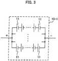
- Fig. 3is a diagram showing the configuration of the assembled battery.
- the first assembled battery 10-1can be formed of cells 11 connected electrically in series and cells 11 connected electrically in parallel.
- a secondary batterysuch as a nickel metal hydride battery and a lithium-ion battery can be used as the cell 11.
- the form of the cell 11can be set as appropriate.
- an electric-generating elementis housed within a cell case formed in cylindrical shape.
- an electric-generating elementis housed within a cell case formed in rectangular shape.
- the electric-generating elementis an element for performing charge and discharge.
- the electric-generating elementcan be formed of a positive electrode plate, a negative electrode plate, and a separator (including an electrolytic solution) placed between the positive electrode plate and the negative electrode plate.
- the positive electrode platehas a collector plate and a positive electrode active material layer formed on a surface of the collector plate.
- the negative electrode platehas a collector plate and a negative electrode active material layer formed on a surface of the collector plate.
- the number of the cells 11 connected in parallelis set to M1, whereas the number of the cells 11 connected in series is set to N1.
- M1 and N1is an integer equal to or larger than one.
- M1is one
- N1is one
- the first assembled battery 10-1consists only of the cells 11 connected in parallel.
- both of M1 and N1are one, the first assembled battery 10-1 consists of only one cell 11.
- the second assembled battery 10-2can be formed of cells 11 connected electrically in series and cells 11 connected electrically in parallel.
- the number of the cells 11 connected in parallelis set to M2
- the number of the cells 11 connected in seriesis set to N2.
- M2 and N2is an integer equal to or larger than one.
- the Xth assembled battery 10-Xcan be formed of cells 11 connected electrically in series and cells 11 connected electrically in parallel.
- the number of the cells 11 connected in parallelis set to Mx
- the number of the cells 11 connected in seriesis set to Nx.
- Mx and Nxis an integer equal to or larger than one.
- the numbers M1 to Mx and N1 to Nx of the cells 11 in the assembled batteries 10-1 to 10-Xcan be determined with a method described later.
- the power W [kW] of the battery pack 100is represented by the following expression (1) where discharge (output) of the battery pack 100 is represented by a positive value and charge (input) of the battery pack 100 is represented by a negative value.
- W(t)represents the power of the battery pack 100 at time t.
- V(t)represents a terminal voltage of the battery pack 100 at time t, and I(t) represents a current value flowing through the battery pack 100 at time t.
- I1 (t) to Ix (t)indicate current values flowing through the assembled batteries 10-1 to 10-X at time t, respectively.
- V(t) of the battery pack 100is represented by the following expression (2).
- V tVo 1 t ⁇ I 1 t ⁇ R 1 TB 1 t
- tVo 2 t ⁇ I 2 t ⁇ R 2 TB 2 t
- t ⁇Vox t ⁇ Ix t ⁇ Rx TBx t , t
- Vo1 (t) to Vox(t)represent the electromotive voltages (open circuit voltages) of the assembled batteries 10-1 to 10-X at time t, respectively.
- the electromotive voltages Vo1 to Vox of the assembled batteries 10-1 to 10-Xare determined from the product of the numbers N1 to Nx of the cells 11 connected in series and the electromotive voltages (open circuit voltages) of the cells 11 connected in series.
- R1 to Rxindicate internal resistances of the assembled batteries 10-1 to 10-X at time t, respectively.
- the internal resistances R1 to Rxare represented as functions of time t and temperatures TB1(t) to TBx(t).
- the temperatures TB1(t) to TBx(t)indicate the temperatures of the assembled batteries 10-1 to 10-X at time t, respectively.
- Specifying time t and the temperatures TB1(t) to TBx(t)can specify the internal resistances R1 to Rx.
- the relationship between the internal resistances R1 to Rx and the temperatures TB1 to TBxcan be predefined.
- variable for time tis omitted.
- the variable for time tis also omitted in expressions described below.
- the expression (3)can be represented by the following expression (4) .
- an index iis a value from one to x and corresponds to the assembled batteries 10-1 to 10-X.
- the expression (4)is represented as the function of I1
- the following expression (5)is given.
- the internal resistances R1 to Rx of the assembled batteries 10-1 to 10-Xcan be specified by specifying the temperature of the battery pack 100. As described in the expression (2), since the internal resistances R1 to Rx are represented as the functions of the temperatures TB1 to TBx, specifying the temperatures TB1 to TBx can specify the internal resistances R1 to Rx. The temperatures TB1 to TBx of the assembled batteries 10-1 to 10-X can be specified as appropriate in view of the use environment for the battery pack 100. When the internal resistances R1 to Rx can be specified, ⁇ can be calculated on the basis of the expression (6).
- the electromotive voltages Vol to Vox of the assembled batteries 10-1 to 10-Xcan be specified by specifying the SOC (State Of Charge) of the assembled batteries 10-1 to 10-X. Since the SOC and the electromotive voltage have a correspondence, the electromotive voltage can be specified from the SOC by previously determining the data representing the correspondence between the SOC and the electromotive voltage.
- SOC and the electromotive voltages Vol to Vox in the assembled batteries 10-1 to 10-Xcan be specified, ⁇ can be calculated on the basis of the expression (6).
- SOC1(t) to SOCx(t) of the assembled batteries 10-1 to 10-Xcan be calculated on the basis of the following expression (10).
- SOCi t + ⁇ tSOCi t ⁇ Ii t ⁇ ⁇ t 3600 ⁇ 100 CAPi ⁇ Mi ⁇ ⁇ i
- an index iis a value from one to x and corresponds to the assembled batteries 10-1 to 10-X.
- SOCi(t)represents the SOC of the assembled battery at time t
- SOCi (t+ ⁇ t)represents the SOC of the assembled battery after the lapse of time ⁇ t.
- CAPiindicates the full charge capacity of the assembled battery
- Miindicates the number of the cells 11 connected in parallel in each of the assembled batteries 10-1 to 10-X
- ⁇indicates a deterioration coefficient which determines the deterioration state (specifically, capacity deterioration) of each of the assembled batteries 10-1 to 10-X.
- the deterioration coefficient ⁇is a value between zero and one, for example, and can be predetermined on the basis of experiments or the like.
- the expression (10)includes the variable Mi, and the SOC calculated on the basis of the expression (10) varies according to the number Mi of the cells 11 connected in parallel.
- the charge and discharge of the assembled batteries 10-1 to 10-Xare controlled such that the SOC of each of the assembled batteries 10-1 to 10-X is changed within a range from predefined upper to lower limit values.
- the SOCneeds to be set within the range from the upper to lower limit values.
- the power W of the battery pack 100is set in the expression (6), the value of ⁇ can be specified.
- the power W of the battery pack 100is equal to the total sum of powers W1 to Wx of the assembled batteries 10-1 to 10-X.
- the power (specifically, the output) W of the battery pack 100needs to be higher than a predefined required power (required output) .
- the required outputis determined on the basis of a predefined running pattern of vehicle (referred to as a target running pattern).
- the target running patternrepresents changes in vehicle speed on a time axis.
- the power (required output) of the battery pack 100 appropriate for the target running patterncan be specified.
- the power (output) W of the battery pack 100needs to be higher than the required output of the battery pack 100.
- the power (output) W of the battery pack 100 satisfying the required outputneeds to be lower than an output limit value .
- the output limit value of the battery pack 100is equal to the total sum of the output limit values of the assembled batteries 10-1 to 10-X.
- the output limit values WOUT1 to WOUTx of the assembled batteries 10-1 to 10-Xcan be specified by using a predetermined map WOUT_MAP. The map is provided for each of the assembled batteries 10-1 to 10-X.
- WOUTi tWOUT _ MAPi TBi t , SOCi t
- an index iindicates a value from one to x and corresponds to the assembled batteries 10-1 to 10-X.
- the output limit values of WOUT1 to WOUTx of the assembled batteries 10-1 to 10-Xdepend on the temperatures TB1 to TBx and the SOC1 to SOCx in the assembled batteries 10-1 to 10-X. Thus, when the temperatures TB1 to TBx and the SOC1 to SOCx are specified, the output limit values WOUT1 to WOUTx in the assembled batteries 10-1 to 10-X can be specified by using the map WOUT_MAP.
- the circulating current flowing through the battery pack 100is the current flowing through the assembled batteries 10-1 to 10-X when the total current of the battery pack 100 is equal to zero.
- Ikindicates the current value flowing through a particular assembled battery.
- the right side of the expression (12)indicates the total sum of the values of the current flowing through all of the assembled batteries except the particular assembled battery.
- the current values I1 to Ix satisfying the condition of the expression (12)can be particularly specified on the basis of the expression (12). Since a plurality of combinations are present for the particularly specified current values I1 to Ix, the maximum and minimum values of each of the current values I1 to Ix are specified from the plurality of combinations. For example, since the current value Ix may take a plurality of numeric values, the maximum and minimum values can be specified from these numeric values.
- an index iindicates a value from one to X and corresponds to the assembled batteries 10-1 to 10-X.
- Ii_maxis the maximum value of a plurality of values when the current value Ii can take those values.
- Idi_limis a continuous allowable discharge current in each of the assembled batteries 10-1 to 10-X. The continuous allowable discharge current varies according to the configuration (especially, the number of the cells 11 connected in parallel) of the assembled batteries 10-1 to 10-X.
- an index iindicates a value from one to X and corresponds to the assembled batteries 10-1 to 10-X.
- Ii_minis the minimum value of a plurality of values when the current value Ii can take those values.
- Ici_limis a continuous allowable charge current in each of the assembled batteries 10-1 to 10-X. The continuous allowable charge current varies according to the configuration (especially, the number of the cells 11 connected in parallel) of the assembled batteries 10-1 to 10-X.
- the current value Ii of the assembled batterycan be determined such that the maximum value Ii_max is smaller than the continuous allowable discharge current Idi_lim and that the minimum value Ii_min is larger than the continuous allowable charge current Ici_lim.
- the value which can be taken by the current value Iican be set such that the discharge current of each assembled battery does not exceed the continuous allowable discharge current of each assembled battery and that the charge current of each assembled battery does not exceed the continuous allowable charge current of each assembled battery.
- the maximum value Ii_maxis set to be smaller than the continuous allowable discharge current Idi_lim and the minimum value Ii_min is set to be larger than the continuous allowable charge current Ici_lim, thereby making it possible to prevent a current exceeding the allowable value from flowing through the assembled batteries 10-1 to 10-X.
- the numbers M1 to Mx of the cells 11 connected electrically in parallelcan be specified on the basis of the expression (10).
- M1 to Mxmay take a plurality of values.
- the numbers N1 to Nx of the cells 11 connected electrically in seriescan be specified in the assembled batteries 10-1 to 10-X.
- the electromotive voltage of the cell 11can be previously measured, and the electromotive voltages Vo1 to Vox of the assembled batteries 10-1 to 10-X are divided by the electromotive voltage of the cell 11 to allow the calculation of the numbers N1 to Nx of the cells 11 connected electrically in series.
- the numbers M1 to Mx and N1 to Nx of the cells 11can be determined in view of the configuration of the battery pack 100.
- the cost of the battery pack 100can be reduced.
- the configuration of each of the assembled batteries 10-1 to 10-Xcan be specified on the basis of M1 to Mx and N1 to Nx.
- M1 cells 11are connected in parallel and N1 cells 11 are connected in series.
- a bas bar or an electric cablecan be used for electrically connecting the plurality of cells 11.
- the processing of calculating M1 to Mx and N1 to Nxcan be performed by a computer. Specifically, parameters necessary for calculating M1 to Mx and N1 to Nx can be input to the computer to determine M1 to Mx and N1 to Nx.
- the z characteristics of the assembled batteries 10-1 to 10-X and the battery pack 100vary according to the type of the cell 11.
- the values of M1 to Mx and N1 to Nxcan be previously determined in view of the type of the cell 11.
- the type of the cell 11 and the values of M1 to Mx and N1 to Nx in association with each othercan be stored in memory.
- the values of M1 to Mx and N1 to Nxcan be easily specified by referring to the information stored in the memory.
Landscapes
- Engineering & Computer Science (AREA)
- Power Engineering (AREA)
- Life Sciences & Earth Sciences (AREA)
- Sustainable Development (AREA)
- Sustainable Energy (AREA)
- Transportation (AREA)
- Mechanical Engineering (AREA)
- Chemical & Material Sciences (AREA)
- Manufacturing & Machinery (AREA)
- Chemical Kinetics & Catalysis (AREA)
- Electrochemistry (AREA)
- General Chemical & Material Sciences (AREA)
- Charge And Discharge Circuits For Batteries Or The Like (AREA)
- Secondary Cells (AREA)
- Battery Mounting, Suspending (AREA)
- Electric Propulsion And Braking For Vehicles (AREA)
Description
- The present invention relates to a battery pack including a plurality of assembled batteries connected electrically in parallel.
- A battery pack including a plurality of assembled batteries connected electrically in parallel is known. For example, Patent Document 1 discloses a battery pack in which two types of assembled batteries having different characteristics are connected electrically in parallel. The characteristics of the assembled battery include the characteristic of the tendency of open circuit voltage to drop in association with a reduction in SOC (State Of Charge).
- [Patent Document 1] Japanese Patent Laid-Open No.
2008-260346 - [Patent Document 2] Japanese Patent Laid-Open No.
2004-328902 - [Patent Document 3] Japanese Patent Laid-Open No.
2004-111242 - [Patent Document 4] Japanese Patent Laid-Open No.
5 (1993) -240890 - [Patent Document 5] Japanese Patent Laid-Open No.
2001-297801 - [Patent Document 6] Japanese Patent Laid-Open No.
2009-004349 - In connecting a plurality of assembled batteries electrically in parallel, a circulating current may flow through the assembled batteries. Depending on the configuration of the battery pack, the circulating current flowing through the assembled batteries may exceed an allowable current value for the assembled batteries.
- The present invention provides a method of manufacturing a battery pack having a plurality of assembled batteries connected in parallel, each of the assembled batteries including a plurality of cells, the method : being defined in claim 1.
- According to the present invention, even when the plurality of assembled batteries are connected in parallel, it is possible to prevent a circulating current exceeding the allowable current value from flowing through the assembled batteries.
- [
Fig. 1 ] A diagram showing the configuration of a battery system. - [
Fig. 2 ] A diagram showing the configuration of a battery pack. - [
Fig. 3 ] A diagram showing the configuration of an assembled battery. - A battery system will be described with reference to
Fig. 1 . The battery system can be mounted on a vehicle. - A
battery pack 100 is connected to aninverter 30 throughrelays relays relays battery pack 100 is supplied to theinverter 30, or the power output from theinverter 30 is supplied to thebattery pack 100. - While the power of the
battery pack 100 is supplied to theinverter 30, a battery system is not limited thereto. For example, a booster circuit can be placed between thebattery pack 100 and theinverter 30. The booster circuit can boost the output voltage of thebattery pack 100 and supply the power after the boost of the voltage to theinverter 30. The booster circuit can also drop the output voltage of theinverter 30 and supply the power after the drop of the voltage to thebattery pack 100. - The
inverter 30 converts the direct-current power output from thebattery pack 100 into alternating-current power and outputs the power to amotor generator 40. A three-phase alternating-current motor can be used as themotor generator 40. Themotor generator 40 receives the alternating-current power from theinverter 30 and produces kinetic energy for running the vehicle. The kinetic energy produced by themotor generator 40 is transferred to wheels. - In decelerating or stopping the vehicle, the
motor generator 40 converts kinetic energy generated in braking of the vehicle into electric energy. The alternating-current power produced by themotor generator 40 is supplied to theinverter 30 which then converts the alternating-current power into direct-current power. Thebattery pack 100 can receive the direct-current power from theinverter 30 and store the regenerative energy. Fig. 2 is a diagram showing the configuration of thebattery pack 100. Thebattery pack 100 has X assembled batteries 10-1 to 10-X which are connected electrically in parallel. The number X of the assembled batteries is an integer equal to or larger than two.Fig. 3 is a diagram showing the configuration of the assembled battery.- The first assembled battery 10-1 can be formed of
cells 11 connected electrically in series andcells 11 connected electrically in parallel. A secondary battery such as a nickel metal hydride battery and a lithium-ion battery can be used as thecell 11. The form of thecell 11 can be set as appropriate. - In the
cell 11 of a so-called cylindrical type, an electric-generating element is housed within a cell case formed in cylindrical shape. In thecell 11 of a so-called square type, an electric-generating element is housed within a cell case formed in rectangular shape. The electric-generating element is an element for performing charge and discharge. The electric-generating element can be formed of a positive electrode plate, a negative electrode plate, and a separator (including an electrolytic solution) placed between the positive electrode plate and the negative electrode plate. The positive electrode plate has a collector plate and a positive electrode active material layer formed on a surface of the collector plate. The negative electrode plate has a collector plate and a negative electrode active material layer formed on a surface of the collector plate. - In the first assembled battery 10-1, the number of the
cells 11 connected in parallel is set to M1, whereas the number of thecells 11 connected in series is set to N1. Each of M1 and N1 is an integer equal to or larger than one. When M1 is one, the first assembled battery 10-1 consists only of thecells 11 connected in series. When N1 is one, the first assembled battery 10-1 consists only of thecells 11 connected in parallel. When both of M1 and N1 are one, the first assembled battery 10-1 consists of only onecell 11. - Similarly to the first assembled battery 10-1, the second assembled battery 10-2 can be formed of
cells 11 connected electrically in series andcells 11 connected electrically in parallel. In the second assembled battery 10-2, the number of thecells 11 connected in parallel is set to M2, whereas the number of thecells 11 connected in series is set to N2. Each of M2 and N2 is an integer equal to or larger than one. - Similarly to the first assembled battery 10-1, the Xth assembled battery 10-X can be formed of
cells 11 connected electrically in series andcells 11 connected electrically in parallel. In the Xth assembled battery 10-X, the number of thecells 11 connected in parallel is set to Mx, whereas the number of thecells 11 connected in series is set to Nx. Each of Mx and Nx is an integer equal to or larger than one. - The numbers M1 to Mx and N1 to Nx of the
cells 11 in the assembled batteries 10-1 to 10-X can be determined with a method described later. - In the configuration shown in
Fig. 2 , the power W [kW] of thebattery pack 100 is represented by the following expression (1) where discharge (output) of thebattery pack 100 is represented by a positive value and charge (input) of thebattery pack 100 is represented by a negative value.
- In the expression (1), W(t) represents the power of the
battery pack 100 at time t. V(t) represents a terminal voltage of thebattery pack 100 at time t, and I(t) represents a current value flowing through thebattery pack 100 at time t. I1 (t) to Ix (t) indicate current values flowing through the assembled batteries 10-1 to 10-X at time t, respectively. - The voltage V(t) of the
battery pack 100 is represented by the following expression (2).
- In the expression (2), Vo1 (t) to Vox(t) represent the electromotive voltages (open circuit voltages) of the assembled batteries 10-1 to 10-X at time t, respectively. The electromotive voltages Vo1 to Vox of the assembled batteries 10-1 to 10-X are determined from the product of the numbers N1 to Nx of the
cells 11 connected in series and the electromotive voltages (open circuit voltages) of thecells 11 connected in series. - R1 to Rx indicate internal resistances of the assembled batteries 10-1 to 10-X at time t, respectively. The internal resistances R1 to Rx are represented as functions of time t and temperatures TB1(t) to TBx(t). The temperatures TB1(t) to TBx(t) indicate the temperatures of the assembled batteries 10-1 to 10-X at time t, respectively. Specifying time t and the temperatures TB1(t) to TBx(t) can specify the internal resistances R1 to Rx. The relationship between the internal resistances R1 to Rx and the temperatures TB1 to TBx can be predefined.
- When the expression (2) is transformed and substituted into the expression (1), the following expression (3) is given.

- In the expression (3), the variable for time t is omitted. The variable for time t is also omitted in expressions described below.
- The expression (3) can be represented by the following expression (4) .

- In the expression (4), an index i is a value from one to x and corresponds to the assembled batteries 10-1 to 10-X. When the expression (4) is represented as the function of I1, the following expression (5) is given.

- As shown in the following expression (6), α, β, and γ are set.

- When the expression (6) is substituted into the expression (5), the following expression (7) is given.

- When the solution to I1 is determined from the expression (7), the expression (8) is given.

- When the relation expression shown in the expression (2) is substituted into the expression (8), the following expression (9) is given.

- When the expression (9) is used, the current values of the assembled batteries 10-1 to 10-X can be specified. When X is one in the expression (9), the expression (8) is given.
- The internal resistances R1 to Rx of the assembled batteries 10-1 to 10-X can be specified by specifying the temperature of the
battery pack 100. As described in the expression (2), since the internal resistances R1 to Rx are represented as the functions of the temperatures TB1 to TBx, specifying the temperatures TB1 to TBx can specify the internal resistances R1 to Rx. The temperatures TB1 to TBx of the assembled batteries 10-1 to 10-X can be specified as appropriate in view of the use environment for thebattery pack 100. When the internal resistances R1 to Rx can be specified, α can be calculated on the basis of the expression (6). - The electromotive voltages Vol to Vox of the assembled batteries 10-1 to 10-X can be specified by specifying the SOC (State Of Charge) of the assembled batteries 10-1 to 10-X. Since the SOC and the electromotive voltage have a correspondence, the electromotive voltage can be specified from the SOC by previously determining the data representing the correspondence between the SOC and the electromotive voltage. When the SOC and the electromotive voltages Vol to Vox in the assembled batteries 10-1 to 10-X can be specified, β can be calculated on the basis of the expression (6).
- SOC1(t) to SOCx(t) of the assembled batteries 10-1 to 10-X can be calculated on the basis of the following expression (10).

- In the expression (10), an index i is a value from one to x and corresponds to the assembled batteries 10-1 to 10-X. SOCi(t) represents the SOC of the assembled battery at time t, and SOCi (t+Δt) represents the SOC of the assembled battery after the lapse of time Δt. CAPi indicates the full charge capacity of the assembled battery, Mi indicates the number of the
cells 11 connected in parallel in each of the assembled batteries 10-1 to 10-X, and µ indicates a deterioration coefficient which determines the deterioration state (specifically, capacity deterioration) of each of the assembled batteries 10-1 to 10-X. The deterioration coefficient µ is a value between zero and one, for example, and can be predetermined on the basis of experiments or the like. - In the expression (10), when SOC1 (0) to SOCx(0) of the assembled batteries 10-1 to 10-X at the initial state (at time t = 0) are previously determined, SOC1(t) to SOCx(t) of the assembled batteries 10-1 to 10-X after the lapse of an arbitrary time Δt can be calculated. The expression (10) includes the variable Mi, and the SOC calculated on the basis of the expression (10) varies according to the number Mi of the
cells 11 connected in parallel. - In charge and discharge control of the assembled batteries 10-1 to 10-X, the charge and discharge of the assembled batteries 10-1 to 10-X are controlled such that the SOC of each of the assembled batteries 10-1 to 10-X is changed within a range from predefined upper to lower limit values. Thus, in setting the SOC of each of the assembled batteries 10-1 to 10-X, the SOC needs to be set within the range from the upper to lower limit values.
- On the other hand, when the power W of the
battery pack 100 is set in the expression (6), the value of γ can be specified. The power W of thebattery pack 100 is equal to the total sum of powers W1 to Wx of the assembled batteries 10-1 to 10-X. - The power (specifically, the output) W of the
battery pack 100 needs to be higher than a predefined required power (required output) . The required output is determined on the basis of a predefined running pattern of vehicle (referred to as a target running pattern). The target running pattern represents changes in vehicle speed on a time axis. When the target running pattern is predetermined, the power (required output) of thebattery pack 100 appropriate for the target running pattern can be specified. For achieving the running according to the target running pattern, the power (output) W of thebattery pack 100 needs to be higher than the required output of thebattery pack 100. - The power (output) W of the
battery pack 100 satisfying the required output needs to be lower than an output limit value . The output limit value of thebattery pack 100 is equal to the total sum of the output limit values of the assembled batteries 10-1 to 10-X. As represented by the following expression (11), the output limit values WOUT1 to WOUTx of the assembled batteries 10-1 to 10-X can be specified by using a predetermined map WOUT_MAP. The map is provided for each of the assembled batteries 10-1 to 10-X.
- In the expression (11), an index i indicates a value from one to x and corresponds to the assembled batteries 10-1 to 10-X. The output limit values of WOUT1 to WOUTx of the assembled batteries 10-1 to 10-X depend on the temperatures TB1 to TBx and the SOC1 to SOCx in the assembled batteries 10-1 to 10-X. Thus, when the temperatures TB1 to TBx and the SOC1 to SOCx are specified, the output limit values WOUT1 to WOUTx in the assembled batteries 10-1 to 10-X can be specified by using the map WOUT_MAP.
- When the values of α, β, and γ, and the internal resistances R1 to Rx, and the electromotive voltages Vo1 to Vox of the assembled batteries 10-1 to 10-X are substituted into the expression (9), the current values I1 to Ix of the assembled batteries 10-1 to 10-X can be calculated.
- The circulating current flowing through the
battery pack 100 is the current flowing through the assembled batteries 10-1 to 10-X when the total current of thebattery pack 100 is equal to zero. The circulating current has the relationship described in the following expression (12).
- In the expression (12), Ik indicates the current value flowing through a particular assembled battery. The right side of the expression (12) indicates the total sum of the values of the current flowing through all of the assembled batteries except the particular assembled battery.
- The current values I1 to Ix satisfying the condition of the expression (12) can be particularly specified on the basis of the expression (12). Since a plurality of combinations are present for the particularly specified current values I1 to Ix, the maximum and minimum values of each of the current values I1 to Ix are specified from the plurality of combinations. For example, since the current value Ix may take a plurality of numeric values, the maximum and minimum values can be specified from these numeric values.
- The maximum value of each of the current values I1 to Ix has the relationship shown by the following expression (13).

- In the expression (13), an index i indicates a value from one to X and corresponds to the assembled batteries 10-1 to 10-X. Ii_max is the maximum value of a plurality of values when the current value Ii can take those values. Idi_lim is a continuous allowable discharge current in each of the assembled batteries 10-1 to 10-X. The continuous allowable discharge current varies according to the configuration (especially, the number of the
cells 11 connected in parallel) of the assembled batteries 10-1 to 10-X. - The minimum value of each of the current values I1 to Ix has the relationship shown by the following expression (14).

- In the expression (14), an index i indicates a value from one to X and corresponds to the assembled batteries 10-1 to 10-X. Ii_min is the minimum value of a plurality of values when the current value Ii can take those values. Ici_lim is a continuous allowable charge current in each of the assembled batteries 10-1 to 10-X. The continuous allowable charge current varies according to the configuration (especially, the number of the
cells 11 connected in parallel) of the assembled batteries 10-1 to 10-X. - When the minimum value Ii_min and the continuous allowable charge current Ici_lim have negative values in the expression (14), the expression (14) can be represented by the following expression (15).

- The current value Ii of the assembled battery can be determined such that the maximum value Ii_max is smaller than the continuous allowable discharge current Idi_lim and that the minimum value Ii_min is larger than the continuous allowable charge current Ici_lim. In other words, the value which can be taken by the current value Ii can be set such that the discharge current of each assembled battery does not exceed the continuous allowable discharge current of each assembled battery and that the charge current of each assembled battery does not exceed the continuous allowable charge current of each assembled battery. The maximum value Ii_max is set to be smaller than the continuous allowable discharge current Idi_lim and the minimum value Ii_min is set to be larger than the continuous allowable charge current Ici_lim, thereby making it possible to prevent a current exceeding the allowable value from flowing through the assembled batteries 10-1 to 10-X.
- When the current values I1 to Ix of the assembled batteries 10-1 to 10-X are specified so that the expression (13) and the expression (14) are satisfied, the numbers M1 to Mx of the
cells 11 connected electrically in parallel can be specified on the basis of the expression (10). M1 to Mx may take a plurality of values. - When the electromotive voltages Vo1 to Vox of the assembled batteries 10-1 to 10-X are specified, the numbers N1 to Nx of the
cells 11 connected electrically in series can be specified in the assembled batteries 10-1 to 10-X. Specifically, the electromotive voltage of thecell 11 can be previously measured, and the electromotive voltages Vo1 to Vox of the assembled batteries 10-1 to 10-X are divided by the electromotive voltage of thecell 11 to allow the calculation of the numbers N1 to Nx of thecells 11 connected electrically in series. - When a plurality of combinations are present for the numbers M1 to Mx of the
cells 11 connected electrically in parallel and the numbers N1 to Nx of thecells 11 connected electrically in series, the numbers M1 to Mx and N1 to Nx of thecells 11 can be determined in view of the configuration of thebattery pack 100. When the smallest value is selected for the numbers M1 to Mx and N1 to Nx of thecells 11, the cost of thebattery pack 100 can be reduced. - Once M1 to Mx and N1 to Nx can be determined, the configuration of each of the assembled batteries 10-1 to 10-X can be specified on the basis of M1 to Mx and N1 to Nx. By way of example, for assembling the assembled battery 10-1,
M1 cells 11 are connected in parallel andN1 cells 11 are connected in series. For electrically connecting the plurality ofcells 11, a bas bar or an electric cable can be used. - The processing of calculating M1 to Mx and N1 to Nx can be performed by a computer. Specifically, parameters necessary for calculating M1 to Mx and N1 to Nx can be input to the computer to determine M1 to Mx and N1 to Nx.
- The z characteristics of the assembled batteries 10-1 to 10-X and the
battery pack 100 vary according to the type of thecell 11. Thus, the values of M1 to Mx and N1 to Nx can be previously determined in view of the type of thecell 11. Then, the type of thecell 11 and the values of M1 to Mx and N1 to Nx in association with each other can be stored in memory. As a result, once the type of thecell 11 is specified, the values of M1 to Mx and N1 to Nx can be easily specified by referring to the information stored in the memory.


Claims (2)
- A method of manufacturing a battery pack (100) having a plurality of assembled batteries (10-1 to 10-X) connected in parallel, each of the assembled batteries (10-1 to 10-X) including a plurality of cells (11), the battery pack (100) being configured to let an allowable circulating current flow through the assembled batteries, the method comprising:a) determining a number (Mi) of the cells (11) connected in parallel and a number (Ni) of the cells (11) connected in series in each of the assembled batteries (10-1 to 10-X) based on the following conditions (I) to (VI),


 indexes 1, i and k represent the corresponding assembled battery (10-1 to 10-X),I represents a current of the corresponding assembled battery (10-1 to 10-X),Vo represents an open circuit voltage of the corresponding assembled battery (10-1 to 10-X) and depends on the number (N) of cells (11) connected in series in the corresponding assembled battery (10-1 to 10-X),R represents an internal resistance of the corresponding assembled battery (10-1 to 10-X),W represents an electric power of the battery pack (100) that is higher than a predetermined electric power,SOC represents a state of charge of the corresponding assembled battery (10-1 to 10-X),t represents a time,CAP represents a full charge capacity of the cell (11) in the corresponding assembled battery (10-1 to 10-X),M represents the number of the cells (11) connected in parallel in the corresponding assembled battery (10-1 to 10-X),µ represents a deterioration coefficient of the cell (11) that is a predetermined value between zero and one; whereinthe current I in the expression (I) that meets the expression (VI) is equal to or lower than a continuous allowable current (Idi_lim, Ici_lim); andthe SOC in the expression (V) falls within a range between a predetermined upper limit value and a predetermined lower limit value; andb) manufacturing each of the assembled batteries (10-1 to 10-X) by using the cells (11), the number of the cells (11) being the determined number determined (M,N).
 - The method of manufacturing the battery pack (100) according to claim 1, wherein each of the assembled batteries (10-1 to 10-X) is configured to output energy for use in running of a vehicle, and
the predetermined electric power is an electric power appropriate for a preset running pattern of the vehicle.


Applications Claiming Priority (1)
| Application Number | Priority Date | Filing Date | Title |
|---|---|---|---|
| PCT/JP2011/002424WO2012147121A1 (en) | 2011-04-25 | 2011-04-25 | Cell pack |
Publications (3)
| Publication Number | Publication Date |
|---|---|
| EP2704285A1 EP2704285A1 (en) | 2014-03-05 |
| EP2704285A4 EP2704285A4 (en) | 2015-01-28 |
| EP2704285B1true EP2704285B1 (en) | 2020-10-21 |
Family
ID=47068139
Family Applications (1)
| Application Number | Title | Priority Date | Filing Date |
|---|---|---|---|
| EP11824287.4AActiveEP2704285B1 (en) | 2011-04-25 | 2011-04-25 | Battery pack |
Country Status (5)
| Country | Link |
|---|---|
| US (1) | US8647765B2 (en) |
| EP (1) | EP2704285B1 (en) |
| JP (1) | JP5376045B2 (en) |
| CN (1) | CN102934314B (en) |
| WO (1) | WO2012147121A1 (en) |
Families Citing this family (9)
| Publication number | Priority date | Publication date | Assignee | Title |
|---|---|---|---|---|
| JP6245094B2 (en) | 2014-06-30 | 2017-12-13 | 日立化成株式会社 | Battery system |
| CN104734283A (en)* | 2015-02-15 | 2015-06-24 | 四川力垦锂动力科技有限公司 | Battery management system and battery management method |
| CN107369859A (en)* | 2016-05-12 | 2017-11-21 | 深圳市沃特玛电池有限公司 | A kind of electric vehicle battery system charging and discharging method |
| JP6664005B2 (en)* | 2016-09-21 | 2020-03-13 | 株式会社エンビジョンAescジャパン | Power system |
| KR102168910B1 (en)* | 2016-09-21 | 2020-10-22 | 가부시키가이샤 인비젼 에이이에스씨 재팬 | Power system |
| CN107367695B (en)* | 2017-07-31 | 2023-08-01 | 创驱(上海)新能源科技有限公司 | A high-voltage lithium-ion battery charge and discharge test system |
| CN110962690B (en)* | 2018-09-28 | 2021-03-02 | 郑州宇通客车股份有限公司 | Battery pack energy management method |
| CN109888416A (en)* | 2019-03-04 | 2019-06-14 | 江苏博煦电池科技有限公司 | A kind of method that lithium ion battery combines in series and parallel |
| JP7563255B2 (en)* | 2021-03-12 | 2024-10-08 | トヨタ自動車株式会社 | vehicle |
Citations (1)
| Publication number | Priority date | Publication date | Assignee | Title |
|---|---|---|---|---|
| US20090297892A1 (en)* | 2008-04-14 | 2009-12-03 | A123 Systems, Inc. | Flexible Voltage Nested Battery Module Design |
Family Cites Families (14)
| Publication number | Priority date | Publication date | Assignee | Title |
|---|---|---|---|---|
| GB2136629B (en)* | 1983-03-16 | 1986-11-19 | South African Inventions | Power storage battery |
| JPH05240890A (en) | 1992-02-28 | 1993-09-21 | Ngk Insulators Ltd | Monitoring device for excess charge and discharge of battery assembly |
| JPH10117447A (en) | 1996-08-22 | 1998-05-06 | Hitachi Ltd | Sodium sulfur battery system |
| JP4959867B2 (en) | 2000-04-12 | 2012-06-27 | パナソニック株式会社 | Assembled battery heat dissipation evaluation method and assembled battery cooling design method using this heat dissipation evaluation method |
| JP4082147B2 (en) | 2002-09-19 | 2008-04-30 | 日産自動車株式会社 | Assembled battery |
| JP4355515B2 (en) | 2003-04-24 | 2009-11-04 | 日本電気株式会社 | Battery module configuration method and battery module |
| JP2006067683A (en) | 2004-08-26 | 2006-03-09 | Railway Technical Res Inst | Power storage device |
| US7573234B1 (en)* | 2005-11-28 | 2009-08-11 | Quallion Llc | System having electronics for dropping current of battery pack |
| JP4379430B2 (en)* | 2006-04-24 | 2009-12-09 | トヨタ自動車株式会社 | Power supply system and vehicle |
| JP5003257B2 (en) | 2007-04-10 | 2012-08-15 | 日産自動車株式会社 | Power supply system for hybrid electric vehicle and control device thereof |
| KR20100020477A (en) | 2007-05-18 | 2010-02-22 | 파나소닉 주식회사 | Battery pack and battery system |
| JP5146726B2 (en)* | 2007-10-25 | 2013-02-20 | 日立工機株式会社 | Charger |
| US9005788B2 (en)* | 2009-07-06 | 2015-04-14 | Amperex Technology Limited | Management scheme for multiple battery cells |
| JP2011072153A (en)* | 2009-09-28 | 2011-04-07 | Sanyo Electric Co Ltd | Vehicular power supply device, vehicle equipped with the same, and method for equalizing capacity of power vehicular supply device |
- 2011
- 2011-04-25EPEP11824287.4Apatent/EP2704285B1/enactiveActive
- 2011-04-25JPJP2012506265Apatent/JP5376045B2/enactiveActive
- 2011-04-25USUS13/501,329patent/US8647765B2/enactiveActive
- 2011-04-25WOPCT/JP2011/002424patent/WO2012147121A1/ennot_activeCeased
- 2011-04-25CNCN201180005325.3Apatent/CN102934314B/enactiveActive
Patent Citations (1)
| Publication number | Priority date | Publication date | Assignee | Title |
|---|---|---|---|---|
| US20090297892A1 (en)* | 2008-04-14 | 2009-12-03 | A123 Systems, Inc. | Flexible Voltage Nested Battery Module Design |
Also Published As
| Publication number | Publication date |
|---|---|
| EP2704285A1 (en) | 2014-03-05 |
| US20120276440A1 (en) | 2012-11-01 |
| CN102934314A (en) | 2013-02-13 |
| US8647765B2 (en) | 2014-02-11 |
| JP5376045B2 (en) | 2013-12-25 |
| JPWO2012147121A1 (en) | 2014-07-28 |
| WO2012147121A1 (en) | 2012-11-01 |
| EP2704285A4 (en) | 2015-01-28 |
| CN102934314B (en) | 2015-12-02 |
Similar Documents
| Publication | Publication Date | Title |
|---|---|---|
| EP2704285B1 (en) | Battery pack | |
| EP3944399B1 (en) | Battery management device, battery management method, and electric power storage system | |
| EP3564693B1 (en) | Method and device for calculating a state of charge of a battery in real time | |
| EP2720343B1 (en) | Battery control device and battery system | |
| US9933491B2 (en) | Electric storage system | |
| US9762077B2 (en) | Method and system for managing the charging of a rechargeable battery comprising several branches of electrochemical elements connected in parallel | |
| US8930070B2 (en) | Method for determining the charge state of a battery pack | |
| EP2770575B1 (en) | Apparatus and method for controlling lithium ion secondary battery | |
| US20130147434A1 (en) | Method for Balancing States of Charge of a Battery having a Plurality of Battery Cells as well as a Corresponding Battery Management System and a Battery | |
| EP4145667B1 (en) | Apparatus and method for controlling power of parallel multi pack module | |
| EP2717415A1 (en) | Electricity storage system | |
| EP3141919A2 (en) | Open circuit voltage estimating device and method | |
| JP2016091613A (en) | Battery system and capacity recovery method | |
| EP3929606A1 (en) | Battery management system, battery pack, electric vehicle, and battery management method | |
| EP4102612B1 (en) | Battery management device, battery management method, and electric power storage system | |
| CN102445665A (en) | Storage battery pack capacity learning algorithm | |
| US20170166078A1 (en) | Battery charge equalization system | |
| CN104160291A (en) | Control device for secondary battery, charging control method, and soc detection method | |
| EP3168954B1 (en) | Battery control device | |
| CN102804480A (en) | Systems and methods for controlling battery pack output | |
| EP3386068A1 (en) | Power control device and power control system | |
| JP6822358B2 (en) | Rechargeable battery system | |
| US10389143B2 (en) | Battery power prediction for high load events | |
| EP3974247B1 (en) | Apparatus and method for controlling power of parallel multipack system | |
| CN104272127A (en) | Method for determining total capacity loss of secondary batteries |
Legal Events
| Date | Code | Title | Description |
|---|---|---|---|
| PUAI | Public reference made under article 153(3) epc to a published international application that has entered the european phase | Free format text:ORIGINAL CODE: 0009012 | |
| 17P | Request for examination filed | Effective date:20120320 | |
| AK | Designated contracting states | Kind code of ref document:A1 Designated state(s):AL AT BE BG CH CY CZ DE DK EE ES FI FR GB GR HR HU IE IS IT LI LT LU LV MC MK MT NL NO PL PT RO RS SE SI SK SM TR | |
| DAX | Request for extension of the european patent (deleted) | ||
| A4 | Supplementary search report drawn up and despatched | Effective date:20150108 | |
| RIC1 | Information provided on ipc code assigned before grant | Ipc:H01M 10/42 20060101ALI20141222BHEP Ipc:H01M 10/48 20060101ALI20141222BHEP Ipc:H01M 6/42 20060101ALI20141222BHEP Ipc:H01M 10/44 20060101ALI20141222BHEP Ipc:H02J 7/00 20060101AFI20141222BHEP Ipc:B60L 11/18 20060101ALI20141222BHEP | |
| STAA | Information on the status of an ep patent application or granted ep patent | Free format text:STATUS: EXAMINATION IS IN PROGRESS | |
| 17Q | First examination report despatched | Effective date:20170911 | |
| GRAP | Despatch of communication of intention to grant a patent | Free format text:ORIGINAL CODE: EPIDOSNIGR1 | |
| STAA | Information on the status of an ep patent application or granted ep patent | Free format text:STATUS: GRANT OF PATENT IS INTENDED | |
| RIC1 | Information provided on ipc code assigned before grant | Ipc:H01M 6/42 20060101ALI20200506BHEP Ipc:H01M 10/42 20060101ALI20200506BHEP Ipc:H02J 7/00 20060101AFI20200506BHEP Ipc:H01M 10/44 20060101ALI20200506BHEP Ipc:H01M 10/48 20060101ALI20200506BHEP | |
| INTG | Intention to grant announced | Effective date:20200525 | |
| GRAS | Grant fee paid | Free format text:ORIGINAL CODE: EPIDOSNIGR3 | |
| GRAA | (expected) grant | Free format text:ORIGINAL CODE: 0009210 | |
| STAA | Information on the status of an ep patent application or granted ep patent | Free format text:STATUS: THE PATENT HAS BEEN GRANTED | |
| AK | Designated contracting states | Kind code of ref document:B1 Designated state(s):AL AT BE BG CH CY CZ DE DK EE ES FI FR GB GR HR HU IE IS IT LI LT LU LV MC MK MT NL NO PL PT RO RS SE SI SK SM TR | |
| REG | Reference to a national code | Ref country code:GB Ref legal event code:FG4D | |
| REG | Reference to a national code | Ref country code:CH Ref legal event code:EP | |
| REG | Reference to a national code | Ref country code:IE Ref legal event code:FG4D | |
| REG | Reference to a national code | Ref country code:DE Ref legal event code:R096 Ref document number:602011069030 Country of ref document:DE | |
| REG | Reference to a national code | Ref country code:AT Ref legal event code:REF Ref document number:1326830 Country of ref document:AT Kind code of ref document:T Effective date:20201115 | |
| REG | Reference to a national code | Ref country code:AT Ref legal event code:MK05 Ref document number:1326830 Country of ref document:AT Kind code of ref document:T Effective date:20201021 | |
| REG | Reference to a national code | Ref country code:NL Ref legal event code:MP Effective date:20201021 | |
| PG25 | Lapsed in a contracting state [announced via postgrant information from national office to epo] | Ref country code:FI Free format text:LAPSE BECAUSE OF FAILURE TO SUBMIT A TRANSLATION OF THE DESCRIPTION OR TO PAY THE FEE WITHIN THE PRESCRIBED TIME-LIMIT Effective date:20201021 Ref country code:RS Free format text:LAPSE BECAUSE OF FAILURE TO SUBMIT A TRANSLATION OF THE DESCRIPTION OR TO PAY THE FEE WITHIN THE PRESCRIBED TIME-LIMIT Effective date:20201021 Ref country code:NL Free format text:LAPSE BECAUSE OF FAILURE TO SUBMIT A TRANSLATION OF THE DESCRIPTION OR TO PAY THE FEE WITHIN THE PRESCRIBED TIME-LIMIT Effective date:20201021 Ref country code:PT Free format text:LAPSE BECAUSE OF FAILURE TO SUBMIT A TRANSLATION OF THE DESCRIPTION OR TO PAY THE FEE WITHIN THE PRESCRIBED TIME-LIMIT Effective date:20210222 Ref country code:NO Free format text:LAPSE BECAUSE OF FAILURE TO SUBMIT A TRANSLATION OF THE DESCRIPTION OR TO PAY THE FEE WITHIN THE PRESCRIBED TIME-LIMIT Effective date:20210121 Ref country code:GR Free format text:LAPSE BECAUSE OF FAILURE TO SUBMIT A TRANSLATION OF THE DESCRIPTION OR TO PAY THE FEE WITHIN THE PRESCRIBED TIME-LIMIT Effective date:20210122 | |
| REG | Reference to a national code | Ref country code:LT Ref legal event code:MG4D | |
| PG25 | Lapsed in a contracting state [announced via postgrant information from national office to epo] | Ref country code:PL Free format text:LAPSE BECAUSE OF FAILURE TO SUBMIT A TRANSLATION OF THE DESCRIPTION OR TO PAY THE FEE WITHIN THE PRESCRIBED TIME-LIMIT Effective date:20201021 Ref country code:LV Free format text:LAPSE BECAUSE OF FAILURE TO SUBMIT A TRANSLATION OF THE DESCRIPTION OR TO PAY THE FEE WITHIN THE PRESCRIBED TIME-LIMIT Effective date:20201021 Ref country code:SE Free format text:LAPSE BECAUSE OF FAILURE TO SUBMIT A TRANSLATION OF THE DESCRIPTION OR TO PAY THE FEE WITHIN THE PRESCRIBED TIME-LIMIT Effective date:20201021 Ref country code:IS Free format text:LAPSE BECAUSE OF FAILURE TO SUBMIT A TRANSLATION OF THE DESCRIPTION OR TO PAY THE FEE WITHIN THE PRESCRIBED TIME-LIMIT Effective date:20210221 Ref country code:ES Free format text:LAPSE BECAUSE OF FAILURE TO SUBMIT A TRANSLATION OF THE DESCRIPTION OR TO PAY THE FEE WITHIN THE PRESCRIBED TIME-LIMIT Effective date:20201021 Ref country code:AT Free format text:LAPSE BECAUSE OF FAILURE TO SUBMIT A TRANSLATION OF THE DESCRIPTION OR TO PAY THE FEE WITHIN THE PRESCRIBED TIME-LIMIT Effective date:20201021 Ref country code:BG Free format text:LAPSE BECAUSE OF FAILURE TO SUBMIT A TRANSLATION OF THE DESCRIPTION OR TO PAY THE FEE WITHIN THE PRESCRIBED TIME-LIMIT Effective date:20210121 | |
| PG25 | Lapsed in a contracting state [announced via postgrant information from national office to epo] | Ref country code:HR Free format text:LAPSE BECAUSE OF FAILURE TO SUBMIT A TRANSLATION OF THE DESCRIPTION OR TO PAY THE FEE WITHIN THE PRESCRIBED TIME-LIMIT Effective date:20201021 | |
| REG | Reference to a national code | Ref country code:DE Ref legal event code:R097 Ref document number:602011069030 Country of ref document:DE | |
| PG25 | Lapsed in a contracting state [announced via postgrant information from national office to epo] | Ref country code:LT Free format text:LAPSE BECAUSE OF FAILURE TO SUBMIT A TRANSLATION OF THE DESCRIPTION OR TO PAY THE FEE WITHIN THE PRESCRIBED TIME-LIMIT Effective date:20201021 Ref country code:RO Free format text:LAPSE BECAUSE OF FAILURE TO SUBMIT A TRANSLATION OF THE DESCRIPTION OR TO PAY THE FEE WITHIN THE PRESCRIBED TIME-LIMIT Effective date:20201021 Ref country code:SK Free format text:LAPSE BECAUSE OF FAILURE TO SUBMIT A TRANSLATION OF THE DESCRIPTION OR TO PAY THE FEE WITHIN THE PRESCRIBED TIME-LIMIT Effective date:20201021 Ref country code:SM Free format text:LAPSE BECAUSE OF FAILURE TO SUBMIT A TRANSLATION OF THE DESCRIPTION OR TO PAY THE FEE WITHIN THE PRESCRIBED TIME-LIMIT Effective date:20201021 Ref country code:CZ Free format text:LAPSE BECAUSE OF FAILURE TO SUBMIT A TRANSLATION OF THE DESCRIPTION OR TO PAY THE FEE WITHIN THE PRESCRIBED TIME-LIMIT Effective date:20201021 Ref country code:EE Free format text:LAPSE BECAUSE OF FAILURE TO SUBMIT A TRANSLATION OF THE DESCRIPTION OR TO PAY THE FEE WITHIN THE PRESCRIBED TIME-LIMIT Effective date:20201021 | |
| PLBE | No opposition filed within time limit | Free format text:ORIGINAL CODE: 0009261 | |
| STAA | Information on the status of an ep patent application or granted ep patent | Free format text:STATUS: NO OPPOSITION FILED WITHIN TIME LIMIT | |
| PG25 | Lapsed in a contracting state [announced via postgrant information from national office to epo] | Ref country code:DK Free format text:LAPSE BECAUSE OF FAILURE TO SUBMIT A TRANSLATION OF THE DESCRIPTION OR TO PAY THE FEE WITHIN THE PRESCRIBED TIME-LIMIT Effective date:20201021 | |
| 26N | No opposition filed | Effective date:20210722 | |
| PG25 | Lapsed in a contracting state [announced via postgrant information from national office to epo] | Ref country code:IT Free format text:LAPSE BECAUSE OF FAILURE TO SUBMIT A TRANSLATION OF THE DESCRIPTION OR TO PAY THE FEE WITHIN THE PRESCRIBED TIME-LIMIT Effective date:20201021 Ref country code:AL Free format text:LAPSE BECAUSE OF FAILURE TO SUBMIT A TRANSLATION OF THE DESCRIPTION OR TO PAY THE FEE WITHIN THE PRESCRIBED TIME-LIMIT Effective date:20201021 | |
| PG25 | Lapsed in a contracting state [announced via postgrant information from national office to epo] | Ref country code:MC Free format text:LAPSE BECAUSE OF FAILURE TO SUBMIT A TRANSLATION OF THE DESCRIPTION OR TO PAY THE FEE WITHIN THE PRESCRIBED TIME-LIMIT Effective date:20201021 Ref country code:SI Free format text:LAPSE BECAUSE OF FAILURE TO SUBMIT A TRANSLATION OF THE DESCRIPTION OR TO PAY THE FEE WITHIN THE PRESCRIBED TIME-LIMIT Effective date:20201021 | |
| GBPC | Gb: european patent ceased through non-payment of renewal fee | Effective date:20210425 | |
| PG25 | Lapsed in a contracting state [announced via postgrant information from national office to epo] | Ref country code:LU Free format text:LAPSE BECAUSE OF NON-PAYMENT OF DUE FEES Effective date:20210425 | |
| REG | Reference to a national code | Ref country code:BE Ref legal event code:MM Effective date:20210430 | |
| PG25 | Lapsed in a contracting state [announced via postgrant information from national office to epo] | Ref country code:GB Free format text:LAPSE BECAUSE OF NON-PAYMENT OF DUE FEES Effective date:20210425 Ref country code:FR Free format text:LAPSE BECAUSE OF NON-PAYMENT OF DUE FEES Effective date:20210430 Ref country code:CH Free format text:LAPSE BECAUSE OF NON-PAYMENT OF DUE FEES Effective date:20210430 Ref country code:LI Free format text:LAPSE BECAUSE OF NON-PAYMENT OF DUE FEES Effective date:20210430 | |
| PG25 | Lapsed in a contracting state [announced via postgrant information from national office to epo] | Ref country code:IE Free format text:LAPSE BECAUSE OF NON-PAYMENT OF DUE FEES Effective date:20210425 | |
| PG25 | Lapsed in a contracting state [announced via postgrant information from national office to epo] | Ref country code:IS Free format text:LAPSE BECAUSE OF FAILURE TO SUBMIT A TRANSLATION OF THE DESCRIPTION OR TO PAY THE FEE WITHIN THE PRESCRIBED TIME-LIMIT Effective date:20210221 | |
| PG25 | Lapsed in a contracting state [announced via postgrant information from national office to epo] | Ref country code:BE Free format text:LAPSE BECAUSE OF NON-PAYMENT OF DUE FEES Effective date:20210430 | |
| PG25 | Lapsed in a contracting state [announced via postgrant information from national office to epo] | Ref country code:HU Free format text:LAPSE BECAUSE OF FAILURE TO SUBMIT A TRANSLATION OF THE DESCRIPTION OR TO PAY THE FEE WITHIN THE PRESCRIBED TIME-LIMIT; INVALID AB INITIO Effective date:20110425 Ref country code:CY Free format text:LAPSE BECAUSE OF FAILURE TO SUBMIT A TRANSLATION OF THE DESCRIPTION OR TO PAY THE FEE WITHIN THE PRESCRIBED TIME-LIMIT Effective date:20201021 | |
| P01 | Opt-out of the competence of the unified patent court (upc) registered | Effective date:20230427 | |
| REG | Reference to a national code | Ref country code:DE Ref legal event code:R084 Ref document number:602011069030 Country of ref document:DE | |
| PG25 | Lapsed in a contracting state [announced via postgrant information from national office to epo] | Ref country code:MK Free format text:LAPSE BECAUSE OF FAILURE TO SUBMIT A TRANSLATION OF THE DESCRIPTION OR TO PAY THE FEE WITHIN THE PRESCRIBED TIME-LIMIT Effective date:20201021 | |
| PG25 | Lapsed in a contracting state [announced via postgrant information from national office to epo] | Ref country code:TR Free format text:LAPSE BECAUSE OF FAILURE TO SUBMIT A TRANSLATION OF THE DESCRIPTION OR TO PAY THE FEE WITHIN THE PRESCRIBED TIME-LIMIT Effective date:20201021 | |
| PG25 | Lapsed in a contracting state [announced via postgrant information from national office to epo] | Ref country code:MT Free format text:LAPSE BECAUSE OF FAILURE TO SUBMIT A TRANSLATION OF THE DESCRIPTION OR TO PAY THE FEE WITHIN THE PRESCRIBED TIME-LIMIT Effective date:20201021 | |
| PGFP | Annual fee paid to national office [announced via postgrant information from national office to epo] | Ref country code:DE Payment date:20250305 Year of fee payment:15 |