EP2700380B1 - Lock bar spring and clip for implant deployment device - Google Patents
Lock bar spring and clip for implant deployment deviceDownload PDFInfo
- Publication number
- EP2700380B1 EP2700380B1EP13181220.8AEP13181220AEP2700380B1EP 2700380 B1EP2700380 B1EP 2700380B1EP 13181220 AEP13181220 AEP 13181220AEP 2700380 B1EP2700380 B1EP 2700380B1
- Authority
- EP
- European Patent Office
- Prior art keywords
- clip
- implant
- protrusion
- lock bar
- clips
- Prior art date
- Legal status (The legal status is an assumption and is not a legal conclusion. Google has not performed a legal analysis and makes no representation as to the accuracy of the status listed.)
- Not-in-force
Links
Images


Classifications
- A—HUMAN NECESSITIES
- A61—MEDICAL OR VETERINARY SCIENCE; HYGIENE
- A61F—FILTERS IMPLANTABLE INTO BLOOD VESSELS; PROSTHESES; DEVICES PROVIDING PATENCY TO, OR PREVENTING COLLAPSING OF, TUBULAR STRUCTURES OF THE BODY, e.g. STENTS; ORTHOPAEDIC, NURSING OR CONTRACEPTIVE DEVICES; FOMENTATION; TREATMENT OR PROTECTION OF EYES OR EARS; BANDAGES, DRESSINGS OR ABSORBENT PADS; FIRST-AID KITS
- A61F2/00—Filters implantable into blood vessels; Prostheses, i.e. artificial substitutes or replacements for parts of the body; Appliances for connecting them with the body; Devices providing patency to, or preventing collapsing of, tubular structures of the body, e.g. stents
- A61F2/0063—Implantable repair or support meshes, e.g. hernia meshes
- A—HUMAN NECESSITIES
- A61—MEDICAL OR VETERINARY SCIENCE; HYGIENE
- A61B—DIAGNOSIS; SURGERY; IDENTIFICATION
- A61B17/00—Surgical instruments, devices or methods
- A61B17/00234—Surgical instruments, devices or methods for minimally invasive surgery
- A—HUMAN NECESSITIES
- A61—MEDICAL OR VETERINARY SCIENCE; HYGIENE
- A61B—DIAGNOSIS; SURGERY; IDENTIFICATION
- A61B17/00—Surgical instruments, devices or methods
- A61B17/064—Surgical staples, i.e. penetrating the tissue
- A—HUMAN NECESSITIES
- A61—MEDICAL OR VETERINARY SCIENCE; HYGIENE
- A61B—DIAGNOSIS; SURGERY; IDENTIFICATION
- A61B17/00—Surgical instruments, devices or methods
- A61B17/064—Surgical staples, i.e. penetrating the tissue
- A61B17/0643—Surgical staples, i.e. penetrating the tissue with separate closing member, e.g. for interlocking with staple
- A—HUMAN NECESSITIES
- A61—MEDICAL OR VETERINARY SCIENCE; HYGIENE
- A61B—DIAGNOSIS; SURGERY; IDENTIFICATION
- A61B17/00—Surgical instruments, devices or methods
- A61B17/068—Surgical staplers, e.g. containing multiple staples or clamps
- A—HUMAN NECESSITIES
- A61—MEDICAL OR VETERINARY SCIENCE; HYGIENE
- A61B—DIAGNOSIS; SURGERY; IDENTIFICATION
- A61B17/00—Surgical instruments, devices or methods
- A61B17/068—Surgical staplers, e.g. containing multiple staples or clamps
- A61B17/0682—Surgical staplers, e.g. containing multiple staples or clamps for applying U-shaped staples or clamps, e.g. without a forming anvil
- A61B17/0686—Surgical staplers, e.g. containing multiple staples or clamps for applying U-shaped staples or clamps, e.g. without a forming anvil having a forming anvil staying below the tissue during stapling
- A—HUMAN NECESSITIES
- A61—MEDICAL OR VETERINARY SCIENCE; HYGIENE
- A61B—DIAGNOSIS; SURGERY; IDENTIFICATION
- A61B17/00—Surgical instruments, devices or methods
- A61B17/00234—Surgical instruments, devices or methods for minimally invasive surgery
- A61B2017/00292—Surgical instruments, devices or methods for minimally invasive surgery mounted on or guided by flexible, e.g. catheter-like, means
- A—HUMAN NECESSITIES
- A61—MEDICAL OR VETERINARY SCIENCE; HYGIENE
- A61F—FILTERS IMPLANTABLE INTO BLOOD VESSELS; PROSTHESES; DEVICES PROVIDING PATENCY TO, OR PREVENTING COLLAPSING OF, TUBULAR STRUCTURES OF THE BODY, e.g. STENTS; ORTHOPAEDIC, NURSING OR CONTRACEPTIVE DEVICES; FOMENTATION; TREATMENT OR PROTECTION OF EYES OR EARS; BANDAGES, DRESSINGS OR ABSORBENT PADS; FIRST-AID KITS
- A61F2/00—Filters implantable into blood vessels; Prostheses, i.e. artificial substitutes or replacements for parts of the body; Appliances for connecting them with the body; Devices providing patency to, or preventing collapsing of, tubular structures of the body, e.g. stents
- A61F2/0063—Implantable repair or support meshes, e.g. hernia meshes
- A61F2002/0072—Delivery tools therefor
- A—HUMAN NECESSITIES
- A61—MEDICAL OR VETERINARY SCIENCE; HYGIENE
- A61F—FILTERS IMPLANTABLE INTO BLOOD VESSELS; PROSTHESES; DEVICES PROVIDING PATENCY TO, OR PREVENTING COLLAPSING OF, TUBULAR STRUCTURES OF THE BODY, e.g. STENTS; ORTHOPAEDIC, NURSING OR CONTRACEPTIVE DEVICES; FOMENTATION; TREATMENT OR PROTECTION OF EYES OR EARS; BANDAGES, DRESSINGS OR ABSORBENT PADS; FIRST-AID KITS
- A61F2220/00—Fixations or connections for prostheses classified in groups A61F2/00 - A61F2/26 or A61F2/82 or A61F9/00 or A61F11/00 or subgroups thereof
- A61F2220/0008—Fixation appliances for connecting prostheses to the body
- A61F2220/0016—Fixation appliances for connecting prostheses to the body with sharp anchoring protrusions, e.g. barbs, pins, spikes
Definitions
- This inventiongenerally relates to a device and method for reversibly coupling an implant to an implant deployment device.
- An object of the present inventionis to provide an apparatus for performing corrective surgery on internal wounds such as a hernia where invasion of the patient's body tissues is minimized and resultant trauma is reduced.
- a herniais a protrusion of a tissue, structure, or part of an organ through the muscular tissue or the membrane by which it is normally contained.
- a herniais a defect in the abdominal wall through which a portion of the intra-abdominal contents can protrude. This often causes discomfort and an unsightly, visible bulge in the abdomen.
- conventional corrective surgeryhas required opening the abdominal cavity by surgical incision through the major abdominal muscles. While this technique provides for effective corrective surgery of the hernia defect, it has the disadvantage of requiring a hospital stay of as much as a week, during which pain is frequently intense, and it requires an extended period of recuperation. After the conventional surgery, patients frequently cannot return to a full range of activity and work schedule for a month or more. Accordingly, medical science has sought alternative techniques that are less traumatic to the patient and provide for more rapid recovery.
- Laparoscopyis the science of introducing a viewing instrument through a port into a patient's body, typically the abdominal cavity, to view its contents. This technique has been used for diagnostic purposes for more than 75 years. Operative laparoscopy is performed through tiny openings in the abdominal wall called ports. In most surgical techniques, several ports, frequently three to six, are used. Through one port is inserted the viewing device, which conventionally comprises a fiber optic rod or bundle having a video camera affixed to the outer end to receive and display images from inside the body. The various surgical instruments are inserted through other ports to do the surgery that normally would be performed through an open incision through the abdominal wall. Because the laparoscopic surgical techniques require only very small holes through the abdominal wall or other portions of the body, a patient undergoing such surgery may frequently leave the hospital within one day after the surgery and resume a full range of normal activities within a few days thereafter.
- tissue anchorssecure the tissue by impaling it with one or more posts or legs that are bent or crimped to lock the tissue into position.
- most traditional anchorsare rigid or are inflexibly attached to the tissue.
- PCT No. WO 07/021834describes an anchor having two curved legs that cross in a single turning direction to form a loop. Those two curved legs are adapted to penetrate tissue in a curved pathway.
- U.S. Pat. No. 4,485,816describes surgical staple made of shape memory alloy. The staple is placed in contact of the tissue and then heated. The heating causes the staple to change its shape thus, penetrating the tissue.
- U.S. Pat. No. 6,893,452describes a tissue attachment device that facilitates wound healing by holding soft tissue together under improved distribution of tension and with minimal disruption of the wound interface and its nutrient supplies.
- U.S. Pat. No. 6,517,584describes a hernia implant which includes at least one anchoring device made of shape memory material.
- the anchoring devicesare initially secured to the prosthesis by being interlaced through a web mesh constituting the prosthesis.
- the attachmentis obtained by altering the attachment element's shape from rectilinear to a loop shape due to heat induced shape memory effect.
- U.S. Pat. No. 5,836,961which relates to an apparatus used for developing an anatomic space for laparoscopic hernia repair and an implant for use therewith.
- the apparatus of U.S. Pat. No. 5,836,961comprises a tubular introducer member having a bore extending therethrough.
- a tunneling shaftis slidably mounted in the bore and has proximal and distal extremities including a bullet-shaped tip.
- a rounded tunneling memberis mounted on the distal extremity of the tunneling shaft.
- the apparatuscomprises an inflatable balloon. Means is provided on the balloon for removably securing the balloon to the tunneling shaft.
- Meansis also provided for forming a balloon inflation lumen for inflating the balloon.
- the balloonis wrapped on the tunneling shaft.
- a sleevesubstantially encloses the balloon and is carried by the tunneling shaft.
- the sleeveis provided with a weakened region extending longitudinally thereof, permitting the sleeve to be removed whereby the balloon can be unwrapped and inflated so that it lies generally in a plane.
- the balloon as it is being inflatedcreates forces generally perpendicular to the plane of the balloon to cause pulling apart of the tissue along a natural plane to provide the anatomic space.
- the deviceis an elongate open-bored applicator and comprises (a) at least one inflatable contour-balloon, (b) at least one inflatable dissection balloon.
- the inflatable contour-balloon and the inflatable dissection balloonare adjustable and located at the distal portion.
- the elongate open-bored applicatoradditionally comprises (c) at least one actuating means located at the proximal portion.
- the actuating meansis in communication with the inflatable contour-balloon and the inflatable dissection balloon.
- the actuating meansis adapted to provide the inflatable contour-balloon and the inflatable dissection balloon with independent activation and/or de-activation.
- US2011/066166describes a type of surgical instrument on which the preamble to the independent claim 1 is based.
- a further aspect of the inventionrelates to a method of coupling an implant to such an instrument. It is one object of the present invention to provide an active reversible connection mechanism adapted to provide a reversible attachment between a prosthetic implant and an implant deployment device, wherein said attachment can be actively reversed without requiring any application of force on said implant.
- said active reversible connection mechanismcomprising at least one clip, hinge-like coupled to said implant deployment device, adapted to attach said implant to said implant deployment device:
- Said cliphas at least three configurations: (i) a horizontal configuration in which said clip is substantially horizontal with respect to said implant deployment device; (ii) a vertical configuration in which said clip is substantially vertical with respect to said implant deployment device; and, (iii) a free motion configuration in which said clip is free to rotate; such that (i) when said clip is in said horizontal configuration said attachment between said implant and said implant deployment device is obtained; (ii) when said clip is in said free motion configuration said detachment between said implant and said implant deployment device is obtained.
- the methodcomprising steps selected, inter alia, from:
- said detachment actuatorcomprises a wire; further wherein said wire is attached to said lock bar.
- An embodiment according to the present inventionincludes a system for closing an aperture in a biological tissue, the system including a proximal portion adapted to remain outside a patient body, a distal portion adapted to be inserted into a patient body, the distal portion including at least one frame arm, at least one clip connected to the at least one frame arm and configured to releasably retain a surgical implant to the frame arm, and a lock bar including at least one protrusion, the at least one protrusion extending away from the at least one frame arm, wherein the at least one protrusion is configured to selectively hold the at least one clip in at least one of an open position or a closed position.
- the at least one protrusionselectively engages the at least one clip to lock the at least one clip in a closed position by inhibiting movement or rotation of the at least one clip when the lock bar is in a locked position, and wherein the lock bar allows the at least one clip to move or rotate to an open position when the lock bar is in an unlocked position.
- the at least one protrusionselectively engages the at least one clip to lock the at least one clip in an initial open position by inhibiting movement or rotation of the at least one clip when the lock bar is in a locked position, wherein the at least one protrusion is shaped to allow the at least one clip to deflect the at least one protrusion inwardly towards the frame arm, thereby allowing the at least one clip to rotate over the at least one protrusion from the initial open position to a closed position.
- the force applied against the protrusion as the clip rotates from the open position to the closed positionis greater than a spring constant of the at least one protrusion.
- the protrusiondeflects inwards as the clip rotates past the protrusion.
- a lock bar for a system for closing an aperture in a biological tissueincludes a body portion and at least one protrusion, the at least one protrusion extending away from the at least one frame arm, wherein the at least one protrusion is configured to selectively hold the at least one clip in at least one of an open position or a closed position.
- the lock barincludes two protrusions configured in a mirror-like arrangement to operate with a pair of clips.
- the at least one protrusionselectively engages the at least one clip to lock the at least one clip in an initial open position by inhibiting movement or rotation of the at least one clip when the lock bar is in a locked position, wherein the at least one protrusion is shaped to allow the at least one clip to deflect the at least one protrusion inwardly towards the frame arm, thereby allowing the at least one clip to rotate over the at least one protrusion from the initial open position to a closed position.
- the lock baris formed from nitinol.
- a methodincludes providing a system for closing an aperture in a biological tissue, the system including a proximal portion adapted to remain outside a patient body, a distal portion adapted to be inserted into a patient body, the distal portion including at least one frame arm, at least one clip connected to the at least one frame arm and configured to releasably retain a surgical implant to the frame arm, and a lock bar including at least one protrusion, the at least one protrusion extending away from the at least one frame arm, wherein the at least one protrusion is configured to selectively hold the at least one clip in at least one of an open position or a closed position, and releasably attaching the surgical implant to the at least one clip.
- the at least one protrusionselectively engages the at least one clip to lock the at least one clip in a closed position by inhibiting movement or rotation of the at least one clip when the lock bar is in a locked position, and wherein the lock bar allows the at least one clip to move or rotate to an open position when the lock bar is in an unlocked position.
- the at least one protrusionselectively engages the at least one clip to lock the at least one clip in an initial open position by inhibiting movement or rotation of the at least one clip when the lock bar is in a locked position, wherein the at least one protrusion is shaped to allow the at least one clip to deflect the at least one protrusion inwardly towards the frame arm, thereby allowing the at least one clip to rotate over the at least one protrusion from the initial open position to a closed position.
- the force applied against the protrusion as the clip rotates from the open position to the closed positionis greater than a spring constant of the at least one protrusion.
- the protrusiondeflects inwards as the clip rotates past the protrusion.
- the systemis provided in the initial open position for facilitating installation of an implant.
- the methodfurther includes moving the clips from the initial open position to the closed position after attaching an implant to the clips.
- the methodfurther includes inserting the system into a patient body after moving the clips from the initial open position to a closed position.
- the methodfurther includes moving the lock bar to an unlocked position after inserting the system into a patient body.
- the methodfurther includes moving the clips to an open position after moving the lock bar to an unlocked position.
- the methodfurther includes releasing the implant from the clips at a target site inside a patient body.
- the methodfurther includes allowing the clips to return to the closed position after the releasing step.
- the methodfurther includes removing the system from the patient body after the allowing step.
- the present inventionprovides an active reversible connection mechanism between a prosthetic implant and an implant deployment device wherein said connection can be performed during a surgery at a standard surgery room by the medical staff.
- the present inventionprovides means so as to enable the surgeon to actively eliminate said attachment once detachment between said implant deployment device and said implant is necessary.
- an implantinclude, but are not limited to, a surgical patch, a surgical mesh, or other biocompatible implants usable in repairing a defect in body tissue.
- the present inventionprovides means to actively disconnect said implant from said implant deployment device, when said disconnection is desired without the need to exert large forces on said implant and/or said tissue.
- Herniarefers hereinafter for umbilical hernia, hiatal hernia, ventral hernia, postoperative hernia, epigastric hernia, aptian hernia, inguinal hernia and femoral hernia, generally any abdominal wall related hernia.
- hingeor "hinge-like connection” refers hereinafter as to a type of bearing that connects two solid objects, typically allowing only a limited angle of rotation between them. Two objects connected by an ideal hinge rotate relative to each other about a fixed axis of rotation (the geometrical axis of the hinge). Hinges may be made of flexible material or of moving components.
- hinge like connectioncan refer to a standard hinge or to a living hinge (i.e., a thin flexible hinge (flexure bearing) made from plastic that joins two rigid parts together while allowing them to bend along the line of the hinge).
- controlled deploymentrefers hereinafter to an implant deployment which is continuous.
- deployment using the presently disclosed implant deployment deviceis variable amongst a number of deployment levels between a fully opened position and a fully closed position rather than a binary arrangement that does not include any intermediate positions or levels between fully opened and fully closed.
- Thisis in contrast to some conventional deployment systems in which the deployment of the implant relies upon the elasticity of a loop member surrounding the implant such that the implant can be either fully folded or fully unfolded. No intermediate stages are enabled. In the present invention, there can be several deployment stages.
- the term "bidirectional" or “fully reversible deployment”refers hereinafter to the deployment of the implant, which according to the present invention, is fully reversible.
- the implant deploymentis bidirectional, i.e., the implant can be fully folded (i.e., deployed within the body) and then, if the surgeon desires, the implant can be fully unfolded simply by the reconfiguration of the flexible arms from the initial stage to the final stage and vice versa.
- minimally invasive surgeryrefers hereinafter to procedures that avoid open invasive surgery in favor of closed or local surgery with fewer traumas. Furthermore, the term refers to a procedure that is carried out by entering the body through the skin or through a body cavity or anatomical opening, but with the smallest damage possible.
- articulationrefers hereinafter to a joint or juncture between two segments of the device.
- the articulating means of the present inventionprovides the ability to better adjust the device to the curvature of the treated tissue.
- orientationrefers hereinafter to the rotation of the mesh within the abdominal cavity so as to fit to the hernia.
- the meshis not symmetric in shape (e.g., rectangular or elliptical)--therefore it has different directions. By rotating the mesh within the abdominal cavity--one can decide which direction is turned where.
- adjustingrefers hereinafter to rolling, folding, and winding of the implant, thus preparing and enabling the insertion of said implant into the abdominal cavity.
- active reversible connectionrefers hereinafter to a coupling between the implant and the implant deployment device implant deployment device in which the coupling/decoupling between the implant and the implant deployment device is enabled by an act performed by the user (namely the physician). Once said user performed said act, said coupling/decoupling is canceled.
- the coupling/decouplingis obtained actively via the aid of dedicated clips which have at least two configurations:
- FIG. 1Aillustrates an example of an implant deployment device 100 which comprises said active reversible connection mechanism.
- Implant deployment device 100is defined hereinafter as a surgical device which can introduce a implant into a body cavity of a patient; implant deployment device 100 can deploy said implant such that it is at least partially spared inside the body cavity; alternatively implant deployment device 100 can only introduce said implant into the body cavity without performing any deployment.
- implant deployment device 100comprises at least two portions: a distal portion 101 and a proximal portion 102.
- the proximal portionis adapted to remain outside the body, adjacently to the user and the distal portion 101 is adapted to be inserted into the body.
- the distal portioncomprises at least one frame arm 104 to which the implant is attached.
- Each frame arm 104comprises said active reversible connection mechanism which provides reversible attachment between each frame arm 104 and the implant 106 such that said implant can be rolled/folded on said distal portion 101, and inserted into the patient's body cavity through a laparoscopic cannula or a small incision.
- reversiblerefers hereinafter to the ability to both attach the implant to the implant deployment device and to decouple the same from the implant deployment device.
- Said active reversible connection mechanismcomprises at least one clip 107.
- Said clipis coupled to said frame arm 104 by hinge tab 132.
- Said active reversible connectionis covered by cover 131 which is attached to the frame arm 104.
- Cover 131comprises at least one hinge tab 132 which is adapted to hold said clip 107 attached to frame arm 104 an to serve as a hinge allowing free rotation of said clip 107.
- Said hinge tab 132is inserted through hinge hole 133, located at clip 107 and through hole 134, located at frame arm 104.
- FIGS. 2A-2Dillustrate the internal operation of said active reversible connection mechanism.
- cover 131is removed from these drawings.
- a locking bar 203is located inside groove 204 at frame arm 104.
- Said locking bar 203can move linearly inside said groove 204 and comprises at least one groove 205.
- Said locking bar 203has at least two positions: free position, in which each of said groove/s 205 is substantially located below said clip 107 (see FIGS. 2C and 2D ), and lock position, in which said groove 205 is located away from said clip 107 (see FIGS. 2A and 2B ).
- the clip 107In the lock position of the locking bar 203, the clip 107 are substantially perpendicular to the frame arm 104; and in free position of the locking bar 203, the clip 107 are free to rotate (hence, as will be discussed hereinafter a detachment is enabled).
- a disconnection wire 206is attached to said locking bar 203. Said wire 206 can be pulled proximally to the proximal portion 102 and is adapted to transform said locking bar 203 from its said lock position into its said free position.
- each clip 107comprises at least 3 sections: protruding portion (PP) 201 adapted to protrude through said implant during said connection process, hinge hole 133, and locking tab 202 which is tilted toward frame arm 104.
- PPprotruding portion
- Each of said clip 107has at least two configurations: horizontal/parallel configuration in which said clip 107 is substantially horizontal and parallel to said frame arm 104 ( FIGS. 2B , 2C ) and vertical configuration in which said clip 107 is substantially vertical with respect to said frame arm 104 ( FIGS. 2A and 2D ).
- At least one holding hole 207is located at said locking bar 203 and is adapted to hold said clip 107 in its vertical configuration.
- At least one niche 208in located at frame arm 104 adapted to accommodate said locking tab 202 of said clip 107 while the clip 107 is in its said horizontal/parallel configuration.
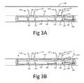
- FIGS. 3A-3Dillustrating a method of using said active reversible connection mechanism in order to provide said reversible connection between said implant and said implant deployment device 100.
- cover 131was removed from these drawings.
- FIG. 3Aillustrates the initial state of said active reversible connection mechanism in which all of said clip 107 are in their vertical configuration and said locking bar 203 is positioned in said lock position.
- each clip 107is located inside said holding hole 207, therefore each clip 107 is held in its said vertical configuration and can penetrate a implant 210 whilst the last is mounted on top of said implant deployment device (see FIG. 3B ).
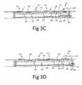
- each of said clip 107is transformed from said vertical configuration into their said horizontal configuration (see FIG. 3C ).
- Said transformationcan be achieved either manually (i.e., the physician will manually rotate the clips 107 thereby transforming them from said vertical configuration into their said horizontal configuration) or by the aid of a dedicated device.
- said locking tab 202is urged into niche 208. Since the locking tab 202 is titled inwardly, if said clip 107 is pulled upwardly in this state, the locking tab 202 is stopped by the upper edge of said locking bar 203, therefore, the rotation back to said vertical configuration of said clip 107 is limited by said locking bar 203 and said clips 107 are locked in said horizontal configuration, holding said implant attached to said frame arm 104.
- locking bar 203is pulled backward by wire 206, changing the position of said locking bar form its said lock position into its said free position (see FIG. 3D ).
- the clips 107are free to rotate (hence, as will be discussed hereinafter, a detachment between the implant deployment device and the implant is enabled).
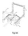
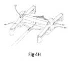
- FIG. 4A-4Hillustrate an example of a stapling apparatus 400 adapted for providing said reversible connection by said active reversible connection mechanism.
- Said stapling apparatus 400comprises a frame 401 which holds the distal portion 101 of an implant deployment device 100.
- Four staplers 403are connected to the frame 401 at each comet by four separate hinges (either standard or living hinges).
- Each said stapler 403is adapted to push down the implant 210 through a pair of clip 107 and to transform said clips 107 from a vertical position into a horizontal position (thus providing said reversible connection).
- Stapling presses 404are located at the end of each stapler inside groove 405 and adapted to push clip 107 into horizontal position.
- Each pair of staplers 403is connected via bridge 407 in order to prevent lateral movement of said staplers 403 during the stapling process.
- a snap groove 406is located at the center of the frame 401 and adapted to reversibly hold said implant deployment device 100 attached to stapling apparatus 400 until said reversible attachment is obtained.
- Each pair of clip 107is held in a vertical position by clip holder 402.
- Each said clip holder 402is adapted to hold a pair of clip 107 in vertical position in order to allow its insertion through the implant 210 during the stapling process.
- clip holder 402is adapted the hold the clips vertical during shipment in order to allow stapling in the operation room without the need of any preparation.
- each clip holder 402comprises two grooves 408 which hold the clip 107 in a vertical position.
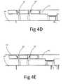
- FIGS. 4D-4Gillustrate the process of connecting the implant 210 to one pair of clip.
- the clipsare held vertically by clip holder 402.
- an implant 210is places on top of the stapling apparatus ( FIG. 4E ); the stapler 403 is then lowered toward the implant 210 by the surgeon (or other member of the medical staff); as a result the two clip 107 are penetrating through implant 210 and into groove 405 ( FIG. 4F ).
- clip 107is held by clip holder 402, thus premature transformation from vertical into horizontal position is prevented.
- clip holder 402is positioned laterally relative to the clip 107 (as also described is FIGS. 4B-4C ); at this stage the surgeon push on stapler press 404 and lower it toward clip 107 ( FIG. 4G ), as a result clip 107 position is transformed form vertical position into horizontal position. Since the said lock bar 203 is located at its said lock position, once clip 107 are substantially horizontal position, they are locked in this stage, thus providing said reversible connection between implant 210 and implant deployment device 100. Once said connection is obtain with all clip 107, implant deployment device is removed from SA 400.
- FIG. 4Hillustrates the configuration of stapling apparatus 400 during shipment.
- at least one, preferably two, packaging caps 411are utilized.
- Said caps 411are reversibly attached to the frame 401, and adapted to retain stapler 403 in a substantially horizontal position during device shipment.
- said caps 411also prevent down movement of stapler press 404, prevent lateral movement of clip holder 402 and prevent non-deliberate extraction of implant deployment device 100 from frame 401.
- said pack caps 411are removed by the medical staff in order to allow stapling of the implant 210 to the implant deployment device 100. Once the caps 411 are removed, the staplers 403 springs into horizontal position allowing the placement of implant 210 onto the stapling apparatus 400 and implant deployment device 100.
- said stapling processis preformed while implant deployment device 100 is not completely opened; as a result, once implant deployment device is completely opened inside the abdominal cavity, it is stretched beyond its original dimension (as was during stapling) therefore tight spreading is obtained.
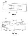
- FIG. 5illustrates an example of a staple return spring 500.
- staple return spring 500is needed in order to return clip 107 into horizontal position immediate after detachment from the implant 210; this is necessary in order prevent damage to internal organs by the sharp tip of clip 107 and in order to prevent clip 107 from being caught at the trocar or at the tissue during device extraction.
- lock bar 203afor use with an implant deployment device 100 is illustrated.
- lock bar 203aincludes protrusions 601, 603 formed from or attached to lock bar 203a that extend at least partially away from the lock bar 203a in a lateral direction that is away from the frame arm 104.
- Each protrusion 601, 603may be a tab of material that is cut out of the lock bar 203a and bent outwardly to create a ramp-like cammed shaped as shown in Fig. 6 .
- Each protrusion 601, 603may also be a separate piece permanently or releasably attached to the lock bar 203a.
- Each protrusion 601, 603acts to block rotation of clips 700 when the lock bar 203a is moved to a locked position beneath the clips 700 as shown in Fig. 7C and discussed further below. Also, each protrusion 601, 603 allows for the clips 700 to be assembled in an open position and selectively held in the open position to facilitate attachment of a surgical implant 210 over the clips 700 ( Fig. 8B ) and against the frame arm 104.
- Each clip 700includes a hook 703, a hinge hole 711, a body portion 705, and a locking portion 707.
- Each clip 700is rotatably coupled to the frame arm 104 at hinge hole 711.
- the locking portion 707is a substantially flat planar surface. Additionally, each clip 700 can be used in any location on the frame arm 104 since the clips 700 are interchangeable with each other. By providing interchangeable clips 700, manufacturing costs are reduced and production of the implant deployment device 100 is simplified.
- an open positionis any position where the hooks 703 as herein described are not in contact with or are in close proximity to the frame arm 104, and a closed position is where the hooks 703 are in contact with or are in close proximity to the frame arm 104 to clamp a desired implant.
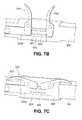
- the lock bar 203amay be made from any suitable rigid or semi-rigid material, including, but not limited to nitinol. Referring to Figs. 7A-7C , the lock bar 203a is shown disposed on a frame arm 104 with the clips 700. As shown in specifically in Fig.
- the lock bar 203ais positioned distally in an unlocked position such that protrusions 601, 603 of the lock bar 203a do not engage the locking portions 707 of either clip 700, thereby allowing the clips 700 to be selectively rotated between an open position ( Fig. 7B ) and a closed position ( Fig. 7A ).
- the staple return spring 500urges the clips 700 towards the closed position.
- the clips 700are rotatable to the open position as shown in FIG. 7B , which allows the clinician to attach the surgical implant 210 ( Fig. 3A ) to the frame arm 104 by passing the surgical implant 210 over the hooks 703 of the clips 700.
- Figs. 7A-7Calso shown in Figs. 7A-7C is the staple return spring 500, as described above, that biases the clips 700 towards a closed position such that when the clips 700 are raised to an open position ( Fig. 7B ) and the lock bar 203a is in the unlocked position, the staple return spring 500 urges the clips 700 downwards towards a closed position ( Figs. 7A and 7C ).
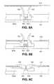
- an implant 210is shown being attached to clips 700 of the implant deployment device 100.
- the clips 700are in an initial open position. Due to the cammed surfaces of the protrusions 601, 603, the clips 700 are inhibited from rotating out of the open position.
- the protrusions 601, 603have a cammed shape to allow clips 700 for slidably rotating over the cammed portion of protrusions 601, 603, pushing the protrusions 601, 603 inwardly towards the frame arm 104 to a flexed position.
- the clips 700may be rotated out of the open position by the user pressing downwards on the clips 700 either manually or with an instrument (not shown).
- the protrusions 601, 603After rotating the clips 700 over the protrusions 601, 603, the protrusions 601, 603 return to their normal outward configuration and thereafter block the clips 700 from rotating out of the closed position when the lock bar 203a is in the locked position, because top surfaces of the protrusions 601, 603 engage the locking portions 707 of the clips 700 as shown in Fig. 8C .
- the lock bar 203aTo reset the clips 700 to the initial open position ( Fig. 8A ), the lock bar 203a is moved to the unlocked position and the clips 700 are rotated to the open position ( Fig. 8A ).
- Utilizing one or more embodiments of the clip and lock bar systems as herein disclosedresults in positive engagement between each clip 700 and the lock bar 203a such that the clips 700 are maintained in a closed position ( Figs. 7C & 8C ) and securely retain the implant 210 against the frame arm 104 ( Fig. 8C ).
- the clips 700may be initially locked in an open position ( Figs. 8A and 8B ) allowing a clinician to position the surgical implant 210 (e.g. a mesh) to the frame arm 104 by passing the surgical implant 210 over the clips 700.
- the usermay rotate the clips 700 past the protrusions 601, 603, thereby transitioning the clips 700 to the closed position.
- the clips 700With the clips 700 in a closed position, the clips 700 secure the surgical implant 210 against the frame arm 104.
- the clinicianplaces the surgical implant 210 at a desired location in a surgical site and affixes the surgical implant 210 to tissue.
- the clinicianactivates a release button (not shown) on the implant deployment device 100, which transitions the lock bar 203a from the locked position ( Fig. 7C ) to the unlocked position ( Fig. 7A ).
- the clinicianWith the lock bar 203a in the unlocked position, the clinician moves the implant deployment device 100 away from the surgical implant 210 that is affixed to tissue.
- the clips 700rotate to the open position as the implant deployment device 100 is moved away from the attached surgical implant 210. Once the implant deployment device 100 is separated from the attached surgical implant 210, the spring member 500 urges the clips 700 towards the closed position. Once the clips 700 are in the closed position, the clinician removes the implant deployment device 100 from the surgical site.
Landscapes
- Health & Medical Sciences (AREA)
- Life Sciences & Earth Sciences (AREA)
- Engineering & Computer Science (AREA)
- Animal Behavior & Ethology (AREA)
- Veterinary Medicine (AREA)
- Biomedical Technology (AREA)
- Heart & Thoracic Surgery (AREA)
- Public Health (AREA)
- General Health & Medical Sciences (AREA)
- Surgery (AREA)
- Transplantation (AREA)
- Cardiology (AREA)
- Vascular Medicine (AREA)
- Oral & Maxillofacial Surgery (AREA)
- Nuclear Medicine, Radiotherapy & Molecular Imaging (AREA)
- Medical Informatics (AREA)
- Molecular Biology (AREA)
- Prostheses (AREA)
Description
- This invention generally relates to a device and method for reversibly coupling an implant to an implant deployment device.
- An object of the present invention is to provide an apparatus for performing corrective surgery on internal wounds such as a hernia where invasion of the patient's body tissues is minimized and resultant trauma is reduced.
- A hernia is a protrusion of a tissue, structure, or part of an organ through the muscular tissue or the membrane by which it is normally contained. In other words, a hernia is a defect in the abdominal wall through which a portion of the intra-abdominal contents can protrude. This often causes discomfort and an unsightly, visible bulge in the abdomen. When such a hernia defect occurs in the abdominal region, conventional corrective surgery has required opening the abdominal cavity by surgical incision through the major abdominal muscles. While this technique provides for effective corrective surgery of the hernia defect, it has the disadvantage of requiring a hospital stay of as much as a week, during which pain is frequently intense, and it requires an extended period of recuperation. After the conventional surgery, patients frequently cannot return to a full range of activity and work schedule for a month or more. Accordingly, medical science has sought alternative techniques that are less traumatic to the patient and provide for more rapid recovery.
- Laparoscopy is the science of introducing a viewing instrument through a port into a patient's body, typically the abdominal cavity, to view its contents. This technique has been used for diagnostic purposes for more than 75 years. Operative laparoscopy is performed through tiny openings in the abdominal wall called ports. In most surgical techniques, several ports, frequently three to six, are used. Through one port is inserted the viewing device, which conventionally comprises a fiber optic rod or bundle having a video camera affixed to the outer end to receive and display images from inside the body. The various surgical instruments are inserted through other ports to do the surgery that normally would be performed through an open incision through the abdominal wall. Because the laparoscopic surgical techniques require only very small holes through the abdominal wall or other portions of the body, a patient undergoing such surgery may frequently leave the hospital within one day after the surgery and resume a full range of normal activities within a few days thereafter.
- In repairing hernia the physician needs to first deploy the implant and then attach the implant to the tissue.
- There are many patents and patent applications relating to attaching a prosthesis implant to a tissue via tacks. Each patent and patent application describes a different attachment mechanism via different anchoring means (see for example
U.S. Pat. No. 6,447,524 ). Traditional anchors used in surgery include clips, staples, or sutures, and may also be referred to as tissue anchors. These devices are usually made of a biocompatible material (or are coated with a biocompatible material), so that they can be safely implanted into the body. - Most tissue anchors secure the tissue by impaling it with one or more posts or legs that are bent or crimped to lock the tissue into position. Thus, most traditional anchors are rigid or are inflexibly attached to the tissue. For example
PCT No. WO 07/021834 U.S. Pat. No. 4,485,816 describes surgical staple made of shape memory alloy. The staple is placed in contact of the tissue and then heated. The heating causes the staple to change its shape thus, penetrating the tissue. U.S. Pat. No. 6,893,452 describes a tissue attachment device that facilitates wound healing by holding soft tissue together under improved distribution of tension and with minimal disruption of the wound interface and its nutrient supplies.U.S. Pat. No. 6,517,584 describes a hernia implant which includes at least one anchoring device made of shape memory material. The anchoring devices are initially secured to the prosthesis by being interlaced through a web mesh constituting the prosthesis. The attachment is obtained by altering the attachment element's shape from rectilinear to a loop shape due to heat induced shape memory effect.- Yet other patent literature relates to devices for endoscopic application of surgical staples adapted to attach surgical mesh to a body tissue.
- An example of such a teaching is to be found in
U.S. Pat. No. 5,364,004 ;U.S. Pat. No. 5,662,662 ;U.S. Pat. No. 5,634,584 ;U.S. Pat. No. 5,560,224 ;U.S. Pat. No. 5,588,581 ; and inU.S. Pat. No. 5,626,587 . - There are a few patent and patent applications teaching the deployment of implants. For example
U.S. Pat. No. 5,836,961 which relates to an apparatus used for developing an anatomic space for laparoscopic hernia repair and an implant for use therewith. The apparatus ofU.S. Pat. No. 5,836,961 comprises a tubular introducer member having a bore extending therethrough. A tunneling shaft is slidably mounted in the bore and has proximal and distal extremities including a bullet-shaped tip. A rounded tunneling member is mounted on the distal extremity of the tunneling shaft. The apparatus comprises an inflatable balloon. Means is provided on the balloon for removably securing the balloon to the tunneling shaft. Means is also provided for forming a balloon inflation lumen for inflating the balloon. The balloon is wrapped on the tunneling shaft. A sleeve substantially encloses the balloon and is carried by the tunneling shaft. The sleeve is provided with a weakened region extending longitudinally thereof, permitting the sleeve to be removed whereby the balloon can be unwrapped and inflated so that it lies generally in a plane. The balloon as it is being inflated creates forces generally perpendicular to the plane of the balloon to cause pulling apart of the tissue along a natural plane to provide the anatomic space. - More patent literature can be found in
PCT No. WO 08/065653 - Although all the above described patents and patent applications demonstrate attachment means or deployment means, none of the literature found relates to a reversible connection device which enable a reversible coupling between the implant and the implant deployment device.
- Thus, there is still a long felt need for a device that will enable a reversible connection between the implant and the implant deployment device.
US2011/066166 describes a type of surgical instrument on which the preamble to the independent claim 1 is based.- According to the invention there is provided a surgical instrument as recited in independent claim 1 with preferred features set forth in the dependent claims. A further aspect of the invention relates to a method of coupling an implant to such an instrument. It is one object of the present invention to provide an active reversible connection mechanism adapted to provide a reversible attachment between a prosthetic implant and an implant deployment device, wherein said attachment can be actively reversed without requiring any application of force on said implant.
- It is an object of the present disclosure to provide the active reversible connection mechanism as defined above, wherein said active reversible connection mechanism comprising at least one clip, hinge-like coupled to said implant deployment device, adapted to attach said implant to said implant deployment device: Said clip has at least three configurations: (i) a horizontal configuration in which said clip is substantially horizontal with respect to said implant deployment device; (ii) a vertical configuration in which said clip is substantially vertical with respect to said implant deployment device; and, (iii) a free motion configuration in which said clip is free to rotate; such that (i) when said clip is in said horizontal configuration said attachment between said implant and said implant deployment device is obtained; (ii) when said clip is in said free motion configuration said detachment between said implant and said implant deployment device is obtained.
- It is another object of the present disclosure to provide the active reversible connection mechanism as defined above, additionally comprising at least one locking bar characterized by at least two configurations: (i) lock configuration in which said lock bar maintains said clip in said horizontal configuration; and, (ii) free configuration in which said locking bar enables said clip a free movement.
- It is another object of the present disclosure to provide the active reversible connection mechanism as defined above, wherein said active reversible connection additionally comprising at least one detachment actuator adapted to reversibly transform said locking bar from said lock configuration to said free configuration.
- It is another object of the present disclosure to provide the active reversible connection mechanism as defined above, wherein said attachment between said implant and said implant deployment device is obtained once said locking bar is in its said lock configuration and said at least one clip is in said horizontal configuration such that the same at least partially penetrates said implant.
- It is another object of the present disclosure to provide the active reversible connection mechanism as defined above, wherein said detachment is achieved by transforming said locking bar from said lock configuration to said free configuration via said at least one detachment actuator.
- It is another object of the present disclosure to provide the active reversible connection mechanism as defined above, wherein said detachment actuator comprises a wire; further wherein said wire is attached to said lock bar.
- It is another object of the present disclosure to provide the active reversible connection mechanism as defined above, wherein said transformation of said clip from said vertical configuration into their said horizontal configuration is performed manually by the physician or by the aid of a dedicated device.
- It is another object of the present disclosure to provide a method for attaching a prosthetic implant to an implant deployment device. The method comprising steps selected, inter alia, from:
- a. obtaining an active reversible connection mechanism adapted to provide a reversible attachment between said prosthetic implant and said implant deployment device; wherein said attachment can be actively reversed without requiring any application of force on said implant; said active reversible connection comprising
- i. at least one clip, hinge-like coupled to said implant deployment device, adapted to attach said implant to said implant deployment device: Said clip has at least three configurations: (i) horizontal configuration in which said clip is substantially horizontal with respect to said implant deployment device; (ii) a vertical configuration in which said clip is substantially vertical with respect to said implant deployment device; and, (iii) a free motion configuration in which said clip is free to rotate;
- ii. at least one locking bar having at least two configurations: (i) lock configuration in which said lock bar maintains said clip in said horizontal configuration; and, (ii) free configuration in which said locking bar enables said clip a free movement; and,
- b. providing said clips in said vertical configuration;
- c. providing said locking bar in said lock configuration;
- d. threading said implant through said clip;
- e. transforming said clip into its said horizontal configuration thereby providing said attachment between said implant and said implant deployment device;
- It is another object of the present disclosure to provide the method as defined above, additionally comprising the step of providing said active reversible connection with at least one detachment actuator.
- It is another object of the present disclosure to provide the method as defined above, additionally comprising the step of reversibly transforming said locking bar from said lock configuration to said free configuration via said detachment actuator; thereby enabling free rotation of said clip such that detachment between said implant and said implant deployment device is obtained.
- It is another object of the present disclosure to provide the method as defined above, additionally comprising the step of introducing said implant deployment device into a body cavity.
- It is another object of the present disclosure to provide the method as defined above, additionally comprising the step of detaching said implant from said implant deployment device.
- It is another object of the present disclosure to provide the method as defined above, wherein said detachment additionally comprising the steps of reversibly transforming said locking bar from said lock configuration to said free configuration via said detachment actuator; thereby enabling said clip to rotate freely such that said detachment between said implant and said implant deployment device is obtained.
- It is another object of the present disclosure to provide a hernia kit useful in minimal invasive hernia surgery, comprising:
- a. an implant;
- b. an implant deployment device, adapted to deploy said implant within the abdominal cavity; and,
- c. an active reversible connection mechanism for reversible attaching said implant to said implant deployment device;
- It is another object of the present disclosure to provide the hernia kit as defined above, wherein said active reversible connection mechanism comprising:
- a. at least one clip, hinge-like coupled to said implant deployment device, adapted to attach said implant to said implant deployment device: Said clip has at least three configurations: (i) horizontal configuration in which said clip is substantially horizontal with respect to said implant deployment device; (ii) a vertical configuration in which said clip is substantially vertical with respect to said implant deployment device; and, (iii) a free motion configuration in which said clip is free to rotate; such that (i) when said clip is in said horizontal configuration said attachment between said implant and said implant deployment device is obtained; (ii) when said clip is in said free motion configuration said detachment between said implant and said implant deployment device is obtained.
- It is another object of the present disclosure to provide the hernia kit as defined above, additionally comprising at least one locking bar having at least two configurations: (i) lock configuration in which said lock bar maintains said clip in said horizontal configuration; and, (ii) free configuration in which said locking bar enables said clip a free movement.
- It is another object of the present disclosure to provide the hernia kit as defined above, wherein said active reversible connection additionally comprising at least one detachment actuator adapted to reversibly transform said locking bar from said lock configuration to said free configuration.
- It is another object of the present disclosure to provide the hernia kit as defined above, wherein said attachment between said implant and said implant deployment device is obtained once said locking bar is in its said lock configuration and said at least one clip is in said horizontal configuration such that the same at least partially penetrates said implant.
- It is another object of the present disclosure to provide the hernia kit as defined above, wherein said detachment is achieved by transforming said locking bar from said lock configuration to said free configuration via said at least one detachment actuator.
- It is still an object of the present disclosure to provide the hernia kit as defined above, wherein said detachment actuator comprises a wire; further wherein said wire is attached to said lock bar.
- It is an object of the present disclosure to provide the hernia kit as defined above, wherein said transformation of said clip from said vertical configuration into their said horizontal configuration is performed manually by the physician or by the aid of a dedicated device.
- An embodiment according to the present invention includes a system for closing an aperture in a biological tissue, the system including a proximal portion adapted to remain outside a patient body, a distal portion adapted to be inserted into a patient body, the distal portion including at least one frame arm, at least one clip connected to the at least one frame arm and configured to releasably retain a surgical implant to the frame arm, and a lock bar including at least one protrusion, the at least one protrusion extending away from the at least one frame arm, wherein the at least one protrusion is configured to selectively hold the at least one clip in at least one of an open position or a closed position.
- In at least one aspect of the present disclosure, the at least one protrusion selectively engages the at least one clip to lock the at least one clip in a closed position by inhibiting movement or rotation of the at least one clip when the lock bar is in a locked position, and wherein the lock bar allows the at least one clip to move or rotate to an open position when the lock bar is in an unlocked position.
- In at least one aspect of the present disclosure, the at least one protrusion selectively engages the at least one clip to lock the at least one clip in an initial open position by inhibiting movement or rotation of the at least one clip when the lock bar is in a locked position, wherein the at least one protrusion is shaped to allow the at least one clip to deflect the at least one protrusion inwardly towards the frame arm, thereby allowing the at least one clip to rotate over the at least one protrusion from the initial open position to a closed position.
- In at least one aspect of the present disclosure, the force applied against the protrusion as the clip rotates from the open position to the closed position is greater than a spring constant of the at least one protrusion. Thus, the protrusion deflects inwards as the clip rotates past the protrusion.
- In at least one aspect of the present disclosure, a lock bar for a system for closing an aperture in a biological tissue includes a body portion and at least one protrusion, the at least one protrusion extending away from the at least one frame arm, wherein the at least one protrusion is configured to selectively hold the at least one clip in at least one of an open position or a closed position.
- In at least one aspect of the present disclosure, the lock bar includes two protrusions configured in a mirror-like arrangement to operate with a pair of clips.
- In at least one aspect of the present disclosure, the at least one protrusion selectively engages the at least one clip to lock the at least one clip in an initial open position by inhibiting movement or rotation of the at least one clip when the lock bar is in a locked position, wherein the at least one protrusion is shaped to allow the at least one clip to deflect the at least one protrusion inwardly towards the frame arm, thereby allowing the at least one clip to rotate over the at least one protrusion from the initial open position to a closed position.
- In at least one aspect of the present disclosure, the lock bar is formed from nitinol.
- In at least one aspect of the present disclosure, a method includes providing a system for closing an aperture in a biological tissue, the system including a proximal portion adapted to remain outside a patient body, a distal portion adapted to be inserted into a patient body, the distal portion including at least one frame arm, at least one clip connected to the at least one frame arm and configured to releasably retain a surgical implant to the frame arm, and a lock bar including at least one protrusion, the at least one protrusion extending away from the at least one frame arm, wherein the at least one protrusion is configured to selectively hold the at least one clip in at least one of an open position or a closed position, and releasably attaching the surgical implant to the at least one clip.
- In at least one aspect of the present disclosure, the at least one protrusion selectively engages the at least one clip to lock the at least one clip in a closed position by inhibiting movement or rotation of the at least one clip when the lock bar is in a locked position, and wherein the lock bar allows the at least one clip to move or rotate to an open position when the lock bar is in an unlocked position.
- In at least one aspect of the present disclosure, the at least one protrusion selectively engages the at least one clip to lock the at least one clip in an initial open position by inhibiting movement or rotation of the at least one clip when the lock bar is in a locked position, wherein the at least one protrusion is shaped to allow the at least one clip to deflect the at least one protrusion inwardly towards the frame arm, thereby allowing the at least one clip to rotate over the at least one protrusion from the initial open position to a closed position.
- In at least one aspect of the present disclosure, the force applied against the protrusion as the clip rotates from the open position to the closed position is greater than a spring constant of the at least one protrusion. Thus, the protrusion deflects inwards as the clip rotates past the protrusion.
- In at least one aspect of the present disclosure, the system is provided in the initial open position for facilitating installation of an implant.
- In at least one aspect of the present disclosure, the method further includes moving the clips from the initial open position to the closed position after attaching an implant to the clips.
- In at least one aspect of the present disclosure, the method further includes inserting the system into a patient body after moving the clips from the initial open position to a closed position.
- In at least one aspect of the present disclosure, the method further includes moving the lock bar to an unlocked position after inserting the system into a patient body.
- In at least one aspect of the present disclosure, the method further includes moving the clips to an open position after moving the lock bar to an unlocked position.
- In at least one aspect of the present disclosure, the method further includes releasing the implant from the clips at a target site inside a patient body.
- In at least one aspect of the present disclosure, the method further includes allowing the clips to return to the closed position after the releasing step.
- In at least one aspect of the present disclosure, the method further includes removing the system from the patient body after the allowing step.
- The invention is herein described, by way of example only, with reference to the accompanying drawings, wherein:
FIG. 1A illustrates an example of an implant deployment device which comprises said active reversible connection mechanism;FIGS. 2A-2D illustrate the internal operation of said active reversible connection mechanism;FIGS. 3A-3E illustrate a method of using said active reversible connection mechanism for providing said reversible connection between said implant and said implant deployment device;FIG. 4A-4H illustrate an example of a stapling apparatus adapted for providing a reversible connection by the active reversible connection mechanism;FIG. 5 illustrates an example of a staple return spring;FIG. 6 is a side perspective view of a lock bar in accordance with the present inventionFIG. 7A is a side perspective view of an embodiment of a clip locking system in a closed and unlocked position in accordance with the present inventionFIG. 7B is a side perspective view ofFig. 7A showing the clip locking system in an open and locked position in accordance with the present inventionFIG. 7C is a side perspective view of the embodiment ofFig. 7A showing the clip locking system in a closed and locked position in accordance with the present inventionFIG. 8A is a side view of an embodiment of a clip locking system in an open and unlocked position prior to attaching an implant in accordance with the present inventionFIG. 8B is a side view of the embodiment ofFig. 8A in an open and unlocked position having an implant attached thereto in accordance with the present invention andFIG. 8C is a side view of the embodiment ofFig. 8A in a closed and locked position with the implant attached thereto in accordance with the present invention- The following description is provided, alongside all chapters of the present invention, so as to enable any person skilled in the art to make use of the invention and sets forth the best modes contemplated by the inventor of carrying out this invention. Various modifications of the present disclosure should be apparent to those skilled in the art, since the generic principles of the present invention have been defined specifically to provide means and method for creating a reversible and active connection between an implant and an implant deployment device.
- The present invention provides an active reversible connection mechanism between a prosthetic implant and an implant deployment device wherein said connection can be performed during a surgery at a standard surgery room by the medical staff.
- Furthermore, the present invention provides means so as to enable the surgeon to actively eliminate said attachment once detachment between said implant deployment device and said implant is necessary.
- It should be emphasized that some of the major advantages of the present invention, with respect to the prior art, is to provide a fast and intuitive method for creating a reliable connection between an implant and an implant deployment device in the surgery room. Embodiments of an implant include, but are not limited to, a surgical patch, a surgical mesh, or other biocompatible implants usable in repairing a defect in body tissue.
- In addition, the present invention provides means to actively disconnect said implant from said implant deployment device, when said disconnection is desired without the need to exert large forces on said implant and/or said tissue.
- The term "Hernia" refers hereinafter for umbilical hernia, hiatal hernia, ventral hernia, postoperative hernia, epigastric hernia, spiegelian hernia, inguinal hernia and femoral hernia, generally any abdominal wall related hernia.
- The term "hinge" or "hinge-like connection" refers hereinafter as to a type of bearing that connects two solid objects, typically allowing only a limited angle of rotation between them. Two objects connected by an ideal hinge rotate relative to each other about a fixed axis of rotation (the geometrical axis of the hinge). Hinges may be made of flexible material or of moving components.
- The term "hinge like connection" can refer to a standard hinge or to a living hinge (i.e., a thin flexible hinge (flexure bearing) made from plastic that joins two rigid parts together while allowing them to bend along the line of the hinge).
- The term "controlled deployment" refers hereinafter to an implant deployment which is continuous. Thus, deployment using the presently disclosed implant deployment device is variable amongst a number of deployment levels between a fully opened position and a fully closed position rather than a binary arrangement that does not include any intermediate positions or levels between fully opened and fully closed. This is in contrast to some conventional deployment systems in which the deployment of the implant relies upon the elasticity of a loop member surrounding the implant such that the implant can be either fully folded or fully unfolded. No intermediate stages are enabled. In the present invention, there can be several deployment stages.
- The term "bidirectional" or "fully reversible deployment" refers hereinafter to the deployment of the implant, which according to the present invention, is fully reversible. In other words, the implant deployment is bidirectional, i.e., the implant can be fully folded (i.e., deployed within the body) and then, if the surgeon desires, the implant can be fully unfolded simply by the reconfiguration of the flexible arms from the initial stage to the final stage and vice versa.
- The term "minimally invasive surgery" refers hereinafter to procedures that avoid open invasive surgery in favor of closed or local surgery with fewer traumas. Furthermore, the term refers to a procedure that is carried out by entering the body through the skin or through a body cavity or anatomical opening, but with the smallest damage possible.
- The term "articulation" refers hereinafter to a joint or juncture between two segments of the device. The articulating means of the present invention provides the ability to better adjust the device to the curvature of the treated tissue.
- The term "orientation" refers hereinafter to the rotation of the mesh within the abdominal cavity so as to fit to the hernia. Usually the mesh is not symmetric in shape (e.g., rectangular or elliptical)--therefore it has different directions. By rotating the mesh within the abdominal cavity--one can decide which direction is turned where.
- The term "adjusting" refers hereinafter to rolling, folding, and winding of the implant, thus preparing and enabling the insertion of said implant into the abdominal cavity.
- The term "active reversible connection" refers hereinafter to a coupling between the implant and the implant deployment device implant deployment device in which the coupling/decoupling between the implant and the implant deployment device is enabled by an act performed by the user (namely the physician). Once said user performed said act, said coupling/decoupling is canceled.
- According to the present disclosure the coupling/decoupling is obtained actively via the aid of dedicated clips which have at least two configurations:
- (a) substantially horizontal/parallel configuration (in which an attachment between the implant and the implant deployment device is provided);
- (b) substantially vertical configuration; and,
- (c) a configuration in which the clips are free to rotate.
- Before explaining the figures, it should be understood that the invention is not limited in its application to the details of construction and the arrangement of the components set forth in the following description or illustrated in the drawings. The invention can be carried out in various ways.
- Reference is now being made to
FIG. 1A illustrates an example of animplant deployment device 100 which comprises said active reversible connection mechanism. Implant deployment device 100 is defined hereinafter as a surgical device which can introduce a implant into a body cavity of a patient;implant deployment device 100 can deploy said implant such that it is at least partially spared inside the body cavity; alternativelyimplant deployment device 100 can only introduce said implant into the body cavity without performing any deployment.- In general,
implant deployment device 100 comprises at least two portions: adistal portion 101 and aproximal portion 102. The proximal portion is adapted to remain outside the body, adjacently to the user and thedistal portion 101 is adapted to be inserted into the body. - The distal portion comprises at least one
frame arm 104 to which the implant is attached. Eachframe arm 104 comprises said active reversible connection mechanism which provides reversible attachment between eachframe arm 104 and the implant 106 such that said implant can be rolled/folded on saiddistal portion 101, and inserted into the patient's body cavity through a laparoscopic cannula or a small incision. - It should be noted that the term reversible refers hereinafter to the ability to both attach the implant to the implant deployment device and to decouple the same from the implant deployment device.
- Said active reversible connection mechanism comprises at least one
clip 107. Said clip is coupled to saidframe arm 104 byhinge tab 132. Said active reversible connection is covered bycover 131 which is attached to theframe arm 104. Cover 131 comprises at least onehinge tab 132 which is adapted to hold saidclip 107 attached to framearm 104 an to serve as a hinge allowing free rotation of saidclip 107. Saidhinge tab 132 is inserted throughhinge hole 133, located atclip 107 and through hole 134, located atframe arm 104. - Reference is now being made to
FIGS. 2A-2D which illustrate the internal operation of said active reversible connection mechanism. For the purpose of illustration only,cover 131 is removed from these drawings. - A locking
bar 203 is located insidegroove 204 atframe arm 104. Said lockingbar 203 can move linearly inside saidgroove 204 and comprises at least onegroove 205. Said lockingbar 203 has at least two positions: free position, in which each of said groove/s 205 is substantially located below said clip 107 (seeFIGS. 2C and 2D ), and lock position, in which saidgroove 205 is located away from said clip 107 (seeFIGS. 2A and 2B ). - In the lock position of the locking
bar 203, theclip 107 are substantially perpendicular to theframe arm 104; and in free position of the lockingbar 203, theclip 107 are free to rotate (hence, as will be discussed hereinafter a detachment is enabled). - A
disconnection wire 206 is attached to said lockingbar 203.Said wire 206 can be pulled proximally to theproximal portion 102 and is adapted to transform said lockingbar 203 from its said lock position into its said free position. - According to this example each
clip 107 comprises at least 3 sections: protruding portion (PP) 201 adapted to protrude through said implant during said connection process, hingehole 133, andlocking tab 202 which is tilted towardframe arm 104. - Each of said
clip 107 has at least two configurations: horizontal/parallel configuration in which saidclip 107 is substantially horizontal and parallel to said frame arm 104 (FIGS. 2B ,2C ) and vertical configuration in which saidclip 107 is substantially vertical with respect to said frame arm 104 (FIGS. 2A and2D ). - At least one holding
hole 207 is located at said lockingbar 203 and is adapted to hold saidclip 107 in its vertical configuration. - At least one
niche 208 in located atframe arm 104 adapted to accommodate saidlocking tab 202 of saidclip 107 while theclip 107 is in its said horizontal/parallel configuration. - Reference is now being made to
FIGS. 3A-3D illustrating a method of using said active reversible connection mechanism in order to provide said reversible connection between said implant and saidimplant deployment device 100. Again, for the purpose of illustration only,cover 131 was removed from these drawings. FIG. 3A illustrates the initial state of said active reversible connection mechanism in which all of saidclip 107 are in their vertical configuration and said lockingbar 203 is positioned in said lock position.- As can be seen in the figure, said
locking tab 202 of each saidclip 107 is located inside said holdinghole 207, therefore eachclip 107 is held in its said vertical configuration and can penetrate aimplant 210 whilst the last is mounted on top of said implant deployment device (seeFIG. 3B ). - Once said implant is mounted, each of said
clip 107 is transformed from said vertical configuration into their said horizontal configuration (seeFIG. 3C ). - Said transformation can be achieved either manually (i.e., the physician will manually rotate the
clips 107 thereby transforming them from said vertical configuration into their said horizontal configuration) or by the aid of a dedicated device. - Once said
clip 107 is transformed to its horizontal configuration while said locking bar is in its said lock position, saidlocking tab 202 is urged intoniche 208. Since thelocking tab 202 is titled inwardly, if saidclip 107 is pulled upwardly in this state, thelocking tab 202 is stopped by the upper edge of said lockingbar 203, therefore, the rotation back to said vertical configuration of saidclip 107 is limited by said lockingbar 203 and saidclips 107 are locked in said horizontal configuration, holding said implant attached to saidframe arm 104. - It should be pointed out that it is a unidirectional mechanism. In other words, if one tries to force
clips 107 to its vertical configuration, lockingtabs 202 will bump into lockingbar 203. - By further pulling said locking
bar 203 towards the proximal portion theclips 107 are unlocked and can be rotated be back to its vertical configuration (seeFIGS. 3D and3E ). - Once detachment between said
implant 210 and said implant deployment device in desired, lockingbar 203 is pulled backward bywire 206, changing the position of said locking bar form its said lock position into its said free position (seeFIG. 3D ). In said free position of the lockingbar 203, theclips 107 are free to rotate (hence, as will be discussed hereinafter, a detachment between the implant deployment device and the implant is enabled). - Once locking
bar 203 is positioned in said free position, said groove's 205 is located below saidclips 107, therefore said lockingbar 202 is no longer limiting the movement of saidclips 107 enabling their free movement. In this state, detachment can be obtained by simply pulling saidframe arm 104 away from said implant; as a result, saidclips 107 rotate back into their said vertical configuration and are released from said implant (see FIG. 2E). - Reference is now made to
FIG. 4A-4H , which illustrate an example of astapling apparatus 400 adapted for providing said reversible connection by said active reversible connection mechanism. Said staplingapparatus 400 comprises aframe 401 which holds thedistal portion 101 of animplant deployment device 100. Fourstaplers 403 are connected to theframe 401 at each comet by four separate hinges (either standard or living hinges). Each saidstapler 403 is adapted to push down theimplant 210 through a pair ofclip 107 and to transform saidclips 107 from a vertical position into a horizontal position (thus providing said reversible connection). Stapling presses 404 are located at the end of each stapler insidegroove 405 and adapted to pushclip 107 into horizontal position. Each pair ofstaplers 403 is connected viabridge 407 in order to prevent lateral movement of saidstaplers 403 during the stapling process. Asnap groove 406 is located at the center of theframe 401 and adapted to reversibly hold saidimplant deployment device 100 attached to staplingapparatus 400 until said reversible attachment is obtained. - Each pair of
clip 107 is held in a vertical position byclip holder 402. Each saidclip holder 402 is adapted to hold a pair ofclip 107 in vertical position in order to allow its insertion through theimplant 210 during the stapling process. In addition,clip holder 402 is adapted the hold the clips vertical during shipment in order to allow stapling in the operation room without the need of any preparation. As illustrated inFIGS. 4B-4C , eachclip holder 402 comprises twogrooves 408 which hold theclip 107 in a vertical position. Once stapling process is performed and the surgeon is lowering thestapler 403 toward the implant, eachclip holder 402 is pushed down and as a result it is also moving laterally. In this state, since theclip 107 are extracted fromgroves 408, their transformation from vertical into horizontal position is enabled; said lateral movement of saidclip holder 402 is obtained asbulge 409 atclip holder 402 is sliding alongbulge 410 at thestapling frame 401 during the down movement ofclip holder 402. FIGS. 4D-4G illustrate the process of connecting theimplant 210 to one pair of clip. At the initial stage (FIG. 4 D) , the clips are held vertically byclip holder 402. Next, animplant 210 is places on top of the stapling apparatus (FIG. 4E ); thestapler 403 is then lowered toward theimplant 210 by the surgeon (or other member of the medical staff); as a result the twoclip 107 are penetrating throughimplant 210 and into groove 405 (FIG. 4F ). During the initial penetration,clip 107 is held byclip holder 402, thus premature transformation from vertical into horizontal position is prevented. Once theclip 107 are completely inserted into saidimplant 210,clip holder 402 is positioned laterally relative to the clip 107 (as also described isFIGS. 4B-4C ); at this stage the surgeon push onstapler press 404 and lower it toward clip 107 (FIG. 4G ), as aresult clip 107 position is transformed form vertical position into horizontal position. Since the saidlock bar 203 is located at its said lock position, onceclip 107 are substantially horizontal position, they are locked in this stage, thus providing said reversible connection betweenimplant 210 andimplant deployment device 100. Once said connection is obtain with allclip 107, implant deployment device is removed fromSA 400.FIG. 4H illustrates the configuration ofstapling apparatus 400 during shipment. In order to reduce package volume during shipment and to keep the device ready for stapling, at least one, preferably two, packaging caps 411 are utilized. Said caps 411 are reversibly attached to theframe 401, and adapted to retainstapler 403 in a substantially horizontal position during device shipment. In addition, saidcaps 411 also prevent down movement ofstapler press 404, prevent lateral movement ofclip holder 402 and prevent non-deliberate extraction ofimplant deployment device 100 fromframe 401.- Once the device in removed from its packaging during the surgery, said pack caps 411 are removed by the medical staff in order to allow stapling of the
implant 210 to theimplant deployment device 100. Once thecaps 411 are removed, thestaplers 403 springs into horizontal position allowing the placement ofimplant 210 onto thestapling apparatus 400 andimplant deployment device 100. - In order to allow tight spreading of the
implant 210 during surgery, said stapling process is preformed whileimplant deployment device 100 is not completely opened; as a result, once implant deployment device is completely opened inside the abdominal cavity, it is stretched beyond its original dimension (as was during stapling) therefore tight spreading is obtained. - Reference is now being made to
FIG. 5 which illustrates an example of astaple return spring 500. In general,staple return spring 500 is needed in order to returnclip 107 into horizontal position immediate after detachment from theimplant 210; this is necessary in order prevent damage to internal organs by the sharp tip ofclip 107 and in order to preventclip 107 from being caught at the trocar or at the tissue during device extraction. - Referring to
Fig. 6 , an embodiment of alock bar 203a for use with animplant deployment device 100 is illustrated. As shownlock bar 203a includesprotrusions bar 203a that extend at least partially away from thelock bar 203a in a lateral direction that is away from theframe arm 104. Eachprotrusion lock bar 203a and bent outwardly to create a ramp-like cammed shaped as shown inFig. 6 . Eachprotrusion lock bar 203a. - Each
protrusion clips 700 when thelock bar 203a is moved to a locked position beneath theclips 700 as shown inFig. 7C and discussed further below. Also, eachprotrusion clips 700 to be assembled in an open position and selectively held in the open position to facilitate attachment of asurgical implant 210 over the clips 700 (Fig. 8B ) and against theframe arm 104. Eachclip 700 includes ahook 703, ahinge hole 711, abody portion 705, and a lockingportion 707. Eachclip 700 is rotatably coupled to theframe arm 104 athinge hole 711. The lockingportion 707 is a substantially flat planar surface. Additionally, eachclip 700 can be used in any location on theframe arm 104 since theclips 700 are interchangeable with each other. By providinginterchangeable clips 700, manufacturing costs are reduced and production of theimplant deployment device 100 is simplified. - As herein described with respect to this and future embodiments, an open position is any position where the
hooks 703 as herein described are not in contact with or are in close proximity to theframe arm 104, and a closed position is where thehooks 703 are in contact with or are in close proximity to theframe arm 104 to clamp a desired implant. Thelock bar 203a may be made from any suitable rigid or semi-rigid material, including, but not limited to nitinol. Referring toFigs. 7A-7C , thelock bar 203a is shown disposed on aframe arm 104 with theclips 700. As shown in specifically inFig. 7A , thelock bar 203a is positioned distally in an unlocked position such thatprotrusions lock bar 203a do not engage the lockingportions 707 of eitherclip 700, thereby allowing theclips 700 to be selectively rotated between an open position (Fig. 7B ) and a closed position (Fig. 7A ). With thelock bar 203a in the unlocked position, thestaple return spring 500 urges theclips 700 towards the closed position. Theclips 700 are rotatable to the open position as shown inFIG. 7B , which allows the clinician to attach the surgical implant 210 (Fig. 3A ) to theframe arm 104 by passing thesurgical implant 210 over thehooks 703 of theclips 700. This is the default configuration for theimplant deployment device 100 since it allows the clinician to attach thesurgical implant 210 to theimplant deployment device 100 since theclips 700 are maintained in the open position due to the interaction between theclips 700 and thelock bar 203a in the locked position (FIG. 7B ). Once thesurgical implant 210 is abutting theframe arm 104, theclips 700 are rotated to the closed position over theprotrusions lock bar 203a as shown inFig. 7C . As shown in specifically inFig. 7C , when thelock bar 203a is in a locked position, theprotrusions clip 700 from rotating to an open position due to the engagement between top surfaces of theprotrusions portions 707 of eachclip 700. - Also shown in
Figs. 7A-7C is thestaple return spring 500, as described above, that biases theclips 700 towards a closed position such that when theclips 700 are raised to an open position (Fig. 7B ) and thelock bar 203a is in the unlocked position, thestaple return spring 500 urges theclips 700 downwards towards a closed position (Figs. 7A and7C ). - Referring to
Figs. 8A-8C , animplant 210 is shown being attached toclips 700 of theimplant deployment device 100. As shown inFigs. 8A and 8B , theclips 700 are in an initial open position. Due to the cammed surfaces of theprotrusions clips 700 are inhibited from rotating out of the open position. As described above, theprotrusions clips 700 for slidably rotating over the cammed portion ofprotrusions protrusions frame arm 104 to a flexed position. Theclips 700 may be rotated out of the open position by the user pressing downwards on theclips 700 either manually or with an instrument (not shown). After rotating theclips 700 over theprotrusions protrusions clips 700 from rotating out of the closed position when thelock bar 203a is in the locked position, because top surfaces of theprotrusions portions 707 of theclips 700 as shown inFig. 8C . To reset theclips 700 to the initial open position (Fig. 8A ), thelock bar 203a is moved to the unlocked position and theclips 700 are rotated to the open position (Fig. 8A ). - Utilizing one or more embodiments of the clip and lock bar systems as herein disclosed results in positive engagement between each
clip 700 and thelock bar 203a such that theclips 700 are maintained in a closed position (Figs. 7C &8C ) and securely retain theimplant 210 against the frame arm 104 (Fig. 8C ). Theclips 700 may be initially locked in an open position (Figs. 8A and 8B ) allowing a clinician to position the surgical implant 210 (e.g. a mesh) to theframe arm 104 by passing thesurgical implant 210 over theclips 700. After thesurgical implant 210 has been attached to theframe arm 104, the user may rotate theclips 700 past theprotrusions clips 700 to the closed position. With theclips 700 in a closed position, theclips 700 secure thesurgical implant 210 against theframe arm 104. When deployment is desired, the clinician places thesurgical implant 210 at a desired location in a surgical site and affixes thesurgical implant 210 to tissue. Subsequently, the clinician activates a release button (not shown) on theimplant deployment device 100, which transitions thelock bar 203a from the locked position (Fig. 7C ) to the unlocked position (Fig. 7A ). With thelock bar 203a in the unlocked position, the clinician moves theimplant deployment device 100 away from thesurgical implant 210 that is affixed to tissue. Since thelock bar 203a is in the unlocked position, theclips 700 rotate to the open position as theimplant deployment device 100 is moved away from the attachedsurgical implant 210. Once theimplant deployment device 100 is separated from the attachedsurgical implant 210, thespring member 500 urges theclips 700 towards the closed position. Once theclips 700 are in the closed position, the clinician removes theimplant deployment device 100 from the surgical site. - The invention may be embodied in other specific forms without departing from the scope of the claims. The foregoing embodiments are therefore to be considered in all respects illustrative rather than limiting on the invention described herein. Scope of the invention is thus indicated by the appended claims rather than by the foregoing description, and all changes which come within the meaning and range of equivalency of the claims are therefore intended to be embraced therein.
Claims (5)
- A surgical instrument (100) comprising:a proximal portion (102);a distal portion (101) including a frame arm (104);a clip (700) rotatably coupled to the frame arm and configured to releasably retain a surgical implant to the frame arm; anda lock bar (203a)characterised in that the lock bar includes a protrusion (601,603), the protrusion extending laterally from the frame arm, wherein the protrusion is configured for selectively holding the clip in a predetermined position.
- The surgical instrument of claim 1, wherein the protrusion selectively engages the clip to lock the one clip in a closed position by inhibiting rotation of the clip when the lock bar is in a locked position and the lock bar allows the clip to rotate to an open position when the lock bar is in an unlocked position; and/or
wherein the protrusion selectively engages the clip to lock the clip in an initial open position by inhibiting rotation of the clip when the lock bar is in a locked position and the protrusion is shaped to allow the at least one clip to deflect the protrusion inwardly towards the frame arm, thereby allowing the clip to rotate over the protrusion from the open position to a closed position; and/or
further including first and second clips rotatably coupled to the frame arm, the first clip having the same configuration as the second clip such that the first and second clips are interchangeable. - The surgical instrument of claim 1 or claim 2, wherein the lock bar includes first (601) and second (603) protrusions.
- The surgical instrument of claim 3, wherein the first and second protrusions engage the first and second clips respectively for maintaining the first and second clips in the predetermined position.
- A method for releasably coupling an implant with an instrument comprising:providing a surgical instrument as recited in any preceding claim and performing the steps of:placing a surgical implant into an abutting relationship with the frame arm when the clip is in an open position;rotating the clip to a closed position; andrepositioning the lock bar from an unlocked position to a locked position such that the clip is maintained in the closed position; preferably,wherein the protrusion includes an upper surface that engages a portion of the clip and maintains the clip in the closed position; and/orwherein the protrusion includes a camming surface that contacts the clip and inhibits rotation of the clip out of the open position.
Applications Claiming Priority (7)
| Application Number | Priority Date | Filing Date | Title |
|---|---|---|---|
| US201261691859P | 2012-08-22 | 2012-08-22 | |
| US201261691864P | 2012-08-22 | 2012-08-22 | |
| US201261691860P | 2012-08-22 | 2012-08-22 | |
| US201261691866P | 2012-08-22 | 2012-08-22 | |
| US201261691863P | 2012-08-22 | 2012-08-22 | |
| US201261691869P | 2012-08-22 | 2012-08-22 | |
| US13/951,496US9301826B2 (en) | 2008-02-18 | 2013-07-26 | Lock bar spring and clip for implant deployment device |
Publications (2)
| Publication Number | Publication Date |
|---|---|
| EP2700380A1 EP2700380A1 (en) | 2014-02-26 |
| EP2700380B1true EP2700380B1 (en) | 2015-07-08 |
Family
ID=49003696
Family Applications (1)
| Application Number | Title | Priority Date | Filing Date |
|---|---|---|---|
| EP13181220.8ANot-in-forceEP2700380B1 (en) | 2012-08-22 | 2013-08-21 | Lock bar spring and clip for implant deployment device |
Country Status (4)
| Country | Link |
|---|---|
| US (1) | US9301826B2 (en) |
| EP (1) | EP2700380B1 (en) |
| AU (1) | AU2013213689A1 (en) |
| CA (1) | CA2823556A1 (en) |
Families Citing this family (6)
| Publication number | Priority date | Publication date | Assignee | Title |
|---|---|---|---|---|
| US9398944B2 (en)* | 2008-02-18 | 2016-07-26 | Covidien Lp | Lock bar spring and clip for implant deployment device |
| US9833240B2 (en)* | 2008-02-18 | 2017-12-05 | Covidien Lp | Lock bar spring and clip for implant deployment device |
| US9034002B2 (en)* | 2008-02-18 | 2015-05-19 | Covidien Lp | Lock bar spring and clip for implant deployment device |
| US9393093B2 (en) | 2008-02-18 | 2016-07-19 | Covidien Lp | Clip for implant deployment device |
| US9393002B2 (en)* | 2008-02-18 | 2016-07-19 | Covidien Lp | Clip for implant deployment device |
| US9301826B2 (en)* | 2008-02-18 | 2016-04-05 | Covidien Lp | Lock bar spring and clip for implant deployment device |
Family Cites Families (491)
| Publication number | Priority date | Publication date | Assignee | Title |
|---|---|---|---|---|
| US4452245A (en) | 1980-06-06 | 1984-06-05 | Usher Francis C | Surgical mesh and method |
| US4347847A (en) | 1980-06-06 | 1982-09-07 | Usher Francis C | Method of hernia repair |
| US4585458A (en) | 1981-06-10 | 1986-04-29 | Kurland Kenneth Z | Means and method of implanting bioprosthetics |
| US4400833A (en) | 1981-06-10 | 1983-08-30 | Kurland Kenneth Z | Means and method of implanting bioprosthetics |
| US4485816A (en) | 1981-06-25 | 1984-12-04 | Alchemia | Shape-memory surgical staple apparatus and method for use in surgical suturing |
| US5125553A (en) | 1987-03-02 | 1992-06-30 | Stryker Sales Corporation | Surgical suturing instrument and method |
| US4633873A (en) | 1984-04-26 | 1987-01-06 | American Cyanamid Company | Surgical repair mesh |
| US5863531A (en) | 1986-04-18 | 1999-01-26 | Advanced Tissue Sciences, Inc. | In vitro preparation of tubular tissue structures by stromal cell culture on a three-dimensional framework |
| US4854316A (en) | 1986-10-03 | 1989-08-08 | Davis Emsley A | Apparatus and method for repairing and preventing para-stomal hernias |
| US5019096A (en) | 1988-02-11 | 1991-05-28 | Trustees Of Columbia University In The City Of New York | Infection-resistant compositions, medical devices and surfaces and methods for preparing and using same |
| US4930674A (en) | 1989-02-24 | 1990-06-05 | Abiomed, Inc. | Surgical stapler |
| US5141515A (en) | 1990-10-11 | 1992-08-25 | Eberbach Mark A | Apparatus and methods for repairing hernias |
| US5116357A (en) | 1990-10-11 | 1992-05-26 | Eberbach Mark A | Hernia plug and introducer apparatus |
| US5122155A (en) | 1990-10-11 | 1992-06-16 | Eberbach Mark A | Hernia repair apparatus and method of use |
| CA2098479C (en) | 1991-01-04 | 1996-10-15 | John H. Burton | Resectable self-expanding stent |
| CA2060040A1 (en) | 1991-02-08 | 1992-08-10 | Miguel A. Velez | Surgical staple and endoscopic stapler |
| US5749895A (en) | 1991-02-13 | 1998-05-12 | Fusion Medical Technologies, Inc. | Method for bonding or fusion of biological tissue and material |
| US5203864A (en) | 1991-04-05 | 1993-04-20 | Phillips Edward H | Surgical fastener system |
| US5254133A (en) | 1991-04-24 | 1993-10-19 | Seid Arnold S | Surgical implantation device and related method of use |
| US5728119A (en) | 1991-05-29 | 1998-03-17 | Origin Medsystems, Inc. | Method and inflatable chamber apparatus for separating layers of tissue |
| US5361752A (en) | 1991-05-29 | 1994-11-08 | Origin Medsystems, Inc. | Retraction apparatus and methods for endoscopic surgery |
| US5865728A (en) | 1991-05-29 | 1999-02-02 | Origin Medsystems, Inc. | Method of using an endoscopic inflatable lifting apparatus to create an anatomic working space |
| US5779728A (en) | 1991-05-29 | 1998-07-14 | Origin Medsystems, Inc. | Method and inflatable chamber apparatus for separating layers of tissue |
| EP0525791A1 (en) | 1991-08-02 | 1993-02-03 | DeMatteis, Ralph A. | Method and apparatus for laparoscopic repair of hernias |
| US5290217A (en) | 1991-10-10 | 1994-03-01 | Earl K. Sipes | Method and apparatus for hernia repair |
| US5289963A (en) | 1991-10-18 | 1994-03-01 | United States Surgical Corporation | Apparatus and method for applying surgical staples to attach an object to body tissue |
| US5497933A (en) | 1991-10-18 | 1996-03-12 | United States Surgical Corporation | Apparatus and method for applying surgical staples to attach an object to body tissue |
| US5356064A (en) | 1991-10-18 | 1994-10-18 | United States Surgical Corporation | Apparatus and method for applying surgical staples to attach an object to body tissue |
| US5292328A (en) | 1991-10-18 | 1994-03-08 | United States Surgical Corporation | Polypropylene multifilament warp knitted mesh and its use in surgery |
| US7198046B1 (en) | 1991-11-14 | 2007-04-03 | Wake Forest University Health Sciences | Wound treatment employing reduced pressure |
| CA2123317C (en) | 1991-11-19 | 2004-07-20 | Albert K. Chin | Endoscopic inflatable retraction devices for separating layers of tissue, and methods of using |
| EP0544485B1 (en) | 1991-11-25 | 1995-03-08 | Cook Incorporated | Tissue aperture repair device |
| US5258000A (en) | 1991-11-25 | 1993-11-02 | Cook Incorporated | Tissue aperture repair device |
| DK168419B1 (en) | 1991-11-25 | 1994-03-28 | Cook Inc A Cook Group Company | Abdominal wall support device and apparatus for insertion thereof |
| US5147374A (en) | 1991-12-05 | 1992-09-15 | Alfredo Fernandez | Prosthetic mesh patch for hernia repair |
| US5176692A (en) | 1991-12-09 | 1993-01-05 | Wilk Peter J | Method and surgical instrument for repairing hernia |
| US5219077A (en) | 1992-02-10 | 1993-06-15 | Ethicon, Inc. | Package for mesh onlay and attached mesh plug technical field |
| US5249682A (en) | 1992-02-10 | 1993-10-05 | Ethicon, Inc. | Package for mesh onlay and attached mesh plug |
| CA2090000A1 (en) | 1992-02-24 | 1993-08-25 | H. Jonathan Tovey | Articulating mesh deployment apparatus |
| US5333624A (en) | 1992-02-24 | 1994-08-02 | United States Surgical Corporation | Surgical attaching apparatus |
| CA2089999A1 (en) | 1992-02-24 | 1993-08-25 | H. Jonathan Tovey | Resilient arm mesh deployer |
| WO1993017635A1 (en) | 1992-03-04 | 1993-09-16 | C.R. Bard, Inc. | Composite prosthesis and method for limiting the incidence of postoperative adhesions |
| US5263969A (en) | 1992-04-17 | 1993-11-23 | Phillips Edward H | Tool for the laparoscopic introduction of a mesh prosthesis |
| US5766246A (en) | 1992-05-20 | 1998-06-16 | C. R. Bard, Inc. | Implantable prosthesis and method and apparatus for loading and delivering an implantable prothesis |
| WO1994027535A1 (en) | 1992-05-20 | 1994-12-08 | C.R. Bard, Inc. | Implantable prosthesis and method and apparatus for loading and delivering an implantable prosthesis |
| US5540711A (en) | 1992-06-02 | 1996-07-30 | General Surgical Innovations, Inc. | Apparatus and method for developing an anatomic space for laparoscopic procedures with laparoscopic visualization |
| US6312442B1 (en) | 1992-06-02 | 2001-11-06 | General Surgical Innovations, Inc. | Method for developing an anatomic space for laparoscopic hernia repair |
| EP0579377A3 (en) | 1992-06-12 | 1996-01-03 | Ethicon Inc | Package for mesh onlay and attached mesh plug |
| US5304187A (en) | 1992-06-30 | 1994-04-19 | United States Surgical Corporation | Surgical element deployment apparatus |
| US5653718A (en)* | 1994-05-16 | 1997-08-05 | Yoon; Inbae | Cannula anchoring system |
| US5601224A (en) | 1992-10-09 | 1997-02-11 | Ethicon, Inc. | Surgical instrument |
| US5662662A (en) | 1992-10-09 | 1997-09-02 | Ethicon Endo-Surgery, Inc. | Surgical instrument and method |
| US5626587A (en) | 1992-10-09 | 1997-05-06 | Ethicon Endo-Surgery, Inc. | Method for operating a surgical instrument |
| US5464403A (en) | 1992-10-29 | 1995-11-07 | General Surgical Innovations, Inc. | Placement tool and method for laparoscopic hernia repair |
| US5725577A (en) | 1993-01-13 | 1998-03-10 | Saxon; Allen | Prosthesis for the repair of soft tissue defects |
| US5356432B1 (en) | 1993-02-05 | 1997-02-04 | Bard Inc C R | Implantable mesh prosthesis and method for repairing muscle or tissue wall defects |
| US5368602A (en) | 1993-02-11 | 1994-11-29 | De La Torre; Roger A. | Surgical mesh with semi-rigid border members |
| US5433996A (en) | 1993-02-18 | 1995-07-18 | W. L. Gore & Associates, Inc. | Laminated patch tissue repair sheet material |
| US5354292A (en) | 1993-03-02 | 1994-10-11 | Braeuer Harry L | Surgical mesh introduce with bone screw applicator for the repair of an inguinal hernia |
| US5814058A (en) | 1993-03-05 | 1998-09-29 | Innerdyne, Inc. | Method and apparatus employing conformable sleeve for providing percutaneous access |
| US5364004A (en) | 1993-05-10 | 1994-11-15 | Hughes Aircraft Company | Wedge bump bonding apparatus and method |
| ATE182453T1 (en) | 1993-05-21 | 1999-08-15 | Ethicon Inc | ENDOSCOPIC FASTENING DEVICE FOR SOFT TISSUE PROSTHESIS |
| US5397332A (en) | 1993-09-02 | 1995-03-14 | Ethicon, Inc. | Surgical mesh applicator |
| FR2709947B1 (en) | 1993-09-13 | 1995-11-10 | Bard Sa Laboratoires | Curved prosthetic mesh and its manufacturing process. |
| US5560532A (en) | 1993-10-08 | 1996-10-01 | United States Surgical Corporation | Apparatus and method for applying surgical staples to body tissue |
| US5618290A (en) | 1993-10-19 | 1997-04-08 | W.L. Gore & Associates, Inc. | Endoscopic suture passer and method |
| US5531759A (en) | 1994-04-29 | 1996-07-02 | Kensey Nash Corporation | System for closing a percutaneous puncture formed by a trocar to prevent tissue at the puncture from herniating |
| WO1995030374A1 (en) | 1994-05-06 | 1995-11-16 | Origin Medsystems, Inc. | Apparatus and method for delivering a patch |
| US5425740A (en) | 1994-05-17 | 1995-06-20 | Hutchinson, Jr.; William B. | Endoscopic hernia repair clip and method |
| GB9414746D0 (en) | 1994-07-21 | 1994-09-07 | Vascutek Ltd | Prosthetic material |
| GB9415125D0 (en) | 1994-07-27 | 1994-09-14 | Notaras Mitchell J | Surgical product and its use |
| AUPM771894A0 (en) | 1994-08-29 | 1994-09-22 | Royal Children's Hospital Research Foundation | Method for the treatment of indirect inguinal hernias and related conditions |
| US6015429A (en) | 1994-09-08 | 2000-01-18 | Gore Enterprise Holdings, Inc. | Procedures for introducing stents and stent-grafts |
| JPH08196538A (en) | 1994-09-26 | 1996-08-06 | Ethicon Inc | Tissue sticking apparatus for surgery with elastomer component and method of attaching mesh for surgery to said tissue |
| US6290708B1 (en) | 1994-09-29 | 2001-09-18 | Bard Asdi Inc. | Hernia mesh patch with seal stiffener |
| US6176863B1 (en) | 1994-09-29 | 2001-01-23 | Bard Asdi Inc. | Hernia mesh patch with I-shaped filament |
| US5769864A (en) | 1994-09-29 | 1998-06-23 | Surgical Sense, Inc. | Hernia mesh patch |
| US5916225A (en) | 1994-09-29 | 1999-06-29 | Surgical Sense, Inc. | Hernia mesh patch |
| US6280453B1 (en) | 1994-09-29 | 2001-08-28 | Bard Asdi Inc. | Hernia mesh patch with stiffener line segment |
| US6174320B1 (en) | 1994-09-29 | 2001-01-16 | Bard Asdi Inc. | Hernia mesh patch with slit |
| US6171318B1 (en) | 1994-09-29 | 2001-01-09 | Bard Asdi Inc. | Hernia mesh patch with stiffening layer |
| US5634931A (en) | 1994-09-29 | 1997-06-03 | Surgical Sense, Inc. | Hernia mesh patches and methods of their use |
| US5560224A (en) | 1994-12-21 | 1996-10-01 | Tessler; Mark | Jewelry mounting relatively large stones higher than relatively small stones and method of manufacture |
| US5733337A (en) | 1995-04-07 | 1998-03-31 | Organogenesis, Inc. | Tissue repair fabric |
| GB9510624D0 (en) | 1995-05-25 | 1995-07-19 | Ellis Dev Ltd | Textile surgical implants |
| AU6254096A (en) | 1995-06-07 | 1996-12-30 | W.L. Gore & Associates, Inc. | A tissue repair patch |
| US5569273A (en) | 1995-07-13 | 1996-10-29 | C. R. Bard, Inc. | Surgical mesh fabric |
| US6113624A (en) | 1995-10-02 | 2000-09-05 | Ethicon, Inc. | Absorbable elastomeric polymer |
| DK0876165T3 (en) | 1995-12-18 | 2007-08-06 | Angiotech Biomaterials Corp | Crosslinked polymer compositions and methods for their preparation |
| US6833408B2 (en) | 1995-12-18 | 2004-12-21 | Cohesion Technologies, Inc. | Methods for tissue repair using adhesive materials |
| US7883693B2 (en) | 1995-12-18 | 2011-02-08 | Angiodevice International Gmbh | Compositions and systems for forming crosslinked biomaterials and methods of preparation of use |
| US5810851A (en) | 1996-03-05 | 1998-09-22 | Yoon; Inbae | Suture spring device |
| WO1997035533A1 (en) | 1996-03-25 | 1997-10-02 | Enrico Nicolo | Surgical mesh prosthetic material and methods of use |
| US6028018A (en) | 1996-07-24 | 2000-02-22 | Kimberly-Clark Worldwide, Inc. | Wet wipes with improved softness |
| EP0827724A3 (en) | 1996-09-09 | 1998-05-06 | Herniamesh S.r.l. | Prosthesis for hernioplasty with preformed monofilament polypropylene mesh |
| DE69736601T2 (en) | 1996-09-20 | 2007-12-27 | United States Surgical Corporation, Norwalk | Surgical device for attaching spiral clips |
| WO1998014134A2 (en) | 1996-10-04 | 1998-04-09 | Ethicon, Inc. | Knitted surgical mesh |
| US5716409A (en) | 1996-10-16 | 1998-02-10 | Debbas; Elie | Reinforcement sheet for use in surgical repair |
| FR2754705B1 (en) | 1996-10-18 | 1998-12-18 | Cogent Sarl | ANATOMICAL PROSTHESIS FOR THE REPAIR OF HERNIA BY LAPAROSCOPIC OR OPEN ROUTE |
| US20030157187A1 (en) | 1996-12-02 | 2003-08-21 | Angiotech Pharmaceuticals, Inc. | Compositions and methods for treating or preventing inflammatory diseases |
| CA2272097C (en) | 1996-12-10 | 2007-02-20 | Purdue Research Foundation | Artificial vascular valves |
| AU6336298A (en) | 1997-02-28 | 1998-09-18 | Sherwood Medical Company | Fabric prosthesis and process for preparing the same |
| US5951997A (en) | 1997-06-30 | 1999-09-14 | Ethicon, Inc. | Aliphatic polyesters of ε-caprolactone, p-dioxanone and gycolide |
| US5824082A (en) | 1997-07-14 | 1998-10-20 | Brown; Roderick B. | Patch for endoscopic repair of hernias |
| US6066776A (en) | 1997-07-16 | 2000-05-23 | Atrium Medical Corporation | Self-forming prosthesis for repair of soft tissue defects |
| US5957939A (en) | 1997-07-31 | 1999-09-28 | Imagyn Medical Technologies, Inc. | Medical device for deploying surgical fabrics |
| US6042592A (en) | 1997-08-04 | 2000-03-28 | Meadox Medicals, Inc. | Thin soft tissue support mesh |
| US6241768B1 (en) | 1997-08-27 | 2001-06-05 | Ethicon, Inc. | Prosthetic device for the repair of a hernia |
| JP4070954B2 (en) | 1997-10-01 | 2008-04-02 | ボストン サイエンティフィック リミテッド | Pelvic floor remodeling |
| US6090116A (en) | 1997-10-03 | 2000-07-18 | D'aversa; Margaret M. | Knitted surgical mesh |
| US5854383A (en) | 1997-10-06 | 1998-12-29 | Ethicon, Inc. | Aliphatic polyesters of trimethylene carbonate epsilon-caprolactone and glycolide |
| FR2769825B1 (en) | 1997-10-22 | 1999-12-03 | Cogent Sarl | PROSTHETIC IMPLANT, ANATOMIC CHANNEL SHUTTER, AND SHUTTER ASSEMBLY COMPRISING SAME |
| US5972007A (en) | 1997-10-31 | 1999-10-26 | Ethicon Endo-Surgery, Inc. | Energy-base method applied to prosthetics for repairing tissue defects |
| US6004333A (en) | 1997-10-31 | 1999-12-21 | Ethicon Endo-Surgery, Inc. | Prosthetic with collagen for tissue repair |
| US5911726A (en) | 1998-01-22 | 1999-06-15 | Belknap; John C. | Surgical mesh stabilizer |
| US7491232B2 (en) | 1998-09-18 | 2009-02-17 | Aptus Endosystems, Inc. | Catheter-based fastener implantation apparatus and methods with implantation force resolution |
| US6319264B1 (en) | 1998-04-03 | 2001-11-20 | Bionx Implants Oy | Hernia mesh |
| US5972008A (en) | 1998-04-29 | 1999-10-26 | Kalinski; Robert J. | Method and apparatus for retaining a surgical mesh |
| US6113609A (en) | 1998-05-26 | 2000-09-05 | Scimed Life Systems, Inc. | Implantable tissue fastener and system for treating gastroesophageal reflux disease |
| US6113611A (en) | 1998-05-28 | 2000-09-05 | Advanced Vascular Technologies, Llc | Surgical fastener and delivery system |
| WO1999062406A2 (en) | 1998-06-03 | 1999-12-09 | Coalescent Surgical, Inc. | Tissue connector apparatus and methods |
| US6945980B2 (en) | 1998-06-03 | 2005-09-20 | Medtronic, Inc. | Multiple loop tissue connector apparatus and methods |
| US6613059B2 (en) | 1999-03-01 | 2003-09-02 | Coalescent Surgical, Inc. | Tissue connector apparatus and methods |
| US6607541B1 (en) | 1998-06-03 | 2003-08-19 | Coalescent Surgical, Inc. | Tissue connector apparatus and methods |
| EP1082071B1 (en) | 1998-06-05 | 2009-03-04 | Organogenesis Inc. | Method of preparing a vascular prosthesis |
| FR2779937B1 (en) | 1998-06-23 | 2000-08-11 | Sofradim Production | ADJUSTED ISOELASTIC PROSTHETIC FABRIC |
| US6669735B1 (en) | 1998-07-31 | 2003-12-30 | Davol, Inc. | Prosthesis for surgical treatment of hernia |
| WO2000015140A1 (en) | 1998-09-15 | 2000-03-23 | Infinite Biomedical Technologies, Incorporated | Intraurethral continent prothesis |
| US6166286A (en) | 1998-09-16 | 2000-12-26 | Arcilius Consultadoria E Servicos Lda | Mesh plug kit for the inguinal box surgical technique for hernioplasty |
| EP0986993A1 (en) | 1998-09-16 | 2000-03-22 | Ermanno Ennio Trabucco | Mesh plug kit for the inguinal box surgical technique for hernioplasty |
| US20010049538A1 (en) | 1999-07-16 | 2001-12-06 | Ermanno E. Trabucco | Mesh plug kit for the inguinal box surgical technique for hernioplasty |
| WO2000016701A1 (en) | 1998-09-18 | 2000-03-30 | United States Surgical Corporation | Endovascular fastener applicator |
| WO2000016822A1 (en) | 1998-09-21 | 2000-03-30 | The Brigham And Women's Hospital, Inc. | Compositions and methods for tissue repair |
| US20030225355A1 (en) | 1998-10-01 | 2003-12-04 | Butler Charles E. | Composite material for wound repair |
| US6099518A (en) | 1998-10-20 | 2000-08-08 | Boston Scientific Corporation | Needle herniorrhaphy devices |
| CA2351531C (en) | 1998-11-18 | 2007-04-24 | General Surgical Innovations, Inc. | Helical fastener and applicator for surgical procedures |
| US20040267349A1 (en) | 2003-06-27 | 2004-12-30 | Kobi Richter | Amorphous metal alloy medical devices |
| US6551241B1 (en) | 1999-12-17 | 2003-04-22 | Leonard S. Schultz | Instruments and methods for performing percutaneous surgery |
| EP1025821A1 (en) | 1999-02-04 | 2000-08-09 | Flawa Schweizer Verbandstoff- und Wattefabriken AG | Medical product having a textile component |
| FR2789888B3 (en) | 1999-02-22 | 2001-08-10 | Francis Lefebvre | COELIOSCOPIC SURGICAL INSTRUMENT FOR PROSTHESIS FOR INGUINAL OR OMBILICAL HERNIA |
| US8118822B2 (en) | 1999-03-01 | 2012-02-21 | Medtronic, Inc. | Bridge clip tissue connector apparatus and methods |
| CA2368470C (en) | 1999-03-25 | 2011-05-17 | Metabolix, Inc. | Medical devices and applications of polyhydroxyalkanoate polymers |
| US6287316B1 (en) | 1999-03-26 | 2001-09-11 | Ethicon, Inc. | Knitted surgical mesh |
| AU4187800A (en) | 1999-03-31 | 2000-10-16 | Peter L. Rosenblatt | Systems and methods for soft tissue reconstruction |
| US20050283189A1 (en) | 1999-03-31 | 2005-12-22 | Rosenblatt Peter L | Systems and methods for soft tissue reconstruction |
| US6416486B1 (en) | 1999-03-31 | 2002-07-09 | Ethicon Endo-Surgery, Inc. | Ultrasonic surgical device having an embedding surface and a coagulating surface |
| FR2791883B1 (en) | 1999-04-08 | 2001-08-10 | Ethicon Inc | FLEXIBLE PROSTHESIS IN PARTICULAR FOR CELIOSCOPIC HERNIA TREATMENT |
| US6258124B1 (en) | 1999-05-10 | 2001-07-10 | C. R. Bard, Inc. | Prosthetic repair fabric |
| US6383201B1 (en) | 1999-05-14 | 2002-05-07 | Tennison S. Dong | Surgical prosthesis for repairing a hernia |
| GB9911863D0 (en) | 1999-05-21 | 1999-07-21 | Knoll Ag | Therapeutic agents |
| GB9911881D0 (en) | 1999-05-21 | 1999-07-21 | Knoll Ag | Therapeutic agents |
| DE60029684T2 (en) | 1999-06-08 | 2007-08-02 | Ethicon Inc. | Surgical knitted fabrics |
| CA2379215C (en) | 1999-07-28 | 2007-01-09 | C.R. Bard, Inc. | Hernia prosthesis |
| US6527785B2 (en) | 1999-08-03 | 2003-03-04 | Onux Medical, Inc. | Surgical suturing instrument and method of use |
| US7553329B2 (en) | 1999-08-18 | 2009-06-30 | Intrinsic Therapeutics, Inc. | Stabilized intervertebral disc barrier |
| US7094258B2 (en) | 1999-08-18 | 2006-08-22 | Intrinsic Therapeutics, Inc. | Methods of reinforcing an annulus fibrosis |
| CA2425951C (en) | 1999-08-18 | 2008-09-16 | Intrinsic Therapeutics, Inc. | Devices and method for nucleus pulposus augmentation and retention |
| EP1624832A4 (en) | 1999-08-18 | 2008-12-24 | Intrinsic Therapeutics Inc | Devices and method for augmenting a vertebral disc nucleus |
| US20040044412A1 (en) | 1999-08-18 | 2004-03-04 | Gregory Lambrecht | Devices and method for augmenting a vertebral disc |
| US20040010317A1 (en) | 1999-08-18 | 2004-01-15 | Gregory Lambrecht | Devices and method for augmenting a vertebral disc |
| US7998213B2 (en) | 1999-08-18 | 2011-08-16 | Intrinsic Therapeutics, Inc. | Intervertebral disc herniation repair |
| WO2001026588A2 (en) | 1999-10-13 | 2001-04-19 | Yeung Jeffrey E | Methods and devices for treating urinary incontinence or obstruction |
| US7615076B2 (en) | 1999-10-20 | 2009-11-10 | Anulex Technologies, Inc. | Method and apparatus for the treatment of the intervertebral disc annulus |
| CA2390053A1 (en) | 1999-11-05 | 2001-05-10 | Gerigene Medical Corporation | Augmentation and repair of age-related soft tissue defects |
| DE19954166A1 (en) | 1999-11-10 | 2001-05-17 | Inst Textil & Faserforschung | Flat implant, method for its production and use in surgery |
| US6293906B1 (en) | 2000-01-14 | 2001-09-25 | Acorn Cardiovascular, Inc. | Delivery of cardiac constraint jacket |
| US6436030B2 (en) | 2000-01-31 | 2002-08-20 | Om P. Rehil | Hiatal hernia repair patch and method for using the same |
| US7101366B2 (en) | 2000-02-15 | 2006-09-05 | Eva Corporation | Apparatus and method for performing a surgical procedure |
| GB0005789D0 (en) | 2000-03-11 | 2000-05-03 | Knoll Ag | Therapeutic agents |
| WO2001070322A1 (en) | 2000-03-24 | 2001-09-27 | Stephen Brushey | Anesthesia conduction catheter |
| US7131979B2 (en) | 2002-05-17 | 2006-11-07 | Dvl Acquisition Sub, Inc. | Surgical suturing instrument and method of use |
| US6425924B1 (en) | 2000-03-31 | 2002-07-30 | Ethicon, Inc. | Hernia repair prosthesis |
| US7727547B2 (en) | 2000-04-04 | 2010-06-01 | Tissuemed Limited | Tissue-adhesive formulations |
| US6719987B2 (en) | 2000-04-17 | 2004-04-13 | Nucryst Pharmaceuticals Corp. | Antimicrobial bioabsorbable materials |
| FR2807937B1 (en) | 2000-04-20 | 2002-08-02 | Sofradim Production | GRIPPED PROSTHETIC KNIT, MANUFACTURING METHOD THEREOF AND REINFORCEMENT IMPLANT FOR THE TREATMENT OF WALL DEFICITS |
| AU2001257212B9 (en) | 2000-04-25 | 2007-03-29 | Impres Medical, Inc. | Method and apparatus for creating intrauterine adhesions |
| IT1318499B1 (en) | 2000-05-05 | 2003-08-25 | Angiologica B M S R L | DOUBLE LAYER ANATOMICAL NETWORK FOR SURGERY. |
| FR2808437B1 (en) | 2000-05-05 | 2002-10-25 | Cousin Biotech | HERNIA REPAIR PROSTHESIS |
| US6478803B1 (en) | 2000-05-19 | 2002-11-12 | Genzyme Corporation | Device for delivery of surgical materials |
| US6485503B2 (en) | 2000-05-19 | 2002-11-26 | Coapt Systems, Inc. | Multi-point tissue tension distribution device, a brow and face lift variation, and a method of tissue approximation using the device |
| IL152817A0 (en) | 2000-05-19 | 2003-06-24 | Coapt Systems Inc | Tissue approximation device and a method using it |
| US6645226B1 (en) | 2000-05-19 | 2003-11-11 | Coapt Systems, Inc. | Multi-point tension distribution system device and method of tissue approximation using that device to improve wound healing |
| US6694192B2 (en) | 2000-07-06 | 2004-02-17 | Impulse Dynamics N.V. | Uterus muscle controller |
| US6610006B1 (en) | 2000-07-25 | 2003-08-26 | C. R. Bard, Inc. | Implantable prosthesis |
| DE10041347A1 (en) | 2000-08-23 | 2002-03-07 | Ethicon Gmbh | Flat implant |
| CA2441883A1 (en) | 2000-09-01 | 2002-03-07 | Onux Medical, Inc. | Multi-fastener surgical apparatus and method |
| US6709442B2 (en) | 2000-09-01 | 2004-03-23 | Onux Medical, Inc. | Vascular bypass grafting instrument and method |
| US20020029048A1 (en) | 2000-09-01 | 2002-03-07 | Arnold Miller | Endovascular fastener and grafting apparatus and method |
| US6746458B1 (en) | 2000-09-07 | 2004-06-08 | William G. Cloud | Mesh material to repair hernias |
| US7404819B1 (en) | 2000-09-14 | 2008-07-29 | C.R. Bard, Inc. | Implantable prosthesis |
| US20020082621A1 (en) | 2000-09-22 | 2002-06-27 | Schurr Marc O. | Methods and devices for folding and securing tissue |
| GB0023610D0 (en) | 2000-09-27 | 2000-11-08 | Knoll Ag | Therapeutic agents |
| US6296607B1 (en) | 2000-10-20 | 2001-10-02 | Praxis, Llc. | In situ bulking device |
| US20020042658A1 (en) | 2000-10-10 | 2002-04-11 | Tyagi Narendra S. | Hernia repair mesh prosthesis, and method of using same |
| CA2323252C (en) | 2000-10-12 | 2007-12-11 | Biorthex Inc. | Artificial disc |
| AU2001212050A1 (en) | 2000-10-13 | 2002-04-29 | Brennen Medical, Inc. | Coated surgical mesh |
| US6447524B1 (en) | 2000-10-19 | 2002-09-10 | Ethicon Endo-Surgery, Inc. | Fastener for hernia mesh fixation |
| US6773438B1 (en) | 2000-10-19 | 2004-08-10 | Ethicon Endo-Surgery | Surgical instrument having a rotary lockout mechanism |
| US6425900B1 (en) | 2000-10-19 | 2002-07-30 | Ethicon Endo-Surgery | Method for attaching hernia mesh |
| US6551333B2 (en) | 2000-10-19 | 2003-04-22 | Ethicon Endo-Surgery, Inc. | Method for attaching hernia mesh |
| CA2692564C (en) | 2000-10-23 | 2013-08-27 | Tyco Healthcare Group Lp | Absorbable fastener and applying apparatus |
| WO2002035990A2 (en) | 2000-10-31 | 2002-05-10 | Prodesco, Inc. | Supported lattice for cell cultivation |
| US6689047B2 (en) | 2000-11-15 | 2004-02-10 | Scimed Life Systems, Inc. | Treating urinary incontinence |
| CA2429149C (en) | 2000-12-15 | 2010-08-24 | Spineology, Inc. | Annulus-reinforcing band |
| CA2342641C (en) | 2000-12-29 | 2009-03-03 | Ethicon, Inc. | Hernia repair prosthesis and method |
| US6805669B2 (en) | 2001-01-25 | 2004-10-19 | Rebecca L. Swanbom | Method and device for marking skin during an ultrasound examination |
| US20020103494A1 (en) | 2001-01-31 | 2002-08-01 | Pacey John Allen | Percutaneous cannula delvery system for hernia patch |
| US20040030217A1 (en) | 2001-02-02 | 2004-02-12 | Yeung Jeffrey E | Urethral muscle controlled micro-invasive sphincteric closure device |
| US6783554B2 (en) | 2001-02-20 | 2004-08-31 | Atrium Medical Corporation | Pile mesh prosthesis |
| US7119062B1 (en) | 2001-02-23 | 2006-10-10 | Neucoll, Inc. | Methods and compositions for improved articular surgery using collagen |
| JP4181410B2 (en) | 2001-03-09 | 2008-11-12 | ボストン サイエンティフィック リミテッド | System and method for implanting an implant |
| DE60223502T2 (en) | 2001-03-09 | 2008-11-13 | Boston Scientific Ltd., St. Michael | MEDICAL SLING |
| US7364541B2 (en) | 2001-03-09 | 2008-04-29 | Boston Scientific Scimed, Inc. | Systems, methods and devices relating to delivery of medical implants |
| US6551356B2 (en) | 2001-03-19 | 2003-04-22 | Ethicon, Inc. | Pocketed hernia repair |
| GB0108088D0 (en) | 2001-03-30 | 2001-05-23 | Browning Healthcare Ltd | Surgical implant |
| US20020173803A1 (en) | 2001-05-01 | 2002-11-21 | Stephen Ainsworth | Self-closing surgical clip for tissue |
| WO2002087425A2 (en) | 2001-05-01 | 2002-11-07 | Coalescent Surgical, Inc. | Self-closing surgical clip for tissue |
| US20020169452A1 (en) | 2001-05-14 | 2002-11-14 | Pertti Tormala | Minimally traumatic surgical device for tissue treatment |
| US6575988B2 (en) | 2001-05-15 | 2003-06-10 | Ethicon, Inc. | Deployment apparatus for supple surgical materials |
| US7083629B2 (en) | 2001-05-30 | 2006-08-01 | Satiety, Inc. | Overtube apparatus for insertion into a body |
| US6558400B2 (en) | 2001-05-30 | 2003-05-06 | Satiety, Inc. | Obesity treatment tools and methods |
| US6616685B2 (en) | 2001-06-06 | 2003-09-09 | Ethicon, Inc. | Hernia repair device |
| US20030004581A1 (en) | 2001-06-27 | 2003-01-02 | Rousseau Robert A. | Implantable prosthetic mesh system |
| US7049345B2 (en) | 2001-06-29 | 2006-05-23 | Genzyme Corporation | Fat-binding polymers |
| US7407480B2 (en) | 2001-07-27 | 2008-08-05 | Ams Research Corporation | Method and apparatus for correction of urinary and gynecological pathologies, including treatment of incontinence cystocele |
| PT1432380E (en) | 2001-08-17 | 2007-01-31 | Polyzenix Gmbh | Device based on nitinol with a polyphosphazene coating |
| FR2829922B1 (en) | 2001-09-21 | 2004-06-18 | Sofradim Production | COMPLETE AND UNIVERSAL IMPLANT FOR THE REPAIR OF HERNIA BY ANTERIOR |
| US6666817B2 (en) | 2001-10-05 | 2003-12-23 | Scimed Life Systems, Inc. | Expandable surgical implants and methods of using them |
| US20050043820A1 (en) | 2001-10-12 | 2005-02-24 | James Browning | Biomaterial comprising microfeatures |
| US6800082B2 (en) | 2001-10-19 | 2004-10-05 | Ethicon, Inc. | Absorbable mesh device |
| DE10155842A1 (en) | 2001-11-14 | 2003-05-28 | Ethicon Gmbh | Flat implant |
| AU2002353807B2 (en) | 2001-11-28 | 2008-08-14 | Aptus Endosystems, Inc. | Endovascular aneurysm repair system |
| US7381715B2 (en) | 2001-12-21 | 2008-06-03 | E.I. Du Pont De Nemours And Company | Antimicrobial solid surface materials containing chitosan-metal complexes |
| US20030171812A1 (en) | 2001-12-31 | 2003-09-11 | Ilan Grunberg | Minimally invasive modular support implant device and method |
| US6790213B2 (en) | 2002-01-07 | 2004-09-14 | C.R. Bard, Inc. | Implantable prosthesis |
| DK175054B1 (en) | 2002-01-15 | 2004-05-10 | Coloplast As | An ostomy appliance |
| WO2003077730A2 (en) | 2002-03-11 | 2003-09-25 | Wardle John L | Surgical coils and methods of deploying |
| WO2003082125A1 (en) | 2002-03-25 | 2003-10-09 | Onux Medical, Inc. | Surgical suturing instrument and method of use |
| WO2003084410A1 (en) | 2002-04-01 | 2003-10-16 | Board Of Regents, The University Of Texas System | Composite material for wound repair |
| AU2003241285A1 (en) | 2002-04-11 | 2003-12-22 | Eva Corporation | Apparatus and method for performing a surgical procedure |
| WO2003088846A1 (en) | 2002-04-22 | 2003-10-30 | Tyco Healthcare Group, Lp | Tack and tack applier |
| US8241308B2 (en) | 2002-04-24 | 2012-08-14 | Boston Scientific Scimed, Inc. | Tissue fastening devices and processes that promote tissue adhesion |
| US6960233B1 (en) | 2002-12-10 | 2005-11-01 | Torax Medical, Inc. | Methods and apparatus for improving the function of biological passages |
| US7077850B2 (en) | 2002-05-01 | 2006-07-18 | Scimed Life Systems, Inc. | Tissue fastening devices and related insertion tools and methods |
| DE10221320A1 (en) | 2002-05-07 | 2003-11-27 | Gfe Medizintechnik Gmbh | Flat implant made of textile thread material, especially hernia mesh |
| US6736823B2 (en) | 2002-05-10 | 2004-05-18 | C.R. Bard, Inc. | Prosthetic repair fabric |
| US6736854B2 (en) | 2002-05-10 | 2004-05-18 | C. R. Bard, Inc. | Prosthetic repair fabric with erosion resistant edge |
| US7011688B2 (en) | 2002-05-10 | 2006-03-14 | C.R. Bard, Inc. | Prosthetic repair fabric |
| AU2003241464A1 (en) | 2002-05-17 | 2003-12-02 | Eisai Co., Ltd. | Compositions and methods using proton pump inhibitors |
| DE10222872B4 (en) | 2002-05-23 | 2018-08-16 | Johnson & Johnson Medical Gmbh | Medical implant and method for manufacturing a medical implant |
| US6638297B1 (en) | 2002-05-30 | 2003-10-28 | Ethicon Endo-Surgery, Inc. | Surgical staple |
| AU2003253106A1 (en) | 2002-07-04 | 2004-01-23 | Gyne Ideas Ltd | Medical implant |
| US20040059356A1 (en) | 2002-07-17 | 2004-03-25 | Peter Gingras | Soft tissue implants and methods for making same |
| DK174649B1 (en) | 2002-07-25 | 2003-08-04 | Nortec Holding S A | Implant is used for hypodermal implantation in animal or human body to surround e.g. intestine and comprises outer ring, inner ring within outer ring and connecting units extending between outer and inner rings |
| US20040019360A1 (en) | 2002-07-25 | 2004-01-29 | Farnsworth Ted R. | Tissue repair device with a removable support member |
| US7101381B2 (en) | 2002-08-02 | 2006-09-05 | C.R. Bard, Inc. | Implantable prosthesis |
| CA2492630C (en) | 2002-08-02 | 2009-01-13 | C.R. Bard, Inc. | Self anchoring sling and introducer system |
| US7083630B2 (en) | 2002-08-29 | 2006-08-01 | Scimed Life Systems, Inc. | Devices and methods for fastening tissue layers |
| US20040044364A1 (en) | 2002-08-29 | 2004-03-04 | Devries Robert | Tissue fasteners and related deployment systems and methods |
| TR200202198A2 (en) | 2002-09-13 | 2004-04-21 | Zafer Malazgirt | Patch-plug used to repair large trocar holes after laparoscopic surgery |
| US6966916B2 (en) | 2002-09-26 | 2005-11-22 | Kumar Sarbjeet S | Device and method for surgical repair of abdominal wall hernias |
| US20040073237A1 (en) | 2002-10-08 | 2004-04-15 | Leinsing Karl R. | Surgical fastener and delivery system |
| US20040073257A1 (en) | 2002-10-09 | 2004-04-15 | Spitz Gregory A. | Methods and apparatus for the repair of hernias |
| IL152278A0 (en) | 2002-10-14 | 2003-05-29 | Expandis Ltd | Minimally invasive support implant device and method |
| US20040092970A1 (en) | 2002-10-18 | 2004-05-13 | Xavier Alfredo F. | Prosthetic mesh anchor device |
| US7148315B2 (en) | 2002-10-23 | 2006-12-12 | Ethicon, Inc. | Monomer addition techniques to control manufacturing of bioabsorbable copolymers |
| DE10249927B3 (en) | 2002-10-26 | 2004-03-04 | Karl Storz Gmbh & Co. Kg | Appliance for compressing tubular endoprosthesis which is inserted into applicator tube, consists of holder with inner lumen and folding implement |
| FR2847155B1 (en) | 2002-11-20 | 2005-08-05 | Younes Boudjemline | METHOD FOR MANUFACTURING A MEDICAL IMPLANT WITH ADJUSTED STRUCTURE AND IMPLANT OBTAINED THEREBY |
| MXPA05006670A (en) | 2002-12-18 | 2005-10-19 | Algorx Pharmaceuticals Inc | ADMINISTRATION OF CAPSAICINOIDS. |
| DK1587506T3 (en) | 2002-12-18 | 2008-11-24 | Algorx | Administration of capsaicinoids |
| KR20050086949A (en) | 2002-12-27 | 2005-08-30 | 안지오테크 인터내셔날 아게 | Compositions and methods of using collajolie |
| GB0300786D0 (en) | 2003-01-14 | 2003-02-12 | Barker Stephen G E | Laparoscopic port hernia device |
| GB0300784D0 (en) | 2003-01-14 | 2003-02-12 | Barker Stephen G E | Inguinal hernia repair prosthesis |
| US20070135335A1 (en) | 2003-02-10 | 2007-06-14 | Autogen Research Pty Ltd. | Therapeutic molecules |
| DE10305811A1 (en) | 2003-02-12 | 2004-08-26 | Ethicon Gmbh | Surgical implant, preferably in net form, comprises basic structure containing anabolic steroid and corticosteroid to accelerate healing and reduce scar contraction |
| US20050015102A1 (en) | 2003-02-21 | 2005-01-20 | Chefitz Allen B. | Hernia mesh-device with incorporated local anesthetic |
| US20050010239A1 (en) | 2003-02-21 | 2005-01-13 | Chefitz Allen B. | Hernia mesh-device with tissue adhesive |
| IL154918A0 (en) | 2003-03-13 | 2003-10-31 | Samuel Eldar | Device and method for deploying and placing a surgical prosthesis mesh |
| DE10318801A1 (en) | 2003-04-17 | 2004-11-04 | Aesculap Ag & Co. Kg | Flat implant and its use in surgery |
| DE20306635U1 (en) | 2003-04-28 | 2003-06-26 | GfE Medizintechnik GmbH, 90431 Nürnberg | Surgical surface insert |
| ITRM20030210A1 (en) | 2003-04-30 | 2004-11-01 | Mauro Cervigni | PROSTHESIS TO BE USED IN THE PROLASSO SURGICAL THERAPY |
| US8034048B2 (en) | 2003-05-05 | 2011-10-11 | Boston Scientific Scimed, Inc. | Tissue patches and related delivery systems and methods |
| US7416546B2 (en) | 2003-05-05 | 2008-08-26 | Boston Scientific Scimed, Inc. | Tissue patches and related delivery systems and methods |
| WO2004101002A2 (en) | 2003-05-08 | 2004-11-25 | Tepha, Inc. | Polyhydroxyalkanoate medical textiles and fibers |
| US20040230208A1 (en) | 2003-05-13 | 2004-11-18 | Vafa Shayani | Article for positioning mesh over tissue |
| US7105001B2 (en) | 2003-05-21 | 2006-09-12 | Mandelbaum Jon A | Surgical method and composition utilizing submucosal tissue to prevent incisional hernias |
| US20040249412A1 (en) | 2003-06-04 | 2004-12-09 | Snow Brent W. | Apparatus and methods for puncture site closure |
| US7850660B2 (en)* | 2003-12-19 | 2010-12-14 | Ethicon Endo-Surgery, Inc. | Implantable medical device with simultaneous attachment mechanism and method |
| US6974862B2 (en) | 2003-06-20 | 2005-12-13 | Kensey Nash Corporation | High density fibrous polymers suitable for implant |
| US20060228775A1 (en) | 2003-07-08 | 2006-10-12 | Chemgenex Pharmaceuticals Llimited | Differential expression of nucleic acid molecules |
| JP2007518446A (en) | 2003-07-11 | 2007-07-12 | エンドグン・メディカル・システムズ・リミテッド | Surgical fasteners and surgical fixation devices |
| US20070134292A1 (en) | 2003-07-17 | 2007-06-14 | Esa Suokas | Synthetic, bioabsorbable polymer materials and implants |
| FR2857578B1 (en) | 2003-07-18 | 2007-02-09 | Cie Eu Etude Rech Dispositifs | INTRODUCTION KIT FOR A PLASTIC SURGERY IMPLANT, CASE FOR INTRODUCING SUCH AN IMPLANT AND METHOD OF MANUFACTURING THE SAME |
| WO2005016389A2 (en) | 2003-08-04 | 2005-02-24 | Kelly Jackson | Medical instruments and methods for using the same |
| WO2005014634A1 (en) | 2003-08-12 | 2005-02-17 | Agt Biosciences Limited | A gene and uses therefor |
| US20050038452A1 (en) | 2003-08-14 | 2005-02-17 | Scimed Life Systems, Inc. | Medical slings |
| EP1653880B1 (en) | 2003-08-14 | 2009-04-29 | Boston Scientific Limited | Medical sling |
| WO2005019241A2 (en) | 2003-08-18 | 2005-03-03 | E.I. Dupont De Nemours And Company | Cationic antimicrobial peptides and compositions thereof |
| US8043632B2 (en) | 2003-08-18 | 2011-10-25 | E. I. Du Pont De Nemours And Company | Process for making antimicrobial articles by reacting chitosan with amino-reactive polymer surfaces |
| US7235295B2 (en) | 2003-09-10 | 2007-06-26 | Laurencin Cato T | Polymeric nanofibers for tissue engineering and drug delivery |
| US7556647B2 (en) | 2003-10-08 | 2009-07-07 | Arbor Surgical Technologies, Inc. | Attachment device and methods of using the same |
| ES2437491T3 (en) | 2003-10-10 | 2014-01-10 | Alchemia Oncology Pty Limited | Modulation of the synthesis and degradation of hyaluronan in the treatment of disease |
| US20050202067A1 (en) | 2003-10-28 | 2005-09-15 | Gkss Forschungszentrum | Matrix structure and hybrid matrix system for inducing a neofacia, their use and method for generating a neofacia |
| GB0325442D0 (en) | 2003-10-31 | 2003-12-03 | Mpathy Medical Devices Ltd | Plug |
| WO2005046516A2 (en) | 2003-11-10 | 2005-05-26 | Angiotech International Ag | Medical implants and anti-scarring agents |
| US20050148512A1 (en) | 2003-11-10 | 2005-07-07 | Angiotech International Ag | Medical implants and fibrosis-inducing agents |
| US20070026043A1 (en) | 2003-11-20 | 2007-02-01 | Angiotech International Ag | Medical devices combined with diblock copolymer compositions |
| AU2004293024A1 (en) | 2003-11-20 | 2005-06-09 | The Catheter Exchange, Inc. | Method and device for cavity obliteration |
| US20050113849A1 (en) | 2003-11-26 | 2005-05-26 | Nicholas Popadiuk | Prosthetic repair device |
| WO2005055958A2 (en) | 2003-12-09 | 2005-06-23 | Promethean Surgical Devices Llc | Improved surgical adhesive and uses therefor |
| ITMI20032448A1 (en) | 2003-12-12 | 2005-06-13 | Angiologica B M S R L | REINFORCEMENT PARIETAL PROSTHESIS AND METHOD OF REALIZING THE SAME. |
| US20050273138A1 (en) | 2003-12-19 | 2005-12-08 | Guided Delivery Systems, Inc. | Devices and methods for anchoring tissue |
| US20050142315A1 (en) | 2003-12-24 | 2005-06-30 | Desimone Joseph M. | Liquid perfluoropolymers and medical applications incorporating same |
| US20050271794A1 (en) | 2003-12-24 | 2005-12-08 | Synecor, Llc | Liquid perfluoropolymers and medical and cosmetic applications incorporating same |
| US20050273146A1 (en) | 2003-12-24 | 2005-12-08 | Synecor, Llc | Liquid perfluoropolymers and medical applications incorporating same |
| US20050149072A1 (en) | 2003-12-31 | 2005-07-07 | Devries Robert B. | Devices and methods for tissue invagination |
| US8751003B2 (en) | 2004-02-11 | 2014-06-10 | Ethicon, Inc. | Conductive mesh for neurostimulation |
| EP1718245A4 (en) | 2004-02-12 | 2008-03-19 | Univ Akron | COVERINGS OF MEDICAL DEVICES FIXED MECHANICALLY |
| US20050192600A1 (en) | 2004-02-24 | 2005-09-01 | Enrico Nicolo | Inguinal hernia repair prosthetic |
| DE102004009892A1 (en) | 2004-02-26 | 2005-09-15 | Gfe Medizintechnik Gmbh | Implantable prosthesis for the repair of hernia defects |
| DE102004009894A1 (en) | 2004-02-26 | 2005-09-15 | Gfe Medizintechnik Gmbh | Hernia mesh for the treatment of inguinal and hiatal hernias |
| US7255675B2 (en) | 2004-03-23 | 2007-08-14 | Michael Gertner | Devices and methods to treat a patient |
| EP1771124B1 (en) | 2004-03-30 | 2010-12-29 | Proxy Biomedical Limited | Treated surgical mesh comprising monofilament fibres |
| EP1737391A2 (en) | 2004-04-13 | 2007-01-03 | Cook Incorporated | Implantable frame with variable compliance |
| EP1744796B1 (en) | 2004-04-20 | 2015-03-18 | Genzyme Corporation | Surgical mesh-like implant |
| DE102004020469A1 (en) | 2004-04-26 | 2005-11-10 | Gfe Medizintechnik Gmbh | Flat mesh implant for hernia repair |
| US20060129152A1 (en) | 2004-12-10 | 2006-06-15 | Shipp John I | Absorbable Anchor for Hernia Mesh Fixation |
| US10478179B2 (en) | 2004-04-27 | 2019-11-19 | Covidien Lp | Absorbable fastener for hernia mesh fixation |
| US8114099B2 (en) | 2004-04-27 | 2012-02-14 | Tyco Healthcare Group Lp | Absorbable anchor for hernia mesh fixation |
| US7500945B2 (en) | 2004-04-30 | 2009-03-10 | Ams Research Corporation | Method and apparatus for treating pelvic organ prolapse |
| CA2562096A1 (en) | 2004-05-03 | 2005-11-24 | Ams Research Corporation | Surgical implants and related methods |
| US20050283190A1 (en) | 2004-06-16 | 2005-12-22 | Huitema Thomas W | Surgical fastener |
| US20050288775A1 (en) | 2004-06-24 | 2005-12-29 | Scimed Life Systems, Inc. | Metallic fibers reinforced textile prosthesis |
| US20050288691A1 (en) | 2004-06-28 | 2005-12-29 | Leiboff Arnold R | Hernia patch |
| US7678133B2 (en) | 2004-07-10 | 2010-03-16 | Arstasis, Inc. | Biological tissue closure device and method |
| US8512730B2 (en) | 2004-07-12 | 2013-08-20 | Isto Technologies, Inc. | Methods of tissue repair and compositions therefor |
| US8795383B2 (en) | 2004-07-19 | 2014-08-05 | Alfredo Alvarado | Laparoscopic inguinal hernia prosthesis |
| EP1773238A1 (en) | 2004-07-20 | 2007-04-18 | Stephen G. E. Barker | Umbilical or paraumbilical hernia repair prosthesis |
| US20060048691A1 (en) | 2004-07-20 | 2006-03-09 | Brier John J Jr | Systems and methods for displaying images as embroidered designs |
| AU2005269338B2 (en) | 2004-07-28 | 2012-02-02 | Ethicon, Inc. | Minimally invasive medical implant and insertion device and method for using the same |
| KR20070051297A (en) | 2004-08-03 | 2007-05-17 | 티슈메드 리미티드 | Tissue-adhesive material |
| CA2573564C (en) | 2004-08-13 | 2010-04-06 | Mast Biosurgery Ag | Surgical prosthesis having biodegradable and nonbiodegradable regions |
| AU2005277591B2 (en) | 2004-08-17 | 2011-07-14 | Covidien Lp | Anti-adhesion barrier |
| AU2005280005A1 (en) | 2004-08-25 | 2006-03-09 | Pavad Medical, Inc. | Artificial sphincter |
| CA2595809A1 (en) | 2004-08-31 | 2006-03-09 | Cook Incorporated | Device for treating an aneurysm |
| US8298290B2 (en) | 2004-09-20 | 2012-10-30 | Davol, Inc. | Implantable prosthesis for soft tissue repair |
| US7718674B2 (en) | 2004-09-27 | 2010-05-18 | Bridge Pharma, Inc. | Methods of relieving neuropathic pain with the S-isomer of 2-{2[N-(2-indanyl)-N-phenylamino]ethyl}piperidine |
| WO2006037047A2 (en) | 2004-09-27 | 2006-04-06 | Bridge Pharma, Inc. | The r-isomer of 2-{2-[n-(2-indanyl)-n-phenylamino]ethyl}piperidine and other dermal anesthetic agents |
| IL164591A0 (en) | 2004-10-14 | 2005-12-18 | Hernia repair device | |
| US20060083710A1 (en) | 2004-10-18 | 2006-04-20 | Joerger Melissa C | Process for making antimicrobial polymer articles |
| DE102004051487A1 (en) | 2004-10-21 | 2006-04-27 | Ethicon Gmbh | Surgical implant, useful for closing and covering soft tissue defects, e.g. for hernia repair, comprises a flat base having projections able to absorb body fluids |
| US20060155379A1 (en) | 2004-10-25 | 2006-07-13 | Heneveld Scott H Sr | Expandable implant for repairing a defect in a nucleus of an intervertebral disc |
| CA2586043A1 (en) | 2004-11-08 | 2006-05-11 | Endogun Medical Systems Ltd. | Surgical grafts |
| US8172745B2 (en) | 2004-12-20 | 2012-05-08 | Ams Research Corporation | Treatment of anal incontinence and defecatory dysfunction |
| DE602004023742D1 (en) | 2004-12-23 | 2009-12-03 | Novus Scient Pte Ltd | Tissue implant for use in the reconstruction of soft tissue defects |
| EP1848345B1 (en) | 2005-02-03 | 2019-09-04 | Moshe Dudai | Surgical mesh introducing and placing devices |
| EP1846051A2 (en) | 2005-02-07 | 2007-10-24 | E.I.Du pont de nemours and company | Attachment of chitosan to surfaces using rehydration process |
| US7789888B2 (en) | 2005-02-14 | 2010-09-07 | Bartee Chad M | PTFE composite multi-layer material |
| US20090155332A1 (en) | 2005-02-25 | 2009-06-18 | Eugene Sherry | Replacement bone tissue |
| DE102005009356A1 (en) | 2005-03-01 | 2006-09-07 | Ethicon Gmbh | Surgical implant |
| US20060206178A1 (en) | 2005-03-11 | 2006-09-14 | Kim Daniel H | Percutaneous endoscopic access tools for the spinal epidural space and related methods of treatment |
| DE102005012555B4 (en) | 2005-03-11 | 2007-01-04 | Ethicon Gmbh | Surgical implant |
| JP2008534065A (en) | 2005-03-22 | 2008-08-28 | タイコ ヘルスケア グループ リミテッド パートナーシップ | Mesh implant |
| WO2006102457A2 (en) | 2005-03-24 | 2006-09-28 | Wyeth | Use of fibrous tissue inducing proteins for hernia repair |
| US20060233852A1 (en) | 2005-04-19 | 2006-10-19 | Promethean Surgical Devices | Prosthetic for tissue reinforcement |
| US8109866B2 (en) | 2005-04-26 | 2012-02-07 | Ams Research Corporation | Method and apparatus for prolapse repair |
| EP1874226B1 (en) | 2005-04-26 | 2018-01-10 | Poly-Med, Inc. | Absorbable/biodegradable composite yarns and property-modulated surgical implants therefrom |
| US20060253203A1 (en) | 2005-05-03 | 2006-11-09 | Alfredo Alvarado | Hernial prosthesis for intraprosthetic fixation |
| AU2006244393B2 (en) | 2005-05-05 | 2012-06-21 | Cook Biotech Incorporated | Implantable materials and methods for inhibiting tissue adhesion formation |
| US20070162135A1 (en) | 2005-06-15 | 2007-07-12 | Jerome Segal | Mechanical apparatus and method for artificial disc replacement |
| US7601172B2 (en) | 2005-06-15 | 2009-10-13 | Ouroboros Medical, Inc. | Mechanical apparatus and method for artificial disc replacement |
| US7547319B2 (en) | 2005-06-15 | 2009-06-16 | Ouroboros Medical | Mechanical apparatus and method for artificial disc replacement |
| WO2007004228A1 (en) | 2005-07-06 | 2007-01-11 | Endogun Medical Systems Ltd. | Surgical fasteners and fastening devices |
| US7500993B2 (en) | 2005-07-15 | 2009-03-10 | Towertech Research Group, Inc. | Ventral hernia repair method |
| US20080319258A1 (en) | 2005-07-15 | 2008-12-25 | Thompson Christopher C | Sterile Access Conduit |
| EP1912591A2 (en) | 2005-08-10 | 2008-04-23 | NFOCUS Neuromedical Inc. | Anti-restenotic therapeutic device |
| GB2442429A (en) | 2005-08-11 | 2008-04-02 | Endogun Medical Systems Ltd | Surgical fasteners and devices for surgical fastening |
| US20090216104A1 (en) | 2005-08-26 | 2009-08-27 | Desimone Joseph M | Use of acid derivatives of fluoropolymers for fouling-resistant surfaces |
| US20070203507A1 (en) | 2005-08-26 | 2007-08-30 | G-Surge Medical Solutions, Inc. | Suturing apparatus and methods |
| WO2007030676A2 (en) | 2005-09-09 | 2007-03-15 | University Of South Florida | Laparoscopic hernia mesh spreader |
| EP1937183B1 (en) | 2005-09-12 | 2018-11-28 | Proxy Biomedical Limited | Soft tissue implants |
| GB2430372B (en) | 2005-09-19 | 2010-09-29 | Stephen George Edward Barker | Reinforcement device |
| US8506582B2 (en) | 2005-10-25 | 2013-08-13 | Ethicon, Inc. | Template for surgical meshes |
| US20070100355A1 (en) | 2005-10-27 | 2007-05-03 | Medtronic, Inc. | Method and device for controlling bulking agent depth in tissue |
| WO2007051221A1 (en) | 2005-11-04 | 2007-05-10 | Craig Mclachlan | Substrate for tissue growth |
| US20070110786A1 (en) | 2005-11-15 | 2007-05-17 | Boston Scientific Scimed, Inc. | Medical articles having enhanced therapeutic agent binding |
| US7579005B2 (en) | 2005-11-28 | 2009-08-25 | E. I. Du Pont De Nemours And Company | Process for recombinant expression and purification of antimicrobial peptides using periplasmic targeting signals as precipitable hydrophobic tags |
| WO2007072469A2 (en) | 2005-12-23 | 2007-06-28 | Vysera Biomedical Limited | A medical device suitable for treating reflux from a stomach to an oesophagus |
| US20070162030A1 (en) | 2006-01-06 | 2007-07-12 | Ernest Aranyi | Multi-pronged compressive absorbable tack |
| BRPI0706475A2 (en) | 2006-01-10 | 2011-03-29 | American Med Syst | pelvic organ prolapse surgical kit, apparatus, and, method for treating pelvic organ prolapse |
| ATE449578T1 (en) | 2006-01-12 | 2009-12-15 | Minnesota Medical Dev Inc | BREAK PLASTER FRAME |
| US9144483B2 (en) | 2006-01-13 | 2015-09-29 | Boston Scientific Scimed, Inc. | Placing fixation devices |
| US8252333B2 (en) | 2006-01-26 | 2012-08-28 | Jorge Cueto-Garcia | Biodegradable, non-toxic biological adhesive for use in abdominal surgery |
| JP5367692B2 (en) | 2006-02-08 | 2013-12-11 | タイレックス・インコーポレイテッド | Temporary stiffening mesh prosthesis |
| US8585753B2 (en) | 2006-03-04 | 2013-11-19 | John James Scanlon | Fibrillated biodegradable prosthesis |
| DE102006011903A1 (en) | 2006-03-09 | 2007-09-13 | Aesculap Ag & Co. Kg | Flat implant, especially hernia mesh |
| FR2898804B1 (en) | 2006-03-21 | 2009-02-13 | Cousin Biotech Soc Par Actions | SURGICAL DEVICE FOR THE TRAINING BY THE PRACTITIONER OF AT LEAST ONE IMPLANT |
| US20090254103A1 (en) | 2006-03-29 | 2009-10-08 | Deutsch Harvey L | Method and device for cavity obliteration |
| US8342183B2 (en)* | 2006-04-19 | 2013-01-01 | Vibrynt, Inc. | Devices and methods for treatment of obesity |
| US20090281563A1 (en) | 2006-04-19 | 2009-11-12 | Newell Matthew B | Devices, tools and methods for performing minimally invasive abdominal surgical procedures |
| EP1849440A1 (en) | 2006-04-28 | 2007-10-31 | Younes Boudjemline | Vascular stents with varying diameter |
| US20070265710A1 (en) | 2006-05-10 | 2007-11-15 | Minnesota Medical Development | Method of making hernia patch and resulting product |
| US20070293717A1 (en) | 2006-05-12 | 2007-12-20 | Ams Research Corporation | Tube mesh for abdominal sacral colpopexy |
| BRPI0711615A2 (en) | 2006-05-18 | 2011-12-06 | Aponos Medical Corp | introducer to access a site on a mammal's body, and method of making a high-torsion folding tubular introducer |
| EP2026712A4 (en) | 2006-05-22 | 2014-09-24 | Tarun John Edwin | Tissue synthetic-biomaterial hybrid medical devices |
| EP2926765A3 (en) | 2006-06-08 | 2015-12-23 | AMS Research Corporation | Apparatus for levator distension repair |
| US20070293878A1 (en) | 2006-06-16 | 2007-12-20 | Butsch John L | Magnetic mesh support for tissue walls |
| US8083755B2 (en) | 2006-06-22 | 2011-12-27 | Novus Scientific Pte. Ltd. | Mesh implant for use in reconstruction of soft tissue defects |
| EP1870056B1 (en) | 2006-06-22 | 2011-02-23 | Novus Scientific Pte. Ltd. | Mesh implant for use in reconstruction of soft tissue defects |
| WO2008006097A2 (en) | 2006-07-07 | 2008-01-10 | Intezyne Technologies Llc | Covalent modification of metal surfaces |
| WO2008030873A2 (en) | 2006-09-05 | 2008-03-13 | Elliot Lander | Apparatus and method for pelvic organ prolapse repair |
| WO2008030939A2 (en) | 2006-09-06 | 2008-03-13 | Innovia, Llc | Porous polymeric material particularly suited for medical implant applications |
| US7544213B2 (en) | 2006-09-12 | 2009-06-09 | Adams Jason P | Inflatable hernia patch |
| US9289279B2 (en) | 2006-10-06 | 2016-03-22 | Promethean Surgical Devices, Llc | Apparatus and method for limiting surgical adhesions |
| WO2008045635A2 (en) | 2006-10-12 | 2008-04-17 | The Catheter Exchange, Inc. | Method and device for attaching a patch |
| US7614258B2 (en) | 2006-10-19 | 2009-11-10 | C.R. Bard, Inc. | Prosthetic repair fabric |
| US7828854B2 (en) | 2006-10-31 | 2010-11-09 | Ethicon, Inc. | Implantable repair device |
| EP2099385B1 (en) | 2006-11-27 | 2021-02-24 | Davol Inc. | A device especially useful for hernia repair surgeries |
| US7943683B2 (en) | 2006-12-01 | 2011-05-17 | Tepha, Inc. | Medical devices containing oriented films of poly-4-hydroxybutyrate and copolymers |
| US8192760B2 (en) | 2006-12-04 | 2012-06-05 | Abbott Cardiovascular Systems Inc. | Methods and compositions for treating tissue using silk proteins |
| JP2010514538A (en) | 2007-01-03 | 2010-05-06 | エーエムエス リサーチ コーポレイション | Stool attachment method for fecal incontinence and related devices |
| US20080167519A1 (en) | 2007-01-10 | 2008-07-10 | Pascal St-Germain | Prosthetic repair patch with integrated sutures |
| US7678144B2 (en) | 2007-01-29 | 2010-03-16 | Cook Incorporated | Prosthetic valve with slanted leaflet design |
| US20080260794A1 (en) | 2007-02-12 | 2008-10-23 | Lauritzen Nels J | Collagen products and methods for producing collagen products |
| US7947054B2 (en) | 2007-02-14 | 2011-05-24 | EasyLab Ltd. | Mesh deployment apparatus |
| US8556988B2 (en) | 2007-03-15 | 2013-10-15 | Insightra Medical, Inc. | Apparatus and repair of defect in inguinal canal and other muscular structures |
| US20090192530A1 (en) | 2008-01-29 | 2009-07-30 | Insightra Medical, Inc. | Fortified mesh for tissue repair |
| AU2008236731B2 (en) | 2007-04-04 | 2013-09-19 | Ajay Rane | Kit for levator avulsion repair |
| US20080255593A1 (en) | 2007-04-12 | 2008-10-16 | Pascal St-Germain | Prosthetic repair patch with suture retaining structure |
| US7931660B2 (en) | 2007-05-10 | 2011-04-26 | Tyco Healthcare Group Lp | Powered tacker instrument |
| US8163034B2 (en) | 2007-05-11 | 2012-04-24 | Portaero, Inc. | Methods and devices to create a chemically and/or mechanically localized pleurodesis |
| WO2008140989A2 (en) | 2007-05-11 | 2008-11-20 | Portaero, Inc. | Medical devices and procedures for assessing a lung and treating chronic obstructive pulmonary disease |
| EP2002800B1 (en) | 2007-06-11 | 2009-09-30 | Novus Scientific Pte. Ltd. | Mesh implant with an interlocking knitted structure |
| CA2945295C (en) | 2007-06-15 | 2020-01-14 | Warsaw Orthopedic, Inc. | Method of treating tissue |
| CA2691443C (en) | 2007-06-21 | 2015-10-27 | Arthur Schwartz | Phenyl ester side chains to increase polymer resorptivity |
| US8933290B2 (en) | 2007-06-26 | 2015-01-13 | Sofradim Production Sas | Mesh implant |
| US8932619B2 (en) | 2007-06-27 | 2015-01-13 | Sofradim Production | Dural repair material |
| WO2009005625A1 (en) | 2007-07-03 | 2009-01-08 | Synecor, Llc | Satiation devices and methods for controlling obesity |
| US20090012546A1 (en) | 2007-07-03 | 2009-01-08 | Synecor, Llc | Devices for treating gastroesophageal reflux disease and hiatal hernia, and methods of treating gastroesophageal reflux disease and hiatal hernia using same |
| US9956067B2 (en) | 2007-07-06 | 2018-05-01 | Claude Tihon | Partial cuff |
| WO2009011824A1 (en) | 2007-07-13 | 2009-01-22 | The Brigham And Women's Hospital, Inc. | System and method for hernia mesh fixation |
| US20090024147A1 (en) | 2007-07-18 | 2009-01-22 | Ralph James D | Implantable mesh for musculoskeletal trauma, orthopedic reconstruction and soft tissue repair |
| US20090036996A1 (en) | 2007-08-03 | 2009-02-05 | Roeber Peter J | Knit PTFE Articles and Mesh |
| CA2696540A1 (en) | 2007-08-16 | 2009-02-19 | I.B.I. Israel Biomedical Innovations Ltd. | Surgical fasteners and devices for surgical fastening |
| WO2009036094A2 (en) | 2007-09-12 | 2009-03-19 | The Brigham And Women's Hospital, Inc. | Magnetic prosthetic materials for implantation using natural orifice transluminal endoscopic methods |
| US8101116B2 (en) | 2007-09-19 | 2012-01-24 | Ethicon, Inc. | Preformed support device and method and apparatus for manufacturing the same |
| WO2009039371A1 (en) | 2007-09-19 | 2009-03-26 | Ethicon, Inc. | Performed support device and method and apparatus for manufacturing the same |
| US8500759B2 (en) | 2007-09-26 | 2013-08-06 | Ethicon, Inc. | Hernia mesh support device |
| US20110076316A1 (en) | 2007-10-08 | 2011-03-31 | Sureshan Sivananthan | Scalable matrix for the in vivo cultivation of bone and cartilage |
| US20090099579A1 (en) | 2007-10-16 | 2009-04-16 | Tyco Healthcare Group Lp | Self-adherent implants and methods of preparation |
| ITMI20072011A1 (en) | 2007-10-17 | 2009-04-18 | Pipo Llc | SURGICAL PROCEDURE FOR CORRECTION OF THE CISTOCEL AND RECTOCEL. |
| EP2995276B1 (en) | 2007-10-17 | 2017-07-05 | Davol, Inc. | Fixating means between a mesh and mesh deployment means especially useful for hernia repair surgeries |
| US20100298953A1 (en) | 2007-10-31 | 2010-11-25 | Vanderbilt University | Device and method for positioning a surgical prosthesis |
| WO2009064845A2 (en) | 2007-11-16 | 2009-05-22 | Bernstein Eric F | Sterilizing compositions comprising phosphors for converting electromagnetic radiation to uvc radiation and methods for using the same |
| US8603112B2 (en) | 2007-11-30 | 2013-12-10 | Easylap Ltd. | Suturing assembly and method |
| US20110015760A1 (en) | 2007-12-07 | 2011-01-20 | Kullas Karen E | Implantable prosthesis |
| WO2009075932A1 (en) | 2007-12-13 | 2009-06-18 | Insightra Medical | Methods and apparatus for treating pelvic floor prolapse |
| WO2009075933A1 (en) | 2007-12-13 | 2009-06-18 | Insightra Medical | Methods and apparatus for treating ventral wall hernia |
| US9439746B2 (en) | 2007-12-13 | 2016-09-13 | Insightra Medical, Inc. | Methods and apparatus for treating ventral wall hernia |
| DE102007062273A1 (en) | 2007-12-14 | 2009-06-18 | Aesculap Ag | Fluorinated implant |
| US20090162273A1 (en) | 2007-12-21 | 2009-06-25 | Howmedica Osteonics Corp. | Chromium oxide powder having a reduced level of hexavalent chromium and a method of making the powder |
| US8123817B2 (en) | 2007-12-28 | 2012-02-28 | Boston Scientific Scimed, Inc. | Meshes of variable construction |
| US20090182190A1 (en) | 2008-01-11 | 2009-07-16 | Ams Research Corporation | Surgical Tools and Methods for Treating Incontinence and Related Pelvic Conditions |
| US8172908B2 (en) | 2008-01-17 | 2012-05-08 | The University Of Hong Kong | Implant for tissue engineering |
| WO2009094015A1 (en) | 2008-01-22 | 2009-07-30 | Claude Tihon | Partial cuff |
| US20090192528A1 (en) | 2008-01-29 | 2009-07-30 | Biomet Biologics, Inc. | Method and device for hernia repair |
| US7959640B2 (en) | 2008-02-13 | 2011-06-14 | Apollo Endosurgery, Inc. | Method of performing transgastric ventral hernia repair and tissue anchors and deployment devices therefor |
| US8080260B2 (en) | 2008-02-13 | 2011-12-20 | The Cleveland Clinic Foundation | Molecular enhancement of extracellular matrix and methods of use |
| US9393093B2 (en)* | 2008-02-18 | 2016-07-19 | Covidien Lp | Clip for implant deployment device |
| US9301826B2 (en)* | 2008-02-18 | 2016-04-05 | Covidien Lp | Lock bar spring and clip for implant deployment device |
| US8758373B2 (en)* | 2008-02-18 | 2014-06-24 | Covidien Lp | Means and method for reversibly connecting a patch to a patch deployment device |
| US8808314B2 (en) | 2008-02-18 | 2014-08-19 | Covidien Lp | Device and method for deploying and attaching an implant to a biological tissue |
| US9393002B2 (en)* | 2008-02-18 | 2016-07-19 | Covidien Lp | Clip for implant deployment device |
| US9044235B2 (en)* | 2008-02-18 | 2015-06-02 | Covidien Lp | Magnetic clip for implant deployment device |
| US9034002B2 (en)* | 2008-02-18 | 2015-05-19 | Covidien Lp | Lock bar spring and clip for implant deployment device |
| WO2009104182A2 (en) | 2008-02-18 | 2009-08-27 | Polytouch Medical Ltd | A device and method for deploying and attaching a patch to a biological tissue |
| US8753361B2 (en) | 2008-02-18 | 2014-06-17 | Covidien Lp | Biocompatible sleeve for mesh insertion instrument |
| US9833240B2 (en)* | 2008-02-18 | 2017-12-05 | Covidien Lp | Lock bar spring and clip for implant deployment device |
| US9398944B2 (en) | 2008-02-18 | 2016-07-26 | Covidien Lp | Lock bar spring and clip for implant deployment device |
| US20090234461A1 (en) | 2008-03-14 | 2009-09-17 | Rehnke Robert D | Apparatus and method for use of a biosurgical prosthetic rectus sheath |
| US20090234379A1 (en) | 2008-03-14 | 2009-09-17 | Rehnke Robert D | Apparatuses for the performance of a minimally invasive ventral hernia repair |
| EP2278925A1 (en) | 2008-04-09 | 2011-02-02 | Paul A. Talmo | Devices and methods for deploying medical sutures |
| WO2010033189A1 (en) | 2008-09-16 | 2010-03-25 | VentralFix, Inc. | Method and apparatus for minimally invasive delivery, tensioned deployment and fixation of secondary material prosthetic devices in patient body tissue, including hernia repair within the patient's herniation site |
| EP3238661B1 (en) | 2008-10-10 | 2019-05-22 | Boston Scientific Scimed, Inc. | Medical devices and delivery systems for delivering medical devices |
| EP2337502B1 (en) | 2008-10-20 | 2014-08-06 | Covidien LP | A device for attaching a patch to a biological tissue |
| JP5530455B2 (en) | 2008-12-04 | 2014-06-25 | ジョージア テック リサーチ コーポレーション | Device for minimally invasive heart valve treatment |
| CA2763937C (en) | 2009-06-04 | 2017-05-23 | Rotation Medical, Inc. | Methods and apparatus for deploying sheet-like materials |
| WO2011021082A1 (en) | 2009-08-17 | 2011-02-24 | PolyTouch Medical, Inc. | Means and method for reversibly connecting an implant to a deployment device |
| US8906045B2 (en) | 2009-08-17 | 2014-12-09 | Covidien Lp | Articulating patch deployment device and method of use |
| WO2012112565A2 (en) | 2011-02-15 | 2012-08-23 | Rotation Medical, Inc. | Methods and apparatus for delivering and positioning sheet-like materials |
| WO2013020107A1 (en) | 2011-08-03 | 2013-02-07 | Evolap, LLC | Surgical implant deployment device |
- 2013
- 2013-07-26USUS13/951,496patent/US9301826B2/enactiveActive
- 2013-08-07AUAU2013213689Apatent/AU2013213689A1/ennot_activeAbandoned
- 2013-08-13CACA2823556Apatent/CA2823556A1/ennot_activeAbandoned
- 2013-08-21EPEP13181220.8Apatent/EP2700380B1/ennot_activeNot-in-force
Also Published As
| Publication number | Publication date |
|---|---|
| EP2700380A1 (en) | 2014-02-26 |
| AU2013213689A1 (en) | 2014-03-13 |
| CA2823556A1 (en) | 2014-02-22 |
| US20130310858A1 (en) | 2013-11-21 |
| US9301826B2 (en) | 2016-04-05 |
Similar Documents
| Publication | Publication Date | Title |
|---|---|---|
| EP2444003B1 (en) | Means for reversibly connecting a patch to a patch deployment device | |
| US10159554B2 (en) | Clip for implant deployment device | |
| US9999424B2 (en) | Means and method for reversibly connecting an implant to a deployment device | |
| EP2653133B1 (en) | Biocompatible sleeve for mesh insertion instrument | |
| US10182898B2 (en) | Clip for implant deployment device | |
| EP2700379B1 (en) | Lock bar and clip for implant deployment device | |
| US9044235B2 (en) | Magnetic clip for implant deployment device | |
| US9034002B2 (en) | Lock bar spring and clip for implant deployment device | |
| US9398944B2 (en) | Lock bar spring and clip for implant deployment device | |
| EP2700380B1 (en) | Lock bar spring and clip for implant deployment device |
Legal Events
| Date | Code | Title | Description |
|---|---|---|---|
| PUAI | Public reference made under article 153(3) epc to a published international application that has entered the european phase | Free format text:ORIGINAL CODE: 0009012 | |
| AK | Designated contracting states | Kind code of ref document:A1 Designated state(s):AL AT BE BG CH CY CZ DE DK EE ES FI FR GB GR HR HU IE IS IT LI LT LU LV MC MK MT NL NO PL PT RO RS SE SI SK SM TR | |
| AX | Request for extension of the european patent | Extension state:BA ME | |
| 17P | Request for examination filed | Effective date:20140811 | |
| RBV | Designated contracting states (corrected) | Designated state(s):AL AT BE BG CH CY CZ DE DK EE ES FI FR GB GR HR HU IE IS IT LI LT LU LV MC MK MT NL NO PL PT RO RS SE SI SK SM TR | |
| GRAP | Despatch of communication of intention to grant a patent | Free format text:ORIGINAL CODE: EPIDOSNIGR1 | |
| INTG | Intention to grant announced | Effective date:20150219 | |
| GRAS | Grant fee paid | Free format text:ORIGINAL CODE: EPIDOSNIGR3 | |
| GRAA | (expected) grant | Free format text:ORIGINAL CODE: 0009210 | |
| AK | Designated contracting states | Kind code of ref document:B1 Designated state(s):AL AT BE BG CH CY CZ DE DK EE ES FI FR GB GR HR HU IE IS IT LI LT LU LV MC MK MT NL NO PL PT RO RS SE SI SK SM TR | |
| REG | Reference to a national code | Ref country code:GB Ref legal event code:FG4D | |
| REG | Reference to a national code | Ref country code:AT Ref legal event code:REF Ref document number:734776 Country of ref document:AT Kind code of ref document:T Effective date:20150715 Ref country code:CH Ref legal event code:EP | |
| REG | Reference to a national code | Ref country code:IE Ref legal event code:FG4D | |
| REG | Reference to a national code | Ref country code:DE Ref legal event code:R096 Ref document number:602013002207 Country of ref document:DE | |
| REG | Reference to a national code | Ref country code:AT Ref legal event code:MK05 Ref document number:734776 Country of ref document:AT Kind code of ref document:T Effective date:20150708 | |
| REG | Reference to a national code | Ref country code:NL Ref legal event code:MP Effective date:20150708 | |
| REG | Reference to a national code | Ref country code:LT Ref legal event code:MG4D | |
| PG25 | Lapsed in a contracting state [announced via postgrant information from national office to epo] | Ref country code:LV Free format text:LAPSE BECAUSE OF FAILURE TO SUBMIT A TRANSLATION OF THE DESCRIPTION OR TO PAY THE FEE WITHIN THE PRESCRIBED TIME-LIMIT Effective date:20150708 Ref country code:FI Free format text:LAPSE BECAUSE OF FAILURE TO SUBMIT A TRANSLATION OF THE DESCRIPTION OR TO PAY THE FEE WITHIN THE PRESCRIBED TIME-LIMIT Effective date:20150708 Ref country code:LT Free format text:LAPSE BECAUSE OF FAILURE TO SUBMIT A TRANSLATION OF THE DESCRIPTION OR TO PAY THE FEE WITHIN THE PRESCRIBED TIME-LIMIT Effective date:20150708 Ref country code:GR Free format text:LAPSE BECAUSE OF FAILURE TO SUBMIT A TRANSLATION OF THE DESCRIPTION OR TO PAY THE FEE WITHIN THE PRESCRIBED TIME-LIMIT Effective date:20151009 Ref country code:NO Free format text:LAPSE BECAUSE OF FAILURE TO SUBMIT A TRANSLATION OF THE DESCRIPTION OR TO PAY THE FEE WITHIN THE PRESCRIBED TIME-LIMIT Effective date:20151008 | |
| PG25 | Lapsed in a contracting state [announced via postgrant information from national office to epo] | Ref country code:AT Free format text:LAPSE BECAUSE OF FAILURE TO SUBMIT A TRANSLATION OF THE DESCRIPTION OR TO PAY THE FEE WITHIN THE PRESCRIBED TIME-LIMIT Effective date:20150708 Ref country code:HR Free format text:LAPSE BECAUSE OF FAILURE TO SUBMIT A TRANSLATION OF THE DESCRIPTION OR TO PAY THE FEE WITHIN THE PRESCRIBED TIME-LIMIT Effective date:20150708 Ref country code:SE Free format text:LAPSE BECAUSE OF FAILURE TO SUBMIT A TRANSLATION OF THE DESCRIPTION OR TO PAY THE FEE WITHIN THE PRESCRIBED TIME-LIMIT Effective date:20150708 Ref country code:IS Free format text:LAPSE BECAUSE OF FAILURE TO SUBMIT A TRANSLATION OF THE DESCRIPTION OR TO PAY THE FEE WITHIN THE PRESCRIBED TIME-LIMIT Effective date:20151108 Ref country code:PT Free format text:LAPSE BECAUSE OF FAILURE TO SUBMIT A TRANSLATION OF THE DESCRIPTION OR TO PAY THE FEE WITHIN THE PRESCRIBED TIME-LIMIT Effective date:20151109 Ref country code:ES Free format text:LAPSE BECAUSE OF FAILURE TO SUBMIT A TRANSLATION OF THE DESCRIPTION OR TO PAY THE FEE WITHIN THE PRESCRIBED TIME-LIMIT Effective date:20150708 Ref country code:PL Free format text:LAPSE BECAUSE OF FAILURE TO SUBMIT A TRANSLATION OF THE DESCRIPTION OR TO PAY THE FEE WITHIN THE PRESCRIBED TIME-LIMIT Effective date:20150708 Ref country code:RS Free format text:LAPSE BECAUSE OF FAILURE TO SUBMIT A TRANSLATION OF THE DESCRIPTION OR TO PAY THE FEE WITHIN THE PRESCRIBED TIME-LIMIT Effective date:20150708 | |
| REG | Reference to a national code | Ref country code:DE Ref legal event code:R097 Ref document number:602013002207 Country of ref document:DE | |
| PG25 | Lapsed in a contracting state [announced via postgrant information from national office to epo] | Ref country code:EE Free format text:LAPSE BECAUSE OF FAILURE TO SUBMIT A TRANSLATION OF THE DESCRIPTION OR TO PAY THE FEE WITHIN THE PRESCRIBED TIME-LIMIT Effective date:20150708 Ref country code:DK Free format text:LAPSE BECAUSE OF FAILURE TO SUBMIT A TRANSLATION OF THE DESCRIPTION OR TO PAY THE FEE WITHIN THE PRESCRIBED TIME-LIMIT Effective date:20150708 Ref country code:CZ Free format text:LAPSE BECAUSE OF FAILURE TO SUBMIT A TRANSLATION OF THE DESCRIPTION OR TO PAY THE FEE WITHIN THE PRESCRIBED TIME-LIMIT Effective date:20150708 Ref country code:SK Free format text:LAPSE BECAUSE OF FAILURE TO SUBMIT A TRANSLATION OF THE DESCRIPTION OR TO PAY THE FEE WITHIN THE PRESCRIBED TIME-LIMIT Effective date:20150708 Ref country code:IT Free format text:LAPSE BECAUSE OF FAILURE TO SUBMIT A TRANSLATION OF THE DESCRIPTION OR TO PAY THE FEE WITHIN THE PRESCRIBED TIME-LIMIT Effective date:20150708 Ref country code:MC Free format text:LAPSE BECAUSE OF FAILURE TO SUBMIT A TRANSLATION OF THE DESCRIPTION OR TO PAY THE FEE WITHIN THE PRESCRIBED TIME-LIMIT Effective date:20150708 | |
| PLBE | No opposition filed within time limit | Free format text:ORIGINAL CODE: 0009261 | |
| STAA | Information on the status of an ep patent application or granted ep patent | Free format text:STATUS: NO OPPOSITION FILED WITHIN TIME LIMIT | |
| PG25 | Lapsed in a contracting state [announced via postgrant information from national office to epo] | Ref country code:RO Free format text:LAPSE BECAUSE OF FAILURE TO SUBMIT A TRANSLATION OF THE DESCRIPTION OR TO PAY THE FEE WITHIN THE PRESCRIBED TIME-LIMIT Effective date:20150708 | |
| REG | Reference to a national code | Ref country code:IE Ref legal event code:MM4A | |
| 26N | No opposition filed | Effective date:20160411 | |
| REG | Reference to a national code | Ref country code:FR Ref legal event code:PLFP Year of fee payment:4 | |
| PG25 | Lapsed in a contracting state [announced via postgrant information from national office to epo] | Ref country code:IE Free format text:LAPSE BECAUSE OF NON-PAYMENT OF DUE FEES Effective date:20150821 | |
| PG25 | Lapsed in a contracting state [announced via postgrant information from national office to epo] | Ref country code:SI Free format text:LAPSE BECAUSE OF FAILURE TO SUBMIT A TRANSLATION OF THE DESCRIPTION OR TO PAY THE FEE WITHIN THE PRESCRIBED TIME-LIMIT Effective date:20150708 | |
| PG25 | Lapsed in a contracting state [announced via postgrant information from national office to epo] | Ref country code:MT Free format text:LAPSE BECAUSE OF FAILURE TO SUBMIT A TRANSLATION OF THE DESCRIPTION OR TO PAY THE FEE WITHIN THE PRESCRIBED TIME-LIMIT Effective date:20150708 | |
| REG | Reference to a national code | Ref country code:CH Ref legal event code:PL | |
| PG25 | Lapsed in a contracting state [announced via postgrant information from national office to epo] | Ref country code:CH Free format text:LAPSE BECAUSE OF NON-PAYMENT OF DUE FEES Effective date:20160831 Ref country code:LI Free format text:LAPSE BECAUSE OF NON-PAYMENT OF DUE FEES Effective date:20160831 | |
| PG25 | Lapsed in a contracting state [announced via postgrant information from national office to epo] | Ref country code:BG Free format text:LAPSE BECAUSE OF FAILURE TO SUBMIT A TRANSLATION OF THE DESCRIPTION OR TO PAY THE FEE WITHIN THE PRESCRIBED TIME-LIMIT Effective date:20150708 Ref country code:HU Free format text:LAPSE BECAUSE OF FAILURE TO SUBMIT A TRANSLATION OF THE DESCRIPTION OR TO PAY THE FEE WITHIN THE PRESCRIBED TIME-LIMIT; INVALID AB INITIO Effective date:20130821 | |
| PG25 | Lapsed in a contracting state [announced via postgrant information from national office to epo] | Ref country code:CY Free format text:LAPSE BECAUSE OF FAILURE TO SUBMIT A TRANSLATION OF THE DESCRIPTION OR TO PAY THE FEE WITHIN THE PRESCRIBED TIME-LIMIT Effective date:20150708 Ref country code:NL Free format text:LAPSE BECAUSE OF FAILURE TO SUBMIT A TRANSLATION OF THE DESCRIPTION OR TO PAY THE FEE WITHIN THE PRESCRIBED TIME-LIMIT Effective date:20150708 | |
| REG | Reference to a national code | Ref country code:FR Ref legal event code:PLFP Year of fee payment:5 | |
| PG25 | Lapsed in a contracting state [announced via postgrant information from national office to epo] | Ref country code:BE Free format text:LAPSE BECAUSE OF NON-PAYMENT OF DUE FEES Effective date:20150831 | |
| PG25 | Lapsed in a contracting state [announced via postgrant information from national office to epo] | Ref country code:LU Free format text:LAPSE BECAUSE OF NON-PAYMENT OF DUE FEES Effective date:20150821 | |
| PG25 | Lapsed in a contracting state [announced via postgrant information from national office to epo] | Ref country code:SM Free format text:LAPSE BECAUSE OF FAILURE TO SUBMIT A TRANSLATION OF THE DESCRIPTION OR TO PAY THE FEE WITHIN THE PRESCRIBED TIME-LIMIT Effective date:20150708 | |
| PG25 | Lapsed in a contracting state [announced via postgrant information from national office to epo] | Ref country code:MK Free format text:LAPSE BECAUSE OF FAILURE TO SUBMIT A TRANSLATION OF THE DESCRIPTION OR TO PAY THE FEE WITHIN THE PRESCRIBED TIME-LIMIT Effective date:20150708 Ref country code:TR Free format text:LAPSE BECAUSE OF FAILURE TO SUBMIT A TRANSLATION OF THE DESCRIPTION OR TO PAY THE FEE WITHIN THE PRESCRIBED TIME-LIMIT Effective date:20150708 | |
| REG | Reference to a national code | Ref country code:FR Ref legal event code:PLFP Year of fee payment:6 | |
| PG25 | Lapsed in a contracting state [announced via postgrant information from national office to epo] | Ref country code:AL Free format text:LAPSE BECAUSE OF FAILURE TO SUBMIT A TRANSLATION OF THE DESCRIPTION OR TO PAY THE FEE WITHIN THE PRESCRIBED TIME-LIMIT Effective date:20150708 | |
| PGFP | Annual fee paid to national office [announced via postgrant information from national office to epo] | Ref country code:GB Payment date:20230720 Year of fee payment:11 | |
| PGFP | Annual fee paid to national office [announced via postgrant information from national office to epo] | Ref country code:FR Payment date:20230720 Year of fee payment:11 Ref country code:DE Payment date:20230720 Year of fee payment:11 | |
| REG | Reference to a national code | Ref country code:DE Ref legal event code:R119 Ref document number:602013002207 Country of ref document:DE | |
| GBPC | Gb: european patent ceased through non-payment of renewal fee | Effective date:20240821 | |
| PG25 | Lapsed in a contracting state [announced via postgrant information from national office to epo] | Ref country code:DE Free format text:LAPSE BECAUSE OF NON-PAYMENT OF DUE FEES Effective date:20250301 | |
| PG25 | Lapsed in a contracting state [announced via postgrant information from national office to epo] | Ref country code:GB Free format text:LAPSE BECAUSE OF NON-PAYMENT OF DUE FEES Effective date:20240821 | |
| PG25 | Lapsed in a contracting state [announced via postgrant information from national office to epo] | Ref country code:FR Free format text:LAPSE BECAUSE OF NON-PAYMENT OF DUE FEES Effective date:20240831 |