EP2699328B1 - Apparatus and method for separating and concentrating fluids containing multiple components - Google Patents
Apparatus and method for separating and concentrating fluids containing multiple componentsDownload PDFInfo
- Publication number
- EP2699328B1 EP2699328B1EP12721035.9AEP12721035AEP2699328B1EP 2699328 B1EP2699328 B1EP 2699328B1EP 12721035 AEP12721035 AEP 12721035AEP 2699328 B1EP2699328 B1EP 2699328B1
- Authority
- EP
- European Patent Office
- Prior art keywords
- buoy
- tube
- fraction
- buoy member
- valve
- Prior art date
- Legal status (The legal status is an assumption and is not a legal conclusion. Google has not performed a legal analysis and makes no representation as to the accuracy of the status listed.)
- Active
Links
Images


Classifications
- B—PERFORMING OPERATIONS; TRANSPORTING
- B01—PHYSICAL OR CHEMICAL PROCESSES OR APPARATUS IN GENERAL
- B01D—SEPARATION
- B01D17/00—Separation of liquids, not provided for elsewhere, e.g. by thermal diffusion
- B01D17/02—Separation of non-miscible liquids
- B01D17/0217—Separation of non-miscible liquids by centrifugal force
- G—PHYSICS
- G01—MEASURING; TESTING
- G01N—INVESTIGATING OR ANALYSING MATERIALS BY DETERMINING THEIR CHEMICAL OR PHYSICAL PROPERTIES
- G01N1/00—Sampling; Preparing specimens for investigation
- G01N1/28—Preparing specimens for investigation including physical details of (bio-)chemical methods covered elsewhere, e.g. G01N33/50, C12Q
- G01N1/40—Concentrating samples
- G01N1/4077—Concentrating samples by other techniques involving separation of suspended solids
- B—PERFORMING OPERATIONS; TRANSPORTING
- B01—PHYSICAL OR CHEMICAL PROCESSES OR APPARATUS IN GENERAL
- B01D—SEPARATION
- B01D21/00—Separation of suspended solid particles from liquids by sedimentation
- B01D21/003—Sedimentation tanks provided with a plurality of compartments separated by a partition wall
- B—PERFORMING OPERATIONS; TRANSPORTING
- B01—PHYSICAL OR CHEMICAL PROCESSES OR APPARATUS IN GENERAL
- B01D—SEPARATION
- B01D21/00—Separation of suspended solid particles from liquids by sedimentation
- B01D21/26—Separation of sediment aided by centrifugal force or centripetal force
- B01D21/262—Separation of sediment aided by centrifugal force or centripetal force by using a centrifuge
- B—PERFORMING OPERATIONS; TRANSPORTING
- B01—PHYSICAL OR CHEMICAL PROCESSES OR APPARATUS IN GENERAL
- B01D—SEPARATION
- B01D21/00—Separation of suspended solid particles from liquids by sedimentation
- B01D21/30—Control equipment
- B01D21/307—Passive control mechanisms without external energy, e.g. using a float
- B—PERFORMING OPERATIONS; TRANSPORTING
- B01—PHYSICAL OR CHEMICAL PROCESSES OR APPARATUS IN GENERAL
- B01L—CHEMICAL OR PHYSICAL LABORATORY APPARATUS FOR GENERAL USE
- B01L3/00—Containers or dishes for laboratory use, e.g. laboratory glassware; Droppers
- B01L3/50—Containers for the purpose of retaining a material to be analysed, e.g. test tubes
- B01L3/502—Containers for the purpose of retaining a material to be analysed, e.g. test tubes with fluid transport, e.g. in multi-compartment structures
- B01L3/5021—Test tubes specially adapted for centrifugation purposes
- B01L3/50215—Test tubes specially adapted for centrifugation purposes using a float to separate phases
- G—PHYSICS
- G01—MEASURING; TESTING
- G01N—INVESTIGATING OR ANALYSING MATERIALS BY DETERMINING THEIR CHEMICAL OR PHYSICAL PROPERTIES
- G01N33/00—Investigating or analysing materials by specific methods not covered by groups G01N1/00 - G01N31/00
- G01N33/48—Biological material, e.g. blood, urine; Haemocytometers
- G01N33/483—Physical analysis of biological material
- G01N33/487—Physical analysis of biological material of liquid biological material
- G01N33/49—Blood
- G01N33/491—Blood by separating the blood components
- B—PERFORMING OPERATIONS; TRANSPORTING
- B01—PHYSICAL OR CHEMICAL PROCESSES OR APPARATUS IN GENERAL
- B01D—SEPARATION
- B01D2221/00—Applications of separation devices
- B01D2221/10—Separation devices for use in medical, pharmaceutical or laboratory applications, e.g. separating amalgam from dental treatment residues
- B—PERFORMING OPERATIONS; TRANSPORTING
- B01—PHYSICAL OR CHEMICAL PROCESSES OR APPARATUS IN GENERAL
- B01L—CHEMICAL OR PHYSICAL LABORATORY APPARATUS FOR GENERAL USE
- B01L1/00—Enclosures; Chambers
- B01L1/52—Transportable laboratories; Field kits
- B—PERFORMING OPERATIONS; TRANSPORTING
- B01—PHYSICAL OR CHEMICAL PROCESSES OR APPARATUS IN GENERAL
- B01L—CHEMICAL OR PHYSICAL LABORATORY APPARATUS FOR GENERAL USE
- B01L2200/00—Solutions for specific problems relating to chemical or physical laboratory apparatus
- B01L2200/02—Adapting objects or devices to another
- B01L2200/026—Fluid interfacing between devices or objects, e.g. connectors, inlet details
- B—PERFORMING OPERATIONS; TRANSPORTING
- B01—PHYSICAL OR CHEMICAL PROCESSES OR APPARATUS IN GENERAL
- B01L—CHEMICAL OR PHYSICAL LABORATORY APPARATUS FOR GENERAL USE
- B01L2400/00—Moving or stopping fluids
- B01L2400/04—Moving fluids with specific forces or mechanical means
- B01L2400/0403—Moving fluids with specific forces or mechanical means specific forces
- B01L2400/0409—Moving fluids with specific forces or mechanical means specific forces centrifugal forces
- B—PERFORMING OPERATIONS; TRANSPORTING
- B01—PHYSICAL OR CHEMICAL PROCESSES OR APPARATUS IN GENERAL
- B01L—CHEMICAL OR PHYSICAL LABORATORY APPARATUS FOR GENERAL USE
- B01L2400/00—Moving or stopping fluids
- B01L2400/04—Moving fluids with specific forces or mechanical means
- B01L2400/0475—Moving fluids with specific forces or mechanical means specific mechanical means and fluid pressure
- B01L2400/0478—Moving fluids with specific forces or mechanical means specific mechanical means and fluid pressure pistons
- B—PERFORMING OPERATIONS; TRANSPORTING
- B01—PHYSICAL OR CHEMICAL PROCESSES OR APPARATUS IN GENERAL
- B01L—CHEMICAL OR PHYSICAL LABORATORY APPARATUS FOR GENERAL USE
- B01L9/00—Supporting devices; Holding devices
- B01L9/54—Supports specially adapted for pipettes and burettes
Definitions
- the present teachingsrelate to a multiple component fluid and a concentrator/separator, and more particularly relates to a container operable with a centrifuge to separate and concentrate various biological components.
- whole blood samplesmay include a plurality of constituents that may be separated by density in a device such as a centrifuge.
- the whole blood samplemay be placed in a test tube, or other similar device, which is then spun in a centrifuge. In the centrifuge the whole blood is separated into different fractions depending upon the density of that fraction. The centrifugal force separates the blood or other sample into different fractions.
- various elementsmay be added to the test tube to create more than two fractions.
- gelsmay be used to divide the whole blood into a plurality of different fractions which may include fractions such as platelets, red blood cells, and plasma.
- fractionssuch as platelets, red blood cells, and plasma.
- Various other biological fluidsmay be separated as well.
- nucleated cellsmay be separated and extracted from bone marrow or adipose tissue sample.
- the top fraction of whole bloodis plasma, or other blood constituents suspended in plasma.
- the plasma fractionmust either be removed or spun again to obtain the constituents suspended in this plasma. It is difficult to pierce the top fraction without comingling the sample. Accordingly, obtaining the other fractions is difficult with commonly known systems.
- An apparatusthat separates and/or concentrates a selected fraction or component of a fluid, such as a biological fluid.
- a fluidsuch as a biological fluid.
- the apparatuswhen used with a centrifuge, is generally able to create at least two fractions. It also provides for a new method of extracting the buffy coat fraction or component or middle fraction from a sample.
- a separation systemfor separating at least one component of a multiple component material with a centrifugal force.
- the separation systemincludes a first buoy member having an exterior perimeter defined by an exterior wall, the first buoy member including a passage through the first buoy member and within the exterior perimeter; a connection member operably connected to the first buoy member; and a second buoy member operably connected to the connection member, wherein a distance between the second buoy member and the first buoy member is operable to be formed so that at least a first surface of the second buoy member is operable to be spaced a distance from the first buoy member.
- the buoy memberfurther includes a valve assembly including a gate member biased towards the first buoy member to contact the first buoy member and close the passage through the first buoy member.
- a separation systemfor separating at least one component of a multiple component material with a centrifugal force.
- the separation systemincludes a first buoy member having a first side and a second side; a second buoy member having a first and second side, wherein the second buoy member defines a passage that extends through the first side and the second side and within an external perimeter of the second buoy member; and a connection member fixedly connected to the second side of the first buoy member and the first side of the second buoy member so that the second side of the first buoy member is spaced a distance from the first side of the second buoy member.
- the buoysfurther includes a plug member and a spring biasing the plug member towards the second side of the second buoy member.
- a method for separating at least one component of a multiple component material with a centrifugal forceincludes providing a container with a buoy separation system including a first buoy member and a second buoy member fixed to a connection member and spaced apart and placing a first volume of a whole material into the provided container.
- the methodfurther includes applying a gravitational force to the container including the buoy separation system and the first volume of the whole material and a valve opening to allow moving at least a portion of the first volume of the whole material through a passage defined within at least one of the first buoy member or the second buoy member.
- At least a portion of one component of the multiple component materialis separated into a volume defined at least in part by the buoy separation system after moving at least the portion of the first volume of the whole material through the passage.
- the valvecloses the passage defined within at least one of the first buoy member and the second buoy member.
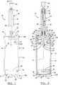
- the separator 10generally includes a tube or container 12 that is adapted to hold a fluid sample, such as an anticoagulated whole blood sample, for further processing. It will be understood that the tube may hold other solutions including constituents of more than one density, such as bone marrow or a mixture of whole blood and bone marrow.
- the tube 12includes a top or open end 12a, which is closeable, and a bottom or closed end 12b. The bottom 12b may also be selectively closeable.
- a first piston or buoy 14that is able to move along a central axis A of the tube 12.
- the buoy 14is generally nearer the bottom end 12b of the tube 12 rather than the open end 12a.
- a second piston or plunger 16is also disposed within the tube 12 .
- the plunger 16is also able to move within the tube 12 generally between positions closer to the open end 12a to a position closer to the closed end 12b of the tube 12.
- a cap 18substantially mates with the open end 12a of the tube 12 to close the tube 12 save for ports formed in the cap 18.
- Extending from the cap 18is a plasma valve or port 20 that communicates with an area, described further herein, within the tube 12 defined between the plunger 16 and the cap 18. It will be understood that the plasma port 20 is merely exemplary in nature and simply allows for removal of a selected fraction of a sample, such as plasma from whole blood.
- the cap 18also includes a depth gage port 19. Extending from the plunger 16 and through the depth gage port 19 is a first plunger port 22.
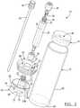
- a depth guide or gage 24includes a female connector 26 adapted to connect with the first plunger port 22.
- the depth gage 24also includes a depth gage housing or cannula 28.
- the depth gage housing 28defines a depth gage bore 30.
- Incorporated in the housing 28 and extending distal from the end mating with the plungeris a neck 32.
- the neck 32includes external neck threads 34.
- the external neck threads 34are adapted to engage appropriate internal threads of a mating member.
- the mating membermay include a compression nut 36 that mates with the external neck threads 34 to lock a depth gage rod 38 in a predetermined position.
- a split bushing 39is also provided to substantially seal the depth gage housing 28 when the depth gage rod 38 is locked in place.
- the depth gage rod 38extends through the depth gage housing 28 and terminates at a rod handle 40.
- the rod handle 40may be a form easily manipulated by a human operator.
- the rod 38extends coaxially with axis A of the tube 12.
- the depth gage rod 38extends through the plunger 16 a predetermined distance and may be locked at that distance with the compression nut 36.
- the tube 12is described here as a cylinder, it will be understood that other shapes may be used, such as polygons.
- the internal portions, such as the cap 18, buoy 14, and plunger 16,would also include this alternate shape.
- the tube 12is formed of a thermal plastic material which is flexible under the forces required to separate blood.
- the tube 12may be made of a material that includes the properties of both lipid and alcohol resistance. These properties help increase the separation speed and decrease the amount of material which may cling to the tube wall 42. For example, Cyrolite MED2® produced by Cyro Industries of Rockaway, New Jersey may be used to produce the tube 12.
- the tube 12has a tube wall 42 with a thickness of between about .01 millimeters and about 30.0 millimeters, although the tube wall 42 may be any appropriate thickness.
- the thickness of the tube wall 42allows the tube wall 42 to flex during the centrifuge process yet be rigid enough for further processing of a blood sample disposed in the tube 12.
- the tube 12is closed at the bottom end 12b with a tube bottom 44 formed of the same material as the tube wall 42 and is formed integrally therewith.
- the tube bottom 44has a thickness which is substantially rigid under the forces required to separate the sample such that it does not flex.
- the buoy 14includes an upper or collection face 46 that defines an inverse cone or concave surface.
- the conehas an angle of between about 0.5° to about 45°, and may be about 0.5° to about 90° from a vertical axis, wherein the apex of the cone is within the buoy 14.
- the collection face 46forms a depression in the buoy 14 which collects and concentrates material during the separation process.
- the buoy 14has a bottom face 48 that defines an inverse cone, dome, or covered surface.
- the buoy bottom face 48includes an apex 50 that engages the tube bottom 44 before a buoy edge 52 engages the tube bottom 44.
- the buoy 14includes a material that is a substantially rigid such that the buoy edges 52 never meet the tube bottom 44. Therefore, there is a gap or free space 54 formed between the buoy edge 52 and the tube bottom 44 along the perimeter of the buoy 14.
- the separator 10is generally provided to separate a multi-component fluid that generally includes various components or constituents of varying densities that are co-mingled or mixed together.
- the separator 10includes the buoy 14 that is of a selected density depending upon a selected constituent of the multi-constituent liquid.
- the buoy 14may be tuned or of any selected density, the following example relates to separation of whole blood to various components. Therefore, the buoy 14 will be discussed to include a selected density relative to whole blood separation. It will be understood, however, that the buoy 14 may be of any appropriate density depending upon the multi-component fluid being separated.
- the buoy 14may be formed of any appropriate material that may have a selected density.
- the buoy 14when the separator 10 is to separate blood, the buoy 14 generally has a density which is greater than that of red blood cells in a whole blood sample, but less than the plasma or non-red blood cell fraction of a whole blood sample.
- the density of the buoy 14is generally between about 1.02 g/cc and about 1.09 g/cc.
- the buoy 14may be formed as a composite or multi-piece construction, including a plurality of materials.
- a first or outside portion 56defines the collection face or surface 46 and the buoy edge 52 and is formed of the same material as the tube 12.
- the outside portion 56defines a cup or void into which a plug or insert 58 is placed.
- the insert 58has a mass such that the density of the entire buoy 14 is within the selected range, for example the range described above.
- a high density polyethylenemay be used, but the material and size of the insert 58 may be altered to produce the desired density of the buoy 14.
- the buoy 14may be formed of a single suitable material that has a density in the selected range. Nevertheless, the buoy 14 formed unitarily or of a single material would still include the other portions described in conjunction with the buoy 14.
- the outside portion 56 of the buoy 14also defines the outside circumference of the buoy 14.
- the outside circumference of the buoy 14is very close to the internal circumference of the tube 12. Due to the operation of the buoy 14, however, described further herein, there is a slight gap between the outside of the buoy 14 and the inside of the tube 12. Generally, this gap is between about 1 and about 10 thousandths of an inch around the entire circumference of the buoy 14. Generally, it is desired that the distance between the outside circumference of the buoy 14 and the inside circumference of the tube 12 is great enough to allow a selected material or component to pass. For example, in whole blood the distance is selected so that red blood cells may pass through the gap without being lysed, damaged, or activated.
- the plunger 16includes a plunger front or collection face 60 and a plunger wall 62 that extends from the plunger front face 60.
- the plunger wall 62extends relatively perpendicular to the plunger front face 60 and substantially parallel to the tube wall 42.
- Extending from the center of the plunger 16is a sample collection projection 64. Extending from the top of the collection projection 64 is the first plunger port 22.
- the sample collection projection 64includes a plunger sample collection bore 68 defined therethrough.
- the plunger sample collection bore 68terminates at a sample collection aperture 70 that is substantially in the center of the plunger front face 60.
- the plunger front face 60also defines an inverse cone where the sample collection aperture 70 is the apex of the cone.
- the plunger front face 60defines a cone with an angle substantially similar or complimentary to the collection face 46 of the buoy 14. In this way, the plunger front face 60 may mate substantially completely with the collection face 46 for reasons described more fully herein.
- the plunger 16also includes a back face 72. Extending from the plunger front face 60 to the back face 72 is a bore 74. A check valve 76 is operably connected to the bore 74. The check valve 76 allows a liquid to move from the plunger front face 60 to the back face 72 while not allowing the liquid to move from the back face 72 to the plunger front face 60. Therefore, the check valve 76 is substantially a one-way valve which allows a material to move in only one direction. The check valve 76 may also operate automatically allowing flow in only one predetermined direction. Alternatively, the check valve 76 may be operated manually and include a portion extending from the check valve 76 requiring manipulation to stop or start a flow through the check valve 76.
- the plunger 16may be made out of any appropriate material which does not interfere with the separation of the fractions of the fluid, such as whole blood.
- the plunger 16, however,is made of a material that is flexible or at least partially deformable.
- a flexible materialallows the plunger 16 to have an external circumference defined by the plunger walls 62 that is substantially equal to the internal circumference of the tube 12. Because of the deformability of the plunger 16, however, the plunger 16 is still able to move within the tube 12.
- the plunger 16is able to move through the tube 12 and also substantially wipe the interior of the tube wall 42. This creates, generally, a moveable seal within the tube 12.
- substantially no materialescapes the action of the separator 10 when the plunger 16 is plunged into the tube 12. This also helps concentrate the portion of the sample desired to be collected, described more fully herein.
- the cap 18provides a structure to substantially close the tube 12.
- the cap 18particularly includes a plate 78 that has an external circumference substantially equal to the external circumference of the tube 12. Extending from the plate 78 and into the tube 12 is a flange 80. The external circumference of the flange 80 is substantially equal to the internal circumference of the tube 12. In this way, the cap 18 substantially closes the tube 12. It will be understood the cap 18 may be in any form so long as the cap 18 substantially closes and/or seals the tube 12 when installed.
- the depth gage port 19is also adapted to receive the sample collection projection 64.
- the first plunger port 22extends above the plate 78 through the depth gage port 19.
- the circumference of the depth gage port 19is substantially equal to the external circumference of the sample collection projection 64 such that a liquid seal is formed.
- the plate 78defines a sample face 84 that includes an interior side of the cap 18.
- the area between the sample face 84 of the cap 18 and the back face 72 of the plunger 16define a plasma collection area 86.
- the plasma collection area 86is exemplary called the plasma collection area, it will be understood that the plasma collection area 86 may also collect any appropriate fraction of the sample that is positioned within a separator 10.
- the plasma collection area 86is merely an exemplary name and an example of what material may be collected in the area of the separator 10. As discussed herein, the separator 10 may used to separate whole blood into various fractions, therefore the plasma collection area 86 is used to collect plasma. The plasma collection area 86 also allows a space for the check valve 76 to be installed.
- a second bore 88is formed in the plate 78. Extending through the second bore 88 is the plasma collection valve 20. In liquid communication with the plasma collection valve 20 is a plasma collection tube 92.
- the plasma collection tube 92has a length such that the plasma collection tube 92 is able to extend from the plasma collection valve 20 to substantially the tube bottom 44.
- the plasma collection tube 92is flexible enough such that it may be folded or compressed to fit within the plasma collection area 86 when the plunger is substantially near the top 12a of the tube 12.
- the plasma collection tube 92may also be connected to a hose barb 93 that includes a plasma collection bore 93a.
- the plasma collection bore 93ais substantially level with the plunger back face 72. Alternatively, the plasma collection bore 93a may be positioned below the plunger back face 72 but in fluid communication with the plasma collection tube 92.
- the outboard side of the plasma collection valve 20may include external threads 94 to mate with internal threads of a plasma valve cap 96. Therefore, the plasma collection valve 20 may be selectively opened and closed via the plasma valve cap 96. It will be understood, however, that other appropriate means may be used to open and close the plasma collection valve 20 such as a clip or a plug. It will be understood that the plasma collection valve 20, plasma collection tube 92, plasma collection bore 23a may be used to collect any appropriate material or fraction from the separator 10.
- vent bore 98Also formed in the plate 78 is a vent bore 98.
- the vent bore 98allows air to flow into the collection area 86 as the plunger 16 is being plunged into the tube 12.
- the vent bore 98may include a filter 100 such that liquid cannot escape from the tube 12.
- the filter 100allows air to enter or escape from the collection area 86 while maintaining the liquid seal of the tube 12 produced by the cap 18.
- the depth gage 24is selectiveively attachable to the first plunger port 22.
- the female connector 26interconnects the depth gage housing 28 to the first plunger port 22. Internal threads in the female connector 26 mate with an external thread 102 formed on the first plunger port 22. It will be understood, however, that other engagement mechanisms between the depth gage 24 and the plunger 16 may be used. For example, a snap connection rather than a threaded connection between the two may be used.
- the depth gage housing 28is formed to be substantially rigid. Suitable materials, when sized properly, include polycarbonate and CYRO MED2®. The material preferably is both rigid and does not substantially react with the sample. It is rigid enough to provide a mechanism to plunge the plunger 16 into the tube 12. In addition the external circumference of the depth gage housing 28 is substantially equal to the circumference of the depth gage port 19 in the plate 78. Therefore, as the plunger 16 is being plunged into the tube 12 with the depth gage 24, no liquid material is allowed to escape around the depth gage housing 28 and through depth gage port 19.
- the depth gage rod 38Formed within the depth gage housing 28 is the bore 30 which receives the depth gage rod 38.
- the depth gage rod 38extends through the sample collection bore 68 of the sample collection projection 64 and protrudes through the sample collection aperture 70 a predetermined length.
- the depth gage rod 38extends through the sample collection aperture 70 a length such that when an end 104 of the depth gage rod 38 meets the buoy 14, the volume defined by the collection face 46 and the plunger front face 60 is between about 5 percent and about 30 percent of the total volume of the sample that the tube 12 holds.
- the projection of the depth gage rod 38allows for an easily reproducible collection amount and concentration over several trials.
- the compression nut 36locks the depth gage rod 38 in the predetermined position. Nevertheless, once the plunger 16 has been plunged to the desired depth in the tube 12, the compression nut 36 may be loosened so that the depth gage rod 38 may be removed from the plunger 16 and the depth gage housing 28 without moving the plunger 16. A syringe or other appropriate device may then be affixed to the external neck threads 34 of the depth gage 24 to extract the fraction or phase that is between the plunger front face 60 and the collection face 46. As described further herein, the fraction or phase that is left between the plunger front face 60 and the collection face 46 may be the buffy coat of a whole blood sample. Nevertheless, it will be understood that the fraction between the plunger front face 60 and the collection face 46 may be any appropriate fraction of the sample that is disposed in the separator 10.
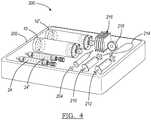
- the separator 10may be provided alone or in a kit 200, as illustrated in Fig. 4 .
- the kit 200may be placed in a tray 202 which is covered to provide a clean or sterile environment for the contents of the kit 200.
- the kit 200may include at least a first separator 10 and a second separator 10'.
- a first depth gage 24 and a second depth gage 24'are also provided, one for each separator 10, 10'.
- the kit 200also generally includes a first syringe 204, including a needle, to draw a biological sample, such as blood from a patient.
- the first syringe 204may also be used to place the sample in the first separator 10.
- a second device or syringe 210may be used to extract a first fraction of the sample. While a third device or syringe 212 may be used to extract a second fraction of the sample. Also a tourniquet 214 and other medical supplies, such as gauze 216 and tape 218, may be provided to assist the practitioner. It will be understood the elements of the kit 200 are merely exemplary and other appropriate items or elements may be included.
- a method using the blood separator 10is illustrated.
- the following examplerelates specifically to the taking and separation of a sample of whole blood from a patient.
- another appropriate biological materialmay be separated and concentrated using the separator 10.
- bone marrowmay be separated and concentrated using the separator 10.
- the various fractions of the bone marroware similar to the fractions of whole blood.
- the bone marrowincludes a fraction that includes substantially dense material and a second phase that is less dense and has other components suspended therein, such as nucleated cells.
- the bone marrow samplemay be positioned in the separator 10, similarly to the whole blood as described herein, and separated in a substantially similar manner as the whole blood.
- the separator 10can then be used to remove nucleated cells from the bone marrow sample whereas the separator 10, as described herein, is used to remove the buffy coat from the whole blood which includes platelets and other appropriate materials.
- a mixture of whole blood and bone marrowmay be positioned in the separator 10 for separation and concentration. Similar methods and steps will be used to separate the mixture of whole blood and bone marrow with a main difference being the material that is separated. It will also be understood that various centrifuge times or forces may be altered depending upon the exact material that is being separated with the separator 10. It will also be understood that the separation of whole blood, bone marrow, or a mixture of whole blood and bone marrow are merely exemplary of the materials that may be separated using the separator 10.
- a sample of whole blood taken from a patientis placed in the tube 12 with an anticoagulant using the first syringe 204 or other appropriate delivery method.
- the first syringe 204may be connected to the first plunger port 22.
- the blood sampleis provided to the tube 12 via the sample collection bore 68 and sample collection aperture 70.
- a cap 220is then placed over the first plunger port 22 to substantially seal the tube 12.
- the separator 10is placed in a centrifuge.
- the second separator 10'substantially identical to the first, is placed opposite the first separator 10 including the sample in a centrifuge.
- the second separator 10'may also include a second sample or may include a blank, such as water, so that the centrifuge is balanced.
- the second separator 10'balances the centrifuge, both by weight and dynamics.
- the separator 10is then spun in the centrifuge in a range between about 1,000 and about 8,000 RPMs. This produces a force between about 65 and about 4500 times greater than the force of normal gravity, as generally calculated in the art, on the separator 10 and the blood sample placed in the separator 10. At this force, the more dense material in a whole blood sample is forced towards the bottom 12b of the tube 12. The dense material, such as red blood cells or a red blood cell fraction 222, collects on the tube bottom 44. Because the buoy 14 has a density that is less than the red blood cell fraction 222, it is forced in a direction toward the top 12a of the tube 12 in the centrifuge. Nevertheless, because the buoy 14 is denser than a plasma fraction 224, the buoy 14 does not reach the top 12a of the tube 12.
- the forcesalso affect the tube wall 42.
- the forcescompress the tube 12 linearly along axis a thereby bowing or flexing the tube wall 42.
- the tube wall 42compresses it increases the diameter of the tube 12 making it easier for the buoy 14 to move in the direction of the top 12a of the tube 12.
- the bottom face 48defining an inverse cone, helps the initial movement of the buoy 14. Because the buoy 14 is not substantially flat along its bottom, it does not form a vacuum interaction with the tube bottom 44. Therefore, the initial movement of the buoy 14 away from the tube bottom 44 is quicker than if the bottom of the buoy 14 was flat.
- the red bloods cells of the red blood cell fraction 222force the buoy 14 in the direction of the top 12a of the tube 12 because the buoy 14 is less dense than the red blood cell fraction 222.
- the red blood cellsare able to move between the buoy 14 and the tube wall 42 because the circumference of the buoy 14 is less than the internal circumference of the tube 12.
- the buoy 14stops at an interface of a plasma fraction 224 and the red blood cell fraction 222 because of the selected or tuned density of the buoy 14.
- the centrifuge processhas been completed and the buoy 14 has moved to the interface of the red blood cell fraction 222 and plasma fraction 224.
- the tube wall 42decompresses which helps support the buoy 14 at the interface position. It is also understood that applying an external pressure to the tube 12 via fingers or another apparatus may help stabilize the buoy 14 during the plunging procedure described herein.
- a third fraction 226including a small, yet concentrated, amount of red blood cells, white blood cells, platelets, and a substantial portion of a buffy coat of the blood sample.
- the plasmais also present near the collection face 46 at this point the solid portions of the buffy coat are more compressed against the collection face 46.
- the position of the buoy 14also helps in this matter. Because the buoy 14 is a single body it defines the interface of the plasma traction 224 and the red blood cell fraction 222. Also the density of the buoy 14 assures that it has not passed into the plasma fraction 224. Therefore, the fractions remain separated after the centrifuge process. In addition because the buoy 14 is tuned to the density of the red blood cell fraction 222, it is not affected by variations in the density of the plasma fraction 224 and the buoy's 14 position is always at the interface of the red blood cell fraction 222 and the plasma fraction 224.
- the depth gage 24is affixed to the first plunger port 22 of the sample collection projection 64. After connecting the depth gage 24 to the first plunger port 22, the plunger 16 is plunged into the tube 12 by pushing on the depth gage 24. As this is performed the plasma fraction 224, formed and separated above the buoy 14, is able to flow through the check valve 76 into the plasma collection area 86. This displacement of the plasma fraction 224 allows the plunger 16 to be plunged into the tube 12 containing the blood sample.
- the plunger 16is plunged into the tube 12 until the point where the end 104 of the depth gage rod 38 reaches the buoy 14.
- the volume left in the collection face 46is the third fraction 226 and is determined by the depth gage 24. It may be adjusted by selectively determining the amount that the depth gage rod 38 extends below the plunger front face 60. By adjusting the depth gage 24, the concentration of the third fraction 226 can be adjusted depending upon the desires of the operator.
- the plasma fraction 224is held in the plasma collection area 86 for later withdrawal. Therefore, the use of the plunger 16 and the buoy 14 creates three distinct fractions that may be removed from the tube 12 after only one spin procedure.
- the fractionsinclude the red blood cell fraction 222, held between the buoy 14 and the tube bottom 44.
- the third or buffy coat fraction 226is held between the plunger 16 and the buoy 14.
- the plasma fraction 224is collected in the plasma collection area 86.
- the third fraction 226may be extracted from the tube 12 first, without commingling the other fractions; through the sample collection bore 68.
- the depth gage rod 38may be removed from the depth gage housing 28. This creates a sample collection cannula which includes the depth gage bore 30; the sample collection bore 68, and the sample collection aperture 70.
- the second syringe 210may be affixed to the depth gage housing 28 via the external neck threads 34.
- the second syringe 210may be substantially similar to the first syringe 204.
- the separator 10may be agitated to re-suspend of the platelets and concentrated red blood cells in a portion of the plasma remaining in the collection face 46. This allows for easier and more complete removal of the third fraction 226 because it is suspended rather than compressed against the collection face 46. A vacuum is then created in the second syringe 210 by pulling back the plunger to draw the third fraction 226 into the second syringe 210.
- the plunger 16moves towards the buoy 14. This action is allowed because of the vent bore 98 formed in the cap 18. Atmospheric air is transferred to the plasma collection area 86 through the vent bore 98 to allow the third fraction 226 to be removed. This also allows the movement of the plunger 16 towards the buoy 14. This action also allows the plunger 16 to "wipe" the collection face 46. As the plunger front face 60 mates with the collection area 46 the third fraction 226 is pushed into the sample collection aperture 70. This ensures that substantially the entire third fraction 226 collected in the collection area 46 is removed into the second syringe 210. It can also increase the repeatability of the collection volumes.
- the second syringe 210does not protrude out the sample collection aperture 70, it does not interfere with the collection of the third fraction 226.
- the second syringe 210is removed from the first plunger port 22. Also the extraction of the third fraction 226 leaves the plasma fraction 224 and the red blood cell fractions 222 separated in the tube 12.
- a third syringe 212may be affixed to the plasma collection valve 20.
- the third syringe 212is connected to the external threads 94 of the plasma collection valve 20 to ensure a liquid tight connection. It will be understood, however, that another connection mechanism such as a snap or compression engagement may be used to connect the third syringe 212 to the plasma collection valve 20.
- a vacuumis then created in the third syringe 212 to draw the plasma fraction 224 from the plasma collection area 86 through the plasma collection tube 92.
- the plasma collection tube 92is connected to the hose barb 93. Therefore, the plasma flows through the plasma collection bore 93a through the hose barb 93, and then through the plasma collection tube 92.
- the plasma collection tube 92may alternatively simply rest on the plunger back face 72 to collect the plasma fraction 224. In this way the plasma fraction 224 may be removed from the blood separator 10 without commingling it with the red blood cell fraction 222. After the plasma fraction 224 is removed, the separator 10 may be dismantled to remove the red blood cell fraction 222. Alternatively, the separator 10 may be discarded in an appropriate manner while retaining the red blood cell fraction 222.
- the separator 10allows for the collection of three of a whole blood sample's fractions with only one centrifugation spin.
- the interaction of the buoy 14 and the plunger 16allows a collection of at least 40% of the available buffy coat in the whole blood sample after a centrifuge processing time of about 5 minutes to about 15 minutes.
- the complimentary geometry of the plunger front face 60 and the collection face 46help increase the collection efficiency. Although only the cone geometry is discussed herein, it will be understood that various other geometries may be used with similar results.
- the plunger front face 60 being flexiblealso helps ensure a complete mating with the collection face 46. This, in turn, helps ensure that substantially the entire volume between the two is evacuated.
- the processfirst begins with the suction withdrawal of the third fraction 226 via the second syringe 210, but is completed with a fluid force action of the third fraction 226 as the plunger front face 60 mates with the collection face 46. As the plunger front face 60 mates with the collection face 46 the fluid force assists in removal of the selected fraction.
- the plunger 16also substantially wipes the tube wall 42. Because the plunger 16 is formed of a flexible material it forms a seal with the tube wall 42 which is movable. Therefore, substantially no liquid is able to move between the plunger wall 62 and the tube wall 42. Material is substantially only able to go past the plunger front face 60 via the check valve 76.
- the complimentary geometryalso helps decrease the collection time of the third fraction 226. Therefore, entire time to prepare and remove the third fraction 226 is generally about 5 to about 40 minutes. This efficiency is also assisted by the fact that the separator 10 allows for the removal of the third fraction 226 without first removing the plasma fraction 224, which includes the buffy coat, and respinning the plasma fraction 224. Rather one spin in the separator 10 with the whole blood sample allows for the separation of the buffy coat for easy extraction through the plunger 16.
- the separator 10may be used to separate any appropriate multi-component material.
- a bone marrow samplemay be placed in the separator 10 to be centrifuged and separated using the separator 10.
- the bone marrow samplemay include several fractions or components that are similar to whole blood fractions or may differ therefrom. Therefore, the buoy 14 may be altered to include a selected density that is dependent upon a density of a selected fraction of the bone marrow.
- the bone marrowmay include a selected fraction that has a different density than another fraction and the buoy 14 may be designed to move to an interface between the two fractions to allow for a physical separation thereof. Similar to the whole blood fraction, the plunger 16 may then be moved to near a collection face 46 of the buoy 14.
- the fraction that is then defined by the collection face 46 and the plunger 16may be withdrawn, as described for the removal of the buffy coat from the whole blood sample.
- the middle fraction or third fraction in the bone marrow samplemay include a fraction of undifferentiated or stem cells.
- mixtures of various fluidsmay be separated in the separator 10.
- a mixture of whole blood and bone marrowmay be positioned in the separator 10 at a single time.
- the buoy 14may be tuned to move to an interface that will allow for easy removal of both the buffy coat, from the whole blood sample, and the undifferentiated cells, from the bone marrow sample.
- the separator 10may be used within any appropriate biological material or other material having multiple fractions or components therein. Simply, the buoy 14 may be tuned to the appropriate density and the plunger 16 may be used to cooperate with the buoy 14 to remove a selected fraction.
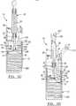
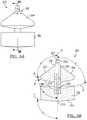
- the buoy system 300generally includes a first buoy or fraction separator member 302 and a second buoy member or fraction separator 304.
- the first buoy 302 and the second buoy 304may be operably interconnected with a buoy system cylinder or member 306.
- the buoy system 300may be placed in a tube, such as the tube 12.
- the tube 12may be formed of any appropriate material, such as the Cryolite Med® 2 as discussed above. Nevertheless, the buoy system 300 may be designed to fit in the tube 12 or may be formed to fit in any appropriate member that may be disposed within a selected centrifuging device.
- buoy system 300may be substantially matched to the size of the tube 12 is merely exemplary. As the buoy 14 may be sized to fit in any appropriate tube, the buoy system 300 may also be sized to fit in any appropriate tube. It will be further understood that the tube 12 may be any appropriate shape. The tube 12 need not only be cylindrical but may also be or include conical portions, polygonal portions, or any other appropriate shapes.
- the first buoy 302 of the buoy system 300may be generally similar in geometry to the buoy 14. It will be understood that the first buoy member 302 may be formed in the appropriate manner including shape or size to achieve selected results. Nevertheless, the first buoy member 302 generally includes an exterior diameter that may be slightly smaller than the interior diameter of the tube 12. Therefore, the first buoy member 302 may be able to move within the tube 12 during the centrifugal process. Also, as discussed above, the tube 12 may flex slightly during the centrifuging process, thus allowing the first buoy member 302 to include an exterior diameter substantially equivalent to the interior diameter of the tube 12. As discussed further herein, during the centrifugation process, a portion of the fraction of a sample may pass between the exterior wall of the first buoy member 302 and the tube 12.
- the first buoy member 302may generally include a density that is substantially equivalent to a first or selected fraction of the sample. If the sample to be separated includes whole blood and is desired to separate the red blood cells from the other portions of the sample, the first buoy member 302 may have a selected density that may be about 1.00 grams per cc (g/cc) to about 1.10 g/cc. It will be understood that the density of the first buoy member 302 may be any appropriate density, depending upon the fraction to be separated, and this range of densities is merely exemplary for separating red blood cells from a whole blood sample.
- the first buoy member 302includes a collection face or area 308 at a proximal or upper portion of the first buoy member 302.
- the collection face 308generally defines a concave area of the first buoy member 302 and may have a selected angle of concavity.
- the buoy assembly 300defines a central axis D.
- the collection face 308defines a surface E that is formed at an angle ⁇ to the central axis D of the buoy system 300.
- the angle ⁇may be any appropriate angle and may be about 0.5° to about 90°.
- the angle ⁇may, however, be between about 45° and 89.5°. Nevertheless, it will be understood that the angle ⁇ may be any appropriate angle to assist in collection of a selected fraction or portion of the sample by the first buoy member 302.
- a bottom or lower surface 310 of the first buoy member 302may define a bottom face.
- the bottom face 310may also be formed at an angle D relative to the central axis D.
- the bottom surface 310defines a surface or plane F that may be formed at an angle ⁇ relative to the central axis D of the buoy system 300.
- the angle ⁇may be any appropriate angle and may be about 90° to about 160°.
- the angle ⁇may be about 15°.
- the bottom surface 310defines an apex 312 that may first engage the bottom 12d of the tube 12, such that most or the majority of the bottom surface 310 does not engage the tube 12. As illustrated further herein, the apex 312 allows for a free space or gap to be formed between the bottom face 310 of the first buoy member 302 and the bottom 12b of the tube 12.
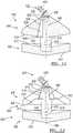
- the second buoy member 304may include an outer diameter substantially equivalent to the outer diameter of the first buoy member 302. Therefore, the second buoy 304 may move with the first buoy 302, particularly if the second buoy 304 is interconnected with the first buoy 302 with the buoy central cylinder 306. Nevertheless, the second buoy member 304 may be allowed to move substantially freely within the tube 12 during the centrifuging process.
- the second buoy member 304also includes an upper or superior surface 314 that defines a plane G that is formed at an angle relative to the central axis D of the buoy system 300.
- the angle ⁇ of the plane G relative to the central axis D of the buoy system 300may be any appropriate angle.
- the angle ⁇may be about 90° to about 150°.
- the angle ⁇may assist in allowing a selected fraction or a portion of the sample to pass over the top surface 314 and past the second buoy member 304 during the centrifuging process.
- the second buoy member 304also define a bottom or inferior surface 316 that also defines a plane H that may be formed at an angle K relative to the central axis D of the buoy system 300.
- the angle Kmay be any appropriate angle, such as about 90° to about 150°. Nevertheless, the angle K may be substantially complimentary to the angle ⁇ of the collection face 308 of the first buoy member 302. For example, if the angle ⁇ is about 80°, the angle K may be about 100°, such that substantially 180° or a straight line is formed when the first buoy member 302 engages the second buoy member 304. This may be for any appropriate reason, such as extraction of a fraction that may be disposed near the collection face 308 of the first buoy member 302. Nevertheless, the angle K may be any appropriate angle as the angle ⁇ .
- the second buoy member 304may be formed to include any appropriate density.
- the second buoy member 304may include a density that is less than the plasma fraction of a whole blood sample. It will be understood that the second buoy member 304 may include any appropriate density and a density that is less than the plasma fraction of a whole blood sample is merely exemplary. Nevertheless, if a whole blood sample is desired to be separated and the plasma sample is to be substantially separated from another fraction, the second buoy member 304 may include a density that is less than the plasma fraction of the whole blood sample. Therefore, the density of the second buoy member 304 may be about 0.01 g/cc to about 1.03 g/cc.
- the buoy system 300may be substantially positioned near an interface between the red blood cell fraction and the plasma fraction of a whole blood sample. Therefore, as discussed above and further described herein, the platelet or buffy coat fraction of the whole blood sample may be substantially collected near or in the collection face 308 of the buoy system 300.
- the buoy post 306may operably interconnect the first buoy member 302 and the second buoy member 304.
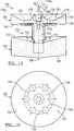
- the buoy post 306may be any appropriate connection member.
- the buoy postneed not be a single cylindrical portion.
- the buoy post 306may include one or more members interconnecting the first buoy member 302 and the second buoy member 304, such as around a perimeter thereof.
- the buoy post 306may include any appropriate shape or geometry.
- the buoy system post 306may be rigidly affixed to the first buoy member 302 and the second buoy member 304, such that the first buoy member 302 may not move relative to the second buoy member 304 and vice versa.
- the buoy post 306may be slidably connected to either or both the first buoy member 302 and the second buoy member 304.
- the buoy post 306is generally fixedly connected to the first buoy member 302 and slidably interconnected to the second buoy member 304.
- the buoy post 306may include a catch portion or lip 320 that are able to engage a portion of the second buoy member 304, such that a range of travel of the second buoy member 304, relative to the first buoy member 302 is limited. Nevertheless, the range of travel of the second buoy member 304 towards the first buoy member 302 may be substantially unlimited until the second buoy member 304 engages the first buoy member 302.
- the buoy post 306may also define a central cannula or bore 322.
- the post bore 322may include a connection portion 324 substantially defined near an upper or a proximal end of the buoy post 306. This may allow for interconnection of various components with the buoy post 306, such that various components may be moved through the bore 322 from an exterior location.
- the buoy post 306may also define a port or cannula 326 that connects the post cannula 322 with the collection face 308. Therefore, a substance may travel through the post cannula 322 and through the port 326. Various substances may then be provided to or removed from the collection face 308 of the first buoy member 302.
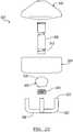
- the buoy system 300may be used to separate a selected multi component sample, such as a whole blood sample.
- a method of using the buoy system 300is illustrated and described.
- like reference numeralsare used to indicate like portions of the tube 12 and the associated mechanisms described in Figs. 1-3 . Therefore, it will be understood that the buoy system 300 may be used with the tube 12 or any other appropriate tube or container system or apparatus. Nevertheless, for simplicity, the description of a method of use of the buoy system 300 will be described in conjunction with the tube 12.
- the tube 12may include the cap 18 that further defines a plasma valve or port 20. Extending through the cap 18 and interconnecting with a first flexible tube or member 92, the plasma port 20 may be used to extract a selected fraction of the sample that is positioned above the second buoy member 304. As illustrated above, the first tube 92 may also be interconnected with a selected portion of the system, such as the top surface 314 of the second buoy member 304. As illustrated above, a valve may be positioned and is operably interconnect the tube 92 with the upper surface 314 of the second buoy member 304. Nevertheless, such a valve is not necessary and it may be provided merely for convenience.
- buoy system 300may be included in the tube 12 and used with the buoy system 300. Nevertheless, once the buoy system 300 is interconnected, it may be positioned in the interior of the tube 12 and the syringe 204 used to place a sample into the tube 12. The sample may be expressed from the syringe 204 into the interior of the tube 12 and the sample may be any appropriate sample, such as a whole blood sample. Nevertheless, it will be understood, such as discussed above, various other samples may be used, such as bone marrow samples, a mixture of bone marrow and whole blood or nonbiological fluids or materials. It will be understood that two buoys 302 and 304 may generally be near one another when the sample is positioned in the tube 12, but are illustrated apart for clarity of the present discussion.
- the samplemay be placed in the tube 12 according to various methods.
- an anticoagulant or other componentsmay be mixed with the whole blood sample, if a whole blood sample is used, before the whole blood sample is positioned within the tube 12.
- the syringe 204is connected with the plunger port 22 extending from the cap 18, although a plunger may not be used in various embodiments.
- a capmay be positioned over the port 22, such that the sample is not allowed to escape from the tube 12.
- the tube 12 including the sample and the buoy system 300may be centrifuged.
- substantially three fractions of the samplemay be formed.
- a first fraction 330may be positioned between the bottom face 310 and the bottom of the tube 44.
- a second fractionmay be positioned between the collection face 308 and the bottom surface 316 of the second buoy 304.
- a third fractionmay be positioned between the upper surface 314 and the cap 18 of the tube 12.
- the first fraction 330, the second fraction 332, and the third fraction 334are substantially physically separated with the buoy system 300.
- the tube 12may flex slightly to allow for ease of movement of the buoy system 300 through the tube 12 and the sample. Nevertheless, the buoy system 300, during the centrifugation process, substantially creates the three fractions 330, 332, and 334 without the operation of an operator. Therefore, the formation of at least three fractions may be substantially simultaneous and automatic using the buoy system 300.
- the buoy system 300substantially separates the fractions 330, 332, and 334, such that they may be easily removed from the tube 12.
- a syringe or other instrument 340may be used to extract the second fraction 332 by interconnecting a cannula or bored tube 342 with the connection portion 324 of the buoy cylinder 306.
- a vacuum or upward forceis produced within the extraction syringe 340. This force draws the second fraction 332 through the ports 326 of the buoy post 306 and through the buoy cannula 322.
- the second fraction 332may be extracted from the tube 12 without substantially comingling the second fraction 332 with either the first fraction 330 or the third fraction 334.
- the second fraction 332is drawn in the direction of arrow M through the cannula 322 and into the extraction syringe 340.
- the post 306is not provided other portions may be provided to gain access to the second fraction 332.
- a valve portionsuch as a puncture-able valve, may be provided in the second buoy 304 to be punctured with an object. In this way an extraction needle may puncture the valve to gain access to the second fraction 332.
- the buoy system 300may be able to form a plurality of fractions, such as the three fractions 330, 332, and 334 and at least the second fraction 332 may be extracted without substantially commingling the various fractions.
- the second buoy member 304may move in the direction of arrow M towards the first buoy member 302.
- the collection face 308 of the first buoy membermay include an angle ⁇ that is substantially complementary to the bottom face 316 of the second buoy member 304. Therefore, if the second buoy member 304 is allowed to move along the buoy cylinder 306, the bottom face 316 of the second buoy member 304 may be able to substantially mate with the collection face 308 of the first buoy member 302.
- the second buoy member 304may be provided with a vent port or valve, such that the extraction of the second fraction 332 from the collection face 308 may not be hindered by the buildup of undesirable forces. Nevertheless, if the second buoy member 304 may move, the interaction of the bottom face 316 of the second buoy member 304 may assist in substantially removing the entire second fraction 332 from the tube 12. As described above, the bottom face 60 of the plunger 16 may also serve a similar purpose when engaging the collection face 46 of the buoy 14.
- the second buoy member 304may substantially mate with a portion of the first buoy member 302. As discussed above, the second buoy member 304 may substantially only mate with the first buoy member 302 if the second buoy member 304 is able to substantially move relative to the first buoy member 302. Therefore, it will be understood that the second buoy member 304 need not necessarily mate with the first buoy member 302 and is merely exemplary of an operation of various embodiments.
- the port 20may be used in conjunction with a selected instrument, such as a plasma extraction syringe 212 to remove the plasma or the third fraction 334 from the tube 12 using the extraction tube 92 interconnected with the port 20.
- a selected instrumentsuch as a plasma extraction syringe 212 to remove the plasma or the third fraction 334 from the tube 12 using the extraction tube 92 interconnected with the port 20.
- the tube 92allows for extraction of the third fraction 334 from the tube 12 without comingling the third fraction 334 with the remaining first fraction 330 in the tube 12. Therefore, similar to the separator and extraction system 10, three fractions may be substantially formed within the tube 12 with the buoy system 300 and may be extracted without substantially comingling the various fractions.
- the buoy system 300may be removed from the tube 12, such that the first fraction 330 may be removed from the tube 12.
- the first fraction 330may be discarded with the tube 12 and the buoy system 300 as a disposable system.
- the systemmay be substantially reusable, such that it can be sterilized and may be sterilized for various uses.
- the description of the method of use of the buoy system 300is exemplary of a method of using a system according to various other embodiments. It will be understood, however, that various specifics may be used from various embodiments to allow for the extraction of selected fractions.
- the centrifugation processmay be substantially a single step centrifugation process.
- the buoy system 300may allow for the formation of three fractions during a single centrifugation process. This centrifugation process may occur at any appropriate speed, such as about 1000 rpms to about 8000 rpms. This speed may produce a selected gravity that may be approximately 4500 times greater than the normal force of gravity. Nevertheless, these specifics are not necessary to the operation of the buoy system 300 according to various embodiments.
- the buoy system 300may be used to extract a plurality of fractions of a sample after only a single centrifuging process and without substantially comingling the various fractions of the sample.
- the blood collection and separation system that includes the tube 12may be filled with a multi-component fluid or solution, such as blood from a patient, is illustrated.
- the tube 12may include any appropriate separation system, such as the separation system 300.
- any appropriate methodmay be used to fill the tube 12. For example, when a solution, including a plurality of components, is placed into the tube 12 it may be collected directly from a source.
- a patient 350may be provided.
- the patient 350may be provided for a selected procedure, such as generally an operative procedure or other procedure that requires an intravenous connection 352, such as a butterfly needle, to be provided in the patient 350.
- the intravenous connection 352generally provides a tube 354 extending therefrom.
- the tube 354may be used to withdraw fluids from the patient 350 or provide materials to the patient 350, such as medicines or other selected components. Nevertheless, the intravenous connection 352 is generally provided for various procedures and may be used to fill the tube 12.
- the tube 354may interconnect with the plunger port 22 or any appropriate portion of the tube 12.
- the port 22may be used to connect with the tube 354 in a similar manner as it would connect with the syringe 204, if the syringe 204 was provided. Nevertheless, it will be understood that the tube 354 may be provided directly to the tube 12 from the patient 350. This may reduce the number of steps required to fill the tube 12 and reduce possible cross-contamination from the patient 350 with the various components. Moreover, making a connection directly with the patient 350 may make the withdrawal and collection of blood from the patient 350 more efficient.
- a vacuum system 356may be provided.
- the vacuum system 356may include a vacuum inducing portion or member 358, such as a resilient bulb.
- the vacuum inducing member 358may be interconnected with the tube 12 through a selected connecting portion 360.
- the vacuum connecting portion 360may interconnect with an orifice 362.
- the orifice 362may be interconnected or extend from the cap 18 or provided in any appropriate portion with the tube 12. Nevertheless, a first one way valve 364 may be provided along the connection portion 360 or near the orifice 362.
- the one way valve 364provides that a flow of a fluid, such as a gas, may pass in a first direction but not in a second.
- a second one way valve 366may also be provided downstream from the first one way valve 364. In this way, a vacuum may be created with the vacuum inducing member 358, such that air is drawn out of the tube 12 and removed through the second one way valve 366 in the direction of arrow V.
- the airis generally withdrawn from the tube 12 without substantially allowing the air to flow back into the tube 12.
- a vacuumcan be created within the tube 12 to assist with removing a selected volume of fluid, such as blood, from the patient 350.
- the tube 12may be filled substantially directly from the patient 350, the collection of the fluid, such as blood, may be provided substantially efficiently to the tube 12.
- the vacuum system 356may be provided including the vacuum inducing member 358.
- Any appropriate vacuum creating devicemay be used, such as a mechanical pump or the like. Nevertheless, the tube 12 may be filled for use during a selected procedure.
- the tube 12may be used to separate a selected portion of the blood obtained from the patient 350 substantially intraoperatively. Therefore, the collection or separation of the various components may be substantially autologous and substantially intraoperatively. Moreover, obtaining the fluid directly from the patient 350 may increase the efficiency of the procedure and the efficiency of the intraoperative or the operative procedure.
- the separator 10may be used to separate any appropriate material.
- the materialmay be separated for any purpose, such as a surgical procedure.
- a selected fraction of a bone marrow aspirate or a bone marrow portionmay be produced with the separator 10 according to various embodiments.
- the selected fraction of the bone marrow aspiratemay include various components, such as undifferentiated cells.
- the various undifferentiated cellsmay be positioned in a selected scaffold or relative to a selected portion of a patient for providing a volume of the undifferentiated cells to the patient. It will be understood that the method described according to Fig.
- 9is merely exemplary of various embodiments that may be used to provide a selected fraction of a bone marrow aspirate or other material to a patient or selected position.
- the selected portionmay be placed on the scaffold in any appropriate manner, such as by spraying, dipping, infiltrating, or any appropriate method.
- a method of selecting or creating a selected fraction of a bone marrow aspirate in a selected scaffold according to a method 400is illustrated in Fig. 9 .
- the method 400may start in block 402 in obtaining a bone marrow aspirate volume.
- the bone marrow aspirate (BMA)may be obtained in any selected or generally known manner. For example, a selected region of bone, such as a portion near an operative procedure, may be used to obtain the bone marrow aspirate.
- an accessing devicesuch as a syringe and needle, may be used to access an intramedullary area of a selected bone. The BMA may then be withdrawn into the syringe for various procedures.
- the BMAmay be positioned in the separator 10 according to various embodiments in block 404.
- the BMAmay be positioned in any appropriate separator, such as those described above including the separator 10. Once the BMA is positioned in the separator 10, a selected fraction of the BMA may be separated from the BMA in block 406.
- the selected fraction of the BMAmay include undifferentiated cells or any appropriate portion of the BMA.
- the fractionation or separation of various fractions of the BMAmay allow for a volume of BMA to be taken from a single location and the separation or concentration of the selected portion may be performed in the separator 10.
- obtaining a small volume of the selected portion from a plurality of locationsmay be used to obtain an appropriate volume of BMA or selected fraction of the BMA.
- the separator 10may allow for separating a selected volume from a single location from which the BMA is obtained. This may reduce the time of a procedure and increase the efficiency of obtaining the selected fraction of the BMA.
- a volume of whole bloodmay be obtained in block 408.
- the volume of blood obtained in block 408, according to any appropriate procedure, including those described above,may then be positioned in the separator 10, in block 410.
- the whole bloodmay be positioned in any appropriate separator, such as those described above or a separator to separate a selected fraction of the whole blood.
- the whole bloodmay be separated into an appropriate fraction, such as a fraction including a platelet portion or buffy coat.
- the whole bloodmay be separated into selected fractions in block 412. It will be understood that the BMA and the whole blood volume may be obtained substantially simultaneously or consecutively in block 402 and 408.
- the selected fractions of the BMA obtained in block 406 and whole blood obtained in block 412may also be performed substantially sequentially or simultaneously.
- the separator 10 including the volume of the BMAmay be positioned in a separating device, such as a centrifuge, substantially opposite, so as to balance, the separator 10 including the volume of the whole blood. Therefore, a single separation, such as centrifuge procedure may be used to separate both the BMA and the whole blood into selected fractions. This again may increase the efficiency of the procedure to provide both a selected fraction of the BMA and a selected fraction of the whole blood substantially simultaneously.
- the selected fractions of the BMA and the whole blood, provided in block 406 and 412may be harvested in block 414.
- the selected fractions of the BMA and the whole bloodmay be harvested in block 414 for appropriate purposes, such as those described herein.
- the separator 10may be used to obtain the selected fractions of the BMA and the whole blood, through various procedures, such as those described above.
- the selected fraction of the BMAmay be positioned on an appropriate scaffold in block 416.
- the scaffold in block 416may be any appropriate scaffold, such as synthetic bone substitutes or allogenic tissue.
- the scaffoldsmay be used for appropriate procedures, such as hard or soft tissue grafting, including uses in non-union or chronic wounds.
- the undifferentiated cells of the BMAmay allow for a substantial source of cells for use during a substantially natural healing after an operative procedure, for example, the natural healing of a patient may use the supplied undifferentiated cells. Therefore, the scaffold may be positioned in a selected portion of the anatomy and the cells may be allowed to grow and differentiate into selected portions in the implanted position.
- the platelets of the whole bloodmay be positioned on or near the scaffold of block 418.
- the platelets of the whole blood fraction positioned in the scaffold of block 418may assist the undifferentiated cells and the anatomy into which the scaffold is positioned to allow for a substantially efficient and complete healing.
- the platelet fraction of the whole blood samplemay include various healing and growth factors that may assist in providing an efficient and proper healing in the anatomy. Therefore, the undifferentiated cells of the BMA, or other selected fraction obtained from the separation of the BMA, and the selected fraction of the whole blood, obtained from the separator, may be used with the scaffold to provide a substantially efficient implant.
- the separator 10, or any appropriate separator, such as that described abovemay allow for a substantially quick and efficient separation of the BMA and the whole blood into an appropriate fraction for use in the procedure.
- the scaffoldmay be implanted in block 420.
- the scaffoldmay be implanted in any appropriate position in the block 420 for various procedures. It will be understood that the scaffold may be implanted for any appropriate procedure and may allow for positioning the selected portion of the BMA, such as undifferentiated cells, and the selected portion of the whole blood, such as platelets, relative to a selected portion of the anatomy.
- the scaffoldmay allow for a bone ingrowth, such as allowed with the undifferentiated cells, to assist in healing of a selected portion of the anatomy.
- the separator 10can include alternative or multiple portions, apparatuses, or systems to assist in removing any selected portion or fraction from the tube 12.
- the tube 12can also include a second port 21, which may also be referred to as a plasma rich port (PRP).
- a second flexible member, such as a flexible tube 21a,can interconnect the PRP port 21 and the connection portion 324 of the buoy cylinder 306.
- the syringe 204can be used to introduce a whole sample, such as whole blood, BMA, combinations thereof, or any appropriate material, to the tube 12, as discussed above.
- the tube 12can then be placed in a centrifuge, or similar device, to separate the whole material into selected fractions.
- the flexible tube 21acan remain attached to the cylinder 306.
- the centrifuge forcesdecrease the tube 12 will decompress and assist in holding the buoy system 300 in place, as illustrated in Fig. 10B .
- the extraction syringe 340may be interconnected with the PRP 21 that is interconnected with the connection portion 324 of the buoy cylinder 306 via the flexible member 21a.
- the buoy cylinderallows access to the platelet rich area 332 between the buoy portions 302,304.
- accessmay be obtained and the platelet rich portion of the sample 332, between the two buoys 302,304, may be extracted in a plurality of ways.
- the illustrations and method described hereinare merely exemplary.
- the various fractions of the materialcan be used for various purposes, including those discussed above and herein.
- the various fractions that can be created with a separator 10can be applied to various portions of the patient 350 for selected purposes.
- the various fractions or componentsfor example of whole blood, can include various growth factors, anti-infection or anti-microbial components, and other selected portions.
- These materialscan be applied to the patient 350 ( Fig. 11 ) for various purposes such as infection prevention or reduction, speed healing, speed in growth, and the like.
- the platelet rich plasma and the platelet poor plasmacan be withdrawn from the separator 10 according to various embodiments.
- the extraction syringe 340can be used to extract the platelet rich plasma 332 from the tube 12.
- the platelet rich plasmacan be formed in any appropriate manner, including according to various embodiments discussed above.
- the extraction syringecan be used to apply a selected material, such as the platelet rich plasma fraction 332 onto the patient 350.
- the platelet rich plasma and the extraction syringe 340can be mixed with any selected component either during the application, prior to application, or at any appropriate time.
- the extraction syringe 340can be interconnected with an application syringe 448 as part of an application system 449.
- the application systemcan be any appropriate application system such as the one provided with the GPSII system sold by Biomet, Inc. It will be understood, however, that the application system 449 can be any appropriate application system.
- the application system 449can form a mixed spray S that can be sprayed onto a selected portion of the patient 350.
- a femur 450 and a tibia 452may be resected for various purposes.
- the resected portion of the femur 454 and the resected portion of the tibia 456may have a portion of the mixture, or any appropriate fraction, sprayed thereon for various purposes.
- the various portions of the whole blood fractioncan include growth factors that assist in bony re-growth or healing after the application of the material.
- the implant portionscan then be positioned relative to the femur 450 and the tibia 452 and healing can occur thereafter.
- an incision 458can be formed through the soft tissue of the patient 350 to gain access to the various portions, such as the femur 450 and the tibia 452.
- a portion of the material, such as a mixture of the platelet rich plasma from the extraction syringe 340can be mixed with a select other components, such as a material positioned in the second syringe application syringe 448 and sprayed onto soft tissue surrounding the incision 458.
- the mixturecan be any appropriate mixture, a thrombin can be included in this second application syringe 448 and mixed with platelet rich plasma in the extraction syringe 340.
- various other clotting agents, pharmaceuticalse.g., antibiotics, medicines and the like
- pharmaceuticalse.g., antibiotics, medicines and the like
- any of the selected materialscan be mixed with the platelet rich plasma in the extraction syringe 340 and applied to the patient 350 and in any appropriate manner.
- the various fractionssuch as the platelet poor plasma, the platelet rich plasma, the buffy coat, and the like, can be applied to the patient 350 and can be formed with the separator 10 according to various embodiments.
- the buffy coatcan provide a selected amount of white blood cells to the wound 458, the resected site 454, 456, and the like to assist in reducing or inhibiting postoperative infection and can assist with healing after an operative procedure.
- the various componentscan be formed autologously from the patient's whole blood, from their Bone Marrow Aspirate (BMA), or other biological fluids or materials. Therefore, as discussed above, the chance of contamination because of the use of an external source is reduced.
- BMABone Marrow Aspirate
- the selected fraction of the componentcan be applied during any appropriate procedure for purposes such as speed in healing, anti-infection action or the like.
- the buffy coatincluding the selected portion of white blood cells, platelet anti-microbial peptides and the like can be applied during a cesarean section operation, orthopedic operation, cosmetic operative procedures or the like.
- the various examplesare not intended to limit the teachings or applications of the selected materials such as buffy coat, which can be formed with the separator 10.
- the additional materials that can be added to the buffy coat fraction, the other fractions, or the likeare also intended to be merely exemplary and not intended to limit the teachings herein.
- the various portions or fractionscan be used for assisting in healing, regrowth, and infection or the like.
- the fractionsuch as the buffy coat
- the fractions, such as the white blood cellscan assist in anti-infection and healing of a patient or anatomy.
- the materialcan assist in reducing infection after an incision is made and during healing.
- the selected fractioncan be mixed with other materials for application to a patient.
- the buffy coatcan be mixed with other anti-infection materials, such as pharmaceuticals (i.e. antibiotics) to be applied to a surgical site.
- the materialscan be applied to a surgical site, such as a soft tissue incision, a resected bone portion, or the like for various purposes, such as anti-infection, help in healing, or the like.
- Various biological materials or factions thereofcan be formed according to selected methods and using various apparatuses. Apparatuses according to various embodiments, including those discussed herein, can be used to separate a selected fraction of a whole material for various purposes.
- a buoy or buoy systemthat can also be referred to as separation system, can be used to assist in separating a whole material into various and/or plurality of fractions. It will be understood, however, that any appropriate separation system can be provided to assist in separating a material.
- the buoy system 500can include portions that are similar to portions discussed above, such as the buoy system 300.
- the buoy system 300includes a first buoy portion 302 and a second buoy portion 304.
- the first buoy portion 302can move relative to the second buoy portion 304 along the connection portion 306.
- the second buoy portion 304can seal relative to a portion of the connection portion 306, such as an O-ring or other appropriate sealing interaction, including a tight fit between the second buoy member 304 and the connection member 306.
- the buoy system 500can also include a first buoy portion 502 and a second buoy portion 504.
- the buoy portions 502, 504can be formed substantially fixed relative to one another with a connection member 506.
- the connection member 506can extend along an axis 508 that can be similar to the axis D discussed above.
- the connection member 506, however,can fixedly interconnect to the first buoy member 502 and the second buoy member 504.
- the buoy portions 502, 504remain substantially fixed relative to one another such that they are not able to move relative to one another.
- the second buoy member 502can define a bottom surface 510 that includes features similar to the bottom surface 310.
- the first buoy portion 502can also define a collection face 512 that can include features similar to the collection face 308.
- the second buoy portion 304can also define a bottom surface 514 that can include any appropriate configuration, such as the bottom surface 316. Nevertheless, the bottom surface 514 of the second buoy portion 504 need not be formed to substantially mate with the collection surface 512 of the first buoy member 502 as the buoy portions are substantially fixed relative to one another.
- the buoy system 500can be formed in various ways.
- the buoy systemcan be formed as a single member, formed of a single piece, or can be formed of multiple pieces that are interconnected to form the buoy system 500.
- the buoy system 500can include any selected density or specific gravity, including those discussed above. It can be selected to form the buoy system 500 to include a density that can substantially position the collection face 512 generally below a fraction including the buffy coat of the whole blood sample. It will be understood that such a density can be any appropriate density such as about 1.00 gram per cc to about 1.10 grams per cc. Nevertheless, the entire buoy system 500 can be designed or formed to include the selected density because the portions of the buoy do not move relative to one another. It will be understood, however, that any appropriate portion of the buoy system 500 can be a formed to include the selected density.
- connection member 506defines a central or first bore 516 passing through the connection portion 506.
- the central bore 516can interconnect with a second or traversing bore 518 that includes an opening or multiple openings 520 near the collection surface 512. This can allow a material that is collected near the collection surface 512 to be transported through the central bore 516 as discussed above and further herein.
- a hose connection 522can be provided that defines a bore 524 that interconnects with the central bore 516 of the connection member 506.
- the various portions, including the connection member 506 and the tube connection 522can be formed as a single member with the other portions of the buoy system 500 or can be formed of separate portions that are interconnected.
- the second buoy member 504can be fixedly connected to the connection portion 506 in any appropriate manner.
- the second buoy portion 504can be formed as a single member or a single piece with the connection member 506.
- the second buoy portion 504can be connected to the connection member 506 using any appropriate method such as welding, adhesives, or any appropriate method. Nevertheless, a gap or passageway 526 can be defined between an inner wall 528 of the second buoy portion 504 in an outer surface 530 of the connection member 506.
- the passage 526can be provided in any appropriate number in or through the second buoy member 504.
- the passage 526can be opened at a selected end such as a top end 532 of the second buoy member 504. As discussed herein, this can allow selected materials to pass through the passage 526 at a selected time.
- a sealing member or check valve 534can be provided at a second end of the channel 526 such as an area between the bottom surface 514 of the second buoy member 504 and the collection surface 512.
- the check valve 534can allow for passage of a selected material upon the application of a force, such as centrifuging, a vacuum, or the like.
- the check valve 534can be any appropriate portion, such as a substantially flexible washer or member that is positioned relative to the second buoy portion 504.
- the check valve 534can include a washer or flat portion that is formed of any appropriate material such as a silicone material, a rigid material including a living hinge, or any appropriate configuration. Nevertheless, the check valve 534 can allow for a selected passage of a material or an inhibition of a passage of material at a selected time.
- a buoy system 600can be provided that is similar to the buoy system 500 illustrated in Fig. 12 .
- the buoy system 600can include portions that are similar to the portions of the buoy system 500 and like reference numerals are used to reference these portions for brevity of the current discussion.
- the buoy system 600can include a bottom buoy portion 502, a collection surface 512, a connection member 506, and bores 516 and 518 that pass through the connection portion 506.
- the bore 518can terminate or include a passage or opening 520 that can allow access to the internal bores from the collection surface 512.
- a hose connection 522can be provided to interconnect with the selected tool and a bore 524 can be provided therein.
- the buoy system 600can also include a second buoy portion 602 that is similar in operation but different in design from the second buoy portion 504.
- the second buoy portion 602can include a top surface that includes a geometry and design substantially similar to the second buoy portion 504.
- a bottom surface 604, however, of the second buoy member 602can include a first surface portion of 606 that can be substantially flat or perpendicular to a central axis of 608 of the buoy system 600.
- a second surface portion 610can also be defined by the second buoy portion 602 that substantially increases a volume between the collection surface 512 and the bottom surface 604 of the second buoy member 602 relative to the second buoy member 504 illustrated in the buoy system 500.
- the various surfaces 606, 610can be provided for any appropriate reason, such as providing a selected volume, separating a selected volume, or any appropriate purpose. Nevertheless, it will be understood that the various portions of the buoy systems according to various embodiments can be configured and designed for any appropriate purpose, such as separating a selected volume of material, achieving or sequestering a selected volume of material, or any other appropriate purpose.
- the first buoy portion 502, second buoy portion 602, the connecting portion 506, and the tube connection 522can be fixed together in any appropriate manner.
- the various portionscan be formed from a single piece such that they are formed as a single member or piece such as with injection molding, machining, or the like. Further, various portions can be interconnected in any appropriate manner, such as welding, adhesives, or the like.
- the second buoy portion 602can include a passage 614 that is similar to the passage 526 of the buoy system 500.
- the passage 614can be formed and defined between an inner wall 616 of the second buoy member and an outer wall or portion 618 of the connection member 506.
- the passage 614can be open at a top end 620 of the second buoy member 602 and can be closed with a check valve 622 near a bottom end of the passage 614.
- the check valve 622can be similar to the check valve 634 of the buoy system 500 and can be formed of any appropriate material, configuration or the like.
- buoy systems 500, 600having been described above include various portions. Although the buoy systems 500, 600 can be formed of differing materials, designs, or the like, they can be provided in the separator 10 to separate, sequester, and provide a selected material.
- buoy system 600will be described during use for illustration purposes only. It will be understood that the use of the buoy system 600 can be substantially similar to the use of the buoy system 500 and the geometry of the various portions can be selected for various reasons.
- the buoy system 600can be provided in the tube 12 as discussed above.
- the buoy system 600can be interconnected with a platelet rich plasma port 21 through the tube 21a that interconnects with the tube connection 522.
- the connection 522can interconnect with the bores 516 and 518 to obtain access to the collection face 512.
- a selected materialsuch as a whole blood sample from the syringe 200, can be positioned within the tube 12.
- the separator system 10including the tube 12 and the buoy system 600, can be positioned in the centrifuge for any selected period of time and under selected conditions, including those discussed above.
- the walls of the tube 12may flex, the buoy system 600 may move, and any other appropriate condition may occur, including those discussed above. Nevertheless, the buoy system 600 includes a selected density, specific gravity or other appropriate configuration can move to a selected region within the whole sample positioned within the tube 12.
- a buffy coat fraction or area 332that may also be referred to as a platelet rich plasma (PRP) can be substantially defined between an area of the second buoy portion 602 and the first buoy portion 502.
- PRPplatelet rich plasma
- a buffy coat fraction or area 332that may also be referred to as a platelet rich plasma (PRP)
- PRPplatelet rich plasma
- the PPP tube 92can interconnect with the PPP port 20 for access to the PPP fraction 334.
- the buoy system 600can define a passage 614 or any appropriate number of passages. During the centrifugation process, a portion of the material, such as the PRP 332, the PPP 334, or any other appropriate material may pass through the passage 614 because of the check valve 622. Therefore, the passage 614 can be provided to allow for ease of separation and movement of the buoy system 600 for various reasons.
- the buoy system 600can come to rest at a selected region within the tube 12, as illustrated exemplary in Fig. 14B .
- a syringe or other appropriate devicecan be interconnected with the PPP port 20 such that the PPP 334 is substantially withdrawn from the tube 12. It will be understood that the withdrawal tube 92 can extend to substantially near the second buoy portion 602 to allow for a substantially complete withdrawal of the PPP 334.
- the separation system 10can be used to separate any appropriate material in the separation of a whole blood sample or materials including blood is merely exemplary. Nevertheless, the PRP 332 can be accessed through the PRP tube 21a that is interconnected with the PRP port 21.
- a withdrawal device or extraction devicesuch as the syringe 340, can be interconnected with the PRP port 21.
- a vacuumcan be formed in the syringe 340 with the plunger 344 such that a vacuum is also formed within the bores 516, 518 of the connection member 506. With the vacuum, the PRP 332 can be withdrawn through the opening 520, the bores 516, 518, and the bore 524 through the tube connection 522 and into the syringe 340.
- the check valve 622can move to allow atmospheric air to enter into the area defined between the surfaces 604, 610 and the collection face 512.
- the pressure differential between the area of the collection phase 512 and the atmospheric pressure surrounding tube 12 and other portionscan be substantially released as the material is drawn within to the syringe 340. Therefore, the material can be easily drawn into the syringe 340, substantially all the material can be drawn into the syringe 340, and a back pressure is released to maintain the PRP in the syringe 340.
- buoy systems 500, 600can be used with any appropriate system.
- the separator 10, according to various embodiments, including those discussed herein,can be provided for various purposes, such as those discussed above.
- the buoy systems 500, 600can be used in the separator 10 as can any of the other appropriate buoy or separation systems.
- the separation buoy systems 500, 600are merely exemplary and not intended to limit the teachings included herein.
- separator 10can be used including any appropriate portions to achieve a separation, sequestering, extraction, or the like of any appropriate materials that are positioned within the separator 10.
- the discussion of the use of any selected buoy system, also referred to as a separation system, or the like,is merely exemplary and intended to provide various illustrative devices or applications. Nevertheless, the buoy systems 500, 600 can be provided to achieve selected results in a separation system 10.
- check valves 534, 622can be provided that open to allow the material to move in a first direction relative to the respective buoy systems 500, 600.
- the valves 534, 622can then move to a closed position to disallow material to move in a second direction relative to the buoy systems 500, 600.
- the buoy systems 500, 600can be provided for separating the material within the separation system 10.
- check valves or valvescan be provided in various configurations along with various configurations of the buoy systems to allow for separation of the material within the separation system 10.
- a buoy system 700is illustrated.
- the buoy system 700can include a first buoy member or portion 702 and a second buoy member or portion 704.
- the second buoy member 704can include a bottom surface 706 that includes an inverted apex or point 708.
- the apex 708can contact a bottom surface of the container 12 to assist in movement of the buoy system 700 during centrifugation.
- the second buoy member 704can also include a top surface 710 that defines a collection surface or face of the buoy system 700.
- a sump or shallow area 712is provided to allow material to collect within the collection face 710.
- the collected materialcan include the buffy coat or platelet rich plasma fraction or portion of a whole blood sample, as discussed above.
- other materialscan include a multi-potent (e.g. undifferentiated) or stem cell portion or fraction of a bone marrow sample.
- a multi-potent (e.g. undifferentiated) or stem cell portion or fraction of a bone marrow samplecan include materials of similar densities from various sources, such as a mixture of a whole blood sample and a bone marrow sample. The collected sample can be withdrawn, as discussed herein, and used for various purposes such as matrix creation, autologous application, etc.
- a channel 714can be formed in a post or connection member 716 that extends along an axis 716x that is interconnected or formed with the second buoy member 704.
- An elongated channel 718can extend towards a top of the container 12 through the post 716 similar to the first bore 516 of the buoy system 500.
- a connection member or hose barb 522can be provided to extend from the internal bore 718.
- a connection hosesuch as the hose 21a, can connect with the hose connection member 522 to allow for withdraw of material from the collection face 710 through the first passage 714 and the second passage 718.
- the top buoy 702can differ from the top buoys otherwise discussed above by including a sump or collection area 730.
- the collection area 730can be defined between a first inclined wall 732.
- the first inclined wall 732extends at an angle 732 ⁇ relative to the axis 716x and extends from a high point or higher point near an external perimeter or top edge 733 of the first buoy member 702 towards the central passage 718.
- a second angled wall 734that extends at an angle 734 ⁇ relative to the axis 716x from a higher point near the central passage 718 towards a lower point near the exterior perimeter 733 of the buoy member 702.
- a bottom wall 736can be provided to interconnect the two angled walls 732, 734 to define the collection area 730.
- the bottom wall 736is generally below or spaced a distance from a plane 733p (e.g. a top plane) defined at least in part by the upper edge of the edge 733.
- the bottom wall 734, or portions of the angled wall 732, 734can be removed or made open to define a void or passage vent 740 through the first buoy member 702.
- the vent passages 740allow material, such as the whole blood, to pass through the top or first buoy member 702 and to move towards a bottom of the container 44 during centrifugation of a material, such as whole blood and/or bone portions including bone marrow.
- the bottom wall 736can, therefore, be formed as spokes or arms that extends generally perpendicular to the axis 716x of the connection member 716 between the external angled wall 732 and the internal angled wall 734.
- bottom wall arms or spokes 736can be angled to taper towards the post connection portion 522 or away from the second buoy member 704. As illustrated further herein, whole blood or other material can then be directed towards the second buoy member 704 through the vent passage 740 by the angled wall 732, 734 and the bottom wall 736.
- a valve assembly 737both can be defined in part by a bottom surface 742 of the first buoy member 702.
- the valve assembly 737can further include a valve member 744 that can include a gate portion 746 that directly contacts the bottom surface 742 of the first buoy member 702 to close the vent passages 740 through the first buoy member 702.
- a seal portion 747can be provided to directly contact the bottom surface 742 and be positioned between the bottom surface 742 and the gate member 746.
- the gate portion 746can extend from and be formed as a single member with valve post or extension member 748 that can extend over and in various embodiments can be connected to the central post 716.
- the second valve body member 748can be adhered to the post 716 so that it does not cover the passage 714 so that material can be drawn though the central passage 718.
- the gate member 746can, however, be formed separately and later connected to the valve support 748.
- the valve portion 744can be formed of a single material, such as a flexible rubber, such as silicon rubber. Other particular materials can include appropriate polymers that have selected properties.
- the polymer of the gate portion 746 or the entire valve portion 744can be formed of a material that has a specific gravity of about 1.13 grams per cubic centimeter (g/cm 3 ).
- the specific gravity of the gate member 746can be selected such that it will move towards the second buoy member 704 during centrifugation with the whole material to allow material to pass through the vent passages 740 during the centrifugation process.
- the specific gravityaccording to any of the various embodiments, can also be selected to collect a selected component and can depend on the selected component or the multiple component material (e.g.
- the specific gravity of the gate portion 746 and/or the whole valve portion 744can be selected to be greater than a densest component of the multiple component material and/or greater than an aggregate density of all portions of the multiple component material (e.g. the fluid density and the cellular component density in whole blood).
- a biasing area or portion, such as a hinge or connection area 750connects the gate portion 746 and the support 748.
- the hinge area 750can be sized (e.g. appropriate thickness) or formed of an appropriate material such that it will then hinge or bend at a selected force, such as during centrifugation of a whole blood material. In either case, the hinge portion 750 hingedly biases the gate portion 748 towards the first buoy member.
- a process to use the buoy assembly 700is illustrated.
- a whole blood materialcan be positioned into the container 12.
- the container 12can then be positioned into a centrifuge and the container 12 can be spun around a central axis such that the whole blood material is forced towards the bottom 44 of the container 12.
- the whole bloodcan pass generally in a direction of arrows 760 and 762.
- the whole blood or portions thereofcan move through the vents 740 in the top buoy member 702 as the gate portion 746 of the valve portion 744 open.
- the gate portion 746can move in the direction of the arrow 762 and allow the vents 740 to be opened so that the blood and/or other selected material can pass through the vent 740 of the buoy assembly 700.
- the gate portion 746can be angled towards the bottom of the container 44 to allow for passage of at least a portion of the whole blood, such as the red blood cells and the buffy coat to pass through the vent 740.
- the whole bloodcan be separated into at least three portions and positions.
- the red blood cellscan be in a red blood cell fraction 330 near the bottom of the container 12, the platelet poor fraction 334 can be positioned in the top of the container 12, and the buffy coat 322 can be positioned between the first buoy portion 702 and the second buoy portion 704.
- the gate portion 746can be contacting the bottom surface 742 of the first buoy member 702 to close the vent 740 and maintain a separation of the material within the container 12.
- the buffy coatcan then be withdrawn through the tube 21a or otherwise removed from the container 12.
- the valve assembly 737can be used to assist in separating the whole or multiple component material placed in the container 12.
- the whole materialcan be placed above the buoy assembly including a selected valve assembly.
- the container 12can then be centrifuged and the buoy assembly can rise through the material.
- various componentscan be separated, agitated from the whole material, and otherwise collected in the collection area. This can increase collection volumes of selected components of the multiple component material.
- the buoy assembly 800can include portions that are similar to the buoy portion 700 discussed above, and like reference numerals are used to describe those portions and they are only described briefly here for reference.
- the buoy assembly 700can include the first buoy portion 702 and the second buoy portion 704.
- the second buoy portion 704can include the bottom portion 706 and the top surface 710 that defines a collection face.
- the passages 714 and 718can be provided to allow withdrawal through the central post 716 and the hose barb 522 for withdrawal from the collection container, as discussed above.
- the first buoy member 702can include the vents 740, as discussed above.
- the buoy system 800can include a valve assembly 810 that includes a biasing portion or member, such as a spring member 812, and a gate or clapper member 814.
- the gate member 814can be formed of appropriate materials that can contact or seal with the bottom surface 742 of the first buoy member 702 in a non-centrifugation or substantially static state.
- the gate portion 814therefore, can be formed of appropriate materials such as rubber, including silicone rubber materials. Additionally, polymer materials can also be used to form the gate member 814.
- the spring portion 812can also be formed of appropriate materials that are substantially non-reactive with the whole blood or a portion of the blood sample.
- the spring member 812can be formed of an appropriate stainless steel or titanium metal or alloys but can also be formed of an appropriate polymer material having a selected stiffness for acting as a valve biasing member.
- a sealing member or portion 816can be placed between the gate member 814 and the first buoy member 702. Thus, the gate 814 need not seal directly with the buoy member 702, as discussed above.
- the valve assembly 810can be selected to include a reactionary or actual specific gravity of about 1.13 grams per centimeter cubed such that the gate member 814 will move away from the bottom surface 742 of the first buoy member 702 to allow passage through the vent 740 of the first buoy member 702. Accordingly, the spring force of the spring member 812 can be selected such that the interaction of the gate member 814 in the buoy assembly 800 will effectively be 1.13 grams per centimeter cubed. Alternatively, the spring force can be selected to be any appropriate spring force to hold the gate member 814 relative to the first buoy bottom 742.
- the specific gravity of the gate member 814can be provided to be substantially greater than specific gravity of 1.13 g/cm 3 and can be a specific gravity such as about 1.0 g/cm 3 to about 3 g/cm 3 ; including about 1.1 g/cm 3 to about 1.2 g/cm 3 ; including about 1.13 g/cm 3 .
- the spring force of the spring member 812can be enough to hold the gate member 814 against the first buoy member bottom surface 742 but is overcome by the forces of the whole blood or portion of the whole blood on the gate member 814 during centrifugation when the buoy assembly 800 is in the container 12 with the whole blood sample.
- the process of using the buoy system 800is illustrated.
- the container 12can be filed with a whole blood sample, as illustrated in Fig. 14A , and centrifugation can be applied to the tube 12 and the buoy assembly 800 to force at least a portion of the whole blood sample to move generally in the direction of arrows 820 and 822.
- the gate portion 814will also generally move in the direction of arrows 820 and 822.
- a portion of the whole blood sample, including the red blood cells and the buffy coatcan then move in the direction of arrows 820 and 822 through the vents 740 in the first buoy member 702.
- the force on the whole blood sample and/or the gate member 814can overcome the spring force of the spring member 812 and allow the gate portion 814 to move away from the first buoy member bottom 742 and open the valve to allow the portion of the whole blood sample, including buffy coat and the red blood cells, to pass through the first buoy member 702 through the vent 740.
- the gate member 814can move to contact the first buoy member bottom 742 to close the valve.
- the movement of the gate member 814can be due to the spring force of the spring member 812 pushing or moving the gate portion or member 814 towards the first buoy member bottom 742.
- the fractions of the whole blood samplecan then be maintained and selected materials can be separated or collected from the tube 12. For example, as illustrated above, selected fractions can be withdrawn through the tube 21a including the buffy coat fraction 322 through the passages 714 and 718.
- various embodimentscan allow for a valve assembly to be provided in various buoy assemblies to assist in separation of a whole blood sample into selected fractions.
- the valve systemscan allow for maintaining a separation of various fractions, such as components of whole blood sample.
- the valvescan also assist in allowing passage of certain fractions of the whole blood sample to achieve the separation of the components and the buoy assemblies can assist in maintaining separation with the valve assemblies.
- the passage vent 740 and the first buoy member 702can also assist in separation of the whole blood sample by allowing a greater surface area for passage a portion of the whole blood sample through portions of the buoy assemblies. Accordingly, the passage vent 740 can reduce a separation time of the whole blood sample into at least the buffy coat.
- the container 12can also include the features as discussed above, such as flexing, to assist in separation of the whole blood sample. Additionally, the container can contact the respective buoy assemblies to hold the buoy assemblies at a selected location within container 12 when a centrifugation force is not being applied to the container 12 with a whole blood sample and buoy assemblies within the container 12.
- the buoy assemblies 700 and 800are illustrated with substantially fixed portions, such as the first buoy member 702 fixed relative to the second buoy member 704 with the post portion 716. It will be understood, however, that the first buoy member can be provided to move relative to the second buoy member 704 as discussed above. For example, the first buoy member 702 can move relative to the second buoy member 704 and the spring force of the spring member 812 can maintain the gate portion or member 814 in contact the first buoy member bottom surface 742.
- first buoy member 702 and the second buoy member 704can be provided at different specific gravies such that they will separate at different times and at different speeds during centrifugation process to allow for the gate member 746, 814 to move away from the vent 740 while still allowing the first buoy member 702 to move relative to the second buoy member 704.
- a passagecan be provided in selected buoy members.
- a buoy assembly 900is illustrated.
- the buoy assembly 900includes a first buoy member 902 and a second buoy member 904 that are interconnected, either fixedly or moveably, with a post 906.
- the post 906can include a longitudinal bore 908 to allow withdrawal of a material from a collection surface or face 910 formed by the second buoy member 904 and a bore passage 912.
- the second buoy member 904can include spokes or extension members 914 that form passage or vent 916 through the second buoy member 904.
- the passage vents 916can allow material, such as a portion of a whole blood sample, to pass through the second buoy member 904 during centrifugation.
- the buoy assembly 900can be positioned in the separation tube 12 and positioned in a centrifuged bucket or chamber.
- the buoy assembly 900can also include a bottom or base support 920 that fixedly engages the second buoy member 904, such as with a fusing or adhesion of an end of a member of the bottom support 920 into or with the second buoy member 904.
- Extending from near a center of the bottom support 920can be a plug or closing member guide post 924.
- a plug member 926Moveable relative to the guide post 924 is a plug member 926 that includes an internal passage or blind bore 928 that allows the plug 926 to slide over the plug support post 924.
- the plug 926can also include a plug surface or valve stopping or closing 930 that can engage a passage surface 932 defined by a surface of the second buoy member 904 defined at least in part by the spokes 914.
- the plug surface 930can be provided complimentary to the passage surface 932 to form a seal.
- the plug surface 930can be angle obliquely relative to an axis of centrifugal force to allow material to easily or efficiently pass when the valve
- the plug 926In the assembled and uncentrifuged state, the plug 926 can be biased against the valve body surface 932. In the static state, the plug surface 930 of the plug 926 engages the bottom surface 932. The plug 936 thus closes or plugs the vent passages 916 by the force of a biasing spring 940.
- the plug 926can move towards an exterior surface 942 of the support member 920 to open the valve defined by or formed by the plug surface 930 and the bottom surface 932 of the second buoy member 904. That is, the plug 926 is operable to move towards or in the direction of an arrow 926a during centrifugation by overcoming the spring force of the spring 940.
- the separation container 12can enclose the buoy assembly 900 and include a passage or port 946 near the resting position of the buoy assembly 900 and near or substantially adjacent to the bottom support 920 of the buoy assembly 900. Accordingly, material can be introduced into the container 12 generally in the direction of arrow 950 to allow filling of the container 12 from a position adjacent to or in the direction that the buoy assembly 900 will move during centrifugation. Effectively, the port 946 is positioned at or near the bottom 44 of the separation tube 12. During centrifugation, the separation tube 12 including the buoy assembly 900 is spun around a central axis such that the centrifugal force is generally in the direction of arrow 12c and towards the bottom 44 of the container 12.
- material positioned within the separation container 12can move in the direction of arrows 952 through the second buoy member 904 towards the first buoy member 902.
- the plug member 926is able to overcome the spring force of the spring 40 and move towards the bottom surface 942 of the bottom support 920 generally in the direction of arrow 926a.
- the plug 926can move based upon its specific gravity relative to the whole material, as discussed herein.
- the buoy assembly 900can at least float on top of or move through the whole blood sample or other whole material sample as it is positioned within the separation container 12. During the centrifugation and when the plug 926 overcomes the spring biasing force then the buoy assembly 900 can move towards the bottom 44 of the separation container 12 and move through the whole blood sample. The movement of the buoy assembly 900 through the whole blood sample can assist in separating, with a mechanical force and mechanical means, materials within the whole blood sample.
- a valve or portcan be provided to connect to the collection tube 21a to allow for withdraw from the collection surface 910, similar to that discussed above.
- the plug 926can be formed of a material that has a specific gravity greater than that of the whole blood or other whole material sample. For example, if whole blood is separated in the separation tube 12, the specific gravity of the plug 926 can be about 1.13 grams per cubic centimeter. Although it will be understood that other materials can include different specific gravities, thus it will be understood that specific gravity of the plug 926 can be selected based on the different materials.
- the spring force and spring material of the spring 940can be substantially relate with the material to be separated and can have a spring force that can be overcome with by the plug 926 during the centrifugation.
- a buoy assembly 1000is illustrated including two valve assembly portions.
- the buoy assembly 1000can include the first buoy member 702, as illustrated in Fig. 15 that includes the sump area 730 as discussed above.
- a first valve portioncan be defined or formed by the gate portion 746 that engages the bottom surface 742 of the first buoy member 702.
- the gate 746can be hingedly biased with the hinge portion 750 or the spring 812.
- the valve portions 744can be or are positioned around the post 906 of the buoy assembly 900.
- the buoy assembly 1000can further include the second buoy member 904 of the buoy assembly 900.
- the second buoy member 904can include the bottom surface or surface 932 that can engage the plug member 926 that is biased and positioned by the spring 940 carried on the bottom member or support member 920.
- the buoy assembly 1000can thus include two valve portions such as the gate portion 746 and the plug portion 926.
- the multiple valve assemblies of the buoy assembly 1000can be provided within the separation container 12, as illustrated above, to allow for movement of material through the buoy assembly 1000 during the various centrifugation steps.
- the separation container 12 including the buoy assembly 1000can be filled from either end and the various valve assemblies can be used to assist in allowing the portions of the multiple component material to move past the buoy assembly 1000 during centrifugation or separation within the container 12.
- the buoy assembly 1000can include multiple valve areas to assist in allowing material to move pass the buoy assembly 1000.
Landscapes
- Chemical & Material Sciences (AREA)
- Health & Medical Sciences (AREA)
- Life Sciences & Earth Sciences (AREA)
- Chemical Kinetics & Catalysis (AREA)
- Engineering & Computer Science (AREA)
- Physics & Mathematics (AREA)
- Hematology (AREA)
- Biomedical Technology (AREA)
- Analytical Chemistry (AREA)
- General Health & Medical Sciences (AREA)
- Pathology (AREA)
- Immunology (AREA)
- General Physics & Mathematics (AREA)
- Biochemistry (AREA)
- Ecology (AREA)
- Medicinal Chemistry (AREA)
- Food Science & Technology (AREA)
- Urology & Nephrology (AREA)
- Molecular Biology (AREA)
- Biophysics (AREA)
- Thermal Sciences (AREA)
- Clinical Laboratory Science (AREA)
- Centrifugal Separators (AREA)
- External Artificial Organs (AREA)
- Investigating Or Analysing Biological Materials (AREA)
Description
- The present teachings relate to a multiple component fluid and a concentrator/separator, and more particularly relates to a container operable with a centrifuge to separate and concentrate various biological components.
- Various fluids, such as whole blood or various other biological fluids may be separated into their constituent parts, also referred to as fractions or phases. For example, whole blood samples may include a plurality of constituents that may be separated by density in a device such as a centrifuge. The whole blood sample may be placed in a test tube, or other similar device, which is then spun in a centrifuge. In the centrifuge the whole blood is separated into different fractions depending upon the density of that fraction. The centrifugal force separates the blood or other sample into different fractions. In addition, various elements may be added to the test tube to create more than two fractions. In particular, commonly used gels may be used to divide the whole blood into a plurality of different fractions which may include fractions such as platelets, red blood cells, and plasma. Various other biological fluids may be separated as well. For example, nucleated cells may be separated and extracted from bone marrow or adipose tissue sample.
- Many of these systems, however, do not provide a simple or efficient method to extract any more than one fraction and especially a fraction other than the top fraction. The top fraction of whole blood is plasma, or other blood constituents suspended in plasma. Thus, to extract other fractions the plasma fraction must either be removed or spun again to obtain the constituents suspended in this plasma. It is difficult to pierce the top fraction without comingling the sample. Accordingly, obtaining the other fractions is difficult with commonly known systems.
- Other systems have attempted to alleviate this problem by providing a float or other device that is disposed within the sample at the interfaces of the different fractions during the centrifuge process. Nevertheless, these systems still do not allow a simple way to remove the different fractions without remixing the sample fractions. In addition, many of the systems do not allow an easy and reproducible method to remove the desired sample fraction.
fraction. A solution of said prior art known systems is, for example, disclosed in the documentUS 2010/256595 A1 . - Therefore, it is desired to provide a device to allow for the easy and reproducible removal of a particular fraction which does not happen to be the top fraction of a sample. It is desired to remove the required sample without mixing the different fractions during the extraction process. In addition, it is desired to provide a device which allows for a consistent extraction which includes known volumes or concentration of the fraction elements. Moreover, it is desired to separate and concentrate a selected fraction with one centrifugation step.
- An apparatus that separates and/or concentrates a selected fraction or component of a fluid, such as a biological fluid. For example, a buffy coat or platelet fraction or component of a whole blood sample or an undifferentiated cell component of bone marrow or adipose tissue sample. The apparatus, when used with a centrifuge, is generally able to create at least two fractions. It also provides for a new method of extracting the buffy coat fraction or component or middle fraction from a sample.
- According to various embodiments a separation system for separating at least one component of a multiple component material with a centrifugal force is disclosed. The separation system includes a first buoy member having an exterior perimeter defined by an exterior wall, the first buoy member including a passage through the first buoy member and within the exterior perimeter; a connection member operably connected to the first buoy member; and a second buoy member operably connected to the connection member, wherein a distance between the second buoy member and the first buoy member is operable to be formed so that at least a first surface of the second buoy member is operable to be spaced a distance from the first buoy member. The buoy member further includes a valve assembly including a gate member biased towards the first buoy member to contact the first buoy member and close the passage through the first buoy member.
- According to various embodiments a separation system for separating at least one component of a multiple component material with a centrifugal force is disclosed. The separation system includes a first buoy member having a first side and a second side; a second buoy member having a first and second side, wherein the second buoy member defines a passage that extends through the first side and the second side and within an external perimeter of the second buoy member; and a connection member fixedly connected to the second side of the first buoy member and the first side of the second buoy member so that the second side of the first buoy member is spaced a distance from the first side of the second buoy member. The buoys further includes a plug member and a spring biasing the plug member towards the second side of the second buoy member.
- According to various embodiments a method for separating at least one component of a multiple component material with a centrifugal force is disclosed. The method includes providing a container with a buoy separation system including a first buoy member and a second buoy member fixed to a connection member and spaced apart and placing a first volume of a whole material into the provided container. The method further includes applying a gravitational force to the container including the buoy separation system and the first volume of the whole material and a valve opening to allow moving at least a portion of the first volume of the whole material through a passage defined within at least one of the first buoy member or the second buoy member. At least a portion of one component of the multiple component material is separated into a volume defined at least in part by the buoy separation system after moving at least the portion of the first volume of the whole material through the passage. In the method, the valve closes the passage defined within at least one of the first buoy member and the second buoy member.
- Further areas of applicability of the present invention will become apparent from the detailed description provided hereinafter. It should be understood that the detailed description and specific examples, while indicating various embodiment of the invention, are intended for purposes of illustration only and are not intended to limit the scope of the invention.
- The present invention will become more fully understood from the detailed description and the accompanying drawings, wherein:
Fig. 1 is a plan view of a separator including a depth gage affixed to a plunger in a tube according to a first embodiment of the present invention;Fig. 2 is a cross-section view taken along line 2-2 ofFig. 1 ;Fig. 3 is an exploded of the separator apparatus;Fig. 4 is a kit including the separator according to an embodiment of the present invention;Fig. 5A is a plan view of the separator being filled;Fig. 5B is a plan view of a blood sample in the separator after the centrifuge process;Fig. 5C is a plan view of the plunger plunged into the tube with the depth gage to further separate the blood sample;Fig. 5D is a plan view of the buffy coat and the plasma fractions being extracted from the separator;Fig. 6A is a side plan view of a buoy system according to various embodiments;Fig. 6B is a cross-sectional view of the buoy system ofFig. 6a ;Fig. 7A is a plan view of a separator according to various embodiments being filled;Fig. 7B is a plan view of a separator, according to various embodiments, after a centrifugation process;Fig. 7C is a plan view of a separator system being used to extract a selected fraction after the centrifugation process;Fig. 7D is a plan view of a second fraction being extracted from the separator according to various embodiments;Fig. 8 is a schematic view of an assisted blood withdrawal device;Fig. 9 is a block diagram of a method for implanting selected fractions of a fluid;Figs. 10A-10C is a plan view of a separator system in operation;Fig. 11 is an environmental view of a sprayer system with a two-part mixture being expressed onto a portion of an anatomy;Fig. 12 is a partial cross-section view of a buoy system according to various embodiments;Fig. 13 is a detail partial cross-section view of a buoy system according to various embodiments;Fig. 14A-14C is a plan view of a separator system in operation;Fig. 15 is a cross-sectional view of a buoy assembly according to various embodiments;Fig. 16 is a top plan view of the buoy assembly ofFig. 15 ;Fig. 17 is an exploded perspective view of the buoy assembly ofFig. 15 ;Figs. 18A and 18B illustrate the buoy assembly inFig. 15 in use;Fig. 19 is a cross-sectional view of a buoy assembly according to various embodiments;Fig. 20 is an exploded perspective view of the buoy assembly ofFig. 19 ;Figs. 21A and 21B illustrate the buoy assembly inFig. 19 in use;Fig. 22 is a cross-sectional view of a buoy assembly according to various embodiments;Fig. 23 is an exploded view of the buoy assembly ofFig. 22 ;Fig. 24 is an exploded perspective view of the buoy assembly ofFig. 22 ;Figs. 25A and 25B illustrate the buoy assembly inFig. 22 in use; andFig. 26 is a cross-sectional view of a buoy assembly according to various embodiments.- The following description of various embodiments is merely exemplary in nature and is in no way intended to limit the invention, its application, or uses. Although the following description exemplary refers to a blood separation, it will be understood that the present invention may be used to separate and concentrate any appropriate material. It will be further understood that many multi-component or multi-fraction fluids may be separated. The components or fractions are generally inter-mingled in the whole sample but may be separated with a centrifuge device that causes increased local gravity or gravitational forces.
- With reference to
Figs. 1-3 , according to various embodiments aseparator 10, also referred to as a concentrator, is illustrated according to a first embodiment of the present invention. Theseparator 10 generally includes a tube orcontainer 12 that is adapted to hold a fluid sample, such as an anticoagulated whole blood sample, for further processing. It will be understood that the tube may hold other solutions including constituents of more than one density, such as bone marrow or a mixture of whole blood and bone marrow. Thetube 12 includes a top oropen end 12a, which is closeable, and a bottom orclosed end 12b. The bottom 12b may also be selectively closeable. - Disposed within the
tube 12 is a first piston or buoy 14 that is able to move along a central axis A of thetube 12. Thebuoy 14 is generally nearer thebottom end 12b of thetube 12 rather than theopen end 12a. Also disposed within thetube 12 is a second piston orplunger 16. Theplunger 16 is also able to move within thetube 12 generally between positions closer to theopen end 12a to a position closer to theclosed end 12b of thetube 12. Acap 18 substantially mates with theopen end 12a of thetube 12 to close thetube 12 save for ports formed in thecap 18. Extending from thecap 18 is a plasma valve orport 20 that communicates with an area, described further herein, within thetube 12 defined between theplunger 16 and thecap 18. It will be understood that theplasma port 20 is merely exemplary in nature and simply allows for removal of a selected fraction of a sample, such as plasma from whole blood. - The
cap 18 also includes adepth gage port 19. Extending from theplunger 16 and through thedepth gage port 19 is afirst plunger port 22. A depth guide orgage 24 includes afemale connector 26 adapted to connect with thefirst plunger port 22. Thedepth gage 24 also includes a depth gage housing orcannula 28. Thedepth gage housing 28 defines a depth gage bore 30. Incorporated in thehousing 28 and extending distal from the end mating with the plunger is aneck 32. Theneck 32 includesexternal neck threads 34. Theexternal neck threads 34 are adapted to engage appropriate internal threads of a mating member. - The mating member may include a
compression nut 36 that mates with theexternal neck threads 34 to lock adepth gage rod 38 in a predetermined position. Asplit bushing 39 is also provided to substantially seal thedepth gage housing 28 when thedepth gage rod 38 is locked in place. Thedepth gage rod 38 extends through thedepth gage housing 28 and terminates at arod handle 40. The rod handle 40 may be a form easily manipulated by a human operator. Therod 38 extends coaxially with axis A of thetube 12. Thedepth gage rod 38 extends through the plunger 16 a predetermined distance and may be locked at that distance with thecompression nut 36. - Although the
tube 12 is described here as a cylinder, it will be understood that other shapes may be used, such as polygons. The internal portions, such as thecap 18,buoy 14, andplunger 16, would also include this alternate shape. Preferably thetube 12 is formed of a thermal plastic material which is flexible under the forces required to separate blood. Thetube 12 may be made of a material that includes the properties of both lipid and alcohol resistance. These properties help increase the separation speed and decrease the amount of material which may cling to thetube wall 42. For example, Cyrolite MED2® produced by Cyro Industries of Rockaway, New Jersey may be used to produce thetube 12. - The
tube 12 has atube wall 42 with a thickness of between about .01 millimeters and about 30.0 millimeters, although thetube wall 42 may be any appropriate thickness. The thickness of thetube wall 42 allows thetube wall 42 to flex during the centrifuge process yet be rigid enough for further processing of a blood sample disposed in thetube 12. Thetube 12 is closed at thebottom end 12b with a tube bottom 44 formed of the same material as thetube wall 42 and is formed integrally therewith. Generally the tube bottom 44 has a thickness which is substantially rigid under the forces required to separate the sample such that it does not flex. - The
buoy 14 includes an upper or collection face 46 that defines an inverse cone or concave surface. Generally the cone has an angle of between about 0.5° to about 45°, and may be about 0.5° to about 90° from a vertical axis, wherein the apex of the cone is within thebuoy 14. The collection face 46 forms a depression in thebuoy 14 which collects and concentrates material during the separation process. Additionally, thebuoy 14 has abottom face 48 that defines an inverse cone, dome, or covered surface. Thebuoy bottom face 48 includes an apex 50 that engages the tube bottom 44 before abuoy edge 52 engages thetube bottom 44. Thebuoy 14 includes a material that is a substantially rigid such that the buoy edges 52 never meet thetube bottom 44. Therefore, there is a gap orfree space 54 formed between thebuoy edge 52 and the tube bottom 44 along the perimeter of thebuoy 14. - The
separator 10 is generally provided to separate a multi-component fluid that generally includes various components or constituents of varying densities that are co-mingled or mixed together. Theseparator 10 includes thebuoy 14 that is of a selected density depending upon a selected constituent of the multi-constituent liquid. Although thebuoy 14 may be tuned or of any selected density, the following example relates to separation of whole blood to various components. Therefore, thebuoy 14 will be discussed to include a selected density relative to whole blood separation. It will be understood, however, that thebuoy 14 may be of any appropriate density depending upon the multi-component fluid being separated. - The
buoy 14 may be formed of any appropriate material that may have a selected density. For example, when theseparator 10 is to separate blood, thebuoy 14 generally has a density which is greater than that of red blood cells in a whole blood sample, but less than the plasma or non-red blood cell fraction of a whole blood sample. For blood, the density of thebuoy 14 is generally between about 1.02 g/cc and about 1.09 g/cc. - To achieve the selected density, the
buoy 14 may be formed as a composite or multi-piece construction, including a plurality of materials. Particularly, a first oroutside portion 56 defines the collection face orsurface 46 and thebuoy edge 52 and is formed of the same material as thetube 12. Theoutside portion 56 defines a cup or void into which a plug or insert 58 is placed. Theinsert 58 has a mass such that the density of theentire buoy 14 is within the selected range, for example the range described above. Generally, a high density polyethylene may be used, but the material and size of theinsert 58 may be altered to produce the desired density of thebuoy 14. Alternatively, thebuoy 14 may be formed of a single suitable material that has a density in the selected range. Nevertheless, thebuoy 14 formed unitarily or of a single material would still include the other portions described in conjunction with thebuoy 14. - The
outside portion 56 of thebuoy 14 also defines the outside circumference of thebuoy 14. The outside circumference of thebuoy 14 is very close to the internal circumference of thetube 12. Due to the operation of thebuoy 14, however, described further herein, there is a slight gap between the outside of thebuoy 14 and the inside of thetube 12. Generally, this gap is between about 1 and about 10 thousandths of an inch around the entire circumference of thebuoy 14. Generally, it is desired that the distance between the outside circumference of thebuoy 14 and the inside circumference of thetube 12 is great enough to allow a selected material or component to pass. For example, in whole blood the distance is selected so that red blood cells may pass through the gap without being lysed, damaged, or activated. - The
plunger 16 includes a plunger front orcollection face 60 and aplunger wall 62 that extends from theplunger front face 60. Theplunger wall 62 extends relatively perpendicular to theplunger front face 60 and substantially parallel to thetube wall 42. Extending from the center of theplunger 16 is asample collection projection 64. Extending from the top of thecollection projection 64 is thefirst plunger port 22. Thesample collection projection 64 includes a plunger sample collection bore 68 defined therethrough. The plunger sample collection bore 68 terminates at asample collection aperture 70 that is substantially in the center of theplunger front face 60. Theplunger front face 60 also defines an inverse cone where thesample collection aperture 70 is the apex of the cone. Theplunger front face 60 defines a cone with an angle substantially similar or complimentary to thecollection face 46 of thebuoy 14. In this way, theplunger front face 60 may mate substantially completely with thecollection face 46 for reasons described more fully herein. - The
plunger 16 also includes aback face 72. Extending from theplunger front face 60 to theback face 72 is abore 74. Acheck valve 76 is operably connected to thebore 74. Thecheck valve 76 allows a liquid to move from theplunger front face 60 to theback face 72 while not allowing the liquid to move from theback face 72 to theplunger front face 60. Therefore, thecheck valve 76 is substantially a one-way valve which allows a material to move in only one direction. Thecheck valve 76 may also operate automatically allowing flow in only one predetermined direction. Alternatively, thecheck valve 76 may be operated manually and include a portion extending from thecheck valve 76 requiring manipulation to stop or start a flow through thecheck valve 76. - The
plunger 16 may be made out of any appropriate material which does not interfere with the separation of the fractions of the fluid, such as whole blood. Theplunger 16, however, is made of a material that is flexible or at least partially deformable. A flexible material allows theplunger 16 to have an external circumference defined by theplunger walls 62 that is substantially equal to the internal circumference of thetube 12. Because of the deformability of theplunger 16, however, theplunger 16 is still able to move within thetube 12. Theplunger 16 is able to move through thetube 12 and also substantially wipe the interior of thetube wall 42. This creates, generally, a moveable seal within thetube 12. Thus, substantially no material escapes the action of theseparator 10 when theplunger 16 is plunged into thetube 12. This also helps concentrate the portion of the sample desired to be collected, described more fully herein. - The
cap 18 provides a structure to substantially close thetube 12. Thecap 18 particularly includes aplate 78 that has an external circumference substantially equal to the external circumference of thetube 12. Extending from theplate 78 and into thetube 12 is aflange 80. The external circumference of theflange 80 is substantially equal to the internal circumference of thetube 12. In this way, thecap 18 substantially closes thetube 12. It will be understood thecap 18 may be in any form so long as thecap 18 substantially closes and/or seals thetube 12 when installed. - Formed through the center of the
plate 78 is thedepth gage port 19. Thedepth gage port 19 is also adapted to receive thesample collection projection 64. Thefirst plunger port 22 extends above theplate 78 through thedepth gage port 19. The circumference of thedepth gage port 19 is substantially equal to the external circumference of thesample collection projection 64 such that a liquid seal is formed. Theplate 78 defines asample face 84 that includes an interior side of thecap 18. The area between thesample face 84 of thecap 18 and theback face 72 of theplunger 16 define aplasma collection area 86. Although theplasma collection area 86 is exemplary called the plasma collection area, it will be understood that theplasma collection area 86 may also collect any appropriate fraction of the sample that is positioned within aseparator 10. Theplasma collection area 86 is merely an exemplary name and an example of what material may be collected in the area of theseparator 10. As discussed herein, theseparator 10 may used to separate whole blood into various fractions, therefore theplasma collection area 86 is used to collect plasma. Theplasma collection area 86 also allows a space for thecheck valve 76 to be installed. - A
second bore 88 is formed in theplate 78. Extending through thesecond bore 88 is theplasma collection valve 20. In liquid communication with theplasma collection valve 20 is aplasma collection tube 92. Theplasma collection tube 92 has a length such that theplasma collection tube 92 is able to extend from theplasma collection valve 20 to substantially thetube bottom 44. Theplasma collection tube 92, however, is flexible enough such that it may be folded or compressed to fit within theplasma collection area 86 when the plunger is substantially near the top 12a of thetube 12. Theplasma collection tube 92 may also be connected to ahose barb 93 that includes aplasma collection bore 93a. Theplasma collection bore 93a is substantially level with the plunger backface 72. Alternatively, theplasma collection bore 93a may be positioned below the plunger back face 72 but in fluid communication with theplasma collection tube 92. - The outboard side of the
plasma collection valve 20 may includeexternal threads 94 to mate with internal threads of aplasma valve cap 96. Therefore, theplasma collection valve 20 may be selectively opened and closed via theplasma valve cap 96. It will be understood, however, that other appropriate means may be used to open and close theplasma collection valve 20 such as a clip or a plug. It will be understood that theplasma collection valve 20,plasma collection tube 92, plasma collection bore 23a may be used to collect any appropriate material or fraction from theseparator 10. - Also formed in the
plate 78 is a vent bore 98. The vent bore 98 allows air to flow into thecollection area 86 as theplunger 16 is being plunged into thetube 12. The vent bore 98 may include afilter 100 such that liquid cannot escape from thetube 12. Thefilter 100 allows air to enter or escape from thecollection area 86 while maintaining the liquid seal of thetube 12 produced by thecap 18. - Selectively attachable to the
first plunger port 22 is thedepth gage 24. Thefemale connector 26 interconnects thedepth gage housing 28 to thefirst plunger port 22. Internal threads in thefemale connector 26 mate with anexternal thread 102 formed on thefirst plunger port 22. It will be understood, however, that other engagement mechanisms between thedepth gage 24 and theplunger 16 may be used. For example, a snap connection rather than a threaded connection between the two may be used. - The
depth gage housing 28 is formed to be substantially rigid. Suitable materials, when sized properly, include polycarbonate and CYRO MED2®. The material preferably is both rigid and does not substantially react with the sample. It is rigid enough to provide a mechanism to plunge theplunger 16 into thetube 12. In addition the external circumference of thedepth gage housing 28 is substantially equal to the circumference of thedepth gage port 19 in theplate 78. Therefore, as theplunger 16 is being plunged into thetube 12 with thedepth gage 24, no liquid material is allowed to escape around thedepth gage housing 28 and throughdepth gage port 19. - Formed within the
depth gage housing 28 is thebore 30 which receives thedepth gage rod 38. Thedepth gage rod 38 extends through the sample collection bore 68 of thesample collection projection 64 and protrudes through the sample collection aperture 70 a predetermined length. Thedepth gage rod 38 extends through the sample collection aperture 70 a length such that when anend 104 of thedepth gage rod 38 meets thebuoy 14, the volume defined by thecollection face 46 and theplunger front face 60 is between about 5 percent and about 30 percent of the total volume of the sample that thetube 12 holds. The projection of thedepth gage rod 38 allows for an easily reproducible collection amount and concentration over several trials. - The
compression nut 36 locks thedepth gage rod 38 in the predetermined position. Nevertheless, once theplunger 16 has been plunged to the desired depth in thetube 12, thecompression nut 36 may be loosened so that thedepth gage rod 38 may be removed from theplunger 16 and thedepth gage housing 28 without moving theplunger 16. A syringe or other appropriate device may then be affixed to theexternal neck threads 34 of thedepth gage 24 to extract the fraction or phase that is between theplunger front face 60 and thecollection face 46. As described further herein, the fraction or phase that is left between theplunger front face 60 and thecollection face 46 may be the buffy coat of a whole blood sample. Nevertheless, it will be understood that the fraction between theplunger front face 60 and thecollection face 46 may be any appropriate fraction of the sample that is disposed in theseparator 10. - The
separator 10 may be provided alone or in akit 200, as illustrated inFig. 4 . Thekit 200 may be placed in atray 202 which is covered to provide a clean or sterile environment for the contents of thekit 200. Thekit 200 may include at least afirst separator 10 and a second separator 10'. Afirst depth gage 24 and a second depth gage 24' are also provided, one for eachseparator 10, 10'. Thekit 200 also generally includes afirst syringe 204, including a needle, to draw a biological sample, such as blood from a patient. Thefirst syringe 204 may also be used to place the sample in thefirst separator 10. After centrifuging the sample a second device orsyringe 210 may be used to extract a first fraction of the sample. While a third device orsyringe 212 may be used to extract a second fraction of the sample. Also atourniquet 214 and other medical supplies, such asgauze 216 andtape 218, may be provided to assist the practitioner. It will be understood the elements of thekit 200 are merely exemplary and other appropriate items or elements may be included. - With reference to
Figs. 5A-5D a method using theblood separator 10 is illustrated. The following example relates specifically to the taking and separation of a sample of whole blood from a patient. Nevertheless, it will be understood that another appropriate biological material may be separated and concentrated using theseparator 10. For example, bone marrow may be separated and concentrated using theseparator 10. The various fractions of the bone marrow are similar to the fractions of whole blood. Generally, the bone marrow includes a fraction that includes substantially dense material and a second phase that is less dense and has other components suspended therein, such as nucleated cells. The bone marrow sample may be positioned in theseparator 10, similarly to the whole blood as described herein, and separated in a substantially similar manner as the whole blood. Theseparator 10 can then be used to remove nucleated cells from the bone marrow sample whereas theseparator 10, as described herein, is used to remove the buffy coat from the whole blood which includes platelets and other appropriate materials. - A mixture of whole blood and bone marrow may be positioned in the
separator 10 for separation and concentration. Similar methods and steps will be used to separate the mixture of whole blood and bone marrow with a main difference being the material that is separated. It will also be understood that various centrifuge times or forces may be altered depending upon the exact material that is being separated with theseparator 10. It will also be understood that the separation of whole blood, bone marrow, or a mixture of whole blood and bone marrow are merely exemplary of the materials that may be separated using theseparator 10. - With reference to
Figs. 5A-5D and to a whole blood sample, a sample of whole blood taken from a patient is placed in thetube 12 with an anticoagulant using thefirst syringe 204 or other appropriate delivery method. In particular, thefirst syringe 204 may be connected to thefirst plunger port 22. After which the blood sample is provided to thetube 12 via the sample collection bore 68 andsample collection aperture 70. Acap 220 is then placed over thefirst plunger port 22 to substantially seal thetube 12. - After the whole blood sample is delivered to the
tube 12, theseparator 10 is placed in a centrifuge. The second separator 10', substantially identical to the first, is placed opposite thefirst separator 10 including the sample in a centrifuge. The second separator 10' may also include a second sample or may include a blank, such as water, so that the centrifuge is balanced. The second separator 10' balances the centrifuge, both by weight and dynamics. - The
separator 10 is then spun in the centrifuge in a range between about 1,000 and about 8,000 RPMs. This produces a force between about 65 and about 4500 times greater than the force of normal gravity, as generally calculated in the art, on theseparator 10 and the blood sample placed in theseparator 10. At this force, the more dense material in a whole blood sample is forced towards the bottom 12b of thetube 12. The dense material, such as red blood cells or a redblood cell fraction 222, collects on thetube bottom 44. Because thebuoy 14 has a density that is less than the redblood cell fraction 222, it is forced in a direction toward the top 12a of thetube 12 in the centrifuge. Nevertheless, because thebuoy 14 is denser than aplasma fraction 224, thebuoy 14 does not reach the top 12a of thetube 12. - The forces also affect the
tube wall 42. The forces compress thetube 12 linearly along axis a thereby bowing or flexing thetube wall 42. As thetube wall 42 compresses it increases the diameter of thetube 12 making it easier for thebuoy 14 to move in the direction of the top 12a of thetube 12. In addition, thebottom face 48, defining an inverse cone, helps the initial movement of thebuoy 14. Because thebuoy 14 is not substantially flat along its bottom, it does not form a vacuum interaction with thetube bottom 44. Therefore, the initial movement of thebuoy 14 away from the tube bottom 44 is quicker than if the bottom of thebuoy 14 was flat. - During the centrifuge process the red bloods cells of the red
blood cell fraction 222 force thebuoy 14 in the direction of the top 12a of thetube 12 because thebuoy 14 is less dense than the redblood cell fraction 222. Although the whole blood sample, including the red blood cells is loaded above thebuoy 14, the red blood cells are able to move between thebuoy 14 and thetube wall 42 because the circumference of thebuoy 14 is less than the internal circumference of thetube 12. During the centrifuge process thebuoy 14 stops at an interface of aplasma fraction 224 and the redblood cell fraction 222 because of the selected or tuned density of thebuoy 14. - With particular reference to
Fig. 5B , the centrifuge process has been completed and thebuoy 14 has moved to the interface of the redblood cell fraction 222 andplasma fraction 224. After the centrifuge has slowed or stopped, and before or after thetube 12 has been removed from the centrifuge, thetube wall 42 decompresses which helps support thebuoy 14 at the interface position. It is also understood that applying an external pressure to thetube 12 via fingers or another apparatus may help stabilize thebuoy 14 during the plunging procedure described herein. - On or
near collection face 46 is athird fraction 226 including a small, yet concentrated, amount of red blood cells, white blood cells, platelets, and a substantial portion of a buffy coat of the blood sample. Although the plasma is also present near thecollection face 46 at this point the solid portions of the buffy coat are more compressed against thecollection face 46. The position of thebuoy 14 also helps in this matter. Because thebuoy 14 is a single body it defines the interface of theplasma traction 224 and the redblood cell fraction 222. Also the density of thebuoy 14 assures that it has not passed into theplasma fraction 224. Therefore, the fractions remain separated after the centrifuge process. In addition because thebuoy 14 is tuned to the density of the redblood cell fraction 222, it is not affected by variations in the density of theplasma fraction 224 and the buoy's 14 position is always at the interface of the redblood cell fraction 222 and theplasma fraction 224. - With particular reference to
Fig. 5C , thedepth gage 24 is affixed to thefirst plunger port 22 of thesample collection projection 64. After connecting thedepth gage 24 to thefirst plunger port 22, theplunger 16 is plunged into thetube 12 by pushing on thedepth gage 24. As this is performed theplasma fraction 224, formed and separated above thebuoy 14, is able to flow through thecheck valve 76 into theplasma collection area 86. This displacement of theplasma fraction 224 allows theplunger 16 to be plunged into thetube 12 containing the blood sample. - The
plunger 16 is plunged into thetube 12 until the point where theend 104 of thedepth gage rod 38 reaches thebuoy 14. The volume left in thecollection face 46 is thethird fraction 226 and is determined by thedepth gage 24. It may be adjusted by selectively determining the amount that thedepth gage rod 38 extends below theplunger front face 60. By adjusting thedepth gage 24, the concentration of thethird fraction 226 can be adjusted depending upon the desires of the operator. - The
plasma fraction 224 is held in theplasma collection area 86 for later withdrawal. Therefore, the use of theplunger 16 and thebuoy 14 creates three distinct fractions that may be removed from thetube 12 after only one spin procedure. The fractions include the redblood cell fraction 222, held between thebuoy 14 and thetube bottom 44. The third orbuffy coat fraction 226 is held between theplunger 16 and thebuoy 14. Finally, theplasma fraction 224 is collected in theplasma collection area 86. - The
third fraction 226 may be extracted from thetube 12 first, without commingling the other fractions; through the sample collection bore 68. With particular reference toFig. 5D , thedepth gage rod 38 may be removed from thedepth gage housing 28. This creates a sample collection cannula which includes the depth gage bore 30; the sample collection bore 68, and thesample collection aperture 70. After thedepth gage rod 38 has been removed, thesecond syringe 210 may be affixed to thedepth gage housing 28 via theexternal neck threads 34. Thesecond syringe 210 may be substantially similar to thefirst syringe 204. - Before attempting to withdraw the
third fraction 226 theseparator 10 may be agitated to re-suspend of the platelets and concentrated red blood cells in a portion of the plasma remaining in thecollection face 46. This allows for easier and more complete removal of thethird fraction 226 because it is suspended rather than compressed against thecollection face 46. A vacuum is then created in thesecond syringe 210 by pulling back the plunger to draw thethird fraction 226 into thesecond syringe 210. - As the
third fraction 226 is drawn into thesecond syringe 210 theplunger 16 moves towards thebuoy 14. This action is allowed because of the vent bore 98 formed in thecap 18. Atmospheric air is transferred to theplasma collection area 86 through the vent bore 98 to allow thethird fraction 226 to be removed. This also allows the movement of theplunger 16 towards thebuoy 14. This action also allows theplunger 16 to "wipe" thecollection face 46. As theplunger front face 60 mates with thecollection area 46 thethird fraction 226 is pushed into thesample collection aperture 70. This ensures that substantially the entirethird fraction 226 collected in thecollection area 46 is removed into thesecond syringe 210. It can also increase the repeatability of the collection volumes. In addition, because thesecond syringe 210 does not protrude out thesample collection aperture 70, it does not interfere with the collection of thethird fraction 226. Once theplunger front face 60 has mated with thecollection face 46 there is substantially no volume between theplunger 16 and thebuoy 14. - Once the
third fraction 226 is extracted thesecond syringe 210 is removed from thefirst plunger port 22. Also the extraction of thethird fraction 226 leaves theplasma fraction 224 and the redblood cell fractions 222 separated in thetube 12. At this point athird syringe 212 may be affixed to theplasma collection valve 20. Thethird syringe 212 is connected to theexternal threads 94 of theplasma collection valve 20 to ensure a liquid tight connection. It will be understood, however, that another connection mechanism such as a snap or compression engagement may be used to connect thethird syringe 212 to theplasma collection valve 20. - A vacuum is then created in the
third syringe 212 to draw theplasma fraction 224 from theplasma collection area 86 through theplasma collection tube 92. As discussed above, theplasma collection tube 92 is connected to thehose barb 93. Therefore, the plasma flows through the plasma collection bore 93a through thehose barb 93, and then through theplasma collection tube 92. It will be understood that theplasma collection tube 92 may alternatively simply rest on the plunger back face 72 to collect theplasma fraction 224. In this way theplasma fraction 224 may be removed from theblood separator 10 without commingling it with the redblood cell fraction 222. After theplasma fraction 224 is removed, theseparator 10 may be dismantled to remove the redblood cell fraction 222. Alternatively, theseparator 10 may be discarded in an appropriate manner while retaining the redblood cell fraction 222. - The
separator 10 allows for the collection of three of a whole blood sample's fractions with only one centrifugation spin. The interaction of thebuoy 14 and theplunger 16 allows a collection of at least 40% of the available buffy coat in the whole blood sample after a centrifuge processing time of about 5 minutes to about 15 minutes. The complimentary geometry of theplunger front face 60 and thecollection face 46 help increase the collection efficiency. Although only the cone geometry is discussed herein, it will be understood that various other geometries may be used with similar results. - The
plunger front face 60 being flexible also helps ensure a complete mating with thecollection face 46. This, in turn, helps ensure that substantially the entire volume between the two is evacuated. The process first begins with the suction withdrawal of thethird fraction 226 via thesecond syringe 210, but is completed with a fluid force action of thethird fraction 226 as theplunger front face 60 mates with thecollection face 46. As theplunger front face 60 mates with thecollection face 46 the fluid force assists in removal of the selected fraction. - The
plunger 16 also substantially wipes thetube wall 42. Because theplunger 16 is formed of a flexible material it forms a seal with thetube wall 42 which is movable. Therefore, substantially no liquid is able to move between theplunger wall 62 and thetube wall 42. Material is substantially only able to go past theplunger front face 60 via thecheck valve 76. - The complimentary geometry also helps decrease the collection time of the
third fraction 226. Therefore, entire time to prepare and remove thethird fraction 226 is generally about 5 to about 40 minutes. This efficiency is also assisted by the fact that theseparator 10 allows for the removal of thethird fraction 226 without first removing theplasma fraction 224, which includes the buffy coat, and respinning theplasma fraction 224. Rather one spin in theseparator 10 with the whole blood sample allows for the separation of the buffy coat for easy extraction through theplunger 16. - As discussed above, the
separator 10 may be used to separate any appropriate multi-component material. For example, a bone marrow sample may be placed in theseparator 10 to be centrifuged and separated using theseparator 10. The bone marrow sample may include several fractions or components that are similar to whole blood fractions or may differ therefrom. Therefore, thebuoy 14 may be altered to include a selected density that is dependent upon a density of a selected fraction of the bone marrow. The bone marrow may include a selected fraction that has a different density than another fraction and thebuoy 14 may be designed to move to an interface between the two fractions to allow for a physical separation thereof. Similar to the whole blood fraction, theplunger 16 may then be moved to near acollection face 46 of thebuoy 14. The fraction that is then defined by thecollection face 46 and theplunger 16 may be withdrawn, as described for the removal of the buffy coat from the whole blood sample. For example, the middle fraction or third fraction in the bone marrow sample may include a fraction of undifferentiated or stem cells. - It will also be understood that mixtures of various fluids may be separated in the
separator 10. For example, a mixture of whole blood and bone marrow may be positioned in theseparator 10 at a single time. Thebuoy 14 may be tuned to move to an interface that will allow for easy removal of both the buffy coat, from the whole blood sample, and the undifferentiated cells, from the bone marrow sample. Nevertheless, it will be understood that theseparator 10 may be used within any appropriate biological material or other material having multiple fractions or components therein. Simply, thebuoy 14 may be tuned to the appropriate density and theplunger 16 may be used to cooperate with thebuoy 14 to remove a selected fraction. - With reference to
Fig. 6A and 6B , abuoy system 300 is illustrated. Thebuoy system 300 generally includes a first buoy orfraction separator member 302 and a second buoy member orfraction separator 304. Thefirst buoy 302 and thesecond buoy 304 may be operably interconnected with a buoy system cylinder ormember 306. Thebuoy system 300 may be placed in a tube, such as thetube 12. Thetube 12 may be formed of any appropriate material, such as theCryolite Med® 2 as discussed above. Nevertheless, thebuoy system 300 may be designed to fit in thetube 12 or may be formed to fit in any appropriate member that may be disposed within a selected centrifuging device. It will be understood that the following discussion relating to buoysystem 300 to be substantially matched to the size of thetube 12 is merely exemplary. As thebuoy 14 may be sized to fit in any appropriate tube, thebuoy system 300 may also be sized to fit in any appropriate tube. It will be further understood that thetube 12 may be any appropriate shape. Thetube 12 need not only be cylindrical but may also be or include conical portions, polygonal portions, or any other appropriate shapes. - The
first buoy 302 of thebuoy system 300 may be generally similar in geometry to thebuoy 14. It will be understood that thefirst buoy member 302 may be formed in the appropriate manner including shape or size to achieve selected results. Nevertheless, thefirst buoy member 302 generally includes an exterior diameter that may be slightly smaller than the interior diameter of thetube 12. Therefore, thefirst buoy member 302 may be able to move within thetube 12 during the centrifugal process. Also, as discussed above, thetube 12 may flex slightly during the centrifuging process, thus allowing thefirst buoy member 302 to include an exterior diameter substantially equivalent to the interior diameter of thetube 12. As discussed further herein, during the centrifugation process, a portion of the fraction of a sample may pass between the exterior wall of thefirst buoy member 302 and thetube 12. - The
first buoy member 302 may generally include a density that is substantially equivalent to a first or selected fraction of the sample. If the sample to be separated includes whole blood and is desired to separate the red blood cells from the other portions of the sample, thefirst buoy member 302 may have a selected density that may be about 1.00 grams per cc (g/cc) to about 1.10 g/cc. It will be understood that the density of thefirst buoy member 302 may be any appropriate density, depending upon the fraction to be separated, and this range of densities is merely exemplary for separating red blood cells from a whole blood sample. - In addition, the
first buoy member 302 includes a collection face orarea 308 at a proximal or upper portion of thefirst buoy member 302. Thecollection face 308 generally defines a concave area of thefirst buoy member 302 and may have a selected angle of concavity. Thebuoy assembly 300 defines a central axis D. Thecollection face 308 defines a surface E that is formed at an angle γ to the central axis D of thebuoy system 300. The angle γ may be any appropriate angle and may be about 0.5° to about 90°. The angle γ may, however, be between about 45° and 89.5°. Nevertheless, it will be understood that the angle γ may be any appropriate angle to assist in collection of a selected fraction or portion of the sample by thefirst buoy member 302. - A bottom or
lower surface 310 of thefirst buoy member 302 may define a bottom face. Thebottom face 310 may also be formed at an angle D relative to the central axis D. Thebottom surface 310 defines a surface or plane F that may be formed at an angle Δ relative to the central axis D of thebuoy system 300. The angle Δ may be any appropriate angle and may be about 90° to about 160°. For example, the angle Δ may be about 15°. Similarly to thebuoy bottom face 48, thebottom surface 310 defines an apex 312 that may first engage the bottom 12d of thetube 12, such that most or the majority of thebottom surface 310 does not engage thetube 12. As illustrated further herein, the apex 312 allows for a free space or gap to be formed between thebottom face 310 of thefirst buoy member 302 and the bottom 12b of thetube 12. - The
second buoy member 304 may include an outer diameter substantially equivalent to the outer diameter of thefirst buoy member 302. Therefore, thesecond buoy 304 may move with thefirst buoy 302, particularly if thesecond buoy 304 is interconnected with thefirst buoy 302 with the buoycentral cylinder 306. Nevertheless, thesecond buoy member 304 may be allowed to move substantially freely within thetube 12 during the centrifuging process. - The
second buoy member 304 also includes an upper orsuperior surface 314 that defines a plane G that is formed at an angle relative to the central axis D of thebuoy system 300. The angle ε of the plane G relative to the central axis D of thebuoy system 300 may be any appropriate angle. For example, the angle ε may be about 90° to about 150°. Generally, the angle ε may assist in allowing a selected fraction or a portion of the sample to pass over thetop surface 314 and past thesecond buoy member 304 during the centrifuging process. - The
second buoy member 304 also define a bottom orinferior surface 316 that also defines a plane H that may be formed at an angle K relative to the central axis D of thebuoy system 300. The angle K may be any appropriate angle, such as about 90° to about 150°. Nevertheless, the angle K may be substantially complimentary to the angle γ of thecollection face 308 of thefirst buoy member 302. For example, if the angle γ is about 80°, the angle K may be about 100°, such that substantially 180° or a straight line is formed when thefirst buoy member 302 engages thesecond buoy member 304. This may be for any appropriate reason, such as extraction of a fraction that may be disposed near thecollection face 308 of thefirst buoy member 302. Nevertheless, the angle K may be any appropriate angle as the angle γ. - The
second buoy member 304 may be formed to include any appropriate density. For example, thesecond buoy member 304 may include a density that is less than the plasma fraction of a whole blood sample. It will be understood that thesecond buoy member 304 may include any appropriate density and a density that is less than the plasma fraction of a whole blood sample is merely exemplary. Nevertheless, if a whole blood sample is desired to be separated and the plasma sample is to be substantially separated from another fraction, thesecond buoy member 304 may include a density that is less than the plasma fraction of the whole blood sample. Therefore, the density of thesecond buoy member 304 may be about 0.01 g/cc to about 1.03 g/cc. As described herein, if thesecond buoy member 304 includes a density less than the plasma fraction of a whole blood sample and thefirst buoy member 302 includes a density greater than that of the red blood cells, thebuoy system 300 may be substantially positioned near an interface between the red blood cell fraction and the plasma fraction of a whole blood sample. Therefore, as discussed above and further described herein, the platelet or buffy coat fraction of the whole blood sample may be substantially collected near or in thecollection face 308 of thebuoy system 300. - The
buoy post 306 may operably interconnect thefirst buoy member 302 and thesecond buoy member 304. Thebuoy post 306 may be any appropriate connection member. The buoy post need not be a single cylindrical portion. For example thebuoy post 306 may include one or more members interconnecting thefirst buoy member 302 and thesecond buoy member 304, such as around a perimeter thereof. In addition, thebuoy post 306 may include any appropriate shape or geometry. - The
buoy system post 306 may be rigidly affixed to thefirst buoy member 302 and thesecond buoy member 304, such that thefirst buoy member 302 may not move relative to thesecond buoy member 304 and vice versa. Alternatively, thebuoy post 306 may be slidably connected to either or both thefirst buoy member 302 and thesecond buoy member 304. According to various embodiments, thebuoy post 306 is generally fixedly connected to thefirst buoy member 302 and slidably interconnected to thesecond buoy member 304. Thebuoy post 306 may include a catch portion orlip 320 that are able to engage a portion of thesecond buoy member 304, such that a range of travel of thesecond buoy member 304, relative to thefirst buoy member 302 is limited. Nevertheless, the range of travel of thesecond buoy member 304 towards thefirst buoy member 302 may be substantially unlimited until thesecond buoy member 304 engages thefirst buoy member 302. - The
buoy post 306 may also define a central cannula or bore 322. The post bore 322 may include aconnection portion 324 substantially defined near an upper or a proximal end of thebuoy post 306. This may allow for interconnection of various components with thebuoy post 306, such that various components may be moved through thebore 322 from an exterior location. Thebuoy post 306 may also define a port orcannula 326 that connects thepost cannula 322 with thecollection face 308. Therefore, a substance may travel through thepost cannula 322 and through theport 326. Various substances may then be provided to or removed from thecollection face 308 of thefirst buoy member 302. - The
buoy system 300 may be used to separate a selected multi component sample, such as a whole blood sample. With continuing reference toFigs. 6A and 6B , and reference toFigs. 7A-7D , a method of using thebuoy system 300, according to various embodiments, is illustrated and described. With reference toFigs. 7A-7D , like reference numerals are used to indicate like portions of thetube 12 and the associated mechanisms described inFigs. 1-3 . Therefore, it will be understood that thebuoy system 300 may be used with thetube 12 or any other appropriate tube or container system or apparatus. Nevertheless, for simplicity, the description of a method of use of thebuoy system 300 will be described in conjunction with thetube 12. - The
tube 12 may include thecap 18 that further defines a plasma valve orport 20. Extending through thecap 18 and interconnecting with a first flexible tube ormember 92, theplasma port 20 may be used to extract a selected fraction of the sample that is positioned above thesecond buoy member 304. As illustrated above, thefirst tube 92 may also be interconnected with a selected portion of the system, such as thetop surface 314 of thesecond buoy member 304. As illustrated above, a valve may be positioned and is operably interconnect thetube 92 with theupper surface 314 of thesecond buoy member 304. Nevertheless, such a valve is not necessary and it may be provided merely for convenience. - Other portions of the
blood separator system 20, particularly those portions of thetube 12 and thecap 18 that have various valves connected therewith may be included in thetube 12 and used with thebuoy system 300. Nevertheless, once thebuoy system 300 is interconnected, it may be positioned in the interior of thetube 12 and thesyringe 204 used to place a sample into thetube 12. The sample may be expressed from thesyringe 204 into the interior of thetube 12 and the sample may be any appropriate sample, such as a whole blood sample. Nevertheless, it will be understood, such as discussed above, various other samples may be used, such as bone marrow samples, a mixture of bone marrow and whole blood or nonbiological fluids or materials. It will be understood that twobuoys tube 12, but are illustrated apart for clarity of the present discussion. - Also, the sample may be placed in the
tube 12 according to various methods. As described above, an anticoagulant or other components may be mixed with the whole blood sample, if a whole blood sample is used, before the whole blood sample is positioned within thetube 12. Thesyringe 204 is connected with theplunger port 22 extending from thecap 18, although a plunger may not be used in various embodiments. - After the sample is positioned within the
tube 12, as described above, a cap may be positioned over theport 22, such that the sample is not allowed to escape from thetube 12. After the sample is placed in thetube 12 and the cap placed on theport 22, thetube 12 including the sample and thebuoy system 300 may be centrifuged. - With reference to
Fig. 7B , after a centrifugation of thetube 12, including thebuoy system 300, substantially three fractions of the sample may be formed. Afirst fraction 330 may be positioned between thebottom face 310 and the bottom of thetube 44. A second fraction may be positioned between thecollection face 308 and thebottom surface 316 of thesecond buoy 304. In addition, a third fraction may be positioned between theupper surface 314 and thecap 18 of thetube 12. Generally, thefirst fraction 330, thesecond fraction 332, and thethird fraction 334 are substantially physically separated with thebuoy system 300. During the centrifugation process, thetube 12 may flex slightly to allow for ease of movement of thebuoy system 300 through thetube 12 and the sample. Nevertheless, thebuoy system 300, during the centrifugation process, substantially creates the threefractions buoy system 300. - The
buoy system 300 substantially separates thefractions tube 12. For example, with reference toFig. 7C , a syringe orother instrument 340 may be used to extract thesecond fraction 332 by interconnecting a cannula orbored tube 342 with theconnection portion 324 of thebuoy cylinder 306. By drawing theplunger 344 into theextraction syringe 340, a vacuum or upward force is produced within theextraction syringe 340. This force draws thesecond fraction 332 through theports 326 of thebuoy post 306 and through thebuoy cannula 322. Therefore, thesecond fraction 332 may be extracted from thetube 12 without substantially comingling thesecond fraction 332 with either thefirst fraction 330 or thethird fraction 334. Thesecond fraction 332 is drawn in the direction of arrow M through thecannula 322 and into theextraction syringe 340. - Alternatively, if the
post 306 is not provided other portions may be provided to gain access to thesecond fraction 332. For example, if a plurality of members are provided around the perimeter of thefirst buoy 302 and the second buoy 304 a valve portion, such as a puncture-able valve, may be provided in thesecond buoy 304 to be punctured with an object. In this way an extraction needle may puncture the valve to gain access to thesecond fraction 332. Regardless, it will be understood that thebuoy system 300 may be able to form a plurality of fractions, such as the threefractions second fraction 332 may be extracted without substantially commingling the various fractions. - During the extraction of the
second fraction 332 through thecannula 322, thesecond buoy member 304 may move in the direction of arrow M towards thefirst buoy member 302. As described above, thecollection face 308 of the first buoy member may include an angle γ that is substantially complementary to thebottom face 316 of thesecond buoy member 304. Therefore, if thesecond buoy member 304 is allowed to move along thebuoy cylinder 306, thebottom face 316 of thesecond buoy member 304 may be able to substantially mate with thecollection face 308 of thefirst buoy member 302. Alternatively, if thesecond buoy member 304 is not allowed to move, the second buoy member may be provided with a vent port or valve, such that the extraction of thesecond fraction 332 from thecollection face 308 may not be hindered by the buildup of undesirable forces. Nevertheless, if thesecond buoy member 304 may move, the interaction of thebottom face 316 of thesecond buoy member 304 may assist in substantially removing the entiresecond fraction 332 from thetube 12. As described above, thebottom face 60 of theplunger 16 may also serve a similar purpose when engaging thecollection face 46 of thebuoy 14. - With reference to
Fig. 7D , once thesecond fraction 332 has been extracted from thetube 12, thesecond buoy member 304 may substantially mate with a portion of thefirst buoy member 302. As discussed above, thesecond buoy member 304 may substantially only mate with thefirst buoy member 302 if thesecond buoy member 304 is able to substantially move relative to thefirst buoy member 302. Therefore, it will be understood that thesecond buoy member 304 need not necessarily mate with thefirst buoy member 302 and is merely exemplary of an operation of various embodiments. Nevertheless, once thesecond fraction 332 has been extracted from thetube 12, theport 20 may be used in conjunction with a selected instrument, such as aplasma extraction syringe 212 to remove the plasma or thethird fraction 334 from thetube 12 using theextraction tube 92 interconnected with theport 20. - As described above, the
tube 92 allows for extraction of thethird fraction 334 from thetube 12 without comingling thethird fraction 334 with the remainingfirst fraction 330 in thetube 12. Therefore, similar to the separator andextraction system 10, three fractions may be substantially formed within thetube 12 with thebuoy system 300 and may be extracted without substantially comingling the various fractions. Once thethird fraction 334 is extracted from thetube 12, thebuoy system 300 may be removed from thetube 12, such that thefirst fraction 330 may be removed from thetube 12. Alternatively, thefirst fraction 330 may be discarded with thetube 12 and thebuoy system 300 as a disposable system. Alternatively, the system may be substantially reusable, such that it can be sterilized and may be sterilized for various uses. - The description of the method of use of the
buoy system 300 is exemplary of a method of using a system according to various other embodiments. It will be understood, however, that various specifics may be used from various embodiments to allow for the extraction of selected fractions. For example, the centrifugation process may be substantially a single step centrifugation process. Thebuoy system 300, according to various embodiments, may allow for the formation of three fractions during a single centrifugation process. This centrifugation process may occur at any appropriate speed, such as about 1000 rpms to about 8000 rpms. This speed may produce a selected gravity that may be approximately 4500 times greater than the normal force of gravity. Nevertheless, these specifics are not necessary to the operation of thebuoy system 300 according to various embodiments. Thebuoy system 300, according to various embodiments, may be used to extract a plurality of fractions of a sample after only a single centrifuging process and without substantially comingling the various fractions of the sample. - With reference to
Fig. 8 , the blood collection and separation system that includes thetube 12, according to various embodiments, may be filled with a multi-component fluid or solution, such as blood from a patient, is illustrated. Thetube 12 may include any appropriate separation system, such as theseparation system 300. Nevertheless, in addition to filling thetube 12 with a fluid from thesyringe 204 any appropriate method may be used to fill thetube 12. For example, when a solution, including a plurality of components, is placed into thetube 12 it may be collected directly from a source. - For example, a
patient 350 may be provided. Thepatient 350 may be provided for a selected procedure, such as generally an operative procedure or other procedure that requires anintravenous connection 352, such as a butterfly needle, to be provided in thepatient 350. Theintravenous connection 352 generally provides atube 354 extending therefrom. Thetube 354 may be used to withdraw fluids from thepatient 350 or provide materials to thepatient 350, such as medicines or other selected components. Nevertheless, theintravenous connection 352 is generally provided for various procedures and may be used to fill thetube 12. - The
tube 354 may interconnect with theplunger port 22 or any appropriate portion of thetube 12. Theport 22 may be used to connect with thetube 354 in a similar manner as it would connect with thesyringe 204, if thesyringe 204 was provided. Nevertheless, it will be understood that thetube 354 may be provided directly to thetube 12 from thepatient 350. This may reduce the number of steps required to fill thetube 12 and reduce possible cross-contamination from thepatient 350 with the various components. Moreover, making a connection directly with thepatient 350 may make the withdrawal and collection of blood from thepatient 350 more efficient. - Once the
tube 354 is interconnected with thetube 12 the pressure differential between the patient 350, such as the intravenous pressure of the blood, may be used to fill thetube 12 to a selected volume. In addition, avacuum system 356 may be provided. Thevacuum system 356 may include a vacuum inducing portion ormember 358, such as a resilient bulb. Thevacuum inducing member 358 may be interconnected with thetube 12 through a selected connectingportion 360. - The
vacuum connecting portion 360 may interconnect with anorifice 362. Theorifice 362 may be interconnected or extend from thecap 18 or provided in any appropriate portion with thetube 12. Nevertheless, a first oneway valve 364 may be provided along theconnection portion 360 or near theorifice 362. The oneway valve 364 provides that a flow of a fluid, such as a gas, may pass in a first direction but not in a second. A second one way valve 366 may also be provided downstream from the first oneway valve 364. In this way, a vacuum may be created with thevacuum inducing member 358, such that air is drawn out of thetube 12 and removed through the second one way valve 366 in the direction of arrow V. Due to the first and second one-way valves 364, 366 the air is generally withdrawn from thetube 12 without substantially allowing the air to flow back into thetube 12. Thus, a vacuum can be created within thetube 12 to assist with removing a selected volume of fluid, such as blood, from thepatient 350. - Because the
tube 12 may be filled substantially directly from thepatient 350, the collection of the fluid, such as blood, may be provided substantially efficiently to thetube 12. Although any appropriate mechanism may be used to assist in withdrawing the blood from thepatient 350 thevacuum system 356 may be provided including thevacuum inducing member 358. Any appropriate vacuum creating device may be used, such as a mechanical pump or the like. Nevertheless, thetube 12 may be filled for use during a selected procedure. - As discussed above, the
tube 12 may be used to separate a selected portion of the blood obtained from thepatient 350 substantially intraoperatively. Therefore, the collection or separation of the various components may be substantially autologous and substantially intraoperatively. Moreover, obtaining the fluid directly from thepatient 350 may increase the efficiency of the procedure and the efficiency of the intraoperative or the operative procedure. - With reference to
Fig. 9 , theseparator 10 may be used to separate any appropriate material. The material may be separated for any purpose, such as a surgical procedure. For example, a selected fraction of a bone marrow aspirate or a bone marrow portion may be produced with theseparator 10 according to various embodiments. The selected fraction of the bone marrow aspirate may include various components, such as undifferentiated cells. The various undifferentiated cells may be positioned in a selected scaffold or relative to a selected portion of a patient for providing a volume of the undifferentiated cells to the patient. It will be understood that the method described according toFig. 9 is merely exemplary of various embodiments that may be used to provide a selected fraction of a bone marrow aspirate or other material to a patient or selected position. The selected portion may be placed on the scaffold in any appropriate manner, such as by spraying, dipping, infiltrating, or any appropriate method. - A method of selecting or creating a selected fraction of a bone marrow aspirate in a selected scaffold according to a
method 400 is illustrated inFig. 9 . Generally, themethod 400 may start inblock 402 in obtaining a bone marrow aspirate volume. The bone marrow aspirate (BMA) may be obtained in any selected or generally known manner. For example, a selected region of bone, such as a portion near an operative procedure, may be used to obtain the bone marrow aspirate. Generally, an accessing device, such as a syringe and needle, may be used to access an intramedullary area of a selected bone. The BMA may then be withdrawn into the syringe for various procedures. Once a selected volume of the BMA is obtained inblock 402, the BMA may be positioned in theseparator 10 according to various embodiments inblock 404. The BMA may be positioned in any appropriate separator, such as those described above including theseparator 10. Once the BMA is positioned in theseparator 10, a selected fraction of the BMA may be separated from the BMA inblock 406. - The selected fraction of the BMA may include undifferentiated cells or any appropriate portion of the BMA. The fractionation or separation of various fractions of the BMA may allow for a volume of BMA to be taken from a single location and the separation or concentration of the selected portion may be performed in the
separator 10. Generally, obtaining a small volume of the selected portion from a plurality of locations may be used to obtain an appropriate volume of BMA or selected fraction of the BMA. Nevertheless, theseparator 10 may allow for separating a selected volume from a single location from which the BMA is obtained. This may reduce the time of a procedure and increase the efficiency of obtaining the selected fraction of the BMA. - In addition to obtaining a volume of the BMA in
block 402, a volume of whole blood may be obtained inblock 408. The volume of blood obtained inblock 408, according to any appropriate procedure, including those described above, may then be positioned in theseparator 10, inblock 410. The whole blood may be positioned in any appropriate separator, such as those described above or a separator to separate a selected fraction of the whole blood. As described above, the whole blood may be separated into an appropriate fraction, such as a fraction including a platelet portion or buffy coat. The whole blood may be separated into selected fractions inblock 412. It will be understood that the BMA and the whole blood volume may be obtained substantially simultaneously or consecutively inblock block 406 and whole blood obtained inblock 412 may also be performed substantially sequentially or simultaneously. For example, theseparator 10 including the volume of the BMA may be positioned in a separating device, such as a centrifuge, substantially opposite, so as to balance, theseparator 10 including the volume of the whole blood. Therefore, a single separation, such as centrifuge procedure may be used to separate both the BMA and the whole blood into selected fractions. This again may increase the efficiency of the procedure to provide both a selected fraction of the BMA and a selected fraction of the whole blood substantially simultaneously. - The selected fractions of the BMA and the whole blood, provided in
block separator 10 may be used to obtain the selected fractions of the BMA and the whole blood, through various procedures, such as those described above. - After harvesting the selected fractions of the BMA and the whole blood in block 414, the selected fraction of the BMA may be positioned on an appropriate scaffold in block 416. The scaffold in block 416 may be any appropriate scaffold, such as synthetic bone substitutes or allogenic tissue. The scaffolds may be used for appropriate procedures, such as hard or soft tissue grafting, including uses in non-union or chronic wounds. The undifferentiated cells of the BMA may allow for a substantial source of cells for use during a substantially natural healing after an operative procedure, for example, the natural healing of a patient may use the supplied undifferentiated cells. Therefore, the scaffold may be positioned in a selected portion of the anatomy and the cells may be allowed to grow and differentiate into selected portions in the implanted position.
- In addition to positioning the selected fraction of the BMA and the scaffold in block 416, the platelets of the whole blood may be positioned on or near the scaffold of
block 418. The platelets of the whole blood fraction positioned in the scaffold ofblock 418 may assist the undifferentiated cells and the anatomy into which the scaffold is positioned to allow for a substantially efficient and complete healing. The platelet fraction of the whole blood sample may include various healing and growth factors that may assist in providing an efficient and proper healing in the anatomy. Therefore, the undifferentiated cells of the BMA, or other selected fraction obtained from the separation of the BMA, and the selected fraction of the whole blood, obtained from the separator, may be used with the scaffold to provide a substantially efficient implant. In addition, theseparator 10, or any appropriate separator, such as that described above, may allow for a substantially quick and efficient separation of the BMA and the whole blood into an appropriate fraction for use in the procedure. - After the selected portion of the BMA and the whole blood are positioned on the scaffold in
blocks 416 and 418 the scaffold may be implanted inblock 420. As described above, the scaffold may be implanted in any appropriate position in theblock 420 for various procedures. It will be understood that the scaffold may be implanted for any appropriate procedure and may allow for positioning the selected portion of the BMA, such as undifferentiated cells, and the selected portion of the whole blood, such as platelets, relative to a selected portion of the anatomy. The scaffold may allow for a bone ingrowth, such as allowed with the undifferentiated cells, to assist in healing of a selected portion of the anatomy. - With reference to
Figs. 10A-10C theseparator 10 can include alternative or multiple portions, apparatuses, or systems to assist in removing any selected portion or fraction from thetube 12. For example, thetube 12 can also include asecond port 21, which may also be referred to as a plasma rich port (PRP). A second flexible member, such as aflexible tube 21a, can interconnect thePRP port 21 and theconnection portion 324 of thebuoy cylinder 306. - The
syringe 204 can be used to introduce a whole sample, such as whole blood, BMA, combinations thereof, or any appropriate material, to thetube 12, as discussed above. Thetube 12 can then be placed in a centrifuge, or similar device, to separate the whole material into selected fractions. As thebuoy system 300 moves, as discussed above, theflexible tube 21a can remain attached to thecylinder 306. As discussed above, as the centrifuge forces decrease thetube 12 will decompress and assist in holding thebuoy system 300 in place, as illustrated inFig. 10B . - Once the centrifugation is complete the
extraction syringe 340 may be interconnected with thePRP 21 that is interconnected with theconnection portion 324 of thebuoy cylinder 306 via theflexible member 21a. As discussed herein the buoy cylinder allows access to the plateletrich area 332 between the buoy portions 302,304. Thus, it will be understood, that access may be obtained and the platelet rich portion of thesample 332, between the two buoys 302,304, may be extracted in a plurality of ways. The illustrations and method described herein are merely exemplary. - Also, the various fractions of the material can be used for various purposes, including those discussed above and herein. The various fractions that can be created with a
separator 10 can be applied to various portions of thepatient 350 for selected purposes. For example, the various fractions or components, for example of whole blood, can include various growth factors, anti-infection or anti-microbial components, and other selected portions. These materials can be applied to the patient 350 (Fig. 11 ) for various purposes such as infection prevention or reduction, speed healing, speed in growth, and the like. - As discussed above, the platelet rich plasma and the platelet poor plasma can be withdrawn from the
separator 10 according to various embodiments. For example, theextraction syringe 340 can be used to extract the plateletrich plasma 332 from thetube 12. It will be understood that the platelet rich plasma can be formed in any appropriate manner, including according to various embodiments discussed above. - If the platelet rich plasma is withdrawn into the
extraction syringe 340, the extraction syringe can be used to apply a selected material, such as the plateletrich plasma fraction 332 onto thepatient 350. - It will be understood that the platelet rich plasma and the
extraction syringe 340 can be mixed with any selected component either during the application, prior to application, or at any appropriate time. For example, theextraction syringe 340 can be interconnected with anapplication syringe 448 as part of anapplication system 449. The application system can be any appropriate application system such as the one provided with the GPSII system sold by Biomet, Inc. It will be understood, however, that theapplication system 449 can be any appropriate application system. - The
application system 449, can form a mixed spray S that can be sprayed onto a selected portion of thepatient 350. For example, during a procedure, such as during a total, partial, or the like knee replacement, afemur 450 and atibia 452 may be resected for various purposes. The resected portion of thefemur 454 and the resected portion of thetibia 456 may have a portion of the mixture, or any appropriate fraction, sprayed thereon for various purposes. For example, the various portions of the whole blood fraction can include growth factors that assist in bony re-growth or healing after the application of the material. The implant portions can then be positioned relative to thefemur 450 and thetibia 452 and healing can occur thereafter. - Further, an
incision 458 can be formed through the soft tissue of thepatient 350 to gain access to the various portions, such as thefemur 450 and thetibia 452. A portion of the material, such as a mixture of the platelet rich plasma from theextraction syringe 340 can be mixed with a select other components, such as a material positioned in the secondsyringe application syringe 448 and sprayed onto soft tissue surrounding theincision 458. The mixture can be any appropriate mixture, a thrombin can be included in thissecond application syringe 448 and mixed with platelet rich plasma in theextraction syringe 340. Alternatively, or in addition thereto, various other clotting agents, pharmaceuticals (e.g., antibiotics, medicines and the like) can be included in thesecond application syringe 448. Further, any of the selected materials can be mixed with the platelet rich plasma in theextraction syringe 340 and applied to thepatient 350 and in any appropriate manner. - It will be understood that the various fractions, such as the platelet poor plasma, the platelet rich plasma, the buffy coat, and the like, can be applied to the
patient 350 and can be formed with theseparator 10 according to various embodiments. In addition to the various pharmaceuticals, the buffy coat can provide a selected amount of white blood cells to thewound 458, the resectedsite - It will be understood that the selected fraction of the component can be applied during any appropriate procedure for purposes such as speed in healing, anti-infection action or the like. For example, the buffy coat, including the selected portion of white blood cells, platelet anti-microbial peptides and the like can be applied during a cesarean section operation, orthopedic operation, cosmetic operative procedures or the like. It will be understood that the various examples are not intended to limit the teachings or applications of the selected materials such as buffy coat, which can be formed with the
separator 10. Further, the additional materials that can be added to the buffy coat fraction, the other fractions, or the like, are also intended to be merely exemplary and not intended to limit the teachings herein. - As discussed above, the various portions or fractions can be used for assisting in healing, regrowth, and infection or the like. As discussed above the fraction, such as the buffy coat, can include high concentrations of white blood cells or other selected blood components. These fractions, such as the white blood cells can assist in anti-infection and healing of a patient or anatomy. For example, the material can assist in reducing infection after an incision is made and during healing.
- Also, as discussed above, the selected fraction can be mixed with other materials for application to a patient. For example, the buffy coat can be mixed with other anti-infection materials, such as pharmaceuticals (i.e. antibiotics) to be applied to a surgical site. Nevertheless, as discussed above the materials can be applied to a surgical site, such as a soft tissue incision, a resected bone portion, or the like for various purposes, such as anti-infection, help in healing, or the like.
- Various biological materials or factions thereof can be formed according to selected methods and using various apparatuses. Apparatuses according to various embodiments, including those discussed herein, can be used to separate a selected fraction of a whole material for various purposes. According to the various embodiments discussed above, a buoy or buoy system, that can also be referred to as separation system, can be used to assist in separating a whole material into various and/or plurality of fractions. It will be understood, however, that any appropriate separation system can be provided to assist in separating a material.
- For example, with reference to
Fig. 12 , a buoy orseparation system 500 is illustrated. Thebuoy system 500 can include portions that are similar to portions discussed above, such as thebuoy system 300. As discussed above, thebuoy system 300 includes afirst buoy portion 302 and asecond buoy portion 304. Thefirst buoy portion 302 can move relative to thesecond buoy portion 304 along theconnection portion 306. Thesecond buoy portion 304 can seal relative to a portion of theconnection portion 306, such as an O-ring or other appropriate sealing interaction, including a tight fit between thesecond buoy member 304 and theconnection member 306. - The
buoy system 500, however, can also include afirst buoy portion 502 and asecond buoy portion 504. Thebuoy portions connection member 506. Theconnection member 506 can extend along anaxis 508 that can be similar to the axis D discussed above. Theconnection member 506, however, can fixedly interconnect to thefirst buoy member 502 and thesecond buoy member 504. During use of thebuoy system 500, thebuoy portions - Nevertheless, the
second buoy member 502 can define abottom surface 510 that includes features similar to thebottom surface 310. Further, thefirst buoy portion 502 can also define acollection face 512 that can include features similar to thecollection face 308. Thesecond buoy portion 304 can also define abottom surface 514 that can include any appropriate configuration, such as thebottom surface 316. Nevertheless, thebottom surface 514 of thesecond buoy portion 504 need not be formed to substantially mate with thecollection surface 512 of thefirst buoy member 502 as the buoy portions are substantially fixed relative to one another. - Further, the
buoy system 500 can be formed in various ways. For example, the buoy system can be formed as a single member, formed of a single piece, or can be formed of multiple pieces that are interconnected to form thebuoy system 500. Nevertheless, thebuoy system 500 can include any selected density or specific gravity, including those discussed above. It can be selected to form thebuoy system 500 to include a density that can substantially position thecollection face 512 generally below a fraction including the buffy coat of the whole blood sample. It will be understood that such a density can be any appropriate density such as about 1.00 gram per cc to about 1.10 grams per cc. Nevertheless, theentire buoy system 500 can be designed or formed to include the selected density because the portions of the buoy do not move relative to one another. It will be understood, however, that any appropriate portion of thebuoy system 500 can be a formed to include the selected density. - The
connection member 506 defines a central orfirst bore 516 passing through theconnection portion 506. Thecentral bore 516 can interconnect with a second or traversingbore 518 that includes an opening ormultiple openings 520 near thecollection surface 512. This can allow a material that is collected near thecollection surface 512 to be transported through thecentral bore 516 as discussed above and further herein. Further, ahose connection 522 can be provided that defines abore 524 that interconnects with thecentral bore 516 of theconnection member 506. Although the various portions, including theconnection member 506 and thetube connection 522 can be formed as a single member with the other portions of thebuoy system 500 or can be formed of separate portions that are interconnected. - The
second buoy member 504 can be fixedly connected to theconnection portion 506 in any appropriate manner. For example, thesecond buoy portion 504 can be formed as a single member or a single piece with theconnection member 506. Further, thesecond buoy portion 504 can be connected to theconnection member 506 using any appropriate method such as welding, adhesives, or any appropriate method. Nevertheless, a gap orpassageway 526 can be defined between aninner wall 528 of thesecond buoy portion 504 in anouter surface 530 of theconnection member 506. - The
passage 526 can be provided in any appropriate number in or through thesecond buoy member 504. Thepassage 526 can be opened at a selected end such as atop end 532 of thesecond buoy member 504. As discussed herein, this can allow selected materials to pass through thepassage 526 at a selected time. A sealing member orcheck valve 534 can be provided at a second end of thechannel 526 such as an area between thebottom surface 514 of thesecond buoy member 504 and thecollection surface 512. Thecheck valve 534 can allow for passage of a selected material upon the application of a force, such as centrifuging, a vacuum, or the like. Thecheck valve 534 can be any appropriate portion, such as a substantially flexible washer or member that is positioned relative to thesecond buoy portion 504. Thecheck valve 534 can include a washer or flat portion that is formed of any appropriate material such as a silicone material, a rigid material including a living hinge, or any appropriate configuration. Nevertheless, thecheck valve 534 can allow for a selected passage of a material or an inhibition of a passage of material at a selected time. - With reference to
Fig. 13 , abuoy system 600, according to various embodiments, can be provided that is similar to thebuoy system 500 illustrated inFig. 12 . Thebuoy system 600 can include portions that are similar to the portions of thebuoy system 500 and like reference numerals are used to reference these portions for brevity of the current discussion. For example, thebuoy system 600 can include abottom buoy portion 502, acollection surface 512, aconnection member 506, and bores 516 and 518 that pass through theconnection portion 506. As discussed above, thebore 518 can terminate or include a passage oropening 520 that can allow access to the internal bores from thecollection surface 512. Further, ahose connection 522 can be provided to interconnect with the selected tool and abore 524 can be provided therein. - The
buoy system 600 can also include asecond buoy portion 602 that is similar in operation but different in design from thesecond buoy portion 504. Thesecond buoy portion 602 can include a top surface that includes a geometry and design substantially similar to thesecond buoy portion 504. Abottom surface 604, however, of thesecond buoy member 602 can include a first surface portion of 606 that can be substantially flat or perpendicular to a central axis of 608 of thebuoy system 600. Asecond surface portion 610 can also be defined by thesecond buoy portion 602 that substantially increases a volume between thecollection surface 512 and thebottom surface 604 of thesecond buoy member 602 relative to thesecond buoy member 504 illustrated in thebuoy system 500. It will be understood that thevarious surfaces - The
first buoy portion 502,second buoy portion 602, the connectingportion 506, and thetube connection 522 can be fixed together in any appropriate manner. For example, the various portions can be formed from a single piece such that they are formed as a single member or piece such as with injection molding, machining, or the like. Further, various portions can be interconnected in any appropriate manner, such as welding, adhesives, or the like. Nevertheless, thesecond buoy portion 602 can include apassage 614 that is similar to thepassage 526 of thebuoy system 500. - The
passage 614 can be formed and defined between aninner wall 616 of the second buoy member and an outer wall orportion 618 of theconnection member 506. Thepassage 614 can be open at atop end 620 of thesecond buoy member 602 and can be closed with acheck valve 622 near a bottom end of thepassage 614. Thecheck valve 622 can be similar to the check valve 634 of thebuoy system 500 and can be formed of any appropriate material, configuration or the like. - The
buoy systems buoy systems separator 10 to separate, sequester, and provide a selected material. - With reference to
Figs. 14A-14C , thebuoy system 600 will be described during use for illustration purposes only. It will be understood that the use of thebuoy system 600 can be substantially similar to the use of thebuoy system 500 and the geometry of the various portions can be selected for various reasons. - With initial reference to
Fig. 14A , thebuoy system 600 can be provided in thetube 12 as discussed above. Thebuoy system 600 can be interconnected with a plateletrich plasma port 21 through thetube 21a that interconnects with thetube connection 522. As discussed above, theconnection 522 can interconnect with thebores collection face 512. Nevertheless, a selected material, such as a whole blood sample from thesyringe 200, can be positioned within thetube 12. As discussed above, once the material is positioned within the tube, theseparator system 10, including thetube 12 and thebuoy system 600, can be positioned in the centrifuge for any selected period of time and under selected conditions, including those discussed above. During the centrifugation of theseparator system 10, the walls of thetube 12 may flex, thebuoy system 600 may move, and any other appropriate condition may occur, including those discussed above. Nevertheless, thebuoy system 600 includes a selected density, specific gravity or other appropriate configuration can move to a selected region within the whole sample positioned within thetube 12. - As discussed above, a buffy coat fraction or
area 332, that may also be referred to as a platelet rich plasma (PRP), can be substantially defined between an area of thesecond buoy portion 602 and thefirst buoy portion 502. In a region above thesecond buoy portion 602 near thecap 18, may be a platelet poor plasma (PPP) orarea 334, as discussed above. ThePPP tube 92 can interconnect with thePPP port 20 for access to thePPP fraction 334. - As discussed above, the
buoy system 600 can define apassage 614 or any appropriate number of passages. During the centrifugation process, a portion of the material, such as thePRP 332, thePPP 334, or any other appropriate material may pass through thepassage 614 because of thecheck valve 622. Therefore, thepassage 614 can be provided to allow for ease of separation and movement of thebuoy system 600 for various reasons. - After the centrifugation, the
buoy system 600 can come to rest at a selected region within thetube 12, as illustrated exemplary inFig. 14B . A syringe or other appropriate device can be interconnected with thePPP port 20 such that thePPP 334 is substantially withdrawn from thetube 12. It will be understood that thewithdrawal tube 92 can extend to substantially near thesecond buoy portion 602 to allow for a substantially complete withdrawal of thePPP 334. - As illustrated in
Fig. 14C , once thePPP 334 is substantially removed from thetube 12, the upper portion of thetube 12 can be filled with an empty space or atmospheric air. Therefore, the two remaining fractions, includingvarious platelet materials 330 and the PRP or a selectedmiddle fraction 332 is left between thebuoy portion separation system 10 can be used to separate any appropriate material in the separation of a whole blood sample or materials including blood is merely exemplary. Nevertheless, thePRP 332 can be accessed through thePRP tube 21a that is interconnected with thePRP port 21. - A withdrawal device or extraction device, such as the
syringe 340, can be interconnected with thePRP port 21. A vacuum can be formed in thesyringe 340 with theplunger 344 such that a vacuum is also formed within thebores connection member 506. With the vacuum, thePRP 332 can be withdrawn through theopening 520, thebores bore 524 through thetube connection 522 and into thesyringe 340. As the material is drawn from thecollection face 512, thecheck valve 622 can move to allow atmospheric air to enter into the area defined between thesurfaces collection face 512. Because of thecheck valve 622, the pressure differential between the area of thecollection phase 512 and the atmosphericpressure surrounding tube 12 and other portions can be substantially released as the material is drawn within to thesyringe 340. Therefore, the material can be easily drawn into thesyringe 340, substantially all the material can be drawn into thesyringe 340, and a back pressure is released to maintain the PRP in thesyringe 340. - It will be understood that the
buoy systems separator 10, according to various embodiments, including those discussed herein, can be provided for various purposes, such as those discussed above. Thebuoy systems separator 10 as can any of the other appropriate buoy or separation systems. Theseparation buoy systems separator 10 can be used including any appropriate portions to achieve a separation, sequestering, extraction, or the like of any appropriate materials that are positioned within theseparator 10. The discussion of the use of any selected buoy system, also referred to as a separation system, or the like, is merely exemplary and intended to provide various illustrative devices or applications. Nevertheless, thebuoy systems separation system 10. - According to various embodiments, including the
buoy system check valves respective buoy systems valves buoy systems buoy systems separation system 10. According to various embodiments, including those discussed further herein, check valves or valves can be provided in various configurations along with various configurations of the buoy systems to allow for separation of the material within theseparation system 10. - According to various embodiments, as illustrated in
Figs. 15-17 , abuoy system 700 is illustrated. Thebuoy system 700 can include a first buoy member orportion 702 and a second buoy member orportion 704. Thesecond buoy member 704 can include abottom surface 706 that includes an inverted apex orpoint 708. As discussed above, the apex 708 can contact a bottom surface of thecontainer 12 to assist in movement of thebuoy system 700 during centrifugation. Thesecond buoy member 704 can also include atop surface 710 that defines a collection surface or face of thebuoy system 700. A sump orshallow area 712 is provided to allow material to collect within thecollection face 710. The collected material can include the buffy coat or platelet rich plasma fraction or portion of a whole blood sample, as discussed above. Also, other materials can include a multi-potent (e.g. undifferentiated) or stem cell portion or fraction of a bone marrow sample. Also collected can be materials of similar densities from various sources, such as a mixture of a whole blood sample and a bone marrow sample. The collected sample can be withdrawn, as discussed herein, and used for various purposes such as matrix creation, autologous application, etc. - A
channel 714 can be formed in a post orconnection member 716 that extends along anaxis 716x that is interconnected or formed with thesecond buoy member 704. Anelongated channel 718 can extend towards a top of thecontainer 12 through thepost 716 similar to thefirst bore 516 of thebuoy system 500. Additionally, a connection member orhose barb 522 can be provided to extend from theinternal bore 718. As discussed above, a connection hose, such as thehose 21a, can connect with thehose connection member 522 to allow for withdraw of material from thecollection face 710 through thefirst passage 714 and thesecond passage 718. - The
top buoy 702 can differ from the top buoys otherwise discussed above by including a sump orcollection area 730. Thecollection area 730 can be defined between a firstinclined wall 732. The firstinclined wall 732 extends at an angle 732α relative to theaxis 716x and extends from a high point or higher point near an external perimeter ortop edge 733 of thefirst buoy member 702 towards thecentral passage 718. A secondangled wall 734 that extends at anangle 734 α relative to theaxis 716x from a higher point near thecentral passage 718 towards a lower point near theexterior perimeter 733 of thebuoy member 702. Abottom wall 736 can be provided to interconnect the twoangled walls collection area 730. Thebottom wall 736 is generally below or spaced a distance from a plane 733p (e.g. a top plane) defined at least in part by the upper edge of theedge 733. - With additional reference to
Fig. 16 , thebottom wall 734, or portions of theangled wall passage vent 740 through thefirst buoy member 702. Thevent passages 740 allow material, such as the whole blood, to pass through the top orfirst buoy member 702 and to move towards a bottom of thecontainer 44 during centrifugation of a material, such as whole blood and/or bone portions including bone marrow. Thebottom wall 736 can, therefore, be formed as spokes or arms that extends generally perpendicular to theaxis 716x of theconnection member 716 between the externalangled wall 732 and the internalangled wall 734. Additionally, the bottom wall arms orspokes 736 can be angled to taper towards thepost connection portion 522 or away from thesecond buoy member 704. As illustrated further herein, whole blood or other material can then be directed towards thesecond buoy member 704 through thevent passage 740 by theangled wall bottom wall 736. - With continuing reference to
Figs. 15-17 and additional reference toFig. 17 , avalve assembly 737 both can be defined in part by abottom surface 742 of thefirst buoy member 702. Thevalve assembly 737 can further include avalve member 744 that can include agate portion 746 that directly contacts thebottom surface 742 of thefirst buoy member 702 to close thevent passages 740 through thefirst buoy member 702. Alternatively or in addition thereto, aseal portion 747 can be provided to directly contact thebottom surface 742 and be positioned between thebottom surface 742 and thegate member 746. Thegate portion 746 can extend from and be formed as a single member with valve post orextension member 748 that can extend over and in various embodiments can be connected to thecentral post 716. The secondvalve body member 748 can be adhered to thepost 716 so that it does not cover thepassage 714 so that material can be drawn though thecentral passage 718. Thegate member 746 can, however, be formed separately and later connected to thevalve support 748. - The
valve portion 744 can be formed of a single material, such as a flexible rubber, such as silicon rubber. Other particular materials can include appropriate polymers that have selected properties. For example, the polymer of thegate portion 746 or theentire valve portion 744 can be formed of a material that has a specific gravity of about 1.13 grams per cubic centimeter (g/cm3). The specific gravity of thegate member 746 can be selected such that it will move towards thesecond buoy member 704 during centrifugation with the whole material to allow material to pass through thevent passages 740 during the centrifugation process. The specific gravity, according to any of the various embodiments, can also be selected to collect a selected component and can depend on the selected component or the multiple component material (e.g. whole blood, whole blood and bone marrow, adipose tissue). Generally, the specific gravity of thegate portion 746 and/or thewhole valve portion 744 can be selected to be greater than a densest component of the multiple component material and/or greater than an aggregate density of all portions of the multiple component material (e.g. the fluid density and the cellular component density in whole blood). - A biasing area or portion, such as a hinge or
connection area 750 connects thegate portion 746 and thesupport 748. Thehinge area 750 can be sized (e.g. appropriate thickness) or formed of an appropriate material such that it will then hinge or bend at a selected force, such as during centrifugation of a whole blood material. In either case, thehinge portion 750 hingedly biases thegate portion 748 towards the first buoy member. - With references to
Figs. 18A and 18B , a process to use thebuoy assembly 700 is illustrated. As discussed above, and illustrated inFig. 14A , a whole blood material can be positioned into thecontainer 12. Thecontainer 12 can then be positioned into a centrifuge and thecontainer 12 can be spun around a central axis such that the whole blood material is forced towards the bottom 44 of thecontainer 12. When this occurs, the whole blood can pass generally in a direction ofarrows vents 740 in thetop buoy member 702 as thegate portion 746 of thevalve portion 744 open. When opening, thegate portion 746 can move in the direction of thearrow 762 and allow thevents 740 to be opened so that the blood and/or other selected material can pass through thevent 740 of thebuoy assembly 700. - Accordingly, in a non-static (e.g. centrifuging condition) the
gate portion 746 can be angled towards the bottom of thecontainer 44 to allow for passage of at least a portion of the whole blood, such as the red blood cells and the buffy coat to pass through thevent 740. As illustrated particularly inFig. 18B in a static condition, such as after centrifugation is complete and separation is complete, the whole blood can be separated into at least three portions and positions. The red blood cells can be in a redblood cell fraction 330 near the bottom of thecontainer 12, the plateletpoor fraction 334 can be positioned in the top of thecontainer 12, and thebuffy coat 322 can be positioned between thefirst buoy portion 702 and thesecond buoy portion 704. Additionally, in a non-centrifugation state, thegate portion 746 can be contacting thebottom surface 742 of thefirst buoy member 702 to close thevent 740 and maintain a separation of the material within thecontainer 12. The buffy coat can then be withdrawn through thetube 21a or otherwise removed from thecontainer 12. - The
valve assembly 737, according to various embodiments, can be used to assist in separating the whole or multiple component material placed in thecontainer 12. For example, the whole material can be placed above the buoy assembly including a selected valve assembly. Thecontainer 12 can then be centrifuged and the buoy assembly can rise through the material. As the valve assembly opens and the whole material passes over the collection area, defined by a portion of the buoy assembly, various components can be separated, agitated from the whole material, and otherwise collected in the collection area. This can increase collection volumes of selected components of the multiple component material. - With reference to
Figs. 19 and 20 , abuoy assembly 800 is illustrated. Thebuoy assembly 800 can include portions that are similar to thebuoy portion 700 discussed above, and like reference numerals are used to describe those portions and they are only described briefly here for reference. Thebuoy assembly 700 can include thefirst buoy portion 702 and thesecond buoy portion 704. Thesecond buoy portion 704 can include thebottom portion 706 and thetop surface 710 that defines a collection face. Thepassages central post 716 and thehose barb 522 for withdrawal from the collection container, as discussed above. Thefirst buoy member 702 can include thevents 740, as discussed above. - With reference to
Fig. 19 and addition reference toFig. 20 , thebuoy system 800 can include avalve assembly 810 that includes a biasing portion or member, such as aspring member 812, and a gate orclapper member 814. Thegate member 814 can be formed of appropriate materials that can contact or seal with thebottom surface 742 of thefirst buoy member 702 in a non-centrifugation or substantially static state. Thegate portion 814, therefore, can be formed of appropriate materials such as rubber, including silicone rubber materials. Additionally, polymer materials can also be used to form thegate member 814. Thespring portion 812 can also be formed of appropriate materials that are substantially non-reactive with the whole blood or a portion of the blood sample. For example, thespring member 812 can be formed of an appropriate stainless steel or titanium metal or alloys but can also be formed of an appropriate polymer material having a selected stiffness for acting as a valve biasing member. Also, a sealing member orportion 816 can be placed between thegate member 814 and thefirst buoy member 702. Thus, thegate 814 need not seal directly with thebuoy member 702, as discussed above. - The
valve assembly 810 can be selected to include a reactionary or actual specific gravity of about 1.13 grams per centimeter cubed such that thegate member 814 will move away from thebottom surface 742 of thefirst buoy member 702 to allow passage through thevent 740 of thefirst buoy member 702. Accordingly, the spring force of thespring member 812 can be selected such that the interaction of thegate member 814 in thebuoy assembly 800 will effectively be 1.13 grams per centimeter cubed. Alternatively, the spring force can be selected to be any appropriate spring force to hold thegate member 814 relative to thefirst buoy bottom 742. That is, the specific gravity of thegate member 814 can be provided to be substantially greater than specific gravity of 1.13 g/cm3 and can be a specific gravity such as about 1.0 g/cm3 to about 3 g/cm3; including about 1.1 g/cm3 to about 1.2 g/cm3; including about 1.13 g/cm3. Accordingly, the spring force of thespring member 812 can be enough to hold thegate member 814 against the first buoymember bottom surface 742 but is overcome by the forces of the whole blood or portion of the whole blood on thegate member 814 during centrifugation when thebuoy assembly 800 is in thecontainer 12 with the whole blood sample. - With reference to
Figs. 21A and 21B , the process of using thebuoy system 800 is illustrated. As illustrated inFig. 21A , thecontainer 12 can be filed with a whole blood sample, as illustrated inFig. 14A , and centrifugation can be applied to thetube 12 and thebuoy assembly 800 to force at least a portion of the whole blood sample to move generally in the direction ofarrows gate portion 814 will also generally move in the direction ofarrows arrows vents 740 in thefirst buoy member 702. The force on the whole blood sample and/or thegate member 814 can overcome the spring force of thespring member 812 and allow thegate portion 814 to move away from the firstbuoy member bottom 742 and open the valve to allow the portion of the whole blood sample, including buffy coat and the red blood cells, to pass through thefirst buoy member 702 through thevent 740. - As illustrated in
Fig. 21B , after separation of the whole blood sample into selected fractions (including thered blood cells 330, thebuffy coat 322, and the platelet poor plasma 334) thegate member 814 can move to contact the firstbuoy member bottom 742 to close the valve. The movement of thegate member 814 can be due to the spring force of thespring member 812 pushing or moving the gate portion ormember 814 towards the firstbuoy member bottom 742. Upon closing of the valve portion, the fractions of the whole blood sample can then be maintained and selected materials can be separated or collected from thetube 12. For example, as illustrated above, selected fractions can be withdrawn through thetube 21a including thebuffy coat fraction 322 through thepassages - Accordingly, various embodiments can allow for a valve assembly to be provided in various buoy assemblies to assist in separation of a whole blood sample into selected fractions. The valve systems can allow for maintaining a separation of various fractions, such as components of whole blood sample. The valves can also assist in allowing passage of certain fractions of the whole blood sample to achieve the separation of the components and the buoy assemblies can assist in maintaining separation with the valve assemblies.
- The
passage vent 740 and thefirst buoy member 702 can also assist in separation of the whole blood sample by allowing a greater surface area for passage a portion of the whole blood sample through portions of the buoy assemblies. Accordingly, thepassage vent 740 can reduce a separation time of the whole blood sample into at least the buffy coat. It will be understood, however, that thecontainer 12 can also include the features as discussed above, such as flexing, to assist in separation of the whole blood sample. Additionally, the container can contact the respective buoy assemblies to hold the buoy assemblies at a selected location withincontainer 12 when a centrifugation force is not being applied to thecontainer 12 with a whole blood sample and buoy assemblies within thecontainer 12. - The
buoy assemblies first buoy member 702 fixed relative to thesecond buoy member 704 with thepost portion 716. It will be understood, however, that the first buoy member can be provided to move relative to thesecond buoy member 704 as discussed above. For example, thefirst buoy member 702 can move relative to thesecond buoy member 704 and the spring force of thespring member 812 can maintain the gate portion ormember 814 in contact the first buoymember bottom surface 742. Additionally, thefirst buoy member 702 and thesecond buoy member 704 can be provided at different specific gravies such that they will separate at different times and at different speeds during centrifugation process to allow for thegate member vent 740 while still allowing thefirst buoy member 702 to move relative to thesecond buoy member 704. - According to various embodiments, a passage can be provided in selected buoy members. With reference to
Figs. 22-24 , abuoy assembly 900 is illustrated. Thebuoy assembly 900 includes afirst buoy member 902 and asecond buoy member 904 that are interconnected, either fixedly or moveably, with apost 906. Thepost 906 can include alongitudinal bore 908 to allow withdrawal of a material from a collection surface or face 910 formed by thesecond buoy member 904 and abore passage 912. Thesecond buoy member 904 can include spokes orextension members 914 that form passage or vent 916 through thesecond buoy member 904. The passage vents 916 can allow material, such as a portion of a whole blood sample, to pass through thesecond buoy member 904 during centrifugation. For example, as discussed above, thebuoy assembly 900 can be positioned in theseparation tube 12 and positioned in a centrifuged bucket or chamber. - As a part of the
buoy assembly 900, thebuoy assembly 900 can also include a bottom orbase support 920 that fixedly engages thesecond buoy member 904, such as with a fusing or adhesion of an end of a member of thebottom support 920 into or with thesecond buoy member 904. Extending from near a center of thebottom support 920 can be a plug or closingmember guide post 924. Moveable relative to theguide post 924 is aplug member 926 that includes an internal passage orblind bore 928 that allows theplug 926 to slide over theplug support post 924. Theplug 926 can also include a plug surface or valve stopping or closing 930 that can engage apassage surface 932 defined by a surface of thesecond buoy member 904 defined at least in part by thespokes 914. Theplug surface 930 can be provided complimentary to thepassage surface 932 to form a seal. Also, theplug surface 930 can be angle obliquely relative to an axis of centrifugal force to allow material to easily or efficiently pass when the valve is opened. - In the assembled and uncentrifuged state, the
plug 926 can be biased against thevalve body surface 932. In the static state, theplug surface 930 of theplug 926 engages thebottom surface 932. The plug 936 thus closes or plugs thevent passages 916 by the force of abiasing spring 940. - During centrifugation, the
plug 926 can move towards anexterior surface 942 of thesupport member 920 to open the valve defined by or formed by theplug surface 930 and thebottom surface 932 of thesecond buoy member 904. That is, theplug 926 is operable to move towards or in the direction of anarrow 926a during centrifugation by overcoming the spring force of thespring 940. - As illustrated in
Figs. 25A and 25B , theseparation container 12 can enclose thebuoy assembly 900 and include a passage orport 946 near the resting position of thebuoy assembly 900 and near or substantially adjacent to thebottom support 920 of thebuoy assembly 900. Accordingly, material can be introduced into thecontainer 12 generally in the direction ofarrow 950 to allow filling of thecontainer 12 from a position adjacent to or in the direction that thebuoy assembly 900 will move during centrifugation. Effectively, theport 946 is positioned at or near the bottom 44 of theseparation tube 12. During centrifugation, theseparation tube 12 including thebuoy assembly 900 is spun around a central axis such that the centrifugal force is generally in the direction ofarrow 12c and towards the bottom 44 of thecontainer 12. - With reference to
Fig. 25B , during centrifugation, material positioned within theseparation container 12 can move in the direction ofarrows 952 through thesecond buoy member 904 towards thefirst buoy member 902. During centrifugation theplug member 926 is able to overcome the spring force of thespring 40 and move towards thebottom surface 942 of thebottom support 920 generally in the direction ofarrow 926a. Theplug 926 can move based upon its specific gravity relative to the whole material, as discussed herein. - By filling the
separation container 12 though theopening 946 from the bottom 44 of theseparation container 12, thebuoy assembly 900 can at least float on top of or move through the whole blood sample or other whole material sample as it is positioned within theseparation container 12. During the centrifugation and when theplug 926 overcomes the spring biasing force then thebuoy assembly 900 can move towards the bottom 44 of theseparation container 12 and move through the whole blood sample. The movement of thebuoy assembly 900 through the whole blood sample can assist in separating, with a mechanical force and mechanical means, materials within the whole blood sample. By assisting in the separation of a material, such as the buffy coat from other fractions of the whole blood with the mechanical means, a greater separation and/or greater percentage of collection the selected material, such as the buffy coat of whole blood, may be achieved. A valve or port, as discussed above, can be provided to connect to thecollection tube 21a to allow for withdraw from thecollection surface 910, similar to that discussed above. - The
plug 926 can be formed of a material that has a specific gravity greater than that of the whole blood or other whole material sample. For example, if whole blood is separated in theseparation tube 12, the specific gravity of theplug 926 can be about 1.13 grams per cubic centimeter. Although it will be understood that other materials can include different specific gravities, thus it will be understood that specific gravity of theplug 926 can be selected based on the different materials. The spring force and spring material of thespring 940 can be substantially relate with the material to be separated and can have a spring force that can be overcome with by theplug 926 during the centrifugation. - With reference to
Fig. 26 , abuoy assembly 1000 is illustrated including two valve assembly portions. Thebuoy assembly 1000 can include thefirst buoy member 702, as illustrated inFig. 15 that includes thesump area 730 as discussed above. A first valve portion can be defined or formed by thegate portion 746 that engages thebottom surface 742 of thefirst buoy member 702. Thegate 746 can be hingedly biased with thehinge portion 750 or thespring 812. Thevalve portions 744 can be or are positioned around thepost 906 of thebuoy assembly 900. Thebuoy assembly 1000 can further include thesecond buoy member 904 of thebuoy assembly 900. Thesecond buoy member 904 can include the bottom surface orsurface 932 that can engage theplug member 926 that is biased and positioned by thespring 940 carried on the bottom member orsupport member 920. - The
buoy assembly 1000 can thus include two valve portions such as thegate portion 746 and theplug portion 926. The multiple valve assemblies of thebuoy assembly 1000 can be provided within theseparation container 12, as illustrated above, to allow for movement of material through thebuoy assembly 1000 during the various centrifugation steps. Theseparation container 12 including thebuoy assembly 1000 can be filled from either end and the various valve assemblies can be used to assist in allowing the portions of the multiple component material to move past thebuoy assembly 1000 during centrifugation or separation within thecontainer 12. Thus, it will be understood that thebuoy assembly 1000, according to various embodiments, can include multiple valve areas to assist in allowing material to move pass thebuoy assembly 1000.
Claims (15)
- A separation system (10) for separating at least one component of a multiple component material with a centrifugal force, the separation system (10) comprising:a first buoy member (702) having a first exterior perimeter defined by an exterior wall, the first buoy member (702) including a first passage (714) through the first buoy member (702) and within the first exterior perimeter;a connection member (716) fixedly connected to the first buoy member (702) near a first end of the connection member (716);a second buoy member (704) fixedly connected near a second end of the connection member (716) a distance from the first buoy member (702) so that at least a first surface of the second buoy member (704) is spaced a distance from the first buoy member (702), the second buoy member (704) including a second passage through the second buoy member (704) and within the exterior perimeter;a first valve assembly including a gate member (814) biased towards the first buoy member (702) to contact the first buoy member (702) to close the first passage (714) through the first buoy member (702); anda second valve assembly including a plug member (926) biased towards the second buoy member (704) to close the second passage through the second buoy member (704),wherein the separation system (10) ischaracterized by the fact that the first valve assembly includes a spring member (812) , wherein the spring member (812) surrounds at least a portion of the connection member (716) and springedly biases the gate member (814) towards the first buoy member (702) .
- The separation system (10) of Claim 1, wherein the first valve assembly includes a hinge portion (750) interconnecting a valve support portion and the gate member (814);
wherein the hinge portion (750) hingedly biases the gate member (814) towards the first buoy member (702). - The separation system (10) of Claim 1, wherein the second valve includes a spring member (940) that biases the plug member (926) towards the second buoy member.
- The separation system (10) of Claim 3, further comprising:a base member extending from the second buoy member (704) including a support portion;wherein the spring (940) surrounds at least a portion of the support portion and the plug member (926) is operable to move, while engaging at least a portion of the support portion, between an open position and a closed position relative to the second member.
- The separation system (10) of Claim 1, wherein the second valve assembly further includes a base member fixedly connected to the second buoy member (704), wherein the base member defines a support post and around at least a portion of the support post is a second spring (940) that biases the plug member (926) towards the second buoy member.
- The separation system (10) of Claim 1, further comprising:a separation container (12) operable to contain the first buoy member (702), the connection member (716), the second buoy member (704), the first valve assembly and the second valve assembly;wherein the first valve assembly and the second valve assembly are operable to open during the application of the centrifugal force to separate a selected component of the multiple component material within the separation container.
- The separation system (10) of Claim 1, wherein the first buoy member (702) further includes:a first surface that is positioned a distance from a top edge defined by a side of the first buoy member (702), wherein the first passage (740) is formed at least in part through the first surface; anda second surface inclined towards the first surface.
- The separation system (10) of Claim 1, wherein the hinge portion (750) includes a reduced thickness area of the gate member (814) operable to allow the gate member (814) to flex relative to the valve support portion.
- The separation system (10) of Claim 1, wherein the gate member (814) includes a specific density greater than at least one of the densest component of the multiple component material or an aggregate density of the multiple component material.
- The separation system (10) of Claim 2, wherein the gate member (814) includes a specific gravity greater than the specific gravity of the densest component of the multicomponent material and the spring member (812) includes a spring force less than a force formed by the densest component on the gate member (814) during the application of the centrifugal force.
- The separation system (10) of Claim 3, wherein the base member includes a substantially cruciform member with the support portion extending towards the second buoy member (704) from an intersection of a first portion and a second portion of the cruciform member;
wherein the spring member (812) is positioned over the support portion;
further wherein the plug member (926) includes a depression operable to allow the plug member (926) to move from the closed position to the open position relative to the second buoy member (704) while riding over the support portion. - The separation system (10) of Claim 3,
wherein the plug member (926) includes a specific gravity substantially equal to or greater than a specific gravity of the densest component of the multiple component material;
wherein the spring includes a spring force operable to be overcome during the application of a centrifugal force to the densest component causing the plug member (926) to overcome the spring force of the spring and move away from the second buoy member. - A method for separating at least one component of a multiple component material with a centrifugal force, the method comprising:placing a first volume of a whole material into a container with a buoy separation system (10) including a first buoy member (702) and a second buoy member (704) fixed to a connection member (716) and spaced apart;applying a force to the container including the buoy separation system (10) and the first volume of the whole material, wherein applying the force to the container further operates to:cause a first and a second valve assemblies to open to allow moving at least a portion of the first volume of the whole material through a passage defined within at least one of the first buoy member (702) or the second buoy member; andseparate at least a portion of one component of the multiple component material into a volume defined at least in part by the buoy separation system (10) after moving at least the portion of the first volume of the whole material through the passage;ceasing the application of the force to allow the valve to close the passage defined within at least one of the first buoy member (702) and the second buoy member; andwithdrawing a least the portion through the connection member (716),wherein the sealing potion moves away from at least one of the first buoy member (702) and the second buoy member (704) by overcoming a spring biasing force,wherein overcoming the spring biasing force includes pushing against a surface that extends transverse to an axis of a coil spring (810) around the connection member (716) that provides the spring biasing force,wherein when the valve opens a first valve assembly is caused to open and a second valve assembly is caused to open;wherein the first valve assembly opens relative to the first buoy member (702) and the second valve assembly opens relative to the second buoy member.
- The method of Claim 13, wherein opening the first valve assembly and the second valve assembly includes moving a first valve sealing portion of the first valve assembly and the second valve assembly sealing of the second valve substantially axially relative to the buoy separation system.
- The method of Claim 13, wherein placing a first volume of a whole material into the container includes placing a volume of bone marrow into the container.
Applications Claiming Priority (2)
| Application Number | Priority Date | Filing Date | Title |
|---|---|---|---|
| US13/089,591US8567609B2 (en) | 2006-05-25 | 2011-04-19 | Apparatus and method for separating and concentrating fluids containing multiple components |
| PCT/US2012/034104WO2012145414A2 (en) | 2011-04-19 | 2012-04-18 | Apparatus and method for separating and concentrating fluids containing multiple components |
Publications (2)
| Publication Number | Publication Date |
|---|---|
| EP2699328A2 EP2699328A2 (en) | 2014-02-26 |
| EP2699328B1true EP2699328B1 (en) | 2020-08-12 |
Family
ID=46085151
Family Applications (1)
| Application Number | Title | Priority Date | Filing Date |
|---|---|---|---|
| EP12721035.9AActiveEP2699328B1 (en) | 2011-04-19 | 2012-04-18 | Apparatus and method for separating and concentrating fluids containing multiple components |
Country Status (5)
| Country | Link |
|---|---|
| US (2) | US8567609B2 (en) |
| EP (1) | EP2699328B1 (en) |
| CN (1) | CN103702729B (en) |
| AU (1) | AU2012245492B2 (en) |
| WO (1) | WO2012145414A2 (en) |
Families Citing this family (43)
| Publication number | Priority date | Publication date | Assignee | Title |
|---|---|---|---|---|
| US20030205538A1 (en) | 2002-05-03 | 2003-11-06 | Randel Dorian | Methods and apparatus for isolating platelets from blood |
| US7832566B2 (en) | 2002-05-24 | 2010-11-16 | Biomet Biologics, Llc | Method and apparatus for separating and concentrating a component from a multi-component material including macroparticles |
| US7845499B2 (en) | 2002-05-24 | 2010-12-07 | Biomet Biologics, Llc | Apparatus and method for separating and concentrating fluids containing multiple components |
| US20060278588A1 (en) | 2002-05-24 | 2006-12-14 | Woodell-May Jennifer E | Apparatus and method for separating and concentrating fluids containing multiple components |
| US8567609B2 (en) | 2006-05-25 | 2013-10-29 | Biomet Biologics, Llc | Apparatus and method for separating and concentrating fluids containing multiple components |
| US8328024B2 (en) | 2007-04-12 | 2012-12-11 | Hanuman, Llc | Buoy suspension fractionation system |
| JP5479319B2 (en) | 2007-04-12 | 2014-04-23 | バイオメット・バイオロジックス・リミテッド・ライアビリティ・カンパニー | Buoy suspension fractionation system |
| US8753690B2 (en) | 2008-02-27 | 2014-06-17 | Biomet Biologics, Llc | Methods and compositions for delivering interleukin-1 receptor antagonist |
| EP2259774B1 (en) | 2008-02-27 | 2012-12-12 | Biomet Biologics, LLC | Methods and compositions for delivering interleukin-1 receptor antagonist |
| US8337711B2 (en) | 2008-02-29 | 2012-12-25 | Biomet Biologics, Llc | System and process for separating a material |
| US8177072B2 (en)* | 2008-12-04 | 2012-05-15 | Thermogenesis Corp. | Apparatus and method for separating and isolating components of a biological fluid |
| US8187475B2 (en) | 2009-03-06 | 2012-05-29 | Biomet Biologics, Llc | Method and apparatus for producing autologous thrombin |
| US8313954B2 (en) | 2009-04-03 | 2012-11-20 | Biomet Biologics, Llc | All-in-one means of separating blood components |
| US9011800B2 (en) | 2009-07-16 | 2015-04-21 | Biomet Biologics, Llc | Method and apparatus for separating biological materials |
| WO2011031553A2 (en) | 2009-08-27 | 2011-03-17 | Biomet Biologics, Llc | Implantable device for production of interleukin-1 receptor antagonist |
| US8591391B2 (en) | 2010-04-12 | 2013-11-26 | Biomet Biologics, Llc | Method and apparatus for separating a material |
| US9642956B2 (en) | 2012-08-27 | 2017-05-09 | Biomet Biologics, Llc | Apparatus and method for separating and concentrating fluids containing multiple components |
| US9950035B2 (en) | 2013-03-15 | 2018-04-24 | Biomet Biologics, Llc | Methods and non-immunogenic compositions for treating inflammatory disorders |
| US10208095B2 (en) | 2013-03-15 | 2019-02-19 | Biomet Manufacturing, Llc | Methods for making cytokine compositions from tissues using non-centrifugal methods |
| US20140271589A1 (en) | 2013-03-15 | 2014-09-18 | Biomet Biologics, Llc | Treatment of collagen defects using protein solutions |
| US10143725B2 (en) | 2013-03-15 | 2018-12-04 | Biomet Biologics, Llc | Treatment of pain using protein solutions |
| US9878011B2 (en) | 2013-03-15 | 2018-01-30 | Biomet Biologics, Llc | Treatment of inflammatory respiratory disease using biological solutions |
| US9758806B2 (en) | 2013-03-15 | 2017-09-12 | Biomet Biologics, Llc | Acellular compositions for treating inflammatory disorders |
| US9895418B2 (en) | 2013-03-15 | 2018-02-20 | Biomet Biologics, Llc | Treatment of peripheral vascular disease using protein solutions |
| US9662649B2 (en)* | 2013-05-06 | 2017-05-30 | Hitachi Chemical Company America, Ltd. | Devices and methods for capturing target molecules |
| WO2015081253A1 (en) | 2013-11-26 | 2015-06-04 | Biomet Biologics, Llc | Methods of mediating macrophage phenotypes |
| US9937445B2 (en) | 2014-03-27 | 2018-04-10 | Biomet Biologics, Llc | System and method for separating a fraction |
| US10266895B2 (en) | 2014-11-05 | 2019-04-23 | Hitachi Chemical Company Ltd. | Exosomes and microvesicles in intestinal luminal fluids and stool and use of same for the assessment of inflammatory bowel disease |
| US10441635B2 (en) | 2014-11-10 | 2019-10-15 | Biomet Biologics, Llc | Methods of treating pain using protein solutions |
| EP3218521B1 (en) | 2014-11-12 | 2019-12-25 | Hitachi Chemical Co., Ltd. | Method for diagnosing organ injury |
| US9763800B2 (en) | 2015-03-18 | 2017-09-19 | Biomet C. V. | Implant configured for hammertoe and small bone fixation |
| JP6624704B2 (en) | 2015-08-31 | 2019-12-25 | 日立化成株式会社 | Molecular methods for assessing urothelial disease |
| AU2016359598B2 (en)* | 2015-11-24 | 2021-10-07 | Royal Biologics | Methods and apparatus for separating fluid components |
| AU2017204355B2 (en) | 2016-07-08 | 2021-09-09 | Mako Surgical Corp. | Scaffold for alloprosthetic composite implant |
| US11345892B2 (en) | 2017-05-18 | 2022-05-31 | Herbert A F Larsen | Centrifugal syringe and method for blood fractionation |
| CA3101350A1 (en) | 2018-07-09 | 2020-01-16 | Hanuman Pelican, Inc. | Apparatus and methods for separating blood components |
| US11534533B2 (en) | 2018-07-09 | 2022-12-27 | Hanuman Pelican, Inc. | Apparatus and methods for processing blood |
| WO2020154305A1 (en) | 2019-01-21 | 2020-07-30 | Eclipse Medcorp, Llc | Methods, systems and apparatus for separating components of a biological sample |
| WO2020163105A1 (en) | 2019-02-06 | 2020-08-13 | Hanuman Pelican, Inc. | Apparatus and methods for concentrating platelet-rich plasma |
| US12007382B2 (en) | 2019-10-31 | 2024-06-11 | Crown Laboratories, Inc. | Systems, methods and apparatus for separating components of a sample |
| CN113109123B (en)* | 2021-03-29 | 2023-06-02 | 黑龙江省绿色食品科学研究院 | Milk product detection device and detection method |
| CN114768300B (en)* | 2022-04-22 | 2023-04-14 | 正大制药(青岛)有限公司 | Preparation method for paricalcitol production |
| US12434889B2 (en) | 2022-12-09 | 2025-10-07 | Instrumentation Laboratory Company | Sealing systems |
Family Cites Families (514)
| Publication number | Priority date | Publication date | Assignee | Title |
|---|---|---|---|---|
| US280820A (en) | 1883-07-10 | Milk-can | ||
| US593333A (en) | 1897-11-09 | Device for separating liquids of different | ||
| US1468313A (en) | 1920-07-03 | 1923-09-18 | Firm Luftfahrzeugbau Schutte L | Process of producing a cold glue from blood |
| GB229644A (en) | 1924-02-19 | 1925-10-08 | Robert Vogel | A method of producing a substance adapted to tampon wounds |
| US2722257A (en) | 1953-02-12 | 1955-11-01 | Compule Corp | Sampling tube equipment |
| SE169293C1 (en) | 1958-03-13 | 1959-11-10 | ||
| US3013557A (en) | 1959-04-13 | 1961-12-19 | Hazleton Lab Inc | Combination syringe, shipping container and centrifuge tube |
| US3159159A (en) | 1960-06-01 | 1964-12-01 | Milton J Cohen | Fluid withdrawal device and container |
| SE358894B (en) | 1961-10-25 | 1973-08-13 | Pharmacia Ab | |
| US3141846A (en) | 1962-04-05 | 1964-07-21 | Western States Machine Co | Load control unit for cyclical centrifugal installation |
| DK113248B (en) | 1963-09-02 | 1969-03-03 | Pharmacia Ab | Process for the preparation of dextran substituted by one or more mono- or dihydroxyalkyl groups. |
| US3300051A (en) | 1963-09-26 | 1967-01-24 | Internat Equipment Co | Filter tube for use in a centrifuge |
| JPS497539B1 (en) | 1966-04-13 | 1974-02-21 | ||
| US3469369A (en) | 1966-12-29 | 1969-09-30 | Bell Telephone Labor Inc | Method for preparing and applying a viscous fluid |
| US3441143A (en) | 1967-02-10 | 1969-04-29 | Marvel Eng Co | Plural element filter assembly |
| US3545671A (en) | 1967-02-14 | 1970-12-08 | Eugene Ross Lab Inc | Apparatus for and method of collecting,storing,separating and dispensing blood and blood components |
| US3409165A (en) | 1967-04-03 | 1968-11-05 | Olin Mathieson | Floating deck |
| US3508653A (en) | 1967-11-17 | 1970-04-28 | Charles M Coleman | Method and apparatus for fluid handling and separation |
| US3596652A (en) | 1968-10-14 | 1971-08-03 | Bio Science Labor | Fluid separatory device |
| US3583627A (en) | 1969-09-04 | 1971-06-08 | Onslow H Wilson | Apparatus for the concentration of macromolecules and subcellular particles from dilute solutions |
| US3654925A (en) | 1969-09-23 | 1972-04-11 | Becton Dickinson Co | Plasma separator system |
| US3647070A (en) | 1970-06-11 | 1972-03-07 | Technicon Corp | Method and apparatus for the provision of fluid interface barriers |
| US3741400A (en)* | 1970-06-15 | 1973-06-26 | J Dick | Blood sample container |
| US3661265A (en) | 1970-07-27 | 1972-05-09 | Contemporary Research And Dev | Serum separator type container |
| USRE32089E (en) | 1970-08-25 | 1986-03-04 | Amicon Corporation | Blood fractionating process and apparatus for carrying out same |
| US3723244A (en) | 1971-01-18 | 1973-03-27 | Atomic Energy Commission | Fibrous fibrin sheet and method for producing same |
| US3706306A (en) | 1971-03-03 | 1972-12-19 | Harold J Berger | Combination blood sampling vacuum syringe centrifuge container and specimen cup |
| US3706305A (en) | 1971-03-03 | 1972-12-19 | Harold J Berger | Combination blood sampling vacuum syringe centrifuge container and specimen cup |
| DE2115032C3 (en) | 1971-03-29 | 1975-05-07 | Kernforschungsanlage Juelich Gmbh, 5170 Juelich | Device for separating two phases in liquid-liquid extraction in a centrifuge |
| US3814248A (en) | 1971-09-07 | 1974-06-04 | Corning Glass Works | Method and apparatus for fluid collection and/or partitioning |
| US3965889A (en) | 1971-11-26 | 1976-06-29 | Commissariat A L'energie Atomique | Apparatus for the sampling of blood and the separation of plasma under anaerobic conditions |
| US3849072A (en) | 1972-04-25 | 1974-11-19 | Becton Dickinson Co | Plasma separator |
| US3779383A (en) | 1972-04-25 | 1973-12-18 | Becton Dickinson Co | Sealed assembly for separation of blood components and method |
| US3785549A (en) | 1972-07-31 | 1974-01-15 | Haemonetics Corp | Centrifuge chuck for disposable, snap-in centrifuge rotor |
| DE7239445U (en) | 1972-10-27 | 1973-08-02 | Merten Utz P | Disposable syringes, especially for taking blood samples |
| US4537767A (en) | 1973-01-29 | 1985-08-27 | Pharmacia Aktiebolag | Method for cleansing fluid discharging skin surfaces, wounds and mucous membranes and means for carrying out the method |
| SE452109B (en) | 1973-01-29 | 1987-11-16 | Pharmacia Ab | SCIENTIFIC CLEANER EXTENDED SARYTOR |
| US3850369A (en) | 1973-03-08 | 1974-11-26 | Coulter Electronics | Centrifuge for preparing platelet rich plasma |
| US3879295A (en) | 1973-08-17 | 1975-04-22 | Eastman Kodak Co | Vacutainer with positive separation barrier |
| US4001122A (en) | 1973-08-22 | 1977-01-04 | Telan Corporation | Method and device for separating blood components |
| US3896733A (en) | 1973-10-18 | 1975-07-29 | Pall Corp | Autotransfusion apparatus |
| US3962085A (en) | 1973-12-19 | 1976-06-08 | Abbott Laboratories | Skimmer assembly |
| US3941699A (en) | 1974-02-27 | 1976-03-02 | Becton, Dickinson And Company | Plasma separator with centrifugal valve |
| US3887466A (en) | 1974-02-27 | 1975-06-03 | Becton Dickinson Co | Serum/plasma separator cannula fluid by-pass type centrifugal valve cannula seal |
| US3935113A (en) | 1974-02-27 | 1976-01-27 | Becton, Dickinson And Company | Serum/plasma separator with centrifugal valve |
| US3957654A (en) | 1974-02-27 | 1976-05-18 | Becton, Dickinson And Company | Plasma separator with barrier to eject sealant |
| US3897343A (en) | 1974-02-27 | 1975-07-29 | Becton Dickinson Co | Plasma separator-hydrostatic pressure type |
| US3931010A (en) | 1974-02-27 | 1976-01-06 | Becton, Dickinson And Company | Serum/plasma separators with centrifugal valves |
| US3951801A (en) | 1974-02-27 | 1976-04-20 | Becton, Dickinson And Company | Serum/plasma separator-strut stop type |
| US3945928A (en) | 1974-02-27 | 1976-03-23 | Becton, Dickinson And Company | Serum/plasma separators with centrifugal valves |
| US3894952A (en) | 1974-02-27 | 1975-07-15 | Becton Dickinson Co | Serum/plasma separator assembly having interface-seeking piston |
| US3909419A (en) | 1974-02-27 | 1975-09-30 | Becton Dickinson Co | Plasma separator with squeezed sealant |
| US3897337A (en) | 1974-02-27 | 1975-07-29 | Becton Dickinson Co | Plasma separator assembly having interface-seeking piston with centrifugal valve |
| US3929646A (en) | 1974-07-22 | 1975-12-30 | Technicon Instr | Serum separator and fibrin filter |
| US3931018A (en) | 1974-08-09 | 1976-01-06 | Becton, Dickinson And Company | Assembly for collection, separation and filtration of blood |
| US4204537A (en) | 1974-08-15 | 1980-05-27 | Haemonetics Corporation | Process for pheresis procedure and disposable plasma |
| US4059108A (en) | 1974-08-15 | 1977-11-22 | Haemonetics Corporation | Process for pheresis procedure and disposable pheresis bowl therefor |
| DE2444524A1 (en) | 1974-09-18 | 1976-04-08 | Oeser Henning Dr | METHOD AND DEVICE FOR EXPLORATION OF HUMAN BLOOD PLASMA COMPONENTS |
| US3982691A (en) | 1974-10-09 | 1976-09-28 | Schlutz Charles A | Centrifuge separation and washing device and method |
| US3972812A (en) | 1975-05-08 | 1976-08-03 | Becton, Dickinson And Company | Blood serum separation filter disc |
| US4020831A (en) | 1975-12-04 | 1977-05-03 | Technicon Instruments Corporation | Blood collecting syringe |
| US4088582A (en) | 1976-01-16 | 1978-05-09 | Sherwood Medical Industries Inc. | Blood phase separation means |
| US4055501A (en) | 1976-01-16 | 1977-10-25 | Sherwood Medical Industries Inc. | Fluid collection device with phase partitioning means |
| US4027660A (en) | 1976-04-02 | 1977-06-07 | Wardlaw Stephen C | Material layer volume determination |
| CA1074273A (en) | 1976-05-06 | 1980-03-25 | Sherwood Medical Industries Inc. | Phase separation device |
| US4046699A (en) | 1976-11-01 | 1977-09-06 | Corning Glass Works | Access device for centrifugal separation assemblies |
| IT1103118B (en) | 1977-01-10 | 1985-10-14 | Levine Robert A | DEVICE AND TECHNIQUE TO IMPROVE THE SEPARATION OF CELL LAYERS IN CENTRIFUGAL BLOOD SAMPLES |
| AT381466B (en) | 1977-03-16 | 1986-10-27 | Ballies Uwe | SEPARATING TUBES FOR CENTRIFUGAL SEPARATION |
| US4189385A (en)* | 1977-05-03 | 1980-02-19 | Greenspan Donald J | Method and apparatus for separating serum or plasma from the formed elements of the blood |
| US5217426A (en) | 1977-08-12 | 1993-06-08 | Baxter International Inc. | Combination disposable plastic blood receiving container and blood component centrifuge |
| US4146172A (en) | 1977-10-18 | 1979-03-27 | Baxter Travenol Laboratories, Inc. | Centrifugal liquid processing system |
| US4187979A (en) | 1978-09-21 | 1980-02-12 | Baxter Travenol Laboratories, Inc. | Method and system for fractionating a quantity of blood into the components thereof |
| US4303193A (en) | 1979-01-22 | 1981-12-01 | Haemonetics Corporation | Apparatus for separating blood into components thereof |
| US4229298A (en) | 1979-02-05 | 1980-10-21 | The Western States Machine Company | Method and apparatus for determining the thickness of a charge wall formed in a centrifugal basket |
| US4453927A (en) | 1979-02-07 | 1984-06-12 | Gesco International | Method and apparatus for microfiltration of blood |
| AT359652B (en) | 1979-02-15 | 1980-11-25 | Immuno Ag | METHOD FOR PRODUCING A TISSUE ADHESIVE |
| AT359653B (en) | 1979-02-15 | 1980-11-25 | Immuno Ag | METHOD FOR PRODUCING A TISSUE ADHESIVE |
| US4314823A (en) | 1979-03-05 | 1982-02-09 | Dionex Corporation | Combination apparatus and method for chromatographic separation and quantitative analysis of multiple ionic species |
| JPS5917386B2 (en) | 1979-03-23 | 1984-04-20 | テルモ株式会社 | Blood separation method and device |
| US4300717A (en) | 1979-04-02 | 1981-11-17 | Haemonetics Corporation | Rotary centrifuge seal |
| NO146616C (en) | 1979-10-04 | 1982-11-03 | Ken Heimreid | PROCEDURE AND APPARATUS FOR PREPARATION FOR INVESTIGATION OF UNCOAGULATED BLOOD. |
| US4269718A (en) | 1980-05-05 | 1981-05-26 | The Institutes Of Medical Sciences | Process and device for centrifugal separation of platelets |
| EP0039898B1 (en) | 1980-05-08 | 1984-08-22 | Terumo Corporation | Apparatus for separating blood |
| US4332351A (en) | 1980-09-22 | 1982-06-01 | International Business Machines Corporation | Blood fraction extracting centrifuge |
| DE3101752A1 (en) | 1981-01-21 | 1982-08-26 | Behringwerke Ag, 3550 Marburg | "METHOD FOR PURIFYING THE BLOOD COAGINING FACTORS II, VII, IX AND / OR X AND PREPARATIONS PRODUCED THEREFORE" |
| DE3101733C2 (en) | 1981-01-21 | 1982-10-14 | Uwe Dr.Med. 2300 Kiel Ballies | Separating element in a separating tube for centrifugal separation |
| US4424132A (en) | 1981-02-05 | 1984-01-03 | Asahi Kasei Kogyo Kabushiki Kaisha | Apparatus and method for separating blood components |
| DE3105624A1 (en) | 1981-02-16 | 1982-09-02 | Hormon-Chemie München GmbH, 8000 München | MATERIAL FOR SEALING AND HEALING Wounds |
| US4417981A (en) | 1981-05-04 | 1983-11-29 | Becton, Dickinson And Company | Blood phase separator device |
| US4322298A (en) | 1981-06-01 | 1982-03-30 | Advanced Blood Component Technology, Inc. | Centrifugal cell separator, and method of use thereof |
| US4442655A (en) | 1981-06-25 | 1984-04-17 | Serapharm Michael Stroetmann | Fibrinogen-containing dry preparation, manufacture and use thereof |
| DE3171072D1 (en) | 1981-06-25 | 1985-07-25 | Stroetmann M Serapharm | Enriched plasma derivative for promoting wound sealing and wound covering |
| ATE20824T1 (en) | 1981-06-25 | 1986-08-15 | Serapharm Gmbh & Co Kg | ENRICHED PLASMA DERIVES TO SUPPORT WOUND CLOSURE AND HEALING. |
| US4735726A (en) | 1981-07-22 | 1988-04-05 | E. I. Du Pont De Nemours And Company | Plasmapheresis by reciprocatory pulsatile filtration |
| GB2104401B (en) | 1981-08-25 | 1985-03-20 | Krauss Maffei Ag | Support plate for centrifuges |
| US4464167A (en) | 1981-09-03 | 1984-08-07 | Haemonetics Corporation | Pheresis apparatus |
| US4416654A (en) | 1981-09-03 | 1983-11-22 | Haemonetics Corporation | Pheresis apparatus |
| DE3203775A1 (en) | 1982-02-04 | 1983-08-11 | Behringwerke Ag, 3550 Marburg | FIBRINOGEN PREPARATION, METHOD FOR THEIR PRODUCTION AND THEIR USE |
| DE3212412C2 (en) | 1982-04-02 | 1986-01-02 | Dr. Ruhland Nachf. GmbH, 8425 Neustadt | Tissue-bondable collagen wound dressing |
| US4511662A (en) | 1982-06-18 | 1985-04-16 | Bio-Rad Laboratories, Inc. | Simultaneous assay for T and B lymphocyte populations and subpopulations |
| US4443345A (en) | 1982-06-28 | 1984-04-17 | Wells John R | Serum preparator |
| JPS5928766A (en) | 1982-08-10 | 1984-02-15 | Sony Corp | Delay circuit |
| US4445550B1 (en) | 1982-08-20 | 1999-03-09 | Scholle Corp | Flexible walled container having membrane fitment for use with aseptic filling apparatus |
| DE3378192D1 (en) | 1982-08-24 | 1988-11-17 | Baxter Int | Blood component collection system and method |
| US4680025A (en) | 1982-08-24 | 1987-07-14 | Baxter Travenol Laboratories, Inc. | Blood component collection systems and methods |
| US4839058A (en) | 1982-09-13 | 1989-06-13 | Cawley Leo P | On-line plasma modification method |
| US4722790A (en) | 1982-09-13 | 1988-02-02 | Cawley Leo P | On-line plasma modification means |
| EP0109374A1 (en) | 1982-10-08 | 1984-05-23 | Antoon Soetens | Apparatus for capturing solar energy on a roof or the like |
| SE8206767D0 (en) | 1982-11-26 | 1982-11-26 | Seroteknik Hb | SET AND DEVICE FOR BATTERY CENTRIFUGAL SEPARATION OF BLOOD |
| US5034135A (en) | 1982-12-13 | 1991-07-23 | William F. McLaughlin | Blood fractionation system and method |
| US4632761A (en) | 1983-08-15 | 1986-12-30 | W. R. Grace & Co. | Centrifugal microconcentrator and methods for its use |
| US4755301A (en) | 1983-08-15 | 1988-07-05 | W. R. Grace & Co. | Apparatus and method for centrifugal recovery of retentate |
| JPS6053845U (en) | 1983-09-20 | 1985-04-16 | セイレイ工業株式会社 | Bracket support structure for backhoe in hand dozer with backhoe |
| US4672969A (en) | 1983-10-06 | 1987-06-16 | Sonomo Corporation | Laser healing method |
| CH665565A5 (en) | 1983-10-22 | 1988-05-31 | Mitsui Toatsu Chemicals | METHOD FOR CONTROLLING THE CONCENTRATION OF AN AQUEOUS SOLUTION OR EMULSION CONTAINING A MACROMOLECULAR CONNECTION. |
| JPS60250014A (en) | 1984-05-28 | 1985-12-10 | Mitsui Toatsu Chem Inc | Concentrating resin |
| CA1244774A (en) | 1983-11-09 | 1988-11-15 | Thomas Jefferson University | Medium for storing blood platelets |
| DE3410286C2 (en) | 1984-03-21 | 1986-01-23 | Fresenius AG, 6380 Bad Homburg | Method for separating blood and device for carrying out the method |
| AT379311B (en) | 1984-03-29 | 1985-12-27 | Immuno Ag | DEVICE FOR APPLICATING A TISSUE ADHESIVE |
| US4577514A (en) | 1984-04-09 | 1986-03-25 | Vanderbilt University | Method and apparatus for sampling liquid phase components from a liquid-semisolid fluid |
| JPS6144825A (en) | 1984-08-09 | 1986-03-04 | Unitika Ltd | Hemostatic agent |
| US4610656A (en) | 1984-08-21 | 1986-09-09 | Mehealus Partnership | Fully portable semi-automatic mechanical heart-lung substitution system and method |
| US4776964A (en) | 1984-08-24 | 1988-10-11 | William F. McLaughlin | Closed hemapheresis system and method |
| US4627879A (en) | 1984-09-07 | 1986-12-09 | The Trustees Of Columbia University In The City Of New York | Fibrin adhesive prepared as a concentrate from single donor fresh frozen plasma |
| US4928603A (en) | 1984-09-07 | 1990-05-29 | The Trustees Of Columbia University In The City Of New York | Method of preparing a cryoprecipitated suspension and use thereof |
| US5165938A (en) | 1984-11-29 | 1992-11-24 | Regents Of The University Of Minnesota | Wound healing agents derived from platelets |
| US4917801A (en) | 1984-12-04 | 1990-04-17 | Becton Dickinson And Company | Lymphocyte collection tube |
| US5053134A (en) | 1984-12-04 | 1991-10-01 | Becton Dickinson And Company | Lymphocyte collection tube |
| US4639316A (en) | 1984-12-14 | 1987-01-27 | Becton, Dickinson And Company | Automatic liquid component separator |
| US5372945A (en) | 1985-06-06 | 1994-12-13 | Alchas; Paul G. | Device and method for collecting and processing fat tissue and procuring microvessel endothelial cells to produce endothelial cell product |
| AT382783B (en) | 1985-06-20 | 1987-04-10 | Immuno Ag | DEVICE FOR APPLICATING A TISSUE ADHESIVE |
| SE448323B (en) | 1985-08-27 | 1987-02-09 | Ersson Nils Olof | PROCEDURE AND PROCEDURE TO SEPARATE SERUM OR PLASMA FROM BLOOD |
| EP0587257B1 (en) | 1985-09-10 | 1998-06-10 | Vereniging Het Nederlands Kanker Instituut | Method and device for preventing imbalance during the separation and isolation of blood or bone marrow components |
| US4724317A (en) | 1985-12-05 | 1988-02-09 | Baxter Travenol Laboratories, Inc. | Optical data collection apparatus and method used with moving members |
| US4871462A (en) | 1985-12-23 | 1989-10-03 | Haemonetics Corporation | Enhanced separation of blood components |
| US4755300A (en) | 1985-12-23 | 1988-07-05 | Haemonetics Corporation | Couette membrane filtration apparatus for separating suspended components in a fluid medium using high shear |
| AU578554B2 (en) | 1986-01-24 | 1988-10-27 | Japanese Red Cross Society | Centrifugal method of separating blood components |
| US5112490A (en) | 1986-02-19 | 1992-05-12 | Jon Turpen | Sample filtration, separation and dispensing device |
| ES2004281A6 (en) | 1986-04-04 | 1988-12-16 | Univ Jefferson | Method of treating a synthetic naturally occurring surface with a collagen laminate to support microvascular endothelial cell growth, and the surface itself |
| SE8601891D0 (en) | 1986-04-24 | 1986-04-24 | Svante Jonsson | PLASMA SWITCH TREATMENT AND TROMBOCYTING MACHINE |
| DE3615558A1 (en) | 1986-05-09 | 1987-11-12 | Behringwerke Ag | METHOD FOR PRODUCING A FACTOR V CONCENTRATE |
| DE3622642A1 (en) | 1986-07-05 | 1988-01-14 | Behringwerke Ag | ONE-COMPONENT TISSUE ADHESIVE AND METHOD FOR THE PRODUCTION THEREOF |
| US4983158A (en) | 1986-07-22 | 1991-01-08 | Haemonetics Corporation | Plasmapheresis centrifuge bowl |
| US4943273A (en) | 1986-07-22 | 1990-07-24 | Haemonetics Corporation | Disposable centrifuge bowl for blood processing |
| US4714457A (en) | 1986-09-15 | 1987-12-22 | Robert Alterbaum | Method and apparatus for use in preparation of fibrinogen from a patient's blood |
| DK475386D0 (en) | 1986-10-03 | 1986-10-03 | Weis Fogh Ulla Sivertsen | METHOD AND APPARATUS FOR MANUFACTURING BIOLOGICAL SUBSTANCES |
| US4915847A (en) | 1987-08-04 | 1990-04-10 | Baxter International Inc. | Cryoglobulin separation |
| US4929242A (en) | 1986-11-26 | 1990-05-29 | Baxter International Inc. | Solution and method for maintaining patency of a catheter |
| CH673117A5 (en) | 1986-12-10 | 1990-02-15 | Ajinomoto Kk | |
| US4933291A (en) | 1986-12-22 | 1990-06-12 | Eastman Kodak Company | Centrifugable pipette tip and pipette therefor |
| US5053127A (en) | 1987-01-13 | 1991-10-01 | William F. McLaughlin | Continuous centrifugation system and method for directly deriving intermediate density material from a suspension |
| US5104526A (en) | 1987-01-30 | 1992-04-14 | Baxter International Inc. | Centrifugation system having an interface detection system |
| US5641414A (en) | 1987-01-30 | 1997-06-24 | Baxter International Inc. | Blood processing systems and methods which restrict in flow of whole blood to increase platelet yields |
| US5370802A (en) | 1987-01-30 | 1994-12-06 | Baxter International Inc. | Enhanced yield platelet collection systems and methods |
| US4834890A (en) | 1987-01-30 | 1989-05-30 | Baxter International Inc. | Centrifugation pheresis system |
| US4832851A (en) | 1987-02-02 | 1989-05-23 | W. R. Grace & Co. | Centrifugal force-enhanced filtration of fluids |
| US4983157A (en) | 1987-03-23 | 1991-01-08 | Ceramics Process Systems Corp. | Centrifugation system using static layer |
| US5030341A (en) | 1987-04-03 | 1991-07-09 | Andronic Technologies, Inc. | Apparatus for separating phases of blood |
| US5019243A (en) | 1987-04-03 | 1991-05-28 | Mcewen James A | Apparatus for collecting blood |
| IT1203461B (en) | 1987-04-08 | 1989-02-15 | Dideco Spa | BLOOD CENTRIFUGATION CELL |
| US4939081A (en) | 1987-05-27 | 1990-07-03 | The Netherlands Cancer Institute | Cell-separation |
| US4846835A (en) | 1987-06-15 | 1989-07-11 | Grande Daniel A | Technique for healing lesions in cartilage |
| US4738655A (en) | 1987-06-17 | 1988-04-19 | Utah Bioresearch, Inc. | Apparatus and method for obtaining a rapid hematocrit |
| DE3723092C1 (en) | 1987-07-13 | 1989-01-26 | Westfalia Separator Ag | Continuous centrifuge for the industrial production of proteins from human blood plasma |
| US5260420A (en) | 1987-07-30 | 1993-11-09 | Centre Regional De Transfusion Sanguine De Lille | Concentrate of thrombin coagulable proteins, the method of obtaining same and therapeutical use thereof |
| DE3726227A1 (en) | 1987-08-07 | 1989-02-16 | Krauss Maffei Ag | DEVICE FOR RESULTS CONTROLLING A FILTER CENTRIFUGE |
| US4818386A (en) | 1987-10-08 | 1989-04-04 | Becton, Dickinson And Company | Device for separating the components of a liquid sample having higher and lower specific gravities |
| US4877520A (en) | 1987-10-08 | 1989-10-31 | Becton, Dickinson And Company | Device for separating the components of a liquid sample having higher and lower specific gravities |
| US4957638A (en) | 1987-10-23 | 1990-09-18 | Becton Dickinson And Company | Method for separating the cellular components of blood samples |
| US4844818A (en) | 1987-10-23 | 1989-07-04 | Becton Dickinson & Company | Method for separating the cellular components of blood samples |
| US5290552A (en) | 1988-05-02 | 1994-03-01 | Matrix Pharmaceutical, Inc./Project Hear | Surgical adhesive material |
| US4957637A (en) | 1988-05-23 | 1990-09-18 | Sherwood Medical Company | Serum separator system for centrifuge with piercable membrane |
| AT397203B (en) | 1988-05-31 | 1994-02-25 | Immuno Ag | FABRIC ADHESIVE |
| DE68902698C5 (en) | 1988-06-23 | 2005-07-14 | Asahi Medical Co. Ltd. | Method for separating blood into blood components and unit for separating blood components. |
| US5024613A (en) | 1988-07-18 | 1991-06-18 | Pfizer Hospital Products Group, Inc. | Blood recovery system and method |
| US4874368A (en) | 1988-07-25 | 1989-10-17 | Micromedics, Inc. | Fibrin glue delivery system |
| US4846780A (en) | 1988-08-10 | 1989-07-11 | Exxon Production Research Company | Centrifuge processor and liquid level control system |
| US4902281A (en) | 1988-08-16 | 1990-02-20 | Corus Medical Corporation | Fibrinogen dispensing kit |
| US4946601A (en) | 1988-08-22 | 1990-08-07 | Sherwood Medical Company | Blood serum separator tube |
| JPH02129224A (en) | 1988-11-10 | 1990-05-17 | Terumo Corp | Preparation of fibrin |
| JPH0271747U (en) | 1988-11-22 | 1990-05-31 | ||
| US4973168A (en) | 1989-01-13 | 1990-11-27 | Chan Kwan Ho | Vacuum mixing/bone cement cartridge and kit |
| DE8900469U1 (en) | 1989-01-17 | 1990-05-23 | Espe Stiftung & Co Produktions- und Vertriebs KG, 8031 Seefeld | Device for mixing and dispensing pasty masses |
| US5002571A (en) | 1989-02-06 | 1991-03-26 | Donnell Jr Francis E O | Intraocular lens implant and method of locating and adhering within the posterior chamber |
| SE8900586L (en) | 1989-02-21 | 1990-08-22 | Pharmacia Ab | COMPOSITION AND PROCEDURES TO PREVENT ADHESION BETWEEN BODY TISSUE |
| CA2011100C (en) | 1989-05-24 | 1996-06-11 | Stephen C. Wardlaw | Centrifuged material layer measurements taken in an evacuated tube |
| US5226877A (en) | 1989-06-23 | 1993-07-13 | Epstein Gordon H | Method and apparatus for preparing fibrinogen adhesive from whole blood |
| US5000970A (en) | 1989-06-30 | 1991-03-19 | Horizons International Foods, Inc. | Process for preparing reheatable french fried potatoes |
| WO1991001383A1 (en) | 1989-07-14 | 1991-02-07 | Michigan State University | Method for diagnosing blood clotting disorders |
| US5207638A (en) | 1989-08-24 | 1993-05-04 | Hemotrans, Inc. | Blood transfer apparatus |
| US5152905A (en) | 1989-09-12 | 1992-10-06 | Pall Corporation | Method for processing blood for human transfusion |
| US5258126A (en) | 1989-09-12 | 1993-11-02 | Pall Corporation | Method for obtaining platelets |
| US5316674A (en) | 1989-09-12 | 1994-05-31 | Pall Corporation | Device for processing blood for human transfusion |
| US5100564A (en) | 1990-11-06 | 1992-03-31 | Pall Corporation | Blood collection and processing system |
| IL95641A0 (en) | 1989-09-15 | 1991-06-30 | Curative Tech Inc | Preparation of a platelet releasate product |
| US5104375A (en) | 1989-10-16 | 1992-04-14 | Johnson & Johnson Medical, Inc. | Locking holder for a pair of syringes and method of use |
| US5039401A (en) | 1990-05-16 | 1991-08-13 | Eastman Kodak Company | Blood collection and centrifugal separation device including a valve |
| US5318524A (en) | 1990-01-03 | 1994-06-07 | Cryolife, Inc. | Fibrin sealant delivery kit |
| US5219328A (en) | 1990-01-03 | 1993-06-15 | Cryolife, Inc. | Fibrin sealant delivery method |
| US5030215A (en) | 1990-01-03 | 1991-07-09 | Cryolife, Inc. | Preparation of fibrinogen/factor XIII precipitate |
| NL9000090A (en) | 1990-01-15 | 1991-08-01 | Harimex Ligos Bv | METHOD FOR PREPARING A FIBRINOGEN CONCENTRATE FROM BLOOD PLASMA, APPARATUS FOR CARRYING OUT THIS PROCESS AND METHOD FOR PREPARING FIBRINOGEN FROM THE CONCENTRATE |
| US5185001A (en) | 1990-01-18 | 1993-02-09 | The Research Foundation Of State University Of New York | Method of preparing autologous plasma fibrin and application apparatus therefor |
| US5047004A (en) | 1990-02-07 | 1991-09-10 | Wells John R | Automatic decanting centrifuge |
| US5178602A (en) | 1990-02-07 | 1993-01-12 | Wells John R | Automatic decanting centrifuge |
| US5045048A (en) | 1990-03-29 | 1991-09-03 | Haemonetics Corporation | Rotary centrifuge bowl and seal for blood processing |
| US5204537A (en) | 1990-03-30 | 1993-04-20 | Recognition Equipment Incorporated | Thickness sensor comprising a leaf spring means, and a light sensor |
| DK119490D0 (en) | 1990-05-14 | 1990-05-14 | Unes As | Apparatus for the preparation of a concentrate of coagulation factors, such as the fibrinogen, from a blood portion |
| US5171456A (en) | 1990-06-14 | 1992-12-15 | Baxter International Inc. | Automated blood component separation procedure and apparatus promoting different functional characteristics in multiple blood components |
| US5156586A (en) | 1990-07-10 | 1992-10-20 | Bardyne | Orbital separator for orbitally separating a mixture |
| FR2665378B1 (en) | 1990-08-03 | 1992-10-09 | Guigan Jean | DEVICE FOR SEPARATING BY CENTRIFUGATION TWO PHASES FROM A SAMPLE OF A HETEROGENEOUS LIQUID, USABLE IN PARTICULAR FOR THE SEPARATION OF TOTAL BLOOD PLASMA. |
| US5420250A (en) | 1990-08-06 | 1995-05-30 | Fibrin Corporation | Phase transfer process for producing native plasma protein concentrates |
| US5641622A (en) | 1990-09-13 | 1997-06-24 | Baxter International Inc. | Continuous centrifugation process for the separation of biological components from heterogeneous cell populations |
| US5173295A (en) | 1990-10-05 | 1992-12-22 | Advance Biofactures Of Curacao, N.V. | Method of enhancing the regeneration of injured nerves and adhesive pharamaceutical formulation therefor |
| US5112484A (en) | 1990-10-11 | 1992-05-12 | Zuk, Inc. | Filtration apparatus |
| US5217627A (en) | 1990-11-06 | 1993-06-08 | Pall Corporation | System and method for processing biological fluid |
| US5226914A (en) | 1990-11-16 | 1993-07-13 | Caplan Arnold I | Method for treating connective tissue disorders |
| US5197985A (en) | 1990-11-16 | 1993-03-30 | Caplan Arnold I | Method for enhancing the implantation and differentiation of marrow-derived mesenchymal cells |
| US5811094A (en) | 1990-11-16 | 1998-09-22 | Osiris Therapeutics, Inc. | Connective tissue regeneration using human mesenchymal stem cell preparations |
| US5486359A (en) | 1990-11-16 | 1996-01-23 | Osiris Therapeutics, Inc. | Human mesenchymal stem cells |
| US5955436A (en) | 1990-11-20 | 1999-09-21 | Alcon Laboratories, Inc. | Use of platelet derived growth factor to enhance wound healing |
| US6197325B1 (en) | 1990-11-27 | 2001-03-06 | The American National Red Cross | Supplemented and unsupplemented tissue sealants, methods of their production and use |
| US6117425A (en) | 1990-11-27 | 2000-09-12 | The American National Red Cross | Supplemented and unsupplemented tissue sealants, method of their production and use |
| US6054122A (en) | 1990-11-27 | 2000-04-25 | The American National Red Cross | Supplemented and unsupplemented tissue sealants, methods of their production and use |
| US5234608A (en) | 1990-12-11 | 1993-08-10 | Baxter International Inc. | Systems and methods for processing cellular rich suspensions |
| JPH0774772B2 (en) | 1990-12-31 | 1995-08-09 | エイ. レビン ロバート | Blood sampling assembly, target cell collection method and target component collection method |
| US5137832A (en) | 1991-01-02 | 1992-08-11 | Becton Dickinson & Company | Quantification of fibrinogen in whole blood samples contained in a tube using a float to separate materials |
| US5206023A (en) | 1991-01-31 | 1993-04-27 | Robert F. Shaw | Method and compositions for the treatment and repair of defects or lesions in cartilage |
| US5156613A (en) | 1991-02-13 | 1992-10-20 | Interface Biomedical Laboratories Corp. | Collagen welding rod material for use in tissue welding |
| US5762798A (en) | 1991-04-12 | 1998-06-09 | Minntech Corporation | Hollow fiber membranes and method of manufacture |
| US5269927A (en) | 1991-05-29 | 1993-12-14 | Sherwood Medical Company | Separation device for use in blood collection tubes |
| US5236604A (en) | 1991-05-29 | 1993-08-17 | Sherwood Medical Company | Serum separation blood collection tube and the method of using thereof |
| US5203825A (en) | 1991-06-07 | 1993-04-20 | Becton, Dickinson And Company | Capillary tube assembly including a vented cap |
| SE9101853D0 (en) | 1991-06-17 | 1991-06-17 | Jonas Wadstroem | IMPROVED TISSUE ASHESIVE |
| FR2679251B1 (en) | 1991-07-18 | 1993-11-12 | Nord Assoc Essor Transfusion San | PROCESS FOR THE PREPARATION OF A HUMAN THROMBIN CONCENTRATE FOR THERAPEUTIC USE. |
| DE4126341C1 (en) | 1991-08-09 | 1993-01-28 | Fresenius Ag, 6380 Bad Homburg, De | |
| US5251786A (en) | 1991-08-16 | 1993-10-12 | Helena Laboratories Corporation | Biological fluid collection and delivery apparatus and method |
| BR9103724A (en) | 1991-08-29 | 1993-03-30 | Univ Estadual Paulista Julio D | FIBRINE GLUE DERIVED FROM SNAKE POISON AND PROCESS FOR ITS PREPARATION |
| CA2117058A1 (en) | 1991-09-05 | 1993-03-18 | Daphne C. Tse | Topical fibrinogen complex |
| DE4129516C2 (en) | 1991-09-06 | 2000-03-09 | Fresenius Ag | Method and device for separating blood into its components |
| EP0534178B1 (en) | 1991-09-27 | 2001-04-18 | Omrix Biopharmaceuticals S.A. | Improved tissue glue prepared by using cryoprecipitate |
| EP0563364A4 (en) | 1991-10-18 | 1994-08-17 | Baxter Int | Bone marrow kit |
| US5344752A (en) | 1991-10-30 | 1994-09-06 | Thomas Jefferson University | Plasma-based platelet concentrate preparations |
| CA2074671A1 (en) | 1991-11-04 | 1993-05-05 | Thomas Bormann | Device and method for separating plasma from a biological fluid |
| US5190057A (en) | 1991-12-13 | 1993-03-02 | Faezeh Sarfarazi | Sarfarazi method of closing a corneal incision |
| US5833866A (en) | 1991-12-23 | 1998-11-10 | Baxter International Inc. | Blood collection systems and methods which derive instantaneous blood component yield information during blood processing |
| US5804079A (en) | 1991-12-23 | 1998-09-08 | Baxter International Inc. | Systems and methods for reducing the number of leukocytes in cellular products like platelets harvested for therapeutic purposes |
| DE4202667C1 (en) | 1992-01-29 | 1993-05-13 | Behringwerke Ag, 3550 Marburg, De | |
| DE4204012A1 (en) | 1992-02-12 | 1993-08-19 | Ulrich Prof Dr Zimmermann | MITOGEN-FREE SUBSTANCE, THEIR PRODUCTION AND USE |
| WO1993016719A2 (en) | 1992-02-26 | 1993-09-02 | Allergan, Inc. | Use of platelet derived growth factor in ophthalmic wound healing |
| US5298016A (en) | 1992-03-02 | 1994-03-29 | Advanced Haemotechnologies | Apparatus for separating plasma and other wastes from blood |
| SE9201413L (en) | 1992-04-30 | 1993-10-31 | Stiftelsen Foer Medicinsk Tekn | Preparation and Methods for Apheresis Preparation of Platelet Concentrate with Significantly Extended Durability |
| US5271852A (en) | 1992-05-01 | 1993-12-21 | E. I. Du Pont De Nemours And Company | Centrifugal methods using a phase-separation tube |
| US5403272A (en) | 1992-05-29 | 1995-04-04 | Baxter International Inc. | Apparatus and methods for generating leukocyte free platelet concentrate |
| US5275585A (en) | 1992-06-03 | 1994-01-04 | Zimmer Patient Care | Autotransfusion system with portable detachable vacuum source |
| FR2691911B1 (en) | 1992-06-05 | 1994-11-25 | Delmas Olivier | Device for obtaining a supernatant of activated thrombocytes, process using the device and obtained supernatant. |
| DK83092D0 (en) | 1992-06-24 | 1992-06-24 | Unes As | PROCEDURE FOR THE EXTRACTION OF THROMBIN |
| US5443481A (en) | 1992-07-27 | 1995-08-22 | Lee; Benjamin I. | Methods and device for percutaneous sealing of arterial puncture sites |
| AU4926193A (en) | 1992-09-21 | 1994-04-12 | Vitaphore Corporation | Embolization plugs for blood vessels |
| FR2696095B1 (en) | 1992-09-30 | 1994-11-25 | Inoteb | Biological glue based on proteins coagulable by thrombin, enriched in platelet factors, its preparation and its application. |
| US5354483A (en) | 1992-10-01 | 1994-10-11 | Andronic Technologies, Inc. | Double-ended tube for separating phases of blood |
| CN1091315A (en) | 1992-10-08 | 1994-08-31 | E·R·斯奎布父子公司 | Fibrin sealant compositions and methods of use thereof |
| DE69328738T2 (en) | 1992-12-01 | 2000-12-07 | Haemonetics Corp., Braintree | DEVICE FOR APHERESIS OF RED BLOOD CELLS |
| US5520885A (en) | 1993-01-19 | 1996-05-28 | Thermogenesis Corporation | Fibrinogen processing apparatus, method and container |
| US5370221A (en) | 1993-01-29 | 1994-12-06 | Biomet, Inc. | Flexible package for bone cement components |
| US5395923A (en) | 1993-02-23 | 1995-03-07 | Haemacure-Biotech, Inc. | Process for the obtention of a biological adhesive made of concentrated coagulation factors by "salting-out" |
| US5290918A (en) | 1993-02-23 | 1994-03-01 | Haemacure Biotech Inc. | Process for the obtention of a biological adhesive made of concentrated coagulation factors by acidic precipitation |
| US5330974A (en) | 1993-03-01 | 1994-07-19 | Fibratek, Inc. | Therapeutic fibrinogen compositions |
| US5614106A (en) | 1993-03-12 | 1997-03-25 | Baxter International Inc. | Method and apparatus for collection of platelets |
| GB9307321D0 (en) | 1993-04-07 | 1993-06-02 | Knight Scient Ltd | Method of separating particles from a filter |
| JP2776988B2 (en) | 1993-04-27 | 1998-07-16 | ヘモネティクス・コーポレイション | Apheresis device |
| US5409833A (en) | 1993-07-01 | 1995-04-25 | Baxter International Inc. | Microvessel cell isolation apparatus |
| US5456885A (en) | 1993-07-12 | 1995-10-10 | Coleman; Charles M. | Fluid collection, separation and dispensing tube |
| US6189704B1 (en) | 1993-07-12 | 2001-02-20 | Baxter International Inc. | Inline filter |
| JPH07103969A (en) | 1993-08-13 | 1995-04-21 | Niigata Kako Kk | Blood separation member and blood collecting tube for blood separation |
| US5916557A (en) | 1993-11-12 | 1999-06-29 | The Trustees Of Columbia University In The City Of New York | Methods of repairing connective tissues |
| CA2131738C (en) | 1993-11-17 | 2001-09-04 | Lonny R. Kelley | Flow enhanced one-pass centrifuge separator |
| ZA948564B (en) | 1993-11-19 | 1995-07-26 | Bristol Myers Squibb Co | Liquid separation apparatus and method |
| US5411885A (en) | 1993-12-17 | 1995-05-02 | New York Blood Center, Inc. | Methods for tissue embedding and tissue culturing |
| US5437598A (en) | 1994-01-21 | 1995-08-01 | Cobe Laboratories, Inc. | Automation of plasma sequestration |
| EP0744409B9 (en) | 1994-02-23 | 2009-08-19 | Kyowa Hakko Kogyo Co., Ltd | Platelet growth accelerator |
| US5545339A (en) | 1994-02-25 | 1996-08-13 | Pall Corporation | Method for processing biological fluid and treating separated component |
| AU1999995A (en) | 1994-04-08 | 1995-11-10 | Atrix Laboratories, Inc. | An adjunctive polymer system for use with medical device |
| US5533518A (en) | 1994-04-22 | 1996-07-09 | Becton, Dickinson And Company | Blood collection assembly including mechanical phase separating insert |
| US5723331A (en) | 1994-05-05 | 1998-03-03 | Genzyme Corporation | Methods and compositions for the repair of articular cartilage defects in mammals |
| US5795751A (en) | 1994-06-09 | 1998-08-18 | Lockheed Martin Idaho Technologies Company | Biofilter for removal of nitrogen oxides from contaminated gases under aerobic conditions |
| US5501371A (en) | 1994-07-07 | 1996-03-26 | Schwartz-Feldman; Jean | Mixing syringe |
| US5577513A (en) | 1994-08-31 | 1996-11-26 | Activated Cell Therapy, Inc. | Centrifugation syringe, system and method |
| US5648223A (en) | 1994-08-31 | 1997-07-15 | Activated Cell Therapy, Inc. | Methods for enriching breast tumor cells |
| US5840502A (en) | 1994-08-31 | 1998-11-24 | Activated Cell Therapy, Inc. | Methods for enriching specific cell-types by density gradient centrifugation |
| US5474687A (en) | 1994-08-31 | 1995-12-12 | Activated Cell Therapy, Inc. | Methods for enriching CD34+ human hematopoietic progenitor cells |
| US5663051A (en) | 1994-08-31 | 1997-09-02 | Activated Cell Therapy, Inc. | Separation apparatus and method |
| US5646004A (en) | 1994-08-31 | 1997-07-08 | Activated Cell Therapy, Inc. | Methods for enriching fetal cells from maternal body fluids |
| US5588958A (en) | 1994-09-21 | 1996-12-31 | C. R. Bard, Inc. | Closed wound orthopaedic drainage and autotransfusion system |
| US5575778A (en) | 1994-09-21 | 1996-11-19 | B. Braun Melsungen Ag | Blood-taking device |
| US5645540A (en) | 1994-10-11 | 1997-07-08 | Stryker Corporation | Blood conservation system |
| US5733253A (en) | 1994-10-13 | 1998-03-31 | Transfusion Technologies Corporation | Fluid separation system |
| US5601711A (en) | 1994-10-31 | 1997-02-11 | Gelman Sciences Inc. | Selective separation filter device |
| US5738784A (en) | 1994-12-02 | 1998-04-14 | E.R. Squibb & Sons, Inc. | Device for separating a blood component from blood or plasma |
| US5733446A (en) | 1994-12-02 | 1998-03-31 | Bristol-Myers Squibb Company | Centrifuge with annular filter |
| BR9509860A (en) | 1994-12-02 | 1997-09-30 | Squibb & Sons Inc | Centrifuge reagent delivery system |
| CA2182862C (en) | 1994-12-07 | 2006-10-03 | Richard D. Antanavich | Plasma concentrate and tissue sealant compositions |
| US5585007A (en) | 1994-12-07 | 1996-12-17 | Plasmaseal Corporation | Plasma concentrate and tissue sealant methods and apparatuses for making concentrated plasma and/or tissue sealant |
| US5560830A (en) | 1994-12-13 | 1996-10-01 | Coleman; Charles M. | Separator float and tubular body for blood collection and separation and method of use thereof |
| NO301562B1 (en) | 1994-12-21 | 1997-11-10 | Exxon Production Research Co | Device for measuring |
| US5510102A (en) | 1995-01-23 | 1996-04-23 | The Regents Of The University Of California | Plasma and polymer containing surgical hemostatic adhesives |
| US6676629B2 (en) | 1995-02-06 | 2004-01-13 | Mark S. Andrew | Tissue liquefaction and aspiration for dental treatment |
| US7011644B1 (en) | 1995-02-06 | 2006-03-14 | Andrew Mark S | Tissue liquefaction and aspiration for dental treatment |
| US5823986A (en) | 1995-02-08 | 1998-10-20 | Medtronic, Inc. | Perfusion system |
| FR2731176B1 (en) | 1995-03-02 | 1997-04-30 | Sidel Sa | INSTALLATION FOR MANUFACTURING CONTAINERS BY BLOWING PLASTIC PREFORMS |
| US5733545A (en) | 1995-03-03 | 1998-03-31 | Quantic Biomedical Partners | Platelet glue wound sealant |
| US5906934A (en) | 1995-03-14 | 1999-05-25 | Morphogen Pharmaceuticals, Inc. | Mesenchymal stem cells for cartilage repair |
| US5900245A (en) | 1996-03-22 | 1999-05-04 | Focal, Inc. | Compliant tissue sealants |
| US5716616A (en) | 1995-03-28 | 1998-02-10 | Thomas Jefferson University | Isolated stromal cells for treating diseases, disorders or conditions characterized by bone defects |
| US5643192A (en) | 1995-04-06 | 1997-07-01 | Hamilton Civic Hospitals Research Development, Inc. | Autologous fibrin glue and methods for its preparation and use |
| US5674173A (en) | 1995-04-18 | 1997-10-07 | Cobe Laboratories, Inc. | Apparatus for separating particles |
| DE69638219D1 (en) | 1995-04-18 | 2010-08-26 | Caridianbct Inc | Teilchentrennverfahren |
| US6022306A (en) | 1995-04-18 | 2000-02-08 | Cobe Laboratories, Inc. | Method and apparatus for collecting hyperconcentrated platelets |
| US6053856A (en) | 1995-04-18 | 2000-04-25 | Cobe Laboratories | Tubing set apparatus and method for separation of fluid components |
| USRE38730E1 (en) | 1995-05-05 | 2005-04-26 | Harvest Technologies Corporation | Automatic multiple-decanting centrifuge and method of treating physiological fluids |
| US5707331A (en) | 1995-05-05 | 1998-01-13 | John R. Wells | Automatic multiple-decanting centrifuge |
| EP0836487A1 (en) | 1995-06-06 | 1998-04-22 | Quantic Biomedical Partners | Device and method for concentrating plasma |
| US5750025A (en) | 1995-06-07 | 1998-05-12 | Cobe Laboratories, Inc. | Disposable for an apheresis system with a contoured support |
| US5958250A (en) | 1995-06-07 | 1999-09-28 | Baxter International Inc. | Blood processing systems and methods which optically derive the volume of platelets contained in a plasma constituent |
| US5738644A (en) | 1995-06-07 | 1998-04-14 | Cobe Laboratories, Inc. | Extracorporeal blood processing methods and apparatus |
| US5837150A (en) | 1995-06-07 | 1998-11-17 | Cobe Laboratories, Inc. | Extracorporeal blood processing methods |
| US6544727B1 (en) | 1995-06-07 | 2003-04-08 | Cerus Corporation | Methods and devices for the removal of psoralens from blood products |
| US20020192632A1 (en) | 1995-06-07 | 2002-12-19 | Hei Derek J. | Method and devices for the removal of psoralens from blood products |
| US5632905A (en) | 1995-08-07 | 1997-05-27 | Haynes; John L. | Method and apparatus for separating formed and unformed components |
| US6351659B1 (en) | 1995-09-28 | 2002-02-26 | Brainlab Med. Computersysteme Gmbh | Neuro-navigation system |
| AU700988B2 (en) | 1995-10-03 | 1999-01-14 | Beckman Instruments, Inc. | Axial spin blood separation system and method |
| US5643193A (en) | 1995-12-13 | 1997-07-01 | Haemonetics Corporation | Apparatus for collection washing and reinfusion of shed blood |
| US5736033A (en) | 1995-12-13 | 1998-04-07 | Coleman; Charles M. | Separator float for blood collection tubes with water swellable material |
| US5817519A (en) | 1995-12-28 | 1998-10-06 | Bayer Corporation | Automated method and device for identifying and quantifying platelets and for determining platelet activation state using whole blood samples |
| US6025201A (en) | 1995-12-28 | 2000-02-15 | Bayer Corporation | Highly sensitive, accurate, and precise automated method and device for identifying and quantifying platelets and for determining platelet activation state using whole blood samples |
| US6200606B1 (en) | 1996-01-16 | 2001-03-13 | Depuy Orthopaedics, Inc. | Isolation of precursor cells from hematopoietic and nonhematopoietic tissues and their use in vivo bone and cartilage regeneration |
| US5733466A (en) | 1996-02-06 | 1998-03-31 | International Business Machines Corporation | Electrolytic method of depositing gold connectors on a printed circuit board |
| US5865785A (en) | 1996-02-23 | 1999-02-02 | Baxter International Inc. | Systems and methods for on line finishing of cellular blood products like platelets harvested for therapeutic purposes |
| US5834418A (en) | 1996-03-20 | 1998-11-10 | Theratechnologies, Inc. | Process for the preparation of platelet growth factors extract |
| US5707876A (en) | 1996-03-25 | 1998-01-13 | Stephen C. Wardlaw | Method and apparatus for harvesting constituent layers from a centrifuged material mixture |
| US6123655A (en) | 1996-04-24 | 2000-09-26 | Fell; Claude | Cell separation system with variable size chamber for the processing of biological fluids |
| WO2000062828A1 (en) | 1996-04-30 | 2000-10-26 | Medtronic, Inc. | Autologous fibrin sealant and method for making the same |
| WO1997040864A1 (en) | 1996-04-30 | 1997-11-06 | Medtronic, Inc. | Method for making autologous fibrin sealant |
| US6099493A (en) | 1997-05-06 | 2000-08-08 | Sherwood Services, Ag | Continuous autotransfusion filtration system |
| JP2859845B2 (en) | 1996-05-09 | 1999-02-24 | 照明 伊藤 | Serum collection aid |
| US6020196A (en) | 1996-05-09 | 2000-02-01 | Baxter International Inc. | Devices for harvesting and homogenizing adipose tissue containing autologous endothelial cells |
| US5811151A (en) | 1996-05-31 | 1998-09-22 | Medtronic, Inc. | Method of modifying the surface of a medical device |
| US5824084A (en) | 1996-07-03 | 1998-10-20 | The Cleveland Clinic Foundation | Method of preparing a composite bone graft |
| AU730749B2 (en) | 1996-07-25 | 2001-03-15 | Genzyme Corporation | Chondrocyte media formulations and culture procedures |
| AU4648697A (en) | 1996-09-23 | 1998-04-14 | Chandrashekar Pathak | Methods and devices for preparing protein concentrates |
| FR2757770B1 (en) | 1996-12-30 | 1999-02-26 | Inoteb | PROCESS FOR THE PREPARATION OF A BIOLOGICAL GLUE CAPABLE OF COAGULATING BY SIMPLE ADDITION OF CALCIUM IONS |
| US5879624A (en) | 1997-01-15 | 1999-03-09 | Boehringer Laboratories, Inc. | Method and apparatus for collecting and processing blood |
| US5961210A (en) | 1997-01-24 | 1999-10-05 | Mccardel; Brian R. | Bone cement preparation device, and methods of constructing and utilizing same |
| US5889584A (en) | 1997-03-10 | 1999-03-30 | Robert A. Levine | Assembly for rapid measurement of cell layers |
| WO1998043720A1 (en) | 1997-04-03 | 1998-10-08 | Baxter International Inc. | Interface detection and control systems and methods |
| US6544162B1 (en) | 1997-04-25 | 2003-04-08 | Washington State University Research Foundation | Semi-continuous, small volume centrifugal blood separator and method of using therefor |
| US5860937A (en) | 1997-04-30 | 1999-01-19 | Becton, Dickinson & Company | Evacuated sample collection tube with aqueous additive |
| DE19718648A1 (en) | 1997-05-02 | 1998-11-05 | Merck Patent Gmbh | Method and device for producing sterile packed bone cement |
| US6063624A (en) | 1997-06-09 | 2000-05-16 | Baxter International Inc. | Platelet suspensions and methods for resuspending platelets |
| AU7977298A (en) | 1997-06-18 | 1999-01-04 | Cohesion Technologies, Inc. | Compositions containing thrombin and microfibrillar collagen, and methods for preparation and use thereof |
| IT1292410B1 (en) | 1997-06-24 | 1999-02-08 | Roberto Beretta | READY-TO-USE CONTAINER TO OBTAIN AUTOLOGOUS FIBRIN GLUE |
| US6979307B2 (en) | 1997-06-24 | 2005-12-27 | Cascade Medical Enterprises Llc | Systems and methods for preparing autologous fibrin glue |
| US5918622A (en) | 1997-07-01 | 1999-07-06 | Bermad | Separation valve |
| US6007811A (en) | 1997-07-01 | 1999-12-28 | Sea Run Holdings, Inc. | Method of producing fibrin sealant from clotting factors in fish blood |
| US6200287B1 (en) | 1997-09-05 | 2001-03-13 | Gambro, Inc. | Extracorporeal blood processing methods and apparatus |
| US5938621A (en) | 1997-09-12 | 1999-08-17 | Becton Dickinson And Company | Collection container assembly |
| US5955032A (en) | 1997-09-12 | 1999-09-21 | Becton Dickinson And Company | Collection container assembly |
| CA2307743A1 (en) | 1997-10-30 | 1999-05-14 | The General Hospital Corporation | Bonding of cartilaginous matrices using isolated chondrocytes |
| US5934803A (en) | 1997-10-30 | 1999-08-10 | Physical Systems, Inc. | Apparatus and method for mixing multi-part reaction materials under vacuum |
| US7031775B2 (en) | 1997-11-07 | 2006-04-18 | Medtronic, Inc. | Method and system for myocardial infarction repair |
| US5951160A (en) | 1997-11-20 | 1999-09-14 | Biomet, Inc. | Method and apparatus for packaging, mixing and delivering bone cement |
| US6478808B2 (en) | 1997-12-17 | 2002-11-12 | Closys Corporation | Clotting cascade initiating apparatus and methods of use and methods of closing wounds |
| US6051146A (en) | 1998-01-20 | 2000-04-18 | Cobe Laboratories, Inc. | Methods for separation of particles |
| CA2323073C (en) | 1998-03-13 | 2010-06-22 | Osiris Therapeutics, Inc. | Uses for human non-autologous mesenchymal stem cells |
| WO1999047190A1 (en) | 1998-03-16 | 1999-09-23 | Medtronic, Inc. | Hemostatic system and components for extracorporeal circuit |
| US5924972A (en) | 1998-03-24 | 1999-07-20 | Turvaville; L. Jackson | Portable D.C. powered centrifuge |
| US6835377B2 (en) | 1998-05-13 | 2004-12-28 | Osiris Therapeutics, Inc. | Osteoarthritis cartilage regeneration |
| CA2334136A1 (en) | 1998-06-01 | 1999-12-09 | Wesley H. Verkaart | System for withdrawal of blood |
| US6327491B1 (en) | 1998-07-06 | 2001-12-04 | Neutar, Llc | Customized surgical fixture |
| US6274090B1 (en) | 1998-08-05 | 2001-08-14 | Thermogenesis Corp. | Apparatus and method of preparation of stable, long term thrombin from plasma and thrombin formed thereby |
| US6308747B1 (en) | 1998-10-01 | 2001-10-30 | Barry Farris | Needleless method and apparatus for transferring liquid from a container to an injecting device without ambient air contamination |
| US6563953B2 (en) | 1998-11-30 | 2003-05-13 | Microsoft Corporation | Predictive image compression using a single variable length code for both the luminance and chrominance blocks for each macroblock |
| US6328765B1 (en) | 1998-12-03 | 2001-12-11 | Gore Enterprise Holdings, Inc. | Methods and articles for regenerating living tissue |
| US6479298B1 (en) | 1998-12-05 | 2002-11-12 | Becton, Dickinson And Company | Device and method for separating components of a fluid sample |
| US6406671B1 (en) | 1998-12-05 | 2002-06-18 | Becton, Dickinson And Company | Device and method for separating components of a fluid sample |
| DE69930192T2 (en) | 1998-12-05 | 2006-11-23 | Becton Dickinson And Co. | Apparatus and method for separating components of a liquid sample |
| US6516953B1 (en) | 1998-12-05 | 2003-02-11 | Becton, Dickinson And Company | Device for separating components of a fluid sample |
| US6280400B1 (en) | 1998-12-05 | 2001-08-28 | Becton Dickinson And Company | Device and method for separating component of a liquid sample |
| US6153113A (en) | 1999-02-22 | 2000-11-28 | Cobe Laboratories, Inc. | Method for using ligands in particle separation |
| US6294187B1 (en) | 1999-02-23 | 2001-09-25 | Osteotech, Inc. | Load-bearing osteoimplant, method for its manufacture and method of repairing bone using same |
| US6322785B1 (en) | 1999-03-02 | 2001-11-27 | Natrex Technologies | Methods and compositions for bone graft implants |
| US20030082152A1 (en) | 1999-03-10 | 2003-05-01 | Hedrick Marc H. | Adipose-derived stem cells and lattices |
| US20050153442A1 (en) | 1999-03-10 | 2005-07-14 | Adam Katz | Adipose-derived stem cells and lattices |
| AU784580B2 (en) | 1999-03-10 | 2006-05-04 | Regents Of The University Of California, The | Adipose-derived stem cells and lattices |
| US6777231B1 (en) | 1999-03-10 | 2004-08-17 | The Regents Of The University Of California | Adipose-derived stem cells and lattices |
| US20050076396A1 (en) | 1999-03-10 | 2005-04-07 | Katz Adam J. | Adipose-derived stem cells and lattices |
| US6334842B1 (en) | 1999-03-16 | 2002-01-01 | Gambro, Inc. | Centrifugal separation apparatus and method for separating fluid components |
| US6296602B1 (en) | 1999-03-17 | 2001-10-02 | Transfusion Technologies Corporation | Method for collecting platelets and other blood components from whole blood |
| EP1093390B1 (en) | 1999-04-12 | 2013-05-08 | Harvest Technologies Corporation | Method and apparatus for producing platelet rich plasma and/or platelet concentrate |
| US6417004B1 (en) | 1999-04-29 | 2002-07-09 | Helena Laboratories Corporation | Enhancing clot detection in activated clotting time and other fibrin endpoint based tests |
| EP1057534A1 (en) | 1999-06-03 | 2000-12-06 | Haemonetics Corporation | Centrifugation bowl with filter core |
| US6629919B2 (en) | 1999-06-03 | 2003-10-07 | Haemonetics Corporation | Core for blood processing apparatus |
| US6472162B1 (en) | 1999-06-04 | 2002-10-29 | Thermogenesis Corp. | Method for preparing thrombin for use in a biological glue |
| US6316247B1 (en) | 1999-06-15 | 2001-11-13 | University Of Pittsburgh | System and method for refining liposuctioned adipose tissue |
| AU5918800A (en) | 1999-07-08 | 2001-01-30 | Implant Innovations, Inc. | Platelet concentration syringe kit |
| US6716187B1 (en) | 1999-07-08 | 2004-04-06 | Implant Innovations, Inc. | Platelet concentration syringe kit |
| US6758978B1 (en) | 1999-08-06 | 2004-07-06 | Gl&V Management Hungary Kft. | Deep bed thickener/clarifiers with enhanced liquid removal |
| US6294094B1 (en)* | 1999-09-03 | 2001-09-25 | Baxter International Inc. | Systems and methods for sensing red blood cell hematocrit |
| US6284142B1 (en)* | 1999-09-03 | 2001-09-04 | Baxter International Inc. | Sensing systems and methods for differentiating between different cellular blood species during extracorporeal blood separation or processing |
| US6487992B1 (en) | 1999-11-22 | 2002-12-03 | Robert L. Hollis | Dog behavior monitoring and training apparatus |
| US6803022B2 (en) | 1999-12-06 | 2004-10-12 | Becton, Dickinson And Company | Device and method for separating components of a fluid sample |
| US6471069B2 (en) | 1999-12-03 | 2002-10-29 | Becton Dickinson And Company | Device for separating components of a fluid sample |
| US6409528B1 (en) | 1999-12-06 | 2002-06-25 | Becton, Dickinson And Company | Device and method for collecting, preparation and stabilizing a sample |
| ITAL990010U1 (en) | 1999-12-14 | 2001-06-14 | Maria Cristina Sacchi | NEW LABORATORY METHOD FOR PREPARING GEL AND PLATE MEMBRANES OBTAINED FROM THE PLATE CONCENTRATE. |
| KR100505445B1 (en) | 1999-12-28 | 2005-08-04 | 주식회사 하이닉스반도체 | Ferroelectric capacitor and method for forming the same in semiconductor device |
| US6286670B1 (en) | 2000-03-14 | 2001-09-11 | Biomet, Inc. | Method and apparatus for mixing a compound utilizing a gas permeable barrier |
| US20020104808A1 (en) | 2000-06-30 | 2002-08-08 | Lou Blasetti | Method and apparatus for producing platelet rich plasma and/or platelet concentrate |
| CA2407346C (en) | 2000-04-28 | 2009-09-01 | Harvest Technologies Corporation | Blood components separator disk |
| SG149679A1 (en) | 2000-06-29 | 2009-02-27 | Biosyntech Canada Inc | Composition and method for the repair and regeneration of cartilage and other tissues |
| US6368498B1 (en) | 2000-08-30 | 2002-04-09 | Paul Guilmette | Liquid separator |
| US7411006B2 (en) | 2000-10-23 | 2008-08-12 | Shanbrom Technologies, Llc | Enhanced production of blood clotting factors and fibrin fabric |
| HUP0301766A3 (en) | 2000-11-08 | 2005-12-28 | Octapharma Ag | Process for the preparation of latent antithrombin iii |
| US20020090711A1 (en) | 2000-11-20 | 2002-07-11 | Goran Karlsson | Process for preparing latent antithrombin III |
| WO2002060925A1 (en) | 2001-01-30 | 2002-08-08 | Genzymes Corporation | Method of producing latent antithrombin iii |
| US6911202B2 (en) | 2001-02-06 | 2005-06-28 | Abraham Amir | Cosmetic repair using cartilage producing cells and medical implants coated therewith |
| US20030050709A1 (en) | 2001-02-23 | 2003-03-13 | Ulrich Noth | Trabecular bone-derived human mesenchymal stem cells |
| US7195606B2 (en) | 2001-02-26 | 2007-03-27 | Erythrosave Ltd. | Syringe and a method for its utilization in analysis |
| US6723131B2 (en) | 2001-02-28 | 2004-04-20 | The Cleveland Clinic Foundation | Composite bone marrow graft material with method and kit |
| JP2005098704A (en) | 2001-03-13 | 2005-04-14 | Hajime Ogata | Method for fractionating particulate of different specific gravity |
| JP2004536794A (en) | 2001-04-09 | 2004-12-09 | メドトロニック、インコーポレイテッド | Method for separating blood components using microcentrifuge and method for using the same |
| AU2002346247B2 (en) | 2001-06-06 | 2007-04-26 | Perfusion Partners & Associates, Inc. | Centrifuge tube assembly |
| US6623959B2 (en) | 2001-06-13 | 2003-09-23 | Ethicon, Inc. | Devices and methods for cell harvesting |
| US6764531B2 (en) | 2001-07-06 | 2004-07-20 | J. S. Hogan | Method and apparatus for cleaning a gas |
| US8012205B2 (en) | 2001-07-16 | 2011-09-06 | Depuy Products, Inc. | Cartilage repair and regeneration device |
| CA2456716A1 (en) | 2001-08-09 | 2003-02-27 | Sebastiano Andreana | Tissue implants and methods for making and using same |
| US7371409B2 (en) | 2001-09-06 | 2008-05-13 | Wright Medical Technology, Inc. | Bone graft substitute composition |
| US20030054331A1 (en) | 2001-09-14 | 2003-03-20 | Stemsource, Inc. | Preservation of non embryonic cells from non hematopoietic tissues |
| US6638503B2 (en) | 2001-11-28 | 2003-10-28 | Maharashtra Association For The Cultivation Of Science | Streptomyces megasporus sd5, process for the isolation thereof, novel fibrinolytic enzyme prepared therefrom, process for the production of said enzyme and method of treatment of thrombolytic disorders using said enzyme |
| CA2469370C (en) | 2001-12-07 | 2014-07-08 | Macropore Biosurgery, Inc. | Adipose-derived cell processing unit |
| US7585670B2 (en) | 2001-12-07 | 2009-09-08 | Cytori Therapeutics, Inc. | Automated methods for isolating and using clinically safe adipose derived regenerative cells |
| US9597395B2 (en) | 2001-12-07 | 2017-03-21 | Cytori Therapeutics, Inc. | Methods of using adipose tissue-derived cells in the treatment of cardiovascular conditions |
| US7514075B2 (en) | 2001-12-07 | 2009-04-07 | Cytori Therapeutics, Inc. | Systems and methods for separating and concentrating adipose derived stem cells from tissue |
| EP1467746A4 (en) | 2001-12-20 | 2006-10-04 | Macropore Inc | Systems and methods for treating patients with collagen-rich material extracted from adipose tissue |
| US8313742B2 (en) | 2002-03-29 | 2012-11-20 | Depuy Acromed, Inc. | Cell-containing bone graft material |
| US6811777B2 (en) | 2002-04-13 | 2004-11-02 | Allan Mishra | Compositions and minimally invasive methods for treating incomplete connective tissue repair |
| US7832566B2 (en) | 2002-05-24 | 2010-11-16 | Biomet Biologics, Llc | Method and apparatus for separating and concentrating a component from a multi-component material including macroparticles |
| US6905612B2 (en) | 2003-03-21 | 2005-06-14 | Hanuman Llc | Plasma concentrate apparatus and method |
| US20040182795A1 (en) | 2003-03-21 | 2004-09-23 | Randel Dorian | Apparatus and method for concentration of plasma from whole blood |
| US20030205538A1 (en) | 2002-05-03 | 2003-11-06 | Randel Dorian | Methods and apparatus for isolating platelets from blood |
| US7374678B2 (en) | 2002-05-24 | 2008-05-20 | Biomet Biologics, Inc. | Apparatus and method for separating and concentrating fluids containing multiple components |
| US7992725B2 (en) | 2002-05-03 | 2011-08-09 | Biomet Biologics, Llc | Buoy suspension fractionation system |
| CA2484876C (en) | 2002-05-13 | 2011-11-22 | Becton, Dickinson And Company | Protease inhibitor sample collection system |
| WO2003099412A1 (en) | 2002-05-24 | 2003-12-04 | Biomet Manufacturing Corp. | Apparatus and method for separating and concentrating fluids containing multiple components |
| US7845499B2 (en) | 2002-05-24 | 2010-12-07 | Biomet Biologics, Llc | Apparatus and method for separating and concentrating fluids containing multiple components |
| US20060278588A1 (en) | 2002-05-24 | 2006-12-14 | Woodell-May Jennifer E | Apparatus and method for separating and concentrating fluids containing multiple components |
| US7304128B2 (en) | 2002-06-04 | 2007-12-04 | E.I. Du Pont De Nemours And Company | Carbon nanotube binding peptides |
| US7176034B2 (en) | 2002-07-03 | 2007-02-13 | St. Joseph's Healthcare | Apparatus and method for filtering biological samples |
| WO2004009207A1 (en) | 2002-07-18 | 2004-01-29 | Hanuman Llc | Plasma concentrating apparatus and method |
| US7077827B2 (en) | 2002-08-30 | 2006-07-18 | Christian John Greenfield | Syringe for sequential delivery of different fluids |
| AU2003272492B2 (en) | 2002-09-19 | 2007-12-20 | Harvest Technologies Corporation | Sterile disposable unit |
| US20040120942A1 (en) | 2002-12-23 | 2004-06-24 | Mcginnis Daniel | Device and process for the preparation of autologous thrombin serum |
| US20040182394A1 (en) | 2003-03-21 | 2004-09-23 | Alvey Jeffrey Arthur | Powered air purifying respirator system and self contained breathing apparatus |
| JP4344528B2 (en) | 2003-04-07 | 2009-10-14 | テルモ株式会社 | Medical container and method for manufacturing medical container |
| PT1638691E (en) | 2003-05-19 | 2011-12-16 | Harvest Technologies Corp | Method and apparatus for separating fluid components |
| US7273886B2 (en) | 2003-05-20 | 2007-09-25 | Genentech, Inc. | Benzofuran inhibitors of factor VIIa |
| JP2005013783A (en) | 2003-06-23 | 2005-01-20 | Moriai Seiki Kk | Liquid centrifugal separator |
| CN101072572B (en) | 2003-07-09 | 2013-12-11 | 华沙整形外科股份有限公司 | Isolation of bone marrow fraction rich in connective tissue growth components and the use thereof to promote connective tissue formation |
| US7744869B2 (en) | 2003-08-20 | 2010-06-29 | Ebi, Llc | Methods of treatment using electromagnetic field stimulated mesenchymal stem cells |
| US20050084962A1 (en) | 2003-08-20 | 2005-04-21 | Bruce Simon | Methods of treatment using electromagnetic field stimulated stem cells |
| WO2005034843A2 (en) | 2003-09-17 | 2005-04-21 | Macropore Biosurgery Inc. | Methods of using regenerative cells in the treatment of peripheral vascular disease and related disorders |
| US20050145187A1 (en) | 2003-12-29 | 2005-07-07 | Gray James D. | Asset management of livestock in an open range using satellite communications |
| US7354515B2 (en) | 2004-02-23 | 2008-04-08 | Millennium Medical Technologies, Inc. | Fluid concentrator |
| US20060051865A1 (en) | 2004-08-31 | 2006-03-09 | Higgins Joel C | Systems and methods for isolating stromal cells from adipose tissue and uses thereof |
| SE0402500D0 (en) | 2004-10-14 | 2004-10-14 | Astra Tech Ab | Method and apparatus for autotransfusion |
| ITRM20040638A1 (en) | 2004-12-24 | 2005-03-24 | Advance Holdings Ltd | SEMISINTETIC PIASTRINIC GEL AND METHOD FOR ITS PREPARATION. |
| DK1848473T3 (en) | 2005-02-07 | 2013-09-02 | Hanuman Llc | Plasma concentrations device |
| US7866485B2 (en) | 2005-02-07 | 2011-01-11 | Hanuman, Llc | Apparatus and method for preparing platelet rich plasma and concentrates thereof |
| US7708152B2 (en) | 2005-02-07 | 2010-05-04 | Hanuman Llc | Method and apparatus for preparing platelet rich plasma and concentrates thereof |
| EP2666493B1 (en) | 2005-02-07 | 2020-09-23 | Hanuman LLC | Platelet rich plasma concentrate apparatus |
| US7766900B2 (en) | 2005-02-21 | 2010-08-03 | Biomet Manufacturing Corp. | Method and apparatus for application of a fluid |
| US7694828B2 (en) | 2005-04-27 | 2010-04-13 | Biomet Manufacturing Corp. | Method and apparatus for producing autologous clotting components |
| US7531355B2 (en) | 2005-07-29 | 2009-05-12 | The Regents Of The University Of California | Methods and compositions for smooth muscle reconstruction |
| US8048297B2 (en) | 2005-08-23 | 2011-11-01 | Biomet Biologics, Llc | Method and apparatus for collecting biological materials |
| US7771590B2 (en) | 2005-08-23 | 2010-08-10 | Biomet Manufacturing Corp. | Method and apparatus for collecting biological materials |
| FR2890976B1 (en) | 2005-09-20 | 2007-12-14 | Univ La Reunion | KIT FOR PREPARING A COMPOSITION COMPRISING ADIPOCYTE CELLS AND METHOD FOR OBTAINING THE SAME |
| US9096839B2 (en) | 2006-04-26 | 2015-08-04 | Arteriocyte Medical Systems, Inc. | Compositions and methods of preparation thereof |
| US8567609B2 (en) | 2006-05-25 | 2013-10-29 | Biomet Biologics, Llc | Apparatus and method for separating and concentrating fluids containing multiple components |
| CA2662001C (en) | 2006-09-05 | 2015-02-24 | Maasland N.V. | A milking implement |
| JP2008104789A (en) | 2006-10-27 | 2008-05-08 | Nipro Corp | Method and device for separation of platelet rich plasma |
| US20080164204A1 (en) | 2007-01-08 | 2008-07-10 | Mehdi Hatamian | Valve for facilitating and maintaining separation of fluids and materials |
| US20080193424A1 (en) | 2007-02-09 | 2008-08-14 | Biomet Biologics, Inc. | Treatment of tissue defects with a therapeutic composition |
| US8034014B2 (en) | 2007-03-06 | 2011-10-11 | Biomet Biologics, Llc | Angiogenesis initation and growth |
| JP5479319B2 (en) | 2007-04-12 | 2014-04-23 | バイオメット・バイオロジックス・リミテッド・ライアビリティ・カンパニー | Buoy suspension fractionation system |
| US8328024B2 (en) | 2007-04-12 | 2012-12-11 | Hanuman, Llc | Buoy suspension fractionation system |
| US20080268064A1 (en) | 2007-04-25 | 2008-10-30 | Biomet Biologics, Inc. | Method for treating cartilage defects |
| US20080269762A1 (en) | 2007-04-25 | 2008-10-30 | Biomet Manufacturing Corp. | Method and device for repair of cartilage defects |
| US7901344B2 (en) | 2007-05-11 | 2011-03-08 | Biomet Biologics, Llc | Methods of reducing surgical complications in cancer patients |
| WO2009021257A1 (en) | 2007-08-13 | 2009-02-19 | Greiner Bio-One Gmbh | Medical separator |
| US20090131827A1 (en) | 2007-11-21 | 2009-05-21 | Stemcor Systems, Inc. | Apparatus and methods for tissue disruption |
| JP5364102B2 (en) | 2007-12-07 | 2013-12-11 | ハーベスト・テクノロジーズ・コーポレイション | Floating disc for separating blood components |
| JP5132303B2 (en) | 2007-12-26 | 2013-01-30 | Meiji Seikaファルマ株式会社 | Stabilized agrochemical solid pharmaceutical composition |
| US20090192528A1 (en) | 2008-01-29 | 2009-07-30 | Biomet Biologics, Inc. | Method and device for hernia repair |
| EP2259774B1 (en) | 2008-02-27 | 2012-12-12 | Biomet Biologics, LLC | Methods and compositions for delivering interleukin-1 receptor antagonist |
| US8753690B2 (en) | 2008-02-27 | 2014-06-17 | Biomet Biologics, Llc | Methods and compositions for delivering interleukin-1 receptor antagonist |
| US8337711B2 (en) | 2008-02-29 | 2012-12-25 | Biomet Biologics, Llc | System and process for separating a material |
| US8182769B2 (en) | 2008-04-04 | 2012-05-22 | Biomet Biologics, Llc | Clean transportation system |
| US8518272B2 (en) | 2008-04-04 | 2013-08-27 | Biomet Biologics, Llc | Sterile blood separating system |
| US8012077B2 (en) | 2008-05-23 | 2011-09-06 | Biomet Biologics, Llc | Blood separating device |
| US8177072B2 (en)* | 2008-12-04 | 2012-05-15 | Thermogenesis Corp. | Apparatus and method for separating and isolating components of a biological fluid |
| US8187475B2 (en) | 2009-03-06 | 2012-05-29 | Biomet Biologics, Llc | Method and apparatus for producing autologous thrombin |
| US8313954B2 (en) | 2009-04-03 | 2012-11-20 | Biomet Biologics, Llc | All-in-one means of separating blood components |
| US9011800B2 (en)* | 2009-07-16 | 2015-04-21 | Biomet Biologics, Llc | Method and apparatus for separating biological materials |
| US8591391B2 (en) | 2010-04-12 | 2013-11-26 | Biomet Biologics, Llc | Method and apparatus for separating a material |
| US9642956B2 (en) | 2012-08-27 | 2017-05-09 | Biomet Biologics, Llc | Apparatus and method for separating and concentrating fluids containing multiple components |
| US10208095B2 (en) | 2013-03-15 | 2019-02-19 | Biomet Manufacturing, Llc | Methods for making cytokine compositions from tissues using non-centrifugal methods |
- 2011
- 2011-04-19USUS13/089,591patent/US8567609B2/enactiveActive
- 2012
- 2012-04-18WOPCT/US2012/034104patent/WO2012145414A2/enactiveApplication Filing
- 2012-04-18EPEP12721035.9Apatent/EP2699328B1/enactiveActive
- 2012-04-18CNCN201280030026.XApatent/CN103702729B/enactiveActive
- 2012-04-18AUAU2012245492Apatent/AU2012245492B2/enactiveActive
- 2013
- 2013-10-28USUS14/064,859patent/US9239276B2/enactiveActive
Non-Patent Citations (1)
| Title |
|---|
| None* |
Also Published As
| Publication number | Publication date |
|---|---|
| AU2012245492B2 (en) | 2017-08-24 |
| US8567609B2 (en) | 2013-10-29 |
| US9239276B2 (en) | 2016-01-19 |
| EP2699328A2 (en) | 2014-02-26 |
| WO2012145414A3 (en) | 2012-12-13 |
| CN103702729B (en) | 2015-09-16 |
| WO2012145414A2 (en) | 2012-10-26 |
| WO2012145414A9 (en) | 2013-02-28 |
| AU2012245492A1 (en) | 2013-11-07 |
| US20140051061A1 (en) | 2014-02-20 |
| CN103702729A (en) | 2014-04-02 |
| US20110192804A1 (en) | 2011-08-11 |
Similar Documents
| Publication | Publication Date | Title |
|---|---|---|
| EP2699328B1 (en) | Apparatus and method for separating and concentrating fluids containing multiple components | |
| EP2038064B1 (en) | Apparatus and method for separating and concentrating fluids containing multiple components | |
| US8048321B2 (en) | Apparatus and method for separating and concentrating fluids containing multiple components | |
| US7374678B2 (en) | Apparatus and method for separating and concentrating fluids containing multiple components | |
| US10393728B2 (en) | Apparatus and method for separating and concentrating fluids containing multiple components | |
| US10183042B2 (en) | Apparatus and method for separating and concentrating fluids containing multiple components |
Legal Events
| Date | Code | Title | Description |
|---|---|---|---|
| PUAI | Public reference made under article 153(3) epc to a published international application that has entered the european phase | Free format text:ORIGINAL CODE: 0009012 | |
| 17P | Request for examination filed | Effective date:20131024 | |
| AK | Designated contracting states | Kind code of ref document:A2 Designated state(s):AL AT BE BG CH CY CZ DE DK EE ES FI FR GB GR HR HU IE IS IT LI LT LU LV MC MK MT NL NO PL PT RO RS SE SI SK SM TR | |
| DAX | Request for extension of the european patent (deleted) | ||
| STAA | Information on the status of an ep patent application or granted ep patent | Free format text:STATUS: EXAMINATION IS IN PROGRESS | |
| 17Q | First examination report despatched | Effective date:20180305 | |
| GRAP | Despatch of communication of intention to grant a patent | Free format text:ORIGINAL CODE: EPIDOSNIGR1 | |
| STAA | Information on the status of an ep patent application or granted ep patent | Free format text:STATUS: GRANT OF PATENT IS INTENDED | |
| INTG | Intention to grant announced | Effective date:20200306 | |
| GRAS | Grant fee paid | Free format text:ORIGINAL CODE: EPIDOSNIGR3 | |
| GRAA | (expected) grant | Free format text:ORIGINAL CODE: 0009210 | |
| STAA | Information on the status of an ep patent application or granted ep patent | Free format text:STATUS: THE PATENT HAS BEEN GRANTED | |
| AK | Designated contracting states | Kind code of ref document:B1 Designated state(s):AL AT BE BG CH CY CZ DE DK EE ES FI FR GB GR HR HU IE IS IT LI LT LU LV MC MK MT NL NO PL PT RO RS SE SI SK SM TR | |
| REG | Reference to a national code | Ref country code:GB Ref legal event code:FG4D | |
| REG | Reference to a national code | Ref country code:CH Ref legal event code:EP | |
| REG | Reference to a national code | Ref country code:IE Ref legal event code:FG4D | |
| REG | Reference to a national code | Ref country code:DE Ref legal event code:R096 Ref document number:602012071746 Country of ref document:DE | |
| REG | Reference to a national code | Ref country code:AT Ref legal event code:REF Ref document number:1300973 Country of ref document:AT Kind code of ref document:T Effective date:20200915 | |
| REG | Reference to a national code | Ref country code:CH Ref legal event code:NV Representative=s name:VALIPAT S.A. C/O BOVARD SA NEUCHATEL, CH | |
| REG | Reference to a national code | Ref country code:LT Ref legal event code:MG4D | |
| REG | Reference to a national code | Ref country code:NL Ref legal event code:MP Effective date:20200812 | |
| PG25 | Lapsed in a contracting state [announced via postgrant information from national office to epo] | Ref country code:LT Free format text:LAPSE BECAUSE OF FAILURE TO SUBMIT A TRANSLATION OF THE DESCRIPTION OR TO PAY THE FEE WITHIN THE PRESCRIBED TIME-LIMIT Effective date:20200812 Ref country code:FI Free format text:LAPSE BECAUSE OF FAILURE TO SUBMIT A TRANSLATION OF THE DESCRIPTION OR TO PAY THE FEE WITHIN THE PRESCRIBED TIME-LIMIT Effective date:20200812 Ref country code:BG Free format text:LAPSE BECAUSE OF FAILURE TO SUBMIT A TRANSLATION OF THE DESCRIPTION OR TO PAY THE FEE WITHIN THE PRESCRIBED TIME-LIMIT Effective date:20201112 Ref country code:GR Free format text:LAPSE BECAUSE OF FAILURE TO SUBMIT A TRANSLATION OF THE DESCRIPTION OR TO PAY THE FEE WITHIN THE PRESCRIBED TIME-LIMIT Effective date:20201113 Ref country code:NO Free format text:LAPSE BECAUSE OF FAILURE TO SUBMIT A TRANSLATION OF THE DESCRIPTION OR TO PAY THE FEE WITHIN THE PRESCRIBED TIME-LIMIT Effective date:20201112 Ref country code:ES Free format text:LAPSE BECAUSE OF FAILURE TO SUBMIT A TRANSLATION OF THE DESCRIPTION OR TO PAY THE FEE WITHIN THE PRESCRIBED TIME-LIMIT Effective date:20200812 Ref country code:SE Free format text:LAPSE BECAUSE OF FAILURE TO SUBMIT A TRANSLATION OF THE DESCRIPTION OR TO PAY THE FEE WITHIN THE PRESCRIBED TIME-LIMIT Effective date:20200812 Ref country code:HR Free format text:LAPSE BECAUSE OF FAILURE TO SUBMIT A TRANSLATION OF THE DESCRIPTION OR TO PAY THE FEE WITHIN THE PRESCRIBED TIME-LIMIT Effective date:20200812 | |
| REG | Reference to a national code | Ref country code:AT Ref legal event code:MK05 Ref document number:1300973 Country of ref document:AT Kind code of ref document:T Effective date:20200812 | |
| PG25 | Lapsed in a contracting state [announced via postgrant information from national office to epo] | Ref country code:NL Free format text:LAPSE BECAUSE OF FAILURE TO SUBMIT A TRANSLATION OF THE DESCRIPTION OR TO PAY THE FEE WITHIN THE PRESCRIBED TIME-LIMIT Effective date:20200812 Ref country code:PL Free format text:LAPSE BECAUSE OF FAILURE TO SUBMIT A TRANSLATION OF THE DESCRIPTION OR TO PAY THE FEE WITHIN THE PRESCRIBED TIME-LIMIT Effective date:20200812 Ref country code:RS Free format text:LAPSE BECAUSE OF FAILURE TO SUBMIT A TRANSLATION OF THE DESCRIPTION OR TO PAY THE FEE WITHIN THE PRESCRIBED TIME-LIMIT Effective date:20200812 Ref country code:LV Free format text:LAPSE BECAUSE OF FAILURE TO SUBMIT A TRANSLATION OF THE DESCRIPTION OR TO PAY THE FEE WITHIN THE PRESCRIBED TIME-LIMIT Effective date:20200812 Ref country code:IS Free format text:LAPSE BECAUSE OF FAILURE TO SUBMIT A TRANSLATION OF THE DESCRIPTION OR TO PAY THE FEE WITHIN THE PRESCRIBED TIME-LIMIT Effective date:20201212 | |
| PG25 | Lapsed in a contracting state [announced via postgrant information from national office to epo] | Ref country code:RO Free format text:LAPSE BECAUSE OF FAILURE TO SUBMIT A TRANSLATION OF THE DESCRIPTION OR TO PAY THE FEE WITHIN THE PRESCRIBED TIME-LIMIT Effective date:20200812 Ref country code:SM Free format text:LAPSE BECAUSE OF FAILURE TO SUBMIT A TRANSLATION OF THE DESCRIPTION OR TO PAY THE FEE WITHIN THE PRESCRIBED TIME-LIMIT Effective date:20200812 Ref country code:CZ Free format text:LAPSE BECAUSE OF FAILURE TO SUBMIT A TRANSLATION OF THE DESCRIPTION OR TO PAY THE FEE WITHIN THE PRESCRIBED TIME-LIMIT Effective date:20200812 Ref country code:EE Free format text:LAPSE BECAUSE OF FAILURE TO SUBMIT A TRANSLATION OF THE DESCRIPTION OR TO PAY THE FEE WITHIN THE PRESCRIBED TIME-LIMIT Effective date:20200812 Ref country code:DK Free format text:LAPSE BECAUSE OF FAILURE TO SUBMIT A TRANSLATION OF THE DESCRIPTION OR TO PAY THE FEE WITHIN THE PRESCRIBED TIME-LIMIT Effective date:20200812 | |
| REG | Reference to a national code | Ref country code:DE Ref legal event code:R097 Ref document number:602012071746 Country of ref document:DE | |
| PG25 | Lapsed in a contracting state [announced via postgrant information from national office to epo] | Ref country code:AT Free format text:LAPSE BECAUSE OF FAILURE TO SUBMIT A TRANSLATION OF THE DESCRIPTION OR TO PAY THE FEE WITHIN THE PRESCRIBED TIME-LIMIT Effective date:20200812 Ref country code:AL Free format text:LAPSE BECAUSE OF FAILURE TO SUBMIT A TRANSLATION OF THE DESCRIPTION OR TO PAY THE FEE WITHIN THE PRESCRIBED TIME-LIMIT Effective date:20200812 | |
| PLBE | No opposition filed within time limit | Free format text:ORIGINAL CODE: 0009261 | |
| STAA | Information on the status of an ep patent application or granted ep patent | Free format text:STATUS: NO OPPOSITION FILED WITHIN TIME LIMIT | |
| PG25 | Lapsed in a contracting state [announced via postgrant information from national office to epo] | Ref country code:SK Free format text:LAPSE BECAUSE OF FAILURE TO SUBMIT A TRANSLATION OF THE DESCRIPTION OR TO PAY THE FEE WITHIN THE PRESCRIBED TIME-LIMIT Effective date:20200812 | |
| 26N | No opposition filed | Effective date:20210514 | |
| PG25 | Lapsed in a contracting state [announced via postgrant information from national office to epo] | Ref country code:IT Free format text:LAPSE BECAUSE OF FAILURE TO SUBMIT A TRANSLATION OF THE DESCRIPTION OR TO PAY THE FEE WITHIN THE PRESCRIBED TIME-LIMIT Effective date:20200812 | |
| PG25 | Lapsed in a contracting state [announced via postgrant information from national office to epo] | Ref country code:SI Free format text:LAPSE BECAUSE OF FAILURE TO SUBMIT A TRANSLATION OF THE DESCRIPTION OR TO PAY THE FEE WITHIN THE PRESCRIBED TIME-LIMIT Effective date:20200812 | |
| PG25 | Lapsed in a contracting state [announced via postgrant information from national office to epo] | Ref country code:MC Free format text:LAPSE BECAUSE OF FAILURE TO SUBMIT A TRANSLATION OF THE DESCRIPTION OR TO PAY THE FEE WITHIN THE PRESCRIBED TIME-LIMIT Effective date:20200812 | |
| PG25 | Lapsed in a contracting state [announced via postgrant information from national office to epo] | Ref country code:LU Free format text:LAPSE BECAUSE OF NON-PAYMENT OF DUE FEES Effective date:20210418 | |
| REG | Reference to a national code | Ref country code:BE Ref legal event code:MM Effective date:20210430 | |
| PG25 | Lapsed in a contracting state [announced via postgrant information from national office to epo] | Ref country code:FR Free format text:LAPSE BECAUSE OF NON-PAYMENT OF DUE FEES Effective date:20210430 | |
| PG25 | Lapsed in a contracting state [announced via postgrant information from national office to epo] | Ref country code:IE Free format text:LAPSE BECAUSE OF NON-PAYMENT OF DUE FEES Effective date:20210418 | |
| PG25 | Lapsed in a contracting state [announced via postgrant information from national office to epo] | Ref country code:IS Free format text:LAPSE BECAUSE OF FAILURE TO SUBMIT A TRANSLATION OF THE DESCRIPTION OR TO PAY THE FEE WITHIN THE PRESCRIBED TIME-LIMIT Effective date:20201212 | |
| PG25 | Lapsed in a contracting state [announced via postgrant information from national office to epo] | Ref country code:BE Free format text:LAPSE BECAUSE OF NON-PAYMENT OF DUE FEES Effective date:20210430 | |
| PG25 | Lapsed in a contracting state [announced via postgrant information from national office to epo] | Ref country code:PT Free format text:LAPSE BECAUSE OF FAILURE TO SUBMIT A TRANSLATION OF THE DESCRIPTION OR TO PAY THE FEE WITHIN THE PRESCRIBED TIME-LIMIT Effective date:20201214 | |
| PG25 | Lapsed in a contracting state [announced via postgrant information from national office to epo] | Ref country code:HU Free format text:LAPSE BECAUSE OF FAILURE TO SUBMIT A TRANSLATION OF THE DESCRIPTION OR TO PAY THE FEE WITHIN THE PRESCRIBED TIME-LIMIT; INVALID AB INITIO Effective date:20120418 Ref country code:CY Free format text:LAPSE BECAUSE OF FAILURE TO SUBMIT A TRANSLATION OF THE DESCRIPTION OR TO PAY THE FEE WITHIN THE PRESCRIBED TIME-LIMIT Effective date:20200812 | |
| P01 | Opt-out of the competence of the unified patent court (upc) registered | Effective date:20230526 | |
| PG25 | Lapsed in a contracting state [announced via postgrant information from national office to epo] | Ref country code:MK Free format text:LAPSE BECAUSE OF FAILURE TO SUBMIT A TRANSLATION OF THE DESCRIPTION OR TO PAY THE FEE WITHIN THE PRESCRIBED TIME-LIMIT Effective date:20200812 | |
| PG25 | Lapsed in a contracting state [announced via postgrant information from national office to epo] | Ref country code:MT Free format text:LAPSE BECAUSE OF FAILURE TO SUBMIT A TRANSLATION OF THE DESCRIPTION OR TO PAY THE FEE WITHIN THE PRESCRIBED TIME-LIMIT Effective date:20200812 | |
| PGFP | Annual fee paid to national office [announced via postgrant information from national office to epo] | Ref country code:GB Payment date:20250312 Year of fee payment:14 | |
| PGFP | Annual fee paid to national office [announced via postgrant information from national office to epo] | Ref country code:DE Payment date:20250313 Year of fee payment:14 | |
| PGFP | Annual fee paid to national office [announced via postgrant information from national office to epo] | Ref country code:CH Payment date:20250501 Year of fee payment:14 |