EP2697890B1 - Transcutaneous energy transfer coil with integrated radio frequency antenna - Google Patents
Transcutaneous energy transfer coil with integrated radio frequency antennaDownload PDFInfo
- Publication number
- EP2697890B1 EP2697890B1EP11863269.4AEP11863269AEP2697890B1EP 2697890 B1EP2697890 B1EP 2697890B1EP 11863269 AEP11863269 AEP 11863269AEP 2697890 B1EP2697890 B1EP 2697890B1
- Authority
- EP
- European Patent Office
- Prior art keywords
- antenna
- implantable
- frequency
- coils
- coil
- Prior art date
- Legal status (The legal status is an assumption and is not a legal conclusion. Google has not performed a legal analysis and makes no representation as to the accuracy of the status listed.)
- Active
Links
Images


Classifications
- A—HUMAN NECESSITIES
- A61—MEDICAL OR VETERINARY SCIENCE; HYGIENE
- A61N—ELECTROTHERAPY; MAGNETOTHERAPY; RADIATION THERAPY; ULTRASOUND THERAPY
- A61N1/00—Electrotherapy; Circuits therefor
- A61N1/18—Applying electric currents by contact electrodes
- A61N1/32—Applying electric currents by contact electrodes alternating or intermittent currents
- A61N1/36—Applying electric currents by contact electrodes alternating or intermittent currents for stimulation
- A61N1/372—Arrangements in connection with the implantation of stimulators
- A61N1/378—Electrical supply
- A61N1/3787—Electrical supply from an external energy source
- A—HUMAN NECESSITIES
- A61—MEDICAL OR VETERINARY SCIENCE; HYGIENE
- A61M—DEVICES FOR INTRODUCING MEDIA INTO, OR ONTO, THE BODY; DEVICES FOR TRANSDUCING BODY MEDIA OR FOR TAKING MEDIA FROM THE BODY; DEVICES FOR PRODUCING OR ENDING SLEEP OR STUPOR
- A61M60/00—Blood pumps; Devices for mechanical circulatory actuation; Balloon pumps for circulatory assistance
- A61M60/10—Location thereof with respect to the patient's body
- A61M60/122—Implantable pumps or pumping devices, i.e. the blood being pumped inside the patient's body
- A61M60/165—Implantable pumps or pumping devices, i.e. the blood being pumped inside the patient's body implantable in, on, or around the heart
- A61M60/178—Implantable pumps or pumping devices, i.e. the blood being pumped inside the patient's body implantable in, on, or around the heart drawing blood from a ventricle and returning the blood to the arterial system via a cannula external to the ventricle, e.g. left or right ventricular assist devices
- A—HUMAN NECESSITIES
- A61—MEDICAL OR VETERINARY SCIENCE; HYGIENE
- A61M—DEVICES FOR INTRODUCING MEDIA INTO, OR ONTO, THE BODY; DEVICES FOR TRANSDUCING BODY MEDIA OR FOR TAKING MEDIA FROM THE BODY; DEVICES FOR PRODUCING OR ENDING SLEEP OR STUPOR
- A61M60/00—Blood pumps; Devices for mechanical circulatory actuation; Balloon pumps for circulatory assistance
- A61M60/20—Type thereof
- A61M60/205—Non-positive displacement blood pumps
- A61M60/216—Non-positive displacement blood pumps including a rotating member acting on the blood, e.g. impeller
- A—HUMAN NECESSITIES
- A61—MEDICAL OR VETERINARY SCIENCE; HYGIENE
- A61M—DEVICES FOR INTRODUCING MEDIA INTO, OR ONTO, THE BODY; DEVICES FOR TRANSDUCING BODY MEDIA OR FOR TAKING MEDIA FROM THE BODY; DEVICES FOR PRODUCING OR ENDING SLEEP OR STUPOR
- A61M60/00—Blood pumps; Devices for mechanical circulatory actuation; Balloon pumps for circulatory assistance
- A61M60/50—Details relating to control
- A61M60/508—Electronic control means, e.g. for feedback regulation
- A61M60/538—Regulation using real-time blood pump operational parameter data, e.g. motor current
- A—HUMAN NECESSITIES
- A61—MEDICAL OR VETERINARY SCIENCE; HYGIENE
- A61M—DEVICES FOR INTRODUCING MEDIA INTO, OR ONTO, THE BODY; DEVICES FOR TRANSDUCING BODY MEDIA OR FOR TAKING MEDIA FROM THE BODY; DEVICES FOR PRODUCING OR ENDING SLEEP OR STUPOR
- A61M60/00—Blood pumps; Devices for mechanical circulatory actuation; Balloon pumps for circulatory assistance
- A61M60/50—Details relating to control
- A61M60/585—User interfaces
- A—HUMAN NECESSITIES
- A61—MEDICAL OR VETERINARY SCIENCE; HYGIENE
- A61M—DEVICES FOR INTRODUCING MEDIA INTO, OR ONTO, THE BODY; DEVICES FOR TRANSDUCING BODY MEDIA OR FOR TAKING MEDIA FROM THE BODY; DEVICES FOR PRODUCING OR ENDING SLEEP OR STUPOR
- A61M60/00—Blood pumps; Devices for mechanical circulatory actuation; Balloon pumps for circulatory assistance
- A61M60/80—Constructional details other than related to driving
- A61M60/855—Constructional details other than related to driving of implantable pumps or pumping devices
- A61M60/871—Energy supply devices; Converters therefor
- A61M60/873—Energy supply devices; Converters therefor specially adapted for wireless or transcutaneous energy transfer [TET], e.g. inductive charging
- A61M60/875—Energy supply devices; Converters therefor specially adapted for wireless or transcutaneous energy transfer [TET], e.g. inductive charging specially adapted for optimising alignment of external and implantable coils
- A—HUMAN NECESSITIES
- A61—MEDICAL OR VETERINARY SCIENCE; HYGIENE
- A61M—DEVICES FOR INTRODUCING MEDIA INTO, OR ONTO, THE BODY; DEVICES FOR TRANSDUCING BODY MEDIA OR FOR TAKING MEDIA FROM THE BODY; DEVICES FOR PRODUCING OR ENDING SLEEP OR STUPOR
- A61M60/00—Blood pumps; Devices for mechanical circulatory actuation; Balloon pumps for circulatory assistance
- A61M60/80—Constructional details other than related to driving
- A61M60/855—Constructional details other than related to driving of implantable pumps or pumping devices
- A61M60/871—Energy supply devices; Converters therefor
- A61M60/88—Percutaneous cables
- A—HUMAN NECESSITIES
- A61—MEDICAL OR VETERINARY SCIENCE; HYGIENE
- A61M—DEVICES FOR INTRODUCING MEDIA INTO, OR ONTO, THE BODY; DEVICES FOR TRANSDUCING BODY MEDIA OR FOR TAKING MEDIA FROM THE BODY; DEVICES FOR PRODUCING OR ENDING SLEEP OR STUPOR
- A61M2205/00—General characteristics of the apparatus
- A61M2205/35—Communication
- A61M2205/3507—Communication with implanted devices, e.g. external control
- A61M2205/3523—Communication with implanted devices, e.g. external control using telemetric means
- A—HUMAN NECESSITIES
- A61—MEDICAL OR VETERINARY SCIENCE; HYGIENE
- A61M—DEVICES FOR INTRODUCING MEDIA INTO, OR ONTO, THE BODY; DEVICES FOR TRANSDUCING BODY MEDIA OR FOR TAKING MEDIA FROM THE BODY; DEVICES FOR PRODUCING OR ENDING SLEEP OR STUPOR
- A61M2205/00—General characteristics of the apparatus
- A61M2205/82—Internal energy supply devices
- A61M2205/8237—Charging means
- A61M2205/8243—Charging means by induction
Definitions
- the present inventionrelates to transcutaneous energy transfer (TET) systems and, in particular, to TET systems having an integrated radio frequency (RF) antenna.
- TETtranscutaneous energy transfer
- RFradio frequency
- one or more devices that require powercan be located within the confines of a fully sealed or contained system in which it can be difficult and/or undesirable to include a substantial and/or long term source of power. It can also be undesirable to repeatedly enter the closed system for a variety of reasons. In these cases, a power source external to the fully sealed or contained system and some feasible means of transferring power from the external source to one or more internal devices without direct electrical conduction can be preferable.
- a closed systemis the human body.
- prosthetic and other devicesthat require power can be surgically implanted within various portions of the body.
- Examples of such devicesinclude a synthetic replacement heart, a circulatory blood pump or ventricular assist device (VAD), a cochlear implant, a pacemaker, and the like.
- VADcirculatory blood pump or ventricular assist device
- cochlear implanta cochlear implant
- pacemakera pacemaker
- transcutaneous energy transfer (TET) systemsare employed to transfer energy from outside the body to inside the body in order to provide power to one or more implanted devices from an external power source.
- TET systemsuse an inductive link to transfer power without puncturing the skin.
- TET devicestypically include an external primary coil and an implanted secondary coil that are separated by intervening layers of tissue.
- the primary coilis designed to induce alternating current in the subcutaneously placed secondary coil, typically for transformation to direct current to power an implanted device.
- TET devicestherefore also typically include electrical circuits for periodically providing appropriate alternating current to the primary coil. These circuits typically receive their power from an external power source.
- Radio frequency (RF) communication systemshave been developed to address the need for bi-directional data communication between operators and/or patients and implanted medical devices. These systems are components of the implanted system and use a separate RF antenna so that an external controller or programmer can communicate with internal sensors or control elements. Typically, the separate RF antenna is implanted in a patient away from the implanted secondary TET coil to avoid radio interference when the coil is in use.
- Prior art RF antennashave several disadvantages. First, they suffer from signal attenuation. RF antennas are often implanted deeper within a patient's body than the secondary TET coil, for example, within the chest or in the abdominal cavity. Placing the RF antenna in such a location requires communicating through a large amount of muscle, skin, and fat, resulting in a large amount of signal attenuation during use.
- the present inventionprovides an improved implantable device with secondary coils for use in a transcutaneous energy transfer (TET) system having an integrated radio frequency (RF) antenna and methods for use.
- TETtranscutaneous energy transfer
- RFradio frequency
- One aspect of the inventionprovides an implantable device for use in a transcutaneous energy transfer system, the device comprising a plurality of implantable secondary coils, each of the plurality of implantable coils comprising a coil winding adapted to produce an electric current in the presence of a time-varying magnetic field operating at a first frequency, circuitry in electrical communication with the coil winding adapted to receive and condition the electric current produced in the coil winding, a radio frequency (RF) antenna configured to operate at a second frequency different from the first frequency, and a controller configured to scan among the plurality of implantable coils to determine which RF antenna of the plurality of implantable coils has a highest RF signal quality, select the RF antenna of the plurality of implantable coils having the highest RF signal quality for a communication exchange with an external device.
- RFradio frequency
- the power conditioning circuitrycan be contained within a ferrite core in the implantable coil.
- the ferrite corecan isolate the circuitry from both the TET and RF antenna operating frequencies.
- the coil winding, ferrite core, circuitry, and RF antennacan further be encapsulated in a biocompatible material.
- the encapsulating biocompatible materialcan be epoxy.
- the biocompatible materialcan be a polyurethane, such as ANGIOFLEX®, a polyether-based polyurethane plastic manufactured by Abiomed, Inc. of Danvers, MA.
- the biocompatible materialcan be a silicone rubber compound.
- the coil windingcan be operated at a frequency below about 30 MHz, which is an operating range that minimizes tissue-related attenuation. In other embodiments, the coil winding can be operated at a first frequency of about 300 KHz. In still other embodiments, the coil winding can be operated at a first frequency of 327 KHz.
- the term "about” as used hereintypically refers to a range of +/- 10%, more preferably +/- 5% or +/- 3%.
- the RF antennacan be operated at any frequency suitable for RF communication. In some embodiments, the RF antenna can be operated at a second frequency of about 900 MHz. In other embodiments, the RF antenna can be operated at a second frequency in the range of about 902 MHz to about 928 MHz. In still other embodiments, the RF antenna can be operated at a second frequency in the range of about 863 MHz to about 870 MHz.
- the RF antennacan be a micro-strip patch antenna. In other embodiments, the RF antenna can be a micro-strip patch antenna laminated to the ferrite core of the implantable coil.
- the RF antennacan be a loop antenna.
- the coil windingcan be used as the RF antenna, which reduces complexity and improves reliability of the implantable system.
- the implantable coilsmay further include a connecting portion containing one or more wires connected to the coil winding and the RF antenna in order to facilitate connecting the coil to the controller.
- the controllermay be configured to resume scanning among the plurality of implantable coils after completing communication with the external device.
- This aspectmay also provide an implantable apparatus comprising the implantable device and an implantable assist device, wherein the implantable device is arranged to power the assist device.
- this aspectmay provide a transcutaneous energy transfer system including the implantable device and a primary coil configured to transmit transcutaneous energy to the secondary coil, wherein the controllerincludes circuitry to direct electric current from the secondary coil to charge a storage device and/or power an implantable assist device.
- a method of communicating between an external device and an implanted device in a transcutaneous energy transfer (TET) systemcomprises scanning among a plurality of implanted secondary coils having integrated radio frequency (RF) antennas to determine which RF antenna has the best RF signal quality and selecting the RF antenna having the best RF signal quality for a communication exchange between the external device and the implanted device.
- the methodmay also include resuming scanning among the plurality of implanted secondary coils to determine whether another RF antenna exhibits a better RF signal quality.
- the methodcan further include switching to the other RF antenna that exhibits better RF signal quality for a communication exchange.
- a transcutaneous energy transfer (TET) systemworks by inductively coupling an external primary coil winding to an implanted secondary coil winding.
- the primary coilcan be connected to a power source and creates a time-varying magnetic field.
- the time-varying magnetic field from the primary coilinduces an alternating electric current in the secondary coil.
- the secondary coilcan be connected to a controller that harnesses the electric current and uses it to, for example, charge a battery pack or power an implantable device like a ventricular assist device (VAD), or other implantable assist device.
- VADventricular assist device
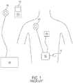
- FIG. 1illustrates a modern TET system known in the prior art.
- the systemincludes an external primary coil 106 that is connected to a power supply 108, as well as a separate external RF communicator 112.
- Implanted inside a patientis a secondary coil 100 adapted to receive energy from primary coil 106, a controller 102, a VAD 104 or other implanted assist device, and a radio frequency (RF) antenna 110.
- RFradio frequency
- primary coil 106can be placed over the area of secondary coil 100 such that they are substantially in axial alignment. In this position, the primary coil 106 does not impede the RF transmission between the external communicator 112 and the secondary coil 100.
- the secondary coil 100can be implanted at various locations in the body, but is often implanted close to the skin to minimize the number of layers of tissue disposed between primary coil 106 and secondary coil 100.
- Power source 108which can include conditioning circuitry to produce a desired output voltage and current profile, can then be activated to produce a time-varying magnetic field in the primary coil 106. The time-varying magnetic field induces clcctric current flow in the secondary coil 100 that is in axial alignment with the primary coil 106. The current can be subsequently distributed to controller 102 and any attached ventricular assist devices 104 or charge storage devices.
- a RF communication link between external communicator 112 and internal controller 102can be established.
- RF telemetry circuitry within the controller 102communicates using RF antenna 110.
- External RF communicator 112can be any communication device adapted to transmit and receive RF signals to and from controller 102.
- the external communicator 112can, for example, be part of the power source 108.
- the communicator 112can be a separate unit.
- RF antenna 110can be any form of RF antenna suitable for implantation inside the body. In some cases, RF antenna 110 can be a monopole antenna connected to controller 102.
- Controller 102is often larger than the secondary coil 100 and, as a result, is typically implanted in the abdominal cavity because its size can be better accommodated. This places controller 102 deeper within the body than secondary coil 100.
- RF antenna 110which is connected to controller 102, is also typically disposed deeper within the body. The result is a great deal of signal attenuation during transmission and reception due to the number of intervening layers of muscle, fat, and tissue between RF antenna 110 and external communicator 112.
- Such a configurationcan also be disadvantageous because it requires that surgeons implant RF antenna 110 separately when implanting the TET system in a patient.
- This additional componentrequires added time and can result in a more invasive surgery.
- the additional componentcan also be another possible site for infection or other medical complication.
- Such a configurationcan be disadvantageous because it requires an additional connection into the controller 102. This makes the overall implantable TET system more complex and introduces an additional point of potential failure in the system. It is always desirable to reduce complexity and possible modes of failure in systems designed to be implanted in the body for long periods of time.
- some embodiments of the present inventionare in the form of an implantable device for use in a TET system that has a plurality of implantable coils that have an integrated RF antenna.
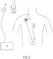
- a TET system outside the scope of the present claims, as illustrated in Figure 2will be used to explain features of embodiments of the present invention.
- the system shown in Figure 2is generally similar to the one shown in Figure 1 , with the notable difference that the secondary coil 200 is integrated with RF antenna 210.
- integrating the secondary coil 200 and radio frequency (RF) antenna 210there are a number of benefits to integrating the secondary coil 200 and radio frequency (RF) antenna 210.
- RFradio frequency
- integrating the RF antenna 210 into the secondary coilmoves the antenna from deep within the body to just below the surface of the skin. This location results in significantly less signal attenuation when communicating with external communicator 112. This means less power can be used to communicate and greater range can be achieved.
- integrating the RF antenna into secondary coil 200reduces the overall number of components and connections that are necessary to implant the TET system into a patient. This, in turn, reduces the invasiveness of the surgery required to implant the system, while also reducing possible sites for infection and modes of failure for the system.
- FIG. 3illustrates an exemplary secondary coil 300 for use in an embodiment of the present invention adapted for disposition within a patient.
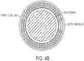
- Secondary coil 300features a coil winding portion 302 consisting of several turns of conductive wire, a core 304 containing electrical circuitry in connection with coil portion 302, radio frequency (RF) antenna 306, a connecting portion 308, and an interface portion 310.
- RFradio frequency
- Coil portion 302can vary in size and turns of wire depending on numerous factors such as the intended implantation site, the desired driving frequency, etc.
- coil portion 302comprises 13 turns of Litz wire in a two-inch diameter coil.
- the secondary coil 300can contain a ferrite core 304 that houses electronic circuitry which rectifies the AC current in the coil portion 302 to provide a regulated DC output voltage to the controller 102 or ventricular assist device 104.
- Coil portion 302is typically wound around core 304.
- An exemplary secondary coil using a ferrite coreis described in U.S. Patent Pub. No. 2003/0171792 .
- the ferrite core 304can be omitted from the secondary coil 300.
- the integrated TET power delivery coil and RF antennawould still function as described.
- Securing the RF antenna in place relative to the coil portion 302 in these embodimentscan be accomplished by an encapsulation material, adhesive plastic sheet, or any other method known in the prior art.
- the secondary coilalso comprises connecting portion 308.
- connecting portion 308comprises a cable jacket that can carry connecting wires for power delivery and a coaxial cable for communications through RF antenna 306.
- the length of connecting portion 308can vary based on, for example, the distance from the implantation site of a secondary coil 300 to a controller 102.
- Connecting portion 308can be coupled to interface portion 310.
- Interface portion 310can be used to connect the secondary coil 300 to a controller 102.
- the interface portion 310can include any electrical connector known in the art to facilitate modular connection to a controller 102, or can consist of terminal ends of the wires carried by connecting portion 308 that are capable of being electrically connected to a controller.
- interface portion 310comprises a single modular connector carrying leads for the electrical connection of both the coil and RF antenna 306.
- RF antenna 306can be integrated into the secondary coil 300 in a number of ways.
- RF antenna 306comprises a micro-strip patch antenna that can be laminated to the ferrite core 304.
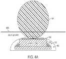
- Figures 4A and 4Bshow the ferrite core 304, coil portion 302, and RF antenna 306 in alternative views.
- the secondary coilcan be encapsulated in a biocompatible material before implantation.
- the secondary coil 300can be encapsulated in epoxy 402 and subsequently dipped in ANGIOFLEX®, or a silicone rubber having low permeability and moisture ingress. These materials can prevent moisture ingress into the secondary coil.
- Micro-strip patch antennastypically comprise a metal patch separated from a larger ground plane by an air gap or dielectric material. The size of the patch and spacing from the ground plane can be used to tune the operating frequencies of the antenna. Micro-strip patch antennas can be formed in a variety of shapes and sizes, and are relatively inexpensive to manufacture.
- micro-strip patch antennashave highly directional radiation patterns. Radiation emanates from the metal patch traveling primarily in a direction away from the ground plane. As a result, the strongest gain is found directly above the antenna opposite of the ground plane.
- FIG. 4AAn exemplary representative radiation pattern 404 for RF antenna 306 is illustrated in Figure 4A .
- the patternillustrates that the micro-strip patch antenna radiates primarily away from the patient's body through the least amount of skin, muscle, and fat.
- a lower transmitter power levelcan be used since the amount of signal attenuation is minimized. This, in turn, minimizes any potential radiation-induced tissue damage.
- the dielectric ferrite core 304 mounted underneath the micro-strip patch antennacan serve, in conjunction with the antenna's ground plane, to further direct the radiation of the antenna and limit radiation directed deeper into a patient's body.
- the end resultis a highly directional RF antenna that is configured to transmit through the least amount of tissue possible without wasting energy by also radiating back into a patient's body.
- the secondary coilshould be implanted in an orientation that directs the antenna toward the skin surface.
- An exemplary orientationis shown in the cross-sectional view of Figure 4A .
- one or more identifying marks or labelscan be included on the secondary coil to identify the location of the RF antenna or the proper orientation of the secondary coil.
- the RF antennacomprises a loop antenna that can be wound around the ferrite core 304 outside of the coil portion 302.
- the windings of coil portion 302can be used as both the TET power receiving coil and the RF antenna.
- Such an arrangementrequires the use of a diplexer to drive the coil portion 302 at the desired RF frequency and the desired TET power delivery frequency.
- This configurationprovides the extra benefit of eliminating the RF antenna as a separate component and using the coil portion 302 for both power delivery and RF communications. This, in turn, reduces the complexity and improves the reliability of the implantable system.
- Interferencecan be a concern when operating the TET power transfer and RF communications systems simultaneously in close proximity. Indeed, concerns over radio interference often result in the separate antennas known in the prior art and shown in Figure 1 . However, interference can be avoided by selecting the operating frequencies of the TET power delivery and RF communications systems such that there is significant separation between the two. Operating frequencies can also be selected so as to avoid the presence of any shared harmonic frequencies.
- the TET power delivery systemcan be operated at a frequency below about 30 MHz and the RF communications system can be operated at any frequency suitable for RF communications. Operating the TET power delivery system below about 30MHz can aid in minimizing tissue-related signal attenuation.
- the TET power delivery systemcan be operated at a fixed frequency of about 300 KHz and the RF communications system can be operated at a frequency of about 900 MHz. More particularly, in another exemplary embodiment, the TET power delivery system can be operated at 327 KHz and the RF communications system can be operated in a frequency range between about 902 MHz and about 928 MHz. In other exemplary embodiments, the RF communications system can be operated in a frequency range between about 863 MHz and 870 MHz.
- a secondary coil like the one depicted in Figure 3can be inductively coupled with, for example, the primary coil 500 illustrated in Figure 5 .
- primary coil 500includes a coil portion 502, a connecting portion 504, and an interface portion 506. In exemplary embodiments, however, primary coil 500 does not contain a ferrite core or RF antenna.
- Primary coil 500can be adapted to connect, using interface portion 506, to power supply 108.
- Power supply 108can include an external battery pack, wall-powered AC adapter, or other power source, as well as conditioning circuitry that produces a desired voltage, frequency, and current profile.
- exemplary primary coil 500 illustrated in Figure 5does not contain a ferrite core or RF antenna, embodiments that contain these features are not outside the scope of the present invention.
- a primary coil having an integrated RF antenna similar to secondary coil 300could be connected to a combination power supply and external communicator device to both power and bidirectionally communicate with an implanted coil.
- a primary coil having an integrated RF antennacould be used in connection with a separate power supply and external communicator device by using, for example, separate connecting leads in the connecting portion 504.
- the placement of an external RF antenna in the primary coilensures that the antenna can be in close proximity to the implanted RF antenna. More than simple proximity, however, the antenna can be located directly on top of the implanted antenna in the area of strongest gain shown in Figure 4A . This, again, allows for more reliable communication using less power than conventional RF communication configurations.
- Controller 600features a rechargeable battery pack represented by battery cells 602, as well as charger circuitry 618.
- the controller 600also contains TET interface circuitry 614 that receives the rectified DC output voltage from secondary coil 300.
- Power regulation circuitry 604can also be included to condition the received voltage for use with the rechargeable battery pack, ventricular assist device 104, and other controller components.
- Controller 600also contains A/D circuitiy 606 and blood pump motor driver 616 to drive and sense operating parameters of the ventricular assist device 104.
- Microprocessor 610coordinates the operation of all of these components to run the controller 600 according to programmed instructions.
- Microprocessoruses RF telemetry circuitry 608, in conjunction with integrated RF antenna 306, to communicate with external communicator 112.
- external communicator 112can be used to poll controller 600 for data regarding the operation of the TET system, including the presence of any alarm conditions or other failures.
- the Controller 600can independently initiate communication with the external communicator 112 in the event of an internal alarm.
- Controller 600can provide data related to any system component either continuously or upon interrogation from external communicator 112. Exemplary parameters include secondary coil input voltage, pump operating speed, battery charge level, etc.
- External communicator 112can also be used to send new program instructions to controller 600 to reconfigure its operation.
- the external communicatorcan be used to upload new algorithms or other operational parameters.
- the exemplary coils and controller shown in Figures 3 to 6 and described aboveare incorporated into an implantable device that utilizes more than one secondary coil.
- Implanting a plurality of secondary coilscan have significant benefits including, for example, allowing a patient to periodically connect a primary coil to a different area of their body, thereby reducing discomfort, as well as allowing a patient to rest in a greater variety of positions. Furthermore, a patient also has the option of connecting more than one primary coil at a time in order to more quickly recharge an implanted battery or other charge storage device.
- a plurality of secondary coils like coil 300 shown in Figure 3can be implanted in a patient and connected to controller 102.
- Each secondary coil 300can have its own RF antenna 306 that can also be connected to controller 102.
- controller 102can be configured to continually scan among the plurality of secondary coils for the RF antenna receiving the strongest signal quality from, for example, external communicator 112. The controller 102 can then isolate the antenna with the best signal quality for a communication exchange.
- the controllercan be further configured to continue scanning among the plurality of secondary coils to determine whether any other RF antenna exhibits stronger RF signal quality.
- the controllercan be configured to switch over to the other RF antenna for communication exchange if a stronger signal is detected.
- each coilincludes an integrated RF antenna
- the implantable systemis able to provide the best RF signal path by not only using antennas disposed close to a patient's skin, but also by choosing among two or more antennas to communicate using the antenna receiving the highest signal quality.
- having two or more RF antennas available for communicationprovides redundancy in the event that there is a failure of an antenna or secondary coil.
Landscapes
- Health & Medical Sciences (AREA)
- Engineering & Computer Science (AREA)
- Heart & Thoracic Surgery (AREA)
- Public Health (AREA)
- Animal Behavior & Ethology (AREA)
- Veterinary Medicine (AREA)
- General Health & Medical Sciences (AREA)
- Biomedical Technology (AREA)
- Cardiology (AREA)
- Life Sciences & Earth Sciences (AREA)
- Hematology (AREA)
- Anesthesiology (AREA)
- Mechanical Engineering (AREA)
- Computer Networks & Wireless Communication (AREA)
- Nuclear Medicine, Radiotherapy & Molecular Imaging (AREA)
- Radiology & Medical Imaging (AREA)
- Human Computer Interaction (AREA)
- Electrotherapy Devices (AREA)
Description
- This application claims priority to United States Provisional Application Serial Number
61/475,573, filed on April 14, 2011 - The present invention relates to transcutaneous energy transfer (TET) systems and, in particular, to TET systems having an integrated radio frequency (RF) antenna.
- In a variety of scientific, industrial, and medically related applications, it can be desirable to transfer energy or power across some type of boundary. For example, one or more devices that require power can be located within the confines of a fully sealed or contained system in which it can be difficult and/or undesirable to include a substantial and/or long term source of power. It can also be undesirable to repeatedly enter the closed system for a variety of reasons. In these cases, a power source external to the fully sealed or contained system and some feasible means of transferring power from the external source to one or more internal devices without direct electrical conduction can be preferable.
- One example of a closed system is the human body. In several medically related and scientific applications, a variety of prosthetic and other devices that require power can be surgically implanted within various portions of the body. Examples of such devices include a synthetic replacement heart, a circulatory blood pump or ventricular assist device (VAD), a cochlear implant, a pacemaker, and the like. With respect to the human body, complications associated with repeated surgical entry make replaceable internal power sources impractical. Likewise, the risk of infection and/or dislodgment make direct electrical linkages between external power supplies and implanted devices undesirable.
- Accordingly, transcutaneous energy transfer (TET) systems (see e.g.
US 5,755,748 ) are employed to transfer energy from outside the body to inside the body in order to provide power to one or more implanted devices from an external power source. TET systems use an inductive link to transfer power without puncturing the skin. Thus, the possibility of infection is reduced while comfort and convenience for patients is increased. - TET devices typically include an external primary coil and an implanted secondary coil that are separated by intervening layers of tissue. The primary coil is designed to induce alternating current in the subcutaneously placed secondary coil, typically for transformation to direct current to power an implanted device. TET devices therefore also typically include electrical circuits for periodically providing appropriate alternating current to the primary coil. These circuits typically receive their power from an external power source.
- As implanted medical devices have become increasingly complex, a need has developed to also provide data communication between the implanted devices and an outside operator, such as a physician or scientist. As with the transfer of power, it can be desirable to provide a method of communication that does not require a physical connection, e.g., wires passing through the skin, between the implanted device and external monitors or controllers.
- Radio frequency (RF) communication systems have been developed to address the need for bi-directional data communication between operators and/or patients and implanted medical devices. These systems are components of the implanted system and use a separate RF antenna so that an external controller or programmer can communicate with internal sensors or control elements. Typically, the separate RF antenna is implanted in a patient away from the implanted secondary TET coil to avoid radio interference when the coil is in use.
- Prior art RF antennas have several disadvantages. First, they suffer from signal attenuation. RF antennas are often implanted deeper within a patient's body than the secondary TET coil, for example, within the chest or in the abdominal cavity. Placing the RF antenna in such a location requires communicating through a large amount of muscle, skin, and fat, resulting in a large amount of signal attenuation during use.
- Second, the use of a separate RF communication antenna means there is yet another component that must be implanted into a patient's body and connected to an implanted device controller or other implanted circuitry. Having this additional component increases the complexity of the system, requires a more invasive surgery to implant, and provides another possible point of failure in the system.
- Thus, a need exists for a better performing and more integrated RF antenna for use in a TET system.
- To overcome the above and other drawbacks of conventional systems, the present invention provides an improved implantable device with secondary coils for use in a transcutaneous energy transfer (TET) system having an integrated radio frequency (RF) antenna and methods for use.
- One aspect of the invention provides an implantable device for use in a transcutaneous energy transfer system, the device comprising a plurality of implantable secondary coils, each of the plurality of implantable coils comprising a coil winding adapted to produce an electric current in the presence of a time-varying magnetic field operating at a first frequency, circuitry in electrical communication with the coil winding adapted to receive and condition the electric current produced in the coil winding, a radio frequency (RF) antenna configured to operate at a second frequency different from the first frequency, and a controller configured to scan among the plurality of implantable coils to determine which RF antenna of the plurality of implantable coils has a highest RF signal quality, select the RF antenna of the plurality of implantable coils having the highest RF signal quality for a communication exchange with an external device.
- In one embodiment of the invention, the power conditioning circuitry can be contained within a ferrite core in the implantable coil. The ferrite core can isolate the circuitry from both the TET and RF antenna operating frequencies.
- The coil winding, ferrite core, circuitry, and RF antenna can further be encapsulated in a biocompatible material. In certain embodiments, the encapsulating biocompatible material can be epoxy. In other embodiments, the biocompatible material can be a polyurethane, such as ANGIOFLEX®, a polyether-based polyurethane plastic manufactured by Abiomed, Inc. of Danvers, MA. In still other embodiments, the biocompatible material can be a silicone rubber compound.
- In one embodiment, the coil winding can be operated at a frequency below about 30 MHz, which is an operating range that minimizes tissue-related attenuation. In other embodiments, the coil winding can be operated at a first frequency of about 300 KHz. In still other embodiments, the coil winding can be operated at a first frequency of 327 KHz. The term "about" as used herein typically refers to a range of +/- 10%, more preferably +/- 5% or +/- 3%.
- The RF antenna can be operated at any frequency suitable for RF communication. In some embodiments, the RF antenna can be operated at a second frequency of about 900 MHz. In other embodiments, the RF antenna can be operated at a second frequency in the range of about 902 MHz to about 928 MHz. In still other embodiments, the RF antenna can be operated at a second frequency in the range of about 863 MHz to about 870 MHz.
- In one embodiment of the invention, the RF antenna can be a micro-strip patch antenna. In other embodiments, the RF antenna can be a micro-strip patch antenna laminated to the ferrite core of the implantable coil.
- In still other embodiments of the invention, the RF antenna can be a loop antenna. In certain other embodiments, the coil winding can be used as the RF antenna, which reduces complexity and improves reliability of the implantable system.
- The implantable coils may further include a connecting portion containing one or more wires connected to the coil winding and the RF antenna in order to facilitate connecting the coil to the controller.
- The controller may be configured to resume scanning among the plurality of implantable coils after completing communication with the external device.
- This aspect may also provide an implantable apparatus comprising the implantable device and an implantable assist device, wherein the implantable device is arranged to power the assist device.
- Alternatively, or additionally, this aspect may provide a transcutaneous energy transfer system including the implantable device and a primary coil configured to transmit transcutaneous energy to the secondary coil, wherein the controllerincludes circuitry to direct electric current from the secondary coil to charge a storage device and/or power an implantable assist device.
- In another aspect, a method of communicating between an external device and an implanted device in a transcutaneous energy transfer (TET) system comprises scanning among a plurality of implanted secondary coils having integrated radio frequency (RF) antennas to determine which RF antenna has the best RF signal quality and selecting the RF antenna having the best RF signal quality for a communication exchange between the external device and the implanted device. The method may also include resuming scanning among the plurality of implanted secondary coils to determine whether another RF antenna exhibits a better RF signal quality.
- In some embodiments, the method can further include switching to the other RF antenna that exhibits better RF signal quality for a communication exchange.
- The invention will be more fully understood from the following detailed description taken in conjunction with the accompanying drawings, in which:
FIG. 1 is an illustration of a transcutaneous energy transfer (TET) system of the prior art;FIG. 2 is an illustration of a TET system outside the scope of the present claims;FIG. 3 is an illustration of an exemplary TET secondary coil for use in an embodiment of the present invention;FIG. 4A is a cross-sectional view of the exemplary TET secondary coil shown inFIG. 3 ;FIG. 4B is a top view of the exemplary TET secondary coil shown inFIG. 3 ;FIG. 5 is an illustration of an exemplary TET primary coil for use in an embodiment of the present invention; andFIG. 6 is a block diagram of an exemplary TET controller for use in an embodiment of the present invention.- Certain exemplary embodiments will now be described to provide an overall understanding of the principles of the methods and devices disclosed herein. One or more examples of these embodiments are illustrated in the accompanying drawings. Those skilled in the art will understand that the methods and devices specifically described herein and illustrated in the accompanying drawings are non-limiting exemplary embodiments and that the scope of the present invention is defined solely by the claims. The features illustrated or described in connection with one exemplary embodiment can be combined with the features of other embodiments. Such modifications and variations are intended to be included within the scope of the present invention.
- A transcutaneous energy transfer (TET) system works by inductively coupling an external primary coil winding to an implanted secondary coil winding. The primary coil can be connected to a power source and creates a time-varying magnetic field. When properly aligned with a secondary coil, the time-varying magnetic field from the primary coil induces an alternating electric current in the secondary coil. The secondary coil can be connected to a controller that harnesses the electric current and uses it to, for example, charge a battery pack or power an implantable device like a ventricular assist device (VAD), or other implantable assist device. By utilizing induction to transfer energy, TET systems avoid having to maintain an open passage through a patient's skin to power an implantable device.
Figure 1 illustrates a modern TET system known in the prior art. The system includes an externalprimary coil 106 that is connected to apower supply 108, as well as a separateexternal RF communicator 112. Implanted inside a patient is asecondary coil 100 adapted to receive energy fromprimary coil 106, acontroller 102, aVAD 104 or other implanted assist device, and a radio frequency (RF)antenna 110.- In use,
primary coil 106 can be placed over the area ofsecondary coil 100 such that they are substantially in axial alignment. In this position, theprimary coil 106 does not impede the RF transmission between theexternal communicator 112 and thesecondary coil 100. Thesecondary coil 100 can be implanted at various locations in the body, but is often implanted close to the skin to minimize the number of layers of tissue disposed betweenprimary coil 106 andsecondary coil 100.Power source 108, which can include conditioning circuitry to produce a desired output voltage and current profile, can then be activated to produce a time-varying magnetic field in theprimary coil 106. The time-varying magnetic field induces clcctric current flow in thesecondary coil 100 that is in axial alignment with theprimary coil 106. The current can be subsequently distributed tocontroller 102 and any attached ventricular assistdevices 104 or charge storage devices. - To monitor and/or control operating parameters associated with
ventricular assist device 104 or any other implanted component, a RF communication link betweenexternal communicator 112 andinternal controller 102 can be established. RF telemetry circuitry within thecontroller 102 communicates usingRF antenna 110.External RF communicator 112 can be any communication device adapted to transmit and receive RF signals to and fromcontroller 102. Theexternal communicator 112 can, for example, be part of thepower source 108. Alternatively, thecommunicator 112 can be a separate unit.RF antenna 110 can be any form of RF antenna suitable for implantation inside the body. In some cases,RF antenna 110 can be a monopole antenna connected tocontroller 102. - The configuration shown in
Figure 1 can have several disadvantages, however.Controller 102 is often larger than thesecondary coil 100 and, as a result, is typically implanted in the abdominal cavity because its size can be better accommodated. This placescontroller 102 deeper within the body thansecondary coil 100.RF antenna 110, which is connected tocontroller 102, is also typically disposed deeper within the body. The result is a great deal of signal attenuation during transmission and reception due to the number of intervening layers of muscle, fat, and tissue betweenRF antenna 110 andexternal communicator 112. - Such a configuration can also be disadvantageous because it requires that surgeons implant
RF antenna 110 separately when implanting the TET system in a patient. This additional component requires added time and can result in a more invasive surgery. The additional component can also be another possible site for infection or other medical complication. - Third, such a configuration can be disadvantageous because it requires an additional connection into the
controller 102. This makes the overall implantable TET system more complex and introduces an additional point of potential failure in the system. It is always desirable to reduce complexity and possible modes of failure in systems designed to be implanted in the body for long periods of time. - Accordingly, some embodiments of the present invention are in the form of an implantable device for use in a TET system that has a plurality of implantable coils that have an integrated RF antenna. A TET system outside the scope of the present claims, as illustrated in
Figure 2 , will be used to explain features of embodiments of the present invention. The system shown inFigure 2 is generally similar to the one shown inFigure 1 , with the notable difference that thesecondary coil 200 is integrated withRF antenna 210. - There are a number of benefits to integrating the
secondary coil 200 and radio frequency (RF)antenna 210. For example, integrating theRF antenna 210 into the secondary coil moves the antenna from deep within the body to just below the surface of the skin. This location results in significantly less signal attenuation when communicating withexternal communicator 112. This means less power can be used to communicate and greater range can be achieved. - Furthermore, integrating the RF antenna into
secondary coil 200 reduces the overall number of components and connections that are necessary to implant the TET system into a patient. This, in turn, reduces the invasiveness of the surgery required to implant the system, while also reducing possible sites for infection and modes of failure for the system. Figure 3 illustrates an exemplarysecondary coil 300 for use in an embodiment of the present invention adapted for disposition within a patient.Secondary coil 300 features acoil winding portion 302 consisting of several turns of conductive wire, acore 304 containing electrical circuitry in connection withcoil portion 302, radio frequency (RF)antenna 306, a connectingportion 308, and aninterface portion 310.Coil portion 302 can vary in size and turns of wire depending on numerous factors such as the intended implantation site, the desired driving frequency, etc. In an exemplary embodiment,coil portion 302 comprises 13 turns of Litz wire in a two-inch diameter coil. In addition to the wire, thesecondary coil 300 can contain aferrite core 304 that houses electronic circuitry which rectifies the AC current in thecoil portion 302 to provide a regulated DC output voltage to thecontroller 102 orventricular assist device 104.Coil portion 302 is typically wound aroundcore 304. An exemplary secondary coil using a ferrite core is described inU.S. Patent Pub. No. 2003/0171792 .- In other exemplary embodiments, the
ferrite core 304 can be omitted from thesecondary coil 300. In such a configuration, the integrated TET power delivery coil and RF antenna would still function as described. Securing the RF antenna in place relative to thecoil portion 302 in these embodiments can be accomplished by an encapsulation material, adhesive plastic sheet, or any other method known in the prior art. - The secondary coil also comprises connecting
portion 308. In an exemplary embodiment, connectingportion 308 comprises a cable jacket that can carry connecting wires for power delivery and a coaxial cable for communications throughRF antenna 306. The length of connectingportion 308 can vary based on, for example, the distance from the implantation site of asecondary coil 300 to acontroller 102. - Connecting
portion 308 can be coupled tointerface portion 310.Interface portion 310 can be used to connect thesecondary coil 300 to acontroller 102. Theinterface portion 310 can include any electrical connector known in the art to facilitate modular connection to acontroller 102, or can consist of terminal ends of the wires carried by connectingportion 308 that are capable of being electrically connected to a controller. In an exemplary embodiment,interface portion 310 comprises a single modular connector carrying leads for the electrical connection of both the coil andRF antenna 306. RF antenna 306 can be integrated into thesecondary coil 300 in a number of ways. In the exemplary embodiment shown inFigure 3 ,RF antenna 306 comprises a micro-strip patch antenna that can be laminated to theferrite core 304.Figures 4A and4B show theferrite core 304,coil portion 302, andRF antenna 306 in alternative views. After attachment of the RF antenna to thecore 304, the secondary coil can be encapsulated in a biocompatible material before implantation. In an exemplary embodiment, thesecondary coil 300 can be encapsulated inepoxy 402 and subsequently dipped in ANGIOFLEX®, or a silicone rubber having low permeability and moisture ingress. These materials can prevent moisture ingress into the secondary coil.- Micro-strip patch antennas typically comprise a metal patch separated from a larger ground plane by an air gap or dielectric material. The size of the patch and spacing from the ground plane can be used to tune the operating frequencies of the antenna. Micro-strip patch antennas can be formed in a variety of shapes and sizes, and are relatively inexpensive to manufacture.
- One beneficial feature of micro-strip patch antennas is that they have highly directional radiation patterns. Radiation emanates from the metal patch traveling primarily in a direction away from the ground plane. As a result, the strongest gain is found directly above the antenna opposite of the ground plane.
- By integrating a micro-strip patch antenna into the secondary coil as shown in
Figures 3 ,4A , and4B , this characteristic of the antenna can be utilized. An exemplaryrepresentative radiation pattern 404 forRF antenna 306 is illustrated inFigure 4A . The pattern illustrates that the micro-strip patch antenna radiates primarily away from the patient's body through the least amount of skin, muscle, and fat. Correspondingly, a lower transmitter power level can be used since the amount of signal attenuation is minimized. This, in turn, minimizes any potential radiation-induced tissue damage. - Furthermore, technicians or patients operating
external communicator 112 have no doubt as to where the device should be positioned in order to receive the best RF signal. This can be particularly helpful in situations where users are attempting to troubleshoot RF communication and want to be sure that signal strength is as high as possible. - Moreover, the
dielectric ferrite core 304 mounted underneath the micro-strip patch antenna can serve, in conjunction with the antenna's ground plane, to further direct the radiation of the antenna and limit radiation directed deeper into a patient's body. The end result is a highly directional RF antenna that is configured to transmit through the least amount of tissue possible without wasting energy by also radiating back into a patient's body. - In order to take advantage of the benefits associated with the directionality of micro-strip patch antennas, the secondary coil should be implanted in an orientation that directs the antenna toward the skin surface. An exemplary orientation is shown in the cross-sectional view of
Figure 4A . In order to assist in correctly orienting the secondary coil during implantation, one or more identifying marks or labels can be included on the secondary coil to identify the location of the RF antenna or the proper orientation of the secondary coil. - While a micro-strip patch antenna is one embodiment of an integrated RF antenna, other methods of integration are possible as well. In another exemplary embodiment, the RF antenna comprises a loop antenna that can be wound around the
ferrite core 304 outside of thecoil portion 302. - In yet another exemplary embodiment, the windings of
coil portion 302 can be used as both the TET power receiving coil and the RF antenna. Such an arrangement requires the use of a diplexer to drive thecoil portion 302 at the desired RF frequency and the desired TET power delivery frequency. This configuration provides the extra benefit of eliminating the RF antenna as a separate component and using thecoil portion 302 for both power delivery and RF communications. This, in turn, reduces the complexity and improves the reliability of the implantable system. - Interference can be a concern when operating the TET power transfer and RF communications systems simultaneously in close proximity. Indeed, concerns over radio interference often result in the separate antennas known in the prior art and shown in
Figure 1 . However, interference can be avoided by selecting the operating frequencies of the TET power delivery and RF communications systems such that there is significant separation between the two. Operating frequencies can also be selected so as to avoid the presence of any shared harmonic frequencies. - It is possible to choose operating frequencies that are not significantly separated because signal filtering can be used to prevent interference. The closer the frequencies become, however, the greater amount of filtering is necessary. As a result, operating frequencies with significant separation are preferable because the amount of filtering, and thus the overall complexity of the system, can be minimized.
- In an exemplary embodiment, the TET power delivery system can be operated at a frequency below about 30 MHz and the RF communications system can be operated at any frequency suitable for RF communications. Operating the TET power delivery system below about 30MHz can aid in minimizing tissue-related signal attenuation. In some exemplary embodiments, the TET power delivery system can be operated at a fixed frequency of about 300 KHz and the RF communications system can be operated at a frequency of about 900 MHz. More particularly, in another exemplary embodiment, the TET power delivery system can be operated at 327 KHz and the RF communications system can be operated in a frequency range between about 902 MHz and about 928 MHz. In other exemplary embodiments, the RF communications system can be operated in a frequency range between about 863 MHz and 870 MHz.
- A secondary coil like the one depicted in
Figure 3 can be inductively coupled with, for example, theprimary coil 500 illustrated inFigure 5 . Similar tosecondary coil 300,primary coil 500 includes acoil portion 502, a connectingportion 504, and aninterface portion 506. In exemplary embodiments, however,primary coil 500 does not contain a ferrite core or RF antenna.Primary coil 500 can be adapted to connect, usinginterface portion 506, topower supply 108.Power supply 108 can include an external battery pack, wall-powered AC adapter, or other power source, as well as conditioning circuitry that produces a desired voltage, frequency, and current profile. - While the exemplary
primary coil 500 illustrated inFigure 5 does not contain a ferrite core or RF antenna, embodiments that contain these features are not outside the scope of the present invention. By way of non-limiting example, a primary coil having an integrated RF antenna similar tosecondary coil 300 could be connected to a combination power supply and external communicator device to both power and bidirectionally communicate with an implanted coil. - In still other embodiments, a primary coil having an integrated RF antenna could be used in connection with a separate power supply and external communicator device by using, for example, separate connecting leads in the connecting
portion 504. - In any such embodiments, the placement of an external RF antenna in the primary coil ensures that the antenna can be in close proximity to the implanted RF antenna. More than simple proximity, however, the antenna can be located directly on top of the implanted antenna in the area of strongest gain shown in
Figure 4A . This, again, allows for more reliable communication using less power than conventional RF communication configurations. - Inside the body,
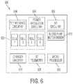
secondary coil 300 can be connected, usinginterface portion 310, to an implantable device controller. A block diagram of an exemplary controller of the present invention is illustrated inFigure 6 .Controller 600 features a rechargeable battery pack represented bybattery cells 602, as well ascharger circuitry 618. Thecontroller 600 also containsTET interface circuitry 614 that receives the rectified DC output voltage fromsecondary coil 300.Power regulation circuitry 604 can also be included to condition the received voltage for use with the rechargeable battery pack, ventricular assistdevice 104, and other controller components. Controller 600 also contains A/D circuitiy 606 and bloodpump motor driver 616 to drive and sense operating parameters of the ventricular assistdevice 104.Microprocessor 610 coordinates the operation of all of these components to run thecontroller 600 according to programmed instructions.- Microprocessor uses
RF telemetry circuitry 608, in conjunction withintegrated RF antenna 306, to communicate withexternal communicator 112. In such a configuration,external communicator 112 can be used to pollcontroller 600 for data regarding the operation of the TET system, including the presence of any alarm conditions or other failures. TheController 600 can independently initiate communication with theexternal communicator 112 in the event of an internal alarm.Controller 600 can provide data related to any system component either continuously or upon interrogation fromexternal communicator 112. Exemplary parameters include secondary coil input voltage, pump operating speed, battery charge level, etc.External communicator 112 can also be used to send new program instructions tocontroller 600 to reconfigure its operation. In addition, the external communicator can be used to upload new algorithms or other operational parameters. - In an example embodiment, the exemplary coils and controller shown in
Figures 3 to 6 and described above are incorporated into an implantable device that utilizes more than one secondary coil. - Implanting a plurality of secondary coils can have significant benefits including, for example, allowing a patient to periodically connect a primary coil to a different area of their body, thereby reducing discomfort, as well as allowing a patient to rest in a greater variety of positions. Furthermore, a patient also has the option of connecting more than one primary coil at a time in order to more quickly recharge an implanted battery or other charge storage device.
- In exemplary multi-coil embodiments, a plurality of secondary coils like
coil 300 shown inFigure 3 can be implanted in a patient and connected tocontroller 102. Eachsecondary coil 300 can have itsown RF antenna 306 that can also be connected tocontroller 102. Using a microprocessor and RF telemetry chip like those shown inFigure 6 ,controller 102 can be configured to continually scan among the plurality of secondary coils for the RF antenna receiving the strongest signal quality from, for example,external communicator 112. Thecontroller 102 can then isolate the antenna with the best signal quality for a communication exchange. In some embodiments, the controller can be further configured to continue scanning among the plurality of secondary coils to determine whether any other RF antenna exhibits stronger RF signal quality. The controller can be configured to switch over to the other RF antenna for communication exchange if a stronger signal is detected. - Systems employing a plurality of secondary coils where each coil includes an integrated RF antenna provide several advantages. For example, the implantable system is able to provide the best RF signal path by not only using antennas disposed close to a patient's skin, but also by choosing among two or more antennas to communicate using the antenna receiving the highest signal quality. Furthermore, having two or more RF antennas available for communication provides redundancy in the event that there is a failure of an antenna or secondary coil.
- All of the embodiments described above are non-limiting examples of the present invention only. One of skill in the art will appreciate further features and advantages of the invention based on the above-described embodiments. Accordingly, the invention is not to be limited by what has been particularly shown and described, except as indicated by the appended claims.
Claims (15)
- An implantable device for use in a transcutaneous energy transfer system, the device comprising:a plurality of implantable secondary coils (200, 300), each of the plurality of implantable coils comprising:a coil winding (302) adapted to produce an electric current in the presence of a time-varying magnetic field operating at a first frequency;circuitry in electrical communication with the coil winding adapted to receive and condition the electric current produced in the coil winding;a radio frequency (RF) antenna (210, 306) configured to operate at a second frequency different from the first frequency; anda controller (102);wherein:the controller is configured to:scan among the plurality of implantable coils to determine which RF antenna of the plurality of implantable coils has a best RF signal quality;select the RF antenna of the plurality of implantable coils having the best RF signal quality for a communication exchange with an external device (112).
- The device of claim 1, wherein the circuitry is contained in a ferrite core (304).
- The device of claim 1, wherein the coil winding, circuitry, and radio frequency antenna are encapsulated in a biocompatible material, and optionally wherein said biocompatible material comprises epoxy (402).
- The device of claim 3, wherein said epoxy is coated with a polyurethane plastic, or silicone rubber.
- The device of claim 1, wherein the first frequency is below about 30 MHz, or is about 300 KHz, or 327 KHz.
- The device of claim 1, wherein the second frequency is a frequency suitable for RF communication, or wherein the second frequency is about 900 MHz, or between about 902 MHz and about 928 MHz, or between about 863 MHz and about 870 MHz.
- The device of claim 1, wherein the RF antenna comprises a micro-strip patch antenna.
- The device of claim 2, wherein the RF antenna comprises a micro-strip patch antenna laminated to the ferrite core.
- The device of claim 1, wherein the RF antenna comprises a loop antenna, or wherein the coil winding is also used as the RF antenna.
- The device of any of the preceding claims, wherein the controller is configured to resume scanning among the plurality of implantable coils after completing communication with the external device.
- An implantable apparatus comprising the implantable device of any of the preceding claims and an implantable assist device, wherein the implantable device is arranged to power the assist device.
- A transcutaneous energy transfer system, comprising:an implantable device according to any of claims 1-10; anda primary coil (106, 500) configured to transmit transcutaneous energy to said implantable coils; andwherein the controller comprises circuitry to direct electric current from the implantable coils to charge a storage device and/or power an implantable assist device.
- A method of communicating between an external device (112) and an implanted device in a transcutaneous energy transfer (TET) system comprising:scanning among a plurality of implanted secondary coils (300) each having integrated radio frequency (RF) antennas (306) to determine which RF antenna has the best RF signal quality;selecting the RF antenna having the best RF signal quality for a communication exchange between the external device and the implanted device.
- The method of claim 13, further comprising resuming scanning among the plurality of implanted secondary coils to determine whether another of the RF antennas exhibits a better RF signal quality.
- The method of claim 14, wherein the method further comprises switching to the other RF antenna that exhibits better RF signal quality for communication exchange.
Priority Applications (3)
| Application Number | Priority Date | Filing Date | Title |
|---|---|---|---|
| EP22194146.1AEP4119184B1 (en) | 2011-04-14 | 2011-12-16 | Transcutaneous energy transfer coil with integrated radio frequency antenna |
| DK19150057.8TDK3485819T3 (en) | 2011-04-14 | 2011-12-16 | TRANSCUTANEOUS ENERGY TRANSFER COIL WITH INTEGRATED RADIO FREQUENCY ANTENNA |
| EP19150057.8AEP3485819B1 (en) | 2011-04-14 | 2011-12-16 | Transcutaneous energy transfer coil with integrated radio frequency antenna |
Applications Claiming Priority (2)
| Application Number | Priority Date | Filing Date | Title |
|---|---|---|---|
| US201161475573P | 2011-04-14 | 2011-04-14 | |
| PCT/US2011/065477WO2012141752A2 (en) | 2011-04-14 | 2011-12-16 | Transcutaneous energy transfer coil with integrated radio frequency antenna |
Related Child Applications (3)
| Application Number | Title | Priority Date | Filing Date |
|---|---|---|---|
| EP22194146.1ADivisionEP4119184B1 (en) | 2011-04-14 | 2011-12-16 | Transcutaneous energy transfer coil with integrated radio frequency antenna |
| EP19150057.8ADivisionEP3485819B1 (en) | 2011-04-14 | 2011-12-16 | Transcutaneous energy transfer coil with integrated radio frequency antenna |
| EP19150057.8ADivision-IntoEP3485819B1 (en) | 2011-04-14 | 2011-12-16 | Transcutaneous energy transfer coil with integrated radio frequency antenna |
Publications (3)
| Publication Number | Publication Date |
|---|---|
| EP2697890A2 EP2697890A2 (en) | 2014-02-19 |
| EP2697890A4 EP2697890A4 (en) | 2015-10-21 |
| EP2697890B1true EP2697890B1 (en) | 2019-02-20 |
Family
ID=47006895
Family Applications (3)
| Application Number | Title | Priority Date | Filing Date |
|---|---|---|---|
| EP11863269.4AActiveEP2697890B1 (en) | 2011-04-14 | 2011-12-16 | Transcutaneous energy transfer coil with integrated radio frequency antenna |
| EP22194146.1AActiveEP4119184B1 (en) | 2011-04-14 | 2011-12-16 | Transcutaneous energy transfer coil with integrated radio frequency antenna |
| EP19150057.8AActiveEP3485819B1 (en) | 2011-04-14 | 2011-12-16 | Transcutaneous energy transfer coil with integrated radio frequency antenna |
Family Applications After (2)
| Application Number | Title | Priority Date | Filing Date |
|---|---|---|---|
| EP22194146.1AActiveEP4119184B1 (en) | 2011-04-14 | 2011-12-16 | Transcutaneous energy transfer coil with integrated radio frequency antenna |
| EP19150057.8AActiveEP3485819B1 (en) | 2011-04-14 | 2011-12-16 | Transcutaneous energy transfer coil with integrated radio frequency antenna |
Country Status (5)
| Country | Link |
|---|---|
| US (1) | US8620447B2 (en) |
| EP (3) | EP2697890B1 (en) |
| DK (1) | DK3485819T3 (en) |
| ES (2) | ES2717653T3 (en) |
| WO (1) | WO2012141752A2 (en) |
Families Citing this family (78)
| Publication number | Priority date | Publication date | Assignee | Title |
|---|---|---|---|---|
| US9409013B2 (en) | 2009-10-20 | 2016-08-09 | Nyxoah SA | Method for controlling energy delivery as a function of degree of coupling |
| US10751537B2 (en) | 2009-10-20 | 2020-08-25 | Nyxoah SA | Arced implant unit for modulation of nerves |
| US10716940B2 (en) | 2009-10-20 | 2020-07-21 | Nyxoah SA | Implant unit for modulation of small diameter nerves |
| US8562508B2 (en) | 2009-12-30 | 2013-10-22 | Thoratec Corporation | Mobility-enhancing blood pump system |
| JP2014502528A (en) | 2010-12-20 | 2014-02-03 | アビオメド インコーポレイティド | Method and apparatus for accurately tracking charge available in a transdermal energy transmission system |
| DK2654878T3 (en) | 2010-12-20 | 2019-07-22 | Abiomed Inc | TRANSCUTANT ENERGY TRANSFER SYSTEM WITH A MULTIPLE OF SECONDARY COILS |
| WO2012087819A2 (en) | 2010-12-20 | 2012-06-28 | Abiomed, Inc. | Transcutaneous energy transfer system with vibration inducing warning circuitry |
| US9002468B2 (en) | 2011-12-16 | 2015-04-07 | Abiomed, Inc. | Automatic power regulation for transcutaneous energy transfer charging system |
| EP2877239B1 (en) | 2012-07-26 | 2023-06-21 | Nyxoah SA | Electrical contacts on a medical device patch |
| US10052097B2 (en) | 2012-07-26 | 2018-08-21 | Nyxoah SA | Implant unit delivery tool |
| US9907967B2 (en) | 2012-07-26 | 2018-03-06 | Adi Mashiach | Transcutaneous power conveyance device |
| US11253712B2 (en) | 2012-07-26 | 2022-02-22 | Nyxoah SA | Sleep disordered breathing treatment apparatus |
| WO2014018969A2 (en) | 2012-07-27 | 2014-01-30 | Thoratec Corporation | Resonant power transfer system and method of estimating system state |
| EP4257174A3 (en) | 2012-07-27 | 2023-12-27 | Tc1 Llc | Thermal management for implantable wireless power transfer systems |
| US10383990B2 (en) | 2012-07-27 | 2019-08-20 | Tc1 Llc | Variable capacitor for resonant power transfer systems |
| WO2014018973A1 (en) | 2012-07-27 | 2014-01-30 | Thoratec Corporation | Resonant power transmission coils and systems |
| WO2014018974A1 (en) | 2012-07-27 | 2014-01-30 | Thoratec Corporation | Magnetic power transmission utilizing phased transmitter coil arrays and phased receiver coil arrays |
| WO2014018971A1 (en) | 2012-07-27 | 2014-01-30 | Thoratec Corporation | Resonant power transfer systems with protective algorithm |
| US10291067B2 (en) | 2012-07-27 | 2019-05-14 | Tc1 Llc | Computer modeling for resonant power transfer systems |
| US9287040B2 (en) | 2012-07-27 | 2016-03-15 | Thoratec Corporation | Self-tuning resonant power transfer systems |
| DE202012009867U1 (en)* | 2012-10-16 | 2012-11-26 | em-tec GmbH Werner Heinze | Coil for inductive transcutaneous transmission of high powers |
| WO2014062308A1 (en)* | 2012-10-16 | 2014-04-24 | California Institute Of Technology | Systems and methods for wireless transducers through integrated on-chip antenna |
| WO2014145664A1 (en) | 2013-03-15 | 2014-09-18 | Thoratec Corporation | Integrated implantable tets housing including fins and coil loops |
| EP2984731B8 (en) | 2013-03-15 | 2019-06-26 | Tc1 Llc | Malleable tets coil with improved anatomical fit |
| AU2014288938B2 (en) | 2013-06-17 | 2019-03-14 | Nyxoah SA | Dynamic modification of modulation throughout a therapy period |
| EP3072210B1 (en) | 2013-11-11 | 2023-12-20 | Tc1 Llc | Resonant power transfer systems with communications |
| US10695476B2 (en) | 2013-11-11 | 2020-06-30 | Tc1 Llc | Resonant power transfer systems with communications |
| EP3069358B1 (en) | 2013-11-11 | 2019-06-12 | Tc1 Llc | Hinged resonant power transfer coil |
| CN106165198A (en)* | 2014-01-09 | 2016-11-23 | 迷你泵有限责任公司 | Telemetry devices for implantable devices |
| WO2015134871A1 (en) | 2014-03-06 | 2015-09-11 | Thoratec Corporation | Electrical connectors for implantable devices |
| GB2527075A (en) | 2014-03-17 | 2015-12-16 | Daassist As | Percutaneous system, devices and methods |
| DE102015112097A1 (en) | 2014-07-25 | 2016-01-28 | Minnetronix, Inc. | power scale |
| DE102015112098A1 (en) | 2014-07-25 | 2016-01-28 | Minnetronix, Inc. | Coil parameters and control |
| EP3826104B1 (en) | 2014-09-22 | 2023-05-03 | Tc1 Llc | Antenna designs for communication between a wirelessly powered implant to an external device outside the body |
| EP3200846B1 (en) | 2014-10-01 | 2020-01-15 | Heartware, Inc. | Backup controller system with updating |
| WO2016057525A1 (en) | 2014-10-06 | 2016-04-14 | Thoratec Corporation | Multiaxial connector for implantable devices |
| US10342908B2 (en) | 2015-01-14 | 2019-07-09 | Minnetronix, Inc. | Distributed transformer |
| DE102016100534A1 (en) | 2015-01-16 | 2016-07-21 | Vlad BLUVSHTEIN | Data transmission in a transcutaneous energy transmission system |
| US10193395B2 (en) | 2015-04-14 | 2019-01-29 | Minnetronix, Inc. | Repeater resonator |
| WO2017025606A1 (en)* | 2015-08-12 | 2017-02-16 | Nuheart As | System, apparatus and method for improved contactless power transfer in implantable devices |
| US10148126B2 (en) | 2015-08-31 | 2018-12-04 | Tc1 Llc | Wireless energy transfer system and wearables |
| WO2017062552A1 (en) | 2015-10-07 | 2017-04-13 | Tc1 Llc | Resonant power transfer systems having efficiency optimization based on receiver impedance |
| US10893847B2 (en) | 2015-12-30 | 2021-01-19 | Nuheart As | Transcatheter insertion system |
| DE102016209871A1 (en) | 2016-06-06 | 2017-12-07 | Robert Bosch Gmbh | Punching device and method for punching a lumen and implanting an implant device |
| EP4084271A1 (en) | 2016-09-21 | 2022-11-02 | Tc1 Llc | Systems and methods for locating implanted wireless power transmission devices |
| US10335528B2 (en) | 2016-10-07 | 2019-07-02 | Nuheart As | Transcatheter method and system for the delivery of intracorporeal devices |
| US10537672B2 (en) | 2016-10-07 | 2020-01-21 | Nuheart As | Transcatheter device and system for the delivery of intracorporeal devices |
| WO2018136592A2 (en) | 2017-01-18 | 2018-07-26 | Tc1 Llc | Systems and methods for transcutaneous power transfer using microneedles |
| US10888646B2 (en) | 2017-04-28 | 2021-01-12 | Nuheart As | Ventricular assist device and method |
| US10537670B2 (en) | 2017-04-28 | 2020-01-21 | Nuheart As | Ventricular assist device and method |
| CA3066361A1 (en) | 2017-06-07 | 2018-12-13 | Shifamed Holdings, Llc | Intravascular fluid movement devices, systems, and methods of use |
| WO2019094963A1 (en) | 2017-11-13 | 2019-05-16 | Shifamed Holdings, Llc | Intravascular fluid movement devices, systems, and methods of use |
| FR3075831B1 (en) | 2017-12-22 | 2020-11-13 | Univ Grenoble Alpes | IMPLANTABLE HYDROGEN PRODUCTION DEVICE |
| WO2019135890A1 (en) | 2018-01-04 | 2019-07-11 | Tc1 Llc | Systems and methods for elastic wireless power transmission devices |
| DE102018201030B4 (en) | 2018-01-24 | 2025-10-16 | Kardion Gmbh | Magnetic dome element with magnetic bearing function |
| CN112004563B (en) | 2018-02-01 | 2024-08-06 | 施菲姆德控股有限责任公司 | Intravascular blood pump and methods of use and manufacture |
| DE102018206750A1 (en) | 2018-05-02 | 2019-11-07 | Kardion Gmbh | Device for inductive energy transfer into a human body and its use |
| DE102018206725A1 (en) | 2018-05-02 | 2019-11-07 | Kardion Gmbh | Receiving unit, transmitting unit, energy transmission system and method for wireless energy transmission |
| DE102018206731A1 (en) | 2018-05-02 | 2019-11-07 | Kardion Gmbh | Device for inductive energy transmission in a human body and use of the device |
| DE102018206754A1 (en) | 2018-05-02 | 2019-11-07 | Kardion Gmbh | Method and device for determining the temperature at a surface and use of the method |
| DE102018206724A1 (en) | 2018-05-02 | 2019-11-07 | Kardion Gmbh | Energy transmission system and method for wireless energy transmission |
| DE102018208555A1 (en) | 2018-05-30 | 2019-12-05 | Kardion Gmbh | Apparatus for anchoring a cardiac assist system in a blood vessel, method of operation, and method of making a device and cardiac assist system |
| US12161857B2 (en) | 2018-07-31 | 2024-12-10 | Shifamed Holdings, Llc | Intravascular blood pumps and methods of use |
| WO2020073047A1 (en) | 2018-10-05 | 2020-04-09 | Shifamed Holdings, Llc | Intravascular blood pumps and methods of use |
| US11642454B2 (en) | 2019-06-06 | 2023-05-09 | Medtronic Minimed, Inc. | Fluid infusion systems |
| WO2021011473A1 (en) | 2019-07-12 | 2021-01-21 | Shifamed Holdings, Llc | Intravascular blood pumps and methods of manufacture and use |
| US11654275B2 (en) | 2019-07-22 | 2023-05-23 | Shifamed Holdings, Llc | Intravascular blood pumps with struts and methods of use and manufacture |
| EP4501393A3 (en) | 2019-09-25 | 2025-04-09 | Shifamed Holdings, LLC | Catheter blood pumps and collapsible pump housings |
| US12121713B2 (en) | 2019-09-25 | 2024-10-22 | Shifamed Holdings, Llc | Catheter blood pumps and collapsible blood conduits |
| WO2021062265A1 (en) | 2019-09-25 | 2021-04-01 | Shifamed Holdings, Llc | Intravascular blood pump systems and methods of use and control thereof |
| EP4072650A4 (en) | 2019-12-11 | 2024-01-10 | Shifamed Holdings, LLC | Descending aorta and vena cava blood pumps |
| US20210187291A1 (en)* | 2019-12-23 | 2021-06-24 | Medtronic, Inc. | Ceramic-to-metal joint for implantable pulse generators |
| US12138442B2 (en) | 2020-05-11 | 2024-11-12 | Medtronic, Inc. | External wireless power transfer coil |
| US12138440B2 (en) | 2020-07-31 | 2024-11-12 | Medtronic, Inc. | Managing pump speed when power constrained in a fully implanted LVAD system |
| US11616397B2 (en)* | 2020-08-12 | 2023-03-28 | Medtronic, Inc. | Magnetic alignment of transcutaneous energy transfer coils |
| US20220133965A1 (en)* | 2020-11-02 | 2022-05-05 | Medtronic, Inc. | Interconnect design for joining dissimilar materials |
| US11699551B2 (en) | 2020-11-05 | 2023-07-11 | Kardion Gmbh | Device for inductive energy transmission in a human body and use of the device |
| CN116997386A (en)* | 2021-03-10 | 2023-11-03 | 科利耳有限公司 | Systems and methods for wireless communication with medical implants |
Family Cites Families (185)
| Publication number | Priority date | Publication date | Assignee | Title |
|---|---|---|---|---|
| NL278413A (en) | 1961-05-15 | |||
| US3195540A (en) | 1963-03-29 | 1965-07-20 | Louis C Waller | Power supply for body implanted instruments |
| US3357434A (en) | 1964-04-06 | 1967-12-12 | Avco Corp | Inductively linked receiver |
| US3357432A (en) | 1965-02-09 | 1967-12-12 | Edwards Lab Inc | Anastomotic coupling |
| JPS50497Y1 (en) | 1970-08-13 | 1975-01-09 | ||
| US3867950A (en) | 1971-06-18 | 1975-02-25 | Univ Johns Hopkins | Fixed rate rechargeable cardiac pacemaker |
| US3756246A (en) | 1971-07-15 | 1973-09-04 | American Optical Corp | Apparatus for externally determining actual output of an implanted energy source |
| FR2179507B1 (en) | 1972-04-10 | 1975-03-21 | Drusch Gaston | |
| US3888260A (en) | 1972-06-28 | 1975-06-10 | Univ Johns Hopkins | Rechargeable demand inhibited cardiac pacer and tissue stimulator |
| US3824129A (en) | 1973-03-14 | 1974-07-16 | Mallory & Co Inc P R | Heart pacer rechargeable cell and protective control system |
| JPS5232625B2 (en) | 1973-03-29 | 1977-08-23 | ||
| US3987799A (en) | 1973-07-12 | 1976-10-26 | Coratomic Inc. | Heart pacer |
| US3866616A (en) | 1973-07-12 | 1975-02-18 | Coratomic | Heart pacer |
| US3942535A (en) | 1973-09-27 | 1976-03-09 | G. D. Searle & Co. | Rechargeable tissue stimulating system |
| US3915038A (en) | 1973-10-09 | 1975-10-28 | Walter Malin | Fiber board cutter |
| US3934177A (en) | 1975-01-09 | 1976-01-20 | Stephen Horbach | Heat sink casing for circuit board components |
| US4068292A (en) | 1975-03-27 | 1978-01-10 | International Medical Electronics, Inc. | Electrostatic shield for diathermy treatment head |
| US4012769A (en) | 1975-08-04 | 1977-03-15 | Thermalloy Incorporated | Heat sink with parallel flat faces |
| US4071032A (en) | 1976-01-29 | 1978-01-31 | Pacesetter Systems Inc. | Implantable living tissue stimulators |
| US4041955A (en) | 1976-01-29 | 1977-08-16 | Pacesetter Systems Inc. | Implantable living tissue stimulator with an improved hermetic metal container |
| US4011499A (en) | 1976-02-11 | 1977-03-08 | The Bendix Corporation | Low loss a.c. voltage regulator |
| US4134408A (en) | 1976-11-12 | 1979-01-16 | Research Corporation | Cardiac pacer energy conservation system |
| US4266532A (en) | 1976-11-17 | 1981-05-12 | Electro-Biology, Inc. | Modification of the growth, repair and maintenance behavior of living tissues and cells by a specific and selective change in electrical environment |
| US4104701A (en) | 1976-11-22 | 1978-08-01 | Powercube Corporation | Mounting assembly for electronic power devices |
| US4186749A (en) | 1977-05-12 | 1980-02-05 | The United States Of America As Represented By The Administrator Of The National Aeronautics And Space Administration | Induction powered biological radiosonde |
| US4143661A (en) | 1977-12-12 | 1979-03-13 | Andros Incorporated | Power supply for body implant and method for operation |
| US4441210A (en) | 1981-09-18 | 1984-04-03 | Hochmair Erwin S | Transcutaneous signal transmission system and methods |
| US4441498A (en) | 1982-05-10 | 1984-04-10 | Cardio-Pace Medical, Inc. | Planar receiver antenna coil for programmable electromedical pulse generator |
| FR2527832A1 (en) | 1982-05-25 | 1983-12-02 | Barthelemy Louis | ELECTRICAL TRANSFORMER WITH MODULAR PRIMARY CIRCUITS POWERED SELECTIVELY |
| US4517585A (en) | 1982-08-13 | 1985-05-14 | Lucas Chloride Ev Systems Limited | Heat sink for semi-conductor devices having terminals projecting from a heat sink transfer face |
| US4539433A (en) | 1982-11-24 | 1985-09-03 | Tdk Corporation | Electromagnetic shield |
| US4586508A (en) | 1984-03-23 | 1986-05-06 | Cordis Corporation | Implant communication system with patient coil |
| US4741339A (en) | 1984-10-22 | 1988-05-03 | Cochlear Pty. Limited | Power transfer for implanted prostheses |
| US4679560A (en) | 1985-04-02 | 1987-07-14 | Board Of Trustees Of The Leland Stanford Junior University | Wide band inductive transdermal power and data link |
| US4665896A (en) | 1985-07-22 | 1987-05-19 | Novacor Medical Corporation | Power supply for body implant and method of use |
| US5000178A (en) | 1986-05-23 | 1991-03-19 | Lti Biomedical, Inc. | Shielded electromagnetic transducer |
| US4716353A (en) | 1986-09-02 | 1987-12-29 | Electro-Voice Inc. | Battery charger |
| US4673888A (en) | 1986-09-02 | 1987-06-16 | Electro-Voice, Inc. | Power control system |
| US4717889A (en) | 1986-09-02 | 1988-01-05 | Electro-Voice, Incorporated | Power control system for periodically and selectively energizing or shorting primary windings of transformers for controlling the output voltage across a common secondary winding |
| US4808924A (en) | 1987-02-19 | 1989-02-28 | Atomic Energy Of Canada Limited | Circumferentially compensating eddy current probe with alternately polarized transmit coils and receiver coils |
| US4925443A (en) | 1987-02-27 | 1990-05-15 | Heilman Marlin S | Biocompatible ventricular assist and arrhythmia control device |
| JP2597623B2 (en) | 1987-10-08 | 1997-04-09 | 株式会社トキメック | Power supply method by electromagnetic induction coupling |
| US4837497A (en) | 1987-12-29 | 1989-06-06 | Gregory Leibovich | Variable transformer, reactor and method of their control |
| US5214392A (en) | 1988-11-08 | 1993-05-25 | Murata Mfg. Co., Ltd. | Multilayered ceramic type electromagnetic coupler apparatus |
| FR2643362B1 (en) | 1989-02-22 | 1993-04-09 | Air Liquide | PROCESS FOR PREPARING A GLASS-METAL LINK AND APPARATUS FOR IMPLEMENTING SAME |
| US4944299A (en) | 1989-08-08 | 1990-07-31 | Siemens-Pacesetter, Inc. | High speed digital telemetry system for implantable device |
| US5350413B1 (en) | 1990-06-21 | 1999-09-07 | Heart Inst Research Corp | Transcutaneous energy transfer device |
| US5109843A (en) | 1990-11-30 | 1992-05-05 | University Of Cincinnati | Extra to-intracorporeal power supply |
| EP0507360B1 (en) | 1991-01-30 | 1996-05-08 | The Boeing Company | Current mode bus coupler with planar coils and shields |
| US5314453A (en) | 1991-12-06 | 1994-05-24 | Spinal Cord Society | Position sensitive power transfer antenna |
| US5312439A (en) | 1991-12-12 | 1994-05-17 | Loeb Gerald E | Implantable device having an electrolytic storage electrode |
| US5193539A (en) | 1991-12-18 | 1993-03-16 | Alfred E. Mann Foundation For Scientific Research | Implantable microstimulator |
| US5358514A (en) | 1991-12-18 | 1994-10-25 | Alfred E. Mann Foundation For Scientific Research | Implantable microdevice with self-attaching electrodes |
| CA2076205C (en) | 1992-08-14 | 1999-04-20 | Valentino S. Cecco | Differential transmit-receive eddy current probe incorporating bracelets of multi-coil units |
| US5355296A (en) | 1992-12-10 | 1994-10-11 | Sundstrand Corporation | Switching converter and summing transformer for use therein |
| US5383912A (en) | 1993-05-05 | 1995-01-24 | Intermedics, Inc. | Apparatus for high speed data communication between an external medical device and an implantable medical device |
| US5411536A (en) | 1993-06-03 | 1995-05-02 | Intermedics, Inc. | Method and apparatus for communicating data between medical devices to improve detectability of errors |
| US5350411A (en) | 1993-06-28 | 1994-09-27 | Medtronic, Inc. | Pacemaker telemetry system |
| WO1995007109A1 (en) | 1993-09-10 | 1995-03-16 | Ottawa Heart Institute Research Corporation | Electrohydraulic ventricular assist device |
| US5411537A (en) | 1993-10-29 | 1995-05-02 | Intermedics, Inc. | Rechargeable biomedical battery powered devices with recharging and control system therefor |
| US5545191A (en) | 1994-05-06 | 1996-08-13 | Alfred E. Mann Foundation For Scientific Research | Method for optimally positioning and securing the external unit of a transcutaneous transducer of the skin of a living body |
| US5613935A (en) | 1994-12-16 | 1997-03-25 | Jarvik; Robert | High reliability cardiac assist system |
| US5630836A (en) | 1995-01-19 | 1997-05-20 | Vascor, Inc. | Transcutaneous energy and information transmission apparatus |
| US5527348A (en) | 1995-02-03 | 1996-06-18 | Medtronic, Inc. | Magnetically permeable E-shield and method of connection thereto |
| US5556421A (en) | 1995-02-22 | 1996-09-17 | Intermedics, Inc. | Implantable medical device with enclosed physiological parameter sensors or telemetry link |
| US20080065290A1 (en) | 2000-09-08 | 2008-03-13 | Automotive Technologies International, Inc. | Component Monitoring System |
| US5722998A (en) | 1995-06-07 | 1998-03-03 | Intermedics, Inc. | Apparatus and method for the control of an implantable medical device |
| US5702431A (en) | 1995-06-07 | 1997-12-30 | Sulzer Intermedics Inc. | Enhanced transcutaneous recharging system for battery powered implantable medical device |
| US5690693A (en) | 1995-06-07 | 1997-11-25 | Sulzer Intermedics Inc. | Transcutaneous energy transmission circuit for implantable medical device |
| US5621369A (en) | 1995-09-18 | 1997-04-15 | Gardner; Harris L. | Flexible magnet |
| US5755748A (en)* | 1996-07-24 | 1998-05-26 | Dew Engineering & Development Limited | Transcutaneous energy transfer device |
| US5733313A (en) | 1996-08-01 | 1998-03-31 | Exonix Corporation | RF coupled, implantable medical device with rechargeable back-up power source |
| US5713939A (en) | 1996-09-16 | 1998-02-03 | Sulzer Intermedics Inc. | Data communication system for control of transcutaneous energy transmission to an implantable medical device |
| US5963132A (en) | 1996-10-11 | 1999-10-05 | Avid Indentification Systems, Inc. | Encapsulated implantable transponder |
| US5749909A (en) | 1996-11-07 | 1998-05-12 | Sulzer Intermedics Inc. | Transcutaneous energy coupling using piezoelectric device |
| US5741316A (en) | 1996-12-02 | 1998-04-21 | Light Sciences Limited Partnership | Electromagnetic coil configurations for power transmission through tissue |
| US5735887A (en) | 1996-12-10 | 1998-04-07 | Exonix Corporation | Closed-loop, RF-coupled implanted medical device |
| US5740257A (en) | 1996-12-19 | 1998-04-14 | Lucent Technologies Inc. | Active noise control earpiece being compatible with magnetic coupled hearing aids |
| DE69812447D1 (en) | 1997-01-20 | 2003-04-30 | Daido Steel Co Ltd | Soft magnetic powder for electromagnetic and magnetic shielding and shielding with this powder |
| US5861019A (en)* | 1997-07-25 | 1999-01-19 | Medtronic Inc. | Implantable medical device microstrip telemetry antenna |
| ES2224420T3 (en) | 1997-08-01 | 2005-03-01 | Alfred E. Mann Foundation For Scientific Research | IMPLANTABLE DEVICE WITH IMPROVED POWER AND BATTERY RECHARGE CONFIGURATION. |
| US5951459A (en) | 1997-08-29 | 1999-09-14 | Orthosoft, L.L.C. | Magnetic coil for pulsed electromagnetic field |
| US5991665A (en) | 1997-09-18 | 1999-11-23 | Sulzer Intermedics Inc. | Self-cooling transcutaneous energy transfer system for battery powered implantable device |
| US6947795B2 (en) | 2001-10-01 | 2005-09-20 | Transoma Medical, Inc. | Frame length modulation and pulse position modulation for telemetry of analog and digital data |
| US5959522A (en) | 1998-02-03 | 1999-09-28 | Motorola, Inc. | Integrated electromagnetic device and method |
| US5978713A (en) | 1998-02-06 | 1999-11-02 | Intermedics Inc. | Implantable device with digital waveform telemetry |
| US5995874A (en) | 1998-02-09 | 1999-11-30 | Dew Engineering And Development Limited | Transcutaneous energy transfer device |
| US6058330A (en) | 1998-03-06 | 2000-05-02 | Dew Engineering And Development Limited | Transcutaneous energy transfer device |
| US6141592A (en) | 1998-03-06 | 2000-10-31 | Intermedics Inc. | Data transmission using a varying electric field |
| US6144841A (en) | 1998-03-10 | 2000-11-07 | Nortel Networks Corporation | Method and system for managing forward link power control within a code-division multiple access mobile telephone communication network |
| US6047214A (en) | 1998-06-09 | 2000-04-04 | North Carolina State University | System and method for powering, controlling, and communicating with multiple inductively-powered devices |
| US6243608B1 (en) | 1998-06-12 | 2001-06-05 | Intermedics Inc. | Implantable device with optical telemetry |
| US6324431B1 (en) | 1998-07-06 | 2001-11-27 | Abiomed, Inc. | Transcutaneous energy transfer device with magnetic field protected components in secondary coil |
| US6324430B1 (en) | 1998-07-06 | 2001-11-27 | Abiomed, Inc. | Magnetic shield for primary coil of transcutaneous energy transfer device |
| US6389318B1 (en) | 1998-07-06 | 2002-05-14 | Abiomed, Inc. | Magnetic shield for primary coil of transcutaneous energy transfer device |
| US8489200B2 (en) | 1998-07-06 | 2013-07-16 | Abiomed, Inc. | Transcutaneous energy transfer module with integrated conversion circuitry |
| US6149683A (en) | 1998-10-05 | 2000-11-21 | Kriton Medical, Inc. | Power system for an implantable heart pump |
| US5948006A (en) | 1998-10-14 | 1999-09-07 | Advanced Bionics Corporation | Transcutaneous transmission patch |
| US6275737B1 (en) | 1998-10-14 | 2001-08-14 | Advanced Bionics Corporation | Transcutaneous transmission pouch |
| US6321118B1 (en) | 1999-01-28 | 2001-11-20 | Advanced Bionics Corporation | Method and apparatus for power link detection with implantable medical devices |
| US6166518A (en) | 1999-04-26 | 2000-12-26 | Exonix Corporation | Implantable power management system |
| US6212430B1 (en) | 1999-05-03 | 2001-04-03 | Abiomed, Inc. | Electromagnetic field source with detection of position of secondary coil in relation to multiple primary coils |
| US7177690B2 (en) | 1999-07-27 | 2007-02-13 | Advanced Bionics Corporation | Implantable system having rechargeable battery indicator |
| US6553263B1 (en) | 1999-07-30 | 2003-04-22 | Advanced Bionics Corporation | Implantable pulse generators using rechargeable zero-volt technology lithium-ion batteries |
| US7295878B1 (en) | 1999-07-30 | 2007-11-13 | Advanced Bionics Corporation | Implantable devices using rechargeable zero-volt technology lithium-ion batteries |
| US6445956B1 (en) | 1999-10-18 | 2002-09-03 | Abiomed, Inc. | Implantable medical device |
| US6442434B1 (en) | 1999-10-19 | 2002-08-27 | Abiomed, Inc. | Methods and apparatus for providing a sufficiently stable power to a load in an energy transfer system |
| US6415186B1 (en) | 2000-01-14 | 2002-07-02 | Advanced Bionics Corporation | Active feed forward power control loop |
| US6577899B2 (en) | 2000-01-21 | 2003-06-10 | Medtronic Minimed, Inc. | Microprocessor controlled ambulatory medical apparatus with hand held communication device |
| US6631296B1 (en) | 2000-03-17 | 2003-10-07 | Advanced Bionics Corporation | Voltage converter for implantable microstimulator using RF-powering coil |
| US6478820B1 (en) | 2000-04-25 | 2002-11-12 | The Penn State Research Foundation | Artificial heart with synchronous rectification |
| US6395027B1 (en) | 2000-04-25 | 2002-05-28 | The Penn State Research Foundation | Artificial heart with arrhythmia signalling |
| US6327504B1 (en) | 2000-05-10 | 2001-12-04 | Thoratec Corporation | Transcutaneous energy transfer with circuitry arranged to avoid overheating |
| US6591139B2 (en) | 2000-09-06 | 2003-07-08 | Advanced Bionics Corporation | Low-power, high-modulation-index amplifier for use in battery-powered device |
| US6443891B1 (en) | 2000-09-20 | 2002-09-03 | Medtronic, Inc. | Telemetry modulation protocol system for medical devices |
| US6745077B1 (en) | 2000-10-11 | 2004-06-01 | Advanced Bionics Corporation | Electronic impedance transformer for inductively-coupled load stabilization |
| US6542777B1 (en) | 2001-01-19 | 2003-04-01 | Advanced Bionics Corporation | Spiral shield for a flexible high-Q implantable inductively coupled device |
| KR100606307B1 (en) | 2001-05-23 | 2006-07-28 | 안태영 | Contactless power train for human implant |
| US7151914B2 (en) | 2001-08-21 | 2006-12-19 | Medtronic, Inc. | Transmitter system for wireless communication with implanted devices |
| US6763269B2 (en)* | 2001-11-02 | 2004-07-13 | Pacesetter, Inc. | Frequency agile telemetry system for implantable medical device |
| US7238151B2 (en) | 2002-02-26 | 2007-07-03 | Frazier O Howard | Permanent heart assist system |
| US6968234B2 (en)* | 2002-04-25 | 2005-11-22 | Medtronic, Inc. | Implantable medical device having biologically active polymeric casing |
| US7515012B2 (en) | 2002-06-20 | 2009-04-07 | Alfred E. Mann Foundation For Scientific Research | System and method for automatic tuning of a magnetic field generator |
| US7015769B2 (en) | 2002-06-20 | 2006-03-21 | Alfred E. Mann Foundation For Scientific Research | System and method for automatic tuning of a magnetic field generator |
| US7822480B2 (en) | 2002-06-28 | 2010-10-26 | Boston Scientific Neuromodulation Corporation | Systems and methods for communicating with an implantable stimulator |
| US7016738B1 (en) | 2002-07-31 | 2006-03-21 | Advanced Bionics Corporation | Digitally controlled RF amplifier with wide dynamic range output |
| US6772011B2 (en) | 2002-08-20 | 2004-08-03 | Thoratec Corporation | Transmission of information from an implanted medical device |
| US6959217B2 (en) | 2002-10-24 | 2005-10-25 | Alfred E. Mann Foundation For Scientific Research | Multi-mode crystal oscillator system selectively configurable to minimize power consumption or noise generation |
| US7076304B2 (en) | 2003-04-07 | 2006-07-11 | Kidney Replacement Services P.C. | Transcutaneous power supply |
| AU2003902964A0 (en) | 2003-06-13 | 2003-06-26 | Cochlear Limited | Adjustment mechanism for a coil magnet |
| US7286881B2 (en) | 2003-10-02 | 2007-10-23 | Medtronic, Inc. | External power source having an adjustable magnetic core and method of use |
| US7515967B2 (en) | 2003-10-02 | 2009-04-07 | Medtronic, Inc. | Ambulatory energy transfer system for an implantable medical device and method therefore |
| US7286880B2 (en) | 2003-10-02 | 2007-10-23 | Medtronic, Inc. | System and method for transcutaneous energy transfer achieving high efficiency |
| US7308316B2 (en) | 2003-10-02 | 2007-12-11 | Medtronic, Inc. | Storable implantable medical device assembly allowing in package charging |
| US7225032B2 (en) | 2003-10-02 | 2007-05-29 | Medtronic Inc. | External power source, charger and system for an implantable medical device having thermal characteristics and method therefore |
| US8265770B2 (en) | 2003-10-02 | 2012-09-11 | Medtronic, Inc. | Driver circuitry switchable between energy transfer and telemetry for an implantable medical device |
| US20050075696A1 (en) | 2003-10-02 | 2005-04-07 | Medtronic, Inc. | Inductively rechargeable external energy source, charger, system and method for a transcutaneous inductive charger for an implantable medical device |
| EP1673143B1 (en) | 2003-10-02 | 2012-08-22 | Medtronic, Inc. | User interface for external charger for implantable medical device |
| DE10353943B4 (en) | 2003-11-18 | 2013-01-03 | Deutsches Zentrum für Luft- und Raumfahrt e.V. | Arrangement for the wireless transmission of energy to an implanted device |
| US7471986B2 (en) | 2004-02-20 | 2008-12-30 | Cardiac Pacemakers, Inc. | System and method for transmitting energy to and establishing a communications network with one or more implanted devices |
| US7512443B2 (en) | 2004-04-30 | 2009-03-31 | Medtronic, Inc. | Spacers for use with transcutaneous energy transfer system |
| US7289855B2 (en)* | 2004-06-09 | 2007-10-30 | Medtronic, Inc. | Implantable medical device package antenna |
| US20050288740A1 (en) | 2004-06-24 | 2005-12-29 | Ethicon Endo-Surgery, Inc. | Low frequency transcutaneous telemetry to implanted medical device |
| US7599743B2 (en) | 2004-06-24 | 2009-10-06 | Ethicon Endo-Surgery, Inc. | Low frequency transcutaneous energy transfer to implanted medical device |
| US7599744B2 (en)* | 2004-06-24 | 2009-10-06 | Ethicon Endo-Surgery, Inc. | Transcutaneous energy transfer primary coil with a high aspect ferrite core |
| US7191007B2 (en) | 2004-06-24 | 2007-03-13 | Ethicon Endo-Surgery, Inc | Spatially decoupled twin secondary coils for optimizing transcutaneous energy transfer (TET) power transfer characteristics |
| US20050288739A1 (en) | 2004-06-24 | 2005-12-29 | Ethicon, Inc. | Medical implant having closed loop transcutaneous energy transfer (TET) power transfer regulation circuitry |
| US20080027513A1 (en)* | 2004-07-09 | 2008-01-31 | Advanced Bionics Corporation | Systems And Methods For Using A Butterfly Coil To Communicate With Or Transfer Power To An Implantable Medical Device |
| US7437644B2 (en) | 2004-10-29 | 2008-10-14 | Codman Neuro Sciences Sárl | Automatic self-testing of an internal device in a closed system |
| CN104678315B (en) | 2004-11-08 | 2018-03-30 | 皇家飞利浦电子股份有限公司 | Wireless battery condition managing for portable medical equipment |
| US7632235B1 (en) | 2004-11-22 | 2009-12-15 | Pacesetter, Inc. | System and method for measuring cardiac output via thermal dilution using an implantable medical device with an external ultrasound power delivery system |
| US7237712B2 (en) | 2004-12-01 | 2007-07-03 | Alfred E. Mann Foundation For Scientific Research | Implantable device and communication integrated circuit implementable therein |
| US7658196B2 (en) | 2005-02-24 | 2010-02-09 | Ethicon Endo-Surgery, Inc. | System and method for determining implanted device orientation |
| US7689176B2 (en) | 2005-03-07 | 2010-03-30 | Codman NeuroSciences Sárl | Telemetry system employing DC balanced encoding |
| US7532932B2 (en) | 2005-03-08 | 2009-05-12 | Kenergy, Inc. | Implantable medical apparatus having an omnidirectional antenna for receiving radio frequency signals |
| US7774069B2 (en) | 2005-04-29 | 2010-08-10 | Medtronic, Inc. | Alignment indication for transcutaneous energy transfer |
| US7801620B2 (en)* | 2005-08-29 | 2010-09-21 | Cardiac Pacemakers, Inc. | RF telemetry link quality assessment system and method |
| US20070106274A1 (en) | 2005-10-19 | 2007-05-10 | Ayre Peter J | Control systems for implantable medical devices |
| US20070142696A1 (en) | 2005-12-08 | 2007-06-21 | Ventrassist Pty Ltd | Implantable medical devices |
| US7813801B2 (en) | 2005-12-15 | 2010-10-12 | Cardiac Pacemakers, Inc. | Implantable medical device powered by rechargeable battery |
| US7962211B2 (en) | 2006-04-28 | 2011-06-14 | Medtronic, Inc. | Antenna for an external power source for an implantable medical device, system and method |
| US7738965B2 (en) | 2006-04-28 | 2010-06-15 | Medtronic, Inc. | Holster for charging pectorally implanted medical devices |
| US9480846B2 (en)* | 2006-05-17 | 2016-11-01 | Medtronic Urinary Solutions, Inc. | Systems and methods for patient control of stimulation systems |
| US9002445B2 (en) | 2006-07-28 | 2015-04-07 | Boston Scientific Neuromodulation Corporation | Charger with orthogonal PCB for implantable medical device |
| US20080129517A1 (en) | 2006-11-24 | 2008-06-05 | Ventrassist Pty Ltd | Control System With Alarm |
| US20080167531A1 (en) | 2007-01-05 | 2008-07-10 | Cardiac Pacemakers, Inc. | System and method to monitor battery status in an implantable medical device |
| WO2008106717A1 (en) | 2007-03-02 | 2008-09-12 | Ventrassist Pty Ltd | Transcutaneous energy transfer system |
| US20090069869A1 (en) | 2007-09-11 | 2009-03-12 | Advanced Bionics Corporation | Rotating field inductive data telemetry and power transfer in an implantable medical device system |
| EP2211989A4 (en) | 2007-10-16 | 2016-01-20 | Kirk Promotion Ltd | METHOD AND APPARATUS FOR PROVIDING ENERGY TO A MEDICAL DEVICE |
| NZ565234A (en) | 2008-01-18 | 2010-11-26 | Telemetry Res Ltd | Selectable resonant frequency transcutaneous energy transfer system |
| US8823382B2 (en) | 2008-04-30 | 2014-09-02 | Medtronic, Inc. | System and method for monitoring a power source of an implantable medical device |
| US8229567B2 (en) | 2008-04-30 | 2012-07-24 | Medtronic, Inc. | Concentric primary coils for inductively charging an implantable medical device, external power source and method |
| AU2009292201B2 (en)* | 2008-09-10 | 2015-04-16 | Heartware, Inc. | TET system for implanted medical device |
| US7956591B2 (en) | 2008-09-26 | 2011-06-07 | Apple Inc. | Power supply with zero power consumption capability |
| TWI503101B (en) | 2008-12-15 | 2015-10-11 | Proteus Digital Health Inc | Body-associated receiver and method |
| US8214042B2 (en) | 2009-05-26 | 2012-07-03 | Boston Scientific Neuromodulation Corporation | Techniques for controlling charging of batteries in an external charger and an implantable medical device |
| JP2010284065A (en)* | 2009-06-08 | 2010-12-16 | Nec Tokin Corp | Power/signal transmission module, noncontact charging module, and noncontact charging and signal transmission systems |
| US8996121B2 (en) | 2009-07-10 | 2015-03-31 | Cochlear Limited | Varying the effective coil area for an inductive transcutaneous power link |
| EP4122531A1 (en)* | 2009-07-17 | 2023-01-25 | Implantica Patent Ltd. | Coil system |
| US8562508B2 (en) | 2009-12-30 | 2013-10-22 | Thoratec Corporation | Mobility-enhancing blood pump system |
| JP2014502528A (en) | 2010-12-20 | 2014-02-03 | アビオメド インコーポレイティド | Method and apparatus for accurately tracking charge available in a transdermal energy transmission system |
| WO2012087819A2 (en) | 2010-12-20 | 2012-06-28 | Abiomed, Inc. | Transcutaneous energy transfer system with vibration inducing warning circuitry |
| WO2012087811A2 (en) | 2010-12-20 | 2012-06-28 | Abiomed, Inc. | A compact battery and controller module for a transcutaneous energy transfer system |
| DK2654878T3 (en) | 2010-12-20 | 2019-07-22 | Abiomed Inc | TRANSCUTANT ENERGY TRANSFER SYSTEM WITH A MULTIPLE OF SECONDARY COILS |
| US9002468B2 (en) | 2011-12-16 | 2015-04-07 | Abiomed, Inc. | Automatic power regulation for transcutaneous energy transfer charging system |
- 2011
- 2011-12-16EPEP11863269.4Apatent/EP2697890B1/enactiveActive
- 2011-12-16ESES11863269Tpatent/ES2717653T3/enactiveActive
- 2011-12-16DKDK19150057.8Tpatent/DK3485819T3/enactive
- 2011-12-16EPEP22194146.1Apatent/EP4119184B1/enactiveActive
- 2011-12-16WOPCT/US2011/065477patent/WO2012141752A2/enactiveApplication Filing
- 2011-12-16USUS13/328,636patent/US8620447B2/enactiveActive
- 2011-12-16EPEP19150057.8Apatent/EP3485819B1/enactiveActive
- 2011-12-16ESES19150057Tpatent/ES2927951T3/enactiveActive
Non-Patent Citations (1)
| Title |
|---|
| None* |
Also Published As
| Publication number | Publication date |
|---|---|
| WO2012141752A3 (en) | 2013-01-17 |
| EP4119184B1 (en) | 2025-09-03 |
| DK3485819T3 (en) | 2022-10-17 |
| US8620447B2 (en) | 2013-12-31 |
| WO2012141752A2 (en) | 2012-10-18 |
| EP4119184A1 (en) | 2023-01-18 |
| EP3485819A1 (en) | 2019-05-22 |
| ES2927951T3 (en) | 2022-11-14 |
| EP2697890A2 (en) | 2014-02-19 |
| US20120265003A1 (en) | 2012-10-18 |
| EP3485819B1 (en) | 2022-09-07 |
| ES2717653T3 (en) | 2019-06-24 |
| EP2697890A4 (en) | 2015-10-21 |
Similar Documents
| Publication | Publication Date | Title |
|---|---|---|
| EP2697890B1 (en) | Transcutaneous energy transfer coil with integrated radio frequency antenna | |
| US10881773B2 (en) | Transcutaneous energy transfer systems | |
| EP2588192B1 (en) | Charging system for an implantable medical device employing magnetic and electric fields | |
| EP3131623B1 (en) | Improvements in transcutaneous energy transfer systems | |
| CA2510014C (en) | Low frequency transcutaneous energy transfer to implanted medical device | |
| US8010205B2 (en) | Multiple telemetry and/or charging coil configurations for an implantable medical device system | |
| US20120157754A1 (en) | Compact battery and controller module for a transcutaneous energy transfer system | |
| US20090192574A1 (en) | Antenna for an implantable medical device | |
| WO2021127379A1 (en) | Implantable medical system with external power charger | |
| AU2008351351A1 (en) | Printed circuit board communication coil for use in an implantable medical device system | |
| HK40009128A (en) | Transcutaneous energy transfer coil with integrated radio frequency antenna | |
| HK40009128B (en) | Transcutaneous energy transfer coil with integrated radio frequency antenna | |
| US20250120814A1 (en) | Implantable urological device with power and communication interface | |
| US20240416135A1 (en) | Integrated Header-Based Data and Charging Antenna for an Implantable Medical Device | |
| WO2025080569A1 (en) | Implantable urological device with power and communication interface | |
| WO2024258713A1 (en) | Implantable medical device with tethered power and communication interface |
Legal Events
| Date | Code | Title | Description |
|---|---|---|---|
| PUAI | Public reference made under article 153(3) epc to a published international application that has entered the european phase | Free format text:ORIGINAL CODE: 0009012 | |
| 17P | Request for examination filed | Effective date:20130719 | |
| AK | Designated contracting states | Kind code of ref document:A2 Designated state(s):AL AT BE BG CH CY CZ DE DK EE ES FI FR GB GR HR HU IE IS IT LI LT LU LV MC MK MT NL NO PL PT RO RS SE SI SK SM TR | |
| DAX | Request for extension of the european patent (deleted) | ||
| A4 | Supplementary search report drawn up and despatched | Effective date:20150921 | |
| RIC1 | Information provided on ipc code assigned before grant | Ipc:H02J 17/00 20060101AFI20150915BHEP Ipc:A61N 1/378 20060101ALI20150915BHEP Ipc:A61B 17/00 20060101ALI20150915BHEP Ipc:A61M 1/12 20060101ALI20150915BHEP | |
| REG | Reference to a national code | Ref country code:DE Ref legal event code:R079 Ref document number:602011056490 Country of ref document:DE Free format text:PREVIOUS MAIN CLASS: H02J0017000000 Ipc:A61B0017000000 | |
| GRAP | Despatch of communication of intention to grant a patent | Free format text:ORIGINAL CODE: EPIDOSNIGR1 | |
| STAA | Information on the status of an ep patent application or granted ep patent | Free format text:STATUS: GRANT OF PATENT IS INTENDED | |
| RIC1 | Information provided on ipc code assigned before grant | Ipc:A61B 17/00 20060101AFI20180713BHEP Ipc:A61M 1/12 20060101ALI20180713BHEP Ipc:A61N 1/378 20060101ALI20180713BHEP | |
| INTG | Intention to grant announced | Effective date:20180820 | |
| GRAS | Grant fee paid | Free format text:ORIGINAL CODE: EPIDOSNIGR3 | |
| GRAA | (expected) grant | Free format text:ORIGINAL CODE: 0009210 | |
| STAA | Information on the status of an ep patent application or granted ep patent | Free format text:STATUS: THE PATENT HAS BEEN GRANTED | |
| AK | Designated contracting states | Kind code of ref document:B1 Designated state(s):AL AT BE BG CH CY CZ DE DK EE ES FI FR GB GR HR HU IE IS IT LI LT LU LV MC MK MT NL NO PL PT RO RS SE SI SK SM TR | |
| REG | Reference to a national code | Ref country code:GB Ref legal event code:FG4D | |
| REG | Reference to a national code | Ref country code:CH Ref legal event code:EP | |
| REG | Reference to a national code | Ref country code:DE Ref legal event code:R096 Ref document number:602011056490 Country of ref document:DE | |
| REG | Reference to a national code | Ref country code:AT Ref legal event code:REF Ref document number:1097134 Country of ref document:AT Kind code of ref document:T Effective date:20190315 | |
| REG | Reference to a national code | Ref country code:IE Ref legal event code:FG4D | |
| REG | Reference to a national code | Ref country code:SE Ref legal event code:TRGR | |
| REG | Reference to a national code | Ref country code:NL Ref legal event code:FP | |
| REG | Reference to a national code | Ref country code:CH Ref legal event code:NV Representative=s name:PATENTANWAELTE SCHAAD, BALASS, MENZL AND PARTN, CH | |
| REG | Reference to a national code | Ref country code:ES Ref legal event code:FG2A Ref document number:2717653 Country of ref document:ES Kind code of ref document:T3 Effective date:20190624 | |
| REG | Reference to a national code | Ref country code:LT Ref legal event code:MG4D | |
| PG25 | Lapsed in a contracting state [announced via postgrant information from national office to epo] | Ref country code:PT Free format text:LAPSE BECAUSE OF FAILURE TO SUBMIT A TRANSLATION OF THE DESCRIPTION OR TO PAY THE FEE WITHIN THE PRESCRIBED TIME-LIMIT Effective date:20190620 Ref country code:LT Free format text:LAPSE BECAUSE OF FAILURE TO SUBMIT A TRANSLATION OF THE DESCRIPTION OR TO PAY THE FEE WITHIN THE PRESCRIBED TIME-LIMIT Effective date:20190220 Ref country code:FI Free format text:LAPSE BECAUSE OF FAILURE TO SUBMIT A TRANSLATION OF THE DESCRIPTION OR TO PAY THE FEE WITHIN THE PRESCRIBED TIME-LIMIT Effective date:20190220 Ref country code:NO Free format text:LAPSE BECAUSE OF FAILURE TO SUBMIT A TRANSLATION OF THE DESCRIPTION OR TO PAY THE FEE WITHIN THE PRESCRIBED TIME-LIMIT Effective date:20190520 | |
| PG25 | Lapsed in a contracting state [announced via postgrant information from national office to epo] | Ref country code:GR Free format text:LAPSE BECAUSE OF FAILURE TO SUBMIT A TRANSLATION OF THE DESCRIPTION OR TO PAY THE FEE WITHIN THE PRESCRIBED TIME-LIMIT Effective date:20190521 Ref country code:BG Free format text:LAPSE BECAUSE OF FAILURE TO SUBMIT A TRANSLATION OF THE DESCRIPTION OR TO PAY THE FEE WITHIN THE PRESCRIBED TIME-LIMIT Effective date:20190520 Ref country code:HR Free format text:LAPSE BECAUSE OF FAILURE TO SUBMIT A TRANSLATION OF THE DESCRIPTION OR TO PAY THE FEE WITHIN THE PRESCRIBED TIME-LIMIT Effective date:20190220 Ref country code:RS Free format text:LAPSE BECAUSE OF FAILURE TO SUBMIT A TRANSLATION OF THE DESCRIPTION OR TO PAY THE FEE WITHIN THE PRESCRIBED TIME-LIMIT Effective date:20190220 Ref country code:IS Free format text:LAPSE BECAUSE OF FAILURE TO SUBMIT A TRANSLATION OF THE DESCRIPTION OR TO PAY THE FEE WITHIN THE PRESCRIBED TIME-LIMIT Effective date:20190620 Ref country code:LV Free format text:LAPSE BECAUSE OF FAILURE TO SUBMIT A TRANSLATION OF THE DESCRIPTION OR TO PAY THE FEE WITHIN THE PRESCRIBED TIME-LIMIT Effective date:20190220 | |
| REG | Reference to a national code | Ref country code:AT Ref legal event code:MK05 Ref document number:1097134 Country of ref document:AT Kind code of ref document:T Effective date:20190220 | |
| PG25 | Lapsed in a contracting state [announced via postgrant information from national office to epo] | Ref country code:RO Free format text:LAPSE BECAUSE OF FAILURE TO SUBMIT A TRANSLATION OF THE DESCRIPTION OR TO PAY THE FEE WITHIN THE PRESCRIBED TIME-LIMIT Effective date:20190220 Ref country code:SK Free format text:LAPSE BECAUSE OF FAILURE TO SUBMIT A TRANSLATION OF THE DESCRIPTION OR TO PAY THE FEE WITHIN THE PRESCRIBED TIME-LIMIT Effective date:20190220 Ref country code:CZ Free format text:LAPSE BECAUSE OF FAILURE TO SUBMIT A TRANSLATION OF THE DESCRIPTION OR TO PAY THE FEE WITHIN THE PRESCRIBED TIME-LIMIT Effective date:20190220 Ref country code:DK Free format text:LAPSE BECAUSE OF FAILURE TO SUBMIT A TRANSLATION OF THE DESCRIPTION OR TO PAY THE FEE WITHIN THE PRESCRIBED TIME-LIMIT Effective date:20190220 Ref country code:AL Free format text:LAPSE BECAUSE OF FAILURE TO SUBMIT A TRANSLATION OF THE DESCRIPTION OR TO PAY THE FEE WITHIN THE PRESCRIBED TIME-LIMIT Effective date:20190220 Ref country code:EE Free format text:LAPSE BECAUSE OF FAILURE TO SUBMIT A TRANSLATION OF THE DESCRIPTION OR TO PAY THE FEE WITHIN THE PRESCRIBED TIME-LIMIT Effective date:20190220 | |
| REG | Reference to a national code | Ref country code:DE Ref legal event code:R097 Ref document number:602011056490 Country of ref document:DE | |
| PG25 | Lapsed in a contracting state [announced via postgrant information from national office to epo] | Ref country code:SM Free format text:LAPSE BECAUSE OF FAILURE TO SUBMIT A TRANSLATION OF THE DESCRIPTION OR TO PAY THE FEE WITHIN THE PRESCRIBED TIME-LIMIT Effective date:20190220 Ref country code:PL Free format text:LAPSE BECAUSE OF FAILURE TO SUBMIT A TRANSLATION OF THE DESCRIPTION OR TO PAY THE FEE WITHIN THE PRESCRIBED TIME-LIMIT Effective date:20190220 | |
| PLBE | No opposition filed within time limit | Free format text:ORIGINAL CODE: 0009261 | |
| STAA | Information on the status of an ep patent application or granted ep patent | Free format text:STATUS: NO OPPOSITION FILED WITHIN TIME LIMIT | |
| PG25 | Lapsed in a contracting state [announced via postgrant information from national office to epo] | Ref country code:AT Free format text:LAPSE BECAUSE OF FAILURE TO SUBMIT A TRANSLATION OF THE DESCRIPTION OR TO PAY THE FEE WITHIN THE PRESCRIBED TIME-LIMIT Effective date:20190220 | |
| 26N | No opposition filed | Effective date:20191121 | |
| PG25 | Lapsed in a contracting state [announced via postgrant information from national office to epo] | Ref country code:SI Free format text:LAPSE BECAUSE OF FAILURE TO SUBMIT A TRANSLATION OF THE DESCRIPTION OR TO PAY THE FEE WITHIN THE PRESCRIBED TIME-LIMIT Effective date:20190220 | |
| PG25 | Lapsed in a contracting state [announced via postgrant information from national office to epo] | Ref country code:TR Free format text:LAPSE BECAUSE OF FAILURE TO SUBMIT A TRANSLATION OF THE DESCRIPTION OR TO PAY THE FEE WITHIN THE PRESCRIBED TIME-LIMIT Effective date:20190220 | |
| REG | Reference to a national code | Ref country code:BE Ref legal event code:MM Effective date:20191231 | |
| PG25 | Lapsed in a contracting state [announced via postgrant information from national office to epo] | Ref country code:MC Free format text:LAPSE BECAUSE OF FAILURE TO SUBMIT A TRANSLATION OF THE DESCRIPTION OR TO PAY THE FEE WITHIN THE PRESCRIBED TIME-LIMIT Effective date:20190220 | |
| PG25 | Lapsed in a contracting state [announced via postgrant information from national office to epo] | Ref country code:LU Free format text:LAPSE BECAUSE OF NON-PAYMENT OF DUE FEES Effective date:20191216 | |
| PG25 | Lapsed in a contracting state [announced via postgrant information from national office to epo] | Ref country code:BE Free format text:LAPSE BECAUSE OF NON-PAYMENT OF DUE FEES Effective date:20191231 | |
| PG25 | Lapsed in a contracting state [announced via postgrant information from national office to epo] | Ref country code:CY Free format text:LAPSE BECAUSE OF FAILURE TO SUBMIT A TRANSLATION OF THE DESCRIPTION OR TO PAY THE FEE WITHIN THE PRESCRIBED TIME-LIMIT Effective date:20190220 | |
| PG25 | Lapsed in a contracting state [announced via postgrant information from national office to epo] | Ref country code:HU Free format text:LAPSE BECAUSE OF FAILURE TO SUBMIT A TRANSLATION OF THE DESCRIPTION OR TO PAY THE FEE WITHIN THE PRESCRIBED TIME-LIMIT; INVALID AB INITIO Effective date:20111216 Ref country code:MT Free format text:LAPSE BECAUSE OF FAILURE TO SUBMIT A TRANSLATION OF THE DESCRIPTION OR TO PAY THE FEE WITHIN THE PRESCRIBED TIME-LIMIT Effective date:20190220 | |
| PG25 | Lapsed in a contracting state [announced via postgrant information from national office to epo] | Ref country code:MK Free format text:LAPSE BECAUSE OF FAILURE TO SUBMIT A TRANSLATION OF THE DESCRIPTION OR TO PAY THE FEE WITHIN THE PRESCRIBED TIME-LIMIT Effective date:20190220 | |
| PGFP | Annual fee paid to national office [announced via postgrant information from national office to epo] | Ref country code:NL Payment date:20241121 Year of fee payment:14 | |
| PGFP | Annual fee paid to national office [announced via postgrant information from national office to epo] | Ref country code:DE Payment date:20241121 Year of fee payment:14 | |
| PGFP | Annual fee paid to national office [announced via postgrant information from national office to epo] | Ref country code:GB Payment date:20241122 Year of fee payment:14 | |
| PGFP | Annual fee paid to national office [announced via postgrant information from national office to epo] | Ref country code:FR Payment date:20241121 Year of fee payment:14 | |
| PGFP | Annual fee paid to national office [announced via postgrant information from national office to epo] | Ref country code:IE Payment date:20241122 Year of fee payment:14 | |
| PGFP | Annual fee paid to national office [announced via postgrant information from national office to epo] | Ref country code:SE Payment date:20241121 Year of fee payment:14 | |
| PGFP | Annual fee paid to national office [announced via postgrant information from national office to epo] | Ref country code:ES Payment date:20250102 Year of fee payment:14 | |
| PGFP | Annual fee paid to national office [announced via postgrant information from national office to epo] | Ref country code:CH Payment date:20250101 Year of fee payment:14 | |
| PGFP | Annual fee paid to national office [announced via postgrant information from national office to epo] | Ref country code:IT Payment date:20241121 Year of fee payment:14 |