EP2689878B1 - Saw - Google Patents
SawDownload PDFInfo
- Publication number
- EP2689878B1 EP2689878B1EP13175583.7AEP13175583AEP2689878B1EP 2689878 B1EP2689878 B1EP 2689878B1EP 13175583 AEP13175583 AEP 13175583AEP 2689878 B1EP2689878 B1EP 2689878B1
- Authority
- EP
- European Patent Office
- Prior art keywords
- saw
- drive
- rods
- base assembly
- output shaft
- Prior art date
- Legal status (The legal status is an assumption and is not a legal conclusion. Google has not performed a legal analysis and makes no representation as to the accuracy of the status listed.)
- Active
Links
Images


Classifications
- B—PERFORMING OPERATIONS; TRANSPORTING
- B23—MACHINE TOOLS; METAL-WORKING NOT OTHERWISE PROVIDED FOR
- B23D—PLANING; SLOTTING; SHEARING; BROACHING; SAWING; FILING; SCRAPING; LIKE OPERATIONS FOR WORKING METAL BY REMOVING MATERIAL, NOT OTHERWISE PROVIDED FOR
- B23D45/00—Sawing machines or sawing devices with circular saw blades or with friction saw discs
- B23D45/04—Sawing machines or sawing devices with circular saw blades or with friction saw discs with a circular saw blade or the stock carried by a pivoted lever
- B23D45/042—Sawing machines or sawing devices with circular saw blades or with friction saw discs with a circular saw blade or the stock carried by a pivoted lever with the saw blade carried by a pivoted lever
- B23D45/044—Sawing machines or sawing devices with circular saw blades or with friction saw discs with a circular saw blade or the stock carried by a pivoted lever with the saw blade carried by a pivoted lever the saw blade being adjustable according to angle of cut
- B—PERFORMING OPERATIONS; TRANSPORTING
- B23—MACHINE TOOLS; METAL-WORKING NOT OTHERWISE PROVIDED FOR
- B23D—PLANING; SLOTTING; SHEARING; BROACHING; SAWING; FILING; SCRAPING; LIKE OPERATIONS FOR WORKING METAL BY REMOVING MATERIAL, NOT OTHERWISE PROVIDED FOR
- B23D45/00—Sawing machines or sawing devices with circular saw blades or with friction saw discs
- B23D45/04—Sawing machines or sawing devices with circular saw blades or with friction saw discs with a circular saw blade or the stock carried by a pivoted lever
- B23D45/042—Sawing machines or sawing devices with circular saw blades or with friction saw discs with a circular saw blade or the stock carried by a pivoted lever with the saw blade carried by a pivoted lever
- B23D45/046—Sawing machines or sawing devices with circular saw blades or with friction saw discs with a circular saw blade or the stock carried by a pivoted lever with the saw blade carried by a pivoted lever the pivoted lever being mounted on a carriage
- B—PERFORMING OPERATIONS; TRANSPORTING
- B23—MACHINE TOOLS; METAL-WORKING NOT OTHERWISE PROVIDED FOR
- B23D—PLANING; SLOTTING; SHEARING; BROACHING; SAWING; FILING; SCRAPING; LIKE OPERATIONS FOR WORKING METAL BY REMOVING MATERIAL, NOT OTHERWISE PROVIDED FOR
- B23D45/00—Sawing machines or sawing devices with circular saw blades or with friction saw discs
- B23D45/02—Sawing machines or sawing devices with circular saw blades or with friction saw discs with a circular saw blade or the stock mounted on a carriage
- B23D45/021—Sawing machines or sawing devices with circular saw blades or with friction saw discs with a circular saw blade or the stock mounted on a carriage with the saw blade mounted on a carriage
- B23D45/028—Sawing machines or sawing devices with circular saw blades or with friction saw discs with a circular saw blade or the stock mounted on a carriage with the saw blade mounted on a carriage the saw carriage being mounted on a pivoted lever
- B—PERFORMING OPERATIONS; TRANSPORTING
- B23—MACHINE TOOLS; METAL-WORKING NOT OTHERWISE PROVIDED FOR
- B23D—PLANING; SLOTTING; SHEARING; BROACHING; SAWING; FILING; SCRAPING; LIKE OPERATIONS FOR WORKING METAL BY REMOVING MATERIAL, NOT OTHERWISE PROVIDED FOR
- B23D45/00—Sawing machines or sawing devices with circular saw blades or with friction saw discs
- B23D45/04—Sawing machines or sawing devices with circular saw blades or with friction saw discs with a circular saw blade or the stock carried by a pivoted lever
- B23D45/042—Sawing machines or sawing devices with circular saw blades or with friction saw discs with a circular saw blade or the stock carried by a pivoted lever with the saw blade carried by a pivoted lever
- B23D45/046—Sawing machines or sawing devices with circular saw blades or with friction saw discs with a circular saw blade or the stock carried by a pivoted lever with the saw blade carried by a pivoted lever the pivoted lever being mounted on a carriage
- B23D45/048—Sawing machines or sawing devices with circular saw blades or with friction saw discs with a circular saw blade or the stock carried by a pivoted lever with the saw blade carried by a pivoted lever the pivoted lever being mounted on a carriage the saw blade being adjustable according to angle of cut
- B—PERFORMING OPERATIONS; TRANSPORTING
- B23—MACHINE TOOLS; METAL-WORKING NOT OTHERWISE PROVIDED FOR
- B23D—PLANING; SLOTTING; SHEARING; BROACHING; SAWING; FILING; SCRAPING; LIKE OPERATIONS FOR WORKING METAL BY REMOVING MATERIAL, NOT OTHERWISE PROVIDED FOR
- B23D47/00—Sawing machines or sawing devices working with circular saw blades, characterised only by constructional features of particular parts
- B23D47/12—Sawing machines or sawing devices working with circular saw blades, characterised only by constructional features of particular parts of drives for circular saw blades
- B—PERFORMING OPERATIONS; TRANSPORTING
- B23—MACHINE TOOLS; METAL-WORKING NOT OTHERWISE PROVIDED FOR
- B23D—PLANING; SLOTTING; SHEARING; BROACHING; SAWING; FILING; SCRAPING; LIKE OPERATIONS FOR WORKING METAL BY REMOVING MATERIAL, NOT OTHERWISE PROVIDED FOR
- B23D59/00—Accessories specially designed for sawing machines or sawing devices
- B23D59/006—Accessories specially designed for sawing machines or sawing devices for removing or collecting chips
- B—PERFORMING OPERATIONS; TRANSPORTING
- B23—MACHINE TOOLS; METAL-WORKING NOT OTHERWISE PROVIDED FOR
- B23D—PLANING; SLOTTING; SHEARING; BROACHING; SAWING; FILING; SCRAPING; LIKE OPERATIONS FOR WORKING METAL BY REMOVING MATERIAL, NOT OTHERWISE PROVIDED FOR
- B23D59/00—Accessories specially designed for sawing machines or sawing devices
- B23D59/02—Devices for lubricating or cooling circular saw blades
- B—PERFORMING OPERATIONS; TRANSPORTING
- B23—MACHINE TOOLS; METAL-WORKING NOT OTHERWISE PROVIDED FOR
- B23Q—DETAILS, COMPONENTS, OR ACCESSORIES FOR MACHINE TOOLS, e.g. ARRANGEMENTS FOR COPYING OR CONTROLLING; MACHINE TOOLS IN GENERAL CHARACTERISED BY THE CONSTRUCTION OF PARTICULAR DETAILS OR COMPONENTS; COMBINATIONS OR ASSOCIATIONS OF METAL-WORKING MACHINES, NOT DIRECTED TO A PARTICULAR RESULT
- B23Q11/00—Accessories fitted to machine tools for keeping tools or parts of the machine in good working condition or for cooling work; Safety devices specially combined with or arranged in, or specially adapted for use in connection with, machine tools
- B23Q11/12—Arrangements for cooling or lubricating parts of the machine
- B23Q11/126—Arrangements for cooling or lubricating parts of the machine for cooling only
- B23Q11/127—Arrangements for cooling or lubricating parts of the machine for cooling only for cooling motors or spindles
- Y—GENERAL TAGGING OF NEW TECHNOLOGICAL DEVELOPMENTS; GENERAL TAGGING OF CROSS-SECTIONAL TECHNOLOGIES SPANNING OVER SEVERAL SECTIONS OF THE IPC; TECHNICAL SUBJECTS COVERED BY FORMER USPC CROSS-REFERENCE ART COLLECTIONS [XRACs] AND DIGESTS
- Y10—TECHNICAL SUBJECTS COVERED BY FORMER USPC
- Y10T—TECHNICAL SUBJECTS COVERED BY FORMER US CLASSIFICATION
- Y10T83/00—Cutting
- Y10T83/768—Rotatable disc tool pair or tool and carrier
- Y10T83/7684—With means to support work relative to tool[s]
- Y10T83/7693—Tool moved relative to work-support during cutting
Definitions
- the present inventionrelates to saws and in particular to sliding compound mitre saws.
- Sliding compound mitre sawscomprise a motor unit pivotally mounted on a base.
- the motor unitis located above the base and can pivot between a high position where it is located further most away from the base to a low position where a circular saw blade, which is mounted on the motor unit and which is capable of being rotationally driven by a motor located within the motor unit, can engage with a work piece located on the base.
- a springbiases the motor unit to its upper most position.
- Such sawshave a sliding feature wherein the motor unit, in addition to be able to perform a pivotal or chopping movement, can slide linearly across the base to perform a slide cut. Furthermore, these types of saw include mechanisms by which they are able to perform mitre and bevel cuts on work pieces located on the base.
- These types of sawcomprise guards which surround the edge of the saw blade in order to prevent the operator from touching the cutting edge.
- Such sawscomprise a fixed guard which surrounds the cutting edge of the top half of the cutting blade and a pivotal guard which is capable of surrounding the cutting edge of the lower half of the cutting blade.
- the pivotal guardis capable of being pivoted from a first position where it surrounds the cutting edge of the lower half of the cutting blade to a retracted position where the cutting edge of the lower half of the cutting blade is exposed so that the cutting blade can be used to cut a work piece.
- the purpose of the pivotal guardis to enable the cutting edge of the lower half of the circular saw blade to be surrounded when the saw blade is not being used to provide protection to the operator whilst allowing the cutting edge of the lower half of the circular saw blade to be exposed when it is required to perform the cutting function.
- EP1772221describes one example of a design sliding compound mitre saw.
- the saw described in EP1772221comprises a base 2 in which is mounted a circular table 4.
- the circular table 4can rotate about a vertical axis.
- An arm 6is attached to the front of the circular table 4 which extends through a recess 8 formed in the front of the base 2 and then forward of the base 2. As the circular table rotates, the arm 6 swings within the recess 8, the maximum amount of pivotal movement being limited by the sides 10 of the recess 8.
- a latch 12is attached to the underside of the end of the arm 6 which is capable of releasably locking the angular position of the arm 6 within the recess 8.
- a fence 14is rigidly attached to the base 2 and passes over the circular table 4.
- a bevel support 16Pivotally attached to the rear of the circular table 4 is a bevel support 16.
- the bevel support 16can pivot about a horizontal bevel axis 18.
- the bevel support 16can be locked in a range of angular positions relative to the circular table 4 using a locking handle 20.
- a slide support 22Pivotally mounted onto the bevel support 16 is a slide support 22.
- the slide support 22can pivot about a chopping axis 24 which is parallel to the axis of rotation 26 of a cutting blade 28.
- Rigidly mounted within the slide support 22are the ends of two straight rods 30; 32.
- the rods 30; 32are prevented from sliding or rotating within the slide support 22.
- the rods 30, 32are located one above the other and are parallel to each other.
- Attached to the end 34 of the top rod 30is a spring 36.
- the other end of the spring 36is attached to the bevel support 16.
- the spring 36is under tension, biasing the end 34 of the top rod 30 downwardly, biasing the ends of the two rods 30, 32 located remotely from the slide support 22 upwardly due to the pivotal connection of the slide support 22 to the bevel support 16.
- a saw assembly 38Slideably mounted onto the two rods 30, 32 is a saw assembly 38.
- the saw assembly 38comprises a motor housing 40 in which is mounted an electric motor.
- the electric motoris powered via an electric cable 42.
- Mounted on the front of the motor housing 40is a handle 44.
- a trigger switch 46is mounted within the handle 44, which when depressed, activates the motor.
- a drive spindle 48projects from the housing 40.
- a circular saw blade 28is rigidly mounted onto the drive spindle 48. When the motor, is activated, the drive spindle rotates, rotatingly driving the saw blade 28.
- a fixed guard 52is rigidly mounted onto the motor housing 40 and surrounds the top cutting edge of the saw blade 28.
- a pivotal guard 54is pivotally mounted on the motor housing 40 and can pivot about the axis of rotation 26 of the saw blade 28.
- the pivotal guard 54can pivot between an enclosed position where it surrounds the lower cutting edge of the saw blade 28 and a retracted position where it exposes the lower cutting edge of the saw blade 28. When the pivotal guard is in the retracted position, it is telescopically pivoted into the fixed guard 52. A pivotal guard spring biases the pivotal guard 54 to the enclosed position.
- the saw assembly 38can slide along the two rods 30, 32 towards or away from the slide support 22.
- a work pieceis placed on the base 2 and circular table 4 against the fence 14.
- the pivotal movement of the circular table 4 about the vertical axisallows the saw to perform mitre cuts on the work piece.
- the pivotal movement of the bevel support 16 in relation to the circular table 4 about the bevel axis 18allows the saw to perform bevel cuts on the work piece.
- the pivotal movement of the slide support 22 on the bevel support 16 about the chopping axis 24allows the saw to perform chop cuts on the work piece.
- the sliding movement of the saw assembly 38 along the two rods 30, 32allows the saw to perform sliding cuts on the work piece.
- the sawcomprises a pivotal guard actuating mechanism.
- the pivotal guard actuating mechanismcauses the pivotal guard to pivot to its retracted position when the saw assembly is pivoted about the chopping axis 24 from its upper position to its lower position.
- the spring 36biases the saw assembly 38 to pivot about the chopping axis 24 to its upper most position. In this position, the pivotal guard 54 encloses the lower edge of the cutting blade 28.
- the pivotal guard actuating mechanismcauses the guard 54 to retract into the fixed guard 52, exposing the lower cutting edge of the blade 28.
- EP1878525discloses a chop saw having the features in the pre-characterising portion of claim 1.
- the aim of the present inventionis to provide a saw in accordance with claim 1.
- the sawcomprises a base 2 in which is mounted a circular table 4.
- the circular table 4can rotate about a vertical axis.
- An arm 6is attached to the front of the circular table 4 which extends through a recess 8 formed in the front of the base 2 and then forward of the base 2. As the circular table rotates, the arm 6 swings within the recess 8, the maximum amount of pivotal movement being limited by the sides 10 of the recess 8.
- a latch 12is attached to the underside of the end of the arm 6 which is capable of releasably locking the angular position of the arm 6 within the recess 8 in well known manner.
- a fixed fence 14is rigidly attached to the base 2 and passes over the circular table 4.
- a sliding fence 208is sideably mounted on top of the fixed fence 14 which is capable of sliding in the direction of Arrow M.
- a bevel support 16Pivotally attached to the rear of the circular table 4 is a bevel support 16.
- the bevel support 16can pivot about a horizontal bevel axis.
- the bevel support 16can be locked in a range of angular positions relative to the circular table 4 using a locking handle 20.
- a slide support 22Pivotally mounted onto the bevel support 16 is a slide support 22.
- the slide support 22can pivot about a chopping axis which is parallel to the axis of rotation of a cutting blade 28.
- the saw assemblycomprises a motor unit 100 as shown in Figures 4 to 6 .
- the motor unit 100comprises three housings, namely a base housing 102, the motor housing 40 and an end cap 104, which are connected together using bolts 106.
- a motoris mounted within the motor housing 40 and comprises a stator 108 and an armature 110 rotatably mounted within the stator 108.
- the armaturecomprises an output shaft 112 by which the rotary motion of the motor is provided to the saw.
- a radial fan 114is rigidly fixed to the output shaft 112 for drawing air over the motor.
- the fanlocates inside a guide ring 116 which is rigidly mounted in the end of the motor housing 40.
- the fan 114draws in air through holes 118 form through the end cap 104, across the armature 110 and stator 108 and then expels it side ways through holes 120 formed through the side of the guide ring and motor housing 40 as indicated by arrows shown in Figure 10 .
- the output shaft 112projects into the base housing 102 through an aperture 122 in the base housing 102.
- the output shaft 112is supported by a bearing 124 located within the aperture 122.
- a first drive wheel 126is rigidly mounted on the end of the output shaft 112 inside of the base housing 102.
- An intermediate shaft 128is mounted within a second aperture 130 formed through the base housing 102.
- the intermediate shaft 128is supported by a second bearing 132 located within the aperture 130 and is a parallel to the output shaft 112.
- Located on the end of the intermediate shaft 128 inside of the base housing 102is a first driven wheel 134.
- a rubber belt 138wraps tightly around the first drive wheel 126 and first driven wheel 134 and frictionally engages with them so that rotation of the drive wheel 126 is transferred to the driven wheel 134 via the rotation of the belt 138. As such rotation of the output shaft 112 is transferred to the intermediate shaft 128.
- the diameter of the first drive wheelis smaller that that the first driven wheel and therefore the rate of rotation the intermediate shaft 128 is reduced when compared to that of the output shaft 112.
- a second drive wheel 136mounted rigidly on the other end of the intermediate shaft 128 outside of the base housing is a second drive wheel 136.
- a drive spindle 48is mounted within a third aperture 140 formed through the base housing 102.
- the drive spindle 48is supported by a third bearing 142 located within the aperture 130 and is a parallel to the output shaft 112.
- Located on the end of the drive spindle 48 outside of the base housing 102is a second driven wheel 144.
- a second rubber belt 146wraps tightly around the second drive wheel 136 and second driven wheel 144 and frictionally engages with them so that rotation of the second drive wheel 136 is transferred to the second driven wheel 144 via the rotation of the second belt 146. As such rotation of the intermediate shaft 128 is transferred to the drive spindle 48.
- the diameter of the second drive wheel 136is smaller that that the second driven wheel 144 and therefore the rate of rotation of the drive spindle 48 is reduced when compared to that of the intermediate shaft 128.
- Each of the belts 146, 138can be slightly elastically deformed in a lengthwise direction allowing for impacts and sudden torque changes experienced by the blade during a cutting operation to be damped by the transmission system comprising the belts, thus protecting the motor.
- the open end of the base housing 102is sealed by a first side housing 150 which is rigidly attached to the base housing 102.
- the first belt 138is enclosed within the base housing by the first side housing 102. By enclosing the belt 138, no dust or debris generated during the operation of the saw can enter the base housing and interfere with the operation of the belt.
- the second belt 146is located outside of the base housing and is enclosed by a cover 158 which is attached to the base housing using a bolt 160.
- a hole 152is formed through the side housing through which the drive spindle 48 projects.
- a blade 28can be rigidly mounted on the drive spindle48 using two side plates 154 and a clamp nut 156.
- An aperture 120is formed through the side of the cover 158 which aligns with the apertures 120 in the side of the guide ring and motor housing 40 when it is attached to the base housing 102 as best seen in Figure 10 .
- Airis blown by the fan 114 into the cover 158 and across the belt (as shown in Figure 10 ) before being expelled through vents 162 in the cover 158.
- the flow of air across the belt 146reduces the operating temperature of the belt 146 by about 15 to 20 degrees centigrade.
- the base housing 102slideably mounts onto the two guide rods 30, 32 which are rigidly mounted to the slide support 22.
- the rods 30; 32are prevented from sliding or rotating within the slide support 22.
- the rods 30, 32are located in a vertical plane with one being above the other, and are parallel to each other.
- the top rod 30passes through two tubular passageways 170, 172 formed within the base housing 102 as best seen in Figure 6 .
- the lower rod 32locates in a third tubular passageway 174 within the base housing 102.
- the base housing 102can freely slide along the two rods 30, 32.
- the output shaft 112passes between the two guide rods 30, 32, in a direction perpendicular to the plane within which the rods 30, 32 are located, the first belt 138 being located on the opposite side of the plane within which the rods 30, 32 are located to the motor.
- the intermediate shaft 128is located above and passes over the two guide rods 30, 32 in a direction perpendicular to the plane within which the rods 30, 32 are located, the second belt 146 being located on the opposite side of the plane within which the rods 30, 32 are located to the first belt 138.
- the drive spindle 48passes between the two guide rods 30, 32 in close proximity to the lower rod 32 in a direction perpendicular to the plane within which the rods 30, 32 are located, the blade being located on the opposite side of the plane within which the rods 30, 32 are located to the motor. This provides a compact arrangement whilst maximising the depth of cut.
- the first side housing 150which is rigidly attached to the base housing 102, attaches to a second side housing 180 using bolts 184 to form the fixed guard 52 and a dust chute 182.
- dust and debrisare driven through the dust chute 182 by the rotary motion of the cutting blade 28.
- An inner wall 186is mounted within the first and second side housings to assist in guiding the dust and debris.
- a separate vacuum cleanercan be attached to the chute 182 to assist in the removal of the dust and debris.
- a rubber chute 188is attached to lower rear end of the fixed guard 52 by the insertion of pegs 190 attached to the fixed guard 58 locating within holes 192 formed in the rubber chute and then being secured using clips 194 which attach to the ends of the pegs 190 as best seen in Figure 7 .
- the rubber chuteassists in guiding dust and debris generated by the cutting action of the blade at the rear of the blade into the fixed guard 52 and towards the dust chute 182.
- the rubber chute 188extends downwardly to a position where it is just able to pass of over the fixed and moveable fences 14, 208 as the saw assembly slides back and fourth on the rods 30, 32.
- the bevel support 16attaches to the rear of the circular table 4 adjacent a circular support 200 integrally formed with the circular table 4. Attached to the bevel support 16 using a screw 204 is a plastic guide chute 202 and which faces towards the rear of the blade.
- a plastic guide chute 202Attached to the bevel support 16 using a screw 204 is a plastic guide chute 202 and which faces towards the rear of the blade.
- the rubber chute 188is located behind the fence 14 in alignment with the plastic chute 200 so that the rubber chute 188 and plastic guide chute act as a single combined chute.
- the rear lower part of the saw blade 28passes through the centre gap 206 of the fence 214 and rearwardly of the fence 14 in close proximity of the plastic guide chute 202.
- the combined chuteacts to guide dust and debris generated by the cutting action of the blade 28 at the rear of the blade into the fixed guard 52 and towards the dust chute 182.
- the arm 6, which extends forward of the base 2,has an L shaped support 210 attached to its underside of the end of the arm remote from the circular table 6 using screws 218 as best seen in Figure 9 .
- the L shaped support 210comprises a vertical plate 214 and a perpendicular horizontal plate 216 connected to its lower end.
- the horizontal plate 216is located 4mm above the work surface 21 indicated by Arrow N.
- the arm 6will pivot forwards until the L shape support 210 engages with the work surface 212 preventing any further movement.
- the arm 6 and support 210is located above the work surface to enable them to be freely rotated within the base 2 bout a vertical axis.
- the length of the arm 6 and the location of the L shaped support 210 on the arm 6are such that when the arm is pivoted to its extreme angular positions within the recess 8, the L shaped support is able to pass in front of and locate forward of the front side sections 220 of the base 2 as shown in Figure 11 .
- a light aperture 240is formed in the top of the fixed guard 52.
- a light unit 242comprising an LED is mounted on the outside of the fixed guard 52 so that the light of the LED shines through the light aperture 240 inside of the fixed guard, the light passing on either side of the blade 28.
- the pivotal guard 54is retracted inside of the fixed guard 54, the light is able to pass the blade and shine onto the circular table 4 and arm 6, the blade casting a shadow on the circular table 4 and arm 6.
- the shadowis cast onto the work piece and provides an indication of where the blade 28 will contact the work piece when it is moved towards the work piece to cut it.
- a power supply 244is to the top of the saw assemble and connects to the light unit via a cable 246.
- a switch 248 on the power supply 244is used to switch the LED on and off.
- the power supplyis power by electricity provide through the cable 42.
- the pivotal guard 54is pivoted inside the fix guard 52 using a guard actuation mechanism comprising a lever 250 pivotally mounted on the handle 44 about an axis 254, an elongate rod 252 pivotally attached at one end to the lever 250 via a bolt 256 which passes through a slot 260 formed in the rod 252 and screws into a threaded recess 258 and which is axially slideable within the saw assembly, and a cable 262 attached to the other end of the elongate rod 252 and to the pivotal guard.
- the cable 262wraps around a circular inner wall 264 formed on the pivotal guard 52 before attaching to it. Pivotal movement of the lever 250 results in a sliding movement of the elongate rod 252 which in turn pulls on the cable 262.
- a spring 268biases the lever 2590 away from the handle 44.
- a second spring 270biases the pivotal guard shut.
- the slot 260allows for movement of the guard 54 without movement of the lever 250.
Landscapes
- Engineering & Computer Science (AREA)
- Mechanical Engineering (AREA)
- Sawing (AREA)
Description
- The present invention relates to saws and in particular to sliding compound mitre saws.
- Sliding compound mitre saws comprise a motor unit pivotally mounted on a base. The motor unit is located above the base and can pivot between a high position where it is located further most away from the base to a low position where a circular saw blade, which is mounted on the motor unit and which is capable of being rotationally driven by a motor located within the motor unit, can engage with a work piece located on the base. A spring biases the motor unit to its upper most position.
- Such saws have a sliding feature wherein the motor unit, in addition to be able to perform a pivotal or chopping movement, can slide linearly across the base to perform a slide cut. Furthermore, these types of saw include mechanisms by which they are able to perform mitre and bevel cuts on work pieces located on the base.
- These types of saw comprise guards which surround the edge of the saw blade in order to prevent the operator from touching the cutting edge. Typically, such saws comprise a fixed guard which surrounds the cutting edge of the top half of the cutting blade and a pivotal guard which is capable of surrounding the cutting edge of the lower half of the cutting blade. The pivotal guard is capable of being pivoted from a first position where it surrounds the cutting edge of the lower half of the cutting blade to a retracted position where the cutting edge of the lower half of the cutting blade is exposed so that the cutting blade can be used to cut a work piece. The purpose of the pivotal guard is to enable the cutting edge of the lower half of the circular saw blade to be surrounded when the saw blade is not being used to provide protection to the operator whilst allowing the cutting edge of the lower half of the circular saw blade to be exposed when it is required to perform the cutting function.
EP1772221 describes one example of a design sliding compound mitre saw.- Referring to
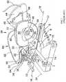
Figure 1 , the saw described inEP1772221 comprises abase 2 in which is mounted a circular table 4. The circular table 4 can rotate about a vertical axis. Anarm 6 is attached to the front of the circular table 4 which extends through arecess 8 formed in the front of thebase 2 and then forward of thebase 2. As the circular table rotates, thearm 6 swings within therecess 8, the maximum amount of pivotal movement being limited by thesides 10 of therecess 8. Alatch 12 is attached to the underside of the end of thearm 6 which is capable of releasably locking the angular position of thearm 6 within therecess 8. Afence 14 is rigidly attached to thebase 2 and passes over the circular table 4. - Pivotally attached to the rear of the circular table 4 is a
bevel support 16. Thebevel support 16 can pivot about ahorizontal bevel axis 18. Thebevel support 16 can be locked in a range of angular positions relative to the circular table 4 using alocking handle 20. - Pivotally mounted onto the
bevel support 16 is aslide support 22. Theslide support 22 can pivot about achopping axis 24 which is parallel to the axis ofrotation 26 of acutting blade 28. - Rigidly mounted within the
slide support 22 are the ends of twostraight rods 30; 32. Therods 30; 32 are prevented from sliding or rotating within theslide support 22. Therods end 34 of thetop rod 30 is aspring 36. The other end of thespring 36 is attached to thebevel support 16. Thespring 36 is under tension, biasing theend 34 of thetop rod 30 downwardly, biasing the ends of the tworods slide support 22 upwardly due to the pivotal connection of theslide support 22 to thebevel support 16. - Slideably mounted onto the two
rods saw assembly 38. - The
saw assembly 38 comprises amotor housing 40 in which is mounted an electric motor. The electric motor is powered via anelectric cable 42. Mounted on the front of themotor housing 40 is ahandle 44. Atrigger switch 46 is mounted within thehandle 44, which when depressed, activates the motor. Adrive spindle 48 projects from thehousing 40. Acircular saw blade 28 is rigidly mounted onto thedrive spindle 48. When the motor, is activated, the drive spindle rotates, rotatingly driving thesaw blade 28. Afixed guard 52 is rigidly mounted onto themotor housing 40 and surrounds the top cutting edge of thesaw blade 28. Apivotal guard 54 is pivotally mounted on themotor housing 40 and can pivot about the axis ofrotation 26 of thesaw blade 28. Thepivotal guard 54 can pivot between an enclosed position where it surrounds the lower cutting edge of thesaw blade 28 and a retracted position where it exposes the lower cutting edge of thesaw blade 28. When the pivotal guard is in the retracted position, it is telescopically pivoted into thefixed guard 52. A pivotal guard spring biases thepivotal guard 54 to the enclosed position. - The
saw assembly 38 can slide along the tworods slide support 22. - In use, a work piece is placed on the
base 2 and circular table 4 against thefence 14. The pivotal movement of the circular table 4 about the vertical axis allows the saw to perform mitre cuts on the work piece. The pivotal movement of the bevel support 16 in relation to the circular table 4 about thebevel axis 18 allows the saw to perform bevel cuts on the work piece. The pivotal movement of theslide support 22 on thebevel support 16 about thechopping axis 24 allows the saw to perform chop cuts on the work piece. The sliding movement of thesaw assembly 38 along the tworods - The saw comprises a pivotal guard actuating mechanism. The pivotal guard actuating mechanism causes the pivotal guard to pivot to its retracted position when the saw assembly is pivoted about the
chopping axis 24 from its upper position to its lower position. Thespring 36 biases thesaw assembly 38 to pivot about thechopping axis 24 to its upper most position. In this position, thepivotal guard 54 encloses the lower edge of thecutting blade 28. As the saw assembly is pivoted downwardly towards the circular table 4, the pivotal guard actuating mechanism causes theguard 54 to retract into thefixed guard 52, exposing the lower cutting edge of theblade 28. EP1878525 discloses a chop saw having the features in the pre-characterising portion of claim 1.- Accordingly, the aim of the present invention is to provide a saw in accordance with claim 1.
- Such an arrangement provides a compact construction for a saw. Whilst it will be appreciated that the output shaft in the embodiment below is the armature shaft of the motor,it is clear that the out put shaft could be driven indirectly by the motor, for example, via gears.
- An embodiment of the present invention will now be described with reference to the accompanying drawings of which:-
Figure 1 shows a perspective view of a prior art design of saw as disclosed inEP1772221 ;Figures 2A and2B show an exploded view of an embodiment of the saw according to the present invention;Figure 3 show an exploded view of the pivotal and fixed guard mechanism of the embodiment;Figure 4 shows a perspective view of the motor unit from a first side;Figure 5 shows a perspective view of the motor unit from a second side;Figure 6 shows an exploded view of the motor unit;Figure 7 shows a perspective view of the dust extraction arrangement;Figure 8 shows a schematic view of the base housing mounted on the two guide rods;Figure 9 shows a perspective view of the arm support mechanism;Figure 10 shows a schematic diagram of the air flow across the motor; andFigure 11 shows a schematic diagram of the arm located in one of its extreme angular positions within the recess.- An embodiment of the present invention will now be described with reference to
Figures 2 to 11 . The general construction of the saw in accordance with the present embodiment is similar to that disclosed inEP1772221 . Where the same features are disclosed inFigures 2 to 11 which have been previously disclosed inFigure 1 , the same reference numbers have been used. - The saw comprises a
base 2 in which is mounted a circular table 4. The circular table 4 can rotate about a vertical axis. Anarm 6 is attached to the front of the circular table 4 which extends through arecess 8 formed in the front of thebase 2 and then forward of thebase 2. As the circular table rotates, thearm 6 swings within therecess 8, the maximum amount of pivotal movement being limited by thesides 10 of therecess 8. Alatch 12 is attached to the underside of the end of thearm 6 which is capable of releasably locking the angular position of thearm 6 within therecess 8 in well known manner. A fixedfence 14 is rigidly attached to thebase 2 and passes over the circular table 4. A slidingfence 208 is sideably mounted on top of the fixedfence 14 which is capable of sliding in the direction of Arrow M. - Pivotally attached to the rear of the circular table 4 is a
bevel support 16. Thebevel support 16 can pivot about a horizontal bevel axis. Thebevel support 16 can be locked in a range of angular positions relative to the circular table 4 using alocking handle 20. - Pivotally mounted onto the
bevel support 16 is aslide support 22. Theslide support 22 can pivot about a chopping axis which is parallel to the axis of rotation of acutting blade 28. - Rigidly mounted within the
slide support 22 are the ends of twostraight rods 30; 32. Slideably mounted onto the tworods saw assembly 38. - Referring to
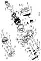
Figures 2B ,4 ,5 and6 , the saw assembly comprises amotor unit 100 as shown inFigures 4 to 6 . Themotor unit 100 comprises three housings, namely abase housing 102, themotor housing 40 and anend cap 104, which are connected together usingbolts 106. A motor is mounted within themotor housing 40 and comprises astator 108 and anarmature 110 rotatably mounted within thestator 108. The armature comprises anoutput shaft 112 by which the rotary motion of the motor is provided to the saw. Aradial fan 114 is rigidly fixed to theoutput shaft 112 for drawing air over the motor. The fan locates inside aguide ring 116 which is rigidly mounted in the end of themotor housing 40. Thefan 114 draws in air throughholes 118 form through theend cap 104, across thearmature 110 andstator 108 and then expels it side ways throughholes 120 formed through the side of the guide ring andmotor housing 40 as indicated by arrows shown inFigure 10 . - The
output shaft 112 projects into thebase housing 102 through anaperture 122 in thebase housing 102. Theoutput shaft 112 is supported by a bearing 124 located within theaperture 122. Afirst drive wheel 126 is rigidly mounted on the end of theoutput shaft 112 inside of thebase housing 102. - An
intermediate shaft 128 is mounted within asecond aperture 130 formed through thebase housing 102. Theintermediate shaft 128 is supported by asecond bearing 132 located within theaperture 130 and is a parallel to theoutput shaft 112. Located on the end of theintermediate shaft 128 inside of thebase housing 102 is a first drivenwheel 134. Arubber belt 138 wraps tightly around thefirst drive wheel 126 and first drivenwheel 134 and frictionally engages with them so that rotation of thedrive wheel 126 is transferred to the drivenwheel 134 via the rotation of thebelt 138. As such rotation of theoutput shaft 112 is transferred to theintermediate shaft 128. - The diameter of the first drive wheel is smaller that that the first driven wheel and therefore the rate of rotation the
intermediate shaft 128 is reduced when compared to that of theoutput shaft 112. - Mounted rigidly on the other end of the
intermediate shaft 128 outside of the base housing is asecond drive wheel 136. Adrive spindle 48 is mounted within athird aperture 140 formed through thebase housing 102. Thedrive spindle 48 is supported by athird bearing 142 located within theaperture 130 and is a parallel to theoutput shaft 112. Located on the end of thedrive spindle 48 outside of thebase housing 102 is a second drivenwheel 144. Asecond rubber belt 146 wraps tightly around thesecond drive wheel 136 and second drivenwheel 144 and frictionally engages with them so that rotation of thesecond drive wheel 136 is transferred to the second drivenwheel 144 via the rotation of thesecond belt 146. As such rotation of theintermediate shaft 128 is transferred to thedrive spindle 48. - The diameter of the
second drive wheel 136 is smaller that that the second drivenwheel 144 and therefore the rate of rotation of thedrive spindle 48 is reduced when compared to that of theintermediate shaft 128. - As such rotation of the
output shaft 112 is transferred to the drive spindle via the two belts, the speed of thedrive spindle 48 being considerably reduced compared to that of theoutput shaft 112. - Each of the
belts - The open end of the
base housing 102 is sealed by afirst side housing 150 which is rigidly attached to thebase housing 102. Thefirst belt 138 is enclosed within the base housing by thefirst side housing 102. By enclosing thebelt 138, no dust or debris generated during the operation of the saw can enter the base housing and interfere with the operation of the belt. Thesecond belt 146 is located outside of the base housing and is enclosed by acover 158 which is attached to the base housing using abolt 160. Ahole 152 is formed through the side housing through which thedrive spindle 48 projects. Ablade 28 can be rigidly mounted on the drive spindle48 using two side plates 154 and a clamp nut 156. - An
aperture 120 is formed through the side of thecover 158 which aligns with theapertures 120 in the side of the guide ring andmotor housing 40 when it is attached to thebase housing 102 as best seen inFigure 10 . Air is blown by thefan 114 into thecover 158 and across the belt (as shown inFigure 10 ) before being expelled throughvents 162 in thecover 158. The flow of air across thebelt 146 reduces the operating temperature of thebelt 146 by about 15 to 20 degrees centigrade. - The
base housing 102 slideably mounts onto the twoguide rods slide support 22. Therods 30; 32 are prevented from sliding or rotating within theslide support 22. Therods top rod 30 passes through twotubular passageways base housing 102 as best seen inFigure 6 . Thelower rod 32 locates in a thirdtubular passageway 174 within thebase housing 102. Thebase housing 102 can freely slide along the tworods - Referring to
Figure 8 which shows a schematic view of thebase housing 102 mounted on the twoguide rods output shaft 112 passes between the twoguide rods rods first belt 138 being located on the opposite side of the plane within which therods intermediate shaft 128 is located above and passes over the twoguide rods rods second belt 146 being located on the opposite side of the plane within which therods first belt 138. Thedrive spindle 48 passes between the twoguide rods lower rod 32 in a direction perpendicular to the plane within which therods rods - The
first side housing 150, which is rigidly attached to thebase housing 102, attaches to a second side housing 180 using bolts 184 to form the fixedguard 52 and adust chute 182. During the cutting operation, dust and debris are driven through thedust chute 182 by the rotary motion of thecutting blade 28. An inner wall 186 is mounted within the first and second side housings to assist in guiding the dust and debris. A separate vacuum cleaner can be attached to thechute 182 to assist in the removal of the dust and debris. - A
rubber chute 188 is attached to lower rear end of the fixedguard 52 by the insertion of pegs 190 attached to the fixed guard 58 locating within holes 192 formed in the rubber chute and then being secured usingclips 194 which attach to the ends of the pegs 190 as best seen inFigure 7 . The rubber chute assists in guiding dust and debris generated by the cutting action of the blade at the rear of the blade into the fixedguard 52 and towards thedust chute 182. When thesaw assembly 38 is located in its lowest position, therubber chute 188 extends downwardly to a position where it is just able to pass of over the fixed andmoveable fences rods - The
bevel support 16 attaches to the rear of the circular table 4 adjacent acircular support 200 integrally formed with the circular table 4. Attached to thebevel support 16 using ascrew 204 is aplastic guide chute 202 and which faces towards the rear of the blade. When thesaw assembly 38 is located in its lowest rearward position, therubber chute 188 is located behind thefence 14 in alignment with theplastic chute 200 so that therubber chute 188 and plastic guide chute act as a single combined chute. When thesaw assembly 38 is located in its lowest rearward position, the rear lower part of thesaw blade 28 passes through thecentre gap 206 of thefence 214 and rearwardly of thefence 14 in close proximity of theplastic guide chute 202. The combined chute acts to guide dust and debris generated by the cutting action of theblade 28 at the rear of the blade into the fixedguard 52 and towards thedust chute 182. - The
arm 6, which extends forward of thebase 2, has an L shapedsupport 210 attached to its underside of the end of the arm remote from the circular table 6 usingscrews 218 as best seen inFigure 9 . The L shapedsupport 210 comprises avertical plate 214 and a perpendicularhorizontal plate 216 connected to its lower end. When the saw is located on aflat work surface 212, thehorizontal plate 216 is located 4mm above the work surface 21 indicated by Arrow N. When the saw assembly is located in its forward most position, remote from thebevel support 16, with the blade located at its further extent towards the end of thearm 6 remote from the circular table 4, and a downward pressure is being exerted to cut a work piece, there is a force exerted onto the saw which can cause it to tip forward. In such circumstances thearm 6 will pivot forwards until theL shape support 210 engages with thework surface 212 preventing any further movement. Under normal circumstances it is desirable that thearm 6 andsupport 210 is located above the work surface to enable them to be freely rotated within thebase 2 bout a vertical axis. The length of thearm 6 and the location of the L shapedsupport 210 on thearm 6 are such that when the arm is pivoted to its extreme angular positions within therecess 8, the L shaped support is able to pass in front of and locate forward of thefront side sections 220 of thebase 2 as shown inFigure 11 . - A light aperture 240 is formed in the top of the fixed
guard 52. A light unit 242 comprising an LED is mounted on the outside of the fixedguard 52 so that the light of the LED shines through the light aperture 240 inside of the fixed guard, the light passing on either side of theblade 28. When thepivotal guard 54 is retracted inside of the fixedguard 54, the light is able to pass the blade and shine onto the circular table 4 andarm 6, the blade casting a shadow on the circular table 4 andarm 6. When a work piece is located on the circular table 4 andarm 6, the shadow is cast onto the work piece and provides an indication of where theblade 28 will contact the work piece when it is moved towards the work piece to cut it. - A power supply 244 is to the top of the saw assemble and connects to the light unit via a cable 246. A switch 248 on the power supply 244 is used to switch the LED on and off. The power supply is power by electricity provide through the
cable 42. - The
pivotal guard 54 is pivoted inside thefix guard 52 using a guard actuation mechanism comprising alever 250 pivotally mounted on thehandle 44 about anaxis 254, anelongate rod 252 pivotally attached at one end to thelever 250 via abolt 256 which passes through aslot 260 formed in therod 252 and screws into a threadedrecess 258 and which is axially slideable within the saw assembly, and acable 262 attached to the other end of theelongate rod 252 and to the pivotal guard. Thecable 262 wraps around a circularinner wall 264 formed on thepivotal guard 52 before attaching to it. Pivotal movement of thelever 250 results in a sliding movement of theelongate rod 252 which in turn pulls on thecable 262. As the cable is wrapped around the inner wall, as it is pulled it causes the pivotal guard to rotate thus pivoting it inside of the fixed guard and exposing theblade 28. Aspring 268 biases the lever 2590 away from thehandle 44. Asecond spring 270 biases the pivotal guard shut. Theslot 260 allows for movement of theguard 54 without movement of thelever 250.
Claims (8)
- A saw comprising:a base assembly (2);a saw assembly (38) pivotally mounted on the base assembly which is capable of pivoting towards or away from the base assembly to a cut a work piece located on the base assembly;a motor (108, 110) mounted within the saw assembly;a drive spindle (48) rotatably driven by the motor via a drive mechanism;characterised in that the drive mechanism comprises a rotatable output shaft (112), a first drive wheel (126) mounted on the output shaft, a rotatable intermediate shaft (128) parallel to the output shaft, a first driven wheel (134) mounted on the intermediate shaft, a first drive belt (138) wrapped around the first drive wheel and first driven wheel to transfer rotary motion of the output shaft to the intermediate shaft;a second drive wheel (136) mounted on the intermediate shaft, a second driven wheel (144) mounted on the drive spindle, a second drive belt (146) wrapped around the second drive wheel and second driven wheel to transfer rotary motion of the intermediate shaft to the drive spindle, the drive spindle being parallel to the output shaft;characterised in that the saw assembly is slideably mounted onto two parallel guide rods (30, 32) which are pivotally mounted on the base assembly, the rods (30, 32) being located in a vertical plane with one being located above the other;wherein the output shaft (112) passes between the two guide rods (30, 32) in a direction perpendicular to the plane within which the rods (30, 32) are located; wherein the intermediate shaft (128)is located above and passes over the two guide rods (30, 32) in a direction perpendicular to the plane within which the rods (30, 32) are located;wherein the drive spindle (48) passes between the two guide rods (30, 32) in a direction perpendicular to the plane within which the rods 30, 32 are located,wherein the first belt (138) is located on a fist side of the plane within which the rods (30, 32) are located to the motor and the second belt 146 is located on a second side of the plane within which the rods 30, 32 are located opposite to the first belt 138.
- A saw as claimed in claim 1 wherein the drive spindle 48 passes between the two guide rods (30, 32) in close proximity to the lower rod (32).
- A saw as claimed in any of the previous claims wherein the first drive wheel is smaller than the first driven wheel.
- A saw as claimed in any of the previous claims wherein the second drive wheel is smaller than the second driven wheel.
- A saw as claimed in any of the previous claims wherein at least one of the drive belts is elastically deformable in a lengthwise direction.
- A saw as claimed in any of the previous claims wherein the guide rods are rigidly attached to a slide support (22) which is pivotally attached to the base assembly.
- A saw as claimed in claim 6 wherein the slide support is pivotally mounted on a bevel support (16) which is pivotally attached to the base assembly.
- A saw as claimed in claim 7 wherein bevel support is pivotally attached to a circular table which pivotally mounted on the base assembly.
Applications Claiming Priority (1)
| Application Number | Priority Date | Filing Date | Title |
|---|---|---|---|
| GB1213061.3AGB2504275A (en) | 2012-07-23 | 2012-07-23 | Compact Drive Mechanism for Sliding Compound Mitre Saw |
Publications (2)
| Publication Number | Publication Date |
|---|---|
| EP2689878A1 EP2689878A1 (en) | 2014-01-29 |
| EP2689878B1true EP2689878B1 (en) | 2017-09-20 |
Family
ID=46881814
Family Applications (1)
| Application Number | Title | Priority Date | Filing Date |
|---|---|---|---|
| EP13175583.7AActiveEP2689878B1 (en) | 2012-07-23 | 2013-07-08 | Saw |
Country Status (4)
| Country | Link |
|---|---|
| US (1) | US9174289B2 (en) |
| EP (1) | EP2689878B1 (en) |
| CN (1) | CN103567538B (en) |
| GB (1) | GB2504275A (en) |
Families Citing this family (9)
| Publication number | Priority date | Publication date | Assignee | Title |
|---|---|---|---|---|
| EP2969333B1 (en)* | 2013-03-15 | 2019-09-25 | Robert Bosch GmbH | Miter saw rear guard |
| WO2015088963A1 (en)* | 2013-12-11 | 2015-06-18 | Robert Bosch Gmbh | Miter saw including a chain drive |
| CN208195813U (en)* | 2015-02-25 | 2018-12-07 | 米沃奇电动工具公司 | Mitre saw |
| EP3165312B1 (en) | 2015-11-06 | 2023-02-22 | Black & Decker Inc. | Mitre saw with slide rods |
| EP3165313B1 (en) | 2015-11-06 | 2023-03-29 | Black & Decker Inc. | Mitre saw with rods |
| GB201520416D0 (en)* | 2015-11-19 | 2016-01-06 | Black & Decker Inc | Sliding compound mitre saw |
| GB201610953D0 (en)* | 2016-06-23 | 2016-08-10 | Black & Decker Inc | Motor end cap |
| CN109849200B (en)* | 2019-03-07 | 2019-10-01 | 杭州曼京科技有限公司 | A ground slotting and cutting device for interior decoration |
| CN112405104A (en)* | 2020-11-20 | 2021-02-26 | 南京芝德曼家具有限公司 | Numerical control lathe cooling device |
Family Cites Families (12)
| Publication number | Priority date | Publication date | Assignee | Title |
|---|---|---|---|---|
| JPH0656906B2 (en) | 1984-09-28 | 1994-07-27 | 株式会社日立製作所 | Semiconductor laser device |
| JPH10225925A (en)* | 1997-02-14 | 1998-08-25 | Kioritz Corp | Power cutting machine and centrifugal clutch for the cutting machine |
| EP1902802B1 (en)* | 2001-02-08 | 2014-04-09 | Black & Decker, Inc. | Miter saw |
| US6810780B2 (en)* | 2001-05-10 | 2004-11-02 | Black & Decker Inc. | Miter detent override for a sliding compound miter saw |
| TWM248587U (en)* | 2003-10-30 | 2004-11-01 | Ruei-Sen Liau | Circular sawing machine |
| RU2308359C2 (en)* | 2004-09-02 | 2007-10-20 | Хитачи Коки Ко., Лтд. | Machine tool for cutting by angle (variants) |
| US7240598B2 (en)* | 2004-10-20 | 2007-07-10 | Chun-Hsiang Wang | Power transmission structure with dual blade shaft of a circular saw |
| EP1772221B1 (en) | 2005-10-07 | 2009-01-14 | Black & Decker | Saw |
| KR100635125B1 (en)* | 2006-07-13 | 2006-10-18 | 최이구 | cutter |
| CN101004206A (en)* | 2007-01-18 | 2007-07-25 | 宁波中强电动工具有限公司 | Two stage belt drive mechanism for adjusting degree of tightness of strap |
| JP5476798B2 (en)* | 2009-05-29 | 2014-04-23 | 日立工機株式会社 | Tabletop cutting machine |
| US9555490B2 (en)* | 2011-09-06 | 2017-01-31 | Robert Bosch Tool Corporation | Miter saw with double belt drive |
- 2012
- 2012-07-23GBGB1213061.3Apatent/GB2504275A/ennot_activeWithdrawn
- 2013
- 2013-07-08EPEP13175583.7Apatent/EP2689878B1/enactiveActive
- 2013-07-22USUS13/947,309patent/US9174289B2/enactiveActive
- 2013-07-23CNCN201310311403.3Apatent/CN103567538B/ennot_activeExpired - Fee Related
Non-Patent Citations (1)
| Title |
|---|
| None* |
Also Published As
| Publication number | Publication date |
|---|---|
| GB201213061D0 (en) | 2012-09-05 |
| CN103567538A (en) | 2014-02-12 |
| EP2689878A1 (en) | 2014-01-29 |
| CN103567538B (en) | 2017-03-08 |
| US9174289B2 (en) | 2015-11-03 |
| GB2504275A (en) | 2014-01-29 |
| US20140020539A1 (en) | 2014-01-23 |
Similar Documents
| Publication | Publication Date | Title |
|---|---|---|
| EP2689878B1 (en) | Saw | |
| EP2689879B1 (en) | Saw | |
| EP2689880B1 (en) | Saw | |
| EP1772222B1 (en) | Sliding compound miter saw with locking mechanism | |
| EP1772221B1 (en) | Saw | |
| CN103537754B (en) | portable cutting machine | |
| GB2446690A (en) | A Miter Saw | |
| WO2011104538A1 (en) | Guard means for a saw and method of use thereof | |
| EP2689877A1 (en) | Saw | |
| GB2496406A (en) | Guard mounted on inclining structure of mitre saw | |
| EP2689876A1 (en) | Saw | |
| EP1504863A2 (en) | Power miter saw | |
| EP3168017B1 (en) | Saw | |
| CN110014190B (en) | Portable cutting machine | |
| EP2253439B1 (en) | Mitre Saw | |
| CN218557163U (en) | Cutting device | |
| CN211185230U (en) | Chain saw | |
| CN209793969U (en) | electric circular saw capable of being rapidly switched to dust collection mode | |
| JP2009184304A (en) | Portable cutting machine | |
| EP3165338A1 (en) | Mitre saw with pivot joint | |
| CN104412840A (en) | Chain saw | |
| GB2435010A (en) | Saw with Bowden cable connected to pivotal guard |
Legal Events
| Date | Code | Title | Description |
|---|---|---|---|
| PUAI | Public reference made under article 153(3) epc to a published international application that has entered the european phase | Free format text:ORIGINAL CODE: 0009012 | |
| AK | Designated contracting states | Kind code of ref document:A1 Designated state(s):AL AT BE BG CH CY CZ DE DK EE ES FI FR GB GR HR HU IE IS IT LI LT LU LV MC MK MT NL NO PL PT RO RS SE SI SK SM TR | |
| AX | Request for extension of the european patent | Extension state:BA ME | |
| 17P | Request for examination filed | Effective date:20140625 | |
| RBV | Designated contracting states (corrected) | Designated state(s):AL AT BE BG CH CY CZ DE DK EE ES FI FR GB GR HR HU IE IS IT LI LT LU LV MC MK MT NL NO PL PT RO RS SE SI SK SM TR | |
| GRAP | Despatch of communication of intention to grant a patent | Free format text:ORIGINAL CODE: EPIDOSNIGR1 | |
| STAA | Information on the status of an ep patent application or granted ep patent | Free format text:STATUS: GRANT OF PATENT IS INTENDED | |
| INTG | Intention to grant announced | Effective date:20170704 | |
| GRAS | Grant fee paid | Free format text:ORIGINAL CODE: EPIDOSNIGR3 | |
| GRAA | (expected) grant | Free format text:ORIGINAL CODE: 0009210 | |
| STAA | Information on the status of an ep patent application or granted ep patent | Free format text:STATUS: THE PATENT HAS BEEN GRANTED | |
| AK | Designated contracting states | Kind code of ref document:B1 Designated state(s):AL AT BE BG CH CY CZ DE DK EE ES FI FR GB GR HR HU IE IS IT LI LT LU LV MC MK MT NL NO PL PT RO RS SE SI SK SM TR | |
| REG | Reference to a national code | Ref country code:GB Ref legal event code:FG4D | |
| REG | Reference to a national code | Ref country code:CH Ref legal event code:EP | |
| REG | Reference to a national code | Ref country code:AT Ref legal event code:REF Ref document number:929761 Country of ref document:AT Kind code of ref document:T Effective date:20171015 | |
| REG | Reference to a national code | Ref country code:IE Ref legal event code:FG4D | |
| REG | Reference to a national code | Ref country code:SE Ref legal event code:TRGR | |
| REG | Reference to a national code | Ref country code:DE Ref legal event code:R096 Ref document number:602013026792 Country of ref document:DE | |
| REG | Reference to a national code | Ref country code:NL Ref legal event code:MP Effective date:20170920 | |
| PG25 | Lapsed in a contracting state [announced via postgrant information from national office to epo] | Ref country code:FI Free format text:LAPSE BECAUSE OF FAILURE TO SUBMIT A TRANSLATION OF THE DESCRIPTION OR TO PAY THE FEE WITHIN THE PRESCRIBED TIME-LIMIT Effective date:20170920 Ref country code:LT Free format text:LAPSE BECAUSE OF FAILURE TO SUBMIT A TRANSLATION OF THE DESCRIPTION OR TO PAY THE FEE WITHIN THE PRESCRIBED TIME-LIMIT Effective date:20170920 Ref country code:NO Free format text:LAPSE BECAUSE OF FAILURE TO SUBMIT A TRANSLATION OF THE DESCRIPTION OR TO PAY THE FEE WITHIN THE PRESCRIBED TIME-LIMIT Effective date:20171220 Ref country code:HR Free format text:LAPSE BECAUSE OF FAILURE TO SUBMIT A TRANSLATION OF THE DESCRIPTION OR TO PAY THE FEE WITHIN THE PRESCRIBED TIME-LIMIT Effective date:20170920 | |
| REG | Reference to a national code | Ref country code:LT Ref legal event code:MG4D | |
| REG | Reference to a national code | Ref country code:AT Ref legal event code:MK05 Ref document number:929761 Country of ref document:AT Kind code of ref document:T Effective date:20170920 | |
| PG25 | Lapsed in a contracting state [announced via postgrant information from national office to epo] | Ref country code:RS Free format text:LAPSE BECAUSE OF FAILURE TO SUBMIT A TRANSLATION OF THE DESCRIPTION OR TO PAY THE FEE WITHIN THE PRESCRIBED TIME-LIMIT Effective date:20170920 Ref country code:LV Free format text:LAPSE BECAUSE OF FAILURE TO SUBMIT A TRANSLATION OF THE DESCRIPTION OR TO PAY THE FEE WITHIN THE PRESCRIBED TIME-LIMIT Effective date:20170920 Ref country code:BG Free format text:LAPSE BECAUSE OF FAILURE TO SUBMIT A TRANSLATION OF THE DESCRIPTION OR TO PAY THE FEE WITHIN THE PRESCRIBED TIME-LIMIT Effective date:20171220 Ref country code:GR Free format text:LAPSE BECAUSE OF FAILURE TO SUBMIT A TRANSLATION OF THE DESCRIPTION OR TO PAY THE FEE WITHIN THE PRESCRIBED TIME-LIMIT Effective date:20171221 | |
| PG25 | Lapsed in a contracting state [announced via postgrant information from national office to epo] | Ref country code:NL Free format text:LAPSE BECAUSE OF FAILURE TO SUBMIT A TRANSLATION OF THE DESCRIPTION OR TO PAY THE FEE WITHIN THE PRESCRIBED TIME-LIMIT Effective date:20170920 | |
| PG25 | Lapsed in a contracting state [announced via postgrant information from national office to epo] | Ref country code:CZ Free format text:LAPSE BECAUSE OF FAILURE TO SUBMIT A TRANSLATION OF THE DESCRIPTION OR TO PAY THE FEE WITHIN THE PRESCRIBED TIME-LIMIT Effective date:20170920 Ref country code:PL Free format text:LAPSE BECAUSE OF FAILURE TO SUBMIT A TRANSLATION OF THE DESCRIPTION OR TO PAY THE FEE WITHIN THE PRESCRIBED TIME-LIMIT Effective date:20170920 Ref country code:RO Free format text:LAPSE BECAUSE OF FAILURE TO SUBMIT A TRANSLATION OF THE DESCRIPTION OR TO PAY THE FEE WITHIN THE PRESCRIBED TIME-LIMIT Effective date:20170920 Ref country code:ES Free format text:LAPSE BECAUSE OF FAILURE TO SUBMIT A TRANSLATION OF THE DESCRIPTION OR TO PAY THE FEE WITHIN THE PRESCRIBED TIME-LIMIT Effective date:20170920 | |
| PG25 | Lapsed in a contracting state [announced via postgrant information from national office to epo] | Ref country code:IS Free format text:LAPSE BECAUSE OF FAILURE TO SUBMIT A TRANSLATION OF THE DESCRIPTION OR TO PAY THE FEE WITHIN THE PRESCRIBED TIME-LIMIT Effective date:20180120 Ref country code:AT Free format text:LAPSE BECAUSE OF FAILURE TO SUBMIT A TRANSLATION OF THE DESCRIPTION OR TO PAY THE FEE WITHIN THE PRESCRIBED TIME-LIMIT Effective date:20170920 Ref country code:SM Free format text:LAPSE BECAUSE OF FAILURE TO SUBMIT A TRANSLATION OF THE DESCRIPTION OR TO PAY THE FEE WITHIN THE PRESCRIBED TIME-LIMIT Effective date:20170920 Ref country code:EE Free format text:LAPSE BECAUSE OF FAILURE TO SUBMIT A TRANSLATION OF THE DESCRIPTION OR TO PAY THE FEE WITHIN THE PRESCRIBED TIME-LIMIT Effective date:20170920 Ref country code:SK Free format text:LAPSE BECAUSE OF FAILURE TO SUBMIT A TRANSLATION OF THE DESCRIPTION OR TO PAY THE FEE WITHIN THE PRESCRIBED TIME-LIMIT Effective date:20170920 | |
| REG | Reference to a national code | Ref country code:DE Ref legal event code:R097 Ref document number:602013026792 Country of ref document:DE | |
| PLBE | No opposition filed within time limit | Free format text:ORIGINAL CODE: 0009261 | |
| STAA | Information on the status of an ep patent application or granted ep patent | Free format text:STATUS: NO OPPOSITION FILED WITHIN TIME LIMIT | |
| PG25 | Lapsed in a contracting state [announced via postgrant information from national office to epo] | Ref country code:DK Free format text:LAPSE BECAUSE OF FAILURE TO SUBMIT A TRANSLATION OF THE DESCRIPTION OR TO PAY THE FEE WITHIN THE PRESCRIBED TIME-LIMIT Effective date:20170920 | |
| 26N | No opposition filed | Effective date:20180621 | |
| PGFP | Annual fee paid to national office [announced via postgrant information from national office to epo] | Ref country code:FR Payment date:20180813 Year of fee payment:13 | |
| PG25 | Lapsed in a contracting state [announced via postgrant information from national office to epo] | Ref country code:SI Free format text:LAPSE BECAUSE OF FAILURE TO SUBMIT A TRANSLATION OF THE DESCRIPTION OR TO PAY THE FEE WITHIN THE PRESCRIBED TIME-LIMIT Effective date:20170920 | |
| PGFP | Annual fee paid to national office [announced via postgrant information from national office to epo] | Ref country code:SE Payment date:20180710 Year of fee payment:6 | |
| REG | Reference to a national code | Ref country code:CH Ref legal event code:PL | |
| PG25 | Lapsed in a contracting state [announced via postgrant information from national office to epo] | Ref country code:MC Free format text:LAPSE BECAUSE OF FAILURE TO SUBMIT A TRANSLATION OF THE DESCRIPTION OR TO PAY THE FEE WITHIN THE PRESCRIBED TIME-LIMIT Effective date:20170920 Ref country code:LU Free format text:LAPSE BECAUSE OF NON-PAYMENT OF DUE FEES Effective date:20180708 | |
| REG | Reference to a national code | Ref country code:BE Ref legal event code:MM Effective date:20180731 | |
| REG | Reference to a national code | Ref country code:IE Ref legal event code:MM4A | |
| PG25 | Lapsed in a contracting state [announced via postgrant information from national office to epo] | Ref country code:IE Free format text:LAPSE BECAUSE OF NON-PAYMENT OF DUE FEES Effective date:20180708 Ref country code:FR Free format text:LAPSE BECAUSE OF NON-PAYMENT OF DUE FEES Effective date:20180731 Ref country code:LI Free format text:LAPSE BECAUSE OF NON-PAYMENT OF DUE FEES Effective date:20180731 Ref country code:CH Free format text:LAPSE BECAUSE OF NON-PAYMENT OF DUE FEES Effective date:20180731 | |
| PG25 | Lapsed in a contracting state [announced via postgrant information from national office to epo] | Ref country code:BE Free format text:LAPSE BECAUSE OF NON-PAYMENT OF DUE FEES Effective date:20180731 | |
| PG25 | Lapsed in a contracting state [announced via postgrant information from national office to epo] | Ref country code:MT Free format text:LAPSE BECAUSE OF NON-PAYMENT OF DUE FEES Effective date:20180708 | |
| REG | Reference to a national code | Ref country code:SE Ref legal event code:EUG | |
| PG25 | Lapsed in a contracting state [announced via postgrant information from national office to epo] | Ref country code:TR Free format text:LAPSE BECAUSE OF FAILURE TO SUBMIT A TRANSLATION OF THE DESCRIPTION OR TO PAY THE FEE WITHIN THE PRESCRIBED TIME-LIMIT Effective date:20170920 | |
| PG25 | Lapsed in a contracting state [announced via postgrant information from national office to epo] | Ref country code:SE Free format text:LAPSE BECAUSE OF NON-PAYMENT OF DUE FEES Effective date:20190709 | |
| PG25 | Lapsed in a contracting state [announced via postgrant information from national office to epo] | Ref country code:HU Free format text:LAPSE BECAUSE OF FAILURE TO SUBMIT A TRANSLATION OF THE DESCRIPTION OR TO PAY THE FEE WITHIN THE PRESCRIBED TIME-LIMIT; INVALID AB INITIO Effective date:20130708 Ref country code:PT Free format text:LAPSE BECAUSE OF FAILURE TO SUBMIT A TRANSLATION OF THE DESCRIPTION OR TO PAY THE FEE WITHIN THE PRESCRIBED TIME-LIMIT Effective date:20170920 | |
| PG25 | Lapsed in a contracting state [announced via postgrant information from national office to epo] | Ref country code:CY Free format text:LAPSE BECAUSE OF FAILURE TO SUBMIT A TRANSLATION OF THE DESCRIPTION OR TO PAY THE FEE WITHIN THE PRESCRIBED TIME-LIMIT Effective date:20170920 Ref country code:MK Free format text:LAPSE BECAUSE OF NON-PAYMENT OF DUE FEES Effective date:20170920 | |
| PG25 | Lapsed in a contracting state [announced via postgrant information from national office to epo] | Ref country code:AL Free format text:LAPSE BECAUSE OF FAILURE TO SUBMIT A TRANSLATION OF THE DESCRIPTION OR TO PAY THE FEE WITHIN THE PRESCRIBED TIME-LIMIT Effective date:20170920 | |
| PG25 | Lapsed in a contracting state [announced via postgrant information from national office to epo] | Ref country code:IT Free format text:LAPSE BECAUSE OF NON-PAYMENT OF DUE FEES Effective date:20190708 | |
| PGFP | Annual fee paid to national office [announced via postgrant information from national office to epo] | Ref country code:DE Payment date:20240719 Year of fee payment:12 | |
| PGFP | Annual fee paid to national office [announced via postgrant information from national office to epo] | Ref country code:GB Payment date:20240723 Year of fee payment:12 |