EP2689751A1 - Cement pressurizing glenoid - Google Patents
Cement pressurizing glenoidDownload PDFInfo
- Publication number
- EP2689751A1 EP2689751A1EP13177866.4AEP13177866AEP2689751A1EP 2689751 A1EP2689751 A1EP 2689751A1EP 13177866 AEP13177866 AEP 13177866AEP 2689751 A1EP2689751 A1EP 2689751A1
- Authority
- EP
- European Patent Office
- Prior art keywords
- pegs
- peg
- glenoid
- diameter
- glenoid component
- Prior art date
- Legal status (The legal status is an assumption and is not a legal conclusion. Google has not performed a legal analysis and makes no representation as to the accuracy of the status listed.)
- Granted
Links
- 241001653121GlenoidesSpecies0.000titleclaimsabstractdescription95
- 239000004568cementSubstances0.000titledescription2
- 210000000988bone and boneAnatomy0.000claimsabstractdescription27
- 239000002639bone cementSubstances0.000description16
- 210000001991scapulaAnatomy0.000description15
- 238000000034methodMethods0.000description9
- 238000002513implantationMethods0.000description4
- 238000003780insertionMethods0.000description4
- 230000037431insertionEffects0.000description4
- 239000007943implantSubstances0.000description3
- 210000000845cartilageAnatomy0.000description2
- 235000014443Pyrus communisNutrition0.000description1
- 229920010741Ultra High Molecular Weight Polyethylene (UHMWPE)Polymers0.000description1
- 210000002659acromionAnatomy0.000description1
- 210000003484anatomyAnatomy0.000description1
- 238000004873anchoringMethods0.000description1
- 230000015572biosynthetic processEffects0.000description1
- 230000008468bone growthEffects0.000description1
- 239000001506calcium phosphateSubstances0.000description1
- 235000011010calcium phosphatesNutrition0.000description1
- 230000000295complement effectEffects0.000description1
- 230000002939deleterious effectEffects0.000description1
- 210000004095humeral headAnatomy0.000description1
- 210000002758humerusAnatomy0.000description1
- 210000003041ligamentAnatomy0.000description1
- 239000000463materialSubstances0.000description1
- 238000012986modificationMethods0.000description1
- 230000004048modificationEffects0.000description1
- 210000003205muscleAnatomy0.000description1
- 238000000926separation methodMethods0.000description1
- 210000000323shoulder jointAnatomy0.000description1
- 210000002435tendonAnatomy0.000description1
- QORWJWZARLRLPR-UHFFFAOYSA-Htricalcium bis(phosphate)Chemical class[Ca+2].[Ca+2].[Ca+2].[O-]P([O-])([O-])=O.[O-]P([O-])([O-])=OQORWJWZARLRLPR-UHFFFAOYSA-H0.000description1
Images


Classifications
- A—HUMAN NECESSITIES
- A61—MEDICAL OR VETERINARY SCIENCE; HYGIENE
- A61F—FILTERS IMPLANTABLE INTO BLOOD VESSELS; PROSTHESES; DEVICES PROVIDING PATENCY TO, OR PREVENTING COLLAPSING OF, TUBULAR STRUCTURES OF THE BODY, e.g. STENTS; ORTHOPAEDIC, NURSING OR CONTRACEPTIVE DEVICES; FOMENTATION; TREATMENT OR PROTECTION OF EYES OR EARS; BANDAGES, DRESSINGS OR ABSORBENT PADS; FIRST-AID KITS
- A61F2/00—Filters implantable into blood vessels; Prostheses, i.e. artificial substitutes or replacements for parts of the body; Appliances for connecting them with the body; Devices providing patency to, or preventing collapsing of, tubular structures of the body, e.g. stents
- A61F2/02—Prostheses implantable into the body
- A61F2/30—Joints
- A61F2/40—Joints for shoulders
- A61F2/4081—Glenoid components, e.g. cups
- A—HUMAN NECESSITIES
- A61—MEDICAL OR VETERINARY SCIENCE; HYGIENE
- A61F—FILTERS IMPLANTABLE INTO BLOOD VESSELS; PROSTHESES; DEVICES PROVIDING PATENCY TO, OR PREVENTING COLLAPSING OF, TUBULAR STRUCTURES OF THE BODY, e.g. STENTS; ORTHOPAEDIC, NURSING OR CONTRACEPTIVE DEVICES; FOMENTATION; TREATMENT OR PROTECTION OF EYES OR EARS; BANDAGES, DRESSINGS OR ABSORBENT PADS; FIRST-AID KITS
- A61F2/00—Filters implantable into blood vessels; Prostheses, i.e. artificial substitutes or replacements for parts of the body; Appliances for connecting them with the body; Devices providing patency to, or preventing collapsing of, tubular structures of the body, e.g. stents
- A61F2/02—Prostheses implantable into the body
- A61F2/30—Joints
- A61F2/30767—Special external or bone-contacting surface, e.g. coating for improving bone ingrowth
- A61F2/30771—Special external or bone-contacting surface, e.g. coating for improving bone ingrowth applied in original prostheses, e.g. holes or grooves
- A61F2002/3082—Grooves
- A61F2002/30822—Circumferential grooves
- A—HUMAN NECESSITIES
- A61—MEDICAL OR VETERINARY SCIENCE; HYGIENE
- A61F—FILTERS IMPLANTABLE INTO BLOOD VESSELS; PROSTHESES; DEVICES PROVIDING PATENCY TO, OR PREVENTING COLLAPSING OF, TUBULAR STRUCTURES OF THE BODY, e.g. STENTS; ORTHOPAEDIC, NURSING OR CONTRACEPTIVE DEVICES; FOMENTATION; TREATMENT OR PROTECTION OF EYES OR EARS; BANDAGES, DRESSINGS OR ABSORBENT PADS; FIRST-AID KITS
- A61F2/00—Filters implantable into blood vessels; Prostheses, i.e. artificial substitutes or replacements for parts of the body; Appliances for connecting them with the body; Devices providing patency to, or preventing collapsing of, tubular structures of the body, e.g. stents
- A61F2/02—Prostheses implantable into the body
- A61F2/30—Joints
- A61F2/30767—Special external or bone-contacting surface, e.g. coating for improving bone ingrowth
- A61F2/30771—Special external or bone-contacting surface, e.g. coating for improving bone ingrowth applied in original prostheses, e.g. holes or grooves
- A61F2002/30878—Special external or bone-contacting surface, e.g. coating for improving bone ingrowth applied in original prostheses, e.g. holes or grooves with non-sharp protrusions, for instance contacting the bone for anchoring, e.g. keels, pegs, pins, posts, shanks, stems, struts
- A61F2002/30891—Plurality of protrusions
- A—HUMAN NECESSITIES
- A61—MEDICAL OR VETERINARY SCIENCE; HYGIENE
- A61F—FILTERS IMPLANTABLE INTO BLOOD VESSELS; PROSTHESES; DEVICES PROVIDING PATENCY TO, OR PREVENTING COLLAPSING OF, TUBULAR STRUCTURES OF THE BODY, e.g. STENTS; ORTHOPAEDIC, NURSING OR CONTRACEPTIVE DEVICES; FOMENTATION; TREATMENT OR PROTECTION OF EYES OR EARS; BANDAGES, DRESSINGS OR ABSORBENT PADS; FIRST-AID KITS
- A61F2/00—Filters implantable into blood vessels; Prostheses, i.e. artificial substitutes or replacements for parts of the body; Appliances for connecting them with the body; Devices providing patency to, or preventing collapsing of, tubular structures of the body, e.g. stents
- A61F2/02—Prostheses implantable into the body
- A61F2/30—Joints
- A61F2/30767—Special external or bone-contacting surface, e.g. coating for improving bone ingrowth
- A61F2/30771—Special external or bone-contacting surface, e.g. coating for improving bone ingrowth applied in original prostheses, e.g. holes or grooves
- A61F2002/30878—Special external or bone-contacting surface, e.g. coating for improving bone ingrowth applied in original prostheses, e.g. holes or grooves with non-sharp protrusions, for instance contacting the bone for anchoring, e.g. keels, pegs, pins, posts, shanks, stems, struts
- A61F2002/30897—Stepped protrusions, i.e. having discrete diameter changes
- A—HUMAN NECESSITIES
- A61—MEDICAL OR VETERINARY SCIENCE; HYGIENE
- A61F—FILTERS IMPLANTABLE INTO BLOOD VESSELS; PROSTHESES; DEVICES PROVIDING PATENCY TO, OR PREVENTING COLLAPSING OF, TUBULAR STRUCTURES OF THE BODY, e.g. STENTS; ORTHOPAEDIC, NURSING OR CONTRACEPTIVE DEVICES; FOMENTATION; TREATMENT OR PROTECTION OF EYES OR EARS; BANDAGES, DRESSINGS OR ABSORBENT PADS; FIRST-AID KITS
- A61F2/00—Filters implantable into blood vessels; Prostheses, i.e. artificial substitutes or replacements for parts of the body; Appliances for connecting them with the body; Devices providing patency to, or preventing collapsing of, tubular structures of the body, e.g. stents
- A61F2/02—Prostheses implantable into the body
- A61F2/30—Joints
- A61F2/46—Special tools for implanting artificial joints
- A61F2002/4631—Special tools for implanting artificial joints the prosthesis being specially adapted for being cemented
Definitions
- the present inventionrelates generally to prosthetic implants for reconstructing the shoulder joint. More specifically, the invention relates to a glenoid component for a shoulder prosthesis and a method for affixing the glenoid component to a scapula in an implant procedure.
- the glenoid cavityis located on the upper external border of the scapula between the acromion process and the coracoid process on a boney formation known as the scapula head.
- the glenoid cavityis a shallow, pear shaped, articular surface whose longest diameter is in the proximal-distal direction. It is broader distally than proximally, and its apex is a slight impression, the supra-glenoid tubercle, to which is attached the long tendon of the biceps muscle.
- the cavityis covered with cartilage and its margins, slightly raised, give attachment to a fibro-cartilaginous structure, the glenoid ligament, by which its cavity is deepened.
- the glenoid cavityarticulates with a large, rounded head at the proximal end of the humerus.
- the headis nearly hemispherical in form and is directed proximally and medially and slightly posteriorly. Its surface is smooth and coated with cartilage.
- the glenoid resurfacing componentis made of ultrahigh molecular weight polyethylene (UHMWPE) having a concave laterally facing articulating surface and a convex medial bone contacting surface, which may include multiple pegs.
- UHMWPEultrahigh molecular weight polyethylene
- the pegsresist the various types of loading placed on the glenoid by the head portion of the humeral component allowing the glenoid component to offer a stable and secure articulating surface.
- the pegsare inserted into a hole bored in the glenoid cavity and are secured either by bone cement or by being press fit in the bores.
- the medial surface of the glenoid componentincludes three to five pegs to stabilize and secure the glenoid component to the scapula.
- the glenoid componentsmay offer one of two larger diameter pegs and multiple pegs especially on the distal medial surface of the glenoid component.
- the pegs on the glenoid componentare located and oriented for placement within the scapula at locations where maximum amounts of natural bone are available for effective anchoring of the pegs and for minimal risk of deleterious bone perforation, and for managing moments exerted on the glenoid component as a result of the forces encountered during service.
- the glenoid componenttypically employs a full complement of the fixation pegs combined with an overall curved affixation surface for resisting shear forces and rocking the glenoid on the scapula, while preserving existing natural bone at the implant site.
- Typical glenoid componentsare shown in U.S. Patent Nos. 4,964,865 ; 5,573,448 ; 6,379,386 ; and 6,911,047 .
- the prosthetic glenoid component of the present inventionhas a body having a concave bearing surface and a convex glenoid contacting surface.
- the bodyhas a first end and a second end with first and second pegs extending outwardly from adjacent the respective first and second ends of the bone contacting surface of the body.
- the first and second pegshave portions with a first diameter at the bone contacting surface extending for a first length and a second diameter extending from the first diameter for a second length, the first diameter being larger than the second diameter.
- a third pegextends outwardly from the bone contacting surface intermediate the first and second pegs.
- the third peghas a third diameter greater than the second diameter portion of the first and second pegs and a third length greater than the first length of the first diameter portion of the first and second pegs, the third length less than the sum of the lengths of the first and second peg portions.
- the first and second diameters of the first and second peg portionsare preferably equal.
- the first and second pegsmay have circumferential grooves formed around their first and second diameters and the pegs may also have longitudinally extending grooves.
- the first, second, and third pegseach have a longitudinal central axis wherein the longitudinal axis of the first, second, and third pegs are all parallel.
- the first portion diameter of the first and second pegsis equal to the third diameter of the third peg.
- the glenoidmay further comprise a fourth peg extending outwardly of the bone contacting surface adjacent the first end of the bone contacting surface.
- the first and fourth pegshave a central longitudinal axes which may be parallel and coplanar along a first plane.
- the second and third pegseach have central longitudinal axis which are parallel and coplanar along a second plane which is perpendicular to the first plane.
- the axis of the first pegmay also be parallel and coplanar with the longitudinal axis of the second and third pegs.
- the inventionalso relates to a method for implanting a prosthetic component in a scapular glenoid cavity includes forming three bores in a glenoid cavity including a proximal first bore, a distal second bore, and a third bore intermediate the first and second bores.
- a prosthetic glenoid componentfor implantation in the glenoid cavity which has a body having a concave bearing surface, and a bone contacting surface having three pegs extending outwardly therefrom.
- a first proximal peghas a first length
- a second distal peghas a second length
- a third peg intermediate the first and second pegshas a length shorter than the first and second pegs.
- the first and second pegshave a larger diameter first portion adjacent the glenoid bone contacting surface and a smaller diameter second portion adjacent a free end of the first and second pegs.
- the glenoid componentis implanted by first inserting the smaller diameter second portion of the first and second pegs, respectively into the proximal first bore and the distal second bore. Thereafter the third peg is inserted into the third bore and lastly the large diameter first portion of the first and second pegs is inserted into the first and second bores.
- the first, second, and third boresmay be filled with bone cement prior to implanting the glenoid component.
- Each of the pegsmay have recessed circumferential grooves for receiving the bone cement.
- the larger portion of the first and second pegs and the first and second boreshave diameters producing line to line contact therebetween or may overlap slightly to produce an interference fit.
- the third peg and the central boremay also have diameters which produce line to line contact or an interference fit therebetween.
- proximalmeans close to the heart and the term “distal” means more distant from the heart.
- distalmeans more distant from the heart.
- inferiormeans toward the feet and the term “superior” means toward the head.
- anteriormeans toward the front part or the face and the term “posterior” means toward the back of the body.
- medialmeans toward the midline of the body and the term “lateral” means away from the midline of the body.
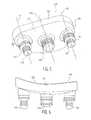
- FIG. 1is an isometric view of a glenoid component of the present invention viewed from a bone contacting or medial side;
- FIG. 2is an elevation view of the glenoid component of FIG. 1 ;
- FIG. 3is a isometric view as seen from the medial bone contacting side of an alternate embodiment of a glenoid component designed for use without bone cement;
- FIG. 4is an elevation view of the alternate embodiment of FIG. 3 ;
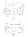
- FIG. 5is an isometric view of an additional alternate glenoid component having three pegs viewed from a medial or bone contacting side thereof;
- FIG. 6is an elevation view of the glenoid component of FIG. 5 ;
- FIG. 7is an embodiment of the glenoid component having three pegs designed for use without bone cement as seen from the bone contacting or medial side;
- FIG. 8is an elevation view of the glenoid component of FIG. 7 ;
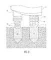
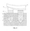
- FIG. 9-11show the method of implantation of the glenoid component of FIG. 1 , using bone cement with FIG. 9 showing the location of the pegs in relation to bone cement filled bores in the scapula prior to insertion; FIG. 10 showing the engagement of the central bore with the central peg just prior to the engagement of the larger diameter of the left-hand peg with the bore; and FIG. 11 showing the cement being pressurized in the respective bore by the larger diameter of the left-hand peg of FIG. 11 and the central (right-hand peg) of FIG. 11 .
- FIGS. 1 and 2there is shown an isometric view of a first embodiment of a glenoid component generally denoted as 10.
- This embodimenthas a body 12 with a bone contacting surface 14 and has four pegs 16, 18, 20, and 22.
- body 12During implantation on the scapula, body 12 has a distal or inferior end 24 and a proximal or superior end 26.
- glenoid component 10there are two pegs 20 and 22 at distal end 24 and one peg a proximal or superior end 26.
- a central peg 18is provided on the body.
- the scapula or glenoid cavityis prepared in a standard manner to create four bores corresponding in location to the four pegs 16, 18, 20 and 22 on the bone contacting surface 14 of glenoid component 10.
- Pegs 16, 20 and 22have a central longitudinal axis 38 and peg 18 has a central longitudinal axis 40.
- body 12includes a bearing surface 30 which is designed to articulate against a prosthetic humeral head (not shown).
- pegs 16 and 22are identically shaped and extend away from the bone contacting surface a greater distance than central peg 18.
- pegs 16 and 22include a first larger diameter portion 32 adjacent bone contacting surface 14 and a smaller diameter second portion 34 extending medially from an end of the larger first diameter portion 32.
- peg 22is preferably also identical to pegs 16 and 20.
- the first and second portions 32 and 34 of pegs 16, 20, and 22have surfaces with circumferentially extending grooves 36. As can be seen, multiple grooves 36 are spaced along each peg generally perpendicular to the central axis 38. Central peg 18 also includes a series of grooves 39 extending around the circumference thereof centered about axis 40 of peg 18 and generally perpendicular thereto. Peg 18 and portions 34 of pegs 16, 20, and 22 may include at least one axial groove 42 extending through each of the flanged portions 44 created by circumferential grooves 36 on pegs 16, 20, and 22 as well as flange 46 formed by grooves 39 on central peg 18.
- the purpose of the axial grooves 42is to allow bone cement to move upwardly in the bores formed in the glenoid cavity upon insertion of the glenoid component 12 therein. Grooves 42 ensure that pressurized bone cement flows into the grooves 36 and 39 to ensure positive interlocking between the glenoid component 12 and the scapula. Any number of grooves can be used on pegs 16-22 so long as the flanges 44 and 46 are thick enough to resist deformation upon standard loads being applied to the glenoid component during use.
- an alternate glenoid componentgenerally denoted as 10', which is in all ways similar to the glenoid component 10 of FIGS. 1 and 2 with the exception that the four pegs 16', 18', 20', and 22' have smooth or nongrooved outer surfaces. These nongrooved outer surfaces are used in press fit applications wherein the outer diameter of the pegs is equal to or very slightly more than the diameters of the corresponding bores drilled in the glenoid cavity.
- a plane connecting the central axes 37, 37' of pegs 16, 16', and axis 40, 40' of pegs 18, 18'lie in a single plane 54, 54'.
- pegs 20, 20' and 22, 22'have their central longitudinal axes 38 and 38' extending parallel and lying in the plane 50, 50'.
- planes 54, 54' and 50, 50'are perpendicular to one another.
- FIGS. 5 and 6there is shown an alternate glenoid component 100 in which a body 112 which is identical to the glenoid component of FIGS. 1-4 with the exception that there are three pegs 116, 118, and 120 extending from bone contacting surface 114. It can be seen that the bone contacting surfaces 14 and 114 are both convex in shape to match the anatomy of the glenoid cavity.
- the glenoid 100 of FIG. 5 and 6is designed to be utilized with bone cement in a manner similar to that shown in FIGS. 1 and 2 and include circumferential grooves 136 separated by flanges 144, which are identical to the grooves 36, 39 discussed above with regard to FIGS. 1 and 2 .
- distal end 124 and proximal end 126include only a single peg 116 and 120.
- pegs 16 and 18include parallel longitudinal axes 138, 140, and 142, which lie in the same plane extending from end 124 to 126.
- the glenoid componentsrespectively include bearing surfaces 30, 30', and 130.
- FIGS. 7 and 8there is shown an alternate embodiment of the glenoid component 100 of FIGS. 5 and 6 generally denoted as 100'.
- the glenoid component of FIGS. 7 and 8include smooth outer surfaces for enlarged diameter portion 132' and smaller diameter portion 134' of pegs 116' and 120' and a smooth outer surface for central peg 118'.
- All of the glenoid component pegs of FIGS. 1-8include a portion 60 surrounded by chamfered portion 64 and, with regard to central peg 18, an enlarged portion 62 surrounded again by chamfered portion 66.
- the chamfered portions 64, 66make it easier to insert the peg tips into the bores formed in the scapula.
- FIGS. 9-11the insertion process of any of the glenoid components of FIGS. 1-8 will now be described. Although a glenoid component similar to those shown in FIGS. 1 and 2 and 5 and 6 is shown, the insertion technique would be the same whether a cemented or noncemented component is utilized. Again, this process will be described with reference to the glenoid component of FIGS. 1 and 2 for simplification.
- the glenoid component 10is aligned over the bores in the scapula by partially inserting smaller diameter section 34 of proximal or superior peg 16 into a corresponding bore 216 and, although not shown, the reduced diameter portion 34 of distal or inferior pegs 20 and 22 in corresponding bores (not shown) on the distal side of the glenoid cavity.
- the partial engagement of the three reduced diameter sections 34 and their corresponding boreshelps align central peg 18 with a corresponding bore 218 formed in the glenoid cavity. If a cemented implantation is used, the bores 216, 218 will have been previously filled with bone cement in a noncured state.
- the central peg 18will then be partially inserted into bore 218 to center the glenoid component with respect to all the pegs and bores formed in the glenoid cavity. It will be noted that the outer diameter of peg 18 contacts the bore prior to the larger diameter portion 32 of pegs 16, 20 and 22. Also note that bone cement filling bore 218 can flow axially through groove 42 into the plurality of grooves 39 of central peg 18.
- the glenoid componentis typically made of UHWMPE, when the embodiments of FIGS. 3, 4 and 7 and 8 are utilized, it is possible to form the pegs slightly larger than the bores in the scapula produce a slight interference or press fit. In this situation, bone cement is not utilized.
- the grooved designs of FIGS. 1 and 2 and 5 and 6can be utilized in a press fit manner with bone growth materials, such as calcium phosphates, packed into the grooves.
Landscapes
- Health & Medical Sciences (AREA)
- Orthopedic Medicine & Surgery (AREA)
- Cardiology (AREA)
- Oral & Maxillofacial Surgery (AREA)
- Transplantation (AREA)
- Engineering & Computer Science (AREA)
- Biomedical Technology (AREA)
- Heart & Thoracic Surgery (AREA)
- Vascular Medicine (AREA)
- Life Sciences & Earth Sciences (AREA)
- Animal Behavior & Ethology (AREA)
- General Health & Medical Sciences (AREA)
- Public Health (AREA)
- Veterinary Medicine (AREA)
- Prostheses (AREA)
Abstract
Description
- The present invention relates generally to prosthetic implants for reconstructing the shoulder joint. More specifically, the invention relates to a glenoid component for a shoulder prosthesis and a method for affixing the glenoid component to a scapula in an implant procedure.
- The glenoid cavity is located on the upper external border of the scapula between the acromion process and the coracoid process on a boney formation known as the scapula head. The glenoid cavity is a shallow, pear shaped, articular surface whose longest diameter is in the proximal-distal direction. It is broader distally than proximally, and its apex is a slight impression, the supra-glenoid tubercle, to which is attached the long tendon of the biceps muscle. The cavity is covered with cartilage and its margins, slightly raised, give attachment to a fibro-cartilaginous structure, the glenoid ligament, by which its cavity is deepened. The glenoid cavity articulates with a large, rounded head at the proximal end of the humerus. The head is nearly hemispherical in form and is directed proximally and medially and slightly posteriorly. Its surface is smooth and coated with cartilage.
- Multiple forces are applied to the glenoid cavity and are accounted for in designing a glenoid prosthesis. Typically, the glenoid resurfacing component is made of ultrahigh molecular weight polyethylene (UHMWPE) having a concave laterally facing articulating surface and a convex medial bone contacting surface, which may include multiple pegs. The pegs resist the various types of loading placed on the glenoid by the head portion of the humeral component allowing the glenoid component to offer a stable and secure articulating surface. Typically, the pegs are inserted into a hole bored in the glenoid cavity and are secured either by bone cement or by being press fit in the bores.
- Typically, the medial surface of the glenoid component includes three to five pegs to stabilize and secure the glenoid component to the scapula. The glenoid components may offer one of two larger diameter pegs and multiple pegs especially on the distal medial surface of the glenoid component. The pegs on the glenoid component are located and oriented for placement within the scapula at locations where maximum amounts of natural bone are available for effective anchoring of the pegs and for minimal risk of deleterious bone perforation, and for managing moments exerted on the glenoid component as a result of the forces encountered during service. For more effective resistance to separation of the glenoid component from the scapula, the glenoid component typically employs a full complement of the fixation pegs combined with an overall curved affixation surface for resisting shear forces and rocking the glenoid on the scapula, while preserving existing natural bone at the implant site.
- Typical glenoid components are shown in
U.S. Patent Nos. 4,964,865 ;5,573,448 ;6,379,386 ; and6,911,047 . - The prosthetic glenoid component of the present invention has a body having a concave bearing surface and a convex glenoid contacting surface. The body has a first end and a second end with first and second pegs extending outwardly from adjacent the respective first and second ends of the bone contacting surface of the body. The first and second pegs have portions with a first diameter at the bone contacting surface extending for a first length and a second diameter extending from the first diameter for a second length, the first diameter being larger than the second diameter. A third peg extends outwardly from the bone contacting surface intermediate the first and second pegs. The third peg has a third diameter greater than the second diameter portion of the first and second pegs and a third length greater than the first length of the first diameter portion of the first and second pegs, the third length less than the sum of the lengths of the first and second peg portions.
- The first and second diameters of the first and second peg portions are preferably equal.
- The first and second pegs may have circumferential grooves formed around their first and second diameters and the pegs may also have longitudinally extending grooves.
- The first, second, and third pegs each have a longitudinal central axis wherein the longitudinal axis of the first, second, and third pegs are all parallel. The first portion diameter of the first and second pegs is equal to the third diameter of the third peg.
- The glenoid may further comprise a fourth peg extending outwardly of the bone contacting surface adjacent the first end of the bone contacting surface.
- The first and fourth pegs have a central longitudinal axes which may be parallel and coplanar along a first plane.
- The second and third pegs each have central longitudinal axis which are parallel and coplanar along a second plane which is perpendicular to the first plane. The axis of the first peg may also be parallel and coplanar with the longitudinal axis of the second and third pegs.
- The invention also relates to a method for implanting a prosthetic component in a scapular glenoid cavity includes forming three bores in a glenoid cavity including a proximal first bore, a distal second bore, and a third bore intermediate the first and second bores.
- A prosthetic glenoid component is provided for implantation in the glenoid cavity which has a body having a concave bearing surface, and a bone contacting surface having three pegs extending outwardly therefrom. A first proximal peg has a first length, a second distal peg has a second length, and a third peg intermediate the first and second pegs has a length shorter than the first and second pegs. The first and second pegs have a larger diameter first portion adjacent the glenoid bone contacting surface and a smaller diameter second portion adjacent a free end of the first and second pegs. The glenoid component is implanted by first inserting the smaller diameter second portion of the first and second pegs, respectively into the proximal first bore and the distal second bore. Thereafter the third peg is inserted into the third bore and lastly the large diameter first portion of the first and second pegs is inserted into the first and second bores.
- The first, second, and third bores may be filled with bone cement prior to implanting the glenoid component. Each of the pegs may have recessed circumferential grooves for receiving the bone cement.
- The larger portion of the first and second pegs and the first and second bores have diameters producing line to line contact therebetween or may overlap slightly to produce an interference fit.
- The third peg and the central bore may also have diameters which produce line to line contact or an interference fit therebetween.
- As used herein when referring to bones or other parts of the body, the term "proximal" means close to the heart and the term "distal" means more distant from the heart. The term "inferior" means toward the feet and the term "superior" means toward the head. The term "anterior" means toward the front part or the face and the term "posterior" means toward the back of the body. The term "medial" means toward the midline of the body and the term "lateral" means away from the midline of the body.
FIG. 1 is an isometric view of a glenoid component of the present invention viewed from a bone contacting or medial side;FIG. 2 is an elevation view of the glenoid component ofFIG. 1 ;FIG. 3 is a isometric view as seen from the medial bone contacting side of an alternate embodiment of a glenoid component designed for use without bone cement;FIG. 4 is an elevation view of the alternate embodiment ofFIG. 3 ;FIG. 5 is an isometric view of an additional alternate glenoid component having three pegs viewed from a medial or bone contacting side thereof;FIG. 6 is an elevation view of the glenoid component ofFIG. 5 ;FIG. 7 is an embodiment of the glenoid component having three pegs designed for use without bone cement as seen from the bone contacting or medial side;FIG. 8 is an elevation view of the glenoid component ofFIG. 7 ;FIG. 9-11 show the method of implantation of the glenoid component ofFIG. 1 , using bone cement withFIG. 9 showing the location of the pegs in relation to bone cement filled bores in the scapula prior to insertion;FIG. 10 showing the engagement of the central bore with the central peg just prior to the engagement of the larger diameter of the left-hand peg with the bore; andFIG. 11 showing the cement being pressurized in the respective bore by the larger diameter of the left-hand peg ofFIG. 11 and the central (right-hand peg) ofFIG. 11 .- Referring to
FIGS. 1 and 2 , there is shown an isometric view of a first embodiment of a glenoid component generally denoted as 10. This embodiment has abody 12 with abone contacting surface 14 and has fourpegs body 12 has a distal orinferior end 24 and a proximal orsuperior end 26. - In the embodiment of
glenoid component 10 shown inFIG. 1 , there are twopegs distal end 24 and one peg a proximal orsuperior end 26. Acentral peg 18 is provided on the body. It should be noted that the scapula or glenoid cavity is prepared in a standard manner to create four bores corresponding in location to the fourpegs bone contacting surface 14 ofglenoid component 10.Pegs longitudinal axis 38 andpeg 18 has a centrallongitudinal axis 40. - Referring to
FIG. 2 can be seen atbody 12 includes a bearingsurface 30 which is designed to articulate against a prosthetic humeral head (not shown). FromFIG. 2 it can also be seen that pegs 16 and 22 are identically shaped and extend away from the bone contacting surface a greater distance thancentral peg 18. As shown, pegs 16 and 22 include a firstlarger diameter portion 32 adjacentbone contacting surface 14 and a smaller diametersecond portion 34 extending medially from an end of the largerfirst diameter portion 32. It should be noted thatpeg 22 is preferably also identical topegs - Since the glenoid component of
FIGS. 1 and 2 is primarily designed for use with bone cement, the first andsecond portions pegs grooves 36. As can be seen,multiple grooves 36 are spaced along each peg generally perpendicular to thecentral axis 38.Central peg 18 also includes a series ofgrooves 39 extending around the circumference thereof centered aboutaxis 40 ofpeg 18 and generally perpendicular thereto.Peg 18 andportions 34 ofpegs axial groove 42 extending through each of theflanged portions 44 created bycircumferential grooves 36 onpegs flange 46 formed bygrooves 39 oncentral peg 18. The purpose of theaxial grooves 42 is to allow bone cement to move upwardly in the bores formed in the glenoid cavity upon insertion of theglenoid component 12 therein.Grooves 42 ensure that pressurized bone cement flows into thegrooves glenoid component 12 and the scapula. Any number of grooves can be used on pegs 16-22 so long as theflanges - Referring to
FIGS. 3 and 4 , there is shown an alternate glenoid component generally denoted as 10', which is in all ways similar to theglenoid component 10 ofFIGS. 1 and 2 with the exception that the fourpegs - As can be seen in
FIGS. 1 and3 , in a preferred embodiment, a plane connecting thecentral axes 37, 37' ofpegs 16, 16', andaxis 40, 40' ofpegs single plane 54, 54'. Likewise, pegs 20, 20' and 22, 22' have their centrallongitudinal axes 38 and 38' extending parallel and lying in theplane 50, 50'. Preferably, planes 54, 54' and 50, 50' are perpendicular to one another. - Referring to
FIGS. 5 and 6 , there is shown an alternateglenoid component 100 in which abody 112 which is identical to the glenoid component ofFIGS. 1-4 with the exception that there are threepegs bone contacting surface 114. It can be seen that thebone contacting surfaces FIG. 5 and 6 is designed to be utilized with bone cement in a manner similar to that shown inFIGS. 1 and 2 and includecircumferential grooves 136 separated by flanges 144, which are identical to thegrooves FIGS. 1 and 2 . Thus, the only difference beingdistal end 124 andproximal end 126 include only asingle peg pegs longitudinal axes end 124 to 126. As with the design ofFIGS. 1-4 , the glenoid components respectively include bearingsurfaces - Referring to
FIGS. 7 and 8 , there is shown an alternate embodiment of theglenoid component 100 ofFIGS. 5 and 6 generally denoted as 100'. Like the glenoid component ofFIGS. 3 and 4 , the glenoid component ofFIGS. 7 and 8 include smooth outer surfaces for enlarged diameter portion 132' and smaller diameter portion 134' ofpegs 116' and 120' and a smooth outer surface forcentral peg 118'. - All of the glenoid component pegs of
FIGS. 1-8 , as shown specifically referring to onlyFIG. 1 , include aportion 60 surrounded by chamferedportion 64 and, with regard tocentral peg 18, anenlarged portion 62 surrounded again bychamfered portion 66. Thechamfered portions - Referring to
FIGS. 9-11 , the insertion process of any of the glenoid components ofFIGS. 1-8 will now be described. Although a glenoid component similar to those shown inFIGS. 1 and 2 and5 and 6 is shown, the insertion technique would be the same whether a cemented or noncemented component is utilized. Again, this process will be described with reference to the glenoid component ofFIGS. 1 and 2 for simplification. - Referring to
FIG. 9 , theglenoid component 10 is aligned over the bores in the scapula by partially insertingsmaller diameter section 34 of proximal orsuperior peg 16 into acorresponding bore 216 and, although not shown, the reduceddiameter portion 34 of distal orinferior pegs diameter sections 34 and their corresponding bores helps aligncentral peg 18 with acorresponding bore 218 formed in the glenoid cavity. If a cemented implantation is used, thebores - As shown in
FIG. 10 , thecentral peg 18 will then be partially inserted intobore 218 to center the glenoid component with respect to all the pegs and bores formed in the glenoid cavity. It will be noted that the outer diameter ofpeg 18 contacts the bore prior to thelarger diameter portion 32 ofpegs groove 42 into the plurality ofgrooves 39 ofcentral peg 18. - As shown in
FIG. 11 , further movement of theglenoid component 10 now causeslarge diameter portion 32 to enterbore 216 and pressurize the bone cement therein. Ascomponent 10 is moved further medially intobores glenoid component 10 becomes fully seated on the scapula and is held in position until the bone cement hardens. - Since the glenoid component is typically made of UHWMPE, when the embodiments of
FIGS. 3, 4 and7 and 8 are utilized, it is possible to form the pegs slightly larger than the bores in the scapula produce a slight interference or press fit. In this situation, bone cement is not utilized. Alternately, the grooved designs ofFIGS. 1 and 2 and5 and 6 can be utilized in a press fit manner with bone growth materials, such as calcium phosphates, packed into the grooves. - Although the invention herein has been described with reference to particular embodiments, it is to be understood that these embodiments are merely illustrative of the principles and applications of the present invention. It is therefore to be understood that numerous modifications may be made to the illustrative embodiments and that other arrangements may be devised without departing from the spirit and scope of the present invention as defined by the appended claims.
Claims (14)
- A prosthetic glenoid component comprising:a body having a concave bearing surface and a glenoid contacting surface,a first peg extending outwardly from the glenoid contacting surface of the body, the first peg having a first portion with a first diameter at the glenoid contacting surface extending for a first length and a second portion with a second diameter extending from the first portion for a second length, the first diameter larger than the second diameter; anda second peg extending outwardly from the glenoid contacting surface, the second peg having a third length.
- The prosthetic glenoid component as set forth in claim 1, wherein the first and second diameters of the first and second pegs are equal.
- The prosthetic glenoid component as set forth in claim 1, wherein the first and second pegs have circumferential grooves formed around their first and second diameters.
- The prosthetic glenoid component as set forth in claim 3, wherein the pegs have longitudinally extending grooves.
- The prosthetic glenoid component of claim 1 further comprising a third peg extending outwardly from the glenoid contacting surface intermediate the first and second pegs, the third peg having a diameter greater than the second diameter of the first peg second portion and a third length greater than the first length of the first peg portion, the third length less than the sum of the lengths of the first and second first peg portions.
- The prosthetic glenoid component as set forth in claim 5 wherein the second peg has a first portion adjacent the glenoid contacting surface having a first diameter and a first length and a second portion with a second diameter and a second length extending from the first portion of the second peg.
- The prosthetic glenoid component as set forth in claim 5, wherein the first, second, and third pegs each have a longitudinal central axis wherein the longitudinal axis of the first, second, and third pegs are all parallel.
- The prosthetic glenoid component as set forth in claim 6, wherein the first diameter of the first and second pegs is equal to the third diameter of the third peg.
- The prosthetic glenoid component as set forth in claim 5 further comprising a fourth peg extending outwardly of the bone contacting surface adjacent the first end of the bone contacting surface.
- The glenoid component as set forth in claim 9, wherein the fourth peg has a shape identical to the first peg.
- The glenoid component as set forth in claim 9, wherein the first and fourth pegs have central longitudinal axes which are parallel and coplanar along a first plane.
- The glenoid component as set forth in claim 11, wherein the second and third pegs have central longitudinal axis which are parallel and coplanar along a second plane which is perpendicular to the first plane.
- The glenoid component as set forth in claim 5, wherein the second and third pegs have central longitudinal axes which are parallel and coplanar.
- The glenoid component as set forth in claim 12, wherein the first peg is parallel and coplanar with the second and third pegs.
Applications Claiming Priority (1)
| Application Number | Priority Date | Filing Date | Title |
|---|---|---|---|
| US13/558,872US8876907B2 (en) | 2012-07-26 | 2012-07-26 | Cement pressurizing glenoid |
Publications (2)
| Publication Number | Publication Date |
|---|---|
| EP2689751A1true EP2689751A1 (en) | 2014-01-29 |
| EP2689751B1 EP2689751B1 (en) | 2017-07-12 |
Family
ID=48985551
Family Applications (1)
| Application Number | Title | Priority Date | Filing Date |
|---|---|---|---|
| EP13177866.4AActiveEP2689751B1 (en) | 2012-07-26 | 2013-07-24 | Cement pressurizing glenoid |
Country Status (4)
| Country | Link |
|---|---|
| US (1) | US8876907B2 (en) |
| EP (1) | EP2689751B1 (en) |
| AU (1) | AU2013209336B2 (en) |
| CA (1) | CA2821529A1 (en) |
Cited By (12)
| Publication number | Priority date | Publication date | Assignee | Title |
|---|---|---|---|---|
| WO2015148655A1 (en)* | 2014-03-26 | 2015-10-01 | Biomet Manufacturing, Llc | Press-fit glenoid with peripheral compression pegs |
| WO2015159223A1 (en)* | 2014-04-15 | 2015-10-22 | Budge Matthew D | Total shoulder arthroplasty prosthesis |
| WO2016089642A1 (en)* | 2014-12-02 | 2016-06-09 | Biomet Manufacturing, Llc | In-line pegged hybrid glenoid |
| USD759819S1 (en) | 2013-03-11 | 2016-06-21 | Catalyst Orthopaedics Llc | Glenoid implant |
| US9814588B2 (en) | 2015-08-10 | 2017-11-14 | Catalyst Orthoscience Inc. | Glenoid arthroplasty with multi-directional fixation |
| US9814471B2 (en) | 2013-03-11 | 2017-11-14 | Catalyst Orthoscience Inc. | Glenoid arthroplasty and offset reamers |
| US10806587B2 (en) | 2001-08-27 | 2020-10-20 | Zimmer, Inc. | Prosthetic implant support structure |
| US10893947B2 (en) | 2001-08-27 | 2021-01-19 | Zimmer, Inc. | Femoral augments for use with knee joint prosthesis |
| US10973646B2 (en) | 2013-03-11 | 2021-04-13 | Catalyst Orthoscience Inc. | Stabilized drill guide |
| US11007063B2 (en) | 2013-03-11 | 2021-05-18 | Catalyst Orthoscience Inc. | Offset reamers |
| US11141276B2 (en) | 2017-01-20 | 2021-10-12 | Biomet Manufacturing, Llc | Modular augment component |
| CN120420136A (en)* | 2025-04-22 | 2025-08-05 | 北京力达康科技有限公司 | Intra-osseous total ankle joint prosthesis system |
Families Citing this family (15)
| Publication number | Priority date | Publication date | Assignee | Title |
|---|---|---|---|---|
| US20170319348A1 (en)* | 2015-08-10 | 2017-11-09 | Catalyst Orthoscience Inc. | Arthroplasty prostheses with multi-axis fixation |
| US9962266B2 (en) | 2015-09-11 | 2018-05-08 | Deltoid, Llc | Arthroplasty components |
| US10433969B2 (en) | 2013-12-30 | 2019-10-08 | United Orthopedic Corp. | Arthroplasty implants and methods for orienting joint prosthesis |
| US10575968B2 (en) | 2014-05-16 | 2020-03-03 | Howmedica Osteonics Corp. | Guides for fracture system |
| US9681960B2 (en) | 2014-05-16 | 2017-06-20 | Howmedica Osteonics Corp. | Guides for fracture system |
| CA2983650C (en) | 2015-04-24 | 2021-03-16 | Biomet Manufacturing, Llc | Patient-specific augmented glenoid systems and methods |
| USD835276S1 (en)* | 2015-09-11 | 2018-12-04 | United Orthopedic Corporation | Keeled glenoid |
| JP6703144B2 (en) | 2016-02-28 | 2020-06-03 | コンソーシアム オブ フォーカスド オーソペディスツ, エルエルシー | Shoulder arthroplasty implant system |
| US11833055B2 (en) | 2016-02-28 | 2023-12-05 | Integrated Shoulder Collaboration, Inc. | Shoulder arthroplasty implant system |
| KR20250080917A (en) | 2017-01-19 | 2025-06-05 | 앙코르 메디컬, 엘.피.(디/비/에이 디제이오 서지컬) | Shoulder implant components |
| US11510785B2 (en)* | 2017-04-25 | 2022-11-29 | Biomet Manufacturing, Llc | Augmented glenoid with groove |
| AU2020204539B2 (en)* | 2019-07-12 | 2024-10-31 | Howmedica Osteonics Corp. | Augmented glenoid design |
| AU2020207869A1 (en) | 2019-08-01 | 2021-02-18 | Howmedica Osteonics Corp. | Hybrid metal-backed glenoid component |
| AU2021200854A1 (en) | 2020-03-03 | 2021-09-16 | Howmedica Osteonics Corp. | Glenoid implant with additively manufactured fixation posts |
| US20240216143A1 (en)* | 2021-04-29 | 2024-07-04 | Raphael S.F. Longobardi, Llc | Modular Glenoid Component for Use in a Universal Shoulder Prosthesis System |
Citations (7)
| Publication number | Priority date | Publication date | Assignee | Title |
|---|---|---|---|---|
| US4964865A (en) | 1988-02-03 | 1990-10-23 | Intermedics Orthopedics, Inc. | Glenoid prosthesis and method of use |
| US5573448A (en) | 1993-08-18 | 1996-11-12 | Shin-Etsu Handotai Co., Ltd. | Method of polishing wafers, a backing pad used therein, and method of making the backing pad |
| EP1136046A2 (en)* | 2000-03-17 | 2001-09-26 | Depuy Orthopaedics, Inc. | Cementless glenoid component |
| US6379386B1 (en) | 1997-09-09 | 2002-04-30 | Stryker Technologies Corporation | Anatomic glenoid shoulder prosthesis together with methods and tools for implanting same |
| EP1323395A2 (en)* | 2001-12-31 | 2003-07-02 | Depuy Orthopaedics, Inc. | Augmented glenoid component having an interrupted surface |
| US20100228352A1 (en)* | 2009-03-05 | 2010-09-09 | Tomier, Inc. | Glenoid implant anchor post |
| US20110035013A1 (en)* | 2006-03-20 | 2011-02-10 | Biomet Manufacturing Corp. | Modular center pegged glenoid |
Family Cites Families (7)
| Publication number | Priority date | Publication date | Assignee | Title |
|---|---|---|---|---|
| US5080673A (en) | 1988-02-03 | 1992-01-14 | Intermedics Orthopedics, Inc. | Glenoid prosthesis and method of use |
| US5032132A (en) | 1990-01-22 | 1991-07-16 | Boehringer Mannheim Corporation | Glenoid component |
| US5593448A (en) | 1995-11-14 | 1997-01-14 | Osteonics Corp. | Glenoid component for shoulder prosthesis and implant method |
| US7753959B2 (en) | 2006-03-20 | 2010-07-13 | Biomet Manufacturing Corp. | Modular center pegged glenoid |
| US9833327B2 (en) | 2009-03-20 | 2017-12-05 | DePuy Synthes Products, Inc. | Glenoid component for use in shoulder arthroplasty |
| US8246687B2 (en)* | 2009-11-18 | 2012-08-21 | Biomet Manufacturing Corp. | Shoulder prosthetic |
| US8480750B2 (en)* | 2010-11-24 | 2013-07-09 | DePuy Synthes Products, LLC | Modular glenoid prosthesis |
- 2012
- 2012-07-26USUS13/558,872patent/US8876907B2/enactiveActive
- 2013
- 2013-07-22CACA2821529Apatent/CA2821529A1/ennot_activeAbandoned
- 2013-07-24EPEP13177866.4Apatent/EP2689751B1/enactiveActive
- 2013-07-25AUAU2013209336Apatent/AU2013209336B2/enactiveActive
Patent Citations (8)
| Publication number | Priority date | Publication date | Assignee | Title |
|---|---|---|---|---|
| US4964865A (en) | 1988-02-03 | 1990-10-23 | Intermedics Orthopedics, Inc. | Glenoid prosthesis and method of use |
| US5573448A (en) | 1993-08-18 | 1996-11-12 | Shin-Etsu Handotai Co., Ltd. | Method of polishing wafers, a backing pad used therein, and method of making the backing pad |
| US6379386B1 (en) | 1997-09-09 | 2002-04-30 | Stryker Technologies Corporation | Anatomic glenoid shoulder prosthesis together with methods and tools for implanting same |
| EP1136046A2 (en)* | 2000-03-17 | 2001-09-26 | Depuy Orthopaedics, Inc. | Cementless glenoid component |
| US6911047B2 (en) | 2000-03-17 | 2005-06-28 | Depuy Orthopaedics, Inc. | Apparatus and method for securing a cementless glenoid component to a glenoid surface of a scapula |
| EP1323395A2 (en)* | 2001-12-31 | 2003-07-02 | Depuy Orthopaedics, Inc. | Augmented glenoid component having an interrupted surface |
| US20110035013A1 (en)* | 2006-03-20 | 2011-02-10 | Biomet Manufacturing Corp. | Modular center pegged glenoid |
| US20100228352A1 (en)* | 2009-03-05 | 2010-09-09 | Tomier, Inc. | Glenoid implant anchor post |
Cited By (19)
| Publication number | Priority date | Publication date | Assignee | Title |
|---|---|---|---|---|
| US10806587B2 (en) | 2001-08-27 | 2020-10-20 | Zimmer, Inc. | Prosthetic implant support structure |
| US10893947B2 (en) | 2001-08-27 | 2021-01-19 | Zimmer, Inc. | Femoral augments for use with knee joint prosthesis |
| US9814471B2 (en) | 2013-03-11 | 2017-11-14 | Catalyst Orthoscience Inc. | Glenoid arthroplasty and offset reamers |
| USD759819S1 (en) | 2013-03-11 | 2016-06-21 | Catalyst Orthopaedics Llc | Glenoid implant |
| US11007063B2 (en) | 2013-03-11 | 2021-05-18 | Catalyst Orthoscience Inc. | Offset reamers |
| US10973646B2 (en) | 2013-03-11 | 2021-04-13 | Catalyst Orthoscience Inc. | Stabilized drill guide |
| US9775716B2 (en) | 2013-03-11 | 2017-10-03 | Catalyst Orthoscience Inc. | Glenoid arthroplasty |
| WO2015148655A1 (en)* | 2014-03-26 | 2015-10-01 | Biomet Manufacturing, Llc | Press-fit glenoid with peripheral compression pegs |
| WO2015159223A1 (en)* | 2014-04-15 | 2015-10-22 | Budge Matthew D | Total shoulder arthroplasty prosthesis |
| CN107205824B (en)* | 2014-12-02 | 2020-02-28 | 拜欧米特制造有限责任公司 | In-line pile type composite joint socket |
| AU2015355366B2 (en)* | 2014-12-02 | 2019-07-25 | Biomet Manufacturing, Llc. | In-line pegged hybrid glenoid |
| US10195043B2 (en) | 2014-12-02 | 2019-02-05 | Biomet Manufacturing, Llc | In-line pegged hybrid glenoid |
| WO2016089642A1 (en)* | 2014-12-02 | 2016-06-09 | Biomet Manufacturing, Llc | In-line pegged hybrid glenoid |
| CN107205824A (en)* | 2014-12-02 | 2017-09-26 | 拜欧米特制造有限责任公司 | Stake formula composite joint nest in upright arrangement |
| US9713533B2 (en) | 2014-12-02 | 2017-07-25 | Biomet Manufacturing, Llc | In-line pegged hybrid glenoid |
| US9814588B2 (en) | 2015-08-10 | 2017-11-14 | Catalyst Orthoscience Inc. | Glenoid arthroplasty with multi-directional fixation |
| US11141276B2 (en) | 2017-01-20 | 2021-10-12 | Biomet Manufacturing, Llc | Modular augment component |
| US11559403B2 (en) | 2017-01-20 | 2023-01-24 | Biomet Manufacturing, Llc | Modular augment component |
| CN120420136A (en)* | 2025-04-22 | 2025-08-05 | 北京力达康科技有限公司 | Intra-osseous total ankle joint prosthesis system |
Also Published As
| Publication number | Publication date |
|---|---|
| US8876907B2 (en) | 2014-11-04 |
| CA2821529A1 (en) | 2014-01-26 |
| AU2013209336A1 (en) | 2014-02-13 |
| EP2689751B1 (en) | 2017-07-12 |
| US20140031945A1 (en) | 2014-01-30 |
| AU2013209336B2 (en) | 2017-02-16 |
Similar Documents
| Publication | Publication Date | Title |
|---|---|---|
| EP2689751B1 (en) | Cement pressurizing glenoid | |
| US9474619B2 (en) | Glenoid component with improved fixation stability | |
| US10517736B2 (en) | Glenoid defect-filling component | |
| EP1711132B1 (en) | Shoulder prosthesis with humeral fracture stem | |
| US8308807B2 (en) | Implant with differential anchoring | |
| US9561110B2 (en) | Elbow prosthesis | |
| US20230414261A1 (en) | Platform fracture fixation implants | |
| US9248022B2 (en) | Method of implanting a glenoid defect-filling component | |
| CN112804963A (en) | Implants, systems, and methods of use thereof | |
| EP3205310A2 (en) | Elbow prosthesis | |
| US7854767B2 (en) | Single entry portal implant | |
| US8801799B2 (en) | Femoral head prosthesis | |
| EP2664301A1 (en) | Prosthesis kit with finned sleeve | |
| JP2007536944A5 (en) | ||
| US20160113645A1 (en) | Implant with suture anchor fixation capability | |
| KR102168573B1 (en) | Prosthetic devices to improve joint mechanics in arthroplasty | |
| JP2025526075A (en) | Anatomically shaped stemless shoulder joint for total shoulder arthroplasty and reverse total shoulder arthroplasty | |
| HK1108349A1 (en) | Endoprosthetic elements for an ankle joint | |
| HK1108349B (en) | Endoprosthetic elements for an ankle joint |
Legal Events
| Date | Code | Title | Description |
|---|---|---|---|
| PUAI | Public reference made under article 153(3) epc to a published international application that has entered the european phase | Free format text:ORIGINAL CODE: 0009012 | |
| AK | Designated contracting states | Kind code of ref document:A1 Designated state(s):AL AT BE BG CH CY CZ DE DK EE ES FI FR GB GR HR HU IE IS IT LI LT LU LV MC MK MT NL NO PL PT RO RS SE SI SK SM TR | |
| AX | Request for extension of the european patent | Extension state:BA ME | |
| 17P | Request for examination filed | Effective date:20140728 | |
| 17Q | First examination report despatched | Effective date:20160308 | |
| GRAP | Despatch of communication of intention to grant a patent | Free format text:ORIGINAL CODE: EPIDOSNIGR1 | |
| INTG | Intention to grant announced | Effective date:20170127 | |
| GRAS | Grant fee paid | Free format text:ORIGINAL CODE: EPIDOSNIGR3 | |
| GRAA | (expected) grant | Free format text:ORIGINAL CODE: 0009210 | |
| AK | Designated contracting states | Kind code of ref document:B1 Designated state(s):AL AT BE BG CH CY CZ DE DK EE ES FI FR GB GR HR HU IE IS IT LI LT LU LV MC MK MT NL NO PL PT RO RS SE SI SK SM TR | |
| REG | Reference to a national code | Ref country code:GB Ref legal event code:FG4D | |
| REG | Reference to a national code | Ref country code:CH Ref legal event code:EP | |
| REG | Reference to a national code | Ref country code:AT Ref legal event code:REF Ref document number:907630 Country of ref document:AT Kind code of ref document:T Effective date:20170715 | |
| REG | Reference to a national code | Ref country code:IE Ref legal event code:FG4D | |
| REG | Reference to a national code | Ref country code:DE Ref legal event code:R096 Ref document number:602013023315 Country of ref document:DE | |
| REG | Reference to a national code | Ref country code:FR Ref legal event code:PLFP Year of fee payment:5 | |
| REG | Reference to a national code | Ref country code:NL Ref legal event code:MP Effective date:20170712 | |
| REG | Reference to a national code | Ref country code:LT Ref legal event code:MG4D | |
| REG | Reference to a national code | Ref country code:AT Ref legal event code:MK05 Ref document number:907630 Country of ref document:AT Kind code of ref document:T Effective date:20170712 | |
| PG25 | Lapsed in a contracting state [announced via postgrant information from national office to epo] | Ref country code:FI Free format text:LAPSE BECAUSE OF FAILURE TO SUBMIT A TRANSLATION OF THE DESCRIPTION OR TO PAY THE FEE WITHIN THE PRESCRIBED TIME-LIMIT Effective date:20170712 Ref country code:AT Free format text:LAPSE BECAUSE OF FAILURE TO SUBMIT A TRANSLATION OF THE DESCRIPTION OR TO PAY THE FEE WITHIN THE PRESCRIBED TIME-LIMIT Effective date:20170712 Ref country code:SE Free format text:LAPSE BECAUSE OF FAILURE TO SUBMIT A TRANSLATION OF THE DESCRIPTION OR TO PAY THE FEE WITHIN THE PRESCRIBED TIME-LIMIT Effective date:20170712 Ref country code:NO Free format text:LAPSE BECAUSE OF FAILURE TO SUBMIT A TRANSLATION OF THE DESCRIPTION OR TO PAY THE FEE WITHIN THE PRESCRIBED TIME-LIMIT Effective date:20171012 Ref country code:HR Free format text:LAPSE BECAUSE OF FAILURE TO SUBMIT A TRANSLATION OF THE DESCRIPTION OR TO PAY THE FEE WITHIN THE PRESCRIBED TIME-LIMIT Effective date:20170712 Ref country code:NL Free format text:LAPSE BECAUSE OF FAILURE TO SUBMIT A TRANSLATION OF THE DESCRIPTION OR TO PAY THE FEE WITHIN THE PRESCRIBED TIME-LIMIT Effective date:20170712 Ref country code:LT Free format text:LAPSE BECAUSE OF FAILURE TO SUBMIT A TRANSLATION OF THE DESCRIPTION OR TO PAY THE FEE WITHIN THE PRESCRIBED TIME-LIMIT Effective date:20170712 | |
| PG25 | Lapsed in a contracting state [announced via postgrant information from national office to epo] | Ref country code:RS Free format text:LAPSE BECAUSE OF FAILURE TO SUBMIT A TRANSLATION OF THE DESCRIPTION OR TO PAY THE FEE WITHIN THE PRESCRIBED TIME-LIMIT Effective date:20170712 Ref country code:LV Free format text:LAPSE BECAUSE OF FAILURE TO SUBMIT A TRANSLATION OF THE DESCRIPTION OR TO PAY THE FEE WITHIN THE PRESCRIBED TIME-LIMIT Effective date:20170712 Ref country code:GR Free format text:LAPSE BECAUSE OF FAILURE TO SUBMIT A TRANSLATION OF THE DESCRIPTION OR TO PAY THE FEE WITHIN THE PRESCRIBED TIME-LIMIT Effective date:20171013 Ref country code:ES Free format text:LAPSE BECAUSE OF FAILURE TO SUBMIT A TRANSLATION OF THE DESCRIPTION OR TO PAY THE FEE WITHIN THE PRESCRIBED TIME-LIMIT Effective date:20170712 Ref country code:BG Free format text:LAPSE BECAUSE OF FAILURE TO SUBMIT A TRANSLATION OF THE DESCRIPTION OR TO PAY THE FEE WITHIN THE PRESCRIBED TIME-LIMIT Effective date:20171012 Ref country code:PL Free format text:LAPSE BECAUSE OF FAILURE TO SUBMIT A TRANSLATION OF THE DESCRIPTION OR TO PAY THE FEE WITHIN THE PRESCRIBED TIME-LIMIT Effective date:20170712 Ref country code:IS Free format text:LAPSE BECAUSE OF FAILURE TO SUBMIT A TRANSLATION OF THE DESCRIPTION OR TO PAY THE FEE WITHIN THE PRESCRIBED TIME-LIMIT Effective date:20171112 | |
| REG | Reference to a national code | Ref country code:CH Ref legal event code:PL | |
| REG | Reference to a national code | Ref country code:DE Ref legal event code:R097 Ref document number:602013023315 Country of ref document:DE | |
| REG | Reference to a national code | Ref country code:IE Ref legal event code:MM4A | |
| PG25 | Lapsed in a contracting state [announced via postgrant information from national office to epo] | Ref country code:RO Free format text:LAPSE BECAUSE OF FAILURE TO SUBMIT A TRANSLATION OF THE DESCRIPTION OR TO PAY THE FEE WITHIN THE PRESCRIBED TIME-LIMIT Effective date:20170712 Ref country code:CZ Free format text:LAPSE BECAUSE OF FAILURE TO SUBMIT A TRANSLATION OF THE DESCRIPTION OR TO PAY THE FEE WITHIN THE PRESCRIBED TIME-LIMIT Effective date:20170712 Ref country code:MC Free format text:LAPSE BECAUSE OF FAILURE TO SUBMIT A TRANSLATION OF THE DESCRIPTION OR TO PAY THE FEE WITHIN THE PRESCRIBED TIME-LIMIT Effective date:20170712 Ref country code:CH Free format text:LAPSE BECAUSE OF NON-PAYMENT OF DUE FEES Effective date:20170731 Ref country code:IE Free format text:LAPSE BECAUSE OF NON-PAYMENT OF DUE FEES Effective date:20170724 Ref country code:LI Free format text:LAPSE BECAUSE OF NON-PAYMENT OF DUE FEES Effective date:20170731 Ref country code:DK Free format text:LAPSE BECAUSE OF FAILURE TO SUBMIT A TRANSLATION OF THE DESCRIPTION OR TO PAY THE FEE WITHIN THE PRESCRIBED TIME-LIMIT Effective date:20170712 | |
| PLBE | No opposition filed within time limit | Free format text:ORIGINAL CODE: 0009261 | |
| STAA | Information on the status of an ep patent application or granted ep patent | Free format text:STATUS: NO OPPOSITION FILED WITHIN TIME LIMIT | |
| PG25 | Lapsed in a contracting state [announced via postgrant information from national office to epo] | Ref country code:SK Free format text:LAPSE BECAUSE OF FAILURE TO SUBMIT A TRANSLATION OF THE DESCRIPTION OR TO PAY THE FEE WITHIN THE PRESCRIBED TIME-LIMIT Effective date:20170712 Ref country code:EE Free format text:LAPSE BECAUSE OF FAILURE TO SUBMIT A TRANSLATION OF THE DESCRIPTION OR TO PAY THE FEE WITHIN THE PRESCRIBED TIME-LIMIT Effective date:20170712 Ref country code:SM Free format text:LAPSE BECAUSE OF FAILURE TO SUBMIT A TRANSLATION OF THE DESCRIPTION OR TO PAY THE FEE WITHIN THE PRESCRIBED TIME-LIMIT Effective date:20170712 | |
| REG | Reference to a national code | Ref country code:FR Ref legal event code:PLFP Year of fee payment:6 | |
| REG | Reference to a national code | Ref country code:BE Ref legal event code:MM Effective date:20170731 | |
| 26N | No opposition filed | Effective date:20180413 | |
| PG25 | Lapsed in a contracting state [announced via postgrant information from national office to epo] | Ref country code:LU Free format text:LAPSE BECAUSE OF NON-PAYMENT OF DUE FEES Effective date:20170724 | |
| PG25 | Lapsed in a contracting state [announced via postgrant information from national office to epo] | Ref country code:SI Free format text:LAPSE BECAUSE OF FAILURE TO SUBMIT A TRANSLATION OF THE DESCRIPTION OR TO PAY THE FEE WITHIN THE PRESCRIBED TIME-LIMIT Effective date:20170712 Ref country code:BE Free format text:LAPSE BECAUSE OF NON-PAYMENT OF DUE FEES Effective date:20170731 | |
| PG25 | Lapsed in a contracting state [announced via postgrant information from national office to epo] | Ref country code:MT Free format text:LAPSE BECAUSE OF NON-PAYMENT OF DUE FEES Effective date:20170724 | |
| PG25 | Lapsed in a contracting state [announced via postgrant information from national office to epo] | Ref country code:HU Free format text:LAPSE BECAUSE OF FAILURE TO SUBMIT A TRANSLATION OF THE DESCRIPTION OR TO PAY THE FEE WITHIN THE PRESCRIBED TIME-LIMIT; INVALID AB INITIO Effective date:20130724 | |
| PG25 | Lapsed in a contracting state [announced via postgrant information from national office to epo] | Ref country code:CY Free format text:LAPSE BECAUSE OF NON-PAYMENT OF DUE FEES Effective date:20170712 | |
| PG25 | Lapsed in a contracting state [announced via postgrant information from national office to epo] | Ref country code:MK Free format text:LAPSE BECAUSE OF FAILURE TO SUBMIT A TRANSLATION OF THE DESCRIPTION OR TO PAY THE FEE WITHIN THE PRESCRIBED TIME-LIMIT Effective date:20170712 | |
| PG25 | Lapsed in a contracting state [announced via postgrant information from national office to epo] | Ref country code:TR Free format text:LAPSE BECAUSE OF FAILURE TO SUBMIT A TRANSLATION OF THE DESCRIPTION OR TO PAY THE FEE WITHIN THE PRESCRIBED TIME-LIMIT Effective date:20170712 | |
| PG25 | Lapsed in a contracting state [announced via postgrant information from national office to epo] | Ref country code:PT Free format text:LAPSE BECAUSE OF FAILURE TO SUBMIT A TRANSLATION OF THE DESCRIPTION OR TO PAY THE FEE WITHIN THE PRESCRIBED TIME-LIMIT Effective date:20170712 | |
| PG25 | Lapsed in a contracting state [announced via postgrant information from national office to epo] | Ref country code:AL Free format text:LAPSE BECAUSE OF FAILURE TO SUBMIT A TRANSLATION OF THE DESCRIPTION OR TO PAY THE FEE WITHIN THE PRESCRIBED TIME-LIMIT Effective date:20170712 | |
| P01 | Opt-out of the competence of the unified patent court (upc) registered | Effective date:20230522 | |
| PGFP | Annual fee paid to national office [announced via postgrant information from national office to epo] | Ref country code:GB Payment date:20240530 Year of fee payment:12 | |
| PGFP | Annual fee paid to national office [announced via postgrant information from national office to epo] | Ref country code:FR Payment date:20240611 Year of fee payment:12 | |
| PGFP | Annual fee paid to national office [announced via postgrant information from national office to epo] | Ref country code:IT Payment date:20240612 Year of fee payment:12 | |
| PGFP | Annual fee paid to national office [announced via postgrant information from national office to epo] | Ref country code:DE Payment date:20240604 Year of fee payment:12 |