EP2689701B1 - Autonomous cleaning device - Google Patents
Autonomous cleaning deviceDownload PDFInfo
- Publication number
- EP2689701B1 EP2689701B1EP13176994.5AEP13176994AEP2689701B1EP 2689701 B1EP2689701 B1EP 2689701B1EP 13176994 AEP13176994 AEP 13176994AEP 2689701 B1EP2689701 B1EP 2689701B1
- Authority
- EP
- European Patent Office
- Prior art keywords
- blade
- cleaning device
- autonomous cleaning
- support member
- coupled
- Prior art date
- Legal status (The legal status is an assumption and is not a legal conclusion. Google has not performed a legal analysis and makes no representation as to the accuracy of the status listed.)
- Not-in-force
Links
Images


Classifications
- A—HUMAN NECESSITIES
- A47—FURNITURE; DOMESTIC ARTICLES OR APPLIANCES; COFFEE MILLS; SPICE MILLS; SUCTION CLEANERS IN GENERAL
- A47L—DOMESTIC WASHING OR CLEANING; SUCTION CLEANERS IN GENERAL
- A47L11/00—Machines for cleaning floors, carpets, furniture, walls, or wall coverings
- A47L11/40—Parts or details of machines not provided for in groups A47L11/02 - A47L11/38, or not restricted to one of these groups, e.g. handles, arrangements of switches, skirts, buffers, levers
- A47L11/4097—Means for exhaust-air diffusion; Exhaust-air treatment, e.g. air purification; Means for sound or vibration damping
- A—HUMAN NECESSITIES
- A47—FURNITURE; DOMESTIC ARTICLES OR APPLIANCES; COFFEE MILLS; SPICE MILLS; SUCTION CLEANERS IN GENERAL
- A47L—DOMESTIC WASHING OR CLEANING; SUCTION CLEANERS IN GENERAL
- A47L9/00—Details or accessories of suction cleaners, e.g. mechanical means for controlling the suction or for effecting pulsating action; Storing devices specially adapted to suction cleaners or parts thereof; Carrying-vehicles specially adapted for suction cleaners
- A47L9/02—Nozzles
- A47L9/06—Nozzles with fixed, e.g. adjustably fixed brushes or the like
- A47L9/0606—Nozzles with fixed, e.g. adjustably fixed brushes or the like rigidly anchored brushes, combs, lips or pads
- A—HUMAN NECESSITIES
- A47—FURNITURE; DOMESTIC ARTICLES OR APPLIANCES; COFFEE MILLS; SPICE MILLS; SUCTION CLEANERS IN GENERAL
- A47L—DOMESTIC WASHING OR CLEANING; SUCTION CLEANERS IN GENERAL
- A47L11/00—Machines for cleaning floors, carpets, furniture, walls, or wall coverings
- A47L11/40—Parts or details of machines not provided for in groups A47L11/02 - A47L11/38, or not restricted to one of these groups, e.g. handles, arrangements of switches, skirts, buffers, levers
- A47L11/4036—Parts or details of the surface treating tools
- A47L11/4041—Roll shaped surface treating tools
- A—HUMAN NECESSITIES
- A47—FURNITURE; DOMESTIC ARTICLES OR APPLIANCES; COFFEE MILLS; SPICE MILLS; SUCTION CLEANERS IN GENERAL
- A47L—DOMESTIC WASHING OR CLEANING; SUCTION CLEANERS IN GENERAL
- A47L11/00—Machines for cleaning floors, carpets, furniture, walls, or wall coverings
- A47L11/40—Parts or details of machines not provided for in groups A47L11/02 - A47L11/38, or not restricted to one of these groups, e.g. handles, arrangements of switches, skirts, buffers, levers
- A47L11/4036—Parts or details of the surface treating tools
- A47L11/4044—Vacuuming or pick-up tools; Squeegees
- A—HUMAN NECESSITIES
- A47—FURNITURE; DOMESTIC ARTICLES OR APPLIANCES; COFFEE MILLS; SPICE MILLS; SUCTION CLEANERS IN GENERAL
- A47L—DOMESTIC WASHING OR CLEANING; SUCTION CLEANERS IN GENERAL
- A47L9/00—Details or accessories of suction cleaners, e.g. mechanical means for controlling the suction or for effecting pulsating action; Storing devices specially adapted to suction cleaners or parts thereof; Carrying-vehicles specially adapted for suction cleaners
- A47L9/0081—Means for exhaust-air diffusion; Means for sound or vibration damping
- A—HUMAN NECESSITIES
- A47—FURNITURE; DOMESTIC ARTICLES OR APPLIANCES; COFFEE MILLS; SPICE MILLS; SUCTION CLEANERS IN GENERAL
- A47L—DOMESTIC WASHING OR CLEANING; SUCTION CLEANERS IN GENERAL
- A47L9/00—Details or accessories of suction cleaners, e.g. mechanical means for controlling the suction or for effecting pulsating action; Storing devices specially adapted to suction cleaners or parts thereof; Carrying-vehicles specially adapted for suction cleaners
- A47L9/02—Nozzles
- A47L9/04—Nozzles with driven brushes or agitators
- A47L9/0405—Driving means for the brushes or agitators
- A47L9/0411—Driving means for the brushes or agitators driven by electric motor
- A—HUMAN NECESSITIES
- A47—FURNITURE; DOMESTIC ARTICLES OR APPLIANCES; COFFEE MILLS; SPICE MILLS; SUCTION CLEANERS IN GENERAL
- A47L—DOMESTIC WASHING OR CLEANING; SUCTION CLEANERS IN GENERAL
- A47L9/00—Details or accessories of suction cleaners, e.g. mechanical means for controlling the suction or for effecting pulsating action; Storing devices specially adapted to suction cleaners or parts thereof; Carrying-vehicles specially adapted for suction cleaners
- A47L9/02—Nozzles
- A47L9/06—Nozzles with fixed, e.g. adjustably fixed brushes or the like
- A47L9/0606—Nozzles with fixed, e.g. adjustably fixed brushes or the like rigidly anchored brushes, combs, lips or pads
- A47L9/0626—Rigidly anchored lips, e.g. nozzles adapted for picking up liquids
- A—HUMAN NECESSITIES
- A47—FURNITURE; DOMESTIC ARTICLES OR APPLIANCES; COFFEE MILLS; SPICE MILLS; SUCTION CLEANERS IN GENERAL
- A47L—DOMESTIC WASHING OR CLEANING; SUCTION CLEANERS IN GENERAL
- A47L9/00—Details or accessories of suction cleaners, e.g. mechanical means for controlling the suction or for effecting pulsating action; Storing devices specially adapted to suction cleaners or parts thereof; Carrying-vehicles specially adapted for suction cleaners
- A47L9/10—Filters; Dust separators; Dust removal; Automatic exchange of filters
- A47L9/14—Bags or the like; Rigid filtering receptacles; Attachment of, or closures for, bags or receptacles
- A47L9/1409—Rigid filtering receptacles
- A—HUMAN NECESSITIES
- A47—FURNITURE; DOMESTIC ARTICLES OR APPLIANCES; COFFEE MILLS; SPICE MILLS; SUCTION CLEANERS IN GENERAL
- A47L—DOMESTIC WASHING OR CLEANING; SUCTION CLEANERS IN GENERAL
- A47L9/00—Details or accessories of suction cleaners, e.g. mechanical means for controlling the suction or for effecting pulsating action; Storing devices specially adapted to suction cleaners or parts thereof; Carrying-vehicles specially adapted for suction cleaners
- A47L9/10—Filters; Dust separators; Dust removal; Automatic exchange of filters
- A47L9/19—Means for monitoring filtering operation
- A—HUMAN NECESSITIES
- A47—FURNITURE; DOMESTIC ARTICLES OR APPLIANCES; COFFEE MILLS; SPICE MILLS; SUCTION CLEANERS IN GENERAL
- A47L—DOMESTIC WASHING OR CLEANING; SUCTION CLEANERS IN GENERAL
- A47L9/00—Details or accessories of suction cleaners, e.g. mechanical means for controlling the suction or for effecting pulsating action; Storing devices specially adapted to suction cleaners or parts thereof; Carrying-vehicles specially adapted for suction cleaners
- A47L9/28—Installation of the electric equipment, e.g. adaptation or attachment to the suction cleaner; Controlling suction cleaners by electric means
- A47L9/2805—Parameters or conditions being sensed
- A47L9/281—Parameters or conditions being sensed the amount or condition of incoming dirt or dust
- A—HUMAN NECESSITIES
- A47—FURNITURE; DOMESTIC ARTICLES OR APPLIANCES; COFFEE MILLS; SPICE MILLS; SUCTION CLEANERS IN GENERAL
- A47L—DOMESTIC WASHING OR CLEANING; SUCTION CLEANERS IN GENERAL
- A47L9/00—Details or accessories of suction cleaners, e.g. mechanical means for controlling the suction or for effecting pulsating action; Storing devices specially adapted to suction cleaners or parts thereof; Carrying-vehicles specially adapted for suction cleaners
- A47L9/28—Installation of the electric equipment, e.g. adaptation or attachment to the suction cleaner; Controlling suction cleaners by electric means
- A47L9/2836—Installation of the electric equipment, e.g. adaptation or attachment to the suction cleaner; Controlling suction cleaners by electric means characterised by the parts which are controlled
- A47L9/2842—Suction motors or blowers
- A—HUMAN NECESSITIES
- A47—FURNITURE; DOMESTIC ARTICLES OR APPLIANCES; COFFEE MILLS; SPICE MILLS; SUCTION CLEANERS IN GENERAL
- A47L—DOMESTIC WASHING OR CLEANING; SUCTION CLEANERS IN GENERAL
- A47L9/00—Details or accessories of suction cleaners, e.g. mechanical means for controlling the suction or for effecting pulsating action; Storing devices specially adapted to suction cleaners or parts thereof; Carrying-vehicles specially adapted for suction cleaners
- A47L9/28—Installation of the electric equipment, e.g. adaptation or attachment to the suction cleaner; Controlling suction cleaners by electric means
- A47L9/2836—Installation of the electric equipment, e.g. adaptation or attachment to the suction cleaner; Controlling suction cleaners by electric means characterised by the parts which are controlled
- A47L9/2852—Elements for displacement of the vacuum cleaner or the accessories therefor, e.g. wheels, casters or nozzles
- A—HUMAN NECESSITIES
- A47—FURNITURE; DOMESTIC ARTICLES OR APPLIANCES; COFFEE MILLS; SPICE MILLS; SUCTION CLEANERS IN GENERAL
- A47L—DOMESTIC WASHING OR CLEANING; SUCTION CLEANERS IN GENERAL
- A47L2201/00—Robotic cleaning machines, i.e. with automatic control of the travelling movement or the cleaning operation
Definitions
- the present inventionrelates to an autonomous cleaning device, and more particularly, an autonomous cleaning device in which the structure of a blade assembly is improved, thereby reducing noise that occurs during cleaning.
- An autonomous mobile robotis a device that travels about an arbitrary area to perform a predetermined task without user manipulation.
- the robotmay travel autonomously to a considerable extent, and autonomous travel may be embodied in various manners.
- the robotmay travel along a predetermined route using a map or may travel using a sensor to sense surroundings thereof without following a predetermined route.
- An autonomous cleaning devicetravels about an area to be cleaned so as to clean a floor without user manipulation.
- the autonomous cleaning devicemay function to remove dust or clean a floor at home.
- dustmay include, for example, dirt, motes, powder, fragments and other dust particles that may be collected by a vacuum cleaning device, an automatic or semiautomatic cleaning device.
- the autonomous cleaning deviceincludes a brush unit to sweep up dust and a blade to guide the dust to a dust box.
- a brush unitto sweep up dust
- a bladeto guide the dust to a dust box.
- an autonomous cleaning devicemay reduce noise caused by friction with a floor.
- an autonomous cleaning devicemay include: a main body having an opening; a brush unit that is rotatably disposed in the opening of the main body; and a blade assembly that may guide introduction of dust swept up by the brush unit, wherein the blade assembly may include: a blade that may guide dust toward an inner side of the main body; a support member that may be coupled to the blade so as to support the blade and that may have one side in which a coupling groove is formed; and an insertion member that may be inserted into the coupling groove of the support member.
- a coupling jawmay be disposed at one side of the insertion member and may be coupled to the coupling groove.
- the support membermay include at least one deviation prevention jaw so as to possibly prevent deviation of the insertion member.
- the at least one deviation prevention jawmay be disposed at both sides of the coupling groove so as to face each other based on the coupling groove.
- the insertion membermay include a plate coupled to the support member and a contact part coupled to the plate.
- the contact partmay be formed of a flexible material.
- the blade assemblymay further include a fixing member that is disposed adjacent to the blade so that at least a portion of the blade may closely contact a floor.
- the blade assemblymay further include at least one elastic member that is coupled to an end of the blade so that the blade may move in a forward/backward direction of a direction in which the autonomous cleaning device travels.
- One side of the at least one elastic membermay be coupled to an end of the blade, and the other side of the at least one elastic member may be coupled to the fixing member.
- the blademay be formed of an elastic material so that the blade may move in a forward/backward direction of a direction in which the autonomous cleaning device travels.
- the blademay include at least one movement part that moves in a forward/backward direction of a direction in which the autonomous cleaning device travels.
- the fixing member and the support membermay be integrally injection molded.
- the fixing member and the support membermay be integrally injection molded, and the blade may be injection molded between the fixing member and the support member.
- the blademay include a first part fixed to the main body and a second part that extends from the first part to the floor, and the support member may include a first support part that contacts the first part of the blade and a second support part that is disposed adjacent to the second part of the blade.
- an autonomous cleaning devicemay include: a main body having an opening; a brush unit that is rotatably disposed in the opening of the main body; and a blade assembly that may guide introduction of dust swept up by the brush unit, wherein the blade assembly may include: a blade that may guide dust toward an inner side of the main body; a support member that may be coupled to the blade so as to support the blade; and an insertion member that may be coupled to one side of the support member so as to possibly prevent noise caused by friction between the support member and a floor.
- the insertion membermay be disposed at a rear of the support member so as to be positioned in a space between the support member and the floor.
- the insertion membermay include a plate coupled to the support member and a contact part coupled to the plate and formed of a flexible material, and the insertion member may be inserted into and coupled to one side of the support member.
- a coupling groovemay be disposed in one side of the support member so that the insertion member may be inserted into the support member through the coupling groove, and a coupling jaw may be disposed at one side of the insertion member so that the insertion member may be coupled to the support member through the coupling jaw.
- a deviation prevention jawmay be disposed at both sides of the coupling groove so as to possibly prevent deviation of the insertion member.
- an autonomous cleaning devicemay include: a main body having an opening; a brush unit that is rotatably disposed in the opening of the main body; and a blade assembly that may guide introduction of dust swept up by the brush unit, wherein the blade assembly may include: a blade that may guide dust toward an inner side of the main body and may include at least one wrinkle part so as to be movable in a forward/backward direction of a direction in which the autonomous cleaning device travels; and a support member that may be coupled to the blade so as to support the blade.
- the at least one wrinkle partmay include at least one of a mount-shaped part that protrudes from an upper side of the blade and a valley-shaped part that protrudes from a lower side of the blade.
- the autonomous cleaning devicemay further include an insertion member having a coupling jaw through which the insertion member is inserted into a coupling groove, and the support member may include the coupling groove.
- the support membermay include at least one deviation prevention jaw that may be disposed facing each other based on the coupling groove so as to possibly prevent deviation of the insertion member.
- the insertion membermay include a plate coupled to the support member and a contact part coupled to the plate, and the contact part may be formed of a flexible material.
- the blademay be formed of an elastic material so as to be movable in a forward/backward direction of a direction in which the autonomous cleaning device travels.
- the blademay be formed of hydrogenated nitrile butadiene rubber (HNBR).
- HNBRhydrogenated nitrile butadiene rubber
- the blade assemblymay further include a fixing member that may be disposed adjacent to the blade so that at least a portion of the blade can closely contact a floor.
- FIG. 1is a perspective view illustrating an autonomous cleaning device 10 according to one or more embodiments
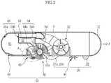
- FIG. 2is a cross-sectional view illustrating an autonomous cleaning device according to one or more embodiments, such as the autonomous cleaning device 10 illustrated in FIG. 1
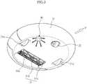
- FIG. 3is a bottom perspective view illustrating an autonomous cleaning device according to one or more embodiments, such as the autonomous cleaning device 10 of FIG. 1 .
- the autonomous cleaning device 10may include a main body 11, a driving unit 20, a cleaning unit 30, and a controller (not shown).
- the main body 11may be configured in various forms.
- the main body 11may be configured in a circular form.
- the circular main body 11may have a uniform radius of rotation, and therefore, the main body 11 may avoid contact with surrounding obstacles and may change course. Also, during travel, the main body 11 may be prevented from being caught by surrounding obstacles.
- Various componentssuch as the driving unit 20, the cleaning unit 30, various sensors 12 and 13, a display unit 14, and the controller (not show), to perform cleaning may be disposed at the main body 11.
- the driving unit 20may enable the main body 11 to travel about an area to be cleaned.
- the driving unit 20may include left and right drive wheels 21a and 21b and a caster 22. Power from a motor (not shown) may be supplied to the left and right drive wheels 21a and 21b. Also, the left and right drive wheels 21a and 21b may be mounted at the middle region of the bottom of the main body 11, and the caster 22 may be mounted at the front region of the bottom of the main body 11 so that the main body 11 may maintain a stable posture.
- the left and right drive wheels 21a and 21b and the caster 22may constitute a single assembly, which may be detachably mounted to the main body 11.
- the cleaning unit 30may remove dust from a floor on which the main body 11 is positioned and surroundings thereof.
- the cleaning unit 30may include a side brush 40, a brush drum unit 50, and a dust box 60.
- the side brush 40may be rotatably mounted at one side of the edge of the bottom of the main body 11.
- the side brush 40may deviate from the middle region of the main body 11 with an inclination to the front F of the main body 11.
- the side brush 40may move dust collected around the main body 11 to an area of a floor where the main body 11 is positioned.
- the side brush 40may extend a cleaning range to an area around the floor where the main body 11 is positioned.
- the side brush 40may remove dust collected from a corner, which is a boundary between the floor and walls.
- the brush drum unit 50may be mounted at a position deviating from the middle region of the bottom of the main body 11.
- the brush drum unit 50may deviate from the left and right drive wheels 21a and 21b mounted at the middle region of the bottom of the main body 11 toward the rear R of the main body 11.
- the brush drum unit 50may remove dust collected on the floor where the main body 11 is positioned.
- the brush drum unit 50may include a dust introduction channel 50a forming a dust introduction route.
- the brush drum unit 50may include a brush unit 51 disposed in the dust introduction channel 50a to sweep dust off of the floor.
- the brush unit 51may include a roller 51a and a brush 51b formed at an outer circumferential surface of the roller 51a. Power from a motor (not shown) may be supplied to the roller 51a. As the roller 51a rotates, the brush 51b may sweep up dust collected on the floor.
- the roller 51amay be formed of a rigid body. However, aspects of embodiments are not limited thereto.
- the brush 51bmay be formed of various materials exhibiting high elasticity.
- the brush unit 51may be driven at uniform speed to maintain uniform cleaning performance.
- the rotational speed of the brush unit 51may be lower than the rotational speed of the brush unit 51 when a smooth floor surface is cleaned. At this time, additional current may be supplied to possibly allow the rotational speed of the brush unit 51 to be uniformly maintained.
- the dust box 60may be mounted at the rear R of the main body 11.
- An introduction port 64 of the dust box 60may communicate with the dust introduction channel 50a of the brush drum unit 50.
- dust swept by the brush unit 51may be stored in the dust box 60 via the dust introduction channel 50a.
- the dust box 60may be divided into a large dust box 61 and a small dust box 62 by a partition wall 63.
- the introduction port 64may be divided into a first introduction port 64a disposed at an inlet of the large dust box 61 and a second introduction port 64b disposed at an inlet of the small dust box 62.
- the brush unit 51may sweep relatively large dust particles into the large dust box 61.
- a blowing unit 52may suction relatively small airborne dust, such as hair, into the small dust box 62.
- a brush cleaning member(not shown) may be disposed at a position adjacent to the second introduction port 64b to separate hair from the brush unit 51.
- the hair separated from the brush unit 51 by the brush cleaning member(not shown) may be stored in the small dust box 62 by suction force of the blowing unit 52.
- a dust amount detection unit 65may be disposed in the dust box 60 to detect whether the dust box 60 is filled with dust.
- the dust amount detection unit 65may include a light emitting part 65a to emit a beam and a light receiving part 65b to receive the beam. When the amount of light received by the light receiving part 65b is equal to or less than a predetermined value, it may be determined that the dust box 60 is filled with dust.
- the brush drum unit 50, the brush unit 51, and the dust box 60may constitute a single assembly, which may be detachably mounted to the main body 11.
- the sensors 12 and 13may include, for example, a proximity sensor 12 and/or an optical sensor 13.
- a proximity sensor 12For example, when the autonomous cleaning device 10 travels in an arbitrary direction without a predetermined route, i.e. in a cleaning system having no map, the autonomous cleaning device 10 may travel about an area to be cleaned using the proximity sensor 12.
- the optical sensor 13may be disposed to receive position information of the autonomous cleaning device 10 and create a map.
- the optical sensor 13may correspond to an embodiment of a location recognition system. Other various methods may be provided.
- the display unit 14may display various states of the autonomous cleaning device 10. For example, the display unit 14 may display a battery charge state, whether the dust box 60 is filled with dust, and a cleaning mode or a resting mode of the autonomous cleaning device 10, etc.
- the controllermay control the driving unit 20 and the cleaning unit 30 to efficiently perform a cleaning task.
- the controllermay receive signals from the sensors 12 and 13 to avoid an obstacle or change travel modes.
- the controllermay receive a signal from the dust amount detection unit 65. If it is determined that the dust box 60 is filled with dust, the controller (not shown) may dock with a maintenance station (not shown) to automatically remove dust from the dust box 60 or may sound an alarm to notify a user.
- the controllermay receive a signal from a dust introduction detection unit (not shown) to distinguish between an area from which dust is introduced and an area from which dust is not introduced. For example, an area may be travelled over repeatedly, a travel speed may be reduced or rotational force of the brush unit 51 or the suction force of the blowing unit 52 may be increased to improve cleaning efficiency at an area from which dust is introduced. On the other hand, a cleaning sequence may be delayed or the number of times of travel may be reduced at an area from which dust is not introduced.
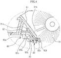
- FIG. 4is an enlarged cross-sectional view illustrating a blade assembly 80 according to one or more embodiments.
- the blade assembly 80may be disposed in the main body 11 so as to guide introduction of dust.
- the blade assembly 80may be mounted at the rear of the brush unit 51 to serve as a kind of dustpan when the brush unit 51 sweeps dust.
- the blade assembly 80may include a blade 82, a fixing member 81, and a support member 83.
- the blade 82may be fixed to the main body 11 and may guide dust toward an inner side of the main body 11.
- the blade 82may include a first part 82a that constitutes an upper part thereof and a second part 82b that may extend from the first part 82a toward a floor side.
- the second part 82b of the blade 82may be inclined downward.
- the second part 82b of the blade 82may extend from the floor to a guide 82d for guiding introduction of dust. Dust may be introduced into the main body 11 along the guide 82d.
- a bent part 82cmay be formed between the guide 82d and the second guide 82b so as to adjust an angle between the guide 82d and the floor. Thus, introduction of dust may be guided.
- a plurality of guidesmay be disposed spaced apart from each other by a predetermined gap.
- the blade 82may be formed of a flexible material, such as rubber, and may be inclined downward toward the floor. In this case, an end of the blade 82 may closely contact the floor.
- the support member 83may restrict movement of the blade 82 to within a predetermined range and may be coupled to the blade 82.
- the support member 83may be coupled to a lower part of the blade 82.
- the fixing member 81may be disposed adjacent to the blade 82 so that at least a portion of the blade closely contacts the floor.
- the fixing member 81may be coupled to the upper part of the blade 82.
- the fixing member 81 and the support member 83may be installed so that the blade 82 exhibits rigidity and flexibility. As a result, the performance of the blade 82 may be increased to improve cleaning efficiency.
- the first part 82a of the blade 82may be tightly fixed by a first fixing part 81a of the fixing member 81 and a first support part 83a of the support member 83. That is, the first part 82a of the blade 82 may be inserted and supported between the first fixing part 81a of the fixing member 81 and the first support part 83a of the support member 83. Thus, the first part 82a of the blade 82 may not be moved.
- a second fixing part 81b of the fixing member 81may be disposed adjacent to an upper part of the second part 82b of the blade 82.
- a second support part 83b of the support member 83may be disposed adjacent to the lower part of the second part 82b of the blade 82.
- the second part 82b of the blade 82may be moved between the second fixing part 81b of the fixing member 81 and the second support part 83b of the support member 83, of which movement may be restricted to within a predetermined range.
- the second support part 83b of the support member 83may prevent the second part 82b of the blade 82 from being bent in an opposite direction to a direction of travel of the main body 11, thereby possibly securing operational reliability of the blade 82.
- An insertion member 90may be disposed at one side of the support member 83 so as to possibly prevent noise from occurring due to friction between the support member 83 and the floor.
- the insertion member 90may be disposed at a rear side of the support member 83 so as to be positioned in a space between the support member 83 and the floor.
- the blade 82may contact the floor while the autonomous cleaning device 10 travels.
- an end of the second part 82b of the blade 82may fall into valleys of the tatami floor and may collide with ridges of the tatami floor, and the blade 82 may be damaged. This may cause damage of the tatami floor and the occurrence of noise while cleaning is performed using the autonomous cleaning device 10.
- the insertion member 90may be disposed to prevent such damage and noise. Since the insertion member 90 may be disposed at the rear side of the support member 83, noise may be reduced while the autonomous cleaning device 10 travels.
- the insertion member 90is disposed on the support member 83, aspects of one or more embodiments are not limited thereto.
- the insertion member 90may be disposed on an end of the blade 82.
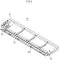
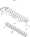
- FIG. 5is a perspective view illustrating a rear side of a blade assembly according to one or more embodiments, such as the blade assembly 80 illustrated in FIG. 4 .
- FIG. 6is a view illustrating a state in which an insertion member 90 is separated from a support member 83, according to one or more embodiments.
- FIG. 7is a view illustrating portions of an insertion member and a support member, such as the insertion member 90 and the support member 83 illustrated in FIG. 6 .
- the fixing member 81may be disposed with a protrusion 81c having a screw groove.
- the blade 82 and the support member 83may have holes 82e and 83d through which the protrusion 81a of the fixing member 81 may be inserted.
- the protrusion 81c of the fixing member 81may be sequentially inserted through the hole 82e of the blade 82 and the hole 83d of the support member 83, and then a screw S may be coupled to the protrusion 8ic of the fixing member 81, thereby completing the blade assembly 80.
- the insertion member 90may be inserted into and coupled to one side of the support member 83; however, aspects of one or more embodiments are not limited thereto.
- the insertion member 90may, for example, be disposed at the second support part 83b of the support member 83 and may face the floor.
- the insertion member 90may include a plate 90a coupled to the support member 83 and a contact part 90b coupled to the plate 90a.
- the contact part 90bmay be formed of a flexible material, such as a brush, rubber, sponge or fiber, so as to possibly reduce damage to the floor.
- a coupling part 91may be disposed at a contact surface between the insertion member 90 and the support member 83 so as to couple the insertion member 90 to the support member 83.
- the coupling part 91may include a coupling jaw 91a disposed at one side of the insertion member 90 and a coupling groove 91b formed in one side of the support member 83.
- the coupling groove 91bmay be disposed in the rear side of the support member 83 and may have one side that is open.
- the coupling jaw 91a of the insertion member 90may be coupled to the open side of the coupling groove 91b.
- the coupling jaw 91a of the insertion member 90may be disposed on the plate 90a to have a shape corresponding to the coupling groove 91b. As shown in Fig. 7 , the coupling groove 91b and the coupling jaw 91a may be rectangular; however, aspects of one or more embodiments are not limited thereto.
- FIG. 8is a view illustrating a state in which an insertion member 190 is separated from a support member 183, according to one or more embodiments
- FIG. 9is a view illustrating portions of an insertion member and a support member according to one or more embodiments, such as the insertion member 190 and the support member 183 illustrated in FIG. 8 .
- a coupling part 191may include a deviation prevention jaw 192. At least one deviation prevention jaw 192 may be disposed on the support member 183 so as to possibly prevent deviation of the insertion member 190.
- the deviation prevention jaw 192may be disposed at an outer side of a coupling groove 191b, i.e., may be disposed at both sides of the coupling groove 191b in a state in which the coupling groove 191b is interposed between the deviation prevention jaws 192.
- the deviation prevention jaw 192 disposed at one side of both sides of the coupling groove 191bis referred to as a first deviation prevention jaw 192a, and the deviation prevention jaw 192 disposed at the other side thereof is referred to as a second deviation prevention jaw 192b.
- the first deviation prevention jaw 192a and the second deviation prevention jaw 192bmay be disposed facing each other based on the coupling groove 191b. However, aspects of one or more embodiments are not limited thereto, and the first deviation prevention jaw 192a and the second deviation prevention jaw 192b may be disposed crossing each other.
- a plurality of deviation prevention jaws 192may be provided as a plurality of pairs of deviation prevention jaws.
- the plurality of first deviation prevention jaws 192a and the plurality of second deviation prevention jaws 192bmay be positioned at the same intervals. Due to the deviation prevention jaw 192, the insertion member 90 may possibly be prevented from being deviated from time when an autonomous cleaning device travels.
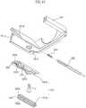
- FIG. 10is an enlarged cross-sectional view illustrating a blade assembly 280 according to one or more embodiments.
- FIG. 11is an exploded view illustrating a blade assembly according to one or more embodiments, such as the blade assembly 280 illustrated in FIG. 10 .
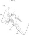
- FIG. 12is an enlarged view illustrating a blade 282 according to one or more embodiments.
- the blade assembly 280may be configured such that the blade 282 may be moved in a forward/backward direction of a direction in which an autonomous cleaning device travels.
- the blade 282may include at least one wrinkle part 282b and 282c.
- the wrinkle parts 282b and 282cmay include a mount-shaped part 282b that protrudes from the upper part of the blade 282, and a valley-shaped part 282c that protrudes from the lower part of the blade 282.
- the wrinkle parts 282b and 282cmay have predetermined mobility.
- the blade 282may be formed of an elastic material.
- the blade 282may be formed of hydrogenated nitrile butadiene rubber (HNBR). Since HNBR has flexibility and simultaneously has mechanical characteristics and strength, an autonomous cleaning device may not be damaged due to friction with the floor. Also, when an autonomous cleaning device travels over a cracked or rough floor, the blade 282 may be moved to some extent due to mobility of the wrinkles 282b and 282c and HNBR so that cleaning may be efficiently performed using the autonomous cleaning device. Thus, the autonomous cleaning device may be used in various floor conditions.
- HNBRhydrogenated nitrile butadiene rubber
- a blade contact surface 282d that contacts the floormay be somewhat inclined and may serve as a guide that guides introduction of dust on the floor toward an inner side of the main body.
- a support member 283may restrict movement of the blade 282 to within a predetermined range.
- a protrusion 281c of a fixing member 281may be inserted through a hole 282a formed in the blade 282.
- the protrusion 281c of the fixing member 281may be inserted through a hole 283c of the support member 283.
- the hole 282a of the blade 282may be formed in such a way that the blade 282 may be moved relative to the fixing member 281.
- FIG. 13is a cross-sectional view illustrating a blade 382 in a latitudinal direction according to one or more embodiments
- FIG. 14is a cross-sectional view illustrating a blade 482 in a latitudinal direction according to one or more embodiments.
- the blades 382 and 482may be configured in various forms.
- the blade 382may include a wrinkle part 382a including only an upwardly-protruding mount-shaped part 382a.
- the blade 382may extend from the mount-shaped part 382a to a blade contact surface 382c via an inclination 382b. In this case, the blade 382 may be more easily processed as compared to other embodiments.
- the blade 482may include a plurality of wrinkle parts 482a, 482b, and 482c.
- mount-shaped parts 482a and 482b and valley-shaped parts 482bmay be alternately arranged.
- a first mount-shaped part 482amay be positioned, and a second mount-shaped part 482c may be positioned between the valley-shaped parts 482b.
- mobility of the blade 482may be relatively large.
- FIG. 15is an enlarged cross-sectional view illustrating a blade assembly 580 according to one or more embodiments
- FIG. 16is an exploded view illustrating a blade assembly according to one or more embodiments, such as the blade assembly 580 illustrated in FIG. 15 .
- the blade assembly 580may include at least one elastic member 584 that may be coupled to an end of a blade 582 so as to move in the forward/backward direction of the direction in which the autonomous cleaning device travels.
- the elastic member 584may be a spring.
- One side of the elastic member 584may be coupled to the end of the blade 582, and the other side of the elastic member 584 may be coupled to a fixing member 581. Since the elastic member 584 may be inserted into a protrusion 581c of the fixing member 581 and the blade 582 may be coupled to the protrusion 581c of the fixing member 581, the blade 582 may be moved relative to the fixing member 581. At least one elastic member 584 may be provided. According to one or more embodiments, the elastic member 584 may be coupled to both sides of the blade 582.
- FIG. 17is an enlarged cross-sectional view of a blade assembly according to another embodiment of the present invention.
- a support member and a fixing member 681may be integrally injection molded.
- a blade 682may be injection molded between the support member 683 and the fixing member 681.
- a mold(not shown)may be disposed between the support member 683 and the fixing member 681 to have a shape corresponding to that of the blade 682.
- a resin that is a material for the blade 682may be forcibly inserted into the mold(not shown).
- a coupling groove 691bmay be integrally injection molded in one side of the support member 683 that contacts the floor so that an insertion member 690 may be inserted into the support member 683 through the coupling groove 691b.
- a coupling jaw 691amay be disposed on the insertion member 690, as in other embodiments, and the insertion member 690 may be inserted into the support member 683 so that the coupling jaw 691a may contact the coupling groove 691b.
- noisemay be prevented from occurring due to abnormal contact between a blade and a floor while the autonomous cleaning device travels.
Landscapes
- Engineering & Computer Science (AREA)
- Mechanical Engineering (AREA)
- Nozzles For Electric Vacuum Cleaners (AREA)
- Electric Vacuum Cleaner (AREA)
Description
- The present invention relates to an autonomous cleaning device, and more particularly, an autonomous cleaning device in which the structure of a blade assembly is improved, thereby reducing noise that occurs during cleaning.
- An autonomous mobile robot is a device that travels about an arbitrary area to perform a predetermined task without user manipulation. The robot may travel autonomously to a considerable extent, and autonomous travel may be embodied in various manners. For example, the robot may travel along a predetermined route using a map or may travel using a sensor to sense surroundings thereof without following a predetermined route.
- An autonomous cleaning device travels about an area to be cleaned so as to clean a floor without user manipulation. Specifically, the autonomous cleaning device may function to remove dust or clean a floor at home. Here, dust may include, for example, dirt, motes, powder, fragments and other dust particles that may be collected by a vacuum cleaning device, an automatic or semiautomatic cleaning device.
- The autonomous cleaning device includes a brush unit to sweep up dust and a blade to guide the dust to a dust box. In the related art, when an unevenness floor area is cleaned, noise occurs due to friction between the blade and the floor.
- The document
EP 2 443 978 A2 describes an autonomous cleaning device according to the preamble of independent claim 1. - Therefore, it is an aspect of one or more embodiments to provide an autonomous cleaning device that may reduce noise caused by friction with a floor.
- Additional aspects and/or advantages of one or more embodiments will be set forth in part in the description which follows and, in part, will be apparent from the description, or may be learned by practice of one or more embodiments of disclosure. One or more embodiments are inclusive of such additional aspects.
- In accordance with one or more embodiments, there is provided an autonomous cleaning device that may include: a main body having an opening; a brush unit that is rotatably disposed in the opening of the main body; and a blade assembly that may guide introduction of dust swept up by the brush unit, wherein the blade assembly may include: a blade that may guide dust toward an inner side of the main body; a support member that may be coupled to the blade so as to support the blade and that may have one side in which a coupling groove is formed; and an insertion member that may be inserted into the coupling groove of the support member.
- A coupling jaw may be disposed at one side of the insertion member and may be coupled to the coupling groove.
- The support member may include at least one deviation prevention jaw so as to possibly prevent deviation of the insertion member.
- The at least one deviation prevention jaw may be disposed at both sides of the coupling groove so as to face each other based on the coupling groove.
- The insertion member may include a plate coupled to the support member and a contact part coupled to the plate.
- The contact part may be formed of a flexible material.
- The blade assembly may further include a fixing member that is disposed adjacent to the blade so that at least a portion of the blade may closely contact a floor.
- The blade assembly may further include at least one elastic member that is coupled to an end of the blade so that the blade may move in a forward/backward direction of a direction in which the autonomous cleaning device travels.
- One side of the at least one elastic member may be coupled to an end of the blade, and the other side of the at least one elastic member may be coupled to the fixing member. The blade may be formed of an elastic material so that the blade may move in a forward/backward direction of a direction in which the autonomous cleaning device travels.
- The blade may include at least one movement part that moves in a forward/backward direction of a direction in which the autonomous cleaning device travels.
- The fixing member and the support member may be integrally injection molded.
- The fixing member and the support member may be integrally injection molded, and the blade may be injection molded between the fixing member and the support member.
- The blade may include a first part fixed to the main body and a second part that extends from the first part to the floor, and the support member may include a first support part that contacts the first part of the blade and a second support part that is disposed adjacent to the second part of the blade.
- The fixing member may include a first fixing part that contacts the first part of the blade and a second fixing part that is disposed adjacent to the second part of the blade. In accordance with one or more embodiments, there is provided an autonomous cleaning device that may include: a main body having an opening; a brush unit that is rotatably disposed in the opening of the main body; and a blade assembly that may guide introduction of dust swept up by the brush unit, wherein the blade assembly may include: a blade that may guide dust toward an inner side of the main body; a support member that may be coupled to the blade so as to support the blade; and an insertion member that may be coupled to one side of the support member so as to possibly prevent noise caused by friction between the support member and a floor.
- The insertion member may be disposed at a rear of the support member so as to be positioned in a space between the support member and the floor.
- The insertion member may include a plate coupled to the support member and a contact part coupled to the plate and formed of a flexible material, and the insertion member may be inserted into and coupled to one side of the support member.
- A coupling groove may be disposed in one side of the support member so that the insertion member may be inserted into the support member through the coupling groove, and a coupling jaw may be disposed at one side of the insertion member so that the insertion member may be coupled to the support member through the coupling jaw.
- A deviation prevention jaw may be disposed at both sides of the coupling groove so as to possibly prevent deviation of the insertion member.
- In accordance with one or more embodiments, there is provided an autonomous cleaning device that may include: a main body having an opening; a brush unit that is rotatably disposed in the opening of the main body; and a blade assembly that may guide introduction of dust swept up by the brush unit, wherein the blade assembly may include: a blade that may guide dust toward an inner side of the main body and may include at least one wrinkle part so as to be movable in a forward/backward direction of a direction in which the autonomous cleaning device travels; and a support member that may be coupled to the blade so as to support the blade.
- The at least one wrinkle part may include at least one of a mount-shaped part that protrudes from an upper side of the blade and a valley-shaped part that protrudes from a lower side of the blade.
- The autonomous cleaning device may further include an insertion member having a coupling jaw through which the insertion member is inserted into a coupling groove, and the support member may include the coupling groove.
- The support member may include at least one deviation prevention jaw that may be disposed facing each other based on the coupling groove so as to possibly prevent deviation of the insertion member.
- The insertion member may include a plate coupled to the support member and a contact part coupled to the plate, and the contact part may be formed of a flexible material.
- The blade may be formed of an elastic material so as to be movable in a forward/backward direction of a direction in which the autonomous cleaning device travels.
- The blade may be formed of hydrogenated nitrile butadiene rubber (HNBR).
- The blade assembly may further include a fixing member that may be disposed adjacent to the blade so that at least a portion of the blade can closely contact a floor.
- These and/or other aspects will become apparent and more readily appreciated from the following description of embodiments, taken in conjunction with the accompanying drawings in which:
FIG. 1 is a perspective view illustrating an autonomous cleaning device according to one or more embodiments;FIG. 2 is a cross-sectional view illustrating autonomous cleaning device one or more embodiments;FIG. 3 is a bottom perspective view illustrating an autonomous cleaning device one or more embodiments;FIG. 4 is an enlarged cross-sectional view illustrating a blade assembly according to one or more embodiments;FIG. 5 is a perspective view illustrating a rear side of a blade assembly according to one or more embodiments, such as the blade assembly illustrated inFIG. 4 ;FIG. 6 is a view illustrating a state in which an insertion member is separated from a support member, according to one or more embodiments;FIG. 7 is a view illustrating portions of an insertion member and a support member according to one or more embodiments, such as the insertion member and the support member illustrated inFIG. 6 ;FIG. 8 is a view illustrating a state in which an insertion member is separated from a support member, according to one or more embodiments;FIG. 9 is a view illustrating portions of an insertion member and a support member according to one or more embodiments, such as the insertion member and the support member illustrated inFIG. 8 ;FIG. 10 is an enlarged cross-sectional view illustrating a blade assembly according to one or more embodiments;FIG. 11 is an exploded view illustrating a blade assembly according to one or more embodiments, such as the blade assembly illustrated inFIG. 10 ;FIG. 12 is an enlarged view illustrating a blade according to one or more embodiments;FIG. 13 is a cross-sectional view illustrating a blade in a latitudinal direction according to one or more embodiments;FIG. 14 is a cross-sectional view illustrating a blade in a latitudinal direction according to one or more embodiments;FIG. 15 is an enlarged cross-sectional view illustrating a blade assembly according to one or more embodiments;FIG. 16 is an exploded view illustrating a blade assembly according to one or more embodiments, such as the blade assembly illustrated inFIG. 15 ; andFIG. 17 is an enlarged cross-sectional view of a blade assembly according to one or more embodiments.- Reference will now be made in detail to one or more embodiments, illustrated in the accompanying drawings, wherein like reference numerals refer to like elements throughout. In this regard, embodiments of the present invention may be embodied in many different forms and should not be construed as being limited to embodiments set forth herein, as various changes, modifications, and equivalents of the systems, apparatuses and/or methods described herein will be understood to be included in the invention as defined by the claims by those of ordinary skill in the art after embodiments discussed herein are understood. Accordingly, embodiments are merely described below, by referring to the figures, to explain aspects of the present invention.
FIG. 1 is a perspective view illustrating anautonomous cleaning device 10 according to one or more embodiments,FIG. 2 is a cross-sectional view illustrating an autonomous cleaning device according to one or more embodiments, such as theautonomous cleaning device 10 illustrated inFIG. 1 , andFIG. 3 is a bottom perspective view illustrating an autonomous cleaning device according to one or more embodiments, such as theautonomous cleaning device 10 ofFIG. 1 .- As illustrated in
FIGS. 1 through 3 , theautonomous cleaning device 10 may include amain body 11, adriving unit 20, acleaning unit 30, and a controller (not shown). Themain body 11 may be configured in various forms. For example, themain body 11 may be configured in a circular form. The circularmain body 11 may have a uniform radius of rotation, and therefore, themain body 11 may avoid contact with surrounding obstacles and may change course. Also, during travel, themain body 11 may be prevented from being caught by surrounding obstacles. - Various components, such as the driving
unit 20, thecleaning unit 30,various sensors display unit 14, and the controller (not show), to perform cleaning may be disposed at themain body 11. - The driving
unit 20 may enable themain body 11 to travel about an area to be cleaned. The drivingunit 20 may include left andright drive wheels caster 22. Power from a motor (not shown) may be supplied to the left andright drive wheels right drive wheels main body 11, and thecaster 22 may be mounted at the front region of the bottom of themain body 11 so that themain body 11 may maintain a stable posture. - The left and
right drive wheels caster 22 may constitute a single assembly, which may be detachably mounted to themain body 11. - The
cleaning unit 30 may remove dust from a floor on which themain body 11 is positioned and surroundings thereof. Thecleaning unit 30 may include aside brush 40, abrush drum unit 50, and adust box 60. - The
side brush 40 may be rotatably mounted at one side of the edge of the bottom of themain body 11. Theside brush 40 may deviate from the middle region of themain body 11 with an inclination to the front F of themain body 11. - The
side brush 40 may move dust collected around themain body 11 to an area of a floor where themain body 11 is positioned. Theside brush 40 may extend a cleaning range to an area around the floor where themain body 11 is positioned. In particular, theside brush 40 may remove dust collected from a corner, which is a boundary between the floor and walls. - The
brush drum unit 50 may be mounted at a position deviating from the middle region of the bottom of themain body 11. Thebrush drum unit 50 may deviate from the left andright drive wheels main body 11 toward the rear R of themain body 11. - The
brush drum unit 50 may remove dust collected on the floor where themain body 11 is positioned. Thebrush drum unit 50 may include adust introduction channel 50a forming a dust introduction route. Also, thebrush drum unit 50 may include abrush unit 51 disposed in thedust introduction channel 50a to sweep dust off of the floor. - The
brush unit 51 may include aroller 51a and abrush 51b formed at an outer circumferential surface of the roller 51a. Power from a motor (not shown) may be supplied to theroller 51a. As theroller 51a rotates, thebrush 51b may sweep up dust collected on the floor. Theroller 51a may be formed of a rigid body. However, aspects of embodiments are not limited thereto. Thebrush 51b may be formed of various materials exhibiting high elasticity. - The
brush unit 51 may be driven at uniform speed to maintain uniform cleaning performance. When a floor surface that is not smooth, for example, such as a carpet, is cleaned, the rotational speed of thebrush unit 51 may be lower than the rotational speed of thebrush unit 51 when a smooth floor surface is cleaned. At this time, additional current may be supplied to possibly allow the rotational speed of thebrush unit 51 to be uniformly maintained. - The
dust box 60 may be mounted at the rear R of themain body 11. Anintroduction port 64 of thedust box 60 may communicate with thedust introduction channel 50a of thebrush drum unit 50. Thus, dust swept by thebrush unit 51 may be stored in thedust box 60 via thedust introduction channel 50a. - The
dust box 60 may be divided into alarge dust box 61 and asmall dust box 62 by apartition wall 63. Correspondingly, theintroduction port 64 may be divided into afirst introduction port 64a disposed at an inlet of thelarge dust box 61 and asecond introduction port 64b disposed at an inlet of thesmall dust box 62. - The
brush unit 51 may sweep relatively large dust particles into thelarge dust box 61. A blowingunit 52 may suction relatively small airborne dust, such as hair, into thesmall dust box 62. In particular, a brush cleaning member (not shown) may be disposed at a position adjacent to thesecond introduction port 64b to separate hair from thebrush unit 51. The hair separated from thebrush unit 51 by the brush cleaning member (not shown) may be stored in thesmall dust box 62 by suction force of the blowingunit 52. Also, a dustamount detection unit 65 may be disposed in thedust box 60 to detect whether thedust box 60 is filled with dust. The dustamount detection unit 65 may include alight emitting part 65a to emit a beam and alight receiving part 65b to receive the beam. When the amount of light received by thelight receiving part 65b is equal to or less than a predetermined value, it may be determined that thedust box 60 is filled with dust. - The
brush drum unit 50, thebrush unit 51, and thedust box 60 may constitute a single assembly, which may be detachably mounted to themain body 11. - The
sensors proximity sensor 12 and/or anoptical sensor 13. For example, when theautonomous cleaning device 10 travels in an arbitrary direction without a predetermined route, i.e. in a cleaning system having no map, theautonomous cleaning device 10 may travel about an area to be cleaned using theproximity sensor 12. On the other hand, when theautonomous cleaning device 10 travels along a predetermined route, i.e. in a cleaning system having a map, theoptical sensor 13 may be disposed to receive position information of theautonomous cleaning device 10 and create a map. Theoptical sensor 13 may correspond to an embodiment of a location recognition system. Other various methods may be provided. - The
display unit 14 may display various states of theautonomous cleaning device 10. For example, thedisplay unit 14 may display a battery charge state, whether thedust box 60 is filled with dust, and a cleaning mode or a resting mode of theautonomous cleaning device 10, etc. - The controller (not shown) may control the driving
unit 20 and thecleaning unit 30 to efficiently perform a cleaning task. The controller (not shown) may receive signals from thesensors - Also, the controller (not shown) may receive a signal from the dust
amount detection unit 65. If it is determined that thedust box 60 is filled with dust, the controller (not shown) may dock with a maintenance station (not shown) to automatically remove dust from thedust box 60 or may sound an alarm to notify a user. - Also, the controller (not shown) may receive a signal from a dust introduction detection unit (not shown) to distinguish between an area from which dust is introduced and an area from which dust is not introduced. For example, an area may be travelled over repeatedly, a travel speed may be reduced or rotational force of the
brush unit 51 or the suction force of the blowingunit 52 may be increased to improve cleaning efficiency at an area from which dust is introduced. On the other hand, a cleaning sequence may be delayed or the number of times of travel may be reduced at an area from which dust is not introduced. FIG. 4 is an enlarged cross-sectional view illustrating ablade assembly 80 according to one or more embodiments.- As illustrated in
FIG. 4 , theblade assembly 80 may be disposed in themain body 11 so as to guide introduction of dust. Theblade assembly 80 may be mounted at the rear of thebrush unit 51 to serve as a kind of dustpan when thebrush unit 51 sweeps dust. Theblade assembly 80 may include ablade 82, a fixingmember 81, and asupport member 83. - The
blade 82 may be fixed to themain body 11 and may guide dust toward an inner side of themain body 11. Theblade 82 may include afirst part 82a that constitutes an upper part thereof and asecond part 82b that may extend from thefirst part 82a toward a floor side. Thesecond part 82b of theblade 82 may be inclined downward. Thesecond part 82b of theblade 82 may extend from the floor to aguide 82d for guiding introduction of dust. Dust may be introduced into themain body 11 along theguide 82d. Abent part 82c may be formed between theguide 82d and thesecond guide 82b so as to adjust an angle between theguide 82d and the floor. Thus, introduction of dust may be guided. Although not shown, a plurality of guides may be disposed spaced apart from each other by a predetermined gap. - The
blade 82 may be formed of a flexible material, such as rubber, and may be inclined downward toward the floor. In this case, an end of theblade 82 may closely contact the floor. - The
support member 83 may restrict movement of theblade 82 to within a predetermined range and may be coupled to theblade 82. Thesupport member 83 may be coupled to a lower part of theblade 82. The fixingmember 81 may be disposed adjacent to theblade 82 so that at least a portion of the blade closely contacts the floor. The fixingmember 81 may be coupled to the upper part of theblade 82. The fixingmember 81 and thesupport member 83 may be installed so that theblade 82 exhibits rigidity and flexibility. As a result, the performance of theblade 82 may be increased to improve cleaning efficiency. - The
first part 82a of theblade 82 may be tightly fixed by afirst fixing part 81a of the fixingmember 81 and afirst support part 83a of thesupport member 83. That is, thefirst part 82a of theblade 82 may be inserted and supported between the first fixingpart 81a of the fixingmember 81 and thefirst support part 83a of thesupport member 83. Thus, thefirst part 82a of theblade 82 may not be moved. - A
second fixing part 81b of the fixingmember 81 may be disposed adjacent to an upper part of thesecond part 82b of theblade 82. Asecond support part 83b of thesupport member 83 may be disposed adjacent to the lower part of thesecond part 82b of theblade 82. As a result, thesecond part 82b of theblade 82 may be moved between thesecond fixing part 81b of the fixingmember 81 and thesecond support part 83b of thesupport member 83, of which movement may be restricted to within a predetermined range. In particular, thesecond support part 83b of thesupport member 83 may prevent thesecond part 82b of theblade 82 from being bent in an opposite direction to a direction of travel of themain body 11, thereby possibly securing operational reliability of theblade 82. - An
insertion member 90 may be disposed at one side of thesupport member 83 so as to possibly prevent noise from occurring due to friction between thesupport member 83 and the floor. Theinsertion member 90 may be disposed at a rear side of thesupport member 83 so as to be positioned in a space between thesupport member 83 and the floor. Theblade 82 may contact the floor while theautonomous cleaning device 10 travels. Thus, when a rugged tatami floor is cleaned, an end of thesecond part 82b of theblade 82 may fall into valleys of the tatami floor and may collide with ridges of the tatami floor, and theblade 82 may be damaged. This may cause damage of the tatami floor and the occurrence of noise while cleaning is performed using theautonomous cleaning device 10. Theinsertion member 90 may be disposed to prevent such damage and noise. Since theinsertion member 90 may be disposed at the rear side of thesupport member 83, noise may be reduced while theautonomous cleaning device 10 travels. - Although the
insertion member 90 is disposed on thesupport member 83, aspects of one or more embodiments are not limited thereto. For example, theinsertion member 90 may be disposed on an end of theblade 82. FIG. 5 is a perspective view illustrating a rear side of a blade assembly according to one or more embodiments, such as theblade assembly 80 illustrated inFIG. 4 .FIG. 6 is a view illustrating a state in which aninsertion member 90 is separated from asupport member 83, according to one or more embodiments.FIG. 7 is a view illustrating portions of an insertion member and a support member, such as theinsertion member 90 and thesupport member 83 illustrated inFIG. 6 .- As illustrated in
FIGS. 5 through 7 , the fixingmember 81 may be disposed with aprotrusion 81c having a screw groove. Theblade 82 and thesupport member 83 may haveholes protrusion 81a of the fixingmember 81 may be inserted. Theprotrusion 81c of the fixingmember 81 may be sequentially inserted through thehole 82e of theblade 82 and thehole 83d of thesupport member 83, and then a screw S may be coupled to the protrusion 8ic of the fixingmember 81, thereby completing theblade assembly 80. - The
insertion member 90 may be inserted into and coupled to one side of thesupport member 83; however, aspects of one or more embodiments are not limited thereto. Theinsertion member 90 may, for example, be disposed at thesecond support part 83b of thesupport member 83 and may face the floor. - According to one or more embodiments, the
insertion member 90 may include aplate 90a coupled to thesupport member 83 and acontact part 90b coupled to theplate 90a. Thecontact part 90b may be formed of a flexible material, such as a brush, rubber, sponge or fiber, so as to possibly reduce damage to the floor. - A
coupling part 91 may be disposed at a contact surface between theinsertion member 90 and thesupport member 83 so as to couple theinsertion member 90 to thesupport member 83. Thecoupling part 91 may include acoupling jaw 91a disposed at one side of theinsertion member 90 and acoupling groove 91b formed in one side of thesupport member 83. As shown inFig. 7 , thecoupling groove 91b may be disposed in the rear side of thesupport member 83 and may have one side that is open. Thecoupling jaw 91a of theinsertion member 90 may be coupled to the open side of thecoupling groove 91b. Thecoupling jaw 91a of theinsertion member 90 may be disposed on theplate 90a to have a shape corresponding to thecoupling groove 91b. As shown inFig. 7 , thecoupling groove 91b and thecoupling jaw 91a may be rectangular; however, aspects of one or more embodiments are not limited thereto. FIG. 8 is a view illustrating a state in which aninsertion member 190 is separated from asupport member 183, according to one or more embodiments, andFIG. 9 is a view illustrating portions of an insertion member and a support member according to one or more embodiments, such as theinsertion member 190 and thesupport member 183 illustrated inFIG. 8 .- As illustrated in
FIGS. 8 and9 , acoupling part 191 may include adeviation prevention jaw 192. At least onedeviation prevention jaw 192 may be disposed on thesupport member 183 so as to possibly prevent deviation of theinsertion member 190. Thedeviation prevention jaw 192 may be disposed at an outer side of acoupling groove 191b, i.e., may be disposed at both sides of thecoupling groove 191b in a state in which thecoupling groove 191b is interposed between thedeviation prevention jaws 192. Thedeviation prevention jaw 192 disposed at one side of both sides of thecoupling groove 191b is referred to as a firstdeviation prevention jaw 192a, and thedeviation prevention jaw 192 disposed at the other side thereof is referred to as a seconddeviation prevention jaw 192b. - The first
deviation prevention jaw 192a and the seconddeviation prevention jaw 192b may be disposed facing each other based on thecoupling groove 191b. However, aspects of one or more embodiments are not limited thereto, and the firstdeviation prevention jaw 192a and the seconddeviation prevention jaw 192b may be disposed crossing each other. A plurality ofdeviation prevention jaws 192 may be provided as a plurality of pairs of deviation prevention jaws. The plurality of firstdeviation prevention jaws 192a and the plurality of seconddeviation prevention jaws 192b may be positioned at the same intervals. Due to thedeviation prevention jaw 192, theinsertion member 90 may possibly be prevented from being deviated from time when an autonomous cleaning device travels. FIG. 10 is an enlarged cross-sectional view illustrating ablade assembly 280 according to one or more embodiments.FIG. 11 is an exploded view illustrating a blade assembly according to one or more embodiments, such as theblade assembly 280 illustrated inFIG. 10 .FIG. 12 is an enlarged view illustrating ablade 282 according to one or more embodiments.- As illustrated in
FIGS. 10 through 12 , theblade assembly 280 may be configured such that theblade 282 may be moved in a forward/backward direction of a direction in which an autonomous cleaning device travels. As illustrated inFIGS. 10 through 12 , theblade 282 may include at least onewrinkle part wrinkle parts part 282b that protrudes from the upper part of theblade 282, and a valley-shapedpart 282c that protrudes from the lower part of theblade 282. Thus, as theautonomous cleaning device 10 travels, thewrinkle parts blade 282 may be formed of an elastic material. According to one or more embodiments, theblade 282 may be formed of hydrogenated nitrile butadiene rubber (HNBR). Since HNBR has flexibility and simultaneously has mechanical characteristics and strength, an autonomous cleaning device may not be damaged due to friction with the floor. Also, when an autonomous cleaning device travels over a cracked or rough floor, theblade 282 may be moved to some extent due to mobility of thewrinkles - In addition, a
blade contact surface 282d that contacts the floor may be somewhat inclined and may serve as a guide that guides introduction of dust on the floor toward an inner side of the main body. Asupport member 283 may restrict movement of theblade 282 to within a predetermined range. To this end, aprotrusion 281c of a fixingmember 281 may be inserted through ahole 282a formed in theblade 282. Also, after theblade 282 is inserted, theprotrusion 281c of the fixingmember 281 may be inserted through ahole 283c of thesupport member 283. Thehole 282a of theblade 282 may be formed in such a way that theblade 282 may be moved relative to the fixingmember 281. FIG. 13 is a cross-sectional view illustrating ablade 382 in a latitudinal direction according to one or more embodiments, andFIG. 14 is a cross-sectional view illustrating ablade 482 in a latitudinal direction according to one or more embodiments.- As illustrated in
FIGS. 13 and14 , theblades - According to one or more embodiments, such as illustrated in
FIG. 13 , theblade 382 may include awrinkle part 382a including only an upwardly-protruding mount-shapedpart 382a. Theblade 382 may extend from the mount-shapedpart 382a to ablade contact surface 382c via aninclination 382b. In this case, theblade 382 may be more easily processed as compared to other embodiments. - According to one or more embodiments, such as illustrated in
FIG. 14 , theblade 482 may include a plurality ofwrinkle parts parts parts 482b may be alternately arranged. A first mount-shapedpart 482a may be positioned, and a second mount-shapedpart 482c may be positioned between the valley-shapedparts 482b. Thus, mobility of theblade 482 may be relatively large. FIG. 15 is an enlarged cross-sectional view illustrating ablade assembly 580 according to one or more embodiments, andFIG. 16 is an exploded view illustrating a blade assembly according to one or more embodiments, such as theblade assembly 580 illustrated inFIG. 15 .- As illustrated in
FIGS. 15 and16 , theblade assembly 580 may include at least oneelastic member 584 that may be coupled to an end of ablade 582 so as to move in the forward/backward direction of the direction in which the autonomous cleaning device travels. Theelastic member 584 may be a spring. - One side of the
elastic member 584 may be coupled to the end of theblade 582, and the other side of theelastic member 584 may be coupled to a fixingmember 581. Since theelastic member 584 may be inserted into aprotrusion 581c of the fixingmember 581 and theblade 582 may be coupled to theprotrusion 581c of the fixingmember 581, theblade 582 may be moved relative to the fixingmember 581. At least oneelastic member 584 may be provided. According to one or more embodiments, theelastic member 584 may be coupled to both sides of theblade 582. - An
insertion member 590 may be inserted in the lower side of asupport member 583 so as to alleviate frictional force with the floor, like in other embodiments.FIG. 17 is an enlarged cross-sectional view of a blade assembly according to another embodiment of the present invention. - As illustrated in
FIG. 17 , a support member and a fixingmember 681 may be integrally injection molded. Ablade 682 may be injection molded between thesupport member 683 and the fixingmember 681. A mold(not shown) may be disposed between thesupport member 683 and the fixingmember 681 to have a shape corresponding to that of theblade 682. Thus, a resin that is a material for theblade 682 may be forcibly inserted into the mold(not shown). - A
coupling groove 691b may be integrally injection molded in one side of thesupport member 683 that contacts the floor so that aninsertion member 690 may be inserted into thesupport member 683 through thecoupling groove 691b. Acoupling jaw 691a may be disposed on theinsertion member 690, as in other embodiments, and theinsertion member 690 may be inserted into thesupport member 683 so that thecoupling jaw 691a may contact thecoupling groove 691b. - As described above, in an autonomous cleaning device according to an embodiment of the present invention, noise may be prevented from occurring due to abnormal contact between a blade and a floor while the autonomous cleaning device travels.
- While aspects of the present invention has been particularly shown and described with reference to differing embodiments thereof, it should be understood that these embodiments should be considered in a descriptive sense only and not for purposes of limitation. Descriptions of features or aspects within each embodiment should typically be considered as available for other similar features or aspects in the remaining embodiments. Suitable results may equally be achieved if the described techniques are performed in a different order and/or if components in a described system, architecture, device, or circuit are combined in a different manner and/or replaced or supplemented by other components or their equivalents.
- Thus, although a few embodiments have been shown and described, with additional embodiments being equally available, it would be appreciated by those skilled in the art that changes may be made in these embodiments without departing from the principles of the invention, the scope of which is defined in the claims.
Claims (15)
- An autonomous cleaning device (10) comprising:a main body (11) having an opening;a brush unit (50) rotatably disposed in the opening of the main body; anda blade assembly (80) to guide introduction of dust swept up by the brush unit,wherein the blade assembly comprises:a blade (82) to guide dust toward an inner side of the main body;a support member (83) coupled to the blade so as to support the blade and having one side in which a coupling groove (91b) is formed;characterised in that the blade assembly comprises further an insertion member (90) inserted into the coupling groove of the support member.
- The autonomous cleaning device according to claim 1, wherein a coupling jaw (90a) is disposed at one side of the insertion member and is coupled to the coupling groove.
- The autonomous cleaning device according to claim 1 or 2, wherein the support member comprises at least one deviation prevention jaw (192) to prevent deviation of the insertion member.
- The autonomous cleaning device according to claim 3, wherein the at least one deviation prevention jaw is disposed at both sides of the coupling groove so as to face each other based on the coupling groove.
- The autonomous cleaning device according to any one of the preceding claims, wherein the insertion member comprises a plate (90a) coupled to the support member and a contact part (90b) coupled to the plate.
- The autonomous cleaning device according to claim 5, wherein the contact part is formed of a flexible material.
- The autonomous cleaning device according to any one of the preceding claims, wherein the blade assembly further comprises a fixing member disposed adjacent to the blade so that at least a portion of the blade contacts a floor.
- The autonomous cleaning device according to any one of the preceding claims, wherein the blade assembly further comprises at least one elastic member coupled to an end of the blade so that the blade is movable in a forward/backward direction of a direction in which the autonomous cleaning device travels.
- The autonomous cleaning device according to claim 8, wherein one side of the at least one elastic member is coupled to an end of the blade and the other side of the at least one elastic member is coupled to the fixing member.
- The autonomous cleaning device according to any one of claims 1 to 7, wherein the blade is formed of an elastic material so that the blade is movable in a forward/backward direction of a direction in which the autonomous cleaning device travels.
- The autonomous cleaning device according to claim 10, wherein the blade comprises at least one movement part that moves in a forward/backward direction of a direction in which the autonomous cleaning device travels.
- The autonomous cleaning device according to claim 7, wherein the fixing member and the support member are integrally injection molded.
- The autonomous cleaning device according to claim 12, wherein the blade is injection molded between the fixing member and the support member.
- The autonomous cleaning device according to claim 1, wherein the blade comprises a first part fixed to the main body and a second part that extends from the first part to the floor and the support member comprises a first support part that contacts the first part of the blade and a second support part disposed adjacent to the second part of the blade.
- The autonomous cleaning device according to claim 14, wherein the fixing member comprises a first fixing part that contacts the first part of the blade and a second fixing part disposed adjacent to the second part of the blade.
Applications Claiming Priority (2)
| Application Number | Priority Date | Filing Date | Title |
|---|---|---|---|
| KR20120081487 | 2012-07-25 | ||
| KR1020120085321AKR20140015099A (en) | 2012-07-25 | 2012-08-03 | Autonomous cleaning device |
Publications (3)
| Publication Number | Publication Date |
|---|---|
| EP2689701A2 EP2689701A2 (en) | 2014-01-29 |
| EP2689701A3 EP2689701A3 (en) | 2017-12-20 |
| EP2689701B1true EP2689701B1 (en) | 2018-12-19 |
Family
ID=48795468
Family Applications (1)
| Application Number | Title | Priority Date | Filing Date |
|---|---|---|---|
| EP13176994.5ANot-in-forceEP2689701B1 (en) | 2012-07-25 | 2013-07-18 | Autonomous cleaning device |
Country Status (4)
| Country | Link |
|---|---|
| US (1) | US20140026338A1 (en) |
| EP (1) | EP2689701B1 (en) |
| JP (1) | JP2014023930A (en) |
| CN (1) | CN103565373B (en) |
Cited By (1)
| Publication number | Priority date | Publication date | Assignee | Title |
|---|---|---|---|---|
| EP3771393B1 (en)* | 2019-07-31 | 2023-09-06 | LG Electronics Inc. | Cleaner |
Families Citing this family (34)
| Publication number | Priority date | Publication date | Assignee | Title |
|---|---|---|---|---|
| KR102137923B1 (en) | 2013-04-15 | 2020-07-24 | 에이비 엘렉트로룩스 | Robotic vacuum cleaner with protruding sidebrush |
| WO2014169943A1 (en) | 2013-04-15 | 2014-10-23 | Aktiebolaget Electrolux | Robotic vacuum cleaner |
| US11272822B2 (en) | 2013-11-12 | 2022-03-15 | Irobot Corporation | Mobile floor cleaning robot with pad holder |
| EP3453300B1 (en)* | 2013-11-12 | 2023-10-18 | iRobot Corporation | Cleaning pad |
| US10209080B2 (en) | 2013-12-19 | 2019-02-19 | Aktiebolaget Electrolux | Robotic cleaning device |
| US10433697B2 (en) | 2013-12-19 | 2019-10-08 | Aktiebolaget Electrolux | Adaptive speed control of rotating side brush |
| KR102116596B1 (en) | 2013-12-19 | 2020-05-28 | 에이비 엘렉트로룩스 | Robotic vacuum cleaner with side brush moving in spiral pattern |
| WO2015090405A1 (en) | 2013-12-19 | 2015-06-25 | Aktiebolaget Electrolux | Sensing climb of obstacle of a robotic cleaning device |
| US10617271B2 (en) | 2013-12-19 | 2020-04-14 | Aktiebolaget Electrolux | Robotic cleaning device and method for landmark recognition |
| WO2015090439A1 (en) | 2013-12-20 | 2015-06-25 | Aktiebolaget Electrolux | Dust container |
| US9510717B2 (en)* | 2014-02-18 | 2016-12-06 | Joseph Y. Ko | Self-moving dust suction apparatus to facalitate cleaning |
| DE102014208080A1 (en)* | 2014-04-29 | 2015-10-29 | BSH Hausgeräte GmbH | vacuum cleaner nozzle |
| KR101573192B1 (en)* | 2014-05-30 | 2015-12-01 | 주식회사 유진로봇 | Cleaning robot having improved driving and cleaning ability |
| CN106415423B (en) | 2014-07-10 | 2021-01-01 | 伊莱克斯公司 | Method for detecting a measurement error of a robotic cleaning device |
| US10499778B2 (en) | 2014-09-08 | 2019-12-10 | Aktiebolaget Electrolux | Robotic vacuum cleaner |
| EP3190938A1 (en)* | 2014-09-08 | 2017-07-19 | Aktiebolaget Electrolux | Robotic vacuum cleaner |
| EP3230814B1 (en) | 2014-12-10 | 2021-02-17 | Aktiebolaget Electrolux | Using laser sensor for floor type detection |
| CN107072454A (en) | 2014-12-12 | 2017-08-18 | 伊莱克斯公司 | Side brushes and robot vacuums |
| CN107003669B (en) | 2014-12-16 | 2023-01-31 | 伊莱克斯公司 | Experience-Based Roadmap for Robotic Cleaning Equipment |
| EP3234713B1 (en) | 2014-12-16 | 2022-06-15 | Aktiebolaget Electrolux | Cleaning method for a robotic cleaning device |
| US11099554B2 (en) | 2015-04-17 | 2021-08-24 | Aktiebolaget Electrolux | Robotic cleaning device and a method of controlling the robotic cleaning device |
| EP3344104B1 (en) | 2015-09-03 | 2020-12-30 | Aktiebolaget Electrolux | System of robotic cleaning devices |
| WO2017157421A1 (en) | 2016-03-15 | 2017-09-21 | Aktiebolaget Electrolux | Robotic cleaning device and a method at the robotic cleaning device of performing cliff detection |
| US11122953B2 (en) | 2016-05-11 | 2021-09-21 | Aktiebolaget Electrolux | Robotic cleaning device |
| CN114468876B (en)* | 2016-12-16 | 2023-11-10 | 云鲸智能创新(深圳)有限公司 | Base stations, cleaning robots and cleaning robot systems |
| EP3629869B1 (en) | 2017-06-02 | 2023-08-16 | Aktiebolaget Electrolux | Method of detecting a difference in level of a surface in front of a robotic cleaning device |
| EP3687357B1 (en) | 2017-09-26 | 2024-07-10 | Aktiebolaget Electrolux | Controlling movement of a robotic cleaning device |
| US11503968B2 (en) | 2018-08-10 | 2022-11-22 | Sharkninja Operating Llc | System and method for reducing noise and/or vibration in a cleaning apparatus with combing unit for removing debris |
| US11291345B2 (en) | 2018-08-27 | 2022-04-05 | Techtronic Floor Care Technology Limited | Floor cleaner |
| CN111990934A (en)* | 2019-05-27 | 2020-11-27 | 江苏美的清洁电器股份有限公司 | Robot, robot control method, and storage medium |
| JP2021126159A (en)* | 2020-02-10 | 2021-09-02 | 株式会社マキタ | Robot dust collector |
| US11832780B2 (en) | 2021-07-29 | 2023-12-05 | Irobot Corporation | Mobile cleaning robot dustpan |
| CN116867412A (en)* | 2022-05-20 | 2023-10-10 | 深圳市好奇心探索科技有限公司 | Cleaning device, cleaning method and storage medium |
| US20240065498A1 (en)* | 2022-08-30 | 2024-02-29 | Irobot Corporation | Mobile cleaning robot with variable cleaning features |
Family Cites Families (18)
| Publication number | Priority date | Publication date | Assignee | Title |
|---|---|---|---|---|
| US2275356A (en)* | 1939-01-16 | 1942-03-03 | Yard Man Inc | Floor sweeper |
| US4709436A (en)* | 1986-02-06 | 1987-12-01 | Shop-Vac Corporation | Debris pan for rotary brush sweeper |
| US4864682A (en)* | 1988-05-02 | 1989-09-12 | Whirlpool Corporation | Self-adjusting wiper strip assembly for a vacuum cleaner |
| US6514354B2 (en)* | 1993-09-08 | 2003-02-04 | Cyclone Surface Cleaning, Inc. | Surface cleaner and retrieval unit |
| US5806123A (en)* | 1994-10-05 | 1998-09-15 | Tono; Gianni | Variable elasticity collection pan for floor cleaning machines |
| SE9501810D0 (en)* | 1995-05-16 | 1995-05-16 | Electrolux Ab | Scratch of elastic material |
| US5749117A (en)* | 1996-09-20 | 1998-05-12 | Forsline; Ladd B. | Paint applicator having an improved working tip |
| US7571511B2 (en)* | 2002-01-03 | 2009-08-11 | Irobot Corporation | Autonomous floor-cleaning robot |
| DE10110906A1 (en)* | 2001-03-07 | 2002-09-19 | Kaercher Gmbh & Co Alfred | sweeper |
| US7784139B2 (en)* | 2004-02-04 | 2010-08-31 | S.C. Johnson & Son, Inc. | Surface treating device with cartridge-based cleaning system |
| KR100588061B1 (en)* | 2004-12-22 | 2006-06-09 | 주식회사유진로보틱스 | Cleaning Robot with Double Suction |
| KR101240732B1 (en)* | 2005-02-18 | 2013-03-07 | 아이로보트 코퍼레이션 | Autonomous surface cleaning robot for wet and dry cleaning |
| ITPN20060086A1 (en)* | 2006-11-03 | 2008-05-04 | Cfm Nilfisk Advance S P A | FLOOR WASHING MACHINE |
| EP1980188B1 (en)* | 2007-03-27 | 2012-11-14 | Samsung Electronics Co., Ltd. | Robot cleaner with improved dust collector |
| CA2761177C (en)* | 2007-09-19 | 2013-01-08 | Emerson Electric Co. | Snap-together wet nozzle for vacuum appliance |
| KR20090063334A (en)* | 2007-12-14 | 2009-06-18 | 웅진코웨이주식회사 | Brush Suction Device for Robot Cleaner |
| KR101573742B1 (en)* | 2010-10-25 | 2015-12-07 | 삼성전자주식회사 | Autonomous cleaning device |
| US20130291319A1 (en)* | 2012-05-07 | 2013-11-07 | Joseph Y. Ko | Cleaning structure for autonomous moving floor sweeping machines |
- 2013
- 2013-07-18EPEP13176994.5Apatent/EP2689701B1/ennot_activeNot-in-force
- 2013-07-24USUS13/949,615patent/US20140026338A1/ennot_activeAbandoned
- 2013-07-24JPJP2013153569Apatent/JP2014023930A/enactivePending
- 2013-07-25CNCN201310316800.XApatent/CN103565373B/enactiveActive
Non-Patent Citations (1)
| Title |
|---|
| None* |
Cited By (1)
| Publication number | Priority date | Publication date | Assignee | Title |
|---|---|---|---|---|
| EP3771393B1 (en)* | 2019-07-31 | 2023-09-06 | LG Electronics Inc. | Cleaner |
Also Published As
| Publication number | Publication date |
|---|---|
| EP2689701A3 (en) | 2017-12-20 |
| US20140026338A1 (en) | 2014-01-30 |
| EP2689701A2 (en) | 2014-01-29 |
| JP2014023930A (en) | 2014-02-06 |
| CN103565373B (en) | 2018-01-12 |
| CN103565373A (en) | 2014-02-12 |
Similar Documents
| Publication | Publication Date | Title |
|---|---|---|
| EP2689701B1 (en) | Autonomous cleaning device | |
| EP2443978B1 (en) | Autonomous Cleaning Device | |
| EP2253258B1 (en) | Autonomous cleaning machine | |
| EP2578125B1 (en) | Robot cleaner | |
| CN102961088B (en) | Independent cleaning equipment and control method thereof | |
| KR101460534B1 (en) | Autonomous cleaning device | |
| JP5175117B2 (en) | Cleaning robot | |
| KR20130025309A (en) | Autonomous cleaning device and control method thereof | |
| EP2721984B1 (en) | Automatic vacuum cleaner with side brush assembly | |
| EP4464220A1 (en) | Automatic cleaning apparatus | |
| JP6698745B2 (en) | Autonomous traveling vacuum cleaner | |
| KR20120112292A (en) | Autonomous cleaning device | |
| KR20140015099A (en) | Autonomous cleaning device | |
| KR20120057123A (en) | Autonomous cleaning device |
Legal Events
| Date | Code | Title | Description |
|---|---|---|---|
| PUAI | Public reference made under article 153(3) epc to a published international application that has entered the european phase | Free format text:ORIGINAL CODE: 0009012 | |
| AK | Designated contracting states | Kind code of ref document:A2 Designated state(s):AL AT BE BG CH CY CZ DE DK EE ES FI FR GB GR HR HU IE IS IT LI LT LU LV MC MK MT NL NO PL PT RO RS SE SI SK SM TR | |
| AX | Request for extension of the european patent | Extension state:BA ME | |
| PUAL | Search report despatched | Free format text:ORIGINAL CODE: 0009013 | |
| STAA | Information on the status of an ep patent application or granted ep patent | Free format text:STATUS: REQUEST FOR EXAMINATION WAS MADE | |
| AK | Designated contracting states | Kind code of ref document:A3 Designated state(s):AL AT BE BG CH CY CZ DE DK EE ES FI FR GB GR HR HU IE IS IT LI LT LU LV MC MK MT NL NO PL PT RO RS SE SI SK SM TR | |
| AX | Request for extension of the european patent | Extension state:BA ME | |
| RIC1 | Information provided on ipc code assigned before grant | Ipc:A47L 9/04 20060101ALI20171113BHEP Ipc:A47L 9/06 20060101ALI20171113BHEP Ipc:A47L 7/00 20060101AFI20171113BHEP Ipc:A47L 11/40 20060101ALI20171113BHEP | |
| 17P | Request for examination filed | Effective date:20171128 | |
| RBV | Designated contracting states (corrected) | Designated state(s):AL AT BE BG CH CY CZ DE DK EE ES FI FR GB GR HR HU IE IS IT LI LT LU LV MC MK MT NL NO PL PT RO RS SE SI SK SM TR | |
| GRAP | Despatch of communication of intention to grant a patent | Free format text:ORIGINAL CODE: EPIDOSNIGR1 | |
| STAA | Information on the status of an ep patent application or granted ep patent | Free format text:STATUS: GRANT OF PATENT IS INTENDED | |
| INTG | Intention to grant announced | Effective date:20180727 | |
| GRAS | Grant fee paid | Free format text:ORIGINAL CODE: EPIDOSNIGR3 | |
| GRAA | (expected) grant | Free format text:ORIGINAL CODE: 0009210 | |
| STAA | Information on the status of an ep patent application or granted ep patent | Free format text:STATUS: THE PATENT HAS BEEN GRANTED | |
| AK | Designated contracting states | Kind code of ref document:B1 Designated state(s):AL AT BE BG CH CY CZ DE DK EE ES FI FR GB GR HR HU IE IS IT LI LT LU LV MC MK MT NL NO PL PT RO RS SE SI SK SM TR | |
| RAP1 | Party data changed (applicant data changed or rights of an application transferred) | Owner name:SAMSUNG ELECTRONICS CO., LTD. | |
| REG | Reference to a national code | Ref country code:GB Ref legal event code:FG4D | |
| REG | Reference to a national code | Ref country code:CH Ref legal event code:EP | |
| REG | Reference to a national code | Ref country code:IE Ref legal event code:FG4D | |
| REG | Reference to a national code | Ref country code:DE Ref legal event code:R096 Ref document number:602013048352 Country of ref document:DE | |
| REG | Reference to a national code | Ref country code:AT Ref legal event code:REF Ref document number:1077773 Country of ref document:AT Kind code of ref document:T Effective date:20190115 | |
| REG | Reference to a national code | Ref country code:NL Ref legal event code:MP Effective date:20181219 | |
| PG25 | Lapsed in a contracting state [announced via postgrant information from national office to epo] | Ref country code:LV Free format text:LAPSE BECAUSE OF FAILURE TO SUBMIT A TRANSLATION OF THE DESCRIPTION OR TO PAY THE FEE WITHIN THE PRESCRIBED TIME-LIMIT Effective date:20181219 Ref country code:HR Free format text:LAPSE BECAUSE OF FAILURE TO SUBMIT A TRANSLATION OF THE DESCRIPTION OR TO PAY THE FEE WITHIN THE PRESCRIBED TIME-LIMIT Effective date:20181219 Ref country code:BG Free format text:LAPSE BECAUSE OF FAILURE TO SUBMIT A TRANSLATION OF THE DESCRIPTION OR TO PAY THE FEE WITHIN THE PRESCRIBED TIME-LIMIT Effective date:20190319 Ref country code:NO Free format text:LAPSE BECAUSE OF FAILURE TO SUBMIT A TRANSLATION OF THE DESCRIPTION OR TO PAY THE FEE WITHIN THE PRESCRIBED TIME-LIMIT Effective date:20190319 Ref country code:FI Free format text:LAPSE BECAUSE OF FAILURE TO SUBMIT A TRANSLATION OF THE DESCRIPTION OR TO PAY THE FEE WITHIN THE PRESCRIBED TIME-LIMIT Effective date:20181219 Ref country code:LT Free format text:LAPSE BECAUSE OF FAILURE TO SUBMIT A TRANSLATION OF THE DESCRIPTION OR TO PAY THE FEE WITHIN THE PRESCRIBED TIME-LIMIT Effective date:20181219 | |
| REG | Reference to a national code | Ref country code:LT Ref legal event code:MG4D | |
| REG | Reference to a national code | Ref country code:AT Ref legal event code:MK05 Ref document number:1077773 Country of ref document:AT Kind code of ref document:T Effective date:20181219 | |
| PG25 | Lapsed in a contracting state [announced via postgrant information from national office to epo] | Ref country code:SE Free format text:LAPSE BECAUSE OF FAILURE TO SUBMIT A TRANSLATION OF THE DESCRIPTION OR TO PAY THE FEE WITHIN THE PRESCRIBED TIME-LIMIT Effective date:20181219 Ref country code:RS Free format text:LAPSE BECAUSE OF FAILURE TO SUBMIT A TRANSLATION OF THE DESCRIPTION OR TO PAY THE FEE WITHIN THE PRESCRIBED TIME-LIMIT Effective date:20181219 Ref country code:AL Free format text:LAPSE BECAUSE OF FAILURE TO SUBMIT A TRANSLATION OF THE DESCRIPTION OR TO PAY THE FEE WITHIN THE PRESCRIBED TIME-LIMIT Effective date:20181219 Ref country code:GR Free format text:LAPSE BECAUSE OF FAILURE TO SUBMIT A TRANSLATION OF THE DESCRIPTION OR TO PAY THE FEE WITHIN THE PRESCRIBED TIME-LIMIT Effective date:20190320 | |
| PG25 | Lapsed in a contracting state [announced via postgrant information from national office to epo] | Ref country code:NL Free format text:LAPSE BECAUSE OF FAILURE TO SUBMIT A TRANSLATION OF THE DESCRIPTION OR TO PAY THE FEE WITHIN THE PRESCRIBED TIME-LIMIT Effective date:20181219 | |
| PG25 | Lapsed in a contracting state [announced via postgrant information from national office to epo] | Ref country code:ES Free format text:LAPSE BECAUSE OF FAILURE TO SUBMIT A TRANSLATION OF THE DESCRIPTION OR TO PAY THE FEE WITHIN THE PRESCRIBED TIME-LIMIT Effective date:20181219 Ref country code:CZ Free format text:LAPSE BECAUSE OF FAILURE TO SUBMIT A TRANSLATION OF THE DESCRIPTION OR TO PAY THE FEE WITHIN THE PRESCRIBED TIME-LIMIT Effective date:20181219 Ref country code:IT Free format text:LAPSE BECAUSE OF FAILURE TO SUBMIT A TRANSLATION OF THE DESCRIPTION OR TO PAY THE FEE WITHIN THE PRESCRIBED TIME-LIMIT Effective date:20181219 Ref country code:PT Free format text:LAPSE BECAUSE OF FAILURE TO SUBMIT A TRANSLATION OF THE DESCRIPTION OR TO PAY THE FEE WITHIN THE PRESCRIBED TIME-LIMIT Effective date:20190419 Ref country code:PL Free format text:LAPSE BECAUSE OF FAILURE TO SUBMIT A TRANSLATION OF THE DESCRIPTION OR TO PAY THE FEE WITHIN THE PRESCRIBED TIME-LIMIT Effective date:20181219 | |
| PG25 | Lapsed in a contracting state [announced via postgrant information from national office to epo] | Ref country code:IS Free format text:LAPSE BECAUSE OF FAILURE TO SUBMIT A TRANSLATION OF THE DESCRIPTION OR TO PAY THE FEE WITHIN THE PRESCRIBED TIME-LIMIT Effective date:20190419 Ref country code:SK Free format text:LAPSE BECAUSE OF FAILURE TO SUBMIT A TRANSLATION OF THE DESCRIPTION OR TO PAY THE FEE WITHIN THE PRESCRIBED TIME-LIMIT Effective date:20181219 Ref country code:EE Free format text:LAPSE BECAUSE OF FAILURE TO SUBMIT A TRANSLATION OF THE DESCRIPTION OR TO PAY THE FEE WITHIN THE PRESCRIBED TIME-LIMIT Effective date:20181219 Ref country code:SM Free format text:LAPSE BECAUSE OF FAILURE TO SUBMIT A TRANSLATION OF THE DESCRIPTION OR TO PAY THE FEE WITHIN THE PRESCRIBED TIME-LIMIT Effective date:20181219 Ref country code:RO Free format text:LAPSE BECAUSE OF FAILURE TO SUBMIT A TRANSLATION OF THE DESCRIPTION OR TO PAY THE FEE WITHIN THE PRESCRIBED TIME-LIMIT Effective date:20181219 | |
| REG | Reference to a national code | Ref country code:DE Ref legal event code:R097 Ref document number:602013048352 Country of ref document:DE | |
| PLBE | No opposition filed within time limit | Free format text:ORIGINAL CODE: 0009261 | |
| STAA | Information on the status of an ep patent application or granted ep patent | Free format text:STATUS: NO OPPOSITION FILED WITHIN TIME LIMIT | |
| PG25 | Lapsed in a contracting state [announced via postgrant information from national office to epo] | Ref country code:AT Free format text:LAPSE BECAUSE OF FAILURE TO SUBMIT A TRANSLATION OF THE DESCRIPTION OR TO PAY THE FEE WITHIN THE PRESCRIBED TIME-LIMIT Effective date:20181219 Ref country code:DK Free format text:LAPSE BECAUSE OF FAILURE TO SUBMIT A TRANSLATION OF THE DESCRIPTION OR TO PAY THE FEE WITHIN THE PRESCRIBED TIME-LIMIT Effective date:20181219 | |
| 26N | No opposition filed | Effective date:20190920 | |
| PG25 | Lapsed in a contracting state [announced via postgrant information from national office to epo] | Ref country code:SI Free format text:LAPSE BECAUSE OF FAILURE TO SUBMIT A TRANSLATION OF THE DESCRIPTION OR TO PAY THE FEE WITHIN THE PRESCRIBED TIME-LIMIT Effective date:20181219 Ref country code:MC Free format text:LAPSE BECAUSE OF FAILURE TO SUBMIT A TRANSLATION OF THE DESCRIPTION OR TO PAY THE FEE WITHIN THE PRESCRIBED TIME-LIMIT Effective date:20181219 | |
| REG | Reference to a national code | Ref country code:CH Ref legal event code:PL | |
| PG25 | Lapsed in a contracting state [announced via postgrant information from national office to epo] | Ref country code:TR Free format text:LAPSE BECAUSE OF FAILURE TO SUBMIT A TRANSLATION OF THE DESCRIPTION OR TO PAY THE FEE WITHIN THE PRESCRIBED TIME-LIMIT Effective date:20181219 | |
| REG | Reference to a national code | Ref country code:BE Ref legal event code:MM Effective date:20190731 | |
| PG25 | Lapsed in a contracting state [announced via postgrant information from national office to epo] | Ref country code:LI Free format text:LAPSE BECAUSE OF NON-PAYMENT OF DUE FEES Effective date:20190731 Ref country code:CH Free format text:LAPSE BECAUSE OF NON-PAYMENT OF DUE FEES Effective date:20190731 Ref country code:LU Free format text:LAPSE BECAUSE OF NON-PAYMENT OF DUE FEES Effective date:20190718 Ref country code:BE Free format text:LAPSE BECAUSE OF NON-PAYMENT OF DUE FEES Effective date:20190731 | |
| PG25 | Lapsed in a contracting state [announced via postgrant information from national office to epo] | Ref country code:FR Free format text:LAPSE BECAUSE OF NON-PAYMENT OF DUE FEES Effective date:20190731 | |
| PG25 | Lapsed in a contracting state [announced via postgrant information from national office to epo] | Ref country code:IE Free format text:LAPSE BECAUSE OF NON-PAYMENT OF DUE FEES Effective date:20190718 | |
| PG25 | Lapsed in a contracting state [announced via postgrant information from national office to epo] | Ref country code:CY Free format text:LAPSE BECAUSE OF FAILURE TO SUBMIT A TRANSLATION OF THE DESCRIPTION OR TO PAY THE FEE WITHIN THE PRESCRIBED TIME-LIMIT Effective date:20181219 | |
| PG25 | Lapsed in a contracting state [announced via postgrant information from national office to epo] | Ref country code:MT Free format text:LAPSE BECAUSE OF FAILURE TO SUBMIT A TRANSLATION OF THE DESCRIPTION OR TO PAY THE FEE WITHIN THE PRESCRIBED TIME-LIMIT Effective date:20181219 Ref country code:HU Free format text:LAPSE BECAUSE OF FAILURE TO SUBMIT A TRANSLATION OF THE DESCRIPTION OR TO PAY THE FEE WITHIN THE PRESCRIBED TIME-LIMIT; INVALID AB INITIO Effective date:20130718 | |
| PGFP | Annual fee paid to national office [announced via postgrant information from national office to epo] | Ref country code:GB Payment date:20210625 Year of fee payment:9 | |
| PGFP | Annual fee paid to national office [announced via postgrant information from national office to epo] | Ref country code:DE Payment date:20210622 Year of fee payment:9 | |
| PG25 | Lapsed in a contracting state [announced via postgrant information from national office to epo] | Ref country code:MK Free format text:LAPSE BECAUSE OF FAILURE TO SUBMIT A TRANSLATION OF THE DESCRIPTION OR TO PAY THE FEE WITHIN THE PRESCRIBED TIME-LIMIT Effective date:20181219 | |
| REG | Reference to a national code | Ref country code:DE Ref legal event code:R119 Ref document number:602013048352 Country of ref document:DE | |
| GBPC | Gb: european patent ceased through non-payment of renewal fee | Effective date:20220718 | |
| PG25 | Lapsed in a contracting state [announced via postgrant information from national office to epo] | Ref country code:GB Free format text:LAPSE BECAUSE OF NON-PAYMENT OF DUE FEES Effective date:20220718 Ref country code:DE Free format text:LAPSE BECAUSE OF NON-PAYMENT OF DUE FEES Effective date:20230201 |