EP2688717B1 - Dexterous telemanipulator system - Google Patents
Dexterous telemanipulator systemDownload PDFInfo
- Publication number
- EP2688717B1 EP2688717B1EP12760592.1AEP12760592AEP2688717B1EP 2688717 B1EP2688717 B1EP 2688717B1EP 12760592 AEP12760592 AEP 12760592AEP 2688717 B1EP2688717 B1EP 2688717B1
- Authority
- EP
- European Patent Office
- Prior art keywords
- arm
- robotic manipulator
- arms
- upper arm
- stereoscopic video
- Prior art date
- Legal status (The legal status is an assumption and is not a legal conclusion. Google has not performed a legal analysis and makes no representation as to the accuracy of the status listed.)
- Active
Links
Images


Classifications
- B—PERFORMING OPERATIONS; TRANSPORTING
- B25—HAND TOOLS; PORTABLE POWER-DRIVEN TOOLS; MANIPULATORS
- B25J—MANIPULATORS; CHAMBERS PROVIDED WITH MANIPULATION DEVICES
- B25J9/00—Programme-controlled manipulators
- B25J9/06—Programme-controlled manipulators characterised by multi-articulated arms
- B—PERFORMING OPERATIONS; TRANSPORTING
- B25—HAND TOOLS; PORTABLE POWER-DRIVEN TOOLS; MANIPULATORS
- B25J—MANIPULATORS; CHAMBERS PROVIDED WITH MANIPULATION DEVICES
- B25J9/00—Programme-controlled manipulators
- B25J9/0084—Programme-controlled manipulators comprising a plurality of manipulators
- B25J9/0087—Dual arms
- B—PERFORMING OPERATIONS; TRANSPORTING
- B25—HAND TOOLS; PORTABLE POWER-DRIVEN TOOLS; MANIPULATORS
- B25J—MANIPULATORS; CHAMBERS PROVIDED WITH MANIPULATION DEVICES
- B25J13/00—Controls for manipulators
- B25J13/02—Hand grip control means
- B25J13/025—Hand grip control means comprising haptic means
- B—PERFORMING OPERATIONS; TRANSPORTING
- B25—HAND TOOLS; PORTABLE POWER-DRIVEN TOOLS; MANIPULATORS
- B25J—MANIPULATORS; CHAMBERS PROVIDED WITH MANIPULATION DEVICES
- B25J19/00—Accessories fitted to manipulators, e.g. for monitoring, for viewing; Safety devices combined with or specially adapted for use in connection with manipulators
- B25J19/02—Sensing devices
- B25J19/021—Optical sensing devices
- B25J19/023—Optical sensing devices including video camera means
- B—PERFORMING OPERATIONS; TRANSPORTING
- B25—HAND TOOLS; PORTABLE POWER-DRIVEN TOOLS; MANIPULATORS
- B25J—MANIPULATORS; CHAMBERS PROVIDED WITH MANIPULATION DEVICES
- B25J9/00—Programme-controlled manipulators
- B25J9/16—Programme controls
- B25J9/1602—Programme controls characterised by the control system, structure, architecture
- B25J9/161—Hardware, e.g. neural networks, fuzzy logic, interfaces, processor
- B—PERFORMING OPERATIONS; TRANSPORTING
- B25—HAND TOOLS; PORTABLE POWER-DRIVEN TOOLS; MANIPULATORS
- B25J—MANIPULATORS; CHAMBERS PROVIDED WITH MANIPULATION DEVICES
- B25J9/00—Programme-controlled manipulators
- B25J9/16—Programme controls
- B25J9/1679—Programme controls characterised by the tasks executed
- B25J9/1689—Teleoperation
Definitions
- the inventionrelates generally to teleoperated robotic manipulator systems.
- Teleoperated systemsgenerally include a man-machine interface through which a human operator can remotely control a robotic manipulator.
- An example of a teleoperated systemis the Da Vinci Surgical System, made by Intuitive Surgical of Sunnyvale, CA.
- the Da Vinci Surgical Systemhas three robotic arms that operate as tools and a fourth arm that carries a two-lens camera.
- a surgeonsits at a console and, while looking at the stereoscopic image captured by the robotic arm with the camera, exercises hand controls and/or foot controls that move the other arms. The movements of the controls translate into micromovements of the instruments.
- Surgeonshave used the Da Vinci Surgical System to perform minimally invasive surgery remotely.
- KRON A ET AL"Haptic Telepresent Control Technology Applied to Disposal of Explosive Ordnances: Principles and Experimental Results", INDUSTRIAL ELECTRONICS, 2005. ISIE 2005. PROCEEDINGS OF THE IEEE INTER NATIONAL SYMPOSIUM ON DUBROVNIK, CROATIA JUNE 20-23, 2005, PISCATAWAY, NJ, USA,IEEE, (20050620), vol. 4, doi:10.1109/ISIE.2005.1529155, ISBN 978-0-7803-8738-6, pages 1505 - 1510, XP010850316 describes the use of bimanual haptic telepresent control technology to dispose of explosive ordinances. Visual feedback rests upon a stereo image stream captured at the teleoperator site with a fixed stereo camera pair.
- KAI XU ET AL"System design of an Insertable Robotic Effector Platform for Single Port Access (SPA) Surgery", INTELLIGENT ROBOTS AND SYSTEMS, 2009. IROS 2009. IEEE/RSJ INTERNATIONAL CONFERENCE ON, IEEE, PISCATAWAY, NJ, USA, (20091010), ISBN 978-1-4244-3803-7, pages 5546 - 5552, XP031580389 presents a novel design and preliminary kinematic analysis of an insertable robotic effector platform for single port access surgery.
- One embodimentincludes two snake arms and a stereo vision module on a flexible stem.
- US 2008/0071290describes a minimally invasive surgery instruments assembly with reduced cross section.
- One embodimentincludes two independently remotely controlled flexible arms and a camera producing stereoscopic video, all emerging from a guide tube.
- the inventionrelates to a robotic manipulator comprising a body and a stereoscopic video system movably coupled to the body.
- the stereoscopic vision systemproduces a stereoscopic video of an environment of the robotic manipulator.
- the robotic manipulatorfurther comprises two independently remotely controlled arms coupled to opposite sides of the body.
- a view direction of the stereoscopic video produced by the stereoscopic video systemaffects the movement of the robotic arms such that each arm moves in proprioceptive alignment with the stereoscopic video in response to commands received from a remote control station based on movements performed by an operator at the remote control station.
- Each armcomprises an upper arm rotatably coupled to one side of the body for rotational movement about first and second axes, and an elbow rotatably joined to the upper arm for rotational movement about a third axis, the three axes of rotation intersecting at a point within the upper arm.
- Each armfurther comprises a forearm rotatably joined to the elbow of that arm for rotational movement about an elbow joint, the forearm having a center of mass at the elbow joint to balance the forearm at the elbow joint.
- the inventionin another aspect, relates to a system comprising a robotic manipulator with a servo actuator subsystem having two independently remotely controlled arms coupled to opposite sides of a body and a video-capture subsystem that produces a stereoscopic video of a local environment of the robotic manipulator.
- the robotic manipulatorfurther comprises a computational host subsystem that transmits movement commands to the servo actuator subsystem. The commands cause the servo actuator subsystem to move each arm in a direction affected by a view direction of the stereoscopic video produced by the video-capture subsystem such that each arm moves in proprioceptive alignment with the stereoscopic video.
- Each armcomprises an upper arm rotatably coupled to one side of the body for rotational movement about first and second axes, and an elbow rotatably joined to the upper arm for rotational movement about a third axis, the three axes of rotation intersecting at a point within the upper arm.
- Each armfurther comprises a forearm rotatably joined to the elbow of that arm for rotational movement about an elbow joint, the forearm having a center of mass at the elbow joint to balance the forearm at the elbow joint.
- the inventionin yet another aspect, relates to a method of remotely operating a robotic manipulator having a body, a stereoscopic video system movably coupled to the body, and two remotely controlled arms coupled to opposite sides of the body.
- Each armcomprises an upper arm rotatably coupled to one side of the body for rotational movement about first and second axes, and an elbow rotatably joined to the upper arm for rotational movement about a third axis, the three axes of rotation intersecting at a point within the upper arm.
- Each armfurther comprises a forearm rotatably joined to the elbow of that arm for rotational movement about an elbow joint, the forearm having a center of mass at the elbow joint to balance the forearm at the elbow joint.
- the methodcomprises capturing, by the video system, a stereoscopic video of an environment of the robotic manipulator, and independently moving, each arm in response to commands received from a remote control station, wherein a view direction of the stereoscopic video produced by the stereoscopic video system affects the direction of movement of the robotic arms such that each arm moves in proprioceptive alignment with the stereoscopic video produced by the stereoscopic video system.
- the robotic manipulator systems described hereincan be vehicle-mounted and used to approach, deactivate, and render harmless improvised explosive devices (IED) by bomb squad personnel.
- Other applicationsinclude, but are not limited to, the repair of orbital spacecraft or the capture or stabilizing of orbital objects.
- the robotic manipulator systems described hereininclude a remotely operated robotic manipulator with three-dimensional stereoscopic vision and two independently controllable dexterous hands having multiple degrees of freedom (DOF).
- the arms of the robot manipulatorcarry tools or instruments, such as graspers, clamps, cutters, electrical probes, or sensors.
- the robotic manipulatorcan serve as an attachment to a coarse-movement vehicle and arm, or operate as a stand-alone unit. Its design is scalable and produces a small form factor that permits the robotic manipulator to enter and operate in tight spaces.
- Control of the robotic manipulatoroccurs from a remote control station over an RF (radio frequency) link, fiber optic or electrical cable tether.
- RFradio frequency
- An operatorworks at the control station with an intuitive human-machine interface through which to perform complex tasks remotely.
- the control stationachieves proprioceptive alignment of stereoscopic imagery with hand controls; that is, the movement of the robotic arms and hands closely corresponds to the movement of the operator's arms and hands.
- Intuitive telemanipulationalso includes motion and rotation clutching, linked camera zoom and movement scaling and transforming movement commands into the camera reference frame for natural, reliable, and predictable operation.
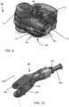
- FIG. 1shows a photograph of an embodiment of a robotic manipulator 10 with a stereoscopic video system 12 and two independently controlled dexterous arms 14-1, 14-2 (generally, 14) movably coupled to a main body or torso having a cylinder-shaped forward portion 16A and a back portion 16B (generally, torso 16).
- the torso 16can mount to a mobile EOD (Explosive Ordnance Disposal) platform, such as Andros F6-A.
- the stereoscopic video system 12is movably coupled to the forward portion 16A of the torso.
- the stereoscopic video system 12has remote-controlled tilt-zoom-focus capabilities.
- Embodiments of stereoscopic video system 12can be standard definition or high-definition (HD).
- Each arm 14-1, 14-2is connected to the cylinder-shaped forward portion 16A of the torso by a respective shoulder 18-1, 18-2 (generally, 18).
- the shoulders 18are rotatably connected to opposite sides of the forward portion 16A of the torso.
- Each arm 14comprises an upper arm 20 rotatably connected to the shoulder 18, a forearm 22 rotatably connected to the upper arm 20 by an elbow 24, and a wrist 26 rotatably connected to the forearm 22.
- the wrists 26can be configured with a variety of changeable tools 28, including, for example, a multi-functional cutter-grasper.
- the long, slender forearm-to-wristlessens obstructing the view of the video system 12 to the work site and tool 28.
- the robotic manipulator 10is capable of holding approximately a 5-pound payload.
- the upper arms 20can rotate about any of three axes, as described in more detail in connection with FIG. 8 . These three axes intersect at a point where the shoulder 18 joins the upper arm 20 (i.e., the shoulder joint).
- the forearmrotates within the elbow, and the wrist rotates about three perpendicular axes, two of which intersect.
- the ability to rotate about any of the seven axescorresponds to six degrees of freedom (DOF) of movement for each arm 14: moving forward and backward, moving left and right, moving up and down, tilting forward and backward (pitch), tilting side-to-side (roll), and rotating left and right (yaw).
- DOFdegrees of freedom
- the seventh axis of rotationprovides redundancy, and the ability of selecting between many arm configurations when the tool 28 is maintained in a desired position and orientation.
- the static design of the robotic manipulator 10is to have the center of mass of the whole arm 14 at the intersection of the three axes of rotation.
- this intersection at the shoulder jointensures the center of mass remains at the shoulder joint throughout the range of 3-dimensional motion of the arm 14.
- This static balance designpromotes stability of the robotic manipulator, enables sensing of the tool and payload forces and not the arm weight, and facilitates efficient dedication of electrical power to the handling of the tool and payload.
- FIG. 2shows a functional block diagram of a teleoperated robotic manipulator system 50 including a control station 52 in communication with the robotic manipulator 10 over a communication link 54.
- the communication link 54can be, for example, a fiber optic cable (10Base T), Ethernet cable, or a RF communication link.
- the robotic manipulator 10also includes a servo actuator subsystem 56, a computational host subsystem 58, a video-capture subsystem 60, and a power conversion and distribution subsystem 62.
- the operatorcan reposition the robotic manipulator 10, individually control the robotic arms 14 simultaneously, and execute camera operations, such as tilt, zoom, motion scaling, tremor filtering, and stereo convergence. Dynamic adjustment to the convergence angle provides comfortable stereoscopic viewing through a wide range of operating depths.
- the controls station 52comprises computational elements (e.g., processor, memory, software, network interface) for translating interface device movements into command data packets, transmitting the commands to the robotic manipulator, performing hardware-accelerated decompression of video arriving from the robotic manipulator, presenting graphical interface overlays and haptic displays for notifying the operator of the limits of the workspace and of any impending collisions with remote structures.
- computational elementse.g., processor, memory, software, network interface
- control station 52provides operator feedback in the form of haptic forces on three axes, tactile vibration on three axes, a sense of tool-grip effort, and a three-dimensional binocular view.
- the control station 52includes a stereoscopic display 64 (preferably capable of high-definition) and haptic-interface devices 66.
- the displaycan be implemented with a pair of 15-inch diagonal LCD displays with a 1024 x 800 resolution, for example.
- the display 64can be a SXGA resolution (1280 x 960) Organic LED micro-display produced by eMagin Corporation of Bellevue WA.
- Other display alternativesinclude LCD panels with 120 Hz refresh rate and active LCD shuttered glasses, or 3D displays using filters and passive glasses.
- the haptic-interface devices 66can be implemented with Omega7 desktop haptic interface devices (manufactured by Force Dimension of Nylon, Switzerland), or with a bimanual interface device produced by Mimic Technologies of Seattle, WA.
- the Mimic desktop deviceuses tensioned cables connecting the control handles to measure position and to exert forces to the operator.
- Servomotorsattach to spools that control the tension in the cables.
- the dual operator hand-control haptic-interface devices 66provide six-DOF movement (left, right, back, forward, up, and down) and a proportional gripper control. Vibrotactile feedback based on 3-axis accelerometers embedded in each manipulator gripper ( FIG. 12 ) is reproduced as resolved forces in the haptic-interface devices 66. Low-pass filtering of the command signals originating from the haptic-interface devices 66 prevents destabilization in the presence of arbitrary latencies.
- a pair of 6 axis joystick devicesmay be used to provide movement commands to the control station. These devices presently do not support the display of haptic forces.
- control station 52can present a display overlay that shows the commanded configuration of the remote arm with minimal delay in order to aid the operator in correctly placing the tools of the robotic manipulator at a desired target without overshoot or hesitation.
- the robotic manipulatorappears to move in immediate real-time response to the movement of the haptic-interface devices.
- deliberately delaying the vibrational haptic feedback in order to synchronize the feedback with the decoded videocan help avoid inconsistent sensory queues that convey a sense of telepresence.
- the servo actuator subsystem 56comprises the various servomotors, encoders, closed-loop position controllers, power amplifiers, and network communication elements of the robotic manipulator 10.
- the computational host subsystem 58translates commands received over the communications link 54 into low-level instructions for the servo actuator subsystem 56, translates and sends feedback signals received from the servomotors to the control station 52, and collects, compresses, and transmits video data from the cameras of the video-capture subsystem 60 to the control station 52 for display.
- the computational host subsystem 58includes a processor 74 that executes communications and embedded software 76 (stored in memory 78) to direct the functionality of the robotic manipulator 10, such as the ability to deploy and stow autonomously, and to calculate rapidly the movement required of each manipulator joint to achieve the motion required by a received command from the control station 52.
- the software 76translates these required movements into instructions expected by the various components of the servo actuator subsystem 56 and video-capture subsystem 60.
- the computational host subsystem 58communicates these instructions to each subsystem 56, 60 through standard communications channels 80, such as USB 2.0, CANBus, or EtherCAT. As an example, commands can be sent to the servo actuator subsystem 56 at 20-500 positions per second.
- An objective of the embedded software 76is for the arms to remain substantially balanced through a large workspace, which, for example, can measure 42 inches in width by 25 inches in depth by 33 inches in height.
- the software 76also collects feedback information from the servo actuator and video capture subsystems 56, 60, translates and encodes the feedback information, and transmits the encoded data to the control station 52 over the communication link 54.
- the embedded software 76can also detect and handle fault conditions, allowing recovery whenever possible.
- the video-capture subsystem 60acquires stereoscopic images of the remote environments, and responds to commands from the computational host subsystem 58 to adjust zoom, focus, or camera convergence.
- the video-capture subsystem 60supports VGA (640 ⁇ 480) stereoscopic video. Other capabilities can include higher display resolution and remote adjustment of zoom, focus, convergence, and stereo baseline.
- the power conversion and distribution subsystem 62can draw power from an external power source 68, here, for example, shown to be part of a mobile host platform 70 to which the robotic manipulator 10 is mounted, and transforms this power into the electrical voltage and current levels required by the various dependent electronic subsystems 56, 58, and 60.
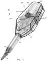
- FIG. 3shows a view of the robotic manipulator 10 without protective covering.
- the stereoscopic video system 12has an undercarriage 100 with four rollers 102. These rollers 102 ride on two arcuate rails 104 of the cylinder-shaped forward portion 16A of the torso.
- a chain drive 106passes through the undercarriage 100 of the video system 12 and an opening 108 in the forward portion 16A, coupling the video system 12 to the forward portion 16A of the torso.
- the chain drive 106operates to pull the video system 12 backward or forward along the rails 104, which, because of the cylinder-shape of the forward portion 16A of the torso, causes the video system 12 to tilt up or down, respectively.
- each upper arm 20includes a servomotor 110 with a speed reducing gearbox and pulley.
- a belt 112couples the pulley of the motor 110 with a pulley 202 ( FIG. 10 ) of the elbow 24.
- Behind each shoulder 18is another motor 114 coupled to another pulley 172 ( FIG. 8 ) of the shoulder 18 by a belt 116.
- the motors 110, 114 and belts 112, 116can be commercial-off-the-shelf (COTS) components.
- COTScommercial-off-the-shelf
- the back portion 16B of the torsohas a motor 120 coupled by a belt 122 to a pulley 164 ( FIG. 8 ) of the shoulder 18 (only the motor 120 and belt 122 for the right arm 14-1 are visible in FIG. 3 ).
- Each belt 112, 116, and 122is flat with integral teeth for meshing with teeth of the pulleys.
- the separate beltsprovide shock isolation.
- a low gear ratio mechanical transmissionprovides manipulator backdrive-ability and low reflected inertia, mitigating the risk of damage to the robotic manipulator or to structures in the event of their collision.
- the mass of the motor 110is disposed on the opposite side of the shoulder 18 from the remainder of the arm (i.e., elbow, forearm, and wrist) to provide a counterweight that counterbalances the arm 14 approximately at the point of 3-axis-intersection within the shoulder joint.
- counterbalancing the armsenables the arms to remain in their current position when power is off; no torque needs to be applied to any of the shoulder and arm joints to hold their current positions. With the arm balanced, the expenditure of electrical power is dedicated to the movement of payload, and motor current is used to sense and hold the tool, not the arm itself.
- FIG. 4 , FIG. 5, and FIG. 6together illustrate the dimensions to which one embodiment of the robotic manipulator can fold for purposes of entering tight quarters.
- FIG. 4shows a front view of the robotic manipulator 10
- FIG. 5shows a top view of the robotic manipulator
- FIG. 6shows a side view of the robotic manipulator.
- the video system 12tilts downward, and the forearms 22 extend forward of the torso 16.
- the compact width 130measured from the outermost edges of the upper arms 20, is approximately 14 inches.
- the height 132measured from the front edge of the back portion 16B of the torso to the back edge of the back portion 16B, is approximately 5.2 inches.
- the circle 134( FIG.
- FIG. 4illustrates an approximate size of a porthole into which the robotic manipulator 10 can project when brought into this compact, folded position.
- the diameter of such a portholeis 14.125 in.
- the length 136( FIG. 5 ), measured from the foremost edge of the forearms 22 to the rearmost edge of the back portion 16B of the torso, is approximately 15 in.
- an embodiment of the robotic manipulator 10can weigh as little as 5kg and consume as little as 50W of electrical power.
- FIG. 7shows a diagram of an embodiment of the torso 16 of the robotic manipulator 10 including the cylinder-shaped forward portion 16A and the back portion 16B.
- a pair of motors 120-1, 120-2housed within the back portion 16B are a pair of motors 120-1, 120-2 (generally, 120).
- Each motor 120is coupled by a gearbox 156 which turns a pulley 152 (only the right pulley being shown), which is coupled by a belt 122 ( FIG. 3 ) to a pulley 164 ( FIG. 8 ) on the shoulder 18.
- the forward portion 16Aincludes a pair of axles 150 (only the right axle being visible), each axle 150 connecting to one of the shoulders 18.
- the motor 120-1rotates the right shoulder 18-1; and the motor 120-2 rotates the left shoulder 18-2.
- the torso 16also has a printed circuit board (PCB) 154 (referred to as a motion control board) for controlling the motors 120.
- the PCB 154includes a servo controller, brushless motor commutation, PCM (pulse-code) modulation, closed-loop position/ torque control, CANBUS communications capability, DC supply, and an incremental position encoder feedback.
- the PCB 154can be implemented with a Maxon EPOS-2 Module, produced by Maxon of Sachseln, Switzerland.
- the torso 16also includes an accelerometer (not shown) that senses a direction in which the host platform (e.g., a robotic arm, mobile platform, or "jaws") is holding the robotic manipulator 10 by sensing a direction of gravity. With knowledge of the direction of gravity and the direction of the arms 14 (acquired from position encoders), the torso 16 can manipulate the motors 120 to ensure the robotic manipulator remains counterbalanced for the purposes of haptic feedback (i.e., torques needing to be applied to the joints in order for the robotic manipulator to remain in position are not used in the determination of the haptic forces displayed in the hand controllers).
- haptic feedbacki.e., torques needing to be applied to the joints in order for the robotic manipulator to remain in position are not used in the determination of the haptic forces displayed in the hand controllers.
- FIG. 8shows a diagram of an embodiment of each right shoulder of the robotic manipulator 10.
- Each shoulder 18includes opposing shoulder blades 160-1, 160-2 that extend orthogonally from a circular end-cap 162.
- the end-cap 162attaches to one side of the cylinder-shaped forward portion 16A of the torso.
- Fixed to the end-cap 162is a central pulley 164 with a bearing 166 for receiving one of the axles 150 of the torso.
- a belt 122 fitted over the central pulley 164couples the shoulder 18 to the pulley 152 of one of the motors 120 in the back portion 16B of the torso. Operation of the motor 120 rotates the arm 14 coupled to the shoulder 18 about the axis 170-1.
- a position encoderso that the position of the motor (and, derivatively, the position of the shoulder) is known.
- a second pulley 172with a socket 174 for receiving a bearing 194 ( FIG. 9 ) of one of the upper arms 20.
- a belt 116( FIG. 3 ) fitted over the pulley 172 couples the shoulder 18 to the pulley of one of the motors 114 in the upper arm 20. Operation of the motor 114 rotates the arm 14 coupled to shoulder 18 about the axis 170-2.
- a third axis of rotation 170-3, described further in connection with FIG. 10intersects the other two axes 170-1, 170-2 at a point 176 within the shoulder 18.
- Each shoulder 18further includes a flex printed circuit board 178 that wraps around the socket 166, extends along a length of the shoulder blade 160-1, and depends from the distal end of the shoulder blade 160-1.
- This flex circuit 178provides electrical power and digital data signals to and from the motion control PCB contained in the upper arm, elbow and instrument subsystems.
- the coiled designpermits rotation of the robot joints throughout their designed range of motion with negligible resistance.
- FIG. 9shows a diagram of an embodiment of each upper arm 20 of the robotic manipulator 10.
- the upper arm 20houses the motor 114 for driving the belt 112 that engages the gear 202 of the elbow 24 ( FIG. 10 ) and the motor 114 for driving the belt 116 that engages a gear 202 ( FIG. 10 ) of the elbow 24.
- the upper arm 20has a first opening 190 for receiving the gear 172 and a second opening 192 for receiving a shaft 200 ( FIG. 10 ) of the elbow 24.
- a rotatable shaft 194 at the opening 190is adapted to enter closely the bearing 174 of the gear 172, thereby coupling the upper arm 20 to the shoulder 18.
- the shaft 194coincides with the axis of rotation 170-2 ( FIG. 8 ).
- the upper arm 20further comprises electronics 196 for controlling the operation of the motors 110, 114 (in response to commands).
- Each motor 120has an associated position encoder so that the position of the motor (and, derivatively, a corresponding position of the upper arm) is known.
- FIG. 10shows a diagram of an embodiment of the elbow 24 of the robotic manipulator 10.
- the elbow 24has a slight bend.
- a shaft 200that enters the opening 192 ( FIG. 9 ) in the upper arm 20 and a gear 202 that engages the belt 112.
- a forearm-mount 204movably connected to a joint 206. Connected to this joint 206, the mount 204 can rotate about the axis 208.
- a flex circuit 209wraps around the joint 206, runs along an interior surface of the forked end, and enters the body of the elbow 24.
- the flex circuit 209is electrically connected to the flex circuit 178, and carries electrical power and digital communication signals to and from motor control PCBs 216 contained within the forearm main housing 210 ( FIG. 11 ) and accelerometer and angle position sensors contained in the wrist 26 ( FIG. 11 ).
- FIG. 11shows a diagram of an embodiment of the forearm 22 of the robotic manipulator 10.
- the forearm 22has a main housing 210 and a tube-shaped portion 212 that extends from one end of the housing 210.
- the tube-shaped portion 212ends at the wrist 26.
- the housing 210Within the housing 210 are four electromagnetic brushless motors with gear reductions 214, printed circuit boards 216, and a cable drive mechanism 218 that rotationally moves the tube shaped portion 212, the wrist 26 and gripper 28 in reaction to rotations of the electric motors 214.
- the electric motors 214may optionally be equipped with high-resolution rotational position sensors, or may be used without such sensors by employing hall-effect sensors within the motor as coarse resolution rotational position sensors.
- the motors 214, PCBs 216, and cable drive system 218are positioned within the housing 210 where they can counterbalance the mass of the tube-shaped 212 and wrist 26.
- the design of the forearm 22is for its center of mass to be within the housing 210 on the axis 220 passing through the forearm joint 222.
- Mechanical features of the cable drive mechanism 218separably connect to the forearm-mount 204 ( FIG. 10 ) of the elbow 24.
- the forearm mount 204is connected to the both ends of the joint 206 of the elbow 24.
- the axes 208 ( FIG. 10 ), 220align.
- the forearm 22moves, it rotates about the forearm joint 222, which aligns with its center of mass; accordingly, the forearm 22 remains balanced throughout its three-dimensional range of movement.
- Attached to the wrist 26are two gripper jaws 28.
- the jaws 28can move up and down across a plus or minus 90-degree range, and open and close for cutting and grasping operations.
- the electronics 216control the movement of the tool 28.
- a four-cable actuator(not shown), which extends from the housing 210 of the forearm 22 through the tube-shaped portion 212 into the wrist 26, executes the yaw, pitch, open, and close movements of the tool 28.
- FIG. 12shows a diagram of an embodiment of the wrist 26 of the robotic manipulator 10.
- the wrist 26is connected to the tool 28 at a rotatable wrist joint 230.
- the robotic manipulator 10can accordingly roll its furthermost joint, the wrist joint 230 allowing the tool 28 to move plus or minus 90 degrees about the axis 232.
- the wrist 26also includes a flex circuit 234 connected to both ends of the wrist joint 230 and to a printed circuit board (PCB) 236.
- the flex circuit 234carries digital electrical signals from two angular position sensors within the wrist joint 230. These signals encode data relating to the angular position of each of the gripper jaws 28.
- the PCB 236includes a surface-mounted 3-axis accelerometer 240 for detecting vibration, thus providing vibrotactile feedback in three dimensions.
- the PCB 236further contains a surface mount capacitance sensing circuit connected to flex circuit 234. These surface mounted IC's communicate digital electrical signals over I2C or similar interfaces.
- the wrist 26also includes wires (not shown) to the tip of the tool for sensing differences in electrical potential (voltage) between objects in contact with the grippers of the right and left manipulator, or the electrical current flowing through a wire being held between the gripper jaws 28.
- a sensore.g., capacitive angular sensor 230
- the PCB 236communicates the data acquired by the accelerometer 240 and the sensed joint position to the arm 14 over an I 2 C bus.
- FIG. 13shows a diagram of an embodiment of the stereoscopic video system 12 of the robotic manipulator 10, including the chain drive 106 and the four rollers 102.
- the video system 12includes two high definition (1080i or 720p) block camera modules 250-1, 250-2 (generally, 250), with low light capability, auto focus, auto iris, a remote digital interface for configuration, zoom, and focus, and a component video output.
- the field of vision for the camera modules 250is 50 degrees (wide angle) and 5.4 degrees (telephoto). These angles may be increased through the use of external wide angle adapters that attach to the cameras 250.
- Video subsystem 12further includes an interface card (not shown) for access to data communication, a camera pitch (tilt) servo, a stereo microphone preamplifier, and a video encoder (e.g., a Teredek Cube by Teredek of Irvine CA) for performing low-latency video compression (e.g., H.264), stereo audio compression, and Ethernet transmission.
- the camera pitch servopulls the video system 12 along the chain drive 106 to tilt the video system 12 up and down. When the video system 12 is tilted downwards through 90 degrees, rotating the robotic manipulator 10 causes the binocular view to turn left and right (such rotation being performed by the host robotic arm to which the robotic manipulator 10 is attached).
- the view direction of the cameraaffects the direction of movement of the robotic arms and hands (i.e., tools). For example, if the camera direction is tilted downwards, the arms move downward in response to a reaching-forward movement of the hand controls by the operator at the remote control station - there is a remapping of the operator's coordinate system to the coordinate system of the binocular view.
- aspects of the present inventionmay be embodied as a system, method, and computer program product.
- aspects of the present inventionmay be embodied entirely in hardware, entirely in software (including, but not limited to, firmware, program code, resident software, microcode), or in a combination of hardware and software. All such embodiments may generally be referred to herein as a circuit, a module, or a system.
- aspects of the present inventionmay be in the form of a computer program product embodied in one or more computer readable media having computer readable program code embodied thereon.
- the computer readable mediummay be a computer readable signal medium or a computer readable storage medium.
- a computer readable storage mediummay be, for example, but not limited to, an electronic, magnetic, optical, electromagnetic, infrared, or semiconductor system, apparatus, or device, or any suitable combination of the foregoing.
- a computer readable storage mediummay be any tangible medium that can contain, or store a program for use by or in connection with an instruction execution system, apparatus, or device.
- a computer readable signal mediummay include a propagated data signal with computer readable program code embodied therein, for example, in baseband or as part of a carrier wave. Such a propagated signal may take any of a variety of forms, including, but not limited to, electro-magnetic, optical, or any suitable combination thereof.
- a computer readable signal mediummay be any computer readable medium that is not a computer readable storage medium and that can communicate, propagate, or transport a program for use by or in connection with an instruction execution system, apparatus, or device.
- Program code embodied on a computer readable mediummay be transmitted using any appropriate medium, including but not limited to wireless, wired, optical fiber cable, radio frequency (RF), etc. or any suitable combination thereof.
- any appropriate mediumincluding but not limited to wireless, wired, optical fiber cable, radio frequency (RF), etc. or any suitable combination thereof.
- Computer program code for carrying out operations for aspects of the present inventionmay be written in any combination of one or more programming languages, including an object oriented programming language such as JAVA, Smalltalk, C++, and Visual C++ or the like and conventional procedural programming languages, such as the C and Pascal programming languages or similar programming languages.
- object oriented programming languagesuch as JAVA, Smalltalk, C++, and Visual C++ or the like
- conventional procedural programming languagessuch as the C and Pascal programming languages or similar programming languages.
- These computer program instructionsmay also be stored in a computer readable medium that can direct a computer, other programmable data processing apparatus, or other devices to function in a particular manner, such that the instructions stored in the computer readable medium produce an article of manufacture including instructions which implement the function/act specified in the flowchart and/or block diagram block or blocks.
- the computer program instructionsmay also be loaded onto a computer, other programmable data processing apparatus, or other devices to cause a series of operational steps to be performed on the computer, other programmable apparatus or other devices to produce a computer implemented process such that the instructions which execute on the computer or other programmable apparatus provide processes for implementing the functions/acts specified in the flowchart and/or block diagram block or blocks.
- each block in the flowchart or block diagramsmay represent a module, segment, or portion of code, which comprises one or more executable instructions for implementing the specified logical function(s).
- the functions noted in the blockmay occur out of the order noted in the figures. For example, two blocks shown in succession may, in fact, be executed substantially concurrently, or the blocks may sometimes be executed in the reverse order, depending upon the functionality involved.
- aspects of the described inventionmay be implemented in one or more integrated circuit (IC) chips manufactured with semiconductor-fabrication processes.
- the maker of the IC chipscan distribute them in raw wafer form (on a single wafer with multiple unpackaged chips), as bare die, or in packaged form.
- the IC chipis mounted in a single chip package, for example, a plastic carrier with leads affixed to a motherboard or other higher level carrier, or in a multichip package, for example, a ceramic carrier having surface and/or buried interconnections.
- the IC chipis then integrated with other chips, discrete circuit elements, and/or other signal processing devices as part of either an intermediate product, such as a motherboard, or of an end product.
- the end productcan be any product that includes IC chips, ranging from electronic gaming systems and other low-end applications to advanced computer products having a display, an input device, and a central processor.
Landscapes
- Engineering & Computer Science (AREA)
- Robotics (AREA)
- Mechanical Engineering (AREA)
- Automation & Control Theory (AREA)
- Human Computer Interaction (AREA)
- Multimedia (AREA)
- Artificial Intelligence (AREA)
- Physics & Mathematics (AREA)
- Evolutionary Computation (AREA)
- Fuzzy Systems (AREA)
- Mathematical Physics (AREA)
- Software Systems (AREA)
- Manipulator (AREA)
Description
- The invention relates generally to teleoperated robotic manipulator systems.
- Teleoperated systems generally include a man-machine interface through which a human operator can remotely control a robotic manipulator. An example of a teleoperated system is the Da Vinci Surgical System, made by Intuitive Surgical of Sunnyvale, CA. The Da Vinci Surgical System has three robotic arms that operate as tools and a fourth arm that carries a two-lens camera. A surgeon sits at a console and, while looking at the stereoscopic image captured by the robotic arm with the camera, exercises hand controls and/or foot controls that move the other arms. The movements of the controls translate into micromovements of the instruments. Surgeons have used the Da Vinci Surgical System to perform minimally invasive surgery remotely.
- Proceedings of the IEEE International Conference on Systems, Man and Cybernetics: "Ground Operated Teleoperation System for Live Power Line Maintenance" published by IEEE in New York, NY, USA, vol. 1, pages 792-798, XP010206729, DOI: 10.1109/ICSMC.1996.569897, ISBN: 978-0-7803-3280-5 discusses work executed for the development of a Ground Operated Teleoperation System for live-line maintenance of Hydro-Quebec's overhead distribution network. It covers the system's development, engineering and implementation as well as forecasted research with the prototype.
- KRON A ET AL, "Haptic Telepresent Control Technology Applied to Disposal of Explosive Ordnances: Principles and Experimental Results", INDUSTRIAL ELECTRONICS, 2005. ISIE 2005. PROCEEDINGS OF THE IEEE INTER NATIONAL SYMPOSIUM ON DUBROVNIK, CROATIA JUNE 20-23, 2005, PISCATAWAY, NJ, USA,IEEE, (20050620), vol. 4, doi:10.1109/ISIE.2005.1529155, ISBN 978-0-7803-8738-6, pages 1505 - 1510, XP010850316 describes the use of bimanual haptic telepresent control technology to dispose of explosive ordinances. Visual feedback rests upon a stereo image stream captured at the teleoperator site with a fixed stereo camera pair.
- KAI XU ET AL, "System design of an Insertable Robotic Effector Platform for Single Port Access (SPA) Surgery", INTELLIGENT ROBOTS AND SYSTEMS, 2009. IROS 2009. IEEE/RSJ INTERNATIONAL CONFERENCE ON, IEEE, PISCATAWAY, NJ, USA, (20091010), ISBN 978-1-4244-3803-7, pages 5546 - 5552, XP031580389 presents a novel design and preliminary kinematic analysis of an insertable robotic effector platform for single port access surgery. One embodiment includes two snake arms and a stereo vision module on a flexible stem.
US 2008/0071290 describes a minimally invasive surgery instruments assembly with reduced cross section. One embodiment includes two independently remotely controlled flexible arms and a camera producing stereoscopic video, all emerging from a guide tube.- The present invention is defined by the appended claims.
- In one aspect, the invention relates to a robotic manipulator comprising a body and a stereoscopic video system movably coupled to the body. The stereoscopic vision system produces a stereoscopic video of an environment of the robotic manipulator. The robotic manipulator further comprises two independently remotely controlled arms coupled to opposite sides of the body. A view direction of the stereoscopic video produced by the stereoscopic video system affects the movement of the robotic arms such that each arm moves in proprioceptive alignment with the stereoscopic video in response to commands received from a remote control station based on movements performed by an operator at the remote control station. Each arm comprises an upper arm rotatably coupled to one side of the body for rotational movement about first and second axes, and an elbow rotatably joined to the upper arm for rotational movement about a third axis, the three axes of rotation intersecting at a point within the upper arm. Each arm further comprises a forearm rotatably joined to the elbow of that arm for rotational movement about an elbow joint, the forearm having a center of mass at the elbow joint to balance the forearm at the elbow joint.
- In another aspect, the invention relates to a system comprising a robotic manipulator with a servo actuator subsystem having two independently remotely controlled arms coupled to opposite sides of a body and a video-capture subsystem that produces a stereoscopic video of a local environment of the robotic manipulator. The robotic manipulator further comprises a computational host subsystem that transmits movement commands to the servo actuator subsystem. The commands cause the servo actuator subsystem to move each arm in a direction affected by a view direction of the stereoscopic video produced by the video-capture subsystem such that each arm moves in proprioceptive alignment with the stereoscopic video. Each arm comprises an upper arm rotatably coupled to one side of the body for rotational movement about first and second axes, and an elbow rotatably joined to the upper arm for rotational movement about a third axis, the three axes of rotation intersecting at a point within the upper arm. Each arm further comprises a forearm rotatably joined to the elbow of that arm for rotational movement about an elbow joint, the forearm having a center of mass at the elbow joint to balance the forearm at the elbow joint.
- In yet another aspect, the invention relates to a method of remotely operating a robotic manipulator having a body, a stereoscopic video system movably coupled to the body, and two remotely controlled arms coupled to opposite sides of the body. Each arm comprises an upper arm rotatably coupled to one side of the body for rotational movement about first and second axes, and an elbow rotatably joined to the upper arm for rotational movement about a third axis, the three axes of rotation intersecting at a point within the upper arm. Each arm further comprises a forearm rotatably joined to the elbow of that arm for rotational movement about an elbow joint, the forearm having a center of mass at the elbow joint to balance the forearm at the elbow joint. The method comprises capturing, by the video system, a stereoscopic video of an environment of the robotic manipulator, and independently moving, each arm in response to commands received from a remote control station, wherein a view direction of the stereoscopic video produced by the stereoscopic video system affects the direction of movement of the robotic arms such that each arm moves in proprioceptive alignment with the stereoscopic video produced by the stereoscopic video system.
- The above and further advantages of this invention may be better understood by referring to the following description in conjunction with the accompanying drawings, in which like numerals indicate like structural elements and features in various figures. The drawings are not necessarily to scale, emphasis instead being placed upon illustrating the principles of the invention.
FIG. 1 is a photograph of an embodiment of a robotic manipulator with a stereoscopic video system and dexterous independently remotely controlled arms.FIG. 2 is a functional block diagram of an embodiment of a teleoperated robotic manipulator system.FIG. 3 is a diagram of an embodiment of the robotic manipulator without protective covering.FIG. 4 is a front view of the robotic manipulator illustrating a width and height to which the robotic manipulator can fold.FIG. 5 is a top view of the robotic manipulator illustrating its folded width and depth.FIG. 6 is a side view of the robotic manipulator illustrating its folded height.FIG. 7 is a diagram of an embodiment of a torso of the robotic manipulator.FIG. 8 is a diagram of an embodiment of a shoulder of the robotic manipulator.FIG. 9 is a diagram of an embodiment of an upper arm of the robotic manipulator.FIG. 10 is a diagram of an embodiment of an elbow of the robotic manipulator.FIG. 11 is a diagram of an embodiment of a forearm of the robotic manipulatorFIG. 12 is a diagram of an embodiment of a wrist of the robotic manipulator.FIG. 13 is a diagram of an embodiment of the stereoscopic video system of the robotic manipulator.- Applicants recognized that various telemanipulator principles embodied in the Da Vinci Surgical System can be extended to non-medical uses, for example, executing operations within environments hazardous to humans while the operator remains at a remote, safe distance. For example, the robotic manipulator systems described herein can be vehicle-mounted and used to approach, deactivate, and render harmless improvised explosive devices (IED) by bomb squad personnel. Other applications include, but are not limited to, the repair of orbital spacecraft or the capture or stabilizing of orbital objects.
- The robotic manipulator systems described herein include a remotely operated robotic manipulator with three-dimensional stereoscopic vision and two independently controllable dexterous hands having multiple degrees of freedom (DOF). The arms of the robot manipulator carry tools or instruments, such as graspers, clamps, cutters, electrical probes, or sensors. The robotic manipulator can serve as an attachment to a coarse-movement vehicle and arm, or operate as a stand-alone unit. Its design is scalable and produces a small form factor that permits the robotic manipulator to enter and operate in tight spaces.
- Control of the robotic manipulator, in general, occurs from a remote control station over an RF (radio frequency) link, fiber optic or electrical cable tether. An operator works at the control station with an intuitive human-machine interface through which to perform complex tasks remotely. The control station achieves proprioceptive alignment of stereoscopic imagery with hand controls; that is, the movement of the robotic arms and hands closely corresponds to the movement of the operator's arms and hands. Intuitive telemanipulation also includes motion and rotation clutching, linked camera zoom and movement scaling and transforming movement commands into the camera reference frame for natural, reliable, and predictable operation.
FIG. 1 shows a photograph of an embodiment of arobotic manipulator 10 with astereoscopic video system 12 and two independently controlled dexterous arms 14-1, 14-2 (generally, 14) movably coupled to a main body or torso having a cylinder-shapedforward portion 16A and aback portion 16B (generally, torso 16). Thetorso 16 can mount to a mobile EOD (Explosive Ordnance Disposal) platform, such as Andros F6-A. Thestereoscopic video system 12 is movably coupled to theforward portion 16A of the torso. Preferably, thestereoscopic video system 12 has remote-controlled tilt-zoom-focus capabilities. Embodiments ofstereoscopic video system 12 can be standard definition or high-definition (HD).- Each arm 14-1, 14-2 is connected to the cylinder-shaped
forward portion 16A of the torso by a respective shoulder 18-1, 18-2 (generally, 18). Theshoulders 18 are rotatably connected to opposite sides of theforward portion 16A of the torso. Each arm 14 comprises anupper arm 20 rotatably connected to theshoulder 18, aforearm 22 rotatably connected to theupper arm 20 by anelbow 24, and awrist 26 rotatably connected to theforearm 22. Thewrists 26 can be configured with a variety ofchangeable tools 28, including, for example, a multi-functional cutter-grasper. The long, slender forearm-to-wrist lessens obstructing the view of thevideo system 12 to the work site andtool 28. In one embodiment, with both arms engaged, therobotic manipulator 10 is capable of holding approximately a 5-pound payload. - The
upper arms 20 can rotate about any of three axes, as described in more detail in connection withFIG. 8 . These three axes intersect at a point where theshoulder 18 joins the upper arm 20 (i.e., the shoulder joint). The forearm rotates within the elbow, and the wrist rotates about three perpendicular axes, two of which intersect. The ability to rotate about any of the seven axes corresponds to six degrees of freedom (DOF) of movement for each arm 14: moving forward and backward, moving left and right, moving up and down, tilting forward and backward (pitch), tilting side-to-side (roll), and rotating left and right (yaw). The seventh axis of rotation provides redundancy, and the ability of selecting between many arm configurations when thetool 28 is maintained in a desired position and orientation. - The static design of the
robotic manipulator 10 is to have the center of mass of the whole arm 14 at the intersection of the three axes of rotation. Advantageously, this intersection at the shoulder joint ensures the center of mass remains at the shoulder joint throughout the range of 3-dimensional motion of the arm 14. This static balance design promotes stability of the robotic manipulator, enables sensing of the tool and payload forces and not the arm weight, and facilitates efficient dedication of electrical power to the handling of the tool and payload. FIG. 2 shows a functional block diagram of a teleoperatedrobotic manipulator system 50 including acontrol station 52 in communication with therobotic manipulator 10 over acommunication link 54. Thecommunication link 54 can be, for example, a fiber optic cable (10Base T), Ethernet cable, or a RF communication link. Therobotic manipulator 10 also includes aservo actuator subsystem 56, acomputational host subsystem 58, a video-capture subsystem 60, and a power conversion anddistribution subsystem 62.- Through the
control station 52, the operator can reposition therobotic manipulator 10, individually control the robotic arms 14 simultaneously, and execute camera operations, such as tilt, zoom, motion scaling, tremor filtering, and stereo convergence. Dynamic adjustment to the convergence angle provides comfortable stereoscopic viewing through a wide range of operating depths. In brief overview, thecontrols station 52 comprises computational elements (e.g., processor, memory, software, network interface) for translating interface device movements into command data packets, transmitting the commands to the robotic manipulator, performing hardware-accelerated decompression of video arriving from the robotic manipulator, presenting graphical interface overlays and haptic displays for notifying the operator of the limits of the workspace and of any impending collisions with remote structures. - In brief overview, the
control station 52 provides operator feedback in the form of haptic forces on three axes, tactile vibration on three axes, a sense of tool-grip effort, and a three-dimensional binocular view. Thecontrol station 52 includes a stereoscopic display 64 (preferably capable of high-definition) and haptic-interface devices 66. The display can be implemented with a pair of 15-inch diagonal LCD displays with a 1024 x 800 resolution, for example. Alternatively, thedisplay 64 can be a SXGA resolution (1280 x 960) Organic LED micro-display produced by eMagin Corporation of Bellevue WA. Other display alternatives include LCD panels with 120 Hz refresh rate and active LCD shuttered glasses, or 3D displays using filters and passive glasses. - The haptic-
interface devices 66 can be implemented with Omega7 desktop haptic interface devices (manufactured by Force Dimension of Nylon, Switzerland), or with a bimanual interface device produced by Mimic Technologies of Seattle, WA. The Mimic desktop device uses tensioned cables connecting the control handles to measure position and to exert forces to the operator. Servomotors attach to spools that control the tension in the cables. The dual operator hand-control haptic-interface devices 66 provide six-DOF movement (left, right, back, forward, up, and down) and a proportional gripper control. Vibrotactile feedback based on 3-axis accelerometers embedded in each manipulator gripper (FIG. 12 ) is reproduced as resolved forces in the haptic-interface devices 66. Low-pass filtering of the command signals originating from the haptic-interface devices 66 prevents destabilization in the presence of arbitrary latencies. - As an alternative to the haptic-interface devices described, in a low cost implementation, a pair of 6 axis joystick devices (e.g., SpaceNavigator™ by 3DConnexion of Boston, MA) may be used to provide movement commands to the control station. These devices presently do not support the display of haptic forces.
- In addition, use of low-latency hardware accelerated video CODECs, for long distance operation using satellite communication techniques, and the collocation of telepresence operations with the communications facilities helps minimize communication latency. To compensate for long round-trip latencies (e.g., greater than 750ms), the
control station 52 can present a display overlay that shows the commanded configuration of the remote arm with minimal delay in order to aid the operator in correctly placing the tools of the robotic manipulator at a desired target without overshoot or hesitation. To the operator, the robotic manipulator appears to move in immediate real-time response to the movement of the haptic-interface devices. In addition, deliberately delaying the vibrational haptic feedback in order to synchronize the feedback with the decoded video can help avoid inconsistent sensory queues that convey a sense of telepresence. - The
servo actuator subsystem 56 comprises the various servomotors, encoders, closed-loop position controllers, power amplifiers, and network communication elements of therobotic manipulator 10. - The
computational host subsystem 58 translates commands received over the communications link 54 into low-level instructions for theservo actuator subsystem 56, translates and sends feedback signals received from the servomotors to thecontrol station 52, and collects, compresses, and transmits video data from the cameras of the video-capture subsystem 60 to thecontrol station 52 for display. - The
computational host subsystem 58 includes aprocessor 74 that executes communications and embedded software 76 (stored in memory 78) to direct the functionality of therobotic manipulator 10, such as the ability to deploy and stow autonomously, and to calculate rapidly the movement required of each manipulator joint to achieve the motion required by a received command from thecontrol station 52. Thesoftware 76 translates these required movements into instructions expected by the various components of theservo actuator subsystem 56 and video-capture subsystem 60. Thecomputational host subsystem 58 communicates these instructions to eachsubsystem standard communications channels 80, such as USB 2.0, CANBus, or EtherCAT. As an example, commands can be sent to theservo actuator subsystem 56 at 20-500 positions per second. - In the absence of position updates from the operator, individual joints of the arms 14 hold their last commanded positions. The various levels of counterbalancing designed into the shapes and locations of the "body parts" of the robotic manipulator and the program algorithms employed to maintain the balance throughout their ranges of motion, as described in more detail below, enable the robotic manipulator to hold these positions using minimum electrical power. An objective of the embedded
software 76 is for the arms to remain substantially balanced through a large workspace, which, for example, can measure 42 inches in width by 25 inches in depth by 33 inches in height. - The
software 76 also collects feedback information from the servo actuator andvideo capture subsystems control station 52 over thecommunication link 54. The embeddedsoftware 76 can also detect and handle fault conditions, allowing recovery whenever possible. - The video-
capture subsystem 60 acquires stereoscopic images of the remote environments, and responds to commands from thecomputational host subsystem 58 to adjust zoom, focus, or camera convergence. In one embodiment, the video-capture subsystem 60 supports VGA (640×480) stereoscopic video. Other capabilities can include higher display resolution and remote adjustment of zoom, focus, convergence, and stereo baseline. - The power conversion and
distribution subsystem 62 can draw power from anexternal power source 68, here, for example, shown to be part of amobile host platform 70 to which therobotic manipulator 10 is mounted, and transforms this power into the electrical voltage and current levels required by the various dependentelectronic subsystems FIG. 3 shows a view of therobotic manipulator 10 without protective covering. Thestereoscopic video system 12 has anundercarriage 100 with fourrollers 102. Theserollers 102 ride on twoarcuate rails 104 of the cylinder-shapedforward portion 16A of the torso. Achain drive 106 passes through theundercarriage 100 of thevideo system 12 and anopening 108 in theforward portion 16A, coupling thevideo system 12 to theforward portion 16A of the torso. Thechain drive 106 operates to pull thevideo system 12 backward or forward along therails 104, which, because of the cylinder-shape of theforward portion 16A of the torso, causes thevideo system 12 to tilt up or down, respectively.- In general, the
robotic manipulator 10 employs distributed control architecture with independent closed-loop position servos for each joint. Specifically, eachupper arm 20 includes aservomotor 110 with a speed reducing gearbox and pulley. Abelt 112 couples the pulley of themotor 110 with a pulley 202 (FIG. 10 ) of theelbow 24. Behind eachshoulder 18 is anothermotor 114 coupled to another pulley 172 (FIG. 8 ) of theshoulder 18 by abelt 116. Themotors belts - For each arm, the
back portion 16B of the torso has amotor 120 coupled by abelt 122 to a pulley 164 (FIG. 8 ) of the shoulder 18 (only themotor 120 andbelt 122 for the right arm 14-1 are visible inFIG. 3 ). Eachbelt - The mass of the
motor 110 is disposed on the opposite side of theshoulder 18 from the remainder of the arm (i.e., elbow, forearm, and wrist) to provide a counterweight that counterbalances the arm 14 approximately at the point of 3-axis-intersection within the shoulder joint. Advantageously, counterbalancing the arms enables the arms to remain in their current position when power is off; no torque needs to be applied to any of the shoulder and arm joints to hold their current positions. With the arm balanced, the expenditure of electrical power is dedicated to the movement of payload, and motor current is used to sense and hold the tool, not the arm itself. FIG. 4 ,FIG. 5, and FIG. 6 together illustrate the dimensions to which one embodiment of the robotic manipulator can fold for purposes of entering tight quarters.FIG. 4 shows a front view of therobotic manipulator 10,FIG. 5 shows a top view of the robotic manipulator, andFIG. 6 shows a side view of the robotic manipulator. In a compact folded position, thevideo system 12 tilts downward, and theforearms 22 extend forward of thetorso 16. Thecompact width 130, measured from the outermost edges of theupper arms 20, is approximately 14 inches. Theheight 132, measured from the front edge of theback portion 16B of the torso to the back edge of theback portion 16B, is approximately 5.2 inches. The circle 134 (FIG. 4 ) illustrates an approximate size of a porthole into which therobotic manipulator 10 can project when brought into this compact, folded position. The diameter of such a porthole is 14.125 in. The length 136 (FIG. 5 ), measured from the foremost edge of theforearms 22 to the rearmost edge of theback portion 16B of the torso, is approximately 15 in. As other measures of its compactness, an embodiment of therobotic manipulator 10 can weigh as little as 5kg and consume as little as 50W of electrical power.FIG. 7 shows a diagram of an embodiment of thetorso 16 of therobotic manipulator 10 including the cylinder-shapedforward portion 16A and theback portion 16B. In the description of thetorso 16, reference is also made to features described in connection withFIG. 3 . Housed within theback portion 16B are a pair of motors 120-1, 120-2 (generally, 120). Eachmotor 120 is coupled by agearbox 156 which turns a pulley 152 (only the right pulley being shown), which is coupled by a belt 122 (FIG. 3 ) to a pulley 164 (FIG. 8 ) on theshoulder 18. Theforward portion 16A includes a pair of axles 150 (only the right axle being visible), eachaxle 150 connecting to one of theshoulders 18. In this embodiment, the motor 120-1 rotates the right shoulder 18-1; and the motor 120-2 rotates the left shoulder 18-2.- The
torso 16 also has a printed circuit board (PCB) 154 (referred to as a motion control board) for controlling themotors 120. ThePCB 154 includes a servo controller, brushless motor commutation, PCM (pulse-code) modulation, closed-loop position/ torque control, CANBUS communications capability, DC supply, and an incremental position encoder feedback. ThePCB 154 can be implemented with a Maxon EPOS-2 Module, produced by Maxon of Sachseln, Switzerland. - The
torso 16 also includes an accelerometer (not shown) that senses a direction in which the host platform (e.g., a robotic arm, mobile platform, or "jaws") is holding therobotic manipulator 10 by sensing a direction of gravity. With knowledge of the direction of gravity and the direction of the arms 14 (acquired from position encoders), thetorso 16 can manipulate themotors 120 to ensure the robotic manipulator remains counterbalanced for the purposes of haptic feedback (i.e., torques needing to be applied to the joints in order for the robotic manipulator to remain in position are not used in the determination of the haptic forces displayed in the hand controllers). FIG. 8 shows a diagram of an embodiment of each right shoulder of therobotic manipulator 10. In the description of the shoulder, reference is made to features described in connection withFIG. 3 and to thetorso 16 described inFIG. 7 . Eachshoulder 18 includes opposing shoulder blades 160-1, 160-2 that extend orthogonally from a circular end-cap 162. The end-cap 162 attaches to one side of the cylinder-shapedforward portion 16A of the torso. Fixed to the end-cap 162 is acentral pulley 164 with abearing 166 for receiving one of theaxles 150 of the torso. Abelt 122 fitted over thecentral pulley 164 couples theshoulder 18 to thepulley 152 of one of themotors 120 in theback portion 16B of the torso. Operation of themotor 120 rotates the arm 14 coupled to theshoulder 18 about the axis 170-1. Associated with eachmotor 120 is a position encoder so that the position of the motor (and, derivatively, the position of the shoulder) is known.- At the distal end of the shoulder blade 160-2 is a
second pulley 172 with a socket 174 for receiving a bearing 194 (FIG. 9 ) of one of theupper arms 20. A belt 116 (FIG. 3 ) fitted over thepulley 172 couples theshoulder 18 to the pulley of one of themotors 114 in theupper arm 20. Operation of themotor 114 rotates the arm 14 coupled toshoulder 18 about the axis 170-2. A third axis of rotation 170-3, described further in connection withFIG. 10 , intersects the other two axes 170-1, 170-2 at apoint 176 within theshoulder 18. - Each
shoulder 18 further includes a flex printedcircuit board 178 that wraps around thesocket 166, extends along a length of the shoulder blade 160-1, and depends from the distal end of the shoulder blade 160-1. Thisflex circuit 178 provides electrical power and digital data signals to and from the motion control PCB contained in the upper arm, elbow and instrument subsystems. The coiled design permits rotation of the robot joints throughout their designed range of motion with negligible resistance. FIG. 9 shows a diagram of an embodiment of eachupper arm 20 of therobotic manipulator 10. In the description of theupper arm 20, reference is made to features described in connection withFIG. 3 and to theshoulder 18 described inFIG. 8 . A major portion of theupper arm 20 fits closely between the two shoulder blades 160-1, 160-2 of theshoulder 18. Theupper arm 20 houses themotor 114 for driving thebelt 112 that engages thegear 202 of the elbow 24 (FIG. 10 ) and themotor 114 for driving thebelt 116 that engages a gear 202 (FIG. 10 ) of theelbow 24.- The
upper arm 20 has afirst opening 190 for receiving thegear 172 and asecond opening 192 for receiving a shaft 200 (FIG. 10 ) of theelbow 24. Arotatable shaft 194 at theopening 190 is adapted to enter closely the bearing 174 of thegear 172, thereby coupling theupper arm 20 to theshoulder 18. Theshaft 194 coincides with the axis of rotation 170-2 (FIG. 8 ). - The
upper arm 20 further compriseselectronics 196 for controlling the operation of themotors 110, 114 (in response to commands). Eachmotor 120 has an associated position encoder so that the position of the motor (and, derivatively, a corresponding position of the upper arm) is known. FIG. 10 shows a diagram of an embodiment of theelbow 24 of therobotic manipulator 10. In the description of theelbow 24, reference is made to features described in connection withFIG. 3 and to theupper arm 20 described inFIG. 9 . Theelbow 24 has a slight bend. At one end of theelbow 24 is ashaft 200 that enters the opening 192 (FIG. 9 ) in theupper arm 20 and agear 202 that engages thebelt 112. At the forked end of theelbow 24 is a forearm-mount 204 movably connected to a joint 206. Connected to this joint 206, themount 204 can rotate about theaxis 208. Aflex circuit 209 wraps around the joint 206, runs along an interior surface of the forked end, and enters the body of theelbow 24. Theflex circuit 209 is electrically connected to theflex circuit 178, and carries electrical power and digital communication signals to and frommotor control PCBs 216 contained within the forearm main housing 210 (FIG. 11 ) and accelerometer and angle position sensors contained in the wrist 26 (FIG. 11 ).FIG. 11 shows a diagram of an embodiment of theforearm 22 of therobotic manipulator 10. In the description of theforearm 22, reference is made to features described in connection withFIG. 3 and to theelbow 24 described inFIG. 10 . Theforearm 22 has amain housing 210 and a tube-shapedportion 212 that extends from one end of thehousing 210. The tube-shapedportion 212 ends at thewrist 26.- Within the
housing 210 are four electromagnetic brushless motors withgear reductions 214, printedcircuit boards 216, and acable drive mechanism 218 that rotationally moves the tube shapedportion 212, thewrist 26 andgripper 28 in reaction to rotations of theelectric motors 214. Theelectric motors 214 may optionally be equipped with high-resolution rotational position sensors, or may be used without such sensors by employing hall-effect sensors within the motor as coarse resolution rotational position sensors. Themotors 214,PCBs 216, andcable drive system 218 are positioned within thehousing 210 where they can counterbalance the mass of the tube-shaped 212 andwrist 26. The design of theforearm 22 is for its center of mass to be within thehousing 210 on theaxis 220 passing through theforearm joint 222. - Mechanical features of the
cable drive mechanism 218 separably connect to the forearm-mount 204 (FIG. 10 ) of theelbow 24. Theforearm mount 204 is connected to the both ends of the joint 206 of theelbow 24. When theforearm 22 is attached to theelbow 24, the axes 208 (FIG. 10 ), 220 align. When theforearm 22 moves, it rotates about the forearm joint 222, which aligns with its center of mass; accordingly, theforearm 22 remains balanced throughout its three-dimensional range of movement. - Attached to the
wrist 26 are twogripper jaws 28. Thejaws 28 can move up and down across a plus or minus 90-degree range, and open and close for cutting and grasping operations. Theelectronics 216 control the movement of thetool 28. A four-cable actuator (not shown), which extends from thehousing 210 of theforearm 22 through the tube-shapedportion 212 into thewrist 26, executes the yaw, pitch, open, and close movements of thetool 28. FIG. 12 shows a diagram of an embodiment of thewrist 26 of therobotic manipulator 10. Thewrist 26 is connected to thetool 28 at arotatable wrist joint 230. Therobotic manipulator 10 can accordingly roll its furthermost joint, the wrist joint 230 allowing thetool 28 to move plus or minus 90 degrees about theaxis 232. Thewrist 26 also includes aflex circuit 234 connected to both ends of the wrist joint 230 and to a printed circuit board (PCB) 236. Theflex circuit 234 carries digital electrical signals from two angular position sensors within thewrist joint 230. These signals encode data relating to the angular position of each of thegripper jaws 28.- The
PCB 236 includes a surface-mounted 3-axis accelerometer 240 for detecting vibration, thus providing vibrotactile feedback in three dimensions. ThePCB 236 further contains a surface mount capacitance sensing circuit connected to flexcircuit 234. These surface mounted IC's communicate digital electrical signals over I2C or similar interfaces. Thewrist 26 also includes wires (not shown) to the tip of the tool for sensing differences in electrical potential (voltage) between objects in contact with the grippers of the right and left manipulator, or the electrical current flowing through a wire being held between thegripper jaws 28. A sensor (e.g., capacitive angular sensor 230) senses and communicates the relative position of thetool 28 to the computational subsystem for processing into haptic control signals. This joint-position sensing is independent of the motor position sensors. In one embodiment, thePCB 236 communicates the data acquired by theaccelerometer 240 and the sensed joint position to the arm 14 over an I2C bus. FIG. 13 shows a diagram of an embodiment of thestereoscopic video system 12 of therobotic manipulator 10, including thechain drive 106 and the fourrollers 102. Thevideo system 12 includes two high definition (1080i or 720p) block camera modules 250-1, 250-2 (generally, 250), with low light capability, auto focus, auto iris, a remote digital interface for configuration, zoom, and focus, and a component video output. In one embodiment, the field of vision for the camera modules 250 is 50 degrees (wide angle) and 5.4 degrees (telephoto). These angles may be increased through the use of external wide angle adapters that attach to the cameras 250.Video subsystem 12 further includes an interface card (not shown) for access to data communication, a camera pitch (tilt) servo, a stereo microphone preamplifier, and a video encoder (e.g., a Teredek Cube by Teredek of Irvine CA) for performing low-latency video compression (e.g., H.264), stereo audio compression, and Ethernet transmission. The camera pitch servo pulls thevideo system 12 along thechain drive 106 to tilt thevideo system 12 up and down. When thevideo system 12 is tilted downwards through 90 degrees, rotating therobotic manipulator 10 causes the binocular view to turn left and right (such rotation being performed by the host robotic arm to which therobotic manipulator 10 is attached). The view direction of the camera affects the direction of movement of the robotic arms and hands (i.e., tools). For example, if the camera direction is tilted downwards, the arms move downward in response to a reaching-forward movement of the hand controls by the operator at the remote control station - there is a remapping of the operator's coordinate system to the coordinate system of the binocular view.- Reference in the specification to "one embodiment" or "an embodiment" means that a particular, feature, structure or characteristic described in connection with the embodiment is included in at least one embodiment of the teaching. References to a particular embodiment within the specification do not all necessarily refer to the same embodiment. The terminology used herein is for the purpose of describing particular embodiments only and is not intended to be limiting of the invention.
- As will be appreciated by one skilled in the art, aspects of the present invention may be embodied as a system, method, and computer program product. Thus, aspects of the present invention may be embodied entirely in hardware, entirely in software (including, but not limited to, firmware, program code, resident software, microcode), or in a combination of hardware and software. All such embodiments may generally be referred to herein as a circuit, a module, or a system. In addition, aspects of the present invention may be in the form of a computer program product embodied in one or more computer readable media having computer readable program code embodied thereon.
- Any combination of one or more computer readable medium(s) may be utilized. The computer readable medium may be a computer readable signal medium or a computer readable storage medium. A computer readable storage medium may be, for example, but not limited to, an electronic, magnetic, optical, electromagnetic, infrared, or semiconductor system, apparatus, or device, or any suitable combination of the foregoing. More specific examples (a non-exhaustive list) of the computer readable storage medium would include the following: an electrical connection having one or more wires, a portable computer diskette, a hard disk, a random access memory (RAM), a read-only memory (ROM), an erasable programmable read-only memory (EPROM or Flash memory), an optical fiber, a portable compact disc read-only memory (CD-ROM), an optical storage device, a magnetic storage device, or any suitable combination of the foregoing. In the context of this document, a computer readable storage medium may be any tangible medium that can contain, or store a program for use by or in connection with an instruction execution system, apparatus, or device.
- A computer readable signal medium may include a propagated data signal with computer readable program code embodied therein, for example, in baseband or as part of a carrier wave. Such a propagated signal may take any of a variety of forms, including, but not limited to, electro-magnetic, optical, or any suitable combination thereof. A computer readable signal medium may be any computer readable medium that is not a computer readable storage medium and that can communicate, propagate, or transport a program for use by or in connection with an instruction execution system, apparatus, or device.
- Program code embodied on a computer readable medium may be transmitted using any appropriate medium, including but not limited to wireless, wired, optical fiber cable, radio frequency (RF), etc. or any suitable combination thereof.
- Computer program code for carrying out operations for aspects of the present invention may be written in any combination of one or more programming languages, including an object oriented programming language such as JAVA, Smalltalk, C++, and Visual C++ or the like and conventional procedural programming languages, such as the C and Pascal programming languages or similar programming languages.
- Aspects of the present invention may be described with reference to flowchart illustrations and/or block diagrams of methods, apparatus (systems) and computer program products according to embodiments of the invention. It will be understood that each block of the flowchart illustrations and/or block diagrams, and combinations of blocks in the flowchart illustrations and/or block diagrams, can be implemented by computer program instructions. These computer program instructions may be provided to a processor of a general purpose computer, special purpose computer, or other programmable data processing apparatus to produce a machine, such that the instructions, which execute via the processor of the computer or other programmable data processing apparatus, create means for implementing the functions/acts specified in the flowchart and/or block diagram block or blocks.
- These computer program instructions may also be stored in a computer readable medium that can direct a computer, other programmable data processing apparatus, or other devices to function in a particular manner, such that the instructions stored in the computer readable medium produce an article of manufacture including instructions which implement the function/act specified in the flowchart and/or block diagram block or blocks.
- The computer program instructions may also be loaded onto a computer, other programmable data processing apparatus, or other devices to cause a series of operational steps to be performed on the computer, other programmable apparatus or other devices to produce a computer implemented process such that the instructions which execute on the computer or other programmable apparatus provide processes for implementing the functions/acts specified in the flowchart and/or block diagram block or blocks.
- The flowchart and block diagrams in the Figures illustrate the architecture, functionality, and operation of possible implementations of systems, methods and computer program products according to various embodiments of the present invention. In this regard, each block in the flowchart or block diagrams may represent a module, segment, or portion of code, which comprises one or more executable instructions for implementing the specified logical function(s). It should also be noted that, in some alternative implementations, the functions noted in the block may occur out of the order noted in the figures. For example, two blocks shown in succession may, in fact, be executed substantially concurrently, or the blocks may sometimes be executed in the reverse order, depending upon the functionality involved. It will also be noted that each block of the block diagrams and/or flowchart illustration, and combinations of blocks in the block diagrams and/or flowchart illustration, can be implemented by special purpose hardware-based systems that perform the specified functions or acts, or combinations of special purpose hardware and computer instructions.
- Aspects of the described invention may be implemented in one or more integrated circuit (IC) chips manufactured with semiconductor-fabrication processes. The maker of the IC chips can distribute them in raw wafer form (on a single wafer with multiple unpackaged chips), as bare die, or in packaged form. When in packaged form, the IC chip is mounted in a single chip package, for example, a plastic carrier with leads affixed to a motherboard or other higher level carrier, or in a multichip package, for example, a ceramic carrier having surface and/or buried interconnections. The IC chip is then integrated with other chips, discrete circuit elements, and/or other signal processing devices as part of either an intermediate product, such as a motherboard, or of an end product. The end product can be any product that includes IC chips, ranging from electronic gaming systems and other low-end applications to advanced computer products having a display, an input device, and a central processor.
- While the invention has been shown and described with reference to specific preferred embodiments, it should be understood by those skilled in the art that various changes in form and detail may be made therein without departing from the scope of the invention as defined by the following claims.
Claims (15)
- A robotic manipulator (10) comprising:a body (16A;16B);a stereoscopic video system (12) movably coupled to the body (16A;16B), the stereoscopic vision system (12) producing a stereoscopic video of an environment of the robotic manipulator (10); and two independently remotely controlled arms (14-1; 14-2) coupled to opposite sides of the body (16A; 16B), wherein a view direction of the stereoscopic video produced by the stereoscopic video system (12) affects the direction of movement of the robotic arms such that each arm moves in proprioceptive alignment with the stereoscopic video in response to commands received from a remote control station (52) based on movements performed by an operator at the remote control station (52),characterised in that:each arm (14-1; 14-2) comprises an upper arm (20) rotatably coupled to one side of the body (16A;16B) for rotational movement about first and second axes, and an elbow (24) rotatably joined to the upper arm (20) for rotational movement about a third axis, the three axes of rotation intersecting at a point within the upper arm (20), andeach arm (14-1; 14-2) further comprises a forearm (22) rotatably joined to the elbow (24) of that arm for rotational movement about an elbow joint (206), the forearm (22) having a center of mass at the elbow joint (206) to balance the forearm at the elbow joint (206).
- The robotic manipulator (10) of claim 1, and any of:a) wherein the body (16A;16B) is adapted to mount to a mobile host platform (70); orb) wherein the body (16A;16B) further comprises an accelerometer for detecting a direction of gravity, and the robotic manipulator (10) further comprises a computational subsystem (58) that balances the arms (14-1; 14-2) of the robotic manipulator (10) in response to the detected direction of gravity and position of the arms (14-1; 14-2); orc) wherein the body (10) has rails (104) and the video system (12) has an undercarriage (100) with rollers (102) that ride on the rails (104) of the body (16A;16B), and the robotic manipulator (10) further comprises a chain drive (106) coupling the video system (12) to the body (16A; 16B) and a servo that moves the video system (12) along the chain drive (106) to tilt the video system (12) up and down.
- The robotic manipulator (10) of claim 1, wherein:a) each forearm (22) comprises a wrist (26) adapted to hold an instrument, in which case optionally each upper arm (20) comprises a first servo that rotates the upper arm about one of the first and second axes and a second servo that rotates the upper arm about the other of the first and second axes, the servos being disposed within the upper arm at locations where the servos provide a counterbalance to a remainder of the arm; orb) wherein each arm comprises a rotatable wrist (26) with a tool (28), the wrist (26) having a three-axis accelerometer that detects and reports vibrations in three dimensions, in which case optionally wherein the wrist (26) further comprises means for detecting a degree of grip opening by the tool (28).
- A system comprising:
a robotic manipulator (10) comprising:a servo actuator subsystem (56) including two independently remotely controlled arms (14-1;14-2) coupled to opposite sides of a body (16A;16B);a video-capture subsystem (60) that produces a stereoscopic video of a local environment of the robotic manipulator (10); anda computational host subsystem (58) transmitting movement commands to the servo actuator subsystem that cause the servo actuator subsystem (56) to move each arm (14-1;14-2) in a direction affected by a view direction of the stereoscopic video produced by the video-capture subsystem (60) such that each arm moves in proprioceptive alignment with the stereoscopic video,characterised in that:each arm (14-1; 14-2) of the robotic manipulator comprises an upper arm (20) rotatably coupled to one side of the body (16A;16B) for rotational movement about first and second axes, and an elbow (24) rotatably joined to the upper arm (20) for rotational movement about a third axis, the three axes of rotation substantially intersecting at a joint within the upper arm; andeach arm further comprises a forearm (22) rotatably joined to the elbow (24) of that arm for rotational movement about an elbow joint (206), the forearm (22) having a center of mass at the elbow joint (206) to balance the forearm (22) at the elbow joint (206). - The system of claim 4, further comprising a remote control station (52) having haptic-interface devices, the remote control station (52) sending movement commands to the computational host subsystem (58) of the robotic manipulator (10) over a network in response to manipulation of the haptic-interface devices by an operator, in which case optionally wherein the computational host subsystem transmits feedback signals received from the servo actuator subsystem (56) and video data received from the video-capture subsystem (60) to the remote control station (52), in which case further optionally any of:i) wherein at least some of the feedback signals correspond to vibrations detected in three dimensions by wrists of the arms; orii) wherein at least some of the feedback signals correspond to a sense of grip effort being exerted by a tool held by a wrist of one of the arms.
- The system of claim 4, wherein the computational host subsystem (58) balances the arms (14-1; 14-2) of the robotic manipulator (10) in response to a detected direction of gravity and position of the arms (14-1; 14-2).
- The system of claim 4, and any of:a) further comprising a mobile host platform (70) to which the robotic manipulator (10) is mounted, in which case optionally wherein the robotic manipulator (10) further comprises a power distribution subsystem (62) that distributes power acquired from the mobile host platform (70) to the other subsystems of the robotic manipulator (10); orb) further comprising a mobile host platform (70) having a manipulator arm with a gripper (28) at a distal end of the manipulator arm (14-1; 14-2), and wherein the robotic manipulator (10) is in the gripper (28) at the distal end of said manipulator arm (14-1; 14-2).
- The system of claim 4, wherein optionally any of:i) each upper arm (20) comprises a first servo that rotates the upper arm about one of the first and second axes and a second servo that rotates the upper arm about the other of the first and second axes, the servos being disposed within the upper arm (20) at locations where the servos provide a counterbalance to a remainder of the arm; orii) each forearm (22) comprises a wrist (26) adapted to hold a tool (28).
- A method of remotely operating a robotic manipulator (10) having a body (16A;16B), a stereoscopic video system (12) movably coupled to the body (16A;16B), and two remotely controlled arms (14-1; 14-2) coupled to opposite sides of the body (16A;16B), wherein each arm (14-1; 14-2) of the robotic manipulator comprises an upper arm (20) rotatably coupled to one side of the body (16A;16B) for rotational movement about first and second axes, and an elbow (24) rotatably joined to the upper arm (20) for rotational movement about a third axis, the three axes of rotation substantially intersecting at a joint within the upper arm, and each arm further comprises a forearm (22) rotatably joined to the elbow (24) of that arm for rotational movement about an elbow joint (206), the forearm (22) having a center of mass at the elbow joint (206) to balance the forearm (22) at the elbow joint (206), the method comprising:capturing, by the video system (12), a stereoscopic video of an environment of the robotic manipulator (10);independently moving each arm in response to commands received from a remote control station (52), wherein a view direction of the stereoscopic video produced by the stereoscopic video system (12) affects the direction of movement of the robotic arms such that each arm moves in proprioceptive alignment with the stereoscopic video produced by the stereoscopic video system (12).
- The method of claim 9, further comprising transmitting feedback signals received from the arms (14-1; 14-2) and the stereoscopic video from the video system (12) to the remote control station (52).
- The method of claim 10, further comprising presenting, on a display screen (64) at the remote control station (52), a display overlay that shows a commanded configuration of the arms (14-1;14-2) in order to compensate for latency of the stereoscopic video.
- The method of claim 10, further comprising delaying generation of a haptic response associated with the feedback signals at the remote control station (52) in order to synchronize the haptic response with display of the stereoscopic video.
- The method of claim 9, further comprising sensing a direction of gravity in the body (16A;16B) and a position of the arms (14-1;14-2), and balancing the robotic manipulator (10) in response to the sensed direction of gravity and arm positions.
- The method of claim 9, further comprising mounting the robotic manipulator (10) to a mobile host platform (70).
- The method of claim 9, further comprising mounting the robotic manipulator (10) to a distal end of a manipulator arm (14-1;14-2) attached to a mobile host platform (70).
Applications Claiming Priority (3)
| Application Number | Priority Date | Filing Date | Title |
|---|---|---|---|
| US201161466902P | 2011-03-23 | 2011-03-23 | |
| US201161466904P | 2011-03-23 | 2011-03-23 | |
| PCT/US2012/029854WO2012129251A2 (en) | 2011-03-23 | 2012-03-21 | Dexterous telemanipulator system |
Publications (3)
| Publication Number | Publication Date |
|---|---|
| EP2688717A2 EP2688717A2 (en) | 2014-01-29 |
| EP2688717A4 EP2688717A4 (en) | 2015-01-07 |
| EP2688717B1true EP2688717B1 (en) | 2023-10-18 |
Family
ID=46880006
Family Applications (1)
| Application Number | Title | Priority Date | Filing Date |
|---|---|---|---|
| EP12760592.1AActiveEP2688717B1 (en) | 2011-03-23 | 2012-03-21 | Dexterous telemanipulator system |
Country Status (4)
| Country | Link |
|---|---|
| US (1) | US9527207B2 (en) |
| EP (1) | EP2688717B1 (en) |
| JP (3) | JP2014508658A (en) |
| WO (1) | WO2012129251A2 (en) |
Families Citing this family (45)
| Publication number | Priority date | Publication date | Assignee | Title |
|---|---|---|---|---|
| US8356704B2 (en) | 2006-01-31 | 2013-01-22 | Andrew Flessas | Robotically controlled entertainment elements |
| US9794533B2 (en) | 2006-01-31 | 2017-10-17 | Andrew Flessas | Robotically controlled entertainment elements |
| US11284048B2 (en) | 2006-01-31 | 2022-03-22 | Andrew Flessas | Robotically controlled display |
| US8918215B2 (en) | 2011-01-19 | 2014-12-23 | Harris Corporation | Telematic interface with control signal scaling based on force sensor feedback |
| US8918214B2 (en) | 2011-01-19 | 2014-12-23 | Harris Corporation | Telematic interface with directional translation |
| US9205555B2 (en) | 2011-03-22 | 2015-12-08 | Harris Corporation | Manipulator joint-limit handling algorithm |
| EP2688717B1 (en)* | 2011-03-23 | 2023-10-18 | SRI International | Dexterous telemanipulator system |
| US9026250B2 (en) | 2011-08-17 | 2015-05-05 | Harris Corporation | Haptic manipulation system for wheelchairs |
| US8996244B2 (en) | 2011-10-06 | 2015-03-31 | Harris Corporation | Improvised explosive device defeat system |
| US10081109B2 (en)* | 2012-09-06 | 2018-09-25 | Fanuc America Corporation | Haptic teach pendant |
| US8954195B2 (en) | 2012-11-09 | 2015-02-10 | Harris Corporation | Hybrid gesture control haptic system |
| US8965620B2 (en) | 2013-02-07 | 2015-02-24 | Harris Corporation | Systems and methods for controlling movement of unmanned vehicles |
| US9128507B2 (en) | 2013-12-30 | 2015-09-08 | Harris Corporation | Compact haptic interface |
| KR102470468B1 (en) | 2014-03-17 | 2022-11-25 | 인튜어티브 서지컬 오퍼레이션즈 인코포레이티드 | System and method for aligning with a reference target |
| JP6486380B2 (en)* | 2014-03-17 | 2019-03-20 | インテュイティブ サージカル オペレーションズ, インコーポレイテッド | Method for controlling the motion of an underactuated joint of a surgical setup structure |
| KR102300251B1 (en) | 2014-03-17 | 2021-09-09 | 인튜어티브 서지컬 오퍼레이션즈 인코포레이티드 | Automatic push-out to avoid range of motion limits |
| JP6361213B2 (en)* | 2014-03-26 | 2018-07-25 | セイコーエプソン株式会社 | Robot control apparatus, robot, robot system, teaching method, and program |
| CN103995476A (en)* | 2014-05-22 | 2014-08-20 | 清华大学深圳研究生院 | Method for simulating movement of space target through industrial robot |
| US9604357B2 (en)* | 2014-07-30 | 2017-03-28 | Kabushiki Kaisha Yaskawa Denki | Robot and device having multi-axis motion sensor, and method of use thereof |
| US9823693B2 (en) | 2014-08-26 | 2017-11-21 | Andrew Flessas | Robotically controlled convertible display |
| CA2886217C (en)* | 2015-03-26 | 2017-07-25 | Steve E. Allen | Storage or transportation cart for retail shelving |
| US10082237B2 (en)* | 2015-03-27 | 2018-09-25 | A9.Com, Inc. | Imaging system for imaging replacement parts |
| US9880553B1 (en)* | 2015-04-28 | 2018-01-30 | Hrl Laboratories, Llc | System and method for robot supervisory control with an augmented reality user interface |
| US10213923B2 (en)* | 2015-09-09 | 2019-02-26 | Carbon Robotics, Inc. | Robotic arm system and object avoidance methods |
| US10456910B2 (en)* | 2016-01-14 | 2019-10-29 | Purdue Research Foundation | Educational systems comprising programmable controllers and methods of teaching therewith |
| US10023250B2 (en) | 2016-06-10 | 2018-07-17 | The Boeing Company | Multi-tread vehicles and methods of operating thereof |
| US10272572B2 (en)* | 2016-06-10 | 2019-04-30 | The Boeing Company | Remotely controlling robotic platforms based on multi-modal sensory data |
| CN109202888A (en)* | 2017-06-30 | 2019-01-15 | 沈阳新松机器人自动化股份有限公司 | A kind of both arms medical treatment auxiliary robot Design of Software Platform method and system |
| JP6267822B1 (en)* | 2017-07-07 | 2018-01-24 | 株式会社タカラトミー | Ball injection device |
| JP6936081B2 (en)* | 2017-08-30 | 2021-09-15 | パナソニック株式会社 | robot |
| WO2019093374A1 (en) | 2017-11-08 | 2019-05-16 | 日本電気株式会社 | Remote control device, system, method, and program |
| JP7212390B2 (en)* | 2018-06-29 | 2023-01-25 | 国立研究開発法人科学技術振興機構 | remote control system |
| CN108858193B (en)* | 2018-07-06 | 2020-07-03 | 清华大学深圳研究生院 | Mechanical arm grabbing method and system |
| US11992933B2 (en) | 2018-08-10 | 2024-05-28 | Kawasaki Jukogyo Kabushiki Kaisha | Intermediation device and intermediating method using the same |
| US12249245B2 (en) | 2018-08-10 | 2025-03-11 | Kawasaki Jukogyo Kabushiki Kaisha | Intermediation device and intermediating method using the same |
| CN109015658B (en)* | 2018-09-20 | 2021-10-08 | 北京邮电大学 | A space dual-arm robot control method for capturing rolling targets |
| CN109461179B (en)* | 2018-10-17 | 2021-07-09 | 河南科技学院 | A collaborative detection system for explosive detonation child-mother robots |
| IT201800020524A1 (en)* | 2018-12-20 | 2020-06-20 | Leonardo Spa | ELECTROMAGNETIC INDUCTION WELDING DEVICE FOR JOINING COMPOSITE MATERIALS AND RELATIVE JOINT METHOD |
| CN110421546A (en)* | 2019-06-21 | 2019-11-08 | 国网安徽省电力有限公司淮南供电公司 | A kind of distribution network live line work robot with automatic quick change engaging tool system |
| CN110308798A (en)* | 2019-07-31 | 2019-10-08 | 彭新楚 | An easy-to-wear multi-link teleoperation controller with stereo vision aid |
| WO2021040714A1 (en) | 2019-08-29 | 2021-03-04 | Flessas Andrew | Method and system for moving cameras using robotic mounts |
| US11559366B2 (en)* | 2019-09-30 | 2023-01-24 | Cilag Gmbh International | Communicating closure effort for robotic surgical tools background |
| US11425308B2 (en) | 2020-12-02 | 2022-08-23 | Andrew Flessas | Robotically movable display synchronously movable with robotically movable camera for displaying captured images in identical orientation |
| CN114872017B (en)* | 2022-04-26 | 2024-05-14 | 中国科学院自动化研究所 | Dual-arm dexterous manipulation robot system |
| CN119635679A (en)* | 2024-12-18 | 2025-03-18 | 华南理工大学 | A dual-arm robot dexterous assembly system and method for optical fiber-splitting box |
Citations (2)
| Publication number | Priority date | Publication date | Assignee | Title |
|---|---|---|---|---|
| US20040106916A1 (en)* | 2002-03-06 | 2004-06-03 | Z-Kat, Inc. | Guidance system and method for surgical procedures with improved feedback |
| US20080071290A1 (en)* | 2006-06-13 | 2008-03-20 | Intuitive Surgical, Inc. | Minimally invasive surgery instrument assembly with reduced cross section |
Family Cites Families (52)
| Publication number | Priority date | Publication date | Assignee | Title |
|---|---|---|---|---|
| US3923166A (en)* | 1973-10-11 | 1975-12-02 | Nasa | Remote manipulator system |
| US4442387A (en)* | 1981-11-25 | 1984-04-10 | Unimation, Inc. | Safe programming system for industrial robots |
| JPS58181590A (en)* | 1982-04-19 | 1983-10-24 | 株式会社小松製作所 | Method of controlling robot arm |
| JPS59110579A (en)* | 1982-12-16 | 1984-06-26 | 松下電器産業株式会社 | Industrial joint type robot |
| DE3448409C2 (en)* | 1984-12-28 | 1993-01-28 | Kuka Schweissanlagen + Roboter Gmbh, 8900 Augsburg, De | Modular driving unit for industrial robot |
| US4736826A (en) | 1985-04-22 | 1988-04-12 | Remote Technology Corporation | Remotely controlled and/or powered mobile robot with cable management arrangement |
| JPH0540956Y2 (en)* | 1987-04-09 | 1993-10-18 | ||
| JP2520660B2 (en)* | 1987-09-22 | 1996-07-31 | 三菱電機株式会社 | Remotely operated manipulator device |
| JP2634880B2 (en)* | 1988-10-24 | 1997-07-30 | 富士通株式会社 | Robot remote control device |
| FR2645788B1 (en)* | 1989-04-13 | 1995-07-28 | Sit Innovations Tech | TELEMANIPULATION MACHINE PROVIDED TO BE SUSPENDED FROM A LIFTING UNIT |
| JPH0771792B2 (en)* | 1990-06-11 | 1995-08-02 | 日本リモテック株式会社 | Small all-terrain traveling robot |
| JP3013536B2 (en) | 1991-08-03 | 2000-02-28 | ソニー株式会社 | Magnetic playback device |
| JP2556644Y2 (en)* | 1991-10-31 | 1997-12-08 | 株式会社アイチコーポレーション | Remote imaging and display device |
| US6963792B1 (en) | 1992-01-21 | 2005-11-08 | Sri International | Surgical method |
| JPH07233639A (en)* | 1994-02-22 | 1995-09-05 | Penta Ocean Constr Co Ltd | Automatic concrete compactor |
| JPH07328971A (en)* | 1994-06-08 | 1995-12-19 | Toshiba Corp | Manipulator with TV camera |
| JPH0811071A (en)* | 1994-06-29 | 1996-01-16 | Yaskawa Electric Corp | Manipulator controller |
| JP3628743B2 (en)* | 1995-02-22 | 2005-03-16 | オリンパス株式会社 | Medical manipulator |
| US5649956A (en) | 1995-06-07 | 1997-07-22 | Sri International | System and method for releasably holding a surgical instrument |
| JP2699941B2 (en) | 1995-07-20 | 1998-01-19 | 日本電気株式会社 | Robot joints |
| JPH09109069A (en) | 1995-10-13 | 1997-04-28 | Gen Sugano | Powered intelligent method and unit |
| US6505096B2 (en) | 1996-12-19 | 2003-01-07 | Honda Giken Kogyo Kabushiki Kaisha | Posture control system of legged mobile robot |
| JP3672426B2 (en) | 1996-12-19 | 2005-07-20 | 本田技研工業株式会社 | Posture control device for legged mobile robot |
| JPH10249786A (en)* | 1997-03-14 | 1998-09-22 | Yaskawa Electric Corp | Manipulator control device and operation support device |
| US6692485B1 (en) | 1998-02-24 | 2004-02-17 | Endovia Medical, Inc. | Articulated apparatus for telemanipulator system |
| JP3812700B2 (en)* | 1998-03-18 | 2006-08-23 | 株式会社安川電機 | Painting robot |
| US6424885B1 (en)* | 1999-04-07 | 2002-07-23 | Intuitive Surgical, Inc. | Camera referenced control in a minimally invasive surgical apparatus |
| JP2002166383A (en)* | 2000-11-29 | 2002-06-11 | Mitsubishi Heavy Ind Ltd | Tactile system for robot arm mechanism |
| US7198630B2 (en)* | 2002-12-17 | 2007-04-03 | Kenneth I. Lipow | Method and apparatus for controlling a surgical robot to mimic, harmonize and enhance the natural neurophysiological behavior of a surgeon |
| US6587750B2 (en)* | 2001-09-25 | 2003-07-01 | Intuitive Surgical, Inc. | Removable infinite roll master grip handle and touch sensor for robotic surgery |
| US8010180B2 (en)* | 2002-03-06 | 2011-08-30 | Mako Surgical Corp. | Haptic guidance system and method |
| TW200304608A (en)* | 2002-03-06 | 2003-10-01 | Z Kat Inc | System and method for using a haptic device in combination with a computer-assisted surgery system |
| JP2003285284A (en)* | 2002-03-28 | 2003-10-07 | Yamaha Motor Co Ltd | Scalar robot |
| AU2003257309A1 (en)* | 2002-08-13 | 2004-02-25 | Microbotics Corporation | Microsurgical robot system |
| JP4137601B2 (en)* | 2002-11-12 | 2008-08-20 | シャープ株式会社 | Robot hand control method, robot hand |
| JP4541091B2 (en)* | 2004-10-04 | 2010-09-08 | 本田技研工業株式会社 | Processing transfer device |
| JP4317518B2 (en)* | 2004-12-14 | 2009-08-19 | 本田技研工業株式会社 | Goods transport system |
| JP2007118176A (en) | 2005-09-27 | 2007-05-17 | Yaskawa Electric Corp | Mobile manipulator |
| JP2008046032A (en)* | 2006-08-18 | 2008-02-28 | Mitsubishi Heavy Ind Ltd | Camera checking system and checking camera of reprocessing facility |
| JP4916011B2 (en)* | 2007-03-20 | 2012-04-11 | 株式会社日立製作所 | Master / slave manipulator system |
| US20080297590A1 (en)* | 2007-05-31 | 2008-12-04 | Barber Fred | 3-d robotic vision and vision control system |
| US8125755B2 (en) | 2007-07-26 | 2012-02-28 | Sri International | Selectively rigidizable and actively steerable articulatable device |
| JP2011523903A (en)* | 2008-05-21 | 2011-08-25 | ジョージア テック リサーチ コーポレイション | Force balance mobile robot system |
| US20100068024A1 (en)* | 2008-09-18 | 2010-03-18 | Agens Michael W | Remotely controlled robots having improved tool deployment systems |
| JP5298873B2 (en)* | 2009-01-19 | 2013-09-25 | 株式会社安川電機 | Robot system |
| CN101590323B (en) | 2009-07-08 | 2012-10-31 | 北京工业大学 | One-wheel robot system and its control method |
| US20110025821A1 (en)* | 2009-07-30 | 2011-02-03 | Dell Products L.P. | Multicast stereoscopic video synchronization |
| JP4981943B2 (en)* | 2010-03-24 | 2012-07-25 | 三菱重工業株式会社 | Traveling work robot |
| JP4918602B2 (en)* | 2010-03-24 | 2012-04-18 | 三菱重工業株式会社 | Traveling work robot |
| NO331872B1 (en)* | 2010-12-22 | 2012-04-23 | Lade As | Ship hulls, as well as ships including the said hulls |
| JP6092183B2 (en)* | 2011-03-21 | 2017-03-08 | エスアールアイ インターナショナルSRI International | Mobile robot manipulator system |
| EP2688717B1 (en)* | 2011-03-23 | 2023-10-18 | SRI International | Dexterous telemanipulator system |
- 2012
- 2012-03-21EPEP12760592.1Apatent/EP2688717B1/enactiveActive
- 2012-03-21WOPCT/US2012/029854patent/WO2012129251A2/enactiveApplication Filing
- 2012-03-21JPJP2014501194Apatent/JP2014508658A/enactivePending
- 2012-03-21USUS14/005,075patent/US9527207B2/enactiveActive
- 2016
- 2016-11-07JPJP2016217140Apatent/JP2017061032A/enactivePending
- 2019
- 2019-07-26JPJP2019137643Apatent/JP7123017B2/enactiveActive
Patent Citations (2)
| Publication number | Priority date | Publication date | Assignee | Title |
|---|---|---|---|---|
| US20040106916A1 (en)* | 2002-03-06 | 2004-06-03 | Z-Kat, Inc. | Guidance system and method for surgical procedures with improved feedback |
| US20080071290A1 (en)* | 2006-06-13 | 2008-03-20 | Intuitive Surgical, Inc. | Minimally invasive surgery instrument assembly with reduced cross section |
Also Published As
| Publication number | Publication date |
|---|---|
| EP2688717A2 (en) | 2014-01-29 |
| JP2017061032A (en) | 2017-03-30 |
| JP2019202413A (en) | 2019-11-28 |
| JP2014508658A (en) | 2014-04-10 |
| US9527207B2 (en) | 2016-12-27 |
| WO2012129251A2 (en) | 2012-09-27 |
| WO2012129251A3 (en) | 2012-12-20 |
| US20140031983A1 (en) | 2014-01-30 |
| EP2688717A4 (en) | 2015-01-07 |
| JP7123017B2 (en) | 2022-08-22 |
Similar Documents
| Publication | Publication Date | Title |
|---|---|---|
| EP2688717B1 (en) | Dexterous telemanipulator system | |
| Tachi et al. | Tele-existence master-slave system for remote manipulation. II | |
| EP3342541B1 (en) | Remote control robot system | |
| US5193963A (en) | Force reflecting hand controller | |
| US11697209B1 (en) | Coordinate mapping for motion control | |
| CN204997657U (en) | Biomimetic mechanical hand with imitate function | |
| EP2703131A2 (en) | Robot | |
| US20180029221A1 (en) | Robot and robot system | |
| EP3123284B1 (en) | System and method for virtual feedback with haptic devices | |
| CN104840253A (en) | Master devices for surgical robots and control methods thereof | |
| Lindemann et al. | Construction and demonstration of a 9-string 6 DOF force reflecting joystick for telerobotics | |
| US11696633B1 (en) | System and methods for controlling motion of a target object and providing discrete, directional tactile feedback | |
| Ryu et al. | Multi-modal user interface for teleoperation of ROBHAZ-DT2 field robot system | |
| Marques et al. | Commodity telepresence with team avatrina’s nursebot in the ana avatar xprize finals | |
| Parvin et al. | Human-Machine Interface (HMI) Robotic Arm Controlled by Gyroscopically Acceleration | |
| Tefera et al. | ROBOT TELEOPERATIVO: Collaborative Cybernetic Systems for Immersive Remote Teleoperation | |
| US20230329810A1 (en) | System and method for implementing a multi-turn rotary concept in an actuator mechanism of a surgical robotic arm | |
| Hasunuma et al. | Development of teleoperation master system with a kinesthetic sensation of presence | |
| WO2022239294A1 (en) | Information input device, control device, and surgery system | |
| JP2014124734A (en) | Robot, and motion trajectory control system | |
| Tachi et al. | Tele-existence experimental system for remote operation with a sensation of presence | |
| Schiele et al. | Towards intuitive control of space robots: a ground development facility with exoskeleton | |
| US11662835B1 (en) | System and methods for controlling motion of a target object and providing discrete, directional tactile feedback | |
| Yong et al. | Robot task execution with telepresence using virtual reality technology | |
| Jau | The Jau-JPL anthropomorphic telerobot |
Legal Events
| Date | Code | Title | Description |
|---|---|---|---|
| PUAI | Public reference made under article 153(3) epc to a published international application that has entered the european phase | Free format text:ORIGINAL CODE: 0009012 | |
| 17P | Request for examination filed | Effective date:20130918 | |
| AK | Designated contracting states | Kind code of ref document:A2 Designated state(s):AL AT BE BG CH CY CZ DE DK EE ES FI FR GB GR HR HU IE IS IT LI LT LU LV MC MK MT NL NO PL PT RO RS SE SI SK SM TR | |
| DAX | Request for extension of the european patent (deleted) | ||
| A4 | Supplementary search report drawn up and despatched | Effective date:20141209 | |
| RIC1 | Information provided on ipc code assigned before grant | Ipc:B25J 19/02 20060101AFI20141203BHEP Ipc:B25J 9/16 20060101ALI20141203BHEP Ipc:B25J 9/00 20060101ALI20141203BHEP Ipc:B25J 13/02 20060101ALI20141203BHEP | |
| STAA | Information on the status of an ep patent application or granted ep patent | Free format text:STATUS: EXAMINATION IS IN PROGRESS | |
| 17Q | First examination report despatched | Effective date:20210415 | |
| GRAP | Despatch of communication of intention to grant a patent | Free format text:ORIGINAL CODE: EPIDOSNIGR1 | |
| STAA | Information on the status of an ep patent application or granted ep patent | Free format text:STATUS: GRANT OF PATENT IS INTENDED | |
| INTG | Intention to grant announced | Effective date:20230515 | |
| P01 | Opt-out of the competence of the unified patent court (upc) registered | Effective date:20230526 | |
| GRAS | Grant fee paid | Free format text:ORIGINAL CODE: EPIDOSNIGR3 | |
| GRAA | (expected) grant | Free format text:ORIGINAL CODE: 0009210 | |
| STAA | Information on the status of an ep patent application or granted ep patent | Free format text:STATUS: THE PATENT HAS BEEN GRANTED | |
| AK | Designated contracting states | Kind code of ref document:B1 Designated state(s):AL AT BE BG CH CY CZ DE DK EE ES FI FR GB GR HR HU IE IS IT LI LT LU LV MC MK MT NL NO PL PT RO RS SE SI SK SM TR | |
| REG | Reference to a national code | Ref country code:GB Ref legal event code:FG4D | |
| REG | Reference to a national code | Ref country code:CH Ref legal event code:EP | |
| REG | Reference to a national code | Ref country code:DE Ref legal event code:R096 Ref document number:602012080202 Country of ref document:DE | |
| REG | Reference to a national code | Ref country code:IE Ref legal event code:FG4D | |
| REG | Reference to a national code | Ref country code:LT Ref legal event code:MG9D | |
| REG | Reference to a national code | Ref country code:NL Ref legal event code:MP Effective date:20231018 | |
| REG | Reference to a national code | Ref country code:AT Ref legal event code:MK05 Ref document number:1622018 Country of ref document:AT Kind code of ref document:T Effective date:20231018 | |
| PG25 | Lapsed in a contracting state [announced via postgrant information from national office to epo] | Ref country code:NL Free format text:LAPSE BECAUSE OF FAILURE TO SUBMIT A TRANSLATION OF THE DESCRIPTION OR TO PAY THE FEE WITHIN THE PRESCRIBED TIME-LIMIT Effective date:20231018 | |
| PG25 | Lapsed in a contracting state [announced via postgrant information from national office to epo] | Ref country code:GR Free format text:LAPSE BECAUSE OF FAILURE TO SUBMIT A TRANSLATION OF THE DESCRIPTION OR TO PAY THE FEE WITHIN THE PRESCRIBED TIME-LIMIT Effective date:20240119 | |
| PG25 | Lapsed in a contracting state [announced via postgrant information from national office to epo] | Ref country code:IS Free format text:LAPSE BECAUSE OF FAILURE TO SUBMIT A TRANSLATION OF THE DESCRIPTION OR TO PAY THE FEE WITHIN THE PRESCRIBED TIME-LIMIT Effective date:20240218 | |
| PG25 | Lapsed in a contracting state [announced via postgrant information from national office to epo] | Ref country code:LT Free format text:LAPSE BECAUSE OF FAILURE TO SUBMIT A TRANSLATION OF THE DESCRIPTION OR TO PAY THE FEE WITHIN THE PRESCRIBED TIME-LIMIT Effective date:20231018 | |
| PG25 | Lapsed in a contracting state [announced via postgrant information from national office to epo] | Ref country code:AT Free format text:LAPSE BECAUSE OF FAILURE TO SUBMIT A TRANSLATION OF THE DESCRIPTION OR TO PAY THE FEE WITHIN THE PRESCRIBED TIME-LIMIT Effective date:20231018 | |
| PG25 | Lapsed in a contracting state [announced via postgrant information from national office to epo] | Ref country code:ES Free format text:LAPSE BECAUSE OF FAILURE TO SUBMIT A TRANSLATION OF THE DESCRIPTION OR TO PAY THE FEE WITHIN THE PRESCRIBED TIME-LIMIT Effective date:20231018 | |
| PG25 | Lapsed in a contracting state [announced via postgrant information from national office to epo] | Ref country code:LT Free format text:LAPSE BECAUSE OF FAILURE TO SUBMIT A TRANSLATION OF THE DESCRIPTION OR TO PAY THE FEE WITHIN THE PRESCRIBED TIME-LIMIT Effective date:20231018 Ref country code:IS Free format text:LAPSE BECAUSE OF FAILURE TO SUBMIT A TRANSLATION OF THE DESCRIPTION OR TO PAY THE FEE WITHIN THE PRESCRIBED TIME-LIMIT Effective date:20240218 Ref country code:GR Free format text:LAPSE BECAUSE OF FAILURE TO SUBMIT A TRANSLATION OF THE DESCRIPTION OR TO PAY THE FEE WITHIN THE PRESCRIBED TIME-LIMIT Effective date:20240119 Ref country code:ES Free format text:LAPSE BECAUSE OF FAILURE TO SUBMIT A TRANSLATION OF THE DESCRIPTION OR TO PAY THE FEE WITHIN THE PRESCRIBED TIME-LIMIT Effective date:20231018 Ref country code:BG Free format text:LAPSE BECAUSE OF FAILURE TO SUBMIT A TRANSLATION OF THE DESCRIPTION OR TO PAY THE FEE WITHIN THE PRESCRIBED TIME-LIMIT Effective date:20240118 Ref country code:AT Free format text:LAPSE BECAUSE OF FAILURE TO SUBMIT A TRANSLATION OF THE DESCRIPTION OR TO PAY THE FEE WITHIN THE PRESCRIBED TIME-LIMIT Effective date:20231018 Ref country code:PT Free format text:LAPSE BECAUSE OF FAILURE TO SUBMIT A TRANSLATION OF THE DESCRIPTION OR TO PAY THE FEE WITHIN THE PRESCRIBED TIME-LIMIT Effective date:20240219 | |
| PG25 | Lapsed in a contracting state [announced via postgrant information from national office to epo] | Ref country code:SE Free format text:LAPSE BECAUSE OF FAILURE TO SUBMIT A TRANSLATION OF THE DESCRIPTION OR TO PAY THE FEE WITHIN THE PRESCRIBED TIME-LIMIT Effective date:20231018 Ref country code:RS Free format text:LAPSE BECAUSE OF FAILURE TO SUBMIT A TRANSLATION OF THE DESCRIPTION OR TO PAY THE FEE WITHIN THE PRESCRIBED TIME-LIMIT Effective date:20231018 Ref country code:PL Free format text:LAPSE BECAUSE OF FAILURE TO SUBMIT A TRANSLATION OF THE DESCRIPTION OR TO PAY THE FEE WITHIN THE PRESCRIBED TIME-LIMIT Effective date:20231018 Ref country code:NO Free format text:LAPSE BECAUSE OF FAILURE TO SUBMIT A TRANSLATION OF THE DESCRIPTION OR TO PAY THE FEE WITHIN THE PRESCRIBED TIME-LIMIT Effective date:20240118 Ref country code:LV Free format text:LAPSE BECAUSE OF FAILURE TO SUBMIT A TRANSLATION OF THE DESCRIPTION OR TO PAY THE FEE WITHIN THE PRESCRIBED TIME-LIMIT Effective date:20231018 Ref country code:HR Free format text:LAPSE BECAUSE OF FAILURE TO SUBMIT A TRANSLATION OF THE DESCRIPTION OR TO PAY THE FEE WITHIN THE PRESCRIBED TIME-LIMIT Effective date:20231018 | |
| PG25 | Lapsed in a contracting state [announced via postgrant information from national office to epo] | Ref country code:DK Free format text:LAPSE BECAUSE OF FAILURE TO SUBMIT A TRANSLATION OF THE DESCRIPTION OR TO PAY THE FEE WITHIN THE PRESCRIBED TIME-LIMIT Effective date:20231018 | |
| REG | Reference to a national code | Ref country code:DE Ref legal event code:R097 Ref document number:602012080202 Country of ref document:DE | |
| PG25 | Lapsed in a contracting state [announced via postgrant information from national office to epo] | Ref country code:CZ Free format text:LAPSE BECAUSE OF FAILURE TO SUBMIT A TRANSLATION OF THE DESCRIPTION OR TO PAY THE FEE WITHIN THE PRESCRIBED TIME-LIMIT Effective date:20231018 | |
| PG25 | Lapsed in a contracting state [announced via postgrant information from national office to epo] | Ref country code:SK Free format text:LAPSE BECAUSE OF FAILURE TO SUBMIT A TRANSLATION OF THE DESCRIPTION OR TO PAY THE FEE WITHIN THE PRESCRIBED TIME-LIMIT Effective date:20231018 | |
| PG25 | Lapsed in a contracting state [announced via postgrant information from national office to epo] | Ref country code:SM Free format text:LAPSE BECAUSE OF FAILURE TO SUBMIT A TRANSLATION OF THE DESCRIPTION OR TO PAY THE FEE WITHIN THE PRESCRIBED TIME-LIMIT Effective date:20231018 Ref country code:SK Free format text:LAPSE BECAUSE OF FAILURE TO SUBMIT A TRANSLATION OF THE DESCRIPTION OR TO PAY THE FEE WITHIN THE PRESCRIBED TIME-LIMIT Effective date:20231018 Ref country code:RO Free format text:LAPSE BECAUSE OF FAILURE TO SUBMIT A TRANSLATION OF THE DESCRIPTION OR TO PAY THE FEE WITHIN THE PRESCRIBED TIME-LIMIT Effective date:20231018 Ref country code:IT Free format text:LAPSE BECAUSE OF FAILURE TO SUBMIT A TRANSLATION OF THE DESCRIPTION OR TO PAY THE FEE WITHIN THE PRESCRIBED TIME-LIMIT Effective date:20231018 Ref country code:EE Free format text:LAPSE BECAUSE OF FAILURE TO SUBMIT A TRANSLATION OF THE DESCRIPTION OR TO PAY THE FEE WITHIN THE PRESCRIBED TIME-LIMIT Effective date:20231018 Ref country code:DK Free format text:LAPSE BECAUSE OF FAILURE TO SUBMIT A TRANSLATION OF THE DESCRIPTION OR TO PAY THE FEE WITHIN THE PRESCRIBED TIME-LIMIT Effective date:20231018 Ref country code:CZ Free format text:LAPSE BECAUSE OF FAILURE TO SUBMIT A TRANSLATION OF THE DESCRIPTION OR TO PAY THE FEE WITHIN THE PRESCRIBED TIME-LIMIT Effective date:20231018 | |
| PLBE | No opposition filed within time limit | Free format text:ORIGINAL CODE: 0009261 | |
| STAA | Information on the status of an ep patent application or granted ep patent | Free format text:STATUS: NO OPPOSITION FILED WITHIN TIME LIMIT | |
| 26N | No opposition filed | Effective date:20240719 | |
| PG25 | Lapsed in a contracting state [announced via postgrant information from national office to epo] | Ref country code:SI Free format text:LAPSE BECAUSE OF FAILURE TO SUBMIT A TRANSLATION OF THE DESCRIPTION OR TO PAY THE FEE WITHIN THE PRESCRIBED TIME-LIMIT Effective date:20231018 | |
| PG25 | Lapsed in a contracting state [announced via postgrant information from national office to epo] | Ref country code:SI Free format text:LAPSE BECAUSE OF FAILURE TO SUBMIT A TRANSLATION OF THE DESCRIPTION OR TO PAY THE FEE WITHIN THE PRESCRIBED TIME-LIMIT Effective date:20231018 | |
| REG | Reference to a national code | Ref country code:CH Ref legal event code:PL | |
| PG25 | Lapsed in a contracting state [announced via postgrant information from national office to epo] | Ref country code:LU Free format text:LAPSE BECAUSE OF NON-PAYMENT OF DUE FEES Effective date:20240321 | |
| PG25 | Lapsed in a contracting state [announced via postgrant information from national office to epo] | Ref country code:MC Free format text:LAPSE BECAUSE OF FAILURE TO SUBMIT A TRANSLATION OF THE DESCRIPTION OR TO PAY THE FEE WITHIN THE PRESCRIBED TIME-LIMIT Effective date:20231018 | |
| GBPC | Gb: european patent ceased through non-payment of renewal fee | Effective date:20240321 | |
| PG25 | Lapsed in a contracting state [announced via postgrant information from national office to epo] | Ref country code:MC Free format text:LAPSE BECAUSE OF FAILURE TO SUBMIT A TRANSLATION OF THE DESCRIPTION OR TO PAY THE FEE WITHIN THE PRESCRIBED TIME-LIMIT Effective date:20231018 Ref country code:LU Free format text:LAPSE BECAUSE OF NON-PAYMENT OF DUE FEES Effective date:20240321 | |
| REG | Reference to a national code | Ref country code:BE Ref legal event code:MM Effective date:20240331 | |
| PG25 | Lapsed in a contracting state [announced via postgrant information from national office to epo] | Ref country code:BE Free format text:LAPSE BECAUSE OF NON-PAYMENT OF DUE FEES Effective date:20240331 | |
| PG25 | Lapsed in a contracting state [announced via postgrant information from national office to epo] | Ref country code:GB Free format text:LAPSE BECAUSE OF NON-PAYMENT OF DUE FEES Effective date:20240321 | |
| PG25 | Lapsed in a contracting state [announced via postgrant information from national office to epo] | Ref country code:FR Free format text:LAPSE BECAUSE OF NON-PAYMENT OF DUE FEES Effective date:20240331 | |
| PG25 | Lapsed in a contracting state [announced via postgrant information from national office to epo] | Ref country code:IE Free format text:LAPSE BECAUSE OF NON-PAYMENT OF DUE FEES Effective date:20240321 | |
| PG25 | Lapsed in a contracting state [announced via postgrant information from national office to epo] | Ref country code:IE Free format text:LAPSE BECAUSE OF NON-PAYMENT OF DUE FEES Effective date:20240321 Ref country code:GB Free format text:LAPSE BECAUSE OF NON-PAYMENT OF DUE FEES Effective date:20240321 Ref country code:FR Free format text:LAPSE BECAUSE OF NON-PAYMENT OF DUE FEES Effective date:20240331 Ref country code:BE Free format text:LAPSE BECAUSE OF NON-PAYMENT OF DUE FEES Effective date:20240331 Ref country code:CH Free format text:LAPSE BECAUSE OF NON-PAYMENT OF DUE FEES Effective date:20240331 | |
| PGFP | Annual fee paid to national office [announced via postgrant information from national office to epo] | Ref country code:DE Payment date:20241231 Year of fee payment:14 | |
| PG25 | Lapsed in a contracting state [announced via postgrant information from national office to epo] | Ref country code:CY Free format text:LAPSE BECAUSE OF FAILURE TO SUBMIT A TRANSLATION OF THE DESCRIPTION OR TO PAY THE FEE WITHIN THE PRESCRIBED TIME-LIMIT; INVALID AB INITIO Effective date:20120321 | |
| PG25 | Lapsed in a contracting state [announced via postgrant information from national office to epo] | Ref country code:HU Free format text:LAPSE BECAUSE OF FAILURE TO SUBMIT A TRANSLATION OF THE DESCRIPTION OR TO PAY THE FEE WITHIN THE PRESCRIBED TIME-LIMIT; INVALID AB INITIO Effective date:20120321 | |
| PG25 | Lapsed in a contracting state [announced via postgrant information from national office to epo] | Ref country code:FI Free format text:LAPSE BECAUSE OF FAILURE TO SUBMIT A TRANSLATION OF THE DESCRIPTION OR TO PAY THE FEE WITHIN THE PRESCRIBED TIME-LIMIT Effective date:20231019 |