EP2686077B1 - Improved exercise table - Google Patents
Improved exercise tableDownload PDFInfo
- Publication number
- EP2686077B1 EP2686077B1EP12757171.9AEP12757171AEP2686077B1EP 2686077 B1EP2686077 B1EP 2686077B1EP 12757171 AEP12757171 AEP 12757171AEP 2686077 B1EP2686077 B1EP 2686077B1
- Authority
- EP
- European Patent Office
- Prior art keywords
- reformer
- frame
- anchor rod
- bar
- foot
- Prior art date
- Legal status (The legal status is an assumption and is not a legal conclusion. Google has not performed a legal analysis and makes no representation as to the accuracy of the status listed.)
- Active
Links
- 238000003860storageMethods0.000claimsdescription39
- 239000000463materialSubstances0.000claimsdescription2
- 210000002414legAnatomy0.000description28
- 230000000712assemblyEffects0.000description5
- 238000000429assemblyMethods0.000description5
- 230000008901benefitEffects0.000description4
- 230000005484gravityEffects0.000description3
- 230000007246mechanismEffects0.000description3
- 239000002023woodSubstances0.000description3
- 229910052782aluminiumInorganic materials0.000description2
- XAGFODPZIPBFFR-UHFFFAOYSA-NaluminiumChemical compound[Al]XAGFODPZIPBFFR-UHFFFAOYSA-N0.000description2
- 230000006872improvementEffects0.000description2
- 230000003993interactionEffects0.000description2
- 238000005259measurementMethods0.000description2
- 238000005096rolling processMethods0.000description2
- 238000012549trainingMethods0.000description2
- 230000004075alterationEffects0.000description1
- 238000000418atomic force spectrumMethods0.000description1
- 238000005452bendingMethods0.000description1
- 230000001419dependent effectEffects0.000description1
- 238000007599dischargingMethods0.000description1
- 230000000694effectsEffects0.000description1
- 238000009408flooringMethods0.000description1
- 230000036541healthEffects0.000description1
- 210000003127kneeAnatomy0.000description1
- 238000004519manufacturing processMethods0.000description1
- 229910052751metalInorganic materials0.000description1
- 239000002184metalSubstances0.000description1
- 238000000034methodMethods0.000description1
- 239000000203mixtureSubstances0.000description1
- 238000012986modificationMethods0.000description1
- 230000004048modificationEffects0.000description1
- 230000002265preventionEffects0.000description1
- 230000008261resistance mechanismEffects0.000description1
- 230000007103staminaEffects0.000description1
- 238000003466weldingMethods0.000description1
Images


Classifications
- A—HUMAN NECESSITIES
- A63—SPORTS; GAMES; AMUSEMENTS
- A63B—APPARATUS FOR PHYSICAL TRAINING, GYMNASTICS, SWIMMING, CLIMBING, OR FENCING; BALL GAMES; TRAINING EQUIPMENT
- A63B21/00—Exercising apparatus for developing or strengthening the muscles or joints of the body by working against a counterforce, with or without measuring devices
- A63B21/00058—Mechanical means for varying the resistance
- A63B21/00065—Mechanical means for varying the resistance by increasing or reducing the number of resistance units
- A—HUMAN NECESSITIES
- A63—SPORTS; GAMES; AMUSEMENTS
- A63B—APPARATUS FOR PHYSICAL TRAINING, GYMNASTICS, SWIMMING, CLIMBING, OR FENCING; BALL GAMES; TRAINING EQUIPMENT
- A63B21/00—Exercising apparatus for developing or strengthening the muscles or joints of the body by working against a counterforce, with or without measuring devices
- A63B21/00058—Mechanical means for varying the resistance
- A63B21/00069—Setting or adjusting the resistance level; Compensating for a preload prior to use, e.g. changing length of resistance or adjusting a valve
- A—HUMAN NECESSITIES
- A63—SPORTS; GAMES; AMUSEMENTS
- A63B—APPARATUS FOR PHYSICAL TRAINING, GYMNASTICS, SWIMMING, CLIMBING, OR FENCING; BALL GAMES; TRAINING EQUIPMENT
- A63B21/00—Exercising apparatus for developing or strengthening the muscles or joints of the body by working against a counterforce, with or without measuring devices
- A63B21/02—Exercising apparatus for developing or strengthening the muscles or joints of the body by working against a counterforce, with or without measuring devices using resilient force-resisters
- A63B21/023—Wound springs
- A—HUMAN NECESSITIES
- A63—SPORTS; GAMES; AMUSEMENTS
- A63B—APPARATUS FOR PHYSICAL TRAINING, GYMNASTICS, SWIMMING, CLIMBING, OR FENCING; BALL GAMES; TRAINING EQUIPMENT
- A63B21/00—Exercising apparatus for developing or strengthening the muscles or joints of the body by working against a counterforce, with or without measuring devices
- A63B21/02—Exercising apparatus for developing or strengthening the muscles or joints of the body by working against a counterforce, with or without measuring devices using resilient force-resisters
- A63B21/04—Exercising apparatus for developing or strengthening the muscles or joints of the body by working against a counterforce, with or without measuring devices using resilient force-resisters attached to static foundation, e.g. a user
- A63B21/0407—Anchored at two end points, e.g. installed within an apparatus
- A63B21/0428—Anchored at two end points, e.g. installed within an apparatus the ends moving relatively by linear reciprocation
- A—HUMAN NECESSITIES
- A63—SPORTS; GAMES; AMUSEMENTS
- A63B—APPARATUS FOR PHYSICAL TRAINING, GYMNASTICS, SWIMMING, CLIMBING, OR FENCING; BALL GAMES; TRAINING EQUIPMENT
- A63B21/00—Exercising apparatus for developing or strengthening the muscles or joints of the body by working against a counterforce, with or without measuring devices
- A63B21/02—Exercising apparatus for developing or strengthening the muscles or joints of the body by working against a counterforce, with or without measuring devices using resilient force-resisters
- A63B21/055—Exercising apparatus for developing or strengthening the muscles or joints of the body by working against a counterforce, with or without measuring devices using resilient force-resisters extension element type
- A—HUMAN NECESSITIES
- A63—SPORTS; GAMES; AMUSEMENTS
- A63B—APPARATUS FOR PHYSICAL TRAINING, GYMNASTICS, SWIMMING, CLIMBING, OR FENCING; BALL GAMES; TRAINING EQUIPMENT
- A63B22/00—Exercising apparatus specially adapted for conditioning the cardio-vascular system, for training agility or co-ordination of movements
- A63B22/0087—Exercising apparatus specially adapted for conditioning the cardio-vascular system, for training agility or co-ordination of movements with a seat or torso support moving during the exercise, e.g. reformers
- A63B22/0089—Exercising apparatus specially adapted for conditioning the cardio-vascular system, for training agility or co-ordination of movements with a seat or torso support moving during the exercise, e.g. reformers a counterforce being provided to the support
- A—HUMAN NECESSITIES
- A63—SPORTS; GAMES; AMUSEMENTS
- A63B—APPARATUS FOR PHYSICAL TRAINING, GYMNASTICS, SWIMMING, CLIMBING, OR FENCING; BALL GAMES; TRAINING EQUIPMENT
- A63B23/00—Exercising apparatus specially adapted for particular parts of the body
- A63B23/02—Exercising apparatus specially adapted for particular parts of the body for the abdomen, the spinal column or the torso muscles related to shoulders (e.g. chest muscles)
- A—HUMAN NECESSITIES
- A63—SPORTS; GAMES; AMUSEMENTS
- A63B—APPARATUS FOR PHYSICAL TRAINING, GYMNASTICS, SWIMMING, CLIMBING, OR FENCING; BALL GAMES; TRAINING EQUIPMENT
- A63B23/00—Exercising apparatus specially adapted for particular parts of the body
- A63B23/035—Exercising apparatus specially adapted for particular parts of the body for limbs, i.e. upper or lower limbs, e.g. simultaneously
- A63B23/03516—For both arms together or both legs together; Aspects related to the co-ordination between right and left side limbs of a user
- A63B23/03525—Supports for both feet or both hands performing simultaneously the same movement, e.g. single pedal or single handle
- A—HUMAN NECESSITIES
- A63—SPORTS; GAMES; AMUSEMENTS
- A63B—APPARATUS FOR PHYSICAL TRAINING, GYMNASTICS, SWIMMING, CLIMBING, OR FENCING; BALL GAMES; TRAINING EQUIPMENT
- A63B23/00—Exercising apparatus specially adapted for particular parts of the body
- A63B23/035—Exercising apparatus specially adapted for particular parts of the body for limbs, i.e. upper or lower limbs, e.g. simultaneously
- A63B23/04—Exercising apparatus specially adapted for particular parts of the body for limbs, i.e. upper or lower limbs, e.g. simultaneously for lower limbs
- A63B23/0405—Exercising apparatus specially adapted for particular parts of the body for limbs, i.e. upper or lower limbs, e.g. simultaneously for lower limbs involving a bending of the knee and hip joints simultaneously
- A—HUMAN NECESSITIES
- A63—SPORTS; GAMES; AMUSEMENTS
- A63B—APPARATUS FOR PHYSICAL TRAINING, GYMNASTICS, SWIMMING, CLIMBING, OR FENCING; BALL GAMES; TRAINING EQUIPMENT
- A63B2208/00—Characteristics or parameters related to the user or player
- A63B2208/02—Characteristics or parameters related to the user or player posture
- A63B2208/0242—Lying down
- A63B2208/0252—Lying down supine
Definitions
- the current inventiongenerally relates to exercise equipment, including an improved exercise table or "reformer” with improved adjustability and/or storage capability to be used in pilates type exercises.
- a reformertypically includes a frame which supports a platform or carriage that may move back and forth along the frame's length.
- a usermay lie, kneel or assume some other body position on the platform.
- Springsare typically connected to the platform and extend to the frame where one or more of the springs are typically attached to adjust the resistance to be experienced by the user.
- the usermay press against the frame with his or her hands or feet, and thereby move the platform away from the end of the frame against the spring's resistance.
- the bias of the springswill then tend to move the carriage so that it returns to its original position, and the user may exert resistance to control this return motion.
- the carriagethus moves back and forth along the length of the frame.
- Typical reformersinclude a foot bar which extends upward from the foot end of the frame and against which the user may apply pressure to move the platform away from the foot end against the spring's resistance.
- Typical reformersalso include handles attached to ropes which the user may also pull to move the platform against the spring's resistance.
- the start position of the carriageWhen the start position of the carriage is changed, that typically also changes the starting resistance of the springs connecting the platform to the frame. For example, where the carriage starts at a position near the foot end of the frame, the springs may hang loosely and provide no resistance. Alternatively, if the carriage starts at a position further away from the foot end of the frame, the springs may already be taut and therefore provide resistance.
- certain adjustable anchor barsmay be generally cumbersome to adjust between functional locations on the frame because they need to be pulled out of angled slots or the like. This may be cumbersome and result in less than optimum performance where quick adjustment of the anchor bar functional location is desired.
- one or more the springsare typically attached to the anchor bar (and thus to the frame) to vary the resistance experienced by the user.
- Many adjustable anchor barsare simply round rods that have a number of eyebolts attached thereto.
- the spring(s)are selectively attached to the eyebolts to vary the resistance to be experienced by the user.
- these anchor rodsare round, they may rotate within the functional slot locations.
- pilates studiosare relatively small. In such studios, space may be at a premium, especially if there are a number of reformers in the studio.
- a pilates studiomay provide reformer instruction but may also provide mat or other types of instruction requiring space. Accordingly, a studio may need to move the reformers to provide space for other instruction. Also, where the reformer is intended for home use, the user may want to store the reformer after its use.
- reformersmay be stored by stacking them on top of each other, there exists a need for an improved manner to pick up the reformer to place it on top of another, as well as the manner in which stacked reformers engage each other.
- reformersmay be vertically stored, there exists a need for an improved manner to tilt the reformer from its horizontal functional position to a vertical storage position, as well as improvement in the stability of the reformer once it is in a vertical position.
- WO 00/23148 A1discloses an exercise apparatus which comprises a generally rectangular frame having a head end, a foot end and including a pair of spaced apart parallel track members, a movable carriage mounted on the frame for movement along the track members between said head, foot ends against one or more springs connected between the carriage, and the foot end of the frame.
- the present inventionprovides a reformer as defined in claim 1. Further embodiments of the present invention are defined in the dependent claims.
- the exercise table, or reformer, of the current inventionaddresses the foregoing and other issues.
- an adjustable foot bar assemblythat includes a storage position is described.
- an adjustable foot barmay be securely positioned in a storage position.
- the adjustable foot barmay also be used as a lift handle to help pick up the reformer for stackable storage.
- an adjustable anchor bar assemblythat may be quickly adjusted from one mounting location to another is described.
- the anchor bar assemblypreferably remains attached to the reformer so as to avoid getting lost.
- the rotation of the anchor bar assemblyis prevented or limited when there are no springs attached thereto.
- the adjustability of the foregoing in combinationis described. That is, the starting position of the carriage and the starting position of spring resistance may be adjusted in connection with each other or separately.
- Table 1includes frame 10 that may be rectangular and extend about the periphery of table 1, thereby defining an open interior 3.
- Frame 10may include side members, a head member and a foot member. More particularly, frame 10 may include a longitudinally extending right side member 11, a longitudinally extending left side member 12, a head member 13 and a foot member 14.
- the frame members 11, 12, 13, 14may be attached together by any appropriate means.
- Exercise table or reformer 1also includes a platform 16 on which the user lies or assumes some other body position, and which may longitudinally move back and forth along the sides of frame 10.
- side frame members 11, 12may include inwardly opening channels 15 as shown in Figs. 1 and 2 , which may define tracks in which vertical rollers may move.
- Channels 15may comprise inward facing u-shaped flanges that include a bottom horizontal flange, a vertical wall attached to the side member 11 or 12, and an upper horizontal flange.
- a channel 15may be contiguous with a side member 11 or 12 such that they comprise a single piece.
- channel 15may be separate from side member 11 or 12 but may be attached thereto by suitable fastening means.
- Vertical rollers 17may engage the bottom horizontal flange and slide in the channel 15. Vertical rollers 17 may be attached to platform 16 by a bracket or other suitable device, and may support platform 16 at it moves along the length of frame 10 as shown in Fig. 2 . As also shown in Fig. 2 , horizontal rollers 18 contact the vertical wall of the inward channel 15 and may also be attached to and support platform 16. Horizontal rollers preferably help ensure that platform 16 moves in a straight line as it longitudinally articulates back and forth along frame 10.
- Platform 16is now more specifically described with reference to Fig. 3 .
- Platform 16preferably includes a rigid structural panel 19 of generally rectangular configuration.
- Platform 16is preferably designed to support the weight of the user and is sized to accommodate the trunks of larger users.
- Platform 16preferably includes support cushion 20 to provide comfort to the user when he or she lies or kneels on it, or assumes some other body position thereon. Cushion 20 may be attached to panel 19 in any suitable manner.
- Platform 16 and panel 19may include a head end and foot end that correspond to the head end 13 and foot end 14 of frame 10.
- an adjustable height head support 21may be centrally positioned for supporting a user's head. Head support 21 may be arranged flat (as shown) or tilted up to place the user's neck in predetermined angles.
- a pair of shoulder blocks 22may be located on either side of head support 21. Blocks 22 may support the shoulders or other body parts such as feet, hands or knees of the user depending upon the exercise being performed.
- rope locks 23may be attached to the underside of panel 19. Rope locks 23 may be positioned on each side of shoulder blocks 23, and their purpose is described later.
- a plurality of resistance members 24may be attached to platform 16 at their first ends 25.
- the current inventionalso contemplates using a single resistance member 24.
- resistance members 24comprise coil springs that are attached to the underneath of panel 19.
- the second ends 26 of springs 24may be selectively attached to anchor bar assembly 27, so that different spring resistances may be experienced by the user.
- second ends 26are not shown attached to anchor bar assembly because in practice, the number of springs attached to anchor bar assembly 27 will vary according to the strength of the user and the exercise being performed.
- anchor bar assembly 27may include a bar or rod 50 and a plurality of eyebolts 51 attached thereto.
- the second ends 26 of one or more springs 24may be selectively attached to eyebolts 51 to suit the exercise and user. It should be noted that other suitable devices for attaching springs 24 to anchor bar assembly 27 may be used.
- Anchor bar assembly 27may include anchor bar positioning devices 61 that are attached to either end of bar 50 and that serve to couple anchor bar assembly 27 to frame 10.
- positioning devices 61may comprise u-channels 52 that engage frame 10 at different mounting, or functional, locations as explained later. In this manner, the start position of spring tension may be adjusted.
- the anchor bar assembly 27 of the current inventionpreferably allows for the quick and efficient adjustment of the start position of spring tension.
- anchor bar assembly 27may move relative to frame 10 between different functional locations, it is preferred that assembly 27 generally remain attached to frame 10. In a preferred embodiment, this occurs by virtue of the positioning devices 61 comprising u-shaped channels that surround positioning plates attached to the frame as discussed below. This is advantageous since it avoids the anchor bar 27 from becoming a loose component that may be lost or damaged. It is also preferred that the positioning devices 61 prevent or limit the amount of rotation that anchor bar assembly may undergo when no springs are attached to it. In a preferred embodiment, this occurs by virtue of the length of positioning devices 61 as they engage the positioning brackets attached to frame 10 as discussed later. This is advantageous because it simplifies changing the spring attached by the user or instructor, i.e., rod 50 will not rotate so that eyebolts 51 are facing downward. Instead, eyebolts 51 remain generally horizontal so that selection of springs may be a one-hand operation.
- the support platform 16may move back and forth in the open area 3 of frame 10 by rolling along the side frame members 11, 12 from a start position proximate the foot end 14 toward the head end 13 of frame 10 against the bias of resistance elements 24, which will automatically return platform 16 toward the foot end 14 when the counter bias force (such as the user pushing his or her legs) is released or lessened.
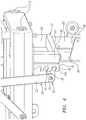
- Foot bar assembly 29may be mounted to frame 10 near its foot end 14.
- Foot bar assembly 29may comprise rod or bar 29a and side links 30 which may be mounted to each end of bar 29a.
- the lower ends of side links 30may be mounted to frame 10, and more specifically to sides 11, 12, via pivot pins 31. Pivot pins 31 preferably rotate so that foot bar assembly 29 may be adjusted as described below.
- Foot bar assembly 29may also include support bar assembly 32, which may in turn include side bars 33 that are mounted to each end of round engagement bar or rod 34 as shown in Figs. 2-3 .
- Side bars 33are preferably pivotally connected to side links 30 as shown to allow for adjustment of foot bar assembly 29.
- engagement bar 34may engage any of the slots 40 of positioning flanges 35, 36 as shown in Figs. 2-4 .
- the slots of each flangeare preferably at the same vertical position of the corresponding slots in the other flange.
- Flanges 35, 36may be mounted to foot end leg assembly 37, which may in turn include vertical legs 66 and horizontal connector leg 67 which serves to connect legs 66.
- the top ends of legs 66may be mounted to the underside of frame 10. More specifically, positioning flanges 35, 36 may each be mounted to a vertical leg 66. Alternatively, flanges 35, 36 may be mounted to the underside of side frame members 11, 12.
- flanges 35, 36each preferably provide a plurality of slots 40 in which engagement bar 34 may be located. Adjusting engagement bar 34 into any pair of positioning slots 40 serves to vary both the horizontal and vertical positions of foot bar 29a to better accommodate users of different anthropomorphic measurements and for proper positioning for the execution of various exercises.
- each positioning slot 40includes a locking feature 38.
- the locking featureenhances safety by preventing engagement bar 34 from becoming dislodged from a pair of positioning slots 40 if foot bar 29a is accidentally pulled toward the head end 13 of reformer 1. If foot bar 29a is pulled toward the head end 13, the configuration of slots 40 preferably provides that engagement bar 34 will move upward until contacting the roof 39 of a respective left and right positioning slot 40. If foot bar 29a is pulled further toward the head end 13, engagement bar 34 is preferably restricted by locking feature 38 which prevents further movement. If the user releases the force on foot bar 29a, slots 40 are configured so that engagement bar 34 preferably returns the bottoms 39a of the respective pair of positioning slots 40.
- foot bar 29ais preferably first pulled slightly toward the head end 13 of reformer 1, thereby raising engagement bar 34 to a position proximate the center of the particular positioning slots 40.
- Support bar assembly 32may then be moved through the mouth of the positioning slots 40 thereby withdrawing engagement bar 34 from its locked position.
- each slot 40amay include a latching surface that is generally located on the bottom portion of slot 40a.
- engagement bar 34is more secured by this latching surface 40b, as opposed to a feature on the top of slot 40a like locking surface 38 near the top of slot 40 in Fig. 4 in the prior embodiment.
- FIG. 29Another aspect of the invention involves the storage of foot bar assembly 29, which is now described with reference to Figs. 2 and 5 .
- such storagefacilitates storage of the overall reformer 1 in a stack of similarly configured reformers. It also helps the reformer to be lifted to be moved.
- the storage aspect described belowalso generally allows foot bar assembly 29, and foot bar 29a, to be lowered if that is otherwise desired.
- reformer 1may include a pair of storage brackets 41 to receive engagement bar 34.
- Brackets 41may be mounted to the underneath of the left and right side frame members 11, 12. Each storage bracket 41 may include a horizontal slot 42 with an opening sized to accept engagement bar 34. Links 33 may pass to the outside of brackets 41 so that bar 34 may extend into horizontal slot 42. Horizontal slot 42 is preferably contiguous with a substantially vertical slot 43 that extends downward.
- engagement bar 34is first released from the pair of positioning slots 40 as described above. Foot bar 29a is then lifted and support bar assembly 32 positioned such that engagement bar 34 may first enter horizontal slots 42, and may then be dropped into vertical slot 43 to a storage position. Engagement bar 34 may then generally be held in place by the sides of vertical slot 43, i.e., foot end wall 44 and head end wall 45.
- foot bar parallel side links 30When in this storage position, foot bar parallel side links 30 may be substantially parallel to the ground and are preferably within the vertical profile of sides 11, 12 of frame 10. Also when in this storage position, foot bar 29a is preferably located beyond the foot end 14 of frame 10 and also positioned within the vertical profile of frame 10.
- the vertical slots 43 in storage brackets 41are preferably sized and positioned to allow the user to use foot bar 29a as a lift handle when lifting reformer 1 for stacking or relocation purposes.
- engagement bar 34is pulled forward against the foot end wall 44 of vertical slot 43.
- the top of foot end wall 44is curved towards head end 13 so as to help secure bar 34.
- the direction of forceis such that engagement bar 34 is pulled into the vertical wall 44 and secured by its curved top section rather than being pulled upward releasing it from slots 43, 42 of storage brackets 41. This allows rod 29a to be used as a lifting handle for the foot end 14 of reformer 1.
- side bars 33 of support bar assembly 32may be lifted, i.e., rotated about the pivot points connecting bars 33 to side bars 30. While side bars 33 are so moved, it is preferred that the rest of foot bar assembly 29 is not moved which allows engagement rod 34 (attached at or near the ends of side bars 33) to move in an arcuate path about those pivot points. In this manner, rod 34 generally moves up and to the left from the bottom of vertical slot 43.
- the head end wall 45 of vertical slot 43has a shape that is the same as or similar to the arcuate path followed by rod 34.
- head end wall 45may be curvilinearly directed up and towards the head end 13. With the head end wall 45 being shaped in this manner, as engagement bar 34 follows its arcuate path, it preferably moves in a path that is coincident to the curve of the head end wall 45, so that bar 34 stays centered in the slot. Engagement bar 34 may then be removed from horizontal slot 42 and foot bar assembly 29 may be set to one of the positions in brackets 35, 36.
- reformer 1will be used by people of different heights and having different leg lengths. Varying the start position of platform 16 relative to foot bar 29a helps accommodate users of various anthropomorphic measurements as well as various exercise patterns. For example, it may be desired to adjust the starting position of platform 16 further away from foot bar 29a for users having longer legs, so that when in the starting position, the user's legs will not be unduly folded. As another example, it may be desired to adjust the starting position of platform 16 to be closer to foot bar 29a for shorter-legged users so that they may perform exercises with a full range of motion.
- reformer 1preferably includes a position block 46 located in the inwardly facing channel 15 side 12. Only one position block 46 is generally necessary for this aspect of the invention, and block 46 may alternately be located on side 11. Generally, block 46 limits the movement of platform 16 by stopping vertical roller 17 from advancing closer to the foot end 14.
- positioning block 46is preferably placed in any one of holes 47 located in the right side frame member 12. Though four holes 47 are shown (with one of the holes receiving block 46), another number of holes 47 may be used. In general, block 46 may be placed in a hole 47 closer to the foot end 14 of reformer 1 for shorter users or for certain exercises. Similarly, block 46 may be placed in a hole farther away from the foot end 14 for taller users and other types of exercises.
- positioning block 46may include engagement pin 48 overmolded with a cylinder 49 of rubber or similar like material. Other methods may be used to manufacture pin 48 and cylinder 49. Engagement pin 48 is preferably sized so as to snugly fit within any of the holes 47.
- side rails 11, 12may comprise extruded aluminum members that are contiguous with their respective inward channels 15.
- each side rail member 11, 12may be hollow inside, and it is preferred that a wood block (not shown) with a commensurate hole pattern be assembled inside this cavity (not shown) so that the hole patterns of the wood block and channel 15 match up to receive pin 48 of block 46.
- the wood block in the side member cavityprovides additional support for the engagement pin 48 by providing a deeper hole to receive such pin 48 (as opposed to only being received by a hole 47 having a thickness equal to the aluminum extruded wall. This insures that block 46 is not dislodged when contacted by the front right wheel 17 of the support platform. 16, as shown in Fig. 2 .
- the starting tension of springs 24may vary. For example, if the starting platform position is moved to the position closest to foot end 14, springs 24 may have slack or very little tension. And springs 24 may experience more tension only after platform 16 is moved away from the foot end 14 by the user. However, if the starting position of platform 16 is located farther from foot end 14, springs 24 may have tension before the user pushes platform 16 away from the foot end.
- the position of anchor bar assembly 27may be adjusted commensurate with the start position of support platform 16. This preferably results in a consistent distance between anchor bar 27 and support platform 16. And if the starting position of platform 16 is moved again, the position of anchor bar assembly 27 may be moved a commensurate amount. Furthermore, if for some reason it is desired to adjust the starting tension of springs 24 for a given platform 16 starting position, anchor bar 27 may be adjusted regardless of the starting position of platform 16 to provide more or less starting tension if desired for a particular exericse.
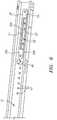
- Anchor bar assembly 27engages positioning plates 28 that are mounted in the inward facing channels 15 of side members 11, 12 of frame 10.
- plates 28provide one or more functional locations at which anchor bar assembly 27 may be mounted to frame 10. The interaction between anchor bar assembly 27 and plates 28 is discussed in more detail below.
- Anchor bar assembly 27may include bar 50 with eyebolts 51 attached thereto. Eyebolts 51 are preferably spaced to correspond to the spacing between springs 24 as they are attached to platform 16. In a preferred embodiment, one or more resistance elements 24 may be selectively attached to eyebolts 51 at their second ends 26. Reformer 1 preferably includes springs 24 having different resistances so that they may be attached to eyebolts 51 in different combinations to provide different overall resistances. Which springs are attached to eyebolts 51 may depend on the user and the desired exercise pattern.
- anchor bar assembly 27includes brackets 61 that are attached to the ends of bar 50 and that may include outwardly facing U-channels 52.
- U-Channels 52may include top and bottom flanges 52a, 52b that may be horizontal and that may be connected by vertical wall 52c.
- U-channels 52are preferably configured so that they generally surround anchor bar positioning plates 28. More specifically, the distance between the top and bottom flanges 52a, 52b is generally larger than the vertical dimension of plates 28. However, as discussed below, the distance between flanges 52a, 52b is preferably not significantly larger than the vertical dimension of plates 28 to prevent or limit rotation of bar 50, which might otherwise occur when, e.g., no springs are attached to eyebolts 51.
- the relative dimensions of brackets 61 in relation to plates 28also allow efficient adjustment of anchor bar assembly 27 in relation to plates 28, in that excessive play therebetween may be avoided.
- Anchor bar assembly 27preferably includes rollers 53 that are rotatably mounted on axles 54 that extend between top and bottom flanges 52a, 52b. Rollers 53 are preferably sized so that their diameter fits within the u-channel 52. Rollers 53 are also preferably positioned so that they are in close proximity to the face 55 of the positioning plate 28. In this manner, rollers 53 may rotate against positioning plates 28 when anchor bar assembly 27 is adjusted as discussed below. Anchor bar assembly 27 also preferably includes positioning pins 56 that extend from each end of bar 50 and into u-channel 52.
- Anchor bar positioning plates 28are mounted to each side frame member 11, 12 and include horizontal slot 57 and one or more vertical slots 58. Plates 28 are preferably mounted at the same relative location on each of side members 11, 12 so that horizontal and vertical slots 57, 58 correspond. Positioning pins 56 are sized to snugly fit within the horizontal and vertical slots 57, 58. When pins 56 are located in corresponding vertical slots 58, anchor bar assembly 27 is located at a functional position (or mounting location). Pins 56 may travel through horizontal slot 57 to adjust to another functional location associated with another pair of corresponding vertical slots 57.
- Anchor bar assembly 27may reside in one or more different functional positions, i.e., when it has been adjusted to the desired position and is thus functional for an exercise to begin.
- positioning pins 56rest at the bottom 58a of corresponding vertical slots 58 on either side of frame 10, and the lower surface 59 of corresponding top flanges 52a rest on or are otherwise in close proximity to the upper edge or top surface 28a of positioning plates 28.
- top flanges 52aprevent or limit any rotation of anchor bar assembly 27 when the resistance elements 24 are removed.
- the weight of anchor bar assembly 27may also help prevent or limit any such rotation. This is in contrast to prior anchor bar designs that are essentially a rod placed into slots on either side of the frame, and which are free to rotate when the springs are removed. (The rotation typically occurs because the weight of the eyebolts or other devices used to attach the springs to the rod causes the rod to rotate so that the eyebolts are facing downward.)
- the prevention or limiting of rotation provided by the current inventionis advantageous because even when all springs 24 are disconnected from rod 50, eyebolts 51 remain in a generally horizontal position making it much easier and efficient to reconnect one or more springs 24 to eyebolts 51. This can typically be done with only one hand. This is in contrast to the situation with prior anchor bars where the rod must first be rotated so that the eyebolts are in a position to receive the springs. This operation is more time consuming and takes two hands.
- the efficiency provided by the anchor bar assembly 27 of the current inventionfacilitates quickly adjusting reformer 1 to accommodate different exercises or different users.
- the anchor bar assembly 27 of the current inventionalso provides a secure engagement between assembly 27 and frame 10 when an exercise is performed.
- the second end 26 of one or more of the resistance elements 24is selectively attached to a respective eye bolt 51 on anchor bar 50.
- Platform 16is moved toward the head end 13 of reformer 1, for example, as the user presses against foot bar 29a.
- resistance elements 24are stretched and the tension caused thereby also serves to pull anchor bar assembly 27 towards the head end 13 of reformer 1. This in turn causes positioning pins 56 to firmly engage the wall 60 of vertical slots 58.
- all of the second ends 26 of resistance elements 24are preferably removed from their respective eyebolts 51.
- Bar 50may then be lifted until the upper surface of the bottom flange 52b of u-Channel 52 contacts the bottom edge 28b of positioning plate 28 and the positioning pins 56 of bar 50 are withdrawn from a respective pair of vertical slots 58.
- pins 56are aligned with horizontal slot 57 and anchor bar assembly 27 may then be horizontally moved toward the foot end 14 or head end 13 until the positioning pins are aligned with the new desired vertical slots 58 and dropped into place.
- Rollers 53 located in each u-channel 52facilitate the smooth adjustment of anchor bar assembly 27.
- rollers 53When anchor bar 27 is being adjusted, if the user (or instructor) applies unequal force causing bar 50 to angle, rollers 53 preferably contact the face 55 of positioning plate 28 to prevent u-channel assemblies 61 from jamming in place.
- anchor bar assembly 27 of the current inventionis that it need not be completely removed from reformer 1 to effect adjustment. In fact, it is preferred that anchor bar assembly 27 generally remains attached to reformer 1 which avoids the risk of losing the anchor bar. This is accomplished by the engagement of the u-shaped brackets 61 with plates 28, as well as horizontal slot 57 having closed ends which may prevent assembly 27 from being removed. This is an advance over prior designs where the anchor bar is a simple rod or other device that must be completely removed from the reformer and then reinserted into another mounting location. In those prior designs, the anchor bar is a completely removable component that may be lost or damaged.
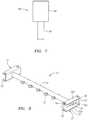
- spring anchor bar assembly 100may include anchor bar 101 which may be similar to anchor bar 50 in the previous embodiment. Eyebolts or other devices (not shown) to engage springs 24 may be attached to bar 101 . These devices may be similar to eyebolts 51 of the previous embodiment.
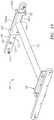
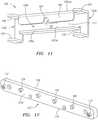
- Brackets 102are attached to either end of anchor bar 101 as shown in Fig. 10 . The attachment may be by welding or other mechanical attachment. A more detailed view of bracket 102 is shown in Fig. 11 . Brackets 102 may include a central portion 102a and u-shaped flanges 102b at its ends. Brackets 102 may also include an outer wall 102aa that may contiguously run from central portion 102a to and through end flange portions 102b. Each flange 102b preferably includes upper flange 104 and lower flange 105. Central portion 102a may include downward flange 106 and horizontal flange 106a.
- Downward flange 106may be connected to wall 102aa by a section 102aaa.
- the distance between wall 102aa and downward flange 106may be defined by the length of section 102aaa, and may be the substantially the same as the length of flange 106a.
- the outward face of flange 106 and the edge of flange 106amay generally reside in the same plane, and the lower edge of downward flange 106 and the end of flange 106a are generally aligned, with the space between them forming slot 111.
- Brackets 102may comprise a contiguous piece of sheet metal that undergoes several bending operations to result in the bracket 102 shown in the figures.
- bracket 102may comprise several components fastened together.
- brackets 102engage positioning plates 103 which are mounted on side members 11, 12 of reformer 1. Positioning plates 103 may be mounted to side members 11, 12 by fastening screws 112 or by other suitable means. Plates 103 include an upper edge or surface 109, a bottom edge or surface 110, an inward face 103a and one or more pins 108.
- flanges 104 and 105 shown in Fig. 11generally engage or surround the anchor bar positioning plate 103. More particularly, flanges 104 engage or are located above the upper surface 109 of plate 103, and flanges 105 engage or are located below the lower surface 110 of plate 103.
- the flanges 106 and 106aand more particularly, the outward face of flange 106 and the outward face or edge of flange 106a, or in close proximity to the face 103a of each positioning plate 103 mounted to the left and right frame members 11, 12.
- the engagement between flanges 106, 106a and their respective plate faces 103aprevents or limits anchor bar assembly 100 from racking or otherwise becoming angled in relation to side frame members 11, 12 when assembly 100 is moved along the length of reformer 1 to adjust the starting spring tension. This engagement preferably enables the anchor bar assembly 100 to be adjusted between positions more smoothly and avoids binding.
- Flange 106preferably includes slot 107 which may engage any of the one or more pins 108 attached to positioning plate 103.
- the top of slot 107bottoms against or otherwise engages a pin 108 in positioning plate 103.
- the two flanges 104are in close proximity to the top edge 109 of the positioning plate. If anchor bar assembly 100 rotates even slightly when in a functional position, one or the other or both of flanges 104 will contact the top edge 109 of positioning plate 103 and prohibit further rotation.
- Anchor bar 101may then be lifted up so that slot 107 disengages pin 108.
- bottom flanges 105preferably contact bottom edge 110 of positioning plate 103 thereby limiting the height of the lift, which also serves to align pins 108 with horizontal slot 111 between flanges 106 and 106a. Accordingly, it is desired that the distance between flanges 104 and 105 be configured to provide this alignment.
- Anchor bar assembly 100may then be moved to the head or foot end of reformer 1, with the positioning pins passing through slot 111 as indicated. Anchor bar assembly 100 may then be moved to the desired location and dropped down over the desired pin 108. At this time, pin 108 again engages slot 107 and anchor bar assembly 100 is in a functional position.
- Positioning plates 103may also include stop pins 112 to ensure that anchor bar assembly 100 is not accidently slid past the edge of the positioning plate. This again provides the benefit over prior designs involving anchor bars that are completely removed from the reformer as discussed above.
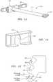
- Assembly 121may be similar to the embodiment described in connection with Figs. 6 and 8 in that it includes rod 123 with eyebolts attached thereto. Furthermore, the ends of rod 123 may be fitted with brackets 127 which may generally comprise the same u-shape as discussed above. But as shown in Figs. 13-14 , the ends of rod 123 may be fitted with flanges 125 at each end. These flanges may be welded to the ends of rod 123 and brackets 127 attached thereto by any suitable mechanical means.
- anchor bar assembly 121functions similar to the other embodiments in that they are generally not removed from reformer 1 and prevent or limit rotation of bar 123. Brackets 127 may also include rollers similar to those discussed above.
- An advantage of this embodimentrelates to the assembly of the overall reformer 1. That is, the rod 123 along with attached flanges 125 may be positioned between the positioning plates 28. Then brackets 127 may be slipped onto flanges 125 by virtue of the slot 129 in each bracket 127, and may then be assembled. This preferably eases overall assembly.
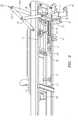
- a pair of vertically adjustable pulleys 62may be mounted to redirect the path of flexible ropes (not shown).
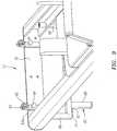
- Pulleys 62may be mounted on vertical posts 63 that preferably move between an elevated functional position, and a retracted storage position as shown in Fig. 9 .
- posts 63may slide up and down within housing 63a.
- Posts 63may include several holes which correspond to the raised functional position and lowered storage position.
- Pulleys 62may be locked in their elevated functional position with lock pins 64 extending into a hole located relatively low on post 63.
- Posts 63may also be restrained in their storage by gravity and friction, or by lock pin 64 engaging another hole located higher up on post 63.
- Reformer 1may generally be supported by head support leg assembly 65 and foot support leg assembly 37 which are secured to the head and foot ends, respectively, and which may extend downwardly from the side frame members 11, 12.
- Each leg assembly 65, 37may include a pair of vertical upper elements 66, horizontal element 67, and two vertical lower leg elements 68.
- the positioning plates 35, 36 for the foot bar support bar 32 or engagement bar 34may be attached to the vertical upper elements 66 of the foot support leg assembly 37 as noted above.
- Rollers 69may also be attached to lower leg elements 68 on the foot end assembly 37 for transporting the table.
- the exercise table 1may be easily rolled between desired locations by lifting the head end 13 of table 1 and rolling it along the ground to a desired final location.
- the vertical lower elements 68are configured to fit within the open area 3 between side frame members 11, 12 by locating the legs 68 of each of the head and foot assemblies 65, 37 at a distance which is less than the distance between side frame members 11, 12. This allows legs 68 to pass through and between side frame members 11, 12. Furthermore, both foot bar assembly 29a and pulley assemblies 65 may be placed in their storage positions.
- the reformer to be placed on top of another reformermay first be lifted by foot bar 29a at the foot end 14 and by head end plate 70 (as shown in Fig. 9 ) at the head end 13. Because foot bar assembly 29 is preferably secured when in the storage position as discussed above, foot bar 29a may serve as a lifting handle.
- the upper reformermay then be placed over the lower reformer by locating support legs 68 of the upper reformer so that they are aligned with the support leg assemblies 37, 65 of the lower reformer, and the upper reformer may then be lowered until stacking bumpers 71 (as shown in Fig. 9 ) located on the underside of the horizontal portion of each leg come to rest on the top of the side frame components 11, 12 of the lower reformer.
- the platforms 16may be securely positioned so that they also do not interfere with the legs 68 of an upper reformer extending down into the open spaces 3 of the lower reformer.
- block 46may be inserted into the hole 47 closest to head end 13, and anchor bar assembly 27 is positioned in the slot 58 that is closest to head end 13.
- At least one resistance member 24may then be attached to rod 50 or 101. This serves to maintain an open space 3 between the foot end of the platform 16 and foot end 14 of frame 10 so that the legs 68 of the rear leg assembly 37 may protrude down into that open space 3.
- the exercise table 1 of the current inventionmay also be vertically stored.
- support platform 16may first be placed in a preferred position by inserting positioning block 46 in the positioning hole 47 closest to foot frame member 14, and anchor bar 50 may be placed in the vertical positioning slot 58 in the anchor bar positioning plate 28 that is also closest to foot member 14. At least one resistance member 24 may then be attached to rod 50 or 101.
- the foot bar support bar assembly 32may then be placed in the highest positioning slot 40 of positioning plates 35, 36.
- the reformer 1may then be then lifted from head component 13 until vertical storage bumpers 72 (as shown in Fig. 4 ) contact the flooring surface. Reformer 1 may then rest on the two transport wheels 69 and the two vertical storage bumpers 72. Because carriage 16 is located nearer the foot end 14 of the reformer, the overall center of gravity is lower which helps tilting reformer 1, and also makes it more secure in its vertical storage position. Preferably the center of gravity in the vertical storage position is located between the line connecting the contact points of the two transport wheels and the line connecting the contact point of the two storage bumpers 72.
- the reformer 1when in this vertical storage position, the reformer 1 is preferably tilted slightly toward the person who had tilted it up towards vertical. This provides stability during the tilting phase as opposed to other reformers which ultimately tilt away from the person tilting it, i.e., it is problematic to tilt a reformer upward knowing that its weight will be beyond true vertical when reaching its storage position.
Landscapes
- Health & Medical Sciences (AREA)
- General Health & Medical Sciences (AREA)
- Physical Education & Sports Medicine (AREA)
- Orthopedic Medicine & Surgery (AREA)
- Life Sciences & Earth Sciences (AREA)
- Biophysics (AREA)
- Engineering & Computer Science (AREA)
- Biomedical Technology (AREA)
- Neurology (AREA)
- Pulmonology (AREA)
- Cardiology (AREA)
- Vascular Medicine (AREA)
- Rehabilitation Tools (AREA)
Description
- The current invention generally relates to exercise equipment, including an improved exercise table or "reformer" with improved adjustability and/or storage capability to be used in pilates type exercises.
- Exercise and other efforts to improve physical fitness and general health have become increasing popular. Many different forms of exercise and fitness routines have come into being such as aerobics, weight training, yoga and more recently, exercises related to pilates, gyrotonics and the like. Pilates has become increasingly popular since it provides a unique blend of training to improve flexibility, strength and aerobic stamina.
- Various forms of exercise may be performed without the use of any equipment, while other forms may require basic or specialized equipment. Many exercises associated with pilates involve an exercise table that is commonly referred to as a reformer. A reformer typically includes a frame which supports a platform or carriage that may move back and forth along the frame's length. A user may lie, kneel or assume some other body position on the platform. Springs are typically connected to the platform and extend to the frame where one or more of the springs are typically attached to adjust the resistance to be experienced by the user. The user may press against the frame with his or her hands or feet, and thereby move the platform away from the end of the frame against the spring's resistance. The bias of the springs will then tend to move the carriage so that it returns to its original position, and the user may exert resistance to control this return motion. The carriage thus moves back and forth along the length of the frame.
- Typical reformers include a foot bar which extends upward from the foot end of the frame and against which the user may apply pressure to move the platform away from the foot end against the spring's resistance. Typical reformers also include handles attached to ropes which the user may also pull to move the platform against the spring's resistance.
- Many pilates studios have one or more reformers that are used by different people. Sometimes, a given reformer will be used by numerous people in a given day. The height and body proportions, such as leg and torso lengths, may vary between users, sometimes significantly.
- Accordingly, there exists a need to adjust the start position of the spring resisted platform or carriage relative to the foot bar so that users of all heights and leg lengths may exercise in an appropriate and safe range of motion. For example, if a user with long legs were forced to lie down on the carriage in the same starting position as a user with short legs, the legs of the taller user may be unsafely cramped at the starting position.
- When the start position of the carriage is changed, that typically also changes the starting resistance of the springs connecting the platform to the frame. For example, where the carriage starts at a position near the foot end of the frame, the springs may hang loosely and provide no resistance. Alternatively, if the carriage starts at a position further away from the foot end of the frame, the springs may already be taut and therefore provide resistance.
- Accordingly, there is also a need for a means to adjust the start position of the resistance springs, preferably commensurate with the start position of the carriage. In this manner, users of various heights and with different leg lengths may experience the same or similar start tension and resulting force curves for whatever combination of spring(s) are attached to the frame as the springs are extended through movement of the carriage.
- In prior reformers, all the springs are typically attached at one of their ends to the platform underside. One or more of the other ends of the springs are typically attached to a bar that is in turn removably attached to the frame. Sometimes, this bar is referred to as an anchor bar. To adjust the start position of whatever spring(s) are attached to the anchor bar (and thus to the frame), the anchor bar is typically moved between several mounting or functional locations on the frame, such as slots. Several types of mechanisms have been used to adjust the spring anchor bar on pilates equipment, but they typically face several drawbacks.
- As an example, certain adjustable anchor bars may be generally cumbersome to adjust between functional locations on the frame because they need to be pulled out of angled slots or the like. This may be cumbersome and result in less than optimum performance where quick adjustment of the anchor bar functional location is desired.
- As another example, certain adjustable anchor bars must be completely removed from the reformer when adjusting their functional location. As such, they are loose parts which may be lost, leading to inconvenience and extra expense. Accordingly, there is a need for an improved adjustable anchor bar mechanism which addresses the foregoing issues associated with adjusting its functional location.
- As noted above, one or more the springs are typically attached to the anchor bar (and thus to the frame) to vary the resistance experienced by the user. Many adjustable anchor bars are simply round rods that have a number of eyebolts attached thereto. The spring(s) are selectively attached to the eyebolts to vary the resistance to be experienced by the user. However, because these anchor rods are round, they may rotate within the functional slot locations. And oftentimes when the number of springs attached to the anchor bar is adjusted, there are no spring(s) attached to the eyebolts. When this happens, the weight of the eyebolts typically causes the rod to rotate so that the eyebolts are pointing downward. Because of this, when the user or instructor wants to re-attach one or more springs to the rod, they must first rotate the rod in the other direction so that the eyebolts are pointing toward the carriage, and then re-attach the spring(s). This is a cumbersome operation and typically requires two hands, and may result in less than optimum performance where quick adjustment in the number of springs attached to the anchor bar is desired
- Many pilates studios are relatively small. In such studios, space may be at a premium, especially if there are a number of reformers in the studio. For example, a pilates studio may provide reformer instruction but may also provide mat or other types of instruction requiring space. Accordingly, a studio may need to move the reformers to provide space for other instruction. Also, where the reformer is intended for home use, the user may want to store the reformer after its use.
- Accordingly, there exists a need to provide improved storage capability of reformers. Where reformers may be stored by stacking them on top of each other, there exists a need for an improved manner to pick up the reformer to place it on top of another, as well as the manner in which stacked reformers engage each other. Where reformers may be vertically stored, there exists a need for an improved manner to tilt the reformer from its horizontal functional position to a vertical storage position, as well as improvement in the stability of the reformer once it is in a vertical position.
WO 00/23148 A1 - The present invention provides a reformer as defined in claim 1. Further embodiments of the present invention are defined in the dependent claims.
- The exercise table, or reformer, of the current invention addresses the foregoing and other issues.
- In one aspect of the current invention, an adjustable foot bar assembly that includes a storage position is described.
- In another aspect of the current invention, an adjustable foot bar may be securely positioned in a storage position. The adjustable foot bar may also be used as a lift handle to help pick up the reformer for stackable storage.
- In another aspect of the current invention, an adjustable anchor bar assembly that may be quickly adjusted from one mounting location to another is described. The anchor bar assembly preferably remains attached to the reformer so as to avoid getting lost.
- In another aspect of the current invention the rotation of the anchor bar assembly is prevented or limited when there are no springs attached thereto.
- In another aspect of the current invention, a mechanism to adjust the starting position of the platform or carriage is described.
- In another aspect of the current invention, the adjustability of the foregoing in combination is described. That is, the starting position of the carriage and the starting position of spring resistance may be adjusted in connection with each other or separately.
- In another aspect of the invention, storage of multiple reformers is described, including nestable stacking and vertical storage, as well as improvements in the manner in which reformers are so stored.
- Other aspects, features and details of the present invention can be more completely understood by reference to the following detailed description of the preferred embodiment taken in conjunction with the drawings and appended claims.
Figure 1 is a perspective view of an exercise table.Figure 2 is an underneath perspective view of an exercise table.Figure 3 is a top perspective view of an exercise table.Figure 4 is a detailed view of a foot end portion of an exercise table including an adjustable foot bar assembly.Figure 5 is a side view of an exercise table showing components of an adjustable foot bar assembly.Figure 6 is detailed view of a components associated with adjustment of the starting position of the carriage and adjustment of the anchor bar assembly.Figure 7 is a side view of an adjustment block.Figure 8 is a perspective view of an anchor bar assembly.Figure 9 is a perspective view showing a head end of a reformer including pulley assemblies.Figure 10 is a perspective view of an alternate embodiment of an anchor bar assembly.Figure 11 is a perspective view of a bracket for an anchor bar assembly.Figure 12 is a perspective view of a positioning plate for an anchor bar assembly.Figure 13 is a perspective view of an alternate embodiment of an anchor bar assembly.Figure 14 is a perspective view of an end bracket.Figure 15 is a side view of a positioning plate.- Embodiments of the current invention will now be described with reference to the drawings. To facilitate the description, any reference numeral representing an element in one figure will represent the same element in any other figure. The current invention is not limited to the specific description below, as one skilled in the art will appreciate that variations may occur to the subject matter described below while still being within the scope and content of the current invention. The description below makes reference to reformers, but one skilled in the art will recognize that the current invention is suitable for use with other types of exercise equipment, such as equipment wherein the starting point of spring resistance is desired to be moved.
- Referring to
Fig. 1 , an exercise table or reformer 1 typically used for certain pilates exercises is shown. Table 1 includesframe 10 that may be rectangular and extend about the periphery of table 1, thereby defining anopen interior 3.Frame 10 may include side members, a head member and a foot member. More particularly,frame 10 may include a longitudinally extendingright side member 11, a longitudinally extendingleft side member 12, ahead member 13 and afoot member 14. Theframe members - Exercise table or reformer 1 also includes a
platform 16 on which the user lies or assumes some other body position, and which may longitudinally move back and forth along the sides offrame 10. To this end,side frame members channels 15 as shown inFigs. 1 and2 , which may define tracks in which vertical rollers may move.Channels 15 may comprise inward facing u-shaped flanges that include a bottom horizontal flange, a vertical wall attached to theside member channel 15 may be contiguous with aside member channel 15 may be separate fromside member Vertical rollers 17 may engage the bottom horizontal flange and slide in thechannel 15.Vertical rollers 17 may be attached toplatform 16 by a bracket or other suitable device, and may supportplatform 16 at it moves along the length offrame 10 as shown inFig. 2 . As also shown inFig. 2 ,horizontal rollers 18 contact the vertical wall of theinward channel 15 and may also be attached to andsupport platform 16. Horizontal rollers preferably help ensure thatplatform 16 moves in a straight line as it longitudinally articulates back and forth alongframe 10.Platform 16 is now more specifically described with reference toFig. 3 .Platform 16 preferably includes a rigidstructural panel 19 of generally rectangular configuration.Platform 16 is preferably designed to support the weight of the user and is sized to accommodate the trunks of larger users.Platform 16 preferably includessupport cushion 20 to provide comfort to the user when he or she lies or kneels on it, or assumes some other body position thereon.Cushion 20 may be attached topanel 19 in any suitable manner.Platform 16 andpanel 19 may include a head end and foot end that correspond to thehead end 13 andfoot end 14 offrame 10. At the head end of thepanel 19, an adjustableheight head support 21 may be centrally positioned for supporting a user's head.Head support 21 may be arranged flat (as shown) or tilted up to place the user's neck in predetermined angles. A pair ofshoulder blocks 22 may be located on either side ofhead support 21.Blocks 22 may support the shoulders or other body parts such as feet, hands or knees of the user depending upon the exercise being performed.- Referring to
Figs. 2-3 , rope locks 23 may be attached to the underside ofpanel 19. Rope locks 23 may be positioned on each side ofshoulder blocks 23, and their purpose is described later. - Referring again to
Fig. 2 , a plurality ofresistance members 24 may be attached toplatform 16 at their first ends 25. The current invention also contemplates using asingle resistance member 24. In one embodiment,resistance members 24 comprise coil springs that are attached to the underneath ofpanel 19. The second ends 26 ofsprings 24 may be selectively attached to anchorbar assembly 27, so that different spring resistances may be experienced by the user. InFig. 3 , second ends 26 are not shown attached to anchor bar assembly because in practice, the number of springs attached to anchorbar assembly 27 will vary according to the strength of the user and the exercise being performed. In any event, and as shown inFig. 8 ,anchor bar assembly 27 may include a bar orrod 50 and a plurality ofeyebolts 51 attached thereto. The second ends 26 of one ormore springs 24 may be selectively attached toeyebolts 51 to suit the exercise and user. It should be noted that other suitable devices for attachingsprings 24 to anchorbar assembly 27 may be used. Anchor bar assembly 27 may include anchorbar positioning devices 61 that are attached to either end ofbar 50 and that serve to coupleanchor bar assembly 27 to frame 10. In a preferred embodiment,positioning devices 61 may comprise u-channels 52 that engageframe 10 at different mounting, or functional, locations as explained later. In this manner, the start position of spring tension may be adjusted. As discussed in more detail below, theanchor bar assembly 27 of the current invention preferably allows for the quick and efficient adjustment of the start position of spring tension.- While
anchor bar assembly 27 may move relative to frame 10 between different functional locations, it is preferred thatassembly 27 generally remain attached toframe 10. In a preferred embodiment, this occurs by virtue of thepositioning devices 61 comprising u-shaped channels that surround positioning plates attached to the frame as discussed below. This is advantageous since it avoids theanchor bar 27 from becoming a loose component that may be lost or damaged. It is also preferred that thepositioning devices 61 prevent or limit the amount of rotation that anchor bar assembly may undergo when no springs are attached to it. In a preferred embodiment, this occurs by virtue of the length ofpositioning devices 61 as they engage the positioning brackets attached to frame 10 as discussed later. This is advantageous because it simplifies changing the spring attached by the user or instructor, i.e.,rod 50 will not rotate so thateyebolts 51 are facing downward. Instead,eyebolts 51 remain generally horizontal so that selection of springs may be a one-hand operation. - With the reformer configuration described above, it will be appreciated that the
support platform 16 may move back and forth in theopen area 3 offrame 10 by rolling along theside frame members foot end 14 toward thehead end 13 offrame 10 against the bias ofresistance elements 24, which will automatically returnplatform 16 toward thefoot end 14 when the counter bias force (such as the user pushing his or her legs) is released or lessened. - An aspect of the current invention involving a foot bar assembly for an exercise table is now described in more detail with reference to
Figs. 2-4 Foot bar assembly 29 may be mounted to frame 10 near itsfoot end 14.Foot bar assembly 29 may comprise rod orbar 29a andside links 30 which may be mounted to each end ofbar 29a. The lower ends ofside links 30 may be mounted to frame 10, and more specifically tosides foot bar assembly 29 may be adjusted as described below. Foot bar assembly 29 may also includesupport bar assembly 32, which may in turn include side bars 33 that are mounted to each end of round engagement bar orrod 34 as shown inFigs. 2-3 . Side bars 33 are preferably pivotally connected toside links 30 as shown to allow for adjustment offoot bar assembly 29.- To facilitate adjustment of
foot bar assembly 29,engagement bar 34 may engage any of the slots 40 ofpositioning flanges Figs. 2-4 . The slots of each flange are preferably at the same vertical position of the corresponding slots in the other flange.Flanges end leg assembly 37, which may in turn includevertical legs 66 andhorizontal connector leg 67 which serves to connectlegs 66. The top ends oflegs 66 may be mounted to the underside offrame 10. More specifically,positioning flanges vertical leg 66. Alternatively,flanges side frame members - As noted above,
flanges engagement bar 34 may be located. Adjustingengagement bar 34 into any pair of positioning slots 40 serves to vary both the horizontal and vertical positions offoot bar 29a to better accommodate users of different anthropomorphic measurements and for proper positioning for the execution of various exercises. - It is preferred that each positioning slot 40 includes a
locking feature 38. The locking feature enhances safety by preventingengagement bar 34 from becoming dislodged from a pair of positioning slots 40 iffoot bar 29a is accidentally pulled toward thehead end 13 of reformer 1. Iffoot bar 29a is pulled toward thehead end 13, the configuration of slots 40 preferably provides thatengagement bar 34 will move upward until contacting theroof 39 of a respective left and right positioning slot 40. Iffoot bar 29a is pulled further toward thehead end 13,engagement bar 34 is preferably restricted by lockingfeature 38 which prevents further movement. If the user releases the force onfoot bar 29a, slots 40 are configured so thatengagement bar 34 preferably returns thebottoms 39a of the respective pair of positioning slots 40. - To release
engagement bar 34 from a pair of slots 40,foot bar 29a is preferably first pulled slightly toward thehead end 13 of reformer 1, thereby raisingengagement bar 34 to a position proximate the center of the particular positioning slots 40.Support bar assembly 32 may then be moved through the mouth of the positioning slots 40 thereby withdrawingengagement bar 34 from its locked position. - Referring to
Fig. 15 , an alternate embodiment for positioningplate engagement slots 40a preferably further guard againstengagement bar 34 accidentally discharging therefrom. As shown, eachslot 40a may include a latching surface that is generally located on the bottom portion ofslot 40a. In this embodiment,engagement bar 34 is more secured by this latchingsurface 40b, as opposed to a feature on the top ofslot 40a like lockingsurface 38 near the top of slot 40 inFig. 4 in the prior embodiment. - Another aspect of the invention involves the storage of
foot bar assembly 29, which is now described with reference toFigs. 2 and5 . As described in more detail later, such storage facilitates storage of the overall reformer 1 in a stack of similarly configured reformers. It also helps the reformer to be lifted to be moved. The storage aspect described below also generally allowsfoot bar assembly 29, andfoot bar 29a, to be lowered if that is otherwise desired. For this aspect of the current invention, reformer 1 may include a pair ofstorage brackets 41 to receiveengagement bar 34. Brackets 41 may be mounted to the underneath of the left and rightside frame members storage bracket 41 may include ahorizontal slot 42 with an opening sized to acceptengagement bar 34.Links 33 may pass to the outside ofbrackets 41 so thatbar 34 may extend intohorizontal slot 42.Horizontal slot 42 is preferably contiguous with a substantiallyvertical slot 43 that extends downward. To storefoot bar assembly 29,engagement bar 34 is first released from the pair of positioning slots 40 as described above.Foot bar 29a is then lifted andsupport bar assembly 32 positioned such thatengagement bar 34 may first enterhorizontal slots 42, and may then be dropped intovertical slot 43 to a storage position.Engagement bar 34 may then generally be held in place by the sides ofvertical slot 43, i.e.,foot end wall 44 andhead end wall 45.- When in this storage position, foot bar
parallel side links 30 may be substantially parallel to the ground and are preferably within the vertical profile ofsides frame 10. Also when in this storage position,foot bar 29a is preferably located beyond thefoot end 14 offrame 10 and also positioned within the vertical profile offrame 10. - The
vertical slots 43 instorage brackets 41 are preferably sized and positioned to allow the user to usefoot bar 29a as a lift handle when lifting reformer 1 for stacking or relocation purposes. To this end, when the user liftsfoot bar 29a,engagement bar 34 is pulled forward against thefoot end wall 44 ofvertical slot 43. As shown, the top offoot end wall 44 is curved towardshead end 13 so as to help securebar 34. The direction of force is such thatengagement bar 34 is pulled into thevertical wall 44 and secured by its curved top section rather than being pulled upward releasing it fromslots storage brackets 41. This allowsrod 29a to be used as a lifting handle for thefoot end 14 of reformer 1. - In order to remove the
foot bar assembly 29 from this storage position, side bars 33 ofsupport bar assembly 32 may be lifted, i.e., rotated about the pivotpoints connecting bars 33 to side bars 30. While side bars 33 are so moved, it is preferred that the rest offoot bar assembly 29 is not moved which allows engagement rod 34 (attached at or near the ends of side bars 33) to move in an arcuate path about those pivot points. In this manner,rod 34 generally moves up and to the left from the bottom ofvertical slot 43. - To avoid jamming of
engagement bar 34 withbrackets 45, however, it is preferred that thehead end wall 45 ofvertical slot 43 has a shape that is the same as or similar to the arcuate path followed byrod 34. To this end,head end wall 45 may be curvilinearly directed up and towards thehead end 13. With thehead end wall 45 being shaped in this manner, asengagement bar 34 follows its arcuate path, it preferably moves in a path that is coincident to the curve of thehead end wall 45, so thatbar 34 stays centered in the slot.Engagement bar 34 may then be removed fromhorizontal slot 42 andfoot bar assembly 29 may be set to one of the positions inbrackets - An aspect of the current invention relating to adjustment of the starting position of the carriage or
platform 16 relative to footbar 29a is now further described with reference toFigs. 2 ,6 and7 . As noted earlier, reformer 1 will be used by people of different heights and having different leg lengths. Varying the start position ofplatform 16 relative to footbar 29a helps accommodate users of various anthropomorphic measurements as well as various exercise patterns. For example, it may be desired to adjust the starting position ofplatform 16 further away fromfoot bar 29a for users having longer legs, so that when in the starting position, the user's legs will not be unduly folded. As another example, it may be desired to adjust the starting position ofplatform 16 to be closer to footbar 29a for shorter-legged users so that they may perform exercises with a full range of motion. - To vary the start position of
platform 16, reformer 1 preferably includes aposition block 46 located in the inwardly facingchannel 15side 12. Only oneposition block 46 is generally necessary for this aspect of the invention, and block 46 may alternately be located onside 11. Generally, block 46 limits the movement ofplatform 16 by stoppingvertical roller 17 from advancing closer to thefoot end 14. - Before beginning an exercise, positioning
block 46 is preferably placed in any one ofholes 47 located in the rightside frame member 12. Though fourholes 47 are shown (with one of the holes receiving block 46), another number ofholes 47 may be used. In general, block 46 may be placed in ahole 47 closer to thefoot end 14 of reformer 1 for shorter users or for certain exercises. Similarly, block 46 may be placed in a hole farther away from thefoot end 14 for taller users and other types of exercises. - As shown in
Fig. 7 ,positioning block 46 may includeengagement pin 48 overmolded with acylinder 49 of rubber or similar like material. Other methods may be used to manufacturepin 48 andcylinder 49.Engagement pin 48 is preferably sized so as to snugly fit within any of theholes 47. - In a preferred embodiment, side rails 11, 12 may comprise extruded aluminum members that are contiguous with their respective
inward channels 15. In this embodiment, eachside rail member channel 15 match up to receivepin 48 ofblock 46. The wood block in the side member cavity provides additional support for theengagement pin 48 by providing a deeper hole to receive such pin 48 (as opposed to only being received by ahole 47 having a thickness equal to the aluminum extruded wall. This insures thatblock 46 is not dislodged when contacted by the frontright wheel 17 of the support platform. 16, as shown inFig. 2 . - An aspect of the current invention relating to adjusting the starting tension of
springs 24 or other resistance mechanism is now further described with reference toFigs. 2 ,3 ,6 and8 . When moving the starting position ofplatform 16 by adjustingblock 46, the starting tension ofsprings 24 may vary. For example, if the starting platform position is moved to the position closest to footend 14, springs 24 may have slack or very little tension. And springs 24 may experience more tension only afterplatform 16 is moved away from thefoot end 14 by the user. However, if the starting position ofplatform 16 is located farther fromfoot end 14, springs 24 may have tension before the user pushesplatform 16 away from the foot end. - In order to adjust the starting tension of
resistance elements 24 so that the starting tension is the same or similar regardless of the start position ofsupport platform 16, the position ofanchor bar assembly 27 may be adjusted commensurate with the start position ofsupport platform 16. This preferably results in a consistent distance betweenanchor bar 27 andsupport platform 16. And if the starting position ofplatform 16 is moved again, the position ofanchor bar assembly 27 may be moved a commensurate amount. Furthermore, if for some reason it is desired to adjust the starting tension ofsprings 24 for a givenplatform 16 starting position,anchor bar 27 may be adjusted regardless of the starting position ofplatform 16 to provide more or less starting tension if desired for a particular exericse. Anchor bar assembly 27 engagespositioning plates 28 that are mounted in theinward facing channels 15 ofside members frame 10. Generally,plates 28 provide one or more functional locations at which anchorbar assembly 27 may be mounted toframe 10. The interaction betweenanchor bar assembly 27 andplates 28 is discussed in more detail below.Anchor bar assembly 27 may includebar 50 witheyebolts 51 attached thereto.Eyebolts 51 are preferably spaced to correspond to the spacing betweensprings 24 as they are attached toplatform 16. In a preferred embodiment, one ormore resistance elements 24 may be selectively attached toeyebolts 51 at their second ends 26. Reformer 1 preferably includessprings 24 having different resistances so that they may be attached toeyebolts 51 in different combinations to provide different overall resistances. Which springs are attached toeyebolts 51 may depend on the user and the desired exercise pattern.- As noted above
anchor bar assembly 27 includesbrackets 61 that are attached to the ends ofbar 50 and that may include outwardly facing U-channels 52. U-Channels 52 may include top andbottom flanges vertical wall 52c. U-channels 52 are preferably configured so that they generally surround anchorbar positioning plates 28. More specifically, the distance between the top andbottom flanges plates 28. However, as discussed below, the distance betweenflanges plates 28 to prevent or limit rotation ofbar 50, which might otherwise occur when, e.g., no springs are attached to eyebolts 51. The relative dimensions ofbrackets 61 in relation toplates 28 also allow efficient adjustment ofanchor bar assembly 27 in relation toplates 28, in that excessive play therebetween may be avoided. Anchor bar assembly 27 preferably includesrollers 53 that are rotatably mounted onaxles 54 that extend between top andbottom flanges Rollers 53 are preferably sized so that their diameter fits within the u-channel 52.Rollers 53 are also preferably positioned so that they are in close proximity to theface 55 of thepositioning plate 28. In this manner,rollers 53 may rotate againstpositioning plates 28 whenanchor bar assembly 27 is adjusted as discussed below.Anchor bar assembly 27 also preferably includes positioning pins 56 that extend from each end ofbar 50 and intou-channel 52.- Anchor
bar positioning plates 28 are mounted to eachside frame member horizontal slot 57 and one or morevertical slots 58.Plates 28 are preferably mounted at the same relative location on each ofside members vertical slots vertical slots vertical slots 58,anchor bar assembly 27 is located at a functional position (or mounting location).Pins 56 may travel throughhorizontal slot 57 to adjust to another functional location associated with another pair of correspondingvertical slots 57. - The interaction between
anchor bar assembly 27 andpositioning plates 28 is now further described.Anchor bar assembly 27 may reside in one or more different functional positions, i.e., when it has been adjusted to the desired position and is thus functional for an exercise to begin. When in a functional position, positioning pins 56 rest at the bottom 58a of correspondingvertical slots 58 on either side offrame 10, and thelower surface 59 of correspondingtop flanges 52a rest on or are otherwise in close proximity to the upper edge ortop surface 28a ofpositioning plates 28. - With this configuration, the
upper wall 59 oftop flanges 52a prevent or limit any rotation ofanchor bar assembly 27 when theresistance elements 24 are removed. The weight ofanchor bar assembly 27 may also help prevent or limit any such rotation. This is in contrast to prior anchor bar designs that are essentially a rod placed into slots on either side of the frame, and which are free to rotate when the springs are removed. (The rotation typically occurs because the weight of the eyebolts or other devices used to attach the springs to the rod causes the rod to rotate so that the eyebolts are facing downward.) - The prevention or limiting of rotation provided by the current invention is advantageous because even when all springs 24 are disconnected from
rod 50,eyebolts 51 remain in a generally horizontal position making it much easier and efficient to reconnect one ormore springs 24 toeyebolts 51. This can typically be done with only one hand. This is in contrast to the situation with prior anchor bars where the rod must first be rotated so that the eyebolts are in a position to receive the springs. This operation is more time consuming and takes two hands. The efficiency provided by theanchor bar assembly 27 of the current invention facilitates quickly adjusting reformer 1 to accommodate different exercises or different users. - The
anchor bar assembly 27 of the current invention also provides a secure engagement betweenassembly 27 andframe 10 when an exercise is performed. During exercise, thesecond end 26 of one or more of theresistance elements 24 is selectively attached to arespective eye bolt 51 onanchor bar 50.Platform 16 is moved toward thehead end 13 of reformer 1, for example, as the user presses againstfoot bar 29a. As this occurs,resistance elements 24 are stretched and the tension caused thereby also serves to pullanchor bar assembly 27 towards thehead end 13 of reformer 1. This in turn causes positioning pins 56 to firmly engage thewall 60 ofvertical slots 58. - To adjust the position of
anchor bar assembly 27, all of the second ends 26 ofresistance elements 24 are preferably removed from theirrespective eyebolts 51.Bar 50 may then be lifted until the upper surface of thebottom flange 52b of u-Channel 52 contacts thebottom edge 28b ofpositioning plate 28 and the positioning pins 56 ofbar 50 are withdrawn from a respective pair ofvertical slots 58. At this point, pins 56 are aligned withhorizontal slot 57 andanchor bar assembly 27 may then be horizontally moved toward thefoot end 14 orhead end 13 until the positioning pins are aligned with the new desiredvertical slots 58 and dropped into place. Rollers 53 located in each u-channel 52 facilitate the smooth adjustment ofanchor bar assembly 27. Whenanchor bar 27 is being adjusted, if the user (or instructor) applies unequalforce causing bar 50 to angle,rollers 53 preferably contact theface 55 ofpositioning plate 28 to preventu-channel assemblies 61 from jamming in place.- Another advantage of the
anchor bar assembly 27 of the current invention is that it need not be completely removed from reformer 1 to effect adjustment. In fact, it is preferred thatanchor bar assembly 27 generally remains attached to reformer 1 which avoids the risk of losing the anchor bar. This is accomplished by the engagement of theu-shaped brackets 61 withplates 28, as well ashorizontal slot 57 having closed ends which may preventassembly 27 from being removed. This is an advance over prior designs where the anchor bar is a simple rod or other device that must be completely removed from the reformer and then reinserted into another mounting location. In those prior designs, the anchor bar is a completely removable component that may be lost or damaged. - An alternate
anchor bar assembly 100 andcorresponding positioning plate 103 are now described with reference toFigs. 10-12 . As shown, springanchor bar assembly 100 may includeanchor bar 101 which may be similar toanchor bar 50 in the previous embodiment. Eyebolts or other devices (not shown) to engagesprings 24 may be attached to bar 101 . These devices may be similar toeyebolts 51 of the previous embodiment. Brackets 102 are attached to either end ofanchor bar 101 as shown inFig. 10 . The attachment may be by welding or other mechanical attachment. A more detailed view ofbracket 102 is shown inFig. 11 .Brackets 102 may include acentral portion 102a andu-shaped flanges 102b at its ends.Brackets 102 may also include an outer wall 102aa that may contiguously run fromcentral portion 102a to and throughend flange portions 102b. Eachflange 102b preferably includesupper flange 104 andlower flange 105.Central portion 102a may includedownward flange 106 andhorizontal flange 106a.Downward flange 106 may be connected to wall 102aa by a section 102aaa. The distance between wall 102aa anddownward flange 106 may be defined by the length of section 102aaa, and may be the substantially the same as the length offlange 106a. In this manner, the outward face offlange 106 and the edge offlange 106a may generally reside in the same plane, and the lower edge ofdownward flange 106 and the end offlange 106a are generally aligned, with the space between them formingslot 111.Brackets 102 may comprise a contiguous piece of sheet metal that undergoes several bending operations to result in thebracket 102 shown in the figures. Alternatively,bracket 102 may comprise several components fastened together.- As discussed more fully later,
brackets 102 engagepositioning plates 103 which are mounted onside members Positioning plates 103 may be mounted toside members screws 112 or by other suitable means.Plates 103 include an upper edge orsurface 109, a bottom edge orsurface 110, aninward face 103a and one or more pins 108. - The inside surfaces of
flanges Fig. 11 , i.e., the lower surface offlange 104 and upper surface offlange 105, generally engage or surround the anchorbar positioning plate 103. More particularly,flanges 104 engage or are located above theupper surface 109 ofplate 103, andflanges 105 engage or are located below thelower surface 110 ofplate 103. - The
flanges flange 106 and the outward face or edge of flange 106a, or in close proximity to theface 103a of eachpositioning plate 103 mounted to the left andright frame members flanges bar assembly 100 from racking or otherwise becoming angled in relation toside frame members assembly 100 is moved along the length of reformer 1 to adjust the starting spring tension. This engagement preferably enables theanchor bar assembly 100 to be adjusted between positions more smoothly and avoids binding. Flange 106 preferably includesslot 107 which may engage any of the one ormore pins 108 attached topositioning plate 103. Whenanchor bar assembly 100 is in a functional position, the top ofslot 107 bottoms against or otherwise engages apin 108 inpositioning plate 103. Also when in the functional position, the twoflanges 104 are in close proximity to thetop edge 109 of the positioning plate. Ifanchor bar assembly 100 rotates even slightly when in a functional position, one or the other or both offlanges 104 will contact thetop edge 109 ofpositioning plate 103 and prohibit further rotation.- To adjust
anchor bar assembly 100,resistance elements 24 are preferably detached.Anchor bar 101 may then be lifted up so thatslot 107 disengagespin 108. When so lifted,bottom flanges 105 preferably contactbottom edge 110 ofpositioning plate 103 thereby limiting the height of the lift, which also serves to alignpins 108 withhorizontal slot 111 betweenflanges flanges Anchor bar assembly 100 may then be moved to the head or foot end of reformer 1, with the positioning pins passing throughslot 111 as indicated.Anchor bar assembly 100 may then be moved to the desired location and dropped down over the desiredpin 108. At this time, pin 108 again engagesslot 107 andanchor bar assembly 100 is in a functional position. Positioning plates 103 may also include stop pins 112 to ensure thatanchor bar assembly 100 is not accidently slid past the edge of the positioning plate. This again provides the benefit over prior designs involving anchor bars that are completely removed from the reformer as discussed above.- Referring now to
Figs. 13-14 , analternate embodiment 121 foranchor bar assembly 27 is now described.Assembly 121 may be similar to the embodiment described in connection withFigs. 6 and8 in that it includesrod 123 with eyebolts attached thereto. Furthermore, the ends ofrod 123 may be fitted withbrackets 127 which may generally comprise the same u-shape as discussed above. But as shown inFigs. 13-14 , the ends ofrod 123 may be fitted withflanges 125 at each end. These flanges may be welded to the ends ofrod 123 andbrackets 127 attached thereto by any suitable mechanical means. Once assembled,anchor bar assembly 121 functions similar to the other embodiments in that they are generally not removed from reformer 1 and prevent or limit rotation ofbar 123.Brackets 127 may also include rollers similar to those discussed above. - An advantage of this embodiment relates to the assembly of the overall reformer 1. That is, the
rod 123 along with attachedflanges 125 may be positioned between thepositioning plates 28. Thenbrackets 127 may be slipped ontoflanges 125 by virtue of theslot 129 in eachbracket 127, and may then be assembled. This preferably eases overall assembly. - Referring now to
Figs. 1 and9 , additional aspects of the current invention are now described. At or nearhead frame member 13, a pair of verticallyadjustable pulleys 62 may be mounted to redirect the path of flexible ropes (not shown).Pulleys 62 may be mounted onvertical posts 63 that preferably move between an elevated functional position, and a retracted storage position as shown inFig. 9 . To this end, posts 63 may slide up and down withinhousing 63a.Posts 63 may include several holes which correspond to the raised functional position and lowered storage position.Pulleys 62 may be locked in their elevated functional position with lock pins 64 extending into a hole located relatively low onpost 63.Posts 63 may also be restrained in their storage by gravity and friction, or bylock pin 64 engaging another hole located higher up onpost 63. - Referring to
Figs. 1 ,2 ,4 ,5 and9 , additional aspects of reformer 1 are now described. Reformer 1 may generally be supported by headsupport leg assembly 65 and footsupport leg assembly 37 which are secured to the head and foot ends, respectively, and which may extend downwardly from theside frame members leg assembly upper elements 66,horizontal element 67, and two verticallower leg elements 68. Thepositioning plates bar support bar 32 orengagement bar 34 may be attached to the verticalupper elements 66 of the footsupport leg assembly 37 as noted above.Rollers 69 may also be attached tolower leg elements 68 on thefoot end assembly 37 for transporting the table. The exercise table 1 may be easily rolled between desired locations by lifting thehead end 13 of table 1 and rolling it along the ground to a desired final location. - Another aspect of the current invention relating to storage and stacking of multiple reformers 1 is now described. Generally, because various components of exercise table 1 are movable between functional and storage positions, and because vertical
lower leg elements 68 are configured in a certain manner, multiple reformers 1 may be stacked one on top the other. This is a significant advantage where reformers 1 will be used in a small pilates studio where space is at a premium. - More specifically, the vertical
lower elements 68 are configured to fit within theopen area 3 betweenside frame members legs 68 of each of the head andfoot assemblies side frame members legs 68 to pass through and betweenside frame members foot bar assembly 29a andpulley assemblies 65 may be placed in their storage positions. - When stacking reformers 1, the reformer to be placed on top of another reformer may first be lifted by
foot bar 29a at thefoot end 14 and by head end plate 70 (as shown inFig. 9 ) at thehead end 13. Becausefoot bar assembly 29 is preferably secured when in the storage position as discussed above,foot bar 29a may serve as a lifting handle. The upper reformer may then be placed over the lower reformer by locatingsupport legs 68 of the upper reformer so that they are aligned with thesupport leg assemblies Fig. 9 ) located on the underside of the horizontal portion of each leg come to rest on the top of theside frame components - To also help in the efficient stacking of reformers 1, the
platforms 16 may be securely positioned so that they also do not interfere with thelegs 68 of an upper reformer extending down into theopen spaces 3 of the lower reformer. To this end, block 46 may be inserted into thehole 47 closest to headend 13, andanchor bar assembly 27 is positioned in theslot 58 that is closest to headend 13. At least oneresistance member 24 may then be attached torod open space 3 between the foot end of theplatform 16 andfoot end 14 offrame 10 so that thelegs 68 of therear leg assembly 37 may protrude down into thatopen space 3. - The exercise table 1 of the current invention may also be vertically stored. To vertically store reformer 1,
support platform 16 may first be placed in a preferred position by insertingpositioning block 46 in thepositioning hole 47 closest tofoot frame member 14, andanchor bar 50 may be placed in thevertical positioning slot 58 in the anchorbar positioning plate 28 that is also closest to footmember 14. At least oneresistance member 24 may then be attached torod support bar assembly 32 may then be placed in the highest positioning slot 40 ofpositioning plates - The reformer 1 may then be then lifted from
head component 13 until vertical storage bumpers 72 (as shown inFig. 4 ) contact the flooring surface. Reformer 1 may then rest on the twotransport wheels 69 and the twovertical storage bumpers 72. Becausecarriage 16 is located nearer thefoot end 14 of the reformer, the overall center of gravity is lower which helps tilting reformer 1, and also makes it more secure in its vertical storage position. Preferably the center of gravity in the vertical storage position is located between the line connecting the contact points of the two transport wheels and the line connecting the contact point of the twostorage bumpers 72. - Furthermore, when in this vertical storage position, the reformer 1 is preferably tilted slightly toward the person who had tilted it up towards vertical. This provides stability during the tilting phase as opposed to other reformers which ultimately tilt away from the person tilting it, i.e., it is problematic to tilt a reformer upward knowing that its weight will be beyond true vertical when reaching its storage position.
- While various embodiments of an exercise table and aspects thereof have been presented in the foregoing disclosure, numerous modifications, alterations and alternate embodiments may be contemplated by those skilled in the art and may be utilized in accomplishing the various aspects of the present invention. Thus, it is to be clearly understood that this description is made only by way of example and not as a limitation on the scope of the invention.
Claims (14)
- A reformer (1), comprising:a frame (10) having a pair of parallel side members (11, 12), each side member having an inward-facing surface (15);a carriage (16) slidably connected to the frame;two substantially vertical plates (28, 103) respectively attached to and extending part of the length of each inward-facing surface, the substantially vertical plates positioned opposing one another;an anchor rod assembly (27, 100) that includes an anchor rod (50,101) and brackets (61,102), the anchor rod (50,101) having two ends and extending between the opposing substantially vertical plates, each end of the anchor rod assembly connectable to the opposing substantially vertical plates at a plurality of positions (60, 108) therealong, each bracket (61, 102) attached to the each end of the anchor rod, each bracket engaging the opposing substantially vertical plates in a manner that limits or prevents rotation of the the anchor rod assembly around the longitudinal axis of the anchor rod; anda plurality of springs (24) each having first and second ends, the first ends of the springs being attached to the carriage, and the second ends of the springs being connectable to the anchor rod.
- The reformer of claim 1, wherein the anchor rod assembly is adjusted by lifting up on the anchor rod (50, 101) and moving the anchor rod assembly toward a head end or a foot end of the reformer, and wherein the brackets limit the distance the anchor rod may be lifted up.
- The reformer of claim 1, wherein each bracket further includes a channel (52, 111), a top flange (52a, 104) and a bottom flange (52b, 105) that engage the opposing substantially vertical plates.
- The reformer of claim 1, wherein each bracket further includes a pin (56), and each substantially vertical plate further includes a plurality of receptacles (60) each configured to engage one of the pins (56).
- The reformer of claim 1, wherein the anchor rod assembly further comprises a pin (56) at each end, and each substantially vertical plate includes a plurality of receptacles (60) each configured to receive the corresponding pin.
- The reformer of claim 1, further comprising an adjustable carriage stop (46) that is separate from the anchor rod assembly (27, 100).
- The reformer of claim 6, wherein the adjustable carriage stop comprises a pin (48) and a plurality of (47) holes configured to receive the pin provided in the frame.
- The reformer of claim 1, further comprising an adjustable foot bar (29a) pivotally connected to the frame.
- The reformer of claim 8, further comprising an engagement bar (34) coupled to the adjustable foot bar (29a).
- The reformer of claim 9, further comprising one or more storage brackets (41) attached to the frame and configured to receive the engagement bar, wherein when the engagement bar is received in the one or more storage brackets, the foot bar is positioned in a storage position.
- The reformer of claim 10, wherein the storage position of the foot bar is beyond the end of the frame, and wherein the one or more storage brackets are configured to receive the engagement bar securely enough that the foot bar can be used as a handle for moving the reformer.
- The reformer of claim 9, wherein a plurality of positioning receptacles (40) is provided on the frame and configured to receive the engagement bar, and wherein the plurality of receptacles comprise slots provided in one or more positioning plates (35, 36) attached to the frame.
- The reformer of claim 7, wherein the pin includes a stopping portion (49) comprising rubber or a like material, and an insertable portion (48), and wherein each of the plurality of holes has an inner profile that matches the outer profile of the insertable portion.
- The reformer of claim 7, wherein the positions of the plurality of holes correspond to the positions of the plurality of positioning receptacles.
Applications Claiming Priority (2)
| Application Number | Priority Date | Filing Date | Title |
|---|---|---|---|
| US201161465229P | 2011-03-16 | 2011-03-16 | |
| PCT/US2012/000142WO2012125211A1 (en) | 2011-03-16 | 2012-03-14 | Improved exercise table |
Publications (3)
| Publication Number | Publication Date |
|---|---|
| EP2686077A1 EP2686077A1 (en) | 2014-01-22 |
| EP2686077A4 EP2686077A4 (en) | 2014-08-20 |
| EP2686077B1true EP2686077B1 (en) | 2020-06-24 |
Family
ID=46831038
Family Applications (1)
| Application Number | Title | Priority Date | Filing Date |
|---|---|---|---|
| EP12757171.9AActiveEP2686077B1 (en) | 2011-03-16 | 2012-03-14 | Improved exercise table |
Country Status (3)
| Country | Link |
|---|---|
| US (3) | US9108079B2 (en) |
| EP (1) | EP2686077B1 (en) |
| WO (1) | WO2012125211A1 (en) |
Families Citing this family (51)
| Publication number | Priority date | Publication date | Assignee | Title |
|---|---|---|---|---|
| EP2686077B1 (en)* | 2011-03-16 | 2020-06-24 | Mad Dogg Athletics, Inc. | Improved exercise table |
| TWI601555B (en)* | 2011-11-02 | 2017-10-11 | 約翰 包德賀 | Improved exercise table |
| WO2014153158A1 (en) | 2013-03-14 | 2014-09-25 | Icon Health & Fitness, Inc. | Strength training apparatus with flywheel and related methods |
| US20150065320A1 (en)* | 2013-08-30 | 2015-03-05 | Brianne Anderson | Reformer |
| USD726263S1 (en)* | 2013-08-30 | 2015-04-07 | Brianne Anderson | Reformer |
| WO2015100429A1 (en) | 2013-12-26 | 2015-07-02 | Icon Health & Fitness, Inc. | Magnetic resistance mechanism in a cable machine |
| US9370678B2 (en) | 2014-01-21 | 2016-06-21 | Daniel Paul PRUSAITIS | Table gym |
| US10433612B2 (en) | 2014-03-10 | 2019-10-08 | Icon Health & Fitness, Inc. | Pressure sensor to quantify work |
| ES1110782Y (en)* | 2014-04-30 | 2014-08-29 | Bonpilates S L | APPLIANCE TO DO GYM |
| CN106470739B (en) | 2014-06-09 | 2019-06-21 | 爱康保健健身有限公司 | Cable system incorporated into the treadmill |
| US9744400B2 (en)* | 2014-10-01 | 2017-08-29 | Emilia Cole | Exercise apparatus |
| US10258828B2 (en) | 2015-01-16 | 2019-04-16 | Icon Health & Fitness, Inc. | Controls for an exercise device |
| US10052518B2 (en) | 2015-03-17 | 2018-08-21 | Lagree Technologies, Inc. | Exercise machine monitoring and instruction system |
| US10953305B2 (en) | 2015-08-26 | 2021-03-23 | Icon Health & Fitness, Inc. | Strength exercise mechanisms |
| US10022579B1 (en)* | 2015-09-21 | 2018-07-17 | Gary Graham | Shuttle training and therapy apparatus |
| US10293211B2 (en) | 2016-03-18 | 2019-05-21 | Icon Health & Fitness, Inc. | Coordinated weight selection |
| US10493349B2 (en) | 2016-03-18 | 2019-12-03 | Icon Health & Fitness, Inc. | Display on exercise device |
| US10561894B2 (en) | 2016-03-18 | 2020-02-18 | Icon Health & Fitness, Inc. | Treadmill with removable supports |
| US10272317B2 (en) | 2016-03-18 | 2019-04-30 | Icon Health & Fitness, Inc. | Lighted pace feature in a treadmill |
| US10625137B2 (en) | 2016-03-18 | 2020-04-21 | Icon Health & Fitness, Inc. | Coordinated displays in an exercise device |
| US10252109B2 (en) | 2016-05-13 | 2019-04-09 | Icon Health & Fitness, Inc. | Weight platform treadmill |
| US20170340947A1 (en)* | 2016-05-31 | 2017-11-30 | Lagree Technologies, Inc. | Exercise Machine Rail Indicia System |
| US10441844B2 (en) | 2016-07-01 | 2019-10-15 | Icon Health & Fitness, Inc. | Cooling systems and methods for exercise equipment |
| US10471299B2 (en) | 2016-07-01 | 2019-11-12 | Icon Health & Fitness, Inc. | Systems and methods for cooling internal exercise equipment components |
| SG11202007768YA (en)* | 2016-08-17 | 2020-09-29 | 9614206 Canada Inc | Resistance-generating device, exercise apparatus, and method |
| US10500473B2 (en) | 2016-10-10 | 2019-12-10 | Icon Health & Fitness, Inc. | Console positioning |
| US10376736B2 (en) | 2016-10-12 | 2019-08-13 | Icon Health & Fitness, Inc. | Cooling an exercise device during a dive motor runway condition |
| TWI646997B (en) | 2016-11-01 | 2019-01-11 | 美商愛康運動與健康公司 | Distance sensor for console positioning |
| US10661114B2 (en) | 2016-11-01 | 2020-05-26 | Icon Health & Fitness, Inc. | Body weight lift mechanism on treadmill |
| TWI680782B (en) | 2016-12-05 | 2020-01-01 | 美商愛康運動與健康公司 | Offsetting treadmill deck weight during operation |
| US10518125B2 (en) | 2016-12-21 | 2019-12-31 | Brian Patrick Janowski | Translating carriage exercise machines and methods of use |
| KR101724327B1 (en)* | 2017-01-05 | 2017-04-07 | 이상곤 | Kinetic chain Energy Movement board for posture of pilates reformer |
| TWI756672B (en) | 2017-08-16 | 2022-03-01 | 美商愛康有限公司 | System for opposing axial impact loading in a motor |
| CN107469274B (en)* | 2017-09-18 | 2019-10-11 | 哈尔滨学院 | Foldable Core Muscle Transformation Trainer Applied in Physical Education Classes |
| US10729965B2 (en) | 2017-12-22 | 2020-08-04 | Icon Health & Fitness, Inc. | Audible belt guide in a treadmill |
| US11148003B1 (en)* | 2018-07-03 | 2021-10-19 | Gary Graham | Range of motion limiting device for shuttle carriage |
| CH715278A1 (en)* | 2018-08-28 | 2020-02-28 | Blbw Ag | Mobile training facility. |
| ES1226164Y (en)* | 2019-02-20 | 2019-05-29 | Bonpilates S L | Gymnastic apparatus |
| US11439887B2 (en) | 2019-09-09 | 2022-09-13 | Lagree Technologies, Inc. | Exercise machine with visual guidance |
| US11465007B2 (en)* | 2019-10-14 | 2022-10-11 | Core Health and Fitness, LLC. | Pilates reformer |
| GB201916039D0 (en)* | 2019-11-04 | 2019-12-18 | Align Pilates Equipment Ltd | Exercise apparatus |
| US11896869B2 (en) | 2019-11-04 | 2024-02-13 | Align-Pilates Equipment LTD | Exercise apparatus |
| CN111557808B (en)* | 2020-05-07 | 2021-05-04 | 王娟 | A multi-position adjustable rehabilitation exercise device suitable for bedridden patients |
| US11607582B2 (en)* | 2021-06-04 | 2023-03-21 | Frame Innovative Technologies Corp. | Pilates reformer |
| CN113877140B (en)* | 2021-11-04 | 2022-10-18 | 浙江工贸职业技术学院 | Be used for pula to carry core control ability training ware |
| US20230226427A1 (en)* | 2022-01-14 | 2023-07-20 | Pilata, Inc. | Stowable exercise studio apparatus |
| USD1018736S1 (en)* | 2022-07-10 | 2024-03-19 | Nika Eshetu | Pilates reformer |
| KR102539712B1 (en)* | 2022-11-03 | 2023-06-02 | 장경원 | exercise equipment for reformer |
| US12377313B2 (en)* | 2023-05-10 | 2025-08-05 | Balanced Body, Inc. | Anchor bar and carriage stop assembly |
| USD1019830S1 (en)* | 2023-08-31 | 2024-03-26 | Xuexiang Mao | Exercise equipment |
| USD1053286S1 (en)* | 2024-07-26 | 2024-12-03 | Yijun Shen | Pilates machine |
Family Cites Families (131)
| Publication number | Priority date | Publication date | Assignee | Title |
|---|---|---|---|---|
| US2733922A (en) | 1956-02-07 | diego | ||
| US931394A (en) | 1909-04-28 | 1909-08-17 | Alfred Day | Exercising device. |
| US1621477A (en) | 1924-08-27 | 1927-03-15 | Pilates Joe | Gymnastic apparatus |
| US1887234A (en) | 1928-10-18 | 1932-11-08 | Philip A Copenhaver | High chair |
| US1738987A (en) | 1928-12-21 | 1929-12-10 | Dattilo Vincent | Exercising device |
| US1934389A (en) | 1931-08-01 | 1933-11-07 | Ulsh Charles Walter | Skid platform |
| US3658327A (en) | 1971-03-10 | 1972-04-25 | Clifford S Thiede | Pull type exercising device |
| US3866914A (en) | 1971-05-24 | 1975-02-18 | Boswell Bruce | Variable weight resistance football training device |
| US3770267A (en) | 1972-03-08 | 1973-11-06 | Carthy M Mc | Exercising machine having plural exercising implements thereon |
| US4023818A (en) | 1976-06-11 | 1977-05-17 | Coolant Equipment Corporation | Tote bin for high density articles and material handling system |
| US4160553A (en) | 1977-01-12 | 1979-07-10 | Henry Fleischer | Child holding device and joint therefor |
| US4256301A (en) | 1979-08-27 | 1981-03-17 | Goyette Richard G | Solo-operable bench press device |
| US4285514A (en) | 1980-01-25 | 1981-08-25 | Robert Romero | Ramp device for practicing wheeled sports |
| AU569851B2 (en) | 1982-09-24 | 1988-02-25 | Nodskov.P.: Thelander.F. | Collapsible exhibit panel |
| US4593903A (en) | 1983-08-12 | 1986-06-10 | Waitz Larry D | Variable weight exercising device |
| US4569401A (en) | 1984-01-16 | 1986-02-11 | Luck Oliver W | Portable boxing exerciser |
| US4546971A (en) | 1984-09-05 | 1985-10-15 | Paul Raasoch | Exercise device |
| US4526548A (en) | 1984-11-01 | 1985-07-02 | Tifa Limited | Mobile firefighter training equipment |
| US4706953A (en) | 1985-10-11 | 1987-11-17 | Graham Gary A | Active/passive exercise apparatus |
| US4869492A (en) | 1987-05-29 | 1989-09-26 | Frank Joutras | Apparatus for exercising hands against constant force |
| US4778173A (en) | 1987-05-29 | 1988-10-18 | Flexion Fitness Products | Apparatus for jumping rope |
| US4813877A (en) | 1987-07-24 | 1989-03-21 | Del Mar Avionics | Remote strafe scoring system |
| US4844456A (en) | 1987-09-14 | 1989-07-04 | Pacific Fitness Corporation | Exercise apparatus |
| US5002271A (en) | 1988-05-17 | 1991-03-26 | Gonzales Ike T | Portable leg exerciser |
| US4884802A (en) | 1988-11-08 | 1989-12-05 | Graham Gary A | Exercise apparatus adjustable during use |
| US5066005A (en) | 1990-10-01 | 1991-11-19 | Luecke Thomas W | Enhanced core movement training bench |
| AU625033B1 (en) | 1991-05-10 | 1992-06-25 | Redara Pty Ltd | Bungy jumping tower |
| US5358462A (en) | 1992-01-03 | 1994-10-25 | Calderone Michael P | Exercise apparatus |
| US5370595A (en) | 1992-04-23 | 1994-12-06 | Paramount Fitness Equipment Corp. | Exercising apparatus with adjustable workout bench |
| US5538454A (en) | 1992-05-07 | 1996-07-23 | Maui Toys, Inc. | Decoration of children's playthings including an exercize and entertainment hoop |
| US5224910A (en) | 1992-07-24 | 1993-07-06 | Deutsch Technology Corp. | Jump rope and handles therefor |
| US5653670A (en) | 1992-09-04 | 1997-08-05 | Endelman; Ken | Exercise apparatus |
| US5338278A (en) | 1992-09-04 | 1994-08-16 | Ken Endelman | Exercise apparatus |
| US5533948A (en) | 1992-12-07 | 1996-07-09 | Wilkinson; William T. | Combination exercise device |
| US5645510A (en) | 1992-09-16 | 1997-07-08 | Wilkinson; William T. | Combination exercise device |
| US5364327A (en) | 1993-01-06 | 1994-11-15 | Graham Gary A | Exercise apparatus comprising an adjustable kickplate assembly |
| US5341941A (en) | 1993-06-28 | 1994-08-30 | Marlor Thomas W | Combined storage and exercise-therapy apparatus |
| US5407246A (en) | 1993-10-01 | 1995-04-18 | Lisco, Inc. | Child exerciser/rocker |
| US5464376A (en) | 1994-03-17 | 1995-11-07 | Weston; Estella D. | Motorized jump rope apparatus |
| US5380262A (en) | 1994-04-13 | 1995-01-10 | Austin; Ben R. | Combination collapsible chair and walker device |
| US5470296A (en) | 1994-06-14 | 1995-11-28 | Welte; David C. | Sport jump apparatus |
| US5497633A (en) | 1994-06-17 | 1996-03-12 | Cool Zone Products & Promotions, Inc. | Evaporative cooling unit |
| US5496204A (en) | 1994-07-22 | 1996-03-05 | Outside Design Corporation | Rotating jumping apparatus |
| US5441471A (en) | 1994-11-04 | 1995-08-15 | Passer; Bernard J. | Universal sport handle |
| US5713302A (en) | 1995-02-16 | 1998-02-03 | Designpoint Industrial Design Studio, Inc. | Pet waste containment system |
| US5662561A (en) | 1995-02-22 | 1997-09-02 | Mcnamara; Thomas | Weighted handle for a jump rope |
| US5620402A (en) | 1995-03-01 | 1997-04-15 | Cybex International, Inc. | Rear deltoid and rowing exercise machine and method of exercising |
| US5549528A (en) | 1995-05-03 | 1996-08-27 | Select Service & Supply Co., Inc. | Octopus skipping rope device |
| US5741167A (en) | 1995-10-30 | 1998-04-21 | The United States Of America As Represented By The Secretary Of The Navy | Remotely controllable signal generating platform |
| US6461408B2 (en) | 1995-11-06 | 2002-10-08 | Robert E. Buxbaum | Hydrogen generator |
| US5681249A (en) | 1995-11-29 | 1997-10-28 | Endelman; Ken | Convertible exercise apparatus |
| US6376733B1 (en) | 1996-01-25 | 2002-04-23 | Exxonmobil Chemical Patents Inc. | Process for production of paraxylene |
| US5772560A (en) | 1996-01-30 | 1998-06-30 | Icon Health & Fitness, Inc. | Reorienting treadmill with lift assistance |
| US5788606A (en) | 1996-02-01 | 1998-08-04 | Rich; Rolland Wayne | Adjustable trampoline support |
| US5681250A (en) | 1996-02-26 | 1997-10-28 | Hoover; Richard L. | Combination chair and exercise apparatus and method therefor |
| US6387024B1 (en) | 1996-06-05 | 2002-05-14 | Jonathan H. Monti | Device and method for kinesiologically correct exercise and rehabilitation |
| CA2179793C (en) | 1996-06-24 | 2004-04-20 | Lindsay Merrithew | Reformer apparatus |
| US5967955A (en) | 1997-05-02 | 1999-10-19 | Total Gym Fitness, Ltd. | Collapsible exercise device |
| US5807217A (en) | 1997-07-23 | 1998-09-15 | Endelman; Ken | Ring shaped exercise apparatus |
| US5899834A (en) | 1997-10-28 | 1999-05-04 | Icon Health & Fitness, Inc. | Fold-out treadmill |
| US5924966A (en) | 1998-01-12 | 1999-07-20 | Havlovic; David A. | Apparatus for exercising triceps muscles |
| CA2319328A1 (en) | 1998-03-18 | 1999-09-23 | Brian Mirfin | Amusement device |
| US5947870A (en) | 1998-03-20 | 1999-09-07 | Hall; David Wayne | Exercise and rehabilitative apparatus |
| US5902220A (en) | 1998-03-30 | 1999-05-11 | Lin; Chen-Da | Reclining chair with exercising function |
| US6045491A (en) | 1998-08-31 | 2000-04-04 | Elyse McNergney | Exercise machine |
| US6120425A (en)* | 1998-10-21 | 2000-09-19 | Endelman; Ken | Exercise apparatus |
| US6090016A (en) | 1998-11-18 | 2000-07-18 | Kuo; Hai Pin | Collapsible treader with enhanced stability |
| US6149556A (en) | 1998-12-10 | 2000-11-21 | Jordan; Duke M. | Multilevel dumbbell support apparatus |
| US6371895B1 (en) | 1999-03-11 | 2002-04-16 | Balanced Body, Inc. | Reformer exercise apparatus |
| US7125369B2 (en) | 1999-03-11 | 2006-10-24 | Balanced Body, Inc. | Reformer exercise apparatus having a trapeze bar |
| US6527685B2 (en) | 1999-03-11 | 2003-03-04 | Balanced Body, Inc. | Reformer exercise apparatus |
| US6926650B2 (en) | 1999-03-11 | 2005-08-09 | Balanced Body, Inc. | Collapsible reformer exercise apparatus |
| US6186929B1 (en) | 1999-03-11 | 2001-02-13 | Balanced Body, Inc. | Reformer exercise apparatus |
| US7163500B2 (en)* | 2003-11-25 | 2007-01-16 | Balanced Body, Inc. | Reformer exercise apparatus anchor bar assembly |
| US6181847B1 (en) | 1999-05-10 | 2001-01-30 | Ametek, Inc. | Optical switch |
| US6338493B1 (en) | 2000-04-19 | 2002-01-15 | Eli Wohlgemuth | Walker chair |
| US6394933B1 (en) | 2000-07-07 | 2002-05-28 | Alilife Industrial Co., Ltd. | Strength-saving structure for foldable treadmill exerciser |
| US6273843B1 (en) | 2000-08-10 | 2001-08-14 | Peter K. C. Lo | Walking exerciser having a treadmill-body inclination adjustment mechanism |
| US6383120B1 (en) | 2000-08-10 | 2002-05-07 | Peter K. C. Lo | Treadmill having a locking device for locking a deck in a folded position |
| TW453207U (en) | 2001-01-18 | 2001-09-01 | Superweigh Entpr Co Ltd | Multifunctional exercise machine |
| US6682460B2 (en) | 2001-09-04 | 2004-01-27 | Peter K. C. Lo | Treadmill with foldable support unit |
| US6935992B2 (en) | 2001-10-19 | 2005-08-30 | Innovative Ellevations | Leg elevator system |
| US6634997B2 (en) | 2001-10-23 | 2003-10-21 | Joan Breibart | Pilates exercise apparatus |
| US7125368B2 (en) | 2001-12-20 | 2006-10-24 | Balanced Body, Inc. | Reformer exercise apparatus having a non-rotating spring anchor bar |
| US6685606B2 (en) | 2001-12-20 | 2004-02-03 | Balanced Body, Inc. | Reformer exercise apparatus having a non-rotating spring anchor bar |
| US7104937B2 (en) | 2001-12-26 | 2006-09-12 | Arbuckle Michael M | Foldable transportable multiple function pilates exercise method and apparatus |
| US6916279B2 (en) | 2002-02-25 | 2005-07-12 | Balanced Body, Inc. | Device for attaching an elastic member to an exercise apparatus |
| US6966871B2 (en) | 2002-03-14 | 2005-11-22 | Parmater Productions Inc. | Multifunction exercise device |
| NL1020295C2 (en) | 2002-04-03 | 2003-10-07 | Visser S Gravendeel Holding | Stackable carrier for plant material. |
| US7163498B1 (en) | 2002-08-20 | 2007-01-16 | Abelbeck Partners, Ltd. | Cantilevering linear motion exercise device and method of physical exercise |
| US7070547B1 (en) | 2002-09-04 | 2006-07-04 | David Michael Pater | Weight bench with dumbbell supports |
| US7597656B2 (en) | 2002-10-29 | 2009-10-06 | Encore Medical Asset Corporation | Therapeutic exercise device |
| US7179207B2 (en) | 2003-01-17 | 2007-02-20 | Stamina Products, Inc. | Exercise apparatus with resilient foot support |
| US7270628B2 (en) | 2003-02-26 | 2007-09-18 | Engineering Fitness International Corp. | Method of using a collapsible exercise device |
| US6921355B2 (en) | 2003-02-26 | 2005-07-26 | Engineering Fitness International | Exercise device |
| US8192338B2 (en) | 2003-04-23 | 2012-06-05 | Mad Dogg Athletics, Inc. | Foldable transportable multiple function pilates exercise apparatus and method |
| US20050043155A1 (en) | 2003-06-07 | 2005-02-24 | Yannitte Thomas Anthony A.J. | Exercise apparatus |
| WO2005051496A2 (en) | 2003-11-25 | 2005-06-09 | Balanced Body, Inc. | Reformer exercise apparatus anchor bar and carriage stop assembly |
| US7125370B1 (en) | 2004-05-12 | 2006-10-24 | The United States Of America As Represented By The Administrator Of The National Aeronautics And Space Administration | Exercise apparatus |
| US7288054B2 (en)* | 2004-09-01 | 2007-10-30 | Balanced Body, Inc. | Reformer exercise apparatus foot bar support |
| US7229391B2 (en) | 2004-09-17 | 2007-06-12 | Spira Flex, Inc. | Resistance exercise machine with stacked resistance packs |
| US7294098B2 (en)* | 2005-03-01 | 2007-11-13 | Balanced Body, Inc. | Carriage for a collapsible reformer exercise apparatus |
| WO2006110412A1 (en) | 2005-04-07 | 2006-10-19 | Stamina Products, Inc. | Exercise apparatus and method |
| US7445586B2 (en) | 2005-04-15 | 2008-11-04 | John Gibson | Combination chair and leg extension apparatus for obesity prophylaxis |
| US7794378B2 (en) | 2005-08-10 | 2010-09-14 | Guthy-Renker Llc | Exercise chair with side supporters |
| US7608030B2 (en) | 2005-08-10 | 2009-10-27 | Guthy-Renker Corporation | Exercise chair |
| WO2007048082A2 (en) | 2005-10-14 | 2007-04-26 | Contemporary Designs, Co. | Treatment table and exercise device method and apparatus |
| US7395672B2 (en) | 2005-10-18 | 2008-07-08 | General Electric Company | Ice dispenser assembly and method of assembling same |
| US20080179214A1 (en) | 2006-02-23 | 2008-07-31 | David Hall | Exercise system carrying kit having a wheeled handle |
| DE602007006946D1 (en) | 2006-06-14 | 2010-07-15 | Peak Pilates Llc | STACKABLE TRAINING CHAIR |
| US7674211B2 (en) | 2007-11-07 | 2010-03-09 | Viktor Uygan | Exercise apparatus with a pull cord central pulley attached to a carriage and a pulley locking mechanism |
| EP2209534B1 (en) | 2007-11-09 | 2012-06-20 | Mad Dogg Athletics, Inc. | Exercise table |
| US9526937B2 (en)* | 2007-11-29 | 2016-12-27 | Balanced Body, Inc. | Exercise apparatus with a pull cord looped about a central pulley and first and second free pulleys |
| US7850584B2 (en) | 2007-11-29 | 2010-12-14 | Viktor Uygan | Exercise apparatus with a pull cord looped about a central pulley and first and second free pulleys |
| US8435163B2 (en)* | 2007-11-29 | 2013-05-07 | Balanced Body, Inc. | Exercise apparatus with a pull cord looped about a central pulley and first and second free pulleys |
| US7857736B2 (en)* | 2008-03-25 | 2010-12-28 | Merrithew Corporation | Adjustable reformer |
| US20120283079A1 (en)* | 2008-06-23 | 2012-11-08 | Mad Dogg Athletics, Inc. | Foldable Transportable Multiple Function Pilates Exercise Apparatus and Method |
| US8152705B2 (en)* | 2008-10-30 | 2012-04-10 | Michael Rooks | Pilates reformer exercise machine |
| GB0910823D0 (en) | 2009-06-23 | 2009-08-05 | Garuda Entpr Ltd | Exercise apparatus |
| EP2473985A1 (en) | 2009-09-04 | 2012-07-11 | Nike International Ltd. | Monitoring and tracking athletic activity |
| US8137247B2 (en) | 2010-01-12 | 2012-03-20 | Stamina Products, Inc. | Exercise apparatus with resilient foot support |
| US8157714B2 (en)* | 2010-04-13 | 2012-04-17 | Balanced Body, Inc. | Dynamic balance reformer exercise apparatus |
| US8506462B2 (en) | 2010-10-01 | 2013-08-13 | Matthew Gregor | Exercise apparatus |
| US8602953B2 (en) | 2011-02-04 | 2013-12-10 | Amy Christine Jordan | Reformer apparatus having integral ergonomic purchase translatable into deployed and stowed positions |
| EP2686077B1 (en)* | 2011-03-16 | 2020-06-24 | Mad Dogg Athletics, Inc. | Improved exercise table |
| US20170043210A9 (en)* | 2011-05-20 | 2017-02-16 | The Superformers, Inc. | Exercise System with Positioning Markings |
| US8721511B2 (en)* | 2011-07-13 | 2014-05-13 | Balanced Body, Inc. | Reformer exercise apparatus |
| TWI601555B (en)* | 2011-11-02 | 2017-10-11 | 約翰 包德賀 | Improved exercise table |
| WO2014047080A1 (en)* | 2012-09-18 | 2014-03-27 | Rockit Body Pilates, Llc | Pilates reformer |
| US9022909B2 (en)* | 2012-10-04 | 2015-05-05 | Reform 180, Inc. | Adaptive split carriage exercise reformer |
| PL3060316T3 (en)* | 2013-10-24 | 2019-04-30 | Balanced Body Inc | Removable shoulder stop assembly with locking mechanism |
- 2012
- 2012-03-14EPEP12757171.9Apatent/EP2686077B1/enactiveActive
- 2012-03-14WOPCT/US2012/000142patent/WO2012125211A1/enactiveApplication Filing
- 2012-03-15USUS13/421,185patent/US9108079B2/enactiveActive
- 2015
- 2015-08-18USUS14/829,568patent/US9675833B2/ennot_activeExpired - Fee Related
- 2017
- 2017-06-12USUS15/620,727patent/US20170368398A1/ennot_activeAbandoned
Non-Patent Citations (1)
| Title |
|---|
| None* |
Also Published As
| Publication number | Publication date |
|---|---|
| WO2012125211A1 (en) | 2012-09-20 |
| EP2686077A1 (en) | 2014-01-22 |
| US20120283078A1 (en) | 2012-11-08 |
| US20160206911A1 (en) | 2016-07-21 |
| US9675833B2 (en) | 2017-06-13 |
| EP2686077A4 (en) | 2014-08-20 |
| US20170368398A1 (en) | 2017-12-28 |
| US9108079B2 (en) | 2015-08-18 |
Similar Documents
| Publication | Publication Date | Title |
|---|---|---|
| EP2686077B1 (en) | Improved exercise table | |
| US10350445B2 (en) | Functional trainer exercise machine | |
| US20200222745A1 (en) | Removable Lat Pull-Down Seat for an Exercise System | |
| US9199123B2 (en) | Exercise table | |
| EP1165189B1 (en) | Reformer exercise apparatus | |
| US6371895B1 (en) | Reformer exercise apparatus | |
| US9480874B2 (en) | Locking mechanism for a vertically storable exercise machine | |
| US7927262B2 (en) | Compact multi-function exercise apparatus | |
| US8007415B1 (en) | Adjustable dumbbell and system | |
| US20100285933A1 (en) | Weight plate lifting exercise apparatus | |
| US9227106B2 (en) | Weight lifting machine | |
| US7018325B2 (en) | Weightlifting system | |
| US12397189B2 (en) | Weightlifting system | |
| US20230277894A1 (en) | Pilates reformer accessory | |
| US20250032849A1 (en) | Exercise machine | |
| US10493312B2 (en) | Ladder with detachable elastic bands or springs for performing resistance exercises incorporating the ladder rungs and/or a detachable backboard | |
| US7503881B2 (en) | Exercise apparatus with weight stacks and elastic bands | |
| AU2003248313C1 (en) | Reformer exercise apparatus | |
| US20250025732A1 (en) | Crossbar Functional Trainer | |
| GB2564970A (en) | Exercise apparatus |
Legal Events
| Date | Code | Title | Description |
|---|---|---|---|
| PUAI | Public reference made under article 153(3) epc to a published international application that has entered the european phase | Free format text:ORIGINAL CODE: 0009012 | |
| 17P | Request for examination filed | Effective date:20131016 | |
| AK | Designated contracting states | Kind code of ref document:A1 Designated state(s):AL AT BE BG CH CY CZ DE DK EE ES FI FR GB GR HR HU IE IS IT LI LT LU LV MC MK MT NL NO PL PT RO RS SE SI SK SM TR | |
| DAX | Request for extension of the european patent (deleted) | ||
| A4 | Supplementary search report drawn up and despatched | Effective date:20140722 | |
| RIC1 | Information provided on ipc code assigned before grant | Ipc:A63B 21/00 20060101ALI20140716BHEP Ipc:A63B 23/035 20060101ALI20140716BHEP Ipc:A63B 21/04 20060101ALI20140716BHEP Ipc:A63B 21/055 20060101ALI20140716BHEP Ipc:A63B 23/02 20060101ALI20140716BHEP Ipc:A63B 22/00 20060101ALI20140716BHEP Ipc:A63B 21/16 20060101ALI20140716BHEP Ipc:A63B 23/04 20060101ALI20140716BHEP Ipc:A63B 21/02 20060101AFI20140716BHEP | |
| GRAP | Despatch of communication of intention to grant a patent | Free format text:ORIGINAL CODE: EPIDOSNIGR1 | |
| STAA | Information on the status of an ep patent application or granted ep patent | Free format text:STATUS: GRANT OF PATENT IS INTENDED | |
| INTG | Intention to grant announced | Effective date:20190409 | |
| GRAS | Grant fee paid | Free format text:ORIGINAL CODE: EPIDOSNIGR3 | |
| GRAA | (expected) grant | Free format text:ORIGINAL CODE: 0009210 | |
| STAA | Information on the status of an ep patent application or granted ep patent | Free format text:STATUS: THE PATENT HAS BEEN GRANTED | |
| AK | Designated contracting states | Kind code of ref document:B1 Designated state(s):AL AT BE BG CH CY CZ DE DK EE ES FI FR GB GR HR HU IE IS IT LI LT LU LV MC MK MT NL NO PL PT RO RS SE SI SK SM TR | |
| REG | Reference to a national code | Ref country code:GB Ref legal event code:FG4D | |
| REG | Reference to a national code | Ref country code:CH Ref legal event code:EP | |
| REG | Reference to a national code | Ref country code:DE Ref legal event code:R096 Ref document number:602012070889 Country of ref document:DE | |
| REG | Reference to a national code | Ref country code:AT Ref legal event code:REF Ref document number:1283317 Country of ref document:AT Kind code of ref document:T Effective date:20200715 | |
| REG | Reference to a national code | Ref country code:IE Ref legal event code:FG4D | |
| REG | Reference to a national code | Ref country code:NL Ref legal event code:FP | |
| PG25 | Lapsed in a contracting state [announced via postgrant information from national office to epo] | Ref country code:SE Free format text:LAPSE BECAUSE OF FAILURE TO SUBMIT A TRANSLATION OF THE DESCRIPTION OR TO PAY THE FEE WITHIN THE PRESCRIBED TIME-LIMIT Effective date:20200624 Ref country code:FI Free format text:LAPSE BECAUSE OF FAILURE TO SUBMIT A TRANSLATION OF THE DESCRIPTION OR TO PAY THE FEE WITHIN THE PRESCRIBED TIME-LIMIT Effective date:20200624 Ref country code:GR Free format text:LAPSE BECAUSE OF FAILURE TO SUBMIT A TRANSLATION OF THE DESCRIPTION OR TO PAY THE FEE WITHIN THE PRESCRIBED TIME-LIMIT Effective date:20200925 Ref country code:NO Free format text:LAPSE BECAUSE OF FAILURE TO SUBMIT A TRANSLATION OF THE DESCRIPTION OR TO PAY THE FEE WITHIN THE PRESCRIBED TIME-LIMIT Effective date:20200924 Ref country code:LT Free format text:LAPSE BECAUSE OF FAILURE TO SUBMIT A TRANSLATION OF THE DESCRIPTION OR TO PAY THE FEE WITHIN THE PRESCRIBED TIME-LIMIT Effective date:20200624 | |
| REG | Reference to a national code | Ref country code:LT Ref legal event code:MG4D | |
| PG25 | Lapsed in a contracting state [announced via postgrant information from national office to epo] | Ref country code:BG Free format text:LAPSE BECAUSE OF FAILURE TO SUBMIT A TRANSLATION OF THE DESCRIPTION OR TO PAY THE FEE WITHIN THE PRESCRIBED TIME-LIMIT Effective date:20200924 Ref country code:RS Free format text:LAPSE BECAUSE OF FAILURE TO SUBMIT A TRANSLATION OF THE DESCRIPTION OR TO PAY THE FEE WITHIN THE PRESCRIBED TIME-LIMIT Effective date:20200624 Ref country code:HR Free format text:LAPSE BECAUSE OF FAILURE TO SUBMIT A TRANSLATION OF THE DESCRIPTION OR TO PAY THE FEE WITHIN THE PRESCRIBED TIME-LIMIT Effective date:20200624 Ref country code:LV Free format text:LAPSE BECAUSE OF FAILURE TO SUBMIT A TRANSLATION OF THE DESCRIPTION OR TO PAY THE FEE WITHIN THE PRESCRIBED TIME-LIMIT Effective date:20200624 | |
| REG | Reference to a national code | Ref country code:AT Ref legal event code:MK05 Ref document number:1283317 Country of ref document:AT Kind code of ref document:T Effective date:20200624 | |
| PG25 | Lapsed in a contracting state [announced via postgrant information from national office to epo] | Ref country code:AL Free format text:LAPSE BECAUSE OF FAILURE TO SUBMIT A TRANSLATION OF THE DESCRIPTION OR TO PAY THE FEE WITHIN THE PRESCRIBED TIME-LIMIT Effective date:20200624 | |
| PG25 | Lapsed in a contracting state [announced via postgrant information from national office to epo] | Ref country code:EE Free format text:LAPSE BECAUSE OF FAILURE TO SUBMIT A TRANSLATION OF THE DESCRIPTION OR TO PAY THE FEE WITHIN THE PRESCRIBED TIME-LIMIT Effective date:20200624 Ref country code:SM Free format text:LAPSE BECAUSE OF FAILURE TO SUBMIT A TRANSLATION OF THE DESCRIPTION OR TO PAY THE FEE WITHIN THE PRESCRIBED TIME-LIMIT Effective date:20200624 Ref country code:IT Free format text:LAPSE BECAUSE OF FAILURE TO SUBMIT A TRANSLATION OF THE DESCRIPTION OR TO PAY THE FEE WITHIN THE PRESCRIBED TIME-LIMIT Effective date:20200624 Ref country code:AT Free format text:LAPSE BECAUSE OF FAILURE TO SUBMIT A TRANSLATION OF THE DESCRIPTION OR TO PAY THE FEE WITHIN THE PRESCRIBED TIME-LIMIT Effective date:20200624 Ref country code:PT Free format text:LAPSE BECAUSE OF FAILURE TO SUBMIT A TRANSLATION OF THE DESCRIPTION OR TO PAY THE FEE WITHIN THE PRESCRIBED TIME-LIMIT Effective date:20201026 Ref country code:RO Free format text:LAPSE BECAUSE OF FAILURE TO SUBMIT A TRANSLATION OF THE DESCRIPTION OR TO PAY THE FEE WITHIN THE PRESCRIBED TIME-LIMIT Effective date:20200624 Ref country code:CZ Free format text:LAPSE BECAUSE OF FAILURE TO SUBMIT A TRANSLATION OF THE DESCRIPTION OR TO PAY THE FEE WITHIN THE PRESCRIBED TIME-LIMIT Effective date:20200624 Ref country code:ES Free format text:LAPSE BECAUSE OF FAILURE TO SUBMIT A TRANSLATION OF THE DESCRIPTION OR TO PAY THE FEE WITHIN THE PRESCRIBED TIME-LIMIT Effective date:20200624 | |
| PG25 | Lapsed in a contracting state [announced via postgrant information from national office to epo] | Ref country code:SK Free format text:LAPSE BECAUSE OF FAILURE TO SUBMIT A TRANSLATION OF THE DESCRIPTION OR TO PAY THE FEE WITHIN THE PRESCRIBED TIME-LIMIT Effective date:20200624 Ref country code:PL Free format text:LAPSE BECAUSE OF FAILURE TO SUBMIT A TRANSLATION OF THE DESCRIPTION OR TO PAY THE FEE WITHIN THE PRESCRIBED TIME-LIMIT Effective date:20200624 Ref country code:IS Free format text:LAPSE BECAUSE OF FAILURE TO SUBMIT A TRANSLATION OF THE DESCRIPTION OR TO PAY THE FEE WITHIN THE PRESCRIBED TIME-LIMIT Effective date:20201024 | |
| REG | Reference to a national code | Ref country code:DE Ref legal event code:R097 Ref document number:602012070889 Country of ref document:DE | |
| PG25 | Lapsed in a contracting state [announced via postgrant information from national office to epo] | Ref country code:DK Free format text:LAPSE BECAUSE OF FAILURE TO SUBMIT A TRANSLATION OF THE DESCRIPTION OR TO PAY THE FEE WITHIN THE PRESCRIBED TIME-LIMIT Effective date:20200624 | |
| PLBE | No opposition filed within time limit | Free format text:ORIGINAL CODE: 0009261 | |
| STAA | Information on the status of an ep patent application or granted ep patent | Free format text:STATUS: NO OPPOSITION FILED WITHIN TIME LIMIT | |
| 26N | No opposition filed | Effective date:20210325 | |
| PG25 | Lapsed in a contracting state [announced via postgrant information from national office to epo] | Ref country code:SI Free format text:LAPSE BECAUSE OF FAILURE TO SUBMIT A TRANSLATION OF THE DESCRIPTION OR TO PAY THE FEE WITHIN THE PRESCRIBED TIME-LIMIT Effective date:20200624 | |
| PG25 | Lapsed in a contracting state [announced via postgrant information from national office to epo] | Ref country code:MC Free format text:LAPSE BECAUSE OF FAILURE TO SUBMIT A TRANSLATION OF THE DESCRIPTION OR TO PAY THE FEE WITHIN THE PRESCRIBED TIME-LIMIT Effective date:20200624 | |
| REG | Reference to a national code | Ref country code:CH Ref legal event code:PL | |
| REG | Reference to a national code | Ref country code:BE Ref legal event code:MM Effective date:20210331 | |
| PG25 | Lapsed in a contracting state [announced via postgrant information from national office to epo] | Ref country code:IE Free format text:LAPSE BECAUSE OF NON-PAYMENT OF DUE FEES Effective date:20210314 Ref country code:CH Free format text:LAPSE BECAUSE OF NON-PAYMENT OF DUE FEES Effective date:20210331 Ref country code:LU Free format text:LAPSE BECAUSE OF NON-PAYMENT OF DUE FEES Effective date:20210314 Ref country code:LI Free format text:LAPSE BECAUSE OF NON-PAYMENT OF DUE FEES Effective date:20210331 | |
| PG25 | Lapsed in a contracting state [announced via postgrant information from national office to epo] | Ref country code:BE Free format text:LAPSE BECAUSE OF NON-PAYMENT OF DUE FEES Effective date:20210331 | |
| PG25 | Lapsed in a contracting state [announced via postgrant information from national office to epo] | Ref country code:HU Free format text:LAPSE BECAUSE OF FAILURE TO SUBMIT A TRANSLATION OF THE DESCRIPTION OR TO PAY THE FEE WITHIN THE PRESCRIBED TIME-LIMIT; INVALID AB INITIO Effective date:20120314 Ref country code:CY Free format text:LAPSE BECAUSE OF FAILURE TO SUBMIT A TRANSLATION OF THE DESCRIPTION OR TO PAY THE FEE WITHIN THE PRESCRIBED TIME-LIMIT Effective date:20200624 | |
| PG25 | Lapsed in a contracting state [announced via postgrant information from national office to epo] | Ref country code:MK Free format text:LAPSE BECAUSE OF FAILURE TO SUBMIT A TRANSLATION OF THE DESCRIPTION OR TO PAY THE FEE WITHIN THE PRESCRIBED TIME-LIMIT Effective date:20200624 | |
| PG25 | Lapsed in a contracting state [announced via postgrant information from national office to epo] | Ref country code:MT Free format text:LAPSE BECAUSE OF FAILURE TO SUBMIT A TRANSLATION OF THE DESCRIPTION OR TO PAY THE FEE WITHIN THE PRESCRIBED TIME-LIMIT Effective date:20200624 | |
| PGFP | Annual fee paid to national office [announced via postgrant information from national office to epo] | Ref country code:DE Payment date:20250326 Year of fee payment:14 | |
| PGFP | Annual fee paid to national office [announced via postgrant information from national office to epo] | Ref country code:NL Payment date:20250324 Year of fee payment:14 | |
| PGFP | Annual fee paid to national office [announced via postgrant information from national office to epo] | Ref country code:FR Payment date:20250324 Year of fee payment:14 | |
| PGFP | Annual fee paid to national office [announced via postgrant information from national office to epo] | Ref country code:GB Payment date:20250324 Year of fee payment:14 |