EP2685582A1 - Converter module, photovoltaic assembly with converter module and method for operating a photovoltaic assembly - Google Patents
Converter module, photovoltaic assembly with converter module and method for operating a photovoltaic assemblyDownload PDFInfo
- Publication number
- EP2685582A1 EP2685582A1EP20130169162EP13169162AEP2685582A1EP 2685582 A1EP2685582 A1EP 2685582A1EP 20130169162EP20130169162EP 20130169162EP 13169162 AEP13169162 AEP 13169162AEP 2685582 A1EP2685582 A1EP 2685582A1
- Authority
- EP
- European Patent Office
- Prior art keywords
- inverter
- converter
- power
- converter module
- input voltage
- Prior art date
- Legal status (The legal status is an assumption and is not a legal conclusion. Google has not performed a legal analysis and makes no representation as to the accuracy of the status listed.)
- Granted
Links
Images

Classifications
- H—ELECTRICITY
- H02—GENERATION; CONVERSION OR DISTRIBUTION OF ELECTRIC POWER
- H02J—CIRCUIT ARRANGEMENTS OR SYSTEMS FOR SUPPLYING OR DISTRIBUTING ELECTRIC POWER; SYSTEMS FOR STORING ELECTRIC ENERGY
- H02J3/00—Circuit arrangements for AC mains or AC distribution networks
- H02J3/38—Arrangements for parallely feeding a single network by two or more generators, converters or transformers
- H02J3/381—Dispersed generators
- H—ELECTRICITY
- H02—GENERATION; CONVERSION OR DISTRIBUTION OF ELECTRIC POWER
- H02J—CIRCUIT ARRANGEMENTS OR SYSTEMS FOR SUPPLYING OR DISTRIBUTING ELECTRIC POWER; SYSTEMS FOR STORING ELECTRIC ENERGY
- H02J3/00—Circuit arrangements for AC mains or AC distribution networks
- H02J3/28—Arrangements for balancing of the load in a network by storage of energy
- H—ELECTRICITY
- H02—GENERATION; CONVERSION OR DISTRIBUTION OF ELECTRIC POWER
- H02J—CIRCUIT ARRANGEMENTS OR SYSTEMS FOR SUPPLYING OR DISTRIBUTING ELECTRIC POWER; SYSTEMS FOR STORING ELECTRIC ENERGY
- H02J2300/00—Systems for supplying or distributing electric power characterised by decentralized, dispersed, or local generation
- H02J2300/20—The dispersed energy generation being of renewable origin
- H02J2300/22—The renewable source being solar energy
- H02J2300/24—The renewable source being solar energy of photovoltaic origin
- H02J2300/26—The renewable source being solar energy of photovoltaic origin involving maximum power point tracking control for photovoltaic sources
- Y—GENERAL TAGGING OF NEW TECHNOLOGICAL DEVELOPMENTS; GENERAL TAGGING OF CROSS-SECTIONAL TECHNOLOGIES SPANNING OVER SEVERAL SECTIONS OF THE IPC; TECHNICAL SUBJECTS COVERED BY FORMER USPC CROSS-REFERENCE ART COLLECTIONS [XRACs] AND DIGESTS
- Y02—TECHNOLOGIES OR APPLICATIONS FOR MITIGATION OR ADAPTATION AGAINST CLIMATE CHANGE
- Y02E—REDUCTION OF GREENHOUSE GAS [GHG] EMISSIONS, RELATED TO ENERGY GENERATION, TRANSMISSION OR DISTRIBUTION
- Y02E10/00—Energy generation through renewable energy sources
- Y02E10/50—Photovoltaic [PV] energy
- Y02E10/56—Power conversion systems, e.g. maximum power point trackers
- Y—GENERAL TAGGING OF NEW TECHNOLOGICAL DEVELOPMENTS; GENERAL TAGGING OF CROSS-SECTIONAL TECHNOLOGIES SPANNING OVER SEVERAL SECTIONS OF THE IPC; TECHNICAL SUBJECTS COVERED BY FORMER USPC CROSS-REFERENCE ART COLLECTIONS [XRACs] AND DIGESTS
- Y02—TECHNOLOGIES OR APPLICATIONS FOR MITIGATION OR ADAPTATION AGAINST CLIMATE CHANGE
- Y02E—REDUCTION OF GREENHOUSE GAS [GHG] EMISSIONS, RELATED TO ENERGY GENERATION, TRANSMISSION OR DISTRIBUTION
- Y02E70/00—Other energy conversion or management systems reducing GHG emissions
- Y02E70/30—Systems combining energy storage with energy generation of non-fossil origin
Definitions
- the inventionrelates to a power converter module, a photovoltaic system with power converter module and a method for operating a photovoltaic system.
- Photovoltaic systems or other systems with DC sourcessuch as fuel cells, galvanic cells or DC generators usually have power converters, which convert the DC voltage source, such as a photovoltaic module with one or more solar cells, provided DC voltage in the required DC voltage and / or AC voltage.
- a photovoltaic module or several photovoltaic modulesvia an input DC-DC converter, such as a buck-boost converter, coupled to a DC link. From the DC link can then be fed via a further DC-DC converter power in a battery storage.
- an optionally galvanically isolated invertercan be coupled to the intermediate circuit, which draws power for feeding into an AC network from the DC link.
- the MPP control unitcontrols semiconductor components in the input DC-DC converter so that the power taken from the photovoltaic module is at a maximum since the optimum operating point of the photovoltaic module can fluctuate, for example due to changing solar radiation or shading of individual solar cells.
- the publication DE 21 2008 000 035 U 1discloses an inverter with an input side power controlled DC-DC converter, an output side DC-DC converter and an output-side inverter.
- the publication US 2004/0125618 A1discloses a modular inverter system having a plurality of DC-DC converters feeding a DC link and an inverter fed from the DC link.
- the present inventionin one aspect, provides a power converter module, in particular for coupling a DC power source to an AC mains on the one hand and an electrical energy storage system on the other hand, having a DC input terminal configured to receive an input voltage of a DC power source, a DC bus connected directly to the DC input terminal coupled to a DC output terminal configured to provide a DC output voltage, an AC output terminal configured to provide an AC output voltage, a DC-DC converter coupled between the DC link and the DC output terminal for extracting an input voltage from the DC link, an inverter, which is between the intermediate circuit and the AC output terminal for taking an input voltage coupled to the intermediate circuit, and a controller, which is coupled to the DC-DC converter and the inverter, and which is adapted to regulate the input voltage of the inverter and the DC-DC converter to a maximum power draw from the DC power source.
- the present inventionprovides a photovoltaic system with one or more photovoltaic modules having at least one solar cell, a converter module according to the invention whose DC voltage input terminal is coupled to an output terminal of the photovoltaic module, and an electrical energy storage module coupled to the DC output terminal of the power converter module.
- the present inventionprovides a method for operating a photovoltaic system, in particular a photovoltaic system with an electrical energy storage system, with the steps of directly feeding a direct current from one or more photovoltaic modules into the intermediate circuit of a converter module, feeding in the DC voltage of the intermediate circuit of the converter module an inverter of the power converter module coupled to the intermediate circuit of the power converter module and a DC-DC converter coupled to the DC bus, and controlling the input voltage of the inverter and the DC-DC converter to a maximum power extraction from the photovoltaic module.
- An idea of the present inventionis to eliminate the input DC-DC converter of the power converter, which couples the DC power source to the DC link of the power converter, and to connect the DC power source directly to the DC link of the power converter.
- MPPTmaximum power point tracking
- An advantage of the inventionis that the power converter can thus be considerably simplified.
- the provision of a DC input voltage converteris eliminated, so that the cost of manufacturing the converter can be reduced.
- the efficiency of the power converteris increased, since the usual in a DC input DC converter power losses omitted.
- the intermediate circuitcan also be simplified by the simplified topology of the power converter if the MPPT is equipped with appropriate control dynamics. As a result, simpler and cheaper film capacitors with a longer service life can be used as a DC link capacitor.
- both a single-phase and a multi-phase, for example, three-phase topologycan be realized in the power converter, that is, the inverter can serve as a single-phase as well as a multi-phase AC voltage source as needed.
- the control devicemay have at least one maximum power point, MPP, controller.
- MPPmaximum power point
- the control devicemay have a first, the inverter associated and the input voltage of the inverter regulating MPP controller.
- the control devicecan have a second MPP regulator assigned to the DC-DC converter and regulating the input voltage of the DC-DC converter.
- the photovoltaic systemmay comprise at least one AC consumer, which is coupled to the AC output terminal of the power converter module.
- the power converter modulecan also feed an alternating current network. This makes it possible in an advantageous manner to operate the photovoltaic system in grid parallel operation.
- the photovoltaic modulecan be designed to feed a three-phase current into the power converter module.
- the power converter modulemay be configured to provide a three-phase current at the AC output terminal of the power converter module.
- the regulation of the inverter and of the DC converter of the power converter modulemay include a maximum power point tracking, MPPT.
- MPPTmaximum power point tracking
- the MPPTcan regulate the input voltage of the inverter and set the power consumption of the DC-DC converter in dependence on the regulated Have input voltage of the inverter.
- the control dynamics of the MPPT of the DC-DC convertercan be greater than the control dynamics of the MPPT of the inverter.
- a two-stage controlcan be implemented with a fast superimposed controller and a slow basic control.
- the electrical energy storage of the energy storage modulecan be used as a charge buffer so as to relieve the DC link.
- the demands on the DC link capacitorcan be reduced, so that, for example, film capacitors with increased service life in the DC link can be used.
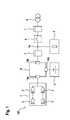
- Fig. 1shows a schematic representation of a system 100, for example, a photovoltaic system in grid parallel operation.
- the system 100has a direct current source 1, for example a photovoltaic module with one or more solar cells 2.
- the number of photovoltaic modules and the solar cell 2is in principle not limited.
- the photovoltaic modules and / or solar cellscan be connected in parallel and / or series connection.
- the DC power source 1may alternatively comprise a fuel cell, a galvanic cell or a DC generator.
- the DC power source 1feeds a power converter module 10 via a DC input terminal 10a.
- the power converter module 10has, in addition to the DC input terminal 10a, a DC output terminal 10c configured to provide a DC output voltage and an AC output terminal 10b configured to provide an AC output voltage.
- the DC output terminal 10cis coupled to an electrical energy storage module 3, for example, an accumulator or other energy storage system.
- the AC output terminal 10b of the power converter 10is coupled to an output node 5a to which one or more AC consumers 5 may be connected, on the one hand.
- an AC power supply 8can be connected via a separation contactor 6.
- the system 100can thus be operated in network parallel operation, that is, depending on requirements, the energy storage module 3 and the AC consumer 5 can be fed with power from the DC power source 1. The remaining power can be fed via the contactor 6 in the AC mains 8.
- electricity meterscan be used at appropriate locations, for example, an income meter 4, which determines the total output of the DC power source 1, and / or a feed meter 7, which detects the energy fed into the AC power 8.
- the system 100may be implemented in a home with home consumers 5 and a photovoltaic module 1 installed on a rooftop.
- Fig. 2shows a schematic representation of a power converter module, in particular a power converter module 10, which in the in Fig. 1 shown system 100 can be used.
- the power converter module 10has a DC input terminal 10 a, which is designed to supply an input voltage to a DC power source 1
- the power converter module 10has an intermediate circuit 12 with a DC link 11, which is directly coupled to the DC input terminal 10a, that is, the DC link 12 is powered by the DC power source 1 without the interposition of an active voltage converting element.
- a protection circuit for the DC power source 1, a contactor or a filter to improve the electromagnetic compatibilitycan be coupled between the DC link 12 and the DC input terminal 10a.
- the intermediate circuit 12may comprise, for example, an intermediate circuit capacitor.
- the power converter module 10further includes a DC output terminal 10c configured to provide a DC output voltage and an AC output terminal 10b configured to provide an AC output voltage.
- a DC-DC converter 14is coupled to remove an input voltage from the intermediate circuit 12.
- an inverter 13is coupled to remove an input voltage from the intermediate circuit 12.
- the DC-DC converter 14may be, for example, a galvanically isolated DC-DC converter, such as a push-pull flow converter or a flyback converter.
- the DC-DC converter 14may be configured without galvanic isolation, for example as a synchronous converter or up / down converter or inverter converter.
- the inverter 13can also be configured with or without galvanic isolation.
- the inverter 13may be a self-commutated or externally-driven single-phase or multi-phase inverter.
- the power converter module 10also has a control device 15, which is coupled to the DC-DC converter 14 and the inverter 13.
- the control device 15is designed to regulate the input voltage of the inverter 13 and the DC-DC converter 14 to a maximum power draw from the DC power source 1.
- the control device 15can perform a maximum power point tracking (MPPT).
- MPPTmaximum power point tracking
- the control device 15regulates the input voltage of the inverter 13 and / or the DC-DC converter 14 to the required value.
- the control device 15varies the voltage by a small amount. If the product of current and voltage increases, that is, the power of the DC power source 1, the new voltage is maintained, otherwise the voltage is reset to the original value.
- This iterative Methodperforms the controller 15 constantly. In particular, in photovoltaic modules with temporally fluctuating yield due to changing irradiation conditions can thus always be guaranteed operation in the maximum power point.
- the control device 15has a first MPP regulator 15a assigned to the inverter 13 and regulating the input voltage of the inverter 13.
- the first MPP controller 15athus executes an MPPT for the inverter 13.
- the first MPP regulator 15amay drive the DC-DC converter 14 for adjusting the input voltage in order to match the power consumption of the inverter 13 and the DC-DC converter 14 from the DC power source 1.
- the first MPP controller 15acan be implemented, for example, in a microprocessor of a first power component 13a comprising the inverter 13.
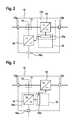
- Fig. 3shows a schematic representation of another converter module, in particular a further converter module 10, which in the in Fig. 1 shown system 100 can be used.
- the power converter module 10 in Fig. 3is different from the one in Fig. 2 shown power converter module essentially in that the control device 15 instead of the first MPP controller 15a has a second, the DC-DC converter 14 associated and the input voltage of the DC-DC converter 14 regulating MPP controller 15b.
- the second MPP controller 15bimplements an MPPT for the DC-DC converter 14 similar to the first MPP controller 15a and can be implemented, for example, in a microprocessor of a second power component 14a comprising the DC-DC converter 14.
- the second MPP regulator 15adepending on the regulated input voltage of the DC-DC converter 14, drive the inverter 13 for setting the input voltage in order to match the power consumption of the inverter 13 and the DC-DC converter 14 from the DC power source 1.
- Fig. 4shows a schematic representation of another converter module, in particular a further converter module 10, which in the in Fig. 1 shown system 100 can be used.
- the control device 15comprises both the first MPP controller 15a and the second MPP controller 15b as a distributed control system.
- the first MPP controller 15amay implement a fast subordinate MPPT
- the second MPP controller 15bimplements a slow overlaid MPPT.
- the MPP controlcan be implemented so fast that the capacity of the electrical energy storage module 3 can be used as a buffer capacity.
- the voltage requirements to the intermediate circuit 12can be reduced, which allows a simple and cheap implementation of a DC link capacitor, for example via a film capacitor with a long life.
- Fig. 5shows a schematic representation of an exemplary method 20 for operating a photovoltaic system, in particular in a grid parallel operation.
- the method 20can, for example, with the aid of in the Fig. 2 to 4
- a direct feed of a direct current from a photovoltaic module 1 into the intermediate circuit 12 of a converter module 10takes place, that is, feeding without voltage conversion.
- the DC voltage of the intermediate circuit 12is fed into an inverter 13 of the power converter module 10 coupled to the intermediate circuit 12 and to a DC voltage converter 14 coupled to the intermediate circuit 12.
- the input voltage of the inverter 13 and of the inverter 13are regulated DC converter 14 to a maximum power extraction from the photovoltaic module 1, in particular via a maximum power point tracking (MPPT), as in connection with Fig. 2 explained.
- MPPTmaximum power point tracking
- the MPPTcan be done, for example, by regulating the input voltage of the inverter 13 and setting the power consumption of the DC-DC converter 14 in dependence on the regulated input voltage of the inverter 13.
- a distributed rulescan also take place, that is to say a correlated regulation of both the input voltage of the DC-DC converter 14 and the input voltage of the inverter 13, so that the power consumption from the photovoltaic module 1 is optimized.
- the control dynamics of the MPPT of the DC-DC converter 14may be, for example, greater than the control dynamics of the MPPT of the inverter 13, for example by regulating the input voltage of the DC-DC converter 14 using a faster superimposed MPP controller, and for regulating the input voltage of the inverter 13, using a slower subordinate MPP controller.
Landscapes
- Engineering & Computer Science (AREA)
- Power Engineering (AREA)
- Inverter Devices (AREA)
- Control Of Electrical Variables (AREA)
- Photovoltaic Devices (AREA)
Abstract
Translated fromGermanDescription
Translated fromGermanDie Erfindung betrifft ein Stromrichtermodul, eine Photovoltaikanlage mit Stromrichtermodul und ein Verfahren zum Betreiben einer Photovoltaikanlage.The invention relates to a power converter module, a photovoltaic system with power converter module and a method for operating a photovoltaic system.
Photovoltaikanlagen oder sonstige Anlagen mit Gleichstromquellen wie beispielsweise Brennstoffzellen, galvanischen Zellen oder Gleichstromgeneratoren verfügen meist über Stromrichter, welche die durch die Gleichstromquelle, beispielsweise ein Photovoltaikmodul mit einer oder mehreren Solarzellen, bereitgestellte Gleichspannung in die erforderlichen Gleichspannungslagen und/oder Wechselspannungslagen umrichten.Photovoltaic systems or other systems with DC sources such as fuel cells, galvanic cells or DC generators usually have power converters, which convert the DC voltage source, such as a photovoltaic module with one or more solar cells, provided DC voltage in the required DC voltage and / or AC voltage.
Üblicherweise wird ein Photovoltaikmodul oder mehrere Photovoltaikmodule über einen Eingangsgleichspannungswandler, beispielsweise einen Hoch-/Tiefsetzsteller, an einen Zwischenkreis gekoppelt. Aus dem Zwischenkreis kann dann über einen weiteren Gleichspannungswandler Leistung in einen Batteriespeicher eingespeist werden. Zudem kann ein gegebenenfalls galvanisch getrennter Wechselrichter an den Zwischenkreis gekoppelt werden, welcher Leistung zur Einspeisung in ein Wechselstromnetz aus dem Zwischenkreis entnimmt.Typically, a photovoltaic module or several photovoltaic modules via an input DC-DC converter, such as a buck-boost converter, coupled to a DC link. From the DC link can then be fed via a further DC-DC converter power in a battery storage. In addition, an optionally galvanically isolated inverter can be coupled to the intermediate circuit, which draws power for feeding into an AC network from the DC link.
Bekannt ist zudem, den Eingangsgleichspannungswandler im Arbeitspunkt maximaler Leistungsaufnahme aus dem Photovoltaikmodul zu betreiben, indem eine maximale Leistungspunktregelung ("maximum power point tracking", MPPT) in einer MPP-Steuereinheit implementiert wird. Die MPP-Steuereinheit steuert dabei Halbleiterbauelemente in dem Eingangsgleichspannungswandler derart an, dass die dem Photovoltaikmodul entnommene Leistung maximal ist, da der optimale Arbeitspunkt des Photovoltaikmoduls schwanken kann, beispielsweise aufgrund von wechselnder Sonneneinstrahlung oder Abschattung von einzelnen Solarzellen.It is also known to operate the DC input voltage converter at the operating point of maximum power consumption from the photovoltaic module by implementing a maximum power point tracking (MPPT) in an MPP control unit. In this case, the MPP control unit controls semiconductor components in the input DC-DC converter so that the power taken from the photovoltaic module is at a maximum since the optimum operating point of the photovoltaic module can fluctuate, for example due to changing solar radiation or shading of individual solar cells.
Die Druckschrift
Es besteht ein Bedarf an Lösungen für aus Gleichstromquellen gespeisten Stromrichtern, bei denen die Topologie des Stromrichters vereinfacht, die Effizienz gesteigert und die Verlustleistung minimiert werden kann.There is a need for solutions for DC-powered converters that simplify the topology of the power converter, increase efficiency, and minimize power dissipation.
Die vorliegende Erfindung schafft gemäß einem Aspekt ein Stromrichtermodul, insbesondere für die Kopplung einer Gleichstromquelle mit einem Wechselstromnetz einerseits und einem elektrischen Energiespeichersystem andererseits, mit einem Gleichspannungseingangsanschluss, welcher dazu ausgelegt ist, eine Eingangsspannung einer Gleichstromquelle zu empfangen, einem Zwischenkreis, welcher direkt mit dem Gleichspannungseingangsanschluss gekoppelt ist, einem Gleichspannungsausgangsanschluss, welcher dazu ausgelegt ist, eine Ausgangsgleichspannung bereitzustellen, einem Wechselspannungsausgangsanschluss, welcher dazu ausgelegt ist, eine Ausgangswechselspannung bereitzustellen, einem Gleichspannungswandler, welcher zwischen den Zwischenkreis und den Gleichspannungsausgangsanschluss zur Entnahme einer Eingangsspannung aus dem Zwischenkreis gekoppelt ist, einem Wechselrichter, welcher zwischen den Zwischenkreis und den Wechselspannungsausgangsanschluss zur Entnahme einer Eingangsspannung aus dem Zwischenkreis gekoppelt ist, und einer Regeleinrichtung, welche mit dem Gleichspannungswandler und dem Wechselrichter gekoppelt ist, und welche dazu ausgelegt ist, die Eingangsspannung des Wechselrichters und des Gleichspannungswandlers auf eine maximale Leistungsentnahme aus der Gleichstromquelle zu regeln.The present invention, in one aspect, provides a power converter module, in particular for coupling a DC power source to an AC mains on the one hand and an electrical energy storage system on the other hand, having a DC input terminal configured to receive an input voltage of a DC power source, a DC bus connected directly to the DC input terminal coupled to a DC output terminal configured to provide a DC output voltage, an AC output terminal configured to provide an AC output voltage, a DC-DC converter coupled between the DC link and the DC output terminal for extracting an input voltage from the DC link, an inverter, which is between the intermediate circuit and the AC output terminal for taking an input voltage coupled to the intermediate circuit, and a controller, which is coupled to the DC-DC converter and the inverter, and which is adapted to regulate the input voltage of the inverter and the DC-DC converter to a maximum power draw from the DC power source.
Gemäß einem weiteren Aspekt schafft die vorliegende Erfindung eine Photovoltaikanlage mit einem oder mehreren Photovoltaikmodulen mit mindestens einer Solarzelle, einem erfindungsgemäßen Stromrichtermodul, dessen Gleichspannungseingangsanschluss mit einem Ausgangsanschluss des Photovoltaikmoduls gekoppelt ist, und einem elektrischen Energiespeichermodul, welches mit dem Gleichspannungsausganganschluss des Stromrichtermoduls gekoppelt ist.According to a further aspect, the present invention provides a photovoltaic system with one or more photovoltaic modules having at least one solar cell, a converter module according to the invention whose DC voltage input terminal is coupled to an output terminal of the photovoltaic module, and an electrical energy storage module coupled to the DC output terminal of the power converter module.
Gemäß einem weiteren Aspekt schafft die vorliegende Erfindung ein Verfahren zum Betreiben einer Photovoltaikanlage, insbesondere einer Photovoltaikanlage mit elektrischem Energiespeichersystem, mit den Schritten des direkten Einspeisens eines Gleichstroms aus einem oder mehreren Photovoltaikmodulen in den Zwischenkreis eines Stromrichtermoduls, des Einspeisens der Gleichspannung des Zwischenkreises des Stromrichtermoduls in einen mit dem Zwischenkreis des Stromrichtermoduls gekoppelten Wechselrichter des Stromrichtermoduls und einen mit dem Zwischenkreis gekoppelten Gleichspannungswandlers, und des Regelns der Eingangsspannung des Wechselrichters und des Gleichspannungswandlers auf eine maximale Leistungsentnahme aus dem Photovoltaikmodul.According to a further aspect, the present invention provides a method for operating a photovoltaic system, in particular a photovoltaic system with an electrical energy storage system, with the steps of directly feeding a direct current from one or more photovoltaic modules into the intermediate circuit of a converter module, feeding in the DC voltage of the intermediate circuit of the converter module an inverter of the power converter module coupled to the intermediate circuit of the power converter module and a DC-DC converter coupled to the DC bus, and controlling the input voltage of the inverter and the DC-DC converter to a maximum power extraction from the photovoltaic module.
Eine Idee der vorliegenden Erfindung ist es, den Eingangsgleichspannungswandler des Stromrichters, welcher die Gleichstromquelle mit dem Zwischenkreis des Stromrichters koppelt, entfallen zu lassen, und die Gleichstromquelle direkt an den Zwischenkreis des Stromrichters anzuschließen. Demzufolge kann eine maximale Leistungspunktregelung ("maximum power point tracking", MPPT) für einen aus dem Zwischenkreis gespeisten Wechselrichter und/oder einen aus dem Zwischenkreis gespeisten Gleichspannungswandler implementiert werden, um die Leistungsentnahme aus der Gleichstromquelle zu optimieren.An idea of the present invention is to eliminate the input DC-DC converter of the power converter, which couples the DC power source to the DC link of the power converter, and to connect the DC power source directly to the DC link of the power converter. As a result, maximum power point tracking (MPPT) may be implemented for a DC link powered inverter and / or a DC link DC powered converter to optimize power draw from the DC power source.
Ein Vorteil der Erfindung ist es, dass der Stromrichter damit erheblich vereinfacht werden kann. Das Vorsehen eines Eingangsgleichspannungswandlers entfällt, so dass die Kosten für die Fertigung des Stromrichters reduziert werden. Zudem wird die Effizienz des Stromrichters gesteigert, da die in einem Eingangsgleichspannungswandler üblicherweise anfallenden Leistungsverluste entfallen.An advantage of the invention is that the power converter can thus be considerably simplified. The provision of a DC input voltage converter is eliminated, so that the cost of manufacturing the converter can be reduced. In addition, the efficiency of the power converter is increased, since the usual in a DC input DC converter power losses omitted.
Besonders vorteilhaft ist es, dass der Zwischenkreis durch die vereinfachte Topologie des Stromrichters ebenfalls vereinfacht werden kann, wenn das MPPT mit entsprechender Regeldynamik ausgestattet wird. Dadurch können einfachere und günstigere Folienkondensatoren mit längerer Lebensdauer als Zwischenkreiskondensator eingesetzt werden.It is particularly advantageous that the intermediate circuit can also be simplified by the simplified topology of the power converter if the MPPT is equipped with appropriate control dynamics. As a result, simpler and cheaper film capacitors with a longer service life can be used as a DC link capacitor.
Außerdem ist es von Vorteil, dass sowohl eine einphasige als auch eine mehrphasige, beispielsweise dreiphasige Topologie in dem Stromrichter realisiert werden kann, das heißt, der Wechselrichter kann je nach Bedarf sowohl als einphasige als auch als mehrphasige Wechselspannungsquelle dienen.Moreover, it is advantageous that both a single-phase and a multi-phase, for example, three-phase topology can be realized in the power converter, that is, the inverter can serve as a single-phase as well as a multi-phase AC voltage source as needed.
Gemäß einer Ausführungsform des erfindungsgemäßen Stromrichtermoduls kann die Regeleinrichtung mindestens einen Maximum Power Point, MPP, Regler aufweisen. Dies bietet den Vorteil, dass die Effizienz einer an das Stromrichtermodul angeschlossenen Gleichstromquelle, insbesondere eines Photovoltaikmoduls, optimiert werden kann.According to one embodiment of the power converter module according to the invention, the control device may have at least one maximum power point, MPP, controller. This offers the advantage that the efficiency of a DC power source connected to the power converter module, in particular of a photovoltaic module, can be optimized.
Gemäß einer weiteren Ausführungsform des erfindungsgemäßen Stromrichtermoduls kann die Regeleinrichtung einen ersten, dem Wechselrichter zugeordneten und die Eingangsspannung des Wechselrichters regelnden MPP-Regler aufweist. Alternativ oder zusätzlich dazu kann die Regeleinrichtung einen zweiten, dem Gleichspannungswandler zugeordneten und die Eingangsspannung des Gleichspannungswandlers regelnden MPP-Regler aufweisen. Durch diese verteilte Regelung kann eine variable und flexible Regelstrategie implementiert werden, welche eine Vereinfachung der Komponenten, insbesondere der Komponenten des Zwischenkreises des Stromrichtermoduls ermöglichen kannAccording to a further embodiment of the power converter module according to the invention, the control device may have a first, the inverter associated and the input voltage of the inverter regulating MPP controller. Alternatively or additionally, the control device can have a second MPP regulator assigned to the DC-DC converter and regulating the input voltage of the DC-DC converter. By this distributed control, a variable and flexible control strategy can be implemented, which can facilitate a simplification of the components, in particular the components of the intermediate circuit of the power converter module
Gemäß einer Ausführungsform der erfindungsgemäßen Photovoltaikanlage kann die Photovoltaikanlage mindestens einen Wechselstromverbraucher umfassen, welcher mit dem Wechselspannungsausgangsanschluss des Stromrichtermoduls gekoppelt ist. Beispielsweise kann das Stromrichtermodul auch ein Wechselstromnetz speisen. Dies ermöglicht es in vorteilhafter Weise, die Photovoltaikanlage im Netzparallelbetrieb zu betreiben.According to one embodiment of the photovoltaic system according to the invention, the photovoltaic system may comprise at least one AC consumer, which is coupled to the AC output terminal of the power converter module. For example, the power converter module can also feed an alternating current network. This makes it possible in an advantageous manner to operate the photovoltaic system in grid parallel operation.
Gemäß einer weiteren Ausführungsform der erfindungsgemäßen Photovoltaikanlage kann das Photovoltaikmodul dazu ausgelegt sein, einen dreiphasigen Strom in das Stromrichtermodul einzuspeisen. Alternativ oder zusätzlich dazu kann das Stromrichtermodul dazu ausgelegt sein, einen dreiphasigen Strom an dem Wechselspannungsausgangsanschluss des Stromrichtermoduls bereitzustellen.According to a further embodiment of the photovoltaic system according to the invention, the photovoltaic module can be designed to feed a three-phase current into the power converter module. Alternatively or additionally, the power converter module may be configured to provide a three-phase current at the AC output terminal of the power converter module.
Gemäß einer Ausführungsform des erfindungsgemäßen Verfahrens kann das Regeln des Wechselrichters und des Gleichspannungswandlers des Stromrichtermoduls ein Maximum Power Point Tracking, MPPT, umfassen. Dies bietet den Vorteil, dass die Effizienz einer an das Stromrichtermodul angeschlossenen Gleichstromquelle, insbesondere eines Photovoltaikmoduls, optimiert werden kann.According to one embodiment of the method according to the invention, the regulation of the inverter and of the DC converter of the power converter module may include a maximum power point tracking, MPPT. This offers the advantage that the efficiency of a DC power source connected to the power converter module, in particular of a photovoltaic module, can be optimized.
Gemäß einer weiteren Ausführungsform des erfindungsgemäßen Verfahrens kann das MPPT ein Regeln der Eingangsspannung des Wechselrichters und ein Festlegen der Leistungsaufnahme des Gleichspannungswandlers in Abhängigkeit von der geregelten Eingangsspannung des Wechselrichters aufweisen. Durch dieses modulare Regelkonzept kann die Leistungsaufnahme sowohl des Wechselrichters als auch des Gleichspannungswandlers flexibel und bedarfsgerecht aufeinander abgestimmt werden.According to a further embodiment of the method according to the invention, the MPPT can regulate the input voltage of the inverter and set the power consumption of the DC-DC converter in dependence on the regulated Have input voltage of the inverter. Through this modular control concept, the power consumption of both the inverter and the DC-DC converter can be flexibly matched to each other as needed.
Gemäß einer weiteren Ausführungsform des erfindungsgemäßen Verfahrens kann die Regeldynamik des MPPT des Gleichspannungswandlers größer als die Regeldynamik des MPPT des Wechselrichters sein. Damit kann vorteilhafterweise eine zweistufige Regelung mit einem schnellen überlagerten Regler und einer langsamen Grundregelung implementiert werden. Dies bietet den Vorteil, dass der elektrische Energiespeicher des Energiespeichermoduls als Ladungspuffer genutzt werden kann, um so den Zwischenkreis zu entlasten. Dadurch können die Anforderungen an den Zwischenkreiskondensator gesenkt werden, so dass beispielsweise Folienkondensatoren mit erhöhter Lebensdauer im Zwischenkreis eingesetzt werden können.According to a further embodiment of the method according to the invention, the control dynamics of the MPPT of the DC-DC converter can be greater than the control dynamics of the MPPT of the inverter. Thus, advantageously, a two-stage control can be implemented with a fast superimposed controller and a slow basic control. This offers the advantage that the electrical energy storage of the energy storage module can be used as a charge buffer so as to relieve the DC link. As a result, the demands on the DC link capacitor can be reduced, so that, for example, film capacitors with increased service life in the DC link can be used.
Weitere Merkmale und Vorteile von Ausführungsformen der Erfindung ergeben sich aus der nachfolgenden Beschreibung mit Bezug auf die beigefügten Zeichnungen.Further features and advantages of embodiments of the invention will become apparent from the following description with reference to the accompanying drawings.
Es zeigen:
- Fig. 1
- eine schematische Darstellung eines Systems mit einer Gleichstromquelle, einem Wechselstromnetz, Wechselstromverbrauchern und einem elektrischen Energiespeicher gemäß einer Ausführungsform der vorliegenden Erfindung;
- Fig. 2
- eine schematische Darstellung eines Stromrichtermoduls gemäß einer weiteren Ausführungsform der vorliegenden Erfindung;
- Fig. 3
- eine schematische Darstellung eines weiteren Stromrichtermoduls gemäß einer weiteren Ausführungsform der vorliegenden Erfindung;
- Fig. 4
- eine schematische Darstellung eines weiteren Stromrichtermoduls gemäß einer weiteren Ausführungsform der vorliegenden Erfindung; und
- Fig. 5
- eine schematische Darstellung eines Verfahrens zum Betreiben einer Photovoltaikanlage gemäß einer weiteren Ausführungsform der vorliegenden Erfindung.
- Fig. 1
- a schematic representation of a system with a DC power source, an AC mains, AC loads and an electrical energy storage according to an embodiment of the present invention;
- Fig. 2
- a schematic representation of a power converter module according to another embodiment of the present invention;
- Fig. 3
- a schematic representation of another power converter module according to another embodiment of the present invention;
- Fig. 4
- a schematic representation of another power converter module according to another embodiment of the present invention; and
- Fig. 5
- a schematic representation of a method for operating a photovoltaic system according to another embodiment of the present invention.
Die Gleichstromquelle 1 speist ein Stromrichtermodul 10 über einen Gleichspannungseingangsanschluss 10a. Das Stromrichtermodul 10 verfügt neben dem Gleichspannungseingangsanschluss 10a über einen Gleichspannungsausgangsanschluss 10c, welcher dazu ausgelegt ist, eine Ausgangsgleichspannung bereitzustellen und einen Wechselspannungsausgangsanschluss 10b, welcher dazu ausgelegt ist, eine Ausgangswechselspannung bereitzustellen. Der Gleichspannungsausgangsanschluss 10c ist mit einem elektrischen Energiespeichermodul 3 gekoppelt, beispielsweise mit einem Akkumulator oder einem sonstigen Energiespeichersystem.The DC power source 1 feeds a
Der Wechselspannungsausgangsanschluss 10b des Stromrichters 10 ist mit einem Ausgangsknoten 5a gekoppelt, an dem einerseits ein oder mehrere Wechselstromverbraucher 5 angeschlossen sein können. Andererseits kann an dem Ausgangsknoten 5a ein Wechselstromnetz 8 über ein Trennschütz 6 angeschlossen werden. Das System 100 kann damit im Netzparallelbetrieb betrieben werden, das heißt, je nach Bedarf kann das Energiespeichermodul 3 sowie die Wechselstromverbraucher 5 mit Leistung aus der Gleichstromquelle 1 gespeist werden. Die übrige Leistung kann über das Trennschütz 6 in das Wechselstromnetz 8 eingespeist werden. Hierzu können Stromzähler an entsprechenden Stellen eingesetzt werden, beispielsweise ein Ertragszähler 4, welcher den gesamten Ertrag der Gleichstromquelle 1 ermittelt, und/oder ein Einspeisezähler 7, welcher die in das Wechselstromnetz 8 eingespeiste Energie erfasst. Das System 100 kann beispielsweise in einem Wohnhaus mit Haushaltsverbrauchern 5 und auf einem Hausdach installiertem Photovoltaikmodul 1 implementiert werden.The
Das Stromrichtermodul 10 weist weiterhin einen Gleichspannungsausgangsanschluss 10c, welcher dazu ausgelegt ist, eine Ausgangsgleichspannung bereitzustellen, sowie eine Wechselspannungsausgangsanschluss 10b, welcher dazu ausgelegt ist, eine Ausgangswechselspannung bereitzustellen, auf. Zwischen den Zwischenkreis 12 und den Gleichspannungsausgangsanschluss 10c ist zur Entnahme einer Eingangsspannung aus dem Zwischenkreis 12 ein Gleichspannungswandler 14 gekoppelt. Zwischen den Zwischenkreis 12 und den Wechselspannungsausgangsanschluss 10b ist zur Entnahme einer Eingangsspannung aus dem Zwischenkreis 12 ein Wechselrichter 13 gekoppelt. Der Gleichspannungswandler 14 kann beispielsweise ein galvanisch getrennter Gleichspannungswandler, wie zum Beispiel ein Gegentaktflusswandler oder ein Sperrwandler sein. Alternativ kann der Gleichspannungswandler 14 auch ohne galvanische Trennung ausgestaltet sein, beispielsweise als Synchronwandler oder Aufwärts-/Abwärtswandler bzw. Inverswandler. Der Wechselrichter 13 kann ebenfalls mit oder ohne galvanischer Trennung ausgestaltet werden. Beispielsweise kann der Wechselrichter 13 ein selbstgeführter oder fremdgeführter einphasiger oder mehrphasiger Wechselrichter sein.The
Das Stromrichtermodul 10. weist zudem eine Regeleinrichtung 15 auf, welche mit dem Gleichspannungswandler 14 und dem Wechselrichter 13 gekoppelt ist. Die Regeleinrichtung 15 ist dazu ausgelegt ist, die Eingangsspannung des Wechselrichters 13 und des Gleichspannungswandlers 14 auf eine maximale Leistungsentnahme aus der Gleichstromquelle 1 zu regeln. Insbesondere kann die Regeleinrichtung 15 ein Maximum Power Point Tracking (MPPT) durchführen. Hierzu regelt die Regeleinrichtung 15 die Eingangsspannung des Wechselrichters 13 und/oder des Gleichspannungswandlers 14 auf den benötigten Wert. Dazu variiert die Regeleinrichtung 15 die Spannung um einen kleinen Betrag. Vergrößert sich dabei das Produkt aus Strom und Spannung, das heißt die Leistung der Gleichstromquelle 1, wird die neue Spannung beibehalten, andernfalls wird die Spannung wieder auf den ursprünglichen Wert zurückgesetzt. Dieses iterative Verfahren führt die Regeleinrichtung 15 ständig aus. Insbesondere bei Photovoltaikmodulen mit zeitlich schwankendem Ertrag aufgrund von wechselnden Bestrahlungsverhältnissen kann somit immer ein Betrieb im maximalen Leistungspunkt gewährleistet werden.The
In der beispielhaften Ausführungsform der
In einem ersten Schritt 21 erfolgt ein direktes Einspeisen eines Gleichstroms aus einem Photovoltaikmodul 1 in den Zwischenkreis 12 eines Stromrichtermoduls 10, das heißt ein Einspeisen ohne Spannungswandlung. In einem zweiten Schritt 22 erfolgt ein Einspeisen der Gleichspannung des Zwischenkreises 12 in einen mit dem Zwischenkreis 12 gekoppelten Wechselrichter 13 des Stromrichtermoduls 10 und einen mit dem Zwischenkreis 12 gekoppelten Gleichspannungswandler 14. In einem dritten Schritt 23 erfolgt ein Regeln der Eingangsspannung des Wechselrichters 13 und des Gleichspannungswandlers 14 auf eine maximale Leistungsentnahme aus dem Photovoltaikmodul 1, insbesondere über ein Maximum Power Point Tracking (MPPT), wie im Zusammenhang mit
Das MPPT kann beispielsweise durch ein Regeln der Eingangsspannung des Wechselrichters 13 und ein Festlegen der Leistungsaufnahme des Gleichspannungswandlers 14 in Abhängigkeit von der geregelten Eingangsspannung des Wechselrichters 13 erfolgen. Alternativ kann auch ein Regeln der Eingangsspannung des Gleichspannungswandlers 14 und ein Festlegen der Leistungsaufnahme des Wechselrichters 13 in Abhängigkeit von der geregelten Eingangsspannung des Gleichspannungswandlers 14 erfolgen. Optional kann auch ein verteiltes Regeln erfolgen, das heißt ein korreliertes Regeln sowohl der Eingangsspannung des Gleichspannungswandlers 14 als auch der Eingangsspannung des Wechselrichters 13, so dass die Leistungsaufnahme aus dem Photovoltaikmodul 1 optimiert wird.The MPPT can be done, for example, by regulating the input voltage of the
Die Regeldynamik des MPPT des Gleichspannungswandlers 14 kann beispielsweise größer als die Regeldynamik des MPPT des Wechselrichters 13 sein, beispielsweise indem zum Regeln der Eingangsspannung des Gleichspannungswandlers 14 ein schneller überlagerter MPP-Regler, und zum Regeln der Eingangsspannung des Wechselrichters 13 ein langsamer unterlagerter MPP-Regler herangezogen wird.The control dynamics of the MPPT of the DC-
Claims (12)
Translated fromGermanApplications Claiming Priority (1)
| Application Number | Priority Date | Filing Date | Title |
|---|---|---|---|
| DE201210212287DE102012212287A1 (en) | 2012-07-13 | 2012-07-13 | Power converter module, photovoltaic system with converter module and method for operating a photovoltaic system |
Publications (2)
| Publication Number | Publication Date |
|---|---|
| EP2685582A1true EP2685582A1 (en) | 2014-01-15 |
| EP2685582B1 EP2685582B1 (en) | 2017-11-29 |
Family
ID=48537796
Family Applications (1)
| Application Number | Title | Priority Date | Filing Date |
|---|---|---|---|
| EP13169162.8AActiveEP2685582B1 (en) | 2012-07-13 | 2013-05-24 | Converter module, photovoltaic assembly with converter module and method for operating a photovoltaic assembly |
Country Status (5)
| Country | Link |
|---|---|
| US (1) | US9698596B2 (en) |
| EP (1) | EP2685582B1 (en) |
| AU (1) | AU2013206703A1 (en) |
| DE (1) | DE102012212287A1 (en) |
| ES (1) | ES2657873T3 (en) |
Cited By (3)
| Publication number | Priority date | Publication date | Assignee | Title |
|---|---|---|---|---|
| US10181724B2 (en) | 2016-02-10 | 2019-01-15 | Eguana Technologies | Seamless transitions between control modes |
| US10305321B2 (en) | 2016-02-10 | 2019-05-28 | Eguana Technologies | Automatic recovery control |
| EP3206275B1 (en)* | 2016-02-10 | 2020-06-10 | Eguana Technologies | Output control and compensation for ac coupled systems |
Families Citing this family (11)
| Publication number | Priority date | Publication date | Assignee | Title |
|---|---|---|---|---|
| US8775846B2 (en) | 2009-07-10 | 2014-07-08 | Protonex Technology Corporation | Portable power manager having one or more device ports for connecting with external power loads |
| EP2982030B1 (en) | 2013-04-01 | 2020-11-18 | Galvion Soldier Power, LLC | Power manager |
| WO2016077216A1 (en) | 2014-11-11 | 2016-05-19 | Protonex Technology Corporation | Control module for dc power network |
| JP6314099B2 (en)* | 2015-02-24 | 2018-04-18 | 株式会社日立製作所 | Power converter |
| US11258366B2 (en) | 2015-11-20 | 2022-02-22 | Galvion Soldier Power, Llc | Power manager with reconfigurable power converting circuits |
| US11108230B2 (en) | 2015-11-20 | 2021-08-31 | Galvion Soldier Power, Llc | Power manager with reconfigurable power converting circuits |
| US10848067B2 (en) | 2015-11-20 | 2020-11-24 | Galvion Soldier Power, Llc | Power manager with reconfigurable power converting circuits |
| US10978876B2 (en)* | 2017-05-30 | 2021-04-13 | General Electric Company | Maximum power point tracking hybrid control of an energy storage system |
| US12155263B2 (en) | 2021-08-06 | 2024-11-26 | Galvion Ltd. | Helmet-mounted power system |
| USD1062615S1 (en) | 2021-12-21 | 2025-02-18 | Galvion Soldier Power, Llc | Power pack |
| US12326707B2 (en) | 2022-05-16 | 2025-06-10 | Galvion Ltd. | Method and system of providing a uniform messaging platform in a heterogeneous environment |
Citations (5)
| Publication number | Priority date | Publication date | Assignee | Title |
|---|---|---|---|---|
| JP2002354677A (en)* | 2001-05-28 | 2002-12-06 | Japan Storage Battery Co Ltd | Power conditioner for solar energy generation |
| US20040125618A1 (en) | 2002-12-26 | 2004-07-01 | Michael De Rooij | Multiple energy-source power converter system |
| DE212008000035U1 (en) | 2007-05-14 | 2010-02-25 | Fronius International Gmbh | High Frequency (HF) Inverter |
| EP2339714A2 (en)* | 2009-12-23 | 2011-06-29 | Samsung SDI Co., Ltd. | Energy storage system and method of controlling the same |
| US20110273130A1 (en)* | 2010-05-06 | 2011-11-10 | Samsung Electro-Mechanics Co., Ltd. | Apparatus and method for charging and discharging photovoltaic pcs integrated battery |
Family Cites Families (2)
| Publication number | Priority date | Publication date | Assignee | Title |
|---|---|---|---|---|
| US8598741B2 (en)* | 2008-12-23 | 2013-12-03 | Samsung Electro-Mechanics Co, Ltd. | Photovoltaic and fuel cell hybrid generation system using single converter and single inverter, and method of controlling the same |
| US9774189B2 (en)* | 2011-07-18 | 2017-09-26 | Enphase Energy, Inc. | Method and apparatus for multi-phase power conversion having modified burst current |
- 2012
- 2012-07-13DEDE201210212287patent/DE102012212287A1/ennot_activeWithdrawn
- 2013
- 2013-05-24ESES13169162.8Tpatent/ES2657873T3/enactiveActive
- 2013-05-24EPEP13169162.8Apatent/EP2685582B1/enactiveActive
- 2013-07-05AUAU2013206703Apatent/AU2013206703A1/ennot_activeAbandoned
- 2013-07-09USUS13/937,755patent/US9698596B2/enactiveActive
Patent Citations (5)
| Publication number | Priority date | Publication date | Assignee | Title |
|---|---|---|---|---|
| JP2002354677A (en)* | 2001-05-28 | 2002-12-06 | Japan Storage Battery Co Ltd | Power conditioner for solar energy generation |
| US20040125618A1 (en) | 2002-12-26 | 2004-07-01 | Michael De Rooij | Multiple energy-source power converter system |
| DE212008000035U1 (en) | 2007-05-14 | 2010-02-25 | Fronius International Gmbh | High Frequency (HF) Inverter |
| EP2339714A2 (en)* | 2009-12-23 | 2011-06-29 | Samsung SDI Co., Ltd. | Energy storage system and method of controlling the same |
| US20110273130A1 (en)* | 2010-05-06 | 2011-11-10 | Samsung Electro-Mechanics Co., Ltd. | Apparatus and method for charging and discharging photovoltaic pcs integrated battery |
Non-Patent Citations (1)
| Title |
|---|
| ZHAN WANG ET AL: "Integrated MPPT and bidirectional battery charger for PV application using one multiphase interleaved three-port dc-dc converter", APPLIED POWER ELECTRONICS CONFERENCE AND EXPOSITION (APEC), 2011 TWENTY-SIXTH ANNUAL IEEE, IEEE, 6 March 2011 (2011-03-06), pages 295 - 300, XP032013896, ISBN: 978-1-4244-8084-5, DOI: 10.1109/APEC.2011.5744611* |
Cited By (5)
| Publication number | Priority date | Publication date | Assignee | Title |
|---|---|---|---|---|
| US10181724B2 (en) | 2016-02-10 | 2019-01-15 | Eguana Technologies | Seamless transitions between control modes |
| US10305321B2 (en) | 2016-02-10 | 2019-05-28 | Eguana Technologies | Automatic recovery control |
| EP3206275B1 (en)* | 2016-02-10 | 2020-06-10 | Eguana Technologies | Output control and compensation for ac coupled systems |
| US11139654B2 (en) | 2016-02-10 | 2021-10-05 | Eguana Technologies | Output control and compensation for AC coupled systems |
| US12206247B2 (en) | 2016-02-10 | 2025-01-21 | Eguana Technologies | Output control and compensation for AC coupled systems |
Also Published As
| Publication number | Publication date |
|---|---|
| US9698596B2 (en) | 2017-07-04 |
| DE102012212287A1 (en) | 2014-01-16 |
| AU2013206703A1 (en) | 2014-01-30 |
| EP2685582B1 (en) | 2017-11-29 |
| US20140015318A1 (en) | 2014-01-16 |
| ES2657873T3 (en) | 2018-03-07 |
Similar Documents
| Publication | Publication Date | Title |
|---|---|---|
| EP2685582B1 (en) | Converter module, photovoltaic assembly with converter module and method for operating a photovoltaic assembly | |
| EP2363947B1 (en) | Inverter with onboard network with multiple supplies | |
| EP3022835B1 (en) | Inverter comprising at least two direct current inputs, a photovoltaic installation comprising such an inverter, and a method for actuating an inverter | |
| EP3014725B1 (en) | Energy storage device having a dc voltage supply circuit and method for providing a dc voltage from an energy storage device | |
| EP2735073B1 (en) | System with battery charging device and vehicle electrical system power supply stage | |
| EP2469238A2 (en) | Photovoltaic device | |
| EP3647108B1 (en) | Charging assembly for motor vehicles with multiple energy sources | |
| DE102010000350B4 (en) | Energy supply system with a renewable power source and method for operating an energy supply system | |
| DE102012002599B4 (en) | Power generation plant with inverter and energy storage system | |
| DE202012008606U1 (en) | Solar storage system | |
| EP3780305A1 (en) | Inverter arrangement for wind turbines and photovoltaic installations | |
| DE102018111154B4 (en) | Charging system | |
| DE102011110197B4 (en) | System with a DC link as common rail and method of operating a system with arranged in different housings actuators | |
| DE102013011427A1 (en) | Electrical arrangement with an inverter and intermediate switching device for the electrical arrangement | |
| EP4348792A1 (en) | Energy system | |
| EP3139481B1 (en) | Method for operating a photovoltaic assembly | |
| EP3472909B1 (en) | Energy management unit, energy supply system and energy management method | |
| DE102010046744A1 (en) | Method for supplying electrical power into direct current (DC) input end of stand-alone inverter, involves fully supplying electrical power to alternating current (AC) load, under condition of lack of energy supplied by energy source | |
| WO2017001030A1 (en) | Energy management system for an energy generation system | |
| DE102012002601A1 (en) | Power generation plant has switchable connecting unit that selectively connects electrical storage device and generator in series with positive and negative poles | |
| DE102011001284A1 (en) | Circuit arrangement for use as emergency power supply, has bidirectional controller that is connected between power source and inverter, so that electrical energy of energy source is stored in memory and is fed into public grid | |
| EP2523339B1 (en) | Method and apparatus for energy generation by a photovoltaic arrangement with compensation of energy between the branches of the photovoltaic generators | |
| WO2014184254A1 (en) | Converter circuit | |
| DE102023129255A1 (en) | Method for controlling a DC charging system for charging battery storage devices in motor vehicles by means of a photovoltaic unit and charging system therefor | |
| DE102015108234A1 (en) | Circuit device for supplying an air conditioner |
Legal Events
| Date | Code | Title | Description |
|---|---|---|---|
| PUAI | Public reference made under article 153(3) epc to a published international application that has entered the european phase | Free format text:ORIGINAL CODE: 0009012 | |
| AK | Designated contracting states | Kind code of ref document:A1 Designated state(s):AL AT BE BG CH CY CZ DE DK EE ES FI FR GB GR HR HU IE IS IT LI LT LU LV MC MK MT NL NO PL PT RO RS SE SI SK SM TR | |
| AX | Request for extension of the european patent | Extension state:BA ME | |
| 17P | Request for examination filed | Effective date:20140715 | |
| RBV | Designated contracting states (corrected) | Designated state(s):AL AT BE BG CH CY CZ DE DK EE ES FI FR GB GR HR HU IE IS IT LI LT LU LV MC MK MT NL NO PL PT RO RS SE SI SK SM TR | |
| RAP1 | Party data changed (applicant data changed or rights of an application transferred) | Owner name:SMA SOLAR TECHNOLOGY AG | |
| GRAP | Despatch of communication of intention to grant a patent | Free format text:ORIGINAL CODE: EPIDOSNIGR1 | |
| INTG | Intention to grant announced | Effective date:20170519 | |
| GRAS | Grant fee paid | Free format text:ORIGINAL CODE: EPIDOSNIGR3 | |
| GRAJ | Information related to disapproval of communication of intention to grant by the applicant or resumption of examination proceedings by the epo deleted | Free format text:ORIGINAL CODE: EPIDOSDIGR1 | |
| GRAL | Information related to payment of fee for publishing/printing deleted | Free format text:ORIGINAL CODE: EPIDOSDIGR3 | |
| GRAR | Information related to intention to grant a patent recorded | Free format text:ORIGINAL CODE: EPIDOSNIGR71 | |
| INTC | Intention to grant announced (deleted) | ||
| GRAA | (expected) grant | Free format text:ORIGINAL CODE: 0009210 | |
| INTG | Intention to grant announced | Effective date:20171018 | |
| AK | Designated contracting states | Kind code of ref document:B1 Designated state(s):AL AT BE BG CH CY CZ DE DK EE ES FI FR GB GR HR HU IE IS IT LI LT LU LV MC MK MT NL NO PL PT RO RS SE SI SK SM TR | |
| REG | Reference to a national code | Ref country code:CH Ref legal event code:EP | |
| REG | Reference to a national code | Ref country code:AT Ref legal event code:REF Ref document number:951236 Country of ref document:AT Kind code of ref document:T Effective date:20171215 | |
| REG | Reference to a national code | Ref country code:IE Ref legal event code:FG4D Free format text:LANGUAGE OF EP DOCUMENT: GERMAN | |
| REG | Reference to a national code | Ref country code:DE Ref legal event code:R096 Ref document number:502013008908 Country of ref document:DE | |
| REG | Reference to a national code | Ref country code:ES Ref legal event code:FG2A Ref document number:2657873 Country of ref document:ES Kind code of ref document:T3 Effective date:20180307 | |
| REG | Reference to a national code | Ref country code:NL Ref legal event code:MP Effective date:20171129 | |
| REG | Reference to a national code | Ref country code:LT Ref legal event code:MG4D | |
| PG25 | Lapsed in a contracting state [announced via postgrant information from national office to epo] | Ref country code:SE Free format text:LAPSE BECAUSE OF FAILURE TO SUBMIT A TRANSLATION OF THE DESCRIPTION OR TO PAY THE FEE WITHIN THE PRESCRIBED TIME-LIMIT Effective date:20171129 Ref country code:LT Free format text:LAPSE BECAUSE OF FAILURE TO SUBMIT A TRANSLATION OF THE DESCRIPTION OR TO PAY THE FEE WITHIN THE PRESCRIBED TIME-LIMIT Effective date:20171129 Ref country code:NO Free format text:LAPSE BECAUSE OF FAILURE TO SUBMIT A TRANSLATION OF THE DESCRIPTION OR TO PAY THE FEE WITHIN THE PRESCRIBED TIME-LIMIT Effective date:20180228 Ref country code:FI Free format text:LAPSE BECAUSE OF FAILURE TO SUBMIT A TRANSLATION OF THE DESCRIPTION OR TO PAY THE FEE WITHIN THE PRESCRIBED TIME-LIMIT Effective date:20171129 | |
| REG | Reference to a national code | Ref country code:FR Ref legal event code:PLFP Year of fee payment:6 | |
| PG25 | Lapsed in a contracting state [announced via postgrant information from national office to epo] | Ref country code:GR Free format text:LAPSE BECAUSE OF FAILURE TO SUBMIT A TRANSLATION OF THE DESCRIPTION OR TO PAY THE FEE WITHIN THE PRESCRIBED TIME-LIMIT Effective date:20180301 Ref country code:BG Free format text:LAPSE BECAUSE OF FAILURE TO SUBMIT A TRANSLATION OF THE DESCRIPTION OR TO PAY THE FEE WITHIN THE PRESCRIBED TIME-LIMIT Effective date:20180228 Ref country code:LV Free format text:LAPSE BECAUSE OF FAILURE TO SUBMIT A TRANSLATION OF THE DESCRIPTION OR TO PAY THE FEE WITHIN THE PRESCRIBED TIME-LIMIT Effective date:20171129 Ref country code:HR Free format text:LAPSE BECAUSE OF FAILURE TO SUBMIT A TRANSLATION OF THE DESCRIPTION OR TO PAY THE FEE WITHIN THE PRESCRIBED TIME-LIMIT Effective date:20171129 Ref country code:RS Free format text:LAPSE BECAUSE OF FAILURE TO SUBMIT A TRANSLATION OF THE DESCRIPTION OR TO PAY THE FEE WITHIN THE PRESCRIBED TIME-LIMIT Effective date:20171129 | |
| PG25 | Lapsed in a contracting state [announced via postgrant information from national office to epo] | Ref country code:NL Free format text:LAPSE BECAUSE OF FAILURE TO SUBMIT A TRANSLATION OF THE DESCRIPTION OR TO PAY THE FEE WITHIN THE PRESCRIBED TIME-LIMIT Effective date:20171129 | |
| PG25 | Lapsed in a contracting state [announced via postgrant information from national office to epo] | Ref country code:CZ Free format text:LAPSE BECAUSE OF FAILURE TO SUBMIT A TRANSLATION OF THE DESCRIPTION OR TO PAY THE FEE WITHIN THE PRESCRIBED TIME-LIMIT Effective date:20171129 Ref country code:SK Free format text:LAPSE BECAUSE OF FAILURE TO SUBMIT A TRANSLATION OF THE DESCRIPTION OR TO PAY THE FEE WITHIN THE PRESCRIBED TIME-LIMIT Effective date:20171129 Ref country code:EE Free format text:LAPSE BECAUSE OF FAILURE TO SUBMIT A TRANSLATION OF THE DESCRIPTION OR TO PAY THE FEE WITHIN THE PRESCRIBED TIME-LIMIT Effective date:20171129 Ref country code:CY Free format text:LAPSE BECAUSE OF FAILURE TO SUBMIT A TRANSLATION OF THE DESCRIPTION OR TO PAY THE FEE WITHIN THE PRESCRIBED TIME-LIMIT Effective date:20171129 Ref country code:DK Free format text:LAPSE BECAUSE OF FAILURE TO SUBMIT A TRANSLATION OF THE DESCRIPTION OR TO PAY THE FEE WITHIN THE PRESCRIBED TIME-LIMIT Effective date:20171129 | |
| REG | Reference to a national code | Ref country code:DE Ref legal event code:R097 Ref document number:502013008908 Country of ref document:DE | |
| PG25 | Lapsed in a contracting state [announced via postgrant information from national office to epo] | Ref country code:RO Free format text:LAPSE BECAUSE OF FAILURE TO SUBMIT A TRANSLATION OF THE DESCRIPTION OR TO PAY THE FEE WITHIN THE PRESCRIBED TIME-LIMIT Effective date:20171129 Ref country code:PL Free format text:LAPSE BECAUSE OF FAILURE TO SUBMIT A TRANSLATION OF THE DESCRIPTION OR TO PAY THE FEE WITHIN THE PRESCRIBED TIME-LIMIT Effective date:20171129 Ref country code:SM Free format text:LAPSE BECAUSE OF FAILURE TO SUBMIT A TRANSLATION OF THE DESCRIPTION OR TO PAY THE FEE WITHIN THE PRESCRIBED TIME-LIMIT Effective date:20171129 | |
| PG25 | Lapsed in a contracting state [announced via postgrant information from national office to epo] | Ref country code:MT Free format text:LAPSE BECAUSE OF FAILURE TO SUBMIT A TRANSLATION OF THE DESCRIPTION OR TO PAY THE FEE WITHIN THE PRESCRIBED TIME-LIMIT Effective date:20171129 | |
| PLBE | No opposition filed within time limit | Free format text:ORIGINAL CODE: 0009261 | |
| STAA | Information on the status of an ep patent application or granted ep patent | Free format text:STATUS: NO OPPOSITION FILED WITHIN TIME LIMIT | |
| 26N | No opposition filed | Effective date:20180830 | |
| PG25 | Lapsed in a contracting state [announced via postgrant information from national office to epo] | Ref country code:SI Free format text:LAPSE BECAUSE OF FAILURE TO SUBMIT A TRANSLATION OF THE DESCRIPTION OR TO PAY THE FEE WITHIN THE PRESCRIBED TIME-LIMIT Effective date:20171129 | |
| REG | Reference to a national code | Ref country code:CH Ref legal event code:PL | |
| REG | Reference to a national code | Ref country code:BE Ref legal event code:MM Effective date:20180531 | |
| PG25 | Lapsed in a contracting state [announced via postgrant information from national office to epo] | Ref country code:MC Free format text:LAPSE BECAUSE OF FAILURE TO SUBMIT A TRANSLATION OF THE DESCRIPTION OR TO PAY THE FEE WITHIN THE PRESCRIBED TIME-LIMIT Effective date:20171129 | |
| REG | Reference to a national code | Ref country code:IE Ref legal event code:MM4A | |
| PG25 | Lapsed in a contracting state [announced via postgrant information from national office to epo] | Ref country code:CH Free format text:LAPSE BECAUSE OF NON-PAYMENT OF DUE FEES Effective date:20180531 Ref country code:LI Free format text:LAPSE BECAUSE OF NON-PAYMENT OF DUE FEES Effective date:20180531 | |
| PG25 | Lapsed in a contracting state [announced via postgrant information from national office to epo] | Ref country code:LU Free format text:LAPSE BECAUSE OF NON-PAYMENT OF DUE FEES Effective date:20180524 | |
| PG25 | Lapsed in a contracting state [announced via postgrant information from national office to epo] | Ref country code:IE Free format text:LAPSE BECAUSE OF NON-PAYMENT OF DUE FEES Effective date:20180524 | |
| PG25 | Lapsed in a contracting state [announced via postgrant information from national office to epo] | Ref country code:BE Free format text:LAPSE BECAUSE OF NON-PAYMENT OF DUE FEES Effective date:20180531 | |
| REG | Reference to a national code | Ref country code:AT Ref legal event code:MM01 Ref document number:951236 Country of ref document:AT Kind code of ref document:T Effective date:20180524 | |
| PG25 | Lapsed in a contracting state [announced via postgrant information from national office to epo] | Ref country code:AT Free format text:LAPSE BECAUSE OF NON-PAYMENT OF DUE FEES Effective date:20180524 | |
| PG25 | Lapsed in a contracting state [announced via postgrant information from national office to epo] | Ref country code:TR Free format text:LAPSE BECAUSE OF FAILURE TO SUBMIT A TRANSLATION OF THE DESCRIPTION OR TO PAY THE FEE WITHIN THE PRESCRIBED TIME-LIMIT Effective date:20171129 | |
| PG25 | Lapsed in a contracting state [announced via postgrant information from national office to epo] | Ref country code:PT Free format text:LAPSE BECAUSE OF FAILURE TO SUBMIT A TRANSLATION OF THE DESCRIPTION OR TO PAY THE FEE WITHIN THE PRESCRIBED TIME-LIMIT Effective date:20171129 Ref country code:HU Free format text:LAPSE BECAUSE OF FAILURE TO SUBMIT A TRANSLATION OF THE DESCRIPTION OR TO PAY THE FEE WITHIN THE PRESCRIBED TIME-LIMIT; INVALID AB INITIO Effective date:20130524 | |
| PG25 | Lapsed in a contracting state [announced via postgrant information from national office to epo] | Ref country code:MK Free format text:LAPSE BECAUSE OF NON-PAYMENT OF DUE FEES Effective date:20171129 | |
| PG25 | Lapsed in a contracting state [announced via postgrant information from national office to epo] | Ref country code:AL Free format text:LAPSE BECAUSE OF FAILURE TO SUBMIT A TRANSLATION OF THE DESCRIPTION OR TO PAY THE FEE WITHIN THE PRESCRIBED TIME-LIMIT Effective date:20171129 Ref country code:IS Free format text:LAPSE BECAUSE OF FAILURE TO SUBMIT A TRANSLATION OF THE DESCRIPTION OR TO PAY THE FEE WITHIN THE PRESCRIBED TIME-LIMIT Effective date:20180329 | |
| PGFP | Annual fee paid to national office [announced via postgrant information from national office to epo] | Ref country code:DE Payment date:20250519 Year of fee payment:13 | |
| PGFP | Annual fee paid to national office [announced via postgrant information from national office to epo] | Ref country code:GB Payment date:20250522 Year of fee payment:13 Ref country code:ES Payment date:20250616 Year of fee payment:13 | |
| PGFP | Annual fee paid to national office [announced via postgrant information from national office to epo] | Ref country code:IT Payment date:20250530 Year of fee payment:13 | |
| PGFP | Annual fee paid to national office [announced via postgrant information from national office to epo] | Ref country code:FR Payment date:20250523 Year of fee payment:13 |