EP2685421B1 - Determining objects present in a process control system - Google Patents
Determining objects present in a process control systemDownload PDFInfo
- Publication number
- EP2685421B1 EP2685421B1EP12176383.3AEP12176383AEP2685421B1EP 2685421 B1EP2685421 B1EP 2685421B1EP 12176383 AEP12176383 AEP 12176383AEP 2685421 B1EP2685421 B1EP 2685421B1
- Authority
- EP
- European Patent Office
- Prior art keywords
- video
- objects
- process control
- area
- control arrangement
- Prior art date
- Legal status (The legal status is an assumption and is not a legal conclusion. Google has not performed a legal analysis and makes no representation as to the accuracy of the status listed.)
- Active
Links
Images


Classifications
- H—ELECTRICITY
- H04—ELECTRIC COMMUNICATION TECHNIQUE
- H04N—PICTORIAL COMMUNICATION, e.g. TELEVISION
- H04N7/00—Television systems
- H04N7/18—Closed-circuit television [CCTV] systems, i.e. systems in which the video signal is not broadcast
- H04N7/181—Closed-circuit television [CCTV] systems, i.e. systems in which the video signal is not broadcast for receiving images from a plurality of remote sources
- G—PHYSICS
- G05—CONTROLLING; REGULATING
- G05B—CONTROL OR REGULATING SYSTEMS IN GENERAL; FUNCTIONAL ELEMENTS OF SUCH SYSTEMS; MONITORING OR TESTING ARRANGEMENTS FOR SUCH SYSTEMS OR ELEMENTS
- G05B19/00—Programme-control systems
- G05B19/02—Programme-control systems electric
- G05B19/04—Programme control other than numerical control, i.e. in sequence controllers or logic controllers
- G05B19/042—Programme control other than numerical control, i.e. in sequence controllers or logic controllers using digital processors
- G—PHYSICS
- G06—COMPUTING OR CALCULATING; COUNTING
- G06V—IMAGE OR VIDEO RECOGNITION OR UNDERSTANDING
- G06V20/00—Scenes; Scene-specific elements
- G06V20/50—Context or environment of the image
- G06V20/52—Surveillance or monitoring of activities, e.g. for recognising suspicious objects
Definitions
- the present inventiongenerally relates to process control systems. More particularly the present invention relates to a method, video control arrangement and a computer program product for determining objects present in a process control system.
- a process control systemnormally comprises a number of process control objects involved in the control of the process.
- the process control systemdoes then typically comprise control computers as well as work stations or monitoring computers via which operators can monitor the process.
- the work stationsare then typically provided in a control room.
- video camerasinstalled at locations around the process control objects.
- the camerascapture video images that are streamed to the control room for being observed via the monitoring computers.
- the operatorscan then view the video streams on the screens of their monitoring computers and order the cameras to view a particular object. This is possible as the video cameras will change both the angle and zoom to view different objects.
- the objectsare then known in relation to the camera views through having been pre-configured to fit the position of each process control object.
- US 2011/0200245describes a manufacturing control system comprising a vision system for viewing operations within a manufacturing area and for producing vision data representing the viewed operations.
- a systems controlanalyzes the vision data, and controls at least two control functions related to the manufacturing operations based on the analyzed vision data.
- US 2002/0130846describes a portable computer for use in interfacing to a process control system having a host system includes a housing adapted for hand-held operation, a processing unit disposed within the housing and a computer readable memory disposed within the housing and coupled to the processing unit.
- the portable computeralso includes a display, a keypad and a radio frequency transceiver adapted to communicate with the host system, all of which are disposed within the housing and communicatively coupled to the processing unit.
- a first software routine stored in the computer readable memoryprocesses a user input received from the keypad and sends a command to the host system via the radio frequency transceiver.
- a second software routine stored in the computer readable memoryreceives process information sent from the host system in response to the command and displays the received process information via the portable computer display.
- US 2011/0199487describes video cameras in a process control system or an automation system where a determination is made of which cameras are in line of sight with an object and also various ways to focus and steer cameras to objects.
- Video camerascan also be used in relation to security such as for ensuring that an operator does not come too close to a dangerous machine or process. This is described in EP 1061487 .
- the parametersFor each object that an operator wants to view in a video stream, the parameters must be configured to enable the video camera to show the relevant object. If a camera is moved, i.e. placed in another location, the parameters have to be reconfigured. If a new object is added in front of the camera, this object may also have to be manually added to the process control system.
- Operatorsmay also want to see live images of all objects, but as it requires a lot of manual work to configure a new object this may not be done. In such views there is furthermore no identification available to ensure which process control object is shown. There is no guarantee that the video stream is showing the correct object as the configuration could have been performed incorrectly.
- the present inventionis provided for solving one or more of the above described problems.
- the present inventionaddresses the problem of determining objects being captured with video cameras in a process control system.
- the inventionis more particularly directed towards improving this type of determination .
- This objectis according to a first aspect of the invention solved through a method of determining objects present in a process control system, the method being performed by a video control arrangement and comprising the steps of:
- This objectis according to a second aspect of the invention solved through a video control arrangement for determining objects present in a process control system, the video control arrangement comprising:
- This objectis according to a third aspect of the invention solved through a computer program product for determining objects present in a process control system, the computer program product being provided on a data carrier comprising computer program code adapted to perform the method of the first aspect, when executed on at least one device providing the video control arrangement.
- the present inventionhas a number of advantages. There is no need to manually program the video cameras to know the location of process control objects as these are automatically determined. There is also no need for reconfigurations of cameras. There is thus no extra work needed if a camera is moved or replaced. If an object known to the process control system but previously not detected in the scanned area is detected in front of one of the video cameras, this object will automatically be reported to the process control system, which system may then update known locations of the object accordingly.
- the inventionalso provides cost savings since there is no need for configuring the location of each process control object. There is furthermore no effort involved with the configuring of a new video camera.
- Fig. 1schematically shows an industrial plant where a process control system 10 is provided.
- the process control system 10is a computerized process control system for controlling an industrial process.
- the processcan be any type of industrial process, such as electrical power generation, transmission and distribution processes as well as water purification and distribution processes, oil and gas production and distribution processes, petrochemical, chemical, pharmaceutical and food processes, and pulp and paper production processes. These are just some examples of processes where the system can be applied. There exist countless other industrial processes.
- the processesmay also be other types of industrial processes such as the manufacturing of goods.
- a processmay be monitored through one or more process monitoring computers, which communicate with a server handling monitoring and control of the process.
- the process control system 10therefore includes a number of process monitoring computers 12 and 14. These computers may here also be considered to form operator terminals or work stations and are connected to a first data bus B1. There is also a video control server 16 connected to this first data bus B1, which server 16 is connected to a first and a second group of video cameras, each group comprising at least one video camera.
- the first grouphere comprises four video cameras, a first video camera 32, a second video camera 34, a third video camera 35 and a fourth video camera 36.
- the second groupcomprises a fifth video camera 37.
- the video control server 16 together with the first and second group of video camerasfurthermore form a video control arrangement 31. It should be realized that it is possible with more or fewer video cameras in the first and second groups. It is also possible with more and fewer groups of video cameras.
- data relating to control and protectionmay here comprise process data such as measurements and control commands, while data relating to protection may comprise alarm and event data as well as data on which alarms and events can be generated, such as measurements made in the process.
- a process control server 22connected between the two buses B1 and B2.
- a first field deviceis a first process control object 24, which as an example is a tank.
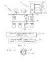
- Fig. 2shows a block schematic of the video control server 16.
- the video control server 16comprises a bus 38 and to this bus there is connected a first communication interface 40 for connection to the first data bus B1, a processor 42, a program memory 44 as well as a second communication interface 49 for communication with the group of video cameras.
- the communication interfaces 40 and 49may be Ethernet communication interfaces.
- program memory 44there is provided software code which when being run by the processor 42 forms a an object determining unit 46 and a view determining unit 48.
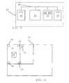
- Fig. 3schematically shows a facility 50 of the industrial plant.
- the facility 50is here in the form of a building with a number of rooms.
- the first process control object 24is located.
- the first roomalso the four video cameras of the first group are provided.
- the first, second, third and fourth video cameras 32, 34, 35, 36are placed in the corners of the first room, for instance one in each corner.
- the video cameras of the second groupare placed.
- the fifth video camera 37is thus placed in the second room.
- the second roomin turn leads to a third larger room.
- In the third roomthere is a door leading out of the premises 50.
- the first roomis also shown as providing an area A that is covered by the first group of video cameras. This area is in this case the first room.
- fig. 4schematically shows a maintenance engineer in the first room with the process control object
- fig. 5schematically shows the transmission of a video stream from one of the video cameras in the first group to the video control server
- fig. 6shows a flow chart of a number of method steps being performed in a method of determining objects present in a process control system
- fig. 7shows a number of additional method steps being performed in a variation of the method.
- All process control objects 24, 26, 28 and 30, which are typically stationary objects,are provided with object identifiers 51, such as optically readable identification tags. These may be barcodes, like one-or two-dimensional bar codes. In this way they can be identified using the video cameras of the video control arrangement 31. However, also other objects in the system such as mobile objects like maintenance engineers and vehicles such as fork lifts may be provided with such object identifiers.
- object identifiers 51such as optically readable identification tags.
- Thesemay be barcodes, like one-or two-dimensional bar codes. In this way they can be identified using the video cameras of the video control arrangement 31.
- other objects in the systemsuch as mobile objects like maintenance engineers and vehicles such as fork lifts may be provided with such object identifiers.
- one maintenance engineer 52being provided with an object identifier 53 in the form of an optically readable identification tag, for instance in the form of a one- or two-dimensional bar code.
- the first process control object 24is equipped with such an optically readable tag 51,
- the video cameras 32, 34, 35, 36 of the first groupare configured to repeatedly scan the area A they are set to cover, step 54, which area is here exemplified by the first room.
- This scanningmay be ordered by the object determining unit 46 and may be performed at regular intervals, such as once every 30 seconds, once a minute or once every fifteen minutes. Scanning may be performed through moving the video camera in a range of angles in a vertical direction and in a range of angles in a horizontal direction. In this scanning the video cameras thus record or register video streams that are transferred to the video control server 16.
- One such video stream VS captured or recorded by the first video camera 32is in fig. 5 schematically shown as being transferred to the video control server 16.
- the video streams being recorded or registered through this scanningare thus forwarded to the object determining unit 46. They may also be stored in a video library, for instance in the memory 44.
- the object determining unit 46analyses the video streams in order to see if there are any object identifiers in them.
- the object determining unit 46thus detects object identifiers of objects in the various video streams, step 56. It may here as an example detect the object identifier 51 of the first process control object 24 as well as the object identifier 53 of the maintenance engineer 52. It may thus detect the bar codes of object identifiers that appear in the line of sights or views of the video cameras when scanning. It may also detect the position of the object. This detection may be made based on a known location of the video camera, the angle(s) of the scan when the object is detected as well as through a determination of the distance between the video camera and the object.
- the memory 44there may furthermore be stored the identifiers of previously detected object identifiers, which known identifiers the object determining unit 46 compares with the newly detected object identifiers. In case the detected identifiers are already known, step 58, then the object determining unit 46 waits until it is time for a new scan and then again orders the video cameras 32, 34, 35 and 36 to perform scanning, step 54. If the first process control object 24 was identified in a previous scanning, the identifier 51 would be handled in this way.
- step 58it is reported to the process control server 22, step 60, which server 22 may thereby be notified of the presence of a process control object or some other object related to the process being in the area A. Also the position may be reported. The process control server 22 can then act upon this knowledge.
- the detected identifiermay also get stored in the memory 44 together with previously detected object identifiers.
- the scanningmay be set to start as soon as the video cameras are installed. This means that the method may be used for determining the objects covered by the video cameras without pre-defining objects in video camera views. This also means that initially there may be no identifiers stored in the memory 44. As an alternative it is possible that some objects are known and that their identifiers are stored in the memory.
- the video streamsmay also be presented, through operator selections, via the display of the monitoring computers 12 and 14.
- the operatormay for instance select an object via process graphics on the monitoring computer and then one or more video streams of video cameras via which an object has been identified.
- the object determining unit 46analyses the recorded video streams VS to see if any of the new objects are stationary or moving. If they are stationary, step 62, then they are registered as process control objects, step 64, and this fact may also be reported to the process control server 22. This is then again followed by a new scan according to the schedule, step 54.
- the registeringmay here involve registering which objects are visible via specific video cameras. It is also possible to register at which angles they are visible as well as the position.
- a previously identified and registered objectis no longer possible to identify in a scan of the area A.
- the object determining unit 46it is possible for the object determining unit 46 to de-register the object and inform the process control server 22 of the object no longer being present in the area A as well as possibly to inform of the last known position of this object.
- step 62it is possible for the operators at the monitoring computers 12 and 14 to select to follow an object. It is for instance possible to determine that an object is mobile through the object having a movement that deviates from the movement caused by the video camera performing the scanning. Therefore if the object determining unit 46 receives an instruction to follow a mobile object, step 66, such as to follow the maintenance engineer 52 with identifier 53, then the video cameras are ordered to follow the object, step 68. It can thus be seen that it is possible to lock onto this object with the video cameras. This may involve following the object from the first room to the second room and may thus involve also the fifth camera 37 following the maintenance engineer 52 if entering the second room. In case there are further video cameras in the second and the third room, it is of course also possible to follow the "object" further.
- the object determining unit 46investigates if the object is in a restricted area. If for instance the object identifier is deemed to be associated with a human and the first process control object contains a chemical substance that is toxic, then it is possible that the human is not allowed to be too close to the first process control object 24.
- step 70the object determining unit 46 may generate an alarm, step 72, which may be presented to the operator via a monitoring computer 12 or 14. The alarm may also be forwarded to the process control server 22. If the mobile object 52 is not in the restricted area then the object determining unit 46 awaits the performing of the next scan, step 54.
- the view determining unit 48may receive an operator selection of a combination of registered process control objects to be viewed, step 74.
- the operatormay for instance perform a logical object combination in the form of (A and B) not (C and D), where A, B, C and D denote different process control objects.
- Such a logical combinationmay specify that the operator desires to view the process control objects A and B, but not process control objects C and D.
- the view determining unit 48thus analyses the operator selections and then selects a video camera and perhaps also a video camera angle that best fulfills the combination selection, i.e. which best meets the operator requirements of objects that are desired to be viewed (and not viewed).
- the camera anglemay be a camera angle in a horizontal position and/or an angle in a vertical direction.
- a video stream from a selected cameracan thus be presented to the operator. It is possible to link further data to an object in a video stream, such as a face plate and process control data of the object such as process measurements. This linking to the object would then be made based on the object identifier and may be accessed by the operator through selecting the object as it is being presented in a video stream.
- the object determining unitmay in this case receive such a user selection and provide a pointer to the corresponding further data, which the monitoring computer may then fetch from the process control system.
- the inventionhas a number of advantages.
- the video camerasmay automatically detect and identify objects in their view. By continuously tracking objects in the picture frames of the video streams, the video cameras will detect identification tags of plant devices or process control objects (such as pumps, tanks or temperature sensors), plant personnel and mobile plant equipment (such as forklifts). Whenever a new object is detected and identified, the process control system will be informed about this object.
- process control objectssuch as pumps, tanks or temperature sensors
- plant personnel and mobile plant equipmentsuch as forklifts
- the automatic object identificationcould be used in a variety of ways:
- This inventionthus allows:
- the object determining unit and view determining unitwere above described as being implemented in a video control server of the process control system. They may as an alternative be provided in one or more of the video cameras. These units may thus be provided in the logic of the video cameras.
- the object determining unit and view determining unitmay furthermore both be provided in the form of one or more processors together with computer program memory including computer program code for performing their functions. As an alternative they may be provided in the form of an Application Specific Integrated Circuit (ASIC) or Field-Programmable Gate Array (FPGA).
- ASICApplication Specific Integrated Circuit
- FPGAField-Programmable Gate Array
- This computer program codemay also be provided on one or more data carriers which perform the functionality of the present invention when the program code thereon is being loaded into an object determination server or the logic of a video camera.
- One such data carrier 78 with computer program code 80, in the form of a CD ROM disc,is schematically shown in fig. 8 .
- Such computer programmay as an alternative be provided on another server and downloaded therefrom into the object determination server and/or a video camera.
- the inventioncan be varied in many ways. Objects were for instance described as being detected via object identifiers in video streams. It is possible with other types of detection.
- a video cameramay for instance be provided with a near field communication reader (NFC) reading an NFC tag on objects. It is also possible to determine a position to which a camera is pointing for instance through using Global Positioning System (GPS) or wireless communication networks and obtain data about objects at these positions in various ways. Moving objects, such as people, may then be identified through mobile terminals, like mobile phones, that they are equipped with and the presence of process control objects may be obtained through investigating a database with positions about these objects. It can therefore be seen that the present invention is only to be limited by the following claims.
Landscapes
- Engineering & Computer Science (AREA)
- Physics & Mathematics (AREA)
- General Physics & Mathematics (AREA)
- Multimedia (AREA)
- Automation & Control Theory (AREA)
- Theoretical Computer Science (AREA)
- Signal Processing (AREA)
- Testing And Monitoring For Control Systems (AREA)
- Alarm Systems (AREA)
- General Factory Administration (AREA)
- Closed-Circuit Television Systems (AREA)
Description
- The present invention generally relates to process control systems. More particularly the present invention relates to a method, video control arrangement and a computer program product for determining objects present in a process control system.
- A process control system normally comprises a number of process control objects involved in the control of the process.
- The process control system does then typically comprise control computers as well as work stations or monitoring computers via which operators can monitor the process. The work stations are then typically provided in a control room.
- It is also customary to have video cameras installed at locations around the process control objects. The cameras capture video images that are streamed to the control room for being observed via the monitoring computers. The operators can then view the video streams on the screens of their monitoring computers and order the cameras to view a particular object. This is possible as the video cameras will change both the angle and zoom to view different objects. Typically the objects are then known in relation to the camera views through having been pre-configured to fit the position of each process control object.
US 2011/0200245 describes a manufacturing control system comprising a vision system for viewing operations within a manufacturing area and for producing vision data representing the viewed operations. A systems control analyzes the vision data, and controls at least two control functions related to the manufacturing operations based on the analyzed vision data.US 2002/0130846 describes a portable computer for use in interfacing to a process control system having a host system includes a housing adapted for hand-held operation, a processing unit disposed within the housing and a computer readable memory disposed within the housing and coupled to the processing unit. The portable computer also includes a display, a keypad and a radio frequency transceiver adapted to communicate with the host system, all of which are disposed within the housing and communicatively coupled to the processing unit. A first software routine stored in the computer readable memory processes a user input received from the keypad and sends a command to the host system via the radio frequency transceiver. Additionally, a second software routine stored in the computer readable memory receives process information sent from the host system in response to the command and displays the received process information via the portable computer display.US 2011/0199487 describes video cameras in a process control system or an automation system where a determination is made of which cameras are in line of sight with an object and also various ways to focus and steer cameras to objects.- Video cameras can also be used in relation to security such as for ensuring that an operator does not come too close to a dangerous machine or process. This is described in
EP 1061487 . - There are a number of problems associated with the above-mentioned use of video cameras.
- For each object that an operator wants to view in a video stream, the parameters must be configured to enable the video camera to show the relevant object. If a camera is moved, i.e. placed in another location, the parameters have to be reconfigured. If a new object is added in front of the camera, this object may also have to be manually added to the process control system.
- Operators may also want to see live images of all objects, but as it requires a lot of manual work to configure a new object this may not be done. In such views there is furthermore no identification available to ensure which process control object is shown. There is no guarantee that the video stream is showing the correct object as the configuration could have been performed incorrectly.
- The present invention is provided for solving one or more of the above described problems.
- The present invention addresses the problem of determining objects being captured with video cameras in a process control system. The invention is more particularly directed towards improving this type of determination.
- This object is according to a first aspect of the invention solved through a method of determining objects present in a process control system, the method being performed by a video control arrangement and comprising the steps of:
- repeatedly scanning an area, via a group of video cameras comprising at least one video camera, in order to obtain a set of video streams,
- determining if there are any new objects associated with the process control system in the area through detecting object identifiers of objects in the video streams,
- determining if a detected new object is stationary or mobile,
- reporting the detected new object to a process control server, and
- registering stationary objects as process control objects.
- This object is according to a second aspect of the invention solved through a video control arrangement for determining objects present in a process control system, the video control arrangement comprising:
- an object determining unit configured to
order a group of video cameras, comprising at least one video camera, to repeatedly scan an area in order to obtain a set of video streams,
determine if there are any new objects associated with the process control system in the area through detecting object identifiers of objects in the video streams,
determine if a detected new object is stationary or mobile,
report the detected new object to a process control server, and
register stationary objects as process control objects. - This object is according to a third aspect of the invention solved through a computer program product for determining objects present in a process control system, the computer program product being provided on a data carrier comprising computer program code adapted to perform the method of the first aspect, when executed on at least one device providing the video control arrangement.
- The present invention has a number of advantages. There is no need to manually program the video cameras to know the location of process control objects as these are automatically determined. There is also no need for reconfigurations of cameras. There is thus no extra work needed if a camera is moved or replaced. If an object known to the process control system but previously not detected in the scanned area is detected in front of one of the video cameras, this object will automatically be reported to the process control system, which system may then update known locations of the object accordingly. The invention also provides cost savings since there is no need for configuring the location of each process control object. There is furthermore no effort involved with the configuring of a new video camera.
- The present invention will in the following be described with reference being made to the accompanying drawings, where
Fig. 1 schematically shows an industrial plant with a process control system operating an industrial process as well as a video control arrangement of the process control system,Fig. 2 schematically shows a block schematic of a video control server of the video control arrangement,Fig. 3 shows premises of the industrial plant with a number of rooms, where a first group of video cameras of the video control arrangement are placed in a first of the rooms comprising a process control object and a second group of video cameras are placed in a second of the rooms,Fig. 4 schematically shows a maintenance engineer in the first room with the process control object,Fig. 5 schematically shows the transmission of a video stream from one of the video cameras in the group to the video control server,Fig. 6 shows a flow chart of a number of method steps being performed in a method of determining objects present in a process control system,Fig. 7 shows a number of additional method steps being performed in the method, andFig. 8 schematically shows a data carrier with computer program code, in the form of a CD-ROM disc, for performing the steps of the method.- In the following, a detailed description of preferred embodiments of a method, data presentation control arrangement and a computer program product for determining objects present in a process control system will be given.
Fig. 1 schematically shows an industrial plant where aprocess control system 10 is provided. Theprocess control system 10 is a computerized process control system for controlling an industrial process. The process can be any type of industrial process, such as electrical power generation, transmission and distribution processes as well as water purification and distribution processes, oil and gas production and distribution processes, petrochemical, chemical, pharmaceutical and food processes, and pulp and paper production processes. These are just some examples of processes where the system can be applied. There exist countless other industrial processes. The processes may also be other types of industrial processes such as the manufacturing of goods. A process may be monitored through one or more process monitoring computers, which communicate with a server handling monitoring and control of the process.- In
fig. 1 theprocess control system 10 therefore includes a number ofprocess monitoring computers video control server 16 connected to this first data bus B1, whichserver 16 is connected to a first and a second group of video cameras, each group comprising at least one video camera. The first group here comprises four video cameras, afirst video camera 32, asecond video camera 34, athird video camera 35 and afourth video camera 36. The second group comprises afifth video camera 37. Thevideo control server 16 together with the first and second group of video cameras furthermore form avideo control arrangement 31. It should be realized that it is possible with more or fewer video cameras in the first and second groups. It is also possible with more and fewer groups of video cameras. - There is furthermore a second data bus B2 and between the first and second data busses B1 and B2 there are connected a
server 18 providing control and protection of the process and adatabase 20 where data relating to control and protection of the process is stored. Such data relating to control and protection may here comprise process data such as measurements and control commands, while data relating to protection may comprise alarm and event data as well as data on which alarms and events can be generated, such as measurements made in the process. There is furthermore aprocess control server 22 connected between the two buses B1 and B2. - To the second data bus B2 there is also connected a number of
further devices further devices process control object 24, which as an example is a tank. Fig. 2 shows a block schematic of thevideo control server 16. Thevideo control server 16 comprises abus 38 and to this bus there is connected afirst communication interface 40 for connection to the first data bus B1, aprocessor 42, aprogram memory 44 as well as asecond communication interface 49 for communication with the group of video cameras. The communication interfaces 40 and 49 may be Ethernet communication interfaces.- In the
program memory 44 there is provided software code which when being run by theprocessor 42 forms a an object determining unit 46 and a view determining unit 48. Fig. 3 schematically shows afacility 50 of the industrial plant. Thefacility 50 is here in the form of a building with a number of rooms. There is here a first room. In this first room the firstprocess control object 24 is located. In the first room also the four video cameras of the first group are provided. In this example the first, second, third andfourth video cameras fifth video camera 37 is thus placed in the second room. The second room in turn leads to a third larger room. In the third room there is a door leading out of thepremises 50. There may also be further video cameras in the second room as well as video cameras also in the third room. However, these have been omitted in order to simplify the description of the invention. The first room is also shown as providing an area A that is covered by the first group of video cameras. This area is in this case the first room.- A first embodiment of the invention will now be described with reference also being made to
fig. 4 - 7 , wherefig. 4 schematically shows a maintenance engineer in the first room with the process control object,fig. 5 schematically shows the transmission of a video stream from one of the video cameras in the first group to the video control server,fig. 6 shows a flow chart of a number of method steps being performed in a method of determining objects present in a process control system andfig. 7 shows a number of additional method steps being performed in a variation of the method. - The invention will now be described in relation to the first group of video cameras. It should however be realized that all groups may operate in the same manner.
- All process control objects 24, 26, 28 and 30, which are typically stationary objects, are provided with
object identifiers 51, such as optically readable identification tags. These may be barcodes, like one-or two-dimensional bar codes. In this way they can be identified using the video cameras of thevideo control arrangement 31. However, also other objects in the system such as mobile objects like maintenance engineers and vehicles such as fork lifts may be provided with such object identifiers. Infig. 4 there is shown onemaintenance engineer 52 being provided with anobject identifier 53 in the form of an optically readable identification tag, for instance in the form of a one- or two-dimensional bar code. Infig. 4 also the firstprocess control object 24 is equipped with such an opticallyreadable tag 51, for instance in the form of a one- or two-dimensional bar code. - As outlined in
fig. 6 , thevideo cameras step 54, which area is here exemplified by the first room. This scanning may be ordered by the object determining unit 46 and may be performed at regular intervals, such as once every 30 seconds, once a minute or once every fifteen minutes. Scanning may be performed through moving the video camera in a range of angles in a vertical direction and in a range of angles in a horizontal direction. In this scanning the video cameras thus record or register video streams that are transferred to thevideo control server 16. One such video stream VS captured or recorded by thefirst video camera 32 is infig. 5 schematically shown as being transferred to thevideo control server 16. The video streams being recorded or registered through this scanning are thus forwarded to the object determining unit 46. They may also be stored in a video library, for instance in thememory 44. - The object determining unit 46 analyses the video streams in order to see if there are any object identifiers in them. The object determining unit 46 thus detects object identifiers of objects in the various video streams,
step 56. It may here as an example detect theobject identifier 51 of the first process control object 24 as well as theobject identifier 53 of themaintenance engineer 52. It may thus detect the bar codes of object identifiers that appear in the line of sights or views of the video cameras when scanning. It may also detect the position of the object. This detection may be made based on a known location of the video camera, the angle(s) of the scan when the object is detected as well as through a determination of the distance between the video camera and the object. - In the
memory 44 there may furthermore be stored the identifiers of previously detected object identifiers, which known identifiers the object determining unit 46 compares with the newly detected object identifiers. In case the detected identifiers are already known,step 58, then the object determining unit 46 waits until it is time for a new scan and then again orders thevideo cameras step 54. If the firstprocess control object 24 was identified in a previous scanning, theidentifier 51 would be handled in this way. - However, in case any detected identifier is not previously known,
step 58, then it is reported to theprocess control server 22,step 60, whichserver 22 may thereby be notified of the presence of a process control object or some other object related to the process being in the area A. Also the position may be reported. Theprocess control server 22 can then act upon this knowledge. The detected identifier may also get stored in thememory 44 together with previously detected object identifiers. - The scanning may be set to start as soon as the video cameras are installed. This means that the method may be used for determining the objects covered by the video cameras without pre-defining objects in video camera views. This also means that initially there may be no identifiers stored in the
memory 44. As an alternative it is possible that some objects are known and that their identifiers are stored in the memory. - The video streams may also be presented, through operator selections, via the display of the
monitoring computers - It is possible for the operator at the
monitoring computers - Because of this the object determining unit 46 analyses the recorded video streams VS to see if any of the new objects are stationary or moving. If they are stationary,
step 62, then they are registered as process control objects,step 64, and this fact may also be reported to theprocess control server 22. This is then again followed by a new scan according to the schedule,step 54. The registering may here involve registering which objects are visible via specific video cameras. It is also possible to register at which angles they are visible as well as the position. - It is furthermore possible that a previously identified and registered object is no longer possible to identify in a scan of the area A. In this case it is possible for the object determining unit 46 to de-register the object and inform the
process control server 22 of the object no longer being present in the area A as well as possibly to inform of the last known position of this object. - If however the objects are not stationary, but mobile,
step 62, it is possible for the operators at themonitoring computers step 66, such as to follow themaintenance engineer 52 withidentifier 53, then the video cameras are ordered to follow the object,step 68. It can thus be seen that it is possible to lock onto this object with the video cameras. This may involve following the object from the first room to the second room and may thus involve also thefifth camera 37 following themaintenance engineer 52 if entering the second room. In case there are further video cameras in the second and the third room, it is of course also possible to follow the "object" further. - In both cases, whether the object is to be followed or not, the object determining unit 46 investigates if the object is in a restricted area. If for instance the object identifier is deemed to be associated with a human and the first process control object contains a chemical substance that is toxic, then it is possible that the human is not allowed to be too close to the first
process control object 24. - If the mobile object is deemed to be within a restricted area,
step 70, then the object determining unit 46 may generate an alarm,step 72, which may be presented to the operator via amonitoring computer process control server 22. If themobile object 52 is not in the restricted area then the object determining unit 46 awaits the performing of the next scan,step 54. - It can thus be seen that it is possible to follow or lock to a mobile object and if this object, as it is being followed, enters a restricted area, then an alarm is generated.
- It is also possible for the operator to make selections of how the stationary process control objects are to be viewed. Such selections are handled by the view determining unit 48. The view determining unit 48 may receive an operator selection of a combination of registered process control objects to be viewed,
step 74. The operator may for instance perform a logical object combination in the form of (A and B) not (C and D), where A, B, C and D denote different process control objects. Such a logical combination may specify that the operator desires to view the process control objects A and B, but not process control objects C and D. - The view determining unit 48 thus analyses the operator selections and then selects a video camera and perhaps also a video camera angle that best fulfills the combination selection, i.e. which best meets the operator requirements of objects that are desired to be viewed (and not viewed). The camera angle may be a camera angle in a horizontal position and/or an angle in a vertical direction.
- A video stream from a selected camera can thus be presented to the operator. It is possible to link further data to an object in a video stream, such as a face plate and process control data of the object such as process measurements. This linking to the object would then be made based on the object identifier and may be accessed by the operator through selecting the object as it is being presented in a video stream. The object determining unit may in this case receive such a user selection and provide a pointer to the corresponding further data, which the monitoring computer may then fetch from the process control system.
- The invention has a number of advantages. The video cameras may automatically detect and identify objects in their view. By continuously tracking objects in the picture frames of the video streams, the video cameras will detect identification tags of plant devices or process control objects (such as pumps, tanks or temperature sensors), plant personnel and mobile plant equipment (such as forklifts). Whenever a new object is detected and identified, the process control system will be informed about this object.
- As was discussed above, the automatic object identification could be used in a variety of ways:
- The operator could select to view all the different video camera views of a particular object.
- A moving object can be traced from one video camera to another. If the operator selects to lock a video camera view on a specific moving object (person or vehicle) the video cameras may then try to focus on the object whenever it moves.
- The operator may also perform smart requests such as "Show me the video camera view where both object x and y are visible".
- As persons are also identified, the operators can track colleagues to find out where they are located.
- If mobile equipment or personnel are detected in a restricted area, the video control arrangement can automatically raise an alarm.
- The following use case scenario can occur when using the invention:
- 1. A
new video camera 32 is mounted on the wall of the first room. - 2. The
video camera 32 is, when idle, continuously scanning (by movements) the environment for any object identifiers. - 3. Whenever an object identifier is found, the information is uploaded to the
process control server 32. No manual configuration is needed. - 4. Operator Nick just obtained an alarm from
Tank 24. Before Nick orders maintenance assistance he wants to confirm the tank status from the video cameras. - 5. He selects the tank from the process graphics on his
operator screen 12 and requests a list of all video camera views that contains thetank 24. - 6. A list of video camera views, populated from the video cameras themselves, is then seen on the screen. All different views contain the
tank 24. - 7. Nick browses through all the video camera views to get a good understanding of the
tank 24. - 8. Suddenly Nick receives an alarm, which indicates that
Nina 52 just entered a restricted area. The alarm is triggered by a camera that has detected theobject identifier 53 ofNina 52. - This invention thus allows:
- Automatic configuration of video camera views. There is no longer any need to manual program the cameras to know the location of process control objects as the video cameras together with the object determining unit themselves identify the objects in their surroundings.
- Redundant video camera views. Several cameras may view the same object from different angles. This prevents the operator from being totally dependent on only one camera, which can be broken or incorrectly configured.
- A moving object can be traced from one camera to another. When the operator selects to lock a video camera view on a specific moving object (person or vehicle) the video cameras are trying to focus on the object whenever it moves.
- Smart requests of video camera views. The operator may perform smart requests, such as "Show me the video camera view where both object x and y are visible but not z".
- Restriction of dangerous areas. As persons can be detected by the cameras, the video control arrangement may immediately detect if some unauthorized person is entering a dangerous or restricted area.
- No need for reconfiguration. As the video cameras automatically updates the process control system if there are new surrounding objects, there is no extra work needed if a camera is moved, or replaced.
- Real time tracking. Mobile objects as vehicles or persons may be tracked. If an object known to the process control system but previously not detected in the covered area is detected in front of one of the video cameras, this object will automatically be reported to the process control system, which system may then update known locations of the object accordingly.
- Several views of an object increases process understanding. Process control objects are recorded using several video cameras, which dramatically improves the operator's situation awareness.
- Several further benefits can be listed for this invention:
- Cost savings. There is no need for configuring the location of each process control object. The video cameras will find them without requiring manual labor.
- Improved situation awareness. With many views of the same process control object, the operators gain a much better comprehension of the process.
- Effortless to configure a new video camera.
- Safety. The video cameras report the location of persons, which may be used to generate an alarm if any unauthorized person enters a blocked area.
- The object determining unit and view determining unit were above described as being implemented in a video control server of the process control system. They may as an alternative be provided in one or more of the video cameras. These units may thus be provided in the logic of the video cameras.
- The object determining unit and view determining unit may furthermore both be provided in the form of one or more processors together with computer program memory including computer program code for performing their functions. As an alternative they may be provided in the form of an Application Specific Integrated Circuit (ASIC) or Field-Programmable Gate Array (FPGA). This computer program code may also be provided on one or more data carriers which perform the functionality of the present invention when the program code thereon is being loaded into an object determination server or the logic of a video camera. One
such data carrier 78 withcomputer program code 80, in the form of a CD ROM disc, is schematically shown infig. 8 . Such computer program may as an alternative be provided on another server and downloaded therefrom into the object determination server and/or a video camera. - The invention can be varied in many ways. Objects were for instance described as being detected via object identifiers in video streams. It is possible with other types of detection. A video camera may for instance be provided with a near field communication reader (NFC) reading an NFC tag on objects. It is also possible to determine a position to which a camera is pointing for instance through using Global Positioning System (GPS) or wireless communication networks and obtain data about objects at these positions in various ways. Moving objects, such as people, may then be identified through mobile terminals, like mobile phones, that they are equipped with and the presence of process control objects may be obtained through investigating a database with positions about these objects. It can therefore be seen that the present invention is only to be limited by the following claims.
Claims (13)
- A method of determining objects (24; 52) present in a process control system (10), the method being performed by a video control arrangement (31) and comprising the steps of:- repeatedly scanning (56) an area (A), via a group of video cameras (32, 34, 35, 36) comprising at least one video camera, in order to obtain a set of video streams (VS), and- determining (58) if there are any new objects (24; 52) associated with the process control system in the area through detecting object identifiers (51; 53) of objects in the video streams,
characterised by the further steps of- determining if a detected new object is stationary or mobile,- reporting (60) the detected new object to a process control server (22), and- registering (64) stationary objects as process control objects. - The method according to claim 1, where there is more than one video camera covering the area from different angles, the method further comprising receiving (74), from an operator, a selection of a combination of registered objects to be monitored and selecting (76) a video camera angle that best meets the operator combination selection desired to be viewed.
- The method according to any previous claim, wherein if (62) the detected new object (52) is moving, by further comprising receiving (66), from an operator, a selection to follow the moving object and following (68), using video cameras of the video control arrangement, the moving object as it moves in the area.
- The method according to claim 3, further comprising determining (70) if the moving object is in a restricted area and generating (72) an alarm if it is.
- The method according to any previous claim, wherein the object identifiers (51; 53) are provided as optically readable codes.
- A video control arrangement (31) for determining objects (24; 52) present in a process control system (10), the video control arrangement comprising:- an object determining unit (46) configured to order a group of video cameras (32, 34, 35, 36), comprising at least one video camera (32), to repeatedly scan an area (A) in order to obtain a set of video streams (VS), and determine if there are any new objects (24; 52) associated with the process control system in the area through detecting object identifiers (51; 53) of objects in the video streams,
characterised by the object determining unit (46) being further configured to
determine if a detected new object is stationary or mobile,
report the detected new object to a process control server (22), and
register stationary objects as process control objects. - The video control arrangement according to claim 6, where the video cameras cover the area from different angles and the arrangement further comprises a view determining unit (48) configured to receive, from an operator, a selection of a combination of registered objects to be monitored and select a video camera angle that best meets the operator combination selection desired to be viewed.
- The video control arrangement according to any of claims 6 - 7, wherein if the detected new object (52) is moving and if the object determining unit receives an operator selection to follow the moving object it is further configured to order the video cameras in the group to follow the moving object as it moves in the area.
- The video control arrangement according to claim 8, wherein the object determining unit is further configured to determine if the moving object is in a restricted area and generate an alarm if it is.
- The video control arrangement according to any of claims 6 - 9, further comprising the group of video cameras.
- The video control arrangement according to any of claims 6 - 10, wherein units of the video control arrangement are provided in a video control server (16) of the process control system.
- The video control arrangement according to any of claims 6 - 10, wherein units of the video control arrangement are provided in at least one of the video cameras.
- A computer program product for determining objects (24; 52) present in a process control system (10), said computer program product being provided on a data carrier (78) comprising computer program code (80) adapted to perform the method of claim 1, when executed on at least one device providing the video control arrangement.
Priority Applications (4)
| Application Number | Priority Date | Filing Date | Title |
|---|---|---|---|
| EP12176383.3AEP2685421B1 (en) | 2012-07-13 | 2012-07-13 | Determining objects present in a process control system |
| PCT/EP2013/062101WO2014009087A1 (en) | 2012-07-13 | 2013-06-12 | Presenting process data of a process control object on a mobile terminal |
| CN201380037495.9ACN104508701B (en) | 2012-07-13 | 2013-06-12 | The method and video control device of object present in determination process control system |
| US14/398,815US20150116498A1 (en) | 2012-07-13 | 2013-06-12 | Presenting process data of a process control object on a mobile terminal |
Applications Claiming Priority (1)
| Application Number | Priority Date | Filing Date | Title |
|---|---|---|---|
| EP12176383.3AEP2685421B1 (en) | 2012-07-13 | 2012-07-13 | Determining objects present in a process control system |
Publications (2)
| Publication Number | Publication Date |
|---|---|
| EP2685421A1 EP2685421A1 (en) | 2014-01-15 |
| EP2685421B1true EP2685421B1 (en) | 2015-10-07 |
Family
ID=48579118
Family Applications (1)
| Application Number | Title | Priority Date | Filing Date |
|---|---|---|---|
| EP12176383.3AActiveEP2685421B1 (en) | 2012-07-13 | 2012-07-13 | Determining objects present in a process control system |
Country Status (4)
| Country | Link |
|---|---|
| US (1) | US20150116498A1 (en) |
| EP (1) | EP2685421B1 (en) |
| CN (1) | CN104508701B (en) |
| WO (1) | WO2014009087A1 (en) |
Families Citing this family (41)
| Publication number | Priority date | Publication date | Assignee | Title |
|---|---|---|---|---|
| US8908995B2 (en) | 2009-01-12 | 2014-12-09 | Intermec Ip Corp. | Semi-automatic dimensioning with imager on a portable device |
| US9146559B2 (en)* | 2011-03-18 | 2015-09-29 | The Raymond Corporation | System and method for gathering video data related to operation of an autonomous industrial vehicle |
| US9779546B2 (en) | 2012-05-04 | 2017-10-03 | Intermec Ip Corp. | Volume dimensioning systems and methods |
| US10007858B2 (en) | 2012-05-15 | 2018-06-26 | Honeywell International Inc. | Terminals and methods for dimensioning objects |
| JP5861564B2 (en)* | 2012-06-01 | 2016-02-16 | ソニー株式会社 | Information processing apparatus, information processing method, and program |
| US10321127B2 (en) | 2012-08-20 | 2019-06-11 | Intermec Ip Corp. | Volume dimensioning system calibration systems and methods |
| US9939259B2 (en) | 2012-10-04 | 2018-04-10 | Hand Held Products, Inc. | Measuring object dimensions using mobile computer |
| US20140104413A1 (en) | 2012-10-16 | 2014-04-17 | Hand Held Products, Inc. | Integrated dimensioning and weighing system |
| US9080856B2 (en) | 2013-03-13 | 2015-07-14 | Intermec Ip Corp. | Systems and methods for enhancing dimensioning, for example volume dimensioning |
| US10228452B2 (en) | 2013-06-07 | 2019-03-12 | Hand Held Products, Inc. | Method of error correction for 3D imaging device |
| EP2913730B1 (en)* | 2014-02-28 | 2019-10-30 | ABB Schweiz AG | Use of a live video stream in a process control system |
| US9823059B2 (en) | 2014-08-06 | 2017-11-21 | Hand Held Products, Inc. | Dimensioning system with guided alignment |
| KR102150703B1 (en) | 2014-08-14 | 2020-09-01 | 한화테크윈 주식회사 | Intelligent video analysing system and video analysing method therein |
| US10810715B2 (en) | 2014-10-10 | 2020-10-20 | Hand Held Products, Inc | System and method for picking validation |
| US9779276B2 (en) | 2014-10-10 | 2017-10-03 | Hand Held Products, Inc. | Depth sensor based auto-focus system for an indicia scanner |
| US10775165B2 (en) | 2014-10-10 | 2020-09-15 | Hand Held Products, Inc. | Methods for improving the accuracy of dimensioning-system measurements |
| US9897434B2 (en) | 2014-10-21 | 2018-02-20 | Hand Held Products, Inc. | Handheld dimensioning system with measurement-conformance feedback |
| US9752864B2 (en) | 2014-10-21 | 2017-09-05 | Hand Held Products, Inc. | Handheld dimensioning system with feedback |
| US10060729B2 (en) | 2014-10-21 | 2018-08-28 | Hand Held Products, Inc. | Handheld dimensioner with data-quality indication |
| US9762793B2 (en) | 2014-10-21 | 2017-09-12 | Hand Held Products, Inc. | System and method for dimensioning |
| US9786101B2 (en) | 2015-05-19 | 2017-10-10 | Hand Held Products, Inc. | Evaluating image values |
| US10066982B2 (en) | 2015-06-16 | 2018-09-04 | Hand Held Products, Inc. | Calibrating a volume dimensioner |
| US20160377414A1 (en) | 2015-06-23 | 2016-12-29 | Hand Held Products, Inc. | Optical pattern projector |
| US9835486B2 (en) | 2015-07-07 | 2017-12-05 | Hand Held Products, Inc. | Mobile dimensioner apparatus for use in commerce |
| EP3118576B1 (en) | 2015-07-15 | 2018-09-12 | Hand Held Products, Inc. | Mobile dimensioning device with dynamic accuracy compatible with nist standard |
| US10094650B2 (en) | 2015-07-16 | 2018-10-09 | Hand Held Products, Inc. | Dimensioning and imaging items |
| US20170017301A1 (en) | 2015-07-16 | 2017-01-19 | Hand Held Products, Inc. | Adjusting dimensioning results using augmented reality |
| US10249030B2 (en) | 2015-10-30 | 2019-04-02 | Hand Held Products, Inc. | Image transformation for indicia reading |
| US10225544B2 (en) | 2015-11-19 | 2019-03-05 | Hand Held Products, Inc. | High resolution dot pattern |
| US10025314B2 (en)* | 2016-01-27 | 2018-07-17 | Hand Held Products, Inc. | Vehicle positioning and object avoidance |
| US10339352B2 (en) | 2016-06-03 | 2019-07-02 | Hand Held Products, Inc. | Wearable metrological apparatus |
| US9940721B2 (en) | 2016-06-10 | 2018-04-10 | Hand Held Products, Inc. | Scene change detection in a dimensioner |
| US10163216B2 (en) | 2016-06-15 | 2018-12-25 | Hand Held Products, Inc. | Automatic mode switching in a volume dimensioner |
| GB2553108B (en)* | 2016-08-22 | 2020-07-15 | Canon Kk | Method, processing device and system for managing copies of media samples in a system comprising a plurality of interconnected network cameras |
| US10909708B2 (en) | 2016-12-09 | 2021-02-02 | Hand Held Products, Inc. | Calibrating a dimensioner using ratios of measurable parameters of optic ally-perceptible geometric elements |
| US11047672B2 (en) | 2017-03-28 | 2021-06-29 | Hand Held Products, Inc. | System for optically dimensioning |
| US10584962B2 (en) | 2018-05-01 | 2020-03-10 | Hand Held Products, Inc | System and method for validating physical-item security |
| US20190337451A1 (en)* | 2018-05-02 | 2019-11-07 | GM Global Technology Operations LLC | Remote vehicle spatial awareness notification system |
| CN112118420A (en)* | 2020-08-28 | 2020-12-22 | 湖南三湘银行股份有限公司 | Automatic configuration method and device for monitoring system |
| US11354994B1 (en)* | 2021-05-04 | 2022-06-07 | Motorola Solutions, Inc. | Analytics for planning an upgrade to a video camera surveillance system |
| CN113949811A (en)* | 2021-10-14 | 2022-01-18 | 广州威拓电子科技有限公司 | Method and device for shooting vehicle |
Family Cites Families (12)
| Publication number | Priority date | Publication date | Assignee | Title |
|---|---|---|---|---|
| US6806847B2 (en)* | 1999-02-12 | 2004-10-19 | Fisher-Rosemount Systems Inc. | Portable computer in a process control environment |
| EP1061487A1 (en) | 1999-06-17 | 2000-12-20 | Istituto Trentino Di Cultura | A method and device for automatically controlling a region in space |
| WO2003010727A1 (en)* | 2001-07-25 | 2003-02-06 | Vislog Technology Pte Ltd. | Method and apparatus for processing image data |
| US9052386B2 (en)* | 2002-02-06 | 2015-06-09 | Nice Systems, Ltd | Method and apparatus for video frame sequence-based object tracking |
| WO2005071634A2 (en)* | 2004-01-27 | 2005-08-04 | Richard Turner | Method and apparatus for detection and tracking of objects within a defined area |
| US20050225634A1 (en)* | 2004-04-05 | 2005-10-13 | Sam Brunetti | Closed circuit TV security system |
| US7746378B2 (en)* | 2004-10-12 | 2010-06-29 | International Business Machines Corporation | Video analysis, archiving and alerting methods and apparatus for a distributed, modular and extensible video surveillance system |
| JP5040258B2 (en)* | 2006-10-23 | 2012-10-03 | 株式会社日立製作所 | Video surveillance apparatus, video surveillance system, and image processing method |
| DE602007007576D1 (en) | 2007-03-30 | 2010-08-19 | Abb Research Ltd | Method of operating remote-controlled cameras in an industrial process |
| US9377778B2 (en)* | 2010-02-17 | 2016-06-28 | The Boeing Company | Integration of manufacturing control functions using a multi-functional vision system |
| WO2011153624A2 (en)* | 2010-06-11 | 2011-12-15 | Ambercore Software Inc. | System and method for manipulating data having spatial coordinates |
| US20130265423A1 (en)* | 2012-04-06 | 2013-10-10 | Xerox Corporation | Video-based detector and notifier for short-term parking violation enforcement |
- 2012
- 2012-07-13EPEP12176383.3Apatent/EP2685421B1/enactiveActive
- 2013
- 2013-06-12USUS14/398,815patent/US20150116498A1/ennot_activeAbandoned
- 2013-06-12CNCN201380037495.9Apatent/CN104508701B/enactiveActive
- 2013-06-12WOPCT/EP2013/062101patent/WO2014009087A1/enactiveApplication Filing
Also Published As
| Publication number | Publication date |
|---|---|
| CN104508701B (en) | 2018-10-12 |
| EP2685421A1 (en) | 2014-01-15 |
| WO2014009087A1 (en) | 2014-01-16 |
| CN104508701A (en) | 2015-04-08 |
| US20150116498A1 (en) | 2015-04-30 |
Similar Documents
| Publication | Publication Date | Title |
|---|---|---|
| EP2685421B1 (en) | Determining objects present in a process control system | |
| US11783553B2 (en) | Systems and methods for facilitating creation of a map of a real-world, process control environment | |
| US10832548B2 (en) | Advanced industrial safety notification systems | |
| JP7347900B2 (en) | Method and apparatus for controlling a process plant with a location-aware mobile control device | |
| US11244515B2 (en) | 3D mapping of a process control environment | |
| EP3482887B1 (en) | Augmented reality safety automation zone system and method | |
| CN110244669B (en) | Mobile control room with real-time environment perception | |
| EP2687926A2 (en) | Common collaboration context between a console operator and a field operator | |
| GB2513958A (en) | Supervisor engine for process control | |
| GB2513956A (en) | Context sensitive mobile control in a process plant | |
| GB2513709A (en) | Method and apparatus for managing a work flow in a process plant | |
| GB2513708A (en) | Method and apparatus for seamless state transfer between user interface devices in a mobile control room | |
| GB2513455A (en) | Generating checklists in a process control environment | |
| GB2513456A (en) | Mobile analysis of physical phenomena in a process plant | |
| GB2513457A (en) | Method and apparatus for controlling a process plant with location aware mobile control devices | |
| GB2513000A (en) | Method and apparatus for seamless state transfer between user interface devices in a mobile control room | |
| GB2512999A (en) | Method and apparatus for seamless state transfer between user interface devices in a mobile control room | |
| GB2513957A (en) | Method and apparatus for determining the position of a mobile control device in a process plant | |
| GB2513707A (en) | Method for initiating or resuming a mobile control session in a process plant | |
| CN104049591B (en) | Method for initiating or restoring a mobile control session in a process plant | |
| GB2606650A (en) | Drift correction for industrial augmented reality applications |
Legal Events
| Date | Code | Title | Description |
|---|---|---|---|
| PUAI | Public reference made under article 153(3) epc to a published international application that has entered the european phase | Free format text:ORIGINAL CODE: 0009012 | |
| AK | Designated contracting states | Kind code of ref document:A1 Designated state(s):AL AT BE BG CH CY CZ DE DK EE ES FI FR GB GR HR HU IE IS IT LI LT LU LV MC MK MT NL NO PL PT RO RS SE SI SK SM TR | |
| AX | Request for extension of the european patent | Extension state:BA ME | |
| 17P | Request for examination filed | Effective date:20140715 | |
| RBV | Designated contracting states (corrected) | Designated state(s):AL AT BE BG CH CY CZ DE DK EE ES FI FR GB GR HR HU IE IS IT LI LT LU LV MC MK MT NL NO PL PT RO RS SE SI SK SM TR | |
| REG | Reference to a national code | Ref country code:DE Ref legal event code:R079 Ref document number:602012011275 Country of ref document:DE Free format text:PREVIOUS MAIN CLASS: G06T0001000000 Ipc:G05B0019042000 | |
| GRAP | Despatch of communication of intention to grant a patent | Free format text:ORIGINAL CODE: EPIDOSNIGR1 | |
| RIC1 | Information provided on ipc code assigned before grant | Ipc:G06K 9/00 20060101ALI20150511BHEP Ipc:H04N 7/18 20060101ALI20150511BHEP Ipc:G05B 19/042 20060101AFI20150511BHEP | |
| INTG | Intention to grant announced | Effective date:20150608 | |
| GRAS | Grant fee paid | Free format text:ORIGINAL CODE: EPIDOSNIGR3 | |
| GRAA | (expected) grant | Free format text:ORIGINAL CODE: 0009210 | |
| AK | Designated contracting states | Kind code of ref document:B1 Designated state(s):AL AT BE BG CH CY CZ DE DK EE ES FI FR GB GR HR HU IE IS IT LI LT LU LV MC MK MT NL NO PL PT RO RS SE SI SK SM TR | |
| REG | Reference to a national code | Ref country code:GB Ref legal event code:FG4D | |
| REG | Reference to a national code | Ref country code:AT Ref legal event code:REF Ref document number:754115 Country of ref document:AT Kind code of ref document:T Effective date:20151015 Ref country code:CH Ref legal event code:EP | |
| REG | Reference to a national code | Ref country code:IE Ref legal event code:FG4D | |
| REG | Reference to a national code | Ref country code:DE Ref legal event code:R096 Ref document number:602012011275 Country of ref document:DE | |
| REG | Reference to a national code | Ref country code:NL Ref legal event code:MP Effective date:20151007 | |
| REG | Reference to a national code | Ref country code:AT Ref legal event code:MK05 Ref document number:754115 Country of ref document:AT Kind code of ref document:T Effective date:20151007 | |
| REG | Reference to a national code | Ref country code:LT Ref legal event code:MG4D | |
| PG25 | Lapsed in a contracting state [announced via postgrant information from national office to epo] | Ref country code:ES Free format text:LAPSE BECAUSE OF FAILURE TO SUBMIT A TRANSLATION OF THE DESCRIPTION OR TO PAY THE FEE WITHIN THE PRESCRIBED TIME-LIMIT Effective date:20151007 Ref country code:LT Free format text:LAPSE BECAUSE OF FAILURE TO SUBMIT A TRANSLATION OF THE DESCRIPTION OR TO PAY THE FEE WITHIN THE PRESCRIBED TIME-LIMIT Effective date:20151007 Ref country code:IT Free format text:LAPSE BECAUSE OF FAILURE TO SUBMIT A TRANSLATION OF THE DESCRIPTION OR TO PAY THE FEE WITHIN THE PRESCRIBED TIME-LIMIT Effective date:20151007 Ref country code:IS Free format text:LAPSE BECAUSE OF FAILURE TO SUBMIT A TRANSLATION OF THE DESCRIPTION OR TO PAY THE FEE WITHIN THE PRESCRIBED TIME-LIMIT Effective date:20160207 Ref country code:NL Free format text:LAPSE BECAUSE OF FAILURE TO SUBMIT A TRANSLATION OF THE DESCRIPTION OR TO PAY THE FEE WITHIN THE PRESCRIBED TIME-LIMIT Effective date:20151007 Ref country code:HR Free format text:LAPSE BECAUSE OF FAILURE TO SUBMIT A TRANSLATION OF THE DESCRIPTION OR TO PAY THE FEE WITHIN THE PRESCRIBED TIME-LIMIT Effective date:20151007 Ref country code:NO Free format text:LAPSE BECAUSE OF FAILURE TO SUBMIT A TRANSLATION OF THE DESCRIPTION OR TO PAY THE FEE WITHIN THE PRESCRIBED TIME-LIMIT Effective date:20160107 | |
| PG25 | Lapsed in a contracting state [announced via postgrant information from national office to epo] | Ref country code:FI Free format text:LAPSE BECAUSE OF FAILURE TO SUBMIT A TRANSLATION OF THE DESCRIPTION OR TO PAY THE FEE WITHIN THE PRESCRIBED TIME-LIMIT Effective date:20151007 Ref country code:PL Free format text:LAPSE BECAUSE OF FAILURE TO SUBMIT A TRANSLATION OF THE DESCRIPTION OR TO PAY THE FEE WITHIN THE PRESCRIBED TIME-LIMIT Effective date:20151007 Ref country code:PT Free format text:LAPSE BECAUSE OF FAILURE TO SUBMIT A TRANSLATION OF THE DESCRIPTION OR TO PAY THE FEE WITHIN THE PRESCRIBED TIME-LIMIT Effective date:20160208 Ref country code:GR Free format text:LAPSE BECAUSE OF FAILURE TO SUBMIT A TRANSLATION OF THE DESCRIPTION OR TO PAY THE FEE WITHIN THE PRESCRIBED TIME-LIMIT Effective date:20160108 Ref country code:SE Free format text:LAPSE BECAUSE OF FAILURE TO SUBMIT A TRANSLATION OF THE DESCRIPTION OR TO PAY THE FEE WITHIN THE PRESCRIBED TIME-LIMIT Effective date:20151007 Ref country code:RS Free format text:LAPSE BECAUSE OF FAILURE TO SUBMIT A TRANSLATION OF THE DESCRIPTION OR TO PAY THE FEE WITHIN THE PRESCRIBED TIME-LIMIT Effective date:20151007 Ref country code:LV Free format text:LAPSE BECAUSE OF FAILURE TO SUBMIT A TRANSLATION OF THE DESCRIPTION OR TO PAY THE FEE WITHIN THE PRESCRIBED TIME-LIMIT Effective date:20151007 Ref country code:AT Free format text:LAPSE BECAUSE OF FAILURE TO SUBMIT A TRANSLATION OF THE DESCRIPTION OR TO PAY THE FEE WITHIN THE PRESCRIBED TIME-LIMIT Effective date:20151007 | |
| REG | Reference to a national code | Ref country code:DE Ref legal event code:R097 Ref document number:602012011275 Country of ref document:DE | |
| REG | Reference to a national code | Ref country code:FR Ref legal event code:PLFP Year of fee payment:5 | |
| PG25 | Lapsed in a contracting state [announced via postgrant information from national office to epo] | Ref country code:CZ Free format text:LAPSE BECAUSE OF FAILURE TO SUBMIT A TRANSLATION OF THE DESCRIPTION OR TO PAY THE FEE WITHIN THE PRESCRIBED TIME-LIMIT Effective date:20151007 | |
| PLBE | No opposition filed within time limit | Free format text:ORIGINAL CODE: 0009261 | |
| STAA | Information on the status of an ep patent application or granted ep patent | Free format text:STATUS: NO OPPOSITION FILED WITHIN TIME LIMIT | |
| PG25 | Lapsed in a contracting state [announced via postgrant information from national office to epo] | Ref country code:SK Free format text:LAPSE BECAUSE OF FAILURE TO SUBMIT A TRANSLATION OF THE DESCRIPTION OR TO PAY THE FEE WITHIN THE PRESCRIBED TIME-LIMIT Effective date:20151007 Ref country code:DK Free format text:LAPSE BECAUSE OF FAILURE TO SUBMIT A TRANSLATION OF THE DESCRIPTION OR TO PAY THE FEE WITHIN THE PRESCRIBED TIME-LIMIT Effective date:20151007 Ref country code:SM Free format text:LAPSE BECAUSE OF FAILURE TO SUBMIT A TRANSLATION OF THE DESCRIPTION OR TO PAY THE FEE WITHIN THE PRESCRIBED TIME-LIMIT Effective date:20151007 Ref country code:RO Free format text:LAPSE BECAUSE OF FAILURE TO SUBMIT A TRANSLATION OF THE DESCRIPTION OR TO PAY THE FEE WITHIN THE PRESCRIBED TIME-LIMIT Effective date:20151007 Ref country code:EE Free format text:LAPSE BECAUSE OF FAILURE TO SUBMIT A TRANSLATION OF THE DESCRIPTION OR TO PAY THE FEE WITHIN THE PRESCRIBED TIME-LIMIT Effective date:20151007 | |
| 26N | No opposition filed | Effective date:20160708 | |
| PG25 | Lapsed in a contracting state [announced via postgrant information from national office to epo] | Ref country code:SI Free format text:LAPSE BECAUSE OF FAILURE TO SUBMIT A TRANSLATION OF THE DESCRIPTION OR TO PAY THE FEE WITHIN THE PRESCRIBED TIME-LIMIT Effective date:20151007 | |
| PG25 | Lapsed in a contracting state [announced via postgrant information from national office to epo] | Ref country code:BE Free format text:LAPSE BECAUSE OF FAILURE TO SUBMIT A TRANSLATION OF THE DESCRIPTION OR TO PAY THE FEE WITHIN THE PRESCRIBED TIME-LIMIT Effective date:20151007 | |
| REG | Reference to a national code | Ref country code:CH Ref legal event code:PL | |
| GBPC | Gb: european patent ceased through non-payment of renewal fee | Effective date:20160713 | |
| PG25 | Lapsed in a contracting state [announced via postgrant information from national office to epo] | Ref country code:MC Free format text:LAPSE BECAUSE OF FAILURE TO SUBMIT A TRANSLATION OF THE DESCRIPTION OR TO PAY THE FEE WITHIN THE PRESCRIBED TIME-LIMIT Effective date:20151007 | |
| PG25 | Lapsed in a contracting state [announced via postgrant information from national office to epo] | Ref country code:CH Free format text:LAPSE BECAUSE OF NON-PAYMENT OF DUE FEES Effective date:20160731 Ref country code:LI Free format text:LAPSE BECAUSE OF NON-PAYMENT OF DUE FEES Effective date:20160731 | |
| REG | Reference to a national code | Ref country code:IE Ref legal event code:MM4A | |
| PG25 | Lapsed in a contracting state [announced via postgrant information from national office to epo] | Ref country code:GB Free format text:LAPSE BECAUSE OF NON-PAYMENT OF DUE FEES Effective date:20160713 | |
| REG | Reference to a national code | Ref country code:FR Ref legal event code:PLFP Year of fee payment:6 | |
| PG25 | Lapsed in a contracting state [announced via postgrant information from national office to epo] | Ref country code:IE Free format text:LAPSE BECAUSE OF NON-PAYMENT OF DUE FEES Effective date:20160713 | |
| PG25 | Lapsed in a contracting state [announced via postgrant information from national office to epo] | Ref country code:LU Free format text:LAPSE BECAUSE OF NON-PAYMENT OF DUE FEES Effective date:20160713 | |
| PG25 | Lapsed in a contracting state [announced via postgrant information from national office to epo] | Ref country code:HU Free format text:LAPSE BECAUSE OF FAILURE TO SUBMIT A TRANSLATION OF THE DESCRIPTION OR TO PAY THE FEE WITHIN THE PRESCRIBED TIME-LIMIT; INVALID AB INITIO Effective date:20120713 Ref country code:CY Free format text:LAPSE BECAUSE OF FAILURE TO SUBMIT A TRANSLATION OF THE DESCRIPTION OR TO PAY THE FEE WITHIN THE PRESCRIBED TIME-LIMIT Effective date:20151007 | |
| PG25 | Lapsed in a contracting state [announced via postgrant information from national office to epo] | Ref country code:MT Free format text:LAPSE BECAUSE OF NON-PAYMENT OF DUE FEES Effective date:20160731 Ref country code:TR Free format text:LAPSE BECAUSE OF FAILURE TO SUBMIT A TRANSLATION OF THE DESCRIPTION OR TO PAY THE FEE WITHIN THE PRESCRIBED TIME-LIMIT Effective date:20151007 Ref country code:MK Free format text:LAPSE BECAUSE OF FAILURE TO SUBMIT A TRANSLATION OF THE DESCRIPTION OR TO PAY THE FEE WITHIN THE PRESCRIBED TIME-LIMIT Effective date:20151007 | |
| REG | Reference to a national code | Ref country code:FR Ref legal event code:PLFP Year of fee payment:7 | |
| PG25 | Lapsed in a contracting state [announced via postgrant information from national office to epo] | Ref country code:BG Free format text:LAPSE BECAUSE OF FAILURE TO SUBMIT A TRANSLATION OF THE DESCRIPTION OR TO PAY THE FEE WITHIN THE PRESCRIBED TIME-LIMIT Effective date:20151007 | |
| PG25 | Lapsed in a contracting state [announced via postgrant information from national office to epo] | Ref country code:AL Free format text:LAPSE BECAUSE OF FAILURE TO SUBMIT A TRANSLATION OF THE DESCRIPTION OR TO PAY THE FEE WITHIN THE PRESCRIBED TIME-LIMIT Effective date:20151007 | |
| REG | Reference to a national code | Ref country code:DE Ref legal event code:R081 Ref document number:602012011275 Country of ref document:DE Owner name:ABB SCHWEIZ AG, CH Free format text:FORMER OWNER: ABB RESEARCH LTD., ZUERICH, CH | |
| PGFP | Annual fee paid to national office [announced via postgrant information from national office to epo] | Ref country code:DE Payment date:20240719 Year of fee payment:13 | |
| PGFP | Annual fee paid to national office [announced via postgrant information from national office to epo] | Ref country code:FR Payment date:20240730 Year of fee payment:13 |