EP2683164B1 - Driving assistance device and towing vehicle - Google Patents
Driving assistance device and towing vehicleDownload PDFInfo
- Publication number
- EP2683164B1 EP2683164B1EP12752034.4AEP12752034AEP2683164B1EP 2683164 B1EP2683164 B1EP 2683164B1EP 12752034 AEP12752034 AEP 12752034AEP 2683164 B1EP2683164 B1EP 2683164B1
- Authority
- EP
- European Patent Office
- Prior art keywords
- tow
- vehicle
- predicted
- section
- trajectory guide
- Prior art date
- Legal status (The legal status is an assumption and is not a legal conclusion. Google has not performed a legal analysis and makes no representation as to the accuracy of the status listed.)
- Active
Links
Images


Classifications
- G—PHYSICS
- G06—COMPUTING OR CALCULATING; COUNTING
- G06T—IMAGE DATA PROCESSING OR GENERATION, IN GENERAL
- G06T11/00—2D [Two Dimensional] image generation
- G06T11/60—Editing figures and text; Combining figures or text
- B—PERFORMING OPERATIONS; TRANSPORTING
- B60—VEHICLES IN GENERAL
- B60D—VEHICLE CONNECTIONS
- B60D1/00—Traction couplings; Hitches; Draw-gear; Towing devices
- B60D1/24—Traction couplings; Hitches; Draw-gear; Towing devices characterised by arrangements for particular functions
- B60D1/36—Traction couplings; Hitches; Draw-gear; Towing devices characterised by arrangements for particular functions for facilitating connection, e.g. hitch catchers, visual guide means, signalling aids
- B—PERFORMING OPERATIONS; TRANSPORTING
- B60—VEHICLES IN GENERAL
- B60D—VEHICLE CONNECTIONS
- B60D1/00—Traction couplings; Hitches; Draw-gear; Towing devices
- B60D1/58—Auxiliary devices
- B60D1/62—Auxiliary devices involving supply lines, electric circuits, or the like
- B—PERFORMING OPERATIONS; TRANSPORTING
- B60—VEHICLES IN GENERAL
- B60R—VEHICLES, VEHICLE FITTINGS, OR VEHICLE PARTS, NOT OTHERWISE PROVIDED FOR
- B60R1/00—Optical viewing arrangements; Real-time viewing arrangements for drivers or passengers using optical image capturing systems, e.g. cameras or video systems specially adapted for use in or on vehicles
- B60R1/002—Optical viewing arrangements; Real-time viewing arrangements for drivers or passengers using optical image capturing systems, e.g. cameras or video systems specially adapted for use in or on vehicles specially adapted for covering the peripheral part of the vehicle, e.g. for viewing tyres, bumpers or the like
- B60R1/003—Optical viewing arrangements; Real-time viewing arrangements for drivers or passengers using optical image capturing systems, e.g. cameras or video systems specially adapted for use in or on vehicles specially adapted for covering the peripheral part of the vehicle, e.g. for viewing tyres, bumpers or the like for viewing trailer hitches
- B—PERFORMING OPERATIONS; TRANSPORTING
- B60—VEHICLES IN GENERAL
- B60R—VEHICLES, VEHICLE FITTINGS, OR VEHICLE PARTS, NOT OTHERWISE PROVIDED FOR
- B60R1/00—Optical viewing arrangements; Real-time viewing arrangements for drivers or passengers using optical image capturing systems, e.g. cameras or video systems specially adapted for use in or on vehicles
- B60R1/20—Real-time viewing arrangements for drivers or passengers using optical image capturing systems, e.g. cameras or video systems specially adapted for use in or on vehicles
- B60R1/22—Real-time viewing arrangements for drivers or passengers using optical image capturing systems, e.g. cameras or video systems specially adapted for use in or on vehicles for viewing an area outside the vehicle, e.g. the exterior of the vehicle
- B60R1/23—Real-time viewing arrangements for drivers or passengers using optical image capturing systems, e.g. cameras or video systems specially adapted for use in or on vehicles for viewing an area outside the vehicle, e.g. the exterior of the vehicle with a predetermined field of view
- B60R1/26—Real-time viewing arrangements for drivers or passengers using optical image capturing systems, e.g. cameras or video systems specially adapted for use in or on vehicles for viewing an area outside the vehicle, e.g. the exterior of the vehicle with a predetermined field of view to the rear of the vehicle
- B—PERFORMING OPERATIONS; TRANSPORTING
- B62—LAND VEHICLES FOR TRAVELLING OTHERWISE THAN ON RAILS
- B62D—MOTOR VEHICLES; TRAILERS
- B62D15/00—Steering not otherwise provided for
- B62D15/02—Steering position indicators ; Steering position determination; Steering aids
- B62D15/027—Parking aids, e.g. instruction means
- B62D15/0275—Parking aids, e.g. instruction means by overlaying a vehicle path based on present steering angle over an image without processing that image
- B—PERFORMING OPERATIONS; TRANSPORTING
- B62—LAND VEHICLES FOR TRAVELLING OTHERWISE THAN ON RAILS
- B62D—MOTOR VEHICLES; TRAILERS
- B62D15/00—Steering not otherwise provided for
- B62D15/02—Steering position indicators ; Steering position determination; Steering aids
- B62D15/029—Steering assistants using warnings or proposing actions to the driver without influencing the steering system
- B62D15/0295—Steering assistants using warnings or proposing actions to the driver without influencing the steering system by overlaying a vehicle path based on present steering angle over an image without processing that image
- G—PHYSICS
- G06—COMPUTING OR CALCULATING; COUNTING
- G06T—IMAGE DATA PROCESSING OR GENERATION, IN GENERAL
- G06T11/00—2D [Two Dimensional] image generation
- G—PHYSICS
- G06—COMPUTING OR CALCULATING; COUNTING
- G06V—IMAGE OR VIDEO RECOGNITION OR UNDERSTANDING
- G06V20/00—Scenes; Scene-specific elements
- G06V20/50—Context or environment of the image
- G06V20/56—Context or environment of the image exterior to a vehicle by using sensors mounted on the vehicle
- G06V20/58—Recognition of moving objects or obstacles, e.g. vehicles or pedestrians; Recognition of traffic objects, e.g. traffic signs, traffic lights or roads
- H—ELECTRICITY
- H04—ELECTRIC COMMUNICATION TECHNIQUE
- H04N—PICTORIAL COMMUNICATION, e.g. TELEVISION
- H04N23/00—Cameras or camera modules comprising electronic image sensors; Control thereof
- H04N23/60—Control of cameras or camera modules
- H04N23/63—Control of cameras or camera modules by using electronic viewfinders
- H04N23/633—Control of cameras or camera modules by using electronic viewfinders for displaying additional information relating to control or operation of the camera
- H04N23/635—Region indicators; Field of view indicators
- H—ELECTRICITY
- H04—ELECTRIC COMMUNICATION TECHNIQUE
- H04N—PICTORIAL COMMUNICATION, e.g. TELEVISION
- H04N7/00—Television systems
- H04N7/18—Closed-circuit television [CCTV] systems, i.e. systems in which the video signal is not broadcast
- H—ELECTRICITY
- H04—ELECTRIC COMMUNICATION TECHNIQUE
- H04N—PICTORIAL COMMUNICATION, e.g. TELEVISION
- H04N7/00—Television systems
- H04N7/18—Closed-circuit television [CCTV] systems, i.e. systems in which the video signal is not broadcast
- H04N7/183—Closed-circuit television [CCTV] systems, i.e. systems in which the video signal is not broadcast for receiving images from a single remote source
- B—PERFORMING OPERATIONS; TRANSPORTING
- B60—VEHICLES IN GENERAL
- B60R—VEHICLES, VEHICLE FITTINGS, OR VEHICLE PARTS, NOT OTHERWISE PROVIDED FOR
- B60R2300/00—Details of viewing arrangements using cameras and displays, specially adapted for use in a vehicle
- B60R2300/30—Details of viewing arrangements using cameras and displays, specially adapted for use in a vehicle characterised by the type of image processing
- B60R2300/304—Details of viewing arrangements using cameras and displays, specially adapted for use in a vehicle characterised by the type of image processing using merged images, e.g. merging camera image with stored images
- B60R2300/305—Details of viewing arrangements using cameras and displays, specially adapted for use in a vehicle characterised by the type of image processing using merged images, e.g. merging camera image with stored images merging camera image with lines or icons
- B—PERFORMING OPERATIONS; TRANSPORTING
- B60—VEHICLES IN GENERAL
- B60R—VEHICLES, VEHICLE FITTINGS, OR VEHICLE PARTS, NOT OTHERWISE PROVIDED FOR
- B60R2300/00—Details of viewing arrangements using cameras and displays, specially adapted for use in a vehicle
- B60R2300/80—Details of viewing arrangements using cameras and displays, specially adapted for use in a vehicle characterised by the intended use of the viewing arrangement
- B60R2300/806—Details of viewing arrangements using cameras and displays, specially adapted for use in a vehicle characterised by the intended use of the viewing arrangement for aiding parking
- B—PERFORMING OPERATIONS; TRANSPORTING
- B60—VEHICLES IN GENERAL
- B60R—VEHICLES, VEHICLE FITTINGS, OR VEHICLE PARTS, NOT OTHERWISE PROVIDED FOR
- B60R2300/00—Details of viewing arrangements using cameras and displays, specially adapted for use in a vehicle
- B60R2300/80—Details of viewing arrangements using cameras and displays, specially adapted for use in a vehicle characterised by the intended use of the viewing arrangement
- B60R2300/808—Details of viewing arrangements using cameras and displays, specially adapted for use in a vehicle characterised by the intended use of the viewing arrangement for facilitating docking to a trailer
- Y—GENERAL TAGGING OF NEW TECHNOLOGICAL DEVELOPMENTS; GENERAL TAGGING OF CROSS-SECTIONAL TECHNOLOGIES SPANNING OVER SEVERAL SECTIONS OF THE IPC; TECHNICAL SUBJECTS COVERED BY FORMER USPC CROSS-REFERENCE ART COLLECTIONS [XRACs] AND DIGESTS
- Y02—TECHNOLOGIES OR APPLICATIONS FOR MITIGATION OR ADAPTATION AGAINST CLIMATE CHANGE
- Y02T—CLIMATE CHANGE MITIGATION TECHNOLOGIES RELATED TO TRANSPORTATION
- Y02T10/00—Road transport of goods or passengers
- Y02T10/80—Technologies aiming to reduce greenhouse gasses emissions common to all road transportation technologies
- Y02T10/84—Data processing systems or methods, management, administration
Definitions
- the present inventionrelates to a driving support apparatus configured to perform appropriate visibility support for coupling a tow vehicle to a tow-target vehicle.
- a vehicle guiding methodto prevent a lateral surface of a vehicle body from coming into contact with an obstacle in the backward direction of the vehicle when the vehicle moves backward.
- This methodguides a vehicle by superimposing, on the monitor, a pair of left and right predicted-trajectories corresponding to the vehicle width in accordance with a steering turning angle (see Patent Literature (hereinafter, referred to as "PTL") 1, for example).
- PTLPatent Literature
- another known vehicle guiding methodis to guide a vehicle through the current state of the vehicle by superimposing, on the monitor, fixed trajectories corresponding to a zero steering turning angle (see PTL 2, for example).
- a vehicle guiding method used when the driving support targetis a tow vehicle in order for the tow vehicle to be coupled to a tow-target vehicle.
- the tow vehicleis moved backward so as to move a tow vehicle side coupler (e.g., hitch ball) installed at a rear portion of the tow vehicle to the vicinity of a tow-target vehicle side coupler (e.g., towing hitch).
- a tow vehicle side couplere.g., hitch ball
- a projected trajectory guidefor avoiding an obstacle in the backward direction of the tow vehicle side coupler from coming into contact with a lateral surface of the vehicle body, and a positioning guide between the tow vehicle side coupler and the tow-target vehicle side coupler.
- the driving support apparatussuperimposes two types of guiding lines, which are predicted-trajectory guiding lines and positioning guiding lines, independently on the monitor. Accordingly, many guiding lines appear on the monitor, which in turn makes it difficult for drivers to intuitively recognize the meaning of each guiding line. Even worse, superimposing fixed trajectory guiding lines on the monitor makes it even more difficult for the drivers to intuitively recognize the meaning of each guiding line.
- one end of a guiding lineis superimposed on a portion of the monitor which corresponds to the tow vehicle side coupler.
- the driverthus drives the tow vehicle in such a way that the other end of the guiding line covers a portion of the monitor which corresponds to the tow-target vehicle side coupler.
- the guiding linemakes it harder for the tow vehicle side coupler and the tow-target vehicle side coupler to be visually recognized on the monitor, which in turn leads to a problem that makes it even harder for the drivers to recognize the positional relation between the tow vehicle side coupler and the tow-target vehicle side coupler.
- US2011/001614 A1is considered as the closest prior art according to the preamble of claim 1 and relates to a rear camera backup assistance with touchscreen display. Assistance for a backup maneuver of a motor vehicle in which a first point of interest on the vehicle is moved toward a second point of interest remote from the vehicle.
- a rear contextual viewis displayed on an electronic display obtained from a rearward directed image sensor on the vehicle.
- a zoom windowis manually placed on the electronic display to include the second point of interest.
- the zoom windowis enlarged, and the location of the second point of interest is manually identified within the enlarged zoom window.
- the identified location of the second point of interestis transformed into target positional coordinates.
- the rear contextual viewredisplayed with a target icon at the target positional coordinates.
- the location of the first point of interestis manually identified on the rear contextual view and transformed into starting positional coordinates.
- a start iconis displayed at the starting positional coordinates in the rear contextual view.
- a target lineis determined between the target positional coordinates and the starting positional coordinates.
- a path line iconis displayed in the rear contextual view corresponding to the determined target line.
- a bearing lineis displayed in the rear contextual view extending from the start icon.
- the target positional coordinatesare re-determined as the rear contextual view shifts during the backup maneuver.
- the target icon and the path line iconare updated in response to the re-determined target positional coordinates.
- a driving support apparatus and a tow vehicleare provided, each of which makes it possible to intuitively recognize a guide for avoiding an obstacle in the backward direction from coming into contact with a lateral surface of a vehicle body and a guide for positioning between a tow vehicle side coupler and a tow-target vehicle side coupler, and also to keep the tow vehicle side coupler and the tow-target vehicle side coupler visible.
- a superimposing sectionsuperimposes sides of predicted-trajectory guide marks respectively at positions in an outer edge direction from a tow coupler, which sides are located on a center side of a vehicle width direction, and the superimposing section superimposes sides of the predicted-trajectory guide marks respectively as predicted-trajectories of both lateral edges of a tow vehicle, which sides are located on an outer edge side of the vehicle width direction.
- the present inventionit is made possible to intuitively recognize a guide for avoiding an obstacle in the backward direction from coming into contact with a lateral surface of a vehicle body and a guide for positioning between a tow vehicle side coupler and a tow-target vehicle side coupler, and also to keep the tow vehicle side coupler and the tow-target vehicle side coupler visible.
- FIG. 1is a block diagram illustrating a configuration of driving support apparatus 101 of the embodiment of the present invention.
- driving support apparatus 101is connected to imaging section 102, display section103, turning-angle sensor 104, vehicle-speed sensor 105, gear-position sensor 106, and input section 107.
- imaging section 102, display section103, turning-angle sensor 104, vehicle-speed sensor 105, gear-position sensor 106, and input section 107may be included in driving support apparatus 101 or be included in a tow vehicle together with driving support apparatus 101.
- Driving support apparatus 101includes image acquiring section 108, control section 109, and storage section 110.
- Driving support apparatus 101generates a superimposed image by superimposing a pair of left and right predicted-trajectory guide marks in accordance with steering operation of the tow vehicle on a captured image of an area behind the tow vehicle received from imaging section 102, on the basis of the input signals from turning-angle sensor 104, vehicle-speed sensor 105, gear-position sensor 106, and input section 107. Driving support apparatus 101 outputs the generated superimposed image to display section 103.
- Imaging section 102includes a camera. Imaging section 102 is attached to a rear portion of the tow vehicle. For example, imaging section 102 is attached near the license plate or trunk of the tow vehicle.
- Imaging section 102may include a plurality of cameras. In addition, imaging section 102 may be attached to any position as long as the position allows imaging section 102 to capture an image of the area behind the tow vehicle including a tow coupler at the rear portion of the tow vehicle and a tow-target vehicle side coupler of a tow-target vehicle (hereinafter, referred to as "tow-target coupler") which is to be coupled to the tow coupler.
- tow couplera tow-target vehicle side coupler of a tow-target vehicle
- Display section 103includes a navigation apparatus, for example.
- Display section 103is provided in the vehicle in such a way as to be viewable from the driving seat.
- Display section 103receives, from driving support apparatus 101, a superimposed image generated by superimposing a pair of left and right predicted guide marks on a captured image of the area behind the tow vehicle and displays this superimposed image.
- Turning-angle sensor 104outputs a turning angle signal indicating the turning angle of the steering to driving support apparatus 101.
- Vehicle-speed sensor 105outputs a vehicle speed signal indicating the vehicle speed of the tow vehicle to driving support apparatus 101.
- Gear-position sensor 106outputs a gear position state signal indicating the state of the gear position to driving support apparatus 101.
- Input section 107outputs an input signal indicating an instruction command from a user to driving support apparatus 101.
- Input section 107includes a touch panel, a remote controller, switches or operation buttons, for example. When input section 107 is a touch panel, input section 107 may be provided to display section 103.
- Input section 107is operated by the user and outputs an input signal indicating an instruction command from the user to driving support apparatus 101. For example, input section 107 outputs, to driving support apparatus 101, a command signal to switch between predicted-trajectory guide marks for assisting coupling between a tow vehicle and a tow-target vehicle.
- the term "predicted-trajectory guide mark for assisting coupling between a tow vehicle and a tow-target vehicle”is simply referred to as a "predicted-trajectory guide mark.”
- Driving support apparatus 101includes image acquiring section 108, control section 109 to be connected to image acquiring section 108, and storage section 110 to be connected to control section 109.
- Control section 109includes image conversion section 111, image superimposing section 112, and state controlling section 113.
- Image acquiring section 108is formed of a nonvolatile memory such as a buffer memory. Image acquiring section 108 is connected to imaging section 102. Image acquiring section 108 temporarily stores video data obtainable from captured video received from imaging section 102. The video data stored in image acquiring section 108 is outputted to image conversion section 111 of control section 109.
- Control section 109includes a very large scale integration (VLSI) chip or a central processing unit (CPU), for example.
- Control section 109is connected to display section 103, turning-angle sensor 104, a vehicle-speed sensor 105, gear-position sensor 106, input section 107, image acquiring section 108, and storage section 110.
- Control section 109performs video processing for guiding a vehicle to move backward (hereinafter, referred to as "backward guiding") based on a turning angle signal from turning-angle sensor 104 and a reverse signal from gear-position sensor 106.
- backward guidingvideo processing for providing backward guiding for towing based on an input signal that prompts backward guiding for towing from input section 107.
- control section 109may further perform various processing operations using an input signal from vehicle-speed sensor 105.
- image conversion section 111image superimposing section 112 and state controlling section 113 in control section 109.
- connection, and input and output of data, and processing of these component elements to outside of control section 109are defined to be the same as the connection, and input and output of data, and processing of control section 109 to outside of control section 109.
- Storage section 110includes a nonvolatile memory such as a flash memory or a read only memory (ROM).
- Storage section 110stores therein predicted-trajectory guide marks, predicted-trajectories for backward guiding in accordance with a turning angle, fixed trajectories for backward guiding corresponding to a zero turning angle, image data specific to the tow vehicle, such as a distance indicator, and various programs for controlling by control section 109.
- Predicted guide marksare formed of a pair of left and right planar shapes.
- Image conversion section 111 and image superimposing section 112are formed of an image processor such as an application specific integrated circuit (ASIC).
- Image conversion section 111performs image processing on the captured video received from image acquiring section 108, converts the processed video into video signals displayable on display section 103 and outputs the video signals to image superimposing section 112.
- ASICapplication specific integrated circuit
- Imaging superimposing section 112selectively reads predicted-trajectories or fixed trajectories, or image data such as a distance indicator from storage section 110 and superimposes the selected trajectories or data in accordance with an instruction from state controlling section 113. Image superimposing section 112 outputs the superimposed video generated every predetermined time to display section 103.
- State controlling section 113instructs image superimposing section 112 to superimpose predicted-trajectory guide marks, predicted-trajectories, or fixed trajectories, or image data such as a distance indicator for towing, or to output a combined video to display section 103, for example.
- State controlling section 113instructs image superimposing section 112 to perform image superimposition for backward guiding, using a turning angle signal from turning-angle sensor 104 and a reverse signal from gear-position sensor 106, for example.
- state controlling section 113instructs image superimposing section 112 to perform image superimposition for backward guiding for towing upon acquisition of an input signal prompting backward guiding for towing from input section 107.
- driving support processingperformed by driving support apparatus 101.
- FIG. 2is a diagram illustrating a representation of operation of tow vehicle 201 in which driving support apparatus 101 is installed.
- tow vehicle 201moves backward for coupling tow coupler 202 provided at the rear portion of the tow vehicle to tow-target coupler 204 of tow-target vehicle 203.
- Rotation centers 205 and 206are used for indicating an appropriate rotation center when the steering turning angle of tow vehicle 201 is smaller than an appropriate amount.
- Rotation centers 205 and 206are each indicated by a point on the rear axis of tow vehicle 201 in accordance with the steering turning angle on the basis of the Ackerman model. Rotation centers 205 and 206 makes it possible to predict a moving path of tow coupler 202.
- tow coupler 202moves along moving path 207, and when the steering turning angle is appropriate, tow coupler 202 moves along moving path 208.
- Predicted-trajectory guide marksare drawn on display section 103 on the basis of these moving paths in accordance with the steering.
- Driverscan adjust the steering turning angle in such a way that tow coupler 202 moves toward tow-target coupler 204 by observing the predicted-trajectory guide marks.
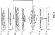
- FIG. 3is flowchart for describing a towing guide provided by driving support apparatus 101 of the present invention.
- step S1state controlling section 113 detects an instruction to start a towing guide, which has been received from input section 107, and starts processing.
- step S2display section 103 displays a rear image captured by imaging section 102.
- image conversion section 111converts the captured image acquired from image acquiring section 108 into displayable video signals.
- the converted video signalsare outputted to display section 103 via image superimposing section 112.
- step S3state controlling section 113 acquires steering turning angle information from steering-angle sensor 104.
- image superimposing section 112reads predicted-trajectory guide marks from storage section 110 on the basis of the turning angle information from steering angle sensor 104, which has been acquired by state controlling section 113.
- Image superimposing section 112superimposes the predicted-trajectory guide marks read from storage section 110 on the video signals obtained by conversion in step S2.
- Display section 103displays the superimposed image outputted from image superimposing section 112.
- step S5state controlling section 113 determines whether or not an instruction to end the towing guide has been received from input section 107.
- control section 109performs the processing in step S3 again and continues the towing guide.
- step S5image superimposing section 112 deletes the predicted-trajectory guide marks superimposed in step S4.
- step S7outputting of the video signals obtained by conversion by image converting section 111 to display section 103 is stopped.
- display section 103cancels displaying of a captured image of the area behind the tow vehicle.
- FIG. 4is a diagram illustrating a representation of predicted-trajectory guide marks to be superimposed by image superimposing section 112.
- FIG. 5is a diagram illustrating a representation of predicted-trajectory guide marks to be superimposed by image superimposing section 112 when the tow vehicle moves backward from the state illustrated in FIG. 4 .
- FIG. 6is a diagram illustrating a representation of predicted-trajectory guide marks to be superimposed by image superimposing section 112 when the tow vehicle further moves backward from the state illustrated in FIG. 5 .
- FIGS. 4 to 6mean both of a superimposed image formed by superimposition performed by image superimposing section 112 and a display image to be displayed on display section 103.
- the display imageshows tow vehicle 401, tow vehicle side coupler 402, tow-target vehicle 403, tow-target vehicle side coupler 404, and obstacle 409.
- predicted-trajectory guide marks 405, 406formed of a pair of left and right planar shapes in accordance with steering operation of the tow vehicle are superimposed.
- Predicted-trajectory guide marks 405, 406are formed of sides 405a, 406a on the center side of the vehicle width direction, sides 405b, 406b on the outer edge side of the vehicle width direction, and sides 405c, 406c in the backward direction, respectively.
- Sides 405a, 406a of predicted-trajectory guide marks 405, 406 which are located on the center side of the vehicle width directionare superimposed at positions in an outer edge direction from tow vehicle side coupler 402.
- side 405a of left predicted-trajectory guide mark 405 on the center side of the vehicle width directionis superimposed in the leftward direction from tow vehicle coupler 402.
- Side 406a of right predicted-trajectory guide mark 406 on the center side of the vehicle width directionis superimposed in the rightward direction from tow vehicle side coupler 402.
- tow vehicle side coupler 402is displayed in a gap between side 405a of the vehicle width direction of left predicted-trajectory guide mark 405 on the center side and side 406a of right predicted-trajectory guide mark 406 on the center side of the vehicle width direction.
- predicted-trajectory guide marks 405 and 406are separated from tow vehicle side coupler 402 without overlapping tow vehicle side coupler 402.
- the region between side 405a and side 406aindicates a predicted-trajectory of tow vehicle side coupler 402.
- Sides 405b, 406b of predicted-trajectory guide marks 405 and 406which are located on the outer edge side of the vehicle width direction indicate the related art predicted-trajectories of left and right side edges of the tow vehicle. Whether or not an object is present in the region between sides 405b, 406b makes it possible to make a judgment on whether or not collision of tow vehicle 401 occurs.
- obstacle 409is in the region between sides 405b, 406b as illustrated in FIG. 4 . Accordingly, the driver can make a judgment that tow vehicle 401 collides with obstacle 409 if the driver further moves tow vehicle 401 backward.
- Sides 405c, 406c in the backward directionserve as a distance indicator.
- lines 405c and 406cmay not be connected in the ends thereof in the backward direction.
- lines 405c and 406cmay be in any form.
- predicted-trajectory guide marks 405, 406include stop indicators 407, 408 in their end portions in the direction of the tow vehicle, respectively. The driver can judge that tow vehicle 401 is coming close to tow-target vehicle 403 when stop indicators 407, 408 approach tow-target vehicle 403 as tow vehicle 401 moves backward. Stop indicators 407, 408, and predicted-trajectory guide marks 405, 406 may be displayed in different colors in order to distinguish stop indicators 407, 408, and predicted-trajectory guide marks 405, 406 from each other. In addition, although predicted-trajectory guide marks 405, 406 are configured to include stop indicators 407, 408, respectively, in this embodiment, it is not necessary for predicted-trajectory guide marks 405, 406 to include stop indicators 407, 408.
- tow vehicle side coupler 402 or tow-target vehicle side coupler 404are not overlapped with images such as guide marks or indicators,
- the region between tow vehicle side coupler 402 and tow-target vehicle side coupler 404is not overlapped with images such as guide marks or indicators, either.
- the drivercan perform positioning while keeping tow vehicle side coupler 402 and tow-target vehicle side coupler 404 visible and without losing the positions of tow vehicle side coupler 402 or tow-target vehicle side coupler 404 from the captured image.
- the drivercan intuitively recognize that the region between side 405a and side 406a is the towing guide.
- this towing guideallows the drivers to intuitively recognize the predicted path of tow vehicle side coupler 402.
- the drivercan accurately perform positioning between tow vehicle side coupler 402 and tow-target vehicle side coupler 404 as illustrated in FIG. 6 by moving tow vehicle 401 backward in such a way as to move tow vehicle side coupler 402 along the region between side 405a and side 406a.
- the drivercan use sides 405b, 406b of predicted-trajectory guide marks 405, 406 in the outer edge direction and thereby avoid an obstacle in the backward direction from coming into contact with a lateral surface of the vehicle body.
- control section 109 of the present inventioni.e., image superimposing section 112
- sides 405a, 406a of the pair of left and right predicted-trajectory guide marks 405, 406 which are located on the center side of the vehicle width directionare superimposed at positions in the outer edge direction from tow vehicle side coupler 402, and sides 405b, 406b of predicted-trajectory guide marks 405, 406 on the outer edge side of the vehicle width direction can be superimposed as predicted-trajectories of both of the lateral edges of the tow vehicle.
- predicted-trajectory guide marks 405, 406are formed by connecting sides 405a, 406a, sides 405b, 406b, and distance indicators 405c, 406c in a planar fashion, respectively.
- two types of guides including the guide to avoid tow vehicle 401 from coming into contact with an obstacle located therearound and the towing guidecan be represented by one type of guide marks, Accordingly, the driver can intuitively recognize multiple guides by one type of guide mark.
- Image superimposing section 112changes an image to be superimposed, between the normal backward assistance and the towing guide. For example, when state controlling section 113 detects an instruction to guide for assisting coupling between tow vehicle 401 and tow-target vehicle 403 from input section 107, image superimposing section 112 superimposes predicted-trajectory guide marks on the captured image. Meanwhile, when state controlling section 113 detects no towing guide instruction from input section 107 but detects a reverse state from gear position sensor 106, image superimposing section 112 reads predicted-trajectories on both of the lateral edges of the tow vehicle in accordance with the steering turning angle, and fixed trajectories corresponding to a zero steering turning angle, and superimposes the trajectories on the captured image.
- the predicted-trajectories of both of the lateral edges of the tow vehicleinclude at least sides 405b, 406b. Ideally, the leading end portions of sides 405b, 406b are connected together.
- towing guidekeeping the visibility of tow vehicle side coupler 402 can be performed by superimposing predicted-trajectory guide marks 405, 406 because tow vehicle side coupler 402, which is the guiding target, is located at the center of a rear end portion of the vehicle body.
- FIG. 7is a diagram illustrating a representation of a variation of predicted-trajectory guide marks 405, 406 of FIG. 4 , which are to be superimposed by image superimposing section 112.
- Image conversion section 111generates an overhead view image by converting a view point of the captured image acquired from image acquiring section 108.
- image superimposing section 112reads tow vehicle image 701, tow vehicle side coupler 702, and predicted-trajectory guide marks 705, 706 from storage section 110 and superimposes the read images on the overhead view image.
- the overhead view imagealso shows tow-target vehicle 703 and tow-target vehicle side coupler 704. The driver can perform positioning without losing the positions of tow vehicle side coupler 702 and tow-target vehicle side coupler 704 by moving tow vehicle 701 along the region interposed between side 705a and side 706a of predicted-trajectory guide marks 705 and 706 on the center side of the vehicle width direction.
- the driving support apparatus and tow vehicle according to the present inventionare useful in providing appropriate visibility support for coupling a tow vehicle to a tow-target vehicle.
Landscapes
- Engineering & Computer Science (AREA)
- Mechanical Engineering (AREA)
- Multimedia (AREA)
- Transportation (AREA)
- Signal Processing (AREA)
- Physics & Mathematics (AREA)
- Chemical & Material Sciences (AREA)
- Combustion & Propulsion (AREA)
- Theoretical Computer Science (AREA)
- General Physics & Mathematics (AREA)
- Closed-Circuit Television Systems (AREA)
- Image Processing (AREA)
- Traffic Control Systems (AREA)
Description
- The present invention relates to a driving support apparatus configured to perform appropriate visibility support for coupling a tow vehicle to a tow-target vehicle.
- In general, there is known a vehicle guiding method to prevent a lateral surface of a vehicle body from coming into contact with an obstacle in the backward direction of the vehicle when the vehicle moves backward. This method guides a vehicle by superimposing, on the monitor, a pair of left and right predicted-trajectories corresponding to the vehicle width in accordance with a steering turning angle (see Patent Literature (hereinafter, referred to as "PTL") 1, for example). Moreover, another known vehicle guiding method is to guide a vehicle through the current state of the vehicle by superimposing, on the monitor, fixed trajectories corresponding to a zero steering turning angle (see
PTL 2, for example). - Furthermore, there is known a vehicle guiding method used when the driving support target is a tow vehicle in order for the tow vehicle to be coupled to a tow-target vehicle. In general, when a tow vehicle is coupled to a tow-target vehicle, the tow vehicle is moved backward so as to move a tow vehicle side coupler (e.g., hitch ball) installed at a rear portion of the tow vehicle to the vicinity of a tow-target vehicle side coupler (e.g., towing hitch). For moving the tow vehicle side coupler backward, there is known a method that accurately guides a vehicle to perform positioning between the tow vehicle side coupler and the tow-target vehicle side coupler, by superimposing, on the monitor screen, guiding lines for positioning between the tow vehicle side coupler and the tow-target vehicle side coupler (see PTL 3, for example).
- PTL 1 Japanese Patent Application Laid-Open No.
2009-173386 - PTL 2 Japanese Patent Application Laid-Open No.
2007-76496 - PTL 3 Japanese Patent Application Laid-Open No.
2002-312768 - For coupling a tow vehicle to a tow-target vehicle, it is desirable to provide both of a projected trajectory guide for avoiding an obstacle in the backward direction of the tow vehicle side coupler from coming into contact with a lateral surface of the vehicle body, and a positioning guide between the tow vehicle side coupler and the tow-target vehicle side coupler.
- However, the driving support apparatus according to the related art superimposes two types of guiding lines, which are predicted-trajectory guiding lines and positioning guiding lines, independently on the monitor. Accordingly, many guiding lines appear on the monitor, which in turn makes it difficult for drivers to intuitively recognize the meaning of each guiding line. Even worse, superimposing fixed trajectory guiding lines on the monitor makes it even more difficult for the drivers to intuitively recognize the meaning of each guiding line.
- In addition, in the positioning guide between the tow vehicle side coupler and the tow-target vehicle side coupler of the related art, one end of a guiding line is superimposed on a portion of the monitor which corresponds to the tow vehicle side coupler. The driver thus drives the tow vehicle in such a way that the other end of the guiding line covers a portion of the monitor which corresponds to the tow-target vehicle side coupler. In a guiding method of this kind, the guiding line makes it harder for the tow vehicle side coupler and the tow-target vehicle side coupler to be visually recognized on the monitor, which in turn leads to a problem that makes it even harder for the drivers to recognize the positional relation between the tow vehicle side coupler and the tow-target vehicle side coupler.
US2011/001614 A1 is considered as the closest prior art according to the preamble ofclaim 1 and relates to a rear camera backup assistance with touchscreen display. Assistance for a backup maneuver of a motor vehicle in which a first point of interest on the vehicle is moved toward a second point of interest remote from the vehicle. A rear contextual view is displayed on an electronic display obtained from a rearward directed image sensor on the vehicle. A zoom window is manually placed on the electronic display to include the second point of interest. The zoom window is enlarged, and the location of the second point of interest is manually identified within the enlarged zoom window. The identified location of the second point of interest is transformed into target positional coordinates. The rear contextual view redisplayed with a target icon at the target positional coordinates. The location of the first point of interest is manually identified on the rear contextual view and transformed into starting positional coordinates. A start icon is displayed at the starting positional coordinates in the rear contextual view. A target line is determined between the target positional coordinates and the starting positional coordinates. A path line icon is displayed in the rear contextual view corresponding to the determined target line. A bearing line is displayed in the rear contextual view extending from the start icon. The target positional coordinates are re-determined as the rear contextual view shifts during the backup maneuver. The target icon and the path line icon are updated in response to the re-determined target positional coordinates.- It is an object of the present invention to provide an improved and useful driving support apparatus in which the above-mentioned problems are eliminated.
- In order to achieve the above-mentioned object, there is provided a driving support apparatus according to
claim 1. In addition, there is provided a tow vehicle according to claim 5. - Advantageous embodiments are defined by the dependent claims.
- Advantageously, a driving support apparatus and a tow vehicle are provided, each of which makes it possible to intuitively recognize a guide for avoiding an obstacle in the backward direction from coming into contact with a lateral surface of a vehicle body and a guide for positioning between a tow vehicle side coupler and a tow-target vehicle side coupler, and also to keep the tow vehicle side coupler and the tow-target vehicle side coupler visible.
- Advantageously, a superimposing section superimposes sides of predicted-trajectory guide marks respectively at positions in an outer edge direction from a tow coupler, which sides are located on a center side of a vehicle width direction, and the superimposing section superimposes sides of the predicted-trajectory guide marks respectively as predicted-trajectories of both lateral edges of a tow vehicle, which sides are located on an outer edge side of the vehicle width direction.
- According to the present invention, it is made possible to intuitively recognize a guide for avoiding an obstacle in the backward direction from coming into contact with a lateral surface of a vehicle body and a guide for positioning between a tow vehicle side coupler and a tow-target vehicle side coupler, and also to keep the tow vehicle side coupler and the tow-target vehicle side coupler visible.
FIG. 1 is a block diagram illustrating a configuration of a driving support apparatus in an embodiment of the present invention;FIG. 2 is a diagram illustrating a representation of operation of a tow vehicle in which the driving support apparatus corresponding to a primary portion ofFIG. 1 is installed;FIG. 3 is a flowchart illustrating how a guide for assisting coupling between a tow vehicle and a tow-target vehicle is provided by the driving support apparatus corresponding to the primary portion ofFIG. 1 ;FIG. 4 is a diagram illustrating a representation of predicted-trajectory guide marks to be superimposed by an image superimposing section in the primary portion ofFIG. 1 ;FIG. 5 is a diagram illustrating a representation of predicted-trajectory guide marks to be superimposed by the image superimposing section when the tow vehicle moves backward from the position illustrated inFIG. 4 ;FIG. 6 is a diagram illustrating a representation of predicted-trajectory guide marks to be superimposed by the image superimposing section when the tow vehicle moves backward from the position illustrated inFIG. 5 ; andFIG. 7 is a diagram illustrating a representation of a variation of predicted-trajectory guide marks to be superimposed by the image superimposing section ofFIG. 4 .- Hereinafter, a driving support apparatus of an embodiment of the present invention will be described with reference to the drawings.
FIG. 1 is a block diagram illustrating a configuration ofdriving support apparatus 101 of the embodiment of the present invention.- In
FIG. 1 ,driving support apparatus 101 is connected toimaging section 102, display section103, turning-angle sensor 104, vehicle-speed sensor 105, gear-position sensor 106, andinput section 107. Note that,imaging section 102, display section103, turning-angle sensor 104, vehicle-speed sensor 105, gear-position sensor 106, andinput section 107 may be included indriving support apparatus 101 or be included in a tow vehicle together withdriving support apparatus 101. Driving support apparatus 101 includesimage acquiring section 108,control section 109, andstorage section 110.Driving support apparatus 101 generates a superimposed image by superimposing a pair of left and right predicted-trajectory guide marks in accordance with steering operation of the tow vehicle on a captured image of an area behind the tow vehicle received fromimaging section 102, on the basis of the input signals from turning-angle sensor 104, vehicle-speed sensor 105, gear-position sensor 106, andinput section 107. Drivingsupport apparatus 101 outputs the generated superimposed image todisplay section 103.Imaging section 102 includes a camera.Imaging section 102 is attached to a rear portion of the tow vehicle. For example,imaging section 102 is attached near the license plate or trunk of the tow vehicle.Imaging section 102 may include a plurality of cameras. In addition,imaging section 102 may be attached to any position as long as the position allowsimaging section 102 to capture an image of the area behind the tow vehicle including a tow coupler at the rear portion of the tow vehicle and a tow-target vehicle side coupler of a tow-target vehicle (hereinafter, referred to as "tow-target coupler") which is to be coupled to the tow coupler.Display section 103 includes a navigation apparatus, for example.Display section 103 is provided in the vehicle in such a way as to be viewable from the driving seat.Display section 103 receives, from drivingsupport apparatus 101, a superimposed image generated by superimposing a pair of left and right predicted guide marks on a captured image of the area behind the tow vehicle and displays this superimposed image.- Turning-
angle sensor 104 outputs a turning angle signal indicating the turning angle of the steering to drivingsupport apparatus 101. - Vehicle-
speed sensor 105 outputs a vehicle speed signal indicating the vehicle speed of the tow vehicle to drivingsupport apparatus 101. - Gear-
position sensor 106 outputs a gear position state signal indicating the state of the gear position to drivingsupport apparatus 101. Input section 107 outputs an input signal indicating an instruction command from a user to drivingsupport apparatus 101.Input section 107 includes a touch panel, a remote controller, switches or operation buttons, for example. Wheninput section 107 is a touch panel,input section 107 may be provided todisplay section 103.Input section 107 is operated by the user and outputs an input signal indicating an instruction command from the user to drivingsupport apparatus 101. For example,input section 107 outputs, to drivingsupport apparatus 101, a command signal to switch between predicted-trajectory guide marks for assisting coupling between a tow vehicle and a tow-target vehicle. In the following description, the term "predicted-trajectory guide mark for assisting coupling between a tow vehicle and a tow-target vehicle" is simply referred to as a "predicted-trajectory guide mark."- Next, the internal configuration of driving
support apparatus 101 will be described. - Driving
support apparatus 101 includesimage acquiring section 108,control section 109 to be connected to image acquiringsection 108, andstorage section 110 to be connected to controlsection 109.Control section 109 includesimage conversion section 111,image superimposing section 112, andstate controlling section 113. Image acquiring section 108 is formed of a nonvolatile memory such as a buffer memory.Image acquiring section 108 is connected toimaging section 102.Image acquiring section 108 temporarily stores video data obtainable from captured video received fromimaging section 102. The video data stored inimage acquiring section 108 is outputted to imageconversion section 111 ofcontrol section 109.Control section 109 includes a very large scale integration (VLSI) chip or a central processing unit (CPU), for example.Control section 109 is connected to displaysection 103, turning-angle sensor 104, a vehicle-speed sensor 105, gear-position sensor 106,input section 107,image acquiring section 108, andstorage section 110.Control section 109 performs video processing for guiding a vehicle to move backward (hereinafter, referred to as "backward guiding") based on a turning angle signal from turning-angle sensor 104 and a reverse signal from gear-position sensor 106. In addition,control section 109 performs video processing for providing backward guiding for towing based on an input signal that prompts backward guiding for towing frominput section 107. Note that,control section 109 may further perform various processing operations using an input signal from vehicle-speed sensor 105. Hereinafter, a description will be further provided withimage conversion section 111,image superimposing section 112 andstate controlling section 113 incontrol section 109. However, the connection, and input and output of data, and processing of these component elements to outside ofcontrol section 109 are defined to be the same as the connection, and input and output of data, and processing ofcontrol section 109 to outside ofcontrol section 109.Storage section 110 includes a nonvolatile memory such as a flash memory or a read only memory (ROM).Storage section 110 stores therein predicted-trajectory guide marks, predicted-trajectories for backward guiding in accordance with a turning angle, fixed trajectories for backward guiding corresponding to a zero turning angle, image data specific to the tow vehicle, such as a distance indicator, and various programs for controlling bycontrol section 109. Predicted guide marks are formed of a pair of left and right planar shapes.Image conversion section 111 andimage superimposing section 112 are formed of an image processor such as an application specific integrated circuit (ASIC).Image conversion section 111 performs image processing on the captured video received fromimage acquiring section 108, converts the processed video into video signals displayable ondisplay section 103 and outputs the video signals to image superimposingsection 112.Imaging superimposing section 112 selectively reads predicted-trajectories or fixed trajectories, or image data such as a distance indicator fromstorage section 110 and superimposes the selected trajectories or data in accordance with an instruction fromstate controlling section 113.Image superimposing section 112 outputs the superimposed video generated every predetermined time to displaysection 103.State controlling section 113 instructsimage superimposing section 112 to superimpose predicted-trajectory guide marks, predicted-trajectories, or fixed trajectories, or image data such as a distance indicator for towing, or to output a combined video to displaysection 103, for example.State controlling section 113 instructsimage superimposing section 112 to perform image superimposition for backward guiding, using a turning angle signal from turning-angle sensor 104 and a reverse signal from gear-position sensor 106, for example. In addition, upon acquisition of an input signal prompting backward guiding for towing frominput section 107,state controlling section 113 instructsimage superimposing section 112 to perform image superimposition for backward guiding for towing.- Next, a description will be provided regarding driving support processing performed by driving
support apparatus 101. FIG. 2 is a diagram illustrating a representation of operation oftow vehicle 201 in which drivingsupport apparatus 101 is installed.- As illustrated in
FIG. 2 ,tow vehicle 201 moves backward forcoupling tow coupler 202 provided at the rear portion of the tow vehicle to tow-target coupler 204 of tow-target vehicle 203. Rotation centers 205 and 206 are used for indicating an appropriate rotation center when the steering turning angle oftow vehicle 201 is smaller than an appropriate amount. Rotation centers 205 and 206 are each indicated by a point on the rear axis oftow vehicle 201 in accordance with the steering turning angle on the basis of the Ackerman model. Rotation centers 205 and 206 makes it possible to predict a moving path oftow coupler 202. For example, when the steering turning angle is small,tow coupler 202 moves along movingpath 207, and when the steering turning angle is appropriate,tow coupler 202 moves along movingpath 208. Predicted-trajectory guide marks are drawn ondisplay section 103 on the basis of these moving paths in accordance with the steering. Drivers can adjust the steering turning angle in such a way that towcoupler 202 moves toward tow-target coupler 204 by observing the predicted-trajectory guide marks. - Next, a description will be provided regarding a guide for assisting coupling between
tow vehicle 201 and a tow-target vehicle by drivingsupport apparatus 101 of the present invention (hereinafter, simply referred to as "towing guide") FIG. 3 is flowchart for describing a towing guide provided by drivingsupport apparatus 101 of the present invention.- First, as illustrated in step S1,
state controlling section 113 detects an instruction to start a towing guide, which has been received frominput section 107, and starts processing. - Next, as illustrated in step S2,
display section 103 displays a rear image captured byimaging section 102. Specifically,image conversion section 111 converts the captured image acquired fromimage acquiring section 108 into displayable video signals. The converted video signals are outputted to displaysection 103 viaimage superimposing section 112. - Next, as illustrated in step S3,
state controlling section 113 acquires steering turning angle information from steering-angle sensor 104. - Next, as illustrated in step S4,
image superimposing section 112 reads predicted-trajectory guide marks fromstorage section 110 on the basis of the turning angle information from steeringangle sensor 104, which has been acquired bystate controlling section 113.Image superimposing section 112 superimposes the predicted-trajectory guide marks read fromstorage section 110 on the video signals obtained by conversion in step S2.Display section 103 displays the superimposed image outputted fromimage superimposing section 112. - Next, as illustrated in step S5,
state controlling section 113 determines whether or not an instruction to end the towing guide has been received frominput section 107. - Next, in case of NO in step S5,
control section 109 performs the processing in step S3 again and continues the towing guide. - In case of YES in step S5, as illustrated in step S6,
image superimposing section 112 deletes the predicted-trajectory guide marks superimposed in step S4. In addition, as illustrated in step S7, outputting of the video signals obtained by conversion byimage converting section 111 to displaysection 103 is stopped. As a result,display section 103 cancels displaying of a captured image of the area behind the tow vehicle. - Next, a description will be provided regarding predicted-trajectory guide marks to be superimposed by
image superimposing section 112. FIG. 4 is a diagram illustrating a representation of predicted-trajectory guide marks to be superimposed byimage superimposing section 112.FIG. 5 is a diagram illustrating a representation of predicted-trajectory guide marks to be superimposed byimage superimposing section 112 when the tow vehicle moves backward from the state illustrated inFIG. 4 .FIG. 6 is a diagram illustrating a representation of predicted-trajectory guide marks to be superimposed byimage superimposing section 112 when the tow vehicle further moves backward from the state illustrated inFIG. 5 . It should be noted that, a description will be provided hereinafter usingFIGS. 4 to 6 as the display images to be displayed ondisplay section 103, but the images onFIGS. 4 to 6 mean both of a superimposed image formed by superimposition performed byimage superimposing section 112 and a display image to be displayed ondisplay section 103.- As illustrated in
FIG. 4 , the display image showstow vehicle 401, towvehicle side coupler 402, tow-target vehicle 403, tow-targetvehicle side coupler 404, andobstacle 409. In addition, predicted-trajectory guide marks 405, 406 formed of a pair of left and right planar shapes in accordance with steering operation of the tow vehicle are superimposed. Predicted-trajectory guide marks 405, 406 are formed ofsides sides Sides vehicle side coupler 402. To put it differently,side 405a of left predicted-trajectory guide mark 405 on the center side of the vehicle width direction is superimposed in the leftward direction fromtow vehicle coupler 402.Side 406a of right predicted-trajectory guide mark 406 on the center side of the vehicle width direction is superimposed in the rightward direction from towvehicle side coupler 402. For this reason, towvehicle side coupler 402 is displayed in a gap betweenside 405a of the vehicle width direction of left predicted-trajectory guide mark 405 on the center side andside 406a of right predicted-trajectory guide mark 406 on the center side of the vehicle width direction. Thus, predicted-trajectory guide marks 405 and 406 are separated from towvehicle side coupler 402 without overlapping towvehicle side coupler 402. The region betweenside 405a andside 406a indicates a predicted-trajectory of towvehicle side coupler 402.Sides sides tow vehicle 401 occurs. For example,obstacle 409 is in the region betweensides FIG. 4 . Accordingly, the driver can make a judgment that towvehicle 401 collides withobstacle 409 if the driver further movestow vehicle 401 backward.Sides - In
FIG. 4 , a line drawn by connecting the ends ofsides line 405c, and a line drawn by connecting the ends ofsides line 406c. Note that, lines 405c and 406c may not be connected in the ends thereof in the backward direction. As long aslines lines lines lines - In addition, predicted-trajectory guide marks 405, 406 include
stop indicators tow vehicle 401 is coming close to tow-target vehicle 403 when stopindicators target vehicle 403 astow vehicle 401 moves backward. Stopindicators stop indicators stop indicators stop indicators - According to predicted-trajectory guide marks 405, 406, as illustrated in
FIGS. 5 and6 , even whentow vehicle 401 approaches tow-target vehicle 403 astow vehicle 401 gradually moves backward, towvehicle side coupler 402 or tow-targetvehicle side coupler 404 are not overlapped with images such as guide marks or indicators, The region between towvehicle side coupler 402 and tow-targetvehicle side coupler 404 is not overlapped with images such as guide marks or indicators, either. Thus, the driver can perform positioning while keeping towvehicle side coupler 402 and tow-targetvehicle side coupler 404 visible and without losing the positions of towvehicle side coupler 402 or tow-targetvehicle side coupler 404 from the captured image. Meanwhile, the driver can intuitively recognize that the region betweenside 405a andside 406a is the towing guide. In addition, this towing guide allows the drivers to intuitively recognize the predicted path of towvehicle side coupler 402. Thus, the driver can accurately perform positioning between towvehicle side coupler 402 and tow-targetvehicle side coupler 404 as illustrated inFIG. 6 by movingtow vehicle 401 backward in such a way as to move towvehicle side coupler 402 along the region betweenside 405a andside 406a. Moreover, the driver can usesides - As described above, according to
control section 109 of the present invention, i.e.,image superimposing section 112,sides vehicle side coupler 402, andsides tow vehicle 401 from coming into contact with a lateral surface of a vehicle body and a guide for positioning between towvehicle side coupler 402 and tow-targetvehicle side coupler 404, and also to keep towvehicle side coupler 402 and tow-targetvehicle side coupler 404 visible. - In addition, predicted-trajectory guide marks 405, 406 are formed by connecting
sides distance indicators tow vehicle 401 from coming into contact with an obstacle located therearound and the towing guide can be represented by one type of guide marks, Accordingly, the driver can intuitively recognize multiple guides by one type of guide mark. Image superimposing section 112 changes an image to be superimposed, between the normal backward assistance and the towing guide. For example, whenstate controlling section 113 detects an instruction to guide for assisting coupling betweentow vehicle 401 and tow-target vehicle 403 frominput section 107,image superimposing section 112 superimposes predicted-trajectory guide marks on the captured image. Meanwhile, whenstate controlling section 113 detects no towing guide instruction frominput section 107 but detects a reverse state fromgear position sensor 106,image superimposing section 112 reads predicted-trajectories on both of the lateral edges of the tow vehicle in accordance with the steering turning angle, and fixed trajectories corresponding to a zero steering turning angle, and superimposes the trajectories on the captured image. The predicted-trajectories of both of the lateral edges of the tow vehicle include atleast sides sides - As described above, changing an image to be superimposed, between the normal backward assistance and the tow guide by
image superimposing section 112 makes it possible to provide a required guide according to the state of the tow vehicle. For the normal backward assistance, no towing guide is required, and only one kind of guide to prevent an obstacle in the backward direction of the tow vehicle from coming into contact with a lateral surface of the vehicle body is necessary. The reason behind this is that superimposing predicted-trajectory guide marks 405, 406 even reduces the attention of the driver tosides vehicle side coupler 402 can be performed by superimposing predicted-trajectory guide marks 405, 406 because towvehicle side coupler 402, which is the guiding target, is located at the center of a rear end portion of the vehicle body. - Next, a variation of predicted-trajectory guide marks 405, 406 of
FIG. 4 will be described.FIG. 7 is a diagram illustrating a representation of a variation of predicted-trajectory guide marks 405, 406 ofFIG. 4 , which are to be superimposed byimage superimposing section 112. Image conversion section 111 generates an overhead view image by converting a view point of the captured image acquired fromimage acquiring section 108. As illustrated inFIG. 7 ,image superimposing section 112 readstow vehicle image 701, towvehicle side coupler 702, and predicted-trajectory guide marks 705, 706 fromstorage section 110 and superimposes the read images on the overhead view image. The overhead view image also shows tow-target vehicle 703 and tow-targetvehicle side coupler 704. The driver can perform positioning without losing the positions of towvehicle side coupler 702 and tow-targetvehicle side coupler 704 by movingtow vehicle 701 along the region interposed betweenside 705a andside 706a of predicted-trajectory guide marks 705 and 706 on the center side of the vehicle width direction.- The driving support apparatus and tow vehicle according to the present invention are useful in providing appropriate visibility support for coupling a tow vehicle to a tow-target vehicle.
- 101
- Driving support apparatus
- 102
- Imaging section
- 103
- Display section
- 109
- Control section
- 112
- Image superimposing section
Claims (5)
- A driving support apparatus (101) comprising:an image acquiring section (108) that acquires a captured image of an area behind a vehicle (401) supported by the apparatus (101), the area including a tow coupler (402) at a rear portion of the vehicle (401) and a tow-target coupler (404) of a tow-target vehicle (403) to be coupled to the tow coupler (402); anda superimposing section (112) that superimposes a pair of left and right planar predicted-trajectory guide marks (405, 406) in accordance with steering operation of the vehicle (401) supported by the apparatus (101), on the captured image acquired by the image acquiring section (108) and that outputs the superimposed image,the left planar predicted-trajectory guide mark (405) includes at least a first line (405a) that forms a first side of the left predicted-trajectory guide mark (405) located on a center side of a vehicle width direction and a second line (405b) that forms a second side of the left predicted-trajectory guide mark (405) located on an outer edge side of the vehicle width direction, the first line (405a) being separated from the second line (405b);the right planar predicted-trajectory guide mark (406) includes at least a third line (406a) that forms a third side of the right predicted-trajectory guide mark (406) located on the center side of the vehicle width direction and a fourth line (406b) that forms a fourth side of the right predicted-trajectory guide mark (406) located on the outer edge side of the vehicle width direction, the third line (406a) being separated from the fourth line (406b);the superimposing section (112) superimposes the first and third lines (405a, 406a) of the left and right predicted-trajectory guide marks (405, 406) respectively at positions in an outer edge direction from the tow coupler (402), the first and third lines (405a, 406a) being located on the center side of the vehicle width direction; andthe superimposing section (112) superimposes the second and fourth lines (405b, 406b) of the left and right predicted-trajectory guide marks (405, 406) respectively as predicted-trajectories of both lateral edges of the vehicle (401) supported by the apparatus (101), the second and fourth lines (405b, 406b) being located on the outer edge side of the vehicle width direction,characterized in thatthe superimposing section (112) changes an image to be superimposed between a tow guide and a normal backward assistance other than the tow guide, andin the case of the normal backward assistance, the superimposing section (112) does not superimpose the first and third lines (405a, 406a) of the left and right predicted-trajectory guide marks (405, 406) respectively at the positions in the outer edge direction from the tow coupler (402).
- The driving support apparatus (101) according to claim 1, further comprising a display section (103) that displays a superimposed image provided by the superimposing section (112), wherein
the display section (103) displays the tow coupler (402) in a gap between the first line (405a) of the left predicted-trajectory guide mark (405) and the third line (406a) of the right predicted-trajectory guide mark (406). - The driving support apparatus (101) according to claim 1 or 2, further comprising a backward imaging section (102) that captures an image of the area behind the vehicle (401) supported by the apparatus (101) and that outputs the captured image to an image processing section.
- The driving support apparatus (101) according to any one of claims 1 to 3, wherein
the left planar predicted-trajectory guide mark (405) includes a stop indicator (407) in its end portion in the direction of the vehicle (401), and
the right planar predicted-trajectory guide mark (406) includes a stop indicator (408) in its end portion in the direction of the vehicle (401). - A tow vehicle (401) comprising the driving support apparatus (101) according to any one of claims 1 to 4.
Priority Applications (1)
| Application Number | Priority Date | Filing Date | Title |
|---|---|---|---|
| EP17156514.6AEP3188480B1 (en) | 2011-03-02 | 2012-02-21 | Driving assistance device and towing vehicle |
Applications Claiming Priority (2)
| Application Number | Priority Date | Filing Date | Title |
|---|---|---|---|
| JP2011044650 | 2011-03-02 | ||
| PCT/JP2012/001158WO2012117693A1 (en) | 2011-03-02 | 2012-02-21 | Driving assistance device and towing vehicle |
Related Child Applications (2)
| Application Number | Title | Priority Date | Filing Date |
|---|---|---|---|
| EP17156514.6ADivisionEP3188480B1 (en) | 2011-03-02 | 2012-02-21 | Driving assistance device and towing vehicle |
| EP17156514.6ADivision-IntoEP3188480B1 (en) | 2011-03-02 | 2012-02-21 | Driving assistance device and towing vehicle |
Publications (3)
| Publication Number | Publication Date |
|---|---|
| EP2683164A1 EP2683164A1 (en) | 2014-01-08 |
| EP2683164A4 EP2683164A4 (en) | 2014-09-10 |
| EP2683164B1true EP2683164B1 (en) | 2017-04-12 |
Family
ID=46757638
Family Applications (2)
| Application Number | Title | Priority Date | Filing Date |
|---|---|---|---|
| EP12752034.4AActiveEP2683164B1 (en) | 2011-03-02 | 2012-02-21 | Driving assistance device and towing vehicle |
| EP17156514.6AActiveEP3188480B1 (en) | 2011-03-02 | 2012-02-21 | Driving assistance device and towing vehicle |
Family Applications After (1)
| Application Number | Title | Priority Date | Filing Date |
|---|---|---|---|
| EP17156514.6AActiveEP3188480B1 (en) | 2011-03-02 | 2012-02-21 | Driving assistance device and towing vehicle |
Country Status (4)
| Country | Link |
|---|---|
| US (3) | US9516275B2 (en) |
| EP (2) | EP2683164B1 (en) |
| JP (1) | JPWO2012117693A1 (en) |
| WO (1) | WO2012117693A1 (en) |
Cited By (6)
| Publication number | Priority date | Publication date | Assignee | Title |
|---|---|---|---|---|
| US10670479B2 (en) | 2018-02-27 | 2020-06-02 | Methode Electronics, Inc. | Towing systems and methods using magnetic field sensing |
| US10696109B2 (en) | 2017-03-22 | 2020-06-30 | Methode Electronics Malta Ltd. | Magnetolastic based sensor assembly |
| US11084342B2 (en) | 2018-02-27 | 2021-08-10 | Methode Electronics, Inc. | Towing systems and methods using magnetic field sensing |
| US11135882B2 (en) | 2018-02-27 | 2021-10-05 | Methode Electronics, Inc. | Towing systems and methods using magnetic field sensing |
| US11221262B2 (en) | 2018-02-27 | 2022-01-11 | Methode Electronics, Inc. | Towing systems and methods using magnetic field sensing |
| US11491832B2 (en) | 2018-02-27 | 2022-11-08 | Methode Electronics, Inc. | Towing systems and methods using magnetic field sensing |
Families Citing this family (34)
| Publication number | Priority date | Publication date | Assignee | Title |
|---|---|---|---|---|
| US9516275B2 (en)* | 2011-03-02 | 2016-12-06 | Panasonic Intellectual Property Management Co., Ltd. | Driving assistance device and towing vehicle |
| US20130226390A1 (en)* | 2012-02-29 | 2013-08-29 | Robert Bosch Gmbh | Hitch alignment assistance |
| GB2513392B (en) | 2013-04-26 | 2016-06-08 | Jaguar Land Rover Ltd | System for a towing vehicle |
| GB2513393B (en)* | 2013-04-26 | 2016-02-03 | Jaguar Land Rover Ltd | Vehicle hitch assistance system |
| US20150115571A1 (en)* | 2013-10-24 | 2015-04-30 | GM Global Technology Operations LLC | Smart tow |
| GB2525036B (en)* | 2014-04-11 | 2018-08-22 | Jaguar Land Rover Ltd | Selectively deployable control device |
| DE102014212041A1 (en)* | 2014-06-24 | 2015-12-24 | Robert Bosch Gmbh | A method for assisting the driver of a motor vehicle in a reverse drive for coupling a trailer |
| JP6361382B2 (en)* | 2014-08-29 | 2018-07-25 | アイシン精機株式会社 | Vehicle control device |
| JP6376936B2 (en)* | 2014-10-14 | 2018-08-22 | アルパイン株式会社 | Driving assistance device |
| EP3020868B1 (en)* | 2014-11-14 | 2020-11-04 | Caterpillar Inc. | Machine of a kind comprising a body and an implement movable relative to the body with a system for assisting a user of the machine |
| JP6358123B2 (en)* | 2015-02-16 | 2018-07-18 | 株式会社デンソー | Driving assistance device |
| JP6464952B2 (en)* | 2015-08-04 | 2019-02-06 | 株式会社デンソー | Display control apparatus, display control program, and display control method |
| JP6713480B2 (en)* | 2015-10-22 | 2020-06-24 | 新明和工業株式会社 | Container handling vehicle |
| US10683035B2 (en)* | 2015-12-08 | 2020-06-16 | Panasonic Intellectual Property Management Co., Ltd. | Parking assistance device, parking assistance method, and non-transitory computer readable medium |
| US10864787B2 (en) | 2016-07-28 | 2020-12-15 | Robert Bosch Gmbh | Systems and methods for a human machine interface for a trailer hitch system |
| JP6338626B2 (en)* | 2016-08-25 | 2018-06-06 | 株式会社Subaru | Vehicle display device |
| JP6760122B2 (en)* | 2017-02-16 | 2020-09-23 | アイシン精機株式会社 | Peripheral monitoring device |
| US10427716B2 (en) | 2017-09-12 | 2019-10-01 | Ford Global Technologies, Llc | Hitch assist system and method |
| US10625782B2 (en)* | 2017-10-03 | 2020-04-21 | Aisin Seiki Kabushiki Kaisha | Surroundings monitoring apparatus |
| JP7000787B2 (en)* | 2017-10-12 | 2022-01-19 | 株式会社アイシン | Peripheral monitoring device |
| DE102017124788A1 (en)* | 2017-10-24 | 2019-04-25 | Jungheinrich Ag | Method for driving support in an industrial truck and industrial truck |
| US11014417B2 (en) | 2018-02-27 | 2021-05-25 | Methode Electronics, Inc. | Towing systems and methods using magnetic field sensing |
| US10351061B1 (en)* | 2018-03-09 | 2019-07-16 | Deere & Company | Implement attachment guidance system |
| US10479404B2 (en)* | 2018-03-13 | 2019-11-19 | Toyota Motor Engineering & Manufacturing North America, Inc. | Backup system for a vehicle with a trailer hitch |
| US20210214001A1 (en)* | 2018-06-01 | 2021-07-15 | Jaguar Land Rover Limited | An apparatus and a method for controlling steering |
| US10926759B2 (en)* | 2018-06-07 | 2021-02-23 | GM Global Technology Operations LLC | Controlling a vehicle based on trailer position |
| JP7147300B2 (en)* | 2018-07-05 | 2022-10-05 | 株式会社アイシン | Traction support device |
| CN110733422B (en)* | 2018-07-18 | 2021-05-04 | 郑州宇通客车股份有限公司 | Method and system for predicting dynamic track of external rearview mirror |
| DE102018212401B3 (en) | 2018-07-25 | 2019-12-24 | Volkswagen Aktiengesellschaft | Method and system for automatically detecting a coupling maneuver of a motor vehicle to a trailer |
| US11090990B2 (en)* | 2018-09-17 | 2021-08-17 | Ford Global Technologies, Llc | Trailer position, heading angle, and level measurement with smart device |
| US20200097021A1 (en)* | 2018-09-19 | 2020-03-26 | Continental Automotive Systems, Inc. | Autonomous Farm Equipment Hitching To A Tractor |
| US11433812B2 (en)* | 2018-10-29 | 2022-09-06 | Ford Global Technologies, Llc | Hitching maneuver |
| US11312416B2 (en)* | 2019-01-30 | 2022-04-26 | Toyota Motor Engineering & Manufacturing North America, Inc. | Three-dimensional vehicle path guidelines |
| DE102020003141A1 (en)* | 2020-05-26 | 2021-12-02 | Jost-Werke Deutschland Gmbh | Driver assistance system and method for coupling a trailer to a towing vehicle |
Family Cites Families (15)
| Publication number | Priority date | Publication date | Assignee | Title |
|---|---|---|---|---|
| JP2002359839A (en) | 2001-03-29 | 2002-12-13 | Matsushita Electric Ind Co Ltd | Rear view camera image display method and device |
| JP4739569B2 (en)* | 2001-04-09 | 2011-08-03 | パナソニック株式会社 | Driving assistance device |
| JP3483143B2 (en) | 2001-04-09 | 2004-01-06 | 松下電器産業株式会社 | Driving support device |
| JP3945467B2 (en) | 2003-10-02 | 2007-07-18 | 日産自動車株式会社 | Vehicle retraction support apparatus and method |
| JP4561479B2 (en)* | 2005-05-26 | 2010-10-13 | アイシン・エィ・ダブリュ株式会社 | Parking support method and parking support device |
| JP4769528B2 (en) | 2005-09-14 | 2011-09-07 | 富士通テン株式会社 | Parking assistance device |
| WO2009036176A1 (en)* | 2007-09-11 | 2009-03-19 | Magna Electronics | Imaging system for vehicle |
| JP2009173386A (en) | 2008-01-23 | 2009-08-06 | Mitsubishi Electric Corp | Elevator installation equipment |
| JP2009292339A (en)* | 2008-06-05 | 2009-12-17 | Aisin Seiki Co Ltd | Parking assistant device |
| US8138899B2 (en)* | 2009-07-01 | 2012-03-20 | Ford Global Technologies, Llc | Rear camera backup assistance with touchscreen display using two points of interest |
| CN102473353B (en)* | 2009-07-22 | 2014-02-26 | 丰田自动车株式会社 | driving aids |
| JP5333046B2 (en) | 2009-08-24 | 2013-11-06 | 株式会社島津製作所 | Manufacturing method of active matrix array |
| TWI365145B (en)* | 2009-11-02 | 2012-06-01 | Ind Tech Res Inst | Method and system for asisting driver |
| CN201646714U (en)* | 2010-01-26 | 2010-11-24 | 德尔福技术有限公司 | Parking guiding system |
| US9516275B2 (en)* | 2011-03-02 | 2016-12-06 | Panasonic Intellectual Property Management Co., Ltd. | Driving assistance device and towing vehicle |
- 2012
- 2012-02-21USUS13/985,014patent/US9516275B2/enactiveActive
- 2012-02-21EPEP12752034.4Apatent/EP2683164B1/enactiveActive
- 2012-02-21EPEP17156514.6Apatent/EP3188480B1/enactiveActive
- 2012-02-21JPJP2013502179Apatent/JPWO2012117693A1/enactivePending
- 2012-02-21WOPCT/JP2012/001158patent/WO2012117693A1/enactiveApplication Filing
- 2016
- 2016-10-28USUS15/336,979patent/US9799132B2/enactiveActive
- 2019
- 2019-10-17USUS16/655,486patent/US20200051299A1/ennot_activeAbandoned
Non-Patent Citations (1)
| Title |
|---|
| None* |
Cited By (7)
| Publication number | Priority date | Publication date | Assignee | Title |
|---|---|---|---|---|
| US10696109B2 (en) | 2017-03-22 | 2020-06-30 | Methode Electronics Malta Ltd. | Magnetolastic based sensor assembly |
| US10940726B2 (en) | 2017-03-22 | 2021-03-09 | Methode Electronics Malta Ltd. | Magnetoelastic based sensor assembly |
| US10670479B2 (en) | 2018-02-27 | 2020-06-02 | Methode Electronics, Inc. | Towing systems and methods using magnetic field sensing |
| US11084342B2 (en) | 2018-02-27 | 2021-08-10 | Methode Electronics, Inc. | Towing systems and methods using magnetic field sensing |
| US11135882B2 (en) | 2018-02-27 | 2021-10-05 | Methode Electronics, Inc. | Towing systems and methods using magnetic field sensing |
| US11221262B2 (en) | 2018-02-27 | 2022-01-11 | Methode Electronics, Inc. | Towing systems and methods using magnetic field sensing |
| US11491832B2 (en) | 2018-02-27 | 2022-11-08 | Methode Electronics, Inc. | Towing systems and methods using magnetic field sensing |
Also Published As
| Publication number | Publication date |
|---|---|
| US9516275B2 (en) | 2016-12-06 |
| EP3188480B1 (en) | 2019-01-02 |
| US9799132B2 (en) | 2017-10-24 |
| US20200051299A1 (en) | 2020-02-13 |
| EP2683164A4 (en) | 2014-09-10 |
| US20130321634A1 (en) | 2013-12-05 |
| WO2012117693A1 (en) | 2012-09-07 |
| JPWO2012117693A1 (en) | 2014-07-07 |
| US20170053428A1 (en) | 2017-02-23 |
| EP2683164A1 (en) | 2014-01-08 |
| EP3188480A1 (en) | 2017-07-05 |
Similar Documents
| Publication | Publication Date | Title |
|---|---|---|
| EP2683164B1 (en) | Driving assistance device and towing vehicle | |
| JP4900326B2 (en) | Parking assistance device and parking assistance method | |
| JP5003946B2 (en) | Parking assistance device | |
| US8138899B2 (en) | Rear camera backup assistance with touchscreen display using two points of interest | |
| JP4853712B2 (en) | Parking assistance device | |
| JP5217152B2 (en) | Vehicle periphery display device | |
| JP4793171B2 (en) | Parking assistance device | |
| EP2540578B1 (en) | Parking assistance device | |
| JP5872517B2 (en) | Vehicle periphery display device | |
| EP2623397A1 (en) | Parking assistance device | |
| EP2265482A1 (en) | Vehicle parking assist system and method | |
| KR20110097902A (en) | Parking Assistance Device | |
| KR20100120693A (en) | Parking support device | |
| US11577782B2 (en) | Method and apparatus for an automated trailer backup system in a motor vehicle | |
| JP5852076B2 (en) | Vehicle periphery display device | |
| WO2019073872A1 (en) | Parking assistance device | |
| JP2012166689A (en) | Driving assistance apparatus | |
| JP2020011668A (en) | Parking support device and control method for the same | |
| JP5075674B2 (en) | Parking assistance device | |
| JP2014162398A (en) | Parking support device | |
| JP4924770B2 (en) | Parking assistance device and parking assistance method | |
| JP2012106732A (en) | Vehicle periphery display device | |
| JP2012030797A (en) | Parking assistance device and method | |
| JP2013063770A (en) | Vehicle surroundings display device | |
| JP2010269791A (en) | Vehicle periphery display device |
Legal Events
| Date | Code | Title | Description |
|---|---|---|---|
| PUAI | Public reference made under article 153(3) epc to a published international application that has entered the european phase | Free format text:ORIGINAL CODE: 0009012 | |
| 17P | Request for examination filed | Effective date:20130730 | |
| AK | Designated contracting states | Kind code of ref document:A1 Designated state(s):AL AT BE BG CH CY CZ DE DK EE ES FI FR GB GR HR HU IE IS IT LI LT LU LV MC MK MT NL NO PL PT RO RS SE SI SK SM TR | |
| DAX | Request for extension of the european patent (deleted) | ||
| A4 | Supplementary search report drawn up and despatched | Effective date:20140811 | |
| RIC1 | Information provided on ipc code assigned before grant | Ipc:B60R 21/00 20060101ALI20140805BHEP Ipc:B60R 1/00 20060101ALI20140805BHEP Ipc:B62D 15/02 20060101ALI20140805BHEP Ipc:B62D 53/00 20060101ALI20140805BHEP Ipc:G06T 1/00 20060101ALI20140805BHEP Ipc:H04N 7/18 20060101AFI20140805BHEP Ipc:B60D 1/36 20060101ALI20140805BHEP Ipc:B60K 35/00 20060101ALI20140805BHEP | |
| RAP1 | Party data changed (applicant data changed or rights of an application transferred) | Owner name:PANASONIC INTELLECTUAL PROPERTY MANAGEMENT CO., LT | |
| RAP1 | Party data changed (applicant data changed or rights of an application transferred) | Owner name:PANASONIC INTELLECTUAL PROPERTY MANAGEMENT CO., LT | |
| 17Q | First examination report despatched | Effective date:20150716 | |
| GRAP | Despatch of communication of intention to grant a patent | Free format text:ORIGINAL CODE: EPIDOSNIGR1 | |
| RIC1 | Information provided on ipc code assigned before grant | Ipc:B60R 21/00 20060101ALI20160920BHEP Ipc:B60R 1/00 20060101ALI20160920BHEP Ipc:B62D 53/00 20060101ALI20160920BHEP Ipc:H04N 7/18 20060101AFI20160920BHEP Ipc:B62D 15/02 20060101ALI20160920BHEP Ipc:B60K 35/00 20060101ALI20160920BHEP Ipc:B60D 1/62 20060101ALI20160920BHEP Ipc:G06T 1/00 20060101ALI20160920BHEP Ipc:G06T 11/00 20060101ALI20160920BHEP Ipc:B60D 1/36 20060101ALI20160920BHEP | |
| INTG | Intention to grant announced | Effective date:20161020 | |
| GRAS | Grant fee paid | Free format text:ORIGINAL CODE: EPIDOSNIGR3 | |
| GRAA | (expected) grant | Free format text:ORIGINAL CODE: 0009210 | |
| AK | Designated contracting states | Kind code of ref document:B1 Designated state(s):AL AT BE BG CH CY CZ DE DK EE ES FI FR GB GR HR HU IE IS IT LI LT LU LV MC MK MT NL NO PL PT RO RS SE SI SK SM TR | |
| REG | Reference to a national code | Ref country code:GB Ref legal event code:FG4D | |
| REG | Reference to a national code | Ref country code:CH Ref legal event code:EP | |
| REG | Reference to a national code | Ref country code:IE Ref legal event code:FG4D | |
| REG | Reference to a national code | Ref country code:AT Ref legal event code:REF Ref document number:884888 Country of ref document:AT Kind code of ref document:T Effective date:20170515 | |
| REG | Reference to a national code | Ref country code:DE Ref legal event code:R096 Ref document number:602012031072 Country of ref document:DE | |
| REG | Reference to a national code | Ref country code:NL Ref legal event code:MP Effective date:20170412 | |
| REG | Reference to a national code | Ref country code:LT Ref legal event code:MG4D | |
| REG | Reference to a national code | Ref country code:AT Ref legal event code:MK05 Ref document number:884888 Country of ref document:AT Kind code of ref document:T Effective date:20170412 | |
| PG25 | Lapsed in a contracting state [announced via postgrant information from national office to epo] | Ref country code:NL Free format text:LAPSE BECAUSE OF FAILURE TO SUBMIT A TRANSLATION OF THE DESCRIPTION OR TO PAY THE FEE WITHIN THE PRESCRIBED TIME-LIMIT Effective date:20170412 | |
| PG25 | Lapsed in a contracting state [announced via postgrant information from national office to epo] | Ref country code:AT Free format text:LAPSE BECAUSE OF FAILURE TO SUBMIT A TRANSLATION OF THE DESCRIPTION OR TO PAY THE FEE WITHIN THE PRESCRIBED TIME-LIMIT Effective date:20170412 Ref country code:ES Free format text:LAPSE BECAUSE OF FAILURE TO SUBMIT A TRANSLATION OF THE DESCRIPTION OR TO PAY THE FEE WITHIN THE PRESCRIBED TIME-LIMIT Effective date:20170412 Ref country code:LT Free format text:LAPSE BECAUSE OF FAILURE TO SUBMIT A TRANSLATION OF THE DESCRIPTION OR TO PAY THE FEE WITHIN THE PRESCRIBED TIME-LIMIT Effective date:20170412 Ref country code:NO Free format text:LAPSE BECAUSE OF FAILURE TO SUBMIT A TRANSLATION OF THE DESCRIPTION OR TO PAY THE FEE WITHIN THE PRESCRIBED TIME-LIMIT Effective date:20170712 Ref country code:GR Free format text:LAPSE BECAUSE OF FAILURE TO SUBMIT A TRANSLATION OF THE DESCRIPTION OR TO PAY THE FEE WITHIN THE PRESCRIBED TIME-LIMIT Effective date:20170713 Ref country code:HR Free format text:LAPSE BECAUSE OF FAILURE TO SUBMIT A TRANSLATION OF THE DESCRIPTION OR TO PAY THE FEE WITHIN THE PRESCRIBED TIME-LIMIT Effective date:20170412 Ref country code:FI Free format text:LAPSE BECAUSE OF FAILURE TO SUBMIT A TRANSLATION OF THE DESCRIPTION OR TO PAY THE FEE WITHIN THE PRESCRIBED TIME-LIMIT Effective date:20170412 | |
| PG25 | Lapsed in a contracting state [announced via postgrant information from national office to epo] | Ref country code:RS Free format text:LAPSE BECAUSE OF FAILURE TO SUBMIT A TRANSLATION OF THE DESCRIPTION OR TO PAY THE FEE WITHIN THE PRESCRIBED TIME-LIMIT Effective date:20170412 Ref country code:SE Free format text:LAPSE BECAUSE OF FAILURE TO SUBMIT A TRANSLATION OF THE DESCRIPTION OR TO PAY THE FEE WITHIN THE PRESCRIBED TIME-LIMIT Effective date:20170412 Ref country code:LV Free format text:LAPSE BECAUSE OF FAILURE TO SUBMIT A TRANSLATION OF THE DESCRIPTION OR TO PAY THE FEE WITHIN THE PRESCRIBED TIME-LIMIT Effective date:20170412 Ref country code:BG Free format text:LAPSE BECAUSE OF FAILURE TO SUBMIT A TRANSLATION OF THE DESCRIPTION OR TO PAY THE FEE WITHIN THE PRESCRIBED TIME-LIMIT Effective date:20170712 Ref country code:PL Free format text:LAPSE BECAUSE OF FAILURE TO SUBMIT A TRANSLATION OF THE DESCRIPTION OR TO PAY THE FEE WITHIN THE PRESCRIBED TIME-LIMIT Effective date:20170412 Ref country code:IS Free format text:LAPSE BECAUSE OF FAILURE TO SUBMIT A TRANSLATION OF THE DESCRIPTION OR TO PAY THE FEE WITHIN THE PRESCRIBED TIME-LIMIT Effective date:20170812 | |
| REG | Reference to a national code | Ref country code:DE Ref legal event code:R097 Ref document number:602012031072 Country of ref document:DE | |
| PG25 | Lapsed in a contracting state [announced via postgrant information from national office to epo] | Ref country code:RO Free format text:LAPSE BECAUSE OF FAILURE TO SUBMIT A TRANSLATION OF THE DESCRIPTION OR TO PAY THE FEE WITHIN THE PRESCRIBED TIME-LIMIT Effective date:20170412 Ref country code:EE Free format text:LAPSE BECAUSE OF FAILURE TO SUBMIT A TRANSLATION OF THE DESCRIPTION OR TO PAY THE FEE WITHIN THE PRESCRIBED TIME-LIMIT Effective date:20170412 Ref country code:SK Free format text:LAPSE BECAUSE OF FAILURE TO SUBMIT A TRANSLATION OF THE DESCRIPTION OR TO PAY THE FEE WITHIN THE PRESCRIBED TIME-LIMIT Effective date:20170412 Ref country code:CZ Free format text:LAPSE BECAUSE OF FAILURE TO SUBMIT A TRANSLATION OF THE DESCRIPTION OR TO PAY THE FEE WITHIN THE PRESCRIBED TIME-LIMIT Effective date:20170412 Ref country code:DK Free format text:LAPSE BECAUSE OF FAILURE TO SUBMIT A TRANSLATION OF THE DESCRIPTION OR TO PAY THE FEE WITHIN THE PRESCRIBED TIME-LIMIT Effective date:20170412 | |
| PLBE | No opposition filed within time limit | Free format text:ORIGINAL CODE: 0009261 | |
| STAA | Information on the status of an ep patent application or granted ep patent | Free format text:STATUS: NO OPPOSITION FILED WITHIN TIME LIMIT | |
| PG25 | Lapsed in a contracting state [announced via postgrant information from national office to epo] | Ref country code:SM Free format text:LAPSE BECAUSE OF FAILURE TO SUBMIT A TRANSLATION OF THE DESCRIPTION OR TO PAY THE FEE WITHIN THE PRESCRIBED TIME-LIMIT Effective date:20170412 Ref country code:IT Free format text:LAPSE BECAUSE OF FAILURE TO SUBMIT A TRANSLATION OF THE DESCRIPTION OR TO PAY THE FEE WITHIN THE PRESCRIBED TIME-LIMIT Effective date:20170412 | |
| 26N | No opposition filed | Effective date:20180115 | |
| PG25 | Lapsed in a contracting state [announced via postgrant information from national office to epo] | Ref country code:SI Free format text:LAPSE BECAUSE OF FAILURE TO SUBMIT A TRANSLATION OF THE DESCRIPTION OR TO PAY THE FEE WITHIN THE PRESCRIBED TIME-LIMIT Effective date:20170412 | |
| REG | Reference to a national code | Ref country code:CH Ref legal event code:PL | |
| PG25 | Lapsed in a contracting state [announced via postgrant information from national office to epo] | Ref country code:MC Free format text:LAPSE BECAUSE OF FAILURE TO SUBMIT A TRANSLATION OF THE DESCRIPTION OR TO PAY THE FEE WITHIN THE PRESCRIBED TIME-LIMIT Effective date:20170412 | |
| GBPC | Gb: european patent ceased through non-payment of renewal fee | Effective date:20180221 | |
| REG | Reference to a national code | Ref country code:IE Ref legal event code:MM4A | |
| REG | Reference to a national code | Ref country code:BE Ref legal event code:MM Effective date:20180228 | |
| PG25 | Lapsed in a contracting state [announced via postgrant information from national office to epo] | Ref country code:LU Free format text:LAPSE BECAUSE OF NON-PAYMENT OF DUE FEES Effective date:20180221 Ref country code:CH Free format text:LAPSE BECAUSE OF NON-PAYMENT OF DUE FEES Effective date:20180228 Ref country code:LI Free format text:LAPSE BECAUSE OF NON-PAYMENT OF DUE FEES Effective date:20180228 | |
| REG | Reference to a national code | Ref country code:FR Ref legal event code:ST Effective date:20181031 | |
| PG25 | Lapsed in a contracting state [announced via postgrant information from national office to epo] | Ref country code:IE Free format text:LAPSE BECAUSE OF NON-PAYMENT OF DUE FEES Effective date:20180221 | |
| PG25 | Lapsed in a contracting state [announced via postgrant information from national office to epo] | Ref country code:FR Free format text:LAPSE BECAUSE OF NON-PAYMENT OF DUE FEES Effective date:20180228 Ref country code:BE Free format text:LAPSE BECAUSE OF NON-PAYMENT OF DUE FEES Effective date:20180228 Ref country code:GB Free format text:LAPSE BECAUSE OF NON-PAYMENT OF DUE FEES Effective date:20180221 | |
| REG | Reference to a national code | Ref country code:DE Ref legal event code:R084 Ref document number:602012031072 Country of ref document:DE | |
| PG25 | Lapsed in a contracting state [announced via postgrant information from national office to epo] | Ref country code:MT Free format text:LAPSE BECAUSE OF NON-PAYMENT OF DUE FEES Effective date:20180221 | |
| PG25 | Lapsed in a contracting state [announced via postgrant information from national office to epo] | Ref country code:TR Free format text:LAPSE BECAUSE OF FAILURE TO SUBMIT A TRANSLATION OF THE DESCRIPTION OR TO PAY THE FEE WITHIN THE PRESCRIBED TIME-LIMIT Effective date:20170412 | |
| PG25 | Lapsed in a contracting state [announced via postgrant information from national office to epo] | Ref country code:HU Free format text:LAPSE BECAUSE OF FAILURE TO SUBMIT A TRANSLATION OF THE DESCRIPTION OR TO PAY THE FEE WITHIN THE PRESCRIBED TIME-LIMIT; INVALID AB INITIO Effective date:20120221 Ref country code:PT Free format text:LAPSE BECAUSE OF FAILURE TO SUBMIT A TRANSLATION OF THE DESCRIPTION OR TO PAY THE FEE WITHIN THE PRESCRIBED TIME-LIMIT Effective date:20170412 | |
| PG25 | Lapsed in a contracting state [announced via postgrant information from national office to epo] | Ref country code:MK Free format text:LAPSE BECAUSE OF NON-PAYMENT OF DUE FEES Effective date:20170412 Ref country code:CY Free format text:LAPSE BECAUSE OF FAILURE TO SUBMIT A TRANSLATION OF THE DESCRIPTION OR TO PAY THE FEE WITHIN THE PRESCRIBED TIME-LIMIT Effective date:20170412 | |
| PG25 | Lapsed in a contracting state [announced via postgrant information from national office to epo] | Ref country code:AL Free format text:LAPSE BECAUSE OF FAILURE TO SUBMIT A TRANSLATION OF THE DESCRIPTION OR TO PAY THE FEE WITHIN THE PRESCRIBED TIME-LIMIT Effective date:20170412 | |
| REG | Reference to a national code | Ref country code:DE Ref legal event code:R081 Ref document number:602012031072 Country of ref document:DE Owner name:PANASONIC AUTOMOTIVE SYSTEMS CO., LTD., YOKOHA, JP Free format text:FORMER OWNER: PANASONIC INTELLECTUAL PROPERTY MANAGEMENT CO., LTD., OSAKA, JP | |
| PGFP | Annual fee paid to national office [announced via postgrant information from national office to epo] | Ref country code:DE Payment date:20250218 Year of fee payment:14 |