EP2680807B1 - Easy linking transfer system - Google Patents
Easy linking transfer systemDownload PDFInfo
- Publication number
- EP2680807B1 EP2680807B1EP12754579.6AEP12754579AEP2680807B1EP 2680807 B1EP2680807 B1EP 2680807B1EP 12754579 AEP12754579 AEP 12754579AEP 2680807 B1EP2680807 B1EP 2680807B1
- Authority
- EP
- European Patent Office
- Prior art keywords
- moveable member
- vial
- housing
- piercing
- moveable
- Prior art date
- Legal status (The legal status is an assumption and is not a legal conclusion. Google has not performed a legal analysis and makes no representation as to the accuracy of the status listed.)
- Active
Links
Images


Classifications
- A—HUMAN NECESSITIES
- A61—MEDICAL OR VETERINARY SCIENCE; HYGIENE
- A61J—CONTAINERS SPECIALLY ADAPTED FOR MEDICAL OR PHARMACEUTICAL PURPOSES; DEVICES OR METHODS SPECIALLY ADAPTED FOR BRINGING PHARMACEUTICAL PRODUCTS INTO PARTICULAR PHYSICAL OR ADMINISTERING FORMS; DEVICES FOR ADMINISTERING FOOD OR MEDICINES ORALLY; BABY COMFORTERS; DEVICES FOR RECEIVING SPITTLE
- A61J1/00—Containers specially adapted for medical or pharmaceutical purposes
- A61J1/14—Details; Accessories therefor
- A61J1/20—Arrangements for transferring or mixing fluids, e.g. from vial to syringe
- A61J1/2096—Combination of a vial and a syringe for transferring or mixing their contents
- A—HUMAN NECESSITIES
- A61—MEDICAL OR VETERINARY SCIENCE; HYGIENE
- A61J—CONTAINERS SPECIALLY ADAPTED FOR MEDICAL OR PHARMACEUTICAL PURPOSES; DEVICES OR METHODS SPECIALLY ADAPTED FOR BRINGING PHARMACEUTICAL PRODUCTS INTO PARTICULAR PHYSICAL OR ADMINISTERING FORMS; DEVICES FOR ADMINISTERING FOOD OR MEDICINES ORALLY; BABY COMFORTERS; DEVICES FOR RECEIVING SPITTLE
- A61J1/00—Containers specially adapted for medical or pharmaceutical purposes
- A61J1/14—Details; Accessories therefor
- A61J1/20—Arrangements for transferring or mixing fluids, e.g. from vial to syringe
- A61J1/2003—Accessories used in combination with means for transfer or mixing of fluids, e.g. for activating fluid flow, separating fluids, filtering fluid or venting
- A61J1/2006—Piercing means
- A61J1/201—Piercing means having one piercing end
- Y—GENERAL TAGGING OF NEW TECHNOLOGICAL DEVELOPMENTS; GENERAL TAGGING OF CROSS-SECTIONAL TECHNOLOGIES SPANNING OVER SEVERAL SECTIONS OF THE IPC; TECHNICAL SUBJECTS COVERED BY FORMER USPC CROSS-REFERENCE ART COLLECTIONS [XRACs] AND DIGESTS
- Y10—TECHNICAL SUBJECTS COVERED BY FORMER USPC
- Y10T—TECHNICAL SUBJECTS COVERED BY FORMER US CLASSIFICATION
- Y10T137/00—Fluid handling
- Y10T137/9029—With coupling
Definitions
- the present inventionrelates to a transfer system and more particularly, relates to an assembly for transferring one or more components of a pharmaceutical composition between containers.
- a syringeis filled manually by aspirating a liquid pharmaceutical component from a pharmaceutical vial which traditionally has a penetrable closure.
- the syringehas a needle that penetrates the penetrable closure following which the syringe is typically filled by drawing air into the body of the syringe, aligning the needle with the vial's penetrable closure and inserting the needle through the penetrable closure into the vial. Subsequently, the vial is inverted and air is forced from the body of the syringe into the vial. The plunger is then withdrawn to draw out the desired volume of the pharmaceutical component into the syringe and the needle is removed from the vial.
- compositionsmust be distributed and sold as two or more separate components - typically a solid component and a liquid component. They are mixed just prior to administration. In some instances, the two or more components may each be liquid and require mixing prior to administration to the patient.
- the transfer device of the present inventionprovides for the easy linking of a vial and a syringe whereby the components may be mixed to form a composition in the syringe ready for patient injection.
- the contents of the vialmay be any suitable pharmaceutical component though in many instances, it will be a dry pharmaceutical component such as a lyophilized product. However, as previously mentioned, it could also be a liquid component.
- the syringewill normally contain a liquid component which is frequently a diluent for the active pharmaceutical ingredient in the vial.
- the syringemay be any conventional syringe readily available from different manufacturers.
- the syringewill contain a piston and have a back stop or finger flange attached to one end thereof.
- a plunger rodwill be attachable to the piston of the syringe.
- transfer devicesOne problem with known transfer devices is that access to the needle or plastic spike within the transfer device should be minimized to prevent accidental pricks. Once such transfer device is shown in International Application PCT/CA2010/001 399 .
- a capis provided to permit access to the syringe side of the device and the luer connection cannot be accessed until the cap is removed. However, the cap can only be removed when the device is coupled to the vial.
- the moveable memberengages the wall of the housing upon upward movement when the vial is inserted into the housing.
- the rotational movementmoves it to an upper position which, when the vial is pulled down, the moveable member moves to a position where it still protects against accidental needle prick but also cannot be moved upwardly again as it is locked position.
- the moveable memberis retracted down to a position from which it started to enable re-use of the transfer device.
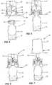
- Vial 12has a body 14 with a neck sealed by a septum 16 over which there is a cap 18.
- a medicant 20is contained within body 14 and would typically comprise a dry ingredient although a fluid may also be utilized.
- Transfer system 10includes an outer housing 24 and a circular side wall 26. On circular side wall 26 there is a protrusion 28 near the bottom thereof. On its upper end, there is provided a luer connection 30. An inner wall 32 mounts a needle 34 which is hollow in nature and has a piercing end 36. As previously mentioned, needle 34 may be a spike.
- Moveable member 40Mounted interiorly of outer housing 24 is a moveable member 40.
- Moveable member 40has a top wall 42 with an aperture 44 centrally located therein to permit the passage of needle 34.
- Extending downwardly from top wall 42is a first leg 46 and a second leg 48.
- First leg 46has an outwardly extending flange 50 at the bottom thereof while second leg 48 also has an outwardly extending flange 52.
- a cover 56is provided to receive transfer system 10.
- Cover 56has a side wall 57 which is adapted to engage with protrusion 28 to retain transfer system 10 in position.
- Side wall 57is provided with an outwardly extending flange 60 at the bottom thereof.
- Flange 60is designed to receive a peelable sealing strip 62 so as to provide a hermetically sealed package.
- the transfer system of the present inventionis preferably utilized with a syringe which has a syringe body 66 and a plunger 68 mounted therein.
- a plunger rod 70is designed to be screwthreadably engageable with plunger 68.
- Syringe body 66includes a backstop 72 to permit proper gripping by the hand of a user.
- syringe body 68includes a luer connector 74.
- syringe body 66is filled with a diluent 76 although any desired fluid may be utilized.
- plunger rod 70is connected to plunger 68 and the diluent 76 is then forced into vial body 14 as shown in Figure 10 .
- the medicant and diluentmay then be mixed and the assembly inverted as shown in Figure 11 .
- the mixture 80is then aspirated back into syringe body 66.
- the mixture 80is then ready for injection when a needle assembly is connected to luer connector 74.
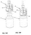
- outer housing 24is provided with a pair of apertures 86 in side wall 26. Also, in this embodiment, there are provided an extra pair of legs 87 each having buttons 88 formed on an exterior surface thereof. In this embodiment, when the moveable member 40 moves upwardly, buttons 88 engage in apertures 86.
- ribs 90which have a groove 92 formed therein.
- top wall 42is provided with protrusions 96 and locking latches 98.
Landscapes
- Health & Medical Sciences (AREA)
- Pharmacology & Pharmacy (AREA)
- Life Sciences & Earth Sciences (AREA)
- Animal Behavior & Ethology (AREA)
- General Health & Medical Sciences (AREA)
- Public Health (AREA)
- Veterinary Medicine (AREA)
- Medical Preparation Storing Or Oral Administration Devices (AREA)
- Infusion, Injection, And Reservoir Apparatuses (AREA)
Description
- The present invention relates to a transfer system and more particularly, relates to an assembly for transferring one or more components of a pharmaceutical composition between containers.
- Typically, a syringe is filled manually by aspirating a liquid pharmaceutical component from a pharmaceutical vial which traditionally has a penetrable closure. The syringe has a needle that penetrates the penetrable closure following which the syringe is typically filled by drawing air into the body of the syringe, aligning the needle with the vial's penetrable closure and inserting the needle through the penetrable closure into the vial. Subsequently, the vial is inverted and air is forced from the body of the syringe into the vial. The plunger is then withdrawn to draw out the desired volume of the pharmaceutical component into the syringe and the needle is removed from the vial.
- Many pharmaceutical preparations must be distributed and sold as two or more separate components - typically a solid component and a liquid component. They are mixed just prior to administration. In some instances, the two or more components may each be liquid and require mixing prior to administration to the patient.
- It is an object of the present invention to provide an assembly for transferring the contents of a first container to a second container.
- According to the present invention, there is provided a transfer device having the features of claim 1.
- In a large number of cases, the transfer device of the present invention provides for the easy linking of a vial and a syringe whereby the components may be mixed to form a composition in the syringe ready for patient injection.
- The contents of the vial may be any suitable pharmaceutical component though in many instances, it will be a dry pharmaceutical component such as a lyophilized product. However, as previously mentioned, it could also be a liquid component.
- The syringe will normally contain a liquid component which is frequently a diluent for the active pharmaceutical ingredient in the vial. The syringe may be any conventional syringe readily available from different manufacturers. Typically, the syringe will contain a piston and have a back stop or finger flange attached to one end thereof. A plunger rod will be attachable to the piston of the syringe.
- One problem with known transfer devices is that access to the needle or plastic spike within the transfer device should be minimized to prevent accidental pricks. Once such transfer device is shown in International Application
PCT/CA2010/001 399 - Another such device is known from
WO2007/101784 . - On some occasions, it is deemed desirable to re-use the transfer device. With the aforementioned transfer device, this was not possible as the vial remains secured to the transfer device and both are disposed of as a unit.
- On other occasions, it is deemed best practise to not permit re-use of the transfer device due to possible contamination. However, it is still desirable to protect the user from the needle or spike.
- In one embodiment of the present invention wherein the device may not be re-used, the moveable member engages the wall of the housing upon upward movement when the vial is inserted into the housing. The rotational movement moves it to an upper position which, when the vial is pulled down, the moveable member moves to a position where it still protects against accidental needle prick but also cannot be moved upwardly again as it is locked position.
- In a further embodiment, the moveable member is retracted down to a position from which it started to enable re-use of the transfer device.
- Having thus generally described the invention, reference will be made to the accompanying drawings illustrating an embodiment thereof, in which:
Figure 1 is a side elevational view of a transfer device according to the present invention;Figure 2 is a side elevational view, partially in section, of a vial containing a medicant;Figure 3 is a side elevational view of a syringe and plunger rod;Figure 4 is a cross sectional view of the transfer device prior to its use;Figure 5 is a side sectional view of the device being placed on a vial;Figure 6 is a side sectional view showing piercing of the vial;Figure 7 is a cross sectional view illustrating the cap being removed;Figure 8 is a view, partially in cross section, of a syringe being attached to the transfer device;Figure 9 is a cross sectional view illustrating a syringe being ready to be placed on the vial;Figure 10 is a cross sectional view illustrating the syringe attached to the vial;Figure 11 is a sectional view illustrating the mixing of components;Figure 12 is a sectional view illustrating the aspiration of the mixture into the syringeFigure 13 is a cross sectional view illustrating placement of the transfer assembly on a vial;Figure 14 is an exploded view illustrating the transfer assembly and the vial prior to insertion of the vial;Figure 15A is a bottom perspective view of a transfer assembly according to one embodiment of the present invention;Figure 15B is a bottom plan view thereof;Figure 16A is a perspective view of the transfer assembly according to a further embodiment;Figure 16B is a bottom plan view thereof;Figure 17A is an exploded view of the transfer assembly;Figure 17B is a bottom perspective view thereof;Figures 17C to 17E show the sequence of placing the transfer assembly on the vial;Figures 17F to 17H illustrate the placement of the transfer assembly in a further embodiment thereof on a vial;Figure 18 is an exploded view of the transfer assembly; andFigures 19A to 19D are perspective views illustrating placement of the transfer assembly on a vial and removal thereof.- Referring to the drawings in greater detail and by reference characters thereto, there is illustrated a transfer system which is generally designated by
reference numeral 10 and which is suitable for use with a vial generally designated byreference numeral 12. - Vial 12 has a
body 14 with a neck sealed by aseptum 16 over which there is acap 18. Amedicant 20 is contained withinbody 14 and would typically comprise a dry ingredient although a fluid may also be utilized. Transfer system 10 includes an outer housing 24 and acircular side wall 26. Oncircular side wall 26 there is aprotrusion 28 near the bottom thereof. On its upper end, there is provided aluer connection 30. Aninner wall 32 mounts aneedle 34 which is hollow in nature and has a piercingend 36. As previously mentioned,needle 34 may be a spike.- Mounted interiorly of outer housing 24 is a
moveable member 40.Moveable member 40 has atop wall 42 with anaperture 44 centrally located therein to permit the passage ofneedle 34. Extending downwardly fromtop wall 42 is afirst leg 46 and asecond leg 48.First leg 46 has an outwardly extendingflange 50 at the bottom thereof whilesecond leg 48 also has an outwardly extending flange 52. - A
cover 56 is provided to receivetransfer system 10.Cover 56 has aside wall 57 which is adapted to engage withprotrusion 28 to retaintransfer system 10 in position.Side wall 57 is provided with an outwardly extendingflange 60 at the bottom thereof.Flange 60 is designed to receive apeelable sealing strip 62 so as to provide a hermetically sealed package. - The transfer system of the present invention is preferably utilized with a syringe which has a
syringe body 66 and aplunger 68 mounted therein. Aplunger rod 70 is designed to be screwthreadably engageable withplunger 68.Syringe body 66 includes abackstop 72 to permit proper gripping by the hand of a user. At its front end,syringe body 68 includes aluer connector 74. Typically,syringe body 66 is filled with a diluent 76 although any desired fluid may be utilized. - As shown in
Figures 8 and 9 ,plunger rod 70 is connected toplunger 68 and the diluent 76 is then forced intovial body 14 as shown inFigure 10 . The medicant and diluent may then be mixed and the assembly inverted as shown inFigure 11 . Themixture 80 is then aspirated back intosyringe body 66. Themixture 80 is then ready for injection when a needle assembly is connected toluer connector 74. - In the embodiment of
Figures 17A to 17H , it will be noted that outer housing 24 is provided with a pair ofapertures 86 inside wall 26. Also, in this embodiment, there are provided an extra pair oflegs 87 each havingbuttons 88 formed on an exterior surface thereof. In this embodiment, when themoveable member 40 moves upwardly,buttons 88 engage inapertures 86. - On the interior surface of
wall 26, there are providedribs 90 which have agroove 92 formed therein. Thus, when pressure is exerted onbuttons 86 asvial 12 is being withdrawn,moveable member 40 will move downwardly until thetop wall 42 engages withgroove 92. This retainsmoveable member 40 in position for further use. - In the embodiment of
Figures 18 to 19D , it will be noted thattop wall 42 is provided withprotrusions 96 and locking latches 98. On the interior there are providedribs 100 and angledside wall portions 102. The arrangement is such that upon upward movement of moveable member 94,protrusions 96 engage withangled side wall 102 to rotatemoveable member 40. Upon withdrawal, locking latches 98 engage withrib 100 so as to prevent further use of the transfer member.
Claims (7)
- A transfer device comprising:a housing (24) having a top, a side wall (26), an open bottom, said open bottom permitting insertion of a vial (12) within said housing;a piercing member (34) mounted within said housing (24), said piercing member (34) having a piercing tip (36) located at a bottom end thereof, said piercing member having an interior passageway formed therein;a connector (30) located on an exterior side of said top;a moveable member (40) mounted within said housing (24), said moveable member (40) being moveable from a first position wherein said moveable member (40) prevents access to said piercing tip (36) and a second position permitting access to said piercing tip when said vial is inserted in said housing,characterized in thatsaid moveable member (40) and
said housing (24) causing said moveable member (40) to rotate when said moveable member (40) moves upwardly upon insertion of said vial (12), said moveable member returning to a third locked position upon removal of said vial, said third locked position being such that a further vial cannot be inserted into said housing. - The transfer device of Claim 1 wherein said moveable member includes at least one leg (46), said housing having a recess formed therein, said leg engaging said recess when said moveable member is in said second position, said moveable member being returnable to said first position upon removal of said vial by pressure on said leg to release said leg from said recess.
- The device of Claim 1 wherein said piercing member is selected from the group consisting of a needle or spike.
- The device of Claim 3 wherein said moveable member (40) has a centrally located aperture (44) to permit said piercing member (34) to pass therethrough.
- The device of Claim 1 wherein said connector (30) on the exterior side of said top comprises a luer connector.
- The device of Claim 2 wherein said moveable member (40) has two projections, each projection being located on a respective one of diametrically opposite legs.
- The device of Claim 6 wherein said housing (24) has a recess formed on an interior surface thereof to receive a disc portion of said moveable member (40) when said moveable member is in said first position.
Applications Claiming Priority (3)
| Application Number | Priority Date | Filing Date | Title |
|---|---|---|---|
| CA2733446ACA2733446A1 (en) | 2011-03-04 | 2011-03-04 | Easy linking device with retractable protector |
| CA2746031ACA2746031A1 (en) | 2011-07-06 | 2011-07-06 | Easy linking device with retractable protector |
| PCT/CA2012/000190WO2012119225A1 (en) | 2011-03-04 | 2012-03-05 | Easy linking transfer system |
Publications (3)
| Publication Number | Publication Date |
|---|---|
| EP2680807A1 EP2680807A1 (en) | 2014-01-08 |
| EP2680807A4 EP2680807A4 (en) | 2014-08-27 |
| EP2680807B1true EP2680807B1 (en) | 2016-08-10 |
Family
ID=46797353
Family Applications (1)
| Application Number | Title | Priority Date | Filing Date |
|---|---|---|---|
| EP12754579.6AActiveEP2680807B1 (en) | 2011-03-04 | 2012-03-05 | Easy linking transfer system |
Country Status (8)
| Country | Link |
|---|---|
| US (1) | US9381135B2 (en) |
| EP (1) | EP2680807B1 (en) |
| JP (3) | JP2014511249A (en) |
| CN (1) | CN103501751B (en) |
| AU (1) | AU2012225163B2 (en) |
| CA (1) | CA2827993C (en) |
| ES (1) | ES2593266T3 (en) |
| WO (1) | WO2012119225A1 (en) |
Families Citing this family (44)
| Publication number | Priority date | Publication date | Assignee | Title |
|---|---|---|---|---|
| US7547300B2 (en) | 2006-04-12 | 2009-06-16 | Icu Medical, Inc. | Vial adaptor for regulating pressure |
| WO2010022095A1 (en) | 2008-08-20 | 2010-02-25 | Icu Medical, Inc. | Anti-reflux vial adaptors |
| ES3004613T3 (en) | 2009-07-29 | 2025-03-12 | Icu Medical Inc | Fluid transfer devices |
| JP2014511249A (en)* | 2011-03-04 | 2014-05-15 | デュオジェクト・メディカル・システムズ・インコーポレイテッド | Easy transfer system |
| CA3176437A1 (en) | 2011-08-18 | 2013-02-21 | Icu Medical, Inc. | Pressure-regulating vial adaptors |
| KR102145639B1 (en) | 2011-12-22 | 2020-08-19 | 아이씨유 메디칼 인코퍼레이티드 | Fluid transfer devices and methods of use |
| DK2802377T3 (en) | 2012-01-13 | 2017-03-20 | Icu Medical Inc | Pressure regulating bottle adapter and method |
| AU2013204180B2 (en) | 2012-03-22 | 2016-07-21 | Icu Medical, Inc. | Pressure-regulating vial adaptors |
| ES2634011T3 (en)* | 2012-05-21 | 2017-09-26 | Carmel Pharma Ab | Protective cap |
| ES2739291T3 (en) | 2013-01-23 | 2020-01-30 | Icu Medical Inc | Pressure regulation vial adapters |
| US9089475B2 (en) | 2013-01-23 | 2015-07-28 | Icu Medical, Inc. | Pressure-regulating vial adaptors |
| EP2759285A1 (en)* | 2013-01-28 | 2014-07-30 | Becton Dickinson France | Adaptor for coupling with a medical container |
| US9597260B2 (en) | 2013-03-15 | 2017-03-21 | Becton Dickinson and Company Ltd. | System for closed transfer of fluids |
| US9414990B2 (en) | 2013-03-15 | 2016-08-16 | Becton Dickinson and Company Ltd. | Seal system for cannula |
| CA3179530A1 (en) | 2013-07-19 | 2015-01-22 | Icu Medical, Inc. | Pressure-regulating fluid transfer systems and methods |
| EP3065694B1 (en) | 2013-11-06 | 2020-04-29 | Becton Dickinson and Company Limited | System for closed transfer of fluids having connector |
| ES2780857T3 (en) | 2013-11-06 | 2020-08-27 | Becton Dickinson & Co Ltd | Connection device for a medical device |
| CA2929476C (en) | 2013-11-06 | 2019-01-22 | Becton Dickinson and Company Limited | System for closed transfer of fluids with a locking member |
| ES2780856T3 (en) | 2013-11-06 | 2020-08-27 | Becton Dickinson & Co Ltd | Medical connector having locking coupling |
| ES2805051T3 (en) | 2013-11-25 | 2021-02-10 | Icu Medical Inc | Procedures and system for filling I.V. bags with therapeutic liquid |
| CN106232082B (en) | 2014-04-16 | 2019-03-12 | 贝克顿迪金森有限公司 | Fluid delivery device with axially and rotatably movable parts |
| BR112016024680B8 (en)* | 2014-04-21 | 2021-11-09 | Becton Dickinson & Co Ltd | Syringe adapter |
| EP3134057B1 (en) | 2014-04-21 | 2018-06-27 | Becton Dickinson and Company Limited | Syringe adapter with compound motion disengagement |
| AU2015249915B2 (en) | 2014-04-21 | 2017-11-30 | Becton Dickinson and Company Limited | System for closed transfer of fluids |
| EP3134058B1 (en) | 2014-04-21 | 2020-03-18 | Becton Dickinson and Company Limited | Fluid transfer device and packaging therefor |
| ES2792512T3 (en) | 2014-04-21 | 2020-11-11 | Becton Dickinson & Co Ltd | Fluid transfer device and packaging for it |
| EP3398583A1 (en) | 2014-04-21 | 2018-11-07 | Becton Dickinson and Company Limited | System with adapter for closed transfer of fluids |
| CN110353993B (en) | 2014-04-21 | 2022-04-12 | 贝克顿迪金森有限公司 | Bottle stabilizer base with attachable bottle adapter |
| EP4091597A1 (en) | 2014-04-21 | 2022-11-23 | Becton Dickinson and Company Limited | Syringe adapter with disconnection feedback mechanism |
| WO2015195844A1 (en) | 2014-06-20 | 2015-12-23 | Icu Medical, Inc. | Pressure-regulating vial adaptors |
| DE102015201288B4 (en) | 2015-01-26 | 2017-01-05 | Bayer Pharma AG | Hollow-needle assembly |
| DE102015201275A1 (en) | 2015-01-26 | 2016-07-28 | Bayer Pharma AG | Device for transferring a liquid between a storage container and at least one further use container |
| EP4534065A3 (en) | 2015-12-04 | 2025-06-04 | ICU Medical, Inc. | Systems methods and components for transferring medical fluids |
| IL243108B (en) | 2015-12-22 | 2018-08-30 | Kriheli Marino | Connector section |
| EP3397231B1 (en) | 2016-01-29 | 2022-03-02 | ICU Medical, Inc. | Pressure-regulating vial adaptors |
| DE102016110569B3 (en)* | 2016-06-08 | 2017-10-26 | Sfm Medical Devices Gmbh | adapter |
| USD851745S1 (en) | 2016-07-19 | 2019-06-18 | Icu Medical, Inc. | Medical fluid transfer system |
| EP3487468B1 (en) | 2016-07-25 | 2025-10-01 | ICU Medical, Inc. | Systems and components for trapping air bubbles in medical fluid transfer modules and systems |
| CA3037577A1 (en)* | 2016-09-30 | 2018-04-05 | Icu Medical, Inc. | Pressure-regulating vial access devices and methods |
| AU2018210833B2 (en)* | 2017-01-17 | 2023-05-04 | Becton Dickinson and Company Limited | Syringe adapter |
| EP4374891A3 (en)* | 2017-10-16 | 2024-08-28 | Enable Injections, Inc. | Pressurized gas powered liquid transfer device and system |
| US11590057B2 (en) | 2020-04-03 | 2023-02-28 | Icu Medical, Inc. | Systems, methods, and components for transferring medical fluids |
| JP2023538204A (en)* | 2020-06-25 | 2023-09-07 | バード・ペリフェラル・バスキュラー・インコーポレーテッド | Vial geometry for optimal mixing |
| JP2024529125A (en)* | 2021-08-12 | 2024-08-01 | ベクトン・ディキンソン・アンド・カンパニー | Syringe adapter with needle hub |
Family Cites Families (69)
| Publication number | Priority date | Publication date | Assignee | Title |
|---|---|---|---|---|
| US3047178A (en)* | 1958-06-24 | 1962-07-31 | Baxter Laboratories Inc | Closure system |
| SE434700B (en)* | 1983-05-20 | 1984-08-13 | Bengt Gustavsson | DEVICE FOR AIRED TRANSFER OF SUBSTANCE FROM A KERLE TO ANOTHER |
| WO1984004673A1 (en)* | 1983-05-20 | 1984-12-06 | Bengt Gustavsson | A device for transferring a substance |
| CA1335167C (en)* | 1988-01-25 | 1995-04-11 | Steven C. Jepson | Pre-slit injection site and associated cannula |
| JPH021277A (en)* | 1988-03-31 | 1990-01-05 | Fujisawa Pharmaceut Co Ltd | infusion container |
| US5171214A (en)* | 1990-12-26 | 1992-12-15 | Abbott Laboratories | Drug storage and delivery system |
| JPH0686738U (en)* | 1992-06-16 | 1994-12-20 | 森下ルセル株式会社 | Medical container |
| JPH06239352A (en)* | 1993-02-05 | 1994-08-30 | Nissho Corp | Solution injection set |
| US5429614A (en)* | 1993-06-30 | 1995-07-04 | Baxter International Inc. | Drug delivery system |
| RU2141306C1 (en)* | 1993-09-07 | 1999-11-20 | Дебиотек С.А. | Syringe device for mixing of two components |
| US5526853A (en)* | 1994-08-17 | 1996-06-18 | Mcgaw, Inc. | Pressure-activated medication transfer system |
| FR2726768A1 (en)* | 1994-11-14 | 1996-05-15 | Debiotech Sa | SYRINGE DEVICE ATTACHABLE TO A VIAL |
| US5647845A (en)* | 1995-02-01 | 1997-07-15 | Habley Medical Technology Corporation | Generic intravenous infusion system |
| IL114960A0 (en)* | 1995-03-20 | 1995-12-08 | Medimop Medical Projects Ltd | Flow control device |
| DK0928182T3 (en)* | 1996-01-11 | 2002-08-26 | Duoject Inc | Delivery system for medicines packed in pharmaceutical bottles |
| US5989237A (en)* | 1997-12-04 | 1999-11-23 | Baxter International Inc. | Sliding reconstitution device with seal |
| US6378714B1 (en)* | 1998-04-20 | 2002-04-30 | Becton Dickinson And Company | Transferset for vials and other medical containers |
| US6209738B1 (en)* | 1998-04-20 | 2001-04-03 | Becton, Dickinson And Company | Transfer set for vials and medical containers |
| US6022339A (en)* | 1998-09-15 | 2000-02-08 | Baxter International Inc. | Sliding reconstitution device for a diluent container |
| CA2345439C (en)* | 1998-10-29 | 2005-08-09 | Minimed, Inc. | Compact pump drive system |
| FR2789369B1 (en)* | 1999-02-10 | 2001-04-27 | Biodome | CONNECTION DEVICE BETWEEN A CONTAINER AND A CONTAINER AND READY-TO-USE ASSEMBLY COMPRISING SUCH A DEVICE |
| FR2790948B1 (en)* | 1999-03-18 | 2001-06-22 | Sedat | DEVICE FOR BIDIRECTIONAL TRANSFER OF A LIQUID BETWEEN A BOTTLE AND A CAPSULE |
| US7470258B2 (en)* | 2001-03-13 | 2008-12-30 | Mdc Investment Holdings, Inc. | Pre-filled safety vial injector |
| US6796967B2 (en)* | 2001-10-22 | 2004-09-28 | Nps Pharmaceuticals, Inc. | Injection needle assembly |
| US6875205B2 (en)* | 2002-02-08 | 2005-04-05 | Alaris Medical Systems, Inc. | Vial adapter having a needle-free valve for use with vial closures of different sizes |
| NZ538754A (en)* | 2002-09-03 | 2010-04-30 | Medical Instill Tech Inc | Sealed vial with a reseable stopper and methods of making and filling same |
| WO2004041148A1 (en)* | 2002-11-08 | 2004-05-21 | Duoject Medical Systems Inc. | Pharmaceutical delivery systems and methods for using same |
| US7678333B2 (en)* | 2003-01-22 | 2010-03-16 | Duoject Medical Systems Inc. | Fluid transfer assembly for pharmaceutical delivery system and method for using same |
| FR2856660A1 (en)* | 2003-06-30 | 2004-12-31 | Biodome | CONNECTION DEVICE BETWEEN A CONTAINER AND A CONTAINER AND READY-TO-USE ASSEMBLY COMPRISING SUCH A DEVICE |
| IN2014MN00187A (en)* | 2003-10-30 | 2015-08-21 | Teva Medical Ltd | |
| US7530546B2 (en)* | 2004-01-13 | 2009-05-12 | Rymed Technologies, Inc. | Swabbable needle-free injection port valve system with zero fluid displacement |
| IL161660A0 (en)* | 2004-04-29 | 2004-09-27 | Medimop Medical Projects Ltd | Liquid drug delivery device |
| US20060184103A1 (en)* | 2005-02-17 | 2006-08-17 | West Pharmaceutical Services, Inc. | Syringe safety device |
| US7648491B2 (en)* | 2005-05-13 | 2010-01-19 | Bob Rogers | Medical substance transfer system |
| GB0510057D0 (en)* | 2005-05-17 | 2005-06-22 | Glaxosmithkline Biolog Sa | Novel device |
| WO2007015233A1 (en)* | 2005-08-01 | 2007-02-08 | Medimop Medical Projects Ltd | Liquid drug delivery system |
| PL1971531T3 (en)* | 2005-11-30 | 2010-01-29 | Biocorp Rech Et Developpement | Plug device for a container and container provided with one such device |
| EP1993503A1 (en)* | 2006-03-06 | 2008-11-26 | Novo Nordisk A/S | A drug mixing device |
| WO2007101772A1 (en)* | 2006-03-07 | 2007-09-13 | Novo Nordisk A/S | A drug mixing device |
| US7547300B2 (en)* | 2006-04-12 | 2009-06-16 | Icu Medical, Inc. | Vial adaptor for regulating pressure |
| CA2652206C (en)* | 2006-05-25 | 2014-02-11 | Bayer Healthcare Llc | Reconstitution device |
| US8211082B2 (en)* | 2006-06-19 | 2012-07-03 | Nipro Corporation | Drug solution preparing kit |
| CA2564061A1 (en)* | 2006-10-16 | 2008-04-16 | Duoject Medical Systems Inc. | Reconstitution system for mixing the contents of a vial containing a first substance with a second substance stored in a cartridge |
| US8167863B2 (en)* | 2006-10-16 | 2012-05-01 | Carefusion 303, Inc. | Vented vial adapter with filter for aerosol retention |
| FR2911493B1 (en)* | 2007-01-24 | 2009-03-13 | Technoflex Sa | METHOD AND SET FOR TRANSFERRING A FLUID BETWEEN TWO CONTAINERS. |
| US20080262466A1 (en)* | 2007-04-19 | 2008-10-23 | Steve Smith | Storage container |
| KR101507841B1 (en)* | 2007-04-23 | 2015-04-07 | 플라스트메드 리미티드 | Method and apparatus for contamination-free transfer of a hazardous drug |
| US20080306439A1 (en)* | 2007-06-08 | 2008-12-11 | Nelson M Bud | Devices for mixing and applying a fluid composition |
| US8287513B2 (en)* | 2007-09-11 | 2012-10-16 | Carmel Pharma Ab | Piercing member protection device |
| AU2009203557B2 (en)* | 2008-01-09 | 2014-02-20 | Novartis Ag | Unitary withdrawal spike unit suitable for factory fitting |
| FR2928539B1 (en)* | 2008-03-12 | 2012-02-24 | Vygon | INTERFACING DEVICE FOR PERFORATING BOTTLES FOR THE PREPARATION OF PERFUME FLUIDS |
| EP2391329B1 (en)* | 2009-01-30 | 2017-06-28 | Biocompatibles UK Limited | Method for increasing the leakage resistance in a closed, pressurized system comprising a septum-sealed container |
| US8864725B2 (en)* | 2009-03-17 | 2014-10-21 | Baxter Corporation Englewood | Hazardous drug handling system, apparatus and method |
| US8277424B2 (en)* | 2009-07-17 | 2012-10-02 | Pan Hsiu-Feng | Needle-less syringe adapter |
| US9662271B2 (en)* | 2009-10-23 | 2017-05-30 | Amgen Inc. | Vial adapter and system |
| EP2493546A4 (en)* | 2009-10-30 | 2014-08-13 | Revance Therapeutics Inc | DEVICE AND METHOD FOR THE TOPICAL APPLICATION OF THERAPEUTIC OR COSMETIC COMPOSITIONS |
| IL202070A0 (en)* | 2009-11-12 | 2010-06-16 | Medimop Medical Projects Ltd | Inline liquid drug medical device |
| US9492353B2 (en)* | 2009-11-20 | 2016-11-15 | Carmel Pharma Ab | Medical device connector |
| US9205248B2 (en)* | 2010-02-24 | 2015-12-08 | Becton, Dickinson And Company | Safety Drug delivery connectors |
| CN103167857B (en)* | 2010-06-30 | 2014-12-10 | 泰尔茂株式会社 | Connector and connector assembly |
| JP2014511249A (en)* | 2011-03-04 | 2014-05-15 | デュオジェクト・メディカル・システムズ・インコーポレイテッド | Easy transfer system |
| US9480623B2 (en)* | 2011-10-14 | 2016-11-01 | Novo Nordisk Healthcare Ag | Pre-assembled fluid transfer arrangement |
| EP2787951B1 (en)* | 2011-12-08 | 2016-03-16 | Novo Nordisk Health Care AG | Medical device having integrated sequence control |
| JP5510986B2 (en)* | 2012-04-02 | 2014-06-04 | 株式会社メディカルクリエーション | Drug transfer device |
| IL221634A0 (en)* | 2012-08-26 | 2012-12-31 | Medimop Medical Projects Ltd | Universal drug vial adapter |
| US9724269B2 (en)* | 2012-11-30 | 2017-08-08 | Becton Dickinson and Company Ltd. | Connector for fluid communication |
| US9597260B2 (en)* | 2013-03-15 | 2017-03-21 | Becton Dickinson and Company Ltd. | System for closed transfer of fluids |
| JP6446438B2 (en)* | 2013-09-23 | 2018-12-26 | ベクトン ディキンソン アンド カンパニー リミテッド | Puncture member for container access device |
| EP3065694B1 (en)* | 2013-11-06 | 2020-04-29 | Becton Dickinson and Company Limited | System for closed transfer of fluids having connector |
- 2012
- 2012-03-05JPJP2013556940Apatent/JP2014511249A/enactivePending
- 2012-03-05EPEP12754579.6Apatent/EP2680807B1/enactiveActive
- 2012-03-05ESES12754579.6Tpatent/ES2593266T3/enactiveActive
- 2012-03-05CNCN201280020984.9Apatent/CN103501751B/enactiveActive
- 2012-03-05AUAU2012225163Apatent/AU2012225163B2/enactiveActive
- 2012-03-05WOPCT/CA2012/000190patent/WO2012119225A1/enactiveApplication Filing
- 2012-03-05USUS13/261,729patent/US9381135B2/enactiveActive
- 2012-03-05CACA2827993Apatent/CA2827993C/enactiveActive
- 2017
- 2017-03-28JPJP2017062340Apatent/JP6502412B2/enactiveActive
- 2018
- 2018-12-14JPJP2018234525Apatent/JP6676740B2/enactiveActive
Also Published As
| Publication number | Publication date |
|---|---|
| CA2827993C (en) | 2018-04-17 |
| CN103501751A (en) | 2014-01-08 |
| JP2019072508A (en) | 2019-05-16 |
| JP6676740B2 (en) | 2020-04-08 |
| ES2593266T3 (en) | 2016-12-07 |
| JP6502412B2 (en) | 2019-04-17 |
| US9381135B2 (en) | 2016-07-05 |
| EP2680807A4 (en) | 2014-08-27 |
| JP2017140419A (en) | 2017-08-17 |
| CA2827993A1 (en) | 2012-09-13 |
| AU2012225163B2 (en) | 2016-05-12 |
| JP2014511249A (en) | 2014-05-15 |
| WO2012119225A1 (en) | 2012-09-13 |
| US20140000738A1 (en) | 2014-01-02 |
| EP2680807A1 (en) | 2014-01-08 |
| AU2012225163A1 (en) | 2013-09-12 |
| CN103501751B (en) | 2016-11-23 |
Similar Documents
| Publication | Publication Date | Title |
|---|---|---|
| EP2680807B1 (en) | Easy linking transfer system | |
| EP2882400B1 (en) | Reconstitution device | |
| EP2475454B1 (en) | Easy-link device for fluid transfer | |
| EP2874594B1 (en) | Reconstitution device with tip cap | |
| US10736818B2 (en) | Reconstitution device with tip cap | |
| EP3880154B1 (en) | Fluid transfer device | |
| CA3015070A1 (en) | Easy linking transfer system | |
| CA2746031A1 (en) | Easy linking device with retractable protector | |
| CA2733446A1 (en) | Easy linking device with retractable protector |
Legal Events
| Date | Code | Title | Description |
|---|---|---|---|
| PUAI | Public reference made under article 153(3) epc to a published international application that has entered the european phase | Free format text:ORIGINAL CODE: 0009012 | |
| 17P | Request for examination filed | Effective date:20130919 | |
| AK | Designated contracting states | Kind code of ref document:A1 Designated state(s):AL AT BE BG CH CY CZ DE DK EE ES FI FR GB GR HR HU IE IS IT LI LT LU LV MC MK MT NL NO PL PT RO RS SE SI SK SM TR | |
| DAX | Request for extension of the european patent (deleted) | ||
| A4 | Supplementary search report drawn up and despatched | Effective date:20140728 | |
| RIC1 | Information provided on ipc code assigned before grant | Ipc:A61J 1/20 20060101AFI20140722BHEP | |
| GRAP | Despatch of communication of intention to grant a patent | Free format text:ORIGINAL CODE: EPIDOSNIGR1 | |
| INTG | Intention to grant announced | Effective date:20160311 | |
| RAP1 | Party data changed (applicant data changed or rights of an application transferred) | Owner name:DUOJECT MEDICAL SYSTEMS INC. | |
| RIN1 | Information on inventor provided before grant (corrected) | Inventor name:TREMBLAY, YAN Inventor name:GEOFFROY, ERIC Inventor name:REYNOLDS, DAVID, L. Inventor name:MACDONALD, DANIEL | |
| GRAS | Grant fee paid | Free format text:ORIGINAL CODE: EPIDOSNIGR3 | |
| GRAA | (expected) grant | Free format text:ORIGINAL CODE: 0009210 | |
| AK | Designated contracting states | Kind code of ref document:B1 Designated state(s):AL AT BE BG CH CY CZ DE DK EE ES FI FR GB GR HR HU IE IS IT LI LT LU LV MC MK MT NL NO PL PT RO RS SE SI SK SM TR | |
| REG | Reference to a national code | Ref country code:GB Ref legal event code:FG4D | |
| REG | Reference to a national code | Ref country code:CH Ref legal event code:EP Ref country code:AT Ref legal event code:REF Ref document number:818290 Country of ref document:AT Kind code of ref document:T Effective date:20160815 | |
| REG | Reference to a national code | Ref country code:IE Ref legal event code:FG4D | |
| REG | Reference to a national code | Ref country code:DE Ref legal event code:R096 Ref document number:602012021523 Country of ref document:DE | |
| REG | Reference to a national code | Ref country code:ES Ref legal event code:FG2A Ref document number:2593266 Country of ref document:ES Kind code of ref document:T3 Effective date:20161207 | |
| REG | Reference to a national code | Ref country code:LT Ref legal event code:MG4D | |
| REG | Reference to a national code | Ref country code:NL Ref legal event code:MP Effective date:20160810 | |
| REG | Reference to a national code | Ref country code:AT Ref legal event code:MK05 Ref document number:818290 Country of ref document:AT Kind code of ref document:T Effective date:20160810 | |
| PG25 | Lapsed in a contracting state [announced via postgrant information from national office to epo] | Ref country code:HR Free format text:LAPSE BECAUSE OF FAILURE TO SUBMIT A TRANSLATION OF THE DESCRIPTION OR TO PAY THE FEE WITHIN THE PRESCRIBED TIME-LIMIT Effective date:20160810 Ref country code:NO Free format text:LAPSE BECAUSE OF FAILURE TO SUBMIT A TRANSLATION OF THE DESCRIPTION OR TO PAY THE FEE WITHIN THE PRESCRIBED TIME-LIMIT Effective date:20161110 Ref country code:FI Free format text:LAPSE BECAUSE OF FAILURE TO SUBMIT A TRANSLATION OF THE DESCRIPTION OR TO PAY THE FEE WITHIN THE PRESCRIBED TIME-LIMIT Effective date:20160810 Ref country code:LT Free format text:LAPSE BECAUSE OF FAILURE TO SUBMIT A TRANSLATION OF THE DESCRIPTION OR TO PAY THE FEE WITHIN THE PRESCRIBED TIME-LIMIT Effective date:20160810 Ref country code:IS Free format text:LAPSE BECAUSE OF FAILURE TO SUBMIT A TRANSLATION OF THE DESCRIPTION OR TO PAY THE FEE WITHIN THE PRESCRIBED TIME-LIMIT Effective date:20161210 Ref country code:NL Free format text:LAPSE BECAUSE OF FAILURE TO SUBMIT A TRANSLATION OF THE DESCRIPTION OR TO PAY THE FEE WITHIN THE PRESCRIBED TIME-LIMIT Effective date:20160810 Ref country code:RS Free format text:LAPSE BECAUSE OF FAILURE TO SUBMIT A TRANSLATION OF THE DESCRIPTION OR TO PAY THE FEE WITHIN THE PRESCRIBED TIME-LIMIT Effective date:20160810 | |
| PG25 | Lapsed in a contracting state [announced via postgrant information from national office to epo] | Ref country code:SE Free format text:LAPSE BECAUSE OF FAILURE TO SUBMIT A TRANSLATION OF THE DESCRIPTION OR TO PAY THE FEE WITHIN THE PRESCRIBED TIME-LIMIT Effective date:20160810 Ref country code:PL Free format text:LAPSE BECAUSE OF FAILURE TO SUBMIT A TRANSLATION OF THE DESCRIPTION OR TO PAY THE FEE WITHIN THE PRESCRIBED TIME-LIMIT Effective date:20160810 Ref country code:GR Free format text:LAPSE BECAUSE OF FAILURE TO SUBMIT A TRANSLATION OF THE DESCRIPTION OR TO PAY THE FEE WITHIN THE PRESCRIBED TIME-LIMIT Effective date:20161111 Ref country code:LV Free format text:LAPSE BECAUSE OF FAILURE TO SUBMIT A TRANSLATION OF THE DESCRIPTION OR TO PAY THE FEE WITHIN THE PRESCRIBED TIME-LIMIT Effective date:20160810 Ref country code:PT Free format text:LAPSE BECAUSE OF FAILURE TO SUBMIT A TRANSLATION OF THE DESCRIPTION OR TO PAY THE FEE WITHIN THE PRESCRIBED TIME-LIMIT Effective date:20161212 Ref country code:AT Free format text:LAPSE BECAUSE OF FAILURE TO SUBMIT A TRANSLATION OF THE DESCRIPTION OR TO PAY THE FEE WITHIN THE PRESCRIBED TIME-LIMIT Effective date:20160810 | |
| REG | Reference to a national code | Ref country code:FR Ref legal event code:PLFP Year of fee payment:6 | |
| PG25 | Lapsed in a contracting state [announced via postgrant information from national office to epo] | Ref country code:EE Free format text:LAPSE BECAUSE OF FAILURE TO SUBMIT A TRANSLATION OF THE DESCRIPTION OR TO PAY THE FEE WITHIN THE PRESCRIBED TIME-LIMIT Effective date:20160810 Ref country code:RO Free format text:LAPSE BECAUSE OF FAILURE TO SUBMIT A TRANSLATION OF THE DESCRIPTION OR TO PAY THE FEE WITHIN THE PRESCRIBED TIME-LIMIT Effective date:20160810 | |
| REG | Reference to a national code | Ref country code:DE Ref legal event code:R097 Ref document number:602012021523 Country of ref document:DE | |
| PG25 | Lapsed in a contracting state [announced via postgrant information from national office to epo] | Ref country code:DK Free format text:LAPSE BECAUSE OF FAILURE TO SUBMIT A TRANSLATION OF THE DESCRIPTION OR TO PAY THE FEE WITHIN THE PRESCRIBED TIME-LIMIT Effective date:20160810 Ref country code:BG Free format text:LAPSE BECAUSE OF FAILURE TO SUBMIT A TRANSLATION OF THE DESCRIPTION OR TO PAY THE FEE WITHIN THE PRESCRIBED TIME-LIMIT Effective date:20161110 Ref country code:CZ Free format text:LAPSE BECAUSE OF FAILURE TO SUBMIT A TRANSLATION OF THE DESCRIPTION OR TO PAY THE FEE WITHIN THE PRESCRIBED TIME-LIMIT Effective date:20160810 Ref country code:BE Free format text:LAPSE BECAUSE OF FAILURE TO SUBMIT A TRANSLATION OF THE DESCRIPTION OR TO PAY THE FEE WITHIN THE PRESCRIBED TIME-LIMIT Effective date:20160810 Ref country code:SK Free format text:LAPSE BECAUSE OF FAILURE TO SUBMIT A TRANSLATION OF THE DESCRIPTION OR TO PAY THE FEE WITHIN THE PRESCRIBED TIME-LIMIT Effective date:20160810 Ref country code:SM Free format text:LAPSE BECAUSE OF FAILURE TO SUBMIT A TRANSLATION OF THE DESCRIPTION OR TO PAY THE FEE WITHIN THE PRESCRIBED TIME-LIMIT Effective date:20160810 | |
| PLBE | No opposition filed within time limit | Free format text:ORIGINAL CODE: 0009261 | |
| STAA | Information on the status of an ep patent application or granted ep patent | Free format text:STATUS: NO OPPOSITION FILED WITHIN TIME LIMIT | |
| 26N | No opposition filed | Effective date:20170511 | |
| PG25 | Lapsed in a contracting state [announced via postgrant information from national office to epo] | Ref country code:SI Free format text:LAPSE BECAUSE OF FAILURE TO SUBMIT A TRANSLATION OF THE DESCRIPTION OR TO PAY THE FEE WITHIN THE PRESCRIBED TIME-LIMIT Effective date:20160810 | |
| REG | Reference to a national code | Ref country code:CH Ref legal event code:PL | |
| PG25 | Lapsed in a contracting state [announced via postgrant information from national office to epo] | Ref country code:MC Free format text:LAPSE BECAUSE OF FAILURE TO SUBMIT A TRANSLATION OF THE DESCRIPTION OR TO PAY THE FEE WITHIN THE PRESCRIBED TIME-LIMIT Effective date:20160810 | |
| REG | Reference to a national code | Ref country code:IE Ref legal event code:MM4A | |
| PG25 | Lapsed in a contracting state [announced via postgrant information from national office to epo] | Ref country code:LU Free format text:LAPSE BECAUSE OF NON-PAYMENT OF DUE FEES Effective date:20170305 | |
| PG25 | Lapsed in a contracting state [announced via postgrant information from national office to epo] | Ref country code:IE Free format text:LAPSE BECAUSE OF NON-PAYMENT OF DUE FEES Effective date:20170305 Ref country code:LI Free format text:LAPSE BECAUSE OF NON-PAYMENT OF DUE FEES Effective date:20170331 Ref country code:CH Free format text:LAPSE BECAUSE OF NON-PAYMENT OF DUE FEES Effective date:20170331 | |
| REG | Reference to a national code | Ref country code:FR Ref legal event code:PLFP Year of fee payment:7 | |
| PG25 | Lapsed in a contracting state [announced via postgrant information from national office to epo] | Ref country code:MT Free format text:LAPSE BECAUSE OF NON-PAYMENT OF DUE FEES Effective date:20170305 | |
| PG25 | Lapsed in a contracting state [announced via postgrant information from national office to epo] | Ref country code:AL Free format text:LAPSE BECAUSE OF FAILURE TO SUBMIT A TRANSLATION OF THE DESCRIPTION OR TO PAY THE FEE WITHIN THE PRESCRIBED TIME-LIMIT Effective date:20160810 | |
| PG25 | Lapsed in a contracting state [announced via postgrant information from national office to epo] | Ref country code:HU Free format text:LAPSE BECAUSE OF FAILURE TO SUBMIT A TRANSLATION OF THE DESCRIPTION OR TO PAY THE FEE WITHIN THE PRESCRIBED TIME-LIMIT; INVALID AB INITIO Effective date:20120305 | |
| PG25 | Lapsed in a contracting state [announced via postgrant information from national office to epo] | Ref country code:CY Free format text:LAPSE BECAUSE OF NON-PAYMENT OF DUE FEES Effective date:20160810 | |
| PG25 | Lapsed in a contracting state [announced via postgrant information from national office to epo] | Ref country code:MK Free format text:LAPSE BECAUSE OF FAILURE TO SUBMIT A TRANSLATION OF THE DESCRIPTION OR TO PAY THE FEE WITHIN THE PRESCRIBED TIME-LIMIT Effective date:20160810 | |
| PG25 | Lapsed in a contracting state [announced via postgrant information from national office to epo] | Ref country code:TR Free format text:LAPSE BECAUSE OF FAILURE TO SUBMIT A TRANSLATION OF THE DESCRIPTION OR TO PAY THE FEE WITHIN THE PRESCRIBED TIME-LIMIT Effective date:20160810 | |
| PGFP | Annual fee paid to national office [announced via postgrant information from national office to epo] | Ref country code:DE Payment date:20250325 Year of fee payment:14 | |
| PGFP | Annual fee paid to national office [announced via postgrant information from national office to epo] | Ref country code:FR Payment date:20250325 Year of fee payment:14 | |
| PGFP | Annual fee paid to national office [announced via postgrant information from national office to epo] | Ref country code:IT Payment date:20250325 Year of fee payment:14 Ref country code:GB Payment date:20250321 Year of fee payment:14 | |
| PGFP | Annual fee paid to national office [announced via postgrant information from national office to epo] | Ref country code:ES Payment date:20250428 Year of fee payment:14 |