EP2680749B1 - Skin conductance sensor - Google Patents
Skin conductance sensorDownload PDFInfo
- Publication number
- EP2680749B1 EP2680749B1EP12704328.9AEP12704328AEP2680749B1EP 2680749 B1EP2680749 B1EP 2680749B1EP 12704328 AEP12704328 AEP 12704328AEP 2680749 B1EP2680749 B1EP 2680749B1
- Authority
- EP
- European Patent Office
- Prior art keywords
- skin conductance
- skin
- sensor
- electrode
- conductance sensor
- Prior art date
- Legal status (The legal status is an assumption and is not a legal conclusion. Google has not performed a legal analysis and makes no representation as to the accuracy of the status listed.)
- Active
Links
- 239000000463materialSubstances0.000claimsdescription49
- WHXSMMKQMYFTQS-UHFFFAOYSA-NLithiumChemical compound[Li]WHXSMMKQMYFTQS-UHFFFAOYSA-N0.000claimsdescription33
- 239000002019doping agentSubstances0.000claimsdescription32
- 229910052744lithiumInorganic materials0.000claimsdescription32
- 239000010931goldSubstances0.000claimsdescription28
- 239000011734sodiumSubstances0.000claimsdescription27
- 229910000510noble metalInorganic materials0.000claimsdescription26
- PCHJSUWPFVWCPO-UHFFFAOYSA-NgoldChemical compound[Au]PCHJSUWPFVWCPO-UHFFFAOYSA-N0.000claimsdescription25
- 229910052737goldInorganic materials0.000claimsdescription25
- 230000002996emotional effectEffects0.000claimsdescription24
- DGAQECJNVWCQMB-PUAWFVPOSA-MIlexoside XXIXChemical compoundC[C@@H]1CC[C@@]2(CC[C@@]3(C(=CC[C@H]4[C@]3(CC[C@@H]5[C@@]4(CC[C@@H](C5(C)C)OS(=O)(=O)[O-])C)C)[C@@H]2[C@]1(C)O)C)C(=O)O[C@H]6[C@@H]([C@H]([C@@H]([C@H](O6)CO)O)O)O.[Na+]DGAQECJNVWCQMB-PUAWFVPOSA-M0.000claimsdescription22
- ZLMJMSJWJFRBEC-UHFFFAOYSA-NPotassiumChemical compound[K]ZLMJMSJWJFRBEC-UHFFFAOYSA-N0.000claimsdescription22
- 229910052708sodiumInorganic materials0.000claimsdescription22
- 229910052700potassiumInorganic materials0.000claimsdescription21
- 239000011591potassiumSubstances0.000claimsdescription21
- KDLHZDBZIXYQEI-UHFFFAOYSA-NPalladiumChemical compound[Pd]KDLHZDBZIXYQEI-UHFFFAOYSA-N0.000claimsdescription19
- BASFCYQUMIYNBI-UHFFFAOYSA-NplatinumChemical compound[Pt]BASFCYQUMIYNBI-UHFFFAOYSA-N0.000claimsdescription19
- 238000001514detection methodMethods0.000claimsdescription14
- 230000005540biological transmissionEffects0.000claimsdescription10
- 229910052763palladiumInorganic materials0.000claimsdescription9
- 229910052697platinumInorganic materials0.000claimsdescription9
- 238000003487electrochemical reactionMethods0.000claimsdescription8
- 229910052739hydrogenInorganic materials0.000claimsdescription7
- 239000001257hydrogenSubstances0.000claimsdescription7
- 125000004435hydrogen atomChemical class[H]*0.000claimsdescription7
- 206010013786Dry skinDiseases0.000claimsdescription6
- 229910052792caesiumInorganic materials0.000claimsdescription6
- TVFDJXOCXUVLDH-UHFFFAOYSA-Ncaesium atomChemical compound[Cs]TVFDJXOCXUVLDH-UHFFFAOYSA-N0.000claimsdescription6
- 230000037336dry skinEffects0.000claimsdescription6
- 229910052701rubidiumInorganic materials0.000claimsdescription6
- IGLNJRXAVVLDKE-UHFFFAOYSA-Nrubidium atomChemical compound[Rb]IGLNJRXAVVLDKE-UHFFFAOYSA-N0.000claimsdescription6
- 210000000707wristAnatomy0.000claimsdescription5
- 238000000034methodMethods0.000claimsdescription3
- 230000008569processEffects0.000claimsdescription3
- PXHVJJICTQNCMI-UHFFFAOYSA-NNickelChemical compound[Ni]PXHVJJICTQNCMI-UHFFFAOYSA-N0.000description15
- 238000005259measurementMethods0.000description11
- 150000002500ionsChemical class0.000description10
- 229910052759nickelInorganic materials0.000description6
- 239000002585baseSubstances0.000description5
- 229910052790berylliumInorganic materials0.000description5
- ATBAMAFKBVZNFJ-UHFFFAOYSA-Nberyllium atomChemical compound[Be]ATBAMAFKBVZNFJ-UHFFFAOYSA-N0.000description5
- 210000000106sweat glandAnatomy0.000description5
- 239000000969carrierSubstances0.000description4
- 230000000694effectsEffects0.000description4
- 238000004544sputter depositionMethods0.000description4
- 229910001369BrassInorganic materials0.000description3
- 229910052783alkali metalInorganic materials0.000description3
- 150000001340alkali metalsChemical group0.000description3
- 230000037007arousalEffects0.000description3
- 125000004429atomChemical group0.000description3
- 239000010951brassSubstances0.000description3
- 230000001419dependent effectEffects0.000description3
- 230000007774longtermEffects0.000description3
- 238000004519manufacturing processMethods0.000description3
- 229910052751metalInorganic materials0.000description3
- 239000002184metalSubstances0.000description3
- 230000000630rising effectEffects0.000description3
- 229910052709silverInorganic materials0.000description3
- 239000004332silverSubstances0.000description3
- 231100000331toxicToxicity0.000description3
- 230000002588toxic effectEffects0.000description3
- 229910021607Silver chlorideInorganic materials0.000description2
- 230000015572biosynthetic processEffects0.000description2
- 239000008280bloodSubstances0.000description2
- 210000004369bloodAnatomy0.000description2
- 230000036760body temperatureEffects0.000description2
- 238000010351charge transfer processMethods0.000description2
- 239000004020conductorSubstances0.000description2
- 238000000151depositionMethods0.000description2
- 230000008021depositionEffects0.000description2
- 238000010586diagramMethods0.000description2
- 238000009792diffusion processMethods0.000description2
- 239000007772electrode materialSubstances0.000description2
- 230000008020evaporationEffects0.000description2
- 238000001704evaporationMethods0.000description2
- 239000012530fluidSubstances0.000description2
- 229910052730franciumInorganic materials0.000description2
- KLMCZVJOEAUDNE-UHFFFAOYSA-Nfrancium atomChemical compound[Fr]KLMCZVJOEAUDNE-UHFFFAOYSA-N0.000description2
- 238000002347injectionMethods0.000description2
- 239000007924injectionSubstances0.000description2
- 239000011159matrix materialSubstances0.000description2
- 230000000737periodic effectEffects0.000description2
- 230000002035prolonged effectEffects0.000description2
- 230000029058respiratory gaseous exchangeEffects0.000description2
- 239000010948rhodiumSubstances0.000description2
- -1silver ionsChemical class0.000description2
- HKZLPVFGJNLROG-UHFFFAOYSA-Msilver monochlorideChemical compound[Cl-].[Ag+]HKZLPVFGJNLROG-UHFFFAOYSA-M0.000description2
- HBBGRARXTFLTSG-UHFFFAOYSA-NLithium ionChemical compound[Li+]HBBGRARXTFLTSG-UHFFFAOYSA-N0.000description1
- KJTLSVCANCCWHF-UHFFFAOYSA-NRutheniumChemical compound[Ru]KJTLSVCANCCWHF-UHFFFAOYSA-N0.000description1
- BQCADISMDOOEFD-UHFFFAOYSA-NSilverChemical compound[Ag]BQCADISMDOOEFD-UHFFFAOYSA-N0.000description1
- 206010040880Skin irritationDiseases0.000description1
- 229910045601alloyInorganic materials0.000description1
- 239000000956alloySubstances0.000description1
- 210000003423ankleAnatomy0.000description1
- 230000008901benefitEffects0.000description1
- 230000008859changeEffects0.000description1
- 230000006870functionEffects0.000description1
- 230000036571hydrationEffects0.000description1
- 238000006703hydration reactionMethods0.000description1
- 239000012535impuritySubstances0.000description1
- 229910052741iridiumInorganic materials0.000description1
- GKOZUEZYRPOHIO-UHFFFAOYSA-Niridium atomChemical compound[Ir]GKOZUEZYRPOHIO-UHFFFAOYSA-N0.000description1
- 229910001416lithium ionInorganic materials0.000description1
- 230000008018meltingEffects0.000description1
- 238000002844meltingMethods0.000description1
- 150000002739metalsChemical class0.000description1
- 239000007773negative electrode materialSubstances0.000description1
- 231100000252nontoxicToxicity0.000description1
- 230000003000nontoxic effectEffects0.000description1
- 229910052762osmiumInorganic materials0.000description1
- SYQBFIAQOQZEGI-UHFFFAOYSA-Nosmium atomChemical compound[Os]SYQBFIAQOQZEGI-UHFFFAOYSA-N0.000description1
- 230000037368penetrate the skinEffects0.000description1
- 238000001020plasma etchingMethods0.000description1
- 229910001414potassium ionInorganic materials0.000description1
- 239000010453quartzSubstances0.000description1
- 229910052703rhodiumInorganic materials0.000description1
- MHOVAHRLVXNVSD-UHFFFAOYSA-Nrhodium atomChemical compound[Rh]MHOVAHRLVXNVSD-UHFFFAOYSA-N0.000description1
- 229910052707rutheniumInorganic materials0.000description1
- VYPSYNLAJGMNEJ-UHFFFAOYSA-Nsilicon dioxideInorganic materialsO=[Si]=OVYPSYNLAJGMNEJ-UHFFFAOYSA-N0.000description1
- 230000036556skin irritationEffects0.000description1
- 231100000475skin irritationToxicity0.000description1
- 230000005808skin problemEffects0.000description1
- 231100000430skin reactionToxicity0.000description1
- 229910001415sodium ionInorganic materials0.000description1
- 230000008961swellingEffects0.000description1
- 239000004753textileSubstances0.000description1
Images


Classifications
- A—HUMAN NECESSITIES
- A61—MEDICAL OR VETERINARY SCIENCE; HYGIENE
- A61B—DIAGNOSIS; SURGERY; IDENTIFICATION
- A61B5/00—Measuring for diagnostic purposes; Identification of persons
- A61B5/05—Detecting, measuring or recording for diagnosis by means of electric currents or magnetic fields; Measuring using microwaves or radio waves
- A61B5/053—Measuring electrical impedance or conductance of a portion of the body
- A61B5/0531—Measuring skin impedance
- A61B5/0533—Measuring galvanic skin response
- A—HUMAN NECESSITIES
- A61—MEDICAL OR VETERINARY SCIENCE; HYGIENE
- A61B—DIAGNOSIS; SURGERY; IDENTIFICATION
- A61B5/00—Measuring for diagnostic purposes; Identification of persons
- A61B5/68—Arrangements of detecting, measuring or recording means, e.g. sensors, in relation to patient
- A61B5/6801—Arrangements of detecting, measuring or recording means, e.g. sensors, in relation to patient specially adapted to be attached to or worn on the body surface
- A61B5/6802—Sensor mounted on worn items
- A61B5/681—Wristwatch-type devices
- A—HUMAN NECESSITIES
- A61—MEDICAL OR VETERINARY SCIENCE; HYGIENE
- A61B—DIAGNOSIS; SURGERY; IDENTIFICATION
- A61B2562/00—Details of sensors; Constructional details of sensor housings or probes; Accessories for sensors
- A61B2562/12—Manufacturing methods specially adapted for producing sensors for in-vivo measurements
- A61B2562/125—Manufacturing methods specially adapted for producing sensors for in-vivo measurements characterised by the manufacture of electrodes
Definitions
- the present inventionrelates to a a skin conductance sensor comprising at least two dry electrodes, wherein the sensor is adapted to sense a user's skin conductance between the at least two dry electrodes.
- the present inventionalso relates to a wristband comprising such a skin conductance sensor and an emotional event detection system comprising such a skin conductance sensor.
- gel electrodesare used for skin conductance sensors. These gel electrodes offer a high signal level. However, prolonged wearing of gel electrodes causes undesirable side effects, such as a white swelling of the skin caused by hydration.
- a skin conductance sensorcomprising at least two dry electrodes, that is adapted to sense a user's skin conductance between the at least two dry electrodes, wherein at least one of the electrodes is a dry skin conductance electrode for contacting the skin of a user is presented, the electrode comprising a material made of a noble metal doped with at least one dopant selected from the group consisting of hydrogen, lithium, sodium, potassium, rubidium, caesium and beryllium, wherein the material is located at an outer surface of the electrode for interfacing with the skin.
- a wristbandthat comprises such a skin conductance sensor.
- the present inventionis based on the idea to provide a skin conductance sensor for long-term measurements (for example several hours or days) comprising dry electrodes with a good non-polarizable electronic skin-electrode interface.
- a dry skin conductance electrodeis an electrode which does not require the use of a conductance gel for skin conductance measurements, thus also called gel-free skin conductance electrode.
- the dry, gel-free skin conductance electrodemakes direct contact with the skin of the user, thus forming a skin-electrode interface.
- the skin-electrode interfaceis an interface between a medium where the current carriers are predominantly electronic (electrode), and a medium where the current carriers are predominantly ionic (skin).
- a non-polarizable skin-electrode interfaceis provided when there is charge transfer at the interface.
- a perfectly non-polarizable interfacewould exhibit no impedance to the charge transfer, which is however not possible in practice.
- ionsare injected into the skin from the positive electrode.
- electronsare left in the positive electrode, causing a current flow to take place.
- ionsare absorbed from the skin, in particular protons, sodium ions or potassium ions, as the fluid secreted by sweat glands contains mainly hydrogen, sodium and potassium.
- the ionsare incorporated into the metal matrix of the negative electrode material as atoms, after the acceptance of an electron.
- the dry skin conductance electrodecomprises a noble metal doped with at least one dopant selected from the group consisting of hydrogen, lithium, sodium, potassium, rubidium, caesium and beryllium, the charge transfer process (ionic exchange between the skin and the electrode material) and thus the interface is improved, leading to a good non-polarizable interface. No gel is needed and no skin problems are caused, such as skin coloration due to the injection of silver ions to the skin.
- a dopantis generally a trace impurity element that is inserted into a base material in very low concentrations, for example in order to alter a specific property of the base material.
- a noble metalis used as base material, since these metals are most likely not to take part in the electrochemical reaction with the skin.
- noble metalsare the group of ruthenium (Ru), rhodium (Rh), palladium (Pd), silver (Ag), osmium (Os), iridium (Ir), platinum (Pt), and gold (Au).
- the noble metal of the claimed materialshould not cause dermatological problems to the user.
- the claimed materialshould be non-toxic, or at a toxic level which is below a value that is harming to the user.
- a toxic levelwhich is below a value that is harming to the user.
- Beberyllium
- itcan be used as the dopant, if the concentration of the dopant is below a value that is harming to the user.
- the noble metalis at least one element selected from the group of gold, palladium and platinum. These noble metals are especially suitable in combination with the dopants mentioned above.
- the dopantis lithium, sodium or potassium. These dopants are especially suitable when used in noble metals.
- the atoms of these dopantshave a relatively high mobility due to their relatively low atomic radius.
- the dopantis an element from the first group of the periodic table or monovalent. Further, in an embodiment, the dopant is an alkali metal. Alkali metals are generally the group of lithium (Li), sodium (Na), potassium (K), rubidium (Rb), caesium (Cs), and francium (Fr).
- the materialis made of gold, palladium or platinum and the dopant is lithium, therefore: gold doped with lithium, palladium doped with lithium or platinum doped with lithium. Since the lithium atoms have a low atomic radius and thus a high mobility, diffusion processes are minimized.
- the materialis made of gold and the dopant is lithium, sodium or potassium.
- the difference in ionization potential between the noble metal and the dopantis at or above a level at which the noble metal is prevented from taking part in the electrochemical reaction with the skin.
- the noble metalis prevented that ions of the noble metals are also injected into the skin due to electrochemical reaction.
- the concentration of the dopantis between 0.1 and 5%, in particular between 0.5 and 3%, in particular between 0.7 and 1.3%, in particular about 1% ⁇ 0.2%. It is achieved that the concentration of the dopant is sufficiently high to prevent depletion and sufficiently low not to change the main properties of the noble metal.
- the materialis located at an outer surface of the electrode for interfacing the skin. This enables that the claimed material is in direct contact with the skin.
- the electrodecomprises an outer layer which is formed of the material.
- the electrodecomprises an outer layer which is formed of the material.
- the electrodefurther comprises an inner layer beneath the outer layer. This can provide more stability to the electrode and can reduce manufacturing costs.
- the inner layeris formed of nickel and/or brass. This reduces manufacturing costs, as these materials are generally cheaper than noble metals.
- the skin conductance sensorcomprises a voltage generator for applying a voltage between the at least two dry electrodes, a measuring means for measuring a current between the at least two dry electrodes, and a calculating unit for calculating skin conductance based on the measured current.
- the applied voltageis a constant voltage.
- the two dry electrodescomprise the same material, in particular the claimed material. In an alternative embodiment of the skin conductance sensor, the two dry electrodes comprise different materials. In one embodiment, the positive electrode comprises the claimed material. Alternatively or cumulatively, the negative electrode comprises the claimed material.
- the at least two dry electrodesare arranged for contacting the volar side of the wrist of the user.
- the volar side of the wristis a region in which the skin conductance is at the same level. Also there is generally no hair, which could influence the measurement, in this region.
- the transmission linkis a wireless link between the skin conductance sensor and the processing unit. This enables to provide for a comfortable mobile system.
- the processing unitis adapted to detect a peak having a particular rising slope and/or a particular down slope in the transmitted skin conductance data. Skin conductance is related with the level of arousal of the user. Hence, an easy way of determining emotional events from skin conductance data is provided.
- the systemcomprise at least one further sensor, such as a heart rate sensor, for example for measuring heart rate variations, a breathing sensor, a blood sensor, a body temperature sensor, a voice sensor, a camera for capturing the face of the user, or the like.
- a heart rate sensorfor example for measuring heart rate variations
- a breathing sensorfor example for measuring heart rate variations
- a blood sensorfor example for measuring heart rate variations
- a body temperature sensorfor example for measuring heart rate variations
- a voice sensorfor example for measuring heart rate variations
- a camerafor capturing the face of the user
- Fig. 1shows an interface between skin 10 of a user and two dry electrodes 12, 13 according to an embodiment of the present disclosure.
- a skin conductance sensor 20comprising the two dry electrodes 12, 13, the two dry electrodes 12, 13 are placed on the skin of the user.
- a voltage 11is applied between the two dry electrodes 12, 13 such that a positive electrode 12 and a negative electrode 13 is provided.
- the positive electrode 12has an outer surface 15 which interfaces with the skin 10 and the negative electrode 13 has an outer surface 19 which interfaces with the skin 10.
- the skin-electrode interfaceis an interface between a medium where the current carriers are predominantly electronic (electrodes 12, 13 in Fig. 1 ), and a medium where the current carriers are predominantly ionic (skin 10 in Fig. 1 ). Usually such an interface suffers from a poor charge transfer, leading to the formation of a space charge.
- a non-polarizable skin-electrode interfaceis provided as there is charge transfer at the interface.
- the dry skin conductance electrodes 12, 13each comprise a material made of a noble metal, marked with M, doped with at least one dopant, marked with D1, selected from the group consisting of hydrogen, lithium, sodium, potassium, rubidium, caesium and beryllium. Due to an electrochemical reaction, ions of the dopant, marked with D1+, are injected into the skin 10 from the material of the positive electrode 12. Thus, electrons are left in the positive electrode, causing a current flow to take place. At the negative electrode 13, ions, marked with D2+, are absorbed from the skin.
- ions D2+are in particular hydrogen, sodium or potassium, as the fluid secreted by sweat glands contains mainly hydrogen, sodium and potassium.
- the ions D2+are incorporated into the metal matrix of the material of the negative electrode 13 as atoms D2, after the acceptance of an electron. Therefore, the charge transfer process and thus the interface is improved, leading to a good non-polarizable interface. The ionic exchange between the skin 10 and the material of the electrode 12, 13 is facilitated.
- the two dry electrodes 12, 13 of the skin conductance sensorcomprise different materials at their outer surfaces 15, 19.
- Positive electrode 12comprises a material made of a noble metal M1 doped with a dopant D1
- negative electrode 13comprises a material made of a noble metal M2 doped with a dopant D2.
- the two dry electrodes 12, 13can comprise the same material.
- the materialis made of palladium doped with lithium (Pt-Li)
- this materialcan be used for both electrodes, the positive electrode 12 and the negative electrode 13, as it is optimal for both electrodes.
- the noble metalis gold, palladium or platinum, or any combination, thus any alloy.
- the dopantis lithium, sodium or potassium.
- the dopantis an element from the first group of the periodic table or monovalent, in particular an alkali metal, thus from the group of lithium (Li), sodium (Na), potassium (K), rubidium (Rb), caesium (Cs), and francium (Fr).
- beryllium (Be)even though toxic, can be used as the dopant, if the concentration of the dopant is below a value that is harming to the user.
- the materialis made of gold doped with lithium (Au-Li), palladium doped with lithium (Pd-Li) or platinum doped with lithium (Pt-Li).
- the materialis made of gold and the dopant is lithium, sodium or potassium, therefore: gold doped with lithium (Au-Li), gold doped with sodium (Au-Na) or gold doped with potassium (Au-K).
- the materialis made of gold doped with lithium (Au-Li, for example with a dopant concentration between 0.1 and 5%, in particular between 0.5 and 3%, in particular between 0.7 and 1.3%, in particular 1 % ⁇ 0.2%.
- the difference in ionization potential between the noble metal and the dopantis at or above a level at which the noble metal is prevented from taking part in the electrochemical reaction with the skin 10.
- the noble metalis prevented that ions of the noble metal are also injected into the skin 10 due to electrochemical reaction.
- Fig. 2shows a cross-section of a skin conductance electrode 12, 13 according to an embodiment.
- the electrode 12, 13has an outer surface 15, 19 for interfacing with the skin 10.
- the material described aboveis located at the outer surface 15, 19.
- the electrode 12, 13comprises an outer layer 14 which is formed of the material.
- the outer layer 14comprises the outer surface 15 for interfacing with the skin 10.
- the electrode 12, 13further comprises a first inner layer 16 located beneath the outer layer 14.
- the electrode 12, 13further comprises a second inner layer, or base layer, 18 located beneath the first inner layer 16.
- the second inner layer, or base layer, 18,is formed of brass
- the first inner layer 16is a formed of nickel
- the outer layer 14is formed of a material made of gold doped with monovalent lithium ions (Au-Li)
- the materialcan be melted, such as in a closed quartz vessel, then cooled, afterwards flattened and the sputter targets, for example of round form, can be cut out.
- the surface of the first inner layer 16can be cleaned using reactive ion etching in order to improve the bonding between the first inner layer 16 and the outer layer 14.
- An alternative to applying the outer layer 14 by sputteringis the codeposition in vacuum by evaporation and/or e-beam deposition.
- goldcan be e-beam deposited and lithium can be deposited in vacuum by evaporation from a heated crucible, due to the low melting point of lithium.
- the thickness of the layercan be monitored so that the deposition speed can be controlled. A good stability of the outer layer 14 can thus be realized throughout the layer.
- the thickness of the outer layer 14can for example be in the order of microns, in particular less than 1 micron.
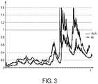
- Fig. 3shows skin conductance traces.
- the measured skin conductance values over timeform a skin conductance trace.
- the x-axisis the time axis, for example measured in minutes (min), and the y-axis is the skin conductance axis, for example measured in microSiemens ( ⁇ S).
- Skin conductanceor also called galvanic skin response (GSR), is a measure of the electrical conductance of the skin, which varies with its moisture level, thus the sweat gland activity.
- GSRgalvanic skin response
- Fig. 3shows a first skin conductance trace, sensed by a skin conductance sensor according to an embodiment, namely the most preferred embodiment described above, using a material made of gold doped with lithium at the outer surface of the electrode.
- This first skin conductance traceis illustrated by a plain solid line.
- Fig. 3also shows a second skin conductance trace, illustrated by the circled solid line, in which a conventional electrode having nickel at the outer surface has been used.
- the improved signal level of the first skin conductance trace (Au-Li) compared to the second skin conductance trace (Ni)can be clearly seen in Fig. 3 .
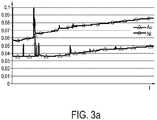
- Fig. 3ashows a skin conductance trace sensed by a skin conductance sensor having a conventional nickel (Ni) electrode and a skin conductance trace sensed by a skin conductance sensor having a gold (Au) electrode.
- potassium radius138 ⁇ m
- lithium radius: 76 ⁇ mThe smaller the ion is, the easier it is to penetrate the skin due to its increased mobility.
- Fig. 4shows a schematic block diagram of a skin conductance sensor 20 according to an embodiment.
- the skin conductance sensor 20comprises two dry electrodes 12, 13.
- the skin conductance sensor 20further comprises a voltage generator 22 for applying a voltage 11, in particular a constant voltage, between the two electrodes 12, 13. Normally, a small voltage is applied, for example less than 1.2 V. Such a small voltage induces a small current, for example in the order of 1 ⁇ A, through the skin.
- the skin conductance sensor 20further comprises a measuring unit 24 for measuring a current or voltage drop between the two dry electrodes 12, 13.
- An A/D converter 25 of the skin conductance sensor 20digitizes the measured current or voltage drop.
- the skin conductance sensorfurther comprises a calculating unit 26, such as a processor, for calculating a skin conductance based on the measured current or voltage drop. It should be understood, that also the skin resistance can be calculated which is the inverse of the skin conductance.
- the measured skin conductance values, or the skin conductance tracecan for example be transmitted by a transmitter 28 over a wireless transmission link. Additionally or alternatively, these measured skin conductance values can be stored in a memory unit 29.
- the skin conductance sensor 20comprises a casing 27. All or only some of the components described above can be integrated in the casing 27. However, some components may also be separate parts. In particular, the electrodes 12, 13 can be separate parts.
- Fig. 5shows an illustration of a wristband according to an embodiment.
- the wristband 30comprises a skin conductance sensor 20 as described above, in particular as illustrated in Fig. 4 .
- the wristband 30comprises a wristband material part 31, for example made of a textile or plastic, which loops around the wrist of the user. Even though called wristband, the wristband 30 could also be worn around the ankle or other suitable body part.
- the two dry electrodes 12, 13are integrated into the wristband 30, in particular integrated into the wristband material part 31.
- the two dry electrodes 12, 13are arranged such that they contact the volar side of the wrist when the wristband 30 is worn by the user.
- the electrodes 12, 13have a round form in Fig. 5 , however any other suitable electrode form may be used.
- the electrodes 12, 13 in Fig. 5are in the form of clothing buttons.
- a casing 27comprises a voltage generator 22, a measuring unit 24, and a calculating unit 26.
- the two electrodes 12, 13are separate parts and are connected to the casing 27 by means of wires located within the wristband. Alternatively, the two electrodes 12, 13 can also be integrated into the casing 27.
- a transmitter 28 for wirelessly transmitting the measured skin conductance valuesis integrated into the casing 27.
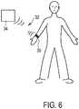
- Fig. 6shows an illustration of an emotional event detection system according to an embodiment.
- the emotional event detection systemdetects an emotional event of a user.
- the systemcomprises a skin conductance sensor 20, which is integrated into the wristband 30 shown in Fig. 6 .
- the wristband 30 shown in Fig. 6can for example be the wristband 30 of the embodiment in Fig. 5 .
- the systemfurther comprises a processing unit 34 adapted to process the transmitted data and detect an emotional event in the user based on the transmitted data.
- the processing unit 34can be a separate part.
- the systemalso comprises a transmission link 32, between the skin conductance sensor 20 and the processing unit 34, for transmitting data indicative of the sensed skin conductance, for example the measured skin conductance values.
- the transmission link 32 illustrated in Fig. 6is a wireless link. However, also other transmission links are possible, such as transmission by downloading data from a memory or using a cable.
- the systemcan comprise at least one further sensor, such as a heart rate sensor, for example for measuring heart rate variations, a breathing sensor, a blood sensor, a body temperature sensor, a voice sensor, a camera for capturing the face of the user, or the like.
- a heart rate sensorfor example for measuring heart rate variations, a breathing sensor, a blood sensor, a body temperature sensor, a voice sensor, a camera for capturing the face of the user, or the like.
- Each of these further sensorscan be adapted to transmit the sensed data to the processing unit 34.
- the processing unit 34can then combine the measurements from the skin conductance sensor with measurements of other sensors, in order to improve the accuracy of the emotional event detection.
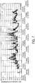
- Fig. 7shows a skin conductance trace sensed by a skin conductance sensor according to an embodiment, in particular measured with the skin conductance sensor or wristband as previously described.
- the skin conductance traceshows several hours of measurement.
- the processing unit 34 shown in Fig. 6is adapted to detect a particular rising slope and/or a particular down slope in the transmitted skin conductance data, in particular detecting peaks with a steeper rising slope and more gentle down slope. In this way, an emotional event can be detected.
- Skin conductanceis related with the level of arousal of the user. Everything that emotionally touches the user activates the sweat glands in the skin leading to a better conductor path through the skin. Hence, an easy way of determining emotional events from skin conductance data is provided.
Landscapes
- Health & Medical Sciences (AREA)
- Life Sciences & Earth Sciences (AREA)
- Engineering & Computer Science (AREA)
- Medical Informatics (AREA)
- Physics & Mathematics (AREA)
- Veterinary Medicine (AREA)
- Biophysics (AREA)
- Pathology (AREA)
- Public Health (AREA)
- Biomedical Technology (AREA)
- Heart & Thoracic Surgery (AREA)
- General Health & Medical Sciences (AREA)
- Molecular Biology (AREA)
- Surgery (AREA)
- Animal Behavior & Ethology (AREA)
- Dermatology (AREA)
- Radiology & Medical Imaging (AREA)
- Nuclear Medicine, Radiotherapy & Molecular Imaging (AREA)
- Measurement And Recording Of Electrical Phenomena And Electrical Characteristics Of The Living Body (AREA)
Description
- The present invention relates to a a skin conductance sensor comprising at least two dry electrodes, wherein the sensor is adapted to sense a user's skin conductance between the at least two dry electrodes. The present invention also relates to a wristband comprising such a skin conductance sensor and an emotional event detection system comprising such a skin conductance sensor.
- It is known that skin conductance of a user is related with the level of arousal of a user. Everything that emotionally touches the user activates the sweat glands in the skin leading to a better conductor path through the skin. For example, in a known lie detector or polygraph, a skin conductance sensor connected to the palm of the hand or to the fingers is used.
- Commonly, gel electrodes are used for skin conductance sensors. These gel electrodes offer a high signal level. However, prolonged wearing of gel electrodes causes undesirable side effects, such as a white swelling of the skin caused by hydration.
- When the period of measurement is long, the skin conductance sensor needs to be comfortable for the user. In the article "A Wearable Sensor for Unobtrusive, Long-Term Assessment of Electrodermal Activity", Ming-Zher Poh, Nicholas C. Swenson, and Rosalind W. Picard, IEEE Transactions on Biomedical Engineering, Viol. 57, No. 5 (2010) 1243-1252, a wrist-worn integrated sensor according to the preamble of
claim 1 is disclosed. This sensor has Ag/AgCl electrodes, and no conductive gel applied to the electrodes. However, due to the Ag/AgCl material, prolonged wearing of this device causes brown skin coloration due to the injection of silver ions into the skin, which is an undesirable side effect. - Various types of electrodes for various uses are disclosed in
US 3,681,136 ,US 2010/0049079 A1 ,EP 2172240 A1 ,US 2009/0069740 A1 ,US 4235241 . - It is an object of the present invention to provide, for long-term measurements, a skin conductance sensor, wristband and emotional event detection system comprising dry electrodes, which does not cause problems to the user, such as skin irritation or skin coloration, while still providing a good signal level.
- In a first aspect of the present invention, which is defined by
claim 1, a skin conductance sensor comprising at least two dry electrodes is presented, that is adapted to sense a user's skin conductance between the at least two dry electrodes, wherein at least one of the electrodes is a dry skin conductance electrode for contacting the skin of a user is presented, the electrode comprising a material made of a noble metal doped with at least one dopant selected from the group consisting of hydrogen, lithium, sodium, potassium, rubidium, caesium and beryllium, wherein the material is located at an outer surface of the electrode for interfacing with the skin. - In a further aspect of the present invention a wristband is presented that comprises such a skin conductance sensor.
- In a still further aspect of the present invention an emotional event detection system for detecting an emotional event of a user is presented, that comprises such a skin conductance sensor, a transmission link for transmitting data indicative of the sensed skin conductance, and a processing unit adapted to process the transmitted data and detect an emotional event in the user based on the transmitted data.
- The present invention is based on the idea to provide a skin conductance sensor for long-term measurements (for example several hours or days) comprising dry electrodes with a good non-polarizable electronic skin-electrode interface. A dry skin conductance electrode is an electrode which does not require the use of a conductance gel for skin conductance measurements, thus also called gel-free skin conductance electrode. The dry, gel-free skin conductance electrode makes direct contact with the skin of the user, thus forming a skin-electrode interface. The skin-electrode interface is an interface between a medium where the current carriers are predominantly electronic (electrode), and a medium where the current carriers are predominantly ionic (skin). Usually, such an interface suffers from a poor charge transfer, leading to the formation of a space charge. A non-polarizable skin-electrode interface is provided when there is charge transfer at the interface. A perfectly non-polarizable interface would exhibit no impedance to the charge transfer, which is however not possible in practice. At a non-polarizable skin-electrode interface, due to an electrochemical reaction, ions are injected into the skin from the positive electrode. Thus, electrons are left in the positive electrode, causing a current flow to take place. At the negative electrode, ions are absorbed from the skin, in particular protons, sodium ions or potassium ions, as the fluid secreted by sweat glands contains mainly hydrogen, sodium and potassium. The ions are incorporated into the metal matrix of the negative electrode material as atoms, after the acceptance of an electron.
- Since the dry skin conductance electrode comprises a noble metal doped with at least one dopant selected from the group consisting of hydrogen, lithium, sodium, potassium, rubidium, caesium and beryllium, the charge transfer process (ionic exchange between the skin and the electrode material) and thus the interface is improved, leading to a good non-polarizable interface. No gel is needed and no skin problems are caused, such as skin coloration due to the injection of silver ions to the skin.
- A dopant is generally a trace impurity element that is inserted into a base material in very low concentrations, for example in order to alter a specific property of the base material. In the claimed material, a noble metal is used as base material, since these metals are most likely not to take part in the electrochemical reaction with the skin. In general, noble metals are the group of ruthenium (Ru), rhodium (Rh), palladium (Pd), silver (Ag), osmium (Os), iridium (Ir), platinum (Pt), and gold (Au). The noble metal of the claimed material should not cause dermatological problems to the user. In general, the claimed material should be non-toxic, or at a toxic level which is below a value that is harming to the user. For example, even though beryllium (Be) is toxic, it can be used as the dopant, if the concentration of the dopant is below a value that is harming to the user.
- Preferred embodiments of the invention are defined in the dependent claims. It shall be understood that the claimed skin conductance sensor, wristband or emotional detection system has similar and/or identical preferred embodiments as the claimed skin conductance electrode and as defined in the dependent claims.
- According to a first embodiment, the noble metal is at least one element selected from the group of gold, palladium and platinum. These noble metals are especially suitable in combination with the dopants mentioned above.
- Further, in a second embodiment, the dopant is lithium, sodium or potassium. These dopants are especially suitable when used in noble metals. In particular, the atoms of these dopants have a relatively high mobility due to their relatively low atomic radius.
- Any combination of the above mentioned elements of the first embodiment and the elements of the second embodiment is possible. In one embodiment, the dopant is an element from the first group of the periodic table or monovalent. Further, in an embodiment, the dopant is an alkali metal. Alkali metals are generally the group of lithium (Li), sodium (Na), potassium (K), rubidium (Rb), caesium (Cs), and francium (Fr).
- In a preferred embodiment, the material is made of gold, palladium or platinum and the dopant is lithium, therefore: gold doped with lithium, palladium doped with lithium or platinum doped with lithium. Since the lithium atoms have a low atomic radius and thus a high mobility, diffusion processes are minimized.
- In another preferred embodiment, the material is made of gold and the dopant is lithium, sodium or potassium.
- In a further embodiment, the difference in ionization potential between the noble metal and the dopant is at or above a level at which the noble metal is prevented from taking part in the electrochemical reaction with the skin. Thus, it is prevented that ions of the noble metals are also injected into the skin due to electrochemical reaction.
- According to a further embodiment, the concentration of the dopant is between 0.1 and 5%, in particular between 0.5 and 3%, in particular between 0.7 and 1.3%, in particular about 1% ±0.2%. It is achieved that the concentration of the dopant is sufficiently high to prevent depletion and sufficiently low not to change the main properties of the noble metal.
- According to the invention, the material is located at an outer surface of the electrode for interfacing the skin. This enables that the claimed material is in direct contact with the skin.
- In another embodiment, the electrode comprises an outer layer which is formed of the material. Thus, only a thin outer layer of the claimed material is needed which reduces costs, as the remaining part of the electrode can be made of a cheaper material.
- In a variant of the embodiment above, the electrode further comprises an inner layer beneath the outer layer. This can provide more stability to the electrode and can reduce manufacturing costs.
- In particular, in this variant, the inner layer is formed of nickel and/or brass. This reduces manufacturing costs, as these materials are generally cheaper than noble metals.
- In an embodiment of the skin conductance sensor, the skin conductance sensor comprises a voltage generator for applying a voltage between the at least two dry electrodes, a measuring means for measuring a current between the at least two dry electrodes, and a calculating unit for calculating skin conductance based on the measured current. This provides for a skin conductance sensor that is easy to implement. Preferably, the applied voltage is a constant voltage.
- In an embodiment of the skin conductance sensor, the two dry electrodes comprise the same material, in particular the claimed material. In an alternative embodiment of the skin conductance sensor, the two dry electrodes comprise different materials. In one embodiment, the positive electrode comprises the claimed material. Alternatively or cumulatively, the negative electrode comprises the claimed material.
- In an embodiment of the wristband or the skin conductance sensor, the at least two dry electrodes are arranged for contacting the volar side of the wrist of the user. Hence, good measurement can be obtained, since the volar side of the wrist is a region in which the skin conductance is at the same level. Also there is generally no hair, which could influence the measurement, in this region.
- In an embodiment of the emotional event detection system or the skin conductance sensor, the transmission link is a wireless link between the skin conductance sensor and the processing unit. This enables to provide for a comfortable mobile system.
- In an embodiment of the emotional event detection system, the processing unit is adapted to detect a peak having a particular rising slope and/or a particular down slope in the transmitted skin conductance data. Skin conductance is related with the level of arousal of the user. Hence, an easy way of determining emotional events from skin conductance data is provided.
- In a still further embodiment of the emotional detection system, the system comprise at least one further sensor, such as a heart rate sensor, for example for measuring heart rate variations, a breathing sensor, a blood sensor, a body temperature sensor, a voice sensor, a camera for capturing the face of the user, or the like. This enables to combine measurements from the skin conductance sensor with measurements of other sensors. Thus, accuracy of the emotional event detection is improved.
- These and other aspects of the invention will be apparent from and elucidated with reference to the embodiment(s) described hereinafter. In the following drawings
Fig. 1 shows an interface between skin and two dry electrodes according to an embodiment of the present disclosure;Fig. 2 shows a cross section of a skin conductance electrode according to an embodiment of the present disclosure;Fig. 3 shows a first skin conductance trace, sensed by a skin conductance sensor according to an embodiment of the present invention, and a second skin conductance trace for comparison;Fig. 3a shows two skin conductance traces for comparison;Fig. 3b shows a skin conductance trace, sensed by a skin conductance sensor according to an embodiment of the present invention;Fig. 4 shows a schematic block diagram of a skin conductance sensor according to an embodiment of the present invention;Fig. 5 shows an illustration of a wristband according to an embodiment of the present invention;Fig. 6 shows an illustration of an emotional event detection system according to an embodiment of the present invention;Fig. 7 shows a skin conductance trace, sensed by a skin conductance sensor according to an embodiment of the present invention, for determining emotional events.Fig. 1 shows an interface betweenskin 10 of a user and twodry electrodes skin conductance sensor 20 comprising the twodry electrodes dry electrodes voltage 11 is applied between the twodry electrodes positive electrode 12 and anegative electrode 13 is provided. Thepositive electrode 12 has anouter surface 15 which interfaces with theskin 10 and thenegative electrode 13 has anouter surface 19 which interfaces with theskin 10. The skin-electrode interface is an interface between a medium where the current carriers are predominantly electronic (electrodes Fig. 1 ), and a medium where the current carriers are predominantly ionic (skin 10 inFig. 1 ). Usually such an interface suffers from a poor charge transfer, leading to the formation of a space charge.- However, as can be seen in
Fig. 1 , a non-polarizable skin-electrode interface is provided as there is charge transfer at the interface. The dryskin conductance electrodes skin 10 from the material of thepositive electrode 12. Thus, electrons are left in the positive electrode, causing a current flow to take place. At thenegative electrode 13, ions, marked with D2+, are absorbed from the skin. These ions D2+ are in particular hydrogen, sodium or potassium, as the fluid secreted by sweat glands contains mainly hydrogen, sodium and potassium. The ions D2+ are incorporated into the metal matrix of the material of thenegative electrode 13 as atoms D2, after the acceptance of an electron. Therefore, the charge transfer process and thus the interface is improved, leading to a good non-polarizable interface. The ionic exchange between theskin 10 and the material of theelectrode - In the embodiment of
Fig. 1 , the twodry electrodes outer surfaces Positive electrode 12 comprises a material made of a noble metal M1 doped with a dopant D1 andnegative electrode 13 comprises a material made of a noble metal M2 doped with a dopant D2. In an alternative embodiment, the twodry electrodes positive electrode 12 and thenegative electrode 13, as it is optimal for both electrodes. - In a first embodiment, the noble metal is gold, palladium or platinum, or any combination, thus any alloy. In a second embodiment, the dopant is lithium, sodium or potassium. In another embodiment the dopant is an element from the first group of the periodic table or monovalent, in particular an alkali metal, thus from the group of lithium (Li), sodium (Na), potassium (K), rubidium (Rb), caesium (Cs), and francium (Fr). In another embodiment, also beryllium (Be), even though toxic, can be used as the dopant, if the concentration of the dopant is below a value that is harming to the user.
- In a preferred embodiment, the material is made of gold doped with lithium (Au-Li), palladium doped with lithium (Pd-Li) or platinum doped with lithium (Pt-Li). In another preferred embodiment, the material is made of gold and the dopant is lithium, sodium or potassium, therefore: gold doped with lithium (Au-Li), gold doped with sodium (Au-Na) or gold doped with potassium (Au-K). In a most preferred embodiment, the material is made of gold doped with lithium (Au-Li, for example with a dopant concentration between 0.1 and 5%, in particular between 0.5 and 3%, in particular between 0.7 and 1.3%, in particular 1 % ± 0.2%. In this case for example, the difference in ionization potential between the noble metal and the dopant is at or above a level at which the noble metal is prevented from taking part in the electrochemical reaction with the
skin 10. Thus, it is prevented that ions of the noble metal are also injected into theskin 10 due to electrochemical reaction. Fig. 2 shows a cross-section of askin conductance electrode electrode outer surface skin 10. The material described above is located at theouter surface Fig. 2 , theelectrode outer layer 14 which is formed of the material. Theouter layer 14 comprises theouter surface 15 for interfacing with theskin 10. Theelectrode outer layer 14. Theelectrode - In the most preferred embodiment, the second inner layer, or base layer, 18, is formed of brass, the first inner layer 16 is a formed of nickel, and the
outer layer 14 is formed of a material made of gold doped with monovalent lithium ions (Au-Li) - In an exemplary manufacturing method, the material of the second
inner layer 18, such as brass in the most preferred embodiment, for example in the form of a plate, is polished and electrochemically plated with the first inner layer 16, such as nickel in the most preferred embodiment. Then, theouter layer 14, such as gold doped with lithium in the most preferred embodiment, is applied by sputtering. Optionally, before sputtering theouter layer 14, the material can be melted, such as in a closed quartz vessel, then cooled, afterwards flattened and the sputter targets, for example of round form, can be cut out. Also optionally, before sputtering theouter layer 14, the surface of the first inner layer 16 can be cleaned using reactive ion etching in order to improve the bonding between the first inner layer 16 and theouter layer 14. An alternative to applying theouter layer 14 by sputtering is the codeposition in vacuum by evaporation and/or e-beam deposition. For example, gold can be e-beam deposited and lithium can be deposited in vacuum by evaporation from a heated crucible, due to the low melting point of lithium. Optionally, the thickness of the layer can be monitored so that the deposition speed can be controlled. A good stability of theouter layer 14 can thus be realized throughout the layer. The thickness of theouter layer 14 can for example be in the order of microns, in particular less than 1 micron. Fig. 3 shows skin conductance traces. The measured skin conductance values over time form a skin conductance trace. The x-axis is the time axis, for example measured in minutes (min), and the y-axis is the skin conductance axis, for example measured in microSiemens (µS). Skin conductance, or also called galvanic skin response (GSR), is a measure of the electrical conductance of the skin, which varies with its moisture level, thus the sweat gland activity.- In particular,
Fig. 3 shows a first skin conductance trace, sensed by a skin conductance sensor according to an embodiment, namely the most preferred embodiment described above, using a material made of gold doped with lithium at the outer surface of the electrode. This first skin conductance trace is illustrated by a plain solid line. For comparison,Fig. 3 also shows a second skin conductance trace, illustrated by the circled solid line, in which a conventional electrode having nickel at the outer surface has been used. The improved signal level of the first skin conductance trace (Au-Li) compared to the second skin conductance trace (Ni) can be clearly seen inFig. 3 . If an undoped gold material (Au) at the outer surface of the electrode material would be used, the signal level of the corresponding skin conductance trace (not shown inFig. 3 ) would be even lower than with the nickel (Ni) electrode. For mere comparison purposes, this is illustrated inFig. 3a showing a skin conductance trace sensed by a skin conductance sensor having a conventional nickel (Ni) electrode and a skin conductance trace sensed by a skin conductance sensor having a gold (Au) electrode. - By using an electrode comprising a material made of gold doped with potassium (Au-K) or gold doped with sodium (Au-Na), similar results as with a material made of gold doped with lithium (Au-Li) can be obtained. However, with potassium and sodium, there is a large period of signal increase, compared to the use of lithium, after first use due to diffusion processes. More time is needed for the skin conductance to reach a stable level, compared to the Au-Li example shown in
Fig. 3 . This is exemplary illustrated inFig.3b , showing a skin conductance trace, sensed by a skin conductance sensor comprising an electrode comprising gold doped with sodium (Au-Na). The slow increase of the signal can be seen inFig. 3b . This can be explained with the difference in radius between sodium, potassium and lithium: potassium radius: 138 µm, sodium radius: 102 µm, lithium radius: 76 µm. The smaller the ion is, the easier it is to penetrate the skin due to its increased mobility. - Similar results as shown for gold doped with lithium, potassium or sodium can also be obtained by doping platinum with lithium, potassium or sodium.
Fig. 4 shows a schematic block diagram of askin conductance sensor 20 according to an embodiment. Theskin conductance sensor 20 comprises twodry electrodes skin conductance sensor 20 further comprises avoltage generator 22 for applying avoltage 11, in particular a constant voltage, between the twoelectrodes skin conductance sensor 20 further comprises a measuringunit 24 for measuring a current or voltage drop between the twodry electrodes D converter 25 of theskin conductance sensor 20 digitizes the measured current or voltage drop. The skin conductance sensor further comprises a calculatingunit 26, such as a processor, for calculating a skin conductance based on the measured current or voltage drop. It should be understood, that also the skin resistance can be calculated which is the inverse of the skin conductance.- The measured skin conductance values, or the skin conductance trace, can for example be transmitted by a
transmitter 28 over a wireless transmission link. Additionally or alternatively, these measured skin conductance values can be stored in amemory unit 29. - The
skin conductance sensor 20 comprises acasing 27. All or only some of the components described above can be integrated in thecasing 27. However, some components may also be separate parts. In particular, theelectrodes Fig. 5 shows an illustration of a wristband according to an embodiment. Thewristband 30 comprises askin conductance sensor 20 as described above, in particular as illustrated inFig. 4 . Thewristband 30 comprises awristband material part 31, for example made of a textile or plastic, which loops around the wrist of the user. Even though called wristband, thewristband 30 could also be worn around the ankle or other suitable body part. The twodry electrodes wristband 30, in particular integrated into thewristband material part 31. The twodry electrodes wristband 30 is worn by the user. Theelectrodes Fig. 5 , however any other suitable electrode form may be used. In particular, theelectrodes Fig. 5 are in the form of clothing buttons. Acasing 27 comprises avoltage generator 22, a measuringunit 24, and a calculatingunit 26. The twoelectrodes casing 27 by means of wires located within the wristband. Alternatively, the twoelectrodes casing 27. InFig. 5 , atransmitter 28 for wirelessly transmitting the measured skin conductance values is integrated into thecasing 27.Fig. 6 shows an illustration of an emotional event detection system according to an embodiment. The emotional event detection system detects an emotional event of a user. The system comprises askin conductance sensor 20, which is integrated into thewristband 30 shown inFig. 6 . Thewristband 30 shown inFig. 6 can for example be thewristband 30 of the embodiment inFig. 5 . The system further comprises aprocessing unit 34 adapted to process the transmitted data and detect an emotional event in the user based on the transmitted data. Theprocessing unit 34 can be a separate part. The system also comprises atransmission link 32, between theskin conductance sensor 20 and theprocessing unit 34, for transmitting data indicative of the sensed skin conductance, for example the measured skin conductance values. The transmitter in thewristband 30, such astransmitter 28 inFig. 5 orFig. 4 , transmits data indicative of the sensed skin conductance to a receiver of theprocessing unit 34 over thewireless transmission link 32. Thetransmission link 32 illustrated inFig. 6 is a wireless link. However, also other transmission links are possible, such as transmission by downloading data from a memory or using a cable. Even though not illustrated inFig. 6 , the system can comprise at least one further sensor, such as a heart rate sensor, for example for measuring heart rate variations, a breathing sensor, a blood sensor, a body temperature sensor, a voice sensor, a camera for capturing the face of the user, or the like. Each of these further sensors can be adapted to transmit the sensed data to theprocessing unit 34. Theprocessing unit 34 can then combine the measurements from the skin conductance sensor with measurements of other sensors, in order to improve the accuracy of the emotional event detection.Fig. 7 shows a skin conductance trace sensed by a skin conductance sensor according to an embodiment, in particular measured with the skin conductance sensor or wristband as previously described. The skin conductance trace shows several hours of measurement. Theprocessing unit 34 shown inFig. 6 is adapted to detect a particular rising slope and/or a particular down slope in the transmitted skin conductance data, in particular detecting peaks with a steeper rising slope and more gentle down slope. In this way, an emotional event can be detected. Skin conductance is related with the level of arousal of the user. Everything that emotionally touches the user activates the sweat glands in the skin leading to a better conductor path through the skin. Hence, an easy way of determining emotional events from skin conductance data is provided.- While the invention has been illustrated and described in detail in the drawings and foregoing description, such illustration and description are to be considered illustrative or exemplary and not restrictive; the invention is not limited to the disclosed embodiments. Other variations to the disclosed embodiments can be understood and effected by those skilled in the art in practicing the claimed invention, from a study of the drawings, the disclosure, and the appended claims.
- In the claims, the word "comprising" does not exclude other elements or steps, and the indefinite article "a" or "an" does not exclude a plurality. A single element or other unit may fulfill the functions of several items recited in the claims. The mere fact that certain measures are recited in mutually different dependent claims does not indicate that a combination of these measures cannot be used to advantage.
- Any reference signs in the claims should not be construed as limiting the scope.
Claims (13)
- Skin conductance sensor (20) comprising at least two dry electrodes for contacting the skin (10) of a user, wherein
the sensor (20) is adapted to sense the user's skin conductance between the at least two dry electrodes, wherein at least one of the dry electrodes is a dry skin conductance electrode (12, 13) comprising a material made of a noble metal, wherein the material is located at an outer surface (15) of the dry skin conductance electrode (12, 13) for interfacing with the skin (10),
characterised in that
the noble metal is doped with at least one dopant selected from the group consisting of hydrogen, lithium, sodium, potassium, rubidium, caesium and berylium. - Skin conductance sensor of claim 1, wherein the noble metal is an element selected from the group consisting of gold, palladium and platinum.
- Skin conductance sensor of claim 1, wherein the dopant is lithium, sodium or potassium.
- Skin conductance sensor of claim 1, wherein the noble metal is gold, palladium or platinum, and the dopant is lithium.
- Skin conductance sensor of claim 1, wherein the difference in ionization potential between the noble metal and the dopant is at or above a level at which the noble metal is prevented from taking part in the electrochemical reaction with the skin (10).
- Skin conductance sensor of claim 1, wherein the concentration of the dopant is between 0.1 and 5%.
- Skin conductance sensor of claim 1, wherein the electrode (12, 13) comprises an outer layer (14) which is formed of the material.
- Skin conductance sensor of claim 7, wherein the electrode (12, 13) further comprises at least one inner layer (16, 18) beneath the outer layer (14).
- Skin conductance sensor of claim 1, further comprising:- a voltage generator (22) for applying a voltage between the at least two electrodes (12, 13),- a measuring unit (24) for measuring a current between the at least two electrodes (12, 13), and- a calculating unit (26) for calculating skin conductance based on the measured current.
- Wristband (30) comprising the skin conductance sensor (20) of claim 9.
- Wristband of claim 10, wherein the at least two electrodes are arranged for contacting the volar side of the wrist of the user.
- Emotional event detection system for detecting an emotional event of a user, the system comprising:- the skin conductance sensor (20) of claim 9,- a transmission link (32) for transmitting data indicative of the sensed skin conductance, and- a processing unit (34) adapted to process the transmitted data and detect an emotional event of the user based on the transmitted data.
- Emotional event detection system of claim 12, wherein the transmission link (32) is a wireless link between the skin conductance sensor (20) and the processing unit (34).
Priority Applications (1)
| Application Number | Priority Date | Filing Date | Title |
|---|---|---|---|
| EP12704328.9AEP2680749B1 (en) | 2011-03-02 | 2012-02-06 | Skin conductance sensor |
Applications Claiming Priority (3)
| Application Number | Priority Date | Filing Date | Title |
|---|---|---|---|
| EP11156641 | 2011-03-02 | ||
| PCT/IB2012/050528WO2012117304A1 (en) | 2011-03-02 | 2012-02-06 | Dry skin conductance electrode |
| EP12704328.9AEP2680749B1 (en) | 2011-03-02 | 2012-02-06 | Skin conductance sensor |
Publications (2)
| Publication Number | Publication Date |
|---|---|
| EP2680749A1 EP2680749A1 (en) | 2014-01-08 |
| EP2680749B1true EP2680749B1 (en) | 2017-04-12 |
Family
ID=45607800
Family Applications (1)
| Application Number | Title | Priority Date | Filing Date |
|---|---|---|---|
| EP12704328.9AActiveEP2680749B1 (en) | 2011-03-02 | 2012-02-06 | Skin conductance sensor |
Country Status (7)
| Country | Link |
|---|---|
| US (2) | US20130338470A1 (en) |
| EP (1) | EP2680749B1 (en) |
| JP (1) | JP6159261B2 (en) |
| CN (1) | CN103501695B (en) |
| BR (1) | BR112013021979B1 (en) |
| RU (1) | RU2596011C2 (en) |
| WO (1) | WO2012117304A1 (en) |
Families Citing this family (16)
| Publication number | Priority date | Publication date | Assignee | Title |
|---|---|---|---|---|
| EP2680749B1 (en) | 2011-03-02 | 2017-04-12 | Koninklijke Philips N.V. | Skin conductance sensor |
| WO2014140960A1 (en) | 2013-03-12 | 2014-09-18 | Koninklijke Philips N.V. | Visit duration control system and method. |
| US20170014043A1 (en)* | 2014-04-30 | 2017-01-19 | Galvanic Limited | Electrodermal Activity Sensor |
| US10123710B2 (en) | 2014-05-30 | 2018-11-13 | Microsoft Technology Licensing, Llc | Optical pulse-rate sensor pillow assembly |
| US9833164B2 (en) | 2014-05-30 | 2017-12-05 | Microsoft Technology Licensing, Llc | Ring-shaped skin sensor |
| WO2015189107A1 (en) | 2014-06-12 | 2015-12-17 | Koninklijke Philips N.V. | Circadian phase detection system |
| CN104107049B (en)* | 2014-07-04 | 2016-04-27 | 深圳市宏电技术股份有限公司 | A kind of kinestate monitoring method based on skin electric conductivity and system |
| WO2016050551A1 (en)* | 2014-09-30 | 2016-04-07 | Koninklijke Philips N.V. | Wearable device for skin conductance measurement |
| US10076254B2 (en)* | 2014-12-16 | 2018-09-18 | Microsoft Technology Licensing, Llc | Optical communication with optical sensors |
| KR101661902B1 (en)* | 2015-06-24 | 2016-10-04 | 주식회사 웨이웨어러블 | Portable device for measuring skin condition, method and program for analyzing skin condition |
| EP3264227A4 (en)* | 2016-04-14 | 2018-04-25 | Shenzhen Goodix Technology Co., Ltd. | Emotion perception intelligent terminal and perception method therefor |
| CN109640811B (en)* | 2016-07-18 | 2023-06-16 | 皇家飞利浦有限公司 | Device for assessing psychophysiological reactivity |
| US11331019B2 (en) | 2017-08-07 | 2022-05-17 | The Research Foundation For The State University Of New York | Nanoparticle sensor having a nanofibrous membrane scaffold |
| US11502545B2 (en) | 2020-05-29 | 2022-11-15 | Puthalath Koroth Raghuprasad | Watch charging assembly |
| CN112057090B (en)* | 2020-09-04 | 2021-10-29 | 浙江大学 | Wearable device and method for emotion judgment based on the characteristics of extremely low frequency potential difference on the body surface |
| RU2763700C1 (en)* | 2020-10-30 | 2021-12-30 | Самсунг Электроникс Ко., Лтд. | Method for monitoring the hydration of a living organism |
Citations (1)
| Publication number | Priority date | Publication date | Assignee | Title |
|---|---|---|---|---|
| US5003978A (en)* | 1985-08-21 | 1991-04-02 | Technology 21, Inc. | Non-polarizable dry biomedical electrode |
Family Cites Families (32)
| Publication number | Priority date | Publication date | Assignee | Title |
|---|---|---|---|---|
| US3681136A (en)* | 1970-03-02 | 1972-08-01 | Intern Biophysics Corp | Metal-metal salt electrodes and process |
| GB2005142B (en)* | 1977-09-08 | 1982-02-10 | Tdk Electronics Co Ltd | Electrodes for living bodies |
| JPH04158835A (en)* | 1990-10-22 | 1992-06-01 | Matsushita Electric Ind Co Ltd | Perspiration sensor and sensing of perspiration |
| US5415176A (en) | 1991-11-29 | 1995-05-16 | Tanita Corporation | Apparatus for measuring body fat |
| JP2716361B2 (en)* | 1994-02-16 | 1998-02-18 | 株式会社アドバンス | Printed electrodes for living body |
| JP3734350B2 (en) | 1997-10-17 | 2006-01-11 | 株式会社タニタ | Body fat meter and body weight scale with body fat meter |
| US6415176B1 (en)* | 1999-10-18 | 2002-07-02 | Massachusetts Institute Of Technology | Sensing and display of skin conductivity |
| US7261690B2 (en)* | 2000-06-16 | 2007-08-28 | Bodymedia, Inc. | Apparatus for monitoring health, wellness and fitness |
| TW505513B (en)* | 2000-11-30 | 2002-10-11 | Sanyo Electric Co | Massager and electronic machine with controller |
| JP2005500116A (en)* | 2001-08-24 | 2005-01-06 | グルコセンス、インコーポレイテッド | Biosignal sensor and apparatus for recording a biosignal incorporating an application associated with the sensor |
| CN1607970B (en)* | 2001-10-24 | 2010-11-10 | 纸型电池有限公司 | Skin patch |
| US7630759B2 (en)* | 2002-05-20 | 2009-12-08 | Epi-Sci, Llc | Method and system for detecting electrophysiological changes in pre-cancerous and cancerous breast tissue and epithelium |
| US7052472B1 (en)* | 2002-12-18 | 2006-05-30 | Dsp Diabetes Sentry Products, Inc. | Systems and methods for detecting symptoms of hypoglycemia |
| US20040158166A1 (en)* | 2003-02-10 | 2004-08-12 | Levengood William C. | Method and apparatus for detecting, recording and analyzing spontaneously generated transient electric charge pulses in living organisms |
| US7479133B2 (en)* | 2003-06-30 | 2009-01-20 | Johnson & Johnson Consumer Companies, Inc. | Methods of treating acne and rosacea with galvanic generated electricity |
| WO2005051478A2 (en)* | 2003-11-12 | 2005-06-09 | Tyco Healthcare Group Lp | Snap electrode |
| CN101472645A (en)* | 2006-06-22 | 2009-07-01 | 皇家飞利浦电子股份有限公司 | Iontophoretic electrotransport device |
| US20080091089A1 (en)* | 2006-10-12 | 2008-04-17 | Kenneth Shane Guillory | Single use, self-contained surface physiological monitor |
| EP1964512A3 (en)* | 2007-02-28 | 2008-10-29 | Sysmex Corporation | Method of measuring skin conductance, method of analyzing component concentration, skin conductive measuring apparatus, and component concentration analyzer |
| US20080262376A1 (en)* | 2007-04-17 | 2008-10-23 | Proactive Health Devices, Inc. | Wireless sensor system for monitoring skin condition using the body as communication conduit |
| CN100546538C (en)* | 2007-06-13 | 2009-10-07 | 中国科学院半导体研究所 | A method of making dry skin electrode |
| FR2919923B1 (en) | 2007-08-08 | 2009-10-30 | Astrium Sas Soc Par Actions Si | PASSIVE DEVICE WITH MICRO BUCKLE FLUID WITH CAPILLARY PUMPING |
| CN101848669B (en)* | 2007-09-07 | 2012-06-13 | 埃姆申塞公司 | Integrated Sensor Headset |
| US20090069740A1 (en) | 2007-09-07 | 2009-03-12 | Polyplus Battery Company | Protected donor electrodes for electro-transport drug delivery |
| JP2009174948A (en)* | 2008-01-23 | 2009-08-06 | National Institute For Environmental Studies | Manufacturing method of electrochemical measuring device |
| DE102008013731B3 (en)* | 2008-03-11 | 2009-09-17 | Heike Schmidt | Performance indicator for e.g. school children with attention deficit syndrome, has sensors for measuring physiological parameters, which produce attention curve that is displayed on display, where display is part of wrist-watch |
| JP2011516128A (en)* | 2008-03-31 | 2011-05-26 | オナブラブ・エービー | Method and apparatus for non-invasive determination of the concentration of a substance in a body fluid |
| US9101734B2 (en)* | 2008-09-09 | 2015-08-11 | Biosense Webster, Inc. | Force-sensing catheter with bonded center strut |
| US8140143B2 (en)* | 2009-04-16 | 2012-03-20 | Massachusetts Institute Of Technology | Washable wearable biosensor |
| ES2617760T3 (en)* | 2009-11-13 | 2017-06-19 | Johnson & Johnson Consumer Inc. | Galvanic device for skin treatment |
| TWI392479B (en)* | 2010-08-20 | 2013-04-11 | Univ Nat Chiao Tung | Dry electrode for measuring bio-medical signals |
| EP2680749B1 (en) | 2011-03-02 | 2017-04-12 | Koninklijke Philips N.V. | Skin conductance sensor |
- 2012
- 2012-02-06EPEP12704328.9Apatent/EP2680749B1/enactiveActive
- 2012-02-06RURU2013144060/14Apatent/RU2596011C2/enactive
- 2012-02-06CNCN201280011229.4Apatent/CN103501695B/enactiveActive
- 2012-02-06USUS14/002,503patent/US20130338470A1/ennot_activeAbandoned
- 2012-02-06WOPCT/IB2012/050528patent/WO2012117304A1/enactiveApplication Filing
- 2012-02-06BRBR112013021979-3Apatent/BR112013021979B1/enactiveIP Right Grant
- 2012-02-06JPJP2013555952Apatent/JP6159261B2/enactiveActive
- 2017
- 2017-07-10USUS15/644,894patent/US10694969B2/enactiveActive
Patent Citations (1)
| Publication number | Priority date | Publication date | Assignee | Title |
|---|---|---|---|---|
| US5003978A (en)* | 1985-08-21 | 1991-04-02 | Technology 21, Inc. | Non-polarizable dry biomedical electrode |
Also Published As
| Publication number | Publication date |
|---|---|
| US20130338470A1 (en) | 2013-12-19 |
| US20170303812A1 (en) | 2017-10-26 |
| CN103501695B (en) | 2016-09-28 |
| US10694969B2 (en) | 2020-06-30 |
| CN103501695A (en) | 2014-01-08 |
| JP2014514002A (en) | 2014-06-19 |
| EP2680749A1 (en) | 2014-01-08 |
| BR112013021979B1 (en) | 2021-09-08 |
| RU2596011C2 (en) | 2016-08-27 |
| RU2013144060A (en) | 2015-04-10 |
| WO2012117304A1 (en) | 2012-09-07 |
| BR112013021979A2 (en) | 2018-06-12 |
| JP6159261B2 (en) | 2017-07-05 |
Similar Documents
| Publication | Publication Date | Title |
|---|---|---|
| US10694969B2 (en) | Dry skin conductance electrode | |
| EP3960068B1 (en) | Ring-shaped biometric signal sensing device | |
| JP4430946B2 (en) | Monitoring system with electrodes with protrusions | |
| US11020008B2 (en) | Method and system for acquiring and analyzing physiological data | |
| US3752151A (en) | Disposable medical electrode with laminate contact member | |
| EP2734109B1 (en) | Wearable device and a method of manufacturing the same | |
| US20200367777A1 (en) | Electrode structure for electrocardiogram (ecg) waveform measurement | |
| CN102469941A (en) | Analyte monitoring apparatus and method | |
| CN111837019A (en) | Biological data measuring device | |
| JP6228086B2 (en) | Biosignal acquisition apparatus and method | |
| Park et al. | Flexible galvanic skin response sensor based on vertically aligned silver nanowires | |
| WO2022074516A1 (en) | In-vivo glucose specific sensor | |
| Brady et al. | Wearable Sensors? What is there to sense? | |
| CN111920383B (en) | Wearable data collection equipment and wearable data collection system | |
| US20090156910A1 (en) | Noninvasive glucose monitor and method | |
| KR20220049105A (en) | Bio-electrode device and method for manufacturing the same | |
| CN118177745B (en) | Self-powered full-time period pulse abnormal signal monitoring wearable device | |
| JPH04158835A (en) | Perspiration sensor and sensing of perspiration | |
| US20030055357A1 (en) | Method and apparatus for determining electrical parameters of a body | |
| Takamatsu et al. | Wearable Perspiration Volume Sensor Using Dual-Frequency Impedance Measurement | |
| EP4491107A1 (en) | Heart-rate variability measurement system and heart-rate variability measurement method | |
| WO2025078720A1 (en) | Wearable health measurement device with heat flow measurement | |
| CN119586985A (en) | Wearable device based on semiconductor multi-parameter physiological signal monitoring and control method thereof | |
| TW202008955A (en) | Method, device and system to analyze cardiac cycles capable of indicating when the user is in a state of poor sleeping quality | |
| JPH04131212U (en) | Probe attachment device for electroencephalogram measurement |
Legal Events
| Date | Code | Title | Description |
|---|---|---|---|
| PUAI | Public reference made under article 153(3) epc to a published international application that has entered the european phase | Free format text:ORIGINAL CODE: 0009012 | |
| 17P | Request for examination filed | Effective date:20131002 | |
| AK | Designated contracting states | Kind code of ref document:A1 Designated state(s):AL AT BE BG CH CY CZ DE DK EE ES FI FR GB GR HR HU IE IS IT LI LT LU LV MC MK MT NL NO PL PT RO RS SE SI SK SM TR | |
| DAX | Request for extension of the european patent (deleted) | ||
| 17Q | First examination report despatched | Effective date:20140616 | |
| GRAP | Despatch of communication of intention to grant a patent | Free format text:ORIGINAL CODE: EPIDOSNIGR1 | |
| INTG | Intention to grant announced | Effective date:20161026 | |
| GRAS | Grant fee paid | Free format text:ORIGINAL CODE: EPIDOSNIGR3 | |
| GRAA | (expected) grant | Free format text:ORIGINAL CODE: 0009210 | |
| AK | Designated contracting states | Kind code of ref document:B1 Designated state(s):AL AT BE BG CH CY CZ DE DK EE ES FI FR GB GR HR HU IE IS IT LI LT LU LV MC MK MT NL NO PL PT RO RS SE SI SK SM TR | |
| REG | Reference to a national code | Ref country code:GB Ref legal event code:FG4D | |
| REG | Reference to a national code | Ref country code:CH Ref legal event code:EP | |
| REG | Reference to a national code | Ref country code:IE Ref legal event code:FG4D | |
| REG | Reference to a national code | Ref country code:AT Ref legal event code:REF Ref document number:883057 Country of ref document:AT Kind code of ref document:T Effective date:20170515 | |
| REG | Reference to a national code | Ref country code:DE Ref legal event code:R096 Ref document number:602012031017 Country of ref document:DE | |
| REG | Reference to a national code | Ref country code:NL Ref legal event code:MP Effective date:20170412 | |
| REG | Reference to a national code | Ref country code:LT Ref legal event code:MG4D | |
| REG | Reference to a national code | Ref country code:AT Ref legal event code:MK05 Ref document number:883057 Country of ref document:AT Kind code of ref document:T Effective date:20170412 | |
| PG25 | Lapsed in a contracting state [announced via postgrant information from national office to epo] | Ref country code:NL Free format text:LAPSE BECAUSE OF FAILURE TO SUBMIT A TRANSLATION OF THE DESCRIPTION OR TO PAY THE FEE WITHIN THE PRESCRIBED TIME-LIMIT Effective date:20170412 | |
| PG25 | Lapsed in a contracting state [announced via postgrant information from national office to epo] | Ref country code:FI Free format text:LAPSE BECAUSE OF FAILURE TO SUBMIT A TRANSLATION OF THE DESCRIPTION OR TO PAY THE FEE WITHIN THE PRESCRIBED TIME-LIMIT Effective date:20170412 Ref country code:GR Free format text:LAPSE BECAUSE OF FAILURE TO SUBMIT A TRANSLATION OF THE DESCRIPTION OR TO PAY THE FEE WITHIN THE PRESCRIBED TIME-LIMIT Effective date:20170713 Ref country code:LT Free format text:LAPSE BECAUSE OF FAILURE TO SUBMIT A TRANSLATION OF THE DESCRIPTION OR TO PAY THE FEE WITHIN THE PRESCRIBED TIME-LIMIT Effective date:20170412 Ref country code:AT Free format text:LAPSE BECAUSE OF FAILURE TO SUBMIT A TRANSLATION OF THE DESCRIPTION OR TO PAY THE FEE WITHIN THE PRESCRIBED TIME-LIMIT Effective date:20170412 Ref country code:HR Free format text:LAPSE BECAUSE OF FAILURE TO SUBMIT A TRANSLATION OF THE DESCRIPTION OR TO PAY THE FEE WITHIN THE PRESCRIBED TIME-LIMIT Effective date:20170412 Ref country code:NO Free format text:LAPSE BECAUSE OF FAILURE TO SUBMIT A TRANSLATION OF THE DESCRIPTION OR TO PAY THE FEE WITHIN THE PRESCRIBED TIME-LIMIT Effective date:20170712 Ref country code:ES Free format text:LAPSE BECAUSE OF FAILURE TO SUBMIT A TRANSLATION OF THE DESCRIPTION OR TO PAY THE FEE WITHIN THE PRESCRIBED TIME-LIMIT Effective date:20170412 | |
| PG25 | Lapsed in a contracting state [announced via postgrant information from national office to epo] | Ref country code:SE Free format text:LAPSE BECAUSE OF FAILURE TO SUBMIT A TRANSLATION OF THE DESCRIPTION OR TO PAY THE FEE WITHIN THE PRESCRIBED TIME-LIMIT Effective date:20170412 Ref country code:RS Free format text:LAPSE BECAUSE OF FAILURE TO SUBMIT A TRANSLATION OF THE DESCRIPTION OR TO PAY THE FEE WITHIN THE PRESCRIBED TIME-LIMIT Effective date:20170412 Ref country code:BG Free format text:LAPSE BECAUSE OF FAILURE TO SUBMIT A TRANSLATION OF THE DESCRIPTION OR TO PAY THE FEE WITHIN THE PRESCRIBED TIME-LIMIT Effective date:20170712 Ref country code:IS Free format text:LAPSE BECAUSE OF FAILURE TO SUBMIT A TRANSLATION OF THE DESCRIPTION OR TO PAY THE FEE WITHIN THE PRESCRIBED TIME-LIMIT Effective date:20170812 Ref country code:LV Free format text:LAPSE BECAUSE OF FAILURE TO SUBMIT A TRANSLATION OF THE DESCRIPTION OR TO PAY THE FEE WITHIN THE PRESCRIBED TIME-LIMIT Effective date:20170412 Ref country code:PL Free format text:LAPSE BECAUSE OF FAILURE TO SUBMIT A TRANSLATION OF THE DESCRIPTION OR TO PAY THE FEE WITHIN THE PRESCRIBED TIME-LIMIT Effective date:20170412 | |
| REG | Reference to a national code | Ref country code:DE Ref legal event code:R097 Ref document number:602012031017 Country of ref document:DE | |
| PG25 | Lapsed in a contracting state [announced via postgrant information from national office to epo] | Ref country code:DK Free format text:LAPSE BECAUSE OF FAILURE TO SUBMIT A TRANSLATION OF THE DESCRIPTION OR TO PAY THE FEE WITHIN THE PRESCRIBED TIME-LIMIT Effective date:20170412 Ref country code:EE Free format text:LAPSE BECAUSE OF FAILURE TO SUBMIT A TRANSLATION OF THE DESCRIPTION OR TO PAY THE FEE WITHIN THE PRESCRIBED TIME-LIMIT Effective date:20170412 Ref country code:RO Free format text:LAPSE BECAUSE OF FAILURE TO SUBMIT A TRANSLATION OF THE DESCRIPTION OR TO PAY THE FEE WITHIN THE PRESCRIBED TIME-LIMIT Effective date:20170412 Ref country code:SK Free format text:LAPSE BECAUSE OF FAILURE TO SUBMIT A TRANSLATION OF THE DESCRIPTION OR TO PAY THE FEE WITHIN THE PRESCRIBED TIME-LIMIT Effective date:20170412 Ref country code:CZ Free format text:LAPSE BECAUSE OF FAILURE TO SUBMIT A TRANSLATION OF THE DESCRIPTION OR TO PAY THE FEE WITHIN THE PRESCRIBED TIME-LIMIT Effective date:20170412 | |
| PLBE | No opposition filed within time limit | Free format text:ORIGINAL CODE: 0009261 | |
| STAA | Information on the status of an ep patent application or granted ep patent | Free format text:STATUS: NO OPPOSITION FILED WITHIN TIME LIMIT | |
| REG | Reference to a national code | Ref country code:FR Ref legal event code:PLFP Year of fee payment:7 | |
| PG25 | Lapsed in a contracting state [announced via postgrant information from national office to epo] | Ref country code:SM Free format text:LAPSE BECAUSE OF FAILURE TO SUBMIT A TRANSLATION OF THE DESCRIPTION OR TO PAY THE FEE WITHIN THE PRESCRIBED TIME-LIMIT Effective date:20170412 Ref country code:IT Free format text:LAPSE BECAUSE OF FAILURE TO SUBMIT A TRANSLATION OF THE DESCRIPTION OR TO PAY THE FEE WITHIN THE PRESCRIBED TIME-LIMIT Effective date:20170412 | |
| 26N | No opposition filed | Effective date:20180115 | |
| PG25 | Lapsed in a contracting state [announced via postgrant information from national office to epo] | Ref country code:SI Free format text:LAPSE BECAUSE OF FAILURE TO SUBMIT A TRANSLATION OF THE DESCRIPTION OR TO PAY THE FEE WITHIN THE PRESCRIBED TIME-LIMIT Effective date:20170412 | |
| REG | Reference to a national code | Ref country code:CH Ref legal event code:PL | |
| PG25 | Lapsed in a contracting state [announced via postgrant information from national office to epo] | Ref country code:MC Free format text:LAPSE BECAUSE OF FAILURE TO SUBMIT A TRANSLATION OF THE DESCRIPTION OR TO PAY THE FEE WITHIN THE PRESCRIBED TIME-LIMIT Effective date:20170412 | |
| REG | Reference to a national code | Ref country code:IE Ref legal event code:MM4A | |
| REG | Reference to a national code | Ref country code:BE Ref legal event code:MM Effective date:20180228 | |
| PG25 | Lapsed in a contracting state [announced via postgrant information from national office to epo] | Ref country code:CH Free format text:LAPSE BECAUSE OF NON-PAYMENT OF DUE FEES Effective date:20180228 Ref country code:LI Free format text:LAPSE BECAUSE OF NON-PAYMENT OF DUE FEES Effective date:20180228 Ref country code:LU Free format text:LAPSE BECAUSE OF NON-PAYMENT OF DUE FEES Effective date:20180206 | |
| PG25 | Lapsed in a contracting state [announced via postgrant information from national office to epo] | Ref country code:IE Free format text:LAPSE BECAUSE OF NON-PAYMENT OF DUE FEES Effective date:20180206 | |
| PG25 | Lapsed in a contracting state [announced via postgrant information from national office to epo] | Ref country code:BE Free format text:LAPSE BECAUSE OF NON-PAYMENT OF DUE FEES Effective date:20180228 | |
| PG25 | Lapsed in a contracting state [announced via postgrant information from national office to epo] | Ref country code:MT Free format text:LAPSE BECAUSE OF NON-PAYMENT OF DUE FEES Effective date:20180206 | |
| PG25 | Lapsed in a contracting state [announced via postgrant information from national office to epo] | Ref country code:PT Free format text:LAPSE BECAUSE OF FAILURE TO SUBMIT A TRANSLATION OF THE DESCRIPTION OR TO PAY THE FEE WITHIN THE PRESCRIBED TIME-LIMIT Effective date:20170412 Ref country code:HU Free format text:LAPSE BECAUSE OF FAILURE TO SUBMIT A TRANSLATION OF THE DESCRIPTION OR TO PAY THE FEE WITHIN THE PRESCRIBED TIME-LIMIT; INVALID AB INITIO Effective date:20120206 | |
| PG25 | Lapsed in a contracting state [announced via postgrant information from national office to epo] | Ref country code:MK Free format text:LAPSE BECAUSE OF NON-PAYMENT OF DUE FEES Effective date:20170412 Ref country code:CY Free format text:LAPSE BECAUSE OF FAILURE TO SUBMIT A TRANSLATION OF THE DESCRIPTION OR TO PAY THE FEE WITHIN THE PRESCRIBED TIME-LIMIT Effective date:20170412 | |
| PG25 | Lapsed in a contracting state [announced via postgrant information from national office to epo] | Ref country code:AL Free format text:LAPSE BECAUSE OF FAILURE TO SUBMIT A TRANSLATION OF THE DESCRIPTION OR TO PAY THE FEE WITHIN THE PRESCRIBED TIME-LIMIT Effective date:20170412 | |
| PGFP | Annual fee paid to national office [announced via postgrant information from national office to epo] | Ref country code:DE Payment date:20250226 Year of fee payment:14 | |
| PGFP | Annual fee paid to national office [announced via postgrant information from national office to epo] | Ref country code:FR Payment date:20250224 Year of fee payment:14 | |
| PGFP | Annual fee paid to national office [announced via postgrant information from national office to epo] | Ref country code:GB Payment date:20250218 Year of fee payment:14 | |
| PGFP | Annual fee paid to national office [announced via postgrant information from national office to epo] | Ref country code:TR Payment date:20250127 Year of fee payment:14 |