EP2677969B1 - Expandable interbody fusion implant - Google Patents
Expandable interbody fusion implantDownload PDFInfo
- Publication number
- EP2677969B1 EP2677969B1EP11706716.5AEP11706716AEP2677969B1EP 2677969 B1EP2677969 B1EP 2677969B1EP 11706716 AEP11706716 AEP 11706716AEP 2677969 B1EP2677969 B1EP 2677969B1
- Authority
- EP
- European Patent Office
- Prior art keywords
- implant
- body member
- cage body
- fixation element
- elongate
- Prior art date
- Legal status (The legal status is an assumption and is not a legal conclusion. Google has not performed a legal analysis and makes no representation as to the accuracy of the status listed.)
- Not-in-force
Links
Images


Classifications
- A—HUMAN NECESSITIES
- A61—MEDICAL OR VETERINARY SCIENCE; HYGIENE
- A61F—FILTERS IMPLANTABLE INTO BLOOD VESSELS; PROSTHESES; DEVICES PROVIDING PATENCY TO, OR PREVENTING COLLAPSING OF, TUBULAR STRUCTURES OF THE BODY, e.g. STENTS; ORTHOPAEDIC, NURSING OR CONTRACEPTIVE DEVICES; FOMENTATION; TREATMENT OR PROTECTION OF EYES OR EARS; BANDAGES, DRESSINGS OR ABSORBENT PADS; FIRST-AID KITS
- A61F2/00—Filters implantable into blood vessels; Prostheses, i.e. artificial substitutes or replacements for parts of the body; Appliances for connecting them with the body; Devices providing patency to, or preventing collapsing of, tubular structures of the body, e.g. stents
- A61F2/02—Prostheses implantable into the body
- A61F2/30—Joints
- A61F2/44—Joints for the spine, e.g. vertebrae, spinal discs
- A61F2/4455—Joints for the spine, e.g. vertebrae, spinal discs for the fusion of spinal bodies, e.g. intervertebral fusion of adjacent spinal bodies, e.g. fusion cages
- A61F2/4465—Joints for the spine, e.g. vertebrae, spinal discs for the fusion of spinal bodies, e.g. intervertebral fusion of adjacent spinal bodies, e.g. fusion cages having a circular or kidney shaped cross-section substantially perpendicular to the axis of the spine
- A—HUMAN NECESSITIES
- A61—MEDICAL OR VETERINARY SCIENCE; HYGIENE
- A61F—FILTERS IMPLANTABLE INTO BLOOD VESSELS; PROSTHESES; DEVICES PROVIDING PATENCY TO, OR PREVENTING COLLAPSING OF, TUBULAR STRUCTURES OF THE BODY, e.g. STENTS; ORTHOPAEDIC, NURSING OR CONTRACEPTIVE DEVICES; FOMENTATION; TREATMENT OR PROTECTION OF EYES OR EARS; BANDAGES, DRESSINGS OR ABSORBENT PADS; FIRST-AID KITS
- A61F2/00—Filters implantable into blood vessels; Prostheses, i.e. artificial substitutes or replacements for parts of the body; Appliances for connecting them with the body; Devices providing patency to, or preventing collapsing of, tubular structures of the body, e.g. stents
- A61F2/02—Prostheses implantable into the body
- A61F2/30—Joints
- A61F2/44—Joints for the spine, e.g. vertebrae, spinal discs
- A61F2/442—Intervertebral or spinal discs, e.g. resilient
- A—HUMAN NECESSITIES
- A61—MEDICAL OR VETERINARY SCIENCE; HYGIENE
- A61B—DIAGNOSIS; SURGERY; IDENTIFICATION
- A61B17/00—Surgical instruments, devices or methods
- A61B17/56—Surgical instruments or methods for treatment of bones or joints; Devices specially adapted therefor
- A61B17/58—Surgical instruments or methods for treatment of bones or joints; Devices specially adapted therefor for osteosynthesis, e.g. bone plates, screws or setting implements
- A61B17/68—Internal fixation devices, including fasteners and spinal fixators, even if a part thereof projects from the skin
- A61B17/84—Fasteners therefor or fasteners being internal fixation devices
- A61B17/86—Pins or screws or threaded wires; nuts therefor
- A61B17/8625—Shanks, i.e. parts contacting bone tissue
- A61B17/863—Shanks, i.e. parts contacting bone tissue with thread interrupted or changing its form along shank, other than constant taper
- A—HUMAN NECESSITIES
- A61—MEDICAL OR VETERINARY SCIENCE; HYGIENE
- A61F—FILTERS IMPLANTABLE INTO BLOOD VESSELS; PROSTHESES; DEVICES PROVIDING PATENCY TO, OR PREVENTING COLLAPSING OF, TUBULAR STRUCTURES OF THE BODY, e.g. STENTS; ORTHOPAEDIC, NURSING OR CONTRACEPTIVE DEVICES; FOMENTATION; TREATMENT OR PROTECTION OF EYES OR EARS; BANDAGES, DRESSINGS OR ABSORBENT PADS; FIRST-AID KITS
- A61F2/00—Filters implantable into blood vessels; Prostheses, i.e. artificial substitutes or replacements for parts of the body; Appliances for connecting them with the body; Devices providing patency to, or preventing collapsing of, tubular structures of the body, e.g. stents
- A61F2/02—Prostheses implantable into the body
- A61F2/30—Joints
- A61F2/3094—Designing or manufacturing processes
- A61F2/30965—Reinforcing the prosthesis by embedding particles or fibres during moulding or dipping
- A—HUMAN NECESSITIES
- A61—MEDICAL OR VETERINARY SCIENCE; HYGIENE
- A61F—FILTERS IMPLANTABLE INTO BLOOD VESSELS; PROSTHESES; DEVICES PROVIDING PATENCY TO, OR PREVENTING COLLAPSING OF, TUBULAR STRUCTURES OF THE BODY, e.g. STENTS; ORTHOPAEDIC, NURSING OR CONTRACEPTIVE DEVICES; FOMENTATION; TREATMENT OR PROTECTION OF EYES OR EARS; BANDAGES, DRESSINGS OR ABSORBENT PADS; FIRST-AID KITS
- A61F2/00—Filters implantable into blood vessels; Prostheses, i.e. artificial substitutes or replacements for parts of the body; Appliances for connecting them with the body; Devices providing patency to, or preventing collapsing of, tubular structures of the body, e.g. stents
- A61F2/02—Prostheses implantable into the body
- A61F2/28—Bones
- A61F2002/2835—Bone graft implants for filling a bony defect or an endoprosthesis cavity, e.g. by synthetic material or biological material
- A—HUMAN NECESSITIES
- A61—MEDICAL OR VETERINARY SCIENCE; HYGIENE
- A61F—FILTERS IMPLANTABLE INTO BLOOD VESSELS; PROSTHESES; DEVICES PROVIDING PATENCY TO, OR PREVENTING COLLAPSING OF, TUBULAR STRUCTURES OF THE BODY, e.g. STENTS; ORTHOPAEDIC, NURSING OR CONTRACEPTIVE DEVICES; FOMENTATION; TREATMENT OR PROTECTION OF EYES OR EARS; BANDAGES, DRESSINGS OR ABSORBENT PADS; FIRST-AID KITS
- A61F2/00—Filters implantable into blood vessels; Prostheses, i.e. artificial substitutes or replacements for parts of the body; Appliances for connecting them with the body; Devices providing patency to, or preventing collapsing of, tubular structures of the body, e.g. stents
- A61F2/02—Prostheses implantable into the body
- A61F2/30—Joints
- A61F2002/30001—Additional features of subject-matter classified in A61F2/28, A61F2/30 and subgroups thereof
- A61F2002/30003—Material related properties of the prosthesis or of a coating on the prosthesis
- A61F2002/30004—Material related properties of the prosthesis or of a coating on the prosthesis the prosthesis being made from materials having different values of a given property at different locations within the same prosthesis
- A61F2002/30019—Material related properties of the prosthesis or of a coating on the prosthesis the prosthesis being made from materials having different values of a given property at different locations within the same prosthesis differing in mechanical expandability, e.g. in mechanical, self- or balloon expandability
- A—HUMAN NECESSITIES
- A61—MEDICAL OR VETERINARY SCIENCE; HYGIENE
- A61F—FILTERS IMPLANTABLE INTO BLOOD VESSELS; PROSTHESES; DEVICES PROVIDING PATENCY TO, OR PREVENTING COLLAPSING OF, TUBULAR STRUCTURES OF THE BODY, e.g. STENTS; ORTHOPAEDIC, NURSING OR CONTRACEPTIVE DEVICES; FOMENTATION; TREATMENT OR PROTECTION OF EYES OR EARS; BANDAGES, DRESSINGS OR ABSORBENT PADS; FIRST-AID KITS
- A61F2/00—Filters implantable into blood vessels; Prostheses, i.e. artificial substitutes or replacements for parts of the body; Appliances for connecting them with the body; Devices providing patency to, or preventing collapsing of, tubular structures of the body, e.g. stents
- A61F2/02—Prostheses implantable into the body
- A61F2/30—Joints
- A61F2002/30001—Additional features of subject-matter classified in A61F2/28, A61F2/30 and subgroups thereof
- A61F2002/30108—Shapes
- A61F2002/3011—Cross-sections or two-dimensional shapes
- A61F2002/30112—Rounded shapes, e.g. with rounded corners
- A61F2002/30131—Rounded shapes, e.g. with rounded corners horseshoe- or crescent- or C-shaped or U-shaped
- A—HUMAN NECESSITIES
- A61—MEDICAL OR VETERINARY SCIENCE; HYGIENE
- A61F—FILTERS IMPLANTABLE INTO BLOOD VESSELS; PROSTHESES; DEVICES PROVIDING PATENCY TO, OR PREVENTING COLLAPSING OF, TUBULAR STRUCTURES OF THE BODY, e.g. STENTS; ORTHOPAEDIC, NURSING OR CONTRACEPTIVE DEVICES; FOMENTATION; TREATMENT OR PROTECTION OF EYES OR EARS; BANDAGES, DRESSINGS OR ABSORBENT PADS; FIRST-AID KITS
- A61F2/00—Filters implantable into blood vessels; Prostheses, i.e. artificial substitutes or replacements for parts of the body; Appliances for connecting them with the body; Devices providing patency to, or preventing collapsing of, tubular structures of the body, e.g. stents
- A61F2/02—Prostheses implantable into the body
- A61F2/30—Joints
- A61F2002/30001—Additional features of subject-matter classified in A61F2/28, A61F2/30 and subgroups thereof
- A61F2002/30108—Shapes
- A61F2002/30199—Three-dimensional shapes
- A61F2002/30224—Three-dimensional shapes cylindrical
- A61F2002/30228—Cylinders of elliptical or oval basis
- A—HUMAN NECESSITIES
- A61—MEDICAL OR VETERINARY SCIENCE; HYGIENE
- A61F—FILTERS IMPLANTABLE INTO BLOOD VESSELS; PROSTHESES; DEVICES PROVIDING PATENCY TO, OR PREVENTING COLLAPSING OF, TUBULAR STRUCTURES OF THE BODY, e.g. STENTS; ORTHOPAEDIC, NURSING OR CONTRACEPTIVE DEVICES; FOMENTATION; TREATMENT OR PROTECTION OF EYES OR EARS; BANDAGES, DRESSINGS OR ABSORBENT PADS; FIRST-AID KITS
- A61F2/00—Filters implantable into blood vessels; Prostheses, i.e. artificial substitutes or replacements for parts of the body; Appliances for connecting them with the body; Devices providing patency to, or preventing collapsing of, tubular structures of the body, e.g. stents
- A61F2/02—Prostheses implantable into the body
- A61F2/30—Joints
- A61F2002/30001—Additional features of subject-matter classified in A61F2/28, A61F2/30 and subgroups thereof
- A61F2002/30316—The prosthesis having different structural features at different locations within the same prosthesis; Connections between prosthetic parts; Special structural features of bone or joint prostheses not otherwise provided for
- A61F2002/30329—Connections or couplings between prosthetic parts, e.g. between modular parts; Connecting elements
- A61F2002/30331—Connections or couplings between prosthetic parts, e.g. between modular parts; Connecting elements made by longitudinally pushing a protrusion into a complementarily-shaped recess, e.g. held by friction fit
- A61F2002/30362—Connections or couplings between prosthetic parts, e.g. between modular parts; Connecting elements made by longitudinally pushing a protrusion into a complementarily-shaped recess, e.g. held by friction fit with possibility of relative movement between the protrusion and the recess
- A61F2002/30364—Rotation about the common longitudinal axis
- A61F2002/30365—Rotation about the common longitudinal axis with additional means for limiting said rotation
- A—HUMAN NECESSITIES
- A61—MEDICAL OR VETERINARY SCIENCE; HYGIENE
- A61F—FILTERS IMPLANTABLE INTO BLOOD VESSELS; PROSTHESES; DEVICES PROVIDING PATENCY TO, OR PREVENTING COLLAPSING OF, TUBULAR STRUCTURES OF THE BODY, e.g. STENTS; ORTHOPAEDIC, NURSING OR CONTRACEPTIVE DEVICES; FOMENTATION; TREATMENT OR PROTECTION OF EYES OR EARS; BANDAGES, DRESSINGS OR ABSORBENT PADS; FIRST-AID KITS
- A61F2/00—Filters implantable into blood vessels; Prostheses, i.e. artificial substitutes or replacements for parts of the body; Appliances for connecting them with the body; Devices providing patency to, or preventing collapsing of, tubular structures of the body, e.g. stents
- A61F2/02—Prostheses implantable into the body
- A61F2/30—Joints
- A61F2002/30001—Additional features of subject-matter classified in A61F2/28, A61F2/30 and subgroups thereof
- A61F2002/30316—The prosthesis having different structural features at different locations within the same prosthesis; Connections between prosthetic parts; Special structural features of bone or joint prostheses not otherwise provided for
- A61F2002/30329—Connections or couplings between prosthetic parts, e.g. between modular parts; Connecting elements
- A61F2002/30433—Connections or couplings between prosthetic parts, e.g. between modular parts; Connecting elements using additional screws, bolts, dowels, rivets or washers e.g. connecting screws
- A—HUMAN NECESSITIES
- A61—MEDICAL OR VETERINARY SCIENCE; HYGIENE
- A61F—FILTERS IMPLANTABLE INTO BLOOD VESSELS; PROSTHESES; DEVICES PROVIDING PATENCY TO, OR PREVENTING COLLAPSING OF, TUBULAR STRUCTURES OF THE BODY, e.g. STENTS; ORTHOPAEDIC, NURSING OR CONTRACEPTIVE DEVICES; FOMENTATION; TREATMENT OR PROTECTION OF EYES OR EARS; BANDAGES, DRESSINGS OR ABSORBENT PADS; FIRST-AID KITS
- A61F2/00—Filters implantable into blood vessels; Prostheses, i.e. artificial substitutes or replacements for parts of the body; Appliances for connecting them with the body; Devices providing patency to, or preventing collapsing of, tubular structures of the body, e.g. stents
- A61F2/02—Prostheses implantable into the body
- A61F2/30—Joints
- A61F2002/30001—Additional features of subject-matter classified in A61F2/28, A61F2/30 and subgroups thereof
- A61F2002/30316—The prosthesis having different structural features at different locations within the same prosthesis; Connections between prosthetic parts; Special structural features of bone or joint prostheses not otherwise provided for
- A61F2002/30329—Connections or couplings between prosthetic parts, e.g. between modular parts; Connecting elements
- A61F2002/30471—Connections or couplings between prosthetic parts, e.g. between modular parts; Connecting elements connected by a hinged linkage mechanism, e.g. of the single-bar or multi-bar linkage type
- A—HUMAN NECESSITIES
- A61—MEDICAL OR VETERINARY SCIENCE; HYGIENE
- A61F—FILTERS IMPLANTABLE INTO BLOOD VESSELS; PROSTHESES; DEVICES PROVIDING PATENCY TO, OR PREVENTING COLLAPSING OF, TUBULAR STRUCTURES OF THE BODY, e.g. STENTS; ORTHOPAEDIC, NURSING OR CONTRACEPTIVE DEVICES; FOMENTATION; TREATMENT OR PROTECTION OF EYES OR EARS; BANDAGES, DRESSINGS OR ABSORBENT PADS; FIRST-AID KITS
- A61F2/00—Filters implantable into blood vessels; Prostheses, i.e. artificial substitutes or replacements for parts of the body; Appliances for connecting them with the body; Devices providing patency to, or preventing collapsing of, tubular structures of the body, e.g. stents
- A61F2/02—Prostheses implantable into the body
- A61F2/30—Joints
- A61F2002/30001—Additional features of subject-matter classified in A61F2/28, A61F2/30 and subgroups thereof
- A61F2002/30316—The prosthesis having different structural features at different locations within the same prosthesis; Connections between prosthetic parts; Special structural features of bone or joint prostheses not otherwise provided for
- A61F2002/30535—Special structural features of bone or joint prostheses not otherwise provided for
- A61F2002/30537—Special structural features of bone or joint prostheses not otherwise provided for adjustable
- A61F2002/30538—Special structural features of bone or joint prostheses not otherwise provided for adjustable for adjusting angular orientation
- A61F2002/3054—Special structural features of bone or joint prostheses not otherwise provided for adjustable for adjusting angular orientation about a connection axis or implantation axis for selecting any one of a plurality of radial orientations between two modular parts, e.g. Morse taper connections, at discrete positions, angular positions or continuous positions
- A—HUMAN NECESSITIES
- A61—MEDICAL OR VETERINARY SCIENCE; HYGIENE
- A61F—FILTERS IMPLANTABLE INTO BLOOD VESSELS; PROSTHESES; DEVICES PROVIDING PATENCY TO, OR PREVENTING COLLAPSING OF, TUBULAR STRUCTURES OF THE BODY, e.g. STENTS; ORTHOPAEDIC, NURSING OR CONTRACEPTIVE DEVICES; FOMENTATION; TREATMENT OR PROTECTION OF EYES OR EARS; BANDAGES, DRESSINGS OR ABSORBENT PADS; FIRST-AID KITS
- A61F2/00—Filters implantable into blood vessels; Prostheses, i.e. artificial substitutes or replacements for parts of the body; Appliances for connecting them with the body; Devices providing patency to, or preventing collapsing of, tubular structures of the body, e.g. stents
- A61F2/02—Prostheses implantable into the body
- A61F2/30—Joints
- A61F2002/30001—Additional features of subject-matter classified in A61F2/28, A61F2/30 and subgroups thereof
- A61F2002/30316—The prosthesis having different structural features at different locations within the same prosthesis; Connections between prosthetic parts; Special structural features of bone or joint prostheses not otherwise provided for
- A61F2002/30535—Special structural features of bone or joint prostheses not otherwise provided for
- A61F2002/30537—Special structural features of bone or joint prostheses not otherwise provided for adjustable
- A61F2002/30553—Special structural features of bone or joint prostheses not otherwise provided for adjustable for adjusting a position by translation along an axis
- A—HUMAN NECESSITIES
- A61—MEDICAL OR VETERINARY SCIENCE; HYGIENE
- A61F—FILTERS IMPLANTABLE INTO BLOOD VESSELS; PROSTHESES; DEVICES PROVIDING PATENCY TO, OR PREVENTING COLLAPSING OF, TUBULAR STRUCTURES OF THE BODY, e.g. STENTS; ORTHOPAEDIC, NURSING OR CONTRACEPTIVE DEVICES; FOMENTATION; TREATMENT OR PROTECTION OF EYES OR EARS; BANDAGES, DRESSINGS OR ABSORBENT PADS; FIRST-AID KITS
- A61F2/00—Filters implantable into blood vessels; Prostheses, i.e. artificial substitutes or replacements for parts of the body; Appliances for connecting them with the body; Devices providing patency to, or preventing collapsing of, tubular structures of the body, e.g. stents
- A61F2/02—Prostheses implantable into the body
- A61F2/30—Joints
- A61F2002/30001—Additional features of subject-matter classified in A61F2/28, A61F2/30 and subgroups thereof
- A61F2002/30316—The prosthesis having different structural features at different locations within the same prosthesis; Connections between prosthetic parts; Special structural features of bone or joint prostheses not otherwise provided for
- A61F2002/30535—Special structural features of bone or joint prostheses not otherwise provided for
- A61F2002/30537—Special structural features of bone or joint prostheses not otherwise provided for adjustable
- A61F2002/30556—Special structural features of bone or joint prostheses not otherwise provided for adjustable for adjusting thickness
- A—HUMAN NECESSITIES
- A61—MEDICAL OR VETERINARY SCIENCE; HYGIENE
- A61F—FILTERS IMPLANTABLE INTO BLOOD VESSELS; PROSTHESES; DEVICES PROVIDING PATENCY TO, OR PREVENTING COLLAPSING OF, TUBULAR STRUCTURES OF THE BODY, e.g. STENTS; ORTHOPAEDIC, NURSING OR CONTRACEPTIVE DEVICES; FOMENTATION; TREATMENT OR PROTECTION OF EYES OR EARS; BANDAGES, DRESSINGS OR ABSORBENT PADS; FIRST-AID KITS
- A61F2/00—Filters implantable into blood vessels; Prostheses, i.e. artificial substitutes or replacements for parts of the body; Appliances for connecting them with the body; Devices providing patency to, or preventing collapsing of, tubular structures of the body, e.g. stents
- A61F2/02—Prostheses implantable into the body
- A61F2/30—Joints
- A61F2002/30001—Additional features of subject-matter classified in A61F2/28, A61F2/30 and subgroups thereof
- A61F2002/30316—The prosthesis having different structural features at different locations within the same prosthesis; Connections between prosthetic parts; Special structural features of bone or joint prostheses not otherwise provided for
- A61F2002/30535—Special structural features of bone or joint prostheses not otherwise provided for
- A61F2002/30579—Special structural features of bone or joint prostheses not otherwise provided for with mechanically expandable devices, e.g. fixation devices
- A—HUMAN NECESSITIES
- A61—MEDICAL OR VETERINARY SCIENCE; HYGIENE
- A61F—FILTERS IMPLANTABLE INTO BLOOD VESSELS; PROSTHESES; DEVICES PROVIDING PATENCY TO, OR PREVENTING COLLAPSING OF, TUBULAR STRUCTURES OF THE BODY, e.g. STENTS; ORTHOPAEDIC, NURSING OR CONTRACEPTIVE DEVICES; FOMENTATION; TREATMENT OR PROTECTION OF EYES OR EARS; BANDAGES, DRESSINGS OR ABSORBENT PADS; FIRST-AID KITS
- A61F2/00—Filters implantable into blood vessels; Prostheses, i.e. artificial substitutes or replacements for parts of the body; Appliances for connecting them with the body; Devices providing patency to, or preventing collapsing of, tubular structures of the body, e.g. stents
- A61F2/02—Prostheses implantable into the body
- A61F2/30—Joints
- A61F2002/30001—Additional features of subject-matter classified in A61F2/28, A61F2/30 and subgroups thereof
- A61F2002/30316—The prosthesis having different structural features at different locations within the same prosthesis; Connections between prosthetic parts; Special structural features of bone or joint prostheses not otherwise provided for
- A61F2002/30535—Special structural features of bone or joint prostheses not otherwise provided for
- A61F2002/30581—Special structural features of bone or joint prostheses not otherwise provided for having a pocket filled with fluid, e.g. liquid
- A61F2002/30584—Special structural features of bone or joint prostheses not otherwise provided for having a pocket filled with fluid, e.g. liquid filled with gas
- A—HUMAN NECESSITIES
- A61—MEDICAL OR VETERINARY SCIENCE; HYGIENE
- A61F—FILTERS IMPLANTABLE INTO BLOOD VESSELS; PROSTHESES; DEVICES PROVIDING PATENCY TO, OR PREVENTING COLLAPSING OF, TUBULAR STRUCTURES OF THE BODY, e.g. STENTS; ORTHOPAEDIC, NURSING OR CONTRACEPTIVE DEVICES; FOMENTATION; TREATMENT OR PROTECTION OF EYES OR EARS; BANDAGES, DRESSINGS OR ABSORBENT PADS; FIRST-AID KITS
- A61F2/00—Filters implantable into blood vessels; Prostheses, i.e. artificial substitutes or replacements for parts of the body; Appliances for connecting them with the body; Devices providing patency to, or preventing collapsing of, tubular structures of the body, e.g. stents
- A61F2/02—Prostheses implantable into the body
- A61F2/30—Joints
- A61F2/30767—Special external or bone-contacting surface, e.g. coating for improving bone ingrowth
- A61F2/30771—Special external or bone-contacting surface, e.g. coating for improving bone ingrowth applied in original prostheses, e.g. holes or grooves
- A61F2002/30772—Apertures or holes, e.g. of circular cross section
- A61F2002/30774—Apertures or holes, e.g. of circular cross section internally-threaded
- A—HUMAN NECESSITIES
- A61—MEDICAL OR VETERINARY SCIENCE; HYGIENE
- A61F—FILTERS IMPLANTABLE INTO BLOOD VESSELS; PROSTHESES; DEVICES PROVIDING PATENCY TO, OR PREVENTING COLLAPSING OF, TUBULAR STRUCTURES OF THE BODY, e.g. STENTS; ORTHOPAEDIC, NURSING OR CONTRACEPTIVE DEVICES; FOMENTATION; TREATMENT OR PROTECTION OF EYES OR EARS; BANDAGES, DRESSINGS OR ABSORBENT PADS; FIRST-AID KITS
- A61F2/00—Filters implantable into blood vessels; Prostheses, i.e. artificial substitutes or replacements for parts of the body; Appliances for connecting them with the body; Devices providing patency to, or preventing collapsing of, tubular structures of the body, e.g. stents
- A61F2/02—Prostheses implantable into the body
- A61F2/30—Joints
- A61F2/30767—Special external or bone-contacting surface, e.g. coating for improving bone ingrowth
- A61F2/30771—Special external or bone-contacting surface, e.g. coating for improving bone ingrowth applied in original prostheses, e.g. holes or grooves
- A61F2002/30772—Apertures or holes, e.g. of circular cross section
- A61F2002/30777—Oblong apertures
- A61F2002/30779—Oblong apertures arcuate
- A—HUMAN NECESSITIES
- A61—MEDICAL OR VETERINARY SCIENCE; HYGIENE
- A61F—FILTERS IMPLANTABLE INTO BLOOD VESSELS; PROSTHESES; DEVICES PROVIDING PATENCY TO, OR PREVENTING COLLAPSING OF, TUBULAR STRUCTURES OF THE BODY, e.g. STENTS; ORTHOPAEDIC, NURSING OR CONTRACEPTIVE DEVICES; FOMENTATION; TREATMENT OR PROTECTION OF EYES OR EARS; BANDAGES, DRESSINGS OR ABSORBENT PADS; FIRST-AID KITS
- A61F2/00—Filters implantable into blood vessels; Prostheses, i.e. artificial substitutes or replacements for parts of the body; Appliances for connecting them with the body; Devices providing patency to, or preventing collapsing of, tubular structures of the body, e.g. stents
- A61F2/02—Prostheses implantable into the body
- A61F2/30—Joints
- A61F2/30767—Special external or bone-contacting surface, e.g. coating for improving bone ingrowth
- A61F2/30771—Special external or bone-contacting surface, e.g. coating for improving bone ingrowth applied in original prostheses, e.g. holes or grooves
- A61F2002/30772—Apertures or holes, e.g. of circular cross section
- A61F2002/30784—Plurality of holes
- A61F2002/30785—Plurality of holes parallel
- A—HUMAN NECESSITIES
- A61—MEDICAL OR VETERINARY SCIENCE; HYGIENE
- A61F—FILTERS IMPLANTABLE INTO BLOOD VESSELS; PROSTHESES; DEVICES PROVIDING PATENCY TO, OR PREVENTING COLLAPSING OF, TUBULAR STRUCTURES OF THE BODY, e.g. STENTS; ORTHOPAEDIC, NURSING OR CONTRACEPTIVE DEVICES; FOMENTATION; TREATMENT OR PROTECTION OF EYES OR EARS; BANDAGES, DRESSINGS OR ABSORBENT PADS; FIRST-AID KITS
- A61F2/00—Filters implantable into blood vessels; Prostheses, i.e. artificial substitutes or replacements for parts of the body; Appliances for connecting them with the body; Devices providing patency to, or preventing collapsing of, tubular structures of the body, e.g. stents
- A61F2/02—Prostheses implantable into the body
- A61F2/30—Joints
- A61F2/30767—Special external or bone-contacting surface, e.g. coating for improving bone ingrowth
- A61F2/30771—Special external or bone-contacting surface, e.g. coating for improving bone ingrowth applied in original prostheses, e.g. holes or grooves
- A61F2002/30772—Apertures or holes, e.g. of circular cross section
- A61F2002/30784—Plurality of holes
- A61F2002/30787—Plurality of holes inclined obliquely with respect to each other
- A—HUMAN NECESSITIES
- A61—MEDICAL OR VETERINARY SCIENCE; HYGIENE
- A61F—FILTERS IMPLANTABLE INTO BLOOD VESSELS; PROSTHESES; DEVICES PROVIDING PATENCY TO, OR PREVENTING COLLAPSING OF, TUBULAR STRUCTURES OF THE BODY, e.g. STENTS; ORTHOPAEDIC, NURSING OR CONTRACEPTIVE DEVICES; FOMENTATION; TREATMENT OR PROTECTION OF EYES OR EARS; BANDAGES, DRESSINGS OR ABSORBENT PADS; FIRST-AID KITS
- A61F2/00—Filters implantable into blood vessels; Prostheses, i.e. artificial substitutes or replacements for parts of the body; Appliances for connecting them with the body; Devices providing patency to, or preventing collapsing of, tubular structures of the body, e.g. stents
- A61F2/02—Prostheses implantable into the body
- A61F2/30—Joints
- A61F2/30767—Special external or bone-contacting surface, e.g. coating for improving bone ingrowth
- A61F2/30771—Special external or bone-contacting surface, e.g. coating for improving bone ingrowth applied in original prostheses, e.g. holes or grooves
- A61F2002/30841—Sharp anchoring protrusions for impaction into the bone, e.g. sharp pins, spikes
- A61F2002/30843—Pyramidally-shaped
- A—HUMAN NECESSITIES
- A61—MEDICAL OR VETERINARY SCIENCE; HYGIENE
- A61F—FILTERS IMPLANTABLE INTO BLOOD VESSELS; PROSTHESES; DEVICES PROVIDING PATENCY TO, OR PREVENTING COLLAPSING OF, TUBULAR STRUCTURES OF THE BODY, e.g. STENTS; ORTHOPAEDIC, NURSING OR CONTRACEPTIVE DEVICES; FOMENTATION; TREATMENT OR PROTECTION OF EYES OR EARS; BANDAGES, DRESSINGS OR ABSORBENT PADS; FIRST-AID KITS
- A61F2/00—Filters implantable into blood vessels; Prostheses, i.e. artificial substitutes or replacements for parts of the body; Appliances for connecting them with the body; Devices providing patency to, or preventing collapsing of, tubular structures of the body, e.g. stents
- A61F2/02—Prostheses implantable into the body
- A61F2/30—Joints
- A61F2/46—Special tools for implanting artificial joints
- A61F2/4603—Special tools for implanting artificial joints for insertion or extraction of endoprosthetic joints or of accessories thereof
- A61F2002/4629—Special tools for implanting artificial joints for insertion or extraction of endoprosthetic joints or of accessories thereof connected to the endoprosthesis or implant via a threaded connection
- A—HUMAN NECESSITIES
- A61—MEDICAL OR VETERINARY SCIENCE; HYGIENE
- A61F—FILTERS IMPLANTABLE INTO BLOOD VESSELS; PROSTHESES; DEVICES PROVIDING PATENCY TO, OR PREVENTING COLLAPSING OF, TUBULAR STRUCTURES OF THE BODY, e.g. STENTS; ORTHOPAEDIC, NURSING OR CONTRACEPTIVE DEVICES; FOMENTATION; TREATMENT OR PROTECTION OF EYES OR EARS; BANDAGES, DRESSINGS OR ABSORBENT PADS; FIRST-AID KITS
- A61F2/00—Filters implantable into blood vessels; Prostheses, i.e. artificial substitutes or replacements for parts of the body; Appliances for connecting them with the body; Devices providing patency to, or preventing collapsing of, tubular structures of the body, e.g. stents
- A61F2/02—Prostheses implantable into the body
- A61F2/30—Joints
- A61F2/46—Special tools for implanting artificial joints
- A61F2002/465—Special tools for implanting artificial joints using heating means
- A—HUMAN NECESSITIES
- A61—MEDICAL OR VETERINARY SCIENCE; HYGIENE
- A61F—FILTERS IMPLANTABLE INTO BLOOD VESSELS; PROSTHESES; DEVICES PROVIDING PATENCY TO, OR PREVENTING COLLAPSING OF, TUBULAR STRUCTURES OF THE BODY, e.g. STENTS; ORTHOPAEDIC, NURSING OR CONTRACEPTIVE DEVICES; FOMENTATION; TREATMENT OR PROTECTION OF EYES OR EARS; BANDAGES, DRESSINGS OR ABSORBENT PADS; FIRST-AID KITS
- A61F2310/00—Prostheses classified in A61F2/28 or A61F2/30 - A61F2/44 being constructed from or coated with a particular material
- A61F2310/00005—The prosthesis being constructed from a particular material
- A61F2310/00011—Metals or alloys
- A61F2310/00017—Iron- or Fe-based alloys, e.g. stainless steel
- A—HUMAN NECESSITIES
- A61—MEDICAL OR VETERINARY SCIENCE; HYGIENE
- A61F—FILTERS IMPLANTABLE INTO BLOOD VESSELS; PROSTHESES; DEVICES PROVIDING PATENCY TO, OR PREVENTING COLLAPSING OF, TUBULAR STRUCTURES OF THE BODY, e.g. STENTS; ORTHOPAEDIC, NURSING OR CONTRACEPTIVE DEVICES; FOMENTATION; TREATMENT OR PROTECTION OF EYES OR EARS; BANDAGES, DRESSINGS OR ABSORBENT PADS; FIRST-AID KITS
- A61F2310/00—Prostheses classified in A61F2/28 or A61F2/30 - A61F2/44 being constructed from or coated with a particular material
- A61F2310/00005—The prosthesis being constructed from a particular material
- A61F2310/00011—Metals or alloys
- A61F2310/00023—Titanium or titanium-based alloys, e.g. Ti-Ni alloys
- A—HUMAN NECESSITIES
- A61—MEDICAL OR VETERINARY SCIENCE; HYGIENE
- A61F—FILTERS IMPLANTABLE INTO BLOOD VESSELS; PROSTHESES; DEVICES PROVIDING PATENCY TO, OR PREVENTING COLLAPSING OF, TUBULAR STRUCTURES OF THE BODY, e.g. STENTS; ORTHOPAEDIC, NURSING OR CONTRACEPTIVE DEVICES; FOMENTATION; TREATMENT OR PROTECTION OF EYES OR EARS; BANDAGES, DRESSINGS OR ABSORBENT PADS; FIRST-AID KITS
- A61F2310/00—Prostheses classified in A61F2/28 or A61F2/30 - A61F2/44 being constructed from or coated with a particular material
- A61F2310/00005—The prosthesis being constructed from a particular material
- A61F2310/00011—Metals or alloys
- A61F2310/00035—Other metals or alloys
- A61F2310/00041—Magnesium or Mg-based alloys
- A—HUMAN NECESSITIES
- A61—MEDICAL OR VETERINARY SCIENCE; HYGIENE
- A61F—FILTERS IMPLANTABLE INTO BLOOD VESSELS; PROSTHESES; DEVICES PROVIDING PATENCY TO, OR PREVENTING COLLAPSING OF, TUBULAR STRUCTURES OF THE BODY, e.g. STENTS; ORTHOPAEDIC, NURSING OR CONTRACEPTIVE DEVICES; FOMENTATION; TREATMENT OR PROTECTION OF EYES OR EARS; BANDAGES, DRESSINGS OR ABSORBENT PADS; FIRST-AID KITS
- A61F2310/00—Prostheses classified in A61F2/28 or A61F2/30 - A61F2/44 being constructed from or coated with a particular material
- A61F2310/00005—The prosthesis being constructed from a particular material
- A61F2310/00011—Metals or alloys
- A61F2310/00035—Other metals or alloys
- A61F2310/00131—Tantalum or Ta-based alloys
- A—HUMAN NECESSITIES
- A61—MEDICAL OR VETERINARY SCIENCE; HYGIENE
- A61F—FILTERS IMPLANTABLE INTO BLOOD VESSELS; PROSTHESES; DEVICES PROVIDING PATENCY TO, OR PREVENTING COLLAPSING OF, TUBULAR STRUCTURES OF THE BODY, e.g. STENTS; ORTHOPAEDIC, NURSING OR CONTRACEPTIVE DEVICES; FOMENTATION; TREATMENT OR PROTECTION OF EYES OR EARS; BANDAGES, DRESSINGS OR ABSORBENT PADS; FIRST-AID KITS
- A61F2310/00—Prostheses classified in A61F2/28 or A61F2/30 - A61F2/44 being constructed from or coated with a particular material
- A61F2310/00005—The prosthesis being constructed from a particular material
- A61F2310/00179—Ceramics or ceramic-like structures
Definitions
- the main objectiveis to relieve pain while preventing iatrogenic injury.
- the interbody deviceshould be stable and subsidence resistant.
- a minimally invasive approachoffers an ideal solution, however, in order to provide stability and subsidence resistance, a large footprint is beneficial. Therefore, a compromise is generally required to achieve both.
- WO-00/25706discloses a laterally expanding vertebral spacer device for repairing damaged vertebral discs.
- the vertebral spacer devicemaintains the height of a distracted vertebral disc space while providing stability to the spine.
- One vertebral spacer device disclosed in the documentis provided with a first arm movably coupled to a second arm, the first and second arms being laterally expandable from a first width for insertion into the disc space to a second width after insertion into the disc space.
- a biasing elementsuch as a spring, may be disposed between the arms to urge them to the expanded condition.
- First ends of the first and second armseach define a corresponding socket portion. When the spacer device is in a first closed position, the socket portions define a socket for receiving a driving tool.
- Another spacer device disclosed in the documentincludes a guide which is received within a recess defined in one of the arms.
- the present inventionprovides an expandable interbody fusion implant as claimed in claim 1.
- the expandable interbody fusion implantmay be configured to have an initial unexpanded configuration having a first footprint width suitable for being inserted into an intervertebral space defined by a pair of adjacent vertebral bodies, and an expanded configuration having a second footprint width that is greater than the first footprint width.
- the implantmay be expanded from the initial configuration to the expanded configuration either bilaterally or unilaterally.
- An exemplary implant disclosed in this documentmay include a first body member and a second body member that is pivotally coupled to the first body member about a pivot axis.
- the first body membermay have a first cage body and the second body member hay have a second cage body.
- the implantmay also include a channel that extends at least partially through at least one of the first and second cage bodies, the channel configured to receive an inflatable balloon.
- the second body membermay be configured to be adjacent the first body member, such that expansion of the inflatable balloon biases the first and second body members away from each other, thereby causing the implant to move from the initial configuration to the expanded configuration.
- An implant falling within the scope of the claimsincludes a first body member and a second body member that is pivotally coupled to the first body member.
- the first body memberis configured to be braced against a vertebral surface.
- the first body memberincludes a first elongate cage body.
- the first elongate cage bodydefines superior and inferior bone engaging surfaces.
- the first elongate cage bodyhas a free end.
- the second body memberincludes a second elongate cage body.
- the second elongate cage bodydefines superior and inferior bone engaging surfaces.
- the second elongate cage bodyhas a free end.
- the first body memberdefines a channel that extends through the first elongate cage body, the channel configured to receive an expandable element, such that when the expandable element is expanded, at least the second body member pivots with respect to the first body member so as to move at least the free end of the second body member relative to the free end of the first body member and expand the implant to the expanded configuration.
- an expandable implantmay be inserted into the intervertebral space.
- the implantmay have a first width during insertion.
- the implantmay include a first body member, and a second body member pivotally coupled to the first body member.
- the first and second body membersmay each include a fixation element receiving aperture.
- An inflatable balloonmay then be positioned within the implant. By inflating the balloon, the implant may expand in a direction that is substantially perpendicular to the transverse direction.
- the implantmay expand to a second width that is greater than the first width.
- a superior vertebral body 10adefines a superior vertebral surface 14a of an intervertebral space 18, and an adjacent inferior vertebral body 10b defines an inferior vertebral surface 14b of the intervertebral space 18.
- the intervertebral space 18is disposed between the vertebral bodies 10a-b.
- the vertebral bodies 10a-bcan be anatomically adjacent vertebral bodies, or remaining vertebral bodies after a vertebral body has been removed from a location between the vertebral bodies 10a-b.
- the intervertebral space 18is illustrated after a discectomy, whereby the disc material has been removed or at least partially removed to prepare the intervertebral space 18 to receive an intervertebral implant 26, as shown in Fig. 1B , that can achieve height restoration.
- the intervertebral space 18can be disposed anywhere along the spine as desired, including at the lumbar, thoracic, and cervical regions of the spine.
- the implant 26is described herein as extending horizontally along a longitudinal direction “L” and lateral direction “A”, and vertically along a transverse direction “T".
- the terms “lateral,” “longitudinal,” and “transverse”are used to describe the orthogonal directional components of various components. It should be appreciated that while the longitudinal and lateral directions are illustrated as extending along a horizontal plane, and that the transverse direction is illustrated as extending along a vertical plane, the planes that encompass the various directions may differ during use.
- the transverse direction Textends vertically generally along the superior-inferior (or caudal-cranial) direction, while the horizontal plane defined by the longitudinal direction L and lateral direction A lies generally in the anatomical plane defined by the anterior-posterior direction, and the medial-lateral direction.
- the directional terms "vertical” and “horizontal”are used to describe the implant 26 and its components as illustrated merely for the purposes of clarity and illustration.
- the interbody expandable implant 26is configured to be positioned within an at least partially cleared out disc space, such as the disc space 18 disposed between the superior vertebral body 10a and the inferior vertebral body 10b.
- the implantis elongate in the longitudinal direction L and defines a distal end D and a proximal end P.
- the implant 26is expandable between a first initial unexpanded configuration having a first footprint width, and a second expanded configuration having a second width that is greater than the first width.
- the implant 26may be implanted while in the unexpanded configuration so as to provide a minimally invasive approach for the procedure.
- the implant 26may be expanded in situ to its expanded configuration so as to provide an adequate footprint for an interbody fusion device.
- the expanded implant 26may achieve improved stability and may reduce subsidence risk.
- the implant 26can be formed entirely from or partially from a range of biocompatible materials or combinations of materials, including polymers, such as PEEK, porous PEEK, carbon fiber-reinforced PEEK, titanium and titanium alloys, stainless steel, ceramic, polylactic acid, tantalum, and magnesium, or even allograft bone.
- the implant 26includes a first body member 30 and a second body member 34 that is pivotally coupled to the first body member 30 at a hinge 38. At least one of the first body member 30 and the second body member 34 may rotate about the hinge 38 relative to the other to thereby expand the implant 26 to its expanded configuration. As shown, the first and second body members 30 and 34 may rotate in the horizontal plane. That is, after the implant 26 has been implanted into an intervertebral space that is defined between adjacent vertebral bodies that are opposed in the transverse direction T, the first and second body members 30 and 34 may rotate in a plane that is substantially perpendicular to the transverse direction T, so at increase the overall footprint of the implant 26.
- the implant 26is configured such that both body members 30 and 34 may rotate so as to provide bilateral expansion of the implant.
- the implant 26may also be configured such that only one of the body members 30 and 34 rotates relative to the other so as to provide unilateral expansion.
- Such unilateral expansionmay be desired if the implant is positioned anterior using a lateral approach. Because in such a case the major vessels (aorta and vena cava) reside anterior to the vertebral column, a bilateral expansion may damage the vessels. Therefore, one of the body members 30 and 34 may be affixed to a vertebra prior to expansion of the implant 26 to thereby allow for unilateral expansion of the implant and prevent any damage to the vessels.
- the first body member 30includes a first plate 40, and a first cage body 44 that is coupled to the first plate 40.
- the first plate 40is coupled to a proximal end of the first cage body 44. While the first plate 40 and the first cage body 44 are shown as separate components that are coupled together, it should be understood that the first plate 40 and the first cage body 44 may be integrally formed as one piece.
- the first plate 40includes a front face member 42 that defines a fixation element receiving aperture 48 that extends therethrough from a front side to a back side at an upward angle.
- the fixation element receiving aperture 48may define internal threads that are configured to engage external threads defined by a fixation element, such as bone screw 52, as the bone screw 52 is inserted into the fixation element receiving aperture 48.
- the bone screw 52is configured to engage the superior vertebral body 10a once it is fully inserted to thereby brace or otherwise affix the first body member 30 to the vertebral body.
- the fixation element receiving aperture 48may be fully enclosed as shown in the illustrated embodiment, or the fixation element receiving aperture 48 may be partially enclosed to thereby define for example a semi-circle.
- the fixation element receiving aperture 48may be configured to receive a fixation element other than the bone screw 52.
- the fixation element receiving aperture 48may be configured to receive blades or nails. Therefore, the fixation element receiving aperture 48 may be void of threads.
- the first body membermay be configured to be braced against the vertebral wall of the vertebral body using structure other than fixation elements.
- the first body member 30may be toothed so as to not allow the first body member 30 to rotate when the implant is inserted.
- the first plate 40also defines a curved internal surface 56 that is generally concave. As shown, the curved internal surface 56 is positioned such that it is adjacent the second body member 34. As will be discussed, the curved internal surface 56 allows the first body member 30 to rotate relative to the second body member 34 without substantial interference from the second body member 34.
- the first cage body 44is elongate in the longitudinal direction L.
- the first cage body 44defines an upper or superior or outer transverse bone engagement or contacting surface 60 configured to contact the superior vertebral body 10a, and a lower or inferior or outer transverse bone engagement or contacting surface 64 configured to contact the inferior vertebral body 10b.
- Both outer contacting surfaces 60 and 64may include teeth 68 that are configured to engage the superior and inferior vertebral bodies 10a and 10b. As shown, the teeth 68 may be aligned in arcs with the centre of these arcs being proximate to the hinge 38.
- the first cage body 44includes an elongate body portion 70 that extends in the longitudinal direction L, and a first joint 74 that extends proximally from the elongate portion 70 and at least partially toward the second body member 34.
- the joint 74extends substantially perpendicularly from the elongate portion 70 toward the second body member 34.
- the cage body 44also includes a free end 78 that extends distally from the elongate body portion 70 and at least partially toward the second body member 34. Therefore, because both the first joint 74 and the free end 78 at least partially extend toward the second body member 34, the first cage body 44 generally defines a C-shaped structure.
- the first joint 74includes a pair of plates 82 that are spaced apart so as to define a gap 86 between the two plates 78.
- Each plate 82defines an aperture 90 that extends completely therethrough in the transverse direction T.
- each aperture 90is aligned and is configured to receive a pin 94 as shown in Fig. 2C .
- the free end 74 of the first cage body 44defines a first mating feature 94.
- the first mating feature 94includes a recess 98 that extends into the curved portion of the free end 74.
- the recess 98is configured to receive a mating feature that is defined by the second body member 34 when the implant 26 is in an unexpanded configuration.
- the first body member 30also defines a channel 102 that extends longitudinally through the first body member 30. That is, the channel 102 extends at least partially through the first joint 74, through the elongate body portion 70, and into the recess 94 defined by the free end 78. As shown, the channel 102 defines a non-linear path 106 from a proximal end of the implant 26 to the distal end of the implant 26. As shown in Figs. 2D and 2E , the channel 102 is configured to receive an expandable element 110 so as to guide the expandable element 110 along the path 106 toward the recess 98.
- the expandable element 110is configured to expand the implant 26 to its expanded configuration when the expandable element 110 has been activated.
- the expandable element 110is an inflatable balloon 114, that may be inflated by injecting air or some other fluid into a tube 118 that is coupled to a proximal end of the balloon 114. It should be understood, however, that the expandable element 110 is not limited to inflatable balloons and that other devices or materials may be used to expand the implant 26.
- the second body member 34includes a first plate 140, and a second cage body 144 that is coupled to the second plate 140.
- the second plate 140is coupled to a proximal end of the second cage body 144. While the second plate 140 and the second cage body 144 are shown as separate components that are coupled together, it should be understood that the second plate 140 and the second cage body 144 may be integrally formed as one piece.
- the second plate 140includes a front face member 142 that defines a fixation element receiving aperture 148 that extends therethrough from a front side to a back side at a downward angle.
- the fixation element receiving aperture 148may define internal threads that are configured to engage external threads defined by a fixation element, such as bone screw 152, as the bone screw 152 is inserted into the fixation element receiving aperture 148.
- the bone screw 152is configured to engage the inferior vertebral body 10b once it is fully inserted to thereby brace or otherwise affix the second body 34 against the vertebral body.
- the fixation element receiving aperture 148may be fully enclosed as shown in the illustrated embodiment, or the fixation element receiving aperture 148 may be partially enclosed to thereby define for example a semi-circle.
- the fixation element receiving aperture 148may be configured to receive a fixation element other than the bone screw 152.
- the fixation element receiving aperture 148may be configured to receive blades or nails. Therefore, the fixation element receiving aperture 148 may be void of threads.
- the second body member 34may be configured to be braced against the vertebral wall of the vertebral body using structure other than fixation elements.
- the second body member 34may be toothed so as to not allow the second body member 34 to rotate when the implant is inserted.
- the front face member 142also defines a holding aperture 154 that extends therethrough adjacent to the fixation element receiving aperture 148.
- the holding aperture 154is configured to receive an insertion tool so as to couple the implant 26 to the insertion tool for insertion of the implant 26 into the intervertebral space 18.
- the holding aperture 154may include internal threads that are configured to engage external threads defined by the insertion tool to thereby securely couple the implant 26 to the insertion tool during insertion.
- the holding aperture 154may also be substantially aligned with the channel 102. Therefore, the expandable element 110 may be inserted into the channel 102 through the holding aperture 154 as shown in Figs. 2D and 2E .
- the second plate 140also defines a curved external surface 156 that is generally convex. As shown, the curved external surface 156 is positioned such that it is adjacent the curved surface 56 of the first body member 30. The curved surfaces 56 and 156 correspond to each other such that as the first body member 30 rotates relative to the second body member 34 the first and second plates 40 and 140 can slide past each without substantial interference.
- the second cage body 144is elongate in the longitudinal direction L.
- the second cage body 144defines an upper or superior or outer transverse bone engagement or contacting surface 160 configured to contact the superior vertebral body 10a, and a lower or inferior or outer transverse bone engagement or contacting surface 164 configured to contact the inferior vertebral body 10b.
- Both outer contacting surfaces 160 and 164may include teeth 68 that are configured to engage the superior and inferior vertebral bodies 10a and 10b. As shown, the teeth 68 may be aligned in arcs with the centre of these arcs being proximate to the hinge 38.
- the second cage body 144includes an elongate body portion 170 that extends in the longitudinal direction L, and a second joint 174 that extends proximally from the elongate body portion 170 and at least partially toward the first body member 30.
- the joint 174extends substantially perpendicularly from the elongate body portion 170 toward the first body member 30.
- the cage body 144also includes a free end 178 that extends distally from the elongate body portion 170 and at least partially toward the first body member 30. Therefore, because both the first joint 174 and the free end 178 at least partially extend toward the first body member 30, the second cage body 144 generally defines a C-shaped structure.
- the second joint 174includes a plate 182 that is configured to engage the gap 86 defined between the two plates 78 of the first joint 74.
- the plate 182defines an aperture 190 that extends completely therethrough in the transverse direction T.
- the aperture 190is configured to align with the apertures 90 of the first joint 74 when the plate 178 is received in the gap 86.
- the apertures 90 and 190should align so that the pin 94 can engage each aperture 90 and 190 to thereby define the hinge 38.
- the hinge 38defines a pivot axis that extends in the transverse or caudal-cranial direction.
- first body member 30 and the second body member 34may rotate about the rotation axis in the horizontal plane defined by the longitudinal and lateral directions to thereby increase the overall footprint of the implant 26.
- the joints 74 and 174may form part of either the first body member 30 or the second body member 34.
- the hinge 38may be defined by structure other than the joints 74 and 174.
- the first body member 30 and the second body member 34may be integral parts that are connected by an integral hinge 38 that allows at least one of first body member 30 and the second body member 34 to rotate relative to the other.
- the free end 174 of the second cage body 144defines a second mating feature 194.
- the second mating feature 194includes a protrusion 198 that extends toward the recess 98 of the first body member 30.
- the second mating feature 194is configured to mate with the first mating feature 94 when the implant 26 is in an unexpanded configuration.
- the protrusion 198is configured to engage or otherwise extend into the recess 94 of the first body member 30 when the implant 26 is in an unexpanded configuration. As shown in Fig.
- the first cage body 44 and the second cage body 144are spaced apart such that a cavity 200 is defined between the elongate body portions 70 and 170.
- the cavity 200is generally oval shaped and the overall implant 26 generally defines an oval shaped ring when the implant 26 is in an unexpanded configuration.
- the cavity 200 or at least the implant 26may include other shapes as desired when the implant 26 is in its unexpanded configuration.
- the expandable element 110may be inserted through the holding aperture 154 and into the channel 102 until at least a portion of the expandable element 110 is within the recess 98 of the first body member 30 and adjacent to the protrusion 198.
- the expandable element 110will contact and apply a force to the protrusion 198 thereby causing at least one of the first body member 30 and the second body member 34 to rotate about the hinge 38.
- the protrusion 198recedes from the recess 98 such that the free ends 74 and 174 of the body members 30 and 34 move away from each other.
- the free ends 74 and 174can be said to move away from each other if the protrusion 198 completely disengages from the recess 98 or if the protrusion 198 partially disengages from the recess 98 so long as the protrusion 198 at least partially recedes from the recess 98.
- the implant 26may be inserted into the intervertebral space 18 while in an unexpanded configuration.
- the implant 26may have an initial insertion or otherwise first width W1 when the implant 26 is being inserted into the intervertebral space 18.
- the initial width W1may be narrow enough to allow for a minimally invasive approach to thereby reduce damage to the patient.
- the expandable element 110may then be inserted through the holding aperture 154 and into the channel 102 so that at least a portion of the expandable element is proximate to the mating features 94 and 194.
- the expandable element 110may then be activated or otherwise expanded so as to apply a force to the mating feature 194 to thereby cause the second body member 34 to rotate relative to the first body member 30 about the hinge 38 and expand the implant 26 to its expanded configuration.
- the implant 26may have an expanded or otherwise second width W2 that is greater than the first width W1 when the implant 26 is in the expanded configuration. As shown, when in the expanded configuration, the implant 26 has a greater footprint to thereby increase stability of the implant.
- the second bone screw 152may be inserted through the fixation element receiving aperture 148 of the second body member 34 and into the inferior vertebral body 10b, as shown in Figs. 3G and 3H .
- the implant 26will be securely affixed to the vertebrae such that the first and second body members won't rotate or otherwise change their orientation, as shown in Fig. 3I .
- the second body member 34may be affixed to the inferior vertebral body 10b first, rather than affixing the first body member 30 prior to expanding the implant 26 to its expanded configuration.
- the implant 26may be expanded to its expanded configuration prior to any of the first and second body members 30 and 34 being affixed to the superior and inferior vertebral bodies 10a and 10b. Therefore, the implant 26 may be expanded unilaterally by affixing one of the body members 30 and 34 prior to expansion, or bilaterally by expanding the implant 26 prior to affixing any of the body members 30 and 34 to the vertebrae.
- the cage or at least the cavity 200maybe filled with filler material (e.g. autologous, allograft bone, bone filler substitute) after implantation of the implant 26. This could be achieved through injection or packing of the material into the cavity 200.
- filler materiale.g. autologous, allograft bone, bone filler substitute
- FIG. 4A and 4BAnother exemplary implant which does not fall within the scope of the invention as claimed is shown in Figs. 4A and 4B .
- the implant 26in this case may be expanded by inserting an expandable element 110 directly into the cavity 200.
- the expandable elementmay be inserted through the holding aperture 154 and into the cavity 200.
- the expandable element 110maybe activated or otherwise expanded and force the body members 30 and 34 to rotate relative to each other about the hinge 38. It would he understood, however, that the expandable element 110 may be inserted directly into the cavity 200 without going through the holding aperture 154.
Landscapes
- Health & Medical Sciences (AREA)
- Engineering & Computer Science (AREA)
- Biomedical Technology (AREA)
- Neurology (AREA)
- Orthopedic Medicine & Surgery (AREA)
- Cardiology (AREA)
- Oral & Maxillofacial Surgery (AREA)
- Transplantation (AREA)
- Heart & Thoracic Surgery (AREA)
- Vascular Medicine (AREA)
- Life Sciences & Earth Sciences (AREA)
- Animal Behavior & Ethology (AREA)
- General Health & Medical Sciences (AREA)
- Public Health (AREA)
- Veterinary Medicine (AREA)
- Prostheses (AREA)
Description
- Historically, complete removal of a disc from between adjacent vertebrae resulted in fusing the adjacent vertebrae together. This "interbody fusion" procedure, which is in use today, is a widely accepted surgical treatment for symptomatic lumbar and cervical degenerative disc disease (DDD). The aim of a spinal fusion is to relieve pain caused by a degenerated disc, restore anatomy (disc height and/or lordotic curvature), and immobilize the affected level (fusion). Such implants have mainly been inserted into lumbar and cervical intervertebral spaces between adjacent vertebral bodies through an anterior, antero-lateral (oblique), lateral, extraforaminal, transforaminal, or posterior surgical approach.
- In most cases of interbody fusion, the main objective is to relieve pain while preventing iatrogenic injury. Moreover the interbody device should be stable and subsidence resistant. In order to prevent iatrogenic injury during interbody fusion, a minimally invasive approach offers an ideal solution, however, in order to provide stability and subsidence resistance, a large footprint is beneficial. Therefore, a compromise is generally required to achieve both.
- While many minimally invasive interbody fusion devices are offered in a fixed shape, some are available that include an expandable footprint. These expandable devices, however, are not ideal and improvements are desired.
- International Patent Publication No.
WO-00/25706 - The present invention provides an expandable interbody fusion implant as claimed in claim 1.
- Optional further features of the implant are defined in the dependent claims.
- The expandable interbody fusion implant may be configured to have an initial unexpanded configuration having a first footprint width suitable for being inserted into an intervertebral space defined by a pair of adjacent vertebral bodies, and an expanded configuration having a second footprint width that is greater than the first footprint width. The implant may be expanded from the initial configuration to the expanded configuration either bilaterally or unilaterally.
- An exemplary implant disclosed in this document, which does not fall within the scope of the invention as claimed, may include a first body member and a second body member that is pivotally coupled to the first body member about a pivot axis. The first body member may have a first cage body and the second body member hay have a second cage body. The implant may also include a channel that extends at least partially through at least one of the first and second cage bodies, the channel configured to receive an inflatable balloon. The second body member may be configured to be adjacent the first body member, such that expansion of the inflatable balloon biases the first and second body members away from each other, thereby causing the implant to move from the initial configuration to the expanded configuration.
- An implant falling within the scope of the claims includes a first body member and a second body member that is pivotally coupled to the first body member. The first body member is configured to be braced against a vertebral surface. The first body member includes a first elongate cage body. The first elongate cage body defines superior and inferior bone engaging surfaces. The first elongate cage body has a free end. The second body member includes a second elongate cage body. The second elongate cage body defines superior and inferior bone engaging surfaces. The second elongate cage body has a free end. The first body member defines a channel that extends through the first elongate cage body, the channel configured to receive an expandable element, such that when the expandable element is expanded, at least the second body member pivots with respect to the first body member so as to move at least the free end of the second body member relative to the free end of the first body member and expand the implant to the expanded configuration.
- Also disclosed is a method of implanting an intervertebral implant into an intervertebral space that is defined by a superior vertebral body and an inferior vertebral body that are opposed in a transverse direction. The method does not fall within the scope of the invention as claimed. According to the method, an expandable implant may be inserted into the intervertebral space. The implant may have a first width during insertion. The implant may include a first body member, and a second body member pivotally coupled to the first body member. The first and second body members may each include a fixation element receiving aperture. An inflatable balloon may then be positioned within the implant. By inflating the balloon, the implant may expand in a direction that is substantially perpendicular to the transverse direction. The implant may expand to a second width that is greater than the first width.
- The foregoing summary, as well as the following detailed description of illustrative embodiments of the interbody fusion implant of the present application, will be better understood when read in conjunction with the appended drawings. For the purposes of illustrating the interbody fusion implant of the present application, there is shown in the drawings illustrative embodiments. It should be understood, however, that the application is not limited to the precise arrangements and instrumentalities shown. In the drawings:
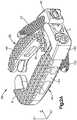
Fig. 1A is a side perspective view of a pair of vertebral bodies separated by an intervertebral space;Fig. 1B is a side perspective view of an expandable intervertebral implant in accordance with one embodiment, the implant inserted into the intervertebral space shown inFig. 1A , the implant expandable between an unexpanded configuration having a first footprint width, and an expanded configuration having a second footprint width that is greater than the first footprint width;Fig. 2A is a side perspective view of the expandable intervertebral implant shown inFig. 1B , the implant including a first body member and a second body member pivotally coupled to the first body member, each body member having a plate and a cage body;Fig. 2B is a an exploded view of the implant shown inFig. 2A ;Fig. 2C is a cross-sectional side perspective view of the implant shown inFig. 2A ;Fig. 2D is a cross-sectional side perspective view of the implant shown inFig. 2C , the implant receiving an expandable element in a channel defined by the first body member;Fig. 2E is a cross-sectional side perspective view of the implant shown inFig. 2D , with the expandable element in an expanded configuration to thereby expand the implant to its expanded configuration;Fig. 3A is a side perspective view of the implant shown inFig. 2A positioned in the intervertebral space while in the unexpanded configuration, the superior vertebral body is removed for clarity;Fig. 3B is a side perspective view of a first fixation element being inserted into a first fixation element receiving aperture of the first body member of the implant shown inFig. 3A ;Fig. 3C is a side perspective view of the first fixation element fully inserted into the first fixation element receiving aperture of the implant so as to affix the first body member of the implant to the superior vertebral body;Fig. 3D is a top plan view of the implant shown inFig. 3C ;Fig. 3E is a side perspective view of the implant shown inFig. 3D , after the implant has been expanded to its expanded configuration;Fig. 3F is a top plan view of the implant shown inFig. 3E ;Fig. 3G is a side perspective view of a second fixation element being inserted into a second fixation element receiving aperture of the second body member of the implant shown inFig. 3F ;Fig. 3H is a side perspective view of the second fixation element fully inserted into the second fixation element receiving aperture of the implant so as to affix the second body member of the implant to the inferior vertebral body;Fig. 3I is a side elevation view showing the implant ofFig. 3H affixed to the superior and inferior vertebrae;Fig. 4A is a cross-sectional side perspective view of an expandable intervertebral implant which does not fall within the scope of the invention as claimed, the implant including a first body member and a second body member that are spaced apart so as to define a cavity therebetween, the cavity receiving an expandable element; andFig. 4B is a cross-sectional side perspective view of the implant shown inFig. 4A , with the expandable element in an expanded configuration to thereby expand the implant to its expanded configuration.- Referring to
Figs. 1A and 1B , a superior vertebral body 10a defines a superior vertebral surface 14a of anintervertebral space 18, and an adjacent inferiorvertebral body 10b defines an inferior vertebral surface 14b of theintervertebral space 18. Thus, theintervertebral space 18 is disposed between the vertebral bodies 10a-b. The vertebral bodies 10a-b can be anatomically adjacent vertebral bodies, or remaining vertebral bodies after a vertebral body has been removed from a location between the vertebral bodies 10a-b. As illustrated, theintervertebral space 18 is illustrated after a discectomy, whereby the disc material has been removed or at least partially removed to prepare theintervertebral space 18 to receive anintervertebral implant 26, as shown inFig. 1B , that can achieve height restoration. Theintervertebral space 18 can be disposed anywhere along the spine as desired, including at the lumbar, thoracic, and cervical regions of the spine. - Certain terminology is used in the following description for convenience only and is not limiting. The words "right", "left", "lower" and "upper" designate directions in the drawings to which reference is made. The words "inner" or "distal" and "outer" or "proximal" refer to directions toward and away from, respectively, the geometric center of the implant and related parts thereof. The words, "anterior", "posterior", "superior," "inferior," "medial," "lateral," and related words and/or phrases are used to designate various positions and orientations in the human body to which reference is made and are not meant to be limiting. The terminology includes the above-listed words, derivatives thereof and words of similar import.
- The
implant 26 is described herein as extending horizontally along a longitudinal direction "L" and lateral direction "A", and vertically along a transverse direction "T". Unless otherwise specified herein, the terms "lateral," "longitudinal," and "transverse" are used to describe the orthogonal directional components of various components. It should be appreciated that while the longitudinal and lateral directions are illustrated as extending along a horizontal plane, and that the transverse direction is illustrated as extending along a vertical plane, the planes that encompass the various directions may differ during use. For instance, when theimplant 26 is implanted into an intervertebral space, such as theintervertebral space 18, the transverse direction T extends vertically generally along the superior-inferior (or caudal-cranial) direction, while the horizontal plane defined by the longitudinal direction L and lateral direction A lies generally in the anatomical plane defined by the anterior-posterior direction, and the medial-lateral direction. Accordingly, the directional terms "vertical" and "horizontal" are used to describe theimplant 26 and its components as illustrated merely for the purposes of clarity and illustration. - Referring now to
Figs. 1B and2A-2E , the interbodyexpandable implant 26 is configured to be positioned within an at least partially cleared out disc space, such as thedisc space 18 disposed between the superior vertebral body 10a and the inferiorvertebral body 10b. The implant is elongate in the longitudinal direction L and defines a distal end D and a proximal end P. Theimplant 26 is expandable between a first initial unexpanded configuration having a first footprint width, and a second expanded configuration having a second width that is greater than the first width. Theimplant 26 may be implanted while in the unexpanded configuration so as to provide a minimally invasive approach for the procedure. Once positioned within the intervertebral space, theimplant 26 may be expanded in situ to its expanded configuration so as to provide an adequate footprint for an interbody fusion device. The expandedimplant 26 may achieve improved stability and may reduce subsidence risk. Theimplant 26 can be formed entirely from or partially from a range of biocompatible materials or combinations of materials, including polymers, such as PEEK, porous PEEK, carbon fiber-reinforced PEEK, titanium and titanium alloys, stainless steel, ceramic, polylactic acid, tantalum, and magnesium, or even allograft bone. - As shown in
Figs 2A-2E , theimplant 26 includes afirst body member 30 and asecond body member 34 that is pivotally coupled to thefirst body member 30 at ahinge 38. At least one of thefirst body member 30 and thesecond body member 34 may rotate about thehinge 38 relative to the other to thereby expand theimplant 26 to its expanded configuration. As shown, the first andsecond body members implant 26 has been implanted into an intervertebral space that is defined between adjacent vertebral bodies that are opposed in the transverse direction T, the first andsecond body members implant 26. Theimplant 26 is configured such that bothbody members implant 26 may also be configured such that only one of thebody members body members implant 26 to thereby allow for unilateral expansion of the implant and prevent any damage to the vessels. - As best shown in
Figs. 2B and2C , thefirst body member 30 includes afirst plate 40, and afirst cage body 44 that is coupled to thefirst plate 40. In particular, thefirst plate 40 is coupled to a proximal end of thefirst cage body 44. While thefirst plate 40 and thefirst cage body 44 are shown as separate components that are coupled together, it should be understood that thefirst plate 40 and thefirst cage body 44 may be integrally formed as one piece. - As best shown in
Fig. 2B , thefirst plate 40 includes afront face member 42 that defines a fixationelement receiving aperture 48 that extends therethrough from a front side to a back side at an upward angle. The fixationelement receiving aperture 48 may define internal threads that are configured to engage external threads defined by a fixation element, such asbone screw 52, as thebone screw 52 is inserted into the fixationelement receiving aperture 48. Thebone screw 52 is configured to engage the superior vertebral body 10a once it is fully inserted to thereby brace or otherwise affix thefirst body member 30 to the vertebral body. The fixationelement receiving aperture 48 may be fully enclosed as shown in the illustrated embodiment, or the fixationelement receiving aperture 48 may be partially enclosed to thereby define for example a semi-circle. The fixationelement receiving aperture 48 may be configured to receive a fixation element other than thebone screw 52. For example the fixationelement receiving aperture 48 may be configured to receive blades or nails. Therefore, the fixationelement receiving aperture 48 may be void of threads. Moreover, it should be understood that the first body member may be configured to be braced against the vertebral wall of the vertebral body using structure other than fixation elements. For example, thefirst body member 30 may be toothed so as to not allow thefirst body member 30 to rotate when the implant is inserted. - As shown in
Fig. 2B , thefirst plate 40 also defines a curvedinternal surface 56 that is generally concave. As shown, the curvedinternal surface 56 is positioned such that it is adjacent thesecond body member 34. As will be discussed, the curvedinternal surface 56 allows thefirst body member 30 to rotate relative to thesecond body member 34 without substantial interference from thesecond body member 34. - As shown in
Figs. 2A and2B , thefirst cage body 44 is elongate in the longitudinal direction L. Thefirst cage body 44 defines an upper or superior or outer transverse bone engagement or contactingsurface 60 configured to contact the superior vertebral body 10a, and a lower or inferior or outer transverse bone engagement or contactingsurface 64 configured to contact the inferiorvertebral body 10b. Both outer contactingsurfaces teeth 68 that are configured to engage the superior and inferiorvertebral bodies 10a and 10b. As shown, theteeth 68 may be aligned in arcs with the centre of these arcs being proximate to thehinge 38. - As shown in
Fig. 2B , thefirst cage body 44 includes anelongate body portion 70 that extends in the longitudinal direction L, and a first joint 74 that extends proximally from theelongate portion 70 and at least partially toward thesecond body member 34. In the embodiment shown, the joint 74 extends substantially perpendicularly from theelongate portion 70 toward thesecond body member 34. As shown, thecage body 44 also includes afree end 78 that extends distally from theelongate body portion 70 and at least partially toward thesecond body member 34. Therefore, because both the first joint 74 and thefree end 78 at least partially extend toward thesecond body member 34, thefirst cage body 44 generally defines a C-shaped structure. - As shown, the first joint 74 includes a pair of
plates 82 that are spaced apart so as to define agap 86 between the twoplates 78. Eachplate 82 defines anaperture 90 that extends completely therethrough in the transverse direction T. As shown, eachaperture 90 is aligned and is configured to receive apin 94 as shown inFig. 2C . - The
free end 74 of thefirst cage body 44 defines afirst mating feature 94. As shown, thefirst mating feature 94 includes arecess 98 that extends into the curved portion of thefree end 74. Therecess 98 is configured to receive a mating feature that is defined by thesecond body member 34 when theimplant 26 is in an unexpanded configuration. - As best shown in
Fig. 2C , thefirst body member 30 also defines achannel 102 that extends longitudinally through thefirst body member 30. That is, thechannel 102 extends at least partially through the first joint 74, through theelongate body portion 70, and into therecess 94 defined by thefree end 78. As shown, thechannel 102 defines anon-linear path 106 from a proximal end of theimplant 26 to the distal end of theimplant 26. As shown inFigs. 2D and 2E , thechannel 102 is configured to receive anexpandable element 110 so as to guide theexpandable element 110 along thepath 106 toward therecess 98. Theexpandable element 110 is configured to expand theimplant 26 to its expanded configuration when theexpandable element 110 has been activated. In the embodiment shown, theexpandable element 110 is aninflatable balloon 114, that may be inflated by injecting air or some other fluid into atube 118 that is coupled to a proximal end of theballoon 114. It should be understood, however, that theexpandable element 110 is not limited to inflatable balloons and that other devices or materials may be used to expand theimplant 26. - As best shown in
Figs. 2B and2C , thesecond body member 34 includes afirst plate 140, and asecond cage body 144 that is coupled to thesecond plate 140. In particular, thesecond plate 140 is coupled to a proximal end of thesecond cage body 144. While thesecond plate 140 and thesecond cage body 144 are shown as separate components that are coupled together, it should be understood that thesecond plate 140 and thesecond cage body 144 may be integrally formed as one piece. - As best shown in
Fig. 2B , thesecond plate 140 includes afront face member 142 that defines a fixationelement receiving aperture 148 that extends therethrough from a front side to a back side at a downward angle. The fixationelement receiving aperture 148 may define internal threads that are configured to engage external threads defined by a fixation element, such asbone screw 152, as thebone screw 152 is inserted into the fixationelement receiving aperture 148. Thebone screw 152 is configured to engage the inferiorvertebral body 10b once it is fully inserted to thereby brace or otherwise affix thesecond body 34 against the vertebral body. The fixationelement receiving aperture 148 may be fully enclosed as shown in the illustrated embodiment, or the fixationelement receiving aperture 148 may be partially enclosed to thereby define for example a semi-circle. The fixationelement receiving aperture 148 may be configured to receive a fixation element other than thebone screw 152. For example the fixationelement receiving aperture 148 may be configured to receive blades or nails. Therefore, the fixationelement receiving aperture 148 may be void of threads. Moreover, it should be understood that thesecond body member 34 may be configured to be braced against the vertebral wall of the vertebral body using structure other than fixation elements. For example, thesecond body member 34 may be toothed so as to not allow thesecond body member 34 to rotate when the implant is inserted. - As shown, the
front face member 142 also defines a holdingaperture 154 that extends therethrough adjacent to the fixationelement receiving aperture 148. The holdingaperture 154 is configured to receive an insertion tool so as to couple theimplant 26 to the insertion tool for insertion of theimplant 26 into theintervertebral space 18. The holdingaperture 154 may include internal threads that are configured to engage external threads defined by the insertion tool to thereby securely couple theimplant 26 to the insertion tool during insertion. As shown, the holdingaperture 154 may also be substantially aligned with thechannel 102. Therefore, theexpandable element 110 may be inserted into thechannel 102 through the holdingaperture 154 as shown inFigs. 2D and 2E . - As shown in
Fig. 2B , thesecond plate 140 also defines a curvedexternal surface 156 that is generally convex. As shown, the curvedexternal surface 156 is positioned such that it is adjacent thecurved surface 56 of thefirst body member 30. The curved surfaces 56 and 156 correspond to each other such that as thefirst body member 30 rotates relative to thesecond body member 34 the first andsecond plates - As shown in
Figs. 2A and2B , thesecond cage body 144 is elongate in the longitudinal direction L. Thesecond cage body 144 defines an upper or superior or outer transverse bone engagement or contactingsurface 160 configured to contact the superior vertebral body 10a, and a lower or inferior or outer transverse bone engagement or contactingsurface 164 configured to contact the inferiorvertebral body 10b. Both outer contactingsurfaces teeth 68 that are configured to engage the superior and inferiorvertebral bodies 10a and 10b. As shown, theteeth 68 may be aligned in arcs with the centre of these arcs being proximate to thehinge 38. - As shown in
Fig. 2B , thesecond cage body 144 includes anelongate body portion 170 that extends in the longitudinal direction L, and a second joint 174 that extends proximally from theelongate body portion 170 and at least partially toward thefirst body member 30. In the embodiment shown, the joint 174 extends substantially perpendicularly from theelongate body portion 170 toward thefirst body member 30. As shown, thecage body 144 also includes afree end 178 that extends distally from theelongate body portion 170 and at least partially toward thefirst body member 30. Therefore, because both the first joint 174 and thefree end 178 at least partially extend toward thefirst body member 30, thesecond cage body 144 generally defines a C-shaped structure. - As shown, the second joint 174 includes a
plate 182 that is configured to engage thegap 86 defined between the twoplates 78 of the first joint 74. Theplate 182 defines anaperture 190 that extends completely therethrough in the transverse direction T. As shown, theaperture 190 is configured to align with theapertures 90 of the first joint 74 when theplate 178 is received in thegap 86. Theapertures pin 94 can engage eachaperture hinge 38. As shown inFig. 2C , thehinge 38 defines a pivot axis that extends in the transverse or caudal-cranial direction. Therefore, at least one of thefirst body member 30 and thesecond body member 34 may rotate about the rotation axis in the horizontal plane defined by the longitudinal and lateral directions to thereby increase the overall footprint of theimplant 26. It should be understood that thejoints first body member 30 or thesecond body member 34. Moreover, thehinge 38 may be defined by structure other than thejoints first body member 30 and thesecond body member 34 may be integral parts that are connected by anintegral hinge 38 that allows at least one offirst body member 30 and thesecond body member 34 to rotate relative to the other. - The
free end 174 of thesecond cage body 144 defines asecond mating feature 194. As shown, thesecond mating feature 194 includes aprotrusion 198 that extends toward therecess 98 of thefirst body member 30. Thesecond mating feature 194 is configured to mate with thefirst mating feature 94 when theimplant 26 is in an unexpanded configuration. In particular, theprotrusion 198 is configured to engage or otherwise extend into therecess 94 of thefirst body member 30 when theimplant 26 is in an unexpanded configuration. As shown inFig. 2D , when theimplant 26 is in its unexpanded configuration, thefirst cage body 44 and the second cage body 144 (or at least theirelongate body portions 70 and 170) are spaced apart such that acavity 200 is defined between theelongate body portions cavity 200 is generally oval shaped and theoverall implant 26 generally defines an oval shaped ring when theimplant 26 is in an unexpanded configuration. Though it should be understood that thecavity 200 or at least theimplant 26 may include other shapes as desired when theimplant 26 is in its unexpanded configuration. - As shown in
Figs 2D and 2E , theexpandable element 110 may be inserted through the holdingaperture 154 and into thechannel 102 until at least a portion of theexpandable element 110 is within therecess 98 of thefirst body member 30 and adjacent to theprotrusion 198. When theexpandable element 110 is activated, theexpandable element 110 will contact and apply a force to theprotrusion 198 thereby causing at least one of thefirst body member 30 and thesecond body member 34 to rotate about thehinge 38. As thebody members protrusion 198 recedes from therecess 98 such that the free ends 74 and 174 of thebody members protrusion 198 completely disengages from therecess 98 or if theprotrusion 198 partially disengages from therecess 98 so long as theprotrusion 198 at least partially recedes from therecess 98. - In operation and in reference to
Figs. 3A-3I , theimplant 26 may be inserted into theintervertebral space 18 while in an unexpanded configuration. As best shown inFig. 3D , theimplant 26 may have an initial insertion or otherwise first width W1 when theimplant 26 is being inserted into theintervertebral space 18. The initial width W1 may be narrow enough to allow for a minimally invasive approach to thereby reduce damage to the patient. Once theimplant 26 has been inserted into theintervertebral space 18, thefirst bone screw 52 may be inserted into the fixationelement receiving aperture 48 of thefirst body member 30 and into the superior vertebral body 10a, as shown inFigs. 3B-3D . At this point thefirst body member 30 may be securely fixed to the superior vertebral body 10a. - As shown in
Figs. 3E and3F , theexpandable element 110 may then be inserted through the holdingaperture 154 and into thechannel 102 so that at least a portion of the expandable element is proximate to the mating features 94 and 194. Theexpandable element 110 may then be activated or otherwise expanded so as to apply a force to themating feature 194 to thereby cause thesecond body member 34 to rotate relative to thefirst body member 30 about thehinge 38 and expand theimplant 26 to its expanded configuration. As best shown inFig. 3F , theimplant 26 may have an expanded or otherwise second width W2 that is greater than the first width W1 when theimplant 26 is in the expanded configuration. As shown, when in the expanded configuration, theimplant 26 has a greater footprint to thereby increase stability of the implant. - Once the
implant 26 has been expanded, thesecond bone screw 152 may be inserted through the fixationelement receiving aperture 148 of thesecond body member 34 and into the inferiorvertebral body 10b, as shown inFigs. 3G and3H . Once thebone screw 152 has been affixed to the inferiorvertebral body 10b, theimplant 26 will be securely affixed to the vertebrae such that the first and second body members won't rotate or otherwise change their orientation, as shown inFig. 3I . - It should be understood that the
second body member 34 may be affixed to the inferiorvertebral body 10b first, rather than affixing thefirst body member 30 prior to expanding theimplant 26 to its expanded configuration. Furthermore, it should be understood that theimplant 26 may be expanded to its expanded configuration prior to any of the first andsecond body members vertebral bodies 10a and 10b. Therefore, theimplant 26 may be expanded unilaterally by affixing one of thebody members implant 26 prior to affixing any of thebody members cavity 200 between the first andsecond body members cavity 200 maybe filled with filler material (e.g. autologous, allograft bone, bone filler substitute) after implantation of theimplant 26. This could be achieved through injection or packing of the material into thecavity 200. - Another exemplary implant which does not fall within the scope of the invention as claimed is shown in
Figs. 4A and 4B . Theimplant 26 in this case may be expanded by inserting anexpandable element 110 directly into thecavity 200. In this example, there may be no need for thechannel 102. For example, as shown inFigs. 4A and 4B , the expandable element may be inserted through the holdingaperture 154 and into thecavity 200. Once positioned, theexpandable element 110 maybe activated or otherwise expanded and force thebody members hinge 38. It would he understood, however, that theexpandable element 110 may be inserted directly into thecavity 200 without going through the holdingaperture 154.
Claims (14)
- An expandable interbody fusion implant (26) that is configured to have an initial configuration and an expanded configuration, the implant (26) comprising:a first body member (30) configured to be braced against a vertebral surface, the first body member (30) including a first elongate cage body (44), the first elongate cage body (44) defining superior and inferior bone engaging surfaces (60, 64), the first elongate cage body (44) having a free end (78), anda second body member (34) pivotally coupled to the first body member (30) at a pivot axis, the second body member (34) including a second elongate cage body (144), the second elongate cage body (144) defining superior and inferior bone engaging surfaces (160, 164), the second elongate cage body (144) having a free end (178),in which the first body member (30) defines a channel (102) that extends through the first elongate cage body (44), the channel (102) configured to receive an expandable element (110), such that when the expandable element (110) is expanded, at least the second body member (34) pivots about the pivot axis with respect to the first body member (30) so as to move at least the free end (178) of the second body member (34) relative to the free end (78) of the first body member (30) and expand the implant (26) to the expanded configuration.
- The implant (26) according to claim 1 in which the first body member (30) further includes a first angled fixation element receiving aperture (48) that is configured to receive a fixation element (42), and the second body member (34) further includes a second angled fixation element receiving aperture (148) that is configured to receive a fixation element (142).
- The implant (26) according to claim 2, in which the first and second fixation element receiving apertures (48, 148) are screw-receiving apertures configured to receive a screw (52, 152) so as to brace the first and second body members (30, 34) against respective vertebral surfaces.
- The implant (26) according to claim 1, in which the free end (78) of the first cage body (44) defines a recess (98) and the free end (178) of the second cage body (144) defines a protrusion (198) that engages the recess (98) when the implant (26) is in the initial configuration.
- The implant (26) according to claim 1, in which the first body member (30) further includes a first plate (40) that defines a curved internal surface and the body member includes a second plate (140) that defines a curved external surface that corresponds to the curved internal surface of the first plate (40) so as to allow the first plate (40) to move relative to the second plate (140) when the implant (26) is being expanded to the expanded configuration.
- The implant (26) according to claim 2, in which the first angled fixation element receiving aperture (48) is configured to receive a bone screw (52) that engages the superior vertebral body and the second angled fixation element receiving aperture (148) is configured to receive a bone screw (152) that engages the inferior vertebral body.
- The implant (26) according to claim 1, in which the second body member (34) further defines a holding aperture (154) that is configured to be engaged by an insertion tool to thereby couple the implant (26) to the insertion tool.
- The implant (26) according to claim 1, in which the first elongate cage body (44) is spaced apart from the second elongate cage body (144) such that a cavity (200) is defined between the first and second elongate cage bodies, the cavity (200) configured to receive the expandable element (110).
- The implant (26) according to claim 1, in which the first body member (30) is configured to be affixed to bone such that only the second body member (34) pivots relative to the first body member (30) when the expandable element (110) is expanded.
- The implant (26) according to claim 1, in which the first body member (30) further includes a first plate (40) coupled to the first elongate cage body (44), the first plate (40) defining a fixation element receiving aperture (48) that is configured to receive a respective bone screw (52), and in which the second body member (34) further includes a second plate (140) coupled to the second elongate cage body (144), the second plate (140) defining a fixation element receiving aperture (148) that is configured to receive a respective bone screw (152).
- The implant (26) according to claim 1, in which the implant (26) has a first footprint width while in the initial configuration, and has a second footprint width that is greater than the first footprint width while in the expanded configuration.
- The implant (26) according to claim 1, in which the channel (102) is nonlinear.
- The implant (26) according to claim 1, wherein the first elongate cage body (44) defines inner and outer walls that extend between the superior and inferior bone engaging surfaces (60, 44) of the first elongate cage body (44), and the channel (102) extends through the first elongate cage body (44) between the superior and inferior bone engaging surfaces (60, 44) of the first elongate cage body (44) and between the opposed inner and outer walls.
- An implant assembly which comprises the implant (26) according to claim 1, and an expandable element (110) which comprises an inflatable balloon.
Applications Claiming Priority (1)
| Application Number | Priority Date | Filing Date | Title |
|---|---|---|---|
| PCT/US2011/025828WO2012115631A1 (en) | 2011-02-23 | 2011-02-23 | Expandable interbody fusion implant |
Publications (2)
| Publication Number | Publication Date |
|---|---|
| EP2677969A1 EP2677969A1 (en) | 2014-01-01 |
| EP2677969B1true EP2677969B1 (en) | 2017-08-30 |
Family
ID=44625291
Family Applications (1)
| Application Number | Title | Priority Date | Filing Date |
|---|---|---|---|
| EP11706716.5ANot-in-forceEP2677969B1 (en) | 2011-02-23 | 2011-02-23 | Expandable interbody fusion implant |
Country Status (4)
| Country | Link |
|---|---|
| EP (1) | EP2677969B1 (en) |
| JP (1) | JP5784757B2 (en) |
| AU (1) | AU2011360240B2 (en) |
| WO (1) | WO2012115631A1 (en) |
Families Citing this family (18)
| Publication number | Priority date | Publication date | Assignee | Title |
|---|---|---|---|---|
| US8940030B1 (en) | 2011-01-28 | 2015-01-27 | Nuvasive, Inc. | Spinal fixation system and related methods |
| US8486149B2 (en) | 2011-02-23 | 2013-07-16 | DePuy Synthes Products, LLC | Expandable interbody fusion implant |
| US9445918B1 (en) | 2012-10-22 | 2016-09-20 | Nuvasive, Inc. | Expandable spinal fusion implants and related instruments and methods |
| US9320613B2 (en) | 2012-12-14 | 2016-04-26 | Facet-Link Inc. | Laterally expandable intervertebral fusion implant |
| AU2013357234A1 (en)* | 2012-12-14 | 2015-07-30 | Facet-Link Inc. | Laterally expandable intervertebral fusion implant |
| US10322006B2 (en)* | 2013-03-15 | 2019-06-18 | Globus Medical, Inc. | Interbody standalone intervertebral implant |
| US9795493B1 (en) | 2013-03-15 | 2017-10-24 | Nuvasive, Inc. | Expandable intervertebral implant and methods of use thereof |
| US20160151171A1 (en)* | 2013-07-17 | 2016-06-02 | Spinal Usa, Inc. | Modular intervertebral cage system |
| FR3009493B1 (en)* | 2013-08-08 | 2015-08-14 | Scientia Consulting | INTERVERTEBRAL FUSION CAGE |
| US9351847B2 (en)* | 2013-08-22 | 2016-05-31 | Globus Medical, Inc. | Interbody fusion devices with self-affixing mechanisms |
| US9968461B2 (en) | 2014-05-15 | 2018-05-15 | Globus Medical, Inc. | Standalone interbody implants |
| US11160666B2 (en) | 2014-05-15 | 2021-11-02 | Globus Medical, Inc. | Laterally insertable intervertebral spinal implant |
| US9545320B2 (en)* | 2014-05-15 | 2017-01-17 | Globus Medical, Inc. | Standalone interbody implants |
| US9486327B2 (en) | 2014-05-15 | 2016-11-08 | Globus Medical, Inc. | Standalone interbody implants |
| AU2015269383B2 (en) | 2014-06-04 | 2017-12-07 | Wenzel Spine, Inc. | Bilaterally expanding intervertebral body fusion device |
| EP3270831A1 (en) | 2015-03-18 | 2018-01-24 | 41Medical AG | Expandable spinal implant |
| CN109481099B (en)* | 2017-09-13 | 2024-06-21 | 医景通(北京)科技发展有限公司 | Fusion device |
| US11219531B2 (en) | 2019-04-10 | 2022-01-11 | Wenzel Spine, Inc. | Rotatable intervertebral spacing implant |
Citations (1)
| Publication number | Priority date | Publication date | Assignee | Title |
|---|---|---|---|---|
| WO2000025706A1 (en)* | 1998-10-29 | 2000-05-11 | Sdgi Holdings, Inc. | Expandable intervertebral spacers |
Family Cites Families (11)
| Publication number | Priority date | Publication date | Assignee | Title |
|---|---|---|---|---|
| CA1283501C (en)* | 1987-02-12 | 1991-04-30 | Thomas P. Hedman | Artificial spinal disc |
| US6190414B1 (en)* | 1996-10-31 | 2001-02-20 | Surgical Dynamics Inc. | Apparatus for fusion of adjacent bone structures |
| US7306628B2 (en)* | 2002-10-29 | 2007-12-11 | St. Francis Medical Technologies | Interspinous process apparatus and method with a selectably expandable spacer |
| US6206923B1 (en)* | 1999-01-08 | 2001-03-27 | Sdgi Holdings, Inc. | Flexible implant using partially demineralized bone |
| DE60110375T2 (en)* | 2000-02-04 | 2006-03-02 | Michelson, Gary Karlin, Los Angeles | EXPANDABLE INTERSPINAL FUSION IMPLANT |
| ATE293940T1 (en)* | 2000-02-04 | 2005-05-15 | Michelson Gary K | EXPANDABLE INTERSPINAL FUSION IMPLANT |
| AU2003298670A1 (en)* | 2002-11-21 | 2004-06-18 | Sdgi Holdings, Inc. | Systems and techniques for intravertebral spinal stabilization with expandable devices |
| WO2007121320A2 (en)* | 2006-04-12 | 2007-10-25 | Spinalmotion, Inc. | Posterior spinal device and method |
| US7985231B2 (en)* | 2007-12-31 | 2011-07-26 | Kyphon Sarl | Bone fusion device and methods |
| US8118873B2 (en)* | 2008-01-16 | 2012-02-21 | Warsaw Orthopedic, Inc. | Total joint replacement |
| EP2237748B1 (en)* | 2008-01-17 | 2012-09-05 | Synthes GmbH | An expandable intervertebral implant |
- 2011
- 2011-02-23EPEP11706716.5Apatent/EP2677969B1/ennot_activeNot-in-force
- 2011-02-23WOPCT/US2011/025828patent/WO2012115631A1/enactiveApplication Filing
- 2011-02-23JPJP2013555401Apatent/JP5784757B2/ennot_activeExpired - Fee Related
- 2011-02-23AUAU2011360240Apatent/AU2011360240B2/enactiveActive
Patent Citations (1)
| Publication number | Priority date | Publication date | Assignee | Title |
|---|---|---|---|---|
| WO2000025706A1 (en)* | 1998-10-29 | 2000-05-11 | Sdgi Holdings, Inc. | Expandable intervertebral spacers |
Also Published As
| Publication number | Publication date |
|---|---|
| JP5784757B2 (en) | 2015-09-24 |
| EP2677969A1 (en) | 2014-01-01 |
| AU2011360240A1 (en) | 2013-09-05 |
| JP2014513579A (en) | 2014-06-05 |
| AU2011360240B2 (en) | 2016-09-01 |
| WO2012115631A1 (en) | 2012-08-30 |
Similar Documents
| Publication | Publication Date | Title |
|---|---|---|
| US11730607B2 (en) | Expandable interbody fusion implant | |
| EP2677969B1 (en) | Expandable interbody fusion implant | |
| US11701236B2 (en) | Articulating expandable intervertebral implant | |
| US20210322182A1 (en) | Expandable intervertebral spacer | |
| US20200121469A1 (en) | Intervertebral Implant with Fixation Geometry | |
| US8409291B2 (en) | Laterally expandable interbody spinal fusion implant | |
| EP2477579B1 (en) | Intervertebral implant having extendable bone fixation members | |
| US8480748B2 (en) | Lordotic expandable interbody implant and method | |
| US20090099568A1 (en) | Device and method for variably adjusting intervertebral distraction and lordosis | |
| US20060129238A1 (en) | Spinal stabilization device and methods | |
| US8419796B2 (en) | Intervertebral prosthetic systems, devices, and associated methods | |
| US20080262501A1 (en) | Multi-function corpectomy instrument |
Legal Events
| Date | Code | Title | Description |
|---|---|---|---|
| PUAI | Public reference made under article 153(3) epc to a published international application that has entered the european phase | Free format text:ORIGINAL CODE: 0009012 | |
| 17P | Request for examination filed | Effective date:20130726 | |
| AK | Designated contracting states | Kind code of ref document:A1 Designated state(s):AL AT BE BG CH CY CZ DE DK EE ES FI FR GB GR HR HU IE IS IT LI LT LU LV MC MK MT NL NO PL PT RO RS SE SI SK SM TR | |
| DAX | Request for extension of the european patent (deleted) | ||
| 17Q | First examination report despatched | Effective date:20160706 | |
| GRAP | Despatch of communication of intention to grant a patent | Free format text:ORIGINAL CODE: EPIDOSNIGR1 | |
| INTG | Intention to grant announced | Effective date:20170403 | |
| GRAS | Grant fee paid | Free format text:ORIGINAL CODE: EPIDOSNIGR3 | |
| GRAA | (expected) grant | Free format text:ORIGINAL CODE: 0009210 | |
| AK | Designated contracting states | Kind code of ref document:B1 Designated state(s):AL AT BE BG CH CY CZ DE DK EE ES FI FR GB GR HR HU IE IS IT LI LT LU LV MC MK MT NL NO PL PT RO RS SE SI SK SM TR | |
| REG | Reference to a national code | Ref country code:GB Ref legal event code:FG4D | |
| REG | Reference to a national code | Ref country code:CH Ref legal event code:EP Ref country code:CH Ref legal event code:NV Representative=s name:E. BLUM AND CO. AG PATENT- UND MARKENANWAELTE , CH | |
| REG | Reference to a national code | Ref country code:AT Ref legal event code:REF Ref document number:922816 Country of ref document:AT Kind code of ref document:T Effective date:20170915 | |
| REG | Reference to a national code | Ref country code:IE Ref legal event code:FG4D | |
| REG | Reference to a national code | Ref country code:DE Ref legal event code:R096 Ref document number:602011041050 Country of ref document:DE | |
| REG | Reference to a national code | Ref country code:NL Ref legal event code:MP Effective date:20170830 | |
| REG | Reference to a national code | Ref country code:LT Ref legal event code:MG4D | |
| REG | Reference to a national code | Ref country code:AT Ref legal event code:MK05 Ref document number:922816 Country of ref document:AT Kind code of ref document:T Effective date:20170830 | |
| PG25 | Lapsed in a contracting state [announced via postgrant information from national office to epo] | Ref country code:FI Free format text:LAPSE BECAUSE OF FAILURE TO SUBMIT A TRANSLATION OF THE DESCRIPTION OR TO PAY THE FEE WITHIN THE PRESCRIBED TIME-LIMIT Effective date:20170830 Ref country code:NO Free format text:LAPSE BECAUSE OF FAILURE TO SUBMIT A TRANSLATION OF THE DESCRIPTION OR TO PAY THE FEE WITHIN THE PRESCRIBED TIME-LIMIT Effective date:20171130 Ref country code:HR Free format text:LAPSE BECAUSE OF FAILURE TO SUBMIT A TRANSLATION OF THE DESCRIPTION OR TO PAY THE FEE WITHIN THE PRESCRIBED TIME-LIMIT Effective date:20170830 Ref country code:AT Free format text:LAPSE BECAUSE OF FAILURE TO SUBMIT A TRANSLATION OF THE DESCRIPTION OR TO PAY THE FEE WITHIN THE PRESCRIBED TIME-LIMIT Effective date:20170830 Ref country code:LT Free format text:LAPSE BECAUSE OF FAILURE TO SUBMIT A TRANSLATION OF THE DESCRIPTION OR TO PAY THE FEE WITHIN THE PRESCRIBED TIME-LIMIT Effective date:20170830 Ref country code:SE Free format text:LAPSE BECAUSE OF FAILURE TO SUBMIT A TRANSLATION OF THE DESCRIPTION OR TO PAY THE FEE WITHIN THE PRESCRIBED TIME-LIMIT Effective date:20170830 | |
| PG25 | Lapsed in a contracting state [announced via postgrant information from national office to epo] | Ref country code:IS Free format text:LAPSE BECAUSE OF FAILURE TO SUBMIT A TRANSLATION OF THE DESCRIPTION OR TO PAY THE FEE WITHIN THE PRESCRIBED TIME-LIMIT Effective date:20171230 Ref country code:GR Free format text:LAPSE BECAUSE OF FAILURE TO SUBMIT A TRANSLATION OF THE DESCRIPTION OR TO PAY THE FEE WITHIN THE PRESCRIBED TIME-LIMIT Effective date:20171201 Ref country code:ES Free format text:LAPSE BECAUSE OF FAILURE TO SUBMIT A TRANSLATION OF THE DESCRIPTION OR TO PAY THE FEE WITHIN THE PRESCRIBED TIME-LIMIT Effective date:20170830 Ref country code:LV Free format text:LAPSE BECAUSE OF FAILURE TO SUBMIT A TRANSLATION OF THE DESCRIPTION OR TO PAY THE FEE WITHIN THE PRESCRIBED TIME-LIMIT Effective date:20170830 Ref country code:RS Free format text:LAPSE BECAUSE OF FAILURE TO SUBMIT A TRANSLATION OF THE DESCRIPTION OR TO PAY THE FEE WITHIN THE PRESCRIBED TIME-LIMIT Effective date:20170830 Ref country code:BG Free format text:LAPSE BECAUSE OF FAILURE TO SUBMIT A TRANSLATION OF THE DESCRIPTION OR TO PAY THE FEE WITHIN THE PRESCRIBED TIME-LIMIT Effective date:20171130 | |
| PG25 | Lapsed in a contracting state [announced via postgrant information from national office to epo] | Ref country code:NL Free format text:LAPSE BECAUSE OF FAILURE TO SUBMIT A TRANSLATION OF THE DESCRIPTION OR TO PAY THE FEE WITHIN THE PRESCRIBED TIME-LIMIT Effective date:20170830 | |
| PG25 | Lapsed in a contracting state [announced via postgrant information from national office to epo] | Ref country code:CZ Free format text:LAPSE BECAUSE OF FAILURE TO SUBMIT A TRANSLATION OF THE DESCRIPTION OR TO PAY THE FEE WITHIN THE PRESCRIBED TIME-LIMIT Effective date:20170830 Ref country code:RO Free format text:LAPSE BECAUSE OF FAILURE TO SUBMIT A TRANSLATION OF THE DESCRIPTION OR TO PAY THE FEE WITHIN THE PRESCRIBED TIME-LIMIT Effective date:20170830 Ref country code:DK Free format text:LAPSE BECAUSE OF FAILURE TO SUBMIT A TRANSLATION OF THE DESCRIPTION OR TO PAY THE FEE WITHIN THE PRESCRIBED TIME-LIMIT Effective date:20170830 Ref country code:PL Free format text:LAPSE BECAUSE OF FAILURE TO SUBMIT A TRANSLATION OF THE DESCRIPTION OR TO PAY THE FEE WITHIN THE PRESCRIBED TIME-LIMIT Effective date:20170830 | |
| PG25 | Lapsed in a contracting state [announced via postgrant information from national office to epo] | Ref country code:EE Free format text:LAPSE BECAUSE OF FAILURE TO SUBMIT A TRANSLATION OF THE DESCRIPTION OR TO PAY THE FEE WITHIN THE PRESCRIBED TIME-LIMIT Effective date:20170830 Ref country code:SK Free format text:LAPSE BECAUSE OF FAILURE TO SUBMIT A TRANSLATION OF THE DESCRIPTION OR TO PAY THE FEE WITHIN THE PRESCRIBED TIME-LIMIT Effective date:20170830 Ref country code:IT Free format text:LAPSE BECAUSE OF FAILURE TO SUBMIT A TRANSLATION OF THE DESCRIPTION OR TO PAY THE FEE WITHIN THE PRESCRIBED TIME-LIMIT Effective date:20170830 Ref country code:SM Free format text:LAPSE BECAUSE OF FAILURE TO SUBMIT A TRANSLATION OF THE DESCRIPTION OR TO PAY THE FEE WITHIN THE PRESCRIBED TIME-LIMIT Effective date:20170830 | |
| REG | Reference to a national code | Ref country code:DE Ref legal event code:R097 Ref document number:602011041050 Country of ref document:DE | |
| PLBE | No opposition filed within time limit | Free format text:ORIGINAL CODE: 0009261 | |
| STAA | Information on the status of an ep patent application or granted ep patent | Free format text:STATUS: NO OPPOSITION FILED WITHIN TIME LIMIT | |
| 26N | No opposition filed | Effective date:20180531 | |
| PG25 | Lapsed in a contracting state [announced via postgrant information from national office to epo] | Ref country code:SI Free format text:LAPSE BECAUSE OF FAILURE TO SUBMIT A TRANSLATION OF THE DESCRIPTION OR TO PAY THE FEE WITHIN THE PRESCRIBED TIME-LIMIT Effective date:20170830 | |
| PG25 | Lapsed in a contracting state [announced via postgrant information from national office to epo] | Ref country code:MC Free format text:LAPSE BECAUSE OF FAILURE TO SUBMIT A TRANSLATION OF THE DESCRIPTION OR TO PAY THE FEE WITHIN THE PRESCRIBED TIME-LIMIT Effective date:20170830 | |
| REG | Reference to a national code | Ref country code:IE Ref legal event code:MM4A | |
| REG | Reference to a national code | Ref country code:BE Ref legal event code:MM Effective date:20180228 | |
| PG25 | Lapsed in a contracting state [announced via postgrant information from national office to epo] | Ref country code:LU Free format text:LAPSE BECAUSE OF NON-PAYMENT OF DUE FEES Effective date:20180223 | |
| REG | Reference to a national code | Ref country code:FR Ref legal event code:ST Effective date:20181031 | |
| PG25 | Lapsed in a contracting state [announced via postgrant information from national office to epo] | Ref country code:IE Free format text:LAPSE BECAUSE OF NON-PAYMENT OF DUE FEES Effective date:20180223 | |
| PG25 | Lapsed in a contracting state [announced via postgrant information from national office to epo] | Ref country code:FR Free format text:LAPSE BECAUSE OF NON-PAYMENT OF DUE FEES Effective date:20180228 Ref country code:BE Free format text:LAPSE BECAUSE OF NON-PAYMENT OF DUE FEES Effective date:20180228 | |
| PG25 | Lapsed in a contracting state [announced via postgrant information from national office to epo] | Ref country code:MT Free format text:LAPSE BECAUSE OF NON-PAYMENT OF DUE FEES Effective date:20180223 | |
| PG25 | Lapsed in a contracting state [announced via postgrant information from national office to epo] | Ref country code:TR Free format text:LAPSE BECAUSE OF FAILURE TO SUBMIT A TRANSLATION OF THE DESCRIPTION OR TO PAY THE FEE WITHIN THE PRESCRIBED TIME-LIMIT Effective date:20170830 | |
| PG25 | Lapsed in a contracting state [announced via postgrant information from national office to epo] | Ref country code:PT Free format text:LAPSE BECAUSE OF FAILURE TO SUBMIT A TRANSLATION OF THE DESCRIPTION OR TO PAY THE FEE WITHIN THE PRESCRIBED TIME-LIMIT Effective date:20170830 Ref country code:HU Free format text:LAPSE BECAUSE OF FAILURE TO SUBMIT A TRANSLATION OF THE DESCRIPTION OR TO PAY THE FEE WITHIN THE PRESCRIBED TIME-LIMIT; INVALID AB INITIO Effective date:20110223 | |
| PG25 | Lapsed in a contracting state [announced via postgrant information from national office to epo] | Ref country code:CY Free format text:LAPSE BECAUSE OF FAILURE TO SUBMIT A TRANSLATION OF THE DESCRIPTION OR TO PAY THE FEE WITHIN THE PRESCRIBED TIME-LIMIT Effective date:20170830 Ref country code:MK Free format text:LAPSE BECAUSE OF NON-PAYMENT OF DUE FEES Effective date:20170830 | |
| PG25 | Lapsed in a contracting state [announced via postgrant information from national office to epo] | Ref country code:AL Free format text:LAPSE BECAUSE OF FAILURE TO SUBMIT A TRANSLATION OF THE DESCRIPTION OR TO PAY THE FEE WITHIN THE PRESCRIBED TIME-LIMIT Effective date:20170830 | |
| PGFP | Annual fee paid to national office [announced via postgrant information from national office to epo] | Ref country code:GB Payment date:20211230 Year of fee payment:12 | |
| PGFP | Annual fee paid to national office [announced via postgrant information from national office to epo] | Ref country code:DE Payment date:20211230 Year of fee payment:12 Ref country code:CH Payment date:20220114 Year of fee payment:12 | |
| REG | Reference to a national code | Ref country code:DE Ref legal event code:R119 Ref document number:602011041050 Country of ref document:DE | |
| REG | Reference to a national code | Ref country code:CH Ref legal event code:PL | |
| GBPC | Gb: european patent ceased through non-payment of renewal fee | Effective date:20230223 | |
| PG25 | Lapsed in a contracting state [announced via postgrant information from national office to epo] | Ref country code:LI Free format text:LAPSE BECAUSE OF NON-PAYMENT OF DUE FEES Effective date:20230228 Ref country code:CH Free format text:LAPSE BECAUSE OF NON-PAYMENT OF DUE FEES Effective date:20230228 | |
| PG25 | Lapsed in a contracting state [announced via postgrant information from national office to epo] | Ref country code:GB Free format text:LAPSE BECAUSE OF NON-PAYMENT OF DUE FEES Effective date:20230223 | |
| PG25 | Lapsed in a contracting state [announced via postgrant information from national office to epo] | Ref country code:GB Free format text:LAPSE BECAUSE OF NON-PAYMENT OF DUE FEES Effective date:20230223 Ref country code:DE Free format text:LAPSE BECAUSE OF NON-PAYMENT OF DUE FEES Effective date:20230901 |