EP2677936B1 - Image reconstruction based on parametric models - Google Patents
Image reconstruction based on parametric modelsDownload PDFInfo
- Publication number
- EP2677936B1 EP2677936B1EP12742937.1AEP12742937AEP2677936B1EP 2677936 B1EP2677936 B1EP 2677936B1EP 12742937 AEP12742937 AEP 12742937AEP 2677936 B1EP2677936 B1EP 2677936B1
- Authority
- EP
- European Patent Office
- Prior art keywords
- boundary curve
- closed boundary
- item
- material specific
- determining
- Prior art date
- Legal status (The legal status is an assumption and is not a legal conclusion. Google has not performed a legal analysis and makes no representation as to the accuracy of the status listed.)
- Active
Links
Images


Classifications
- G—PHYSICS
- G06—COMPUTING OR CALCULATING; COUNTING
- G06F—ELECTRIC DIGITAL DATA PROCESSING
- G06F30/00—Computer-aided design [CAD]
- G—PHYSICS
- G01—MEASURING; TESTING
- G01N—INVESTIGATING OR ANALYSING MATERIALS BY DETERMINING THEIR CHEMICAL OR PHYSICAL PROPERTIES
- G01N23/00—Investigating or analysing materials by the use of wave or particle radiation, e.g. X-rays or neutrons, not covered by groups G01N3/00 – G01N17/00, G01N21/00 or G01N22/00
- G01N23/02—Investigating or analysing materials by the use of wave or particle radiation, e.g. X-rays or neutrons, not covered by groups G01N3/00 – G01N17/00, G01N21/00 or G01N22/00 by transmitting the radiation through the material
- G01N23/04—Investigating or analysing materials by the use of wave or particle radiation, e.g. X-rays or neutrons, not covered by groups G01N3/00 – G01N17/00, G01N21/00 or G01N22/00 by transmitting the radiation through the material and forming images of the material
- G01N23/046—Investigating or analysing materials by the use of wave or particle radiation, e.g. X-rays or neutrons, not covered by groups G01N3/00 – G01N17/00, G01N21/00 or G01N22/00 by transmitting the radiation through the material and forming images of the material using tomography, e.g. computed tomography [CT]
- A—HUMAN NECESSITIES
- A61—MEDICAL OR VETERINARY SCIENCE; HYGIENE
- A61B—DIAGNOSIS; SURGERY; IDENTIFICATION
- A61B6/00—Apparatus or devices for radiation diagnosis; Apparatus or devices for radiation diagnosis combined with radiation therapy equipment
- A61B6/52—Devices using data or image processing specially adapted for radiation diagnosis
- A61B6/5205—Devices using data or image processing specially adapted for radiation diagnosis involving processing of raw data to produce diagnostic data
- G—PHYSICS
- G06—COMPUTING OR CALCULATING; COUNTING
- G06T—IMAGE DATA PROCESSING OR GENERATION, IN GENERAL
- G06T11/00—2D [Two Dimensional] image generation
- G06T11/003—Reconstruction from projections, e.g. tomography
- G06T11/006—Inverse problem, transformation from projection-space into object-space, e.g. transform methods, back-projection, algebraic methods
- G—PHYSICS
- G06—COMPUTING OR CALCULATING; COUNTING
- G06T—IMAGE DATA PROCESSING OR GENERATION, IN GENERAL
- G06T17/00—Three dimensional [3D] modelling, e.g. data description of 3D objects
- G06T17/30—Polynomial surface description
- A—HUMAN NECESSITIES
- A61—MEDICAL OR VETERINARY SCIENCE; HYGIENE
- A61B—DIAGNOSIS; SURGERY; IDENTIFICATION
- A61B6/00—Apparatus or devices for radiation diagnosis; Apparatus or devices for radiation diagnosis combined with radiation therapy equipment
- A61B6/04—Positioning of patients; Tiltable beds or the like
- A61B6/0407—Supports, e.g. tables or beds, for the body or parts of the body
- A61B6/0471—Supports, e.g. tables or beds, for the body or parts of the body based on an endless-band
- A—HUMAN NECESSITIES
- A61—MEDICAL OR VETERINARY SCIENCE; HYGIENE
- A61B—DIAGNOSIS; SURGERY; IDENTIFICATION
- A61B6/00—Apparatus or devices for radiation diagnosis; Apparatus or devices for radiation diagnosis combined with radiation therapy equipment
- A61B6/40—Arrangements for generating radiation specially adapted for radiation diagnosis
- A61B6/4007—Arrangements for generating radiation specially adapted for radiation diagnosis characterised by using a plurality of source units
- A61B6/4014—Arrangements for generating radiation specially adapted for radiation diagnosis characterised by using a plurality of source units arranged in multiple source-detector units
- A—HUMAN NECESSITIES
- A61—MEDICAL OR VETERINARY SCIENCE; HYGIENE
- A61B—DIAGNOSIS; SURGERY; IDENTIFICATION
- A61B6/00—Apparatus or devices for radiation diagnosis; Apparatus or devices for radiation diagnosis combined with radiation therapy equipment
- A61B6/48—Diagnostic techniques
- A61B6/482—Diagnostic techniques involving multiple energy imaging
- F—MECHANICAL ENGINEERING; LIGHTING; HEATING; WEAPONS; BLASTING
- F04—POSITIVE - DISPLACEMENT MACHINES FOR LIQUIDS; PUMPS FOR LIQUIDS OR ELASTIC FLUIDS
- F04C—ROTARY-PISTON, OR OSCILLATING-PISTON, POSITIVE-DISPLACEMENT MACHINES FOR LIQUIDS; ROTARY-PISTON, OR OSCILLATING-PISTON, POSITIVE-DISPLACEMENT PUMPS
- F04C2270/00—Control; Monitoring or safety arrangements
- F04C2270/04—Force
- F04C2270/041—Controlled or regulated
- G—PHYSICS
- G01—MEASURING; TESTING
- G01N—INVESTIGATING OR ANALYSING MATERIALS BY DETERMINING THEIR CHEMICAL OR PHYSICAL PROPERTIES
- G01N2223/00—Investigating materials by wave or particle radiation
- G01N2223/40—Imaging
- G01N2223/401—Imaging image processing
- G—PHYSICS
- G01—MEASURING; TESTING
- G01N—INVESTIGATING OR ANALYSING MATERIALS BY DETERMINING THEIR CHEMICAL OR PHYSICAL PROPERTIES
- G01N2223/00—Investigating materials by wave or particle radiation
- G01N2223/40—Imaging
- G01N2223/419—Imaging computed tomograph
Definitions
- Systems, methods, and computer-readable products consistent with the present inventionare directed generally to image reconstruction, and more particularly to image reconstruction based on parametric models.
- Baggage scannerscan be used for baggage inspection, for example, at an airport or a train station, to detect the presence of liquid and other prohibited objects in baggage or luggage.
- baggage scannerscan be employed at airports and can include one or more sets of stationary x-ray scanning arrays.
- a set of x-ray scanning arrayscan contain one or more radiation sources that are configured to emit x-ray radiation towards an item under inspection, and an array of detectors on the opposite side of the item to detect the x-ray radiation that is not completely absorbed by the item.
- US 4888693discloses a method of obtaining object boundary information in limited-angle computerized tomography.
- the methodis used to construct the convex hull of an object in limited-angle x-ray computerized tomography, the convex hull being the smallest convex region containing an object which can therefore serve as a prior information on the object exterior boundary in reconstructing the object by an iterative limited-angle reconstruction procedure.
- the convex hullis the same as the exterior boundary of many convex objects and is a good approximation if the shape is not too concave. Greater accuracy can be achieved by doing curve fitting near the edges of the x-ray projection data to determine the end points and performing a low energy x-ray exposure at every scan angle in addition to the usual CT energy one.
- EP 1612734discloses a boundary based technique for CT reconstruction for use in CT metrology.
- the boundary based CT reconstruction methodincludes the steps of initializing a boundary of an object to obtain a boundary estimate, defining a forward model based on the boundary estimate, linearizing the forward model to obtain a system matrix and implementing an iterative image reconstruction process using the system matrix to update the boundary estimate.
- a further aspect of the present inventionprovides a system in accordance with claim 14.
- Another aspect of the present inventionprovides a computer readable medium in accordance with claim 15.
- FIG. 1is a schematic diagram of an inspection system 100 according to an exemplary embodiment of the present disclosure.
- the inspection system 100can be configured to inspect a container 10 and detect any material or object of interest contained in the container 10.
- container 10can be a crate, bag, box, or item of luggage.
- the container 10can be any item that is to be transported by an airplane, sea vessel, train, or other mode of conveyance or into or within infrastructure, which can contain a plurality of objects such as clothes, shoes, electronic devices, books, etc.
- the container 10also can contain an item 11 exhibiting a certain shape.
- the item 11can be a bottle of wine or water, a can of beverage, a bottle of liquid explosives, a boxed juice, a bottle of shampoo or conditioner, and the like.
- FIG. 1shows an item 11 in the container 10.
- the item 11can include two or more materials.
- the item 11can be a bottle of wine that includes a glass bottle and wine therein. When the bottle is not completely filled with wine, there can also be air in the bottle.
- the inspection system 100can be employed at a security check point for checked baggage or carry-on baggage at an airport to detect these objects of interest or materials in the container 10. While the above example relates to a bottle of wine, it is contemplated that the inspection system 100 can be employed to detect any object of interest or material in any item capable of being scanned and yielding material-specific information.
- the inspection system 100can include a conveyor 110, a scanner 120, and a data processing system 140 coupled to scanner 120.
- the conveyor 110can include belts for supporting the container 10 and one or more motors that drive the belts.
- the beltscan rotate intermittently or continuously to convey or provide the container 10 from a loading area through a central aperture of the scanner 120.
- the conveyor 110is illustrated as including a plurality of individual conveyor sections in FIG. 1 ; however, it is contemplated that other forms of conveyors can be used.
- the scanner 120can be any suitable scanner.
- the scanner 120can include multiple sets of x-ray source and detector arrays. As illustrated in FIG. 1 , the scanner 120 can include, among other things, four sets of source and detector arrays, including x-ray sources 131, 133, 135, and 137, and x-ray detector arrays 132, 134, 136, and 138. It is contemplated that the scanner 120 can include more or less sets of source and detector arrays as depicted in FIG. 1 .
- any one of-or all of-the x-ray sources 131, 133, 135, and 137can be a point source, and any of the x-ray detector arrays 132, 134, 136, and 138 can present an array of detectors arranged substantially along a line, or substantially along two lines that intersect at a right angle-as is depicted in FIG. 1 .
- the x-ray detector arrays 132, 134, 136, and 138can present an array of detectors arranged substantially along a curve or other path, or combinations of such paths.
- the x-ray sources 131, 133, 135, and 137 and the x-ray detector arrays 132, 134, 136, and 138can be mounted, stationary, and arranged such that a respective x-ray source and corresponding detector array are on opposite sides of the aperture through which the container 10 is conveyed.
- FIG. 1shows the aperture in a substantially square shape, it is contemplated that the aperture can be of any other suitable shape, such as, for example, a substantially circular or oval shape or a substantially rectangular shape, or any combination thereof.
- the x-ray sources 131, 133, 135, and 137 and x-ray detector arrays 132, 134, 136, and 138can be located at different positions along the length of the conveyor 110. Accordingly, when the container 10 is displaced through the aperture by operation of the conveyor 110, it can sequentially pass through a plurality of scanning planes 151, 152, 153, and 154. In some embodiments, the separation between successive scanning planes (as between scanning plane 151 and 152) can be approximately 20 cm.
- each combination of x-ray source and detector arraysuch as a combination including one of the x-ray sources 131, 133, 135, and 137, and one of the detector arrays 132, 134, 136, and 138, can define a scanning plane (respectively, scanning plane 151, 152, 153, and 154 in FIG. 1 ).
- Each of the x-ray sources 131, 133, 135, and 137can generate a fan beam of x-ray radiation over a fan-shaped two-dimensional cross-section through which the container 10 can pass.
- the x-ray beams within the respective scanning planescan pass through and be partially attenuated by the container 10 and then received by the corresponding x-ray detector array associated with that scanning plane.
- the x-ray sources 131, 133, 135, and 137can be oriented to direct the fan-shaped beam in different directions (relative to each other), and as a result, radiation data associated with different projection angles can be obtained from the x-ray detector arrays 132, 134, 136, and 138.
- the radiation data acquired by an x-ray detector arrayis referred to as "projection data," and the perspective defined by the uniform cross-section intersecting with the scanned item is referred to as a "projection perspective.”
- the x-ray detector arrayscan collect multiple sets of projection data representative of the integral of absorption coefficients of the volumetric segment of container 10 through which the x-ray beams pass.
- the measurement of projection datacan be used to form a raster line of a two-dimensional projection image. For example, FIG. 2 shows a two-dimensional projection image of a bottle of wine in a tray.
- a plurality of projection views of the container 10 at different projection perspectivescan be generated and a corresponding plurality of sets of two-dimensional projection data can be acquired by the x-ray detector arrays 132, 134, 136, and 138.
- the image in FIG. 2shows only one "view" of the item, other views can be obtained by other detector arrays simultaneously and/or sequentially.
- the scanner 120can be a multi-energy scanner.
- x-ray beamscan be generated at different energy levels, by multiple x-ray sources or by a single source that operates in a switched manner.
- multi-energy scanningcan be performed using a broad spectrum x-ray source and x-ray detector arrays that detect x-ray radiation in separate energy ranges. For example, in a dual energy scanner, Hi and Low scan data can be collected by each detector array.
- the x-ray detector arrays 132, 134, 136, and 138can be coupled with data processing system 140 via one or more data transmission lines.
- Multi-angle projection data acquired by the scanner 120can be transferred to a data processing system 140 via the data transmission lines.
- the projection datacan also be transferred wirelessly to the data processing system 140.
- the data processing system 140can include one or more computer assemblies configured to analyze scan data acquired from the scanner 120 and associated with a scan of an item exhibiting a certain shape or a material contained therein, such as a liquid material, in the container 10.
- the data processing system 140can be associated with one or more software applications, including, for example, an image reconstruction tool. These software applications can be stored on the data processing system 140, and can be accessed by an authorized user, such as an operator at a customs, ports and borders control, or airport.
- the software applicationsalso can be stored on a computer readable medium, such as a hard drive, computer disk, CD- ROM, or any other suitable medium.
- FIG. 3is a schematic diagram of the data processing system 140.
- the data processing system 140can include a processor 241, a memory module 242, a scanner control interface 243, a storage device 244, an input/output interface 245, and a display device 246.
- the data processing system 140can include additional, fewer, and/or different components than those listed above. The type and number of listed devices are exemplary only and not intended to be limiting.
- the processor 241can be a central processing unit (“CPU”) or a graphic processing unit (“GPU”).
- the processor 241can execute sequences of computer program instructions to perform various processes that will be explained in greater detail below.
- the memory module 242can include, among other things, a random access memory (“RAM”) and a read-only memory (“ROM").
- RAMrandom access memory
- ROMread-only memory
- the computer program instructionscan be accessed and read from the ROM, or any other suitable memory location, and loaded into the RAM for execution by the processor 241.
- the processor 241can include one or more printed circuit boards, and/or a microprocessor chip.
- the scanner control interface 243can be configured for two way communication between the scanner 120 and the data processing system 140. Consistent with one embodiment, the scanner control interface 243 can be configured to receive scan data from the scanner 120 and store the data into the storage device 244. The scanner control interface 243 can be further configured to send scan control instructions to the scanner 120 to initiate and stop scan operations, or to configure the scanners. For example, the scan control instructions can include configuration parameters,.
- the storage device 244can include any type of mass storage suitable for storing information.
- the storage device 244can include one or more hard disk devices, optical disk devices, or any other storage devices that provide data storage space.
- the storage device 244can store data related to a data processing process, such as the processing of scan data received from the scanner 120, and any intermediate data created during the data processing process.
- the storage device 244can also store one or more models and their associated parameters that can be used for assisting the data processing.
- the storage device 244can store a model of a generic object having a same or similar shape to an object of interest, e.g., the item 11 in the container 10.
- the model of the generic objectmay be used for reconstructing the image of the item 11.
- the storage device 244can also include analysis and organization tools for analyzing and organizing data and/or information contained therein.
- the data processing system 140can be accessed and controlled by a user, such as a security officer, using the input/output interface 245.
- the input/output interface 245can be available for the user to input information into data processing system 140, and can include, for example, a keyboard, a mouse, a touch screen and/or optical or wireless computer input devices.
- the usercan input control instructions via the input/output interface 245 to control the operation of the conveyor 110, and/or the scanner 120. For example, the user can push certain buttons on a keyboard to stop the conveyor 110, instruct it to go in reverse (e.g., backwards), or resume going forward.
- the usercan also input parameters to adjust the operation of the data processing system 140.
- the data processing system 140can also provide visualized information to the user via the display device 246.
- the display device 246can include a computer screen (not shown) and make available a graphical user interface ("GUI") to the user.
- GUIgraphical user interface
- the display device 246can display an image of the item 11 and/or the container 10 in its entirety, such as a three-dimensional image, multiple projection images and/or a two-dimensional cross-section image. Consistent with another embodiment, the display device 246 can also display an inspection report to the user indicating certain characteristics of items contained in the container 10, such as a presence of bottled liquid, the type of liquid, and the volume of the liquid, in the container 10.
- FIG. 4is a flow chart of an exemplary process of modeling a target item utilizing the inspection system 100.
- Scan data associated with an itemsuch as exemplary item 11, may be acquired (step 401).
- item 11can be made available, inside the container 10, to the scanner 120 by the conveyor 110.
- An x-ray scancan be conducted on the item 11 by the scanner 120.
- multiple sets of two-dimensional projection datacan be acquired by multiple sets of x-ray source and detector arrays.
- the acquired projection datacan be transferred to the data processing system 140.
- the projection datacan be used to reconstruct image slices perpendicular to the plane of the projection data and to determine one or more closed boundary curves associated with the item (steps 402-412).
- Any suitable image reconstruction methodsincluding, but not limited to, filtered back projection, Fourier reconstruction, and iterative reconstruction, can be used to transform the projection data and determine the one or more closed boundary curves.
- the data processing system 140can use a parametric image reconstruction method.
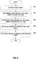
- a first maximum areacan be determined based on a combination of x-ray projections (step 402) and a second maximum area can also be determined (step 403), the second maximum area being completely inside of the first maximum area.
- a fan beam x-ray patterncan be generated by the x-ray source 131.
- the x-ray beamscan pass through and be partially attenuated by the glass bottle 901 of interest and then received by the x-ray detector array 132.
- FIG. 5shows x-ray 902 and x-ray 903 that are tangential to the outer and inner boundary curves of the glass bottle 901.
- X-rays 902 and 903can intersect with the x-ray detector array 132 at locations x 1 and x 2 , respectively.
- the projection data received by the x-ray detector array 132is shown in FIG. 6 . It can be observed from FIG. 6 , that the attenuation values to the left of location x 1 is close to 0, and once past x 1 , the attenuation value increases dramatically to a peak value around location x 2 , after which, the attenuation value starts to decrease. Therefore, locations x 1 and x 2 can be found based on the projection data, and the tangential x-rays can be identified by projecting the x-rays from locations x 1 and x 2 back to the x-ray source 131. As shown in FIG. 5 , four tangential x-rays can be identified from projection data of each projection angle.
- x-ray sources 1001-1003can be used in the scanner 120.
- x-ray sources 1001-1003can correspond to any three of the x-ray sources 131, 133, 135, and 137 depicted in FIG. 1 .
- tangential x-rays 1011 and 1012can be identified for source 1001
- tangential x-rays 1021 and 1022can be identified for source 1002
- tangential x-rays 1031 and 1032can be identified for source 1003, respectively.
- a convex polygonas the one shown in bold lines, can be formed using the tangential x-rays and intersections thereof. Another convex polygon can be formed in a similar manner for the inner boundary curve.
- one or more edges of the maximum areascan be determined (steps 404 and 405).
- the edgesmay be detected by applying image processing methods to the area as shown in FIG. 7 .
- An outer boundary curvecan be determined based on the edges of the first maximum area (step 406) and an inner boundary curve may be determined based on the edges of the second maximum area (step 407).
- the convex polygonsbecome the inner and outer boundary curves of the item.
- solutions closer to the real boundary curvescan be generated, e.g. by fitting a simplified model comprising two concentric ellipses, into the convex polygons.
- the two concentric ellipsescan be uniquely determined by a total of six parameters: the coordinates ( m x , m y ) of the common center point of the two ellipses, the radii ( r x , r y ) of the main axis of the outer ellipse, the thickness of the glass d as well as the angle of rotation ⁇ .
- the fitting processcan be implemented using optimization approaches, such as, for example, Simulated Annealing (SA).
- SASimulated Annealing
- the sum of the squares of the smallest distances between the tangential x-rays and the associated ellipsecan be minimized.
- a model of the itemcan be generated (step 408).
- the modelcan depend upon a set of parameters.
- the parametric modelincludes the inner and outer boundary curves determined in steps 406-407, and a set of material specific parameters including one or more material specific parameters.
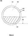
- FIG. 8is a schematic illustration associated with a parametric model 600 of a cross-section of a cylindrical item that exhibits two closed boundary curves.
- model 600can be described by a set of material specific parameters, including a first material specific parameter of the receptacle material 601.
- model 600can be further described by a second material specific parameter of the material content 602 in the receptacle.
- the itemmay be a bottle filled with liquid.
- the first material specific parametercan be an x-ray absorption coefficient of glass, plastic or any other receptacle material 601.
- the second material specific parametercan be an x-ray absorption coefficient of alcohol, water, or any other material content 602.
- the model 600can further include a third material specific parameter corresponding to material content 603, such as air.
- Model 600can also include a set of shape parameters describing the two closed boundary curves.
- model 600may include an outer curvature 604 of the container and an inner curvature 605 of the container.
- outer curvature 604 and inner curvature 605can be of a same shape or two different shapes, including circular, oval, square, rectangular, or any other suitable shapes.
- the boundary curves 604 and 605can be approximated by two ellipses, which have corresponding center points and angles of rotation. Accordingly, the radii of the two ellipses can differ in the direction of the major axis by the thickness of the container.
- each boundary curvecan also be approximated by a polygon whose shape can be determined by a set of points.
- the model 600can further include a third boundary curve that is either closed or open, such as the upper surface of the material content in the receptacle.
- the set of shape parameterscan further include a maximal distance 606 between at least two distal boundaries of the material contents.
- the maximal distance 606can be the distance between this flat surface and the lowest point of the inner curvature of the closed boundary curve 605.
- the maximal distancecan be the distance between this flat surface and the origin of the coordinate system. It is contemplated that the distal boundaries of the material content can be of any shape.
- the exemplary model illustrated in FIG. 8is two-dimensional, it is contemplated that the model can be three-dimensional.
- the set of parameterscan be assigned a set of initial values.
- the initial locations of the two closed boundary curves 604 and 605can be determined as described above in steps 402-407.
- the initial values of the material specific parameterscan be set to a reasonable known value to start with.
- the initial valuescan also be selected based on a solution provided by a conventional image reconstruction method. For example, FBP or regularized iterative method can be employed to reconstruct the image first, and the solution may be used as the initial values.
- a library of initial values of the first material specific parameter and the second material specific parametercan be accessible to the processor 241.
- a set of material specific parameters of objects outside the outer boundary curvecan also be determined concurrently in step 408.
- another object other than the item 11can be located in a region outside outer curvature of closed boundary curve 604 of the item 11 the x-ray absorption coefficients of this object can be determined as a voxel array based on the scan data.
- Any suitable reconstruction methods, such as the parametric reconstruction method,can be utilized for determining the voxel array.
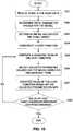
- FIG. 9is a flow chart of an exemplary process for initializing a voxel array, consistent with a disclosed embodiment.
- a voxel arraycan be defined as a three-dimensional array representing the entire scan volume of the container 10 (step 901).
- the voxel arraycan represent a single slice of the volume (that is, virtually a 2-D representation),
- the value of each voxelmay be associated with the x-ray absorption coefficient of a corresponding region in the scan volume.
- the voxel arraycan be segmented into two areas: a first area including voxels outside the item, and a second area including voxels that are occupied by the item (steps 902 and 903).
- the voxel arraycan be estimated from the scan data using any existing image reconstruction method, and then the reconstructed image can be segmented using any existing image segmentation method.
- Initial valuescan be set to the voxels in the first area (step 904). In some embodiments, the initial values can be set to be equal to those estimated from the scan data.
- the voxels in the second areacan be set to zero (step 905). In some embodiments, the voxels in the second area can remain zero throughout the entire process shown in FIG. 4 . For example, during each iteration, the values of voxels in the second area may be computed along with the values of voxels in the first area, and as a result, voxels in the second area may carry on values different than zero, but these values can be suppressed/forced to zero during the iteration.
- computed scan datacan be generated based on the model (step 409).
- the computed scan datacan include multiple projections of the model based on the projection perspectives of the scanner 120.
- the computed datacan be calculated, for example, using forward projection method.
- the computed scan datacan be compared with the scan data acquired in step 401 (step 410), and determine a goodness of fit based on the comparison (step 411).
- the goodness of fitcan be measured by a cost function that includes a data term assessing the difference between the computed scan data and acquired scan data.
- the differencecan be a Lp-Norm difference, where 1 ⁇ p ⁇ ⁇ , or a Pseudo-Norm difference with p ⁇ 1 between the computed scan data and acquired scan data.
- An exemplary cost functionwill be described in greater detail in connection with Fig. 10 .
- the determined goodness of fitcan be compared against an iteration stopping criteria (step 412).
- the iteration stopping criteriacan be set as a sufficiently small number. The smaller the number is, however, the longer time the process may take to achieve convergence. If the goodness of fit does not meet the iteration stopping criteria (step 412: no), process may go back to step 408, and the model can be adjusted. For example, the inner closed boundary curve and the outer closed boundary curve, and/or any of the set of material specific parameters can be altered to adjust the model of the item. Steps 408-412 can be iteratively repeated until the goodness of fit meets the iteration stopping criteria.
- the data processing system 140can determine if the material specific parameter or the set of material specific parameters corresponds to a material specific parameter of a material that satisfies a further criteria.
- further criteriacan include a determination that the material is among a set of materials considered dangerous and therefore not allowed to be carried on an airplane (step 413).
- an indication that the material content 602 corresponds to a prohibited materialcan be included in an inspection report to the user. Based on the report, the user can choose to open the container 10 for a visual inspection if the report suggests that prohibited objects are contained in the item. The process can conclude after step 413.
- FIG. 10is a flow chart of an exemplary process of parametric image reconstruction from projection data, consistent with the present invention.
- the scan data acquired by the scanner 120can have noise due to, e.g., scattering of x-ray beams, device inaccuracies associated with the detector arrays, and etc.
- noisy datacan impair the quality of a reconstructed image, especially when the scan data are under-sampled.
- the scan datacan be pre-processed to reduce noise (step 1001).
- various filtering techniquescan be used for noise reduction.
- filteringcan be conducted using an optimization approach.
- the M matrixcan have a horizontal and a vertical component, calculated using forward differences.
- the first term of Equation (1)dictates a difference between the filtered scan data and the acquired scan data. It is formulated as a L 2 -Norm under the assumption that scan data noise follows a Gaussian distribution. However, it is contemplated that the data term can also be formulated following a different noise distribution, such as a Poisson distribution.
- the second termalso known as the regularization term, dictates the total gradient of the acquired scan data.
- the regularization termpreserves the boundaries of the scan data because of the application of the L 1 -Norm.
- the regularization term used in Equation (1)is exemplary only, and it is contemplated that other types of L 1 -regularization terms can also be used, such as a Total Variation (TV).
- the parameter ⁇can determine the relative weight of the second term, i.e., the strength of the regularization.
- Equation (1)can be optimized using various iterative methods. For example, Equation (1) can be minimized with Iterative Coordinate Descent (ICD) method, which is effectively a Gauss-Seidel iteration. Using this method, in each iteration step, one data value is optimized while adjacent data values are held constant. It is contemplated that other suitable iterative methods, such as Conjugate Gradient (CG), can also be used.
- ICDIterative Coordinate Descent
- CGConjugate Gradient
- the noise reduction step 1001can be performed on the multiple channel scan data, such as the Hi and Low scan data individually.
- the filtered multi-energy projection datacan be broken down into a polyethylene (PE) portion of scan data and an aluminum (Al) portion of scan data to be employed during the projection bound identification process of [0036].
- PEpolyethylene
- Alaluminum
- a parametric modelsuch as model 600 shown schematically in FIG. 8
- Model 600can depend on a set of parameters such as the material specific parameters associated with the receptacle material 601 and material content 602; 601-603 and the shape parameters associated with the closed boundary curves 604, 605 and the maximal distance 606; 604-606.
- the data processing system 140may be configured to determine and set initial values for these parameters as a starting point of an iterative process (step 1002). In one embodiment, initial values may be selected based on prior knowledge about the item 11 in the container 10. For example, if the object is known to be a cylindrical bottle, the outer and inner curvatures of the closed boundary curves 604, 605 can be easily modeled as two circles.
- the estimated boundariescan be determined in two steps: (A) find the projection rays that are tangential to the inner and outer curvature of the container; and (B) use the projection rays found in (A) to construct two convex polygons as the estimated inner and outer boundaries.
- Initial valuescan also be set for a voxel array (step 1003).
- a voxel arraycan be defined and initialized as described above in connection with FIG. 9 .
- the voxels in the second areacan be forced to zeros throughout the entire process shown in FIG. 10 .
- the data processing system 140can be further configured to construct a cost function for the reconstruction problem (step 1004).
- p i,j and h iare the shape parameters:
- p i,jare the position vectors of the 2.
- the first term of the cost functionis a data term that assesses the deviation between the model-based projection data and the measured projection data
- the second term and the third termare regularization terms that allows prior knowledge about the nature of the solution into the reconstruction process.
- the second termis a voxel/pixel value related regularization term
- the third termis a model-related regularization term.
- the voxel-related regularization termcomprises three components, namely a term which penalizes voxel gradients, a term which supports the positivity of the values assigned to the voxels and finally a term which keeps the values of those voxels close to zero that are covered by any of the N m parametric models.
- each of the model related regularization termshosts a component that tries to avoid an excessive local curvature along each of the boundary curves.
- a second componentdrives the outer boundary curve to touch each of the edges of the outer convex hull, while a third component keeps the inner boundary curve a minimum distance away from but inside the outer boundary curve.
- the actual regime under which the cost function of Equation (2) is optimizedfollows that of a Gauss-Seidel iteration. In each iteration, a specific group of parameters is updated conditioned on the tentative estimate of the remaining parameters from the previous iteration. For example, during the n-th iteration the vector of voxels x could be updated first, e.g.
- CGConjugate Gradient
- L 1 -Normmay be used instead of L 2 -Norm in order to improve robustness of the method.
- a gradient term of the cost functioncan be computed (step 1005).
- the gradient of each term in the cost functioncan be separately computed and then summed up to obtain the overall gradient term of the cost function.
- two gradientscan be calculated in an alternating manner: the gradient of cost function with respect to voxel array x and the gradient of cost function with respect to the parameter vector m i .
- the gradient computation of cost function C () with respect to the voxel vector xis known in the art, for example, and can be carried out in the context of the CG method.
- the voxel/pixel values x and the parameters m ican be adjusted alternately.
- a value of the cost function of Equation (2)can be calculated (step 1007).
- other values associated with the cost functioncan be calculated instead, such as the values of the gradients.
- the calculated value in step 1007can be compared to an iteration stopping criteria (step 1008).
- the iteration stopping criteriacan be set to measure if the iterations have converged. Once the cost function value is below the iteration stopping criteria (step 1008: Yes), the iterations can stop and the process may terminate. Otherwise, if the cost function value is above or equal to the iteration stopping criteria (step 1008: No), the next iteration can occur.
- FIG. 11shows a set of reconstructed boundary curves of a cashew nut shaped wine bottle, consistent with an exemplary embodiment of the present disclosure.
- the convex polygonscan be used to set the initial positions of points p on the outer and inner boundary curve, respectively. During the iterations, the positions of these points can be gradually adjusted to approach the real curvatures of the inner and outer boundaries of the object. Throughout the iterations, the curvatures can be bounded by the convex polygons, and the distance between the two curvatures must exceed a minimum threshold. As shown in FIG. 11 , the resulted curvatures can exhibit a cashew nut shape.
- FIGS. 4 and 10 of the present inventioncan be implemented as a combination of hardware and software or in hardware alone.
- certain aspects of the present inventionare described as being stored in memory, one skilled in the art will appreciate that these aspects can also be stored on or read from other computer-readable media, such as secondary storage devices, like hard disks, floppy disks, or CD-Rom; or other forms of RAM or ROM.
- secondary storage deviceslike hard disks, floppy disks, or CD-Rom; or other forms of RAM or ROM.
- RAMrandom access memory
- the disclosed system and methodcan be applied to detect objects of interest using an automated or semi-automated process.
- disclosed embodimentsare described in association with container, crate or baggage inspection such as at an airport, train station, cargo inspection or other port- and border- applications, the disclosed inspection system and inspection method can be used in other applications, such as medical imaging in a hospital or imaging facility, and product quality control in a factory, etc..
Landscapes
- Engineering & Computer Science (AREA)
- Physics & Mathematics (AREA)
- General Physics & Mathematics (AREA)
- Health & Medical Sciences (AREA)
- Theoretical Computer Science (AREA)
- Life Sciences & Earth Sciences (AREA)
- Radiology & Medical Imaging (AREA)
- Mathematical Physics (AREA)
- Medical Informatics (AREA)
- General Health & Medical Sciences (AREA)
- Nuclear Medicine, Radiotherapy & Molecular Imaging (AREA)
- Pure & Applied Mathematics (AREA)
- Pathology (AREA)
- Algebra (AREA)
- Mathematical Analysis (AREA)
- Mathematical Optimization (AREA)
- Geometry (AREA)
- Software Systems (AREA)
- Computer Vision & Pattern Recognition (AREA)
- Veterinary Medicine (AREA)
- Biochemistry (AREA)
- Biophysics (AREA)
- High Energy & Nuclear Physics (AREA)
- Analytical Chemistry (AREA)
- Optics & Photonics (AREA)
- Biomedical Technology (AREA)
- Heart & Thoracic Surgery (AREA)
- Molecular Biology (AREA)
- Surgery (AREA)
- Animal Behavior & Ethology (AREA)
- Public Health (AREA)
- Immunology (AREA)
- Computer Graphics (AREA)
- Chemical & Material Sciences (AREA)
- Pulmonology (AREA)
- Computer Hardware Design (AREA)
- Evolutionary Computation (AREA)
- General Engineering & Computer Science (AREA)
- Analysing Materials By The Use Of Radiation (AREA)
- Architecture (AREA)
Description
- Systems, methods, and computer-readable products consistent with the present invention are directed generally to image reconstruction, and more particularly to image reconstruction based on parametric models.
- Baggage scanners can be used for baggage inspection, for example, at an airport or a train station, to detect the presence of liquid and other prohibited objects in baggage or luggage. For example, baggage scanners can be employed at airports and can include one or more sets of stationary x-ray scanning arrays. A set of x-ray scanning arrays can contain one or more radiation sources that are configured to emit x-ray radiation towards an item under inspection, and an array of detectors on the opposite side of the item to detect the x-ray radiation that is not completely absorbed by the item.
US 4888693 discloses a method of obtaining object boundary information in limited-angle computerized tomography. The method is used to construct the convex hull of an object in limited-angle x-ray computerized tomography, the convex hull being the smallest convex region containing an object which can therefore serve as a prior information on the object exterior boundary in reconstructing the object by an iterative limited-angle reconstruction procedure. The convex hull is the same as the exterior boundary of many convex objects and is a good approximation if the shape is not too concave. Greater accuracy can be achieved by doing curve fitting near the edges of the x-ray projection data to determine the end points and performing a low energy x-ray exposure at every scan angle in addition to the usual CT energy one.EP 1612734 discloses a boundary based technique for CT reconstruction for use in CT metrology. The boundary based CT reconstruction method includes the steps of initializing a boundary of an object to obtain a boundary estimate, defining a forward model based on the boundary estimate, linearizing the forward model to obtain a system matrix and implementing an iterative image reconstruction process using the system matrix to update the boundary estimate.- In accordance with one aspect of the present invention there is provided a method of modelling in accordance with claim 1.
- A further aspect of the present invention provides a system in accordance with claim 14.
- Another aspect of the present invention provides a computer readable medium in accordance with claim 15.
FIG. 1 is a schematic diagram of an inspection system consistent with an exemplary embodiment of the present invention;FIG. 2 shows a two-dimensional projection image of a bottle of wine;FIG. 3 is a schematic diagram of a data processing system, consistent with the exemplary disclosed embodiment shown inFIG. 1 ;FIG. 4 is a flow chart of an exemplary process of analyzing an item, consistent with a disclosed embodiment;FIG. 5 is an illustration of x-rays tangential to the inner and outer boundary curves of an exemplary object;FIG. 6 is a chart illustrating projection data, obtained consistent with the exemplary embodiment ofFIG. 8 ;FIG. 7 illustrates convex polygon formed by tangential x-rays, consistent with an exemplary embodiment using three point x-ray sources;FIG. 8 is a schematic diagram of an exemplary parametric model of a cross-section of a cylindrical container, consistent with a disclosed embodiment;FIG. 9 is a flow chart of an exemplary process for initializing a voxel array, consistent with a disclosed embodiment;FIG. 10 is a flow chart of an exemplary process of parametric image reconstruction from projection data, consistent with a disclosed embodiment andFIG. 11 shows a set of reconstructed boundary curves of a cashew nut shaped wine bottle, consistent with an exemplary disclosed embodiment.FIG. 1 is a schematic diagram of aninspection system 100 according to an exemplary embodiment of the present disclosure. Theinspection system 100 can be configured to inspect acontainer 10 and detect any material or object of interest contained in thecontainer 10. For example,container 10 can be a crate, bag, box, or item of luggage. Thecontainer 10 can be any item that is to be transported by an airplane, sea vessel, train, or other mode of conveyance or into or within infrastructure, which can contain a plurality of objects such as clothes, shoes, electronic devices, books, etc. Thecontainer 10 also can contain anitem 11 exhibiting a certain shape. For example, theitem 11 can be a bottle of wine or water, a can of beverage, a bottle of liquid explosives, a boxed juice, a bottle of shampoo or conditioner, and the like. For example,FIG. 1 shows anitem 11 in thecontainer 10.- The
item 11 can include two or more materials. For example, theitem 11 can be a bottle of wine that includes a glass bottle and wine therein. When the bottle is not completely filled with wine, there can also be air in the bottle. In one embodiment, theinspection system 100 can be employed at a security check point for checked baggage or carry-on baggage at an airport to detect these objects of interest or materials in thecontainer 10. While the above example relates to a bottle of wine, it is contemplated that theinspection system 100 can be employed to detect any object of interest or material in any item capable of being scanned and yielding material-specific information. - The
inspection system 100 can include aconveyor 110, ascanner 120, and adata processing system 140 coupled toscanner 120. Theconveyor 110 can include belts for supporting thecontainer 10 and one or more motors that drive the belts. The belts can rotate intermittently or continuously to convey or provide thecontainer 10 from a loading area through a central aperture of thescanner 120. Theconveyor 110 is illustrated as including a plurality of individual conveyor sections inFIG. 1 ; however, it is contemplated that other forms of conveyors can be used. - The
scanner 120 can be any suitable scanner. For example, thescanner 120 can include multiple sets of x-ray source and detector arrays. As illustrated inFIG. 1 , thescanner 120 can include, among other things, four sets of source and detector arrays, includingx-ray sources x-ray detector arrays scanner 120 can include more or less sets of source and detector arrays as depicted inFIG. 1 . In some embodiments, any one of-or all of-thex-ray sources x-ray detector arrays FIG. 1 . In some embodiments, thex-ray detector arrays x-ray sources x-ray detector arrays container 10 is conveyed. AlthoughFIG. 1 shows the aperture in a substantially square shape, it is contemplated that the aperture can be of any other suitable shape, such as, for example, a substantially circular or oval shape or a substantially rectangular shape, or any combination thereof. - The
x-ray sources x-ray detector arrays conveyor 110. Accordingly, when thecontainer 10 is displaced through the aperture by operation of theconveyor 110, it can sequentially pass through a plurality of scanningplanes scanning plane 151 and 152) can be approximately 20 cm. - As described above, each combination of x-ray source and detector array, such as a combination including one of the
x-ray sources detector arrays scanning plane FIG. 1 ). Each of thex-ray sources container 10 can pass. The x-ray beams within the respective scanning planes can pass through and be partially attenuated by thecontainer 10 and then received by the corresponding x-ray detector array associated with that scanning plane. In some embodiments, thex-ray sources x-ray detector arrays - As used herein, the radiation data acquired by an x-ray detector array is referred to as "projection data," and the perspective defined by the uniform cross-section intersecting with the scanned item is referred to as a "projection perspective." During a scan, the x-ray detector arrays can collect multiple sets of projection data representative of the integral of absorption coefficients of the volumetric segment of
container 10 through which the x-ray beams pass. The measurement of projection data can be used to form a raster line of a two-dimensional projection image. For example,FIG. 2 shows a two-dimensional projection image of a bottle of wine in a tray. - A plurality of projection views of the
container 10 at different projection perspectives can be generated and a corresponding plurality of sets of two-dimensional projection data can be acquired by thex-ray detector arrays FIG. 2 shows only one "view" of the item, other views can be obtained by other detector arrays simultaneously and/or sequentially. - In an embodiment, the
scanner 120 can be a multi-energy scanner. For example, in a source-detector-array set, x-ray beams can be generated at different energy levels, by multiple x-ray sources or by a single source that operates in a switched manner. In some embodiments, multi-energy scanning can be performed using a broad spectrum x-ray source and x-ray detector arrays that detect x-ray radiation in separate energy ranges. For example, in a dual energy scanner, Hi and Low scan data can be collected by each detector array. - The
x-ray detector arrays data processing system 140 via one or more data transmission lines. Multi-angle projection data acquired by thescanner 120 can be transferred to adata processing system 140 via the data transmission lines. The projection data can also be transferred wirelessly to thedata processing system 140. - The
data processing system 140 can include one or more computer assemblies configured to analyze scan data acquired from thescanner 120 and associated with a scan of an item exhibiting a certain shape or a material contained therein, such as a liquid material, in thecontainer 10. Thedata processing system 140 can be associated with one or more software applications, including, for example, an image reconstruction tool. These software applications can be stored on thedata processing system 140, and can be accessed by an authorized user, such as an operator at a customs, ports and borders control, or airport. The software applications also can be stored on a computer readable medium, such as a hard drive, computer disk, CD- ROM, or any other suitable medium. FIG. 3 is a schematic diagram of thedata processing system 140. Thedata processing system 140 can include aprocessor 241, amemory module 242, a scanner control interface 243, astorage device 244, an input/output interface 245, and adisplay device 246. Thedata processing system 140 can include additional, fewer, and/or different components than those listed above. The type and number of listed devices are exemplary only and not intended to be limiting.- The
processor 241 can be a central processing unit ("CPU") or a graphic processing unit ("GPU"). Theprocessor 241 can execute sequences of computer program instructions to perform various processes that will be explained in greater detail below. Thememory module 242 can include, among other things, a random access memory ("RAM") and a read-only memory ("ROM"). The computer program instructions can be accessed and read from the ROM, or any other suitable memory location, and loaded into the RAM for execution by theprocessor 241. Theprocessor 241 can include one or more printed circuit boards, and/or a microprocessor chip. - The scanner control interface 243 can be configured for two way communication between the
scanner 120 and thedata processing system 140. Consistent with one embodiment, the scanner control interface 243 can be configured to receive scan data from thescanner 120 and store the data into thestorage device 244. The scanner control interface 243 can be further configured to send scan control instructions to thescanner 120 to initiate and stop scan operations, or to configure the scanners. For example, the scan control instructions can include configuration parameters,. - The
storage device 244 can include any type of mass storage suitable for storing information. For example, thestorage device 244 can include one or more hard disk devices, optical disk devices, or any other storage devices that provide data storage space. For example, thestorage device 244 can store data related to a data processing process, such as the processing of scan data received from thescanner 120, and any intermediate data created during the data processing process. Thestorage device 244 can also store one or more models and their associated parameters that can be used for assisting the data processing. For example, thestorage device 244 can store a model of a generic object having a same or similar shape to an object of interest, e.g., theitem 11 in thecontainer 10. The model of the generic object may be used for reconstructing the image of theitem 11. Thestorage device 244 can also include analysis and organization tools for analyzing and organizing data and/or information contained therein. - The
data processing system 140 can be accessed and controlled by a user, such as a security officer, using the input/output interface 245. The input/output interface 245 can be available for the user to input information intodata processing system 140, and can include, for example, a keyboard, a mouse, a touch screen and/or optical or wireless computer input devices. The user can input control instructions via the input/output interface 245 to control the operation of theconveyor 110, and/or thescanner 120. For example, the user can push certain buttons on a keyboard to stop theconveyor 110, instruct it to go in reverse (e.g., backwards), or resume going forward. The user can also input parameters to adjust the operation of thedata processing system 140. - The
data processing system 140 can also provide visualized information to the user via thedisplay device 246. For example, thedisplay device 246 can include a computer screen (not shown) and make available a graphical user interface ("GUI") to the user. Thedisplay device 246 can display an image of theitem 11 and/or thecontainer 10 in its entirety, such as a three-dimensional image, multiple projection images and/or a two-dimensional cross-section image. Consistent with another embodiment, thedisplay device 246 can also display an inspection report to the user indicating certain characteristics of items contained in thecontainer 10, such as a presence of bottled liquid, the type of liquid, and the volume of the liquid, in thecontainer 10. - One or more components of the
inspection system 100 can be used to implement a process for analyzing thecontainer 10 containing at least one object.FIG. 4 is a flow chart of an exemplary process of modeling a target item utilizing theinspection system 100. Scan data associated with an item, such asexemplary item 11, may be acquired (step 401). By way of example only, and without limitation,item 11 can be made available, inside thecontainer 10, to thescanner 120 by theconveyor 110. An x-ray scan can be conducted on theitem 11 by thescanner 120. During the scan, multiple sets of two-dimensional projection data can be acquired by multiple sets of x-ray source and detector arrays. The acquired projection data can be transferred to thedata processing system 140. - The projection data can be used to reconstruct image slices perpendicular to the plane of the projection data and to determine one or more closed boundary curves associated with the item (steps 402-412). Any suitable image reconstruction methods, including, but not limited to, filtered back projection, Fourier reconstruction, and iterative reconstruction, can be used to transform the projection data and determine the one or more closed boundary curves. In one embodiment consistent with the present disclosure, the
data processing system 140 can use a parametric image reconstruction method. - According to the invention, a first maximum area can be determined based on a combination of x-ray projections (step 402) and a second maximum area can also be determined (step 403), the second maximum area being completely inside of the first maximum area. As shown in
FIG. 5 , when a cross-section of aglass bottle 901 is scanned by thescanner 120, a fan beam x-ray pattern can be generated by thex-ray source 131. The x-ray beams can pass through and be partially attenuated by theglass bottle 901 of interest and then received by thex-ray detector array 132.FIG. 5 showsx-ray 902 andx-ray 903 that are tangential to the outer and inner boundary curves of theglass bottle 901.X-rays x-ray detector array 132 at locations x1 and x2, respectively. The projection data received by thex-ray detector array 132 is shown inFIG. 6 . It can be observed fromFIG. 6 , that the attenuation values to the left of location x1 is close to 0, and once past x1, the attenuation value increases dramatically to a peak value around location x2, after which, the attenuation value starts to decrease. Therefore, locations x1 and x2 can be found based on the projection data, and the tangential x-rays can be identified by projecting the x-rays from locations x1 and x2 back to thex-ray source 131. As shown inFIG. 5 , four tangential x-rays can be identified from projection data of each projection angle. - When sufficient tangential x-rays are determined as described above, they can be used to form two maximum areas: a first maximum area associated with the outer boundary and a second maximum area associated with the inner boundary. For example, one or more of maximum areas can be in the shape of a convex polygon, such as shown in
FIG. 7 . As illustrated inFIG. 7 , three point x-ray sources 1001-1003 can be used in thescanner 120. In one embodiment, x-ray sources 1001-1003 can correspond to any three of thex-ray sources FIG. 1 . As described above,tangential x-rays source 1001,tangential x-rays source 1002, andtangential x-rays source 1003, respectively. A convex polygon, as the one shown in bold lines, can be formed using the tangential x-rays and intersections thereof. Another convex polygon can be formed in a similar manner for the inner boundary curve. - Once the maximum areas are determined, one or more edges of the maximum areas can be determined (
steps 404 and 405). For example, the edges may be detected by applying image processing methods to the area as shown inFIG. 7 . An outer boundary curve can be determined based on the edges of the first maximum area (step 406) and an inner boundary curve may be determined based on the edges of the second maximum area (step 407). In one embodiment, the convex polygons become the inner and outer boundary curves of the item. - In another embodiment, solutions closer to the real boundary curves can be generated, e.g. by fitting a simplified model comprising two concentric ellipses, into the convex polygons. The two concentric ellipses can be uniquely determined by a total of six parameters: the coordinates (mx, my) of the common center point of the two ellipses, the radii (rx, ry) of the main axis of the outer ellipse, the thickness of the glassd as well as the angle of rotationφ. The fitting process can be implemented using optimization approaches, such as, for example, Simulated Annealing (SA). During the optimization, the sum of the squares of the smallest distances between the tangential x-rays and the associated ellipse can be minimized. Once determined, the two concentric ellipses, instead of the convex polygons, become the inner and outer boundary curves of the item.
- A model of the item can be generated (step 408). The model can depend upon a set of parameters. According to the invention, the parametric model includes the inner and outer boundary curves determined in steps 406-407, and a set of material specific parameters including one or more material specific parameters. For example,
FIG. 8 is a schematic illustration associated with aparametric model 600 of a cross-section of a cylindrical item that exhibits two closed boundary curves. In some embodiments,model 600 can be described by a set of material specific parameters, including a first material specific parameter of thereceptacle material 601. In some embodiments,model 600 can be further described by a second material specific parameter of thematerial content 602 in the receptacle. For example, the item may be a bottle filled with liquid. In this example, the first material specific parameter can be an x-ray absorption coefficient of glass, plastic or anyother receptacle material 601. The second material specific parameter can be an x-ray absorption coefficient of alcohol, water, or anyother material content 602. In one embodiment, themodel 600 can further include a third material specific parameter corresponding tomaterial content 603, such as air. Model 600 can also include a set of shape parameters describing the two closed boundary curves. For example,model 600 may include anouter curvature 604 of the container and aninner curvature 605 of the container. In some embodiments,outer curvature 604 andinner curvature 605 can be of a same shape or two different shapes, including circular, oval, square, rectangular, or any other suitable shapes. For example, the boundary curves 604 and 605 can be approximated by two ellipses, which have corresponding center points and angles of rotation. Accordingly, the radii of the two ellipses can differ in the direction of the major axis by the thickness of the container. Furthermore, for example, each boundary curve can also be approximated by a polygon whose shape can be determined by a set of points. Examples of this explicit representation can be found in published work e.g.Soussen et al., "Polygonal and Polyhedral Contour Reconstruction in Computed Tomography", IEEE Transactions on Image Processing, vol. 13, no. 11, pp. 1507-1523, Nov. 2004. In some embodiments, an implicit, level-set based representation of the boundary curve, similarly to that ofFeng et al., "A Curve Evolution Approach to Object-Based Tomographic Reconstruction", IEEE Transactions on Image Processing, vol. 12, no. 1, pp. 44-57, Jan. 2003, could alternatively be used.- In one embodiment, the
model 600 can further include a third boundary curve that is either closed or open, such as the upper surface of the material content in the receptacle. Accordingly, the set of shape parameters can further include amaximal distance 606 between at least two distal boundaries of the material contents. As illustrated inFIG. 8 , themaximal distance 606 can be the distance between this flat surface and the lowest point of the inner curvature of theclosed boundary curve 605. In another embodiment the maximal distance can be the distance between this flat surface and the origin of the coordinate system. It is contemplated that the distal boundaries of the material content can be of any shape. Although the exemplary model illustrated inFIG. 8 is two-dimensional, it is contemplated that the model can be three-dimensional. - The set of parameters can be assigned a set of initial values. For example, the initial locations of the two closed boundary curves 604 and 605 can be determined as described above in steps 402-407. In one embodiment, the initial values of the material specific parameters can be set to a reasonable known value to start with. Alternatively, the initial values can also be selected based on a solution provided by a conventional image reconstruction method. For example, FBP or regularized iterative method can be employed to reconstruct the image first, and the solution may be used as the initial values. A library of initial values of the first material specific parameter and the second material specific parameter can be accessible to the
processor 241. - In some embodiments, a set of material specific parameters of objects outside the outer boundary curve can also be determined concurrently in
step 408. For example, another object other than theitem 11 can be located in a region outside outer curvature ofclosed boundary curve 604 of theitem 11 the x-ray absorption coefficients of this object can be determined as a voxel array based on the scan data. Any suitable reconstruction methods, such as the parametric reconstruction method, can be utilized for determining the voxel array. FIG. 9 is a flow chart of an exemplary process for initializing a voxel array, consistent with a disclosed embodiment. A voxel array can be defined as a three-dimensional array representing the entire scan volume of the container 10 (step 901). Alternatively, in one embodiment, the voxel array can represent a single slice of the volume (that is, virtually a 2-D representation), For example, the value of each voxel may be associated with the x-ray absorption coefficient of a corresponding region in the scan volume. The voxel array can be segmented into two areas: a first area including voxels outside the item, and a second area including voxels that are occupied by the item (steps 902 and 903). For example, the voxel array can be estimated from the scan data using any existing image reconstruction method, and then the reconstructed image can be segmented using any existing image segmentation method.- Initial values can be set to the voxels in the first area (step 904). In some embodiments, the initial values can be set to be equal to those estimated from the scan data. The voxels in the second area can be set to zero (step 905). In some embodiments, the voxels in the second area can remain zero throughout the entire process shown in
FIG. 4 . For example, during each iteration, the values of voxels in the second area may be computed along with the values of voxels in the first area, and as a result, voxels in the second area may carry on values different than zero, but these values can be suppressed/forced to zero during the iteration. - Once a model is generated and the initial values for the model parameters are set, computed scan data can be generated based on the model (step 409). In some embodiment, the computed scan data can include multiple projections of the model based on the projection perspectives of the
scanner 120. The computed data can be calculated, for example, using forward projection method.
The computed scan data can be compared with the scan data acquired in step 401 (step 410), and determine a goodness of fit based on the comparison (step 411). In some embodiments, the goodness of fit can be measured by a cost function that includes a data term assessing the difference between the computed scan data and acquired scan data. For example, the difference can be a Lp-Norm difference, where 1 ≤p ≤ ∞, or a Pseudo-Norm difference with p < 1 between the computed scan data and acquired scan data. An exemplary cost function will be described in greater detail in connection withFig. 10 . - The determined goodness of fit can be compared against an iteration stopping criteria (step 412). In some embodiments, the iteration stopping criteria can be set as a sufficiently small number. The smaller the number is, however, the longer time the process may take to achieve convergence. If the goodness of fit does not meet the iteration stopping criteria (step 412: no), process may go back to step 408, and the model can be adjusted. For example, the inner closed boundary curve and the outer closed boundary curve, and/or any of the set of material specific parameters can be altered to adjust the model of the item. Steps 408-412 can be iteratively repeated until the goodness of fit meets the iteration stopping criteria.
- Once the criteria is met (step 412: yes), the
data processing system 140 can determine if the material specific parameter or the set of material specific parameters corresponds to a material specific parameter of a material that satisfies a further criteria. For example, and without limitation, further criteria can include a determination that the material is among a set of materials considered dangerous and therefore not allowed to be carried on an airplane (step 413). - In some embodiment, an indication that the
material content 602 corresponds to a prohibited material can be included in an inspection report to the user. Based on the report, the user can choose to open thecontainer 10 for a visual inspection if the report suggests that prohibited objects are contained in the item. The process can conclude afterstep 413. FIG. 10 is a flow chart of an exemplary process of parametric image reconstruction from projection data, consistent with the present invention. The scan data acquired by thescanner 120 can have noise due to, e.g., scattering of x-ray beams, device inaccuracies associated with the detector arrays, and etc. Noisy data can impair the quality of a reconstructed image, especially when the scan data are under-sampled. In one embodiment, the scan data can be pre-processed to reduce noise (step 1001). For example, various filtering techniques can be used for noise reduction. In particular, filtering can be conducted using an optimization approach. For example, the filtering can be based on optimizing an L2-L1 cost function:
- The first term of Equation (1), also known as the data term, dictates a difference between the filtered scan data and the acquired scan data. It is formulated as a L2-Norm under the assumption that scan data noise follows a Gaussian distribution. However, it is contemplated that the data term can also be formulated following a different noise distribution, such as a Poisson distribution. The second term, also known as the regularization term, dictates the total gradient of the acquired scan data. The regularization term preserves the boundaries of the scan data because of the application of the L1-Norm. The regularization term used in Equation (1) is exemplary only, and it is contemplated that other types of L1-regularization terms can also be used, such as a Total Variation (TV). The parameter λ can determine the relative weight of the second term, i.e., the strength of the regularization.
- The cost function of Equation (1) can be optimized using various iterative methods. For example, Equation (1) can be minimized with Iterative Coordinate Descent (ICD) method, which is effectively a Gauss-Seidel iteration. Using this method, in each iteration step, one data value is optimized while adjacent data values are held constant. It is contemplated that other suitable iterative methods, such as Conjugate Gradient (CG), can also be used. When multi-energy projection data are acquired from the
scanner 120, thenoise reduction step 1001 can be performed on the multiple channel scan data, such as the Hi and Low scan data individually. In one embodiment, the filtered multi-energy projection data can be broken down into a polyethylene (PE) portion of scan data and an aluminum (Al) portion of scan data to be employed during the projection bound identification process of [0036]. - As described in connection with
step 408, a parametric model, such asmodel 600 shown schematically inFIG. 8 , can be constructed before iteratively reconstructing the image.Model 600 can depend on a set of parameters such as the material specific parameters associated with thereceptacle material 601 andmaterial content 602; 601-603 and the shape parameters associated with the closed boundary curves 604, 605 and themaximal distance 606; 604-606. Thedata processing system 140 may be configured to determine and set initial values for these parameters as a starting point of an iterative process (step 1002). In one embodiment, initial values may be selected based on prior knowledge about theitem 11 in thecontainer 10. For example, if the object is known to be a cylindrical bottle, the outer and inner curvatures of the closed boundary curves 604, 605 can be easily modeled as two circles. - In one embodiment, the estimated boundaries can be determined in two steps: (A) find the projection rays that are tangential to the inner and outer curvature of the container; and (B) use the projection rays found in (A) to construct two convex polygons as the estimated inner and outer boundaries.
- Initial values can also be set for a voxel array (step 1003). For example, a voxel array can be defined and initialized as described above in connection with
FIG. 9 . In some embodiments, the voxels in the second area can be forced to zeros throughout the entire process shown inFIG. 10 . - After the initial values for both the parametric model and the voxel array are set, the
data processing system 140 can be further configured to construct a cost function for the reconstruction problem (step 1004). An exemplary cost function is given by Equation (2):

p i,j andhi are the shape parameters:p i,j are the position vectors of the 2.Ne points on the inner and the outer boundary curves 604 and 605, andhi is the maximal distance parameter indicative of the filling level of the material content, and the material specific parametersµg,i andµl,I, such as absorption values of the glass bottle and liquid filled therein. The first term of the cost function is a data term that assesses the deviation between the model-based projection data and the measured projection data, the second term and the third term are regularization terms that allows prior knowledge about the nature of the solution into the reconstruction process. The second term is a voxel/pixel value related regularization term, and the third term is a model-related regularization term. The voxel-related regularization term comprises three components, namely a term which penalizes voxel gradients, a term which supports the positivity of the values assigned to the voxels and finally a term which keeps the values of those voxels close to zero that are covered by any of theNm parametric models. Furthermore, each of the model related regularization terms hosts a component that tries to avoid an excessive local curvature along each of the boundary curves. A second component drives the outer boundary curve to touch each of the edges of the outer convex hull, while a third component keeps the inner boundary curve a minimum distance away from but inside the outer boundary curve. The components can be computed as a weighted sum:
- In one embodiment, L1-Norm may be used instead of L2-Norm in order to improve robustness of the method.
- During each iteration, a gradient term of the cost function can be computed (step 1005). In one embodiment, the gradient of each term in the cost function can be separately computed and then summed up to obtain the overall gradient term of the cost function. In each iteration, two gradients can be calculated in an alternating manner: the gradient of cost function with respect to voxel array x and the gradient of cost function with respect to the parameter vectormi. The gradient computation of cost functionC() with respect to the voxel vectorx is known in the art, for example, and can be carried out in the context of the CG method.
- Going back to
FIG. 10 , based on the gradient of the cost function, the set of parametersmi, i = 0,...,Nm -1 can be adjusted (step 1006). In one embodiment, the voxel/pixel valuesx and the parametersmi can be adjusted alternately. - After bothx andmi are adjusted, a value of the cost function of Equation (2) can be calculated (step 1007). In one embodiment, other values associated with the cost function can be calculated instead, such as the values of the gradients. The calculated value in
step 1007 can be compared to an iteration stopping criteria (step 1008). The iteration stopping criteria can be set to measure if the iterations have converged. Once the cost function value is below the iteration stopping criteria (step 1008: Yes), the iterations can stop and the process may terminate. Otherwise, if the cost function value is above or equal to the iteration stopping criteria (step 1008: No), the next iteration can occur. FIG. 11 shows a set of reconstructed boundary curves of a cashew nut shaped wine bottle, consistent with an exemplary embodiment of the present disclosure. The convex polygons can be used to set the initial positions of pointsp on the outer and inner boundary curve, respectively. During the iterations, the positions of these points can be gradually adjusted to approach the real curvatures of the inner and outer boundaries of the object. Throughout the iterations, the curvatures can be bounded by the convex polygons, and the distance between the two curvatures must exceed a minimum threshold. As shown inFIG. 11 , the resulted curvatures can exhibit a cashew nut shape.- It is contemplated that the steps associated with
FIGS. 4 and10 of the present invention can be implemented as a combination of hardware and software or in hardware alone. Furthermore, although certain aspects of the present invention are described as being stored in memory, one skilled in the art will appreciate that these aspects can also be stored on or read from other computer-readable media, such as secondary storage devices, like hard disks, floppy disks, or CD-Rom; or other forms of RAM or ROM. Moreover, although certain aspects of the present invention are described with regard to database instances associated with long-term storage, one skilled in the art will appreciate that the database instances can also be associated with memory records loaded into temporary storage, such as RAM. - The disclosed system and method can be applied to detect objects of interest using an automated or semi-automated process. Although disclosed embodiments are described in association with container, crate or baggage inspection such as at an airport, train station, cargo inspection or other port- and border- applications, the disclosed inspection system and inspection method can be used in other applications, such as medical imaging in a hospital or imaging facility, and product quality control in a factory, etc..
- It will be apparent to those skilled in the art that various modifications and variations can be made in the disclosed system and method without departing from the scope of the disclosure. Additionally, other embodiments of the disclosed system and method will be apparent to those skilled in the art from consideration of the specification. It is intended that the specification and examples be considered as exemplary only, with a true scope of the disclosure being indicated by the following claims and their equivalents.


Claims (15)
- A method of modeling comprising:acquiring (401) scan data, wherein the scan data comprises data associated with a plurality of x-ray projections of an item;determining (402) a first maximum area based on the data associated with the plurality of x-ray projections;determining (404) at least one edge of the first maximum area;determining (406) an outer closed boundary curve associated with the item based on the at least one edge of the first maximum area;determining (403) a second maximum area based on the data associated with the plurality of x-ray projections, wherein the second maximum area is less than the first maximum area;determining (405) at least one edge of the second maximum area;determining (407) an inner closed boundary curve associated with the item based on the at least one edge of the second maximum area;generating (408) a model of the item using the outer closed boundary curve, the inner closed boundary curve and a set of material specific parameters comprising a first material specific parameter associated with a material between the outer closed boundary curve and the inner closed boundary curve and a second material specific parameter associated with a material within the inner closed boundary curve;utilizing (409) the model to generate computed scan data;comparing (410) the computed scan data to the scan data and determining (411) a goodness of fit; andadjusting the model of the item by altering the outer closed boundary curve, the inner closed boundary curve and the first and second material specific parameters by:determining a cost function and a cost function gradient associated with the outer closed boundary curve, the inner closed boundary curve and the first and second material specific parameters; andaltering the outer closed boundary curve, the inner closed boundary curve and the first and second material specific parameters based on the cost function gradient.
- The method of claim 1, wherein the material within the outer closed boundary curve comprises a homogenous material.
- The method of claim 1, further comprising: determining if the goodness of fit satisfies a predetermined criteria.
- The method of claim 1, wherein the goodness of fit is measured by a difference between the scan data and the computed scan data.
- The method of claim 1, wherein the first maximum area or the second maximum area is a polygon.
- The method of claim 1, wherein the first material specific parameter, or each of the first material specific parameter and the second material specific parameter is an absorption coefficient µ.
- The method of claim 1, further comprising:defining (901) a voxel array of a scan volume associated with the item;determining (902) a first area of the voxel array associated with a plurality of voxels outside the item;determining (903) a second area of the voxel array associated with a plurality of voxels co-positioned with the item;setting (905) the voxels of said second area to zero;wherein generating (408) a model of the item comprises generating a model of the scan volume using the outer closed boundary curve, the inner closed boundary curve, the first material specific parameter for the first material between the outer closed boundary curve and the inner closed boundary curve, the second material specific parameter for the second material within the inner closed boundary curve and a third set of material specific parameters for the voxels of the first area, and adjusting the model of the scan volume comprises altering least one of the set of: the outer closed boundary curve, the inner closed boundary curve, the first material specific parameter, the second material specific parameters and the third set of material specific parameters.
- The method of claim 1 or 7, wherein the outer closed boundary curve is associated with an outer curvature of a container and wherein the inner closed boundary curve is associated with an inner curvature of the container.
- The method of claim 7, wherein each of the first material specific parameter and the second material specific parameter is an absorption coefficient µ and the third set of material specific parameters is a set of absorption coefficients.
- The method of claim 1 or 7, further comprising: determining a third boundary curve associated with the liquid level in the item, wherein the third boundary curve is at least one of:
a closed boundary curve and an open boundary curve. - The method of claim 10, further comprising determining a liquid volume utilizing the inner closed boundary curve and the third boundary curve.
- The method of claim 11, further comprising comparing the liquid volume with a threshold, wherein the threshold is predetermined based on security regulations.
- The method of claim 10, further comprising comparing the second material specific parameter with a threshold, wherein the threshold is predetermined based on security regulations.
- A system comprising:a scanner configured to acquire scan data, wherein the scan data comprises data associated with a plurality of x-ray projections of an item; anda processor configured to determine an outer closed boundary curve and an inner closed boundary curve associated with the item as defined in any of claims 1-13.
- A computer-readable medium comprising instructions stored thereon, wherein the instructions cause a system in accordance with claim 14 to perform a method of modeling as claimed in any of claims 1-13.
Priority Applications (1)
| Application Number | Priority Date | Filing Date | Title |
|---|---|---|---|
| PL12742937TPL2677936T3 (en) | 2011-02-25 | 2012-02-23 | Image reconstruction based on parametric models |
Applications Claiming Priority (2)
| Application Number | Priority Date | Filing Date | Title |
|---|---|---|---|
| US201161446558P | 2011-02-25 | 2011-02-25 | |
| PCT/IB2012/000416WO2012114199A2 (en) | 2011-02-25 | 2012-02-23 | Image reconstruction based on parametric models |
Publications (2)
| Publication Number | Publication Date |
|---|---|
| EP2677936A2 EP2677936A2 (en) | 2014-01-01 |
| EP2677936B1true EP2677936B1 (en) | 2021-09-29 |
Family
ID=46603997
Family Applications (1)
| Application Number | Title | Priority Date | Filing Date |
|---|---|---|---|
| EP12742937.1AActiveEP2677936B1 (en) | 2011-02-25 | 2012-02-23 | Image reconstruction based on parametric models |
Country Status (4)
| Country | Link |
|---|---|
| US (1) | US10216866B2 (en) |
| EP (1) | EP2677936B1 (en) |
| PL (1) | PL2677936T3 (en) |
| WO (1) | WO2012114199A2 (en) |
Families Citing this family (39)
| Publication number | Priority date | Publication date | Assignee | Title |
|---|---|---|---|---|
| US9501152B2 (en) | 2013-01-15 | 2016-11-22 | Leap Motion, Inc. | Free-space user interface and control using virtual constructs |
| US11493998B2 (en) | 2012-01-17 | 2022-11-08 | Ultrahaptics IP Two Limited | Systems and methods for machine control |
| US8638989B2 (en) | 2012-01-17 | 2014-01-28 | Leap Motion, Inc. | Systems and methods for capturing motion in three-dimensional space |
| US12260023B2 (en) | 2012-01-17 | 2025-03-25 | Ultrahaptics IP Two Limited | Systems and methods for machine control |
| US9679215B2 (en) | 2012-01-17 | 2017-06-13 | Leap Motion, Inc. | Systems and methods for machine control |
| US10691219B2 (en) | 2012-01-17 | 2020-06-23 | Ultrahaptics IP Two Limited | Systems and methods for machine control |
| US20150253428A1 (en) | 2013-03-15 | 2015-09-10 | Leap Motion, Inc. | Determining positional information for an object in space |
| US9070019B2 (en) | 2012-01-17 | 2015-06-30 | Leap Motion, Inc. | Systems and methods for capturing motion in three-dimensional space |
| US8693731B2 (en) | 2012-01-17 | 2014-04-08 | Leap Motion, Inc. | Enhanced contrast for object detection and characterization by optical imaging |
| US9285893B2 (en) | 2012-11-08 | 2016-03-15 | Leap Motion, Inc. | Object detection and tracking with variable-field illumination devices |
| US10609285B2 (en) | 2013-01-07 | 2020-03-31 | Ultrahaptics IP Two Limited | Power consumption in motion-capture systems |
| US9465461B2 (en) | 2013-01-08 | 2016-10-11 | Leap Motion, Inc. | Object detection and tracking with audio and optical signals |
| US9459697B2 (en) | 2013-01-15 | 2016-10-04 | Leap Motion, Inc. | Dynamic, free-space user interactions for machine control |
| US9632658B2 (en) | 2013-01-15 | 2017-04-25 | Leap Motion, Inc. | Dynamic user interactions for display control and scaling responsiveness of display objects |
| US10620709B2 (en) | 2013-04-05 | 2020-04-14 | Ultrahaptics IP Two Limited | Customized gesture interpretation |
| US9916009B2 (en) | 2013-04-26 | 2018-03-13 | Leap Motion, Inc. | Non-tactile interface systems and methods |
| US9747696B2 (en) | 2013-05-17 | 2017-08-29 | Leap Motion, Inc. | Systems and methods for providing normalized parameters of motions of objects in three-dimensional space |
| US10281987B1 (en) | 2013-08-09 | 2019-05-07 | Leap Motion, Inc. | Systems and methods of free-space gestural interaction |
| US10846942B1 (en) | 2013-08-29 | 2020-11-24 | Ultrahaptics IP Two Limited | Predictive information for free space gesture control and communication |
| US9632572B2 (en) | 2013-10-03 | 2017-04-25 | Leap Motion, Inc. | Enhanced field of view to augment three-dimensional (3D) sensory space for free-space gesture interpretation |
| GB201318998D0 (en) | 2013-10-28 | 2013-12-11 | Kromek Ltd | Method and apparatus for the scanning of contained materials |
| US10168873B1 (en) | 2013-10-29 | 2019-01-01 | Leap Motion, Inc. | Virtual interactions for machine control |
| US9996797B1 (en) | 2013-10-31 | 2018-06-12 | Leap Motion, Inc. | Interactions with virtual objects for machine control |
| US9996638B1 (en) | 2013-10-31 | 2018-06-12 | Leap Motion, Inc. | Predictive information for free space gesture control and communication |
| US9613262B2 (en) | 2014-01-15 | 2017-04-04 | Leap Motion, Inc. | Object detection and tracking for providing a virtual device experience |
| US9785247B1 (en) | 2014-05-14 | 2017-10-10 | Leap Motion, Inc. | Systems and methods of tracking moving hands and recognizing gestural interactions |
| US9741169B1 (en) | 2014-05-20 | 2017-08-22 | Leap Motion, Inc. | Wearable augmented reality devices with object detection and tracking |
| CN204480228U (en) | 2014-08-08 | 2015-07-15 | 厉动公司 | motion sensing and imaging device |
| US10656720B1 (en) | 2015-01-16 | 2020-05-19 | Ultrahaptics IP Two Limited | Mode switching for integrated gestural interaction and multi-user collaboration in immersive virtual reality environments |
| US10429923B1 (en) | 2015-02-13 | 2019-10-01 | Ultrahaptics IP Two Limited | Interaction engine for creating a realistic experience in virtual reality/augmented reality environments |
| US9696795B2 (en) | 2015-02-13 | 2017-07-04 | Leap Motion, Inc. | Systems and methods of creating a realistic grab experience in virtual reality/augmented reality environments |
| US10795047B2 (en) | 2018-01-09 | 2020-10-06 | Voti Inc. | Methods for removing a background object from an image |
| US11875012B2 (en) | 2018-05-25 | 2024-01-16 | Ultrahaptics IP Two Limited | Throwable interface for augmented reality and virtual reality environments |
| GB2576772B (en) | 2018-08-31 | 2023-01-25 | Ibex Innovations Ltd | X-ray Imaging system |
| US11977037B2 (en) | 2018-10-22 | 2024-05-07 | Rapiscan Holdings, Inc. | Insert for screening tray |
| WO2021051191A1 (en) | 2019-09-16 | 2021-03-25 | Voti Inc. | Probabilistic image analysis |
| CN111929338B (en)* | 2020-07-29 | 2022-02-18 | 同济大学 | Analysis Method of Fuel Cell Catalytic Layer Based on Simulated Annealing Algorithm for 3D Reconstruction |
| US11885752B2 (en) | 2021-06-30 | 2024-01-30 | Rapiscan Holdings, Inc. | Calibration method and device therefor |
| US12019035B2 (en) | 2021-07-16 | 2024-06-25 | Rapiscan Holdings, Inc. | Material detection in x-ray security screening |
Family Cites Families (11)
| Publication number | Priority date | Publication date | Assignee | Title |
|---|---|---|---|---|
| US4888693A (en)* | 1987-04-01 | 1989-12-19 | General Electric Company | Method to obtain object boundary information in limited-angle computerized tomography |
| US5070455A (en)* | 1989-11-22 | 1991-12-03 | Singer Imaging, Inc. | Imaging system and method using scattered and diffused radiation |
| US6201888B1 (en)* | 1998-02-18 | 2001-03-13 | International Business Machines Corporation | System and method for restoring, describing and graphically displaying noise-corrupted boundaries in tomography images |
| US7203267B2 (en)* | 2004-06-30 | 2007-04-10 | General Electric Company | System and method for boundary estimation using CT metrology |
| US20060170679A1 (en)* | 2005-02-01 | 2006-08-03 | Hongwu Wang | Representing a volume of interest as boolean combinations of multiple simple contour sets |
| US20090003699A1 (en)* | 2007-05-29 | 2009-01-01 | Peter Dugan | User guided object segmentation recognition |
| CN101403710B (en)* | 2007-10-05 | 2013-06-19 | 清华大学 | Liquid article inspection method and equipment |
| FR2924807B1 (en)* | 2007-12-05 | 2010-09-17 | Alessandro Manneschi | DEVICE FOR ANALYZING THE COMPOSITION OF THE CONTENT OF AN IMPROVED CONTAINER. |
| GB0803514D0 (en)* | 2008-02-27 | 2008-04-02 | Depuy Int Ltd | Customised surgical apparatus |
| US8867816B2 (en)* | 2008-09-05 | 2014-10-21 | Optosecurity Inc. | Method and system for performing X-ray inspection of a liquid product at a security checkpoint |
| EP2459990A4 (en)* | 2009-07-31 | 2017-08-09 | Optosecurity Inc. | Method and system for identifying a liquid product in luggage or other receptacle |
- 2012
- 2012-02-23USUS14/000,907patent/US10216866B2/ennot_activeExpired - Fee Related
- 2012-02-23EPEP12742937.1Apatent/EP2677936B1/enactiveActive
- 2012-02-23WOPCT/IB2012/000416patent/WO2012114199A2/enactiveApplication Filing
- 2012-02-23PLPL12742937Tpatent/PL2677936T3/enunknown
Also Published As
| Publication number | Publication date |
|---|---|
| US10216866B2 (en) | 2019-02-26 |
| US20140222385A1 (en) | 2014-08-07 |
| EP2677936A2 (en) | 2014-01-01 |
| WO2012114199A2 (en) | 2012-08-30 |
| WO2012114199A3 (en) | 2013-01-03 |
| PL2677936T3 (en) | 2022-02-07 |
Similar Documents
| Publication | Publication Date | Title |
|---|---|---|
| EP2677936B1 (en) | Image reconstruction based on parametric models | |
| US11927586B2 (en) | Item inspection by radiation imaging using an iterative projection-matching approach | |
| US10795047B2 (en) | Methods for removing a background object from an image | |
| EP2331944B1 (en) | Method and system for performing x-ray inspection of a liquid product at a security checkpoint | |
| EP2676128B1 (en) | System and method for multi-scanner x-ray inspection | |
| EP2696196B1 (en) | Method and system for performing X-ray inspection of a liquid product at a security checkpoint | |
| EP1639546B1 (en) | Method and apparatus for model-based detection of structure in projection data | |
| US20090190814A1 (en) | Method and system for image reconstruction | |
| US10380727B2 (en) | Systems and methods for generating projection images | |
| US8180138B2 (en) | Method and system for inspection of containers | |
| US8644549B2 (en) | Reconstruction method using direct and iterative techniques | |
| EP3257020B1 (en) | Three-dimensional object image generation | |
| CA2709468C (en) | Method and system for performing x-ray inspection of a liquid product at a security checkpoint | |
| CA2692662C (en) | Method and system for performing x-ray inspection of a liquid product at a security checkpoint | |
| US12322032B2 (en) | Techniques for generating synthetic three-dimensional representations of threats disposed within a volume of a bag | |
| Jin et al. | A model-based 3D multi-slice helical CT reconstruction algorithm for transportation security application | |
| US20210049794A1 (en) | Method for image reconstruction of an object, in particular based on computed-tomography image reconstruction, and apparatus, system and computer program product for the same | |
| Rebuffel et al. | Examination of objects in translation using limited number of X-ray viewpoints |
Legal Events
| Date | Code | Title | Description |
|---|---|---|---|
| PUAI | Public reference made under article 153(3) epc to a published international application that has entered the european phase | Free format text:ORIGINAL CODE: 0009012 | |
| 17P | Request for examination filed | Effective date:20130918 | |
| AK | Designated contracting states | Kind code of ref document:A2 Designated state(s):AL AT BE BG CH CY CZ DE DK EE ES FI FR GB GR HR HU IE IS IT LI LT LU LV MC MK MT NL NO PL PT RO RS SE SI SK SM TR | |
| AX | Request for extension of the european patent | Extension state:BA ME | |
| STAA | Information on the status of an ep patent application or granted ep patent | Free format text:STATUS: EXAMINATION IS IN PROGRESS | |
| 17Q | First examination report despatched | Effective date:20180503 | |
| GRAP | Despatch of communication of intention to grant a patent | Free format text:ORIGINAL CODE: EPIDOSNIGR1 | |
| STAA | Information on the status of an ep patent application or granted ep patent | Free format text:STATUS: GRANT OF PATENT IS INTENDED | |
| RIC1 | Information provided on ipc code assigned before grant | Ipc:G06T 17/30 20060101ALI20210331BHEP Ipc:G01N 23/046 20180101ALI20210331BHEP Ipc:A61B 6/00 20060101ALI20210331BHEP Ipc:G06T 11/00 20060101ALI20210331BHEP Ipc:G01N 23/04 20180101ALI20210331BHEP Ipc:A61B 6/03 20060101AFI20210331BHEP | |
| INTG | Intention to grant announced | Effective date:20210428 | |
| GRAS | Grant fee paid | Free format text:ORIGINAL CODE: EPIDOSNIGR3 | |
| GRAA | (expected) grant | Free format text:ORIGINAL CODE: 0009210 | |
| STAA | Information on the status of an ep patent application or granted ep patent | Free format text:STATUS: THE PATENT HAS BEEN GRANTED | |
| AK | Designated contracting states | Kind code of ref document:B1 Designated state(s):AL AT BE BG CH CY CZ DE DK EE ES FI FR GB GR HR HU IE IS IT LI LT LU LV MC MK MT NL NO PL PT RO RS SE SI SK SM TR | |
| REG | Reference to a national code | Ref country code:GB Ref legal event code:FG4D | |
| REG | Reference to a national code | Ref country code:CH Ref legal event code:EP Ref country code:AT Ref legal event code:REF Ref document number:1433521 Country of ref document:AT Kind code of ref document:T Effective date:20211015 | |
| REG | Reference to a national code | Ref country code:DE Ref legal event code:R096 Ref document number:602012076799 Country of ref document:DE | |
| REG | Reference to a national code | Ref country code:IE Ref legal event code:FG4D | |
| REG | Reference to a national code | Ref country code:DE Ref legal event code:R081 Ref document number:602012076799 Country of ref document:DE Owner name:SMITHS DETECTION GERMANY GMBH, DE Free format text:FORMER OWNER: SMITHS HEIMANN GMBH, 65205 WIESBADEN, DE | |
| REG | Reference to a national code | Ref country code:LT Ref legal event code:MG9D | |
| RAP4 | Party data changed (patent owner data changed or rights of a patent transferred) | Owner name:SMITHS DETECTION GERMANY GMBH | |
| REG | Reference to a national code | Ref country code:NL Ref legal event code:HC Owner name:SMITHS DETECTION GERMANY GMBH; DE Free format text:DETAILS ASSIGNMENT: CHANGE OF OWNER(S), CHANGE OF OWNER(S) NAME; FORMER OWNER NAME: SMITHS HEIMANN GMBH Effective date:20211221 Ref country code:NL Ref legal event code:FP | |
| PG25 | Lapsed in a contracting state [announced via postgrant information from national office to epo] | Ref country code:HR Free format text:LAPSE BECAUSE OF FAILURE TO SUBMIT A TRANSLATION OF THE DESCRIPTION OR TO PAY THE FEE WITHIN THE PRESCRIBED TIME-LIMIT Effective date:20210929 Ref country code:SE Free format text:LAPSE BECAUSE OF FAILURE TO SUBMIT A TRANSLATION OF THE DESCRIPTION OR TO PAY THE FEE WITHIN THE PRESCRIBED TIME-LIMIT Effective date:20210929 Ref country code:RS Free format text:LAPSE BECAUSE OF FAILURE TO SUBMIT A TRANSLATION OF THE DESCRIPTION OR TO PAY THE FEE WITHIN THE PRESCRIBED TIME-LIMIT Effective date:20210929 Ref country code:NO Free format text:LAPSE BECAUSE OF FAILURE TO SUBMIT A TRANSLATION OF THE DESCRIPTION OR TO PAY THE FEE WITHIN THE PRESCRIBED TIME-LIMIT Effective date:20211229 Ref country code:FI Free format text:LAPSE BECAUSE OF FAILURE TO SUBMIT A TRANSLATION OF THE DESCRIPTION OR TO PAY THE FEE WITHIN THE PRESCRIBED TIME-LIMIT Effective date:20210929 Ref country code:BG Free format text:LAPSE BECAUSE OF FAILURE TO SUBMIT A TRANSLATION OF THE DESCRIPTION OR TO PAY THE FEE WITHIN THE PRESCRIBED TIME-LIMIT Effective date:20211229 Ref country code:LT Free format text:LAPSE BECAUSE OF FAILURE TO SUBMIT A TRANSLATION OF THE DESCRIPTION OR TO PAY THE FEE WITHIN THE PRESCRIBED TIME-LIMIT Effective date:20210929 | |
| REG | Reference to a national code | Ref country code:AT Ref legal event code:MK05 Ref document number:1433521 Country of ref document:AT Kind code of ref document:T Effective date:20210929 | |
| PG25 | Lapsed in a contracting state [announced via postgrant information from national office to epo] | Ref country code:LV Free format text:LAPSE BECAUSE OF FAILURE TO SUBMIT A TRANSLATION OF THE DESCRIPTION OR TO PAY THE FEE WITHIN THE PRESCRIBED TIME-LIMIT Effective date:20210929 Ref country code:GR Free format text:LAPSE BECAUSE OF FAILURE TO SUBMIT A TRANSLATION OF THE DESCRIPTION OR TO PAY THE FEE WITHIN THE PRESCRIBED TIME-LIMIT Effective date:20211230 | |
| PG25 | Lapsed in a contracting state [announced via postgrant information from national office to epo] | Ref country code:AT Free format text:LAPSE BECAUSE OF FAILURE TO SUBMIT A TRANSLATION OF THE DESCRIPTION OR TO PAY THE FEE WITHIN THE PRESCRIBED TIME-LIMIT Effective date:20210929 | |
| PG25 | Lapsed in a contracting state [announced via postgrant information from national office to epo] | Ref country code:IS Free format text:LAPSE BECAUSE OF FAILURE TO SUBMIT A TRANSLATION OF THE DESCRIPTION OR TO PAY THE FEE WITHIN THE PRESCRIBED TIME-LIMIT Effective date:20220129 Ref country code:SK Free format text:LAPSE BECAUSE OF FAILURE TO SUBMIT A TRANSLATION OF THE DESCRIPTION OR TO PAY THE FEE WITHIN THE PRESCRIBED TIME-LIMIT Effective date:20210929 Ref country code:RO Free format text:LAPSE BECAUSE OF FAILURE TO SUBMIT A TRANSLATION OF THE DESCRIPTION OR TO PAY THE FEE WITHIN THE PRESCRIBED TIME-LIMIT Effective date:20210929 Ref country code:PT Free format text:LAPSE BECAUSE OF FAILURE TO SUBMIT A TRANSLATION OF THE DESCRIPTION OR TO PAY THE FEE WITHIN THE PRESCRIBED TIME-LIMIT Effective date:20220131 Ref country code:ES Free format text:LAPSE BECAUSE OF FAILURE TO SUBMIT A TRANSLATION OF THE DESCRIPTION OR TO PAY THE FEE WITHIN THE PRESCRIBED TIME-LIMIT Effective date:20210929 Ref country code:EE Free format text:LAPSE BECAUSE OF FAILURE TO SUBMIT A TRANSLATION OF THE DESCRIPTION OR TO PAY THE FEE WITHIN THE PRESCRIBED TIME-LIMIT Effective date:20210929 Ref country code:CZ Free format text:LAPSE BECAUSE OF FAILURE TO SUBMIT A TRANSLATION OF THE DESCRIPTION OR TO PAY THE FEE WITHIN THE PRESCRIBED TIME-LIMIT Effective date:20210929 Ref country code:AL Free format text:LAPSE BECAUSE OF FAILURE TO SUBMIT A TRANSLATION OF THE DESCRIPTION OR TO PAY THE FEE WITHIN THE PRESCRIBED TIME-LIMIT Effective date:20210929 | |
| REG | Reference to a national code | Ref country code:DE Ref legal event code:R097 Ref document number:602012076799 Country of ref document:DE | |
| PG25 | Lapsed in a contracting state [announced via postgrant information from national office to epo] | Ref country code:DK Free format text:LAPSE BECAUSE OF FAILURE TO SUBMIT A TRANSLATION OF THE DESCRIPTION OR TO PAY THE FEE WITHIN THE PRESCRIBED TIME-LIMIT Effective date:20210929 | |
| PLBE | No opposition filed within time limit | Free format text:ORIGINAL CODE: 0009261 | |
| STAA | Information on the status of an ep patent application or granted ep patent | Free format text:STATUS: NO OPPOSITION FILED WITHIN TIME LIMIT | |
| 26N | No opposition filed | Effective date:20220630 | |
| PG25 | Lapsed in a contracting state [announced via postgrant information from national office to epo] | Ref country code:MC Free format text:LAPSE BECAUSE OF FAILURE TO SUBMIT A TRANSLATION OF THE DESCRIPTION OR TO PAY THE FEE WITHIN THE PRESCRIBED TIME-LIMIT Effective date:20210929 | |
| REG | Reference to a national code | Ref country code:CH Ref legal event code:PL | |
| REG | Reference to a national code | Ref country code:BE Ref legal event code:MM Effective date:20220228 | |
| PG25 | Lapsed in a contracting state [announced via postgrant information from national office to epo] | Ref country code:LU Free format text:LAPSE BECAUSE OF NON-PAYMENT OF DUE FEES Effective date:20220223 | |
| PG25 | Lapsed in a contracting state [announced via postgrant information from national office to epo] | Ref country code:SI Free format text:LAPSE BECAUSE OF FAILURE TO SUBMIT A TRANSLATION OF THE DESCRIPTION OR TO PAY THE FEE WITHIN THE PRESCRIBED TIME-LIMIT Effective date:20210929 | |
| PG25 | Lapsed in a contracting state [announced via postgrant information from national office to epo] | Ref country code:LI Free format text:LAPSE BECAUSE OF NON-PAYMENT OF DUE FEES Effective date:20220228 Ref country code:IE Free format text:LAPSE BECAUSE OF NON-PAYMENT OF DUE FEES Effective date:20220223 Ref country code:CH Free format text:LAPSE BECAUSE OF NON-PAYMENT OF DUE FEES Effective date:20220228 | |
| PG25 | Lapsed in a contracting state [announced via postgrant information from national office to epo] | Ref country code:BE Free format text:LAPSE BECAUSE OF NON-PAYMENT OF DUE FEES Effective date:20220228 | |
| P01 | Opt-out of the competence of the unified patent court (upc) registered | Effective date:20230528 | |
| PG25 | Lapsed in a contracting state [announced via postgrant information from national office to epo] | Ref country code:HU Free format text:LAPSE BECAUSE OF FAILURE TO SUBMIT A TRANSLATION OF THE DESCRIPTION OR TO PAY THE FEE WITHIN THE PRESCRIBED TIME-LIMIT; INVALID AB INITIO Effective date:20120223 | |
| PG25 | Lapsed in a contracting state [announced via postgrant information from national office to epo] | Ref country code:SM Free format text:LAPSE BECAUSE OF FAILURE TO SUBMIT A TRANSLATION OF THE DESCRIPTION OR TO PAY THE FEE WITHIN THE PRESCRIBED TIME-LIMIT Effective date:20210929 Ref country code:MK Free format text:LAPSE BECAUSE OF FAILURE TO SUBMIT A TRANSLATION OF THE DESCRIPTION OR TO PAY THE FEE WITHIN THE PRESCRIBED TIME-LIMIT Effective date:20210929 Ref country code:CY Free format text:LAPSE BECAUSE OF FAILURE TO SUBMIT A TRANSLATION OF THE DESCRIPTION OR TO PAY THE FEE WITHIN THE PRESCRIBED TIME-LIMIT Effective date:20210929 | |
| PG25 | Lapsed in a contracting state [announced via postgrant information from national office to epo] | Ref country code:TR Free format text:LAPSE BECAUSE OF FAILURE TO SUBMIT A TRANSLATION OF THE DESCRIPTION OR TO PAY THE FEE WITHIN THE PRESCRIBED TIME-LIMIT Effective date:20210929 | |
| PG25 | Lapsed in a contracting state [announced via postgrant information from national office to epo] | Ref country code:MT Free format text:LAPSE BECAUSE OF FAILURE TO SUBMIT A TRANSLATION OF THE DESCRIPTION OR TO PAY THE FEE WITHIN THE PRESCRIBED TIME-LIMIT Effective date:20210929 | |
| PGFP | Annual fee paid to national office [announced via postgrant information from national office to epo] | Ref country code:PL Payment date:20241216 Year of fee payment:14 | |
| PGFP | Annual fee paid to national office [announced via postgrant information from national office to epo] | Ref country code:FR Payment date:20241231 Year of fee payment:14 | |
| PGFP | Annual fee paid to national office [announced via postgrant information from national office to epo] | Ref country code:NL Payment date:20250107 Year of fee payment:14 | |
| PGFP | Annual fee paid to national office [announced via postgrant information from national office to epo] | Ref country code:DE Payment date:20241231 Year of fee payment:14 | |
| PGFP | Annual fee paid to national office [announced via postgrant information from national office to epo] | Ref country code:IT Payment date:20250110 Year of fee payment:14 Ref country code:GB Payment date:20250102 Year of fee payment:14 |