EP2676617A1 - Spring loaded anvil retainer - Google Patents
Spring loaded anvil retainerDownload PDFInfo
- Publication number
- EP2676617A1 EP2676617A1EP13172397.5AEP13172397AEP2676617A1EP 2676617 A1EP2676617 A1EP 2676617A1EP 13172397 AEP13172397 AEP 13172397AEP 2676617 A1EP2676617 A1EP 2676617A1
- Authority
- EP
- European Patent Office
- Prior art keywords
- anvil
- tube
- anvil retainer
- proximal
- assembly
- Prior art date
- Legal status (The legal status is an assumption and is not a legal conclusion. Google has not performed a legal analysis and makes no representation as to the accuracy of the status listed.)
- Granted
Links
- 0CC(*)CCCCNChemical compoundCC(*)CCCCN0.000description2
Images


Classifications
- A—HUMAN NECESSITIES
- A61—MEDICAL OR VETERINARY SCIENCE; HYGIENE
- A61B—DIAGNOSIS; SURGERY; IDENTIFICATION
- A61B17/00—Surgical instruments, devices or methods
- A61B17/10—Surgical instruments, devices or methods for applying or removing wound clamps, e.g. containing only one clamp or staple; Wound clamp magazines
- A61B17/105—Wound clamp magazines
- A—HUMAN NECESSITIES
- A61—MEDICAL OR VETERINARY SCIENCE; HYGIENE
- A61B—DIAGNOSIS; SURGERY; IDENTIFICATION
- A61B17/00—Surgical instruments, devices or methods
- A61B17/064—Surgical staples, i.e. penetrating the tissue
- A—HUMAN NECESSITIES
- A61—MEDICAL OR VETERINARY SCIENCE; HYGIENE
- A61B—DIAGNOSIS; SURGERY; IDENTIFICATION
- A61B17/00—Surgical instruments, devices or methods
- A61B17/11—Surgical instruments, devices or methods for performing anastomosis; Buttons for anastomosis
- A61B17/1114—Surgical instruments, devices or methods for performing anastomosis; Buttons for anastomosis of the digestive tract, e.g. bowels or oesophagus
- A—HUMAN NECESSITIES
- A61—MEDICAL OR VETERINARY SCIENCE; HYGIENE
- A61B—DIAGNOSIS; SURGERY; IDENTIFICATION
- A61B17/00—Surgical instruments, devices or methods
- A61B17/11—Surgical instruments, devices or methods for performing anastomosis; Buttons for anastomosis
- A61B17/115—Staplers for performing anastomosis, e.g. in a single operation
- A61B17/1155—Circular staplers comprising a plurality of staples
- A—HUMAN NECESSITIES
- A61—MEDICAL OR VETERINARY SCIENCE; HYGIENE
- A61B—DIAGNOSIS; SURGERY; IDENTIFICATION
- A61B17/00—Surgical instruments, devices or methods
- A61B2017/00367—Details of actuation of instruments, e.g. relations between pushing buttons, or the like, and activation of the tool, working tip, or the like
- A61B2017/00398—Details of actuation of instruments, e.g. relations between pushing buttons, or the like, and activation of the tool, working tip, or the like using powered actuators, e.g. stepper motors, solenoids
- A—HUMAN NECESSITIES
- A61—MEDICAL OR VETERINARY SCIENCE; HYGIENE
- A61B—DIAGNOSIS; SURGERY; IDENTIFICATION
- A61B17/00—Surgical instruments, devices or methods
- A61B2017/00477—Coupling
- A—HUMAN NECESSITIES
- A61—MEDICAL OR VETERINARY SCIENCE; HYGIENE
- A61B—DIAGNOSIS; SURGERY; IDENTIFICATION
- A61B17/00—Surgical instruments, devices or methods
- A61B2017/00681—Aspects not otherwise provided for
- A61B2017/00734—Aspects not otherwise provided for battery operated
- A—HUMAN NECESSITIES
- A61—MEDICAL OR VETERINARY SCIENCE; HYGIENE
- A61B—DIAGNOSIS; SURGERY; IDENTIFICATION
- A61B17/00—Surgical instruments, devices or methods
- A61B17/068—Surgical staplers, e.g. containing multiple staples or clamps
- A61B17/072—Surgical staplers, e.g. containing multiple staples or clamps for applying a row of staples in a single action, e.g. the staples being applied simultaneously
- A61B2017/07214—Stapler heads
- A61B2017/07235—Stapler heads containing different staples, e.g. staples of different shapes, sizes or materials
- A—HUMAN NECESSITIES
- A61—MEDICAL OR VETERINARY SCIENCE; HYGIENE
- A61B—DIAGNOSIS; SURGERY; IDENTIFICATION
- A61B17/00—Surgical instruments, devices or methods
- A61B17/068—Surgical staplers, e.g. containing multiple staples or clamps
- A61B17/072—Surgical staplers, e.g. containing multiple staples or clamps for applying a row of staples in a single action, e.g. the staples being applied simultaneously
- A61B2017/07214—Stapler heads
- A61B2017/07242—Stapler heads achieving different staple heights during the same shot, e.g. using an anvil anvil having different heights or staples of different sizes
- A—HUMAN NECESSITIES
- A61—MEDICAL OR VETERINARY SCIENCE; HYGIENE
- A61B—DIAGNOSIS; SURGERY; IDENTIFICATION
- A61B17/00—Surgical instruments, devices or methods
- A61B17/11—Surgical instruments, devices or methods for performing anastomosis; Buttons for anastomosis
- A61B2017/1132—End-to-end connections
- A—HUMAN NECESSITIES
- A61—MEDICAL OR VETERINARY SCIENCE; HYGIENE
- A61B—DIAGNOSIS; SURGERY; IDENTIFICATION
- A61B17/00—Surgical instruments, devices or methods
- A61B17/28—Surgical forceps
- A61B17/29—Forceps for use in minimally invasive surgery
- A61B17/2909—Handles
- A61B2017/2912—Handles transmission of forces to actuating rod or piston
- A61B2017/2913—Handles transmission of forces to actuating rod or piston cams or guiding means
- A61B2017/2916—Handles transmission of forces to actuating rod or piston cams or guiding means pins in guiding slots
Definitions
- the present disclosurerelates generally to a surgical instrument for applying surgical staples to body tissue. More particularly, the present disclosure relates to a surgical stapling instrument suitable for performing circular anastomosis and/or treatment to internal walls of hollow tissue organs.
- Anastomosisis the surgical joining of separate hollow organ sections.
- an anastomosis procedurefollows surgery in which a diseased or defective section of hollow tissue is removed and the remaining end sections are to be joined.
- the end sectionsmay be joined by either circular, end-to-end, end-to-side, or side-to-side organ reconstruction methods.
- these instrumentsinclude an elongated shaft having a handle portion at a proximal end to actuate the instrument, an anvil retainer, and a staple holding component disposed at a distal end.
- An anvil assemblyincluding an anvil rod with attached anvil head is mounted to the distal end of the instrument adjacent the staple holding component.
- Opposed end portions of tissue of the hollow organ(s) to be stapledare clamped between the anvil head and the staple holding component, via the anvil retainer.
- a first actuation mechanismis used to approximate the anvil head and the staple holding component to clamp the tissue.
- the clamped tissueis stapled by driving one or more staples from the staple holding component so that the ends of the staples pass through the tissue and are deformed by the anvil head.
- a second actuation mechanismis used to fire the staples. It is also common for an annular knife to be concurrently advanced to core tissue within the hollow organ to free a tubular passage within the organ.
- the anvil rodUpon engaging the first actuation mechanism and approximating the anvil head and staple holding component, the anvil rod must pass through the aperture made in the tissue where the anvil retainer passed through.
- the problemtypically arises that the aperture diameter made by the anvil retainer is too small for the anvil rod to pass through.
- excess tissueis pulled into the device when approximating the anvil head.
- the tissue in some proceduresis tied to the trocar by a suture. The suture can fail to slide over the anvil during retraction, also leading to too much tissue being pulled into the device. Accordingly, a need exists for a device to prevent the excessive build up of tissue which is pulled into the device, specifically, a device for enabling the anvil head to pass through the aperture made by the anvil retainer.
- the present disclosurerelates to an anvil receiving apparatus including an anvil retainer coupled to a surgical device, and a tube surrounding a portion of the anvil retainer.
- the anvil retainermay include a distal annular protrusion for releasably engaging a center rod of an anvil assembly.
- the tubemay have an outer diameter larger than the outer diameter of the center rod. Alternatively, the tube may have an outer diameter equal to the outer diameter of the center rod.
- the tubemay include a distal tube and a proximal tube where the distal tube and proximal tubes are separated by a resilient member.
- the anvil retainermay further include a proximal protrusion to disable proximal movement of the proximal tube.
- proximal advancement of the center rod onto the anvil retainermay cause proximal advancement of the distal tube toward the proximal tube.
- the anvil assemblymay also include resilient arms with internal shoulders that releasably engage a distal annular protrusion of the anvil retainer.
- the present disclosurealso relates to a surgical stapling device including a handle assembly, a body portion extending distally from the handle assembly, and a head portion including an anvil retainer and a shell assembly.
- the anvil retainermay be movable in relation to the shell assembly between unapproximated and approximated positions.
- the anvil retainermay further include a tube surrounding a portion of the anvil retainer.
- the anvil retainermay include a distal annular protrusion for releasably engaging a center rod of an anvil assembly.
- the tubemay have an outer diameter larger than the outer diameter of the center rod. Alternatively, the tube may have an outer diameter equal to the outer diameter of the center rod.
- the tubemay include a distal tube and a proximal tube where the distal tube and proximal tubes are separated by a resilient member.
- the anvil retainermay further include a proximal protrusion to disable proximal movement of the proximal tube. Additionally, proximal advancement of the center rod onto the anvil retainer may cause proximal advancement of the distal tube toward the proximal tube.
- the anvil assemblymay also include resilient arms with internal shoulders that releasably engage a distal annular protrusion of the anvil retainer.
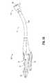
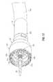
- FIG. 1is a perspective view from the distal end of the presently disclosed surgical stapling instrument illustrated in an unapproximated position, in accordance with an embodiment of the present disclosure
- FIG. 2is a perspective view from the proximal end of the surgical stapling device shown in FIG. 1 ;
- FIG. 3Ais a perspective view of the surgical stapling instrument of FIG. 1 illustrated in an approximated position;
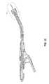
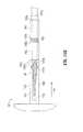
- FIG. 3Bis a side view of the surgical stapling instrument of FIG. 1 illustrated in a fired position;
- FIG. 4Ais a perspective view of another embodiment of a surgical stapling instrument in accordance with another embodiment of the present disclosure.
- FIG. 4Bis a perspective view of the surgical stapling device of FIG. 4A with the attachment removed;
- FIG. 5is an exploded view of the handle assembly, with parts separated, of the surgical stapling device of FIG. 1 ;
- FIG. 6is a side perspective view of the handle assembly of the surgical stapling device as shown in FIG. 1 with a handle section removed;
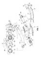
- FIG. 7is an exploded view, with parts separated, of the central body portion and distal head portion of the surgical stapling device shown in FIG. 1 ;
- FIG. 8Ais an enlarged view of the area of detail of FIG. 7 ;
- FIG. 8Bis an enlarged side perspective view of the anvil retainer and band body portions of the central body portion and the screw and screw stop of the approximation mechanism of the surgical stapling device shown in FIG. 1 ;
- FIG. 9is an exploded view, with parts separated, and shown in perspective_from the proximal end of the anvil assembly of the surgical stapling device shown in FIG. 1 ;
- FIG. 10is a side cross-sectional view of the surgical stapling device shown in FIG. 1 with the anvil assembly removed;
- FIG. 11is an enlarged view of the area of detail in FIG. 10 ;
- FIG. 12is a perspective view from the front of the distal end of the surgical stapling device shown in FIG. 10 with the anvil assembly removed;
- FIG. 13is a perspective view from the front of the distal end of the surgical stapling device shown in FIG. 12 with an anvil assembly attached;
- FIG. 14is a side cross-sectional view of the distal end of the surgical stapling device shown in FIG. 13 ;
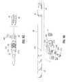
- FIG. 15Ais a side view of the anvil retainer, prior to being engaged to anvil assembly, in accordance with an embodiment of the present disclosure
- FIG. 15Bis a side view of the anvil retainer of FIG. 15A subsequent to being engaged to anvil assembly in accordance with an embodiment of the present disclosure
- FIG 16Aillustrates the anvil retainer of FIG. 15A with the surgical device in the unapproximated or open position prior to attachment of anvil assembly to the anvil retainer;
- FIG 16Bis a view of the anvil retainer of FIG. 16A subsequent to anvil assembly and anvil retainer passing through tissue walls;
- FIG. 16Cis a view of the anvil retainer of FIG. 16B subsequent to engagement of anvil assembly and anvil retainer;
- FIG. 16Dis a view of the anvil retainer of FIG. 16C with the surgical device in the approximated position.
- proximalwill refer to the portion of the instrument closest to the operator and the term “distal” will refer to the portion of the instrument furthest from the operator.
- surgical stapling device 10includes a proximal handle assembly 12, an elongated central body portion 14 including a curved elongated outer tube 14a, and a distal head portion 16. Additionally or alternatively, in some surgical procedures, e.g., the treatment of hemorrhoids, it is desirable to have a substantially straight, preferably shortened, central body portion. The length, shape and/or the diameter of body portion 14 and head portion 16 may also be varied to suit a particular surgical procedure.
- the body portionmay be flexible, or may have a flexible or articulating portion.
- Handle assembly 12includes a stationary handle 18, a firing trigger 20, a rotatable approximation knob 22 and an indicator 24.
- Stationary handle 18is preferably formed from thermoplastic handle sections 18a and 18b, e.g., polycarbonate, ( Fig. 5 ) which together define a housing for the internal components of handle assembly 12.
- Handle sections 18a and 18bare preferably secured together by sonic welding. Additionally or alternatively, other known securement techniques may be employed including screws, adhesives, snap-fit connectors, etc.
- the internal components of handle portion 12will be discussed in detail below.
- cushioned and/or resilient slip resistant portionssuch as a grip (not shown) can be fastened to or included as part of handle sections 18a and 18b and firing trigger 20.
- the slip resistant gripmay be formed over handle sections 18a and 18b and firing trigger 20 using an overmolding procedure and may be formed from neoprene or rubber.
- a pivotally mounted trigger lock 26is fastened to handle assembly 12 and is manually positioned to prevent inadvertent firing of surgical stapling device 10.
- Indicator 24is positioned on the stationary handle 18 and includes indicia, e.g., color coding, alphanumeric labeling, etc., to identify to a surgeon whether the device is approximated and is ready to be fired.
- Indicator 24preferably has a bulbous or convex shape which extends outwardly from a top surface of handle sections 18a and 18b and is easily viewable by a surgeon from the top and sides of the stapling device.
- Head portion 16includes an anvil assembly 30 and a shell assembly 31.
- the components of surgical device 10are generally formed from thermoplastics including polycarbonates, and metals including stainless steel and aluminum.
- the particular material selected to form a particular componentwill depend upon the strength requirements of the particular component.
- the anvilis preferably formed from a metal, such as stainless steel
- the stationary handleis preferably formed from a thermoplastic such as polycarbonate.
- other materials not listed above, which preferably can withstand sterilization proceduresmay be used to form components of surgical stapling device 10 provided the materials are suitable for surgical use and meet the strength requirements of the particular component.
- Figs. 3A and 3Bin operation, rotation of approximation knob 22 causes movement of anvil assembly 30 in relation to shell assembly 31 between spaced ( Figs. 1 and 2 ) and approximated ( Figs. 3A and 3B ) positions, as approximation knob 22 is mechanically engaged with anvil retainer 38 ( Fig. 7 ), which is fastened to anvil assembly 30.
- rotation of approximation knob 22 in a first directioncauses proximal movement of anvil assembly 30 (i.e., towards its approximated position)
- rotation of approximation mechanism 22 in a second opposite directioncauses distal movement of anvil assembly 30 (i.e., towards its spaced position) when anvil assembly 30 is attached to anvil retainer 38.
- firing trigger 20causes staples to be ejected from shell assembly 31 towards anvil assembly 30. That is, firing trigger 20 is disposed in mechanical cooperation with a pusher ( Fig. 7 ), such that actuation of firing trigger 20 causes advancement of the pusher into contact with the staples, which ejects into staple deforming pockets of anvil assembly 30. Details of the firing are disclosed for example in U.S. Patent No. 7,303,106 , the entire contents of which are incorporated herein by reference.
- the apparatushas a replaceable head 30a including the cartridge assembly, anvil member 30 and associated mechanisms.
- the stapling devicecan include the manual stapling device 10 of Fig. 1 and as described herein, or can include a powered stapling device 10' having first and second drive members as shown in Figs. 4A and 4B .
- U.S. Patent Application No. 12/946,082filed November 15, 2010 , the entire disclosure of which is hereby incorporated by reference herein, discloses a surgical device (shown as surgical stapling device 10' in Figs. 4A and 4B herein) having a powered actuator assembly.
- Such actuator assemblycan be powered by a motorized handle.
- the drive membersin some embodiments, are rotatable drive shafts that advance the pusher member to fire staples, advance a knife to cut tissue, and retract the anvil retainer to clamp tissue.
- the stapling device 10'can be configured to apply two or three rows of staples, and that the staples can have a curved or bent backspan, in any of the embodiments disclosed herein.
- the staples in the shell assemblycan be all the same sizes, or the sizes can vary. For example, it is contemplated that the staples in a row of staples can have a different size from the staples in another row.
- the spring loaded anvil retainer 38 of the present disclosuremay be used with both surgical stapling devices 10, 10'. However, for the sake of simplicity, the anvil retainer 38 will be described in use with stapling device 10, and it is noted that its use with stapling device 10' is substantially similar.
- Figs. 5-6illustrate the internal components of handle assembly 12.
- the internal componentsinclude the proximal components of approximation and firing mechanisms, a firing lockout mechanism and an indicator drive mechanism.
- Figs. 7 and 8Aillustrate the internal components of elongated body portion 14. These components include the distal components of the approximation and firing mechanisms. Each of these mechanisms will be disclosed in detail hereinbelow.
- the approximation mechanismincludes approximation knob 22, a drive screw 32, a rotatable sleeve 33, first and second screw extensions 34 and 36 ( Fig. 7 ), respectively, and an anvil retainer 38.
- Rotatable sleeve 33includes a substantially cylindrical hollow body portion 40 and a substantially cylindrical collar 42 which together define a central bore 33a.
- Collar 42has an annular groove 44 formed thereabout which is dimensioned to receive an inwardly extending flange 46 formed on an inner wall of handle sections 18a and 18b. Engagement between groove 44 and flanges 46 axially fixes sleeve 33 within handle 18 while permitting rotation of sleeve 33 in relation to stationary handle 18.
- the proximal end of body portion 40 of rotatable sleeve 33extends through an opening 186 in the proximal end of stationary handle 18.
- a pair of diametrically opposed elongated ribs 48are positioned or formed on the outer surface of body portion 40.
- Approximation knob 22includes a pair of internal slots 49a positioned to receive ribs 48 of sleeve 33 to rotatably fix sleeve 33 to knob 22, such that rotation of knob 22 causes concurrent rotation of sleeve 33.
- the proximal half of screw 32includes a helical channel 50 and is dimensioned to be slidably positioned within central bore 33a of rotatable sleeve 33.
- the distal end of screw 32includes an annular recess 35 dimensioned to receive a seal member 37 ( Fig. 5 ) for providing a fluid tight seal between the outer surface of screw 32 and the inner surface of pusher link 74.
- a pin 52( Fig. 5 ) extends radially through cylindrical collar 42 of sleeve 33 into helical channel 50. Since sleeve 33 is axially fixed with respect to stationary handle 18, rotation of sleeve 33 about screw 32 causes pin 52 to move along channel 50 of screw 32 to effect axial movement of screw 32 within stationary handle 18.
- top and bottom screw extensions 34 and 36each include a proximally located flexible flat band portion 58 and a distally located flat band portion 60.
- screw extensions 34 and 36may have other than a band configuration.
- screw extensions 34 and 36may be semi-circular or circular in cross-section. The flexibility of top and bottom screw extensions 34 and 36 permits movement of screw extensions 34 and 36 through curved elongated body portion 14.
- each band portion 58, 60includes a hole 62 dimensioned to receive a pin 64 for securing the proximal end of screw extensions 34 and 36 within transverse slot 54 of screw 32.
- a pin 64for securing the proximal end of screw extensions 34 and 36 within transverse slot 54 of screw 32.
- other fastening techniquesmay be used to secure each band portion 58 to screw 32, e.g., welding, crimping, etc.
- Distally located band portion 60 of each screw extension 34 and 36is dimensioned to be received within a transverse slot 66 formed in a proximal end of anvil retainer 38 ( Fig. 8A ) to fasten anvil retainer 38 to the distal end of screw extensions 34 and 36.
- a pair of pins 66awhich extend through the proximal end of anvil retainer 38 and band portions 60 are used to secure screw extensions 34 and 36 to anvil retainer 38.
- band portions 60can be brazed or welded within slot 66 or other fastening techniques may be used to secure band portions 60 of screw extensions 34 and 36 to anvil retainer 38, e.g., screws, crimping, etc.
- Anvil retainer 38includes a distal annular protrusion 177b ( Fig. 8A ) which is configured to engage the anvil assembly 30 ( Fig. 1 ) in a manner to be discussed in detail below. Additionally or alternatively, distal protrusion 177b need not be annular or may include different attachment structure, e.g., recesses, grooves, etc.
- rotatable sleeve 33is rotated about the proximal end of screw 32 to move pin 52 along helical channel 50 of screw 32. Since sleeve 33 is axially fixed to stationary handle 18, as pin 52 is moved through channel 50, screw 32 is advanced or retracted within stationary handle 18. As a result, top and bottom screw extensions 34 and 36, which are fastened to the distal end of screw 32, and anvil retainer 38, which is fastened to the distal end of screw extensions 34 and 36, are moved axially within elongated body portion 14. Since anvil assembly 30 is secured to the distal end of anvil retainer 38, rotation of approximation knob 22 will effect movement of anvil assembly 30 in relation to shell assembly 31 between spaced and approximated positions.
- Firing trigger 20includes a body portion 76 and a trigger cover 80.
- a cushioned gripping surface(not shown) preferably formed of neoprene or rubber is provided on trigger cover 80.
- the cushioned gripping surfaceprovides a non-slip cushioned surface to make actuation of surgical stapling device 10 more comfortable to a surgeon.
- the distal end of body portion 76 of trigger 20is pivotally connected to a coupling member 86 by a pivot member 84.
- Coupling member 86is secured to the proximal end of pusher link 74 and may be formed integrally with pusher link 74 or as a separate element fastened thereto.
- Firing link 72has a distal end pivotally secured to body portion 76 of trigger 20 by a pivot member 87 and a second end pivotally secured within a vertical slot 82 formed between stationary handle half-sections 18a and 18b of stationary handle 18 by pivot member 79. Pivot member 79 is free to move vertically within slot 82.
- a spring(not shown) is supported within handle 18 to urge pivot member 79 downwardly towards the bottom of slot 82.
- Body portion 76 of trigger 20further includes a pair of abutments including an abutment 89 and an abutment 91 which are positioned to engage the distal end 26a ( Fig. 6 ) of trigger lock 26 in a manner to be described in greater detail below to prevent actuation of trigger 20 prior to approximation of surgical stapling device 10.
- Coupling member 86which is supported on the proximal end of elongated pusher link 74 includes a flange 104 ( Fig. 7 ).
- a spring 106is positioned between a proximal end of outer tube 14a and flange 104 ( Fig. 6 ) to bias pusher link 74 proximally to a retracted, non-fired position.
- a pair of wings 108extends radially outwardly from coupling member 86. Wings 108 are dimensioned to slide along channels 111 ( Fig. 5 ) formed along the internal walls of stationary handle 18 to maintain proper alignment of pusher link 74 within stationary handle 18 during firing of device 10.
- pusher link 74includes a pair of engagement fingers 110 which are dimensioned to lockingly engage with members 220 formed in the proximal end of pusher back 186.
- Pusher back 186forms part of shell assembly 31 and will be discussed in greater detail below.
- Pusher link 74is preferably formed from a flexible plastic material and includes a plurality of notches 187 which allow the pusher link to bend more easily as it moves through body 14.
- Pusher link 74defines a hollow channel 75 for slidably receiving the approximation mechanism.
- a flat surface or cutout 74a ( Fig. 7 ) formed in pusher link 74slidably supports screw extensions 34 and 36 which are positioned in juxtaposed alignment.
- Spacers 77are positioned within outer tube 14a adjacent cutout 74a to provide additional support for screw extensions 34 and 36 and pusher link 74 to prevent each component from buckling during actuation.
- An annular channel 74bis formed about pusher link 74 to receive an O-ring seal 74c.
- Pusher link 74is slidably positioned within body portion 14 such that O-ring 74c seals the space between pusher link 74 and an internal wall of outer tube 14a. Operation of the firing mechanism of the device will be described in detail below.
- firing link 72is moved proximally until pivot member 79 engages an abutment surface (not shown) formed on screw stop 306 ( Fig. 5 ). Screw stop 306 is axially fixed to screw 32 in a manner to be described in detail below.
- the firing trigger 20advances the pusher link 74 distally against the bias of spring 106. Since the distal end of pusher link 74 is connected to pusher back 186, actuation of firing trigger 20 effects advancement of pusher back 186 within shell assembly 31 to eject staples from shell assembly 31 in a manner to be described below.
- shell assembly 31includes a shell 182, a pusher back 186, a cylindrical knife 188, and a staple guide 192.
- Shell 182includes an outer housing portion 194 and an inner guide portion 196 having grooves 196a for mating with splines 181 on anvil center rod 154 ( Fig. 9 ).
- Outer housing portion 194defines a throughbore 198 having a distal cylindrical section 200, a central conical section 202 and a proximal smaller diameter cylindrical section 204.
- a plurality of openings 206are formed in conical section 202.
- Openings 206are dimensioned to permit fluid and tissue passage during operation of the device.
- a pair of diametrically opposed flexible engagement members 207are formed on proximal cylindrical section 204 of shell 182. Engagement members 207 are positioned to be received in openings 207a formed on the distal end of outer tube 14a to secure shell 182 to elongated body 14.
- a pair of openings 211 formed in the proximal end of outer tube 14aare dimensioned to receive protrusions (not shown) formed on the internal wall of stationary handle 18 to facilitate attachment of tube 14a to handle portion 12.
- Pusher back 186includes a central throughbore 208 which is slidably positioned about inner guide portion 196 of shell 182.
- Pusher back 186includes a distal cylindrical section 210 which is slidably positioned within distal cylindrical section 200 of shell 182, a central conical section 212 and a proximal smaller diameter cylindrical section 214.
- the proximal end of pusher back 186includes members 220 which are configured to lockingly engage with resilient fingers 110 of pusher link 74 to fasten pusher link 74 to pusher back 186 such that a distal face of pusher link 74 abuts a proximal face of pusher back 186.
- the distal end of pusher back 186includes a pusher 190.
- Pusher 190includes a multiplicity of distally extending fingers 226 dimensioned to be slidably received within slots 228 formed in staple guide 192 to eject staples 230 therefrom.
- Cylindrical knife 188is frictionally retained within the central throughbore of pusher back 186 to fixedly secure knife 188 in relation to pusher 190. Alternately, knife 188 may be retained within pusher back 186 using adhesives, crimping, pins, etc.
- the distal end of knife 188includes a circular cutting edge 234.
- pusher back 186is advanced distally within shell 182. Advancement of pusher back 186 advances fingers 226 through slots 228 of staple guide 192 to advance staples 230 positioned within slots 228 and ejects staples 230 from staple guide 192 into staple deforming pockets 140 of anvil 129. Since knife 188 is secured to pusher back 186, knife 188 is also advanced distally to core tissue as will be described in more detail below.
- a rigid bushing 209is supported in the proximal end of inner guide portion 196 of shell 182.
- Bushing 209defines a throughbore dimensioned to slidably receive anvil retainer 38 and center rod 154 of anvil assembly 30.
- Bushing 209provides lateral support for flexible arms 155 of center rod 154 when the anvil assembly 30 has been approximated to prevent disengagement of anvil assembly 30 from anvil retainer 38.
- flexible arms 155 of center rod 154are positioned externally of bushing 209 to permit removal of anvil assembly 30 from retainer 38.
- Figs. 10-12illustrate surgical stapling device 10 in the unapproximated or open position prior to attachment of anvil assembly 30 to anvil retainer 38.
- biasing member(not shown) is engaged with coupling 86 to urge pusher link 74 to its proximal-most position in which coupling 86 abuts screw-stop 306.
- Biasing member 512is engaged with slide member 500 of the indicator mechanism to position slide member 500 in engagement with projection 518 of indicator 24 to pivot indicator 24 in a clockwise direction.
- Biasing member 549is engaged with body 536 of lockout member 530 to urge lockout member 530 to its distal-most position, wherein lip portion 542 of lockout member 530 is positioned above extension 26b of trigger lock 26 to prevent movement of trigger lock 26 to the unlocked position.
- Biasing member 82ais also engaged with pivot member 79 to urge pivot member 79 to the base of vertical slot 82.
- FIGs. 13-14illustrate surgical stapling device 10 with anvil assembly 30 attached to anvil retainer 38 and the surgical stapling device 10 in the unapproximated or open position.
- anvil retainer 38is positioned within bore 170 of center rod 154 of anvil assembly 30. Flexible arms 155 of the center rod deflect outwardly to accommodate the anvil retainer 38.
- Center rod 154is advanced onto anvil retainer 38 in the direction indicated by arrow "K" in Fig. 14 which pushes section 165 of the anvil retainer proximal as it compresses 162.
- anvil retainer 38may be disposed through a proximal tube 160 and a distal tube 165.
- Anvil retainer 38includes a proximal annular protrusion 177a, and distal annular protrusion 177b.
- a resilient member 162is disposed between proximal tube 160 and distal tube 165.
- a proximal end 160a of proximal tube 160lays flush with proximal protrusion 177a such that proximal protrusion 177a restricts proximal translation of proximal tube 160.
- a distal end 160b of proximal tube 160is disposed adjacent to a proximal portion 162a of resilient member 162.
- a distal portion 162b of resilient member 162is disposed adjacent to a proximal end 165a of distal tube 165.
- Distal tube 165is slidingly engaged with anvil retainer 38 such that distal tube 165 may translate proximally toward proximal tube 160.
- the outer diameter "D" of center rod 154may be equal to the outer diameter "d" of distal tube 165 and/or proximal tube 160. With such an arrangement, when anvil assembly 30 is engaged with anvil retainer 38, the outer perimeter of center rod 154 will lay flush with the outer perimeter of distal tube 165 and/or proximal tube 160. Additionally, or alternatively, the outer diameter "D” of center rod 154 may be less than the outer diameter "d” of distal tube 165 and/or proximal tube 160. When the outer diameter "D” of center rod 154 is less than the outer diameter "d” of distal tube 165 and/or proximal tube 160, then the outer perimeter of the center rod 154 will not lay flush with the outer perimeter of the anvil retainer 38.
- anvil assembly 30is shown prior to being engaged with anvil retainer 38.
- This arrangementdisplays anvil retainer 38 in its original position where proximal tube 160 is spaced apart from distal tube 165.
- Resilient member 162provides an outward force against distal end 160b of proximal tube 160 and proximal end 165a of distal tube 165. With the force applied by resilient member 162, the proximal end 160a of proximal tube 160 is resting against proximal protrusion 177a of anvil retainer 38. In addition, the distal end 165b of distal tube 165 rests against distal protrusion 177b.
- FIG. 15Banvil assembly 30 is shown attached to anvil retainer 38.
- anvil retainer 38is positioned within bore 170 of center rod 154 of anvil assembly 30.
- Flexible arms 155deflect outwardly to accommodate center rod 154.
- Center rod 154is advanced onto anvil retainer 38 in the direction indicated by arrow "K" until internal shoulder 155b of flexible arms 155 passes over distal annular protrusion 177b formed on anvil retainer 38.
- the proximal end 154e of center rod 154engages with the distal end 165b of distal tube 165 such that the proximal advancement of center rod 154 translates distal tube 165 proximally toward proximal tube 160, until flexible arms 155 releasably engage the anvil retainer 38, i.e. internal shoulders 155b releasably engage with distal annular protrusion 177b.
- center rod 154 of anvil assembly 30will lay flush with the outer perimeter of distal tube 165 and/or proximal tube 160 of anvil retainer 38.
- the outer diameter "D" of center rod 154may be equal to the outer diameter "d” of distal tube 165 and/or proximal tube 160. Additionally, or alternatively, the outer diameter "D” of center rod 154 may be less than the outer diameter "d” of distal tube 165 and/or proximal tube 160. When the outer diameter "D” of center rod 154 is less than the outer diameter "d” of distal tube 165 and/or proximal tube 160, then the outer perimeter of the center rod 154 will not lay flush with the outer perimeter of the anvil retainer 38.
- Fig. 16Aillustrates surgical stapling device 10 in the unapproximated or open position prior to attachment of anvil assembly 30 to anvil retainer 38, and prior to anvil retainer 38 being pierced through tissue wall "W” and prior to anvil assembly 30 being pierced through tissue wall "T.”
- biasing member 106is engaged with coupling 86 to urge pusher link 74 to its proximal-most position in which coupling 86 abuts screw-stop 306.
- Biasing member 512is engaged with slide member 500 of the indicator mechanism to position slide member 500 in engagement with projection 518 of indicator 24 to pivot indicator 24 in a clockwise direction.
- Biasing member 549is engaged with body 536 of lockout member 530 to urge lockout member 530 to its distal-most position, wherein lip portion 542 of lockout member 530 is positioned above extension 26b of trigger lock 26 to prevent movement of trigger lock 26 to the unlocked position.
- Biasing member 82ais also engaged with pivot member 79 to urge pivot member 79 to the base of vertical slot 82. In this position, anvil retainer 38 is urged through tissue wall "W” and anvil assembly 30 is urged through tissue wall "T.” Additionally, or alternatively, tissue walls "W,” “T” may be cut and opened to allow the passage of anvil retainer 38 and/or anvil assembly 30, respectively, therethrough. In this arrangement, a suture may be used to tie tissue walls "W,” “T” to anvil assembly 30 and anvil retainer 38.
- FIG. 16Bsurgical stapling device 10 is shown in the unapproximated position with anvil retainer 38 pierced through tissue wall "W” and anvil assembly 30 pierced through tissue wall “T.” In this position, anvil assembly 30 is ready to be engaged with anvil retainer 38. As shown in Fig. 16B , tissue wall "W” surrounds the proximal tube 160 of anvil retainer 38.
- FIG. 16Csurgical stapling device 10 is shown in the unapproximated position with anvil retainer 38 pierced through tissue wall "W” and anvil assembly 30 pierced through tissue wall “T” and anvil assembly 30 engaged with anvil retainer 38.
- anvil retainer 38is positioned within bore 170 of center rod 154 of anvil assembly 30.
- Flexible arms 155deflect outwardly to accommodate center rod 154.
- Center rod 154is advanced onto anvil retainer 38 in the direction indicated by arrow "K.” Advancement of center rod 154 onto anvil retainer 38 results in the proximal advancement of distal tube 165 toward proximal tube 160.
- Center rod 154is advanced onto anvil retainer 38 until internal shoulder 155b of flexible arms 155 passes over distal annular protrusion 177b formed on anvil retainer 38. At this point, flexible arms 155 releasably engage the anvil retainer 38. The position of the remaining components of surgical stapling device 10 is not affected by attachment of anvil assembly 30 to anvil retainer 38 and remains as described above.
- surgical stapling device 10is shown with anvil retainer 38 (now internal to surgical stapling device 10) attached to anvil assembly 30, and the surgical stapling device 10 in the approximated or closed position.
- surgical stapling device 10is moved to the approximated or closed position by rotating rotation knob 22.
- Rotation of knob 22causes cylindrical sleeve 33 to rotate to move pin 52 along helical channel 50 of screw 32. Movement of pin 52 15 along helical channel 50 causes screw 32 to translate proximally within sleeve 33.
- the distal end of screw 32is connected to screw extensions 34 and 36 which are fastened at their distal ends to anvil retainer 38. As such, retraction of screw 32 within sleeve 33 is translated into 20 proximal movement of anvil retainer 38 and anvil assembly 30.
- tissue wall "W”slides over proximal tube 160, distal tube 165, and center rod 154 of anvil assembly 30.
- the outer diameter "d” of distal tube 165 and/or proximal tube 160is either equal to or greater than the outer diameter "D" of anvil assembly 30. With the outer diameters in this configuration, tissue wall “W” may slide over center rod 154 of anvil assembly 30 and thus tissue wall "W” will refrain from being pulled into surgical stapling device 10.
Landscapes
- Health & Medical Sciences (AREA)
- Life Sciences & Earth Sciences (AREA)
- Surgery (AREA)
- Heart & Thoracic Surgery (AREA)
- Engineering & Computer Science (AREA)
- Biomedical Technology (AREA)
- Nuclear Medicine, Radiotherapy & Molecular Imaging (AREA)
- Medical Informatics (AREA)
- Molecular Biology (AREA)
- Animal Behavior & Ethology (AREA)
- General Health & Medical Sciences (AREA)
- Public Health (AREA)
- Veterinary Medicine (AREA)
- Physiology (AREA)
- Surgical Instruments (AREA)
Abstract
Description
- This application claims the benefit and priority to
U.S. Provisional Patent Application No. 61/661,464, filed June 19, 2012 - The present disclosure relates generally to a surgical instrument for applying surgical staples to body tissue. More particularly, the present disclosure relates to a surgical stapling instrument suitable for performing circular anastomosis and/or treatment to internal walls of hollow tissue organs.
- Anastomosis is the surgical joining of separate hollow organ sections. Typically, an anastomosis procedure follows surgery in which a diseased or defective section of hollow tissue is removed and the remaining end sections are to be joined. Depending on the desired anastomosis procedure, the end sections may be joined by either circular, end-to-end, end-to-side, or side-to-side organ reconstruction methods.
- In a circular anastomosis procedure, the two ends of the organ sections are joined by means of a stapling instrument which drives a circular array of staples through the end section of each organ section and simultaneously cores any tissue interior of the driven circular array of staples to free the tubular passage. Examples of instruments for performing circular anastomosis of hollow organs are described in
U.S. Patent Nos. 7,303,106 ;6,053,390 ;5,588,579 ;5,119,983 ;5,005,749 ;4,646,745 ;4,576,167 ; and4,473,077 , each of which is incorporated herein in its entirety by reference. Typically, these instruments include an elongated shaft having a handle portion at a proximal end to actuate the instrument, an anvil retainer, and a staple holding component disposed at a distal end. An anvil assembly including an anvil rod with attached anvil head is mounted to the distal end of the instrument adjacent the staple holding component. Opposed end portions of tissue of the hollow organ(s) to be stapled are clamped between the anvil head and the staple holding component, via the anvil retainer. Typically, a first actuation mechanism is used to approximate the anvil head and the staple holding component to clamp the tissue. The clamped tissue is stapled by driving one or more staples from the staple holding component so that the ends of the staples pass through the tissue and are deformed by the anvil head. Typically, a second actuation mechanism is used to fire the staples. It is also common for an annular knife to be concurrently advanced to core tissue within the hollow organ to free a tubular passage within the organ. - Upon engaging the first actuation mechanism and approximating the anvil head and staple holding component, the anvil rod must pass through the aperture made in the tissue where the anvil retainer passed through. The problem typically arises that the aperture diameter made by the anvil retainer is too small for the anvil rod to pass through. As a result, excess tissue is pulled into the device when approximating the anvil head. Furthermore, the tissue in some procedures is tied to the trocar by a suture. The suture can fail to slide over the anvil during retraction, also leading to too much tissue being pulled into the device. Accordingly, a need exists for a device to prevent the excessive build up of tissue which is pulled into the device, specifically, a device for enabling the anvil head to pass through the aperture made by the anvil retainer.
- The present disclosure relates to an anvil receiving apparatus including an anvil retainer coupled to a surgical device, and a tube surrounding a portion of the anvil retainer. The anvil retainer may include a distal annular protrusion for releasably engaging a center rod of an anvil assembly. The tube may have an outer diameter larger than the outer diameter of the center rod. Alternatively, the tube may have an outer diameter equal to the outer diameter of the center rod. The tube may include a distal tube and a proximal tube where the distal tube and proximal tubes are separated by a resilient member. The anvil retainer may further include a proximal protrusion to disable proximal movement of the proximal tube. Additionally, proximal advancement of the center rod onto the anvil retainer may cause proximal advancement of the distal tube toward the proximal tube. The anvil assembly may also include resilient arms with internal shoulders that releasably engage a distal annular protrusion of the anvil retainer.
- The present disclosure also relates to a surgical stapling device including a handle assembly, a body portion extending distally from the handle assembly, and a head portion including an anvil retainer and a shell assembly. The anvil retainer may be movable in relation to the shell assembly between unapproximated and approximated positions. The anvil retainer may further include a tube surrounding a portion of the anvil retainer. The anvil retainer may include a distal annular protrusion for releasably engaging a center rod of an anvil assembly. The tube may have an outer diameter larger than the outer diameter of the center rod. Alternatively, the tube may have an outer diameter equal to the outer diameter of the center rod. The tube may include a distal tube and a proximal tube where the distal tube and proximal tubes are separated by a resilient member. The anvil retainer may further include a proximal protrusion to disable proximal movement of the proximal tube. Additionally, proximal advancement of the center rod onto the anvil retainer may cause proximal advancement of the distal tube toward the proximal tube. The anvil assembly may also include resilient arms with internal shoulders that releasably engage a distal annular protrusion of the anvil retainer.
- Various embodiments of the presently disclosed surgical stapling instrument are disclosed herein with reference to the drawings, wherein:
FIG. 1 is a perspective view from the distal end of the presently disclosed surgical stapling instrument illustrated in an unapproximated position, in accordance with an embodiment of the present disclosure;FIG. 2 is a perspective view from the proximal end of the surgical stapling device shown inFIG. 1 ;FIG. 3A is a perspective view of the surgical stapling instrument ofFIG. 1 illustrated in an approximated position;FIG. 3B is a side view of the surgical stapling instrument ofFIG. 1 illustrated in a fired position;FIG. 4A is a perspective view of another embodiment of a surgical stapling instrument in accordance with another embodiment of the present disclosure;FIG. 4B is a perspective view of the surgical stapling device ofFIG. 4A with the attachment removed;FIG. 5 is an exploded view of the handle assembly, with parts separated, of the surgical stapling device ofFIG. 1 ;FIG. 6 is a side perspective view of the handle assembly of the surgical stapling device as shown inFIG. 1 with a handle section removed;FIG. 7 is an exploded view, with parts separated, of the central body portion and distal head portion of the surgical stapling device shown inFIG. 1 ;FIG. 8A is an enlarged view of the area of detail ofFIG. 7 ;FIG. 8B is an enlarged side perspective view of the anvil retainer and band body portions of the central body portion and the screw and screw stop of the approximation mechanism of the surgical stapling device shown inFIG. 1 ;FIG. 9 is an exploded view, with parts separated, and shown in perspective_from the proximal end of the anvil assembly of the surgical stapling device shown inFIG. 1 ;FIG. 10 is a side cross-sectional view of the surgical stapling device shown inFIG. 1 with the anvil assembly removed;FIG. 11 is an enlarged view of the area of detail inFIG. 10 ;FIG. 12 is a perspective view from the front of the distal end of the surgical stapling device shown inFIG. 10 with the anvil assembly removed;FIG. 13 is a perspective view from the front of the distal end of the surgical stapling device shown inFIG. 12 with an anvil assembly attached;FIG. 14 is a side cross-sectional view of the distal end of the surgical stapling device shown inFIG. 13 ;FIG. 15A is a side view of the anvil retainer, prior to being engaged to anvil assembly, in accordance with an embodiment of the present disclosure;FIG. 15B is a side view of the anvil retainer ofFIG. 15A subsequent to being engaged to anvil assembly in accordance with an embodiment of the present disclosure;FIG 16A illustrates the anvil retainer ofFIG. 15A with the surgical device in the unapproximated or open position prior to attachment of anvil assembly to the anvil retainer;FIG 16B is a view of the anvil retainer ofFIG. 16A subsequent to anvil assembly and anvil retainer passing through tissue walls;FIG. 16C is a view of the anvil retainer ofFIG. 16B subsequent to engagement of anvil assembly and anvil retainer; andFIG. 16D is a view of the anvil retainer ofFIG. 16C with the surgical device in the approximated position.- Embodiments of the presently disclosed surgical stapling instrument will now be described in detail with reference to the drawings in which like reference numerals designate identical or corresponding elements in each of the several views.
- Throughout this description, the term "proximal" will refer to the portion of the instrument closest to the operator and the term "distal" will refer to the portion of the instrument furthest from the operator.
Figs. 1 and2 illustrate one preferred embodiment of the presently disclosed surgical stapling device shown generally as 10. Briefly,surgical stapling device 10 includes aproximal handle assembly 12, an elongatedcentral body portion 14 including a curved elongatedouter tube 14a, and adistal head portion 16. Additionally or alternatively, in some surgical procedures, e.g., the treatment of hemorrhoids, it is desirable to have a substantially straight, preferably shortened, central body portion. The length, shape and/or the diameter ofbody portion 14 andhead portion 16 may also be varied to suit a particular surgical procedure. The body portion may be flexible, or may have a flexible or articulating portion.- Handle
assembly 12 includes astationary handle 18, a firingtrigger 20, arotatable approximation knob 22 and anindicator 24.Stationary handle 18 is preferably formed fromthermoplastic handle sections Fig. 5 ) which together define a housing for the internal components ofhandle assembly 12. Handlesections handle portion 12 will be discussed in detail below. Preferably, cushioned and/or resilient slip resistant portions such as a grip (not shown) can be fastened to or included as part ofhandle sections trigger 20. The slip resistant grip may be formed overhandle sections trigger 20 using an overmolding procedure and may be formed from neoprene or rubber. - Additionally or alternatively, other suitable materials, e.g., elastomeric materials, and joining techniques may be employed. A pivotally mounted
trigger lock 26 is fastened to handleassembly 12 and is manually positioned to prevent inadvertent firing ofsurgical stapling device 10.Indicator 24 is positioned on thestationary handle 18 and includes indicia, e.g., color coding, alphanumeric labeling, etc., to identify to a surgeon whether the device is approximated and is ready to be fired.Indicator 24 preferably has a bulbous or convex shape which extends outwardly from a top surface ofhandle sections Head portion 16 includes ananvil assembly 30 and ashell assembly 31. Each of these assemblies will be discussed in detail below. Except where otherwise noted, the components ofsurgical device 10 are generally formed from thermoplastics including polycarbonates, and metals including stainless steel and aluminum. The particular material selected to form a particular component will depend upon the strength requirements of the particular component. For example, the anvil is preferably formed from a metal, such as stainless steel, and the stationary handle is preferably formed from a thermoplastic such as polycarbonate. Additionally or alternatively, other materials not listed above, which preferably can withstand sterilization procedures, may be used to form components ofsurgical stapling device 10 provided the materials are suitable for surgical use and meet the strength requirements of the particular component.- Turning now to
Figs. 3A and3B , in operation, rotation ofapproximation knob 22 causes movement ofanvil assembly 30 in relation toshell assembly 31 between spaced (Figs. 1 and2 ) and approximated (Figs. 3A and3B ) positions, asapproximation knob 22 is mechanically engaged with anvil retainer 38 (Fig. 7 ), which is fastened toanvil assembly 30. It is envisioned that rotation ofapproximation knob 22 in a first direction (e.g., clockwise) causes proximal movement of anvil assembly 30 (i.e., towards its approximated position), and rotation ofapproximation mechanism 22 in a second opposite direction (e.g., counter-clockwise) causes distal movement of anvil assembly 30 (i.e., towards its spaced position) whenanvil assembly 30 is attached toanvil retainer 38. Details of the approximation mechanism are disclosed for example inU.S. Patent No. 7,303,106 , the entire contents of which are incorporated herein by reference. - Actuation of firing
trigger 20 towardsstationary handle 18, causes staples to be ejected fromshell assembly 31 towardsanvil assembly 30. That is, firingtrigger 20 is disposed in mechanical cooperation with a pusher (Fig. 7 ), such that actuation of firingtrigger 20 causes advancement of the pusher into contact with the staples, which ejects into staple deforming pockets ofanvil assembly 30. Details of the firing are disclosed for example inU.S. Patent No. 7,303,106 , the entire contents of which are incorporated herein by reference. - With additional reference to
Figs. 4A and4B , it is also contemplated that, in certain embodiments, the apparatus has areplaceable head 30a including the cartridge assembly,anvil member 30 and associated mechanisms. The stapling device can include themanual stapling device 10 ofFig. 1 and as described herein, or can include a powered stapling device 10' having first and second drive members as shown inFigs. 4A and4B . For example,U.S. Patent Application No. 12/946,082, filed November 15, 2010 Figs. 4A and4B herein) having a powered actuator assembly. Such actuator assembly can be powered by a motorized handle. The drive members, in some embodiments, are rotatable drive shafts that advance the pusher member to fire staples, advance a knife to cut tissue, and retract the anvil retainer to clamp tissue. It is also contemplated that the stapling device 10' can be configured to apply two or three rows of staples, and that the staples can have a curved or bent backspan, in any of the embodiments disclosed herein. In any of the disclosed embodiments, the staples in the shell assembly can be all the same sizes, or the sizes can vary. For example, it is contemplated that the staples in a row of staples can have a different size from the staples in another row. The spring loadedanvil retainer 38 of the present disclosure may be used with bothsurgical stapling devices 10, 10'. However, for the sake of simplicity, theanvil retainer 38 will be described in use with staplingdevice 10, and it is noted that its use with stapling device 10' is substantially similar. Figs. 5-6 illustrate the internal components ofhandle assembly 12. The internal components include the proximal components of approximation and firing mechanisms, a firing lockout mechanism and an indicator drive mechanism.Figs. 7 and8A illustrate the internal components ofelongated body portion 14. These components include the distal components of the approximation and firing mechanisms. Each of these mechanisms will be disclosed in detail hereinbelow.- Referring to
Figs. 5-8A and8B , the approximation mechanism includesapproximation knob 22, adrive screw 32, arotatable sleeve 33, first andsecond screw extensions 34 and 36 (Fig. 7 ), respectively, and ananvil retainer 38.Rotatable sleeve 33 includes a substantially cylindricalhollow body portion 40 and a substantiallycylindrical collar 42 which together define acentral bore 33a.Collar 42 has anannular groove 44 formed thereabout which is dimensioned to receive an inwardly extendingflange 46 formed on an inner wall ofhandle sections groove 44 andflanges 46 axially fixessleeve 33 withinhandle 18 while permitting rotation ofsleeve 33 in relation tostationary handle 18. The proximal end ofbody portion 40 ofrotatable sleeve 33 extends through anopening 186 in the proximal end ofstationary handle 18. A pair of diametrically opposedelongated ribs 48 are positioned or formed on the outer surface ofbody portion 40.Approximation knob 22 includes a pair ofinternal slots 49a positioned to receiveribs 48 ofsleeve 33 to rotatably fixsleeve 33 toknob 22, such that rotation ofknob 22 causes concurrent rotation ofsleeve 33. - The proximal half of
screw 32 includes ahelical channel 50 and is dimensioned to be slidably positioned withincentral bore 33a ofrotatable sleeve 33. The distal end ofscrew 32 includes anannular recess 35 dimensioned to receive a seal member 37 (Fig. 5 ) for providing a fluid tight seal between the outer surface ofscrew 32 and the inner surface ofpusher link 74. A pin 52 (Fig. 5 ) extends radially throughcylindrical collar 42 ofsleeve 33 intohelical channel 50. Sincesleeve 33 is axially fixed with respect tostationary handle 18, rotation ofsleeve 33 aboutscrew 32causes pin 52 to move alongchannel 50 ofscrew 32 to effect axial movement ofscrew 32 withinstationary handle 18. - Referring to
Figs. 7-8A and8B , the distal end ofscrew 32 includes atransverse slot 54. Top andbottom screw extensions 34 and 36 (Fig. 7 ) each include a proximally located flexibleflat band portion 58 and a distally locatedflat band portion 60. Alternately, it is envisioned thatscrew extensions extensions bottom screw extensions screw extensions elongated body portion 14. The proximal end of eachband portion hole 62 dimensioned to receive apin 64 for securing the proximal end ofscrew extensions transverse slot 54 ofscrew 32. Alternately, other fastening techniques may be used to secure eachband portion 58 to screw 32, e.g., welding, crimping, etc. Distally locatedband portion 60 of eachscrew extension transverse slot 66 formed in a proximal end of anvil retainer 38 (Fig. 8A ) to fastenanvil retainer 38 to the distal end ofscrew extensions pins 66a which extend through the proximal end ofanvil retainer 38 andband portions 60 are used to securescrew extensions anvil retainer 38. Additionally or alternatively,band portions 60 can be brazed or welded withinslot 66 or other fastening techniques may be used to secureband portions 60 ofscrew extensions anvil retainer 38, e.g., screws, crimping, etc.Anvil retainer 38 includes a distalannular protrusion 177b (Fig. 8A ) which is configured to engage the anvil assembly 30 (Fig. 1 ) in a manner to be discussed in detail below. Additionally or alternatively,distal protrusion 177b need not be annular or may include different attachment structure, e.g., recesses, grooves, etc. - Referring again to
Fig. 5-8A and8B , whenapproximation knob 22 is manually rotated,rotatable sleeve 33 is rotated about the proximal end ofscrew 32 to movepin 52 alonghelical channel 50 ofscrew 32. Sincesleeve 33 is axially fixed tostationary handle 18, aspin 52 is moved throughchannel 50,screw 32 is advanced or retracted withinstationary handle 18. As a result, top andbottom screw extensions screw 32, andanvil retainer 38, which is fastened to the distal end ofscrew extensions elongated body portion 14. Sinceanvil assembly 30 is secured to the distal end ofanvil retainer 38, rotation ofapproximation knob 22 will effect movement ofanvil assembly 30 in relation toshell assembly 31 between spaced and approximated positions. - Referring to
Figs. 5-7 , the firing mechanism includes firingtrigger 20, afiring link 72 and an elongated pusher link 74 (Fig. 7 ). Firingtrigger 20 includes abody portion 76 and atrigger cover 80. A cushioned gripping surface (not shown) preferably formed of neoprene or rubber is provided ontrigger cover 80. The cushioned gripping surface provides a non-slip cushioned surface to make actuation ofsurgical stapling device 10 more comfortable to a surgeon. The distal end ofbody portion 76 oftrigger 20 is pivotally connected to acoupling member 86 by apivot member 84. Couplingmember 86 is secured to the proximal end ofpusher link 74 and may be formed integrally withpusher link 74 or as a separate element fastened thereto. Firinglink 72 has a distal end pivotally secured tobody portion 76 oftrigger 20 by apivot member 87 and a second end pivotally secured within avertical slot 82 formed between stationary handle half-sections stationary handle 18 bypivot member 79.Pivot member 79 is free to move vertically withinslot 82. A spring (not shown) is supported withinhandle 18 to urgepivot member 79 downwardly towards the bottom ofslot 82.Body portion 76 oftrigger 20 further includes a pair of abutments including anabutment 89 and anabutment 91 which are positioned to engage thedistal end 26a (Fig. 6 ) oftrigger lock 26 in a manner to be described in greater detail below to prevent actuation oftrigger 20 prior to approximation ofsurgical stapling device 10. - Coupling
member 86 which is supported on the proximal end ofelongated pusher link 74 includes a flange 104 (Fig. 7 ). Aspring 106 is positioned between a proximal end ofouter tube 14a and flange 104 (Fig. 6 ) tobias pusher link 74 proximally to a retracted, non-fired position. A pair ofwings 108 extends radially outwardly from couplingmember 86.Wings 108 are dimensioned to slide along channels 111 (Fig. 5 ) formed along the internal walls ofstationary handle 18 to maintain proper alignment ofpusher link 74 withinstationary handle 18 during firing ofdevice 10. - Referring to
Fig. 7 , the distal end ofpusher link 74 includes a pair ofengagement fingers 110 which are dimensioned to lockingly engage withmembers 220 formed in the proximal end of pusher back 186. Pusher back 186 forms part ofshell assembly 31 and will be discussed in greater detail below.Pusher link 74 is preferably formed from a flexible plastic material and includes a plurality ofnotches 187 which allow the pusher link to bend more easily as it moves throughbody 14.Pusher link 74 defines ahollow channel 75 for slidably receiving the approximation mechanism. A flat surface orcutout 74a (Fig. 7 ) formed inpusher link 74 slidably supports screwextensions Spacers 77 are positioned withinouter tube 14aadjacent cutout 74a to provide additional support forscrew extensions annular channel 74b is formed aboutpusher link 74 to receive an O-ring seal 74c.Pusher link 74 is slidably positioned withinbody portion 14 such that O-ring 74c seals the space betweenpusher link 74 and an internal wall ofouter tube 14a. Operation of the firing mechanism of the device will be described in detail below. - Referring again to
Figs. 5-7 , when firingtrigger 20 is actuated, i.e., pivoted aboutpivot member 84, firinglink 72 is moved proximally untilpivot member 79 engages an abutment surface (not shown) formed on screw stop 306 (Fig. 5 ).Screw stop 306 is axially fixed to screw 32 in a manner to be described in detail below. Thereafter, the firingtrigger 20 advances thepusher link 74 distally against the bias ofspring 106. Since the distal end ofpusher link 74 is connected to pusher back 186, actuation of firingtrigger 20 effects advancement of pusher back 186 withinshell assembly 31 to eject staples fromshell assembly 31 in a manner to be described below. - Referring to
Fig. 7 ,shell assembly 31 includes ashell 182, a pusher back 186, acylindrical knife 188, and astaple guide 192.Shell 182 includes anouter housing portion 194 and aninner guide portion 196 havinggrooves 196a for mating withsplines 181 on anvil center rod 154 (Fig. 9 ). Features other than splines are contemplated, and the anvil center rod may not have any protruding features.Outer housing portion 194 defines athroughbore 198 having a distalcylindrical section 200, a centralconical section 202 and a proximal smaller diametercylindrical section 204. A plurality ofopenings 206 are formed inconical section 202.Openings 206 are dimensioned to permit fluid and tissue passage during operation of the device. A pair of diametrically opposedflexible engagement members 207 are formed on proximalcylindrical section 204 ofshell 182.Engagement members 207 are positioned to be received inopenings 207a formed on the distal end ofouter tube 14a to secureshell 182 toelongated body 14. A pair ofopenings 211 formed in the proximal end ofouter tube 14a are dimensioned to receive protrusions (not shown) formed on the internal wall ofstationary handle 18 to facilitate attachment oftube 14a to handleportion 12. - Pusher back 186 includes a
central throughbore 208 which is slidably positioned aboutinner guide portion 196 ofshell 182. Pusher back 186 includes a distalcylindrical section 210 which is slidably positioned within distalcylindrical section 200 ofshell 182, a centralconical section 212 and a proximal smaller diametercylindrical section 214. The proximal end of pusher back 186 includesmembers 220 which are configured to lockingly engage withresilient fingers 110 ofpusher link 74 to fastenpusher link 74 to pusher back 186 such that a distal face ofpusher link 74 abuts a proximal face of pusher back 186. - The distal end of pusher back 186 includes a
pusher 190.Pusher 190 includes a multiplicity of distally extendingfingers 226 dimensioned to be slidably received withinslots 228 formed instaple guide 192 to ejectstaples 230 therefrom.Cylindrical knife 188 is frictionally retained within the central throughbore of pusher back 186 to fixedlysecure knife 188 in relation topusher 190. Alternately,knife 188 may be retained within pusher back 186 using adhesives, crimping, pins, etc. The distal end ofknife 188 includes acircular cutting edge 234. - In operation, when pusher link 74 is advanced distally in response to actuation of firing
trigger 20, as will be described below, pusher back 186 is advanced distally withinshell 182. Advancement of pusher back 186advances fingers 226 throughslots 228 ofstaple guide 192 to advancestaples 230 positioned withinslots 228 and ejectsstaples 230 fromstaple guide 192 intostaple deforming pockets 140 ofanvil 129. Sinceknife 188 is secured to pusher back 186,knife 188 is also advanced distally to core tissue as will be described in more detail below. - Continuing with reference to
Fig. 7 , and additionally referring toFig. 9 , arigid bushing 209 is supported in the proximal end ofinner guide portion 196 ofshell 182.Bushing 209 defines a throughbore dimensioned to slidably receiveanvil retainer 38 andcenter rod 154 ofanvil assembly 30.Bushing 209 provides lateral support forflexible arms 155 ofcenter rod 154 when theanvil assembly 30 has been approximated to prevent disengagement ofanvil assembly 30 fromanvil retainer 38. In the unapproximated position,flexible arms 155 ofcenter rod 154 are positioned externally ofbushing 209 to permit removal ofanvil assembly 30 fromretainer 38. - Operation of
surgical stapling device 10 with respect to the attachment ofanvil assembly 30 toanvil retainer 38 will now be described in detail with reference toFigs. 10-16 . Figs. 10-12 illustratesurgical stapling device 10 in the unapproximated or open position prior to attachment ofanvil assembly 30 toanvil retainer 38. In this position, and referring back toFig. 5 , biasing member (not shown) is engaged withcoupling 86 to urgepusher link 74 to its proximal-most position in whichcoupling 86 abuts screw-stop 306.Biasing member 512 is engaged withslide member 500 of the indicator mechanism to positionslide member 500 in engagement with projection 518 ofindicator 24 to pivotindicator 24 in a clockwise direction.Biasing member 549 is engaged with body 536 oflockout member 530 to urgelockout member 530 to its distal-most position, whereinlip portion 542 oflockout member 530 is positioned aboveextension 26b oftrigger lock 26 to prevent movement oftrigger lock 26 to the unlocked position.Biasing member 82a is also engaged withpivot member 79 to urgepivot member 79 to the base ofvertical slot 82.Figs. 13-14 illustratesurgical stapling device 10 withanvil assembly 30 attached toanvil retainer 38 and thesurgical stapling device 10 in the unapproximated or open position. Referring toFig. 14 , during attachment ofanvil assembly 30 toanvil retainer 38,anvil retainer 38 is positioned withinbore 170 ofcenter rod 154 ofanvil assembly 30.Flexible arms 155 of the center rod deflect outwardly to accommodate theanvil retainer 38.Center rod 154 is advanced ontoanvil retainer 38 in the direction indicated by arrow "K" inFig. 14 which pushessection 165 of the anvil retainer proximal as it compresses 162. This allowsinternal shoulder 155b offlexible arms 155 to pass over annular protrusion 177 formed onanvil retainer 38. At this point,flexible arms 155 releasably engage theanvil retainer 38. The position of the remaining components of staplingdevice 10 are not affected by attachment ofanvil assembly 30 toanvil retainer 38 and remain as described above and shown inFig. 10-12 .- As shown in
Figs. 15A-15B ,anvil retainer 38 may be disposed through aproximal tube 160 and adistal tube 165.Anvil retainer 38 includes a proximalannular protrusion 177a, and distalannular protrusion 177b. Aresilient member 162 is disposed betweenproximal tube 160 anddistal tube 165. Aproximal end 160a ofproximal tube 160 lays flush withproximal protrusion 177a such thatproximal protrusion 177a restricts proximal translation ofproximal tube 160. In addition, adistal end 160b ofproximal tube 160 is disposed adjacent to aproximal portion 162a ofresilient member 162. Adistal portion 162b ofresilient member 162 is disposed adjacent to aproximal end 165a ofdistal tube 165.Distal tube 165 is slidingly engaged withanvil retainer 38 such thatdistal tube 165 may translate proximally towardproximal tube 160. - The outer diameter "D" of
center rod 154 may be equal to the outer diameter "d" ofdistal tube 165 and/orproximal tube 160. With such an arrangement, whenanvil assembly 30 is engaged withanvil retainer 38, the outer perimeter ofcenter rod 154 will lay flush with the outer perimeter ofdistal tube 165 and/orproximal tube 160. Additionally, or alternatively, the outer diameter "D" ofcenter rod 154 may be less than the outer diameter "d" ofdistal tube 165 and/orproximal tube 160. When the outer diameter "D" ofcenter rod 154 is less than the outer diameter "d" ofdistal tube 165 and/orproximal tube 160, then the outer perimeter of thecenter rod 154 will not lay flush with the outer perimeter of theanvil retainer 38. - Referring specifically to
Fig. 15A ,anvil assembly 30 is shown prior to being engaged withanvil retainer 38. This arrangement displaysanvil retainer 38 in its original position whereproximal tube 160 is spaced apart fromdistal tube 165.Resilient member 162 provides an outward force againstdistal end 160b ofproximal tube 160 andproximal end 165a ofdistal tube 165. With the force applied byresilient member 162, theproximal end 160a ofproximal tube 160 is resting againstproximal protrusion 177a ofanvil retainer 38. In addition, thedistal end 165b ofdistal tube 165 rests againstdistal protrusion 177b. - Turning now to
Fig. 15B ,anvil assembly 30 is shown attached toanvil retainer 38. During attachment ofanvil assembly 30 toanvil retainer 38,anvil retainer 38 is positioned withinbore 170 ofcenter rod 154 ofanvil assembly 30.Flexible arms 155 deflect outwardly to accommodatecenter rod 154.Center rod 154 is advanced ontoanvil retainer 38 in the direction indicated by arrow "K" untilinternal shoulder 155b offlexible arms 155 passes over distalannular protrusion 177b formed onanvil retainer 38. Prior to theinternal shoulders 155b offlexible arms 155 passing over distalannular protrusion 177b, and upon advancement ofcenter rod 154 ontoanvil retainer 38, the proximal end 154e ofcenter rod 154 engages with thedistal end 165b ofdistal tube 165 such that the proximal advancement ofcenter rod 154 translatesdistal tube 165 proximally towardproximal tube 160, untilflexible arms 155 releasably engage theanvil retainer 38, i.e.internal shoulders 155b releasably engage with distalannular protrusion 177b. - As described above, when
anvil assembly 30 is engaged withanvil retainer 38, the outer perimeter ofcenter rod 154 ofanvil assembly 30 will lay flush with the outer perimeter ofdistal tube 165 and/orproximal tube 160 ofanvil retainer 38. The outer diameter "D" ofcenter rod 154 may be equal to the outer diameter "d" ofdistal tube 165 and/orproximal tube 160. Additionally, or alternatively, the outer diameter "D" ofcenter rod 154 may be less than the outer diameter "d" ofdistal tube 165 and/orproximal tube 160. When the outer diameter "D" ofcenter rod 154 is less than the outer diameter "d" ofdistal tube 165 and/orproximal tube 160, then the outer perimeter of thecenter rod 154 will not lay flush with the outer perimeter of theanvil retainer 38. - A method of using
surgical stapling device 10 will now be described with reference toFigs. 16A-16C . Fig. 16A illustratessurgical stapling device 10 in the unapproximated or open position prior to attachment ofanvil assembly 30 toanvil retainer 38, and prior toanvil retainer 38 being pierced through tissue wall "W" and prior toanvil assembly 30 being pierced through tissue wall "T." In this position, and referring briefly toFigs. 5 and7 , biasingmember 106 is engaged withcoupling 86 to urgepusher link 74 to its proximal-most position in whichcoupling 86 abuts screw-stop 306.Biasing member 512 is engaged withslide member 500 of the indicator mechanism to positionslide member 500 in engagement with projection 518 ofindicator 24 to pivotindicator 24 in a clockwise direction.Biasing member 549 is engaged with body 536 oflockout member 530 to urgelockout member 530 to its distal-most position, whereinlip portion 542 oflockout member 530 is positioned aboveextension 26b oftrigger lock 26 to prevent movement oftrigger lock 26 to the unlocked position.Biasing member 82a is also engaged withpivot member 79 to urgepivot member 79 to the base ofvertical slot 82. In this position,anvil retainer 38 is urged through tissue wall "W" andanvil assembly 30 is urged through tissue wall "T." Additionally, or alternatively, tissue walls "W," "T" may be cut and opened to allow the passage ofanvil retainer 38 and/oranvil assembly 30, respectively, therethrough. In this arrangement, a suture may be used to tie tissue walls "W," "T" toanvil assembly 30 andanvil retainer 38.- Turning now to
Fig. 16B ,surgical stapling device 10 is shown in the unapproximated position withanvil retainer 38 pierced through tissue wall "W" andanvil assembly 30 pierced through tissue wall "T." In this position,anvil assembly 30 is ready to be engaged withanvil retainer 38. As shown inFig. 16B , tissue wall "W" surrounds theproximal tube 160 ofanvil retainer 38. - Turning now to
Fig. 16C ,surgical stapling device 10 is shown in the unapproximated position withanvil retainer 38 pierced through tissue wall "W" andanvil assembly 30 pierced through tissue wall "T" andanvil assembly 30 engaged withanvil retainer 38. As described above, during attachment ofanvil assembly 30 toanvil retainer 38,anvil retainer 38 is positioned withinbore 170 ofcenter rod 154 ofanvil assembly 30.Flexible arms 155 deflect outwardly to accommodatecenter rod 154.Center rod 154 is advanced ontoanvil retainer 38 in the direction indicated by arrow "K." Advancement ofcenter rod 154 ontoanvil retainer 38 results in the proximal advancement ofdistal tube 165 towardproximal tube 160.Center rod 154 is advanced ontoanvil retainer 38 untilinternal shoulder 155b offlexible arms 155 passes over distalannular protrusion 177b formed onanvil retainer 38. At this point,flexible arms 155 releasably engage theanvil retainer 38. The position of the remaining components ofsurgical stapling device 10 is not affected by attachment ofanvil assembly 30 toanvil retainer 38 and remains as described above. - Turning now to
Fig. 16D ,surgical stapling device 10 is shown with anvil retainer 38 (now internal to surgical stapling device 10) attached toanvil assembly 30, and thesurgical stapling device 10 in the approximated or closed position. As discussed above, and referring briefly back toFigs. 5-8 ,surgical stapling device 10 is moved to the approximated or closed position by rotatingrotation knob 22. Rotation ofknob 22 causescylindrical sleeve 33 to rotate to movepin 52 alonghelical channel 50 ofscrew 32. Movement ofpin 52 15 alonghelical channel 50 causes screw 32 to translate proximally withinsleeve 33. The distal end ofscrew 32 is connected to screwextensions anvil retainer 38. As such, retraction ofscrew 32 withinsleeve 33 is translated into 20 proximal movement ofanvil retainer 38 andanvil assembly 30. - During approximation of
anvil retainer 38 andanvil assembly 30 intosurgical stapling device 10, tissue wall "W" slides overproximal tube 160,distal tube 165, andcenter rod 154 ofanvil assembly 30. As described above, the outer diameter "d" ofdistal tube 165 and/orproximal tube 160 is either equal to or greater than the outer diameter "D" ofanvil assembly 30. With the outer diameters in this configuration, tissue wall "W" may slide overcenter rod 154 ofanvil assembly 30 and thus tissue wall "W" will refrain from being pulled intosurgical stapling device 10. - Further details of other features of
surgical instrument 10, such as the approximation assembly, firing assembly, and lock out mechanism are disclosed in commonly-ownedU.S. Patent Nos. 7,168,604 and7,303,106 , the entire contents of each of which are incorporated by reference herein. - It will be understood that various modifications may be made to the embodiments disclosed herein. Therefore, the above description should not be construed as limiting, but merely as exemplifications of disclosed embodiments. Those skilled in the art will envision other modifications within the scope and spirit of the claims appended hereto.
- The invention may be described by reference to the following numbered paragraphs:-
- 1. An anvil receiving apparatus, comprising:
- an anvil retainer operatively coupled to a surgical device; and
- a tube surrounding a portion of the anvil retainer;
- wherein the anvil retainer includes a distal annular protrusion for releasably engaging an anvil assembly and wherein the anvil assembly includes a center rod.
- 2. The apparatus as claimed in paragraph 1, wherein the tube has an outer diameter larger than an outer diameter of the center rod.
- 3. The apparatus as claimed in paragraph 1, wherein the tube has an outer diameter equal to the outer diameter of the center rod.
- 4. The apparatus as claimed in paragraph 1, wherein the tube comprises a proximal tube and a distal tube, wherein a resilient member is disposed between the proximal tube and the distal tube.
- 5. The apparatus as claimed in paragraph 4, wherein the anvil retainer further comprises a proximal protrusion configured to disable the proximal tube from moving proximally.
- 6. The apparatus as claimed in paragraph 4, wherein the center rod is configured to engage with the anvil retainer.
- 7. The apparatus as claimed in paragraph 4, wherein proximal advancement of the center rod onto the anvil retainer causes proximal advancement of the distal tube toward the proximal tube.
- 8. The apparatus as claimed in paragraph 6, wherein the center rod further comprises at least one resilient arm for releasably engaging the anvil retainer.
- 9. The apparatus as claimed in paragraph 8, wherein each of the at least one resilient arms further comprises an internal shoulder, and wherein the anvil retainer further comprises a distal annular protrusion configured to releasably engage the internal shoulder.
- 10. A surgical stapling device, comprising:
- a handle assembly;
- a body portion extending distally from the handle assembly;
- a head portion including an anvil retainer and a shell assembly, the anvil retainer being movable in relation to the shell assembly between unapproximated and approximated positions; and
- a tube surrounding a portion of the anvil retainer;
- wherein the anvil retainer includes a distal annular protrusion for releasably engaging an anvil assembly and wherein the anvil assembly includes a center rod.
- 11. The device as claimed in
paragraph 10, wherein the tube has an outer diameter larger than an outer diameter of the center rod. - 12. The device as claimed in
paragraph 10, wherein the tube has an outer diameter equal to the outer diameter of the center rod. - 13. The device as claimed in
paragraph 10, wherein the tube comprises a proximal tube and a distal tube, wherein a resilient member is disposed between the proximal tube and the distal tube. - 14. The device as claimed in paragraph 13, wherein the anvil retainer further comprises a proximal protrusion configured to disable the proximal tube from moving proximally.
- 15. The device as claimed in paragraph 13, wherein the center rod is configured to engage with the anvil retainer.
- 16. The device as claimed in paragraph 13, wherein proximal advancement of the center rod onto the anvil retainer causes proximal advancement of the distal tube toward the proximal tube.
- 17. The device as claimed in
paragraph 15, wherein the center rod further comprises at least one resilient arm for releasably engaging the anvil retainer. - 18. The device as claimed in paragraph 17, wherein each of the at least one resilient arms further comprises an internal shoulder, and wherein the anvil retainer further comprises a distal annular protrusion configured to releasably engage the internal shoulder.
Claims (10)
- An anvil receiving apparatus, comprising:an anvil retainer operatively coupled to a surgical device; anda tube surrounding a portion of the anvil retainer;wherein the anvil retainer includes a distal annular protrusion for releasably engaging an anvil assembly and wherein the anvil assembly includes a center rod.
- The apparatus as claimed in claim 1, wherein the tube has an outer diameter larger than an outer diameter of the center rod.
- The apparatus as claimed in claim 1, wherein the tube has an outer diameter equal to the outer diameter of the center rod.
- The apparatus as claimed in any preceding claim, wherein the tube comprises a proximal tube and a distal tube, wherein a resilient member is disposed between the proximal tube and the distal tube.
- The apparatus as claimed in any preceding claim, wherein the anvil retainer further comprises a proximal protrusion configured to disable the proximal tube from moving proximally.
- The apparatus as claimed in any preceding claim, wherein the center rod is configured to engage with the anvil retainer.
- The apparatus as claimed in any one of claims 4 to 6, wherein proximal advancement of the center rod onto the anvil retainer causes proximal advancement of the distal tube toward the proximal tube.
- The apparatus as claimed in claim 6, wherein the center rod further comprises at least one resilient arm for releasably engaging the anvil retainer.
- The apparatus as claimed in claim 8, wherein each of the at least one resilient arms further comprises an internal shoulder, and wherein the anvil retainer further comprises a distal annular protrusion configured to releasably engage the internal shoulder.
- A surgical stapling device, comprising:a handle assembly;a body portion extending distally from the handle assembly;a head portion including an anvil retainer according to any one of claims 1 to 9 and a shell assembly.
Applications Claiming Priority (2)
| Application Number | Priority Date | Filing Date | Title |
|---|---|---|---|
| US201261661464P | 2012-06-19 | 2012-06-19 | |
| US13/871,431US9351734B2 (en) | 2012-06-19 | 2013-04-26 | Spring loaded anvil retainer |
Publications (2)
| Publication Number | Publication Date |
|---|---|
| EP2676617A1true EP2676617A1 (en) | 2013-12-25 |
| EP2676617B1 EP2676617B1 (en) | 2015-11-18 |
Family
ID=48782856
Family Applications (1)
| Application Number | Title | Priority Date | Filing Date |
|---|---|---|---|
| EP13172397.5AActiveEP2676617B1 (en) | 2012-06-19 | 2013-06-18 | Spring loaded anvil retainer |
Country Status (5)
| Country | Link |
|---|---|
| US (3) | US9351734B2 (en) |
| EP (1) | EP2676617B1 (en) |
| AU (1) | AU2013205802B2 (en) |
| CA (1) | CA2815630C (en) |
| ES (1) | ES2556881T3 (en) |
Cited By (4)
| Publication number | Priority date | Publication date | Assignee | Title |
|---|---|---|---|---|
| EP3123959A1 (en)* | 2015-07-28 | 2017-02-01 | Covidien LP | Trocar tip protector |
| WO2016210088A3 (en)* | 2015-06-26 | 2017-02-09 | Ethicon Endo-Surgery, Llc | Anvil stabilization features for surgical stapler |
| US20170105737A1 (en)* | 2015-10-19 | 2017-04-20 | Covidien Lp | Loading unit with stretchable bushing |
| WO2017172589A1 (en)* | 2016-04-01 | 2017-10-05 | Ethicon Llc | Surgical stapling system comprising a jaw attachment lockout |
Families Citing this family (24)
| Publication number | Priority date | Publication date | Assignee | Title |
|---|---|---|---|---|
| US8408441B2 (en)* | 2009-01-06 | 2013-04-02 | Covidien Lp | Surgical stapler |
| US8360296B2 (en) | 2010-09-09 | 2013-01-29 | Ethicon Endo-Surgery, Inc. | Surgical stapling head assembly with firing lockout for a surgical stapler |
| WO2012042385A2 (en)* | 2010-09-22 | 2012-04-05 | Frankenman International Ltd. | Circular stapler with the capacity to resect and anastomose variable volumes of tissue |
| US9211122B2 (en) | 2011-03-14 | 2015-12-15 | Ethicon Endo-Surgery, Inc. | Surgical access devices with anvil introduction and specimen retrieval structures |
| US9351734B2 (en) | 2012-06-19 | 2016-05-31 | Covidien Lp | Spring loaded anvil retainer |
| US10980542B2 (en) | 2016-11-14 | 2021-04-20 | Ethicon Llc | Circular surgical stapler with recessed deck |
| US10709452B2 (en) | 2013-09-23 | 2020-07-14 | Ethicon Llc | Methods and systems for performing circular stapling |
| CA2949253A1 (en)* | 2014-06-12 | 2015-12-17 | Covidien Lp | Surgical stapling apparatus |
| US9730694B2 (en)* | 2014-07-01 | 2017-08-15 | Covidien Lp | Loading unit including shipping assembly |
| US9987001B2 (en) | 2015-06-12 | 2018-06-05 | Covidien Lp | Surgical anastomosis apparatus |
| US10603042B2 (en)* | 2016-02-10 | 2020-03-31 | Covidien Lp | Flexible circular stapler |
| US11284890B2 (en) | 2016-04-01 | 2022-03-29 | Cilag Gmbh International | Circular stapling system comprising an incisable tissue support |
| JP7010838B2 (en) | 2016-04-01 | 2022-01-26 | エシコン エルエルシー | Surgical staple fasteners |
| US10531874B2 (en) | 2016-04-01 | 2020-01-14 | Ethicon Llc | Surgical cutting and stapling end effector with anvil concentric drive member |
| US10413297B2 (en) | 2016-04-01 | 2019-09-17 | Ethicon Llc | Surgical stapling system configured to apply annular rows of staples having different heights |
| USD833608S1 (en) | 2016-11-14 | 2018-11-13 | Ethicon Llc | Stapling head feature for surgical stapler |
| USD837373S1 (en) | 2016-11-14 | 2019-01-01 | Ethicon Llc | Surgical stapler |
| USD830550S1 (en)* | 2016-11-14 | 2018-10-09 | Ethicon Llc | Surgical stapler |
| US10932784B2 (en)* | 2017-06-09 | 2021-03-02 | Covidien Lp | Handheld electromechanical surgical system |
| US11045199B2 (en) | 2017-06-09 | 2021-06-29 | Covidien Lp | Handheld electromechanical surgical system |
| US10993714B2 (en)* | 2017-11-28 | 2021-05-04 | Covidien Lp | Surgical stapling instrument and associated trigger mechanisms |
| US11896230B2 (en)* | 2018-05-07 | 2024-02-13 | Covidien Lp | Handheld electromechanical surgical device including load sensor having spherical ball pivots |
| US12121237B2 (en)* | 2020-04-28 | 2024-10-22 | Covidien Lp | Surgical stapling apparatus with tissue gap lock |
| US11896231B2 (en)* | 2021-09-10 | 2024-02-13 | Cilag Gmbh International | Coupling feature for circular surgical stapler end effector |
Citations (13)
| Publication number | Priority date | Publication date | Assignee | Title |
|---|---|---|---|---|
| US4473077A (en) | 1982-05-28 | 1984-09-25 | United States Surgical Corporation | Surgical stapler apparatus with flexible shaft |
| US4576167A (en) | 1981-09-03 | 1986-03-18 | United States Surgical Corporation | Surgical stapler apparatus with curved shaft |
| US5005749A (en) | 1988-07-01 | 1991-04-09 | United States Surgical Corp. | Anastomosis surgical stapling instrument |
| US5119983A (en) | 1987-05-26 | 1992-06-09 | United States Surgical Corporation | Surgical stapler apparatus |
| US5271543A (en)* | 1992-02-07 | 1993-12-21 | Ethicon, Inc. | Surgical anastomosis stapling instrument with flexible support shaft and anvil adjusting mechanism |
| US5588579A (en) | 1994-08-25 | 1996-12-31 | United States Surgical Corporation | Anvil for circular stapler |
| US6050472A (en)* | 1996-04-26 | 2000-04-18 | Olympus Optical Co., Ltd. | Surgical anastomosis stapler |
| US6053390A (en) | 1992-05-19 | 2000-04-25 | United States Surgical | Anvil for surgical stapler |
| US7168604B2 (en) | 2003-06-20 | 2007-01-30 | Tyco Healthcare Group Lp | Surgical stapling device |
| US7303106B2 (en) | 2002-10-04 | 2007-12-04 | Tyco Healthcare Group Lp | Surgical stapling device with visual indicator |
| US20090173767A1 (en)* | 2008-01-09 | 2009-07-09 | Milliman Keith L | Raised Boss for Staple Guide |
| EP2153781A2 (en)* | 2008-08-12 | 2010-02-17 | Tyco Healthcare Group, LP | Surgical tilt anvil assembly |
| US20120150221A1 (en)* | 2004-10-18 | 2012-06-14 | Tyco Healthcare Group Lp | Adhesive Suture Structure and Methods of Using the Same |
Family Cites Families (281)
| Publication number | Priority date | Publication date | Assignee | Title |
|---|---|---|---|---|
| CA908529A (en) | 1972-08-29 | V. Astafiev Georgy | Surgical instrument for suturing hollow organs in infants | |
| DE1057729B (en) | 1954-03-29 | 1959-05-21 | Lameris Instr N V | Surgical device for connecting two parts of the intestine |
| CA736256A (en) | 1962-08-27 | 1966-06-14 | S. Kasoolin Viacheslav | Instrument for suturing esophagus to intestine or stomach |
| FR1461464A (en) | 1965-08-20 | 1966-02-25 | Niiex Khirurgicheskoi Apparatu | Surgical device for suturing organs |
| CH470170A (en) | 1968-02-02 | 1969-03-31 | Vnii Khirurgicheskoi Apparatur | Device for applying round anastomoses |
| US3638652A (en) | 1970-06-01 | 1972-02-01 | James L Kelley | Surgical instrument for intraluminal anastomosis |
| US3771526A (en) | 1972-02-07 | 1973-11-13 | P Rudie | Anastomosis clamp |
| US4603693A (en) | 1977-05-26 | 1986-08-05 | United States Surgical Corporation | Instrument for circular surgical stapling of hollow body organs and disposable cartridge therefor |
| US4304236A (en) | 1977-05-26 | 1981-12-08 | United States Surgical Corporation | Stapling instrument having an anvil-carrying part of particular geometric shape |
| US4573468A (en) | 1977-05-26 | 1986-03-04 | United States Surgical Corporation | Hollow body organ stapling instrument and disposable cartridge employing relief vents |
| NL7711347A (en) | 1977-10-17 | 1979-04-19 | Carl Robert Erik Daantje | Stapling instrument for joining intestine ends - has head coupling rod in two parts screwing together with hand grip |
| US4207898A (en) | 1978-03-27 | 1980-06-17 | Senco Products, Inc. | Intralumenal anastomosis surgical stapling instrument |
| US4198982A (en) | 1978-03-31 | 1980-04-22 | Memorial Hospital For Cancer And Allied Diseases | Surgical stapling instrument and method |
| DE2947107A1 (en) | 1978-12-07 | 1980-06-26 | United States Surgical Corp | ACCURATELY ALIGNED CARTRIDGE AND INSTRUMENT FOR CLAMPING ANASTOMOSES |
| SU1088712A1 (en) | 1979-11-14 | 1984-04-30 | Всесоюзный научно-исследовательский и испытательный институт медицинской техники | Apparatus for circular suture of blood vessels |
| AU534210B2 (en) | 1980-02-05 | 1984-01-12 | United States Surgical Corporation | Surgical staples |
| US4319576A (en) | 1980-02-26 | 1982-03-16 | Senco Products, Inc. | Intralumenal anastomosis surgical stapling instrument |
| US4289133A (en) | 1980-02-28 | 1981-09-15 | Senco Products, Inc. | Cut-through backup washer for the scalpel of an intraluminal surgical stapling instrument |
| US4606343A (en) | 1980-08-18 | 1986-08-19 | United States Surgical Corporation | Self-powered surgical fastening instrument |
| US4351466A (en) | 1980-10-16 | 1982-09-28 | United States Surgical Corporation | Disposable instrument for surgical fastening |
| US4379457A (en) | 1981-02-17 | 1983-04-12 | United States Surgical Corporation | Indicator for surgical stapler |
| US4476863A (en) | 1981-03-09 | 1984-10-16 | Kanshin Nikolai N | Surgical instrument for establishing circular coloanastomoses |
| SU1114405A1 (en) | 1982-02-23 | 1984-09-23 | Всесоюзный научно-исследовательский и испытательный институт медицинской техники | Surgical suturing apparatus for placing compression anastomoses on the organs of digestive tract |
| US4485817A (en) | 1982-05-28 | 1984-12-04 | United States Surgical Corporation | Surgical stapler apparatus with flexible shaft |
| US4488523A (en) | 1982-09-24 | 1984-12-18 | United States Surgical Corporation | Flexible, hydraulically actuated device for applying surgical fasteners |
| DE3301713A1 (en) | 1983-01-20 | 1984-07-26 | Horst Dr. 3004 Isernhagen Ziegler | Surgical clip suture apparatus for producing circular joins |
| US4592354A (en) | 1983-10-11 | 1986-06-03 | Senmed, Inc. | Tissue retention spool for intraluminal anastomotic surgical stapling instrument and methods |
| US4505414A (en) | 1983-10-12 | 1985-03-19 | Filipi Charles J | Expandable anvil surgical stapler |
| US4550870A (en) | 1983-10-13 | 1985-11-05 | Alchemia Ltd. Partnership | Stapling device |
| IT1173284B (en) | 1984-02-16 | 1987-06-18 | Riccardo Rosati | CIRCULAR MECHANICAL STAPLING MACHINE |
| US4667673A (en) | 1984-03-12 | 1987-05-26 | American Cyanamid Company | Anastomotic device applicator and method |
| US4754909A (en) | 1984-08-09 | 1988-07-05 | Barker John M | Flexible stapler |
| US4671445A (en) | 1984-08-09 | 1987-06-09 | Baxter Travenol Laboratories, Inc. | Flexible surgical stapler assembly |
| US4703887A (en) | 1985-01-28 | 1987-11-03 | Ethicon, Inc. | Collapsible purse string aid for use with intraluminal stapling device |
| AU582625B2 (en) | 1985-01-28 | 1989-04-06 | Ethicon Inc. | Tissue gripper for use with intraluminal stapling device |
| US4665917A (en) | 1985-01-28 | 1987-05-19 | Ethicon, Inc. | Tissue gripper for use with intraluminal stapling device |
| JPS635697Y2 (en) | 1985-04-04 | 1988-02-17 | ||
| JPS62140776A (en) | 1985-12-16 | 1987-06-24 | 海老原 代師行 | Stapler |
| US4700703A (en) | 1986-03-27 | 1987-10-20 | Semion Resnick | Cartridge assembly for a surgical stapling instrument |
| US4903697A (en) | 1986-03-27 | 1990-02-27 | Semion Resnick | Cartridge assembly for a surgical stapling instrument |
| US4817847A (en) | 1986-04-21 | 1989-04-04 | Finanzaktiengesellschaft Globe Control | Instrument and a procedure for performing an anastomosis |
| US4752024A (en) | 1986-10-17 | 1988-06-21 | Green David T | Surgical fastener and surgical stapling apparatus |
| US4917114A (en) | 1986-10-17 | 1990-04-17 | United States Surgical Corporation | Surgical fastener and surgical stapling apparatus |
| US4776506A (en) | 1986-11-13 | 1988-10-11 | United States Surgical Corporation | Surgical stapler apparatus |
| US4873977A (en) | 1987-02-11 | 1989-10-17 | Odis L. Avant | Stapling method and apparatus for vesicle-urethral re-anastomosis following retropubic prostatectomy and other tubular anastomosis |
| US5285944A (en) | 1987-05-26 | 1994-02-15 | United States Surgical Corporation | Surgical stapler apparatus |
| US5158222A (en) | 1987-05-26 | 1992-10-27 | United States Surgical Corp. | Surgical stapler apparatus |
| SU1616624A1 (en) | 1987-07-14 | 1990-12-30 | Предприятие П/Я А-3697 | Surgical suturing apparatus |
| SU1509052A1 (en) | 1988-01-18 | 1989-09-23 | С. А. Попов | Surgical suturing apparatus |
| US4907591A (en) | 1988-03-29 | 1990-03-13 | Pfizer Hospital Products Group, Inc. | Surgical instrument for establishing compression anastomosis |
| US5193731A (en) | 1988-07-01 | 1993-03-16 | United States Surgical Corporation | Anastomosis surgical stapling instrument |
| ES2011110A6 (en) | 1988-09-02 | 1989-12-16 | Lopez Hervas Pedro | Hydraulic device with flexible body for surgical anastomosts |
| US5197648A (en) | 1988-11-29 | 1993-03-30 | Gingold Bruce S | Surgical stapling apparatus |
| AU4742190A (en) | 1988-11-29 | 1990-06-26 | Bruce S. Gingold | Surgical stapling apparatus |
| US4893662A (en) | 1988-12-06 | 1990-01-16 | Vito Gervasi | Cutting tool |
| CH677728A5 (en) | 1989-10-17 | 1991-06-28 | Bieffe Medital Sa | |
| US5366462A (en) | 1990-08-28 | 1994-11-22 | Robert L. Kaster | Method of side-to-end vascular anastomotic stapling |
| US5047039A (en) | 1990-09-14 | 1991-09-10 | Odis Lynn Avant | Method and apparatus for effecting dorsal vein ligation and tubular anastomosis and laparoscopic prostatectomy |
| US5253793A (en) | 1990-09-17 | 1993-10-19 | United States Surgical Corporation | Apparatus for applying two-part surgical fasteners |
| US5104025A (en) | 1990-09-28 | 1992-04-14 | Ethicon, Inc. | Intraluminal anastomotic surgical stapler with detached anvil |
| US5042707A (en) | 1990-10-16 | 1991-08-27 | Taheri Syde A | Intravascular stapler, and method of operating same |
| CA2055943C (en) | 1990-12-06 | 2003-09-23 | Daniel P. Rodak | Surgical fastening apparatus with locking mechanism |
| US5122156A (en) | 1990-12-14 | 1992-06-16 | United States Surgical Corporation | Apparatus for securement and attachment of body organs |
| US5222963A (en) | 1991-01-17 | 1993-06-29 | Ethicon, Inc. | Pull-through circular anastomosic intraluminal stapler with absorbable fastener means |
| ATE135182T1 (en) | 1991-03-29 | 1996-03-15 | Perouse Implant Lab | SURGICAL STAPLE SEWING DEVICE |
| US5221036A (en) | 1991-06-11 | 1993-06-22 | Haruo Takase | Surgical stapler |
| US5350104A (en) | 1991-08-23 | 1994-09-27 | Ethicon, Inc. | Sealing means for endoscopic surgical anastomosis stapling instrument |
| US5333773A (en) | 1991-08-23 | 1994-08-02 | Ethicon, Inc. | Sealing means for endoscopic surgical anastomosis stapling instrument |
| GR920100358A (en) | 1991-08-23 | 1993-06-07 | Ethicon Inc | Surgical anastomosis stapling instrument. |
| US5443198A (en) | 1991-10-18 | 1995-08-22 | United States Surgical Corporation | Surgical fastener applying apparatus |
| US5474223A (en) | 1991-10-18 | 1995-12-12 | United States Surgical Corporation | Surgical fastener applying apparatus |
| US5197649A (en) | 1991-10-29 | 1993-03-30 | The Trustees Of Columbia University In The City Of New York | Gastrointestinal endoscoptic stapler |
| US5433721A (en) | 1992-01-17 | 1995-07-18 | Ethicon, Inc. | Endoscopic instrument having a torsionally stiff drive shaft for applying fasteners to tissue |
| US5188638A (en) | 1992-02-06 | 1993-02-23 | Tzakis Andreas G | Apparatus and method for preforming anastomosis fastener securement of hollow organs |
| US5348259A (en) | 1992-02-10 | 1994-09-20 | Massachusetts Institute Of Technology | Flexible, articulable column |
| US5425738A (en) | 1992-04-08 | 1995-06-20 | American Cyanamid Company | Endoscopic anastomosis ring insertion device and method of use thereof |
| US5282810A (en) | 1992-04-08 | 1994-02-01 | American Cyanamid Company | Surgical anastomosis device |
| US5355897A (en) | 1992-04-16 | 1994-10-18 | Ethicon, Inc. | Method of performing a pyloroplasty/pylorectomy using a stapler having a shield |
| US5314435A (en) | 1992-05-19 | 1994-05-24 | United States Surgical Corporation | Anvil delivery system |
| US5658300A (en) | 1992-06-04 | 1997-08-19 | Olympus Optical Co., Ltd. | Tissue fixing surgical instrument, tissue-fixing device, and method of fixing tissues |
| JPH0647050A (en) | 1992-06-04 | 1994-02-22 | Olympus Optical Co Ltd | Tissue suture and ligature device |
| US5360154A (en) | 1992-07-17 | 1994-11-01 | United States Surgical Corporation | Apparatus for creating partial anastomoses |
| US5330486A (en) | 1992-07-29 | 1994-07-19 | Wilk Peter J | Laparoscopic or endoscopic anastomosis technique and associated instruments |
| US5261920A (en) | 1992-08-21 | 1993-11-16 | Ethicon, Inc. | Anvil bushing for circular stapler |
| US5368215A (en) | 1992-09-08 | 1994-11-29 | United States Surgical Corporation | Surgical apparatus and detachable anvil rod therefor |
| US5309927A (en) | 1992-10-22 | 1994-05-10 | Ethicon, Inc. | Circular stapler tissue retention spring method |
| US5314436A (en) | 1992-10-30 | 1994-05-24 | Wilk Peter J | Method and apparatus for performing end-to-end anastomoses |
| US5404870A (en) | 1993-05-28 | 1995-04-11 | Ethicon, Inc. | Method of using a transanal inserter |
| US5503320A (en) | 1993-08-19 | 1996-04-02 | United States Surgical Corporation | Surgical apparatus with indicator |
| US5447514A (en) | 1993-10-01 | 1995-09-05 | United States Surgical Corporation | Circular anastomosis device |
| US5454825A (en) | 1993-10-01 | 1995-10-03 | United States Surgical Corporation | Circular anastomosis device with seal |
| US5522534A (en) | 1993-10-01 | 1996-06-04 | United States Surgical Corporation | Anvil for surgical stapler |
| US5437684A (en) | 1993-10-01 | 1995-08-01 | United States Surgical Corporation | Circular anastomosis device |
| CA2132917C (en) | 1993-10-07 | 2004-12-14 | John Charles Robertson | Circular anastomosis device |
| US5503635A (en) | 1993-11-12 | 1996-04-02 | United States Surgical Corporation | Apparatus and method for performing compressional anastomoses |
| DE4407668A1 (en) | 1994-03-09 | 1995-09-14 | Ferdinand Dr Koeckerling | Surgical anastomotic ring setting device |
| US5464415A (en) | 1994-03-15 | 1995-11-07 | Chen; Te-Chuan | Sutureless intestinal anastomosis gun |
| US5860581A (en) | 1994-03-24 | 1999-01-19 | United States Surgical Corporation | Anvil for circular stapler |
| US5715987A (en) | 1994-04-05 | 1998-02-10 | Tracor Incorporated | Constant width, adjustable grip, staple apparatus and method |
| CA2147800C (en) | 1994-05-26 | 2006-07-11 | John Charles Robertson | Circular anastomosis device |
| US5732872A (en) | 1994-06-17 | 1998-03-31 | Heartport, Inc. | Surgical stapling instrument |
| WO1995035065A1 (en) | 1994-06-17 | 1995-12-28 | Heartport, Inc. | Surgical stapling instrument and method thereof |
| US5881943A (en) | 1994-06-17 | 1999-03-16 | Heartport, Inc. | Surgical anastomosis apparatus and method thereof |
| US5685474A (en) | 1994-10-04 | 1997-11-11 | United States Surgical Corporation | Tactile indicator for surgical instrument |
| US7235089B1 (en) | 1994-12-07 | 2007-06-26 | Boston Scientific Corporation | Surgical apparatus and method |
| US5868760A (en) | 1994-12-07 | 1999-02-09 | Mcguckin, Jr.; James F. | Method and apparatus for endolumenally resectioning tissue |
| US5720755A (en) | 1995-01-18 | 1998-02-24 | Dakov; Pepi | Tubular suturing device and methods of use |
| US5904697A (en) | 1995-02-24 | 1999-05-18 | Heartport, Inc. | Devices and methods for performing a vascular anastomosis |
| DE19509115C2 (en) | 1995-03-16 | 1997-11-27 | Deutsche Forsch Luft Raumfahrt | Surgical device for preparing an anastomosis using minimally invasive surgical techniques |
| US5769841A (en) | 1995-06-13 | 1998-06-23 | Electroscope, Inc. | Electrosurgical apparatus for laparoscopic and like procedures |
| US5641111A (en) | 1995-06-28 | 1997-06-24 | Ethicon Endo-Surgery, Inc. | Surgical stapling instrument with anvil cutting guide |
| US5749896A (en) | 1995-07-18 | 1998-05-12 | Cook; Melvin S. | Staple overlap |
| US5839639A (en) | 1995-08-17 | 1998-11-24 | Lasersurge, Inc. | Collapsible anvil assembly and applicator instrument |
| US5814055A (en) | 1995-09-19 | 1998-09-29 | Ethicon Endo-Surgery, Inc. | Surgical clamping mechanism |
| AU701033B2 (en) | 1995-10-31 | 1999-01-21 | Bernafon Ag | Method and anastomotic instrument for use when performing an end-to-side anastomosis |
| US5836503A (en) | 1996-04-22 | 1998-11-17 | United States Surgical Corporation | Insertion device for surgical apparatus |
| US6119913A (en) | 1996-06-14 | 2000-09-19 | Boston Scientific Corporation | Endoscopic stapler |
| US6440146B2 (en) | 1996-07-23 | 2002-08-27 | United States Surgical Corporation | Anastomosis instrument and method |
| US20020019642A1 (en) | 1996-07-23 | 2002-02-14 | Keith Milliman | Anastomosis instrument and method for performing same |
| US6024748A (en) | 1996-07-23 | 2000-02-15 | United States Surgical Corporation | Singleshot anastomosis instrument with detachable loading unit and method |
| US5833698A (en) | 1996-07-23 | 1998-11-10 | United States Surgical Corporation | Anastomosis instrument and method |
| US5855312A (en) | 1996-07-25 | 1999-01-05 | Toledano; Haviv | Flexible annular stapler for closed surgery of hollow organs |
| US6338737B1 (en) | 1997-07-17 | 2002-01-15 | Haviv Toledano | Flexible annular stapler for closed surgery of hollow organs |
| US5865361A (en) | 1997-09-23 | 1999-02-02 | United States Surgical Corporation | Surgical stapling apparatus |
| US6117148A (en) | 1997-10-17 | 2000-09-12 | Ravo; Biagio | Intraluminal anastomotic device |
| US5951576A (en) | 1998-03-02 | 1999-09-14 | Wakabayashi; Akio | End-to-side vascular anastomosing stapling device |
| US6279809B1 (en) | 1998-03-10 | 2001-08-28 | Enrico Nicolo | Circular stapler for side to end, side to side and end to side anastomosis |
| AU751697B2 (en) | 1998-05-11 | 2002-08-22 | Surgical Connections, Inc. | Devices and methods for treating e.g. urinary stress incontinence |
| US6517566B1 (en) | 1998-05-11 | 2003-02-11 | Surgical Connections, Inc. | Devices and methods for treating e.g. urinary stress incontinence |
| US6601749B2 (en) | 1998-06-19 | 2003-08-05 | Scimed Life Systems, Inc. | Multi fire full thickness resectioning device |
| US6126058A (en) | 1998-06-19 | 2000-10-03 | Scimed Life Systems, Inc. | Method and device for full thickness resectioning of an organ |
| US6629630B2 (en) | 1998-06-19 | 2003-10-07 | Scimed Life Systems, Inc. | Non-circular resection device and endoscope |
| US6478210B2 (en) | 2000-10-25 | 2002-11-12 | Scimed Life Systems, Inc. | Method and device for full thickness resectioning of an organ |
| US6585144B2 (en) | 1998-06-19 | 2003-07-01 | Acimed Life Systems, Inc. | Integrated surgical staple retainer for a full thickness resectioning device |
| DE19836950B4 (en) | 1998-08-17 | 2004-09-02 | Deutsches Zentrum für Luft- und Raumfahrt e.V. | Surgical instrument in the form of a suturing device |
| DE19837258A1 (en) | 1998-08-17 | 2000-03-02 | Deutsch Zentr Luft & Raumfahrt | Device for operating a surgical instrument for anastomosis of hollow organs |
| US6203553B1 (en) | 1999-09-08 | 2001-03-20 | United States Surgical | Stapling apparatus and method for heart valve replacement |
| US6102271A (en) | 1998-11-23 | 2000-08-15 | Ethicon Endo-Surgery, Inc. | Circular stapler for hemorrhoidal surgery |
| US6083241A (en) | 1998-11-23 | 2000-07-04 | Ethicon Endo-Surgery, Inc. | Method of use of a circular stapler for hemorrhoidal procedure |
| US6142933A (en) | 1998-11-23 | 2000-11-07 | Ethicon Endo-Surgery, Inc. | Anoscope for hemorrhoidal surgery |
| US6626921B2 (en) | 1999-04-16 | 2003-09-30 | Integrated Vascular Interventional Technologies, L.C. | Externally positioned anvil apparatus for cutting anastomosis |
| US6652542B2 (en) | 1999-04-16 | 2003-11-25 | Integrated Vascular Interventional Technologies, L.C. (Ivit, Lc) | External anastomosis operators and related systems for anastomosis |
| US6551334B2 (en) | 1999-04-16 | 2003-04-22 | Integrated Vascular Interventional Technologies, Lc | Externally directed anastomosis systems and externally positioned anastomosis fenestra cutting apparatus |
| US6743244B2 (en) | 1999-04-16 | 2004-06-01 | Integrated Vascular Interventional Technologies, L.C. | Soft anvil apparatus for cutting anastomosis fenestra |
| US6402008B1 (en) | 1999-04-19 | 2002-06-11 | Deborah A. Lucas | Surgical stapler assembly with interchangeable heads |
| US6068636A (en) | 1999-04-23 | 2000-05-30 | Chen; Te-Chuan | Intra-intestinal bypass gun |
| US6443973B1 (en) | 1999-06-02 | 2002-09-03 | Power Medical Interventions, Inc. | Electromechanical driver device for use with anastomosing, stapling, and resecting instruments |
| US6793652B1 (en) | 1999-06-02 | 2004-09-21 | Power Medical Interventions, Inc. | Electro-mechanical surgical device |
| US6264087B1 (en) | 1999-07-12 | 2001-07-24 | Powermed, Inc. | Expanding parallel jaw device for use with an electromechanical driver device |
| US6491201B1 (en) | 2000-02-22 | 2002-12-10 | Power Medical Interventions, Inc. | Fluid delivery mechanism for use with anastomosing, stapling, and resecting instruments |
| US6716233B1 (en) | 1999-06-02 | 2004-04-06 | Power Medical Interventions, Inc. | Electromechanical driver and remote surgical instrument attachment having computer assisted control capabilities |
| US7032798B2 (en) | 1999-06-02 | 2006-04-25 | Power Medical Interventions, Inc. | Electro-mechanical surgical device |
| US8025199B2 (en) | 2004-02-23 | 2011-09-27 | Tyco Healthcare Group Lp | Surgical cutting and stapling device |
| US6315184B1 (en) | 1999-06-02 | 2001-11-13 | Powermed, Inc. | Stapling device for use with an electromechanical driver device for use with anastomosing, stapling, and resecting instruments |
| US6981941B2 (en) | 1999-06-02 | 2006-01-03 | Power Medical Interventions | Electro-mechanical surgical device |
| AU2001232902B2 (en) | 2000-01-18 | 2004-07-08 | Covidien Lp | Anastomosis instrument and method for performing same |
| US6193129B1 (en) | 2000-01-24 | 2001-02-27 | Ethicon Endo-Surgery, Inc. | Cutting blade for a surgical anastomosis stapling instrument |
| HU225908B1 (en) | 2000-01-24 | 2007-12-28 | Ethicon Endo Surgery Europe | Surgical circular stapling head |
| US6533157B1 (en) | 2000-02-22 | 2003-03-18 | Power Medical Interventions, Inc. | Tissue stapling attachment for use with an electromechanical driver device |
| US6488197B1 (en) | 2000-02-22 | 2002-12-03 | Power Medical Interventions, Inc. | Fluid delivery device for use with anastomosing resecting and stapling instruments |
| US6273897B1 (en) | 2000-02-29 | 2001-08-14 | Ethicon, Inc. | Surgical bettress and surgical stapling apparatus |
| DE60136862D1 (en) | 2000-03-06 | 2009-01-15 | Tyco Healthcare | DEVICE FOR IMPLEMENTING A BYPASS IN THE DIGESTING SYSTEM |
| IL139788A (en) | 2000-11-20 | 2006-10-05 | Minelu Zonnenschein | Stapler for endoscopes |
| US6592596B1 (en) | 2000-05-10 | 2003-07-15 | Scimed Life Systems, Inc. | Devices and related methods for securing a tissue fold |
| US20040267310A1 (en) | 2000-10-20 | 2004-12-30 | Racenet David C | Directionally biased staple and anvil assembly for forming the staple |
| US8286845B2 (en) | 2000-11-27 | 2012-10-16 | Boston Scientific Scimed, Inc. | Full thickness resection device control handle |
| US6821282B2 (en) | 2000-11-27 | 2004-11-23 | Scimed Life Systems, Inc. | Full thickness resection device control handle |
| US6398795B1 (en) | 2000-11-30 | 2002-06-04 | Scimed Life Systems, Inc. | Stapling and cutting in resectioning for full thickness resection devices |
| US6439446B1 (en) | 2000-12-01 | 2002-08-27 | Stephen J. Perry | Safety lockout for actuator shaft |
| US6503259B2 (en) | 2000-12-27 | 2003-01-07 | Ethicon, Inc. | Expandable anastomotic device |
| US6632237B2 (en) | 2001-01-11 | 2003-10-14 | Bio-Seal Tech, Inc. | Device and method for sealing a puncture in a blood vessel |
| EP1357844B1 (en) | 2001-01-24 | 2008-06-25 | Tyco Healthcare Group Lp | Anastomosis instrument and method for performing same |
| US6835199B2 (en) | 2001-01-31 | 2004-12-28 | Rex Medical, L.P. | Apparatus and method for resectioning gastro-esophageal tissue |
| US6769590B2 (en) | 2001-04-02 | 2004-08-03 | Susan E. Vresh | Luminal anastomotic device and method |
| EP2397080B1 (en) | 2001-04-03 | 2018-08-01 | Covidien LP | Surgical stapling device |
| US6632227B2 (en) | 2001-08-24 | 2003-10-14 | Scimed Life Systems, Inc. | Endoscopic resection devices |
| JP2005502421A (en) | 2001-09-17 | 2005-01-27 | ガルシア・ビセンテ ヒレテ | Craniotomy bone anchor |
| US6578751B2 (en) | 2001-09-26 | 2003-06-17 | Scimed Life Systems, Inc. | Method of sequentially firing staples using springs and a rotary or linear shutter |
| US20070060952A1 (en) | 2005-09-02 | 2007-03-15 | Roby Mark S | Surgical stapling device with coated knife blade |
| US6605098B2 (en) | 2001-09-28 | 2003-08-12 | Ethicon, Inc. | Surgical device for creating an anastomosis between first and second hollow organs |
| CA2462536C (en) | 2001-10-05 | 2010-03-30 | Tyco Healthcare Group Lp | Tilt top anvil for a surgical fastener device |
| US6605078B2 (en) | 2001-11-26 | 2003-08-12 | Scimed Life Systems, Inc. | Full thickness resection device |
| DE10158246C1 (en) | 2001-11-28 | 2003-08-21 | Ethicon Endo Surgery Europe | Surgical stapling instrument |
| US6981979B2 (en) | 2001-12-14 | 2006-01-03 | Enrico Nicolo | Surgical anastomotic devices |
| US20030111507A1 (en) | 2001-12-14 | 2003-06-19 | George Nunez | Balloon actuator for use in a resectioning device |
| US6905504B1 (en) | 2002-02-26 | 2005-06-14 | Cardica, Inc. | Tool for performing end-to-end anastomosis |
| US7128748B2 (en) | 2002-03-26 | 2006-10-31 | Synovis Life Technologies, Inc. | Circular stapler buttress combination |
| US7141055B2 (en) | 2002-04-24 | 2006-11-28 | Surgical Connections, Inc. | Resection and anastomosis devices and methods |
| WO2003090630A2 (en) | 2002-04-25 | 2003-11-06 | Tyco Healthcare Group, Lp | Surgical instruments including micro-electromechanical systems (mems) |
| US6685079B2 (en) | 2002-05-24 | 2004-02-03 | Scimed Life Systems, Inc. | Full thickness resectioning device |
| US7195142B2 (en) | 2003-05-30 | 2007-03-27 | Tyco Healthcare Group Lp | End-to-end anastomosis instrument and method for performing same |
| US6769594B2 (en) | 2002-05-31 | 2004-08-03 | Tyco Healthcare Group, Lp | End-to-end anastomosis instrument and method for performing same |
| EP1515645B1 (en) | 2002-06-17 | 2006-08-16 | Tyco Healthcare Group Lp | Annular support structures |
| IL150855A (en) | 2002-07-22 | 2007-06-03 | Leonid Monassevitch | Intratubular anastomosis apparatus |
| CA2500785C (en) | 2002-10-04 | 2011-04-26 | Philip C. Roy | Pneumatic powered surgical stapling device |
| US7220237B2 (en) | 2002-10-23 | 2007-05-22 | Satiety, Inc. | Method and device for use in endoscopic organ procedures |
| JP2006509595A (en) | 2002-12-16 | 2006-03-23 | エドリッチ・ヴァスキュラー・ディヴァイシズ,インコーポレイテッド | Multiple stapling instruments for narrow vessels |
| EP1572012B1 (en) | 2002-12-20 | 2008-08-20 | Tyco Healthcare Group Lp | Vacuum assisted surgical stapler |
| US6852122B2 (en) | 2003-01-23 | 2005-02-08 | Cordis Corporation | Coated endovascular AAA device |
| KR100547166B1 (en) | 2003-04-11 | 2006-01-26 | 허윤석 | Improved Short-Stage Anastomator |
| CA2531909C (en) | 2003-07-16 | 2011-02-15 | Tyco Healthcare Group Lp | Surgical stapling device with tissue tensioner |
| US7686201B2 (en) | 2003-09-01 | 2010-03-30 | Tyco Healthcare Group Lp | Circular stapler for hemorrhoid operations |
| US7547312B2 (en) | 2003-09-17 | 2009-06-16 | Gore Enterprise Holdings, Inc. | Circular stapler buttress |
| US7309341B2 (en) | 2003-09-30 | 2007-12-18 | Ethicon Endo-Surgery, Inc. | Single lumen anastomosis applier for self-deploying fastener |
| EP1680028B1 (en) | 2003-10-17 | 2012-01-25 | Tyco Healthcare Group LP | Surgical stapling device |
| US8590764B2 (en) | 2003-12-24 | 2013-11-26 | Boston Scientific Scimed, Inc. | Circumferential full thickness resectioning device |
| US7585306B2 (en) | 2003-12-24 | 2009-09-08 | Maquet Cardiovascular Llc | Anastomosis device, tools and methods of using |
| US6953138B1 (en) | 2004-02-18 | 2005-10-11 | Frank W. Dworak | Surgical stapler anvil with nested staple forming pockets |
| US7086267B2 (en) | 2004-02-18 | 2006-08-08 | Frank W. Dworak | Metal-forming die and method for manufacturing same |
| US7118528B1 (en) | 2004-03-16 | 2006-10-10 | Gregory Piskun | Hemorrhoids treatment method and associated instrument assembly including anoscope and cofunctioning tissue occlusion device |
| ES2400050T3 (en) | 2004-03-19 | 2013-04-05 | Covidien Lp | Anvil set with improved cutting ring |
| US8181840B2 (en) | 2004-03-19 | 2012-05-22 | Tyco Healthcare Group Lp | Tissue tensioner assembly and approximation mechanism for surgical stapling device |
| WO2005115254A2 (en) | 2004-05-17 | 2005-12-08 | Datascope Investment Corp. | Surgical stapling system |
| JP4257270B2 (en) | 2004-07-14 | 2009-04-22 | オリンパス株式会社 | Biological tissue suturing method and biological tissue suturing device |
| US7410086B2 (en) | 2004-07-28 | 2008-08-12 | Ethicon Endo-Surgery, Inc. | Electroactive polymer-based actuation mechanism for circular stapler |
| US7182239B1 (en) | 2004-08-27 | 2007-02-27 | Myers Stephan R | Segmented introducer device for a circular surgical stapler |
| KR100646762B1 (en) | 2004-09-10 | 2006-11-23 | 인하대학교 산학협력단 | Surgical staples and surgical anastomosis device having the same |
| US7938307B2 (en) | 2004-10-18 | 2011-05-10 | Tyco Healthcare Group Lp | Support structures and methods of using the same |
| US7922743B2 (en) | 2004-10-18 | 2011-04-12 | Tyco Healthcare Group Lp | Structure for applying sprayable wound treatment material |
| CA2583590C (en) | 2004-10-18 | 2013-05-07 | Tyco Healthcare Group, Lp | Compression anastomosis device and method |
| US7823592B2 (en) | 2004-10-18 | 2010-11-02 | Tyco Healthcare Group Lp | Annular adhesive structure |
| US7455682B2 (en) | 2004-10-18 | 2008-11-25 | Tyco Healthcare Group Lp | Structure containing wound treatment material |
| US7845536B2 (en) | 2004-10-18 | 2010-12-07 | Tyco Healthcare Group Lp | Annular adhesive structure |
| US7717313B2 (en) | 2004-10-18 | 2010-05-18 | Tyco Healthcare Group Lp | Surgical apparatus and structure for applying sprayable wound treatment material |
| ITMI20042132A1 (en) | 2004-11-05 | 2005-02-05 | Ethicon Endo Surgery Inc | DEVICE AND METHOD FOR OBESITY THERAPY |
| US7207168B2 (en) | 2004-11-19 | 2007-04-24 | The Schnipke Family Limited Liability Company | Apparatus and method for inserting staple drivers in a cartridge |
| EP1847225B1 (en) | 2005-01-26 | 2011-12-21 | Suzhou Touchstone International Medical Science Co., Ltd. | Surgical stapler having a stapling head with a rotatable cutter |
| US20060201989A1 (en) | 2005-03-11 | 2006-09-14 | Ojeda Herminio F | Surgical anvil and system for deploying the same |
| US9364229B2 (en) | 2005-03-15 | 2016-06-14 | Covidien Lp | Circular anastomosis structures |
| US7717312B2 (en) | 2005-06-03 | 2010-05-18 | Tyco Healthcare Group Lp | Surgical instruments employing sensors |
| US8627995B2 (en) | 2006-05-19 | 2014-01-14 | Ethicon Endo-Sugery, Inc. | Electrically self-powered surgical instrument with cryptographic identification of interchangeable part |
| US7959050B2 (en) | 2005-07-26 | 2011-06-14 | Ethicon Endo-Surgery, Inc | Electrically self-powered surgical instrument with manual release |
| US8573462B2 (en) | 2006-05-19 | 2013-11-05 | Ethicon Endo-Surgery, Inc. | Electrical surgical instrument with optimized power supply and drive |
| US20070029363A1 (en) | 2005-08-07 | 2007-02-08 | Sergey Popov | Surgical apparatus with remote drive |
| US7401721B2 (en) | 2005-08-15 | 2008-07-22 | Tyco Healthcare Group Lp | Surgical stapling instruments including a cartridge having multiple staple sizes |
| US7398908B2 (en) | 2005-08-15 | 2008-07-15 | Tyco Healthcare Group Lp | Surgical stapling instruments including a cartridge having multiple staple sizes |
| US7407075B2 (en) | 2005-08-15 | 2008-08-05 | Tyco Healthcare Group Lp | Staple cartridge having multiple staple sizes for a surgical stapling instrument |
| US7771440B2 (en) | 2005-08-18 | 2010-08-10 | Ethicon Endo-Surgery, Inc. | Method and apparatus for endoscopically performing gastric reduction surgery in a single pass |
| US7673781B2 (en) | 2005-08-31 | 2010-03-09 | Ethicon Endo-Surgery, Inc. | Surgical stapling device with staple driver that supports multiple wire diameter staples |
| CN2868208Y (en) | 2005-12-14 | 2007-02-14 | 苏州天臣国际医疗科技有限公司 | Round Tube Binding Instrument with Automatic Safety Mechanism |
| US7422138B2 (en) | 2006-02-01 | 2008-09-09 | Ethicon Endo-Surgery, Inc. | Elliptical intraluminal surgical stapler for anastomosis |
| US7793813B2 (en) | 2006-02-28 | 2010-09-14 | Tyco Healthcare Group Lp | Hub for positioning annular structure on a surgical device |
| US20100019016A1 (en) | 2006-03-23 | 2010-01-28 | Edoga John K | Vascular Anastomotic Staplers |
| DE602006010845D1 (en) | 2006-07-07 | 2010-01-14 | Ethicon Endo Surgery Inc | Surgical stapling device |
| US8205782B2 (en) | 2006-07-12 | 2012-06-26 | Niti Surgical Solutions Ltd. | Compression assemblies and applicators for use therewith |
| US7527185B2 (en) | 2006-07-12 | 2009-05-05 | Niti Surgical Solutions Ltd. | Compression anastomosis ring assembly and applicator for use therewith |
| US7506791B2 (en) | 2006-09-29 | 2009-03-24 | Ethicon Endo-Surgery, Inc. | Surgical stapling instrument with mechanical mechanism for limiting maximum tissue compression |
| JP5070300B2 (en) | 2007-03-07 | 2012-11-07 | コヴィディエン・アクチェンゲゼルシャフト | Mucosal resection stapler |
| US7673782B2 (en) | 2007-03-15 | 2010-03-09 | Ethicon Endo-Surgery, Inc. | Surgical stapling instrument having a releasable buttress material |
| US8038045B2 (en) | 2007-05-25 | 2011-10-18 | Tyco Healthcare Group Lp | Staple buttress retention system |
| US7600663B2 (en) | 2007-07-05 | 2009-10-13 | Green David T | Apparatus for stapling and incising tissue |
| US7967181B2 (en) | 2007-08-29 | 2011-06-28 | Tyco Healthcare Group Lp | Rotary knife cutting systems |
| US8733611B2 (en) | 2008-03-12 | 2014-05-27 | Covidien Lp | Ratcheting mechanism for surgical stapling device |
| US8020741B2 (en) | 2008-03-18 | 2011-09-20 | Barosense, Inc. | Endoscopic stapling devices and methods |
| US8231041B2 (en) | 2008-04-14 | 2012-07-31 | Tyco Healthcare Group Lp | Variable compression surgical fastener cartridge |
| US8640940B2 (en) | 2008-04-30 | 2014-02-04 | Educational Foundation Jichi Medical University | Surgical system and surgical method for natural orifice transluminal endoscopic surgery (NOTES) |
| US8011551B2 (en) | 2008-07-01 | 2011-09-06 | Tyco Healthcare Group Lp | Retraction mechanism with clutch-less drive for use with a surgical apparatus |
| US8678264B2 (en) | 2008-07-07 | 2014-03-25 | Covidien Lp | Surgical instrument with elongated channel |
| US20100051668A1 (en) | 2008-09-03 | 2010-03-04 | Milliman Keith L | Surgical instrument with indicator |
| US8181838B2 (en) | 2008-09-10 | 2012-05-22 | Tyco Healthcare Group Lp | Surgical stapling device |
| US7837080B2 (en) | 2008-09-18 | 2010-11-23 | Ethicon Endo-Surgery, Inc. | Surgical stapling instrument with device for indicating when the instrument has cut through tissue |
| US20100084453A1 (en) | 2008-10-03 | 2010-04-08 | Changzhou Waston Medical Appliance Co., Ltd | Circular stapler |
| US7918377B2 (en) | 2008-10-16 | 2011-04-05 | Ethicon Endo-Surgery, Inc. | Surgical stapling instrument with apparatus for providing anvil position feedback |
| US8231042B2 (en) | 2008-11-06 | 2012-07-31 | Tyco Healthcare Group Lp | Surgical stapler |
| US7886951B2 (en) | 2008-11-24 | 2011-02-15 | Tyco Healthcare Group Lp | Pouch used to deliver medication when ruptured |
| US8770460B2 (en) | 2008-12-23 | 2014-07-08 | George E. Belzer | Shield for surgical stapler and method of use |
| US8408441B2 (en) | 2009-01-06 | 2013-04-02 | Covidien Lp | Surgical stapler |
| US8066167B2 (en) | 2009-03-23 | 2011-11-29 | Ethicon Endo-Surgery, Inc. | Circular surgical stapling instrument with anvil locking system |
| US8418909B2 (en) | 2009-06-02 | 2013-04-16 | Covidien Lp | Surgical instrument and method for performing a resection |
| US8276802B2 (en) | 2009-07-11 | 2012-10-02 | Tyco Healthcare Group Lp | Surgical instrument with double cartridge and anvil assemblies |
| US8146790B2 (en) | 2009-07-11 | 2012-04-03 | Tyco Healthcare Group Lp | Surgical instrument with safety mechanism |
| US20110011916A1 (en) | 2009-07-16 | 2011-01-20 | New York University | Anastomosis device |
| US8328062B2 (en) | 2009-07-21 | 2012-12-11 | Covidien Lp | Surgical instrument with curvilinear tissue-contacting surfaces |
| US8267301B2 (en) | 2009-08-19 | 2012-09-18 | Tyco Healthcare Group Lp | Surgical stapler |
| US8430292B2 (en) | 2009-10-28 | 2013-04-30 | Covidien Lp | Surgical fastening apparatus |
| US8322590B2 (en) | 2009-10-28 | 2012-12-04 | Covidien Lp | Surgical stapling instrument |
| US8413872B2 (en) | 2009-10-28 | 2013-04-09 | Covidien Lp | Surgical fastening apparatus |
| US20110114697A1 (en) | 2009-11-19 | 2011-05-19 | Ethicon Endo-Surgery, Inc. | Circular stapler introducer with multi-lumen sheath |
| US8136712B2 (en) | 2009-12-10 | 2012-03-20 | Ethicon Endo-Surgery, Inc. | Surgical stapler with discrete staple height adjustment and tactile feedback |
| US8662370B2 (en) | 2010-04-08 | 2014-03-04 | Hidehisa Thomas Takei | Introducer system and assembly for surgical staplers |
| US9351734B2 (en) | 2012-06-19 | 2016-05-31 | Covidien Lp | Spring loaded anvil retainer |
- 2013
- 2013-04-26USUS13/871,431patent/US9351734B2/enactiveActive
- 2013-05-10AUAU2013205802Apatent/AU2013205802B2/ennot_activeCeased
- 2013-05-13CACA2815630Apatent/CA2815630C/enactiveActive
- 2013-06-18EPEP13172397.5Apatent/EP2676617B1/enactiveActive
- 2013-06-18ESES13172397.5Tpatent/ES2556881T3/enactiveActive
- 2016
- 2016-05-06USUS15/148,619patent/US10285701B2/enactiveActive
- 2019
- 2019-05-10USUS16/409,258patent/US10980540B2/enactiveActive
Patent Citations (14)
| Publication number | Priority date | Publication date | Assignee | Title |
|---|---|---|---|---|
| US4576167A (en) | 1981-09-03 | 1986-03-18 | United States Surgical Corporation | Surgical stapler apparatus with curved shaft |
| US4646745A (en) | 1981-09-03 | 1987-03-03 | United States Surgical Corporation | Surgical stapler apparatus with curved shaft |
| US4473077A (en) | 1982-05-28 | 1984-09-25 | United States Surgical Corporation | Surgical stapler apparatus with flexible shaft |
| US5119983A (en) | 1987-05-26 | 1992-06-09 | United States Surgical Corporation | Surgical stapler apparatus |
| US5005749A (en) | 1988-07-01 | 1991-04-09 | United States Surgical Corp. | Anastomosis surgical stapling instrument |
| US5271543A (en)* | 1992-02-07 | 1993-12-21 | Ethicon, Inc. | Surgical anastomosis stapling instrument with flexible support shaft and anvil adjusting mechanism |
| US6053390A (en) | 1992-05-19 | 2000-04-25 | United States Surgical | Anvil for surgical stapler |
| US5588579A (en) | 1994-08-25 | 1996-12-31 | United States Surgical Corporation | Anvil for circular stapler |
| US6050472A (en)* | 1996-04-26 | 2000-04-18 | Olympus Optical Co., Ltd. | Surgical anastomosis stapler |
| US7303106B2 (en) | 2002-10-04 | 2007-12-04 | Tyco Healthcare Group Lp | Surgical stapling device with visual indicator |
| US7168604B2 (en) | 2003-06-20 | 2007-01-30 | Tyco Healthcare Group Lp | Surgical stapling device |
| US20120150221A1 (en)* | 2004-10-18 | 2012-06-14 | Tyco Healthcare Group Lp | Adhesive Suture Structure and Methods of Using the Same |
| US20090173767A1 (en)* | 2008-01-09 | 2009-07-09 | Milliman Keith L | Raised Boss for Staple Guide |
| EP2153781A2 (en)* | 2008-08-12 | 2010-02-17 | Tyco Healthcare Group, LP | Surgical tilt anvil assembly |
Cited By (12)
| Publication number | Priority date | Publication date | Assignee | Title |
|---|---|---|---|---|
| WO2016210088A3 (en)* | 2015-06-26 | 2017-02-09 | Ethicon Endo-Surgery, Llc | Anvil stabilization features for surgical stapler |
| EP3108825A3 (en)* | 2015-06-26 | 2017-03-29 | Ethicon Endo-Surgery, LLC | Anvil stabilization features for surgical stapler |
| US10271842B2 (en) | 2015-06-26 | 2019-04-30 | Ethicon Llc | Anvil stabilization features for surgical stapler |
| EP3123959A1 (en)* | 2015-07-28 | 2017-02-01 | Covidien LP | Trocar tip protector |
| US10117675B2 (en) | 2015-07-28 | 2018-11-06 | Covidien Lp | Trocar tip protector |
| AU2016204209B2 (en)* | 2015-07-28 | 2021-02-25 | Covidien Lp | Trocar tip protector |
| US20170105737A1 (en)* | 2015-10-19 | 2017-04-20 | Covidien Lp | Loading unit with stretchable bushing |
| EP3158949A1 (en)* | 2015-10-19 | 2017-04-26 | Covidien LP | Loading unit with stretchable bushing |
| US10542992B2 (en) | 2015-10-19 | 2020-01-28 | Covidien Lp | Loading unit with stretchable bushing |
| WO2017172589A1 (en)* | 2016-04-01 | 2017-10-05 | Ethicon Llc | Surgical stapling system comprising a jaw attachment lockout |
| EP3225193A3 (en)* | 2016-04-01 | 2017-10-11 | Ethicon LLC | Surgical stapling system comprising a jaw attachment lockout |
| EP3656316A3 (en)* | 2016-04-01 | 2020-07-22 | Ethicon LLC | Surgical stapling system comprising a jaw attachment lockout |
Also Published As
| Publication number | Publication date |
|---|---|
| AU2013205802B2 (en) | 2017-07-06 |
| US10980540B2 (en) | 2021-04-20 |
| EP2676617B1 (en) | 2015-11-18 |
| US9351734B2 (en) | 2016-05-31 |
| ES2556881T3 (en) | 2016-01-20 |
| AU2013205802A1 (en) | 2014-01-16 |
| CA2815630C (en) | 2020-05-26 |
| US20160242785A1 (en) | 2016-08-25 |
| US20130334279A1 (en) | 2013-12-19 |
| US10285701B2 (en) | 2019-05-14 |
| US20190261993A1 (en) | 2019-08-29 |
| CA2815630A1 (en) | 2013-12-19 |
Similar Documents
| Publication | Publication Date | Title |
|---|---|---|
| US10980540B2 (en) | Spring loaded anvil retainer | |
| US11083461B2 (en) | Surgical stapling apparatus with reusable components | |
| US10874399B2 (en) | Circular stapler with visual indicator mechanism | |
| JP6279604B2 (en) | Circular anvil introduction system with alignment mechanism | |
| US6945444B2 (en) | Surgical stapling device for performing circular anastomoses | |
| US8348122B2 (en) | Surgical stapling device | |
| US8733611B2 (en) | Ratcheting mechanism for surgical stapling device | |
| EP2848205A1 (en) | Surgical instrument with preload assembly | |
| US20120228357A1 (en) | Surgical Stapling Device | |
| US20170105736A1 (en) | Surgical stapling apparatus | |
| MX2015006801A (en) | Pivoting anvil for surgical circular stapler. | |
| WO2014139442A1 (en) | Surgical fastener applying apparatus | |
| EP3949873A1 (en) | Surgical stapling device with flexible shaft | |
| US10973522B2 (en) | Circular stapler with tissue gap indicator assembly |
Legal Events
| Date | Code | Title | Description |
|---|---|---|---|
| PUAI | Public reference made under article 153(3) epc to a published international application that has entered the european phase | Free format text:ORIGINAL CODE: 0009012 | |
| AK | Designated contracting states | Kind code of ref document:A1 Designated state(s):AL AT BE BG CH CY CZ DE DK EE ES FI FR GB GR HR HU IE IS IT LI LT LU LV MC MK MT NL NO PL PT RO RS SE SI SK SM TR | |
| AX | Request for extension of the european patent | Extension state:BA ME | |
| 17P | Request for examination filed | Effective date:20140624 | |
| RBV | Designated contracting states (corrected) | Designated state(s):AL AT BE BG CH CY CZ DE DK EE ES FI FR GB GR HR HU IE IS IT LI LT LU LV MC MK MT NL NO PL PT RO RS SE SI SK SM TR | |
| 17Q | First examination report despatched | Effective date:20140821 | |
| GRAP | Despatch of communication of intention to grant a patent | Free format text:ORIGINAL CODE: EPIDOSNIGR1 | |
| INTG | Intention to grant announced | Effective date:20150210 | |
| GRAP | Despatch of communication of intention to grant a patent | Free format text:ORIGINAL CODE: EPIDOSNIGR1 | |
| INTG | Intention to grant announced | Effective date:20150707 | |
| GRAS | Grant fee paid | Free format text:ORIGINAL CODE: EPIDOSNIGR3 | |
| GRAA | (expected) grant | Free format text:ORIGINAL CODE: 0009210 | |
| AK | Designated contracting states | Kind code of ref document:B1 Designated state(s):AL AT BE BG CH CY CZ DE DK EE ES FI FR GB GR HR HU IE IS IT LI LT LU LV MC MK MT NL NO PL PT RO RS SE SI SK SM TR | |
| REG | Reference to a national code | Ref country code:GB Ref legal event code:FG4D | |
| REG | Reference to a national code | Ref country code:CH Ref legal event code:EP | |
| REG | Reference to a national code | Ref country code:AT Ref legal event code:REF Ref document number:761118 Country of ref document:AT Kind code of ref document:T Effective date:20151215 | |
| REG | Reference to a national code | Ref country code:IE Ref legal event code:FG4D | |
| REG | Reference to a national code | Ref country code:DE Ref legal event code:R096 Ref document number:602013003827 Country of ref document:DE | |
| REG | Reference to a national code | Ref country code:ES Ref legal event code:FG2A Ref document number:2556881 Country of ref document:ES Kind code of ref document:T3 Effective date:20160120 | |
| REG | Reference to a national code | Ref country code:NL Ref legal event code:MP Effective date:20160218 | |
| REG | Reference to a national code | Ref country code:LT Ref legal event code:MG4D | |
| REG | Reference to a national code | Ref country code:AT Ref legal event code:MK05 Ref document number:761118 Country of ref document:AT Kind code of ref document:T Effective date:20151118 | |
| PG25 | Lapsed in a contracting state [announced via postgrant information from national office to epo] | Ref country code:HR Free format text:LAPSE BECAUSE OF FAILURE TO SUBMIT A TRANSLATION OF THE DESCRIPTION OR TO PAY THE FEE WITHIN THE PRESCRIBED TIME-LIMIT Effective date:20151118 Ref country code:NL Free format text:LAPSE BECAUSE OF FAILURE TO SUBMIT A TRANSLATION OF THE DESCRIPTION OR TO PAY THE FEE WITHIN THE PRESCRIBED TIME-LIMIT Effective date:20151118 Ref country code:NO Free format text:LAPSE BECAUSE OF FAILURE TO SUBMIT A TRANSLATION OF THE DESCRIPTION OR TO PAY THE FEE WITHIN THE PRESCRIBED TIME-LIMIT Effective date:20160218 Ref country code:LT Free format text:LAPSE BECAUSE OF FAILURE TO SUBMIT A TRANSLATION OF THE DESCRIPTION OR TO PAY THE FEE WITHIN THE PRESCRIBED TIME-LIMIT Effective date:20151118 Ref country code:IS Free format text:LAPSE BECAUSE OF FAILURE TO SUBMIT A TRANSLATION OF THE DESCRIPTION OR TO PAY THE FEE WITHIN THE PRESCRIBED TIME-LIMIT Effective date:20160318 | |
| REG | Reference to a national code | Ref country code:FR Ref legal event code:PLFP Year of fee payment:4 | |
| PG25 | Lapsed in a contracting state [announced via postgrant information from national office to epo] | Ref country code:GR Free format text:LAPSE BECAUSE OF FAILURE TO SUBMIT A TRANSLATION OF THE DESCRIPTION OR TO PAY THE FEE WITHIN THE PRESCRIBED TIME-LIMIT Effective date:20160219 Ref country code:AT Free format text:LAPSE BECAUSE OF FAILURE TO SUBMIT A TRANSLATION OF THE DESCRIPTION OR TO PAY THE FEE WITHIN THE PRESCRIBED TIME-LIMIT Effective date:20151118 Ref country code:PT Free format text:LAPSE BECAUSE OF FAILURE TO SUBMIT A TRANSLATION OF THE DESCRIPTION OR TO PAY THE FEE WITHIN THE PRESCRIBED TIME-LIMIT Effective date:20160318 Ref country code:PL Free format text:LAPSE BECAUSE OF FAILURE TO SUBMIT A TRANSLATION OF THE DESCRIPTION OR TO PAY THE FEE WITHIN THE PRESCRIBED TIME-LIMIT Effective date:20151118 Ref country code:LV Free format text:LAPSE BECAUSE OF FAILURE TO SUBMIT A TRANSLATION OF THE DESCRIPTION OR TO PAY THE FEE WITHIN THE PRESCRIBED TIME-LIMIT Effective date:20151118 Ref country code:RS Free format text:LAPSE BECAUSE OF FAILURE TO SUBMIT A TRANSLATION OF THE DESCRIPTION OR TO PAY THE FEE WITHIN THE PRESCRIBED TIME-LIMIT Effective date:20151118 Ref country code:SE Free format text:LAPSE BECAUSE OF FAILURE TO SUBMIT A TRANSLATION OF THE DESCRIPTION OR TO PAY THE FEE WITHIN THE PRESCRIBED TIME-LIMIT Effective date:20151118 Ref country code:FI Free format text:LAPSE BECAUSE OF FAILURE TO SUBMIT A TRANSLATION OF THE DESCRIPTION OR TO PAY THE FEE WITHIN THE PRESCRIBED TIME-LIMIT Effective date:20151118 | |
| PG25 | Lapsed in a contracting state [announced via postgrant information from national office to epo] | Ref country code:CZ Free format text:LAPSE BECAUSE OF FAILURE TO SUBMIT A TRANSLATION OF THE DESCRIPTION OR TO PAY THE FEE WITHIN THE PRESCRIBED TIME-LIMIT Effective date:20151118 | |
| REG | Reference to a national code | Ref country code:DE Ref legal event code:R097 Ref document number:602013003827 Country of ref document:DE | |
| PG25 | Lapsed in a contracting state [announced via postgrant information from national office to epo] | Ref country code:EE Free format text:LAPSE BECAUSE OF FAILURE TO SUBMIT A TRANSLATION OF THE DESCRIPTION OR TO PAY THE FEE WITHIN THE PRESCRIBED TIME-LIMIT Effective date:20151118 Ref country code:DK Free format text:LAPSE BECAUSE OF FAILURE TO SUBMIT A TRANSLATION OF THE DESCRIPTION OR TO PAY THE FEE WITHIN THE PRESCRIBED TIME-LIMIT Effective date:20151118 Ref country code:SM Free format text:LAPSE BECAUSE OF FAILURE TO SUBMIT A TRANSLATION OF THE DESCRIPTION OR TO PAY THE FEE WITHIN THE PRESCRIBED TIME-LIMIT Effective date:20151118 Ref country code:SK Free format text:LAPSE BECAUSE OF FAILURE TO SUBMIT A TRANSLATION OF THE DESCRIPTION OR TO PAY THE FEE WITHIN THE PRESCRIBED TIME-LIMIT Effective date:20151118 Ref country code:RO Free format text:LAPSE BECAUSE OF FAILURE TO SUBMIT A TRANSLATION OF THE DESCRIPTION OR TO PAY THE FEE WITHIN THE PRESCRIBED TIME-LIMIT Effective date:20151118 | |
| PLBE | No opposition filed within time limit | Free format text:ORIGINAL CODE: 0009261 | |
| STAA | Information on the status of an ep patent application or granted ep patent | Free format text:STATUS: NO OPPOSITION FILED WITHIN TIME LIMIT | |
| 26N | No opposition filed | Effective date:20160819 | |
| PG25 | Lapsed in a contracting state [announced via postgrant information from national office to epo] | Ref country code:SI Free format text:LAPSE BECAUSE OF FAILURE TO SUBMIT A TRANSLATION OF THE DESCRIPTION OR TO PAY THE FEE WITHIN THE PRESCRIBED TIME-LIMIT Effective date:20151118 | |
| PG25 | Lapsed in a contracting state [announced via postgrant information from national office to epo] | Ref country code:BE Free format text:LAPSE BECAUSE OF FAILURE TO SUBMIT A TRANSLATION OF THE DESCRIPTION OR TO PAY THE FEE WITHIN THE PRESCRIBED TIME-LIMIT Effective date:20151118 | |
| PG25 | Lapsed in a contracting state [announced via postgrant information from national office to epo] | Ref country code:MC Free format text:LAPSE BECAUSE OF FAILURE TO SUBMIT A TRANSLATION OF THE DESCRIPTION OR TO PAY THE FEE WITHIN THE PRESCRIBED TIME-LIMIT Effective date:20151118 | |
| REG | Reference to a national code | Ref country code:CH Ref legal event code:PL | |
| REG | Reference to a national code | Ref country code:IE Ref legal event code:MM4A | |
| PG25 | Lapsed in a contracting state [announced via postgrant information from national office to epo] | Ref country code:CH Free format text:LAPSE BECAUSE OF NON-PAYMENT OF DUE FEES Effective date:20160630 Ref country code:LI Free format text:LAPSE BECAUSE OF NON-PAYMENT OF DUE FEES Effective date:20160630 | |
| REG | Reference to a national code | Ref country code:FR Ref legal event code:PLFP Year of fee payment:5 | |
| PG25 | Lapsed in a contracting state [announced via postgrant information from national office to epo] | Ref country code:IE Free format text:LAPSE BECAUSE OF NON-PAYMENT OF DUE FEES Effective date:20160618 | |
| REG | Reference to a national code | Ref country code:FR Ref legal event code:PLFP Year of fee payment:6 | |
| PG25 | Lapsed in a contracting state [announced via postgrant information from national office to epo] | Ref country code:HU Free format text:LAPSE BECAUSE OF FAILURE TO SUBMIT A TRANSLATION OF THE DESCRIPTION OR TO PAY THE FEE WITHIN THE PRESCRIBED TIME-LIMIT; INVALID AB INITIO Effective date:20130618 Ref country code:CY Free format text:LAPSE BECAUSE OF FAILURE TO SUBMIT A TRANSLATION OF THE DESCRIPTION OR TO PAY THE FEE WITHIN THE PRESCRIBED TIME-LIMIT Effective date:20151118 | |
| PG25 | Lapsed in a contracting state [announced via postgrant information from national office to epo] | Ref country code:LU Free format text:LAPSE BECAUSE OF NON-PAYMENT OF DUE FEES Effective date:20160618 Ref country code:MT Free format text:LAPSE BECAUSE OF NON-PAYMENT OF DUE FEES Effective date:20160630 Ref country code:MK Free format text:LAPSE BECAUSE OF FAILURE TO SUBMIT A TRANSLATION OF THE DESCRIPTION OR TO PAY THE FEE WITHIN THE PRESCRIBED TIME-LIMIT Effective date:20151118 Ref country code:TR Free format text:LAPSE BECAUSE OF FAILURE TO SUBMIT A TRANSLATION OF THE DESCRIPTION OR TO PAY THE FEE WITHIN THE PRESCRIBED TIME-LIMIT Effective date:20151118 | |
| PG25 | Lapsed in a contracting state [announced via postgrant information from national office to epo] | Ref country code:BG Free format text:LAPSE BECAUSE OF FAILURE TO SUBMIT A TRANSLATION OF THE DESCRIPTION OR TO PAY THE FEE WITHIN THE PRESCRIBED TIME-LIMIT Effective date:20151118 | |
| PG25 | Lapsed in a contracting state [announced via postgrant information from national office to epo] | Ref country code:AL Free format text:LAPSE BECAUSE OF FAILURE TO SUBMIT A TRANSLATION OF THE DESCRIPTION OR TO PAY THE FEE WITHIN THE PRESCRIBED TIME-LIMIT Effective date:20151118 | |
| PGFP | Annual fee paid to national office [announced via postgrant information from national office to epo] | Ref country code:IT Payment date:20200519 Year of fee payment:8 | |
| PG25 | Lapsed in a contracting state [announced via postgrant information from national office to epo] | Ref country code:IT Free format text:LAPSE BECAUSE OF NON-PAYMENT OF DUE FEES Effective date:20210618 | |
| PGFP | Annual fee paid to national office [announced via postgrant information from national office to epo] | Ref country code:GB Payment date:20220520 Year of fee payment:10 | |
| PGFP | Annual fee paid to national office [announced via postgrant information from national office to epo] | Ref country code:ES Payment date:20220701 Year of fee payment:10 | |
| GBPC | Gb: european patent ceased through non-payment of renewal fee | Effective date:20230618 | |
| PG25 | Lapsed in a contracting state [announced via postgrant information from national office to epo] | Ref country code:GB Free format text:LAPSE BECAUSE OF NON-PAYMENT OF DUE FEES Effective date:20230618 | |
| REG | Reference to a national code | Ref country code:ES Ref legal event code:FD2A Effective date:20240801 | |
| PG25 | Lapsed in a contracting state [announced via postgrant information from national office to epo] | Ref country code:ES Free format text:LAPSE BECAUSE OF NON-PAYMENT OF DUE FEES Effective date:20230619 | |
| PG25 | Lapsed in a contracting state [announced via postgrant information from national office to epo] | Ref country code:ES Free format text:LAPSE BECAUSE OF NON-PAYMENT OF DUE FEES Effective date:20230619 | |
| PGFP | Annual fee paid to national office [announced via postgrant information from national office to epo] | Ref country code:DE Payment date:20250520 Year of fee payment:13 | |
| PGFP | Annual fee paid to national office [announced via postgrant information from national office to epo] | Ref country code:FR Payment date:20250520 Year of fee payment:13 |