EP2676611B1 - Systems for posterior dynamic stabilization of the spine. - Google Patents
Systems for posterior dynamic stabilization of the spine.Download PDFInfo
- Publication number
- EP2676611B1 EP2676611B1EP13184922.6AEP13184922AEP2676611B1EP 2676611 B1EP2676611 B1EP 2676611B1EP 13184922 AEP13184922 AEP 13184922AEP 2676611 B1EP2676611 B1EP 2676611B1
- Authority
- EP
- European Patent Office
- Prior art keywords
- spacer
- extension member
- extension
- interspinous
- expandable
- Prior art date
- Legal status (The legal status is an assumption and is not a legal conclusion. Google has not performed a legal analysis and makes no representation as to the accuracy of the status listed.)
- Active
Links
- 230000006641stabilisationEffects0.000titledescription12
- 238000011105stabilizationMethods0.000titledescription12
- 238000000034methodMethods0.000claimsdescription134
- 230000008569processEffects0.000claimsdescription90
- 230000033001locomotionEffects0.000claimsdescription61
- 230000000087stabilizing effectEffects0.000claimsdescription20
- 125000006850spacer groupChemical group0.000description244
- 239000007943implantSubstances0.000description58
- 239000000463materialSubstances0.000description54
- 238000002513implantationMethods0.000description37
- 210000002517zygapophyseal jointAnatomy0.000description36
- 238000013459approachMethods0.000description28
- 210000003041ligamentAnatomy0.000description26
- 230000007246mechanismEffects0.000description22
- 230000035939shockEffects0.000description20
- 230000006870functionEffects0.000description15
- 208000002193PainDiseases0.000description13
- 239000006096absorbing agentSubstances0.000description12
- 230000004927fusionEffects0.000description12
- 238000011282treatmentMethods0.000description10
- 210000000988bone and boneAnatomy0.000description8
- 208000014674injuryDiseases0.000description8
- 238000013519translationMethods0.000description8
- 208000037265diseases, disorders, signs and symptomsDiseases0.000description7
- 238000002224dissectionMethods0.000description7
- 238000003780insertionMethods0.000description7
- 230000037431insertionEffects0.000description7
- 230000004044responseEffects0.000description7
- 230000006835compressionEffects0.000description6
- 238000007906compressionMethods0.000description6
- 230000006378damageEffects0.000description6
- 230000005012migrationEffects0.000description6
- 238000013508migrationMethods0.000description6
- 229920000642polymerPolymers0.000description6
- 238000004904shorteningMethods0.000description6
- 210000001519tissueAnatomy0.000description6
- 206010072005Spinal painDiseases0.000description5
- 208000027418Wounds and injuryDiseases0.000description5
- 238000004873anchoringMethods0.000description5
- 208000035475disorderDiseases0.000description5
- 230000009977dual effectEffects0.000description5
- 238000002594fluoroscopyMethods0.000description5
- 238000003384imaging methodMethods0.000description5
- 238000002347injectionMethods0.000description5
- 239000007924injectionSubstances0.000description5
- 229910052751metalInorganic materials0.000description5
- 239000002184metalSubstances0.000description5
- 230000035515penetrationEffects0.000description5
- 230000002829reductive effectEffects0.000description5
- 239000007787solidSubstances0.000description5
- 208000012659Joint diseaseDiseases0.000description4
- 238000010521absorption reactionMethods0.000description4
- 238000005452bendingMethods0.000description4
- 239000000560biocompatible materialSubstances0.000description4
- 230000000694effectsEffects0.000description4
- 238000005516engineering processMethods0.000description4
- 238000011049fillingMethods0.000description4
- 230000009969flowable effectEffects0.000description4
- 239000012530fluidSubstances0.000description4
- 230000008733traumaEffects0.000description4
- 208000007623LordosisDiseases0.000description3
- 230000009471actionEffects0.000description3
- 210000003484anatomyAnatomy0.000description3
- 230000008901benefitEffects0.000description3
- 230000015556catabolic processEffects0.000description3
- 230000008859changeEffects0.000description3
- 238000000576coating methodMethods0.000description3
- 230000001010compromised effectEffects0.000description3
- 238000006731degradation reactionMethods0.000description3
- 238000006073displacement reactionMethods0.000description3
- 239000013536elastomeric materialSubstances0.000description3
- 230000035876healingEffects0.000description3
- 230000007774longtermEffects0.000description3
- 230000014759maintenance of locationEffects0.000description3
- 210000003205muscleAnatomy0.000description3
- 239000011148porous materialSubstances0.000description3
- 239000011359shock absorbing materialSubstances0.000description3
- 239000011343solid materialSubstances0.000description3
- 230000009466transformationEffects0.000description3
- 238000012800visualizationMethods0.000description3
- NIXOWILDQLNWCW-UHFFFAOYSA-MAcrylateChemical compound[O-]C(=O)C=CNIXOWILDQLNWCW-UHFFFAOYSA-M0.000description2
- 208000003618Intervertebral Disc DisplacementDiseases0.000description2
- FAPWRFPIFSIZLT-UHFFFAOYSA-MSodium chlorideChemical compound[Na+].[Cl-]FAPWRFPIFSIZLT-UHFFFAOYSA-M0.000description2
- 208000020307Spinal diseaseDiseases0.000description2
- RTAQQCXQSZGOHL-UHFFFAOYSA-NTitaniumChemical compound[Ti]RTAQQCXQSZGOHL-UHFFFAOYSA-N0.000description2
- 230000002745absorbentEffects0.000description2
- 239000002250absorbentSubstances0.000description2
- 230000002917arthritic effectEffects0.000description2
- 230000009286beneficial effectEffects0.000description2
- 230000002146bilateral effectEffects0.000description2
- 239000000919ceramicSubstances0.000description2
- 239000011248coating agentSubstances0.000description2
- 230000008878couplingEffects0.000description2
- 238000010168coupling processMethods0.000description2
- 238000005859coupling reactionMethods0.000description2
- 230000003412degenerative effectEffects0.000description2
- 238000013461designMethods0.000description2
- 201000010099diseaseDiseases0.000description2
- -1e.g.Substances0.000description2
- 239000000835fiberSubstances0.000description2
- 238000001727in vivoMethods0.000description2
- 239000004816latexSubstances0.000description2
- 229920000126latexPolymers0.000description2
- 230000000670limiting effectEffects0.000description2
- HLXZNVUGXRDIFK-UHFFFAOYSA-Nnickel titaniumChemical compound[Ti].[Ti].[Ti].[Ti].[Ti].[Ti].[Ti].[Ti].[Ti].[Ti].[Ti].[Ni].[Ni].[Ni].[Ni].[Ni].[Ni].[Ni].[Ni].[Ni].[Ni].[Ni].[Ni].[Ni].[Ni]HLXZNVUGXRDIFK-UHFFFAOYSA-N0.000description2
- 229910001000nickel titaniumInorganic materials0.000description2
- 239000004033plasticSubstances0.000description2
- 229920003023plasticPolymers0.000description2
- 239000002861polymer materialSubstances0.000description2
- 229920002635polyurethanePolymers0.000description2
- 239000004814polyurethaneSubstances0.000description2
- 230000002441reversible effectEffects0.000description2
- 239000011780sodium chlorideSubstances0.000description2
- 208000005198spinal stenosisDiseases0.000description2
- 239000010935stainless steelSubstances0.000description2
- 229910001220stainless steelInorganic materials0.000description2
- 239000010936titaniumSubstances0.000description2
- 229910052719titaniumInorganic materials0.000description2
- 210000002105tongueAnatomy0.000description2
- 230000010415tropismEffects0.000description2
- 238000002604ultrasonographyMethods0.000description2
- 208000036487ArthropathiesDiseases0.000description1
- 241001631457CannulaSpecies0.000description1
- 208000017667Chronic DiseaseDiseases0.000description1
- 229910000684Cobalt-chromeInorganic materials0.000description1
- 206010060820Joint injuryDiseases0.000description1
- 239000004698PolyethyleneSubstances0.000description1
- 208000002607PseudarthrosisDiseases0.000description1
- 230000003213activating effectEffects0.000description1
- 239000000853adhesiveSubstances0.000description1
- 230000001070adhesive effectEffects0.000description1
- 229910045601alloyInorganic materials0.000description1
- 239000000956alloySubstances0.000description1
- 239000003242anti bacterial agentSubstances0.000description1
- 229940088710antibiotic agentDrugs0.000description1
- 208000037873arthrodesisDiseases0.000description1
- 230000005540biological transmissionEffects0.000description1
- 230000001684chronic effectEffects0.000description1
- 238000002591computed tomographyMethods0.000description1
- 230000001351cycling effectEffects0.000description1
- 230000007850degenerationEffects0.000description1
- 230000001419dependent effectEffects0.000description1
- 230000006866deteriorationEffects0.000description1
- 229920001971elastomerPolymers0.000description1
- 210000002744extracellular matrixAnatomy0.000description1
- 239000003102growth factorSubstances0.000description1
- 230000006872improvementEffects0.000description1
- 238000011065in-situ storageMethods0.000description1
- 230000002757inflammatory effectEffects0.000description1
- 238000002684laminectomyMethods0.000description1
- 239000007788liquidSubstances0.000description1
- 238000011068loading methodMethods0.000description1
- 238000002595magnetic resonance imagingMethods0.000description1
- 238000005259measurementMethods0.000description1
- 230000002503metabolic effectEffects0.000description1
- 239000007769metal materialSubstances0.000description1
- 150000002739metalsChemical class0.000description1
- 230000001613neoplastic effectEffects0.000description1
- 210000005036nerveAnatomy0.000description1
- 230000001537neural effectEffects0.000description1
- 230000036961partial effectEffects0.000description1
- 230000007170pathologyEffects0.000description1
- 230000037361pathwayEffects0.000description1
- 230000000149penetrating effectEffects0.000description1
- 231100000435percutaneous penetrationToxicity0.000description1
- 230000000704physical effectEffects0.000description1
- 229920000728polyesterPolymers0.000description1
- 229920000573polyethylenePolymers0.000description1
- 230000008439repair processEffects0.000description1
- 230000000717retained effectEffects0.000description1
- 238000007789sealingMethods0.000description1
- 238000000926separation methodMethods0.000description1
- 238000007493shaping processMethods0.000description1
- 238000004513sizingMethods0.000description1
- 210000004872soft tissueAnatomy0.000description1
- 210000000130stem cellAnatomy0.000description1
- 238000001356surgical procedureMethods0.000description1
- 229910052715tantalumInorganic materials0.000description1
- GUVRBAGPIYLISA-UHFFFAOYSA-Ntantalum atomChemical compound[Ta]GUVRBAGPIYLISA-UHFFFAOYSA-N0.000description1
- 230000000472traumatic effectEffects0.000description1
Images


Classifications
- A—HUMAN NECESSITIES
- A61—MEDICAL OR VETERINARY SCIENCE; HYGIENE
- A61B—DIAGNOSIS; SURGERY; IDENTIFICATION
- A61B17/00—Surgical instruments, devices or methods
- A61B17/56—Surgical instruments or methods for treatment of bones or joints; Devices specially adapted therefor
- A61B17/58—Surgical instruments or methods for treatment of bones or joints; Devices specially adapted therefor for osteosynthesis, e.g. bone plates, screws or setting implements
- A61B17/68—Internal fixation devices, including fasteners and spinal fixators, even if a part thereof projects from the skin
- A61B17/70—Spinal positioners or stabilisers, e.g. stabilisers comprising fluid filler in an implant
- A61B17/7062—Devices acting on, attached to, or simulating the effect of, vertebral processes, vertebral facets or ribs ; Tools for such devices
- A61B17/7065—Devices with changeable shape, e.g. collapsible or having retractable arms to aid implantation; Tools therefor
- A—HUMAN NECESSITIES
- A61—MEDICAL OR VETERINARY SCIENCE; HYGIENE
- A61B—DIAGNOSIS; SURGERY; IDENTIFICATION
- A61B17/00—Surgical instruments, devices or methods
- A61B17/02—Surgical instruments, devices or methods for holding wounds open, e.g. retractors; Tractors
- A61B17/025—Joint distractors
- A—HUMAN NECESSITIES
- A61—MEDICAL OR VETERINARY SCIENCE; HYGIENE
- A61B—DIAGNOSIS; SURGERY; IDENTIFICATION
- A61B17/00—Surgical instruments, devices or methods
- A61B17/16—Instruments for performing osteoclasis; Drills or chisels for bones; Trepans
- A61B17/1662—Instruments for performing osteoclasis; Drills or chisels for bones; Trepans for particular parts of the body
- A61B17/1671—Instruments for performing osteoclasis; Drills or chisels for bones; Trepans for particular parts of the body for the spine
- A—HUMAN NECESSITIES
- A61—MEDICAL OR VETERINARY SCIENCE; HYGIENE
- A61B—DIAGNOSIS; SURGERY; IDENTIFICATION
- A61B17/00—Surgical instruments, devices or methods
- A61B17/16—Instruments for performing osteoclasis; Drills or chisels for bones; Trepans
- A61B17/1697—Instruments for performing osteoclasis; Drills or chisels for bones; Trepans specially adapted for wire insertion
- A—HUMAN NECESSITIES
- A61—MEDICAL OR VETERINARY SCIENCE; HYGIENE
- A61B—DIAGNOSIS; SURGERY; IDENTIFICATION
- A61B17/00—Surgical instruments, devices or methods
- A61B17/16—Instruments for performing osteoclasis; Drills or chisels for bones; Trepans
- A61B17/17—Guides or aligning means for drills, mills, pins or wires
- A61B17/1739—Guides or aligning means for drills, mills, pins or wires specially adapted for particular parts of the body
- A61B17/1757—Guides or aligning means for drills, mills, pins or wires specially adapted for particular parts of the body for the spine
- A—HUMAN NECESSITIES
- A61—MEDICAL OR VETERINARY SCIENCE; HYGIENE
- A61B—DIAGNOSIS; SURGERY; IDENTIFICATION
- A61B17/00—Surgical instruments, devices or methods
- A61B17/34—Trocars; Puncturing needles
- A61B17/3417—Details of tips or shafts, e.g. grooves, expandable, bendable; Multiple coaxial sliding cannulas, e.g. for dilating
- A61B17/3421—Cannulas
- A—HUMAN NECESSITIES
- A61—MEDICAL OR VETERINARY SCIENCE; HYGIENE
- A61B—DIAGNOSIS; SURGERY; IDENTIFICATION
- A61B17/00—Surgical instruments, devices or methods
- A61B17/56—Surgical instruments or methods for treatment of bones or joints; Devices specially adapted therefor
- A61B17/58—Surgical instruments or methods for treatment of bones or joints; Devices specially adapted therefor for osteosynthesis, e.g. bone plates, screws or setting implements
- A61B17/88—Osteosynthesis instruments; Methods or means for implanting or extracting internal or external fixation devices
- A61B17/8866—Osteosynthesis instruments; Methods or means for implanting or extracting internal or external fixation devices for gripping or pushing bones, e.g. approximators
- A—HUMAN NECESSITIES
- A61—MEDICAL OR VETERINARY SCIENCE; HYGIENE
- A61B—DIAGNOSIS; SURGERY; IDENTIFICATION
- A61B17/00—Surgical instruments, devices or methods
- A61B17/02—Surgical instruments, devices or methods for holding wounds open, e.g. retractors; Tractors
- A61B17/0206—Surgical instruments, devices or methods for holding wounds open, e.g. retractors; Tractors with antagonistic arms as supports for retractor elements
- A—HUMAN NECESSITIES
- A61—MEDICAL OR VETERINARY SCIENCE; HYGIENE
- A61B—DIAGNOSIS; SURGERY; IDENTIFICATION
- A61B17/00—Surgical instruments, devices or methods
- A61B17/56—Surgical instruments or methods for treatment of bones or joints; Devices specially adapted therefor
- A61B17/58—Surgical instruments or methods for treatment of bones or joints; Devices specially adapted therefor for osteosynthesis, e.g. bone plates, screws or setting implements
- A61B17/68—Internal fixation devices, including fasteners and spinal fixators, even if a part thereof projects from the skin
- A61B17/70—Spinal positioners or stabilisers, e.g. stabilisers comprising fluid filler in an implant
- A61B17/7062—Devices acting on, attached to, or simulating the effect of, vertebral processes, vertebral facets or ribs ; Tools for such devices
- A—HUMAN NECESSITIES
- A61—MEDICAL OR VETERINARY SCIENCE; HYGIENE
- A61B—DIAGNOSIS; SURGERY; IDENTIFICATION
- A61B17/00—Surgical instruments, devices or methods
- A61B17/56—Surgical instruments or methods for treatment of bones or joints; Devices specially adapted therefor
- A61B17/58—Surgical instruments or methods for treatment of bones or joints; Devices specially adapted therefor for osteosynthesis, e.g. bone plates, screws or setting implements
- A61B17/68—Internal fixation devices, including fasteners and spinal fixators, even if a part thereof projects from the skin
- A61B17/84—Fasteners therefor or fasteners being internal fixation devices
- A61B17/846—Nails or pins, i.e. anchors without movable parts, holding by friction only, with or without structured surface
- A61B17/848—Kirschner wires, i.e. thin, long nails
- A—HUMAN NECESSITIES
- A61—MEDICAL OR VETERINARY SCIENCE; HYGIENE
- A61B—DIAGNOSIS; SURGERY; IDENTIFICATION
- A61B17/00—Surgical instruments, devices or methods
- A61B17/56—Surgical instruments or methods for treatment of bones or joints; Devices specially adapted therefor
- A61B17/58—Surgical instruments or methods for treatment of bones or joints; Devices specially adapted therefor for osteosynthesis, e.g. bone plates, screws or setting implements
- A61B17/88—Osteosynthesis instruments; Methods or means for implanting or extracting internal or external fixation devices
- A61B17/8897—Guide wires or guide pins
- A—HUMAN NECESSITIES
- A61—MEDICAL OR VETERINARY SCIENCE; HYGIENE
- A61B—DIAGNOSIS; SURGERY; IDENTIFICATION
- A61B17/00—Surgical instruments, devices or methods
- A61B2017/00004—(bio)absorbable, (bio)resorbable or resorptive
- A—HUMAN NECESSITIES
- A61—MEDICAL OR VETERINARY SCIENCE; HYGIENE
- A61B—DIAGNOSIS; SURGERY; IDENTIFICATION
- A61B17/00—Surgical instruments, devices or methods
- A61B2017/0023—Surgical instruments, devices or methods disposable
- A—HUMAN NECESSITIES
- A61—MEDICAL OR VETERINARY SCIENCE; HYGIENE
- A61B—DIAGNOSIS; SURGERY; IDENTIFICATION
- A61B17/00—Surgical instruments, devices or methods
- A61B17/00234—Surgical instruments, devices or methods for minimally invasive surgery
- A61B2017/00238—Type of minimally invasive operation
- A61B2017/00261—Discectomy
- A—HUMAN NECESSITIES
- A61—MEDICAL OR VETERINARY SCIENCE; HYGIENE
- A61B—DIAGNOSIS; SURGERY; IDENTIFICATION
- A61B17/00—Surgical instruments, devices or methods
- A61B2017/00535—Surgical instruments, devices or methods pneumatically or hydraulically operated
- A61B2017/00557—Surgical instruments, devices or methods pneumatically or hydraulically operated inflatable
- A—HUMAN NECESSITIES
- A61—MEDICAL OR VETERINARY SCIENCE; HYGIENE
- A61B—DIAGNOSIS; SURGERY; IDENTIFICATION
- A61B17/00—Surgical instruments, devices or methods
- A61B17/02—Surgical instruments, devices or methods for holding wounds open, e.g. retractors; Tractors
- A61B17/025—Joint distractors
- A61B2017/0256—Joint distractors for the spine
- A—HUMAN NECESSITIES
- A61—MEDICAL OR VETERINARY SCIENCE; HYGIENE
- A61B—DIAGNOSIS; SURGERY; IDENTIFICATION
- A61B17/00—Surgical instruments, devices or methods
- A61B17/56—Surgical instruments or methods for treatment of bones or joints; Devices specially adapted therefor
- A61B17/58—Surgical instruments or methods for treatment of bones or joints; Devices specially adapted therefor for osteosynthesis, e.g. bone plates, screws or setting implements
- A61B17/68—Internal fixation devices, including fasteners and spinal fixators, even if a part thereof projects from the skin
- A61B2017/681—Alignment, compression, or distraction mechanisms
- A—HUMAN NECESSITIES
- A61—MEDICAL OR VETERINARY SCIENCE; HYGIENE
- A61B—DIAGNOSIS; SURGERY; IDENTIFICATION
- A61B90/00—Instruments, implements or accessories specially adapted for surgery or diagnosis and not covered by any of the groups A61B1/00 - A61B50/00, e.g. for luxation treatment or for protecting wound edges
- A61B90/03—Automatic limiting or abutting means, e.g. for safety
- A61B2090/033—Abutting means, stops, e.g. abutting on tissue or skin
- A61B2090/034—Abutting means, stops, e.g. abutting on tissue or skin abutting on parts of the device itself
- A—HUMAN NECESSITIES
- A61—MEDICAL OR VETERINARY SCIENCE; HYGIENE
- A61B—DIAGNOSIS; SURGERY; IDENTIFICATION
- A61B90/00—Instruments, implements or accessories specially adapted for surgery or diagnosis and not covered by any of the groups A61B1/00 - A61B50/00, e.g. for luxation treatment or for protecting wound edges
- A61B90/06—Measuring instruments not otherwise provided for
- A61B2090/062—Measuring instruments not otherwise provided for penetration depth
- A—HUMAN NECESSITIES
- A61—MEDICAL OR VETERINARY SCIENCE; HYGIENE
- A61B—DIAGNOSIS; SURGERY; IDENTIFICATION
- A61B90/00—Instruments, implements or accessories specially adapted for surgery or diagnosis and not covered by any of the groups A61B1/00 - A61B50/00, e.g. for luxation treatment or for protecting wound edges
- A61B90/39—Markers, e.g. radio-opaque or breast lesions markers
- A—HUMAN NECESSITIES
- A61—MEDICAL OR VETERINARY SCIENCE; HYGIENE
- A61F—FILTERS IMPLANTABLE INTO BLOOD VESSELS; PROSTHESES; DEVICES PROVIDING PATENCY TO, OR PREVENTING COLLAPSING OF, TUBULAR STRUCTURES OF THE BODY, e.g. STENTS; ORTHOPAEDIC, NURSING OR CONTRACEPTIVE DEVICES; FOMENTATION; TREATMENT OR PROTECTION OF EYES OR EARS; BANDAGES, DRESSINGS OR ABSORBENT PADS; FIRST-AID KITS
- A61F2/00—Filters implantable into blood vessels; Prostheses, i.e. artificial substitutes or replacements for parts of the body; Appliances for connecting them with the body; Devices providing patency to, or preventing collapsing of, tubular structures of the body, e.g. stents
- A61F2/0077—Special surfaces of prostheses, e.g. for improving ingrowth
Definitions
- the present inventionis directed towards the treatment of spinal disorders and pain. More particularly, the present invention is directed to systems for treating the spine, which eliminate pain and enable spinal motion, which effectively mimics that of a normally functioning spine.
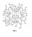
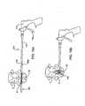
- Fig. 1illustrates a portion of the human spine having a superior vertebra 2 and an inferior vertebra 4, with an intervertebral disc 6 located in between the two vertebral bodies.
- the superior vertebra 2has superior facet joints 8a and 8b, inferior facet joints 10a and 10b, and spinous process 18.
- Pedicles 3a and 3binterconnect the respective superior facet joints 8a, 8b to the vertebral body 2. Extending laterally from superior facet joints 8a, 8b are transverse processes 7a and 7b, respectively. Extending between each inferior facet joints 10a and 10b and the spinous process 18 are laminal zones 5a and 5b, respectively.
- inferior vertebra 4has superior facet joints 12a and 12b, superior pedicles 9a and 9b, transverse processes 11a and 11b, inferior facet joints 14a and 14b, laminal zones 15a and 15b, and spinous process 22.
- the superior vertebra with its inferior facets, the inferior vertebra with its superior facet joints, the intervertebral disc, and seven spinal ligaments (not shown) extending between the superior and inferior vertebrae togethercomprise a spinal motion segment or functional spine unit.
- Each spinal motion segmentenables motion along three orthogonal axes, both in rotation and in translation.
- the various spinal motionsare illustrated in Figs. 2A-2C .
- Fig. 2Aillustrates flexion and extension motions and axial loading
- Fig. 2Billustrates lateral bending motion
- Fig. 2Cillustrated axial rotational motion.
- a normally functioning spinal motion segmentprovides physiological limits and stiffness in each rotational and translational direction to create a stable and strong column structure to support physiological loads.
- the specific location or source of spinal painis most often an affected intervertebral disc or facet joint. Often, a disorder in one location or spinal component can lead to eventual deterioration or disorder, and ultimately, pain in the other.
- Spine fusionis a procedure in which two or more adjacent vertebral bodies are fused together. It is one of the most common approaches to alleviating various types of spinal pain, particularly pain associated with one or more affected intervertebral discs. While spine fusion generally helps to eliminate certain types of pain, it has been shown to decrease function by limiting the range of motion for patients in flexion, extension, rotation and lateral bending. Furthermore, the fusion creates increased stresses on adjacent non-fused motion segments and accelerated degeneration of the motion segments. Additionally, pseudarthrosis (resulting from an incomplete or ineffective fusion) may not provide the expected pain-relief for the patient. Also, the device(s) used for fusion, whether artificial or biological, may migrate out of the fusion site creating significant new problems for the patient.
- facet jointscan also be a significant source of spinal disorders and debilitating pain.
- a patientmay suffer from arthritic facet joints, severe facet joint tropism, otherwise deformed facet joints, facet joint injuries, etc.
- spinal stenosis, degenerative spondylolithesis, and/or isthmic spondylotlisthesispinching the nerves that extend between the affected vertebrae.
- Facetectomyretractal of the facet joints
- Laminectomyretractal of the lamina, including the spinal arch and the spinous process
- problems with the facet jointscan also complicate treatments associated with other portions of the spine.
- contraindications for disc replacementinclude arthritic facet joints, absent facet joints, severe facet joint tropism, or otherwise deformed facet joints due to the inability of the artificial disc (when used with compromised or missing facet joints) to properly restore the natural biomechanics of the spinal motion segment.
- facet joint replacementWhile various attempts have been made at facet joint replacement, they have been inadequate. This is due to the fact that prosthetic facet joints preserve existing bony structures and therefore do not address pathologies that affect facet joints themselves. Certain facet joint prostheses, such as those disclosed in U.S. Pat. No. 6,132,464 , are intended to be supported on the lamina or the posterior arch. As the lamina is a very complex and highly variable anatomical structure, it is very difficult to design a prosthesis that provides reproducible positioning against the lamina to correctly locate the prosthetic facet joints. In addition, when facet joint replacement involves complete removal and replacement of the natural facet joint, as disclosed in U.S. Patent No.
- the prosthesisis unlikely to endure the loads and cycling experienced by the vertebra.
- the facet joint replacementmay be subject to long-term displacement.
- facet joint disordersare accompanied by disease or trauma to other structures of a vertebra (such as the lamina, spinous process, and/or transverse processes) facet joint replacement is insufficient to treat the problem(s).
- Dynamic posterior stabilizationMost recently, surgical-based technologies, referred to as “dynamic posterior stabilization,” have been developed to address spinal pain resulting from more than one disorder, when more than one structure of the spine have been compromised. An objective of such technologies is to provide the support of fusion-based implants while maximizing the natural biomechanics of the spine. Dynamic posterior stabilization systems typically fall into one of two general categories: posterior pedicle screw-based systems and interspinous spacers.
- pedicle screw-based systemsare disclosed in U.S. Patent Nos. 5,015,247 , 5,484,437 , 5,489,308 , 5,609,636 and 5,658,337 , 5,741,253 , 6,080,155 , 6,096,03 8 , 6,264,656 and 6,270,498 . These types of systems involve the use of screws that are positioned in the vertebral body through the pedicle. Certain types of these pedicle screw-based systems may be used to augment compromised facet joints, while others require removal of the spinous process and/or the facet joints for implantation.
- the Zimmer Spine Dynesys®employs a cord which is extended between the pedicle screws and a fairly rigid spacer which is passed over the cord and positioned between the screws. While this system is able to provide load sharing and restoration of disc height, because it is so rigid, it does not effective in preserving the natural motion of the spinal segment into which it is implanted.
- Other pedicle screw-based systemsemploy articulating joints between the pedicle screws. Because these types of systems require the use of pedicle screws, implantation of the systems are often more invasive to implant than interspinous spacers.
- interspinous spacersare preferred over pedicle based systems as they require a less invasive implantation approach and less dissection of the surrounding tissue and ligaments.
- Examples of interspinous spacersare disclosed in U.S. Patent Nos. Re. 36,211 , 5,645,599 , 6,149,642 , 6,500178 , 6,695,842 , 6,716,245 and 6,761,720 .
- the spacerswhich are made of either a hard or compliant material, are placed in between adjacent spinous processes.
- the harder material spacersare fixed in place by means of the opposing force caused by distracting the affected spinal segment and/or by use of keels or screws that anchor into the spinous process. While slightly less invasive than the procedures required for implanting a pedicle screw-based dynamic stabilization system, implantation of hard or solid interspinous spacers still requires dissection of muscle tissue and of the supraspinous and interspinous ligaments. Additionally, these tend to facilitate spinal motion that is less analogous to the natural spinal motion than do the more compliant and flexible interspinous spacers. Another advantage of the compliant/flexible interspinous spacers is the ability to deliver them somewhat less invasively than those that are not compliant or flexible; however, their compliancy makes them more susceptible to displacement or migration over time.
- US 6,796,983which is considered to represent the most relevant state of the art, discloses a spine distraction implant that is said to alleviate pain associated with spinal stenosis and facet arthropathy by expanding the volume in the spine canal and/or neural foramen.
- the implantis said to provide a spinal extension stop while allowing freedom of spinal flexion.
- the present inventionprovides devices for stabilizing at least one spinal motion segment according to claim 1. Preferred embodiments are set forth in the dependent claims.
- the stabilizing devicesinclude an expandable spacer or member having an unexpanded or lower profile configuration and an expanded or higher profile configuration.
- the unexpanded or lower profilefacilitates delivery of the device to an implant site by reducing the space requirements for such delivery.
- the spacer deviceIn an expanded or higher profile configuration, has a size, volume, diameter, length, cross-section and/or shape configured for positioning between the spinous processes of adjacent vertebrae in order to engage the vertebrae and/or distract the vertebrae relative to each other. Still yet, the expanded profile of the device may be further extended if necessary as elaborated on below.
- the spacer or expandable memberis a balloon made of either non-compliant or compliant material which may be porous or non-porous, or may include a mesh material which may be coated or lined with a porous or non-porous material.
- the materialmay define a cavity which is fillable with an inflation and/or expansion medium for inflating and/or expanding the expandable member.
- the devicemay further include a port for coupling to a source of inflation/expansion medium. In certain examples, the port may be used to deflate or evacuate the expandable member.
- the spacer or expandable membersare cages, struts, wires or solid objects having a first or unexpanded shape (having a lower profile) which facilitates delivery to the implant site and a second or expanded shape (having a larger profile) which facilitates distraction between vertebrae.
- the devicesmay have annular, spherical, cylindrical, cross, "X", star or elliptical shapes when in an expanded condition and/or unexpanded condition.
- the expandable membersmay be self-expanding or adjustably expandable depending on the extent of distraction required. Certain of the devices may be further extended once in an expanded state. For example, the height dimension of the device, or that dimension which affects distraction between adjacent vertebrae and/or spinous processes, may be further increased upon expansion in order to achieve the amount of distraction desired.
- the stabilizing devicesmay be configured such that the transformation from the low-profile state to the high-profile state is immediate or gradual, where the extent of expansion is controllable.
- the transformationmay occur in multiple discrete steps (i.e., extension of a dimension after the device is in an expanded state), in one-step, or evolve in a continuous fashion where at least one of volume, shape, size, diameter, length, etc. until the desired expansion end point is achieved in order to accommodate the size of the interspinous implant space and/or the amount of distraction desired between adjacent vertebrae.
- a minimum expanded or high-profile stateis initially achieved with the option to further expand or extend the high-profile state to accommodate the particular space requirements or distraction objectives of the implant site.
- This transformationmay be reversible such that after implantation, the stabilizing device may be partially or completely unexpanded, collapsed, compressed, retracted, deflated or at least reduced in size, volume, etc. in order to facilitate removal of the member from the implant site or to facilitate adjustment or repositioning of the member in vivo.
- the stabilizing devicesmay be configured to stay stationary in the implant site on their own (or "float") or may be further fixed or anchored to surrounding tissue, e.g., bone (e.g., spinous processes, vertebrae), muscle, ligaments or other soft tissue, to ensure against migration of the implant.
- the stabilizing devicesmay be flexible to allow some degree of extension of the spine or may otherwise be rigid so as prevent extension altogether.
- the devicesmay include one or more markers on a surface of the expandable member to facilitate fluoroscopic imaging.
- Systems for stabilizing at least one spinal motion segmentmay include one or more of the expandable members as described above.
- the systemsmay further include an expansion medium for injection within or for filling the interior of the expandable member via the port.
- the systemsmay further include delivery mechanisms to which the stabilizing spacers are attached which, when actuated or released from the stabilizing device, cause the device to expand or deploy.
- the subject systemsmay further include at least one means for anchoring or securing the expandable member to the spinal motion segment to prevent migration of the device from the implant site.
- the securing meansis a screw or the like for penetrating bone, where the spacer is configured to receive or partially constrain the screw.
- the devicemay then be anchored or secured to a bony structure of the vertebrae, such as one of the spinous processes between which it is implanted.
- the devicemay be further configured to be anchored to a bony structure of both vertebrae between which it is implanted and, as such, function to "fuse" the vertebrae together.
- Such capabilitywould allow a physician to convert a spinal stabilization procedure to a fusion procedure if, upon commencing the implant procedure, the spinal motion segment being treated is observed to require such.
- a devicewould allow a fusion procedure to be performed subsequently (e.g., months or years later) to the dynamic stabilization procedure should the affected spinal motion segment degenerate further. Without having to remove the device and/or implant additional components (other than bone screws or the like), trauma to the patient and the cost of the procedure is greatly minimized.
- Methods for stabilizing at least one spinal motion segmentinvolve the implantation of one or more devices or expandable spacers of the present invention, in which the expandable member is positioned between the spinous processes of adjacent vertebrae in an unexpanded or undeployed condition and then subsequently expanded or deployed to a size and/or shape for selectively distracting the adjacent vertebrae.
- the temporary implantation of the subject devicesis also described which may be subsequently removed from the patient once the intended treatment is complete.
- the methodsmay also include adjustment of the implants in vivo.
- Many of the methodsinvolve the percutaneous implantation of the subject devices from either an ipsolateral approach or a mid-line approach into the interspinous space. Certain methods involve the delivery of certain components by a lateral approach and other components by a mid-line approach.
- the implantation methodsmay involve the use of cannulas through which the stabilizing devices are delivered into an implant site, however, such may not be required, with the stabilizing devices be configured to pass directly through an incision.
- the inventiongenerally includes an interspinous spacer device as well as instruments for the percutaneous implantation of the interspinous spacer.
- a key feature of the interspinous spacer deviceis that it is expandable from a low profile configuration to a higher profile or operative configuration. This design allows the device, when in the low profile condition, to be delivered by percutaneous means without requiring the removal of any portion of the spinal motion segment into which the device is implanted.
- certain of the devicesinclude balloon embodiments or those having expandable cavities which are expandable by the introduction of an inflation or expansion medium therein. Many of these are illustrated in Figs. 3-14 . Certain other devices include those which have a more mechanical structure which is self-expandable upon release from a confined condition or which is actively expandable by actuation of another instrument. These are illustrated in Figs. 15-31 .
- Interspinous device 24includes an expandable spacer body 34 that has a size and shape when in the expanded condition for operative positioning between the spinous processes of adjacent superior and inferior vertebrae of the spinal motion segment being treated.
- Expandable body 34is made of an expandable or inflatable biocompatible material such as non-porous material, e.g., latex, acrylate or a metal mesh, e.g., a nitinol or titanium cage.
- spacers made of an inflatable non-porous materialare inflated with an inflation or expansion medium, such as air, saline, another biologically compatible fluid, or a flowable solid material, such as polyurethane, or a gel, which thickens or hardens substantially upon injection into balloon 34.
- an inflation or expansion mediumsuch as air, saline, another biologically compatible fluid, or a flowable solid material, such as polyurethane, or a gel, which thickens or hardens substantially upon injection into balloon 34.
- balloon 34is initially inflated with air to provide some structure or rigidity to it to facilitate its optimum positioning and alignment between the spinous processes. Once positioned as desired, balloon 34 is injected with a flowable solid material (the air therein being displaced possibly via a vent hole within port 32).
- the expandable bodyis made of a non-compliant or semi-compliant material so as to maintain a substantially fixed shape or configuration and ensure proper, long-term retention within the implant site.
- the expandable membermay be made of a compliant material.
- the compressibility and flexibility of balloon 34can be selected to address the indications being treated.
- the mesh or cagemaybe made of a super-elastic memory material which is compressible for delivery through a cannula and which is self-expanding upon implantation. Upon expansion, the mesh or cage may be self-retaining whereby its struts, links or wires are sufficiently rigid by themselves to maintain the expanded condition and withstand the natural forces exerted on it by spine.
- the mesh or cagemay have an exterior coating or an interior lining made of materials similar to or the same as that used for the balloon spacers, or may otherwise be embedded in such material.
- an expansion mediummay be used to fill the interior of the cage or mesh structure, such as with a biologically compatible fluid or flowable solid material used with the balloon-type embodiments.
- the size or volume of the implanted expandable spacermay be selectively adjusted or varied. For example, after an initial assessment upon implant, it may be necessary to adjust, either reduce or increase, the size or volume of the spacer to optimize the intended treatment. Further, it may be intended to only temporarily implant the spacer for the purpose of treating a temporary condition, e.g., an injured or bulging or herniated disk. Once the repair is achieved or the treatment completed, the spacer may be removed, either with or without substantially reducing the size or volume of the spacer.
- the spacer as well as the inflation/expansion materialmay be made of biodegradable materials wherein the spacer degrades after a time in which the injury is healed or the treatment completed.
- expandable body 34When unexpanded or deflated, as shown in Figs. 3A and 3B (balloon type) and in Figs. 11C and 11D (mesh type) expandable body 34 has a low profile, such as a narrow, elongated shape, to be easily translated through a delivery cannula 70.
- the shape of expandable body 34when in an expanded or inflated state, has larger profile which is generally H-shaped.
- Expandable body 34has lateral or side portions 30, end portions 26 and apexes 28 defined between the side portions 30 and the end portions 26. End portions 26 are preferably recessed or contoured to provide a narrowed central portion along the height dimension or major axis of expandable body 34 to readily fit between and to conform to the spinous processes.
- expandable body 34has an apex-to-apex dimension (i.e., height or major axis dimension) from about 1 cm to about 5 cm, and typically from about 1 cm to about 2 cm, and a width dimension (minor axis dimension) from about 1 cm to about 4 cm and typically about 1 cm.
- apex-to-apex dimensioni.e., height or major axis dimension
- balloon 34has an inflation or injection port 32 at a sidewall 30 for coupling to a source of inflation or expansion material or medium.
- Port 32may consist of a one-way valve which is self-sealing upon release from an inflation mechanism or tube 76.
- Port 32is further configured to releasably engage from tube 76, where such engagement may be threaded or involve a releasable locking mechanism.
- port 32simply acts as an exit port, however, where an expansion material is used, it also functions as an injection port for the expansion material.
- device 24may include a pair of tabs 36 which may be positioned on one side of the device where the tabs 36 are preferably situated at the apexes 28 of expandable body 34. Pins or screws (not yet shown) may be used to secure the tabs against the spinous process to further ensure long-term retention of device 24 within the implant site.
- Tabs 36are made of a biocompatible material, such as latex, acrylate, rubber, or a metal, and may be made of the same material used for the expandable member 34.
- Shown here attached to tabs 36are tethers 38 which are used in part to manipulate the positioning of expandable body 34 upon implantation into the targeted spinal motion segment.
- the tethersmay be made of any suitable material including but not limited to materials used to make conventional sutures.
- tethers 38may be attached directly to the expandable body itself.
- device 24may further include radiopaque markers 40 on the surface of expandable body 34 visible under fluoroscopic imaging to facilitate positioning of the expandable body. Any number of markers 40 may be employed anywhere on expandable body 34, however, as few as four markers, one at each apex, may be sufficient. With embodiments employing cage or mesh expandable bodies, the cage or mesh material itself may be radiopaque.
- a systemincludes a cannula device 70 having an outer sheath 72, a proximal hub 78 and preferably at least two interior lumens 74, 76 for the percutaneous delivery the device and other tools for implanting the device, which tools may include a cutting instrument 62 (see Fig. 6C ), a device delivery instrument 76, an endoscope, etc., which tools will be further discussed in the context of the description of the subject methods with reference to Figs. 5-10 .
- Figs. 5A-5Cthe spinal motion segment of Fig. 1 is illustrated having spinal ligament 54 extending between the superior spinous process 18 and the inferior spinous process 22.
- a percutaenous punctureis made into the skin 30 adjacent the target spinal motion segment of a patient undergoing the implantation of the interspinous device, and a cannula 70 is penetrated to the spinous ligament 54.
- the puncture and subsequent penetrationmay be made by way of a sharp distal tip of cannula 70 or by a trocar (not shown) delivered through a lumen of cannula 70.
- the spinous ligament 54is then dissected and an opening 58 created therein by way of a cutting instrument 60, such as a simple scalpel, an electrosurgical device or the like, delivered through a lumen of cannula 70.
- a cutting instrument 60such as a simple scalpel, an electrosurgical device or the like
- Cutting instrument 60may then be removed from cannula 70 and, as illustrated in Figs. 7A-7D (balloon type) and in Figs. 11A-11D (cage type), a delivery instrument 16 having interspinous device 24 operatively preloaded is delivered through cannula 70.
- the preloading of device 24 to delivery instrument 76involves providing expandable body 34 in an unexpanded or deflated state and releasably coupled, as described above, by way of inflation or injection port 32 of expandable body 34 to the distal end of delivery instrument 76.
- instrument 76may act as an inflation lumen for balloon type embodiments through which an inflation medium is transported to within expandable body 34.
- the expandable bodymay have a degree of stiffness in an unexpanded or deflated state such that it may maintain an elongated configuration so as to be directly insertable and pushable through cannula 70.
- the expandable member 34is made of a cage or mesh material.
- a pusher or small diameter rod(not shown) may be inserted through inflation port 32 to within expandable body 34 to keep it in an elongated state so as to prevent expandable body 4 from bunching within cannula 70 and to provide some rigidity to more effectively position the expandable body in the target implant site. The rod is then removed from expandable body 34 and from delivery device 76 upon positioning the expandable body at the target implant site.
- expandable body 34is folded or compressed about its minor axis with the side wall opposite the inflation port 32 defining a distal end 25 (see Fig. 3B ) and the apexes 28 of the expandable body folded proximally of distal end 25 to provide a streamline, low profile configuration for delivery through cannula 70.
- interspinous device 24is preloaded to delivery device 76 as just described, device 24 is then inserted into a lumen of cannula 70 with tethers 38 pulled back and trail proximally so that the tether ends 38a extend from hub 78 of cannula 70.
- Expandable body member 34is translated through cannula 70 to within opening 58 within spinous ligament 54 as best illustrated in Figs. 7C and 11C .
- expandable body 34is centrally positioned within opening 58 so that the countered ends 26 of expandable body 34 readily engage with the opposed spinous processes 18, 22.
- Fluoroscopymay be employed to visualize markers 40 so as to ensure that expandable body 34 centrally straddles the spinous ligament opening 58, i.e., the markers on the distal side 25 of the expandable body are positioned on one side of the spine and the markers on the proximal side of the expandable body (the side on which port 32 is located) are positioned on the other side of the spine.
- expandable body 34is inflated or expanded, as illustrated in Figs. 8A-8D and 12A-12D .
- inflationoccurs by allowing an inflation or expansion medium, as discussed above, to enter into the interior of the expandable body via port 32.
- the expandable bodymay be configured to expand automatically upon exiting cannula 70.
- the inflation or expansion of expandable body 34may also be visualized under fluoroscopy whereby markers 40, as best shown in Fig. 8C , are observed and the position of expandable body 34 may be adjusted to ensure optimum positioning upon complete inflation.
- Adjustments of the expandable body's positionmay be accomplished by manually pulling on one or both tether ends 38a which in turn pulls on tabs 26 to which the tethers 38 are attached at their proximal ends.
- the tethers 38are selectively pulled as necessary to center or optimally position interspinous expandable body 34 to achieve the desired treatment of the targeted spinal motion segment.
- the expandable bodyis initially inflated with air and then filled with a solid or fluid medium
- the latteris preferably not delivered or injected into the interior of the expandable body until the position of the expandable body within the interspinous space has been verified and optimized.
- the expandable bodymay simply be deflated of air to the extent necessary and repositioned in a less inflated or deflated state. If necessary, for example where it is found that the maximum spacer or expandable body size is insufficient for the particular application at hand, expandable body 34 may be completely deflated and removed and replaced with a more suitably sized unit.
- the expansion mediume.g., polyurethane
- expandable body 34is caused to expand to a selected volume and in so doing forces apart (see arrow 80) the spinous processes 18, 22 in between which it is situated.
- This selective distraction of the spinous processesalso results in distraction of the vertebral bodies 2, 4 (see arrow 82) which in turn allows the disk, if bulging or distended, to retract to a more natural position (see arrow 84).
- the extent of distraction or lordosis undergone by the subject vertebraecan be monitored by observing expandable body markers 40 under fluoroscopy.
- the extent of possible distractionmaybe limited by the capacity of expandable body 34 and the type of expandable body material employed.
- the requisite volume of the inflation mediummay be substantially fixed whereby the balloon achieves its fully expanded configuration upon filling it with the fixed volume of medium.
- the extent of expansionmay be variable and selectable intraoperatively depending on the extent of lordosis or distraction to be achieved between the spinous processes in which balloon 34 is now interposed.
- inflation/expansion lumen 76is disengaged from expandable body port 32 which then becomes sealed by means of a one-way valve that is closed upon disengagement of lumen 76. Inflation/expansion lumen is then removed from cannula 70. While the opposing compressive force exerted on expandable body 34 by the distracted spinous processes 18, 22 maybe sufficient to permanently retain expandable body 34 therebetween, the interspinous device may be further secured to the spinous processes 18, 22 to ensure that the expandable body does not slip or migrate from its implanted position. To this end, tabs 36 are anchored to the spinous processes as illustrated in Figs. 10A and 10B and in Figs. 13A and 13B .
- anchoring meanssuch as screws, tacks, staples, adhesive, etc.
- cannulated screws 90are used as anchors and are delivered to the target site releasably coupled to screw driving instrument 88. While various screw attachment and release mechanisms may be employed, a simple configuration involves providing the screws 90 with a threaded inner lumen which is threadably engagable with the threaded distal end of instrument 88.
- screws 90along with instrument 88, can be tracked and translated over respective tethers 38, which function as guide wires.
- instrument 88By manipulating instrument 88, the screws are driven or screwed into the respective spinous process. Screwdriver 88 is then disengaged or unscrewed from screw 90. After both tabs 36 are securely anchored to the spinous processes, the screwdriver and the cannula may be removed from the patient's back.
- Figs. 14A-14Fillustrate an alternative method for implanting the expandable member.
- the methodcontemplates pre-inflating or pre-expanding the expandable member prior to positioning the expandable member within the interspinous space.
- the vertebrae 2 and 4may be distracted prior to insertion of the pre-expandable balloon implant.
- a temporary distraction mechanismsuch as another balloon or a mechanically actuated device, is inserted into the interspinous space.
- the permanent or implantable expandable membercan then be placed within the interspinous space, and the temporary distraction member may then be removed from the space.
- the expansion materialmost likely is a fluid, such as saline, which may be easily aspirated through port 32 or may be allowed to drain out via a penetration or cut made in the expandable member.
- the expansion materialis a flowable solid, which may or may not subsequently harden within the expandable member, the material may be one that is reconstitutable into a liquid form which may then be subsequently aspirated or evacuated from the expandable member.
- a cannulasuch as cannula 70 may be used and an aspiration instrument delivered therethrough and coupled to port 32.
- the expandable membermay be easily removed through cannula 70.
- removal of the spaceris obviated.
- any of the above-described steps or proceduresincluding but not limited to cannulation of the target area, dissection of the spinous ligament, insertion of the expandable body within the dissected opening of the spinous ligament, inflation and/or expansion of the expandable body, adjustment or readjustment of the expandable body, and anchoring of the tabs, etc., may be facilitated by way of a scope 62 delivered through a lumen of cannula 70 to the open distal tip of cannula 70.
- a second cannula delivered through another percutaneous penetrationmay be employed for use of an endoscope and any other instruments needed to facilitate the procedure.
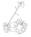
- FIG. 14Aillustrates an exemplary embodiment of a temporary distraction mechanism 100 having an expandable strut configuration.
- Mechanism 100includes bilateral struts 102 which are hinged and foldable at hubs 104, respectively. Bridging the struts 102 at superior and inferior ends are spinous process engagement portions 106 which are preferably configured to conformingly engage with the spinous processes 18, 22. Extending centrally between hubs 104 is a distal portion of guide wire 108, which also extends proximally through proximal hub 104a. Guide wire 108 is in threaded engagement with hub 104a whereby hub 104a can be translated both proximally and distally along guide wire 108.
- expandable member 100can be provided in a low profile, compressed state upon proximally translating hub 104a in a Proximal direction.
- distraction mechanism 100is easily deliverable through cannula 70, as described above, to with the interspinous space.
- distraction mechanism 100is expandable to a higher profile or expanded state by translating hub 104a toward hub 104b in a distal direction along guide wire 108, as illustrated in Fig. 14A .
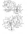
- an implantable expandable member 110is delivered adjacent the distracted spinal motion segment.
- Expandable member 110may be delivered from the same incision and side as distraction mechanism 100 (ipsolateral approach) and as well as through the same working channel, or may be delivered through a different incision on the same or opposing side of the spinal motion segment being treated (bilateral approach) using two different working channels.
- expandable member 110is delivered from the same side of the spinous process as distraction mechanism 100.
- Expandable member 110may delivered through a separate designated lumen in cannula 70 and translated distally of hub 104b of distraction mechanism 100.
- expandable member 110is inflated or expanded as described above with respect to expandable member 34, for example, by way of an inflation lumen extending through guide wire 108.
- Tethers 112may be provided on expandable member 110 to retract and manipulate it to within the interspinous space, as illustrated in Fig. 14C .
- distraction mechanism 100may be removed from the interspinous space immediately or, if the expandable member has been filled with a curable expansion medium or one that involves setting or hardening, the distraction mechanism may be kept in the interspinous space until the desired consistency, curing or hardening has been achieved by the expansion medium.
- a low profile stateAs illustrated in Fig. 14D , this is accomplished by translating proximal hub 104a proximally along guide wire 108. Distraction member 100 may be retracted out through a cannula or removed directly in this low profile state, leaving expandable member 100 alone within the implant site as illustrated in Fig. 14E . Tethers 112 may then be cut or secured in place.
- a strap 116 or the likemay be implanted to further secure expandable member 110 within the implant site and reduce the risk of migration.
- bores or holes 114have been formed through the thickness of the spinous processes 18, 22 and strap 116 threaded there through with its ends secured together by a securing means 120, such as a suture, staple or clip, as illustrated in Fig. 14F .
- a securing means 120such as a suture, staple or clip, as illustrated in Fig. 14F .
- strap 116could be wrapped around the spinous processes 18, 22.
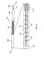
- expandable spacer 130 of Fig. 15Ais a cage-like structure having spaced-apart, parallel strut members 132 extending between and fixed to hubs 134.
- spacer 130may be provided on and deliverable by way of a guide wire 136 which is threadably engaged to and disengagable from proximal hub 134a.
- spacer 130is expanded by advancing proximal hub 134a distally along guide wire 136 thereby forcing struts 132 radially outward and away from each other whereby the expanded configuration of spacer 130 is elliptical or, in a more advanced state of expansion, substantially spherical.
- guide wire 136unthreaded from hub 134a and removed from the implant region.
- Figs. 16A and 16Billustrate another embodiment of an expandable spacer 140 which is in the form of a coiled band 142 terminating at an outer end 144 having a configuration for receiving and locking onto inner end 146 upon full expansion or unwinding of the coil.
- the diameter of coil 142 in an unexpanded or fully wound stateis small enough to allow easy insertion between spinous processes 18, 22.
- coil 142is allowed to expand and unwind thereby distracting vertebrae 2 and 4 apart from each other.
- inner end 146is coupled to outer end 144. While the figures show band 142 inserted transversely to spinous processes 18, 22, it may alternatively be inserted in line or in the same plan defined by the spinous processes.
- Figs. 17A-17Cillustrate another interspinous spacer 150 having interlocked nested portions 152.
- Nested portions 152are each shaped and configured to be received within one of its adjacent portions and to receive the other of the adjacent portions when in a low profile state, as illustrated in Fig. 17A .
- spacer 150which may be spring loaded or be expandable by way of an instrument (not shown) which may be inserted into the spacer's center and rotated to flare portions 152, vertebrae 2 and 4 are caused to distract from each other.
- Portions 152may have a configuration or shape which allows them to bite or dig into the spinous process 18, 22 and become securely retained therein.
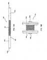
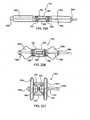
- FIGs. 18A and 18Billustrate another interspinous spacer 160 in an undeployed or unexpanded state and a deployed or expanded state, respectively.
- Spacer 160includes an expandable tubular member 162 having end portions 164a, 164b which are capped by hubs 166a, 166b, respectively.
- hubsmay be provided fixed to tubular member 162 or may be releasably coupled thereto.
- a sleeve or retaining member 168is circumferentially positioned about tubular between end portions 164a, 165a. Most typically, retaining member 168 is positioned substantially centrally (as shown) on tubular member 162, but may be positioned laterally towards one or the other end.
- Retaining member 168has a length that covers about one third of the length of tubular member 162, but may be longer or shorter depending on the application.
- interspinous spacer 160may further include a core member (shown in Fig. 21 ) within the lumen of the tubular member and which may be provided integrated with spacer 160.
- the core membermay be provided as a detachable component of the device used to deliver and implant the spacer (see Figs. 19A and 19B ).
- spacer 160has an elongated tubular or cylindrical shape, and may have any suitable cross-sectional shape, e.g., circular, oval, starred, etc., where the more angular cross-sections may allow the device to bite or dig into the spinous processes and for better retention.
- tubular member 162has a length in the range from about 20 mm to about 80 mm, and more typically from about 30 mm to about 50 mm, and a diameter or average thickness in the range from about 4 mm to about 12 mm, and more typically from about 6 mm to about 9 mm.
- spacer 160is deliverable to an implant site between adjacent spinous processes in a minimally invasive manner.
- spacer 160In the deployed state, as illustrated in Fig. 18B , spacer 160 has a dumbbell or H-shaped configuration, where the length of spacer 160 is less than and the diameter or height of spacer 160 is greater than the corresponding dimensions of the spacer when in an undeployed state.
- the length dimension of the end portions 164a, 164b of tubular member 162has been reduced by about 25% to about 70% while the diameter of the end portions 164a, 164b has been increased by about 50% to about 600%, and the diameter of the central or sleeve-covered portion has been increased by about 200% to about 400%, where the diameter of the portions of the tubular member 164a, 164b not covered by retaining member 168 have a greater diameter than the portion of tubular member 162 which is covered by retaining member 168.
- the increased diameter of covered or central portion 168distracts the adjacent vertebrae so as to provide pain relief.
- the diameter of hubs 166a, 166bmay remain constant upon deployment of device 160.
- tubular member 162has a length in the range from about 15 mm to about 50 mm, and more typically from about 20 mm to about 40 mm, and an end portion diameter in the range from about 10 mm to about 60 mm, and more typically from about 15 mm to about 30 mm, and a central portion diameter in the range from about 5 mm to about 30 mm, and more typically from about 8 mm to about 15 mm.
- the deployed spacer 160fits snugly within the interspinous space and is held in place by the surrounding muscle, ligaments and tissue.
- any suitable materialsmay be used to provide a spacer 160 which is provided in a first state or configuration, e.g., the undeployed state illustrated in Fig. 18A , and which can be manipulated to achieve a second state or configuration, and back again if so desired.
- a polymer based material or any other material which allows for simultaneous axial shortening and radial expansionis suitable for use to form tubular member 162.
- the end portions 164a, 164bmay be made of the same or a different material as that of the central or covered portion.
- a flexible or shaped memory material or any other material which also allows for simultaneous axial shortening and radial expansion, but which is less expandable, i.e., maintains a compressive force about tubular member 162, than the material employed for tubular member 162may be used to form retaining member 168.
- retaining member 168limits the extent of radial expansion as well as axial shortening that the covered portion of tubular member 162 can undergo.
- suitable materials for the retaining memberinclude but are not limited to Nitinol or polyethelene in a braided or mesh form.
- retaining member 168may be such that the radial force applied to the portion of tubular member 162 that it covers is constant or consistent along its length so as to maintain a constant diameter along its length or, alternatively, may have a varying radial force so as to allow for selective shaping of the covered portion of tubular member when in a deployed state.
- Retaining member 168may be constructed so as to resist bending or flexing upon forcible contact with the spinous processes and, as such, does not conform to the spinous processes.
- the retaining member 168may be constructed from a more flexible material that allows for some compression and, as such, may conform or be conformable to the spinous processes. Further, the physical properties and dimensions of the materials used for both the tubular member and the retaining may be selected to provide the desired amount of distraction between target vertebrae.
- Delivery device 170includes an outer shaft 172 and an inner shaft 178, movable relative (axially, rotationally or both) to outer shaft 172, both extending from a handle mechanism 174.
- inner shaft 178may be configured to be retracted proximally within outer shaft 172, or outer shaft 172 may be configured to be advanced distally over inner shaft 178, or both configurations may be employed together, i.e., while outer shaft 178 is advanced, inner shaft 178 is retracted.
- the relative movementmay be accomplished in any suitable manner, for example by way of a screw configuration, i.e., where the shaft members engage by way of corresponding threads, as illustrated in Fig. 20A , or by way of a ratchet configuration, as illustrated in Fig. 20B .
- the relative movementis accomplished by manual actuation of actuator 176 coupled to handle 174. While only mechanical embodiments of the movement actuation are illustrated, the same can be achieved by electrically or pneumatically-driven devices or mechanisms.
- spacer 160may be provided with an integrated core member or the core member may be detachably provided on the distal end 182 of inner shaft 178.
- distal end 182 of inner shaft 178is configured to temporarily couple with a proximal end (i.e., the end closest to handle 174) of the core member.
- the distal end 182 of inner shaft 178is configured to be inserted into the lumen of tubular member 162, as illustrated in Fig. 21 , connect to or engaged with distal hub 166b (i.e., the hub positioned furthest from handle 174) and be detachable at a proximal end 184 from inner shaft 178 to function as a core member.
- the end portion 182 of the inner shaft 178 functioning as the core membermay have a length that is as short as the length of tubular member 172 when in a deployed state, with no extra length or remaining portion extending laterally of the implanted device.
- the core lengthmay need to be as long as tubular member 172 when in the undeployed state.
- the core membermay be segmented to allow for selective removal of one or more lengths or portions from the proximal side of the core member subsequent to implantation of the spacer so as not to have any excess length extending from the spacer.
- retraction of inner shaft 178retracts distal hub 166b towards proximal hub 166a and/or advancement of outer shaft 172 advances proximal hub 166a towards distal hub 166b, thereby causing tubular member 162 to be compressed axially, and thus expanded radially, as shown in Fig. 19B .
- distal hub 166bmay be fixed to tubular member 162
- proximal hub 166amay be provided as a separate component having a central bore which allows it to receive and axially translate over inner shaft 178.
- Proximal hub 166amay be configured to readily slide over inner sha$ 178 in a distal direction (but possibly not in a proximal direction) or may be threaded in order to advance over inner shaft 178.
- the advancement of proximal hub 166aaxially compresses tubular member 172 and causes it to radially expand.
- the axial compression or radial expansionmay be continued until the desired extent of distraction occurs between vertebrae 2 and 4.
- proximal hub 166ais secured to either the proximal end of tubular member 162 and/or the proximal end of the core member 182, such as by a threaded or snap-fit engagement or by activating a lock mechanism (not shown).
- Inner shaft 178may then be released from the core member (or distal end 182 of inner shaft 178 may be released from inner shaft 178 and left within tubular member 172 to function as the core member) which, along with the end hubs 166a and 166b, maintain the implanted spacer 160 in a deployed state so as to maintain distraction between the vertebrae.
- the reconfiguration of spacer 160may be further facilitated by selectively configuring the wall of tubular member 162.
- the interior or luminal surface of tubular member 162may be contoured or incorporated with divets or spaces 180 where, upon compression of tubular member 162, the walls of the uncovered portions 164a, 164b of tubular member 162 will more readily fold inward to provide the resulting configuration shown in Fig. 18B .
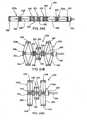
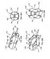
- FIGs. 22A-22Cillustrate another interspinous spacer 190 in an undeployed/unexpanded state, in an intermediate state during deployment and in a deployed/expanded state, respectively.
- Spacer 190includes expandable end portions 192a, 192b which are capped by hubs 198a, 198b, respectively.
- hubs 198a, 198bmay be provided fixed to the end members or may be releasably coupled thereto.
- Extending between end portions 192a, 192bis a central portion 194 including a plurality of blocks or wedges, such as side blocks 200 and end blocks 202, surrounded by a cover, sleeve or retaining member (not shown) which functions to hold the blocks in frictional engagement with each other.
- a core member or rod 196extends centrally through end portions 192a, 192b and central portion 194 where end blocks 202 are coaxially positioned on core 196 and are slidably translatable thereon.
- Core member 196 or a portion thereofmay be provided integrated with spacer 190 or may be provided as a detachable component of the device used to deliver and implant the spacer.
- end portions 192a, 192bmay be made of a polymer based material or any other material which allows for simultaneous axial shortening and radial expansion when compressed.
- Blocks 200, 202have a more rigid configuration in order to distract the adjacent spinous processes which define the interspinous space into which spacer 190 is positioned without substantial compression of central portion 194.
- the blocksmay be made of a rigid polymer material, a metal, ceramics, plastics, or the like.
- the blocksare selectively sized, shaped and arranged such that an inwardly compressive force on end blocks 202 along the longitudinal axis of the spacer forces end blocks 202 together which in turn forces side or lateral blocks 200 outward and away from each other, as illustrated in Fig. 22B .
- the inwardly tapered sides of the blocksenable slidable engagement between adjacent blocks.
- the covering (not shown) around the blocksis made of a stretchable material so as to accommodate the radial expansion of central portion 194. As such, the cover may be made of a polymer based material.
- the central and end portions of spacer 190When in an undeployed state, as shown in Fig. 22A , the central and end portions of spacer 190 have tubular or cylindrical configurations, and may have any cross-sectional shape, length and or diameter as provided above with respect to spacer 160 of Figs. 18A and 18B . Deployment of spacer 190 within an interspinous space may be accomplished in the manner described above. In a fully deployed state, as illustrated in Fig. 22C , spacer 190 has a dumbbell or H-shaped configuration with a change in length and height dimensions as provided above. The increased diameter of central portion 194 when spacer 190 is the deployed configuration distracts the adjacent vertebrae so as to provide pain relief. While the respective dimensions of the spacers change from an undeployed to a deployed state, the spacers may be configured such that the overall size of volume occupied by the spacer does not change.
- Spacer 210is illustrated in an undeployed/unexpanded state, in an intermediate state during deployment and in a deployed/expanded state in Figs. 23A-23C , respectively.
- Spacer 210includes expandable end portions 212a, 212b capped by hubs 224a, 224b, respectively.
- hubs 224a, 224bmay be provided fixed to the end members or may be releasably coupled thereto.
- Extending between end portions 212a, 212bis a central portion 214 including a plurality of linkages 216 and blocks 220, 222, which collectively provide opposing struts.
- Each linkage 216has a length and is pivotally coupled to a side block 220 and an end block 222, where end blocks 222 are coaxially positioned on core 218 and are slidably translatable thereon. While the materials and configuration of end portions 212a, 212b may be as described above, linkages 216 are preferably made of a metal material.
- a core member or rod 218extends centrally through end portions 212a, 212b and central portion 214. Core member 218 or a portion thereof may be provided integrated with spacer 210 or may be provided as a detachable component of the device used to deliver and implant the spacer.
- the central and end portions of spacer 190have tubular or cylindrical configurations, and may have any cross-sectional shape, length and or diameter as provided above.
- side blocks 220are close together and end blocks 222 are spaced apart with the lengths of linkages 216 aligned with the longitudinal axis of core member 218.
- end portions 212a, 212baxially compress and radially expand as described above thereby forcing end blocks 222 together which in turn force side or lateral blocks 220 outward and away from each other, as illustrated in Fig. 23B .
- This actioncauses linkages 216 to spread apart, as shown in Fig. 23B , and move to positions where their lengths are transverse to the longitudinal axis of core 218, as illustrated in Fig. 23C .
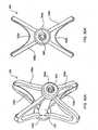
- Interspinous spacer 230 of Figs. 24A-24Cemploys the linkage arrangement of the central portion of spacer 190 of Figs. 23A-23C in both of its end portions 232a, 232b as well as its central portion 234.
- end portions 232a, 232bemploy linkages 236, which are longer than linkages 238 used for central portion 234, but which are arranged in similar engagement with side blocks 248 and end blocks 250.
- dampening washers 244On each side of central portion 234 and in between the central portion and the end portions 232a, 232b, respectively, are dampening washers 244.
- a core member 240extends between and through the end blocks 250 of distal end member 232a and the end blocks 252 of central portion 234 as well as the dampening washers 244 positioned therebetween, all of which, except the most distal end block, may slidably translatable along core member 240.
- Core member 240is releasably attached at a proximal end to ratcheted drive rod 242 of a delivery device as discussed above with respect to Figs. 19-21 which rod 242 extends through the proximal end portion 232a and hub 246, as illustrated in Fig. 24B .
- the central and end portions of spacer 230have tubular or cylindrical configurations.
- side blocks 248 and 252 of end portions 232a, 232b and central portion 234, respectively,are close together and end blocks 250 and 252 of end portions 232a, 232b and central portion 234, respectively, are spaced apart with the lengths of linkages 236, 238 aligned with the longitudinal axis of core member 240.
- the end blocksare drawn together thereby forcing side or lateral blocks 220 outward and away from each other, as illustrated in Fig. 24B .
- This actioncauses the linkages of the end and central portions to spread apart, and move to positions where their lengths are transverse to the longitudinal axis of core 240, as illustrated in Fig. 24C , the fully deployed state of spacer 230.
- Figs. 18A and 18B and the linkage end portions of Figs. 24A-24Cmay be used together to form a spacer.
- spacer 260is illustrated in Figs. 25A-25C .
- Spacer 260includes linkage-block end portions 262a, 262b and a compressible central member 264 around which is positioned a circumferential retaining member 278 made of a braided mesh-like material.
- a core member 274extends between and through the end blocks 270 of distal end member 262a and through central portion 264, all of which, except the most distal end block, may slidably translatable along core member 260.
- Core member 260is releasably attached at a proximal end to ratcheted drive rod 272 of a delivery device as discussed above with respect to Figs. 19-21 which rod 272 extends through the proximal end portion 262a and hub 272, as illustrated in Fig. 25B .
- the central and end portions of spacer 230have tubular or cylindrical configurations.
- side blocks 268 of end portions 262a, 262bare close together and end blocks 270 of end portions 262a, 262b are spaced apart with the lengths of linkages 266 aligned with the longitudinal axis of core member 274.
- the end blocksare drawn together thereby causing linkages 266 of the end portions to spread apart thereby forcing side or lateral blocks 268 outward and away from each other, as illustrated in Fig. 25B , until linkages 266 move to positions where their lengths are transverse to the longitudinal axis of core 274, as illustrated in Fig. 25C , the fully deployed state of spacer 260.
- Each of the expandable and or inflatable interspinous spacers described thus faris particularly configured to be delivered minimally invasively, even percutaneously, from a single incision located laterally to one side (left or right) of the spinal motion segment to be treated.
- the present examplealso includes interspinous spacers which are deliverable through a mid-line incision made directly into the interspinous ligament. Examples of such spacers are now described.
- FIGs. 26A and 26Bare perspective and front views, respectively, of interspinous spacer 280 which is configured for implantation by way of a percutaneous mid-line approach.
- Spacer 280shown in a deployed state, includes a central member or portion 282 and four struts or legs 284 which are substantially radially expandable from central portion 282.
- Central portion 282has a cylindrical configuration having a diameter sized for delivery through a small gauge cannula and a length that allows placement within an interspinous space.
- a lumen 285extends at least partially through the center of central portion 282 and is configured, e.g., threaded, to be releasably engaged to a delivery tool.
- Each strut 284includes one or more blocks 288. Where more than one block 288 per strut is employed, such as with spacer 280 which employs two blocks 288 per strut 284 and spacer 290 of Fig. 27 which employs three blocks 288 per strut 284, the blocks are stacked and slidably interconnected to each other in a manner that allows the to translate linearly relative to each other along parallel axes.
- a tongue and groove configuration 292is employed with the illustrated embodiment to interconnect stacked blocks, but any suitable interconnection which enables such relative motion between the blocks may be used.
- Such configurationmay also be employed to interconnect the innermost block to central member 282 where outer ridges or tongues 296 on central member 282 slidably interface with a corresponding groove on inner end of the innermost block.
- blocks 288are slidable relative to central member 282 along an axis parallel to the longitudinal axis of central member 282.
- struts 284may be evenly spaced apart about the circumference of central member 282. In other embodiments the distance between superior struts 284a and between inferior struts 284b may vary and/or the distance between each of those and between struts on the same side of the central member may vary.
- Straps 286may be made of any suitable material which is strong enough to maintain distraction between adjacent spinous processes and to endure any frictional wear which it may undergo due to natural spinal motion.
- the strapsmay be flexible such that they act as slings, or may be conformable to the spinous processes once in situ.
- the strapsmay be non-conforming and rigid with a planar or curved shape depending on the application at hand. Suitable strap materials include but are not limited to polyester, polyethylene, etc.
- FIGs. 28A-28Evarious steps of a method according to the present invention for implanting spacer 280 as well as other spacers configured for a mid-line implantation approach into a target spinal motion segment (defined by components of vertebral bodies 2 and 4) of a patient are described.
- a delivery instrument 300 having interspinous device 280 operatively preloaded in an undeployed state at a distal endis delivered to within the interspinous space.
- the delivery instrument 300is provided with a mechanism for releasably connecting to spacer 280, such as by way of threaded screw 302 (see Fig. 28D ) which is threadedly engaged with threaded lumens 285 of spacer 280.
- spacer 280when in an undeployed state, spacer 280 has a relatively low profile to facilitate entry into the interspinous space.
- deployment of the spacer 280is initiated, as illustrated in Fig. 28B , by manipulation of instrument 300 which simultaneously causes outward radial movement of the outermost blocks of strut pairs 284a, 284b and distal linear advancement of the proximal portion 304 of spacer 282 (see Figs. 28B' and 28B" ) resulting in radial expansion and axial shortening of spacer 280.
- Spacer 280may be configured such that deployment of the struts is accomplished by either or both axial rotation of internally componentry or axial compression of central member 282.
- the delivery instrument 300is released from spacer 280 by unscrewing threaded screw 302 from threaded lumen 285 and removing it from the implant site, as illustrated in Fig. 28D .
- Spacer 280remains behind within the interspinous space, locked in a deployed state (see Fig. 28E ).
- Spacer 280may be configured such that the struts are not retractable without active manipulation of delivery instrument 300 to ensure that their extension, and thus the distraction on the spinal motion segment, is maintained. As configured, spacer 280 may be easily repositioned or removed by subsequent insertion of instrument 300 into the interspinous space and operative engagement with the spacer. Instrument 300 is then manipulated to cause retraction of the struts and the straps, reducing the spacer's profile to allow repositioning or removal of the spacer.
- Figs. 29A-29Dillustrate another spacer 310 that is implantable through a mid-line approach to the interspinous space.
- Spacer 310includes centrally opposed front and rear structures or blocks 312a, 32b which are pivotally interconnected on both sides to pairs of elongated linkages 314. The other end of each linkage 314 is pivotally connected to a lateral structure 318a or 318b.
- the resulting "X" configurationprovides interconnected strut pairs on each side of spacer 310 which move and function similarly to the linkages described above with respect to the spacers illustrated in Figs.
- the lengths of linkages 314extend parallel to the central axis of spacer 310 when in a fully undeployed state ( Fig. 29A ) and extend transverse to the central axis of spacer 310 in a fully deployed state ( Fig. 29D ).
- Extending between opposing superior lateral structures 318a and between opposing inferior structures 318bare straps 316a and 316b, respectively.
- Spacer 310is implantable and deployable by way of a mid-line approach similar to that described above with respect to the spacer of Figs. 28A-28E .
- Spacer 310is preloaded to a delivery instrument shaft 320 which is insertable and axial translatable through a central opening within front block 312a.
- the distal end of shaft 320is releasably attached to an axial member (not shown) of spacer 310.
- Axial memberis fixed to rear block 312b and extends along the central axis of spacer 310, having a length which extends to front block 312a when spacer 210 is in a fully deployed state, as illustrated in Fig. 29D but which extends only a portion of the length of spacer 310 when it is in an undeployed state ( Fig. 29A ) or a partially undeployed ( Figs. 29B and 29C ) state.
- spacer 310which is releasably connected to delivery shaft 320 as described above, is inserted into the space in a fully undeployed sate (see Figs. 29A and 29A' ). Deployment of the spacer is accomplished by proximally pulling on shaft 320 which compresses rear block 312b towards front block 312a. This in turn causes the linkages 314 to pivot about their respective attachment points with superior and inferior lateral structures or blocks 318a and 318b forced away from each other, as illustrated in Figs. 29B and 29B' .
- FIGs. 30A-30Cillustrate yet another spacer 330 having an "X" shape in an expanded condition and which is implantable through a mid-line approach to the interspinous space.
- spacer 330includes an elongated central member 332 extending between front and rear hubs 334a and 334b and a plurality of flexible or deformable struts 336 which also extend between hubs 334a, 334b.
- Struts 336are configured to be deformable and to have a directional character to facilitate deployment of them radially outward from central member 332.
- Suitable constructs of these strutsinclude but are not limited to thin metal plates, e.g., flat springs, wire bundles or a polymer material. Extending between and affixed to each of strut pairs 336a and 336b are straps 338a and 338b, respectively.
- the proximal end 342 of central member 332is provided with ratcheted grooves which are releasably engaged within the distal end of 352 of delivery instrument 350 (see Fig. 30C' ).
- Front hub 334ais provided with an opening 340 which also has a grooved internal surface for engaging with the grooves of central member 332.
- Spacer 330is implantable and deployable by way of a mid-line approach similar to that described above with respect to the spacer of Figs. 29A-2D .
- Spacer 330is preloaded in a fully undeployed state to delivery instrument shaft 350 as illustrated in Figs. 30B and 30B' .
- spacer 330is inserted into the interspinous space. Deployment of the spacer is accomplished by proximally pulling on shaft 350, by ratcheting as described above, which compresses rear hub 334b towards front hub 334a or distally pushing on front hub 334a towards rear hub 334b.
- struts 336a, 336bto flex or bend outward, as illustrated in Figs. 30C and 30C' .
- instrument 350or pushing of hub 334a
- the strutssuch that they define an X-shaped structure with straps 338a and 338b forcably abutting against the interspinous processes.
- the pulling.(or pushing) actionadvances the grooved proximal end 342 of central member 332 into grooved opening 340 of front hub 334a.
- the opposing grooves of the central member and the openingprovide a ratchet relationship between the two whereby central member is readily translatable in a proximal direction but not in a distal direction, thereby locking spacer 330 in a deployed state.
- delivery instrument 350is released from spacer 310 (such as by unscrewing) and removed from the implant site.
- FIGs. 31A and 31Billustrate a stabilizing spacer 360 similar to spacer 330 just described but which forms the expanded "X" configuration with solid linkages rather than struts.
- Spacer 360includes an elongated central member 362 extending from and fixed to a rear hub 364a and slidably through a front hub 364b proximally to a delivery tool having a shaft 372. Also extending between the front and rear hubs are four linkage pairs, where each linkage pair 366a and 366b are interconnected to a respective hub by a hinge 368 and are interconnected to each other by a hinge 370. When in a fully unexpanded condition, each linkage pair extends parallel to central member 362, providing a low profile for delivery.
- each linkage pair 366a, 366bexpands substantially radially outward from central member 362, as illustrated in Fig. 31A .
- the hubsare brought together to the extent desired to provide an expanded "X" configuration, as illustrated in Fig. 31B .
- central member 362is released or detached from delivery shaft 372.
- attachment and release of the spacer from the delivery devicemay be accomplished by various means, including but not limited to ratchet, threaded or quick-release configurations between the spacer and the delivery device.
- Brackets 374Extending between and affixed to each of the top and bottom linkage pairs are brackets or saddles 374 for receiving the inner surfaces of opposing interspinous processes. Brackets 374 have a substantially rigid and flat central portion 374a and relatively flexible lateral portions 374b which are affixed to hinges 370. The rigid, flat central portion 374a facilitates engagement with the interspinous process. The flexible lateral portions 374b and their hinged connections to spacer 360 facilitate folding of the lateral portions 374b when in an undeployed state and allow for adjustment of spacer 360 once in a deployed state, where a least a portion of the adjustment may be self-adjustment by spacer 360 relative to interspinous space into which it is implanted.
- Figs. 32A-32Cillustrate a spacer 380 according to the present invention configured for delivery through a percutaneous posterior or midline approach having a main body, hub or block element 382.
- Hub 382has a cross-sectional size and shape (e.g., cylindrical, oval, geometric, triangular, etc.) that allows for implantation between adjacent spinous processes and facilitates delivery through a narrow port or cannula 400.
- spacer 380further includes four extension members or four sets of extension or arm pairs 384, 388, 392, 396, each member or pair of arms of which is movable between an undeployed or collapsed state ( Fig. 32A ) and a deployed or expanded state ( Figs. 32B and 32C ).
- the extension member or arm pairsare "folded" and aligned generally or substantially axially to the translation path into the interspinous space (i.e., axially with the longitudinal axis defined by body 382), or otherwise characterized as substantially transverse to the spine's axis (when spacer 380 is operatively implanted), to provide a minimized profile (e.g., a minimized radial profile with respect to the longitudinal axis defined by body 382).
- a minimized profilee.g., a minimized radial profile with respect to the longitudinal axis defined by body 382).
- the extension member or arm pairsare positioned generally or substantially transverse to the collapsed position (i.e., transverse to the longitudinal axis defined by body 382 or to the translation path into the interspinous space) and substantially parallel to the spine's axis (when spacer 380 is operatively implanted).
- extension pairs (384 and 388)are positioned at a proximal end or side of hub 382 (i.e., "proximal” being defined as that which is closest to the physician user during delivery of the device) and are “folded” in a proximal direction when in an undeployed state.
- the other two extension pairs (392 and 396)are positioned at a distal end or side of hub 382 and are "folded” in a distal direction when in an undeployed state.
- Proximal extension members 384, 388may be interconnected to body 382 and/or to each other in a manner which enables them to be moved simultaneously or independently of each other. The same may be true for the distal extension members 392, 396.
- Proximal extension members 384 and 388each include two elongated arms or extensions 386a, 386b and 390a, 390b, respectively, which extend substantially parallel to each other. Extending between each proximal arm pair is a saddle strut, bridge, bracket or saddle 402. Similarly, distal extension members 392 and 396 each include two extensions 394a, 394b and 398a, 398b, respectively, which extend substantially parallel to each other. Extending between each distal extension pair is a saddle, strut or bridge 404. The resulting "U" configurations enable device 380 to be positioned between adjacent interspinous processes, i.e., within an interspinous space.
- the individual extension armsmay have any angle curvature and/or contouring to facilitate anatomical engagement within the interspinous space and/or to enable a "stacking" arrangement of spacer devices for use in multiple, adjacent interspinous spaces.
- the spacersmay include an element which enables them to be interconnected or attached to each other in either a fixed or dynamic fashion (e.g., by vertical overlap or interconnection) to accommodate a multiple level procedure.
- the configuration, shape, width, length and arm separation distances of the distal and proximal extensionsmay vary from each other and from device to device, where the particular parameters and dimensions are selected to best fit the anatomy of the particular spine being treated.
- the particular dimensionsmay vary between the extension pairs where one pair (e.g., the distal extensions) may primarily function to distract and/or providing load-bearing support to the vertebrae and the other pair (e.g., the proximal extensions) may primarily function to maintain the position of the device and resist migration.
- distal extension 392, 396have shorter, blunter extension arms 394a, 294b, 398a, 398b so as to fit within and better engage the "crotch" of the interspinous space.
- proximal extensions 384, 388have longer arms 386a, 386b, 390a, 390b for engaging the outer surfaces or side walls of the spinous processes, thereby preventing lateral displacement or migration of the spacer.
- Each of the distal and proximal extension membersmay be interconnected to body 382 and/or to each other in a manner which enables them to be moved simultaneously or independently of each other.
- the extension membersmay be attached in a spring loaded fashion whereby the natural or biased position of the extension pairs is in a deployed or higher profile state.
- the extension membersmay be biased in an undeployed state which may facilitate abandonment, if desired or indicated, of the implant procedure prior to full deployment of the extension members or removal of the device after implantation.
- the manner of attachmentmay be such to enable or require manual actuation in order to move or deploy the arm pairs and/or to undeploy the arm pairs.
- the extension member or arm pairsare movable between at least two states or positions by way of their attachment to block 382, for example, by a hinge means or the like.
- deploymentinvolves rotational movement where the extension member(s) traverses an arc within the range from 0 degrees to about 90 degrees or less with respect to the longitudinal axis defined by block 382.
- the extension member(s)traverses an arc within the range from 0 degrees to greater than 90 degrees with respect to the longitudinal axis defined by block 382.
- the deployment of the device from a low-profile state to a high-profile statemay immediate or gradual, where the extent of rotation is controllable.
- the deploymentmay occur in multiple discrete steps, in one-step, or evolve in a continuous fashion until the desired angle of deployment is achieved. Additionally, complete or full deployment may further involve the extension of a dimension, e.g., height, after the device is in an expanded state.
- a dimensione.g., height
- the deviceis releasably attached to a delivery rod 406 or the like at a proximal end or side, such as attached to body 382 at a location between proximal extension pairs 384 and 388.
- Device 380is provided or otherwise placed in its undeployed state as illustrated in Fig. 32A . In the undeployed state, and attached to the delivery rod 406, device 380 is inserted into port or cannula 400 (if not already preloaded therein) which has been operatively positioned with a patient's back as described previously.
- Cannula 400has an inner diameter which allows translation of device 380 there through and a relatively narrow outer diameter to minimize the size of the access site required.
- the inner diameter of cannula 400typically ranges form about 5 mm to about 10 mm but may be smaller or larger depending on the application.
- the outer diametermay be up to 15 mm; however, the lower the profile, the less invasive the procedure.
- the deviceis then advanced through cannula 400 to within the targeted interspinous space.
- Device 380is advanced beyond the distal end of cannula 400 or cannula 400 is pulled so that its distal end is retracted proximally of device 380.
- the distal and proximal extension membersare released and allowed to passively deploy or are otherwise actively deployed by actuation of delivery rod 406.
- the order of deployment between the distal and proximal extension membersmay vary between embodiments where both members may be simultaneously deployed or deployed in a staged or serial fashion where the proximal pairs may be deployed prior to the distal pairs or vice-versa, or the superior pairs may be deployed prior to the inferior pairs or vice-versa.
- extension members 392, 396are designed to be additionally, e.g., vertically, extended from each other and or spacer body 382 subsequent to initial deployment, as illustrated by arrow 408 in Fig. 32C .
- Thismay be accomplished by actuation of rod 406 or the members may be coupled to body 382 in a manner where additional extension is automatic upon full deployment.
- This featureallows for adjusting the amount of distraction between the vertebrae. If necessary, distraction adjustment can be performed post surgically, such as more than twenty-four hours after implantation of the device, by reinserting actuation rod 406 into the interspinous space and re-engaging it with the spacer.
- Figs. 33A-33Cillustrate a spacer 410 having a configuration somewhat similar to that of spacer 380 of Figs. 32A-32C for implantation through a posterior midline approach.
- Spacer 410includes a main body or hub or block element 412 which has a cross-sectional size and shape (e.g., cylindrical) that allows for implantation between adjacent spinous processes and facilitates delivery through a narrow port or cannula 424.
- Spacer 410further includes two sets of extension members or arm pairs 414, 416 movably or rotatably attached to body 412, for example, by a hinge means or the like to provide rotational movement within about a 90° range.
- Extension pairs 414 and 416each include two elongated arms or extensions 418a, 418b and 420a, 420b, respectively, which extend substantially parallel to each other in both an undeployed configuration and in a fully-deployed configuration. Extending between each arm pair is a strut, bridge, bracket or saddle 422. The resulting "U" configuration of each the extension pairs enables device 410 to receive adjacent interspinous processes and engage the surfaces thereof.
- the arm pairsare rotationally movable between at least an undeployed, collapsed or folded state ( Fig. 33A ) and a fully deployed state ( Fig. 33B ).
- the arm pairsare aligned generally or substantially axially (i.e., axially with the longitudinal axis defined by body 412 or to the translation path into the interspinous space) to provide a minimized radial profile.
- the arm pairsare positioned generally or substantially transverse to the collapsed position (i.e., transverse to the longitudinal axis defined by body 412 or to the translation path into the interspinous space).
- the extension membersmay also be linearly moveable or translatable from the deployed state ( Fig.
- the memberscan be extended in the vertical direction (along an axis parallel to the spine) wherein the members are extended away from each other as denoted by arrow 428 in Fig. 33C .
- Extension pairs 414 and 416may be interconnected to body 412 and/or to each other in a manner which enables them to be moved simultaneously or independently of each other, as well as in a manner to provide passive deployment and/or vertical extension or, alternatively, active or actuated deployment and/or vertical extension.
- the extension pairsmay be attached in a spring loaded fashion whereby the natural or biased position of the extension pairs is a deployed state, or the manner of attachment may be such to enable manual actuation in order to move the arms.
- the deviceis releasably attached to a delivery rod 426 or the like at a proximal end or side of body 412.
- Device 410is provided or otherwise placed in its undeployed state as illustrated in Fig. 33A .
- device 410is inserted into port or cannula 424 (if not already preloaded therein) (shown in Fig. 33A ) which has been operatively positioned with a patient's back as described previously.
- cannulawhere the device is inserted through a percutaneous opening in the skin.
- the deviceis then advanced through cannula 424 to within the targeted interspinous space.
- Device 410is advanced beyond the distal end of cannula 424 or, alternatively, cannula 424 is pulled so that its distal end is retracted proximally of device 410.
- the extension members 414, 416are released and allowed to passively deploy or are otherwise actively deployed by actuation of delivery rod 426.
- the order of deployment between the superior and inferior extension membersmay vary between embodiments where both members may be simultaneously deployed or deployed in a staged or serial fashion where the superior pair may be deployed prior to the inferior pair or visce-versa.
- the extension members 414, 416may then be vertically extended, if necessary or desired, to optimize positioning, fit and securement of the spacer within the interspinous space or to provide further distraction between the adjacent spinous processes. If performing a multi-level procedure, this process may be repeated to implant one or more other spacers through adjacent or spaced apart interspinous spaces.
- Figs. 38A-38Cillustrate another variation of a mechanical spacer 480 of the present invention which is configured for implantation within an interspinous space by way of a lateral approach, i.e., through one or more incisions made laterally of the spine.
- Spacer 480has a main body, hub or block element 482.
- Hub 482has a cross-sectional size and shape (e.g., cylindrical, oval, geometric, triangular, etc.) that allows for implantation between adjacent spinous processes and facilitates delivery through a narrow port or cannula 500.
- Spacer 480further includes four sets of extension or arm pairs 484a and 484b, 486a and 486b, 488a and 488b, 490a and 490b, each member or pair of arms of which is movable between an undeployed or collapsed state ( Figs. 38A and Fig. 38B ) and a deployed or expanded state ( Fig. 38C ).
- the extension member or arm pairsare aligned generally or substantially axially to the translation path into the interspinous space (i.e., axially with the longitudinal axis defined by body 482), or otherwise characterized as substantially transverse to the spine's axis (when spacer 480 is operatively implanted), to provide a minimized profile (e.g., a minimized radial profile with respect to the longitudinal axis defined by body 482).
- a minimized profilee.g., a minimized radial profile with respect to the longitudinal axis defined by body 482).
- the extension member or arm pairsare positioned generally or substantially transverse to the collapsed position (i.e., transverse to the longitudinal axis defined by body 482 or to the translation path into the interspinous space) and substantially parallel to the spine's axis (when spacer 480 is operatively implanted).
- extension member or arm pairsare movable between at least two states or positions by way of their attachment to block 482, for example, by a hinge or pivoting means or the like to provide rotational movement within about a 90° range or more.
- Two of the extension pairs 484a and 484b, 486a and 486bare positioned at a proximal end or side of hub 482 (i.e., "proximal” being defined as that which is closest to the physician user during delivery of the device) and are "folded" in a proximal direction when in an undeployed state.
- extension pairs 488a and 488b, 490a and 490bare positioned at a distal end or side of hub 482 and are "folded" in a distal direction when in an undeployed state.
- the proximal extension arms and the distal extension membersmay be interconnected to body 482 and/or to each other in a manner which enables them to be moved simultaneously or independently of each other. Actuation of the arms from an undeployed to a deployed state, and vice versa, is accomplished by manipulation of delivery rod 492.
- the extension armsmay be further extended, either subsequent to or prior to deployment.
- any of the spacers described herein which are configured for implantation through a percutaneous incisionmay be so implanted according to a method which involves selective dissection of the supraspinous ligament in which the fibers of the ligament are separated or spread apart from each other in manner to maintain as much of the ligament intact as possible.
- This approachavoids crosswise dissection of or cutting the ligament and thereby reduces healing time and minimizes the amount of instability to the affected spinal segment. While this approach is ideally suited to be performed through a posterior or midline incision, the approach may also be performed through one or more incisions made laterally of the spine.
- Figs. 39A-39Cillustrates a tool 500 which facilitates this less invasive approach through the supraspinous ligament.
- Tool 500includes a shaft or cannula body 502 having internal dimensions for the passage of a spacer there through.
- the distal end 504 of cannula 502is equipped with at least one radially extending blade 506 whereby the delivery tool can also be used to dissect tissue.
- blades 506are employed, as with the illustrated embodiment, they are positioned diametrically opposite each other to provide a substantially straight or linear incision or pathway.
- tool 500can be rotationally positioned at a location posterior to the interspinous space into which a device is to be planted, whereby the blades are vertically aligned with the supraspinous ligament fibers.
- Distal end 504 of cannula 502may also have a tapered configuration to further facilitate penetration of the cannula into the interspinous space.
- the proximal end 508 of cannula 502is configured to receive a spacer implant and instruments for advancing and deploying the spacer.
- Proximal end 508may be provided with a handle 510 to enable hand-held manipulation of tool 500 by a physician user.
- Handle 510allows tool 500 to be distally pushed, proximally pulled, and rotated, if desired.
- a spacer devicemay include only a single extension member or a single pair of extension arms which are configured to receive either the superior spinous process or the inferior spinous process.
- the surface of the device body opposite the side to which the extension arms are deployedmay be contoured or otherwise configured to engage the opposing spinous process wherein the device is sized to be securely positioned in the interspinous space and provide the desired distraction of the spinous processes defining such space.
- the additional extension of the extension members subsequent to their initial deployment in order to effect the desired distraction between the vertebraemay be accomplished by expanding the body portion of the device instead of or in addition to extending the individual extension members.
- the extension arms of the subject devicemay be configured to be selectively movable subsequent to implantation, either to a fixed position prior to closure of the access site or otherwise enabled or allowed to move in response to normal spinal motion exerted on the device thereafter.
- the deployment angles of the extension armsmay range from less than 90° (relative to the axis defined by the device body) or may extend beyond 90° where each extension member may be rotationally movable within a range which is different from that of the other extension members.
- the individual extension armsmay be movable in any direction relative to the strut or bridge extending between an arm pair or relative to the device body in order to provide shock absorption and/or function as a motion limiter, particularly during lateral bending and axial rotation of the spine.
- the manner of attachment or affixation of the arm to the extension membermay be selected so as to provide movement of the extension arms which is passive or active or both.
- the extension arm 430illustrated in Figs. 34A and 34B , having a rigid structure 432 may comprise a joint 434 which allows the arm 430 to bend or pivot to passively accommodate loads 436 that are applied to it, e.g., from the side, during normal motion of the spine in order to avoid injury to the spinous process and other tissue structures.
- Joint 434may be made of any flexible material or component, such as a polymer or a spring, configured to be resiliently biased and/or plastically deformable upon application of a load. In this way, arm 430 acts as a shock absorber.
- Joint 434may be configured to bend in all degrees of freedom or in limited degrees of freedom, e.g., within a single plane.
- Figs. 35A and 35Billustrate an extension member 440 having arms 442a, 442b which are pivotally connected to bridge 444 at joints 446.
- Joints 446may comprise screws or the like which can be rotated or the like with a driving member or the like upon implant to pivot arms 442a and 442b inward against the spinous process 447 which they straddle.
- the jointsmay be configured so that the compression by arms 442a, 442b is tight and rigid against spinous process 447 or may be spring-loaded or resiliently biased to allow some flexibility or give when a force is applied to an arm.
- the armscan act as motion limiters, resiliently biased force applicators, as well as shock absorbers.
- the arm positioningmay also be reversed (i.e., moved outward) in order to readjust the position of the device or to remove the device from the implant site altogether.
- Extension arm 470includes a covering 472 of shock absorbing material 472 such as an elastomeric material which avoids any damage that may be caused to the bones by an otherwise bare surface of the extension arm.
- the shock absorption featuremay alternatively be integrated with the strut or bridge component of the extension member.
- an extension member 450 usable with the mechanical spacers of the type described with respect to Figs. 32 and 33 , for example,is provided having extension arms 452 affixed to a bridge component 454.
- a shock absorber 456Lining the top or inner surface of bridge 454 is a shock absorber 456 made of a compressible material, such as elastomeric material.
- a hard plate 458, made of a more rigid material, such as stainless steel or the like,may be provided on top of the elastomeric material so as to reduce wear and to better distribute the load exerted by the spinous process onto the shock absorber 456.
- the shock absorber componentmay be configured to provide "dual response" absorption to loads exerted on it.
- Fig. 36Billustrates one manner in which to effect such a dual response with the extension member 450 of Fig. 36A .
- a second layer of shock absorbing material 460is added to the stacked shock absorber.
- the first or top layer 456 of the shock absorberaccommodates loads resulting from normal motion of the spine while the second or bottom layer 460 of the shock absorber acts as a safety net to prevent damage in extreme load conditions.
- the dual responsecan be fine tuned by selecting shock absorbing materials which have varying durometer values (Newtons), e.g., where the durometer of the first layer is lower than that of the second layer or vice versa.
- Newtonsdurometer values
- Fig. 36Cillustrates another variation by which to provide two levels of load response on extension member 450.
- shock absorber 462includes two spring mechanisms 464 and 466 where the first spring 464 is initially responsive to loads exerted on shock absorber 462 to allow for a first travel distance D1 (see Fig. 36D ) and the second spring 466 provides additional resistance and shock absorption for a distance D2 after travel distance D1.
- a graphical representation of the stress and strain undergone by shock absorber 462is illustrated in Fig. 36D .
- a cushioning or padding member 468(see Fig. 36C ) maybe used in addition to or in lieu of a shock absorber.
- the bone-contacting surface of the cushion 468may have any shape or contouring to achieve the desired effect or to match that of the bone surface to be contacted.
- the bone-contacting surfacemay have a concave configuration so as to cradle the interspinous process.
- a rigid spacer structure having biodegradable portionse.g., extension members or arms
- a rigid spacer structure having biodegradable portionsis implanted within an interspinous space or elsewhere to provide temporary fixation of a spinal motion segment.
- the remaining spacer structureUpon degradation of the biodegradable portions of the spacer, the remaining spacer structure provides dynamic stabilization to that spinal motion segment.
- the spacer devicemay be made wholly of non-biodegradable materials and configured to be anchored to a bony structure with a biodegradable securing member, e.g., a screw.
- the spacerupon implantation of the spacer and its securement to both vertebrae between which it is implanted, for example, the spacer functions to "fuse" the vertebrae together. Subsequent degradation of the screws will release the fixed interconnection between the spacer and the bone thereby enabling it to dynamically stabilize the spinal motion segment.
- the half life of the biodegradable materialmay be selected so as to delay degradation until a minimum level of healing and improvement is achieved.
- the static-to-dynamic function of the spacersis reversed, i.e., the spacer is initially implanted for dynamically stabilizing a spinal motion segment, and then subsequently converted to fuse that same segment.
- the spacermay be configured to be anchored or secured to a bony structure of the vertebrae, such as one of the spinous processes between which it is implanted. Such capability would allow a physician to convert a spinal stabilization procedure to a fusion procedure if, upon commencing the implant procedure, the spinal motion segment being treated is observed to require such.
- such a devicewould allow a fusion procedure to be performed subsequently (e.g., months or years later) to the dynamic stabilization procedure should the affected spinal motion segment degenerate further.
- additional componentsother than bone screws or the like
- markers or the likemay be employed at various locations on the spacer for a variety of purposes. For example, markers may be used to ensure proper placement of the spacer prior to deployment. Markers on opposite sides of a spacer body would ensure that the spacer body has been fully advanced within the interspinous space and that it is in a proper rotational alignment to ensure that the extension arms clear the spinous processes when deployed. Linear marks or grooves aligned relative to the spacer body axis may be useful for this purpose. Other markers may be employed on the spacer delivery or insertion tool, for example, on the blades of the cannula of Fig. 39 or elsewhere at its distal end in order to visualize the distal end upon penetration into skin.
- Markers on the extension members themselvescould be used to identify their deployment angle and to confirm their complete and adequate deployment and/or extension within the interspinous space.
- the markersmay be made of one or more types of material for visualizations by various modalities, e.g., radiographic for fluoroscopic/x-ray visualization, textures or air bubbles for ultrasound, etc.
- Various coatingsmay be employed over the entire surface of the spacer or a portion (a "zoned” area) thereof including but not limited to antibiotics, lubricous materials, stem cells, extracellular matrices, growth factors, etc.
- a lubricous coatingcould prevent the implant from "sticking" to bone and facilitate easier implantation.
- the vertebral bodies of the spinal segments being treatedmay be distracted prior to implantation of the subject spacers. This maybe accomplished by the spacer insertion device itself (e.g., tool 500 or another insertion device) or by a separate instrument.
- the need for pre-distractionmaybe assessed by way of diagnostic measurements performed prior to the implant procedure by means of an imaging apparatus (e.g., X-ray, MRI, ultrasound, fluoroscopy, CT-scan, etc.). Additionally, the same imaging systems may be used to confirm post-surgical distraction and proper placement of the implant.
- an imaging apparatuse.g., X-ray, MRI, ultrasound, fluoroscopy, CT-scan, etc.
- Implant size and/or geometry selectionis also facilitated by use of such imaging systems prior to the implantation procedure.
- the appropriate size and/or geometry of the implantmay also be determined by using a temporary implant which can be adjusted in size or shape to determine the ideal size and geometry of the permanent implant to be selected.
- a selection of temporary implantsmay be provided and implanted until the one having the suitable size and/or geometry has been determined.
- Certain other factors including patient-specific parametersmay also be taken into consideration when determining the proper implant size and geometry.
- Relevant patient parametersinclude but are not limited to anatomical geometry of the patient, the disease state of the patient, the trauma state of the patient and combinations thereof.
- the subject devices and systemsmay be provided in the form of a kit which includes at least one interspinous device of the present invention.
- a plurality of such devicesmay be provided where the devices have the same or varying sizes and shapes and are made of the same or varying biocompatible materials.
- biocompatible materialsinclude polymers, plastics, ceramic, metals, e.g., titanium, stainless steel, tantalum, chrome cobalt alloys, etc.
- kitsmay further include temporary device implants used for sizing a device to be permanently implanted, instruments and tools for implanting the subject devices, including but not limited to, a cannula, a trocar, a scope, a device delivery/inflation/expansion lumen, a cutting instrument, a screw driver, etc., as well as a selection of screws or other devices for anchoring the spacer tabs to the spinous processes.
- the kitsmay also include a supply of the expandable body inflation and/or expansion medium. Instructions for implanting the interspinous spacers and using the above-described instrumentation may also be provided with the kits.
Landscapes
- Health & Medical Sciences (AREA)
- Surgery (AREA)
- Life Sciences & Earth Sciences (AREA)
- Orthopedic Medicine & Surgery (AREA)
- Medical Informatics (AREA)
- Molecular Biology (AREA)
- Veterinary Medicine (AREA)
- Engineering & Computer Science (AREA)
- Biomedical Technology (AREA)
- Heart & Thoracic Surgery (AREA)
- Public Health (AREA)
- Nuclear Medicine, Radiotherapy & Molecular Imaging (AREA)
- Animal Behavior & Ethology (AREA)
- General Health & Medical Sciences (AREA)
- Dentistry (AREA)
- Oral & Maxillofacial Surgery (AREA)
- Neurology (AREA)
- Pathology (AREA)
- Prostheses (AREA)
- Surgical Instruments (AREA)
Description
- The present invention is directed towards the treatment of spinal disorders and pain. More particularly, the present invention is directed to systems for treating the spine, which eliminate pain and enable spinal motion, which effectively mimics that of a normally functioning spine.
Fig. 1 illustrates a portion of the human spine having asuperior vertebra 2 and aninferior vertebra 4, with anintervertebral disc 6 located in between the two vertebral bodies. Thesuperior vertebra 2 hassuperior facet joints inferior facet joints spinous process 18.Pedicles superior facet joints vertebral body 2. Extending laterally fromsuperior facet joints transverse processes inferior facet joints spinous process 18 arelaminal zones inferior vertebra 4 hassuperior facet joints superior pedicles transverse processes inferior facet joints laminal zones spinous process 22.- The superior vertebra with its inferior facets, the inferior vertebra with its superior facet joints, the intervertebral disc, and seven spinal ligaments (not shown) extending between the superior and inferior vertebrae together comprise a spinal motion segment or functional spine unit. Each spinal motion segment enables motion along three orthogonal axes, both in rotation and in translation. The various spinal motions are illustrated in
Figs. 2A-2C . In particular,Fig. 2A illustrates flexion and extension motions and axial loading,Fig. 2B illustrates lateral bending motion andFig. 2C illustrated axial rotational motion. A normally functioning spinal motion segment provides physiological limits and stiffness in each rotational and translational direction to create a stable and strong column structure to support physiological loads. - Traumatic, inflammatory, metabolic, synovial, neoplastic and degenerative disorders of the spine can produce debilitating pain that can affect a spinal motion segment's ability to properly function. The specific location or source of spinal pain is most often an affected intervertebral disc or facet joint. Often, a disorder in one location or spinal component can lead to eventual deterioration or disorder, and ultimately, pain in the other.
- Spine fusion (arthrodesis) is a procedure in which two or more adjacent vertebral bodies are fused together. It is one of the most common approaches to alleviating various types of spinal pain, particularly pain associated with one or more affected intervertebral discs. While spine fusion generally helps to eliminate certain types of pain, it has been shown to decrease function by limiting the range of motion for patients in flexion, extension, rotation and lateral bending. Furthermore, the fusion creates increased stresses on adjacent non-fused motion segments and accelerated degeneration of the motion segments. Additionally, pseudarthrosis (resulting from an incomplete or ineffective fusion) may not provide the expected pain-relief for the patient. Also, the device(s) used for fusion, whether artificial or biological, may migrate out of the fusion site creating significant new problems for the patient.
- Various technologies and approaches have been developed to treat spinal pain without fusion in order to maintain or recreate the natural biomechanics of the spine. To this end, significant efforts are being made in the use of implantable artificial intervertebral discs. Artificial discs are intended to restore articulation between vertebral bodies so as to recreate the full range of motion normally allowed by the elastic properties of the natural disc. Unfortunately, the currently available artificial discs do not adequately address all of the mechanics of motion for the spinal column.
- It has been found that the facet joints can also be a significant source of spinal disorders and debilitating pain. For example, a patient may suffer from arthritic facet joints, severe facet joint tropism, otherwise deformed facet joints, facet joint injuries, etc. These disorders lead to spinal stenosis, degenerative spondylolithesis, and/or isthmic spondylotlisthesis, pinching the nerves that extend between the affected vertebrae.
- Current interventions for the treatment of facet joint disorders have not been found to provide completely successful results. Facetectomy (removal of the facet joints) may provide some pain relief; but as the facet joints help to support axial, torsional, and shear loads that act on the spinal column in addition to providing a sliding articulation and mechanism for load transmission, their removal inhibits natural spinal function. Laminectomy (removal of the lamina, including the spinal arch and the spinous process) may also provide pain relief associated with facet joint disorders; however, the spine is made less stable and subject to hypermobility. Problems with the facet joints can also complicate treatments associated with other portions of the spine. In fact, contraindications for disc replacement include arthritic facet joints, absent facet joints, severe facet joint tropism, or otherwise deformed facet joints due to the inability of the artificial disc (when used with compromised or missing facet joints) to properly restore the natural biomechanics of the spinal motion segment.
- While various attempts have been made at facet joint replacement, they have been inadequate. This is due to the fact that prosthetic facet joints preserve existing bony structures and therefore do not address pathologies that affect facet joints themselves. Certain facet joint prostheses, such as those disclosed in
U.S. Pat. No. 6,132,464 , are intended to be supported on the lamina or the posterior arch. As the lamina is a very complex and highly variable anatomical structure, it is very difficult to design a prosthesis that provides reproducible positioning against the lamina to correctly locate the prosthetic facet joints. In addition, when facet joint replacement involves complete removal and replacement of the natural facet joint, as disclosed inU.S. Patent No. 6,579,319 , the prosthesis is unlikely to endure the loads and cycling experienced by the vertebra. Thus, the facet joint replacement may be subject to long-term displacement. Furthermore, when facet joint disorders are accompanied by disease or trauma to other structures of a vertebra (such as the lamina, spinous process, and/or transverse processes) facet joint replacement is insufficient to treat the problem(s). - Most recently, surgical-based technologies, referred to as "dynamic posterior stabilization," have been developed to address spinal pain resulting from more than one disorder, when more than one structure of the spine have been compromised. An objective of such technologies is to provide the support of fusion-based implants while maximizing the natural biomechanics of the spine. Dynamic posterior stabilization systems typically fall into one of two general categories: posterior pedicle screw-based systems and interspinous spacers.
- Examples of pedicle screw-based systems are disclosed in
U.S. Patent Nos. 5,015,247 ,5,484,437 ,5,489,308 ,5,609,636 and5,658,337 ,5,741,253 ,6,080,155 ,6,096,03 8 ,6,264,656 and6,270,498 . These types of systems involve the use of screws that are positioned in the vertebral body through the pedicle. Certain types of these pedicle screw-based systems may be used to augment compromised facet joints, while others require removal of the spinous process and/or the facet joints for implantation. One such system, the Zimmer Spine Dynesys® employs a cord which is extended between the pedicle screws and a fairly rigid spacer which is passed over the cord and positioned between the screws. While this system is able to provide load sharing and restoration of disc height, because it is so rigid, it does not effective in preserving the natural motion of the spinal segment into which it is implanted. Other pedicle screw-based systems employ articulating joints between the pedicle screws. Because these types of systems require the use of pedicle screws, implantation of the systems are often more invasive to implant than interspinous spacers. - Where the level of disability or pain to the affected spinal motion segments is not that severe or where the condition, such as an injury, is not chronic, the use of interspinous spacers are preferred over pedicle based systems as they require a less invasive implantation approach and less dissection of the surrounding tissue and ligaments. Examples of interspinous spacers are disclosed in
U.S. Patent Nos. Re. 36,211 ,5,645,599 ,6,149,642 ,6,500178 ,6,695,842 ,6,716,245 and6,761,720 . The spacers, which are made of either a hard or compliant material, are placed in between adjacent spinous processes. The harder material spacers are fixed in place by means of the opposing force caused by distracting the affected spinal segment and/or by use of keels or screws that anchor into the spinous process. While slightly less invasive than the procedures required for implanting a pedicle screw-based dynamic stabilization system, implantation of hard or solid interspinous spacers still requires dissection of muscle tissue and of the supraspinous and interspinous ligaments. Additionally, these tend to facilitate spinal motion that is less analogous to the natural spinal motion than do the more compliant and flexible interspinous spacers. Another advantage of the compliant/flexible interspinous spacers is the ability to deliver them somewhat less invasively than those that are not compliant or flexible; however, their compliancy makes them more susceptible to displacement or migration over time. To obviate this risk, many of these spacers employ straps or the like that are wrapped around the spinous processes of the vertebrae above and below the level where the spacer is implanted. Of course, this requires some additional tissue and ligament dissection superior and inferior to the implant site, i.e., at least within the adjacent interspinous spaces. US 6,796,983 , which is considered to represent the most relevant state of the art, discloses a spine distraction implant that is said to alleviate pain associated with spinal stenosis and facet arthropathy by expanding the volume in the spine canal and/or neural foramen. The implant is said to provide a spinal extension stop while allowing freedom of spinal flexion.- With the limitations of current spine stabilization technologies, there is clearly a need for an improved means and method for dynamic posterior stabilization of the spine that address the drawbacks of prior devices. In particular, it would be highly beneficial to have a dynamic stabilization system that involves a minimally invasive implantation procedure, where the extent of distraction between the affected vertebrae is adjustable upon implantation and at a later time if necessary. It would be additionally advantageous if the system or device was also removable in a minimally invasive manner.
- The present invention provides devices for stabilizing at least one spinal motion segment according to claim 1. Preferred embodiments are set forth in the dependent claims.
- The stabilizing devices include an expandable spacer or member having an unexpanded or lower profile configuration and an expanded or higher profile configuration. The unexpanded or lower profile, in certain examples, facilitates delivery of the device to an implant site by reducing the space requirements for such delivery. In an expanded or higher profile configuration, the spacer device has a size, volume, diameter, length, cross-section and/or shape configured for positioning between the spinous processes of adjacent vertebrae in order to engage the vertebrae and/or distract the vertebrae relative to each other. Still yet, the expanded profile of the device may be further extended if necessary as elaborated on below.
- In certain examples, the spacer or expandable member is a balloon made of either non-compliant or compliant material which may be porous or non-porous, or may include a mesh material which may be coated or lined with a porous or non-porous material. The material may define a cavity which is fillable with an inflation and/or expansion medium for inflating and/or expanding the expandable member. The device may further include a port for coupling to a source of inflation/expansion medium. In certain examples, the port may be used to deflate or evacuate the expandable member.
- In other examples, the spacer or expandable members are cages, struts, wires or solid objects having a first or unexpanded shape (having a lower profile) which facilitates delivery to the implant site and a second or expanded shape (having a larger profile) which facilitates distraction between vertebrae. The devices may have annular, spherical, cylindrical, cross, "X", star or elliptical shapes when in an expanded condition and/or unexpanded condition. The expandable members may be self-expanding or adjustably expandable depending on the extent of distraction required. Certain of the devices may be further extended once in an expanded state. For example, the height dimension of the device, or that dimension which affects distraction between adjacent vertebrae and/or spinous processes, may be further increased upon expansion in order to achieve the amount of distraction desired.
- The stabilizing devices may be configured such that the transformation from the low-profile state to the high-profile state is immediate or gradual, where the extent of expansion is controllable. The transformation may occur in multiple discrete steps (i.e., extension of a dimension after the device is in an expanded state), in one-step, or evolve in a continuous fashion where at least one of volume, shape, size, diameter, length, etc. until the desired expansion end point is achieved in order to accommodate the size of the interspinous implant space and/or the amount of distraction desired between adjacent vertebrae. In certain embodiments, a minimum expanded or high-profile state is initially achieved with the option to further expand or extend the high-profile state to accommodate the particular space requirements or distraction objectives of the implant site.
- This transformation may be reversible such that after implantation, the stabilizing device may be partially or completely unexpanded, collapsed, compressed, retracted, deflated or at least reduced in size, volume, etc. in order to facilitate removal of the member from the implant site or to facilitate adjustment or repositioning of the member in vivo.
- The stabilizing devices may be configured to stay stationary in the implant site on their own (or "float") or may be further fixed or anchored to surrounding tissue, e.g., bone (e.g., spinous processes, vertebrae), muscle, ligaments or other soft tissue, to ensure against migration of the implant. In their final deployed state, the stabilizing devices may be flexible to allow some degree of extension of the spine or may otherwise be rigid so as prevent extension altogether. Optionally, the devices may include one or more markers on a surface of the expandable member to facilitate fluoroscopic imaging.
- Systems for stabilizing at least one spinal motion segment may include one or more of the expandable members as described above. For spacers having a balloon configuration, the systems may further include an expansion medium for injection within or for filling the interior of the expandable member via the port. For expandable members which are expandable by mechanical means or actuation, the systems may further include delivery mechanisms to which the stabilizing spacers are attached which, when actuated or released from the stabilizing device, cause the device to expand or deploy.
- The subject systems may further include at least one means for anchoring or securing the expandable member to the spinal motion segment to prevent migration of the device from the implant site. In certain embodiments, the securing means is a screw or the like for penetrating bone, where the spacer is configured to receive or partially constrain the screw. The device may then be anchored or secured to a bony structure of the vertebrae, such as one of the spinous processes between which it is implanted. The device may be further configured to be anchored to a bony structure of both vertebrae between which it is implanted and, as such, function to "fuse" the vertebrae together. Such capability would allow a physician to convert a spinal stabilization procedure to a fusion procedure if, upon commencing the implant procedure, the spinal motion segment being treated is observed to require such. Alternatively, such a device would allow a fusion procedure to be performed subsequently (e.g., months or years later) to the dynamic stabilization procedure should the affected spinal motion segment degenerate further. Without having to remove the device and/or implant additional components (other than bone screws or the like), trauma to the patient and the cost of the procedure is greatly minimized.
- Methods for stabilizing at least one spinal motion segment are described which involve the implantation of one or more devices or expandable spacers of the present invention, in which the expandable member is positioned between the spinous processes of adjacent vertebrae in an unexpanded or undeployed condition and then subsequently expanded or deployed to a size and/or shape for selectively distracting the adjacent vertebrae. The temporary implantation of the subject devices is also described which may be subsequently removed from the patient once the intended treatment is complete. The methods may also include adjustment of the implants in vivo.
- Many of the methods involve the percutaneous implantation of the subject devices from either an ipsolateral approach or a mid-line approach into the interspinous space. Certain methods involve the delivery of certain components by a lateral approach and other components by a mid-line approach. The implantation methods may involve the use of cannulas through which the stabilizing devices are delivered into an implant site, however, such may not be required, with the stabilizing devices be configured to pass directly through an incision.
- These and other objects, advantages, and features of the invention will become apparent to those persons skilled in the art upon reading the details of the invention as more fully described below.
- The invention is best understood from the following detailed description when read in conjunction with the accompanying drawings. The embodiments which form part of the invention are illustrated in the
figures 32A-38C . The examples shown in the other figures represent background art which is useful for understanding the invention. - It is emphasized that, according to common practice, the various features of the drawings are not to-scale. On the contrary, the dimensions of the various features are arbitrarily expanded or reduced for clarity. Included in the drawings are the following figures:
Fig. 1 illustrated s perspective view of a portion of the human spine having two vertebral segments.Figs. 2A, 2B and2C illustrate left side, dorsal and top views, respectively, of the spinal segments ofFig. 1A under going various motions.Fig. 3A illustrates an interspinous device in an unexpanded or collapsed state coupled to a cannula of the delivery system.Fig. 3B is an enlarged view of the interspinous device ofFig. 3A .Fig. 4A illustrates an interspinous device in an expanded state coupled to a cannula of the delivery system.Fig. 4B is an enlarged view of the interspinous device ofFig. 4A .Figs. 5A-5C illustrates top, dorsal and side views of an initial step of the method of the present invention in which a cannula is delivered to the target implant site.Figs. 6A and 6B illustrate dorsal and side views of the step of dissecting an opening within the spinous ligament utilizing a cutting instrument of the system ofFigs. 3 and4 .Fig. 6C is an enlarged view of the target area within the spinous ligament.Figs. 7A and 7B illustrate dorsal aid side views of the step of inserting the interspinous device ofFig. 4A into the dissected opening of the spinous ligament.Figs. 7C and 7D are enlarged views of the target area inFigs. 7A and 7B , respectively.Figs. 8A and 8B illustrate dorsal aid side views of the step of inflating or expanding the interspinous device ofFig. 4A within the implant site.Figs. 8C and 8D are enlarged views of the target area inFigs. 8C and 8D , respectively.Fig. 9A illustrates a side view of the step of filling the interspinous device ofFig. 4A with an expansion medium.Fig. 9B is an enlarged view of the target area inFig. 9A .Fig. 10A illustrates a dorsal view of the step of further securing the interspinous device ofFig. 4A within the implant site.Fig. 10B is an enlarged view of the target area inFig. 10A .Figs. 11A and 11B illustrate dorsal aid side views of the step of inserting another embodiment of an interspinous device into the dissected opening of the spinous ligament.Figs. 11C and 11D are enlarged views of the target area inFigs. 11A and 11B , respectively.Figs. 12A and 12B illustrate dorsal aid side views of the step of expanding the interspinous device ofFigs. 11A-11D within the implant site.Figs. 12C and 12D are enlarged views of the target area inFigs. 12A and 12B , respectively.Fig. 13A illustrates a side view of the step of filling the interspinous device ofFigs. 11A-11D with an expansion medium.Fig. 13B is an enlarged view of the target area inFig. 13A .Figs. 14A-14F illustrate dorsal views of another interspinous device and a device for implanting the interspinous device where the implantation device is used to initially distract the interspinous space prior to implanting the interspinous device.Figs. 15A and 15B illustrate dorsal views of another interspinous device implanted within an interspinous space.Figs. 16A and 16B illustrate dorsal views of another interspinous device implanted within an interspinous space.Fig. 16C is a side view ofFig. 16B .Figs. 17A and 17B illustrate side views of another interspinous device implanted within an interspinous space.Fig. 17C is a dorsal view ofFig. 17B .Figs. 18A and 18B illustrate another interspinous device in undeployed and deployed states, respectively.Figs. 19A and 19B illustrate the device ofFig. 18 implanted within an interspinous space and operably coupled to a delivery device.Figs. 20A and 20B illustrate cut-away views of two embodiments of the handle portion of the delivery device ofFigs. 19A and 19B .Fig. 21 illustrates a cut-away view of a distal portion of the device ofFig. 18 operably positioned over the delivery device ofFig. 20B .Figs. 22A-22C illustrate another interspinous spacer device in undeployed, partially deployed and fully deployed states, respectively.Figs. 23A-23C illustrate another interspinous spacer device in undeployed, partially deployed and fully deployed states, respectively.Figs. 24A-24C illustrate yet another interspinous spacer device in undeployed, partially deployed and fully deployed states, respectively.Figs. 25A-25C illustrate another interspinous spacer device in undeployed, partially deployed and fully deployed states, respectively.Figs. 26A and 26B illustrate perspective and front views of another interspinous spacer device in a deployed state.Fig. 27 illustrates a front view of another interspinous spacer device.Fig. 28A illustrates a step in a method of implanting the interspinous spacer device ofFigs. 26A and 26B .Figs. 28A' and 28A" illustrate side and front views of the interspinous spacer device in an undeployed state in the context of the step illustrated inFig. 28A .Fig. 28B illustrates a step in a method of implanting the interspinous spacer device ofFigs. 26A and 26B .Figs. 28B' and28B" illustrate side and front views of the interspinous spacer device in a partially deployed state in the context of the step illustrated inFig. 28B .Fig. 28C illustrates a step in a method of implanting the interspinous spacer device ofFigs. 26A and 26B .Figs. 28C" and 28C " illustrate side and front views of the interspinous spacer device in a partially deployed state in the context of the step illustrated inFig. 28C .Fig. 28D illustrates a step in a method of implanting the interspinous spacer device ofFigs. 26A and 26B in which the spacer is fully deployed and being released from a delivery device.Fig. 28E illustrates the interspinous spacer device ofFigs. 26A and 26B operatively implanted within an interspinous space.Fig. 29A and 29A' illustrate perspective and front views of another interspinous spacer device in an undeployed state.Fig. 29B and 29B' illustrate perspective and front views of the interspinous spacer device ofFig. 29A in a partially deployed state.Fig. 29C and 29C' illustrate perspective and front views of the interspinous spacer device ofFig. 29A in a partially deployed state but one which is more deployed than depicted inFig. 29B .Fig. 29D and 29D' illustrate perspective and front views of the interspinous spacer device ofFig. 29A in a fully deployed state.Fig. 30A and 30A' illustrate perspective and front views of another interspinous spacer device in a fully deployed state.Fig. 30B and 30B' illustrate perspective and side views of the interspinous spacer device ofFig. 30A in an undeployed state.Fig. 30C and 30C' illustrate perspective and side views of the interspinous spacer device ofFig. 30A in a partially deployed state.Figs. 31A and 31B illustrate perspective views of another stabilizing device in partial and fully deployed states, respectively.Figs. 32A-32C illustrate a stabilizing device of the present invention deliverable through a posterior midline approach, where the device is shown in various configurations undergone during implantation and deployment of the device.Figs. 33A-33C illustrate another stabilizing device of the present invention deliverable through a posterior midline approach, where the device is shown in various configurations undergone during implantation and deployment of the device.Figs. 34A and 34B illustrate a passively bendable or pivotable extension arm usable with the extension members of the present invention.Figs. 35A and 35B illustrate an extension member of the present invention having pivotable extension arms.Fig. 36A illustrates an extension member of the present invention having a shock absorbing saddle or bridge member;Fig. 36B illustrates the extension member ofFig. 36A having an additional feature which enables the saddle or bridge member to provide a dual response shock absorbency;Fig. 36C illustrates another variation of a dual response shock absorbent saddle or bridge member; andFig. 36D is a graphical representation of the stress and strain undergone by saddle member ofFig. 36C .Fig. 37 illustrates an extension arm usable with the extension members of the present invention which has a shock absorbent covering.Figs. 38A-38C illustrate a stabilizing device of the present invention suitable for delivery to an implant site through a lateral approach.Figs. 39A-39C illustrate perspective, side and end view respectively of a tool suitable for facilitating posterior implantation of many of the spacers through the supraspinous ligament.- Before the subject devices, systems and methods are described, it is to be understood that this invention is not limited to particular embodiments described, as such may, of course, vary. It is also to be understood that the terminology used herein is for the purpose of describing particular embodiments only, and is not intended to be limiting, since the scope of the present invention will be limited only by the appended claims.
- Unless defined otherwise, all technical and scientific terms used herein have the same meaning as commonly understood by one of ordinary skill in the art to which this invention belongs.
- It must be noted that as used herein and in the appended claims, the singular forms "a", "an", and "the" include plural referents unless the context clearly dictates otherwise. Thus, for example, reference to "a spinal segment" may include a plurality of such spinal segments and reference to "the screw" includes reference to one or more screw and equivalents thereof known to those skilled in the art, and so forth.
- Where a range of values is provided, it is understood that each intervening value, to the tenth of the unit of the lower limit unless the context clearly dictates otherwise, between the upper and lower limits of that range is also specifically disclosed. Each smaller range between any stated value or intervening value in a stated range and any other stated or intervening value in that stated range is encompassed within the invention. The upper and lower limits of these smaller ranges may independently be included or excluded in the range, and each range where either, neither or both limits are included in the smaller ranges is also encompassed within the invention, subject to any specifically excluded limit in the stated range. Where the stated range includes one or both of the limits, ranges excluding either or both of those included limits are also included in the invention.
- All publications mentioned herein are incorporated herein by reference to disclose and describe the methods and/or materials in connection with which the publications are cited. The publications discussed herein are provided solely for their disclosure prior to the filing date of the present application. Nothing herein is to be construed as an admission that the present invention is not entitled to antedate such publication by virtue of prior invention. Further, the dates of publication provided may be different from the actual publication dates which may need to be independently confinned.
- The present invention will now be described in greater detail by way of the following description of exemplary embodiments and variations of the devices and methods of the present invention. The invention generally includes an interspinous spacer device as well as instruments for the percutaneous implantation of the interspinous spacer. A key feature of the interspinous spacer device is that it is expandable from a low profile configuration to a higher profile or operative configuration. This design allows the device, when in the low profile condition, to be delivered by percutaneous means without requiring the removal of any portion of the spinal motion segment into which the device is implanted.
- As mentioned above, certain of the devices include balloon embodiments or those having expandable cavities which are expandable by the introduction of an inflation or expansion medium therein. Many of these are illustrated in
Figs. 3-14 . Certain other devices include those which have a more mechanical structure which is self-expandable upon release from a confined condition or which is actively expandable by actuation of another instrument. These are illustrated inFigs. 15-31 . - Referring now to the drawings and to
Figs. 3 and4 in particular, an exemplaryinterspinous spacer device 24 is illustrated in collapsed and expanded configurations, respectively.Interspinous device 24 includes anexpandable spacer body 34 that has a size and shape when in the expanded condition for operative positioning between the spinous processes of adjacent superior and inferior vertebrae of the spinal motion segment being treated.Expandable body 34 is made of an expandable or inflatable biocompatible material such as non-porous material, e.g., latex, acrylate or a metal mesh, e.g., a nitinol or titanium cage. - Those spacers made of an inflatable non-porous material, i.e., balloon type spacers (see
Figs. 3-10 ), are inflated with an inflation or expansion medium, such as air, saline, another biologically compatible fluid, or a flowable solid material, such as polyurethane, or a gel, which thickens or hardens substantially upon injection intoballoon 34. In one embodiment,balloon 34 is initially inflated with air to provide some structure or rigidity to it to facilitate its optimum positioning and alignment between the spinous processes. Once positioned as desired,balloon 34 is injected with a flowable solid material (the air therein being displaced possibly via a vent hole within port 32). In certain embodiments, the expandable body is made of a non-compliant or semi-compliant material so as to maintain a substantially fixed shape or configuration and ensure proper, long-term retention within the implant site. In other embodiments, the expandable member may be made of a compliant material. In any embodiment, the compressibility and flexibility ofballoon 34 can be selected to address the indications being treated. - Other embodiments of the subject spacers are made of an expandable mesh or cage (see
Figs. 11-12 ). The mesh or cage maybe made of a super-elastic memory material which is compressible for delivery through a cannula and which is self-expanding upon implantation. Upon expansion, the mesh or cage may be self-retaining whereby its struts, links or wires are sufficiently rigid by themselves to maintain the expanded condition and withstand the natural forces exerted on it by spine. The mesh or cage may have an exterior coating or an interior lining made of materials similar to or the same as that used for the balloon spacers, or may otherwise be embedded in such material. In certain embodiments, an expansion medium may be used to fill the interior of the cage or mesh structure, such as with a biologically compatible fluid or flowable solid material used with the balloon-type embodiments. - In certain embodiments, either during the implant procedure or in a subsequent procedure, the size or volume of the implanted expandable spacer may be selectively adjusted or varied. For example, after an initial assessment upon implant, it may be necessary to adjust, either reduce or increase, the size or volume of the spacer to optimize the intended treatment. Further, it may be intended to only temporarily implant the spacer for the purpose of treating a temporary condition, e.g., an injured or bulging or herniated disk. Once the repair is achieved or the treatment completed, the spacer may be removed, either with or without substantially reducing the size or volume of the spacer. In other embodiments, the spacer as well as the inflation/expansion material may be made of biodegradable materials wherein the spacer degrades after a time in which the injury is healed or the treatment completed.
- When unexpanded or deflated, as shown in
Figs. 3A and 3B (balloon type) and inFigs. 11C and 11D (mesh type)expandable body 34 has a low profile, such as a narrow, elongated shape, to be easily translated through adelivery cannula 70. The shape ofexpandable body 34, when in an expanded or inflated state, has larger profile which is generally H-shaped.Expandable body 34 has lateral orside portions 30,end portions 26 and apexes 28 defined between theside portions 30 and theend portions 26.End portions 26 are preferably recessed or contoured to provide a narrowed central portion along the height dimension or major axis ofexpandable body 34 to readily fit between and to conform to the spinous processes. Accordingly,expandable body 34 has an apex-to-apex dimension (i.e., height or major axis dimension) from about 1 cm to about 5 cm, and typically from about 1 cm to about 2 cm, and a width dimension (minor axis dimension) from about 1 cm to about 4 cm and typically about 1 cm. - For those embodiments of expandable bodies which comprise a balloon configuration,
balloon 34 has an inflation orinjection port 32 at asidewall 30 for coupling to a source of inflation or expansion material or medium.Port 32 may consist of a one-way valve which is self-sealing upon release from an inflation mechanism ortube 76.Port 32 is further configured to releasably engage fromtube 76, where such engagement may be threaded or involve a releasable locking mechanism. Where the expandable body comprises a mesh or cage,port 32 simply acts as an exit port, however, where an expansion material is used, it also functions as an injection port for the expansion material. - Optionally,
device 24 may include a pair oftabs 36 which may be positioned on one side of the device where thetabs 36 are preferably situated at theapexes 28 ofexpandable body 34. Pins or screws (not yet shown) may be used to secure the tabs against the spinous process to further ensure long-term retention ofdevice 24 within the implant site.Tabs 36 are made of a biocompatible material, such as latex, acrylate, rubber, or a metal, and may be made of the same material used for theexpandable member 34. Shown here attached totabs 36 aretethers 38 which are used in part to manipulate the positioning ofexpandable body 34 upon implantation into the targeted spinal motion segment. The tethers may be made of any suitable material including but not limited to materials used to make conventional sutures. They may also be made of a biodegradable material. While two tabs and associated tethers are provided in the illustrated embodiment, one, three or more may be employed, where the respective tabs are located on the expandable body so as to be adjacent a bony structure of the vertebra suitable for anchoring thereto. In embodiments which do not employ securingtabs 36, tethers 38 may be attached directly to the expandable body itself. - Optionally still,
device 24 may further includeradiopaque markers 40 on the surface ofexpandable body 34 visible under fluoroscopic imaging to facilitate positioning of the expandable body. Any number ofmarkers 40 may be employed anywhere onexpandable body 34, however, as few as four markers, one at each apex, may be sufficient. With embodiments employing cage or mesh expandable bodies, the cage or mesh material itself may be radiopaque. - A system includes a
cannula device 70 having anouter sheath 72, aproximal hub 78 and preferably at least twointerior lumens Fig. 6C ), adevice delivery instrument 76, an endoscope, etc., which tools will be further discussed in the context of the description of the subject methods with reference toFigs. 5-10 . - In
Figs. 5A-5C , the spinal motion segment ofFig. 1 is illustrated havingspinal ligament 54 extending between the superiorspinous process 18 and the inferiorspinous process 22. A percutaenous puncture is made into theskin 30 adjacent the target spinal motion segment of a patient undergoing the implantation of the interspinous device, and acannula 70 is penetrated to thespinous ligament 54. The puncture and subsequent penetration may be made by way of a sharp distal tip ofcannula 70 or by a trocar (not shown) delivered through a lumen ofcannula 70. - As illustrated in
Figs. 6A-6C , thespinous ligament 54 is then dissected and anopening 58 created therein by way of a cuttinginstrument 60, such as a simple scalpel, an electrosurgical device or the like, delivered through a lumen ofcannula 70. Cuttinginstrument 60 may then be removed fromcannula 70 and, as illustrated inFigs. 7A-7D (balloon type) and inFigs. 11A-11D (cage type), adelivery instrument 16 havinginterspinous device 24 operatively preloaded is delivered throughcannula 70. - The preloading of
device 24 todelivery instrument 76 involves providingexpandable body 34 in an unexpanded or deflated state and releasably coupled, as described above, by way of inflation orinjection port 32 ofexpandable body 34 to the distal end ofdelivery instrument 76. In addition to functioning as a pusher,instrument 76 may act as an inflation lumen for balloon type embodiments through which an inflation medium is transported to withinexpandable body 34. - Depending upon the material used to fabricate
expandable body 34, the expandable body may have a degree of stiffness in an unexpanded or deflated state such that it may maintain an elongated configuration so as to be directly insertable and pushable throughcannula 70. This may the case where theexpandable member 34 is made of a cage or mesh material. Alternatively, a pusher or small diameter rod (not shown) may be inserted throughinflation port 32 to withinexpandable body 34 to keep it in an elongated state so as to preventexpandable body 4 from bunching withincannula 70 and to provide some rigidity to more effectively position the expandable body in the target implant site. The rod is then removed fromexpandable body 34 and fromdelivery device 76 upon positioning the expandable body at the target implant site. In either case,expandable body 34 is folded or compressed about its minor axis with the side wall opposite theinflation port 32 defining a distal end 25 (seeFig. 3B ) and theapexes 28 of the expandable body folded proximally ofdistal end 25 to provide a streamline, low profile configuration for delivery throughcannula 70. - Once
interspinous device 24 is preloaded todelivery device 76 as just described,device 24 is then inserted into a lumen ofcannula 70 withtethers 38 pulled back and trail proximally so that the tether ends 38a extend fromhub 78 ofcannula 70.Expandable body member 34 is translated throughcannula 70 to within opening 58 withinspinous ligament 54 as best illustrated inFigs. 7C and11C . For best results,expandable body 34 is centrally positioned within opening 58 so that the countered ends 26 ofexpandable body 34 readily engage with the opposed spinous processes 18, 22. Fluoroscopy may be employed to visualizemarkers 40 so as to ensure thatexpandable body 34 centrally straddles thespinous ligament opening 58, i.e., the markers on thedistal side 25 of the expandable body are positioned on one side of the spine and the markers on the proximal side of the expandable body (the side on whichport 32 is located) are positioned on the other side of the spine. - Once centrally positioned,
expandable body 34 is inflated or expanded, as illustrated inFigs. 8A-8D and12A-12D . For balloon spacers, inflation occurs by allowing an inflation or expansion medium, as discussed above, to enter into the interior of the expandable body viaport 32. For expandable mesh spacers, the expandable body may be configured to expand automatically upon exitingcannula 70. The inflation or expansion ofexpandable body 34 may also be visualized under fluoroscopy wherebymarkers 40, as best shown inFig. 8C , are observed and the position ofexpandable body 34 may be adjusted to ensure optimum positioning upon complete inflation. Adjustments of the expandable body's position may be accomplished by manually pulling on one or both tether ends 38a which in turn pulls ontabs 26 to which thetethers 38 are attached at their proximal ends. Thetethers 38 are selectively pulled as necessary to center or optimally position interspinousexpandable body 34 to achieve the desired treatment of the targeted spinal motion segment. - With embodiments in which the expandable body is initially inflated with air and then filled with a solid or fluid medium, the latter is preferably not delivered or injected into the interior of the expandable body until the position of the expandable body within the interspinous space has been verified and optimized. This is beneficial in situations where, upon inflation, it is found that the expandable body is misaligned within the interspinous space and requires repositioning. The expandable body may simply be deflated of air to the extent necessary and repositioned in a less inflated or deflated state. If necessary, for example where it is found that the maximum spacer or expandable body size is insufficient for the particular application at hand,
expandable body 34 may be completely deflated and removed and replaced with a more suitably sized unit. - For balloon spacers and those mesh spacers which are not by themselves sufficiently self-retaining, once the position and extent of inflation or expansion of
expandable body 34 are optimized, the expansion medium, e.g., polyurethane, is allowed to flow or injected into the interior of the expandable body viaport 32. As illustrated inFigs. 9A and 9B ,expandable body 34 is caused to expand to a selected volume and in so doing forces apart (see arrow 80) the spinous processes 18, 22 in between which it is situated. This selective distraction of the spinous processes also results in distraction of thevertebral bodies 2, 4 (see arrow 82) which in turn allows the disk, if bulging or distended, to retract to a more natural position (see arrow 84). Again, the extent of distraction or lordosis undergone by the subject vertebrae can be monitored by observingexpandable body markers 40 under fluoroscopy. - The extent of possible distraction maybe limited by the capacity of
expandable body 34 and the type of expandable body material employed. In certain embodiments, such as expandable bodies made of non-compliant or semi-compliant balloons, the requisite volume of the inflation medium may be substantially fixed whereby the balloon achieves its fully expanded configuration upon filling it with the fixed volume of medium. In other embodiments, such as with balloons made of a compliant material, the extent of expansion may be variable and selectable intraoperatively depending on the extent of lordosis or distraction to be achieved between the spinous processes in whichballoon 34 is now interposed. - Upon achieving the desired distraction between the vertebrae, inflation/
expansion lumen 76 is disengaged fromexpandable body port 32 which then becomes sealed by means of a one-way valve that is closed upon disengagement oflumen 76. Inflation/expansion lumen is then removed fromcannula 70. While the opposing compressive force exerted onexpandable body 34 by the distractedspinous processes expandable body 34 therebetween, the interspinous device may be further secured to the spinous processes 18, 22 to ensure that the expandable body does not slip or migrate from its implanted position. To this end,tabs 36 are anchored to the spinous processes as illustrated inFigs. 10A and 10B and inFigs. 13A and 13B . Any type of anchoring means, such as screws, tacks, staples, adhesive, etc. may be employed to anchortabs 36. Here, cannulated screws 90 are used as anchors and are delivered to the target site releasably coupled to screw drivinginstrument 88. While various screw attachment and release mechanisms may be employed, a simple configuration involves providing thescrews 90 with a threaded inner lumen which is threadably engagable with the threaded distal end ofinstrument 88. - To ensure accurate placement of
screws 90, along withinstrument 88, can be tracked and translated overrespective tethers 38, which function as guide wires. By manipulatinginstrument 88, the screws are driven or screwed into the respective spinous process.Screwdriver 88 is then disengaged or unscrewed fromscrew 90. After bothtabs 36 are securely anchored to the spinous processes, the screwdriver and the cannula may be removed from the patient's back. Figs. 14A-14F illustrate an alternative method for implanting the expandable member. In particular, the method contemplates pre-inflating or pre-expanding the expandable member prior to positioning the expandable member within the interspinous space. To accomplish this, thevertebrae - While certain of the expandable spacers are intended to be permanently implanted within a spine, certain others may be implanted only temporarily to facilitate the healing of an injury or the treatment of a reversible or non-chronic condition, such as a herniated disk. For such temporary treatments, the expansion material most likely is a fluid, such as saline, which may be easily aspirated through
port 32 or may be allowed to drain out via a penetration or cut made in the expandable member. In those embodiments in which the expansion material is a flowable solid, which may or may not subsequently harden within the expandable member, the material may be one that is reconstitutable into a liquid form which may then be subsequently aspirated or evacuated from the expandable member. For percutaneous removal of the expandable member, a cannula such ascannula 70 may be used and an aspiration instrument delivered therethrough and coupled toport 32. After deflation and/or evacuation of the expandable member, and removal of the tacks, sutures, staples, etc. if such are used to securetabs 36, the expandable member may be easily removed throughcannula 70. With biodegradable spacers, removal of the spacer is obviated. - It should be noted that any of the above-described steps or procedures, including but not limited to cannulation of the target area, dissection of the spinous ligament, insertion of the expandable body within the dissected opening of the spinous ligament, inflation and/or expansion of the expandable body, adjustment or readjustment of the expandable body, and anchoring of the tabs, etc., may be facilitated by way of a
scope 62 delivered through a lumen ofcannula 70 to the open distal tip ofcannula 70. Alternatively, a second cannula delivered through another percutaneous penetration may be employed for use of an endoscope and any other instruments needed to facilitate the procedure. Fig. 14A illustrates an exemplary embodiment of atemporary distraction mechanism 100 having an expandable strut configuration.Mechanism 100 includesbilateral struts 102 which are hinged and foldable at hubs 104, respectively. Bridging thestruts 102 at superior and inferior ends are spinousprocess engagement portions 106 which are preferably configured to conformingly engage with the spinous processes 18, 22. Extending centrally between hubs 104 is a distal portion ofguide wire 108, which also extends proximally throughproximal hub 104a.Guide wire 108 is in threaded engagement withhub 104a wherebyhub 104a can be translated both proximally and distally alongguide wire 108. As such,expandable member 100 can be provided in a low profile, compressed state upon proximally translatinghub 104a in a Proximal direction. In such a low-profile state,distraction mechanism 100 is easily deliverable throughcannula 70, as described above, to with the interspinous space. Upon proper positioning,distraction mechanism 100 is expandable to a higher profile or expanded state by translatinghub 104a towardhub 104b in a distal direction alongguide wire 108, as illustrated inFig. 14A .- After the desired amount of distraction is achieved between
vertebrae expandable member 110 is delivered adjacent the distracted spinal motion segment.Expandable member 110 may be delivered from the same incision and side as distraction mechanism 100 (ipsolateral approach) and as well as through the same working channel, or may be delivered through a different incision on the same or opposing side of the spinal motion segment being treated (bilateral approach) using two different working channels. In the illustrated embodiment,expandable member 110 is delivered from the same side of the spinous process asdistraction mechanism 100.Expandable member 110 may delivered through a separate designated lumen incannula 70 and translated distally ofhub 104b ofdistraction mechanism 100. - As shown in
Fig. 14B , after deployment,expandable member 110 is inflated or expanded as described above with respect toexpandable member 34, for example, by way of an inflation lumen extending throughguide wire 108.Tethers 112 may be provided onexpandable member 110 to retract and manipulate it to within the interspinous space, as illustrated inFig. 14C . Onceexpandable member 110 is properly positioned within the interspinous space,distraction mechanism 100 may be removed from the interspinous space immediately or, if the expandable member has been filled with a curable expansion medium or one that involves setting or hardening, the distraction mechanism may be kept in the interspinous space until the desired consistency, curing or hardening has been achieved by the expansion medium. To removedistraction mechanism 100 from the interspinous space, its profile is reduced to a low profile state, as illustrated inFig. 14D . As mentioned earlier, this is accomplished by translatingproximal hub 104a proximally alongguide wire 108.Distraction member 100 may be retracted out through a cannula or removed directly in this low profile state, leavingexpandable member 100 alone within the implant site as illustrated inFig. 14E .Tethers 112 may then be cut or secured in place. Optionally, astrap 116 or the like may be implanted to further secureexpandable member 110 within the implant site and reduce the risk of migration. Here, bores orholes 114 have been formed through the thickness of the spinous processes 18, 22 andstrap 116 threaded there through with its ends secured together by a securing means 120, such as a suture, staple or clip, as illustrated inFig. 14F . Alternatively,strap 116 could be wrapped around the spinous processes 18, 22. - In addition to the expandable balloon spacers, the present example further provides for mechanically expandable spacers such as those illustrated in
Figs. 15-17 . For example,expandable spacer 130 ofFig. 15A is a cage-like structure having spaced-apart,parallel strut members 132 extending between and fixed to hubs 134. Like the distraction mechanism ofFigs. 14A-14F ,spacer 130 may be provided on and deliverable by way of aguide wire 136 which is threadably engaged to and disengagable fromproximal hub 134a. After placement ofspacer 130 within the interspinous space, as illustrated inFig. 15A ,spacer 130 is expanded by advancingproximal hub 134a distally alongguide wire 136 thereby forcingstruts 132 radially outward and away from each other whereby the expanded configuration ofspacer 130 is elliptical or, in a more advanced state of expansion, substantially spherical. Once the desired degree of distraction is achieved betweenvertebrae guide wire 136 unthreaded fromhub 134a and removed from the implant region. Figs. 16A and 16B illustrate another embodiment of anexpandable spacer 140 which is in the form of acoiled band 142 terminating at anouter end 144 having a configuration for receiving and locking ontoinner end 146 upon full expansion or unwinding of the coil. The diameter ofcoil 142 in an unexpanded or fully wound state is small enough to allow easy insertion betweenspinous processes coil 142 is allowed to expand and unwind therebydistracting vertebrae inner end 146 is coupled toouter end 144. While the figures showband 142 inserted transversely tospinous processes Figs. 17A-17C illustrate anotherinterspinous spacer 150 having interlocked nestedportions 152.Nested portions 152 are each shaped and configured to be received within one of its adjacent portions and to receive the other of the adjacent portions when in a low profile state, as illustrated inFig. 17A . Upon expansion ofspacer 150, which may be spring loaded or be expandable by way of an instrument (not shown) which may be inserted into the spacer's center and rotated to flareportions 152,vertebrae Portions 152 may have a configuration or shape which allows them to bite or dig into thespinous process Figs. 18A and 18B illustrate anotherinterspinous spacer 160 in an undeployed or unexpanded state and a deployed or expanded state, respectively.Spacer 160 includes anexpandable tubular member 162 havingend portions hubs tubular member 162 or may be releasably coupled thereto. A sleeve or retainingmember 168 is circumferentially positioned about tubular betweenend portions 164a, 165a. Most typically, retainingmember 168 is positioned substantially centrally (as shown) ontubular member 162, but may be positioned laterally towards one or the other end. Retainingmember 168 has a length that covers about one third of the length oftubular member 162, but may be longer or shorter depending on the application. As is explained in greater detail below,interspinous spacer 160 may further include a core member (shown inFig. 21 ) within the lumen of the tubular member and which may be provided integrated withspacer 160. Alternatively, the core member may be provided as a detachable component of the device used to deliver and implant the spacer (seeFigs. 19A and 19B ).- In the undeployed state, as illustrated in
Fig. 18A ,spacer 160 has an elongated tubular or cylindrical shape, and may have any suitable cross-sectional shape, e.g., circular, oval, starred, etc., where the more angular cross-sections may allow the device to bite or dig into the spinous processes and for better retention. In this undeployed or lengthened state,tubular member 162 has a length in the range from about 20 mm to about 80 mm, and more typically from about 30 mm to about 50 mm, and a diameter or average thickness in the range from about 4 mm to about 12 mm, and more typically from about 6 mm to about 9 mm. As such,spacer 160 is deliverable to an implant site between adjacent spinous processes in a minimally invasive manner. - In the deployed state, as illustrated in
Fig. 18B ,spacer 160 has a dumbbell or H-shaped configuration, where the length ofspacer 160 is less than and the diameter or height ofspacer 160 is greater than the corresponding dimensions of the spacer when in an undeployed state. In particular, the length dimension of theend portions tubular member 162 has been reduced by about 25% to about 70% while the diameter of theend portions tubular member member 168 have a greater diameter than the portion oftubular member 162 which is covered by retainingmember 168. The increased diameter of covered orcentral portion 168 distracts the adjacent vertebrae so as to provide pain relief. The diameter ofhubs device 160. In this deployed state,tubular member 162 has a length in the range from about 15 mm to about 50 mm, and more typically from about 20 mm to about 40 mm, and an end portion diameter in the range from about 10 mm to about 60 mm, and more typically from about 15 mm to about 30 mm, and a central portion diameter in the range from about 5 mm to about 30 mm, and more typically from about 8 mm to about 15 mm. As such, when operatively placed and deployed within an interspinous space, the deployedspacer 160 fits snugly within the interspinous space and is held in place by the surrounding muscle, ligaments and tissue. - Any suitable materials may be used to provide a
spacer 160 which is provided in a first state or configuration, e.g., the undeployed state illustrated inFig. 18A , and which can be manipulated to achieve a second state or configuration, and back again if so desired. A polymer based material or any other material which allows for simultaneous axial shortening and radial expansion is suitable for use to formtubular member 162. Theend portions tubular member 162, than the material employed fortubular member 162 may be used to form retainingmember 168. As such, retainingmember 168 limits the extent of radial expansion as well as axial shortening that the covered portion oftubular member 162 can undergo. Examples of suitable materials for the retaining member include but are not limited to Nitinol or polyethelene in a braided or mesh form. Further, the construct of retainingmember 168 may be such that the radial force applied to the portion oftubular member 162 that it covers is constant or consistent along its length so as to maintain a constant diameter along its length or, alternatively, may have a varying radial force so as to allow for selective shaping of the covered portion of tubular member when in a deployed state. Retainingmember 168 may be constructed so as to resist bending or flexing upon forcible contact with the spinous processes and, as such, does not conform to the spinous processes. Conversely, the retainingmember 168 may be constructed from a more flexible material that allows for some compression and, as such, may conform or be conformable to the spinous processes. Further, the physical properties and dimensions of the materials used for both the tubular member and the retaining may be selected to provide the desired amount of distraction between target vertebrae. - Referring now to
Figs. 19A and 19B ,spacer 160 is shown operatively employed within an interspinous space and coupled todelivery device 170.Delivery device 170 includes anouter shaft 172 and aninner shaft 178, movable relative (axially, rotationally or both) toouter shaft 172, both extending from ahandle mechanism 174. For example,inner shaft 178 may be configured to be retracted proximally withinouter shaft 172, orouter shaft 172 may be configured to be advanced distally overinner shaft 178, or both configurations may be employed together, i.e., whileouter shaft 178 is advanced,inner shaft 178 is retracted. The relative movement may be accomplished in any suitable manner, for example by way of a screw configuration, i.e., where the shaft members engage by way of corresponding threads, as illustrated inFig. 20A , or by way of a ratchet configuration, as illustrated inFig. 20B . The relative movement is accomplished by manual actuation ofactuator 176 coupled to handle 174. While only mechanical embodiments of the movement actuation are illustrated, the same can be achieved by electrically or pneumatically-driven devices or mechanisms. - As mentioned above,
spacer 160 may be provided with an integrated core member or the core member may be detachably provided on thedistal end 182 ofinner shaft 178. In the first embodiment,distal end 182 ofinner shaft 178 is configured to temporarily couple with a proximal end (i.e., the end closest to handle 174) of the core member. In the latter embodiment, thedistal end 182 ofinner shaft 178 is configured to be inserted into the lumen oftubular member 162, as illustrated inFig. 21 , connect to or engaged withdistal hub 166b (i.e., the hub positioned furthest from handle 174) and be detachable at aproximal end 184 frominner shaft 178 to function as a core member. An advantage of the latter embodiment is that theend portion 182 of theinner shaft 178 functioning as the core member may have a length that is as short as the length oftubular member 172 when in a deployed state, with no extra length or remaining portion extending laterally of the implanted device. In the integrated embodiment, the core length may need to be as long astubular member 172 when in the undeployed state. However, the core member may be segmented to allow for selective removal of one or more lengths or portions from the proximal side of the core member subsequent to implantation of the spacer so as not to have any excess length extending from the spacer. - With either embodiment, retraction of
inner shaft 178, as described above, retractsdistal hub 166b towardsproximal hub 166a and/or advancement ofouter shaft 172 advancesproximal hub 166a towardsdistal hub 166b, thereby causingtubular member 162 to be compressed axially, and thus expanded radially, as shown inFig. 19B . Whiledistal hub 166b may be fixed totubular member 162,proximal hub 166a may be provided as a separate component having a central bore which allows it to receive and axially translate overinner shaft 178.Proximal hub 166a may be configured to readily slide over inner sha$ 178 in a distal direction (but possibly not in a proximal direction) or may be threaded in order to advance overinner shaft 178. The advancement ofproximal hub 166a axially compressestubular member 172 and causes it to radially expand. The axial compression or radial expansion may be continued until the desired extent of distraction occurs betweenvertebrae proximal hub 166a is secured to either the proximal end oftubular member 162 and/or the proximal end of thecore member 182, such as by a threaded or snap-fit engagement or by activating a lock mechanism (not shown).Inner shaft 178 may then be released from the core member (ordistal end 182 ofinner shaft 178 may be released frominner shaft 178 and left withintubular member 172 to function as the core member) which, along with theend hubs spacer 160 in a deployed state so as to maintain distraction between the vertebrae. - The reconfiguration of
spacer 160 may be further facilitated by selectively configuring the wall oftubular member 162. For example, the interior or luminal surface oftubular member 162 may be contoured or incorporated with divets orspaces 180 where, upon compression oftubular member 162, the walls of the uncoveredportions tubular member 162 will more readily fold inward to provide the resulting configuration shown inFig. 18B . Figs. 22A-22C illustrate anotherinterspinous spacer 190 in an undeployed/unexpanded state, in an intermediate state during deployment and in a deployed/expanded state, respectively.Spacer 190 includesexpandable end portions hubs end portions central portion 194 including a plurality of blocks or wedges, such as side blocks 200 and endblocks 202, surrounded by a cover, sleeve or retaining member (not shown) which functions to hold the blocks in frictional engagement with each other. A core member orrod 196 extends centrally throughend portions central portion 194 where end blocks 202 are coaxially positioned oncore 196 and are slidably translatable thereon.Core member 196 or a portion thereof may be provided integrated withspacer 190 or may be provided as a detachable component of the device used to deliver and implant the spacer.- As with the previously described spacer,
end portions Blocks central portion 194. As such, the blocks may be made of a rigid polymer material, a metal, ceramics, plastics, or the like. In order to effect radial expansion and axial shortening ofcentral portion 194, the blocks are selectively sized, shaped and arranged such that an inwardly compressive force onend blocks 202 along the longitudinal axis of the spacer forces endblocks 202 together which in turn forces side orlateral blocks 200 outward and away from each other, as illustrated inFig. 22B . The inwardly tapered sides of the blocks enable slidable engagement between adjacent blocks. The covering (not shown) around the blocks is made of a stretchable material so as to accommodate the radial expansion ofcentral portion 194. As such, the cover may be made of a polymer based material. - When in an undeployed state, as shown in
Fig. 22A , the central and end portions ofspacer 190 have tubular or cylindrical configurations, and may have any cross-sectional shape, length and or diameter as provided above with respect tospacer 160 ofFigs. 18A and 18B . Deployment ofspacer 190 within an interspinous space may be accomplished in the manner described above. In a fully deployed state, as illustrated inFig. 22C ,spacer 190 has a dumbbell or H-shaped configuration with a change in length and height dimensions as provided above. The increased diameter ofcentral portion 194 whenspacer 190 is the deployed configuration distracts the adjacent vertebrae so as to provide pain relief. While the respective dimensions of the spacers change from an undeployed to a deployed state, the spacers may be configured such that the overall size of volume occupied by the spacer does not change. - Another
interspinous spacer 210 is illustrated in an undeployed/unexpanded state, in an intermediate state during deployment and in a deployed/expanded state inFigs. 23A-23C , respectively.Spacer 210 includesexpandable end portions end portions central portion 214 including a plurality oflinkages 216 and blocks 220, 222, which collectively provide opposing struts. Eachlinkage 216 has a length and is pivotally coupled to aside block 220 and anend block 222, where end blocks 222 are coaxially positioned oncore 218 and are slidably translatable thereon. While the materials and configuration ofend portions linkages 216 are preferably made of a metal material. A core member orrod 218 extends centrally throughend portions central portion 214.Core member 218 or a portion thereof may be provided integrated withspacer 210 or may be provided as a detachable component of the device used to deliver and implant the spacer. - In an undeployed state, as shown in
Fig. 23A , the central and end portions ofspacer 190 have tubular or cylindrical configurations, and may have any cross-sectional shape, length and or diameter as provided above. As such, side blocks 220 are close together and endblocks 222 are spaced apart with the lengths oflinkages 216 aligned with the longitudinal axis ofcore member 218. When opposing, inwardly compressive forces are exerted onspacer 210 along its longitudinal axis,end portions lateral blocks 220 outward and away from each other, as illustrated inFig. 23B . This action causeslinkages 216 to spread apart, as shown inFig. 23B , and move to positions where their lengths are transverse to the longitudinal axis ofcore 218, as illustrated inFig. 23C . Interspinous spacer 230 ofFigs. 24A-24C employs the linkage arrangement of the central portion ofspacer 190 ofFigs. 23A-23C in both of itsend portions central portion 234. Specifically,end portions 232b employ linkages 236, which are longer thanlinkages 238 used forcentral portion 234, but which are arranged in similar engagement withside blocks 248 and end blocks 250. On each side ofcentral portion 234 and in between the central portion and theend portions washers 244. Acore member 240 extends between and through the end blocks 250 ofdistal end member 232a and the end blocks 252 ofcentral portion 234 as well as the dampeningwashers 244 positioned therebetween, all of which, except the most distal end block, may slidably translatable alongcore member 240.Core member 240 is releasably attached at a proximal end to ratcheteddrive rod 242 of a delivery device as discussed above with respect toFigs. 19-21 whichrod 242 extends through theproximal end portion 232a andhub 246, as illustrated inFig. 24B .- In an undeployed state, as shown in
Fig. 24A , the central and end portions ofspacer 230 have tubular or cylindrical configurations. As such, side blocks 248 and 252 ofend portions central portion 234, respectively, are close together and endblocks end portions central portion 234, respectively, are spaced apart with the lengths oflinkages core member 240. When opposing, inwardly compressive forces are exerted on thedistal block 250 andhub 246 ofspacer 230 along its longitudinal axis, the end blocks are drawn together thereby forcing side orlateral blocks 220 outward and away from each other, as illustrated inFig. 24B . This action causes the linkages of the end and central portions to spread apart, and move to positions where their lengths are transverse to the longitudinal axis ofcore 240, as illustrated inFig. 24C , the fully deployed state ofspacer 230. - The end portions and central portions of the compressible spacers described above may be used in any combination. For example, the polymer-based central portion of
Figs. 18A and 18B and the linkage end portions ofFigs. 24A-24C may be used together to form a spacer. Such aspacer 260 is illustrated inFigs. 25A-25C .Spacer 260 includes linkage-block end portions central member 264 around which is positioned a circumferential retainingmember 278 made of a braided mesh-like material. Acore member 274 extends between and through the end blocks 270 ofdistal end member 262a and throughcentral portion 264, all of which, except the most distal end block, may slidably translatable alongcore member 260.Core member 260 is releasably attached at a proximal end to ratcheteddrive rod 272 of a delivery device as discussed above with respect toFigs. 19-21 whichrod 272 extends through theproximal end portion 262a andhub 272, as illustrated inFig. 25B . - In an undeployed state, as shown in
Fig. 25A , the central and end portions ofspacer 230 have tubular or cylindrical configurations. As such, side blocks 268 ofend portions blocks 270 ofend portions linkages 266 aligned with the longitudinal axis ofcore member 274. When opposing, inwardly compressive forces are exerted on thedistal block 270 andhub 272 ofspacer 260 along its longitudinal axis, the end blocks are drawn together thereby causinglinkages 266 of the end portions to spread apart thereby forcing side orlateral blocks 268 outward and away from each other, as illustrated inFig. 25B , untillinkages 266 move to positions where their lengths are transverse to the longitudinal axis ofcore 274, as illustrated inFig. 25C , the fully deployed state ofspacer 260. - Each of the expandable and or inflatable interspinous spacers described thus far is particularly configured to be delivered minimally invasively, even percutaneously, from a single incision located laterally to one side (left or right) of the spinal motion segment to be treated. However, the present example also includes interspinous spacers which are deliverable through a mid-line incision made directly into the interspinous ligament. Examples of such spacers are now described.
Figs. 26A and 26B are perspective and front views, respectively, ofinterspinous spacer 280 which is configured for implantation by way of a percutaneous mid-line approach.Spacer 280, shown in a deployed state, includes a central member orportion 282 and four struts or legs 284 which are substantially radially expandable fromcentral portion 282.Central portion 282 has a cylindrical configuration having a diameter sized for delivery through a small gauge cannula and a length that allows placement within an interspinous space. Alumen 285 extends at least partially through the center ofcentral portion 282 and is configured, e.g., threaded, to be releasably engaged to a delivery tool.- Each strut 284 includes one or
more blocks 288. Where more than oneblock 288 per strut is employed, such as withspacer 280 which employs twoblocks 288 per strut 284 andspacer 290 ofFig. 27 which employs threeblocks 288 per strut 284, the blocks are stacked and slidably interconnected to each other in a manner that allows the to translate linearly relative to each other along parallel axes. A tongue andgroove configuration 292 is employed with the illustrated embodiment to interconnect stacked blocks, but any suitable interconnection which enables such relative motion between the blocks may be used. Such configuration may also be employed to interconnect the innermost block tocentral member 282 where outer ridges ortongues 296 oncentral member 282 slidably interface with a corresponding groove on inner end of the innermost block. As such, blocks 288 are slidable relative tocentral member 282 along an axis parallel to the longitudinal axis ofcentral member 282. Depending on the application and the particular anatomy of the implant site, struts 284 may be evenly spaced apart about the circumference ofcentral member 282. In other embodiments the distance betweensuperior struts 284a and betweeninferior struts 284b may vary and/or the distance between each of those and between struts on the same side of the central member may vary. - Spanning between each
strut pair strap - With reference to
Figs. 28A-28E , various steps of a method according to the present invention for implantingspacer 280 as well as other spacers configured for a mid-line implantation approach into a target spinal motion segment (defined by components ofvertebral bodies 2 and 4) of a patient are described. - The initial steps of creating a percutaneous puncture and subsequent penetration into the
skin 30 and the dissection of thespinous ligament 54 involve many of the same instruments (e.g., K-wire, trocar, cutting instrument, delivery cannula, etc.) and surgical techniques used in the ipsolateral implantation approach described above with respect toFigs. 5 and6 . Upon creating an opening within the interspinous space extending between the superiorspinous process 18 and the inferiorspinous process 22, adelivery instrument 300 havinginterspinous device 280 operatively preloaded in an undeployed state at a distal end is delivered to within the interspinous space. Thedelivery instrument 300 is provided with a mechanism for releasably connecting tospacer 280, such as by way of threaded screw 302 (seeFig. 28D ) which is threadedly engaged with threadedlumens 285 ofspacer 280. - As best illustrated in
Figs. 28A' and 28A" , when in an undeployed state,spacer 280 has a relatively low profile to facilitate entry into the interspinous space. Once properly positioned within the interspinous space, deployment of thespacer 280 is initiated, as illustrated inFig. 28B , by manipulation ofinstrument 300 which simultaneously causes outward radial movement of the outermost blocks ofstrut pairs proximal portion 304 of spacer 282 (seeFigs. 28B' and 28B" ) resulting in radial expansion and axial shortening ofspacer 280.Spacer 280 may be configured such that deployment of the struts is accomplished by either or both axial rotation of internally componentry or axial compression ofcentral member 282. - As the struts are radially extended,
straps spacer 280 causesstraps spinous processes Figs. 28C, 28C' and 28C" , until the desired amount of distraction between the vertebra is achieved. This selective distraction of the spinous processes also results in distraction of thevertebral bodies - At this point, the
delivery instrument 300 is released fromspacer 280 by unscrewing threadedscrew 302 from threadedlumen 285 and removing it from the implant site, as illustrated inFig. 28D .Spacer 280 remains behind within the interspinous space, locked in a deployed state (seeFig. 28E ). Spacer 280 may configured such that the struts are not retractable without active manipulation ofdelivery instrument 300 to ensure that their extension, and thus the distraction on the spinal motion segment, is maintained. As configured,spacer 280 may be easily repositioned or removed by subsequent insertion ofinstrument 300 into the interspinous space and operative engagement with the spacer.Instrument 300 is then manipulated to cause retraction of the struts and the straps, reducing the spacer's profile to allow repositioning or removal of the spacer.Figs. 29A-29D illustrate anotherspacer 310 that is implantable through a mid-line approach to the interspinous space.Spacer 310 includes centrally opposed front and rear structures orblocks 312a, 32b which are pivotally interconnected on both sides to pairs ofelongated linkages 314. The other end of eachlinkage 314 is pivotally connected to alateral structure spacer 310 which move and function similarly to the linkages described above with respect to the spacers illustrated inFigs. 23 ,24 and25 , i.e., the lengths oflinkages 314 extend parallel to the central axis ofspacer 310 when in a fully undeployed state (Fig. 29A ) and extend transverse to the central axis ofspacer 310 in a fully deployed state (Fig. 29D ). Extending between opposingsuperior lateral structures 318a and between opposinginferior structures 318b arestraps Spacer 310 is implantable and deployable by way of a mid-line approach similar to that described above with respect to the spacer ofFigs. 28A-28E .Spacer 310 is preloaded to adelivery instrument shaft 320 which is insertable and axial translatable through a central opening withinfront block 312a. The distal end ofshaft 320 is releasably attached to an axial member (not shown) ofspacer 310. Axial member is fixed torear block 312b and extends along the central axis ofspacer 310, having a length which extends tofront block 312a whenspacer 210 is in a fully deployed state, as illustrated inFig. 29D but which extends only a portion of the length ofspacer 310 when it is in an undeployed state (Fig. 29A ) or a partially undeployed (Figs. 29B and29C ) state.- After the necessary space is created within the interspinous space as described above,
spacer 310, which is releasably connected todelivery shaft 320 as described above, is inserted into the space in a fully undeployed sate (seeFigs. 29A and 29A' ). Deployment of the spacer is accomplished by proximally pulling onshaft 320 which compressesrear block 312b towardsfront block 312a. This in turn causes thelinkages 314 to pivot about their respective attachment points with superior and inferior lateral structures orblocks Figs. 29B and 29B' . Continued pulling ofinstrument 320 further expandslinkages 314 in a direction transverse to the central axis ofspacer 310 and extendstraps rear blocks Figs. 29C' and29D' . In the fully deployed state, the spacer's axial member is positioned within the opening offront block 312a and locked to it. Additionally, straps 316a and 316b are firmly engaged against the spinous processes and the contacted vertebra are distracted from each other.Delivery instrument 320 may then be released fromspacer 310 and removed from the implant site. Figs. 30A-30C illustrate yet anotherspacer 330 having an "X" shape in an expanded condition and which is implantable through a mid-line approach to the interspinous space. As best illustrated inFigs. 30A and 30A' ,spacer 330 includes an elongatedcentral member 332 extending between front andrear hubs hubs central member 332. Examples of suitable constructs of these struts include but are not limited to thin metal plates, e.g., flat springs, wire bundles or a polymer material. Extending between and affixed to each ofstrut pairs straps - The
proximal end 342 ofcentral member 332 is provided with ratcheted grooves which are releasably engaged within the distal end of 352 of delivery instrument 350 (seeFig. 30C' ).Front hub 334a is provided with anopening 340 which also has a grooved internal surface for engaging with the grooves ofcentral member 332. Spacer 330 is implantable and deployable by way of a mid-line approach similar to that described above with respect to the spacer ofFigs. 29A-2D .Spacer 330 is preloaded in a fully undeployed state todelivery instrument shaft 350 as illustrated inFigs. 30B and 30B' . After the necessary space is created within the interspinous space as described above,spacer 330 is inserted into the interspinous space. Deployment of the spacer is accomplished by proximally pulling onshaft 350, by ratcheting as described above, which compressesrear hub 334b towardsfront hub 334a or distally pushing onfront hub 334a towardsrear hub 334b. This in turn causesstruts Figs. 30C and 30C' . Continued pulling of instrument 350 (or pushing ofhub 334a) further bends the struts such that they define an X-shaped structure withstraps proximal end 342 ofcentral member 332 into groovedopening 340 offront hub 334a. The opposing grooves of the central member and the opening provide a ratchet relationship between the two whereby central member is readily translatable in a proximal direction but not in a distal direction, thereby lockingspacer 330 in a deployed state. Upon achieving the desired amount of distraction between the vertebra,delivery instrument 350 is released from spacer 310 (such as by unscrewing) and removed from the implant site.Figs. 31A and 31B illustrate a stabilizingspacer 360 similar tospacer 330 just described but which forms the expanded "X" configuration with solid linkages rather than struts.Spacer 360 includes an elongatedcentral member 362 extending from and fixed to arear hub 364a and slidably through afront hub 364b proximally to a delivery tool having ashaft 372. Also extending between the front and rear hubs are four linkage pairs, where eachlinkage pair hinge 368 and are interconnected to each other by ahinge 370. When in a fully unexpanded condition, each linkage pair extends parallel tocentral member 362, providing a low profile for delivery. When the front and rear hubs are caused to approach each other, eachlinkage pair central member 362, as illustrated inFig. 31A . The hubs are brought together to the extent desired to provide an expanded "X" configuration, as illustrated inFig. 31B . Upon achieving the desired expansion,central member 362 is released or detached fromdelivery shaft 372. As with many of the "mechanical" type spacers discussed above, attachment and release of the spacer from the delivery device may be accomplished by various means, including but not limited to ratchet, threaded or quick-release configurations between the spacer and the delivery device.- Extending between and affixed to each of the top and bottom linkage pairs are brackets or saddles 374 for receiving the inner surfaces of opposing interspinous processes.
Brackets 374 have a substantially rigid and flatcentral portion 374a and relatively flexible lateral portions 374b which are affixed to hinges 370. The rigid, flatcentral portion 374a facilitates engagement with the interspinous process. The flexible lateral portions 374b and their hinged connections to spacer 360 facilitate folding of the lateral portions 374b when in an undeployed state and allow for adjustment ofspacer 360 once in a deployed state, where a least a portion of the adjustment may be self-adjustment byspacer 360 relative to interspinous space into which it is implanted. Figs. 32A-32C illustrate aspacer 380 according to the present invention configured for delivery through a percutaneous posterior or midline approach having a main body, hub orblock element 382.Hub 382 has a cross-sectional size and shape (e.g., cylindrical, oval, geometric, triangular, etc.) that allows for implantation between adjacent spinous processes and facilitates delivery through a narrow port orcannula 400. In this example,spacer 380 further includes four extension members or four sets of extension or arm pairs 384, 388, 392, 396, each member or pair of arms of which is movable between an undeployed or collapsed state (Fig. 32A ) and a deployed or expanded state (Figs. 32B and 32C ). In the undeployed state, the extension member or arm pairs are "folded" and aligned generally or substantially axially to the translation path into the interspinous space (i.e., axially with the longitudinal axis defined by body 382), or otherwise characterized as substantially transverse to the spine's axis (whenspacer 380 is operatively implanted), to provide a minimized profile (e.g., a minimized radial profile with respect to the longitudinal axis defined by body 382). In the deployed state, the extension member or arm pairs are positioned generally or substantially transverse to the collapsed position (i.e., transverse to the longitudinal axis defined bybody 382 or to the translation path into the interspinous space) and substantially parallel to the spine's axis (whenspacer 380 is operatively implanted).- Two of the extension pairs (384 and 388) are positioned at a proximal end or side of hub 382 (i.e., "proximal" being defined as that which is closest to the physician user during delivery of the device) and are "folded" in a proximal direction when in an undeployed state. The other two extension pairs (392 and 396) are positioned at a distal end or side of
hub 382 and are "folded" in a distal direction when in an undeployed state.Proximal extension members body 382 and/or to each other in a manner which enables them to be moved simultaneously or independently of each other. The same may be true for thedistal extension members Proximal extension members extensions saddle 402. Similarly,distal extension members extensions bridge 404. The resulting "U" configurations enabledevice 380 to be positioned between adjacent interspinous processes, i.e., within an interspinous space.- The individual extension arms may have any angle curvature and/or contouring to facilitate anatomical engagement within the interspinous space and/or to enable a "stacking" arrangement of spacer devices for use in multiple, adjacent interspinous spaces. Additionally, the spacers may include an element which enables them to be interconnected or attached to each other in either a fixed or dynamic fashion (e.g., by vertical overlap or interconnection) to accommodate a multiple level procedure. The configuration, shape, width, length and arm separation distances of the distal and proximal extensions may vary from each other and from device to device, where the particular parameters and dimensions are selected to best fit the anatomy of the particular spine being treated. For example, the particular dimensions may vary between the extension pairs where one pair (e.g., the distal extensions) may primarily function to distract and/or providing load-bearing support to the vertebrae and the other pair (e.g., the proximal extensions) may primarily function to maintain the position of the device and resist migration. In the embodiment of
Fig. 32 , for example,distal extension blunter extension arms proximal extensions longer arms - Each of the distal and proximal extension members may be interconnected to
body 382 and/or to each other in a manner which enables them to be moved simultaneously or independently of each other. The extension members may be attached in a spring loaded fashion whereby the natural or biased position of the extension pairs is in a deployed or higher profile state. Alternatively, the extension members may be biased in an undeployed state which may facilitate abandonment, if desired or indicated, of the implant procedure prior to full deployment of the extension members or removal of the device after implantation. Still yet, the manner of attachment may be such to enable or require manual actuation in order to move or deploy the arm pairs and/or to undeploy the arm pairs. - The extension member or arm pairs are movable between at least two states or positions by way of their attachment to block 382, for example, by a hinge means or the like. In certain embodiments, deployment involves rotational movement where the extension member(s) traverses an arc within the range from 0 degrees to about 90 degrees or less with respect to the longitudinal axis defined by
block 382. In other embodiments, the extension member(s) traverses an arc within the range from 0 degrees to greater than 90 degrees with respect to the longitudinal axis defined byblock 382. The deployment of the device from a low-profile state to a high-profile state may immediate or gradual, where the extent of rotation is controllable. The deployment may occur in multiple discrete steps, in one-step, or evolve in a continuous fashion until the desired angle of deployment is achieved. Additionally, complete or full deployment may further involve the extension of a dimension, e.g., height, after the device is in an expanded state. - To deliver and deploy
device 380 within the body, the device is releasably attached to adelivery rod 406 or the like at a proximal end or side, such as attached tobody 382 at a location between proximal extension pairs 384 and 388.Device 380 is provided or otherwise placed in its undeployed state as illustrated inFig. 32A . In the undeployed state, and attached to thedelivery rod 406,device 380 is inserted into port or cannula 400 (if not already preloaded therein) which has been operatively positioned with a patient's back as described previously. (In some circumstances it may not be necessary to use a cannula where the device is inserted through a percutaneous opening in the skin.)Cannula 400 has an inner diameter which allows translation ofdevice 380 there through and a relatively narrow outer diameter to minimize the size of the access site required. The inner diameter ofcannula 400 typically ranges form about 5 mm to about 10 mm but may be smaller or larger depending on the application. The outer diameter may be up to 15 mm; however, the lower the profile, the less invasive the procedure. The device is then advanced throughcannula 400 to within the targeted interspinous space.Device 380 is advanced beyond the distal end ofcannula 400 orcannula 400 is pulled so that its distal end is retracted proximally ofdevice 380. Depending on the particular device configuration being used, the distal and proximal extension members are released and allowed to passively deploy or are otherwise actively deployed by actuation ofdelivery rod 406. The order of deployment between the distal and proximal extension members may vary between embodiments where both members may be simultaneously deployed or deployed in a staged or serial fashion where the proximal pairs may be deployed prior to the distal pairs or vice-versa, or the superior pairs may be deployed prior to the inferior pairs or vice-versa. - As mentioned above, the extension members may be deployed in stages or be incrementally extended subsequent to deployment. For example, in the illustrated embodiment of
Figs. 32A-32C ,distal extension members spacer body 382 subsequent to initial deployment, as illustrated byarrow 408 inFig. 32C . This may be accomplished by actuation ofrod 406 or the members may be coupled tobody 382 in a manner where additional extension is automatic upon full deployment. This feature allows for adjusting the amount of distraction between the vertebrae. If necessary, distraction adjustment can be performed post surgically, such as more than twenty-four hours after implantation of the device, by reinsertingactuation rod 406 into the interspinous space and re-engaging it with the spacer. Figs. 33A-33C illustrate aspacer 410 having a configuration somewhat similar to that ofspacer 380 ofFigs. 32A-32C for implantation through a posterior midline approach.Spacer 410 includes a main body or hub orblock element 412 which has a cross-sectional size and shape (e.g., cylindrical) that allows for implantation between adjacent spinous processes and facilitates delivery through a narrow port orcannula 424.Spacer 410 further includes two sets of extension members or arm pairs 414, 416 movably or rotatably attached tobody 412, for example, by a hinge means or the like to provide rotational movement within about a 90° range. Extension pairs 414 and 416 each include two elongated arms orextensions saddle 422. The resulting "U" configuration of each the extension pairs enablesdevice 410 to receive adjacent interspinous processes and engage the surfaces thereof.- The arm pairs are rotationally movable between at least an undeployed, collapsed or folded state (
Fig. 33A ) and a fully deployed state (Fig. 33B ). In the undeployed state, the arm pairs are aligned generally or substantially axially (i.e., axially with the longitudinal axis defined bybody 412 or to the translation path into the interspinous space) to provide a minimized radial profile. In the deployed state, the arm pairs are positioned generally or substantially transverse to the collapsed position (i.e., transverse to the longitudinal axis defined bybody 412 or to the translation path into the interspinous space). The extension members may also be linearly moveable or translatable from the deployed state (Fig. 33B ) to an additionally extended state (Fig. 33C ). More specifically, the members can be extended in the vertical direction (along an axis parallel to the spine) wherein the members are extended away from each other as denoted byarrow 428 inFig. 33C . - Extension pairs 414 and 416 may be interconnected to
body 412 and/or to each other in a manner which enables them to be moved simultaneously or independently of each other, as well as in a manner to provide passive deployment and/or vertical extension or, alternatively, active or actuated deployment and/or vertical extension. For example, the extension pairs may be attached in a spring loaded fashion whereby the natural or biased position of the extension pairs is a deployed state, or the manner of attachment may be such to enable manual actuation in order to move the arms. - To deliver and deploy
device 410 within the body, the device is releasably attached to adelivery rod 426 or the like at a proximal end or side ofbody 412.Device 410 is provided or otherwise placed in its undeployed state as illustrated inFig. 33A . In the undeployed state, and attached to thedelivery rod 416,device 410 is inserted into port or cannula 424 (if not already preloaded therein) (shown inFig. 33A ) which has been operatively positioned with a patient's back as described previously. (In some circumstances it may not be necessary to use a cannula where the device is inserted through a percutaneous opening in the skin.) The device is then advanced throughcannula 424 to within the targeted interspinous space.Device 410 is advanced beyond the distal end ofcannula 424 or, alternatively,cannula 424 is pulled so that its distal end is retracted proximally ofdevice 410. Depending on the particular device configuration being used, theextension members delivery rod 426. The order of deployment between the superior and inferior extension members may vary between embodiments where both members may be simultaneously deployed or deployed in a staged or serial fashion where the superior pair may be deployed prior to the inferior pair or visce-versa. Theextension members Figs. 38A-38C illustrate another variation of amechanical spacer 480 of the present invention which is configured for implantation within an interspinous space by way of a lateral approach, i.e., through one or more incisions made laterally of the spine.Spacer 480 has a main body, hub orblock element 482.Hub 482 has a cross-sectional size and shape (e.g., cylindrical, oval, geometric, triangular, etc.) that allows for implantation between adjacent spinous processes and facilitates delivery through a narrow port orcannula 500.Spacer 480 further includes four sets of extension orarm pairs Figs. 38A and Fig. 38B ) and a deployed or expanded state (Fig. 38C ). In the undeployed state, the extension member or arm pairs are aligned generally or substantially axially to the translation path into the interspinous space (i.e., axially with the longitudinal axis defined by body 482), or otherwise characterized as substantially transverse to the spine's axis (whenspacer 480 is operatively implanted), to provide a minimized profile (e.g., a minimized radial profile with respect to the longitudinal axis defined by body 482). In the deployed state, the extension member or arm pairs are positioned generally or substantially transverse to the collapsed position (i.e., transverse to the longitudinal axis defined bybody 482 or to the translation path into the interspinous space) and substantially parallel to the spine's axis (whenspacer 480 is operatively implanted).- The extension member or arm pairs are movable between at least two states or positions by way of their attachment to block 482, for example, by a hinge or pivoting means or the like to provide rotational movement within about a 90° range or more. Two of the extension pairs 484a and 484b, 486a and 486b are positioned at a proximal end or side of hub 482 (i.e., "proximal" being defined as that which is closest to the physician user during delivery of the device) and are "folded" in a proximal direction when in an undeployed state. The other two
extension pairs hub 482 and are "folded" in a distal direction when in an undeployed state. As with the spacers configured for a posterior midline implantation approach, the proximal extension arms and the distal extension members may be interconnected tobody 482 and/or to each other in a manner which enables them to be moved simultaneously or independently of each other. Actuation of the arms from an undeployed to a deployed state, and vice versa, is accomplished by manipulation ofdelivery rod 492. As with the above-described spacers, the extension arms may be further extended, either subsequent to or prior to deployment. - Any of the spacers described herein which are configured for implantation through a percutaneous incision, may be so implanted according to a method which involves selective dissection of the supraspinous ligament in which the fibers of the ligament are separated or spread apart from each other in manner to maintain as much of the ligament intact as possible. This approach avoids crosswise dissection of or cutting the ligament and thereby reduces healing time and minimizes the amount of instability to the affected spinal segment. While this approach is ideally suited to be performed through a posterior or midline incision, the approach may also be performed through one or more incisions made laterally of the spine.
Figs. 39A-39C illustrates atool 500 which facilitates this less invasive approach through the supraspinous ligament.Tool 500 includes a shaft orcannula body 502 having internal dimensions for the passage of a spacer there through. Thedistal end 504 ofcannula 502 is equipped with at least one radially extendingblade 506 whereby the delivery tool can also be used to dissect tissue. Where twoblades 506 are employed, as with the illustrated embodiment, they are positioned diametrically opposite each other to provide a substantially straight or linear incision or pathway. As such,tool 500 can be rotationally positioned at a location posterior to the interspinous space into which a device is to be planted, whereby the blades are vertically aligned with the supraspinous ligament fibers.Distal end 504 ofcannula 502 may also have a tapered configuration to further facilitate penetration of the cannula into the interspinous space. Theproximal end 508 ofcannula 502 is configured to receive a spacer implant and instruments for advancing and deploying the spacer.Proximal end 508 may be provided with ahandle 510 to enable hand-held manipulation oftool 500 by a physician user. Handle 510 allowstool 500 to be distally pushed, proximally pulled, and rotated, if desired.- Other variations and features of the various mechanical spacers described above may be covered by the present invention. For example, a spacer device may include only a single extension member or a single pair of extension arms which are configured to receive either the superior spinous process or the inferior spinous process. The surface of the device body opposite the side to which the extension arms are deployed may be contoured or otherwise configured to engage the opposing spinous process wherein the device is sized to be securely positioned in the interspinous space and provide the desired distraction of the spinous processes defining such space. The additional extension of the extension members subsequent to their initial deployment in order to effect the desired distraction between the vertebrae may be accomplished by expanding the body portion of the device instead of or in addition to extending the individual extension members.
- The extension arms of the subject device may be configured to be selectively movable subsequent to implantation, either to a fixed position prior to closure of the access site or otherwise enabled or allowed to move in response to normal spinal motion exerted on the device thereafter. The deployment angles of the extension arms may range from less than 90° (relative to the axis defined by the device body) or may extend beyond 90° where each extension member may be rotationally movable within a range which is different from that of the other extension members. Additionally, the individual extension arms may be movable in any direction relative to the strut or bridge extending between an arm pair or relative to the device body in order to provide shock absorption and/or function as a motion limiter, particularly during lateral bending and axial rotation of the spine. The manner of attachment or affixation of the arm to the extension member may be selected so as to provide movement of the extension arms which is passive or active or both.
- For example, the
extension arm 430, illustrated inFigs. 34A and 34B , having arigid structure 432 may comprise a joint 434 which allows thearm 430 to bend or pivot to passively accommodateloads 436 that are applied to it, e.g., from the side, during normal motion of the spine in order to avoid injury to the spinous process and other tissue structures.Joint 434 may be made of any flexible material or component, such as a polymer or a spring, configured to be resiliently biased and/or plastically deformable upon application of a load. In this way,arm 430 acts as a shock absorber.Joint 434 may be configured to bend in all degrees of freedom or in limited degrees of freedom, e.g., within a single plane. Figs. 35A and 35B illustrate anextension member 440 havingarms joints 446.Joints 446 may comprise screws or the like which can be rotated or the like with a driving member or the like upon implant to pivotarms spinous process 447 which they straddle. The joints may be configured so that the compression byarms spinous process 447 or may be spring-loaded or resiliently biased to allow some flexibility or give when a force is applied to an arm. As such, the arms can act as motion limiters, resiliently biased force applicators, as well as shock absorbers. The arm positioning may also be reversed (i.e., moved outward) in order to readjust the position of the device or to remove the device from the implant site altogether.- Another variation of a shock absorbing extension arm is provided in
Fig. 37 .Extension arm 470 includes a covering 472 ofshock absorbing material 472 such as an elastomeric material which avoids any damage that may be caused to the bones by an otherwise bare surface of the extension arm. The shock absorption feature may alternatively be integrated with the strut or bridge component of the extension member. - Referring to
Fig. 36A , anextension member 450 usable with the mechanical spacers of the type described with respect toFigs. 32 and33 , for example, is provided havingextension arms 452 affixed to abridge component 454. Lining the top or inner surface ofbridge 454 is ashock absorber 456 made of a compressible material, such as elastomeric material. Optionally, ahard plate 458, made of a more rigid material, such as stainless steel or the like, may be provided on top of the elastomeric material so as to reduce wear and to better distribute the load exerted by the spinous process onto theshock absorber 456. - The shock absorber component may be configured to provide "dual response" absorption to loads exerted on it.
Fig. 36B illustrates one manner in which to effect such a dual response with theextension member 450 ofFig. 36A . Here, a second layer ofshock absorbing material 460 is added to the stacked shock absorber. The first ortop layer 456 of the shock absorber accommodates loads resulting from normal motion of the spine while the second orbottom layer 460 of the shock absorber acts as a safety net to prevent damage in extreme load conditions. The dual response can be fine tuned by selecting shock absorbing materials which have varying durometer values (Newtons), e.g., where the durometer of the first layer is lower than that of the second layer or vice versa. Fig. 36C illustrates another variation by which to provide two levels of load response onextension member 450. Here,shock absorber 462 includes twospring mechanisms first spring 464 is initially responsive to loads exerted onshock absorber 462 to allow for a first travel distance D1 (seeFig. 36D ) and thesecond spring 466 provides additional resistance and shock absorption for a distance D2 after travel distance D1. A graphical representation of the stress and strain undergone byshock absorber 462 is illustrated inFig. 36D .- With any of the extension members described, a cushioning or padding member 468 (see
Fig. 36C ) maybe used in addition to or in lieu of a shock absorber. The bone-contacting surface of thecushion 468 may have any shape or contouring to achieve the desired effect or to match that of the bone surface to be contacted. For example, the bone-contacting surface may have a concave configuration so as to cradle the interspinous process. - Other optional features which may be employed with the subject spacers include the use of biodegradable materials to form the entire spacer structure or one or more portions thereof. In one variation, a rigid spacer structure having biodegradable portions, e.g., extension members or arms, is implanted within an interspinous space or elsewhere to provide temporary fixation of a spinal motion segment. Upon degradation of the biodegradable portions of the spacer, the remaining spacer structure provides dynamic stabilization to that spinal motion segment. In another variation, the spacer device may be made wholly of non-biodegradable materials and configured to be anchored to a bony structure with a biodegradable securing member, e.g., a screw. As such, upon implantation of the spacer and its securement to both vertebrae between which it is implanted, for example, the spacer functions to "fuse" the vertebrae together. Subsequent degradation of the screws will release the fixed interconnection between the spacer and the bone thereby enabling it to dynamically stabilize the spinal motion segment. The half life of the biodegradable material may be selected so as to delay degradation until a minimum level of healing and improvement is achieved.
- With other embodiments of the subject spacers, the static-to-dynamic function of the spacers is reversed, i.e., the spacer is initially implanted for dynamically stabilizing a spinal motion segment, and then subsequently converted to fuse that same segment. The spacer may be configured to be anchored or secured to a bony structure of the vertebrae, such as one of the spinous processes between which it is implanted. Such capability would allow a physician to convert a spinal stabilization procedure to a fusion procedure if, upon commencing the implant procedure, the spinal motion segment being treated is observed to require such. Alternatively, such a device would allow a fusion procedure to be performed subsequently (e.g., months or years later) to the dynamic stabilization procedure should the affected spinal motion segment degenerate further. Thus, without having to remove the device and/or implant additional components (other than bone screws or the like), trauma to the patient and the cost of the procedure is greatly minimized.
- Visualization markers or the like may be employed at various locations on the spacer for a variety of purposes. For example, markers may be used to ensure proper placement of the spacer prior to deployment. Markers on opposite sides of a spacer body would ensure that the spacer body has been fully advanced within the interspinous space and that it is in a proper rotational alignment to ensure that the extension arms clear the spinous processes when deployed. Linear marks or grooves aligned relative to the spacer body axis may be useful for this purpose. Other markers may be employed on the spacer delivery or insertion tool, for example, on the blades of the cannula of
Fig. 39 or elsewhere at its distal end in order to visualize the distal end upon penetration into skin. Markers on the extension members themselves could be used to identify their deployment angle and to confirm their complete and adequate deployment and/or extension within the interspinous space. The markers may be made of one or more types of material for visualizations by various modalities, e.g., radiographic for fluoroscopic/x-ray visualization, textures or air bubbles for ultrasound, etc. - Various coatings may be employed over the entire surface of the spacer or a portion (a "zoned" area) thereof including but not limited to antibiotics, lubricous materials, stem cells, extracellular matrices, growth factors, etc. For example, a lubricous coating could prevent the implant from "sticking" to bone and facilitate easier implantation.
- As mentioned above with respect to
Figs. 14A-14F , the vertebral bodies of the spinal segments being treated may be distracted prior to implantation of the subject spacers. This maybe accomplished by the spacer insertion device itself (e.g.,tool 500 or another insertion device) or by a separate instrument. The need for pre-distraction maybe assessed by way of diagnostic measurements performed prior to the implant procedure by means of an imaging apparatus (e.g., X-ray, MRI, ultrasound, fluoroscopy, CT-scan, etc.). Additionally, the same imaging systems may be used to confirm post-surgical distraction and proper placement of the implant. - Implant size and/or geometry selection is also facilitated by use of such imaging systems prior to the implantation procedure. The appropriate size and/or geometry of the implant may also be determined by using a temporary implant which can be adjusted in size or shape to determine the ideal size and geometry of the permanent implant to be selected. Alternatively, a selection of temporary implants may be provided and implanted until the one having the suitable size and/or geometry has been determined. Certain other factors including patient-specific parameters may also be taken into consideration when determining the proper implant size and geometry. Relevant patient parameters include but are not limited to anatomical geometry of the patient, the disease state of the patient, the trauma state of the patient and combinations thereof.
- The subject devices and systems may be provided in the form of a kit which includes at least one interspinous device of the present invention. A plurality of such devices may be provided where the devices have the same or varying sizes and shapes and are made of the same or varying biocompatible materials. Possible biocompatible materials include polymers, plastics, ceramic, metals, e.g., titanium, stainless steel, tantalum, chrome cobalt alloys, etc. The kits may further include temporary device implants used for sizing a device to be permanently implanted, instruments and tools for implanting the subject devices, including but not limited to, a cannula, a trocar, a scope, a device delivery/inflation/expansion lumen, a cutting instrument, a screw driver, etc., as well as a selection of screws or other devices for anchoring the spacer tabs to the spinous processes. The kits may also include a supply of the expandable body inflation and/or expansion medium. Instructions for implanting the interspinous spacers and using the above-described instrumentation may also be provided with the kits.
- The preceding merely illustrates the principles of the invention. It will be appreciated that those skilled in the art will be able to devise various arrangements which, although not explicitly described or shown herein, embody the principles of the invention and are included within its spirit and scope. Furthermore, all examples and conditional language recited herein are principally intended to aid the reader in understanding the principles of the invention and the concepts contributed by the inventors to furthering the art, and are to be construed as being without limitation to such specifically recited examples and conditions. The scope of the present invention, therefore, is not intended to be limited to the exemplary embodiments shown and described herein. Rather, the scope of present invention is embodied by the appended claims.
Claims (15)
- A device (380, 410, 480) for stabilizing at least one spinal motion segment comprising a first vertebra having a first spinous process and a second vertebra having a second spinous process, wherein an interspinous space is defined therebetween, the device comprising:a body (382, 412, 482) sized and shaped for positioning within the interspinous space; andat least one extension member movably attached to the body, wherein the at least one extension member can be moved from an undeployed position to a deployed position, and the device ischaracterized in that the at least one extension member includes two elongate members (384, 388, 430, 440, 484a,b, 486a,b, 488a,b, 490a,b) and has a U configuration for receiving one of the first and second spinous processes.
- The device of claim 1, wherein at least one of the elongate members includes a rotating element (434, 446) along its length.
- The device of claim 1, wherein the two elongate members are parallel to one another and spaced to receive one of the first and second spinous processes therebetween.
- The device of claim 3, wherein the elongate members are configured to be rotated to apply a force to the first spinous process or the second spinous process received between the elongate members.
- The device of claim 1, wherein the at least one extension member includes:a first extension member including the two elongate members and being movable from the undeployed position to the deployed position to receive the first spinous process; anda second extension member including two elongate members and being movable from the undeployed position to the deployed position to receive the second spinous process.
- The device of claim 5, wherein the two elongate members of the first extension member and the two elongate members of the second extension member are parallel to each other when in the undeployed position.
- The device of claim 5, wherein the first and second extension members are rotatably attached to the body.
- The device of claim 1, further comprising a saddle (402, 422) extending between the two elongate members.
- The device of claim 1, further comprising a strut extending between the two elongate members.
- The device of claim 1, wherein the at least one extension member is movable from the undeployed position to the deployed position to provide distraction of the first and second spinous processes.
- The device of claim 1, wherein the at least one extension member includes two extension members rotatably attached to the body.
- The device of claim 1, wherein the at least one extension member includes a first extension member and a second extension member each rotatable through an arc of ninety degrees when the first and second extension members move from the undeployed position to the deployed position.
- The device of claim 1, wherein the at least one extension member includes a first extension member and a second extension member which extend away from each other when in the deployed state.
- A system for stabilizing at least one spinal motion segment comprising a first vertebra having a first spinous process and a second vertebra having a second spinous process and an interspinous space defined between the first and second spinous processes, the system comprising:the device of claim 1; anda delivery tool (426) releasably detachable from a proximal end of the body for delivering the device to the interspinous space.
- The system of claim 14, wherein the at least one extension member includes a first extension member and a second extension member, and wherein the delivery tool is configured to be actuated to simultaneously deploy the first and second extension members.
Applications Claiming Priority (2)
| Application Number | Priority Date | Filing Date | Title |
|---|---|---|---|
| US11/314,712US8152837B2 (en) | 2004-10-20 | 2005-12-20 | Systems and methods for posterior dynamic stabilization of the spine |
| EP06845480.0AEP1968494B1 (en) | 2005-12-20 | 2006-12-13 | Systems for posterior dynamic stabilization of the spine |
Related Parent Applications (2)
| Application Number | Title | Priority Date | Filing Date |
|---|---|---|---|
| EP06845480.0Division | 2006-12-13 | ||
| EP06845480.0ADivisionEP1968494B1 (en) | 2005-12-20 | 2006-12-13 | Systems for posterior dynamic stabilization of the spine |
Publications (2)
| Publication Number | Publication Date |
|---|---|
| EP2676611A1 EP2676611A1 (en) | 2013-12-25 |
| EP2676611B1true EP2676611B1 (en) | 2015-03-25 |
Family
ID=38218437
Family Applications (2)
| Application Number | Title | Priority Date | Filing Date |
|---|---|---|---|
| EP06845480.0ANot-in-forceEP1968494B1 (en) | 2005-12-20 | 2006-12-13 | Systems for posterior dynamic stabilization of the spine |
| EP13184922.6AActiveEP2676611B1 (en) | 2005-12-20 | 2006-12-13 | Systems for posterior dynamic stabilization of the spine. |
Family Applications Before (1)
| Application Number | Title | Priority Date | Filing Date |
|---|---|---|---|
| EP06845480.0ANot-in-forceEP1968494B1 (en) | 2005-12-20 | 2006-12-13 | Systems for posterior dynamic stabilization of the spine |
Country Status (7)
| Country | Link |
|---|---|
| US (3) | US8152837B2 (en) |
| EP (2) | EP1968494B1 (en) |
| AU (1) | AU2006329867B2 (en) |
| CA (1) | CA2634251C (en) |
| ES (2) | ES2439945T3 (en) |
| IL (1) | IL192322A (en) |
| WO (2) | WO2007075375A2 (en) |
Cited By (1)
| Publication number | Priority date | Publication date | Assignee | Title |
|---|---|---|---|---|
| CN111265346A (en)* | 2020-01-20 | 2020-06-12 | 西安交通大学 | A height-adjustable self-locking cage device |
Families Citing this family (197)
| Publication number | Priority date | Publication date | Assignee | Title |
|---|---|---|---|---|
| US7833250B2 (en) | 2004-11-10 | 2010-11-16 | Jackson Roger P | Polyaxial bone screw with helically wound capture connection |
| US6673113B2 (en) | 2001-10-18 | 2004-01-06 | Spinecore, Inc. | Intervertebral spacer device having arch shaped spring elements |
| US7169182B2 (en) | 2001-07-16 | 2007-01-30 | Spinecore, Inc. | Implanting an artificial intervertebral disc |
| US8292926B2 (en) | 2005-09-30 | 2012-10-23 | Jackson Roger P | Dynamic stabilization connecting member with elastic core and outer sleeve |
| US7862587B2 (en) | 2004-02-27 | 2011-01-04 | Jackson Roger P | Dynamic stabilization assemblies, tool set and method |
| US10729469B2 (en) | 2006-01-09 | 2020-08-04 | Roger P. Jackson | Flexible spinal stabilization assembly with spacer having off-axis core member |
| US8353932B2 (en) | 2005-09-30 | 2013-01-15 | Jackson Roger P | Polyaxial bone anchor assembly with one-piece closure, pressure insert and plastic elongate member |
| US10258382B2 (en) | 2007-01-18 | 2019-04-16 | Roger P. Jackson | Rod-cord dynamic connection assemblies with slidable bone anchor attachment members along the cord |
| US7713302B2 (en) | 2001-10-01 | 2010-05-11 | Spinecore, Inc. | Intervertebral spacer device utilizing a spirally slotted belleville washer having radially spaced concentric grooves |
| US7771477B2 (en) | 2001-10-01 | 2010-08-10 | Spinecore, Inc. | Intervertebral spacer device utilizing a belleville washer having radially spaced concentric grooves |
| US8876868B2 (en) | 2002-09-06 | 2014-11-04 | Roger P. Jackson | Helical guide and advancement flange with radially loaded lip |
| WO2006052796A2 (en) | 2004-11-10 | 2006-05-18 | Jackson Roger P | Helical guide and advancement flange with break-off extensions |
| US7621918B2 (en) | 2004-11-23 | 2009-11-24 | Jackson Roger P | Spinal fixation tool set and method |
| US7377923B2 (en) | 2003-05-22 | 2008-05-27 | Alphatec Spine, Inc. | Variable angle spinal screw assembly |
| US7776067B2 (en) | 2005-05-27 | 2010-08-17 | Jackson Roger P | Polyaxial bone screw with shank articulation pressure insert and method |
| US8926670B2 (en) | 2003-06-18 | 2015-01-06 | Roger P. Jackson | Polyaxial bone screw assembly |
| US8092500B2 (en) | 2007-05-01 | 2012-01-10 | Jackson Roger P | Dynamic stabilization connecting member with floating core, compression spacer and over-mold |
| US8366753B2 (en) | 2003-06-18 | 2013-02-05 | Jackson Roger P | Polyaxial bone screw assembly with fixed retaining structure |
| US7967850B2 (en) | 2003-06-18 | 2011-06-28 | Jackson Roger P | Polyaxial bone anchor with helical capture connection, insert and dual locking assembly |
| US7766915B2 (en) | 2004-02-27 | 2010-08-03 | Jackson Roger P | Dynamic fixation assemblies with inner core and outer coil-like member |
| US11419642B2 (en) | 2003-12-16 | 2022-08-23 | Medos International Sarl | Percutaneous access devices and bone anchor assemblies |
| US7527638B2 (en) | 2003-12-16 | 2009-05-05 | Depuy Spine, Inc. | Methods and devices for minimally invasive spinal fixation element placement |
| US7179261B2 (en) | 2003-12-16 | 2007-02-20 | Depuy Spine, Inc. | Percutaneous access devices and bone anchor assemblies |
| US11241261B2 (en) | 2005-09-30 | 2022-02-08 | Roger P Jackson | Apparatus and method for soft spinal stabilization using a tensionable cord and releasable end structure |
| US7160300B2 (en) | 2004-02-27 | 2007-01-09 | Jackson Roger P | Orthopedic implant rod reduction tool set and method |
| US8152810B2 (en) | 2004-11-23 | 2012-04-10 | Jackson Roger P | Spinal fixation tool set and method |
| JP2007525274A (en) | 2004-02-27 | 2007-09-06 | ロジャー・ピー・ジャクソン | Orthopedic implant rod reduction instrument set and method |
| CN102499729B (en) | 2004-06-23 | 2015-07-22 | 直空间有限公司 | Device system and method for tissue displacement or separation |
| US7651502B2 (en) | 2004-09-24 | 2010-01-26 | Jackson Roger P | Spinal fixation tool set and method for rod reduction and fastener insertion |
| US8613747B2 (en) | 2004-10-20 | 2013-12-24 | Vertiflex, Inc. | Spacer insertion instrument |
| US8267969B2 (en) | 2004-10-20 | 2012-09-18 | Exactech, Inc. | Screw systems and methods for use in stabilization of bone structures |
| US8012207B2 (en)* | 2004-10-20 | 2011-09-06 | Vertiflex, Inc. | Systems and methods for posterior dynamic stabilization of the spine |
| US9161783B2 (en) | 2004-10-20 | 2015-10-20 | Vertiflex, Inc. | Interspinous spacer |
| US8152837B2 (en) | 2004-10-20 | 2012-04-10 | The Board Of Trustees Of The Leland Stanford Junior University | Systems and methods for posterior dynamic stabilization of the spine |
| US8409282B2 (en) | 2004-10-20 | 2013-04-02 | Vertiflex, Inc. | Systems and methods for posterior dynamic stabilization of the spine |
| US9119680B2 (en) | 2004-10-20 | 2015-09-01 | Vertiflex, Inc. | Interspinous spacer |
| US9023084B2 (en) | 2004-10-20 | 2015-05-05 | The Board Of Trustees Of The Leland Stanford Junior University | Systems and methods for stabilizing the motion or adjusting the position of the spine |
| US8162985B2 (en) | 2004-10-20 | 2012-04-24 | The Board Of Trustees Of The Leland Stanford Junior University | Systems and methods for posterior dynamic stabilization of the spine |
| US8945183B2 (en) | 2004-10-20 | 2015-02-03 | Vertiflex, Inc. | Interspinous process spacer instrument system with deployment indicator |
| US8273108B2 (en) | 2004-10-20 | 2012-09-25 | Vertiflex, Inc. | Interspinous spacer |
| US7763074B2 (en) | 2004-10-20 | 2010-07-27 | The Board Of Trustees Of The Leland Stanford Junior University | Systems and methods for posterior dynamic stabilization of the spine |
| US8317864B2 (en) | 2004-10-20 | 2012-11-27 | The Board Of Trustees Of The Leland Stanford Junior University | Systems and methods for posterior dynamic stabilization of the spine |
| US8123782B2 (en) | 2004-10-20 | 2012-02-28 | Vertiflex, Inc. | Interspinous spacer |
| US8277488B2 (en) | 2004-10-20 | 2012-10-02 | Vertiflex, Inc. | Interspinous spacer |
| US8123807B2 (en) | 2004-10-20 | 2012-02-28 | Vertiflex, Inc. | Systems and methods for posterior dynamic stabilization of the spine |
| US8167944B2 (en) | 2004-10-20 | 2012-05-01 | The Board Of Trustees Of The Leland Stanford Junior University | Systems and methods for posterior dynamic stabilization of the spine |
| US8425559B2 (en) | 2004-10-20 | 2013-04-23 | Vertiflex, Inc. | Systems and methods for posterior dynamic stabilization of the spine |
| US8128662B2 (en) | 2004-10-20 | 2012-03-06 | Vertiflex, Inc. | Minimally invasive tooling for delivery of interspinous spacer |
| US8926672B2 (en) | 2004-11-10 | 2015-01-06 | Roger P. Jackson | Splay control closure for open bone anchor |
| US9168069B2 (en) | 2009-06-15 | 2015-10-27 | Roger P. Jackson | Polyaxial bone anchor with pop-on shank and winged insert with lower skirt for engaging a friction fit retainer |
| US8444681B2 (en) | 2009-06-15 | 2013-05-21 | Roger P. Jackson | Polyaxial bone anchor with pop-on shank, friction fit retainer and winged insert |
| US9980753B2 (en) | 2009-06-15 | 2018-05-29 | Roger P Jackson | pivotal anchor with snap-in-place insert having rotation blocking extensions |
| WO2006057837A1 (en) | 2004-11-23 | 2006-06-01 | Jackson Roger P | Spinal fixation tool attachment structure |
| US9216041B2 (en) | 2009-06-15 | 2015-12-22 | Roger P. Jackson | Spinal connecting members with tensioned cords and rigid sleeves for engaging compression inserts |
| EP2219538B1 (en) | 2004-12-06 | 2022-07-06 | Vertiflex, Inc. | Spacer insertion instrument |
| US10076361B2 (en) | 2005-02-22 | 2018-09-18 | Roger P. Jackson | Polyaxial bone screw with spherical capture, compression and alignment and retention structures |
| US7901437B2 (en) | 2007-01-26 | 2011-03-08 | Jackson Roger P | Dynamic stabilization member with molded connection |
| US8696707B2 (en) | 2005-03-08 | 2014-04-15 | Zyga Technology, Inc. | Facet joint stabilization |
| US8523865B2 (en) | 2005-07-22 | 2013-09-03 | Exactech, Inc. | Tissue splitter |
| US8105368B2 (en) | 2005-09-30 | 2012-01-31 | Jackson Roger P | Dynamic stabilization connecting member with slitted core and outer sleeve |
| US20070191838A1 (en)* | 2006-01-27 | 2007-08-16 | Sdgi Holdings, Inc. | Interspinous devices and methods of use |
| US20070185490A1 (en)* | 2006-01-31 | 2007-08-09 | Dante Implicito | Percutaneous interspinous distraction device and method |
| US7806900B2 (en) | 2006-04-26 | 2010-10-05 | Illuminoss Medical, Inc. | Apparatus and methods for delivery of reinforcing materials to bone |
| US7811290B2 (en) | 2006-04-26 | 2010-10-12 | Illuminoss Medical, Inc. | Apparatus and methods for reinforcing bone |
| US8845726B2 (en) | 2006-10-18 | 2014-09-30 | Vertiflex, Inc. | Dilator |
| US8096996B2 (en) | 2007-03-20 | 2012-01-17 | Exactech, Inc. | Rod reducer |
| CA2669129C (en) | 2006-11-10 | 2014-09-16 | Illuminoss Medical, Inc. | Systems and methods for internal bone fixation |
| US7879041B2 (en) | 2006-11-10 | 2011-02-01 | Illuminoss Medical, Inc. | Systems and methods for internal bone fixation |
| CA2670988C (en) | 2006-12-08 | 2014-03-25 | Roger P. Jackson | Tool system for dynamic spinal implants |
| US8163019B2 (en)* | 2006-12-22 | 2012-04-24 | Pioneer Surgical Technology, Inc. | Implant restraint device and methods |
| US20080161929A1 (en) | 2006-12-29 | 2008-07-03 | Mccormack Bruce | Cervical distraction device |
| US8475498B2 (en) | 2007-01-18 | 2013-07-02 | Roger P. Jackson | Dynamic stabilization connecting member with cord connection |
| US8366745B2 (en) | 2007-05-01 | 2013-02-05 | Jackson Roger P | Dynamic stabilization assembly having pre-compressed spacers with differential displacements |
| US8012177B2 (en) | 2007-02-12 | 2011-09-06 | Jackson Roger P | Dynamic stabilization assembly with frusto-conical connection |
| AU2008241447B2 (en) | 2007-04-16 | 2014-03-27 | Vertiflex, Inc. | Interspinous spacer |
| US10383660B2 (en) | 2007-05-01 | 2019-08-20 | Roger P. Jackson | Soft stabilization assemblies with pretensioned cords |
| US8979904B2 (en) | 2007-05-01 | 2015-03-17 | Roger P Jackson | Connecting member with tensioned cord, low profile rigid sleeve and spacer with torsion control |
| US20090012614A1 (en)* | 2007-05-08 | 2009-01-08 | Dixon Robert A | Device and method for tethering a spinal implant |
| CA2690038C (en) | 2007-05-31 | 2012-11-27 | Roger P. Jackson | Dynamic stabilization connecting member with pre-tensioned solid core |
| US8070779B2 (en)* | 2007-06-04 | 2011-12-06 | K2M, Inc. | Percutaneous interspinous process device and method |
| WO2009039464A1 (en)* | 2007-09-20 | 2009-03-26 | Life Spine, Inc. | Expandable spinal spacer |
| US8343189B2 (en)* | 2007-09-25 | 2013-01-01 | Zyga Technology, Inc. | Method and apparatus for facet joint stabilization |
| US8911477B2 (en) | 2007-10-23 | 2014-12-16 | Roger P. Jackson | Dynamic stabilization member with end plate support and cable core extension |
| US9427289B2 (en) | 2007-10-31 | 2016-08-30 | Illuminoss Medical, Inc. | Light source |
| US9750544B2 (en)* | 2007-11-02 | 2017-09-05 | Zimmer Biomet Spine, Inc. | Interspinous implants with deployable wing |
| US8403968B2 (en) | 2007-12-26 | 2013-03-26 | Illuminoss Medical, Inc. | Apparatus and methods for repairing craniomaxillofacial bones using customized bone plates |
| WO2009089367A2 (en) | 2008-01-09 | 2009-07-16 | Providence Medical Technology, Inc. | Methods and apparatus for accessing and treating the facet joint |
| AU2009206098B2 (en)* | 2008-01-15 | 2014-10-30 | Vertiflex, Inc. | Interspinous spacer |
| DE202008000914U1 (en) | 2008-01-22 | 2008-03-20 | Stryker Trauma Gmbh | Kirschner wire clamp |
| US20090198338A1 (en)* | 2008-02-04 | 2009-08-06 | Phan Christopher U | Medical implants and methods |
| ITPI20080010A1 (en)* | 2008-02-07 | 2009-08-08 | Giuseppe Calvosa | INTERSTEIN VERTEBRAL DISTRACTOR FOR PERCUTANEOUS INSERTION |
| TW200938157A (en)* | 2008-03-11 | 2009-09-16 | Fong-Ying Chuang | Interspinous spine fixing device |
| US20100049251A1 (en)* | 2008-03-28 | 2010-02-25 | Kuslich Stephen D | Method and device for interspinous process fusion |
| US8361152B2 (en) | 2008-06-06 | 2013-01-29 | Providence Medical Technology, Inc. | Facet joint implants and delivery tools |
| US8267966B2 (en) | 2008-06-06 | 2012-09-18 | Providence Medical Technology, Inc. | Facet joint implants and delivery tools |
| US9333086B2 (en) | 2008-06-06 | 2016-05-10 | Providence Medical Technology, Inc. | Spinal facet cage implant |
| US11224521B2 (en) | 2008-06-06 | 2022-01-18 | Providence Medical Technology, Inc. | Cervical distraction/implant delivery device |
| US9381049B2 (en) | 2008-06-06 | 2016-07-05 | Providence Medical Technology, Inc. | Composite spinal facet implant with textured surfaces |
| EP2361046B1 (en)* | 2008-06-06 | 2019-04-24 | Providence Medical Technology, Inc. | Cervical distraction/implant delivery device |
| CA2725811A1 (en) | 2008-06-06 | 2009-12-10 | Providence Medical Technology, Inc. | Facet joint implants and delivery tools |
| AU2010260521C1 (en) | 2008-08-01 | 2013-08-01 | Roger P. Jackson | Longitudinal connecting member with sleeved tensioned cords |
| US20100137908A1 (en)* | 2008-12-01 | 2010-06-03 | Zimmer Spine, Inc. | Dynamic Stabilization System Components Including Readily Visualized Polymeric Compositions |
| US20100217272A1 (en)* | 2009-02-20 | 2010-08-26 | Holt Development Llc | Method and apparatus for positioning implant between spinous processes |
| US8945184B2 (en)* | 2009-03-13 | 2015-02-03 | Spinal Simplicity Llc. | Interspinous process implant and fusion cage spacer |
| WO2010106507A2 (en) | 2009-03-17 | 2010-09-23 | Mor Research Applications Ltd | Hallux abducto valgus assemblies |
| CN102448379B (en)* | 2009-04-03 | 2014-11-19 | 米切尔·A·哈登布鲁克 | Surgical retractor system |
| US8210729B2 (en) | 2009-04-06 | 2012-07-03 | Illuminoss Medical, Inc. | Attachment system for light-conducting fibers |
| US8512338B2 (en) | 2009-04-07 | 2013-08-20 | Illuminoss Medical, Inc. | Photodynamic bone stabilization systems and methods for reinforcing bone |
| BRPI1015207A2 (en)* | 2009-04-07 | 2016-05-03 | Illuminoss Medical Inc | photodynamic bone stabilization systems and methods for treating spine conditions |
| EP2427132B1 (en) | 2009-05-08 | 2015-04-08 | Synthes GmbH | Expandable bone implant |
| US11229457B2 (en) | 2009-06-15 | 2022-01-25 | Roger P. Jackson | Pivotal bone anchor assembly with insert tool deployment |
| US9668771B2 (en) | 2009-06-15 | 2017-06-06 | Roger P Jackson | Soft stabilization assemblies with off-set connector |
| CN103826560A (en) | 2009-06-15 | 2014-05-28 | 罗杰.P.杰克逊 | Polyaxial Bone Anchor with Socket Stem and Winged Inserts with Friction Fit Compression Collars |
| US8998959B2 (en) | 2009-06-15 | 2015-04-07 | Roger P Jackson | Polyaxial bone anchors with pop-on shank, fully constrained friction fit retainer and lock and release insert |
| US8105360B1 (en) | 2009-07-16 | 2012-01-31 | Orthonex LLC | Device for dynamic stabilization of the spine |
| US8394125B2 (en) | 2009-07-24 | 2013-03-12 | Zyga Technology, Inc. | Systems and methods for facet joint treatment |
| EP2467098A4 (en) | 2009-08-19 | 2015-07-08 | Illuminoss Medical Inc | Devices and methods for bone alignment, stabilization and distraction |
| EP2467099B1 (en) | 2009-08-19 | 2019-05-15 | Synthes GmbH | Apparatus for augmenting bone |
| EP2485654B1 (en) | 2009-10-05 | 2021-05-05 | Jackson P. Roger | Polyaxial bone anchor with non-pivotable retainer and pop-on shank, some with friction fit |
| JP2013509959A (en)* | 2009-11-06 | 2013-03-21 | ジンテス ゲゼルシャフト ミット ベシュレンクテル ハフツング | Minimally invasive interspinous spacer implant and method |
| BR112012011132A2 (en)* | 2009-11-10 | 2016-07-05 | Illuminoss Medical Inc | intramedullary implants having variable fixation placement |
| US8740948B2 (en) | 2009-12-15 | 2014-06-03 | Vertiflex, Inc. | Spinal spacer for cervical and other vertebra, and associated systems and methods |
| US10201325B2 (en) | 2010-01-07 | 2019-02-12 | Bioprotect Ltd. | Controlled tissue dissection systems and methods |
| US8876870B2 (en)* | 2010-04-27 | 2014-11-04 | Adnan Iqbal Qureshi | Intraspinal device deployed through percutaneous approach into subarachnoid or intradural space of vertebral canal to protect spinal cord from external compression |
| US9233006B2 (en) | 2010-06-15 | 2016-01-12 | Zyga Technology, Inc. | Systems and methods for facet joint treatment |
| US8663293B2 (en) | 2010-06-15 | 2014-03-04 | Zyga Technology, Inc. | Systems and methods for facet joint treatment |
| US8684965B2 (en) | 2010-06-21 | 2014-04-01 | Illuminoss Medical, Inc. | Photodynamic bone stabilization and drug delivery systems |
| JP5822933B2 (en) | 2010-08-29 | 2015-11-25 | ボンフィックス リミテッド | Orthopedic implants for treating bone deformities |
| AU2011299558A1 (en) | 2010-09-08 | 2013-05-02 | Roger P. Jackson | Dynamic stabilization members with elastic and inelastic sections |
| AU2011324058A1 (en) | 2010-11-02 | 2013-06-20 | Roger P. Jackson | Polyaxial bone anchor with pop-on shank and pivotable retainer |
| US8721566B2 (en) | 2010-11-12 | 2014-05-13 | Robert A. Connor | Spinal motion measurement device |
| US9044274B2 (en) | 2010-12-01 | 2015-06-02 | Amendia, Inc. | Bone screw system |
| EP2654584A1 (en) | 2010-12-22 | 2013-10-30 | Illuminoss Medical, Inc. | Systems and methods for treating conditions and diseases of the spine |
| WO2012090156A1 (en)* | 2010-12-27 | 2012-07-05 | S-Ballon | Method and device for treating stenosis |
| JP5989548B2 (en)* | 2011-02-11 | 2016-09-07 | テルモ株式会社 | Interspinous process expansion device |
| US9308099B2 (en) | 2011-02-14 | 2016-04-12 | Imds Llc | Expandable intervertebral implants and instruments |
| JP5865479B2 (en) | 2011-03-24 | 2016-02-17 | ロジャー・ピー・ジャクソン | Multiaxial bone anchor with compound joint and pop-mounted shank |
| US8936644B2 (en) | 2011-07-19 | 2015-01-20 | Illuminoss Medical, Inc. | Systems and methods for joint stabilization |
| US20130023876A1 (en) | 2011-07-19 | 2013-01-24 | Illuminoss Medical, Inc. | Combination Photodynamic Devices |
| WO2013075053A1 (en) | 2011-11-17 | 2013-05-23 | Vertiflex Inc. | Interspinous spacers and associated methods of use and manufacture |
| US9393126B2 (en)* | 2012-04-20 | 2016-07-19 | Peter L. Mayer | Bilaterally placed disc prosthesis for spinal implant and method of bilateral placement |
| US9364339B2 (en)* | 2012-04-30 | 2016-06-14 | Peter L. Mayer | Unilaterally placed expansile spinal prosthesis |
| US8939977B2 (en) | 2012-07-10 | 2015-01-27 | Illuminoss Medical, Inc. | Systems and methods for separating bone fixation devices from introducer |
| US9011450B2 (en) | 2012-08-08 | 2015-04-21 | DePuy Synthes Products, LLC | Surgical instrument |
| USD732667S1 (en) | 2012-10-23 | 2015-06-23 | Providence Medical Technology, Inc. | Cage spinal implant |
| USD745156S1 (en) | 2012-10-23 | 2015-12-08 | Providence Medical Technology, Inc. | Spinal implant |
| CA2887215A1 (en) | 2012-11-15 | 2014-05-22 | Zyga Technology, Inc. | Systems and methods for facet joint treatment |
| US8911478B2 (en) | 2012-11-21 | 2014-12-16 | Roger P. Jackson | Splay control closure for open bone anchor |
| US9687281B2 (en) | 2012-12-20 | 2017-06-27 | Illuminoss Medical, Inc. | Distal tip for bone fixation devices |
| US10058354B2 (en) | 2013-01-28 | 2018-08-28 | Roger P. Jackson | Pivotal bone anchor assembly with frictional shank head seating surfaces |
| US8852239B2 (en) | 2013-02-15 | 2014-10-07 | Roger P Jackson | Sagittal angle screw with integral shank and receiver |
| US9675303B2 (en) | 2013-03-15 | 2017-06-13 | Vertiflex, Inc. | Visualization systems, instruments and methods of using the same in spinal decompression procedures |
| US9788971B1 (en) | 2013-05-22 | 2017-10-17 | Nuvasive, Inc. | Expandable fusion implant and related methods |
| US11779380B2 (en) | 2013-09-20 | 2023-10-10 | Fred F Naraghi | Methods, systems, and devices for the treatment of stenosis |
| US9808233B2 (en) | 2013-09-20 | 2017-11-07 | Fred F. Naraghi | Methods, systems, and devices for the treatment of stenosis |
| US10022113B2 (en) | 2013-09-20 | 2018-07-17 | Fred F. Naraghi | Methods, systems, and devices for the treatment of stenosis |
| US20150112351A1 (en)* | 2013-10-22 | 2015-04-23 | Spirit Spine Holdings Corporation, Inc. | Device for bone fixation |
| US9566092B2 (en) | 2013-10-29 | 2017-02-14 | Roger P. Jackson | Cervical bone anchor with collet retainer and outer locking sleeve |
| US9717533B2 (en) | 2013-12-12 | 2017-08-01 | Roger P. Jackson | Bone anchor closure pivot-splay control flange form guide and advancement structure |
| US9451993B2 (en) | 2014-01-09 | 2016-09-27 | Roger P. Jackson | Bi-radial pop-on cervical bone anchor |
| AU2015256024B2 (en) | 2014-05-07 | 2020-03-05 | Vertiflex, Inc. | Spinal nerve decompression systems, dilation systems, and methods of using the same |
| AU2015267055B2 (en) | 2014-05-27 | 2020-04-02 | Christopher U. Phan | Lateral mass fixation implant |
| JP2017520357A (en) | 2014-05-28 | 2017-07-27 | プロビデンス メディカル テクノロジー インコーポレイテッド | Outer mass fixing system |
| US9597119B2 (en) | 2014-06-04 | 2017-03-21 | Roger P. Jackson | Polyaxial bone anchor with polymer sleeve |
| US10064658B2 (en) | 2014-06-04 | 2018-09-04 | Roger P. Jackson | Polyaxial bone anchor with insert guides |
| KR101647450B1 (en)* | 2014-10-20 | 2016-08-10 | 주식회사 메드릭스 | Interspinous dynamic implant |
| DE102015104784B4 (en)* | 2015-03-27 | 2018-09-13 | Gert Stephanus Becker | Device for supporting a spinal column or for spreading two adjacent ribs |
| JP6949725B2 (en) | 2015-05-12 | 2021-10-13 | ニューヴェイジヴ,インコーポレイテッド | Expandable lordotic face implant |
| JP6949006B2 (en) | 2015-08-25 | 2021-10-13 | アイエムディーエス リミテッド ライアビリティ カンパニー | Expandable facet implant |
| CN108289689A (en) | 2015-10-13 | 2018-07-17 | 普罗维登斯医疗技术公司 | Joint of vertebral column implantation material conveying device and system |
| USD841165S1 (en) | 2015-10-13 | 2019-02-19 | Providence Medical Technology, Inc. | Cervical cage |
| CN108472143B (en) | 2015-12-30 | 2021-03-16 | 纽文思公司 | Deployable fusion implant for lordosis |
| TW201806562A (en) | 2016-06-28 | 2018-03-01 | 普羅維登斯醫療科技公司 | Spinal implant and methods of using the same |
| USD887552S1 (en) | 2016-07-01 | 2020-06-16 | Providence Medical Technology, Inc. | Cervical cage |
| WO2018009671A1 (en) | 2016-07-07 | 2018-01-11 | Stern Mark S | Spinous laminar clamp assembly |
| EP4368128A3 (en) | 2016-09-07 | 2024-07-17 | Vertos Medical, Inc. | Percutaneous lateral recess resection methods and instruments |
| WO2018081322A1 (en) | 2016-10-25 | 2018-05-03 | Imds Llc | Methods and instrumentation for intervertebral cage expansion |
| US11871968B2 (en) | 2017-05-19 | 2024-01-16 | Providence Medical Technology, Inc. | Spinal fixation access and delivery system |
| US11273047B2 (en) | 2017-12-18 | 2022-03-15 | Nuvasive, Inc. | Expandable implant device |
| US11648128B2 (en) | 2018-01-04 | 2023-05-16 | Providence Medical Technology, Inc. | Facet screw and delivery device |
| US10945859B2 (en) | 2018-01-29 | 2021-03-16 | Amplify Surgical, Inc. | Expanding fusion cages |
| CN112040880B (en) | 2018-02-15 | 2025-03-14 | 米奈特朗尼克斯神经有限公司 | Medical devices for accessing the central nervous system |
| US11071572B2 (en) | 2018-06-27 | 2021-07-27 | Illuminoss Medical, Inc. | Systems and methods for bone stabilization and fixation |
| WO2020061464A1 (en) | 2018-09-21 | 2020-03-26 | Providence Medical Technology, Inc. | Vertebral joint access and decortication devices and methods of using |
| WO2020072469A1 (en)* | 2018-10-01 | 2020-04-09 | K2M, Inc. | Graft scaffold |
| USD933230S1 (en) | 2019-04-15 | 2021-10-12 | Providence Medical Technology, Inc. | Cervical cage |
| USD911525S1 (en) | 2019-06-21 | 2021-02-23 | Providence Medical Technology, Inc. | Spinal cage |
| US11026805B2 (en) | 2019-07-30 | 2021-06-08 | Loubert S. Suddaby | Expandable intervertebral fusion implant |
| ES3034735T3 (en) | 2020-01-22 | 2025-08-22 | Minnetronix Neuro Inc | Medical device for accessing the central nervous system |
| USD945621S1 (en) | 2020-02-27 | 2022-03-08 | Providence Medical Technology, Inc. | Spinal cage |
| WO2022250665A1 (en)* | 2021-05-26 | 2022-12-01 | James Carr | Spinal retractor blade and related retractor device |
| WO2023158581A1 (en) | 2022-02-15 | 2023-08-24 | Boston Scientific Neuromodulation Corporation | Interspinous spacer and systems utilizing the interspinous spacer |
| US20230404561A1 (en) | 2022-06-16 | 2023-12-21 | Vertos Medical, Inc. | Integrated instrument assembly |
| US12133664B2 (en) | 2022-12-13 | 2024-11-05 | Spinal Simplicity, Llc | Medical implant |
| US12433646B2 (en) | 2023-02-21 | 2025-10-07 | Boston Scientific Neuromodulation Corporation | Interspinous spacer with actuator locking arrangements and methods and systems |
| US12390340B2 (en) | 2023-03-15 | 2025-08-19 | Boston Scientific Neuromodulation Corporation | Interspinous spacer with a range of deployment positions and methods and systems |
| CN117958931A (en)* | 2024-02-27 | 2024-05-03 | 北京德益达美医疗科技有限公司 | X-shaped meniscus fixation device and implantation system thereof |
Family Cites Families (456)
| Publication number | Priority date | Publication date | Assignee | Title |
|---|---|---|---|---|
| CA268461A (en) | 1927-02-15 | H. Everett Claud | Storage battery | |
| US2248054A (en) | 1939-06-07 | 1941-07-08 | Becker Joseph | Screw driver |
| US2677369A (en) | 1952-03-26 | 1954-05-04 | Fred L Knowles | Apparatus for treatment of the spinal column |
| US2933114A (en) | 1957-09-16 | 1960-04-19 | Agnar F Bystrom | Screw-holding screw driver |
| US3242120A (en) | 1960-03-22 | 1966-03-22 | Du Pont | Self-supporting gel shaped structures |
| US3486505A (en) | 1967-05-22 | 1969-12-30 | Gordon M Morrison | Orthopedic surgical instrument |
| US3648691A (en) | 1970-02-24 | 1972-03-14 | Univ Colorado State Res Found | Method of applying vertebral appliance |
| US3780733A (en) | 1972-07-24 | 1973-12-25 | Manzor M Martinez | Catheter |
| US3986383A (en)* | 1974-01-02 | 1976-10-19 | Petteys Howard A | Expander tool |
| SU988281A1 (en) | 1981-06-26 | 1983-01-15 | За витель | Vertical column fixing device |
| US4545374A (en) | 1982-09-03 | 1985-10-08 | Jacobson Robert E | Method and instruments for performing a percutaneous lumbar diskectomy |
| US4632101A (en)* | 1985-01-31 | 1986-12-30 | Yosef Freedland | Orthopedic fastener |
| US4685447A (en)* | 1985-03-25 | 1987-08-11 | Pmt Corporation | Tissue expander system |
| US5863948A (en)* | 1985-06-14 | 1999-01-26 | Massachusetts Eye And Ear Infirmary | Increasing aqueous humor outflow |
| GB8620937D0 (en) | 1986-08-29 | 1986-10-08 | Shepperd J A N | Spinal implant |
| US5019081A (en)* | 1986-12-10 | 1991-05-28 | Watanabe Robert S | Laminectomy surgical process |
| US4799484A (en) | 1987-04-10 | 1989-01-24 | Ethicon, Inc. | Tapered I-beam surgical needles |
| FR2623085B1 (en) | 1987-11-16 | 1992-08-14 | Breard Francis | SURGICAL IMPLANT TO LIMIT THE RELATIVE MOVEMENT OF VERTEBRES |
| US5487739A (en) | 1987-11-17 | 1996-01-30 | Brown University Research Foundation | Implantable therapy systems and methods |
| FR2625097B1 (en) | 1987-12-23 | 1990-05-18 | Cote Sarl | INTER-SPINOUS PROSTHESIS COMPOSED OF SEMI-ELASTIC MATERIAL COMPRISING A TRANSFILING EYE AT ITS END AND INTER-SPINOUS PADS |
| US5195526A (en)* | 1988-03-11 | 1993-03-23 | Michelson Gary K | Spinal marker needle |
| US4986831A (en) | 1988-04-25 | 1991-01-22 | Angeion Corporation | Medical implant |
| US4895564A (en) | 1988-06-08 | 1990-01-23 | Farrell Edward M | Percutaneous femoral bypass system |
| US5015247A (en)* | 1988-06-13 | 1991-05-14 | Michelson Gary K | Threaded spinal implant |
| US7452359B1 (en)* | 1988-06-13 | 2008-11-18 | Warsaw Orthopedic, Inc. | Apparatus for inserting spinal implants |
| US5484437A (en)* | 1988-06-13 | 1996-01-16 | Michelson; Gary K. | Apparatus and method of inserting spinal implants |
| EP0703757B1 (en)* | 1988-06-13 | 2003-08-27 | Karlin Technology, Inc. | Apparatus for inserting spinal implants |
| CA1333209C (en) | 1988-06-28 | 1994-11-29 | Gary Karlin Michelson | Artificial spinal fusion implants |
| FR2642645B1 (en) | 1989-02-03 | 1992-08-14 | Breard Francis | FLEXIBLE INTERVERTEBRAL STABILIZER AND METHOD AND APPARATUS FOR CONTROLLING ITS VOLTAGE BEFORE PLACEMENT ON THE RACHIS |
| US5458638A (en)* | 1989-07-06 | 1995-10-17 | Spine-Tech, Inc. | Non-threaded spinal implant |
| FR2649312A1 (en) | 1989-07-10 | 1991-01-11 | Lacaffiniere Jean Yves | LATEST LOCKING DEVICE FOR CENTRO-MEDALLION PINS USED FOR OSTEOSYNTHESIS OF FRACTURES OF FEMUR, TIBIA AND HUMERUS |
| JP3158405B2 (en)* | 1989-07-21 | 2001-04-23 | ブラザー工業株式会社 | Communication management information processing device for facsimile machine |
| US5059193A (en) | 1989-11-20 | 1991-10-22 | Spine-Tech, Inc. | Expandable spinal implant and surgical method |
| US5331975A (en)* | 1990-03-02 | 1994-07-26 | Bonutti Peter M | Fluid operated retractors |
| US5040542A (en) | 1990-03-05 | 1991-08-20 | Norman Gray | Bone biopsy needle |
| JPH03289951A (en) | 1990-04-05 | 1991-12-19 | Matsutani Seisakusho Co Ltd | Edged sewing needle |
| JPH0433794A (en)* | 1990-05-30 | 1992-02-05 | Mitsubishi Heavy Ind Ltd | Brazing method in inert atmosphere |
| FR2666981B1 (en) | 1990-09-21 | 1993-06-25 | Commarmond Jacques | SYNTHETIC LIGAMENT VERTEBRAL. |
| CA2051716C (en) | 1990-10-01 | 2002-05-14 | James H. Lefiles | Copper hydroxide dry flowable bactericide/fungicide and method of making and using same |
| US6471976B1 (en)* | 1990-10-01 | 2002-10-29 | Evelyn J. Taylor | Copper complex bactericide/fungicide and method of making same |
| FR2671972B1 (en) | 1991-01-25 | 1995-03-03 | Esteve Labor Dr | USE OF 1-H-AZOLE- (OMEGA- (4- (2-PYRIMIDINYL) -1-PIPERAZINYL) -ALKYL) DERIVATIVES FOR THE PREPARATION OF MEDICINAL PRODUCTS FOR THE TREATMENT OF COGNITIVE FUNCTION DISORDERS. |
| US5390683A (en)* | 1991-02-22 | 1995-02-21 | Pisharodi; Madhavan | Spinal implantation methods utilizing a middle expandable implant |
| FR2681525A1 (en) | 1991-09-19 | 1993-03-26 | Medical Op | Device for flexible or semi-rigid stabilisation of the spine, in particular of the human spine, by a posterior route |
| FR2681776A1 (en) | 1991-09-30 | 1993-04-02 | Fixano Sa | VERTEBRAL OSTEOSYNTHESIS DEVICE. |
| US5762629A (en)* | 1991-10-30 | 1998-06-09 | Smith & Nephew, Inc. | Oval cannula assembly and method of use |
| US5857996A (en) | 1992-07-06 | 1999-01-12 | Catheter Imaging Systems | Method of epidermal surgery |
| FR2693364B1 (en) | 1992-07-07 | 1995-06-30 | Erpios Snc | INTERVERTEBRAL PROSTHESIS FOR STABILIZING ROTATORY AND FLEXIBLE-EXTENSION CONSTRAINTS. |
| GB9217578D0 (en) | 1992-08-19 | 1992-09-30 | Surgicarft Ltd | Surgical implants,etc |
| FR2697743B1 (en)* | 1992-11-09 | 1995-01-27 | Fabrication Mat Orthopedique S | Spinal osteosynthesis device applicable in particular to degenerative vertebrae. |
| FR2698261B1 (en) | 1992-11-24 | 1995-03-17 | Lacaffiniere Jean Yves De | Device for guiding a double screw of the neck of the femur for locked trochantero-diaphyseal nail. |
| US5456722A (en) | 1993-01-06 | 1995-10-10 | Smith & Nephew Richards Inc. | Load bearing polymeric cable |
| US5496318A (en) | 1993-01-08 | 1996-03-05 | Advanced Spine Fixation Systems, Inc. | Interspinous segmental spine fixation device |
| US5415661A (en) | 1993-03-24 | 1995-05-16 | University Of Miami | Implantable spinal assist device |
| FR2704745B1 (en) | 1993-05-07 | 1995-11-24 | Erpios | Device for connecting the ends of a ligament for osteosynthesis, in particular for vertebral osteosynthesis. |
| GB2280359B (en) | 1993-07-28 | 1998-01-14 | Gold Star Co | Shelf device for a refrigerator |
| ATE361028T1 (en) | 1994-01-26 | 2007-05-15 | Kyphon Inc | IMPROVED INFLATABLE DEVICE FOR USE IN SURGICAL METHODS OF FIXATION OF BONE |
| EP0751753B1 (en) | 1994-03-23 | 1997-10-22 | Schnorrenberg Chirurgiemechanik GmbH | Positioning and support device for the spinal column |
| FR2719763B1 (en) | 1994-05-11 | 1996-09-27 | Jean Taylor | Vertebral implant. |
| US5571189A (en)* | 1994-05-20 | 1996-11-05 | Kuslich; Stephen D. | Expandable fabric implant for stabilizing the spinal motion segment |
| JP3509103B2 (en)* | 1994-05-23 | 2004-03-22 | スルザー スパイン−テック インコーポレイテッド | Intervertebral fusion implant |
| FR2721501B1 (en) | 1994-06-24 | 1996-08-23 | Fairant Paulette | Prostheses of the vertebral articular facets. |
| FR2722980B1 (en) | 1994-07-26 | 1996-09-27 | Samani Jacques | INTERTEPINOUS VERTEBRAL IMPLANT |
| US5472452A (en) | 1994-08-30 | 1995-12-05 | Linvatec Corporation | Rectilinear anchor for soft tissue fixation |
| JPH10507386A (en)* | 1994-10-17 | 1998-07-21 | レイメディカ, インコーポレイテッド | Artificial spinal disc nucleus |
| US5654599A (en) | 1994-12-29 | 1997-08-05 | The United States Of America As Represented By The Administrator Of The National Aeronautics And Space Administration | Dynamically timed electric motor |
| US5658335A (en) | 1995-03-09 | 1997-08-19 | Cohort Medical Products Group, Inc. | Spinal fixator |
| US6602248B1 (en) | 1995-06-07 | 2003-08-05 | Arthro Care Corp. | Methods for repairing damaged intervertebral discs |
| DE19529605C2 (en)* | 1995-08-11 | 1997-10-09 | Bernhard Zientek | Intervertebral implant |
| NZ272994A (en) | 1995-09-12 | 2001-06-29 | C G Surgical Ltd | Spinal prosthesis device which stabilises lamina after laminoplasty |
| US5746720A (en) | 1995-10-18 | 1998-05-05 | Stouder, Jr.; Albert E. | Method and apparatus for insertion of a cannula and trocar |
| US5700264A (en) | 1996-07-01 | 1997-12-23 | Zucherman; James F. | Apparatus and method for preparing a site for an interbody fusion implant |
| US6620155B2 (en) | 1996-07-16 | 2003-09-16 | Arthrocare Corp. | System and methods for electrosurgical tissue contraction within the spine |
| FR2753368B1 (en)* | 1996-09-13 | 1999-01-08 | Chauvin Jean Luc | EXPANSIONAL OSTEOSYNTHESIS CAGE |
| US5893850A (en) | 1996-11-12 | 1999-04-13 | Cachia; Victor V. | Bone fixation device |
| EP0873145A2 (en)* | 1996-11-15 | 1998-10-28 | Advanced Bio Surfaces, Inc. | Biomaterial system for in situ tissue repair |
| US6695842B2 (en)* | 1997-10-27 | 2004-02-24 | St. Francis Medical Technologies, Inc. | Interspinous process distraction system and method with positionable wing and method |
| US6902566B2 (en)* | 1997-01-02 | 2005-06-07 | St. Francis Medical Technologies, Inc. | Spinal implants, insertion instruments, and methods of use |
| US6068630A (en) | 1997-01-02 | 2000-05-30 | St. Francis Medical Technologies, Inc. | Spine distraction implant |
| US6712819B2 (en)* | 1998-10-20 | 2004-03-30 | St. Francis Medical Technologies, Inc. | Mating insertion instruments for spinal implants and methods of use |
| US20080071378A1 (en) | 1997-01-02 | 2008-03-20 | Zucherman James F | Spine distraction implant and method |
| US7101375B2 (en) | 1997-01-02 | 2006-09-05 | St. Francis Medical Technologies, Inc. | Spine distraction implant |
| US20080027552A1 (en) | 1997-01-02 | 2008-01-31 | Zucherman James F | Spine distraction implant and method |
| US20050245937A1 (en) | 2004-04-28 | 2005-11-03 | St. Francis Medical Technologies, Inc. | System and method for insertion of an interspinous process implant that is rotatable in order to retain the implant relative to the spinous processes |
| US6156038A (en)* | 1997-01-02 | 2000-12-05 | St. Francis Medical Technologies, Inc. | Spine distraction implant and method |
| US5860977A (en) | 1997-01-02 | 1999-01-19 | Saint Francis Medical Technologies, Llc | Spine distraction implant and method |
| US5836948A (en)* | 1997-01-02 | 1998-11-17 | Saint Francis Medical Technologies, Llc | Spine distraction implant and method |
| US6796983B1 (en)* | 1997-01-02 | 2004-09-28 | St. Francis Medical Technologies, Inc. | Spine distraction implant and method |
| US20080086212A1 (en) | 1997-01-02 | 2008-04-10 | St. Francis Medical Technologies, Inc. | Spine distraction implant |
| US6451019B1 (en) | 1998-10-20 | 2002-09-17 | St. Francis Medical Technologies, Inc. | Supplemental spine fixation device and method |
| US7959652B2 (en) | 2005-04-18 | 2011-06-14 | Kyphon Sarl | Interspinous process implant having deployable wings and method of implantation |
| US7201751B2 (en) | 1997-01-02 | 2007-04-10 | St. Francis Medical Technologies, Inc. | Supplemental spine fixation device |
| US20080039859A1 (en) | 1997-01-02 | 2008-02-14 | Zucherman James F | Spine distraction implant and method |
| US6514256B2 (en)* | 1997-01-02 | 2003-02-04 | St. Francis Medical Technologies, Inc. | Spine distraction implant and method |
| US7306628B2 (en) | 2002-10-29 | 2007-12-11 | St. Francis Medical Technologies | Interspinous process apparatus and method with a selectably expandable spacer |
| US20020143331A1 (en) | 1998-10-20 | 2002-10-03 | Zucherman James F. | Inter-spinous process implant and method with deformable spacer |
| US6039761A (en)* | 1997-02-12 | 2000-03-21 | Li Medical Technologies, Inc. | Intervertebral spacer and tool and method for emplacement thereof |
| WO2004110300A2 (en) | 2001-07-25 | 2004-12-23 | Disc Orthopaedic Technologies Inc. | Deformable tools and implants |
| IL128261A0 (en) | 1999-01-27 | 1999-11-30 | Disc O Tech Medical Tech Ltd | Expandable element |
| IES77331B2 (en) | 1997-06-03 | 1997-12-03 | Tecos Holdings Inc | Pluridirectional and modulable vertebral osteosynthesis device of small overall size |
| US5972015A (en) | 1997-08-15 | 1999-10-26 | Kyphon Inc. | Expandable, asymetric structures for deployment in interior body regions |
| DE19726141A1 (en) | 1997-06-19 | 1999-01-28 | Daum Gmbh | Device for inserting medical instrument into neuronal part of head |
| US5928207A (en) | 1997-06-30 | 1999-07-27 | The Regents Of The University Of California | Microneedle with isotropically etched tip, and method of fabricating such a device |
| GB9714580D0 (en)* | 1997-07-10 | 1997-09-17 | Wardlaw Douglas | Prosthetic intervertebral disc nucleus |
| JP2001518306A (en) | 1997-10-01 | 2001-10-16 | オレゴン ヘルス サイエンシーズ ユニバーシティー | Methods for replicating viruses in cultures of monocyte-derived macrophages |
| US6174390B1 (en)* | 1997-10-02 | 2001-01-16 | Canon Kabushiki Kaisha | Spiral parts heat treatment apparatus and method, and spiral part |
| US5948017A (en) | 1997-10-12 | 1999-09-07 | Taheri; Syde A. | Modular graft assembly |
| EP1867293A2 (en)* | 1997-10-27 | 2007-12-19 | St. Francis Medical Technologies, Inc. | Spine distraction implant |
| FR2770767B1 (en) | 1997-11-10 | 2000-03-10 | Dimso Sa | IMPLANT FOR VERTEBRA |
| US6159215A (en) | 1997-12-19 | 2000-12-12 | Depuy Acromed, Inc. | Insertion instruments and method for delivering a vertebral body spacer |
| EP1045669A1 (en) | 1998-01-05 | 2000-10-25 | Tegementa, L.L.C. | Distraction device for vertebral disc procedures |
| US6149642A (en)* | 1998-01-16 | 2000-11-21 | Medical Creative Technologies Inc. | Surgical instrument and method for use in hand-assisted laparoscopy |
| FR2774581B1 (en) | 1998-02-10 | 2000-08-11 | Dimso Sa | INTEREPINOUS STABILIZER TO BE ATTACHED TO SPINOUS APOPHYSIS OF TWO VERTEBRES |
| US5904636A (en) | 1998-02-17 | 1999-05-18 | Chen; Paul | Exerciser for surfing |
| FR2775183B1 (en) | 1998-02-20 | 2000-08-04 | Jean Taylor | INTER-SPINOUS PROSTHESIS |
| US6093185A (en) | 1998-03-05 | 2000-07-25 | Scimed Life Systems, Inc. | Expandable PMR device and method |
| US6045552A (en) | 1998-03-18 | 2000-04-04 | St. Francis Medical Technologies, Inc. | Spine fixation plate system |
| WO2000013619A1 (en) | 1998-09-04 | 2000-03-16 | Spinal Dynamics Corporation | Peanut spectacle multi discoid thoraco-lumbar disc prosthesis |
| IL126333A0 (en)* | 1998-09-24 | 1999-05-09 | Super Dimension Ltd | System and method of recording and displaying in context of an image a location of at least one point-of-interest in body during an intra-body medical procedure |
| US6652527B2 (en) | 1998-10-20 | 2003-11-25 | St. Francis Medical Technologies, Inc. | Supplemental spine fixation device and method |
| US6652534B2 (en) | 1998-10-20 | 2003-11-25 | St. Francis Medical Technologies, Inc. | Apparatus and method for determining implant size |
| US7189234B2 (en) | 1998-10-20 | 2007-03-13 | St. Francis Medical Technologies, Inc. | Interspinous process implant sizer and distractor with a split head and size indicator and method |
| US7029473B2 (en) | 1998-10-20 | 2006-04-18 | St. Francis Medical Technologies, Inc. | Deflectable spacer for use as an interspinous process implant and method |
| US6174311B1 (en) | 1998-10-28 | 2001-01-16 | Sdgi Holdings, Inc. | Interbody fusion grafts and instrumentation |
| FR2787018B1 (en)* | 1998-12-11 | 2001-03-02 | Dimso Sa | INTERVERTEBRAL DISC PROSTHESIS WITH LIQUID ENCLOSURE |
| BR9805340B1 (en) | 1998-12-14 | 2009-01-13 | variable expansion insert for spinal stabilization. | |
| US6413228B1 (en)* | 1998-12-28 | 2002-07-02 | Pro Duct Health, Inc. | Devices, methods and systems for collecting material from a breast duct |
| AU761818C (en) | 1999-02-04 | 2004-05-27 | Warsaw Orthopedic, Inc. | Methods and instrumentation for vertebral interbody fusion |
| US6746485B1 (en) | 1999-02-18 | 2004-06-08 | St. Francis Medical Technologies, Inc. | Hair used as a biologic disk, replacement, and/or structure and method |
| US6582451B1 (en) | 1999-03-16 | 2003-06-24 | The University Of Sydney | Device for use in surgery |
| US6328730B1 (en) | 1999-03-26 | 2001-12-11 | William W. Harkrider, Jr. | Endoluminal multi-luminal surgical sheath and method |
| US6267763B1 (en) | 1999-03-31 | 2001-07-31 | Surgical Dynamics, Inc. | Method and apparatus for spinal implant insertion |
| US6048345A (en) | 1999-04-08 | 2000-04-11 | Joseph J. Berke | Motorized reciprocating surgical file apparatus and method |
| US6783529B2 (en)* | 1999-04-09 | 2004-08-31 | Depuy Orthopaedics, Inc. | Non-metal inserts for bone support assembly |
| AU4246000A (en) | 1999-04-16 | 2000-11-02 | Nuvasive, Inc. | Articulation systems for positioning minimally invasive surgical tools |
| US6805697B1 (en) | 1999-05-07 | 2004-10-19 | University Of Virginia Patent Foundation | Method and system for fusing a spinal region |
| WO2002009626A1 (en) | 1999-07-26 | 2002-02-07 | Advanced Prosthetic Technologies, Inc. | Improved spinal surgical prosthesis |
| US7717961B2 (en)* | 1999-08-18 | 2010-05-18 | Intrinsic Therapeutics, Inc. | Apparatus delivery in an intervertebral disc |
| USD433193S (en) | 1999-08-18 | 2000-10-31 | The Procter & Gamble Company | Sprayer |
| US6783546B2 (en) | 1999-09-13 | 2004-08-31 | Keraplast Technologies, Ltd. | Implantable prosthetic or tissue expanding device |
| FR2799640B1 (en)* | 1999-10-15 | 2002-01-25 | Spine Next Sa | IMPLANT INTERVETEBRAL |
| FR2799639B1 (en) | 1999-10-18 | 2002-07-19 | Dimso Sa | TOOTHED FACED INTERVERTEBRAL DISC PROSTHESIS |
| US20030153976A1 (en) | 1999-10-20 | 2003-08-14 | Cauthen Joseph C. | Spinal disc annulus reconstruction method and spinal disc annulus stent |
| ATE285207T1 (en) | 1999-10-22 | 2005-01-15 | Archus Orthopedics Inc | FACET ARTHROPLASTY DEVICES |
| US6974478B2 (en) | 1999-10-22 | 2005-12-13 | Archus Orthopedics, Inc. | Prostheses, systems and methods for replacement of natural facet joints with artificial facet joint surfaces |
| US6716215B1 (en) | 1999-10-29 | 2004-04-06 | Image-Guided Neurologics | Cranial drill with sterile barrier |
| US7717958B2 (en) | 2000-02-16 | 2010-05-18 | Trans1, Inc. | Prosthetic nucleus apparatus |
| US6336930B1 (en)* | 2000-03-07 | 2002-01-08 | Zimmer, Inc. | Polymer filled bone plate |
| FR2806616B1 (en) | 2000-03-21 | 2003-04-11 | Cousin Biotech | INTERPINEUSE SHIM AND FASTENING DEVICE ON THE SACRUM |
| US6402750B1 (en) | 2000-04-04 | 2002-06-11 | Spinlabs, Llc | Devices and methods for the treatment of spinal disorders |
| US6312431B1 (en) | 2000-04-24 | 2001-11-06 | Wilson T. Asfora | Vertebrae linking system |
| FR2808181B1 (en) | 2000-04-28 | 2002-06-14 | Fixano | EXTERNAL FIXER FOR IMMOBILIZATION OF BONE FRAGMENTS, ESPECIALLY AT THE WRIST |
| US6645207B2 (en)* | 2000-05-08 | 2003-11-11 | Robert A. Dixon | Method and apparatus for dynamized spinal stabilization |
| US6478800B1 (en) | 2000-05-08 | 2002-11-12 | Depuy Acromed, Inc. | Medical installation tool |
| US20070191991A1 (en) | 2000-06-05 | 2007-08-16 | Aqua Conserve, Inc. | Irrigation Controller Communication System |
| US6875212B2 (en) | 2000-06-23 | 2005-04-05 | Vertelink Corporation | Curable media for implantable medical device |
| FR2811543B1 (en)* | 2000-07-12 | 2003-07-04 | Spine Next Sa | INTERSOMATIC IMPLANT |
| FR2811540B1 (en) | 2000-07-12 | 2003-04-25 | Spine Next Sa | IMPORTING INTERVERTEBRAL IMPLANT |
| US7114501B2 (en) | 2000-08-14 | 2006-10-03 | Spine Wave, Inc. | Transverse cavity device and method |
| US6679886B2 (en) | 2000-09-01 | 2004-01-20 | Synthes (Usa) | Tools and methods for creating cavities in bone |
| US6579281B2 (en) | 2000-10-11 | 2003-06-17 | Popcab, Llc | Instrument stabilizer for through-a-port surgery |
| FR2816195B1 (en) | 2000-11-07 | 2003-01-03 | Medicrea | VERTEBRAL ARTHRODESIS MATERIAL |
| FR2816197B1 (en) | 2000-11-07 | 2003-01-10 | Jean Taylor | INTER-SPINABLE PROSTHESIS, TOOL AND PROCESS FOR PREPARING THE SAME |
| FR2816196B1 (en) | 2000-11-07 | 2003-01-03 | Medicrea | VERTEBRAL ARTHRODESIS MATERIAL |
| US6579319B2 (en)* | 2000-11-29 | 2003-06-17 | Medicinelodge, Inc. | Facet joint replacement |
| FR2818530B1 (en) | 2000-12-22 | 2003-10-31 | Spine Next Sa | INTERVERTEBRAL IMPLANT WITH DEFORMABLE SHIM |
| US6663637B2 (en) | 2001-01-02 | 2003-12-16 | Robert A Dixon | Vertebral distraction stabilizer |
| US6645211B2 (en) | 2001-02-07 | 2003-11-11 | Howmedica Osteonics Corp. | Orthopedic support system and method of installation |
| US7575576B2 (en) | 2001-07-16 | 2009-08-18 | Spinecore, Inc. | Wedge ramp distractor and related methods for use in implanting artificial intervertebral discs |
| US6364883B1 (en) | 2001-02-23 | 2002-04-02 | Albert N. Santilli | Spinous process clamp for spinal fusion and method of operation |
| US7229441B2 (en) | 2001-02-28 | 2007-06-12 | Warsaw Orthopedic, Inc. | Flexible systems for spinal stabilization and fixation |
| US6769983B2 (en) | 2001-03-01 | 2004-08-03 | Igt | Bonus game |
| FR2822051B1 (en) | 2001-03-13 | 2004-02-27 | Spine Next Sa | INTERVERTEBRAL IMPLANT WITH SELF-LOCKING ATTACHMENT |
| US6565570B2 (en) | 2001-03-14 | 2003-05-20 | Electro-Biology, Inc. | Bone plate and retractor assembly |
| US6478822B1 (en)* | 2001-03-20 | 2002-11-12 | Spineco, Inc. | Spherical spinal implant |
| US7128760B2 (en) | 2001-03-27 | 2006-10-31 | Warsaw Orthopedic, Inc. | Radially expanding interbody spinal fusion implants, instrumentation, and methods of insertion |
| US6582433B2 (en) | 2001-04-09 | 2003-06-24 | St. Francis Medical Technologies, Inc. | Spine fixation device and method |
| US6616673B1 (en) | 2001-04-19 | 2003-09-09 | Biomet, Inc. | Segmented joint distractor |
| US20030149438A1 (en)* | 2001-04-30 | 2003-08-07 | Howmedica Osteonics Corp. | Insertion instrument |
| TW524094U (en) | 2001-05-02 | 2003-03-11 | Jung-Chiuan Ye | Retaining and recovering apparatus for spines |
| US6702847B2 (en) | 2001-06-29 | 2004-03-09 | Scimed Life Systems, Inc. | Endoluminal device with indicator member for remote detection of endoleaks and/or changes in device morphology |
| US6478801B1 (en) | 2001-07-16 | 2002-11-12 | Third Millennium Engineering, Llc | Insertion tool for use with tapered trial intervertebral distraction spacers |
| US6926728B2 (en) | 2001-07-18 | 2005-08-09 | St. Francis Medical Technologies, Inc. | Curved dilator and method |
| WO2003007829A1 (en) | 2001-07-20 | 2003-01-30 | Spinal Concepts, Inc. | Spinal stabilization system and method |
| US20030028251A1 (en) | 2001-07-30 | 2003-02-06 | Mathews Hallett H. | Methods and devices for interbody spinal stabilization |
| US6375682B1 (en) | 2001-08-06 | 2002-04-23 | Lewis W. Fleischmann | Collapsible, rotatable and expandable spinal hydraulic prosthetic device |
| FR2828398B1 (en) | 2001-08-08 | 2003-09-19 | Jean Taylor | VERTEBRA STABILIZATION ASSEMBLY |
| SK1002004A3 (en) | 2001-08-20 | 2004-08-03 | Synthes Ag | Interspinal prosthesis |
| EP1437989A2 (en)* | 2001-08-27 | 2004-07-21 | James C. Thomas, Jr. | Expandable implant for partial disc replacement and reinforcement of a disc partially removed in a discectomy and for reduction and maintenance of alignment of cancellous bone fractures and methods and apparatuses for same. |
| US8025684B2 (en) | 2001-11-09 | 2011-09-27 | Zimmer Spine, Inc. | Instruments and methods for inserting a spinal implant |
| US20030105466A1 (en) | 2001-11-30 | 2003-06-05 | Ralph James D. | Spacer device and insertion instrument for use in anterior cervical fixation surgery |
| FR2832917B1 (en) | 2001-11-30 | 2004-09-24 | Spine Next Sa | ELASTICALLY DEFORMABLE INTERVERTEBRAL IMPLANT |
| US6726690B2 (en) | 2002-01-17 | 2004-04-27 | Concept Matrix, Llc | Diskectomy instrument and method |
| FR2835173B1 (en) | 2002-01-28 | 2004-11-05 | Biomet Merck France | INTERTEPINEOUS VERTEBRAL IMPLANT |
| US6733534B2 (en) | 2002-01-29 | 2004-05-11 | Sdgi Holdings, Inc. | System and method for spine spacing |
| JP4064122B2 (en) | 2002-02-13 | 2008-03-19 | 任天堂株式会社 | Collection card that can be linked with electronic game machine and game system using the collection card |
| GB2385791B (en) | 2002-02-28 | 2005-03-30 | Alexander Craig Wille Campbell | Surgical device |
| US20030176921A1 (en) | 2002-03-13 | 2003-09-18 | Lawson Kevin Jon | Two-part prosthetic nucleus replacement for surgical reconstruction of intervertebral discs |
| FR2837094B1 (en) | 2002-03-15 | 2004-11-26 | Fixano | INTERVERTEBRAL IMPLANT |
| AU2003218189A1 (en) | 2002-03-18 | 2003-10-08 | American Osteomedix, Inc. | Minimally invasive bone manipulation device and method of use |
| US7223289B2 (en)* | 2002-04-16 | 2007-05-29 | Warsaw Orthopedic, Inc. | Annulus repair systems and techniques |
| AU2003234508A1 (en) | 2002-05-06 | 2003-11-17 | Warsaw Orthopedic, Inc. | Instrumentation and methods for preparation of an intervertebral space |
| US7572276B2 (en) | 2002-05-06 | 2009-08-11 | Warsaw Orthopedic, Inc. | Minimally invasive instruments and methods for inserting implants |
| US7048736B2 (en) | 2002-05-17 | 2006-05-23 | Sdgi Holdings, Inc. | Device for fixation of spinous processes |
| ATE381295T1 (en) | 2002-05-21 | 2008-01-15 | Warsaw Orthopedic Inc | DEVICE FOR DISTRACTING BONE SEGMENTS |
| US6840944B2 (en) | 2002-05-21 | 2005-01-11 | Loubert Suddaby | Vertebral body end plate cutter |
| US8388684B2 (en) | 2002-05-23 | 2013-03-05 | Pioneer Signal Technology, Inc. | Artificial disc device |
| US20030220643A1 (en) | 2002-05-24 | 2003-11-27 | Ferree Bret A. | Devices to prevent spinal extension |
| US20030233098A1 (en) | 2002-06-18 | 2003-12-18 | Stryker Spine | Variable depth drill guide |
| US7087055B2 (en) | 2002-06-25 | 2006-08-08 | Sdgi Holdings, Inc. | Minimally invasive expanding spacer and method |
| US7070598B2 (en) | 2002-06-25 | 2006-07-04 | Sdgi Holdings, Inc. | Minimally invasive expanding spacer and method |
| US8062332B2 (en) | 2002-07-17 | 2011-11-22 | Tyco Healthcare Group Lp | Surgical cobra head suture needle |
| US20040087947A1 (en) | 2002-08-28 | 2004-05-06 | Roy Lim | Minimally invasive expanding spacer and method |
| WO2006047598A1 (en) | 2002-09-27 | 2006-05-04 | Surgifile, Inc. | Surgical file system |
| WO2004028351A2 (en) | 2002-09-27 | 2004-04-08 | Surgifile, Inc. | Shielded reciprocating surgical file |
| FR2845587B1 (en) | 2002-10-14 | 2005-01-21 | Scient X | DYNAMIC DEVICE FOR INTERVERTEBRAL CONNECTION WITH MULTIDIRECTIONALLY CONTROLLED DEBATMENT |
| US7083649B2 (en) | 2002-10-29 | 2006-08-01 | St. Francis Medical Technologies, Inc. | Artificial vertebral disk replacement implant with translating pivot point |
| US7909853B2 (en) | 2004-09-23 | 2011-03-22 | Kyphon Sarl | Interspinous process implant including a binder and method of implantation |
| US7549999B2 (en) | 2003-05-22 | 2009-06-23 | Kyphon Sarl | Interspinous process distraction implant and method of implantation |
| US8048117B2 (en) | 2003-05-22 | 2011-11-01 | Kyphon Sarl | Interspinous process implant and method of implantation |
| US20060064165A1 (en) | 2004-09-23 | 2006-03-23 | St. Francis Medical Technologies, Inc. | Interspinous process implant including a binder and method of implantation |
| US20060271194A1 (en) | 2005-03-22 | 2006-11-30 | St. Francis Medical Technologies, Inc. | Interspinous process implant having deployable wing as an adjunct to spinal fusion and method of implantation |
| US8147548B2 (en) | 2005-03-21 | 2012-04-03 | Kyphon Sarl | Interspinous process implant having a thread-shaped wing and method of implantation |
| US7497859B2 (en) | 2002-10-29 | 2009-03-03 | Kyphon Sarl | Tools for implanting an artificial vertebral disk |
| US20080021468A1 (en) | 2002-10-29 | 2008-01-24 | Zucherman James F | Interspinous process implants and methods of use |
| US7273496B2 (en)* | 2002-10-29 | 2007-09-25 | St. Francis Medical Technologies, Inc. | Artificial vertebral disk replacement implant with crossbar spacer and method |
| US20080221692A1 (en) | 2002-10-29 | 2008-09-11 | Zucherman James F | Interspinous process implants and methods of use |
| US20060264939A1 (en) | 2003-05-22 | 2006-11-23 | St. Francis Medical Technologies, Inc. | Interspinous process implant with slide-in distraction piece and method of implantation |
| US8070778B2 (en) | 2003-05-22 | 2011-12-06 | Kyphon Sarl | Interspinous process implant with slide-in distraction piece and method of implantation |
| US7931674B2 (en) | 2005-03-21 | 2011-04-26 | Kyphon Sarl | Interspinous process implant having deployable wing and method of implantation |
| US20050075634A1 (en) | 2002-10-29 | 2005-04-07 | Zucherman James F. | Interspinous process implant with radiolucent spacer and lead-in tissue expander |
| US20040106997A1 (en) | 2002-11-01 | 2004-06-03 | Lieberson Robert E. | Apparatus and method for creating a surgical channel |
| US20040148028A1 (en) | 2002-12-19 | 2004-07-29 | Ferree Bret A. | Artificial disc replacement (ADR) extraction methods and apparatus |
| US6869398B2 (en)* | 2003-01-06 | 2005-03-22 | Theodore G. Obenchain | Four-blade surgical speculum |
| US7828849B2 (en) | 2003-02-03 | 2010-11-09 | Warsaw Orthopedic, Inc. | Expanding interbody implant and articulating inserter and method |
| US7335203B2 (en) | 2003-02-12 | 2008-02-26 | Kyphon Inc. | System and method for immobilizing adjacent spinous processes |
| FR2851154B1 (en) | 2003-02-19 | 2006-07-07 | Sdgi Holding Inc | INTER-SPINOUS DEVICE FOR BRAKING THE MOVEMENTS OF TWO SUCCESSIVE VERTEBRATES, AND METHOD FOR MANUFACTURING THE SAME THEREOF |
| US20040176764A1 (en) | 2003-03-03 | 2004-09-09 | Centerpulse Spine-Tech, Inc. | Apparatus and method for spinal distraction using a flip-up portal |
| ITFI20030084A1 (en) | 2003-03-28 | 2004-09-29 | Cousin Biotech S A S | INTERLAMINARY VERTEBRAL PROSTHESIS |
| US7491204B2 (en) | 2003-04-28 | 2009-02-17 | Spine Solutions, Inc. | Instruments and method for preparing an intervertebral space for receiving an artificial disc implant |
| JP2007515988A (en) | 2003-06-20 | 2007-06-21 | イントリンジック セラピューティックス インコーポレイテッド | Device and method for delivering an implant from an annular defect of an intervertebral disc |
| US7803162B2 (en) | 2003-07-21 | 2010-09-28 | Spine Solutions, Inc. | Instruments and method for inserting an intervertebral implant |
| DE602004023039D1 (en)* | 2003-07-23 | 2009-10-22 | Ebi Llc | Expandable intervertebral implant |
| KR100582768B1 (en) | 2003-07-24 | 2006-05-23 | 최병관 | Prostheses for spinal spine insertion |
| WO2005009299A1 (en) | 2003-07-25 | 2005-02-03 | Impliant Ltd. | Elastomeric spinal disc nucleus replacement |
| US7753958B2 (en) | 2003-08-05 | 2010-07-13 | Gordon Charles R | Expandable intervertebral implant |
| US7794476B2 (en) | 2003-08-08 | 2010-09-14 | Warsaw Orthopedic, Inc. | Implants formed of shape memory polymeric material for spinal fixation |
| DE602004018342D1 (en)* | 2003-08-26 | 2009-01-22 | Zimmer Spine Inc | ACCESS SYSTEMS FOR MINIMALLY INVASIVE SURGERY |
| US7252673B2 (en) | 2003-09-10 | 2007-08-07 | Warsaw Orthopedic, Inc. | Devices and methods for inserting spinal implants |
| US20050090822A1 (en) | 2003-10-24 | 2005-04-28 | Dipoto Gene | Methods and apparatus for stabilizing the spine through an access device |
| FR2860428B1 (en) | 2003-10-02 | 2006-05-12 | Fixano | INTERVERTEBRAL IMPLANT |
| US6966930B2 (en) | 2003-10-20 | 2005-11-22 | Impliant Ltd. | Facet prosthesis |
| US7588588B2 (en) | 2003-10-21 | 2009-09-15 | Innovative Spinal Technologies | System and method for stabilizing of internal structures |
| US7520899B2 (en) | 2003-11-05 | 2009-04-21 | Kyphon Sarl | Laterally insertable artificial vertebral disk replacement implant with crossbar spacer |
| DE602004006709T2 (en) | 2003-11-07 | 2008-02-07 | Impliant Ltd. | SPINE GRAFT |
| US7699852B2 (en)* | 2003-11-19 | 2010-04-20 | Zimmer Spine, Inc. | Fenestrated bone tap and method |
| US7670377B2 (en) | 2003-11-21 | 2010-03-02 | Kyphon Sarl | Laterally insertable artifical vertebral disk replacement implant with curved spacer |
| US7862586B2 (en) | 2003-11-25 | 2011-01-04 | Life Spine, Inc. | Spinal stabilization systems |
| US20050154462A1 (en) | 2003-12-02 | 2005-07-14 | St. Francis Medical Technologies, Inc. | Laterally insertable artificial vertebral disk replacement implant with translating pivot point |
| US7481839B2 (en) | 2003-12-02 | 2009-01-27 | Kyphon Sarl | Bioresorbable interspinous process implant for use with intervertebral disk remediation or replacement implants and procedures |
| US20050125066A1 (en) | 2003-12-08 | 2005-06-09 | Innovative Spinal Technologies | Nucleus replacement securing device and method |
| US7217291B2 (en) | 2003-12-08 | 2007-05-15 | St. Francis Medical Technologies, Inc. | System and method for replacing degenerated spinal disks |
| US20050131406A1 (en) | 2003-12-15 | 2005-06-16 | Archus Orthopedics, Inc. | Polyaxial adjustment of facet joint prostheses |
| US20050216087A1 (en) | 2004-01-05 | 2005-09-29 | St. Francis Medical Technologies, Inc. | Disk repair structures for positioning disk repair material |
| US20050165398A1 (en)* | 2004-01-26 | 2005-07-28 | Reiley Mark A. | Percutaneous spine distraction implant systems and methods |
| US7846183B2 (en) | 2004-02-06 | 2010-12-07 | Spinal Elements, Inc. | Vertebral facet joint prosthesis and method of fixation |
| US7763028B2 (en) | 2004-02-13 | 2010-07-27 | Warsaw Orthopedic, Inc. | Spacer with height and angle adjustments for spacing vertebral members |
| US7248988B2 (en) | 2004-03-01 | 2007-07-24 | Transmeta Corporation | System and method for reducing temperature variation during burn in |
| US8070750B2 (en) | 2004-03-05 | 2011-12-06 | Depuy Mitek, Inc. | Tunnel notcher and guidewire delivery device |
| ATE387165T1 (en) | 2004-03-08 | 2008-03-15 | Impliant Ltd | SPINAL PROSTHESIS |
| US7763073B2 (en) | 2004-03-09 | 2010-07-27 | Depuy Spine, Inc. | Posterior process dynamic spacer |
| FR2870107B1 (en) | 2004-05-11 | 2007-07-27 | Spine Next Sa | SELF-LOCKING DEVICE FOR FIXING AN INTERVERTEBRAL IMPLANT |
| US7585316B2 (en) | 2004-05-21 | 2009-09-08 | Warsaw Orthopedic, Inc. | Interspinous spacer |
| US20060036258A1 (en) | 2004-06-08 | 2006-02-16 | St. Francis Medical Technologies, Inc. | Sizing distractor and method for implanting an interspinous implant between adjacent spinous processes |
| US7297162B2 (en)* | 2004-06-09 | 2007-11-20 | Zimmer Spine, Inc. | Expandable helical cage |
| FR2871366A1 (en) | 2004-06-09 | 2005-12-16 | Ceravic Soc Par Actions Simpli | PROSTHETIC EXPANSIBLE BONE IMPLANT |
| US7776091B2 (en) | 2004-06-30 | 2010-08-17 | Depuy Spine, Inc. | Adjustable posterior spinal column positioner |
| US7594919B2 (en) | 2004-07-23 | 2009-09-29 | Warsaw Orthopedic, Inc. | Artificial disc inserter |
| US20060184175A1 (en) | 2004-07-29 | 2006-08-17 | X-Sten, Inc. | Spinal ligament modification devices |
| US8012209B2 (en) | 2004-09-23 | 2011-09-06 | Kyphon Sarl | Interspinous process implant including a binder, binder aligner and method of implantation |
| US7547309B2 (en) | 2004-09-23 | 2009-06-16 | Spine Solutions, Inc. | Distractor for lumbar insertion instrument |
| US20060074431A1 (en) | 2004-09-28 | 2006-04-06 | Depuy Spine, Inc. | Disc distraction instrument and measuring device |
| US7481840B2 (en) | 2004-09-29 | 2009-01-27 | Kyphon Sarl | Multi-piece artificial spinal disk replacement device with selectably positioning articulating element |
| US7575600B2 (en) | 2004-09-29 | 2009-08-18 | Kyphon Sarl | Artificial vertebral disk replacement implant with translating articulation contact surface and method |
| US20060084976A1 (en) | 2004-09-30 | 2006-04-20 | Depuy Spine, Inc. | Posterior stabilization systems and methods |
| AU2005292345B9 (en) | 2004-09-30 | 2011-12-15 | Janssen Pharmaceutica N.V. | Novel benzimidazole derivatives useful as selective androgen receptor modulators (SARMS) |
| US7738969B2 (en) | 2004-10-15 | 2010-06-15 | Baxano, Inc. | Devices and methods for selective surgical removal of tissue |
| US20060122458A1 (en) | 2004-10-15 | 2006-06-08 | Baxano, Inc. | Devices and methods for tissue access |
| US20060085073A1 (en)* | 2004-10-18 | 2006-04-20 | Kamshad Raiszadeh | Medical device systems for the spine |
| US8123782B2 (en) | 2004-10-20 | 2012-02-28 | Vertiflex, Inc. | Interspinous spacer |
| US8273108B2 (en) | 2004-10-20 | 2012-09-25 | Vertiflex, Inc. | Interspinous spacer |
| US9023084B2 (en) | 2004-10-20 | 2015-05-05 | The Board Of Trustees Of The Leland Stanford Junior University | Systems and methods for stabilizing the motion or adjusting the position of the spine |
| US7763074B2 (en)* | 2004-10-20 | 2010-07-27 | The Board Of Trustees Of The Leland Stanford Junior University | Systems and methods for posterior dynamic stabilization of the spine |
| US8123807B2 (en) | 2004-10-20 | 2012-02-28 | Vertiflex, Inc. | Systems and methods for posterior dynamic stabilization of the spine |
| US9119680B2 (en) | 2004-10-20 | 2015-09-01 | Vertiflex, Inc. | Interspinous spacer |
| US9161783B2 (en) | 2004-10-20 | 2015-10-20 | Vertiflex, Inc. | Interspinous spacer |
| US8012207B2 (en) | 2004-10-20 | 2011-09-06 | Vertiflex, Inc. | Systems and methods for posterior dynamic stabilization of the spine |
| US8945183B2 (en) | 2004-10-20 | 2015-02-03 | Vertiflex, Inc. | Interspinous process spacer instrument system with deployment indicator |
| US8152837B2 (en) | 2004-10-20 | 2012-04-10 | The Board Of Trustees Of The Leland Stanford Junior University | Systems and methods for posterior dynamic stabilization of the spine |
| US8425559B2 (en)* | 2004-10-20 | 2013-04-23 | Vertiflex, Inc. | Systems and methods for posterior dynamic stabilization of the spine |
| US8226690B2 (en) | 2005-07-22 | 2012-07-24 | The Board Of Trustees Of The Leland Stanford Junior University | Systems and methods for stabilization of bone structures |
| US8277488B2 (en) | 2004-10-20 | 2012-10-02 | Vertiflex, Inc. | Interspinous spacer |
| US8167944B2 (en) | 2004-10-20 | 2012-05-01 | The Board Of Trustees Of The Leland Stanford Junior University | Systems and methods for posterior dynamic stabilization of the spine |
| US8317864B2 (en) | 2004-10-20 | 2012-11-27 | The Board Of Trustees Of The Leland Stanford Junior University | Systems and methods for posterior dynamic stabilization of the spine |
| US8613747B2 (en) | 2004-10-20 | 2013-12-24 | Vertiflex, Inc. | Spacer insertion instrument |
| US8128662B2 (en)* | 2004-10-20 | 2012-03-06 | Vertiflex, Inc. | Minimally invasive tooling for delivery of interspinous spacer |
| US8409282B2 (en) | 2004-10-20 | 2013-04-02 | Vertiflex, Inc. | Systems and methods for posterior dynamic stabilization of the spine |
| US9055981B2 (en) | 2004-10-25 | 2015-06-16 | Lanx, Inc. | Spinal implants and methods |
| JP4549164B2 (en) | 2004-11-17 | 2010-09-22 | 住友ゴム工業株式会社 | Pneumatic tire and manufacturing method thereof |
| WO2006058195A2 (en)* | 2004-11-23 | 2006-06-01 | Pneumrx, Inc. | Steerable device for accessing a target site and methods |
| EP2219538B1 (en) | 2004-12-06 | 2022-07-06 | Vertiflex, Inc. | Spacer insertion instrument |
| US7187064B2 (en) | 2004-12-09 | 2007-03-06 | Domintech Co., Ltd. | Electrical-interference-isolated transistor structure |
| US8172877B2 (en) | 2004-12-13 | 2012-05-08 | Kyphon Sarl | Inter-cervical facet implant with surface enhancements |
| AU2005316646B2 (en) | 2004-12-13 | 2011-09-15 | Kyphon Sarl | Inter-facet implant |
| US8118838B2 (en) | 2004-12-13 | 2012-02-21 | Kyphon Sarl | Inter-cervical facet implant with multiple direction articulation joint and method for implanting |
| US7763050B2 (en) | 2004-12-13 | 2010-07-27 | Warsaw Orthopedic, Inc. | Inter-cervical facet implant with locking screw and method |
| US7776090B2 (en) | 2004-12-13 | 2010-08-17 | Warsaw Orthopedic, Inc. | Inter-cervical facet implant and method |
| US8066749B2 (en) | 2004-12-13 | 2011-11-29 | Warsaw Orthopedic, Inc. | Implant for stabilizing a bone graft during spinal fusion |
| US8128660B2 (en) | 2004-12-13 | 2012-03-06 | Kyphon Sarl | Inter-cervical facet joint implant with locking screw system |
| US20070016196A1 (en) | 2005-05-10 | 2007-01-18 | Winslow Charles J | Inter-cervical facet implant with implantation tool |
| US8403959B2 (en) | 2004-12-16 | 2013-03-26 | Med-Titan Spine Gmbh | Implant for the treatment of lumbar spinal canal stenosis |
| US7988709B2 (en) | 2005-02-17 | 2011-08-02 | Kyphon Sarl | Percutaneous spinal implants and methods |
| US8034080B2 (en) | 2005-02-17 | 2011-10-11 | Kyphon Sarl | Percutaneous spinal implants and methods |
| US20070055237A1 (en) | 2005-02-17 | 2007-03-08 | Edidin Avram A | Percutaneous spinal implants and methods |
| WO2006089085A2 (en) | 2005-02-17 | 2006-08-24 | Kyphon Inc. | Percutaneous spinal implants and methods |
| US20070276373A1 (en) | 2005-02-17 | 2007-11-29 | Malandain Hugues F | Percutaneous Spinal Implants and Methods |
| US8007521B2 (en) | 2005-02-17 | 2011-08-30 | Kyphon Sarl | Percutaneous spinal implants and methods |
| US20070276493A1 (en) | 2005-02-17 | 2007-11-29 | Malandain Hugues F | Percutaneous spinal implants and methods |
| US8097018B2 (en) | 2005-02-17 | 2012-01-17 | Kyphon Sarl | Percutaneous spinal implants and methods |
| US8057513B2 (en) | 2005-02-17 | 2011-11-15 | Kyphon Sarl | Percutaneous spinal implants and methods |
| US8096994B2 (en) | 2005-02-17 | 2012-01-17 | Kyphon Sarl | Percutaneous spinal implants and methods |
| US20070276372A1 (en) | 2005-02-17 | 2007-11-29 | Malandain Hugues F | Percutaneous Spinal Implants and Methods |
| US20060195102A1 (en)* | 2005-02-17 | 2006-08-31 | Malandain Hugues F | Apparatus and method for treatment of spinal conditions |
| EP2438877B1 (en) | 2005-03-28 | 2016-02-17 | Vessix Vascular, Inc. | Intraluminal electrical tissue characterization and tuned RF energy for selective treatment of atheroma and other target tissues |
| US7731751B2 (en) | 2005-03-31 | 2010-06-08 | Life Spine, Inc. | Expandable spinal devices and method of insertion |
| US8066742B2 (en) | 2005-03-31 | 2011-11-29 | Warsaw Orthopedic, Inc. | Intervertebral prosthetic device for spinal stabilization and method of implanting same |
| US20060241757A1 (en) | 2005-03-31 | 2006-10-26 | Sdgi Holdings, Inc. | Intervertebral prosthetic device for spinal stabilization and method of manufacturing same |
| US20060276801A1 (en)* | 2005-04-04 | 2006-12-07 | Yerby Scott A | Inter-cervical facet implant distraction tool |
| FR2884136B1 (en) | 2005-04-08 | 2008-02-22 | Spinevision Sa | INTERVERTEBRAL SURGICAL IMPLANT FORMING BALL |
| US7862590B2 (en) | 2005-04-08 | 2011-01-04 | Warsaw Orthopedic, Inc. | Interspinous process spacer |
| US8034079B2 (en) | 2005-04-12 | 2011-10-11 | Warsaw Orthopedic, Inc. | Implants and methods for posterior dynamic stabilization of a spinal motion segment |
| US7780709B2 (en) | 2005-04-12 | 2010-08-24 | Warsaw Orthopedic, Inc. | Implants and methods for inter-transverse process dynamic stabilization of a spinal motion segment |
| US20060235386A1 (en) | 2005-04-14 | 2006-10-19 | Sdgi Holdings, Inc. | Magnetic manipulation of a cable in blind approach |
| US7789898B2 (en) | 2005-04-15 | 2010-09-07 | Warsaw Orthopedic, Inc. | Transverse process/laminar spacer |
| CN2794456Y (en) | 2005-04-22 | 2006-07-12 | 强生(上海)医疗器材有限公司 | Hand aid device for cavity mirror |
| US20060247773A1 (en) | 2005-04-29 | 2006-11-02 | Sdgi Holdings, Inc. | Instrumented implant for diagnostics |
| US20060247623A1 (en) | 2005-04-29 | 2006-11-02 | Sdgi Holdings, Inc. | Local delivery of an active agent from an orthopedic implant |
| US7727233B2 (en) | 2005-04-29 | 2010-06-01 | Warsaw Orthopedic, Inc. | Spinous process stabilization devices and methods |
| US20060271055A1 (en) | 2005-05-12 | 2006-11-30 | Jeffery Thramann | Spinal stabilization |
| JP4624851B2 (en)* | 2005-05-17 | 2011-02-02 | 株式会社東海理化電機製作所 | Wiper control device and correction method in wiper control device |
| US7951169B2 (en) | 2005-06-10 | 2011-05-31 | Depuy Spine, Inc. | Posterior dynamic stabilization cross connectors |
| US7837688B2 (en) | 2005-06-13 | 2010-11-23 | Globus Medical | Spinous process spacer |
| FR2887434B1 (en) | 2005-06-28 | 2008-03-28 | Jean Taylor | SURGICAL TREATMENT EQUIPMENT OF TWO VERTEBRATES |
| FR2888744B1 (en) | 2005-07-21 | 2007-08-24 | Charles Khalife | ROTARY INTERINEABLE DEVICE |
| EP2335600B1 (en) | 2005-07-29 | 2017-04-19 | Vertos Medical, Inc. | Percutaneous tissue excision devices |
| FR2889438B1 (en) | 2005-08-04 | 2008-06-06 | Scient X Sa | DOUBLE-SHAPED INTERVERTEBRAL IMPLANT |
| US7753938B2 (en) | 2005-08-05 | 2010-07-13 | Synthes Usa, Llc | Apparatus for treating spinal stenosis |
| US8870890B2 (en) | 2005-08-05 | 2014-10-28 | DePuy Synthes Products, LLC | Pronged holder for treating spinal stenosis |
| US7722674B1 (en) | 2005-08-12 | 2010-05-25 | Innvotec Surgical Inc. | Linearly expanding spine cage for enhanced spinal fusion |
| DE102005044364A1 (en) | 2005-09-09 | 2007-03-15 | Karl Storz Gmbh & Co. Kg | Spacer for a medical instrument |
| PL377136A1 (en) | 2005-09-19 | 2007-04-02 | Lfc Spółka Z Ograniczoną Odpowiedzialnością | Intervertebral space implant |
| US7879074B2 (en) | 2005-09-27 | 2011-02-01 | Depuy Spine, Inc. | Posterior dynamic stabilization systems and methods |
| EP1942817B1 (en) | 2005-09-27 | 2014-05-07 | Paradigm Spine, LLC | Interspinous vertebral stabilization devices |
| US8357181B2 (en) | 2005-10-27 | 2013-01-22 | Warsaw Orthopedic, Inc. | Intervertebral prosthetic device for spinal stabilization and method of implanting same |
| US20070100366A1 (en) | 2005-10-28 | 2007-05-03 | Sara Dziedzic | Minimally invasive tissue expander systems and methods |
| US20070123904A1 (en) | 2005-10-31 | 2007-05-31 | Depuy Spine, Inc. | Distraction instrument and method for distracting an intervertebral site |
| US7699873B2 (en) | 2005-11-23 | 2010-04-20 | Warsaw Orthopedic, Inc. | Spinous process anchoring systems and methods |
| US20070198091A1 (en) | 2005-12-06 | 2007-08-23 | Boyer Michael L | Facet joint prosthesis |
| US7862592B2 (en) | 2005-12-06 | 2011-01-04 | Nuvasive, Inc. | Methods and apparatus for treating spinal stenosis |
| US8430911B2 (en) | 2005-12-14 | 2013-04-30 | Spinefrontier Inc | Spinous process fixation implant |
| EP1968466A2 (en) | 2005-12-19 | 2008-09-17 | M. S. Abdou | Devices for inter-vertebral orthopedic device placement |
| US7585313B2 (en) | 2005-12-22 | 2009-09-08 | Depuy Spine, Inc. | Rotatable interspinous spacer |
| WO2007078692A2 (en) | 2005-12-23 | 2007-07-12 | The Board Of Trustees Of The Leland Stanford Junior University | Systems and methods for fixation of bone with an expandable device |
| US7922745B2 (en) | 2006-01-09 | 2011-04-12 | Zimmer Spine, Inc. | Posterior dynamic stabilization of the spine |
| US20070173822A1 (en) | 2006-01-13 | 2007-07-26 | Sdgi Holdings, Inc. | Use of a posterior dynamic stabilization system with an intradiscal device |
| US20070173821A1 (en) | 2006-01-13 | 2007-07-26 | Sdgi Holdings, Inc. | Materials, devices, and methods for treating multiple spinal regions including the posterior and spinous process regions |
| US20070173823A1 (en) | 2006-01-18 | 2007-07-26 | Sdgi Holdings, Inc. | Intervertebral prosthetic device for spinal stabilization and method of implanting same |
| US20070233084A1 (en) | 2006-01-25 | 2007-10-04 | Spinemedica Corporation | Implantable spinous process prosthetic devices, including cuffs, and methods of fabricating same |
| US7837711B2 (en) | 2006-01-27 | 2010-11-23 | Warsaw Orthopedic, Inc. | Artificial spinous process for the sacrum and methods of use |
| US7682376B2 (en)* | 2006-01-27 | 2010-03-23 | Warsaw Orthopedic, Inc. | Interspinous devices and methods of use |
| US20070233088A1 (en) | 2006-01-27 | 2007-10-04 | Edmond Elizabeth W | Pedicle and non-pedicle based interspinous and lateral spacers |
| US7766918B2 (en) | 2006-01-31 | 2010-08-03 | Warsaw Orthopedic, Inc. | Spinal disc replacement surgical instrument and methods for use in spinal disc replacement |
| US20070185490A1 (en) | 2006-01-31 | 2007-08-09 | Dante Implicito | Percutaneous interspinous distraction device and method |
| US8500778B2 (en) | 2006-02-01 | 2013-08-06 | DePuy Synthes Products, LLC | Interspinous process spacer |
| US20070233096A1 (en) | 2006-02-13 | 2007-10-04 | Javier Garcia-Bengochea | Dynamic inter-spinous device |
| US9011441B2 (en) | 2006-02-17 | 2015-04-21 | Paradigm Spine, L.L.C. | Method and system for performing interspinous space preparation for receiving an implant |
| US20070233089A1 (en) | 2006-02-17 | 2007-10-04 | Endius, Inc. | Systems and methods for reducing adjacent level disc disease |
| US20070198045A1 (en) | 2006-02-21 | 2007-08-23 | John Morton | System to Facilitate the Use of a Surgical Instrument |
| US20070233068A1 (en) | 2006-02-22 | 2007-10-04 | Sdgi Holdings, Inc. | Intervertebral prosthetic assembly for spinal stabilization and method of implanting same |
| US20070208366A1 (en) | 2006-03-03 | 2007-09-06 | Richard Pellegrino | Minimally invasive tissue expander systems and methods |
| US8262698B2 (en) | 2006-03-16 | 2012-09-11 | Warsaw Orthopedic, Inc. | Expandable device for insertion between anatomical structures and a procedure utilizing same |
| US7871426B2 (en) | 2006-03-21 | 2011-01-18 | Spinefrontier, LLS | Spinous process fixation device |
| GB2436292B (en) | 2006-03-24 | 2011-03-16 | Galley Geoffrey H | Expandable spacing means for insertion between spinous processes of adjacent vertebrae |
| GB0605960D0 (en) | 2006-03-24 | 2006-05-03 | Galley Geoffrey H | Expandable spinal prosthesis |
| GB2436293A (en) | 2006-03-24 | 2007-09-26 | Galley Geoffrey H | Spinous processes insertion device |
| US8361116B2 (en) | 2006-03-24 | 2013-01-29 | U.S. Spine, Inc. | Non-pedicle based interspinous spacer |
| US7985246B2 (en) | 2006-03-31 | 2011-07-26 | Warsaw Orthopedic, Inc. | Methods and instruments for delivering interspinous process spacers |
| US20070233077A1 (en) | 2006-03-31 | 2007-10-04 | Khalili Farid B | Dynamic intervertebral spacer assembly |
| US8251900B2 (en) | 2009-03-06 | 2012-08-28 | Ethicon Endo-Surgery, Inc. | Surgical access devices and methods providing seal movement in predefined paths |
| US7766967B2 (en) | 2006-04-06 | 2010-08-03 | Warsaw Orthopedic Inc. | Intervertebral disc nucleus replacement implants and methods |
| US7806911B2 (en) | 2006-04-14 | 2010-10-05 | Warsaw Orthopedic, Inc. | Fixation plate and method of use |
| US8118844B2 (en) | 2006-04-24 | 2012-02-21 | Warsaw Orthopedic, Inc. | Expandable device for insertion between anatomical structures and a procedure utilizing same |
| US20070270823A1 (en) | 2006-04-28 | 2007-11-22 | Sdgi Holdings, Inc. | Multi-chamber expandable interspinous process brace |
| US20070270824A1 (en) | 2006-04-28 | 2007-11-22 | Warsaw Orthopedic, Inc. | Interspinous process brace |
| US8252031B2 (en) | 2006-04-28 | 2012-08-28 | Warsaw Orthopedic, Inc. | Molding device for an expandable interspinous process implant |
| US8348978B2 (en) | 2006-04-28 | 2013-01-08 | Warsaw Orthopedic, Inc. | Interosteotic implant |
| US20070270822A1 (en) | 2006-04-28 | 2007-11-22 | Sdgi Holdings, Inc. | Bone fixation grommet |
| US8048118B2 (en) | 2006-04-28 | 2011-11-01 | Warsaw Orthopedic, Inc. | Adjustable interspinous process brace |
| US7846185B2 (en) | 2006-04-28 | 2010-12-07 | Warsaw Orthopedic, Inc. | Expandable interspinous process implant and method of installing same |
| US8105357B2 (en) | 2006-04-28 | 2012-01-31 | Warsaw Orthopedic, Inc. | Interspinous process brace |
| US8062337B2 (en) | 2006-05-04 | 2011-11-22 | Warsaw Orthopedic, Inc. | Expandable device for insertion between anatomical structures and a procedure utilizing same |
| US8529626B2 (en) | 2006-05-09 | 2013-09-10 | Centinel Spine, Inc. | Systems and methods for stabilizing a functional spinal unit |
| US7942830B2 (en) | 2006-05-09 | 2011-05-17 | Vertos Medical, Inc. | Ipsilateral approach to minimally invasive ligament decompression procedure |
| US8147517B2 (en) | 2006-05-23 | 2012-04-03 | Warsaw Orthopedic, Inc. | Systems and methods for adjusting properties of a spinal implant |
| US20070276497A1 (en) | 2006-05-23 | 2007-11-29 | Sdgi Holdings. Inc. | Surgical spacer |
| US20070272259A1 (en) | 2006-05-23 | 2007-11-29 | Sdgi Holdings, Inc. | Surgical procedure for inserting a device between anatomical structures |
| US20070276496A1 (en) | 2006-05-23 | 2007-11-29 | Sdgi Holdings, Inc. | Surgical spacer with shape control |
| US20070276369A1 (en) | 2006-05-26 | 2007-11-29 | Sdgi Holdings, Inc. | In vivo-customizable implant |
| US20080058808A1 (en) | 2006-06-14 | 2008-03-06 | Spartek Medical, Inc. | Implant system and method to treat degenerative disorders of the spine |
| US7862569B2 (en) | 2006-06-22 | 2011-01-04 | Kyphon Sarl | System and method for strengthening a spinous process |
| US7857815B2 (en) | 2006-06-22 | 2010-12-28 | Kyphon Sarl | System and method for strengthening a spinous process |
| AU2007276694A1 (en) | 2006-07-17 | 2008-01-24 | Commonwealth Scientific And Industrial Research Organisation | CO2 capture using solar thermal energy |
| US20080051896A1 (en) | 2006-08-25 | 2008-02-28 | Loubert Suddaby | Expandable Spinous Process Distractor |
| US20080071380A1 (en) | 2006-09-19 | 2008-03-20 | Thomas Sweeney | Systems and Methods for Percutaneous Placement of Interspinous Process Spacers |
| US8845726B2 (en) | 2006-10-18 | 2014-09-30 | Vertiflex, Inc. | Dilator |
| US20080108990A1 (en) | 2006-11-02 | 2008-05-08 | St. Francis Medical Technologies, Inc. | Interspinous process implant having a fixed wing and a deployable wing and method of implantation |
| US20080114455A1 (en) | 2006-11-15 | 2008-05-15 | Warsaw Orthopedic, Inc. | Rotating Interspinous Process Devices and Methods of Use |
| AR064013A1 (en) | 2006-11-30 | 2009-03-04 | Paradigm Spine Llc | VERTEBRAL, INTERLAMINAR, INTERESPINOUS STABILIZATION SYSTEM |
| US7955392B2 (en) | 2006-12-14 | 2011-06-07 | Warsaw Orthopedic, Inc. | Interspinous process devices and methods |
| US8529570B2 (en) | 2006-12-15 | 2013-09-10 | The Adelman Research Ltd | Technique and device for laminar osteotomy and laminoplasty |
| US20080177312A1 (en) | 2006-12-28 | 2008-07-24 | Mi4Spine, Llc | Interspinous Process Spacer Device |
| US20080167657A1 (en) | 2006-12-31 | 2008-07-10 | Stout Medical Group, L.P. | Expandable support device and method of use |
| US20080167655A1 (en) | 2007-01-05 | 2008-07-10 | Jeffrey Chun Wang | Interspinous implant, tools and methods of implanting |
| WO2008098054A2 (en) | 2007-02-06 | 2008-08-14 | Pioneer Surgical Technology, Inc. | Intervertebral implant devices and methods for insertion thereof |
| US8034081B2 (en) | 2007-02-06 | 2011-10-11 | CollabComl, LLC | Interspinous dynamic stabilization implant and method of implanting |
| US8142461B2 (en) | 2007-03-22 | 2012-03-27 | Ethicon Endo-Surgery, Inc. | Surgical instruments |
| AU2008241447B2 (en) | 2007-04-16 | 2014-03-27 | Vertiflex, Inc. | Interspinous spacer |
| CN101854887B (en) | 2007-05-01 | 2013-09-25 | 斯百诺辛普利斯提有限责任公司 | Interspinous implants and methods for implanting same |
| CA2698718C (en) | 2007-09-07 | 2015-10-06 | Vertiflex, Inc. | Interspinous spacer |
| US20090118833A1 (en) | 2007-11-05 | 2009-05-07 | Zimmer Spine, Inc. | In-situ curable interspinous process spacer |
| AU2009206098B2 (en) | 2008-01-15 | 2014-10-30 | Vertiflex, Inc. | Interspinous spacer |
| AU2009206394A1 (en) | 2008-01-23 | 2009-07-30 | Vertiflex, Inc. | Dilator |
| CA2717315A1 (en) | 2008-03-12 | 2009-09-17 | Vertiflex, Inc. | Interspinous process spacer instrument system with deployment indicator |
| US8313512B2 (en)* | 2008-03-26 | 2012-11-20 | Depuy Spine, Inc. | S-shaped interspinous process spacer having tight access offset hooks |
| EP2189124A1 (en) | 2008-11-19 | 2010-05-26 | Christian Röbling | Thorn removal set implant |
| US8945184B2 (en) | 2009-03-13 | 2015-02-03 | Spinal Simplicity Llc. | Interspinous process implant and fusion cage spacer |
| US20100261972A1 (en) | 2009-04-08 | 2010-10-14 | Ethicon Endo-Surgery, Inc. | Surgical Access Device with One Time Seal |
| US9622792B2 (en) | 2009-04-29 | 2017-04-18 | Nuvasive Specialized Orthopedics, Inc. | Interspinous process device and method |
| USD618796S1 (en) | 2009-07-28 | 2010-06-29 | Vertos Medical, Inc. | Lockable articulating base plate |
| US8740948B2 (en) | 2009-12-15 | 2014-06-03 | Vertiflex, Inc. | Spinal spacer for cervical and other vertebra, and associated systems and methods |
| US8894654B2 (en) | 2010-03-31 | 2014-11-25 | Smart Medical Devices, Inc. | Depth controllable and measurable medical driver devices and methods of use |
| US8518087B2 (en) | 2011-03-10 | 2013-08-27 | Interventional Spine, Inc. | Method and apparatus for minimally invasive insertion of intervertebral implants |
| US8834508B2 (en) | 2011-05-27 | 2014-09-16 | Spinefrontier Inc | Methods, tools and devices for percutaneous access in minimally invasive spinal surgeries |
| US20130289399A1 (en) | 2012-04-27 | 2013-10-31 | Vertiflex, Inc. | Decompression systems and methods of using the same |
| US9675303B2 (en) | 2013-03-15 | 2017-06-13 | Vertiflex, Inc. | Visualization systems, instruments and methods of using the same in spinal decompression procedures |
| AU2015256024B2 (en) | 2014-05-07 | 2020-03-05 | Vertiflex, Inc. | Spinal nerve decompression systems, dilation systems, and methods of using the same |
| JP2016157863A (en) | 2015-02-25 | 2016-09-01 | 株式会社ミツトヨ | Laser light source device and adjustment method therefor |
- 2005
- 2005-12-20USUS11/314,712patent/US8152837B2/enactiveActive
- 2006
- 2006-12-13AUAU2006329867Apatent/AU2006329867B2/ennot_activeCeased
- 2006-12-13CACA2634251Apatent/CA2634251C/enactiveActive
- 2006-12-13WOPCT/US2006/047824patent/WO2007075375A2/enactiveApplication Filing
- 2006-12-13EPEP06845480.0Apatent/EP1968494B1/ennot_activeNot-in-force
- 2006-12-13ESES06845480.0Tpatent/ES2439945T3/enactiveActive
- 2006-12-13ESES13184922.6Tpatent/ES2540082T3/enactiveActive
- 2006-12-13EPEP13184922.6Apatent/EP2676611B1/enactiveActive
- 2006-12-20WOPCT/US2006/048614patent/WO2007075791A2/enactiveApplication Filing
- 2008
- 2008-06-19ILIL192322Apatent/IL192322A/enactiveIP Right Grant
- 2012
- 2012-04-09USUS13/442,751patent/US9039742B2/enactiveActive
- 2015
- 2015-04-22USUS14/693,572patent/US10278744B2/ennot_activeExpired - Lifetime
Cited By (2)
| Publication number | Priority date | Publication date | Assignee | Title |
|---|---|---|---|---|
| CN111265346A (en)* | 2020-01-20 | 2020-06-12 | 西安交通大学 | A height-adjustable self-locking cage device |
| CN111265346B (en)* | 2020-01-20 | 2021-08-13 | 西安交通大学 | A height-adjustable self-locking cage device |
Also Published As
| Publication number | Publication date |
|---|---|
| US20160030092A1 (en) | 2016-02-04 |
| AU2006329867B2 (en) | 2013-09-19 |
| EP1968494B1 (en) | 2013-09-25 |
| EP1968494A2 (en) | 2008-09-17 |
| US20130012998A1 (en) | 2013-01-10 |
| WO2007075791A3 (en) | 2009-04-23 |
| US20070161991A1 (en) | 2007-07-12 |
| US10278744B2 (en) | 2019-05-07 |
| WO2007075791A2 (en) | 2007-07-05 |
| IL192322A0 (en) | 2008-12-29 |
| AU2006329867A1 (en) | 2007-07-05 |
| ES2540082T3 (en) | 2015-07-08 |
| WO2007075375A2 (en) | 2007-07-05 |
| CA2634251C (en) | 2015-06-30 |
| US8152837B2 (en) | 2012-04-10 |
| CA2634251A1 (en) | 2007-07-05 |
| IL192322A (en) | 2014-06-30 |
| US9039742B2 (en) | 2015-05-26 |
| WO2007075375A3 (en) | 2008-12-18 |
| ES2439945T3 (en) | 2014-01-27 |
| EP1968494A4 (en) | 2012-09-12 |
| EP2676611A1 (en) | 2013-12-25 |
Similar Documents
| Publication | Publication Date | Title |
|---|---|---|
| EP2676611B1 (en) | Systems for posterior dynamic stabilization of the spine. | |
| EP2094195B1 (en) | Systems for posterior dynamic stabilization of the spine | |
| AU2005295212B2 (en) | Systems and methods for posterior dynamic stabilization of the spine | |
| US8012207B2 (en) | Systems and methods for posterior dynamic stabilization of the spine | |
| US8317864B2 (en) | Systems and methods for posterior dynamic stabilization of the spine | |
| AU2013273815B2 (en) | Systems and methods for posterior dynamic stabilization of the spine |
Legal Events
| Date | Code | Title | Description |
|---|---|---|---|
| PUAI | Public reference made under article 153(3) epc to a published international application that has entered the european phase | Free format text:ORIGINAL CODE: 0009012 | |
| AC | Divisional application: reference to earlier application | Ref document number:1968494 Country of ref document:EP Kind code of ref document:P | |
| AK | Designated contracting states | Kind code of ref document:A1 Designated state(s):AT BE BG CH CY CZ DE DK EE ES FI FR GB GR HU IE IS IT LI LT LU LV MC NL PL PT RO SE SI SK TR | |
| RAP1 | Party data changed (applicant data changed or rights of an application transferred) | Owner name:VERTIFLEX, INC. | |
| RIN1 | Information on inventor provided before grant (corrected) | Inventor name:FLAHERTY, CHRISTOPHER J. Inventor name:KIM, DANIEL H Inventor name:TEBBE, SHAWN Inventor name:ALTARAC, MOTI | |
| RIN1 | Information on inventor provided before grant (corrected) | Inventor name:KIM, DANIEL H Inventor name:TEBBE, SHAWN Inventor name:FLAHERTY, CHRISTOPHER J. Inventor name:ALTARAC, MOTI | |
| 17P | Request for examination filed | Effective date:20140625 | |
| RBV | Designated contracting states (corrected) | Designated state(s):AT BE BG CH CY CZ DE DK EE ES FI FR GB GR HU IE IS IT LI LT LU LV MC NL PL PT RO SE SI SK TR | |
| GRAP | Despatch of communication of intention to grant a patent | Free format text:ORIGINAL CODE: EPIDOSNIGR1 | |
| INTG | Intention to grant announced | Effective date:20141015 | |
| GRAS | Grant fee paid | Free format text:ORIGINAL CODE: EPIDOSNIGR3 | |
| GRAA | (expected) grant | Free format text:ORIGINAL CODE: 0009210 | |
| AC | Divisional application: reference to earlier application | Ref document number:1968494 Country of ref document:EP Kind code of ref document:P | |
| AK | Designated contracting states | Kind code of ref document:B1 Designated state(s):AT BE BG CH CY CZ DE DK EE ES FI FR GB GR HU IE IS IT LI LT LU LV MC NL PL PT RO SE SI SK TR | |
| REG | Reference to a national code | Ref country code:GB Ref legal event code:FG4D | |
| REG | Reference to a national code | Ref country code:CH Ref legal event code:EP | |
| REG | Reference to a national code | Ref country code:IE Ref legal event code:FG4D | |
| REG | Reference to a national code | Ref country code:DE Ref legal event code:R096 Ref document number:602006044939 Country of ref document:DE Effective date:20150507 | |
| REG | Reference to a national code | Ref country code:AT Ref legal event code:REF Ref document number:717367 Country of ref document:AT Kind code of ref document:T Effective date:20150515 | |
| REG | Reference to a national code | Ref country code:ES Ref legal event code:FG2A Ref document number:2540082 Country of ref document:ES Kind code of ref document:T3 Effective date:20150708 Ref country code:NL Ref legal event code:T3 | |
| PG25 | Lapsed in a contracting state [announced via postgrant information from national office to epo] | Ref country code:LT Free format text:LAPSE BECAUSE OF FAILURE TO SUBMIT A TRANSLATION OF THE DESCRIPTION OR TO PAY THE FEE WITHIN THE PRESCRIBED TIME-LIMIT Effective date:20150325 Ref country code:FI Free format text:LAPSE BECAUSE OF FAILURE TO SUBMIT A TRANSLATION OF THE DESCRIPTION OR TO PAY THE FEE WITHIN THE PRESCRIBED TIME-LIMIT Effective date:20150325 Ref country code:SE Free format text:LAPSE BECAUSE OF FAILURE TO SUBMIT A TRANSLATION OF THE DESCRIPTION OR TO PAY THE FEE WITHIN THE PRESCRIBED TIME-LIMIT Effective date:20150325 | |
| REG | Reference to a national code | Ref country code:AT Ref legal event code:MK05 Ref document number:717367 Country of ref document:AT Kind code of ref document:T Effective date:20150325 | |
| REG | Reference to a national code | Ref country code:LT Ref legal event code:MG4D | |
| PG25 | Lapsed in a contracting state [announced via postgrant information from national office to epo] | Ref country code:GR Free format text:LAPSE BECAUSE OF FAILURE TO SUBMIT A TRANSLATION OF THE DESCRIPTION OR TO PAY THE FEE WITHIN THE PRESCRIBED TIME-LIMIT Effective date:20150626 Ref country code:LV Free format text:LAPSE BECAUSE OF FAILURE TO SUBMIT A TRANSLATION OF THE DESCRIPTION OR TO PAY THE FEE WITHIN THE PRESCRIBED TIME-LIMIT Effective date:20150325 | |
| PG25 | Lapsed in a contracting state [announced via postgrant information from national office to epo] | Ref country code:EE Free format text:LAPSE BECAUSE OF FAILURE TO SUBMIT A TRANSLATION OF THE DESCRIPTION OR TO PAY THE FEE WITHIN THE PRESCRIBED TIME-LIMIT Effective date:20150325 Ref country code:CZ Free format text:LAPSE BECAUSE OF FAILURE TO SUBMIT A TRANSLATION OF THE DESCRIPTION OR TO PAY THE FEE WITHIN THE PRESCRIBED TIME-LIMIT Effective date:20150325 Ref country code:PT Free format text:LAPSE BECAUSE OF FAILURE TO SUBMIT A TRANSLATION OF THE DESCRIPTION OR TO PAY THE FEE WITHIN THE PRESCRIBED TIME-LIMIT Effective date:20150727 Ref country code:RO Free format text:LAPSE BECAUSE OF FAILURE TO SUBMIT A TRANSLATION OF THE DESCRIPTION OR TO PAY THE FEE WITHIN THE PRESCRIBED TIME-LIMIT Effective date:20150325 Ref country code:SK Free format text:LAPSE BECAUSE OF FAILURE TO SUBMIT A TRANSLATION OF THE DESCRIPTION OR TO PAY THE FEE WITHIN THE PRESCRIBED TIME-LIMIT Effective date:20150325 | |
| REG | Reference to a national code | Ref country code:FR Ref legal event code:PLFP Year of fee payment:10 | |
| PG25 | Lapsed in a contracting state [announced via postgrant information from national office to epo] | Ref country code:IS Free format text:LAPSE BECAUSE OF FAILURE TO SUBMIT A TRANSLATION OF THE DESCRIPTION OR TO PAY THE FEE WITHIN THE PRESCRIBED TIME-LIMIT Effective date:20150725 Ref country code:AT Free format text:LAPSE BECAUSE OF FAILURE TO SUBMIT A TRANSLATION OF THE DESCRIPTION OR TO PAY THE FEE WITHIN THE PRESCRIBED TIME-LIMIT Effective date:20150325 Ref country code:PL Free format text:LAPSE BECAUSE OF FAILURE TO SUBMIT A TRANSLATION OF THE DESCRIPTION OR TO PAY THE FEE WITHIN THE PRESCRIBED TIME-LIMIT Effective date:20150325 | |
| REG | Reference to a national code | Ref country code:DE Ref legal event code:R097 Ref document number:602006044939 Country of ref document:DE | |
| PG25 | Lapsed in a contracting state [announced via postgrant information from national office to epo] | Ref country code:DK Free format text:LAPSE BECAUSE OF FAILURE TO SUBMIT A TRANSLATION OF THE DESCRIPTION OR TO PAY THE FEE WITHIN THE PRESCRIBED TIME-LIMIT Effective date:20150325 | |
| PLBE | No opposition filed within time limit | Free format text:ORIGINAL CODE: 0009261 | |
| STAA | Information on the status of an ep patent application or granted ep patent | Free format text:STATUS: NO OPPOSITION FILED WITHIN TIME LIMIT | |
| 26N | No opposition filed | Effective date:20160105 | |
| PG25 | Lapsed in a contracting state [announced via postgrant information from national office to epo] | Ref country code:BE Free format text:LAPSE BECAUSE OF NON-PAYMENT OF DUE FEES Effective date:20151231 Ref country code:SI Free format text:LAPSE BECAUSE OF FAILURE TO SUBMIT A TRANSLATION OF THE DESCRIPTION OR TO PAY THE FEE WITHIN THE PRESCRIBED TIME-LIMIT Effective date:20150325 | |
| PG25 | Lapsed in a contracting state [announced via postgrant information from national office to epo] | Ref country code:LU Free format text:LAPSE BECAUSE OF FAILURE TO SUBMIT A TRANSLATION OF THE DESCRIPTION OR TO PAY THE FEE WITHIN THE PRESCRIBED TIME-LIMIT Effective date:20151213 Ref country code:MC Free format text:LAPSE BECAUSE OF FAILURE TO SUBMIT A TRANSLATION OF THE DESCRIPTION OR TO PAY THE FEE WITHIN THE PRESCRIBED TIME-LIMIT Effective date:20150325 | |
| REG | Reference to a national code | Ref country code:CH Ref legal event code:PL | |
| PG25 | Lapsed in a contracting state [announced via postgrant information from national office to epo] | Ref country code:BE Free format text:LAPSE BECAUSE OF FAILURE TO SUBMIT A TRANSLATION OF THE DESCRIPTION OR TO PAY THE FEE WITHIN THE PRESCRIBED TIME-LIMIT Effective date:20150325 | |
| REG | Reference to a national code | Ref country code:IE Ref legal event code:MM4A | |
| PG25 | Lapsed in a contracting state [announced via postgrant information from national office to epo] | Ref country code:CH Free format text:LAPSE BECAUSE OF NON-PAYMENT OF DUE FEES Effective date:20151231 Ref country code:IE Free format text:LAPSE BECAUSE OF NON-PAYMENT OF DUE FEES Effective date:20151213 Ref country code:LI Free format text:LAPSE BECAUSE OF NON-PAYMENT OF DUE FEES Effective date:20151231 | |
| REG | Reference to a national code | Ref country code:FR Ref legal event code:PLFP Year of fee payment:11 | |
| PG25 | Lapsed in a contracting state [announced via postgrant information from national office to epo] | Ref country code:BG Free format text:LAPSE BECAUSE OF FAILURE TO SUBMIT A TRANSLATION OF THE DESCRIPTION OR TO PAY THE FEE WITHIN THE PRESCRIBED TIME-LIMIT Effective date:20150325 Ref country code:HU Free format text:LAPSE BECAUSE OF FAILURE TO SUBMIT A TRANSLATION OF THE DESCRIPTION OR TO PAY THE FEE WITHIN THE PRESCRIBED TIME-LIMIT; INVALID AB INITIO Effective date:20061213 | |
| PG25 | Lapsed in a contracting state [announced via postgrant information from national office to epo] | Ref country code:CY Free format text:LAPSE BECAUSE OF FAILURE TO SUBMIT A TRANSLATION OF THE DESCRIPTION OR TO PAY THE FEE WITHIN THE PRESCRIBED TIME-LIMIT Effective date:20150325 | |
| REG | Reference to a national code | Ref country code:FR Ref legal event code:PLFP Year of fee payment:12 | |
| PG25 | Lapsed in a contracting state [announced via postgrant information from national office to epo] | Ref country code:TR Free format text:LAPSE BECAUSE OF FAILURE TO SUBMIT A TRANSLATION OF THE DESCRIPTION OR TO PAY THE FEE WITHIN THE PRESCRIBED TIME-LIMIT Effective date:20150325 | |
| REG | Reference to a national code | Ref country code:DE Ref legal event code:R082 Ref document number:602006044939 Country of ref document:DE Representative=s name:VOSSIUS & PARTNER PATENTANWAELTE RECHTSANWAELT, DE Ref country code:DE Ref legal event code:R082 Ref document number:602006044939 Country of ref document:DE Representative=s name:D YOUNG & CO LLP, DE | |
| PGFP | Annual fee paid to national office [announced via postgrant information from national office to epo] | Ref country code:NL Payment date:20211116 Year of fee payment:16 Ref country code:GB Payment date:20211104 Year of fee payment:16 | |
| REG | Reference to a national code | Ref country code:NL Ref legal event code:MM Effective date:20230101 | |
| GBPC | Gb: european patent ceased through non-payment of renewal fee | Effective date:20221213 | |
| PG25 | Lapsed in a contracting state [announced via postgrant information from national office to epo] | Ref country code:NL Free format text:LAPSE BECAUSE OF NON-PAYMENT OF DUE FEES Effective date:20230101 | |
| PG25 | Lapsed in a contracting state [announced via postgrant information from national office to epo] | Ref country code:GB Free format text:LAPSE BECAUSE OF NON-PAYMENT OF DUE FEES Effective date:20221213 | |
| PG25 | Lapsed in a contracting state [announced via postgrant information from national office to epo] | Ref country code:FR Free format text:LAPSE BECAUSE OF NON-PAYMENT OF DUE FEES Effective date:20221231 | |
| PG25 | Lapsed in a contracting state [announced via postgrant information from national office to epo] | Ref country code:IT Free format text:LAPSE BECAUSE OF NON-PAYMENT OF DUE FEES Effective date:20221213 | |
| REG | Reference to a national code | Ref country code:DE Ref legal event code:R082 Ref document number:602006044939 Country of ref document:DE Representative=s name:VOSSIUS & PARTNER PATENTANWAELTE RECHTSANWAELT, DE Ref country code:DE Ref legal event code:R081 Ref document number:602006044939 Country of ref document:DE Owner name:BOSTON SCIENTIFIC NEUROMODULATION CORP., VALEN, US Free format text:FORMER OWNER: VERTIFLEX, INC., SAN CLEMENTE, CALIF., US | |
| PG25 | Lapsed in a contracting state [announced via postgrant information from national office to epo] | Ref country code:FR Free format text:LAPSE BECAUSE OF NON-PAYMENT OF DUE FEES Effective date:20221231 | |
| PGRI | Patent reinstated in contracting state [announced from national office to epo] | Ref country code:FR Effective date:20240227 | |
| PG25 | Lapsed in a contracting state [announced via postgrant information from national office to epo] | Ref country code:IT Free format text:LAPSE BECAUSE OF NON-PAYMENT OF DUE FEES Effective date:20221213 | |
| PGRI | Patent reinstated in contracting state [announced from national office to epo] | Ref country code:IT Effective date:20221231 | |
| PGFP | Annual fee paid to national office [announced via postgrant information from national office to epo] | Ref country code:DE Payment date:20241121 Year of fee payment:19 | |
| PGFP | Annual fee paid to national office [announced via postgrant information from national office to epo] | Ref country code:FR Payment date:20241121 Year of fee payment:19 | |
| PGFP | Annual fee paid to national office [announced via postgrant information from national office to epo] | Ref country code:IT Payment date:20241121 Year of fee payment:19 | |
| PGFP | Annual fee paid to national office [announced via postgrant information from national office to epo] | Ref country code:ES Payment date:20250102 Year of fee payment:19 |