EP2675354B1 - System for providing an electrical activity map using optical shape sensing - Google Patents
System for providing an electrical activity map using optical shape sensingDownload PDFInfo
- Publication number
- EP2675354B1 EP2675354B1EP20120706694EP12706694AEP2675354B1EP 2675354 B1EP2675354 B1EP 2675354B1EP 20120706694EP20120706694EP 20120706694EP 12706694 AEP12706694 AEP 12706694AEP 2675354 B1EP2675354 B1EP 2675354B1
- Authority
- EP
- European Patent Office
- Prior art keywords
- shape sensing
- optical shape
- ultrasound
- living
- vest
- Prior art date
- Legal status (The legal status is an assumption and is not a legal conclusion. Google has not performed a legal analysis and makes no representation as to the accuracy of the status listed.)
- Not-in-force
Links
- 230000003287optical effectEffects0.000titleclaimsdescription182
- 230000000694effectsEffects0.000titleclaimsdescription71
- 230000000747cardiac effectEffects0.000claimsdescription117
- 238000002604ultrasonographyMethods0.000claimsdescription117
- 239000000835fiberSubstances0.000claimsdescription79
- 238000004364calculation methodMethods0.000claimsdescription46
- 239000000523sampleSubstances0.000claimsdescription30
- 238000000034methodMethods0.000claimsdescription25
- 238000004590computer programMethods0.000claimsdescription11
- 230000033001locomotionEffects0.000description21
- 230000004807localizationEffects0.000description17
- 238000004458analytical methodMethods0.000description12
- 210000003484anatomyAnatomy0.000description11
- 210000000038chestAnatomy0.000description11
- 230000004913activationEffects0.000description6
- 238000003384imaging methodMethods0.000description6
- 238000013507mappingMethods0.000description6
- 210000003492pulmonary veinAnatomy0.000description5
- 239000003416antiarrhythmic agentSubstances0.000description4
- 206010003119arrhythmiaDiseases0.000description4
- 238000005516engineering processMethods0.000description4
- 230000005855radiationEffects0.000description4
- 230000011218segmentationEffects0.000description4
- 241001465754MetazoaSpecies0.000description3
- 238000002591computed tomographyMethods0.000description3
- 239000003814drugSubstances0.000description3
- 229940079593drugDrugs0.000description3
- 238000004070electrodepositionMethods0.000description3
- 238000002001electrophysiologyMethods0.000description3
- 230000007831electrophysiologyEffects0.000description3
- 206010003658Atrial FibrillationDiseases0.000description2
- 238000012935AveragingMethods0.000description2
- 206010019280Heart failuresDiseases0.000description2
- 241000282412HomoSpecies0.000description2
- 230000006793arrhythmiaEffects0.000description2
- 238000012512characterization methodMethods0.000description2
- 230000001419dependent effectEffects0.000description2
- 238000002565electrocardiographyMethods0.000description2
- 239000004744fabricSubstances0.000description2
- 238000005259measurementMethods0.000description2
- 230000007246mechanismEffects0.000description2
- 230000002861ventricularEffects0.000description2
- 206010047302ventricular tachycardiaDiseases0.000description2
- 206010047289Ventricular extrasystolesDiseases0.000description1
- 239000000853adhesiveSubstances0.000description1
- 230000001070adhesive effectEffects0.000description1
- 230000003288anthiarrhythmic effectEffects0.000description1
- 230000008901benefitEffects0.000description1
- 238000009125cardiac resynchronization therapyMethods0.000description1
- 238000010276constructionMethods0.000description1
- 238000003745diagnosisMethods0.000description1
- 238000002405diagnostic procedureMethods0.000description1
- 239000013307optical fiberSubstances0.000description1
- 230000008569processEffects0.000description1
- 230000029058respiratory gaseous exchangeEffects0.000description1
- 230000033764rhythmic processEffects0.000description1
- 239000004753textileSubstances0.000description1
- 238000013519translationMethods0.000description1
- 238000012285ultrasound imagingMethods0.000description1
Images

Classifications
- A—HUMAN NECESSITIES
- A61—MEDICAL OR VETERINARY SCIENCE; HYGIENE
- A61B—DIAGNOSIS; SURGERY; IDENTIFICATION
- A61B5/00—Measuring for diagnostic purposes; Identification of persons
- A61B5/24—Detecting, measuring or recording bioelectric or biomagnetic signals of the body or parts thereof
- A61B5/316—Modalities, i.e. specific diagnostic methods
- A61B5/318—Heart-related electrical modalities, e.g. electrocardiography [ECG]
- A—HUMAN NECESSITIES
- A61—MEDICAL OR VETERINARY SCIENCE; HYGIENE
- A61B—DIAGNOSIS; SURGERY; IDENTIFICATION
- A61B5/00—Measuring for diagnostic purposes; Identification of persons
- A61B5/06—Devices, other than using radiation, for detecting or locating foreign bodies ; Determining position of diagnostic devices within or on the body of the patient
- A61B5/065—Determining position of the probe employing exclusively positioning means located on or in the probe, e.g. using position sensors arranged on the probe
- A—HUMAN NECESSITIES
- A61—MEDICAL OR VETERINARY SCIENCE; HYGIENE
- A61B—DIAGNOSIS; SURGERY; IDENTIFICATION
- A61B5/00—Measuring for diagnostic purposes; Identification of persons
- A61B5/24—Detecting, measuring or recording bioelectric or biomagnetic signals of the body or parts thereof
- A61B5/25—Bioelectric electrodes therefor
- A61B5/279—Bioelectric electrodes therefor specially adapted for particular uses
- A61B5/28—Bioelectric electrodes therefor specially adapted for particular uses for electrocardiography [ECG]
- A61B5/282—Holders for multiple electrodes
- A—HUMAN NECESSITIES
- A61—MEDICAL OR VETERINARY SCIENCE; HYGIENE
- A61B—DIAGNOSIS; SURGERY; IDENTIFICATION
- A61B5/00—Measuring for diagnostic purposes; Identification of persons
- A61B5/68—Arrangements of detecting, measuring or recording means, e.g. sensors, in relation to patient
- A61B5/6801—Arrangements of detecting, measuring or recording means, e.g. sensors, in relation to patient specially adapted to be attached to or worn on the body surface
- A61B5/6802—Sensor mounted on worn items
- A61B5/6804—Garments; Clothes
- A61B5/6805—Vests, e.g. shirts or gowns
- A—HUMAN NECESSITIES
- A61—MEDICAL OR VETERINARY SCIENCE; HYGIENE
- A61B—DIAGNOSIS; SURGERY; IDENTIFICATION
- A61B5/00—Measuring for diagnostic purposes; Identification of persons
- A61B5/68—Arrangements of detecting, measuring or recording means, e.g. sensors, in relation to patient
- A61B5/6801—Arrangements of detecting, measuring or recording means, e.g. sensors, in relation to patient specially adapted to be attached to or worn on the body surface
- A61B5/684—Indicating the position of the sensor on the body
- A—HUMAN NECESSITIES
- A61—MEDICAL OR VETERINARY SCIENCE; HYGIENE
- A61B—DIAGNOSIS; SURGERY; IDENTIFICATION
- A61B6/00—Apparatus or devices for radiation diagnosis; Apparatus or devices for radiation diagnosis combined with radiation therapy equipment
- A—HUMAN NECESSITIES
- A61—MEDICAL OR VETERINARY SCIENCE; HYGIENE
- A61B—DIAGNOSIS; SURGERY; IDENTIFICATION
- A61B6/00—Apparatus or devices for radiation diagnosis; Apparatus or devices for radiation diagnosis combined with radiation therapy equipment
- A61B6/44—Constructional features of apparatus for radiation diagnosis
- A61B6/4429—Constructional features of apparatus for radiation diagnosis related to the mounting of source units and detector units
- A61B6/4435—Constructional features of apparatus for radiation diagnosis related to the mounting of source units and detector units the source unit and the detector unit being coupled by a rigid structure
- A61B6/4441—Constructional features of apparatus for radiation diagnosis related to the mounting of source units and detector units the source unit and the detector unit being coupled by a rigid structure the rigid structure being a C-arm or U-arm
- A—HUMAN NECESSITIES
- A61—MEDICAL OR VETERINARY SCIENCE; HYGIENE
- A61B—DIAGNOSIS; SURGERY; IDENTIFICATION
- A61B6/00—Apparatus or devices for radiation diagnosis; Apparatus or devices for radiation diagnosis combined with radiation therapy equipment
- A61B6/50—Apparatus or devices for radiation diagnosis; Apparatus or devices for radiation diagnosis combined with radiation therapy equipment specially adapted for specific body parts; specially adapted for specific clinical applications
- A61B6/503—Apparatus or devices for radiation diagnosis; Apparatus or devices for radiation diagnosis combined with radiation therapy equipment specially adapted for specific body parts; specially adapted for specific clinical applications for diagnosis of the heart
- A—HUMAN NECESSITIES
- A61—MEDICAL OR VETERINARY SCIENCE; HYGIENE
- A61B—DIAGNOSIS; SURGERY; IDENTIFICATION
- A61B8/00—Diagnosis using ultrasonic, sonic or infrasonic waves
- A61B8/08—Clinical applications
- A61B8/0883—Clinical applications for diagnosis of the heart
- A—HUMAN NECESSITIES
- A61—MEDICAL OR VETERINARY SCIENCE; HYGIENE
- A61B—DIAGNOSIS; SURGERY; IDENTIFICATION
- A61B8/00—Diagnosis using ultrasonic, sonic or infrasonic waves
- A61B8/12—Diagnosis using ultrasonic, sonic or infrasonic waves in body cavities or body tracts, e.g. by using catheters
- A—HUMAN NECESSITIES
- A61—MEDICAL OR VETERINARY SCIENCE; HYGIENE
- A61B—DIAGNOSIS; SURGERY; IDENTIFICATION
- A61B8/00—Diagnosis using ultrasonic, sonic or infrasonic waves
- A61B8/42—Details of probe positioning or probe attachment to the patient
- A61B8/4245—Details of probe positioning or probe attachment to the patient involving determining the position of the probe, e.g. with respect to an external reference frame or to the patient
- A61B8/4254—Details of probe positioning or probe attachment to the patient involving determining the position of the probe, e.g. with respect to an external reference frame or to the patient using sensors mounted on the probe
- A—HUMAN NECESSITIES
- A61—MEDICAL OR VETERINARY SCIENCE; HYGIENE
- A61B—DIAGNOSIS; SURGERY; IDENTIFICATION
- A61B2576/00—Medical imaging apparatus involving image processing or analysis
- A61B2576/02—Medical imaging apparatus involving image processing or analysis specially adapted for a particular organ or body part
- A61B2576/023—Medical imaging apparatus involving image processing or analysis specially adapted for a particular organ or body part for the heart
- G—PHYSICS
- G16—INFORMATION AND COMMUNICATION TECHNOLOGY [ICT] SPECIALLY ADAPTED FOR SPECIFIC APPLICATION FIELDS
- G16H—HEALTHCARE INFORMATICS, i.e. INFORMATION AND COMMUNICATION TECHNOLOGY [ICT] SPECIALLY ADAPTED FOR THE HANDLING OR PROCESSING OF MEDICAL OR HEALTHCARE DATA
- G16H30/00—ICT specially adapted for the handling or processing of medical images
- G16H30/40—ICT specially adapted for the handling or processing of medical images for processing medical images, e.g. editing
Definitions
- the systemfurther comprises a reconstruction unit for reconstructing epicardial electrical potentials based on i) a spatial relation between the heart surface and the surface electrodes on the outer surface of the person and ii) the measured electrical potentials.
- the plurality of surface electrodesis incorporated in a vest that can be worn by the living being.
- the living beingis preferentially a person, but the living being can also be an animal.
- the cardiac structure position calculation unitis adapted to perform a segmentation procedure for segmenting the cardiac structure in the ultrasound image for detecting the cardiac structure.
- the cardiac structure position calculation unitis adapted to provide an anatomical cardiac model being an anatomical model of a heart including the cardiac structure and to adjust the cardiac model to the ultrasound image of the heart for detecting the cardiac structure.
- the adjustmentcan just be a rotation and/or translation and optionally a scaling of the cardiac model, or it can also include a deformation of the cardiac model.
- the cardiac modelis preferentially a generalized cardiac model, i.e. a cardiac model which is, before being adjusted, not specific for a certain person or animal. It can be determined by, for instance, averaging segmented hearts of a group of living beings, which may be segmented in medical images.
- the ultrasound unitis equipped with an optical shape sensing sensor for generating an optical shape sensing signal being indicative of the position of the ultrasound unit, wherein the cardiac structure position calculation unit is adapted to determine the position of the cardiac structure based on the optical shape sensing signal and the ultrasound signal.
- the optical shape sensing sensoris an optical shape sensing fiber, which may be partly arranged within the ultrasound unit. This allows determining the position of the ultrasound unit by optical shape sensing, without applying, for instance, x-rays to the person.
- the ultrasound signalrepresents an ultrasound image of the heart
- the epicardial surface in the ultrasound imagecan be segmented for determining the position of the epicardial surface within the ultrasound image and this determined position of the epicardial surface can be related to a reference position, i.e. it can be determined within a reference coordinate system, based on the position of the ultrasound unit known from the optical shape sensing signal.
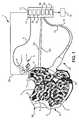
- Fig. 1shows schematically and exemplarily an embodiment of a system for providing an electrical activity map of the heart of a living being by means of electrical signals from the heart acquired by a plurality of surface electrodes being arranged on an outer surface of the living being.
- the system 1comprises an optical shape sensing element 4, 6 for generating an optical shape sensing signal being indicative of the position of the tip 17 of the optical shape sensing element 4, 6 while being in contact with a respective reference mark 2, in order to generate an optical shape sensing signal being indicative of the position of the respective reference mark 2.
- the living being 30being, in this embodiment, a person wears a vest 8 with surface electrodes 9 and reference marks 2.
- an ultrasound probe 22 with an optical shape sensing fiber 10is used to image the cardiac anatomy, wherein the optical shape sensing fiber 10, which is preferentially embedded in the ultrasound probe 22, is used to measure the location of the ultrasound probe 22 with respect to the reference patch 7, thus ensuring that the location of the cardiac anatomy as imaged by the ultrasound probe 22 and the positions of the surface electrodes 9 in three-dimensional space are known with respect to each other.
- the positions of the surface electrodes 9 and of the epicardial surfaceare determined with respect to the same reference being the reference patch 7, the spatial relation between the surface electrodes 9 and the epicardial surface is known.
- the positions of the surface electrodes and the position of, for instance, the epicardial surfacecan be determined with respect to another reference.
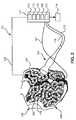
- the determination system 111comprises a spatial relation providing unit 112 for providing a spatial relation between the optical shape sensing fiber 107 within the vest 108 and the surface electrodes 109. This spatial relation is used together with the optical shape sensing signal, which is provided by the optical shape sensing fiber 107 and which is indicative of the position of each portion of the optical shape sensing fiber 107 within the vest 108, for determining the position of the surface electrodes 109 incorporated into the vest 108.
- the shape of at least one optical shape sensing fiber 107which is embedded in a specific pattern in the vest 108, can be measured for determining the position of each portion of the optical shape sensing fiber 107 within the vest 108.
Landscapes
- Health & Medical Sciences (AREA)
- Life Sciences & Earth Sciences (AREA)
- Engineering & Computer Science (AREA)
- Medical Informatics (AREA)
- General Health & Medical Sciences (AREA)
- Pathology (AREA)
- Biomedical Technology (AREA)
- Heart & Thoracic Surgery (AREA)
- Biophysics (AREA)
- Molecular Biology (AREA)
- Surgery (AREA)
- Animal Behavior & Ethology (AREA)
- Physics & Mathematics (AREA)
- Public Health (AREA)
- Veterinary Medicine (AREA)
- Nuclear Medicine, Radiotherapy & Molecular Imaging (AREA)
- Radiology & Medical Imaging (AREA)
- Cardiology (AREA)
- High Energy & Nuclear Physics (AREA)
- Optics & Photonics (AREA)
- Dentistry (AREA)
- Oral & Maxillofacial Surgery (AREA)
- Human Computer Interaction (AREA)
- Measurement And Recording Of Electrical Phenomena And Electrical Characteristics Of The Living Body (AREA)
- Apparatus For Radiation Diagnosis (AREA)
- Ultra Sonic Daignosis Equipment (AREA)
Description
- The invention relates to a system, a method and a computer program for providing an electrical activity map of the heart of a living being by means of electrical signals from the heart acquired by a plurality of surface electrodes being arranged on an outer surface of the living being. The invention relates further to a vest comprising the plurality of surface electrodes.
- The article "Noninvasive Characterization of Epicardial Activation in Humans With Diverse Atrial Fibrillation Patterns" by P.S. Cuculich et al., Circulation, Journal of the American Heart Association, 122, pages 1364 to 1372 (2010) discloses a system comprising an electrode vest with surface electrodes for measuring electrical potentials on an outer surface of a person. The system further comprises a reconstruction unit for reconstructing epicardial electrical potentials based on i) a spatial relation between the heart surface and the surface electrodes on the outer surface of the person and ii) the measured electrical potentials. The spatial relation between the heart surface and the surface electrodes on the outer surface of the person are obtained by acquiring an x-ray computed tomography image showing both, the heart surface and the surface electrodes on the outer surface of the person. By acquiring the x-ray computed tomography image a relatively high radiation dose is applied to the person.
- The article byL. K. Cheng et al., "Rapid construction of a patient-specific torso model from 3D ultrasound for non-invasive imaging of cardiac electrophysiology", Med. Biol. Eng. Comput., 2005, vol. 43, p. 325-330, discloses a system for providing an electrical activity map using 256 surface electrodes embedded in a vest. The positions of the plurality of surface electrodes are determined by means of a hand-held laser scanner, the orientation and position of which is determined by an embedded magnetic tracking system. The system further comprises a cardiac structure position determination unit and an electrical activity map determination unit. An ultrasound probe is used to determine the cardiac structure position, wherein the location and orientation of the ultrasound probe are reconstructed using a magnetic tracking device.
WO 2009/023801 A1 discloses that one or more optical shape sensing fibers may be coupled to an elongate medical instrument in order to determine its orientation and position, and that optical shape sensing fibers may also advantageously be attached to a patient patch in order to determine patient movement e.g. caused by respiration.- It is an object of the present invention to provide a system, a method and a computer program for providing an electrical activity map of the heart of a living being by means of electrical signals from the heart acquired by a plurality of surface electrodes being arranged on an outer surface of the living being, wherein the radiation dose applied to the person can be reduced, in particular, can be eliminated. It is a further object of the present invention to provide a vest for being worn by a living being and for being used for providing the electrical activity map.
- In a first aspect of the present invention a vest for being worn by a living being is presented, the vest being adapted to be used for providing an electrical activity map, the vest comprising:
- a plurality of surface electrodes for being arranged on an outer surface of the living being, when the vest is worn by the living being, and for acquiring electrical signals from the heart of the living being,
- an optical shape sensing fiber for generating an optical shape sensing signal being indicative of the three-dimensional shape of the optical shape sensing fiber and for providing the optical shape sensing signal to a surface electrodes positions calculation unit.
- In a further aspect of the present invention a system for providing an electrical activity map of the heart of a living being by means of electrical signals from the heart acquired by a plurality of surface electrodes being arranged on an outer surface of the living being is presented, wherein the system is adapted to be used with a vest for being worn by the living being and comprising the plurality of surface electrodes and an optical shape sensing fiber, the system comprising:
- a spatial relation providing unit for providing spatial relations between the optical shape sensing fiber of the vest and the surface electrodes,
- a surface electrodes positions calculation unit for calculating the positions of the surface electrodes depending on the three-dimensional shape of the optical shape sensing fiber as indicated by the optical shape sensing signal provided by the optical shape sensing fiber and the provided spatial relation,
- a cardiac structure position calculation unit for calculating the position of the cardiac structure based on a) the optical shape sensing signal received from the optical shape sensing fiber embedded in the vest, b) an ultrasound signal received from an ultrasound unit equipped with an optical shape sensing fiber, wherein the ultrasound signal is indicative of the position of the cardiac structure, and c) the optical shape sensing signal received from the optical shape sensing fiber of the ultrasound unit, wherein the optical shape sensing signal is indicative of the position of the ultrasound unit,
- an electrical activity map determination unit for determining the electrical activity map at the cardiac structure based on the electrical signals measured on the outer surface of the living being, the determined positions of the plurality of electrodes and the determined position of the cardiac structure.
- Since the positions of the plurality of surface electrodes are determined by means of optical shape sensing localization, these positions can be determined without necessarily acquiring a computed tomography image showing the plurality of surface electrodes. This allows reducing, in particular, eliminating, the x-ray radiation dose applied to the living being for generating an electrical activity map of the heart.
- The cardiac structure is preferentially the epicardial surface of the heart.
- If the cardiac structure is three-dimensional, in particular, if the cardiac structure is the three-dimensional epicardial surface, the position of the cardiac structure preferentially defines the position of each point of the cardiac structure at which the electrical activity map should be determined. Thus, for instance, if the cardiac structure position determination unit determines the position of the epicardial surface, it determines at least the positions of the points on the epicardial surface for which an electrical potential should be determined for generating the electrical activity map.
- The plurality of surface electrodes can be regarded as being an element of the system or it can be regarded as being a separate element, wherein the system is adapted to use the electrical signals of the surface electrodes for providing the electrical activity map.
- The plurality of surface electrodes is incorporated in a vest that can be worn by the living being. The living being is preferentially a person, but the living being can also be an animal.
- The system comprises preferentially the ultrasound unit for generating an ultrasound signal being indicative of the position of the cardiac structure. The ultrasound unit is preferentially a transthoracic echo probe or a transesophageal echo probe. If the ultrasound unit is a transthoracic echo probe or a transesophageal echo probe, an ultrasound image of the heart showing the epicardial surface can be acquired with high quality, thereby allowing the cardiac structure position calculation unit to determine the position of the epicardial surface being the preferred cardiac structure with high accuracy.
- In an embodiment the cardiac structure position calculation unit is adapted to perform a segmentation procedure for segmenting the cardiac structure in the ultrasound image for detecting the cardiac structure. In another embodiment the cardiac structure position calculation unit is adapted to provide an anatomical cardiac model being an anatomical model of a heart including the cardiac structure and to adjust the cardiac model to the ultrasound image of the heart for detecting the cardiac structure. The adjustment can just be a rotation and/or translation and optionally a scaling of the cardiac model, or it can also include a deformation of the cardiac model. The cardiac model is preferentially a generalized cardiac model, i.e. a cardiac model which is, before being adjusted, not specific for a certain person or animal. It can be determined by, for instance, averaging segmented hearts of a group of living beings, which may be segmented in medical images.
- The ultrasound unit is equipped with an optical shape sensing sensor for generating an optical shape sensing signal being indicative of the position of the ultrasound unit, wherein the cardiac structure position calculation unit is adapted to determine the position of the cardiac structure based on the optical shape sensing signal and the ultrasound signal. The optical shape sensing sensor is an optical shape sensing fiber, which may be partly arranged within the ultrasound unit. This allows determining the position of the ultrasound unit by optical shape sensing, without applying, for instance, x-rays to the person. In particular, if the ultrasound signal represents an ultrasound image of the heart, the epicardial surface in the ultrasound image can be segmented for determining the position of the epicardial surface within the ultrasound image and this determined position of the epicardial surface can be related to a reference position, i.e. it can be determined within a reference coordinate system, based on the position of the ultrasound unit known from the optical shape sensing signal.
- The system can further comprise a movement determination unit for determining a movement of the living being, wherein the surface electrodes positions determination unit can be adapted to determine the positions of the plurality of surface electrodes depending on the determined movement. The movement determination unit can comprise an optical shape sensing sensor for being attached to the living being at an attachment location and for generating an optical shape sensing signal being indicative of an actual position of the optical shape sensing sensor and a movement calculation unit for calculating a movement of the living being depending on the generated optical shape sensing signal. One or several optical shape sensing sensors can be used for determining the movement of the living being. The optical shape sensing sensors can be adapted to be directly attached to the living being or to be attached to another means being attached to the living being. The other means can be, for instance, the vest comprising the plurality of the surface electrodes or patches that can be put on, for example, a person's thorax. Considering a possible movement of the person while determining the electrical activity map of the heart can reduce corresponding possible inaccuracies in the electrical activity map.
- The optical shape sensing fiber is incorporated into the vest which also comprises the plurality of surface electrodes, wherein the spatial relations between the optical shape sensing fiber and the plurality of surface electrodes are known and stored in the spatial relation providing unit. This allows determining the positions of the surface electrodes without using, for instance, an optical shape sensing wand touching the different surface electrodes. For instance, an electrical activity map can be generated just by using the vest with the one or several optical shape sensing sensors and an ultrasound unit also being equipped with an optical shape sensing sensor such that the position of the ultrasound unit relative to the surface electrodes can be determined by optical shape sensing, preferentially without requiring further means for determining the positions of the surface electrodes and the cardiac structure. Since less elements are needed for generating the electrical activity map, the process for determining the electrical activity map to be performed by, for instance, a physician can be simplified.
- In a further aspect of the present invention a method for providing an electrical activity map of the heart of a living being by means of electrical signals from the heart acquired by a plurality of surface electrodes being arranged on an outer surface of the living being is presented, the method comprising:
- determining positions of the plurality of surface electrodes, wherein the vest is worn by the living being and comprises the plurality of surface electrodes, wherein spatial relations between the optical shape sensing fiber of the vest and the surface electrodes are provided by a spatial relation providing unit, and wherein the positions of the surface electrodes are calculated by a surface electrodes positions calculation unit depending on the three-dimensional shape of the optical shape sensing fiber as indicated by the optical shape sensing signal provided by the optical shape sensing fiber and the provided spatial relation,
- determining a position of a cardiac structure of the living being by an cardiac structure position calculation unit, wherein the position of the cardiac structure is determined based on a) the optical shape sensing signal received from the optical shape sensing fiber embedded in the vest, b) an utrasound signal received from a transthoracic ultrasound unit equipped with an optical shape sensing fiber, wherein the ultrasound signal is indicative of the position of the cardiac structure, and c) the optical shape sensing signal received from the optical shape sensing sensor of the ultrasound unit, wherein the optical shape sensing signal is indicative of the position of the ultrasound unit,
- determining the electrical activity map at the cardiac structure by an electrical activity map determination unit based on the electrical signals measured on the outer surface of the living being, the determined positions of the plurality of electrodes and the determined position of the cardiac structure.
- In a further aspect of the present invention a computer program for providing an electrical activity map of the heart of a living being by means of electrical signals from the heart acquired by a plurality of surface electrodes being arranged on an outer surface of the living being is presented, the computer program comprising program code means for causing a system as defined in
claim 1 to carry out the steps of the method as defined inclaim 6, when the computer program is run on a computer controlling the system. - It shall be understood that the system of
claim 2, the method ofclaim 6 and thecomputer program claim 7 have similar and/or identical preferred embodiments, in particular, as defined in the dependent claims. - These and other aspects of the invention will be apparent from and elucidated with reference to the embodiments described hereinafter.
- In the following drawings:
Fig. 1 shows schematically and exemplarily an embodiment of a system for providing an electrical activity map of the heart of a living being, which does not form part of the present invention,Fig. 2 shows schematically and exemplarily a further embodiment of a system in accordance with the present invention for providing an electrical activity map of the heart of the living being, andFig. 3 shows a flowchart exemplarily illustrating an embodiment of a method for providing an electrical activity map of the heart of a living being.Fig. 1 shows schematically and exemplarily an embodiment of a system for providing an electrical activity map of the heart of a living being by means of electrical signals from the heart acquired by a plurality of surface electrodes being arranged on an outer surface of the living being. Thesystem 1 comprises an opticalshape sensing element 4, 6 for generating an optical shape sensing signal being indicative of the position of thetip 17 of the opticalshape sensing element 4, 6 while being in contact with arespective reference mark 2, in order to generate an optical shape sensing signal being indicative of the position of therespective reference mark 2. In particular, the living being 30 being, in this embodiment, a person wears avest 8 withsurface electrodes 9 and reference marks 2. A user like a physician can use the opticalshape sensing element 4, 6 such that the tip of the opticalshape sensing element 4, 6 consecutively touches thedifferent reference marks 2 of thevest 8, in order to determine the positions of the reference marks 2. Thevest 8 is electrically connected with adetermination system 11 via anelectrical connection 25, in order to transmit the electrical signals acquired by thesurface electrodes 9 to the electrical activitymap determination unit 16.- The optical
shape sensing element 4, 6 comprises a wand 4, which can be held by ahand 5 of a user, with thetip 17 for being brought in contact withdifferent reference marks 2 and an opticalshape sensing fiber 6 being connected to the wand 4. The opticalshape sensing element 4, 6 can be adapted to, for example, continuously generate an optical shape sensing signal or to generate an optical shape sensing signal only after a user has requested an optical shape sensing signal via an input unit like a button to be pressed. The tip can also be provided with a pressure sensitive sensor for detecting whether the tip is in contact with an element or not, wherein the optical shape sensing element can be adapted to generate an optical shape sensing signal, when the pressure sensitive sensor detects that the tip is in contact with a reference mark. - The
system 1 comprises a further optical shape sensing element, i.e. an opticalshape sensing sensor 7, 26 for being attached to theperson 30 at an attachment location and for generating an optical shape sensing signal being indicative of the actual position of the opticalshape sensing sensor 7, 26. In this embodiment this optical shape sensing sensor comprises areference patch 7 connected to an optical shape sensing fiber 26, wherein the generated optical shape sensing signal is indicative of the position of thereference patch 7. - The optical shape sensing signal from the optical
shape sensing sensor 7, 26, which is indicative of the position of thereference patch 7, and the optical shape sensing signal from the opticalshape sensing element 4, 6, which is indicative of the position of thetip 17 of the opticalshape sensing element 4, 6, are provided to a surface electrodes positionscalculation unit 13 of thedetermination system 11. The surface electrodes positionscalculation unit 13 is adapted to determine the three-dimensional positions of the reference marks 2 with respect to thereference patch 7 based on the provided optical shape sensing signals. For determining the positions of the reference marks 2 known optical shape sensing localization method can be used like the optical shape sensing methods disclosed inWO 2011/141830 A1 . - After the positions of the
reference markers 2 have been determined, the surface electrodes positionscalculation unit 13 determines the positions of thesurface electrodes 9 depending on the determined positions of the reference marks 2 and known spatial relations between the positions of the plurality ofsurface electrodes 9 and the positions of the reference marks 2 provided by a spatialrelation providing unit 12. - Thus, the wand 4 with the optical
shape sensing fiber 6 is used to measure the positions of the reference marks 2 in the three-dimensional space with respect to thereference patch 7. By going from onereference mark 2 to anotherreference mark 2 and recording the three-dimensional positions, a three-dimensional distribution of the reference marks 2 and thus, since the spatial relations between the reference marks 2 and thesurface electrodes 9 being connected bytortuous wires 3 are known, the three-dimensional distribution of the vest electrodes can be reconstructed. The wand 4 with the opticalshape sensing fiber 6, the spatialrelations providing unit 12 and the surface electrodes positionscalculation 13 can therefore be regarded as being components of a surface electrodes positions determination unit for determining the positions of a plurality of surface electrodes by means of optical shape sensing localization. - The
system 1 further comprises anultrasound unit 22 for generating an ultrasound signal being indicative of the position of the cardiac structure within theperson 30. The ultrasound signal is provided to thedetermination system 11 via theelectrical connection 15. In this embodiment the ultrasound unit is atransthoracic echo probe 22 for generating an ultrasound signal representing a three-dimensional ultrasound image of the heart. In another embodiment the ultrasound unit can also be another probe like a transesophageal echo probe. - The ultrasound signal is provided to a cardiac structure
position calculation unit 14 for calculating the position of the cardiac structure based on the ultrasound signal. In particular, the cardiacstructure calculation unit 14 is adapted to detect the cardiac structure in the ultrasound image and to calculate the position of the cardiac structure based on the cardiac structure detected in the ultrasound image. For instance, the cardiac structureposition calculation unit 14 can be adapted to perform a segmentation procedure for segmenting the cardiac structure being, in this embodiment, the epicardial surface, in the ultrasound image for detecting the cardiac structure. The cardiac structure position calculation unit can also be adapted to provide an anatomical cardiac model being an anatomical model of a heart including the cardiac structure, i.e. in this embodiment including the epicardial surface, and to adjust the cardiac model to the ultrasound image of the heart for detecting the cardiac structure. The cardiac model is preferentially a generalized cardiac model, i.e. a cardiac model which is, before being adjusted, not specific for a certain person or animal. It can be determined by, for instance, averaging of segmented hearts of a group of living beings, which may be segmented in medical images. In order to allow the cardiac structure position calculation unit to calculate the position of the detected cardiac structure, the cardiac structureposition calculation unit 14 further receives an optical shape sensing signal from theultrasound unit 22. Theultrasound unit 22 is equipped with an opticalshape sensing sensor 10 for generating the optical shape sensing signal being indicative of the position of theultrasound unit 22, wherein the cardiac structureposition calculation unit 14 is adapted to determine the position of theultrasound unit 22 with respect to the position of thereference patch 7 based on the optical sensing signals received from the opticalshape sensing sensor 10 of theultrasound unit 22, which is an optical shape sensing fiber, and from the optical shape sensing sensor comprising thereference patch 7 and the optical shape sensing fiber 26 connected to thepatch 7. The position of the cardiac structure, i.e. in this embodiment of the epicardial surface, is then determined based on the determined three-dimensional position of theultrasound unit 22 and the determined position of the cardiac structure within the ultrasound image acquired by theultrasound unit 22. - Thus, an
ultrasound probe 22 with an opticalshape sensing fiber 10 is used to image the cardiac anatomy, wherein the opticalshape sensing fiber 10, which is preferentially embedded in theultrasound probe 22, is used to measure the location of theultrasound probe 22 with respect to thereference patch 7, thus ensuring that the location of the cardiac anatomy as imaged by theultrasound probe 22 and the positions of thesurface electrodes 9 in three-dimensional space are known with respect to each other. In other words, since in this embodiment the positions of thesurface electrodes 9 and of the epicardial surface are determined with respect to the same reference being thereference patch 7, the spatial relation between thesurface electrodes 9 and the epicardial surface is known. In other embodiments, the positions of the surface electrodes and the position of, for instance, the epicardial surface can be determined with respect to another reference. The opticalshape sensing sensor 10, the cardiac structureposition calculation unit 14 and theultrasound unit 22 with theelectrical connection 15 for transferring the ultrasound signal can be regarded as being elements of a cardiac structure position determination unit for determining a position of a cardiac structure like the epicardial surface of theperson 30. - The system further comprises a movement determination unit for determining a movement of the
person 30, wherein the surface electrodes positionscalculation unit 13 is adapted to determine the positions of the plurality ofsurface electrodes 9 also depending on the determined movement. The movement determination unit comprises afurther patch 24, a further opticalshape sensing fiber 23 attached to thepatch 24 and amovement calculation unit 18. Themovement calculation unit 18 receives an optical shape sensing signal being indicative of the position of thefurther patch 24 attached to thevest 8, wherein for providing this optical shape sensing signal thepatch 24 is connected with the opticalshape sensing fiber 23. Themovement calculation unit 18 calculates the position of thepatch 24 at different times from the received optical shape sensing signal, in order to determine the movement of theperson 30. - One or several optical shape sensing sensors, for instance, one or several patches with optical shape sensing fibers, can be used for determining the movement of the
person 30. The optical shape sensing sensors for determining the movement of the person can be adapted to be directly attached to the person. For instance, the optical shape sensing sensors, in particular, patches connected to optical shape sensing fibers, can be put on a person's thorax. Alternatively or in addition, the optical shape sensing sensors can be attached to another means being attached to the person. The other means can be, as shown inFig. 1 , a vest comprising the plurality of surface electrodes. - The
system 1 further comprises an electrical activitymap determination unit 16 for determining the electrical activity map at the cardiac structure, i.e. in this embodiment on the epicardial surface, based on the electrical signals measured on the outer surface of theperson 30, the determined positions of the plurality ofelectrodes 9 and the determined position of the cardiac structure. For determining the electrical activity map well known methods can be used like the methods disclosed in the article "Electrocardiographic Imaging (ECGI): A Noninvasive Imaging Modality for Cardiac Electrophysiology and Arrhythmia" by Ramanathan et al.,) or disclosed inUS 7,471,973 . Moreover, known products from the companies CardioInsight Technologies and Amycard can be used for determining the electrical activity map at the cardiac structure, i.e. in this embodiment on the epicardial surface, based on the electrical signals measured on the outer surface of the person, the determined positions of the plurality of electrodes and the determined position of the cardiac structure. - The
determination system 11 further comprises ananalysis unit 21 for analyzing the electrical activity map for determining electrophysiological mechanisms of certain cardiac arrhythmias. Moreover, in addition or alternatively theanalysis unit 21 may be adapted to analyze the electrical activity behaviour of cardiac dyssnychrony in heart failure patients as disclosed in the articles "Noninvasive Characterization of Epicardial Activation in Humans with Diverse Atrial Fibrillation Patterns" by P.S. Cuculich et al.,), "Electrocardiographic Imaging of Ventricular Bigeminy in a Human Subject" by Y. Wang et al., Circulation Arrhythmia and) and "Electrocardiographic Imaging of Cardiac Resynchronization Therapy in Heart Failure: Observations of Variable Electrophysiological Responses" by P. Jia et al.,). - In particular, the analysis unit can be adapted to perform at least one of following analyses based on the electrical activity map: determination of an anatomical position of ectopi foci, determination of an anatomical position of ventricular re-entries, distinguishing between re-entry or focal ventricular tachycardia and assessing of its localizations, assessing re-connection of pulmonary vein conduction and localization of culprit pulmonary veins, and assessment of effects of antiarrhythmic drugs.
- The electrical activity map of the heart and optionally results of the analysis can be shown on a
display unit 19. Fig. 2 shows schematically and exemplarily a further embodiment of a system for providing an electrical activity map of the heart of a living being by means of electrical signals from the heart acquired by a plurality of surface electrodes being arranged on an outer surface of the living being. Also in this embodiment the living being is aperson 130 wearing avest 108 with a plurality ofelectrodes 109 connected bytortuous wires 103. Thesurface electrodes 109 are used for acquiring electrical signals at the outer surface of theperson 130, wherein the acquired electrical signals are provided to adetermination system 111 via anelectrical connection 125.- The
vest 108 comprises an opticalshape sensing fiber 107 for providing an optical shape sensing signal being indicative of the position of each portion of the opticalshape sensing fiber 107 within thevest 108. Anultrasound unit 122 with an opticalshape sensing fiber 110 and anelectrical connection 115 for providing ultrasound signals to thedetermination system 111 is used for generating a three-dimensional ultrasound image of the heart of theperson 130. Theultrasound unit 122 with the opticalshape sensing fiber 110 and theelectrical connection 115 is similar to theultrasound unit 22 with the opticalshape sensing fiber 10 and theelectrical connection 15 described above with reference toFig. 1 . - The
determination system 111 comprises a spatialrelation providing unit 112 for providing a spatial relation between the opticalshape sensing fiber 107 within thevest 108 and thesurface electrodes 109. This spatial relation is used together with the optical shape sensing signal, which is provided by the opticalshape sensing fiber 107 and which is indicative of the position of each portion of the opticalshape sensing fiber 107 within thevest 108, for determining the position of thesurface electrodes 109 incorporated into thevest 108. Thus, the shape of at least one opticalshape sensing fiber 107, which is embedded in a specific pattern in thevest 108, can be measured for determining the position of each portion of the opticalshape sensing fiber 107 within thevest 108. The locations of thesurface electrodes 109 with respect to the opticalshape sensing fiber 107 are known from the spatial relation provided by the spatialrelation providing unit 112. Therefore, a surface electrodes positionscalculation unit 113 can calculate the three-dimensional distribution of thesurface electrodes 109 by measuring the three-dimensional shape of theoptical fiber 107. The opticalshape sensing fiber 107, the spatialrelation providing unit 112 and the surface electrodes positionscalculation unit 113 can therefore be regarded as being elements of a surface electrodes positions determination unit for determining positions of the plurality ofsurface electrodes 109 by means of optical shape sensing localization. - The
determination system 111 further comprises a cardiac structureposition calculation unit 114 for calculating the position of the cardiac structure, i.e. in this embodiment of the epicardial surface, based on the optical shape sensing signal received from the vest opticalshape sensing fiber 107, the optical shape sensing signal received from the ultrasound opticalshape sensing fiber 110 and the ultrasound signal acquired by theultrasound unit 122. In particular, the ultrasound signal is a three-dimensional ultrasound image of the heart of theperson 130, wherein the cardiac structureposition calculation unit 114 is adapted to segment the epicardial surface in the three-dimensional ultrasound image for determining the position of the epicardial surface within this image. The position of this epicardial surface with respect to the position of thesurface electrodes 109 is then determined by determining the position of theultrasound unit 122 with respect to the position of the opticalshape sensing fiber 107. Thus, theultrasound unit 122, which can be regarded as being an ultrasound probe wand, is used to image the cardiac anatomy, wherein the opticalshape sensing fiber 110, which is embedded in theultrasound unit 122, is used to measure the location of theultrasound unit 122 with respect to the opticalshape sensing fiber 107 embedded in thevest 108, thereby ensuring that the location of the cardiac anatomy, i.e. in this embodiment of the epicardial surface, as imaged by theultrasound unit 122 and the position of thesurface electrodes 109 are known in the three-dimensional space. The opticalshape sensing fiber 110, the cardiac structurecalculation determination unit 114 and theultrasound unit 122 with theelectrical connection 115 for transferring the ultrasound signals can be regarded as being elements of a cardiac structure position determination unit for determining a position of a cardiac structure of theperson 130. - The
determination system 111 further comprises an electrical activitymap determination unit 116 and ananalysis unit 121, which are similar to the electrical activitymap determination unit 16 and theanalysis unit 21, respectively, described above with reference toFig. 1 . Also thedisplay unit 119 is similar to thedisplay unit 19 described above with reference toFig. 1 . - In the following a method for providing an electrical activity map of the heart of a living being by means of electrical signals from the heart acquired by a plurality of surface electrodes at an outer surface of the living being will exemplarily be described with reference to a flowchart shown in
Fig. 3 . - In
step 101, the positions of the plurality of surface electrodes are determined by the surface electrodes positions determination unit by means of optical shape sensing localization. For instance, the wand 4 with the connected opticalshape sensing fiber 6 described above with reference toFig. 1 is used for determining the three-dimensional positions of reference marks of a vest worn by a person by using optical shape sensing. A surface electrodes positions calculation unit can then calculate the three-dimensional positions of the electrodes of the vest based on the determined three-dimensional positions of the reference marks and provided spatial relations between the reference marks and the surface electrodes incorporated in the vest. Alternatively, an opticalshape sensing fiber 107 embedded in the vest worn by the person can be used for determining the three-dimensional position of the surface electrodes as described above with reference toFig. 2 . In particular, the three-dimensional position of each portion of the opticalshape sensing fiber 107 within thevest 108 can be determined by optical shape sensing, wherein the surface electrodes positions calculation unit can calculate the three-dimensional positions of the surface electrodes based on the determined three-dimensional position of each portion of the opticalshape sensing fiber 107 within thevest 108 and a provided spatial relation between the optical shape sensing fiber within the vest and the surface electrodes embedded in the vest. - In
step 102, the position of a cardiac structure of theperson 30 is determined. In this embodiment the position of the epicardial surface is determined. For instance, the ultrasound unit with the optical shape sensing sensor described above with reference toFigs. 1 and2 is used for generating a three-dimensional ultrasound image showing the epicardial surface, wherein the cardiac structure position calculation unit can calculate the three-dimensional position of the epicardial surface based on, for example, a segmentation of the epicardial surface in the three-dimensional ultrasound image and the position of the ultrasound unit determined by optical shape sensing localization.Steps - In
step 103, the electrical activity map determination unit determines the electrical activity map at the cardiac structure, i.e., in this embodiment, on the epicardial surface, based on the electrical signals measured on the outer surface of the person, the positions of the plurality of surface electrodes determined instep 101 and the position of the cardiac structure determined instep 102. Instep 104, the analysis unit analyzes the electrical activity map, in order to determine, for example, electrophysiological mechanisms of certain cardiac arrhythmias. Instep 105, the electrical activity map and optionally also results of the analysis are shown on the display unit. - In the embodiment of the method for providing an electrical activity map of the heart described above with reference to
Fig. 3 it is assumed that the electrical signals on the outer surface of the person have been measured already and are provided to the electrical activity map determination unit for allowing the electrical activity map determination unit to determine the electrical activity map. In another embodiment the measurement of the electrical signals on the outer surface of the person can also be a part of the method for providing the electrical activity map, wherein in this case a corresponding electrical signals measurement step is performed beforestep 103. - Electrocardiographic mapping (ECM) is a method where body surface signals, i.e. electrical signals like electrical potentials measured at the outer surface of the person, which are measured by a multitude of electrodes covering the entire human thorax, are used to calculate the activation of the epicardial surface of the heart. The electrodes are surface electrodes, i.e. electrodes measuring electrical signals at the surface of the person, and they are contained in the vest that is tightly attached to the skin of the thorax by an adhesive. Alternatively or in addition, the vest can comprise elastic textiles for tightly fitting the vest to the skin of the thorax. Since the position of the epicardial heart surface and the positions of the surface electrodes have been determined, the three-dimensional spatial relations between the epicardial heart surface and the surface electrodes are known. This enables the electrical activity map determination unit to compute an accurate single beat electrical activation pattern on the epicardial heart surface being the electrical activity map. The system described above with reference to
Fig. 1 can therefore provide a non-invasive method for rapid assessment, i.e. within seconds to real time, of cardiac electrical activation. This electrocardiographic mapping can be performed, for example, during an electrophysiological procedure or during interventional cardiology procedures in a corresponding laboratory. However, the electrocardiographic mapping can also be performed for pre-interventional or post-interventional follow-up diagnostic procedures. In particular, the electrocardiographic mapping can be used to assess effects of antiarrhythmic drugs at certain points during a course of drug use and may be used for performing a high resolution electrocardiographic analysis. - The systems described above with reference to
Figs. 1 and2 allow a rapid assessment of the three-dimensional positions of the vest electrodes, i.e. of the surface electrodes, by means of optical shape sensing localization and the assessment of the three-dimensional cardiac anatomy in relation to the three-dimensional positions of the vest electrodes by means of a transthoracic or transesophageal echo probe that is localized in the three-dimensional space by means of optical shape sensing localization. The systems can be used as an advanced electrocardiography tool with epicardial activation diagnosis capabilities. - Preferentially, the configuration of the electrodes in the electrocardiography mapping vest within the vest fabric is known. In an embodiment, in particular in the embodiment described above with reference to
Fig. 1 , within the vest are a plurality of landmark points, i.e. reference marks, that can be visually identified, for instance, by having a certain color and/or shape. The positions of electrodes in relation to the landmark points are known as well. After putting on the vest to the person the three-dimensional positions of the landmark points can be determined by touching the landmarks by means of the wand equipped with the optical shape sensing sensor. The number and distribution of the landmark points are preferentially such that the relative positions of all electrodes in relation to the landmarks and therefore in relation to a frame of reference can be calculated based on the known positions of the electrodes within the fabric and in relation to the landmarks. To avoid person motion distortion, one or more additional optical shape sensing sensors can be temporally added to the vest or attached to patches that are put somewhere on the patient's thorax to compensate for the person movement. - Preferentially, the ultrasound unit is used for reconstructing a transthoracic or transesophageal three-dimensional representation of the person's cardiac anatomy. This reconstruction can be based on three-dimensional imaging of the heart and subsequent segmentation of the cardiac structures or by matching a generalized three-dimensional cardiac model to the three-dimensional ultrasound image, wherein optionally the generalized three-dimensional cardiac model can be deformed. The ultrasound probe is equipped with optical shape sensing localization as well, thus allowing to correlate the three-dimensional cardiac anatomy with the vest electrode positions. In an embodiment the ultrasound based cardiac anatomy assessment is performed before or after the vest electrodes positions assessment. In both cases optical shape sensing sensors temporally added to the vest or attached to a patch that is put somewhere on the patient's thorax can be used to relate the ultrasound probe position and therefore the three-dimensional cardiac anatomy to the vest electrode positions.
- In an embodiment, in particular in the embodiment described above with reference to
Fig. 2 , the electrode vest can be equipped with one or more optical shape sensing fibers, wherein the positions of the vest electrodes are identified and therefore known in relation to the one or more optical shape sensing fibers. Through assessing the three-dimensional shape of the one or more optical shape sensing fibers the three-dimensional positions of the vest electrodes can be calculated. Also in this embodiment the position of the cardiac anatomy is determined as described above by using an ultrasound probe, wherein in this embodiment the position of the ultrasound probe is registered with the position of the vest electrodes by using the optical shape sensing signals from the one or more optical shape sensing fibers within the vest and from the optical shape sensing sensor of the ultrasound probe. - Although in the embodiment described above with reference to
Fig. 1 an additional wand 4 equipped with an opticalshape sensing fiber 6 is used for determining the three-dimensional positions ofreference marks 2, in another embodiment this additional wand 4 with the opticalshape sensing fiber 6 is not needed. Instead, theultrasound probe 22 can be used for determining the three-dimensional positions of the reference marks 2. Thus, a user like a physician can move theultrasound probe 22 from reference mark to reference mark, in order to determine the three-dimensional positions of these reference mark by optical shape sensing localization. These three-dimensional positions of the reference marks are then used by the surface electrodes position calculation unit for determining the three-dimensional positions of the surface electrodes as described above. Thesame ultrasound probe 22 can then be used for providing an ultrasound signal being indicative of the cardiac structure, in particular, being indicative of the epicardial surface, in order to determine the position of the epicardial surface. - The ultrasound probe is preferentially used through an opening in the vest directly on the skin of the thorax, or before the vest is put on by the person. In the embodiment described above with reference to
Fig. 1 , theultrasound probe 22 may be used on the skin of the thorax for acquiring an ultrasound image of the heart before the vest is put on by the person, but after a reference patch being connected to an optical shape sensing fiber for determining the position of the reference patch is applied to the skin of the thorax. - The locations of the surface electrodes of the vest can be determined by means of Fiber Optic Shape Sensing and Localization (FOSSL) technology, for example, based on Fiber Bragg Gratings. The vest may contain one or more fibers with such grating that allow the full three-dimensional shape and location of the fibers to be determined. By knowing the spatial relation between each of the surface electrodes and a relevant fiber, the location of each of the electrodes can be determined. This can then be realized without any x-ray or magnetic resonance based localization of the surface electrodes. Moreover, the ultrasound probe can be a three-dimensional transesophageal or micro transthoracic ultrasound probe which can be used to reconstruct the heart. Furthermore, the FOSSL technology can be used to localize the probe by means of such a fiber, in particular, in a catheter. The FOSSL technology can be used to localize the surface electrodes as described above.
- The systems described above with reference to
Figs. 1 and2 provide an electrocardiographic mapping based on a three-dimensional assessment of vest electrode positions by means of optical shape sensing localized vest electrodes and based on a three-dimensional cardiac anatomy assessment of optical shape sensing localized ultrasound imaging. The system can therefore provide an electrocardiographic diagnostic tool that can be used for obtaining, for instance, pre-interventional and post-interventional information that is not obtainable by known electrocardiographic systems. For example, information can be provided such as reasonably accurate positions of ectopic foci, reasonable accurate positions of ventricular re-entries, information that distinguishes between re-entry or focal ventricular tachycardia and its localizations, information about re-connection of pulmonary vein conduction and localization of culprit pulmonary veins, in order to be at least able to distinguish between left and right pulmonary veins, and information about effects of antiarrhythmic drugs, in particuluar, of changes in use of antiarrhythmics drugs. - Although in above described embodiments, in particular, in
Figs. 1 and2 , the vest has a certain distribution of electrodes, it should be noted that the electrodes in the vest are only schematically and exemplarily indicated inFigs. 1 and2 , i.e., for instance, they can be distributed differently within the vest. The vest preferentially comprises several hundreds of the electrodes covering the entire thorax of the person. - Other variations to the disclosed embodiments can be understood and effected by those skilled in the art in practicing the claimed invention, from a study of the drawings, the disclosure, and the appended claims.
- In the claims, the word "comprising" does not exclude other elements or steps, and the indefinite article "a" or "an" does not exclude a plurality.
- A single unit or device may fulfill the functions of several items recited in the claims. The mere fact that certain measures are recited in mutually different dependent claims does not indicate that a combination of these measures cannot be used to advantage.
- Calculations like the calculation of the surface electrodes positions, the calculation of the cardiac structure position, the calculation of the electrical activity map and/or the analysis of the electrical activity map performed by one or several units or devices can be performed by any other number of units or devices. The calculations and/or the analysis of the electrical activity map and/or the control of the system for providing an electrical activity map in accordance with the method for providing an electrical activity map can be implemented as program code means of a computer program and/or as dedicated hardware.
- A computer program may be stored/distributed on a suitable medium, such as an optical storage medium or a solid-state medium, supplied together with or as part of other hardware, but may also be distributed in other forms, such as via the Internet or other wired or wireless telecommunication systems.
- Any reference signs in the claims should not be construed as limiting the scope.
- The invention relates to a system for providing an electrical activity map of the heart of a living being by means of electrical signals from the heart acquired by a plurality of surface electrodes being arranged on an outer surface of the living being. A surface electrodes positions determination unit determines positions of the plurality of surface electrodes by means of optical shape sensing localization and an electrical activity map determination unit determines the electrical activity map at the cardiac structure based on the measured electrical signals, the determined positions of the plurality of electrodes and a position of a cardiac structure, in particular, of the epicardial surface. Since optical shape sensing is used for determining the positions of the plurality of surface electrodes and not, for instance, x-rays, the electrical activity map can be determined, without necessarily applying an x-ray radiation dose.
Claims (7)
- A vest for being worn by a living being, the vest being adapted to be used for providing an electrical activity map of the heart of a living being (30), the vest (108) comprising:- a plurality of surface electrodes (109) for being arranged on an outer surface of the living being (30), when the vest (108) is worn by the living being (30), and for acquiring electrical signals from the heart of the living being (30),- an optical shape sensing fiber (107) for generating an optical shape sensing signal being indicative of the three-dimensional shape of the optical shape sensing fiber (107) and for providing the optical shape sensing signal to a surface electrodes positions calculation unit.
- A system for providing an electrical activity map of the heart of a living being by means of electrical signals from the heart acquired by a plurality of surface electrodes being arranged on an outer surface of the living being, wherein the system is adapted to be used with a vest as defined in claim 1 for being worn by the living being (30) and comprising the plurality of surface electrodes, the system comprising:- a spatial relation providing unit (112) for providing spatial relations between the optical shape sensing fiber (107) of the vest (108) and the surface electrodes (109),- a surface electrodes positions calculation unit (113) for calculating the positions of the surface electrodes (109) depending on the three-dimensional shape of the optical shape sensing fiber (107) as indicated by the optical shape sensing signal provided by the optical shape sensing fiber (107) and the provided spatial relation,- a cardiac structure position calculation unit (114) for calculating the position of a cardiac structure of the living being based on a) the optical shape sensing signal received from the optical shape sensing fiber (107) embedded in the vest, b) an ultrasound signal received from an ultrasound unit (122) equipped with an optical shape sensing fiber (110), wherein the ultrasound signal is indicative of the position of the cardiac structure, and c) the optical shape sensing signal received from the optical shape sensing fiber (110) of the ultrasound unit (122), wherein the optical shape sensing signal is indicative of the position of the ultrasound unit (122),- an electrical activity map determination unit (116) for determining the electrical activity map at the cardiac structure based on the electrical signals measured on the outer surface of the living being (30), the determined positions of the plurality of electrodes (109) and the determined position of the cardiac structure.
- The system as defined in claim 2, wherein the system comprises the ultrasound unit (122) for generating the ultrasound signal being indicative of the position of the cardiac structure, wherein the ultrasound unit (122) is equipped with the optical shape sensing sensor (110) for generating the optical shape sensing signal being indicative of the position of the ultrasound unit (122).
- The system as defined in claim 3, wherein the ultrasound unit (122) is a transthoracic echo probe or a transesophageal echo probe.
- The system as defined in claim 3, wherein the ultrasound signal represents an ultrasound image and wherein the cardiac structure calculation unit (14) is adapted to detect the cardiac structure in the ultrasound image and to calculate the position of the cardiac structure based on the cardiac structure detected in the ultrasound image.
- A method for providing an electrical activity map of the heart of a living being by means of electrical signals from the heart acquired by a plurality of surface electrodes being arranged on an outer surface of the living being, the method comprising:- determining positions of the plurality of surface electrodes, wherein a vest (108) as defined in claim 1 is worn by the living being (30) and comprises the plurality of surface electrodes (109), wherein spatial relations between the optical shape sensing fiber (107) of the vest (108) and the surface electrodes (109) are provided by a spatial relation providing unit (112), and wherein the positions of the surface electrodes (109) are calculated by a surface electrodes positions calculation unit (113) depending on the three-dimensional shape of the optical shape sensing fiber (107) as indicated by the optical shape sensing signal provided by the optical shape sensing fiber (107) and the provided spatial relation,- determining a position of a cardiac structure of the living being by an cardiac structure position calculation unit (114), wherein the position of the cardiac structure is determined based on a) the optical shape sensing signal received from the optical shape sensing fiber (107) embedded in the vest, b) an ultrasound signal received from a transthoracic ultrasound unit (122) equipped with an optical shape sensing of fiber (110), wherein the ultrasound signal is indicative of the position of the cardiac structure, and c) the optical shape sensing signal received from the optical shape sensing sensor (110) of the ultrasound unit (122), wherein the optical shape sensing signal is indicative of the position of the ultrasound unit (122),- determining the electrical activity map at the cardiac structure by an electrical activity map determination unit based on the electrical signals measured on the outer surface of the living being, the determined positions of the plurality of electrodes and the determined position of the cardiac structure.
- A computer program for providing an electrical activity map of the heart of a living being by means of electrical signals from the heart acquired by a plurality of surface electrodes being arranged on an outer surface of the living being, the computer program comprising program code means for causing a system as defined in claim 2 to carry out the steps of the method as defined in claim 6, when the computer program is run on a computer controlling the system.
Priority Applications (1)
| Application Number | Priority Date | Filing Date | Title |
|---|---|---|---|
| EP20120706694EP2675354B1 (en) | 2011-02-17 | 2012-02-14 | System for providing an electrical activity map using optical shape sensing |
Applications Claiming Priority (3)
| Application Number | Priority Date | Filing Date | Title |
|---|---|---|---|
| EP11154871 | 2011-02-17 | ||
| EP20120706694EP2675354B1 (en) | 2011-02-17 | 2012-02-14 | System for providing an electrical activity map using optical shape sensing |
| PCT/IB2012/050653WO2012110942A1 (en) | 2011-02-17 | 2012-02-14 | System for providing an electrical activity map using optical shape sensing |
Publications (2)
| Publication Number | Publication Date |
|---|---|
| EP2675354A1 EP2675354A1 (en) | 2013-12-25 |
| EP2675354B1true EP2675354B1 (en) | 2015-01-07 |
Family
ID=45774282
Family Applications (2)
| Application Number | Title | Priority Date | Filing Date |
|---|---|---|---|
| EP20120706694Not-in-forceEP2675354B1 (en) | 2011-02-17 | 2012-02-14 | System for providing an electrical activity map using optical shape sensing |
| EP20120706693ActiveEP2675350B1 (en) | 2011-02-17 | 2012-02-14 | System for providing an electrical activity map |
Family Applications After (1)
| Application Number | Title | Priority Date | Filing Date |
|---|---|---|---|
| EP20120706693ActiveEP2675350B1 (en) | 2011-02-17 | 2012-02-14 | System for providing an electrical activity map |
Country Status (7)
| Country | Link |
|---|---|
| US (2) | US20140148677A1 (en) |
| EP (2) | EP2675354B1 (en) |
| JP (2) | JP5993877B2 (en) |
| CN (2) | CN103391744B (en) |
| BR (2) | BR112013020718A2 (en) |
| RU (2) | RU2622371C2 (en) |
| WO (2) | WO2012110942A1 (en) |
Cited By (1)
| Publication number | Priority date | Publication date | Assignee | Title |
|---|---|---|---|---|
| US11172860B2 (en) | 2014-05-06 | 2021-11-16 | Peacs Investments B.V. | Estimating distribution fluctuation and/or movement of electrical activity through a heart tissue |
Families Citing this family (90)
| Publication number | Priority date | Publication date | Assignee | Title |
|---|---|---|---|---|
| WO2008014629A2 (en) | 2006-08-03 | 2008-02-07 | Christoph Scharf | Method and device for determining and presenting surface charge and dipole densities on cardiac walls |
| EP2737849A3 (en) | 2008-01-17 | 2014-10-29 | Christoph Scharf | A device and method for the geometric determination of electrical dipole densities on the cardiac wall |
| EP2533853A4 (en) | 2010-02-12 | 2013-11-06 | Brigham & Womens Hospital | SYSTEM AND METHOD FOR AUTOMATED ADJUSTMENT OF CONTROL PARAMETERS IN CARDIAC RESYNCHRONIZATION THERAPY |
| US9757044B2 (en) | 2011-03-10 | 2017-09-12 | Acutus Medical, Inc. | Device and method for the geometric determination of electrical dipole densities on the cardiac wall |
| US8972228B2 (en) | 2011-05-03 | 2015-03-03 | Medtronic, Inc. | Assessing intra-cardiac activation patterns |
| EP2890292B1 (en) | 2012-08-31 | 2021-01-13 | Acutus Medical, Inc. | Catheter system for the heart |
| BR112015019171A2 (en) | 2013-02-14 | 2017-07-18 | Koninklijke Philips Nv | intervention system, intervention method, and computer program |
| US9278219B2 (en) | 2013-03-15 | 2016-03-08 | Medtronic, Inc. | Closed loop optimization of control parameters during cardiac pacing |
| US9931048B2 (en) | 2013-04-30 | 2018-04-03 | Medtronic, Inc. | Systems, methods, and interfaces for identifying effective electrodes |
| US10064567B2 (en) | 2013-04-30 | 2018-09-04 | Medtronic, Inc. | Systems, methods, and interfaces for identifying optimal electrical vectors |
| US9877789B2 (en) | 2013-06-12 | 2018-01-30 | Medtronic, Inc. | Implantable electrode location selection |
| US10251555B2 (en) | 2013-06-12 | 2019-04-09 | Medtronic, Inc. | Implantable electrode location selection |
| US9474457B2 (en) | 2013-06-12 | 2016-10-25 | Medtronic, Inc. | Metrics of electrical dyssynchrony and electrical activation patterns from surface ECG electrodes |
| US9278220B2 (en) | 2013-07-23 | 2016-03-08 | Medtronic, Inc. | Identification of healthy versus unhealthy substrate for pacing from a multipolar lead |
| US9282907B2 (en) | 2013-07-23 | 2016-03-15 | Medtronic, Inc. | Identification of healthy versus unhealthy substrate for pacing from a multipolar lead |
| US9265955B2 (en) | 2013-07-26 | 2016-02-23 | Medtronic, Inc. | Method and system for improved estimation of time of left ventricular pacing with respect to intrinsic right ventricular activation in cardiac resynchronization therapy |
| US9265954B2 (en) | 2013-07-26 | 2016-02-23 | Medtronic, Inc. | Method and system for improved estimation of time of left ventricular pacing with respect to intrinsic right ventricular activation in cardiac resynchronization therapy |
| CA2922941C (en) | 2013-09-13 | 2021-11-16 | Acutus Medical, Inc. | Devices and methods for determination of electrical dipole densities on a cardiac surface |
| US10206601B2 (en)* | 2013-12-09 | 2019-02-19 | Medtronic, Inc. | Noninvasive cardiac therapy evaluation |
| US9320446B2 (en) | 2013-12-09 | 2016-04-26 | Medtronic, Inc. | Bioelectric sensor device and methods |
| US9776009B2 (en) | 2014-03-20 | 2017-10-03 | Medtronic, Inc. | Non-invasive detection of phrenic nerve stimulation |
| JP6739346B2 (en) | 2014-03-25 | 2020-08-12 | アクタス メディカル インクAcutus Medical,Inc. | Method of operating system of cardiac analysis user interface |
| US10779743B2 (en)* | 2014-05-06 | 2020-09-22 | Peacs B.V. | Estimating distribution, fluctuation and/or movement of electrical activity through a heart tissue |
| US9591982B2 (en) | 2014-07-31 | 2017-03-14 | Medtronic, Inc. | Systems and methods for evaluating cardiac therapy |
| US9707400B2 (en) | 2014-08-15 | 2017-07-18 | Medtronic, Inc. | Systems, methods, and interfaces for configuring cardiac therapy |
| US9586052B2 (en) | 2014-08-15 | 2017-03-07 | Medtronic, Inc. | Systems and methods for evaluating cardiac therapy |
| US9586050B2 (en) | 2014-08-15 | 2017-03-07 | Medtronic, Inc. | Systems and methods for configuration of atrioventricular interval |
| US9764143B2 (en) | 2014-08-15 | 2017-09-19 | Medtronic, Inc. | Systems and methods for configuration of interventricular interval |
| EP3191800B1 (en)* | 2014-09-08 | 2021-08-18 | Koninklijke Philips N.V. | Detection of surface contact with optical shape sensing |
| ES2572142B1 (en)* | 2014-10-30 | 2017-06-21 | Fundación Para La Investigación Biomédica Del Hospital Gregorio Marañón | CARDIAC ARRITMIAS LOCATION DEVICE |
| US10639007B2 (en) | 2014-12-02 | 2020-05-05 | Koninklijke Philips N.V. | Automatic tracking and registration of ultrasound probe using optical shape sensing without tip fixation |
| BR112017014743B1 (en)* | 2015-01-09 | 2023-03-07 | Max-Planck-Gesellschaft Zur Forderung Der Wissenschaften E.V. | METHOD FOR CHARACTERIZING THE SPACE-TEMPORAL DYNAMICS OF AN EXCITED MEDIUM FOR DEFORMATION AND AN APPARATUS FOR VISUALIZING THE SPACE-TEMPORAL DYNAMICS OF AN EXCITED MEDIUM FOR DEFORMATION |
| US11253178B2 (en) | 2015-01-29 | 2022-02-22 | Medtronic, Inc. | Noninvasive assessment of cardiac resynchronization therapy |
| CN115299988A (en) | 2015-05-12 | 2022-11-08 | 阿库图森医疗有限公司 | Ultrasonic sequencing systems and methods |
| US10593234B2 (en) | 2015-05-12 | 2020-03-17 | Acutus Medical, Inc. | Cardiac virtualization test tank and testing system and method |
| US10653318B2 (en) | 2015-05-13 | 2020-05-19 | Acutus Medical, Inc. | Localization system and method useful in the acquisition and analysis of cardiac information |
| US20170000369A1 (en)* | 2015-07-03 | 2017-01-05 | Elwha Llc | Electrocardiogram systems and related methods |
| US11289207B2 (en) | 2015-07-09 | 2022-03-29 | Peacs Investments B.V. | System for visualizing heart activation |
| EP3349663B1 (en)* | 2015-09-16 | 2018-12-05 | Koninklijke Philips N.V. | Ultrasound apparatus and method for medical examination of a subject |
| GB201521477D0 (en) | 2015-12-04 | 2016-01-20 | Imp Innovations Ltd | Methods and apparatus for analysing changes in the electrical activity of a patient's heart in different states |
| US10780279B2 (en) | 2016-02-26 | 2020-09-22 | Medtronic, Inc. | Methods and systems of optimizing right ventricular only pacing for patients with respect to an atrial event and left ventricular event |
| US11219769B2 (en) | 2016-02-26 | 2022-01-11 | Medtronic, Inc. | Noninvasive methods and systems of determining the extent of tissue capture from cardiac pacing |
| CA3022806A1 (en) | 2016-05-03 | 2017-11-09 | Acutus Medical, Inc. | Cardiac mapping system with efficiency algorithm |
| US11458320B2 (en) | 2016-09-06 | 2022-10-04 | Peacs Investments B.V. | Method of cardiac resynchronization therapy |
| US10532213B2 (en) | 2017-03-03 | 2020-01-14 | Medtronic, Inc. | Criteria for determination of local tissue latency near pacing electrode |
| US10987517B2 (en) | 2017-03-15 | 2021-04-27 | Medtronic, Inc. | Detection of noise signals in cardiac signals |
| CN108618776A (en)* | 2017-03-22 | 2018-10-09 | 美商宇心生医股份有限公司 | Electrocardiogram electrode positioning aid and method for positioning electrocardiogram paster position by aid of aid |
| WO2019014453A2 (en) | 2017-07-12 | 2019-01-17 | Cardioinsight Technologies, Inc. | Imaging to determine electrode geometry |
| CN110996784B (en) | 2017-07-28 | 2023-05-30 | 美敦力公司 | generating excitation time |
| EP3658227B1 (en) | 2017-07-28 | 2021-05-12 | Medtronic, Inc. | Cardiac cycle selection |
| KR101964918B1 (en)* | 2017-10-17 | 2019-04-02 | 연세대학교 산학협력단 | Apparatus and method for generating heart model based on heart voltage map and voltage activation map |
| US11298565B2 (en) | 2017-11-16 | 2022-04-12 | Ebamed Sa | Heart arrhythmia non-invasive treatment device and method |
| US11164371B2 (en)* | 2017-12-20 | 2021-11-02 | Biosense Webster (Israel) Ltd. | Marking a computerized model of a cardiac surface |
| US11419539B2 (en) | 2017-12-22 | 2022-08-23 | Regents Of The University Of Minnesota | QRS onset and offset times and cycle selection using anterior and posterior electrode signals |
| US10786167B2 (en) | 2017-12-22 | 2020-09-29 | Medtronic, Inc. | Ectopic beat-compensated electrical heterogeneity information |
| US10492705B2 (en) | 2017-12-22 | 2019-12-03 | Regents Of The University Of Minnesota | Anterior and posterior electrode signals |
| US10799703B2 (en) | 2017-12-22 | 2020-10-13 | Medtronic, Inc. | Evaluation of his bundle pacing therapy |
| US10433746B2 (en) | 2017-12-22 | 2019-10-08 | Regents Of The University Of Minnesota | Systems and methods for anterior and posterior electrode signal analysis |
| US11445994B2 (en)* | 2018-01-24 | 2022-09-20 | Siemens Healthcare Gmbh | Non-invasive electrophysiology mapping based on affordable electrocardiogram hardware and imaging |
| US10617318B2 (en) | 2018-02-27 | 2020-04-14 | Medtronic, Inc. | Mapping electrical activity on a model heart |
| US10668290B2 (en) | 2018-03-01 | 2020-06-02 | Medtronic, Inc. | Delivery of pacing therapy by a cardiac pacing device |
| US10918870B2 (en) | 2018-03-07 | 2021-02-16 | Medtronic, Inc. | Atrial lead placement for treatment of atrial dyssynchrony |
| US10780281B2 (en) | 2018-03-23 | 2020-09-22 | Medtronic, Inc. | Evaluation of ventricle from atrium pacing therapy |
| US11285312B2 (en) | 2018-03-29 | 2022-03-29 | Medtronic, Inc. | Left ventricular assist device adjustment and evaluation |
| US10940321B2 (en) | 2018-06-01 | 2021-03-09 | Medtronic, Inc. | Systems, methods, and interfaces for use in cardiac evaluation |
| US11304641B2 (en) | 2018-06-01 | 2022-04-19 | Medtronic, Inc. | Systems, methods, and interfaces for use in cardiac evaluation |
| US12178582B2 (en) | 2018-11-09 | 2024-12-31 | Acutus Medical, Inc. | Systems and methods for calculating patient information |
| CN109717954A (en)* | 2019-03-08 | 2019-05-07 | 江苏霆升科技有限公司 | A kind of 3 D model construction method, apparatus and system |
| US11547858B2 (en) | 2019-03-29 | 2023-01-10 | Medtronic, Inc. | Systems, methods, and devices for adaptive cardiac therapy |
| US11697025B2 (en) | 2019-03-29 | 2023-07-11 | Medtronic, Inc. | Cardiac conduction system capture |
| CA3135773A1 (en) | 2019-06-04 | 2020-12-10 | Acutus Medical, Inc. | Systems and methods for performing localization within a body |
| US11116435B2 (en)* | 2019-08-26 | 2021-09-14 | Biosense Webster (Israel) Ltd. | Automatic identification of a location of focal source in atrial fibrillation (AF) |
| US11497431B2 (en) | 2019-10-09 | 2022-11-15 | Medtronic, Inc. | Systems and methods for configuring cardiac therapy |
| US12201843B2 (en) | 2019-10-09 | 2025-01-21 | Medtronic, Inc. | Synchronizing external electrical activity |
| CN112741634B (en)* | 2019-10-31 | 2023-02-24 | 清华大学深圳国际研究生院 | Heart focus positioning system |
| US11642533B2 (en) | 2019-11-04 | 2023-05-09 | Medtronic, Inc. | Systems and methods for evaluating cardiac therapy |
| US12156760B2 (en) | 2019-11-14 | 2024-12-03 | Ebamed Sa | Cardiac phase gating system for radiation therapy |
| WO2021130683A1 (en) | 2019-12-23 | 2021-07-01 | Alimetry Limited | Electrode patch and connection system |
| EP4091129A1 (en)* | 2020-01-14 | 2022-11-23 | Koninklijke Philips N.V. | Image enhancement based on fiber optic shape sensing |
| US12383183B2 (en) | 2020-01-30 | 2025-08-12 | Medtronic, Inc. | Disturbance detection and removal in cardiac signals |
| PL243072B1 (en)* | 2020-04-20 | 2023-06-19 | Heart Sense Spolka Z Ograniczona Odpowiedzialnoscia | An epicardial ECG monitoring measurement probe and an epicardial ECG measurement system comprising such a probe |
| US12023503B2 (en) | 2020-07-30 | 2024-07-02 | Medtronic, Inc. | ECG belt systems to interoperate with IMDs |
| US11813464B2 (en) | 2020-07-31 | 2023-11-14 | Medtronic, Inc. | Cardiac conduction system evaluation |
| US11490872B2 (en) | 2020-08-21 | 2022-11-08 | GE Precision Healthcare LLC | C-arm imaging system and method |
| US11974881B2 (en)* | 2020-08-26 | 2024-05-07 | GE Precision Healthcare LLC | Method and system for providing an anatomic orientation indicator with a patient-specific model of an anatomical structure of interest extracted from a three-dimensional ultrasound volume |
| US12280260B2 (en) | 2020-12-02 | 2025-04-22 | Medtronic, Inc. | Evaluation and adjustment of left bundle branch (LBB) pacing therapy |
| EP4267243A1 (en) | 2020-12-23 | 2023-11-01 | Ebamed SA | A multiplanar motion management system |
| CN114815669B (en)* | 2021-01-18 | 2025-09-16 | 欧飞康科技(深圳)有限公司 | Sign data acquisition method, equipment and system |
| US12004284B2 (en) | 2021-10-21 | 2024-06-04 | GE Precision Healthcare LLC | Methods and systems for x-ray imaging |
| CN114668497B (en)* | 2022-03-29 | 2023-06-06 | 四川大学华西医院 | A computer-aided three-dimensional modeling system for liver surgery planning |
Family Cites Families (23)
| Publication number | Priority date | Publication date | Assignee | Title |
|---|---|---|---|---|
| CN1041692A (en)* | 1988-10-07 | 1990-05-02 | 赵峰 | Multifunctional automatic diagnosis and treatment instrument for complex electrocardio-activity |
| DE19511532A1 (en)* | 1995-03-29 | 1996-10-02 | Siemens Ag | Process for locating electrical cardiac activity |
| DE19622078A1 (en)* | 1996-05-31 | 1997-12-04 | Siemens Ag | Active current localising appts. for heart |
| US5701907A (en)* | 1996-12-16 | 1997-12-30 | Hewlett-Packard Company | Electrocardiographic waveform monitoring method and system |
| US6002952A (en) | 1997-04-14 | 1999-12-14 | Masimo Corporation | Signal processing apparatus and method |
| US6975900B2 (en)* | 1997-07-31 | 2005-12-13 | Case Western Reserve University | Systems and methods for determining a surface geometry |
| AU8677098A (en)* | 1997-07-31 | 1999-02-22 | Case Western Reserve University | A system and method for non-invasive electrocardiographic imaging |
| US6687523B1 (en)* | 1997-09-22 | 2004-02-03 | Georgia Tech Research Corp. | Fabric or garment with integrated flexible information infrastructure for monitoring vital signs of infants |
| US6856830B2 (en)* | 2001-07-19 | 2005-02-15 | Bin He | Method and apparatus of three dimension electrocardiographic imaging |
| AU2002362438A1 (en) | 2001-10-04 | 2003-04-14 | Case Western Reserve University | Systems and methods for noninvasive electrocardiographic imaging (ecgi) using generalized minimum residual (gmres) |
| DE10245943B4 (en)* | 2002-09-30 | 2008-06-26 | Siemens Ag | Method for generating CT images of a periodically moved organ and CT apparatus for carrying out such a method |
| US7381187B2 (en)* | 2003-09-12 | 2008-06-03 | Textronics, Inc. | Blood pressure monitoring system and method of having an extended optical range |
| RS49856B (en)* | 2004-01-16 | 2008-08-07 | Boško Bojović | METHOD AND DEVICE FOR VISUAL THREE-DIMENSIONAL PRESENTATlON OF ECG DATA |
| US20080234570A1 (en)* | 2004-03-05 | 2008-09-25 | Koninklijke Philips Electronics, N.V. | System For Guiding a Medical Instrument in a Patient Body |
| US8050739B2 (en) | 2005-12-15 | 2011-11-01 | Koninklijke Philips Electronics N.V. | System and method for visualizing heart morphology during electrophysiology mapping and treatment |
| US7988639B2 (en) | 2006-05-17 | 2011-08-02 | St. Jude Medical, Atrial Fibrillation Division, Inc. | System and method for complex geometry modeling of anatomy using multiple surface models |
| US9370312B2 (en)* | 2006-09-06 | 2016-06-21 | Biosense Webster, Inc. | Correlation of cardiac electrical maps with body surface measurements |
| US7996055B2 (en)* | 2006-12-29 | 2011-08-09 | St. Jude Medical, Atrial Fibrillation Division, Inc. | Cardiac navigation system including electrode array for use therewith |
| EP2626030A3 (en)* | 2007-08-14 | 2017-03-08 | Koninklijke Philips N.V. | Robotic instrument systems and methods utilizing optical fiber sensors |
| US8359092B2 (en)* | 2007-11-29 | 2013-01-22 | Biosense Webster, Inc. | Determining locations of ganglia and plexi in the heart using complex fractionated atrial electrogram |
| RU2409313C2 (en) | 2008-11-27 | 2011-01-20 | Амиран Шотаевич РЕВИШВИЛИ | Method for noninvasive electrophysiological examination of heart |
| RU2589625C2 (en)* | 2010-02-09 | 2016-07-10 | Конинклейке Филипс Электроникс Н.В. | Device, system and method for imaging and treatment using optical determination of position |
| JP2013534433A (en) | 2010-05-13 | 2013-09-05 | コーニンクレッカ フィリップス エヌ ヴェ | Optical fiber shape reconstruction |
- 2012
- 2012-02-14RURU2013142269Apatent/RU2622371C2/enactive
- 2012-02-14CNCN201280009082.5Apatent/CN103391744B/enactiveActive
- 2012-02-14EPEP20120706694patent/EP2675354B1/ennot_activeNot-in-force
- 2012-02-14WOPCT/IB2012/050653patent/WO2012110942A1/enactiveApplication Filing
- 2012-02-14RURU2013142271/14Apatent/RU2013142271A/ennot_activeApplication Discontinuation
- 2012-02-14WOPCT/IB2012/050650patent/WO2012110940A1/enactiveApplication Filing
- 2012-02-14BRBR112013020718Apatent/BR112013020718A2/ennot_activeApplication Discontinuation
- 2012-02-14BRBR112013020724Apatent/BR112013020724A2/ennot_activeIP Right Cessation
- 2012-02-14JPJP2013554032Apatent/JP5993877B2/ennot_activeExpired - Fee Related
- 2012-02-14JPJP2013554033Apatent/JP5883888B2/ennot_activeExpired - Fee Related
- 2012-02-14USUS13/984,070patent/US20140148677A1/ennot_activeAbandoned
- 2012-02-14CNCN201280009015.3Apatent/CN103429148B/ennot_activeExpired - Fee Related
- 2012-02-14USUS13/984,313patent/US10548496B2/enactiveActive
- 2012-02-14EPEP20120706693patent/EP2675350B1/enactiveActive
Cited By (1)
| Publication number | Priority date | Publication date | Assignee | Title |
|---|---|---|---|---|
| US11172860B2 (en) | 2014-05-06 | 2021-11-16 | Peacs Investments B.V. | Estimating distribution fluctuation and/or movement of electrical activity through a heart tissue |
Also Published As
| Publication number | Publication date |
|---|---|
| CN103391744B (en) | 2015-06-17 |
| EP2675354A1 (en) | 2013-12-25 |
| US20140148677A1 (en) | 2014-05-29 |
| RU2013142271A (en) | 2015-03-27 |
| EP2675350B1 (en) | 2014-12-17 |
| RU2013142269A (en) | 2015-03-27 |
| US10548496B2 (en) | 2020-02-04 |
| WO2012110942A1 (en) | 2012-08-23 |
| BR112013020718A2 (en) | 2016-10-18 |
| JP2014505568A (en) | 2014-03-06 |
| JP5993877B2 (en) | 2016-09-14 |
| CN103429148B (en) | 2016-01-20 |
| JP5883888B2 (en) | 2016-03-15 |
| EP2675350A1 (en) | 2013-12-25 |
| CN103391744A (en) | 2013-11-13 |
| JP2014509234A (en) | 2014-04-17 |
| BR112013020724A2 (en) | 2016-10-18 |
| WO2012110940A1 (en) | 2012-08-23 |
| CN103429148A (en) | 2013-12-04 |
| US20150038862A1 (en) | 2015-02-05 |
| RU2622371C2 (en) | 2017-06-14 |
Similar Documents
| Publication | Publication Date | Title |
|---|---|---|
| EP2675354B1 (en) | System for providing an electrical activity map using optical shape sensing | |
| JP7047016B2 (en) | Alignment map using intracardiac signal | |
| CN110719754B (en) | Ultrasound-based geometric determination for electrophysiological mapping | |
| US11832927B2 (en) | Imaging to determine electrode geometry | |
| JP6681332B2 (en) | Device and method for determination of electric dipole density at the surface of the heart | |
| EP3092944A1 (en) | Combined electrophysiological mapping and cardiac ablation methods, systems, components and devices | |
| JP2019051309A (en) | Automatic display of the earliest LAT | |
| CA2871031A1 (en) | Tracking of catheter from insertion point to heart using impedance measurements | |
| EP3795075B1 (en) | Using supplemental information to improve inverse problem solutions | |
| JP2017518849A (en) | Estimation of the distribution, variation and / or movement of electrical activity through the heart tissue | |
| JP2015093201A (en) | Reverse ecg mapping | |
| Cheng et al. | Rapid construction of a patient-specific torso model from 3D ultrasound for non-invasive imaging of cardiac electrophysiology | |
| JP2018518270A (en) | Non-invasive system and method for spatial localization of specific electrocardiographic elements | |
| EP3669758A1 (en) | Electrocardiographic imaging system | |
| Modre et al. | Ventricular surface activation time imaging from electrocardiogram mapping data | |
| Scinicariello et al. | Cardiac Mapping Technologies | |
| WO2024259236A1 (en) | Electrocardiography based determination of a cardiac activation area | |
| Seger et al. | Online noninvasive localization of accessory pathways in the EP lab | |
| Sands et al. | Rapid construction of a patient-specific torso model from 3D ultrasound for non-invasive imaging of cardiac electrophysiologyf |
Legal Events
| Date | Code | Title | Description |
|---|---|---|---|
| PUAI | Public reference made under article 153(3) epc to a published international application that has entered the european phase | Free format text:ORIGINAL CODE: 0009012 | |
| 17P | Request for examination filed | Effective date:20130917 | |
| AK | Designated contracting states | Kind code of ref document:A1 Designated state(s):AL AT BE BG CH CY CZ DE DK EE ES FI FR GB GR HR HU IE IS IT LI LT LU LV MC MK MT NL NO PL PT RO RS SE SI SK SM TR | |
| DAX | Request for extension of the european patent (deleted) | ||
| GRAP | Despatch of communication of intention to grant a patent | Free format text:ORIGINAL CODE: EPIDOSNIGR1 | |
| INTG | Intention to grant announced | Effective date:20140717 | |
| GRAS | Grant fee paid | Free format text:ORIGINAL CODE: EPIDOSNIGR3 | |
| GRAA | (expected) grant | Free format text:ORIGINAL CODE: 0009210 | |
| AK | Designated contracting states | Kind code of ref document:B1 Designated state(s):AL AT BE BG CH CY CZ DE DK EE ES FI FR GB GR HR HU IE IS IT LI LT LU LV MC MK MT NL NO PL PT RO RS SE SI SK SM TR | |
| REG | Reference to a national code | Ref country code:GB Ref legal event code:FG4D | |
| REG | Reference to a national code | Ref country code:CH Ref legal event code:EP | |
| REG | Reference to a national code | Ref country code:IE Ref legal event code:FG4D | |
| REG | Reference to a national code | Ref country code:AT Ref legal event code:REF Ref document number:705115 Country of ref document:AT Kind code of ref document:T Effective date:20150215 | |
| REG | Reference to a national code | Ref country code:DE Ref legal event code:R096 Ref document number:602012004798 Country of ref document:DE Effective date:20150219 | |
| REG | Reference to a national code | Ref country code:NL Ref legal event code:VDEP Effective date:20150107 | |
| REG | Reference to a national code | Ref country code:AT Ref legal event code:MK05 Ref document number:705115 Country of ref document:AT Kind code of ref document:T Effective date:20150107 | |
| REG | Reference to a national code | Ref country code:LT Ref legal event code:MG4D | |
| PG25 | Lapsed in a contracting state [announced via postgrant information from national office to epo] | Ref country code:BE Free format text:LAPSE BECAUSE OF NON-PAYMENT OF DUE FEES Effective date:20150228 | |
| PG25 | Lapsed in a contracting state [announced via postgrant information from national office to epo] | Ref country code:BG Free format text:LAPSE BECAUSE OF FAILURE TO SUBMIT A TRANSLATION OF THE DESCRIPTION OR TO PAY THE FEE WITHIN THE PRESCRIBED TIME-LIMIT Effective date:20150407 Ref country code:LT Free format text:LAPSE BECAUSE OF FAILURE TO SUBMIT A TRANSLATION OF THE DESCRIPTION OR TO PAY THE FEE WITHIN THE PRESCRIBED TIME-LIMIT Effective date:20150107 Ref country code:SE Free format text:LAPSE BECAUSE OF FAILURE TO SUBMIT A TRANSLATION OF THE DESCRIPTION OR TO PAY THE FEE WITHIN THE PRESCRIBED TIME-LIMIT Effective date:20150107 Ref country code:FI Free format text:LAPSE BECAUSE OF FAILURE TO SUBMIT A TRANSLATION OF THE DESCRIPTION OR TO PAY THE FEE WITHIN THE PRESCRIBED TIME-LIMIT Effective date:20150107 Ref country code:ES Free format text:LAPSE BECAUSE OF FAILURE TO SUBMIT A TRANSLATION OF THE DESCRIPTION OR TO PAY THE FEE WITHIN THE PRESCRIBED TIME-LIMIT Effective date:20150107 Ref country code:HR Free format text:LAPSE BECAUSE OF FAILURE TO SUBMIT A TRANSLATION OF THE DESCRIPTION OR TO PAY THE FEE WITHIN THE PRESCRIBED TIME-LIMIT Effective date:20150107 Ref country code:NO Free format text:LAPSE BECAUSE OF FAILURE TO SUBMIT A TRANSLATION OF THE DESCRIPTION OR TO PAY THE FEE WITHIN THE PRESCRIBED TIME-LIMIT Effective date:20150407 | |
| PG25 | Lapsed in a contracting state [announced via postgrant information from national office to epo] | Ref country code:NL Free format text:LAPSE BECAUSE OF FAILURE TO SUBMIT A TRANSLATION OF THE DESCRIPTION OR TO PAY THE FEE WITHIN THE PRESCRIBED TIME-LIMIT Effective date:20150107 Ref country code:AT Free format text:LAPSE BECAUSE OF FAILURE TO SUBMIT A TRANSLATION OF THE DESCRIPTION OR TO PAY THE FEE WITHIN THE PRESCRIBED TIME-LIMIT Effective date:20150107 Ref country code:PL Free format text:LAPSE BECAUSE OF FAILURE TO SUBMIT A TRANSLATION OF THE DESCRIPTION OR TO PAY THE FEE WITHIN THE PRESCRIBED TIME-LIMIT Effective date:20150107 Ref country code:IS Free format text:LAPSE BECAUSE OF FAILURE TO SUBMIT A TRANSLATION OF THE DESCRIPTION OR TO PAY THE FEE WITHIN THE PRESCRIBED TIME-LIMIT Effective date:20150507 Ref country code:LV Free format text:LAPSE BECAUSE OF FAILURE TO SUBMIT A TRANSLATION OF THE DESCRIPTION OR TO PAY THE FEE WITHIN THE PRESCRIBED TIME-LIMIT Effective date:20150107 Ref country code:RS Free format text:LAPSE BECAUSE OF FAILURE TO SUBMIT A TRANSLATION OF THE DESCRIPTION OR TO PAY THE FEE WITHIN THE PRESCRIBED TIME-LIMIT Effective date:20150107 Ref country code:GR Free format text:LAPSE BECAUSE OF FAILURE TO SUBMIT A TRANSLATION OF THE DESCRIPTION OR TO PAY THE FEE WITHIN THE PRESCRIBED TIME-LIMIT Effective date:20150408 | |
| REG | Reference to a national code | Ref country code:CH Ref legal event code:PL | |
| REG | Reference to a national code | Ref country code:DE Ref legal event code:R097 Ref document number:602012004798 Country of ref document:DE | |
| PG25 | Lapsed in a contracting state [announced via postgrant information from national office to epo] | Ref country code:MC Free format text:LAPSE BECAUSE OF FAILURE TO SUBMIT A TRANSLATION OF THE DESCRIPTION OR TO PAY THE FEE WITHIN THE PRESCRIBED TIME-LIMIT Effective date:20150107 Ref country code:SK Free format text:LAPSE BECAUSE OF FAILURE TO SUBMIT A TRANSLATION OF THE DESCRIPTION OR TO PAY THE FEE WITHIN THE PRESCRIBED TIME-LIMIT Effective date:20150107 Ref country code:LI Free format text:LAPSE BECAUSE OF NON-PAYMENT OF DUE FEES Effective date:20150228 Ref country code:RO Free format text:LAPSE BECAUSE OF FAILURE TO SUBMIT A TRANSLATION OF THE DESCRIPTION OR TO PAY THE FEE WITHIN THE PRESCRIBED TIME-LIMIT Effective date:20150107 Ref country code:CH Free format text:LAPSE BECAUSE OF NON-PAYMENT OF DUE FEES Effective date:20150228 Ref country code:DK Free format text:LAPSE BECAUSE OF FAILURE TO SUBMIT A TRANSLATION OF THE DESCRIPTION OR TO PAY THE FEE WITHIN THE PRESCRIBED TIME-LIMIT Effective date:20150107 Ref country code:CZ Free format text:LAPSE BECAUSE OF FAILURE TO SUBMIT A TRANSLATION OF THE DESCRIPTION OR TO PAY THE FEE WITHIN THE PRESCRIBED TIME-LIMIT Effective date:20150107 Ref country code:EE Free format text:LAPSE BECAUSE OF FAILURE TO SUBMIT A TRANSLATION OF THE DESCRIPTION OR TO PAY THE FEE WITHIN THE PRESCRIBED TIME-LIMIT Effective date:20150107 | |
| PLBE | No opposition filed within time limit | Free format text:ORIGINAL CODE: 0009261 | |
| STAA | Information on the status of an ep patent application or granted ep patent | Free format text:STATUS: NO OPPOSITION FILED WITHIN TIME LIMIT | |
| REG | Reference to a national code | Ref country code:IE Ref legal event code:MM4A | |
| 26N | No opposition filed | Effective date:20151008 | |
| PG25 | Lapsed in a contracting state [announced via postgrant information from national office to epo] | Ref country code:IT Free format text:LAPSE BECAUSE OF FAILURE TO SUBMIT A TRANSLATION OF THE DESCRIPTION OR TO PAY THE FEE WITHIN THE PRESCRIBED TIME-LIMIT Effective date:20150107 | |
| PG25 | Lapsed in a contracting state [announced via postgrant information from national office to epo] | Ref country code:IE Free format text:LAPSE BECAUSE OF NON-PAYMENT OF DUE FEES Effective date:20150214 | |
| PG25 | Lapsed in a contracting state [announced via postgrant information from national office to epo] | Ref country code:SI Free format text:LAPSE BECAUSE OF FAILURE TO SUBMIT A TRANSLATION OF THE DESCRIPTION OR TO PAY THE FEE WITHIN THE PRESCRIBED TIME-LIMIT Effective date:20150107 | |
| REG | Reference to a national code | Ref country code:FR Ref legal event code:PLFP Year of fee payment:5 | |
| PG25 | Lapsed in a contracting state [announced via postgrant information from national office to epo] | Ref country code:BE Free format text:LAPSE BECAUSE OF FAILURE TO SUBMIT A TRANSLATION OF THE DESCRIPTION OR TO PAY THE FEE WITHIN THE PRESCRIBED TIME-LIMIT Effective date:20150107 | |
| PG25 | Lapsed in a contracting state [announced via postgrant information from national office to epo] | Ref country code:MT Free format text:LAPSE BECAUSE OF FAILURE TO SUBMIT A TRANSLATION OF THE DESCRIPTION OR TO PAY THE FEE WITHIN THE PRESCRIBED TIME-LIMIT Effective date:20150107 | |
| REG | Reference to a national code | Ref country code:FR Ref legal event code:PLFP Year of fee payment:6 | |
| PGFP | Annual fee paid to national office [announced via postgrant information from national office to epo] | Ref country code:FR Payment date:20170224 Year of fee payment:6 | |
| PG25 | Lapsed in a contracting state [announced via postgrant information from national office to epo] | Ref country code:HU Free format text:LAPSE BECAUSE OF FAILURE TO SUBMIT A TRANSLATION OF THE DESCRIPTION OR TO PAY THE FEE WITHIN THE PRESCRIBED TIME-LIMIT; INVALID AB INITIO Effective date:20120214 Ref country code:SM Free format text:LAPSE BECAUSE OF FAILURE TO SUBMIT A TRANSLATION OF THE DESCRIPTION OR TO PAY THE FEE WITHIN THE PRESCRIBED TIME-LIMIT Effective date:20150107 | |
| PGFP | Annual fee paid to national office [announced via postgrant information from national office to epo] | Ref country code:GB Payment date:20170228 Year of fee payment:6 | |
| PG25 | Lapsed in a contracting state [announced via postgrant information from national office to epo] | Ref country code:CY Free format text:LAPSE BECAUSE OF FAILURE TO SUBMIT A TRANSLATION OF THE DESCRIPTION OR TO PAY THE FEE WITHIN THE PRESCRIBED TIME-LIMIT Effective date:20150107 | |
| PG25 | Lapsed in a contracting state [announced via postgrant information from national office to epo] | Ref country code:PT Free format text:LAPSE BECAUSE OF FAILURE TO SUBMIT A TRANSLATION OF THE DESCRIPTION OR TO PAY THE FEE WITHIN THE PRESCRIBED TIME-LIMIT Effective date:20150507 | |
| PGFP | Annual fee paid to national office [announced via postgrant information from national office to epo] | Ref country code:DE Payment date:20170428 Year of fee payment:6 | |
| PG25 | Lapsed in a contracting state [announced via postgrant information from national office to epo] | Ref country code:TR Free format text:LAPSE BECAUSE OF FAILURE TO SUBMIT A TRANSLATION OF THE DESCRIPTION OR TO PAY THE FEE WITHIN THE PRESCRIBED TIME-LIMIT Effective date:20150107 | |
| PG25 | Lapsed in a contracting state [announced via postgrant information from national office to epo] | Ref country code:LU Free format text:LAPSE BECAUSE OF NON-PAYMENT OF DUE FEES Effective date:20150214 | |
| PG25 | Lapsed in a contracting state [announced via postgrant information from national office to epo] | Ref country code:MK Free format text:LAPSE BECAUSE OF FAILURE TO SUBMIT A TRANSLATION OF THE DESCRIPTION OR TO PAY THE FEE WITHIN THE PRESCRIBED TIME-LIMIT Effective date:20150107 | |
| REG | Reference to a national code | Ref country code:DE Ref legal event code:R119 Ref document number:602012004798 Country of ref document:DE | |
| GBPC | Gb: european patent ceased through non-payment of renewal fee | Effective date:20180214 | |
| PG25 | Lapsed in a contracting state [announced via postgrant information from national office to epo] | Ref country code:AL Free format text:LAPSE BECAUSE OF FAILURE TO SUBMIT A TRANSLATION OF THE DESCRIPTION OR TO PAY THE FEE WITHIN THE PRESCRIBED TIME-LIMIT Effective date:20150107 | |
| REG | Reference to a national code | Ref country code:FR Ref legal event code:ST Effective date:20181031 | |
| PG25 | Lapsed in a contracting state [announced via postgrant information from national office to epo] | Ref country code:DE Free format text:LAPSE BECAUSE OF NON-PAYMENT OF DUE FEES Effective date:20180901 | |
| PG25 | Lapsed in a contracting state [announced via postgrant information from national office to epo] | Ref country code:FR Free format text:LAPSE BECAUSE OF NON-PAYMENT OF DUE FEES Effective date:20180228 Ref country code:GB Free format text:LAPSE BECAUSE OF NON-PAYMENT OF DUE FEES Effective date:20180214 |