EP2673462B1 - A method for individually servicing a plurality of zones of a subterranean formation - Google Patents
A method for individually servicing a plurality of zones of a subterranean formationDownload PDFInfo
- Publication number
- EP2673462B1 EP2673462B1EP12704524.3AEP12704524AEP2673462B1EP 2673462 B1EP2673462 B1EP 2673462B1EP 12704524 AEP12704524 AEP 12704524AEP 2673462 B1EP2673462 B1EP 2673462B1
- Authority
- EP
- European Patent Office
- Prior art keywords
- sleeve
- mode
- sleeve system
- seat
- fluid
- Prior art date
- Legal status (The legal status is an assumption and is not a legal conclusion. Google has not performed a legal analysis and makes no representation as to the accuracy of the status listed.)
- Active
Links
Images


Classifications
- E—FIXED CONSTRUCTIONS
- E21—EARTH OR ROCK DRILLING; MINING
- E21B—EARTH OR ROCK DRILLING; OBTAINING OIL, GAS, WATER, SOLUBLE OR MELTABLE MATERIALS OR A SLURRY OF MINERALS FROM WELLS
- E21B34/00—Valve arrangements for boreholes or wells
- E21B34/06—Valve arrangements for boreholes or wells in wells
- E21B34/10—Valve arrangements for boreholes or wells in wells operated by control fluid supplied from outside the borehole
- E21B34/102—Valve arrangements for boreholes or wells in wells operated by control fluid supplied from outside the borehole with means for locking the closing element in open or closed position
- E—FIXED CONSTRUCTIONS
- E21—EARTH OR ROCK DRILLING; MINING
- E21B—EARTH OR ROCK DRILLING; OBTAINING OIL, GAS, WATER, SOLUBLE OR MELTABLE MATERIALS OR A SLURRY OF MINERALS FROM WELLS
- E21B34/00—Valve arrangements for boreholes or wells
- E21B34/06—Valve arrangements for boreholes or wells in wells
- E21B34/10—Valve arrangements for boreholes or wells in wells operated by control fluid supplied from outside the borehole
- E21B34/108—Valve arrangements for boreholes or wells in wells operated by control fluid supplied from outside the borehole with time delay systems, e.g. hydraulic impedance mechanisms
- E—FIXED CONSTRUCTIONS
- E21—EARTH OR ROCK DRILLING; MINING
- E21B—EARTH OR ROCK DRILLING; OBTAINING OIL, GAS, WATER, SOLUBLE OR MELTABLE MATERIALS OR A SLURRY OF MINERALS FROM WELLS
- E21B34/00—Valve arrangements for boreholes or wells
- E21B34/06—Valve arrangements for boreholes or wells in wells
- E21B34/14—Valve arrangements for boreholes or wells in wells operated by movement of tools, e.g. sleeve valves operated by pistons or wire line tools
- E21B34/142—Valve arrangements for boreholes or wells in wells operated by movement of tools, e.g. sleeve valves operated by pistons or wire line tools unsupported or free-falling elements, e.g. balls, plugs, darts or pistons
- E—FIXED CONSTRUCTIONS
- E21—EARTH OR ROCK DRILLING; MINING
- E21B—EARTH OR ROCK DRILLING; OBTAINING OIL, GAS, WATER, SOLUBLE OR MELTABLE MATERIALS OR A SLURRY OF MINERALS FROM WELLS
- E21B43/00—Methods or apparatus for obtaining oil, gas, water, soluble or meltable materials or a slurry of minerals from wells
- E21B43/12—Methods or apparatus for controlling the flow of the obtained fluid to or in wells
- E—FIXED CONSTRUCTIONS
- E21—EARTH OR ROCK DRILLING; MINING
- E21B—EARTH OR ROCK DRILLING; OBTAINING OIL, GAS, WATER, SOLUBLE OR MELTABLE MATERIALS OR A SLURRY OF MINERALS FROM WELLS
- E21B43/00—Methods or apparatus for obtaining oil, gas, water, soluble or meltable materials or a slurry of minerals from wells
- E21B43/14—Obtaining from a multiple-zone well
- E—FIXED CONSTRUCTIONS
- E21—EARTH OR ROCK DRILLING; MINING
- E21B—EARTH OR ROCK DRILLING; OBTAINING OIL, GAS, WATER, SOLUBLE OR MELTABLE MATERIALS OR A SLURRY OF MINERALS FROM WELLS
- E21B43/00—Methods or apparatus for obtaining oil, gas, water, soluble or meltable materials or a slurry of minerals from wells
- E21B43/25—Methods for stimulating production
- E—FIXED CONSTRUCTIONS
- E21—EARTH OR ROCK DRILLING; MINING
- E21B—EARTH OR ROCK DRILLING; OBTAINING OIL, GAS, WATER, SOLUBLE OR MELTABLE MATERIALS OR A SLURRY OF MINERALS FROM WELLS
- E21B2200/00—Special features related to earth drilling for obtaining oil, gas or water
- E21B2200/06—Sleeve valves
Definitions
- Subterranean formations that contain hydrocarbonsare sometimes nonhomogeneous in their composition along the length of wellbores that extend into such formations. It is sometimes desirable to treat and/or otherwise manage the formation and/or the wellbore differently in response to the differing formation composition.
- Some wellbore servicing systems and methodsallow such treatment, referred to by some as zonal isolation treatments.
- multiple tools for use in treating zonesmay be activated by a single obturator, such activation of one tool by the obturator may cause activation of additional tools to be more difficult.
- a ballmay be used to activate a plurality of stimulation tools, thereby allowing fluid communication between a flow bore of the tools with a space exterior to the tools.
- such fluid communication accomplished by activated toolsmay increase the working pressure required to subsequently activate additional tools. Accordingly, there exists a need for improved systems and methods of treating multiple zones of a wellbore.
- WO 2010/127457discloses a tubing string assembly for fluid treatment of a wellbore.
- the tubing stringcan be used for staged wellbore fluid treatment where a selected segment of the wellbore is treated, while other segments are sealed off.
- the tubing stringcan also be used where a ported tubing string is required to be run-in in a pressure tight condition and later is needed to be in an open-port condition
- a sliding sleeve in a tubularhas a driver selected to be acted upon by an inner bore conveyed actuating device, the driver drives the generation of a ball stop on the sleeve.
- WO 2009/029437discloses fracturing tools for use in oil and gas wells, which tools have a run-in position and two operational positions.
- a sleeve disposed in the bore of the fracturing toolcomprises a sleeve port alignable with a first port in the housing of the frac tool, i.e., the first operational position, during fracturing operations.
- a second port having a restriction memberis disposed in the housing and is closed by the sleeve during fracturing operations.
- a return member in the frac toolmoves the sleeve from the first operational position to a second operational position for production operations. In this second operational position, the first port is closed and the sleeve port is aligned with the second port. Movement of the sleeve from the first operational position to the second operational position is performed without the need for an additional well intervention step.
- WO 2009/050518discloses a device for use downhole comprising a body housing: a power source arranged to supply power to a driver; and a hydraulic system including a piston sealed in a chamber and an outlet provided at each opposing end of the chamber, wherein each outlet is in communication with a respective reservoir, the driver being actuable to drive the piston in a first direction, such that fluid is driven out of the chamber through one outlet and simultaneously fluid is drawn into the chamber through the other outlet at the opposing ends.
- the present inventionprovides a method of individually servicing a plurality of zones of a subterranean formation comprising providing a work string comprising a first sleeve system comprising a first one or more ports, the first sleeve system being transitionable from a first mode to a second mode and transitionable from the second mode to a third mode, wherein, when the first sleeve system is in the first mode and the second mode, fluid communication via the first one or more ports is restricted, and wherein, when the first sleeve system is in the third mode, fluid may be communicated via the first one or more ports, and a second sleeve system comprising a second one or more ports, the second sleeve system being transitionable from a first mode to a second mode and transitionable from the second mode to a third mode, wherein, when the second sleeve system is in the first mode and the second mode, fluid communication via the second one or more ports is restricted, and wherein, when the second sleeve system
- Also disclosed hereinis a method of individually servicing a plurality of zones of a subterranean formation comprising providing a work string having integrated therein a first sleeve system and a second sleeve system, positioning the first sleeve system configured in an installation mode proximate to a first zone, wherein the first sleeve system is configured to restrict fluid communication to the first zone when in installation mode, positioning the second sleeve system configured in an installation mode proximate to a second zone, wherein the second sleeve system is configured to restrict fluid communication to the second zone when in installation mode, transitioning the second sleeve from the installation mode to a delayed mode, wherein the second sleeve system is configured to restrict fluid communication to the second zone when in the delayed mode, transitioning the first sleeve from the installation mode to a delayed mode, wherein the first sleeve system is configured to restrict fluid communication to the first zone when in the delayed mode, allowing the first sleeve
- any use of any form of the terms “connect,” “engage,” “couple,” “attach,” or any other term describing an interaction between elementsis not meant to limit the interaction to direct interaction between the elements and may also include indirect interaction between the elements described.
- the terms “including” and “comprising”are used in an open-ended fashion, and thus should be interpreted to mean “including, but not limited to ." Reference to up or down will be made for purposes of description with “up,” “upper,” “upward,” or “upstream” meaning toward the surface of the wellbore and with “down,” “lower,” “downward,” or “downstream” meaning toward the terminal end of the well, regardless of the wellbore orientation.
- zoneor “pay zone” as used herein refers to separate parts of the wellbore designated for treatment or production and may refer to an entire hydrocarbon formation or separate portions of a single formation such as horizontally and/or vertically spaced portions of the same formation.
- a sheathed, segmented seatfor use in downhole tools.
- a sheathed, segmented seatmay be employed alone or in combination with other components to transition one or more downhole tools from a first configuration to a second, third, or fourth, etc. configuration or mode by selectively receiving, retaining, and releasing an obturator (or any other suitable actuator or actuating device).
- sleeve systems and methods of using downhole toolsmore specifically sleeve systems employing a sheathed, segmented seat that may be placed in a wellbore in a "run-in” configuration or an "installation mode” where a sleeve of the sleeve system blocks fluid transfer between a flow bore of the sleeve system and a port of the sleeve system.
- the installation modemay also be referred to as a "locked mode” since the sleeve is selectively locked in position relative to the port.
- the locked positional relationship between the sleeves and the portsmay be selectively discontinued or disabled by unlocking one or more components relative to each other, thereby potentially allowing movement of the sleeves relative to the ports. Still further, once the components are no longer locked in position relative to each other, some of the embodiments are configured to thereafter operate in a "delay mode" where relative movement between the sleeve and the port is delayed insofar as (1) such relative movement occurs but occurs at a reduced and/or controlled rate and/or (2) such relative movement is delayed until the occurrence of a selected wellbore condition.
- the delay modemay also be referred to as an "unlocked mode" since the sleeves are no longer locked in position relative to the ports.
- the sleeve systemsmay be operated in the delay mode until the sleeve system achieves a "fully open mode" where the sleeve has moved relative to the port to allow maximum fluid communication between the flow bore of the sleeve system and the port of the sleeve system.
- devices, systems, and/or components of sleeve system embodiments that selectively contribute to establishing and/or maintaining the locked modemay be referred to as locking devices, locking systems, locks, movement restrictors, restrictors, and the like.
- devices, systems, and/or components of sleeve system embodiments that selectively contribute to establishing and/or maintaining the delay modemay be referred to as delay devices, delay systems, delays, timers, contingent openers, and the like.
- one or more sleeve systemsmay be configured to interact with an obturator of a first configuration while other sleeve systems may be configured not to interact with the obturator having the first configuration, but rather, configured to interact with an obturator having a second configuration.
- Such differences in configurations amongst the various sleeve systemsmay allow an operator to selectively transition some sleeve systems to the exclusion of other sleeve systems.
- Such differences in configurations amongst the various sleeve systemsmay allow an operator to selectively transition some sleeve systems to the exclusion of other sleeve systems, for example, such that a servicing fluid may be communicated (e.g., for the performance of a servicing operation) via a first sleeve system while not being communicated via a second, third, fourth, etc. sleeve system.
- a servicing fluidmay be communicated (e.g., for the performance of a servicing operation) via a first sleeve system while not being communicated via a second, third, fourth, etc. sleeve system.
- the following discussiondescribes various embodiments of sleeve
- the operating environmentcomprises a servicing rig 106 (e.g., a drilling, completion, or workover rig) that is positioned on the earth's surface 104 and extends over and around a wellbore 114 that penetrates a subterranean formation 102 for the purpose of recovering hydrocarbons.
- the wellbore 114may be drilled into the subterranean formation 102 using any suitable drilling technique.
- the wellbore 114extends substantially vertically away from the earth's surface 104 over a vertical wellbore portion 116, deviates from vertical relative to the earth's surface 104 over a deviated wellbore portion 136, and transitions to a horizontal wellbore portion 118.
- all or portions of a wellboremay be vertical, deviated at any suitable angle, horizontal, and/or curved.
- the servicing rig 106comprises a derrick 108 with a rig floor 110 through which a tubing or work string 112 (e.g., cable, wireline, E-line, Z-line, jointed pipe, coiled tubing, casing, or liner string, etc.) extends downward from the servicing rig 106 into the wellbore 114 and defines an annulus 128 between the work string 112 and the wellbore 114.
- a tubing or work string 112e.g., cable, wireline, E-line, Z-line, jointed pipe, coiled tubing, casing, or liner string, etc.
- the work string 112delivers the wellbore servicing system 100 to a selected depth within the wellbore 114 to perform an operation such as perforating the casing 120 and/or subterranean formation 102, creating perforation tunnels and/or fractures (e.g., dominant fractures, micro-fractures, etc.) within the subterranean formation 102, producing hydrocarbons from the subterranean formation 102, and/or other completion operations.
- the servicing rig 106comprises a motor driven winch and other associated equipment for extending the work string 112 into the wellbore 114 to position the wellbore servicing system 100 at the selected depth.
- FIG. 1refers to a stationary servicing rig 106 for lowering and setting the wellbore servicing system 100 within a land-based wellbore 114
- mobile workover rigssuch as coiled tubing units
- wellbore servicing unitssuch as coiled tubing units
- a wellbore servicing systemmay alternatively be used in other operational environments, such as within an offshore wellbore operational environment.
- the subterranean formation 102comprises a zone 150 associated with deviated wellbore portion 136.
- the subterranean formation 102further comprises first, second, third, fourth, and fifth horizontal zones, 150a, 150b, 150c, 150d, 150e, respectively, associated with the horizontal wellbore portion 118.
- the zones 150, 150a, 150b, 150c, 150d, 150eare offset from each other along the length of the wellbore 114 in the following order of increasingly downhole location: 150, 150e, 150d, 150c, 150b, and 150a.
- stimulation and production sleeve systems 200, 200a, 200b, 200c, 200d, and 200eare located within wellbore 114 in the work string 112 and are associated with zones 150, 150a, 150b, 150c, 150d, and 150e, respectively.
- zone isolation devicessuch as annular isolation devices (e.g., annular packers and/or swellpackers) may be selectively disposed within wellbore 114 in a manner that restricts fluid communication between spaces immediately uphole and downhole of each annular isolation device.
- Sleeve system 200a cross-sectional view of an embodiment of a stimulation and production sleeve system 200 (hereinafter referred to as "sleeve system" 200) is shown. Many of the components of sleeve system 200 lie substantially coaxial with a central axis 202 of sleeve system 200.
- Sleeve system 200comprises an upper adapter 204, a lower adapter 206, and a ported case 208.
- the ported case 208is joined between the upper adapter 204 and the lower adapter 206.
- the upper adapter 204comprises a collar 218, a makeup portion 220, and a case interface 222.
- the collar 218is internally threaded and otherwise configured for attachment to an element of work string 112 that is adjacent and uphole of sleeve system 200 while the case interface 222 comprises external threads for engaging the ported case 208.
- the lower adapter 206comprises a nipple 224, a makeup portion 226, and a case interface 228.
- the nipple 224is externally threaded and otherwise configured for attachment to an element of work string 112 that is adjacent and downhole of sleeve system 200 while the case interface 228 also comprises external threads for engaging the ported case 208.
- the ported case 208is substantially tubular in shape and comprises an upper adapter interface 230, a central ported body 232, and a lower adapter interface 234, each having substantially the same exterior diameters.
- the inner surface 214 of ported case 208comprises a case shoulder 236 that separates an upper inner surface 238 from a lower inner surface 240.
- the ported case 208further comprises ports 244.
- ports 244are through holes extending radially through the ported case 208 and are selectively used to provide fluid communication between sleeve flow bore 216 and a space immediately exterior to the ported case 208.
- the sleeve system 200further comprises a piston 246 carried within the ported case 208.
- the piston 246is substantially configured as a tube comprising an upper seal shoulder 248 and a plurality of slots 250 near a lower end 252 of the piston 246.
- the piston 246comprises an outer diameter smaller than the diameter of the upper inner surface 238.
- the upper seal shoulder 248carries a circumferential seal 254 that provides a fluid tight seal between the upper seal shoulder 248 and the upper inner surface 238.
- case shoulder 236carries a seal 254 that provides a fluid tight seal between the case shoulder 236 and an outer surface 256 of piston 246.
- the upper seal shoulder 248 of the piston 246abuts the upper adapter 204.
- the piston 246extends from the upper seal shoulder 248 toward the lower adapter 206 so that the slots 250 are located downhole of the seal 254 carried by case shoulder 236.
- the portion of the piston 246 between the seal 254 carried by case shoulder 236 and the seal 254 carried by the upper seal shoulder 248comprises no apertures in the tubular wall (i.e., is a solid, fluid tight wall).
- a low pressure chamber 258is located between the outer surface 256 of piston 246 and the upper inner surface 238 of the ported case 208.
- the sleeve system 200further comprises a sleeve 260 carried within the ported case 208 below the piston 246.
- the sleeve 260is substantially configured as a tube comprising an upper seal shoulder 262. With the exception of upper seal shoulder 262, the sleeve 260 comprises an outer diameter substantially smaller than the diameter of the lower inner surface 240.
- the upper seal shoulder 262carries two circumferential seals 254, one seal 254 near each end (e.g., upper and lower ends) of the upper seal shoulder 262, that provide fluid tight seals between the upper seal shoulder 262 and the lower inner surface 240 of ported case 208.
- two seals 254are carried by the sleeve 260 near a lower end 264 of sleeve 260, and the two seals 254 form fluid tight seals between the sleeve 260 and the inner surface 212 of the lower adapter 206.
- an upper end 266 of sleeve 260substantially abuts a lower end of the case shoulder 236 and the lower end 252 of piston 246.
- the upper seal shoulder 262 of the sleeve 260seals ports 244 from fluid communication with the sleeve flow bore 216.
- the seal 254 carried near the lower end of the upper seal shoulder 262is located downhole of (e.g., below) ports 244 while the seal 254 carried near the upper end of the upper seal shoulder 262 is located uphole of (e.g., above) ports 244.
- the portion of the sleeve 260 between the seal 254 carried near the lower end of the upper seal shoulder 262 and the seals 254 carried by the sleeve 260 near a lower end 264 of sleeve 260comprises no apertures in the tubular wall (i.e., is a solid, fluid tight wall).
- a fluid chamber 268is located between the outer surface of sleeve 260 and the lower inner surface 240 of the ported case 208.
- the sleeve system 200further comprises a segmented seat 270 carried within the lower adapter 206 below the sleeve 260.
- the segmented seat 270is substantially configured as a tube comprising an inner bore surface 273 and a chamfer 271 at the upper end of the seat, the chamfer 271 being configured and/or sized to selectively engage and/or retain an obturator of a particular size and/or shape (such as obturator 276).
- the segmented seat 270may be radially divided with respect to central axis 202 into segments.
- the segmented seat 270is divided (e.g., as represented by dividing or segmenting lines/cuts 277) into three complementary segments of approximately equal size, shape, and/or configuration.
- the three complementary segments (270A, 270B, and 270C, respectively)together form the segmented seat 270, with each of the segments (270A, 270B, and 270C) constituting about one-third (e.g., extending radially about 120°) of the segmented seat 270.
- a segmented seat like segmented seat 270may comprise any suitable number of equally or unequally-divided segments.
- a segmented seatmay comprise two, four, five, six, or more complementary, radial segments.
- the segmented seat 270may be formed from a suitable material.
- suitable materialinclude composites, phenolics, cast iron, aluminum, brass, various metal alloys, rubbers, ceramics, or combinations thereof.
- the material employed to form the segmented seatmay be characterized as drillable, that is, the segmented seat 270 may be fully or partially degraded or removed by drilling, as will be appreciated by one of skill in the art with the aid of this disclosure.
- Segments 270A, 270B, and 270Cmay be formed independently or, alternatively, a preformed seat may be divided into segments.
- obturator 276is shown in Figure 2 with the sleeve system 200 in an installation mode, in most applications of the sleeve system 200, the sleeve system 200 would be placed downhole without the obturator 276, and the obturator 276 would subsequently be provided as discussed below in greater detail.
- the obturator 276is a ball, an obturator of other embodiments may be any other suitable shape or device for sealing against a protective sheath 272 and or a seat gasket (both of which will be discussed below) and obstructing flow through the sleeve flow bore 216.
- a sleeve system like sleeve system 200may comprise an expandable seat.
- Such an expandable seatmay be constructed of, for example but not limited to, a low alloy steel such as AISI 4140 or 4130, and is generally configured to be biased radially outward so that if unrestricted radially, a diameter (e.g., outer/inner) of the seat 270 increases.
- the expandable seatmay be constructed from a generally serpentine length of AISI 4140.
- the expandable seatmay comprise a plurality of serpentine loops between upper and lower portions of the seat and continuing circumferentially to form the seat.
- such an expandable seatmay be covered by a protective sheath 272 (as will be discussed below) and/or may comprise a seat gasket.
- one or more surfaces of the segmented seat 270are covered by a protective sheath 272.
- a protective sheath 272covers the chamfer 271 of the segmented seat 270, the inner bore 273 of the segmented seat 270, and a lower face 275 of the segmented seat 270.
- the protective sheath 272may cover the chamfer 271, the inner bore 273, and a lower face 275, the back 279 of the segmented seat 270, or combinations thereof.
- a protective sheathmay cover any one or more of the surfaces of a segmented seat 270, as will be appreciated by one of skill in the art viewing this disclosure.
- the protective sheath 272forms a continuous layer over those surfaces of the segmented seat 270 in fluid communication with the sleeve flow bore 216.
- small crevices or gapse.g., at dividing lines 277 may exist at the radially extending divisions between the segments (e.g., 270A, 270B, and 270C) of the segmented seat 270.
- the continuous layer formed by the protective sheath 272may fill, seal, minimize, or cover, any such crevices or gaps such that a fluid flowing via the sleeve flow bore 216 will be impeded from contacting and/or penetrating any such crevices or gaps.
- the protective sheath 272may be applied to the segmented seat 270 while the segments 270A, 270B, and 270C are retained in a close conformation (e.g., where each segment abuts the adjacent segments, as illustrated in Figure 2A ).
- the segmented seat 270may be retained in such a close conformation by bands, bindings, straps, wrappings, or combinations thereof.
- the segmented seat 270may be coated and/or covered with the protective sheath 272 via any suitable method of application.
- the segmented seat 270may submerged (e.g., dipped) in a material (as will be discussed below) that will form the protective sheath 272, a material that will form the protective sheath 272 may be sprayed and/or brushed onto the desired surfaces of the segmented seat 270, or combinations thereof.
- the protective sheath 270may adhere to the segments 270A, 270B, and 270C of the segmented seat 270 and thereby retain the segments in the close conformation.
- the protective sheath 272may be applied individually to each of the segments 270A, 270B, and 270C of the segmented seat 270.
- the segments 270A, 270B, and/or 270Cmay individually submerged (e.g., dipped) in a material that will form the protective sheath 272, a material that will form the protective sheath 272 may be sprayed and/or brushed onto the desired surfaces of the segments 270A, 270B, and 270C, or combinations thereof.
- the protective sheath 272may adhere to some or all of the surfaces of each of the segments 270A, 270B, and 270C.
- the segments 270A, 270B, and 270Cmay be brought together to form the segmented seat 270.
- the segmented seat 270may be retained in such a close conformation (e.g., as illustrated in Figure 2A ) by bands, bindings, straps, wrappings, or combinations thereof.
- the protective sheath 272may be sufficiently malleable or pliable that when the sheathed segments are retained in the close conformation, any crevices or gaps between the segments (e.g., segments 270A, 270B, and 270C) will be filled or minimized by the protective sheath 272 such that a fluid flowing via the sleeve flow bore 216 will be impeded from contacting and/or penetrating any such crevices or gaps.
- the protective sheath 272need not be applied directly to the segmented seat 270.
- a protective sheathmay be fitted to or within the segmented seat 270, draped over a portion of segmented seat 270, or the like.
- the protective sheathmay comprise a sleeve or like insert configured and sized to be positioned within the bore of the segmented sheath and to fit against the chamfer 271 of the segmented seat 270, the inner bore 273 of the segmented seat 270, and/or the lower face 275 of the segmented seat 270 and thereby form a continuous layer that may fill, seal, or cover, any such crevices or gaps such that a fluid flowing via the sleeve flow bore 216 will be impeded from contacting and/or penetrating any such crevices or gaps.
- the protective sheath 272comprises a heat-shrinkable material (as will be discussed below)
- a materialmay be positioned over, around, within, about, or similarly, at least a portion of the segmented seat 270 and/or one or more of the segments 270A, 270B, and 270C, and heated sufficiently to cause the shrinkable material to shrink to the surfaces of the segmented seat 270 and/or the segments 270A, 270B, and 270C.
- the protective sheath 272may be formed from a suitable material.
- suitable materialinclude ceramics, carbides, hardened plastics, molded rubbers, various heat-shrinkable materials, or combinations thereof.
- the protective sheathmay be characterized as having a hardness of from about 25 durometers to about 150 durometers, alternatively, from about 50 durometers to about 100 durometers, alternatively, from about 60 durometers to about 80 durometers.
- the protective sheathmay be characterized as having a thickness of from about 1/64 th of an inch (3.97 x 10 -4 m) to about 3/16 th of an inch (4.76 x 10 -3 m), alternatively, about 1/32 nd of an inch (7.94 x 10 -4 m).
- materials suitable for the formation of the protective sheathinclude nitrile rubber, which commercially available from several rubber, plastic, and/or composite materials companies.
- a protective sheathmay be employed to advantageously lessen the degree of erosion and/or degradation to a segmented seat, like segmented seat 270.
- a protective sheathmay improve the service life of a segmented seat covered by such a protective sheath by decreasing the impingement of erosive fluids (e.g., cutting, hydrojetting, and/or fracturing fluids comprising abrasives and/or proppants) with the segmented seat.
- erosive fluidse.g., cutting, hydrojetting, and/or fracturing fluids comprising abrasives and/or proppants
- a segmented seat protected by such a protective sheathmay have a service life at least 20% greater, alternatively, at least 30% greater, alternatively, at least 35% greater than an otherwise similar seat not protected by such a protective sheath.
- the segmented seat 270may further comprise a seat gasket that serves to seal against an obturator.
- the seat gasketmay be constructed of rubber.
- the seat gasketmay be substantially captured between the expandable seat and the lower end of the sleeve.
- the protective sheath 272may serve as such a gasket, for example, by engaging and/or sealing an obturator.
- the protective sheath 272may have a variable thickness.
- the surface(s) of the protective sheath 272 configured to engage the obturatore.g., chamfer 271 may comprise a greater thickness than the one or more other surfaces of the protective sheath 272.
- the sleeve system 200further comprises a seat support 274 carried within the lower adapter 206 below the seat 270.
- the seat support 274is substantially formed as a tubular member.
- the seat support 274comprises an outer chamfer 278 on the upper end of the seat support 274 that selectively engages an inner chamfer 280 on the lower end of the segmented seat 270.
- the seat support 274comprises a circumferential channel 282.
- the seat support 274further comprises two seals 254, one seal 254 carried uphole of (e.g., above) the channel 282 and the other seal 254 carried downhole of (e.g., below) the channel 282, and the seals 254 form a fluid seal between the seat support 274 and the inner surface 212 of the lower adapter 206.
- the seat support 274is restricted from downhole movement by a shear pin 284 that extends from the lower adapter 206 and is received within the channel 282. Accordingly, each of the seat 270, protective sheath 272, sleeve 260, and piston 246 are captured between the seat support 274 and the upper adapter 204 due to the restriction of movement of the seat support 274.
- the lower adapter 206further comprises a fill port 286, a fill bore 288, a metering device receptacle 290, a drain bore 292, and a plug 294.
- the fill port 286comprises a check valve device housed within a radial through bore formed in the lower adapter 206 that joins the fill bore 288 to a space exterior to the lower adapter 206.
- the fill bore 288is formed as a substantially cylindrical longitudinal bore that lies substantially parallel to the central axis 202.
- the fill bore 288joins the fill port 286 in fluid communication with the fluid chamber 268.
- the metering device receptacle 290is formed as a substantially cylindrical longitudinal bore that lies substantially parallel to the central axis 202.
- drain bore 292is formed as a substantially cylindrical longitudinal bore that lies substantially parallel to the central axis 202.
- the drain bore 292extends from the metering device receptacle 290 to each of a plug bore 296 and a shear pin bore 298.
- the plug bore 296is a radial through bore formed in the lower adapter 206 that joins the drain bore 292 to a space exterior to the lower adapter 206.
- the shear pin bore 298is a radial through bore formed in the lower adapter 206 that joins the drain bore 292 to sleeve flow bore 216.
- the sleeve system 200further comprises a fluid metering device 291 received at least partially within the metering device receptacle 290.
- the fluid metering device 291is a fluid restrictor, for example a precision microhydraulics fluid restrictor or micro-dispensing valve of the type produced by The Lee Company of Westbrook, CT.
- any other suitable fluid metering devicemay be used.
- any suitable electro-fluid devicemay be used to selectively pump and/or restrict passage of fluid through the device.
- a fluid metering devicemay be selectively controlled by an operator and/or computer so that passage of fluid through the metering device may be started, stopped, and/or a rate of fluid flow through the device may be changed.
- controllable fluid metering devicesmay be, for example, substantially similar to the fluid restrictors produced by The Lee Company. Suitable commercially available examples of such a fluid metering device include the JEVA1835424H and the JEVA1835385H, commercially available from The Lee Company.
- the lower adapter 206may be described as comprising an upper central bore 300 having an upper central bore diameter 302, the seat catch bore 304 having a seat catch bore diameter 306, and a lower central bore 308 having a lower central bore diameter 310.
- the upper central bore 300is joined to the lower central bore 308 by the seat catch bore 304.
- the upper central bore diameter 302is sized to closely fit an exterior of the seat support 274, and in an embodiment is about equal to the diameter of the outer surface of the sleeve 260.
- the seat catch bore diameter 306is substantially larger than the upper central bore diameter 302, thereby allowing radial expansion of the expandable seat 270 when the expandable seat 270 enters the seat catch bore 304 as described in greater detail below.
- the lower central bore diameter 310is smaller than each of the upper central bore diameter 302 and the seat catch bore diameter 306, and in an embodiment is about equal to the diameter of the inner surface of the sleeve 260. Accordingly, as described in greater detail below, while the seat support 274 closely fits within the upper central bore 300 and loosely fits within the seat catch bore diameter 306, the seat support 274 is too large to fit within the lower central bore 308.
- Figure 2shows the sleeve system 200 in an "installation mode” where sleeve 260 is restricted from moving relative to the ported case 208 by the shear pin 284.
- Figure 3shows the sleeve system 200 in a "delay mode” where sleeve 260 is no longer restricted from moving relative to the ported case 208 by the shear pin 284 but remains restricted from such movement due to the presence of a fluid within the fluid chamber 268.
- Figure 4shows the sleeve system 200 in a "fully open mode" where sleeve 260 no longer obstructs a fluid path between ports 244 and sleeve flow bore 216, but rather, a fluid path is provided between ports 244 and the sleeve flow bore 216 through slots 250 of the piston 246.
- each of the piston 246, sleeve 260, protective sheath 272, segmented seat 270, and seat support 274are all restricted from movement along the central axis 202 at least because the shear pin 284 is received within both the shear pin bore 298 of the lower adapter 206 and within the circumferential channel 282 of the seat support 274.
- low pressure chamber 258is provided a volume of compressible fluid at atmospheric pressure. It will be appreciated that the fluid within the low pressure chamber 258 may be air, gaseous nitrogen, or any other suitable compressible fluid.
- the fluid pressure within the sleeve flow bore 216is substantially greater than the pressure within the low pressure chamber 258.
- a pressure differentialmay be attributed in part due to the weight of the fluid column within the sleeve flow bore 216, and in some circumstances, also due to increased pressures within the sleeve flow bore 216 caused by pressurizing the sleeve flow bore 216 using pumps.
- a fluidis provided within the fluid chamber 268. Generally, the fluid may be introduced into the fluid chamber 268 through the fill port 286 and subsequently through the fill bore 288.
- one or more of the shear pin 284 and the plug 294may be removed to allow egress of other fluids or excess of the filling fluid. Thereafter, the shear pin 284 and/or the plug 294 may be replaced to capture the fluid within the fill bore 288, fluid chamber 268, the metering device 291, and the drain bore 292.
- the sleeve system 200 and installation mode described abovethough the sleeve flow bore 216 may be pressurized, movement of the above-described restricted portions of the sleeve system 200 remains restricted.
- the obturator 276may be passed through the work string 112 until the obturator 276 substantially seals against the protective sheath 272 (as shown in Figure 2 ), alternatively, the seat gasket in embodiments where a seat gasket is present. With the obturator 276 in place against the protective sheath 272 and/or seat gasket, the pressure within the sleeve flow bore 216 may be increased uphole of the obturator until the obturator 276 transmits sufficient force through the protective sheath 272, the segmented seat 270, and the seat support 274 to cause the shear pin 284 to shear.
- the obturator 276drives the protective sheath 272, the segmented seat 270, and the seat support 274 downhole from their installation mode positions.
- the sleeve 260is no longer restricted from downhole movement by the protective sheath 272 and the segmented seat 270, downhole movement of the sleeve 260 and the piston 246 above the sleeve 260 is delayed.
- the sleeve system 200may be referred to as being in a "delayed mode.”
- downhole movement of the sleeve 260 and the piston 246are delayed by the presence of fluid within fluid chamber 268.
- the relatively low pressure within the low pressure chamber 258in combination with relatively high pressures within the sleeve flow bore 216 acting on the upper end 253 of the piston 246, the piston 246 is biased in a downhole direction.
- downhole movement of the piston 246is obstructed by the sleeve 260. Nonetheless, downhole movement of the obturator 276, the protective sheath 272, the segmented seat 270, and the seat support 274 are not restricted or delayed by the presence of fluid within fluid chamber 268.
- the protective sheath 272, the segmented seat 270, and the seat support 274move downhole into the seat catch bore 304 of the lower adapter 206. While within the seat catch bore 304, the protective sheath 272 expands, tears, breaks, or disintegrates, thereby allowing the segmented seat 270 to expand radially at the divisions between the segments (e.g., 270A, 270B, and 270C) to substantially match the seat catch bore diameter 306.
- a band, strap, binding, or the likeis employed to hold segments (e.g., 270A, 270B, and 270C) of the segmented seat 270 together
- such band, strap, or bindingmay similarly expand, tear, break, or disintegrate to allow the segmented seat 270 to expand.
- the seat support 274is subsequently captured between the expanded seat 270 and substantially at an interface (e.g., a shoulder formed) between the seat catch bore 304 and the lower central bore 308.
- the outer diameter of seat support 274is greater than the lower central bore diameter 310.
- the segmented seat 270, the segments (e.g., 270A, 270B, and 270C) thereof, the protective sheath 272, or combinations thereofmay be configured to disintegrate when acted upon by the obturator 276 as described above.
- the remnants of the segmented seat 270, the segments (e.g., 270A, 270B, and 270C) thereof, or the protective sheath 272may fall (e.g., by gravity) or be washed (e.g., by movement of a fluid) out of the sleeve flow bore 216.
- the obturator 276is then free to exit the sleeve system 200 and flow further downhole to interact with additional sleeve systems.
- the sleeve 260moves in a downhole direction until the upper seal shoulder 262 of the sleeve 260 contacts the lower adapter 206 near the metering device receptacle 290. It will be appreciated that shear pins or screws with central bores that provide a convenient fluid path may be used in place of shear pin 284.
- sleeve system 200when substantially all of the fluid within fluid chamber 268 has escaped, sleeve system 200 is in a "fully open mode."
- upper seal shoulder 262 of sleeve 260contacts lower adapter 206 so that the fluid chamber 268 is substantially eliminated.
- the upper seal shoulder 248 of the piston 246is located substantially further downhole and has compressed the fluid within low pressure chamber 258 so that the upper seal shoulder 248 is substantially closer to the case shoulder 236 of the ported case 208.
- the slots 250are substantially aligned with ports 244 thereby providing fluid communication between the sleeve flow bore 216 and the ports 244.
- the sleeve system 200is configured in various "partially opened modes" when movement of the components of sleeve system 200 provides fluid communication between sleeve flow bore 216 and the ports 244 to a degree less than that of the "fully open mode.” It will further be appreciated that with any degree of fluid communication between the sleeve flow bore 216 and the ports 244, fluids may be forced out of the sleeve system 200 through the ports 244, or alternatively, fluids may be passed into the sleeve system 200 through the ports 244.
- Sleeve system 400comprises an upper adapter 404, a lower adapter 406, and a ported case 408.
- the ported case 408is joined between the upper adapter 404 and the lower adapter 406. Together, inner surfaces 410, 412 of the upper adapter 404 and the lower adapter 406, respectively, and the inner surface of the ported case 408 substantially define a sleeve flow bore 416.
- the upper adapter 404comprises a collar 418, a makeup portion 420, and a case interface 422.
- the collar 418is internally threaded and otherwise configured for attachment to an element of a work string, such as for example, work string 112, that is adjacent and uphole of sleeve system 400 while the case interface 422 comprises external threads for engaging the ported case 408.
- the lower adapter 406comprises a makeup portion 426 and a case interface 428.
- the lower adapter 406is configured (e.g., threaded) for attachment to an element of a work string that is adjacent and downhole of sleeve system 400 while the case interface 428 comprises external threads for engaging the ported case 408.
- the ported case 408is substantially tubular in shape and comprises an upper adapter interface 430, a central ported body 432, and a lower adapter interface 434, each having substantially the same exterior diameters.
- the inner surface 414 of ported case 408comprises a case shoulder 436 between an upper inner surface 438 and ports 444.
- a lower inner surface 440is adjacent and below the upper inner surface 438, and the lower inner surface 440 comprises a smaller diameter than the upper inner surface 438.
- ports 444are through holes extending radially through the ported case 408 and are selectively used to provide fluid communication between sleeve flow bore 416 and a space immediately exterior to the ported case 408.
- the sleeve system 400further comprises a sleeve 460 carried within the ported case 408 below the upper adapter 404.
- the sleeve 460is substantially configured as a tube comprising an upper section 462 and a lower section 464.
- the lower section 464comprises a smaller outer diameter than the upper section 462.
- the lower section 464comprises circumferential ridges or teeth 466.
- an upper end 468 of sleeve 460substantially abuts the upper adapter 404 and extends downward therefrom, thereby blocking fluid communication between the ports 444 and the sleeve flow bore 416.
- the sleeve system 400further comprises a piston 446 carried within the ported case 408.
- the piston 446is substantially configured as a tube comprising an upper portion 448 joined to a lower portion 450 by a central body 452. In the installation mode, the piston 446 abuts the lower adapter 406. Together, an upper end 453 of piston 446, upper sleeve section 462, the upper inner surface 438, the lower inner surface 440, and the lower end of case shoulder 436 form a bias chamber 451.
- a compressible spring 424is received within the bias chamber 451 and the spring 424 is generally wrapped around the sleeve 460.
- the piston 446further comprises a c-ring channel 454 for receiving a c-ring 456 therein.
- the pistonalso comprises a shear pin receptacle 457 for receiving a shear pin 458 therein.
- the shear pin 458extends from the shear pin receptacle 457 into a similar shear pin aperture 459 that is formed in the sleeve 460. Accordingly, in the installation mode shown in Figure 5 , the piston 446 is restricted from moving relative to the sleeve 460 by the shear pin 458.
- the c-ring 456comprises ridges or teeth 469 that complement the teeth 466 in a manner that allows sliding of the c-ring 456 upward relative to the sleeve 460 but not downward while the sets of teeth 466, 469 are engaged with each other.
- the sleeve system 400further comprises a segmented seat 470 carried within the piston 446 and within an upper portion of the lower adapter 406.
- the segmented seat 470is substantially configured as a tube comprising an inner bore surface 473 and a chamfer 471 at the upper end of the seat, the chamfer 471 being configured and/or sized to selectively engage and/or retain an obturator of a particular size and/or shape (such as obturator 476).
- the segmented seat 470may be radially divided with respect to central axis 402 into segments.
- the segmented seat 470is divided into three complementary segments of approximately equal size, shape, and/or configuration.
- the three complementary segments(similar to segments 270A, 270B, and 270C disclosed with respect to Figure 2A ) together form the segmented seat 470, with each of the segments constituting about one-third (e.g., extending radially about 120°) of the segmented seat 470.
- a segmented seat like segmented seat 470may comprise any suitable number of equally or unequally-divided segments.
- a segmented seatmay comprise two, four, five, six, or more complementary, radial segments.
- the segmented seat 470may be formed from a suitable material and in any suitable manner, for example, as disclosed above with respect to segmented seat 270 illustrated in Figures 2-4 . It will be appreciated that while obturator 476 is shown in Figure 5 with the sleeve system 400 in an installation mode, in most applications of the sleeve system 400, the sleeve system 400 would be placed downhole without the obturator 476, and the obturator 476 would subsequently be provided as discussed below in greater detail.
- an obturator of other embodimentsmay be any other suitable shape or device for sealing against a protective sheath 272 and/or a seat gasket (both of which will be discussed below) and obstructing flow through the sleeve flow bore 216.
- a sleeve system like sleeve system 200may comprise an expandable seat.
- Such an expandable seatmay be constructed of, for example but not limited to, a low alloy steel such as AISI 4140 or 4130, and is generally configured to be biased radially outward so that if unrestricted radially, a diameter (e.g., outer/inner) of the seat 270 increases.
- the expandable seatmay be constructed from a generally serpentine length of AISI 4140.
- the expandable seatmay comprise a plurality of serpentine loops between upper and lower portions of the seat and continuing circumferentially to form the seat.
- such an expandable seatmay be covered by a protective sheath 272 (as will be discussed below) and/or may comprise a seat gasket.
- one or more surfaces of the segmented seat 470are covered by a protective sheath 472.
- the segmented seat 470covers one or more of the chamfer 471 of the segmented seat 470, the inner bore 473 of the segmented seat 470, a lower face 475 of the segmented seat 470, or combinations thereof.
- a protective sheathmay cover any one or more of the surfaces of a segmented seat 470, as will be appreciated by one of skill in the art viewing this disclosure.
- the protective sheath 472may form a continuous layer over those surfaces of the segmented seat 470 in fluid communication with the sleeve flow bore 416, may be formed in any suitable manner, and may be formed of a suitable material, for example, as disclosed above with respect to segmented seat 270 illustrated in Figures 2-4 .
- all disclosure herein with respect to protective sheath 272 and segmented seat 270are applicable to protective sheath 472 and segmented seat 470.
- the segmented seat 470may further comprise a seat gasket that serves to seal against an obturator.
- the seat gasketmay be constructed of rubber.
- the seat gasketmay be substantially captured between the expandable seat and the lower end of the sleeve.
- the protective sheath 472may serve as such a gasket, for example, by engaging and/or sealing an obturator.
- the protective sheath 472may have a variable thickness.
- the surface(s) of the protective sheath 472 configured to engage the obturatore.g., chamfer 471
- the seat 470further comprises a seat shear pin aperture 478 that is radially aligned with and substantially coaxial with a similar piston shear pin aperture 480 formed in the piston 446. Together, the apertures 478, 480 receive a shear pin 482, thereby restricting movement of the seat 470 relative to the piston 446.
- the piston 446comprises a lug receptacle 484 for receiving a lug 486. In the installation mode of the sleeve system 400, the lug 486 is captured within the lug receptacle 484 between the seat 470 and the ported case 408.
- the lug 486extends into a substantially circumferential lug channel 488 formed in the ported case 408, thereby restricting movement of the piston 446 relative to the ported case 408. Accordingly, in the installation mode, with each of the shear pins 458, 482 and the lug 486 in place as described above, the piston 446, sleeve 460, and seat 470 are all substantially locked into position relative to the ported case 408 and relative to each other so that fluid communication between the sleeve flow bore 416 and the ports 444 is prevented.
- the lower adapter 406may be described as comprising an upper central bore 490 having an upper central bore diameter 492 and a seat catch bore 494 having a seat catch bore diameter 496 joined to the upper central bore 490.
- the upper central bore diameter 492is sized to closely fit an exterior of the seat 470, and, in an embodiment, is about equal to the diameter of the outer surface of the lower sleeve section 464.
- the seat catch bore diameter 496is substantially larger than the upper central bore diameter 492, thereby allowing radial expansion of the expandable seat 470 when the expandable seat 470 enters the seat catch bore 494 as described in greater detail below.
- Figure 5shows the sleeve system 400 in an "installation mode" where sleeve 460 is at rest in position relative to the ported case 408 and so that the sleeve 460 prevents fluid communication between the sleeve flow bore 416 and the ports 444. It will be appreciated that sleeve 460 may be pressure balanced.
- Figure 6shows the sleeve system 400 in another stage of the installation mode where sleeve 460 is no longer restricted from moving relative to the ported case 408 by either the shear pin 482 or the lug 486, but remains restricted from such movement due to the presence of the shear pin 458.
- the pin 458may primarily be used to prevent inadvertent movement of the sleeve 460 due to accidentally dropping the tool or other undesirable acts that cause the sleeve 460 to move due to undesired momentum forces.
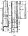
- Figure 7shows the sleeve system 400 in a "delay mode" where movement of the sleeve 460 relative to the ported case 408 has not yet occurred but where such movement is contingent upon the occurrence of a selected wellbore condition.
- the selected wellbore conditionis the occurrence of a sufficient reduction of fluid pressure within the flow bore 416 following the achievement of the mode shown in Figure 6 .
- Figure 8shows the sleeve system 400 in a "fully open mode" where sleeve 460 no longer obstructs a fluid path between ports 444 and sleeve flow bore 416, but rather, a maximum fluid path is provided between ports 444 and the sleeve flow bore 416.
- each of the piston 446, sleeve 460, protective sheath 472, and seat 470are all restricted from movement along the central axis 402 at least because the shear pins 482, 458 lock the seat 470, piston 446, and sleeve 460 relative to the ported case 408.
- the lug 486further restricts movement of the piston 446 relative to the ported case 408 because the lug 486 is captured within the lug receptacle 484 of the piston 446 and between the seat 470 and the ported case 408.
- the lug 486is captured within the lug channel 488, thereby preventing movement of the piston 446 relative to the ported case 408. Further, in the installment mode, the spring 424 is partially compressed along the central axis 402, thereby biasing the piston 446 downward and away from the case shoulder 436.
- the bias chamber 451may be adequately sealed to allow containment of pressurized fluids that supply such biasing of the piston 446. For example, a nitrogen charge may be contained within such an alternative embodiment.
- the bias chamber 451, in alternative embodimentsmay comprise one or both of a spring such as spring 424 and such a pressurized fluid.
- the obturator 476may be passed through a work string such as work string 112 until the obturator 476 substantially seals against the protective sheath 472 (as shown in Figure 5 ), alternatively, the seat gasket in embodiments where a seat gasket is present. With the obturator 476 in place against the protective sheath 472 and/or seat gasket, the pressure within the sleeve flow bore 416 may be increased uphole of the obturator 476 until the obturator 476 transmits sufficient force through the protective sheath 472 and the seat 470 to cause the shear pin 482 to shear.
- the obturator 476drives the protective sheath 472 and the seat 470 downhole from their installation mode positions. Such downhole movement of the seat 470 uncovers the lug 486, thereby disabling the positional locking feature formally provided by the lug 486. Nonetheless, even though the piston 446 is no longer restricted from uphole movement by the protective sheath 472, the seat 470, and the lug 486, the piston remains locked in position by the spring force of the spring 424 and the shear pin 458. Accordingly, the sleeve system remains in a balanced or locked mode, albeit a different configuration or stage of the installation mode.
- the engagement of teeth 469, 466prevents any subsequent downward movement of the piston 446 relative to the sleeve 460. Accordingly, the piston 446 is locked in position relative to the sleeve 460 and the sleeve system 400 may be referred to as being in a delay mode.
- the sleeve system 400is configured to discontinue covering the ports 444 with the sleeve 460 in response to an adequate reduction in fluid pressure within the flow bore 416.
- the spring force provided by spring 424eventually overcomes the upward forced applied against the piston 446 that is generated by the fluid pressure within the flow bore 416.
- the spring 424forces the piston 446 downward. Because the piston 446 is now locked to the sleeve 460 via the c-ring 456, the sleeve is also forced downward.
- Such downward movement of the sleeve 460uncovers the ports 444, thereby providing fluid communication between the flow bore 416 and the ports 444.
- the sleeve system 400is referred to as being in a fully open mode.
- the sleeve system 400is shown in a fully open mode in Figure 8 .
- operating a wellbore servicing systemsuch as wellbore servicing system 100 may comprise providing a first sleeve system (e.g., of the type of sleeve systems 200, 400) in a wellbore and providing a second sleeve system in the wellbore downhole of the first sleeve system.
- a first sleeve systeme.g., of the type of sleeve systems 200, 400
- wellbore servicing pumps and/or other equipmentmay be used to produce a fluid flow through the sleeve flow bores of the first and second sleeve systems.
- an obturatormay be introduced into the fluid flow so that the obturator travels downhole and into engagement with the seat of the first sleeve system.
- each of the first sleeve system and the second sleeve systemare in one of the above-described installation modes so that there is not substantial fluid communication between the sleeve flow bores and an area external thereto (e.g., an annulus of the wellbore and/or an a perforation, fracture, or flowpath within the formation) through the ported cases of the sleeve systems.
- the fluid pressuremay be increased to cause unlocking a restrictor of the first sleeve system as described in one of the above-described manners, thereby transitioning the first sleeve system from the installation mode to one of the above-described delayed modes.
- the fluid flow and pressuremay be maintained so that the obturator passes through the first sleeve system in the above-described manner and subsequently engages the seat of the second sleeve system.
- the delayed mode of operation of the first sleeve systemprevents fluid communication between the sleeve flow bore of the first sleeve and the annulus of the wellbore, thereby ensuring that no pressure loss attributable to such fluid communication prevents subsequent pressurization within the sleeve flow bore of the second sleeve system. Accordingly, the fluid pressure uphole of the obturator may again be increased as necessary to unlock a restrictor of the second sleeve system in one of the above-described manners.
- the delay modes of operationmay be employed to thereafter provide and/or increase fluid communication between the sleeve flow bores and the proximate annulus of the wellbore and/or surrounding formation without adversely impacting an ability to unlock either of the first and second sleeve systems.
- one or more of the features of the sleeve systemsmay be configured to cause one or more relatively uphole located sleeve systems to have a longer delay periods before allowing substantial fluid communication between the sleeve flow bore and the annulus as compared to the delay period provided by one or more relatively downhole located sleeve systems.
- the volume of the fluid chamber 268, the amount of and/or type of fluid placed within fluid chamber 268, the fluid metering device 291, and/or other features of the first sleeve systemmay be chosen differently and/or in different combinations than the related components of the second sleeve system in order to adequately delay provision of the above-described fluid communication via the first sleeve system until the second sleeve system is unlocked and/or otherwise transitioned into a delay mode of operation, until the provision of fluid communication to the annulus and/or the formation via the second sleeve system, and/or until a predetermined amount of time after the provision of fluid communication via the second sleeve system.
- such first and second sleeve systemsmay be configured to allow substantially simultaneous and/or overlapping occurrences of providing substantial fluid communication (e.g., substantial fluid communication and/or achievement of the above-described fully open mode).
- the second sleeve systemmay provide such fluid communication prior to such fluid communication being provided by the first sleeve system.
- wellbore servicing system 100may be used to selectively treat selected one or more of zone 150, first, second, third, fourth, and fifth zones 150a-150e by selectively providing fluid communication via (e.g., opening) one or more the sleeve systems (e.g., sleeve systems 200 and 200a-200e) associated with a given zone. More specifically, by employing the above-described method of operating individual sleeve systems such as sleeve systems 200 and/or 400, any one of the zones 150, 150a-150e may be treated using the respective associated sleeve systems 200 and 200a-200e.
- sleeve systemse.g., sleeve systems 200 and 200a-200e
- zones 150, 150a-150emay be isolated from one another, for example, via swell packers, mechanical packers, sand plugs, sealant compositions (e.g., cement), or combinations thereof.
- a plurality of sleeve systemse.g., a third, fourth, fifth, etc. sleeve system
- a plurality of sleeve systemsmay be similarly operated to selectively treat a plurality of zones (e.g., a third, fourth, fifth, etc. treatment zone), for example, as discussed below with respect to Figure 1 .
- a method of performing a wellbore servicing operation by individually servicing a plurality of zones of a subterranean formation with a plurality of associated sleeve systemsis provided.
- sleeve systems 200 and 200a-200emay be configured substantially similar to sleeve system 200 described above.
- Sleeve systems 200 and 200a-200emay be provided with seats configured to interact with an obturator of a first configuration and/or size (e.g., a single ball and/or multiple balls of the same size and configuration).
- the sleeve systems 200 and 200a-200ecomprise the fluid metering delay system and each of the various sleeve systems may be configured with a fluid metering device chosen to provide fluid communication via that particular sleeve system within a selectable passage of time after being transitioned from installation mode to delay mode.
- Each sleeve systemmay be configured to transition from the delay mode to the fully open mode and thereby provide fluid communication in an amount of time equal to the sum of the amount of time necessary to transition all sleeves located further downhole from that sleeve system from installation mode to delay mode (for example, by engaging an obturator as described above) and perform a desired servicing operation with respect to the zone(s) associated with that sleeve system(s); in addition, an operator may choose to build in an extra amount of time as a "safety margin" (e.g., to ensure the completion of such operations).
- a safety margine.g., to ensure the completion of such operations.
- each sleeve systemmight be configured to transition from delay mode to fully open mode about 2 hours after the sleeve system immediately downhole from that sleeve system.
- the furthest downhole sleeve system (200a)might be configured to transition from delay mode to fully open mode shortly after being transitioned from installation mode to delay mode (e.g., immediately, within about 30 seconds, within about 1 minute, or within about 5 minutes); the second furthest downhole sleeve system (200b) might be configured to transition to fully open mode at about 2 hours, the third most downhole sleeve system (200c) might be configured to transition to fully open mode at about 4 hours, the fourth most downhole sleeve system (200d) might be configured to transition to fully open mode at about 6 hours, the fifth most downhole sleeve system (200e) might be configured to transition to fully open mode at about 8 hours, and the sixth most downhole sleeve system might be transitioned to fully open mode at about 10 hours.
- any one or more of the sleeve systemsmay be configured to open within a desired amount of time.
- a given sleevemay be configured to open within about 1 second after being transitioned from installation mode to delay mode, alternatively, within about 30 seconds, 1 minute, 5 minutes, 15 minutes, 30 minutes, 1 hour, 2 hours, 3 hours, 4 hours, 6 hours, 8 hours, 10 hours, 12 hours, 14 hours, 16 hours, 18 hours, 20 hours, 24 hours, or any amount of time to achieve a given treatment profile, as will be discussed herein below.
- sleeve systems 200 and 200b-200eare configured substantially similar to sleeve system 200 described above, and sleeve system 200a is configured substantially similar to sleeve system 400 described above.
- Sleeve systems 200 and 200a-200emay be provided with seats configured to interact with an obturator of a first configuration and/or size.
- the sleeve systems 200 and 200b-200ecomprise the fluid metering delay system and each of the various sleeve systems may be configured with a fluid metering device chosen to provide fluid communication via that particular sleeve system within a selectable amount of time after being transitioned from installation mode to delay mode, as described above.
- the furthest downhole sleeve system (200a)may be configured to transition from delay mode to fully open mode upon an adequate reduction in fluid pressure within the flow bore of that sleeve system, as described above with reference to sleeve system 400.
- the furthest downhole sleeve system (200a)may be transitioned from delay mode to fully open mode shortly after being transitioned to delay mode.
- Sleeve systems being further upholemay be transitioned from delay mode to fully open mode at selectable passage of time thereafter, as described above.
- the fluid metering devicesmay be selected so that no sleeve system will provide fluid communication between its respective flow bore and ports until each of the sleeve systems further downhole from that particular sleeve system has achieved transition from the delayed mode to the fully open mode and/or until a predetermined amount of time has passed.
- Such a configurationmay be employed where it is desirable to treat multiple zones (e.g., zones 150 and 150a-150e) individually and to activate the associated sleeve systems using a single obturator, thereby avoiding the need to introduce and remove multiple obturators through a work string such as work string 112.
- obturatormay be employed with respect to multiple (e.g., all) sleeve systems a common work string
- the size of the flowpathe.g., the diameter of a flowbore
- the size of the flowpathmay be more consistent, eliminating or decreasing the restrictions to fluid movement through the work string. As such, there may be few deviations with respect to flowrate of a fluid.
- a method of performing a wellbore servicing operationmay comprise providing a work string comprising a plurality of sleeve systems in a configuration as described above and positioning the work string within the wellbore such that one or more of the plurality of sleeve systems is positioned proximate and/or substantially adjacent to one or more of the zones (e.g., deviated zones) to be serviced.
- the zonesmay be isolated, for example, by actuating one or more packers or similar isolation devices.
- an obturator like obturator 276configured and/or sized to interact with the seats of the sleeve systems is introduced into and passed through the work string 112 until the obturator 276 reaches the relatively furthest uphole sleeve system 200 and engages a seat like seat 270 of that sleeve system.
- Continued pumpingmay increase the pressure applied against the seat 270 causing the sleeve system to transition from installation mode to delay mode and the obturator to pass through the sleeve system, as described above.
- the obturatormay then continue to move through the work string to similarly engage and transition sleeve systems 200a-200e to delay mode.
- the sleeve systemsmay be transitioned from delay mode to fully open in the order in which the zone or zones associated with a sleeve system are to be serviced.
- the zonesmay be serviced beginning with the relatively furthest downhole zone (150a) and working toward progressively lesser downhole zones (e.g., 150b, 150c, 150d, 150e, then 150).
- servicing a particular zoneis accomplished by transitioning the sleeve system associated with that zone to fully open mode and communicating a servicing fluid to that zone via the ports of the sleeve system.
- transitioning sleeve system 200a(which is associated with zone 150a) to fully open mode may be accomplished by waiting for the preset amount of time following unlocking the sleeve system 200a while the fluid metering system allows the sleeve system to open, as described above. With the sleeve system 200a fully open, a servicing fluid may be communicated to the associated zone (150a).
- transitioning sleeve system 200a to fully open modemay be accomplished by allowing a reduction in the pressure within the flow bore of the sleeve system, as described above.
- servicing fluid communicated to the zonemay be selected dependent upon the servicing operation to be performed.
- servicing fluidsinclude a fracturing fluid, a hydrajetting or perforating fluid, an acidizing, an injection fluid, a fluid loss fluid, a sealant composition, or the like.
- a zonewhen a zone has been serviced, it may be desirable to restrict fluid communication with that zone, for example, so that a servicing fluid may be communicated to another zone.
- an operatormay restrict fluid communication with zone 150a (e.g., via sleeve system 200a) by intentionally causing a "screenout” or sand-plug.
- a "screenout” or “screening out”refers to a condition where solid and/or particulate material carried within a servicing fluid creates a "bridge" that restricts fluid flow through a flowpath. By screening out the flow paths to a zone, fluid communication to the zone may be restricted so that fluid may be directed to one or more other zones.
- the servicing operationmay proceed with respect to additional zones (e.g., 150b-150e and 150) and the associated sleeve systems (e.g., 200b-200e and 200).
- additional sleeve systemswill transition to fully open mode at preset time intervals following transitioning from installation mode to delay mode, thereby providing fluid communication with the associated zone and allowing the zone to be serviced.
- fluid communication with that zonemay be restricted, as disclosed above.
- the solid and/or particulate material employed to restrict fluid communication with one or more of the zonesmay be removed, for example, to allow the flow of wellbore production fluid into the flow bores of the of the open sleeve systems via the ports of the open sleeve systems.
- various treatment zonesmay be treated and/or serviced in any suitable sequence, that is, a given treatment profile.
- a treatment profilemay be determined and a plurality of sleeve systems like sleeve system 200 may be configured (e.g., via suitable time delay mechanisms, as disclosed herein) to achieve that particular profile.
- a plurality of sleeve systems like sleeve system 200may be configured (e.g., via suitable time delay mechanisms, as disclosed herein) to achieve that particular profile.
- three sleeve systems of the type disclosed hereinmay be positioned proximate to each zone.
- the first sleeve system(e.g., proximate to the lowermost zone) may be configured to open first
- the third sleeve system(e.g., proximate to the uppermost zone) may be configured to open second (e.g., allowing enough time to complete the servicing operation with respect to the first zone and obstruct fluid communication via the first sleeve system)
- the second sleeve system(e.g., proximate to the intermediate zone) may be configured to open last (e.g., allowing enough time to complete the servicing operation with respect to the first and second zones and obstruct fluid communication via the first and second sleeve systems).
- sleeve systems 200a-200eare configured substantially similar to sleeve system 200 described above.
- sleeve systems 200a, 200b, and 200cmay be provided with seats configured to interact with an obturator of a first configuration and/or size while sleeve systems 200d, 200e, and 200 are configured not to interact with the obturator having the first configuration.
- sleeve systems 200a, 200b, and 200cmay be transitioned from installation mode to delay mode by passing the obturator having a first configuration through the uphole sleeve systems 200, 200e, and 200d and into successive engagement with sleeve systems 200c, 200b, and 200a. Since the sleeve systems 200a-200c comprise the fluid metering delay system, the various sleeve systems may be configured with fluid metering devices chosen to provide a controlled and/or relatively slower opening of the sleeve systems.
- the fluid metering devicesmay be selected so that none of the sleeve systems 200a-200c actually provide fluid communication between their respective flow bores and ports prior to each of the sleeve systems 200a-200c having achieved transition from the installation mode to the delayed mode.
- the delay systemsmay be configured to ensure that each of the sleeve systems 200a-200c has been unlocked by the obturator prior to such fluid communication.
- each of sleeve systems 200c, 200bmay be provided with a fluid metering device that delays such loss until the obturator has unlocked the sleeve system 200a.
- individual sleeve systemsmay be configured to provide relatively longer delays (e.g., the time from when a sleeve system is unlocked to the time that the sleeve system allows fluid flow through its ports) in response to the location of the sleeve system being located relatively further uphole from a final sleeve system that must be unlocked during the operation (e.g., in this case, sleeve system 200a).
- a sleeve system 200cmay be configured to provide a greater delay than the delay provided by sleeve system 200b.
- the sleeve system 200cmay be provided with a delay of at least about 20 minutes. The 20 minute delay may ensure that the obturator can both reach and unlock the sleeve systems 200b, 200a prior to any fluid and/or fluid pressure being lost through the ports of sleeve system 200c.
- sleeve systems 200c, 200bmay each be configured to provide the same delay so long as the delay of both are sufficient to prevent the above-described fluid and/or fluid pressure loss from the sleeve systems 200c, 200b prior to the obturator unlocking the sleeve system 200a.
- the sleeve systems 200c, 200bmay each be provided with a delay of at least about 20 minutes.
- all three of the sleeve systems 200a-200cmay be unlocked and transitioned into fully open mode with a single trip through the work string 112 of a single obturator and without unlocking the sleeve systems 200d, 200e, and 200 that are located uphole of the sleeve system 200c.
- an obturator having a second configuration and/or sizemay be passed through sleeve systems 200d, 200e, and 200 in a similar manner to that described above to selectively open the remaining sleeve systems 200d, 200e, and 200.
- thisis accomplished by providing 200d, 200e, and 200 with seats configured to interact with the obturator having the second configuration.
- sleeve systemssuch as 200a, 200b, and 200c may all be associated with a single zone of a wellbore and may all be provided with seats configured to interact with an obturator of a first configuration and/or size while sleeve systems such as 200d, 200e, and 200 may not be associated with the above-mentioned single zone and are configured not to interact with the obturator having the first configuration.
- sleeve systemssuch as 200a, 200b, and 200c may be transitioned from an installation mode to a delay mode by passing the obturator having a first configuration through the uphole sleeve systems 200, 200e, and 200d and into successive engagement with sleeve systems 200c, 200b, and 200a.
- the single obturator having the first configurationmay be used to unlock and/or activate multiple sleeve systems (e.g., 200c, 200b, and 200a) within a selected single zone after having selectively passed through other uphole and/or non-selected sleeve systems (e.g., 200d, 200e, and 200).
- An alternative embodiment of a method of servicing a wellboremay be substantially the same as the previous examples, but instead, using at least one sleeve system substantially similar to sleeve system 400. It will be appreciated that while using the sleeve systems substantially similar to sleeve system 400 in place of the sleeve systems substantially similar to sleeve system 200, a primary difference in the method is that fluid flow between related fluid flow bores and ports is not achieved amongst the three sleeve systems being transitioned from an installation mode to a fully open mode until pressure within the fluid flow bores is adequately reduced. Only after such reduction in pressure will the springs of the sleeve systems substantially similar to sleeve system 400 force the piston and the sleeves downward to provide the desired fully open mode.
- a method of servicing a wellboremay comprise providing a first sleeve system in a wellbore and also providing a second sleeve system downhole of the first sleeve system. Subsequently, a first obturator may be passed through at least a portion of the first sleeve system to unlock a restrictor of the first sleeve, thereby transitioning the first sleeve from an installation mode of operation to a delayed mode of operation.
- the obturatormay travel downhole from the first sleeve system to pass through at least a portion of the second sleeve system to unlock a restrictor of the second sleeve system.
- the unlocking of the restrictor of the second sleevemay occur prior to loss of fluid and/or fluid pressure through ports of the first sleeve system.
- the methodsmay be continued by flowing wellbore servicing fluids from the fluid flow bores of the open sleeve systems out through the ports of the open sleeve systems.
- wellbore production fluidsmay be flowed into the flow bores of the open sleeve systems via the ports of the open sleeve systems.
Landscapes
- Geology (AREA)
- Life Sciences & Earth Sciences (AREA)
- Engineering & Computer Science (AREA)
- Mining & Mineral Resources (AREA)
- Geochemistry & Mineralogy (AREA)
- Fluid Mechanics (AREA)
- Environmental & Geological Engineering (AREA)
- General Life Sciences & Earth Sciences (AREA)
- Physics & Mathematics (AREA)
- Earth Drilling (AREA)
- Branch Pipes, Bends, And The Like (AREA)
- Quick-Acting Or Multi-Walled Pipe Joints (AREA)
- Soil Working Implements (AREA)
- Tents Or Canopies (AREA)
- Pipeline Systems (AREA)
- Filling Or Discharging Of Gas Storage Vessels (AREA)
- Excavating Of Shafts Or Tunnels (AREA)
- Massaging Devices (AREA)
Description
- Subterranean formations that contain hydrocarbons are sometimes nonhomogeneous in their composition along the length of wellbores that extend into such formations. It is sometimes desirable to treat and/or otherwise manage the formation and/or the wellbore differently in response to the differing formation composition. Some wellbore servicing systems and methods allow such treatment, referred to by some as zonal isolation treatments. However, in some wellbore servicing systems and methods, while multiple tools for use in treating zones may be activated by a single obturator, such activation of one tool by the obturator may cause activation of additional tools to be more difficult. For example, a ball may be used to activate a plurality of stimulation tools, thereby allowing fluid communication between a flow bore of the tools with a space exterior to the tools. However, such fluid communication accomplished by activated tools may increase the working pressure required to subsequently activate additional tools. Accordingly, there exists a need for improved systems and methods of treating multiple zones of a wellbore.
WO 2010/127457 discloses a tubing string assembly for fluid treatment of a wellbore. The tubing string can be used for staged wellbore fluid treatment where a selected segment of the wellbore is treated, while other segments are sealed off. The tubing string can also be used where a ported tubing string is required to be run-in in a pressure tight condition and later is needed to be in an open-port condition A sliding sleeve in a tubular has a driver selected to be acted upon by an inner bore conveyed actuating device, the driver drives the generation of a ball stop on the sleeve.WO 2009/029437 discloses fracturing tools for use in oil and gas wells, which tools have a run-in position and two operational positions. A sleeve disposed in the bore of the fracturing tool comprises a sleeve port alignable with a first port in the housing of the frac tool, i.e., the first operational position, during fracturing operations. A second port having a restriction member is disposed in the housing and is closed by the sleeve during fracturing operations. After fracturing operations are completed, a return member in the frac tool moves the sleeve from the first operational position to a second operational position for production operations. In this second operational position, the first port is closed and the sleeve port is aligned with the second port. Movement of the sleeve from the first operational position to the second operational position is performed without the need for an additional well intervention step.WO 2009/050518 discloses a device for use downhole comprising a body housing: a power source arranged to supply power to a driver; and a hydraulic system including a piston sealed in a chamber and an outlet provided at each opposing end of the chamber, wherein each outlet is in communication with a respective reservoir, the driver being actuable to drive the piston in a first direction, such that fluid is driven out of the chamber through one outlet and simultaneously fluid is drawn into the chamber through the other outlet at the opposing ends.- The present invention provides a method of individually servicing a plurality of zones of a subterranean formation comprising providing a work string comprising a first sleeve system comprising a first one or more ports, the first sleeve system being transitionable from a first mode to a second mode and transitionable from the second mode to a third mode, wherein, when the first sleeve system is in the first mode and the second mode, fluid communication via the first one or more ports is restricted, and wherein, when the first sleeve system is in the third mode, fluid may be communicated via the first one or more ports, and a second sleeve system comprising a second one or more ports, the second sleeve system being transitionable from a first mode to a second mode and transitionable from the second mode to a third mode, wherein, when the second sleeve system is in the first mode and the second mode, fluid communication via the second one or more ports is restricted, and wherein, when the second sleeve system is in the third mode, fluid may be communicated via the second one or more ports, positioning the first sleeve system proximate to a first zone of the subterranean formation and the second sleeve system proximate to a second zone of the subterranean formation which is uphole relative to the first zone, circulating an obturator through the work string, contacting the obturator with a seat of the second sleeve system, applying pressure to the obturator such that the second sleeve transitions to the second mode and the obturator passes through the seat of the second sleeve system, contacting the obturator with a seat of the first sleeve system, applying pressure to the obturator such that the first sleeve system transitions to the second mode and the obturator passes through the seat of the first sleeve system, allowing the first sleeve system to transition from the second mode to the third mode, and communicating a servicing fluid to the first zone via the first one or more ports of the first sleeve system.
- Also disclosed herein is a method of individually servicing a plurality of zones of a subterranean formation comprising providing a work string having integrated therein a first sleeve system and a second sleeve system, positioning the first sleeve system configured in an installation mode proximate to a first zone, wherein the first sleeve system is configured to restrict fluid communication to the first zone when in installation mode, positioning the second sleeve system configured in an installation mode proximate to a second zone, wherein the second sleeve system is configured to restrict fluid communication to the second zone when in installation mode, transitioning the second sleeve from the installation mode to a delayed mode, wherein the second sleeve system is configured to restrict fluid communication to the second zone when in the delayed mode, transitioning the first sleeve from the installation mode to a delayed mode, wherein the first sleeve system is configured to restrict fluid communication to the first zone when in the delayed mode, allowing the first sleeve system to transition from the delayed mode to an open mode, communicating a servicing fluid to the first zone via the first sleeve system while the second sleeve system is in the delayed mode.
- For a more complete understanding of the present disclosure and the advantages thereof, reference is now made to the following brief description, taken in connection with the accompanying drawings and detailed description:
Figure 1 is a cut-away view of an embodiment of a wellbore servicing system according to the disclosure;Figure 2 is a cross-sectional view of a sleeve system of the wellbore servicing system ofFigure 1 showing the sleeve system in an installation mode;Figure 2A is a cross-sectional end-view of a segmented seat of the sleeve system ofFigure 2 showing the segmented seat divided into three segments;Figure 2B is a cross-sectional view of a segmented seat of the sleeve system ofFigure 2 having a protective sheath applied thereto;Figure 3 is a cross-sectional view of the sleeve system ofFigure 2 showing the sleeve system in a delay mode;Figure 4 is a cross-sectional view of the sleeve system ofFigure 2 showing the sleeve system in a fully open mode;Figure 5 is a cross-sectional view of an alternative embodiment of a sleeve system according to the disclosure showing the sleeve system in an installation mode;Figure 6 is a cross-sectional view of the sleeve system ofFigure 5 showing the sleeve system in another stage of the installation mode;Figure 7 is a cross-sectional view of the sleeve system ofFigure 5 showing the sleeve system in a delay mode; andFigure 8 is a cross-sectional view of the sleeve system ofFigure 5 showing the sleeve system in a fully open mode.- In the drawings and description that follow, like parts are typically marked throughout the specification and drawings with the same reference numerals, respectively. The drawing figures are not necessarily to scale. Certain features of the invention may be shown exaggerated in scale or in somewhat schematic form and some details of conventional elements may not be shown in the interest of clarity and conciseness.
- Unless otherwise specified, any use of any form of the terms "connect," "engage," "couple," "attach," or any other term describing an interaction between elements is not meant to limit the interaction to direct interaction between the elements and may also include indirect interaction between the elements described. In the following discussion and in the claims, the terms "including" and "comprising" are used in an open-ended fashion, and thus should be interpreted to mean "including, but not limited to ...." Reference to up or down will be made for purposes of description with "up," "upper," "upward," or "upstream" meaning toward the surface of the wellbore and with "down," "lower," "downward," or "downstream" meaning toward the terminal end of the well, regardless of the wellbore orientation. The term "zone" or "pay zone" as used herein refers to separate parts of the wellbore designated for treatment or production and may refer to an entire hydrocarbon formation or separate portions of a single formation such as horizontally and/or vertically spaced portions of the same formation. The various characteristics mentioned above, as well as other features and characteristics described in more detail below, will be readily apparent to those skilled in the art with the aid of this disclosure upon reading the following detailed description of the embodiments and by referring to the accompanying drawings.
- Disclosed herein are improved components, more specifically, a sheathed, segmented seat, for use in downhole tools. Such a sheathed, segmented seat may be employed alone or in combination with other components to transition one or more downhole tools from a first configuration to a second, third, or fourth, etc. configuration or mode by selectively receiving, retaining, and releasing an obturator (or any other suitable actuator or actuating device).
- Also disclosed herein are sleeve systems and methods of using downhole tools, more specifically sleeve systems employing a sheathed, segmented seat that may be placed in a wellbore in a "run-in" configuration or an "installation mode" where a sleeve of the sleeve system blocks fluid transfer between a flow bore of the sleeve system and a port of the sleeve system. The installation mode may also be referred to as a "locked mode" since the sleeve is selectively locked in position relative to the port. In some embodiments, the locked positional relationship between the sleeves and the ports may be selectively discontinued or disabled by unlocking one or more components relative to each other, thereby potentially allowing movement of the sleeves relative to the ports. Still further, once the components are no longer locked in position relative to each other, some of the embodiments are configured to thereafter operate in a "delay mode" where relative movement between the sleeve and the port is delayed insofar as (1) such relative movement occurs but occurs at a reduced and/or controlled rate and/or (2) such relative movement is delayed until the occurrence of a selected wellbore condition. The delay mode may also be referred to as an "unlocked mode" since the sleeves are no longer locked in position relative to the ports. In some embodiments, the sleeve systems may be operated in the delay mode until the sleeve system achieves a "fully open mode" where the sleeve has moved relative to the port to allow maximum fluid communication between the flow bore of the sleeve system and the port of the sleeve system. It will be appreciated that devices, systems, and/or components of sleeve system embodiments that selectively contribute to establishing and/or maintaining the locked mode may be referred to as locking devices, locking systems, locks, movement restrictors, restrictors, and the like. It will also be appreciated that devices, systems, and/or components of sleeve system embodiments that selectively contribute to establishing and/or maintaining the delay mode may be referred to as delay devices, delay systems, delays, timers, contingent openers, and the like.
- Also disclosed herein are methods for configuring a plurality of such sleeve systems so that one or more sleeve systems may be selectively transitioned from the installation mode to the delay mode by passing a single obturator through the plurality of sleeve systems. As will be explained below in greater detail, in some embodiments, one or more sleeve systems may be configured to interact with an obturator of a first configuration while other sleeve systems may be configured not to interact with the obturator having the first configuration, but rather, configured to interact with an obturator having a second configuration. Such differences in configurations amongst the various sleeve systems may allow an operator to selectively transition some sleeve systems to the exclusion of other sleeve systems.
- Also disclosed herein are methods for performing a wellbore servicing operation employing a plurality of such sleeve systems by configuring such sleeve systems so that one or more of the sleeve systems may be selectively transitioned from the delay mode to the fully open mode at varying time intervals. Such differences in configurations amongst the various sleeve systems may allow an operator to selectively transition some sleeve systems to the exclusion of other sleeve systems, for example, such that a servicing fluid may be communicated (e.g., for the performance of a servicing operation) via a first sleeve system while not being communicated via a second, third, fourth, etc. sleeve system. The following discussion describes various embodiments of sleeve systems, the physical operation of the sleeve systems individually, and methods of servicing wellbores using such sleeve systems.
- Referring to
Figure 1 , an embodiment of awellbore servicing system 100 is shown in an example of an operating environment. As depicted, the operating environment comprises a servicing rig 106 (e.g., a drilling, completion, or workover rig) that is positioned on the earth'ssurface 104 and extends over and around awellbore 114 that penetrates asubterranean formation 102 for the purpose of recovering hydrocarbons. Thewellbore 114 may be drilled into thesubterranean formation 102 using any suitable drilling technique. Thewellbore 114 extends substantially vertically away from the earth'ssurface 104 over a verticalwellbore portion 116, deviates from vertical relative to the earth'ssurface 104 over a deviatedwellbore portion 136, and transitions to a horizontalwellbore portion 118. In alternative operating environments, all or portions of a wellbore may be vertical, deviated at any suitable angle, horizontal, and/or curved. - At least a portion of the
vertical wellbore portion 116 is lined with acasing 120 that is secured into position against thesubterranean formation 102 in a conventionalmanner using cement 122. In alternative operating environments, a horizontal wellbore portion may be cased and cemented and/or portions of the wellbore may be uncased. Theservicing rig 106 comprises aderrick 108 with arig floor 110 through which a tubing or work string 112 (e.g., cable, wireline, E-line, Z-line, jointed pipe, coiled tubing, casing, or liner string, etc.) extends downward from theservicing rig 106 into thewellbore 114 and defines anannulus 128 between thework string 112 and thewellbore 114. Thework string 112 delivers thewellbore servicing system 100 to a selected depth within thewellbore 114 to perform an operation such as perforating thecasing 120 and/orsubterranean formation 102, creating perforation tunnels and/or fractures (e.g., dominant fractures, micro-fractures, etc.) within thesubterranean formation 102, producing hydrocarbons from thesubterranean formation 102, and/or other completion operations. Theservicing rig 106 comprises a motor driven winch and other associated equipment for extending thework string 112 into thewellbore 114 to position thewellbore servicing system 100 at the selected depth. - While the operating environment depicted in
Figure 1 refers to astationary servicing rig 106 for lowering and setting thewellbore servicing system 100 within a land-basedwellbore 114, in alternative embodiments, mobile workover rigs, wellbore servicing units (such as coiled tubing units), and the like may be used to lower a wellbore servicing system into a wellbore. It should be understood that a wellbore servicing system may alternatively be used in other operational environments, such as within an offshore wellbore operational environment. - The
subterranean formation 102 comprises azone 150 associated with deviatedwellbore portion 136. Thesubterranean formation 102 further comprises first, second, third, fourth, and fifth horizontal zones, 150a, 150b, 150c, 150d, 150e, respectively, associated with thehorizontal wellbore portion 118. In this embodiment, thezones wellbore 114 in the following order of increasingly downhole location: 150, 150e, 150d, 150c, 150b, and 150a. In this embodiment, stimulation andproduction sleeve systems wellbore 114 in thework string 112 and are associated withzones wellbore 114 in a manner that restricts fluid communication between spaces immediately uphole and downhole of each annular isolation device. - Referring now to
Figure 2 , a cross-sectional view of an embodiment of a stimulation and production sleeve system 200 (hereinafter referred to as "sleeve system" 200) is shown. Many of the components ofsleeve system 200 lie substantially coaxial with acentral axis 202 ofsleeve system 200.Sleeve system 200 comprises anupper adapter 204, alower adapter 206, and a portedcase 208. The portedcase 208 is joined between theupper adapter 204 and thelower adapter 206. Together,inner surfaces upper adapter 204, thelower adapter 206, and the portedcase 208, respectively, substantially define a sleeve flow bore 216. Theupper adapter 204 comprises acollar 218, amakeup portion 220, and acase interface 222. Thecollar 218 is internally threaded and otherwise configured for attachment to an element ofwork string 112 that is adjacent and uphole ofsleeve system 200 while thecase interface 222 comprises external threads for engaging the portedcase 208. Thelower adapter 206 comprises anipple 224, amakeup portion 226, and acase interface 228. Thenipple 224 is externally threaded and otherwise configured for attachment to an element ofwork string 112 that is adjacent and downhole ofsleeve system 200 while thecase interface 228 also comprises external threads for engaging the portedcase 208. - The ported
case 208 is substantially tubular in shape and comprises anupper adapter interface 230, a centralported body 232, and alower adapter interface 234, each having substantially the same exterior diameters. Theinner surface 214 of portedcase 208 comprises acase shoulder 236 that separates an upperinner surface 238 from a lowerinner surface 240. The portedcase 208 further comprisesports 244. As will be explained in further detail below,ports 244 are through holes extending radially through the portedcase 208 and are selectively used to provide fluid communication between sleeve flow bore 216 and a space immediately exterior to the portedcase 208. - The
sleeve system 200 further comprises apiston 246 carried within the portedcase 208. Thepiston 246 is substantially configured as a tube comprising anupper seal shoulder 248 and a plurality ofslots 250 near alower end 252 of thepiston 246. With the exception ofupper seal shoulder 248, thepiston 246 comprises an outer diameter smaller than the diameter of the upperinner surface 238. Theupper seal shoulder 248 carries acircumferential seal 254 that provides a fluid tight seal between theupper seal shoulder 248 and the upperinner surface 238. Further,case shoulder 236 carries aseal 254 that provides a fluid tight seal between thecase shoulder 236 and anouter surface 256 ofpiston 246. In the embodiment shown and when thesleeve system 200 is configured in an installation mode, theupper seal shoulder 248 of thepiston 246 abuts theupper adapter 204. Thepiston 246 extends from theupper seal shoulder 248 toward thelower adapter 206 so that theslots 250 are located downhole of theseal 254 carried bycase shoulder 236. In this embodiment, the portion of thepiston 246 between theseal 254 carried bycase shoulder 236 and theseal 254 carried by theupper seal shoulder 248 comprises no apertures in the tubular wall (i.e., is a solid, fluid tight wall). As shown in this embodiment and in the installation mode ofFigure 2 , alow pressure chamber 258 is located between theouter surface 256 ofpiston 246 and the upperinner surface 238 of the portedcase 208. - The
sleeve system 200 further comprises asleeve 260 carried within the portedcase 208 below thepiston 246. Thesleeve 260 is substantially configured as a tube comprising anupper seal shoulder 262. With the exception ofupper seal shoulder 262, thesleeve 260 comprises an outer diameter substantially smaller than the diameter of the lowerinner surface 240. Theupper seal shoulder 262 carries twocircumferential seals 254, oneseal 254 near each end (e.g., upper and lower ends) of theupper seal shoulder 262, that provide fluid tight seals between theupper seal shoulder 262 and the lowerinner surface 240 of portedcase 208. Further, twoseals 254 are carried by thesleeve 260 near alower end 264 ofsleeve 260, and the twoseals 254 form fluid tight seals between thesleeve 260 and theinner surface 212 of thelower adapter 206. In this embodiment and installation mode shown inFigure 2 , anupper end 266 ofsleeve 260 substantially abuts a lower end of thecase shoulder 236 and thelower end 252 ofpiston 246. In this embodiment and installation mode shown inFigure 2 , theupper seal shoulder 262 of thesleeve 260seals ports 244 from fluid communication with the sleeve flow bore 216. Further, theseal 254 carried near the lower end of theupper seal shoulder 262 is located downhole of (e.g., below)ports 244 while theseal 254 carried near the upper end of theupper seal shoulder 262 is located uphole of (e.g., above)ports 244. The portion of thesleeve 260 between theseal 254 carried near the lower end of theupper seal shoulder 262 and theseals 254 carried by thesleeve 260 near alower end 264 ofsleeve 260 comprises no apertures in the tubular wall (i.e., is a solid, fluid tight wall). As shown in this embodiment and in the installation mode ofFigure 2 , afluid chamber 268 is located between the outer surface ofsleeve 260 and the lowerinner surface 240 of the portedcase 208. - The
sleeve system 200 further comprises asegmented seat 270 carried within thelower adapter 206 below thesleeve 260. Thesegmented seat 270 is substantially configured as a tube comprising aninner bore surface 273 and achamfer 271 at the upper end of the seat, thechamfer 271 being configured and/or sized to selectively engage and/or retain an obturator of a particular size and/or shape (such as obturator 276). In the embodiment ofFigure 2 , thesegmented seat 270 may be radially divided with respect tocentral axis 202 into segments. For example, referring now toFigure 2A , thesegmented seat 270 is divided (e.g., as represented by dividing or segmenting lines/cuts 277) into three complementary segments of approximately equal size, shape, and/or configuration. In the embodiment ofFigure 2A , the three complementary segments (270A, 270B, and 270C, respectively) together form thesegmented seat 270, with each of the segments (270A, 270B, and 270C) constituting about one-third (e.g., extending radially about 120°) of thesegmented seat 270. In an alternative embodiment, a segmented seat likesegmented seat 270 may comprise any suitable number of equally or unequally-divided segments. For example, a segmented seat may comprise two, four, five, six, or more complementary, radial segments. Thesegmented seat 270 may be formed from a suitable material. Nonlimiting examples of such a suitable material include composites, phenolics, cast iron, aluminum, brass, various metal alloys, rubbers, ceramics, or combinations thereof. In an embodiment, the material employed to form the segmented seat may be characterized as drillable, that is, thesegmented seat 270 may be fully or partially degraded or removed by drilling, as will be appreciated by one of skill in the art with the aid of this disclosure. Segments 270A, 270B, and 270C may be formed independently or, alternatively, a preformed seat may be divided into segments. It will be appreciated that whileobturator 276 is shown inFigure 2 with thesleeve system 200 in an installation mode, in most applications of thesleeve system 200, thesleeve system 200 would be placed downhole without theobturator 276, and theobturator 276 would subsequently be provided as discussed below in greater detail. Further, while theobturator 276 is a ball, an obturator of other embodiments may be any other suitable shape or device for sealing against aprotective sheath 272 and or a seat gasket (both of which will be discussed below) and obstructing flow through the sleeve flow bore 216. - In an alternative embodiment, a sleeve system like
sleeve system 200 may comprise an expandable seat. Such an expandable seat may be constructed of, for example but not limited to, a low alloy steel such as AISI 4140 or 4130, and is generally configured to be biased radially outward so that if unrestricted radially, a diameter (e.g., outer/inner) of theseat 270 increases. In some embodiments, the expandable seat may be constructed from a generally serpentine length of AISI 4140. For example, the expandable seat may comprise a plurality of serpentine loops between upper and lower portions of the seat and continuing circumferentially to form the seat. In an embodiment, such an expandable seat may be covered by a protective sheath 272 (as will be discussed below) and/or may comprise a seat gasket. - In the embodiment of
Figure 2 , one or more surfaces of thesegmented seat 270 are covered by aprotective sheath 272. Referring toFigure 2B , an embodiment of thesegmented seat 270 andprotective sheath 272 are illustrated in greater detail. In the embodiment ofFigure 2B theprotective sheath 272 covers thechamfer 271 of thesegmented seat 270, theinner bore 273 of thesegmented seat 270, and alower face 275 of thesegmented seat 270. In an alternative embodiment, theprotective sheath 272 may cover thechamfer 271, theinner bore 273, and alower face 275, the back 279 of thesegmented seat 270, or combinations thereof. In another alternative embodiment, a protective sheath may cover any one or more of the surfaces of asegmented seat 270, as will be appreciated by one of skill in the art viewing this disclosure. In the embodiment illustrated byFigures 2 ,2A, and 2B , theprotective sheath 272 forms a continuous layer over those surfaces of thesegmented seat 270 in fluid communication with the sleeve flow bore 216. For example, small crevices or gaps (e.g., at dividing lines 277) may exist at the radially extending divisions between the segments (e.g., 270A, 270B, and 270C) of thesegmented seat 270. In an embodiment, the continuous layer formed by theprotective sheath 272 may fill, seal, minimize, or cover, any such crevices or gaps such that a fluid flowing via the sleeve flow bore 216 will be impeded from contacting and/or penetrating any such crevices or gaps. - In an embodiment, the
protective sheath 272 may be applied to thesegmented seat 270 while the segments 270A, 270B, and 270C are retained in a close conformation (e.g., where each segment abuts the adjacent segments, as illustrated inFigure 2A ). For example, thesegmented seat 270 may be retained in such a close conformation by bands, bindings, straps, wrappings, or combinations thereof. In an embodiment, thesegmented seat 270 may be coated and/or covered with theprotective sheath 272 via any suitable method of application. For example, thesegmented seat 270 may submerged (e.g., dipped) in a material (as will be discussed below) that will form theprotective sheath 272, a material that will form theprotective sheath 272 may be sprayed and/or brushed onto the desired surfaces of thesegmented seat 270, or combinations thereof. In such an embodiment, theprotective sheath 270 may adhere to the segments 270A, 270B, and 270C of thesegmented seat 270 and thereby retain the segments in the close conformation. - In an alternative embodiment, the
protective sheath 272 may be applied individually to each of the segments 270A, 270B, and 270C of thesegmented seat 270. For example, the segments 270A, 270B, and/or 270C may individually submerged (e.g., dipped) in a material that will form theprotective sheath 272, a material that will form theprotective sheath 272 may be sprayed and/or brushed onto the desired surfaces of the segments 270A, 270B, and 270C, or combinations thereof. In such an embodiment, theprotective sheath 272 may adhere to some or all of the surfaces of each of the segments 270A, 270B, and 270C. After theprotective sheath 272 has been applied, the segments 270A, 270B, and 270C may be brought together to form thesegmented seat 270. Thesegmented seat 270 may be retained in such a close conformation (e.g., as illustrated inFigure 2A ) by bands, bindings, straps, wrappings, or combinations thereof. In such an embodiment, theprotective sheath 272 may be sufficiently malleable or pliable that when the sheathed segments are retained in the close conformation, any crevices or gaps between the segments (e.g., segments 270A, 270B, and 270C) will be filled or minimized by theprotective sheath 272 such that a fluid flowing via the sleeve flow bore 216 will be impeded from contacting and/or penetrating any such crevices or gaps. - In still another alternative embodiment, the
protective sheath 272 need not be applied directly to thesegmented seat 270. For example, a protective sheath may be fitted to or within thesegmented seat 270, draped over a portion ofsegmented seat 270, or the like. The protective sheath may comprise a sleeve or like insert configured and sized to be positioned within the bore of the segmented sheath and to fit against thechamfer 271 of thesegmented seat 270, theinner bore 273 of thesegmented seat 270, and/or thelower face 275 of thesegmented seat 270 and thereby form a continuous layer that may fill, seal, or cover, any such crevices or gaps such that a fluid flowing via the sleeve flow bore 216 will be impeded from contacting and/or penetrating any such crevices or gaps. In another embodiment where theprotective sheath 272 comprises a heat-shrinkable material (as will be discussed below), such a material may be positioned over, around, within, about, or similarly, at least a portion of thesegmented seat 270 and/or one or more of the segments 270A, 270B, and 270C, and heated sufficiently to cause the shrinkable material to shrink to the surfaces of thesegmented seat 270 and/or the segments 270A, 270B, and 270C. - In an embodiment, the
protective sheath 272 may be formed from a suitable material. Nonlimiting examples of such a suitable material include ceramics, carbides, hardened plastics, molded rubbers, various heat-shrinkable materials, or combinations thereof. In an embodiment, the protective sheath may be characterized as having a hardness of from about 25 durometers to about 150 durometers, alternatively, from about 50 durometers to about 100 durometers, alternatively, from about 60 durometers to about 80 durometers. In an embodiment, the protective sheath may be characterized as having a thickness of from about 1/64th of an inch (3.97 x 10⁻⁴ m) to about 3/16th of an inch (4.76 x 10⁻³ m), alternatively, about 1/32nd of an inch (7.94 x 10⁻⁴ m). Examples of materials suitable for the formation of the protective sheath include nitrile rubber, which commercially available from several rubber, plastic, and/or composite materials companies. - In an embodiment, a protective sheath, like
protective sheath 272, may be employed to advantageously lessen the degree of erosion and/or degradation to a segmented seat, likesegmented seat 270. Not intending to be bound by theory, such a protective sheath may improve the service life of a segmented seat covered by such a protective sheath by decreasing the impingement of erosive fluids (e.g., cutting, hydrojetting, and/or fracturing fluids comprising abrasives and/or proppants) with the segmented seat. In an embodiment, a segmented seat protected by such a protective sheath may have a service life at least 20% greater, alternatively, at least 30% greater, alternatively, at least 35% greater than an otherwise similar seat not protected by such a protective sheath. - In an embodiment, the
segmented seat 270 may further comprise a seat gasket that serves to seal against an obturator. In some embodiments, the seat gasket may be constructed of rubber. In such an embodiment and installation mode, the seat gasket may be substantially captured between the expandable seat and the lower end of the sleeve. In an embodiment, theprotective sheath 272 may serve as such a gasket, for example, by engaging and/or sealing an obturator. In such an embodiment, theprotective sheath 272 may have a variable thickness. For example, the surface(s) of theprotective sheath 272 configured to engage the obturator (e.g., chamfer 271) may comprise a greater thickness than the one or more other surfaces of theprotective sheath 272. - The
sleeve system 200 further comprises aseat support 274 carried within thelower adapter 206 below theseat 270. Theseat support 274 is substantially formed as a tubular member. Theseat support 274 comprises anouter chamfer 278 on the upper end of theseat support 274 that selectively engages aninner chamfer 280 on the lower end of thesegmented seat 270. Theseat support 274 comprises acircumferential channel 282. Theseat support 274 further comprises twoseals 254, oneseal 254 carried uphole of (e.g., above) thechannel 282 and theother seal 254 carried downhole of (e.g., below) thechannel 282, and theseals 254 form a fluid seal between theseat support 274 and theinner surface 212 of thelower adapter 206. In this embodiment and when in installation mode as shown inFigure 2 , theseat support 274 is restricted from downhole movement by ashear pin 284 that extends from thelower adapter 206 and is received within thechannel 282. Accordingly, each of theseat 270,protective sheath 272,sleeve 260, andpiston 246 are captured between theseat support 274 and theupper adapter 204 due to the restriction of movement of theseat support 274. - The
lower adapter 206 further comprises afill port 286, afill bore 288, ametering device receptacle 290, adrain bore 292, and aplug 294. In this embodiment, thefill port 286 comprises a check valve device housed within a radial through bore formed in thelower adapter 206 that joins the fill bore 288 to a space exterior to thelower adapter 206. The fill bore 288 is formed as a substantially cylindrical longitudinal bore that lies substantially parallel to thecentral axis 202. The fill bore 288 joins thefill port 286 in fluid communication with thefluid chamber 268. Similarly, themetering device receptacle 290 is formed as a substantially cylindrical longitudinal bore that lies substantially parallel to thecentral axis 202. Themetering device receptacle 290 joins thefluid chamber 268 in fluid communication with the drain bore 292. Further, drain bore 292 is formed as a substantially cylindrical longitudinal bore that lies substantially parallel to thecentral axis 202. The drain bore 292 extends from themetering device receptacle 290 to each of aplug bore 296 and a shear pin bore 298. In this embodiment, the plug bore 296 is a radial through bore formed in thelower adapter 206 that joins the drain bore 292 to a space exterior to thelower adapter 206. The shear pin bore 298 is a radial through bore formed in thelower adapter 206 that joins the drain bore 292 to sleeve flow bore 216. However, in the installation mode shown inFigure 2 , fluid communication between the drain bore 292 and the flow bore 216 is obstructed byseat support 274, seals 254, andshear pin 284. - The
sleeve system 200 further comprises afluid metering device 291 received at least partially within themetering device receptacle 290. In this embodiment, thefluid metering device 291 is a fluid restrictor, for example a precision microhydraulics fluid restrictor or micro-dispensing valve of the type produced by The Lee Company of Westbrook, CT. However, it will be appreciated that in alternative embodiments any other suitable fluid metering device may be used. For example, any suitable electro-fluid device may be used to selectively pump and/or restrict passage of fluid through the device. In further alternative embodiments, a fluid metering device may be selectively controlled by an operator and/or computer so that passage of fluid through the metering device may be started, stopped, and/or a rate of fluid flow through the device may be changed. Such controllable fluid metering devices may be, for example, substantially similar to the fluid restrictors produced by The Lee Company. Suitable commercially available examples of such a fluid metering device include the JEVA1835424H and the JEVA1835385H, commercially available from The Lee Company. - The
lower adapter 206 may be described as comprising an uppercentral bore 300 having an uppercentral bore diameter 302, the seat catch bore 304 having a seat catch borediameter 306, and a lowercentral bore 308 having a lowercentral bore diameter 310. The uppercentral bore 300 is joined to the lowercentral bore 308 by the seat catch bore 304. In this embodiment, the uppercentral bore diameter 302 is sized to closely fit an exterior of theseat support 274, and in an embodiment is about equal to the diameter of the outer surface of thesleeve 260. However, the seat catch borediameter 306 is substantially larger than the uppercentral bore diameter 302, thereby allowing radial expansion of theexpandable seat 270 when theexpandable seat 270 enters the seat catch bore 304 as described in greater detail below. In this embodiment, the lowercentral bore diameter 310 is smaller than each of the uppercentral bore diameter 302 and the seat catch borediameter 306, and in an embodiment is about equal to the diameter of the inner surface of thesleeve 260. Accordingly, as described in greater detail below, while theseat support 274 closely fits within the uppercentral bore 300 and loosely fits within the seat catch borediameter 306, theseat support 274 is too large to fit within the lowercentral bore 308. - Referring now to
Figures 2-4 , a method of operating thesleeve system 200 is described below. Most generally,Figure 2 shows thesleeve system 200 in an "installation mode" wheresleeve 260 is restricted from moving relative to the portedcase 208 by theshear pin 284.Figure 3 shows thesleeve system 200 in a "delay mode" wheresleeve 260 is no longer restricted from moving relative to the portedcase 208 by theshear pin 284 but remains restricted from such movement due to the presence of a fluid within thefluid chamber 268. Finally,Figure 4 shows thesleeve system 200 in a "fully open mode" wheresleeve 260 no longer obstructs a fluid path betweenports 244 and sleeve flow bore 216, but rather, a fluid path is provided betweenports 244 and the sleeve flow bore 216 throughslots 250 of thepiston 246. - Referring now to
Figure 2 , while thesleeve system 200 is in the installation mode, each of thepiston 246,sleeve 260,protective sheath 272,segmented seat 270, andseat support 274 are all restricted from movement along thecentral axis 202 at least because theshear pin 284 is received within both the shear pin bore 298 of thelower adapter 206 and within thecircumferential channel 282 of theseat support 274. Also in this installation mode,low pressure chamber 258 is provided a volume of compressible fluid at atmospheric pressure. It will be appreciated that the fluid within thelow pressure chamber 258 may be air, gaseous nitrogen, or any other suitable compressible fluid. Because the fluid within thelow pressure chamber 258 is at atmospheric pressure, whensleeve system 200 is located downhole, the fluid pressure within the sleeve flow bore 216 is substantially greater than the pressure within thelow pressure chamber 258. Such a pressure differential may be attributed in part due to the weight of the fluid column within the sleeve flow bore 216, and in some circumstances, also due to increased pressures within the sleeve flow bore 216 caused by pressurizing the sleeve flow bore 216 using pumps. Further, a fluid is provided within thefluid chamber 268. Generally, the fluid may be introduced into thefluid chamber 268 through thefill port 286 and subsequently through thefill bore 288. During such filling of thefluid chamber 268, one or more of theshear pin 284 and theplug 294 may be removed to allow egress of other fluids or excess of the filling fluid. Thereafter, theshear pin 284 and/or theplug 294 may be replaced to capture the fluid within the fill bore 288,fluid chamber 268, themetering device 291, and the drain bore 292. With thesleeve system 200 and installation mode described above, though the sleeve flow bore 216 may be pressurized, movement of the above-described restricted portions of thesleeve system 200 remains restricted. - Referring now to
Figure 3 , theobturator 276 may be passed through thework string 112 until theobturator 276 substantially seals against the protective sheath 272 (as shown inFigure 2 ), alternatively, the seat gasket in embodiments where a seat gasket is present. With theobturator 276 in place against theprotective sheath 272 and/or seat gasket, the pressure within the sleeve flow bore 216 may be increased uphole of the obturator until theobturator 276 transmits sufficient force through theprotective sheath 272, thesegmented seat 270, and theseat support 274 to cause theshear pin 284 to shear. Once theshear pin 284 has sheared, theobturator 276 drives theprotective sheath 272, thesegmented seat 270, and theseat support 274 downhole from their installation mode positions. However, even though thesleeve 260 is no longer restricted from downhole movement by theprotective sheath 272 and thesegmented seat 270, downhole movement of thesleeve 260 and thepiston 246 above thesleeve 260 is delayed. Once theprotective sheath 272 and thesegmented seat 270 no longer obstruct downward movement of thesleeve 260, thesleeve system 200 may be referred to as being in a "delayed mode." - More specifically, downhole movement of the
sleeve 260 and thepiston 246 are delayed by the presence of fluid withinfluid chamber 268. With thesleeve system 200 in the delay mode, the relatively low pressure within thelow pressure chamber 258 in combination with relatively high pressures within the sleeve flow bore 216 acting on theupper end 253 of thepiston 246, thepiston 246 is biased in a downhole direction. However, downhole movement of thepiston 246 is obstructed by thesleeve 260. Nonetheless, downhole movement of theobturator 276, theprotective sheath 272, thesegmented seat 270, and theseat support 274 are not restricted or delayed by the presence of fluid withinfluid chamber 268. Instead, theprotective sheath 272, thesegmented seat 270, and theseat support 274 move downhole into the seat catch bore 304 of thelower adapter 206. While within the seat catch bore 304, theprotective sheath 272 expands, tears, breaks, or disintegrates, thereby allowing thesegmented seat 270 to expand radially at the divisions between the segments (e.g., 270A, 270B, and 270C) to substantially match the seat catch borediameter 306. In an embodiment where a band, strap, binding, or the like is employed to hold segments (e.g., 270A, 270B, and 270C) of thesegmented seat 270 together, such band, strap, or binding may similarly expand, tear, break, or disintegrate to allow thesegmented seat 270 to expand. Theseat support 274 is subsequently captured between the expandedseat 270 and substantially at an interface (e.g., a shoulder formed) between the seat catch bore 304 and the lowercentral bore 308. For example, the outer diameter ofseat support 274 is greater than the lowercentral bore diameter 310. Once theseat 270 expands sufficiently, theobturator 276 is free to pass through the expandedseat 270, through theseat support 274, and into the lowercentral bore 308. In an alternative embodiment, thesegmented seat 270, the segments (e.g., 270A, 270B, and 270C) thereof, theprotective sheath 272, or combinations thereof may be configured to disintegrate when acted upon by theobturator 276 as described above. In such an embodiment, the remnants of thesegmented seat 270, the segments (e.g., 270A, 270B, and 270C) thereof, or theprotective sheath 272 may fall (e.g., by gravity) or be washed (e.g., by movement of a fluid) out of the sleeve flow bore 216. In either embodiment and as will be explained below in greater detail, theobturator 276 is then free to exit thesleeve system 200 and flow further downhole to interact with additional sleeve systems. - Even after the exiting of the
obturator 276 fromsleeve system 200, downhole movement of thesleeve 260 occurs at a rate dependent upon the rate at which fluid is allowed to escape thefluid chamber 268 through thefluid metering device 291. It will be appreciated that fluid may escape thefluid chamber 268 by passing from thefluid chamber 268 through thefluid metering device 291, through the drain bore 292, through the shear pin bore 298 around the remnants of the shearedshear pin 284, and into the sleeve flow bore 216. As the volume of fluid within thefluid chamber 268 decreases, thesleeve 260 moves in a downhole direction until theupper seal shoulder 262 of thesleeve 260 contacts thelower adapter 206 near themetering device receptacle 290. It will be appreciated that shear pins or screws with central bores that provide a convenient fluid path may be used in place ofshear pin 284. - Referring now to
Figure 4 , when substantially all of the fluid withinfluid chamber 268 has escaped,sleeve system 200 is in a "fully open mode." In the fully open mode,upper seal shoulder 262 ofsleeve 260 contactslower adapter 206 so that thefluid chamber 268 is substantially eliminated. Similarly, in a fully open mode, theupper seal shoulder 248 of thepiston 246 is located substantially further downhole and has compressed the fluid withinlow pressure chamber 258 so that theupper seal shoulder 248 is substantially closer to thecase shoulder 236 of the portedcase 208. With thepiston 246 in this position, theslots 250 are substantially aligned withports 244 thereby providing fluid communication between the sleeve flow bore 216 and theports 244. It will be appreciated that thesleeve system 200 is configured in various "partially opened modes" when movement of the components ofsleeve system 200 provides fluid communication between sleeve flow bore 216 and theports 244 to a degree less than that of the "fully open mode." It will further be appreciated that with any degree of fluid communication between the sleeve flow bore 216 and theports 244, fluids may be forced out of thesleeve system 200 through theports 244, or alternatively, fluids may be passed into thesleeve system 200 through theports 244. - Referring now to
Figure 5 , a cross-sectional view of an alternative embodiment of a stimulation and production sleeve system 400 (hereinafter referred to as "sleeve system" 400) is shown. Many of the components ofsleeve system 400 lie substantially coaxial with acentral axis 402 ofsleeve system 400.Sleeve system 400 comprises anupper adapter 404, alower adapter 406, and a portedcase 408. The portedcase 408 is joined between theupper adapter 404 and thelower adapter 406. Together,inner surfaces upper adapter 404 and thelower adapter 406, respectively, and the inner surface of the portedcase 408 substantially define a sleeve flow bore 416. Theupper adapter 404 comprises acollar 418, amakeup portion 420, and acase interface 422. Thecollar 418 is internally threaded and otherwise configured for attachment to an element of a work string, such as for example,work string 112, that is adjacent and uphole ofsleeve system 400 while thecase interface 422 comprises external threads for engaging the portedcase 408. Thelower adapter 406 comprises amakeup portion 426 and acase interface 428. Thelower adapter 406 is configured (e.g., threaded) for attachment to an element of a work string that is adjacent and downhole ofsleeve system 400 while thecase interface 428 comprises external threads for engaging the portedcase 408. - The ported
case 408 is substantially tubular in shape and comprises anupper adapter interface 430, a centralported body 432, and alower adapter interface 434, each having substantially the same exterior diameters. Theinner surface 414 of portedcase 408 comprises acase shoulder 436 between an upperinner surface 438 andports 444. A lowerinner surface 440 is adjacent and below the upperinner surface 438, and the lowerinner surface 440 comprises a smaller diameter than the upperinner surface 438. As will be explained in further detail below,ports 444 are through holes extending radially through the portedcase 408 and are selectively used to provide fluid communication between sleeve flow bore 416 and a space immediately exterior to the portedcase 408. - The
sleeve system 400 further comprises asleeve 460 carried within the portedcase 408 below theupper adapter 404. Thesleeve 460 is substantially configured as a tube comprising anupper section 462 and alower section 464. Thelower section 464 comprises a smaller outer diameter than theupper section 462. Thelower section 464 comprises circumferential ridges orteeth 466. In this embodiment and when in installation mode as shown inFigure 5 , anupper end 468 ofsleeve 460 substantially abuts theupper adapter 404 and extends downward therefrom, thereby blocking fluid communication between theports 444 and the sleeve flow bore 416. - The
sleeve system 400 further comprises apiston 446 carried within the portedcase 408. Thepiston 446 is substantially configured as a tube comprising anupper portion 448 joined to alower portion 450 by acentral body 452. In the installation mode, thepiston 446 abuts thelower adapter 406. Together, anupper end 453 ofpiston 446,upper sleeve section 462, the upperinner surface 438, the lowerinner surface 440, and the lower end ofcase shoulder 436 form abias chamber 451. In this embodiment, acompressible spring 424 is received within thebias chamber 451 and thespring 424 is generally wrapped around thesleeve 460. Thepiston 446 further comprises a c-ring channel 454 for receiving a c-ring 456 therein. The piston also comprises ashear pin receptacle 457 for receiving ashear pin 458 therein. Theshear pin 458 extends from theshear pin receptacle 457 into a similarshear pin aperture 459 that is formed in thesleeve 460. Accordingly, in the installation mode shown inFigure 5 , thepiston 446 is restricted from moving relative to thesleeve 460 by theshear pin 458. It will be appreciated that the c-ring 456 comprises ridges orteeth 469 that complement theteeth 466 in a manner that allows sliding of the c-ring 456 upward relative to thesleeve 460 but not downward while the sets ofteeth - The
sleeve system 400 further comprises asegmented seat 470 carried within thepiston 446 and within an upper portion of thelower adapter 406. In the embodiment ofFigure 5 , thesegmented seat 470 is substantially configured as a tube comprising aninner bore surface 473 and achamfer 471 at the upper end of the seat, thechamfer 471 being configured and/or sized to selectively engage and/or retain an obturator of a particular size and/or shape (such as obturator 476). Similar to thesegmented seat 270 disclosed above with respect toFigures 2-4 , in the embodiment ofFigure 5 thesegmented seat 470 may be radially divided with respect tocentral axis 402 into segments. For example, like thesegmented seat 270 illustrated inFigure 2A , thesegmented seat 470 is divided into three complementary segments of approximately equal size, shape, and/or configuration. In an embodiment, the three complementary segments (similar to segments 270A, 270B, and 270C disclosed with respect toFigure 2A ) together form thesegmented seat 470, with each of the segments constituting about one-third (e.g., extending radially about 120°) of thesegmented seat 470. In an alternative embodiment, a segmented seat likesegmented seat 470 may comprise any suitable number of equally or unequally-divided segments. For example, a segmented seat may comprise two, four, five, six, or more complementary, radial segments. Thesegmented seat 470 may be formed from a suitable material and in any suitable manner, for example, as disclosed above with respect tosegmented seat 270 illustrated inFigures 2-4 . It will be appreciated that whileobturator 476 is shown inFigure 5 with thesleeve system 400 in an installation mode, in most applications of thesleeve system 400, thesleeve system 400 would be placed downhole without theobturator 476, and theobturator 476 would subsequently be provided as discussed below in greater detail. Further, while theobturator 476 is a ball, an obturator of other embodiments may be any other suitable shape or device for sealing against aprotective sheath 272 and/or a seat gasket (both of which will be discussed below) and obstructing flow through the sleeve flow bore 216. - In an alternative embodiment, a sleeve system like
sleeve system 200 may comprise an expandable seat. Such an expandable seat may be constructed of, for example but not limited to, a low alloy steel such as AISI 4140 or 4130, and is generally configured to be biased radially outward so that if unrestricted radially, a diameter (e.g., outer/inner) of theseat 270 increases. In some embodiments, the expandable seat may be constructed from a generally serpentine length of AISI 4140. For example, the expandable seat may comprise a plurality of serpentine loops between upper and lower portions of the seat and continuing circumferentially to form the seat. In an embodiment, such an expandable seat may be covered by a protective sheath 272 (as will be discussed below) and/or may comprise a seat gasket. - Similar to the
segmented seat 270 disclosed above with respect toFigures 2-4 , in the embodiment ofFigure 5 , one or more surfaces of thesegmented seat 470 are covered by aprotective sheath 472. Like thesegmented seat 270 illustrated inFigure 2A , thesegmented seat 470 covers one or more of thechamfer 471 of thesegmented seat 470, theinner bore 473 of thesegmented seat 470, alower face 475 of thesegmented seat 470, or combinations thereof. In an alternative embodiment, a protective sheath may cover any one or more of the surfaces of asegmented seat 470, as will be appreciated by one of skill in the art viewing this disclosure. In an embodiment, theprotective sheath 472 may form a continuous layer over those surfaces of thesegmented seat 470 in fluid communication with the sleeve flow bore 416, may be formed in any suitable manner, and may be formed of a suitable material, for example, as disclosed above with respect tosegmented seat 270 illustrated inFigures 2-4 . In summary, all disclosure herein with respect toprotective sheath 272 andsegmented seat 270 are applicable toprotective sheath 472 andsegmented seat 470. - In an embodiment, the
segmented seat 470 may further comprise a seat gasket that serves to seal against an obturator. In some embodiments, the seat gasket may be constructed of rubber. In such an embodiment and installation mode, the seat gasket may be substantially captured between the expandable seat and the lower end of the sleeve. In an embodiment, theprotective sheath 472 may serve as such a gasket, for example, by engaging and/or sealing an obturator. In such an embodiment, theprotective sheath 472 may have a variable thickness. For example, the surface(s) of theprotective sheath 472 configured to engage the obturator (e.g., chamfer 471) may comprise a greater thickness than the one or more other surfaces of theprotective sheath 472. - The
seat 470 further comprises a seatshear pin aperture 478 that is radially aligned with and substantially coaxial with a similar pistonshear pin aperture 480 formed in thepiston 446. Together, theapertures shear pin 482, thereby restricting movement of theseat 470 relative to thepiston 446. Further, thepiston 446 comprises alug receptacle 484 for receiving alug 486. In the installation mode of thesleeve system 400, thelug 486 is captured within thelug receptacle 484 between theseat 470 and the portedcase 408. More specifically, thelug 486 extends into a substantiallycircumferential lug channel 488 formed in the portedcase 408, thereby restricting movement of thepiston 446 relative to the portedcase 408. Accordingly, in the installation mode, with each of the shear pins 458, 482 and thelug 486 in place as described above, thepiston 446,sleeve 460, andseat 470 are all substantially locked into position relative to the portedcase 408 and relative to each other so that fluid communication between the sleeve flow bore 416 and theports 444 is prevented. - The
lower adapter 406 may be described as comprising an uppercentral bore 490 having an uppercentral bore diameter 492 and a seat catch bore 494 having a seat catch borediameter 496 joined to the uppercentral bore 490. In this embodiment, the uppercentral bore diameter 492 is sized to closely fit an exterior of theseat 470, and, in an embodiment, is about equal to the diameter of the outer surface of thelower sleeve section 464. However, the seat catch borediameter 496 is substantially larger than the uppercentral bore diameter 492, thereby allowing radial expansion of theexpandable seat 470 when theexpandable seat 470 enters the seat catch bore 494 as described in greater detail below. - Referring now to
Figures 5-8 , a method of operating thesleeve system 400 is described below. Most generally,Figure 5 shows thesleeve system 400 in an "installation mode" wheresleeve 460 is at rest in position relative to the portedcase 408 and so that thesleeve 460 prevents fluid communication between the sleeve flow bore 416 and theports 444. It will be appreciated thatsleeve 460 may be pressure balanced.Figure 6 shows thesleeve system 400 in another stage of the installation mode wheresleeve 460 is no longer restricted from moving relative to the portedcase 408 by either theshear pin 482 or thelug 486, but remains restricted from such movement due to the presence of theshear pin 458. In the case where thesleeve 460 is pressure balanced, thepin 458 may primarily be used to prevent inadvertent movement of thesleeve 460 due to accidentally dropping the tool or other undesirable acts that cause thesleeve 460 to move due to undesired momentum forces.Figure 7 shows thesleeve system 400 in a "delay mode" where movement of thesleeve 460 relative to the portedcase 408 has not yet occurred but where such movement is contingent upon the occurrence of a selected wellbore condition. In this embodiment, the selected wellbore condition is the occurrence of a sufficient reduction of fluid pressure within the flow bore 416 following the achievement of the mode shown inFigure 6 . Finally,Figure 8 shows thesleeve system 400 in a "fully open mode" wheresleeve 460 no longer obstructs a fluid path betweenports 444 and sleeve flow bore 416, but rather, a maximum fluid path is provided betweenports 444 and the sleeve flow bore 416. - Referring now to
Figure 5 , while thesleeve system 400 is in the installation mode, each of thepiston 446,sleeve 460,protective sheath 472, andseat 470 are all restricted from movement along thecentral axis 402 at least because the shear pins 482, 458 lock theseat 470,piston 446, andsleeve 460 relative to the portedcase 408. In this embodiment, thelug 486 further restricts movement of thepiston 446 relative to the portedcase 408 because thelug 486 is captured within thelug receptacle 484 of thepiston 446 and between theseat 470 and the portedcase 408. More specifically, thelug 486 is captured within thelug channel 488, thereby preventing movement of thepiston 446 relative to the portedcase 408. Further, in the installment mode, thespring 424 is partially compressed along thecentral axis 402, thereby biasing thepiston 446 downward and away from thecase shoulder 436. It will be appreciated that in alternative embodiments, thebias chamber 451 may be adequately sealed to allow containment of pressurized fluids that supply such biasing of thepiston 446. For example, a nitrogen charge may be contained within such an alternative embodiment. It will be appreciated that thebias chamber 451, in alternative embodiments, may comprise one or both of a spring such asspring 424 and such a pressurized fluid. - Referring now to
Figure 6 , theobturator 476 may be passed through a work string such aswork string 112 until theobturator 476 substantially seals against the protective sheath 472 (as shown inFigure 5 ), alternatively, the seat gasket in embodiments where a seat gasket is present. With theobturator 476 in place against theprotective sheath 472 and/or seat gasket, the pressure within the sleeve flow bore 416 may be increased uphole of theobturator 476 until theobturator 476 transmits sufficient force through theprotective sheath 472 and theseat 470 to cause theshear pin 482 to shear. Once theshear pin 482 has sheared, theobturator 476 drives theprotective sheath 472 and theseat 470 downhole from their installation mode positions. Such downhole movement of theseat 470 uncovers thelug 486, thereby disabling the positional locking feature formally provided by thelug 486. Nonetheless, even though thepiston 446 is no longer restricted from uphole movement by theprotective sheath 472, theseat 470, and thelug 486, the piston remains locked in position by the spring force of thespring 424 and theshear pin 458. Accordingly, the sleeve system remains in a balanced or locked mode, albeit a different configuration or stage of the installation mode. It will be appreciated that theobturator 476, theprotective sheath 472, and theseat 470 continue downward movement toward and interact with the seat catch bore 494 in substantially the same manner as theobturator 276, theprotective sheath 272, and theseat 270 move toward and interact with the seat catch bore 304, as disclosed above with reference toFigures 2-4 . - Referring now to
Figure 7 , to initiate further transition from the installation mode to the delay mode, pressure within the flow bore 416 is increased until thepiston 446 is forced upward and shears theshear pin 458. After such shearing of theshear pin 458, thepiston 446 moves upward toward thecase shoulder 436, thereby further compressingspring 424. With sufficient upward movement of thepiston 446, thelower portion 450 of thepiston 446 abuts theupper sleeve section 462. As thepiston 446 travels to such abutment, theteeth 469 of c-ring 456 engage theteeth 466 of thelower sleeve section 464. The abutment between thelower portion 450 of thepiston 446 and theupper sleeve section 446 prevents further upward movement ofpiston 446 relative to thesleeve 460. The engagement ofteeth piston 446 relative to thesleeve 460. Accordingly, thepiston 446 is locked in position relative to thesleeve 460 and thesleeve system 400 may be referred to as being in a delay mode. - While in the delay mode, the
sleeve system 400 is configured to discontinue covering theports 444 with thesleeve 460 in response to an adequate reduction in fluid pressure within the flow bore 416. For example, with the pressure within the flow bore 416 is adequately reduced, the spring force provided byspring 424 eventually overcomes the upward forced applied against thepiston 446 that is generated by the fluid pressure within the flow bore 416. With continued reduction of pressure within the flow bore 416, thespring 424 forces thepiston 446 downward. Because thepiston 446 is now locked to thesleeve 460 via the c-ring 456, the sleeve is also forced downward. Such downward movement of thesleeve 460 uncovers theports 444, thereby providing fluid communication between the flow bore 416 and theports 444. When thepiston 446 is returned to its position in abutment against thelower adapter 406, thesleeve system 400 is referred to as being in a fully open mode. Thesleeve system 400 is shown in a fully open mode inFigure 8 . - In some embodiments, operating a wellbore servicing system such as
wellbore servicing system 100 may comprise providing a first sleeve system (e.g., of the type ofsleeve systems 200, 400) in a wellbore and providing a second sleeve system in the wellbore downhole of the first sleeve system. Next, wellbore servicing pumps and/or other equipment may be used to produce a fluid flow through the sleeve flow bores of the first and second sleeve systems. Subsequently, an obturator may be introduced into the fluid flow so that the obturator travels downhole and into engagement with the seat of the first sleeve system. When the obturator first contacts the seat of the first sleeve system, each of the first sleeve system and the second sleeve system are in one of the above-described installation modes so that there is not substantial fluid communication between the sleeve flow bores and an area external thereto (e.g., an annulus of the wellbore and/or an a perforation, fracture, or flowpath within the formation) through the ported cases of the sleeve systems. Accordingly, the fluid pressure may be increased to cause unlocking a restrictor of the first sleeve system as described in one of the above-described manners, thereby transitioning the first sleeve system from the installation mode to one of the above-described delayed modes. - In some embodiments, the fluid flow and pressure may be maintained so that the obturator passes through the first sleeve system in the above-described manner and subsequently engages the seat of the second sleeve system. The delayed mode of operation of the first sleeve system prevents fluid communication between the sleeve flow bore of the first sleeve and the annulus of the wellbore, thereby ensuring that no pressure loss attributable to such fluid communication prevents subsequent pressurization within the sleeve flow bore of the second sleeve system. Accordingly, the fluid pressure uphole of the obturator may again be increased as necessary to unlock a restrictor of the second sleeve system in one of the above-described manners. With both the first and second sleeve systems having been unlocked and in their respective delay modes, the delay modes of operation may be employed to thereafter provide and/or increase fluid communication between the sleeve flow bores and the proximate annulus of the wellbore and/or surrounding formation without adversely impacting an ability to unlock either of the first and second sleeve systems.
- Further, it will be appreciated that one or more of the features of the sleeve systems may be configured to cause one or more relatively uphole located sleeve systems to have a longer delay periods before allowing substantial fluid communication between the sleeve flow bore and the annulus as compared to the delay period provided by one or more relatively downhole located sleeve systems. For example, the volume of the
fluid chamber 268, the amount of and/or type of fluid placed withinfluid chamber 268, thefluid metering device 291, and/or other features of the first sleeve system may be chosen differently and/or in different combinations than the related components of the second sleeve system in order to adequately delay provision of the above-described fluid communication via the first sleeve system until the second sleeve system is unlocked and/or otherwise transitioned into a delay mode of operation, until the provision of fluid communication to the annulus and/or the formation via the second sleeve system, and/or until a predetermined amount of time after the provision of fluid communication via the second sleeve system. In some embodiments, such first and second sleeve systems may be configured to allow substantially simultaneous and/or overlapping occurrences of providing substantial fluid communication (e.g., substantial fluid communication and/or achievement of the above-described fully open mode). However, in other embodiments, the second sleeve system may provide such fluid communication prior to such fluid communication being provided by the first sleeve system. - Referring now to
Figure 1 , one or more methods ofservicing wellbore 114 usingwellbore servicing system 100 are described. In some cases,wellbore servicing system 100 may be used to selectively treat selected one or more ofzone 150, first, second, third, fourth, andfifth zones 150a-150e by selectively providing fluid communication via (e.g., opening) one or more the sleeve systems (e.g.,sleeve systems sleeve systems 200 and/or 400, any one of thezones sleeve systems zones Figure 1 . - In a first embodiment, a method of performing a wellbore servicing operation by individually servicing a plurality of zones of a subterranean formation with a plurality of associated sleeve systems is provided. In such an embodiment,
sleeve systems sleeve system 200 described above.Sleeve systems sleeve systems Figure 1 , in such an example, the furthest downhole sleeve system (200a) might be configured to transition from delay mode to fully open mode shortly after being transitioned from installation mode to delay mode (e.g., immediately, within about 30 seconds, within about 1 minute, or within about 5 minutes); the second furthest downhole sleeve system (200b) might be configured to transition to fully open mode at about 2 hours, the third most downhole sleeve system (200c) might be configured to transition to fully open mode at about 4 hours, the fourth most downhole sleeve system (200d) might be configured to transition to fully open mode at about 6 hours, the fifth most downhole sleeve system (200e) might be configured to transition to fully open mode at about 8 hours, and the sixth most downhole sleeve system might be transitioned to fully open mode at about 10 hours. In various alternative embodiments, any one or more of the sleeve systems (e.g., 200 and 200a-200e) may be configured to open within a desired amount of time. For example, a given sleeve may be configured to open within about 1 second after being transitioned from installation mode to delay mode, alternatively, within about 30 seconds, 1 minute, 5 minutes, 15 minutes, 30 minutes, 1 hour, 2 hours, 3 hours, 4 hours, 6 hours, 8 hours, 10 hours, 12 hours, 14 hours, 16 hours, 18 hours, 20 hours, 24 hours, or any amount of time to achieve a given treatment profile, as will be discussed herein below. - In an alternative embodiment,
sleeve systems sleeve system 200 described above, andsleeve system 200a is configured substantially similar tosleeve system 400 described above.Sleeve systems sleeve systems sleeve system 400. In such an alternative embodiment, the furthest downhole sleeve system (200a) may be transitioned from delay mode to fully open mode shortly after being transitioned to delay mode. Sleeve systems being further uphole may be transitioned from delay mode to fully open mode at selectable passage of time thereafter, as described above. - In other words, in either embodiment, the fluid metering devices may be selected so that no sleeve system will provide fluid communication between its respective flow bore and ports until each of the sleeve systems further downhole from that particular sleeve system has achieved transition from the delayed mode to the fully open mode and/or until a predetermined amount of time has passed. Such a configuration may be employed where it is desirable to treat multiple zones (e.g.,
zones work string 112. In addition, because a single size and/or configuration of obturator may be employed with respect to multiple (e.g., all) sleeve systems a common work string, the size of the flowpath (e.g., the diameter of a flowbore) through that work string may be more consistent, eliminating or decreasing the restrictions to fluid movement through the work string. As such, there may be few deviations with respect to flowrate of a fluid. - In either of these embodiments, a method of performing a wellbore servicing operation may comprise providing a work string comprising a plurality of sleeve systems in a configuration as described above and positioning the work string within the wellbore such that one or more of the plurality of sleeve systems is positioned proximate and/or substantially adjacent to one or more of the zones (e.g., deviated zones) to be serviced. The zones may be isolated, for example, by actuating one or more packers or similar isolation devices.
- Next, when fluid communication is to be provided via
sleeve systems obturator 276 configured and/or sized to interact with the seats of the sleeve systems is introduced into and passed through thework string 112 until theobturator 276 reaches the relatively furthestuphole sleeve system 200 and engages a seat likeseat 270 of that sleeve system. Continued pumping may increase the pressure applied against theseat 270 causing the sleeve system to transition from installation mode to delay mode and the obturator to pass through the sleeve system, as described above. The obturator may then continue to move through the work string to similarly engage andtransition sleeve systems 200a-200e to delay mode. When all of thesleeve systems sleeve systems Figure 1 are configured substantially similar tosleeve system 200 ofFigure 2 , transitioningsleeve system 200a (which is associated withzone 150a) to fully open mode may be accomplished by waiting for the preset amount of time following unlocking thesleeve system 200a while the fluid metering system allows the sleeve system to open, as described above. With thesleeve system 200a fully open, a servicing fluid may be communicated to the associated zone (150a). In an embodiment wheresleeve systems sleeve system 200 andsleeve system 200a is configured substantially similar tosleeve system 400, transitioningsleeve system 200a to fully open mode may be accomplished by allowing a reduction in the pressure within the flow bore of the sleeve system, as described above. - One of skill in the art will appreciate that the servicing fluid communicated to the zone may be selected dependent upon the servicing operation to be performed. Nonlimiting examples of such servicing fluids include a fracturing fluid, a hydrajetting or perforating fluid, an acidizing, an injection fluid, a fluid loss fluid, a sealant composition, or the like.
- As may be appreciated by one of skill in the art viewing this disclosure, when a zone has been serviced, it may be desirable to restrict fluid communication with that zone, for example, so that a servicing fluid may be communicated to another zone. In an embodiment, when the servicing operation has been completed with respect to the relatively furthest downhole zone (150a), an operator may restrict fluid communication with
zone 150a (e.g., viasleeve system 200a) by intentionally causing a "screenout" or sand-plug. As will be appreciated by one of skill in the art viewing this disclosure, a "screenout" or "screening out" refers to a condition where solid and/or particulate material carried within a servicing fluid creates a "bridge" that restricts fluid flow through a flowpath. By screening out the flow paths to a zone, fluid communication to the zone may be restricted so that fluid may be directed to one or more other zones. - When fluid communication has been restricted, the servicing operation may proceed with respect to additional zones (e.g., 150b-150e and 150) and the associated sleeve systems (e.g., 200b-200e and 200). As disclosed above, additional sleeve systems will transition to fully open mode at preset time intervals following transitioning from installation mode to delay mode, thereby providing fluid communication with the associated zone and allowing the zone to be serviced. Following completion of servicing a given zone, fluid communication with that zone may be restricted, as disclosed above. In an embodiment, when the servicing operation has been completed with respect to all zones, the solid and/or particulate material employed to restrict fluid communication with one or more of the zones may be removed, for example, to allow the flow of wellbore production fluid into the flow bores of the of the open sleeve systems via the ports of the open sleeve systems.
- In an alternative embodiment, employing the systems and/or methods disclosed herein, various treatment zones may be treated and/or serviced in any suitable sequence, that is, a given treatment profile. Such a treatment profile may be determined and a plurality of sleeve systems like
sleeve system 200 may be configured (e.g., via suitable time delay mechanisms, as disclosed herein) to achieve that particular profile. For example, in an embodiment where an operator desires to treat three zones of a formation beginning with the lowermost zone, followed by the uppermost zone, followed by the intermediate zone, three sleeve systems of the type disclosed herein may be positioned proximate to each zone. The first sleeve system (e.g., proximate to the lowermost zone) may be configured to open first, the third sleeve system (e.g., proximate to the uppermost zone) may be configured to open second (e.g., allowing enough time to complete the servicing operation with respect to the first zone and obstruct fluid communication via the first sleeve system) and the second sleeve system (e.g., proximate to the intermediate zone) may be configured to open last (e.g., allowing enough time to complete the servicing operation with respect to the first and second zones and obstruct fluid communication via the first and second sleeve systems). - While the following discussion is related to actuating two groups of sleeves (each group having three sleeves), it should be understood that such description is non-limiting and that any suitable number and/or grouping of sleeves may be actuated in corresponding treatment stages. In a second embodiment where treatment of
zones zones sleeve systems 200a-200e are configured substantially similar tosleeve system 200 described above. In such an embodiment,sleeve systems sleeve systems sleeve systems uphole sleeve systems sleeve systems sleeve systems 200a-200c comprise the fluid metering delay system, the various sleeve systems may be configured with fluid metering devices chosen to provide a controlled and/or relatively slower opening of the sleeve systems. For example, the fluid metering devices may be selected so that none of thesleeve systems 200a-200c actually provide fluid communication between their respective flow bores and ports prior to each of thesleeve systems 200a-200c having achieved transition from the installation mode to the delayed mode. In other words, the delay systems may be configured to ensure that each of thesleeve systems 200a-200c has been unlocked by the obturator prior to such fluid communication. - To accomplish the above-described treatment of
zones sleeve systems sleeve systems sleeve system 200a. It will further be appreciated that individual sleeve systems may be configured to provide relatively longer delays (e.g., the time from when a sleeve system is unlocked to the time that the sleeve system allows fluid flow through its ports) in response to the location of the sleeve system being located relatively further uphole from a final sleeve system that must be unlocked during the operation (e.g., in this case,sleeve system 200a). Accordingly, in some embodiments, asleeve system 200c may be configured to provide a greater delay than the delay provided bysleeve system 200b. For example, in some embodiments where an estimated time of travel of an obturator fromsleeve system 200c tosleeve system 200b is about 10 minutes and an estimated time of travel fromsleeve system 200b tosleeve system 200a is also about 10 minutes, thesleeve system 200c may be provided with a delay of at least about 20 minutes. The 20 minute delay may ensure that the obturator can both reach and unlock thesleeve systems sleeve system 200c. - Alternatively, in some embodiments,
sleeve systems sleeve systems sleeve system 200a. For example, in an embodiment where an estimated time of travel of an obturator fromsleeve system 200c tosleeve system 200b is about 10 minutes and an estimated time of travel fromsleeve system 200b tosleeve system 200a is also about 10 minutes, thesleeve systems sleeve systems 200a-200c may be unlocked and transitioned into fully open mode with a single trip through thework string 112 of a single obturator and without unlocking thesleeve systems sleeve system 200c. - Next, if
sleeve systems sleeve systems sleeve systems - In alternative embodiments, sleeve systems such as 200a, 200b, and 200c may all be associated with a single zone of a wellbore and may all be provided with seats configured to interact with an obturator of a first configuration and/or size while sleeve systems such as 200d, 200e, and 200 may not be associated with the above-mentioned single zone and are configured not to interact with the obturator having the first configuration. Accordingly, sleeve systems such as 200a, 200b, and 200c may be transitioned from an installation mode to a delay mode by passing the obturator having a first configuration through the
uphole sleeve systems sleeve systems - An alternative embodiment of a method of servicing a wellbore may be substantially the same as the previous examples, but instead, using at least one sleeve system substantially similar to
sleeve system 400. It will be appreciated that while using the sleeve systems substantially similar tosleeve system 400 in place of the sleeve systems substantially similar tosleeve system 200, a primary difference in the method is that fluid flow between related fluid flow bores and ports is not achieved amongst the three sleeve systems being transitioned from an installation mode to a fully open mode until pressure within the fluid flow bores is adequately reduced. Only after such reduction in pressure will the springs of the sleeve systems substantially similar tosleeve system 400 force the piston and the sleeves downward to provide the desired fully open mode. - Regardless of which type of the above-disclosed
sleeve systems - In either of the above-described methods of servicing a wellbore, the methods may be continued by flowing wellbore servicing fluids from the fluid flow bores of the open sleeve systems out through the ports of the open sleeve systems. Alternatively and/or in combination with such outward flow of wellbore servicing fluids, wellbore production fluids may be flowed into the flow bores of the open sleeve systems via the ports of the open sleeve systems.
Claims (14)
- A method of individually servicing a plurality of zones (150) of a subterranean formation comprising:providing a work string (112) comprising:a first sleeve system (200c) comprising a first one or more ports, the first sleeve system (200c) being transitionable from a first mode to a second mode and transitionable from the second mode to a third mode, wherein, when the first sleeve system (200c) is in the first mode and the second mode, fluid communication via the first one or more ports is restricted, and wherein, when the first sleeve system (200c) is in the third mode, fluid may be communicated via the first one or more ports; anda second sleeve system (200b) comprising a second one or more ports, the second sleeve system (200b) being transitionable from a first mode to a second mode and transitionable from the second mode to a third mode, wherein, when the second sleeve system (200b) is in the first mode and the second mode, fluid communication via the second one or more ports is restricted, and wherein, when the second sleeve system (200b) is in the third mode, fluid may be communicated via the second one or more ports;positioning the first sleeve system (200c) proximate to a first zone (150c) of the subterranean formation and the second sleeve system (200b) proximate to a second zone (150b) of the subterranean formation which is uphole relative to the first zone (150c);circulating an obturator (276) through the work string (112);contacting the obturator (276) with a seat of the second sleeve system (200b);applying pressure to the obturator (276) such that the second sleeve transitions to the second mode and the obturator (276) passes through the seat of the second sleeve system (200b);contacting the obturator (276) with a seat of the first sleeve system (200c);applying pressure to the obturator (276) such that the first sleeve system (200c) transitions to the second mode and the obturator (276) passes through the seat of the first sleeve system (200c);allowing the first sleeve system (200c) to transition from the second mode to the third mode; andcommunicating a servicing fluid to the first zone (150c) via the first one or more ports of the first sleeve system (200c).
- A method according to claim 1, further comprising:
after communicating the servicing fluid to the first zone (150c) via the first one or more ports, restricting fluid communication via the first one or more ports. - A method according to claim 1 or 2, further comprising:after restricting fluid communication via the first one or more ports, allowing the second sleeve system (200b) to transition from the second mode to the third mode; andcommunicating a servicing fluid to the second zone (150b) via the second one or more ports of the second sleeve system (200b).
- A method according to claim 1, 2 or 3, wherein the first sleeve system (200c) transitions from the second mode to the third mode almost instantaneously.
- A method according to any preceding claim, wherein allowing the first sleeve system (200c) to transition from the second mode to the third mode comprises allowing a first amount of time to pass after the first sleeve system (200c) transitions to the second mode.
- A method according to claim 5, wherein the first amount of time is in the range of from about 30 seconds to about 30 minutes.
- A method according to any preceding claim , wherein allowing the first sleeve system (200c) to transition from the second mode to the third mode comprises allowing the pressure applied to a flow bore of the first sleeve system (200c) to be reduced.
- A method according to claim 5, 6 or 7 further comprising allowing the second sleeve system (200b) to transition from the second mode to the third mode, wherein allowing the second sleeve system (200b) to transition from the second mode to the third mode comprises allowing a second amount of time to pass after the second sleeve system (200b) transitions to the second mode.
- A method according to claim 8, wherein the second amount of time is greater than the first amount of time.
- A method according to claim 8 or 9, wherein the second amount of time is greater than the first amount of time by at least about 1 hour.
- A method according to claim 8, 9 or 10, wherein the second amount of time is greater than the first amount of time by at least about 2 hours.
- A method according to any one of claims 2 to 11, wherein restricting fluid communication via the first one or more ports comprises allowing a flow path via the first one or more ports to screen out.
- A method according to any one of claims 3 to 12, wherein the work string (112) further comprises:
a third sleeve system comprising a third one or more ports, the third sleeve system being transitionable from a first mode to a second mode and transitionable from the second mode to a third mode, wherein, when the third sleeve system is in the first mode and the second mode, fluid communication via the third one or more ports is restricted, and wherein, when the third sleeve system is in the third mode, fluid may be communicated via the third one or more ports, wherein the first sleeve system (200c) and the second sleeve system (200b) are located further downhole relative to the third sleeve system. - A method according to claim 13, further comprising:positioning the third sleeve system proximate to a third zone of the subterranean formation;before contacting the obturator (276) with the seat of the second sleeve system (200b), contacting the obturator (276) with a seat of the third sleeve system;applying pressure to the obturator (276) such that the third sleeve system transitions to the second mode and the obturator (276) passes through the seat of the third sleeve system,wherein the third sleeve system does not transition from the second mode to the third mode until after fluid has been communicated to the second zone (150b) via the second one or more ports of the second sleeve system (200b).
Priority Applications (1)
| Application Number | Priority Date | Filing Date | Title |
|---|---|---|---|
| EP18179750.7AEP3404200A1 (en) | 2011-02-10 | 2012-02-10 | A method for individually servicing a plurality of zones of a subterranean formation |
Applications Claiming Priority (2)
| Application Number | Priority Date | Filing Date | Title |
|---|---|---|---|
| US13/025,039US8695710B2 (en) | 2011-02-10 | 2011-02-10 | Method for individually servicing a plurality of zones of a subterranean formation |
| PCT/GB2012/000139WO2012107730A2 (en) | 2011-02-10 | 2012-02-10 | A method for indivdually servicing a plurality of zones of a subterranean formation |
Related Child Applications (2)
| Application Number | Title | Priority Date | Filing Date |
|---|---|---|---|
| EP18179750.7ADivision-IntoEP3404200A1 (en) | 2011-02-10 | 2012-02-10 | A method for individually servicing a plurality of zones of a subterranean formation |
| EP18179750.7ADivisionEP3404200A1 (en) | 2011-02-10 | 2012-02-10 | A method for individually servicing a plurality of zones of a subterranean formation |
Publications (2)
| Publication Number | Publication Date |
|---|---|
| EP2673462A2 EP2673462A2 (en) | 2013-12-18 |
| EP2673462B1true EP2673462B1 (en) | 2018-10-31 |
Family
ID=45688174
Family Applications (2)
| Application Number | Title | Priority Date | Filing Date |
|---|---|---|---|
| EP18179750.7AWithdrawnEP3404200A1 (en) | 2011-02-10 | 2012-02-10 | A method for individually servicing a plurality of zones of a subterranean formation |
| EP12704524.3AActiveEP2673462B1 (en) | 2011-02-10 | 2012-02-10 | A method for individually servicing a plurality of zones of a subterranean formation |
Family Applications Before (1)
| Application Number | Title | Priority Date | Filing Date |
|---|---|---|---|
| EP18179750.7AWithdrawnEP3404200A1 (en) | 2011-02-10 | 2012-02-10 | A method for individually servicing a plurality of zones of a subterranean formation |
Country Status (11)
| Country | Link |
|---|---|
| US (2) | US8695710B2 (en) |
| EP (2) | EP3404200A1 (en) |
| CN (1) | CN103477028B (en) |
| AU (1) | AU2012215163B2 (en) |
| BR (1) | BR112013020522A2 (en) |
| CA (1) | CA2825355C (en) |
| CO (1) | CO6761342A2 (en) |
| DK (1) | DK2673462T3 (en) |
| EA (1) | EA201391112A1 (en) |
| MX (1) | MX337279B (en) |
| WO (1) | WO2012107730A2 (en) |
Families Citing this family (73)
| Publication number | Priority date | Publication date | Assignee | Title |
|---|---|---|---|---|
| US9682425B2 (en) | 2009-12-08 | 2017-06-20 | Baker Hughes Incorporated | Coated metallic powder and method of making the same |
| US8695710B2 (en)* | 2011-02-10 | 2014-04-15 | Halliburton Energy Services, Inc. | Method for individually servicing a plurality of zones of a subterranean formation |
| US8668012B2 (en)* | 2011-02-10 | 2014-03-11 | Halliburton Energy Services, Inc. | System and method for servicing a wellbore |
| US10240419B2 (en) | 2009-12-08 | 2019-03-26 | Baker Hughes, A Ge Company, Llc | Downhole flow inhibition tool and method of unplugging a seat |
| US8839871B2 (en) | 2010-01-15 | 2014-09-23 | Halliburton Energy Services, Inc. | Well tools operable via thermal expansion resulting from reactive materials |
| US8474533B2 (en) | 2010-12-07 | 2013-07-02 | Halliburton Energy Services, Inc. | Gas generator for pressurizing downhole samples |
| US8631876B2 (en) | 2011-04-28 | 2014-01-21 | Baker Hughes Incorporated | Method of making and using a functionally gradient composite tool |
| US9080098B2 (en) | 2011-04-28 | 2015-07-14 | Baker Hughes Incorporated | Functionally gradient composite article |
| US8893811B2 (en) | 2011-06-08 | 2014-11-25 | Halliburton Energy Services, Inc. | Responsively activated wellbore stimulation assemblies and methods of using the same |
| US9139928B2 (en) | 2011-06-17 | 2015-09-22 | Baker Hughes Incorporated | Corrodible downhole article and method of removing the article from downhole environment |
| US9707739B2 (en) | 2011-07-22 | 2017-07-18 | Baker Hughes Incorporated | Intermetallic metallic composite, method of manufacture thereof and articles comprising the same |
| US9643250B2 (en) | 2011-07-29 | 2017-05-09 | Baker Hughes Incorporated | Method of controlling the corrosion rate of alloy particles, alloy particle with controlled corrosion rate, and articles comprising the particle |
| US9833838B2 (en) | 2011-07-29 | 2017-12-05 | Baker Hughes, A Ge Company, Llc | Method of controlling the corrosion rate of alloy particles, alloy particle with controlled corrosion rate, and articles comprising the particle |
| US9033055B2 (en) | 2011-08-17 | 2015-05-19 | Baker Hughes Incorporated | Selectively degradable passage restriction and method |
| US8899334B2 (en) | 2011-08-23 | 2014-12-02 | Halliburton Energy Services, Inc. | System and method for servicing a wellbore |
| US9856547B2 (en) | 2011-08-30 | 2018-01-02 | Bakers Hughes, A Ge Company, Llc | Nanostructured powder metal compact |
| US9090956B2 (en) | 2011-08-30 | 2015-07-28 | Baker Hughes Incorporated | Aluminum alloy powder metal compact |
| US9109269B2 (en) | 2011-08-30 | 2015-08-18 | Baker Hughes Incorporated | Magnesium alloy powder metal compact |
| US9643144B2 (en) | 2011-09-02 | 2017-05-09 | Baker Hughes Incorporated | Method to generate and disperse nanostructures in a composite material |
| WO2013040709A1 (en) | 2011-09-19 | 2013-03-28 | Steelhaus Technologies, Inc. | Axially compressed and radially pressed seal |
| EP2766561A4 (en)* | 2011-10-11 | 2015-11-18 | Packers Plus Energy Serv Inc | Wellbore actuators, treatment strings and methods |
| US9238953B2 (en) | 2011-11-08 | 2016-01-19 | Schlumberger Technology Corporation | Completion method for stimulation of multiple intervals |
| US9010416B2 (en) | 2012-01-25 | 2015-04-21 | Baker Hughes Incorporated | Tubular anchoring system and a seat for use in the same |
| US9394773B2 (en)* | 2012-01-27 | 2016-07-19 | Weatherford Technology Holdings, Llc | Resettable ball seat |
| US9103189B2 (en)* | 2012-03-08 | 2015-08-11 | Halliburton Energy Services, Inc. | Segmented seat for wellbore servicing system |
| US8991509B2 (en) | 2012-04-30 | 2015-03-31 | Halliburton Energy Services, Inc. | Delayed activation activatable stimulation assembly |
| US9605508B2 (en) | 2012-05-08 | 2017-03-28 | Baker Hughes Incorporated | Disintegrable and conformable metallic seal, and method of making the same |
| US9650851B2 (en) | 2012-06-18 | 2017-05-16 | Schlumberger Technology Corporation | Autonomous untethered well object |
| US9784070B2 (en) | 2012-06-29 | 2017-10-10 | Halliburton Energy Services, Inc. | System and method for servicing a wellbore |
| US9260930B2 (en) | 2012-08-30 | 2016-02-16 | Halliburton Energy Services, Inc. | Pressure testing valve and method of using the same |
| US20140083678A1 (en)* | 2012-09-27 | 2014-03-27 | D&L Manufacturing, Inc. | Ball seat for a well fracturing apparatus and method of making and using same |
| US9169705B2 (en) | 2012-10-25 | 2015-10-27 | Halliburton Energy Services, Inc. | Pressure relief-assisted packer |
| US10030473B2 (en) | 2012-11-13 | 2018-07-24 | Exxonmobil Upstream Research Company | Method for remediating a screen-out during well completion |
| US9121273B2 (en)* | 2012-12-04 | 2015-09-01 | Schlumberger Technology Corporation | Flow control system |
| US9624756B2 (en)* | 2012-12-13 | 2017-04-18 | Weatherford Technology Holdings, Llc | Sliding sleeve having contracting, dual segmented ball seat |
| WO2014100421A1 (en)* | 2012-12-19 | 2014-06-26 | Schlumberger Canada Limited | Downhole valve utilizing degradable material |
| WO2014094135A1 (en)* | 2012-12-21 | 2014-06-26 | Resource Well Completion Technologies Inc. | Multi-stage well isolation |
| CN102979494B (en)* | 2012-12-28 | 2015-10-28 | 中国石油集团渤海钻探工程有限公司 | Pitching open-type many bunches of sliding sleeves |
| US9334710B2 (en) | 2013-01-16 | 2016-05-10 | Halliburton Energy Services, Inc. | Interruptible pressure testing valve |
| US9260940B2 (en) | 2013-01-22 | 2016-02-16 | Halliburton Energy Services, Inc. | Pressure testing valve and method of using the same |
| US9279310B2 (en) | 2013-01-22 | 2016-03-08 | Halliburton Energy Services, Inc. | Pressure testing valve and method of using the same |
| US9587486B2 (en) | 2013-02-28 | 2017-03-07 | Halliburton Energy Services, Inc. | Method and apparatus for magnetic pulse signature actuation |
| US9982530B2 (en) | 2013-03-12 | 2018-05-29 | Halliburton Energy Services, Inc. | Wellbore servicing tools, systems and methods utilizing near-field communication |
| US9284817B2 (en) | 2013-03-14 | 2016-03-15 | Halliburton Energy Services, Inc. | Dual magnetic sensor actuation assembly |
| US9624754B2 (en) | 2013-03-28 | 2017-04-18 | Halliburton Energy Services, Inc. | Radiused ID baffle |
| US20140318815A1 (en)* | 2013-04-30 | 2014-10-30 | Halliburton Energy Services, Inc. | Actuator ball retriever and valve actuation tool |
| US20150075770A1 (en) | 2013-05-31 | 2015-03-19 | Michael Linley Fripp | Wireless activation of wellbore tools |
| US9752414B2 (en) | 2013-05-31 | 2017-09-05 | Halliburton Energy Services, Inc. | Wellbore servicing tools, systems and methods utilizing downhole wireless switches |
| US20150034324A1 (en)* | 2013-08-02 | 2015-02-05 | Schlumberger Technology Corporation | Valve assembly |
| US9816339B2 (en)* | 2013-09-03 | 2017-11-14 | Baker Hughes, A Ge Company, Llc | Plug reception assembly and method of reducing restriction in a borehole |
| US9631468B2 (en) | 2013-09-03 | 2017-04-25 | Schlumberger Technology Corporation | Well treatment |
| WO2015074243A1 (en) | 2013-11-22 | 2015-05-28 | 中国石油天然气股份有限公司 | Intelligent test system and method for multi-segment fractured horizontal well |
| CA2936851A1 (en) | 2014-02-21 | 2015-08-27 | Terves, Inc. | Fluid activated disintegrating metal system |
| US11167343B2 (en) | 2014-02-21 | 2021-11-09 | Terves, Llc | Galvanically-active in situ formed particles for controlled rate dissolving tools |
| US10689740B2 (en) | 2014-04-18 | 2020-06-23 | Terves, LLCq | Galvanically-active in situ formed particles for controlled rate dissolving tools |
| US10047586B2 (en)* | 2014-03-02 | 2018-08-14 | Thomas Eugene FERG | Backpressure ball |
| CN107109917B (en)* | 2014-10-03 | 2019-05-10 | 埃克森美孚上游研究公司 | Method for remedying sand fallout during complete well |
| US9951596B2 (en)* | 2014-10-16 | 2018-04-24 | Exxonmobil Uptream Research Company | Sliding sleeve for stimulating a horizontal wellbore, and method for completing a wellbore |
| US10808523B2 (en) | 2014-11-25 | 2020-10-20 | Halliburton Energy Services, Inc. | Wireless activation of wellbore tools |
| US9910026B2 (en) | 2015-01-21 | 2018-03-06 | Baker Hughes, A Ge Company, Llc | High temperature tracers for downhole detection of produced water |
| US10378303B2 (en) | 2015-03-05 | 2019-08-13 | Baker Hughes, A Ge Company, Llc | Downhole tool and method of forming the same |
| GB2538550B (en)* | 2015-05-21 | 2017-11-29 | Statoil Petroleum As | Method for achieving zonal control in a wellbore when using casing or liner drilling |
| US10221637B2 (en) | 2015-08-11 | 2019-03-05 | Baker Hughes, A Ge Company, Llc | Methods of manufacturing dissolvable tools via liquid-solid state molding |
| US10016810B2 (en) | 2015-12-14 | 2018-07-10 | Baker Hughes, A Ge Company, Llc | Methods of manufacturing degradable tools using a galvanic carrier and tools manufactured thereof |
| US20170275969A1 (en)* | 2016-03-24 | 2017-09-28 | Baker Hughes Incorporated | Treatment Ported Sub and Method of Use |
| CA3012511A1 (en) | 2017-07-27 | 2019-01-27 | Terves Inc. | Degradable metal matrix composite |
| US10612370B2 (en)* | 2017-08-01 | 2020-04-07 | Saudi Arabian Oil Company | Open smart completion |
| US10480661B2 (en)* | 2017-09-06 | 2019-11-19 | Baker Hughes, A Ge Company, Llc | Leak rate reducing sealing device |
| NO343274B1 (en) | 2017-10-25 | 2019-01-14 | Sbs Tech As | Well tool device with a breakable ballseat |
| CA2994290C (en) | 2017-11-06 | 2024-01-23 | Entech Solution As | Method and stimulation sleeve for well completion in a subterranean wellbore |
| CN110318673A (en)* | 2018-03-30 | 2019-10-11 | 中国石油化工股份有限公司 | Radially horizontal well exploits shale oil method between salt |
| US10954751B2 (en)* | 2019-06-04 | 2021-03-23 | Baker Hughes Oilfield Operations Llc | Shearable split ball seat |
| US20240191599A1 (en)* | 2022-12-07 | 2024-06-13 | Chevron U.S.A. Inc. | Autonomous self-regulating injection control valve (asricv) |
Citations (1)
| Publication number | Priority date | Publication date | Assignee | Title |
|---|---|---|---|---|
| WO2009050518A2 (en)* | 2007-10-19 | 2009-04-23 | Petrowell Limited | Method and device |
Family Cites Families (266)
| Publication number | Priority date | Publication date | Assignee | Title |
|---|---|---|---|---|
| US2201290A (en) | 1939-03-04 | 1940-05-21 | Haskell M Greene | Method and means for perforating well casings |
| US2537066A (en) | 1944-07-24 | 1951-01-09 | James O Lewis | Apparatus for controlling fluid producing formations |
| US2493650A (en) | 1946-03-01 | 1950-01-03 | Baker Oil Tools Inc | Valve device for well conduits |
| US2627314A (en) | 1949-11-14 | 1953-02-03 | Baker Oil Tools Inc | Cementing plug and valve device for well casings |
| US2913051A (en) | 1956-10-09 | 1959-11-17 | Huber Corp J M | Method and apparatus for completing oil wells and the like |
| US3054415A (en) | 1959-08-03 | 1962-09-18 | Baker Oil Tools Inc | Sleeve valve apparatus |
| US3057405A (en) | 1959-09-03 | 1962-10-09 | Pan American Petroleum Corp | Method for setting well conduit with passages through conduit wall |
| US3151681A (en) | 1960-08-08 | 1964-10-06 | Cicero C Brown | Sleeve valve for well pipes |
| US3216497A (en) | 1962-12-20 | 1965-11-09 | Pan American Petroleum Corp | Gravel-packing method |
| US3295607A (en) | 1964-06-12 | 1967-01-03 | Sutliff Downen Inc | Testing tool |
| US3363696A (en) | 1966-04-04 | 1968-01-16 | Schlumberger Technology Corp | Full bore bypass valve |
| US3434537A (en) | 1967-10-11 | 1969-03-25 | Solis Myron Zandmer | Well completion apparatus |
| US3662826A (en) | 1970-06-01 | 1972-05-16 | Schlumberger Technology Corp | Offshore drill stem testing |
| US3662825A (en) | 1970-06-01 | 1972-05-16 | Schlumberger Technology Corp | Well tester apparatus |
| US3768556A (en) | 1972-05-10 | 1973-10-30 | Halliburton Co | Cementing tool |
| US3850238A (en) | 1972-10-02 | 1974-11-26 | Exxon Production Research Co | Method of operating a surface controlled subsurface safety valve |
| US4047564A (en) | 1975-07-14 | 1977-09-13 | Halliburton Company | Weight and pressure operated well testing apparatus and its method of operation |
| GB1520976A (en) | 1976-06-10 | 1978-08-09 | Ciba Geigy Ag | Photographic emulsions |
| US4081990A (en) | 1976-12-29 | 1978-04-04 | Chatagnier John C | Hydraulic pipe testing apparatus |
| US4105069A (en) | 1977-06-09 | 1978-08-08 | Halliburton Company | Gravel pack liner assembly and selective opening sleeve positioner assembly for use therewith |
| US4109725A (en) | 1977-10-27 | 1978-08-29 | Halliburton Company | Self adjusting liquid spring operating apparatus and method for use in an oil well valve |
| US4196782A (en) | 1978-10-10 | 1980-04-08 | Dresser Industries, Inc. | Temperature compensated sleeve valve hydraulic jar tool |
| US4469136A (en) | 1979-12-10 | 1984-09-04 | Hughes Tool Company | Subsea flowline connector |
| US4373582A (en) | 1980-12-22 | 1983-02-15 | Exxon Production Research Co. | Acoustically controlled electro-mechanical circulation sub |
| US4417622A (en) | 1981-06-09 | 1983-11-29 | Halliburton Company | Well sampling method and apparatus |
| US4605074A (en) | 1983-01-21 | 1986-08-12 | Barfield Virgil H | Method and apparatus for controlling borehole pressure in perforating wells |
| US4691779A (en) | 1986-01-17 | 1987-09-08 | Halliburton Company | Hydrostatic referenced safety-circulating valve |
| US4673039A (en) | 1986-01-24 | 1987-06-16 | Mohaupt Henry H | Well completion technique |
| US4714117A (en) | 1987-04-20 | 1987-12-22 | Atlantic Richfield Company | Drainhole well completion |
| US4889199A (en) | 1987-05-27 | 1989-12-26 | Lee Paul B | Downhole valve for use when drilling an oil or gas well |
| US4771831A (en) | 1987-10-06 | 1988-09-20 | Camco, Incorporated | Liquid level actuated sleeve valve |
| US4842062A (en) | 1988-02-05 | 1989-06-27 | Weatherford U.S., Inc. | Hydraulic lock alleviation device, well cementing stage tool, and related methods |
| US4893678A (en) | 1988-06-08 | 1990-01-16 | Tam International | Multiple-set downhole tool and method |
| US5156220A (en) | 1990-08-27 | 1992-10-20 | Baker Hughes Incorporated | Well tool with sealing means |
| US5125582A (en) | 1990-08-31 | 1992-06-30 | Halliburton Company | Surge enhanced cavitating jet |
| US5193621A (en) | 1991-04-30 | 1993-03-16 | Halliburton Company | Bypass valve |
| US5127472A (en) | 1991-07-29 | 1992-07-07 | Halliburton Company | Indicating ball catcher |
| US5375662A (en) | 1991-08-12 | 1994-12-27 | Halliburton Company | Hydraulic setting sleeve |
| US5180016A (en) | 1991-08-12 | 1993-01-19 | Otis Engineering Corporation | Apparatus and method for placing and for backwashing well filtration devices in uncased well bores |
| US5137086A (en) | 1991-08-22 | 1992-08-11 | Tam International | Method and apparatus for obtaining subterranean fluid samples |
| EP0539040A3 (en) | 1991-10-21 | 1993-07-21 | Halliburton Company | Downhole casing valve |
| US5361856A (en) | 1992-09-29 | 1994-11-08 | Halliburton Company | Well jetting apparatus and met of modifying a well therewith |
| US5325923A (en) | 1992-09-29 | 1994-07-05 | Halliburton Company | Well completions with expandable casing portions |
| US5396957A (en) | 1992-09-29 | 1995-03-14 | Halliburton Company | Well completions with expandable casing portions |
| US5323856A (en) | 1993-03-31 | 1994-06-28 | Halliburton Company | Detecting system and method for oil or gas well |
| US5314032A (en) | 1993-05-17 | 1994-05-24 | Camco International Inc. | Movable joint bent sub |
| US5381862A (en) | 1993-08-27 | 1995-01-17 | Halliburton Company | Coiled tubing operated full opening completion tool system |
| US5366015A (en) | 1993-11-12 | 1994-11-22 | Halliburton Company | Method of cutting high strength materials with water soluble abrasives |
| US5494107A (en) | 1993-12-07 | 1996-02-27 | Bode; Robert E. | Reverse cementing system and method |
| US5425424A (en) | 1994-02-28 | 1995-06-20 | Baker Hughes Incorporated | Casing valve |
| US5826661A (en) | 1994-05-02 | 1998-10-27 | Halliburton Energy Services, Inc. | Linear indexing apparatus and methods of using same |
| US5484016A (en) | 1994-05-27 | 1996-01-16 | Halliburton Company | Slow rotating mole apparatus |
| US5533571A (en) | 1994-05-27 | 1996-07-09 | Halliburton Company | Surface switchable down-jet/side-jet apparatus |
| US5499678A (en) | 1994-08-02 | 1996-03-19 | Halliburton Company | Coplanar angular jetting head for well perforating |
| US5558153A (en) | 1994-10-20 | 1996-09-24 | Baker Hughes Incorporated | Method & apparatus for actuating a downhole tool |
| US5732776A (en) | 1995-02-09 | 1998-03-31 | Baker Hughes Incorporated | Downhole production well control system and method |
| US5947198A (en) | 1996-04-23 | 1999-09-07 | Schlumberger Technology Corporation | Downhole tool |
| US5918669A (en) | 1996-04-26 | 1999-07-06 | Camco International, Inc. | Method and apparatus for remote control of multilateral wells |
| US6237683B1 (en) | 1996-04-26 | 2001-05-29 | Camco International Inc. | Wellbore flow control device |
| US5947205A (en) | 1996-06-20 | 1999-09-07 | Halliburton Energy Services, Inc. | Linear indexing apparatus with selective porting |
| US6003834A (en) | 1996-07-17 | 1999-12-21 | Camco International, Inc. | Fluid circulation apparatus |
| DE19630940C2 (en) | 1996-07-31 | 1999-03-04 | Siemens Ag | Procedure for checking the catalyst efficiency |
| US6000468A (en) | 1996-08-01 | 1999-12-14 | Camco International Inc. | Method and apparatus for the downhole metering and control of fluids produced from wells |
| US5765642A (en) | 1996-12-23 | 1998-06-16 | Halliburton Energy Services, Inc. | Subterranean formation fracturing methods |
| US5865254A (en) | 1997-01-31 | 1999-02-02 | Schlumberger Technology Corporation | Downhole tubing conveyed valve |
| US5865252A (en) | 1997-02-03 | 1999-02-02 | Halliburton Energy Services, Inc. | One-trip well perforation/proppant fracturing apparatus and methods |
| US6116343A (en) | 1997-02-03 | 2000-09-12 | Halliburton Energy Services, Inc. | One-trip well perforation/proppant fracturing apparatus and methods |
| GB2323871A (en) | 1997-03-14 | 1998-10-07 | Well-Flow Oil Tools Ltd | A cleaning device |
| US5960881A (en) | 1997-04-22 | 1999-10-05 | Jerry P. Allamon | Downhole surge pressure reduction system and method of use |
| US6787758B2 (en) | 2001-02-06 | 2004-09-07 | Baker Hughes Incorporated | Wellbores utilizing fiber optic-based sensors and operating devices |
| GB9717572D0 (en) | 1997-08-20 | 1997-10-22 | Hennig Gregory E | Main bore isolation assembly for multi-lateral use |
| US5944105A (en) | 1997-11-11 | 1999-08-31 | Halliburton Energy Services, Inc. | Well stabilization methods |
| US6079496A (en) | 1997-12-04 | 2000-06-27 | Baker Hughes Incorporated | Reduced-shock landing collar |
| US6041864A (en) | 1997-12-12 | 2000-03-28 | Schlumberger Technology Corporation | Well isolation system |
| US6253861B1 (en) | 1998-02-25 | 2001-07-03 | Specialised Petroleum Services Limited | Circulation tool |
| US6216785B1 (en) | 1998-03-26 | 2001-04-17 | Schlumberger Technology Corporation | System for installation of well stimulating apparatus downhole utilizing a service tool string |
| US6189618B1 (en) | 1998-04-20 | 2001-02-20 | Weatherford/Lamb, Inc. | Wellbore wash nozzle system |
| US6167974B1 (en) | 1998-09-08 | 2001-01-02 | Halliburton Energy Services, Inc. | Method of underbalanced drilling |
| US6152232A (en) | 1998-09-08 | 2000-11-28 | Halliburton Energy Services, Inc. | Underbalanced well completion |
| US6006838A (en) | 1998-10-12 | 1999-12-28 | Bj Services Company | Apparatus and method for stimulating multiple production zones in a wellbore |
| US6230811B1 (en) | 1999-01-27 | 2001-05-15 | Halliburton Energy Services, Inc. | Internal pressure operated circulating valve with annulus pressure operated safety mandrel |
| GB2369630B (en) | 1999-02-09 | 2003-09-03 | Schlumberger Technology Corp | Completion equipment having a plurality of fluid paths for use in a well |
| US6241015B1 (en) | 1999-04-20 | 2001-06-05 | Camco International, Inc. | Apparatus for remote control of wellbore fluid flow |
| US6467541B1 (en) | 1999-05-14 | 2002-10-22 | Edward A. Wells | Plunger lift method and apparatus |
| US6336502B1 (en) | 1999-08-09 | 2002-01-08 | Halliburton Energy Services, Inc. | Slow rotating tool with gear reducer |
| US6244342B1 (en) | 1999-09-01 | 2001-06-12 | Halliburton Energy Services, Inc. | Reverse-cementing method and apparatus |
| US6343649B1 (en) | 1999-09-07 | 2002-02-05 | Halliburton Energy Services, Inc. | Methods and associated apparatus for downhole data retrieval, monitoring and tool actuation |
| US6308779B1 (en) | 1999-09-16 | 2001-10-30 | Mcneilly A. Keith | Hydraulically driven fishing jars |
| US6257339B1 (en) | 1999-10-02 | 2001-07-10 | Weatherford/Lamb, Inc | Packer system |
| US6318470B1 (en) | 2000-02-15 | 2001-11-20 | Halliburton Energy Services, Inc. | Recirculatable ball-drop release device for lateral oilwell drilling applications |
| US6571875B2 (en) | 2000-02-17 | 2003-06-03 | Schlumberger Technology Corporation | Circulation tool for use in gravel packing of wellbores |
| US6286599B1 (en) | 2000-03-10 | 2001-09-11 | Halliburton Energy Services, Inc. | Method and apparatus for lateral casing window cutting using hydrajetting |
| US7385523B2 (en) | 2000-03-28 | 2008-06-10 | Schlumberger Technology Corporation | Apparatus and method for downhole well equipment and process management, identification, and operation |
| DZ3387A1 (en) | 2000-07-18 | 2002-01-24 | Exxonmobil Upstream Res Co | PROCESS FOR TREATING MULTIPLE INTERVALS IN A WELLBORE |
| ATE341697T1 (en) | 2000-08-12 | 2006-10-15 | Paul Bernard Lee | ACTIVATION BALL FOR USE WITH A BY-PASS IN A DRILL STRING |
| US6997263B2 (en) | 2000-08-31 | 2006-02-14 | Halliburton Energy Services, Inc. | Multi zone isolation tool having fluid loss prevention capability and method for use of same |
| US6422317B1 (en) | 2000-09-05 | 2002-07-23 | Halliburton Energy Services, Inc. | Flow control apparatus and method for use of the same |
| US6561277B2 (en) | 2000-10-13 | 2003-05-13 | Schlumberger Technology Corporation | Flow control in multilateral wells |
| US6712160B1 (en) | 2000-11-07 | 2004-03-30 | Halliburton Energy Services Inc. | Leadless sub assembly for downhole detection system |
| US6662877B2 (en) | 2000-12-01 | 2003-12-16 | Schlumberger Technology Corporation | Formation isolation valve |
| NO313341B1 (en) | 2000-12-04 | 2002-09-16 | Ziebel As | Sleeve valve for regulating fluid flow and method for assembling a sleeve valve |
| US6520257B2 (en) | 2000-12-14 | 2003-02-18 | Jerry P. Allamon | Method and apparatus for surge reduction |
| GB0106538D0 (en) | 2001-03-15 | 2001-05-02 | Andergauge Ltd | Downhole tool |
| NO314701B3 (en) | 2001-03-20 | 2007-10-08 | Reslink As | Flow control device for throttling flowing fluids in a well |
| US6634428B2 (en) | 2001-05-03 | 2003-10-21 | Baker Hughes Incorporated | Delayed opening ball seat |
| US20030029611A1 (en) | 2001-08-10 | 2003-02-13 | Owens Steven C. | System and method for actuating a subterranean valve to terminate a reverse cementing operation |
| US6662874B2 (en) | 2001-09-28 | 2003-12-16 | Halliburton Energy Services, Inc. | System and method for fracturing a subterranean well formation for improving hydrocarbon production |
| US6719054B2 (en) | 2001-09-28 | 2004-04-13 | Halliburton Energy Services, Inc. | Method for acid stimulating a subterranean well formation for improving hydrocarbon production |
| US6725933B2 (en) | 2001-09-28 | 2004-04-27 | Halliburton Energy Services, Inc. | Method and apparatus for acidizing a subterranean well formation for improving hydrocarbon production |
| US6938690B2 (en) | 2001-09-28 | 2005-09-06 | Halliburton Energy Services, Inc. | Downhole tool and method for fracturing a subterranean well formation |
| US6722427B2 (en) | 2001-10-23 | 2004-04-20 | Halliburton Energy Services, Inc. | Wear-resistant, variable diameter expansion tool and expansion methods |
| CA2412072C (en) | 2001-11-19 | 2012-06-19 | Packers Plus Energy Services Inc. | Method and apparatus for wellbore fluid treatment |
| US7096954B2 (en) | 2001-12-31 | 2006-08-29 | Schlumberger Technology Corporation | Method and apparatus for placement of multiple fractures in open hole wells |
| US6776238B2 (en) | 2002-04-09 | 2004-08-17 | Halliburton Energy Services, Inc. | Single trip method for selectively fracture packing multiple formations traversed by a wellbore |
| US6789619B2 (en) | 2002-04-10 | 2004-09-14 | Bj Services Company | Apparatus and method for detecting the launch of a device in oilfield applications |
| US6769490B2 (en) | 2002-07-01 | 2004-08-03 | Allamon Interests | Downhole surge reduction method and apparatus |
| WO2009132462A1 (en) | 2008-04-29 | 2009-11-05 | Packers Plus Energy Services Inc. | Downhole sub with hydraulically actuable sleeve valve |
| US7108067B2 (en) | 2002-08-21 | 2006-09-19 | Packers Plus Energy Services Inc. | Method and apparatus for wellbore fluid treatment |
| US7021384B2 (en) | 2002-08-21 | 2006-04-04 | Packers Plus Energy Services Inc. | Apparatus and method for wellbore isolation |
| US7055598B2 (en) | 2002-08-26 | 2006-06-06 | Halliburton Energy Services, Inc. | Fluid flow control device and method for use of same |
| US7219730B2 (en) | 2002-09-27 | 2007-05-22 | Weatherford/Lamb, Inc. | Smart cementing systems |
| GB2394488B (en)* | 2002-10-22 | 2006-06-07 | Smith International | Improved multi-cycle downhole apparatus |
| US6802374B2 (en) | 2002-10-30 | 2004-10-12 | Schlumberger Technology Corporation | Reverse cementing float shoe |
| GB0302121D0 (en) | 2003-01-30 | 2003-03-05 | Specialised Petroleum Serv Ltd | Improved mechanism for actuation of a downhole tool |
| US7021389B2 (en) | 2003-02-24 | 2006-04-04 | Bj Services Company | Bi-directional ball seat system and method |
| GB2428719B (en) | 2003-04-01 | 2007-08-29 | Specialised Petroleum Serv Ltd | Method of Circulating Fluid in a Borehole |
| US7013971B2 (en) | 2003-05-21 | 2006-03-21 | Halliburton Energy Services, Inc. | Reverse circulation cementing process |
| GB0312180D0 (en) | 2003-05-28 | 2003-07-02 | Specialised Petroleum Serv Ltd | Drilling sub |
| US7252152B2 (en) | 2003-06-18 | 2007-08-07 | Weatherford/Lamb, Inc. | Methods and apparatus for actuating a downhole tool |
| US6997252B2 (en) | 2003-09-11 | 2006-02-14 | Halliburton Energy Services, Inc. | Hydraulic setting tool for packers |
| US7066265B2 (en) | 2003-09-24 | 2006-06-27 | Halliburton Energy Services, Inc. | System and method of production enhancement and completion of a well |
| GB2407595B8 (en) | 2003-10-24 | 2017-04-12 | Schlumberger Holdings | System and method to control multiple tools |
| US7503390B2 (en) | 2003-12-11 | 2009-03-17 | Baker Hughes Incorporated | Lock mechanism for a sliding sleeve |
| US7353879B2 (en) | 2004-03-18 | 2008-04-08 | Halliburton Energy Services, Inc. | Biodegradable downhole tools |
| US7225869B2 (en) | 2004-03-24 | 2007-06-05 | Halliburton Energy Services, Inc. | Methods of isolating hydrajet stimulated zones |
| US7234529B2 (en) | 2004-04-07 | 2007-06-26 | Halliburton Energy Services, Inc. | Flow switchable check valve and method |
| US20080060810A9 (en) | 2004-05-25 | 2008-03-13 | Halliburton Energy Services, Inc. | Methods for treating a subterranean formation with a curable composition using a jetting tool |
| US7159660B2 (en) | 2004-05-28 | 2007-01-09 | Halliburton Energy Services, Inc. | Hydrajet perforation and fracturing tool |
| US7367393B2 (en) | 2004-06-01 | 2008-05-06 | Baker Hughes Incorporated | Pressure monitoring of control lines for tool position feedback |
| US7287592B2 (en) | 2004-06-11 | 2007-10-30 | Halliburton Energy Services, Inc. | Limited entry multiple fracture and frac-pack placement in liner completions using liner fracturing tool |
| US7347275B2 (en) | 2004-06-17 | 2008-03-25 | Schlumberger Technology Corporation | Apparatus and method to detect actuation of a flow control device |
| US7243723B2 (en) | 2004-06-18 | 2007-07-17 | Halliburton Energy Services, Inc. | System and method for fracturing and gravel packing a borehole |
| US7290611B2 (en) | 2004-07-22 | 2007-11-06 | Halliburton Energy Services, Inc. | Methods and systems for cementing wells that lack surface casing |
| US7252147B2 (en) | 2004-07-22 | 2007-08-07 | Halliburton Energy Services, Inc. | Cementing methods and systems for initiating fluid flow with reduced pumping pressure |
| US7090153B2 (en) | 2004-07-29 | 2006-08-15 | Halliburton Energy Services, Inc. | Flow conditioning system and method for fluid jetting tools |
| US7195067B2 (en) | 2004-08-03 | 2007-03-27 | Halliburton Energy Services, Inc. | Method and apparatus for well perforating |
| US7322412B2 (en) | 2004-08-30 | 2008-01-29 | Halliburton Energy Services, Inc. | Casing shoes and methods of reverse-circulation cementing of casing |
| US7303008B2 (en) | 2004-10-26 | 2007-12-04 | Halliburton Energy Services, Inc. | Methods and systems for reverse-circulation cementing in subterranean formations |
| US20060086507A1 (en) | 2004-10-26 | 2006-04-27 | Halliburton Energy Services, Inc. | Wellbore cleanout tool and method |
| US7237612B2 (en) | 2004-11-17 | 2007-07-03 | Halliburton Energy Services, Inc. | Methods of initiating a fracture tip screenout |
| US7228908B2 (en) | 2004-12-02 | 2007-06-12 | Halliburton Energy Services, Inc. | Hydrocarbon sweep into horizontal transverse fractured wells |
| US7273099B2 (en) | 2004-12-03 | 2007-09-25 | Halliburton Energy Services, Inc. | Methods of stimulating a subterranean formation comprising multiple production intervals |
| US7398825B2 (en) | 2004-12-03 | 2008-07-15 | Halliburton Energy Services, Inc. | Methods of controlling sand and water production in subterranean zones |
| US7322417B2 (en) | 2004-12-14 | 2008-01-29 | Schlumberger Technology Corporation | Technique and apparatus for completing multiple zones |
| US20090084553A1 (en) | 2004-12-14 | 2009-04-02 | Schlumberger Technology Corporation | Sliding sleeve valve assembly with sand screen |
| US7387165B2 (en) | 2004-12-14 | 2008-06-17 | Schlumberger Technology Corporation | System for completing multiple well intervals |
| US7506689B2 (en) | 2005-02-22 | 2009-03-24 | Halliburton Energy Services, Inc. | Fracturing fluids comprising degradable diverting agents and methods of use in subterranean formations |
| US7278486B2 (en) | 2005-03-04 | 2007-10-09 | Halliburton Energy Services, Inc. | Fracturing method providing simultaneous flow back |
| US7926571B2 (en) | 2005-03-15 | 2011-04-19 | Raymond A. Hofman | Cemented open hole selective fracing system |
| US7377322B2 (en) | 2005-03-15 | 2008-05-27 | Peak Completion Technologies, Inc. | Method and apparatus for cementing production tubing in a multilateral borehole |
| GB2435659B (en) | 2005-03-15 | 2009-06-24 | Schlumberger Holdings | System for use in wells |
| US7431090B2 (en) | 2005-06-22 | 2008-10-07 | Halliburton Energy Services, Inc. | Methods and apparatus for multiple fracturing of subterranean formations |
| US7422060B2 (en) | 2005-07-19 | 2008-09-09 | Schlumberger Technology Corporation | Methods and apparatus for completing a well |
| US7296625B2 (en) | 2005-08-02 | 2007-11-20 | Halliburton Energy Services, Inc. | Methods of forming packs in a plurality of perforations in a casing of a wellbore |
| US7343975B2 (en) | 2005-09-06 | 2008-03-18 | Halliburton Energy Services, Inc. | Method for stimulating a well |
| US7946340B2 (en) | 2005-12-01 | 2011-05-24 | Halliburton Energy Services, Inc. | Method and apparatus for orchestration of fracture placement from a centralized well fluid treatment center |
| US7740072B2 (en) | 2006-10-10 | 2010-06-22 | Halliburton Energy Services, Inc. | Methods and systems for well stimulation using multiple angled fracturing |
| US7510010B2 (en) | 2006-01-10 | 2009-03-31 | Halliburton Energy Services, Inc. | System and method for cementing through a safety valve |
| US7802627B2 (en) | 2006-01-25 | 2010-09-28 | Summit Downhole Dynamics, Ltd | Remotely operated selective fracing system and method |
| US7325617B2 (en) | 2006-03-24 | 2008-02-05 | Baker Hughes Incorporated | Frac system without intervention |
| US7543641B2 (en) | 2006-03-29 | 2009-06-09 | Schlumberger Technology Corporation | System and method for controlling wellbore pressure during gravel packing operations |
| US20070261851A1 (en) | 2006-05-09 | 2007-11-15 | Halliburton Energy Services, Inc. | Window casing |
| US7337844B2 (en) | 2006-05-09 | 2008-03-04 | Halliburton Energy Services, Inc. | Perforating and fracturing |
| US7866396B2 (en)* | 2006-06-06 | 2011-01-11 | Schlumberger Technology Corporation | Systems and methods for completing a multiple zone well |
| US20070284114A1 (en) | 2006-06-08 | 2007-12-13 | Halliburton Energy Services, Inc. | Method for removing a consumable downhole tool |
| US7478676B2 (en) | 2006-06-09 | 2009-01-20 | Halliburton Energy Services, Inc. | Methods and devices for treating multiple-interval well bores |
| US7575062B2 (en) | 2006-06-09 | 2009-08-18 | Halliburton Energy Services, Inc. | Methods and devices for treating multiple-interval well bores |
| US20080000637A1 (en) | 2006-06-29 | 2008-01-03 | Halliburton Energy Services, Inc. | Downhole flow-back control for oil and gas wells by controlling fluid entry |
| US7520327B2 (en) | 2006-07-20 | 2009-04-21 | Halliburton Energy Services, Inc. | Methods and materials for subterranean fluid forming barriers in materials surrounding wells |
| US7464764B2 (en) | 2006-09-18 | 2008-12-16 | Baker Hughes Incorporated | Retractable ball seat having a time delay material |
| US7571766B2 (en) | 2006-09-29 | 2009-08-11 | Halliburton Energy Services, Inc. | Methods of fracturing a subterranean formation using a jetting tool and a viscoelastic surfactant fluid to minimize formation damage |
| US7661478B2 (en)* | 2006-10-19 | 2010-02-16 | Baker Hughes Incorporated | Ball drop circulation valve |
| US7510017B2 (en) | 2006-11-09 | 2009-03-31 | Halliburton Energy Services, Inc. | Sealing and communicating in wells |
| WO2008060297A2 (en) | 2006-11-15 | 2008-05-22 | Halliburton Energy Services, Inc. | Well tool including swellable material and integrated fluid for initiating swelling |
| US8657039B2 (en) | 2006-12-04 | 2014-02-25 | Baker Hughes Incorporated | Restriction element trap for use with an actuation element of a downhole apparatus and method of use |
| US20080135248A1 (en) | 2006-12-11 | 2008-06-12 | Halliburton Energy Service, Inc. | Method and apparatus for completing and fluid treating a wellbore |
| DK2189622T3 (en) | 2007-01-25 | 2019-02-04 | Welldynamics Inc | Casing valve system for selective borehole stimulation and control |
| US7617871B2 (en) | 2007-01-29 | 2009-11-17 | Halliburton Energy Services, Inc. | Hydrajet bottomhole completion tool and process |
| US7934559B2 (en)* | 2007-02-12 | 2011-05-03 | Baker Hughes Incorporated | Single cycle dart operated circulation sub |
| US20080202764A1 (en) | 2007-02-22 | 2008-08-28 | Halliburton Energy Services, Inc. | Consumable downhole tools |
| US20080202766A1 (en) | 2007-02-23 | 2008-08-28 | Matt Howell | Pressure Activated Locking Slot Assembly |
| US7681645B2 (en)* | 2007-03-01 | 2010-03-23 | Bj Services Company | System and method for stimulating multiple production zones in a wellbore |
| US7870907B2 (en) | 2007-03-08 | 2011-01-18 | Weatherford/Lamb, Inc. | Debris protection for sliding sleeve |
| US8162050B2 (en) | 2007-04-02 | 2012-04-24 | Halliburton Energy Services Inc. | Use of micro-electro-mechanical systems (MEMS) in well treatments |
| US20080264641A1 (en) | 2007-04-30 | 2008-10-30 | Slabaugh Billy F | Blending Fracturing Gel |
| US7527103B2 (en) | 2007-05-29 | 2009-05-05 | Baker Hughes Incorporated | Procedures and compositions for reservoir protection |
| US7673673B2 (en) | 2007-08-03 | 2010-03-09 | Halliburton Energy Services, Inc. | Apparatus for isolating a jet forming aperture in a well bore servicing tool |
| US7644772B2 (en) | 2007-08-13 | 2010-01-12 | Baker Hughes Incorporated | Ball seat having segmented arcuate ball support member |
| US7637323B2 (en) | 2007-08-13 | 2009-12-29 | Baker Hughes Incorporated | Ball seat having fluid activated ball support |
| US7673677B2 (en) | 2007-08-13 | 2010-03-09 | Baker Hughes Incorporated | Reusable ball seat having ball support member |
| US7740079B2 (en) | 2007-08-16 | 2010-06-22 | Halliburton Energy Services, Inc. | Fracturing plug convertible to a bridge plug |
| US7703510B2 (en) | 2007-08-27 | 2010-04-27 | Baker Hughes Incorporated | Interventionless multi-position frac tool |
| US20090071651A1 (en) | 2007-09-17 | 2009-03-19 | Patel Dinesh R | system for completing water injector wells |
| US20090090501A1 (en) | 2007-10-05 | 2009-04-09 | Henning Hansen | Remotely controllable wellbore valve system |
| US7866402B2 (en) | 2007-10-11 | 2011-01-11 | Halliburton Energy Services, Inc. | Circulation control valve and associated method |
| GB0720421D0 (en) | 2007-10-19 | 2007-11-28 | Petrowell Ltd | Method and apparatus for completing a well |
| US7849924B2 (en) | 2007-11-27 | 2010-12-14 | Halliburton Energy Services Inc. | Method and apparatus for moving a high pressure fluid aperture in a well bore servicing tool |
| WO2009068302A2 (en)* | 2007-11-30 | 2009-06-04 | Services Petroliers Schlumberger | Downhole, single trip, multi-zone testing system and downhole testing method using such |
| US10119377B2 (en) | 2008-03-07 | 2018-11-06 | Weatherford Technology Holdings, Llc | Systems, assemblies and processes for controlling tools in a well bore |
| US7735559B2 (en)* | 2008-04-21 | 2010-06-15 | Schlumberger Technology Corporation | System and method to facilitate treatment and production in a wellbore |
| US8757273B2 (en) | 2008-04-29 | 2014-06-24 | Packers Plus Energy Services Inc. | Downhole sub with hydraulically actuable sleeve valve |
| US8307913B2 (en) | 2008-05-01 | 2012-11-13 | Schlumberger Technology Corporation | Drilling system with drill string valves |
| US8540035B2 (en) | 2008-05-05 | 2013-09-24 | Weatherford/Lamb, Inc. | Extendable cutting tools for use in a wellbore |
| US20090308588A1 (en) | 2008-06-16 | 2009-12-17 | Halliburton Energy Services, Inc. | Method and Apparatus for Exposing a Servicing Apparatus to Multiple Formation Zones |
| US20100000727A1 (en) | 2008-07-01 | 2010-01-07 | Halliburton Energy Services, Inc. | Apparatus and method for inflow control |
| US7779906B2 (en) | 2008-07-09 | 2010-08-24 | Halliburton Energy Services, Inc. | Downhole tool with multiple material retaining ring |
| US8590637B2 (en) | 2008-08-04 | 2013-11-26 | Charles Brunet | Apparatus and method for controlling the feed-in speed of a high pressure hose in jet drilling operations |
| US8186444B2 (en) | 2008-08-15 | 2012-05-29 | Schlumberger Technology Corporation | Flow control valve platform |
| US8960292B2 (en) | 2008-08-22 | 2015-02-24 | Halliburton Energy Services, Inc. | High rate stimulation method for deep, large bore completions |
| NO333210B1 (en) | 2008-10-01 | 2013-04-08 | Reelwell As | Downhole Valve assembly |
| US7967067B2 (en) | 2008-11-13 | 2011-06-28 | Halliburton Energy Services, Inc. | Coiled tubing deployed single phase fluid sampling apparatus |
| US7775285B2 (en) | 2008-11-19 | 2010-08-17 | Halliburton Energy Services, Inc. | Apparatus and method for servicing a wellbore |
| US20100155055A1 (en) | 2008-12-16 | 2010-06-24 | Robert Henry Ash | Drop balls |
| US8496055B2 (en) | 2008-12-30 | 2013-07-30 | Schlumberger Technology Corporation | Efficient single trip gravel pack service tool |
| US7926575B2 (en) | 2009-02-09 | 2011-04-19 | Halliburton Energy Services, Inc. | Hydraulic lockout device for pressure controlled well tools |
| US7909108B2 (en)* | 2009-04-03 | 2011-03-22 | Halliburton Energy Services Inc. | System and method for servicing a wellbore |
| DK2427627T3 (en) | 2009-05-07 | 2019-01-28 | Churchill Drilling Tools Ltd | DELIVERY OF EQUIPMENT IN BOREHOLES |
| AU2010244947B2 (en) | 2009-05-07 | 2015-05-07 | Packers Plus Energy Services Inc. | Sliding sleeve sub and method and apparatus for wellbore fluid treatment |
| MY162236A (en)* | 2009-05-27 | 2017-05-31 | Schlumberger Technology Bv | Method and system of sand management |
| DK178500B1 (en) | 2009-06-22 | 2016-04-18 | Maersk Olie & Gas | A completion assembly for stimulating, segmenting and controlling ERD wells |
| US8365824B2 (en)* | 2009-07-15 | 2013-02-05 | Baker Hughes Incorporated | Perforating and fracturing system |
| US8276675B2 (en) | 2009-08-11 | 2012-10-02 | Halliburton Energy Services Inc. | System and method for servicing a wellbore |
| US8668012B2 (en) | 2011-02-10 | 2014-03-11 | Halliburton Energy Services, Inc. | System and method for servicing a wellbore |
| US8668016B2 (en) | 2009-08-11 | 2014-03-11 | Halliburton Energy Services, Inc. | System and method for servicing a wellbore |
| US8695710B2 (en) | 2011-02-10 | 2014-04-15 | Halliburton Energy Services, Inc. | Method for individually servicing a plurality of zones of a subterranean formation |
| US8291980B2 (en)* | 2009-08-13 | 2012-10-23 | Baker Hughes Incorporated | Tubular valving system and method |
| US8316951B2 (en) | 2009-09-25 | 2012-11-27 | Baker Hughes Incorporated | Tubular actuator and method |
| US8418769B2 (en) | 2009-09-25 | 2013-04-16 | Baker Hughes Incorporated | Tubular actuator and method |
| US8191625B2 (en) | 2009-10-05 | 2012-06-05 | Halliburton Energy Services Inc. | Multiple layer extrusion limiter |
| US8408314B2 (en) | 2009-10-06 | 2013-04-02 | Schlumberger Technology Corporation | Multi-point chemical injection system for intelligent completion |
| US8245788B2 (en) | 2009-11-06 | 2012-08-21 | Weatherford/Lamb, Inc. | Cluster opening sleeves for wellbore treatment and method of use |
| US8215411B2 (en)* | 2009-11-06 | 2012-07-10 | Weatherford/Lamb, Inc. | Cluster opening sleeves for wellbore treatment and method of use |
| US8272443B2 (en) | 2009-11-12 | 2012-09-25 | Halliburton Energy Services Inc. | Downhole progressive pressurization actuated tool and method of using the same |
| US20110155392A1 (en) | 2009-12-30 | 2011-06-30 | Frazier W Lynn | Hydrostatic Flapper Stimulation Valve and Method |
| US8739881B2 (en) | 2009-12-30 | 2014-06-03 | W. Lynn Frazier | Hydrostatic flapper stimulation valve and method |
| MX2012008185A (en) | 2010-01-12 | 2012-08-08 | Luc De Boer | Drill string flow control valve and methods of use. |
| US8479822B2 (en) | 2010-02-08 | 2013-07-09 | Summit Downhole Dynamics, Ltd | Downhole tool with expandable seat |
| US9279301B2 (en) | 2010-03-23 | 2016-03-08 | Halliburton Energy Services, Inc. | Apparatus and method for well operations |
| US8505639B2 (en) | 2010-04-02 | 2013-08-13 | Weatherford/Lamb, Inc. | Indexing sleeve for single-trip, multi-stage fracing |
| US8297367B2 (en) | 2010-05-21 | 2012-10-30 | Schlumberger Technology Corporation | Mechanism for activating a plurality of downhole devices |
| US8403036B2 (en) | 2010-09-14 | 2013-03-26 | Halliburton Energy Services, Inc. | Single piece packer extrusion limiter ring |
| WO2012037646A1 (en) | 2010-09-22 | 2012-03-29 | Packers Plus Energy Services Inc. | Delayed opening wellbore tubular port closure |
| US8978765B2 (en) | 2010-12-13 | 2015-03-17 | I-Tec As | System and method for operating multiple valves |
| EP2484862B1 (en) | 2011-02-07 | 2018-04-11 | Weatherford Technology Holdings, LLC | Indexing sleeve for single-trip, multi-stage fracing |
| US8893811B2 (en) | 2011-06-08 | 2014-11-25 | Halliburton Energy Services, Inc. | Responsively activated wellbore stimulation assemblies and methods of using the same |
| US8899334B2 (en) | 2011-08-23 | 2014-12-02 | Halliburton Energy Services, Inc. | System and method for servicing a wellbore |
| US9151138B2 (en) | 2011-08-29 | 2015-10-06 | Halliburton Energy Services, Inc. | Injection of fluid into selected ones of multiple zones with well tools selectively responsive to magnetic patterns |
| US20130048290A1 (en) | 2011-08-29 | 2013-02-28 | Halliburton Energy Services, Inc. | Injection of fluid into selected ones of multiple zones with well tools selectively responsive to magnetic patterns |
| US8267178B1 (en) | 2011-09-01 | 2012-09-18 | Team Oil Tools, Lp | Valve for hydraulic fracturing through cement outside casing |
| US8662178B2 (en) | 2011-09-29 | 2014-03-04 | Halliburton Energy Services, Inc. | Responsively activated wellbore stimulation assemblies and methods of using the same |
| CN102518420B (en) | 2011-12-26 | 2014-07-16 | 四机赛瓦石油钻采设备有限公司 | Unlimited-layer electrically controlled fracturing sliding sleeve |
| CN102518418B (en) | 2011-12-26 | 2014-07-16 | 四机赛瓦石油钻采设备有限公司 | Unlimited layer fracturing process |
| US8826980B2 (en) | 2012-03-29 | 2014-09-09 | Halliburton Energy Services, Inc. | Activation-indicating wellbore stimulation assemblies and methods of using the same |
| US8991509B2 (en) | 2012-04-30 | 2015-03-31 | Halliburton Energy Services, Inc. | Delayed activation activatable stimulation assembly |
| US9784070B2 (en) | 2012-06-29 | 2017-10-10 | Halliburton Energy Services, Inc. | System and method for servicing a wellbore |
| US8757265B1 (en) | 2013-03-12 | 2014-06-24 | EirCan Downhole Technologies, LLC | Frac valve |
- 2011
- 2011-02-10USUS13/025,039patent/US8695710B2/enactiveActive
- 2012
- 2012-02-10WOPCT/GB2012/000139patent/WO2012107730A2/enactiveApplication Filing
- 2012-02-10EPEP18179750.7Apatent/EP3404200A1/ennot_activeWithdrawn
- 2012-02-10DKDK12704524.3Tpatent/DK2673462T3/enactive
- 2012-02-10EAEA201391112Apatent/EA201391112A1/enunknown
- 2012-02-10CNCN201280008011.3Apatent/CN103477028B/ennot_activeExpired - Fee Related
- 2012-02-10CACA2825355Apatent/CA2825355C/enactiveActive
- 2012-02-10BRBR112013020522Apatent/BR112013020522A2/ennot_activeIP Right Cessation
- 2012-02-10EPEP12704524.3Apatent/EP2673462B1/enactiveActive
- 2012-02-10AUAU2012215163Apatent/AU2012215163B2/enactiveActive
- 2012-02-10MXMX2013009194Apatent/MX337279B/enactiveIP Right Grant
- 2013
- 2013-09-09COCO13213356Apatent/CO6761342A2/enactiveIP Right Grant
- 2014
- 2014-02-24USUS14/187,761patent/US9458697B2/enactiveActive
Patent Citations (1)
| Publication number | Priority date | Publication date | Assignee | Title |
|---|---|---|---|---|
| WO2009050518A2 (en)* | 2007-10-19 | 2009-04-23 | Petrowell Limited | Method and device |
Also Published As
| Publication number | Publication date |
|---|---|
| US9458697B2 (en) | 2016-10-04 |
| WO2012107730A2 (en) | 2012-08-16 |
| EA201391112A1 (en) | 2014-03-31 |
| AU2012215163B2 (en) | 2015-08-20 |
| WO2012107730A8 (en) | 2013-08-22 |
| MX2013009194A (en) | 2014-01-31 |
| CN103477028B (en) | 2016-11-16 |
| CA2825355A1 (en) | 2012-08-16 |
| CO6761342A2 (en) | 2013-09-30 |
| MX337279B (en) | 2016-02-23 |
| US8695710B2 (en) | 2014-04-15 |
| EP2673462A2 (en) | 2013-12-18 |
| DK2673462T3 (en) | 2019-01-28 |
| US20120205120A1 (en) | 2012-08-16 |
| CA2825355C (en) | 2016-04-26 |
| US20140166290A1 (en) | 2014-06-19 |
| EP3404200A1 (en) | 2018-11-21 |
| CN103477028A (en) | 2013-12-25 |
| BR112013020522A2 (en) | 2019-09-24 |
| WO2012107730A3 (en) | 2013-02-28 |
Similar Documents
| Publication | Publication Date | Title |
|---|---|---|
| EP2673462B1 (en) | A method for individually servicing a plurality of zones of a subterranean formation | |
| EP2715052B1 (en) | System and method for servicing a wellbore | |
| EP2673463B1 (en) | System and method for servicing a wellbore | |
| US9494008B2 (en) | Segmented seat for wellbore servicing system | |
| EP2464816B1 (en) | System and method for servicing a wellbore | |
| AU2012215163A1 (en) | A method for indivdually servicing a plurality of zones of a subterranean formation | |
| AU2012215164A1 (en) | System and method for servicing a wellbore |
Legal Events
| Date | Code | Title | Description |
|---|---|---|---|
| PUAI | Public reference made under article 153(3) epc to a published international application that has entered the european phase | Free format text:ORIGINAL CODE: 0009012 | |
| 17P | Request for examination filed | Effective date:20130724 | |
| AK | Designated contracting states | Kind code of ref document:A2 Designated state(s):AL AT BE BG CH CY CZ DE DK EE ES FI FR GB GR HR HU IE IS IT LI LT LU LV MC MK MT NL NO PL PT RO RS SE SI SK SM TR | |
| DAX | Request for extension of the european patent (deleted) | ||
| STAA | Information on the status of an ep patent application or granted ep patent | Free format text:STATUS: EXAMINATION IS IN PROGRESS | |
| 17Q | First examination report despatched | Effective date:20170905 | |
| GRAP | Despatch of communication of intention to grant a patent | Free format text:ORIGINAL CODE: EPIDOSNIGR1 | |
| STAA | Information on the status of an ep patent application or granted ep patent | Free format text:STATUS: GRANT OF PATENT IS INTENDED | |
| INTG | Intention to grant announced | Effective date:20180524 | |
| RIN1 | Information on inventor provided before grant (corrected) | Inventor name:HOWELL, MATTHEW TODD | |
| GRAS | Grant fee paid | Free format text:ORIGINAL CODE: EPIDOSNIGR3 | |
| GRAA | (expected) grant | Free format text:ORIGINAL CODE: 0009210 | |
| STAA | Information on the status of an ep patent application or granted ep patent | Free format text:STATUS: THE PATENT HAS BEEN GRANTED | |
| AK | Designated contracting states | Kind code of ref document:B1 Designated state(s):AL AT BE BG CH CY CZ DE DK EE ES FI FR GB GR HR HU IE IS IT LI LT LU LV MC MK MT NL NO PL PT RO RS SE SI SK SM TR | |
| REG | Reference to a national code | Ref country code:CH Ref legal event code:EP Ref country code:GB Ref legal event code:FG4D | |
| REG | Reference to a national code | Ref country code:AT Ref legal event code:REF Ref document number:1059626 Country of ref document:AT Kind code of ref document:T Effective date:20181115 | |
| REG | Reference to a national code | Ref country code:IE Ref legal event code:FG4D | |
| REG | Reference to a national code | Ref country code:DE Ref legal event code:R096 Ref document number:602012052838 Country of ref document:DE | |
| REG | Reference to a national code | Ref country code:RO Ref legal event code:EPE | |
| REG | Reference to a national code | Ref country code:DK Ref legal event code:T3 Effective date:20190123 | |
| REG | Reference to a national code | Ref country code:NO Ref legal event code:T2 Effective date:20181031 | |
| REG | Reference to a national code | Ref country code:NL Ref legal event code:MP Effective date:20181031 | |
| REG | Reference to a national code | Ref country code:LT Ref legal event code:MG4D | |
| REG | Reference to a national code | Ref country code:AT Ref legal event code:MK05 Ref document number:1059626 Country of ref document:AT Kind code of ref document:T Effective date:20181031 | |
| PG25 | Lapsed in a contracting state [announced via postgrant information from national office to epo] | Ref country code:FI Free format text:LAPSE BECAUSE OF FAILURE TO SUBMIT A TRANSLATION OF THE DESCRIPTION OR TO PAY THE FEE WITHIN THE PRESCRIBED TIME-LIMIT Effective date:20181031 Ref country code:LT Free format text:LAPSE BECAUSE OF FAILURE TO SUBMIT A TRANSLATION OF THE DESCRIPTION OR TO PAY THE FEE WITHIN THE PRESCRIBED TIME-LIMIT Effective date:20181031 Ref country code:BG Free format text:LAPSE BECAUSE OF FAILURE TO SUBMIT A TRANSLATION OF THE DESCRIPTION OR TO PAY THE FEE WITHIN THE PRESCRIBED TIME-LIMIT Effective date:20190131 Ref country code:PL Free format text:LAPSE BECAUSE OF FAILURE TO SUBMIT A TRANSLATION OF THE DESCRIPTION OR TO PAY THE FEE WITHIN THE PRESCRIBED TIME-LIMIT Effective date:20181031 Ref country code:HR Free format text:LAPSE BECAUSE OF FAILURE TO SUBMIT A TRANSLATION OF THE DESCRIPTION OR TO PAY THE FEE WITHIN THE PRESCRIBED TIME-LIMIT Effective date:20181031 Ref country code:LV Free format text:LAPSE BECAUSE OF FAILURE TO SUBMIT A TRANSLATION OF THE DESCRIPTION OR TO PAY THE FEE WITHIN THE PRESCRIBED TIME-LIMIT Effective date:20181031 Ref country code:ES Free format text:LAPSE BECAUSE OF FAILURE TO SUBMIT A TRANSLATION OF THE DESCRIPTION OR TO PAY THE FEE WITHIN THE PRESCRIBED TIME-LIMIT Effective date:20181031 Ref country code:IS Free format text:LAPSE BECAUSE OF FAILURE TO SUBMIT A TRANSLATION OF THE DESCRIPTION OR TO PAY THE FEE WITHIN THE PRESCRIBED TIME-LIMIT Effective date:20190228 Ref country code:AT Free format text:LAPSE BECAUSE OF FAILURE TO SUBMIT A TRANSLATION OF THE DESCRIPTION OR TO PAY THE FEE WITHIN THE PRESCRIBED TIME-LIMIT Effective date:20181031 | |
| PGFP | Annual fee paid to national office [announced via postgrant information from national office to epo] | Ref country code:RO Payment date:20190125 Year of fee payment:8 Ref country code:NO Payment date:20190129 Year of fee payment:8 | |
| PG25 | Lapsed in a contracting state [announced via postgrant information from national office to epo] | Ref country code:PT Free format text:LAPSE BECAUSE OF FAILURE TO SUBMIT A TRANSLATION OF THE DESCRIPTION OR TO PAY THE FEE WITHIN THE PRESCRIBED TIME-LIMIT Effective date:20190301 Ref country code:GR Free format text:LAPSE BECAUSE OF FAILURE TO SUBMIT A TRANSLATION OF THE DESCRIPTION OR TO PAY THE FEE WITHIN THE PRESCRIBED TIME-LIMIT Effective date:20190201 Ref country code:SE Free format text:LAPSE BECAUSE OF FAILURE TO SUBMIT A TRANSLATION OF THE DESCRIPTION OR TO PAY THE FEE WITHIN THE PRESCRIBED TIME-LIMIT Effective date:20181031 Ref country code:NL Free format text:LAPSE BECAUSE OF FAILURE TO SUBMIT A TRANSLATION OF THE DESCRIPTION OR TO PAY THE FEE WITHIN THE PRESCRIBED TIME-LIMIT Effective date:20181031 Ref country code:RS Free format text:LAPSE BECAUSE OF FAILURE TO SUBMIT A TRANSLATION OF THE DESCRIPTION OR TO PAY THE FEE WITHIN THE PRESCRIBED TIME-LIMIT Effective date:20181031 Ref country code:AL Free format text:LAPSE BECAUSE OF FAILURE TO SUBMIT A TRANSLATION OF THE DESCRIPTION OR TO PAY THE FEE WITHIN THE PRESCRIBED TIME-LIMIT Effective date:20181031 | |
| PGFP | Annual fee paid to national office [announced via postgrant information from national office to epo] | Ref country code:DK Payment date:20190128 Year of fee payment:8 | |
| PG25 | Lapsed in a contracting state [announced via postgrant information from national office to epo] | Ref country code:IT Free format text:LAPSE BECAUSE OF FAILURE TO SUBMIT A TRANSLATION OF THE DESCRIPTION OR TO PAY THE FEE WITHIN THE PRESCRIBED TIME-LIMIT Effective date:20181031 Ref country code:CZ Free format text:LAPSE BECAUSE OF FAILURE TO SUBMIT A TRANSLATION OF THE DESCRIPTION OR TO PAY THE FEE WITHIN THE PRESCRIBED TIME-LIMIT Effective date:20181031 | |
| REG | Reference to a national code | Ref country code:DE Ref legal event code:R097 Ref document number:602012052838 Country of ref document:DE | |
| PG25 | Lapsed in a contracting state [announced via postgrant information from national office to epo] | Ref country code:SK Free format text:LAPSE BECAUSE OF FAILURE TO SUBMIT A TRANSLATION OF THE DESCRIPTION OR TO PAY THE FEE WITHIN THE PRESCRIBED TIME-LIMIT Effective date:20181031 Ref country code:EE Free format text:LAPSE BECAUSE OF FAILURE TO SUBMIT A TRANSLATION OF THE DESCRIPTION OR TO PAY THE FEE WITHIN THE PRESCRIBED TIME-LIMIT Effective date:20181031 Ref country code:SM Free format text:LAPSE BECAUSE OF FAILURE TO SUBMIT A TRANSLATION OF THE DESCRIPTION OR TO PAY THE FEE WITHIN THE PRESCRIBED TIME-LIMIT Effective date:20181031 | |
| REG | Reference to a national code | Ref country code:DE Ref legal event code:R119 Ref document number:602012052838 Country of ref document:DE | |
| PLBE | No opposition filed within time limit | Free format text:ORIGINAL CODE: 0009261 | |
| STAA | Information on the status of an ep patent application or granted ep patent | Free format text:STATUS: NO OPPOSITION FILED WITHIN TIME LIMIT | |
| REG | Reference to a national code | Ref country code:CH Ref legal event code:PL | |
| 26N | No opposition filed | Effective date:20190801 | |
| PG25 | Lapsed in a contracting state [announced via postgrant information from national office to epo] | Ref country code:MC Free format text:LAPSE BECAUSE OF FAILURE TO SUBMIT A TRANSLATION OF THE DESCRIPTION OR TO PAY THE FEE WITHIN THE PRESCRIBED TIME-LIMIT Effective date:20181031 Ref country code:LU Free format text:LAPSE BECAUSE OF NON-PAYMENT OF DUE FEES Effective date:20190210 Ref country code:SI Free format text:LAPSE BECAUSE OF FAILURE TO SUBMIT A TRANSLATION OF THE DESCRIPTION OR TO PAY THE FEE WITHIN THE PRESCRIBED TIME-LIMIT Effective date:20181031 | |
| REG | Reference to a national code | Ref country code:BE Ref legal event code:MM Effective date:20190228 | |
| REG | Reference to a national code | Ref country code:IE Ref legal event code:MM4A | |
| PG25 | Lapsed in a contracting state [announced via postgrant information from national office to epo] | Ref country code:LI Free format text:LAPSE BECAUSE OF NON-PAYMENT OF DUE FEES Effective date:20190228 Ref country code:CH Free format text:LAPSE BECAUSE OF NON-PAYMENT OF DUE FEES Effective date:20190228 | |
| PG25 | Lapsed in a contracting state [announced via postgrant information from national office to epo] | Ref country code:DE Free format text:LAPSE BECAUSE OF NON-PAYMENT OF DUE FEES Effective date:20190903 Ref country code:IE Free format text:LAPSE BECAUSE OF NON-PAYMENT OF DUE FEES Effective date:20190210 | |
| PG25 | Lapsed in a contracting state [announced via postgrant information from national office to epo] | Ref country code:FR Free format text:LAPSE BECAUSE OF NON-PAYMENT OF DUE FEES Effective date:20190228 Ref country code:BE Free format text:LAPSE BECAUSE OF NON-PAYMENT OF DUE FEES Effective date:20190228 | |
| PG25 | Lapsed in a contracting state [announced via postgrant information from national office to epo] | Ref country code:TR Free format text:LAPSE BECAUSE OF FAILURE TO SUBMIT A TRANSLATION OF THE DESCRIPTION OR TO PAY THE FEE WITHIN THE PRESCRIBED TIME-LIMIT Effective date:20181031 | |
| PG25 | Lapsed in a contracting state [announced via postgrant information from national office to epo] | Ref country code:MT Free format text:LAPSE BECAUSE OF NON-PAYMENT OF DUE FEES Effective date:20190210 | |
| REG | Reference to a national code | Ref country code:DK Ref legal event code:EBP Effective date:20200229 | |
| REG | Reference to a national code | Ref country code:NO Ref legal event code:MMEP | |
| PG25 | Lapsed in a contracting state [announced via postgrant information from national office to epo] | Ref country code:RO Free format text:LAPSE BECAUSE OF NON-PAYMENT OF DUE FEES Effective date:20200210 Ref country code:NO Free format text:LAPSE BECAUSE OF NON-PAYMENT OF DUE FEES Effective date:20200229 | |
| PG25 | Lapsed in a contracting state [announced via postgrant information from national office to epo] | Ref country code:DK Free format text:LAPSE BECAUSE OF NON-PAYMENT OF DUE FEES Effective date:20200229 | |
| PG25 | Lapsed in a contracting state [announced via postgrant information from national office to epo] | Ref country code:CY Free format text:LAPSE BECAUSE OF FAILURE TO SUBMIT A TRANSLATION OF THE DESCRIPTION OR TO PAY THE FEE WITHIN THE PRESCRIBED TIME-LIMIT Effective date:20181031 | |
| PG25 | Lapsed in a contracting state [announced via postgrant information from national office to epo] | Ref country code:HU Free format text:LAPSE BECAUSE OF FAILURE TO SUBMIT A TRANSLATION OF THE DESCRIPTION OR TO PAY THE FEE WITHIN THE PRESCRIBED TIME-LIMIT; INVALID AB INITIO Effective date:20120210 | |
| PG25 | Lapsed in a contracting state [announced via postgrant information from national office to epo] | Ref country code:MK Free format text:LAPSE BECAUSE OF FAILURE TO SUBMIT A TRANSLATION OF THE DESCRIPTION OR TO PAY THE FEE WITHIN THE PRESCRIBED TIME-LIMIT Effective date:20181031 | |
| PGFP | Annual fee paid to national office [announced via postgrant information from national office to epo] | Ref country code:GB Payment date:20241202 Year of fee payment:14 |