EP2673035B1 - Infusion device with automatic insertion and introducer needle retraction - Google Patents
Infusion device with automatic insertion and introducer needle retractionDownload PDFInfo
- Publication number
- EP2673035B1 EP2673035B1EP12765138.8AEP12765138AEP2673035B1EP 2673035 B1EP2673035 B1EP 2673035B1EP 12765138 AEP12765138 AEP 12765138AEP 2673035 B1EP2673035 B1EP 2673035B1
- Authority
- EP
- European Patent Office
- Prior art keywords
- infusion device
- catheter
- hub
- base
- skin surface
- Prior art date
- Legal status (The legal status is an assumption and is not a legal conclusion. Google has not performed a legal analysis and makes no representation as to the accuracy of the status listed.)
- Active
Links
- 238000001802infusionMethods0.000titleclaimsdescription87
- 238000003780insertionMethods0.000titledescription51
- 230000037431insertionEffects0.000titledescription51
- 230000014759maintenance of locationEffects0.000claimsdescription34
- 239000012790adhesive layerSubstances0.000claimsdescription23
- 239000003381stabilizerSubstances0.000claimsdescription14
- 238000004806packaging method and processMethods0.000claimsdescription5
- 239000000853adhesiveSubstances0.000description41
- 230000001070adhesive effectEffects0.000description41
- NOESYZHRGYRDHS-UHFFFAOYSA-NinsulinChemical compoundN1C(=O)C(NC(=O)C(CCC(N)=O)NC(=O)C(CCC(O)=O)NC(=O)C(C(C)C)NC(=O)C(NC(=O)CN)C(C)CC)CSSCC(C(NC(CO)C(=O)NC(CC(C)C)C(=O)NC(CC=2C=CC(O)=CC=2)C(=O)NC(CCC(N)=O)C(=O)NC(CC(C)C)C(=O)NC(CCC(O)=O)C(=O)NC(CC(N)=O)C(=O)NC(CC=2C=CC(O)=CC=2)C(=O)NC(CSSCC(NC(=O)C(C(C)C)NC(=O)C(CC(C)C)NC(=O)C(CC=2C=CC(O)=CC=2)NC(=O)C(CC(C)C)NC(=O)C(C)NC(=O)C(CCC(O)=O)NC(=O)C(C(C)C)NC(=O)C(CC(C)C)NC(=O)C(CC=2NC=NC=2)NC(=O)C(CO)NC(=O)CNC2=O)C(=O)NCC(=O)NC(CCC(O)=O)C(=O)NC(CCCNC(N)=N)C(=O)NCC(=O)NC(CC=3C=CC=CC=3)C(=O)NC(CC=3C=CC=CC=3)C(=O)NC(CC=3C=CC(O)=CC=3)C(=O)NC(C(C)O)C(=O)N3C(CCC3)C(=O)NC(CCCCN)C(=O)NC(C)C(O)=O)C(=O)NC(CC(N)=O)C(O)=O)=O)NC(=O)C(C(C)CC)NC(=O)C(CO)NC(=O)C(C(C)O)NC(=O)C1CSSCC2NC(=O)C(CC(C)C)NC(=O)C(NC(=O)C(CCC(N)=O)NC(=O)C(CC(N)=O)NC(=O)C(NC(=O)C(N)CC=1C=CC=CC=1)C(C)C)CC1=CN=CN1NOESYZHRGYRDHS-UHFFFAOYSA-N0.000description36
- 230000004913activationEffects0.000description33
- 102000004877InsulinHuman genes0.000description18
- 108090001061InsulinProteins0.000description18
- 229940125396insulinDrugs0.000description18
- 239000004820Pressure-sensitive adhesiveSubstances0.000description14
- 208000012266Needlestick injuryDiseases0.000description9
- 230000007246mechanismEffects0.000description9
- 239000000463materialSubstances0.000description7
- 230000002028prematureEffects0.000description6
- 206010069803Injury associated with deviceDiseases0.000description4
- 239000012530fluidSubstances0.000description4
- 238000000926separation methodMethods0.000description4
- 230000003213activating effectEffects0.000description3
- 230000002265preventionEffects0.000description3
- 238000007920subcutaneous administrationMethods0.000description3
- 238000002560therapeutic procedureMethods0.000description3
- WQZGKKKJIJFFOK-GASJEMHNSA-NGlucoseNatural productsOC[C@H]1OC(O)[C@H](O)[C@@H](O)[C@@H]1OWQZGKKKJIJFFOK-GASJEMHNSA-N0.000description2
- 229910000831SteelInorganic materials0.000description2
- 230000000052comparative effectEffects0.000description2
- 238000013461designMethods0.000description2
- 239000003814drugSubstances0.000description2
- 239000006260foamSubstances0.000description2
- 239000008103glucoseSubstances0.000description2
- 238000002347injectionMethods0.000description2
- 239000007924injectionSubstances0.000description2
- 239000010410layerSubstances0.000description2
- 229920000139polyethylene terephthalatePolymers0.000description2
- 239000005020polyethylene terephthalateSubstances0.000description2
- 239000010959steelSubstances0.000description2
- 230000000712assemblyEffects0.000description1
- 238000000429assemblyMethods0.000description1
- 230000004888barrier functionEffects0.000description1
- 239000012620biological materialSubstances0.000description1
- 230000000903blocking effectEffects0.000description1
- 239000008280bloodSubstances0.000description1
- 210000004369bloodAnatomy0.000description1
- 238000010276constructionMethods0.000description1
- 239000004035construction materialSubstances0.000description1
- 206010012601diabetes mellitusDiseases0.000description1
- 230000000694effectsEffects0.000description1
- 230000036512infertilityEffects0.000description1
- 238000009434installationMethods0.000description1
- 238000010255intramuscular injectionMethods0.000description1
- 239000007927intramuscular injectionSubstances0.000description1
- 239000007788liquidSubstances0.000description1
- 238000012423maintenanceMethods0.000description1
- 238000000034methodMethods0.000description1
- 239000002991molded plasticSubstances0.000description1
- 229920000515polycarbonatePolymers0.000description1
- 239000004417polycarbonateSubstances0.000description1
- -1polyethylene terephthalatePolymers0.000description1
- 229920005644polyethylene terephthalate glycol copolymerPolymers0.000description1
- 238000002360preparation methodMethods0.000description1
- 230000001681protective effectEffects0.000description1
- 238000009877renderingMethods0.000description1
- 230000000717retained effectEffects0.000description1
- 238000007789sealingMethods0.000description1
- 230000006641stabilisationEffects0.000description1
- 238000011105stabilizationMethods0.000description1
- 229910001220stainless steelInorganic materials0.000description1
- 239000010935stainless steelSubstances0.000description1
- 238000010254subcutaneous injectionMethods0.000description1
- 239000007929subcutaneous injectionSubstances0.000description1
- 230000009182swimmingEffects0.000description1
- 229920001169thermoplasticPolymers0.000description1
- 239000002699waste materialSubstances0.000description1
Images


Classifications
- A—HUMAN NECESSITIES
- A61—MEDICAL OR VETERINARY SCIENCE; HYGIENE
- A61M—DEVICES FOR INTRODUCING MEDIA INTO, OR ONTO, THE BODY; DEVICES FOR TRANSDUCING BODY MEDIA OR FOR TAKING MEDIA FROM THE BODY; DEVICES FOR PRODUCING OR ENDING SLEEP OR STUPOR
- A61M5/00—Devices for bringing media into the body in a subcutaneous, intra-vascular or intramuscular way; Accessories therefor, e.g. filling or cleaning devices, arm-rests
- A61M5/14—Infusion devices, e.g. infusing by gravity; Blood infusion; Accessories therefor
- A61M5/158—Needles for infusions; Accessories therefor, e.g. for inserting infusion needles, or for holding them on the body
- A—HUMAN NECESSITIES
- A61—MEDICAL OR VETERINARY SCIENCE; HYGIENE
- A61M—DEVICES FOR INTRODUCING MEDIA INTO, OR ONTO, THE BODY; DEVICES FOR TRANSDUCING BODY MEDIA OR FOR TAKING MEDIA FROM THE BODY; DEVICES FOR PRODUCING OR ENDING SLEEP OR STUPOR
- A61M25/00—Catheters; Hollow probes
- A61M25/01—Introducing, guiding, advancing, emplacing or holding catheters
- A61M25/02—Holding devices, e.g. on the body
- A—HUMAN NECESSITIES
- A61—MEDICAL OR VETERINARY SCIENCE; HYGIENE
- A61M—DEVICES FOR INTRODUCING MEDIA INTO, OR ONTO, THE BODY; DEVICES FOR TRANSDUCING BODY MEDIA OR FOR TAKING MEDIA FROM THE BODY; DEVICES FOR PRODUCING OR ENDING SLEEP OR STUPOR
- A61M25/00—Catheters; Hollow probes
- A61M25/01—Introducing, guiding, advancing, emplacing or holding catheters
- A61M25/06—Body-piercing guide needles or the like
- A61M25/0612—Devices for protecting the needle; Devices to help insertion of the needle, e.g. wings or holders
- A61M25/0631—Devices for protecting the needle; Devices to help insertion of the needle, e.g. wings or holders having means for fully covering the needle after its withdrawal, e.g. needle being withdrawn inside the handle or a cover being advanced over the needle
- A—HUMAN NECESSITIES
- A61—MEDICAL OR VETERINARY SCIENCE; HYGIENE
- A61M—DEVICES FOR INTRODUCING MEDIA INTO, OR ONTO, THE BODY; DEVICES FOR TRANSDUCING BODY MEDIA OR FOR TAKING MEDIA FROM THE BODY; DEVICES FOR PRODUCING OR ENDING SLEEP OR STUPOR
- A61M25/00—Catheters; Hollow probes
- A61M25/01—Introducing, guiding, advancing, emplacing or holding catheters
- A61M25/06—Body-piercing guide needles or the like
- A61M25/065—Guide needles
- A—HUMAN NECESSITIES
- A61—MEDICAL OR VETERINARY SCIENCE; HYGIENE
- A61M—DEVICES FOR INTRODUCING MEDIA INTO, OR ONTO, THE BODY; DEVICES FOR TRANSDUCING BODY MEDIA OR FOR TAKING MEDIA FROM THE BODY; DEVICES FOR PRODUCING OR ENDING SLEEP OR STUPOR
- A61M5/00—Devices for bringing media into the body in a subcutaneous, intra-vascular or intramuscular way; Accessories therefor, e.g. filling or cleaning devices, arm-rests
- A61M5/14—Infusion devices, e.g. infusing by gravity; Blood infusion; Accessories therefor
- A61M5/142—Pressure infusion, e.g. using pumps
- A61M5/14244—Pressure infusion, e.g. using pumps adapted to be carried by the patient, e.g. portable on the body
- A—HUMAN NECESSITIES
- A61—MEDICAL OR VETERINARY SCIENCE; HYGIENE
- A61M—DEVICES FOR INTRODUCING MEDIA INTO, OR ONTO, THE BODY; DEVICES FOR TRANSDUCING BODY MEDIA OR FOR TAKING MEDIA FROM THE BODY; DEVICES FOR PRODUCING OR ENDING SLEEP OR STUPOR
- A61M5/00—Devices for bringing media into the body in a subcutaneous, intra-vascular or intramuscular way; Accessories therefor, e.g. filling or cleaning devices, arm-rests
- A61M5/178—Syringes
- A61M5/31—Details
- A61M5/32—Needles; Details of needles pertaining to their connection with syringe or hub; Accessories for bringing the needle into, or holding the needle on, the body; Devices for protection of needles
- A61M5/3287—Accessories for bringing the needle into the body; Automatic needle insertion
- A—HUMAN NECESSITIES
- A61—MEDICAL OR VETERINARY SCIENCE; HYGIENE
- A61M—DEVICES FOR INTRODUCING MEDIA INTO, OR ONTO, THE BODY; DEVICES FOR TRANSDUCING BODY MEDIA OR FOR TAKING MEDIA FROM THE BODY; DEVICES FOR PRODUCING OR ENDING SLEEP OR STUPOR
- A61M5/00—Devices for bringing media into the body in a subcutaneous, intra-vascular or intramuscular way; Accessories therefor, e.g. filling or cleaning devices, arm-rests
- A61M5/14—Infusion devices, e.g. infusing by gravity; Blood infusion; Accessories therefor
- A61M5/158—Needles for infusions; Accessories therefor, e.g. for inserting infusion needles, or for holding them on the body
- A61M2005/1583—Needle extractors
- A—HUMAN NECESSITIES
- A61—MEDICAL OR VETERINARY SCIENCE; HYGIENE
- A61M—DEVICES FOR INTRODUCING MEDIA INTO, OR ONTO, THE BODY; DEVICES FOR TRANSDUCING BODY MEDIA OR FOR TAKING MEDIA FROM THE BODY; DEVICES FOR PRODUCING OR ENDING SLEEP OR STUPOR
- A61M5/00—Devices for bringing media into the body in a subcutaneous, intra-vascular or intramuscular way; Accessories therefor, e.g. filling or cleaning devices, arm-rests
- A61M5/14—Infusion devices, e.g. infusing by gravity; Blood infusion; Accessories therefor
- A61M5/158—Needles for infusions; Accessories therefor, e.g. for inserting infusion needles, or for holding them on the body
- A61M2005/1585—Needle inserters
- A—HUMAN NECESSITIES
- A61—MEDICAL OR VETERINARY SCIENCE; HYGIENE
- A61M—DEVICES FOR INTRODUCING MEDIA INTO, OR ONTO, THE BODY; DEVICES FOR TRANSDUCING BODY MEDIA OR FOR TAKING MEDIA FROM THE BODY; DEVICES FOR PRODUCING OR ENDING SLEEP OR STUPOR
- A61M5/00—Devices for bringing media into the body in a subcutaneous, intra-vascular or intramuscular way; Accessories therefor, e.g. filling or cleaning devices, arm-rests
- A61M5/14—Infusion devices, e.g. infusing by gravity; Blood infusion; Accessories therefor
- A61M5/158—Needles for infusions; Accessories therefor, e.g. for inserting infusion needles, or for holding them on the body
- A61M2005/1586—Holding accessories for holding infusion needles on the body
- A—HUMAN NECESSITIES
- A61—MEDICAL OR VETERINARY SCIENCE; HYGIENE
- A61M—DEVICES FOR INTRODUCING MEDIA INTO, OR ONTO, THE BODY; DEVICES FOR TRANSDUCING BODY MEDIA OR FOR TAKING MEDIA FROM THE BODY; DEVICES FOR PRODUCING OR ENDING SLEEP OR STUPOR
- A61M5/00—Devices for bringing media into the body in a subcutaneous, intra-vascular or intramuscular way; Accessories therefor, e.g. filling or cleaning devices, arm-rests
- A61M5/14—Infusion devices, e.g. infusing by gravity; Blood infusion; Accessories therefor
- A61M5/158—Needles for infusions; Accessories therefor, e.g. for inserting infusion needles, or for holding them on the body
- A61M2005/1587—Needles for infusions; Accessories therefor, e.g. for inserting infusion needles, or for holding them on the body suitable for being connected to an infusion line after insertion into a patient
- A—HUMAN NECESSITIES
- A61—MEDICAL OR VETERINARY SCIENCE; HYGIENE
- A61M—DEVICES FOR INTRODUCING MEDIA INTO, OR ONTO, THE BODY; DEVICES FOR TRANSDUCING BODY MEDIA OR FOR TAKING MEDIA FROM THE BODY; DEVICES FOR PRODUCING OR ENDING SLEEP OR STUPOR
- A61M25/00—Catheters; Hollow probes
- A61M25/01—Introducing, guiding, advancing, emplacing or holding catheters
- A61M25/02—Holding devices, e.g. on the body
- A61M2025/0253—Holding devices, e.g. on the body where the catheter is attached by straps, bands or the like secured by adhesives
- A—HUMAN NECESSITIES
- A61—MEDICAL OR VETERINARY SCIENCE; HYGIENE
- A61M—DEVICES FOR INTRODUCING MEDIA INTO, OR ONTO, THE BODY; DEVICES FOR TRANSDUCING BODY MEDIA OR FOR TAKING MEDIA FROM THE BODY; DEVICES FOR PRODUCING OR ENDING SLEEP OR STUPOR
- A61M25/00—Catheters; Hollow probes
- A61M25/01—Introducing, guiding, advancing, emplacing or holding catheters
- A61M25/02—Holding devices, e.g. on the body
- A61M2025/028—Holding devices, e.g. on the body having a mainly rigid support structure
- A—HUMAN NECESSITIES
- A61—MEDICAL OR VETERINARY SCIENCE; HYGIENE
- A61M—DEVICES FOR INTRODUCING MEDIA INTO, OR ONTO, THE BODY; DEVICES FOR TRANSDUCING BODY MEDIA OR FOR TAKING MEDIA FROM THE BODY; DEVICES FOR PRODUCING OR ENDING SLEEP OR STUPOR
- A61M25/00—Catheters; Hollow probes
- A61M25/002—Packages specially adapted therefor ; catheter kit packages
- A—HUMAN NECESSITIES
- A61—MEDICAL OR VETERINARY SCIENCE; HYGIENE
- A61M—DEVICES FOR INTRODUCING MEDIA INTO, OR ONTO, THE BODY; DEVICES FOR TRANSDUCING BODY MEDIA OR FOR TAKING MEDIA FROM THE BODY; DEVICES FOR PRODUCING OR ENDING SLEEP OR STUPOR
- A61M5/00—Devices for bringing media into the body in a subcutaneous, intra-vascular or intramuscular way; Accessories therefor, e.g. filling or cleaning devices, arm-rests
- A61M5/002—Packages specially adapted therefor, e.g. for syringes or needles, kits for diabetics
Definitions
- the present inventionrelates generally to medical infusion systems, such as an insulin infusion device with one or more of automatic insertion and automatic retraction, needle safety, soft catheter and extension set.
- the systemcan further comprise a side-push button activation feature or a rotary-button activation feature, and one or more of a manual interlock of an outer barrel and base, and an extension set top and base, a manual interlock for an extension set top and base and packaging for an integrated and/or removable inserter for activation button protection.
- infusion therapysuch as daily insulin infusions
- the first modeincludes syringes and insulin pens. These devices are simple to use and are relatively low in cost, but they require a needle stick at each injection, typically three to four times per day.
- the second modeincludes infusion pump therapy, which entails the purchase of an insulin pump that lasts for about three years. The initial cost of the pump can be significant, but from a user perspective, the overwhelming majority of patients who have used pumps prefer to remain with pumps for the rest of their lives. This is because infusion pumps, although more complex than syringes and pens, offer the advantages of continuous infusion of insulin, precision dosing and programmable delivery schedules. This results in closer blood glucose control and an improved feeling of wellness.
- an infusion pumprequires the use of a disposable component, typically referred to as an infusion set or pump set, which conveys the insulin from a reservoir within the pump into the skin of the user.
- An infusion settypically consists of a pump connector, a length of tubing, and a hub or base from which an infusion needle or a flexible cannula extends.
- the hub or basehas an adhesive which retains the base on the skin surface during use, which may be applied to the skin manually or with the aid of a manual or automatic insertion device.
- infusion setsThere are many available types of infusion sets, including steel needle infusion sets and soft catheter sets.
- Soft catheter setsare typically inserted into a patient manually with the aid of a steel needle introducer, which is removed from the patient after insertion to leave the soft catheter in place.
- a mechanized insertion deviceis used to forcefully and rapidly insert the introducer needle and catheter, remove the introducer, or both.
- the insertion deviceis a separate, stand-alone unit that the user is required to carry and provide. Stand-alone inserters typically require the user to manually load a set and compress a spring of the inserter, which can result in catheter insertion failure when either the set or the spring is not properly loaded or compressed.
- the introducer needleIn soft catheter sets, the introducer needle is completely removed from the infusion set before being connected to the insulin pump.
- One problem associated with manually inserting and retracting the introducer needleis variability in the insertion and retraction force, speed, smoothness and angle. This variability can lead to an increased rate of catheter insertion failure.
- the usertypically must remove the introducer needle after inserting the catheter. This exposes the user to accidental needle sticks from handling the removed introducer needle.
- US 2004/0158207 A1discloses a device for inserting a cannula into tissue, the device including a cannula and a protective element which can accommodate the cannula.
- a system for connecting a liquid supply to the cannulais also enclosed.
- An object of the present inventionwhich is defined in the independent claims 1 and 8, is to substantially address the above and other concerns, and provide an infusion device that facilitates insertion of the catheter, while reducing the number of components a user must carry and substantially preventing accidental needle sticks.
- An infusion device with one or more of automatic insertion and automatic retraction and a safety insulin catheter and extension setmay be provided.
- An infusion device with a side-push button activation featuremay be provided.
- An infusion device with a rotary-button activation featuremay be provided.
- An infusion device with a manual interlock of an outer barrel and base, and an extension set top and basemay be provided.
- An infusion device with a manual interlock for an extension set top and basemay be provided.
- An infusion device with packaging for an integrated and/or removable inserter for activation button protectionmay be provided.
- An infusion devicemay be provided that includes one or more of automatic insertion and automatic retraction, needle safety, soft catheter and extension set.
- the devicecan further comprise a top-push button activation feature, a side-push button activation feature or a rotary-button activation feature, and one or more of a manual interlock of an outer barrel and base, and a manual interlock for an extension set top and base.
- the exemplary embodiments of the present inventiondeliver insulin to the subcutaneous layers of the skin via a standard insulin pump or other similar device.
- a standard insulin pump or other similar deviceBy utilizing an infusion device with one or more of automatic insertion and automatic retraction, needle safety, soft catheter and extension set, with either top, side or rotary activation and one or more interlocks, proper insertion and maintenance of the inserted catheter in the subcutaneous space is ensured, while maintaining a degree of comfort to the user.
- standard infusion set elementssuch as connectors, infusion catheters, adhesives and hubs can be provided.
- the devicecomprises an infusion set and insertion device packaged as a single unit, thereby eliminating the need to carry any additional accessories and avoid the difficulty associated with loading the infusion set onto the insertion device at each use.
- Fig. 1is a sectional view of a device 10 in accordance with an embodiment of the present invention.
- the device 10comprises an outer.barrel 12, a base 14 and a button 16.
- the base 14comprises at least one outer barrel retention tab 18 that is configured to rotatably enter openings 20 in the base 14 and be captured at a rotational position by shoulders 22 of the base 14.
- a drive spring 24, needle hub sear 26 and catheter 28are disposed within the outer barrel 12.
- the catheter 28contains a septum 30, and has one or more catheter alignment and retention tabs 32 extending therefrom, to be captured and guided within one or more catheter alignment slots 34 within the outer barrel 12.
- One or more needle hub sear slots 36are also provided within the outer barrel 12.
- the embodiment of the present inventioncan be provided with a skin contacting adhesive layer 15 such as a pressure sensitive adhesive (PSA), and an adhesive cover 17.
- PSApressure sensitive adhesive
- Precise insertionis achieved by removing the adhesive cover 17 and securing the infusion set to the infusion site via the adhesive layer 15, which permits the user to activate the inserter or place the catheter as described below at the proper alignment and depth.
- the adhesive at or very near the insertion sitesecures the skin surface such that the introducer needle and catheter, or in-dwelling catheter are driven into the skin surface in a manner to minimize the risk of tenting at needle insertion.
- the outer barrel 14is rotatably secured to the base 14 and the button 16 is extended from the top of the device, the drive spring 24 is compressed, and the catheter 28 is in a retracted position.
- the needle hub 38 and introducer needle 40are also retracted.
- the button 16has been pressed and contacts the needle hub 38.
- the downward travel of the button 16serves to rotate the needle hub 38 such that the needle hub sear 26 becomes aligned with the needle hub sear slot 36.
- the device 10is then permitted to activate as driven by the spring 24 such that the introducer needle 40 and catheter 28 are inserted into the skin surface (not shown).
- one or more button cam slots 42 shown in Fig. 3rotate the needle hub 38 by guiding the rotational lugs 44 (see Fig. 6 ) on the needle hub 38 as the button 16 is pressed down, so that the needle hub sears 26 become aligned with the needle hub sear slots 36 and the device 10 is permitted to activate.
- the userturns the outer barrel 12 of the device, which moves the catheter alignment/retention tab 32 into a locked position with the base 14. That is, the catheter alignment/retention tabs 32 enter the openings 20 to be captured by the shoulders 22 of the base 14 as shown in Fig. 4 .
- the turning motionalso serves to release the barrel retention tabs 18 of the outer barrel 12 from the same openings 20 and shoulders 22 of the base 14, leaving the base 14 as shown in Fig. 5 in condition for attachment of the tube set (not shown).
- a needle safetycan be configured to operate with the above device, utilizing the same actions and operations for deployment.
- the button 16is shown again in Fig. 6 to illustrate such a safety concept button cam in detail, in an inactivated position, and in Fig. 7 to illustrate an activated position.
- Figs. 6 and 7show the rotational lugs 44 of the needle hub 38 within the slots 42 of the button 16.
- the device 10can further comprise an outer barrel cap 50, inner barrel cap 52, inner barrel 54 and safety spring 56.
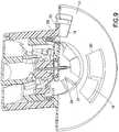
- the rotation of the outer barrel 12which serves to secure the catheter alignment/retention tabs 32 and release the barrel retention tabs 18 as described above, can also serve to move an inner barrel retention tab 58 from an initial state where the inner barrel retention tab 58 is locked to the outer barrel 12 as shown in Fig. 8 , to a position to release the safety.
- the inner barrel retention tab 58is restrained so as not to rotate, and aligns with the release slot 60 in the outer barrel 12.
- the catheter alignment/retention tab 32is engaged with the base 14 as described above.
- the outer barrel retention tab 18is then disengaged from the base 14.
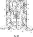
- the inner barrel retention tabs 58are shown engaged with the outer barrel 12, and Fig.
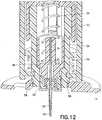
- FIG. 12illustrates the inner barrel retention tabs 58 engaged with the outer barrel 12 in an activated position.
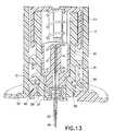
- the inner barrel retention tabs 58disengage the instant before the needle safety activates, and once rotated to align with the trigger slot 60 in the outer barrel 12 as shown in Fig. 13 , allows the needle safety to activate into the retracted position shown in Fig. 14 .
- the deviceagain comprises an infusion set and insertion device packaged as a single unit, thereby eliminating the need to carry any additional accessories and avoid the difficulty associated with loading the infusion set onto the insertion device at each use.
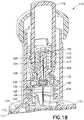
- Fig. 18is a sectional view of a device 110 utilizing an inserter and set in accordance with the second embodiment of the present invention.
- the device 110comprises an outer barrel 112, a base 114 and a button 116.
- the base 114comprises at least one outer barrel retention tab 118 that is configured to rotatably enter openings 120 in the base 114 and be captured at a rotational position by shoulders 122 of the base 114 as described above.
- a drive spring 124, flexible sear 126 and catheter 128are disposed within the outer barrel 112.
- the flexible sear of the second embodimentcan be provided in a number of positions.
- the flexible sear 126is secured to the outer barrel 112 at a point 125.
- the flexible sear 136is secured to the outer barrel 112 at a point 135.
- the catheter 128contains a septum 130, and has one or more catheter alignment and retention tabs 132 extending therefrom, to be captured and guided within one or more catheter alignment slots 134 within the outer barrel 112.
- the push button 116further comprises one or more deflectable, inclined button cams 117 to engage, deflect and release the flexible sears 126 from a needle hub 138.
- the needle hub 138is provided with an introducer needle 140.
- the embodiment of the present inventioncan be provided with a skin contacting adhesive layer 115 such as a pressure sensitive adhesive (PSA), and an adhesive cover 117.
- Precise insertionis achieved by removing the adhesive cover 117 and securing the infusion set to the infusion site via the adhesive layer 115, which permits the user to activate the inserter or place the catheter as described below at the proper alignment and depth.
- the adhesive at or very near the insertion sitesecures the skin surface such that the introducer needle and catheter, or in-dwelling catheter are driven into the skin surface in a manner to minimize the risk of tenting at needle insertion.
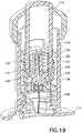
- the outer barrel 114is rotatably secured to the base 114 and the button 116 is extended from the top of the device, the drive spring 124 is compressed, and the catheter 128 is in a retracted position.
- the needle hub 138 and introducer needle 140are also retracted.
- the button 116has been pressed and the deflectable, inclined button cams 117 engage, deflect and release the flexible sear 126 from the needle hub 138.
- the device 110is permitted to activate as driven by the spring 124 such that the introducer needle 140 and catheter 128 are inserted into the skin surface as shown in Fig. 20 .
- the userturns the outer barrel 112 of the device which moves the catheter alignment/retention tab 132 into a locked position with the base 114. That is, the catheter alignment/retention tabs 132 enter the openings 120 to be captured by the shoulders 122 of the base 114.
- the turning motionalso serves to release the barrel retention tabs 118 of the outer barrel 112 from the same openings 120 and shoulders 122 of the base 114, leaving the base 114 in condition for attachment of the extension (tube) set.
- Further turning of the outer barrel 112can activate a safety as described above.
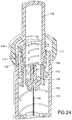
- Fig. 24shows the safety 144 in greater detail.
- outer barrel 112results in the disengagement of the outer barrel retention tabs 118 from the base 114, and moves the catheter alignment/retention tab 132 into a locked position with the base 114, leaving the base 114 in condition for attachment of the extension set 146 as shown in Figs. 25 and 26 .
- the turning of the outer barrel 112also allows the needle safety to activate into the retracted position shown in Fig. 24 substantially as described above.
- a blunt cannula 148can be provided in the extension set connector to penetrate the septum 130 of the set as shown in Fig. 26 .
- the disposable launcher or inserter assemblycan then be removed and discarded.
- Figs. 27-37illustrate additional features for use with the above or other infusion devices.
- a clocked insertercan be provided to secure and release an introducer needle 220 and catheter 224.
- Fig. 27illustrates a device 210 having a top cap 212, a button 214 and a sterility/safety cap 216.
- a circular control member 218is shown having stops 219, and at least one clock 217, and is secured to a top of the introducer needle 220. The circular control member 218 can be held in place by stops 219, and released by aligning the clock 217 with the stops allowing downward movement of the circular control member 218 and introducer needle 220.
- the introducer needle 220, septum 222, catheter 224 and septum 226are positioned beneath a drive spring 228.
- rotation of one or more of the elements using the top cap 212 or push button 214can align the clock 217 with the stops allowing downward movement of the circular control member 218 and introducer needle 220 for placement of the catheter 224.
- the device 210is configured to be very small, and to place the catheter 224 using, for example, a reversed BD AutoguardTM inserter, and a 3M TegadermTM-style adhesive 232.
- the embodiment of the present inventioncan be provided with a skin contacting adhesive layer 225 such as a pressure sensitive adhesive (PSA), and an adhesive cover.
- PSApressure sensitive adhesive
- Precise insertionis achieved by removing the adhesive cover and securing the infusion set to the infusion site via the adhesive layer 22, which permits the user to activate the inserter or place the catheter at the proper alignment and depth.
- the adhesive at or very near the insertion sitesecures the skin surface such that the introducer needle and catheter, or in-dwelling catheter are driven into the skin surface in a manner to minimize the risk of tenting at needle insertion.
- Fig. 28illustrates another feature for use with the above or other infusion devices.
- Fig. 28illustrates views of a catheter stabilizer 250 for use with the above or other embodiments of the present invention.
- the catheter stabilizer 250can be molded as a separate part, using materials such as VialonTM, or stamped from foam or other similar materials.
- the catheter stabilizer 250comprises a plurality of arms or stabilizers 252, one or more having an adhesive and backing 254.
- a press-in catheter 256can then be positioned within a central opening 258 of the catheter stabilizer 250.
- the stabilizers 252can be adhesively secured to a surface to stabilize the catheter 256 during use.
- Fig. 29illustrates views of another catheter stabilizer for use with the above or other embodiments of the present invention.
- the catheter stabilizer 275can be molded as a one-piece, molded catheter/hub stabilization part, using a polymeric material such as TeflonTM or BD VialonTM biomaterial, or stamped from foam or other similar materials.
- the catheter stabilizer 275comprises a circular stabilizer 276 or plurality of wings 277, one or more having an adhesive and backing as described above.
- a catheter 279can be provided at a first side and opposite, a septum 278 can be positioned within a central opening 280 of the catheter stabilizer 275 to stabilize the catheter during use.
- a manual inserter 282 or 284can be used.
- the first inserter 282is an introducer needle and handle 282.
- the second inserter 284is shown having compressible handles 286 to move grasping arms 288 at an opposite end, via a living hinge 290 therebetween.
- the grasping arms 288can comprise snap features configured to grab similar features of a septum, hub and needle 292.
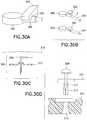
- Figs. 30A-30Dillustrate views of an exemplary strain relief member for use with the above or other exemplary embodiments of the present invention.
- the exemplary strain relief member of Figs. 30A and 30Bcomprises a strap-type latch 300 that can be used with a set, such as the exemplary set 306 and tube 304.
- the latch 300can be adhesively secured to a skin surface some distance from the set 306, or can be incorporated with the set 306. Once in position, the tube 304 can be pressed into the latch 300, which serves to absorb any strain imparted on the tube 304.
- Figs. 30C and 30Dalso illustrate views of an exemplary rivet-type tube set connector for use with the above or other exemplary embodiments of the present invention.
- the exemplary strain relief membercomprises a rivet connector 308 and a rivet receiving base 310.
- Such a setcan use a rivet connector 308 which is configured to expand a distal end when pressed. The expanding distal end, if first placed into an opening of the base 310, secures the rivet 308 to the base 310.
- the rivet 308can be proved with a slidable member 312 in a tube connecting end 314.
- pressing the rivet 308expands the tube connecting end in the opening 316 of the base 310 to secure the tube 304 to the set.
- on or more of the elementscan be secured using an adhesive or covering 318, such as TegadermTM.
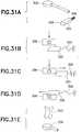
- Figs. 31A-31Eillustrate views of another securing member for use with the above or other embodiments of the present invention.
- the securing member 325can be used with a set, such as the set 306 described above.
- the securing member 325can comprise a spring 326 and an incline 328.
- the securing member 325can be adhesively secured to a skin surface some distance from the set 306, or can be incorporated with the set 306. Accordingly, as a set 306 is positioned as illustrated in Fig. 31B , the set 306 can contact the incline 328 such that the securing member 325 is deflected to the side compressing the spring 326 as illustrated in Fig.
- a deployment devicesuch as a fuse-puller style device 320 as illustrated in Fig. 31E can be used to defeat the securing member 325 to place or remove the set 306.
- Figs. 32A-32Eshow another embodiment in which the securing member 330 can be used with a set, such as the set 306.
- the securing member 330can comprise a spring 334 and a shoulder 332 as illustrated in Fig. 32E .
- the securing member 330can be adhesively secured to a skin surface some distance from the set 306, or can be incorporated with the set 306. Accordingly, as a set 306 is positioned as illustrated in Figs. 32A and 32B , the securing member 330 is deflected to the side by the inserter arms 336 as the arms move outward to release the set 306, thereby compressing the spring 334 as illustrated in Figs. 32C and 32D .
- the securing member 330returns to a position above the set 306 after placement by the plunger 338 as illustrated in Fig. 32E , such that the set is secured.
- Fig. 33illustrates views of a top-push button for use with the above or other embodiments of the present invention.
- the button 350can be used with a needle hub 352, and a trigger 354.
- the needle hub 352comprises an introducer needle 368, alignment pins 360 and pin 362 to engage an outer enclosure to prevent the needle hub 352 from rotating.
- the trigger 354comprises alignment pins 366 and pin 364 to engage a guide slot 356 of the button.
- the button 350is configured to be pushed downward into the device, and comprises guide slots 356 with a pitch to rotate pin 364 of the trigger 354 for releasing the needle hub 352.
- the trigger 354is rotated and moves pins 366 from blocking pins 360 allowing the needle hub 352 to release and place the introducer needle or in-dwelling catheter 368 into the skin surface.
- the button 350further comprises a pin 358 to engage the outer housing for further guidance and control of the button.
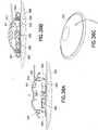
- Figs. 34A and 34Billustrate views of a pen-style actuator 375 for use with the above or other embodiments of the present invention.
- the actuator 375comprises a drive spring 380, introducer needle 382, and septum and/or catheter 384 as illustrated in Fig. 34A .
- the actuator 375can be positioned though a dome 376 which is configured to contain the contents therein and place an outer adhesive ring 396 and an inner adhesive ring 394 beneath the septum 388.
- Two or more molded flexures 386can be provided between the adhesive rings 396 and 394, and between a septum or U-shaped gasket 388 and a tubing connection 390.
- the dome 376is shaped and configured to flex, so as to be user-friendly.
- the embodiment of the present inventioncan be provided with a skin contacting adhesive layers 394 and 396 such as a pressure sensitive adhesive (PSA), and an adhesive cover 378.
- Precise insertionis achieved by removing the adhesive cover 378 and securing the infusion set to the infusion site 385 via the adhesive layers 394 and 396, which permits the user to activate the inserter or place the catheter as described below at the proper alignment and depth.
- the adhesive at or very near the insertion sitesecures the skin surface such that the introducer needle and catheter, or in-dwelling catheter are driven into the skin surface in a manner to minimize the risk of tenting at needle insertion.
- the userremoves an adhesive layer cover 378 and places the device on a skin surface 385.
- the actuator 375can then be used to place the introducer needle 382 and catheter 384, or an in-dwelling catheter.
- the actuator 375 and dome 376can then be removed with the introducer needle.
- the flexures 386can be provided between the adhesive rings 396 and 394, and between the septum 388 and the tubing connection 390, and can comprise for example, molded S-shaped members extending between the septum 388 of the inner ring to the outer ring as more clearly shown in Fig. 37 . Accordingly, once the catheter 384 is in place, the flexures 386 stabilize the outer adhesive ring 396 to the inner adhesive ring 394 beneath the septum 388.
- Figs. 35A, 35B , 36A-36B and 37illustrate views of the use of the device of Fig. 34 .
- a top of the actuator 375is pressed to deploy the introducer needle 382 and catheter 384 into the infusion site 385, and turning the actuator 375 releases the actuator and dome from the set as shown in Fig. 35B , leaving the catheter 384 within the septum 388 and removing the introducer needle 382.
- Figs. 36A-36Cshow views of the placement of a tube set and cap system 392 with the set. The tube set and cap system 392 can be snapped into place with the set as illustrated in Figs. 36A and 36B .
- the cap 392can comprise detents 395 to releasably capture detents 398 of the set such that the cap 392 can be releasably secured to the set as illustrated in Fig. 36B .
- the cap 392can be provided with a blunt cannula connector 391 for completing a fluid connection with the tubing connection 390.
- the embodimentalso provides an integrated and disposable actuator for every tube set.
- the integrated inserteris slim, and disposable, with a pen barrel-style, with a low-impact, activation mechanism.
- the strain reliefis provided by inner and outer adhesive rings coupled by flexures to decouple the catheter site from the tubing connection site as illustrated in Fig. 37 . Any tugs and pulls can break connections on the outer ring, but do not affect the catheter site.
- the adhesiveis placed on the skin surface first, which minimizes tenting, improves stability and accuracy, and minimizes kinking at insertion.
- the flexures 386can be omitted so that the septum 388 is totally independent from outside movement.
- the devicecomprises inherent dampening of motion due to the completion of the fluid path with, for example, a U-shaped gasket.
- the housings, hubs and other elementscan be constructed of molded plastic materials, polycarbonate, thermoplastic polymers such as polyethylene terephthalate (PET and PETG), or similar materials.
- Springs and introducer needlescan be constructed of stainless steel or similar materials.
- the catheterIn current infusion sets which deliver insulin or other medicament to the subcutaneous layer, the catheter is not isolated from any undesired outside forces, which may cause pain when translated to the catheter which then moves within the skin. Also, other devices face problems of premature or unintended catheter removal when the device is bumped if the catheter is not isolated from the outside forces.
- the cathetercan be isolated from outside forces by at least one flexible or resilient feature, or protected from outside forces by at least one covering member.
- exemplary embodiments of the present inventionprovide a catheter and extension set for insulin infusion from an insulin pump or other medicament supply.
- the deviceis placed upon the skin surface of a user with adhesive, such as an adhesive layer disposed upon a base member, then activated by pressing a button, whereupon insertion of the introducer needle and catheter are performed manually or automatically using energy supplied by a drive member, such as a drive spring.
- a drive membersuch as a drive spring.
- Removal of the introducer needleis also performed manually or automatically and the introducer needle is retracted into the outer barrel where it is locked into place using for example, a latch, such that it cannot cause accidental needle sticks when the launcher or inserter is removed from the base.
- the extension setis then attached to the base, and the fluid path to the catheter is completed by a blunt cannula that pierces the septum of the base.
- the exemplary systemis then connected to an infusion pump or other supply, and primed for use.
- the deviceis configured to insert the catheter by pressing a button without requiring the user to load the catheter into a launching device or inserter, or loading the launching device in some way by the user.
- the deviceis further configured to retract the introducer needle and/or implement other safety features.
- the element being launchedcomprises only the catheter and needle hub subassembly, the mass is much smaller than what is launched with existing devices. The effect of this is that the energy requirements of the device are less, leading to smaller, quieter devices, with further advantages of being environmentally “greener” (i.e., requiring less construction materials, construction steps, and generating less waste), and with less noise and impact upon activation. Further, since the adhesive layer is already in place on the skin surface of the user, manipulation of the adhesive after insertion of the catheter is less likely to occur and thereby eliminating a common cause of kinking of the catheter.
- exemplary embodimentsare configured to be smaller than comparative devices, yet accomplish both insertion and retraction of the introducer needle. Further, because the device is packaged and shipped in an assembled and loaded state, there are inherently fewer pieces to carry and preparatory steps than associated with comparative devices. Such advantages are realized, in part, due to the requirement for activation or launching a smaller mass. In exemplary embodiments provided with flexible sears for activation control, the embodiments have smaller activation forces and larger part tolerances, as compared to other exemplary embodiments.
- a top-push activation buttonproviding a number of advantages.
- similar or other advantagescan be achieved using a side-push activation button. That is, instead of pressing a top or top-mounted button into a device (i.e., toward the skin surface of the user) as described above, the device can be activated by pressing a button located on the side of the device, potentially molded into the outer barrel cap as shown in Figs. 38-41 .
- Fig. 38is a sectional view of a device utilizing a side-push button in accordance with a third embodiment of the present invention.
- the deviceis substantially as described above in regard to the second embodiment, and comprises an outer barrel 112, a slidable inner barrel cap 152 and inner barrel 154 and a base 114.
- the base 114comprises at least one outer barrel retention tab 118 that is configured to rotatably enter openings in the base 114 and be captured at a rotational position by shoulders 122 of the base 114 as described above.
- a drive spring 124 and a safety spring 156are also provided to extend and retract an introducer needle.
- a side-push button 402 and conforming outer barrel cap 404 and inner barrel cap 406are provided to facilitate a different method of activating the third exemplary embodiment.
- the side-push button 402is located on the side of the device, molded into the outer barrel cap 404, and acts upon the slidable inner barrel cap 152 as shown in Figs. 38 and 39 , causing the inner barrel cap 152 to slide to the left.
- the slidable inner barrel cap 152comprises an interference side 406 which captures a slot of the needle hub 138 in a first position, and comprises a clearance side 408 which permits the slidable inner cap 152 to be slide toward the needle hub 138 and move the interference side 406 from the slot of the needle hub 138 as shown in Fig. 40 .
- the slot in the needle hub 138disengages the keyhole slot in the inner barrel cap 152, releasing the needle hub 138 to drive the catheter assembly 424 into the user's skin surface.
- the catheter assembly 424can be molded as a single piece or provided with a septum, and can include the septum, introducer needle and catheter, or an in-dwelling catheter.
- the configuration of the present inventioncan be provided with a skin contacting adhesive layer 115 such as a pressure sensitive adhesive (PSA), and an adhesive cover 117.
- Precise insertionis achieved by removing the adhesive cover 117 and securing the infusion set to the infusion site via the adhesive layer 115, which permits the user to activate the inserter or place the catheter as described below at the proper alignment and depth.
- the adhesive at or very near the insertion sitesecures the skin surface such that the introducer needle and catheter, or in-dwelling catheter are driven into the skin surface in a manner to minimize the risk of tenting at needle insertion.
- the button 402can be a molded-in component that drives the inner barrel cap 152 as opposed to a sliding button that has the keyhole slot molded therein. In doing so, the configuration ensures that the button will not inadvertently become caught on the outer barrel 112 when the needle stick protection mechanism is activated.
- other configurations of the sliding buttoncan have the keyhole molded in as part of the button. Further, these configurations can be configured to work with these or any other spring-assisted catheter insertion devices, and/or combined with spring-assisted needle stick prevention features.
- Such a keyhole triggering configurationcan be more robust for shipping and handling than a top-push button embodiment. Also, the configuration addresses the event where there is a user preference for a side-push button as opposed to a top-push button.
- a rotary activation buttoninstead of pressing a top or top-mounted button into a device (i.e., toward the skin surface of the user) as described above, the device can be activated by rotating a button located on the device and, by further rotation, disengage the inserter, insertion mechanism or module, from the base.
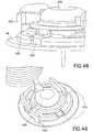
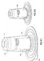
- Fig. 42is a sectional view of a device utilizing a rotary button in accordance with a fourth embodiment of the present invention.
- the deviceis substantially as described above in regard to the second and third embodiments, and comprises an outer barrel 112, inner barrel cap 152 and inner barrel 154 and a base 114.
- the base 114comprises at least one outer barrel retention tab 118 that is configured to rotatably enter openings in the base 114 and be captured at a rotational position by shoulders 122 of the base 114 as described above.
- a drive spring 124 and a safety spring 156are also provided to extend and retract an introducer needle.
- the configuration of the present inventioncan be provided with a skin contacting adhesive layer 115 such as a pressure sensitive adhesive (PSA), and an adhesive cover 117.
- Precise insertionis achieved by removing the adhesive cover 117 and securing the infusion set to the infusion site via the adhesive layer 115, which permits the user to activate the inserter or place the catheter as described below at the proper alignment and depth.
- the adhesive at or very near the insertion sitesecures the skin surface such that the introducer needle and catheter, or in-dwelling catheter are driven into the skin surface in a manner to minimize the risk of tenting at needle insertion.
- the usercan use one motion to activate the device. That is, a rotary motion can be used to activate the device or inserter of the device, followed by further rotation to activate the safety of the device, the retraction of the introducer needle for needle stick protection, and further rotation to detach the inserter from the base. All actions can be implemented using a single, smooth rotation by the user. In this or other embodiments, tactile and/or audible feedback can be provided to indicate needle insertion, needle retraction, safety activation and removal.
- the button 412can be rotated about the remainder of the device, being adhesively secured to the skin surface, and in turn, rotate a trigger 414 via the button slot 416 pressing on a trigger tab 418, as shown in Fig. 42 .
- Activationoccurs by rotating the button 412 first to the introducer needle and catheter insertion position, then to the safe position, all in one smooth rotary motion.
- the drive spring 124is compressed between the inner barrel cap 152 and the needle hub 138, and is retained by the needle hub sear engagement with the inner barrel cap as shown in Figs. 42 and 43 .
- the rotation of the button 412rotates the trigger 414 via the trigger tab 418, and rotation of the trigger 414 rotates a bar-shaped needle hub sear 422.
- a slot 420is provided in the inner barrel cap 152 such that, when the bar-shaped needle hub sear 422 is rotated into alignment with the slot 420, the drive spring 124 will drive the needle hub 138, including the introducer needle and catheter assembly 424, into the skin of the user.
- Such a rotation triggering configurationcan also be more robust in shipping and handling than a top-push button embodiment, and the disclosed embodiments address the situation where there is a user preference for a rotation button as opposed to a top-push button.
- Activation of the needle safety, or needle tip shieldingcan be achieved by disengaging the tabs in the outer barrel from the base, which also allows removal of the inserter from the base as described above.
- the disclosed embodimentscan be used with any number of triggering modes, such as one wherein the needle hub rotates until the molded-in tabs align with the slots in the inner barrel.
- the disclosed embodimentscan be configured to work with these or any other spring-assisted, catheter insertion devices, and/or combined with spring-assisted needle stick prevention features.
- Fig. 43illustrates the drive spring 124 in a loaded state as secured by the needle hub sear 422 and the inner barrel cap 152.
- Fig. 44illustrates the needle hub sear 422 and the inner barrel cap slot 420 coming into alignment, such that the needle hub 138 will be released from the inner barrel cap 152, allowing the needle hub 138 to drive the introducer needle and catheter assembly into the users skin surface.
- Fig. 45illustrates the needle hub in a final position after being released from the inner barrel cap.
- a number of featurescan be provided to prevent premature activation of the introducer needle.
- the following embodiments of the present inventiondescribe a number of such features including a manually-activated interlock designed to prevent premature activation and features to prevent separation of the extension set from the base.
- Such featurescan include elements for interlocking the outer barrel, hence the integrated/removable inserter assembly, to the base, as well as the extension set to the base, with variants of the same mechanism.
- Fig. 46illustrates a locking latch to prevent rotation of elements.
- a latch 425has been added to the outer barrel 12 of the embodiments described above.
- the latch 425rotates about a molded pivot point 427 and engages a slot 426 in the base 14, thereby locking the two from significantly rotating relative to one another, thus preventing inadvertent detachment of the inserter and subsequent activation of the needle stick prevention mechanism.
- the usercan do so by pressing the button 428 as shown in Fig. 47 , thereby rotating the latch 425 out of the engagement with the slot 426 in the base 14.
- the inserter assemblymay be rotated and removed, at which time the needle stick protection mechanism will activate and retract the introducer needle from the catheter.
- the set topcan also incorporate the features described above to secure an operational position of the set top or tube set connector.
- the set topcan include a latch 435 as shown in Figs. 48-51 .
- a chamfered lead-in area 430can be provided to deflect the latch 435 around the base 14 as shown in Figs. 48 and 49 .
- Subsequent rotation of the extension set top 432 relative to the base 14will bring the latch 435 into engagement with one of the base slots 426 to rotatably secure the extension set top 432 with the base 14 as shown in Figs. 50 and 51 .
- a stop 438can be employed to limit the travel of the button and latch, such that the molded pivot 440 will not become over-stressed.
- such a manually-activated interlockcan be designed to prevent separation of the extension set from the base in the embodiments described above.
- embodiments of the present inventioncan provide a secondary interlock for the extension set top and base in order to prevent disconnection.
- a lock ring 450 having one or more lock ring tabs 452, extension set top 455, and a lock ring spring 460can be added to the design to prevent disconnection.
- the rotatable lock ring 450can be provided with lock ring lock tabs 452 that are designed to drop into base slots 426 once the extension set top 455 has moved into the correct locking position with the base 14.
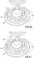
- the useraligns the extension set top interlock tabs 454 with the base slots 426 as shown in Figs. 52 and 55 , and presses down on the center dome of the extension set top 455 as shown in Fig. 52 .
- Thismoves the extension set top 455 down relative to the lock ring 450, which bears on the upper surface of the base 14 as shown in Fig. 52 .
- extension set top 455 and lock ring 450can be rotated until the extension set top interlock tabs 454 lock with shoulders 22 of the base 14, and the lock ring tabs 452 drop into the base slots 426 as urged by the lock ring spring 460 as shown in Fig. 53 .
- the extension set top 455 and locking ring 450are now prevented from further rotation, thereby securing the extension set top 455 to the base 14 by means of the extension set top interlock tabs 454.
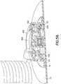
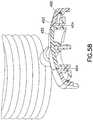
- Figs. 57-59show the lock ring spring 460 and its retention feature in greater detail
- Fig. 60is an exploded view of the embodiment.
- the lock ring spring 460is held within the locking ring 450 by a retention feature that comprises a shoulder 462 on an inner circumference of the lock ring 450.
- the lock ring 450is held with the extension set top 455 by a retention feature that comprises a shoulder engagement 464 with the extension set top 455.
- a package 500 as shown in Fig. 61can be provided that encloses the integrated/removable inserter, and shields the activation and removal buttons. This allows placement of the device in a manner that prevents premature activation of these buttons.
- One or more of the above or other exemplary devicescan comprise the activation button 16 on the top of the device, so that when the user places the device on the skin prior to activation, there is an ease of access and minimal requirement for dexterity to activate the button.
- a package 500 as described belowis used to fully protect at least the buttons 16 and 428 from activation during handling and placement of the device.
- a package 500wherein at least the buttons 16 and 428 are shielded by the package.
- the device within the package 500can be provided with a skin contacting adhesive layer such as a pressure sensitive adhesive (PSA), and an adhesive cover as described above.
- PSApressure sensitive adhesive
- the adhesive layer cover of the infusion device and the package sealare integrated into a single, combined adhesive layer/package opening cover 504 with a user-graspable pull-tab 505.
- the combined cover 504is used to cover one or more pockets of the package 500 for other components related to filling and dispensing.
- Fig. 61shows in transparency a small package 500 for enclosing and shrouding the buttons 16 and 428 of an embodiment as described above, and providing large, smooth handling surfaces 502.
- Fig. 62shows the device of Fig. 61 with the package seal and/or adhesive cover 504 removed such that the device within the package can be placed on the skin surface and ready for activation of the buttons 16 and 428 once the package is removed from the device as shown in Fig. 63 . Once the device is adhesively secured to the skin surface, the package can be lifted away.
- Fig. 64is a sectional view to illustrate the device of Fig. 61 in greater detail, including retention snaps 506 within an opening of the package 500 for engaging the device therein and releasably securing the device within the package.
- the snaps 506can be configured to engage a surface of the device, or can correspond to detents or other profile features of the device contained therein.
- the exemplary device contained within the packagecan comprise any number of embodiments, such as those described above.
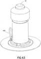
- Fig. 65shows the device of Fig. 64 with the skin adhesive layer 508 exposed after removal of the package seal and/or release liner 504 using pull tab 505.
- Fig. 66shows another embodiment of the present invention substantially as described above, but further comprising one or more additional pockets for other components related to filling and dispensing.
- This embodimentcomprises a larger package design 510 with the filling and dispensing components in a sample configuration.
- the package 510can also comprise a package seal integrated into a single, combined adhesive layer/package opening cover 514 with a user-graspable pull-tab 515, and retention snaps 516 within an opening of the package 510 for engaging the devices therein and releasably securing the devices within the package.
- Fig. 67shows the device of Fig. 66 with the package seal/adhesive release liner removed exposing the adhesive layer 518.
- the devicewhen the package seal and/or skin adhesive release liner is removed, the device can be placed on the skin surface, without removing it from the package, allowing placement without the possibility of premature button activation.
- the package retention snaps 506 and 516are incorporated into the package 500 and 510 to maintain the devices in the package until the user is ready to activate the inserter, at which time the user may squeeze the package, such as at a 90 degree angle relative to the snaps, to open the snaps and allow the package to be lifted from the device, leaving the integrated/removable inserter on the user's skin surface.
- the package 510can include one or more additional cavities for the insulin reservoir, reservoir filling and dispensing components, and extension set tubing and connections.
- the catheter extension set, reservoir, and reservoir filling and dispensing componentsare integrated into a single package for user convenience. Further, in the embodiment configured as a smaller package, there is a greater ease in placement. In the embodiment configured as a larger package, there is the convenience of having all of the components readily available for the subsequent steps of connecting the infusion pump.
- the packagefurther provides a sterile barrier which can also serve as the skin adhesive release liner to reduce steps.
- the packagealso protects the activation button during placement, after which the package is removed from the device by pressing the sides to release the undercut snaps.
- the packagecan be configured to house other elements, for example, the insulin reservoir and extension set.
Landscapes
- Health & Medical Sciences (AREA)
- Life Sciences & Earth Sciences (AREA)
- Hematology (AREA)
- Animal Behavior & Ethology (AREA)
- Engineering & Computer Science (AREA)
- Anesthesiology (AREA)
- Biomedical Technology (AREA)
- Heart & Thoracic Surgery (AREA)
- Veterinary Medicine (AREA)
- Public Health (AREA)
- General Health & Medical Sciences (AREA)
- Pulmonology (AREA)
- Biophysics (AREA)
- Vascular Medicine (AREA)
- Infusion, Injection, And Reservoir Apparatuses (AREA)
- Media Introduction/Drainage Providing Device (AREA)
Description
- The present invention relates generally to medical infusion systems, such as an insulin infusion device with one or more of automatic insertion and automatic retraction, needle safety, soft catheter and extension set. The system can further comprise a side-push button activation feature or a rotary-button activation feature, and one or more of a manual interlock of an outer barrel and base, and an extension set top and base, a manual interlock for an extension set top and base and packaging for an integrated and/or removable inserter for activation button protection.
- A large number of people, including those suffering from conditions such as diabetes, use some form of infusion therapy, such as daily insulin infusions, to maintain close control of their glucose levels. Currently, there are two principal modes of daily insulin therapy. The first mode includes syringes and insulin pens. These devices are simple to use and are relatively low in cost, but they require a needle stick at each injection, typically three to four times per day. The second mode includes infusion pump therapy, which entails the purchase of an insulin pump that lasts for about three years. The initial cost of the pump can be significant, but from a user perspective, the overwhelming majority of patients who have used pumps prefer to remain with pumps for the rest of their lives. This is because infusion pumps, although more complex than syringes and pens, offer the advantages of continuous infusion of insulin, precision dosing and programmable delivery schedules. This results in closer blood glucose control and an improved feeling of wellness.
- The use of an infusion pump requires the use of a disposable component, typically referred to as an infusion set or pump set, which conveys the insulin from a reservoir within the pump into the skin of the user. An infusion set typically consists of a pump connector, a length of tubing, and a hub or base from which an infusion needle or a flexible cannula extends. The hub or base has an adhesive which retains the base on the skin surface during use, which may be applied to the skin manually or with the aid of a manual or automatic insertion device.
- There are many available types of infusion sets, including steel needle infusion sets and soft catheter sets. Soft catheter sets are typically inserted into a patient manually with the aid of a steel needle introducer, which is removed from the patient after insertion to leave the soft catheter in place. In another type of infusion set, a mechanized insertion device is used to forcefully and rapidly insert the introducer needle and catheter, remove the introducer, or both. Often, the insertion device is a separate, stand-alone unit that the user is required to carry and provide. Stand-alone inserters typically require the user to manually load a set and compress a spring of the inserter, which can result in catheter insertion failure when either the set or the spring is not properly loaded or compressed.
- In soft catheter sets, the introducer needle is completely removed from the infusion set before being connected to the insulin pump. One problem associated with manually inserting and retracting the introducer needle is variability in the insertion and retraction force, speed, smoothness and angle. This variability can lead to an increased rate of catheter insertion failure.
- Further, as noted above, the user typically must remove the introducer needle after inserting the catheter. This exposes the user to accidental needle sticks from handling the removed introducer needle.
- Accordingly, a need exists for infusion sets and insertion devices that facilitate insertion of the catheter, while reducing the number of components a user must carry and substantially preventing accidental needle sticks.
US 2004/0158207 A1 discloses a device for inserting a cannula into tissue, the device including a cannula and a protective element which can accommodate the cannula. A system for connecting a liquid supply to the cannula is also enclosed.- An object of the present invention, which is defined in the independent claims 1 and 8, is to substantially address the above and other concerns, and provide an infusion device that facilitates insertion of the catheter, while reducing the number of components a user must carry and substantially preventing accidental needle sticks.
- An infusion device with one or more of automatic insertion and automatic retraction and a safety insulin catheter and extension set may be provided.
- An infusion device with a side-push button activation feature may be provided.
- An infusion device with a rotary-button activation feature may be provided.
- An infusion device with a manual interlock of an outer barrel and base, and an extension set top and base may be provided.
- An infusion device with a manual interlock for an extension set top and base may be provided.
- An infusion device with packaging for an integrated and/or removable inserter for activation button protection may be provided.
- An infusion device may be provided that includes one or more of automatic insertion and automatic retraction, needle safety, soft catheter and extension set. The device can further comprise a top-push button activation feature, a side-push button activation feature or a rotary-button activation feature, and one or more of a manual interlock of an outer barrel and base, and a manual interlock for an extension set top and base.
- The various objects, advantages and novel features of the exemplary embodiments of the present invention will be more readily appreciated from the following detailed description when read in conjunction with the appended drawings, in which:
Fig. 1 is a sectional view of an infusion device utilizing a top-push button in accordance with a first embodiment of the present invention;Figs. 2-5 are views of the device ofFig. 1 during use;Figs. 6 and 7 are views of the top-push button of the device ofFig. 1 incorporating a needle safety feature in accordance with an embodiment of the present invention;Fig. 8 is a sectional view of the device ofFig. 1 incorporating a needle safety feature in accordance with an embodiment of the present invention;Figs. 9-17 are views of the device ofFig. 8 during use;Fig. 18 is a sectional view of an infusion device utilizing a top-push button in accordance with a second embodiment which is not part of the present invention;Figs. 19-26 illustrate views of the device ofFig. 18 during use;Fig. 27 illustrates additional features for use with the above or other infusion devices;Fig. 28 illustrates views of a stabilizer for use with the above or other embodiments of the present invention;Fig. 29 illustrates views of another stabilizer for use with the above or other embodiments of the present invention;Figs. 30A-30D illustrate views of a strain relief member for use with the above or other embodiments of the present invention;Figs. 31A-31E illustrate views of a securing member for use with the above or other embodiments of the present invention;Figs. 32A-32E show another configuration in which the securing member can be used with a set;Fig. 33 illustrates views of a top-push button for use with the above or other embodiments of the present invention;Figs. 34A and 34B illustrate views of a pen-style actuator for use with the above or other embodiments of the present invention;Figs. 35A-35B ,36A-36C , and37 illustrate views of the device ofFig. 34 during use;Figs. 38-41 illustrate views of an infusion device utilizing a side-push button not being part of the present invention;Figs. 42-45 illustrate views of an infusion device utilizing a rotary button in accordance with an embodiment of the present invention;Figs. 46-51 illustrate views of a manually-activated interlock for use with the above or other embodiments of the present invention;Figs. 52-60 illustrate views of a secondary interlock for use with the above or other embodiments of the present invention; andFigs. 61-67 illustrate views of a package for use with the above or other embodiments of the present invention.- Throughout the drawings, like reference numerals will be understood to refer to like parts, components and structures.
- The exemplary embodiments of the present invention deliver insulin to the subcutaneous layers of the skin via a standard insulin pump or other similar device. By utilizing an infusion device with one or more of automatic insertion and automatic retraction, needle safety, soft catheter and extension set, with either top, side or rotary activation and one or more interlocks, proper insertion and maintenance of the inserted catheter in the subcutaneous space is ensured, while maintaining a degree of comfort to the user. In each embodiment of the present invention described below, standard infusion set elements such as connectors, infusion catheters, adhesives and hubs can be provided.
- In a first exemplary embodiment of the present invention, the device comprises an infusion set and insertion device packaged as a single unit, thereby eliminating the need to carry any additional accessories and avoid the difficulty associated with loading the infusion set onto the insertion device at each use.
Fig. 1 is a sectional view of adevice 10 in accordance with an embodiment of the present invention. Thedevice 10 comprises anouter.barrel 12, abase 14 and abutton 16. Thebase 14 comprises at least one outerbarrel retention tab 18 that is configured to rotatably enteropenings 20 in thebase 14 and be captured at a rotational position byshoulders 22 of thebase 14. Adrive spring 24, needle hub sear 26 andcatheter 28 are disposed within theouter barrel 12. Thecatheter 28 contains aseptum 30, and has one or more catheter alignment andretention tabs 32 extending therefrom, to be captured and guided within one or morecatheter alignment slots 34 within theouter barrel 12. One or more needle hubsear slots 36 are also provided within theouter barrel 12. - The embodiment of the present invention can be provided with a skin contacting
adhesive layer 15 such as a pressure sensitive adhesive (PSA), and anadhesive cover 17. Precise insertion is achieved by removing theadhesive cover 17 and securing the infusion set to the infusion site via theadhesive layer 15, which permits the user to activate the inserter or place the catheter as described below at the proper alignment and depth. In doing so, the adhesive at or very near the insertion site secures the skin surface such that the introducer needle and catheter, or in-dwelling catheter are driven into the skin surface in a manner to minimize the risk of tenting at needle insertion. - In the loaded position shown in
Fig. 1 , theouter barrel 14 is rotatably secured to thebase 14 and thebutton 16 is extended from the top of the device, thedrive spring 24 is compressed, and thecatheter 28 is in a retracted position. Theneedle hub 38 andintroducer needle 40 are also retracted. In the unloaded position shown inFig. 2 , thebutton 16 has been pressed and contacts theneedle hub 38. As described in greater detail below, the downward travel of thebutton 16 serves to rotate theneedle hub 38 such that the needle hub sear 26 becomes aligned with the needlehub sear slot 36. Thedevice 10 is then permitted to activate as driven by thespring 24 such that theintroducer needle 40 andcatheter 28 are inserted into the skin surface (not shown). Specifically, one or morebutton cam slots 42 shown inFig. 3 , rotate theneedle hub 38 by guiding the rotational lugs 44 (seeFig. 6 ) on theneedle hub 38 as thebutton 16 is pressed down, so that theneedle hub sears 26 become aligned with the needle hubsear slots 36 and thedevice 10 is permitted to activate. - After activating the
device 10 as described above, and theintroducer needle 40 andcatheter 28 are inserted into a skin surface, the user turns theouter barrel 12 of the device, which moves the catheter alignment/retention tab 32 into a locked position with thebase 14. That is, the catheter alignment/retention tabs 32 enter theopenings 20 to be captured by theshoulders 22 of the base 14 as shown inFig. 4 . The turning motion also serves to release thebarrel retention tabs 18 of theouter barrel 12 from thesame openings 20 andshoulders 22 of thebase 14, leaving the base 14 as shown inFig. 5 in condition for attachment of the tube set (not shown). - In yet another embodiment of the present invention, a needle safety can be configured to operate with the above device, utilizing the same actions and operations for deployment. For example, the
button 16 is shown again inFig. 6 to illustrate such a safety concept button cam in detail, in an inactivated position, and inFig. 7 to illustrate an activated position.Figs. 6 and 7 show therotational lugs 44 of theneedle hub 38 within theslots 42 of thebutton 16. To provide an automatic safety shown in greater detail inFig. 8 , thedevice 10 can further comprise anouter barrel cap 50,inner barrel cap 52,inner barrel 54 andsafety spring 56. - In this case, the rotation of the
outer barrel 12 which serves to secure the catheter alignment/retention tabs 32 and release thebarrel retention tabs 18 as described above, can also serve to move an innerbarrel retention tab 58 from an initial state where the innerbarrel retention tab 58 is locked to theouter barrel 12 as shown inFig. 8 , to a position to release the safety. As theouter barrel 12 is turned, the innerbarrel retention tab 58 is restrained so as not to rotate, and aligns with therelease slot 60 in theouter barrel 12. The catheter alignment/retention tab 32 is engaged with the base 14 as described above. The outerbarrel retention tab 18 is then disengaged from thebase 14. InFig. 11 , the innerbarrel retention tabs 58 are shown engaged with theouter barrel 12, andFig. 12 illustrates the innerbarrel retention tabs 58 engaged with theouter barrel 12 in an activated position. The innerbarrel retention tabs 58 disengage the instant before the needle safety activates, and once rotated to align with thetrigger slot 60 in theouter barrel 12 as shown inFig. 13 , allows the needle safety to activate into the retracted position shown inFig. 14 . - Further turning results in the disengagement of the outer
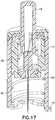
barrel retention tabs 18 from the base 14 as shown inFig. 15 , and moves the catheter alignment/retention tab 32 into a locked position with thebase 14, leaving the base 14 in condition for attachment of the tube set as shown inFig. 16 . The disposable launcher or inserter assembly can then be removed and discarded as shown inFig. 17 . - In a second exemplary embodiment which is not part of the present invention, the device again comprises an infusion set and insertion device packaged as a single unit, thereby eliminating the need to carry any additional accessories and avoid the difficulty associated with loading the infusion set onto the insertion device at each use.
Fig. 18 is a sectional view of adevice 110 utilizing an inserter and set in accordance with the second embodiment of the present invention. Thedevice 110 comprises anouter barrel 112, abase 114 and abutton 116. Thebase 114 comprises at least one outerbarrel retention tab 118 that is configured to rotatably enteropenings 120 in thebase 114 and be captured at a rotational position byshoulders 122 of the base 114 as described above. Adrive spring 124,flexible sear 126 andcatheter 128 are disposed within theouter barrel 112. The flexible sear of the second embodiment can be provided in a number of positions. For example, in the embodiment shown inFigs. 18-20 , theflexible sear 126 is secured to theouter barrel 112 at apoint 125. In the embodiment shown inFigs. 21-23 , theflexible sear 136 is secured to theouter barrel 112 at apoint 135. - Disposed within the
device 110, thecatheter 128 contains aseptum 130, and has one or more catheter alignment andretention tabs 132 extending therefrom, to be captured and guided within one or morecatheter alignment slots 134 within theouter barrel 112. Thepush button 116 further comprises one or more deflectable,inclined button cams 117 to engage, deflect and release theflexible sears 126 from aneedle hub 138. Theneedle hub 138 is provided with anintroducer needle 140. - The embodiment of the present invention can be provided with a skin contacting
adhesive layer 115 such as a pressure sensitive adhesive (PSA), and anadhesive cover 117. Precise insertion is achieved by removing theadhesive cover 117 and securing the infusion set to the infusion site via theadhesive layer 115, which permits the user to activate the inserter or place the catheter as described below at the proper alignment and depth. In doing so, the adhesive at or very near the insertion site secures the skin surface such that the introducer needle and catheter, or in-dwelling catheter are driven into the skin surface in a manner to minimize the risk of tenting at needle insertion. - In the loaded position shown in
Fig. 18 , theouter barrel 114 is rotatably secured to thebase 114 and thebutton 116 is extended from the top of the device, thedrive spring 124 is compressed, and thecatheter 128 is in a retracted position. Theneedle hub 138 andintroducer needle 140 are also retracted. In the unloaded position shown inFig. 19 , thebutton 116 has been pressed and the deflectable,inclined button cams 117 engage, deflect and release theflexible sear 126 from theneedle hub 138. At this point, thedevice 110 is permitted to activate as driven by thespring 124 such that theintroducer needle 140 andcatheter 128 are inserted into the skin surface as shown inFig. 20 . - After activating the
device 110 as described above, the user turns theouter barrel 112 of the device which moves the catheter alignment/retention tab 132 into a locked position with thebase 114. That is, the catheter alignment/retention tabs 132 enter theopenings 120 to be captured by theshoulders 122 of thebase 114. The turning motion also serves to release thebarrel retention tabs 118 of theouter barrel 112 from thesame openings 120 andshoulders 122 of thebase 114, leaving the base 114 in condition for attachment of the extension (tube) set. Further turning of theouter barrel 112 can activate a safety as described above.Fig. 24 shows thesafety 144 in greater detail. - Turning of the
outer barrel 112 results in the disengagement of the outerbarrel retention tabs 118 from thebase 114, and moves the catheter alignment/retention tab 132 into a locked position with thebase 114, leaving the base 114 in condition for attachment of the extension set 146 as shown inFigs. 25 and 26 . The turning of theouter barrel 112 also allows the needle safety to activate into the retracted position shown inFig. 24 substantially as described above. Ablunt cannula 148 can be provided in the extension set connector to penetrate theseptum 130 of the set as shown inFig. 26 . The disposable launcher or inserter assembly can then be removed and discarded. Figs. 27-37 illustrate additional features for use with the above or other infusion devices. For example, a clocked inserter can be provided to secure and release anintroducer needle 220 andcatheter 224.Fig. 27 illustrates adevice 210 having atop cap 212, abutton 214 and a sterility/safety cap 216. Acircular control member 218 is shown havingstops 219, and at least oneclock 217, and is secured to a top of theintroducer needle 220. Thecircular control member 218 can be held in place bystops 219, and released by aligning theclock 217 with the stops allowing downward movement of thecircular control member 218 andintroducer needle 220.- Within the
top cap 212, theintroducer needle 220, septum 222,catheter 224 andseptum 226 are positioned beneath adrive spring 228. When thesafety cap 216 is removed, rotation of one or more of the elements using thetop cap 212 orpush button 214 can align theclock 217 with the stops allowing downward movement of thecircular control member 218 andintroducer needle 220 for placement of thecatheter 224. Thedevice 210 is configured to be very small, and to place thecatheter 224 using, for example, a reversed BD Autoguard™ inserter, and a 3M Tegaderm™-style adhesive 232. The embodiment of the present invention can be provided with a skin contactingadhesive layer 225 such as a pressure sensitive adhesive (PSA), and an adhesive cover. Precise insertion is achieved by removing the adhesive cover and securing the infusion set to the infusion site via theadhesive layer 22, which permits the user to activate the inserter or place the catheter at the proper alignment and depth. In doing so, the adhesive at or very near the insertion site secures the skin surface such that the introducer needle and catheter, or in-dwelling catheter are driven into the skin surface in a manner to minimize the risk of tenting at needle insertion. Fig. 28 illustrates another feature for use with the above or other infusion devices. Specifically,Fig. 28 illustrates views of acatheter stabilizer 250 for use with the above or other embodiments of the present invention. Thecatheter stabilizer 250 can be molded as a separate part, using materials such as Vialon™, or stamped from foam or other similar materials. Thecatheter stabilizer 250 comprises a plurality of arms orstabilizers 252, one or more having an adhesive andbacking 254. A press-incatheter 256 can then be positioned within acentral opening 258 of thecatheter stabilizer 250. Thestabilizers 252 can be adhesively secured to a surface to stabilize thecatheter 256 during use.Fig. 29 illustrates views of another catheter stabilizer for use with the above or other embodiments of the present invention. Thecatheter stabilizer 275 can be molded as a one-piece, molded catheter/hub stabilization part, using a polymeric material such as Teflon™ or BD Vialon™ biomaterial, or stamped from foam or other similar materials. Thecatheter stabilizer 275 comprises acircular stabilizer 276 or plurality ofwings 277, one or more having an adhesive and backing as described above. Acatheter 279 can be provided at a first side and opposite, aseptum 278 can be positioned within acentral opening 280 of thecatheter stabilizer 275 to stabilize the catheter during use. As shown inFig. 29 , amanual inserter first inserter 282 is an introducer needle and handle 282. Thesecond inserter 284 is shown havingcompressible handles 286 to move graspingarms 288 at an opposite end, via aliving hinge 290 therebetween. The graspingarms 288 can comprise snap features configured to grab similar features of a septum, hub andneedle 292.Figs. 30A-30D illustrate views of an exemplary strain relief member for use with the above or other exemplary embodiments of the present invention. The exemplary strain relief member ofFigs. 30A and 30B comprises a strap-type latch 300 that can be used with a set, such as theexemplary set 306 andtube 304. Thelatch 300 can be adhesively secured to a skin surface some distance from theset 306, or can be incorporated with theset 306. Once in position, thetube 304 can be pressed into thelatch 300, which serves to absorb any strain imparted on thetube 304.Figs. 30C and 30D also illustrate views of an exemplary rivet-type tube set connector for use with the above or other exemplary embodiments of the present invention. The exemplary strain relief member comprises arivet connector 308 and arivet receiving base 310. Such a set can use arivet connector 308 which is configured to expand a distal end when pressed. The expanding distal end, if first placed into an opening of thebase 310, secures therivet 308 to thebase 310. Specifically, therivet 308 can be proved with aslidable member 312 in atube connecting end 314. When placed into acontoured opening 316 of thebase 310, pressing therivet 308 expands the tube connecting end in theopening 316 of the base 310 to secure thetube 304 to the set. In such exemplary embodiments, on or more of the elements can be secured using an adhesive or covering 318, such as Tegaderm™.Figs. 31A-31E illustrate views of another securing member for use with the above or other embodiments of the present invention. The securingmember 325 can be used with a set, such as theset 306 described above. The securingmember 325 can comprise aspring 326 and anincline 328. The securingmember 325 can be adhesively secured to a skin surface some distance from theset 306, or can be incorporated with theset 306. Accordingly, as aset 306 is positioned as illustrated inFig. 31B , theset 306 can contact theincline 328 such that the securingmember 325 is deflected to the side compressing thespring 326 as illustrated inFig. 31C , but returns to a position above theset 306 after placement as illustrated inFig. 31D , such that theset 306 is secured. A deployment device, such as a fuse-puller style device 320 as illustrated inFig. 31E can be used to defeat the securingmember 325 to place or remove theset 306.Figs. 32A-32E show another embodiment in which the securingmember 330 can be used with a set, such as theset 306. The securingmember 330 can comprise aspring 334 and ashoulder 332 as illustrated inFig. 32E . The securingmember 330 can be adhesively secured to a skin surface some distance from theset 306, or can be incorporated with theset 306. Accordingly, as aset 306 is positioned as illustrated inFigs. 32A and 32B , the securingmember 330 is deflected to the side by theinserter arms 336 as the arms move outward to release theset 306, thereby compressing thespring 334 as illustrated inFigs. 32C and 32D . The securingmember 330 returns to a position above theset 306 after placement by theplunger 338 as illustrated inFig. 32E , such that the set is secured.Fig. 33 illustrates views of a top-push button for use with the above or other embodiments of the present invention. Thebutton 350 can be used with aneedle hub 352, and atrigger 354. Theneedle hub 352 comprises anintroducer needle 368, alignment pins 360 and pin 362 to engage an outer enclosure to prevent theneedle hub 352 from rotating. Thetrigger 354 comprises alignment pins 366 and pin 364 to engage aguide slot 356 of the button. Thebutton 350 is configured to be pushed downward into the device, and comprises guideslots 356 with a pitch to rotatepin 364 of thetrigger 354 for releasing theneedle hub 352. As thebutton 350 is pushed, thetrigger 354 is rotated and movespins 366 from blockingpins 360 allowing theneedle hub 352 to release and place the introducer needle or in-dwellingcatheter 368 into the skin surface. Thebutton 350 further comprises apin 358 to engage the outer housing for further guidance and control of the button.Figs. 34A and 34B illustrate views of a pen-style actuator 375 for use with the above or other embodiments of the present invention. Theactuator 375 comprises adrive spring 380,introducer needle 382, and septum and/orcatheter 384 as illustrated inFig. 34A . Theactuator 375 can be positioned though adome 376 which is configured to contain the contents therein and place an outeradhesive ring 396 and an inneradhesive ring 394 beneath theseptum 388. Two or more moldedflexures 386 can be provided between theadhesive rings U-shaped gasket 388 and atubing connection 390. Thedome 376 is shaped and configured to flex, so as to be user-friendly.- The embodiment of the present invention can be provided with a skin contacting
adhesive layers adhesive cover 378. Precise insertion is achieved by removing theadhesive cover 378 and securing the infusion set to theinfusion site 385 via theadhesive layers - In an exemplary use, the user removes an
adhesive layer cover 378 and places the device on askin surface 385. Theactuator 375 can then be used to place theintroducer needle 382 andcatheter 384, or an in-dwelling catheter. Theactuator 375 anddome 376 can then be removed with the introducer needle. As noted above, theflexures 386 can be provided between theadhesive rings septum 388 and thetubing connection 390, and can comprise for example, molded S-shaped members extending between theseptum 388 of the inner ring to the outer ring as more clearly shown inFig. 37 . Accordingly, once thecatheter 384 is in place, theflexures 386 stabilize the outeradhesive ring 396 to the inneradhesive ring 394 beneath theseptum 388. Figs. 35A, 35B ,36A-36B and37 illustrate views of the use of the device ofFig. 34 . InFig. 35A , a top of theactuator 375 is pressed to deploy theintroducer needle 382 andcatheter 384 into theinfusion site 385, and turning theactuator 375 releases the actuator and dome from the set as shown inFig. 35B , leaving thecatheter 384 within theseptum 388 and removing theintroducer needle 382.Figs. 36A-36C show views of the placement of a tube set andcap system 392 with the set. The tube set andcap system 392 can be snapped into place with the set as illustrated inFigs. 36A and 36B .- In one example, the
cap 392 can comprisedetents 395 toreleasably capture detents 398 of the set such that thecap 392 can be releasably secured to the set as illustrated inFig. 36B . Further, thecap 392 can be provided with ablunt cannula connector 391 for completing a fluid connection with thetubing connection 390. In such an embodiment, there are fewer and better controlled insertion and connection steps, with limited error points. Use is silent, with painless insertion due to scale. The embodiment also provides an integrated and disposable actuator for every tube set. The integrated inserter is slim, and disposable, with a pen barrel-style, with a low-impact, activation mechanism. Further, the strain relief is provided by inner and outer adhesive rings coupled by flexures to decouple the catheter site from the tubing connection site as illustrated inFig. 37 . Any tugs and pulls can break connections on the outer ring, but do not affect the catheter site. The adhesive is placed on the skin surface first, which minimizes tenting, improves stability and accuracy, and minimizes kinking at insertion. In yet other embodiments, theflexures 386 can be omitted so that theseptum 388 is totally independent from outside movement. Further, the device comprises inherent dampening of motion due to the completion of the fluid path with, for example, a U-shaped gasket. - In exemplary embodiments of the present invention, the housings, hubs and other elements can be constructed of molded plastic materials, polycarbonate, thermoplastic polymers such as polyethylene terephthalate (PET and PETG), or similar materials. Springs and introducer needles can be constructed of stainless steel or similar materials. Although the embodiments described above are dimensioned and configured for subcutaneous injection, they can also be used for other types of injection, such as intradermal or intramuscular injection.
- In current infusion sets which deliver insulin or other medicament to the subcutaneous layer, the catheter is not isolated from any undesired outside forces, which may cause pain when translated to the catheter which then moves within the skin. Also, other devices face problems of premature or unintended catheter removal when the device is bumped if the catheter is not isolated from the outside forces. In embodiments of the present invention, the catheter can be isolated from outside forces by at least one flexible or resilient feature, or protected from outside forces by at least one covering member.
- As noted above, exemplary embodiments of the present invention provide a catheter and extension set for insulin infusion from an insulin pump or other medicament supply. The device is placed upon the skin surface of a user with adhesive, such as an adhesive layer disposed upon a base member, then activated by pressing a button, whereupon insertion of the introducer needle and catheter are performed manually or automatically using energy supplied by a drive member, such as a drive spring. Removal of the introducer needle is also performed manually or automatically and the introducer needle is retracted into the outer barrel where it is locked into place using for example, a latch, such that it cannot cause accidental needle sticks when the launcher or inserter is removed from the base. The extension set is then attached to the base, and the fluid path to the catheter is completed by a blunt cannula that pierces the septum of the base. The exemplary system is then connected to an infusion pump or other supply, and primed for use. In doing so, the device is configured to insert the catheter by pressing a button without requiring the user to load the catheter into a launching device or inserter, or loading the launching device in some way by the user. The device is further configured to retract the introducer needle and/or implement other safety features.
- Since the element being launched comprises only the catheter and needle hub subassembly, the mass is much smaller than what is launched with existing devices. The effect of this is that the energy requirements of the device are less, leading to smaller, quieter devices, with further advantages of being environmentally "greener" (i.e., requiring less construction materials, construction steps, and generating less waste), and with less noise and impact upon activation. Further, since the adhesive layer is already in place on the skin surface of the user, manipulation of the adhesive after insertion of the catheter is less likely to occur and thereby eliminating a common cause of kinking of the catheter.
- Still further, exemplary embodiments are configured to be smaller than comparative devices, yet accomplish both insertion and retraction of the introducer needle. Further, because the device is packaged and shipped in an assembled and loaded state, there are inherently fewer pieces to carry and preparatory steps than associated with comparative devices. Such advantages are realized, in part, due to the requirement for activation or launching a smaller mass. In exemplary embodiments provided with flexible sears for activation control, the embodiments have smaller activation forces and larger part tolerances, as compared to other exemplary embodiments.
- The first and second embodiments described above used an exemplary top-push activation button providing a number of advantages. In yet another embodiment not according to the present invention, similar or other advantages can be achieved using a side-push activation button. That is, instead of pressing a top or top-mounted button into a device (i.e., toward the skin surface of the user) as described above, the device can be activated by pressing a button located on the side of the device, potentially molded into the outer barrel cap as shown in
Figs. 38-41 .Fig. 38 is a sectional view of a device utilizing a side-push button in accordance with a third embodiment of the present invention. The device is substantially as described above in regard to the second embodiment, and comprises anouter barrel 112, a slidableinner barrel cap 152 andinner barrel 154 and abase 114. Thebase 114 comprises at least one outerbarrel retention tab 118 that is configured to rotatably enter openings in thebase 114 and be captured at a rotational position byshoulders 122 of the base 114 as described above. Adrive spring 124 and asafety spring 156 are also provided to extend and retract an introducer needle. - In a configuration shown in
Figs. 38-41 , a side-push button 402 and conformingouter barrel cap 404 andinner barrel cap 406 are provided to facilitate a different method of activating the third exemplary embodiment. The side-push button 402 is located on the side of the device, molded into theouter barrel cap 404, and acts upon the slidableinner barrel cap 152 as shown inFigs. 38 and39 , causing theinner barrel cap 152 to slide to the left. That is, the slidableinner barrel cap 152 comprises aninterference side 406 which captures a slot of theneedle hub 138 in a first position, and comprises aclearance side 408 which permits the slidableinner cap 152 to be slide toward theneedle hub 138 and move theinterference side 406 from the slot of theneedle hub 138 as shown inFig. 40 . Once theinner barrel cap 152 has advanced to the position shown inFig. 40 , the slot in theneedle hub 138 disengages the keyhole slot in theinner barrel cap 152, releasing theneedle hub 138 to drive thecatheter assembly 424 into the user's skin surface. Thecatheter assembly 424 can be molded as a single piece or provided with a septum, and can include the septum, introducer needle and catheter, or an in-dwelling catheter. - The configuration of the present invention can be provided with a skin contacting
adhesive layer 115 such as a pressure sensitive adhesive (PSA), and anadhesive cover 117. Precise insertion is achieved by removing theadhesive cover 117 and securing the infusion set to the infusion site via theadhesive layer 115, which permits the user to activate the inserter or place the catheter as described below at the proper alignment and depth. In doing so, the adhesive at or very near the insertion site secures the skin surface such that the introducer needle and catheter, or in-dwelling catheter are driven into the skin surface in a manner to minimize the risk of tenting at needle insertion. - In the configuration shown, the
button 402 can be a molded-in component that drives theinner barrel cap 152 as opposed to a sliding button that has the keyhole slot molded therein. In doing so, the configuration ensures that the button will not inadvertently become caught on theouter barrel 112 when the needle stick protection mechanism is activated. However, other configurations of the sliding button can have the keyhole molded in as part of the button. Further, these configurations can be configured to work with these or any other spring-assisted catheter insertion devices, and/or combined with spring-assisted needle stick prevention features. Such a keyhole triggering configuration can be more robust for shipping and handling than a top-push button embodiment. Also, the configuration addresses the event where there is a user preference for a side-push button as opposed to a top-push button. - In yet another embodiment of the present invention, similar or other advantages can be achieved using a rotary activation button. That is, instead of pressing a top or top-mounted button into a device (i.e., toward the skin surface of the user) as described above, the device can be activated by rotating a button located on the device and, by further rotation, disengage the inserter, insertion mechanism or module, from the base.
Fig. 42 is a sectional view of a device utilizing a rotary button in accordance with a fourth embodiment of the present invention. The device is substantially as described above in regard to the second and third embodiments, and comprises anouter barrel 112,inner barrel cap 152 andinner barrel 154 and abase 114. Thebase 114 comprises at least one outerbarrel retention tab 118 that is configured to rotatably enter openings in thebase 114 and be captured at a rotational position byshoulders 122 of the base 114 as described above. Adrive spring 124 and asafety spring 156 are also provided to extend and retract an introducer needle. - The configuration of the present invention can be provided with a skin contacting
adhesive layer 115 such as a pressure sensitive adhesive (PSA), and anadhesive cover 117. Precise insertion is achieved by removing theadhesive cover 117 and securing the infusion set to the infusion site via theadhesive layer 115, which permits the user to activate the inserter or place the catheter as described below at the proper alignment and depth. In doing so, the adhesive at or very near the insertion site secures the skin surface such that the introducer needle and catheter, or in-dwelling catheter are driven into the skin surface in a manner to minimize the risk of tenting at needle insertion. - In the fourth exemplary embodiment, the user can use one motion to activate the device. That is, a rotary motion can be used to activate the device or inserter of the device, followed by further rotation to activate the safety of the device, the retraction of the introducer needle for needle stick protection, and further rotation to detach the inserter from the base. All actions can be implemented using a single, smooth rotation by the user. In this or other embodiments, tactile and/or audible feedback can be provided to indicate needle insertion, needle retraction, safety activation and removal.
- In an exemplary embodiment, the
button 412 can be rotated about the remainder of the device, being adhesively secured to the skin surface, and in turn, rotate atrigger 414 via thebutton slot 416 pressing on atrigger tab 418, as shown inFig. 42 . Activation occurs by rotating thebutton 412 first to the introducer needle and catheter insertion position, then to the safe position, all in one smooth rotary motion. Thedrive spring 124 is compressed between theinner barrel cap 152 and theneedle hub 138, and is retained by the needle hub sear engagement with the inner barrel cap as shown inFigs. 42 and43 . - The rotation of the
button 412 rotates thetrigger 414 via thetrigger tab 418, and rotation of thetrigger 414 rotates a bar-shapedneedle hub sear 422. Aslot 420 is provided in theinner barrel cap 152 such that, when the bar-shaped needle hub sear 422 is rotated into alignment with theslot 420, thedrive spring 124 will drive theneedle hub 138, including the introducer needle andcatheter assembly 424, into the skin of the user. Such a rotation triggering configuration can also be more robust in shipping and handling than a top-push button embodiment, and the disclosed embodiments address the situation where there is a user preference for a rotation button as opposed to a top-push button. - Activation of the needle safety, or needle tip shielding, can be achieved by disengaging the tabs in the outer barrel from the base, which also allows removal of the inserter from the base as described above. Further, the disclosed embodiments can be used with any number of triggering modes, such as one wherein the needle hub rotates until the molded-in tabs align with the slots in the inner barrel. Still further, the disclosed embodiments can be configured to work with these or any other spring-assisted, catheter insertion devices, and/or combined with spring-assisted needle stick prevention features.
Fig. 43 illustrates thedrive spring 124 in a loaded state as secured by the needle hub sear 422 and theinner barrel cap 152.Fig. 44 illustrates the needle hub sear 422 and the innerbarrel cap slot 420 coming into alignment, such that theneedle hub 138 will be released from theinner barrel cap 152, allowing theneedle hub 138 to drive the introducer needle and catheter assembly into the users skin surface.Fig. 45 illustrates the needle hub in a final position after being released from the inner barrel cap.- In these and other exemplary embodiments of the present invention, a number of features can be provided to prevent premature activation of the introducer needle. The following embodiments of the present invention describe a number of such features including a manually-activated interlock designed to prevent premature activation and features to prevent separation of the extension set from the base. Such features can include elements for interlocking the outer barrel, hence the integrated/removable inserter assembly, to the base, as well as the extension set to the base, with variants of the same mechanism.
- In such embodiments, there may be a concern that users can accidentally activate the needle stick protection mechanism before deploying the catheter assembly insertion mechanism, thereby rendering the device useless. Additionally, there can be a need to prevent rotation of the extension set top of the devices described above once it has been attached to the base in order to prevent inadvertent separation of the extension set and base, and interrupting the flow of insulin. A similar feature to that used to prevent premature activation of the needle stick protection mechanism can be added to the extension set top to prevent separation of the extension set and base.
Fig. 46 illustrates a locking latch to prevent rotation of elements. As shown inFig. 46 , alatch 425 has been added to theouter barrel 12 of the embodiments described above. Thelatch 425 rotates about a moldedpivot point 427 and engages aslot 426 in thebase 14, thereby locking the two from significantly rotating relative to one another, thus preventing inadvertent detachment of the inserter and subsequent activation of the needle stick prevention mechanism.- After insertion of the catheter has been accomplished, and the user is ready to detach the inserter, the user can do so by pressing the
button 428 as shown inFig. 47 , thereby rotating thelatch 425 out of the engagement with theslot 426 in thebase 14. Once thelatch 425 has been disengaged from theslot 426, the inserter assembly may be rotated and removed, at which time the needle stick protection mechanism will activate and retract the introducer needle from the catheter. - The set top can also incorporate the features described above to secure an operational position of the set top or tube set connector. In an exemplary embodiment, the set top can include a
latch 435 as shown inFigs. 48-51 . When the extension settop 432 and latch 435 are brought into engagement with the base 14 as shown inFig. 48 , a chamfered lead-inarea 430 can be provided to deflect thelatch 435 around thebase 14 as shown inFigs. 48 and 49 . Subsequent rotation of the extension set top 432 relative to the base 14 will bring thelatch 435 into engagement with one of thebase slots 426 to rotatably secure the extension set top 432 with the base 14 as shown inFigs. 50 and 51 . When the user wishes to disconnect the extension set from the base, pressure applied to thebutton 436 of the extension set top will rotate thelatch 435 out of the engagement with thebase slot 426, and the extension set top 432 can then be rotated to disconnect it from thebase 14. Astop 438 can be employed to limit the travel of the button and latch, such that the moldedpivot 440 will not become over-stressed. - The disclosed embodiments can achieve the desired functions of an interlock described above without additional components and assemblies. However, in these and other embodiments of the present invention, additional parts can be employed rather than molded-in parts and pivots as shown.
- In yet another embodiment of the present invention, such a manually-activated interlock can be designed to prevent separation of the extension set from the base in the embodiments described above. In such embodiments, there may also be a concern that users can accidentally rotate the extension set top relative to the base, potentially disengaging the extension set top interlock tabs and allow the extension set to separate from the base. This can break the fluid path from the pump, and interrupt the flow of insulin to the patient. Accordingly, embodiments of the present invention can provide a secondary interlock for the extension set top and base in order to prevent disconnection. As shown in
Fig. 52 and60 , alock ring 450 having one or morelock ring tabs 452, extension set top 455, and alock ring spring 460 can be added to the design to prevent disconnection. - The
rotatable lock ring 450 can be provided with lockring lock tabs 452 that are designed to drop intobase slots 426 once the extension set top 455 has moved into the correct locking position with thebase 14. Upon installation, the user aligns the extension settop interlock tabs 454 with thebase slots 426 as shown inFigs. 52 and55 , and presses down on the center dome of the extension set top 455 as shown inFig. 52 . This moves the extension set top 455 down relative to thelock ring 450, which bears on the upper surface of the base 14 as shown inFig. 52 . Once the extension set top lockingtabs 454 are pressed into theslots 426 in thebase 14, the extension settop 455 andlock ring 450 can be rotated until the extension settop interlock tabs 454 lock withshoulders 22 of thebase 14, and thelock ring tabs 452 drop into thebase slots 426 as urged by thelock ring spring 460 as shown inFig. 53 . The extension settop 455 and lockingring 450 are now prevented from further rotation, thereby securing the extension set top 455 to thebase 14 by means of the extension settop interlock tabs 454. - When the user needs to remove the extension set from the base, such as when swimming or showering, the user grasps the
lock ring 450 and lifts it away from thebase 14, then rotates the extension set top 455 until the extension settop interlock tabs 454 disengage from the base 14 as shown inFig. 55 , and removes the extension set.Figs. 57-59 show thelock ring spring 460 and its retention feature in greater detail, andFig. 60 is an exploded view of the embodiment. As shown inFig. 57 , thelock ring spring 460 is held within thelocking ring 450 by a retention feature that comprises ashoulder 462 on an inner circumference of thelock ring 450. Thelock ring 450 is held with the extension set top 455 by a retention feature that comprises ashoulder engagement 464 with the extension settop 455. - The disclosed embodiments can achieve the desired functions of an interlock described above with a more ergonomic interlock between the extension set and the base. In yet another embodiment of the present invention, a
package 500 as shown inFig. 61 can be provided that encloses the integrated/removable inserter, and shields the activation and removal buttons. This allows placement of the device in a manner that prevents premature activation of these buttons. - One or more of the above or other exemplary devices can comprise the
activation button 16 on the top of the device, so that when the user places the device on the skin prior to activation, there is an ease of access and minimal requirement for dexterity to activate the button. However, in such cases, there is a possibility that the device can be activated unintentionally, and therefore, apackage 500 as described below is used to fully protect at least thebuttons - Accordingly, a
package 500 is provided wherein at least thebuttons package 500 can be provided with a skin contacting adhesive layer such as a pressure sensitive adhesive (PSA), and an adhesive cover as described above. The adhesive layer cover of the infusion device and the package seal are integrated into a single, combined adhesive layer/package opening cover 504 with a user-graspable pull-tab 505. In addition to sealing the package and covering the adhesive of the device, the combinedcover 504 is used to cover one or more pockets of thepackage 500 for other components related to filling and dispensing.Fig. 61 shows in transparency asmall package 500 for enclosing and shrouding thebuttons Fig. 62 shows the device ofFig. 61 with the package seal and/oradhesive cover 504 removed such that the device within the package can be placed on the skin surface and ready for activation of thebuttons Fig. 63 . Once the device is adhesively secured to the skin surface, the package can be lifted away. Fig. 64 is a sectional view to illustrate the device ofFig. 61 in greater detail, including retention snaps 506 within an opening of thepackage 500 for engaging the device therein and releasably securing the device within the package. Thesnaps 506 can be configured to engage a surface of the device, or can correspond to detents or other profile features of the device contained therein. The exemplary device contained within the package can comprise any number of embodiments, such as those described above.Fig. 65 shows the device ofFig. 64 with theskin adhesive layer 508 exposed after removal of the package seal and/orrelease liner 504 usingpull tab 505.Fig. 66 shows another embodiment of the present invention substantially as described above, but further comprising one or more additional pockets for other components related to filling and dispensing. This embodiment comprises alarger package design 510 with the filling and dispensing components in a sample configuration. As noted above, thepackage 510 can also comprise a package seal integrated into a single, combined adhesive layer/package opening cover 514 with a user-graspable pull-tab 515, and retention snaps 516 within an opening of thepackage 510 for engaging the devices therein and releasably securing the devices within the package.Fig. 67 shows the device ofFig. 66 with the package seal/adhesive release liner removed exposing theadhesive layer 518.- In these embodiments, when the package seal and/or skin adhesive release liner is removed, the device can be placed on the skin surface, without removing it from the package, allowing placement without the possibility of premature button activation. The package retention snaps 506 and 516 are incorporated into the
package - As shown in
Figs. 66 and67 , thepackage 510 can include one or more additional cavities for the insulin reservoir, reservoir filling and dispensing components, and extension set tubing and connections. By integrating the package seal and adhesive release liner, the number of steps to open the device in preparation for placing the catheter is minimized. Further, in one embodiment, the catheter extension set, reservoir, and reservoir filling and dispensing components, are integrated into a single package for user convenience. Further, in the embodiment configured as a smaller package, there is a greater ease in placement. In the embodiment configured as a larger package, there is the convenience of having all of the components readily available for the subsequent steps of connecting the infusion pump. - Accordingly, concerns regarding devices having a button on top that may be prematurely activated during placement of the device on the skin surface can be minimized. The package further provides a sterile barrier which can also serve as the skin adhesive release liner to reduce steps. The package also protects the activation button during placement, after which the package is removed from the device by pressing the sides to release the undercut snaps. Further, the package can be configured to house other elements, for example, the insulin reservoir and extension set.
Claims (15)
- An infusion device (10), comprising an inserter that can insert a catheter (28) into a skin surface, comprising:an infusion device housing, comprising a catheter (28) and a driver for inserting said catheter (28) into a skin surface;an infusion device base (14) for rotatably securing said infusion device housing, comprising at least one adhesive layer (15) for releasably securing said infusion device base (14) with said skin surface;an introducer needle (40); anda hub (38) provided with said introducer needle (40) and which, upon actuation by said driver, drives said catheter (28) and said introducer needle (40) into said skin surface;wherein said driver comprises a push button (16) configured to travel substantially perpendicular to said skin surface, said push button (16) being provided with at least one button cam slot (42) which guides a respective rotational lug (44) on the hub (38) to thereby rotate said hub (38) into a release position as the button (16) is pressed down.
- An infusion device (10) as claimed in claim 1, wherein:said hub (38) comprises a retention sear; andsaid infusion device housing comprises a slot (20) for slidably receiving said retention sear in said release position.
- An infusion device (10) as claimed in claim 1, further comprising:
a drive spring (24) to drive said introducer needle (40) and said catheter (28, 128) into said skin surface when said hub (38) is rotated into said release position. - An infusion device (10) as claimed in claim 1, wherein said hub (38) comprises at least one sear (26) holding said hub (38) in a retracted position and wherein said driver comprises: said push button (16) configured to deflect said sear (26) of said hub (38) into said release position.
- An infusion device (10) as claimed in claim 4, further comprising:
a drive spring (24) to drive said introducer needle (40) and said catheter (28) into said skin surface when said sear of said hub (38) is deflected into said release position. - An infusion device (10) as claimed in claim 1, wherein said hub (38) comprises at least one key holding said hub (38) in a retracted position and wherein said driver comprises:
said push button (16) configured to secure said key of said hub (38) and comprising a keyhole, said push button (16) configured to align said keyhole with said key of said hub (38) in said release position. - An infusion device (10) as claimed in claim 6, further comprising:
a drive spring (24) to drive said introducer needle (40) and said catheter (28) into said skin surface when said keyhole and said key of said hub (38) are aligned in said release position. - An infusion device (110), comprising an inserter that can insert a catheter (128) into a skin surface, comprising:an infusion device housing, comprising a catheter (128) and a driver for inserting said catheter (128) into a skin surface;an infusion device base (114) for rotatably securing said infusion device housing, comprising at least one adhesive layer (115) for releasably securing said infusion device base (114) with said skin surface;an introducer needle (140); anda hub (138) provided with said introducer needle (140) and which, upon actuation by said driver, drives said catheter (128) and said introducer needle (140) into said skin surface;wherein said housing comprises a slot (420) and said hub (138) comprises at least one sear (422) holding said hub (138) in a retracted position and wherein said driver comprises:
a rotatable button (412) configured to rotate said sear (422) of said hub (38) into alignment with said slot (420) for release. - An infusion device (110) as claimed in claim 8, further comprising:
a drive spring (124) to drive said introducer needle (140) and said catheter (128) into said skin surface when said sear (422) of said hub (138) is rotated into alignment with said slot (420) in said release position. - An infusion device (10, 110) as claimed in one of claims 1, 4, 6 or 8 wherein said driver is configured to release from said base (14, 114) and retract said introducer needle (40, 140) when rotated.
- An infusion device (110) as claimed in claim 1, further comprising a deflectable latch (425) to prevent rotation of said infusion device housing relative to said infusion device base (114).
- An infusion device (10) as claimed in claim 1, further comprising:a tube set connector (308); anda deflectable latch to prevent rotation of said tube set connector relative to said infusion device (10) base.
- An infusion device (10) as claimed in claim 1, further comprising a stabilizer (250, 252) extending from said catheter (256).
- An infusion device (10) as claimed in claim 1, further comprising:
a packaging element (500) for receiving said infusion device housing, wherein at least one side of said packaging element (500) comprises said infusion device base (14). - An infusion device (10) as claimed in claim 14, wherein said packaging element (500) comprises at least one detent to releasably secure said infusion device housing.
Applications Claiming Priority (3)
| Application Number | Priority Date | Filing Date | Title |
|---|---|---|---|
| US201161441258P | 2011-02-09 | 2011-02-09 | |
| US201161448975P | 2011-03-03 | 2011-03-03 | |
| PCT/US2012/000068WO2012134588A1 (en) | 2011-02-09 | 2012-02-08 | Infusion device with automatic insertion and introducer needle retraction |
Publications (3)
| Publication Number | Publication Date |
|---|---|
| EP2673035A1 EP2673035A1 (en) | 2013-12-18 |
| EP2673035A4 EP2673035A4 (en) | 2014-08-27 |
| EP2673035B1true EP2673035B1 (en) | 2020-04-01 |
Family
ID=46931824
Family Applications (1)
| Application Number | Title | Priority Date | Filing Date |
|---|---|---|---|
| EP12765138.8AActiveEP2673035B1 (en) | 2011-02-09 | 2012-02-08 | Infusion device with automatic insertion and introducer needle retraction |
Country Status (6)
| Country | Link |
|---|---|
| US (3) | US9522229B2 (en) |
| EP (1) | EP2673035B1 (en) |
| CN (1) | CN203609736U (en) |
| CA (3) | CA2828873C (en) |
| ES (1) | ES2797528T3 (en) |
| WO (1) | WO2012134588A1 (en) |
Cited By (1)
| Publication number | Priority date | Publication date | Assignee | Title |
|---|---|---|---|---|
| US10898644B2 (en) | 2011-03-30 | 2021-01-26 | Uno Medical A/S | Subcutaneous inserter device |
Families Citing this family (143)
| Publication number | Priority date | Publication date | Assignee | Title |
|---|---|---|---|---|
| EP1907042B1 (en) | 2005-07-06 | 2009-03-11 | Vascular Pathways Inc. | Intravenous catheter insertion device and method of use |
| EP1762259B2 (en) | 2005-09-12 | 2025-01-01 | Unomedical A/S | Inserter for an infusion set with a first and second spring units |
| EP2150304B1 (en) | 2007-05-07 | 2010-12-01 | Vascular Pathways Inc. | Intravenous catheter insertion and blood sample devices and method of use |
| US8881774B2 (en)* | 2007-12-31 | 2014-11-11 | Deka Research & Development Corp. | Apparatus, system and method for fluid delivery |
| US7959598B2 (en) | 2008-08-20 | 2011-06-14 | Asante Solutions, Inc. | Infusion pump systems and methods |
| US12097357B2 (en) | 2008-09-15 | 2024-09-24 | West Pharma. Services IL, Ltd. | Stabilized pen injector |
| US9393369B2 (en) | 2008-09-15 | 2016-07-19 | Medimop Medical Projects Ltd. | Stabilized pen injector |
| US9427529B2 (en) | 2008-09-15 | 2016-08-30 | Medimop Medical Projects Ltd. | Safeguard mechanism for autoinjector needle |
| KR20130018783A (en)* | 2010-03-30 | 2013-02-25 | 우노메디컬 에이/에스 | Medical device |
| US9872971B2 (en) | 2010-05-14 | 2018-01-23 | C. R. Bard, Inc. | Guidewire extension system for a catheter placement device |
| US9950139B2 (en) | 2010-05-14 | 2018-04-24 | C. R. Bard, Inc. | Catheter placement device including guidewire and catheter control elements |
| US11925779B2 (en) | 2010-05-14 | 2024-03-12 | C. R. Bard, Inc. | Catheter insertion device including top-mounted advancement components |
| US10384039B2 (en) | 2010-05-14 | 2019-08-20 | C. R. Bard, Inc. | Catheter insertion device including top-mounted advancement components |
| US8932258B2 (en) | 2010-05-14 | 2015-01-13 | C. R. Bard, Inc. | Catheter placement device and method |
| US8690833B2 (en) | 2011-01-31 | 2014-04-08 | Vascular Pathways, Inc. | Intravenous catheter and insertion device with reduced blood spatter |
| CA2828873C (en)* | 2011-02-09 | 2020-07-14 | Becton, Dickinson And Company | Infusion device with automatic insertion and introducer needle retraction |
| ES2835652T3 (en) | 2011-02-25 | 2021-06-22 | Bard Inc C R | Medical component insertion device including a retractable needle |
| WO2012123274A1 (en) | 2011-03-14 | 2012-09-20 | Unomedical A/S | Inserter system with transport protection |
| US8366685B2 (en) | 2011-04-26 | 2013-02-05 | Creative Vascular, Llc | Systems and methods for phlebotomy through a peripheral IV catheter |
| US10076272B2 (en) | 2011-04-26 | 2018-09-18 | Velano Vascular, Inc. | Systems and methods for phlebotomy through a peripheral IV catheter |
| USD903101S1 (en) | 2011-05-13 | 2020-11-24 | C. R. Bard, Inc. | Catheter |
| WO2013050277A1 (en) | 2011-10-05 | 2013-04-11 | Unomedical A/S | Inserter for simultaneous insertion of multiple transcutaneous parts |
| EP2583715A1 (en) | 2011-10-19 | 2013-04-24 | Unomedical A/S | Infusion tube system and method for manufacture |
| ES2666386T3 (en) | 2011-12-07 | 2018-05-04 | Becton, Dickinson And Company | Needle protection sets and infusion devices for use with them |
| CA2858199C (en) | 2011-12-07 | 2020-05-12 | Becton, Dickinson And Company | Infusion device with releasable fluid connector |
| EP4406568A3 (en) | 2012-03-30 | 2024-10-16 | Insulet Corporation | Fluid delivery device with transcutaneous access tool, insertion mechanism and blood glucose monitoring for use therewith |
| US20140155819A1 (en)* | 2012-12-03 | 2014-06-05 | PicoLife Technologies | Medicament Delivery Systems |
| USD754842S1 (en)* | 2012-12-07 | 2016-04-26 | Becton, Dickinson And Company | Infusion set needle guard |
| USD754843S1 (en)* | 2012-12-07 | 2016-04-26 | Becton, Dickinson And Company | Infusion set assembly |
| USD747458S1 (en)* | 2012-12-07 | 2016-01-12 | Becton, Dickinson And Company | Infusion set insertion needle assembly |
| USD747459S1 (en)* | 2012-12-07 | 2016-01-12 | Becton, Dickinson And Company | Infusion set assembly |
| USD747457S1 (en)* | 2012-12-07 | 2016-01-12 | Becton, Dickinson And Company | Infusion set needle guard |
| USD756504S1 (en)* | 2012-12-07 | 2016-05-17 | Becton, Dickinson And Company | Infusion set base |
| USD747456S1 (en)* | 2012-12-07 | 2016-01-12 | Becton, Dickinson And Company | Infusion set assembly |
| WO2014120741A1 (en) | 2013-01-30 | 2014-08-07 | Vascular Pathways, Inc. | Systems and methods for venipuncture and catheter placement |
| DK2978470T3 (en)* | 2013-03-28 | 2021-07-26 | Sanofi Aventis Deutschland | FILLING DEVICE FOR A MEDICINE DELIVERY DEVICE AND SYSTEM WITH A FILLING DEVICE AND A MEDICINE DELIVERY DEVICE |
| US9617020B2 (en)* | 2013-07-03 | 2017-04-11 | Deka Products Limited Partnership | Apparatus, system and method for fluid delivery |
| US9561324B2 (en) | 2013-07-19 | 2017-02-07 | Bigfoot Biomedical, Inc. | Infusion pump system and method |
| EP3052165B1 (en)* | 2013-09-30 | 2019-03-20 | Medimop Medical Projects Ltd. | Needle retraction mechanism for autoinjector |
| GB2523989B (en) | 2014-01-30 | 2020-07-29 | Insulet Netherlands B V | Therapeutic product delivery system and method of pairing |
| WO2015164648A1 (en)* | 2014-04-24 | 2015-10-29 | Becton, Dickinson And Company | Catheter insertion mechanism for a patch pump |
| EP4585239A3 (en)* | 2014-04-24 | 2025-10-15 | Becton, Dickinson and Company | Catheter insertion device |
| US10195342B2 (en) | 2014-04-24 | 2019-02-05 | Becton, Dickinson And Company | Cannula deployment mechanism |
| EP3134153B1 (en) | 2014-04-24 | 2024-07-31 | Becton, Dickinson and Company | Catheter insertion device |
| US9839768B2 (en)* | 2014-04-28 | 2017-12-12 | Araz Ibragimov | Introducer catheter with a rotating needle to obtain vascular access |
| CH709930A2 (en)* | 2014-07-29 | 2016-01-29 | Tecpharma Licensing Ag | Insertion device for an infusion. |
| WO2016037127A1 (en)* | 2014-09-05 | 2016-03-10 | C.R. Bard, Inc. | Catheter insertion device including retractable needle |
| EP4140520A1 (en) | 2015-02-10 | 2023-03-01 | Amgen Inc. | Rotationally biased insertion mechanism for a drug delivery pump |
| JP2018505756A (en) | 2015-02-18 | 2018-03-01 | インシュレット コーポレイション | Fluid delivery and infusion device and method of use thereof |
| USD903100S1 (en) | 2015-05-01 | 2020-11-24 | C. R. Bard, Inc. | Catheter placement device |
| CN113350614A (en) | 2015-05-15 | 2021-09-07 | C·R·巴德股份有限公司 | Catheter placement device including extendable needle safety feature |
| US10413665B2 (en) | 2015-11-25 | 2019-09-17 | Insulet Corporation | Wearable medication delivery device |
| EP3374905A1 (en) | 2016-01-13 | 2018-09-19 | Bigfoot Biomedical, Inc. | User interface for diabetes management system |
| US10806859B2 (en) | 2016-01-14 | 2020-10-20 | Bigfoot Biomedical, Inc. | Adjusting insulin delivery rates |
| HK1256995A1 (en) | 2016-01-14 | 2019-10-11 | Bigfoot Biomedical, Inc. | Occlusion resolution in medication delivery devices, systems, and methods |
| CN108778370B (en) | 2016-01-19 | 2021-10-08 | 优诺医疗有限公司 | Cannula and infusion set |
| USD857191S1 (en) | 2016-01-21 | 2019-08-20 | Becton, Dickinson And Company | Wearable drug delivery device |
| USD830537S1 (en) | 2016-01-21 | 2018-10-09 | Becton, Dickinson And Company | Wearable drug delivery device with adhesive and liner |
| USD805631S1 (en) | 2016-01-21 | 2017-12-19 | Becton, Dickinson And Company | Drug delivery device with insertion mechanism button safety |
| USD830547S1 (en) | 2016-01-21 | 2018-10-09 | Becton, Dickinson And Company | Adhesive liner for wearable drug delivery device |
| USD806232S1 (en) | 2016-01-21 | 2017-12-26 | Becton, Dickinson And Company | Drug delivery device with insertion mechanism |
| USD829889S1 (en) | 2016-01-21 | 2018-10-02 | Becton, Dickinson And Company | Wearable drug delivery device with adhesive |
| USD829894S1 (en) | 2016-01-21 | 2018-10-02 | Becton, Dickinson And Company | Wearable drug delivery device baseplate |
| US10363342B2 (en) | 2016-02-04 | 2019-07-30 | Insulet Corporation | Anti-inflammatory cannula |
| EP3416704B1 (en)* | 2016-02-16 | 2022-11-09 | DEKA Products Limited Partnership | Infusion set and inserter assembly |
| WO2017147127A1 (en)* | 2016-02-22 | 2017-08-31 | Cheche Stephen T | Apparatus for administering liquids to a human intravenously via an implanted port |
| KR101754981B1 (en) | 2016-02-29 | 2017-07-06 | 중소기업은행 | Apparatus for Infusing medical liquid |
| KR101957963B1 (en)* | 2016-03-11 | 2019-07-04 | 이오플로우 주식회사 | Apparatus for Infusing medical liquid |
| WO2017189172A1 (en)* | 2016-04-28 | 2017-11-02 | Becton, Dickinson And Company | Needle storage magazine assembly |
| US12383166B2 (en) | 2016-05-23 | 2025-08-12 | Insulet Corporation | Insulin delivery system and methods with risk-based set points |
| WO2018022433A1 (en) | 2016-07-27 | 2018-02-01 | Becton, Dickinson And Company | Infusion device with stabilizer member |
| JP7059251B2 (en) | 2016-08-01 | 2022-04-25 | ウェスト ファーマ サービシーズ イスラエル リミテッド | A spring that prevents the door from closing halfway |
| KR101928297B1 (en) | 2016-09-08 | 2018-12-12 | 이오플로우(주) | Medical fluid delivery device |
| US10493262B2 (en) | 2016-09-12 | 2019-12-03 | C. R. Bard, Inc. | Blood control for a catheter insertion device |
| CA3032455A1 (en) | 2016-09-15 | 2018-03-22 | Becton, Dickinson And Company | Subcutaneous infusion needle stick prevention device using needle hub retraction |
| EP3512585B1 (en)* | 2016-09-15 | 2024-04-24 | Becton, Dickinson and Company | Needle hub for subcutaneous infusion set |
| US11260173B2 (en) | 2016-09-15 | 2022-03-01 | Becton, Dickinson And Company | Needle assembly for subcutaneous infusion set |
| US10765807B2 (en) | 2016-09-23 | 2020-09-08 | Insulet Corporation | Fluid delivery device with sensor |
| WO2018060023A1 (en)* | 2016-09-27 | 2018-04-05 | Sanofi-Aventis Deutschland Gmbh | A medicament delivery device |
| EP3500161A4 (en) | 2016-12-12 | 2020-01-08 | Bigfoot Biomedical, Inc. | ALARMS AND WARNINGS FOR MEDICINE DELIVERY DEVICES AND RELATED SYSTEMS AND METHODS |
| EP3568859A1 (en) | 2017-01-13 | 2019-11-20 | Bigfoot Biomedical, Inc. | Insulin delivery methods, systems and devices |
| US10758675B2 (en) | 2017-01-13 | 2020-09-01 | Bigfoot Biomedical, Inc. | System and method for adjusting insulin delivery |
| US10881792B2 (en) | 2017-01-13 | 2021-01-05 | Bigfoot Biomedical, Inc. | System and method for adjusting insulin delivery |
| US10500334B2 (en) | 2017-01-13 | 2019-12-10 | Bigfoot Biomedical, Inc. | System and method for adjusting insulin delivery |
| WO2018156548A1 (en) | 2017-02-22 | 2018-08-30 | Insulet Corporation | Needle insertion mechanisms for drug containers |
| EP3585471B1 (en) | 2017-03-01 | 2025-01-01 | C. R. Bard, Inc. | Catheter insertion device |
| US10773056B2 (en) | 2017-03-21 | 2020-09-15 | Velano Vascular, Inc. | Systems and methods for controlling catheter device size |
| KR102573751B1 (en) | 2017-03-21 | 2023-09-04 | 벨라노 바스큘라, 인크. | Devices and methods for fluid delivery through a deployed peripheral intravenous catheter |
| US10413658B2 (en) | 2017-03-31 | 2019-09-17 | Capillary Biomedical, Inc. | Helical insertion infusion device |
| EP3630257A4 (en) | 2017-05-26 | 2021-03-17 | Piper Access, LLC | Catheter delivery devices, systems, and methods |
| EP3630226A1 (en) | 2017-05-30 | 2020-04-08 | West Pharma. Services Il, Ltd. | Modular drive train for wearable injector |
| US11103636B2 (en)* | 2017-08-22 | 2021-08-31 | Amgen Inc. | Needle insertion mechanism for drug delivery device |
| EP3687600B1 (en)* | 2017-09-26 | 2022-04-27 | Insulet Corporation | Needle mechanism module for drug delivery device |
| US11147931B2 (en) | 2017-11-17 | 2021-10-19 | Insulet Corporation | Drug delivery device with air and backflow elimination |
| ES2980192T3 (en) | 2018-03-07 | 2024-09-30 | Bard Access Systems Inc | Guidewire advancement and blood reflux systems for a medical device insertion system |
| USD928199S1 (en) | 2018-04-02 | 2021-08-17 | Bigfoot Biomedical, Inc. | Medication delivery device with icons |
| EP4492399A3 (en) | 2018-05-04 | 2025-03-26 | Insulet Corporation | Safety constraints for a control algorithm-based drug delivery system |
| CN108992744B (en)* | 2018-06-29 | 2020-11-03 | 苏州沙力医疗器械有限公司 | Rotary locking type safe insulin injection needle |
| USD921884S1 (en) | 2018-07-27 | 2021-06-08 | Bard Access Systems, Inc. | Catheter insertion device |
| WO2020069406A1 (en) | 2018-09-28 | 2020-04-02 | Insulet Corporation | Activity mode for artificial pancreas system |
| US11565039B2 (en) | 2018-10-11 | 2023-01-31 | Insulet Corporation | Event detection for drug delivery system |
| CA3116875A1 (en)* | 2018-10-16 | 2020-04-23 | Emed Technologies Corporation | Insertion device |
| EP3643344A1 (en)* | 2018-10-23 | 2020-04-29 | Tecpharma Licensing AG | Infusion set for an infusion device |
| EP3877018A4 (en) | 2018-11-08 | 2022-08-10 | Capillary Biomedical, Inc. | LINEAR INTRODUCER WITH ROTARY DRIVE |
| GB2579834A (en)* | 2018-12-17 | 2020-07-08 | Kimal Plc | Introducer needle device |
| USD920343S1 (en) | 2019-01-09 | 2021-05-25 | Bigfoot Biomedical, Inc. | Display screen or portion thereof with graphical user interface associated with insulin delivery |
| CA3126999A1 (en) | 2019-02-22 | 2020-08-27 | Deka Products Limited Partnership | Infusion set and inserter assembly systems and methods |
| US20210069413A1 (en)* | 2019-04-20 | 2021-03-11 | Nicholas John Foley | Infusion Set with Full Insertion and Removal Action |
| US11458292B2 (en) | 2019-05-20 | 2022-10-04 | Unomedical A/S | Rotatable infusion device and methods thereof |
| CA3151126A1 (en) | 2019-08-19 | 2021-02-25 | Becton, Dickinson And Company | Midline catheter placement device |
| CN119185741A (en) | 2019-08-20 | 2024-12-27 | 威蓝诺血管股份有限公司 | Fluid delivery device with elongate conduit and method of use thereof |
| US11801344B2 (en) | 2019-09-13 | 2023-10-31 | Insulet Corporation | Blood glucose rate of change modulation of meal and correction insulin bolus quantity |
| US11935637B2 (en) | 2019-09-27 | 2024-03-19 | Insulet Corporation | Onboarding and total daily insulin adaptivity |
| EP4354455A3 (en) | 2019-12-06 | 2024-07-10 | Insulet Corporation | Techniques and devices providing adaptivity and personalization in diabetes treatment |
| US11833329B2 (en) | 2019-12-20 | 2023-12-05 | Insulet Corporation | Techniques for improved automatic drug delivery performance using delivery tendencies from past delivery history and use patterns |
| AU2021206190A1 (en) | 2020-01-06 | 2022-08-18 | Insulet Corporation | Prediction of meal and/or exercise events based on persistent residuals |
| WO2021158580A1 (en) | 2020-02-03 | 2021-08-12 | Insulet Corporation | Use of fuzzy logic in predicting user behavior affecting blood glucose concentration |
| US11551802B2 (en) | 2020-02-11 | 2023-01-10 | Insulet Corporation | Early meal detection and calorie intake detection |
| US11986630B2 (en) | 2020-02-12 | 2024-05-21 | Insulet Corporation | Dual hormone delivery system for reducing impending hypoglycemia and/or hyperglycemia risk |
| US11547800B2 (en) | 2020-02-12 | 2023-01-10 | Insulet Corporation | User parameter dependent cost function for personalized reduction of hypoglycemia and/or hyperglycemia in a closed loop artificial pancreas system |
| US11324889B2 (en) | 2020-02-14 | 2022-05-10 | Insulet Corporation | Compensation for missing readings from a glucose monitor in an automated insulin delivery system |
| US11607493B2 (en) | 2020-04-06 | 2023-03-21 | Insulet Corporation | Initial total daily insulin setting for user onboarding |
| WO2022020197A1 (en) | 2020-07-22 | 2022-01-27 | Insulet Corporation | Open-loop insulin delivery basal parameters based on insulin delivery records |
| US11684716B2 (en) | 2020-07-31 | 2023-06-27 | Insulet Corporation | Techniques to reduce risk of occlusions in drug delivery systems |
| EP4204066A4 (en) | 2020-08-28 | 2024-11-13 | Tandem Diabetes Care, Inc. | INSULIN INFUSION SET |
| EP4221785A1 (en) | 2020-09-30 | 2023-08-09 | Insulet Corporation | Drug delivery device with integrated optical-based glucose monitor |
| WO2022072618A1 (en) | 2020-09-30 | 2022-04-07 | Insulet Corporation | Secure wireless communications between a glucose monitor and other devices |
| MX2023006170A (en) | 2020-11-26 | 2023-06-08 | Avia Vascular Llc | BLOOD COLLECTION DEVICES, SYSTEMS AND METHODS. |
| AU2022206656A1 (en)* | 2021-01-05 | 2023-07-20 | Becton, Dickinson And Company | Needle hub for drug delivery device |
| US11160925B1 (en) | 2021-01-29 | 2021-11-02 | Insulet Corporation | Automatic drug delivery system for delivery of a GLP-1 therapeutic |
| CN112773976B (en)* | 2021-02-01 | 2023-01-13 | 邢台医学高等专科学校 | Insulin administration auxiliary device for diabetic patients and using method thereof |
| US11904140B2 (en) | 2021-03-10 | 2024-02-20 | Insulet Corporation | Adaptable asymmetric medicament cost component in a control system for medicament delivery |
| EP4305636A1 (en) | 2021-03-10 | 2024-01-17 | Insulet Corporation | A medicament delivery device with an adjustable and piecewise analyte level cost component to address persistent positive analyte level excursions |
| EP4101482A1 (en) | 2021-06-07 | 2022-12-14 | Insulet Corporation | Exercise safety prediction based on physiological conditions |
| USD1013864S1 (en) | 2021-08-26 | 2024-02-06 | Deka Products Limited Partnership | Fluid administration apparatus assembly |
| US11738144B2 (en) | 2021-09-27 | 2023-08-29 | Insulet Corporation | Techniques enabling adaptation of parameters in aid systems by user input |
| CN116159206B (en)* | 2021-11-25 | 2025-07-29 | 微泰医疗器械(杭州)股份有限公司 | Needle assist system, method of assembling a needle assist system, and method of use |
| US11439754B1 (en) | 2021-12-01 | 2022-09-13 | Insulet Corporation | Optimizing embedded formulations for drug delivery |
| USD1090862S1 (en) | 2022-08-26 | 2025-08-26 | Deka Products Limited Partnership | Adhering assembly for medical devices and the like |
| USD1043976S1 (en) | 2022-08-26 | 2024-09-24 | Deka Products Limited Partnership | Fluid transfer connector |
| USD1057941S1 (en) | 2022-08-26 | 2025-01-14 | Deka Products Limited Partnership | Patient care assembly component |
| US12097355B2 (en) | 2023-01-06 | 2024-09-24 | Insulet Corporation | Automatically or manually initiated meal bolus delivery with subsequent automatic safety constraint relaxation |
| WO2025186150A1 (en) | 2024-03-05 | 2025-09-12 | Roche Diabetes Care Gmbh | Inserter attachment device |
Family Cites Families (11)
| Publication number | Priority date | Publication date | Assignee | Title |
|---|---|---|---|---|
| US4490141A (en)* | 1982-08-04 | 1984-12-25 | Becton Dickinson And Company | Catheter stabilizer and method of securing same to a patient |
| EP1383560B2 (en) | 2001-04-06 | 2023-04-26 | F. Hoffmann-La Roche AG | Infusion set |
| US6830562B2 (en) | 2001-09-27 | 2004-12-14 | Unomedical A/S | Injector device for placing a subcutaneous infusion set |
| US8696570B2 (en)* | 2006-11-28 | 2014-04-15 | Roche Diagnostics Operations Inc. | Insertion device and method for inserting a subcutaneously insertable element into body |
| US20080167620A1 (en)* | 2007-01-09 | 2008-07-10 | Seattle Medical Technologies | Disposable infusion device facilitating tissue fold formation for cannula deployment and method |
| EP2164544A1 (en)* | 2007-07-06 | 2010-03-24 | Novo Nordisk A/S | Automatic injection device |
| AU2008277766A1 (en)* | 2007-07-18 | 2009-01-22 | Unomedical A/S | Inserter device with controlled acceleration |
| AR070764A1 (en)* | 2007-12-07 | 2010-05-05 | Pyng Medical Corp | APPLIANCES AND METHODS TO ENTER OSEOS PORTALS |
| US8795234B2 (en)* | 2010-11-30 | 2014-08-05 | Becton, Dickinson And Company | Integrated spring-activated ballistic insertion for drug infusion device |
| CA2820070A1 (en) | 2011-01-27 | 2012-08-02 | Medtronic Minimed, Inc. | Insertion device systems and methods |
| CA2828873C (en)* | 2011-02-09 | 2020-07-14 | Becton, Dickinson And Company | Infusion device with automatic insertion and introducer needle retraction |
- 2012
- 2012-02-08CACA2828873Apatent/CA2828873C/enactiveActive
- 2012-02-08USUS14/002,683patent/US9522229B2/enactiveActive
- 2012-02-08CACA3191606Apatent/CA3191606A1/enactivePending
- 2012-02-08CACA3080222Apatent/CA3080222C/enactiveActive
- 2012-02-08WOPCT/US2012/000068patent/WO2012134588A1/enactiveApplication Filing
- 2012-02-08ESES12765138Tpatent/ES2797528T3/enactiveActive
- 2012-02-08EPEP12765138.8Apatent/EP2673035B1/enactiveActive
- 2012-02-08CNCN201290000383.7Upatent/CN203609736U/ennot_activeExpired - Lifetime
- 2016
- 2016-09-28USUS15/278,863patent/US10434250B2/enactiveActive
- 2019
- 2019-09-04USUS16/560,321patent/US11607488B2/enactiveActive
Non-Patent Citations (1)
| Title |
|---|
| None* |
Cited By (2)
| Publication number | Priority date | Publication date | Assignee | Title |
|---|---|---|---|---|
| US10898644B2 (en) | 2011-03-30 | 2021-01-26 | Uno Medical A/S | Subcutaneous inserter device |
| US11957871B2 (en) | 2011-03-30 | 2024-04-16 | Unomedical A/S | Coated subcutaneous device and inserter system |
Also Published As
| Publication number | Publication date |
|---|---|
| ES2797528T3 (en) | 2020-12-02 |
| US20140088509A1 (en) | 2014-03-27 |
| CA2828873A1 (en) | 2012-10-04 |
| US10434250B2 (en) | 2019-10-08 |
| CA2828873C (en) | 2020-07-14 |
| CA3080222A1 (en) | 2012-10-04 |
| US9522229B2 (en) | 2016-12-20 |
| US11607488B2 (en) | 2023-03-21 |
| CN203609736U (en) | 2014-05-28 |
| EP2673035A1 (en) | 2013-12-18 |
| CA3080222C (en) | 2023-06-13 |
| WO2012134588A1 (en) | 2012-10-04 |
| US20170014570A1 (en) | 2017-01-19 |
| CA3191606A1 (en) | 2012-10-04 |
| US20190388615A1 (en) | 2019-12-26 |
| EP2673035A4 (en) | 2014-08-27 |
Similar Documents
| Publication | Publication Date | Title |
|---|---|---|
| US11607488B2 (en) | Infusion device with automatic insertion and introducer needle retraction | |
| JP7619903B2 (en) | Method for manufacturing an introducer needle subassembly | |
| US20230347070A1 (en) | Medicament delivery device | |
| JP6367988B2 (en) | Needle shield assembly and infusion device for its use | |
| EP3117852B1 (en) | Perpendicular infusion set and disposable inserter | |
| EP2716314B1 (en) | Infusion set with safety device | |
| JP5524973B2 (en) | Pen needle assembly for intradermal injection of drugs | |
| CN110913927A (en) | Automatic injector with anti-resealing | |
| EP3242700B1 (en) | Needle unit with a lockable needle shield and an injection device comprising such a needle unit | |
| CN110740771A (en) | Auto-injector with hollow plunger rod | |
| CN218900435U (en) | Insertion mechanism and drug infusion device | |
| JPWO2022271910A5 (en) | ||
| HK40018427A (en) | Auto-injector device |
Legal Events
| Date | Code | Title | Description |
|---|---|---|---|
| PUAI | Public reference made under article 153(3) epc to a published international application that has entered the european phase | Free format text:ORIGINAL CODE: 0009012 | |
| 17P | Request for examination filed | Effective date:20130905 | |
| AK | Designated contracting states | Kind code of ref document:A1 Designated state(s):AL AT BE BG CH CY CZ DE DK EE ES FI FR GB GR HR HU IE IS IT LI LT LU LV MC MK MT NL NO PL PT RO RS SE SI SK SM TR | |
| DAX | Request for extension of the european patent (deleted) | ||
| A4 | Supplementary search report drawn up and despatched | Effective date:20140729 | |
| RIC1 | Information provided on ipc code assigned before grant | Ipc:A61M 5/158 20060101ALI20140723BHEP Ipc:A61M 25/02 20060101AFI20140723BHEP | |
| 17Q | First examination report despatched | Effective date:20151208 | |
| RAP1 | Party data changed (applicant data changed or rights of an application transferred) | Owner name:BECTON, DICKINSON AND COMPANY | |
| STAA | Information on the status of an ep patent application or granted ep patent | Free format text:STATUS: EXAMINATION IS IN PROGRESS | |
| GRAP | Despatch of communication of intention to grant a patent | Free format text:ORIGINAL CODE: EPIDOSNIGR1 | |
| STAA | Information on the status of an ep patent application or granted ep patent | Free format text:STATUS: GRANT OF PATENT IS INTENDED | |
| INTG | Intention to grant announced | Effective date:20191025 | |
| GRAS | Grant fee paid | Free format text:ORIGINAL CODE: EPIDOSNIGR3 | |
| GRAA | (expected) grant | Free format text:ORIGINAL CODE: 0009210 | |
| STAA | Information on the status of an ep patent application or granted ep patent | Free format text:STATUS: THE PATENT HAS BEEN GRANTED | |
| AK | Designated contracting states | Kind code of ref document:B1 Designated state(s):AL AT BE BG CH CY CZ DE DK EE ES FI FR GB GR HR HU IE IS IT LI LT LU LV MC MK MT NL NO PL PT RO RS SE SI SK SM TR | |
| REG | Reference to a national code | Ref country code:GB Ref legal event code:FG4D | |
| REG | Reference to a national code | Ref country code:AT Ref legal event code:REF Ref document number:1250574 Country of ref document:AT Kind code of ref document:T Effective date:20200415 Ref country code:CH Ref legal event code:EP | |
| REG | Reference to a national code | Ref country code:DE Ref legal event code:R096 Ref document number:602012068930 Country of ref document:DE | |
| REG | Reference to a national code | Ref country code:IE Ref legal event code:FG4D | |
| PG25 | Lapsed in a contracting state [announced via postgrant information from national office to epo] | Ref country code:BG Free format text:LAPSE BECAUSE OF FAILURE TO SUBMIT A TRANSLATION OF THE DESCRIPTION OR TO PAY THE FEE WITHIN THE PRESCRIBED TIME-LIMIT Effective date:20200701 | |
| REG | Reference to a national code | Ref country code:NL Ref legal event code:MP Effective date:20200401 | |
| REG | Reference to a national code | Ref country code:LT Ref legal event code:MG4D | |
| PG25 | Lapsed in a contracting state [announced via postgrant information from national office to epo] | Ref country code:PT Free format text:LAPSE BECAUSE OF FAILURE TO SUBMIT A TRANSLATION OF THE DESCRIPTION OR TO PAY THE FEE WITHIN THE PRESCRIBED TIME-LIMIT Effective date:20200817 Ref country code:FI Free format text:LAPSE BECAUSE OF FAILURE TO SUBMIT A TRANSLATION OF THE DESCRIPTION OR TO PAY THE FEE WITHIN THE PRESCRIBED TIME-LIMIT Effective date:20200401 Ref country code:NO Free format text:LAPSE BECAUSE OF FAILURE TO SUBMIT A TRANSLATION OF THE DESCRIPTION OR TO PAY THE FEE WITHIN THE PRESCRIBED TIME-LIMIT Effective date:20200701 Ref country code:GR Free format text:LAPSE BECAUSE OF FAILURE TO SUBMIT A TRANSLATION OF THE DESCRIPTION OR TO PAY THE FEE WITHIN THE PRESCRIBED TIME-LIMIT Effective date:20200702 Ref country code:LT Free format text:LAPSE BECAUSE OF FAILURE TO SUBMIT A TRANSLATION OF THE DESCRIPTION OR TO PAY THE FEE WITHIN THE PRESCRIBED TIME-LIMIT Effective date:20200401 Ref country code:IS Free format text:LAPSE BECAUSE OF FAILURE TO SUBMIT A TRANSLATION OF THE DESCRIPTION OR TO PAY THE FEE WITHIN THE PRESCRIBED TIME-LIMIT Effective date:20200801 Ref country code:CZ Free format text:LAPSE BECAUSE OF FAILURE TO SUBMIT A TRANSLATION OF THE DESCRIPTION OR TO PAY THE FEE WITHIN THE PRESCRIBED TIME-LIMIT Effective date:20200401 Ref country code:NL Free format text:LAPSE BECAUSE OF FAILURE TO SUBMIT A TRANSLATION OF THE DESCRIPTION OR TO PAY THE FEE WITHIN THE PRESCRIBED TIME-LIMIT Effective date:20200401 Ref country code:SE Free format text:LAPSE BECAUSE OF FAILURE TO SUBMIT A TRANSLATION OF THE DESCRIPTION OR TO PAY THE FEE WITHIN THE PRESCRIBED TIME-LIMIT Effective date:20200401 | |
| REG | Reference to a national code | Ref country code:AT Ref legal event code:MK05 Ref document number:1250574 Country of ref document:AT Kind code of ref document:T Effective date:20200401 | |
| PG25 | Lapsed in a contracting state [announced via postgrant information from national office to epo] | Ref country code:RS Free format text:LAPSE BECAUSE OF FAILURE TO SUBMIT A TRANSLATION OF THE DESCRIPTION OR TO PAY THE FEE WITHIN THE PRESCRIBED TIME-LIMIT Effective date:20200401 Ref country code:HR Free format text:LAPSE BECAUSE OF FAILURE TO SUBMIT A TRANSLATION OF THE DESCRIPTION OR TO PAY THE FEE WITHIN THE PRESCRIBED TIME-LIMIT Effective date:20200401 Ref country code:LV Free format text:LAPSE BECAUSE OF FAILURE TO SUBMIT A TRANSLATION OF THE DESCRIPTION OR TO PAY THE FEE WITHIN THE PRESCRIBED TIME-LIMIT Effective date:20200401 | |
| REG | Reference to a national code | Ref country code:ES Ref legal event code:FG2A Ref document number:2797528 Country of ref document:ES Kind code of ref document:T3 Effective date:20201202 | |
| PG25 | Lapsed in a contracting state [announced via postgrant information from national office to epo] | Ref country code:AL Free format text:LAPSE BECAUSE OF FAILURE TO SUBMIT A TRANSLATION OF THE DESCRIPTION OR TO PAY THE FEE WITHIN THE PRESCRIBED TIME-LIMIT Effective date:20200401 | |
| REG | Reference to a national code | Ref country code:DE Ref legal event code:R097 Ref document number:602012068930 Country of ref document:DE | |
| PG25 | Lapsed in a contracting state [announced via postgrant information from national office to epo] | Ref country code:AT Free format text:LAPSE BECAUSE OF FAILURE TO SUBMIT A TRANSLATION OF THE DESCRIPTION OR TO PAY THE FEE WITHIN THE PRESCRIBED TIME-LIMIT Effective date:20200401 Ref country code:SM Free format text:LAPSE BECAUSE OF FAILURE TO SUBMIT A TRANSLATION OF THE DESCRIPTION OR TO PAY THE FEE WITHIN THE PRESCRIBED TIME-LIMIT Effective date:20200401 Ref country code:EE Free format text:LAPSE BECAUSE OF FAILURE TO SUBMIT A TRANSLATION OF THE DESCRIPTION OR TO PAY THE FEE WITHIN THE PRESCRIBED TIME-LIMIT Effective date:20200401 Ref country code:RO Free format text:LAPSE BECAUSE OF FAILURE TO SUBMIT A TRANSLATION OF THE DESCRIPTION OR TO PAY THE FEE WITHIN THE PRESCRIBED TIME-LIMIT Effective date:20200401 Ref country code:DK Free format text:LAPSE BECAUSE OF FAILURE TO SUBMIT A TRANSLATION OF THE DESCRIPTION OR TO PAY THE FEE WITHIN THE PRESCRIBED TIME-LIMIT Effective date:20200401 | |
| PLBE | No opposition filed within time limit | Free format text:ORIGINAL CODE: 0009261 | |
| STAA | Information on the status of an ep patent application or granted ep patent | Free format text:STATUS: NO OPPOSITION FILED WITHIN TIME LIMIT | |
| PG25 | Lapsed in a contracting state [announced via postgrant information from national office to epo] | Ref country code:SK Free format text:LAPSE BECAUSE OF FAILURE TO SUBMIT A TRANSLATION OF THE DESCRIPTION OR TO PAY THE FEE WITHIN THE PRESCRIBED TIME-LIMIT Effective date:20200401 Ref country code:PL Free format text:LAPSE BECAUSE OF FAILURE TO SUBMIT A TRANSLATION OF THE DESCRIPTION OR TO PAY THE FEE WITHIN THE PRESCRIBED TIME-LIMIT Effective date:20200401 | |
| 26N | No opposition filed | Effective date:20210112 | |
| PG25 | Lapsed in a contracting state [announced via postgrant information from national office to epo] | Ref country code:SI Free format text:LAPSE BECAUSE OF FAILURE TO SUBMIT A TRANSLATION OF THE DESCRIPTION OR TO PAY THE FEE WITHIN THE PRESCRIBED TIME-LIMIT Effective date:20200401 | |
| PG25 | Lapsed in a contracting state [announced via postgrant information from national office to epo] | Ref country code:MC Free format text:LAPSE BECAUSE OF FAILURE TO SUBMIT A TRANSLATION OF THE DESCRIPTION OR TO PAY THE FEE WITHIN THE PRESCRIBED TIME-LIMIT Effective date:20200401 | |
| REG | Reference to a national code | Ref country code:BE Ref legal event code:MM Effective date:20210228 | |
| PG25 | Lapsed in a contracting state [announced via postgrant information from national office to epo] | Ref country code:LU Free format text:LAPSE BECAUSE OF NON-PAYMENT OF DUE FEES Effective date:20210208 Ref country code:LI Free format text:LAPSE BECAUSE OF NON-PAYMENT OF DUE FEES Effective date:20210228 Ref country code:CH Free format text:LAPSE BECAUSE OF NON-PAYMENT OF DUE FEES Effective date:20210228 | |
| PG25 | Lapsed in a contracting state [announced via postgrant information from national office to epo] | Ref country code:IE Free format text:LAPSE BECAUSE OF NON-PAYMENT OF DUE FEES Effective date:20210208 | |
| PG25 | Lapsed in a contracting state [announced via postgrant information from national office to epo] | Ref country code:BE Free format text:LAPSE BECAUSE OF NON-PAYMENT OF DUE FEES Effective date:20210228 | |
| PG25 | Lapsed in a contracting state [announced via postgrant information from national office to epo] | Ref country code:HU Free format text:LAPSE BECAUSE OF FAILURE TO SUBMIT A TRANSLATION OF THE DESCRIPTION OR TO PAY THE FEE WITHIN THE PRESCRIBED TIME-LIMIT; INVALID AB INITIO Effective date:20120208 Ref country code:CY Free format text:LAPSE BECAUSE OF FAILURE TO SUBMIT A TRANSLATION OF THE DESCRIPTION OR TO PAY THE FEE WITHIN THE PRESCRIBED TIME-LIMIT Effective date:20200401 | |
| PG25 | Lapsed in a contracting state [announced via postgrant information from national office to epo] | Ref country code:MK Free format text:LAPSE BECAUSE OF FAILURE TO SUBMIT A TRANSLATION OF THE DESCRIPTION OR TO PAY THE FEE WITHIN THE PRESCRIBED TIME-LIMIT Effective date:20200401 | |
| PG25 | Lapsed in a contracting state [announced via postgrant information from national office to epo] | Ref country code:TR Free format text:LAPSE BECAUSE OF FAILURE TO SUBMIT A TRANSLATION OF THE DESCRIPTION OR TO PAY THE FEE WITHIN THE PRESCRIBED TIME-LIMIT Effective date:20200401 | |
| PG25 | Lapsed in a contracting state [announced via postgrant information from national office to epo] | Ref country code:MT Free format text:LAPSE BECAUSE OF FAILURE TO SUBMIT A TRANSLATION OF THE DESCRIPTION OR TO PAY THE FEE WITHIN THE PRESCRIBED TIME-LIMIT Effective date:20200401 | |
| PGFP | Annual fee paid to national office [announced via postgrant information from national office to epo] | Ref country code:DE Payment date:20250122 Year of fee payment:14 | |
| PGFP | Annual fee paid to national office [announced via postgrant information from national office to epo] | Ref country code:ES Payment date:20250303 Year of fee payment:14 | |
| PGFP | Annual fee paid to national office [announced via postgrant information from national office to epo] | Ref country code:FR Payment date:20250122 Year of fee payment:14 | |
| PGFP | Annual fee paid to national office [announced via postgrant information from national office to epo] | Ref country code:IT Payment date:20250121 Year of fee payment:14 Ref country code:GB Payment date:20250123 Year of fee payment:14 |