EP2670210B1 - System for implementing a radio over fiber transmission in a passive optical network - Google Patents
System for implementing a radio over fiber transmission in a passive optical networkDownload PDFInfo
- Publication number
- EP2670210B1 EP2670210B1EP12170387.0AEP12170387AEP2670210B1EP 2670210 B1EP2670210 B1EP 2670210B1EP 12170387 AEP12170387 AEP 12170387AEP 2670210 B1EP2670210 B1EP 2670210B1
- Authority
- EP
- European Patent Office
- Prior art keywords
- signal
- leaf nodes
- over fiber
- radio
- leaf
- Prior art date
- Legal status (The legal status is an assumption and is not a legal conclusion. Google has not performed a legal analysis and makes no representation as to the accuracy of the status listed.)
- Not-in-force
Links
- 239000000835fiberSubstances0.000titleclaimsdescription47
- 230000003287optical effectEffects0.000titleclaimsdescription42
- 230000005540biological transmissionEffects0.000titleclaimsdescription23
- 238000012545processingMethods0.000claimsdescription37
- 238000000034methodMethods0.000claimsdescription13
- 230000009466transformationEffects0.000claimsdescription4
- 238000004891communicationMethods0.000claimsdescription3
- 229920003266Leaf®Polymers0.000description71
- 238000011176poolingMethods0.000description14
- 238000005516engineering processMethods0.000description10
- 238000001228spectrumMethods0.000description9
- 238000013459approachMethods0.000description4
- 238000006243chemical reactionMethods0.000description4
- 239000000796flavoring agentSubstances0.000description3
- 235000019634flavorsNutrition0.000description3
- 239000013307optical fiberSubstances0.000description3
- 238000004458analytical methodMethods0.000description2
- MWRWFPQBGSZWNV-UHFFFAOYSA-NDinitrosopentamethylenetetramineChemical compoundC1N2CN(N=O)CN1CN(N=O)C2MWRWFPQBGSZWNV-UHFFFAOYSA-N0.000description1
- 230000002457bidirectional effectEffects0.000description1
- 229940112112capexDrugs0.000description1
- 230000015556catabolic processEffects0.000description1
- 238000007596consolidation processMethods0.000description1
- 238000006731degradation reactionMethods0.000description1
- 238000013461designMethods0.000description1
- FEBLZLNTKCEFIT-VSXGLTOVSA-Nfluocinolone acetonideChemical compoundC1([C@@H](F)C2)=CC(=O)C=C[C@]1(C)[C@]1(F)[C@@H]2[C@@H]2C[C@H]3OC(C)(C)O[C@@]3(C(=O)CO)[C@@]2(C)C[C@@H]1OFEBLZLNTKCEFIT-VSXGLTOVSA-N0.000description1
- 230000002093peripheral effectEffects0.000description1
- 230000003595spectral effectEffects0.000description1
Images


Classifications
- H—ELECTRICITY
- H04—ELECTRIC COMMUNICATION TECHNIQUE
- H04B—TRANSMISSION
- H04B10/00—Transmission systems employing electromagnetic waves other than radio-waves, e.g. infrared, visible or ultraviolet light, or employing corpuscular radiation, e.g. quantum communication
- H04B10/11—Arrangements specific to free-space transmission, i.e. transmission through air or vacuum
- H04B10/114—Indoor or close-range type systems
- H04B10/1143—Bidirectional transmission
- H—ELECTRICITY
- H04—ELECTRIC COMMUNICATION TECHNIQUE
- H04B—TRANSMISSION
- H04B10/00—Transmission systems employing electromagnetic waves other than radio-waves, e.g. infrared, visible or ultraviolet light, or employing corpuscular radiation, e.g. quantum communication
- H04B10/25—Arrangements specific to fibre transmission
- H04B10/2575—Radio-over-fibre, e.g. radio frequency signal modulated onto an optical carrier
- H04B10/25752—Optical arrangements for wireless networks
- H04B10/25753—Distribution optical network, e.g. between a base station and a plurality of remote units
- H04B10/25754—Star network topology
- H—ELECTRICITY
- H04—ELECTRIC COMMUNICATION TECHNIQUE
- H04J—MULTIPLEX COMMUNICATION
- H04J14/00—Optical multiplex systems
- H04J14/02—Wavelength-division multiplex systems
- H04J14/0278—WDM optical network architectures
- H04J14/0282—WDM tree architectures
- H—ELECTRICITY
- H04—ELECTRIC COMMUNICATION TECHNIQUE
- H04J—MULTIPLEX COMMUNICATION
- H04J14/00—Optical multiplex systems
- H04J14/02—Wavelength-division multiplex systems
- H04J14/0298—Wavelength-division multiplex systems with sub-carrier multiplexing [SCM]
Definitions
- the present inventionrelates to a system and a method for implementing a radio over fiber (RoF) transmission in a passive optical network (PON).
- RoFradio over fiber
- PONpassive optical network
- a passive optical networkis an access network technology that connects a central office entity called "Optical Line Terminal OLT” with the customer premises equipment called “Optical Network Unit ONU” over a maximum distance of several 10kms.
- the devicesare connected by optical fibers that are deployed in a tree structure.
- PONsare currently considered as a candidate for access network sharing as the optical fiber offers high bandwidth and is already deployed to a large number of customers.
- Access network sharingis a paradigm that allows different operators, e.g., a mobile and a fixed operator to use the 'last mile' of the network conjointly. While the fixed operator uses this access part to directly attach its customers, the mobile operator uses the access to connect base stations. In access network sharing, the two networks will run on the same hardware (i.e. devices and physical links), but will be logically separated.
- Radio over fiberis a technology widely used in the design and the deployment of base stations, in which a baseband processing unit (BBU) is connected via an optical link to the radio equipment and via this to an antenna.
- BBUbaseband processing unit
- the BBUreceives the signals from the core network of a mobile operator, e.g. in case of a LTE network the evolved packet core EPC S1 signals and converts them to RoF signals, these are transmitted via the optical link to the radio equipment/antenna unit (which will be called remote radio head in the following sections) where they are modulated on the wireless channel.
- the hardware costsare significant. It is therefore desirable to use an approach where the baseband processing resources are "pooled" such that one BBU serves several remote radio heads. It is even further preferable if the network over which the RoF signals are transmitted is shared with a fixed network operator.
- Radio-over-fiberis the digitized or analogue transmission of the radio layer signals via an optical fiber.
- Digital radio over fiberrequires large amounts of bandwidth, between 10-30 times the bytes of the S1 traffic are necessary.
- a typical site with 3 cells with 1 Gbps S1 traffic each (for LTE-A)thus can require 60-70 Gbps RoF capacity. It is difficult to fit this high amount of bandwidth into a (shared) PON system.
- the presently most advanced TDM PON systems on the market todaysupport 10Gbps, shared between all users of the PON. WDM PON systems might support higher bandwidths, but whether 60-70 Gbps for a single user can be supported in the near future is questionable.
- Fig. 1The three known approaches for baseband pooling and/or network sharing are illustrated in Fig. 1 .
- the first one(shown on the left-hand side in Fig. 1 ) is the centralized baseband pooling at the PON's central office location with analogue or digital RoF. This has the above outlined limitations.
- the second solution(shown in the center of Fig. 1 ) is a distributed baseband processing, in which each unit connected to the passive optical network is a complete base station. Obviously, this approach does not allow realizing baseband pooling gains and only can achieve network sharing.
- the last know solution(shown on the right-hand side in Fig.
- the baseband processing unitis connected to one of the leaf nodes, and the remote radio heads of the other leaf nodes are connected to it via a dedicated network.
- the length of the PON tree trunkis not problematic; however, the mobile operator has to deploy new fibers to attach the remote radio heads, thus not being able to realizing the network sharing gains.
- RoFradio over fiber
- PONpassive optical network
- a baseband pooling gaincan be achieved and the PON can be shared between a fixed network operator and a mobile network operator.
- one or more of said other leaf nodescomprise a remote radio head to transmit the received radio over fiber signal as a radio signal.
- said signal which is received via said trunk line by said one of said plurality of leaf nodesis a signal received from the core network of a mobile network operator.
- said signal which is received via said trunk lineis a S1 signal.
- S1 signalThis is a specific implementation for a LTE network.
- said radio over fiber signal generated in said one of said plurality of leaf nodesis transmitted in a waveband range outside the bands suitable for covering a range which includes the length of the trunk line and a leaf line but in a band suitable for covering a range communication covering the length which includes the distance from one leaf node to another leaf node via said remote node.
- the length of said trunk lineis longer than the length from the remote node to a leaf node.
- said passive optical networkis shared between a fixed and a mobile operator such that the fixed operator uses the PON to transmit FTTH signals, and the mobile operator uses the PON, the remote node and the leaf nodes to transmit a signal from its core to said one of said leaf nodes and radio over fiber signals from said one of said leaf nodes to other ones of said leaf nodes via said remote node.
- the RoF signalis transmitted in analogue form. This enables a cost efficient implementation.
- a system for implementing a radio over fiber (RoF) transmissioncomprising:
- the one or more first systemsare used to cover areas which are more far away from the optical line terminal; the one or more second systems are used to cover areas which are less far away from the optical line terminal.
- RoFradio over fiber
- a system for sharing the access network between a fixed and a mobile operatorin which the operator can realize baseband processing pooling gains by using radio over fiber technology.
- a specifically designed remote node of a passive optical networkwhich is capable to create a signal path between a first PON leaf node and the other PON leaf nodes.
- Such a remote node with this capabilityis - in a different context - described in the European patent application no. 11182745.7 titled "System for interconnecting nodes attached to a passive optical network" which has been filed by the same applicant as the present application.
- the baseband processing unitcan be installed in a first one of the PON leaf nodes, and the remote radio heads can be installed in the other PON leafs.
- the first one of the PON leafsmay then receive the S1 signal over the PON, carry out the baseband processing to generate the RoF signal, and then forward the RoF signal to the other leaf nodes of the PON via the specific remote node which is capable to forward or direct the RoF signal to the other leaf nodes of the PON.
- the feeder fiber(the trunk of the PON tree) becomes very long, and thus a radio over fiber (RoF) transmission is difficult or impossible due to the higher attenuation or high cost for suitable transmission equipment.
- the long distanceis then covered by the low-bandwidth S1 signal and the high-bandwidth or analogue RoF signal needs to only cover the (relatively short) distance between the remote node and the leaf nodes.
- the baseband processing unitis located in one of the leaf nodes of a shared PON, and the remote node is specifically modified such that this BBU can transmit the RoF signals via the remote node to the other PON leaf nodes.
- remote radio headsare attached, and the system is able to realize baseband pooling gains also in case the trunk of the PON tree is long, since the RoF signals only have to traverse the branches of the fiber tree, but not the trunk.
- a fixed operatorcan create a fiber to the home network with long trunk lines (long reach PONs) and thus realize the reduction of central offices, while at the same time the mobile operator can cover the area with base stations that apply baseband pooling technology.
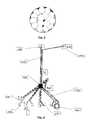
- the overall coverage of an area by such a systemis outlined in Fig. 2 .
- the gray arearepresents the coverage by the fiber to the home system.
- the mobile operatorinstalls its RoF system as illustrated by the white circles in Fig. 2 .
- the mobile operatorinstalls its RoF system in two flavours as illustrated in Fig. 3 :
- FIG. 4A more detailed overview of an embodiment of the invention can be found in Fig. 4 .
- a PONfor implementing a Fiber to the home (FTTH) infrastructure by connecting a central office CO 400 via a trunk line 410, a remote node 420, and leaf lines 430 to optical leaf nodes 440.
- This FTTH infrastructureis now according to one embodiment shared by a mobile operator which implements a radio over fiber system using this infrastructure.
- the mobile operatorhas a core network 450 (e.g. a evolved packet core, EPC) which delivers a packet oriented signal, e.g. the S1 signal, which should be distributed to its base stations.
- the S1 signalis transmitted via the trunk line 410 and one of the leaf lines to one of the leaf nodes.
- EPCevolved packet core
- a baseband processing unit (BBU) 460at the leaf node which receives the S1 signal.
- the BBUthen carries out a baseband processing and generates a RoF signal.
- This RoF signalwhich is illustrated by the dashed lines in Fig. 4 , is then transmitted from the leaf node which comprises the BBU 460 to the remote node 420 via a leaf line 430 and from there to the other leaf nodes 470, also via a leaf line 430.
- These other leaf nodesare provided with remote radio heads RRH 470 for transmitting the radio signal via the air interface to the mobile terminals.
- the baseband processing unitis located in one of the PON leaf nodes, and the remote radio heads are located in one or multiple other PON leaf nodes.
- the remote node 420 of the PONis modified such that it creates a bidirectional channel between the BBU and the RRHs.
- the S1 trafficis transmitted via the "normal" channel over the PON to the BBU, there it is transformed to RoF signals, and the newly created signal path is used to exchange the RoF signals between BBU and RRHs.
- the BBU at the leaf nodetherefore allows a baseband processing pooling at the PON leaf node.
- the RoF signalwhich is transmitted via the remote node interconnects the baseband processing pool with the RRHs at the other leaf nodes, and the trunk line connects the baseband processing pool implemented by the BBU with the core network of the mobile operator (in case of an LTE network the EPC).
- the RoF signalcan be transmitted with higher loss, and therefore in an unused spectrum range (e.g. in the waterpeak region).
- the relatively long distance between the core network and the BBUthen is covered by transmitting the packet oriented signal from the core (e.g. the S1 signal). Therefore only for transmitting the S1 signal there is a need to make use of the low attenuation optical spectrum resources, and for the transmission of the RoF signal a different part of the spectrum with higher loss can be used.
- the connection between the leaf nodes and the remote nodeis sufficiently short, the RoF signal can be generated and transmitted also as analogue RoF signal as the short distance reduces the optical non-linearities.
- the baseband processing unitneeds not to carry out a "full baseband processing", which means a "part” of the baseband processing may also be shifted to the remote radio heads.
- the baseband processingmay be implemented by any means which at least partly carries out the baseband processing normally carried out by a base station so that the functionality of the baseband processing which is taken over by the baseband processing unit can be carried out centrally by one unit for several remote radio heads which thereby become less complicated and less costly than a "normal base station” because the BBU takes over at least a part of their baseband processing tasks.
- the wavelength assignment in this embodimentis schematically illustrated in Fig. 5 .
- the S1 signal from the coreto the leaf node which has the BBU it is necessary to use only one wavelength in the spectrum range where the resources are limited and which can be used for long range communication (the low attenuation spectrum).
- the RoF signalBy generating the RoF signal at the leaf node so that it has from there to travel only the (relatively short) distance to the remote node and the other leaf nodes, it is possible to transmit the RoF signal at wavelengths with higher attenuation which is a part of the spectrum where the resources are less limited. Furthermore, if this distance is sufficiently short, the transmission of the RoF signal can also be made in analogue form.
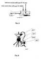
- Fig. 6It consists of the passive splitter 530 (which can be either a power splitter in case of a TDM PON or a wavelength splitter in case of a WDM PON), two waveband (de-)multiplexers 500 and 510, and one filter 540.
- the RoF signal from the leaf node where the BBU is locatedis fed to the waveband (de-)multiplexer 500 and extracted, then it is forwarded to the other waveband (de-)multiplexer 510 where it is fed to the splitter 530 and from there distributed to the other leaf nodes.
- the filter 540prevents a collision between the RoF signal received from the BBU and the one which is fed into the splitter and distributed to the other leaf nodes.
- the thus modified splitter 530forms a remote node which can redirect a RoF signal which it has received from a BBU located at a leaf node to the other leaf nodes of the PON.
- FIG. 7Therein there is shown how a PON can be used by a mobile operator using two different flavours of RoF transmission.
- the backhaul S1 IP trafficis transmitted via a core transport network to a central office. From there the distribution to the leaf nodes is done in two different ways via a PON. If the PON is short, then the baseband pooling can be carried out in the central office and the RoF signal can be sent through the whole PON to the leaf nodes and their remote radio units RRU or remote radio heads. This is illustrated by the PON on the left-hand side where the whole path from the BBU in the central office to the leaf nodes is shown by the dashed line, thereby indicating that the RoF signal travels via the trunk line and the leaf lines of the PON.
Landscapes
- Engineering & Computer Science (AREA)
- Computer Networks & Wireless Communication (AREA)
- Signal Processing (AREA)
- Physics & Mathematics (AREA)
- Electromagnetism (AREA)
- Optical Communication System (AREA)
- Mobile Radio Communication Systems (AREA)
- Small-Scale Networks (AREA)
Description
- The present invention relates to a system and a method for implementing a radio over fiber (RoF) transmission in a passive optical network (PON).
- A passive optical network (PON) is an access network technology that connects a central office entity called "Optical Line Terminal OLT" with the customer premises equipment called "Optical Network Unit ONU" over a maximum distance of several 10kms. The devices are connected by optical fibers that are deployed in a tree structure. PONs are currently considered as a candidate for access network sharing as the optical fiber offers high bandwidth and is already deployed to a large number of customers.
- (Access) network sharing is a paradigm that allows different operators, e.g., a mobile and a fixed operator to use the 'last mile' of the network conjointly. While the fixed operator uses this access part to directly attach its customers, the mobile operator uses the access to connect base stations. In access network sharing, the two networks will run on the same hardware (i.e. devices and physical links), but will be logically separated.
- Radio over fiber (RoF) is a technology widely used in the design and the deployment of base stations, in which a baseband processing unit (BBU) is connected via an optical link to the radio equipment and via this to an antenna. The BBU receives the signals from the core network of a mobile operator, e.g. in case of a LTE network the evolved packet core EPC S1 signals and converts them to RoF signals, these are transmitted via the optical link to the radio equipment/antenna unit (which will be called remote radio head in the following sections) where they are modulated on the wireless channel.
- If there is provided one BBU for each remote radio head, the hardware costs are significant. It is therefore desirable to use an approach where the baseband processing resources are "pooled" such that one BBU serves several remote radio heads. It is even further preferable if the network over which the RoF signals are transmitted is shared with a fixed network operator.
- Such scenarios will now be explained in somewhat more detail in the following.
- Radio-over-fiber is the digitized or analogue transmission of the radio layer signals via an optical fiber. Digital radio over fiber requires large amounts of bandwidth, between 10-30 times the bytes of the S1 traffic are necessary. A typical site with 3 cells with 1 Gbps S1 traffic each (for LTE-A) thus can require 60-70 Gbps RoF capacity. It is difficult to fit this high amount of bandwidth into a (shared) PON system. The presently most advanced TDM PON systems on the market today support 10Gbps, shared between all users of the PON. WDM PON systems might support higher bandwidths, but whether 60-70 Gbps for a single user can be supported in the near future is questionable.
- One alternative is to multiplex digital RoF signals via high-capacity, long-range technologies like CWDM or DWDM (coarse/dense wavelength division multiplexing) on the shared PON. However, both systems have their disadvantages: while CWDM is cheap, it uses a lot of the optical spectrum, which might be already occupied by the different FTTH systems. DWDM requires only a low amount of spectrum, however it is quite costly.
- Another alternative is analogue RoF, however this only works via short distances as the transmission distance is limited by fiber distortions and non-linearities. At the same time, there is a trend in the fiber-to-the-home community to create access networks with long optical reach. This is advantageous as the amount of central offices can be reduced, thus saving CAPEX and OPEX.
- When one looks at access network sharing and RoF, it becomes clear that this trend becomes problematic: it is the goal of FTTH-operators to cover larger and larger areas from a central location for cost saving reasons; however a mobile operator can only cover a part of the area with a centralized baseband pool and analogue RoF. Thus, the coverage area is not the same, and the mobile operator has to resort to (at least in the peripheral of the network, where a transmission of RoF signals from the central office is not possible) deploy conventional base station technology, without the benefit of baseband pooling.
- As mentioned above, high-capacity long-range digital technologies also have their disadvantages with respect to spectrum usage and/or cost. Furthermore, (digital) RoF transmission distance is also limited from an unexpected direction, the radio layer: certain wireless protocols require a reaction within a strict time limit. A wireless signal that requires such a reaction initially arrives at the antenna, is then transmitted via RoF to the baseband processing where it is decoded and such a reaction is calculated. The reaction is transmitted back to the antenna, again via RoF, and then sent out wirelessly. In this processing and transmission chain, each kilometer of fiber over which the RoF signal is transported adds latency due to the pure signal propagation delay, while the overall time is limited by radio layer standards.
- The three known approaches for baseband pooling and/or network sharing are illustrated in
Fig. 1 . The first one (shown on the left-hand side inFig. 1 ) is the centralized baseband pooling at the PON's central office location with analogue or digital RoF. This has the above outlined limitations. The second solution (shown in the center ofFig. 1 ) is a distributed baseband processing, in which each unit connected to the passive optical network is a complete base station. Obviously, this approach does not allow realizing baseband pooling gains and only can achieve network sharing.
The last know solution (shown on the right-hand side inFig. 1 ) is one in which the baseband processing unit is connected to one of the leaf nodes, and the remote radio heads of the other leaf nodes are connected to it via a dedicated network. Here, the length of the PON tree trunk is not problematic; however, the mobile operator has to deploy new fibers to attach the remote radio heads, thus not being able to realizing the network sharing gains. - It is therefore desirable to have a system where baseband pooling gains and network sharing gains can be achieved simultaneously, and even in cases where the PON covers a long distance. None of the existing solutions has such capabilities.
- Hung-Chang Chien et al., "Long-Reach, 60-GHz Mm-Wave Optical-Wireless Access Network Using remote Signal Regenaration and Upconversion", 34th European Conference on Optical Communication, IEEE, 21. September 2008 presents a 125 km long-reach, 60 GHz optical-wireless access network using remote signal regeneration and an upconversion technique without dispersion compensation, which is first demonstrated to accommodate over 128 users at 2.5 GB/s. This work addresses limitations at the radio layer, in particular limitations of transmission distance in the mm-wave over fiber technology, by extending the reach of mm-wave wireless data over optical access network using remote signal regeneration and upconversion at a local exchange stage.
- Christine Lim et al., "Capacity Analysis for WDM Fiber-Radio Backbones With Star-Tree and Ring Architecture Incorporating Wavelength Interleaving", Journal of Lightwave Technology, Vol. 21, No. 12, December 2003 presents a model based on link budget calculations to investigate the capacity of the wavelength-division-multiplexed (WDM) fiber-radio backbone incorporating a wavelength-interleaving technique. The wavelength-interleaving technique improves the optical spectral efficiency of the millimeter-wave fiber radio system incorporating optical single sideband with carrier modulation. Capacity limitations of WDM fiber-radio backbones incorporating both wavelength interleaving and optical single sideband with carrier modulation for star-tree and ring architecture are investigated. The analysis provides an estimation of the overall system capacity and insight into the network layout and performance limitations. This work addresses limitations at the radio layer, such as degradation of received RF power, by incorporating both wavelength interleaving techniques and optical single sideband with carrier modulation.
- According to one embodiment there is provided a system for implementing a radio over fiber (RoF) transmission in a passive optical network (PON), said passive optical network comprising a trunk line,
a remote node, and
a plurality of leaf nodes connected to said remote node, wherein
one of said plurality of leaf nodes comprises a baseband processing unit for performing a baseband processing on a signal received via said trunk line to perform the transformation to radio over fiber by generating a radio over fiber signal and to forward the resulting radio over fiber signal to said remote node, wherein
said remote node is adapted to forward the radio over fiber signal received from said leaf node to the other leaf nodes of said passive optical network. - By such a configuration a baseband pooling gain can be achieved and the PON can be shared between a fixed network operator and a mobile network operator.
- According to one embodiment one or more of said other leaf nodes comprise a remote radio head to transmit the received radio over fiber signal as a radio signal.
- This allows the usage of the baseband pooling gains by replacing base stations through remote radio heads.
- According to one embodiment said signal which is received via said trunk line by said one of said plurality of leaf nodes is a signal received from the core network of a mobile network operator.
- This enables the usage of the system by a mobile network operator.
- According to one embodiment said signal which is received via said trunk line is a S1 signal.
This is a specific implementation for a LTE network. - According to one embodiment said radio over fiber signal generated in said one of said plurality of leaf nodes is transmitted in a waveband range outside the bands suitable for covering a range which includes the length of the trunk line and a leaf line but in a band suitable for covering a range communication covering the length which includes the distance from one leaf node to another leaf node via said remote node.
- This enables an efficient usage of the optical frequency resources.
- According to one embodiment the length of said trunk line is longer than the length from the remote node to a leaf node.
- This is a specific configuration where the usage of a system according to the invention is advantageous for covering long range trunk lines.
- According to one embodiment said passive optical network is shared between a fixed and a mobile operator such that
the fixed operator uses the PON to transmit FTTH signals, and
the mobile operator uses the PON, the remote node and the leaf nodes to transmit a signal from its core to said one of said leaf nodes and radio over fiber signals from said one of said leaf nodes to other ones of said leaf nodes via said remote node. - This is an advantageous implementation for access network sharing.
- According to one embodiment the RoF signal is transmitted in analogue form.
This enables a cost efficient implementation. - According to one embodiment there is provided a system for implementing a radio over fiber (RoF) transmission, said system comprising:
- One or more first systems according to one of the embodiments of the invention;
- one or more second systems for implementing a RoF transmission, wherein a baseband processing unit is located at the optical line terminal, remote radio heads are located at PON leaf nodes, and the RoF signals are transmitted from the optical line terminal to the leaf nodes via the trunk line and the leaf lines of the PON.
- This enables wide area coverage by two flavours of RoF transmission.
- According to one embodiment the one or more first systems are used to cover areas which are more far away from the optical line terminal;
the one or more second systems are used to cover areas which are less far away from the optical line terminal. - This is a specific implementation for wide area coverage.
- According to one embodiment there is provided a method for implementing a radio over fiber (RoF) transmission in a passive optical network (PON), said passive optical network comprising
a trunk line,
a remote node, and
a plurality of leaf nodes connected to said remote node, said method comprising: wherein
performing a baseband processing in a baseband processing unit of one of said plurality of leaf nodes on a signal received via said trunk line to perform the transformation to radio over fiber by generating a radio over fiber signal;
forwarding the resulting radio over fiber signal to said remote node, and
forwarding the radio over fiber signal received from said at least one leaf node by said remote node to the other leaf nodes of second passive optical network. - This is an implementation of a method according to an embodiment of the invention.
Fig. 1 schematically illustrates three different approaches of PON implementations.Fig. 2 schematically illustrates a structure where multiple PONs are connected to a central office.Fig. 3 schematically illustrates a structure where multiple PONs are connected to a central office according to an embodiment of the invention.Fig. 4 schematically illustrates a system according to an embodiment of the invention.Fig. 5 schematically illustrates a frequency assignment according to an embodiment of the invention.Fig. 6 schematically illustrates a remote node according to an embodiment of the invention.Fig. 7 schematically illustrates a system according to an embodiment of the invention.- According to one embodiment there is proposed a system for sharing the access network between a fixed and a mobile operator in which the operator can realize baseband processing pooling gains by using radio over fiber technology. For that purpose there is used a specifically designed remote node of a passive optical network which is capable to create a signal path between a first PON leaf node and the other PON leaf nodes. Such a remote node with this capability is - in a different context - described in the European patent application no.
11182745.7 - This is especially advantageous if the feeder fiber (the trunk of the PON tree) becomes very long, and thus a radio over fiber (RoF) transmission is difficult or impossible due to the higher attenuation or high cost for suitable transmission equipment. The long distance is then covered by the low-bandwidth S1 signal and the high-bandwidth or analogue RoF signal needs to only cover the (relatively short) distance between the remote node and the leaf nodes.
- This is a system that allows implementing a pooled baseband processing in case the access network is shared between fixed and mobile operator and the feeder of the shared PON is long.
- First of all, this results in fewer sites with high complexity (the sites that only host a remote radio heads are simple, thus cheap and less prone to errors). Furthermore, with the current trend to install long range PONs, a fixed fiber to the home network will cover a large area that cannot be covered with conventional (analogue) RoF technology from the central office to the PON leafs or requires expensive, high speed digital transmission equipment for digital RoF. The embodiment allows to also cover this larger area, by allowing for distributed baseband processing pools.
- According to one embodiment there is provided a system in which the baseband processing unit is located in one of the leaf nodes of a shared PON, and the remote node is specifically modified such that this BBU can transmit the RoF signals via the remote node to the other PON leaf nodes. There, remote radio heads are attached, and the system is able to realize baseband pooling gains also in case the trunk of the PON tree is long, since the RoF signals only have to traverse the branches of the fiber tree, but not the trunk.
- With this, a fixed operator can create a fiber to the home network with long trunk lines (long reach PONs) and thus realize the reduction of central offices, while at the same time the mobile operator can cover the area with base stations that apply baseband pooling technology. The overall coverage of an area by such a system is outlined in
Fig. 2 . The gray area represents the coverage by the fiber to the home system. On top of this, the mobile operator installs its RoF system as illustrated by the white circles inFig. 2 . - According to one embodiment the mobile operator installs its RoF system in two flavours as illustrated in
Fig. 3 : - The part that is reachable with RoF from the central office will be covered with conventional technology (i.e. using RoF transmission with the BBU close to the central office). This is illustrated by the white circles drawn by dashed lines in the middle of the grey circle.
- The part of the area that is too far away from the central office to be covered is covered by using the system where the BBU is installed at one of the leaf nodes and the RoF signal is distributed from this leaf node to the other leaf nodes via the remote node. This is illustrated by the white circles drawn by solid lines in the periphery which surround the dashed circles in the center.
- With this configuration, fixed and mobile operator can thus cover the same area even in the presence of long range PONs, thus realizing baseband pooling gains, sharing gains, and central office consolidation gains all on the same system.
- Now further embodiments of the invention will be described.
- A more detailed overview of an embodiment of the invention can be found in
Fig. 4 . There is shown a PON for implementing a Fiber to the home (FTTH) infrastructure by connecting acentral office CO 400 via atrunk line 410, aremote node 420, andleaf lines 430 tooptical leaf nodes 440. This FTTH infrastructure is now according to one embodiment shared by a mobile operator which implements a radio over fiber system using this infrastructure. The mobile operator has a core network 450 (e.g. a evolved packet core, EPC) which delivers a packet oriented signal, e.g. the S1 signal, which should be distributed to its base stations. The S1 signal is transmitted via thetrunk line 410 and one of the leaf lines to one of the leaf nodes. - In order to make use of baseband pooling gains there is provided a baseband processing unit (BBU) 460 at the leaf node which receives the S1 signal. The BBU then carries out a baseband processing and generates a RoF signal. This RoF signal, which is illustrated by the dashed lines in
Fig. 4 , is then transmitted from the leaf node which comprises theBBU 460 to theremote node 420 via aleaf line 430 and from there to theother leaf nodes 470, also via aleaf line 430. These other leaf nodes are provided with remote radio headsRRH 470 for transmitting the radio signal via the air interface to the mobile terminals. - Therefore, according to the embodiment, the baseband processing unit is located in one of the PON leaf nodes, and the remote radio heads are located in one or multiple other PON leaf nodes. The
remote node 420 of the PON is modified such that it creates a bidirectional channel between the BBU and the RRHs. The S1 traffic is transmitted via the "normal" channel over the PON to the BBU, there it is transformed to RoF signals, and the newly created signal path is used to exchange the RoF signals between BBU and RRHs. - The BBU at the leaf node therefore allows a baseband processing pooling at the PON leaf node. The RoF signal which is transmitted via the remote node interconnects the baseband processing pool with the RRHs at the other leaf nodes, and the trunk line connects the baseband processing pool implemented by the BBU with the core network of the mobile operator (in case of an LTE network the EPC).
- Since in typical configurations the connection between the leaf nodes and the remote node is relatively short, especially compared to the length of the trunk line, the RoF signal can be transmitted with higher loss, and therefore in an unused spectrum range (e.g. in the waterpeak region). The relatively long distance between the core network and the BBU then is covered by transmitting the packet oriented signal from the core (e.g. the S1 signal). Therefore only for transmitting the S1 signal there is a need to make use of the low attenuation optical spectrum resources, and for the transmission of the RoF signal a different part of the spectrum with higher loss can be used.
Furthermore, if the connection between the leaf nodes and the remote node is sufficiently short, the RoF signal can be generated and transmitted also as analogue RoF signal as the short distance reduces the optical non-linearities. - It should be mentioned here that according to one embodiment the baseband processing unit needs not to carry out a "full baseband processing", which means a "part" of the baseband processing may also be shifted to the remote radio heads. It should be noted that the baseband processing may be implemented by any means which at least partly carries out the baseband processing normally carried out by a base station so that the functionality of the baseband processing which is taken over by the baseband processing unit can be carried out centrally by one unit for several remote radio heads which thereby become less complicated and less costly than a "normal base station" because the BBU takes over at least a part of their baseband processing tasks.
- The wavelength assignment in this embodiment is schematically illustrated in
Fig. 5 . By transmitting the S1 signal from the core to the leaf node which has the BBU it is necessary to use only one wavelength in the spectrum range where the resources are limited and which can be used for long range communication (the low attenuation spectrum). By generating the RoF signal at the leaf node so that it has from there to travel only the (relatively short) distance to the remote node and the other leaf nodes, it is possible to transmit the RoF signal at wavelengths with higher attenuation which is a part of the spectrum where the resources are less limited. Furthermore, if this distance is sufficiently short, the transmission of the RoF signal can also be made in analogue form. - In the following a more detailed view of the architecture of the remote node which can be used in connection with embodiments of the invention will be explained by referring to
Fig. 6 . It consists of the passive splitter 530 (which can be either a power splitter in case of a TDM PON or a wavelength splitter in case of a WDM PON), two waveband (de-)multiplexers filter 540. The RoF signal from the leaf node where the BBU is located is fed to the waveband (de-)multiplexer 500 and extracted, then it is forwarded to the other waveband (de-)multiplexer 510 where it is fed to thesplitter 530 and from there distributed to the other leaf nodes. Thefilter 540 prevents a collision between the RoF signal received from the BBU and the one which is fed into the splitter and distributed to the other leaf nodes. - The thus modified
splitter 530 forms a remote node which can redirect a RoF signal which it has received from a BBU located at a leaf node to the other leaf nodes of the PON. - An even more detailed description of such a modified remote node, albeit in a different context, can be found in European patent application no.
11182745.7 - A further embodiment will now be described in connection with
Fig. 7 . Therein there is shown how a PON can be used by a mobile operator using two different flavours of RoF transmission. - From an EPC GW the backhaul S1 IP traffic is transmitted via a core transport network to a central office. From there the distribution to the leaf nodes is done in two different ways via a PON. If the PON is short, then the baseband pooling can be carried out in the central office and the RoF signal can be sent through the whole PON to the leaf nodes and their remote radio units RRU or remote radio heads. This is illustrated by the PON on the left-hand side where the whole path from the BBU in the central office to the leaf nodes is shown by the dashed line, thereby indicating that the RoF signal travels via the trunk line and the leaf lines of the PON.
- If the PON is long a different configuration is used where the S1 traffic travels to the BBU located at a leaf node of the PON and the RoF signal is generated and directed to the other leaf nodes via the remote node. This is illustrated by the right-hand PON shown in
Fig. 7 . - While the present invention has been described by exemplary embodiments, it will be understood that these embodiments may be modified without departing form the scope of the claims.
Claims (14)
- A system for implementing a radio over fiber (RoF) transmission in a passive optical network (PON), said passive optical network comprising
a trunk line (410),
a remote node (420), and
a plurality of leaf nodes (440) connected to said remote node, wherein
one of said plurality of leaf nodes comprises a baseband processing unit (460) for performing a baseband processing on a signal received via said trunk line to perform the transformation to radio over fiber by generating a radio over fiber signal;
said baseband processing unit beingcharacterized in that it is adapted to forward the resulting radio over fiber signal to said remote node, wherein
said remote node is adapted to forward the radio over fiber signal received from said leaf node to the other leaf nodes of said passive optical network. - The system of claim 1, wherein
one or more of said other leaf nodes comprise a remote radio head (470) to transmit the received radio over fiber signal as a radio signal. - The system of claim 1 or 2, wherein
said signal which is received via said trunk line (410) by said one of said plurality of leaf nodes (440) is a signal received from the core network of a mobile network operator. - The system of claim 3, wherein said signal which is received via said trunk line (410) is a S1 signal.
- The system of one of the preceding claims, wherein
said radio over fiber signal generated in said one of said plurality of leaf nodes (440) is transmitted in a waveband range outside the bands suitable for covering a range which includes the length of the trunk line (410) and a leaf line but in a band suitable for covering a range communication covering the length which includes the distance from one leaf node to another leaf node via said remote node (420). - The system of one of the preceding claims, wherein the length of said trunk line (410) is longer than the length from the remote node (420) to a leaf node (440).
- The system of one of the preceding claims, wherein
said passive optical network is shared between a fixed and a mobile operator such that
the fixed operator uses the PON to transmit FTTH signals, and
the mobile operator uses the PON, the remote node (420) and the leaf nodes (440) to transmit a signal from its core to said one of said leaf nodes and radio over fiber signals from said one of said leaf nodes to other ones of said leaf nodes via said remote node. - The system of one of claims 1 to 7, wherein the RoF signal is transmitted in analogue form.
- A system for implementing a radio over fiber (RoF) transmission, said system comprising:One or more first systems according to one of claims 1 to 7;One or more second systems for implementing a RoF transmission, wherein a baseband processing unit (460) is located at the optical line terminal, remote radio heads (470) are located at PON leaf nodes (440), and the RoF signals are transmitted from the optical line terminal to the leaf nodes via the trunk line (410) and the leaf lines of the PON.
- The system of claim 9, wherein
the one or more first systems are used to cover areas which are more far away from the optical line terminal;
the one or more second systems are used to cover areas which are less far away from the optical line terminal. - A method for implementing a radio over fiber (RoF) transmission in a passive optical network (PON), said passive optical network comprising
a trunk line (410),
a remote node (420), and
a plurality of leaf nodes (440) connected to said remote node, said method comprising:performing a baseband processing in a baseband processing unit (460) of one of said plurality of leaf nodes on a signal received via said trunk line (410) to perform the transformation to radio over fiber by generating a radio over fiber signal;the method beingcharacterized in that it further comprises forwarding the resulting radio over fiber signal to said remote node, and forwarding the radio over fiber signal received from said at least one leaf node by said remote node to the other leaf nodes of second passive optical network. - The method of claim 11, wherein
one or more of said other leaf nodes comprise a remote radio head (470) to transmit the received radio over fiber signal as a radio signal. - The method of claim 11 or 12, wherein
said signal which is received via said trunk (410) line by said one of said plurality of leaf nodes (440) is a signal received from the core network of a mobile network operator. - The method of one of claims 11 to 13, further comprising the features as defined in one of claims 1 to 10.
Priority Applications (4)
| Application Number | Priority Date | Filing Date | Title |
|---|---|---|---|
| EP12170387.0AEP2670210B1 (en) | 2012-06-01 | 2012-06-01 | System for implementing a radio over fiber transmission in a passive optical network |
| US13/905,973US9236941B2 (en) | 2012-06-01 | 2013-05-30 | System for implementing a radio over fiber transmission in a passive optical network |
| JP2013114213AJP5657747B2 (en) | 2012-06-01 | 2013-05-30 | System for implementing fiber optic wireless transmission in a passive optical network |
| CN201310211557.5ACN103457664B (en) | 2012-06-01 | 2013-05-31 | EPON realizes the system of optical-fiber wireless transmission |
Applications Claiming Priority (1)
| Application Number | Priority Date | Filing Date | Title |
|---|---|---|---|
| EP12170387.0AEP2670210B1 (en) | 2012-06-01 | 2012-06-01 | System for implementing a radio over fiber transmission in a passive optical network |
Publications (2)
| Publication Number | Publication Date |
|---|---|
| EP2670210A1 EP2670210A1 (en) | 2013-12-04 |
| EP2670210B1true EP2670210B1 (en) | 2014-09-17 |
Family
ID=46229253
Family Applications (1)
| Application Number | Title | Priority Date | Filing Date |
|---|---|---|---|
| EP12170387.0ANot-in-forceEP2670210B1 (en) | 2012-06-01 | 2012-06-01 | System for implementing a radio over fiber transmission in a passive optical network |
Country Status (4)
| Country | Link |
|---|---|
| US (1) | US9236941B2 (en) |
| EP (1) | EP2670210B1 (en) |
| JP (1) | JP5657747B2 (en) |
| CN (1) | CN103457664B (en) |
Families Citing this family (7)
| Publication number | Priority date | Publication date | Assignee | Title |
|---|---|---|---|---|
| JP6023103B2 (en)* | 2014-01-28 | 2016-11-09 | 日本電信電話株式会社 | Distributed wireless communication base station system and communication method |
| CN104618205B (en)* | 2015-02-05 | 2018-02-09 | 武汉虹信通信技术有限责任公司 | A kind of indoor fixed network access and mobile communication signal covering integrated system |
| CN106027190B (en)* | 2016-05-23 | 2018-10-16 | 北京邮电大学 | A kind of clock synchronizing method and device |
| US11645029B2 (en) | 2018-07-12 | 2023-05-09 | Manufacturing Resources International, Inc. | Systems and methods for remotely monitoring electronic displays |
| CN108966279B (en)* | 2018-08-17 | 2020-02-18 | 北京邮电大学 | A method and system for optical carrier wireless access based on central pressure marginalization |
| CN109164544A (en)* | 2018-09-19 | 2019-01-08 | 武汉华工正源光子技术有限公司 | A kind of ROF optical device packaging method based on CWDM |
| US11972672B1 (en) | 2022-10-26 | 2024-04-30 | Manufacturing Resources International, Inc. | Display assemblies providing open and unlatched alerts, systems and methods for the same |
Family Cites Families (29)
| Publication number | Priority date | Publication date | Assignee | Title |
|---|---|---|---|---|
| US5179720A (en)* | 1990-02-23 | 1993-01-12 | Motorola, Inc. | Method and apparatus for extended coverage of a trunked radio communications system |
| US6685976B2 (en) | 2000-01-19 | 2004-02-03 | The Quaker Oats Company | Modified oat and corn grit products and method |
| US20020114038A1 (en)* | 2000-11-09 | 2002-08-22 | Shlomi Arnon | Optical communication system |
| KR100352852B1 (en)* | 2000-12-22 | 2002-09-16 | 엘지전자 주식회사 | A transmitting device of receiving signal for optical bts |
| JP4324675B2 (en)* | 2003-02-28 | 2009-09-02 | 独立行政法人情報通信研究機構 | Wireless communication system |
| KR20050012075A (en)* | 2003-07-24 | 2005-01-31 | 유티스타콤코리아 유한회사 | Method for layout of remote multi-distributed BTS system |
| US8401385B2 (en)* | 2003-10-02 | 2013-03-19 | Trex Enterprises Corp. | Optically switched communication network |
| US20060045524A1 (en)* | 2004-08-28 | 2006-03-02 | Samsung Electronics Co.; Ltd | Optical access network of wavelength division method and passive optical network using the same |
| CN101076961B (en)* | 2004-10-25 | 2014-07-02 | 意大利电信股份公司 | Communication method, especially for mobile radio networks |
| US7720510B2 (en)* | 2004-11-15 | 2010-05-18 | Bae Systems Plc | Data communications between terminals in a mobile communication system |
| US8126510B1 (en)* | 2006-11-15 | 2012-02-28 | Nextel Communications Inc. | Public safety communications network architecture |
| US8111998B2 (en)* | 2007-02-06 | 2012-02-07 | Corning Cable Systems Llc | Transponder systems and methods for radio-over-fiber (RoF) wireless picocellular systems |
| US20090016718A1 (en)* | 2007-07-10 | 2009-01-15 | Viasat, Inc. | Wireless distribution of passive optical network signals |
| CN101442798B (en)* | 2007-11-22 | 2011-10-26 | 中兴通讯股份有限公司 | Ascending/descending synchronous communication method for radio base station control node and cascade far-end node thereof |
| CN101277135B (en)* | 2008-05-07 | 2012-03-07 | 中兴通讯股份有限公司 | Method for a plurality of far-end radio frequency units to support single subdistrict |
| CN101772047B (en)* | 2009-01-07 | 2013-08-07 | 中兴通讯股份有限公司 | Method and system for monitoring network quality |
| TWI412256B (en)* | 2009-03-05 | 2013-10-11 | Ind Tech Res Inst | Circuit for switching signal path, antenna module and radio over fiber system |
| CN102045892B (en)* | 2009-10-20 | 2013-02-27 | 中兴通讯股份有限公司 | Baseband pool equipment and method for realizing baseband data distributed switching |
| US8275265B2 (en)* | 2010-02-15 | 2012-09-25 | Corning Cable Systems Llc | Dynamic cell bonding (DCB) for radio-over-fiber (RoF)-based networks and communication systems and related methods |
| US8774109B2 (en)* | 2010-06-17 | 2014-07-08 | Kathrein-Werke Kg | Mobile communications network with distributed processing resources |
| WO2012024247A1 (en)* | 2010-08-16 | 2012-02-23 | Corning Cable Systems Llc | Remote antenna clusters and related systems, components, and methods supporting digital data signal propagation between remote antenna units |
| US9107199B2 (en)* | 2010-09-30 | 2015-08-11 | Lg Electronics Inc. | Method for transmitting signal in multi-node system |
| WO2012148940A1 (en)* | 2011-04-29 | 2012-11-01 | Corning Cable Systems Llc | Systems, methods, and devices for increasing radio frequency (rf) power in distributed antenna systems |
| WO2012148938A1 (en)* | 2011-04-29 | 2012-11-01 | Corning Cable Systems Llc | Determining propagation delay of communications in distributed antenna systems, and related components, systems and methods |
| WO2012167820A1 (en)* | 2011-06-07 | 2012-12-13 | Nokia Siemens Networks Oy | Controlling retransmissions |
| CN202121782U (en)* | 2011-07-20 | 2012-01-18 | 中国联合网络通信集团有限公司 | Near-end node, far-end node, and indoor distribution system |
| US8897648B2 (en)* | 2012-02-20 | 2014-11-25 | Nec Laboratories America, Inc. | Orthogonal frequency division multiple access time division multiple access-passive optical networks OFDMA TDMA PON architecture for 4G and beyond mobile backhaul |
| HK1221853A1 (en)* | 2012-02-24 | 2017-06-09 | Apple Inc. | Cooperative radio access network with centralized base station baseband unit (bbu) processing pool |
| CN102723994B (en)* | 2012-06-15 | 2016-06-22 | 华为技术有限公司 | The method of data transmission, Apparatus and system |
- 2012
- 2012-06-01EPEP12170387.0Apatent/EP2670210B1/ennot_activeNot-in-force
- 2013
- 2013-05-30JPJP2013114213Apatent/JP5657747B2/enactiveActive
- 2013-05-30USUS13/905,973patent/US9236941B2/ennot_activeExpired - Fee Related
- 2013-05-31CNCN201310211557.5Apatent/CN103457664B/ennot_activeExpired - Fee Related
Also Published As
| Publication number | Publication date |
|---|---|
| CN103457664B (en) | 2016-06-08 |
| CN103457664A (en) | 2013-12-18 |
| JP2013251901A (en) | 2013-12-12 |
| EP2670210A1 (en) | 2013-12-04 |
| JP5657747B2 (en) | 2015-01-21 |
| US9236941B2 (en) | 2016-01-12 |
| US20150365170A1 (en) | 2015-12-17 |
Similar Documents
| Publication | Publication Date | Title |
|---|---|---|
| EP2670210B1 (en) | System for implementing a radio over fiber transmission in a passive optical network | |
| US8855489B2 (en) | Communications method, particularly for a mobile radio network | |
| Opatić | Radio over fiber technology for wireless access | |
| KR102160865B1 (en) | Wireless access system | |
| US8098990B2 (en) | System and method for providing wireless over a passive optical network (PON) | |
| US9554284B2 (en) | Wireless over PON | |
| CN102918924B (en) | Providing digital data services in fiber-optic-based distributed radio frequency (RF) communication systems | |
| US9401764B2 (en) | Optical network unit | |
| Chang et al. | 1–100GHz microwave photonics link technologies for next-generation WiFi and 5G wireless communications | |
| JP4995676B2 (en) | System and method for providing wireless communication over a passive optical network (PON) | |
| JP2014110574A (en) | Optical radio access system | |
| CN101860770A (en) | A method and system for integrating fixed network and mobile network | |
| Monteiro et al. | Mobile fronthaul RoF transceivers for C-RAN applications | |
| CN113543151A (en) | 4G/5G signal wireless coverage method | |
| US10085077B2 (en) | Optical switch for radio access network | |
| Bhatt et al. | Fiber-wireless (Fi-Wi) architectural technologies: A survey | |
| Ponzini et al. | Optical access network solutions for 5G fronthaul | |
| Mikroulis et al. | CPRI for 5G cloud RAN?–efficient implementations enabling massive MIMO deployment–challenges and perspectives | |
| JP4280551B2 (en) | Optical transmission system | |
| Mahapatra et al. | Optimization in fronthaul and backhaul network for cloud RAN (C-RAN): Design and deployment challenges | |
| Monteiro et al. | Radio-over-fiber as the enabler for joint processing of spatially separated radio signals | |
| Agus et al. | Novel 5G broadband front-haul architectures for ultra-dense and hot-spot areas exploiting optical technologies and photonic integrated circuits | |
| KR101771535B1 (en) | Distributed Antenna System of Hybrid Transmission | |
| Pato et al. | Prospects of supporting distributed antenna systems over next-generation optical access and metro-access networks | |
| Wang et al. | Fiber-connected massively distributed antenna systems |
Legal Events
| Date | Code | Title | Description |
|---|---|---|---|
| PUAI | Public reference made under article 153(3) epc to a published international application that has entered the european phase | Free format text:ORIGINAL CODE: 0009012 | |
| 17P | Request for examination filed | Effective date:20130812 | |
| AK | Designated contracting states | Kind code of ref document:A1 Designated state(s):AL AT BE BG CH CY CZ DE DK EE ES FI FR GB GR HR HU IE IS IT LI LT LU LV MC MK MT NL NO PL PT RO RS SE SI SK SM TR | |
| AX | Request for extension of the european patent | Extension state:BA ME | |
| REG | Reference to a national code | Ref country code:DE Ref legal event code:R079 Ref document number:602012003115 Country of ref document:DE Free format text:PREVIOUS MAIN CLASS: H04W0088080000 Ipc:H04B0010257500 | |
| RIC1 | Information provided on ipc code assigned before grant | Ipc:H04B 10/2575 20130101AFI20131204BHEP Ipc:H04W 88/08 20090101ALI20131204BHEP Ipc:H04J 14/02 20060101ALI20131204BHEP | |
| GRAP | Despatch of communication of intention to grant a patent | Free format text:ORIGINAL CODE: EPIDOSNIGR1 | |
| INTG | Intention to grant announced | Effective date:20140424 | |
| GRAS | Grant fee paid | Free format text:ORIGINAL CODE: EPIDOSNIGR3 | |
| GRAA | (expected) grant | Free format text:ORIGINAL CODE: 0009210 | |
| AK | Designated contracting states | Kind code of ref document:B1 Designated state(s):AL AT BE BG CH CY CZ DE DK EE ES FI FR GB GR HR HU IE IS IT LI LT LU LV MC MK MT NL NO PL PT RO RS SE SI SK SM TR | |
| REG | Reference to a national code | Ref country code:GB Ref legal event code:FG4D | |
| REG | Reference to a national code | Ref country code:CH Ref legal event code:EP | |
| REG | Reference to a national code | Ref country code:IE Ref legal event code:FG4D | |
| REG | Reference to a national code | Ref country code:AT Ref legal event code:REF Ref document number:688093 Country of ref document:AT Kind code of ref document:T Effective date:20141015 | |
| REG | Reference to a national code | Ref country code:DE Ref legal event code:R096 Ref document number:602012003115 Country of ref document:DE Effective date:20141030 | |
| PG25 | Lapsed in a contracting state [announced via postgrant information from national office to epo] | Ref country code:FI Free format text:LAPSE BECAUSE OF FAILURE TO SUBMIT A TRANSLATION OF THE DESCRIPTION OR TO PAY THE FEE WITHIN THE PRESCRIBED TIME-LIMIT Effective date:20140917 Ref country code:NO Free format text:LAPSE BECAUSE OF FAILURE TO SUBMIT A TRANSLATION OF THE DESCRIPTION OR TO PAY THE FEE WITHIN THE PRESCRIBED TIME-LIMIT Effective date:20141217 Ref country code:SE Free format text:LAPSE BECAUSE OF FAILURE TO SUBMIT A TRANSLATION OF THE DESCRIPTION OR TO PAY THE FEE WITHIN THE PRESCRIBED TIME-LIMIT Effective date:20140917 Ref country code:LT Free format text:LAPSE BECAUSE OF FAILURE TO SUBMIT A TRANSLATION OF THE DESCRIPTION OR TO PAY THE FEE WITHIN THE PRESCRIBED TIME-LIMIT Effective date:20140917 Ref country code:GR Free format text:LAPSE BECAUSE OF FAILURE TO SUBMIT A TRANSLATION OF THE DESCRIPTION OR TO PAY THE FEE WITHIN THE PRESCRIBED TIME-LIMIT Effective date:20141218 | |
| REG | Reference to a national code | Ref country code:NL Ref legal event code:VDEP Effective date:20140917 | |
| REG | Reference to a national code | Ref country code:LT Ref legal event code:MG4D | |
| PG25 | Lapsed in a contracting state [announced via postgrant information from national office to epo] | Ref country code:CY Free format text:LAPSE BECAUSE OF FAILURE TO SUBMIT A TRANSLATION OF THE DESCRIPTION OR TO PAY THE FEE WITHIN THE PRESCRIBED TIME-LIMIT Effective date:20140917 Ref country code:HR Free format text:LAPSE BECAUSE OF FAILURE TO SUBMIT A TRANSLATION OF THE DESCRIPTION OR TO PAY THE FEE WITHIN THE PRESCRIBED TIME-LIMIT Effective date:20140917 Ref country code:RS Free format text:LAPSE BECAUSE OF FAILURE TO SUBMIT A TRANSLATION OF THE DESCRIPTION OR TO PAY THE FEE WITHIN THE PRESCRIBED TIME-LIMIT Effective date:20140917 Ref country code:LV Free format text:LAPSE BECAUSE OF FAILURE TO SUBMIT A TRANSLATION OF THE DESCRIPTION OR TO PAY THE FEE WITHIN THE PRESCRIBED TIME-LIMIT Effective date:20140917 | |
| REG | Reference to a national code | Ref country code:AT Ref legal event code:MK05 Ref document number:688093 Country of ref document:AT Kind code of ref document:T Effective date:20140917 | |
| PG25 | Lapsed in a contracting state [announced via postgrant information from national office to epo] | Ref country code:NL Free format text:LAPSE BECAUSE OF FAILURE TO SUBMIT A TRANSLATION OF THE DESCRIPTION OR TO PAY THE FEE WITHIN THE PRESCRIBED TIME-LIMIT Effective date:20140917 | |
| PG25 | Lapsed in a contracting state [announced via postgrant information from national office to epo] | Ref country code:ES Free format text:LAPSE BECAUSE OF FAILURE TO SUBMIT A TRANSLATION OF THE DESCRIPTION OR TO PAY THE FEE WITHIN THE PRESCRIBED TIME-LIMIT Effective date:20140917 Ref country code:PT Free format text:LAPSE BECAUSE OF FAILURE TO SUBMIT A TRANSLATION OF THE DESCRIPTION OR TO PAY THE FEE WITHIN THE PRESCRIBED TIME-LIMIT Effective date:20150119 Ref country code:SK Free format text:LAPSE BECAUSE OF FAILURE TO SUBMIT A TRANSLATION OF THE DESCRIPTION OR TO PAY THE FEE WITHIN THE PRESCRIBED TIME-LIMIT Effective date:20140917 Ref country code:IS Free format text:LAPSE BECAUSE OF FAILURE TO SUBMIT A TRANSLATION OF THE DESCRIPTION OR TO PAY THE FEE WITHIN THE PRESCRIBED TIME-LIMIT Effective date:20150117 Ref country code:CZ Free format text:LAPSE BECAUSE OF FAILURE TO SUBMIT A TRANSLATION OF THE DESCRIPTION OR TO PAY THE FEE WITHIN THE PRESCRIBED TIME-LIMIT Effective date:20140917 Ref country code:RO Free format text:LAPSE BECAUSE OF FAILURE TO SUBMIT A TRANSLATION OF THE DESCRIPTION OR TO PAY THE FEE WITHIN THE PRESCRIBED TIME-LIMIT Effective date:20140917 Ref country code:EE Free format text:LAPSE BECAUSE OF FAILURE TO SUBMIT A TRANSLATION OF THE DESCRIPTION OR TO PAY THE FEE WITHIN THE PRESCRIBED TIME-LIMIT Effective date:20140917 | |
| PG25 | Lapsed in a contracting state [announced via postgrant information from national office to epo] | Ref country code:AT Free format text:LAPSE BECAUSE OF FAILURE TO SUBMIT A TRANSLATION OF THE DESCRIPTION OR TO PAY THE FEE WITHIN THE PRESCRIBED TIME-LIMIT Effective date:20140917 Ref country code:PL Free format text:LAPSE BECAUSE OF FAILURE TO SUBMIT A TRANSLATION OF THE DESCRIPTION OR TO PAY THE FEE WITHIN THE PRESCRIBED TIME-LIMIT Effective date:20140917 | |
| REG | Reference to a national code | Ref country code:DE Ref legal event code:R097 Ref document number:602012003115 Country of ref document:DE | |
| PLBE | No opposition filed within time limit | Free format text:ORIGINAL CODE: 0009261 | |
| STAA | Information on the status of an ep patent application or granted ep patent | Free format text:STATUS: NO OPPOSITION FILED WITHIN TIME LIMIT | |
| PG25 | Lapsed in a contracting state [announced via postgrant information from national office to epo] | Ref country code:DK Free format text:LAPSE BECAUSE OF FAILURE TO SUBMIT A TRANSLATION OF THE DESCRIPTION OR TO PAY THE FEE WITHIN THE PRESCRIBED TIME-LIMIT Effective date:20140917 | |
| 26N | No opposition filed | Effective date:20150618 | |
| PG25 | Lapsed in a contracting state [announced via postgrant information from national office to epo] | Ref country code:IT Free format text:LAPSE BECAUSE OF FAILURE TO SUBMIT A TRANSLATION OF THE DESCRIPTION OR TO PAY THE FEE WITHIN THE PRESCRIBED TIME-LIMIT Effective date:20140917 | |
| PG25 | Lapsed in a contracting state [announced via postgrant information from national office to epo] | Ref country code:SI Free format text:LAPSE BECAUSE OF FAILURE TO SUBMIT A TRANSLATION OF THE DESCRIPTION OR TO PAY THE FEE WITHIN THE PRESCRIBED TIME-LIMIT Effective date:20140917 | |
| PG25 | Lapsed in a contracting state [announced via postgrant information from national office to epo] | Ref country code:MC Free format text:LAPSE BECAUSE OF FAILURE TO SUBMIT A TRANSLATION OF THE DESCRIPTION OR TO PAY THE FEE WITHIN THE PRESCRIBED TIME-LIMIT Effective date:20140917 | |
| REG | Reference to a national code | Ref country code:CH Ref legal event code:PL | |
| PG25 | Lapsed in a contracting state [announced via postgrant information from national office to epo] | Ref country code:LU Free format text:LAPSE BECAUSE OF FAILURE TO SUBMIT A TRANSLATION OF THE DESCRIPTION OR TO PAY THE FEE WITHIN THE PRESCRIBED TIME-LIMIT Effective date:20150601 | |
| REG | Reference to a national code | Ref country code:IE Ref legal event code:MM4A | |
| REG | Reference to a national code | Ref country code:FR Ref legal event code:ST Effective date:20160229 | |
| PG25 | Lapsed in a contracting state [announced via postgrant information from national office to epo] | Ref country code:LI Free format text:LAPSE BECAUSE OF NON-PAYMENT OF DUE FEES Effective date:20150630 Ref country code:IE Free format text:LAPSE BECAUSE OF NON-PAYMENT OF DUE FEES Effective date:20150601 Ref country code:CH Free format text:LAPSE BECAUSE OF NON-PAYMENT OF DUE FEES Effective date:20150630 | |
| PG25 | Lapsed in a contracting state [announced via postgrant information from national office to epo] | Ref country code:FR Free format text:LAPSE BECAUSE OF NON-PAYMENT OF DUE FEES Effective date:20150630 | |
| PG25 | Lapsed in a contracting state [announced via postgrant information from national office to epo] | Ref country code:MT Free format text:LAPSE BECAUSE OF FAILURE TO SUBMIT A TRANSLATION OF THE DESCRIPTION OR TO PAY THE FEE WITHIN THE PRESCRIBED TIME-LIMIT Effective date:20140917 | |
| GBPC | Gb: european patent ceased through non-payment of renewal fee | Effective date:20160601 | |
| PG25 | Lapsed in a contracting state [announced via postgrant information from national office to epo] | Ref country code:GB Free format text:LAPSE BECAUSE OF NON-PAYMENT OF DUE FEES Effective date:20160601 Ref country code:SM Free format text:LAPSE BECAUSE OF FAILURE TO SUBMIT A TRANSLATION OF THE DESCRIPTION OR TO PAY THE FEE WITHIN THE PRESCRIBED TIME-LIMIT Effective date:20140917 Ref country code:BG Free format text:LAPSE BECAUSE OF FAILURE TO SUBMIT A TRANSLATION OF THE DESCRIPTION OR TO PAY THE FEE WITHIN THE PRESCRIBED TIME-LIMIT Effective date:20140917 Ref country code:HU Free format text:LAPSE BECAUSE OF FAILURE TO SUBMIT A TRANSLATION OF THE DESCRIPTION OR TO PAY THE FEE WITHIN THE PRESCRIBED TIME-LIMIT; INVALID AB INITIO Effective date:20120601 | |
| PG25 | Lapsed in a contracting state [announced via postgrant information from national office to epo] | Ref country code:TR Free format text:LAPSE BECAUSE OF FAILURE TO SUBMIT A TRANSLATION OF THE DESCRIPTION OR TO PAY THE FEE WITHIN THE PRESCRIBED TIME-LIMIT Effective date:20140917 | |
| PG25 | Lapsed in a contracting state [announced via postgrant information from national office to epo] | Ref country code:BE Free format text:LAPSE BECAUSE OF FAILURE TO SUBMIT A TRANSLATION OF THE DESCRIPTION OR TO PAY THE FEE WITHIN THE PRESCRIBED TIME-LIMIT Effective date:20140917 | |
| PG25 | Lapsed in a contracting state [announced via postgrant information from national office to epo] | Ref country code:MK Free format text:LAPSE BECAUSE OF FAILURE TO SUBMIT A TRANSLATION OF THE DESCRIPTION OR TO PAY THE FEE WITHIN THE PRESCRIBED TIME-LIMIT Effective date:20140917 | |
| PGFP | Annual fee paid to national office [announced via postgrant information from national office to epo] | Ref country code:DE Payment date:20180522 Year of fee payment:7 | |
| PG25 | Lapsed in a contracting state [announced via postgrant information from national office to epo] | Ref country code:AL Free format text:LAPSE BECAUSE OF FAILURE TO SUBMIT A TRANSLATION OF THE DESCRIPTION OR TO PAY THE FEE WITHIN THE PRESCRIBED TIME-LIMIT Effective date:20140917 | |
| REG | Reference to a national code | Ref country code:DE Ref legal event code:R119 Ref document number:602012003115 Country of ref document:DE | |
| PG25 | Lapsed in a contracting state [announced via postgrant information from national office to epo] | Ref country code:DE Free format text:LAPSE BECAUSE OF NON-PAYMENT OF DUE FEES Effective date:20200101 |