EP2668920A1 - Polyaxial bone anchoring device - Google Patents
Polyaxial bone anchoring deviceDownload PDFInfo
- Publication number
- EP2668920A1 EP2668920A1EP12170595.8AEP12170595AEP2668920A1EP 2668920 A1EP2668920 A1EP 2668920A1EP 12170595 AEP12170595 AEP 12170595AEP 2668920 A1EP2668920 A1EP 2668920A1
- Authority
- EP
- European Patent Office
- Prior art keywords
- bone anchoring
- anchoring device
- deformable
- polyaxial bone
- rod
- Prior art date
- Legal status (The legal status is an assumption and is not a legal conclusion. Google has not performed a legal analysis and makes no representation as to the accuracy of the status listed.)
- Granted
Links
Images


Classifications
- A—HUMAN NECESSITIES
- A61—MEDICAL OR VETERINARY SCIENCE; HYGIENE
- A61B—DIAGNOSIS; SURGERY; IDENTIFICATION
- A61B17/00—Surgical instruments, devices or methods
- A61B17/56—Surgical instruments or methods for treatment of bones or joints; Devices specially adapted therefor
- A61B17/58—Surgical instruments or methods for treatment of bones or joints; Devices specially adapted therefor for osteosynthesis, e.g. bone plates, screws or setting implements
- A61B17/68—Internal fixation devices, including fasteners and spinal fixators, even if a part thereof projects from the skin
- A61B17/70—Spinal positioners or stabilisers, e.g. stabilisers comprising fluid filler in an implant
- A61B17/7001—Screws or hooks combined with longitudinal elements which do not contact vertebrae
- A61B17/7035—Screws or hooks, wherein a rod-clamping part and a bone-anchoring part can pivot relative to each other
- A61B17/7037—Screws or hooks, wherein a rod-clamping part and a bone-anchoring part can pivot relative to each other wherein pivoting is blocked when the rod is clamped
- A—HUMAN NECESSITIES
- A61—MEDICAL OR VETERINARY SCIENCE; HYGIENE
- A61B—DIAGNOSIS; SURGERY; IDENTIFICATION
- A61B17/00—Surgical instruments, devices or methods
- A61B17/56—Surgical instruments or methods for treatment of bones or joints; Devices specially adapted therefor
- A61B17/58—Surgical instruments or methods for treatment of bones or joints; Devices specially adapted therefor for osteosynthesis, e.g. bone plates, screws or setting implements
- A61B17/68—Internal fixation devices, including fasteners and spinal fixators, even if a part thereof projects from the skin
- A61B17/70—Spinal positioners or stabilisers, e.g. stabilisers comprising fluid filler in an implant
- A61B17/7001—Screws or hooks combined with longitudinal elements which do not contact vertebrae
- A61B17/7032—Screws or hooks with U-shaped head or back through which longitudinal rods pass
- A—HUMAN NECESSITIES
- A61—MEDICAL OR VETERINARY SCIENCE; HYGIENE
- A61B—DIAGNOSIS; SURGERY; IDENTIFICATION
- A61B17/00—Surgical instruments, devices or methods
- A61B17/56—Surgical instruments or methods for treatment of bones or joints; Devices specially adapted therefor
- A61B17/58—Surgical instruments or methods for treatment of bones or joints; Devices specially adapted therefor for osteosynthesis, e.g. bone plates, screws or setting implements
- A61B17/68—Internal fixation devices, including fasteners and spinal fixators, even if a part thereof projects from the skin
- A61B17/70—Spinal positioners or stabilisers, e.g. stabilisers comprising fluid filler in an implant
- A61B17/7001—Screws or hooks combined with longitudinal elements which do not contact vertebrae
- A61B17/7035—Screws or hooks, wherein a rod-clamping part and a bone-anchoring part can pivot relative to each other
- A—HUMAN NECESSITIES
- A61—MEDICAL OR VETERINARY SCIENCE; HYGIENE
- A61B—DIAGNOSIS; SURGERY; IDENTIFICATION
- A61B17/00—Surgical instruments, devices or methods
- A61B17/56—Surgical instruments or methods for treatment of bones or joints; Devices specially adapted therefor
- A61B17/58—Surgical instruments or methods for treatment of bones or joints; Devices specially adapted therefor for osteosynthesis, e.g. bone plates, screws or setting implements
- A61B17/68—Internal fixation devices, including fasteners and spinal fixators, even if a part thereof projects from the skin
- A61B17/70—Spinal positioners or stabilisers, e.g. stabilisers comprising fluid filler in an implant
- A61B17/7049—Connectors, not bearing on the vertebrae, for linking longitudinal elements together
- A—HUMAN NECESSITIES
- A61—MEDICAL OR VETERINARY SCIENCE; HYGIENE
- A61B—DIAGNOSIS; SURGERY; IDENTIFICATION
- A61B17/00—Surgical instruments, devices or methods
- A61B17/56—Surgical instruments or methods for treatment of bones or joints; Devices specially adapted therefor
- A61B17/58—Surgical instruments or methods for treatment of bones or joints; Devices specially adapted therefor for osteosynthesis, e.g. bone plates, screws or setting implements
- A61B17/68—Internal fixation devices, including fasteners and spinal fixators, even if a part thereof projects from the skin
- A61B17/84—Fasteners therefor or fasteners being internal fixation devices
- A61B17/86—Pins or screws or threaded wires; nuts therefor
- A61B17/8665—Nuts
- A61B2017/867—Nuts with integral locking or clamping means
- A61B2017/8675—Nuts with integral locking or clamping means clamping effect due to tapering, e.g. conical thread
- A—HUMAN NECESSITIES
- A61—MEDICAL OR VETERINARY SCIENCE; HYGIENE
- A61F—FILTERS IMPLANTABLE INTO BLOOD VESSELS; PROSTHESES; DEVICES PROVIDING PATENCY TO, OR PREVENTING COLLAPSING OF, TUBULAR STRUCTURES OF THE BODY, e.g. STENTS; ORTHOPAEDIC, NURSING OR CONTRACEPTIVE DEVICES; FOMENTATION; TREATMENT OR PROTECTION OF EYES OR EARS; BANDAGES, DRESSINGS OR ABSORBENT PADS; FIRST-AID KITS
- A61F2/00—Filters implantable into blood vessels; Prostheses, i.e. artificial substitutes or replacements for parts of the body; Appliances for connecting them with the body; Devices providing patency to, or preventing collapsing of, tubular structures of the body, e.g. stents
- A61F2/02—Prostheses implantable into the body
- A61F2/30—Joints
- A61F2002/30001—Additional features of subject-matter classified in A61F2/28, A61F2/30 and subgroups thereof
- A61F2002/30316—The prosthesis having different structural features at different locations within the same prosthesis; Connections between prosthetic parts; Special structural features of bone or joint prostheses not otherwise provided for
- A61F2002/30329—Connections or couplings between prosthetic parts, e.g. between modular parts; Connecting elements
- A61F2002/30476—Connections or couplings between prosthetic parts, e.g. between modular parts; Connecting elements locked by an additional locking mechanism
- A61F2002/30495—Connections or couplings between prosthetic parts, e.g. between modular parts; Connecting elements locked by an additional locking mechanism using a locking ring
Definitions
- the inventionrelates to a polyaxial bone anchoring device, in particular for use in spinal or trauma surgery.
- the polyaxial bone anchoring devicecomprises a bone anchoring element with a shank to be anchored in the bone and a head.
- the headis pivotably held in a receiving part and can be fixed at an angle by applying pressure onto it via a pressure element.
- the bone anchoring elementcan be coupled to a stabilization rod that is placed into a channel of the receiving part.
- the polyaxial bone anchoring devicefurther includes a locking member that is insertable into the channel and that has a deformable first portion and a second portion on its side facing the pressure member.
- the deformable first portioncomes into contact with the pressure member and is deformed resulting in a load applied to the pressure member that clamps the head, and thereafter the second portion comes into contact with the rod and clamps the rod.
- the head and the rodcan be fixed in a sequential manner using a tool with a single drive portion that engages the locking member.
- US 7,972,364describes a locking assembly for securing a rod in a rod receiving part of a bone anchoring device that includes a first locking element and a second locking element. With the first locking element and the second locking element the head of the bone anchoring element and the rod can be locked independently using a tool with two drive portions.
- US 8,088,152 B2describes an orthopaedic retaining system comprising at least one bone screw which has a head part and a threaded shaft pivotably mounted thereon.
- a clamping elementis mounted in the head part, which can be pressed against the threaded shaft from its upper side and, as a result, secure the threaded shaft relative to the head part.
- a retaining baris arranged in a receptacle of the head part. Further, a clamping device is provided on the upper side of the head part, by means of which the clamping element and the retaining bar are pressed into the head part such that the threaded shaft and the retaining bar are secured in positions relative to the head part.
- the clamping devicecomprises an elastically deformable pressure element which is displaced into a clamping position during actuation of the clamping device.
- the pressure elementupon actuation of the clamping device, the pressure element abuts first on the clamping element and thereby secures the pivotable threaded shaft in position on the head part while the retaining bar remains freely displaceable. Only upon further actuation of the clamping device the pressure element is elastically deformed thereby abutting on the retaining bar and securing the retaining bar in position.
- the polyaxial bone anchoring deviceallows to lock the head of the bone anchoring element in the receiving part and the rod in a sequential manner using only a single tool with a single drive portion.
- this sequential locking mechanismit is possible to first lock or at least preliminarily clamp the head and thereafter clamp the rod and finally lock the rod and the head.
- a full locking of the head and the rodcan be carried out and thereafter the fixation of the rod can be loosened to perform adjustments of the rod.
- the deformable portionmay be designed as a separate part that is fixed to the locking member in order to be able to vary the clamping force by selecting an appropriate deformable portion in view of the material and the shape of the deformable portion.
- the polyaxial bone anchoring devicecomprises only few parts.
- the locking membercan be used with existing polyaxial bone anchoring devices that allow a separate head and rod fixation. Further features and advantages of the invention will become apparent from the description of embodiments by means of the accompanying drawings.
- the receiving part 5has a top end 51 and a bottom end 52 and is of substantially cylindrical construction with a longitudinal axis C extending through the top end and the bottom end. Coaxially with the longitudinal axis C, a bore is provided extending from the top end 51 to a predetermined distance from the bottom end 52.
- the borehas a first section 53a with a first diameter adjacent the top end that goes over with an inclined shoulder in a second section 53b with a second diameter smaller than the first diameter.
- an opening 54is provided, the diameter of which is smaller than the diameter of the bore 53.
- the coaxial borenarrows towards the opening 54, for example, with a spherically-shaped section 55 that provides a seat for the head 3.
- the section 55can have any other shape such as, for example, a conical shape, that ensures the function of the head 3 being pivotably held in the receiving part 5 similar to a ball and socket joint.
- the receiving part 5further comprises a U-shaped recess 56 starting at the top end 51 and extending in the direction of the bottom end 52.
- a U-shaped recess 56By means of the U-shaped recess, two free legs 57, 58 are formed that are open towards the top end 51 and define a channel for receiving the rod 6.
- the internal thread 59is a flat thread having substantially horizontal upper and lower thread flanks. Any other thread form can be used for the internal thread 59, however, a thread form that reduces or eliminates splaying of the legs is preferable.
- the pressure member 7is of substantially cylindrical construction with an outer diameter sized so as to allow the pressure member to be introduced into the second portion 53b of the bore of the receiving part 5 and to be moved therein in the axial direction.
- the pressure member 7has a top end 71 and an opposite bottom end 72 and a longitudinal axis C extending through the two ends being in a mounted state the same as the longitudinal axis C of the receiving part 5.
- the pressure elementis arranged in the receiving part 5 such that its top end 71 is oriented towards the top end 51 of the receiving part and the bottom end 72 is oriented towards the bottom end 52 of the receiving part.
- the pressure elementcomprises a substantially U-shaped recess 73 that is configured to receive the rod 6. When the rod 6 is positioned on the bottom of the recess 73, the top end 71 of the pressure member 7 is located at a height above the surface of the rod 6.
- the pressure membercomprises a collar 77 shaped as two opposite segments of a circle.
- two enlarged surface portions 71aare formed at the upper end of the sidewalls of the U-shaped recess 73.
- the outer diameter of the pressure element in the region of the collar 77is enlarged so that the enlarged surface portions 71a extend into the first part 53 a of the bore.
- the enlarged surface portions 71aprovide an abutment for the locking member described below.
- the pressure member 7On its lower side, the pressure member 7 comprises a spherically-shaped recess 74 cooperating with a spherical outer surface portion of the head 3. Furthermore, a coaxial through-hole 75 is provided in the pressure member that allows access to the recess 4 of the head 3 when the bone anchoring element 1 and the pressure member 7 are mounted in the receiving part 5.
- the locking member 8will be described with reference to Figs. 1 and 6 to 8 .
- the locking member 8 in the first embodimentis a monolithic piece. It is formed as a set screw having a top end 81 and a bottom end 82 that faces the pressure member when the locking element is inserted between the legs 57, 58 of the receiving part 5. More in detail, the locking member 8 has adjacent to the top end 81 a screw portion 83 with an external thread that cooperates with the internal thread of the legs and on the bottom side of the screw portion 83 a cylindrical projection 84 surrounded by a conically outwardly extending portion 85 that is inclined away from the screw portion 83. The outer diameter of the conical portion 85 is smaller than the outer diameter of the screw portion 83 such that the locking member 8 can be inserted between the legs with its bottom end 82 ahead.
- the cylindrical portion 84is configured to be a rigid portion, i.e. does not deform under normal operating conditions when it is pressed against the rod, which is described below.
- the conical portion 85has a shape similar to a conical washer. It is configured to be a deformable portion that is deformed towards the screw portion 83, when it is pressed against the pressure member 7 described below.
- the conical portion 85is elastically deformable so that it forms a resilient portion that assumes its original shape when the load is removed. Further, in the original configuration, the conical portion 85 protrudes from the cylindrical portion 87 in the axial direction.
- the locking member 8further comprises a coaxial through-hole 86 with an engagement portion 87.
- the engagement portion 87is the embodiment showing a hexagonal recess. However, it can have any other shape such as a torx-shape or longitudinal grooves or any structure that allows engagement with a tool.
- the engagement portionneeds not to be provided on a through hole. It can be provided as a recess with a depth extending into the locking member from the top end.
- the parts of the bone anchoring deviceare made of a bio-compatible material, for example, of a bio-compatible metal or a metal alloy, such as titanium, stainless steel, nickel titanium alloys, such as Nitinol, or made of a bio-compatible plastic material, such as PEEK (polyetheretherketone).
- a bio-compatible materialfor example, of a bio-compatible metal or a metal alloy, such as titanium, stainless steel, nickel titanium alloys, such as Nitinol, or made of a bio-compatible plastic material, such as PEEK (polyetheretherketone).
- PEEKpolyetheretherketone
- the receiving part 5 and the anchoring element 1 as well as the pressure member 7are usually pre-assembled such that the head 3 is pivotably held in the seat 55 of the receiving part 5 and the pressure member 7 is placed onto the head.
- At least two polyaxial bone anchoring devicesshall be connected via the rod 6. After insertion of the bone anchoring elements into the bone, the receiving parts are aligned and the rod is 6 inserted.
- the locking member 8is inserted into the receiving part with the bottom end 82 of the locking member facing towards the rod.
- the locking memberis then further screwed-in until an outermost edge of the conical portion contacts the top end surface 71 a of the pressure member 7 that serves as an abutment.
- the conical portion 85 and the cylindrical portion 84do not contact the rod 6. Therefore, the rod 6 is freely displaceable in the U-shaped recess of the pressure member that is aligned with the U-shaped recess of the receiving part.
- the locking memberis screwed-back until the rod becomes displaceable. This is possible due to the resilient property of the conical portion 85. It may be even possible to fully remove the locking member 8 and to carry out a revision of the complete polyaxial bone anchoring device.
- the second embodimentdiffers from the first embodiment in the design of the locking member.
- the locking member 8' according to the second embodimentcomprises a conical portion 95' that is a separate member.
- the conical portion 95'that has a shape similar to a conical washer, i.e. has a coaxial hole 85a', the inner diameter of which is dimensioned such that the conical portion 85' can be placed around the cylindrical portion 84'.
- the conical portion 85'is mounted from the side of the cylindrical portion 84' onto the locking member 8'. It can be press-fit onto the cylindrical portion 84' or crimped, welded or fixed with any other method.
- the conical portion 85'is fixed to the screw portion 83 so that the locking member 8' forms a single part.
- the conical portion 85'can be made of a different material compared to the material of the screw portion 83.
- Various conical portions 85can be provided that differ with respect to the material, the cone angle, the thickness, or any other properties to allow an adjustment of the clamping force by selecting an appropriate portion.
- the deformable portiondoesn't have to be a conical ring-shaped portion. It is sufficient that a deformable portion is located at a position that comes into contact with the top end surface 71a of the pressure member.
- the ring-shaped portionis, however, particularly appropriate for a locking member that is advanced by screwing it between the legs.
- any known polyaxial bone anchoring devicescan be used that comprise a bone anchoring element that is pivotably received in a receiving part.
- bone anchoring deviceswherein the bone anchoring element is introduced from the bottom end of the receiving part into the receiving part may be used.
- the design of the receiving partcan be different.
- any known bone anchorssuch as screws, nails, with or without canulation can be used.
- connection between the locking member and the receiving partdoes not necessarily have to be threaded connection.
- Other connectionsmay be possible, such as, for example, a bayonet connection.
Landscapes
- Health & Medical Sciences (AREA)
- Orthopedic Medicine & Surgery (AREA)
- Life Sciences & Earth Sciences (AREA)
- Neurology (AREA)
- Surgery (AREA)
- Heart & Thoracic Surgery (AREA)
- Engineering & Computer Science (AREA)
- Biomedical Technology (AREA)
- Nuclear Medicine, Radiotherapy & Molecular Imaging (AREA)
- Medical Informatics (AREA)
- Molecular Biology (AREA)
- Animal Behavior & Ethology (AREA)
- General Health & Medical Sciences (AREA)
- Public Health (AREA)
- Veterinary Medicine (AREA)
- Surgical Instruments (AREA)
Abstract
Description
- The invention relates to a polyaxial bone anchoring device, in particular for use in spinal or trauma surgery. The polyaxial bone anchoring device comprises a bone anchoring element with a shank to be anchored in the bone and a head. The head is pivotably held in a receiving part and can be fixed at an angle by applying pressure onto it via a pressure element. With the receiving part, the bone anchoring element can be coupled to a stabilization rod that is placed into a channel of the receiving part. The polyaxial bone anchoring device further includes a locking member that is insertable into the channel and that has a deformable first portion and a second portion on its side facing the pressure member. When the locking member is advanced into the channel, first the deformable first portion comes into contact with the pressure member and is deformed resulting in a load applied to the pressure member that clamps the head, and thereafter the second portion comes into contact with the rod and clamps the rod. With such a locking member the head and the rod can be fixed in a sequential manner using a tool with a single drive portion that engages the locking member.
US 7,972,364 describes a locking assembly for securing a rod in a rod receiving part of a bone anchoring device that includes a first locking element and a second locking element. With the first locking element and the second locking element the head of the bone anchoring element and the rod can be locked independently using a tool with two drive portions.US 8,088,152 B2 describes an orthopaedic retaining system comprising at least one bone screw which has a head part and a threaded shaft pivotably mounted thereon. A clamping element is mounted in the head part, which can be pressed against the threaded shaft from its upper side and, as a result, secure the threaded shaft relative to the head part. A retaining bar is arranged in a receptacle of the head part. Further, a clamping device is provided on the upper side of the head part, by means of which the clamping element and the retaining bar are pressed into the head part such that the threaded shaft and the retaining bar are secured in positions relative to the head part. The clamping device comprises an elastically deformable pressure element which is displaced into a clamping position during actuation of the clamping device. With such a configuration, upon actuation of the clamping device, the pressure element abuts first on the clamping element and thereby secures the pivotable threaded shaft in position on the head part while the retaining bar remains freely displaceable. Only upon further actuation of the clamping device the pressure element is elastically deformed thereby abutting on the retaining bar and securing the retaining bar in position.- It is the object of the invention to provide an improved polyaxial bone anchoring device that provides for a simplified handling and a reliable fixation of the head and the rod.
- The object is solved by a polyaxial bone anchoring device according to claim 1. Further developments are given in the dependent claims.
- The polyaxial bone anchoring device allows to lock the head of the bone anchoring element in the receiving part and the rod in a sequential manner using only a single tool with a single drive portion. By this sequential locking mechanism it is possible to first lock or at least preliminarily clamp the head and thereafter clamp the rod and finally lock the rod and the head. Moreover, a full locking of the head and the rod can be carried out and thereafter the fixation of the rod can be loosened to perform adjustments of the rod.
- Because only a single tool with a single drive portion and one-piece loading member is needed for performing these steps, the use of the polyaxial bone anchoring device is facilitated.
- When the deformable portion of the locking member is elastically deformed, it is possible to perform revisions of the polyaxial anchoring device by removing the locking member and using it again.
- The deformable portion may be designed as a separate part that is fixed to the locking member in order to be able to vary the clamping force by selecting an appropriate deformable portion in view of the material and the shape of the deformable portion.
- The polyaxial bone anchoring device comprises only few parts. The locking member can be used with existing polyaxial bone anchoring devices that allow a separate head and rod fixation. Further features and advantages of the invention will become apparent from the description of embodiments by means of the accompanying drawings.
- In the drawings:
- Fig. 1:
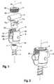
- shows a perspective exploded view of the polyaxial bone anchoring device according to a fist embodiment.
- Fig. 2:
- shows a perspective view of the polyaxial bone anchoring device of
Fig. 1 in an assembled state. - Fig. 3:
- shows a perspective view from the bottom of the pressure member of the polyaxial bone anchoring device according to the first embodiment.
- Fig. 4:
- shows a top view of the pressure member of
Fig. 3 . - Fig. 5:
- shows a cross-sectional view of the pressure member along line A-A in
Fig. 4 . - Fig. 6:
- shows a perspective view from the bottom of the locking member of the polyaxial bone anchoring device according to the first embodiment.
- Fig. 7:
- shows a top view of the locking member shown in
Fig. 6 . - Fig. 8:
- shows a cross-sectional view of the locking member along line B-B in
Fig. 7 - Figs. 9 to 12:
- show cross-sectional views of steps of use of the polyaxial bone anchoring device according to the first embodiment, the section taken in a plane perpendicular to the rod axis.
- Fig. 13:
- shows an enlarged portion of a detail of
Fig. 12 . - Fig. 14:
- shows a perspective exploded view of the locking member of the polyaxial bone anchoring device according to a second embodiment.
- Fig. 15:
- shows a perspective view of the locking member of
Fig. 14 in an assembled state. - Figs. 16 to 17:
- show cross-sectional views of steps of use of the polyaxial bone anchoring device according to the second embodiment, the section being taken in a plane perpendicular to the rod axis.
- Fig. 18:
- shows an enlarged portion of a detail of
Fig. 17 . - Referring to
Figs. 1 and 2 as well asFig. 9 to 12 , thereceiving part 5 has atop end 51 and abottom end 52 and is of substantially cylindrical construction with a longitudinal axis C extending through the top end and the bottom end. Coaxially with the longitudinal axis C, a bore is provided extending from thetop end 51 to a predetermined distance from thebottom end 52. The bore has afirst section 53a with a first diameter adjacent the top end that goes over with an inclined shoulder in asecond section 53b with a second diameter smaller than the first diameter. At thebottom end 52, anopening 54 is provided, the diameter of which is smaller than the diameter of the bore 53. The coaxial bore narrows towards theopening 54, for example, with a spherically-shaped section 55 that provides a seat for thehead 3. However, thesection 55 can have any other shape such as, for example, a conical shape, that ensures the function of thehead 3 being pivotably held in thereceiving part 5 similar to a ball and socket joint. - The
receiving part 5 further comprises aU-shaped recess 56 starting at thetop end 51 and extending in the direction of thebottom end 52. By means of the U-shaped recess, twofree legs top end 51 and define a channel for receiving therod 6. Adjacent to thetop end 51, a portion with aninternal thread 59 is provided at the inner surface of thelegs internal thread 59 is a flat thread having substantially horizontal upper and lower thread flanks. Any other thread form can be used for theinternal thread 59, however, a thread form that reduces or eliminates splaying of the legs is preferable. - The
pressure member 7 is of substantially cylindrical construction with an outer diameter sized so as to allow the pressure member to be introduced into thesecond portion 53b of the bore of the receivingpart 5 and to be moved therein in the axial direction. Thepressure member 7 has atop end 71 and an oppositebottom end 72 and a longitudinal axis C extending through the two ends being in a mounted state the same as the longitudinal axis C of the receivingpart 5. The pressure element is arranged in the receivingpart 5 such that itstop end 71 is oriented towards thetop end 51 of the receiving part and thebottom end 72 is oriented towards thebottom end 52 of the receiving part. At itstop end 71, the pressure element comprises a substantiallyU-shaped recess 73 that is configured to receive therod 6. When therod 6 is positioned on the bottom of therecess 73, thetop end 71 of thepressure member 7 is located at a height above the surface of therod 6. - At the
top end 71, the pressure member comprises acollar 77 shaped as two opposite segments of a circle. By the collar, twoenlarged surface portions 71a are formed at the upper end of the sidewalls of theU-shaped recess 73. The outer diameter of the pressure element in the region of thecollar 77 is enlarged so that theenlarged surface portions 71a extend into thefirst part 53 a of the bore. Theenlarged surface portions 71a provide an abutment for the locking member described below. - On its lower side, the
pressure member 7 comprises a spherically-shapedrecess 74 cooperating with a spherical outer surface portion of thehead 3. Furthermore, a coaxial through-hole 75 is provided in the pressure member that allows access to therecess 4 of thehead 3 when the bone anchoring element 1 and thepressure member 7 are mounted in the receivingpart 5. - The locking
member 8 will be described with reference toFigs. 1 and6 to 8 . The lockingmember 8 in the first embodiment is a monolithic piece. It is formed as a set screw having atop end 81 and abottom end 82 that faces the pressure member when the locking element is inserted between thelegs part 5. More in detail, the lockingmember 8 has adjacent to the top end 81 ascrew portion 83 with an external thread that cooperates with the internal thread of the legs and on the bottom side of the screw portion 83 acylindrical projection 84 surrounded by a conically outwardly extendingportion 85 that is inclined away from thescrew portion 83. The outer diameter of theconical portion 85 is smaller than the outer diameter of thescrew portion 83 such that the lockingmember 8 can be inserted between the legs with itsbottom end 82 ahead. - The
cylindrical portion 84 is configured to be a rigid portion, i.e. does not deform under normal operating conditions when it is pressed against the rod, which is described below. Theconical portion 85 has a shape similar to a conical washer. It is configured to be a deformable portion that is deformed towards thescrew portion 83, when it is pressed against thepressure member 7 described below. In particular, theconical portion 85 is elastically deformable so that it forms a resilient portion that assumes its original shape when the load is removed. Further, in the original configuration, theconical portion 85 protrudes from thecylindrical portion 87 in the axial direction. It has a size and an elasticity such that when a load is applied to theconical portion 85 in the direction to thetop end 81, theconical portion 85 is bent against thescrew portion 83 . In the bent configuration, thecylindrical portion 84 protrudes in an axial direction beyond theconical portion 85. - The locking
member 8 further comprises a coaxial through-hole 86 with anengagement portion 87. Theengagement portion 87 is the embodiment showing a hexagonal recess. However, it can have any other shape such as a torx-shape or longitudinal grooves or any structure that allows engagement with a tool. The engagement portion needs not to be provided on a through hole. It can be provided as a recess with a depth extending into the locking member from the top end. - The parts of the bone anchoring device are made of a bio-compatible material, for example, of a bio-compatible metal or a metal alloy, such as titanium, stainless steel, nickel titanium alloys, such as Nitinol, or made of a bio-compatible plastic material, such as PEEK (polyetheretherketone). The parts can be made all of the same or of different materials.
- In use, the receiving
part 5 and the anchoring element 1 as well as thepressure member 7 are usually pre-assembled such that thehead 3 is pivotably held in theseat 55 of the receivingpart 5 and thepressure member 7 is placed onto the head. At least two polyaxial bone anchoring devices shall be connected via therod 6. After insertion of the bone anchoring elements into the bone, the receiving parts are aligned and the rod is 6 inserted. - The locking procedure will be explained with reference to
Figs. 9 to 13 . First, as shown inFig. 9 , the lockingmember 8 is inserted into the receiving part with thebottom end 82 of the locking member facing towards the rod. The locking member is then further screwed-in until an outermost edge of the conical portion contacts thetop end surface 71 a of thepressure member 7 that serves as an abutment. In this position, shown inFig. 10 , theconical portion 85 and thecylindrical portion 84 do not contact therod 6. Therefore, therod 6 is freely displaceable in the U-shaped recess of the pressure member that is aligned with the U-shaped recess of the receiving part. When theconical portion 85 contacts thepressure member 7, pressure is exerted onto thehead 3 via thepressure member 7. This clamps thehead 3 in a adjustable angular position with respect to the receiving part and holds thehead 3 in this position by means of friction. The clamping force may be precisely adjusted to be higher or lower depending on how far the locking member is screwed-in. - Further advancement of the locking member towards the rod leads to a deformation of the
conical portion 85. Theconical portion 85 is bent towards thescrew portion 83 with thetop end surface 71a of thepressure member 7 acting as an abutment. - Still further advancement of the locking member towards the rod increases the deformation of the
conical portion 85 until thecylindrical portion 84 comes in contact with the surface of therod 6 as shown inFig. 12 . By means of this, the head and the rod are locked. - It is possible to correct the position of the rod without loosening of the locking of the head. To achieve this, the locking member is screwed-back until the rod becomes displaceable. This is possible due to the resilient property of the
conical portion 85. It may be even possible to fully remove the lockingmember 8 and to carry out a revision of the complete polyaxial bone anchoring device. - A second embodiment of the polyaxial anchoring device will be described with reference to
Figs. 14 to 18 . The second embodiment differs from the first embodiment in the design of the locking member. The locking member 8' according to the second embodiment comprises a conical portion 95' that is a separate member. The conical portion 95'that has a shape similar to a conical washer, i.e. has acoaxial hole 85a', the inner diameter of which is dimensioned such that theconical portion 85' can be placed around the cylindrical portion 84'. As shown inFig. 14 , theconical portion 85' is mounted from the side of the cylindrical portion 84' onto the locking member 8'. It can be press-fit onto the cylindrical portion 84' or crimped, welded or fixed with any other method. In the assembled state as shown inFig. 15 , theconical portion 85' is fixed to thescrew portion 83 so that the locking member 8' forms a single part. - The
conical portion 85' can be made of a different material compared to the material of thescrew portion 83. Variousconical portions 85 can be provided that differ with respect to the material, the cone angle, the thickness, or any other properties to allow an adjustment of the clamping force by selecting an appropriate portion. - In use, as shown in
Figs. 16 and 18 , because the conical portion projects from the cylindrical portion, the conical portion comes first into contact with thetop end surface 71a of thepressure member 7 and begins to clamp the head. Upon further insertion of the locking member 8', theconical portion 85' is deformed and the clamping force onto the head is increased until the head is locked. When theconical portion 85' has been deformed such that the cylindrical portion 84' protrudes, the cylindrical portion 84' comes into contact with the rod and clamps the rod. Final tightening locks the whole assembly. - Various modifications of the previous embodiments are conceivable. In particular, the deformable portion doesn't have to be a conical ring-shaped portion. It is sufficient that a deformable portion is located at a position that comes into contact with the
top end surface 71a of the pressure member. The ring-shaped portion is, however, particularly appropriate for a locking member that is advanced by screwing it between the legs. - For the polyaxial bone anchoring device any known polyaxial bone anchoring devices can be used that comprise a bone anchoring element that is pivotably received in a receiving part. In particular, bone anchoring devices, wherein the bone anchoring element is introduced from the bottom end of the receiving part into the receiving part may be used. The design of the receiving part can be different. As the bone anchoring element, any known bone anchors, such as screws, nails, with or without canulation can be used.
- The connection between the locking member and the receiving part does not necessarily have to be threaded connection. Other connections may be possible, such as, for example, a bayonet connection.
Claims (15)
- A polyaxial bone anchoring device comprising
a bone anchoring element (1) having a shank (2) to be anchored in the bone and a head (3);
a receiving part (5) coupled to the shank and configured to pivotably receive the head, and having a channel (56) for receiving a rod (6) and a central axis (C);
a pressure member (7) arranged in the receiving part and configured to exert pressure onto the head to lock the head in the receiving part;
a locking member (8, 8') that is insertable into the channel, the locking member comprising a top end (81) and a bottom (82) end facing the pressure member; and
a deformable first portion (85, 85') and a second portion (84, 84') provided at the bottom end;
wherein, when the locking member is advanced into the channel in the direction of the central axis (C), first the deformable first portion (85, 85') comes into contact with the pressure member (7) and is deformed resulting in a load applied to the pressure member that clamps the head,
and thereafter the second portion (84) comes into contact with the rod and clamps the rod. - The polyaxial bone anchoring device of claim 1, wherein the deformable first portion (85, 85') is elastically deformable.
- The polyaxial bone anchoring device of claim 1 or 2, wherein the second portion (84, 84') is a rigid portion.
- The polyaxial bone anchoring device of one of claims 1 to 3, wherein the second portion (84, 84') is provided closer to the central axis (C) than the deformable first portion.
- The polyaxial bone anchoring device of one of claims 1 to 4, wherein in the non-deformed configuration, the deformable first portion (85, 85') projects farther outward in an axial direction than the second portion (84).
- The polyaxial bone anchoring device of one of claims 1 to 5, wherein deformable first portion (85) and the second portion (84) are a monolithic section of the locking member (8).
- The polyaxial bone anchoring device of one of claims 1 to 5, wherein the deformable first portion (85') and the second portion (84') are separate parts that are connected together.
- The polyaxial bone anchoring device of one of claims 1 to 7, wherein the deformable first portion (85, 85') is ring-shaped.
- The polyaxial bone anchoring device of one of claims 1 to 8, wherein the deformable first portion (85, 85') is inclined with an angle of inclination that opens towards the pressure member (7).
- The polyaxial bone anchoring device of one of claims 1 to 9, wherein the pressure member (7) comprises a channel (73) to receive the rod and wherein sidewalls of the channel extend above the surface of the rod when the rod is seated in the channel.
- The polyaxial bone anchoring device of one of claims 1 to 10, wherein the pressure member (7) is a substantially cylindrical part with a top end and a bottom end and a U-shaped recess (73) at the top end for receiving the rod, and two open legs.
- The polyaxial bone anchoring device of one of claims 1 to 11, wherein the end surface (71a) of the pressure member that comes into contact with the deformable portion has such a size that it forms an abutment for the deformable portion (85, 85') over at least a portion of the length along which the deformable portion is deformed.
- The polyaxial bone anchoring device of one of claims 1 to 12, wherein the receiving part (5) comprises a top end (51) and a bottom end (52), a bore (53) extending from the top end to the bottom end and wherein the channel for the rod is formed by a recess (56) adjacent the top end with a substantially U-shaped cross-section.
- The polyaxial bone anchoring device of claim 12, wherein by the recess (56) two open legs (57, 58) are formed and wherein an internal thread (59) is provided on the legs that cooperates with an external thread (93) on the locking member (9).
- The polyaxial bone anchoring device of one of claims 1 to 14, wherein the locking member (8, 8') is a set screw.
Priority Applications (6)
| Application Number | Priority Date | Filing Date | Title |
|---|---|---|---|
| EP12170595.8AEP2668920B1 (en) | 2012-06-01 | 2012-06-01 | Polyaxial bone anchoring device |
| ES12170595.8TES2563785T3 (en) | 2012-06-01 | 2012-06-01 | Polyaxial bone anchoring device |
| JP2013112787AJP6208982B2 (en) | 2012-06-01 | 2013-05-29 | Multiaxial bone anchoring device |
| CN201310203914.3ACN103445846B (en) | 2012-06-01 | 2013-05-29 | Polyaxial bone anchoring device |
| KR1020130062119AKR20130135769A (en) | 2012-06-01 | 2013-05-30 | Polyaxial bone anchoring device |
| US13/907,329US9510868B2 (en) | 2012-06-01 | 2013-05-31 | Polyaxial bone anchoring device |
Applications Claiming Priority (1)
| Application Number | Priority Date | Filing Date | Title |
|---|---|---|---|
| EP12170595.8AEP2668920B1 (en) | 2012-06-01 | 2012-06-01 | Polyaxial bone anchoring device |
Publications (2)
| Publication Number | Publication Date |
|---|---|
| EP2668920A1true EP2668920A1 (en) | 2013-12-04 |
| EP2668920B1 EP2668920B1 (en) | 2015-12-30 |
Family
ID=46320782
Family Applications (1)
| Application Number | Title | Priority Date | Filing Date |
|---|---|---|---|
| EP12170595.8AActiveEP2668920B1 (en) | 2012-06-01 | 2012-06-01 | Polyaxial bone anchoring device |
Country Status (6)
| Country | Link |
|---|---|
| US (1) | US9510868B2 (en) |
| EP (1) | EP2668920B1 (en) |
| JP (1) | JP6208982B2 (en) |
| KR (1) | KR20130135769A (en) |
| CN (1) | CN103445846B (en) |
| ES (1) | ES2563785T3 (en) |
Families Citing this family (10)
| Publication number | Priority date | Publication date | Assignee | Title |
|---|---|---|---|---|
| EP2606841B1 (en)* | 2011-12-23 | 2016-03-09 | Biedermann Technologies GmbH & Co. KG | Polyaxial bone anchoring device |
| EP2674123B1 (en)* | 2012-06-11 | 2018-03-21 | Biedermann Technologies GmbH & Co. KG | Polyaxial bone anchoring device |
| EP3023064B1 (en) | 2014-11-20 | 2019-01-09 | Biedermann Technologies GmbH & Co. KG | Receiving part for coupling a bone anchor to a rod and bone anchoring device with such a receiving part |
| US9707013B2 (en)* | 2015-04-30 | 2017-07-18 | Warsaw Orthopedic, Inc. | Spinal implant system and methods of use |
| CN108697445B (en) | 2016-02-26 | 2022-04-19 | 美多斯国际有限公司 | Polyaxial bone fixation element |
| US11026730B2 (en) | 2017-05-10 | 2021-06-08 | Medos International Sarl | Bone anchors with drag features and related methods |
| USD956233S1 (en)* | 2020-04-24 | 2022-06-28 | Solco Biomedical Co., Ltd. | Cervical screw |
| WO2021263088A1 (en) | 2020-06-26 | 2021-12-30 | K2M, Inc. | Modular head assembly |
| WO2022108875A1 (en) | 2020-11-19 | 2022-05-27 | K2M, Inc. | Modular head assembly for spinal fixation |
| US12364515B2 (en) | 2021-03-05 | 2025-07-22 | Medos International Sàrl | Multi-feature polyaxial screw |
Citations (6)
| Publication number | Priority date | Publication date | Assignee | Title |
|---|---|---|---|---|
| US20030125741A1 (en)* | 2001-12-28 | 2003-07-03 | Biedermann Motech Gmbh | Locking device for securing a rod-shaped element in a holding element connected to a shank |
| US20040236330A1 (en)* | 2003-05-22 | 2004-11-25 | Thomas Purcell | Variable angle spinal screw assembly |
| US20070260246A1 (en)* | 2001-11-27 | 2007-11-08 | Biedermann Motech Gmbh | Locking device for securing a rod-shaped element in a holding element connected to a shank |
| US20110152947A1 (en)* | 2009-12-18 | 2011-06-23 | X-Spine Systems, Inc. | Spinal implant locking member with improved guidance, tactile and visual feedback |
| US7972364B2 (en) | 2006-03-31 | 2011-07-05 | Biedermann Motech Gmbh | Locking assembly for securing a rod member in a receiver part for use in spinal or trauma surgery, bone anchoring device with such a locking assembly and tool therefor |
| US8088152B2 (en) | 2007-08-30 | 2012-01-03 | Aesculap Ag | Orthopedic retaining system |
Family Cites Families (38)
| Publication number | Priority date | Publication date | Assignee | Title |
|---|---|---|---|---|
| FR2697742B1 (en)* | 1992-11-06 | 1994-12-16 | Biomat | Osteosynthesis device for spinal consolidation. |
| US5882350A (en)* | 1995-04-13 | 1999-03-16 | Fastenetix, Llc | Polyaxial pedicle screw having a threaded and tapered compression locking mechanism |
| FR2748387B1 (en) | 1996-05-13 | 1998-10-30 | Stryker France Sa | BONE FIXATION DEVICE, IN PARTICULAR TO THE SACRUM, IN OSTEOSYNTHESIS OF THE SPINE |
| FR2771280B1 (en)* | 1997-11-26 | 2001-01-26 | Albert P Alby | RESILIENT VERTEBRAL CONNECTION DEVICE |
| US7833250B2 (en)* | 2004-11-10 | 2010-11-16 | Jackson Roger P | Polyaxial bone screw with helically wound capture connection |
| US8353932B2 (en)* | 2005-09-30 | 2013-01-15 | Jackson Roger P | Polyaxial bone anchor assembly with one-piece closure, pressure insert and plastic elongate member |
| US7658582B2 (en)* | 2003-07-09 | 2010-02-09 | Ortho Innovations, Llc | Precise linear fastener system and method for use |
| US7530992B2 (en)* | 2002-03-27 | 2009-05-12 | Biedermann Motech Gmbh | Bone anchoring device for stabilising bone segments and seat part of a bone anchoring device |
| US7842073B2 (en) | 2002-04-18 | 2010-11-30 | Aesculap Ii, Inc. | Screw and rod fixation assembly and device |
| FR2847152B1 (en)* | 2002-11-19 | 2005-02-18 | Eurosurgical | VERTEBRAL ANCHORING DEVICE AND ITS LOCKING DEVICE ON A POLY AXIAL SCREW |
| US7087057B2 (en)* | 2003-06-27 | 2006-08-08 | Depuy Acromed, Inc. | Polyaxial bone screw |
| TW200518711A (en)* | 2003-12-11 | 2005-06-16 | A Spine Holding Group Corp | Rotation buckling ball-head spine restoring equipment |
| DE102004010382B4 (en) | 2004-03-03 | 2006-04-20 | Biedermann Motech Gmbh | Bone anchoring element for anchoring in a bone or in a vertebra and its use in a stabilizing device |
| US7744636B2 (en) | 2004-12-16 | 2010-06-29 | Aesculap Ii, Inc. | Locking mechanism |
| TWI375545B (en)* | 2005-04-25 | 2012-11-01 | Synthes Gmbh | Bone anchor with locking cap and method of spinal fixation |
| DE102005021879B4 (en)* | 2005-05-04 | 2007-04-12 | Aesculap Ag & Co. Kg | Orthopedic anchoring element and osteosynthesis device |
| WO2007038429A1 (en)* | 2005-09-27 | 2007-04-05 | Endius, Inc. | Methods and apparatuses for stabilizing the spine through an access device |
| US20090093844A1 (en) | 2005-09-30 | 2009-04-09 | Jackson Roger P | Elastic covered dynamic stabilization connector and assembly |
| US8057519B2 (en)* | 2006-01-27 | 2011-11-15 | Warsaw Orthopedic, Inc. | Multi-axial screw assembly |
| US8361130B2 (en)* | 2006-10-06 | 2013-01-29 | Depuy Spine, Inc. | Bone screw fixation |
| US7909855B2 (en) | 2006-10-17 | 2011-03-22 | Warsaw Orthopedics, Inc. | Orthopedic implant assembly |
| EP2301456B1 (en)* | 2007-02-23 | 2013-04-17 | Biedermann Technologies GmbH & Co. KG | Rod connector for stabilizing vertebrae |
| DE102007042959B4 (en) | 2007-08-30 | 2011-03-31 | Aesculap Ag | Surgical retaining screw |
| US20090069852A1 (en)* | 2007-09-06 | 2009-03-12 | Warsaw Orthopedic, Inc. | Multi-Axial Bone Anchor Assembly |
| US8998958B2 (en) | 2007-12-20 | 2015-04-07 | Aesculap Implant Systems, Llc | Locking device introducer instrument |
| US8057523B2 (en) | 2008-07-23 | 2011-11-15 | Warsaw Orthopedic, Inc. | Set screw with deformable member |
| US8870924B2 (en) | 2008-09-04 | 2014-10-28 | Zimmer Spine, Inc. | Dynamic vertebral fastener |
| WO2010065648A1 (en)* | 2008-12-02 | 2010-06-10 | Eminent Spine Llc | Pedicle screw fixation system and method for use of same |
| ES2375879T3 (en)* | 2008-12-23 | 2012-03-07 | Biedermann Motech Gmbh | RECEPTION AREA OF A ROD FOR COUPLING THE ROD IN AN BONE ANCHORAGE ELEMENT AND BONE ANCHORAGE DEVICE WITH SUCH RECEPTION AREA. |
| FR2940758B1 (en)* | 2009-01-07 | 2011-01-28 | Creaspine | DYNAMIC TYPE IMPLANT "VIS ROD" TO STABILIZE A RACHIS |
| ES2548580T3 (en)* | 2009-02-20 | 2015-10-19 | Biedermann Technologies Gmbh & Co. Kg | Receiving part for housing a rod for coupling to a bone anchoring element and bone anchoring device that includes such receiving part |
| KR101041373B1 (en) | 2009-04-30 | 2011-06-15 | 김민석 | Spinal fixation device including set screw with double spiral |
| US8529609B2 (en)* | 2009-12-01 | 2013-09-10 | Osteomed Llc | Polyaxial facet fixation screw system |
| CN102309361A (en)* | 2010-07-08 | 2012-01-11 | 北京市奥斯比利克新技术开发有限公司 | Elastic support body and manufacturing method thereof |
| US20110270321A1 (en)* | 2010-04-30 | 2011-11-03 | Warsaw Orthopedic, Inc. | Engaging Member With a Cavity-Base for Engaging a Connecting Element to a Bone Anchor |
| US8920475B1 (en)* | 2011-01-07 | 2014-12-30 | Lanx, Inc. | Vertebral fixation system including torque mitigation |
| US20140257411A1 (en)* | 2013-03-08 | 2014-09-11 | Warsaw Orthopedic, Inc. | Bone fastener and methods of use |
| ES2611158T3 (en)* | 2013-07-24 | 2017-05-05 | Biedermann Technologies Gmbh & Co. Kg | Coupling assembly for coupling a rod to a bone anchoring element, kit for such coupling assembly and different rod receiving elements, and bone anchoring device |
- 2012
- 2012-06-01ESES12170595.8Tpatent/ES2563785T3/enactiveActive
- 2012-06-01EPEP12170595.8Apatent/EP2668920B1/enactiveActive
- 2013
- 2013-05-29CNCN201310203914.3Apatent/CN103445846B/ennot_activeExpired - Fee Related
- 2013-05-29JPJP2013112787Apatent/JP6208982B2/ennot_activeExpired - Fee Related
- 2013-05-30KRKR1020130062119Apatent/KR20130135769A/ennot_activeCeased
- 2013-05-31USUS13/907,329patent/US9510868B2/enactiveActive
Patent Citations (6)
| Publication number | Priority date | Publication date | Assignee | Title |
|---|---|---|---|---|
| US20070260246A1 (en)* | 2001-11-27 | 2007-11-08 | Biedermann Motech Gmbh | Locking device for securing a rod-shaped element in a holding element connected to a shank |
| US20030125741A1 (en)* | 2001-12-28 | 2003-07-03 | Biedermann Motech Gmbh | Locking device for securing a rod-shaped element in a holding element connected to a shank |
| US20040236330A1 (en)* | 2003-05-22 | 2004-11-25 | Thomas Purcell | Variable angle spinal screw assembly |
| US7972364B2 (en) | 2006-03-31 | 2011-07-05 | Biedermann Motech Gmbh | Locking assembly for securing a rod member in a receiver part for use in spinal or trauma surgery, bone anchoring device with such a locking assembly and tool therefor |
| US8088152B2 (en) | 2007-08-30 | 2012-01-03 | Aesculap Ag | Orthopedic retaining system |
| US20110152947A1 (en)* | 2009-12-18 | 2011-06-23 | X-Spine Systems, Inc. | Spinal implant locking member with improved guidance, tactile and visual feedback |
Also Published As
| Publication number | Publication date |
|---|---|
| CN103445846A (en) | 2013-12-18 |
| ES2563785T3 (en) | 2016-03-16 |
| US9510868B2 (en) | 2016-12-06 |
| CN103445846B (en) | 2017-08-11 |
| JP6208982B2 (en) | 2017-10-04 |
| KR20130135769A (en) | 2013-12-11 |
| EP2668920B1 (en) | 2015-12-30 |
| US20130338716A1 (en) | 2013-12-19 |
| JP2013248397A (en) | 2013-12-12 |
Similar Documents
| Publication | Publication Date | Title |
|---|---|---|
| US11931076B2 (en) | Polyaxial bone anchoring device | |
| EP2668920B1 (en) | Polyaxial bone anchoring device | |
| US10271877B2 (en) | Coupling device for coupling a rod to a bone anchoring element and bone anchoring device with such a coupling device | |
| US20190336175A1 (en) | Bone anchoring device | |
| EP2457527B1 (en) | Polyaxial bone anchoring device with enlarged pivot angle | |
| CN102100577B (en) | Bone anchoring device | |
| EP1935358B1 (en) | Bone anchoring device | |
| US9339302B2 (en) | Polyaxial bone anchoring device | |
| EP1741396A1 (en) | Bone anchoring device | |
| EP2609883A1 (en) | A receiving part for receiving a rod for coupling the rod to a bone anchoring element | |
| US20120143265A1 (en) | Polyaxial bone anchoring device | |
| US20130096622A1 (en) | Polyaxial bone anchoring device |
Legal Events
| Date | Code | Title | Description |
|---|---|---|---|
| PUAI | Public reference made under article 153(3) epc to a published international application that has entered the european phase | Free format text:ORIGINAL CODE: 0009012 | |
| AK | Designated contracting states | Kind code of ref document:A1 Designated state(s):AL AT BE BG CH CY CZ DE DK EE ES FI FR GB GR HR HU IE IS IT LI LT LU LV MC MK MT NL NO PL PT RO RS SE SI SK SM TR | |
| AX | Request for extension of the european patent | Extension state:BA ME | |
| 17P | Request for examination filed | Effective date:20140526 | |
| RBV | Designated contracting states (corrected) | Designated state(s):AL AT BE BG CH CY CZ DE DK EE ES FI FR GB GR HR HU IE IS IT LI LT LU LV MC MK MT NL NO PL PT RO RS SE SI SK SM TR | |
| 17Q | First examination report despatched | Effective date:20141002 | |
| GRAP | Despatch of communication of intention to grant a patent | Free format text:ORIGINAL CODE: EPIDOSNIGR1 | |
| INTG | Intention to grant announced | Effective date:20150618 | |
| GRAS | Grant fee paid | Free format text:ORIGINAL CODE: EPIDOSNIGR3 | |
| GRAA | (expected) grant | Free format text:ORIGINAL CODE: 0009210 | |
| RIN1 | Information on inventor provided before grant (corrected) | Inventor name:BIEDERMANN, TIMO Inventor name:BIEDERMANN, LUTZ Inventor name:DANNECKER, BERTHOLD Inventor name:MATTHIS, WILFRIED | |
| AK | Designated contracting states | Kind code of ref document:B1 Designated state(s):AL AT BE BG CH CY CZ DE DK EE ES FI FR GB GR HR HU IE IS IT LI LT LU LV MC MK MT NL NO PL PT RO RS SE SI SK SM TR | |
| REG | Reference to a national code | Ref country code:GB Ref legal event code:FG4D | |
| REG | Reference to a national code | Ref country code:CH Ref legal event code:EP | |
| REG | Reference to a national code | Ref country code:AT Ref legal event code:REF Ref document number:767098 Country of ref document:AT Kind code of ref document:T Effective date:20160115 Ref country code:CH Ref legal event code:NV Representative=s name:NOVAGRAAF INTERNATIONAL SA, CH | |
| REG | Reference to a national code | Ref country code:IE Ref legal event code:FG4D | |
| REG | Reference to a national code | Ref country code:DE Ref legal event code:R096 Ref document number:602012013305 Country of ref document:DE | |
| REG | Reference to a national code | Ref country code:ES Ref legal event code:FG2A Ref document number:2563785 Country of ref document:ES Kind code of ref document:T3 Effective date:20160316 | |
| REG | Reference to a national code | Ref country code:LT Ref legal event code:MG4D | |
| PG25 | Lapsed in a contracting state [announced via postgrant information from national office to epo] | Ref country code:LT Free format text:LAPSE BECAUSE OF FAILURE TO SUBMIT A TRANSLATION OF THE DESCRIPTION OR TO PAY THE FEE WITHIN THE PRESCRIBED TIME-LIMIT Effective date:20151230 Ref country code:NO Free format text:LAPSE BECAUSE OF FAILURE TO SUBMIT A TRANSLATION OF THE DESCRIPTION OR TO PAY THE FEE WITHIN THE PRESCRIBED TIME-LIMIT Effective date:20160330 Ref country code:HR Free format text:LAPSE BECAUSE OF FAILURE TO SUBMIT A TRANSLATION OF THE DESCRIPTION OR TO PAY THE FEE WITHIN THE PRESCRIBED TIME-LIMIT Effective date:20151230 | |
| REG | Reference to a national code | Ref country code:NL Ref legal event code:MP Effective date:20151230 | |
| REG | Reference to a national code | Ref country code:AT Ref legal event code:MK05 Ref document number:767098 Country of ref document:AT Kind code of ref document:T Effective date:20151230 | |
| PG25 | Lapsed in a contracting state [announced via postgrant information from national office to epo] | Ref country code:FI Free format text:LAPSE BECAUSE OF FAILURE TO SUBMIT A TRANSLATION OF THE DESCRIPTION OR TO PAY THE FEE WITHIN THE PRESCRIBED TIME-LIMIT Effective date:20151230 Ref country code:SE Free format text:LAPSE BECAUSE OF FAILURE TO SUBMIT A TRANSLATION OF THE DESCRIPTION OR TO PAY THE FEE WITHIN THE PRESCRIBED TIME-LIMIT Effective date:20151230 Ref country code:GR Free format text:LAPSE BECAUSE OF FAILURE TO SUBMIT A TRANSLATION OF THE DESCRIPTION OR TO PAY THE FEE WITHIN THE PRESCRIBED TIME-LIMIT Effective date:20160331 Ref country code:LV Free format text:LAPSE BECAUSE OF FAILURE TO SUBMIT A TRANSLATION OF THE DESCRIPTION OR TO PAY THE FEE WITHIN THE PRESCRIBED TIME-LIMIT Effective date:20151230 Ref country code:RS Free format text:LAPSE BECAUSE OF FAILURE TO SUBMIT A TRANSLATION OF THE DESCRIPTION OR TO PAY THE FEE WITHIN THE PRESCRIBED TIME-LIMIT Effective date:20151230 | |
| REG | Reference to a national code | Ref country code:FR Ref legal event code:PLFP Year of fee payment:5 | |
| PG25 | Lapsed in a contracting state [announced via postgrant information from national office to epo] | Ref country code:NL Free format text:LAPSE BECAUSE OF FAILURE TO SUBMIT A TRANSLATION OF THE DESCRIPTION OR TO PAY THE FEE WITHIN THE PRESCRIBED TIME-LIMIT Effective date:20151230 | |
| PG25 | Lapsed in a contracting state [announced via postgrant information from national office to epo] | Ref country code:CZ Free format text:LAPSE BECAUSE OF FAILURE TO SUBMIT A TRANSLATION OF THE DESCRIPTION OR TO PAY THE FEE WITHIN THE PRESCRIBED TIME-LIMIT Effective date:20151230 | |
| PGFP | Annual fee paid to national office [announced via postgrant information from national office to epo] | Ref country code:ES Payment date:20160622 Year of fee payment:5 | |
| PG25 | Lapsed in a contracting state [announced via postgrant information from national office to epo] | Ref country code:SK Free format text:LAPSE BECAUSE OF FAILURE TO SUBMIT A TRANSLATION OF THE DESCRIPTION OR TO PAY THE FEE WITHIN THE PRESCRIBED TIME-LIMIT Effective date:20151230 Ref country code:PT Free format text:LAPSE BECAUSE OF FAILURE TO SUBMIT A TRANSLATION OF THE DESCRIPTION OR TO PAY THE FEE WITHIN THE PRESCRIBED TIME-LIMIT Effective date:20160502 Ref country code:RO Free format text:LAPSE BECAUSE OF FAILURE TO SUBMIT A TRANSLATION OF THE DESCRIPTION OR TO PAY THE FEE WITHIN THE PRESCRIBED TIME-LIMIT Effective date:20151230 Ref country code:EE Free format text:LAPSE BECAUSE OF FAILURE TO SUBMIT A TRANSLATION OF THE DESCRIPTION OR TO PAY THE FEE WITHIN THE PRESCRIBED TIME-LIMIT Effective date:20151230 Ref country code:PL Free format text:LAPSE BECAUSE OF FAILURE TO SUBMIT A TRANSLATION OF THE DESCRIPTION OR TO PAY THE FEE WITHIN THE PRESCRIBED TIME-LIMIT Effective date:20151230 Ref country code:SM Free format text:LAPSE BECAUSE OF FAILURE TO SUBMIT A TRANSLATION OF THE DESCRIPTION OR TO PAY THE FEE WITHIN THE PRESCRIBED TIME-LIMIT Effective date:20151230 Ref country code:IS Free format text:LAPSE BECAUSE OF FAILURE TO SUBMIT A TRANSLATION OF THE DESCRIPTION OR TO PAY THE FEE WITHIN THE PRESCRIBED TIME-LIMIT Effective date:20160430 Ref country code:AT Free format text:LAPSE BECAUSE OF FAILURE TO SUBMIT A TRANSLATION OF THE DESCRIPTION OR TO PAY THE FEE WITHIN THE PRESCRIBED TIME-LIMIT Effective date:20151230 | |
| PGFP | Annual fee paid to national office [announced via postgrant information from national office to epo] | Ref country code:FR Payment date:20160621 Year of fee payment:5 | |
| REG | Reference to a national code | Ref country code:DE Ref legal event code:R097 Ref document number:602012013305 Country of ref document:DE | |
| PG25 | Lapsed in a contracting state [announced via postgrant information from national office to epo] | Ref country code:DK Free format text:LAPSE BECAUSE OF FAILURE TO SUBMIT A TRANSLATION OF THE DESCRIPTION OR TO PAY THE FEE WITHIN THE PRESCRIBED TIME-LIMIT Effective date:20151230 | |
| PGFP | Annual fee paid to national office [announced via postgrant information from national office to epo] | Ref country code:IT Payment date:20160628 Year of fee payment:5 | |
| PLBE | No opposition filed within time limit | Free format text:ORIGINAL CODE: 0009261 | |
| STAA | Information on the status of an ep patent application or granted ep patent | Free format text:STATUS: NO OPPOSITION FILED WITHIN TIME LIMIT | |
| 26N | No opposition filed | Effective date:20161003 | |
| PG25 | Lapsed in a contracting state [announced via postgrant information from national office to epo] | Ref country code:BE Free format text:LAPSE BECAUSE OF FAILURE TO SUBMIT A TRANSLATION OF THE DESCRIPTION OR TO PAY THE FEE WITHIN THE PRESCRIBED TIME-LIMIT Effective date:20151230 | |
| PG25 | Lapsed in a contracting state [announced via postgrant information from national office to epo] | Ref country code:MC Free format text:LAPSE BECAUSE OF FAILURE TO SUBMIT A TRANSLATION OF THE DESCRIPTION OR TO PAY THE FEE WITHIN THE PRESCRIBED TIME-LIMIT Effective date:20151230 | |
| PG25 | Lapsed in a contracting state [announced via postgrant information from national office to epo] | Ref country code:SI Free format text:LAPSE BECAUSE OF FAILURE TO SUBMIT A TRANSLATION OF THE DESCRIPTION OR TO PAY THE FEE WITHIN THE PRESCRIBED TIME-LIMIT Effective date:20151230 | |
| REG | Reference to a national code | Ref country code:IE Ref legal event code:MM4A | |
| PG25 | Lapsed in a contracting state [announced via postgrant information from national office to epo] | Ref country code:IE Free format text:LAPSE BECAUSE OF NON-PAYMENT OF DUE FEES Effective date:20160601 | |
| REG | Reference to a national code | Ref country code:FR Ref legal event code:ST Effective date:20180228 | |
| PG25 | Lapsed in a contracting state [announced via postgrant information from national office to epo] | Ref country code:FR Free format text:LAPSE BECAUSE OF NON-PAYMENT OF DUE FEES Effective date:20170630 Ref country code:IT Free format text:LAPSE BECAUSE OF NON-PAYMENT OF DUE FEES Effective date:20170601 Ref country code:CY Free format text:LAPSE BECAUSE OF FAILURE TO SUBMIT A TRANSLATION OF THE DESCRIPTION OR TO PAY THE FEE WITHIN THE PRESCRIBED TIME-LIMIT Effective date:20151230 Ref country code:HU Free format text:LAPSE BECAUSE OF FAILURE TO SUBMIT A TRANSLATION OF THE DESCRIPTION OR TO PAY THE FEE WITHIN THE PRESCRIBED TIME-LIMIT; INVALID AB INITIO Effective date:20120601 | |
| REG | Reference to a national code | Ref country code:ES Ref legal event code:FD2A Effective date:20180625 | |
| PG25 | Lapsed in a contracting state [announced via postgrant information from national office to epo] | Ref country code:MT Free format text:LAPSE BECAUSE OF NON-PAYMENT OF DUE FEES Effective date:20160630 Ref country code:MK Free format text:LAPSE BECAUSE OF FAILURE TO SUBMIT A TRANSLATION OF THE DESCRIPTION OR TO PAY THE FEE WITHIN THE PRESCRIBED TIME-LIMIT Effective date:20151230 Ref country code:TR Free format text:LAPSE BECAUSE OF FAILURE TO SUBMIT A TRANSLATION OF THE DESCRIPTION OR TO PAY THE FEE WITHIN THE PRESCRIBED TIME-LIMIT Effective date:20151230 Ref country code:LU Free format text:LAPSE BECAUSE OF NON-PAYMENT OF DUE FEES Effective date:20160601 | |
| PG25 | Lapsed in a contracting state [announced via postgrant information from national office to epo] | Ref country code:BG Free format text:LAPSE BECAUSE OF FAILURE TO SUBMIT A TRANSLATION OF THE DESCRIPTION OR TO PAY THE FEE WITHIN THE PRESCRIBED TIME-LIMIT Effective date:20151230 Ref country code:ES Free format text:LAPSE BECAUSE OF NON-PAYMENT OF DUE FEES Effective date:20170602 | |
| PG25 | Lapsed in a contracting state [announced via postgrant information from national office to epo] | Ref country code:AL Free format text:LAPSE BECAUSE OF FAILURE TO SUBMIT A TRANSLATION OF THE DESCRIPTION OR TO PAY THE FEE WITHIN THE PRESCRIBED TIME-LIMIT Effective date:20151230 | |
| P01 | Opt-out of the competence of the unified patent court (upc) registered | Effective date:20230525 | |
| PGFP | Annual fee paid to national office [announced via postgrant information from national office to epo] | Ref country code:DE Payment date:20240626 Year of fee payment:13 | |
| PGFP | Annual fee paid to national office [announced via postgrant information from national office to epo] | Ref country code:CH Payment date:20240701 Year of fee payment:13 | |
| PGFP | Annual fee paid to national office [announced via postgrant information from national office to epo] | Ref country code:GB Payment date:20250619 Year of fee payment:14 |