EP2668639B1 - Truncation compensation for iterative cone-beam ct reconstruction for spect/ct systems - Google Patents
Truncation compensation for iterative cone-beam ct reconstruction for spect/ct systemsDownload PDFInfo
- Publication number
- EP2668639B1 EP2668639B1EP12704124.2AEP12704124AEP2668639B1EP 2668639 B1EP2668639 B1EP 2668639B1EP 12704124 AEP12704124 AEP 12704124AEP 2668639 B1EP2668639 B1EP 2668639B1
- Authority
- EP
- European Patent Office
- Prior art keywords
- fov
- extended
- subject
- image representation
- imaging
- Prior art date
- Legal status (The legal status is an assumption and is not a legal conclusion. Google has not performed a legal analysis and makes no representation as to the accuracy of the status listed.)
- Active
Links
Images


Classifications
- G—PHYSICS
- G06—COMPUTING OR CALCULATING; COUNTING
- G06T—IMAGE DATA PROCESSING OR GENERATION, IN GENERAL
- G06T11/00—2D [Two Dimensional] image generation
- G06T11/003—Reconstruction from projections, e.g. tomography
- G06T11/005—Specific pre-processing for tomographic reconstruction, e.g. calibration, source positioning, rebinning, scatter correction, retrospective gating
- A—HUMAN NECESSITIES
- A61—MEDICAL OR VETERINARY SCIENCE; HYGIENE
- A61B—DIAGNOSIS; SURGERY; IDENTIFICATION
- A61B6/00—Apparatus or devices for radiation diagnosis; Apparatus or devices for radiation diagnosis combined with radiation therapy equipment
- A61B6/02—Arrangements for diagnosis sequentially in different planes; Stereoscopic radiation diagnosis
- A61B6/03—Computed tomography [CT]
- A61B6/037—Emission tomography
- A—HUMAN NECESSITIES
- A61—MEDICAL OR VETERINARY SCIENCE; HYGIENE
- A61B—DIAGNOSIS; SURGERY; IDENTIFICATION
- A61B6/00—Apparatus or devices for radiation diagnosis; Apparatus or devices for radiation diagnosis combined with radiation therapy equipment
- A61B6/02—Arrangements for diagnosis sequentially in different planes; Stereoscopic radiation diagnosis
- A61B6/03—Computed tomography [CT]
- A—HUMAN NECESSITIES
- A61—MEDICAL OR VETERINARY SCIENCE; HYGIENE
- A61B—DIAGNOSIS; SURGERY; IDENTIFICATION
- A61B6/00—Apparatus or devices for radiation diagnosis; Apparatus or devices for radiation diagnosis combined with radiation therapy equipment
- A61B6/48—Diagnostic techniques
- A61B6/488—Diagnostic techniques involving pre-scan acquisition
- A—HUMAN NECESSITIES
- A61—MEDICAL OR VETERINARY SCIENCE; HYGIENE
- A61B—DIAGNOSIS; SURGERY; IDENTIFICATION
- A61B6/00—Apparatus or devices for radiation diagnosis; Apparatus or devices for radiation diagnosis combined with radiation therapy equipment
- A61B6/52—Devices using data or image processing specially adapted for radiation diagnosis
- A61B6/5211—Devices using data or image processing specially adapted for radiation diagnosis involving processing of medical diagnostic data
- A61B6/5229—Devices using data or image processing specially adapted for radiation diagnosis involving processing of medical diagnostic data combining image data of a patient, e.g. combining a functional image with an anatomical image
- A61B6/5235—Devices using data or image processing specially adapted for radiation diagnosis involving processing of medical diagnostic data combining image data of a patient, e.g. combining a functional image with an anatomical image combining images from the same or different ionising radiation imaging techniques, e.g. PET and CT
- A—HUMAN NECESSITIES
- A61—MEDICAL OR VETERINARY SCIENCE; HYGIENE
- A61B—DIAGNOSIS; SURGERY; IDENTIFICATION
- A61B6/00—Apparatus or devices for radiation diagnosis; Apparatus or devices for radiation diagnosis combined with radiation therapy equipment
- A61B6/52—Devices using data or image processing specially adapted for radiation diagnosis
- A61B6/5294—Devices using data or image processing specially adapted for radiation diagnosis involving using additional data, e.g. patient information, image labeling, acquisition parameters
- A—HUMAN NECESSITIES
- A61—MEDICAL OR VETERINARY SCIENCE; HYGIENE
- A61B—DIAGNOSIS; SURGERY; IDENTIFICATION
- A61B6/00—Apparatus or devices for radiation diagnosis; Apparatus or devices for radiation diagnosis combined with radiation therapy equipment
- A61B6/02—Arrangements for diagnosis sequentially in different planes; Stereoscopic radiation diagnosis
- A61B6/03—Computed tomography [CT]
- A61B6/032—Transmission computed tomography [CT]
- A—HUMAN NECESSITIES
- A61—MEDICAL OR VETERINARY SCIENCE; HYGIENE
- A61B—DIAGNOSIS; SURGERY; IDENTIFICATION
- A61B6/00—Apparatus or devices for radiation diagnosis; Apparatus or devices for radiation diagnosis combined with radiation therapy equipment
- A61B6/52—Devices using data or image processing specially adapted for radiation diagnosis
- A61B6/5211—Devices using data or image processing specially adapted for radiation diagnosis involving processing of medical diagnostic data
- A61B6/5229—Devices using data or image processing specially adapted for radiation diagnosis involving processing of medical diagnostic data combining image data of a patient, e.g. combining a functional image with an anatomical image
- G—PHYSICS
- G06—COMPUTING OR CALCULATING; COUNTING
- G06T—IMAGE DATA PROCESSING OR GENERATION, IN GENERAL
- G06T2211/00—Image generation
- G06T2211/40—Computed tomography
- G06T2211/432—Truncation
- G—PHYSICS
- G06—COMPUTING OR CALCULATING; COUNTING
- G06T—IMAGE DATA PROCESSING OR GENERATION, IN GENERAL
- G06T7/00—Image analysis
- G06T7/0002—Inspection of images, e.g. flaw detection
- G06T7/0012—Biomedical image inspection
Definitions
- the present applicationrelates to medical imaging arts. It finds particular application in reconstruction schemes for x-ray computed tomography (CT) imaging. However, it also finds general application with other imaging modalities such as, but not limited to, single photon emission computed tomography (SPECT) and positron emission tomography (PET).
- CTcomputed tomography
- SPECTsingle photon emission computed tomography
- PETpositron emission tomography
- radiopharmaceuticalIn diagnostic nuclear imaging, a radionuclide distribution is studied as it passes through a patient's bloodstream for imaging the circulatory system or for imaging specific organs that accumulate the injected radiopharmaceutical.
- the radiopharmaceuticalcan be designed to concentrate in selected tissues to provide preferential imaging of those selected tissues.
- each gamma cameraincludes a radiation detector array and a collimator disposed in front of the radiation detector array.
- the collimatordefines a linear or small-angle conical line of sight so that the detected radiation comprises projection data. If the gamma cameras are moved over a range of angular views, for example over a 180° or 360° angular range, then the resulting projection data can be reconstructed into an image of the radiopharmaceutical distribution in the patient.
- positron emission tomographyPET
- the radioactive decay events of the radiopharmaceuticalproduce positrons.
- Each positroninteracts with an electron to produce a positron-electron annihilation event that emits two oppositely directed gamma rays.
- coincidence detection circuitryUsing coincidence detection circuitry, a ring array of radiation detectors surrounding the imaging patient detect the coincident oppositely directed gamma ray events corresponding to the positron-electron annihilation.
- a line of response (LOR) connecting the two coincident detectionscontains the position of the positron-electron annihilation event. Such lines of response can be reconstructed to produce an image of the radiopharmaceutical distribution.
- time-of-flight PETIn time-of-flight PET (TOF-PET), the small time difference between the detection times of the two coincident y ray events is used to localize the annihilation event along the LOR (line of response).
- a radiation sourceirradiates an imaging subject; and a radiation detector array disposed on the opposite side of the imaging subject detects the transmitted radiation. Due to varying attenuations of radiation by tissues in the imaging subject, the detected radiation can be reconstructed into an image depicting radiation-absorbing structures in the imaging subject.
- CTcomputed tomography
- Reconstruction algorithms for nuclear emission tomography and x-ray transmission tomographyinclude filtered back projection (FBP) or convolution backprojection methods and the associated filtering necessary to reconstruct emission and transmission projection data.
- FBPis an analytical method which takes a signal-to-detector approach.
- FBPis easily implemented, computationally fast, and generally linear.
- FBPhas some limitations, more notably there are no provisions for modeling noise resulting from low photon counts at the detector, which hinders signal-to-noise ratio (SNR).
- SNRsignal-to-noise ratio
- One way to reduce image noise using FBP reconstructionis to use a higher radiation dose, which is a concern regarding patient safety.
- Another class of reconstruction techniquesare the iterative reconstruction methods, which uses a complex iterative algorithm that refines and builds the image representation and can accommodate corrections for attenuation, noise, scatter, detector efficiency, dead-time, anatomical models, patient motion, and radiotracer kinetics, and the like.
- iterative reconstruction methodsare prone to truncation errors.
- iterative reconstruction methodswork by comparing simulated acquisitions of the reconstructed image with the measured data. For example, in the case of CT the method calculates line integrals of the reconstructed attenuation image and compares these to the measured attenuation. According to the difference between simulated data and measured data, the reconstructed image is refined in an iterative fashion, until the simulated data matches the measured data.
- the measured datamay contain attenuation that was originally located outside the reconstructed FoV.
- the iterative methodin matching simulated and measured attenuation given the fixed FoV, places this attenuation inside the FoV. This may lead to strong artifacts, such as streaking and shading. Truncation problems are especially severe for trans-axial truncation of the imaged object. Increasing the reconstruction FoV, to encompass the whole imaged object, removes truncation artifacts. Similar arguments apply for the case of emission tomography, where tracer activity is reconstructed instead of attenuation.
- One problem with both SPECT and PET imaging techniquesis that the photon absorption and scatter by the anatomy of the patient between the radionuclide and the detector distorts the resultant image.
- One techniqueuses x-ray CT scan data to generate an attenuation map. Since both x-rays and gamma rays are more strongly attenuated by hard tissue, such as bone or even synthetic implants, as compared to softer tissue, the CT data can be used to estimate an attenuation map for gamma rays emitted by the radiopharmaceutical. If the reconstructed attenuation map suffers from truncation errors, the errors will be carried into the corrected SPECT/PET projection data resulting in inaccurate reconstructed activity values.
- the present applicationprovides a new and improved system and method which overcomes the above-referenced problems and others.
- a method for diagnostic imagingincludes acquiring projection data of a subject situated in an examination region with a first imaging modality; defining a field-of-view (FoV) with a voxel grid in a trans-axial direction; determining the subject's maximum trans-axial extents; generating an extended FoV by extending the voxel grid of the FoV to at least one extended region outside the FoV that encompass at least the determined maximum trans-axial extents and attenuation in the trans-axial direction; and iteratively reconstructing the acquired projection data into an image representation of the extended FoV.
- FoVfield-of-view
- an imaging scanner in accordance with claim 9is presented.
- the imaging scannerincludes a first imaging scanner which acquires projection data of a subject situated in an examination region using a first imaging modality.
- At least one processoris programmed to perform the method of claim 1.
- One advantageis that field-of view truncation errors are reduced.
- emission tomography datacan be corrected more accurately for attenuation and scatter effects.
- the inventionmay take form in various components and arrangements of components, and in various steps and arrangements of steps.
- the drawingsare only for purposes of illustrating the preferred embodiments and are not to be construed as limiting the invention.
- a diagnostic imaging system 10performs concurrently and/or independently x-ray computed tomography (CT) and nuclear imaging, such as PET or SPECT.
- the imaging system 10includes a stationary housing 12 which defines a patient receiving bore 14 .
- a rotatable gantry 16supported by the housing 12 , is arranged for rotation around the bore to define a common examination region 18 .
- a patient support 20which supports a patient or subject 22 to be imaged and/or examined, is longitudinally and/or vertically adjusted to achieve the desired positioning of the patient in the examination region.
- an x-ray assembly 24which is mounted on the rotatable gantry 16 includes an x-ray source 26 , such as an x-ray tube, and a filter, collimator, and/or shutter assembly 28 .
- the collimatorcollimates the radiation from the x-ray source 26 into a cone or wedge beam, one or more substantially parallel fan beams, or the like.
- the shuttergates the beam on and off.
- An x-ray detector 30such as a solid state, flat panel detector, is mounted on the rotatable gantry 16 opposite the x-ray assembly 24 . In the illustrated embodiment, the detector panel is offset relative to the projected center of radiation or transversely displaced from the center of rotation in the trans-axial plane.
- Offset detector geometriesare desirable because they allow for an increased FoV or allow for smaller detectors sizes. Larger detectors tend to be more complex, expensive to manufacture, can limit the overall system design, and can limit detector positioning or patient access or the like. X-ray systems with a wide, non-offset detector that spans the full field-of-view are also contemplated.
- the x-ray assembly 24 and the x-ray detector 30revolve in concert around the examination region 18 to acquire CT projection data spanning a full 360° revolution, multiple revolutions, or a smaller arc.
- Each CT projectionindicates x-ray attenuation along a linear path between the x-ray assembly 24 and a detecting element of the x-ray detector 30 .
- the acquired CT projection datais stored in a CT data buffer 32 and processed by a CT reconstruction processor 34 into a CT image representation and then stored in a CT image memory unit 36 .
- the x-ray source, the collimator/shutter assembly, the detector, and the reconstruction processordefine a system or means for generating an anatomical, CT, x-ray, or first image.
- one or more nuclear detector heads 40a , 40bare moveably mounted to the rotating gantry 16 .
- Mounting the x-ray assembly 24 and the nuclear detector heads 40a , 40b on the same gantrypermits the examination region 18 to be imaged by both modalities without moving the patient 22 .
- the detector headsare moveably supported by a robotic assembly (not shown) which is mounted to the rotating gantry 16 .
- the robotic assemblyenables the detector heads to be positioned at a selectable offset about the patient 22 , e.g. 90° offset, 180° opposite each other, etc.
- Each SPECT detector headincludes a collimator such that each detected radiation event is known to have originated along an identifiable linear or small-angle conical line of sight so that the acquired radiation comprises projection data.
- the acquired SPECT projection datais stored in a data buffer 42 and processed by a SPECT reconstruction processor 44 into a SPECT image representation and stored in a SPECT image memory unit 46 .
- the SPECT detector heads and the SPECT reconstruction processordefine a system means for generating a nuclear, functional, or second image.
- the functional imaging system or meansincludes positron emission tomography (PET) detectors.
- PETpositron emission tomography
- One or more rings of PET detectorsare arranged about the patient receiving bore 14 to receive gamma radiation therefrom.
- Detected pairs of coincident radiation eventsdefine LORs which are stored in list mode in a data buffer and processed by a PET reconstruction processor into a PET image representation and stored in a PET image memory unit.
- the PET detector ring(s) and the PET reconstruction processordefine the system or means for generating the functional image.
- FBPFiltered convolution backprojection
- An alternative techniqueis the iterative reconstruction method which uses a complex iterative algorithm, such as maximum likelihood expectation maximization (MLEM) or ordered subset expectation maximization (OSEM), which refines and builds the image representation and can accommodate processing steps to account for attenuation, scatter, noise, detector efficiency, dead-time, anatomical models, patient motion, and radiotracer kinetics, and the like.
- MLEMmaximum likelihood expectation maximization
- OSEMordered subset expectation maximization
- an initial estimate of the activity or attenuation in a FoVis made.
- an initial image representationis generated, e.g., from an FBP or assuming a homogeneous signal distribution.
- Projection datais calculated or forward projected from the initial image and compared to the corresponding acquired projection data.
- a difference between the calculated projection data and the actual projection datais back projected on to the initial image representation to update the image representation.
- the algorithmis iterated until the difference is minimized or an optimal solution is available.
- the FoV with a selected voxel gridis selected by a user or a clinician and the extended FoV (ex-FoV) which includes extended regions outside of the FoV is determined.
- the CT reconstruction processor 34automatically extends the field-of-view (FoV) during reconstruction such that it includes the entire subject in the trans-axial direction to account for all attenuation that is present in the CT projection data or all activity that is present in the PET/SPECT projection data.
- the FoVis forward-projected on the acquired X-ray projection data to define the FoV 'footprint'.
- the presence of a substantial amount of attenuation or activity outside the FoV footprint in the trans-axial directionindicates truncation.
- the ex-FoVis then selected large enough such that it encompasses all attenuation or activity present in all projections in the trans-axial direction. This method may not be applicable if the subject extends beyond the detector in the trans-axial direction, i.e. the subject extends beyond the scanner FoV in which case one of the following methods for determining the ex-FoV can be used.
- the subject's trans-axial extentis estimated from their weight and height in conjunction with statistical data regarding typical patient shapes.
- the subject's height and weightare measured and then compared to a patient collective or database which indexes maximum trans-axial extents according to statistics regarding height and weight.
- the ex-FoVis then determined to encompass this estimated patient size.
- a typical maximum trans-axial extentcan be estimated from a patient collective. This maximum extent is then used to determine the ex-FoV.
- the subject's extentscan be estimated from other available image data, such as from previously acquired CT, MRI, SPECT, PET, or the like image representations, which, however, is not claimed here.
- the subject's extentcan be estimated from concurrently or subsequently acquired projection data or reconstructed image data in which the imaged patient region does not move out of the examination region 18 .
- the SPECT/PET data or reconstructed image representation therefromcan be used to estimate the subject's outline and thus the subject's extents.
- additional CT projection datacan be acquired for determining the subject's extents.
- a first reconstruction(possibly at low resolution) is performed in a very large FoV that is known to encompass the entire subject.
- the FoVcan be chosen at least as large as the scanner bore.
- the true patient outlinecan then be detected in this first reconstruction, and the extended FoV for the extended reconstruction can be chosen accordingly.
- the FoVis extended to encompass the ex-FoV in a number of ways depending on the intended use of the reconstruction and computational hardware limitations.
- the voxel grid of the FoVis extended to at least one extended region outside the FoV up to the size of the ex-FoV. In other words, the number of voxels in the voxel grid of the FoV is increased while the size of each voxel remains the same.
- the size or dimensions of each voxel of the FoVis increased while the number of voxels in the grid remains constant thus enlarging the spatial extent of the voxel grid.
- an image representation of at least the FoVis generated, e.g., using an iterative reconstruction method, based on the ex-FoV and stored into CT image memory 36 for display on a graphical user interface 50 .
- the graphic user interface 50also includes a user input device by which a clinician or user interacts with a scan controller 52 to select scanning sequences and protocols, and the like.
- the ex-FoVis displayed with the user-selected FoV labeled.
- a labelcan indicate the fully sampled FoV and possibly undersampled regions.
- the reconstructed image representationcan cropped to display just user defined FoV.
- the reconstructed image representationis re-sampled back to the voxel size of the user selected FoV.
- the reconstructed ex-FOVis used to generate an attenuation map for correcting projection data acquired with the nuclear imaging scanner, such as SPECT or PET emission data.
- the attenuation maprepresents the whole object to account for all attenuation during the acquisition. While this may not be the case for a user-defined FoV, complete coverage can be assured by using the described method and generating an attenuation map from the ex-FoV reconstruction.
- the SPECT reconstruction processor 44receives the reconstructed image representation of the ex-FOV and generates an attenuation map therefrom.
- the attenuation mapis used to correct photon absorption and scatter by the anatomy of the subject.
- the iterative reconstruction method utilizing an extended FoV to compensate for truncation errorsis described for use in computed tomography image reconstruction, the method is also applicable in other imaging modalities for which iterative reconstruction methods are also performed.
- the ex-FoV iterative reconstruction methodcan be applied to single slice CT, PET, SPECT, or the like.
- the SPECT reconstruction processor 44can compensate for truncation errors in acquired SPECT emission data by utilizing the extended field of view along with an iterative reconstruction algorithm to generate SPECT image representations.
- the projection data of the subjectis acquired S100 from the examination region 18 .
- a cliniciandefines or selects a field of view S102 .
- the subjects maximum trans-axial extentsare determined S104 which are then used to determine an extended field of view S106 that encompass at least the determined maximum trans-axial extents and all attenuation or activity in the trans-axial direction.
- the extended field-of-viewis iteratively reconstructed S108 using the acquired projection data.
- the reconstructed image representationcan be displayed S110 in multiple ways.
- the reconstructed CT image representation of the ex-FoVcan be used to generated an attenuation map S110 which is used to correct nuclear projection data, e.g. SPECT/PET data S112 , which is then reconstructed S114 , e.g., iteratively, into an attenuation corrected nuclear image representation.
- nuclear projection datae.g. SPECT/PET data S112
- reconstructed S114e.g., iteratively, into an attenuation corrected nuclear image representation.
- the subject's trans-axial extentscan be determined a number of ways.
- the location of the ex-FoVthe FoV is forward-projected on the acquired X-ray projection data to define the FoV 'footprint' S200 .
- the presence of a substantial amount of attenuation outside the FoV footprint in the trans-axial directionindicates truncation.
- the ex-FoVis then selected S202 large enough such that it encompasses all attenuation present in all projections in the trans-axial direction. This method may not be applicable if the subject extends beyond the detector in the trans-axial direction, i.e. the subject extends beyond the scanner FoV, in which case one of the following methods for determining the ex-FoV can be used.
- the subject's trans-axial extentsare estimated S304 from his/her weight and height in conjunction with statistical data regarding typical patient shapes.
- the subject's height and weightare measured S300 and cross-referenced to a patient collective or database and the maximum trans-axial extents are estimated 302 according to statistics regarding height and weight.
- the ex-FoVis then determined 304 to encompass this estimated patient size.
- a typical maximum trans-axial extentcan be estimated from a patient collective. This maximum extent is then used to determine the ex-FoV.
- the subject's extentsare estimated from other available image data, such as from a previously acquired CT, SPECT, PET, or the like image representation.
- the previously acquired image representationis obtained S400 by the reconstruction processor 34 , 44 and an outline of the subject generated S402 .
- the maximum extentsare then determined S404 from the subject outline.
- the subject's extentscan be estimated from concurrently or subsequently acquired projection data in which the imaged patient region remains within the examination region 18 .
- a first reconstruction S502using a low resolution and/or a faster algorithm such as FBP, is performed in a selected very large FoV S500 that is known to encompass the entire subject.
- the FoVis chosen at least as large as the scanner bore.
- the true patient outlineis determined S504 in this first reconstruction, and the extended FoV for the extended reconstruction is chosen according to the maximum trans-axial extents of the determined outline.
- the FoVcan be extended to encompass the ex-FoV a number of ways depending on the intended use of the reconstruction and computational hardware limitations.
- the voxel grid of the FoVis extended to at least one extended region outside the FoV up to the size of the ex-FoV. In other words, the number of voxels in the voxel grid of the FoV is increased while the size of each voxel remains the same.
- the size or dimensions of each voxel of the FoVis increased while the number of voxels in the grid remains constant thus enlarging the spatial extent of the voxel grid.
- the various computational and control components disclosed hereincan be implemented in various ways, for example by a computer or other device including a digital processor and programmed or including firmware to perform the disclosed processing, or by hybrid or analog circuitry configured to perform the disclosed processing or portions thereof, or so forth.
- the computational componentsmay be embodied by a computer having suitable firmware or programming.
- the techniques disclosed hereincan be implemented by a processor other hardware, and/or can be embodied as a storage medium storing instructions that, when executed by such a processor or other hardware, perform the disclosed methods.
- Such a storage mediummay be embodied by one or more types of storage media, such as one or more of: a magnetic disk, an optical disk; a FLASH memory or other electrostatic memory; a random access memory (RAM); a read-only memory (ROM); DVD; or so forth.
- a magnetic disksuch as one or more of: a magnetic disk, an optical disk; a FLASH memory or other electrostatic memory; a random access memory (RAM); a read-only memory (ROM); DVD; or so forth.
Landscapes
- Health & Medical Sciences (AREA)
- Life Sciences & Earth Sciences (AREA)
- Engineering & Computer Science (AREA)
- Medical Informatics (AREA)
- Physics & Mathematics (AREA)
- Biomedical Technology (AREA)
- Molecular Biology (AREA)
- Biophysics (AREA)
- Nuclear Medicine, Radiotherapy & Molecular Imaging (AREA)
- Optics & Photonics (AREA)
- Pathology (AREA)
- Radiology & Medical Imaging (AREA)
- Veterinary Medicine (AREA)
- Heart & Thoracic Surgery (AREA)
- High Energy & Nuclear Physics (AREA)
- Surgery (AREA)
- Animal Behavior & Ethology (AREA)
- General Health & Medical Sciences (AREA)
- Public Health (AREA)
- Computer Vision & Pattern Recognition (AREA)
- General Physics & Mathematics (AREA)
- Theoretical Computer Science (AREA)
- Apparatus For Radiation Diagnosis (AREA)
- Nuclear Medicine (AREA)
- Image Processing (AREA)
Description
- The present application relates to medical imaging arts. It finds particular application in reconstruction schemes for x-ray computed tomography (CT) imaging. However, it also finds general application with other imaging modalities such as, but not limited to, single photon emission computed tomography (SPECT) and positron emission tomography (PET).
- In diagnostic nuclear imaging, a radionuclide distribution is studied as it passes through a patient's bloodstream for imaging the circulatory system or for imaging specific organs that accumulate the injected radiopharmaceutical. Advantageously, the radiopharmaceutical can be designed to concentrate in selected tissues to provide preferential imaging of those selected tissues.
- In single-photon emission computed tomography (SPECT), one or more radiation detectors, commonly called gamma cameras, are used to detect the radiopharmaceutical via radiation emission caused by radioactive decay events. Typically, each gamma camera includes a radiation detector array and a collimator disposed in front of the radiation detector array. The collimator defines a linear or small-angle conical line of sight so that the detected radiation comprises projection data. If the gamma cameras are moved over a range of angular views, for example over a 180° or 360° angular range, then the resulting projection data can be reconstructed into an image of the radiopharmaceutical distribution in the patient.
- In positron emission tomography (PET), the radioactive decay events of the radiopharmaceutical produce positrons. Each positron interacts with an electron to produce a positron-electron annihilation event that emits two oppositely directed gamma rays. Using coincidence detection circuitry, a ring array of radiation detectors surrounding the imaging patient detect the coincident oppositely directed gamma ray events corresponding to the positron-electron annihilation. A line of response (LOR) connecting the two coincident detections contains the position of the positron-electron annihilation event. Such lines of response can be reconstructed to produce an image of the radiopharmaceutical distribution.
- In time-of-flight PET (TOF-PET), the small time difference between the detection times of the two coincident y ray events is used to localize the annihilation event along the LOR (line of response).
- In computed tomography (CT) imaging, a radiation source irradiates an imaging subject; and a radiation detector array disposed on the opposite side of the imaging subject detects the transmitted radiation. Due to varying attenuations of radiation by tissues in the imaging subject, the detected radiation can be reconstructed into an image depicting radiation-absorbing structures in the imaging subject.
- Reconstruction algorithms for nuclear emission tomography and x-ray transmission tomography include filtered back projection (FBP) or convolution backprojection methods and the associated filtering necessary to reconstruct emission and transmission projection data. FBP is an analytical method which takes a signal-to-detector approach. FBP is easily implemented, computationally fast, and generally linear. However, FBP has some limitations, more notably there are no provisions for modeling noise resulting from low photon counts at the detector, which hinders signal-to-noise ratio (SNR). One way to reduce image noise using FBP reconstruction is to use a higher radiation dose, which is a concern regarding patient safety.
- Another class of reconstruction techniques are the iterative reconstruction methods, which uses a complex iterative algorithm that refines and builds the image representation and can accommodate corrections for attenuation, noise, scatter, detector efficiency, dead-time, anatomical models, patient motion, and radiotracer kinetics, and the like.
- However, iterative reconstruction methods are prone to truncation errors. In principle, iterative reconstruction methods work by comparing simulated acquisitions of the reconstructed image with the measured data. For example, in the case of CT the method calculates line integrals of the reconstructed attenuation image and compares these to the measured attenuation. According to the difference between simulated data and measured data, the reconstructed image is refined in an iterative fashion, until the simulated data matches the measured data. In the case of a truncated reconstruction FoV (reconstruction volume) which does not encompass the whole imaged object, the measured data may contain attenuation that was originally located outside the reconstructed FoV. However, the iterative method, in matching simulated and measured attenuation given the fixed FoV, places this attenuation inside the FoV. This may lead to strong artifacts, such as streaking and shading. Truncation problems are especially severe for trans-axial truncation of the imaged object. Increasing the reconstruction FoV, to encompass the whole imaged object, removes truncation artifacts. Similar arguments apply for the case of emission tomography, where tracer activity is reconstructed instead of attenuation.
- The article "Projection Extension for Region Of Interest Imaging in Cone-Beam CT" by J. Wiegert et al., Academic Radiology,) discloses a method for projection extension for region of interest imaging in cone-beam CT is outlined. The method makes use of prior knowledge by combining forward projections of a previously acquired, nontruncated 3D reference image with the truncated ROI projections. Rigid registration between the two datasets is achieved by using a technique based on local cross-correlation. To account for a gravy value mismatch between the two data sets due to, e.g., differing beam quality and different contributions of scattered radiation, a linear gray level transformation is applied to the forward-projected reference data.
- One problem with both SPECT and PET imaging techniques is that the photon absorption and scatter by the anatomy of the patient between the radionuclide and the detector distorts the resultant image. One technique uses x-ray CT scan data to generate an attenuation map. Since both x-rays and gamma rays are more strongly attenuated by hard tissue, such as bone or even synthetic implants, as compared to softer tissue, the CT data can be used to estimate an attenuation map for gamma rays emitted by the radiopharmaceutical. If the reconstructed attenuation map suffers from truncation errors, the errors will be carried into the corrected SPECT/PET projection data resulting in inaccurate reconstructed activity values.
- The present application provides a new and improved system and method which overcomes the above-referenced problems and others.
- In accordance with one aspect, a method for diagnostic imaging according to claim 1 is presented. The method includes acquiring projection data of a subject situated in an examination region with a first imaging modality; defining a field-of-view (FoV) with a voxel grid in a trans-axial direction; determining the subject's maximum trans-axial extents; generating an extended FoV by extending the voxel grid of the FoV to at least one extended region outside the FoV that encompass at least the determined maximum trans-axial extents and attenuation in the trans-axial direction; and iteratively reconstructing the acquired projection data into an image representation of the extended FoV.
- In accordance to another aspect, an imaging scanner in accordance with claim 9 is presented. The imaging scanner includes a first imaging scanner which acquires projection data of a subject situated in an examination region using a first imaging modality. At least one processor is programmed to perform the method of claim 1.
- One advantage is that field-of view truncation errors are reduced.
- Another advantage is that emission tomography data can be corrected more accurately for attenuation and scatter effects.
- Still further advantages of the present invention will be appreciated to those of ordinary skill in the art upon reading and understand the following detailed description.
- The invention may take form in various components and arrangements of components, and in various steps and arrangements of steps. The drawings are only for purposes of illustrating the preferred embodiments and are not to be construed as limiting the invention.
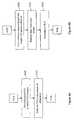
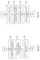
FIGURE 1 is diagrammatic view of a combined SPECT/CT single gantry system;FIGURE 2A is an image representation of an iterative reconstruction in a field of view that does not encompass the subject in the trans-axial direction causing strong artifacts;FIGURE 2B is an image representation of an iterative reconstruction for which the reconstruction was carried out with an extended field of view to reduce truncation errors;FIGURE 2C is an image representation of a user selected field of view and an extend field of view;FIGURE 3 is a flow chart of a method for truncation compensation for iterative reconstruction methods;FIGURE 4A-4D are flow charts of alternate methods for determining an extended field of view; andFIGURE 5 is a flow chart of method for extending a voxel grid of a field of view into an extended field of view.- With reference to
FIG. 1 , adiagnostic imaging system 10 performs concurrently and/or independently x-ray computed tomography (CT) and nuclear imaging, such as PET or SPECT. Theimaging system 10 includes astationary housing 12 which defines a patient receivingbore 14. Arotatable gantry 16, supported by thehousing 12, is arranged for rotation around the bore to define acommon examination region 18. Apatient support 20, which supports a patient orsubject 22 to be imaged and/or examined, is longitudinally and/or vertically adjusted to achieve the desired positioning of the patient in the examination region. - To provide CT imaging capabilities, an
x-ray assembly 24 which is mounted on therotatable gantry 16 includes anx-ray source 26, such as an x-ray tube, and a filter, collimator, and/orshutter assembly 28. The collimator collimates the radiation from thex-ray source 26 into a cone or wedge beam, one or more substantially parallel fan beams, or the like. The shutter gates the beam on and off. Anx-ray detector 30, such as a solid state, flat panel detector, is mounted on therotatable gantry 16 opposite thex-ray assembly 24. In the illustrated embodiment, the detector panel is offset relative to the projected center of radiation or transversely displaced from the center of rotation in the trans-axial plane. Offset detector geometries are desirable because they allow for an increased FoV or allow for smaller detectors sizes. Larger detectors tend to be more complex, expensive to manufacture, can limit the overall system design, and can limit detector positioning or patient access or the like. X-ray systems with a wide, non-offset detector that spans the full field-of-view are also contemplated. - As the gantry rotates, the
x-ray assembly 24 and thex-ray detector 30 revolve in concert around theexamination region 18 to acquire CT projection data spanning a full 360° revolution, multiple revolutions, or a smaller arc. Each CT projection indicates x-ray attenuation along a linear path between thex-ray assembly 24 and a detecting element of thex-ray detector 30. The acquired CT projection data is stored in aCT data buffer 32 and processed by aCT reconstruction processor 34 into a CT image representation and then stored in a CTimage memory unit 36. Taken together, the x-ray source, the collimator/shutter assembly, the detector, and the reconstruction processor define a system or means for generating an anatomical, CT, x-ray, or first image. - To provide functional nuclear imaging capabilities, one or more nuclear detector heads40a,40b, such as single photon emission tomography (SPECT) detectors, are moveably mounted to the
rotating gantry 16. Mounting thex-ray assembly 24 and the nuclear detector heads40a,40b on the same gantry permits theexamination region 18 to be imaged by both modalities without moving thepatient 22. In one embodiment, the detector heads are moveably supported by a robotic assembly (not shown) which is mounted to therotating gantry 16. The robotic assembly enables the detector heads to be positioned at a selectable offset about thepatient 22, e.g. 90° offset, 180° opposite each other, etc. Each SPECT detector head includes a collimator such that each detected radiation event is known to have originated along an identifiable linear or small-angle conical line of sight so that the acquired radiation comprises projection data. The acquired SPECT projection data is stored in adata buffer 42 and processed by aSPECT reconstruction processor 44 into a SPECT image representation and stored in a SPECT image memory unit46. Taken together, the SPECT detector heads and the SPECT reconstruction processor define a system means for generating a nuclear, functional, or second image. - In another embodiment, the functional imaging system or means includes positron emission tomography (PET) detectors. One or more rings of PET detectors are arranged about the patient receiving bore14 to receive gamma radiation therefrom. Detected pairs of coincident radiation events define LORs which are stored in list mode in a data buffer and processed by a PET reconstruction processor into a PET image representation and stored in a PET image memory unit. Taken together, the PET detector ring(s) and the PET reconstruction processor define the system or means for generating the functional image.
- Filtered convolution backprojection (FBP) is commonly employed to reconstruct emission and transmission projection data. FBP is an analytical method which takes a signal-to-detector approach, i.e. it assumes that point-source radiation from a focal spot on the x-ray tube passing through as a single, thin line through the center of a voxel that goes to the center of each detector cell. FBP is easy to implement and computationally fast. However, FBP has some limitations, more notably there are no provisions for modeling noise resulting from low photon counts which hinders signal-to-noise ratio (SNR). To overcome image noise using FBP reconstruction, a higher radiation dose can be used which is a concern regarding patient safety.
- An alternative technique is the iterative reconstruction method which uses a complex iterative algorithm, such as maximum likelihood expectation maximization (MLEM) or ordered subset expectation maximization (OSEM), which refines and builds the image representation and can accommodate processing steps to account for attenuation, scatter, noise, detector efficiency, dead-time, anatomical models, patient motion, and radiotracer kinetics, and the like. In an iterative algorithm, an initial estimate of the activity or attenuation in a FoV is made. In other words, an initial image representation is generated, e.g., from an FBP or assuming a homogeneous signal distribution. Projection data is calculated or forward projected from the initial image and compared to the corresponding acquired projection data. A difference between the calculated projection data and the actual projection data is back projected on to the initial image representation to update the image representation. The algorithm is iterated until the difference is minimized or an optimal solution is available.
- Though iterative reconstruction methods have attractive properties, e.g., when dealing with noisy data they can generate reconstructions with lower noise than FBP, but they are prone to truncation errors.
- The FoV with a selected voxel grid is selected by a user or a clinician and the extended FoV (ex-FoV) which includes extended regions outside of the FoV is determined. To compensate for truncation errors, the
CT reconstruction processor 34 automatically extends the field-of-view (FoV) during reconstruction such that it includes the entire subject in the trans-axial direction to account for all attenuation that is present in the CT projection data or all activity that is present in the PET/SPECT projection data. - In one embodiment for determining the ex-FoV, the FoV is forward-projected on the acquired X-ray projection data to define the FoV 'footprint'. The presence of a substantial amount of attenuation or activity outside the FoV footprint in the trans-axial direction indicates truncation. The ex-FoV is then selected large enough such that it encompasses all attenuation or activity present in all projections in the trans-axial direction. This method may not be applicable if the subject extends beyond the detector in the trans-axial direction, i.e. the subject extends beyond the scanner FoV in which case one of the following methods for determining the ex-FoV can be used.
- In another embodiment, the subject's trans-axial extent is estimated from their weight and height in conjunction with statistical data regarding typical patient shapes. The subject's height and weight are measured and then compared to a patient collective or database which indexes maximum trans-axial extents according to statistics regarding height and weight. The ex-FoV is then determined to encompass this estimated patient size. Similarly, a typical maximum trans-axial extent can be estimated from a patient collective. This maximum extent is then used to determine the ex-FoV.
- In another embodiment for determining the extent of the ex-FoV, which is not claimed here, the subject's extents can be estimated from other available image data, such as from previously acquired CT, MRI, SPECT, PET, or the like image representations, which, however, is not claimed here. Similarly, the subject's extent can be estimated from concurrently or subsequently acquired projection data or reconstructed image data in which the imaged patient region does not move out of the
examination region 18. For example, when performing a SPECT/CT or PET/CT acquisition with theimaging system 10, the SPECT/PET data or reconstructed image representation therefrom can be used to estimate the subject's outline and thus the subject's extents. Alternatively, additional CT projection data can be acquired for determining the subject's extents. - In another embodiment for determining the ex-FoV, a first reconstruction (possibly at low resolution) is performed in a very large FoV that is known to encompass the entire subject. For example, the FoV can be chosen at least as large as the scanner bore. The true patient outline can then be detected in this first reconstruction, and the extended FoV for the extended reconstruction can be chosen accordingly.
- Once the ex-FoV is determined, the FoV is extended to encompass the ex-FoV in a number of ways depending on the intended use of the reconstruction and computational hardware limitations. In one embodiment, the voxel grid of the FoV is extended to at least one extended region outside the FoV up to the size of the ex-FoV. In other words, the number of voxels in the voxel grid of the FoV is increased while the size of each voxel remains the same. In another embodiment, if the extension of the FoV voxel grid is unachievable due to limitations on processing memory or processing time, the size or dimensions of each voxel of the FoV is increased while the number of voxels in the grid remains constant thus enlarging the spatial extent of the voxel grid.
- After the location and the voxel grid of the ex-FoV are determined, an image representation of at least the FoV is generated, e.g., using an iterative reconstruction method, based on the ex-FoV and stored into
CT image memory 36 for display on agraphical user interface 50. Thegraphic user interface 50 also includes a user input device by which a clinician or user interacts with a scan controller52 to select scanning sequences and protocols, and the like. - In one embodiment, the ex-FoV is displayed with the user-selected FoV labeled. Additionally, a label can indicate the fully sampled FoV and possibly undersampled regions. Alternatively, in the embodiment where the voxel grid of the FoV is extended, the reconstructed image representation can cropped to display just user defined FoV. In the embodiment where the voxel grid of the FoV is enlarged or extended and enlarged, or where the size of some or all of the voxels were enlarged, the reconstructed image representation is re-sampled back to the voxel size of the user selected FoV.
- In another embodiment, the reconstructed ex-FOV is used to generate an attenuation map for correcting projection data acquired with the nuclear imaging scanner, such as SPECT or PET emission data. For accurate attenuation correction, it is important that the attenuation map represents the whole object to account for all attenuation during the acquisition. While this may not be the case for a user-defined FoV, complete coverage can be assured by using the described method and generating an attenuation map from the ex-FoV reconstruction. For example, the
SPECT reconstruction processor 44 receives the reconstructed image representation of the ex-FOV and generates an attenuation map therefrom. The attenuation map is used to correct photon absorption and scatter by the anatomy of the subject. - Though the iterative reconstruction method utilizing an extended FoV to compensate for truncation errors is described for use in computed tomography image reconstruction, the method is also applicable in other imaging modalities for which iterative reconstruction methods are also performed. For example, the ex-FoV iterative reconstruction method can be applied to single slice CT, PET, SPECT, or the like. With regards to the
imaging system 10, theSPECT reconstruction processor 44 can compensate for truncation errors in acquired SPECT emission data by utilizing the extended field of view along with an iterative reconstruction algorithm to generate SPECT image representations. - With reference to
FIGURE 3 , a method for truncation compensation in an iterative reconstruction method is presented. The projection data of the subject is acquiredS100 from theexamination region 18. Using the graphical user interface52, a clinician defines or selects a field of viewS102. The subjects maximum trans-axial extents are determinedS104 which are then used to determine an extended field of viewS106 that encompass at least the determined maximum trans-axial extents and all attenuation or activity in the trans-axial direction. The extended field-of-view is iteratively reconstructedS108 using the acquired projection data. - The reconstructed image representation can be displayedS110 in multiple ways.
- In the embodiment where the CT projection data is CT transmission data, the reconstructed CT image representation of the ex-FoV can be used to generated an attenuation mapS110 which is used to correct nuclear projection data, e.g. SPECT/PET dataS112, which is then reconstructedS114, e.g., iteratively, into an attenuation corrected nuclear image representation.
- The subject's trans-axial extents can be determined a number of ways. In one embodiment illustrated in
FIGURE 4A the location of the ex-FoV, the FoV is forward-projected on the acquired X-ray projection data to define the FoV 'footprint'S200. The presence of a substantial amount of attenuation outside the FoV footprint in the trans-axial direction indicates truncation. The ex-FoV is then selectedS202 large enough such that it encompasses all attenuation present in all projections in the trans-axial direction. This method may not be applicable if the subject extends beyond the detector in the trans-axial direction, i.e. the subject extends beyond the scanner FoV, in which case one of the following methods for determining the ex-FoV can be used. - With reference to
FIGURE 4B , in another embodiment, the subject's trans-axial extents are estimatedS304 from his/her weight and height in conjunction with statistical data regarding typical patient shapes. The subject's height and weight are measuredS300 and cross-referenced to a patient collective or database and the maximum trans-axial extents are estimated302 according to statistics regarding height and weight. The ex-FoV is then determined304 to encompass this estimated patient size. Similarly, a typical maximum trans-axial extent can be estimated from a patient collective. This maximum extent is then used to determine the ex-FoV. - With reference to
FIGURE 4C , in another embodiment the subject's extents are estimated from other available image data, such as from a previously acquired CT, SPECT, PET, or the like image representation. The previously acquired image representation is obtainedS400 by thereconstruction processor examination region 18. - With reference to
FIGURE 4D , a first reconstructionS502, using a low resolution and/or a faster algorithm such as FBP, is performed in a selected very large FoVS500 that is known to encompass the entire subject. For example, the FoV is chosen at least as large as the scanner bore. The true patient outline is determinedS504 in this first reconstruction, and the extended FoV for the extended reconstruction is chosen according to the maximum trans-axial extents of the determined outline. - With reference to
FIGURE 5 , the FoV can be extended to encompass the ex-FoV a number of ways depending on the intended use of the reconstruction and computational hardware limitations. In one embodiment, the voxel grid of the FoV is extended to at least one extended region outside the FoV up to the size of the ex-FoV. In other words, the number of voxels in the voxel grid of the FoV is increased while the size of each voxel remains the same. In another embodiment, if the extension of the FoV voxel grid may be unachievable due to limitations on processing memory or processing time, the size or dimensions of each voxel of the FoV is increased while the number of voxels in the grid remains constant thus enlarging the spatial extent of the voxel grid. - The various computational and control components disclosed herein can be implemented in various ways, for example by a computer or other device including a digital processor and programmed or including firmware to perform the disclosed processing, or by hybrid or analog circuitry configured to perform the disclosed processing or portions thereof, or so forth. In some embodiment, the computational components may be embodied by a computer having suitable firmware or programming. The techniques disclosed herein can be implemented by a processor other hardware, and/or can be embodied as a storage medium storing instructions that, when executed by such a processor or other hardware, perform the disclosed methods. Such a storage medium may be embodied by one or more types of storage media, such as one or more of: a magnetic disk, an optical disk; a FLASH memory or other electrostatic memory; a random access memory (RAM); a read-only memory (ROM); DVD; or so forth.
- The invention has been described with reference to the preferred embodiments. Modifications and alterations may occur to others upon reading and understanding the preceding detailed description. It is intended that the invention be constructed as including all such modifications and alterations insofar as they come within the scope of the appended claims or the equivalents thereof.
Claims (11)
- A method for imaging, comprising:acquiring projection data of a subject situated in an examination region with a first imaging modality;defining a field-of-view (FoV) with a voxel grid in a trans-axial direction;determining the subject's maximum trans-axial extents;generating an extended FoV by extending the voxel grid of the FoV to at least one extended region outside the FoV that encompass at least the determined maximum trans-axial extents and attenuation in the trans-axial direction; anditeratively reconstructing the acquired projection data into an image representation of the extended FoV;wherein determining the subject's maximum trans-axial extents includesdefining a coarse voxel grid in a FoV which is known to be greater than the subject's trans-axial extents,reconstructing the large FoV into a coarse image representation, the coarse image representation having a resolution lower than the reconstructed image representation, anddetermining the subject's trans-axial extents based on the coarse image representation.
- The method according to claim 1, further including:generating an attenuation map based on the reconstructed image representation of the extended FoV;generating a second projection data set of the subject acquired with a second imaging modality; andreconstructing the second projection image data including using the attenuation map.
- The method according to claim 1, wherein the projection data from the first imaging modality is acquired concurrently or in close temporal proximity with the projection data of the second imaging modality.
- The method according to any one of claims 1-3, wherein determining the extended FoV includes:forward projecting the FoV onto the acquired projection data to define a FoV footprint; andextending the FoV footprint such that it includes all attenuation or activity present in the projection data.
- The method according to any one of claims 1-4, wherein the step of extending the FoV includes at least one of:increasing the number of voxels in the FoV to encompass the at least one extended region; orincreasing the size of each voxel in the FoV to encompass the at least one extended region.
- The method according to claim 5, wherein the voxels of the FoV and the voxels of the at least one extended region have a different size.
- The method according to claim 6, wherein the reconstructed image representation includes the FoV and the extended regions, the method further including:resampling the reconstructed image representation to decrease the voxel size to that of the FoV voxel grid; anddisplaying the resampled image representation such that the defined FoV is visible.
- A computer medium carrying software to control one or more processors to perform the method according to any one of claims 1-7.
- An imaging scanner (10) comprising:a first imaging scanner (24,30,40a,40b) which acquires projection data of a subject situated in an examination region (18) using a first imaging modality;at least one processor (34,44) programmed to perform the method of any one of claims 1-7.
- The imaging scanner according to claim 9, wherein the first imaging scanner includes a cone-beam computed tomography scanner (24,30) which includes an offset detector (30).
- The imaging scanner (10) according to claim 10, further including:a nuclear imaging scanner (24,30,40a,40b) which acquires nuclear data of the subject situated in the examination region (18); andwherein the processor is further programmed to:generate an attenuation map based on the iteratively reconstructed image representation of the extended FoV; andreconstruct the nuclear data using the attenuation maps.
Applications Claiming Priority (2)
| Application Number | Priority Date | Filing Date | Title |
|---|---|---|---|
| US201161436714P | 2011-01-27 | 2011-01-27 | |
| PCT/IB2012/050239WO2012101548A2 (en) | 2011-01-27 | 2012-01-18 | Truncation compensation for iterative cone-beam ct reconstruction for spect/ct systems |
Publications (2)
| Publication Number | Publication Date |
|---|---|
| EP2668639A2 EP2668639A2 (en) | 2013-12-04 |
| EP2668639B1true EP2668639B1 (en) | 2016-11-02 |
Family
ID=45607309
Family Applications (1)
| Application Number | Title | Priority Date | Filing Date |
|---|---|---|---|
| EP12704124.2AActiveEP2668639B1 (en) | 2011-01-27 | 2012-01-18 | Truncation compensation for iterative cone-beam ct reconstruction for spect/ct systems |
Country Status (6)
| Country | Link |
|---|---|
| US (1) | US9462988B2 (en) |
| EP (1) | EP2668639B1 (en) |
| JP (1) | JP6192542B2 (en) |
| CN (1) | CN103329168B (en) |
| RU (1) | RU2606561C2 (en) |
| WO (1) | WO2012101548A2 (en) |
Families Citing this family (32)
| Publication number | Priority date | Publication date | Assignee | Title |
|---|---|---|---|---|
| US8977026B2 (en)* | 2012-05-30 | 2015-03-10 | General Electric Company | Methods and systems for locating a region of interest in an object |
| US10846860B2 (en) | 2013-03-05 | 2020-11-24 | Nview Medical Inc. | Systems and methods for x-ray tomosynthesis image reconstruction |
| JP6571313B2 (en)* | 2013-05-28 | 2019-09-04 | キヤノンメディカルシステムズ株式会社 | Medical image diagnostic apparatus and control method |
| EP3028257B1 (en)* | 2013-07-31 | 2017-04-12 | Koninklijke Philips N.V. | Iterative ct image reconstruction of a roi with objects outside the scan fov |
| CN105578963B (en)* | 2013-09-27 | 2019-07-12 | 皇家飞利浦有限公司 | Image data Z axis coverage area for tissue dose estimation extends |
| US9980693B2 (en) | 2014-01-23 | 2018-05-29 | Ermi, Inc. | Imaging proxy |
| US10188358B2 (en)* | 2014-05-15 | 2019-01-29 | General Electric Company | System and method for subject shape estimation |
| US9763631B2 (en) | 2014-09-17 | 2017-09-19 | General Electric Company | Systems and methods for imaging plural axial locations |
| KR102379067B1 (en) | 2014-12-01 | 2022-03-25 | 삼성전자주식회사 | Medical image apparatus and method for processing medical image |
| US9936926B2 (en) | 2015-02-02 | 2018-04-10 | Palodex Group Oy | System and method of small field of view X-ray imaging |
| US11308662B2 (en) | 2016-08-02 | 2022-04-19 | Shanghai United Imaging Healthcare Co., Ltd. | System and method for image reconstruction |
| US10347014B2 (en) | 2016-08-02 | 2019-07-09 | Shanghai United Imaging Healthcare Co., Ltd. | System and method for image reconstruction |
| CN106296765B (en)* | 2016-08-02 | 2020-06-02 | 上海联影医疗科技有限公司 | Image reconstruction method and system |
| US10395353B2 (en)* | 2016-08-31 | 2019-08-27 | Siemens Medical Solutions Usa, Inc. | Model-based scatter in multi-modality multi-energy SPECT reconstruction |
| JP2018105734A (en)* | 2016-12-27 | 2018-07-05 | キヤノンメディカルシステムズ株式会社 | Nuclear medicine diagnostic equipment |
| WO2019060843A1 (en) | 2017-09-22 | 2019-03-28 | Nview Medical Inc. | Image reconstruction using machine learning regularizers |
| CN108447553B (en)* | 2018-03-07 | 2021-07-30 | 上海联影医疗科技股份有限公司 | A medical imaging method, apparatus, system, and computer-readable storage medium |
| US20210012546A1 (en)* | 2018-03-26 | 2021-01-14 | Koninklijke Philips N.V. | Automatic fault detection in hybrid imaging |
| CN110693513B (en)* | 2018-10-27 | 2023-07-25 | 上海联影医疗科技股份有限公司 | Control method, system and storage medium of multi-mode medical system |
| US11357467B2 (en) | 2018-11-30 | 2022-06-14 | Accuray, Inc. | Multi-pass computed tomography scans for improved workflow and performance |
| EP3886707A1 (en) | 2018-11-30 | 2021-10-06 | Accuray, Inc. | Helical cone-beam computed tomography imaging with an off-centered detector |
| EP3667620A1 (en) | 2018-12-12 | 2020-06-17 | Koninklijke Philips N.V. | System for reconstructing an image of an object |
| US11654304B2 (en) | 2018-12-17 | 2023-05-23 | Shanghai United Imaging Healthcare Co., Ltd. | Systems and methods for determining a region of interest of a subject |
| CN109961491B (en)* | 2019-04-12 | 2023-05-26 | 上海联影医疗科技股份有限公司 | Multi-mode image truncation compensation method, device, computer equipment and medium |
| CN111915692A (en)* | 2019-05-08 | 2020-11-10 | 通用电气精准医疗有限责任公司 | Imaging method and device |
| CN110215228B (en)* | 2019-06-11 | 2023-09-05 | 上海联影医疗科技股份有限公司 | PET reconstruction attenuation correction method, system, readable storage medium and apparatus |
| CN113081010A (en)* | 2021-04-12 | 2021-07-09 | 北京肿瘤医院(北京大学肿瘤医院) | CT imaging system and method based on body surface guidance of object to be detected and application thereof |
| US11647975B2 (en) | 2021-06-04 | 2023-05-16 | Accuray, Inc. | Radiotherapy apparatus and methods for treatment and imaging using hybrid MeV-keV, multi-energy data acquisition for enhanced imaging |
| US11605186B2 (en) | 2021-06-30 | 2023-03-14 | Accuray, Inc. | Anchored kernel scatter estimate |
| US11794039B2 (en) | 2021-07-13 | 2023-10-24 | Accuray, Inc. | Multimodal radiation apparatus and methods |
| US11854123B2 (en) | 2021-07-23 | 2023-12-26 | Accuray, Inc. | Sparse background measurement and correction for improving imaging |
| US12257083B2 (en) | 2022-02-07 | 2025-03-25 | Accuray Inc. | Methods for saturation correction and dynamic gain configuration and apparatuses for performing the same |
Family Cites Families (20)
| Publication number | Priority date | Publication date | Assignee | Title |
|---|---|---|---|---|
| RU2071725C1 (en)* | 1993-06-22 | 1997-01-20 | Научно-производственная коммерческая фирма "Ренси Лтд." | Computer-based tomograph |
| DE69625546T2 (en)* | 1995-05-11 | 2003-11-20 | Koninklijke Philips Electronics N.V., Eindhoven | Improved gamma camera imaging system |
| JP4170449B2 (en) | 1998-07-07 | 2008-10-22 | 株式会社東芝 | Truncation correction device for transmission CT, nuclear medicine diagnostic device, and truncation correction method |
| JP2002209880A (en) | 2000-12-26 | 2002-07-30 | Ge Medical Systems Global Technology Co Llc | X-ray ct system, operation console, and its control method, and recording medium |
| JP2004073432A (en) | 2002-08-15 | 2004-03-11 | Ge Medical Systems Global Technology Co Llc | X-ray ct apparatus, image processing method, and program |
| US6810102B2 (en)* | 2002-10-04 | 2004-10-26 | Ge Medical Systems Global Technology Company, Llc | Methods and apparatus for truncation compensation |
| US6907102B1 (en)* | 2002-12-16 | 2005-06-14 | Ken Sauer | Iterative reconstruction methods for multi-slice computed tomography |
| JP4965433B2 (en) | 2004-04-21 | 2012-07-04 | コーニンクレッカ フィリップス エレクトロニクス エヌ ヴィ | Cone beam CT apparatus using truncated projection and pre-acquired 3D CT image |
| US7542792B2 (en) | 2004-06-01 | 2009-06-02 | General Electric Company | Methods for automatic protocol selection |
| ATE465425T1 (en) | 2004-12-17 | 2010-05-15 | Koninkl Philips Electronics Nv | CUT-OFF COMPENSATION ALGORITHM FOR ITERATIVE RECONSTRUCTION |
| JP2006312027A (en) | 2005-04-05 | 2006-11-16 | Toshiba Corp | Radiation diagnostic equipment |
| US7502440B2 (en) | 2005-04-05 | 2009-03-10 | Kabushiki Toshiba | Radiodiagnostic apparatus |
| US7756315B2 (en)* | 2005-11-23 | 2010-07-13 | General Electric Company | Method and apparatus for field-of-view expansion of volumetric CT imaging |
| DE102006014630B4 (en) | 2006-03-29 | 2014-04-24 | Siemens Aktiengesellschaft | Method for correcting truncation artifacts |
| RU2452385C2 (en) | 2006-08-17 | 2012-06-10 | Конинклейке Филипс Электроникс Н.В. | Obtaining computer-tomographic images |
| JP5492560B2 (en)* | 2006-09-21 | 2014-05-14 | コーニンクレッカ フィリップス エヌ ヴェ | Cardiac SPECT system with trajectory optimization |
| US7737406B2 (en) | 2006-09-27 | 2010-06-15 | Siemens Medical Solutions Usa, Inc. | Compensating for truncated CT images for use as attenuation maps in emission tomography |
| DE102006062277A1 (en) | 2006-12-22 | 2008-06-26 | Siemens Ag | Truncation artifact correcting method for computer tomographic picture, involves performing smoothing of signal of projection data row to reduce noise parts of signal, and calculating truncated part of row from smoothened signal |
| US8184889B2 (en)* | 2007-09-28 | 2012-05-22 | Siemens Medical Solutions Usa, Inc. | Reconstruction support regions for improving the performance of iterative SPECT reconstruction techniques |
| CN102483852B (en)* | 2009-06-08 | 2016-08-03 | 皇家飞利浦电子股份有限公司 | Time-of-flight positron emission tomography reconstruction using image content generated event-by-event based on time-of-flight information |
- 2012
- 2012-01-18WOPCT/IB2012/050239patent/WO2012101548A2/enactiveApplication Filing
- 2012-01-18JPJP2013550974Apatent/JP6192542B2/enactiveActive
- 2012-01-18USUS13/979,142patent/US9462988B2/enactiveActive
- 2012-01-18CNCN201280006458.7Apatent/CN103329168B/enactiveActive
- 2012-01-18EPEP12704124.2Apatent/EP2668639B1/enactiveActive
- 2012-01-18RURU2013139541Apatent/RU2606561C2/enactive
Also Published As
| Publication number | Publication date |
|---|---|
| CN103329168A (en) | 2013-09-25 |
| US9462988B2 (en) | 2016-10-11 |
| WO2012101548A2 (en) | 2012-08-02 |
| RU2606561C2 (en) | 2017-01-10 |
| JP6192542B2 (en) | 2017-09-06 |
| JP2014507988A (en) | 2014-04-03 |
| WO2012101548A3 (en) | 2013-01-03 |
| RU2013139541A (en) | 2015-03-10 |
| CN103329168B (en) | 2016-10-26 |
| EP2668639A2 (en) | 2013-12-04 |
| US20130294570A1 (en) | 2013-11-07 |
Similar Documents
| Publication | Publication Date | Title |
|---|---|---|
| EP2668639B1 (en) | Truncation compensation for iterative cone-beam ct reconstruction for spect/ct systems | |
| EP3067864B1 (en) | Iterative reconstruction with enhanced noise control filtering | |
| JP6133089B2 (en) | System and method for attenuation compensation in nuclear medicine imaging based on emission data | |
| RU2471204C2 (en) | Local positron emission tomography | |
| CN107111867B (en) | Multimodal imaging system and method | |
| US9619905B2 (en) | Apparatus and method for generation of attenuation map | |
| US8903152B2 (en) | Methods and systems for enhanced tomographic imaging | |
| US20120278055A1 (en) | Motion correction in radiation therapy | |
| JP5172347B2 (en) | Reconstruction of 2D planar images of nuclear medicine by iterative constraint deconvolution | |
| US8467584B2 (en) | Use of multifocal collimators in both organ-specific and non-specific SPECT acquisitions | |
| JP2017067765A (en) | Medical image processing device and positron emission tomography device | |
| JP6662880B2 (en) | Radiation emission imaging system, storage medium, and imaging method | |
| AU2009208949A1 (en) | Dose reduction and image enhancement in tomography through the utilization of the object's surroundings as dynamic constraints | |
| JP4731571B2 (en) | A truncation compensation algorithm for iterative reconstruction | |
| JP2008185335A (en) | Medical image animation display device | |
| US20250232865A1 (en) | Systems and methods for image registration | |
| JP7209496B2 (en) | nuclear medicine diagnostic equipment | |
| Volterrani et al. | Image Acquisition and Processing with Gamma Cameras Including Integrated SPECT/CT and Dedicated Gamma Cameras | |
| Li et al. | Lesion quantification in dual-modality mammotomography |
Legal Events
| Date | Code | Title | Description |
|---|---|---|---|
| PUAI | Public reference made under article 153(3) epc to a published international application that has entered the european phase | Free format text:ORIGINAL CODE: 0009012 | |
| 17P | Request for examination filed | Effective date:20130827 | |
| AK | Designated contracting states | Kind code of ref document:A2 Designated state(s):AL AT BE BG CH CY CZ DE DK EE ES FI FR GB GR HR HU IE IS IT LI LT LU LV MC MK MT NL NO PL PT RO RS SE SI SK SM TR | |
| DAX | Request for extension of the european patent (deleted) | ||
| 17Q | First examination report despatched | Effective date:20140520 | |
| GRAP | Despatch of communication of intention to grant a patent | Free format text:ORIGINAL CODE: EPIDOSNIGR1 | |
| INTG | Intention to grant announced | Effective date:20160524 | |
| GRAS | Grant fee paid | Free format text:ORIGINAL CODE: EPIDOSNIGR3 | |
| GRAA | (expected) grant | Free format text:ORIGINAL CODE: 0009210 | |
| AK | Designated contracting states | Kind code of ref document:B1 Designated state(s):AL AT BE BG CH CY CZ DE DK EE ES FI FR GB GR HR HU IE IS IT LI LT LU LV MC MK MT NL NO PL PT RO RS SE SI SK SM TR | |
| REG | Reference to a national code | Ref country code:GB Ref legal event code:FG4D | |
| REG | Reference to a national code | Ref country code:AT Ref legal event code:REF Ref document number:842520 Country of ref document:AT Kind code of ref document:T Effective date:20161115 Ref country code:CH Ref legal event code:EP | |
| REG | Reference to a national code | Ref country code:IE Ref legal event code:FG4D | |
| REG | Reference to a national code | Ref country code:DE Ref legal event code:R096 Ref document number:602012024801 Country of ref document:DE | |
| PG25 | Lapsed in a contracting state [announced via postgrant information from national office to epo] | Ref country code:LV Free format text:LAPSE BECAUSE OF FAILURE TO SUBMIT A TRANSLATION OF THE DESCRIPTION OR TO PAY THE FEE WITHIN THE PRESCRIBED TIME-LIMIT Effective date:20161102 | |
| REG | Reference to a national code | Ref country code:NL Ref legal event code:MP Effective date:20161102 | |
| REG | Reference to a national code | Ref country code:LT Ref legal event code:MG4D | |
| REG | Reference to a national code | Ref country code:AT Ref legal event code:MK05 Ref document number:842520 Country of ref document:AT Kind code of ref document:T Effective date:20161102 | |
| PG25 | Lapsed in a contracting state [announced via postgrant information from national office to epo] | Ref country code:SE Free format text:LAPSE BECAUSE OF FAILURE TO SUBMIT A TRANSLATION OF THE DESCRIPTION OR TO PAY THE FEE WITHIN THE PRESCRIBED TIME-LIMIT Effective date:20161102 Ref country code:LT Free format text:LAPSE BECAUSE OF FAILURE TO SUBMIT A TRANSLATION OF THE DESCRIPTION OR TO PAY THE FEE WITHIN THE PRESCRIBED TIME-LIMIT Effective date:20161102 Ref country code:NL Free format text:LAPSE BECAUSE OF FAILURE TO SUBMIT A TRANSLATION OF THE DESCRIPTION OR TO PAY THE FEE WITHIN THE PRESCRIBED TIME-LIMIT Effective date:20161102 Ref country code:GR Free format text:LAPSE BECAUSE OF FAILURE TO SUBMIT A TRANSLATION OF THE DESCRIPTION OR TO PAY THE FEE WITHIN THE PRESCRIBED TIME-LIMIT Effective date:20170203 Ref country code:NO Free format text:LAPSE BECAUSE OF FAILURE TO SUBMIT A TRANSLATION OF THE DESCRIPTION OR TO PAY THE FEE WITHIN THE PRESCRIBED TIME-LIMIT Effective date:20170202 | |
| PG25 | Lapsed in a contracting state [announced via postgrant information from national office to epo] | Ref country code:BE Free format text:LAPSE BECAUSE OF NON-PAYMENT OF DUE FEES Effective date:20170131 Ref country code:IS Free format text:LAPSE BECAUSE OF FAILURE TO SUBMIT A TRANSLATION OF THE DESCRIPTION OR TO PAY THE FEE WITHIN THE PRESCRIBED TIME-LIMIT Effective date:20170302 Ref country code:PT Free format text:LAPSE BECAUSE OF FAILURE TO SUBMIT A TRANSLATION OF THE DESCRIPTION OR TO PAY THE FEE WITHIN THE PRESCRIBED TIME-LIMIT Effective date:20170302 Ref country code:RS Free format text:LAPSE BECAUSE OF FAILURE TO SUBMIT A TRANSLATION OF THE DESCRIPTION OR TO PAY THE FEE WITHIN THE PRESCRIBED TIME-LIMIT Effective date:20161102 Ref country code:AT Free format text:LAPSE BECAUSE OF FAILURE TO SUBMIT A TRANSLATION OF THE DESCRIPTION OR TO PAY THE FEE WITHIN THE PRESCRIBED TIME-LIMIT Effective date:20161102 Ref country code:FI Free format text:LAPSE BECAUSE OF FAILURE TO SUBMIT A TRANSLATION OF THE DESCRIPTION OR TO PAY THE FEE WITHIN THE PRESCRIBED TIME-LIMIT Effective date:20161102 Ref country code:HR Free format text:LAPSE BECAUSE OF FAILURE TO SUBMIT A TRANSLATION OF THE DESCRIPTION OR TO PAY THE FEE WITHIN THE PRESCRIBED TIME-LIMIT Effective date:20161102 Ref country code:ES Free format text:LAPSE BECAUSE OF FAILURE TO SUBMIT A TRANSLATION OF THE DESCRIPTION OR TO PAY THE FEE WITHIN THE PRESCRIBED TIME-LIMIT Effective date:20161102 Ref country code:PL Free format text:LAPSE BECAUSE OF FAILURE TO SUBMIT A TRANSLATION OF THE DESCRIPTION OR TO PAY THE FEE WITHIN THE PRESCRIBED TIME-LIMIT Effective date:20161102 | |
| PG25 | Lapsed in a contracting state [announced via postgrant information from national office to epo] | Ref country code:EE Free format text:LAPSE BECAUSE OF FAILURE TO SUBMIT A TRANSLATION OF THE DESCRIPTION OR TO PAY THE FEE WITHIN THE PRESCRIBED TIME-LIMIT Effective date:20161102 Ref country code:SK Free format text:LAPSE BECAUSE OF FAILURE TO SUBMIT A TRANSLATION OF THE DESCRIPTION OR TO PAY THE FEE WITHIN THE PRESCRIBED TIME-LIMIT Effective date:20161102 Ref country code:CZ Free format text:LAPSE BECAUSE OF FAILURE TO SUBMIT A TRANSLATION OF THE DESCRIPTION OR TO PAY THE FEE WITHIN THE PRESCRIBED TIME-LIMIT Effective date:20161102 Ref country code:DK Free format text:LAPSE BECAUSE OF FAILURE TO SUBMIT A TRANSLATION OF THE DESCRIPTION OR TO PAY THE FEE WITHIN THE PRESCRIBED TIME-LIMIT Effective date:20161102 Ref country code:RO Free format text:LAPSE BECAUSE OF FAILURE TO SUBMIT A TRANSLATION OF THE DESCRIPTION OR TO PAY THE FEE WITHIN THE PRESCRIBED TIME-LIMIT Effective date:20161102 | |
| REG | Reference to a national code | Ref country code:DE Ref legal event code:R097 Ref document number:602012024801 Country of ref document:DE | |
| PG25 | Lapsed in a contracting state [announced via postgrant information from national office to epo] | Ref country code:IT Free format text:LAPSE BECAUSE OF FAILURE TO SUBMIT A TRANSLATION OF THE DESCRIPTION OR TO PAY THE FEE WITHIN THE PRESCRIBED TIME-LIMIT Effective date:20161102 Ref country code:BE Free format text:LAPSE BECAUSE OF FAILURE TO SUBMIT A TRANSLATION OF THE DESCRIPTION OR TO PAY THE FEE WITHIN THE PRESCRIBED TIME-LIMIT Effective date:20161102 Ref country code:SM Free format text:LAPSE BECAUSE OF FAILURE TO SUBMIT A TRANSLATION OF THE DESCRIPTION OR TO PAY THE FEE WITHIN THE PRESCRIBED TIME-LIMIT Effective date:20161102 Ref country code:BG Free format text:LAPSE BECAUSE OF FAILURE TO SUBMIT A TRANSLATION OF THE DESCRIPTION OR TO PAY THE FEE WITHIN THE PRESCRIBED TIME-LIMIT Effective date:20170202 | |
| REG | Reference to a national code | Ref country code:CH Ref legal event code:PL | |
| PLBE | No opposition filed within time limit | Free format text:ORIGINAL CODE: 0009261 | |
| STAA | Information on the status of an ep patent application or granted ep patent | Free format text:STATUS: NO OPPOSITION FILED WITHIN TIME LIMIT | |
| PG25 | Lapsed in a contracting state [announced via postgrant information from national office to epo] | Ref country code:MC Free format text:LAPSE BECAUSE OF FAILURE TO SUBMIT A TRANSLATION OF THE DESCRIPTION OR TO PAY THE FEE WITHIN THE PRESCRIBED TIME-LIMIT Effective date:20161102 | |
| 26N | No opposition filed | Effective date:20170803 | |
| GBPC | Gb: european patent ceased through non-payment of renewal fee | Effective date:20170202 | |
| REG | Reference to a national code | Ref country code:FR Ref legal event code:ST Effective date:20170929 | |
| PG25 | Lapsed in a contracting state [announced via postgrant information from national office to epo] | Ref country code:FR Free format text:LAPSE BECAUSE OF NON-PAYMENT OF DUE FEES Effective date:20170131 Ref country code:LI Free format text:LAPSE BECAUSE OF NON-PAYMENT OF DUE FEES Effective date:20170131 Ref country code:CH Free format text:LAPSE BECAUSE OF NON-PAYMENT OF DUE FEES Effective date:20170131 | |
| REG | Reference to a national code | Ref country code:IE Ref legal event code:MM4A | |
| PG25 | Lapsed in a contracting state [announced via postgrant information from national office to epo] | Ref country code:SI Free format text:LAPSE BECAUSE OF FAILURE TO SUBMIT A TRANSLATION OF THE DESCRIPTION OR TO PAY THE FEE WITHIN THE PRESCRIBED TIME-LIMIT Effective date:20161102 Ref country code:LU Free format text:LAPSE BECAUSE OF NON-PAYMENT OF DUE FEES Effective date:20170118 | |
| PG25 | Lapsed in a contracting state [announced via postgrant information from national office to epo] | Ref country code:IE Free format text:LAPSE BECAUSE OF NON-PAYMENT OF DUE FEES Effective date:20170118 Ref country code:GB Free format text:LAPSE BECAUSE OF NON-PAYMENT OF DUE FEES Effective date:20170202 | |
| PG25 | Lapsed in a contracting state [announced via postgrant information from national office to epo] | Ref country code:MT Free format text:LAPSE BECAUSE OF NON-PAYMENT OF DUE FEES Effective date:20170118 | |
| PG25 | Lapsed in a contracting state [announced via postgrant information from national office to epo] | Ref country code:HU Free format text:LAPSE BECAUSE OF FAILURE TO SUBMIT A TRANSLATION OF THE DESCRIPTION OR TO PAY THE FEE WITHIN THE PRESCRIBED TIME-LIMIT; INVALID AB INITIO Effective date:20120118 | |
| PG25 | Lapsed in a contracting state [announced via postgrant information from national office to epo] | Ref country code:CY Free format text:LAPSE BECAUSE OF NON-PAYMENT OF DUE FEES Effective date:20161102 | |
| PG25 | Lapsed in a contracting state [announced via postgrant information from national office to epo] | Ref country code:MK Free format text:LAPSE BECAUSE OF FAILURE TO SUBMIT A TRANSLATION OF THE DESCRIPTION OR TO PAY THE FEE WITHIN THE PRESCRIBED TIME-LIMIT Effective date:20161102 | |
| PG25 | Lapsed in a contracting state [announced via postgrant information from national office to epo] | Ref country code:TR Free format text:LAPSE BECAUSE OF FAILURE TO SUBMIT A TRANSLATION OF THE DESCRIPTION OR TO PAY THE FEE WITHIN THE PRESCRIBED TIME-LIMIT Effective date:20161102 | |
| PG25 | Lapsed in a contracting state [announced via postgrant information from national office to epo] | Ref country code:AL Free format text:LAPSE BECAUSE OF FAILURE TO SUBMIT A TRANSLATION OF THE DESCRIPTION OR TO PAY THE FEE WITHIN THE PRESCRIBED TIME-LIMIT Effective date:20161102 | |
| REG | Reference to a national code | Ref country code:DE Ref legal event code:R084 Ref document number:602012024801 Country of ref document:DE | |
| PGFP | Annual fee paid to national office [announced via postgrant information from national office to epo] | Ref country code:DE Payment date:20250129 Year of fee payment:14 |