EP2667987B1 - Method for production of a three-dimensional object - Google Patents
Method for production of a three-dimensional objectDownload PDFInfo
- Publication number
- EP2667987B1 EP2667987B1EP11857319.5AEP11857319AEP2667987B1EP 2667987 B1EP2667987 B1EP 2667987B1EP 11857319 AEP11857319 AEP 11857319AEP 2667987 B1EP2667987 B1EP 2667987B1
- Authority
- EP
- European Patent Office
- Prior art keywords
- temperature
- exp
- beam path
- specific energy
- intended
- Prior art date
- Legal status (The legal status is an assumption and is not a legal conclusion. Google has not performed a legal analysis and makes no representation as to the accuracy of the status listed.)
- Active
Links
- 238000004519manufacturing processMethods0.000titleclaimsdescription17
- 239000000843powderSubstances0.000claimsdescription49
- 238000000151depositionMethods0.000claimsdescription47
- 230000008021depositionEffects0.000claimsdescription47
- 238000000034methodMethods0.000claimsdescription47
- 238000004364calculation methodMethods0.000claimsdescription44
- 239000000463materialSubstances0.000claimsdescription35
- 238000009826distributionMethods0.000claimsdescription33
- 230000036962time dependentEffects0.000claimsdescription8
- 230000005855radiationEffects0.000claimsdescription6
- 230000008859changeEffects0.000claimsdescription5
- 230000006870functionEffects0.000description17
- 239000000155meltSubstances0.000description11
- 230000014509gene expressionEffects0.000description8
- 238000002844meltingMethods0.000description7
- 230000008018meltingEffects0.000description7
- 230000008569processEffects0.000description5
- 238000010894electron beam technologyMethods0.000description3
- 238000005457optimizationMethods0.000description3
- 230000004044responseEffects0.000description3
- 238000012546transferMethods0.000description3
- 238000012937correctionMethods0.000description2
- 230000002349favourable effectEffects0.000description2
- 230000004927fusionEffects0.000description2
- 238000010438heat treatmentMethods0.000description2
- 230000010354integrationEffects0.000description2
- 238000007493shaping processMethods0.000description2
- 238000012360testing methodMethods0.000description2
- 230000006978adaptationEffects0.000description1
- 238000000149argon plasma sinteringMethods0.000description1
- 230000009286beneficial effectEffects0.000description1
- 230000015572biosynthetic processEffects0.000description1
- 238000004422calculation algorithmMethods0.000description1
- 230000000295complement effectEffects0.000description1
- 238000005094computer simulationMethods0.000description1
- 238000001816coolingMethods0.000description1
- 230000001419dependent effectEffects0.000description1
- 238000011161developmentMethods0.000description1
- 230000018109developmental processEffects0.000description1
- 230000000694effectsEffects0.000description1
- 230000005670electromagnetic radiationEffects0.000description1
- 238000000605extractionMethods0.000description1
- 238000007710freezingMethods0.000description1
- 238000007499fusion processingMethods0.000description1
- 230000008571general functionEffects0.000description1
- 230000001678irradiating effectEffects0.000description1
- 239000000203mixtureSubstances0.000description1
- 239000002245particleSubstances0.000description1
- 230000009467reductionEffects0.000description1
- 238000004088simulationMethods0.000description1
- 238000005245sinteringMethods0.000description1
- 238000010408sweepingMethods0.000description1
- 238000004613tight binding modelMethods0.000description1
Images


Classifications
- B—PERFORMING OPERATIONS; TRANSPORTING
- B22—CASTING; POWDER METALLURGY
- B22F—WORKING METALLIC POWDER; MANUFACTURE OF ARTICLES FROM METALLIC POWDER; MAKING METALLIC POWDER; APPARATUS OR DEVICES SPECIALLY ADAPTED FOR METALLIC POWDER
- B22F10/00—Additive manufacturing of workpieces or articles from metallic powder
- B22F10/20—Direct sintering or melting
- B22F10/28—Powder bed fusion, e.g. selective laser melting [SLM] or electron beam melting [EBM]
- B—PERFORMING OPERATIONS; TRANSPORTING
- B22—CASTING; POWDER METALLURGY
- B22F—WORKING METALLIC POWDER; MANUFACTURE OF ARTICLES FROM METALLIC POWDER; MAKING METALLIC POWDER; APPARATUS OR DEVICES SPECIALLY ADAPTED FOR METALLIC POWDER
- B22F10/00—Additive manufacturing of workpieces or articles from metallic powder
- B22F10/30—Process control
- B22F10/36—Process control of energy beam parameters
- B—PERFORMING OPERATIONS; TRANSPORTING
- B29—WORKING OF PLASTICS; WORKING OF SUBSTANCES IN A PLASTIC STATE IN GENERAL
- B29C—SHAPING OR JOINING OF PLASTICS; SHAPING OF MATERIAL IN A PLASTIC STATE, NOT OTHERWISE PROVIDED FOR; AFTER-TREATMENT OF THE SHAPED PRODUCTS, e.g. REPAIRING
- B29C41/00—Shaping by coating a mould, core or other substrate, i.e. by depositing material and stripping-off the shaped article; Apparatus therefor
- B29C41/003—Shaping by coating a mould, core or other substrate, i.e. by depositing material and stripping-off the shaped article; Apparatus therefor characterised by the choice of material
- B—PERFORMING OPERATIONS; TRANSPORTING
- B29—WORKING OF PLASTICS; WORKING OF SUBSTANCES IN A PLASTIC STATE IN GENERAL
- B29C—SHAPING OR JOINING OF PLASTICS; SHAPING OF MATERIAL IN A PLASTIC STATE, NOT OTHERWISE PROVIDED FOR; AFTER-TREATMENT OF THE SHAPED PRODUCTS, e.g. REPAIRING
- B29C41/00—Shaping by coating a mould, core or other substrate, i.e. by depositing material and stripping-off the shaped article; Apparatus therefor
- B29C41/34—Component parts, details or accessories; Auxiliary operations
- B29C41/52—Measuring, controlling or regulating
- B—PERFORMING OPERATIONS; TRANSPORTING
- B29—WORKING OF PLASTICS; WORKING OF SUBSTANCES IN A PLASTIC STATE IN GENERAL
- B29C—SHAPING OR JOINING OF PLASTICS; SHAPING OF MATERIAL IN A PLASTIC STATE, NOT OTHERWISE PROVIDED FOR; AFTER-TREATMENT OF THE SHAPED PRODUCTS, e.g. REPAIRING
- B29C64/00—Additive manufacturing, i.e. manufacturing of three-dimensional [3D] objects by additive deposition, additive agglomeration or additive layering, e.g. by 3D printing, stereolithography or selective laser sintering
- B29C64/10—Processes of additive manufacturing
- B29C64/141—Processes of additive manufacturing using only solid materials
- B29C64/153—Processes of additive manufacturing using only solid materials using layers of powder being selectively joined, e.g. by selective laser sintering or melting
- B—PERFORMING OPERATIONS; TRANSPORTING
- B29—WORKING OF PLASTICS; WORKING OF SUBSTANCES IN A PLASTIC STATE IN GENERAL
- B29C—SHAPING OR JOINING OF PLASTICS; SHAPING OF MATERIAL IN A PLASTIC STATE, NOT OTHERWISE PROVIDED FOR; AFTER-TREATMENT OF THE SHAPED PRODUCTS, e.g. REPAIRING
- B29C64/00—Additive manufacturing, i.e. manufacturing of three-dimensional [3D] objects by additive deposition, additive agglomeration or additive layering, e.g. by 3D printing, stereolithography or selective laser sintering
- B29C64/30—Auxiliary operations or equipment
- B29C64/386—Data acquisition or data processing for additive manufacturing
- B29C64/393—Data acquisition or data processing for additive manufacturing for controlling or regulating additive manufacturing processes
- B—PERFORMING OPERATIONS; TRANSPORTING
- B33—ADDITIVE MANUFACTURING TECHNOLOGY
- B33Y—ADDITIVE MANUFACTURING, i.e. MANUFACTURING OF THREE-DIMENSIONAL [3-D] OBJECTS BY ADDITIVE DEPOSITION, ADDITIVE AGGLOMERATION OR ADDITIVE LAYERING, e.g. BY 3-D PRINTING, STEREOLITHOGRAPHY OR SELECTIVE LASER SINTERING
- B33Y50/00—Data acquisition or data processing for additive manufacturing
- B33Y50/02—Data acquisition or data processing for additive manufacturing for controlling or regulating additive manufacturing processes
- G—PHYSICS
- G05—CONTROLLING; REGULATING
- G05D—SYSTEMS FOR CONTROLLING OR REGULATING NON-ELECTRIC VARIABLES
- G05D23/00—Control of temperature
- G—PHYSICS
- G16—INFORMATION AND COMMUNICATION TECHNOLOGY [ICT] SPECIALLY ADAPTED FOR SPECIFIC APPLICATION FIELDS
- G16Z—INFORMATION AND COMMUNICATION TECHNOLOGY [ICT] SPECIALLY ADAPTED FOR SPECIFIC APPLICATION FIELDS, NOT OTHERWISE PROVIDED FOR
- G16Z99/00—Subject matter not provided for in other main groups of this subclass
- B—PERFORMING OPERATIONS; TRANSPORTING
- B22—CASTING; POWDER METALLURGY
- B22F—WORKING METALLIC POWDER; MANUFACTURE OF ARTICLES FROM METALLIC POWDER; MAKING METALLIC POWDER; APPARATUS OR DEVICES SPECIALLY ADAPTED FOR METALLIC POWDER
- B22F10/00—Additive manufacturing of workpieces or articles from metallic powder
- B22F10/30—Process control
- B22F10/36—Process control of energy beam parameters
- B22F10/366—Scanning parameters, e.g. hatch distance or scanning strategy
- B—PERFORMING OPERATIONS; TRANSPORTING
- B22—CASTING; POWDER METALLURGY
- B22F—WORKING METALLIC POWDER; MANUFACTURE OF ARTICLES FROM METALLIC POWDER; MAKING METALLIC POWDER; APPARATUS OR DEVICES SPECIALLY ADAPTED FOR METALLIC POWDER
- B22F10/00—Additive manufacturing of workpieces or articles from metallic powder
- B22F10/80—Data acquisition or data processing
- B—PERFORMING OPERATIONS; TRANSPORTING
- B29—WORKING OF PLASTICS; WORKING OF SUBSTANCES IN A PLASTIC STATE IN GENERAL
- B29K—INDEXING SCHEME ASSOCIATED WITH SUBCLASSES B29B, B29C OR B29D, RELATING TO MOULDING MATERIALS OR TO MATERIALS FOR MOULDS, REINFORCEMENTS, FILLERS OR PREFORMED PARTS, e.g. INSERTS
- B29K2105/00—Condition, form or state of moulded material or of the material to be shaped
- B29K2105/25—Solid
- B29K2105/251—Particles, powder or granules
- B—PERFORMING OPERATIONS; TRANSPORTING
- B33—ADDITIVE MANUFACTURING TECHNOLOGY
- B33Y—ADDITIVE MANUFACTURING, i.e. MANUFACTURING OF THREE-DIMENSIONAL [3-D] OBJECTS BY ADDITIVE DEPOSITION, ADDITIVE AGGLOMERATION OR ADDITIVE LAYERING, e.g. BY 3-D PRINTING, STEREOLITHOGRAPHY OR SELECTIVE LASER SINTERING
- B33Y10/00—Processes of additive manufacturing
- Y—GENERAL TAGGING OF NEW TECHNOLOGICAL DEVELOPMENTS; GENERAL TAGGING OF CROSS-SECTIONAL TECHNOLOGIES SPANNING OVER SEVERAL SECTIONS OF THE IPC; TECHNICAL SUBJECTS COVERED BY FORMER USPC CROSS-REFERENCE ART COLLECTIONS [XRACs] AND DIGESTS
- Y02—TECHNOLOGIES OR APPLICATIONS FOR MITIGATION OR ADAPTATION AGAINST CLIMATE CHANGE
- Y02P—CLIMATE CHANGE MITIGATION TECHNOLOGIES IN THE PRODUCTION OR PROCESSING OF GOODS
- Y02P10/00—Technologies related to metal processing
- Y02P10/25—Process efficiency
Definitions
- This inventionrelates to a method for production of a three-dimensional body by successively providing powder layers and fusing together of selected areas of said layers, which areas correspond to successive cross sections of the three-dimensional body, according to claim 1.
- Equipment for producing a three-dimensional object layer by layer using a powdery material which can be fused together and solidified by irradiating it with a high-energy beam of electromagnetic radiation or electronsare known from e.g. US4863538 , US5647931 and SE524467 .
- Such equipmentinclude for instance a supply of powder, means for successively applying layers of powder on a vertically adjustable platform or working area, and means for directing the beam over the working area. The powder sinters or melts and solidifies as the beam, layer by layer, moves over the working area.
- the beamsweeps in a certain path over each selected area in a scan or hatch pattern that makes the area completely fused together. Often, this scan pattern has the form of parallel lines distributed at equal distances over the selected area. Each of these selected areas, which may include several part areas, corresponds to a cross section of the object being built up in the powder bed.
- Sweeping the beam in a scan pattern with parallel linescan be done by scanning the lines in order. Due to heat transfer from heated material along previously scanned lines, the temperature in the material along a certain line to be scanned will be higher than the starting temperature (i.e. higher than the temperature in the material when the first line is scanned). At least when using a high-energy beam this temperature build-up must be taken into account in order to maintain an appropriate local temperature within the material.
- One way of taking this into accountis to adjust the beam energy input in response to the temperature build up. This could, for instance, be done by varying the beam power or by varying the speed at which the beam moves over the powder layer.
- An exampleis to increase the beam speed at beam turning positions where the end of a first scan line is close to the beginning of a second scan line.
- This temperatureor more exactly the surface temperature of the powder bed, can be measured using a heat camera.
- Real-time corrections or controlling of the beam based on input from such a camerais, however, difficult to perform properly because of the long response time of the system (even if actions are taken to decrease the temperature immediately when an increased temperature has been detected the temperature is likely to continue increasing for some time).
- a heat cameramay yet be useful for checking, after the production, whether anything went wrong in the production process.
- US5904890discloses a method where the beam scan speed is varied as a function of length of the scan lines in a scan pattern with parallel lines.
- the beam speedis lower for longer scan lines and higher for shorter lines as to avoid varying cooling when the beam is away from a certain area.
- the purposeis to achieve a homogeneous density distribution in the product produced.
- This methodmay be useful with regard to the above-mentioned temperature build-up if the beam speed is high compared with the length of the scan lines.
- the scan linesare long the beam speed should be adjusted only at the end parts of the scan lines, and if the lines are distributed over several selected areas of the same powder layer or in a different pattern the temperature build up will not be similar at all parts of the area(s).
- the beam energyis high a more complex scan pattern may be required. In such cases the temperature build-up will not be properly taken into account just by varying the beam speed with respect to the length of the scan lines.
- WO 2008/013483discloses a method where parallel scan lines are scanned in a particular order so that a minimum security distance is established between consecutively scanned lines. Temperature (and charged particle) build-up between the scan lines is thus taken into account by preventing the occurrence of heat transfer interference between consecutively scanned lines.
- the methodis primarily intended for pre-heating of the powder layer with a high beam speed and high beam power but could also be used for avoiding heat transfer interference during the step of melting the powder. However, this would lead to a rather time-consuming production process.
- EP2277687discloses a process for establishing manufacturing parameters for a laser sintering process by computer simulation.
- An object of this inventionis to provide a method of the above discussed type for production of a three-dimensional body, which method exhibits improved possibilities for controlling the temperature and speeding-up of the production. This object is achieved by the method defined by the technical features contained in independent claim 1.
- the inventionconcerns a method for production of a three-dimensional body by successively providing powder layers and fusing together of selected areas of said layers, which areas correspond to successive cross sections of the three-dimensional body, wherein the method comprises the following steps for at least one of said layers: applying the at least one powder layer onto a working area, and fusing together a selected area of the at least one powder layer by supplying energy from a radiation gun to the selected area.
- the inventionis characterized in that the method comprises the steps of: establishing an intended beam path that is to be used when fusing together the selected area of the at least one powder layer; calculating a temperature in the at least one powder layer along the intended beam path as a function of a specific energy deposition of an imaginary beam that is assumed to move along the intended beam path; adjusting the specific energy deposition of the imaginary beam along the intended beam path depending on the calculated temperature and on conditions set for the step of fusing together the selected area; and providing, based on the calculations and the adjustments, an operating scheme for the specific energy deposition of the real beam to be used for the intended beam path when fusing together the selected area of the at least one layer.
- the term "intended beam path"relates to the scan or line pattern that is arranged across the selected area and refers to at least a part of the path the beam spot is intended to follow when the beam is swept over the selected area for the purpose of melting/fusing the powder within that area.
- the intended beam pathcan have any form as long as it provides for a thorough fusing of the powder within the selected area, i.e. it can for instance be segmented or continuous and include both straight and curved portions.
- the beam pathcan vary even if the line pattern is the same, for instance if lines are scanned in a different order or if a single line is scanned in an opposite direction.
- the step of "calculating the temperature in the at least one powder layer along the intended beam path as a function of a specific energy deposition of an imaginary beam that is assumed to move along the intended beam path”means that a local temperature or local temperature distribution in or close to the intended beam path along its extension is calculated, for instance by calculating the local temperature (distribution) in a number of points distributed along the intended beam path, taking into account the energy deposited to the material by an imaginary beam that is assumed to generate a specific energy deposition while moving along the intended beam path.
- the local powder layer temperature in a certain point along the intended beam pathdepends, for instance, on the starting temperature distribution in the material layer, the thermal properties of the material (such as thermal conductivity), the history of the specific energy deposition of the imaginary beam (including the current position of the beam and how much energy or power that has been deposited to the material layer during its path to the current position), and the geometrical pattern of the beam path.
- the term "specific energy deposition of the beam”refers to the energy deposited by the (imaginary or real) beam per time unit and area unit of the layer (beam power and spot size), i.e. the power deposited per area unit, divided by the beam speed.
- varying the specific energy depositioncan be done by varying the speed at which the beam moves over the layer surface, by varying the power of the beam and/or by varying the spot size of the beam (i.e. the layer surface area directly exposed to the beam at a certain point of time).
- the history of the specific energy deposition of the imaginary beamthus includes also variations in speed, power or spot size.
- the shape of the beam and the energy/power distribution in the beammay be varied and included in the calculations.
- the calculationsmay be complicated and time-consuming and various simplifications can be made that allows a sufficiently accurate temperature to be calculated while still taking into account the history of the specific energy deposition (which may strongly affect the temperature in a point of the intended beam path where the beam not yet has reached but where heat has been conducted from previous, already “fused” parts of the intended beam path).
- the step of "adjusting the specific energy deposition of the imaginary beam along the intended beam path depending on the calculated temperature and on conditions set for the step of fusing together the selected area”means that at least one of the beam parameters, i.e. the beam speed, power and/or spot size, is adjusted over a certain portion of the intended beam path if, for instance, the calculations indicate that the temperature becomes higher in a certain point than a condition set for the maximum temperature (which would call for e.g. an increase in beam speed or a reduction in beam power close to that particular point or for a change of the history of the specific energy deposition to reduce indirect, thermally conducted, heating of that point from previous parts of the beam path).
- the beam parametersi.e. the beam speed, power and/or spot size
- Adjustments of the specific energy deposition of the imaginary beam along the intended beam pathmay be handled such that re-calculations of the temperature along (parts of) the path are performed using other beam parameters.
- a set of predetermined data related to the material to be fusedwherein said data set comprises suitable values of the specific energy deposition as a function of the calculated temperature and the conditions set.
- Such predetermined dataare useful for avoiding time-consuming re-calculations and can, for instance, be used when the temperature is calculated in a number of points distributed along the intended beam path.
- a suitable value of the specific energy deposition to be used when moving the beam from the current position until it reaches the "next" pointcan be directly obtained from the predetermined data. This procedure is repeated for the remaining points distributed along the intended beam path. Thus, in this way the specific energy deposition is stepwise adjusted along the intended beam path.
- the term "operating scheme"refers to how the specific energy deposition, i.e. how each of the speed, power and spot size, of the real beam is supposed to vary with time (or with position along the beam path since this position is related to time) during the step of fusing the powder.
- the operating schemecontains information on how the speed, power and spot size of the beam should vary when fusing the selected area.
- the step of providing or determining/establishing this operation schemeis a form of extraction and summary of the results from the previous steps.
- the operation schemeincludes the stepwise variations of the beam parameters.
- the operation schemecan also include information on beam parameter settings for parts of the intended beam path where temperature calculations and specific energy deposition adjustments may not be required, such as for an initial part of the intended beam path.
- the temperature in the materialis related to its content of energy. It is therefore possible to, instead of calculating a true temperature, calculate and make use of another energy- and temperature-related parameter.
- the term calculated temperaturecovers also such related parameters.
- the steps of establishing the intended beam path, calculating the temperature along the intended beam path, adjusting the imaginary specific energy deposition and determining the operating schemedo not necessarily have to be carried out one at a time or strictly in the order given. For instance, calculations and adjustments can be carried out in an iterative manner and the operating scheme can be determined step by step for fractions of the entire beam path.
- the step of establishing the intended beam pathcan be rather simple - a preset line pattern with equally spaced straight and parallel lines with a given scan direction can be chosen - this step may comprise calculations and adjustments for finding a favourable line pattern and a favourable, finally selected, intended beam path.
- the inventionrefers in short to a method where the specific energy deposition of the beam to be used when fusing together the powder can be pre-adjusted to vary in response to the temperature build-up for the particular scan pattern to be used by calculating the resulting temperature along the beam path for different specific energy depositions and conditions.
- the inventive methodmakes it possible to predetermine, by calculation and adaptation, how the specific energy deposition of the beam should vary with time (or position on the selected area) when it passes along the path pattern and melts the powder.
- Various conditionsmay be used in the calculations to optimize the operation scheme of the specific energy deposition such as to minimize production time, avoid exceeding a certain maximum temperature, avoid exceeding a certain temperature during a certain time interval, minimizing the highest temperature acquired, obtain an even width of melted material along the beam path, and various combinations of these, such as a compromise between minimizing production time and the highest temperature acquired.
- Various possible beam pathscan be evaluated before selecting the intended one.
- the conditionscan include preset (pre-calculated) values of one or two of the beam parameters (speed, power and spot size) and/or a preset beam path, such as a set of parallel lines placed at a similar distance from each other.
- a powder layermay comprise several selected areas that may have similar or different geometries.
- this schemeis used for the actual melting/fusing together of (the part of) the selected area of the layer in question.
- the inventive methodis preferably used on all, or at least most of, the layers in the object formed.
- An effect of the inventionis that it provides for a thorough control of the temperature and the temperature distribution of the selected area and makes it possible to plan the fusion step in a sophisticated way. In turn, this can be used to avoid reaching too high temperatures (which may destroy the product being built), to obtain a homogeneous temperature distribution (which improves the product properties by reducing stress and crack formation) and to speed up the production (which makes the production more cost-effective).
- the methodcomprises the step of using the operating scheme for the specific energy deposition when fusing together the selected area of the at least one powder layer.
- the specific energy depositionis the energy deposited by the beam per time unit and area unit divided by the beam speed, and that the specific energy deposition can be varied by varying a beam speed, a beam power and/or a beam spot size.
- the methodcomprises the use of a set of predetermined data related to the material to be fused, wherein said data set comprises values of the specific energy deposition to be selected as a function of temperature calculated and conditions set.
- the conditions set for the fusing stepincludes one or several of the following conditions for the at least one powder layer: maximum temperature; working temperature: melt depth and melt width.
- the step of calculating the temperatureincludes the step of solving a time dependent heat equation.
- the step of calculating the temperatureincludes calculating a local temperature distribution along the intended beam path.
- the step of calculating the temperatureincludes several calculations carried out in or close to a number of points distributed along the intended beam path.
- the maximum distance between adjacent points of calculationis set by setting a limiting value for the allowed change of the specific energy deposition between the adjacent points. For instance, if only the beam speed is varied a maximum allowed change for the beam speed is set.
- the step of establishing the intended beam pathincludes the steps of: making calculations of the temperature along a plurality of possible beam paths, and selecting the intended beam path out of said plurality of beam paths.
- Figure 1shows an example of a known device 1 for producing a three-dimensional product.
- the device 1comprises a vertically adjustable work table 2 on which a three-dimensional product 3 is to be built up, one or more powder dispensers 4, means 28 arranged to successively distribute thin layer of powder on the work table 2 for forming a powder bed 5, a radiation gun 6 in the form of an electron gun for delivering energy to the powder bed 5 as to fuse together parts of the powder bed 5, deflection and beam shaping coils 7 for guiding and shaping the electron beam emitted by the radiation gun 6 over said work table 2, and a control unit 8 arranged to control the various parts of the device 1.
- apparatuses provided with an electron gunwork with vacuum, normally below at least 10 -2 mbar, to avoid that the electron beam interacts with atoms or molecules located between the electron gun and the working area.
- FIG. 7An example of a powder layer selected area having the form of an isosceles trapezoid is shown in figure 7 .
- the intended beam pathis also shown.
- the intended beam pathfollows a plurality of parallel and straight lines (scan or hatch lines) distributed at an equal distance from each other.
- the beam parameter adjustedis in this example the beam speed.
- the beam speedis adjusted such that the width of the melted material at a specific depth (Cf. melt width and melt depth in figure 2 ) becomes equal along the entire beam path. This allows for the use of a fixed distance between the parallel parts of the beam path.
- Remaining parametersare predetermined (or calculated from other predetermined parameters).
- the expression that the calculations are carried out in real timemeans that fusing of the powder is carried out at the same time as the calculations.
- calculations of the beam parameter operating scheme for a subsequent layeris carried out while a previous layer is fused.
- the calculations and determinations of the operation schemeis carried out for points along the beam path very close to where the real beam is positioned, but this would lead to a very small margin for making corrections or re-calculations if something goes wrong in the calculations or in the fusing.
- T ( x,y,z,t )is the time dependent temperature distribution
- ⁇is the thermal conductivity
- c pis the heat capacity
- ⁇is the density of the material.
- TT 0 ; x , y ⁇ ⁇ ⁇ , z ⁇ ⁇ ⁇
- P inis the absorbed beam power
- v xis the beam speed
- ⁇is the variance (beam spot size)
- radcoeffis the radiation coefficient from the surface
- T suris the surrounding temperature above the surface.
- T 0is the working temperature, i.e. the desired temperature of the material before melting/fusing.
- Figure 2depictures a "test box" where the beam is travelling in the direction of the positive x-axes.
- the temperature profile at the surfaceis shown together with a slice in which the melt volume is represented by the isothermal curve corresponding to the melt temperature of the material.
- the beam parameters, v x and ⁇have been optimized to obtain a specific profile of the melt volume in terms of melt depth and melt width.
- the maximum temperature within the materialhas been limited to Tmax.
- Tmaxthermodynamical temperature
- the temperature profiles needed for describing the energy input at the end of a hatch linewill be obtained by approximating T ( x,y,z ) in eq. 2a with a series of Gaussian functions. By doing this it will later on be possible to obtain an analytical solution for the temperature distribution in the half infinity domain even for an arbitrary number of hatch lines.
- the goodness of the fitis mainly determined by the number of Gaussian functions used.
- Nis equal to a value of 10 to 12 meaning that there are 30 to 36 Gaussian functions used for each temperature profile.
- T' ( x,y,z,t )The time dependent temperature distribution, within the material after the beam has scanned one line is obtained by Green functions and convolution together with the initial conditions T' ( x',y',z' ), obtained from equation 3:
- T ′ x y z t1 4 ⁇ Dt 3 / 2 ⁇ ⁇ ⁇ ⁇ ⁇ ⁇ ⁇ ⁇ ⁇ ⁇ 0 exp ⁇ z ⁇ z ′ 2 4 ⁇ Dt + exp ⁇ z + z ′ 2 4 ⁇ Dt exp ⁇ y ⁇ y ′ 2 4 ⁇ Dt exp ⁇ x ⁇ x ′ 2 4 ⁇ Dt T ′ x ′ , y ′ , z ′ dz ′ dy ′ dx ′ + T surf ⁇ T 0
- D⁇ c p ⁇
- d y ′ k jwhich is the distance between line segment k for line j and the point ( x',y' )
- x'-xpos ihas to be replaced by d x i ′ k j , which is the distance between the position of the exponential x-term i on the line segment and the projection point of the ( x',y ') on the same line segment (see figure 6 ).
- Figure 6shows point-line and point-point distances, d y i ′ k j and d x i ′ k j , respectively.
- xpo s i k j , ypo s i k jis the position in the global coordinate system for the exponential terms.
- x 2 k j y 2 k j and x 1 k j y 1 k jare the coordinates in the global coordinate system for line segment k of line j .
- I x ij I y ij⁇ ⁇ ⁇ ⁇ ⁇ ⁇ ⁇ exp ⁇ y ⁇ y ′ 2 4 ⁇ D t ⁇ t j exp ⁇ x ⁇ x ′ 2 4 ⁇ D t ⁇ t j exp ⁇ d x i ′ k j 2 / ⁇ x i j exp ⁇ d y i ′ k j 2 / ⁇ y i j dy ′ dx ′
- ypo s i k jy 1 k j
- a x 2 ijexp ⁇ x ef f 2 ij ⁇ x 2 4 ⁇ D t ⁇ t j exp ⁇ x ef f 2 ij ⁇ xpo
- the temperature around the spotcan now be calculated from the expression in eq. 6 and by inserting pre calculated Gaussian functions for the temperature profiles for the previous hatch lines.
- the beam energy inputi.e. the specific energy deposition
- a trapezoidwill be melted with a constant beam power and it will be the beam speed that is varied in order to have constant melt depth and melt width.
- the intended beam pathis such that the beam starts to scan the lines in figure 7 from the bottom to the top by altering the direction from left to right to right to left.
- the spot sizehas been optimized for Tsurf, the temperature in the part prior to fusing, such that the maximum temperature in the melt pool is limited to Tmax.
- the speed in each point of calculation distributed along the intended beam pathis obtained by first calculating the temperature distribution around the point and then from speed versus temperature data in the data base.
- the speed in the data basehas been optimized for the specific beam settings (power and spot size) and temperature such that the melt depth and the melt width are the same for all lines.
- the temperature profile created by the imaginary beamis modeled by Gaussian functions taken from the data base.
- the range of the temperature of the data basewas from Tsurf to Tmelt and the temperature step for the pre calculated data was set to 20 K.
- a lookup table procedurewas used to pick the nearest speed and Gaussian functions for the calculated temperature.
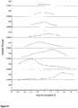
- the resulting speed profiles along each hatch lineare depicted in figure 8 . These profiles are based on the calculations of the local temperature distributions along the intended beam path and correspond to the determined operating scheme for the specific energy deposition of the beam to be used for the intended beam path when fusing together the selected area of the at least one layer, wherein the specific energy deposition in this example is varied by varying the beam speed.
- the calculations according to equation 6can be used for optimizing the hatch strategy with respect to, for instance, a minimum melt/fusing time. For such an optimization there is no need for doing all the calculations in real time as long as they are made possible from a practical point of view. However, it might be beneficial if the calculation for each possible hatch strategy could be done in real time. Thus, there will be no need for saving all the data obtained from the optimization step. Instead information to be saved during the optimization step could be limited to for instance hatch angles, distances between hatch lines, position of the hatch with respect to the part etc.
- the method describecan be combined with e.g. a method used for calculating the beam power needed for maintaining the parts to be built at a specific temperature as described in WO 2004/056511 .
- the overall energy inputcan be calculated from an energy equilibrium calculation including the geometry of the part, whereas the method described here is used for controlling the local energy or power deposition provided by the beam during fusing.
- the method describeduses a homogenous material model to obtain the local temperature (distributions) along the hatch lines.
- local differences in material propertiescould be modeled by using different D values on different locations. For instance sections which are very thin could be modeled by having a lower thermal conductivity.
- the at least one powder layermay comprise more than one selected area; these selected (part) areas may have different forms and can be handled separately.
- the energy deposited by the (imaginary) beam along the path up to a certain point of timeis taken into consideration when the temperature calculation for the same point of time is carried out. This way the temperature build-up is properly taken into account.
- the temperature calculationsare carried out in a number of positions distributed along the intended beam path and in each of these positions a local temperature distribution is calculated. Further, the local temperature distribution is calculated in a position one step ahead of the position of the imaginary beam.
- the specific energy deposition to be used when moving the beam this single step to the next position somewhat aheadis obtained from a database containing a number of pre-calculated specific energy depositions (i.e. beam speeds in the described example) for different local temperature distributions (for the powdery material used and for certain fusing conditions), wherein the calculated local temperature distribution in the next position is used to select the proper value or values from the data base.
Landscapes
- Engineering & Computer Science (AREA)
- Materials Engineering (AREA)
- Chemical & Material Sciences (AREA)
- Manufacturing & Machinery (AREA)
- Physics & Mathematics (AREA)
- Mechanical Engineering (AREA)
- Optics & Photonics (AREA)
- Automation & Control Theory (AREA)
- Plasma & Fusion (AREA)
- General Physics & Mathematics (AREA)
- Powder Metallurgy (AREA)
- Laser Beam Processing (AREA)
- Welding Or Cutting Using Electron Beams (AREA)
Description
- This invention relates to a method for production of a three-dimensional body by successively providing powder layers and fusing together of selected areas of said layers, which areas correspond to successive cross sections of the three-dimensional body, according to
claim 1. - Equipment for producing a three-dimensional object layer by layer using a powdery material which can be fused together and solidified by irradiating it with a high-energy beam of electromagnetic radiation or electrons are known from e.g.
US4863538 ,US5647931 andSE524467 - When melting or sintering a powder using a high-energy beam, it is important to have a thorough control of the temperature of the irradiated material to provide the object with appropriate material properties and to avoid geometrical deformations. For instance, a too high local temperature might destroy the object being produced and a too inhomogeneous temperature distribution might lead to cracks. Further, to provide for a thorough fusion the temperature of the upper layers of the powder bed should normally be kept above a minimum value during the melting step. Besides keeping control of the temperature it is normally important to try to reduce the production time, i.e. to try to sweep the beam as efficiently as possible over the selected area. Only a selected part or area of each powder layer is fused together. The beam sweeps in a certain path over each selected area in a scan or hatch pattern that makes the area completely fused together. Often, this scan pattern has the form of parallel lines distributed at equal distances over the selected area. Each of these selected areas, which may include several part areas, corresponds to a cross section of the object being built up in the powder bed.
- Sweeping the beam in a scan pattern with parallel lines can be done by scanning the lines in order. Due to heat transfer from heated material along previously scanned lines, the temperature in the material along a certain line to be scanned will be higher than the starting temperature (i.e. higher than the temperature in the material when the first line is scanned). At least when using a high-energy beam this temperature build-up must be taken into account in order to maintain an appropriate local temperature within the material.
- One way of taking this into account is to adjust the beam energy input in response to the temperature build up. This could, for instance, be done by varying the beam power or by varying the speed at which the beam moves over the powder layer. An example is to increase the beam speed at beam turning positions where the end of a first scan line is close to the beginning of a second scan line. However, to do this properly it is needed to have information on the temperature in the material. This temperature, or more exactly the surface temperature of the powder bed, can be measured using a heat camera. Real-time corrections or controlling of the beam based on input from such a camera is, however, difficult to perform properly because of the long response time of the system (even if actions are taken to decrease the temperature immediately when an increased temperature has been detected the temperature is likely to continue increasing for some time). A heat camera may yet be useful for checking, after the production, whether anything went wrong in the production process.
US5904890 discloses a method where the beam scan speed is varied as a function of length of the scan lines in a scan pattern with parallel lines. The beam speed is lower for longer scan lines and higher for shorter lines as to avoid varying cooling when the beam is away from a certain area. The purpose is to achieve a homogeneous density distribution in the product produced. This method may be useful with regard to the above-mentioned temperature build-up if the beam speed is high compared with the length of the scan lines. However, if the scan lines are long the beam speed should be adjusted only at the end parts of the scan lines, and if the lines are distributed over several selected areas of the same powder layer or in a different pattern the temperature build up will not be similar at all parts of the area(s). Moreover, if the beam energy is high a more complex scan pattern may be required. In such cases the temperature build-up will not be properly taken into account just by varying the beam speed with respect to the length of the scan lines.WO 2008/013483 discloses a method where parallel scan lines are scanned in a particular order so that a minimum security distance is established between consecutively scanned lines. Temperature (and charged particle) build-up between the scan lines is thus taken into account by preventing the occurrence of heat transfer interference between consecutively scanned lines. The method is primarily intended for pre-heating of the powder layer with a high beam speed and high beam power but could also be used for avoiding heat transfer interference during the step of melting the powder. However, this would lead to a rather time-consuming production process.EP2277687 discloses a process for establishing manufacturing parameters for a laser sintering process by computer simulation.- Thus, there is need for more elaborated scanning strategies which allows for a thorough temperature control as well as a time-efficient production.
- An object of this invention is to provide a method of the above discussed type for production of a three-dimensional body, which method exhibits improved possibilities for controlling the temperature and speeding-up of the production. This object is achieved by the method defined by the technical features contained in
independent claim 1. - The dependent claims contain advantageous embodiments, further developments and variants of the invention.
- The invention concerns a method for production of a three-dimensional body by successively providing powder layers and fusing together of selected areas of said layers, which areas correspond to successive cross sections of the three-dimensional body, wherein the method comprises the following steps for at least one of said layers: applying the at least one powder layer onto a working area, and fusing together a selected area of the at least one powder layer by supplying energy from a radiation gun to the selected area. The invention is characterized in that the method comprises the steps of: establishing an intended beam path that is to be used when fusing together the selected area of the at least one powder layer; calculating a temperature in the at least one powder layer along the intended beam path as a function of a specific energy deposition of an imaginary beam that is assumed to move along the intended beam path; adjusting the specific energy deposition of the imaginary beam along the intended beam path depending on the calculated temperature and on conditions set for the step of fusing together the selected area; and providing, based on the calculations and the adjustments, an operating scheme for the specific energy deposition of the real beam to be used for the intended beam path when fusing together the selected area of the at least one layer.
- The term "intended beam path" relates to the scan or line pattern that is arranged across the selected area and refers to at least a part of the path the beam spot is intended to follow when the beam is swept over the selected area for the purpose of melting/fusing the powder within that area. In principle, the intended beam path can have any form as long as it provides for a thorough fusing of the powder within the selected area, i.e. it can for instance be segmented or continuous and include both straight and curved portions. Further, the beam path can vary even if the line pattern is the same, for instance if lines are scanned in a different order or if a single line is scanned in an opposite direction.
- The step of "calculating the temperature in the at least one powder layer along the intended beam path as a function of a specific energy deposition of an imaginary beam that is assumed to move along the intended beam path" means that a local temperature or local temperature distribution in or close to the intended beam path along its extension is calculated, for instance by calculating the local temperature (distribution) in a number of points distributed along the intended beam path, taking into account the energy deposited to the material by an imaginary beam that is assumed to generate a specific energy deposition while moving along the intended beam path.
- The local powder layer temperature in a certain point along the intended beam path (i.e. at a certain point of time) depends, for instance, on the starting temperature distribution in the material layer, the thermal properties of the material (such as thermal conductivity), the history of the specific energy deposition of the imaginary beam (including the current position of the beam and how much energy or power that has been deposited to the material layer during its path to the current position), and the geometrical pattern of the beam path.
- The term "specific energy deposition of the beam" refers to the energy deposited by the (imaginary or real) beam per time unit and area unit of the layer (beam power and spot size), i.e. the power deposited per area unit, divided by the beam speed. Thus, varying the specific energy deposition can be done by varying the speed at which the beam moves over the layer surface, by varying the power of the beam and/or by varying the spot size of the beam (i.e. the layer surface area directly exposed to the beam at a certain point of time). In the calculations, the history of the specific energy deposition of the imaginary beam thus includes also variations in speed, power or spot size. Also the shape of the beam and the energy/power distribution in the beam may be varied and included in the calculations.
- The calculations may be complicated and time-consuming and various simplifications can be made that allows a sufficiently accurate temperature to be calculated while still taking into account the history of the specific energy deposition (which may strongly affect the temperature in a point of the intended beam path where the beam not yet has reached but where heat has been conducted from previous, already "fused" parts of the intended beam path).
- The step of "adjusting the specific energy deposition of the imaginary beam along the intended beam path depending on the calculated temperature and on conditions set for the step of fusing together the selected area" means that at least one of the beam parameters, i.e. the beam speed, power and/or spot size, is adjusted over a certain portion of the intended beam path if, for instance, the calculations indicate that the temperature becomes higher in a certain point than a condition set for the maximum temperature (which would call for e.g. an increase in beam speed or a reduction in beam power close to that particular point or for a change of the history of the specific energy deposition to reduce indirect, thermally conducted, heating of that point from previous parts of the beam path).
- Adjustments of the specific energy deposition of the imaginary beam along the intended beam path may be handled such that re-calculations of the temperature along (parts of) the path are performed using other beam parameters. Alternatively, or as a complement, it is possible to make use of a set of predetermined data related to the material to be fused, wherein said data set comprises suitable values of the specific energy deposition as a function of the calculated temperature and the conditions set. Such predetermined data are useful for avoiding time-consuming re-calculations and can, for instance, be used when the temperature is calculated in a number of points distributed along the intended beam path. Depending on the temperature calculated in a "next" point positioned relatively closely ahead of a point corresponding to the current position of the imaginary beam, a suitable value of the specific energy deposition to be used when moving the beam from the current position until it reaches the "next" point can be directly obtained from the predetermined data. This procedure is repeated for the remaining points distributed along the intended beam path. Thus, in this way the specific energy deposition is stepwise adjusted along the intended beam path.
- The term "operating scheme" (for the specific energy deposition) refers to how the specific energy deposition, i.e. how each of the speed, power and spot size, of the real beam is supposed to vary with time (or with position along the beam path since this position is related to time) during the step of fusing the powder. Thus, the operating scheme contains information on how the speed, power and spot size of the beam should vary when fusing the selected area. The step of providing or determining/establishing this operation scheme is a form of extraction and summary of the results from the previous steps. In the example above with stepwise adjustments of the specific energy deposition the operation scheme includes the stepwise variations of the beam parameters. The operation scheme can also include information on beam parameter settings for parts of the intended beam path where temperature calculations and specific energy deposition adjustments may not be required, such as for an initial part of the intended beam path.
- The temperature in the material is related to its content of energy. It is therefore possible to, instead of calculating a true temperature, calculate and make use of another energy- and temperature-related parameter. The term calculated temperature covers also such related parameters.
- The steps of establishing the intended beam path, calculating the temperature along the intended beam path, adjusting the imaginary specific energy deposition and determining the operating scheme do not necessarily have to be carried out one at a time or strictly in the order given. For instance, calculations and adjustments can be carried out in an iterative manner and the operating scheme can be determined step by step for fractions of the entire beam path. Further, although the step of establishing the intended beam path can be rather simple - a preset line pattern with equally spaced straight and parallel lines with a given scan direction can be chosen - this step may comprise calculations and adjustments for finding a favourable line pattern and a favourable, finally selected, intended beam path.
- Accordingly, the invention refers in short to a method where the specific energy deposition of the beam to be used when fusing together the powder can be pre-adjusted to vary in response to the temperature build-up for the particular scan pattern to be used by calculating the resulting temperature along the beam path for different specific energy depositions and conditions. In other words, the inventive method makes it possible to predetermine, by calculation and adaptation, how the specific energy deposition of the beam should vary with time (or position on the selected area) when it passes along the path pattern and melts the powder.
- Various conditions may be used in the calculations to optimize the operation scheme of the specific energy deposition such as to minimize production time, avoid exceeding a certain maximum temperature, avoid exceeding a certain temperature during a certain time interval, minimizing the highest temperature acquired, obtain an even width of melted material along the beam path, and various combinations of these, such as a compromise between minimizing production time and the highest temperature acquired. Various possible beam paths can be evaluated before selecting the intended one.
- To simplify and speed up the calculations, the conditions can include preset (pre-calculated) values of one or two of the beam parameters (speed, power and spot size) and/or a preset beam path, such as a set of parallel lines placed at a similar distance from each other.
- The inventive method is generic and is applicable to any geometry of the selected area. It should be noted that a powder layer may comprise several selected areas that may have similar or different geometries.
- When a suitable specific energy deposition operation scheme has been determined, this scheme is used for the actual melting/fusing together of (the part of) the selected area of the layer in question. The inventive method is preferably used on all, or at least most of, the layers in the object formed.
- An effect of the invention is that it provides for a thorough control of the temperature and the temperature distribution of the selected area and makes it possible to plan the fusion step in a sophisticated way. In turn, this can be used to avoid reaching too high temperatures (which may destroy the product being built), to obtain a homogeneous temperature distribution (which improves the product properties by reducing stress and crack formation) and to speed up the production (which makes the production more cost-effective).
- In an advantageous embodiment of the invention the method comprises the step of using the operating scheme for the specific energy deposition when fusing together the selected area of the at least one powder layer.
- In a further advantageous embodiment of the invention the specific energy deposition is the energy deposited by the beam per time unit and area unit divided by the beam speed, and that the specific energy deposition can be varied by varying a beam speed, a beam power and/or a beam spot size.
- In a further advantageous embodiment of the invention the method comprises the use of a set of predetermined data related to the material to be fused, wherein said data set comprises values of the specific energy deposition to be selected as a function of temperature calculated and conditions set.
- In a further advantageous embodiment of the invention the conditions set for the fusing step includes one or several of the following conditions for the at least one powder layer: maximum temperature; working temperature: melt depth and melt width.
- In a further advantageous embodiment of the invention the step of calculating the temperature includes the step of solving a time dependent heat equation.
- In a further advantageous embodiment of the invention the step of calculating the temperature includes calculating a local temperature distribution along the intended beam path.
- In a further advantageous embodiment of the invention the step of calculating the temperature includes several calculations carried out in or close to a number of points distributed along the intended beam path.
- In a variant of this embodiment, the maximum distance between adjacent points of calculation is set by setting a limiting value for the allowed change of the specific energy deposition between the adjacent points. For instance, if only the beam speed is varied a maximum allowed change for the beam speed is set.
- In a further advantageous embodiment of the invention the step of establishing the intended beam path includes the steps of: making calculations of the temperature along a plurality of possible beam paths, and selecting the intended beam path out of said plurality of beam paths.
- In the description of the invention given below reference is made to the following figure, in which:
- Figure 1
- shows, in a schematic view, an example of a known device for producing a three-dimensional product to which the inventive method can be applied,
- Figure 2
- shows a schematic view of the surface temperature profile and the corresponding melt depth and melt width in a box where the beam is travelling in the direction of the positive x-axes,
- Figures 3-5
- show some temperature distribution profiles, calculated by FEM, together with approximated distributions according to the Gaussian series in eq. 3.
- Figure 6
- shows point-line and point-point distances,


- Figure 7
- shows an example of an intended beam path for a selected area having the form of an isosceles trapezoid, wherein the intended beam path is such that the beam starts to scan the lines from the bottom to the top while altering the direction from left to right to right to left, and
- Figure 8
- shows a determined operating scheme for the specific energy deposition of the beam to be used for the intended beam path shown in
figure 7 , wherein the specific energy deposition in this example is varied by varying the beam speed. Figure 1 shows an example of a knowndevice 1 for producing a three-dimensional product. Thedevice 1 comprises a vertically adjustable work table 2 on which a three-dimensional product 3 is to be built up, one or more powder dispensers 4, means 28 arranged to successively distribute thin layer of powder on the work table 2 for forming apowder bed 5, aradiation gun 6 in the form of an electron gun for delivering energy to thepowder bed 5 as to fuse together parts of thepowder bed 5, deflection and beam shaping coils 7 for guiding and shaping the electron beam emitted by theradiation gun 6 over said work table 2, and acontrol unit 8 arranged to control the various parts of thedevice 1.- In a typical work cycle, the work table 2 is lowered, a new layer of powder is applied onto a working area on top of the
powder bed 5, and the electron beam is scanned over selected parts of theupper layer 5' of thepowder bed 5. In principal, this cycle is repeated until the product is finished. An expert in the field is familiar with the general function and composition of devices for producing a three-dimensional product, both with regard to the type outlined infigure 1 and to devices equipped with a laser gun instead of an electron gun. - Conventionally, apparatuses provided with an electron gun work with vacuum, normally below at least 10-2 mbar, to avoid that the electron beam interacts with atoms or molecules located between the electron gun and the working area.
- An example of a powder layer selected area having the form of an isosceles trapezoid is shown in
figure 7 . The intended beam path is also shown. - An embodiment of the inventive method will now be described. In an example of this embodiment the intended beam path follows a plurality of parallel and straight lines (scan or hatch lines) distributed at an equal distance from each other. The beam parameter adjusted is in this example the beam speed. In the calculations, the beam speed is adjusted such that the width of the melted material at a specific depth (Cf. melt width and melt depth in
figure 2 ) becomes equal along the entire beam path. This allows for the use of a fixed distance between the parallel parts of the beam path. Remaining parameters are predetermined (or calculated from other predetermined parameters). - As an overview, the embodiment of the method can be described as follows:
- 1. Data consisting of temperature profiles and related beam parameters (spot size and beam speed) for different sets of material properties, material temperatures and beam powers are created and stored in a data base. These data are obtained by FEM calculations on a simple geometry similar to the test box shown in
figure 2 . - 2. The machine used for producing the three dimensional body calculates in real time the local temperature distribution for each of a number of points distributed along the beam trajectory (path) by solving a time dependent heat equation. The solution of the equation is obtained by expanding the temperature profiles of previously fused (i.e. imaginary fused) hatch lines with Gaussian envelopes. The temperature profiles corresponding to the used beam and material parameters are obtained from the data base
- 3. The beam parameters in a specific point are selected depending on the local calculated temperature distribution and they are obtained from the pre-calculated data in the data base (by comparing the calculated temperature distribution with the pre-calculated temperature profiles for the material used and selecting the beam parameters corresponding to the profile that best fits the calculated distribution).
- 4. Once a hatch line has been finished the temperature profile at the end of the line is also approximated by Gaussian functions and
steps 2 and 3 (i.e. the two previous steps) are repeated for the next hatch line. - The expression that the calculations are carried out in real time means that fusing of the powder is carried out at the same time as the calculations. Typically, calculations of the beam parameter operating scheme for a subsequent layer is carried out while a previous layer is fused. In principle it is possible to carry out all calculations and determinations of the operation scheme for all layers before starting the fusion process of the first layer, but this would normally lead to a waiting time before starting the production. In the other extreme the calculations and determinations of the operation scheme is carried out for points along the beam path very close to where the real beam is positioned, but this would lead to a very small margin for making corrections or re-calculations if something goes wrong in the calculations or in the fusing.
- To obtain the appropriate data needed for controlling the melt process according to the method described, consider the time dependent heat equation without heat source and over the homogeneous material domain -∞<x<∞, -∞<y<∞ and -∞<z<0:

- Here,T(x,y,z,t) is the time dependent temperature distribution, λ is the thermal conductivity,cp is the heat capacity and ρ is the density of the material.
- The boundary conditions are summarized as follows:


- Here,Pin is the absorbed beam power,vx is the beam speed, σ is the variance (beam spot size),radcoeff is the radiation coefficient from the surface andTsur is the surrounding temperature above the surface.
- T0 is the working temperature, i.e. the desired temperature of the material before melting/fusing.
- To decrease the time it will take to generate the data it might be appropriate to remove the time dependency by assuming that the temperature distribution around the moving spot has reached steady state (x=x-tvx, dt=-dx/vx)


- How this procedure may work is exemplified in
figure 2 . Figure 2 depictures a "test box" where the beam is travelling in the direction of the positive x-axes. The temperature profile at the surface is shown together with a slice in which the melt volume is represented by the isothermal curve corresponding to the melt temperature of the material. Here, the beam parameters,vx and σ, have been optimized to obtain a specific profile of the melt volume in terms of melt depth and melt width. Moreover the maximum temperature within the material has been limited to Tmax. Of course there could be other conditions used for optimizing the beam parameters. For instance minimizing temperature gradients in the melt volumes could be one such condition.- The temperature profiles needed for describing the energy input at the end of a hatch line will be obtained by approximatingT(x,y,z) in eq. 2a with a series of Gaussian functions. By doing this it will later on be possible to obtain an analytical solution for the temperature distribution in the half infinity domain even for an arbitrary number of hatch lines. The seriesT'(x,y,z) will be:

- The parametersAi, xposi, σx
i , σyi , σzi and a can be obtained from a point wise non linear square fit betweenT(x,y,z) andT'(x,y,z). Here,xposi is thex-position of the exponential termi along the beam path. In the beam coordinate system it will be a negative value since the beam is assumed to travel in the positivex-direction and located atx=0. - In
figures 3-5 some temperature distributions, calculated by FEM, are shown together with the approximated distribution according to eq. 3. - The goodness of the fit is mainly determined by the number of Gaussian functions used. In the example belowN is equal to a value of 10 to 12 meaning that there are 30 to 36 Gaussian functions used for each temperature profile.
- The time dependent temperature distribution,T'(x,y,z,t), within the material after the beam has scanned one line is obtained by Green functions and convolution together with the initial conditionsT'(x',y',z'), obtained from equation 3:


- Here we have assumed that the material temperature is equal toTsurf and different fromT0. The heat loss through the surface is now put to zero:

- When the beam has scanned M lines the right hand side of the equation 4 is replaced by a summation:


- When inserting the expression forT'(x,y,z) (eq. 4.) into eq. 5 it has to be kept in mind that thex, xposi andy coordinates in eq. 3 refer to a local coordinate system centred around the end point of linej with thex axes pointing in the direction of the beam movement for this line, whereas thex' andy' coordinates in eq. 5 refer to the global coordinate system determined by the surface of the part. Moreover if the beam path of linej has to be described by several line segments, each with a different direction,y in eq. 3 has to be replaced by


figure 6 ). - In this way any kind of beam paths can be considered. However, it should be remembered that the temperature distribution in eq. 3 is obtained from a straight line simulation. Thus, if the curvature of the beam path is very significant just placing the terms in eq. 3 along this path with the same distances as determined by thexposi values, might be a rather poor approximation. In such case a FEM solution on a curved geometry may be needed.
Figure 6 shows point-line and point-point distances,


- For each line segmentkj which contain at least one exponential term, positioned at


- Here we have assumed that the beam is travelling from
point 1 topoint 2 and thatline segment 1 is the last line segment of linej. Thus, line segments are summed backwards.
- Putting all together will give us the following expression for the time dependent temperature distribution when the beam has scanned M lines:

Where: - Kj is the number of straight line segments for hatch pathj.

- In subsequent sections analytical expressions for the terms within the summations will be derived. However, it should be mentioned that using the expression above forT'(x,y,z,t) it will be possible to calculate the temperature for more or less any kind of beam path and that the calculations can be effectively done in a multi CPU configuration, which means that calculation can be performed in real time.
- In order to solve the expression in eq. 6 some properties of Gaussian functions have to be known.
- 1. Multiplication of two Gaussian functions is another Gaussian function:


- 2. Integrals of one Gaussian:


- First consider the integrals in the z direction:


- Second consider the x and y integrals:

- In the case that all line segments are parallel there is no need for differencing between x and y since the coordinate system can easily be transformed to align with the hatch lines. Thus, in the example below all lines are assumed to be parallel with the x - axis.


- If the line segments are not parallel and have an arbitrary direction the algebra becomes a bit more involved. In such case first consider thex-integration:


- Positions of the exponential terms:


- As the (imaginary) beam scans along the hatch paths the temperature around the spot can now be calculated from the expression in eq. 6 and by inserting pre calculated Gaussian functions for the temperature profiles for the previous hatch lines.
- By knowing the temperature and by having access to optimized data for the beam parameters for different conditions it will be possible to adjust the beam energy input (i.e. the specific energy deposition) in an appropriate way.
- In the following hatch example (cf.
figure 7 ) a trapezoid will be melted with a constant beam power and it will be the beam speed that is varied in order to have constant melt depth and melt width. The intended beam path is such that the beam starts to scan the lines infigure 7 from the bottom to the top by altering the direction from left to right to right to left. - The spot size has been optimized for Tsurf, the temperature in the part prior to fusing, such that the maximum temperature in the melt pool is limited to Tmax. This means that the first hatch line is scanned with a constant speed and a fixed spot size. All the other lines are scanned with the same spot size and power but with different and varying speeds. The speed in each point of calculation distributed along the intended beam path is obtained by first calculating the temperature distribution around the point and then from speed versus temperature data in the data base. The speed in the data base has been optimized for the specific beam settings (power and spot size) and temperature such that the melt depth and the melt width are the same for all lines. At the end of each hatch line the temperature profile created by the imaginary beam is modeled by Gaussian functions taken from the data base. The range of the temperature of the data base was from Tsurf to Tmelt and the temperature step for the pre calculated data was set to 20 K. A lookup table procedure was used to pick the nearest speed and Gaussian functions for the calculated temperature.
- The resulting speed profiles along each hatch line are depicted in
figure 8 . These profiles are based on the calculations of the local temperature distributions along the intended beam path and correspond to the determined operating scheme for the specific energy deposition of the beam to be used for the intended beam path when fusing together the selected area of the at least one layer, wherein the specific energy deposition in this example is varied by varying the beam speed. - In the example above a step wise procedure was used to obtain the temperature and the speed along the lines. This means that, firstly, the temperature at a specific point along the line was calculated using
equation 6 for parallel lines. Secondly, the speed was obtained from the temperature by using the data base as a lookup table. The next point along the hatch line could be calculated with a fixed distance, Δr, where the time step would be equal to Δr /Speed. However, since the gradients of the temperature vary rather dramatically with respect to the time and space coordinates a fixed distance procedure was not efficient enough. In some places a small step would be needed whereas in other places a rather long step could be accurate enough. Instead a maximum allowed change in speed was used. From this the maximum allowed difference in temperature could be obtained and by numerically calculating the derivates of the temperature with respect to both time and space the maximum allowed spatial step could be obtained. The derived algorithm was very efficient, and there were no problems for including up to thousands of hatch lines in a real time calculation. The term real time calculation refer to a calculation in which the time for calculating the speed along the hatch lines will be less than the actual melting time. - The disclosure is not limited by the embodiments described above but can be modified in various ways within the scope of the claims. For instance, it is possible to use a more detailed and complex description of the melt process when optimizing the beam parameters and creating the data base; powder can be modeled as an inhomogeneous material together with melt enthalpies and a detailed model of the melting-freezing process.
- The calculations according to
equation 6 can be used for optimizing the hatch strategy with respect to, for instance, a minimum melt/fusing time. For such an optimization there is no need for doing all the calculations in real time as long as they are made possible from a practical point of view. However, it might be beneficial if the calculation for each possible hatch strategy could be done in real time. Thus, there will be no need for saving all the data obtained from the optimization step. Instead information to be saved during the optimization step could be limited to for instance hatch angles, distances between hatch lines, position of the hatch with respect to the part etc. - The method describe can be combined with e.g. a method used for calculating the beam power needed for maintaining the parts to be built at a specific temperature as described in
WO 2004/056511 . Thus, the overall energy input can be calculated from an energy equilibrium calculation including the geometry of the part, whereas the method described here is used for controlling the local energy or power deposition provided by the beam during fusing. - The method described uses a homogenous material model to obtain the local temperature (distributions) along the hatch lines. However, local differences in material properties could be modeled by using different D values on different locations. For instance sections which are very thin could be modeled by having a lower thermal conductivity. There is no limitation in the method for expanding the data base with optimized data for even for such sections. In a similar way it is possible to take into account that lower layers in the powder bed are located closer to the adjustable work table which is likely to have thermal properties that differ from that of the powder bed.
- It is possible to establish the intended beam path for only a part of the selected area before calculating and determining the operation scheme for that part of the selected area. Further, it is possible to calculate and determine the operation scheme for only a part of a fully established intended beam path. The step of fusing together the selected area of the at least one layer may be initiated while the steps of establishing an intended beam path, calculating the temperature etc. regarding a still non-fused portion of the selected area are on-going. Further, the at least one powder layer may comprise more than one selected area; these selected (part) areas may have different forms and can be handled separately.
- As explained above, in the calculations of the temperature along the intended beam path the energy deposited by the (imaginary) beam along the path up to a certain point of time is taken into consideration when the temperature calculation for the same point of time is carried out. This way the temperature build-up is properly taken into account.
- In the example described above the temperature calculations are carried out in a number of positions distributed along the intended beam path and in each of these positions a local temperature distribution is calculated. Further, the local temperature distribution is calculated in a position one step ahead of the position of the imaginary beam. The specific energy deposition to be used when moving the beam this single step to the next position somewhat ahead is obtained from a database containing a number of pre-calculated specific energy depositions (i.e. beam speeds in the described example) for different local temperature distributions (for the powdery material used and for certain fusing conditions), wherein the calculated local temperature distribution in the next position is used to select the proper value or values from the data base.


Claims (10)
- Method for production of a three-dimensional body (3) by successively providing powder layers and fusing together of selected areas of said layers, which areas correspond to successive cross sections of the three-dimensional body (3), wherein the method comprises the following steps for at least one of said layers:- applying the at least one powder layer (5') onto a working area (2),- fusing together a selected area of the at least one powder layer (5') by supplying energy from a radiation gun (6) to the selected area, comprising the steps of:- establishing an intended beam path that is to be used when fusing together the selected area of the at least one powder layer (5'),- calculating a temperature in the at least one powder layer (5') along the intended beam path as a function of a specific energy deposition of an imaginary beam that is assumed to move along the intended beam path,- adjusting the specific energy deposition of the imaginary beam along the intended beam path depending on the calculated temperature and on conditions set for the step of fusing together the selected area, and- providing, based on the calculations and the adjustments, an operating scheme for the specific energy deposition of the real beam to be used for the intended beam path when fusing together the selected area of the at least one layer.
- Method according to claim 1
characterized in
that it comprises the step of using the operating scheme for the specific energy deposition when fusing together the selected area of the at least one powder layer. - Method according to claim 1 or 2,
characterized in
that the specific energy deposition is the energy deposited by the beam per time unit and area unit divided by the beam speed, and that the specific energy deposition can be varied by varying a beam speed, a beam power and/or a beam spot size. - Method according to any of the above claims,
characterized in
that the method comprises the use of a set of predetermined data related to the material to be fused, wherein said data set comprises values of the specific energy deposition to be selected as a function of temperature calculated and conditions set. - Method according to any of the above claims,
characterized in
that the conditions set for the fusing step includes one or several of the following conditions for the at least one powder layer: maximum temperature; working temperature: melt depth and melt width. - Method according to any of the above claims,
characterized in
that the step of calculating the temperature includes the step of solving a time dependent heat equation. - Method according to any of the above claims,
characterized in
that the step of calculating the temperature includes calculating a local temperature distribution along the intended beam path. - Method according to any of the above claims,
characterized in
that the step of calculating the temperature includes several calculations carried out in or close to a number of points distributed along the intended beam path. - Method according to claim 8,
characterized in
that the maximum distance between adjacent points of calculation is set by setting a limiting value for the allowed change of the specific energy deposition between the adjacent points. - Method according to any of the above claims,
characterized in
that the step of establishing the intended beam path includes the steps of:- making calculations of the temperature along a plurality of possible beam paths, and- selecting the intended beam path out of said plurality of beam paths.
Applications Claiming Priority (1)
| Application Number | Priority Date | Filing Date | Title |
|---|---|---|---|
| PCT/SE2011/050093WO2012102655A1 (en) | 2011-01-28 | 2011-01-28 | Method for production of a three-dimensional body |
Publications (3)
| Publication Number | Publication Date |
|---|---|
| EP2667987A1 EP2667987A1 (en) | 2013-12-04 |
| EP2667987A4 EP2667987A4 (en) | 2017-11-08 |
| EP2667987B1true EP2667987B1 (en) | 2019-03-06 |
Family
ID=46581041
Family Applications (1)
| Application Number | Title | Priority Date | Filing Date |
|---|---|---|---|
| EP11857319.5AActiveEP2667987B1 (en) | 2011-01-28 | 2011-01-28 | Method for production of a three-dimensional object |
Country Status (8)
| Country | Link |
|---|---|
| US (1) | US9073265B2 (en) |
| EP (1) | EP2667987B1 (en) |
| JP (1) | JP5712306B2 (en) |
| KR (1) | KR101820553B1 (en) |
| CN (1) | CN103338880B (en) |
| BR (1) | BR112013009155B1 (en) |
| RU (1) | RU2553796C2 (en) |
| WO (1) | WO2012102655A1 (en) |
Families Citing this family (151)
| Publication number | Priority date | Publication date | Assignee | Title |
|---|---|---|---|---|
| US8992816B2 (en) | 2008-01-03 | 2015-03-31 | Arcam Ab | Method and apparatus for producing three-dimensional objects |
| CN102470439B (en) | 2009-07-15 | 2016-03-02 | 阿卡姆股份公司 | Manufacture the method and apparatus of three-dimensional body |
| EP2667987B1 (en) | 2011-01-28 | 2019-03-06 | Arcam Ab | Method for production of a three-dimensional object |
| EP2797730B2 (en) | 2011-12-28 | 2020-03-04 | Arcam Ab | Method and apparatus for detecting defects in freeform fabrication |
| IN2014DN03184A (en) | 2011-12-28 | 2015-05-22 | Arcam Ab | |
| US10189086B2 (en) | 2011-12-28 | 2019-01-29 | Arcam Ab | Method and apparatus for manufacturing porous three-dimensional articles |
| JP5599957B2 (en)* | 2012-03-09 | 2014-10-01 | パナソニック株式会社 | Manufacturing method of three-dimensional shaped object |
| WO2013167194A1 (en) | 2012-05-11 | 2013-11-14 | Arcam Ab | Powder distribution in additive manufacturing |
| WO2014071968A1 (en) | 2012-11-06 | 2014-05-15 | Arcam Ab | Powder pre-processing for additive manufacturing |
| DE112013006045T5 (en) | 2012-12-17 | 2015-09-17 | Arcam Ab | Additive manufacturing method and device |
| US9505172B2 (en) | 2012-12-17 | 2016-11-29 | Arcam Ab | Method and apparatus for additive manufacturing |
| US10464172B2 (en) | 2013-02-21 | 2019-11-05 | Nlight, Inc. | Patterning conductive films using variable focal plane to control feature size |
| CN105144346B (en) | 2013-02-21 | 2017-12-15 | 恩耐公司 | The laser scribing of sandwich construction |
| US9842665B2 (en) | 2013-02-21 | 2017-12-12 | Nlight, Inc. | Optimization of high resolution digitally encoded laser scanners for fine feature marking |
| US9550207B2 (en) | 2013-04-18 | 2017-01-24 | Arcam Ab | Method and apparatus for additive manufacturing |
| US9676031B2 (en) | 2013-04-23 | 2017-06-13 | Arcam Ab | Method and apparatus for forming a three-dimensional article |
| US9415443B2 (en)* | 2013-05-23 | 2016-08-16 | Arcam Ab | Method and apparatus for additive manufacturing |
| US9468973B2 (en) | 2013-06-28 | 2016-10-18 | Arcam Ab | Method and apparatus for additive manufacturing |
| US9505057B2 (en) | 2013-09-06 | 2016-11-29 | Arcam Ab | Powder distribution in additive manufacturing of three-dimensional articles |
| US9676032B2 (en) | 2013-09-20 | 2017-06-13 | Arcam Ab | Method for additive manufacturing |
| EP2865465B1 (en)* | 2013-09-27 | 2018-01-17 | Ansaldo Energia IP UK Limited | Method for manufacturing a metallic component by additive laser manufacturing |
| DE102013017792A1 (en)* | 2013-10-28 | 2015-04-30 | Cl Schutzrechtsverwaltungs Gmbh | Method for producing a three-dimensional component |
| US10434572B2 (en) | 2013-12-19 | 2019-10-08 | Arcam Ab | Method for additive manufacturing |
| DE102013224693A1 (en) | 2013-12-02 | 2015-06-03 | Eos Gmbh Electro Optical Systems | Method for the accelerated production of objects by means of generative production |
| US9802253B2 (en) | 2013-12-16 | 2017-10-31 | Arcam Ab | Additive manufacturing of three-dimensional articles |
| US10130993B2 (en) | 2013-12-18 | 2018-11-20 | Arcam Ab | Additive manufacturing of three-dimensional articles |
| US9789563B2 (en) | 2013-12-20 | 2017-10-17 | Arcam Ab | Method for additive manufacturing |
| KR101872628B1 (en)* | 2014-01-16 | 2018-06-28 | 휴렛-팩커드 디벨롭먼트 컴퍼니, 엘.피. | Generating a three-dimensional object |
| US10252474B2 (en) | 2014-01-16 | 2019-04-09 | Hewlett-Packard Development Company, L.P. | Temperature determination based on emissivity |
| US10220564B2 (en) | 2014-01-16 | 2019-03-05 | Hewlett-Packard Development Company, L.P. | Generating three-dimensional objects |
| WO2015108560A1 (en)* | 2014-01-16 | 2015-07-23 | Hewlett-Packard Development Company, L.P. | Temperature determination based on emissivity |
| US10889059B2 (en) | 2014-01-16 | 2021-01-12 | Hewlett-Packard Development Company, L.P. | Generating three-dimensional objects |
| DE102014201818A1 (en)* | 2014-01-31 | 2015-08-06 | Eos Gmbh Electro Optical Systems | Method and device for improved control of energy input in a generative layer construction process |
| US9789541B2 (en) | 2014-03-07 | 2017-10-17 | Arcam Ab | Method for additive manufacturing of three-dimensional articles |
| JP2015182419A (en)* | 2014-03-26 | 2015-10-22 | 日本電子株式会社 | Three-dimensional additive manufacturing apparatus and three-dimensional additive manufacturing method |
| US20150283613A1 (en) | 2014-04-02 | 2015-10-08 | Arcam Ab | Method for fusing a workpiece |
| JP6030597B2 (en)* | 2014-04-04 | 2016-11-24 | 株式会社松浦機械製作所 | Three-dimensional modeling apparatus and manufacturing method of three-dimensional shaped object |
| US10069271B2 (en) | 2014-06-02 | 2018-09-04 | Nlight, Inc. | Scalable high power fiber laser |
| US10618131B2 (en) | 2014-06-05 | 2020-04-14 | Nlight, Inc. | Laser patterning skew correction |
| US9486878B2 (en) | 2014-06-20 | 2016-11-08 | Velo3D, Inc. | Apparatuses, systems and methods for three-dimensional printing |
| CN105720463B (en) | 2014-08-01 | 2021-05-14 | 恩耐公司 | Protection and monitoring of back reflection in optical fiber and fiber-optic transmission lasers |
| EP3183108B1 (en) | 2014-08-20 | 2020-12-09 | Etxe-Tar, S.A. | Method and system for additive manufacturing using a light beam |
| US9310188B2 (en) | 2014-08-20 | 2016-04-12 | Arcam Ab | Energy beam deflection speed verification |
| US10786865B2 (en) | 2014-12-15 | 2020-09-29 | Arcam Ab | Method for additive manufacturing |
| US9721755B2 (en) | 2015-01-21 | 2017-08-01 | Arcam Ab | Method and device for characterizing an electron beam |
| US9837783B2 (en) | 2015-01-26 | 2017-12-05 | Nlight, Inc. | High-power, single-mode fiber sources |
| WO2017137391A1 (en) | 2016-02-10 | 2017-08-17 | Trumpf Laser- Und Systemtechnik Gmbh | Method for producing a layer or a sub-region of a layer of a three-dimensional component; and corresponding computer program |
| DE102015202347A1 (en) | 2015-02-10 | 2016-08-11 | Trumpf Laser- Und Systemtechnik Gmbh | Irradiation device, processing machine and method for producing a layer of a three-dimensional component |
| US10098746B1 (en) | 2015-02-13 | 2018-10-16 | Nextstep Arthropedix, LLC | Medical implants having desired surface features and methods of manufacturing |
| US10050404B2 (en) | 2015-03-26 | 2018-08-14 | Nlight, Inc. | Fiber source with cascaded gain stages and/or multimode delivery fiber with low splice loss |
| US11014161B2 (en) | 2015-04-21 | 2021-05-25 | Arcam Ab | Method for additive manufacturing |
| JP6483551B2 (en) | 2015-07-03 | 2019-03-13 | 株式会社アスペクト | Powder bed fusion unit |
| US10520671B2 (en) | 2015-07-08 | 2019-12-31 | Nlight, Inc. | Fiber with depressed central index for increased beam parameter product |
| US10807187B2 (en) | 2015-09-24 | 2020-10-20 | Arcam Ab | X-ray calibration standard object |
| WO2017059883A1 (en)* | 2015-10-05 | 2017-04-13 | Hewlett-Packard Development Company L.P. | Fusing in additive manufacturing systems |
| US10583483B2 (en) | 2015-10-15 | 2020-03-10 | Arcam Ab | Method and apparatus for producing a three-dimensional article |
| US10065270B2 (en) | 2015-11-06 | 2018-09-04 | Velo3D, Inc. | Three-dimensional printing in real time |
| US10525531B2 (en) | 2015-11-17 | 2020-01-07 | Arcam Ab | Additive manufacturing of three-dimensional articles |
| US10610930B2 (en) | 2015-11-18 | 2020-04-07 | Arcam Ab | Additive manufacturing of three-dimensional articles |
| US11179807B2 (en) | 2015-11-23 | 2021-11-23 | Nlight, Inc. | Fine-scale temporal control for laser material processing |
| WO2017091505A1 (en)* | 2015-11-23 | 2017-06-01 | Nlight, Inc. | Fine-scale temporal control for laser material processing |
| WO2017091606A1 (en) | 2015-11-23 | 2017-06-01 | Nlight, Inc. | Predictive modification of laser diode drive current waveform in high power laser systems |
| US10286603B2 (en) | 2015-12-10 | 2019-05-14 | Velo3D, Inc. | Skillful three-dimensional printing |
| WO2017127573A1 (en) | 2016-01-19 | 2017-07-27 | Nlight, Inc. | Method of processing calibration data in 3d laser scanner systems |
| US20170239719A1 (en) | 2016-02-18 | 2017-08-24 | Velo3D, Inc. | Accurate three-dimensional printing |
| US10831180B2 (en)* | 2016-02-25 | 2020-11-10 | General Electric Company | Multivariate statistical process control of laser powder bed additive manufacturing |
| US11247274B2 (en) | 2016-03-11 | 2022-02-15 | Arcam Ab | Method and apparatus for forming a three-dimensional article |
| JP6732502B2 (en)* | 2016-03-31 | 2020-07-29 | キヤノン株式会社 | 3D modeling method, program, recording medium, and 3D modeling apparatus |
| US10766197B2 (en) | 2016-03-31 | 2020-09-08 | Hexcel Corporation | Apparatus and method for selective laser sintering an object with a void |
| US11179894B2 (en)* | 2016-05-12 | 2021-11-23 | Hewlett-Packard Development Company, L.P. | Managing thermal contributions between layers during additive manufacturing |
| US10953599B2 (en)* | 2016-05-12 | 2021-03-23 | Hewlett-Packard Development Company, L.P. | Printer warming device control |
| US10549348B2 (en) | 2016-05-24 | 2020-02-04 | Arcam Ab | Method for additive manufacturing |
| US11325191B2 (en) | 2016-05-24 | 2022-05-10 | Arcam Ab | Method for additive manufacturing |
| US10525547B2 (en) | 2016-06-01 | 2020-01-07 | Arcam Ab | Additive manufacturing of three-dimensional articles |
| WO2017216630A1 (en)* | 2016-06-13 | 2017-12-21 | Dmg Mori Co., Ltd. | Systems and methods for temperature control in an additive manufacturing process |
| EP3492244A1 (en) | 2016-06-29 | 2019-06-05 | VELO3D, Inc. | Three-dimensional printing system and method for three-dimensional printing |
| US11691343B2 (en) | 2016-06-29 | 2023-07-04 | Velo3D, Inc. | Three-dimensional printing and three-dimensional printers |
| CN106180707B (en)* | 2016-07-01 | 2018-01-23 | 西安铂力特增材技术股份有限公司 | A kind of method that printing strategy is adjusted according to part real-time temperature field |
| US10864578B2 (en)* | 2016-08-29 | 2020-12-15 | Honeywell Federal Manufacturing & Technologies, Llc | Device for controlling additive manufacturing machinery |
| US10394223B2 (en)* | 2016-08-29 | 2019-08-27 | Honeywell Federal Manufacturing & Technologies, Llc | Device for controlling additive manufacturing machinery |
| US10871766B2 (en)* | 2016-08-29 | 2020-12-22 | Honeywell Federal Manufacturing & Technologies, Llc | Device for controlling additive manufacturing machinery |
| US10394222B2 (en)* | 2016-08-29 | 2019-08-27 | Honeywell Federal Manufacturing & Technologies, Llc | Device for controlling additive manufacturing machinery |
| BE1024495B1 (en)* | 2016-09-27 | 2018-03-13 | Materialise N.V. | ENERGY DENSITY CLASSIFICATION IN ADDITIVE PRODUCTION ENVIRONMENTS |
| CN109791252B (en) | 2016-09-29 | 2021-06-29 | 恩耐公司 | Adjustable beam characteristics |
| US10732439B2 (en) | 2016-09-29 | 2020-08-04 | Nlight, Inc. | Fiber-coupled device for varying beam characteristics |
| US10730785B2 (en) | 2016-09-29 | 2020-08-04 | Nlight, Inc. | Optical fiber bending mechanisms |
| US20180093418A1 (en) | 2016-09-30 | 2018-04-05 | Velo3D, Inc. | Three-dimensional objects and their formation |
| US10792757B2 (en) | 2016-10-25 | 2020-10-06 | Arcam Ab | Method and apparatus for additive manufacturing |
| US20180126460A1 (en) | 2016-11-07 | 2018-05-10 | Velo3D, Inc. | Gas flow in three-dimensional printing |
| US10987752B2 (en) | 2016-12-21 | 2021-04-27 | Arcam Ab | Additive manufacturing of three-dimensional articles |
| US20180186082A1 (en) | 2017-01-05 | 2018-07-05 | Velo3D, Inc. | Optics in three-dimensional printing |
| US10821512B2 (en)* | 2017-01-06 | 2020-11-03 | General Electric Company | Systems and methods for controlling microstructure of additively manufactured components |
| EP3363562A1 (en)* | 2017-02-16 | 2018-08-22 | Siemens Aktiengesellschaft | Improved additive manufacturing |
| US10315252B2 (en) | 2017-03-02 | 2019-06-11 | Velo3D, Inc. | Three-dimensional printing of three-dimensional objects |
| US10695865B2 (en) | 2017-03-03 | 2020-06-30 | General Electric Company | Systems and methods for fabricating a component with at least one laser device |
| US10449696B2 (en) | 2017-03-28 | 2019-10-22 | Velo3D, Inc. | Material manipulation in three-dimensional printing |
| WO2018182596A1 (en) | 2017-03-29 | 2018-10-04 | Hewlett-Packard Development Company, L.P. | Energy dosing for additive manufacturing |
| EP3607389B1 (en) | 2017-04-04 | 2023-06-07 | Nlight, Inc. | Optical fiducial generation for galvanometric scanner calibration |
| US11059123B2 (en) | 2017-04-28 | 2021-07-13 | Arcam Ab | Additive manufacturing of three-dimensional articles |
| DE102017207832A1 (en)* | 2017-05-09 | 2018-11-15 | Eos Gmbh Electro Optical Systems | Position-specific energy input |
| EP4249255A3 (en)* | 2017-05-18 | 2023-11-08 | Honeywell Federal Manufacturing & Technologies, LLC | Device for controlling additive manufacturing machinery |
| US11532760B2 (en) | 2017-05-22 | 2022-12-20 | Howmedica Osteonics Corp. | Device for in-situ fabrication process monitoring and feedback control of an electron beam additive manufacturing process |
| US11292062B2 (en) | 2017-05-30 | 2022-04-05 | Arcam Ab | Method and device for producing three-dimensional objects |
| EP3441214B1 (en)* | 2017-08-09 | 2022-09-28 | CL Schutzrechtsverwaltungs GmbH | Apparatus for additively manufacturing of three-dimensional objects |
| US10710307B2 (en) | 2017-08-11 | 2020-07-14 | Applied Materials, Inc. | Temperature control for additive manufacturing |
| CN111050956B (en) | 2017-09-06 | 2022-04-29 | 株式会社Ihi | Three-dimensional modeling apparatus and three-dimensional modeling method |
| JP6887926B2 (en)* | 2017-09-21 | 2021-06-16 | 日本電子株式会社 | Manufacturing method of three-dimensional structure and manufacturing equipment of three-dimensional structure |
| US11185926B2 (en) | 2017-09-29 | 2021-11-30 | Arcam Ab | Method and apparatus for additive manufacturing |
| JP7277103B2 (en)* | 2017-10-27 | 2023-05-18 | キヤノン株式会社 | Manufacturing method of ceramic model |
| TWI642536B (en)* | 2017-10-30 | 2018-12-01 | 國立成功大學 | Method of performing powder bed fusion process |
| JP6919714B2 (en)* | 2017-10-31 | 2021-08-18 | 株式会社Ihi | 3D modeling device and 3D modeling method |
| US10529070B2 (en) | 2017-11-10 | 2020-01-07 | Arcam Ab | Method and apparatus for detecting electron beam source filament wear |
| US11072117B2 (en) | 2017-11-27 | 2021-07-27 | Arcam Ab | Platform device |
| US10821721B2 (en) | 2017-11-27 | 2020-11-03 | Arcam Ab | Method for analysing a build layer |
| EP3501758A1 (en)* | 2017-12-22 | 2019-06-26 | Heraeus Additive Manufacturing GmbH | Method of determining at least one printing process parameter value, computer-readable storage medium and additives manufacturing plant |
| US11517975B2 (en) | 2017-12-22 | 2022-12-06 | Arcam Ab | Enhanced electron beam generation |
| US12350754B2 (en) | 2017-12-22 | 2025-07-08 | Arcam Ab | Electron beam source and the use of the same |
| US10272525B1 (en) | 2017-12-27 | 2019-04-30 | Velo3D, Inc. | Three-dimensional printing systems and methods of their use |
| US10144176B1 (en) | 2018-01-15 | 2018-12-04 | Velo3D, Inc. | Three-dimensional printing systems and methods of their use |
| US10800101B2 (en) | 2018-02-27 | 2020-10-13 | Arcam Ab | Compact build tank for an additive manufacturing apparatus |
| US11267051B2 (en) | 2018-02-27 | 2022-03-08 | Arcam Ab | Build tank for an additive manufacturing apparatus |
| US11224943B2 (en) | 2018-03-07 | 2022-01-18 | Divergent Technologies, Inc. | Variable beam geometry laser-based powder bed fusion |
| US10695867B2 (en) | 2018-03-08 | 2020-06-30 | General Electric Company | Controlling microstructure of selected range of layers of object during additive manufacture |
| US11400519B2 (en) | 2018-03-29 | 2022-08-02 | Arcam Ab | Method and device for distributing powder material |
| US10518480B2 (en)* | 2018-04-02 | 2019-12-31 | Nanotronics Imaging, Inc. | Systems, methods, and media for artificial intelligence feedback control in additive manufacturing |
| US11084225B2 (en) | 2018-04-02 | 2021-08-10 | Nanotronics Imaging, Inc. | Systems, methods, and media for artificial intelligence process control in additive manufacturing |
| DE102018205689A1 (en)* | 2018-04-13 | 2019-10-17 | Eos Gmbh Electro Optical Systems | Method and device for improving the component homogeneity of objects produced by an additive manufacturing method |
| DE102018205688A1 (en) | 2018-04-13 | 2019-10-17 | Eos Gmbh Electro Optical Systems | Method and device for improving the component quality of objects produced by an additive manufacturing method |
| KR20210006378A (en)* | 2018-04-23 | 2021-01-18 | 머티어리얼리스 엔브이 | Thermal control of laser sintering |
| DE102018110294A1 (en) | 2018-04-27 | 2019-10-31 | Eos Gmbh Electro Optical Systems | Method and device for generating control data for an additive manufacturing device |
| EP3597333A1 (en) | 2018-07-19 | 2020-01-22 | Howmedica Osteonics Corporation | System and process for in-process electron beam profile and location analyses |
| KR102145356B1 (en)* | 2018-08-29 | 2020-08-19 | 한국생산기술연구원 | Porous component manufacturing method using selective laser melting lamination molding and porous component manufactured thereof |
| US20200147868A1 (en)* | 2018-11-09 | 2020-05-14 | General Electric Company | Method for Detecting Errors and Compensating for Thermal Dissipation in an Additive Manufacturing Process |
| US11534961B2 (en) | 2018-11-09 | 2022-12-27 | General Electric Company | Melt pool monitoring system and method for detecting errors in a multi-laser additive manufacturing process |
| EP3671489A1 (en)* | 2018-12-20 | 2020-06-24 | Siemens Aktiengesellschaft | Method for determining building regulations for an additive production method, method for creating a database with corrective measures for the management of an additives production process and a computer program product |
| EP3902679A1 (en) | 2018-12-30 | 2021-11-03 | Stratasys Ltd. | Printing head for non-cartesian inkjet printing |
| EP3906149B1 (en) | 2018-12-31 | 2023-12-13 | Stratasys Ltd. | Method and system for controlling a cooling system in three-dimensional printing |
| FR3092019B1 (en)* | 2019-01-28 | 2022-01-14 | Addup | Additive manufacturing by slew rate modulation |
| FR3092020B1 (en)* | 2019-01-28 | 2021-01-08 | Addup | Additive manufacturing by laser power modulation |
| CN112823090A (en)* | 2019-02-26 | 2021-05-18 | 惠普发展公司,有限责任合伙企业 | Determining melting energy curves in 3D printing |
| CA3148849A1 (en) | 2019-07-26 | 2021-02-04 | Velo3D, Inc. | Quality assurance in formation of three-dimensional objects |
| WO2021050034A1 (en)* | 2019-09-09 | 2021-03-18 | Hewlett-Packard Development Company, L.P. | Fusing build material based on thermal transfer |
| FR3101268B1 (en)* | 2019-09-27 | 2021-10-01 | Addup | ADAPTIVE TRAJECTORY FOR ADDITIVE MANUFACTURING USING LASER SOURCE |
| US11225027B2 (en) | 2019-10-29 | 2022-01-18 | Applied Materials, Inc. | Melt pool monitoring in multi-laser systems |
| RU2750994C1 (en)* | 2020-06-02 | 2021-07-07 | федеральное государственное автономное образовательное учреждение высшего образования "Пермский национальный исследовательский политехнический университет" | Method for controlling surfacing process |
| US12263636B2 (en) | 2020-11-02 | 2025-04-01 | General Electric Company | In-process optical based monitoring and control of additive manufacturing processes |
| KR102595671B1 (en)* | 2021-11-08 | 2023-10-27 | 성균관대학교산학협력단 | Method and apparatus for visualizing of stack, computer-readable storage medium and computer program |
| CN114799213A (en)* | 2022-03-30 | 2022-07-29 | 湖南华曙高科技股份有限公司 | Laser scanning method, device and storage medium for powder bed melting process |
| US12343933B2 (en) | 2022-08-25 | 2025-07-01 | The Boeing Company | Methods of additively manufacturing a manufactured component and systems that perform the methods |
| US20240190082A1 (en)* | 2022-12-13 | 2024-06-13 | The Boeing Company | Methods of additively manufacturing a manufactured component, additive manufacturing systems that perform the methods, and storage media that directs additive manufacturing systems to perform the methods |
| CN119426624B (en)* | 2025-01-13 | 2025-04-11 | 宁波市特种设备检验研究院 | Heat input regulation and control method and system for electric arc additive continuous forming |
Family Cites Families (88)
| Publication number | Priority date | Publication date | Assignee | Title |
|---|---|---|---|---|
| JPS56156767A (en) | 1980-05-02 | 1981-12-03 | Sumitomo Electric Ind Ltd | Highly hard substance covering material |
| US4863538A (en) | 1986-10-17 | 1989-09-05 | Board Of Regents, The University Of Texas System | Method and apparatus for producing parts by selective sintering |
| EP0289116A1 (en) | 1987-03-04 | 1988-11-02 | Westinghouse Electric Corporation | Method and device for casting powdered materials |
| US4927992A (en) | 1987-03-04 | 1990-05-22 | Westinghouse Electric Corp. | Energy beam casting of metal articles |
| US4818562A (en) | 1987-03-04 | 1989-04-04 | Westinghouse Electric Corp. | Casting shapes |
| US5876550A (en) | 1988-10-05 | 1999-03-02 | Helisys, Inc. | Laminated object manufacturing apparatus and method |
| US5182170A (en) | 1989-09-05 | 1993-01-26 | Board Of Regents, The University Of Texas System | Method of producing parts by selective beam interaction of powder with gas phase reactant |
| US5252264A (en) | 1991-11-08 | 1993-10-12 | Dtm Corporation | Apparatus and method for producing parts with multi-directional powder delivery |
| US5393482A (en)* | 1993-10-20 | 1995-02-28 | United Technologies Corporation | Method for performing multiple beam laser sintering employing focussed and defocussed laser beams |
| DE4400523C2 (en) | 1994-01-11 | 1996-07-11 | Eos Electro Optical Syst | Method and device for producing a three-dimensional object |
| US5906863A (en) | 1994-08-08 | 1999-05-25 | Lombardi; John | Methods for the preparation of reinforced three-dimensional bodies |
| DE19511772C2 (en) | 1995-03-30 | 1997-09-04 | Eos Electro Optical Syst | Device and method for producing a three-dimensional object |
| US5837960A (en) | 1995-08-14 | 1998-11-17 | The Regents Of The University Of California | Laser production of articles from powders |
| DE19606128A1 (en)* | 1996-02-20 | 1997-08-21 | Eos Electro Optical Syst | Device and method for producing a three-dimensional object |
| DE19846478C5 (en) | 1998-10-09 | 2004-10-14 | Eos Gmbh Electro Optical Systems | Laser-sintering machine |
| DE19853947C1 (en) | 1998-11-23 | 2000-02-24 | Fraunhofer Ges Forschung | Process chamber for selective laser fusing of material powder comprises a raised section in the cover surface above the structure volume, in which a window is arranged for the coupling in of the laser beam |
| FR2790418B1 (en) | 1999-03-01 | 2001-05-11 | Optoform Sarl Procedes De Prot | RAPID PROTOTYPING PROCESS ALLOWING THE USE OF PASTY MATERIALS, AND DEVICE FOR IMPLEMENTING SAME |
| US6811744B2 (en) | 1999-07-07 | 2004-11-02 | Optomec Design Company | Forming structures from CAD solid models |
| US6391251B1 (en) | 1999-07-07 | 2002-05-21 | Optomec Design Company | Forming structures from CAD solid models |
| DE19939616C5 (en) | 1999-08-20 | 2008-05-21 | Eos Gmbh Electro Optical Systems | Device for the generative production of a three-dimensional object |
| JP2001113605A (en)* | 1999-10-18 | 2001-04-24 | Toyota Motor Corp | 3D additive manufacturing design method |
| DE19952998B4 (en) | 1999-11-04 | 2004-04-15 | Exner, Horst, Prof. Dr.-Ing. | Device for the direct production of bodies in the layer structure of pulverulent substances |
| SE521124C2 (en) | 2000-04-27 | 2003-09-30 | Arcam Ab | Device and method for making a three-dimensional product |
| SE520565C2 (en) | 2000-06-16 | 2003-07-29 | Ivf Industriforskning Och Utve | Method and apparatus for making objects by FFF |
| US20020020164A1 (en) | 2000-07-26 | 2002-02-21 | Cleveland Bradley A. | Tubular body with deposited features and method of manufacture therefor |
| US6751516B1 (en) | 2000-08-10 | 2004-06-15 | Richardson Technologies, Inc. | Method and system for direct writing, editing and transmitting a three dimensional part and imaging systems therefor |
| DE10047615A1 (en) | 2000-09-26 | 2002-04-25 | Generis Gmbh | Swap bodies |
| DE10058748C1 (en) | 2000-11-27 | 2002-07-25 | Markus Dirscherl | Method for producing a component and device for carrying out the method |
| US6492651B2 (en) | 2001-02-08 | 2002-12-10 | 3D Systems, Inc. | Surface scanning system for selective deposition modeling |
| US6419203B1 (en) | 2001-07-20 | 2002-07-16 | Chi Hung Dang | Vibration isolator with parallelogram mechanism |
| JP3724437B2 (en) | 2002-02-25 | 2005-12-07 | 松下電工株式会社 | Manufacturing method and manufacturing apparatus for three-dimensional shaped object |
| DE10235434A1 (en) | 2002-08-02 | 2004-02-12 | Eos Gmbh Electro Optical Systems | Device for producing a three-dimensional object by e.g. selective laser sintering comprises a support and a material-distributing unit which move relative to each other |
| DE10236697A1 (en)* | 2002-08-09 | 2004-02-26 | Eos Gmbh Electro Optical Systems | Method and device for producing a three-dimensional object by means of sintering |
| US20040084814A1 (en) | 2002-10-31 | 2004-05-06 | Boyd Melissa D. | Powder removal system for three-dimensional object fabricator |
| AU2003261497B2 (en) | 2002-11-08 | 2009-02-26 | Howmedica Osteonics Corp. | Laser-produced porous surface |
| US20060147332A1 (en) | 2004-12-30 | 2006-07-06 | Howmedica Osteonics Corp. | Laser-produced porous structure |
| US20040148048A1 (en) | 2002-11-11 | 2004-07-29 | Farnworth Warren M. | Methods for recognizing features as one or more objects are being fabricated by programmed material consolidation techniques |
| SE524467C2 (en) | 2002-12-13 | 2004-08-10 | Arcam Ab | Apparatus for manufacturing a three-dimensional product, the apparatus comprising a housing |
| SE524421C2 (en)* | 2002-12-19 | 2004-08-10 | Arcam Ab | Apparatus and method for making a three-dimensional product |
| SE524432C2 (en) | 2002-12-19 | 2004-08-10 | Arcam Ab | Apparatus and method for making a three-dimensional product |
| DE20305843U1 (en) | 2003-02-26 | 2003-06-26 | Laserinstitut Mittelsachsen e.V., 09648 Mittweida | Mechanism for manufacturing miniature or microstructure bodies with at least one support for bodies |
| DE10310385B4 (en) | 2003-03-07 | 2006-09-21 | Daimlerchrysler Ag | Method for the production of three-dimensional bodies by means of powder-based layer-building methods |
| US6815636B2 (en) | 2003-04-09 | 2004-11-09 | 3D Systems, Inc. | Sintering using thermal image feedback |
| US20100174392A1 (en)* | 2003-06-10 | 2010-07-08 | Fink Jeffrey E | Optimal dimensional and mechanical properties of laser sintered hardware by thermal analysis and parameter optimization |
| GB0317387D0 (en) | 2003-07-25 | 2003-08-27 | Univ Loughborough | Method and apparatus for combining particulate material |
| CA2436267C (en) | 2003-07-30 | 2010-07-27 | Control And Metering Limited | Vibrating table assembly for bag filling apparatus |
| DE102004009127A1 (en) | 2004-02-25 | 2005-09-15 | Bego Medical Ag | Method and device for producing products by sintering and / or melting |
| DE102004009126A1 (en) | 2004-02-25 | 2005-09-22 | Bego Medical Ag | Method and device for generating control data sets for the production of products by free-form sintering or melting and device for this production |
| WO2006091097A2 (en) | 2005-01-14 | 2006-08-31 | Cam Implants B.V. | Two-dimensional and three-dimensional structures with a pattern identical to that of e.g. cancellous bone |
| DE102005015870B3 (en)* | 2005-04-06 | 2006-10-26 | Eos Gmbh Electro Optical Systems | Device and method for producing a three-dimensional object |
| DE102005016940B4 (en) | 2005-04-12 | 2007-03-15 | Eos Gmbh Electro Optical Systems | Apparatus and method for applying layers of powdered material to a surface |
| US7807947B2 (en) | 2005-05-09 | 2010-10-05 | 3D Systems, Inc. | Laser sintering process chamber gas curtain window cleansing in a laser sintering system |
| WO2006121374A1 (en) | 2005-05-11 | 2006-11-16 | Arcam Ab | Powder application system |
| DE102005056260B4 (en) | 2005-11-25 | 2008-12-18 | Prometal Rct Gmbh | Method and device for the surface application of flowable material |
| US7557491B2 (en) | 2006-02-09 | 2009-07-07 | Citizen Holdings Co., Ltd. | Electronic component package |
| DE102006014694B3 (en) | 2006-03-28 | 2007-10-31 | Eos Gmbh Electro Optical Systems | Process chamber and method for processing a material with a directed beam of electromagnetic radiation, in particular for a laser sintering device |
| DE102006023484A1 (en) | 2006-05-18 | 2007-11-22 | Eos Gmbh Electro Optical Systems | Apparatus and method for layering a three-dimensional object from a powdery building material |
| JP5108884B2 (en) | 2006-07-27 | 2012-12-26 | アルカム アーベー | Method and apparatus for generating a three-dimensional object |
| RU2401179C1 (en)* | 2006-07-27 | 2010-10-10 | Аркам Аб | Method and device for fabrication of 3d products |
| WO2008057844A1 (en) | 2006-11-09 | 2008-05-15 | Valspar Sourcing, Inc. | Powder compositions and methods of manufacturing articles therefrom |
| DE102006055052A1 (en) | 2006-11-22 | 2008-05-29 | Eos Gmbh Electro Optical Systems | Apparatus for layering a three-dimensional object |
| DE102006055078A1 (en) | 2006-11-22 | 2008-06-05 | Eos Gmbh Electro Optical Systems | Apparatus for layering a three-dimensional object |
| US8691329B2 (en)* | 2007-01-31 | 2014-04-08 | General Electric Company | Laser net shape manufacturing using an adaptive toolpath deposition method |
| DE102007018126A1 (en) | 2007-04-16 | 2008-10-30 | Eads Deutschland Gmbh | Production method for high-temperature components and component produced therewith |
| US7515986B2 (en)* | 2007-04-20 | 2009-04-07 | The Boeing Company | Methods and systems for controlling and adjusting heat distribution over a part bed |
| CN101678455B (en) | 2007-05-15 | 2012-09-26 | 阿卡姆股份公司 | Method and apparatus for generating three-dimensional products |
| DE102007029142A1 (en) | 2007-06-25 | 2009-01-02 | 3D-Micromac Ag | Layer application device for electrostatic layer application of a powdery material and apparatus and method for producing a three-dimensional object |
| ATE553910T1 (en) | 2007-07-04 | 2012-05-15 | Envisiontec Gmbh | METHOD AND DEVICE FOR PRODUCING A THREE-DIMENSIONAL OBJECT |
| DE102007056984A1 (en) | 2007-11-27 | 2009-05-28 | Eos Gmbh Electro Optical Systems | Method for producing a three-dimensional object by means of laser sintering |
| US20100310404A1 (en) | 2007-12-06 | 2010-12-09 | Ulf Ackelid | Apparataus and method for producing a three-dimensional object |
| US8992816B2 (en) | 2008-01-03 | 2015-03-31 | Arcam Ab | Method and apparatus for producing three-dimensional objects |
| DE102008012064B4 (en) | 2008-02-29 | 2015-07-09 | Cl Schutzrechtsverwaltungs Gmbh | Method and device for producing a hybrid molding produced by a hybrid process and hybrid molding produced by the process |
| DE202008005417U1 (en) | 2008-04-17 | 2008-07-03 | Hochschule Mittweida (Fh) | Device for producing objects from powder particles for the safe handling of a quantity of powder particles |
| JP5272871B2 (en) | 2008-04-21 | 2013-08-28 | パナソニック株式会社 | Additive manufacturing equipment |
| US20090283501A1 (en) | 2008-05-15 | 2009-11-19 | General Electric Company | Preheating using a laser beam |
| EP2398611B1 (en) | 2009-02-18 | 2014-04-16 | Arcam Ab | Apparatus for producing a three-dimensional object |
| CN102470439B (en) | 2009-07-15 | 2016-03-02 | 阿卡姆股份公司 | Manufacture the method and apparatus of three-dimensional body |
| FR2949667B1 (en) | 2009-09-09 | 2011-08-19 | Obl | POROUS STRUCTURE WITH A CONTROLLED PATTERN, REPEAT IN SPACE, FOR THE PRODUCTION OF SURGICAL IMPLANTS |
| KR101869106B1 (en) | 2009-11-12 | 2018-06-19 | 스미스 앤드 네퓨, 인크. | Controlled randomized porous structures and methods for making same |
| EP2667987B1 (en) | 2011-01-28 | 2019-03-06 | Arcam Ab | Method for production of a three-dimensional object |
| IN2014DN03184A (en) | 2011-12-28 | 2015-05-22 | Arcam Ab | |
| US10189086B2 (en) | 2011-12-28 | 2019-01-29 | Arcam Ab | Method and apparatus for manufacturing porous three-dimensional articles |
| WO2013159811A1 (en) | 2012-04-24 | 2013-10-31 | Arcam Ab | Safety protection method and apparatus for additive manufacturing device |
| WO2013167194A1 (en) | 2012-05-11 | 2013-11-14 | Arcam Ab | Powder distribution in additive manufacturing |
| WO2014071968A1 (en) | 2012-11-06 | 2014-05-15 | Arcam Ab | Powder pre-processing for additive manufacturing |
| US9505172B2 (en) | 2012-12-17 | 2016-11-29 | Arcam Ab | Method and apparatus for additive manufacturing |
| DE112013006045T5 (en) | 2012-12-17 | 2015-09-17 | Arcam Ab | Additive manufacturing method and device |
| GB201310762D0 (en) | 2013-06-17 | 2013-07-31 | Rolls Royce Plc | An additive layer manufacturing method |
- 2011
- 2011-01-28EPEP11857319.5Apatent/EP2667987B1/enactiveActive
- 2011-01-28WOPCT/SE2011/050093patent/WO2012102655A1/enactiveApplication Filing
- 2011-01-28CNCN201180043206.7Apatent/CN103338880B/enactiveActive
- 2011-01-28JPJP2013551939Apatent/JP5712306B2/enactiveActive
- 2011-01-28USUS13/881,597patent/US9073265B2/enactiveActive
- 2011-01-28BRBR112013009155-0Apatent/BR112013009155B1/ennot_activeIP Right Cessation
- 2011-01-28KRKR1020137007421Apatent/KR101820553B1/ennot_activeExpired - Fee Related
- 2011-01-28RURU2013112124/02Apatent/RU2553796C2/enactive
Non-Patent Citations (1)
| Title |
|---|
| None* |
Also Published As
| Publication number | Publication date |
|---|---|
| KR101820553B1 (en) | 2018-01-19 |
| JP2014508668A (en) | 2014-04-10 |
| KR20130139247A (en) | 2013-12-20 |
| CN103338880A (en) | 2013-10-02 |
| BR112013009155A2 (en) | 2016-07-26 |
| EP2667987A1 (en) | 2013-12-04 |
| WO2012102655A1 (en) | 2012-08-02 |
| RU2553796C2 (en) | 2015-06-20 |
| JP5712306B2 (en) | 2015-05-07 |
| EP2667987A4 (en) | 2017-11-08 |
| CN103338880B (en) | 2015-04-22 |
| US9073265B2 (en) | 2015-07-07 |
| US20130300035A1 (en) | 2013-11-14 |
| RU2013112124A (en) | 2015-03-10 |
| BR112013009155B1 (en) | 2018-02-06 |
Similar Documents
| Publication | Publication Date | Title |
|---|---|---|
| EP2667987B1 (en) | Method for production of a three-dimensional object | |
| EP1583627B1 (en) | Arrangement and method for producing a three-dimensional product | |
| CN100453218C (en) | Device and method for producing three-dimensional products | |
| EP1583628B2 (en) | Method for production of a three dimensional object | |
| US7635825B2 (en) | Arrangement and method for producing a three-dimensional product | |
| CN105881896B (en) | Device and method for producing three-dimensional objects | |
| CN114641358B (en) | Adaptive trajectories for additive manufacturing using laser sources |
Legal Events
| Date | Code | Title | Description |
|---|---|---|---|
| PUAI | Public reference made under article 153(3) epc to a published international application that has entered the european phase | Free format text:ORIGINAL CODE: 0009012 | |
| 17P | Request for examination filed | Effective date:20130603 | |
| AK | Designated contracting states | Kind code of ref document:A1 Designated state(s):AL AT BE BG CH CY CZ DE DK EE ES FI FR GB GR HR HU IE IS IT LI LT LU LV MC MK MT NL NO PL PT RO RS SE SI SK SM TR | |
| DAX | Request for extension of the european patent (deleted) | ||
| REG | Reference to a national code | Ref country code:DE Ref legal event code:R079 Ref document number:602011057007 Country of ref document:DE Free format text:PREVIOUS MAIN CLASS: B22F0003105000 Ipc:B29C0064393000 | |
| RA4 | Supplementary search report drawn up and despatched (corrected) | Effective date:20171009 | |
| RIC1 | Information provided on ipc code assigned before grant | Ipc:B22F 3/105 20060101ALI20171002BHEP Ipc:B29C 64/393 20170101AFI20171002BHEP Ipc:B33Y 50/02 20150101ALI20171002BHEP | |
| GRAP | Despatch of communication of intention to grant a patent | Free format text:ORIGINAL CODE: EPIDOSNIGR1 | |
| STAA | Information on the status of an ep patent application or granted ep patent | Free format text:STATUS: GRANT OF PATENT IS INTENDED | |
| INTG | Intention to grant announced | Effective date:20181126 | |
| GRAS | Grant fee paid | Free format text:ORIGINAL CODE: EPIDOSNIGR3 | |
| GRAA | (expected) grant | Free format text:ORIGINAL CODE: 0009210 | |
| STAA | Information on the status of an ep patent application or granted ep patent | Free format text:STATUS: THE PATENT HAS BEEN GRANTED | |
| RIC1 | Information provided on ipc code assigned before grant | Ipc:B22F 3/105 20060101ALI20171002BHEP Ipc:B29C 64/393 20170101AFI20171002BHEP Ipc:B33Y 50/02 20150101ALI20171002BHEP | |
| AK | Designated contracting states | Kind code of ref document:B1 Designated state(s):AL AT BE BG CH CY CZ DE DK EE ES FI FR GB GR HR HU IE IS IT LI LT LU LV MC MK MT NL NO PL PT RO RS SE SI SK SM TR | |
| REG | Reference to a national code | Ref country code:GB Ref legal event code:FG4D | |
| REG | Reference to a national code | Ref country code:CH Ref legal event code:EP Ref country code:AT Ref legal event code:REF Ref document number:1103954 Country of ref document:AT Kind code of ref document:T Effective date:20190315 | |
| REG | Reference to a national code | Ref country code:DE Ref legal event code:R096 Ref document number:602011057007 Country of ref document:DE | |
| REG | Reference to a national code | Ref country code:IE Ref legal event code:FG4D | |
| REG | Reference to a national code | Ref country code:NL Ref legal event code:MP Effective date:20190306 | |
| REG | Reference to a national code | Ref country code:LT Ref legal event code:MG4D | |
| PG25 | Lapsed in a contracting state [announced via postgrant information from national office to epo] | Ref country code:SE Free format text:LAPSE BECAUSE OF FAILURE TO SUBMIT A TRANSLATION OF THE DESCRIPTION OR TO PAY THE FEE WITHIN THE PRESCRIBED TIME-LIMIT Effective date:20190306 Ref country code:NO Free format text:LAPSE BECAUSE OF FAILURE TO SUBMIT A TRANSLATION OF THE DESCRIPTION OR TO PAY THE FEE WITHIN THE PRESCRIBED TIME-LIMIT Effective date:20190606 Ref country code:LT Free format text:LAPSE BECAUSE OF FAILURE TO SUBMIT A TRANSLATION OF THE DESCRIPTION OR TO PAY THE FEE WITHIN THE PRESCRIBED TIME-LIMIT Effective date:20190306 Ref country code:FI Free format text:LAPSE BECAUSE OF FAILURE TO SUBMIT A TRANSLATION OF THE DESCRIPTION OR TO PAY THE FEE WITHIN THE PRESCRIBED TIME-LIMIT Effective date:20190306 | |
| PG25 | Lapsed in a contracting state [announced via postgrant information from national office to epo] | Ref country code:BG Free format text:LAPSE BECAUSE OF FAILURE TO SUBMIT A TRANSLATION OF THE DESCRIPTION OR TO PAY THE FEE WITHIN THE PRESCRIBED TIME-LIMIT Effective date:20190606 Ref country code:NL Free format text:LAPSE BECAUSE OF FAILURE TO SUBMIT A TRANSLATION OF THE DESCRIPTION OR TO PAY THE FEE WITHIN THE PRESCRIBED TIME-LIMIT Effective date:20190306 Ref country code:RS Free format text:LAPSE BECAUSE OF FAILURE TO SUBMIT A TRANSLATION OF THE DESCRIPTION OR TO PAY THE FEE WITHIN THE PRESCRIBED TIME-LIMIT Effective date:20190306 Ref country code:HR Free format text:LAPSE BECAUSE OF FAILURE TO SUBMIT A TRANSLATION OF THE DESCRIPTION OR TO PAY THE FEE WITHIN THE PRESCRIBED TIME-LIMIT Effective date:20190306 Ref country code:LV Free format text:LAPSE BECAUSE OF FAILURE TO SUBMIT A TRANSLATION OF THE DESCRIPTION OR TO PAY THE FEE WITHIN THE PRESCRIBED TIME-LIMIT Effective date:20190306 Ref country code:GR Free format text:LAPSE BECAUSE OF FAILURE TO SUBMIT A TRANSLATION OF THE DESCRIPTION OR TO PAY THE FEE WITHIN THE PRESCRIBED TIME-LIMIT Effective date:20190607 | |
| REG | Reference to a national code | Ref country code:AT Ref legal event code:MK05 Ref document number:1103954 Country of ref document:AT Kind code of ref document:T Effective date:20190306 | |
| PG25 | Lapsed in a contracting state [announced via postgrant information from national office to epo] | Ref country code:CZ Free format text:LAPSE BECAUSE OF FAILURE TO SUBMIT A TRANSLATION OF THE DESCRIPTION OR TO PAY THE FEE WITHIN THE PRESCRIBED TIME-LIMIT Effective date:20190306 Ref country code:IT Free format text:LAPSE BECAUSE OF FAILURE TO SUBMIT A TRANSLATION OF THE DESCRIPTION OR TO PAY THE FEE WITHIN THE PRESCRIBED TIME-LIMIT Effective date:20190306 Ref country code:RO Free format text:LAPSE BECAUSE OF FAILURE TO SUBMIT A TRANSLATION OF THE DESCRIPTION OR TO PAY THE FEE WITHIN THE PRESCRIBED TIME-LIMIT Effective date:20190306 Ref country code:SK Free format text:LAPSE BECAUSE OF FAILURE TO SUBMIT A TRANSLATION OF THE DESCRIPTION OR TO PAY THE FEE WITHIN THE PRESCRIBED TIME-LIMIT Effective date:20190306 Ref country code:PT Free format text:LAPSE BECAUSE OF FAILURE TO SUBMIT A TRANSLATION OF THE DESCRIPTION OR TO PAY THE FEE WITHIN THE PRESCRIBED TIME-LIMIT Effective date:20190706 Ref country code:AL Free format text:LAPSE BECAUSE OF FAILURE TO SUBMIT A TRANSLATION OF THE DESCRIPTION OR TO PAY THE FEE WITHIN THE PRESCRIBED TIME-LIMIT Effective date:20190306 Ref country code:EE Free format text:LAPSE BECAUSE OF FAILURE TO SUBMIT A TRANSLATION OF THE DESCRIPTION OR TO PAY THE FEE WITHIN THE PRESCRIBED TIME-LIMIT Effective date:20190306 Ref country code:ES Free format text:LAPSE BECAUSE OF FAILURE TO SUBMIT A TRANSLATION OF THE DESCRIPTION OR TO PAY THE FEE WITHIN THE PRESCRIBED TIME-LIMIT Effective date:20190306 | |
| PG25 | Lapsed in a contracting state [announced via postgrant information from national office to epo] | Ref country code:SM Free format text:LAPSE BECAUSE OF FAILURE TO SUBMIT A TRANSLATION OF THE DESCRIPTION OR TO PAY THE FEE WITHIN THE PRESCRIBED TIME-LIMIT Effective date:20190306 Ref country code:PL Free format text:LAPSE BECAUSE OF FAILURE TO SUBMIT A TRANSLATION OF THE DESCRIPTION OR TO PAY THE FEE WITHIN THE PRESCRIBED TIME-LIMIT Effective date:20190306 | |
| REG | Reference to a national code | Ref country code:DE Ref legal event code:R097 Ref document number:602011057007 Country of ref document:DE | |
| PG25 | Lapsed in a contracting state [announced via postgrant information from national office to epo] | Ref country code:IS Free format text:LAPSE BECAUSE OF FAILURE TO SUBMIT A TRANSLATION OF THE DESCRIPTION OR TO PAY THE FEE WITHIN THE PRESCRIBED TIME-LIMIT Effective date:20190706 Ref country code:AT Free format text:LAPSE BECAUSE OF FAILURE TO SUBMIT A TRANSLATION OF THE DESCRIPTION OR TO PAY THE FEE WITHIN THE PRESCRIBED TIME-LIMIT Effective date:20190306 | |
| PLBE | No opposition filed within time limit | Free format text:ORIGINAL CODE: 0009261 | |
| STAA | Information on the status of an ep patent application or granted ep patent | Free format text:STATUS: NO OPPOSITION FILED WITHIN TIME LIMIT | |
| PG25 | Lapsed in a contracting state [announced via postgrant information from national office to epo] | Ref country code:DK Free format text:LAPSE BECAUSE OF FAILURE TO SUBMIT A TRANSLATION OF THE DESCRIPTION OR TO PAY THE FEE WITHIN THE PRESCRIBED TIME-LIMIT Effective date:20190306 | |
| 26N | No opposition filed | Effective date:20191209 | |
| PG25 | Lapsed in a contracting state [announced via postgrant information from national office to epo] | Ref country code:SI Free format text:LAPSE BECAUSE OF FAILURE TO SUBMIT A TRANSLATION OF THE DESCRIPTION OR TO PAY THE FEE WITHIN THE PRESCRIBED TIME-LIMIT Effective date:20190306 | |
| PG25 | Lapsed in a contracting state [announced via postgrant information from national office to epo] | Ref country code:TR Free format text:LAPSE BECAUSE OF FAILURE TO SUBMIT A TRANSLATION OF THE DESCRIPTION OR TO PAY THE FEE WITHIN THE PRESCRIBED TIME-LIMIT Effective date:20190306 | |
| PG25 | Lapsed in a contracting state [announced via postgrant information from national office to epo] | Ref country code:MC Free format text:LAPSE BECAUSE OF FAILURE TO SUBMIT A TRANSLATION OF THE DESCRIPTION OR TO PAY THE FEE WITHIN THE PRESCRIBED TIME-LIMIT Effective date:20190306 | |
| REG | Reference to a national code | Ref country code:CH Ref legal event code:PL | |
| REG | Reference to a national code | Ref country code:BE Ref legal event code:MM Effective date:20200131 | |
| PG25 | Lapsed in a contracting state [announced via postgrant information from national office to epo] | Ref country code:LU Free format text:LAPSE BECAUSE OF NON-PAYMENT OF DUE FEES Effective date:20200128 | |
| PG25 | Lapsed in a contracting state [announced via postgrant information from national office to epo] | Ref country code:BE Free format text:LAPSE BECAUSE OF NON-PAYMENT OF DUE FEES Effective date:20200131 Ref country code:LI Free format text:LAPSE BECAUSE OF NON-PAYMENT OF DUE FEES Effective date:20200131 Ref country code:CH Free format text:LAPSE BECAUSE OF NON-PAYMENT OF DUE FEES Effective date:20200131 | |
| PG25 | Lapsed in a contracting state [announced via postgrant information from national office to epo] | Ref country code:IE Free format text:LAPSE BECAUSE OF NON-PAYMENT OF DUE FEES Effective date:20200128 | |
| PG25 | Lapsed in a contracting state [announced via postgrant information from national office to epo] | Ref country code:MT Free format text:LAPSE BECAUSE OF FAILURE TO SUBMIT A TRANSLATION OF THE DESCRIPTION OR TO PAY THE FEE WITHIN THE PRESCRIBED TIME-LIMIT Effective date:20190306 Ref country code:CY Free format text:LAPSE BECAUSE OF FAILURE TO SUBMIT A TRANSLATION OF THE DESCRIPTION OR TO PAY THE FEE WITHIN THE PRESCRIBED TIME-LIMIT Effective date:20190306 | |
| PG25 | Lapsed in a contracting state [announced via postgrant information from national office to epo] | Ref country code:MK Free format text:LAPSE BECAUSE OF FAILURE TO SUBMIT A TRANSLATION OF THE DESCRIPTION OR TO PAY THE FEE WITHIN THE PRESCRIBED TIME-LIMIT Effective date:20190306 | |
| P01 | Opt-out of the competence of the unified patent court (upc) registered | Effective date:20230517 | |
| P02 | Opt-out of the competence of the unified patent court (upc) changed | Effective date:20230622 | |
| PGFP | Annual fee paid to national office [announced via postgrant information from national office to epo] | Ref country code:GB Payment date:20241224 Year of fee payment:15 | |
| PGFP | Annual fee paid to national office [announced via postgrant information from national office to epo] | Ref country code:FR Payment date:20241220 Year of fee payment:15 | |
| PGFP | Annual fee paid to national office [announced via postgrant information from national office to epo] | Ref country code:DE Payment date:20241218 Year of fee payment:15 |