EP2667943B1 - Defibrillator paddles with lighted shock buttons - Google Patents
Defibrillator paddles with lighted shock buttonsDownload PDFInfo
- Publication number
- EP2667943B1 EP2667943B1EP12703347.0AEP12703347AEP2667943B1EP 2667943 B1EP2667943 B1EP 2667943B1EP 12703347 AEP12703347 AEP 12703347AEP 2667943 B1EP2667943 B1EP 2667943B1
- Authority
- EP
- European Patent Office
- Prior art keywords
- defibrillator
- paddle
- shock
- button
- electrode
- Prior art date
- Legal status (The legal status is an assumption and is not a legal conclusion. Google has not performed a legal analysis and makes no representation as to the accuracy of the status listed.)
- Active
Links
- 230000035939shockEffects0.000titleclaimsdescription103
- 239000000853adhesiveSubstances0.000claimsdescription26
- 230000001070adhesive effectEffects0.000claimsdescription26
- 239000003086colorantSubstances0.000claims1
- 206010003119arrhythmiaDiseases0.000description9
- 238000002560therapeutic procedureMethods0.000description9
- 230000006793arrhythmiaEffects0.000description8
- 238000005286illuminationMethods0.000description7
- 238000000034methodMethods0.000description5
- 208000003663ventricular fibrillationDiseases0.000description5
- 208000010496Heart ArrestDiseases0.000description4
- 230000001862defibrillatory effectEffects0.000description4
- 206010047302ventricular tachycardiaDiseases0.000description4
- 206010003658Atrial FibrillationDiseases0.000description3
- 230000008878couplingEffects0.000description3
- 238000010168coupling processMethods0.000description3
- 238000005859coupling reactionMethods0.000description3
- 238000001827electrotherapyMethods0.000description3
- 230000033764rhythmic processEffects0.000description3
- 230000000747cardiac effectEffects0.000description2
- 230000004087circulationEffects0.000description2
- 238000007599dischargingMethods0.000description2
- 238000002372labellingMethods0.000description2
- 230000002269spontaneous effectEffects0.000description2
- 230000001225therapeutic effectEffects0.000description2
- 230000001755vocal effectEffects0.000description2
- 206010049418Sudden Cardiac DeathDiseases0.000description1
- 208000003443UnconsciousnessDiseases0.000description1
- 229960003965antiepilepticsDrugs0.000description1
- 230000017531blood circulationEffects0.000description1
- 230000000981bystanderEffects0.000description1
- 238000013194cardioversionMethods0.000description1
- 238000004891communicationMethods0.000description1
- 230000008828contractile functionEffects0.000description1
- 238000003745diagnosisMethods0.000description1
- 239000000463materialSubstances0.000description1
- 230000003278mimic effectEffects0.000description1
- 229920002379silicone rubberPolymers0.000description1
- 208000014221sudden cardiac arrestDiseases0.000description1
- 230000004083survival effectEffects0.000description1
- 230000001360synchronised effectEffects0.000description1
Images

Classifications
- A—HUMAN NECESSITIES
- A61—MEDICAL OR VETERINARY SCIENCE; HYGIENE
- A61N—ELECTROTHERAPY; MAGNETOTHERAPY; RADIATION THERAPY; ULTRASOUND THERAPY
- A61N1/00—Electrotherapy; Circuits therefor
- A61N1/18—Applying electric currents by contact electrodes
- A61N1/32—Applying electric currents by contact electrodes alternating or intermittent currents
- A61N1/38—Applying electric currents by contact electrodes alternating or intermittent currents for producing shock effects
- A61N1/39—Heart defibrillators
- A61N1/3968—Constructional arrangements, e.g. casings
- A—HUMAN NECESSITIES
- A61—MEDICAL OR VETERINARY SCIENCE; HYGIENE
- A61N—ELECTROTHERAPY; MAGNETOTHERAPY; RADIATION THERAPY; ULTRASOUND THERAPY
- A61N1/00—Electrotherapy; Circuits therefor
- A61N1/02—Details
- A61N1/04—Electrodes
- A61N1/0404—Electrodes for external use
- A61N1/0408—Use-related aspects
- A61N1/046—Specially adapted for shock therapy, e.g. defibrillation
- A—HUMAN NECESSITIES
- A61—MEDICAL OR VETERINARY SCIENCE; HYGIENE
- A61N—ELECTROTHERAPY; MAGNETOTHERAPY; RADIATION THERAPY; ULTRASOUND THERAPY
- A61N1/00—Electrotherapy; Circuits therefor
- A61N1/18—Applying electric currents by contact electrodes
- A61N1/32—Applying electric currents by contact electrodes alternating or intermittent currents
- A61N1/38—Applying electric currents by contact electrodes alternating or intermittent currents for producing shock effects
- A61N1/39—Heart defibrillators
- A61N1/3993—User interfaces for automatic external defibrillators
Definitions
- the present inventionrelates to defibrillators for cardiac resuscitation.
- the inventionrelates in particular to an improved user interface for delivering defibrillation therapy from a defibrillator configured for electrodes both in a handheld paddle form and in an adhesively applied electrode pads form.
- Cardiac arrestis a life-threatening medical condition in which the patient's heart fails to provide blood flow to support life.
- a defibrillatorcan be used to deliver defibrillating shocks to a patient suffering from cardiac arrest or other arrhythmia. The defibrillator resolves this condition by delivering a high-voltage impulse to the heart in order to restore normal rhythm and contractile function in patients who are experiencing cardiac arrhythmia.
- VFVentricular fibrillation
- VTventricular tachycardia
- AFAtrial fibrillation
- VF and unstable VTare immediately life-threatening arrhythmias that are typically non-perfusing, i.e. not accompanied by spontaneous circulation.
- Atrial fibrillation (AF)is an arrhythmia which is potentially life-threatening, but is accompanied by spontaneous circulation.
- Each type of arrhythmiamay be best treated with a different type of defibrillation shock.
- AFis treated with a synchronized shock (cardio-version).
- VF and unstable VTare treated with an unsynchronized shock.
- Defibrillators suitable for use in advanced life support or hospital environmentsoften have a number of modes of operation. Each mode treats a different kind of cardiac event. Each event in turn has a different level of urgency in providing treatment. Advanced defibrillators such as these are typically more complicated to use.
- defibrillation of non-perfusing arrhythmiassuch as VF or VT must be delivered very soon after the onset of cardiac arrest in order to be effective. It is estimated that the chance of survival falls by 10% for every minute of delay to defibrillation beyond four minutes after cardiac arrest. Hence, it is vital that once a defibrillator is brought to the patient, the rescuer deploy and use it quickly.
- Automated external defibrillator (AED) modeis effective for rapid treatment of non-perfusing arrhythmias by lesser-trained rescuers.
- the defibrillatorautomatically analyzes the electrocardiogram (ECG) rhythm of an unconscious patient to quickly ascertain whether defibrillation is necessary.
- ECGelectrocardiogram
- the defibrillatoranalyzes the ECG signal for signs of arrhythmia. If VF is detected, the defibrillator signals the rescuer that a shock is advised and charges its electrotherapy circuit to a therapeutic energy. The rescuer must only press a shock button on the defibrillator to deliver a defibrillation pulse to resuscitate the patient.
- the defibrillatorIn the manual mode of operation, the defibrillator allows the user to select a desired amount of defibrillation energy and apply that energy directly to the patient without previous automatic diagnosis. Generally, only the minimum amount of energy necessary to convert the particular arrhythmia is desired, because too much energy can potentially injure the heart or create other complications.
- the usertypically selects the energy level by turning a knob on the defibrillator control panel to one of several energy setting positions.
- the manual moderequires a more highly trained user to diagnose the underlying rhythm and select the proper therapeutic energy.
- External defibrillatorstypically act through hand-held electrode paddles or adhesively-applied electrode pads applied across the chest of the patient.
- the electrodesare used to apply the defibrillating shock and can also be used to acquire an ECG signal from the patient's heart.
- Paddle electrodestypically have a shock delivery button(s) or key(s) located on the paddles themselves. The rescuer delivers the shock by pressing the paddles to the patient's torso, verifying that bystanders are clear, and then pressing the paddle shock key(s).
- Defibrillatorsmay also employ disposable adhesive electrodes, which are applied to the patient's torso. Defibrillators using these types of electrodes typically rely on a shock delivery button that resides on the defibrillator's front control panel.
- One exemplary defibrillatoris the MRx monitor/Defibrillator, manufactured by Philips Electronics North America Corp. of Andover, MA which uses an orange triangular shaped shock button that is located on the front panel.
- the MRx shock buttonlights up when the device is ready to deliver a shock.
- FIGURE 1illustrates the front panel shock button 110 and the paddle shock button 120, 120' as disposed on the MRx monitor/defibrillator.
- a usermay have one or more choices of shock delivery control depending on the electrode type employed.
- US 5713925describes a defibrillator capable of being connected to both paddle and adhesive electrodes.
- US 5441520describes a defibrillator that automatically determines the type of pads or paddles connected.
- a problem that arises with advanced defibrillatorsis that their complexity requires more training to use properly and efficiently.
- Many rescuerssuch as first responders, are trained only in the use of simpler and more automated AEDs, which use adhesive electrodes. These rescuers may find themselves in situations in which only an advanced defibrillator having paddles is available. Any confusion or mistake associated with the rescuer's lack of familiarity with the device can lead to unacceptable delay of treatment.
- the present inventionarises from the discovery that the prior art arrangement of controls for delivering electrotherapy in an advanced defibrillator is not optimal.
- the inventorshave discovered that the prior art arrangement may incur delay to defibrillation in a sudden cardiac arrest event because the operator may become confused by the differences between the user controls when using paddle-type electrodes or adhesive pad electrodes.
- the inventorshave solved the problem by describing user controls that are consistent in shape and appearance across both types of electrodes.
- the object of the present inventionis achieved with a defibrillator according to claim 1.
- a defibrillatorfor use with both paddle and adhesive electrodes is described, wherein the shock button or buttons on the paddles are configured to visually match the orange triangular shock button on the front panel of the defibrillator.
- the overall user interfaceis conformed and simplified, which reduces confusion during use.
- a defibrillatorfor use with both paddle and adhesive electrodes, wherein the shock button or buttons on the paddles are configured to selectively light up when the product is charged and ready to shock.
- the shock button on the paddle electrodeoperates and looks similar to the shock button located on the control panel. This feature reduces confusion, by intuitively informing lesser-trained users that the paddle shock button or buttons initiate exactly the same therapy as the shock button on the front panel.
- a defibrillatorfor use with both paddle and adhesive pad electrodes is described, wherein the control buttons and indications associated with charging and discharging the defibrillating high energy circuit have the same operation and appearance regardless of the type of electrodes in use.
- a method of enabling a defibrillator for delivering therapycomprising the steps of providing a first shock delivery button on a user control panel disposed on the defibrillator, electrically coupling either a paddle electrode having a second shock delivery button or an adhesive electrode to the defibrillator, sensing the coupling of the adhesive electrode and enabling the first shock delivery button only upon sensing the electrically coupling the adhesive electrode step.
- each of the first shock delivery button and the second shock delivery buttonhas the same shape.
- FIGURE 1a known defibrillator 100 which is configured to use both a paddle electrode 180 or an adhesive pad electrode 190 is illustrated.
- the base of defibrillator 100comprises a connector port 170 for electrodes and a user control panel 115. Messages regarding the status of the defibrillator, patient, and/or electrodes may be displayed on optional display 105.
- User control panel 115comprises graphic and text labeling indicia that are located adjacent to the controls associated with charging and discharging the defibrillating high energy circuit.
- FIGURE 1illustrates the use of text indications located next to the respective control, such as "Select Energy", “Charge”, or "Shock.”
- a 1-2-3 numbering schememay be shown on user control panel 115 to help guide the user in the proper execution of the steps of a rescue.
- the first step of selecting energymay be indicated by a "1" label
- the second step of charging the high energy circuitmay be indicated by a "2" label
- the third step of delivering the shockmay be indicated by a "3" label, each appearing adjacent the respective control.
- Either type of electrode 180, 190may be connected to defibrillator 100 at connector port 170.
- each type of electrode 180,190may have a unique connector port on the defibrillator.
- Paddle electrodes 180are employed by pressing the electrodes to the patient's chest at the standard anterior-anterior (A-A) positions.
- the defibrillator high energy circuitis charged by pressing charge button 140.
- charge indicator light 150illuminates.
- Aural or verbal prompts, such as "press shock button now", or "deliver shock now”may be issued simultaneously with the indicator light 150 illumination. Then, when good electrical contact with the patient is established, the user presses both shock buttons 120, 120' simultaneously to deliver the therapy.
- Adhesive pad electrodes 190are employed by applying the adhesive pads 190 to the patient's chest at either the A-A or anterior-posterior (A-P) positions. All shock controls for these pads are located on the control panel 115.
- the manual shock moderequires the user to press the charge button 130 on control panel 115 to charge the defibrillator high energy circuit.
- shock button 110When the defibrillator is fully charged and ready to shock, shock button 110 illuminates. Aural or verbal prompts, such as “press shock button now”, or “deliver shock now” may be issued simultaneously with the shock button 110 illumination. The user then presses shock button 110 to deliver the therapy.
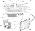
- FIGURE 2illustrates a paddle electrode 200 for a defibrillator, such as that shown in FIGURE 1 , having an improved shock button 210.
- the FIGURE 2 embodimentadopts shock button 210 having the same appearance and operation as the shock button on the user control panel of the defibrillator to which the paddle is connected.
- shock button 210has the same triangular or teardrop shape as shock button 110.
- shock button 210includes a shock graphic 230 on the button, such as a lightning bolt graphic.
- the paddle 200may also include a label 220, such as "Shock" or "3", that is similar to the indicia adjacent shock button 110 on the user control panel 115.
- Shock button 210may have the same color as the user control panel shock button; preferably red or orange. Shock button 210 may also incorporate the same internal illumination like the user control panel shock button. Shock button 210 would thus light up when the defibrillator high energy circuit is charged and armed for use. The lighted buttons may optionally flash when armed.
- Shock button 220should mimic the operation of the user control panel shock button as closely as possible.
- Each buttonmay employ the same push button operation with tactile feedback when the internal switch closes.
- Each buttonmay be comprised of the same outer textural material, such as silicon rubber. Within the exigencies of paddle operation ergonomics, the closing travel distance may be similar in each button.
- the improved shock button 210may also be used on the second paddle as well.
- the improved shock button 210may effectively replace both prior art shock buttons 120, 120' as shown in FIGURE 1 . If defibrillation paddle electrodes are in use, a shock is delivered by pressing both paddle shock buttons 210 simultaneously, as with the prior art paddle electrodes.
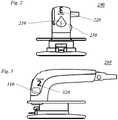
- FIGURE 3a paddle electrode 205 having an improved charging button 310 is illustrated.
- the appearance and operation of the paddle charging button 310is similar to the charging button that is located on the defibrillator user control panel. It is seen that charging button 310 effectively replaces both charge button 140 and charge indicator light 150 of the prior art paddle electrode 180.
- charging buttons 140, 310are shown in FIGURES 1 and 3 to be rectangular, alternative shapes such as circular may be used.
- Paddle electrode 205may also include a label 320 next to the charging button 310 that is similar to the indicia adjacent charge button 130 on the user control panel 115. Such consistent labeling may be textual, such as the same word “Charge” or "2" appearing beside each charge button 310, 130.
- Charging button 310may have the same color as the user control panel charge button; preferably blue or yellow. Charging button 310 may also incorporate the same internal illumination as the user control panel charging button. Shock button 210 would thus light up when the defibrillator high energy circuit is available to be charged.
- shock delivery button 210differs in shape and appearance from any of the other non-shock delivery buttons employed by the defibrillator.
- the color and/or illumination of shock delivery button 210is distinctive from any of the other non-shock delivery buttons employed by the defibrillator.
- defibrillator 110may comprise a controller in communication with an electrode type sensor, which detects which of paddle electrode 200, 205 or adhesive pad electrode 190 is connected at connector port 170. If the electrode type sensor detects an adhesive pad electrode, the controller causes the shock delivery button on the user control panel to be enabled. In this case, the defibrillator may alert the user by button illumination, display 105 messaging, or aural indicators that the adhesive pad electrodes are connected and that the user control panel shock button is enabled.
- Defibrillator 110may further comprise a paddle electrode sensor disposed adjacent a paddle electrode holder that is attached to the base unit.
- the paddle electrode sensordetects when the paddle electrodes are removed from the holder, presumably for use.
- the paddle electrode sensorcommunicates paddle deployment to the controller, which then enables the paddle operating controls, i.e., the shock button and/or the charging button. If the controller senses both the connection of paddle electrodes and deployment of paddle electrodes, it may optionally disable the user control panel shock button. In this case, the defibrillator may alert the user by button illumination, display 105 messaging, or aural indicators that the paddle electrodes are connected and that the paddle shock button is enabled.
- step 400Use of the defibrillator begins at step 400.
- advanced defibrillatorsare typically staged with the paddle electrode already connected to the device, in order to allow rapid deployment.
- step 410can also be accomplished before a defibrillation event begins.
- a usermay connect or replace the paddle electrode with an adhesive pad electrode, at step 420.
- its controller/sensordetects which type of electrode is in use at step 430. If the adhesive pad electrode is connected, the user control panel shock button is enabled, step 440. If the paddle electrode is connected, or if no electrode at all is detected, the controller may disable the user control panel shock button at step 450. The defibrillator may then display a message, warning light, or audible signal at step 460 that the electrode is not connected and to check the electrode.
- the defibrillatornext senses when the paddle electrodes are removed from their holder for deployment at step 470. Once deployed, the defibrillator will enable the paddle electrode charging and shock controls, at step 480. Once either step 440 or step 480 is complete, the defibrillator is ready to deliver therapy, step 490.
- the defibrillation methodcontinues after step 490 similar to that performed in the prior art.
- the userpresses the charge button on the front panel or paddle electrode.
- the defibrillatoralerts the user when charging is complete.
- the userthen applies the defibrillation therapy by pressing the enabled shock button on the paddle or user control panel as appropriate.
Landscapes
- Health & Medical Sciences (AREA)
- Engineering & Computer Science (AREA)
- Animal Behavior & Ethology (AREA)
- Biomedical Technology (AREA)
- Nuclear Medicine, Radiotherapy & Molecular Imaging (AREA)
- Radiology & Medical Imaging (AREA)
- Life Sciences & Earth Sciences (AREA)
- General Health & Medical Sciences (AREA)
- Public Health (AREA)
- Veterinary Medicine (AREA)
- Cardiology (AREA)
- Heart & Thoracic Surgery (AREA)
- Human Computer Interaction (AREA)
- Electrotherapy Devices (AREA)
Description
- The present invention relates to defibrillators for cardiac resuscitation. The invention relates in particular to an improved user interface for delivering defibrillation therapy from a defibrillator configured for electrodes both in a handheld paddle form and in an adhesively applied electrode pads form.
- Cardiac arrest is a life-threatening medical condition in which the patient's heart fails to provide blood flow to support life. A defibrillator can be used to deliver defibrillating shocks to a patient suffering from cardiac arrest or other arrhythmia. The defibrillator resolves this condition by delivering a high-voltage impulse to the heart in order to restore normal rhythm and contractile function in patients who are experiencing cardiac arrhythmia.
- Ventricular fibrillation (VF) or ventricular tachycardia (VT) are immediately life-threatening arrhythmias that are typically non-perfusing, i.e. not accompanied by spontaneous circulation. Atrial fibrillation (AF) is an arrhythmia which is potentially life-threatening, but is accompanied by spontaneous circulation. Each type of arrhythmia may be best treated with a different type of defibrillation shock. For example, AF is treated with a synchronized shock (cardio-version). VF and unstable VT are treated with an unsynchronized shock.
- Defibrillators suitable for use in advanced life support or hospital environments often have a number of modes of operation. Each mode treats a different kind of cardiac event. Each event in turn has a different level of urgency in providing treatment. Advanced defibrillators such as these are typically more complicated to use.
- For example, defibrillation of non-perfusing arrhythmias such as VF or VT must be delivered very soon after the onset of cardiac arrest in order to be effective. It is estimated that the chance of survival falls by 10% for every minute of delay to defibrillation beyond four minutes after cardiac arrest. Hence, it is vital that once a defibrillator is brought to the patient, the rescuer deploy and use it quickly.
- Automated external defibrillator (AED) mode is effective for rapid treatment of non-perfusing arrhythmias by lesser-trained rescuers. In the AED mode, the defibrillator automatically analyzes the electrocardiogram (ECG) rhythm of an unconscious patient to quickly ascertain whether defibrillation is necessary. The defibrillator analyzes the ECG signal for signs of arrhythmia. If VF is detected, the defibrillator signals the rescuer that a shock is advised and charges its electrotherapy circuit to a therapeutic energy. The rescuer must only press a shock button on the defibrillator to deliver a defibrillation pulse to resuscitate the patient.
- In the manual mode of operation, the defibrillator allows the user to select a desired amount of defibrillation energy and apply that energy directly to the patient without previous automatic diagnosis. Generally, only the minimum amount of energy necessary to convert the particular arrhythmia is desired, because too much energy can potentially injure the heart or create other complications. The user typically selects the energy level by turning a knob on the defibrillator control panel to one of several energy setting positions. The manual mode requires a more highly trained user to diagnose the underlying rhythm and select the proper therapeutic energy.
- External defibrillators typically act through hand-held electrode paddles or adhesively-applied electrode pads applied across the chest of the patient. The electrodes are used to apply the defibrillating shock and can also be used to acquire an ECG signal from the patient's heart. Paddle electrodes typically have a shock delivery button(s) or key(s) located on the paddles themselves. The rescuer delivers the shock by pressing the paddles to the patient's torso, verifying that bystanders are clear, and then pressing the paddle shock key(s).
- Defibrillators may also employ disposable adhesive electrodes, which are applied to the patient's torso. Defibrillators using these types of electrodes typically rely on a shock delivery button that resides on the defibrillator's front control panel. One exemplary defibrillator is the MRx monitor/Defibrillator, manufactured by Philips Electronics North America Corp. of Andover, MA which uses an orange triangular shaped shock button that is located on the front panel. The MRx shock button lights up when the device is ready to deliver a shock.
FIGURE 1 illustrates the frontpanel shock button 110 and thepaddle shock button 120, 120' as disposed on the MRx monitor/defibrillator. - Many advanced defibrillators accept both paddle and adhesive electrodes. Therefore, a user may have one or more choices of shock delivery control depending on the electrode type employed.
US 5713925 describes a defibrillator capable of being connected to both paddle and adhesive electrodes.US 5441520 describes a defibrillator that automatically determines the type of pads or paddles connected.- A problem that arises with advanced defibrillators is that their complexity requires more training to use properly and efficiently. Many rescuers, such as first responders, are trained only in the use of simpler and more automated AEDs, which use adhesive electrodes. These rescuers may find themselves in situations in which only an advanced defibrillator having paddles is available. Any confusion or mistake associated with the rescuer's lack of familiarity with the device can lead to unacceptable delay of treatment.
- Specifically, there is the possibility with existing advanced defibrillators that users unfamiliar with the complexity of the defibrillator may become confused by the differences between the appearance of the defibrillation control buttons on the front panel of the device and of the control buttons on the external paddles. The less-experienced user may delay treatment if he believes that the therapy differs according to differences in the control buttons. Thus it is desirable for an advanced defibrillator to have an intuitive user interface that a lesser-trained rescuer can quickly and unambiguously understand, deploy, and use.
- The present invention arises from the discovery that the prior art arrangement of controls for delivering electrotherapy in an advanced defibrillator is not optimal. The inventors have discovered that the prior art arrangement may incur delay to defibrillation in a sudden cardiac arrest event because the operator may become confused by the differences between the user controls when using paddle-type electrodes or adhesive pad electrodes. The inventors have solved the problem by describing user controls that are consistent in shape and appearance across both types of electrodes.
- The object of the present invention is achieved with a defibrillator according to claim 1.
- In accordance with the principles of the present invention, a defibrillator for use with both paddle and adhesive electrodes is described, wherein the shock button or buttons on the paddles are configured to visually match the orange triangular shock button on the front panel of the defibrillator. Thus, the overall user interface is conformed and simplified, which reduces confusion during use.
- In accordance with another embodiment of the present invention, a defibrillator for use with both paddle and adhesive electrodes is described, wherein the shock button or buttons on the paddles are configured to selectively light up when the product is charged and ready to shock. The shock button on the paddle electrode operates and looks similar to the shock button located on the control panel. This feature reduces confusion, by intuitively informing lesser-trained users that the paddle shock button or buttons initiate exactly the same therapy as the shock button on the front panel.
- In accordance with yet another embodiment of the present invention, a defibrillator for use with both paddle and adhesive pad electrodes is described, wherein the control buttons and indications associated with charging and discharging the defibrillating high energy circuit have the same operation and appearance regardless of the type of electrodes in use.
- Also a method of enabling a defibrillator for delivering therapy is described, comprising the steps of providing a first shock delivery button on a user control panel disposed on the defibrillator, electrically coupling either a paddle electrode having a second shock delivery button or an adhesive electrode to the defibrillator, sensing the coupling of the adhesive electrode and enabling the first shock delivery button only upon sensing the electrically coupling the adhesive electrode step. In this method, each of the first shock delivery button and the second shock delivery button has the same shape.
- In the drawings:
FIGURE 1 illustrates a prior art defibrillator arrangement of shock control buttons for delivering electrotherapy through paddle or adhesive pad electrodes.FIGURE 2 illustrates an improved arrangement for a defibrillator shock button or buttons, as disposed on a paddle electrode.FIGURE 3 illustrates an improved arrangement for a defibrillator charge control button, as disposed on a paddle electrode.FIGURE 4 is a flow chart showing an improved method for delivering defibrillation shocks from a defibrillator having either a paddle or adhesive pad electrode.- Turning now to
FIGURE 1 , a knowndefibrillator 100 which is configured to use both apaddle electrode 180 or anadhesive pad electrode 190 is illustrated. The base ofdefibrillator 100 comprises aconnector port 170 for electrodes and auser control panel 115. Messages regarding the status of the defibrillator, patient, and/or electrodes may be displayed onoptional display 105. User control panel 115 comprises graphic and text labeling indicia that are located adjacent to the controls associated with charging and discharging the defibrillating high energy circuit.FIGURE 1 illustrates the use of text indications located next to the respective control, such as "Select Energy", "Charge", or "Shock." Alternatively, a 1-2-3 numbering scheme may be shown onuser control panel 115 to help guide the user in the proper execution of the steps of a rescue. Thus, the first step of selecting energy may be indicated by a "1" label, the second step of charging the high energy circuit may be indicated by a "2" label, and the third step of delivering the shock may be indicated by a "3" label, each appearing adjacent the respective control.- Either type of
electrode defibrillator 100 atconnector port 170. Alternatively, each type of electrode 180,190 may have a unique connector port on the defibrillator.Paddle electrodes 180 are employed by pressing the electrodes to the patient's chest at the standard anterior-anterior (A-A) positions. The defibrillator high energy circuit is charged by pressingcharge button 140. When the defibrillator is fully charged and ready to shock,charge indicator light 150 illuminates. Aural or verbal prompts, such as "press shock button now", or "deliver shock now" may be issued simultaneously with theindicator light 150 illumination. Then, when good electrical contact with the patient is established, the user presses bothshock buttons 120, 120' simultaneously to deliver the therapy. Adhesive pad electrodes 190 are employed by applying theadhesive pads 190 to the patient's chest at either the A-A or anterior-posterior (A-P) positions. All shock controls for these pads are located on thecontrol panel 115. The manual shock mode requires the user to press thecharge button 130 oncontrol panel 115 to charge the defibrillator high energy circuit. When the defibrillator is fully charged and ready to shock,shock button 110 illuminates. Aural or verbal prompts, such as "press shock button now", or "deliver shock now" may be issued simultaneously with theshock button 110 illumination. The user then pressesshock button 110 to deliver the therapy.FIGURE 2 illustrates apaddle electrode 200 for a defibrillator, such as that shown inFIGURE 1 , having animproved shock button 210. TheFIGURE 2 embodiment adoptsshock button 210 having the same appearance and operation as the shock button on the user control panel of the defibrillator to which the paddle is connected. In a preferred embodiment,shock button 210 has the same triangular or teardrop shape asshock button 110. Likeshock button 110,shock button 210 includes a shock graphic 230 on the button, such as a lightning bolt graphic. Thepaddle 200 may also include alabel 220, such as "Shock" or "3", that is similar to the indiciaadjacent shock button 110 on theuser control panel 115.Shock button 210 may have the same color as the user control panel shock button; preferably red or orange.Shock button 210 may also incorporate the same internal illumination like the user control panel shock button.Shock button 210 would thus light up when the defibrillator high energy circuit is charged and armed for use. The lighted buttons may optionally flash when armed.Shock button 220 should mimic the operation of the user control panel shock button as closely as possible. Each button may employ the same push button operation with tactile feedback when the internal switch closes. Each button may be comprised of the same outer textural material, such as silicon rubber. Within the exigencies of paddle operation ergonomics, the closing travel distance may be similar in each button.- Although just one paddle is shown in
FIGURE 2 , it is understood that theimproved shock button 210 may also be used on the second paddle as well. Thus, theimproved shock button 210 may effectively replace both priorart shock buttons 120, 120' as shown inFIGURE 1 . If defibrillation paddle electrodes are in use, a shock is delivered by pressing bothpaddle shock buttons 210 simultaneously, as with the prior art paddle electrodes. - Turning now to
FIGURE 3 , apaddle electrode 205 having animproved charging button 310 is illustrated. Under the same principles of invention as described above, the appearance and operation of thepaddle charging button 310 is similar to the charging button that is located on the defibrillator user control panel. It is seen that chargingbutton 310 effectively replaces bothcharge button 140 andcharge indicator light 150 of the priorart paddle electrode 180. Although chargingbuttons FIGURES 1 and3 to be rectangular, alternative shapes such as circular may be used. Paddle electrode 205 may also include alabel 320 next to thecharging button 310 that is similar to the indiciaadjacent charge button 130 on theuser control panel 115. Such consistent labeling may be textual, such as the same word "Charge" or "2" appearing beside eachcharge button Charging button 310 may have the same color as the user control panel charge button; preferably blue or yellow.Charging button 310 may also incorporate the same internal illumination as the user control panel charging button.Shock button 210 would thus light up when the defibrillator high energy circuit is available to be charged.- It is understood that the
shock delivery button 210, as well as the shock delivery button on the user control panel, differs in shape and appearance from any of the other non-shock delivery buttons employed by the defibrillator. In addition, the color and/or illumination ofshock delivery button 210 is distinctive from any of the other non-shock delivery buttons employed by the defibrillator. These features further reduce operator confusion and more quickly direct the operator's attention to the controls required to deliver defibrillation therapy. - In order to reduce confusion further,
defibrillator 110 may comprise a controller in communication with an electrode type sensor, which detects which ofpaddle electrode adhesive pad electrode 190 is connected atconnector port 170. If the electrode type sensor detects an adhesive pad electrode, the controller causes the shock delivery button on the user control panel to be enabled. In this case, the defibrillator may alert the user by button illumination,display 105 messaging, or aural indicators that the adhesive pad electrodes are connected and that the user control panel shock button is enabled. Defibrillator 110 may further comprise a paddle electrode sensor disposed adjacent a paddle electrode holder that is attached to the base unit. The paddle electrode sensor detects when the paddle electrodes are removed from the holder, presumably for use. The paddle electrode sensor communicates paddle deployment to the controller, which then enables the paddle operating controls, i.e., the shock button and/or the charging button. If the controller senses both the connection of paddle electrodes and deployment of paddle electrodes, it may optionally disable the user control panel shock button. In this case, the defibrillator may alert the user by button illumination,display 105 messaging, or aural indicators that the paddle electrodes are connected and that the paddle shock button is enabled.- Turning now to
FIGURE 4 , a method of enabling a defibrillator having either paddle electrodes or adhesive pad electrodes is illustrated. Use of the defibrillator begins atstep 400. In addition, advanced defibrillators are typically staged with the paddle electrode already connected to the device, in order to allow rapid deployment. Thus, step 410 can also be accomplished before a defibrillation event begins. - At the beginning of the defibrillation event, a user may connect or replace the paddle electrode with an adhesive pad electrode, at
step 420. Once the defibrillator is activated, its controller/sensor detects which type of electrode is in use atstep 430. If the adhesive pad electrode is connected, the user control panel shock button is enabled,step 440. If the paddle electrode is connected, or if no electrode at all is detected, the controller may disable the user control panel shock button atstep 450. The defibrillator may then display a message, warning light, or audible signal atstep 460 that the electrode is not connected and to check the electrode. - If the paddle electrodes are connected, the defibrillator next senses when the paddle electrodes are removed from their holder for deployment at
step 470. Once deployed, the defibrillator will enable the paddle electrode charging and shock controls, atstep 480. Once eitherstep 440 or step 480 is complete, the defibrillator is ready to deliver therapy,step 490. - The defibrillation method continues after
step 490 similar to that performed in the prior art. When defibrillation is desired, the user presses the charge button on the front panel or paddle electrode. The defibrillator alerts the user when charging is complete. The user then applies the defibrillation therapy by pressing the enabled shock button on the paddle or user control panel as appropriate. - Other variations will readily occur to those skilled in the art. For instance, the particular identifying markings on the first and second shock buttons or the functionality of the underlying modes of enabling the buttons to deliver a shock may vary within the scope of the claimed invention.
Claims (9)
- A defibrillator (100) configured to use both of a paddle electrode and an adhesive electrode (190), comprising:a base unit with a user control panel (115);a first shock delivery button (110) having a first shape disposed on the user control panel;a paddle electrode (200) electrically connected to the base unit;a second shock delivery button (210) having the first shape disposed on the paddle electrode;an electrode type sensor for sensing when the adhesive electrode is connected; anda controller communicatively coupled to the electrode type sensor and to the first shock delivery button, wherein the controller enables the first shock delivery button only when the adhesive electrode is connected.
- The defibrillator of Claim 1, further comprising a plurality of non-shock delivery buttons having a plurality of shapes, and further wherein the first shape is different than any other of the plurality of shapes.
- The defibrillator of Claim 2, wherein the first shape is one of a triangular shape or a teardrop shape.
- The defibrillator of Claim 2, wherein the first shock delivery button is illuminated in a first color when enabled for shock delivery, and further wherein the second shock delivery button is illuminated in the first color when enabled for shock delivery.
- The defibrillator of Claim 4, wherein the first shock delivery button flashes when enabled, and wherein the second shock delivery button flashes when enabled.
- The defibrillator of Claim 5, wherein the plurality of non-shock delivery buttons have a plurality of colors that are different than the first color.
- The defibrillator of Claim 1, wherein the first shock delivery button is illuminated when the adhesive electrode is connected.
- The defibrillator of Claim 1, further comprising:a paddle holder disposed on the base unit for holding the paddle electrode; a paddle sensor for sensing when the paddle electrode is removed from the paddle holder; anda controller communicatively coupled to the paddle sensor and to the second shock delivery button, wherein the controller enables the second shock delivery button when the paddle electrode is deployed.
- The defibrillator of Claim 2, further comprising:a second paddle electrode electrically connected to the base unit; anda third shock delivery button having the first shape disposed on the second paddle electrode.
Applications Claiming Priority (2)
| Application Number | Priority Date | Filing Date | Title |
|---|---|---|---|
| US201161436668P | 2011-01-27 | 2011-01-27 | |
| PCT/IB2012/050318WO2012101573A2 (en) | 2011-01-27 | 2012-01-24 | Defibrillator paddles with lighted shock buttons |
Publications (2)
| Publication Number | Publication Date |
|---|---|
| EP2667943A2 EP2667943A2 (en) | 2013-12-04 |
| EP2667943B1true EP2667943B1 (en) | 2019-03-13 |
Family
ID=45571570
Family Applications (1)
| Application Number | Title | Priority Date | Filing Date |
|---|---|---|---|
| EP12703347.0AActiveEP2667943B1 (en) | 2011-01-27 | 2012-01-24 | Defibrillator paddles with lighted shock buttons |
Country Status (7)
| Country | Link |
|---|---|
| US (2) | US9839789B2 (en) |
| EP (1) | EP2667943B1 (en) |
| JP (1) | JP6096125B2 (en) |
| CN (1) | CN103338813B (en) |
| BR (1) | BR112013018980A2 (en) |
| RU (1) | RU2633472C2 (en) |
| WO (1) | WO2012101573A2 (en) |
Families Citing this family (9)
| Publication number | Priority date | Publication date | Assignee | Title |
|---|---|---|---|---|
| JP6096125B2 (en)* | 2011-01-27 | 2017-03-15 | コーニンクレッカ フィリップス エヌ ヴェKoninklijke Philips N.V. | Defibrillator paddle with lit shock button |
| US9700227B2 (en)* | 2013-09-25 | 2017-07-11 | Bardy Diagnostics, Inc. | Ambulatory electrocardiography monitoring patch optimized for capturing low amplitude cardiac action potential propagation |
| WO2016058004A1 (en)* | 2014-10-10 | 2016-04-14 | Ruse Technologies, Llc | Method and system for hospital, emt/ems, and aed grade external defibrillation and transcutaneous pacing |
| JP6444695B2 (en)* | 2014-11-11 | 2018-12-26 | フクダ電子株式会社 | External defibrillator |
| JP2019512332A (en) | 2016-03-31 | 2019-05-16 | コーニンクレッカ フィリップス エヌ ヴェKoninklijke Philips N.V. | Defibrillator paddle with usage indicator |
| USD849952S1 (en)* | 2016-05-04 | 2019-05-28 | Koninklijke Philips N.V. | Set of defibrillator paddles |
| CN106039563A (en)* | 2016-05-14 | 2016-10-26 | 赵建国 | Angina pectoris alleviation treatment apparatus for cardiovascular medicine |
| US11484718B2 (en) | 2021-01-22 | 2022-11-01 | Ruse Technologies, Llc | Multimode ICD system comprising phased array amplifiers to treat and manage CRT, CHF, and PVC disorders using ventricle level-shifting therapy to minimize VT/VF and SCA |
| CA3204115A1 (en) | 2021-01-28 | 2022-08-04 | Tommi KUUTTI | Pocket-sized automated external defibrillator |
Citations (1)
| Publication number | Priority date | Publication date | Assignee | Title |
|---|---|---|---|---|
| US5713925A (en)* | 1996-01-11 | 1998-02-03 | Physio-Control Corporation | Adapter for isolating pacing and defibrillation signals |
Family Cites Families (47)
| Publication number | Priority date | Publication date | Assignee | Title |
|---|---|---|---|---|
| US4850356A (en)* | 1980-08-08 | 1989-07-25 | Darox Corporation | Defibrillator electrode system |
| US4681112A (en)* | 1985-01-08 | 1987-07-21 | Physio-Control Corporation | Medical instrument including electrodes adapted for right and left-handed use |
| US4705044A (en)* | 1985-11-12 | 1987-11-10 | Kone Instruments Inc. | Defibrillator paddle |
| US4779630A (en)* | 1987-09-18 | 1988-10-25 | Katecho, Inc. | Defibrillator pad assembly and method for using same |
| US4915109A (en)* | 1988-09-23 | 1990-04-10 | Physio-Control Corporation | Defibrillator electrode adaptor |
| US5148805A (en)* | 1991-02-11 | 1992-09-22 | Kas Products, Inc. | Defibrillator pad system and method for using same |
| US5441520A (en)* | 1993-04-06 | 1995-08-15 | Hewlett-Packard Corporation | Defibrillator patient connection system with automatic identification |
| US5342403A (en)* | 1993-04-09 | 1994-08-30 | Hewlett-Packard Corporation | Integrated defibrillator/monitor architecture with defibrillator-only fail-safe mode of operation |
| FR2720947B1 (en)* | 1994-06-09 | 1996-08-09 | Odam Off Distri App Medicaux | Defibrillator apparatus having a plurality of connector / electrode assemblies of different types. |
| US6532379B2 (en)* | 1995-05-04 | 2003-03-11 | Robert A. Stratbucker | Bio-electic interface adapter with twelve-lead ECG capability and provision for defibrillation |
| US5705044A (en) | 1995-08-07 | 1998-01-06 | Akashic Memories Corporation | Modular sputtering machine having batch processing and serial thin film sputtering |
| US6154673A (en)* | 1997-12-30 | 2000-11-28 | Agilent Technologies, Inc. | Multilingual defibrillator |
| US20060058848A1 (en)* | 1998-11-20 | 2006-03-16 | Medtronic Emergency Response Systems, Inc. | AED with user inputs in response to prompts |
| US6334070B1 (en)* | 1998-11-20 | 2001-12-25 | Medtronic Physio-Control Manufacturing Corp. | Visual and aural user interface for an automated external defibrillator |
| US6097987A (en)* | 1998-12-30 | 2000-08-01 | Medical Research Laboratories, Inc. | External defibrillator electrode apparatus |
| US6872080B2 (en)* | 1999-01-29 | 2005-03-29 | Cardiac Science, Inc. | Programmable AED-CPR training device |
| RU2153901C1 (en)* | 1999-02-08 | 2000-08-10 | Открытое акционерное общество "Ижевский мотозавод "Аксион-холдинг" | Defibrillator |
| US6266562B1 (en)* | 1999-04-30 | 2001-07-24 | Agilent Technologies, Inc. | Defibrillator with automated test load |
| US20050131465A1 (en)* | 2000-02-04 | 2005-06-16 | Freeman Gary A. | Integrated resuscitation |
| US7016726B1 (en)* | 2000-05-17 | 2006-03-21 | Koninklijke Philips Electronics N.V. | Smart medical connector system and method of use |
| US6754526B2 (en) | 2000-11-13 | 2004-06-22 | Medtronic Physio-Control Corp | Defibrillator with a multiple-mode interface |
| US6662056B2 (en)* | 2000-12-22 | 2003-12-09 | Koninklijke Philips Electronics N.V. | Cartridge for storing an electrode pad |
| US6580945B2 (en)* | 2001-03-20 | 2003-06-17 | Koninklijke Philips Electronics N.V. | Defibrillator using low impedance high capacitance double layer capacitor |
| US6560485B2 (en)* | 2001-03-27 | 2003-05-06 | Koninklijke Philips Electronics N.V. | Four contact identification defibrillator electrode system |
| JP2004049566A (en) | 2002-07-19 | 2004-02-19 | Olympus Corp | Electrosurgical apparatus |
| AU2003264833A1 (en)* | 2002-10-23 | 2004-05-13 | Denney, Douglas, Michael | Interactive automatic external defibrillator providing attachment guidance to operator |
| US7970464B2 (en)* | 2002-11-13 | 2011-06-28 | Physio-Control, Inc. | Method and system for responding to non-perfusing and non-shockable heart rhythms |
| US7769465B2 (en)* | 2003-06-11 | 2010-08-03 | Matos Jeffrey A | System for cardiac resuscitation |
| US20050033397A1 (en)* | 2003-08-04 | 2005-02-10 | Integral Technologies, Inc. | Low cost electrical stimulation and shock devices manufactured from conductive loaded resin-based materials |
| US20050070964A1 (en)* | 2003-09-30 | 2005-03-31 | Kim Hansen | Automated external defibrillator (AED) with context-sensitive help |
| US8401637B2 (en)* | 2004-11-24 | 2013-03-19 | Galvani, Ltd. | Medium voltage therapy applications in treating cardiac arrest |
| CN101084040B (en)* | 2004-12-20 | 2012-12-05 | 皇家飞利浦电子股份有限公司 | Automatic external defibrillator for adult and pediatric patients |
| US20060142805A1 (en) | 2004-12-27 | 2006-06-29 | Koninklijke Philips Electronics N.V. | Method and article for packaging an automatic external defibrillator for use without a prescription |
| US20100023074A1 (en)* | 2004-12-27 | 2010-01-28 | Koninklijke Philips Electronics N.V. | Method and Apparatus for Contacting an Over-the-Counter Automatic External Defibrillator |
| US7510526B2 (en)* | 2004-12-30 | 2009-03-31 | Medtronic Emergency Response Systems, Inc. | Medical device information system |
| US20080004663A1 (en)* | 2005-12-22 | 2008-01-03 | Medtronic Emergency Response Systems, Inc. | Defibrillator with implantable medical device detection |
| JP2010509006A (en)* | 2006-11-15 | 2010-03-25 | ハートサイン テクノロジーズ リミテッド | Disposable external defibrillator |
| US8271082B2 (en)* | 2007-06-07 | 2012-09-18 | Zoll Medical Corporation | Medical device configured to test for user responsiveness |
| US8140154B2 (en)* | 2007-06-13 | 2012-03-20 | Zoll Medical Corporation | Wearable medical treatment device |
| US7985793B2 (en)* | 2007-06-29 | 2011-07-26 | Exxonmobil Chemical Patents Inc. | Composites comprising elastomer, layered filler and tackifier |
| US20090292213A1 (en)* | 2008-05-21 | 2009-11-26 | Searete Llc, A Limited Liability Corporation Of The State Of Delaware | Circulatory monitoring systems and methods |
| GB2460690A (en)* | 2008-06-05 | 2009-12-09 | Poems Ltd | Pocket-sized defibrillator with direct attachment to a patient. |
| US8097926B2 (en)* | 2008-10-07 | 2012-01-17 | Mc10, Inc. | Systems, methods, and devices having stretchable integrated circuitry for sensing and delivering therapy |
| US8781576B2 (en)* | 2009-03-17 | 2014-07-15 | Cardiothrive, Inc. | Device and method for reducing patient transthoracic impedance for the purpose of delivering a therapeutic current |
| US8615295B2 (en)* | 2009-03-17 | 2013-12-24 | Cardiothrive, Inc. | External defibrillator |
| JP6096125B2 (en)* | 2011-01-27 | 2017-03-15 | コーニンクレッカ フィリップス エヌ ヴェKoninklijke Philips N.V. | Defibrillator paddle with lit shock button |
| US9592177B2 (en)* | 2012-11-26 | 2017-03-14 | Sayed Nour | Circulatory flow restoration device |
- 2012
- 2012-01-24JPJP2013550982Apatent/JP6096125B2/enactiveActive
- 2012-01-24RURU2013139562Apatent/RU2633472C2/ennot_activeIP Right Cessation
- 2012-01-24CNCN201280006490.5Apatent/CN103338813B/enactiveActive
- 2012-01-24EPEP12703347.0Apatent/EP2667943B1/enactiveActive
- 2012-01-24BRBR112013018980Apatent/BR112013018980A2/ennot_activeApplication Discontinuation
- 2012-01-24USUS13/981,712patent/US9839789B2/enactiveActive
- 2012-01-24WOPCT/IB2012/050318patent/WO2012101573A2/enactiveApplication Filing
- 2017
- 2017-11-08USUS15/806,979patent/US10369371B2/enactiveActive
Patent Citations (1)
| Publication number | Priority date | Publication date | Assignee | Title |
|---|---|---|---|---|
| US5713925A (en)* | 1996-01-11 | 1998-02-03 | Physio-Control Corporation | Adapter for isolating pacing and defibrillation signals |
Also Published As
| Publication number | Publication date |
|---|---|
| CN103338813B (en) | 2015-06-17 |
| RU2633472C2 (en) | 2017-10-12 |
| BR112013018980A2 (en) | 2017-11-07 |
| RU2013139562A (en) | 2015-03-10 |
| WO2012101573A3 (en) | 2012-11-15 |
| EP2667943A2 (en) | 2013-12-04 |
| US20180126181A1 (en) | 2018-05-10 |
| US10369371B2 (en) | 2019-08-06 |
| JP6096125B2 (en) | 2017-03-15 |
| CN103338813A (en) | 2013-10-02 |
| US9839789B2 (en) | 2017-12-12 |
| WO2012101573A2 (en) | 2012-08-02 |
| JP2014505551A (en) | 2014-03-06 |
| US20140005737A1 (en) | 2014-01-02 |
Similar Documents
| Publication | Publication Date | Title |
|---|---|---|
| US10369371B2 (en) | Defibrillator paddles with lighted shock buttons | |
| US6021349A (en) | Defibrillator with automatic and manual modes | |
| EP2688644B1 (en) | Universal aed training adapter | |
| EP1833565B1 (en) | Automatic external defibrillator for adult and pediatric patients | |
| US6405082B1 (en) | Method and apparatus for distinguishing between therapy modes in a defibrillator | |
| US20180342319A1 (en) | Single use aed | |
| EP2994190B1 (en) | Defibrillator electrode having adult and pediatric graphics | |
| WO2008020369A1 (en) | External defibrillators for analysis of multiple arrhythmia conditions | |
| US9511239B2 (en) | Electrode with feature for indicating prior use with adult or pediatric subject and systems and methods including same | |
| CN102526881A (en) | Defibrillator device with status indicating transport handle | |
| JP2019512332A (en) | Defibrillator paddle with usage indicator | |
| KR20100062015A (en) | Defibrillator with video function | |
| EP2624909B1 (en) | Mode knob with time criticality ordering of modes |
Legal Events
| Date | Code | Title | Description |
|---|---|---|---|
| PUAI | Public reference made under article 153(3) epc to a published international application that has entered the european phase | Free format text:ORIGINAL CODE: 0009012 | |
| 17P | Request for examination filed | Effective date:20130827 | |
| AK | Designated contracting states | Kind code of ref document:A2 Designated state(s):AL AT BE BG CH CY CZ DE DK EE ES FI FR GB GR HR HU IE IS IT LI LT LU LV MC MK MT NL NO PL PT RO RS SE SI SK SM TR | |
| 17Q | First examination report despatched | Effective date:20160510 | |
| RIN1 | Information on inventor provided before grant (corrected) | Inventor name:MATHESON, ANTHONY Inventor name:KOZIN, SIMON EDWARD | |
| STAA | Information on the status of an ep patent application or granted ep patent | Free format text:STATUS: EXAMINATION IS IN PROGRESS | |
| GRAP | Despatch of communication of intention to grant a patent | Free format text:ORIGINAL CODE: EPIDOSNIGR1 | |
| STAA | Information on the status of an ep patent application or granted ep patent | Free format text:STATUS: GRANT OF PATENT IS INTENDED | |
| INTG | Intention to grant announced | Effective date:20180814 | |
| GRAS | Grant fee paid | Free format text:ORIGINAL CODE: EPIDOSNIGR3 | |
| GRAA | (expected) grant | Free format text:ORIGINAL CODE: 0009210 | |
| STAA | Information on the status of an ep patent application or granted ep patent | Free format text:STATUS: THE PATENT HAS BEEN GRANTED | |
| AK | Designated contracting states | Kind code of ref document:B1 Designated state(s):AL AT BE BG CH CY CZ DE DK EE ES FI FR GB GR HR HU IE IS IT LI LT LU LV MC MK MT NL NO PL PT RO RS SE SI SK SM TR | |
| REG | Reference to a national code | Ref country code:GB Ref legal event code:FG4D | |
| REG | Reference to a national code | Ref country code:CH Ref legal event code:EP Ref country code:AT Ref legal event code:REF Ref document number:1106897 Country of ref document:AT Kind code of ref document:T Effective date:20190315 | |
| REG | Reference to a national code | Ref country code:IE Ref legal event code:FG4D | |
| REG | Reference to a national code | Ref country code:DE Ref legal event code:R096 Ref document number:602012057714 Country of ref document:DE | |
| REG | Reference to a national code | Ref country code:NL Ref legal event code:MP Effective date:20190313 | |
| REG | Reference to a national code | Ref country code:LT Ref legal event code:MG4D | |
| PG25 | Lapsed in a contracting state [announced via postgrant information from national office to epo] | Ref country code:NO Free format text:LAPSE BECAUSE OF FAILURE TO SUBMIT A TRANSLATION OF THE DESCRIPTION OR TO PAY THE FEE WITHIN THE PRESCRIBED TIME-LIMIT Effective date:20190613 Ref country code:FI Free format text:LAPSE BECAUSE OF FAILURE TO SUBMIT A TRANSLATION OF THE DESCRIPTION OR TO PAY THE FEE WITHIN THE PRESCRIBED TIME-LIMIT Effective date:20190313 Ref country code:SE Free format text:LAPSE BECAUSE OF FAILURE TO SUBMIT A TRANSLATION OF THE DESCRIPTION OR TO PAY THE FEE WITHIN THE PRESCRIBED TIME-LIMIT Effective date:20190313 Ref country code:LT Free format text:LAPSE BECAUSE OF FAILURE TO SUBMIT A TRANSLATION OF THE DESCRIPTION OR TO PAY THE FEE WITHIN THE PRESCRIBED TIME-LIMIT Effective date:20190313 | |
| PG25 | Lapsed in a contracting state [announced via postgrant information from national office to epo] | Ref country code:HR Free format text:LAPSE BECAUSE OF FAILURE TO SUBMIT A TRANSLATION OF THE DESCRIPTION OR TO PAY THE FEE WITHIN THE PRESCRIBED TIME-LIMIT Effective date:20190313 Ref country code:RS Free format text:LAPSE BECAUSE OF FAILURE TO SUBMIT A TRANSLATION OF THE DESCRIPTION OR TO PAY THE FEE WITHIN THE PRESCRIBED TIME-LIMIT Effective date:20190313 Ref country code:GR Free format text:LAPSE BECAUSE OF FAILURE TO SUBMIT A TRANSLATION OF THE DESCRIPTION OR TO PAY THE FEE WITHIN THE PRESCRIBED TIME-LIMIT Effective date:20190614 Ref country code:NL Free format text:LAPSE BECAUSE OF FAILURE TO SUBMIT A TRANSLATION OF THE DESCRIPTION OR TO PAY THE FEE WITHIN THE PRESCRIBED TIME-LIMIT Effective date:20190313 Ref country code:BG Free format text:LAPSE BECAUSE OF FAILURE TO SUBMIT A TRANSLATION OF THE DESCRIPTION OR TO PAY THE FEE WITHIN THE PRESCRIBED TIME-LIMIT Effective date:20190613 Ref country code:LV Free format text:LAPSE BECAUSE OF FAILURE TO SUBMIT A TRANSLATION OF THE DESCRIPTION OR TO PAY THE FEE WITHIN THE PRESCRIBED TIME-LIMIT Effective date:20190313 | |
| REG | Reference to a national code | Ref country code:AT Ref legal event code:MK05 Ref document number:1106897 Country of ref document:AT Kind code of ref document:T Effective date:20190313 | |
| PG25 | Lapsed in a contracting state [announced via postgrant information from national office to epo] | Ref country code:IT Free format text:LAPSE BECAUSE OF FAILURE TO SUBMIT A TRANSLATION OF THE DESCRIPTION OR TO PAY THE FEE WITHIN THE PRESCRIBED TIME-LIMIT Effective date:20190313 Ref country code:RO Free format text:LAPSE BECAUSE OF FAILURE TO SUBMIT A TRANSLATION OF THE DESCRIPTION OR TO PAY THE FEE WITHIN THE PRESCRIBED TIME-LIMIT Effective date:20190313 Ref country code:EE Free format text:LAPSE BECAUSE OF FAILURE TO SUBMIT A TRANSLATION OF THE DESCRIPTION OR TO PAY THE FEE WITHIN THE PRESCRIBED TIME-LIMIT Effective date:20190313 Ref country code:AL Free format text:LAPSE BECAUSE OF FAILURE TO SUBMIT A TRANSLATION OF THE DESCRIPTION OR TO PAY THE FEE WITHIN THE PRESCRIBED TIME-LIMIT Effective date:20190313 Ref country code:PT Free format text:LAPSE BECAUSE OF FAILURE TO SUBMIT A TRANSLATION OF THE DESCRIPTION OR TO PAY THE FEE WITHIN THE PRESCRIBED TIME-LIMIT Effective date:20190713 Ref country code:ES Free format text:LAPSE BECAUSE OF FAILURE TO SUBMIT A TRANSLATION OF THE DESCRIPTION OR TO PAY THE FEE WITHIN THE PRESCRIBED TIME-LIMIT Effective date:20190313 Ref country code:CZ Free format text:LAPSE BECAUSE OF FAILURE TO SUBMIT A TRANSLATION OF THE DESCRIPTION OR TO PAY THE FEE WITHIN THE PRESCRIBED TIME-LIMIT Effective date:20190313 Ref country code:SK Free format text:LAPSE BECAUSE OF FAILURE TO SUBMIT A TRANSLATION OF THE DESCRIPTION OR TO PAY THE FEE WITHIN THE PRESCRIBED TIME-LIMIT Effective date:20190313 | |
| PG25 | Lapsed in a contracting state [announced via postgrant information from national office to epo] | Ref country code:PL Free format text:LAPSE BECAUSE OF FAILURE TO SUBMIT A TRANSLATION OF THE DESCRIPTION OR TO PAY THE FEE WITHIN THE PRESCRIBED TIME-LIMIT Effective date:20190313 Ref country code:SM Free format text:LAPSE BECAUSE OF FAILURE TO SUBMIT A TRANSLATION OF THE DESCRIPTION OR TO PAY THE FEE WITHIN THE PRESCRIBED TIME-LIMIT Effective date:20190313 | |
| REG | Reference to a national code | Ref country code:DE Ref legal event code:R097 Ref document number:602012057714 Country of ref document:DE | |
| PG25 | Lapsed in a contracting state [announced via postgrant information from national office to epo] | Ref country code:AT Free format text:LAPSE BECAUSE OF FAILURE TO SUBMIT A TRANSLATION OF THE DESCRIPTION OR TO PAY THE FEE WITHIN THE PRESCRIBED TIME-LIMIT Effective date:20190313 Ref country code:IS Free format text:LAPSE BECAUSE OF FAILURE TO SUBMIT A TRANSLATION OF THE DESCRIPTION OR TO PAY THE FEE WITHIN THE PRESCRIBED TIME-LIMIT Effective date:20190713 | |
| PLBE | No opposition filed within time limit | Free format text:ORIGINAL CODE: 0009261 | |
| STAA | Information on the status of an ep patent application or granted ep patent | Free format text:STATUS: NO OPPOSITION FILED WITHIN TIME LIMIT | |
| PG25 | Lapsed in a contracting state [announced via postgrant information from national office to epo] | Ref country code:DK Free format text:LAPSE BECAUSE OF FAILURE TO SUBMIT A TRANSLATION OF THE DESCRIPTION OR TO PAY THE FEE WITHIN THE PRESCRIBED TIME-LIMIT Effective date:20190313 | |
| 26N | No opposition filed | Effective date:20191216 | |
| PG25 | Lapsed in a contracting state [announced via postgrant information from national office to epo] | Ref country code:SI Free format text:LAPSE BECAUSE OF FAILURE TO SUBMIT A TRANSLATION OF THE DESCRIPTION OR TO PAY THE FEE WITHIN THE PRESCRIBED TIME-LIMIT Effective date:20190313 | |
| PG25 | Lapsed in a contracting state [announced via postgrant information from national office to epo] | Ref country code:TR Free format text:LAPSE BECAUSE OF FAILURE TO SUBMIT A TRANSLATION OF THE DESCRIPTION OR TO PAY THE FEE WITHIN THE PRESCRIBED TIME-LIMIT Effective date:20190313 | |
| PG25 | Lapsed in a contracting state [announced via postgrant information from national office to epo] | Ref country code:MC Free format text:LAPSE BECAUSE OF FAILURE TO SUBMIT A TRANSLATION OF THE DESCRIPTION OR TO PAY THE FEE WITHIN THE PRESCRIBED TIME-LIMIT Effective date:20190313 | |
| REG | Reference to a national code | Ref country code:CH Ref legal event code:PL | |
| REG | Reference to a national code | Ref country code:BE Ref legal event code:MM Effective date:20200131 | |
| PG25 | Lapsed in a contracting state [announced via postgrant information from national office to epo] | Ref country code:LU Free format text:LAPSE BECAUSE OF NON-PAYMENT OF DUE FEES Effective date:20200124 | |
| PG25 | Lapsed in a contracting state [announced via postgrant information from national office to epo] | Ref country code:LI Free format text:LAPSE BECAUSE OF NON-PAYMENT OF DUE FEES Effective date:20200131 Ref country code:CH Free format text:LAPSE BECAUSE OF NON-PAYMENT OF DUE FEES Effective date:20200131 Ref country code:BE Free format text:LAPSE BECAUSE OF NON-PAYMENT OF DUE FEES Effective date:20200131 | |
| PG25 | Lapsed in a contracting state [announced via postgrant information from national office to epo] | Ref country code:IE Free format text:LAPSE BECAUSE OF NON-PAYMENT OF DUE FEES Effective date:20200124 | |
| PG25 | Lapsed in a contracting state [announced via postgrant information from national office to epo] | Ref country code:MT Free format text:LAPSE BECAUSE OF FAILURE TO SUBMIT A TRANSLATION OF THE DESCRIPTION OR TO PAY THE FEE WITHIN THE PRESCRIBED TIME-LIMIT Effective date:20190313 Ref country code:CY Free format text:LAPSE BECAUSE OF FAILURE TO SUBMIT A TRANSLATION OF THE DESCRIPTION OR TO PAY THE FEE WITHIN THE PRESCRIBED TIME-LIMIT Effective date:20190313 | |
| PG25 | Lapsed in a contracting state [announced via postgrant information from national office to epo] | Ref country code:MK Free format text:LAPSE BECAUSE OF FAILURE TO SUBMIT A TRANSLATION OF THE DESCRIPTION OR TO PAY THE FEE WITHIN THE PRESCRIBED TIME-LIMIT Effective date:20190313 | |
| REG | Reference to a national code | Ref country code:DE Ref legal event code:R084 Ref document number:602012057714 Country of ref document:DE | |
| REG | Reference to a national code | Ref country code:GB Ref legal event code:746 Effective date:20240719 | |
| PGFP | Annual fee paid to national office [announced via postgrant information from national office to epo] | Ref country code:DE Payment date:20250129 Year of fee payment:14 | |
| PGFP | Annual fee paid to national office [announced via postgrant information from national office to epo] | Ref country code:FR Payment date:20250127 Year of fee payment:14 | |
| PGFP | Annual fee paid to national office [announced via postgrant information from national office to epo] | Ref country code:GB Payment date:20250121 Year of fee payment:14 |