EP2667829B1 - Electrospun ptfe coated stent and method of use - Google Patents
Electrospun ptfe coated stent and method of useDownload PDFInfo
- Publication number
- EP2667829B1 EP2667829B1EP12739348.6AEP12739348AEP2667829B1EP 2667829 B1EP2667829 B1EP 2667829B1EP 12739348 AEP12739348 AEP 12739348AEP 2667829 B1EP2667829 B1EP 2667829B1
- Authority
- EP
- European Patent Office
- Prior art keywords
- stent
- ptfe
- layer
- electrospun
- poly
- Prior art date
- Legal status (The legal status is an assumption and is not a legal conclusion. Google has not performed a legal analysis and makes no representation as to the accuracy of the status listed.)
- Active
Links
Images


Classifications
- A—HUMAN NECESSITIES
- A61—MEDICAL OR VETERINARY SCIENCE; HYGIENE
- A61F—FILTERS IMPLANTABLE INTO BLOOD VESSELS; PROSTHESES; DEVICES PROVIDING PATENCY TO, OR PREVENTING COLLAPSING OF, TUBULAR STRUCTURES OF THE BODY, e.g. STENTS; ORTHOPAEDIC, NURSING OR CONTRACEPTIVE DEVICES; FOMENTATION; TREATMENT OR PROTECTION OF EYES OR EARS; BANDAGES, DRESSINGS OR ABSORBENT PADS; FIRST-AID KITS
- A61F2/00—Filters implantable into blood vessels; Prostheses, i.e. artificial substitutes or replacements for parts of the body; Appliances for connecting them with the body; Devices providing patency to, or preventing collapsing of, tubular structures of the body, e.g. stents
- A61F2/02—Prostheses implantable into the body
- A61F2/04—Hollow or tubular parts of organs, e.g. bladders, tracheae, bronchi or bile ducts
- A61F2/06—Blood vessels
- A61F2/07—Stent-grafts
- A—HUMAN NECESSITIES
- A61—MEDICAL OR VETERINARY SCIENCE; HYGIENE
- A61F—FILTERS IMPLANTABLE INTO BLOOD VESSELS; PROSTHESES; DEVICES PROVIDING PATENCY TO, OR PREVENTING COLLAPSING OF, TUBULAR STRUCTURES OF THE BODY, e.g. STENTS; ORTHOPAEDIC, NURSING OR CONTRACEPTIVE DEVICES; FOMENTATION; TREATMENT OR PROTECTION OF EYES OR EARS; BANDAGES, DRESSINGS OR ABSORBENT PADS; FIRST-AID KITS
- A61F2/00—Filters implantable into blood vessels; Prostheses, i.e. artificial substitutes or replacements for parts of the body; Appliances for connecting them with the body; Devices providing patency to, or preventing collapsing of, tubular structures of the body, e.g. stents
- A61F2/82—Devices providing patency to, or preventing collapsing of, tubular structures of the body, e.g. stents
- A61F2/86—Stents in a form characterised by the wire-like elements; Stents in the form characterised by a net-like or mesh-like structure
- A61F2/88—Stents in a form characterised by the wire-like elements; Stents in the form characterised by a net-like or mesh-like structure the wire-like elements formed as helical or spiral coils
- A—HUMAN NECESSITIES
- A61—MEDICAL OR VETERINARY SCIENCE; HYGIENE
- A61L—METHODS OR APPARATUS FOR STERILISING MATERIALS OR OBJECTS IN GENERAL; DISINFECTION, STERILISATION OR DEODORISATION OF AIR; CHEMICAL ASPECTS OF BANDAGES, DRESSINGS, ABSORBENT PADS OR SURGICAL ARTICLES; MATERIALS FOR BANDAGES, DRESSINGS, ABSORBENT PADS OR SURGICAL ARTICLES
- A61L31/00—Materials for other surgical articles, e.g. stents, stent-grafts, shunts, surgical drapes, guide wires, materials for adhesion prevention, occluding devices, surgical gloves, tissue fixation devices
- A61L31/08—Materials for coatings
- A61L31/10—Macromolecular materials
- A—HUMAN NECESSITIES
- A61—MEDICAL OR VETERINARY SCIENCE; HYGIENE
- A61L—METHODS OR APPARATUS FOR STERILISING MATERIALS OR OBJECTS IN GENERAL; DISINFECTION, STERILISATION OR DEODORISATION OF AIR; CHEMICAL ASPECTS OF BANDAGES, DRESSINGS, ABSORBENT PADS OR SURGICAL ARTICLES; MATERIALS FOR BANDAGES, DRESSINGS, ABSORBENT PADS OR SURGICAL ARTICLES
- A61L31/00—Materials for other surgical articles, e.g. stents, stent-grafts, shunts, surgical drapes, guide wires, materials for adhesion prevention, occluding devices, surgical gloves, tissue fixation devices
- A61L31/14—Materials characterised by their function or physical properties, e.g. injectable or lubricating compositions, shape-memory materials, surface modified materials
- A61L31/146—Porous materials, e.g. foams or sponges
- B—PERFORMING OPERATIONS; TRANSPORTING
- B32—LAYERED PRODUCTS
- B32B—LAYERED PRODUCTS, i.e. PRODUCTS BUILT-UP OF STRATA OF FLAT OR NON-FLAT, e.g. CELLULAR OR HONEYCOMB, FORM
- B32B27/00—Layered products comprising a layer of synthetic resin
- B32B27/32—Layered products comprising a layer of synthetic resin comprising polyolefins
- B32B27/322—Layered products comprising a layer of synthetic resin comprising polyolefins comprising halogenated polyolefins, e.g. PTFE
- D—TEXTILES; PAPER
- D01—NATURAL OR MAN-MADE THREADS OR FIBRES; SPINNING
- D01D—MECHANICAL METHODS OR APPARATUS IN THE MANUFACTURE OF ARTIFICIAL FILAMENTS, THREADS, FIBRES, BRISTLES OR RIBBONS
- D01D5/00—Formation of filaments, threads, or the like
- D01D5/0007—Electro-spinning
- D—TEXTILES; PAPER
- D01—NATURAL OR MAN-MADE THREADS OR FIBRES; SPINNING
- D01D—MECHANICAL METHODS OR APPARATUS IN THE MANUFACTURE OF ARTIFICIAL FILAMENTS, THREADS, FIBRES, BRISTLES OR RIBBONS
- D01D5/00—Formation of filaments, threads, or the like
- D01D5/0007—Electro-spinning
- D01D5/0015—Electro-spinning characterised by the initial state of the material
- D01D5/003—Electro-spinning characterised by the initial state of the material the material being a polymer solution or dispersion
- D01D5/0038—Electro-spinning characterised by the initial state of the material the material being a polymer solution or dispersion the fibre formed by solvent evaporation, i.e. dry electro-spinning
- D—TEXTILES; PAPER
- D01—NATURAL OR MAN-MADE THREADS OR FIBRES; SPINNING
- D01D—MECHANICAL METHODS OR APPARATUS IN THE MANUFACTURE OF ARTIFICIAL FILAMENTS, THREADS, FIBRES, BRISTLES OR RIBBONS
- D01D5/00—Formation of filaments, threads, or the like
- D01D5/0007—Electro-spinning
- D01D5/0015—Electro-spinning characterised by the initial state of the material
- D01D5/003—Electro-spinning characterised by the initial state of the material the material being a polymer solution or dispersion
- D01D5/0046—Electro-spinning characterised by the initial state of the material the material being a polymer solution or dispersion the fibre formed by coagulation, i.e. wet electro-spinning
- D—TEXTILES; PAPER
- D01—NATURAL OR MAN-MADE THREADS OR FIBRES; SPINNING
- D01D—MECHANICAL METHODS OR APPARATUS IN THE MANUFACTURE OF ARTIFICIAL FILAMENTS, THREADS, FIBRES, BRISTLES OR RIBBONS
- D01D5/00—Formation of filaments, threads, or the like
- D01D5/0007—Electro-spinning
- D01D5/0061—Electro-spinning characterised by the electro-spinning apparatus
- D01D5/0076—Electro-spinning characterised by the electro-spinning apparatus characterised by the collecting device, e.g. drum, wheel, endless belt, plate or grid
- D01D5/0084—Coating by electro-spinning, i.e. the electro-spun fibres are not removed from the collecting device but remain integral with it, e.g. coating of prostheses
- A—HUMAN NECESSITIES
- A61—MEDICAL OR VETERINARY SCIENCE; HYGIENE
- A61F—FILTERS IMPLANTABLE INTO BLOOD VESSELS; PROSTHESES; DEVICES PROVIDING PATENCY TO, OR PREVENTING COLLAPSING OF, TUBULAR STRUCTURES OF THE BODY, e.g. STENTS; ORTHOPAEDIC, NURSING OR CONTRACEPTIVE DEVICES; FOMENTATION; TREATMENT OR PROTECTION OF EYES OR EARS; BANDAGES, DRESSINGS OR ABSORBENT PADS; FIRST-AID KITS
- A61F2/00—Filters implantable into blood vessels; Prostheses, i.e. artificial substitutes or replacements for parts of the body; Appliances for connecting them with the body; Devices providing patency to, or preventing collapsing of, tubular structures of the body, e.g. stents
- A61F2/82—Devices providing patency to, or preventing collapsing of, tubular structures of the body, e.g. stents
- A61F2/86—Stents in a form characterised by the wire-like elements; Stents in the form characterised by a net-like or mesh-like structure
- A61F2/89—Stents in a form characterised by the wire-like elements; Stents in the form characterised by a net-like or mesh-like structure the wire-like elements comprising two or more adjacent rings flexibly connected by separate members
- A—HUMAN NECESSITIES
- A61—MEDICAL OR VETERINARY SCIENCE; HYGIENE
- A61F—FILTERS IMPLANTABLE INTO BLOOD VESSELS; PROSTHESES; DEVICES PROVIDING PATENCY TO, OR PREVENTING COLLAPSING OF, TUBULAR STRUCTURES OF THE BODY, e.g. STENTS; ORTHOPAEDIC, NURSING OR CONTRACEPTIVE DEVICES; FOMENTATION; TREATMENT OR PROTECTION OF EYES OR EARS; BANDAGES, DRESSINGS OR ABSORBENT PADS; FIRST-AID KITS
- A61F2/00—Filters implantable into blood vessels; Prostheses, i.e. artificial substitutes or replacements for parts of the body; Appliances for connecting them with the body; Devices providing patency to, or preventing collapsing of, tubular structures of the body, e.g. stents
- A61F2/82—Devices providing patency to, or preventing collapsing of, tubular structures of the body, e.g. stents
- A61F2/86—Stents in a form characterised by the wire-like elements; Stents in the form characterised by a net-like or mesh-like structure
- A61F2/90—Stents in a form characterised by the wire-like elements; Stents in the form characterised by a net-like or mesh-like structure characterised by a net-like or mesh-like structure
- A61F2/91—Stents in a form characterised by the wire-like elements; Stents in the form characterised by a net-like or mesh-like structure characterised by a net-like or mesh-like structure made from perforated sheets or tubes, e.g. perforated by laser cuts or etched holes
- A61F2/915—Stents in a form characterised by the wire-like elements; Stents in the form characterised by a net-like or mesh-like structure characterised by a net-like or mesh-like structure made from perforated sheets or tubes, e.g. perforated by laser cuts or etched holes with bands having a meander structure, adjacent bands being connected to each other
- A—HUMAN NECESSITIES
- A61—MEDICAL OR VETERINARY SCIENCE; HYGIENE
- A61F—FILTERS IMPLANTABLE INTO BLOOD VESSELS; PROSTHESES; DEVICES PROVIDING PATENCY TO, OR PREVENTING COLLAPSING OF, TUBULAR STRUCTURES OF THE BODY, e.g. STENTS; ORTHOPAEDIC, NURSING OR CONTRACEPTIVE DEVICES; FOMENTATION; TREATMENT OR PROTECTION OF EYES OR EARS; BANDAGES, DRESSINGS OR ABSORBENT PADS; FIRST-AID KITS
- A61F2/00—Filters implantable into blood vessels; Prostheses, i.e. artificial substitutes or replacements for parts of the body; Appliances for connecting them with the body; Devices providing patency to, or preventing collapsing of, tubular structures of the body, e.g. stents
- A61F2/02—Prostheses implantable into the body
- A61F2/04—Hollow or tubular parts of organs, e.g. bladders, tracheae, bronchi or bile ducts
- A61F2/06—Blood vessels
- A61F2/07—Stent-grafts
- A61F2002/072—Encapsulated stents, e.g. wire or whole stent embedded in lining
Definitions
- the present disclosurerelates generally to medical devices. More specifically, the present disclosure relates to stents coated by electrospun polytetrafluoroethylene (PTFE).
- PTFEpolytetrafluoroethylene
- US2003/211135A1discloses a process for providing a stent having an electrospun coating.
- the inventiondiscloses a stent comprising; a coating, the coating comprising; an inner layer of electrospun polytetrafluoroethylene (PTFE) fibers, an outer layer of electrospun PTFE fibers, and a non-electrospun tie layer disposed between the inner layer of electrospun PTFE fibers and the outer layer of electrospun fibers, wherein the inner layer of electrospun PTFE fibers has an average pore size between 1 micron and 12 microns and is configured to permit the growth of endothelial cells on a surface of the stent and the tie layer is impermeable to tissue growth.
- PTFEelectrospun polytetrafluoroethylene
- the inventionalso discloses a method of constructing a stent, comprising; electrospinning a first tube of PTFE onto a rotating mandrel; sintering the first tube; applying a tie layer around the first tube, and applying a second tube of electrospun PTFE around the tie layer, wherein the first tube of PTFE has an average pore size between 1 micron and 12 microns and the tie layer is impermeable to tissue growth.
- Stentsmay be deployed in various body lumens for a variety of purposes. Stents may be deployed, for example, in the central venous system for a variety of therapeutic purposes including the treatment of occlusions within the lumens of that system. It will be appreciated that the current disclosure may be applicable to stents designed for the central venous (“CV") system, peripheral vascular (“PV”) stents, abdominal aortic aneurism (“AAA”) stents, bronchial stents, esophageal stents, biliary stents, or any other stent. Further, the present disclosure may equally be applicable to other prosthesis such as grafts. Thus, the disclosure provided below in connection with specific examples of stents may apply analogously to other prostheses.
- CVcentral venous
- PVperipheral vascular
- AAAAabdominal aortic aneurism
- bronchial stentsesophageal stents
- phrases “connected to,” “coupled to,” and “in communication with”refer to any form of interaction between two or more entities, including mechanical, electrical, magnetic, electromagnetic, fluid, and thermal interaction.
- Two componentsmay be coupled to each other even though they are not in direct contact with each other.
- two componentsmay be coupled to each other through an intermediate component.
- proximal and distalare used herein to refer to opposite locations on a stent.
- the proximal end of a stentis defined as the end of the stent closest to the practitioner when the stent is disposed within a deployment device which is being used by the practitioner.
- the distal endis the end opposite the proximal end, along the longitudinal direction of the stent, or the end furthest from the practitioner. It is understood that, as used in the art, these terms may have different meanings once the stent is deployed (i.e. the "proximal” end may refer to the end closest to the head or heart of the patient depending on application).
- the ends of the stent labeled "proximal” and “distal” prior to deploymentremain the same regardless of whether the stent is deployed.
- the longitudinal direction of the stentis the direction along the axis of a generally tubular stent.
- the metal structureis referred to as the "scaffolding" and the polymer layer as the “coating.”
- the term “coating”may refer to a single layer of polymer, multiple layers of the same polymer, or layers comprising distinct polymers used in combination.
- Lumens within the central venous systemare generally lined with endothelial cells. This lining of endothelial cells throughout the central venous system makes up the endothelium.
- the endotheliumacts as an interface between blood flowing through the lumens of the central venous system and the inner walls of the lumens. The endothelium, among other functions, reduces or prevents turbulent blood flow within the lumen.
- a therapeutic stent which includes a coating of porous or semi-porous materialmay permit the formation of an endothelial layer on the inside surface of the stent.
- a stent which permits the formation of the endothelium within the stentmay further promote healing at the therapeutic region.
- a stent coated with endothelial cellsmay be more consistent with the surrounding body lumens, thereby resulting in less turbulent blood flow or a decreased risk of thrombosis, or the formation of blood clots.
- a stent which permits the formation of an endothelial layer on the inside surface of the stentmay therefore be particularly biocompatible, resulting in less trauma at the point of application and fewer side effects.
- Electrospun polytetrafluoroethylenemay be used as a stent coating where endothelial cell growth is desirable.
- Electrospinningrefers to a process for forming mats, tubes, or other shapes by depositing small strings of PTFE on charged surfaces. The electrospinning process controls the thickness, density, porosity, and other characteristics of the PTFE so formed. Electrospinning of PTFE is described in United States Patent Application, Publication No. US 2010/0193999 .
- the present disclosurerelates to a stent which has, in certain embodiments, metal scaffolding coated with at least one layer of electrospun PTFE.
- Certain figuresshow metal scaffolding without any coating; the features described and illustrated in those figures may be combined with any combination of coatings disclosed herein.
- Figures 1, 2A, and 2Bshow views of a possible embodiment of a stent.
- Figures 3 and 4are views of one embodiment of a stent which includes flared ends.
- Figure 5illustrates one embodiment of how a wire may be shaped to form a scaffold for a stent.
- Figures 6A and 6Billustrate an embodiment of a covered stent.
- Figure 7illustrates a stent deployed within a body lumen.
- Figures 8A - 11Dare scanning electron micrographs (SEMs) of possible coatings for stents. As indicated above, it will be understood that, regardless of whether the stent illustrated in any particular figure is illustrated with a particular coating, or any coating at all, any embodiment may be configured with any of the combinations of coatings shown or described herein.
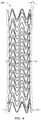
- Figure 1illustrates a front elevation view of an embodiment of a stent 100.
- the illustrated embodimentdepicts one embodiment of a configuration for a metal wire 110 forming a scaffolding structure.
- the scaffoldingmay consist of a single continuous wire.
- the stent 100may consist of a wire 110 shaped to form scaffolding.
- the wire 110may be shaped in a wave-type configuration, the waves defining apexes 102 and arms 104 of the stent.
- the scaffoldingmay further be coupled to a covering layer (not pictured). Additionally, in some embodiments, any covering as disclosed herein may be applied to any type of scaffolding or stent frame, for example, laser cut stent frames, polymeric stent frames, wire scaffolding, and so forth.
- the stent 100may be designed such that the midsection of the stent is "harder” than the ends.
- the “hardness” of the stentrefers to the relative strength of the stent (e.g., its compressibility). A harder portion of the stent will have greater strength (i.e. exert a greater radial outward force) than a softer portion.
- the midsection of the stentis harder than the proximal and distal end sections which are relatively softer.
- apex to apex distancedesignated as H x in Figures 1 and 2A
- arm lengthdesignated as A x in Figures 1 and 2A
- apex radiusdesignated as R x in Figure 2A
- the diameter of the scaffolding wire 110may or may not be constant at different points on a stent.
- each distance identified as “H”refers to an apex to apex distance with subscripts 1, 2, 3, etc., signifying the apex to apex distance at a particular point. It will be appreciated that these subscript designations do not necessarily refer to a specific distance, but may be used relatively (i.e., H 1 may be designated as smaller than H 2 without assigning any precise value to either measurement). Further, as will be apparent to one skilled in the art having the benefit of this disclosure, an analogous pattern of measurements and subscripts is employed for other parameters described herein, for example A x and R x .
- the overall stent designmay be configured to optimize desired radial force, crush profile, and strain profile.
- the stent design parametersmay each be configured and tuned to create desired stent characteristics.
- the strain profilemay be configured to be less than the failure point for the material being used.
- a first parameter, the apex to apex distance,is designated as H x .
- This measurementsignifies the distance between a first apex and a second apex where both apexes substantially lie along a line on the outside diameter of the stent which is co-planar with, and parallel to, the longitudinal axis of the stent.
- H xmay be constant along the entire length of the stent.
- the length of the stentmay be divided into one or more "zones" where H x is constant within a zone, but each zone may have a different H x .
- H xmay vary along the entire length of the stent.
- H xmay be configured, in connection with the other design parameters, to determine the properties of the stent. Generally, regions of the stent with a smaller H x value will be harder than regions with a larger H x value.
- H 1designates the apex to apex distance in the midbody zone of the stent and H 2 designates the apex to apex distance in the flare zones of the stent.
- the apex to apex distance, H 2is the same in both the flare zone near the distal end of the stent and the flare zone near the proximal end of the stent.
- H 1may be smaller than H 2 , resulting in a stent that is relatively harder in the midbody and relatively softer on the ends.
- a stent with such propertiesmay be utilized in applications where strength is necessary along the midbody, for example to treat a tumor or other occlusion, but the ends are configured to rest on healthy tissue where softer ends will minimize trauma to the healthy tissue.
- H 1may be between about 2 mm and 30 mm and H 2 between about 2.1 mm and 30.1 mm.
- H 1may be between about 3 mm and 10 mm and H 2 between about 3.1 mm and 10.1 mm, such as: 3 mm ⁇ H 1 ⁇ 8 mm and 3.5 mm ⁇ H 2 ⁇ 9 mm; 3 mm ⁇ H 1 ⁇ 6.5 mm and 4 mm ⁇ H 2 ⁇ 8 mm; or 3 mm ⁇ H 1 ⁇ 5 mm and 5.5 mm ⁇ H 2 ⁇ 6.5 mm.
- the change in apex to apex lengthmay be correlated to the displacement of the apexes from the midpoint of the stent.
- the apex to apex lengthmay increase incrementally as one moves away from the midpoint of the stent toward the ends in a manner that gives the stent the same geometry, and therefore the same properties, on either side of the midpoint of the length of the stent.
- different geometriesmay be utilized at any point along the length of the stent.
- a stentmay have an apex to apex length at midbody within one of the ranges disclosed above for H 1 , and the value of H x may vary incrementally, in steps, or some other pattern, along the length of the stent reaching an apex to apex length at the ends within the complimentary range for H 2 .
- the value of H xmay be small enough that adjacent coils are "nested" within each other.
- the apexes of a first helical coilmay extend up into the spaces just below the apexes of the next adjacent coil.
- apexes of lower coilsmay extend a sufficient amount so as to be disposed between the arms of higher coils.
- the value of H xmay be large enough that adjacent coils are completely separated.
- the number of wires at any particular cross section of the stentmay be higher than a non-nested stent.
- Nested stentsmay create relatively higher strains in the scaffolding structure when the stent is loaded into a delivery catheter.
- the delivery catheter for a nested stentmay therefore be relatively larger than a delivery catheter configured for a non-nested stent.
- nested stentsmay be relatively stiff as compared to non-nested stents with similar parameters.
- stents with a hard mid body and soft endsmay be desirable for a variety of applications.
- a basically "symmetric" stentmay be desirable; in other words, a stent with certain properties at the midbody section and other properties at the ends, where the properties at both ends are substantially identical.
- other embodimentsmay have varied properties along the entire length of the stent.
- the effect of changing variablesfor instance the difference between H 1 and H 2
- a substantially symmetric stentas in Figure 1
- the same principlesmay be utilized to control the properties of a stent where the geometry varies along the entire length of the stent.
- a second parameter, arm lengthis designated as A x in Figures 1 and 2A .
- a xmay be constant along the length of the stent, be constant within zones, or vary along the length of the stent. Variations in the length of A x may be configured in conjunction with variations in the other parameters to create a stent with a particular set of properties. Generally, regions of the stent where A x is relatively shorter will be harder than regions where A x is longer.
- the arm length A 1 near the midsection of the stent 100will be shorter than the arm length A 2 near the ends. This configuration may result in the stent being relatively harder in the midsection. In embodiments where soft ends and a hard midbody are desirable, A 1 may be between about 2 mm and 30 mm and A 2 between about 2.1 mm and 30.1 mm.
- a 1may be between about 2 mm and 10 mm and A 2 between about 2.1 mm and 10.1 mm, such as: 2.5 mm ⁇ A 1 ⁇ 8 mm and 3 mm ⁇ A 2 ⁇ 9 mm; 3 mm ⁇ A 1 ⁇ 6 mm and 4 mm ⁇ A 2 ⁇ 7.5 mm; or 4 mm ⁇ A 1 ⁇ 5 mm and 5 mm ⁇ A 2 ⁇ 6 mm.
- the change in arm lengthmay be correlated to the displacement of the arm from the midpoint along of the stent.
- the arm lengthmay increase incrementally as one moves away from the midpoint of the stent toward the ends in a manner that gives the stent the same geometry, and therefore the same properties, on either side of the midpoint of the length of the stent.
- different geometriesmay be utilized at any point along the length of the stent. It will be appreciated that the ranges of values for A x disclosed above apply analogously to embodiments where the stent has multiple arm lengths.
- a stentmay have an arm length at midbody within one of the ranges disclosed above for A 1 , and the value of A x may vary incrementally, in steps, or some other pattern, along the length of the stent reaching an arm length at the ends within the complimentary range for A 2 .
- a third parameter, the apex radius,is designated as R 1 in Figure 2A .
- R xmay be configured in order to create desired properties in a stent.
- the inside radius of each apexmay form an arc with has a substantially constant radius. As shown by a dashed line in Figure 2A , this arc can be extended to form a circle within the apex.
- the measurement R xrefers to the radius of the arc and circle so described.
- the arms and apexes of the stent scaffoldingare formed by molding a wire around pins protruding from a mandrel.
- R xwill be constant along the entire length of the stent, be constant within zones along the length of the stent, or vary along the entire length of the stent. Variations in the magnitude of R x may be configured in conjunction with variations in the other parameters to create a stent with a particular set of properties. Generally, regions of the stent where R x is relatively smaller will be harder than regions where R x is larger.
- R xmay result in relatively lower strain in the wire scaffolding when the scaffolding is compressed, for example when the stent is disposed within a delivery catheter.
- wires of relatively larger diametersmay result in relatively lower strain at or adjacent the radius measured by R x when compressed, as compared to wires of smaller diameters.
- the strainmay be optimized for a particular design by varying the value of R x and the diameter of the wire forming the scaffolding.
- R xmay take on a range of values depending on the application and the desired properties of the stent. In some embodiments R x may be between about 0.25 mm and 1.5 mm. For example, in stents for CV or PV application, R x may be between about 0.35 mm and 0.70 mm, such as: 0.35 mm ⁇ R x ⁇ 0.65 mm; 0.35 mm ⁇ R x ⁇ 0.6 mm; or 0.4 mm ⁇ R x ⁇ 0.5 mm.
- R xthe disclosed ranges for R x apply whether the value of R x is constant along the length of the stent, whether the stent is divided into zones with different R x values, or whether R x varies along the entire length of the stent.
- Figure 2Aillustrates a cutaway view of the front portions of two adjacent coils of a stent.
- the portions of the coils depictedare meant to be illustrative, providing a clear view of the three parameters H x , A x , and R x . It will be appreciated that all three of these parameters may be configured in order to create a stent with particular properties. Any combination of the values, ranges, or relative magnitudes of these parameters disclosed herein may be used within the scope of this disclosure.
- H 1may be about 4 mm and H 2 about 5.9 mm;
- a 1may be about 4.5 mm and A 2 about 5.6 mm; and
- R 1about 0.5 mm.
- Figure 2Bis a close up view of one end of a stent.
- Figure 2Billustrates one way in which the end of the wire 106 may be coupled to the scaffolding.
- the wiremay be disposed such that the final coil approaches and runs substantially parallel to the previous coil. This configuration results in the apex to apex distance between the two coils decreasing near the end 106 of the wire. In some embodiments this transition will occur along the distance of about 4 ⁇ 8 apexes along the length of the wire.
- a stentis configured with a apex to apex spacing of H 2 ' along the region of the stent nearest the ends, the apex to apex distance will decrease from H 2 ' to a smaller distance which allows the end of the wire 106 to meet the prior coil (as illustrated in Figure 2B ) over the course of about 4 ⁇ 8 apexes.
- Figure 2Cillustrates an alternative configuration of a wire scaffolding.
- apexes 102'alternate in relative height along the length of the wire.
- the apexesform a pattern comprising a higher apex, a shorter apex, a higher apex, a shorter apex, and so on, around the helical coil.
- a stentmay be configured with alternating apexes at one or both ends of the stent.
- a stent as shown in Figure 1may be configured with the pattern of apexes 102' and arms 104' shown in Figure 2C at one or both ends of the stent.
- Such an alternating pattern of apexesmay distribute the force along the vessel wall at the ends of the stent, thus creating relatively a-traumatic ends.
- the end 106may be attached to the scaffolding in a variety of ways known in the art.
- the end 106may be laser welded to the scaffolding or mechanically crimped to the scaffolding.
- the end 106may be secured by simply being bound to the cover.
- a stringmay be used to bind or tie the end 106 to adjacent portions of the scaffolding.
- a radiopaque markermay be crimped around the end 106 in such a manner as to couple the end 106 to the scaffolding. Additionally other methods known in the art may be utilized.
- the stent 100may be configured with radiopaque markers at one or more points along the stent 100. Such markers may be crimped to the scaffolding structure.
- a radiopaque ribbonfor example a gold ribbon, may be threaded or applied to the stent 100. In some embodiments these markers may be located at or adjacent one or both ends of the stent 100. Any radiopaque material may be used, for example gold or tantalum.
- the stent 100may be configured with flared ends. It will be appreciated that in certain embodiments a stent may have a flare at both the proximal and distal ends, only at the proximal end or only at the distal end, or at neither end. In certain of these embodiments the stent 100 may have a substantially constant diameter in the midbody zone of the stent, with the ends flaring outward to a larger diameter at the ends. It will be appreciated that the geometry of the flares at the proximal and distal ends may or may not be the same.
- the stent 100has a diameter, D 1 , at the midbody of the stent. This diameter may be constant along the entire midbody of the stent.
- the illustrated embodimenthas a second diameter, D 2 , at the ends. This change in diameter creates a "flare zone" at the end of the stent, or an area in which the diameter is increasing and the stent therefore may be described as including a "flared” portion.
- the flare zonewill be from about 1 mm to 60 mm in length.
- the flare zonemay be from about 3 mm to about 25 mm in length, such as: from about 4 mm to 15 mm, or from about 5 mm to about 10 mm in length.
- Figures 3 and 4also illustrate how a stent may be flared at the ends.
- Diameters D 1 ' and D 1 "refer to midbody diameters, analogous to D 1
- D 2 ' and D 2 "refer to end diameters analogous to D 2 .
- the flared endmay create an angle, alpha, between the surface of the stent at the midbody and the surface of the flare.
- the flare sectionwill uniformly flare out at a constant angle, as illustrated in Figure 4 .
- angle alphawill be from about 1 degree to about 30 degrees.
- alphawill be from about 2 degrees to 8 degrees, such as: from about 2.5 degrees to about 7 degrees or from about 3 degrees to about 5 degrees.
- alphamay be about 3.6 degrees.
- the stent 100 of Figure 1also has a length L. It will be appreciated that this length can vary depending on the desired application of the stent. In embodiments where the stent has flare zones at the ends, longer stents may or may not have proportionally longer flare zones. In some embodiments, this flare zone may be any length described above, regardless of the overall length of the stent.
- Lmay be from about 20 mm to about 200 mm.
- the stentmay have a length, L, of from about 40 mm to 100 mm or any value between, for example, at least about 50 mm, 60 mm, 70 mm, 80 mm, or 90 mm.
- the stentmay have a length, L, of from about 25 mm to 150 mm or any value between, for example at least about 50 mm, 75 mm, 100 mm or 125 mm.
- the stentmay also be longer or shorter than these exemplary values in other stent applications.
- the stentmay be formed with a variety of diameters.
- the midbody diameter of the stentmay be from about 4 mm to about 40 mm.
- the stentmay have a midbody inside diameter of about 3 mm to 16 mm or any distance within this range such as between about 5 mm to 14 mm or between about 7 mm to about 10 mm.
- the stentmay or may not be configured with flared ends regardless of the midbody diameter employed.
- the maximum diameter at the flared endwill be between about 0.5 mm to about 2.5 mm greater than the midbody diameter.
- the maximum diameter at the flared endmay be between about 1 mm to about 2 mm, or alternatively between about 1 .25 mm and about 1 .5 mm, such as about 1 .25 mm or about 1 .5 mm greater than the midbody diameter.
- the scaffolding of the stentmay be formed from a single continuous wire.
- the wiremay be comprised of Nitinol (ASTM F2063), or other suitable materials.
- the wirewill have a diameter between about 0.127 mm (0.005 inches) and about 0.508 mm (0.020 inches).
- the wire diametermay be from about 0.203 mm (0.008 inches) to about 0.305 mm (0.012 inches) in diameter including certain embodiments where the wire is from about 0.229 mm (0.009 inches) to about 0.279 mm (0.011 inches) in diameter or embodiments where the wire is about 0.254 mm (0.010 inches) in diameter.
- stents configured for the thoracic aortamay be formed of wires up to 0.508 mm (0.020 inches) in diameter, including wires up to about 0.381 mm (0.015 inches) or 0.254 mm (0.010 inches) in diameter.
- Figure 5illustrates how, in some embodiments, the wire 1 10 may be wound in a helical pattern creating coils that incline along the length of the stent.
- the waves of the wire which form the arms and apexesmay be centered around this helix, represented by the dashed line 120.
- the stent 100may be comprised of a wire 1 10 which forms the scaffolding and a cover 200 coupled to the scaffolding.
- this covermay be comprised of a single layer, while in other embodiments it may be comprised of 2, 3, or more layers of material.
- One or more layersmay be comprised of a polymer.
- the illustrated embodimenthas two cover layers, an outer layer 210 and an inner layer 220. Portions of the scaffolding may protrude through one or both layers at certain points, or, the scaffolding may be completely enclosed on the outside diameter by the outer layer 210 and on the inside diameter by the inner layer 220.
- Electrospun PTFEconsists of tubes, mats, or other shapes of PTFE formed from randomly deposited strings of PTFE. As previously indicated, electrospinning of PTFE is described in United States Patent Application, Publication No. US 2010/0193999 . As described in the reference, electrospinning may comprise depositing a polymer on a collection surface, in the presence of an electrostatic field. In some instances the polymer may be electrostatically charged and may be discharged through one or more orifices.
- electrospinning PTFErelative to electrospinning PTFE or other polymer is included below.
- the properties of electrospun PTFE, including density and porosity,may be controlled or influenced during the creation of the electrospun PTFE, through controlling the electrospinning process.
- a PTFE dispersionmay be discharged through an orifice to electrospin the PTFE.
- polyethylene oxide (PEO)may be added to the PTFE dispersion prior to electrospinning the material.
- the PEOmay be added as a fiberizing agent, to aid in the formation of PTFE fibers within the dispersion or during the process of electrospinning the material.
- the PEOmay more readily dissolve in the PTFE dispersion if the PEO is first mixed with water. In some examples this increased solubility may reduce the time needed to dissolve PEO in a PTFE dispersion from as long as multiple days to as little as 30 minutes.
- the materialmay then be sintered as further described below.
- the sintering processwill tend to set or harden the structure of the PTFE.
- sinteringmay also eliminate the water and PEO, resulting in a mat of substantially pure PTFE.
- a 60 wt% PTFE water dispersionwas mixed with PEO and water as follows. First 5 mL of water was added to 1.4 g of PEO. The water and PEO were mixed until the PEO was fully dissolved and the solution created a thick gel. 30 mL of 60 wt% PTFE was then added to the PEO/water mixture. The combined solution was then allowed to sit or mix in a non-agitating jar roller until the solution achieved homogeneity.
- the water, PEO, and PTFE amountsmay be controlled to optimize the viscosity, PEO/PTFE ratio, or other properties of the mixture. In some instances adding water to the PEO before mixing with the PTFE dispersion may aid in reducing the number of large solid chunks in the mixture, lower the preparation time for the mixtures, and reduce the time needed for the combined mixture to solubilize.
- Membranes composed of electrospun PTFEmay have a microstructure composed of many fibers crossing and each other at various and random points. The electrospinning process may control the thickness of this structure and, thereby the relative permeability of the membrane. As more and more strands of PTFE are electrospun onto a membrane, the membrane may both increase in thickness and decrease in permeability (due to successive layers of strands occluding the pores and openings of layers below). (This microstructure is shown in Figures 9A - 11D which are discussed in more detail below.)
- the complex and random microstructure of electrospun PTFEpresents a challenge to the direct measurement of the average pore size of the membrane.
- Average pore sizecan be indirectly determined by measuring the permeability of the membrane to fluids using known testing techniques and instruments. Once the permeability is determined, that measurement may be used to determine an "effective" pore size of the electrospun PTFE membrane.
- the "pore size" of an electrospun PTFE membranerefers to the pore size of a membrane which corresponds to the permeability of the electrospun PTFE when measured using ASTM standard F316 for the permeability measurement. This standard is described in ASTM publication F316 "Standard Test Methods for Pore Size Characteristics of Membrane Filters by Bubble Point and Mean Flow Pore Test".
- a stent 100 with an outer layer 210 which is substantially impermeablemay decrease the incidence of lumen tissue surrounding the stent growing into the stent. This may be desirable in applications where the stent is used to treat stenosis or other occlusions; an impermeable outer layer may prevent tissue from growing into the lumen of the stent and reblocking or restricting the body lumen.
- a substantially impermeable outer layeris produced by using electrospun PTFE with an average pore size of about 0 microns to about 1.5 microns. In other embodiments, the impermeable layer may have an average pore size less than about 0.5 microns.
- the impermeable layermay have an average pore size less than about 1.0 microns.
- the impermeable layermay be a layer other than the outer layer, such as a tie layer.
- a substantially impermeable layermay be formed of fluorinated ethylene proplyene (FEP) which is applied, for example, as a film or dip coating.
- FEPmay be electrospun with a small average pore size to create a substantially impermeable layer.
- a porous outer layer 210may permit healing and the integration of the prosthesis into the body. For instance, tissue of the surrounding lumen may grow into the porous outer diameter. This "tissue ingrowth" may permit healing at the therapy site.
- a porous outer layer 210may be formed of electrospun PTFE.
- a relatively porous inner layer 220is used in conjunction with a substantially impermeable outer layer 210.
- a relatively porous inner layerpermits endothelial growth on the inside diameter of the stent 100 which may be desirable for healing, biocompatibility, and reducing turbulent blood flow within the stent.
- the inner layeris comprised of electrospun PTFE with an average pore size of 1 micron to 12 microns, such as from about 2 microns to about 8 microns, or from about 3 microns to about 5 microns, or alternatively from about 3.5 to about 4.5 microns.
- Figure 6Billustrates a cross sectional view of a stent with an outer layer 210, an inner layer 220, and a wire scaffold 110. Additionally, the location between the outer layer 210 and the inner layer 220 is illustrated as 230. It will be appreciated that in embodiments where there are only two layers, there may not be a gap between the two layers, but the outer layer 210 and inner layer 220 may be in direct contact where they are not separated by the wire 110.
- a third layeris disposed in the location 230 between the outer layer 210 and the inner layer 220.
- This layeris a "tie layer” configured to promote bonding between the outer layer 210 and the inner layer 220.
- the tie layermay further be configured to provide certain properties to the stent as a whole, such as stiffness or tensile strength.
- the tie layermay be configured to create an impermeable layer between the two porous layers.
- the stentmay permit cell growth and healing on both the inner and outer surfaces of the stent while still preventing tissue from outside the stent from growing into the lumen and occluding the lumen.
- the tie layermay consist of any thermoplastic and may or may not be electrospun.
- the tie layermay be expanded PTFE.
- itmay be electrospun PTFE.
- itmay be FEP, including electrospun FEP and FEP applied as a film or dip coating.
- the tie layermay consist of any of the following polymers or any other thermoplastic: dextran, alginates, chitosan, guar gum compounds, starch, polyvinylpyridine compounds, cellulosic compounds, cellulose ether, hydrolyzed polyacrylamides, polyacrylates, polycarboxylates, polyvinyl alcohol, polyethylene oxide, polyethylene glycol, polyethylene imine, polyvinylpyrrolidone, polyacrylic acid, poly(methacrylic acid), poly(itaconic acid), poly(2-hydroxyethyl acrylate), poly(2-(dimethylamino)ethyl methacrylate-co-acrylamide), poly(N-isopropylacrylamide), poly(2-acrylamido-2-methyl-I-propanesulfonic acid), poly (methoxyethylene), poly(vinyl alcohol), poly(vinyl alcohol) 12% acetyl, poly(2,4-dimethyl-6-triazinylethylene), poly(3morpholin
- the tie layeris a non-electrospun tie layer.
- the stentmay consist of two or more tie layers.
- the tie layermay be formed in any manner known in the art and attached to the inner and outer layers in any manner known in the art.
- the tie layermay comprise a sheet of material which is wrapped around the inner layer 210 or a tube of material which is slipped over the inner layer 210 which is then heat shrunk or otherwise bonded to the inner and outer layers.
- the tie layermay be melted after the stent is constructed to bond the tie layer to adjacent layers of the stent covering.
- tie layersmay be configured to change the overall properties of the stent covering.
- a cover comprised solely of electrospun PTFE(of the desired pore size) may not have desired tensile or burst strength.
- a tie layer comprised of a relatively stronger materialmay be used to reinforce the PTFE inner layer, the PTFE outer layer, or both.
- FEP layersmay be used to increase the material strength of the cover.
- one or more layers of electrospun PTFEmay be used in connection with a scaffolding structure other than that disclosed herein.
- the disclosure above relating to covers, layers, tie layers, and related componentsis applicable to any type of scaffolding structure as well as to stents or grafts with no separate scaffolding structure at all.
- Figure 7illustrates a cross section of a stent 100 disposed within a body lumen 50.
- the stentincludes wire scaffolding 110 and a cover 200.
- the cover 200is composed of an outer layer and an inner layer
- the outer layermay be disposed adjacent to the body lumen while the inner layer may be disposed toward the inside portion of the body lumen.
- the outer cover layermay be defined as the layer disposed adjacent the body lumen wall and the inner cover layer defined as the layer disposed toward the inner portion of the body lumen.
- a cover 200may be formed by electrospinning a membrane onto a spinning mandrel.
- the collection devicemay comprise a mandrel, such as a substantially cylindrical mandrel, which rotates during the electrospinning process. Varying the speed at which the mandrel rotates may influence certain properties of the membrane. For example, in some embodiments, the density of the membrane (and thereby the average pore size) may be related to the rotational speed of the mandrel. Further, the directionality of the fibers, or the degree to which the fibers are deposited in a more controlled direction or manner, may be related to the rotational speed of the mandrel.
- a collection mandrelmay rotate at rates between about 1 RPM and about 500 RPM during the elctrospinning process, including rates from about 1 RPM to about 50 RPM or at about 25 RPM.
- a membrane of electrospun PTFE formed onto a spinning mandrelmay thus comprise a tubular membrane having no seam and substantially isotropic properties.
- the membranemay then be sintered.
- the membranemay be sintered at temperatures of about 385 degrees C, including temperatures from about 360 degrees C to about 400 degrees C.
- Sinteringmay tend to set the structure of the PTFE, meaning sintering reduces the softness or flowability of the PTFE.
- sinteringmay evaporate any water or PEO mixed with the PTFE, resulting in a material comprised substantially of pure PTFE.
- a PTFE layermay be spun onto a mandrel and then sintered. Once the membrane is sintered, the tube of material may be removed from the mandrel, then slid back on the mandrel (to initially break any adherence of the membrane to the mandrel). In other instances, low friction coatings may alternatively or additionally be applied to the mandrel before the membrane is electrospun. Once the membrane is reapplied to the mandrel, a wire scaffolding can be formed over the mandrel and the membrane. A second layer of material may then be spun onto the scaffolding and the membrane, and subsequently sintered. Additionally layers may also be added.
- the layersmay comprise a first layer of PTFE, a second layer of FEP, and a third layer of PTFE.
- the properties of each of these layers, including average pore size,may be controlled to form coating that inhibit growth of tissue through a particular layer or that permits endothelial growth on a particular layer.
- a first layer of PTFEmay be spun on a mandrel, sintered, removed from the mandrel, replaced and the mandrel, and a scaffolding structure applied.
- An FEP layermay then be applied by dipping, spraying, application of a film layer, electrospinning, or other processing.
- the FEP layermay or may not be sintered before applying an outer PTFE layer.
- a first layer of PTFEmay again be spun on a mandrel, sintered, removed, replaced, and a scaffolding structure applied.
- An FEP layermay then be applied as a film layer. In some instances it may be "tacked" into place, for example by a soldering iron.
- An outer tube of PTFE(which may be formed separately by electrospinning onto a mandrel and sintering) may then be disposed over the FEP film layer.
- the entire constructmay then be pressured, for example by applying a compression wrap.
- this wrapmay comprise any suitable material, including a PTFE based material.
- a Kapton filmmay be wrapped around the construct before the compression wrap, to prevent the construct from adhering to the compression wrap.
- the compressed layersmay then be heated above the melting temperature of the FEP, but below the sintering temperature of the PTFE.
- the melt temperature of the FEPmay be from about 300 degrees C to about 330 degrees C, including about 325 degrees C.
- PTFEmay be sintered at temperatures from about 360 degrees C to about 400 degrees C.
- the entire constructmay be heated to an appropriate temperature such as about 325 degrees C.
- the constructmay be held at this temperature for about 15 to about 20 minutes. This may allow the FEP to "flow" into the porous PTFE nanofiber layers surrounding the FEP.
- the joining of the FEP tie layer to the PTFE outer and inner cover layersmay increase the strength of the finished covering.
- the constructmay then be cooled and the compression wrap and the Kaptron film discarded.
- the constructmay then be removed from the mandrel.
- a stent formed by the exemplary process described abovemay be configured with desired characteristics of porosity and strength.
- the FEP materialmay coat the PTFE nanofibers, but still allow for porosity which permits endothelial growth.
- the degree to which the FEP coats the PTFEmay be controlled by the temperature and time of processing. The lower the temperature and/or the shorter the time the construct is held at temperature, the less the FEP may flow.
- a tie layer of FEP which is impervious the tissue growth through the layermay be formed by heating the construction only to about 260 degrees C.
- a stentmay also include a cuff at one or both ends of the stent.
- the cuffmay be an additional coating on the outside diameter of the stent, disposed adjacent one of the ends of the stent.
- the cuffmay be configured to promote rapid cellular ingrowth into the cuff; for example the cuff may be more porous than the outer layer of the covering of the stent.
- Factorssuch as porosity, type of coating, type of material, use of organic material, and/or use or composite materials formed of synthetic material and organic material may be used to create a cuff configured for rapid tissue ingrowth.
- the cuffmay be configured to promote rapid growth or endothelization at one or both ends of the stent.
- cuffsmay be disposed adjacent both ends of the stent.
- the cuff or cuffsmay tend to "anchor" the ends of the stent with respect to the vessel walls, reducing the relative movement of the stent ends with respect to the vessel walls. Such a reduction in movement may lessen irritation of the vessel by the stent ends, minimizing complications such as stenosis.
- Cuffsmay be configured for use in CVO type applications in some instances.
- the outer layer of the covering of the stentmay be relatively non-porous to limit tissue growth through the layer, but the cuff, disposed about the outer cover layer may provide a section near each end at which some ingrowth may occur.
- the cuffmay be comprised of an electrospun material, such as PTFE, and may be bonded to the outer covering layer through any method, including methods described herein.
- a layer of FEPmay be disposed between the outer covering layer and the cuff and heated to bond the layers.
- the cuffmay comprise a collagen layer which is glued to the stent. Further, a co-electrospun collagen and PTFE cuff may be utilized.
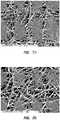
- Figures 8A - 9Dare scanning electron micrograph (SEM) images of an exemplary embodiment of a stent covering.
- Figures 8A - 8Dare images of the outer layer of the covering while Figures 9A - 9D are images of the inner layer of the covering.
- SEMscanning electron micrograph
- the electrospun PTFEwas covered with a very thin layer of gold in order to make the structure visible on an SEM image.
- Figure 8Ais an SEM image of the outer covering at 750X magnification
- Figure 8Ban SEM image at 1500X magnification
- Figures 8C and 8Dat 3000X magnification
- Figure 9Ais an image of the inner covering at 750X magnification
- Figure 9Bat 1500X magnification
- Figures 9C and 9Dat 3000X magnification.
- SEM imagesreflect the microstructure of electrospun PTFE, depicting the randomly deposited criss-crossing branches of PTFE that form the covering.
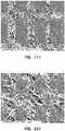
- Figures 10A - 11Dare scanning electron micrograph (SEM) images of a second exemplary embodiment of a stent covering.
- Figures 10A - 10Dare images of the outer layer of the covering while Figures 11A - 11D are images of the inner layer of the covering.
- SEMscanning electron micrograph
- Figure 10Ais an SEM image of the outer covering at 750X magnification
- Figure 10Ban SEM image at 1500X magnification
- Figures 10C and 10Dat 3000X magnification
- Figure 11Ais an image of the inner covering at 750X magnification
- Figure 11Bat 1500X magnification
- Figures 11C and 11Dat 3000X magnification.
Landscapes
- Health & Medical Sciences (AREA)
- Engineering & Computer Science (AREA)
- General Health & Medical Sciences (AREA)
- Veterinary Medicine (AREA)
- Public Health (AREA)
- Heart & Thoracic Surgery (AREA)
- Vascular Medicine (AREA)
- Life Sciences & Earth Sciences (AREA)
- Animal Behavior & Ethology (AREA)
- Biomedical Technology (AREA)
- Textile Engineering (AREA)
- Mechanical Engineering (AREA)
- Oral & Maxillofacial Surgery (AREA)
- Cardiology (AREA)
- Transplantation (AREA)
- Chemical & Material Sciences (AREA)
- Dispersion Chemistry (AREA)
- Surgery (AREA)
- Epidemiology (AREA)
- Gastroenterology & Hepatology (AREA)
- Pulmonology (AREA)
- Prostheses (AREA)
- Chemical Kinetics & Catalysis (AREA)
- Medicinal Chemistry (AREA)
- Polymers & Plastics (AREA)
- Organic Chemistry (AREA)
- Materials For Medical Uses (AREA)
- Media Introduction/Drainage Providing Device (AREA)
Description
- The present disclosure relates generally to medical devices. More specifically, the present disclosure relates to stents coated by electrospun polytetrafluoroethylene (PTFE).
- The document
US2004/033364A1 discloses implantable prostheses having an expanded PTFE layer and a fabric layer. Electrospun PTFE layers are not disclosed. - The document
US2003/211135A1 discloses a process for providing a stent having an electrospun coating. - The document
US2007/207186A1 discloses expanded or extruded PTFE material which may be used in constructing stents. Electrospun PTFE is not disclosed. - The document
US2011/0030885A1 discloses a process for forming a prosthetic device. - The document
US2003/114917A1 discloses a stent comprising expanded and non-porous PTFE. Electrospun PTFE is not used. - The invention discloses a stent comprising; a coating, the coating comprising; an inner layer of electrospun polytetrafluoroethylene (PTFE) fibers, an outer layer of electrospun PTFE fibers, and a non-electrospun tie layer disposed between the inner layer of electrospun PTFE fibers and the outer layer of electrospun fibers, wherein the inner layer of electrospun PTFE fibers has an average pore size between 1 micron and 12 microns and is configured to permit the growth of endothelial cells on a surface of the stent and the tie layer is impermeable to tissue growth. The invention also discloses a method of constructing a stent, comprising; electrospinning a first tube of PTFE onto a rotating mandrel; sintering the first tube; applying a tie layer around the first tube, and applying a second tube of electrospun PTFE around the tie layer, wherein the first tube of PTFE has an average pore size between 1 micron and 12 microns and the tie layer is impermeable to tissue growth. The embodiments disclosed herein will become more fully apparent from the following description and appended claims, taken in conjunction with the accompanying drawings. These drawings depict only typical embodiments, which will be described with additional specificity and detail through use of the accompanying drawings in which:
Figure 1 is a front elevation view of one embodiment of a stent.Figure 2A is a cutaway view of the front portions of two adjacent coils of one embodiment of a stent.Figure 2B is a detail view of one end of the stent ofFigure 1 .Figure 2C is a detail view of an alternative design of an end portion of a stent.Figure 3 is a top view of another embodiment of a stent with flared ends.Figure 4 is a front elevation view of the stent ofFigure 3 .Figure 5 is a perspective view of one embodiment of a stent, illustrating how a wire may be shaped to form the structure of the stent.Figure 6A is a perspective view of a covered stent.Figure 6B is a cross sectional view of the stent ofFigure 6A along theplane 6B-6B.Figure 7 illustrates one embodiment of a stent deployed in a body lumen.Figures 8A-8D are scanning electron micrograph ("SEM") images of embodiment of an electrospun PTFE outer covering for a stent.Figures 9A-9D are SEM images of an electrospun PTFE inner layer of the covering of the stent ofFigure 8A-8D .Figures 10A-10D are SEM images of an electrospun PTFE outer covering of another embodiment of a stent.Figures 11A-11D are SEM images of an electrospun PTFE inner layer of the covering of the stent ofFigure 10A-10D .- The invention is defined by the claims. Any subject-matter falling outside the scope of the claims is provided for information purposes only. Stents may be deployed in various body lumens for a variety of purposes. Stents may be deployed, for example, in the central venous system for a variety of therapeutic purposes including the treatment of occlusions within the lumens of that system. It will be appreciated that the current disclosure may be applicable to stents designed for the central venous ("CV") system, peripheral vascular ("PV") stents, abdominal aortic aneurism ("AAA") stents, bronchial stents, esophageal stents, biliary stents, or any other stent. Further, the present disclosure may equally be applicable to other prosthesis such as grafts. Thus, the disclosure provided below in connection with specific examples of stents may apply analogously to other prostheses.
- It will be readily understood that the components of the embodiments as generally described and illustrated in the Figures herein could be arranged and designed in a wide variety of different configurations. Thus, the following more detailed description of various embodiments, as represented in the Figures, is not intended to limit the scope of the disclosure, but is merely representative of various embodiments. While the various aspects of the embodiments are presented in drawings, the drawings are not necessarily drawn to scale unless specifically indicated.
- The phrases "connected to," "coupled to," and "in communication with" refer to any form of interaction between two or more entities, including mechanical, electrical, magnetic, electromagnetic, fluid, and thermal interaction. Two components may be coupled to each other even though they are not in direct contact with each other. For example, two components may be coupled to each other through an intermediate component.
- The directional terms "proximal" and "distal" are used herein to refer to opposite locations on a stent. The proximal end of a stent is defined as the end of the stent closest to the practitioner when the stent is disposed within a deployment device which is being used by the practitioner. The distal end is the end opposite the proximal end, along the longitudinal direction of the stent, or the end furthest from the practitioner. It is understood that, as used in the art, these terms may have different meanings once the stent is deployed (i.e. the "proximal" end may refer to the end closest to the head or heart of the patient depending on application). For consistency, as used herein, the ends of the stent labeled "proximal" and "distal" prior to deployment remain the same regardless of whether the stent is deployed. The longitudinal direction of the stent is the direction along the axis of a generally tubular stent. In embodiments where a stent is composed of a metal wire structure coupled to a polymer layer, the metal structure is referred to as the "scaffolding" and the polymer layer as the "coating." The term "coating" may refer to a single layer of polymer, multiple layers of the same polymer, or layers comprising distinct polymers used in combination.
- Lumens within the central venous system are generally lined with endothelial cells. This lining of endothelial cells throughout the central venous system makes up the endothelium. The endothelium acts as an interface between blood flowing through the lumens of the central venous system and the inner walls of the lumens. The endothelium, among other functions, reduces or prevents turbulent blood flow within the lumen.
- A therapeutic stent which includes a coating of porous or semi-porous material may permit the formation of an endothelial layer on the inside surface of the stent. A stent which permits the formation of the endothelium within the stent may further promote healing at the therapeutic region. For example, a stent coated with endothelial cells may be more consistent with the surrounding body lumens, thereby resulting in less turbulent blood flow or a decreased risk of thrombosis, or the formation of blood clots. A stent which permits the formation of an endothelial layer on the inside surface of the stent may therefore be particularly biocompatible, resulting in less trauma at the point of application and fewer side effects.
- Electrospun polytetrafluoroethylene (PTFE) may be used as a stent coating where endothelial cell growth is desirable. "Electrospinning" refers to a process for forming mats, tubes, or other shapes by depositing small strings of PTFE on charged surfaces. The electrospinning process controls the thickness, density, porosity, and other characteristics of the PTFE so formed. Electrospinning of PTFE is described in
United States Patent Application, Publication No. US 2010/0193999 . - The present disclosure relates to a stent which has, in certain embodiments, metal scaffolding coated with at least one layer of electrospun PTFE. Certain figures show metal scaffolding without any coating; the features described and illustrated in those figures may be combined with any combination of coatings disclosed herein.
Figures 1, 2A, and 2B show views of a possible embodiment of a stent.Figures 3 and4 are views of one embodiment of a stent which includes flared ends.Figure 5 illustrates one embodiment of how a wire may be shaped to form a scaffold for a stent.Figures 6A and 6B illustrate an embodiment of a covered stent.Figure 7 illustrates a stent deployed within a body lumen. Finally,Figures 8A - 11D are scanning electron micrographs (SEMs) of possible coatings for stents. As indicated above, it will be understood that, regardless of whether the stent illustrated in any particular figure is illustrated with a particular coating, or any coating at all, any embodiment may be configured with any of the combinations of coatings shown or described herein.Figure 1 illustrates a front elevation view of an embodiment of astent 100. The illustrated embodiment depicts one embodiment of a configuration for ametal wire 110 forming a scaffolding structure. As depicted inFigure 1 , the scaffolding may consist of a single continuous wire.- Referring generally to
Figures 1, 2A, and 2B , particular features of the illustrated stent are indicated. It will be appreciated that the numerals and designations used in any figure apply to analogous features in other illustrated embodiments, whether or not the feature is so identified in each figure. As generally shown in these Figures, thestent 100 may consist of awire 110 shaped to form scaffolding. Thewire 110 may be shaped in a wave-type configuration, thewaves defining apexes 102 andarms 104 of the stent. The scaffolding may further be coupled to a covering layer (not pictured). Additionally, in some embodiments, any covering as disclosed herein may be applied to any type of scaffolding or stent frame, for example, laser cut stent frames, polymeric stent frames, wire scaffolding, and so forth. - The
stent 100 may be designed such that the midsection of the stent is "harder" than the ends. The "hardness" of the stent refers to the relative strength of the stent (e.g., its compressibility). A harder portion of the stent will have greater strength (i.e. exert a greater radial outward force) than a softer portion. In one embodiment, the midsection of the stent is harder than the proximal and distal end sections which are relatively softer. - Four basic design parameters may be manipulated to influence the properties (hardness, strength, crush force, hoop force, flexibility, etc.) of the illustrated stent. These properties are: (1) apex to apex distance, designated as Hx in
Figures 1 and 2A ; (2) arm length, designated as Ax inFigures 1 and 2A ; (3) apex radius, designated as Rx inFigure 2A ; and (4 ) the diameter of thescaffolding wire 110. These values may or may not be constant at different points on a stent. Thus, the subscript "x" is used generically; that is, each distance identified as "H" refers to an apex to apex distance with subscripts 1, 2, 3, etc., signifying the apex to apex distance at a particular point. It will be appreciated that these subscript designations do not necessarily refer to a specific distance, but may be used relatively (i.e., H1 may be designated as smaller than H2 without assigning any precise value to either measurement). Further, as will be apparent to one skilled in the art having the benefit of this disclosure, an analogous pattern of measurements and subscripts is employed for other parameters described herein, for example Ax and Rx. - The overall stent design may be configured to optimize desired radial force, crush profile, and strain profile. The stent design parameters may each be configured and tuned to create desired stent characteristics. For example, the strain profile may be configured to be less than the failure point for the material being used.
- A first parameter, the apex to apex distance, is designated as Hx. This measurement signifies the distance between a first apex and a second apex where both apexes substantially lie along a line on the outside diameter of the stent which is co-planar with, and parallel to, the longitudinal axis of the stent. In some embodiments, Hx may be constant along the entire length of the stent. In other embodiments the length of the stent may be divided into one or more "zones" where Hx is constant within a zone, but each zone may have a different Hx. In still other embodiments Hx may vary along the entire length of the stent. Hx may be configured, in connection with the other design parameters, to determine the properties of the stent. Generally, regions of the stent with a smaller Hx value will be harder than regions with a larger Hx value.
- In the embodiment illustrated in
Figure 1 , there are two "flare zones" at either end of the stent and a midbody zone along the remaining length of the stent. In the illustrated embodiment, H1 designates the apex to apex distance in the midbody zone of the stent and H2 designates the apex to apex distance in the flare zones of the stent. In the illustrated embodiment, the apex to apex distance, H2, is the same in both the flare zone near the distal end of the stent and the flare zone near the proximal end of the stent. In some embodiments H1 may be smaller than H2, resulting in a stent that is relatively harder in the midbody and relatively softer on the ends. A stent with such properties may be utilized in applications where strength is necessary along the midbody, for example to treat a tumor or other occlusion, but the ends are configured to rest on healthy tissue where softer ends will minimize trauma to the healthy tissue. - In embodiments where soft ends and a hard midbody are desirable, H1 may be between about 2 mm and 30 mm and H2 between about 2.1 mm and 30.1 mm. For example, in stents for CV or PV application, H1 may be between about 3 mm and 10 mm and H2 between about 3.1 mm and 10.1 mm, such as: 3 mm < H1 < 8 mm and 3.5 mm < H2 < 9 mm; 3 mm < H1 < 6.5 mm and 4 mm < H2 < 8 mm; or 3 mm < H1 < 5 mm and 5.5 mm < H2 < 6.5 mm.
- In other embodiments where two or more apex to apex lengths are present in one stent, the change in apex to apex length may be correlated to the displacement of the apexes from the midpoint of the stent. In other words, the apex to apex length may increase incrementally as one moves away from the midpoint of the stent toward the ends in a manner that gives the stent the same geometry, and therefore the same properties, on either side of the midpoint of the length of the stent. In other embodiments, different geometries may be utilized at any point along the length of the stent. It will be appreciated that the ranges of values for Hx disclosed above apply analogously to embodiments where the stent has multiple apex to apex lengths. For example, in one embodiment a stent may have an apex to apex length at midbody within one of the ranges disclosed above for H1, and the value of Hx may vary incrementally, in steps, or some other pattern, along the length of the stent reaching an apex to apex length at the ends within the complimentary range for H2.
- Moreover, in some embodiments, the value of Hx may be small enough that adjacent coils are "nested" within each other. In other words, the apexes of a first helical coil may extend up into the spaces just below the apexes of the next adjacent coil. In other words, apexes of lower coils may extend a sufficient amount so as to be disposed between the arms of higher coils. In other embodiments the value of Hx may be large enough that adjacent coils are completely separated. In embodiments wherein adjacent coils are "nested," the number of wires at any particular cross section of the stent may be higher than a non-nested stent. In other words, cutting the stent along an imaginary plane disposed orthogonal to the longitudinal axis of the stent will intersect more wires if the stent is nested as compared to non-nested stents. The smaller the value of Hx, the more rows may be intersected by such a plane (that is, more than just the next adjacent row may extend into the spaces below the apexes of a particular row). Nested stents may create relatively higher strains in the scaffolding structure when the stent is loaded into a delivery catheter. In some instances the delivery catheter for a nested stent may therefore be relatively larger than a delivery catheter configured for a non-nested stent. Further, nested stents may be relatively stiff as compared to non-nested stents with similar parameters.
- As will be apparent to those skilled in the art having the benefit of this disclosure, stents with a hard mid body and soft ends may be desirable for a variety of applications. Further, in some instances a basically "symmetric" stent may be desirable; in other words, a stent with certain properties at the midbody section and other properties at the ends, where the properties at both ends are substantially identical. Of course, other embodiments may have varied properties along the entire length of the stent. It will be appreciated that while the effect of changing variables, for instance the difference between H1 and H2, may be described in connection with a substantially symmetric stent (as in
Figure 1 ) the same principles may be utilized to control the properties of a stent where the geometry varies along the entire length of the stent. As will be appreciated by those skilled in the art having the benefit of this disclosure, this applies to each of the variable parameters described herein, for example Hx, Ax, and Rx. - A second parameter, arm length, is designated as Ax in
Figures 1 and 2A . As with Hx, Ax may be constant along the length of the stent, be constant within zones, or vary along the length of the stent. Variations in the length of Ax may be configured in conjunction with variations in the other parameters to create a stent with a particular set of properties. Generally, regions of the stent where Ax is relatively shorter will be harder than regions where Ax is longer. - In some embodiments, the arm length A1 near the midsection of the
stent 100 will be shorter than the arm length A2 near the ends. This configuration may result in the stent being relatively harder in the midsection. In embodiments where soft ends and a hard midbody are desirable, A1 may be between about 2 mm and 30 mm and A2 between about 2.1 mm and 30.1 mm. For example, in stents for CV or PV application, A1 may be between about 2 mm and 10 mm and A2 between about 2.1 mm and 10.1 mm, such as: 2.5 mm < A1 < 8 mm and 3 mm < A2 < 9 mm; 3 mm < A1 < 6 mm and 4 mm < A2 < 7.5 mm; or 4 mm < A1 < 5 mm and 5 mm < A2 < 6 mm. - In other embodiments where two or more arm lengths are present in one stent, the change in arm length may be correlated to the displacement of the arm from the midpoint along of the stent. In other words, the arm length may increase incrementally as one moves away from the midpoint of the stent toward the ends in a manner that gives the stent the same geometry, and therefore the same properties, on either side of the midpoint of the length of the stent. In other embodiments, different geometries may be utilized at any point along the length of the stent. It will be appreciated that the ranges of values for Ax disclosed above apply analogously to embodiments where the stent has multiple arm lengths. For example, in one embodiment a stent may have an arm length at midbody within one of the ranges disclosed above for A1, and the value of Ax may vary incrementally, in steps, or some other pattern, along the length of the stent reaching an arm length at the ends within the complimentary range for A2.
- A third parameter, the apex radius, is designated as R1 in
Figure 2A . As with Hx, and Ax, Rx may be configured in order to create desired properties in a stent. In some embodiments, the inside radius of each apex may form an arc with has a substantially constant radius. As shown by a dashed line inFigure 2A , this arc can be extended to form a circle within the apex. The measurement Rx refers to the radius of the arc and circle so described. Further, in some embodiments the arms and apexes of the stent scaffolding are formed by molding a wire around pins protruding from a mandrel. The radius of the pin used gives the apex its shape and therefore has substantially the same radius as the apex. In some embodiments Rx will be constant along the entire length of the stent, be constant within zones along the length of the stent, or vary along the entire length of the stent. Variations in the magnitude of Rx may be configured in conjunction with variations in the other parameters to create a stent with a particular set of properties. Generally, regions of the stent where Rx is relatively smaller will be harder than regions where Rx is larger. - Furthermore, in some instances, smaller values of Rx may result in relatively lower strain in the wire scaffolding when the scaffolding is compressed, for example when the stent is disposed within a delivery catheter. Moreover, wires of relatively larger diameters may result in relatively lower strain at or adjacent the radius measured by Rx when compressed, as compared to wires of smaller diameters. Thus, in some instances, the strain may be optimized for a particular design by varying the value of Rx and the diameter of the wire forming the scaffolding.
- Like the other variables, Rx may take on a range of values depending on the application and the desired properties of the stent. In some embodiments Rx may be between about 0.25 mm and 1.5 mm. For example, in stents for CV or PV application, Rx may be between about 0.35 mm and 0.70 mm, such as: 0.35 mm < Rx < 0.65 mm; 0.35 mm < Rx < 0.6 mm; or 0.4 mm < Rx < 0.5 mm.
- It will be appreciated that the disclosed ranges for Rx apply whether the value of Rx is constant along the length of the stent, whether the stent is divided into zones with different Rx values, or whether Rx varies along the entire length of the stent.
- The fourth parameter, wire diameter, is discussed in detail in connection with
Figure 5 below. Figure 2A illustrates a cutaway view of the front portions of two adjacent coils of a stent. The portions of the coils depicted are meant to be illustrative, providing a clear view of the three parameters Hx, Ax, and Rx. It will be appreciated that all three of these parameters may be configured in order to create a stent with particular properties. Any combination of the values, ranges, or relative magnitudes of these parameters disclosed herein may be used within the scope of this disclosure. As an example of these values taken together, in one embodiment of a CV or PV stent with a relatively hard midbody and softer ends, H1 may be about 4 mm and H2 about 5.9 mm; A1 may be about 4.5 mm and A2 about 5.6 mm; and R1 about 0.5 mm.Figure 2B is a close up view of one end of a stent. In embodiments where the scaffolding is formed by a single continuous wire,Figure 2B illustrates one way in which the end of thewire 106 may be coupled to the scaffolding. As illustrated, the wire may be disposed such that the final coil approaches and runs substantially parallel to the previous coil. This configuration results in the apex to apex distance between the two coils decreasing near theend 106 of the wire. In some embodiments this transition will occur along the distance of about 4 ― 8 apexes along the length of the wire. For example, if a stent is configured with a apex to apex spacing of H2' along the region of the stent nearest the ends, the apex to apex distance will decrease from H2' to a smaller distance which allows the end of thewire 106 to meet the prior coil (as illustrated inFigure 2B ) over the course of about 4 ― 8 apexes.Figure 2C illustrates an alternative configuration of a wire scaffolding. In the embodiment ofFigure 2C , apexes 102' alternate in relative height along the length of the wire. In particular, in the embodiment shown, the apexes form a pattern comprising a higher apex, a shorter apex, a higher apex, a shorter apex, and so on, around the helical coil. In some instances, a stent may be configured with alternating apexes at one or both ends of the stent. For example, a stent as shown inFigure 1 may be configured with the pattern of apexes 102' and arms 104' shown inFigure 2C at one or both ends of the stent. Such an alternating pattern of apexes may distribute the force along the vessel wall at the ends of the stent, thus creating relatively a-traumatic ends.- The
end 106 may be attached to the scaffolding in a variety of ways known in the art. Theend 106 may be laser welded to the scaffolding or mechanically crimped to the scaffolding. In embodiments where the stent includes a polymer cover, theend 106 may be secured by simply being bound to the cover. In other instances, a string may be used to bind or tie theend 106 to adjacent portions of the scaffolding. Similarly, in some instances, a radiopaque marker may be crimped around theend 106 in such a manner as to couple theend 106 to the scaffolding. Additionally other methods known in the art may be utilized. - Furthermore, in some embodiments the
stent 100 may be configured with radiopaque markers at one or more points along thestent 100. Such markers may be crimped to the scaffolding structure. In other embodiments a radiopaque ribbon, for example a gold ribbon, may be threaded or applied to thestent 100. In some embodiments these markers may be located at or adjacent one or both ends of thestent 100. Any radiopaque material may be used, for example gold or tantalum. - Referring again to
Figure 1 as well as toFigures 3 and4 , thestent 100 may be configured with flared ends. It will be appreciated that in certain embodiments a stent may have a flare at both the proximal and distal ends, only at the proximal end or only at the distal end, or at neither end. In certain of these embodiments thestent 100 may have a substantially constant diameter in the midbody zone of the stent, with the ends flaring outward to a larger diameter at the ends. It will be appreciated that the geometry of the flares at the proximal and distal ends may or may not be the same. - In the embodiment illustrated in
Figure 1 , thestent 100 has a diameter, D1, at the midbody of the stent. This diameter may be constant along the entire midbody of the stent. The illustrated embodiment has a second diameter, D2, at the ends. This change in diameter creates a "flare zone" at the end of the stent, or an area in which the diameter is increasing and the stent therefore may be described as including a "flared" portion. In some embodiments the flare zone will be from about 1 mm to 60 mm in length. For example in certain stents designed for CV or PV application the flare zone may be from about 3 mm to about 25 mm in length, such as: from about 4 mm to 15 mm, or from about 5 mm to about 10 mm in length. Figures 3 and4 also illustrate how a stent may be flared at the ends. Diameters D1' and D1" refer to midbody diameters, analogous to D1, while D2' and D2" refer to end diameters analogous to D2. Further, as illustrated inFigure 4 , the flared end may create an angle, alpha, between the surface of the stent at the midbody and the surface of the flare. In some instances the flare section will uniformly flare out at a constant angle, as illustrated inFigure 4 . In some embodiments angle alpha will be from about 1 degree to about 30 degrees. For example, in some stents designed for CV or PV application, alpha will be from about 2 degrees to 8 degrees, such as: from about 2.5 degrees to about 7 degrees or from about 3 degrees to about 5 degrees. In one exemplary embodiment alpha may be about 3.6 degrees.- The
stent 100 ofFigure 1 also has a length L. It will be appreciated that this length can vary depending on the desired application of the stent. In embodiments where the stent has flare zones at the ends, longer stents may or may not have proportionally longer flare zones. In some embodiments, this flare zone may be any length described above, regardless of the overall length of the stent. - It will be appreciated that the disclosed stent may be formed in a variety of sizes. In some embodiments, L may be from about 20 mm to about 200 mm. For example, in CV applications the stent may have a length, L, of from about 40 mm to 100 mm or any value between, for example, at least about 50 mm, 60 mm, 70 mm, 80 mm, or 90 mm. In PV applications the stent may have a length, L, of from about 25 mm to 150 mm or any value between, for example at least about 50 mm, 75 mm, 100 mm or 125 mm. The stent may also be longer or shorter than these exemplary values in other stent applications.
- Likewise the stent may be formed with a variety of diameters. In some embodiments the midbody diameter of the stent may be from about 4 mm to about 40 mm. For example, in CV or PV applications the stent may have a midbody inside diameter of about 3 mm to 16 mm or any distance within this range such as between about 5 mm to 14 mm or between about 7 mm to about 10 mm.
- The stent may or may not be configured with flared ends regardless of the midbody diameter employed. In some central venous embodiments the maximum diameter at the flared end will be between about 0.5 mm to about 2.5 mm greater than the midbody diameter. For example, the maximum diameter at the flared end may be between about 1 mm to about 2 mm, or alternatively between about 1 .25 mm and about 1 .5 mm, such as about 1 .25 mm or about 1 .5 mm greater than the midbody diameter.
- Referring now to
Figure 5 , the scaffolding of the stent may be formed from a single continuous wire. In some embodiments the wire may be comprised of Nitinol (ASTM F2063), or other suitable materials. In some embodiments the wire will have a diameter between about 0.127 mm (0.005 inches) and about 0.508 mm (0.020 inches). For example, in some stents designed for CV or PV application, the wire diameter may be from about 0.203 mm (0.008 inches) to about 0.305 mm (0.012 inches) in diameter including certain embodiments where the wire is from about 0.229 mm (0.009 inches) to about 0.279 mm (0.011 inches) in diameter or embodiments where the wire is about 0.254 mm (0.010 inches) in diameter. Furthermore stents configured for the thoracic aorta may be formed of wires up to 0.508 mm (0.020 inches) in diameter, including wires up to about 0.381 mm (0.015 inches) or 0.254 mm (0.010 inches) in diameter. Figure 5 illustrates how, in some embodiments, the wire 1 10 may be wound in a helical pattern creating coils that incline along the length of the stent. The waves of the wire which form the arms and apexes may be centered around this helix, represented by the dashedline 120.- Referring now to
Figures 6A and 6B , in some embodiments thestent 100 may be comprised of a wire 1 10 which forms the scaffolding and acover 200 coupled to the scaffolding. In some embodiments this cover may be comprised of a single layer, while in other embodiments it may be comprised of 2, 3, or more layers of material. One or more layers may be comprised of a polymer. - The illustrated embodiment has two cover layers, an
outer layer 210 and aninner layer 220. Portions of the scaffolding may protrude through one or both layers at certain points, or, the scaffolding may be completely enclosed on the outside diameter by theouter layer 210 and on the inside diameter by theinner layer 220. - The
outer layer 210 and theinner layer 220, are comprised of electrospun PTFE. Electrospun PTFE consists of tubes, mats, or other shapes of PTFE formed from randomly deposited strings of PTFE. As previously indicated, electrospinning of PTFE is described in United States Patent Application, Publication No.US 2010/0193999 . As described in the reference, electrospinning may comprise depositing a polymer on a collection surface, in the presence of an electrostatic field. In some instances the polymer may be electrostatically charged and may be discharged through one or more orifices. - Further information, which is unique to this disclosure, relative to electrospinning PTFE or other polymer is included below. The properties of electrospun PTFE, including density and porosity, may be controlled or influenced during the creation of the electrospun PTFE, through controlling the electrospinning process.
- In some embodiments, a PTFE dispersion may be discharged through an orifice to electrospin the PTFE. Furthermore, in some exemplary embodiments polyethylene oxide (PEO) may be added to the PTFE dispersion prior to electrospinning the material. The PEO may be added as a fiberizing agent, to aid in the formation of PTFE fibers within the dispersion or during the process of electrospinning the material. In some instances the PEO may more readily dissolve in the PTFE dispersion if the PEO is first mixed with water. In some examples this increased solubility may reduce the time needed to dissolve PEO in a PTFE dispersion from as long as multiple days to as little as 30 minutes. After the material is electrospun onto a collector, the material may then be sintered as further described below. In some instances the sintering process will tend to set or harden the structure of the PTFE. Furthermore, sintering may also eliminate the water and PEO, resulting in a mat of substantially pure PTFE.
- In one exemplary process, a 60 wt% PTFE water dispersion was mixed with PEO and water as follows. First 5 mL of water was added to 1.4 g of PEO. The water and PEO were mixed until the PEO was fully dissolved and the solution created a thick gel. 30 mL of 60 wt% PTFE was then added to the PEO/water mixture. The combined solution was then allowed to sit or mix in a non-agitating jar roller until the solution achieved homogeneity. In other examples, the water, PEO, and PTFE amounts may be controlled to optimize the viscosity, PEO/PTFE ratio, or other properties of the mixture. In some instances adding water to the PEO before mixing with the PTFE dispersion may aid in reducing the number of large solid chunks in the mixture, lower the preparation time for the mixtures, and reduce the time needed for the combined mixture to solubilize.
- Membranes composed of electrospun PTFE may have a microstructure composed of many fibers crossing and each other at various and random points. The electrospinning process may control the thickness of this structure and, thereby the relative permeability of the membrane. As more and more strands of PTFE are electrospun onto a membrane, the membrane may both increase in thickness and decrease in permeability (due to successive layers of strands occluding the pores and openings of layers below). (This microstructure is shown in
Figures 9A - 11D which are discussed in more detail below.) - The complex and random microstructure of electrospun PTFE presents a challenge to the direct measurement of the average pore size of the membrane. Average pore size can be indirectly determined by measuring the permeability of the membrane to fluids using known testing techniques and instruments. Once the permeability is determined, that measurement may be used to determine an "effective" pore size of the electrospun PTFE membrane. As used herein, the "pore size" of an electrospun PTFE membrane refers to the pore size of a membrane which corresponds to the permeability of the electrospun PTFE when measured using ASTM standard F316 for the permeability measurement. This standard is described in ASTM publication F316 "Standard Test Methods for Pore Size Characteristics of Membrane Filters by Bubble Point and Mean Flow Pore Test".
- In some applications it may be desirable to create a
stent 100 with anouter layer 210 which is substantially impermeable. Such a layer may decrease the incidence of lumen tissue surrounding the stent growing into the stent. This may be desirable in applications where the stent is used to treat stenosis or other occlusions; an impermeable outer layer may prevent tissue from growing into the lumen of the stent and reblocking or restricting the body lumen. In some embodiments a substantially impermeable outer layer is produced by using electrospun PTFE with an average pore size of about 0 microns to about 1.5 microns. In other embodiments, the impermeable layer may have an average pore size less than about 0.5 microns. In yet other embodiments, the impermeable layer may have an average pore size less than about 1.0 microns. The impermeable layer may be a layer other than the outer layer, such as a tie layer. Furthermore, a substantially impermeable layer may be formed of fluorinated ethylene proplyene (FEP) which is applied, for example, as a film or dip coating. Furthermore, FEP may be electrospun with a small average pore size to create a substantially impermeable layer. - In other potential embodiments it may be desirable to create a stent with an
outer layer 210 which is more porous. A porousouter layer 210 may permit healing and the integration of the prosthesis into the body. For instance, tissue of the surrounding lumen may grow into the porous outer diameter. This "tissue ingrowth" may permit healing at the therapy site. In some embodiments a porousouter layer 210 may be formed of electrospun PTFE. - A relatively porous
inner layer 220 is used in conjunction with a substantially impermeableouter layer 210. A relatively porous inner layer permits endothelial growth on the inside diameter of thestent 100 which may be desirable for healing, biocompatibility, and reducing turbulent blood flow within the stent. The inner layer is comprised of electrospun PTFE with an average pore size of 1 micron to 12 microns, such as from about 2 microns to about 8 microns, or from about 3 microns to about 5 microns, or alternatively from about 3.5 to about 4.5 microns. Figure 6B illustrates a cross sectional view of a stent with anouter layer 210, aninner layer 220, and awire scaffold 110. Additionally, the location between theouter layer 210 and theinner layer 220 is illustrated as 230. It will be appreciated that in embodiments where there are only two layers, there may not be a gap between the two layers, but theouter layer 210 andinner layer 220 may be in direct contact where they are not separated by thewire 110.- A third layer is disposed in the
location 230 between theouter layer 210 and theinner layer 220. This layer is a "tie layer" configured to promote bonding between theouter layer 210 and theinner layer 220. In other embodiments the tie layer may further be configured to provide certain properties to the stent as a whole, such as stiffness or tensile strength. Furthermore, in embodiments where both theinner layer 220 and theouter layer 210 are porous in nature, the tie layer may be configured to create an impermeable layer between the two porous layers. In such embodiments the stent may permit cell growth and healing on both the inner and outer surfaces of the stent while still preventing tissue from outside the stent from growing into the lumen and occluding the lumen. - The tie layer may consist of any thermoplastic and may or may not be electrospun. In one embodiment, the tie layer may be expanded PTFE. In another it may be electrospun PTFE. In other embodiments it may be FEP, including electrospun FEP and FEP applied as a film or dip coating. Furthermore, the tie layer may consist of any of the following polymers or any other thermoplastic: dextran, alginates, chitosan, guar gum compounds, starch, polyvinylpyridine compounds, cellulosic compounds, cellulose ether, hydrolyzed polyacrylamides, polyacrylates, polycarboxylates, polyvinyl alcohol, polyethylene oxide, polyethylene glycol, polyethylene imine, polyvinylpyrrolidone, polyacrylic acid, poly(methacrylic acid), poly(itaconic acid), poly(2-hydroxyethyl acrylate), poly(2-(dimethylamino)ethyl methacrylate-co-acrylamide), poly(N-isopropylacrylamide), poly(2-acrylamido-2-methyl-I-propanesulfonic acid), poly (methoxyethylene), poly(vinyl alcohol), poly(vinyl alcohol) 12% acetyl, poly(2,4-dimethyl-6-triazinylethylene), poly(3morpholinylethylene), poly(N-I,2,4-triazolyethylene), poly (vinyl sulfoxide), poly(vinyl amine), poly(N-vinyl pyrrolidone-co-vinyl acetate), poly(g-glutamic acid), poly(Npropanoyliminoethylene), poly(4-amino-sulfo-aniline), poly [N-(p - sulphophenyl)amino -3 -hy droxymethyl -1,4phenyleneimino-I,4-phenylene)], isopropyl cellulose, hydroxyethyl, hydroxylpropyl cellulose, cellulose acetate, cellulose nitrate, alginic ammonium salts, i-carrageenan, N-[(3'-hydroxy-2',3'-dicarboxy)ethyl]chitosan, konjac glocomannan, pullulan, xanthan gum, poly(allyammonium chloride), poly(allyammonium phosphate), poly(diallydimethylammonium chloride), poly(benzyltrimethylammonium chloride), poly(dimethyldodecyl(2-acrylamidoethyly) ammonium bromide), poly(4-N-butylpyridiniumethylene iodine), poly(2-N-methylpridiniummethylene iodine), poly(N methylpryidinium-2,5-diylethenylene), polyethylene glycol polymers and copolymers, cellulose ethyl ether, cellulose ethyl hydroxyethyl ether, cellulose methyl hydroxyethyl ether, poly(I-glycerol methacrylate), poly(2-ethyl-2-oxazoline), poly(2-hydroxyethyl methacrylate/methacrylic acid) 90:10, poly(2-hydroxypropyl methacrylate), poly(2-methacryloxyethyltrimethylammonium bromide), poly(2-vinyl1-methylpyridinium bromide), poly(2-vinylpyridine N-oxide), poly(2-vinylpyridine), poly(3-chloro-2-hydroxypropyl 2- methacryloxyethyldimethylammonium chloride), poly(4vinylpyridine N-oxide), poly(4-vinylpyridine), poly (acrylamide/2-methacryloxyethyltrimethylammonium bromide) 80:20, poly(acrylamide/acrylic acid), poly(allylamine hydrochloride), poly(butadiene/maleic acid), poly(diallyldimethylammonium chloride), poly(ethyl acrylate/ acrylic acid), poly(ethylene glycol) bis(2-aminoethyl), poly (ethylene glycol) monomethyl ether, poly(ethylene glycol)bisphenol A diglycidyl ether adduct, poly(ethylene oxide-bpropylene oxide), poly(ethylene/acrylic acid) 92:8, poly(Ilysine hydrobromide), poly(I-lysine hydrobromide), poly (maleic acid), poly(n-butyl acrylate/2methacryloxyethyltrimethylammonium bromide), poly(Niso-propylacrylamide), poly(N-vinylpyrrolidone/2dimethylaminoethyl methacrylate), dimethyl sulfatequaternary, poly(N-vinylpyrrolidone/vinyl acetate), poly(oxyethylene) sorbitan monolaurate (Tween 20®), poly (styrenesulfonic acid), poly(vinyl alcohol), N-methyl-4(4'formylstyryl)pyridinium, methosulfate acetal, poly(vinyl methyl ether), poly(vinylamine) hydrochloride, poly(vinylphosphonic acid), poly(vinylsulfonic acid) sodium salt and polyaniline.
- The tie layer is a non-electrospun tie layer. Further, in certain embodiments the stent may consist of two or more tie layers. The tie layer may be formed in any manner known in the art and attached to the inner and outer layers in any manner known in the art. For example, the tie layer may comprise a sheet of material which is wrapped around the
inner layer 210 or a tube of material which is slipped over theinner layer 210 which is then heat shrunk or otherwise bonded to the inner and outer layers. In some instances the tie layer may be melted after the stent is constructed to bond the tie layer to adjacent layers of the stent covering. - Furthermore, tie layers may be configured to change the overall properties of the stent covering. For example, in some instances a cover comprised solely of electrospun PTFE (of the desired pore size) may not have desired tensile or burst strength. A tie layer comprised of a relatively stronger material may be used to reinforce the PTFE inner layer, the PTFE outer layer, or both. For example, in some instances FEP layers may be used to increase the material strength of the cover.
- It will also be appreciated that one or more layers of electrospun PTFE may be used in connection with a scaffolding structure other than that disclosed herein. In other words, the disclosure above relating to covers, layers, tie layers, and related components is applicable to any type of scaffolding structure as well as to stents or grafts with no separate scaffolding structure at all.
Figure 7 illustrates a cross section of astent 100 disposed within abody lumen 50. The stent includeswire scaffolding 110 and acover 200. In embodiments where thecover 200 is composed of an outer layer and an inner layer, the outer layer may be disposed adjacent to the body lumen while the inner layer may be disposed toward the inside portion of the body lumen. In particular, in embodiments where the stent is not substantially tubular in shape, the outer cover layer may be defined as the layer disposed adjacent the body lumen wall and the inner cover layer defined as the layer disposed toward the inner portion of the body lumen.- In some embodiments, a
cover 200 may be formed by electrospinning a membrane onto a spinning mandrel. In other words, the collection device may comprise a mandrel, such as a substantially cylindrical mandrel, which rotates during the electrospinning process. Varying the speed at which the mandrel rotates may influence certain properties of the membrane. For example, in some embodiments, the density of the membrane (and thereby the average pore size) may be related to the rotational speed of the mandrel. Further, the directionality of the fibers, or the degree to which the fibers are deposited in a more controlled direction or manner, may be related to the rotational speed of the mandrel. In some instances a collection mandrel may rotate at rates between about 1 RPM and about 500 RPM during the elctrospinning process, including rates from about 1 RPM to about 50 RPM or at about 25 RPM. A membrane of electrospun PTFE formed onto a spinning mandrel may thus comprise a tubular membrane having no seam and substantially isotropic properties. - Once a membrane has been electrospun onto a mandrel, the membrane may then be sintered. In the case of PTFE, the membrane may be sintered at temperatures of about 385 degrees C, including temperatures from about 360 degrees C to about 400 degrees C. Sintering may tend to set the structure of the PTFE, meaning sintering reduces the softness or flowability of the PTFE. Furthermore, sintering may evaporate any water or PEO mixed with the PTFE, resulting in a material comprised substantially of pure PTFE.
- In some embodiments, a PTFE layer may be spun onto a mandrel and then sintered. Once the membrane is sintered, the tube of material may be removed from the mandrel, then slid back on the mandrel (to initially break any adherence of the membrane to the mandrel). In other instances, low friction coatings may alternatively or additionally be applied to the mandrel before the membrane is electrospun. Once the membrane is reapplied to the mandrel, a wire scaffolding can be formed over the mandrel and the membrane. A second layer of material may then be spun onto the scaffolding and the membrane, and subsequently sintered. Additionally layers may also be added.
- In some instances, the layers may comprise a first layer of PTFE, a second layer of FEP, and a third layer of PTFE. The properties of each of these layers, including average pore size, may be controlled to form coating that inhibit growth of tissue through a particular layer or that permits endothelial growth on a particular layer.
- In another example, a first layer of PTFE may be spun on a mandrel, sintered, removed from the mandrel, replaced and the mandrel, and a scaffolding structure applied. An FEP layer may then be applied by dipping, spraying, application of a film layer, electrospinning, or other processing. The FEP layer may or may not be sintered before applying an outer PTFE layer.
- In another particular example, a first layer of PTFE may again be spun on a mandrel, sintered, removed, replaced, and a scaffolding structure applied. An FEP layer may then be applied as a film layer. In some instances it may be "tacked" into place, for example by a soldering iron. An outer tube of PTFE (which may be formed separately by electrospinning onto a mandrel and sintering) may then be disposed over the FEP film layer. The entire construct may then be pressured, for example by applying a compression wrap. In some embodiments this wrap may comprise any suitable material, including a PTFE based material. In other embodiments a Kapton film may be wrapped around the construct before the compression wrap, to prevent the construct from adhering to the compression wrap.
- The compressed layers may then be heated above the melting temperature of the FEP, but below the sintering temperature of the PTFE. For example, the melt temperature of the FEP may be from about 300 degrees C to about 330 degrees C, including about 325 degrees C. PTFE may be sintered at temperatures from about 360 degrees C to about 400 degrees C. Thus, the entire construct may be heated to an appropriate temperature such as about 325 degrees C. In some embodiments the construct may be held at this temperature for about 15 to about 20 minutes. This may allow the FEP to "flow" into the porous PTFE nanofiber layers surrounding the FEP. The joining of the FEP tie layer to the PTFE outer and inner cover layers may increase the strength of the finished covering. The construct may then be cooled and the compression wrap and the Kaptron film discarded. The construct may then be removed from the mandrel.
- A stent formed by the exemplary process described above may be configured with desired characteristics of porosity and strength. In some instances the FEP material may coat the PTFE nanofibers, but still allow for porosity which permits endothelial growth. The degree to which the FEP coats the PTFE may be controlled by the temperature and time of processing. The lower the temperature and/or the shorter the time the construct is held at temperature, the less the FEP may flow. In some instances a tie layer of FEP which is impervious the tissue growth through the layer may be formed by heating the construction only to about 260 degrees C.
- Additionally, in some embodiments a stent may also include a cuff at one or both ends of the stent. The cuff may be an additional coating on the outside diameter of the stent, disposed adjacent one of the ends of the stent. The cuff may be configured to promote rapid cellular ingrowth into the cuff; for example the cuff may be more porous than the outer layer of the covering of the stent. Factors such as porosity, type of coating, type of material, use of organic material, and/or use or composite materials formed of synthetic material and organic material may be used to create a cuff configured for rapid tissue ingrowth. Again, the cuff may be configured to promote rapid growth or endothelization at one or both ends of the stent. In some embodiments cuffs may be disposed adjacent both ends of the stent. The cuff or cuffs may tend to "anchor" the ends of the stent with respect to the vessel walls, reducing the relative movement of the stent ends with respect to the vessel walls. Such a reduction in movement may lessen irritation of the vessel by the stent ends, minimizing complications such as stenosis. Cuffs may be configured for use in CVO type applications in some instances.
- In some embodiments, the outer layer of the covering of the stent may be relatively non-porous to limit tissue growth through the layer, but the cuff, disposed about the outer cover layer may provide a section near each end at which some ingrowth may occur.
- The cuff may be comprised of an electrospun material, such as PTFE, and may be bonded to the outer covering layer through any method, including methods described herein. For example, a layer of FEP may be disposed between the outer covering layer and the cuff and heated to bond the layers. In other embodiments the cuff may comprise a collagen layer which is glued to the stent. Further, a co-electrospun collagen and PTFE cuff may be utilized.
Figures 8A - 9D are scanning electron micrograph (SEM) images of an exemplary embodiment of a stent covering.Figures 8A - 8D are images of the outer layer of the covering whileFigures 9A - 9D are images of the inner layer of the covering. For each SEM, the electrospun PTFE was covered with a very thin layer of gold in order to make the structure visible on an SEM image.Figure 8A is an SEM image of the outer covering at 750X magnification,Figure 8B an SEM image at 1500X magnification, andFigures 8C and 8D at 3000X magnification. Similarly,Figure 9A is an image of the inner covering at 750X magnification,Figure 9B at 1500X magnification, andFigures 9C and 9D at 3000X magnification.- These SEM images reflect the microstructure of electrospun PTFE, depicting the randomly deposited criss-crossing branches of PTFE that form the covering.
Figures 10A - 11D are scanning electron micrograph (SEM) images of a second exemplary embodiment of a stent covering.Figures 10A - 10D are images of the outer layer of the covering whileFigures 11A - 11D are images of the inner layer of the covering. Again, for each SEM, the electrospun PTFE was covered with a very thin layer of gold in order to make the structure visible on an SEM image.Figure 10A is an SEM image of the outer covering at 750X magnification,Figure 10B an SEM image at 1500X magnification, andFigures 10C and 10D at 3000X magnification. Similarly,Figure 11A is an image of the inner covering at 750X magnification,Figure 11B at 1500X magnification, andFigures 11C and 11D at 3000X magnification.
Claims (7)
- A stent, comprising;a coating, the coating comprising;an inner layer of electrospun polytetrafluoroethylene (PTFE) fibers,an outer layer of electrospun PTFE fibers, anda non-electrospun tie layer disposed between the inner layer of electrospun PTFE fibers and the outer layer of electrospun PTFE fibers,wherein the inner layer of electrospun PTFE fibers has an average pore size of between 1 micron and 12 microns and is configured to permit the growth of endothelial cells on a surface of the stent and the tie layer is impermeable to tissue growth.
- A stent according to claim 1 wherein the outer layer of PTFE fibers has an average pore size of 1.5 microns or less and is configured to resist tissue growth through the outside surface of the stent.
- A stent according to claim 1, further comprising a cuff adjacent an end of the stent, the cuff configured to promote rapid cellular ingrowth into the cuff.
- A stent according to claim 1 wherein the tie layer comprises fluorinated ethylene propylene (FEP).
- A stent according to any preceding claim, further comprising a scaffolding structure configured to resist radial compression when disposed in the lumen of a patient.
- A method of constructing a stent, comprising;electrospinning a first tube of PTFE onto a rotating mandrel;sintering the first tube;applying a tie layer around the first tube, andapplying a second tube of electrospun PTFE around the tie layer, wherein the first tube of PTFE has an average pore size between 1 micron and 12 microns and the tie layer is impermeable to tissue growth.
- The method of claim 6 wherein electrospinning the inner and outer tubes of PTFE comprises;mixing a PTFE dispersion with PEO, wherein the PEO is dissolved in water to form a mixture; anddischarging the mixture from an orifice onto the rotating mandrel.
Priority Applications (1)
| Application Number | Priority Date | Filing Date | Title |
|---|---|---|---|
| EP21165437.1AEP3928807A1 (en) | 2011-01-28 | 2012-01-27 | Electrospun ptfe coated stent and method of use |
Applications Claiming Priority (2)
| Application Number | Priority Date | Filing Date | Title |
|---|---|---|---|
| US201161437404P | 2011-01-28 | 2011-01-28 | |
| PCT/US2012/023006WO2012103501A1 (en) | 2011-01-28 | 2012-01-27 | Electrospun ptfe coated stent and method of use |
Related Child Applications (2)
| Application Number | Title | Priority Date | Filing Date |
|---|---|---|---|
| EP21165437.1ADivision-IntoEP3928807A1 (en) | 2011-01-28 | 2012-01-27 | Electrospun ptfe coated stent and method of use |
| EP21165437.1ADivisionEP3928807A1 (en) | 2011-01-28 | 2012-01-27 | Electrospun ptfe coated stent and method of use |
Publications (3)
| Publication Number | Publication Date |
|---|---|
| EP2667829A1 EP2667829A1 (en) | 2013-12-04 |
| EP2667829A4 EP2667829A4 (en) | 2015-07-29 |
| EP2667829B1true EP2667829B1 (en) | 2021-09-22 |
Family
ID=46581196
Family Applications (2)
| Application Number | Title | Priority Date | Filing Date |
|---|---|---|---|
| EP21165437.1APendingEP3928807A1 (en) | 2011-01-28 | 2012-01-27 | Electrospun ptfe coated stent and method of use |
| EP12739348.6AActiveEP2667829B1 (en) | 2011-01-28 | 2012-01-27 | Electrospun ptfe coated stent and method of use |
Family Applications Before (1)
| Application Number | Title | Priority Date | Filing Date |
|---|---|---|---|
| EP21165437.1APendingEP3928807A1 (en) | 2011-01-28 | 2012-01-27 | Electrospun ptfe coated stent and method of use |
Country Status (6)
| Country | Link |
|---|---|
| US (7) | US10653511B2 (en) |
| EP (2) | EP3928807A1 (en) |
| JP (1) | JP6203639B2 (en) |
| CN (2) | CN103561682A (en) |
| RU (1) | RU2581871C2 (en) |
| WO (1) | WO2012103501A1 (en) |
Families Citing this family (68)
| Publication number | Priority date | Publication date | Assignee | Title |
|---|---|---|---|---|
| CN2817768Y (en)* | 2005-05-24 | 2006-09-20 | 微创医疗器械(上海)有限公司 | Tectorium stand and host cage section thereof |
| US20130268062A1 (en) | 2012-04-05 | 2013-10-10 | Zeus Industrial Products, Inc. | Composite prosthetic devices |
| CN104178926B (en) | 2009-01-16 | 2018-02-09 | Zeus工业品公司 | Electrospun is carried out to PTFE using heavy viscous material |
| CN102596534B (en) | 2009-08-07 | 2015-04-29 | 宙斯工业产品股份有限公司 | Multilayered composite |
| RU2581871C2 (en) | 2011-01-28 | 2016-04-20 | Мерит Медикал Системз, Инк. | Electrospun ptfe coated stent and method of use |
| US10285798B2 (en) | 2011-06-03 | 2019-05-14 | Merit Medical Systems, Inc. | Esophageal stent |
| EP2720626B1 (en) | 2011-06-15 | 2017-06-14 | Phraxis Inc. | Anastomotic connector and system for delivery |
| EP2546394B1 (en)* | 2011-07-15 | 2018-04-18 | Cook Medical Technologies LLC | Method of making a stent graft by electrospinning |
| US8986368B2 (en) | 2011-10-31 | 2015-03-24 | Merit Medical Systems, Inc. | Esophageal stent with valve |
| US11623438B2 (en)* | 2012-01-16 | 2023-04-11 | Merit Medical Systems, Inc. | Rotational spun material covered medical appliances and methods of manufacture |
| US9107770B2 (en)* | 2012-02-14 | 2015-08-18 | W. L. Gore & Associates, Inc. | Endoprosthesis with varying compressibility and methods of use |
| CA2867181C (en)* | 2012-03-16 | 2020-08-11 | Microvention, Inc. | Stent and stent delivery device |
| US9993328B2 (en) | 2012-04-03 | 2018-06-12 | Trivascular, Inc. | Advanced kink resistant stent graft |
| KR102313261B1 (en) | 2012-06-05 | 2021-10-14 | 메리트 메디컬 시스템즈, 인크. | Esophageal stent |
| EP2861182B1 (en) | 2012-06-15 | 2019-02-20 | Phraxis Inc. | Arterial and venous anchor devices forming an anastomotic connector |
| US20140081386A1 (en)* | 2012-09-14 | 2014-03-20 | Cook Medical Technologies Llc | Endoluminal prosthesis |
| US10507268B2 (en) | 2012-09-19 | 2019-12-17 | Merit Medical Systems, Inc. | Electrospun material covered medical appliances and methods of manufacture |
| US9198999B2 (en) | 2012-09-21 | 2015-12-01 | Merit Medical Systems, Inc. | Drug-eluting rotational spun coatings and methods of use |
| EP2964148A4 (en) | 2013-03-05 | 2016-08-24 | Merit Medical Systems Inc | REINFORCED VALVE |
| EP2967929B1 (en) | 2013-03-13 | 2017-11-29 | Merit Medical Systems, Inc. | Methods, systems, and apparatuses for manufacturing rotational spun appliances |
| WO2014159710A1 (en)* | 2013-03-13 | 2014-10-02 | Merit Medical Systems, Inc. | Serially deposited fiber materials and associated devices and methods |
| WO2014150130A1 (en)* | 2013-03-15 | 2014-09-25 | Merit Medical Systems, Inc. | Esophageal stent |
| CN105705118B (en) | 2013-09-12 | 2018-03-30 | 波士顿科学国际有限公司 | Support with anti-displacement connector |
| US10117763B2 (en) | 2014-03-18 | 2018-11-06 | Boston Scientific Scimed, Inc. | Reduced granulation and inflammation stent design |
| WO2015171897A1 (en) | 2014-05-09 | 2015-11-12 | Mayo Foundation For Medical Education And Research | Devices and methods for endothelialization of magnetic vascular grafts |
| CN104287869B (en)* | 2014-09-19 | 2017-03-29 | 上海市肺科医院 | A kind of novel nano tunica fibrosa/yarn count frame for graft of trachea and preparation method thereof |
| WO2016054536A1 (en) | 2014-10-02 | 2016-04-07 | Boston Scientific Scimed, Inc. | Controlled ingrowth feature for antimigration |
| WO2016065086A1 (en) | 2014-10-22 | 2016-04-28 | Boston Scientific Scimed, Inc. | Stent with flexible hinge |
| WO2016073597A1 (en) | 2014-11-06 | 2016-05-12 | Boston Scientific Scimed, Inc. | Tracheal stent |
| CN104436319A (en)* | 2014-11-12 | 2015-03-25 | 无锡中科光远生物材料有限公司 | Multi-channel covered vascular stent and preparation method thereof |
| CN104436320A (en)* | 2014-11-12 | 2015-03-25 | 无锡中科光远生物材料有限公司 | Polytetrafluoroethylene fibrous membrane and preparation method thereof |
| CN104383608A (en)* | 2014-11-12 | 2015-03-04 | 无锡中科光远生物材料有限公司 | Multi-channel membrane-coated intravascular stent and preparation method thereof |
| CN104389106A (en)* | 2014-11-12 | 2015-03-04 | 无锡中科光远生物材料有限公司 | Polytetrafluoroethylene superfine fiber film and preparation method thereof |
| ES2989899T3 (en) | 2015-02-26 | 2024-11-28 | Merit Medical Systems Inc | Medical devices in layers |
| CN107530162B (en)* | 2015-05-11 | 2020-01-24 | 曲瓦斯库勒股份有限公司 | Stent graft with improved flexibility |
| WO2016196511A1 (en) | 2015-05-29 | 2016-12-08 | Duke Empirical, Inc. | Dynamic walled tubing |
| CN104984408A (en)* | 2015-07-03 | 2015-10-21 | 中国人民解放军第二军医大学 | Medicine covered stent used for aorta endovascular graft exclusion |
| US10463470B2 (en) | 2015-07-31 | 2019-11-05 | Cook Medical Technologies Llc | Methods of making a prosthesis with a smooth covering |
| US9592138B1 (en) | 2015-09-13 | 2017-03-14 | Martin Mayse | Pulmonary airflow |
| JP6925640B2 (en)* | 2016-03-11 | 2021-08-25 | ザ・ジョンズ・ホプキンス・ユニバーシティー | Partial fraction decomposition stent for controlled reduction of intraocular pressure |
| US10010403B2 (en)* | 2016-04-18 | 2018-07-03 | Medtronic Vascular, Inc. | Stent-graft prosthesis and method of manufacture |
| EP4552619A1 (en)* | 2016-05-16 | 2025-05-14 | Edwards Lifesciences Corporation | System and method for applying material to a stent |
| CN105862256B (en)* | 2016-05-27 | 2018-01-30 | 江西先材纳米纤维科技有限公司 | The method that polyfluortetraethylenanofibre nanofibre perforated membrane is prepared by PEO templates sacrifice method |
| US20180161185A1 (en)* | 2016-12-14 | 2018-06-14 | eLum Technologies, Inc. | Electrospun stents, flow diverters, and occlusion devices and methods of making the same |
| US11648135B2 (en) | 2017-09-13 | 2023-05-16 | Boston Scientific Scimed, Inc. | Coated stent |
| EP3870105A4 (en)* | 2018-10-25 | 2022-08-03 | Endologix LLC | Bifurcated stent grafts, stents, and methods |
| JP7641222B2 (en)* | 2019-01-30 | 2025-03-06 | バイオトロニック アクチェンゲゼルシャフト | Covered stents for localized drug delivery |
| WO2020163542A1 (en) | 2019-02-06 | 2020-08-13 | Seshadri Raju | Venous and arterial application of the unitary stent & balloon |
| FI3941392T3 (en) | 2019-03-20 | 2025-07-28 | Inqb8 Medical Tech Llc | Aortic dissection implant |
| WO2021146021A1 (en) | 2020-01-13 | 2021-07-22 | Boston Scientific Scimed, Inc. | Anti-migration stent |
| TR202001425A2 (en)* | 2020-01-30 | 2021-08-23 | Bogazici Ueniversitesi | MANUFACTURING OF POLYTETRAFLUROETHYLENE FIBER COATING MATERIAL |
| KR102755588B1 (en) | 2020-02-03 | 2025-01-15 | 보스톤 싸이엔티픽 싸이메드 인코포레이티드 | Stent, mandrel, and method for forming a stent with anti-migration features |
| CN111388763B (en)* | 2020-03-25 | 2021-12-10 | 南通纺织丝绸产业技术研究院 | Preparation method and application of PTFE-based intravascular stent |
| CN113893071B (en)* | 2020-07-06 | 2025-03-11 | 上海启功医疗科技有限公司 | A bare stent compressible in the axial direction |
| US20230346537A1 (en)* | 2020-11-13 | 2023-11-02 | Xeltis Ag | Graft Device for Endogenous Tissue Restoration in Between Two Tubular Structures |
| CN114680950B (en)* | 2020-12-29 | 2024-12-31 | 先健科技(深圳)有限公司 | Implantable device and method for preparing the same |
| US12310987B2 (en) | 2021-02-26 | 2025-05-27 | Merit Medical Systems, Inc. | Fibrous constructs with therapeutic material particles |
| CN113151980A (en)* | 2021-03-19 | 2021-07-23 | 苏州大学 | PTFE (polytetrafluoroethylene) tubular covered stent and preparation method thereof |
| CN113654772B (en)* | 2021-06-30 | 2023-05-12 | 北京航空航天大学 | Composite loading device of vascular stent, fatigue testing equipment and method |
| CN113654774B (en)* | 2021-06-30 | 2023-05-12 | 北京航空航天大学 | Vascular stent fatigue test equipment |
| AU2022314061A1 (en) | 2021-07-20 | 2024-02-08 | Apreo Health, Inc. | Endobronchial implants and related technology |
| EP4387573A1 (en)* | 2021-08-17 | 2024-06-26 | Medinol Ltd. | Stent with enhanced low crimping profile |
| CN113797650A (en)* | 2021-08-25 | 2021-12-17 | 安徽元琛环保科技股份有限公司 | Preparation method of PTFE (polytetrafluoroethylene) filtering material with high catalyst loading rate |
| CN116407378A (en)* | 2021-12-31 | 2023-07-11 | 先健科技(深圳)有限公司 | Endoluminal stents and delivery systems |
| CN114452033B (en)* | 2022-04-13 | 2022-07-01 | 深圳市库珀科技发展有限公司 | Ureteral stent and its testing device |
| US12066129B2 (en) | 2022-10-20 | 2024-08-20 | Qmax, Llc | Tubes and methods of expanding and/or contracting tubes |
| CN116590930B (en)* | 2023-07-13 | 2023-10-03 | 苏州扬越高新材料有限公司 | Modified polyester fiber and preparation method thereof |
| US20250275859A1 (en)* | 2024-03-01 | 2025-09-04 | Merit Medical Systems, Inc. | Layered medical appliances and methods |
Family Cites Families (296)
| Publication number | Priority date | Publication date | Assignee | Title |
|---|---|---|---|---|
| US2772444A (en) | 1954-08-12 | 1956-12-04 | Du Pont | Composition comprising a polyhalogenated ethylene polymer and viscose and process of shaping the same |
| US3047444A (en) | 1955-07-15 | 1962-07-31 | Kimberly Clark Co | Non-woven fabric and method of making the same |
| US3203365A (en) | 1962-06-21 | 1965-08-31 | Bowe John | Cotton candy spinning machine |
| JPS5140476B1 (en) | 1968-07-31 | 1976-11-04 | ||
| US4096227A (en) | 1973-07-03 | 1978-06-20 | W. L. Gore & Associates, Inc. | Process for producing filled porous PTFE products |
| GB1527592A (en)* | 1974-08-05 | 1978-10-04 | Ici Ltd | Wound dressing |
| GB1522605A (en) | 1974-09-26 | 1978-08-23 | Ici Ltd | Preparation of fibrous sheet product |
| US6436135B1 (en) | 1974-10-24 | 2002-08-20 | David Goldfarb | Prosthetic vascular graft |
| BG25388A1 (en) | 1975-07-01 | 1978-10-10 | Balla | A method of and an equipment for obtaining butter-like products with a law content of greases |
| EP0005035B1 (en) | 1978-04-19 | 1981-09-23 | Imperial Chemical Industries Plc | A method of preparing a tubular product by electrostatic spinning |
| US4223101A (en) | 1978-07-17 | 1980-09-16 | Inmont Corporation | Method of producing fibrous structure |
| EP0009941B2 (en) | 1978-10-10 | 1987-05-27 | Imperial Chemical Industries Plc | Production of electrostatically spun products |
| EP0011437B1 (en) | 1978-11-20 | 1983-06-22 | Imperial Chemical Industries Plc | A process for setting a product comprising electrostatically spun fibres, and products prepared according to this process |
| GB2121286B (en) | 1982-06-02 | 1985-11-06 | Ethicon Inc | Improvements in synthetic vascular grafts, and methods of manufacturing such grafts |
| US4758223A (en) | 1986-07-02 | 1988-07-19 | Schneider-Shiley (Usa) Inc. | Inflation device for angioplasty catheter |
| US5162074A (en) | 1987-10-02 | 1992-11-10 | Basf Corporation | Method of making plural component fibers |
| AT391473B (en) | 1989-04-06 | 1990-10-10 | Chemiefaser Lenzing Ag | MONOAXIAL STRETCHED MOLDED BODY MADE OF POLYTETRAFLUORETHYLENE AND METHOD FOR THE PRODUCTION THEREOF |
| US5632746A (en) | 1989-08-16 | 1997-05-27 | Medtronic, Inc. | Device or apparatus for manipulating matter |
| US5172702A (en) | 1989-11-24 | 1992-12-22 | Medical Device Technologies, Inc. | Disposable spring-loaded soft tissue biopsy apparatus |
| AU7524391A (en) | 1990-05-15 | 1991-11-21 | C.R. Bard Inc. | Multiple layer high strength balloon for dilatation catheter |
| US5236447A (en)* | 1990-06-29 | 1993-08-17 | Nissho Corporation | Artificial tubular organ |
| US5328946A (en) | 1991-08-29 | 1994-07-12 | E. I. Du Pont De Nemours And Company | Solvents for tetrafluoroethylene polymers |
| DE4130356C2 (en) | 1991-09-12 | 1995-01-26 | Bitterfeld Wolfen Chemie | PTFE fiber material and process for its manufacture |
| US5238430A (en) | 1992-08-17 | 1993-08-24 | Wan Hwan J | Receptacle |
| US5512051A (en) | 1993-02-16 | 1996-04-30 | Boston Scientific Corporation | Slip-layered catheter balloon |
| US5562986A (en) | 1993-04-05 | 1996-10-08 | Daikin Industries, Ltd. | Polytetrafluoroethylene fibers, polytetrafluoroethylene materials and process for preparation of the same |
| DE69431956T2 (en) | 1993-07-12 | 2003-09-04 | The Regents Of The University Of California, Oakland | REINFORCEMENT DEVICE FOR SOFT TISSUE |
| US5735892A (en) | 1993-08-18 | 1998-04-07 | W. L. Gore & Associates, Inc. | Intraluminal stent graft |
| CA2167943C (en) | 1993-08-18 | 1999-08-17 | Wayne D. House | A thin-wall, seamless, porous polytetrafluoroethylene tube |
| US6685736B1 (en) | 1993-09-30 | 2004-02-03 | Endogad Research Pty Limited | Intraluminal graft |
| US5723004A (en) | 1993-10-21 | 1998-03-03 | Corvita Corporation | Expandable supportive endoluminal grafts |
| AU6943694A (en) | 1994-02-17 | 1995-09-04 | W.L. Gore & Associates, Inc. | A carvable ptfe implant material |
| US5509902A (en)* | 1994-07-25 | 1996-04-23 | Raulerson; J. Daniel | Subcutaneous catheter stabilizing devices and methods for securing a catheter using the same |
| US6126617A (en) | 1995-01-26 | 2000-10-03 | Ascendia Ab | Impact-damped biopsy instrument |
| US5655542A (en) | 1995-01-26 | 1997-08-12 | Weilandt; Anders | Instrument and apparatus for biopsy and a method thereof |
| US6451047B2 (en) | 1995-03-10 | 2002-09-17 | Impra, Inc. | Encapsulated intraluminal stent-graft and methods of making same |
| US6124523A (en) | 1995-03-10 | 2000-09-26 | Impra, Inc. | Encapsulated stent |
| US6053943A (en) | 1995-12-08 | 2000-04-25 | Impra, Inc. | Endoluminal graft with integral structural support and method for making same |
| BE1009278A3 (en)* | 1995-04-12 | 1997-01-07 | Corvita Europ | Guardian self-expandable medical device introduced in cavite body, and medical device with a stake as. |
| US5552100A (en) | 1995-05-02 | 1996-09-03 | Baxter International Inc. | Method for manufacturing porous fluoropolymer films |
| US5665428A (en) | 1995-10-25 | 1997-09-09 | Macromed, Inc. | Preparation of peptide containing biodegradable microspheres by melt process |
| ATE290832T1 (en) | 1996-01-05 | 2005-04-15 | Medtronic Inc | EXPANDABLE ENDOLUMINAL PROSTHESES |
| US6428571B1 (en) | 1996-01-22 | 2002-08-06 | Scimed Life Systems, Inc. | Self-sealing PTFE vascular graft and manufacturing methods |
| US5800389A (en) | 1996-02-09 | 1998-09-01 | Emx, Inc. | Biopsy device |
| US5702658A (en) | 1996-02-29 | 1997-12-30 | Owens-Corning Fiberglas Technology, Inc. | Bicomponent polymer fibers made by rotary process |
| US5922021A (en) | 1996-04-26 | 1999-07-13 | Jang; G. David | Intravascular stent |
| US5928279A (en) | 1996-07-03 | 1999-07-27 | Baxter International Inc. | Stented, radially expandable, tubular PTFE grafts |
| US5842999A (en) | 1996-07-31 | 1998-12-01 | C.R. Bard, Inc. | Automated tissue sampling device |
| US6010529A (en)* | 1996-12-03 | 2000-01-04 | Atrium Medical Corporation | Expandable shielded vessel support |
| US6015431A (en) | 1996-12-23 | 2000-01-18 | Prograft Medical, Inc. | Endolumenal stent-graft with leak-resistant seal |
| CA2275249C (en) | 1997-01-30 | 2004-03-23 | Boston Scientific Corporation | Pneumatically actuated tissue sampling device |
| EP0884029B1 (en)* | 1997-06-13 | 2004-12-22 | Gary J. Becker | Expandable intraluminal endoprosthesis |
| US6106913A (en) | 1997-10-10 | 2000-08-22 | Quantum Group, Inc | Fibrous structures containing nanofibrils and other textile fibers |
| CA2346011C (en) | 1997-10-10 | 2009-01-20 | Drexel University | Hybrid nanofibril matrices for use as tissue engineering devices |
| EP1359194B1 (en)* | 1998-02-24 | 2006-10-11 | Asahi Glass Company, Limited | Polytetrafluoroethylene aqueous dispersion composition |
| SE9800738D0 (en) | 1998-03-06 | 1998-03-06 | Ascendia Ab | Impacted biopsy instrument |
| EP0950421B1 (en) | 1998-04-14 | 2006-10-18 | Tranquil Prospects Ltd. | Implantable material and method for its preparation |
| USD418223S (en) | 1998-06-05 | 1999-12-28 | Eclipse Surgical Technologies, Inc. | Hand piece for surgical and biopsy procedures |
| US6086543A (en) | 1998-06-24 | 2000-07-11 | Rubicor Medical, Inc. | Fine needle and core biopsy devices and methods |
| US6156064A (en) | 1998-08-14 | 2000-12-05 | Schneider (Usa) Inc | Stent-graft-membrane and method of making the same |
| US6336937B1 (en) | 1998-12-09 | 2002-01-08 | Gore Enterprise Holdings, Inc. | Multi-stage expandable stent-graft |
| ES2259996T3 (en)* | 1999-01-22 | 2006-11-01 | Gore Enterprise Holdings, Inc. | ENDOPROTESIS COVER. |
| US6517571B1 (en) | 1999-01-22 | 2003-02-11 | Gore Enterprise Holdings, Inc. | Vascular graft with improved flow surfaces |
| EP1073385A2 (en) | 1999-01-22 | 2001-02-07 | Gore Enterprise Holdings, Inc. | A biliary stent-graft |
| US7018401B1 (en) | 1999-02-01 | 2006-03-28 | Board Of Regents, The University Of Texas System | Woven intravascular devices and methods for making the same and apparatus for delivery of the same |
| USD428150S (en) | 1999-02-23 | 2000-07-11 | Lifescan, Inc. | Lancing device |
| US6045567A (en) | 1999-02-23 | 2000-04-04 | Lifescan Inc. | Lancing device causing reduced pain |
| US20020090725A1 (en) | 2000-11-17 | 2002-07-11 | Simpson David G. | Electroprocessed collagen |
| US6248122B1 (en)* | 1999-02-26 | 2001-06-19 | Vascular Architects, Inc. | Catheter with controlled release endoluminal prosthesis |
| US6364903B2 (en) | 1999-03-19 | 2002-04-02 | Meadox Medicals, Inc. | Polymer coated stent |
| MXPA01013402A (en) | 1999-06-22 | 2004-03-10 | E Blanco Ernesto | Safety trocar with progressive cutting tip guards and gas jet tissue deflector. |
| US6306424B1 (en) | 1999-06-30 | 2001-10-23 | Ethicon, Inc. | Foam composite for the repair or regeneration of tissue |
| US6652570B2 (en) | 1999-07-02 | 2003-11-25 | Scimed Life Systems, Inc. | Composite vascular graft |
| US7947069B2 (en) | 1999-11-24 | 2011-05-24 | University Of Washington | Medical devices comprising small fiber biomaterials, and methods of use |
| US6942688B2 (en) | 2000-02-29 | 2005-09-13 | Cordis Corporation | Stent delivery system having delivery catheter member with a clear transition zone |
| US7300662B2 (en) | 2000-05-12 | 2007-11-27 | Cordis Corporation | Drug/drug delivery systems for the prevention and treatment of vascular disease |
| SE0002281D0 (en) | 2000-06-16 | 2000-06-16 | Ascendia Ab | Multiple biopsy device and corresponding disposable biopsy instrument |
| US20020077693A1 (en)* | 2000-12-19 | 2002-06-20 | Barclay Bruce J. | Covered, coiled drug delivery stent and method |
| US20020049489A1 (en) | 2000-07-11 | 2002-04-25 | Herweck Steve A. | Prosthesis and method of making a prosthesis having an external support structure |
| AU2001286731A1 (en)* | 2000-08-25 | 2002-03-04 | Kensey Nash Corporation | Covered stents, systems for deploying covered stents |
| USD460185S1 (en) | 2000-10-26 | 2002-07-09 | Grieshaber & Co. Ag Schaffhausen | Ophthalmologic surgical instrument |
| US7416559B2 (en) | 2000-10-27 | 2008-08-26 | Poly-Med, Inc. | Micromantled drug-eluting stent |
| US6758824B1 (en) | 2000-11-06 | 2004-07-06 | Suros Surgical Systems, Inc. | Biopsy apparatus |
| US6419641B1 (en) | 2000-11-28 | 2002-07-16 | Promex, Llc | Flexible tip medical instrument |
| US6494909B2 (en) | 2000-12-01 | 2002-12-17 | Prodesco, Inc. | Endovascular valve |
| US20070031607A1 (en) | 2000-12-19 | 2007-02-08 | Alexander Dubson | Method and apparatus for coating medical implants |
| US20020084178A1 (en)* | 2000-12-19 | 2002-07-04 | Nicast Corporation Ltd. | Method and apparatus for manufacturing polymer fiber shells via electrospinning |
| US7244272B2 (en)* | 2000-12-19 | 2007-07-17 | Nicast Ltd. | Vascular prosthesis and method for production thereof |
| US20040030377A1 (en)* | 2001-10-19 | 2004-02-12 | Alexander Dubson | Medicated polymer-coated stent assembly |
| US6488662B2 (en) | 2000-12-19 | 2002-12-03 | Laksen Sirimanne | Percutaneous catheter assembly |
| USD457955S1 (en) | 2001-03-29 | 2002-05-28 | Annex Medical, Inc. | Handle |
| US6673105B1 (en) | 2001-04-02 | 2004-01-06 | Advanced Cardiovascular Systems, Inc. | Metal prosthesis coated with expandable ePTFE |
| US7510571B2 (en) | 2001-06-11 | 2009-03-31 | Boston Scientific, Scimed, Inc. | Pleated composite ePTFE/textile hybrid covering |
| US6863678B2 (en) | 2001-09-19 | 2005-03-08 | Advanced Cardiovascular Systems, Inc. | Catheter with a multilayered shaft section having a polyimide layer |
| US6827737B2 (en) | 2001-09-25 | 2004-12-07 | Scimed Life Systems, Inc. | EPTFE covering for endovascular prostheses and method of manufacture |
| CA2457189C (en) | 2001-09-28 | 2011-08-09 | Boston Scientific Limited | Medical devices comprising nanomaterials and therapeutic methods utilizing the same |
| US20030100944A1 (en) | 2001-11-28 | 2003-05-29 | Olga Laksin | Vascular graft having a chemicaly bonded electrospun fibrous layer and method for making same |
| US6752826B2 (en) | 2001-12-14 | 2004-06-22 | Thoratec Corporation | Layered stent-graft and methods of making the same |
| US6911040B2 (en)* | 2002-01-24 | 2005-06-28 | Cordis Corporation | Covered segmented stent |
| JP4332329B2 (en) | 2002-02-26 | 2009-09-16 | 三菱レイヨン株式会社 | Hollow fiber membrane module manufacturing apparatus and manufacturing method |
| US8137317B2 (en) | 2002-03-15 | 2012-03-20 | Oscor Inc. | Locking vascular introducer assembly with adjustable hemostatic seal |
| US20030211135A1 (en)* | 2002-04-11 | 2003-11-13 | Greenhalgh Skott E. | Stent having electrospun covering and method |
| US20050187605A1 (en) | 2002-04-11 | 2005-08-25 | Greenhalgh Skott E. | Electrospun skin capable of controlling drug release rates and method |
| US20040051201A1 (en) | 2002-04-11 | 2004-03-18 | Greenhalgh Skott E. | Coated stent and method for coating by treating an electrospun covering with heat or chemicals |
| US20030195611A1 (en)* | 2002-04-11 | 2003-10-16 | Greenhalgh Skott E. | Covering and method using electrospinning of very small fibers |
| US7485141B2 (en) | 2002-05-10 | 2009-02-03 | Cordis Corporation | Method of placing a tubular membrane on a structural frame |
| JP2004028261A (en)* | 2002-06-27 | 2004-01-29 | Fuji Koki Corp | Expansion valve |
| ATE383111T1 (en) | 2002-08-01 | 2008-01-15 | James E Selis | BIOPSY DEVICES |
| TW200410714A (en)* | 2002-08-07 | 2004-07-01 | Smithkline Beecham Corp | Electrospun amorphous pharmaceutical compositions |
| US7550004B2 (en) | 2002-08-20 | 2009-06-23 | Cook Biotech Incorporated | Endoluminal device with extracellular matrix material and methods |
| US6833178B2 (en) | 2002-08-22 | 2004-12-21 | Compagnie Plastic Omnium | Multilayer laminated structure, in particular for wrapping electric cables |
| US8337937B2 (en) | 2002-09-30 | 2012-12-25 | Abbott Cardiovascular Systems Inc. | Stent spin coating method |
| WO2004032995A2 (en) | 2002-10-10 | 2004-04-22 | Becton, Dickinson And Company | Method of delivering local anesthesia |
| US7025791B2 (en) | 2002-12-02 | 2006-04-11 | Gi Dynamics, Inc. | Bariatric sleeve |
| US7224272B2 (en)* | 2002-12-10 | 2007-05-29 | Current Technologies, Llc | Power line repeater system and method |
| US7247160B2 (en) | 2002-12-30 | 2007-07-24 | Calypso Medical Technologies, Inc. | Apparatuses and methods for percutaneously implanting objects in patients |
| US20040133124A1 (en) | 2003-01-06 | 2004-07-08 | Cook Incorporated. | Flexible biopsy needle |
| USD490152S1 (en) | 2003-02-28 | 2004-05-18 | Glaukos Corporation | Surgical handpiece |
| DE20305093U1 (en) | 2003-03-29 | 2003-09-11 | Heske, Norbert F., 82288 Kottgeisering | Coaxial cannula with sealing element |
| CN100429336C (en) | 2003-04-03 | 2008-10-29 | 纳幕尔杜邦公司 | Rotary method for forming homogeneous materials |
| US7311673B2 (en) | 2003-04-24 | 2007-12-25 | Acueity, Inc. | Biopsy device |
| US7524527B2 (en) | 2003-05-19 | 2009-04-28 | Boston Scientific Scimed, Inc. | Electrostatic coating of a device |
| WO2005018600A2 (en) | 2003-08-22 | 2005-03-03 | Cube Medical A/S | Method of treating a patient suffering from a solid tumour |
| US7608048B2 (en) | 2003-08-28 | 2009-10-27 | Goldenberg Alec S | Rotating soft tissue biopsy needle |
| US20050053782A1 (en) | 2003-09-04 | 2005-03-10 | Ayusman Sen | Process for forming polymeric micro and nanofibers |
| US20060259137A1 (en) | 2003-10-06 | 2006-11-16 | Jason Artof | Minimally invasive valve replacement system |
| US20070255206A1 (en)* | 2003-10-14 | 2007-11-01 | Reneker Darrell H | Balloon for Use in Angioplasty |
| US7988642B2 (en) | 2003-10-14 | 2011-08-02 | Suros Surgical Systems, Inc. | Vacuum assisted biopsy device |
| US20050125017A1 (en) | 2003-12-05 | 2005-06-09 | Paul Kudrna | Lancet device and method |
| MXPA06006949A (en) | 2003-12-18 | 2006-08-23 | Procter & Gamble | Rotary spinning processes for forming hydroxyl polymer-containing fibers. |
| AU2003299404A1 (en) | 2003-12-23 | 2005-08-11 | Laboratoires Perouse | Kit which is intended to be implanted in a conduit |
| CN101420989B (en) | 2004-01-22 | 2011-04-06 | 阿克伦大学 | Coating of polymeric NO-donor prodrug nanofibers for medical devices and therapeutics |
| US7803178B2 (en) | 2004-01-30 | 2010-09-28 | Trivascular, Inc. | Inflatable porous implants and methods for drug delivery |
| EP1718245A4 (en) | 2004-02-12 | 2008-03-19 | Univ Akron | COVERINGS OF MEDICAL DEVICES FIXED MECHANICALLY |
| CA2561913A1 (en) | 2004-03-11 | 2005-09-22 | Medrad, Inc. | Energy assisted medical devices, systems and methods |
| EP2329852A1 (en) | 2004-03-26 | 2011-06-08 | SurModics, Inc. | Composition and method for preparing biocompatible surfaces |
| JP4856625B2 (en) | 2004-04-01 | 2012-01-18 | イー・アイ・デュポン・ドウ・ヌムール・アンド・カンパニー | Rotating process to form uniform material |
| US7134857B2 (en) | 2004-04-08 | 2006-11-14 | Research Triangle Institute | Electrospinning of fibers using a rotatable spray head |
| EP1605014A1 (en) | 2004-06-09 | 2005-12-14 | SOLVAY POLYOLEFINS EUROPE - BELGIUM (Société Anonyme) | Polyethylene pipe fitting resins |
| US7297158B2 (en) | 2004-06-14 | 2007-11-20 | Thoratec Corporation | Multilayer composite vascular access graft |
| WO2006055052A2 (en) | 2004-07-19 | 2006-05-26 | Michael Gertner | Methods and devices for chronic embolic protection |
| US8113681B2 (en) | 2004-08-03 | 2012-02-14 | Fiskars Brands, Inc. | Blood tracking system |
| GB0417400D0 (en) | 2004-08-05 | 2004-09-08 | Univ Dundee | Biopsy apparatus and method |
| US7413575B2 (en) | 2004-08-30 | 2008-08-19 | Phaneuf Matthew D | Nanofibrous biocomposite prosthetic vascular graft |
| TWI369970B (en) | 2004-10-20 | 2012-08-11 | Beaver Visitec Int Us Inc | Surgical knife safety handle having user operable lock |
| DE102004058924A1 (en) | 2004-12-07 | 2006-06-08 | Roche Diagnostics Gmbh | Test element with nanofibers |
| US20060142852A1 (en) | 2004-12-29 | 2006-06-29 | Boston Scientific Scimed, Inc. | Low profile, durable, reinforced ePTFE composite graft |
| US7470237B2 (en) | 2005-01-10 | 2008-12-30 | Ethicon Endo-Surgery, Inc. | Biopsy instrument with improved needle penetration |
| WO2006081556A2 (en) | 2005-01-28 | 2006-08-03 | The General Hospital Corporation | Biopsy needle |
| WO2006110197A2 (en)* | 2005-03-03 | 2006-10-19 | Icon Medical Corp. | Polymer biodegradable medical device |
| US8771582B2 (en) | 2005-03-04 | 2014-07-08 | BioScurfaces, Inc. | Electrospinning process for making a textile suitable for use as a medical article |
| US8691543B2 (en) | 2009-11-25 | 2014-04-08 | Worcester Polytechnic Institute | Nanofibrous scaffold comprising immobilized cells |
| US20060200232A1 (en) | 2005-03-04 | 2006-09-07 | Phaneuf Matthew D | Nanofibrous materials as drug, protein, or genetic release vehicles |
| WO2006099020A2 (en) | 2005-03-09 | 2006-09-21 | The University Of Tennessee Research Foundation | Barrier stent and use thereof |
| US20060233990A1 (en) | 2005-04-13 | 2006-10-19 | Trivascular, Inc. | PTFE layers and methods of manufacturing |
| KR20080008364A (en) | 2005-05-05 | 2008-01-23 | 헤모텍 아게 | Front coating of tubular stent |
| US7854760B2 (en) | 2005-05-16 | 2010-12-21 | Boston Scientific Scimed, Inc. | Medical devices including metallic films |
| JP2008540022A (en)* | 2005-05-17 | 2008-11-20 | ナイキャスト リミテッド | Implantable charged medical device |
| US8663312B2 (en) | 2005-05-27 | 2014-03-04 | Hlt, Inc. | Intravascular cuff |
| US7850810B2 (en) | 2005-07-29 | 2010-12-14 | Gore Enterprise Holdings, Inc. | Method of making porous self-cohered web materials |
| US20080305143A1 (en) | 2005-08-25 | 2008-12-11 | Medtronic Vascular, Inc. | Controlled Radical Polymerization-Derived Block Copolymer Compositions for Medical Device Coatings |
| US20070078472A1 (en) | 2005-10-04 | 2007-04-05 | Gajendra Singh | Gajendra Safe Surgical Knife - AKA- GSS knife |
| WO2007053592A2 (en)* | 2005-10-31 | 2007-05-10 | Cook Incorporated | Composite stent graft |
| EP1951127B1 (en) | 2005-11-07 | 2010-03-24 | Jaak Ph. Janssens | A biopsy needle assembly and a device for taking a tissue sample |
| US7981353B2 (en) | 2005-12-12 | 2011-07-19 | University Of Washington | Method for controlled electrospinning |
| US20070142744A1 (en) | 2005-12-16 | 2007-06-21 | Provencher Kevin M | Tissue sample needle and method of using same |
| US7828766B2 (en) | 2005-12-20 | 2010-11-09 | Advanced Cardiovascular Systems, Inc. | Non-compliant multilayered balloon for a catheter |
| CA2640601C (en) | 2006-01-27 | 2015-12-29 | The Regents Of The University Of California | Biomimetic fibrous polymer scaffolds |
| US9622850B2 (en) | 2006-02-28 | 2017-04-18 | C.R. Bard, Inc. | Flexible stretch stent-graft |
| US8585753B2 (en)* | 2006-03-04 | 2013-11-19 | John James Scanlon | Fibrillated biodegradable prosthesis |
| US8303874B2 (en) | 2006-03-28 | 2012-11-06 | E I Du Pont De Nemours And Company | Solution spun fiber process |
| US20090136651A1 (en) | 2006-03-28 | 2009-05-28 | Gustavo Larsen | Method of Manufacturing Fibrous Hemostatic Bandages |
| US8048150B2 (en) | 2006-04-12 | 2011-11-01 | Boston Scientific Scimed, Inc. | Endoprosthesis having a fiber meshwork disposed thereon |
| US7790273B2 (en) | 2006-05-24 | 2010-09-07 | Nellix, Inc. | Material for creating multi-layered films and methods for making the same |
| USD598543S1 (en) | 2006-06-13 | 2009-08-18 | Angiomed Gmbh & Co. Medizintechnik Kg | Handle for a medical delivery device |
| US20080200835A1 (en) | 2006-06-30 | 2008-08-21 | Monson Gavin M | Energy Biopsy Device for Tissue Penetration and Hemostasis |
| JP2008011942A (en)* | 2006-07-03 | 2008-01-24 | Univ Kansai Medical | Medical tube |
| WO2008004712A2 (en) | 2006-07-05 | 2008-01-10 | Panasonic Corporation | Method and apparatus for producing nanofibers and polymeric webs |
| EP2054537A2 (en) | 2006-08-02 | 2009-05-06 | Boston Scientific Scimed, Inc. | Endoprosthesis with three-dimensional disintegration control |
| KR100845239B1 (en) | 2006-08-07 | 2008-07-10 | 한국과학기술연구원 | Separator with heat-resistant ultra-fine fiber layer and secondary battery using same |
| EP2057307A2 (en) | 2006-08-21 | 2009-05-13 | Basf Se | Process for producing nano- and mesofibres by electrospinning colloidal dispersions |
| AU311984S (en) | 2006-08-31 | 2006-12-14 | Thoratec Corp | Surgical tool |
| EP2068763A4 (en)* | 2006-09-14 | 2012-10-31 | Bard Inc C R | Compressed inner covering hinged segmented stent-graft |
| EP2959925B1 (en) | 2006-09-15 | 2018-08-29 | Boston Scientific Limited | Medical devices and methods of making the same |
| US9622888B2 (en)* | 2006-11-16 | 2017-04-18 | W. L. Gore & Associates, Inc. | Stent having flexibly connected adjacent stent elements |
| US20080118541A1 (en) | 2006-11-21 | 2008-05-22 | Abbott Laboratories | Use of a terpolymer of tetrafluoroethylene, hexafluoropropylene, and vinylidene fluoride in drug eluting coatings on medical devices |
| WO2008069759A1 (en) | 2006-12-05 | 2008-06-12 | Nanyang Technological University | Manufacturing three-dimensional scaffolds using electrospinning at low temperatures |
| US7857608B2 (en) | 2006-12-08 | 2010-12-28 | Spindynamics, Inc. | Fiber and nanofiber spinning apparatus |
| US20130150943A1 (en)* | 2007-01-19 | 2013-06-13 | Elixir Medical Corporation | Biodegradable endoprostheses and methods for their fabrication |
| EP2111185B1 (en) | 2007-01-30 | 2017-12-20 | University of Pittsburgh - Of the Commonwealth System of Higher Education | Bioerodible wraps and uses therefor |
| US20080188923A1 (en) | 2007-02-01 | 2008-08-07 | Jack Fa-De Chu | Endovascular devices to protect aneurysmal wall |
| JP2010517625A (en)* | 2007-02-05 | 2010-05-27 | ボストン サイエンティフィック リミテッド | Synthetic composite material structure |
| US20080208325A1 (en) | 2007-02-27 | 2008-08-28 | Boston Scientific Scimed, Inc. | Medical articles for long term implantation |
| WO2008109066A1 (en) | 2007-03-05 | 2008-09-12 | Alb Associates, Llc | Guarded surgical scalpel with means for mounting a blade thereon |
| US8277711B2 (en) | 2007-03-29 | 2012-10-02 | E I Du Pont De Nemours And Company | Production of nanofibers by melt spinning |
| US8398566B2 (en) | 2007-05-11 | 2013-03-19 | Alec S. Goldenberg | Biopsy needles |
| AU2008261691A1 (en) | 2007-06-11 | 2008-12-18 | Nanovasc, Inc. | Stents |
| US9895217B2 (en) | 2007-06-13 | 2018-02-20 | Cook Medical Technologies Llc | Stent attachment for endovascular aneurysm repair |
| ATE545441T1 (en) | 2007-06-13 | 2012-03-15 | Pervasis Therapeutics Inc | METHOD AND DEVICE FOR THE MINIMALLY INVASIVE DELIVERY OF CELL-CONTAINING FLOWABLE COMPOSITIONS |
| US7498079B1 (en) | 2007-06-13 | 2009-03-03 | Toray Fluorofibers (America), Inc. | Thermally stable polytetrafluoroethylene fiber and method of making same |
| US20080319535A1 (en)* | 2007-06-25 | 2008-12-25 | Medtronic Vascular, Inc. | Vascular Stent and Method of Making Vascular Stent |
| KR100932688B1 (en) | 2007-07-06 | 2009-12-21 | 한국과학기술연구원 | Tubular porous scaffold with double membrane structure for artificial blood vessel and its manufacturing method |
| US8182446B2 (en) | 2007-09-12 | 2012-05-22 | Cook Medical Technologies | Balloon catheter for delivering a therapeutic agent |
| US8663309B2 (en)* | 2007-09-26 | 2014-03-04 | Trivascular, Inc. | Asymmetric stent apparatus and method |
| US10159557B2 (en) | 2007-10-04 | 2018-12-25 | Trivascular, Inc. | Modular vascular graft for low profile percutaneous delivery |
| US8992471B2 (en) | 2007-11-05 | 2015-03-31 | Nanocopoeia, Inc. | Coated devices and method of making coated devices that reduce smooth muscle cell proliferation and platelet activity |
| US7799261B2 (en) | 2007-11-30 | 2010-09-21 | Cook Incorporated | Needle-to-needle electrospinning |
| US9834865B2 (en) | 2007-12-17 | 2017-12-05 | E I Du Pont De Nemours And Company | Centrifugal solution spun nanofiber process |
| EP2231214A2 (en) | 2007-12-21 | 2010-09-29 | Boston Scientific Scimed, Inc. | Flexible stent-graft device having patterned polymeric coverings |
| EP2257660A4 (en) | 2008-03-17 | 2012-01-04 | Univ Texas | METHODS AND APPARATUSES FOR REALIZING SUPERFIN FIBERS |
| USD619251S1 (en) | 2008-03-21 | 2010-07-06 | Hilda Justiniano-Garcia | Adjustable multi-use punch |
| JP5396032B2 (en) | 2008-03-25 | 2014-01-22 | テルモ株式会社 | Dilatation catheter |
| JP5140476B2 (en) | 2008-03-31 | 2013-02-06 | アズビル株式会社 | Abnormality detection method and abnormality detection device |
| US20090248131A1 (en)* | 2008-03-31 | 2009-10-01 | Medtronic Vascular, Inc. | Covered Stent and Method of Making Same |
| US7938809B2 (en) | 2008-04-14 | 2011-05-10 | Merit Medical Systems, Inc. | Quick release hemostasis valve |
| CZ2008226A3 (en) | 2008-04-15 | 2009-10-29 | Elmarco S.R.O. | Process for producing nanofibers from fluorinated copolymers and terpolymers by electrostatic spinning, nanofibers and fabrics per se |
| WO2009132187A1 (en) | 2008-04-23 | 2009-10-29 | Medtronic, Inc. | Stented heart valve devices |
| USD586916S1 (en) | 2008-05-09 | 2009-02-17 | Lifescan Scotland, Ltd. | Handheld lancing device |
| US8771332B2 (en) | 2008-05-29 | 2014-07-08 | Boston Scientific Scimed, Inc. | Multi-layer balloon design for use in combination with catheter assemblies, and methods of making the same |
| US8197419B2 (en) | 2008-05-30 | 2012-06-12 | Inrad, Inc. | Biopsy device having specimen length adjustment |
| US20090319034A1 (en) | 2008-06-19 | 2009-12-24 | Boston Scientific Scimed, Inc | METHOD OF DENSIFYING ePTFE TUBE |
| US20100042199A1 (en) | 2008-08-18 | 2010-02-18 | Burton David G | Dilation balloon catheter and methods of use thereof |
| US20100042198A1 (en) | 2008-08-18 | 2010-02-18 | Burton David G | Single piece double wall dilation balloon catheter |
| US8394138B2 (en)* | 2008-09-05 | 2013-03-12 | Cook Medical Technologies Llc | Multi-strand helical stent |
| US8226603B2 (en) | 2008-09-25 | 2012-07-24 | Abbott Cardiovascular Systems Inc. | Expandable member having a covering formed of a fibrous matrix for intraluminal drug delivery |
| CN102084043B (en) | 2008-10-02 | 2013-04-10 | 松下电器产业株式会社 | Nanofiber manufacturing device |
| WO2010042651A1 (en) | 2008-10-07 | 2010-04-15 | Nanonerve, Inc. | Multilayer fibrous polymer scaffolds, methods of production and methods of use |
| US20100119578A1 (en) | 2008-11-07 | 2010-05-13 | Specialized Vascular Technologies, Inc. | Extracellular matrix modulating coatings for medical devices |
| US8470236B2 (en) | 2008-11-25 | 2013-06-25 | E I Du Pont De Nemours And Company | Process of making a non-woven web |
| USD612051S1 (en) | 2008-12-18 | 2010-03-16 | Facet Technologies, Llc | Lancing device |
| KR20100077913A (en) | 2008-12-29 | 2010-07-08 | (주)엔티시 | Centrifugal electric spinning apparatus |
| USD612044S1 (en) | 2009-01-07 | 2010-03-16 | Greatbatch Ltd | Catheter handle |
| IT1394522B1 (en) | 2009-01-09 | 2012-07-05 | Invatec Technology Ct Gmbh | MEDICAL DEVICE WITH DRUG RELEASE |
| CN104178926B (en) | 2009-01-16 | 2018-02-09 | Zeus工业品公司 | Electrospun is carried out to PTFE using heavy viscous material |
| US20130238086A1 (en)* | 2009-01-16 | 2013-09-12 | Zeus Industrial Products, Inc. | Electrospun PTFE Encapsulated Stent & Method of Manufature |
| US20130268062A1 (en) | 2012-04-05 | 2013-10-10 | Zeus Industrial Products, Inc. | Composite prosthetic devices |
| US8206375B2 (en) | 2009-02-07 | 2012-06-26 | Merit Medical Systems, Inc. | Valved connector |
| US9410267B2 (en) | 2009-05-13 | 2016-08-09 | President And Fellows Of Harvard College | Methods and devices for the fabrication of 3D polymeric fibers |
| EP2429453B1 (en)* | 2009-05-14 | 2021-01-27 | Orbusneich Medical Pte. Ltd | Self-expanding stent with polygon transition zone |
| CN101584612B (en) | 2009-06-12 | 2011-11-09 | 广州迈普再生医学科技有限公司 | Regeneration type artificial blood vessel based on in-situ self stem cell technology and preparation method thereof |
| CN102596534B (en) | 2009-08-07 | 2015-04-29 | 宙斯工业产品股份有限公司 | Multilayered composite |
| US8474120B2 (en) | 2009-10-09 | 2013-07-02 | W. L. Gore & Associates, Inc. | Bifurcated highly conformable medical device branch access |
| WO2011062736A1 (en) | 2009-11-17 | 2011-05-26 | Cook Incorporated | Deflectable biopsy device |
| US8637109B2 (en)* | 2009-12-03 | 2014-01-28 | Cook Medical Technologies Llc | Manufacturing methods for covering endoluminal prostheses |
| US20110152715A1 (en) | 2009-12-22 | 2011-06-23 | Cook Incorporated | Biopsy needle with vacuum assist |
| US8092768B2 (en) | 2010-02-11 | 2012-01-10 | Energy & Environmental Research Center Foundation | Advanced particulate matter control apparatus and methods |
| DE102010010553A1 (en) | 2010-03-05 | 2011-09-08 | Carl Freudenberg Kg | Process for the preparation of fibers from polymer dispersions |
| US20110251631A1 (en) | 2010-04-09 | 2011-10-13 | Oasis Medical, Inc. | Micro surgical knife with safety feature |
| US10292808B2 (en)* | 2010-06-07 | 2019-05-21 | Q3 Medical Devices Limited | Device and method for management of aneurism, perforation and other vascular abnormalities |
| EP2598037B1 (en) | 2010-07-30 | 2016-11-02 | Cook Medical Technologies LLC | Coaxial incisional full-core biopsy needle |
| EP2563956A4 (en) | 2010-10-14 | 2013-09-18 | Zeus Ind Products Inc | Antimicrobial substrate |
| RU2581871C2 (en) | 2011-01-28 | 2016-04-20 | Мерит Медикал Системз, Инк. | Electrospun ptfe coated stent and method of use |
| US8778240B2 (en) | 2011-02-07 | 2014-07-15 | Fiberio Technology Corporation | Split fiber producing devices and methods for the production of microfibers and nanofibers |
| US8609249B2 (en) | 2011-02-09 | 2013-12-17 | Phillips Scientific Inc. | Thin wall expandable polymer tubes having improved axial and radial strength, and a method of manufacturing thereof |
| US20120225602A1 (en) | 2011-03-04 | 2012-09-06 | Xerox Corporation | Fuser manufacture and apparatus |
| WO2012122485A2 (en) | 2011-03-09 | 2012-09-13 | Board Of Regents Of The University Of Texas System | Apparatuses and methods for the production of fibers |
| WO2012167216A2 (en) | 2011-06-03 | 2012-12-06 | Theragenics Corporation | Methods and apparatus for tissue removal |
| US20120316633A1 (en) | 2011-06-07 | 2012-12-13 | Boston Scientific Scimed, Inc. | Durable Stent Drug Eluting Coating |
| EP2546394B1 (en) | 2011-07-15 | 2018-04-18 | Cook Medical Technologies LLC | Method of making a stent graft by electrospinning |
| JP2014530677A (en) | 2011-09-23 | 2014-11-20 | ゼウス インダストリアル プロダクツ インコーポレイテッド | Compound prosthetic shunt device |
| US11623438B2 (en) | 2012-01-16 | 2023-04-11 | Merit Medical Systems, Inc. | Rotational spun material covered medical appliances and methods of manufacture |
| CN102560896A (en) | 2012-02-13 | 2012-07-11 | 东华大学 | Method and device for preparation of composite functional membrane with nanofiber layer |
| US9775933B2 (en)* | 2012-03-02 | 2017-10-03 | W. L. Gore & Associates, Inc. | Biocompatible surfaces and devices incorporating such surfaces |
| US20130324910A1 (en) | 2012-05-31 | 2013-12-05 | Covidien Lp | Ablation device with drug delivery component and biopsy tissue-sampling component |
| CN104541358B (en) | 2012-06-05 | 2018-01-16 | 斯特拉塔西斯公司 | The base material of graphene coated and the composite of gained |
| EP2861182B1 (en)* | 2012-06-15 | 2019-02-20 | Phraxis Inc. | Arterial and venous anchor devices forming an anastomotic connector |
| US20140012304A1 (en) | 2012-07-03 | 2014-01-09 | Merit Medical Systems, Inc. | Multilayered balloon |
| US20140081386A1 (en) | 2012-09-14 | 2014-03-20 | Cook Medical Technologies Llc | Endoluminal prosthesis |
| US10507268B2 (en) | 2012-09-19 | 2019-12-17 | Merit Medical Systems, Inc. | Electrospun material covered medical appliances and methods of manufacture |
| US9198999B2 (en)* | 2012-09-21 | 2015-12-01 | Merit Medical Systems, Inc. | Drug-eluting rotational spun coatings and methods of use |
| US20150290354A1 (en) | 2012-10-22 | 2015-10-15 | North Carolina State University | Nonwoven fiber materials |
| WO2014100349A1 (en) | 2012-12-19 | 2014-06-26 | Merit Medical Systems, Inc. | Biopsy device and method of use |
| US10154918B2 (en)* | 2012-12-28 | 2018-12-18 | Cook Medical Technologies Llc | Endoluminal prosthesis with fiber matrix |
| WO2014109379A1 (en) | 2013-01-11 | 2014-07-17 | 独立行政法人物質・材料研究機構 | Nanofiber having self-heating properties and biologically active substance release properties, production method for same, and nonwoven fabric having self-heating properties and biologically active substance release capabilities |
| EP3868304A1 (en) | 2013-01-18 | 2021-08-25 | Merit Medical Systems, Inc. | Biopsy device with transfer of kinetic energy to the needle assembly |
| WO2014159710A1 (en) | 2013-03-13 | 2014-10-02 | Merit Medical Systems, Inc. | Serially deposited fiber materials and associated devices and methods |
| EP2967929B1 (en) | 2013-03-13 | 2017-11-29 | Merit Medical Systems, Inc. | Methods, systems, and apparatuses for manufacturing rotational spun appliances |
| US20140283027A1 (en) | 2013-03-14 | 2014-09-18 | Carefusion 303, Inc. | Auditing User Actions in Treatment Related Files |
| EP3030194B1 (en) | 2013-08-09 | 2019-03-13 | Merit Medical Systems, Inc. | Vascular filter delivery systems |
| CN105530895B (en)* | 2013-09-13 | 2019-01-11 | 雅培心血管系统有限公司 | braiding support frame |
| US9968372B2 (en) | 2013-10-02 | 2018-05-15 | Medical Instrument Development Laboratories, Inc. | Cannula insertion tool |
| CN105519003B (en) | 2013-11-15 | 2018-07-27 | 联发科技股份有限公司 | Touch communication device and method for performing touch communication |
| ES2746123T3 (en) | 2014-01-17 | 2020-03-04 | Merit Medical Systems Inc | Flush Cut Biopsy Needle Mount |
| WO2015112484A1 (en) | 2014-01-21 | 2015-07-30 | Merit Medical Systems, Inc. | Introducer sheath and methods |
| US20160331528A1 (en) | 2014-01-23 | 2016-11-17 | President And Fellows Of Harvard College | Engineered polymeric valves, tubular structures, and sheets and uses thereof |
| EP3139972B1 (en)* | 2014-05-08 | 2020-04-29 | The Secant Group, LLC | Composite lumen with reinforcing textile and matrix |
| ES2989899T3 (en) | 2015-02-26 | 2024-11-28 | Merit Medical Systems Inc | Medical devices in layers |
| US10758386B2 (en)* | 2015-03-11 | 2020-09-01 | Board Of Regents Of The University Of Nebraska | Automated retrievable hemorrhage control system |
| US10405963B2 (en) | 2015-11-16 | 2019-09-10 | The Trustees Of Princeton University | Method of producing a 3D subject specific biomimetic nerve conduit |
| US10835394B2 (en)* | 2016-05-31 | 2020-11-17 | V-Wave, Ltd. | Systems and methods for making encapsulated hourglass shaped stents |
| WO2017222875A1 (en)* | 2016-06-21 | 2017-12-28 | Medtronic Vascular Inc. | Coated endovascular prostheses for aneurism treatment |
| US10814041B2 (en)* | 2017-08-29 | 2020-10-27 | Cook Medical Technologies Llc | Graft material and method of use thereof |
| US10271977B2 (en)* | 2017-09-08 | 2019-04-30 | Vesper Medical, Inc. | Hybrid stent |
| IE20190118U1 (en)* | 2018-07-12 | 2020-07-22 | Medibrane Ltd | Stent assembly |
| CN109157928A (en) | 2018-08-29 | 2019-01-08 | 清华大学 | A kind of nanofiber filter membrane of functionalization graphene intercalation and preparation method thereof |
| US12310987B2 (en) | 2021-02-26 | 2025-05-27 | Merit Medical Systems, Inc. | Fibrous constructs with therapeutic material particles |
- 2012
- 2012-01-27RURU2013139874/05Apatent/RU2581871C2/enactive
- 2012-01-27WOPCT/US2012/023006patent/WO2012103501A1/enactiveApplication Filing
- 2012-01-27CNCN201280006944.9Apatent/CN103561682A/enactivePending
- 2012-01-27JPJP2013551390Apatent/JP6203639B2/enactiveActive
- 2012-01-27EPEP21165437.1Apatent/EP3928807A1/enactivePending
- 2012-01-27USUS13/360,444patent/US10653511B2/enactiveActive
- 2012-01-27EPEP12739348.6Apatent/EP2667829B1/enactiveActive
- 2012-01-27CNCN201811493447.1Apatent/CN109806042A/enactivePending
- 2013
- 2013-10-02USUS14/044,050patent/US20140067047A1/ennot_activeAbandoned
- 2014
- 2014-01-10USUS14/152,626patent/US9655710B2/enactiveActive
- 2014-01-10USUS14/152,590patent/US10653512B2/enactiveActive
- 2020
- 2020-05-18USUS16/877,259patent/US12396837B2/enactiveActive
- 2021
- 2021-11-01USUS17/516,069patent/US20220054252A1/enactivePending
- 2023
- 2023-01-09USUS18/151,885patent/US20230157804A1/enactivePending
Also Published As
| Publication number | Publication date |
|---|---|
| US20140248418A1 (en) | 2014-09-04 |
| US20130085565A1 (en) | 2013-04-04 |
| US20220054252A1 (en) | 2022-02-24 |
| EP2667829A4 (en) | 2015-07-29 |
| US20200383767A1 (en) | 2020-12-10 |
| CN109806042A (en) | 2019-05-28 |
| RU2013139874A (en) | 2015-03-10 |
| WO2012103501A1 (en) | 2012-08-02 |
| EP3928807A1 (en) | 2021-12-29 |
| US20140067047A1 (en) | 2014-03-06 |
| US9655710B2 (en) | 2017-05-23 |
| US12396837B2 (en) | 2025-08-26 |
| CN103561682A (en) | 2014-02-05 |
| JP2014511202A (en) | 2014-05-15 |
| RU2581871C2 (en) | 2016-04-20 |
| US10653512B2 (en) | 2020-05-19 |
| JP6203639B2 (en) | 2017-09-27 |
| EP2667829A1 (en) | 2013-12-04 |
| US10653511B2 (en) | 2020-05-19 |
| WO2012103501A9 (en) | 2013-08-29 |
| US20230157804A1 (en) | 2023-05-25 |
| US20140249619A1 (en) | 2014-09-04 |
Similar Documents
| Publication | Publication Date | Title |
|---|---|---|
| US12396837B2 (en) | Electrospun PTFE coated stent and method of use | |
| US20230311472A1 (en) | Rotational spun material covered medical appliances and methods of manufacture | |
| US20230191005A1 (en) | Electrospun material covered appliances and methods of manufacture |
Legal Events
| Date | Code | Title | Description |
|---|---|---|---|
| PUAI | Public reference made under article 153(3) epc to a published international application that has entered the european phase | Free format text:ORIGINAL CODE: 0009012 | |
| 17P | Request for examination filed | Effective date:20130827 | |
| AK | Designated contracting states | Kind code of ref document:A1 Designated state(s):AL AT BE BG CH CY CZ DE DK EE ES FI FR GB GR HR HU IE IS IT LI LT LU LV MC MK MT NL NO PL PT RO RS SE SI SK SM TR | |
| DAX | Request for extension of the european patent (deleted) | ||
| RA4 | Supplementary search report drawn up and despatched (corrected) | Effective date:20150625 | |
| RIC1 | Information provided on ipc code assigned before grant | Ipc:A61F 2/86 20130101AFI20150619BHEP | |
| STAA | Information on the status of an ep patent application or granted ep patent | Free format text:STATUS: EXAMINATION IS IN PROGRESS | |
| 17Q | First examination report despatched | Effective date:20181213 | |
| GRAP | Despatch of communication of intention to grant a patent | Free format text:ORIGINAL CODE: EPIDOSNIGR1 | |
| STAA | Information on the status of an ep patent application or granted ep patent | Free format text:STATUS: GRANT OF PATENT IS INTENDED | |
| INTG | Intention to grant announced | Effective date:20201127 | |
| GRAS | Grant fee paid | Free format text:ORIGINAL CODE: EPIDOSNIGR3 | |
| GRAJ | Information related to disapproval of communication of intention to grant by the applicant or resumption of examination proceedings by the epo deleted | Free format text:ORIGINAL CODE: EPIDOSDIGR1 | |
| GRAL | Information related to payment of fee for publishing/printing deleted | Free format text:ORIGINAL CODE: EPIDOSDIGR3 | |
| STAA | Information on the status of an ep patent application or granted ep patent | Free format text:STATUS: EXAMINATION IS IN PROGRESS | |
| GRAP | Despatch of communication of intention to grant a patent | Free format text:ORIGINAL CODE: EPIDOSNIGR1 | |
| STAA | Information on the status of an ep patent application or granted ep patent | Free format text:STATUS: GRANT OF PATENT IS INTENDED | |
| INTC | Intention to grant announced (deleted) | ||
| INTG | Intention to grant announced | Effective date:20210429 | |
| GRAA | (expected) grant | Free format text:ORIGINAL CODE: 0009210 | |
| STAA | Information on the status of an ep patent application or granted ep patent | Free format text:STATUS: THE PATENT HAS BEEN GRANTED | |
| AK | Designated contracting states | Kind code of ref document:B1 Designated state(s):AL AT BE BG CH CY CZ DE DK EE ES FI FR GB GR HR HU IE IS IT LI LT LU LV MC MK MT NL NO PL PT RO RS SE SI SK SM TR | |
| REG | Reference to a national code | Ref country code:GB Ref legal event code:FG4D | |
| REG | Reference to a national code | Ref country code:DE Ref legal event code:R096 Ref document number:602012076735 Country of ref document:DE | |
| REG | Reference to a national code | Ref country code:IE Ref legal event code:FG4D | |
| REG | Reference to a national code | Ref country code:CH Ref legal event code:EP Ref country code:AT Ref legal event code:REF Ref document number:1431722 Country of ref document:AT Kind code of ref document:T Effective date:20211015 | |
| REG | Reference to a national code | Ref country code:LT Ref legal event code:MG9D | |
| REG | Reference to a national code | Ref country code:NL Ref legal event code:MP Effective date:20210922 | |
| PG25 | Lapsed in a contracting state [announced via postgrant information from national office to epo] | Ref country code:SE Free format text:LAPSE BECAUSE OF FAILURE TO SUBMIT A TRANSLATION OF THE DESCRIPTION OR TO PAY THE FEE WITHIN THE PRESCRIBED TIME-LIMIT Effective date:20210922 Ref country code:HR Free format text:LAPSE BECAUSE OF FAILURE TO SUBMIT A TRANSLATION OF THE DESCRIPTION OR TO PAY THE FEE WITHIN THE PRESCRIBED TIME-LIMIT Effective date:20210922 Ref country code:NO Free format text:LAPSE BECAUSE OF FAILURE TO SUBMIT A TRANSLATION OF THE DESCRIPTION OR TO PAY THE FEE WITHIN THE PRESCRIBED TIME-LIMIT Effective date:20211222 Ref country code:RS Free format text:LAPSE BECAUSE OF FAILURE TO SUBMIT A TRANSLATION OF THE DESCRIPTION OR TO PAY THE FEE WITHIN THE PRESCRIBED TIME-LIMIT Effective date:20210922 Ref country code:FI Free format text:LAPSE BECAUSE OF FAILURE TO SUBMIT A TRANSLATION OF THE DESCRIPTION OR TO PAY THE FEE WITHIN THE PRESCRIBED TIME-LIMIT Effective date:20210922 Ref country code:BG Free format text:LAPSE BECAUSE OF FAILURE TO SUBMIT A TRANSLATION OF THE DESCRIPTION OR TO PAY THE FEE WITHIN THE PRESCRIBED TIME-LIMIT Effective date:20211222 Ref country code:LT Free format text:LAPSE BECAUSE OF FAILURE TO SUBMIT A TRANSLATION OF THE DESCRIPTION OR TO PAY THE FEE WITHIN THE PRESCRIBED TIME-LIMIT Effective date:20210922 | |
| REG | Reference to a national code | Ref country code:AT Ref legal event code:MK05 Ref document number:1431722 Country of ref document:AT Kind code of ref document:T Effective date:20210922 | |
| PG25 | Lapsed in a contracting state [announced via postgrant information from national office to epo] | Ref country code:LV Free format text:LAPSE BECAUSE OF FAILURE TO SUBMIT A TRANSLATION OF THE DESCRIPTION OR TO PAY THE FEE WITHIN THE PRESCRIBED TIME-LIMIT Effective date:20210922 Ref country code:GR Free format text:LAPSE BECAUSE OF FAILURE TO SUBMIT A TRANSLATION OF THE DESCRIPTION OR TO PAY THE FEE WITHIN THE PRESCRIBED TIME-LIMIT Effective date:20211223 | |
| PG25 | Lapsed in a contracting state [announced via postgrant information from national office to epo] | Ref country code:AT Free format text:LAPSE BECAUSE OF FAILURE TO SUBMIT A TRANSLATION OF THE DESCRIPTION OR TO PAY THE FEE WITHIN THE PRESCRIBED TIME-LIMIT Effective date:20210922 | |
| PG25 | Lapsed in a contracting state [announced via postgrant information from national office to epo] | Ref country code:IS Free format text:LAPSE BECAUSE OF FAILURE TO SUBMIT A TRANSLATION OF THE DESCRIPTION OR TO PAY THE FEE WITHIN THE PRESCRIBED TIME-LIMIT Effective date:20220122 Ref country code:SK Free format text:LAPSE BECAUSE OF FAILURE TO SUBMIT A TRANSLATION OF THE DESCRIPTION OR TO PAY THE FEE WITHIN THE PRESCRIBED TIME-LIMIT Effective date:20210922 Ref country code:RO Free format text:LAPSE BECAUSE OF FAILURE TO SUBMIT A TRANSLATION OF THE DESCRIPTION OR TO PAY THE FEE WITHIN THE PRESCRIBED TIME-LIMIT Effective date:20210922 Ref country code:PT Free format text:LAPSE BECAUSE OF FAILURE TO SUBMIT A TRANSLATION OF THE DESCRIPTION OR TO PAY THE FEE WITHIN THE PRESCRIBED TIME-LIMIT Effective date:20220124 Ref country code:PL Free format text:LAPSE BECAUSE OF FAILURE TO SUBMIT A TRANSLATION OF THE DESCRIPTION OR TO PAY THE FEE WITHIN THE PRESCRIBED TIME-LIMIT Effective date:20210922 Ref country code:NL Free format text:LAPSE BECAUSE OF FAILURE TO SUBMIT A TRANSLATION OF THE DESCRIPTION OR TO PAY THE FEE WITHIN THE PRESCRIBED TIME-LIMIT Effective date:20210922 Ref country code:ES Free format text:LAPSE BECAUSE OF FAILURE TO SUBMIT A TRANSLATION OF THE DESCRIPTION OR TO PAY THE FEE WITHIN THE PRESCRIBED TIME-LIMIT Effective date:20210922 Ref country code:EE Free format text:LAPSE BECAUSE OF FAILURE TO SUBMIT A TRANSLATION OF THE DESCRIPTION OR TO PAY THE FEE WITHIN THE PRESCRIBED TIME-LIMIT Effective date:20210922 Ref country code:CZ Free format text:LAPSE BECAUSE OF FAILURE TO SUBMIT A TRANSLATION OF THE DESCRIPTION OR TO PAY THE FEE WITHIN THE PRESCRIBED TIME-LIMIT Effective date:20210922 Ref country code:AL Free format text:LAPSE BECAUSE OF FAILURE TO SUBMIT A TRANSLATION OF THE DESCRIPTION OR TO PAY THE FEE WITHIN THE PRESCRIBED TIME-LIMIT Effective date:20210922 | |
| REG | Reference to a national code | Ref country code:DE Ref legal event code:R097 Ref document number:602012076735 Country of ref document:DE | |
| PG25 | Lapsed in a contracting state [announced via postgrant information from national office to epo] | Ref country code:DK Free format text:LAPSE BECAUSE OF FAILURE TO SUBMIT A TRANSLATION OF THE DESCRIPTION OR TO PAY THE FEE WITHIN THE PRESCRIBED TIME-LIMIT Effective date:20210922 | |
| PLBE | No opposition filed within time limit | Free format text:ORIGINAL CODE: 0009261 | |
| STAA | Information on the status of an ep patent application or granted ep patent | Free format text:STATUS: NO OPPOSITION FILED WITHIN TIME LIMIT | |
| 26N | No opposition filed | Effective date:20220623 | |
| PG25 | Lapsed in a contracting state [announced via postgrant information from national office to epo] | Ref country code:MC Free format text:LAPSE BECAUSE OF FAILURE TO SUBMIT A TRANSLATION OF THE DESCRIPTION OR TO PAY THE FEE WITHIN THE PRESCRIBED TIME-LIMIT Effective date:20210922 | |
| REG | Reference to a national code | Ref country code:CH Ref legal event code:PL | |
| REG | Reference to a national code | Ref country code:BE Ref legal event code:MM Effective date:20220131 | |
| PG25 | Lapsed in a contracting state [announced via postgrant information from national office to epo] | Ref country code:LU Free format text:LAPSE BECAUSE OF NON-PAYMENT OF DUE FEES Effective date:20220127 | |
| PG25 | Lapsed in a contracting state [announced via postgrant information from national office to epo] | Ref country code:SI Free format text:LAPSE BECAUSE OF FAILURE TO SUBMIT A TRANSLATION OF THE DESCRIPTION OR TO PAY THE FEE WITHIN THE PRESCRIBED TIME-LIMIT Effective date:20210922 Ref country code:BE Free format text:LAPSE BECAUSE OF NON-PAYMENT OF DUE FEES Effective date:20220131 | |
| PG25 | Lapsed in a contracting state [announced via postgrant information from national office to epo] | Ref country code:LI Free format text:LAPSE BECAUSE OF NON-PAYMENT OF DUE FEES Effective date:20220131 Ref country code:CH Free format text:LAPSE BECAUSE OF NON-PAYMENT OF DUE FEES Effective date:20220131 | |
| PG25 | Lapsed in a contracting state [announced via postgrant information from national office to epo] | Ref country code:IT Free format text:LAPSE BECAUSE OF FAILURE TO SUBMIT A TRANSLATION OF THE DESCRIPTION OR TO PAY THE FEE WITHIN THE PRESCRIBED TIME-LIMIT Effective date:20210922 Ref country code:IE Free format text:LAPSE BECAUSE OF NON-PAYMENT OF DUE FEES Effective date:20220127 | |
| P01 | Opt-out of the competence of the unified patent court (upc) registered | Effective date:20230513 | |
| PG25 | Lapsed in a contracting state [announced via postgrant information from national office to epo] | Ref country code:HU Free format text:LAPSE BECAUSE OF FAILURE TO SUBMIT A TRANSLATION OF THE DESCRIPTION OR TO PAY THE FEE WITHIN THE PRESCRIBED TIME-LIMIT; INVALID AB INITIO Effective date:20120127 | |
| PG25 | Lapsed in a contracting state [announced via postgrant information from national office to epo] | Ref country code:SM Free format text:LAPSE BECAUSE OF FAILURE TO SUBMIT A TRANSLATION OF THE DESCRIPTION OR TO PAY THE FEE WITHIN THE PRESCRIBED TIME-LIMIT Effective date:20210922 Ref country code:MK Free format text:LAPSE BECAUSE OF FAILURE TO SUBMIT A TRANSLATION OF THE DESCRIPTION OR TO PAY THE FEE WITHIN THE PRESCRIBED TIME-LIMIT Effective date:20210922 Ref country code:CY Free format text:LAPSE BECAUSE OF FAILURE TO SUBMIT A TRANSLATION OF THE DESCRIPTION OR TO PAY THE FEE WITHIN THE PRESCRIBED TIME-LIMIT Effective date:20210922 | |
| PG25 | Lapsed in a contracting state [announced via postgrant information from national office to epo] | Ref country code:TR Free format text:LAPSE BECAUSE OF FAILURE TO SUBMIT A TRANSLATION OF THE DESCRIPTION OR TO PAY THE FEE WITHIN THE PRESCRIBED TIME-LIMIT Effective date:20210922 | |
| PG25 | Lapsed in a contracting state [announced via postgrant information from national office to epo] | Ref country code:MT Free format text:LAPSE BECAUSE OF FAILURE TO SUBMIT A TRANSLATION OF THE DESCRIPTION OR TO PAY THE FEE WITHIN THE PRESCRIBED TIME-LIMIT Effective date:20210922 | |
| PGFP | Annual fee paid to national office [announced via postgrant information from national office to epo] | Ref country code:GB Payment date:20241205 Year of fee payment:14 | |
| PGFP | Annual fee paid to national office [announced via postgrant information from national office to epo] | Ref country code:FR Payment date:20241209 Year of fee payment:14 | |
| PGFP | Annual fee paid to national office [announced via postgrant information from national office to epo] | Ref country code:DE Payment date:20241203 Year of fee payment:14 |