EP2667490B1 - Brush assembly for a power tool motor - Google Patents
Brush assembly for a power tool motorDownload PDFInfo
- Publication number
- EP2667490B1 EP2667490B1EP13168345.0AEP13168345AEP2667490B1EP 2667490 B1EP2667490 B1EP 2667490B1EP 13168345 AEP13168345 AEP 13168345AEP 2667490 B1EP2667490 B1EP 2667490B1
- Authority
- EP
- European Patent Office
- Prior art keywords
- brush
- power tool
- tool
- brush holder
- spring
- Prior art date
- Legal status (The legal status is an assumption and is not a legal conclusion. Google has not performed a legal analysis and makes no representation as to the accuracy of the status listed.)
- Active
Links
Images


Classifications
- H—ELECTRICITY
- H02—GENERATION; CONVERSION OR DISTRIBUTION OF ELECTRIC POWER
- H02K—DYNAMO-ELECTRIC MACHINES
- H02K5/00—Casings; Enclosures; Supports
- H02K5/04—Casings or enclosures characterised by the shape, form or construction thereof
- H02K5/14—Means for supporting or protecting brushes or brush holders
- H02K5/143—Means for supporting or protecting brushes or brush holders for cooperation with commutators
- H02K5/148—Slidably supported brushes
- H—ELECTRICITY
- H02—GENERATION; CONVERSION OR DISTRIBUTION OF ELECTRIC POWER
- H02K—DYNAMO-ELECTRIC MACHINES
- H02K3/00—Details of windings
- H02K3/32—Windings characterised by the shape, form or construction of the insulation
- H02K3/34—Windings characterised by the shape, form or construction of the insulation between conductors or between conductor and core, e.g. slot insulation
- H02K3/345—Windings characterised by the shape, form or construction of the insulation between conductors or between conductor and core, e.g. slot insulation between conductor and core, e.g. slot insulation
- H—ELECTRICITY
- H01—ELECTRIC ELEMENTS
- H01R—ELECTRICALLY-CONDUCTIVE CONNECTIONS; STRUCTURAL ASSOCIATIONS OF A PLURALITY OF MUTUALLY-INSULATED ELECTRICAL CONNECTING ELEMENTS; COUPLING DEVICES; CURRENT COLLECTORS
- H01R39/00—Rotary current collectors, distributors or interrupters
- H01R39/02—Details for dynamo electric machines
- H01R39/38—Brush holders
- H01R39/385—Means for mechanical fixation of the brush holder
- H—ELECTRICITY
- H02—GENERATION; CONVERSION OR DISTRIBUTION OF ELECTRIC POWER
- H02K—DYNAMO-ELECTRIC MACHINES
- H02K3/00—Details of windings
- H02K3/32—Windings characterised by the shape, form or construction of the insulation
- H02K3/38—Windings characterised by the shape, form or construction of the insulation around winding heads, equalising connectors, or connections thereto
- H—ELECTRICITY
- H02—GENERATION; CONVERSION OR DISTRIBUTION OF ELECTRIC POWER
- H02K—DYNAMO-ELECTRIC MACHINES
- H02K9/00—Arrangements for cooling or ventilating
- H02K9/02—Arrangements for cooling or ventilating by ambient air flowing through the machine
- H02K9/04—Arrangements for cooling or ventilating by ambient air flowing through the machine having means for generating a flow of cooling medium
- H02K9/06—Arrangements for cooling or ventilating by ambient air flowing through the machine having means for generating a flow of cooling medium with fans or impellers driven by the machine shaft
Definitions
- the present inventionrelates to power tools, and more particularly to a brush system for a power tool motor.
- Known portable power toolstypically have an electric motor received within a housing.
- One common type of electric motor used in power toolshas a rotor, a stator, and brushes.
- the rotorincludes a rotor shaft, laminations mounted on the rotor shaft, armature windings wound in slots in the lamination stack, and a commutator mounted on the rotor shaft and electrically connected to the armature windings.
- the statormay have field windings wound in laminations, or may have permanent magnets.
- the brushesare mounted in brush housings, often known as brush boxes, surrounding the commutator. Electric current is supplied from a power source through the brushes to the commutator and then to the armature windings.
- the brushes and brush boxesare typically part of a brush assembly(ies).
- the brush boxes and brushesare disposed diametrically opposite to each other with the commutator disposed therebetween.
- the brush assembly(ies)includes springs that urge the brushes against the commutator.
- Fig. 1illustrates a half piece 102 of a conventional brush assembly 100.
- Each piece 102 in this designincludes a base member 103 on which a brush box 104 is mounted.
- the base member 103has a semi-annular periphery 106.
- Brush box 104includes a mounting portion 116, an arm 118 connected to the mounting portion 116 and extending perpendicularly from the base member 103, and a metallic brush box 120.
- Brush box 104receives a brush therein.
- the mounting portion 116includes a plurality of legs 122 for crimping to corresponding cutout portions 124 in the base member 103 to secure the mounting portion 116 to the base member 103.
- the spring 101includes one end connected to the arm 118 and the other end having a contact portion 132.
- the contact portion 132is disposed adjacent to the second open end 128 of the brush box 120. When the brush is received in the brush box 120, the contact portion 132 of the spring 101 contacts the brush and urges the brush radially inwardly against the motor commutator.
- Fig. 2depicts the conventional brush assembly 100 including two half pieces 102 inside a power tool. As can be shown in this figure, the brush half pieces 102 are inserted inside a groove 103 of the tool housing. The brush box 120 are arranged around the commutator 34 of the motor 14. Bosses 134 are used to mate the two housing halves together after assembling the half pieces 102 is complete.
- the brush assembly 100 depicted hereinis for a direct current (DC) cordless power tools. However, similar brush assemblies may be used in alternating current (AC) corded power tools. Further, also the brush box 120 depicted in Fig. 1 mounted on a brush card 102, similar brush boxes are mounted directly into the tool housing around the commutator.
- DCdirect current
- ACalternating current
- brush box 120includes a large amount of metal, which is both expensive and requires a great degree of accuracy in performing procedures such as stamping, bending and crimping the metal components.
- the gap between the brush box 120 and the brushis prone to collecting dust and debris over time. This increases the wear on the brush over time and may even cause the brush to jam inside the brush box. A jammed or "hung" brush results in the tool failing during runtime and may even damage the motor commutator.
- the brush box 120encloses all four sides of the brush, it limits direct brush exposure to airflow. This can raise the brush box 102 temperature to fairly high levels, particularly in high power applications such as power tools, which can potentially damage the tool housing.
- a power toolcomprising the features of claim 1.
- the brush holderis supported by the tool housing.
- the tool housingincludes at least one openings around the commutator in which the brush assembly is arranged, the tool housing including retaining features for retaining the brush holder in the opening.
- the brush holdercomprises conductive material.
- the two support platesare arranged along a single plane and the brush holder further comprises at least one side plate extending angularly from the two support plates to provide an opening for the axial movement of the brush.
- the side plateincludes a terminal pin extending therefrom adapted to couple to a motor terminal.
- the side plateis supported by the tool housing.
- the tool housingincludes a spring post formed therein adjacent the brush assembly to support the spring in the proximity of the brush.
- the brush holderincludes a spring post extending therefrom to support the spring in the proximity of the brush.
- the brush holderincludes at least one side plate extending angularly from the support plates to provide an opening for the axial movement of the brush, and the spring post extends from the side plate perpendicularly to the axis of the brush.
- a shunt wireattaching the brush to a motor terminal.
- a brush cardis provided on which the brush holder is mounted, the brush card being supported by the tool housing.
- the groovesextend through the entire length of the brush.
- the groovesextend through only one end of the brush and close-ended at an opposite end.
- FIGs. 3A and 3Ba perspective view and a rear view of a brush assembly 300 is illustrated, according to an exemplary embodiment of the invention.
- a brush 302is illustratively shown with two grooves 304 on two opposing surfaces.
- the brushis supported by a brush holder 306 that includes two guide rails 308 engaging oppositely-arranged grooves 304 in the opposing surfaces the brush 302.
- the guide rails 308may be open-ended to allow for easy removal of the brush 302 (e.g., when the brush need be replaced during a routine power tool service).
- the grooves 304 on the brush 302may be similarly be open-ended on one or both sides.
- the grooves 304may extend only through a portion of the brush 302 and be close-ended on one or both sides.
- the brush holder 306may be formed in different shapes to accommodate the back and forth (axial) movement of the brush 302.
- the brush holder 306may include support plates 306a arranged on a first plane and extended on two sides of the brush 302 to form the guides 308, and one or more legs 306b (also referred to as side plates 306b) that support the support plates 306a and engage a portion of the tool housing.
- the legs 306bmay protrude on one or more sides of the support plates 306a at an angle (typically 90 degrees). It is possible for one of the legs 306b to be on the same plane as the support plates 306a.
- Size and angular arrangement of the support plates 306a and legs 306bmay vary from one tool to another depending on the tool housing and motor design requirements.
- the brush holder 306may be mounted on a portion of the tool housing via the legs 306b, the support plates 306a, or a combination of the two.
- the brush holder 306may alternatively be mounted on a brush card, which is in turn secured to the tool housing.
- a spring mechanism 310is mounted adjacent the brush 302.
- a first leg 310a of the springengages a post (described later) and a second leg 310b extends from the spring 310 to engage a back portion of the brush 302 and apply a biasing force to the brush towards the motor armature commutator.
- the brush holder 306includes no legs 306b and the plates 306a is provided as two separate parts embedded in the tool housing.
- the support plates 306a(or lets 306b) may be embedded into additional components, which are them supported or embedded into the tool housing
- Fig. 4illustrates a perspective view of a portion of a power tool 400, in this case a small angle grinder, incorporating the brush assembly 300 described above, according to an embodiment of the invention.
- the full operation of a grinderis beyond the scope of this disclosure.
- An outer shell of the grinder 400 that houses the brush assembly 300has been removed for illustration purposes, although the main housing 402 that houses the motor (not shown) and supports the brush assembly 300 has been depicted.
- the tool housing 402includes two opening 404 on the two sides of the commutator for arranging the brush assembly 300.
- the openings 404include retaining features 406, which may be ribs, slots, snapping features, etc., to securely maintain the brush holder 306 in the tool housing 402.
- the tool housing 402further includes a post 408 arranged adjacent the opening 404 to accommodate the spring 310.
- the post 408may be an integral part of the tool housing 402.
- the post 408includes a slot that receives the first leg 310a of the spring 310.
- a flexible shunt wire 312, made of braided copper or similar material,is welded at one end to the brush 302. The other end of the shut wire 312 may be connected to a motor terminal, as disclosed in U.S. Patent No. 7,059,038 assigned to Black & Decker Inc..
- the brush 302is inserted through the guide rails 308 of the brush holder 306 adjacent the motor commutator.
- the spring 310is then inserted into the post 408 and the second leg 310b of the spring 310 is manually pulled to engage the back of the brush 302.
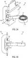
- Figs. 5A and 5Bdepict perspective front and rear views of a brush assembly 500, according to an alternative embodiment of the invention.
- a brush 502is illustratively shown with two grooves 504 on two opposite surfaces.
- the brushis supported by a brush holder 506 that includes two guide rails 508 engaging oppositely-arranged grooves 504 in the opposite surfaces the brush 502.
- the guide rails 508may be open-ended to allow for easy removal of the brush 502.
- the brush holder 506may be formed in different shapes to accommodate the back and forth (axial) movement of the brush 502.
- the brush holder 506includes support plates 506a arranged on a first plane and extended on two sides of the brush 502 to form the guides 508, and one or more side plates 506b, 506c that support the support plates 506a and engage a portion of the tool housing.
- side plates 506b and 506cprotrude angularly (typically 90 degrees) from the support plates 506a in opposite directions, although it is envisioned that other arrangements of the side plates 506b, 506c are within the scope of this invention. It is possible for one of the side plates 506b, 506c to be on the same plane as the support plates 506a.
- the brush holder 506may be mounted on a portion of the tool housing via the side plates 506b and/or 506c, the support plates 506a, or a combination of the two. Additionally, according to this embodiment, a spring post 516 extends from the side plate 506c to support a spring 510 of the brush assembly 500. Also depicted in these figures is shut wire 512 connected to a terminal 514.
- Fig. 6illustrates a perspective view of a portion of a power tool 600, in this case a small angle grinder, incorporating the brush assembly 500 described above, according to an embodiment of the invention.
- Fig. 7depicts the same perspective view of the grinder 600 without components of the brush assembly 500.
- An outer shell of the grinder 600 tool housing that houses the brush assembly 500has been removed for illustration purposes, although the main housing 602 that houses the motor (not shown) and supports the brush assembly 500 has been depicted.
- the tool housing 602includes two opening 604 on the two sides of the commutator for arranging the brush assembly 500.
- retaining featuressuch as slots 606, arranged to receive end portions of the support plate 506a, and side portions 508 arranged to accommodate side plate 506b.
- a screw receptacle 610may be arranged in alignment with a hole 518 in the side plate 506b to receive a screw in order to secure the brush holder 506 in the tool housing 602.
- Tool housing 602further includes a support post 614 arranged adjacent the gap 612 to support an end of the spring post 516.
- a flexible shunt wire 512made of braided copper or similar material, is welded at one end to the brush 502. The other end of the shut wire 512 may be connected to a motor terminal.
- Fig. 8illustrates a similar perspective view to Fig. 6 , with half of the tool housing 602 removed to show the motor components, including a stator (i.e., field) lamination stack (or field can) 802, field windings 804, an armature (not shown) arranged within the stator, a commutator 806 attached to the armature, and an armature shaft end bearing 808.
- a statori.e., field lamination stack (or field can) 802
- field windings 804an armature (not shown) arranged within the stator
- a commutator 806attached to the armature
- an armature shaft end bearing 808armature shaft end bearing
- Fig. 9illustrates a brush assembly 900 according to yet another exemplary embodiment of the invention.
- This embodimentis different from the previous two embodiments in two ways.
- the brush holder 906is mounted on a brush card 912 rather than be the tool housing.
- the brush holder 906is secured on the brush card 912 via two pins 922.
- the spring mechanism 910is also mounted on a post 920 of the brush card 912.
- the brush card 912may be attached to the tool housing using any known method.
- the brush card 912although shown as a rectangular piece herein, may be a one or two piece brush card with a circular inner aperture that can be received within the tool housing around the armature commutator.
- a side plate 906b of the brush holder 906is provided with a pin terminal 914 provided to receive electric power for the brush 902.
- a shunt wire(not shown) may be used to connect the brush 902 to the brush holder 906. It must be understood that these two features may be combined with any of the features and/or designed described in the previous embodiments.
- the brush assemblies according to embodiments of the inventionmay be used in any other power tool, either corded or cordless, including, but not limited to, drills, impact drivers, circular saw, miter saw, chop saw, recip saw, router, power screw gun, sandom orbital sander, large angle grinders, impact wrench, etc.
- U.S. Patent No. 7,893,583assigned to Black & Decker Inc., describes examples of different types of power tools that can incorporate the brush assemblies of this invention.
- tool housingor “motor housing” in this disclosure has been used to refer to a single piece of insulating material housing the motor components including the stator, commutator, brushes, etc. It must be understood that the term “tool housing” or “motor housing” may include any type of housing, including, but not limited to, a motor frame (for framed motors), a multi-piece housing, a inner motor housing inside a separate outer housing, and outer housing containing a separate inner housing, etc.
- clock springsThe spring mechanisms depicted in the figures 3A through 8 of this disclosure are commonly known as "clock springs.” It must be understood that any type of spring may alternatively be used. For example, a conventional wound spring may be placed directly behind the brush. Also, instead of a spring post, it is envisioned that the spring may be supported by a hole in the housing.
- the brush holders discussed in embodiments of this disclosureare made of conductive material. It is envisioned, however, that the brush holder may be made of either fully non-conductive material, or a combination of conductive and non-conductive material.
Landscapes
- Engineering & Computer Science (AREA)
- Power Engineering (AREA)
- Insulation, Fastening Of Motor, Generator Windings (AREA)
- Motor Or Generator Current Collectors (AREA)
- Motor Or Generator Frames (AREA)
Description
- The present invention relates to power tools, and more particularly to a brush system for a power tool motor.
- The statements in this section merely provide background information related to the present disclosure and may not constitute prior art.
- Known portable power tools typically have an electric motor received within a housing. One common type of electric motor used in power tools has a rotor, a stator, and brushes. The rotor includes a rotor shaft, laminations mounted on the rotor shaft, armature windings wound in slots in the lamination stack, and a commutator mounted on the rotor shaft and electrically connected to the armature windings. The stator may have field windings wound in laminations, or may have permanent magnets. The brushes are mounted in brush housings, often known as brush boxes, surrounding the commutator. Electric current is supplied from a power source through the brushes to the commutator and then to the armature windings.
- The brushes and brush boxes are typically part of a brush assembly(ies). The brush boxes and brushes are disposed diametrically opposite to each other with the commutator disposed therebetween. The brush assembly(ies) includes springs that urge the brushes against the commutator.
Fig. 1 illustrates ahalf piece 102 of aconventional brush assembly 100. Eachpiece 102 in this design includes abase member 103 on which abrush box 104 is mounted. Thebase member 103 has asemi-annular periphery 106.Brush box 104 includes amounting portion 116, anarm 118 connected to themounting portion 116 and extending perpendicularly from thebase member 103, and ametallic brush box 120.Brush box 104 receives a brush therein. Themounting portion 116 includes a plurality oflegs 122 for crimping tocorresponding cutout portions 124 in thebase member 103 to secure themounting portion 116 to thebase member 103. Thespring 101 includes one end connected to thearm 118 and the other end having acontact portion 132. Thecontact portion 132 is disposed adjacent to the secondopen end 128 of thebrush box 120. When the brush is received in thebrush box 120, thecontact portion 132 of thespring 101 contacts the brush and urges the brush radially inwardly against the motor commutator.Fig. 2 depicts theconventional brush assembly 100 including twohalf pieces 102 inside a power tool. As can be shown in this figure, thebrush half pieces 102 are inserted inside agroove 103 of the tool housing. Thebrush box 120 are arranged around the commutator 34 of themotor 14.Bosses 134 are used to mate the two housing halves together after assembling thehalf pieces 102 is complete.- The
brush assembly 100 depicted herein is for a direct current (DC) cordless power tools. However, similar brush assemblies may be used in alternating current (AC) corded power tools. Further, also thebrush box 120 depicted inFig. 1 mounted on abrush card 102, similar brush boxes are mounted directly into the tool housing around the commutator. - The conventional brush assembly described herein has several disadvantages. First,
brush box 120 includes a large amount of metal, which is both expensive and requires a great degree of accuracy in performing procedures such as stamping, bending and crimping the metal components. In addition, the gap between thebrush box 120 and the brush is prone to collecting dust and debris over time. This increases the wear on the brush over time and may even cause the brush to jam inside the brush box. A jammed or "hung" brush results in the tool failing during runtime and may even damage the motor commutator. Moreover, since thebrush box 120 encloses all four sides of the brush, it limits direct brush exposure to airflow. This can raise thebrush box 102 temperature to fairly high levels, particularly in high power applications such as power tools, which can potentially damage the tool housing. - Examples of power tools of the prior art which demonstrate some of the problems set out above are disclosed in
US2009/115266 ,GB2302999 EP1592112 ,JPS6188743 JPH10201204 US2008/090504 . - Accordingly, there is provided a power tool in accordance with claim 1.
Fig. 1 illustrates a conventional brush assembly with a brush box.Fig. 2 illustrates the arrangement of the brush assembly ofFig. 1 inside a power tool.Fig. 3A illustrates a perspective view of a brush assembly according to an embodiment of the invention.Fig. 3B illustrates a rear view of the brush assembly ofFig. 3A , according to an embodiment.Fig. 4 illustrates a perspective view of a portion of an exemplary power tool, in this case a small angle grinder, incorporating the brush assembly ofFig. 3A , according to an embodiment.Fig. 5A illustrates a perspective view of a brush assembly according to an alternative embodiment of the invention.Fig. 5B illustrates a rear view of the brush assembly ofFig. 5A , according to an embodiment.Fig. 5A illustrates a perspective view of a brush assembly according to an alternative embodiment of the invention.Fig. 5B illustrates a rear view of the brush assembly ofFig. 5A , according to an embodiment.Fig. 6 illustrates a perspective view of a portion of an exemplary power tool, in this case a small angle grinder, incorporating the brush assembly ofFig. 5A , according to an embodiment.Fig. 7 illustrates the same perspective view ofFig. 6 , without the brush assembly assembled into the housing, according to an embodiment.Fig. 8 illustrates a similar perspective view toFig. 6 , with half of the tool housing removed to show the motor components, according to an embodiment.Fig. 9 illustrates a perspective view of a brush assembly according to yet another embodiment of the invention.- The drawings described herein are for illustrative purposes only of selected embodiments and not all possible implementations, and are not intended to limit the scope of the present disclosure. Corresponding reference numerals indicate corresponding parts throughout the several views of the drawings.
- According to the invention, there is provided a power tool comprising the features of claim 1.
- According to an embodiment, the brush holder is supported by the tool housing.
- The tool housing includes at least one openings around the commutator in which the brush assembly is arranged, the tool housing including retaining features for retaining the brush holder in the opening. The brush holder comprises conductive material.
- The two support plates are arranged along a single plane and the brush holder further comprises at least one side plate extending angularly from the two support plates to provide an opening for the axial movement of the brush. The side plate includes a terminal pin extending therefrom adapted to couple to a motor terminal. In an embodiment, the side plate is supported by the tool housing.
- According to an embodiment, the tool housing includes a spring post formed therein adjacent the brush assembly to support the spring in the proximity of the brush.
- According to an embodiment, the brush holder includes a spring post extending therefrom to support the spring in the proximity of the brush. The brush holder includes at least one side plate extending angularly from the support plates to provide an opening for the axial movement of the brush, and the spring post extends from the side plate perpendicularly to the axis of the brush.
- According to an embodiment, a shunt wire is provided attaching the brush to a motor terminal. In an embodiment, a brush card is provided on which the brush holder is mounted, the brush card being supported by the tool housing.
- According to an embodiment, the grooves extend through the entire length of the brush. Alternatively, the grooves extend through only one end of the brush and close-ended at an opposite end.
- Referring to
FIGs. 3A and 3B , a perspective view and a rear view of abrush assembly 300 is illustrated, according to an exemplary embodiment of the invention. - A
brush 302 is illustratively shown with twogrooves 304 on two opposing surfaces. The brush is supported by abrush holder 306 that includes twoguide rails 308 engaging oppositely-arrangedgrooves 304 in the opposing surfaces thebrush 302. In an embodiment, theguide rails 308 may be open-ended to allow for easy removal of the brush 302 (e.g., when the brush need be replaced during a routine power tool service). Thegrooves 304 on thebrush 302 may be similarly be open-ended on one or both sides. Alternatively, thegrooves 304 may extend only through a portion of thebrush 302 and be close-ended on one or both sides. - The
brush holder 306 may be formed in different shapes to accommodate the back and forth (axial) movement of thebrush 302. For example, thebrush holder 306 may includesupport plates 306a arranged on a first plane and extended on two sides of thebrush 302 to form theguides 308, and one ormore legs 306b (also referred to asside plates 306b) that support thesupport plates 306a and engage a portion of the tool housing. Thelegs 306b may protrude on one or more sides of thesupport plates 306a at an angle (typically 90 degrees). It is possible for one of thelegs 306b to be on the same plane as thesupport plates 306a. Size and angular arrangement of thesupport plates 306a andlegs 306b may vary from one tool to another depending on the tool housing and motor design requirements. Thebrush holder 306 may be mounted on a portion of the tool housing via thelegs 306b, thesupport plates 306a, or a combination of the two. Thebrush holder 306 may alternatively be mounted on a brush card, which is in turn secured to the tool housing. - A
spring mechanism 310 is mounted adjacent thebrush 302. Afirst leg 310a of the spring engages a post (described later) and asecond leg 310b extends from thespring 310 to engage a back portion of thebrush 302 and apply a biasing force to the brush towards the motor armature commutator. In one embodiment, thebrush holder 306 includes nolegs 306b and theplates 306a is provided as two separate parts embedded in the tool housing. In yet another embodiment, thesupport plates 306a (or lets 306b) may be embedded into additional components, which are them supported or embedded into the tool housing Fig. 4 illustrates a perspective view of a portion of apower tool 400, in this case a small angle grinder, incorporating thebrush assembly 300 described above, according to an embodiment of the invention. The full operation of a grinder is beyond the scope of this disclosure. Reference is made toU.S. Patent No. 8,087,977 assigned to Black & Decker Inc., for an example of a grinder. An outer shell of thegrinder 400 that houses thebrush assembly 300 has been removed for illustration purposes, although themain housing 402 that houses the motor (not shown) and supports thebrush assembly 300 has been depicted. Thetool housing 402 includes two opening 404 on the two sides of the commutator for arranging thebrush assembly 300. Theopenings 404 include retainingfeatures 406, which may be ribs, slots, snapping features, etc., to securely maintain thebrush holder 306 in thetool housing 402. Thetool housing 402 further includes apost 408 arranged adjacent theopening 404 to accommodate thespring 310. Thepost 408 may be an integral part of thetool housing 402. Thepost 408 includes a slot that receives thefirst leg 310a of thespring 310. Aflexible shunt wire 312, made of braided copper or similar material, is welded at one end to thebrush 302. The other end of theshut wire 312 may be connected to a motor terminal, as disclosed inU.S. Patent No. 7,059,038 assigned to Black & Decker Inc..- During assembly, according to an exemplary embodiment, the
brush 302 is inserted through theguide rails 308 of thebrush holder 306 adjacent the motor commutator. Thespring 310 is then inserted into thepost 408 and thesecond leg 310b of thespring 310 is manually pulled to engage the back of thebrush 302. Figs. 5A and 5B depict perspective front and rear views of abrush assembly 500, according to an alternative embodiment of the invention. In this embodiment, similarly to the fist embodiment, abrush 502 is illustratively shown with twogrooves 504 on two opposite surfaces. The brush is supported by abrush holder 506 that includes twoguide rails 508 engaging oppositely-arrangedgrooves 504 in the opposite surfaces thebrush 502. As in the first embodiment, theguide rails 508 may be open-ended to allow for easy removal of thebrush 502.- The
brush holder 506 may be formed in different shapes to accommodate the back and forth (axial) movement of thebrush 502. In the illustrated example, thebrush holder 506 includessupport plates 506a arranged on a first plane and extended on two sides of thebrush 502 to form theguides 508, and one ormore side plates support plates 506a and engage a portion of the tool housing. In this embodiment,side plates support plates 506a in opposite directions, although it is envisioned that other arrangements of theside plates side plates support plates 506a. Thebrush holder 506 may be mounted on a portion of the tool housing via theside plates 506b and/or 506c, thesupport plates 506a, or a combination of the two. Additionally, according to this embodiment, aspring post 516 extends from theside plate 506c to support aspring 510 of thebrush assembly 500. Also depicted in these figures is shutwire 512 connected to a terminal 514. Fig. 6 illustrates a perspective view of a portion of apower tool 600, in this case a small angle grinder, incorporating thebrush assembly 500 described above, according to an embodiment of the invention.Fig. 7 depicts the same perspective view of thegrinder 600 without components of thebrush assembly 500. An outer shell of thegrinder 600 tool housing that houses thebrush assembly 500 has been removed for illustration purposes, although themain housing 602 that houses the motor (not shown) and supports thebrush assembly 500 has been depicted. Thetool housing 602 includes two opening 604 on the two sides of the commutator for arranging thebrush assembly 500. Arranged in the periphery of theopenings 604 are retaining features such asslots 606, arranged to receive end portions of thesupport plate 506a, andside portions 508 arranged to accommodateside plate 506b. In addition, ascrew receptacle 610 may be arranged in alignment with ahole 518 in theside plate 506b to receive a screw in order to secure thebrush holder 506 in thetool housing 602. In the periphery of theopening 604 may further be provided agap 612 through which thespring 510 is supported by thespring post 516.Tool housing 602 further includes asupport post 614 arranged adjacent thegap 612 to support an end of thespring post 516. Aflexible shunt wire 512, made of braided copper or similar material, is welded at one end to thebrush 502. The other end of theshut wire 512 may be connected to a motor terminal.Fig. 8 illustrates a similar perspective view toFig. 6 , with half of thetool housing 602 removed to show the motor components, including a stator (i.e., field) lamination stack (or field can) 802,field windings 804, an armature (not shown) arranged within the stator, acommutator 806 attached to the armature, and an armatureshaft end bearing 808. Details of the operation of the motor in a grinder are outside the scope of this disclosure, and can be found inU.S. Patent Publication No. 2012/0077424 filed by Black & Decker, Inc. This figure is provided to illustrate the arrangement of thebrush assembly 500 with respect to thearmature commutator 806.Fig. 9 illustrates abrush assembly 900 according to yet another exemplary embodiment of the invention. This embodiment is different from the previous two embodiments in two ways. First, thebrush holder 906 is mounted on abrush card 912 rather than be the tool housing. Thebrush holder 906 is secured on thebrush card 912 via twopins 922. Thespring mechanism 910 is also mounted on apost 920 of thebrush card 912. Thebrush card 912 may be attached to the tool housing using any known method. For example, thebrush card 912, although shown as a rectangular piece herein, may be a one or two piece brush card with a circular inner aperture that can be received within the tool housing around the armature commutator. Second, in this embodiment, aside plate 906b of thebrush holder 906 is provided with apin terminal 914 provided to receive electric power for thebrush 902. This arrangement therefore eliminates the need for a separate shunt wire connection to thebrush 902. In an embodiment, a shunt wire (not shown) may be used to connect thebrush 902 to thebrush holder 906. It must be understood that these two features may be combined with any of the features and/or designed described in the previous embodiments.- It should be noted that although the illustrated power tool described above is a small angle grinder, the brush assemblies according to embodiments of the invention may be used in any other power tool, either corded or cordless, including, but not limited to, drills, impact drivers, circular saw, miter saw, chop saw, recip saw, router, power screw gun, sandom orbital sander, large angle grinders, impact wrench, etc.
U.S. Patent No. 7,893,583 , assigned to Black & Decker Inc., describes examples of different types of power tools that can incorporate the brush assemblies of this invention. - The term "tool housing" or "motor housing" in this disclosure has been used to refer to a single piece of insulating material housing the motor components including the stator, commutator, brushes, etc. It must be understood that the term "tool housing" or "motor housing" may include any type of housing, including, but not limited to, a motor frame (for framed motors), a multi-piece housing, a inner motor housing inside a separate outer housing, and outer housing containing a separate inner housing, etc.
- The spring mechanisms depicted in the
figures 3A through 8 of this disclosure are commonly known as "clock springs." It must be understood that any type of spring may alternatively be used. For example, a conventional wound spring may be placed directly behind the brush. Also, instead of a spring post, it is envisioned that the spring may be supported by a hole in the housing. - The brush holders discussed in embodiments of this disclosure are made of conductive material. It is envisioned, however, that the brush holder may be made of either fully non-conductive material, or a combination of conductive and non-conductive material.
Claims (11)
- A power tool (400) comprising:a tool housing (402) in which an electric motor is disposed, the electric motor including a stator (802) and an armature rotatably received within the stator, the armature having an armature shaft on which a commutator (806) is mounted; and
at least one brush assembly (300), comprising a brush (302) and a brush holder (306), disposed around the commutator (806);
wherein the brush holder (306) comprises conductive material; anda spring (310) contacting the brush (302) that urges the brush (302) radially inwardly along an axis, the brush assembly (300)characterised by:
the brush (302) having two grooves (304) on opposites surfaces therein; a brush holder (306) comprising two support plates (306a) arranged defining guiderails (308) that extend into the grooves (304) of the brush (302) to facilitate movement of the brush (302) along the single axis;
wherein the tool housing (402) includes at least one opening (404) adjacent the commutator (806) through which the brush (302) is disposed, and two oppositely-arranged slots (406) formed around the periphery of the opening (404) to receive two end portions of the support plates (306a) of the brush holder (306) to securely maintain the brush holder (306) in the tool housing (402);
wherein the two support plates (306a) are arranged along a single plane and the brush holder (306) further comprises at least one side plate (306b) extending angularly from the two support plates (306a) to provide an opening for the radial movement of the brush (302);
wherein the side plate 306b) includes a terminal pin (914) extending therefrom to receive electric power for the brush (302). - The power tool of claim 1, wherein the brush holder (306) is supported by the tool housing (402).
- The power tool of any of the previous claims, wherein the side plate (306b) is supported by the tool housing (402).
- The power tool of claim 1, wherein the tool housing (402) comprises a spring post (408) formed therein adjacent the brush assembly (300) to support the spring (310) in the proximity of the brush (302).
- The power tool of claim 1, wherein the brush holder (506) includes a spring post (516) extending therefrom to support the spring (310) in the proximity of the brush (302).
- The power tool of claim 5, wherein the brush holder (506) comprises at least one side plate (506c) extending angularly from the support plates (306a) to provide an opening for the radial movement of the brush (302), and the spring post (516) extends from the side plate (306b) perpendicularly to the axis of the brush (302).
- The power tool of claim 1, further comprising a shunt wire (312) attaching the brush (302) to a motor terminal.
- The power tool of claim 1, further comprising a brush card (912) on which the brush holder (306) is mounted, the brush card (912) being supported by the tool housing (402).
- The power tool of claim 1, wherein the power tool is a grinder powered by an AC power source.
- The power tool of claim 1, wherein the grooves (304) extend through the entire length of the brush (302).
- The power tool of claim 1, wherein the grooves (304) extend through only one end of the brush (302) and close-ended at an opposite end.
Applications Claiming Priority (1)
| Application Number | Priority Date | Filing Date | Title |
|---|---|---|---|
| US201261650622P | 2012-05-23 | 2012-05-23 |
Publications (3)
| Publication Number | Publication Date |
|---|---|
| EP2667490A2 EP2667490A2 (en) | 2013-11-27 |
| EP2667490A3 EP2667490A3 (en) | 2017-05-24 |
| EP2667490B1true EP2667490B1 (en) | 2021-08-18 |
Family
ID=48430594
Family Applications (2)
| Application Number | Title | Priority Date | Filing Date |
|---|---|---|---|
| EP13168345.0AActiveEP2667490B1 (en) | 2012-05-23 | 2013-05-17 | Brush assembly for a power tool motor |
| EP13168849.1AActiveEP2667488B1 (en) | 2012-05-23 | 2013-05-23 | Armature end insulator for a power tool motor |
Family Applications After (1)
| Application Number | Title | Priority Date | Filing Date |
|---|---|---|---|
| EP13168849.1AActiveEP2667488B1 (en) | 2012-05-23 | 2013-05-23 | Armature end insulator for a power tool motor |
Country Status (2)
| Country | Link |
|---|---|
| US (2) | US9143015B2 (en) |
| EP (2) | EP2667490B1 (en) |
Families Citing this family (4)
| Publication number | Priority date | Publication date | Assignee | Title |
|---|---|---|---|---|
| DE102012224153A1 (en)* | 2012-12-21 | 2014-06-26 | Robert Bosch Gmbh | Stator for an electric machine |
| US20150194859A1 (en) | 2013-08-09 | 2015-07-09 | Black & Decker Inc. | Power tool having improved motor fan assembly |
| US11219980B2 (en)* | 2018-10-29 | 2022-01-11 | Nanjing Chevron Industry Co., Ltd. | Angle grinder and motor thereof |
| JP7620505B2 (en)* | 2021-06-15 | 2025-01-23 | 株式会社ミツバ | Insulator, stator and electric motor |
Family Cites Families (91)
| Publication number | Priority date | Publication date | Assignee | Title |
|---|---|---|---|---|
| FR1023026A (en) | 1950-08-04 | 1953-03-12 | Method for isolating coiled electrical members comprising hollowed-out parts and products obtained by implementing this method | |
| DE1797835U (en) | 1958-06-20 | 1959-10-15 | Pfaff Ag G M | GROOVE INSULATION FOR ELECTRIC MACHINERY. |
| US3095515A (en)* | 1961-11-06 | 1963-06-25 | Louis Marx & Company | Subminiature electric motor |
| CH409104A (en) | 1964-11-25 | 1966-03-15 | Mefina Sa | Electric motor armature with commutator |
| US3917967A (en) | 1971-12-27 | 1975-11-04 | Rockwell International Corp | Electric motor armature construction |
| US3882336A (en) | 1973-12-03 | 1975-05-06 | Briggs & Stratton Corp | Electric motor armature core |
| US3831268A (en)* | 1973-12-03 | 1974-08-27 | Briggs & Stratton Corp | Method of making an electric motor armature core |
| FR2310012A1 (en) | 1975-04-29 | 1976-11-26 | Seim | ROTOR FOR ELECTRIC MACHINE |
| FR2328318A1 (en) | 1975-10-17 | 1977-05-13 | Peugeot Aciers Et Outillage | Insulating slot liner assembly for rotating machine - is moulded in one piece and inserted as one into all slots |
| CA1071680A (en) | 1976-06-16 | 1980-02-12 | Itw Fastex Italia S.P.A. | Insulating assembly for stator slots of electrical motors |
| US4340829A (en) | 1979-06-22 | 1982-07-20 | Sheller Globe Corporation | Molded end coil insulator |
| DE3216117A1 (en) | 1982-04-30 | 1983-11-03 | Henschel Gerätebau GmbH, 3035 Hodenhagen | Slot insulation for a rotor of an electrical machine |
| JPS58201565A (en)* | 1982-05-18 | 1983-11-24 | Matsushita Electric Ind Co Ltd | Stator for rotary electric machine |
| JPS5914336A (en) | 1982-07-14 | 1984-01-25 | Hitachi Ltd | Rotary electric machine |
| DE3327744A1 (en) | 1983-08-01 | 1985-02-21 | Siemens AG, 1000 Berlin und 8000 München | METHOD FOR BALANCING WINDED RUNNERS OF ELECTRICAL MACHINES |
| JPS6188743A (en)* | 1984-10-03 | 1986-05-07 | Nippon Denso Co Ltd | Brush holder |
| US4631433A (en) | 1985-05-06 | 1986-12-23 | General Electric Company | Plastic end shield with thermal barrier for dynamoelectric machines |
| US4663835A (en)* | 1985-12-23 | 1987-05-12 | The Singer Company | Method of applying electric motor armature insulation |
| JPS62233046A (en) | 1986-03-31 | 1987-10-13 | Aisin Seiki Co Ltd | Core-insulating cap for skew type motor |
| JPH0628937Y2 (en) | 1987-02-17 | 1994-08-03 | 松下電器産業株式会社 | Non-commutator DC axial flow fan motor |
| DE3712226A1 (en)* | 1987-04-10 | 1988-10-27 | Danfoss As | ELECTRICAL MACHINE WITH A WINDING PACKAGE AND A METHOD FOR THEIR PRODUCTION |
| DD269954A1 (en)* | 1987-12-31 | 1989-07-12 | Elektrogeraete Ingbuero Veb | INSULATING DISC FOR ANCHOR PACKAGES OF ELECTRICAL MACHINES |
| US4904893A (en) | 1988-10-27 | 1990-02-27 | Emerson Electric Co. | Stator end cap insulator assembly including end turn ventilation and lead wire tie down structure |
| DD286694A5 (en)* | 1989-07-04 | 1991-01-31 | Veb Elektromaschinenbau Dresden, | ARRANGEMENT FOR INSULATING THE HEADLINK AND FOR A TARGETED PAINT FINISHING |
| GB9015604D0 (en)* | 1990-07-16 | 1990-09-05 | Johnson Electric Sa | Armature in an electric motor |
| US5144182A (en) | 1991-09-04 | 1992-09-01 | Onan Corporation | Skewed rotor assembly |
| GB9312312D0 (en)* | 1993-06-15 | 1993-07-28 | Johnson Electric Sa | Armature end protector for a wound rotor |
| US5428258A (en) | 1993-06-25 | 1995-06-27 | Ryobi Motor Products Corp. | Armature for an electric motor having a core face insulation disc |
| US5576585A (en) | 1993-08-30 | 1996-11-19 | Axis Usa, Inc. | Methods and apparatus for producing dynamo-electric machine armatures with improved balance |
| JP2758837B2 (en) | 1994-09-09 | 1998-05-28 | アスモ株式会社 | Commutator fixing structure |
| US5828152A (en) | 1995-02-07 | 1998-10-27 | Denyo Kabushiki Kaisha | Rotor with permanent magnet of generator and method of manufacturing the same |
| US6006418A (en) | 1995-02-07 | 1999-12-28 | Denyo Kabushiki Kaisha | Method of manufacturing a rotors with permanent magnet |
| DE19523896B4 (en)* | 1995-06-30 | 2007-01-11 | Robert Bosch Gmbh | Mechanically commutated electric motor |
| US5717273A (en) | 1996-02-28 | 1998-02-10 | Onan Corporation | Insulating armature end turn cap |
| JPH10201204A (en)* | 1997-01-17 | 1998-07-31 | Asmo Co Ltd | Electric rotary machine, brush holder and commutator piece |
| JPH10243594A (en)* | 1997-02-25 | 1998-09-11 | Tec Corp | Motor |
| FR2778283A1 (en) | 1998-04-30 | 1999-11-05 | Valeo Systemes Dessuyage | Insulated end fitting for an automobile cooling fan motor. |
| JP2001286085A (en) | 2000-03-30 | 2001-10-12 | Asmo Co Ltd | Core insulator for motor rotor |
| US6580193B2 (en) | 2000-03-31 | 2003-06-17 | Asmo Co., Ltd. | Rotary electric machine and manufacturing method therefor |
| JP2003047216A (en) | 2001-08-03 | 2003-02-14 | Moric Co Ltd | Armature winding method, apparatus thereof and armature |
| EP1235327A3 (en) | 2001-02-21 | 2004-07-07 | Kabushiki Kaisha Moric | Stator coil structure for rotary electrical machine and method of manufacturing the same |
| US6590310B2 (en) | 2001-02-21 | 2003-07-08 | Kabushiki Kaisha Moric | Stator coil structure for revolving-field electrical machine and method of manufacturing same |
| US6831389B2 (en) | 2001-07-11 | 2004-12-14 | Kabushiki Kaisha Moric | Stator coil structure for revolving-field electrical machine and method of manufacturing same |
| JP2003047214A (en) | 2001-08-03 | 2003-02-14 | Moric Co Ltd | Method and apparatus for winding armature including skew |
| JP2003047217A (en) | 2001-08-03 | 2003-02-14 | Moric Co Ltd | Method and apparatus for winding coil of armature of rotating field type electric appliance |
| JP2003047215A (en) | 2001-08-03 | 2003-02-14 | Moric Co Ltd | Method and apparatus for winding coil of armature of rotating field type electric appliance |
| JP2003088026A (en)* | 2001-09-07 | 2003-03-20 | Moric Co Ltd | Armature insulator for rotating electrical equipment |
| EP1292003A1 (en) | 2001-09-07 | 2003-03-12 | Kabushiki Kaisha Moric | Insulator for armature of dynamo-electric machine |
| JP2003088025A (en) | 2001-09-07 | 2003-03-20 | Moric Co Ltd | Armature insulator for rotating electrical equipment |
| US6670736B2 (en) | 2002-02-19 | 2003-12-30 | Sunonwealth Electric Machine Industry Co., Ltd. | Insulating jacket structure of a stator of a direct current motor |
| JP2004007902A (en) | 2002-05-31 | 2004-01-08 | Tamagawa Seiki Co Ltd | Rotating machine insulation cap structure |
| US6664701B1 (en) | 2002-06-13 | 2003-12-16 | Black & Decker Inc. | Brush assembly |
| JP3973509B2 (en) | 2002-07-30 | 2007-09-12 | ミネベア株式会社 | Stator device |
| JP3952290B2 (en) | 2002-09-06 | 2007-08-01 | ヤマハモーターエレクトロニクス株式会社 | Armature of rotating electrical equipment and winding method thereof |
| US6798109B2 (en)* | 2002-10-31 | 2004-09-28 | Black & Decker Inc. | Electric motor brush assembly |
| US6713916B1 (en) | 2002-10-31 | 2004-03-30 | Black & Decker Inc. | Electric motor assembly |
| EP1575147B1 (en) | 2002-12-11 | 2008-01-23 | Asmo Co., Ltd. | Insulator, armature and dynamo-electric machine |
| JP2004242442A (en) | 2003-02-06 | 2004-08-26 | Asmo Co Ltd | Armature |
| JP4287215B2 (en) | 2003-07-11 | 2009-07-01 | ヤマハモーターエレクトロニクス株式会社 | Rotating armature bobbin |
| DE10335559A1 (en) | 2003-08-02 | 2005-03-03 | Valeo Motoren Und Aktuatoren Gmbh | multi-part insulating element for armature winding of electric motor e.g. motor vehicle electric auxiliary drive, includes shaped sections distributed around axis of inserted part |
| US7893583B2 (en) | 2003-09-05 | 2011-02-22 | Black & Decker Inc. | Power tools with motor having a multi-piece stator |
| KR20050046359A (en) | 2003-11-14 | 2005-05-18 | 박광식 | Rotor of motor having an inserted insulator and insulator thereof |
| US7362028B2 (en) | 2004-02-26 | 2008-04-22 | Lg Electronics Inc. | Stator of outer rotor type motor for drum type washer |
| GB0409662D0 (en)* | 2004-04-30 | 2004-06-02 | Johnson Electric Sa | Brush assembly |
| DE202004010956U1 (en) | 2004-07-13 | 2005-11-24 | Minebea Co., Ltd., Kitasaku | Device for insulating stator slots |
| CN100377472C (en) | 2004-07-16 | 2008-03-26 | 鸿富锦精密工业(深圳)有限公司 | motor stator |
| CN1309147C (en) | 2004-07-30 | 2007-04-04 | 鸿富锦精密工业(深圳)有限公司 | Stator of motor |
| JP4498358B2 (en) | 2004-09-01 | 2010-07-07 | 三菱電機株式会社 | Electric motor and electric blower provided with the same |
| JP4647966B2 (en) | 2004-11-04 | 2011-03-09 | ミネベア株式会社 | Slot insulator for multiplexed resolver and multiplexed resolver using the same |
| US8087977B2 (en) | 2005-05-13 | 2012-01-03 | Black & Decker Inc. | Angle grinder |
| KR100584457B1 (en) | 2005-09-16 | 2006-05-26 | 신한정밀공업(주) | Rotor of motor with insulator including glass fiber |
| CN201263101Y (en) | 2006-02-20 | 2009-06-24 | 布莱克和戴克公司 | DC motor with double commutator strip set and selectable series/parallel connection adjacent coil |
| TWM304689U (en) | 2006-06-09 | 2007-01-11 | Tricore Corp | Focusing actuator using voice coil motor |
| DE102006032713A1 (en)* | 2006-07-14 | 2008-01-17 | BSH Bosch und Siemens Hausgeräte GmbH | Rotor package with grooved insulation end disk |
| DE102006034120A1 (en) | 2006-07-24 | 2008-01-31 | Robert Bosch Gmbh | Rotor for electric motor, has two axially facing insulation lamellas exhibiting insulation walls running into grooves, where insulation walls of insulation lamellas form catch in circumferential direction for each sheet metal blade |
| WO2008027535A2 (en) | 2006-09-01 | 2008-03-06 | Sears David B | Insulator for stator assembly of brushless dc motor |
| US20080079101A1 (en) | 2006-10-02 | 2008-04-03 | Chi Ai | Insulation frame device for a stator in a motor |
| US7988538B2 (en)* | 2006-10-13 | 2011-08-02 | Black & Decker Inc. | Large angle grinder |
| JP2008253027A (en) | 2007-03-29 | 2008-10-16 | Nissin Kogyo Co Ltd | Electric motor |
| JP5285328B2 (en)* | 2007-06-19 | 2013-09-11 | アスモ株式会社 | Armature and motor |
| JP2009055741A (en) | 2007-08-28 | 2009-03-12 | Jtekt Corp | Electric motor |
| JP5234899B2 (en) | 2007-09-04 | 2013-07-10 | 株式会社ミツバ | Insulator for electric motor |
| US20090115266A1 (en)* | 2007-11-05 | 2009-05-07 | Black And Decker Inc. | Power tool with frameless motor and two-piece brush assembly, and method of assembly |
| JP2009240133A (en) | 2008-03-28 | 2009-10-15 | Mitsuba Corp | Electric motor and fuel pump unit |
| DE102008041716A1 (en)* | 2008-08-29 | 2010-03-04 | Robert Bosch Gmbh | Hand tool with brush motor |
| JP5155782B2 (en) | 2008-09-04 | 2013-03-06 | アスモ株式会社 | Armature and motor |
| KR101070987B1 (en) | 2009-10-29 | 2011-10-06 | 뉴모텍(주) | Motor |
| JP5482121B2 (en) | 2009-11-10 | 2014-04-23 | 株式会社富士通ゼネラル | Rotating electric machine stator |
| JP5482383B2 (en) | 2010-03-31 | 2014-05-07 | 株式会社富士通ゼネラル | Electric motor stator and rotary compressor |
| TWM401923U (en) | 2010-10-12 | 2011-04-11 | Headline Electric Co Ltd | Motor stator windings insulation structure improvement |
| KR101876226B1 (en) | 2011-10-20 | 2018-07-09 | 엘지이노텍 주식회사 | Stator core for Motor and manufacturing method thereof |
- 2013
- 2013-03-15USUS13/835,614patent/US9143015B2/enactiveActive
- 2013-05-17EPEP13168345.0Apatent/EP2667490B1/enactiveActive
- 2013-05-22USUS13/899,956patent/US9438079B2/enactiveActive
- 2013-05-23EPEP13168849.1Apatent/EP2667488B1/enactiveActive
Non-Patent Citations (1)
| Title |
|---|
| None* |
Also Published As
| Publication number | Publication date |
|---|---|
| EP2667488B1 (en) | 2022-07-20 |
| US20130313940A1 (en) | 2013-11-28 |
| EP2667488A2 (en) | 2013-11-27 |
| EP2667490A2 (en) | 2013-11-27 |
| US20130313924A1 (en) | 2013-11-28 |
| EP2667490A3 (en) | 2017-05-24 |
| EP2667488A3 (en) | 2017-06-07 |
| US9438079B2 (en) | 2016-09-06 |
| US9143015B2 (en) | 2015-09-22 |
Similar Documents
| Publication | Publication Date | Title |
|---|---|---|
| EP2835897B1 (en) | Brush assembly for an electric motor | |
| JP5214954B2 (en) | Brush holder guide frame, brush assembly, and electric device including brush holder with brush assembly | |
| EP2667490B1 (en) | Brush assembly for a power tool motor | |
| CN109314446B (en) | Ground terminal, cover subassembly and including its motor | |
| KR100624669B1 (en) | Motor with grounding structure to reduce radio noise | |
| EP2396870B1 (en) | Brush holder assembly for a dynamo-electric machine | |
| US20090115266A1 (en) | Power tool with frameless motor and two-piece brush assembly, and method of assembly | |
| RU2506683C2 (en) | Hand-held machine with brush commutated electric motor | |
| JP6856067B2 (en) | Motor and motor manufacturing method | |
| US9991770B2 (en) | Spring post for brush card for a power tool | |
| KR20180042686A (en) | Ground terminal, Cover assembly and vehicle having the same | |
| JP2007288840A (en) | Motor with brush | |
| US9866078B2 (en) | Brush assembly mount | |
| JP4437079B2 (en) | Electric motor for handheld machine tools | |
| JP6077793B2 (en) | Electric motor | |
| EP3018799B1 (en) | Spring post for brush card for a power tool | |
| JP6536249B2 (en) | Electric rotating machine | |
| WO2023188590A1 (en) | Electric motor and method for manufacturing electric motor | |
| JPWO2022137890A5 (en) | ||
| US10096960B2 (en) | Brush holder assembly and commutator motor comprising said brush holder assembly | |
| JP6127262B2 (en) | Commutator motor | |
| KR20130002818A (en) | Brush motor and assembly method thereof | |
| JP6082979B2 (en) | Commutator motor | |
| JP5280949B2 (en) | DC motor | |
| JP2010074867A (en) | Rotating electrical machine |
Legal Events
| Date | Code | Title | Description |
|---|---|---|---|
| PUAI | Public reference made under article 153(3) epc to a published international application that has entered the european phase | Free format text:ORIGINAL CODE: 0009012 | |
| AK | Designated contracting states | Kind code of ref document:A2 Designated state(s):AL AT BE BG CH CY CZ DE DK EE ES FI FR GB GR HR HU IE IS IT LI LT LU LV MC MK MT NL NO PL PT RO RS SE SI SK SM TR | |
| AX | Request for extension of the european patent | Extension state:BA ME | |
| PUAL | Search report despatched | Free format text:ORIGINAL CODE: 0009013 | |
| AK | Designated contracting states | Kind code of ref document:A3 Designated state(s):AL AT BE BG CH CY CZ DE DK EE ES FI FR GB GR HR HU IE IS IT LI LT LU LV MC MK MT NL NO PL PT RO RS SE SI SK SM TR | |
| AX | Request for extension of the european patent | Extension state:BA ME | |
| RIC1 | Information provided on ipc code assigned before grant | Ipc:H02K 5/14 20060101AFI20170420BHEP Ipc:H01R 39/40 20060101ALI20170420BHEP | |
| STAA | Information on the status of an ep patent application or granted ep patent | Free format text:STATUS: REQUEST FOR EXAMINATION WAS MADE | |
| 17P | Request for examination filed | Effective date:20170531 | |
| RBV | Designated contracting states (corrected) | Designated state(s):AL AT BE BG CH CY CZ DE DK EE ES FI FR GB GR HR HU IE IS IT LI LT LU LV MC MK MT NL NO PL PT RO RS SE SI SK SM TR | |
| STAA | Information on the status of an ep patent application or granted ep patent | Free format text:STATUS: EXAMINATION IS IN PROGRESS | |
| 17Q | First examination report despatched | Effective date:20180418 | |
| REG | Reference to a national code | Ref country code:DE Ref legal event code:R079 Ref document number:602013078811 Country of ref document:DE Free format text:PREVIOUS MAIN CLASS: H02K0005140000 Ipc:H01R0039380000 | |
| GRAP | Despatch of communication of intention to grant a patent | Free format text:ORIGINAL CODE: EPIDOSNIGR1 | |
| STAA | Information on the status of an ep patent application or granted ep patent | Free format text:STATUS: GRANT OF PATENT IS INTENDED | |
| RIC1 | Information provided on ipc code assigned before grant | Ipc:H02K 9/06 20060101ALI20210414BHEP Ipc:H02K 5/14 20060101ALI20210414BHEP Ipc:H02K 3/38 20060101ALI20210414BHEP Ipc:H01R 39/38 20060101AFI20210414BHEP | |
| INTG | Intention to grant announced | Effective date:20210518 | |
| GRAS | Grant fee paid | Free format text:ORIGINAL CODE: EPIDOSNIGR3 | |
| GRAA | (expected) grant | Free format text:ORIGINAL CODE: 0009210 | |
| STAA | Information on the status of an ep patent application or granted ep patent | Free format text:STATUS: THE PATENT HAS BEEN GRANTED | |
| AK | Designated contracting states | Kind code of ref document:B1 Designated state(s):AL AT BE BG CH CY CZ DE DK EE ES FI FR GB GR HR HU IE IS IT LI LT LU LV MC MK MT NL NO PL PT RO RS SE SI SK SM TR | |
| REG | Reference to a national code | Ref country code:GB Ref legal event code:FG4D | |
| REG | Reference to a national code | Ref country code:CH Ref legal event code:EP | |
| REG | Reference to a national code | Ref country code:DE Ref legal event code:R096 Ref document number:602013078811 Country of ref document:DE | |
| REG | Reference to a national code | Ref country code:IE Ref legal event code:FG4D Ref country code:AT Ref legal event code:REF Ref document number:1422481 Country of ref document:AT Kind code of ref document:T Effective date:20210915 | |
| REG | Reference to a national code | Ref country code:LT Ref legal event code:MG9D | |
| REG | Reference to a national code | Ref country code:NL Ref legal event code:MP Effective date:20210818 | |
| REG | Reference to a national code | Ref country code:AT Ref legal event code:MK05 Ref document number:1422481 Country of ref document:AT Kind code of ref document:T Effective date:20210818 | |
| PG25 | Lapsed in a contracting state [announced via postgrant information from national office to epo] | Ref country code:HR Free format text:LAPSE BECAUSE OF FAILURE TO SUBMIT A TRANSLATION OF THE DESCRIPTION OR TO PAY THE FEE WITHIN THE PRESCRIBED TIME-LIMIT Effective date:20210818 Ref country code:SE Free format text:LAPSE BECAUSE OF FAILURE TO SUBMIT A TRANSLATION OF THE DESCRIPTION OR TO PAY THE FEE WITHIN THE PRESCRIBED TIME-LIMIT Effective date:20210818 Ref country code:PT Free format text:LAPSE BECAUSE OF FAILURE TO SUBMIT A TRANSLATION OF THE DESCRIPTION OR TO PAY THE FEE WITHIN THE PRESCRIBED TIME-LIMIT Effective date:20211220 Ref country code:RS Free format text:LAPSE BECAUSE OF FAILURE TO SUBMIT A TRANSLATION OF THE DESCRIPTION OR TO PAY THE FEE WITHIN THE PRESCRIBED TIME-LIMIT Effective date:20210818 Ref country code:NO Free format text:LAPSE BECAUSE OF FAILURE TO SUBMIT A TRANSLATION OF THE DESCRIPTION OR TO PAY THE FEE WITHIN THE PRESCRIBED TIME-LIMIT Effective date:20211118 Ref country code:ES Free format text:LAPSE BECAUSE OF FAILURE TO SUBMIT A TRANSLATION OF THE DESCRIPTION OR TO PAY THE FEE WITHIN THE PRESCRIBED TIME-LIMIT Effective date:20210818 Ref country code:FI Free format text:LAPSE BECAUSE OF FAILURE TO SUBMIT A TRANSLATION OF THE DESCRIPTION OR TO PAY THE FEE WITHIN THE PRESCRIBED TIME-LIMIT Effective date:20210818 Ref country code:LT Free format text:LAPSE BECAUSE OF FAILURE TO SUBMIT A TRANSLATION OF THE DESCRIPTION OR TO PAY THE FEE WITHIN THE PRESCRIBED TIME-LIMIT Effective date:20210818 Ref country code:BG Free format text:LAPSE BECAUSE OF FAILURE TO SUBMIT A TRANSLATION OF THE DESCRIPTION OR TO PAY THE FEE WITHIN THE PRESCRIBED TIME-LIMIT Effective date:20211118 Ref country code:AT Free format text:LAPSE BECAUSE OF FAILURE TO SUBMIT A TRANSLATION OF THE DESCRIPTION OR TO PAY THE FEE WITHIN THE PRESCRIBED TIME-LIMIT Effective date:20210818 | |
| PG25 | Lapsed in a contracting state [announced via postgrant information from national office to epo] | Ref country code:PL Free format text:LAPSE BECAUSE OF FAILURE TO SUBMIT A TRANSLATION OF THE DESCRIPTION OR TO PAY THE FEE WITHIN THE PRESCRIBED TIME-LIMIT Effective date:20210818 Ref country code:LV Free format text:LAPSE BECAUSE OF FAILURE TO SUBMIT A TRANSLATION OF THE DESCRIPTION OR TO PAY THE FEE WITHIN THE PRESCRIBED TIME-LIMIT Effective date:20210818 Ref country code:GR Free format text:LAPSE BECAUSE OF FAILURE TO SUBMIT A TRANSLATION OF THE DESCRIPTION OR TO PAY THE FEE WITHIN THE PRESCRIBED TIME-LIMIT Effective date:20211119 | |
| PG25 | Lapsed in a contracting state [announced via postgrant information from national office to epo] | Ref country code:NL Free format text:LAPSE BECAUSE OF FAILURE TO SUBMIT A TRANSLATION OF THE DESCRIPTION OR TO PAY THE FEE WITHIN THE PRESCRIBED TIME-LIMIT Effective date:20210818 | |
| PG25 | Lapsed in a contracting state [announced via postgrant information from national office to epo] | Ref country code:DK Free format text:LAPSE BECAUSE OF FAILURE TO SUBMIT A TRANSLATION OF THE DESCRIPTION OR TO PAY THE FEE WITHIN THE PRESCRIBED TIME-LIMIT Effective date:20210818 | |
| REG | Reference to a national code | Ref country code:DE Ref legal event code:R097 Ref document number:602013078811 Country of ref document:DE | |
| PG25 | Lapsed in a contracting state [announced via postgrant information from national office to epo] | Ref country code:SM Free format text:LAPSE BECAUSE OF FAILURE TO SUBMIT A TRANSLATION OF THE DESCRIPTION OR TO PAY THE FEE WITHIN THE PRESCRIBED TIME-LIMIT Effective date:20210818 Ref country code:SK Free format text:LAPSE BECAUSE OF FAILURE TO SUBMIT A TRANSLATION OF THE DESCRIPTION OR TO PAY THE FEE WITHIN THE PRESCRIBED TIME-LIMIT Effective date:20210818 Ref country code:RO Free format text:LAPSE BECAUSE OF FAILURE TO SUBMIT A TRANSLATION OF THE DESCRIPTION OR TO PAY THE FEE WITHIN THE PRESCRIBED TIME-LIMIT Effective date:20210818 Ref country code:EE Free format text:LAPSE BECAUSE OF FAILURE TO SUBMIT A TRANSLATION OF THE DESCRIPTION OR TO PAY THE FEE WITHIN THE PRESCRIBED TIME-LIMIT Effective date:20210818 Ref country code:CZ Free format text:LAPSE BECAUSE OF FAILURE TO SUBMIT A TRANSLATION OF THE DESCRIPTION OR TO PAY THE FEE WITHIN THE PRESCRIBED TIME-LIMIT Effective date:20210818 Ref country code:AL Free format text:LAPSE BECAUSE OF FAILURE TO SUBMIT A TRANSLATION OF THE DESCRIPTION OR TO PAY THE FEE WITHIN THE PRESCRIBED TIME-LIMIT Effective date:20210818 | |
| PLBE | No opposition filed within time limit | Free format text:ORIGINAL CODE: 0009261 | |
| STAA | Information on the status of an ep patent application or granted ep patent | Free format text:STATUS: NO OPPOSITION FILED WITHIN TIME LIMIT | |
| 26N | No opposition filed | Effective date:20220519 | |
| PG25 | Lapsed in a contracting state [announced via postgrant information from national office to epo] | Ref country code:IT Free format text:LAPSE BECAUSE OF FAILURE TO SUBMIT A TRANSLATION OF THE DESCRIPTION OR TO PAY THE FEE WITHIN THE PRESCRIBED TIME-LIMIT Effective date:20210818 | |
| PG25 | Lapsed in a contracting state [announced via postgrant information from national office to epo] | Ref country code:SI Free format text:LAPSE BECAUSE OF FAILURE TO SUBMIT A TRANSLATION OF THE DESCRIPTION OR TO PAY THE FEE WITHIN THE PRESCRIBED TIME-LIMIT Effective date:20210818 | |
| REG | Reference to a national code | Ref country code:CH Ref legal event code:PL | |
| REG | Reference to a national code | Ref country code:BE Ref legal event code:MM Effective date:20220531 | |
| PG25 | Lapsed in a contracting state [announced via postgrant information from national office to epo] | Ref country code:MC Free format text:LAPSE BECAUSE OF FAILURE TO SUBMIT A TRANSLATION OF THE DESCRIPTION OR TO PAY THE FEE WITHIN THE PRESCRIBED TIME-LIMIT Effective date:20210818 Ref country code:LU Free format text:LAPSE BECAUSE OF NON-PAYMENT OF DUE FEES Effective date:20220517 Ref country code:LI Free format text:LAPSE BECAUSE OF NON-PAYMENT OF DUE FEES Effective date:20220531 Ref country code:CH Free format text:LAPSE BECAUSE OF NON-PAYMENT OF DUE FEES Effective date:20220531 | |
| PG25 | Lapsed in a contracting state [announced via postgrant information from national office to epo] | Ref country code:IE Free format text:LAPSE BECAUSE OF NON-PAYMENT OF DUE FEES Effective date:20220517 Ref country code:FR Free format text:LAPSE BECAUSE OF NON-PAYMENT OF DUE FEES Effective date:20220531 | |
| PG25 | Lapsed in a contracting state [announced via postgrant information from national office to epo] | Ref country code:BE Free format text:LAPSE BECAUSE OF NON-PAYMENT OF DUE FEES Effective date:20220531 | |
| PG25 | Lapsed in a contracting state [announced via postgrant information from national office to epo] | Ref country code:HU Free format text:LAPSE BECAUSE OF FAILURE TO SUBMIT A TRANSLATION OF THE DESCRIPTION OR TO PAY THE FEE WITHIN THE PRESCRIBED TIME-LIMIT; INVALID AB INITIO Effective date:20130517 | |
| PG25 | Lapsed in a contracting state [announced via postgrant information from national office to epo] | Ref country code:MK Free format text:LAPSE BECAUSE OF FAILURE TO SUBMIT A TRANSLATION OF THE DESCRIPTION OR TO PAY THE FEE WITHIN THE PRESCRIBED TIME-LIMIT Effective date:20210818 Ref country code:CY Free format text:LAPSE BECAUSE OF FAILURE TO SUBMIT A TRANSLATION OF THE DESCRIPTION OR TO PAY THE FEE WITHIN THE PRESCRIBED TIME-LIMIT Effective date:20210818 | |
| PG25 | Lapsed in a contracting state [announced via postgrant information from national office to epo] | Ref country code:MT Free format text:LAPSE BECAUSE OF FAILURE TO SUBMIT A TRANSLATION OF THE DESCRIPTION OR TO PAY THE FEE WITHIN THE PRESCRIBED TIME-LIMIT Effective date:20210818 | |
| PGFP | Annual fee paid to national office [announced via postgrant information from national office to epo] | Ref country code:DE Payment date:20250519 Year of fee payment:13 | |
| PGFP | Annual fee paid to national office [announced via postgrant information from national office to epo] | Ref country code:GB Payment date:20250522 Year of fee payment:13 |