EP2667182B1 - Automatic analysis device taking into account thermal drift - Google Patents
Automatic analysis device taking into account thermal driftDownload PDFInfo
- Publication number
- EP2667182B1 EP2667182B1EP12736834.8AEP12736834AEP2667182B1EP 2667182 B1EP2667182 B1EP 2667182B1EP 12736834 AEP12736834 AEP 12736834AEP 2667182 B1EP2667182 B1EP 2667182B1
- Authority
- EP
- European Patent Office
- Prior art keywords
- light
- light quantity
- quantity data
- detectors
- reagent
- Prior art date
- Legal status (The legal status is an assumption and is not a legal conclusion. Google has not performed a legal analysis and makes no representation as to the accuracy of the status listed.)
- Active
Links
Images


Classifications
- G—PHYSICS
- G01—MEASURING; TESTING
- G01N—INVESTIGATING OR ANALYSING MATERIALS BY DETERMINING THEIR CHEMICAL OR PHYSICAL PROPERTIES
- G01N21/00—Investigating or analysing materials by the use of optical means, i.e. using sub-millimetre waves, infrared, visible or ultraviolet light
- G01N21/17—Systems in which incident light is modified in accordance with the properties of the material investigated
- G01N21/47—Scattering, i.e. diffuse reflection
- G01N21/49—Scattering, i.e. diffuse reflection within a body or fluid
- G01N21/51—Scattering, i.e. diffuse reflection within a body or fluid inside a container, e.g. in an ampoule
- G—PHYSICS
- G01—MEASURING; TESTING
- G01N—INVESTIGATING OR ANALYSING MATERIALS BY DETERMINING THEIR CHEMICAL OR PHYSICAL PROPERTIES
- G01N35/00—Automatic analysis not limited to methods or materials provided for in any single one of groups G01N1/00 - G01N33/00; Handling materials therefor
- G01N35/00584—Control arrangements for automatic analysers
- G01N35/00594—Quality control, including calibration or testing of components of the analyser
- G01N35/00693—Calibration
- G—PHYSICS
- G01—MEASURING; TESTING
- G01N—INVESTIGATING OR ANALYSING MATERIALS BY DETERMINING THEIR CHEMICAL OR PHYSICAL PROPERTIES
- G01N2201/00—Features of devices classified in G01N21/00
- G01N2201/04—Batch operation; multisample devices
- G01N2201/0415—Carrusel, sequential
- G—PHYSICS
- G01—MEASURING; TESTING
- G01N—INVESTIGATING OR ANALYSING MATERIALS BY DETERMINING THEIR CHEMICAL OR PHYSICAL PROPERTIES
- G01N2201/00—Features of devices classified in G01N21/00
- G01N2201/12—Circuits of general importance; Signal processing
- G01N2201/121—Correction signals
- G01N2201/1211—Correction signals for temperature
Definitions
- the present inventionrelates to an automatic analyzer that analyzes an amount of a component contained in a sample such as blood or urine, and, more particularly, the present invention relates to a technique enabling correction of drift caused by thermal deformation of an optical system.
- an automatic analyzerAs an analyzer that analyzes an amount of a component contained in a sample, an automatic analyzer is widely used, in which the amount of the component is determined from a relation between absorbance and a concentration in accordance with the Lambert-Beer law by irradiating a sample or reaction solution of a mixture of the sample and a reagent with light from a light source, measuring transmitted light quantity at a single or a plurality of wavelength (s) as a result obtained by the irradiation, and calculating an absorbance (see Patent Document 1).
- reaction containers retaining the reaction solutionare circumferentially arranged on a reaction disk which repeatedly rotates and stops, and time-dependent change of the absorbance is measured at a constant time interval for about 10 minutes during the rotation of the reaction disk by a transmitted-light measuring unit previously arranged. After the measurement is terminated, the reaction containers are cleaned by a cleaning mechanism and are used for the re-analysis.
- reaction of the reaction solutionroughly two types of reactions including color reaction between a substrate and an enzyme and agglutination reaction between an antigen and an antibody are used.
- the former oneis biochemical analysis having test items which are LDH (Lactate Dehydrogenase), ALP (Alkaline Phosphatase), AST (Aspartate Aminotransferase), and others.
- the latter oneis immuno-analysis having tested items which are CRP (C-reactive protein), IgG (Immunoglobulin G), RF (Rheumatoid factor), and others.
- a blood concentration of a measurement substance measured in the immuno-analysis of the latter oneis low, and therefore, a highly sensitive detection system is required.
- the high sensitivityhas been advanced by a latex agglutination method that quantifies the amount of the component contained in the sample by: using a reagent which is obtained by sensitizing (coupling) an antibody onto surfaces of latex particles, irradiating a reaction solution with light upon the agglutination of the latex particles by antigen-antibody reaction with an antigen contained in the sample, and measuring the quantity of the light transmitted without being scattered by latex agglutinate.
- the high sensitivityhas been attempted by measuring not the transmitted light quantity but the scattered light quantity.
- the drifts of the light quantity dataare roughly categorized into (1) drift of a light source, (2) drift of an electric circuit system, and (3) drift caused by thermal deformation of an optical system.
- (1) the drift of the light sourcea technique of monitoring the irradiation light quantity for the correction (see Patent Document 2) is known.
- (2) the drift of the electric circuit systema technique of suppressing the circuit-derived drift by controlling a temperature in a circuit board storage is known (see Patent Document 3).
- JP2008064594shows a turbidimeter device comprising a transmission detector and eight scattering detectors positioned symmetrically around the optical axis.
- JP10120795discloses a scatterometer comprising a light source positioned on a base, a scattering detector positioned on a further base, and a common optical bench.
- the thermal deformation of the optical systemis affected by not only thermal deformation of a photometer but also thermal deformation of a mechanism base on which the photometer is mounted, and these thermal deformations are affected by complex temperature changes between the outside temperature and heat sources (a motor, a board, a heat exchanger, etc.) which are individually operated and controlled, and therefore, control for them is extremely difficult.
- the photometerin a turntable-type automatic analyzer which performs the measurement while rotating the reaction disk, the photometer inevitably has a shape with a cut-out region through which the reaction container passes, and the shape is a disadvantageous shape for the thermal deformations.
- a preferred aim of the present inventionis to provide an automatic analyzer enabling to detect a measurement target substance at high sensitivity without causing the size increase and the complication of the device by correcting the variation in light quantity data caused by the thermal deformation of the optical system caused by the variation in the temperature inside the device.
- An automatic analyzer for use in the inventionis an automatic analyzer which includes: a light source which irradiates a reaction container arranged at a photometric position and housing mixture solution of a sample and a reagent with light; and a detector which detects scattered light or transmitted light from the mixture solution, in which at least a pair of the detectors are arranged symmetrically to each other across an optical axis of the irradiation light from the light source in a vertical direction, and in which an averaged value of the light quantity data and/or a sum thereof from the respective detectors is used for calculation of a concentration of a measurement target substance in the mixture solution.
- An automatic analyzer for use in the inventionis an automatic analyzer which irradiates a reaction container arranged at a photometric position and housing mixture solution of a sample and a reagent with light from a light source, which detects scattered light or transmitted light from the mixture solution by a detector to obtain light quantity data, and which calculates a concentration of a measurement target substance in the mixture solution from the light quantity data, in which at least a pair of the detectors are arranged symmetrically to each other across an optical axis of the irradiation light from the light source, and in which the light quantity data is not used for the calculation of the concentration of the measurement target substance if a ratio of the light quantity data and/or difference thereof from the detectors is out of a previously-set range.
- an automatic analyzer for use in the inventionis an automatic analyzer which irradiates a reaction container arranged at a photometric position and housing mixture solution of a sample and a reagent with light from a light source, which detects scattered light or transmitted light from the mixture solution by a detector to obtain light quantity data, and which calculates a concentration of a measurement target substance in the mixture solution from the light quantity data, in which at least a pair of the detectors are arranged symmetrically to each other across an optical axis of the irradiation light from the light source in a vertical direction, and in which the reaction container housing a reference substance for calculating the concentration of the measurement target substance is arranged at the photometric position, and in which a drift amount of the light quantity data of a reference substance from each detector obtained during previously-set time is calculated prior to the calculation of the concentration of the measurement target substance.
- At least the pair of the detectors which detect the scattered light or the transmitted light from the reaction containerare arranged symmetrically to each other across the optical axis of the irradiation light from the light source, and therefore, the drift of the light quantity data caused by the thermal deformation of the optical system can be corrected by comparing values of the light quantity data of the respective detectors with each other. Therefore, an automatic analyzer can be provided, in which the draft of the light quantity data caused by the thermal deformation of the optical system caused by the variation in the temperature inside the device is corrected without the increase in the size and the complication so as to enhance accuracy and stability of data and so as to detect the measurement target substance at high sensitivity.
- FIG. 1is a system block diagram illustrating an overall configuration of an automatic analyzer according to the embodiment of the present invention.
- an automatic analyzer 1is mainly configured of: a reaction disk 10; a sample disk 20; reagent disks 30a and 30b; a light source 40; a scattering photometer 41; and a computer 50.
- the reaction disk 10can intermittently rotate, and many reaction containers 11 made of a translucent material are mounted on the disk along a circumferential direction thereof.
- the reaction containers 11are maintained at a predetermined temperature (for example, at 37°C) by a constant-temperature bath 12.
- a temperature of a fluid inside the constant-temperature bath 12is adjusted by a constant-temperature maintaining device 13.
- a sample dispensing mechanism 22is arranged in vicinity of the sample disk 20.
- This sample dispensing mechanism 22is mainly configured of: a movable arm 23; and a pipette nozzle 24 attached thereto.
- the pipette nozzle 24is appropriately moved to a dispensing position by the movable arm 23 upon sample dispensing, sucks a predetermined amount of the sample from the specimen container 21 positioned at a suction position of the sample disk 20, and discharges the sample into the reaction container 11 at a discharge position on the reaction disk 10.
- the reagent disks 30a and 30bare disks which have the diameters and the shapes which are almost the same as each other, and have reagent refrigerators 31a and 31b arranged along the circumferential directions, respectively.
- a plurality of reagent bottles 32a and 32b on each of which a label showing reagent identification information such as a barcode is pastedare placed along the circumferential directions of the reagent disks 30a and 30b, respectively.
- These reagent bottles 32a and 32bhouse reagent solutions corresponding to analysis item which can be analyzed by the automatic analyzer 1.
- the barcode reading devices 33a and 33bare attached to the respective reagent refrigerators 31a and 31b, and these devices read the barcodes shown on outer walls of the respective reagent bottles 32a and 32b upon reagent registration.
- the read reagent informationis registered together with the positions thereof on the reagent disks 30a and 30b into a memory 56.
- reagent dispensing mechanisms 34a and 34bwhich have mechanisms almost similar to that of the sample dispensing mechanism 22 are arranged, respectively.
- the reagent solutionis sucked from the reagent bottles 32a and 32b corresponding to the test items positioned at reagent receiving positions on the reaction disk 10, and is discharged into the corresponding reaction container 11.
- Agitating mechanisms 35a and 35bare arranged at positions surrounded by the reaction disk 10, the reagent disks 30a and 30b, and the reagent dispensing mechanisms 34a and 34b.
- the mixture solution of the sample and the reagent housed inside the reaction container 11is agitated by the agitating mechanisms 35a or 35b so as to accelerate a reaction.
- the light source 40is arranged in vicinity of the center of the reaction disk 10, the scattering photometer 41 is arranged on an outer circumferential side of the reaction disk 10, and a line of the reaction containers 11 for which the agitation is finished is moved while being rotated so as to pass through a photometric position sandwiched between the light source 40 and the scattering photometer 41.
- the scattering photometer 41may be provided with a multi-wavelength absorptiometer on a position coaxially with the optical axis or a different position of the constant-temperature bath 12 so that the concentration is calculated by using both of the scattered light and the transmitted light. Note that the light source 40 and the scattering photometer 41 configure an optical detection system.
- the photometry of the reaction solution of the sample and the reagent inside each reaction container 11is measured every time the container passes across the front of the scattering photometer 41 during the rotary movement of the reaction disk 10.
- An analog signal of the scattered light measured for each sampleis inputted to an A/D (analog/digital) converter 54.
- the inside of the used reaction container 11is cleaned by a reaction-container cleaning mechanism 36 arranged in the vicinity of the reaction disk 10, so that the container can be repeatedly used.
- the computer 50is connected to a sample-dispensing controller 52, a reagent-dispensing controller 53, and the A/D converter 54 via an interface 51.
- the computer 50sends a command to the sample-dispensing controller 52 so as to control the dispensing operation for the sample.
- the computer 50sends a command to the reagent-dispensing controller 53 so as to control the dispensing operation for the reagent.
- a photometric value which has been converted into a digital signal by the A/D converter 54is taken into the computer 50.
- a printer 55 for printing, a memory 56 and an external output medium 57 serving as storage devices, a keyboard 58 for inputting an operation command and others, and a CRT display (display device) 59 for screen displayare connected to the interface 51.
- a liquid crystal display or otherscan be employed instead of the CRT display.
- the memory 56is configured of, for example, a hard disk memory or an external memory.
- the memory 56stores information such as a password of each operator, a display level of each screen, an analysis parameter, an analysis-item request content, a calibration result, and an analysis result.
- the analysis parameter about the item which can be analyzed by the automatic analyzer 1is previously inputted via an information inputting device such as the keyboard 58, and is stored in the memory 56.
- the operatorselects a test item requested for each sample by using an operational function screen.
- the pipette nozzle 24 of the sample dispensing mechanism 22dispenses a predetermined amount of the sample from the specimen container 21 to the reaction container 11 in accordance with the analysis parameter.
- the reaction container 11 into which the sample has been dispensedis transported by the rotation of the reaction disk 10, and stops at the reagent receiving position.
- the pipette nozzles of the reagent dispensing mechanisms 34a and 34bdispense a predetermined amount of the reagent solution to the reaction container 11 in accordance with the analysis parameter of the corresponding test item.
- An order of dispensing the sample and the reagentmay be opposite to this example so that the reagent is dispensed earlier than the sample.
- the sample and the reagentare agitated and mixed by the agitating mechanisms 35a and 35b.
- the photometry of the scattered light of the reaction solutionis measured by the scattering photometer 41.
- the photometric-measured scattered lightis converted into a numerical value which is proportional to the light quantity by the A/D converter 54, and the numerical value is taken into the computer 50 via the interface 51.
- the concentration datais calculated based on a calibration curve previously measured by an analysis method specified for each test item.
- the component concentration data as the analysis result of each test itemis outputted to the printer 55 and/or a screen of the CRT display 59.
- the operatorsets various parameters, and registers the sample, which are required for the analysis measurement, via the operation screen of the CRT display 59. Moreover, the operator checks the analysis result obtained after the measurement by using the operational screen on the CRT display 59.
- FIG. 2is a schematic diagram of an optical system according to an embodiment of the present invention.
- the irradiation light from the light source 40passes through a light projector window 42 so as to irradiate the measurement target substance inside the reaction container 11.
- the transmitted light from the measurement target substancepasses through a light receiving window 43, and is received by a transmitted-light detector 44 .
- the scattered light from the measurement target substancepasses through the light receiving window 43, and is received by a pair of a detector 45a for + ⁇ scattered light and a detector 45b for - ⁇ scattered light which are arranged in the vertical direction symmetrically to each other across the optical axis.
- the light source 40is fixed by a light-source holder (that is a base member in which the light source is arranged) 46, and the detectors 44, 45a, and 45b are arranged and fixed at equal intervals on a detector holder (that is a base member in which each detector is arranged) 47.
- the light-source holder 46 and the detector holder 47are fixed to a photometer base 48, and the photometer base 48 is fixed to a mechanism base 49. While the temperature distribution inside the device is changed by operations of a motor, a circuit, a heat exchanger, and others, the temperature change immediately after the startup of the device is particularly large, and deformation as illustrated by an arrow is caused by a temperature difference between top and bottom of the device.
- the deformation as illustrated by the arrowtends to be caused because the photometer has a shape which is opened upward so that the reaction container 11 can pass therethrough.
- the photometer base 48 and the mechanism base 49have large deformation amounts while the light-source holder 46 and the detector holder 47 have small deformation amounts. Therefore, as illustrated in FIG. 3 , the deformation is caused so as to be shifted by ⁇ ° while maintaining a relation of a relative position of the light acceptance angle.
- FIG. 4is a graph illustrating measurement results of the change in the light quantity of ⁇ scattered light caused by the change in the light acceptance angle. That is, the results are actually-measured results of the variations in the light quantity data when an angle of the detector holder 47 is changed while maintaining a relation of a relative position of a certain light acceptance angle ⁇ .
- the ⁇ scattered lightis theoretically supposed to have the same value, and their values almost match with each other also in the present results when there is no shift in the light acceptance angle.
- a proportional relationis established between the shift in the light acceptance angle and the light quantity data, and it can be understood that the sum of the ⁇ light quantity data is constant. That is, it has been found out that the drift of the light quantity data derived from the thermal deformation can be corrected by taking the sum of the ⁇ light quantity data, the average thereof, or both of them.
- the drift of the light quantity datais roughly categorized into (1) drift of the light source, (2) drift of an electric circuit system, and (3) drift caused by the thermal deformation of the optical system.
- (1) the drift of the light source and (2) the drift of the electric circuit systemcan be easily suppressed to a certain level by a temperature adjusting action of the light source and the electric circuit.
- (3) the drift caused by the thermal deformation of the optical systemis affected by not only the deformation of the photometer but also deformation of the base on which the photometer is mounted. Further, this is also affected by complex temperature change caused between the outside air temperature and the heat sources whose operations are individually controlled to each other such as the motor, the substrate, and the heat exchanger. Therefore, it is very difficult to control them, and the significance of the correction is large.
- FIGs. 5A and 5Bare graphs illustrating independent measurement results of the ⁇ scattered light after the startup of the automatic analyzer, respectively. That is, they are results obtained by measuring scattering bodies inside the reaction container for five hours after the startup of the device. Immediately after the startup of the device, both of the ⁇ ⁇ light quantity data are largely reduced, and this reduction is due to the drift of the LED light source having characteristics in which the light quantity is reduced when the temperature increases. When the drift of the light source are almost eliminated, the ⁇ ⁇ light quantity data show opposite behavior, and this is conceived to be the drift of the light quantity data caused by the thermal deformation. Accordingly, as illustrated in FIG.
- the drift caused by the thermal deformationcan be corrected upon the analysis, that is, upon the calculation of the concentration of the measurement target substance.
- FIG. 6exemplifies the average of the ⁇ ⁇ light quantity data.
- the driftmay be corrected based on the sum thereof, or the drift may be corrected by using both of the average and the sum thereof.
- the average of the ⁇ ⁇ light quantity datais also slightly varied. However, this variation is due to the drift of the light source and the electric circuit system.
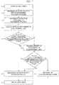
- FIG. 7is an operation flow chart including steps (a) to (j) for checking the drift of the light quantity data before the startup of the analysis by the automatic analyzer of the present invention.
- This functionis automatically executed before the analysis such as upon an initializing operation after the startup of the device or upon change of water in the constant-temperature bath (upon which the constant-temperature maintaining device 13 is temporarily stopped).
- a reference substancesuch as blank water or a blank solution for calculating the concentration of the measurement target substance is dispensed into a predetermined reaction container, and then, (c) the reaction container is moved to the photometric position. After the reaction container is moved, (d) measurement of the scattered light and the transmitted light is executed in a state in which the reaction container is stopped.
- the computer 50checks (calculates) whether the drift caused by the thermal deformation of the optical system and the drifts of the light source and the electric circuit system are within a predetermined range or not. If these values are within the predetermined range, (f) a state of the device proceeds to a standby state. If they are out of the predetermined range, (g) the re-measurement is executed. At this time, the drift caused by the thermal deformation of the light source can be calculated by the ratio of the ⁇ scattered light quantity or the difference between the ⁇ scattered light quantity, and the drifts of the light source and the electric circuit system can be calculated by the average or the sum of the ⁇ scattered light quantity.
- the computer 50checks whether they are within the predetermined range or not. If the ratio of the ⁇ scattered light quantity, the difference between the ⁇ scattered light quantity, and the drift amount of the single transmitted light or scattered light are out of the predetermined range even if the re-measurement is executed, (i) an analysis-disable alarm is sounded so that the flow does not proceed to the analysis operation (the calculation of the concentration of the measurement target substance). Then, (j) the drift check is terminated.
- the number of times of re-measurementcan be arbitrarily set. An aim of this function is to perform the drift check of the optical system before the start of the analysis so as to determine whether the measurement is possible or not.
- the managementis made such that the analysis is started after a certain period of time such as 30 minutes after the startup of the device or after the change of the water in the constant-temperature bath elapses. While this certain period of time is the time required when the drift of the optical system is within an allowable range and is the experimentally-proven time, it is not actually checked whether the drifts have been converged or not.
- a certain period of timeis the time required when the drift of the optical system is within an allowable range and is the experimentally-proven time, it is not actually checked whether the drifts have been converged or not.
- highly-reliable and highly-sensitivity detectioncan be achieved by performing the drift check before the analysis.
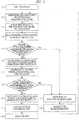
- FIG. 8is an operation flow chart including steps (a) to (m) for checking the drift of the light quantity data during the analysis by the automatic analyzer of the present invention.
- Analysis itemsinclude: a one-reagent system; a two-reagent system; a three-reagent system; and others, and the present example is described by exemplifying the item of the two-reagent system (in which a first reagent and a second reagent are used). Also, generally, in the latex agglutination method, since the first reagent is a pretreatment reagent, the change in the light quantity or others is not caused even if it is mixed with the sample.
- the second reagentcontains antibody-sensitized latex particles
- agglutination of the latex particles due to the antigen-antibody reactionis caused if the sample contains an antigen to be a target, which results in the change in the light quantity. This change in the light quantity is detected, so that the concentration of the target substance is quantified.
- the present exampleis described under the above-described conditions.
- the drift caused by the thermal deformation of the light sourcecan be calculated by the ratio of the ⁇ scattered light quantity or the difference between the ⁇ scattered light quantity obtained from the light quantity data obtained during the rotation of the reaction disk 10, and the drifts of the light source and the electric circuit system can be calculated by the average or the sum of the ⁇ scattered light quantity.
- the computer 50checks whether their values are within the predetermined range or not. If they are out of the predetermined range, (f) an analysis-disable alarm is sounded, and (g) the re-measurement is executed. If they are within the predetermined range, (h) the average or the sum of the ⁇ scattering is calculated by the computer 50 so as to generate the data regarding the reaction process.
- the second reagent (R2)is dispensed into the reaction container, and agitation is performed.
- the drift caused by the thermal deformation of the light sourcecan be calculated by the ratio of the ⁇ scattered light quantity or the difference between the ⁇ scattered light quantities obtained from the light quantity data obtained during the rotation of the reaction disk 10.
- the computer 50checks whether these values are within the predetermined range or not. If they are out of the predetermined range, (f) an analysis-disable alarm is sounded, and (g) the re-measurement is executed.
- the average or the sumis calculated by the computer 50 so as to generate the data regarding the reaction process, (1) the concentration of the measurement target substance is calculated, and (m) the result is outputted so that the analysis is terminated.
- the drift check of the optical systemis not performed during the analysis.
- highly-reliable and highly-sensitive detectioncan be achieved, and measurement results can be ensured.
- the paired two scattered-light detectorsare symmetrically arranged in the vertical direction so as to sandwich the optical axis therebetween.
- the number of themis not limited to this, and four or more detectors, that is, two or more paired detectors may be arranged.
- the present inventioncan be used for an automatic analyzer and an automatic analyzing method for analyzing an amount of a component contained in a sample such as blood or urine.
Landscapes
- Physics & Mathematics (AREA)
- Health & Medical Sciences (AREA)
- Life Sciences & Earth Sciences (AREA)
- Chemical & Material Sciences (AREA)
- Analytical Chemistry (AREA)
- Biochemistry (AREA)
- General Health & Medical Sciences (AREA)
- General Physics & Mathematics (AREA)
- Immunology (AREA)
- Pathology (AREA)
- Engineering & Computer Science (AREA)
- Quality & Reliability (AREA)
- Investigating Or Analysing Materials By Optical Means (AREA)
- Automatic Analysis And Handling Materials Therefor (AREA)
- Investigating Or Analysing Materials By The Use Of Chemical Reactions (AREA)
Description
- The present invention relates to an automatic analyzer that analyzes an amount of a component contained in a sample such as blood or urine, and, more particularly, the present invention relates to a technique enabling correction of drift caused by thermal deformation of an optical system.
- As an analyzer that analyzes an amount of a component contained in a sample, an automatic analyzer is widely used, in which the amount of the component is determined from a relation between absorbance and a concentration in accordance with the Lambert-Beer law by irradiating a sample or reaction solution of a mixture of the sample and a reagent with light from a light source, measuring transmitted light quantity at a single or a plurality of wavelength (s) as a result obtained by the irradiation, and calculating an absorbance (see Patent Document 1).
- In such a device, many reaction containers retaining the reaction solution are circumferentially arranged on a reaction disk which repeatedly rotates and stops, and time-dependent change of the absorbance is measured at a constant time interval for about 10 minutes during the rotation of the reaction disk by a transmitted-light measuring unit previously arranged. After the measurement is terminated, the reaction containers are cleaned by a cleaning mechanism and are used for the re-analysis.
- As the reaction of the reaction solution, roughly two types of reactions including color reaction between a substrate and an enzyme and agglutination reaction between an antigen and an antibody are used.
- The former one is biochemical analysis having test items which are LDH (Lactate Dehydrogenase), ALP (Alkaline Phosphatase), AST (Aspartate Aminotransferase), and others. The latter one is immuno-analysis having tested items which are CRP (C-reactive protein), IgG (Immunoglobulin G), RF (Rheumatoid factor), and others.
- A blood concentration of a measurement substance measured in the immuno-analysis of the latter one is low, and therefore, a highly sensitive detection system is required. For example, the high sensitivity has been advanced by a latex agglutination method that quantifies the amount of the component contained in the sample by: using a reagent which is obtained by sensitizing (coupling) an antibody onto surfaces of latex particles, irradiating a reaction solution with light upon the agglutination of the latex particles by antigen-antibody reaction with an antigen contained in the sample, and measuring the quantity of the light transmitted without being scattered by latex agglutinate.
- Further, as an automatic analyzer, the high sensitivity has been attempted by measuring not the transmitted light quantity but the scattered light quantity.
- Incidentally, in achieving the high sensitivity, even drift of light quantity data caused by slight variation in a temperature in the device becomes a large problem when change of minute light quantity is detected at high sensitivity. It is considered that the drifts of the light quantity data are roughly categorized into (1) drift of a light source, (2) drift of an electric circuit system, and (3) drift caused by thermal deformation of an optical system. Regarding (1) the drift of the light source, a technique of monitoring the irradiation light quantity for the correction (see Patent Document 2) is known. Regarding (2) the drift of the electric circuit system, a technique of suppressing the circuit-derived drift by controlling a temperature in a circuit board storage is known (see Patent Document 3).
JP2008064594 JP10120795 - Patent Document 1:
U.S. Patent No. 4451433 - Patent Document 2: Japanese Patent Application Laid-Open Publication No.
2007-322246 - Patent Document 3: Japanese Patent Application Laid-Open Publication No.
2002-296283 - However, in both of the proposals of Patent Documents 2 and 3, (3) the drift caused by thermal deformation of the optical system is not taken into consideration.
- The thermal deformation of the optical system is affected by not only thermal deformation of a photometer but also thermal deformation of a mechanism base on which the photometer is mounted, and these thermal deformations are affected by complex temperature changes between the outside temperature and heat sources (a motor, a board, a heat exchanger, etc.) which are individually operated and controlled, and therefore, control for them is extremely difficult. Further, in a turntable-type automatic analyzer which performs the measurement while rotating the reaction disk, the photometer inevitably has a shape with a cut-out region through which the reaction container passes, and the shape is a disadvantageous shape for the thermal deformations.
- Here, for example, it is considered to provide a storage for housing the photometer and adjusting the temperature so as not to be affected by the heat sources, etc. However, by adding new equipment, a size of the device is increased, and the device is complicated adversely.
- A preferred aim of the present invention is to provide an automatic analyzer enabling to detect a measurement target substance at high sensitivity without causing the size increase and the complication of the device by correcting the variation in light quantity data caused by the thermal deformation of the optical system caused by the variation in the temperature inside the device.
- The above and other preferred aims and novel characteristics of the present invention will be apparent from the description of the present specification and the accompanying drawings.
- The invention is defined by the appended set of claims.
- An automatic analyzer for use in the invention is an automatic analyzer which includes: a light source which irradiates a reaction container arranged at a photometric position and housing mixture solution of a sample and a reagent with light; and a detector which detects scattered light or transmitted light from the mixture solution, in which at least a pair of the detectors are arranged symmetrically to each other across an optical axis of the irradiation light from the light source in a vertical direction, and in which an averaged value of the light quantity data and/or a sum thereof from the respective detectors is used for calculation of a concentration of a measurement target substance in the mixture solution.
- An automatic analyzer for use in the invention is an automatic analyzer which irradiates a reaction container arranged at a photometric position and housing mixture solution of a sample and a reagent with light from a light source, which detects scattered light or transmitted light from the mixture solution by a detector to obtain light quantity data, and which calculates a concentration of a measurement target substance in the mixture solution from the light quantity data, in which at least a pair of the detectors are arranged symmetrically to each other across an optical axis of the irradiation light from the light source, and in which the light quantity data is not used for the calculation of the concentration of the measurement target substance if a ratio of the light quantity data and/or difference thereof from the detectors is out of a previously-set range.
- Also, an automatic analyzer for use in the invention is an automatic analyzer which irradiates a reaction container arranged at a photometric position and housing mixture solution of a sample and a reagent with light from a light source, which detects scattered light or transmitted light from the mixture solution by a detector to obtain light quantity data, and which calculates a concentration of a measurement target substance in the mixture solution from the light quantity data, in which at least a pair of the detectors are arranged symmetrically to each other across an optical axis of the irradiation light from the light source in a vertical direction, and in which the reaction container housing a reference substance for calculating the concentration of the measurement target substance is arranged at the photometric position, and in which a drift amount of the light quantity data of a reference substance from each detector obtained during previously-set time is calculated prior to the calculation of the concentration of the measurement target substance.
- The effects obtained by typical aspects of the present invention will be briefly described below.
- According to the present invention, at least the pair of the detectors which detect the scattered light or the transmitted light from the reaction container are arranged symmetrically to each other across the optical axis of the irradiation light from the light source, and therefore, the drift of the light quantity data caused by the thermal deformation of the optical system can be corrected by comparing values of the light quantity data of the respective detectors with each other. Therefore, an automatic analyzer can be provided, in which the draft of the light quantity data caused by the thermal deformation of the optical system caused by the variation in the temperature inside the device is corrected without the increase in the size and the complication so as to enhance accuracy and stability of data and so as to detect the measurement target substance at high sensitivity.
FIG. 1 is a system block diagram illustrating an overall configuration of an automatic analyzer according to an embodiment of the present invention;FIG. 2 is a schematic diagram of an optical system according to the embodiment of the present invention;FIG. 3 is a diagram for explaining change in a light acceptance angle caused by thermal deformation of the optical system;FIG. 4 is a graph illustrating measurement results of change in light quantity of ± θ scattered light caused by the change in the light acceptance angle;FIGs. 5A and 5B are graphs illustrating independent measurement results of ± θ scattered light after startup of the automatic analyzer, respectively;FIG. 6 is a graph illustrating an average value of the ± θ scattered light after the startup of the automatic analyzer;FIG. 7 is an operation flow chart including steps (a) to (j) for checking the light quantity data drift before analysis start by the automatic analyzer of the present invention; andFIG. 8 is an operation flow chart including steps (a) to (m) for checking the light quantity data drift during the analysis by the automatic analyzer of the present invention.- Hereinafter, an embodiment of the present invention will be described in detail based on the drawings. Note that components having the same function are denoted by the same reference symbols throughout all drawings for describing the embodiment, and the repetitive description thereof will be omitted as much as possible.
FIG. 1 is a system block diagram illustrating an overall configuration of an automatic analyzer according to the embodiment of the present invention. As illustrated inFIG. 1 , anautomatic analyzer 1 is mainly configured of: areaction disk 10; asample disk 20;reagent disks light source 40; ascattering photometer 41; and acomputer 50.- The
reaction disk 10 can intermittently rotate, andmany reaction containers 11 made of a translucent material are mounted on the disk along a circumferential direction thereof. Thereaction containers 11 are maintained at a predetermined temperature (for example, at 37°C) by a constant-temperature bath 12. A temperature of a fluid inside the constant-temperature bath 12 is adjusted by a constant-temperature maintaining device 13. - On the
sample disk 20,many specimen containers 21 for housing biological samples such as blood and urine are placed doubly along the circumferential direction in an example of the illustration. Asample dispensing mechanism 22 is arranged in vicinity of thesample disk 20. Thissample dispensing mechanism 22 is mainly configured of: amovable arm 23; and apipette nozzle 24 attached thereto. By this configuration, in thesample dispensing mechanism 22, thepipette nozzle 24 is appropriately moved to a dispensing position by themovable arm 23 upon sample dispensing, sucks a predetermined amount of the sample from thespecimen container 21 positioned at a suction position of thesample disk 20, and discharges the sample into thereaction container 11 at a discharge position on thereaction disk 10. - The
reagent disks reagent refrigerators reagent refrigerators reagent bottles reagent disks automatic analyzer 1. Thebarcode reading devices respective reagent refrigerators respective reagent bottles reagent disks memory 56. - Also, in the vicinities of the
reagent disks reagent dispensing mechanisms sample dispensing mechanism 22 are arranged, respectively. Upon the reagent dispensing, by pipette nozzles provided in them, the reagent solution is sucked from thereagent bottles reaction disk 10, and is discharged into thecorresponding reaction container 11. - Agitating
mechanisms reaction disk 10, thereagent disks reagent dispensing mechanisms reaction container 11 is agitated by the agitatingmechanisms - The
light source 40 is arranged in vicinity of the center of thereaction disk 10, the scatteringphotometer 41 is arranged on an outer circumferential side of thereaction disk 10, and a line of thereaction containers 11 for which the agitation is finished is moved while being rotated so as to pass through a photometric position sandwiched between thelight source 40 and the scatteringphotometer 41. The scatteringphotometer 41 may be provided with a multi-wavelength absorptiometer on a position coaxially with the optical axis or a different position of the constant-temperature bath 12 so that the concentration is calculated by using both of the scattered light and the transmitted light. Note that thelight source 40 and the scatteringphotometer 41 configure an optical detection system. - The photometry of the reaction solution of the sample and the reagent inside each
reaction container 11 is measured every time the container passes across the front of the scatteringphotometer 41 during the rotary movement of thereaction disk 10. An analog signal of the scattered light measured for each sample is inputted to an A/D (analog/digital)converter 54. The inside of the usedreaction container 11 is cleaned by a reaction-container cleaning mechanism 36 arranged in the vicinity of thereaction disk 10, so that the container can be repeatedly used. - Next, a control system and a signal processing system in the
automatic analyzer 1 ofFIG. 1 will be briefly explained. Thecomputer 50 is connected to a sample-dispensingcontroller 52, a reagent-dispensingcontroller 53, and the A/D converter 54 via aninterface 51. Thecomputer 50 sends a command to the sample-dispensingcontroller 52 so as to control the dispensing operation for the sample. Thecomputer 50 sends a command to the reagent-dispensingcontroller 53 so as to control the dispensing operation for the reagent. - A photometric value which has been converted into a digital signal by the A/
D converter 54 is taken into thecomputer 50. - A
printer 55 for printing, amemory 56 and anexternal output medium 57 serving as storage devices, akeyboard 58 for inputting an operation command and others, and a CRT display (display device) 59 for screen display are connected to theinterface 51. As thedisplay device 59, a liquid crystal display or others can be employed instead of the CRT display. Thememory 56 is configured of, for example, a hard disk memory or an external memory. Thememory 56 stores information such as a password of each operator, a display level of each screen, an analysis parameter, an analysis-item request content, a calibration result, and an analysis result. - Next, an analysis operation for the sample in the
automatic analyzer 1 ofFIG. 1 will be explained. The analysis parameter about the item which can be analyzed by theautomatic analyzer 1 is previously inputted via an information inputting device such as thekeyboard 58, and is stored in thememory 56. The operator selects a test item requested for each sample by using an operational function screen. - At this time, information such as a patient ID is also inputted from the
keyboard 58. In order to analyze the test item instructed for each sample, thepipette nozzle 24 of thesample dispensing mechanism 22 dispenses a predetermined amount of the sample from thespecimen container 21 to thereaction container 11 in accordance with the analysis parameter. - The
reaction container 11 into which the sample has been dispensed is transported by the rotation of thereaction disk 10, and stops at the reagent receiving position. The pipette nozzles of thereagent dispensing mechanisms reaction container 11 in accordance with the analysis parameter of the corresponding test item. An order of dispensing the sample and the reagent may be opposite to this example so that the reagent is dispensed earlier than the sample. - Then, the sample and the reagent are agitated and mixed by the agitating
mechanisms reaction container 11 passes across the photometric position, the photometry of the scattered light of the reaction solution is measured by the scatteringphotometer 41. The photometric-measured scattered light is converted into a numerical value which is proportional to the light quantity by the A/D converter 54, and the numerical value is taken into thecomputer 50 via theinterface 51. - By using this converted numerical value, the concentration data is calculated based on a calibration curve previously measured by an analysis method specified for each test item. The component concentration data as the analysis result of each test item is outputted to the
printer 55 and/or a screen of theCRT display 59. - Before the above-described measurement operation is executed, the operator sets various parameters, and registers the sample, which are required for the analysis measurement, via the operation screen of the
CRT display 59. Moreover, the operator checks the analysis result obtained after the measurement by using the operational screen on theCRT display 59. FIG. 2 is a schematic diagram of an optical system according to an embodiment of the present invention. The irradiation light from thelight source 40 passes through alight projector window 42 so as to irradiate the measurement target substance inside thereaction container 11. The transmitted light from the measurement target substance passes through alight receiving window 43, and is received by a transmitted-light detector 44 . The scattered light from the measurement target substance passes through thelight receiving window 43, and is received by a pair of adetector 45a for +θ scattered light and adetector 45b for -θ scattered light which are arranged in the vertical direction symmetrically to each other across the optical axis. Thelight source 40 is fixed by a light-source holder (that is a base member in which the light source is arranged) 46, and thedetectors source holder 46 and thedetector holder 47 are fixed to aphotometer base 48, and thephotometer base 48 is fixed to amechanism base 49. While the temperature distribution inside the device is changed by operations of a motor, a circuit, a heat exchanger, and others, the temperature change immediately after the startup of the device is particularly large, and deformation as illustrated by an arrow is caused by a temperature difference between top and bottom of the device. In the turntable-type photometer, the deformation as illustrated by the arrow tends to be caused because the photometer has a shape which is opened upward so that thereaction container 11 can pass therethrough. As a portion to be deformed, due to a dimensional difference, thephotometer base 48 and themechanism base 49 have large deformation amounts while the light-source holder 46 and thedetector holder 47 have small deformation amounts. Therefore, as illustrated inFIG. 3 , the deformation is caused so as to be shifted by δ ° while maintaining a relation of a relative position of the light acceptance angle.FIG. 4 is a graph illustrating measurement results of the change in the light quantity of ±θ scattered light caused by the change in the light acceptance angle. That is, the results are actually-measured results of the variations in the light quantity data when an angle of thedetector holder 47 is changed while maintaining a relation of a relative position of a certain light acceptance angle θ. The ±θ scattered light is theoretically supposed to have the same value, and their values almost match with each other also in the present results when there is no shift in the light acceptance angle. A proportional relation is established between the shift in the light acceptance angle and the light quantity data, and it can be understood that the sum of the ±θ light quantity data is constant. That is, it has been found out that the drift of the light quantity data derived from the thermal deformation can be corrected by taking the sum of the ±θ light quantity data, the average thereof, or both of them.- It is considered that the drift of the light quantity data is roughly categorized into (1) drift of the light source, (2) drift of an electric circuit system, and (3) drift caused by the thermal deformation of the optical system. Among them, (1) the drift of the light source and (2) the drift of the electric circuit system can be easily suppressed to a certain level by a temperature adjusting action of the light source and the electric circuit. However, (3) the drift caused by the thermal deformation of the optical system is affected by not only the deformation of the photometer but also deformation of the base on which the photometer is mounted. Further, this is also affected by complex temperature change caused between the outside air temperature and the heat sources whose operations are individually controlled to each other such as the motor, the substrate, and the heat exchanger. Therefore, it is very difficult to control them, and the significance of the correction is large.
FIGs. 5A and 5B are graphs illustrating independent measurement results of the ±θ scattered light after the startup of the automatic analyzer, respectively. That is, they are results obtained by measuring scattering bodies inside the reaction container for five hours after the startup of the device. Immediately after the startup of the device, both of the ± θ light quantity data are largely reduced, and this reduction is due to the drift of the LED light source having characteristics in which the light quantity is reduced when the temperature increases. When the drift of the light source are almost eliminated, the ± θ light quantity data show opposite behavior, and this is conceived to be the drift of the light quantity data caused by the thermal deformation. Accordingly, as illustrated inFIG. 6 , by averaging the ± θ light quantity data, the drift caused by the thermal deformation can be corrected upon the analysis, that is, upon the calculation of the concentration of the measurement target substance. Note thatFIG. 6 exemplifies the average of the ± θ light quantity data. However, the drift may be corrected based on the sum thereof, or the drift may be corrected by using both of the average and the sum thereof. In the view ofFIG. 6 , the average of the ± θ light quantity data is also slightly varied. However, this variation is due to the drift of the light source and the electric circuit system.FIG. 7 is an operation flow chart including steps (a) to (j) for checking the drift of the light quantity data before the startup of the analysis by the automatic analyzer of the present invention. This function is automatically executed before the analysis such as upon an initializing operation after the startup of the device or upon change of water in the constant-temperature bath (upon which the constant-temperature maintaining device 13 is temporarily stopped). First, when (a) the drift check is started, (b) a reference substance such as blank water or a blank solution for calculating the concentration of the measurement target substance is dispensed into a predetermined reaction container, and then, (c) the reaction container is moved to the photometric position. After the reaction container is moved, (d) measurement of the scattered light and the transmitted light is executed in a state in which the reaction container is stopped. In predetermined measurement time (such as five minutes), (e) thecomputer 50 checks (calculates) whether the drift caused by the thermal deformation of the optical system and the drifts of the light source and the electric circuit system are within a predetermined range or not. If these values are within the predetermined range, (f) a state of the device proceeds to a standby state. If they are out of the predetermined range, (g) the re-measurement is executed. At this time, the drift caused by the thermal deformation of the light source can be calculated by the ratio of the ±θ scattered light quantity or the difference between the ±θ scattered light quantity, and the drifts of the light source and the electric circuit system can be calculated by the average or the sum of the ±θ scattered light quantity. And, (h) thecomputer 50 checks whether they are within the predetermined range or not. If the ratio of the ±θ scattered light quantity, the difference between the ±θ scattered light quantity, and the drift amount of the single transmitted light or scattered light are out of the predetermined range even if the re-measurement is executed, (i) an analysis-disable alarm is sounded so that the flow does not proceed to the analysis operation (the calculation of the concentration of the measurement target substance). Then, (j) the drift check is terminated. The number of times of re-measurement can be arbitrarily set. An aim of this function is to perform the drift check of the optical system before the start of the analysis so as to determine whether the measurement is possible or not. In a conventional automatic analyzer, the management is made such that the analysis is started after a certain period of time such as 30 minutes after the startup of the device or after the change of the water in the constant-temperature bath elapses. While this certain period of time is the time required when the drift of the optical system is within an allowable range and is the experimentally-proven time, it is not actually checked whether the drifts have been converged or not. However, highly-reliable and highly-sensitivity detection can be achieved by performing the drift check before the analysis.FIG. 8 is an operation flow chart including steps (a) to (m) for checking the drift of the light quantity data during the analysis by the automatic analyzer of the present invention. Analysis items include: a one-reagent system; a two-reagent system; a three-reagent system; and others, and the present example is described by exemplifying the item of the two-reagent system (in which a first reagent and a second reagent are used). Also, generally, in the latex agglutination method, since the first reagent is a pretreatment reagent, the change in the light quantity or others is not caused even if it is mixed with the sample. However, since the second reagent contains antibody-sensitized latex particles, agglutination of the latex particles due to the antigen-antibody reaction is caused if the sample contains an antigen to be a target, which results in the change in the light quantity. This change in the light quantity is detected, so that the concentration of the target substance is quantified. The present example is described under the above-described conditions. When (a) the analysis is started, (b) the sample is dispensed into a predetermined reaction container first. Then, (c) the first reagent (R1) is dispensed, and agitation is performed. The drift caused by the thermal deformation of the light source can be calculated by the ratio of the ±θ scattered light quantity or the difference between the ±θ scattered light quantity obtained from the light quantity data obtained during the rotation of thereaction disk 10, and the drifts of the light source and the electric circuit system can be calculated by the average or the sum of the ±θ scattered light quantity. And, (e) thecomputer 50 checks whether their values are within the predetermined range or not. If they are out of the predetermined range, (f) an analysis-disable alarm is sounded, and (g) the re-measurement is executed. If they are within the predetermined range, (h) the average or the sum of the ±θ scattering is calculated by thecomputer 50 so as to generate the data regarding the reaction process. Subsequently, (i) the second reagent (R2) is dispensed into the reaction container, and agitation is performed. Similarly, the drift caused by the thermal deformation of the light source can be calculated by the ratio of the ±θ scattered light quantity or the difference between the ±θ scattered light quantities obtained from the light quantity data obtained during the rotation of thereaction disk 10. And, (j) thecomputer 50 checks whether these values are within the predetermined range or not. If they are out of the predetermined range, (f) an analysis-disable alarm is sounded, and (g) the re-measurement is executed. If they are within the predetermined range, (k) the average or the sum is calculated by thecomputer 50 so as to generate the data regarding the reaction process, (1) the concentration of the measurement target substance is calculated, and (m) the result is outputted so that the analysis is terminated. In a conventional automatic analyzer, the drift check of the optical system is not performed during the analysis. However, by performing the drift check of the optical system during the analysis as described above, highly-reliable and highly-sensitive detection can be achieved, and measurement results can be ensured.- In the foregoing, the invention made by the present inventors has been concretely described based on the embodiment. However, it is needless to say that the present invention is not limited to the foregoing embodiment and various modifications and alterations can be made within the scope of the present invention.
- For example, in the mode illustrated in the drawings, the paired two scattered-light detectors are symmetrically arranged in the vertical direction so as to sandwich the optical axis therebetween. However, the number of them is not limited to this, and four or more detectors, that is, two or more paired detectors may be arranged.
- The present invention can be used for an automatic analyzer and an automatic analyzing method for analyzing an amount of a component contained in a sample such as blood or urine.
- 1 automatic analyzer
- 10 reaction disk
- 11 reaction container
- 12 constant-temperature bath
- 13 constant-temperature maintaining device
- 20 sample disk
- 21 specimen container
- 22 sample dispensing mechanism
- 23 movable arm
- 24 pipette nozzle
- 30a reagent disk
- 30b reagent disk
- 31a reagent refrigerator
- 31b reagent refrigerator
- 32a reagent bottle
- 32b reagent bottle
- 33a barcode reading device
- 33b barcode reading device
- 34a reagent dispensing mechanism
- 34b reagent dispensing mechanism
- 35a agitating mechanism
- 35b agitating mechanism
- 36 reaction-container cleaning mechanism
- 40 light source
- 41 scattering photometer
- 42 light projector window
- 43 light receiving window
- 44 transmitted-light detector
- 45a detector for +θ scattered light
- 45b detector for -θ scattered light
- 46 light-source holder (that is a base member in which the light source is arranged)
- 47 detector holder (that is a base member in which each detector is arranged)
- 48 photometer base
- 49 mechanism base
- 50 computer
- 51 interface
- 52 sample-dispensing controller
- 53 reagent-dispensing controller
- 54 A/D converter
- 55 printer
- 56 memory
- 57 external output medium
- 58 keyboard
- 59 CRT display (display device)
Claims (6)
- An automatic analyzer comprising:a light source (40) that irradiates a reaction container (11) with light, the reaction container (11) being arranged at a photometric position and housing mixture solution of a sample and a reagent; and detectors (44, 45a, 45b) that detect scattered light or transmitted light from the mixture solution,one or more pairs of the detectors (45a, 45b) being arranged symmetrically to each other across an optical axis of irradiation light from the light source (40) at an equal angle or an equal interval, and an averaged value of light quantity data and/or a sum thereof from the respective detectors (45a, 45b) being used for calculation of a concentration of a measurement target substance in the mixture solution,one or more pairs of the detectors (45a, 45b) being arranged on the same base member (47), and the detectors (45a, 45b) being arranged symmetrically to each other on the same base member (47) across the optical axis at the equal angle or the equal interval,characterized in thatthe base member (47) on which the detectors (45a, 45b) are arranged and a base member (46) on which the light source (40) is arranged being arranged on the same base (48);and further comprising computer means arranged so that if a ratio of light quantity data and/or difference thereof from the respective detectors arranged symmetrically to each other at the equal angle or the equal interval across the optical axis of the irradiation light from the light source is out of a previously-set range, the light quantity data is not used for the calculation of the concentration of the measurement target substance.
- The automatic analyzer according to claim 1, wherein the computer means are arranged such that if an averaged value of light quantity data and/or a sum thereof from the respective detectors (45a, 45b) arranged symmetrically to each other at the equal angle or the equal interval across the optical axis of the irradiation light from the light source (40) is out of a previously-set range, the light quantity data is not used for the calculation of the concentration of the measurement target substance.
- The automatic analyzer according to claim 1 or 2,
wherein the reaction container (11) housing a reference substance for the calculation of the concentration of the measurement target substance is arranged at the photometric position, and the computer means are arranged to calculate a drift amount of the light quantity data of the reference substance from each of the detectors (45a, 45b) at previously-set time prior to the calculation of the concentration of the measurement target substance. - The automatic analyzer according to claim 3,
wherein the computer means are arranged such that if the drift amount is out of a previously-set range, a process does not proceed to the calculation of the concentration of the measurement target substance. - The automatic analyzer according to claim 4,
wherein the drift amount is a ratio of light quantity data and/or difference thereof from the respective detectors (45a, 45b). - The automatic analyzer according to claim 4 or 5,
wherein the drift amount is an averaged value of light quantity data and/or a sum thereof from the respective detectors (45a, 45b).
Applications Claiming Priority (2)
| Application Number | Priority Date | Filing Date | Title |
|---|---|---|---|
| JP2011006809AJP5481402B2 (en) | 2011-01-17 | 2011-01-17 | Automatic analyzer |
| PCT/JP2012/050243WO2012098946A1 (en) | 2011-01-17 | 2012-01-10 | Automatic analysis device |
Publications (3)
| Publication Number | Publication Date |
|---|---|
| EP2667182A1 EP2667182A1 (en) | 2013-11-27 |
| EP2667182A4 EP2667182A4 (en) | 2017-04-26 |
| EP2667182B1true EP2667182B1 (en) | 2019-09-11 |
Family
ID=46515577
Family Applications (1)
| Application Number | Title | Priority Date | Filing Date |
|---|---|---|---|
| EP12736834.8AActiveEP2667182B1 (en) | 2011-01-17 | 2012-01-10 | Automatic analysis device taking into account thermal drift |
Country Status (5)
| Country | Link |
|---|---|
| US (1) | US9080972B2 (en) |
| EP (1) | EP2667182B1 (en) |
| JP (1) | JP5481402B2 (en) |
| CN (1) | CN103261876B (en) |
| WO (1) | WO2012098946A1 (en) |
Families Citing this family (12)
| Publication number | Priority date | Publication date | Assignee | Title |
|---|---|---|---|---|
| JP5897323B2 (en)* | 2011-12-26 | 2016-03-30 | 株式会社日立ハイテクノロジーズ | Automatic analyzer and measurement value abnormality detection method |
| JP5946776B2 (en)* | 2013-01-18 | 2016-07-06 | 株式会社日立ハイテクノロジーズ | Automatic analyzer |
| JP6138564B2 (en)* | 2013-04-18 | 2017-05-31 | 株式会社日立ハイテクノロジーズ | Automatic analyzer |
| JP6134210B2 (en) | 2013-06-19 | 2017-05-24 | 株式会社日立ハイテクノロジーズ | Automatic analyzer and automatic analysis method |
| CN103884856B (en)* | 2014-04-01 | 2015-06-10 | 重庆科斯迈生物科技有限公司 | Cup strip conveying system of chemiluminescence immunoassay analyzer |
| WO2016006362A1 (en)* | 2014-07-07 | 2016-01-14 | 株式会社 日立ハイテクノロジーズ | Automatic analysis device |
| CN110785650B (en)* | 2017-06-20 | 2022-05-31 | Ci系统(以色列)股份有限公司 | Flow cells and optical systems for analyzing fluids |
| US11965900B2 (en)* | 2018-11-09 | 2024-04-23 | Wyatt Technology, Llc | Indicating a status of an analytical instrument on a screen of the analytical instrument |
| CN109613284B (en)* | 2018-11-19 | 2023-02-28 | 圣湘生物科技股份有限公司 | Sample detection method, device and system, computer equipment and storage medium |
| JP7525395B2 (en)* | 2020-12-28 | 2024-07-30 | 株式会社島津製作所 | measuring device |
| JPWO2022270037A1 (en)* | 2021-06-25 | 2022-12-29 | ||
| EP4435382A1 (en)* | 2023-03-21 | 2024-09-25 | Netzsch Gerätebau GmbH | Method for controlling measurement device, and measurement device |
Family Cites Families (26)
| Publication number | Priority date | Publication date | Assignee | Title |
|---|---|---|---|---|
| JPS591977B2 (en)* | 1978-01-25 | 1984-01-14 | 株式会社京都第一科学 | Analysis method using color test paper |
| SE7905294L (en)* | 1979-06-15 | 1980-12-16 | Svenska Traeforskningsinst | STOFTMETNING |
| JPS5782769A (en) | 1980-11-10 | 1982-05-24 | Hitachi Ltd | Automatic analyzing device |
| US4408880A (en)* | 1981-09-22 | 1983-10-11 | Chugai Seiyaku Kabushiki Kaisha | Laser nephelometric system |
| US5363463A (en)* | 1982-08-06 | 1994-11-08 | Kleinerman Marcos Y | Remote sensing of physical variables with fiber optic systems |
| GB8415670D0 (en)* | 1984-06-20 | 1984-07-25 | Penlon Ltd | Gas analysis apparatus |
| JPS61173138A (en)* | 1985-01-28 | 1986-08-04 | Olympus Optical Co Ltd | Method for measuring immune reaction by intensity fluctuation of light |
| JPS62291547A (en)* | 1986-06-11 | 1987-12-18 | Olympus Optical Co Ltd | Method for measuring concentration of substance |
| JPH0545282A (en)* | 1991-08-09 | 1993-02-23 | Kurabo Ind Ltd | Automatic clinical analyzing system |
| US5350922A (en)* | 1993-03-22 | 1994-09-27 | Robert Bartz | Underwater light scattering sensor |
| JP3600929B2 (en)* | 1996-10-17 | 2004-12-15 | 東ソー株式会社 | Method and apparatus for measuring the degree of gelation of polyvinyl chloride |
| AU1449699A (en)* | 1997-10-31 | 1999-05-24 | Technical Chemicals & Products, Inc. | Reflectometer |
| JP2002296283A (en) | 2001-04-02 | 2002-10-09 | Hitachi Ltd | Automatic analyzer |
| US6519033B1 (en)* | 2001-11-19 | 2003-02-11 | Point Source Technologies, Llc | Identification of particles in fluid |
| JP3765255B2 (en)* | 2001-08-21 | 2006-04-12 | 株式会社日立製作所 | Stirring device and automatic analyzer using the same |
| JP2003294623A (en)* | 2002-03-29 | 2003-10-15 | Nohmi Bosai Ltd | Smoke fire detector |
| CA2468924A1 (en)* | 2004-01-14 | 2005-07-14 | Laser Diagnostic Instruments International Inc. | A device and method for non-contact sensing of low-concentration and trace substances |
| US7111496B1 (en)* | 2004-04-29 | 2006-09-26 | Pedro Lilienfeld | Methods and apparatus for monitoring a mass concentration of particulate matter |
| JP4756948B2 (en)* | 2005-08-08 | 2011-08-24 | ベイバイオサイエンス株式会社 | Flow cytometer and flow cytometry method |
| US7678330B2 (en)* | 2006-03-01 | 2010-03-16 | Aleksandr Ostrovsky | System, method and apparatus for use in blood testing through luminescence |
| JP2007322246A (en) | 2006-05-31 | 2007-12-13 | Olympus Corp | Autoanalyzer |
| JP2008064594A (en)* | 2006-09-07 | 2008-03-21 | Yokogawa Electric Corp | Turbidimeter |
| CN101403706B (en)* | 2008-11-06 | 2011-06-08 | 清华大学 | Full-automatic bottling liquor inspection machine |
| CN102265140B (en) | 2008-12-24 | 2014-09-10 | 株式会社日立高新技术 | Photometer and analysis system with photometer |
| JP2010197310A (en)* | 2009-02-26 | 2010-09-09 | Toyota Motor Corp | Optical chopper and optical analyzer |
| EP2453224B1 (en)* | 2009-07-10 | 2024-06-26 | Hitachi High-Tech Corporation | Automatic analyzer |
- 2011
- 2011-01-17JPJP2011006809Apatent/JP5481402B2/enactiveActive
- 2012
- 2012-01-10EPEP12736834.8Apatent/EP2667182B1/enactiveActive
- 2012-01-10CNCN201280004143.9Apatent/CN103261876B/enactiveActive
- 2012-01-10USUS13/979,668patent/US9080972B2/enactiveActive
- 2012-01-10WOPCT/JP2012/050243patent/WO2012098946A1/enactiveApplication Filing
Non-Patent Citations (1)
| Title |
|---|
| None* |
Also Published As
| Publication number | Publication date |
|---|---|
| US9080972B2 (en) | 2015-07-14 |
| CN103261876A (en) | 2013-08-21 |
| CN103261876B (en) | 2016-01-13 |
| EP2667182A4 (en) | 2017-04-26 |
| US20130301048A1 (en) | 2013-11-14 |
| JP2012149903A (en) | 2012-08-09 |
| WO2012098946A1 (en) | 2012-07-26 |
| JP5481402B2 (en) | 2014-04-23 |
| EP2667182A1 (en) | 2013-11-27 |
Similar Documents
| Publication | Publication Date | Title |
|---|---|---|
| EP2667182B1 (en) | Automatic analysis device taking into account thermal drift | |
| JP6013796B2 (en) | Automatic analyzer and sample measurement method | |
| US11971425B2 (en) | Automatic analysis device and automatic analysis method | |
| JP5296015B2 (en) | Automatic analyzer | |
| JP5897323B2 (en) | Automatic analyzer and measurement value abnormality detection method | |
| JP5216051B2 (en) | Automatic analyzer and automatic analysis method | |
| JP2014119425A (en) | Automatic analyzer, program, recording medium, and automatic analyzing method of specimen | |
| JP7735412B2 (en) | Automatic analyzer, data processing device, and quality control method for automatic analyzer | |
| WO2024195510A1 (en) | Automated analysis device and sample analysis method |
Legal Events
| Date | Code | Title | Description |
|---|---|---|---|
| PUAI | Public reference made under article 153(3) epc to a published international application that has entered the european phase | Free format text:ORIGINAL CODE: 0009012 | |
| 17P | Request for examination filed | Effective date:20130716 | |
| AK | Designated contracting states | Kind code of ref document:A1 Designated state(s):AL AT BE BG CH CY CZ DE DK EE ES FI FR GB GR HR HU IE IS IT LI LT LU LV MC MK MT NL NO PL PT RO RS SE SI SK SM TR | |
| DAX | Request for extension of the european patent (deleted) | ||
| RA4 | Supplementary search report drawn up and despatched (corrected) | Effective date:20170327 | |
| RIC1 | Information provided on ipc code assigned before grant | Ipc:G01N 21/47 20060101AFI20170321BHEP Ipc:G01N 21/51 20060101ALI20170321BHEP Ipc:G01N 35/02 20060101ALI20170321BHEP | |
| RIN1 | Information on inventor provided before grant (corrected) | Inventor name:MAKINO, AKIHISA Inventor name:ADACHI, SAKUICHIRO | |
| GRAP | Despatch of communication of intention to grant a patent | Free format text:ORIGINAL CODE: EPIDOSNIGR1 | |
| STAA | Information on the status of an ep patent application or granted ep patent | Free format text:STATUS: GRANT OF PATENT IS INTENDED | |
| INTG | Intention to grant announced | Effective date:20190528 | |
| GRAS | Grant fee paid | Free format text:ORIGINAL CODE: EPIDOSNIGR3 | |
| GRAA | (expected) grant | Free format text:ORIGINAL CODE: 0009210 | |
| STAA | Information on the status of an ep patent application or granted ep patent | Free format text:STATUS: THE PATENT HAS BEEN GRANTED | |
| AK | Designated contracting states | Kind code of ref document:B1 Designated state(s):AL AT BE BG CH CY CZ DE DK EE ES FI FR GB GR HR HU IE IS IT LI LT LU LV MC MK MT NL NO PL PT RO RS SE SI SK SM TR | |
| REG | Reference to a national code | Ref country code:GB Ref legal event code:FG4D | |
| REG | Reference to a national code | Ref country code:CH Ref legal event code:EP | |
| REG | Reference to a national code | Ref country code:AT Ref legal event code:REF Ref document number:1179075 Country of ref document:AT Kind code of ref document:T Effective date:20190915 | |
| REG | Reference to a national code | Ref country code:DE Ref legal event code:R096 Ref document number:602012063874 Country of ref document:DE Ref country code:IE Ref legal event code:FG4D | |
| REG | Reference to a national code | Ref country code:NL Ref legal event code:MP Effective date:20190911 | |
| REG | Reference to a national code | Ref country code:LT Ref legal event code:MG4D | |
| PG25 | Lapsed in a contracting state [announced via postgrant information from national office to epo] | Ref country code:BG Free format text:LAPSE BECAUSE OF FAILURE TO SUBMIT A TRANSLATION OF THE DESCRIPTION OR TO PAY THE FEE WITHIN THE PRESCRIBED TIME-LIMIT Effective date:20191211 Ref country code:SE Free format text:LAPSE BECAUSE OF FAILURE TO SUBMIT A TRANSLATION OF THE DESCRIPTION OR TO PAY THE FEE WITHIN THE PRESCRIBED TIME-LIMIT Effective date:20190911 Ref country code:HR Free format text:LAPSE BECAUSE OF FAILURE TO SUBMIT A TRANSLATION OF THE DESCRIPTION OR TO PAY THE FEE WITHIN THE PRESCRIBED TIME-LIMIT Effective date:20190911 Ref country code:NO Free format text:LAPSE BECAUSE OF FAILURE TO SUBMIT A TRANSLATION OF THE DESCRIPTION OR TO PAY THE FEE WITHIN THE PRESCRIBED TIME-LIMIT Effective date:20191211 Ref country code:FI Free format text:LAPSE BECAUSE OF FAILURE TO SUBMIT A TRANSLATION OF THE DESCRIPTION OR TO PAY THE FEE WITHIN THE PRESCRIBED TIME-LIMIT Effective date:20190911 Ref country code:LT Free format text:LAPSE BECAUSE OF FAILURE TO SUBMIT A TRANSLATION OF THE DESCRIPTION OR TO PAY THE FEE WITHIN THE PRESCRIBED TIME-LIMIT Effective date:20190911 | |
| PG25 | Lapsed in a contracting state [announced via postgrant information from national office to epo] | Ref country code:LV Free format text:LAPSE BECAUSE OF FAILURE TO SUBMIT A TRANSLATION OF THE DESCRIPTION OR TO PAY THE FEE WITHIN THE PRESCRIBED TIME-LIMIT Effective date:20190911 Ref country code:ES Free format text:LAPSE BECAUSE OF FAILURE TO SUBMIT A TRANSLATION OF THE DESCRIPTION OR TO PAY THE FEE WITHIN THE PRESCRIBED TIME-LIMIT Effective date:20190911 Ref country code:RS Free format text:LAPSE BECAUSE OF FAILURE TO SUBMIT A TRANSLATION OF THE DESCRIPTION OR TO PAY THE FEE WITHIN THE PRESCRIBED TIME-LIMIT Effective date:20190911 Ref country code:GR Free format text:LAPSE BECAUSE OF FAILURE TO SUBMIT A TRANSLATION OF THE DESCRIPTION OR TO PAY THE FEE WITHIN THE PRESCRIBED TIME-LIMIT Effective date:20191212 Ref country code:AL Free format text:LAPSE BECAUSE OF FAILURE TO SUBMIT A TRANSLATION OF THE DESCRIPTION OR TO PAY THE FEE WITHIN THE PRESCRIBED TIME-LIMIT Effective date:20190911 | |
| REG | Reference to a national code | Ref country code:AT Ref legal event code:MK05 Ref document number:1179075 Country of ref document:AT Kind code of ref document:T Effective date:20190911 | |
| PG25 | Lapsed in a contracting state [announced via postgrant information from national office to epo] | Ref country code:NL Free format text:LAPSE BECAUSE OF FAILURE TO SUBMIT A TRANSLATION OF THE DESCRIPTION OR TO PAY THE FEE WITHIN THE PRESCRIBED TIME-LIMIT Effective date:20190911 Ref country code:PT Free format text:LAPSE BECAUSE OF FAILURE TO SUBMIT A TRANSLATION OF THE DESCRIPTION OR TO PAY THE FEE WITHIN THE PRESCRIBED TIME-LIMIT Effective date:20200113 Ref country code:PL Free format text:LAPSE BECAUSE OF FAILURE TO SUBMIT A TRANSLATION OF THE DESCRIPTION OR TO PAY THE FEE WITHIN THE PRESCRIBED TIME-LIMIT Effective date:20190911 Ref country code:RO Free format text:LAPSE BECAUSE OF FAILURE TO SUBMIT A TRANSLATION OF THE DESCRIPTION OR TO PAY THE FEE WITHIN THE PRESCRIBED TIME-LIMIT Effective date:20190911 Ref country code:AT Free format text:LAPSE BECAUSE OF FAILURE TO SUBMIT A TRANSLATION OF THE DESCRIPTION OR TO PAY THE FEE WITHIN THE PRESCRIBED TIME-LIMIT Effective date:20190911 Ref country code:EE Free format text:LAPSE BECAUSE OF FAILURE TO SUBMIT A TRANSLATION OF THE DESCRIPTION OR TO PAY THE FEE WITHIN THE PRESCRIBED TIME-LIMIT Effective date:20190911 Ref country code:IT Free format text:LAPSE BECAUSE OF FAILURE TO SUBMIT A TRANSLATION OF THE DESCRIPTION OR TO PAY THE FEE WITHIN THE PRESCRIBED TIME-LIMIT Effective date:20190911 | |
| PG25 | Lapsed in a contracting state [announced via postgrant information from national office to epo] | Ref country code:SM Free format text:LAPSE BECAUSE OF FAILURE TO SUBMIT A TRANSLATION OF THE DESCRIPTION OR TO PAY THE FEE WITHIN THE PRESCRIBED TIME-LIMIT Effective date:20190911 Ref country code:CZ Free format text:LAPSE BECAUSE OF FAILURE TO SUBMIT A TRANSLATION OF THE DESCRIPTION OR TO PAY THE FEE WITHIN THE PRESCRIBED TIME-LIMIT Effective date:20190911 Ref country code:SK Free format text:LAPSE BECAUSE OF FAILURE TO SUBMIT A TRANSLATION OF THE DESCRIPTION OR TO PAY THE FEE WITHIN THE PRESCRIBED TIME-LIMIT Effective date:20190911 Ref country code:IS Free format text:LAPSE BECAUSE OF FAILURE TO SUBMIT A TRANSLATION OF THE DESCRIPTION OR TO PAY THE FEE WITHIN THE PRESCRIBED TIME-LIMIT Effective date:20200224 | |
| REG | Reference to a national code | Ref country code:DE Ref legal event code:R097 Ref document number:602012063874 Country of ref document:DE | |
| RAP2 | Party data changed (patent owner data changed or rights of a patent transferred) | Owner name:HITACHI HIGH-TECH CORPORATION | |
| REG | Reference to a national code | Ref country code:DE Ref legal event code:R081 Ref document number:602012063874 Country of ref document:DE Owner name:HITACHI HIGH-TECH CORPORATION, JP Free format text:FORMER OWNER: HITACHI HIGH-TECHNOLOGIES CORPORATION, TOKYO, JP | |
| PLBE | No opposition filed within time limit | Free format text:ORIGINAL CODE: 0009261 | |
| STAA | Information on the status of an ep patent application or granted ep patent | Free format text:STATUS: NO OPPOSITION FILED WITHIN TIME LIMIT | |
| PG2D | Information on lapse in contracting state deleted | Ref country code:IS | |
| PG25 | Lapsed in a contracting state [announced via postgrant information from national office to epo] | Ref country code:DK Free format text:LAPSE BECAUSE OF FAILURE TO SUBMIT A TRANSLATION OF THE DESCRIPTION OR TO PAY THE FEE WITHIN THE PRESCRIBED TIME-LIMIT Effective date:20190911 Ref country code:IS Free format text:LAPSE BECAUSE OF FAILURE TO SUBMIT A TRANSLATION OF THE DESCRIPTION OR TO PAY THE FEE WITHIN THE PRESCRIBED TIME-LIMIT Effective date:20200112 | |
| 26N | No opposition filed | Effective date:20200615 | |
| PG25 | Lapsed in a contracting state [announced via postgrant information from national office to epo] | Ref country code:MC Free format text:LAPSE BECAUSE OF FAILURE TO SUBMIT A TRANSLATION OF THE DESCRIPTION OR TO PAY THE FEE WITHIN THE PRESCRIBED TIME-LIMIT Effective date:20190911 Ref country code:SI Free format text:LAPSE BECAUSE OF FAILURE TO SUBMIT A TRANSLATION OF THE DESCRIPTION OR TO PAY THE FEE WITHIN THE PRESCRIBED TIME-LIMIT Effective date:20190911 | |
| REG | Reference to a national code | Ref country code:CH Ref legal event code:PL | |
| GBPC | Gb: european patent ceased through non-payment of renewal fee | Effective date:20200110 | |
| REG | Reference to a national code | Ref country code:BE Ref legal event code:MM Effective date:20200131 | |
| PG25 | Lapsed in a contracting state [announced via postgrant information from national office to epo] | Ref country code:GB Free format text:LAPSE BECAUSE OF NON-PAYMENT OF DUE FEES Effective date:20200110 Ref country code:LU Free format text:LAPSE BECAUSE OF NON-PAYMENT OF DUE FEES Effective date:20200110 | |
| PG25 | Lapsed in a contracting state [announced via postgrant information from national office to epo] | Ref country code:CH Free format text:LAPSE BECAUSE OF NON-PAYMENT OF DUE FEES Effective date:20200131 Ref country code:LI Free format text:LAPSE BECAUSE OF NON-PAYMENT OF DUE FEES Effective date:20200131 Ref country code:BE Free format text:LAPSE BECAUSE OF NON-PAYMENT OF DUE FEES Effective date:20200131 | |
| PG25 | Lapsed in a contracting state [announced via postgrant information from national office to epo] | Ref country code:IE Free format text:LAPSE BECAUSE OF NON-PAYMENT OF DUE FEES Effective date:20200110 | |
| PG25 | Lapsed in a contracting state [announced via postgrant information from national office to epo] | Ref country code:TR Free format text:LAPSE BECAUSE OF FAILURE TO SUBMIT A TRANSLATION OF THE DESCRIPTION OR TO PAY THE FEE WITHIN THE PRESCRIBED TIME-LIMIT Effective date:20190911 Ref country code:MT Free format text:LAPSE BECAUSE OF FAILURE TO SUBMIT A TRANSLATION OF THE DESCRIPTION OR TO PAY THE FEE WITHIN THE PRESCRIBED TIME-LIMIT Effective date:20190911 Ref country code:CY Free format text:LAPSE BECAUSE OF FAILURE TO SUBMIT A TRANSLATION OF THE DESCRIPTION OR TO PAY THE FEE WITHIN THE PRESCRIBED TIME-LIMIT Effective date:20190911 | |
| PG25 | Lapsed in a contracting state [announced via postgrant information from national office to epo] | Ref country code:MK Free format text:LAPSE BECAUSE OF FAILURE TO SUBMIT A TRANSLATION OF THE DESCRIPTION OR TO PAY THE FEE WITHIN THE PRESCRIBED TIME-LIMIT Effective date:20190911 | |
| PGFP | Annual fee paid to national office [announced via postgrant information from national office to epo] | Ref country code:FR Payment date:20221208 Year of fee payment:12 | |
| PGFP | Annual fee paid to national office [announced via postgrant information from national office to epo] | Ref country code:DE Payment date:20221130 Year of fee payment:12 | |
| REG | Reference to a national code | Ref country code:DE Ref legal event code:R119 Ref document number:602012063874 Country of ref document:DE | |
| PG25 | Lapsed in a contracting state [announced via postgrant information from national office to epo] | Ref country code:DE Free format text:LAPSE BECAUSE OF NON-PAYMENT OF DUE FEES Effective date:20240801 | |
| PG25 | Lapsed in a contracting state [announced via postgrant information from national office to epo] | Ref country code:FR Free format text:LAPSE BECAUSE OF NON-PAYMENT OF DUE FEES Effective date:20240131 | |
| PG25 | Lapsed in a contracting state [announced via postgrant information from national office to epo] | Ref country code:FR Free format text:LAPSE BECAUSE OF NON-PAYMENT OF DUE FEES Effective date:20240131 Ref country code:DE Free format text:LAPSE BECAUSE OF NON-PAYMENT OF DUE FEES Effective date:20240801 |