EP2664539B1 - A method of and apparatus for extending the operation of an unmanned aerial vehicle - Google Patents
A method of and apparatus for extending the operation of an unmanned aerial vehicleDownload PDFInfo
- Publication number
- EP2664539B1 EP2664539B1EP12382181.1AEP12382181AEP2664539B1EP 2664539 B1EP2664539 B1EP 2664539B1EP 12382181 AEP12382181 AEP 12382181AEP 2664539 B1EP2664539 B1EP 2664539B1
- Authority
- EP
- European Patent Office
- Prior art keywords
- uav
- base station
- storage device
- energy storage
- replacement
- Prior art date
- Legal status (The legal status is an assumption and is not a legal conclusion. Google has not performed a legal analysis and makes no representation as to the accuracy of the status listed.)
- Active
Links
Images

Classifications
- G—PHYSICS
- G05—CONTROLLING; REGULATING
- G05D—SYSTEMS FOR CONTROLLING OR REGULATING NON-ELECTRIC VARIABLES
- G05D1/00—Control of position, course, altitude or attitude of land, water, air or space vehicles, e.g. using automatic pilots
- B—PERFORMING OPERATIONS; TRANSPORTING
- B60—VEHICLES IN GENERAL
- B60L—PROPULSION OF ELECTRICALLY-PROPELLED VEHICLES; SUPPLYING ELECTRIC POWER FOR AUXILIARY EQUIPMENT OF ELECTRICALLY-PROPELLED VEHICLES; ELECTRODYNAMIC BRAKE SYSTEMS FOR VEHICLES IN GENERAL; MAGNETIC SUSPENSION OR LEVITATION FOR VEHICLES; MONITORING OPERATING VARIABLES OF ELECTRICALLY-PROPELLED VEHICLES; ELECTRIC SAFETY DEVICES FOR ELECTRICALLY-PROPELLED VEHICLES
- B60L53/00—Methods of charging batteries, specially adapted for electric vehicles; Charging stations or on-board charging equipment therefor; Exchange of energy storage elements in electric vehicles
- B60L53/80—Exchanging energy storage elements, e.g. removable batteries
- B—PERFORMING OPERATIONS; TRANSPORTING
- B64—AIRCRAFT; AVIATION; COSMONAUTICS
- B64U—UNMANNED AERIAL VEHICLES [UAV]; EQUIPMENT THEREFOR
- B64U10/00—Type of UAV
- B64U10/10—Rotorcrafts
- B64U10/13—Flying platforms
- B64U10/14—Flying platforms with four distinct rotor axes, e.g. quadcopters
- B—PERFORMING OPERATIONS; TRANSPORTING
- B64—AIRCRAFT; AVIATION; COSMONAUTICS
- B64U—UNMANNED AERIAL VEHICLES [UAV]; EQUIPMENT THEREFOR
- B64U50/00—Propulsion; Power supply
- B64U50/30—Supply or distribution of electrical power
- B64U50/39—Battery swapping
- B—PERFORMING OPERATIONS; TRANSPORTING
- B60—VEHICLES IN GENERAL
- B60L—PROPULSION OF ELECTRICALLY-PROPELLED VEHICLES; SUPPLYING ELECTRIC POWER FOR AUXILIARY EQUIPMENT OF ELECTRICALLY-PROPELLED VEHICLES; ELECTRODYNAMIC BRAKE SYSTEMS FOR VEHICLES IN GENERAL; MAGNETIC SUSPENSION OR LEVITATION FOR VEHICLES; MONITORING OPERATING VARIABLES OF ELECTRICALLY-PROPELLED VEHICLES; ELECTRIC SAFETY DEVICES FOR ELECTRICALLY-PROPELLED VEHICLES
- B60L2200/00—Type of vehicles
- B60L2200/10—Air crafts
- B—PERFORMING OPERATIONS; TRANSPORTING
- B64—AIRCRAFT; AVIATION; COSMONAUTICS
- B64U—UNMANNED AERIAL VEHICLES [UAV]; EQUIPMENT THEREFOR
- B64U2201/00—UAVs characterised by their flight controls
- B64U2201/20—Remote controls
- Y—GENERAL TAGGING OF NEW TECHNOLOGICAL DEVELOPMENTS; GENERAL TAGGING OF CROSS-SECTIONAL TECHNOLOGIES SPANNING OVER SEVERAL SECTIONS OF THE IPC; TECHNICAL SUBJECTS COVERED BY FORMER USPC CROSS-REFERENCE ART COLLECTIONS [XRACs] AND DIGESTS
- Y02—TECHNOLOGIES OR APPLICATIONS FOR MITIGATION OR ADAPTATION AGAINST CLIMATE CHANGE
- Y02T—CLIMATE CHANGE MITIGATION TECHNOLOGIES RELATED TO TRANSPORTATION
- Y02T10/00—Road transport of goods or passengers
- Y02T10/60—Other road transportation technologies with climate change mitigation effect
- Y02T10/70—Energy storage systems for electromobility, e.g. batteries
- Y—GENERAL TAGGING OF NEW TECHNOLOGICAL DEVELOPMENTS; GENERAL TAGGING OF CROSS-SECTIONAL TECHNOLOGIES SPANNING OVER SEVERAL SECTIONS OF THE IPC; TECHNICAL SUBJECTS COVERED BY FORMER USPC CROSS-REFERENCE ART COLLECTIONS [XRACs] AND DIGESTS
- Y02—TECHNOLOGIES OR APPLICATIONS FOR MITIGATION OR ADAPTATION AGAINST CLIMATE CHANGE
- Y02T—CLIMATE CHANGE MITIGATION TECHNOLOGIES RELATED TO TRANSPORTATION
- Y02T10/00—Road transport of goods or passengers
- Y02T10/60—Other road transportation technologies with climate change mitigation effect
- Y02T10/7072—Electromobility specific charging systems or methods for batteries, ultracapacitors, supercapacitors or double-layer capacitors
- Y—GENERAL TAGGING OF NEW TECHNOLOGICAL DEVELOPMENTS; GENERAL TAGGING OF CROSS-SECTIONAL TECHNOLOGIES SPANNING OVER SEVERAL SECTIONS OF THE IPC; TECHNICAL SUBJECTS COVERED BY FORMER USPC CROSS-REFERENCE ART COLLECTIONS [XRACs] AND DIGESTS
- Y02—TECHNOLOGIES OR APPLICATIONS FOR MITIGATION OR ADAPTATION AGAINST CLIMATE CHANGE
- Y02T—CLIMATE CHANGE MITIGATION TECHNOLOGIES RELATED TO TRANSPORTATION
- Y02T90/00—Enabling technologies or technologies with a potential or indirect contribution to GHG emissions mitigation
- Y02T90/10—Technologies relating to charging of electric vehicles
- Y02T90/12—Electric charging stations
- Y—GENERAL TAGGING OF NEW TECHNOLOGICAL DEVELOPMENTS; GENERAL TAGGING OF CROSS-SECTIONAL TECHNOLOGIES SPANNING OVER SEVERAL SECTIONS OF THE IPC; TECHNICAL SUBJECTS COVERED BY FORMER USPC CROSS-REFERENCE ART COLLECTIONS [XRACs] AND DIGESTS
- Y02—TECHNOLOGIES OR APPLICATIONS FOR MITIGATION OR ADAPTATION AGAINST CLIMATE CHANGE
- Y02T—CLIMATE CHANGE MITIGATION TECHNOLOGIES RELATED TO TRANSPORTATION
- Y02T90/00—Enabling technologies or technologies with a potential or indirect contribution to GHG emissions mitigation
- Y02T90/10—Technologies relating to charging of electric vehicles
- Y02T90/14—Plug-in electric vehicles
Definitions
- This inventionrelates to a method of extending the operation of an unmanned aerial vehicle (UAV).
- UAVunmanned aerial vehicle
- this inventionrelates to a UAV, a base station for a UAV and command-and-control device for a UAV.
- EP 2 433 867 A2relates to an automatic taking-off and landing system, comprising a flying object and a taking-off and landing target, wherein the flying object has an image pickup device for taking images found in downward direction, navigation means, and a control unit for processing images acquired by the image pickup device and for controlling the navigation means, and wherein the control unit calculates a positional relation between the taking-off and landing target and the flying object based on the image of the taking-off and landing target as acquired by the image pickup device and controls taking-off and landing operations of the flying object based on a result of the calculation.
- UAVsare increasingly being used in civilian applications. Many "blue light" services such as the police services and fire-fighting services now use UAVs for intelligence-gathering operations, such as to provide real-time video images of locations that are difficult or dangerous to attend in person. UAVs are often able to provide such images quickly, conveniently and inexpensively.
- the UAVs used in such applicationsare relatively small compared to UAVs used, for example, in military strike operations. These smaller UAVs are often battery powered. This has the advantage of reducing complexity and cost.
- An example of such a UAVis the AR.Drone offered by Parrot.
- Embodiments of the present invention(which is defined by the technical features and method steps set forth in claim 1 or claims 7 and 8) take a different approach from that taken previously. Rather than look at improving batteries, charging times or the power consumption of UAVs, the present approach is to provide an arrangement for the rapid replacement of batteries, or other energy storage devices, on UAVs such that effective operational duration can be extended.
- the operation of the base stationmay comprise the replacement mechanism operating to take the other storage device from a store thereof.
- the operation of the base stationmay comprise operating the replacement mechanism using the detected position and/or orientation of the UAV to move replacement structure of the replacement mechanism to the UAV to remove the storage device therefrom.
- the operation of the base stationmay comprise operating the replacement mechanism using the information indicative of the sensed position and/or orientation of the UAV to move the replacement structure of the replacement mechanism to the UAV to couple the other storage device thereto.
- the methodmay be carried out as a result of instructions executed by a processor on the UAV; and/or a processor at the base station and/or a processor at a remote command-and-control device.
- a UAVthe UAV arranged to carry out one, more or all of the steps of the method of the first aspect.
- a command-and-control devicearranged to carry out one, more or all of the steps of the method of the first aspect.
- the command-and-control devicemay comprise computer processing means.
- itmay comprise a computer such as a portable computer.
- Non exhaustive examples of a portable computercomprise a laptop, a tablet PC and a smartphone.
- a base stationarranged to carry out one, more of all of the steps of the method of the first aspect.
- the base stationmay be arranged as defined hereinabove.
- the base stationmay comprise the replacement mechanism at the base station to remove the storage device on board the UAV from the UAV and replace this with another storage device.
- the base stationmay comprise the sensors to sense the position of the UAV.
- the replacement mechanismmay comprise the replacement structure to remove the storage device from the UAV.
- the replacement mechanismmay comprise a robot arm arranged to remove and/or fit storage device to and/or from the UAV.
- the base stationmay comprise the store of energy storage devices.
- the base stationmay comprise the landing surface.
- Operation of the UAVmay be controlled as a result of instructions executed by a processor on the UAV and/or a processor at the remote command-and-control device.
- Operation of the base stationmay be controlled by a processor at the base station and/or by a processor at the UAV and/or by a processor at the remote command-and-control device.
- One, more or all stepsmay happen automatically subsequent to it being detected that the energy storage device on board the UAV is depleted below a threshold level
- a record carriercomprising processor-executable instructions to cause a processor to carry out a method according to the first aspect.
- the record carriermay comprise solid state storage means, such as, for example, a ROM, EPROM and/or EEPROM.
- the record carriermay comprise optical and/or magnetic storage means, such as, for example, a CD-ROM, DVD-ROM and/or magnetic storage disk.
- the record carriermay comprise a signal such as an electrical, optical and/or wireless signal.
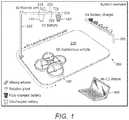
- Figure 1shows in schematic form an overview of a UAV 100, a base station 200 that includes a charging station 300, and a command-and-control (C2) station 400.
- C2command-and-control
- the UAV 100is an existing UAV, such as the AR.Drone provided by Parrot. It is a battery-powered quad-rotor UAV that is able to communicate wirelessly with the C2 station 400.
- the wireless communicationis such that the UAV can receive commands from the C2 station 400 that control operation of the UAV 100, and can send information about operation of the UAV 100 to the C2 station 400.
- the UAV 100has an energy storage device in the form of a removable and rechargeable battery 110.
- the C2 station 400is, in this embodiment, a laptop that communicates wirelessly with the UAV 100 using a radio.
- the C2 station 400communicates using WiFi. In other embodiments, other forms of wireless communication are envisaged.
- the base station 200takes the form of a launch and recovery pad 210 on which the UAV 100 can land and from which it can take off.
- the pad 210is arranged with sensors (not shown) to sense the position and orientation of the UAV 100 when the UAV 100 is on the pad 210. In this embodiment, this is done by the provision of pressure sensors embedded within the pad 210 that are responsive to the weight of the UAV 100 to produce a signal indicative of the position of the UAV 210 on the pad.
- Optical sensorsare also provided on and around the pad 210 to provide a signal indicative of the position and orientation of the UAV 100 when positioned on the pad 210. Signals produced by the sensors are fed to a control unit (not shown) of the base station 200.
- the control unitincludes a microprocessor and a record of software executable by the microprocessor to cause it to operate the base station 200 in the manner described herein.
- the control unitis operable to ascertain, from the signals produced by the sensors, the position and orientation of the UAV 100 on the pad 210.
- a robot arm 220is Also forming part of the base station 200.
- the robot arm 220is arranged to access the UAV 100 wherever the UAV 100 is positioned on the pad 210. In this embodiment, this is accomplished by the robot arm 220 having wheels 230 that allow the robot arm, under the control of the control unit, to move over the pad 210. Movement of the robot arm 220 is further provided for by it being articulated such that sections of the arm 220 are pivotable relative to other sections of the arm 220. One such pivot is shown at 222.
- a battery replacement section 223 of the arm 220is provided with two battery engagement portions 224.
- Each portionis provided with selectively operable magnetic contacts that are operable to releasably engage a battery when adjacent to a battery, such that the battery is grasped by the engagement portion 224 for lifting, moving and subsequently releasing.
- other forms of engagementsuch as a pincer arrangement, are envisaged.
- the battery-replacement section 223is pivotally mounted adjacent its centre to the remainder of the robot arm 220 such that the relative positions of each of the two engagement portions 224 can be swapped by rotating the replacement section 223 180 degrees about its pivot. The purpose of this will become clear.
- the charging station 300forms part of the base station 200.
- the purpose of the charging station 300is to hold batteries for charging and to receive depleted batteries from, and make recharged batteries available to, the robot arm 20. Accordingly, the charging station 300 is arranged to hold multiple batteries (in this embodiment five are envisaged) and to charge each one from a depleted state to a state of maximum charge.
- the charging stationis positioned within reach of the robot arm 220 such that the robot arm 220 can deposit for charging at the charging station 300 a depleted battery that has been removed from the UAV 100 and can collect from the charging station 300 a recharged battery for fitting to the UAV 100.
- the charging station 300also operates under the control of the control unit of the base station 200.
- the control unit of the base station 200also has a wireless communication unit to communicate wirelessly, again in this embodiment by using WiFi, with the C2 station 400.
- the C2 station 400takes the form of, in this embodiment, a laptop computer.
- the computeris able to communicate wirelessly, in the manner previously described, with each of the control unit of the base station 200 and the UAV 100.
- the C2 station 400runs software that controls operation of both the UAV 100 and the base station 200. In other embodiments, however, it is envisaged that the base station 200 may control its own operation in response to the software running thereon and in response to signals from the UAV 100 and/or detecting that the UAV 100 has landed on the pad 210.
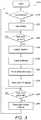
- FIG. 2shows the method of operation 500 of the C2 station 400.
- This method 500is a subroutine that is executed during normal operation of the UAV 10 under the control of the C2 station 400 when the C2 station detects at a first step 510 that the battery 110 of the UAV is discharged below a threshold value such that it is determined that the battery 110 should be replaced.
- the method 500Upon determining at step 510 that the battery 110 should be replaced, the method 500 proceeds to step 520 at which the C2 station 400 sends a signal to the base station 200 that the robot arm 220 should retrieve a fully charged battery 120 from the charging station 300. The method 500 being run by the C2 station then proceeds to step 530 at which the C2 station 400 controls the UAV 100 to land on the launch and recovery pad 210 of the base station 200.
- the method 500 being run by the C2 station 400then waits at step 540 for a signal from the base station 200 that the UAV 100 has been fitted with the new battery 120 and is ready for takeoff.
- the method 600runs on the base station 200. This is in the form of software being executed by the control unit of the base station 200 and is shown in Figure 3 .
- the method 600is initiated at a first step 610 when the base station 200 receives the signal from the C2 station 400 that the robot arm 220 should retrieve the fully charged battery 110 from the charging station 300.
- step 620the control unit of the base station 200 controls the robot arm to move to the charging station 300.
- the magnetic contacts of the engagement portion 224 that is currently positioned at the end of the robot arm 220are operated to pick up the fully charged battery 120.
- the robot arm 220is then operated to rotate the battery replacement section 223 180 degrees about its pivot such that the other, empty, engagement portion 224 is at the end of the arm 220.
- the method of the base station 600then moves on to step 630 at which the base station detects whether or not the UAV 100 has landed on the pad 210. This is done by sensing the signals from the pressure sensors in the pad 210 and the optical sensors in and around the pad 210. When it is detected that the UAV 100 has landed on the pad, the signals from the sensors are used at step 640 to determine the position and orientation of the UAV 100 on the pad 210.
- the robot arm 220is operated at step 650 to move to the determined position of the UAV 100 and to operate the currently empty engagement portion 224 that is at the end of the arm 220 to energise the magnetic contacts and pick up the discharged battery 110 from the UAV.
- the battery replacement section 223 of the robot arm 220is then rotated 180 degrees about its pivot to swap the positions of the discharged battery 110 and the fully charged battery 120. In this way, the fully charged battery 120 is now positioned adjacent the UAV 100.
- the fully charged battery 120is then dropped into place in the UAV 100 by de-energising the magnetic contacts of the relevant battery engagement portion 224.
- step 660the robot arm is moved into a position in which it projects outside and away from the pad 210 so as not to obstruct take off of the UAV 100.
- the base station 200sends a signal at step 670 to the C2 station 400 that the batteries 110, 120 have been swapped and the UAV 100 is ready to resume operation.
- the method 600 running on the base station 200then waits at step 680 until it is detected, by way of the sensors, that the UAV has left the pad 210. Once it has been determined that the UAV has left the pad 210 the robot arm 220 is operated to drop off the discharged battery 110 at the charging station 300 for recharging. The method 600 then returns to step 610 to wait for another signal that it should pick up another fully charged battery.
- step 540a signal that the UAV's discharged battery 110 had been swapped for a fully charged battery 120 and is ready to resume operation.
- this signalis sent from the base station 200 at step 670 of the method running on the base station 200.
- the C2 station 400proceeds to step 550 at which it controls the UAV 100 to take off for resumed operation.
- the subroutinethen returns to the first step 510 to wait for the new battery 120 to become discharged and run the method again.
Landscapes
- Engineering & Computer Science (AREA)
- Aviation & Aerospace Engineering (AREA)
- Mechanical Engineering (AREA)
- Remote Sensing (AREA)
- Power Engineering (AREA)
- Combustion & Propulsion (AREA)
- Chemical & Material Sciences (AREA)
- Transportation (AREA)
- Radar, Positioning & Navigation (AREA)
- Physics & Mathematics (AREA)
- General Physics & Mathematics (AREA)
- Automation & Control Theory (AREA)
- Control Of Position, Course, Altitude, Or Attitude Of Moving Bodies (AREA)
- Charge And Discharge Circuits For Batteries Or The Like (AREA)
- Manipulator (AREA)
Description
- This invention relates to a method of extending the operation of an unmanned aerial vehicle (UAV). In other aspects, this invention relates to a UAV, a base station for a UAV and command-and-control device for a UAV.
EP 2 433 867 A2 relates to an automatic taking-off and landing system, comprising a flying object and a taking-off and landing target, wherein the flying object has an image pickup device for taking images found in downward direction, navigation means, and a control unit for processing images acquired by the image pickup device and for controlling the navigation means, and wherein the control unit calculates a positional relation between the taking-off and landing target and the flying object based on the image of the taking-off and landing target as acquired by the image pickup device and controls taking-off and landing operations of the flying object based on a result of the calculation.- UAVs are increasingly being used in civilian applications. Many "blue light" services such as the police services and fire-fighting services now use UAVs for intelligence-gathering operations, such as to provide real-time video images of locations that are difficult or dangerous to attend in person. UAVs are often able to provide such images quickly, conveniently and inexpensively. The UAVs used in such applications are relatively small compared to UAVs used, for example, in military strike operations. These smaller UAVs are often battery powered. This has the advantage of reducing complexity and cost. An example of such a UAV is the AR.Drone offered by Parrot.
- A problem that exists with such smaller UAVs is that their operational duration is limited by their batteries. It is typical for such UAVs to be able to fly for no longer than 15 to 20 minutes before the battery becomes depleted. This is the principal limitation on the use of such devices.
- Attempts have been made to improve the performance of batteries and so address this problem. For example, battery lives have been improved, charging times have been reduced and the energy consumption of UAVs has also been reduced. Despite these improvements this problem of limited endurance persists.
- There therefore remains a need to address this problem.
- Embodiments of the present invention (which is defined by the technical features and method steps set forth in claim 1 or claims 7 and 8) take a different approach from that taken previously. Rather than look at improving batteries, charging times or the power consumption of UAVs, the present approach is to provide an arrangement for the rapid replacement of batteries, or other energy storage devices, on UAVs such that effective operational duration can be extended.
- Aspects and features of the present invention are set out in the accompanying claims.
- According to a first aspect of the invention as defined in claim 1, there is provided a method of extending the operation of an unmanned aerial vehicle (UAV), the method comprising the steps of:
- detecting that an energy storage device on board the UAV is depleted below a threshold level;
- operating the UAV so as to land at a base station;
- at least initiating operation of a base station to cause a replacement mechanism thereof to remove the storage device on board the UAV from the UAV and to replace this with another storage device.
- The method further comprises the step of operating the base station to detect the position of the UAV relative to the base station when landed. This may include operating sensors at the base station to sense the position of the UAV. Sensing the position may include sensing the orientation of the UAV. Sensing the position may comprise operating pressure sensors positioned in and/or on a landing surface of the base station and/or optical sensors positioned in and/or on and/or around that surface. The surface may be a launch and recovery pad. Sensing the position may comprise generating information indicative of the position and/or orientation of the UAV.
- The operation of the base station may comprise the replacement mechanism operating to take the other storage device from a store thereof. The operation of the base station may comprise operating the replacement mechanism using the detected position and/or orientation of the UAV to move replacement structure of the replacement mechanism to the UAV to remove the storage device therefrom. The operation of the base station may comprise operating the replacement mechanism using the information indicative of the sensed position and/or orientation of the UAV to move the replacement structure of the replacement mechanism to the UAV to couple the other storage device thereto. These steps may occur in the sequence in with they are recited herein; they may occur in another sequence if thereby remaining within the scope of the invention as defined by the claims.
- The other storage device may not be depleted below the threshold. The store may be a charging station at which storage devices arc replenished with energy such that their store thereof is above the threshold and such that the store of energy therein is substantially at a maximum. The or each storage device may be a battery. The or each storage device may be super capacitor. The or each storage device may be a container of fuel.
- The method may be carried out as a result of instructions executed by a processor on the UAV; and/or a processor at the base station and/or a processor at a remote command-and-control device.
- According to a second aspect not forming part of the invention, there is provided a UAV, the UAV arranged to carry out one, more or all of the steps of the method of the first aspect.
- According to a third aspect of the invention as defined in claim 7, there is provided a command-and-control device arranged to carry out one, more or all of the steps of the method of the first aspect. The command-and-control device may comprise computer processing means. For example, it may comprise a computer such as a portable computer. Non exhaustive examples of a portable computer comprise a laptop, a tablet PC and a smartphone.
- According to a fourth aspect not forming part of the invention, there is provided a base station arranged to carry out one, more of all of the steps of the method of the first aspect. The base station may be arranged as defined hereinabove.
- The base station may comprise the replacement mechanism at the base station to remove the storage device on board the UAV from the UAV and replace this with another storage device. The base station may comprise the sensors to sense the position of the UAV. The replacement mechanism may comprise the replacement structure to remove the storage device from the UAV. The replacement mechanism may comprise a robot arm arranged to remove and/or fit storage device to and/or from the UAV. The base station may comprise the store of energy storage devices. The base station may comprise the landing surface.
- Features of the first aspect may also be features of each other aspect if thereby remaining within the scope of the invention as defined by the claims. Operation of the UAV may be controlled as a result of instructions executed by a processor on the UAV and/or a processor at the remote command-and-control device. Operation of the base station may be controlled by a processor at the base station and/or by a processor at the UAV and/or by a processor at the remote command-and-control device.
- One, more or all steps may happen automatically subsequent to it being detected that the energy storage device on board the UAV is depleted below a threshold level
- According to a fifth aspect of the invention as defined in claim 8, there is provided a record carrier comprising processor-executable instructions to cause a processor to carry out a method according to the first aspect. The record carrier may comprise solid state storage means, such as, for example, a ROM, EPROM and/or EEPROM. The record carrier may comprise optical and/or magnetic storage means, such as, for example, a CD-ROM, DVD-ROM and/or magnetic storage disk. The record carrier may comprise a signal such as an electrical, optical and/or wireless signal.
Figure 1 shows in schematic form a UAV, a base station and a command-and-control station;Figure 2 shows a flowchart illustrating the method of operation of the command-and-control station shown inFigure 1 ; andFigure 3 shows a flowchart illustrating the method of operation of the base station shown inFigure 1 .Figure 1 shows in schematic form an overview of aUAV 100, abase station 200 that includes a chargingstation 300, and a command-and-control (C2)station 400.- In this embodiment, the
UAV 100 is an existing UAV, such as the AR.Drone provided by Parrot. It is a battery-powered quad-rotor UAV that is able to communicate wirelessly with theC2 station 400. The wireless communication is such that the UAV can receive commands from theC2 station 400 that control operation of theUAV 100, and can send information about operation of theUAV 100 to theC2 station 400. TheUAV 100 has an energy storage device in the form of a removable andrechargeable battery 110. - The
C2 station 400 is, in this embodiment, a laptop that communicates wirelessly with theUAV 100 using a radio. TheC2 station 400 communicates using WiFi. In other embodiments, other forms of wireless communication are envisaged. - The
base station 200 takes the form of a launch andrecovery pad 210 on which theUAV 100 can land and from which it can take off. Thepad 210 is arranged with sensors (not shown) to sense the position and orientation of theUAV 100 when theUAV 100 is on thepad 210. In this embodiment, this is done by the provision of pressure sensors embedded within thepad 210 that are responsive to the weight of theUAV 100 to produce a signal indicative of the position of theUAV 210 on the pad. Optical sensors are also provided on and around thepad 210 to provide a signal indicative of the position and orientation of theUAV 100 when positioned on thepad 210. Signals produced by the sensors are fed to a control unit (not shown) of thebase station 200. The control unit includes a microprocessor and a record of software executable by the microprocessor to cause it to operate thebase station 200 in the manner described herein. The control unit is operable to ascertain, from the signals produced by the sensors, the position and orientation of theUAV 100 on thepad 210. - Also forming part of the
base station 200 is arobot arm 220. Therobot arm 220 is arranged to access theUAV 100 wherever theUAV 100 is positioned on thepad 210. In this embodiment, this is accomplished by therobot arm 220 having wheels 230 that allow the robot arm, under the control of the control unit, to move over thepad 210. Movement of therobot arm 220 is further provided for by it being articulated such that sections of thearm 220 are pivotable relative to other sections of thearm 220. One such pivot is shown at 222. Abattery replacement section 223 of thearm 220 is provided with twobattery engagement portions 224. Each portion is provided with selectively operable magnetic contacts that are operable to releasably engage a battery when adjacent to a battery, such that the battery is grasped by theengagement portion 224 for lifting, moving and subsequently releasing. In other embodiments, other forms of engagement, such as a pincer arrangement, are envisaged. The battery-replacement section 223 is pivotally mounted adjacent its centre to the remainder of therobot arm 220 such that the relative positions of each of the twoengagement portions 224 can be swapped by rotating thereplacement section 223 180 degrees about its pivot. The purpose of this will become clear. - Again, operation of the
robot arm 220, including the battery-replacement section 223 and theengagement portions 224 is under the control of the control unit of thebase station 200. - The charging
station 300 forms part of thebase station 200. The purpose of the chargingstation 300 is to hold batteries for charging and to receive depleted batteries from, and make recharged batteries available to, the robot arm 20. Accordingly, the chargingstation 300 is arranged to hold multiple batteries (in this embodiment five are envisaged) and to charge each one from a depleted state to a state of maximum charge. The charging station is positioned within reach of therobot arm 220 such that therobot arm 220 can deposit for charging at the charging station 300 a depleted battery that has been removed from theUAV 100 and can collect from the charging station 300 a recharged battery for fitting to theUAV 100. The chargingstation 300 also operates under the control of the control unit of thebase station 200. - The control unit of the
base station 200 also has a wireless communication unit to communicate wirelessly, again in this embodiment by using WiFi, with theC2 station 400. - The
C2 station 400 takes the form of, in this embodiment, a laptop computer. The computer is able to communicate wirelessly, in the manner previously described, with each of the control unit of thebase station 200 and theUAV 100. TheC2 station 400 runs software that controls operation of both theUAV 100 and thebase station 200. In other embodiments, however, it is envisaged that thebase station 200 may control its own operation in response to the software running thereon and in response to signals from theUAV 100 and/or detecting that theUAV 100 has landed on thepad 210. - Operation of the various components will now be described with reference to the flowchart of
Figure 2 . Figure 2 shows the method ofoperation 500 of theC2 station 400. Thismethod 500 is a subroutine that is executed during normal operation of the UAV 10 under the control of theC2 station 400 when the C2 station detects at afirst step 510 that thebattery 110 of the UAV is discharged below a threshold value such that it is determined that thebattery 110 should be replaced.- Upon determining at
step 510 that thebattery 110 should be replaced, themethod 500 proceeds to step 520 at which theC2 station 400 sends a signal to thebase station 200 that therobot arm 220 should retrieve a fully chargedbattery 120 from the chargingstation 300. Themethod 500 being run by the C2 station then proceeds to step 530 at which theC2 station 400 controls theUAV 100 to land on the launch andrecovery pad 210 of thebase station 200. - The
method 500 being run by theC2 station 400 then waits atstep 540 for a signal from thebase station 200 that theUAV 100 has been fitted with thenew battery 120 and is ready for takeoff. - In the meantime, the
method 600 runs on thebase station 200. This is in the form of software being executed by the control unit of thebase station 200 and is shown inFigure 3 . Themethod 600 is initiated at afirst step 610 when thebase station 200 receives the signal from theC2 station 400 that therobot arm 220 should retrieve the fully chargedbattery 110 from the chargingstation 300. - Upon receiving this signal, the
method 600 running on thebase station 200 proceeds to step 620 at which the control unit of thebase station 200 controls the robot arm to move to the chargingstation 300. When the robot arm is at the chargingstation 300, the magnetic contacts of theengagement portion 224 that is currently positioned at the end of therobot arm 220 are operated to pick up the fully chargedbattery 120. Therobot arm 220 is then operated to rotate thebattery replacement section 223 180 degrees about its pivot such that the other, empty,engagement portion 224 is at the end of thearm 220. - The method of the
base station 600 then moves on to step 630 at which the base station detects whether or not theUAV 100 has landed on thepad 210. This is done by sensing the signals from the pressure sensors in thepad 210 and the optical sensors in and around thepad 210. When it is detected that theUAV 100 has landed on the pad, the signals from the sensors are used atstep 640 to determine the position and orientation of theUAV 100 on thepad 210. - Once this is done, the
robot arm 220 is operated atstep 650 to move to the determined position of theUAV 100 and to operate the currentlyempty engagement portion 224 that is at the end of thearm 220 to energise the magnetic contacts and pick up the dischargedbattery 110 from the UAV. Thebattery replacement section 223 of therobot arm 220 is then rotated 180 degrees about its pivot to swap the positions of the dischargedbattery 110 and the fully chargedbattery 120. In this way, the fully chargedbattery 120 is now positioned adjacent theUAV 100. The fully chargedbattery 120 is then dropped into place in theUAV 100 by de-energising the magnetic contacts of the relevantbattery engagement portion 224. - The method then proceeds to step 660 at which the robot arm is moved into a position in which it projects outside and away from the
pad 210 so as not to obstruct take off of theUAV 100. Once this is done, thebase station 200 sends a signal at step 670 to theC2 station 400 that thebatteries UAV 100 is ready to resume operation. - The
method 600 running on thebase station 200 then waits atstep 680 until it is detected, by way of the sensors, that the UAV has left thepad 210. Once it has been determined that the UAV has left thepad 210 therobot arm 220 is operated to drop off the dischargedbattery 110 at the chargingstation 300 for recharging. Themethod 600 then returns to step 610 to wait for another signal that it should pick up another fully charged battery. - Returning now to the
method 500 running on the C2 station, that method had been waiting atstep 540 for a signal that the UAV's dischargedbattery 110 had been swapped for a fully chargedbattery 120 and is ready to resume operation. As mentioned, this signal is sent from thebase station 200 at step 670 of the method running on thebase station 200. Upon receiving this signal, theC2 station 400 proceeds to step 550 at which it controls theUAV 100 to take off for resumed operation. The subroutine then returns to thefirst step 510 to wait for thenew battery 120 to become discharged and run the method again. - In this way, a discharged battery on the UAV is quickly, conveniently and repeatedly swapped for a fully charged battery, thereby prolonging the effective operating duration of the
UAV 100 to be many times its normal operating duration.
Claims (8)
- A method of extending the operation of an unmanned aerial vehicle (UAV) (100) the method comprising the steps of:detecting that an energy storage device (110) on board the UAV is depleted below a threshold level;operating the UAV so as to land at a base station (200);and initiating operation of the base station to cause a replacement mechanism (220) to remove the energy storage device on board the UAV from the UAV and to replace this with another energy storage device (120), the replacement mechanism (220) having a replacement structure with two energy storage device engaging portions (224), a first one of the portions engaging the other energy storage device (120) and the other portion being empty, wherein initiating operation of the base station comprises:detecting the position and/or orientation of the UAV (100) relative to the base station when landed;moving the replacement structure to the UAV (100), and then operating the other portion to engage the energy storage device (110) of the UAV, and then operating the replacement structure by rotating it about a pivot (222) to swap the relative positions of the other energy storage device and that from the UAV, the first one of the portions disengaging the other energy storage device to fit that device to the UAV.
- A method according to claim 1, wherein the detecting the position and/or orientation of the UAV (100) comprises operating sensors at the base station (200) to sense the position of the UAV, which optionally comprises operating pressure sensors positioned in and/or on a landing surface (210) of the base station and/or optical sensors positioned in and/or on and/or around that surface.
- A method according to any preceding claim wherein the operation of the base station (200) comprises the replacement mechanism (220) operating to take the other energy storage device (12) from a store (300) thereof.
- A method according to any of claims 1 to 3, wherein the operation of the base station (200) comprises operating the replacement mechanism (220) using the detected position and/or orientation of the UAV (100) to move replacement structure (224) of the replacement mechanism (220) to the UAV to remove the energy storage device (110) therefrom.
- A method according to any of claims 1 to 4, wherein operation of the base station (200) comprises operating the replacement mechanism (220) using the information indicative of the sensed position and/or orientation of the UAV (100) to move the replacement structure (224) of the replacement mechanism to the UAV to couple the other energy storage device (120) thereto.
- A method according to claim 4 or 5,
wherein operation of the base station (200) comprises operating the replacement mechanism (220) to deposit the energy storage device (110) removed from the UAV (100) at the store (300) for recharging its store of energy. - A command-and-control device (400) arranged to carry out a method according to any of claims 1 to 6.
- A record carrier comprising processor-executable instructions to cause a processor to carry out a method according to any of claims 1 to 6.
Priority Applications (3)
| Application Number | Priority Date | Filing Date | Title |
|---|---|---|---|
| EP12382181.1AEP2664539B1 (en) | 2012-05-17 | 2012-05-17 | A method of and apparatus for extending the operation of an unmanned aerial vehicle |
| US13/871,825US9551989B2 (en) | 2012-05-17 | 2013-04-26 | Method and apparatus for extending the operation of an unmanned aerial vehicle |
| JP2013102786AJP6224347B2 (en) | 2012-05-17 | 2013-05-15 | Method and apparatus for extending the operation of a drone |
Applications Claiming Priority (1)
| Application Number | Priority Date | Filing Date | Title |
|---|---|---|---|
| EP12382181.1AEP2664539B1 (en) | 2012-05-17 | 2012-05-17 | A method of and apparatus for extending the operation of an unmanned aerial vehicle |
Publications (2)
| Publication Number | Publication Date |
|---|---|
| EP2664539A1 EP2664539A1 (en) | 2013-11-20 |
| EP2664539B1true EP2664539B1 (en) | 2018-07-18 |
Family
ID=46982499
Family Applications (1)
| Application Number | Title | Priority Date | Filing Date |
|---|---|---|---|
| EP12382181.1AActiveEP2664539B1 (en) | 2012-05-17 | 2012-05-17 | A method of and apparatus for extending the operation of an unmanned aerial vehicle |
Country Status (3)
| Country | Link |
|---|---|
| US (1) | US9551989B2 (en) |
| EP (1) | EP2664539B1 (en) |
| JP (1) | JP6224347B2 (en) |
Cited By (1)
| Publication number | Priority date | Publication date | Assignee | Title |
|---|---|---|---|---|
| US11912407B1 (en) | 2016-02-04 | 2024-02-27 | United Services Automobile Association (Usaa) | Unmanned vehicle morphing |
Families Citing this family (87)
| Publication number | Priority date | Publication date | Assignee | Title |
|---|---|---|---|---|
| US9513371B2 (en) | 2013-02-28 | 2016-12-06 | Identified Technologies Corporation | Ground survey and obstacle detection system |
| US9382003B2 (en)* | 2013-03-24 | 2016-07-05 | Bee Robotics Corporation | Aerial farm robot system for crop dusting, planting, fertilizing and other field jobs |
| EP2799336B1 (en)* | 2013-04-29 | 2020-03-18 | The Boeing Company | Device and method for use with unmanned aerial vehicles |
| GB201409654D0 (en)* | 2014-05-30 | 2014-07-16 | Geola Technologies Ltd | Charging and re-provisioning station for electric and hybrid UAVx |
| EP3412568B1 (en)* | 2014-07-31 | 2020-06-03 | SZ DJI Technology Co., Ltd. | Unmanned aerial vehicle base station system and method |
| JP6527153B2 (en) | 2014-07-31 | 2019-06-05 | エスゼット ディージェイアイ テクノロジー カンパニー リミテッドSz Dji Technology Co.,Ltd | Unmanned aircraft dock |
| JP5874940B1 (en)* | 2014-08-06 | 2016-03-02 | 八洲電業株式会社 | Aircraft and battery unit storage system |
| EP3177531B1 (en) | 2014-08-08 | 2019-05-01 | SZ DJI Technology Co., Ltd. | Multi-zone battery exchange system for uav |
| JP6395835B2 (en) | 2014-08-08 | 2018-09-26 | エスゼット ディージェイアイ テクノロジー カンパニー リミテッドSz Dji Technology Co.,Ltd | UAV battery power backup system and method |
| EP3167535B1 (en) | 2014-08-08 | 2020-09-23 | SZ DJI Technology Co., Ltd. | Systems and methods for uav battery exchange |
| US10163164B1 (en)* | 2014-09-22 | 2018-12-25 | State Farm Mutual Automobile Insurance Company | Unmanned aerial vehicle (UAV) data collection and claim pre-generation for insured approval |
| US9754496B2 (en) | 2014-09-30 | 2017-09-05 | Elwha Llc | System and method for management of airspace for unmanned aircraft |
| US9429945B2 (en) | 2014-10-22 | 2016-08-30 | Honeywell International Inc. | Surveying areas using a radar system and an unmanned aerial vehicle |
| US9963229B2 (en) | 2014-10-29 | 2018-05-08 | Identified Technologies Corporation | Structure and manufacturing process for unmanned aerial vehicle |
| EP3222530B1 (en) | 2014-11-19 | 2020-12-16 | SZ DJI Technology Co., Ltd. | Positioning mechanism and uav base station using the positioning mechanism |
| CN106103281B (en) | 2014-11-21 | 2019-02-26 | 深圳市大疆创新科技有限公司 | Systems and methods for managing unmanned aerial vehicles |
| US9919797B2 (en) | 2014-12-04 | 2018-03-20 | Elwha Llc | System and method for operation and management of reconfigurable unmanned aircraft |
| US20160272310A1 (en)* | 2014-12-04 | 2016-09-22 | Elwha Llc | Reconfigurable unmanned aircraft system |
| JP2016128696A (en)* | 2015-01-09 | 2016-07-14 | トヨタ自動車株式会社 | Internal combustion engine |
| US9489852B1 (en) | 2015-01-22 | 2016-11-08 | Zipline International Inc. | Unmanned aerial vehicle management system |
| WO2016130112A1 (en)* | 2015-02-10 | 2016-08-18 | Identified Technologies Corporation | Methods and apparatus for persistent deployment of aerial vehicles |
| WO2016145411A1 (en)* | 2015-03-12 | 2016-09-15 | Nightingale Intelligent Systems | Automated drone systems |
| US9488979B1 (en) | 2015-04-14 | 2016-11-08 | Zipline International Inc. | System and method for human operator intervention in autonomous vehicle operations |
| US10023057B2 (en) | 2015-04-22 | 2018-07-17 | Cristian A. Sobota Rodriguez | Contactless charger and battery management |
| US9891631B1 (en) | 2015-06-09 | 2018-02-13 | Amazon Technologies, Inc. | Application program interface for weight and balance metrics |
| US10035592B1 (en)* | 2015-06-09 | 2018-07-31 | Amazon Technologies, Inc. | Unmanned aerial vehicle scale alignment |
| US9656749B1 (en)* | 2015-06-09 | 2017-05-23 | Amazon Technologies, Inc. | Unmanned aerial vehicle physical metrics acquisition |
| US10453348B2 (en)* | 2015-06-15 | 2019-10-22 | ImageKeeper LLC | Unmanned aerial vehicle management |
| US9678507B1 (en)* | 2015-06-25 | 2017-06-13 | Latitude Engineering, LLC | Autonomous infrastructure element survey systems and methods using UAV fleet deployment |
| US9878787B2 (en) | 2015-07-15 | 2018-01-30 | Elwha Llc | System and method for operating unmanned aircraft |
| JP6709690B2 (en) | 2015-07-17 | 2020-06-17 | パナソニック インテレクチュアル プロパティ コーポレーション オブ アメリカPanasonic Intellectual Property Corporation of America | Unmanned aerial vehicle, flight control method and flight control program |
| US10586464B2 (en) | 2015-07-29 | 2020-03-10 | Warren F. LeBlanc | Unmanned aerial vehicles |
| FR3039519B1 (en)* | 2015-07-30 | 2019-01-25 | Airbus | DRONE HOSTING STATION AND MANAGEMENT ASSEMBLY OF SUCH A RECEPTION STATION. |
| JP2018529571A (en) | 2015-09-23 | 2018-10-11 | ウォルマート アポロ,エルエルシー | Portable unmanned delivery aircraft launch system and method of delivering product using aircraft launch system |
| US9969285B2 (en) | 2015-10-05 | 2018-05-15 | Asylon, Inc. | Methods and apparatus for reconfigurable power exchange for multiple UAV types |
| JP2017071285A (en)* | 2015-10-06 | 2017-04-13 | 田淵電機株式会社 | Flight vehicle, flight vehicle power supply device, and flight vehicle control device |
| US11091275B2 (en) | 2015-10-22 | 2021-08-17 | Droneovation, Inc. | Aerial drone operations support base |
| US9659502B1 (en) | 2015-12-18 | 2017-05-23 | International Business Machines Corporation | Drone range extension via host vehicles |
| CN105539824A (en)* | 2015-12-31 | 2016-05-04 | 东莞市吉飞机器人有限公司 | Intelligent drone system that can work continuously in a large area |
| US9714012B1 (en) | 2016-01-22 | 2017-07-25 | International Business Machines Corporation | Power source element replacement during vehicle operation |
| US9764703B2 (en) | 2016-01-22 | 2017-09-19 | International Business Machines Corporation | Power source element detection and monitoring |
| CN105790350A (en)* | 2016-03-01 | 2016-07-20 | 北京佰才邦技术有限公司 | Energy supply station and energy supply method |
| US9975632B2 (en) | 2016-04-08 | 2018-05-22 | Drona, LLC | Aerial vehicle system |
| US10730626B2 (en) | 2016-04-29 | 2020-08-04 | United Parcel Service Of America, Inc. | Methods of photo matching and photo confirmation for parcel pickup and delivery |
| US10726381B2 (en) | 2016-04-29 | 2020-07-28 | United Parcel Service Of America, Inc. | Methods for dispatching unmanned aerial delivery vehicles |
| US10040552B2 (en) | 2016-05-06 | 2018-08-07 | International Business Machines Corporation | Alert system for an unmanned aerial vehicle |
| JP6410760B2 (en)* | 2016-06-20 | 2018-10-24 | ソフトバンク株式会社 | Moored balloon |
| CN106081131A (en)* | 2016-08-17 | 2016-11-09 | 张琬彬 | The control method of electric moter voltage and system in unmanned plane |
| CN106275463A (en)* | 2016-08-17 | 2017-01-04 | 张琬彬 | The method for controlling number of revolution of unmanned plane and system |
| CN106325286A (en)* | 2016-08-17 | 2017-01-11 | 张琬彬 | Method and system for adjusting flight height of unmanned aerial vehicle based on electric quantity |
| CN106208905A (en)* | 2016-08-17 | 2016-12-07 | 张琬彬 | The method and system of electric energy control unmanned plane current of electric |
| WO2018032414A1 (en)* | 2016-08-17 | 2018-02-22 | 张琬彬 | Method and system for adjusting unmanned aerial vehicle flight altitude according to power level |
| CN106184758B (en)* | 2016-09-18 | 2018-07-20 | 成都天麒科技有限公司 | A kind of automatic medicament feeding system and method for plant protection drone |
| CN106364685A (en)* | 2016-09-30 | 2017-02-01 | 安徽翼讯飞行安全技术有限公司 | Power supply structure for unmanned aerial vehicle |
| US20200286034A1 (en)* | 2017-09-25 | 2020-09-10 | Shmuel Ur Innovation Ltd | Drone based delivery system using vehicles |
| WO2018065977A1 (en)* | 2016-10-07 | 2018-04-12 | Shmuel Ur Innovation Ltd. | Drone based delivery system using vehicles |
| CN106516089B (en)* | 2016-10-28 | 2019-05-21 | 深圳市道通智能航空技术有限公司 | Unmanned plane |
| TW201822436A (en)* | 2016-12-14 | 2018-06-16 | 鴻海精密工業股份有限公司 | Wireless charging system of unmanned aerial vehicle and unmanned aerial vehicle |
| TW201822438A (en)* | 2016-12-14 | 2018-06-16 | 鴻海精密工業股份有限公司 | Wireless charging system of unmanned aerial vehicle and unmanned aerial vehicle |
| TW201822437A (en)* | 2016-12-14 | 2018-06-16 | 鴻海精密工業股份有限公司 | UAV wireless charging system and drone |
| CN108237934B (en) | 2016-12-27 | 2021-02-26 | 财团法人工业技术研究院 | Charging Stations and Charging Station Modules |
| CN110536834B (en)* | 2017-04-21 | 2023-04-04 | 乐天集团股份有限公司 | Battery mounting system, battery mounting method, and program |
| US10775792B2 (en) | 2017-06-13 | 2020-09-15 | United Parcel Service Of America, Inc. | Autonomously delivering items to corresponding delivery locations proximate a delivery route |
| CN110997400B (en) | 2017-07-19 | 2024-11-29 | 福特全球技术公司 | Exchangeable battery system |
| CN107453441B (en)* | 2017-09-13 | 2020-07-24 | 国网重庆市电力公司电力科学研究院 | A mobile charging device and method for charging a stationary electric vehicle |
| EP3688684B1 (en) | 2017-09-29 | 2025-02-26 | United Parcel Service Of America, Inc. | Predictive parcel damage identification, analysis, and mitigation |
| US10953984B2 (en) | 2017-12-20 | 2021-03-23 | Wing Aviation Llc | Methods and systems for using an unmanned aerial vehicle (UAV) dedicated to deployment of operational infrastructure |
| US10894601B2 (en) | 2017-12-20 | 2021-01-19 | Wing Aviation Llc | Methods and systems for self-deployment of operational infrastructure by an unmanned aerial vehicle (UAV) |
| CN108196574B (en)* | 2018-01-02 | 2021-11-09 | 广州亿航智能技术有限公司 | Unmanned aerial vehicle endurance judgment method and device and computer storage medium |
| GB2572549A (en)* | 2018-03-28 | 2019-10-09 | Sony Corp | Unmanned aerial vehicle |
| US11124314B2 (en) | 2018-04-12 | 2021-09-21 | The Boeing Company | Systems and methods for transferring electric power to an aircraft during flight |
| CN110450970A (en)* | 2018-05-08 | 2019-11-15 | 龚日鸿 | The energy module of sharable unmanned plane replaces system |
| JP7143122B2 (en)* | 2018-06-13 | 2022-09-28 | Ihi運搬機械株式会社 | parking device |
| LT6769B (en) | 2019-02-28 | 2020-10-12 | Robotopia, UAB | METHOD OF SUPPLYING ENERGY SOURCES TO UNDERTAKINGS AND SYSTEM OF IMPLEMENTATION OF THIS METHOD |
| US12393919B2 (en) | 2019-05-03 | 2025-08-19 | Michele Di Cosola | Data exchange within a layer zero (L_0) HGTP, DAG, Web3 state channel smart self-healing node centric blockchain mesh network |
| US11597515B2 (en)* | 2019-08-19 | 2023-03-07 | Epazz, Inc. | Charging/re-charging drone assembly system and apparatus |
| US11005301B1 (en) | 2020-01-10 | 2021-05-11 | The Boeing Company | System and method for encrypted resonant inductive power transfer |
| WO2021188274A1 (en) | 2020-03-16 | 2021-09-23 | Asylon, Inc. | Automated alert system using unmanned aerial vehicles |
| CN112278276B (en)* | 2020-11-12 | 2022-05-31 | 浙江南瑞飞翼航空技术有限公司 | Battery replacing structure for unmanned aerial vehicle and using method of battery replacing structure |
| US11405801B1 (en)* | 2021-03-18 | 2022-08-02 | Amazon Technologies, Inc. | Managing radio-based network infrastructure using unmanned vehicles |
| KR102583405B1 (en)* | 2021-07-05 | 2023-09-27 | 주식회사 아르고스다인 | Drone Station |
| WO2023056516A1 (en)* | 2021-10-07 | 2023-04-13 | Australian Aeronautics Pty Ltd. | Hybrid drone, base station and methods therefor |
| JP2023087874A (en)* | 2021-12-14 | 2023-06-26 | セコム株式会社 | flying robot enclosure |
| US12246605B2 (en) | 2022-01-28 | 2025-03-11 | Toyota Motor Engineering & Manufacturing North America, Inc. | Configurable dynamic wireless power transfer transmission system |
| CN117897545A (en)* | 2022-03-09 | 2024-04-16 | 深圳市大疆创新科技有限公司 | UAV base station and UAV system |
| US12145753B2 (en)* | 2022-08-09 | 2024-11-19 | Pete Bitar | Compact and lightweight drone delivery device called an ArcSpear electric jet drone system having an electric ducted air propulsion system and being relatively difficult to track in flight |
| JP7697435B2 (en)* | 2022-09-01 | 2025-06-24 | トヨタ自動車株式会社 | Take-off and landing assistance equipment |
Citations (5)
| Publication number | Priority date | Publication date | Assignee | Title |
|---|---|---|---|---|
| US668108A (en)* | 1899-12-29 | 1901-02-12 | Cyprien O Mailloux | Transfer apparatus for electric batteries. |
| GB2174657A (en)* | 1985-05-10 | 1986-11-12 | Gd Spa | Re-placing power source on vehicle |
| US20070113921A1 (en)* | 2005-11-04 | 2007-05-24 | Capizzo Peter D | System for replenishing energy sources onboard different types of automotive vehicles |
| DE102007003458A1 (en)* | 2007-01-24 | 2008-07-31 | Diehl Bgt Defence Gmbh & Co. Kg | Power supply device for battery-operated small air-craft, has charging device provided for recharging rechargeable battery after implementing flight mission of small air-craft, and landing and loading platform attached to battery magazine |
| WO2012130790A2 (en)* | 2011-03-28 | 2012-10-04 | Prox Dynamics As | Uav kit |
Family Cites Families (17)
| Publication number | Priority date | Publication date | Assignee | Title |
|---|---|---|---|---|
| JPH07142551A (en)* | 1993-11-20 | 1995-06-02 | Tokyo Electron Ltd | Carrier arm device and processing chamber collector using carrier arm device |
| JP3857349B2 (en)* | 1996-03-22 | 2006-12-13 | ローツェ株式会社 | Handling robot |
| US5998963A (en)* | 1998-06-11 | 1999-12-07 | Aarseth; Einar | Electric vehicle service center and method for exchanging and charging vehicle batteries |
| JP3757130B2 (en)* | 2001-05-23 | 2006-03-22 | Necモバイリング株式会社 | Car driving skill test scoring system |
| JP4245387B2 (en)* | 2003-03-19 | 2009-03-25 | 東京エレクトロン株式会社 | Substrate transport apparatus and substrate processing apparatus |
| US7398946B1 (en)* | 2004-10-04 | 2008-07-15 | United States Of America As Represented By The Secretary Of The Air Force | Power line sentry charging |
| JP2006236109A (en)* | 2005-02-25 | 2006-09-07 | Sanyo Electric Co Ltd | System for automatically charging robot |
| JP2009102903A (en)* | 2007-10-24 | 2009-05-14 | Fuji Hensokuki Co Ltd | Stepping-off location indication device for parking lot, stepping-on location indication device for parking lot, and stepping-on/off location indication device for parking lot |
| US8006793B2 (en)* | 2008-09-19 | 2011-08-30 | Better Place GmbH | Electric vehicle battery system |
| US20110251935A1 (en)* | 2008-12-15 | 2011-10-13 | Guy German | Mobile Battery Replacement Unit |
| WO2010071502A1 (en)* | 2008-12-15 | 2010-06-24 | Saab Ab | Measuring of a landing platform of a ship |
| JP5369711B2 (en)* | 2009-01-27 | 2013-12-18 | 日産自動車株式会社 | Battery mounted device |
| US8167234B1 (en)* | 2010-03-21 | 2012-05-01 | Michael Moore | Insect-like micro air vehicle having perching, energy scavenging, crawling, and offensive payload capabilities |
| JP2012037204A (en)* | 2010-08-11 | 2012-02-23 | Yasuaki Iwai | Device and method for searching mine |
| JP5429107B2 (en)* | 2010-08-18 | 2014-02-26 | 株式会社豊田自動織機 | Battery replacement device for electric vehicles |
| FR2964573B1 (en)* | 2010-09-15 | 2012-09-28 | Parrot | METHOD FOR CONTROLLING A MULTI-ROTOR ROTOR SAILING DRONE |
| JP5690539B2 (en)* | 2010-09-28 | 2015-03-25 | 株式会社トプコン | Automatic take-off and landing system |
- 2012
- 2012-05-17EPEP12382181.1Apatent/EP2664539B1/enactiveActive
- 2013
- 2013-04-26USUS13/871,825patent/US9551989B2/enactiveActive
- 2013-05-15JPJP2013102786Apatent/JP6224347B2/enactiveActive
Patent Citations (5)
| Publication number | Priority date | Publication date | Assignee | Title |
|---|---|---|---|---|
| US668108A (en)* | 1899-12-29 | 1901-02-12 | Cyprien O Mailloux | Transfer apparatus for electric batteries. |
| GB2174657A (en)* | 1985-05-10 | 1986-11-12 | Gd Spa | Re-placing power source on vehicle |
| US20070113921A1 (en)* | 2005-11-04 | 2007-05-24 | Capizzo Peter D | System for replenishing energy sources onboard different types of automotive vehicles |
| DE102007003458A1 (en)* | 2007-01-24 | 2008-07-31 | Diehl Bgt Defence Gmbh & Co. Kg | Power supply device for battery-operated small air-craft, has charging device provided for recharging rechargeable battery after implementing flight mission of small air-craft, and landing and loading platform attached to battery magazine |
| WO2012130790A2 (en)* | 2011-03-28 | 2012-10-04 | Prox Dynamics As | Uav kit |
Cited By (1)
| Publication number | Priority date | Publication date | Assignee | Title |
|---|---|---|---|---|
| US11912407B1 (en) | 2016-02-04 | 2024-02-27 | United Services Automobile Association (Usaa) | Unmanned vehicle morphing |
Also Published As
| Publication number | Publication date |
|---|---|
| EP2664539A1 (en) | 2013-11-20 |
| JP6224347B2 (en) | 2017-11-01 |
| US9551989B2 (en) | 2017-01-24 |
| US20140129059A1 (en) | 2014-05-08 |
| JP2013241177A (en) | 2013-12-05 |
Similar Documents
| Publication | Publication Date | Title |
|---|---|---|
| EP2664539B1 (en) | A method of and apparatus for extending the operation of an unmanned aerial vehicle | |
| JP6395835B2 (en) | UAV battery power backup system and method | |
| US10195952B2 (en) | System and method for managing unmanned aerial vehicles | |
| EP3167535B1 (en) | Systems and methods for uav battery exchange | |
| US11693400B2 (en) | Unmanned aerial vehicle control system, unmanned aerial vehicle control method, and program | |
| KR101790626B1 (en) | Self-optimizing power transfer | |
| JP2025098036A (en) | Unmanned aerial vehicle airport, unmanned aerial vehicle system, and unmanned aerial vehicle cruise system | |
| JP6538214B2 (en) | Method of supplying energy to UAV, and UAV | |
| EP3728029A1 (en) | System and methods for automatic payload pickup by uav | |
| US11840158B2 (en) | Systems and methods for battery capacity management in a fleet of UAVs | |
| JP6791561B2 (en) | Methods and devices for supplying energy to UAVs | |
| US10739793B2 (en) | UAV with selective operational control during holding | |
| CN113715668B (en) | UAV automatic charging method and system | |
| CN212951176U (en) | Intelligent searching and transporting unmanned aerial vehicle base station | |
| KR20220117952A (en) | Drone battery replacement support method for seamless power supply and device therefor | |
| CN116234751A (en) | Systems and Structures of Unmanned Aerial Vehicles | |
| CN117485630A (en) | Unmanned aerial vehicle cabin, and method, device and system for controlling take-off and landing of unmanned aerial vehicle | |
| CN220786193U (en) | UAV cabin | |
| CN117902081A (en) | UAV charging device, UAV, UAV remote sensing system and charging method |
Legal Events
| Date | Code | Title | Description |
|---|---|---|---|
| PUAI | Public reference made under article 153(3) epc to a published international application that has entered the european phase | Free format text:ORIGINAL CODE: 0009012 | |
| AK | Designated contracting states | Kind code of ref document:A1 Designated state(s):AL AT BE BG CH CY CZ DE DK EE ES FI FR GB GR HR HU IE IS IT LI LT LU LV MC MK MT NL NO PL PT RO RS SE SI SK SM TR | |
| AX | Request for extension of the european patent | Extension state:BA ME | |
| 17P | Request for examination filed | Effective date:20140520 | |
| RBV | Designated contracting states (corrected) | Designated state(s):AL AT BE BG CH CY CZ DE DK EE ES FI FR GB GR HR HU IE IS IT LI LT LU LV MC MK MT NL NO PL PT RO RS SE SI SK SM TR | |
| STAA | Information on the status of an ep patent application or granted ep patent | Free format text:STATUS: EXAMINATION IS IN PROGRESS | |
| 17Q | First examination report despatched | Effective date:20170810 | |
| REG | Reference to a national code | Ref country code:DE Ref legal event code:R079 Ref document number:602012048566 Country of ref document:DE Free format text:PREVIOUS MAIN CLASS: B64C0039020000 Ipc:B60L0011180000 | |
| RIC1 | Information provided on ipc code assigned before grant | Ipc:B64C 39/02 20060101ALI20171206BHEP Ipc:G05D 1/00 20060101ALI20171206BHEP Ipc:B60L 11/18 20060101AFI20171206BHEP | |
| GRAP | Despatch of communication of intention to grant a patent | Free format text:ORIGINAL CODE: EPIDOSNIGR1 | |
| STAA | Information on the status of an ep patent application or granted ep patent | Free format text:STATUS: GRANT OF PATENT IS INTENDED | |
| INTG | Intention to grant announced | Effective date:20180205 | |
| GRAS | Grant fee paid | Free format text:ORIGINAL CODE: EPIDOSNIGR3 | |
| GRAA | (expected) grant | Free format text:ORIGINAL CODE: 0009210 | |
| STAA | Information on the status of an ep patent application or granted ep patent | Free format text:STATUS: THE PATENT HAS BEEN GRANTED | |
| AK | Designated contracting states | Kind code of ref document:B1 Designated state(s):AL AT BE BG CH CY CZ DE DK EE ES FI FR GB GR HR HU IE IS IT LI LT LU LV MC MK MT NL NO PL PT RO RS SE SI SK SM TR | |
| REG | Reference to a national code | Ref country code:GB Ref legal event code:FG4D | |
| REG | Reference to a national code | Ref country code:CH Ref legal event code:EP | |
| REG | Reference to a national code | Ref country code:IE Ref legal event code:FG4D | |
| REG | Reference to a national code | Ref country code:AT Ref legal event code:REF Ref document number:1018976 Country of ref document:AT Kind code of ref document:T Effective date:20180815 | |
| REG | Reference to a national code | Ref country code:DE Ref legal event code:R096 Ref document number:602012048566 Country of ref document:DE | |
| REG | Reference to a national code | Ref country code:NL Ref legal event code:MP Effective date:20180718 | |
| REG | Reference to a national code | Ref country code:LT Ref legal event code:MG4D | |
| REG | Reference to a national code | Ref country code:AT Ref legal event code:MK05 Ref document number:1018976 Country of ref document:AT Kind code of ref document:T Effective date:20180718 | |
| PG25 | Lapsed in a contracting state [announced via postgrant information from national office to epo] | Ref country code:NL Free format text:LAPSE BECAUSE OF FAILURE TO SUBMIT A TRANSLATION OF THE DESCRIPTION OR TO PAY THE FEE WITHIN THE PRESCRIBED TIME-LIMIT Effective date:20180718 | |
| REG | Reference to a national code | Ref country code:DE Ref legal event code:R079 Ref document number:602012048566 Country of ref document:DE Free format text:PREVIOUS MAIN CLASS: B60L0011180000 Ipc:B60L0050500000 | |
| PG25 | Lapsed in a contracting state [announced via postgrant information from national office to epo] | Ref country code:LT Free format text:LAPSE BECAUSE OF FAILURE TO SUBMIT A TRANSLATION OF THE DESCRIPTION OR TO PAY THE FEE WITHIN THE PRESCRIBED TIME-LIMIT Effective date:20180718 Ref country code:BG Free format text:LAPSE BECAUSE OF FAILURE TO SUBMIT A TRANSLATION OF THE DESCRIPTION OR TO PAY THE FEE WITHIN THE PRESCRIBED TIME-LIMIT Effective date:20181018 Ref country code:SE Free format text:LAPSE BECAUSE OF FAILURE TO SUBMIT A TRANSLATION OF THE DESCRIPTION OR TO PAY THE FEE WITHIN THE PRESCRIBED TIME-LIMIT Effective date:20180718 Ref country code:RS Free format text:LAPSE BECAUSE OF FAILURE TO SUBMIT A TRANSLATION OF THE DESCRIPTION OR TO PAY THE FEE WITHIN THE PRESCRIBED TIME-LIMIT Effective date:20180718 Ref country code:PL Free format text:LAPSE BECAUSE OF FAILURE TO SUBMIT A TRANSLATION OF THE DESCRIPTION OR TO PAY THE FEE WITHIN THE PRESCRIBED TIME-LIMIT Effective date:20180718 Ref country code:NO Free format text:LAPSE BECAUSE OF FAILURE TO SUBMIT A TRANSLATION OF THE DESCRIPTION OR TO PAY THE FEE WITHIN THE PRESCRIBED TIME-LIMIT Effective date:20181018 Ref country code:IS Free format text:LAPSE BECAUSE OF FAILURE TO SUBMIT A TRANSLATION OF THE DESCRIPTION OR TO PAY THE FEE WITHIN THE PRESCRIBED TIME-LIMIT Effective date:20181118 Ref country code:AT Free format text:LAPSE BECAUSE OF FAILURE TO SUBMIT A TRANSLATION OF THE DESCRIPTION OR TO PAY THE FEE WITHIN THE PRESCRIBED TIME-LIMIT Effective date:20180718 Ref country code:FI Free format text:LAPSE BECAUSE OF FAILURE TO SUBMIT A TRANSLATION OF THE DESCRIPTION OR TO PAY THE FEE WITHIN THE PRESCRIBED TIME-LIMIT Effective date:20180718 | |
| PG25 | Lapsed in a contracting state [announced via postgrant information from national office to epo] | Ref country code:LV Free format text:LAPSE BECAUSE OF FAILURE TO SUBMIT A TRANSLATION OF THE DESCRIPTION OR TO PAY THE FEE WITHIN THE PRESCRIBED TIME-LIMIT Effective date:20180718 Ref country code:ES Free format text:LAPSE BECAUSE OF FAILURE TO SUBMIT A TRANSLATION OF THE DESCRIPTION OR TO PAY THE FEE WITHIN THE PRESCRIBED TIME-LIMIT Effective date:20180718 Ref country code:AL Free format text:LAPSE BECAUSE OF FAILURE TO SUBMIT A TRANSLATION OF THE DESCRIPTION OR TO PAY THE FEE WITHIN THE PRESCRIBED TIME-LIMIT Effective date:20180718 Ref country code:HR Free format text:LAPSE BECAUSE OF FAILURE TO SUBMIT A TRANSLATION OF THE DESCRIPTION OR TO PAY THE FEE WITHIN THE PRESCRIBED TIME-LIMIT Effective date:20180718 | |
| REG | Reference to a national code | Ref country code:DE Ref legal event code:R097 Ref document number:602012048566 Country of ref document:DE | |
| PG25 | Lapsed in a contracting state [announced via postgrant information from national office to epo] | Ref country code:EE Free format text:LAPSE BECAUSE OF FAILURE TO SUBMIT A TRANSLATION OF THE DESCRIPTION OR TO PAY THE FEE WITHIN THE PRESCRIBED TIME-LIMIT Effective date:20180718 Ref country code:IT Free format text:LAPSE BECAUSE OF FAILURE TO SUBMIT A TRANSLATION OF THE DESCRIPTION OR TO PAY THE FEE WITHIN THE PRESCRIBED TIME-LIMIT Effective date:20180718 Ref country code:RO Free format text:LAPSE BECAUSE OF FAILURE TO SUBMIT A TRANSLATION OF THE DESCRIPTION OR TO PAY THE FEE WITHIN THE PRESCRIBED TIME-LIMIT Effective date:20180718 Ref country code:CZ Free format text:LAPSE BECAUSE OF FAILURE TO SUBMIT A TRANSLATION OF THE DESCRIPTION OR TO PAY THE FEE WITHIN THE PRESCRIBED TIME-LIMIT Effective date:20180718 | |
| PLBE | No opposition filed within time limit | Free format text:ORIGINAL CODE: 0009261 | |
| STAA | Information on the status of an ep patent application or granted ep patent | Free format text:STATUS: NO OPPOSITION FILED WITHIN TIME LIMIT | |
| PG25 | Lapsed in a contracting state [announced via postgrant information from national office to epo] | Ref country code:SM Free format text:LAPSE BECAUSE OF FAILURE TO SUBMIT A TRANSLATION OF THE DESCRIPTION OR TO PAY THE FEE WITHIN THE PRESCRIBED TIME-LIMIT Effective date:20180718 Ref country code:SK Free format text:LAPSE BECAUSE OF FAILURE TO SUBMIT A TRANSLATION OF THE DESCRIPTION OR TO PAY THE FEE WITHIN THE PRESCRIBED TIME-LIMIT Effective date:20180718 Ref country code:DK Free format text:LAPSE BECAUSE OF FAILURE TO SUBMIT A TRANSLATION OF THE DESCRIPTION OR TO PAY THE FEE WITHIN THE PRESCRIBED TIME-LIMIT Effective date:20180718 | |
| 26N | No opposition filed | Effective date:20190423 | |
| PG25 | Lapsed in a contracting state [announced via postgrant information from national office to epo] | Ref country code:SI Free format text:LAPSE BECAUSE OF FAILURE TO SUBMIT A TRANSLATION OF THE DESCRIPTION OR TO PAY THE FEE WITHIN THE PRESCRIBED TIME-LIMIT Effective date:20180718 | |
| REG | Reference to a national code | Ref country code:CH Ref legal event code:PL | |
| PG25 | Lapsed in a contracting state [announced via postgrant information from national office to epo] | Ref country code:MC Free format text:LAPSE BECAUSE OF FAILURE TO SUBMIT A TRANSLATION OF THE DESCRIPTION OR TO PAY THE FEE WITHIN THE PRESCRIBED TIME-LIMIT Effective date:20180718 Ref country code:LI Free format text:LAPSE BECAUSE OF NON-PAYMENT OF DUE FEES Effective date:20190531 Ref country code:CH Free format text:LAPSE BECAUSE OF NON-PAYMENT OF DUE FEES Effective date:20190531 | |
| REG | Reference to a national code | Ref country code:BE Ref legal event code:MM Effective date:20190531 | |
| PG25 | Lapsed in a contracting state [announced via postgrant information from national office to epo] | Ref country code:LU Free format text:LAPSE BECAUSE OF NON-PAYMENT OF DUE FEES Effective date:20190517 | |
| PG25 | Lapsed in a contracting state [announced via postgrant information from national office to epo] | Ref country code:TR Free format text:LAPSE BECAUSE OF FAILURE TO SUBMIT A TRANSLATION OF THE DESCRIPTION OR TO PAY THE FEE WITHIN THE PRESCRIBED TIME-LIMIT Effective date:20180718 | |
| PG25 | Lapsed in a contracting state [announced via postgrant information from national office to epo] | Ref country code:IE Free format text:LAPSE BECAUSE OF NON-PAYMENT OF DUE FEES Effective date:20190517 | |
| PG25 | Lapsed in a contracting state [announced via postgrant information from national office to epo] | Ref country code:BE Free format text:LAPSE BECAUSE OF NON-PAYMENT OF DUE FEES Effective date:20190531 | |
| PG25 | Lapsed in a contracting state [announced via postgrant information from national office to epo] | Ref country code:PT Free format text:LAPSE BECAUSE OF FAILURE TO SUBMIT A TRANSLATION OF THE DESCRIPTION OR TO PAY THE FEE WITHIN THE PRESCRIBED TIME-LIMIT Effective date:20181118 | |
| PG25 | Lapsed in a contracting state [announced via postgrant information from national office to epo] | Ref country code:CY Free format text:LAPSE BECAUSE OF FAILURE TO SUBMIT A TRANSLATION OF THE DESCRIPTION OR TO PAY THE FEE WITHIN THE PRESCRIBED TIME-LIMIT Effective date:20180718 | |
| PG25 | Lapsed in a contracting state [announced via postgrant information from national office to epo] | Ref country code:GR Free format text:LAPSE BECAUSE OF FAILURE TO SUBMIT A TRANSLATION OF THE DESCRIPTION OR TO PAY THE FEE WITHIN THE PRESCRIBED TIME-LIMIT Effective date:20180718 | |
| PG25 | Lapsed in a contracting state [announced via postgrant information from national office to epo] | Ref country code:HU Free format text:LAPSE BECAUSE OF FAILURE TO SUBMIT A TRANSLATION OF THE DESCRIPTION OR TO PAY THE FEE WITHIN THE PRESCRIBED TIME-LIMIT; INVALID AB INITIO Effective date:20120517 Ref country code:MT Free format text:LAPSE BECAUSE OF FAILURE TO SUBMIT A TRANSLATION OF THE DESCRIPTION OR TO PAY THE FEE WITHIN THE PRESCRIBED TIME-LIMIT Effective date:20180718 | |
| PG25 | Lapsed in a contracting state [announced via postgrant information from national office to epo] | Ref country code:MK Free format text:LAPSE BECAUSE OF FAILURE TO SUBMIT A TRANSLATION OF THE DESCRIPTION OR TO PAY THE FEE WITHIN THE PRESCRIBED TIME-LIMIT Effective date:20180718 | |
| P01 | Opt-out of the competence of the unified patent court (upc) registered | Effective date:20230516 | |
| PGFP | Annual fee paid to national office [announced via postgrant information from national office to epo] | Ref country code:DE Payment date:20250529 Year of fee payment:14 | |
| PGFP | Annual fee paid to national office [announced via postgrant information from national office to epo] | Ref country code:GB Payment date:20250527 Year of fee payment:14 | |
| PGFP | Annual fee paid to national office [announced via postgrant information from national office to epo] | Ref country code:FR Payment date:20250526 Year of fee payment:14 |