EP2664442A1 - Three dimensional printing material system and method using peroxide cure - Google Patents
Three dimensional printing material system and method using peroxide cureDownload PDFInfo
- Publication number
- EP2664442A1 EP2664442A1EP13175521.7AEP13175521AEP2664442A1EP 2664442 A1EP2664442 A1EP 2664442A1EP 13175521 AEP13175521 AEP 13175521AEP 2664442 A1EP2664442 A1EP 2664442A1
- Authority
- EP
- European Patent Office
- Prior art keywords
- particulate material
- fluid
- material system
- binder
- particulate
- Prior art date
- Legal status (The legal status is an assumption and is not a legal conclusion. Google has not performed a legal analysis and makes no representation as to the accuracy of the status listed.)
- Granted
Links
Images


Classifications
- B—PERFORMING OPERATIONS; TRANSPORTING
- B29—WORKING OF PLASTICS; WORKING OF SUBSTANCES IN A PLASTIC STATE IN GENERAL
- B29C—SHAPING OR JOINING OF PLASTICS; SHAPING OF MATERIAL IN A PLASTIC STATE, NOT OTHERWISE PROVIDED FOR; AFTER-TREATMENT OF THE SHAPED PRODUCTS, e.g. REPAIRING
- B29C67/00—Shaping techniques not covered by groups B29C39/00 - B29C65/00, B29C70/00 or B29C73/00
- B—PERFORMING OPERATIONS; TRANSPORTING
- B29—WORKING OF PLASTICS; WORKING OF SUBSTANCES IN A PLASTIC STATE IN GENERAL
- B29C—SHAPING OR JOINING OF PLASTICS; SHAPING OF MATERIAL IN A PLASTIC STATE, NOT OTHERWISE PROVIDED FOR; AFTER-TREATMENT OF THE SHAPED PRODUCTS, e.g. REPAIRING
- B29C64/00—Additive manufacturing, i.e. manufacturing of three-dimensional [3D] objects by additive deposition, additive agglomeration or additive layering, e.g. by 3D printing, stereolithography or selective laser sintering
- B29C64/10—Processes of additive manufacturing
- B29C64/165—Processes of additive manufacturing using a combination of solid and fluid materials, e.g. a powder selectively bound by a liquid binder, catalyst, inhibitor or energy absorber
- B—PERFORMING OPERATIONS; TRANSPORTING
- B33—ADDITIVE MANUFACTURING TECHNOLOGY
- B33Y—ADDITIVE MANUFACTURING, i.e. MANUFACTURING OF THREE-DIMENSIONAL [3-D] OBJECTS BY ADDITIVE DEPOSITION, ADDITIVE AGGLOMERATION OR ADDITIVE LAYERING, e.g. BY 3-D PRINTING, STEREOLITHOGRAPHY OR SELECTIVE LASER SINTERING
- B33Y70/00—Materials specially adapted for additive manufacturing
- B33Y70/10—Composites of different types of material, e.g. mixtures of ceramics and polymers or mixtures of metals and biomaterials
Definitions
- This inventionrelates generally to rapid prototyping techniques and, more particularly, to a three-dimensional printing material and method using a peroxide cure.
- the field of rapid prototypinginvolves the production of prototype articles and small quantities of functional parts, as well as structural ceramics and ceramic shell molds for metal casting, directly from computer-generated design data.
- Two well-known methods for rapid prototypinginclude a selective laser sintering process and a liquid binder Three Dimensional Printing process. These techniques are similar, to the extent that they both use layering techniques to build three-dimensional articles. Both methods form successive thin cross-sections of the desired article. The individual cross-sections are formed by bonding together adjacent grains of a granular, (i.e., particulate) material on a generally planar surface of a bed of the granular material. Each layer is bonded to a previously formed layer at the same time as the grains of each layer are bonded together to form the desired three-dimensional article.
- the laser-sintering and liquid binder techniquesare advantageous because they create parts directly from computer-generated design data and can produce parts having complex geometries.
- Three Dimensional Printingmay be quicker and less expensive than machining of prototype parts or production of cast or molded parts by conventional "hard” or "soft” tooling techniques that can take from a few weeks to several months, depending on the complexity of the item.
- An early Three Dimensional Printing techniquedescribes the use of an ink-jet style printing head to deliver a liquid or colloidal binder material to sequentially applied layers of powdered material.
- the three-dimensional ink-jet printing technique or liquid binder methodinvolves applying a layer of a powdered material to a surface using a counter-roller. After the powdered material is applied to the surface, the ink-jet printhead delivers a liquid binder in a predetermined pattern to the layer of powder. The binder infiltrates into gaps in the powder material and hardens to bond the powder material into a solidified layer. The hardened binder also bonds each layer to the previous layer.
- an adhesivemay be suspended in a carrier that evaporates, leaving the hardened adhesive behind.
- the powdered materialmay be ceramic, plastic or a composite material.
- the liquid binder materialmay be organic or inorganic. Typical organic binder materials used are polymeric resins or ceramic precursors, such as polycarbosilazane. Inorganic binders are used where the binder is incorporated into the final articles; silica is typically used in such an application.
- Some groupse.g., Fuji have performed ultraviolet cure of acrylate binders over particulate material.
- Acrylate bindersprovide several advantages. First of all, they are curable by ultraviolet (UV) light, thereby enabling a faster forming process then is possible with other typical curing methods. Secondly, they allow the formation of articles having surfaces with plastic appearances, thereby enabling more realistic modeling of various objects. Finally, because acrylate binders are essentially solids, no evaporation takes place after the binders are printed, thereby allowing the formation of stable, tough structures.
- UVultraviolet
- the fast curing mechanism of UV initiation of (meth)acrylate polymerizationmay cause excessive distortion in free flowing particulate material, resulting in curling of the printed part, which may make the printing of parts having a thickness greater than 1 millimeter exceedingly difficult.
- a first printed layermay be formed on a glass build plate, adhering thereto.
- strong partsmay be made by Three Dimensional Printing over particulate material build material without a need for infiltration.
- Typical existing printing processesinclude a post-processing infiltration step to increase the strength of the printed article.
- Articles printed with the peroxide-containing binders described hereinhave strengths comparable to that of infiltrated articles, e.g., about 20 MPa, thereby eliminating a need for the infiltration step.
- the fast curing mechanism of UV initiation of (meth)acrylate polymerizationmay cause curling and distortions to occur immediately from shrinkage due to the instantaneous decrease in free volume from the conversion of carbon-to-carbon double bonds of the individual (meth)acrylate monomer to single carbon-to-carbon bonds to another (meth)acrylate monomer. This may hinder the production of articles thicker than 1 mm from free-flowing particulate build materials, as articles tend to be destroyed in the process.
- the slower curing mechanism of the peroxide initiation according to the inventionslows down the rate of carbon-to-carbon double bond conversion into single bonds and thus reduces the immediate curling and distortion.
- the acrylate-containing bindercures upon contact with the particulate material, thus providing the advantage of a stable two-component product.
- Both aerobic curing and anaerobic curingmay be employed in embodiments of the invention.
- allyl ethersas described herein, may be employed as oxygen scavengers in both ultraviolet curing and peroxide initiation.
- the inventionfeatures a powder material system for Three Dimensional Printing including a substantially dry particulate material that includes an insoluble filler, a soluble filler, and a transition metal catalyst.
- the dry particulate materialis suitable for use in Three Dimensional Printing to form an article having a plurality of layers, the layers including a reaction product of the particulate material and a non-aqueous fluid that contacts the particulate material during Three Dimensional Printing.
- the particulate materialmay possess an internal angle of friction greater than 40° and less than 70°.
- the particulate materialpossess a critical surface tension greater than 20 dynes/cm.
- the particulate materialmay include about 50% - 90% by weight of the insoluble filler, about 10 - 50% by weight of the soluble filler, and about 0.01 - 0.5 % by weight of the transition metal catalyst.
- the insoluble fillermay include or consist essentially of solid glass microspheres, hollow glass microspheres, solid ceramic microspheres, hollow ceramic microspheres, potato starch, tabular alumina, calcium sulfate hemihydrate, calcium sulfate dihydrate, calcium carbonate, ultra-high molecular weight polyethylene, polyamide, poly-cyclic-olefins, polyurethane, polypropylene and combinations thereof.
- the soluble fillermay include or consist essentially of methyl methacrylate polymers, ethyl methacrylate polymers, butyl methacrylate polymers, polyvinylbutyral, and combinations thereof.
- the soluble fillermay have a molecular weight between 100,000 g/mol and 500,000 g/mol.
- the transition metal catalystmay include or consist essentially of cobalt (II) octoate, cobalt (II) naphthenate, vanadium (II) octoate, manganese naphthenate and combinations thereof.
- the particulate materialmay include a pigment, e.g., about 0.5 to 5% by weight.
- the pigmentmay include or consist essentially of zinc oxide, zinc sulfide, barium sulfate, titanium dioxide, zirconium silicate, lead carbonate, and hollow borosilicate glass spheres.
- the particulate materialmay include a processing aid, e.g., about 0.01 - 2.0 % by weight of the processing aid.
- the processing aidmay include or consist essentially of mineral oil, propylene glycol di(caprylate/caprate), petroleum jelly, propylene glycol, di-isobutyl phthalate, di-isononyl phthalate, polyalkyleneoxide modified heptamethyltrisiloxanes, polyalkyleneoxide modified polydimethylsiloxanes, secondary ethoxylated alcohols, fluorinated hydrocarbons, saturated hydrocarbon resin tackifiers, and combinations thereof.
- the inventionfeatures a kit including a substantially dry particulate material including an insoluble filler, a soluble filler, and a transition metal catalyst.
- the kitalso includes a fluid binder including a (meth)acrylate monomer, an allyl ether functional monomer and/or oligomer, and organic hydroperoxide.
- the fluid bindermay have a contact angle of less than 25° on the particulate material.
- the fluid bindermay include about 40% - 95% by weight of the (meth)acrylate monomer, about 5 - 25% by weight of the allyl ether functional monomer/oligomer, and about 0.5 - 5% by weight of the organic hydroperoxide.
- the fluid bindermay also include 0 - 1% by weight of surfactant.
- the fluid bindermay include a (meth)acrylate oligomer, e.g., about 10 - 40% by weight of the (meth)acrylate oligomer.
- the fluid bindermay include a first accelerator, e.g., up to about 2% by weight of the first accelerator.
- the first acceleratormay include dimethylacetoacetamide.
- a method for forming an article by Three Dimensional Printingincludes the step of providing a substantially dry particulate material including a plurality of adjacent particles, the particulate material comprising a transition metal catalyst.
- a fluid binderis applied to at least some of the plurality of particles in an amount sufficient to bond those particles together to define at least a portion of the article, the fluid binder including a (meth)acrylate monomer, a (meth)acrylate oligomer, an allyl ether functional monomer and/or oligomer, and organic hydroperoxide.
- the transition metal catalystmay induce decomposition of the organic hydroperoxide to generate free radicals and the free radicals initiate anaerobic polymerization of the (meth)acrylate monomer and oligomer, and aerobic polymerization of the allyl ether functional monomer/oligomer.
- the fluid bindermay include a first accelerator.
- the particulate materialmay include an insoluble filler, a soluble filler, a pigment, and/or a processing aid.
- the layer or film of particulate material 20may be formed in any suitable manner, for example using a counter-roller.
- the particulate material 20 applied to the surfaceincludes an insoluble filler material, a soluble filler material, and a transition metal catalyst.
- the particulate material 20may also include a pigment and/or a processing aid material.
- an ink-jet style nozzle 28delivers a fluid binder 26 to at least a portion 30 of the layer or film of the particulate mixture 20 in a two-dimensional pattern.
- the fluid binder 26 delivered to the particulate material 20includes a (meth)acrylate functional monomer, an allylic functional monomer/oligomer, and an organic hydroperoxide.
- the fluid binder 26may also include a surfactant, an accelerator, and/or a (meth)acrylate functional oligomer.
- the fluid binder 26is delivered to the layer or film of particulate material 20 in any predetermined two-dimensional pattern (circular, in the figures, for purposes of illustration only), using any convenient mechanism, such as a drop-on-demand (DOD) printhead driven by software in accordance with article model data from a computer-assisted-design (CAD) system.
- DODdrop-on-demand
- CADcomputer-assisted-design
- the first portion 30 of the particulate materialactivates the fluid binder 26, causing the fluid binder to initiate polymerization into a solid that adheres together the particulate mixture to form a conglomerate of the particulate material 20 (powder) and fluid binder 26.
- the conglomeratedefines an essentially solid circular layer that becomes a cross-sectional portion of an intermediate article 38 (see, e.g., Figures 3 and 4 ).
- activatesis meant to define a change in state in the fluid binder 26 from essentially stable to reactive. This definition encompasses the decomposition of the organic hydroperoxide in the fluid binder 26 once in contact with the transition metal in the particulate material 20.
- the fluid binderis capable of bonding together an amount of the particulate mixture that is several times the mass of a droplet of the fluid.
- the adhesive bondsharden, joining the insoluble filler particulate material and, optionally, pigment into a rigid structure, which becomes a cross-sectional portion of the final article 40.
- any dry particulate mixture 32 that was not exposed to the fluidremains loose and free-flowing on the movable surface 22.
- the dry particulate mixtureis typically left in place until formation of the intermediate article 38 is complete. Leaving the dry, loose particulate mixture in place ensures that the intermediate article 38 is fully supported during processing, allowing features such as overhangs, undercuts, and cavities to be defined and formed without the need to use supplemental support structures.
- the movable surface 22is indexed downwardly, in an embodiment, and the process is repeated.
- a second film or layer of the particulate mixtureis then applied over the first layer, covering both the rigid first cross-sectional portion, and any proximate loose particulate mixture.
- a second application of fluid binderfollows in the manner described above, dissolving the soluble filler and forming adhesive bonds between at least a portion of the previous cross-sectional formed portion, the insoluble filler particulate material, and, optionally, pigment of the second layer, and hardening to form a second rigid cross-sectional portion added to the first rigid cross-sectional portion of the final article.
- the movable surface 22is again indexed downward.
- the previous steps of applying a layer of particulate mixture, including the soluble filler, applying the fluid binder, and indexing the movable surface 22 downwardare repeated until the intermediate article 38 is completed.
- the intermediate article 38may be any shape, such as cylindrical. At the end of the process, only a top surface 34 of the intermediate article 38 is visible in the container 24.
- the intermediate article 38is typically completely immersed in a surrounding bed 36 of dry and loose particulate material.
- an articlecould be formed in layers upward from an immovable platform, by successively depositing, smoothing, and printing a series of such layers.
- the dry and loose particulate materialmay be removed from the intermediate article 38 by pressurized air flow or a vacuum.
- a post-processing treatmentmay be performed, such as heating in an oven, painting, etc. to define a final article 40, having the same shape as intermediate article 38, but with additional desired characteristics, such as a smooth surface appearance, neutral chroma, high lightness, toughness, strength, and flexibility.
- a preferred particle size, i.e., diameter, of components of the particulate materialis less than about 125 microns and greater than about 30 microns.
- the insoluble fillerprovides dimensional stability and adhesion for strength of an article formed from the particulate material.
- One suitable insoluble filler for use with embodiments of the inventionis glass microspheres.
- the glass microspheresmay be made from borosilicate glass with an index of refraction of 1.5 and may be spherical with a particle size distribution ranging from greater than about 20 microns to less than about 125 microns, more preferably between 40 and 90 microns.
- the glass microspheresmay be treated with an amino-silane so that the microsphere surface may have an amine functionality and provide better adhesion to a (meth)acrylate based binder.
- Such glass spheresis SPHERIGLASS 2530 CP03, available from PQ Corporation based in Valley Forge, PA. This supplier also offers another glass microsphere product, T-4 SIGN BEADS, having an index of refraction of 1.9 that offers better light scattering to create a more neutral and lighter color than that of SPHERIGLASS 2530 CP03.
- T-4 SIGN BEADSAnother suitable borosilicate glass bead product with an index of refraction of 1.5, but more translucent than Spheriglass 2530 CP03, is GL0179 from Mo-Sci Specialty products, LLC based in Rolla, MO. The clearer product imparts a more neutral color to articles than both the SPHERIGLASS and T-4 SIGN BEAD products, which may be desirable for attaining a wider color gamut.
- insoluble fillerssuitable for use with embodiments of the invention include solid glass spheres, hollow glass spheres, solid ceramic spheres, hollow ceramic spheres, potato starch, tabular alumina, calcium sulfate hemihydrate, calcium sulfate dehydrate, calcium carbonate, ultra-high molecular weight polyethylene, polyamide, poly-cyclic-olefins, polyurethane, polypropylene, and combinations thereof.
- the insoluble fillerconsist mostly of spherical shaped particles with a particle size distribution with 10% less than 30 to 40 microns, with 90% less than 90 to 125 microns, with 50% between 50 to 70 microns.
- Angular, non-spheroid shaped particles with wide particle size distributions with 10% less than 3 to 30 microns, with 90% less than 60 to 90 microns, and with 50% of the particles between 20 to 60 micronsare to be avoided or used less than 10% by weight in the particulate material in order to provide low capillary pressure which in turn lowers the amount of distortion.
- the addition of angular shaped particlesmay decrease the average capillary radius of the particulate material thus increasing capillary pressure and increasing distortion of the final article.
- the contact angle, ⁇is the angle of contact between a liquid and solid.
- a contact angle of 0°suggest that the fluid will spontaneously wet the entire surface of the solid to which it is applied, while a contact angle greater than 90° suggests that the fluid will not spontaneously spread and wet the surface of the solid to which it is applied.
- Spontaneously used hereinis in reference to thermodynamic equilibrium, and does not denote an instance of time.
- the difference of ⁇ sv - ⁇ sl in the numerator of Equation 2may be defined as the adhesion tension of the solid at the solid-liquid-vapor interfaces. It may be desirable to have this adhesion tension greater than or equal to the surface tension of the fluid at the liquid-vapor interface.
- the adhesion tensionmay be related to the surface characteristic defined as the critical surface tension by Zisman, which is described in the following paragraphs.
- Equation 1capillary pressure increases if the average radius of the capillaries decreases and/or if the contact angle increases through an increase of the fluid's surface tension, and/or the adhesion tension of the solid decreases.
- This effect of capillary pressure infiltrating a porous mediummay be measured by the Washburn infiltration method.
- the Washburn equationdescribes the time a fluid takes to infiltrate into and through porous medium.
- the material constant cmay be determined by infiltrating a porous medium with a very low surface tension fluid that will have a contact angle of 0° against the solid surface of particles comprising the porous medium.
- n-Hexaneis a common fluid used for such purposes, having a surface tension of 18 dynes/cm; it is assumed to have a contact angle of 0° against most solid surfaces. This makes the value of cos ⁇ equal to 1 in Equation 3, thereby making it possible to solve for the material constant c since the fluid properties of n-hexane are known. This leaves one to measure the rate of mass increase of the fluid infiltrating the porous medium over time.
- Softwarerecords the mass increase of the vial over time from the microbalance as the fluid is drawn into the powder in the vial largely by capillary pressure.
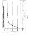
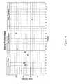
- Onemay then plot the mass squared over time, which should result in a straight line during the time fluid is infiltrating into the powder in the vial (see Figure 5 , that illustrates a typical response from the Washburn infiltration method to determine the material constant and contact angle of a fluid against a particulate material).
- the slopemay be calculated from that plot, which corresponds to the value of m 2 t in Equation 3. After the slope is calculated, one may solve for the material constant c.
- the Washburn method described abovewas used to determine the material constant of (i) a particulate material primarily composed of glass microspheres with a particle size distribution in which 10% of the particles have a particle size, i.e., diameter, of less than 50 microns, 50% are less than 70 microns, and 90% are less than 100 microns and (ii) a particulate material primarily composed of glass microspheres with calcium sulfate hemihydrate which is an angular, non-spheroid shape particle with a particle size distribution in which 10% of the particles have a particle size of less than 5 microns, 50% are less than 25 microns, and 90% are less than 70 microns.
- the resultsare given in Table 1.
- Particulate materialconsisting primarily of glass microspheres
- Particulate materialconsisting a 50/50 blend by bulk volume of glass microspheres with calcium sulfate hemihydrate Ingredient % by wt. % bulk volume Ingredient % by wt.
- a comparison of material constantsshows a significant difference between the two particulate formulations.
- the particulate material consisting primarily of glass microspheresexhibits a material constant almost six times greater than the particulate material formulation consisting of the 50/50 blend by bulk volume of glass microspheres and calcium sulfate hemihydrates. This difference suggests that the angular grains of the calcium sulfate hemihydrate impart a denser packed particulate material that leads to much smaller average capillary radii.
- the larger material constant of the particulate material consisting primarily of glass microspheressuggest a larger average capillary radius, allowing for a lower capillary pressure and thus would exhibit lower distortions on printed articles.
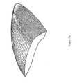
- Figures 6a and 6bmagnified images taken from an Olympus SZX12 microscope of both particulate material formulations illustrate the particle distribution of the two materials.
- Figure 6ais a magnified image of the particulate material consisting primarily of glass microspheres and a soluble filler as the secondary component.
- Figure 6bis a magnified image of the particulate material consisting of a 50/50 blend by bulk volume of glass microspheres and calcium sulfate hemihydrates with a soluble filler as the third component.
- the Washburn methodmay also be utilized to determine the contact angle the fluid binder forms with the particulate material, since the material constant is can be determined for each particulate formulation.
- the fluid binder formulation of Table 2was used to determine the contact angle the fluid has with each of the above particulate formulations of Table 1: Table 2 Fluid Binder Ingredients % by wt.
- Sartomer SR209Tetraethylene glycol dimethacrylate 57.50%
- Sartomer SR-506Isobornyl methacrylate 30.00%
- BYK UV 3500Surfactant 0.05%
- Table 3The contact angles given in Table 3 were determined using the fluid binder of Table 2 to infiltrate each of the particulate material samples in a vial.
- Table 3Particulate material consisting primarily of glass microspheres
- the fluid binderwets the particulate material consisting primarily of glass microspheres better than the formulation containing calcium sulfate hemihydrate because it exhibits a contact angle of zero with the former.
- Articles printed from the particulate material consisting of calcium sulfate hemihydrate along with glass microspheresexhibit distortions such as the cupping of flat rectangular articles as capillary forces pull particles inward in the printed area where fluid binder is applied.
- Articles printed from particulate material formulations consisting primarily of glass microspheres between 70-90% by weight, or 50-75% by bulk volumehave consistently resulted in articles with very little to no distortion from capillary forces.
- the soluble fillerprimarily helps to control the migration of binder through the particulate material, which controls bleed or pooling of fluid binder in selectively printed areas, and also provides extra strength and toughness to the final cured article.
- the soluble fillerhelps control binder migration of binder by dissolving into the fluid binder deposited in the selective areas to increase the viscosity of the fluid binder that decreases the rate of binder migration.
- Soluble fillers suitable for use with embodiments of the inventioninclude methyl methacrylate polymers, ethyl methacrylate polymers, butyl methacrylate polymers, polyvinylbutyral, and combinations thereof.
- a suitable soluble filleris a solid methacrylate polymer with a glass transition temperature between about 40 and about 60 degrees Celsius and a molecular weight from a range of about 100,000 to about 500,000 g/mol.
- a suitable soluble filleris a polymethylmethacrylate/ethyl methacrylate co-polymer resin such as ELVACITE 2014, available from Lucite International based in Cordova, TN.
- Another suitable resinis a butylmethacrylate/methylmethacrylate copolymer resin such as NEOCRYL B-723, available from NeoResins based in Wilmington, MA.
- the soluble fillermay be processed to achieve a particle size distribution where 10% of the particles are less than 20 to 30 microns, and 90% of the particles are less than 80 to 100 microns, and 50% of the particles are between 50 and 70 microns.
- the particulate materialmay be non-reactive such that it does not swell or dissolve in the fluid binder.
- the effect of a molecular weight of the soluble fillermay be measured with a Texture Analyzer TA-XT2i from Stable Micro System based in the United Kingdom.
- This instrumentmay be used to measure a three-point flexural strength of a bar 5 mm thick, 5.7 mm wide, and 50 mm long created from the application of fluid binder onto the particulate material on a three-dimensional printer, supported on a two-point span spaced at a distance of 40 mm.
- the force to break the test part with the force applied at the center of the 40 mm spanmay be used to calculate an estimate of flexural strength.
- the distance to break the test partis also recorded which may estimate the amount of strain the bar endures.
- DSM 15.03% MW200,000 g/mol NeoResins NeoCryl B723 wt. Kronos 2310 1.05% 1.05% 1.07% 1.07% 2.06% 1.05% 1.05% Titanium wt. wt. wt. wt. wt. wt. wt.
- the flexural test barswere printed on a Spectrum Z ® 510 Three Dimensional Printer available from Z Corporation in Burlington, MA modified to use a SM-128 piezoelectric jetting assembly along with an Apollo II Printhead Support Kit both available from FUJIFILM Dimatix based in Santa Clara, CA.
- the flexural test barswere printed applying the fluid binder listed on Table 5 through the SM-128 jetting assembly over the particulate material at a layer thickness of 100 microns.
- the fluidwas deposited selectively and uniformly at each layer to occupy 32% by volume of the flexural test part.
- the flexural test partswere allowed to solidify for 1 hour before they were extracted from the build bed of the Spectrum Z510 and placed in a 60°C oven for 12 hours to cure.
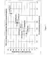
- Table 6summarizes flexural properties of the particulate material compositions that were measured. Referring to Figure 7 , a graphical representation of the results collected is provided. The results suggest that soluble fillers with molecular weights less than 100,000 g/mol exhibit lower flexural properties than soluble fillers with molecular weights greater than 100,000 g/mol.
- the particulate materialmay include pigments in a concentration of 0.5 - 5% by weight.
- Titanium dioxideis a pigment with a refractive index of 2.4 that may be used, but its listing as a possible IARC carcinogen makes it undesirable for use in an office environment.
- Zinc oxideis an alternative pigment with a refractive index of 2.0, and it is not listed as a carcinogen.
- Zinc oxideavailable from Sigma-Aldrich based in Milwaukee, WI, imparts the most neutral color over titanium dioxide.
- Other suitable pigmentsinclude zinc sulfide, barium sulfate, zirconium silicate, lead carbonate, and hollow borosilicate glass spheres.
- Pigmentsmay also be incorporated and bound into the insoluble filler or soluble filler, which may be advantageous to prevent the particulate material from exhibiting excessive dust and to agglomerate as the unbound pigments may adhere to the processing aids used to control the desired spreading characteristics, causing the particulate formulation to lose its desired flowability characteristics.
- OMNICOLOR UN0005 from Clariant based in Charlotte, NCis white colorant compound of pigment and a resin for injection molded plastics which can be use as an alternative pigment source where the pigment is bound in the resin, reducing the dustiness and maintaining the desired flowability characteristics while providing color.
- This colorant and other types of colorant commonly used in injection molding applicationsmay also be used to color the soluble filler, such as ELVACITE 2014, through melt processing to make a more uniform colored particulate formulation.
- DECOSOFT and DECOSILKare pigmented polyurethane and acrylic microbeads respectively from Microchem based in Erlenback, Switzerland commonly used to make colored or transparent, low gloss, soft-feel coatings. These products may be used as an insoluble filler to impart tougher material properties while imparting the desired color because of the pigment incorporated into the microbead product, thus decreasing the dust and maintaining the desired flowability characteristics.
- the transition metal catalystmay induce the decomposition of the organic hydroperoxide in the fluid binder to generate free radicals and to catalyze the absorption of oxygen for allyllic polymerization.
- Transition metalsare metal ions that have multiple oxidation states and can readily lose or gain electrons in the presence of oxidizing or reducing agents, respectively.
- Metal catalysts based on copper, iron, vanadium, manganese titanium, and cobaltare preferred, although other metal catalysts may be used.
- one suitable transition metal catalystincludes cobalt (II) octoate in 65% mineral spirits from Sigma-Aldrich based in St. Louis, Missouri.
- Other suitable metal catalystsinclude, e.g., cobalt (II) naphthenate, vanadium (II) octoate, manganese naphthenate, and combinations thereof.
- Processing aidsmay be used to affect particulate material spreading characteristics to achieve a desirable internal angle of friction (see discussion below) and to reduce capillary forces between the particulate material in contact with the fluid binder. Processing aids can further assist in reducing nuisance dust of the particulate material.
- Mineral oilis a typical processing aid that affects the flowability of the particulate material; it may be used from 0.01 % to 1% by weight in the particulate formulation. The particulate material remains substantially dry upon the inclusion of this small amount of mineral oil.
- Mineral oile.g., from Sigma-Aldrich, may provide a good balance of particulate cohesion and low plasticizing of the soluble filler without reducing capillary pressure.
- Hydrogenated hydrocarbon resinssuch as REGALREZ 1094 from Eastman based in Kingsport, TN, are tackifiers that may be used as processing aid to increase the viscosity of the mineral oil and may be 0.01 to 2% by wt of the particulate material.
- the hydrocarbon resinincreases the viscosity of the processing aid that imparts a unique cohesiveness and flowability characteristic, whereby the particulate material, under shear from a counter-rolling spreader rod, becomes a free-flowing powder. The desired cohesion is restored while at rest to resist dragging while successive layers are being spread.
- the increase in viscosityassists in the fracture of the inter-particle adhesive necks of fluid that the processing aids create to control flowability characteristics under shear; the adhesive necks of fluid then slowly reform while the particulate material is at rest.
- the inter-particular adhesive necks of fluid that lower viscosity processing aid impartsdo not fracture as easily under shear because the processing aids are allowed to flow more easily and faster to reform the inter-particular adhesive necks of fluid.
- processing aids suitable for use with embodiments of the inventioninclude, e.g., propylene glycol di(caprylate/caprate), petroleum jelly, propylene glycol, di-isobutyl phthalate, di-isononyl phthalate, polyalkyleneoxide modified heptamethyltrisiloxanes, polyalkyleneoxide modified polydimethylsiloxanes, secondary alcohol ethoxylates, hydrogenated hydrocarbon resins, and combinations thereof.
- a surfactantis a typical processing aid that may be used in conjunction with mineral oil to reduce the capillary forces between the particulate material in contact with the fluid binder by increasing the critical surface tension of the particulate material.
- Surfactantsmay be used in a range of 0 to 1% by weight of the particulate material.
- Silicone surfactantssuch as SILWET L-7608 or COATOSIL L-77 from General Electric Company based in Wilton, CT having a reported capability of reducing surface tension of water to less than 25 dynes/cm, may effectively reduce capillary forces between particles of the particulate material in contact with the non-aqueous fluid binder.
- Secondary ethoxylated alcohols hydrocarbon surfactantssuch as TERGITOL 15-S-7 and TERGITOL-15-S-5 from DOW based in Midland, MI, also may effectively reduce capillary forces between particles of the particulate material in contact with the non-aqueous fluid binder.
- the effect of the surfactant increasing the surface energy of the particulate materialmay be measured using the Washburn method describe earlier by infiltrating a particulate material formulation with a series of liquid solutions with varying surface tension values.
- the contact angles, ⁇are determined for each surface tension.
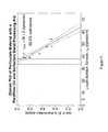
- the cos ⁇ valuesare plotted against the surface tension values to construct a Zisman plot.
- This testwas performed on the formulations listed in Table 7. See Figures 8 (particulate material with paraffinic oil processing aid) and 9 (particulate material with a paraffinic oil and surfactant blend processing aid).
- One preferred embodiment of a fluid binder suitable for Three Dimensional Printingincludes or consists essentially of: (meth)acrylate monomer 40 - 90 wt% (meth)acrylate oligomer 0 - 40 wt% allyl ether functional monomer/oligomer 5 - 25 wt% organic hydroperoxide 0.5 - 5 wt% accelerator 0 - 2 wt% surfactant 0 - 1 wt%
- the (meth)acrylate (i.e., methacrylate and/or acrylate) monomers and oligomersprovide the properties of strength and flexibility.
- Such monomers and oligomersmay be procured from Sartomer based in Exton, PA.
- the allyl ether monomer/oligomerprovides the oxidative drying of the binder on the surface of the article so that the surface is not tacky.
- Allyl ether monomersmay be procured from Perstorp based in Sweden.
- Suitable oligomers with allyl functionalitymay be obtained from Sartomer, who offers CN-9101 urethane allyl functional oligomer.
- Bomar Specialty Chemicals based in CToffers BXI-100, a poly-allyl-glycidyl-ether oligomer, another suitable allyl functional oligomer.
- the organic hydroperoxideis the free radical initiator for the anaerobic polymerization of the (meth)acrylate monomers and oligomer, and the aerobic polymerization of the allylic monomer/oligomer.
- a suitable organic hydroperoxideis cumene hydroperoxide available as LUPEROX CU90 from Arkema based in Philadelphia, PA.
- the transition metal catalystinduces the decomposition of the organic hydroperoxide, thus providing free radicals for subsequent reactions and catalyzes the absorption of oxygen at the surface.
- Another organic hydroperoxide suitable for use with some embodimentsis tert-butyl hydroperoxide, is available as T-HYDRO from Lyondell Chemical Company based in Houston Texas.
- the surfactantis a preferred additive in the formulation of the fluid binders used in Three Dimensional Printing to reduce the surface tension of the binder so that the surface tension is equal to or less than the critical surface tension of the particulate material, such that the contact angle of the fluid binder against the particulate material is less than 25°, but preferably closer to if not equal to 0°.
- Thisallows the fluid binder to wet out onto the particulate material without creating large capillary forces that may cause (i) fissuring at points where the printed area on the particulate material splits apart and (ii) balling where the fluid binder sits on the surface of the particulate material. Both of these occurrences may cause surface defects on the bottoms of flat surfaces of printed articles.
- Figure 10aillustrates an example of good wetting behavior with contact angles less than 25° when the binder has a surface tension at or below a critical surface tension of the particulate material and wets smoothly over the particulate material.
- the critical surface tension of the particulate materialmay be greater than 20 dynes/cm.
- Figure 10billustrates an example of poor wetting behavior with contact angles greater than 25° when the binder has a surface tension greater than the critical surface tension of the particulate material causing the binder to wet irregularly over the particulate material and creating fissures.
- a suitable surfactantis a polyether modified acryl functional polydimethylsiloxane surfactant available as BYK UV 3500 from BYK Chemie based in Hartford, CT. This surfactant is a wetting agent commonly used in UV curable coatings to ensure a smooth finish on substrates and, when used at 0.05% by weight in the fluid formulation, reduces the surface tension to about 25 +/- 1 dynes/cm.
- Other suitable surfactantsmay include fluorinated surfactants such as the ZONYL surfactants available from DuPont, which can reduce the surface tension of the fluid binder down to 20 dynes/cm.
- Fluid formulations of various embodiments of the instant inventionare somewhat similar to anaerobic adhesive formulations commonly known as "threadlockers” such as LOCTITE 290 from Loctite based in Rocky Hill, CT and which is disclosed by Krieble in U.S. Patent No. 2,895,950 assigned in 1957 to American Sealants Company based in Hartford, CT, incorporated herein by reference in its entirety. Aerobically curing formulations using allyl ethers are also known to the art, as described by Cantor et al. in U.S. Patent No. 5,703,138 assigned to Dymax Corporation, incorporated herein by reference in its entirety.
- FUJIFILM Dimatix based in Santa ClaraCA has a published application note describing the application of LOCTITE 290 adhesive through one of their piezo jetting assemblies to accurately deliver adhesive to a substrate.
- these formulationsdo not include a surfactant.
- the fluid adhesive products described in these referencesdo not have the proper surface tension requirements needed for proper wetting, if they were applied onto the particulate material as described in various embodiments of the instant invention. These materials are not intentionally designed to have a surface tension lower than that of the substrate to which they are to be applied, thereby achieving a contact angle of less than 25 degrees. This can be demonstrated by using the Washburn method with the following particulate formulation (Table 8) and binder formulations (Tables 9 and 10).
- Table 8Particulate material prepared with a mineral oil and surfacant processing aid Ingredient % by wt. % bulk volume MO-SCI GL0179 glass microspheres 83.85% ⁇ 66% Lucite Elvacite 2014 15.73% ⁇ 34% Sigma-Aldrich Light Mineral Oil 0.18% Nil DOW TERGITOL 15-S-5 0.18% Nil Sigma-Aldrich Cobalt Octoate, 65% in Mineral Spirits 0.06% Nil Table 9 Fluid Binder Ingredients % by wt.
- the high contact angle LOCTITE 290has on the particulate material formulation indicates that this product would not wet out properly onto the particulate material when applied during Three Dimensional Printing, and would create articles with rough, irregular bottom surfaces, having defects similar to the defects illustrated in Figure 10b .
- a fluid binderproperly formulated to have a surface tension lowered to at least 25 dynes/cm so that it has a contact angle less than 25° and close to, if not equal to 0° will wet out the powder properly, resulting in a smooth bottom facing surface with less edge curling distortion, as is exhibited in Figure 10a .
- Surfactantsmay be used in photocurable inkjet fluid formulation, as disclosed, for example, in U.S. Patent No. 6,433,038 to Tanabe , where surfactants are used to stabilize dyes and pigments in the disclosed fluid inkjet formulation.
- Huo et al.in an international patent application PCT/US2005/025074 disclose the use of surfactants to improve wettability of the fluid over non-porous plastic substrates and to control the dynamic surface tension of the fluid for faster meniscus reformation at the nozzle of a DOD device during jetting. These formulations do not use surfactants to decrease the capillary pressure exerted by the fluid when applied on a particulate material, as disclosed herein.
- FIG. 12Another exemplary formulation listed on Table 12 shows a particulate powder formulation with a lower critical surface tension than critical surface tensions of particulate formulations disclosed on Table 7.
- Figure 11is a Zisman plot of a particulate material including a tackifier processing aid.
- the surface tension of the fluid binderis essentially at the critical surface tension of the particulate material, and therefore results in a contact angle equal to 0°.
- the contact anglemay be greater than 0° and possibly less than 25° if the critical surface tension is 2 dynes/cm less than the surface tension of the binder. This upper limit of a contact angle is estimated from Equation 2 by dividing the critical surface tension of the solid by the surface tension of the fluid.
- the contact angle of the fluid binder against both of the particular material listed in Table 12was determined from the Washburn method to have an average cos ⁇ value of 1.02 +/- 0.05 at 99% confidence, which would result in a contact angle between 0° and 14° within the 99% confidence interval range of the cos ⁇ value.
- This fluid binderwhen applied to the particulate material disclosed in Table 12, results in proper wetting of the fluid binder over the particulate material to impart a smooth bottom finish, as illustrated in Figure 10a .
- Table 12Particulate Material Ingredients % by wt.
- kitsmay include various combinations of the substantially dry particulate material and a fluid binder described above.
- a kitmay include (i) a substantially dry particulate material comprising an insoluble filler, a soluble filler, and a transition metal catalyst, and (ii) a fluid binder including a (meth)acrylate monomer, at least one of an allyl ether functional monomer or an allyl ether functional oligomer, and an organic hydroperoxide.
- the fluid bindermay have a contact angle of less than 25° on the particulate material.
- the fluid bindermay include about 40% - 95% by weight of the (meth)acrylate monomer, about 5 - 25% by weight of the allyl ether functional monomer/oligomer, and about 0.5 - 5% by weight of the organic hydroperoxide.
- the fluid bindermay also include 0% - 1% by weight of surfactant.
- the fluid bindermay include a (meth)acrylate oligomer, e.g., about 10 - 40% by weight of the (meth)acrylate oligomer.
- the fluid bindermay also include a first accelerator such as dimethylacetoacetamide, e.g., up to about 2% by weight of the first accelerator.
- a 1 mm penetration hardening rate of the substantially dry particulate material upon application of the fluid bindermay be e.g., 0.01/min to 1.0 /min.
- the dry particulate materialmay include a pigment and/or a processing aid.
- An articlemay be defined by selectively printing the fluid binder over particulate material.
- the fluid binderincludes a (meth)acrylate monomer, a (meth)acrylate oligomer, an allyl ether functional monomer and/or oligomer, and organic hydroperoxide and, optionally, a first accelerator.
- the amount of binder deposited onto the particulate layercan range from 20% to 35% of the volume of the selectively printed area at a predetermined layer thickness between 50 to 175 microns, and more preferably between 75 and 125 microns.
- the particulate materialincludes a plurality of adjacent particles, comprising a transition metal catalyst and, at least one of an insoluble filler, a soluble filler, a pigment, a second accelerator, and a processing aid.
- the transition metal catalystinduces decomposition of the organic hydroperoxide to generate free radicals.
- the free radicalsinitiate anaerobic polymerization of the (meth)acrylate monomer and oligomer, and aerobic polymerization of the allyl ether functional monomer/oligomer.
- the complete polymerization, i.e., cure, of the articlemay take between about 30 minutes and about 6 hours to complete after the formation of a solid article, after all the layers of the article have been printed.
- the curinghappens substantially instantaneously, so that the printed article may be removed from the printer as soon as the printing is complete.
- Sanoin U.S. Patent Application Publication No. 2007/0007698 and U.S. Patent 7,300,613 , describes primarily the use of photocurable resins applied onto powder via a drop-on-demand printhead as well as two component curing strategies such as epoxy-amine thermosetting resins; Kramer, et al, in U.S. patent 7,120,512 assigned to Hewlett-Packard in Houston, TX, also disclose the use of photocurable resins applied over powder using a drop-on-demand printhead, as well as alternative embodiments of two component systems.
- photocurable fluid bindersare generally not suitable for Three Dimensional Printing because of the instantaneous curing leading to immediate shrinkage, which leads to the first 2 to 10 layers of selectively printed areas to curl and warp out of the plane of the build bed to be eventually dragged and displaced in or completely off the build bed.
- Sanosuggests the use of photocurable resins that polymerize via ring opening mechanism such as epoxides and oxetanes to limit the degree of shrinkage.
- ring opening mechanismsuch as epoxides and oxetanes
- Patel, et al.have international applications published through the World Intellectual Property Organization (publication numbers WO 03/016030 and WO 02/064354 A1 ) with Vantico as the assignee (now owned by Hunstman based in TX) that describe the use of various embodiments of applying photocurable resins and two-component resins.
- Three Dimensional Printing apparatuses and methods using ultraviolet cureare disclosed by Yamane, et al, in U.S. Patent 5,149,548 assigned to Brother Kogyo Kabushiki Kaisha in Japan, which describes the use of a two part curable resin utilizing microcapsules encapsulating a curing agent deposited with a drop-on-demand printhead. The microcapsules are broken upon exposure to ultraviolet light.
- a usertypically waits the above-indicated time after the article is printed before removing the article from the printer.
- the articlemay be heated to a range of about 40°C to about 100°C to accelerate the aerobic cure at the surface of the article.
- Heatmay be supplied through convection, conduction, infra-red radiation, microwave radiation, radio-wave radiation, or any other suitable method.
- the cure rate between a photocurable binder and the current embodimentmay be illustrated by comparing the hardening rate by measuring the force it takes to penetrate 1 mm into the surface of a mass mixture consisting of fluid binder and particulate material with a 0.5 inch spherical probe.
- Such a test of a 1 mm penetration hardening ratemay be performed with a Texture Analyzer TA-XT2i with a P/0.5S stainless steel spherical probe from Stable Micro System based in the United Kingdom.
- the following particulate material system used in this testis listed in Table 13. Table 13 Ingredient % by wt. % by wt. % by wt.
- the binder formulation used in this testis given in Table 14.
- Sartomer SR209Tetraethylene glycol dimethacrylate 57.50% 57.45% 69%
- Sartomer SR-506Isobornyl methacrylate 30.00% 30.00% 29%
- the hardness developmentwas measured at 15 minute intervals using the spherical probe to measure the force to penetrate 1 mm into the mixture contained in the polypropylene dish.
- the mixture in the polypropylene dishwas exposed to 30 seconds of ultraviolet light using a RC250B Flash Curing unit from XENON Corporation based in Wilmington, MA.
- the hardness development of the photocurable exampleis the plot of the penetration force at 30 seconds.
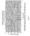
- Figure 12shows the typical development response collected, i.e., of particulate material A mixed with a fluid binder 1. The natural logarithm of the force is taken to determine the hardening rate from the slope of the transformed data before the force plateaus.
- a transformed plot of Figure 12plots the natural logarithm of the force measured against time.
- Table 16lists hardness rates determined from the data collected.
- the photocurable exampleexhibits a hardness development rate on the order of 1000X greater than the current embodiment.
- This hardness rateis related to the rate of conversion of double bonds on the (meth)acrylate monomer.
- the conversion of the carbon-to-carbon double bonds into single carbon-to-carbon bonds with other monomersdecreases the amount of free volume in the fluid binder as it polymerizes.
- the instantaneous conversion of monomers into a polymer in a photocurable fluid bindercauses an instantaneous shrinkage upon exposure to ultraviolet light, which forces selectively printed areas to curl and warp out of the plane of the build bed, causing the selectively printed areas to be dragged and displaced as successive layers are spread.
- the slower hardening rate of some embodimentsrelates to a slower conversion rate and where selectively printed areas do not exhibit the immediate distortion of curling and warping out of the plane of the build bed to successively print layer upon layer without dragging or displacement of features on an article.
- the 1 mm penetration hardening rateis between 0.01/minute and 1.0/minute.
- Strength development of the current embodimentcan also be measured using the earlier described Texture Analyzer to measure a three-point flexural strength of a bar 5 mm thick, 5.7 mm wide, and 50 mm long, supported on a two-point span spaced at a distance of 40 mm.
- the force to break the test part when applied at the center of the 40 mm spancan be used to calculate an estimate of flexural strength.
- the current embodimentcan typically exhibit flexural strengths between 10 and 20 MPa after 60 minutes, and 15 to 25 MPa and greater after 120 minutes in the build bed after the last layer of the article completed printing. This strength represents mostly the anaerobic strength development that occurs within the article, while the aerobic curing occurring within 200 microns from the surface of the article is still ongoing at a slower rate.
- the articlemay exhibit a tacky surface at 60 minutes, but may exhibit a durable and handle-able strength.
- Figure 14shows the typical response of aerobic cure when measured using the test part 1500 shown in Figure 15 .
- the particulate material and fluid binder formulations listed in Table 17were used to conduct this test.
- Anaerobic polymerizationoccurs where no oxygen is present in the interior portions of the three dimensional articles being created, e.g., at depths greater than about 0.2 mm from the surface of the printed article. Aerobic polymerization occurs at the surface and at a depth into which oxygen is capable of diffusing.
- a simplified kinetic mechanism for free radical polymerizationmay be represented by the following steps:
- Anaerobic radical generationoccurs when the hydroperoxide is decomposed by a transition metal capable of oxidizing and reducing its valence charge, such as cobalt. This is represented by the following mechanism: Co +2 +ROOH ⁇ Co +3 +RO ⁇ +OOH
- the oxidized Co +3 ioncan then be reduced to Co +2 via Co +3 +ROOH ⁇ Co +2 +ROO ⁇ +H + and/or Co +3 +OH - ⁇ Co +2 + ⁇ OH
- RO ⁇ , ROO ⁇ , and ⁇ OHare radicals species that can react with a monomer or oligomer species and start polymerization.
- the RO ⁇ and ⁇ OH radicalsare more efficient under anaerobic conditions with (meth)acrylate functional monomers and oligomers.
- Oxygenmay react with these radical species to form weak radicals, or may be scavenged by free radical inhibitors that use oxygen to function, such as the most common type of inhibitors based on hydroquinones.
- the anaerobic polymerizationcontinues to propagate under anaerobic conditions until terminated.
- Transition metals like cobaltalso assist in the auto-oxidative drying (aerobic curing) of the allyl ether functional monomers or oligomers by increasing oxygen absorption at the surface.
- a radical centeris created at the place of allylic hydrogen, where the hydrogen is abstracted by radicals species from the organic hydroperoxide; or with the assistance of cobalt, the allylic hydrogen is abstracted by oxygen.
- the radical center of the allyl groupnow reacts further with oxygen to make a peroxide radical.
- the peroxide radical speciescan add to double bonds of (meth)acrylate functional groups or other allyl groups, terminate with other radicals, or abstract further hydrogen atoms from monomers, oligomers, or the propagating polymer.
- the result of this aerobic mechanismis a highly crosslink polymer network that forms a non-tacky surface.
- compositionsrelate to control of the flow properties of the build material in Three Dimensional Printers.
- the three principal methodsare the addition of liquid "processing aids," control of grain size distribution, and the addition of solid fillers that contribute to the frictional behavior of the build material.
- Many candidate materialshave been disclosed previously, for example, in U.S. Patent Publication Number 2005/0003189 , the disclosure of which is incorporated herein by reference in its entirety.
- Some mechanical properties of dry particulate build materialsare disclosed in the following discussion that are particularly suited for use in Three Dimensional Printing, especially in contrast to other formulations of similar materials for other uses that do not require special flow characteristics of the raw materials.
- a method that may be used to quantify a particulate material's suitability for Three Dimensional Printingincludes placing 1 liter in bulk volume of a particulate material in a metal cylinder with an inside dimension of 6.1 inches, and inside height of 6.2 inches so that the height of the powder is between 2.5 to 3.0 inches when the cylinder is capped with a transluscent cover and laid on its side (i.e., the height of the cylinder is horizontal). The drum is then slowly rolled with a rotational velocity of 2.5 rotations/min +/- 0.5 rotations/min until the powder reaches an angle where it avalanches upon itself.
- the angle, ⁇is the internal angle of friction that particulate material has under these particular test conditions at a room temperature between 65 to 75°F.
- Various particulate materials known to have good and bad spreading characteristicsare compared using this test method, and desirable range of internal angles of friction were determined.
- Table 18summarizes the particulate material compositions that were measured. Referring to Figure 16 , a graphical representation of the results collected is provided.
- Figures 17a and 17bcompare surface finish scans from a VIKING laser profilometer from Solarius. As one may expect, a particulate material with an internal angle of friction that is between 40° and 70° ( Figure 17a ) provides a smoother finish than a particulate material with an internal angle of friction greater than 70° ( Figure 17b ) where the powder is too cohesive to spread an even layer of particulate material, resulting in an article that has very rough and uneven surface finish.
- Figure 17cis a CAD drawing of the formed part illustrated in Figures 17a and 17b .
- Figures 18a and 18bcompare surface finish scans from a VIKING laser profilometer from Solarius. As one may expect, a particulate material with an internal angle of friction that is between 40° and 70° ( Figure 18a ) provides a smoother finish than a particulate material with an internal angle of friction less than 40° ( Figure 18b ) where the powder is too flowable and unable to resist the spreading forces causing previous printed layers to be displaced, resulting in an article that has a rough and uneven surface finish, or even artifacts missing from the surface of the article because they were displaced.
- Figure 18cis a CAD drawing of the formed part illustrated in Figures 18a and 18b .
- This testis a fairly useful technique for identifying relative performance properties between different candidate materials.
- the preferred method for evaluating flow properties of candidate build materials during formal optimization after the initial selection periodis to test samples of the material on a working three dimensional printer. Certain pathological geometries are known to those experienced in the art, and they can be evaluated either qualitatively or quantitatively.
- One particularly useful part for observing stability during spreadingis a flat plate studded with pegs that are oriented downward during the build. During printing, the earliest layers addressed are a series of disconnected patches that are relatively free to shift in the build material. After these have been formed, a plate is printed that joins all of the pegs together in a single object. One can easily examine whether the pegs are uniform and straight, and one can evaluate the quality of spreading on that basis.
- compositions and parameters listed hereinare meant to be exemplary and actual compositions and parameters depend upon the specific application for which the methods and materials of the present invention are used. It is, therefore, to be understood that the foregoing embodiments are presented by way of example only and that, within the scope of the appended claims and equivalents thereto, the invention may be practiced otherwise than as specifically described.
Landscapes
- Engineering & Computer Science (AREA)
- Chemical & Material Sciences (AREA)
- Materials Engineering (AREA)
- Manufacturing & Machinery (AREA)
- Ceramic Engineering (AREA)
- Civil Engineering (AREA)
- Composite Materials (AREA)
- Structural Engineering (AREA)
- Mechanical Engineering (AREA)
- Physics & Mathematics (AREA)
- Optics & Photonics (AREA)
- Compositions Of Macromolecular Compounds (AREA)
Abstract
Description
- This application claims priority to
U.S. Provisional Patent Application Serial No. 60/873,730, filed December 8, 2006 - This invention relates generally to rapid prototyping techniques and, more particularly, to a three-dimensional printing material and method using a peroxide cure.
- The field of rapid prototyping involves the production of prototype articles and small quantities of functional parts, as well as structural ceramics and ceramic shell molds for metal casting, directly from computer-generated design data.
- Two well-known methods for rapid prototyping include a selective laser sintering process and a liquid binder Three Dimensional Printing process. These techniques are similar, to the extent that they both use layering techniques to build three-dimensional articles. Both methods form successive thin cross-sections of the desired article. The individual cross-sections are formed by bonding together adjacent grains of a granular, (i.e., particulate) material on a generally planar surface of a bed of the granular material. Each layer is bonded to a previously formed layer at the same time as the grains of each layer are bonded together to form the desired three-dimensional article. The laser-sintering and liquid binder techniques are advantageous because they create parts directly from computer-generated design data and can produce parts having complex geometries. Moreover, Three Dimensional Printing may be quicker and less expensive than machining of prototype parts or production of cast or molded parts by conventional "hard" or "soft" tooling techniques that can take from a few weeks to several months, depending on the complexity of the item.
- An early Three Dimensional Printing technique, described in
U.S. Patent No. 5,204,055 , incorporated herein by reference in its entirety, describes the use of an ink-jet style printing head to deliver a liquid or colloidal binder material to sequentially applied layers of powdered material. The three-dimensional ink-jet printing technique or liquid binder method involves applying a layer of a powdered material to a surface using a counter-roller. After the powdered material is applied to the surface, the ink-jet printhead delivers a liquid binder in a predetermined pattern to the layer of powder. The binder infiltrates into gaps in the powder material and hardens to bond the powder material into a solidified layer. The hardened binder also bonds each layer to the previous layer. After the first cross-sectional portion is formed, the previous steps are repeated, building successive cross-sectional portions until the final article is formed. Optionally, an adhesive may be suspended in a carrier that evaporates, leaving the hardened adhesive behind. The powdered material may be ceramic, plastic or a composite material. The liquid binder material may be organic or inorganic. Typical organic binder materials used are polymeric resins or ceramic precursors, such as polycarbosilazane. Inorganic binders are used where the binder is incorporated into the final articles; silica is typically used in such an application. - Some groups, e.g., Fuji, have performed ultraviolet cure of acrylate binders over particulate material. Acrylate binders provide several advantages. First of all, they are curable by ultraviolet (UV) light, thereby enabling a faster forming process then is possible with other typical curing methods. Secondly, they allow the formation of articles having surfaces with plastic appearances, thereby enabling more realistic modeling of various objects. Finally, because acrylate binders are essentially solids, no evaporation takes place after the binders are printed, thereby allowing the formation of stable, tough structures.
- The fast curing mechanism of UV initiation of (meth)acrylate polymerization may cause excessive distortion in free flowing particulate material, resulting in curling of the printed part, which may make the printing of parts having a thickness greater than 1 millimeter exceedingly difficult. To reduce curling due to fast curing, a first printed layer may be formed on a glass build plate, adhering thereto.
- In an embodiment of the invention, strong parts may be made by Three Dimensional Printing over particulate material build material without a need for infiltration. Typical existing printing processes include a post-processing infiltration step to increase the strength of the printed article. Articles printed with the peroxide-containing binders described herein have strengths comparable to that of infiltrated articles, e.g., about 20 MPa, thereby eliminating a need for the infiltration step.
- The fast curing mechanism of UV initiation of (meth)acrylate polymerization may cause curling and distortions to occur immediately from shrinkage due to the instantaneous decrease in free volume from the conversion of carbon-to-carbon double bonds of the individual (meth)acrylate monomer to single carbon-to-carbon bonds to another (meth)acrylate monomer. This may hinder the production of articles thicker than 1 mm from free-flowing particulate build materials, as articles tend to be destroyed in the process. The slower curing mechanism of the peroxide initiation according to the invention slows down the rate of carbon-to-carbon double bond conversion into single bonds and thus reduces the immediate curling and distortion. Moreover, the acrylate-containing binder cures upon contact with the particulate material, thus providing the advantage of a stable two-component product.
- Both aerobic curing and anaerobic curing may be employed in embodiments of the invention. In contrast to existing processes where amines may be used as oxygen scavengers solely in ultraviolet curing, allyl ethers, as described herein, may be employed as oxygen scavengers in both ultraviolet curing and peroxide initiation.
- In an embodiment, the invention features a powder material system for Three Dimensional Printing including a substantially dry particulate material that includes an insoluble filler, a soluble filler, and a transition metal catalyst. The dry particulate material is suitable for use in Three Dimensional Printing to form an article having a plurality of layers, the layers including a reaction product of the particulate material and a non-aqueous fluid that contacts the particulate material during Three Dimensional Printing.
- One or more of the following features may be included. The particulate material may possess an internal angle of friction greater than 40° and less than 70°. The particulate material possess a critical surface tension greater than 20 dynes/cm. The particulate material may include about 50% - 90% by weight of the insoluble filler, about 10 - 50% by weight of the soluble filler, and about 0.01 - 0.5 % by weight of the transition metal catalyst.
- The insoluble filler may include or consist essentially of solid glass microspheres, hollow glass microspheres, solid ceramic microspheres, hollow ceramic microspheres, potato starch, tabular alumina, calcium sulfate hemihydrate, calcium sulfate dihydrate, calcium carbonate, ultra-high molecular weight polyethylene, polyamide, poly-cyclic-olefins, polyurethane, polypropylene and combinations thereof.
- The soluble filler may include or consist essentially of methyl methacrylate polymers, ethyl methacrylate polymers, butyl methacrylate polymers, polyvinylbutyral, and combinations thereof. The soluble filler may have a molecular weight between 100,000 g/mol and 500,000 g/mol.
- The transition metal catalyst may include or consist essentially of cobalt (II) octoate, cobalt (II) naphthenate, vanadium (II) octoate, manganese naphthenate and combinations thereof.
- The particulate material may include a pigment, e.g., about 0.5 to 5% by weight. The pigment may include or consist essentially of zinc oxide, zinc sulfide, barium sulfate, titanium dioxide, zirconium silicate, lead carbonate, and hollow borosilicate glass spheres.
- The particulate material may include a processing aid, e.g., about 0.01 - 2.0 % by weight of the processing aid. The processing aid may include or consist essentially of mineral oil, propylene glycol di(caprylate/caprate), petroleum jelly, propylene glycol, di-isobutyl phthalate, di-isononyl phthalate, polyalkyleneoxide modified heptamethyltrisiloxanes, polyalkyleneoxide modified polydimethylsiloxanes, secondary ethoxylated alcohols, fluorinated hydrocarbons, saturated hydrocarbon resin tackifiers, and combinations thereof.
- In another aspect, the invention features a kit including a substantially dry particulate material including an insoluble filler, a soluble filler, and a transition metal catalyst. The kit also includes a fluid binder including a (meth)acrylate monomer, an allyl ether functional monomer and/or oligomer, and organic hydroperoxide.
- One or more of the following features may be included. The fluid binder may have a contact angle of less than 25° on the particulate material. The fluid binder may include about 40% - 95% by weight of the (meth)acrylate monomer, about 5 - 25% by weight of the allyl ether functional monomer/oligomer, and about 0.5 - 5% by weight of the organic hydroperoxide. The fluid binder may also include 0 - 1% by weight of surfactant. The fluid binder may include a (meth)acrylate oligomer, e.g., about 10 - 40% by weight of the (meth)acrylate oligomer. The fluid binder may include a first accelerator, e.g., up to about 2% by weight of the first accelerator. The first accelerator may include dimethylacetoacetamide.
- A 1 mm penetration hardening rate of the substantially dry particulate material upon application of the fluid binder is selected from a range of 0.01/min to 1.0 /min. The dry particulate material may include a pigment and/or a processing aid.
- In yet another aspect, a method for forming an article by Three Dimensional Printing includes the step of providing a substantially dry particulate material including a plurality of adjacent particles, the particulate material comprising a transition metal catalyst. A fluid binder is applied to at least some of the plurality of particles in an amount sufficient to bond those particles together to define at least a portion of the article, the fluid binder including a (meth)acrylate monomer, a (meth)acrylate oligomer, an allyl ether functional monomer and/or oligomer, and organic hydroperoxide.
- One or more of the following features may be included. The transition metal catalyst may induce decomposition of the organic hydroperoxide to generate free radicals and the free radicals initiate anaerobic polymerization of the (meth)acrylate monomer and oligomer, and aerobic polymerization of the allyl ether functional monomer/oligomer.
- The fluid binder may include a first accelerator. The particulate material may include an insoluble filler, a soluble filler, a pigment, and/or a processing aid.
- The following drawings are not necessarily to scale, emphasis instead being placed generally upon illustrating the principles of the invention. The foregoing and other features and advantages of the present invention, as well as the invention itself, will be more fully understood from the following description of exemplary and preferred embodiments, when read together with the accompanying drawings, in which:
Figure 1 is a schematic view of a first layer of a mixture of particulate material of an embodiment of the invention deposited onto a movable surface of a container on which an article is to be built, before any fluid has been delivered;Figure 2 is a schematic view of an ink-jet nozzle delivering a fluid to a portion of the layer of particulate material ofFigure 1 in a predetermined pattern;Figure 3 is a schematic view of a final article of an embodiment of the invention enclosed in the container, the article made by a series of steps illustrated inFigure 2 and embedded in the loose unactivated particles;Figure 4 is a schematic view of the final article ofFigure 3 ;Figure 5 is a graph illustrating a typical response from the Washburn infiltration method to determine the material constant and contact angle of a fluid against a particulate material;Figure 6a is a magnified image of the particulate material consisting primarily of glass microspheres and a soluble filler as the secondary component;Figure 6b is a magnified image of the particulate material consisting of a 50/50 blend by bulk volume of glass microspheres and calcium sulfate hemihydrates with a soluble filler as the third component;Figure 7 is a plot of flexural strength and flexural distance at break of particulate materials using soluble fillers with varying molecular weights.Figure 8 is a Zisman plot of a particulate material using a mineral oil processing aid;Figure 9 is a Zisman plot of a particulate material using a combination of mineral oil and a secondary ethoxylated alcohol surfactant as a processing aid;Figures 10a and10b are laser profilometer images comparing the effect of proper and poor binder wetting on the bottom surfaces of articles;Figure 11 is a Zisman plot of a particulate material using a combination of a saturated hydrocarbon resin and mineral oil as a processing aid;Figure 12 is a graph illustrating a hardness development response of a particulate material and a fluid binder;Figure 13 is the transformed plot ofFigure 11 , plotting the natural logarithm of the force measured against time;Figure 14 is a diagram illustrating the aerobic cure response time of thin-walled articles;Figure 15 is a schematic diagram of a test part used to determine aerobic cure response;Figure 16 is a graph illustrating the internal friction angle of various powders;Figures 17a and17b are laser profilometer images comparing the effect of particulate materials with high internal angle of friction on finished article properties;Figure 17c is a CAD drawing of the par portion printed inFigures 17a and17b ;Figure 18a and18b are laser profilometer images comparing the effect of particulate material with low internal angle of friction on finished article properties; andFigure 18c is a CAD drawing of the part portion printed inFigures 18a and18b .- Referring to
Figure 1 , in accordance with a printing method using the materials system of the present invention, a layer or film of aparticulate material 20, i.e., an essentially dry, and free-flowing powder, is applied on a linearlymovable surface 22 of acontainer 24. The layer or film ofparticulate material 20 may be formed in any suitable manner, for example using a counter-roller. Theparticulate material 20 applied to the surface includes an insoluble filler material, a soluble filler material, and a transition metal catalyst. Theparticulate material 20 may also include a pigment and/or a processing aid material. - Referring to
Figure 2 , an ink-jet style nozzle 28 delivers afluid binder 26 to at least aportion 30 of the layer or film of theparticulate mixture 20 in a two-dimensional pattern. Thefluid binder 26 delivered to theparticulate material 20 includes a (meth)acrylate functional monomer, an allylic functional monomer/oligomer, and an organic hydroperoxide. Thefluid binder 26 may also include a surfactant, an accelerator, and/or a (meth)acrylate functional oligomer. According to the printing method, thefluid binder 26 is delivered to the layer or film ofparticulate material 20 in any predetermined two-dimensional pattern (circular, in the figures, for purposes of illustration only), using any convenient mechanism, such as a drop-on-demand (DOD) printhead driven by software in accordance with article model data from a computer-assisted-design (CAD) system. - The
first portion 30 of the particulate material activates thefluid binder 26, causing the fluid binder to initiate polymerization into a solid that adheres together the particulate mixture to form a conglomerate of the particulate material 20 (powder) andfluid binder 26. The conglomerate defines an essentially solid circular layer that becomes a cross-sectional portion of an intermediate article 38 (see, e.g.,Figures 3 and 4 ). As used herein, "activates" is meant to define a change in state in thefluid binder 26 from essentially stable to reactive. This definition encompasses the decomposition of the organic hydroperoxide in thefluid binder 26 once in contact with the transition metal in theparticulate material 20. When the fluid initially comes into contact with the particulate mixture, it immediately flows outwardly (on a microscopic scale) from the point of impact by capillary suction, dissolving the soluble filler within a time period, such as 30 seconds to one minute. A typical droplet of fluid binder has a volume of about 50 picoliters (pl), and spreads to a diameter of about 100 micrometer (µm) after coming into contact with the particulate mixture. As the fluid binder dissolves the soluble filler, the fluid viscosity increases dramatically, arresting further migration of the fluid from the initial point of impact. Within a few minutes, the fluid with soluble filler dissolved therein flows and adheres to the insoluble filler, forming adhesive bonds between the insoluble filler particulate material. The fluid binder is capable of bonding together an amount of the particulate mixture that is several times the mass of a droplet of the fluid. As the reactive monomers/oligomer of the fluid binder polymerize, the adhesive bonds harden, joining the insoluble filler particulate material and, optionally, pigment into a rigid structure, which becomes a cross-sectional portion of thefinal article 40. - Any
dry particulate mixture 32 that was not exposed to the fluid remains loose and free-flowing on themovable surface 22. The dry particulate mixture is typically left in place until formation of theintermediate article 38 is complete. Leaving the dry, loose particulate mixture in place ensures that theintermediate article 38 is fully supported during processing, allowing features such as overhangs, undercuts, and cavities to be defined and formed without the need to use supplemental support structures. After formation of the first cross-sectional portion of theintermediate article 38, themovable surface 22 is indexed downwardly, in an embodiment, and the process is repeated. - Using, for example, a counter-rolling mechanism, a second film or layer of the particulate mixture is then applied over the first layer, covering both the rigid first cross-sectional portion, and any proximate loose particulate mixture. A second application of fluid binder follows in the manner described above, dissolving the soluble filler and forming adhesive bonds between at least a portion of the previous cross-sectional formed portion, the insoluble filler particulate material, and, optionally, pigment of the second layer, and hardening to form a second rigid cross-sectional portion added to the first rigid cross-sectional portion of the final article. The
movable surface 22 is again indexed downward. - The previous steps of applying a layer of particulate mixture, including the soluble filler, applying the fluid binder, and indexing the
movable surface 22 downward are repeated until theintermediate article 38 is completed. Referring toFigure 3 , theintermediate article 38 may be any shape, such as cylindrical. At the end of the process, only atop surface 34 of theintermediate article 38 is visible in thecontainer 24. Theintermediate article 38 is typically completely immersed in a surroundingbed 36 of dry and loose particulate material. Alternatively, an article could be formed in layers upward from an immovable platform, by successively depositing, smoothing, and printing a series of such layers. - Referring to
Figure 4 , the dry and loose particulate material may be removed from theintermediate article 38 by pressurized air flow or a vacuum. After removal of the dry and loose particulate material from theintermediate article 38, a post-processing treatment may be performed, such as heating in an oven, painting, etc. to define afinal article 40, having the same shape asintermediate article 38, but with additional desired characteristics, such as a smooth surface appearance, neutral chroma, high lightness, toughness, strength, and flexibility. - One preferred embodiment of a particulate material suitable for Three Dimensional Printing, i.e., a substantially dry particulate material, includes or consists essentially of:
insoluble filler 50 - 90 wt% soluble filler 10 - 50 wt% pigment 0.0-5 wt% transition metal catalyst 0.01 - 1 wt% processing aids 0.01-2.0 wt% - A preferred particle size, i.e., diameter, of components of the particulate material is less than about 125 microns and greater than about 30 microns.
- The insoluble filler provides dimensional stability and adhesion for strength of an article formed from the particulate material. One suitable insoluble filler for use with embodiments of the invention is glass microspheres. The glass microspheres may be made from borosilicate glass with an index of refraction of 1.5 and may be spherical with a particle size distribution ranging from greater than about 20 microns to less than about 125 microns, more preferably between 40 and 90 microns. The glass microspheres may be treated with an amino-silane so that the microsphere surface may have an amine functionality and provide better adhesion to a (meth)acrylate based binder. An example of such glass spheres is SPHERIGLASS 2530 CP03, available from PQ Corporation based in Valley Forge, PA. This supplier also offers another glass microsphere product, T-4 SIGN BEADS, having an index of refraction of 1.9 that offers better light scattering to create a more neutral and lighter color than that of SPHERIGLASS 2530 CP03. Another suitable borosilicate glass bead product with an index of refraction of 1.5, but more translucent than Spheriglass 2530 CP03, is GL0179 from Mo-Sci Specialty products, LLC based in Rolla, MO. The clearer product imparts a more neutral color to articles than both the SPHERIGLASS and T-4 SIGN BEAD products, which may be desirable for attaining a wider color gamut.
- Various types of insoluble fillers suitable for use with embodiments of the invention include solid glass spheres, hollow glass spheres, solid ceramic spheres, hollow ceramic spheres, potato starch, tabular alumina, calcium sulfate hemihydrate, calcium sulfate dehydrate, calcium carbonate, ultra-high molecular weight polyethylene, polyamide, poly-cyclic-olefins, polyurethane, polypropylene, and combinations thereof.
- It may be preferable that the insoluble filler consist mostly of spherical shaped particles with a particle size distribution with 10% less than 30 to 40 microns, with 90% less than 90 to 125 microns, with 50% between 50 to 70 microns. Angular, non-spheroid shaped particles with wide particle size distributions with 10% less than 3 to 30 microns, with 90% less than 60 to 90 microns, and with 50% of the particles between 20 to 60 microns are to be avoided or used less than 10% by weight in the particulate material in order to provide low capillary pressure which in turn lowers the amount of distortion. The addition of angular shaped particles may decrease the average capillary radius of the particulate material thus increasing capillary pressure and increasing distortion of the final article.
- Capillary pressure may be described by
Equation 1 below, which is derived into a simple form from the equation of Young and Laplace:
where Δp is the capillary pressure, which is the pressure difference across the fluid interface, γlv is the surface tension at the liquid-vapor interface of the fluid, r is the average radius of the capillaries , and θ is the contact angle at the fluid-solid interface. - The contact angle,θ, is the angle of contact between a liquid and solid. A contact angle of 0° suggest that the fluid will spontaneously wet the entire surface of the solid to which it is applied, while a contact angle greater than 90° suggests that the fluid will not spontaneously spread and wet the surface of the solid to which it is applied. Spontaneously used herein is in reference to thermodynamic equilibrium, and does not denote an instance of time. The contact angle may be defined by the Young and Dupré equation:

whereγsv is the surface energy at the solid and vapor interface, andγsl is the surface energy at the solid and liquid interface. The difference ofγsv-γsl in the numerator ofEquation 2 may be defined as the adhesion tension of the solid at the solid-liquid-vapor interfaces. It may be desirable to have this adhesion tension greater than or equal to the surface tension of the fluid at the liquid-vapor interface. The adhesion tension may be related to the surface characteristic defined as the critical surface tension by Zisman, which is described in the following paragraphs. - One can see from
Equation 1 that capillary pressure increases if the average radius of the capillaries decreases and/or if the contact angle increases through an increase of the fluid's surface tension, and/or the adhesion tension of the solid decreases. This effect of capillary pressure infiltrating a porous medium may be measured by the Washburn infiltration method. The Washburn equation describes the time a fluid takes to infiltrate into and through porous medium. The Washburn equation is often used in the following form:
whereθ is the contact angle at the liquid-solid interface, m is the mass of fluid, t is time, η is the viscosity of the fluid,ρ is the density of the fluid, and c is a material constant. - The material constant c may be determined by infiltrating a porous medium with a very low surface tension fluid that will have a contact angle of 0° against the solid surface of particles comprising the porous medium. n-Hexane is a common fluid used for such purposes, having a surface tension of 18 dynes/cm; it is assumed to have a contact angle of 0° against most solid surfaces. This makes the value of cosθ equal to 1 in
Equation 3, thereby making it possible to solve for the material constant c since the fluid properties of n-hexane are known. This leaves one to measure the rate of mass increase of the fluid infiltrating the porous medium over time. This mass-time response may be measured by use of a Krüss Processor Tensiometer K100 with accessories for Washburn contact angle measurement, available from KRUSS USA based in Mathews, NC, or by use of aKSV Sigma 70 Tensiometer from KSV Instruments USA based in Monroe, CT. With these instruments, a vial of powder is prepared. The vial is perforated at a bottom portion, with a piece of porous filter paper preventing the powder from pouring through the perforated bottom. The vial filled with powder is attached to a microbalance, and the bottom of the vial is brought into contact to the surface of the fluid, in this case n-hexane. Software records the mass increase of the vial over time from the microbalance as the fluid is drawn into the powder in the vial largely by capillary pressure. One may then plot the mass squared over time, which should result in a straight line during the time fluid is infiltrating into the powder in the vial (seeFigure 5 , that illustrates a typical response from the Washburn infiltration method to determine the material constant and contact angle of a fluid against a particulate material). The slope may be calculated from that plot, which corresponds to the value of
Equation 3. After the slope is calculated, one may solve for the material constant c. - The material constant c is sensitive to the packing density of the powder in the vial in which it is prepared, so it is preferable to use a method that consistently provides the same packing density in the vial for each test. It is theorized that the material constant has the following relationship:

where r is the average capillary radius of the porous medium, and n is the number of capillary channels. Loosely packed powder will have a larger average capillary radius increasing the material constant, and, conversely, densely packed powder will have smaller average capillary radius decreasing the material constant. - The Washburn method described above was used to determine the material constant of (i) a particulate material primarily composed of glass microspheres with a particle size distribution in which 10% of the particles have a particle size, i.e., diameter, of less than 50 microns, 50% are less than 70 microns, and 90% are less than 100 microns and (ii) a particulate material primarily composed of glass microspheres with calcium sulfate hemihydrate which is an angular, non-spheroid shape particle with a particle size distribution in which 10% of the particles have a particle size of less than 5 microns, 50% are less than 25 microns, and 90% are less than 70 microns. The results are given in Table 1.
Table 1 Particulate material consisting primarily of glass microspheres Particulate material consisting a 50/50 blend by bulk volume of glass microspheres with calcium sulfate hemihydrate Ingredient % by wt. % bulk volume Ingredient % by wt. % bulk volume Potters Spheriglass 2530 CP03 83.76% ∼66% US Gypsum Hydrocal 38.96% ∼33% Lucite Elvacite 2014 15.89% ∼34% Potters Spheriglass 2530 CP03 44.80% ∼33% Sigma-Aldrich Light Mineral Oil 0.19% Nil Lucite Elvacite 2014 15.89% ∼34% Sigma-Aldrich Cobalt Octoate, 65% in Mineral Spirits 0.16% Nil Sigma-Aldrich Light Mineral Oil 0.19% Nil Sigma-Aldrich Cobalt Octoate, 65% in Mineral Spirits 0.16% Nil Washburn 86.0E-09 m5 +/-3.3E-09 m5 at Washburn 15.0E-09 m5 +/-0.7E-09 m5 Method Material Constant 95% confidence Method Material Constant at 95% confidence - Referring to Table 1, a comparison of material constants shows a significant difference between the two particulate formulations. The particulate material consisting primarily of glass microspheres exhibits a material constant almost six times greater than the particulate material formulation consisting of the 50/50 blend by bulk volume of glass microspheres and calcium sulfate hemihydrates. This difference suggests that the angular grains of the calcium sulfate hemihydrate impart a denser packed particulate material that leads to much smaller average capillary radii. The larger material constant of the particulate material consisting primarily of glass microspheres suggest a larger average capillary radius, allowing for a lower capillary pressure and thus would exhibit lower distortions on printed articles.
- Referring to
Figures 6a and6b , magnified images taken from an Olympus SZX12 microscope of both particulate material formulations illustrate the particle distribution of the two materials.Figure 6a is a magnified image of the particulate material consisting primarily of glass microspheres and a soluble filler as the secondary component.Figure 6b is a magnified image of the particulate material consisting of a 50/50 blend by bulk volume of glass microspheres and calcium sulfate hemihydrates with a soluble filler as the third component. - The Washburn method may also be utilized to determine the contact angle the fluid binder forms with the particulate material, since the material constant is can be determined for each particulate formulation. The fluid binder formulation of Table 2 was used to determine the contact angle the fluid has with each of the above particulate formulations of Table 1:
Table 2 Fluid Binder Ingredients % by wt. Sartomer SR209 Tetraethylene glycol dimethacrylate 57.50% Sartomer SR-506 Isobornyl methacrylate 30.00% Sartomer CN-9101 allylic oligomer 10.00% Sigma-Aldrich di-tert-butyl-hydroquinone 0.05% BYK UV 3500 Surfactant 0.05% Arkema Luperox CU90 cumene hydroperoxide 2.40% Physical Properties Viscosity 16.0 cP @ 21°C° Density 1.044 g/cc Liquid-Vapor Surface Tension 25.436 dynes/cm - The contact angles given in Table 3 were determined using the fluid binder of Table 2 to infiltrate each of the particulate material samples in a vial.
Table 3 Particulate material consisting primarily of glass microspheres Particulate material consisting a 50/50 blend by bulk volume of glass microspheres with calcium sulfate hemihydrates θ = 0° +/- 0° θ = 86° +/- 1° at 99% confidence (cos □ resulted in a calculated value of 1.48 +/- 0.11 at 99% confidence) - The fluid binder wets the particulate material consisting primarily of glass microspheres better than the formulation containing calcium sulfate hemihydrate because it exhibits a contact angle of zero with the former. Articles printed from the particulate material consisting of calcium sulfate hemihydrate along with glass microspheres exhibit distortions such as the cupping of flat rectangular articles as capillary forces pull particles inward in the printed area where fluid binder is applied. Articles printed from particulate material formulations consisting primarily of glass microspheres between 70-90% by weight, or 50-75% by bulk volume have consistently resulted in articles with very little to no distortion from capillary forces.
- The concepts presented here regarding contact angle, capillary pressure, and adhesion tension may be found in thePhysical Chemistry of Surfaces, Adamson, Arthur W., Interscience Publishers, Inc., 1967, and regarding theWashburn method in "Wettability Studies for Porous Solids Including Powders and Fibrous Materials - Technical Note #302" by Rulison, Christopher, 1996, which is a manufacturer's application note from KRUSS USA, the disclosures of which are incorporated herein by reference in their entireties.
- The soluble filler primarily helps to control the migration of binder through the particulate material, which controls bleed or pooling of fluid binder in selectively printed areas, and also provides extra strength and toughness to the final cured article. The soluble filler helps control binder migration of binder by dissolving into the fluid binder deposited in the selective areas to increase the viscosity of the fluid binder that decreases the rate of binder migration. Soluble fillers suitable for use with embodiments of the invention include methyl methacrylate polymers, ethyl methacrylate polymers, butyl methacrylate polymers, polyvinylbutyral, and combinations thereof.
- More specifically, a suitable soluble filler is a solid methacrylate polymer with a glass transition temperature between about 40 and about 60 degrees Celsius and a molecular weight from a range of about 100,000 to about 500,000 g/mol. Another example of a suitable soluble filler is a polymethylmethacrylate/ethyl methacrylate co-polymer resin such as ELVACITE 2014, available from Lucite International based in Cordova, TN. Another suitable resin is a butylmethacrylate/methylmethacrylate copolymer resin such as NEOCRYL B-723, available from NeoResins based in Wilmington, MA. The soluble filler may be processed to achieve a particle size distribution where 10% of the particles are less than 20 to 30 microns, and 90% of the particles are less than 80 to 100 microns, and 50% of the particles are between 50 and 70 microns. In some embodiments, the particulate material may be non-reactive such that it does not swell or dissolve in the fluid binder.
- The effect of a molecular weight of the soluble filler may be measured with a Texture Analyzer TA-XT2i from Stable Micro System based in the United Kingdom. This instrument may be used to measure a three-point flexural strength of a
bar 5 mm thick, 5.7 mm wide, and 50 mm long created from the application of fluid binder onto the particulate material on a three-dimensional printer, supported on a two-point span spaced at a distance of 40 mm. The force to break the test part with the force applied at the center of the 40 mm span may be used to calculate an estimate of flexural strength. The distance to break the test part is also recorded which may estimate the amount of strain the bar endures. Higher flexural distances at break, as the strength increase, may relate to increased toughness of the article. This test was performed on particulate material formulations using soluble fillers with varying molecular weights listed in Table 4 using the fluid binder composition listed in Table 5.Table 4 Ingredients A B C D E F G Notes Potter's 84.57% 83.18% 85.65% 85.47% 82.54% 84.23% 83.66% Spheriglass 2530 CP03 wt. wt. wt. wt. wt. wt. wt. Dianal 13.93% MW= 238,000 g/mol America MB-2847 wt. Lucite 15.44% MW= 119,000 g/mol Elvacite 2014 wt. Lucite 13.01% MW= 165,000 g/mol Elvacite 2046 wt. Lucite 13.01% MW= 19,000 g/mol Elvacite 2927 wt. Lucite 14.96% MW= 33,000 g/mol Elvacite 4026 wt. Lucite 14.48% MW= 110,000 g/mol Elvacite 4044 wt. DSM 15.03% MW= 200,000 g/mol NeoResins NeoCryl B723 wt. Kronos 2310 1.05% 1.05% 1.07% 1.07% 2.06% 1.05% 1.05% Titanium wt. wt. wt. wt. wt. wt. wt. Dioxide Sigma-Aldrich Light 0.24% 0.23% 0.16% 0.24% 0.23% 0.13% 0.16% wt. wt. wt. wt. wt. wt. wt. Mineral Oil Sigma-Aldrich 0.21% 0.10% wt 0.11% 0.21% 0.21% 0.11% 0.10% wt. wt. wt. wt. wt. wt. Cobalt Octoate, 65% in mineral spirits Table 5 Ingredient % by Weight Sigma-Aldrich Polyethylene glycol dimethacrylate (Mn = ∼330 g/mol) 47.50% Sigma-Aldrich Isobornyl Acrylate 29.85% Sartomer CN9101 Allylic Urethane Oligomer 14.93% Sigma-Aldrich Trimethylol ethoxylate triacrylate (Mn = ∼428) 4.98% Luperox CU90 cumene hydroperoxide 2.19% Sigma-Aldrich 4-methoxyphenol 0.05% Eastman Dimethylacetoacetamide 0.5% - The flexural test bars were printed on a Spectrum Z®510 Three Dimensional Printer available from Z Corporation in Burlington, MA modified to use a SM-128 piezoelectric jetting assembly along with an Apollo II Printhead Support Kit both available from FUJIFILM Dimatix based in Santa Clara, CA. The flexural test bars were printed applying the fluid binder listed on Table 5 through the SM-128 jetting assembly over the particulate material at a layer thickness of 100 microns. The fluid was deposited selectively and uniformly at each layer to occupy 32% by volume of the flexural test part. The flexural test parts were allowed to solidify for 1 hour before they were extracted from the build bed of the Spectrum Z510 and placed in a 60°C oven for 12 hours to cure. Table 6 summarizes flexural properties of the particulate material compositions that were measured. Referring to
Figure 7 , a graphical representation of the results collected is provided. The results suggest that soluble fillers with molecular weights less than 100,000 g/mol exhibit lower flexural properties than soluble fillers with molecular weights greater than 100,000 g/mol.Table 6 Formulation Flexural Strength at Break Flexural Distance at Break A 27.6 +/- 1.1 MPa at 90% confidence 0.6 +/- 0.1 mm at 90% confidence B 44.9 +/- 4.2 MPa at 90% confidence 1.1 +/- 0.1 mm at 90% confidence C 33.9 +/- 1.9 MPa at 90% confidence 0.8 +/- 0.1 mm at 90% confidence D 20.4 +/- 2.0 MPa at 90% confidence 0.5 +/- 0.1 mm at 90% confidence E 15.9 +/- 1.7 MPa at 90% confidence 0.4 +/- 0.1 mm at 99% confidence F 33.2 +/- 4.3 MPa at 90% confidence 0.8 +/- 0.1 mm at 90% confidence G 24.4 +/- 2.0 MPa at 90% confidence 0.6 +/- 0.1 mm at 99% confidence - Inclusion of pigments may be used to impart a neutral color to provide a greater color gamut and a high brightness to make white-looking articles. Preferably, the particulate material may include pigments in a concentration of 0.5 - 5% by weight. Titanium dioxide is a pigment with a refractive index of 2.4 that may be used, but its listing as a possible IARC carcinogen makes it undesirable for use in an office environment. Zinc oxide is an alternative pigment with a refractive index of 2.0, and it is not listed as a carcinogen. Zinc oxide, available from Sigma-Aldrich based in Milwaukee, WI, imparts the most neutral color over titanium dioxide. Other suitable pigments include zinc sulfide, barium sulfate, zirconium silicate, lead carbonate, and hollow borosilicate glass spheres.
- Pigments may also be incorporated and bound into the insoluble filler or soluble filler, which may be advantageous to prevent the particulate material from exhibiting excessive dust and to agglomerate as the unbound pigments may adhere to the processing aids used to control the desired spreading characteristics, causing the particulate formulation to lose its desired flowability characteristics. OMNICOLOR UN0005 from Clariant based in Charlotte, NC, is white colorant compound of pigment and a resin for injection molded plastics which can be use as an alternative pigment source where the pigment is bound in the resin, reducing the dustiness and maintaining the desired flowability characteristics while providing color. This colorant and other types of colorant commonly used in injection molding applications may also be used to color the soluble filler, such as ELVACITE 2014, through melt processing to make a more uniform colored particulate formulation. DECOSOFT and DECOSILK are pigmented polyurethane and acrylic microbeads respectively from Microchem based in Erlenback, Switzerland commonly used to make colored or transparent, low gloss, soft-feel coatings. These products may be used as an insoluble filler to impart tougher material properties while imparting the desired color because of the pigment incorporated into the microbead product, thus decreasing the dust and maintaining the desired flowability characteristics.
- The transition metal catalyst may induce the decomposition of the organic hydroperoxide in the fluid binder to generate free radicals and to catalyze the absorption of oxygen for allyllic polymerization. Transition metals are metal ions that have multiple oxidation states and can readily lose or gain electrons in the presence of oxidizing or reducing agents, respectively. Metal catalysts based on copper, iron, vanadium, manganese titanium, and cobalt are preferred, although other metal catalysts may be used. In particular, one suitable transition metal catalyst includes cobalt (II) octoate in 65% mineral spirits from Sigma-Aldrich based in St. Louis, Missouri. Other suitable metal catalysts include, e.g., cobalt (II) naphthenate, vanadium (II) octoate, manganese naphthenate, and combinations thereof.
- Processing aids may be used to affect particulate material spreading characteristics to achieve a desirable internal angle of friction (see discussion below) and to reduce capillary forces between the particulate material in contact with the fluid binder. Processing aids can further assist in reducing nuisance dust of the particulate material. Mineral oil is a typical processing aid that affects the flowability of the particulate material; it may be used from 0.01 % to 1% by weight in the particulate formulation. The particulate material remains substantially dry upon the inclusion of this small amount of mineral oil. Mineral oil, e.g., from Sigma-Aldrich, may provide a good balance of particulate cohesion and low plasticizing of the soluble filler without reducing capillary pressure. Hydrogenated hydrocarbon resins, such as REGALREZ 1094 from Eastman based in Kingsport, TN, are tackifiers that may be used as processing aid to increase the viscosity of the mineral oil and may be 0.01 to 2% by wt of the particulate material. The hydrocarbon resin increases the viscosity of the processing aid that imparts a unique cohesiveness and flowability characteristic, whereby the particulate material, under shear from a counter-rolling spreader rod, becomes a free-flowing powder. The desired cohesion is restored while at rest to resist dragging while successive layers are being spread. The increase in viscosity assists in the fracture of the inter-particle adhesive necks of fluid that the processing aids create to control flowability characteristics under shear; the adhesive necks of fluid then slowly reform while the particulate material is at rest. The inter-particular adhesive necks of fluid that lower viscosity processing aid imparts do not fracture as easily under shear because the processing aids are allowed to flow more easily and faster to reform the inter-particular adhesive necks of fluid.
- Other processing aids suitable for use with embodiments of the invention include, e.g., propylene glycol di(caprylate/caprate), petroleum jelly, propylene glycol, di-isobutyl phthalate, di-isononyl phthalate, polyalkyleneoxide modified heptamethyltrisiloxanes, polyalkyleneoxide modified polydimethylsiloxanes, secondary alcohol ethoxylates, hydrogenated hydrocarbon resins, and combinations thereof.
- A surfactant is a typical processing aid that may be used in conjunction with mineral oil to reduce the capillary forces between the particulate material in contact with the fluid binder by increasing the critical surface tension of the particulate material. Surfactants may be used in a range of 0 to 1% by weight of the particulate material. Silicone surfactants, such as SILWET L-7608 or COATOSIL L-77 from General Electric Company based in Wilton, CT having a reported capability of reducing surface tension of water to less than 25 dynes/cm, may effectively reduce capillary forces between particles of the particulate material in contact with the non-aqueous fluid binder. Secondary ethoxylated alcohols hydrocarbon surfactants, such as TERGITOL 15-S-7 and TERGITOL-15-S-5 from DOW based in Midland, MI, also may effectively reduce capillary forces between particles of the particulate material in contact with the non-aqueous fluid binder.
- The effect of the surfactant increasing the surface energy of the particulate material may be measured using the Washburn method describe earlier by infiltrating a particulate material formulation with a series of liquid solutions with varying surface tension values. The contact angles,θ, are determined for each surface tension. Then the cosθ values are plotted against the surface tension values to construct a Zisman plot. The data are used to linearly extrapolate a trend line to the value where cos θ equals 1 (whenθ = 0°) to determine the critical surface tension of the particulate material which was described earlier to be related to the adhesion tension of the solid at the solid-liquid-vapor interfaces. This test was performed on the formulations listed in Table 7. See
Figures 8 (particulate material with paraffinic oil processing aid) and 9 (particulate material with a paraffinic oil and surfactant blend processing aid). - Further discussion regarding critical surface tension may be found inPhysical Chemistry of Surfaces, Adamson, Arthur W., Interscience Publishers, Inc., 1967, and regarding the Washburn method in "Wettability Studies for Porous Solids Including Powders and Fibrous Materials - Technical Note #302" by Rulison, Christopher, 1996, which is a manufacturer's application note from KRUSS USA; these disclosures are incorporated herein by reference in their entireties.
Table 7 Particulate material prepared with a paraffinic oil processing aid Particulate material prepared with a paraffinic oil and surfactant processing aid Ingredient % by wt. % bulk volume Ingredient % by wt. % bulk volume MO-SCI GL0179 glass microspheres 83.81% ∼66% MO-SCI GL0179 glass microspheres 83.85% ∼66% Lucite Elvacite 2014 15.73% ∼34% Lucite Elvacite 2014 15.73% ∼34% Sigma-Aldrich Light Mineral Oil 0.24% Nil Sigma-Aldrich Light Mineral Oil 0.18% Nil Sigma-Aldrich Cobalt Octoate, 65% in Mineral Spirits 0.22% Nil DOW TERGITOL 15-S-5 0.18% Nil Sigma-Aldrich Cobalt Octoate, 65% in Mineral Spirits 0.06% Nil Zisman Plot Critical Surface Tension 33+/-1 dynes/cm at 99.5% confidence Zisman Plot Critical Surface Tension 36+/-2 dynes/cm at 99.5% confidence - There is a slight increase in the critical surface tension of the particulate material including a surfactant, suggesting that using a surfactant as at least part of the processing aid may help to decrease capillary pressure exerted by the fluid binder as it wets the powder.
- One preferred embodiment of a fluid binder suitable for Three Dimensional Printing includes or consists essentially of:
(meth)acrylate monomer 40 - 90 wt% (meth)acrylate oligomer 0 - 40 wt% allyl ether functional monomer/oligomer 5 - 25 wt% organic hydroperoxide 0.5 - 5 wt% accelerator 0 - 2 wt% surfactant 0 - 1 wt% - The (meth)acrylate (i.e., methacrylate and/or acrylate) monomers and oligomers provide the properties of strength and flexibility. Such monomers and oligomers may be procured from Sartomer based in Exton, PA.
- The allyl ether monomer/oligomer provides the oxidative drying of the binder on the surface of the article so that the surface is not tacky. Allyl ether monomers may be procured from Perstorp based in Sweden. Suitable oligomers with allyl functionality may be obtained from Sartomer, who offers CN-9101 urethane allyl functional oligomer. Bomar Specialty Chemicals based in CT offers BXI-100, a poly-allyl-glycidyl-ether oligomer, another suitable allyl functional oligomer.
- The organic hydroperoxide is the free radical initiator for the anaerobic polymerization of the (meth)acrylate monomers and oligomer, and the aerobic polymerization of the allylic monomer/oligomer. A suitable organic hydroperoxide is cumene hydroperoxide available as LUPEROX CU90 from Arkema based in Philadelphia, PA. The transition metal catalyst induces the decomposition of the organic hydroperoxide, thus providing free radicals for subsequent reactions and catalyzes the absorption of oxygen at the surface. Another organic hydroperoxide suitable for use with some embodiments is tert-butyl hydroperoxide, is available as T-HYDRO from Lyondell Chemical Company based in Houston Texas.
- The surfactant is a preferred additive in the formulation of the fluid binders used in Three Dimensional Printing to reduce the surface tension of the binder so that the surface tension is equal to or less than the critical surface tension of the particulate material, such that the contact angle of the fluid binder against the particulate material is less than 25°, but preferably closer to if not equal to 0°. This allows the fluid binder to wet out onto the particulate material without creating large capillary forces that may cause (i) fissuring at points where the printed area on the particulate material splits apart and (ii) balling where the fluid binder sits on the surface of the particulate material. Both of these occurrences may cause surface defects on the bottoms of flat surfaces of printed articles.
- Referring to
Figures 10a and10b , the effect of the fluid binder formulation is illustrated by laser profilometer scans of flat bottom surfaces of articles at 50 micron resolution on the x and y axes.Figure 10a illustrates an example of good wetting behavior with contact angles less than 25° when the binder has a surface tension at or below a critical surface tension of the particulate material and wets smoothly over the particulate material. For example, the critical surface tension of the particulate material may be greater than 20 dynes/cm.Figure 10b illustrates an example of poor wetting behavior with contact angles greater than 25° when the binder has a surface tension greater than the critical surface tension of the particulate material causing the binder to wet irregularly over the particulate material and creating fissures. - A suitable surfactant is a polyether modified acryl functional polydimethylsiloxane surfactant available as BYK UV 3500 from BYK Chemie based in Hartford, CT. This surfactant is a wetting agent commonly used in UV curable coatings to ensure a smooth finish on substrates and, when used at 0.05% by weight in the fluid formulation, reduces the surface tension to about 25 +/- 1 dynes/cm. Other suitable surfactants may include fluorinated surfactants such as the ZONYL surfactants available from DuPont, which can reduce the surface tension of the fluid binder down to 20 dynes/cm.
- Fluid formulations of various embodiments of the instant invention are somewhat similar to anaerobic adhesive formulations commonly known as "threadlockers" such as LOCTITE 290 from Loctite based in Rocky Hill, CT and which is disclosed by Krieble in
U.S. Patent No. 2,895,950 assigned in 1957 to American Sealants Company based in Hartford, CT, incorporated herein by reference in its entirety. Aerobically curing formulations using allyl ethers are also known to the art, as described by Cantor et al. inU.S. Patent No. 5,703,138 assigned to Dymax Corporation, incorporated herein by reference in its entirety. FUJIFILM Dimatix based in Santa Clara, CA has a published application note describing the application of LOCTITE 290 adhesive through one of their piezo jetting assemblies to accurately deliver adhesive to a substrate. However, these formulations do not include a surfactant. The fluid adhesive products described in these references do not have the proper surface tension requirements needed for proper wetting, if they were applied onto the particulate material as described in various embodiments of the instant invention. These materials are not intentionally designed to have a surface tension lower than that of the substrate to which they are to be applied, thereby achieving a contact angle of less than 25 degrees. This can be demonstrated by using the Washburn method with the following particulate formulation (Table 8) and binder formulations (Tables 9 and 10).Table 8 Particulate material prepared with a mineral oil and surfacant processing aid Ingredient % by wt. % bulk volume MO-SCI GL0179 glass microspheres 83.85% ∼66% Lucite Elvacite 2014 15.73% ∼34% Sigma-Aldrich Light Mineral Oil 0.18% Nil DOW TERGITOL 15-S-5 0.18% Nil Sigma-Aldrich Cobalt Octoate, 65% in Mineral Spirits 0.06% Nil Table 9 Fluid Binder Ingredients % by wt. Sartomer SR209 Tetraethylene glycol dimethacrylate 57.50% Sartomer SR-506 Isobornyl methacrylate 30.00% Sartomer CN-9101 allylic oligomer 10.00% Sigma-Aldrich di-tert-butyl-hydroquinone 0.05% BYK UV 3500 Surfactant 0.05% Arkema Luperox CU90 cumene hydroperoxide 2.40% Physical Properties Viscosity 18.3 cP @ 19.9°C Density 1.004 g/cc Liquid-Vapor Surface Tension 23.733 dynes/cm Table 10 LOCTITE 290 Properties Viscosity 14.0 @ 19.9°C Density 1.088 g/cm3 Liquid-Vapor Surface Tension 35.0 dynes/cm Table 11 Fluid Binder in Table 6 LOCTITE 290 θ = 0° (cos θ values calculated to 1.10+/-0.03 at 99% confidence) θ = 61° +/- 1° - Referring to Table 11, the high contact angle LOCTITE 290 has on the particulate material formulation indicates that this product would not wet out properly onto the particulate material when applied during Three Dimensional Printing, and would create articles with rough, irregular bottom surfaces, having defects similar to the defects illustrated in
Figure 10b . A fluid binder properly formulated to have a surface tension lowered to at least 25 dynes/cm so that it has a contact angle less than 25° and close to, if not equal to 0° will wet out the powder properly, resulting in a smooth bottom facing surface with less edge curling distortion, as is exhibited inFigure 10a . - Surfactants may be used in photocurable inkjet fluid formulation, as disclosed, for example, in
U.S. Patent No. 6,433,038 to Tanabe , where surfactants are used to stabilize dyes and pigments in the disclosed fluid inkjet formulation. Huo et al., in an international patent applicationPCT/US2005/025074 disclose the use of surfactants to improve wettability of the fluid over non-porous plastic substrates and to control the dynamic surface tension of the fluid for faster meniscus reformation at the nozzle of a DOD device during jetting. These formulations do not use surfactants to decrease the capillary pressure exerted by the fluid when applied on a particulate material, as disclosed herein. - Another exemplary formulation listed on Table 12 shows a particulate powder formulation with a lower critical surface tension than critical surface tensions of particulate formulations disclosed on Table 7. See
Figure 11 , which is a Zisman plot of a particulate material including a tackifier processing aid. The surface tension of the fluid binder is essentially at the critical surface tension of the particulate material, and therefore results in a contact angle equal to 0°. The contact angle may be greater than 0° and possibly less than 25° if the critical surface tension is 2 dynes/cm less than the surface tension of the binder. This upper limit of a contact angle is estimated fromEquation 2 by dividing the critical surface tension of the solid by the surface tension of the fluid. The contact angle of the fluid binder against both of the particular material listed in Table 12 was determined from the Washburn method to have an averagecos θ value of 1.02 +/- 0.05 at 99% confidence, which would result in a contact angle between 0° and 14° within the 99% confidence interval range of thecos θ value. This fluid binder, when applied to the particulate material disclosed in Table 12, results in proper wetting of the fluid binder over the particulate material to impart a smooth bottom finish, as illustrated inFigure 10a .Table 12 Particulate Material Ingredients % by wt. Fliud Binder Ingredients % by wt MOSCI GL0179 glass microspheres 84.58% Sartomer SR-423A Isobornyl Acrylate 20.00% Elvacite 2014 15.20% Sartomer SR-209 Tetraethylene glycol dimethacrylate 67.5% Regalrez 1094 0.10% Sartomer CN9101 Allylic Oligomer 10.00% Light Mineral Oil 0.07% di-tert-butyl hydroquinone 0.05% Tergitol 15-S-5 0.01% BYK UV 3500 surfactant 0.05% Cobalt Octoate, 65% in mineral spirits 0.04% Luperox CU90 2.4% Physical Properties Zisman's Critical Surface Tension 24+/2 dynes/cm at 99.5% confidenece Viscosity 17.5 cP @ 24°C Surface Tension 23.733 dynes/cm Density 1.004 g/cc - A kit may include various combinations of the substantially dry particulate material and a fluid binder described above. For example, a kit may include (i) a substantially dry particulate material comprising an insoluble filler, a soluble filler, and a transition metal catalyst, and (ii) a fluid binder including a (meth)acrylate monomer, at least one of an allyl ether functional monomer or an allyl ether functional oligomer, and an organic hydroperoxide.
- The fluid binder may have a contact angle of less than 25° on the particulate material. In an embodiment, the fluid binder may include about 40% - 95% by weight of the (meth)acrylate monomer, about 5 - 25% by weight of the allyl ether functional monomer/oligomer, and about 0.5 - 5% by weight of the organic hydroperoxide. The fluid binder may also include 0% - 1% by weight of surfactant. The fluid binder may include a (meth)acrylate oligomer, e.g., about 10 - 40% by weight of the (meth)acrylate oligomer. The fluid binder may also include a first accelerator such as dimethylacetoacetamide, e.g., up to about 2% by weight of the first accelerator.
- A 1 mm penetration hardening rate of the substantially dry particulate material upon application of the fluid binder may be e.g., 0.01/min to 1.0 /min. The dry particulate material may include a pigment and/or a processing aid.
- An article may be defined by selectively printing the fluid binder over particulate material. The fluid binder includes a (meth)acrylate monomer, a (meth)acrylate oligomer, an allyl ether functional monomer and/or oligomer, and organic hydroperoxide and, optionally, a first accelerator. The amount of binder deposited onto the particulate layer can range from 20% to 35% of the volume of the selectively printed area at a predetermined layer thickness between 50 to 175 microns, and more preferably between 75 and 125 microns. The particulate material includes a plurality of adjacent particles, comprising a transition metal catalyst and, at least one of an insoluble filler, a soluble filler, a pigment, a second accelerator, and a processing aid. The transition metal catalyst induces decomposition of the organic hydroperoxide to generate free radicals. The free radicals initiate anaerobic polymerization of the (meth)acrylate monomer and oligomer, and aerobic polymerization of the allyl ether functional monomer/oligomer.
- The complete polymerization, i.e., cure, of the article may take between about 30 minutes and about 6 hours to complete after the formation of a solid article, after all the layers of the article have been printed. In a conventional UV curing process, the curing happens substantially instantaneously, so that the printed article may be removed from the printer as soon as the printing is complete.
Sano, in U.S. Patent Application Publication No. 2007/0007698 andU.S. Patent 7,300,613 , describes primarily the use of photocurable resins applied onto powder via a drop-on-demand printhead as well as two component curing strategies such as epoxy-amine thermosetting resins;Kramer, et al, in U.S. patent 7,120,512 assigned to Hewlett-Packard in Houston, TX, also disclose the use of photocurable resins applied over powder using a drop-on-demand printhead, as well as alternative embodiments of two component systems. - It was found that photocurable fluid binders are generally not suitable for Three Dimensional Printing because of the instantaneous curing leading to immediate shrinkage, which leads to the first 2 to 10 layers of selectively printed areas to curl and warp out of the plane of the build bed to be eventually dragged and displaced in or completely off the build bed. Sano suggests the use of photocurable resins that polymerize via ring opening mechanism such as epoxides and oxetanes to limit the degree of shrinkage. However, such mechanisms tend to be sensitive to humidity and the alkalinity of the environment and substrate to which the resins are applied.
- Patel, et al., have international applications published through the World Intellectual Property Organization (publication numbers
WO 03/016030 WO 02/064354 A1 Yamane, et al, in U.S. Patent 5,149,548 assigned to Brother Kogyo Kabushiki Kaisha in Japan, which describes the use of a two part curable resin utilizing microcapsules encapsulating a curing agent deposited with a drop-on-demand printhead. The microcapsules are broken upon exposure to ultraviolet light. Oriakhi, et al., in the U.S. Patent Application 2005/0093194 assigned to Hewlett-Packard, discloses the use of a particulate material comprising primarily a polymeric filler and a peroxide initiator, and a fluid binder comprising an activator for the peroxide initiator. This is the reverse of the current embodiment, and also does not include an aerobic curing mechanism for the surface of the article.- In embodiments of the current invention employing a peroxide cure process, a user typically waits the above-indicated time after the article is printed before removing the article from the printer. The article may be heated to a range of about 40°C to about 100°C to accelerate the aerobic cure at the surface of the article. Heat may be supplied through convection, conduction, infra-red radiation, microwave radiation, radio-wave radiation, or any other suitable method.
- The cure rate between a photocurable binder and the current embodiment may be illustrated by comparing the hardening rate by measuring the force it takes to penetrate 1 mm into the surface of a mass mixture consisting of fluid binder and particulate material with a 0.5 inch spherical probe. Such a test of a 1 mm penetration hardening rate may be performed with a Texture Analyzer TA-XT2i with a P/0.5S stainless steel spherical probe from Stable Micro System based in the United Kingdom. The following particulate material system used in this test is listed in Table 13.
Table 13 Ingredient % by wt. % by wt. % by wt. A B C MO-SCI GL0179 glass microspheres 83.85% 83.69% 83.88% Lucite Elvacite 2014 15.73% 15.73% 15.73% Sigma-Aldrich Light Mineral Oil 0.18% 0.18% 0.18% DOW TERGITOL 15-S-5 0.18% 0.18% 0.18% Sigma-Aldrich Cobalt Octoate, 65% in Mineral Spirits 0.06% 0.22% 0.03% - The binder formulation used in this test is given in Table 14.
Table 14 Fluid Binder Ingredients % by wt. % by wt. % by wt. 1 2 3 Sartomer SR209 Tetraethylene glycol dimethacrylate 57.50% 57.45% 69% Sartomer SR-506 Isobornyl methacrylate 30.00% 30.00% 29% Sartomer CN-9101 allylic oligomer 10.00% 10.00% - Sigma-Aldrich di-tert-butyl-hydroquinone 0.05% 0.05% - Sigma-Aldrich hydroquinone - 0.05% - BYK UV3500 Surfactant 0.05% 0.05% - Arkema Luperox CU90 cumene hydroperoxide 2.40% 2.40% - CIBA Irgacure 819 - - 2% - Mixtures, listed in Table 15, totaling 24 to 26 grams were prepared and placed in a
polypropylene dish 40 mm in diameter and 11 mm deep; enough of each of the mixture was used to completely fill the polypropylene dish; usually about 18 to 20 grams.Table 15 Test Particulate Material Fluid Binder % weight fluid binder Notes 1 A 1 16.0% 1X stabilizer, 60 PPM cobalt(II) 2 A 1 14.0% " 3 A 1 21.0% " 4 A 1 17.3% " 5 A 1 27.4% " 6 B 1 17.3% 240 PPM cobalt(II), 1X stabilizer 7 B 1 27.4% " 8 A 2 17.3% 2X stabilizer, 60 PPM cobalt(II) 9 C 1 17.3% 30 PPM Cobalt(II) 10 A 3 17.3% Photocurable example - The hardness development was measured at 15 minute intervals using the spherical probe to measure the force to penetrate 1 mm into the mixture contained in the polypropylene dish. In the case of the photocurable example, the mixture in the polypropylene dish was exposed to 30 seconds of ultraviolet light using a RC250B Flash Curing unit from XENON Corporation based in Wilmington, MA. The hardness development of the photocurable example is the plot of the penetration force at 30 seconds.
Figure 12 shows the typical development response collected, i.e., of particulate material A mixed with afluid binder 1. The natural logarithm of the force is taken to determine the hardening rate from the slope of the transformed data before the force plateaus. Referring toFigure 13 , a transformed plot ofFigure 12 plots the natural logarithm of the force measured against time. The hardness development can be modeled by the following equation:
where F0 is the initial penetration force that would be measured at time zero, m is the hardness rate, andt is the time. Table 16 lists hardness rates determined from the data collected.Table 16 Test Particulate Material Fluid Binder % weight fluid binder Hardness Rate,m Notes 1 A 1 16.0% 0.076/min 1X stabilizer, 60 PPM cobalt(II) 2 A 1 14.0% 0.062/min " 3 A 1 21.0% 0.076/min " 4 A 1 17.3% 0.070/min " 5 A 1 27.4% 0.082/min " 6 B 1 17.3% 0.074/min 240 PPM cobalt(II), 1X stabilizer 7 B 1 27.4% 0.094/min " 8 A 2 17.3% 0.051/min 2X stabilizer, 60 PPM cobalt(II) 9 C 1 17.3% 0.055/ min 30 PPM Cobalt(II) 10 A 3 17.3% 62/min Photocurable example - One can see that the photocurable example exhibits a hardness development rate on the order of 1000X greater than the current embodiment. This hardness rate is related to the rate of conversion of double bonds on the (meth)acrylate monomer. The conversion of the carbon-to-carbon double bonds into single carbon-to-carbon bonds with other monomers decreases the amount of free volume in the fluid binder as it polymerizes. The instantaneous conversion of monomers into a polymer in a photocurable fluid binder causes an instantaneous shrinkage upon exposure to ultraviolet light, which forces selectively printed areas to curl and warp out of the plane of the build bed, causing the selectively printed areas to be dragged and displaced as successive layers are spread. The slower hardening rate of some embodiments relates to a slower conversion rate and where selectively printed areas do not exhibit the immediate distortion of curling and warping out of the plane of the build bed to successively print layer upon layer without dragging or displacement of features on an article. Preferably, the 1 mm penetration hardening rate is between 0.01/minute and 1.0/minute.
- Strength development of the current embodiment can also be measured using the earlier described Texture Analyzer to measure a three-point flexural strength of a
bar 5 mm thick, 5.7 mm wide, and 50 mm long, supported on a two-point span spaced at a distance of 40 mm. The force to break the test part when applied at the center of the 40 mm span can be used to calculate an estimate of flexural strength. The current embodiment can typically exhibit flexural strengths between 10 and 20 MPa after 60 minutes, and 15 to 25 MPa and greater after 120 minutes in the build bed after the last layer of the article completed printing. This strength represents mostly the anaerobic strength development that occurs within the article, while the aerobic curing occurring within 200 microns from the surface of the article is still ongoing at a slower rate. The article may exhibit a tacky surface at 60 minutes, but may exhibit a durable and handle-able strength. Figure 14 shows the typical response of aerobic cure when measured using thetest part 1500 shown inFigure 15 . No curing occurred when the wall on the test part sagged to the point that it touched the bottom surface of thetest part 5 mm away. Partial cure occurred when the wall crept and sagged downwards but did not touch the bottom surface of the test part. Full curing occurred when the wall remained horizontal when extracted from the build bed. From this test, it was determined that after 4 hours, an article with wall thickness of 0.4 mm and less would have sufficient duration of aerobic curing to develop enough strength to be extracted from the build bed. The particulate material and fluid binder formulations listed in Table 17 were used to conduct this test.Particulate Material Ingredients % by wt. Fliud Binder Ingredients % by wt MOSCI GL0179 glass microspheres 18.25% Isobornyl Acrylate 25.00% Potter's T-4 Sign Beads 70.01% Sartomer SR454 10.00% Table 17 Ethoxylated Trimethylolpropane Triacrylate Elvacite 2014 11.25% Tetraethylene glycol dimethacrylate 50.00% Regalrez 1094 0.35% Sartomer CN9101 Allylic Oligomer 10.00% Light Mineral Oil 0.09% di-tert-butyl hydroquinone 0.05% Tergitol 15-S-5 0.02% BYK UV3500 surfactant 0.05% Cobalt Octoate, 65% in mineral spirits 0.03% Eastman dimethyl acetoacetamide 2.45% Luperox CU90 2.45% - When a fluid binder including monomers and/or oligomers with (meth)acrylate functional groups, monomers and/or oligomers with allyl functional groups, and an organic hydroperoxide comes in contact with a transition metal catalyst present in a particulate material suitable for Three Dimensional Printing the organic hydroperoxide is decomposed to initiate a free radical polymerization. Two reaction mechanisms can be involved at this point of contact: anaerobic polymerization and aerobic polymerization.
- Anaerobic polymerization occurs where no oxygen is present in the interior portions of the three dimensional articles being created, e.g., at depths greater than about 0.2 mm from the surface of the printed article. Aerobic polymerization occurs at the surface and at a depth into which oxygen is capable of diffusing.
- A simplified kinetic mechanism for free radical polymerization may be represented by the following steps:
- Radical Generation
- Initiator → Free Radicals
- Initiation
- Free radical + Monomer → Radical Monomer
- Propagation
- Radical Monomer + Monomer → Radical Polymer
- Termination
- Radical Polymer + Radical Polymer → Polymer
- Anaerobic radical generation occurs when the hydroperoxide is decomposed by a transition metal capable of oxidizing and reducing its valence charge, such as cobalt. This is represented by the following mechanism:
Co+2+ROOH→Co+3+RO·+OOH - The oxidized Co+3 ion can then be reduced to Co+2 via
Co+3+ROOH→Co+2 +ROO·+H+
and/or
Co+3+OH-→Co+2 +·OH - RO·, ROO·, and ·OH are radicals species that can react with a monomer or oligomer species and start polymerization. The RO· and ·OH radicals are more efficient under anaerobic conditions with (meth)acrylate functional monomers and oligomers. Oxygen may react with these radical species to form weak radicals, or may be scavenged by free radical inhibitors that use oxygen to function, such as the most common type of inhibitors based on hydroquinones. The anaerobic polymerization continues to propagate under anaerobic conditions until terminated.
- Transition metals like cobalt also assist in the auto-oxidative drying (aerobic curing) of the allyl ether functional monomers or oligomers by increasing oxygen absorption at the surface. A radical center is created at the place of allylic hydrogen, where the hydrogen is abstracted by radicals species from the organic hydroperoxide; or with the assistance of cobalt, the allylic hydrogen is abstracted by oxygen. The radical center of the allyl group now reacts further with oxygen to make a peroxide radical. The peroxide radical species can add to double bonds of (meth)acrylate functional groups or other allyl groups, terminate with other radicals, or abstract further hydrogen atoms from monomers, oligomers, or the propagating polymer. The abstraction of hydrogen atoms with and from allyl ethers has a higher probability to propagate over the termination of peroxy radicals because it can regenerate easily with other abstractable hydrogens present and is abundant in the formulation based on (meth)acrylate and allyl functional monomers and oligomers. This aerobic mechanism proceeds at a much slower rate than the anaerobic mechanism.
- The result of this aerobic mechanism is a highly crosslink polymer network that forms a non-tacky surface.
- Background information regarding the decomposition mechanisms of hydroperoxides using cobalt may be found in theHandbook of Adhesive Technology, Pizzi, A. and Mittal, K.L., Marcel Dekker, Inc., 2003, and regarding the mechanism of allyllic polymerization in "Polyallyl Glycidyl Ether Resins for Very Fast Curing High Performance Coatings," presented by Knapczyk, J. at the 65th Annual Meeting of the Federation of Societies for Coatings Technology, in Dallas, TX, on October 6, 1987, the disclosures of these references are incorporated herein by reference in their entireties.
- Compositions have been disclosed that relate to control of the flow properties of the build material in Three Dimensional Printers. The three principal methods are the addition of liquid "processing aids," control of grain size distribution, and the addition of solid fillers that contribute to the frictional behavior of the build material. Many candidate materials have been disclosed previously, for example, in
U.S. Patent Publication Number 2005/0003189 , the disclosure of which is incorporated herein by reference in its entirety. Some mechanical properties of dry particulate build materials are disclosed in the following discussion that are particularly suited for use in Three Dimensional Printing, especially in contrast to other formulations of similar materials for other uses that do not require special flow characteristics of the raw materials. - A method that may be used to quantify a particulate material's suitability for Three Dimensional Printing includes placing 1 liter in bulk volume of a particulate material in a metal cylinder with an inside dimension of 6.1 inches, and inside height of 6.2 inches so that the height of the powder is between 2.5 to 3.0 inches when the cylinder is capped with a transluscent cover and laid on its side (i.e., the height of the cylinder is horizontal). The drum is then slowly rolled with a rotational velocity of 2.5 rotations/min +/- 0.5 rotations/min until the powder reaches an angle where it avalanches upon itself. The distance that the drum rolled, s, is recorded and the angle, □, can be determined from Equation 6:

wherer would equal the outside radius of the drum. The angle,φ, is the internal angle of friction that particulate material has under these particular test conditions at a room temperature between 65 to 75°F. Various particulate materials known to have good and bad spreading characteristics are compared using this test method, and desirable range of internal angles of friction were determined. Table 18 summarizes the particulate material compositions that were measured. Referring toFigure 16 , a graphical representation of the results collected is provided.Table 18 Ingredients Particulate Material Compositions % by wt A B C D E F G H I Potter's Spheriglass 2530 CP03 84.64% 79.72% 100% 99.8% MoSci GL0179 84.58% Zinc Oxide Pigment 4.75% Lucite Elvacite 2014 15.00% 15.20% 15.19% Eastman Regalrez 1094 0.10% Mineral Oil 0.19% 0.07% 0.18% 0.2% DOW Tergitol 15-S-5 0.01% Cobalt Octoate, 65% in Mineral Spirits 0.17% 0.04% 0.16% Z Corporation zp102 100% Z Corporation zp100 100% Z Corporation zp130 100% Z Corporation ZCast 501 100% Internal Angle of Friction +/-95% Confidence Interval 77°+/-3° 64°+/-3° 36°+/-3° 53°+/- 12° 59°+/-13° 32°+/-3° 81°+/-9° 48°+/- 5° 55°+/- 11° Three Dimensional Printing suitability Too Cohesive Good Too Flowable Good Good Too Flowable Too Cohesive Good Good - Based on the results indicated in Table 18 and illustrated in
Figure 16 , one can conclude that powders that have an internal angle of friction greater than 40° and less than 70° are suitable for Three Dimensional Printing. Figures 17a and17b compare surface finish scans from a VIKING laser profilometer from Solarius. As one may expect, a particulate material with an internal angle of friction that is between 40° and 70° (Figure 17a ) provides a smoother finish than a particulate material with an internal angle of friction greater than 70° (Figure 17b ) where the powder is too cohesive to spread an even layer of particulate material, resulting in an article that has very rough and uneven surface finish.Figure 17c is a CAD drawing of the formed part illustrated inFigures 17a and17b .Figures 18a and18b compare surface finish scans from a VIKING laser profilometer from Solarius. As one may expect, a particulate material with an internal angle of friction that is between 40° and 70° (Figure 18a ) provides a smoother finish than a particulate material with an internal angle of friction less than 40° (Figure 18b ) where the powder is too flowable and unable to resist the spreading forces causing previous printed layers to be displaced, resulting in an article that has a rough and uneven surface finish, or even artifacts missing from the surface of the article because they were displaced.Figure 18c is a CAD drawing of the formed part illustrated inFigures 18a and18b .- This test is a fairly useful technique for identifying relative performance properties between different candidate materials. The preferred method for evaluating flow properties of candidate build materials during formal optimization after the initial selection period is to test samples of the material on a working three dimensional printer. Certain pathological geometries are known to those experienced in the art, and they can be evaluated either qualitatively or quantitatively. One particularly useful part for observing stability during spreading is a flat plate studded with pegs that are oriented downward during the build. During printing, the earliest layers addressed are a series of disconnected patches that are relatively free to shift in the build material. After these have been formed, a plate is printed that joins all of the pegs together in a single object. One can easily examine whether the pegs are uniform and straight, and one can evaluate the quality of spreading on that basis.
- Those skilled in the art will readily appreciate that all compositions and parameters listed herein are meant to be exemplary and actual compositions and parameters depend upon the specific application for which the methods and materials of the present invention are used. It is, therefore, to be understood that the foregoing embodiments are presented by way of example only and that, within the scope of the appended claims and equivalents thereto, the invention may be practiced otherwise than as specifically described.
- 1. A powder material system for three dimensional printing comprising:
- a substantially dry particulate material comprising:
- an insoluble filler,
- a soluble filler, and
- a transition metal catalyst,
- a substantially dry particulate material comprising:
- 2. The material system of
point 1, wherein an internal angle of friction of the particulate material has a value selected from a range of 40° to 70°. - 3. The material system of
point 1, wherein a critical surface tension of the particulate material is greater than 20 dynes/cm. - 4. The material system of
point 1, wherein the particulate material comprises about 50% - 90% by weight of the insoluble filler, about 10 - 50% by weight of the soluble filler, and about 0.01 - 0.5 % by weight of the transition metal catalyst. - 5. The material system of
point 1, wherein the insoluble filler is selected from the group consisting of solid glass spheres, hollow glass spheres, solid ceramic spheres, hollow ceramic spheres, potato starch, tabular alumina, calcium sulfate hemihydrate, calcium sulfate dehydrate, calcium carbonate, ultra-high molecular weight polyethylene, polyamide, poly-cyclic-olefins, polyurethane, polypropylene and combinations thereof. - 6. The material system of
point 1, wherein the soluble filler is selected from the group consisting of methyl methacrylate polymers, ethyl methacrylate polymers, butyl methacrylate polymers, polyvinylbutyral, and combinations thereof. - 7. The material system of
point 6, wherein the soluble filler has a molecular weight selected from a range of 100,000 g/mol to 500,000 g/mol. - 8. The material system of
point 1, wherein the transition metal catalyst is selected from the group consisting of cobalt (II) octoate, cobalt (II) naphthenate, vanadium (II) octoate, manganese naphthenate and combinations thereof. - 9. The material system of
point 1, wherein the particulate material further comprises a pigment. - 10. The material system of point 9, wherein the particulate material comprises about 0.5 - 5% by weight of the pigment.
- 11. The material system of point 9, wherein the pigment is selected from the group consisting of zinc oxide, zinc sulfide, barium sulfate, titanium dioxide, zirconium silicate, lead carbonate, and hollow borosilicate glass spheres.
- 12. The material system of
point 1, wherein the particulate material further comprises a processing aid. - 13. The materials system of
point 12, wherein the particulate material comprises about 0.01 - 2.0 % by weight of the processing aid. - 14. The material system of
point 12, wherein the processing aid is selected from the group consisting of mineral oil, propylene glycol di(caprylate/caprate), petroleum jelly, propylene glycol, di-isobutyl phthalate, di-isononyl phthalate, polyalkyleneoxide modified heptamethyltrisiloxanes, polyalkyleneoxide modified polydimethylsiloxanes, secondary alcohol ethoxylated hydrocarbons, hydrogenated hydrocarbon resins, and combinations thereof. - 15. A kit comprising:
- a substantially dry particulate material comprising:
- an insoluble filler;
- a soluble filler; and
- a transition metal catalyst, and
- a fluid binder comprising:
- a (meth)acrylate monomer;
- at least one of an allyl ether functional monomer or an allyl ether functional oligomer; and
- organic hydroperoxide.
- a substantially dry particulate material comprising:
- 16. The kit of
point 15, wherein the fluid binder comprises about 40% - 95% by weight of the (meth)acrylate monomer, about 5 - 25% by weight of the allyl ether functional monomer/oligomer, and about 0.5 - 5% by weight of the organic hydroperoxide. - 17. The kit of
point 15, wherein a contact angle of the fluid binder is less than 25° when in contact with the particulate material. - 18. The kit of
point 15, wherein a 1 mm penetration hardening rate of the substantially dry particulate material upon application of the fluid binder is selected from a range of 0.01/min to 1.0 /min. - 19. The kit of
point 15, wherein the fluid binder further comprises a (meth)acrylate oligomer. - 20. The kit of point 19, wherein the fluid binder comprises about 10 - 40% by weight of the (meth)acrylate oligomer.
- 21. The kit of
point 15, wherein the fluid binder further comprises a surfactant. - 22. The kit of
point 15, wherein the dry particulate material further comprises at least one of a pigment or a processing aid. - 23. A method for forming an article by three-dimensional printing, the method comprising the steps of:
- providing a substantially dry particulate material comprising a plurality of adjacent particles, the particulate material comprising a transition metal catalyst; and
- applying to at least some of the plurality of particles a fluid binder in an amount sufficient to bond those particles together to define at least a portion of the article, the fluid binder comprising a (meth)acrylate monomer, a (meth)acrylate oligomer, an organic hydroperoxide and at least one of an allyl ether functional monomer or an allyl ether functional oligomer.
- 24. The method of point 23, wherein the transition metal catalyst induces decomposition of the organic hydroperoxide to generate free radicals and the free radicals initiate anaerobic polymerization of the (meth)acrylate monomer and oligomer, and aerobic polymerization of the at least one of the allyl ether functional monomer or the allyl ether functional oligomer.
- 25. The method of point 23, wherein the particulate material further comprises at least one of an insoluble filler, a soluble filler, a pigment, or a processing aid.


Claims (14)
- A powder material system for three dimensional printing comprising: a substantially dry particulate material comprising: an insoluble filler, a soluble filler, and a transition metal catalyst, wherein the dry particulate material is suitable for use in three dimensional printing to form an article comprised of a plurality of layers, the layers including a reaction product of the particulate material and a non-aqueous fluid that contacts the particulate material during three dimensional printing.
- The material system of claim 1, wherein an internal angle of friction of the particulate material has a value selected from a range of 40° to 70°.
- The material system of claim 1, wherein a critical surface tension of the particulate material is greater than 20 dynes/cm.
- The material system of claim 1, wherein the particulate material comprises about 50% - 90% by weight of the insoluble filler, about 10 - 50% by weight of the soluble filler, and about 0.01 - 0.5 % by weight of the transition metal catalyst.
- The material system of claim 1, wherein the insoluble filler is selected from the group consisting of solid glass spheres, hollow glass spheres, solid ceramic spheres, hollow ceramic spheres, potato starch, tabular alumina, calcium sulfate hemihydrate, calcium sulfate dehydrate, calcium carbonate, ultra-high molecular weight polyethylene, polyamide, poly-cyclic-olefins, polyurethane, polypropylene and combinations thereof.
- The material system of claim 1, wherein the soluble filler is selected from the group consisting of methyl methacrylate polymers, ethyl methacrylate polymers, butyl methacrylate polymers, polyvinylbutyral, and combinations thereof.
- The material system of claim 6, wherein the soluble filler has a molecular weight selected from a range of 100,000 g/mol to 500,000 g/mol.
- The material system of claim 1, wherein the transition metal catalyst is selected from the group consisting of cobalt (II) octoate, cobalt (II) naphthenate, vanadium (II) octoate, manganese naphthenate and combinations thereof.
- The material system of claim 1, wherein the particulate material further comprises a pigment.
- The material system of claim 9, wherein the particulate material comprises about 0.5 - 5% by weight of the pigment.
- The material system of claim 9, wherein the pigment is selected from the group consisting of zinc oxide, zinc sulfide, barium sulfate, titanium dioxide, zirconium silicate, lead carbonate, and hollow borosilicate glass spheres.
- The material system of claim 1, wherein the particulate material further comprises a processing aid.
- The materials system of claim 12, wherein the particulate material comprises about 0.01 - 2.0 % by weight of the processing aid.
- The material system of claim 12, wherein the processing aid is selected from the group consisting of mineral oil, propylene glycol di(caprylate/caprate), petroleum jelly, propylene glycol, di-isobutyl phthalate, di-isononyl phthalate, polyalkyleneoxide modified heptamethyltrisiloxanes, polyalkyleneoxide modified polydimethylsiloxanes, secondary alcohol ethoxylated hydrocarbons, hydrogenated hydrocarbon resins, and combinations thereof.
Applications Claiming Priority (2)
| Application Number | Priority Date | Filing Date | Title |
|---|---|---|---|
| US87373006P | 2006-12-08 | 2006-12-08 | |
| EP07862625.6AEP2089215B1 (en) | 2006-12-08 | 2007-12-07 | Three dimensional printing material system |
Related Parent Applications (2)
| Application Number | Title | Priority Date | Filing Date |
|---|---|---|---|
| EP07862625.6ADivision-IntoEP2089215B1 (en) | 2006-12-08 | 2007-12-07 | Three dimensional printing material system |
| EP07862625.6ADivisionEP2089215B1 (en) | 2006-12-08 | 2007-12-07 | Three dimensional printing material system |
Publications (2)
| Publication Number | Publication Date |
|---|---|
| EP2664442A1true EP2664442A1 (en) | 2013-11-20 |
| EP2664442B1 EP2664442B1 (en) | 2018-02-14 |
Family
ID=39409817
Family Applications (2)
| Application Number | Title | Priority Date | Filing Date |
|---|---|---|---|
| EP13175521.7AActiveEP2664442B1 (en) | 2006-12-08 | 2007-12-07 | Three dimensional printing material system |
| EP07862625.6AActiveEP2089215B1 (en) | 2006-12-08 | 2007-12-07 | Three dimensional printing material system |
Family Applications After (1)
| Application Number | Title | Priority Date | Filing Date |
|---|---|---|---|
| EP07862625.6AActiveEP2089215B1 (en) | 2006-12-08 | 2007-12-07 | Three dimensional printing material system |
Country Status (6)
| Country | Link |
|---|---|
| US (2) | US7905951B2 (en) |
| EP (2) | EP2664442B1 (en) |
| JP (1) | JP5189598B2 (en) |
| KR (1) | KR101407801B1 (en) |
| CN (1) | CN101568422B (en) |
| WO (1) | WO2008073297A2 (en) |
Cited By (3)
| Publication number | Priority date | Publication date | Assignee | Title |
|---|---|---|---|---|
| EP3130636A1 (en)* | 2015-08-13 | 2017-02-15 | 3M Innovative Properties Company | Polyolefin composition comprising hollow glass microspheres |
| US11426931B2 (en) | 2018-06-19 | 2022-08-30 | Hewlett-Packard Development Company, L.P. | Three-dimensional printing |
| US11591486B2 (en) | 2018-06-19 | 2023-02-28 | Hewlett-Packard Development Company, L.P. | Three-dimensional printing |
Families Citing this family (132)
| Publication number | Priority date | Publication date | Assignee | Title |
|---|---|---|---|---|
| HK1048617B (en) | 1999-11-05 | 2004-12-03 | 3D系统公司 | Methods of three-dimensional printing |
| WO2008073297A2 (en) | 2006-12-08 | 2008-06-19 | Z Corporation | Three dimensional printing material system and method using peroxide cure |
| CN101616785B (en)* | 2007-01-10 | 2014-01-08 | 3D系统公司 | Three-dimensional printing material system with improved color, article performance, and ease of use |
| WO2008103450A2 (en) | 2007-02-22 | 2008-08-28 | Z Corporation | Three dimensional printing material system and method using plasticizer-assisted sintering |
| US10226919B2 (en) | 2007-07-18 | 2019-03-12 | Voxeljet Ag | Articles and structures prepared by three-dimensional printing method |
| DE102007050953A1 (en) | 2007-10-23 | 2009-04-30 | Voxeljet Technology Gmbh | Device for the layered construction of models |
| US8067305B2 (en) | 2008-09-03 | 2011-11-29 | Ultratech, Inc. | Electrically conductive structure on a semiconductor substrate formed from printing |
| DE102010006939A1 (en) | 2010-02-04 | 2011-08-04 | Voxeljet Technology GmbH, 86167 | Device for producing three-dimensional models |
| DE102010013732A1 (en) | 2010-03-31 | 2011-10-06 | Voxeljet Technology Gmbh | Device for producing three-dimensional models |
| DE102010014969A1 (en) | 2010-04-14 | 2011-10-20 | Voxeljet Technology Gmbh | Device for producing three-dimensional models |
| DE102010015451A1 (en) | 2010-04-17 | 2011-10-20 | Voxeljet Technology Gmbh | Method and device for producing three-dimensional objects |
| JP5890990B2 (en) | 2010-11-01 | 2016-03-22 | 株式会社キーエンス | Model material for optical modeling product formation, support material for shape support during optical modeling of optical modeling product, and manufacturing method of optical modeling product in inkjet optical modeling method |
| DE102010056346A1 (en)* | 2010-12-29 | 2012-07-05 | Technische Universität München | Method for the layered construction of models |
| DE102011007957A1 (en) | 2011-01-05 | 2012-07-05 | Voxeljet Technology Gmbh | Device and method for constructing a layer body with at least one body limiting the construction field and adjustable in terms of its position |
| US9156999B2 (en)* | 2011-07-28 | 2015-10-13 | Hewlett-Packard Development Company, L.P. | Liquid inkjettable materials for three-dimensional printing |
| DE102011111498A1 (en) | 2011-08-31 | 2013-02-28 | Voxeljet Technology Gmbh | Device for the layered construction of models |
| US20130101729A1 (en)* | 2011-10-21 | 2013-04-25 | John J. Keremes | Real time cap flattening during heat treat |
| DE102012004213A1 (en) | 2012-03-06 | 2013-09-12 | Voxeljet Technology Gmbh | Method and device for producing three-dimensional models |
| DE102012010272A1 (en) | 2012-05-25 | 2013-11-28 | Voxeljet Technology Gmbh | Method for producing three-dimensional models with special construction platforms and drive systems |
| DE102012012363A1 (en) | 2012-06-22 | 2013-12-24 | Voxeljet Technology Gmbh | Apparatus for building up a layer body with a storage or filling container movable along the discharge container |
| US8888480B2 (en) | 2012-09-05 | 2014-11-18 | Aprecia Pharmaceuticals Company | Three-dimensional printing system and equipment assembly |
| IN2015DN01776A (en) | 2012-09-05 | 2015-05-29 | Aprecia Pharmaceuticals Co | |
| JP6026546B2 (en)* | 2012-09-13 | 2016-11-16 | 富士機械製造株式会社 | Electronic device manufacturing apparatus and manufacturing method thereof |
| DE102012020000A1 (en) | 2012-10-12 | 2014-04-17 | Voxeljet Ag | 3D multi-stage process |
| DE102013004940A1 (en) | 2012-10-15 | 2014-04-17 | Voxeljet Ag | Method and device for producing three-dimensional models with tempered printhead |
| DE102012022859A1 (en) | 2012-11-25 | 2014-05-28 | Voxeljet Ag | Construction of a 3D printing device for the production of components |
| DE102013003303A1 (en) | 2013-02-28 | 2014-08-28 | FluidSolids AG | Process for producing a molded part with a water-soluble casting mold and material system for its production |
| ES2908292T3 (en) | 2013-03-15 | 2022-04-28 | Aprecia Pharmaceuticals LLC | Three-dimensional printing method |
| WO2014200595A2 (en) | 2013-03-15 | 2014-12-18 | 3D Systems, Inc. | Direct writing for additive manufacturing systems |
| WO2014197086A1 (en) | 2013-03-15 | 2014-12-11 | 3D Systems, Inc. | Microwave post-processing for additive manufacturing |
| WO2014152531A1 (en)* | 2013-03-15 | 2014-09-25 | 3D Systems, Inc. | Three dimensional printing material system |
| US9969930B2 (en) | 2013-08-15 | 2018-05-15 | Halliburton Energy Services, Inc. | Additive fabrication of proppants |
| EP3057776B1 (en)* | 2013-10-17 | 2020-03-18 | Xjet Ltd. | Support ink for three dimensional (3d) printing |
| DE102013018182A1 (en) | 2013-10-30 | 2015-04-30 | Voxeljet Ag | Method and device for producing three-dimensional models with binder system |
| DE102013018031A1 (en) | 2013-12-02 | 2015-06-03 | Voxeljet Ag | Swap body with movable side wall |
| DE102013020491A1 (en) | 2013-12-11 | 2015-06-11 | Voxeljet Ag | 3D infiltration process |
| EP2886307A1 (en) | 2013-12-20 | 2015-06-24 | Voxeljet AG | Device, special paper and method for the production of moulded components |
| WO2015100243A1 (en)* | 2013-12-23 | 2015-07-02 | 3D Systems, Inc. | Three dimensional printing materials, systems, and methods |
| US10544311B2 (en) | 2014-01-16 | 2020-01-28 | Hewlett-Packard Development Company, L.P. | Polymeric powder composition for three-dimensional (3D) printing |
| WO2015108543A1 (en) | 2014-01-16 | 2015-07-23 | Hewlett-Packard Development Company, L.P. | Three-dimensional (3d) printing method |
| DE102014004692A1 (en) | 2014-03-31 | 2015-10-15 | Voxeljet Ag | Method and apparatus for 3D printing with conditioned process control |
| JP5911905B2 (en)* | 2014-03-31 | 2016-04-27 | 株式会社東芝 | Manufacturing method of layered objects |
| DE102014007584A1 (en) | 2014-05-26 | 2015-11-26 | Voxeljet Ag | 3D reverse printing method and apparatus |
| US9486878B2 (en)* | 2014-06-20 | 2016-11-08 | Velo3D, Inc. | Apparatuses, systems and methods for three-dimensional printing |
| CN107418173A (en) | 2014-06-27 | 2017-12-01 | 赛史品威奥(唐山)结构复合材料有限公司 | The low-density moulded material for the microsphere being modified including surface |
| JP6459246B2 (en)* | 2014-06-30 | 2019-01-30 | セイコーエプソン株式会社 | Manufacturing method of three-dimensional structure |
| CN106573294B (en) | 2014-08-02 | 2021-01-01 | 沃克斯艾捷特股份有限公司 | Method and casting mould, in particular for a cold casting method |
| KR101504073B1 (en)* | 2014-09-23 | 2015-03-19 | 박정동 | Three Dimensional Printing Method using Thin Film Lamination and Hardening Material |
| JP6471482B2 (en) | 2014-12-04 | 2019-02-20 | 株式会社リコー | Three-dimensional modeling curable liquid, three-dimensional modeling material set, and manufacturing method of three-dimensional model |
| DE102015006533A1 (en) | 2014-12-22 | 2016-06-23 | Voxeljet Ag | Method and device for producing 3D molded parts with layer construction technique |
| CN107111225B (en) | 2014-12-23 | 2021-07-27 | 普利司通美国轮胎运营有限责任公司 | Additive Manufacturing Methods for Polymer Products |
| US10792856B2 (en)* | 2015-03-13 | 2020-10-06 | Carbon, Inc. | Three-dimensional printing with flexible build plates |
| DE102015003372A1 (en) | 2015-03-17 | 2016-09-22 | Voxeljet Ag | Method and device for producing 3D molded parts with double recoater |
| JP6516149B2 (en)* | 2015-03-18 | 2019-05-22 | 株式会社リコー | Powder material for three-dimensional modeling, kit for three-dimensional modeling, and method for producing three-dimensional object |
| JP6516201B2 (en)* | 2015-03-30 | 2019-05-22 | 株式会社リコー | Powder material for three-dimensional modeling, kit for three-dimensional modeling, and method for producing three-dimensional object |
| US10563292B2 (en) | 2015-04-09 | 2020-02-18 | Electronics And Telecommunications Research Institute | Metal material for 3-dimensional printing, method for manufacturing the same, and method for 3-dimensional printing using the same |
| US10612112B2 (en) | 2015-04-09 | 2020-04-07 | Electronics And Telecommunications Research Institute | Noble metal material for 3-dimensional printing, method for manufacturing the same, and method for 3-dimensional printing using the same |
| DE102015006363A1 (en) | 2015-05-20 | 2016-12-15 | Voxeljet Ag | Phenolic resin method |
| KR102037558B1 (en)* | 2015-07-20 | 2019-10-28 | 주식회사 엘지화학 | An Ink Composition for 3D Printing Support and the Manufacturing Method using the Same |
| AU2016310470A1 (en) | 2015-08-21 | 2018-02-22 | Aprecia Pharmaceuticals LLC | Three-dimensional printing system and equipment assembly |
| DE102015011503A1 (en) | 2015-09-09 | 2017-03-09 | Voxeljet Ag | Method for applying fluids |
| DE102015011790A1 (en) | 2015-09-16 | 2017-03-16 | Voxeljet Ag | Device and method for producing three-dimensional molded parts |
| EP3349973B1 (en) | 2015-09-17 | 2022-12-07 | 3Dbotics, Inc. | Material system and method for fabricating refractory material-based 3d printed objects |
| US10065270B2 (en) | 2015-11-06 | 2018-09-04 | Velo3D, Inc. | Three-dimensional printing in real time |
| DE102015015353A1 (en) | 2015-12-01 | 2017-06-01 | Voxeljet Ag | Method and device for producing three-dimensional components by means of an excess quantity sensor |
| US10286603B2 (en) | 2015-12-10 | 2019-05-14 | Velo3D, Inc. | Skillful three-dimensional printing |
| EP3390006B1 (en) | 2015-12-17 | 2021-01-27 | Bridgestone Americas Tire Operations, LLC | Additive manufacturing cartridges and processes for producing cured polymeric products by additive manufacturing |
| DE102015016464B4 (en) | 2015-12-21 | 2024-04-25 | Voxeljet Ag | Method and device for producing 3D molded parts |
| US20170239719A1 (en) | 2016-02-18 | 2017-08-24 | Velo3D, Inc. | Accurate three-dimensional printing |
| DE102016002777A1 (en) | 2016-03-09 | 2017-09-14 | Voxeljet Ag | Method and device for producing 3D molded parts with construction field tools |
| NO341465B1 (en) | 2016-05-03 | 2017-11-20 | Sintef Tto As | Method for manufacturing a porous foam support, and porous foam supports for catalytic reactors, adsorption processes and energy storage |
| US10765658B2 (en) | 2016-06-22 | 2020-09-08 | Mastix LLC | Oral compositions delivering therapeutically effective amounts of cannabinoids |
| US11691343B2 (en) | 2016-06-29 | 2023-07-04 | Velo3D, Inc. | Three-dimensional printing and three-dimensional printers |
| EP3492244A1 (en) | 2016-06-29 | 2019-06-05 | VELO3D, Inc. | Three-dimensional printing system and method for three-dimensional printing |
| EP3490784B1 (en) | 2016-07-26 | 2022-10-12 | PPG Industries Ohio, Inc. | Three-dimensional printing processes using 1,1-di-activated vinyl compounds |
| JP6921207B2 (en)* | 2016-09-28 | 2021-08-18 | エボニック オペレーションズ ゲーエムベーハー | Manufacture and use of porous bead polymers in 3D printing by binder jetting |
| US20180093418A1 (en) | 2016-09-30 | 2018-04-05 | Velo3D, Inc. | Three-dimensional objects and their formation |
| WO2018081053A1 (en) | 2016-10-27 | 2018-05-03 | Bridgestone Americas Tire Operations, Llc | Processes for producing cured polymeric products by additive manufacturing |
| US20180126460A1 (en) | 2016-11-07 | 2018-05-10 | Velo3D, Inc. | Gas flow in three-dimensional printing |
| DE102016013610A1 (en) | 2016-11-15 | 2018-05-17 | Voxeljet Ag | Intra-head printhead maintenance station for powder bed-based 3D printing |
| KR102202909B1 (en)* | 2016-11-21 | 2021-01-14 | 주식회사 엘지화학 | Composition for 3 dimensional printing |
| US20180186082A1 (en) | 2017-01-05 | 2018-07-05 | Velo3D, Inc. | Optics in three-dimensional printing |
| US10315252B2 (en) | 2017-03-02 | 2019-06-11 | Velo3D, Inc. | Three-dimensional printing of three-dimensional objects |
| US10449696B2 (en) | 2017-03-28 | 2019-10-22 | Velo3D, Inc. | Material manipulation in three-dimensional printing |
| CN107098715A (en)* | 2017-04-26 | 2017-08-29 | 西安交通大学 | A kind of ceramic part 3D printing method based on dual UV curable paint bonding agent |
| KR102626745B1 (en) | 2017-05-26 | 2024-01-17 | 인피니트 머티리얼 솔루션즈, 엘엘씨 | Water-soluble polymer composition |
| DE102017006860A1 (en) | 2017-07-21 | 2019-01-24 | Voxeljet Ag | Method and device for producing 3D molded parts with spectrum converter |
| US11420384B2 (en) | 2017-10-03 | 2022-08-23 | General Electric Company | Selective curing additive manufacturing method |
| US11254052B2 (en) | 2017-11-02 | 2022-02-22 | General Electric Company | Vatless additive manufacturing apparatus and method |
| US11590691B2 (en) | 2017-11-02 | 2023-02-28 | General Electric Company | Plate-based additive manufacturing apparatus and method |
| US10272525B1 (en) | 2017-12-27 | 2019-04-30 | Velo3D, Inc. | Three-dimensional printing systems and methods of their use |
| CN111836723B (en)* | 2017-12-31 | 2023-05-23 | 斯特拉塔西斯公司 | Model material formulations for additive manufacturing of three-dimensional objects at low temperatures |
| US10144176B1 (en) | 2018-01-15 | 2018-12-04 | Velo3D, Inc. | Three-dimensional printing systems and methods of their use |
| US10821668B2 (en) | 2018-01-26 | 2020-11-03 | General Electric Company | Method for producing a component layer-by- layer |
| US10821669B2 (en) | 2018-01-26 | 2020-11-03 | General Electric Company | Method for producing a component layer-by-layer |
| WO2019245534A1 (en) | 2018-06-19 | 2019-12-26 | Hewlett-Packard Development Company, L.P. | Three-dimensional printing |
| CN117106276A (en)* | 2018-07-18 | 2023-11-24 | 阿科玛法国公司 | Compositions and methods for forming sintered articles |
| DE102018006473A1 (en) | 2018-08-16 | 2020-02-20 | Voxeljet Ag | Method and device for the production of 3D molded parts by means of layer construction technology by means of a closure device |
| CN110877427B (en)* | 2018-09-06 | 2021-07-06 | 西安交通大学 | A kind of composite material containing hollow ceramic balls and preparation method thereof |
| CN113329861A (en)* | 2018-11-21 | 2021-08-31 | 适应3D技术公司 | Enhanced additive manufacturing process using a plugging fluid |
| US11911956B2 (en) | 2018-11-21 | 2024-02-27 | Adaptive 3D Technologies | Using occluding fluids to augment additive manufacturing processes |
| WO2020118264A1 (en)* | 2018-12-06 | 2020-06-11 | Jabil Inc. | Apparatus, system and method of imparting specified characteristics to additively manufactured foam |
| WO2020132425A1 (en)* | 2018-12-21 | 2020-06-25 | Braskem America, Inc. | Processing aid for high speed sintering, methods thereof, and articles therefrom |
| DE102019000796A1 (en) | 2019-02-05 | 2020-08-06 | Voxeljet Ag | Exchangeable process unit |
| US11498283B2 (en) | 2019-02-20 | 2022-11-15 | General Electric Company | Method and apparatus for build thickness control in additive manufacturing |
| US11794412B2 (en) | 2019-02-20 | 2023-10-24 | General Electric Company | Method and apparatus for layer thickness control in additive manufacturing |
| US11179891B2 (en) | 2019-03-15 | 2021-11-23 | General Electric Company | Method and apparatus for additive manufacturing with shared components |
| AU2020289129A1 (en)* | 2019-06-04 | 2022-01-06 | A&S Business Group Pty Ltd | Materials and processes for manufacturing carbon composite articles by three-dimensional printing |
| DE102019004176A1 (en) | 2019-06-14 | 2020-12-17 | Voxeljet Ag | Method and device for the production of 3D molded parts by means of layering technology and coater with vacuum seal |
| CA3148849A1 (en) | 2019-07-26 | 2021-02-04 | Velo3D, Inc. | Quality assurance in formation of three-dimensional objects |
| WO2021054931A1 (en) | 2019-09-16 | 2021-03-25 | Hewlett-Packard Development Company, L.P. | Circulation paths for fluid dispensing devices |
| DE102019007073A1 (en) | 2019-10-11 | 2021-04-15 | Voxeljet Ag | Method and device for the production of 3D molded parts by means of high-performance radiators |
| DE102019007595A1 (en) | 2019-11-01 | 2021-05-06 | Voxeljet Ag | 3D PRINTING PROCESS AND MOLDED PART MANUFACTURED WITH LIGNINE SULPHATE |
| CN110684401A (en)* | 2019-11-25 | 2020-01-14 | 武汉绿之美铸造材料有限公司 | Ink for acrylic acid 3D printing |
| US12371581B2 (en) | 2020-03-25 | 2025-07-29 | Infinite Material Solutions, Llc | High performance water soluble polymer compositions |
| EP3914043A1 (en)* | 2020-05-20 | 2021-11-24 | Henkel IP & Holding GmbH | Post processing of 3d printed materials via microwave enhanced chemistry |
| MX2023000474A (en)* | 2020-07-10 | 2023-02-09 | Fosbel Wahl Holdings Llc | High emissivity refractory materials and refractory components formed thereof. |
| US11707883B2 (en) | 2020-11-20 | 2023-07-25 | General Electric Company | Foil interaction device for additive manufacturing |
| US11865780B2 (en) | 2021-02-26 | 2024-01-09 | General Electric Company | Accumalator assembly for additive manufacturing |
| US11951679B2 (en) | 2021-06-16 | 2024-04-09 | General Electric Company | Additive manufacturing system |
| US11731367B2 (en) | 2021-06-23 | 2023-08-22 | General Electric Company | Drive system for additive manufacturing |
| US11958250B2 (en) | 2021-06-24 | 2024-04-16 | General Electric Company | Reclamation system for additive manufacturing |
| US11958249B2 (en) | 2021-06-24 | 2024-04-16 | General Electric Company | Reclamation system for additive manufacturing |
| US11826950B2 (en) | 2021-07-09 | 2023-11-28 | General Electric Company | Resin management system for additive manufacturing |
| US12172379B2 (en) | 2021-08-11 | 2024-12-24 | General Electric Company | Cleaning system for additive manufacturing |
| US12370741B2 (en) | 2021-08-13 | 2025-07-29 | General Electric Company | Material deposition assembly for additive manufacturing |
| US12296535B2 (en) | 2021-08-24 | 2025-05-13 | General Electric Company | Attachment structure for additive manufacturing |
| US11813799B2 (en) | 2021-09-01 | 2023-11-14 | General Electric Company | Control systems and methods for additive manufacturing |
| CN114534740B (en)* | 2022-01-17 | 2023-01-31 | 广州广钢气体能源股份有限公司 | Copper-manganese composite catalyst with three-dimensional porous structure and preparation method and application thereof |
| EP4249216A1 (en) | 2022-03-23 | 2023-09-27 | General Electric Company | Systems and methods for additive manufacturing |
| US12403654B2 (en) | 2022-09-30 | 2025-09-02 | General Electric Company | Systems and methods for additive manufacturing |
| CN120642070A (en)* | 2023-02-17 | 2025-09-12 | 松下知识产权经营株式会社 | Electrode manufacturing method, electrode, and nonaqueous electrolyte secondary battery |
Citations (15)
| Publication number | Priority date | Publication date | Assignee | Title |
|---|---|---|---|---|
| US2895950A (en) | 1955-08-25 | 1959-07-21 | American Sealants Company | Compositions containing hydroperoxide polymerization catalyst and acrylate acid diester |
| US5149548A (en) | 1989-07-03 | 1992-09-22 | Brother Kogyo Kabushiki Kaisha | Apparatus for forming three-dimension article |
| US5204055A (en) | 1989-12-08 | 1993-04-20 | Massachusetts Institute Of Technology | Three-dimensional printing techniques |
| US5703138A (en) | 1994-01-12 | 1997-12-30 | Dymax Corporation | Oxygen-curable coating composition |
| US6433038B1 (en) | 1999-03-16 | 2002-08-13 | Seiko Epson Corporation | Photocurable ink composition for ink jet recording and ink jet recording method using the same |
| WO2002064354A1 (en) | 2001-02-15 | 2002-08-22 | Vantico Gmbh | Three-dimensional structured printing |
| WO2003016030A1 (en) | 2001-05-24 | 2003-02-27 | Vantico Gmbh | Three-dimensional structured printing |
| EP1475221A2 (en)* | 2003-05-09 | 2004-11-10 | Fuji Photo Film Co., Ltd. | Process for producing three-dimensional model |
| EP1491517A2 (en)* | 2003-06-24 | 2004-12-29 | Hewlett-Packard Development Company, L.P. | A cement system including a binder for use in freeform fabrication |
| US20050003189A1 (en) | 2003-05-21 | 2005-01-06 | Bredt James F. | Thermoplastic powder material system for appearance models from 3D prinitng systems |
| EP1498277A1 (en)* | 2003-07-18 | 2005-01-19 | Hewlett-Packard Development Company, L.P. | Ink-jettable reactive polymer systems for free-form fabrication of solid three dimensional objects |
| EP1512519A2 (en)* | 2003-08-25 | 2005-03-09 | Hewlett-Packard Development Company, L.P. | A method and a system for solid freeform fabrication using non-reactive powder |
| US20050093194A1 (en) | 2003-11-03 | 2005-05-05 | Christopher Oriakhi | Solid free-form fabrication of three-dimensional objects |
| US20070007698A1 (en) | 2003-08-27 | 2007-01-11 | Shojiro Sano | Method of producting three-dimensional model |
| US7300613B2 (en) | 2003-05-09 | 2007-11-27 | Fujifilm Corporation | Process for producing three-dimensional model, and three-dimensional model |
Family Cites Families (386)
| Publication number | Priority date | Publication date | Assignee | Title |
|---|---|---|---|---|
| US2156242A (en) | 1935-05-09 | 1939-04-25 | Lilly Co Eli | Ergot derivative and process of obtaining it |
| US2296636A (en) | 1938-12-08 | 1942-09-22 | Du Pont | High surface hiding pigment material and process of making the same |
| US2522548A (en) | 1946-10-03 | 1950-09-19 | Thoger G Jungersen | Method of making a phosphate gel and mold with phosphate gel binder |
| US2662024A (en) | 1951-03-01 | 1953-12-08 | Kaiser Gypsum Company Inc | Cementitious compositions |
| US3303147A (en) | 1963-01-15 | 1967-02-07 | Nat Gypsum Co | Dry powder for wallboard joint treatment |
| US3297601A (en) | 1963-08-13 | 1967-01-10 | United States Gypsum Co | Substantially dry joint compound comprising calcium sulfate, polyvinyl acetate and starch |
| US3309328A (en) | 1964-06-03 | 1967-03-14 | Allied Chem | High strength adhesive for building materials |
| CH423346A (en) | 1964-08-27 | 1966-10-31 | Jacques Dr Jenny | Process for the production of a hoof covering, and the covering produced according to this |
| US4041476A (en) | 1971-07-23 | 1977-08-09 | Wyn Kelly Swainson | Method, medium and apparatus for producing three-dimensional figure product |
| US3525632A (en) | 1967-11-08 | 1970-08-25 | Resco Products Inc | Method for forming a concrete cement composition |
| GB1250631A (en) | 1968-01-25 | 1971-10-20 | ||
| US3821006A (en) | 1971-04-16 | 1974-06-28 | Dentsply Int Inc | Patching method |
| CH569128B5 (en) | 1971-12-30 | 1975-11-14 | Ciba Geigy Ag | |
| US3852083A (en) | 1972-03-30 | 1974-12-03 | J Yang | Manufacture of plaster of paris products containing latex |
| US3930872A (en) | 1973-04-17 | 1976-01-06 | Ashland Oil, Inc. | Binder compositions |
| US3835074A (en) | 1973-04-26 | 1974-09-10 | Hercules Inc | Joint cement compositions |
| US3870538A (en) | 1973-05-07 | 1975-03-11 | Nat Gypsum Co | Gypsum set accelerator |
| US3926870A (en) | 1973-10-15 | 1975-12-16 | Warner Lambert Co | Denture adhesive preparation containing an anionic protein material |
| US3932923A (en) | 1974-10-21 | 1976-01-20 | Dynell Electronics Corporation | Method of generating and constructing three-dimensional bodies |
| US4078229A (en) | 1975-01-27 | 1978-03-07 | Swanson Wyn K | Three dimensional systems |
| GB1498057A (en) | 1975-04-17 | 1978-01-18 | Ass Portland Cement | Hydraulic cements |
| US4303556A (en) | 1977-11-02 | 1981-12-01 | The Procter & Gamble Company | Spray-dried detergent compositions |
| US4288861A (en) | 1977-12-01 | 1981-09-08 | Formigraphic Engine Corporation | Three-dimensional systems |
| CH621597A5 (en) | 1978-02-13 | 1981-02-13 | Epsi Brevets & Participations | |
| GB2048235A (en) | 1979-04-25 | 1980-12-10 | Bpb Industries Ltd | Improved Joint Cement |
| US4247508B1 (en) | 1979-12-03 | 1996-10-01 | Dtm Corp | Molding process |
| US4310996A (en) | 1980-04-23 | 1982-01-19 | General Electric Co. | Cement reinforced gypsum foam with mineral wool |
| US4327156A (en) | 1980-05-12 | 1982-04-27 | Minnesota Mining And Manufacturing Company | Infiltrated powdered metal composite article |
| DE3041794A1 (en) | 1980-11-06 | 1982-05-13 | Dynamit Nobel Ag, 5210 Troisdorf | METHOD FOR PRODUCING DESSINED MOLDED BODIES FROM A CURABLE DIMENSION BASED ON DUROPLASTIC PLASTICS |
| DE3048506C2 (en) | 1980-12-22 | 1986-09-11 | Rigips GmbH, 3452 Bodenwerder | Dry powder plaster mixture and process for its preparation |
| DE3274743D1 (en) | 1981-10-15 | 1987-01-29 | Allied Colloids Ltd | Adhesives for prepasted wallcoverings |
| EP0091262B1 (en) | 1982-04-07 | 1986-03-05 | Adnovum Ag | Heat-activatable multi-component sheet material and process for making same |
| US4444594A (en) | 1982-12-09 | 1984-04-24 | Armstrong World Industries, Inc. | Acid cured inorganic binder compositions which are compatible with mineral wool |
| US4613627A (en) | 1982-12-13 | 1986-09-23 | Usg Acoustical Products Company | Process for the manufacture of shaped fibrous products and the resultant product |
| US4618390A (en) | 1983-06-13 | 1986-10-21 | Ashland Oil, Inc. | Method for preparing laminated articles |
| US4755227A (en) | 1983-08-11 | 1988-07-05 | Stauffer Chemical Company | Production of solid phosphorus pentioxide containing materials for fast-setting cements |
| DE3439493A1 (en) | 1984-10-27 | 1986-05-07 | Wuertex Maschinenbau Hofmann G | Process for the continuous production of mouldings, in particular slabs, from a mixture of gypsum and fibre material and device for carrying out the process |
| GB2155944B (en) | 1984-03-16 | 1988-04-27 | Building Adhesives Ltd | Powder compositions for producing tile adhesives and grouts |
| US4665492A (en) | 1984-07-02 | 1987-05-12 | Masters William E | Computer automated manufacturing process and system |
| US5236637A (en) | 1984-08-08 | 1993-08-17 | 3D Systems, Inc. | Method of and apparatus for production of three dimensional objects by stereolithography |
| US5554336A (en) | 1984-08-08 | 1996-09-10 | 3D Systems, Inc. | Method and apparatus for production of three-dimensional objects by stereolithography |
| US5344298A (en) | 1984-08-08 | 1994-09-06 | 3D Systems, Inc. | Apparatus for making three-dimensional objects by stereolithography |
| US4575330A (en) | 1984-08-08 | 1986-03-11 | Uvp, Inc. | Apparatus for production of three-dimensional objects by stereolithography |
| US4929402A (en) | 1984-08-08 | 1990-05-29 | 3D Systems, Inc. | Method for production of three-dimensional objects by stereolithography |
| US5174943A (en) | 1984-08-08 | 1992-12-29 | 3D Systems, Inc. | Method for production of three-dimensional objects by stereolithography |
| JPS62260754A (en) | 1986-05-07 | 1987-11-13 | 三井東圧化学株式会社 | Method of manufacturing gypsum board |
| US5263130A (en) | 1986-06-03 | 1993-11-16 | Cubital Ltd. | Three dimensional modelling apparatus |
| ES2063737T3 (en) | 1986-06-03 | 1995-01-16 | Cubital Ltd | APPARATUS AND METHOD FOR THREE-DIMENSIONAL MODELING. |
| IL84936A (en) | 1987-12-23 | 1997-02-18 | Cubital Ltd | Three-dimensional modelling apparatus |
| US4752352A (en) | 1986-06-06 | 1988-06-21 | Michael Feygin | Apparatus and method for forming an integral object from laminations |
| ATE138293T1 (en) | 1986-10-17 | 1996-06-15 | Univ Texas | METHOD AND DEVICE FOR PRODUCING SINTERED MOLDED BODIES BY PARTIAL INTERNATION |
| US5017753A (en) | 1986-10-17 | 1991-05-21 | Board Of Regents, The University Of Texas System | Method and apparatus for producing parts by selective sintering |
| US5076869A (en) | 1986-10-17 | 1991-12-31 | Board Of Regents, The University Of Texas System | Multiple material systems for selective beam sintering |
| US5155324A (en) | 1986-10-17 | 1992-10-13 | Deckard Carl R | Method for selective laser sintering with layerwise cross-scanning |
| US5296062A (en) | 1986-10-17 | 1994-03-22 | The Board Of Regents, The University Of Texas System | Multiple material systems for selective beam sintering |
| US4944817A (en) | 1986-10-17 | 1990-07-31 | Board Of Regents, The University Of Texas System | Multiple material systems for selective beam sintering |
| US5147587A (en) | 1986-10-17 | 1992-09-15 | Board Of Regents, The University Of Texas System | Method of producing parts and molds using composite ceramic powders |
| US4863538A (en) | 1986-10-17 | 1989-09-05 | Board Of Regents, The University Of Texas System | Method and apparatus for producing parts by selective sintering |
| US4758278A (en) | 1986-11-28 | 1988-07-19 | E. I. Du Pont De Nemours And Company | Magnesium oxide powder for workable, rapid-setting phosphate-containing cement compositions |
| US4752498A (en) | 1987-03-02 | 1988-06-21 | Fudim Efrem V | Method and apparatus for production of three-dimensional objects by photosolidification |
| US4801477A (en) | 1987-09-29 | 1989-01-31 | Fudim Efrem V | Method and apparatus for production of three-dimensional objects by photosolidification |
| US5287435A (en) | 1987-06-02 | 1994-02-15 | Cubital Ltd. | Three dimensional modeling |
| US5386500A (en) | 1987-06-02 | 1995-01-31 | Cubital Ltd. | Three dimensional modeling apparatus |
| US5015312A (en) | 1987-09-29 | 1991-05-14 | Kinzie Norman F | Method and apparatus for constructing a three-dimensional surface of predetermined shape and color |
| IL84752A (en) | 1987-12-08 | 1991-11-21 | Elscint Ltd | Anatomical models and methods for manufacturing such models |
| US4942001A (en) | 1988-03-02 | 1990-07-17 | Inc. DeSoto | Method of forming a three-dimensional object by stereolithography and composition therefore |
| US4996282A (en) | 1988-03-24 | 1991-02-26 | Desoto, Inc. | Cationically curable polyurethane compositions having vinyl ether functionality |
| US4945032A (en) | 1988-03-31 | 1990-07-31 | Desoto, Inc. | Stereolithography using repeated exposures to increase strength and reduce distortion |
| JPH03501375A (en) | 1988-04-11 | 1991-03-28 | オーストラル・エイジアン・レーザーズ・プロプライエタリー・リミテッド | Laser-based plastic modeling workstation |
| US5137662A (en) | 1988-11-08 | 1992-08-11 | 3-D Systems, Inc. | Method and apparatus for production of three-dimensional objects by stereolithography |
| US5256340A (en) | 1988-04-18 | 1993-10-26 | 3D Systems, Inc. | Method of making a three-dimensional object by stereolithography |
| US5015424A (en) | 1988-04-18 | 1991-05-14 | 3D Systems, Inc. | Methods and apparatus for production of three-dimensional objects by stereolithography |
| US5267013A (en) | 1988-04-18 | 1993-11-30 | 3D Systems, Inc. | Apparatus and method for profiling a beam |
| US5141680A (en) | 1988-04-18 | 1992-08-25 | 3D Systems, Inc. | Thermal stereolighography |
| US5182056A (en) | 1988-04-18 | 1993-01-26 | 3D Systems, Inc. | Stereolithography method and apparatus employing various penetration depths |
| US4999143A (en) | 1988-04-18 | 1991-03-12 | 3D Systems, Inc. | Methods and apparatus for production of three-dimensional objects by stereolithography |
| US5130064A (en) | 1988-04-18 | 1992-07-14 | 3D Systems, Inc. | Method of making a three dimensional object by stereolithography |
| US5772947A (en) | 1988-04-18 | 1998-06-30 | 3D Systems Inc | Stereolithographic curl reduction |
| US5711911A (en) | 1988-04-18 | 1998-01-27 | 3D Systems, Inc. | Method of and apparatus for making a three-dimensional object by stereolithography |
| JP3004667B2 (en) | 1988-04-18 | 2000-01-31 | スリーディー、システムズ、インコーポレーテッド | Conversion of CAD / CAM stereolithographic data |
| US5059359A (en) | 1988-04-18 | 1991-10-22 | 3 D Systems, Inc. | Methods and apparatus for production of three-dimensional objects by stereolithography |
| US5495328A (en) | 1988-04-18 | 1996-02-27 | 3D Systems, Inc. | Apparatus and method for calibrating and normalizing a stereolithographic apparatus |
| US5076974A (en) | 1988-04-18 | 1991-12-31 | 3 D Systems, Inc. | Methods of curing partially polymerized parts |
| US5184307A (en) | 1988-04-18 | 1993-02-02 | 3D Systems, Inc. | Method and apparatus for production of high resolution three-dimensional objects by stereolithography |
| JP2963478B2 (en) | 1988-04-18 | 1999-10-18 | スリーディー、システムズ、インコーポレーテッド | Method and apparatus for forming a three-dimensional object |
| US5182055A (en) | 1988-04-18 | 1993-01-26 | 3D Systems, Inc. | Method of making a three-dimensional object by stereolithography |
| US4996010A (en) | 1988-04-18 | 1991-02-26 | 3D Systems, Inc. | Methods and apparatus for production of three-dimensional objects by stereolithography |
| EP0362982B1 (en) | 1988-04-18 | 1997-03-26 | 3D Systems, Inc. | Stereolithographic curl reduction |
| ES2043958T3 (en) | 1988-06-24 | 1994-01-01 | Pro Mineral Ges | PROCEDURE FOR THE PREPARATION OF A HYDRAULIC BINDING AGENT THAT SOLVES RAPIDLY AFTER Kneading WITH WATER. |
| US4844144A (en) | 1988-08-08 | 1989-07-04 | Desoto, Inc. | Investment casting utilizing patterns produced by stereolithography |
| US5385772A (en) | 1988-09-19 | 1995-01-31 | Adco Products, Inc. | Pressure-sensitive adhesive systems with filler |
| US4943928A (en) | 1988-09-19 | 1990-07-24 | Campbell Albert E | Elongated carrier with a plurality of spot-sources of heat for use with stereolithographic system |
| US5258146A (en) | 1988-09-26 | 1993-11-02 | 3D Systems, Inc. | Method of and apparatus for measuring and controlling fluid level in stereolithography |
| US5174931A (en) | 1988-09-26 | 1992-12-29 | 3D Systems, Inc. | Method of and apparatus for making a three-dimensional product by stereolithography |
| US5637175A (en) | 1988-10-05 | 1997-06-10 | Helisys Corporation | Apparatus for forming an integral object from laminations |
| IL88359A (en) | 1988-11-10 | 1993-06-10 | Cubital Ltd | Method and apparatus for volumetric digitization of 3-dimensional objects |
| US5171490A (en) | 1988-11-29 | 1992-12-15 | Fudim Efrem V | Method and apparatus for production of three-dimensional objects by irradiation of photopolymers |
| US5135379A (en) | 1988-11-29 | 1992-08-04 | Fudim Efrem V | Apparatus for production of three-dimensional objects by photosolidification |
| GB8827952D0 (en) | 1988-11-30 | 1989-01-05 | Screen Form Inc | Display device |
| IL88626A0 (en) | 1988-12-07 | 1989-07-31 | N C T Limited | Method and apparatus for making three-dimensional objects |
| US5089184A (en) | 1989-01-18 | 1992-02-18 | Mitsui Engineering And Shipbuilding Co., Ltd. | Optical molding method |
| US5038014A (en) | 1989-02-08 | 1991-08-06 | General Electric Company | Fabrication of components by layered deposition |
| US5352310A (en) | 1989-02-17 | 1994-10-04 | Natter Marc D | Actinic activation shaping system and method |
| JP2794444B2 (en) | 1989-03-07 | 1998-09-03 | 日本石油化学株式会社 | Method for producing dibenzylbenzenes |
| JP2715527B2 (en) | 1989-03-14 | 1998-02-18 | ソニー株式会社 | 3D shape forming method |
| US4942060A (en) | 1989-04-21 | 1990-07-17 | E. I. Du Pont De Nemours And Company | Solid imaging method utilizing photohardenable compositions of self limiting thickness by phase separation |
| US5051334A (en) | 1989-04-21 | 1991-09-24 | E. I. Du Pont De Nemours And Company | Solid imaging method using photohardenable compositions containing hollow spheres |
| US5128235A (en) | 1989-04-21 | 1992-07-07 | E. I. Du Pont De Nemours And Company | Method of forming a three-dimensional object comprising additives imparting reduction of shrinkage to photohardenable compositions |
| US5011635A (en) | 1989-05-18 | 1991-04-30 | Desoto, Inc. | Stereolithographic method and apparatus in which a membrane separates phases |
| GB2233928B (en) | 1989-05-23 | 1992-12-23 | Brother Ind Ltd | Apparatus and method for forming three-dimensional article |
| US5248456A (en) | 1989-06-12 | 1993-09-28 | 3D Systems, Inc. | Method and apparatus for cleaning stereolithographically produced objects |
| US5143663A (en) | 1989-06-12 | 1992-09-01 | 3D Systems, Inc. | Stereolithography method and apparatus |
| US5134569A (en) | 1989-06-26 | 1992-07-28 | Masters William E | System and method for computer automated manufacturing using fluent material |
| US5216616A (en) | 1989-06-26 | 1993-06-01 | Masters William E | System and method for computer automated manufacture with reduced object shape distortion |
| JPH0624773B2 (en) | 1989-07-07 | 1994-04-06 | 三井造船株式会社 | Optical modeling method |
| US5096491A (en) | 1989-07-19 | 1992-03-17 | Honshu Paper Co., Ltd. | Aqueous starch slurry adhesive |
| US5053090A (en) | 1989-09-05 | 1991-10-01 | Board Of Regents, The University Of Texas System | Selective laser sintering with assisted powder handling |
| JPH03244528A (en) | 1989-09-28 | 1991-10-31 | Three D Syst Inc | Device and method forming substantially flat and solid face for processing planograph |
| US5234636A (en) | 1989-09-29 | 1993-08-10 | 3D Systems, Inc. | Methods of coating stereolithographic parts |
| US5632848A (en) | 1989-10-12 | 1997-05-27 | Georgia-Pacific Corporation | Continuous processing equipment for making fiberboard |
| US5088047A (en) | 1989-10-16 | 1992-02-11 | Bynum David K | Automated manufacturing system using thin sections |
| US5133987A (en) | 1989-10-27 | 1992-07-28 | 3D Systems, Inc. | Stereolithographic apparatus and method |
| DE59007720D1 (en) | 1989-10-27 | 1994-12-22 | Ciba Geigy Ag | Method for tuning the radiation sensitivity of photopolymerizable compositions. |
| US5182715A (en) | 1989-10-27 | 1993-01-26 | 3D Systems, Inc. | Rapid and accurate production of stereolighographic parts |
| US5121329A (en) | 1989-10-30 | 1992-06-09 | Stratasys, Inc. | Apparatus and method for creating three-dimensional objects |
| US5169579A (en) | 1989-12-04 | 1992-12-08 | Board Of Regents, The University Of Texas System | Catalyst and plasma assisted nucleation and renucleation of gas phase selective laser deposition |
| US5017317A (en) | 1989-12-04 | 1991-05-21 | Board Of Regents, The Uni. Of Texas System | Gas phase selective beam deposition |
| US5135695A (en) | 1989-12-04 | 1992-08-04 | Board Of Regents The University Of Texas System | Positioning, focusing and monitoring of gas phase selective beam deposition |
| US5387380A (en) | 1989-12-08 | 1995-02-07 | Massachusetts Institute Of Technology | Three-dimensional printing techniques |
| US5009585A (en) | 1989-12-18 | 1991-04-23 | Mitsui Engineering & Shipbuilding Co., Ltd. | Optical molding apparatus and movable base device therefor |
| US5143817A (en) | 1989-12-22 | 1992-09-01 | E. I. Du Pont De Nemours And Company | Solid imaging system |
| US5139711A (en) | 1989-12-25 | 1992-08-18 | Matsushita Electric Works, Ltd. | Process of and apparatus for making three dimensional objects |
| US5236812A (en) | 1989-12-29 | 1993-08-17 | E. I. Du Pont De Nemours And Company | Solid imaging method and apparatus |
| JP2539125B2 (en) | 1990-02-06 | 1996-10-02 | ビオパック・ビオロギッシェ・フエルパックングス ジステメ・ゲゼルシャフト・ミト・ベシュレンクテル・ハフツング | Method for producing starch-based corrosive thin moldings |
| US5071337A (en) | 1990-02-15 | 1991-12-10 | Quadrax Corporation | Apparatus for forming a solid three-dimensional article from a liquid medium |
| US5358673A (en) | 1990-02-15 | 1994-10-25 | 3D Systems, Inc. | Applicator device and method for dispensing a liquid medium in a laser modeling machine |
| US5338611A (en) | 1990-02-20 | 1994-08-16 | Aluminum Company Of America | Method of welding thermoplastic substrates with microwave frequencies |
| US5626919A (en) | 1990-03-01 | 1997-05-06 | E. I. Du Pont De Nemours And Company | Solid imaging apparatus and method with coating station |
| US5693144A (en) | 1990-03-19 | 1997-12-02 | 3D Systems, Inc. | Vibrationally enhanced stereolithographic recoating |
| FR2659971B1 (en) | 1990-03-20 | 1992-07-10 | Dassault Avions | PROCESS FOR PRODUCING THREE-DIMENSIONAL OBJECTS BY PHOTO-TRANSFORMATION AND APPARATUS FOR CARRYING OUT SUCH A PROCESS. |
| DE4012044A1 (en) | 1990-04-13 | 1991-10-17 | Heidelberger Zement Ag | Prodn. of moulds-models etc., for ceramic industry - made of absorbent core material coated with wear-resistant material |
| US5094935A (en) | 1990-06-26 | 1992-03-10 | E. I. Dupont De Nemours And Company | Method and apparatus for fabricating three dimensional objects from photoformed precursor sheets |
| GB9123070D0 (en) | 1991-10-30 | 1991-12-18 | Domino Printing Sciences Plc | Ink |
| US5096530A (en) | 1990-06-28 | 1992-03-17 | 3D Systems, Inc. | Resin film recoating method and apparatus |
| US5175077A (en) | 1990-07-05 | 1992-12-29 | E. I. Du Pont De Nemours And Company | Solid imaging system using photohardening inhibition |
| US5158858A (en) | 1990-07-05 | 1992-10-27 | E. I. Du Pont De Nemours And Company | Solid imaging system using differential tension elastomeric film |
| US5248249A (en) | 1990-07-27 | 1993-09-28 | Sony Corporation | Three-dimensional structure forming apparatus provided with a liquid-level control system for a main resin tank |
| US5127037A (en) | 1990-08-15 | 1992-06-30 | Bynum David K | Apparatus for forming a three-dimensional reproduction of an object from laminations |
| US5342566A (en) | 1990-08-23 | 1994-08-30 | Carl Schenck Ag | Method of manufacturing fiber gypsum board |
| US5192559A (en) | 1990-09-27 | 1993-03-09 | 3D Systems, Inc. | Apparatus for building three-dimensional objects with sheets |
| US5569349A (en) | 1990-10-04 | 1996-10-29 | 3D Systems, Inc. | Thermal stereolithography |
| US5198159A (en) | 1990-10-09 | 1993-03-30 | Matsushita Electric Works, Ltd. | Process of fabricating three-dimensional objects from a light curable resin liquid |
| US5204124A (en) | 1990-10-09 | 1993-04-20 | Stanley Secretan | Continuous extruded bead object fabrication apparatus |
| US5122441A (en) | 1990-10-29 | 1992-06-16 | E. I. Du Pont De Nemours And Company | Method for fabricating an integral three-dimensional object from layers of a photoformable composition |
| US5209878A (en) | 1990-10-30 | 1993-05-11 | 3D Systems, Inc. | Surface resolution in three-dimensional objects by inclusion of thin fill layers |
| US5597520A (en) | 1990-10-30 | 1997-01-28 | Smalley; Dennis R. | Simultaneous multiple layer curing in stereolithography |
| US5192469A (en) | 1990-10-30 | 1993-03-09 | 3D Systems, Inc. | Simultaneous multiple layer curing in stereolithography |
| US5238639A (en) | 1990-10-31 | 1993-08-24 | 3D Systems, Inc. | Method and apparatus for stereolithographic curl balancing |
| US5155321A (en) | 1990-11-09 | 1992-10-13 | Dtm Corporation | Radiant heating apparatus for providing uniform surface temperature useful in selective laser sintering |
| US5182134A (en) | 1990-11-28 | 1993-01-26 | H. B. Fuller Licensing & Financing Inc. | Radio frequency cure of thermoset-receptor compositions |
| US5328539A (en) | 1990-11-28 | 1994-07-12 | H. B. Fuller Licensing & Financing Inc. | Radio frequency heating of thermoplastic receptor compositions |
| US5167882A (en) | 1990-12-21 | 1992-12-01 | Loctite Corporation | Stereolithography method |
| US5286573A (en) | 1990-12-03 | 1994-02-15 | Fritz Prinz | Method and support structures for creation of objects by layer deposition |
| DE4141648C2 (en) | 1990-12-17 | 1997-01-09 | Toshiba Kawasaki Kk | Ceramic capacitor |
| US5460758A (en) | 1990-12-21 | 1995-10-24 | Eos Gmbh Electro Optical Systems | Method and apparatus for production of a three-dimensional object |
| JP2597778B2 (en) | 1991-01-03 | 1997-04-09 | ストラタシイス,インコーポレイテッド | Three-dimensional object assembling system and assembling method |
| US5740051A (en) | 1991-01-25 | 1998-04-14 | Sanders Prototypes, Inc. | 3-D model making |
| US5506607A (en) | 1991-01-25 | 1996-04-09 | Sanders Prototypes Inc. | 3-D model maker |
| US5594652A (en) | 1991-01-31 | 1997-01-14 | Texas Instruments Incorporated | Method and apparatus for the computer-controlled manufacture of three-dimensional objects from computer data |
| EP0500225B1 (en) | 1991-01-31 | 1995-12-06 | Texas Instruments Incorporated | Method and system for computer-controlled manufacture of three dimensional objects from computer data |
| US5176188A (en) | 1991-02-14 | 1993-01-05 | E. I. Du Pont De Nemours And Company | Investment casting method and pattern material comprising thermally-collapsible expanded microspheres |
| US5474719A (en) | 1991-02-14 | 1995-12-12 | E. I. Du Pont De Nemours And Company | Method for forming solid objects utilizing viscosity reducible compositions |
| US5217653A (en) | 1991-02-18 | 1993-06-08 | Leonid Mashinsky | Method and apparatus for producing a stepless 3-dimensional object by stereolithography |
| WO1992015620A1 (en) | 1991-02-27 | 1992-09-17 | Allied-Signal Inc. | Stereolithography using vinyl ether based polymers |
| US5204823A (en) | 1991-03-20 | 1993-04-20 | Calcomp Inc. | Method and apparatus for high-speed layer thickness curing in 3-D model making |
| DE69208712T2 (en) | 1991-04-19 | 1996-10-17 | Fuji Photo Film Co Ltd | Forerunner of a direct image type planographic printing plate |
| US5173220A (en) | 1991-04-26 | 1992-12-22 | Motorola, Inc. | Method of manufacturing a three-dimensional plastic article |
| GB2273297B (en) | 1991-05-01 | 1995-11-22 | Allied Signal Inc | Stereolithography using vinyl ether-epoxide polymers |
| US5510226A (en) | 1991-05-01 | 1996-04-23 | Alliedsignal Inc. | Stereolithography using vinyl ether-epoxide polymers |
| US5157423A (en) | 1991-05-08 | 1992-10-20 | Cubital Ltd. | Apparatus for pattern generation on a dielectric substrate |
| US5238614A (en) | 1991-05-28 | 1993-08-24 | Matsushita Electric Words, Ltd., Japan | Process of fabricating three-dimensional objects from a light curable resin liquid |
| US5154762A (en) | 1991-05-31 | 1992-10-13 | Minnesota Mining And Manufacturing Company | Universal water-based medical and dental cement |
| US5278442A (en) | 1991-07-15 | 1994-01-11 | Prinz Fritz B | Electronic packages and smart structures formed by thermal spray deposition |
| JPH0525898A (en) | 1991-07-23 | 1993-02-02 | Yayoi Kagaku Kogyo Kk | Surface preparation agent and execution of work therewith |
| US5207371A (en) | 1991-07-29 | 1993-05-04 | Prinz Fritz B | Method and apparatus for fabrication of three-dimensional metal articles by weld deposition |
| US5677107A (en) | 1991-10-02 | 1997-10-14 | Spectra Group Limited, Inc. | Production of three-dimensional objects |
| US5203944A (en) | 1991-10-10 | 1993-04-20 | Prinz Fritz B | Method for fabrication of three-dimensional articles by thermal spray deposition using masks as support structures |
| DE4134265C2 (en) | 1991-10-16 | 1993-11-25 | Eos Electro Optical Syst | Device and method for producing a three-dimensional object by means of stereography |
| US5279665A (en) | 1991-10-30 | 1994-01-18 | Ashland Oil, Inc. | Inorganic foundry binder systems and their uses |
| US5252264A (en) | 1991-11-08 | 1993-10-12 | Dtm Corporation | Apparatus and method for producing parts with multi-directional powder delivery |
| US5348693A (en) | 1991-11-12 | 1994-09-20 | Advanced Cardiovascular Systems, Inc. | Formation of three dimensional objects and assemblies |
| US5314003A (en) | 1991-12-24 | 1994-05-24 | Microelectronics And Computer Technology Corporation | Three-dimensional metal fabrication using a laser |
| US5247180A (en) | 1991-12-30 | 1993-09-21 | Texas Instruments Incorporated | Stereolithographic apparatus and method of use |
| US5345414A (en) | 1992-01-27 | 1994-09-06 | Rohm Co., Ltd. | Semiconductor memory device having ferroelectric film |
| US5545367A (en) | 1992-04-15 | 1996-08-13 | Soane Technologies, Inc. | Rapid prototype three dimensional stereolithography |
| EP0597114A4 (en) | 1992-05-28 | 1995-08-30 | Cmet Inc | Photohardening molding apparatus with improved recoating process and photohardening molding method. |
| FR2691818B1 (en) | 1992-06-02 | 1997-01-03 | Alsthom Cge Alcatel | METHOD FOR MANUFACTURING A FRACTAL OBJECT BY STEREOLITHOGRAPHY AND FRACTAL OBJECT OBTAINED BY SUCH A PROCESS. |
| FR2692065A1 (en) | 1992-06-05 | 1993-12-10 | Laser Int Sa | Process for the production of industrial parts by the action of light on a liquid polymerizable or crosslinkable material without the need for supports. |
| US5365996A (en) | 1992-06-10 | 1994-11-22 | Amei Technologies Inc. | Method and apparatus for making customized fixation devices |
| US5306446A (en) | 1992-07-10 | 1994-04-26 | Howe Robert J | Apparatus with roller and for irradiation of photopolymers |
| EP0579503B1 (en) | 1992-07-17 | 1997-11-05 | Ethicon Inc. | Radiation-curable, urethane-acrylate prepolymers and crosslinked polymers |
| US5281789A (en) | 1992-07-24 | 1994-01-25 | Robert Merz | Method and apparatus for depositing molten metal |
| JPH08500075A (en) | 1992-08-11 | 1996-01-09 | イー・カショーギ・インダストリーズ | Hydrating cohesive container |
| US5506046A (en) | 1992-08-11 | 1996-04-09 | E. Khashoggi Industries | Articles of manufacture fashioned from sheets having a highly inorganically filled organic polymer matrix |
| US5783126A (en) | 1992-08-11 | 1998-07-21 | E. Khashoggi Industries | Method for manufacturing articles having inorganically filled, starch-bound cellular matrix |
| US5512162A (en) | 1992-08-13 | 1996-04-30 | Massachusetts Institute Of Technology | Method for photo-forming small shaped metal containing articles from porous precursors |
| US5370692A (en) | 1992-08-14 | 1994-12-06 | Guild Associates, Inc. | Rapid, customized bone prosthesis |
| JPH06114948A (en) | 1992-10-01 | 1994-04-26 | Shiimetsuto Kk | Optically curable molded form with uncured liquid outlet and molding method therefor |
| DE4233812C1 (en) | 1992-10-07 | 1993-11-04 | Eos Electro Optical Syst | METHOD AND DEVICE FOR PRODUCING THREE-DIMENSIONAL OBJECTS |
| US5264061A (en) | 1992-10-22 | 1993-11-23 | Motorola, Inc. | Method of forming a three-dimensional printed circuit assembly |
| US5603797A (en) | 1992-11-16 | 1997-02-18 | E-Systems, Inc. | Flexible reinforced rubber part manufacturing process utilizing stereolithography tooling |
| US5342919A (en) | 1992-11-23 | 1994-08-30 | Dtm Corporation | Sinterable semi-crystalline powder and near-fully dense article formed therewith |
| US5527877A (en) | 1992-11-23 | 1996-06-18 | Dtm Corporation | Sinterable semi-crystalline powder and near-fully dense article formed therewith |
| US5648450A (en) | 1992-11-23 | 1997-07-15 | Dtm Corporation | Sinterable semi-crystalline powder and near-fully dense article formed therein |
| US5490882A (en) | 1992-11-30 | 1996-02-13 | Massachusetts Institute Of Technology | Process for removing loose powder particles from interior passages of a body |
| US5430666A (en) | 1992-12-18 | 1995-07-04 | Dtm Corporation | Automated method and apparatus for calibration of laser scanning in a selective laser sintering apparatus |
| US5352405A (en) | 1992-12-18 | 1994-10-04 | Dtm Corporation | Thermal control of selective laser sintering via control of the laser scan |
| TW259797B (en) | 1992-12-23 | 1995-10-11 | Ciba Geigy | |
| DE4300478C2 (en) | 1993-01-11 | 1998-05-20 | Eos Electro Optical Syst | Method and device for producing a three-dimensional object |
| JP2558431B2 (en) | 1993-01-15 | 1996-11-27 | ストラタシイス,インコーポレイテッド | Method for operating system for manufacturing three-dimensional structure and apparatus for manufacturing three-dimensional structure |
| DE4302418A1 (en) | 1993-01-28 | 1994-08-11 | Eos Electro Optical Syst | Method and device for producing a three-dimensional object |
| US5514378A (en) | 1993-02-01 | 1996-05-07 | Massachusetts Institute Of Technology | Biocompatible polymer membranes and methods of preparation of three dimensional membrane structures |
| US5296335A (en) | 1993-02-22 | 1994-03-22 | E-Systems, Inc. | Method for manufacturing fiber-reinforced parts utilizing stereolithography tooling |
| TW418346B (en) | 1993-03-05 | 2001-01-11 | Ciba Sc Holding Ag | Photopolymerisable compositions containing tetraacrylates |
| JP2805674B2 (en) | 1993-03-22 | 1998-09-30 | ソニー株式会社 | Optical shaping method and optical shaping apparatus |
| US5429908A (en) | 1993-04-12 | 1995-07-04 | E. I. Du Pont De Nemours And Company | Exposure method for reducing distortion in models produced through solid imaging by forming a non-continuous image of a pattern which is then imaged to form a continuous hardened image of the pattern |
| KR970011573B1 (en) | 1993-04-14 | 1997-07-12 | 마쯔시다덴기산교 가부시기가이샤 | Three dimensional object-forming method |
| DE4316184A1 (en) | 1993-05-14 | 1994-11-17 | Hoechst Ag | Process for producing ceramic microstructures from polymeric precursors |
| US5450205A (en) | 1993-05-28 | 1995-09-12 | Massachusetts Institute Of Technology | Apparatus and method for real-time measurement of thin film layer thickness and changes thereof |
| DE4319128C1 (en) | 1993-06-09 | 1995-02-23 | Fraunhofer Ges Forschung | Method and device for the free-forming production of three-dimensional components of a predetermined shape |
| US5684713A (en) | 1993-06-30 | 1997-11-04 | Massachusetts Institute Of Technology | Method and apparatus for the recursive design of physical structures |
| US5391460A (en) | 1993-07-12 | 1995-02-21 | Hughes Aircraft Company | Resin composition and process for investment casting using stereolithography |
| ES2150977T3 (en) | 1993-08-09 | 2000-12-16 | Vantico Ag | NEW (MET) ACRYLATES CONTAINING URETANIAN GROUPS. |
| US5738921A (en) | 1993-08-10 | 1998-04-14 | E. Khashoggi Industries, Llc | Compositions and methods for manufacturing sealable, liquid-tight containers comprising an inorganically filled matrix |
| US5458825A (en) | 1993-08-12 | 1995-10-17 | Hoover Universal, Inc. | Utilization of blow molding tooling manufactured by sterolithography for rapid container prototyping |
| EP0643329B2 (en) | 1993-08-26 | 2002-02-06 | Vantico AG | Radiation curable liquid composition, particularly for stereolithography |
| US5608814A (en) | 1993-08-26 | 1997-03-04 | General Electric Company | Method of dynamic thresholding for flaw detection in ultrasonic C-scan images |
| US5439622A (en) | 1993-09-07 | 1995-08-08 | Motorola, Inc. | Method and apparatus for producing molded parts |
| US5498782A (en) | 1993-09-08 | 1996-03-12 | Union Carbide Chemicals & Plastics Technology Corporation | Distortion control additives for ultraviolet-curable compositions |
| US5426722A (en) | 1993-09-09 | 1995-06-20 | Stratasys, Inc. | Method for optimizing the motion of a multi-axis robot |
| DE69432023T2 (en) | 1993-09-10 | 2003-10-23 | The University Of Queensland, Santa Lucia | STEREOLITHOGRAPHIC ANATOMIC MODELING PROCESS |
| EP0646580B1 (en) | 1993-09-16 | 2000-05-31 | Ciba SC Holding AG | Vinylether compounds with additional functional groups differing from vinylether and their use in the formulation of curable compositions |
| US5382289A (en) | 1993-09-17 | 1995-01-17 | Ashland Oil, Inc. | Inorganic foundry binder systems and their uses |
| JPH0788966A (en) | 1993-09-22 | 1995-04-04 | Matsushita Electric Works Ltd | Three-dimensional shape forming method |
| US5435902A (en) | 1993-10-01 | 1995-07-25 | Andre, Sr.; Larry E. | Method of incremental object fabrication |
| US5976339A (en) | 1993-10-01 | 1999-11-02 | Andre, Sr.; Larry Edward | Method of incremental layered object fabrication |
| JP2706611B2 (en) | 1993-10-14 | 1998-01-28 | 帝人製機株式会社 | Stereolithography method and stereolithography device |
| US5518680A (en) | 1993-10-18 | 1996-05-21 | Massachusetts Institute Of Technology | Tissue regeneration matrices by solid free form fabrication techniques |
| US5490962A (en) | 1993-10-18 | 1996-02-13 | Massachusetts Institute Of Technology | Preparation of medical devices by solid free-form fabrication methods |
| US5418112A (en) | 1993-11-10 | 1995-05-23 | W. R. Grace & Co.-Conn. | Photosensitive compositions useful in three-dimensional part-building and having improved photospeed |
| US5555481A (en) | 1993-11-15 | 1996-09-10 | Rensselaer Polytechnic Institute | Method of producing solid parts using two distinct classes of materials |
| US5514232A (en) | 1993-11-24 | 1996-05-07 | Burns; Marshall | Method and apparatus for automatic fabrication of three-dimensional objects |
| JP3287683B2 (en) | 1993-12-28 | 2002-06-04 | 日本たばこ産業株式会社 | Leaf tobacco automatic feeding device |
| FR2714668B1 (en) | 1993-12-31 | 1996-01-26 | Rhone Poulenc Chimie | Preparation of phosphomagnesium cements. |
| US5491643A (en) | 1994-02-04 | 1996-02-13 | Stratasys, Inc. | Method for optimizing parameters characteristic of an object developed in a rapid prototyping system |
| JPH07214675A (en) | 1994-02-07 | 1995-08-15 | Matsushita Electric Ind Co Ltd | Method and apparatus for forming resin molded body |
| US5665118A (en) | 1994-02-18 | 1997-09-09 | Johnson & Johnson Professional, Inc. | Bone prostheses with direct cast macrotextured surface regions and method for manufacturing the same |
| BE1008128A3 (en) | 1994-03-10 | 1996-01-23 | Materialise Nv | Method for supporting an object manufactured by stereo lithography or any rapid prototype manufacturing and method for manufacturing the taking used steunkonstruktie. |
| US5433280A (en) | 1994-03-16 | 1995-07-18 | Baker Hughes Incorporated | Fabrication method for rotary bits and bit components and bits and components produced thereby |
| US5429788A (en) | 1994-03-28 | 1995-07-04 | Kimberly-Clark Corporation | Apparatus and method for depositing particulate material in a composite substrate |
| EP0758952B1 (en) | 1994-05-13 | 1998-04-08 | EOS GmbH ELECTRO OPTICAL SYSTEMS | Process and device for manufacturing three-dimensional objects |
| US5503785A (en) | 1994-06-02 | 1996-04-02 | Stratasys, Inc. | Process of support removal for fused deposition modeling |
| US5494618A (en) | 1994-06-27 | 1996-02-27 | Alliedsignal Inc. | Increasing the useful range of cationic photoinitiators in stereolithography |
| US5705116A (en) | 1994-06-27 | 1998-01-06 | Sitzmann; Eugene Valentine | Increasing the useful range of cationic photoinitiators in stereolithography |
| US5639402A (en) | 1994-08-08 | 1997-06-17 | Barlow; Joel W. | Method for fabricating artificial bone implant green parts |
| TW381106B (en) | 1994-09-02 | 2000-02-01 | Ciba Sc Holding Ag | Alkoxyphenyl-substituted bisacylphosphine oxides |
| JP2615429B2 (en) | 1994-09-13 | 1997-05-28 | 工業技術院長 | Creating 3D solid shapes |
| JP3523338B2 (en) | 1994-09-14 | 2004-04-26 | 富士通株式会社 | 3D model creation method and apparatus |
| US5717599A (en) | 1994-10-19 | 1998-02-10 | Bpm Technology, Inc. | Apparatus and method for dispensing build material to make a three-dimensional article |
| US5572431A (en) | 1994-10-19 | 1996-11-05 | Bpm Technology, Inc. | Apparatus and method for thermal normalization in three-dimensional article manufacturing |
| US5633021A (en) | 1994-10-19 | 1997-05-27 | Bpm Technology, Inc. | Apparatus for making a three-dimensional article |
| US5555176A (en) | 1994-10-19 | 1996-09-10 | Bpm Technology, Inc. | Apparatus and method for making three-dimensional articles using bursts of droplets |
| US5593531A (en) | 1994-11-09 | 1997-01-14 | Texas Instruments Incorporated | System, method and process for fabrication of 3-dimensional objects by a static electrostatic imaging and lamination device |
| US5482659A (en) | 1994-12-22 | 1996-01-09 | United Technologies Corporation | Method of post processing stereolithographically produced objects |
| JP2871500B2 (en) | 1994-12-28 | 1999-03-17 | 竹本油脂株式会社 | Optical three-dimensional modeling resin and optical three-dimensional modeling resin composition |
| JPH08183820A (en) | 1994-12-28 | 1996-07-16 | Takemoto Oil & Fat Co Ltd | Stereolithographic resin and stereolithographic resin composition |
| US5611883A (en) | 1995-01-09 | 1997-03-18 | Board Of Regents, The University Of Texas System | Joining ceramics and attaching fasteners to ceramics by gas phase selective beam deposition |
| US5507336A (en) | 1995-01-17 | 1996-04-16 | The Procter & Gamble Company | Method of constructing fully dense metal molds and parts |
| AU4971396A (en) | 1995-02-01 | 1996-08-21 | 3D Systems, Inc. | Rapid recoating of three-dimensional objects formed on a cross-sectional basis |
| US5529471A (en) | 1995-02-03 | 1996-06-25 | University Of Southern California | Additive fabrication apparatus and method |
| US5573721A (en) | 1995-02-16 | 1996-11-12 | Hercules Incorporated | Use of a support liquid to manufacture three-dimensional objects |
| US5659478A (en) | 1995-02-21 | 1997-08-19 | Motorola, Inc. | Rapid product realization process |
| US5728345A (en) | 1995-03-03 | 1998-03-17 | General Motors Corporation | Method for making an electrode for electrical discharge machining by use of a stereolithography model |
| US5616293A (en) | 1995-03-03 | 1997-04-01 | General Motors Corporation | Rapid making of a prototype part or mold using stereolithography model |
| TW418215B (en) | 1995-03-13 | 2001-01-11 | Ciba Sc Holding Ag | A process for the production of three-dimensional articles in a stereolithography bath comprising the step of sequentially irradiating a plurality of layers of a liquid radiation-curable composition |
| US5534059A (en) | 1995-03-20 | 1996-07-09 | United States Gypsum Co. | Machinable plaster |
| DE19511772C2 (en) | 1995-03-30 | 1997-09-04 | Eos Electro Optical Syst | Device and method for producing a three-dimensional object |
| US5639413A (en) | 1995-03-30 | 1997-06-17 | Crivello; James Vincent | Methods and compositions related to stereolithography |
| US5733497A (en) | 1995-03-31 | 1998-03-31 | Dtm Corporation | Selective laser sintering with composite plastic material |
| US5596504A (en) | 1995-04-10 | 1997-01-21 | Clemson University | Apparatus and method for layered modeling of intended objects represented in STL format and adaptive slicing thereof |
| DE19514740C1 (en) | 1995-04-21 | 1996-04-11 | Eos Electro Optical Syst | Appts. for producing three-dimensional objects by laser sintering |
| DE19515165C2 (en) | 1995-04-25 | 1997-03-06 | Eos Electro Optical Syst | Device for producing an object using stereolithography |
| US5707780A (en) | 1995-06-07 | 1998-01-13 | E. I. Du Pont De Nemours And Company | Photohardenable epoxy composition |
| US5746967A (en) | 1995-06-26 | 1998-05-05 | Fox Lite, Inc. | Method of curing thermoset resin with visible light |
| US5663883A (en) | 1995-08-21 | 1997-09-02 | University Of Utah Research Foundation | Rapid prototyping method |
| US5622577A (en) | 1995-08-28 | 1997-04-22 | Delco Electronics Corp. | Rapid prototyping process and cooling chamber therefor |
| US5746844A (en) | 1995-09-08 | 1998-05-05 | Aeroquip Corporation | Method and apparatus for creating a free-form three-dimensional article using a layer-by-layer deposition of molten metal and using a stress-reducing annealing process on the deposited metal |
| US5653925A (en) | 1995-09-26 | 1997-08-05 | Stratasys, Inc. | Method for controlled porosity three-dimensional modeling |
| US5943235A (en) | 1995-09-27 | 1999-08-24 | 3D Systems, Inc. | Rapid prototyping system and method with support region data processing |
| US5749041A (en) | 1995-10-13 | 1998-05-05 | Dtm Corporation | Method of forming three-dimensional articles using thermosetting materials |
| DE69604043T2 (en) | 1995-11-09 | 2000-04-13 | Toyota Jidosha K.K., Toyota | Process for producing a mold from layers and a casting made therewith |
| US5640667A (en) | 1995-11-27 | 1997-06-17 | Board Of Regents, The University Of Texas System | Laser-directed fabrication of full-density metal articles using hot isostatic processing |
| US6077887A (en) | 1995-11-29 | 2000-06-20 | Akzo Nobel Surface Chemistry Ab | Polyelectrolyte composition |
| FR2742142B1 (en) | 1995-12-08 | 1998-01-16 | Rhone Poulenc Chimie | NOVEL BINDING PHASE FOR PHOSPHOMAGNETIC CEMENTS AND THEIR USE FOR THE PREPARATION OF MORTARS |
| US5660621A (en) | 1995-12-29 | 1997-08-26 | Massachusetts Institute Of Technology | Binder composition for use in three dimensional printing |
| US5738817A (en) | 1996-02-08 | 1998-04-14 | Rutgers, The State University | Solid freeform fabrication methods |
| US5705117A (en) | 1996-03-01 | 1998-01-06 | Delco Electronics Corporaiton | Method of combining metal and ceramic inserts into stereolithography components |
| US5641448A (en) | 1996-03-11 | 1997-06-24 | National Research Council Of Canada | Method of producing plastic injection molds for prototype parts |
| US5730817A (en) | 1996-04-22 | 1998-03-24 | Helisys, Inc. | Laminated object manufacturing system |
| US5700406A (en) | 1996-04-26 | 1997-12-23 | Bpm Technology, Inc. | Process of and apparatus for making a three-dimensional article |
| US5697043A (en) | 1996-05-23 | 1997-12-09 | Battelle Memorial Institute | Method of freeform fabrication by selective gelation of powder suspensions |
| US5707578A (en) | 1996-06-14 | 1998-01-13 | Hach Company | Method for making mold inserts |
| EP0907619B1 (en) | 1996-06-25 | 2005-10-05 | Hexion Specialty Chemicals, Inc. | Binders for cores and molds |
| US7332537B2 (en) | 1996-09-04 | 2008-02-19 | Z Corporation | Three dimensional printing material system and method |
| US5902441A (en) | 1996-09-04 | 1999-05-11 | Z Corporation | Method of three dimensional printing |
| US6007318A (en) | 1996-12-20 | 1999-12-28 | Z Corporation | Method and apparatus for prototyping a three-dimensional object |
| US6989115B2 (en) | 1996-12-20 | 2006-01-24 | Z Corporation | Method and apparatus for prototyping a three-dimensional object |
| US7037382B2 (en) | 1996-12-20 | 2006-05-02 | Z Corporation | Three-dimensional printer |
| US5940674A (en) | 1997-04-09 | 1999-08-17 | Massachusetts Institute Of Technology | Three-dimensional product manufacture using masks |
| DE19715582B4 (en) | 1997-04-15 | 2009-02-12 | Ederer, Ingo, Dr. | Method and system for generating three-dimensional bodies from computer data |
| SE509088C2 (en) | 1997-04-30 | 1998-12-07 | Ralf Larsson | Methods and apparatus for the production of volume bodies |
| NL1006059C2 (en) | 1997-05-14 | 1998-11-17 | Geest Adrianus F Van Der | Method and device for manufacturing a shaped body. |
| DE19723892C1 (en) | 1997-06-06 | 1998-09-03 | Rainer Hoechsmann | Method for producing components by build-up technology |
| AU730639B2 (en) | 1997-06-26 | 2001-03-08 | Dow Chemical Company, The | Improved acid catalyzed polymerization |
| DE19727677A1 (en) | 1997-06-30 | 1999-01-07 | Huels Chemische Werke Ag | Method and device for producing three-dimensional objects |
| US6136088A (en) | 1997-10-09 | 2000-10-24 | Mbt Holding Ag | Rapid setting, high early strength binders |
| US6753108B1 (en) | 1998-02-24 | 2004-06-22 | Superior Micropowders, Llc | Energy devices and methods for the fabrication of energy devices |
| US6348679B1 (en) | 1998-03-17 | 2002-02-19 | Ameritherm, Inc. | RF active compositions for use in adhesion, bonding and coating |
| US6821462B2 (en) | 1998-07-10 | 2004-11-23 | Jeneric/Pentron, Inc. | Mass production of shells and models for dental restorations produced by solid free-form fabrication methods |
| US6378974B1 (en) | 1998-09-14 | 2002-04-30 | Agfa-Gevaert | Ink jet method with improved tonal range |
| US6363606B1 (en) | 1998-10-16 | 2002-04-02 | Agere Systems Guardian Corp. | Process for forming integrated structures using three dimensional printing techniques |
| EP1403031B1 (en) | 1998-10-29 | 2005-12-14 | Z Corporation | Composition for three dimensional printing |
| DE19853834A1 (en) | 1998-11-21 | 2000-05-31 | Ingo Ederer | Production of casting molds comprises depositing particulate material on support, applying binder and hardener to form solidified structure in selected region, and removing solidified structure |
| US6071675A (en) | 1999-06-05 | 2000-06-06 | Teng; Gary Ganghui | On-press development of a lithographic plate comprising dispersed solid particles |
| JP2001015613A (en) | 1999-06-29 | 2001-01-19 | Sony Corp | Nonvolatile semiconductor storage device and manufacture thereof |
| US6401001B1 (en) | 1999-07-22 | 2002-06-04 | Nanotek Instruments, Inc. | Layer manufacturing using deposition of fused droplets |
| US6884311B1 (en) | 1999-09-09 | 2005-04-26 | Jodi A. Dalvey | Method of image transfer on a colored base |
| JP2001150556A (en) | 1999-09-14 | 2001-06-05 | Minolta Co Ltd | Three-dimensional printing apparatus and three-dimensional printing method |
| HK1048617B (en) | 1999-11-05 | 2004-12-03 | 3D系统公司 | Methods of three-dimensional printing |
| EP1415792B1 (en)* | 1999-11-05 | 2014-04-30 | 3D Systems Incorporated | Methods and compositions for three-dimensional printing |
| US20030173695A1 (en) | 1999-11-12 | 2003-09-18 | Therics, Inc. | Rapid prototyping and manufacturing process |
| JP3212581B2 (en) | 1999-12-08 | 2001-09-25 | 株式会社筒井プラスチック | Method of manufacturing powder shaped article reinforced by chemical bonding of impregnating liquid |
| US20050104241A1 (en) | 2000-01-18 | 2005-05-19 | Objet Geometried Ltd. | Apparatus and method for three dimensional model printing |
| JP2001207584A (en) | 2000-01-31 | 2001-08-03 | Nichiha Corp | Colored building board and method for manufacturing |
| US20030207959A1 (en) | 2000-03-13 | 2003-11-06 | Eduardo Napadensky | Compositions and methods for use in three dimensional model printing |
| DE60014714T2 (en) | 2000-03-24 | 2006-03-02 | Voxeljet Technology Gmbh | Method for producing a component in deposition technique |
| US20010050031A1 (en) | 2000-04-14 | 2001-12-13 | Z Corporation | Compositions for three-dimensional printing of solid objects |
| JP5160711B2 (en)* | 2000-04-14 | 2013-03-13 | スリーディー システムズ インコーポレーテッド | Fluid composition for three-dimensional printing of solid objects |
| DE10018987A1 (en) | 2000-04-17 | 2001-10-31 | Envision Technologies Gmbh | Device and method for producing three-dimensional objects |
| US6397922B1 (en) | 2000-05-24 | 2002-06-04 | Massachusetts Institute Of Technology | Molds for casting with customized internal structure to collapse upon cooling and to facilitate control of heat transfer |
| DE10026955A1 (en) | 2000-05-30 | 2001-12-13 | Daimler Chrysler Ag | Material system for use in 3D printing |
| AU2001273687A1 (en) | 2000-07-10 | 2002-01-21 | Massachusetts Institute Of Technology | Method and materials for controlling migration of binder liquid in a powder |
| US6780368B2 (en) | 2001-04-10 | 2004-08-24 | Nanotek Instruments, Inc. | Layer manufacturing of a multi-material or multi-color 3-D object using electrostatic imaging and lamination |
| DE10158233A1 (en) | 2001-08-23 | 2003-03-13 | Rolf Muelhaupt | Reactive system for three-dimensional printing comprises two or more components that react chemically with one another to form a solid after adding a liquid medium |
| US7011783B2 (en) | 2001-10-24 | 2006-03-14 | 3D Systems, Inc. | Cooling techniques in solid freeform fabrication |
| ATE322972T1 (en) | 2001-10-29 | 2006-04-15 | Therics Inc | SYSTEM AND METHOD FOR UNIAXIALLY PRESSING AN OBJECT SUCH AS A THREE-DIMENSIONALLY PRINTED DOSAGE FORM |
| US6713125B1 (en) | 2002-03-13 | 2004-03-30 | 3D Systems, Inc. | Infiltration of three-dimensional objects formed by solid freeform fabrication |
| US20040038009A1 (en) | 2002-08-21 | 2004-02-26 | Leyden Richard Noel | Water-based material systems and methods for 3D printing |
| US7087109B2 (en) | 2002-09-25 | 2006-08-08 | Z Corporation | Three dimensional printing material system and method |
| US6742456B1 (en) | 2002-11-14 | 2004-06-01 | Hewlett-Packard Development Company, L.P. | Rapid prototyping material systems |
| ITGE20020104A1 (en) | 2002-11-22 | 2004-05-23 | Fabrizio Parodi | QUICKLY HEATING POLYMERIC COMPOSITIONS |
| AU2003900180A0 (en) | 2003-01-16 | 2003-01-30 | Silverbrook Research Pty Ltd | Method and apparatus (dam001) |
| DE10306886A1 (en) | 2003-02-18 | 2004-09-02 | Daimlerchrysler Ag | Three dimensional object manufacture comprises forming adhesive coated particle layers on top of one another, subjecting each layer to ionizing particles before activating adhesive and smoothing with a blade |
| DE10310385B4 (en) | 2003-03-07 | 2006-09-21 | Daimlerchrysler Ag | Method for the production of three-dimensional bodies by means of powder-based layer-building methods |
| EP1459871B1 (en) | 2003-03-15 | 2011-04-06 | Evonik Degussa GmbH | Method and apparatus for manufacturing three dimensional objects using microwave radiation and shaped body produced according to this method |
| JP2004330730A (en) | 2003-05-12 | 2004-11-25 | Fuji Photo Film Co Ltd | Manufacturing method of three-dimensional structure |
| JP2004330679A (en)* | 2003-05-09 | 2004-11-25 | Fuji Photo Film Co Ltd | Manufacturing method of three-dimensional structure |
| US7807077B2 (en) | 2003-06-16 | 2010-10-05 | Voxeljet Technology Gmbh | Methods and systems for the manufacture of layered three-dimensional forms |
| GB0317387D0 (en) | 2003-07-25 | 2003-08-27 | Univ Loughborough | Method and apparatus for combining particulate material |
| US20050059757A1 (en) | 2003-08-29 | 2005-03-17 | Z Corporation | Absorbent fillers for three-dimensional printing |
| US20070029698A1 (en) | 2003-09-11 | 2007-02-08 | Rynerson Michael L | Layered manufactured articles having small-diameter fluid conduction vents and method of making same |
| US7365129B2 (en) | 2003-10-14 | 2008-04-29 | Hewlett-Packard Development Company, L.P. | Polymer systems with reactive and fusible properties for solid freeform fabrication |
| ITVA20030040A1 (en) | 2003-10-27 | 2005-04-28 | Lamberti Spa | WHITE SOLID PHOTOINIZER FOR POWDER AND PROCEDURE FOR ITS PREPARATION. |
| JP2005144870A (en)* | 2003-11-14 | 2005-06-09 | Noritake Co Ltd | Manufacturing method and manufacturing apparatus of three-dimensional structure |
| US7608672B2 (en) | 2004-02-12 | 2009-10-27 | Illinois Tool Works Inc. | Infiltrant system for rapid prototyping process |
| DE102004012682A1 (en) | 2004-03-16 | 2005-10-06 | Degussa Ag | Process for the production of three-dimensional objects by means of laser technology and application of an absorber by inkjet method |
| DE102004014806B4 (en) | 2004-03-24 | 2006-09-14 | Daimlerchrysler Ag | Rapid technology component |
| DE102004020452A1 (en) | 2004-04-27 | 2005-12-01 | Degussa Ag | Method for producing three-dimensional objects by means of electromagnetic radiation and applying an absorber by inkjet method |
| US7389154B2 (en) | 2004-09-29 | 2008-06-17 | Hewlett-Packard Development Company, L.P. | Fabricating a three-dimensional object |
| CN101326046A (en) | 2005-09-20 | 2008-12-17 | Pts软件公司 | An apparatus for building a three-dimensional article and a method for building a three-dimensional article |
| CN100344440C (en) | 2005-12-19 | 2007-10-24 | 南京师范大学 | Making process of 3D color object |
| WO2007114895A2 (en) | 2006-04-06 | 2007-10-11 | Z Corporation | Production of three-dimensional objects by use of electromagnetic radiation |
| CN1857930A (en) | 2006-05-22 | 2006-11-08 | 西安交通大学 | Three dimension color printing quick forming device and method |
| WO2008073297A2 (en) | 2006-12-08 | 2008-06-19 | Z Corporation | Three dimensional printing material system and method using peroxide cure |
| CN101616785B (en) | 2007-01-10 | 2014-01-08 | 3D系统公司 | Three-dimensional printing material system with improved color, article performance, and ease of use |
| WO2008103450A2 (en) | 2007-02-22 | 2008-08-28 | Z Corporation | Three dimensional printing material system and method using plasticizer-assisted sintering |
- 2007
- 2007-12-07WOPCT/US2007/025075patent/WO2008073297A2/enactiveApplication Filing
- 2007-12-07CNCN2007800480350Apatent/CN101568422B/enactiveActive
- 2007-12-07EPEP13175521.7Apatent/EP2664442B1/enactiveActive
- 2007-12-07KRKR1020097014178Apatent/KR101407801B1/enactiveActive
- 2007-12-07EPEP07862625.6Apatent/EP2089215B1/enactiveActive
- 2007-12-07USUS11/952,727patent/US7905951B2/enactiveActive
- 2007-12-07JPJP2009540311Apatent/JP5189598B2/enactiveActive
- 2011
- 2011-01-28USUS13/016,189patent/US8157908B2/enactiveActive
Patent Citations (16)
| Publication number | Priority date | Publication date | Assignee | Title |
|---|---|---|---|---|
| US2895950A (en) | 1955-08-25 | 1959-07-21 | American Sealants Company | Compositions containing hydroperoxide polymerization catalyst and acrylate acid diester |
| US5149548A (en) | 1989-07-03 | 1992-09-22 | Brother Kogyo Kabushiki Kaisha | Apparatus for forming three-dimension article |
| US5204055A (en) | 1989-12-08 | 1993-04-20 | Massachusetts Institute Of Technology | Three-dimensional printing techniques |
| US5703138A (en) | 1994-01-12 | 1997-12-30 | Dymax Corporation | Oxygen-curable coating composition |
| US6433038B1 (en) | 1999-03-16 | 2002-08-13 | Seiko Epson Corporation | Photocurable ink composition for ink jet recording and ink jet recording method using the same |
| WO2002064354A1 (en) | 2001-02-15 | 2002-08-22 | Vantico Gmbh | Three-dimensional structured printing |
| WO2003016030A1 (en) | 2001-05-24 | 2003-02-27 | Vantico Gmbh | Three-dimensional structured printing |
| US7300613B2 (en) | 2003-05-09 | 2007-11-27 | Fujifilm Corporation | Process for producing three-dimensional model, and three-dimensional model |
| EP1475221A2 (en)* | 2003-05-09 | 2004-11-10 | Fuji Photo Film Co., Ltd. | Process for producing three-dimensional model |
| US20050003189A1 (en) | 2003-05-21 | 2005-01-06 | Bredt James F. | Thermoplastic powder material system for appearance models from 3D prinitng systems |
| EP1491517A2 (en)* | 2003-06-24 | 2004-12-29 | Hewlett-Packard Development Company, L.P. | A cement system including a binder for use in freeform fabrication |
| EP1498277A1 (en)* | 2003-07-18 | 2005-01-19 | Hewlett-Packard Development Company, L.P. | Ink-jettable reactive polymer systems for free-form fabrication of solid three dimensional objects |
| EP1512519A2 (en)* | 2003-08-25 | 2005-03-09 | Hewlett-Packard Development Company, L.P. | A method and a system for solid freeform fabrication using non-reactive powder |
| US7120512B2 (en) | 2003-08-25 | 2006-10-10 | Hewlett-Packard Development Company, L.P. | Method and a system for solid freeform fabricating using non-reactive powder |
| US20070007698A1 (en) | 2003-08-27 | 2007-01-11 | Shojiro Sano | Method of producting three-dimensional model |
| US20050093194A1 (en) | 2003-11-03 | 2005-05-05 | Christopher Oriakhi | Solid free-form fabrication of three-dimensional objects |
Non-Patent Citations (2)
| Title |
|---|
| KNAPCZYK, J.: "Polyallyl Glycidyl Ether Resins for Very Fast Curing High Performance Coatings", 65TH ANNUAL MEETING OF THE FEDERATION OF SOCIETIES FOR COATINGS TECHNOLOGY, 6 October 1987 (1987-10-06) |
| PIZZI, A.; MITTAL, K.L.: "Handbook of Adhesive Technology", 2003, MARCEL DEKKER, INC. |
Cited By (4)
| Publication number | Priority date | Publication date | Assignee | Title |
|---|---|---|---|---|
| EP3130636A1 (en)* | 2015-08-13 | 2017-02-15 | 3M Innovative Properties Company | Polyolefin composition comprising hollow glass microspheres |
| US11426931B2 (en) | 2018-06-19 | 2022-08-30 | Hewlett-Packard Development Company, L.P. | Three-dimensional printing |
| US11591486B2 (en) | 2018-06-19 | 2023-02-28 | Hewlett-Packard Development Company, L.P. | Three-dimensional printing |
| US11628619B2 (en) | 2018-06-19 | 2023-04-18 | Hewlett-Packard Development Company, L.P. | Three-dimensional printing |
Also Published As
| Publication number | Publication date |
|---|---|
| WO2008073297A2 (en) | 2008-06-19 |
| JP2010512255A (en) | 2010-04-22 |
| CN101568422A (en) | 2009-10-28 |
| JP5189598B2 (en) | 2013-04-24 |
| US20080138515A1 (en) | 2008-06-12 |
| US7905951B2 (en) | 2011-03-15 |
| HK1135065A1 (en) | 2010-05-28 |
| WO2008073297A3 (en) | 2008-08-21 |
| US8157908B2 (en) | 2012-04-17 |
| EP2089215A2 (en) | 2009-08-19 |
| EP2089215B1 (en) | 2015-02-18 |
| KR20090090372A (en) | 2009-08-25 |
| CN101568422B (en) | 2013-02-13 |
| KR101407801B1 (en) | 2014-06-20 |
| US20110130489A1 (en) | 2011-06-02 |
| EP2664442B1 (en) | 2018-02-14 |
Similar Documents
| Publication | Publication Date | Title |
|---|---|---|
| EP2089215B1 (en) | Three dimensional printing material system | |
| EP2969482B1 (en) | Three dimensional printing material system | |
| US10406726B2 (en) | Thixotropic, thermosetting resins for use in a material extrusion process in additive manufacturing | |
| US11602892B2 (en) | Three dimensional printing materials, systems, and methods | |
| US7968626B2 (en) | Three dimensional printing material system and method using plasticizer-assisted sintering | |
| US20050049739A1 (en) | Method and a system for solid freeform fabrication using non-reactive powder | |
| JP2010167662A (en) | In-mold coated composition and in-mold coated molded form | |
| JP2023113771A (en) | Building materials for 3D printing | |
| WO2020131675A1 (en) | Energy absorbing dual cure polyurethane elastomers for additive manufacturing | |
| JP2005007572A (en) | Manufacturing method of three-dimensional structure | |
| KR20240005880A (en) | Dual cure isocyanate inkjet compositions | |
| TWI804118B (en) | Actinic radiation-curable compositions containing polyamide | |
| JP2017213812A (en) | Manufacturing method of 3D objects | |
| HK1135065B (en) | Three dimensional printing material system and method using peroxide cure | |
| WO2022268546A1 (en) | Material system for 3d printing |
Legal Events
| Date | Code | Title | Description |
|---|---|---|---|
| PUAI | Public reference made under article 153(3) epc to a published international application that has entered the european phase | Free format text:ORIGINAL CODE: 0009012 | |
| AC | Divisional application: reference to earlier application | Ref document number:2089215 Country of ref document:EP Kind code of ref document:P | |
| AK | Designated contracting states | Kind code of ref document:A1 Designated state(s):AT BE BG CH CY CZ DE DK EE ES FI FR GB GR HU IE IS IT LI LT LU LV MC MT NL PL PT RO SE SI SK TR | |
| 17P | Request for examination filed | Effective date:20140319 | |
| RBV | Designated contracting states (corrected) | Designated state(s):AT BE BG CH CY CZ DE DK EE ES FI FR GB GR HU IE IS IT LI LT LU LV MC MT NL PL PT RO SE SI SK TR | |
| 17Q | First examination report despatched | Effective date:20151105 | |
| REG | Reference to a national code | Ref country code:DE Ref legal event code:R079 Ref document number:602007053937 Country of ref document:DE Free format text:PREVIOUS MAIN CLASS: B29C0067000000 Ipc:B29C0064165000 | |
| GRAP | Despatch of communication of intention to grant a patent | Free format text:ORIGINAL CODE: EPIDOSNIGR1 | |
| STAA | Information on the status of an ep patent application or granted ep patent | Free format text:STATUS: GRANT OF PATENT IS INTENDED | |
| RIC1 | Information provided on ipc code assigned before grant | Ipc:B29C 64/165 20170101AFI20170804BHEP Ipc:B33Y 70/00 20150101ALI20170804BHEP | |
| INTG | Intention to grant announced | Effective date:20170828 | |
| GRAS | Grant fee paid | Free format text:ORIGINAL CODE: EPIDOSNIGR3 | |
| GRAA | (expected) grant | Free format text:ORIGINAL CODE: 0009210 | |
| STAA | Information on the status of an ep patent application or granted ep patent | Free format text:STATUS: THE PATENT HAS BEEN GRANTED | |
| AC | Divisional application: reference to earlier application | Ref document number:2089215 Country of ref document:EP Kind code of ref document:P | |
| AK | Designated contracting states | Kind code of ref document:B1 Designated state(s):AT BE BG CH CY CZ DE DK EE ES FI FR GB GR HU IE IS IT LI LT LU LV MC MT NL PL PT RO SE SI SK TR | |
| REG | Reference to a national code | Ref country code:GB Ref legal event code:FG4D | |
| REG | Reference to a national code | Ref country code:CH Ref legal event code:EP | |
| REG | Reference to a national code | Ref country code:IE Ref legal event code:FG4D | |
| REG | Reference to a national code | Ref country code:DE Ref legal event code:R096 Ref document number:602007053937 Country of ref document:DE Ref country code:AT Ref legal event code:REF Ref document number:969588 Country of ref document:AT Kind code of ref document:T Effective date:20180315 | |
| REG | Reference to a national code | Ref country code:NL Ref legal event code:MP Effective date:20180214 | |
| REG | Reference to a national code | Ref country code:AT Ref legal event code:MK05 Ref document number:969588 Country of ref document:AT Kind code of ref document:T Effective date:20180214 | |
| PG25 | Lapsed in a contracting state [announced via postgrant information from national office to epo] | Ref country code:FI Free format text:LAPSE BECAUSE OF FAILURE TO SUBMIT A TRANSLATION OF THE DESCRIPTION OR TO PAY THE FEE WITHIN THE PRESCRIBED TIME-LIMIT Effective date:20180214 Ref country code:ES Free format text:LAPSE BECAUSE OF FAILURE TO SUBMIT A TRANSLATION OF THE DESCRIPTION OR TO PAY THE FEE WITHIN THE PRESCRIBED TIME-LIMIT Effective date:20180214 Ref country code:NL Free format text:LAPSE BECAUSE OF FAILURE TO SUBMIT A TRANSLATION OF THE DESCRIPTION OR TO PAY THE FEE WITHIN THE PRESCRIBED TIME-LIMIT Effective date:20180214 Ref country code:LT Free format text:LAPSE BECAUSE OF FAILURE TO SUBMIT A TRANSLATION OF THE DESCRIPTION OR TO PAY THE FEE WITHIN THE PRESCRIBED TIME-LIMIT Effective date:20180214 Ref country code:CY Free format text:LAPSE BECAUSE OF FAILURE TO SUBMIT A TRANSLATION OF THE DESCRIPTION OR TO PAY THE FEE WITHIN THE PRESCRIBED TIME-LIMIT Effective date:20180214 | |
| PG25 | Lapsed in a contracting state [announced via postgrant information from national office to epo] | Ref country code:BG Free format text:LAPSE BECAUSE OF FAILURE TO SUBMIT A TRANSLATION OF THE DESCRIPTION OR TO PAY THE FEE WITHIN THE PRESCRIBED TIME-LIMIT Effective date:20180514 Ref country code:GR Free format text:LAPSE BECAUSE OF FAILURE TO SUBMIT A TRANSLATION OF THE DESCRIPTION OR TO PAY THE FEE WITHIN THE PRESCRIBED TIME-LIMIT Effective date:20180515 Ref country code:LV Free format text:LAPSE BECAUSE OF FAILURE TO SUBMIT A TRANSLATION OF THE DESCRIPTION OR TO PAY THE FEE WITHIN THE PRESCRIBED TIME-LIMIT Effective date:20180214 Ref country code:SE Free format text:LAPSE BECAUSE OF FAILURE TO SUBMIT A TRANSLATION OF THE DESCRIPTION OR TO PAY THE FEE WITHIN THE PRESCRIBED TIME-LIMIT Effective date:20180214 Ref country code:AT Free format text:LAPSE BECAUSE OF FAILURE TO SUBMIT A TRANSLATION OF THE DESCRIPTION OR TO PAY THE FEE WITHIN THE PRESCRIBED TIME-LIMIT Effective date:20180214 | |
| PG25 | Lapsed in a contracting state [announced via postgrant information from national office to epo] | Ref country code:PL Free format text:LAPSE BECAUSE OF FAILURE TO SUBMIT A TRANSLATION OF THE DESCRIPTION OR TO PAY THE FEE WITHIN THE PRESCRIBED TIME-LIMIT Effective date:20180214 Ref country code:EE Free format text:LAPSE BECAUSE OF FAILURE TO SUBMIT A TRANSLATION OF THE DESCRIPTION OR TO PAY THE FEE WITHIN THE PRESCRIBED TIME-LIMIT Effective date:20180214 Ref country code:RO Free format text:LAPSE BECAUSE OF FAILURE TO SUBMIT A TRANSLATION OF THE DESCRIPTION OR TO PAY THE FEE WITHIN THE PRESCRIBED TIME-LIMIT Effective date:20180214 | |
| REG | Reference to a national code | Ref country code:DE Ref legal event code:R097 Ref document number:602007053937 Country of ref document:DE | |
| PG25 | Lapsed in a contracting state [announced via postgrant information from national office to epo] | Ref country code:CZ Free format text:LAPSE BECAUSE OF FAILURE TO SUBMIT A TRANSLATION OF THE DESCRIPTION OR TO PAY THE FEE WITHIN THE PRESCRIBED TIME-LIMIT Effective date:20180214 Ref country code:SK Free format text:LAPSE BECAUSE OF FAILURE TO SUBMIT A TRANSLATION OF THE DESCRIPTION OR TO PAY THE FEE WITHIN THE PRESCRIBED TIME-LIMIT Effective date:20180214 Ref country code:DK Free format text:LAPSE BECAUSE OF FAILURE TO SUBMIT A TRANSLATION OF THE DESCRIPTION OR TO PAY THE FEE WITHIN THE PRESCRIBED TIME-LIMIT Effective date:20180214 | |
| PLBE | No opposition filed within time limit | Free format text:ORIGINAL CODE: 0009261 | |
| STAA | Information on the status of an ep patent application or granted ep patent | Free format text:STATUS: NO OPPOSITION FILED WITHIN TIME LIMIT | |
| 26N | No opposition filed | Effective date:20181115 | |
| PG25 | Lapsed in a contracting state [announced via postgrant information from national office to epo] | Ref country code:SI Free format text:LAPSE BECAUSE OF FAILURE TO SUBMIT A TRANSLATION OF THE DESCRIPTION OR TO PAY THE FEE WITHIN THE PRESCRIBED TIME-LIMIT Effective date:20180214 | |
| REG | Reference to a national code | Ref country code:CH Ref legal event code:PL | |
| PG25 | Lapsed in a contracting state [announced via postgrant information from national office to epo] | Ref country code:MC Free format text:LAPSE BECAUSE OF FAILURE TO SUBMIT A TRANSLATION OF THE DESCRIPTION OR TO PAY THE FEE WITHIN THE PRESCRIBED TIME-LIMIT Effective date:20180214 Ref country code:LU Free format text:LAPSE BECAUSE OF NON-PAYMENT OF DUE FEES Effective date:20181207 | |
| REG | Reference to a national code | Ref country code:IE Ref legal event code:MM4A | |
| REG | Reference to a national code | Ref country code:BE Ref legal event code:MM Effective date:20181231 | |
| PG25 | Lapsed in a contracting state [announced via postgrant information from national office to epo] | Ref country code:IE Free format text:LAPSE BECAUSE OF NON-PAYMENT OF DUE FEES Effective date:20181207 | |
| PG25 | Lapsed in a contracting state [announced via postgrant information from national office to epo] | Ref country code:BE Free format text:LAPSE BECAUSE OF NON-PAYMENT OF DUE FEES Effective date:20181231 | |
| PG25 | Lapsed in a contracting state [announced via postgrant information from national office to epo] | Ref country code:CH Free format text:LAPSE BECAUSE OF NON-PAYMENT OF DUE FEES Effective date:20181231 Ref country code:LI Free format text:LAPSE BECAUSE OF NON-PAYMENT OF DUE FEES Effective date:20181231 | |
| PG25 | Lapsed in a contracting state [announced via postgrant information from national office to epo] | Ref country code:MT Free format text:LAPSE BECAUSE OF NON-PAYMENT OF DUE FEES Effective date:20181207 | |
| PG25 | Lapsed in a contracting state [announced via postgrant information from national office to epo] | Ref country code:TR Free format text:LAPSE BECAUSE OF FAILURE TO SUBMIT A TRANSLATION OF THE DESCRIPTION OR TO PAY THE FEE WITHIN THE PRESCRIBED TIME-LIMIT Effective date:20180214 | |
| PG25 | Lapsed in a contracting state [announced via postgrant information from national office to epo] | Ref country code:PT Free format text:LAPSE BECAUSE OF FAILURE TO SUBMIT A TRANSLATION OF THE DESCRIPTION OR TO PAY THE FEE WITHIN THE PRESCRIBED TIME-LIMIT Effective date:20180214 | |
| PG25 | Lapsed in a contracting state [announced via postgrant information from national office to epo] | Ref country code:HU Free format text:LAPSE BECAUSE OF FAILURE TO SUBMIT A TRANSLATION OF THE DESCRIPTION OR TO PAY THE FEE WITHIN THE PRESCRIBED TIME-LIMIT; INVALID AB INITIO Effective date:20071207 | |
| PG25 | Lapsed in a contracting state [announced via postgrant information from national office to epo] | Ref country code:IS Free format text:LAPSE BECAUSE OF FAILURE TO SUBMIT A TRANSLATION OF THE DESCRIPTION OR TO PAY THE FEE WITHIN THE PRESCRIBED TIME-LIMIT Effective date:20180614 | |
| P01 | Opt-out of the competence of the unified patent court (upc) registered | Effective date:20230427 | |
| PGFP | Annual fee paid to national office [announced via postgrant information from national office to epo] | Ref country code:GB Payment date:20231227 Year of fee payment:17 | |
| PGFP | Annual fee paid to national office [announced via postgrant information from national office to epo] | Ref country code:IT Payment date:20231220 Year of fee payment:17 Ref country code:FR Payment date:20231227 Year of fee payment:17 | |
| PGFP | Annual fee paid to national office [announced via postgrant information from national office to epo] | Ref country code:DE Payment date:20231229 Year of fee payment:17 | |
| REG | Reference to a national code | Ref country code:DE Ref legal event code:R119 Ref document number:602007053937 Country of ref document:DE | |
| GBPC | Gb: european patent ceased through non-payment of renewal fee | Effective date:20241207 |