EP2663245B1 - Surgical stapling device - Google Patents
Surgical stapling deviceDownload PDFInfo
- Publication number
- EP2663245B1 EP2663245B1EP12734680.7AEP12734680AEP2663245B1EP 2663245 B1EP2663245 B1EP 2663245B1EP 12734680 AEP12734680 AEP 12734680AEP 2663245 B1EP2663245 B1EP 2663245B1
- Authority
- EP
- European Patent Office
- Prior art keywords
- piston
- carriage
- ratchet
- anvil
- actuating bar
- Prior art date
- Legal status (The legal status is an assumption and is not a legal conclusion. Google has not performed a legal analysis and makes no representation as to the accuracy of the status listed.)
- Active
Links
Images


Classifications
- A—HUMAN NECESSITIES
- A61—MEDICAL OR VETERINARY SCIENCE; HYGIENE
- A61B—DIAGNOSIS; SURGERY; IDENTIFICATION
- A61B17/00—Surgical instruments, devices or methods
- A61B17/11—Surgical instruments, devices or methods for performing anastomosis; Buttons for anastomosis
- A61B17/115—Staplers for performing anastomosis, e.g. in a single operation
- A61B17/1155—Circular staplers comprising a plurality of staples
- A—HUMAN NECESSITIES
- A61—MEDICAL OR VETERINARY SCIENCE; HYGIENE
- A61B—DIAGNOSIS; SURGERY; IDENTIFICATION
- A61B17/00—Surgical instruments, devices or methods
- A61B17/00234—Surgical instruments, devices or methods for minimally invasive surgery
- A—HUMAN NECESSITIES
- A61—MEDICAL OR VETERINARY SCIENCE; HYGIENE
- A61B—DIAGNOSIS; SURGERY; IDENTIFICATION
- A61B17/00—Surgical instruments, devices or methods
- A61B17/068—Surgical staplers, e.g. containing multiple staples or clamps
- A—HUMAN NECESSITIES
- A61—MEDICAL OR VETERINARY SCIENCE; HYGIENE
- A61B—DIAGNOSIS; SURGERY; IDENTIFICATION
- A61B17/00—Surgical instruments, devices or methods
- A61B17/068—Surgical staplers, e.g. containing multiple staples or clamps
- A61B17/072—Surgical staplers, e.g. containing multiple staples or clamps for applying a row of staples in a single action, e.g. the staples being applied simultaneously
- A61B17/07207—Surgical staplers, e.g. containing multiple staples or clamps for applying a row of staples in a single action, e.g. the staples being applied simultaneously the staples being applied sequentially
- A—HUMAN NECESSITIES
- A61—MEDICAL OR VETERINARY SCIENCE; HYGIENE
- A61B—DIAGNOSIS; SURGERY; IDENTIFICATION
- A61B17/00—Surgical instruments, devices or methods
- A61B17/11—Surgical instruments, devices or methods for performing anastomosis; Buttons for anastomosis
- A61B17/115—Staplers for performing anastomosis, e.g. in a single operation
- A—HUMAN NECESSITIES
- A61—MEDICAL OR VETERINARY SCIENCE; HYGIENE
- A61B—DIAGNOSIS; SURGERY; IDENTIFICATION
- A61B17/00—Surgical instruments, devices or methods
- A61B17/28—Surgical forceps
- A61B17/29—Forceps for use in minimally invasive surgery
- A—HUMAN NECESSITIES
- A61—MEDICAL OR VETERINARY SCIENCE; HYGIENE
- A61B—DIAGNOSIS; SURGERY; IDENTIFICATION
- A61B17/00—Surgical instruments, devices or methods
- A61B2017/00017—Electrical control of surgical instruments
- A61B2017/00199—Electrical control of surgical instruments with a console, e.g. a control panel with a display
- A—HUMAN NECESSITIES
- A61—MEDICAL OR VETERINARY SCIENCE; HYGIENE
- A61B—DIAGNOSIS; SURGERY; IDENTIFICATION
- A61B17/00—Surgical instruments, devices or methods
- A61B2017/0046—Surgical instruments, devices or methods with a releasable handle; with handle and operating part separable
- A61B2017/00473—Distal part, e.g. tip or head
- A—HUMAN NECESSITIES
- A61—MEDICAL OR VETERINARY SCIENCE; HYGIENE
- A61B—DIAGNOSIS; SURGERY; IDENTIFICATION
- A61B17/00—Surgical instruments, devices or methods
- A61B2017/00535—Surgical instruments, devices or methods pneumatically or hydraulically operated
- A61B2017/00539—Surgical instruments, devices or methods pneumatically or hydraulically operated hydraulically
- A—HUMAN NECESSITIES
- A61—MEDICAL OR VETERINARY SCIENCE; HYGIENE
- A61B—DIAGNOSIS; SURGERY; IDENTIFICATION
- A61B17/00—Surgical instruments, devices or methods
- A61B17/068—Surgical staplers, e.g. containing multiple staples or clamps
- A61B17/072—Surgical staplers, e.g. containing multiple staples or clamps for applying a row of staples in a single action, e.g. the staples being applied simultaneously
- A61B2017/07214—Stapler heads
- A61B2017/07257—Stapler heads characterised by its anvil
- A—HUMAN NECESSITIES
- A61—MEDICAL OR VETERINARY SCIENCE; HYGIENE
- A61B—DIAGNOSIS; SURGERY; IDENTIFICATION
- A61B17/00—Surgical instruments, devices or methods
- A61B17/068—Surgical staplers, e.g. containing multiple staples or clamps
- A61B17/072—Surgical staplers, e.g. containing multiple staples or clamps for applying a row of staples in a single action, e.g. the staples being applied simultaneously
- A61B2017/07214—Stapler heads
- A61B2017/07278—Stapler heads characterised by its sled or its staple holder
- A—HUMAN NECESSITIES
- A61—MEDICAL OR VETERINARY SCIENCE; HYGIENE
- A61B—DIAGNOSIS; SURGERY; IDENTIFICATION
- A61B17/00—Surgical instruments, devices or methods
- A61B17/068—Surgical staplers, e.g. containing multiple staples or clamps
- A61B17/072—Surgical staplers, e.g. containing multiple staples or clamps for applying a row of staples in a single action, e.g. the staples being applied simultaneously
- A61B2017/07214—Stapler heads
- A61B2017/07285—Stapler heads characterised by its cutter
- A—HUMAN NECESSITIES
- A61—MEDICAL OR VETERINARY SCIENCE; HYGIENE
- A61B—DIAGNOSIS; SURGERY; IDENTIFICATION
- A61B17/00—Surgical instruments, devices or methods
- A61B17/28—Surgical forceps
- A61B17/29—Forceps for use in minimally invasive surgery
- A61B2017/2926—Details of heads or jaws
- A61B2017/2932—Transmission of forces to jaw members
- A61B2017/2943—Toothed members, e.g. rack and pinion
Definitions
- the present inventionrelates to a surgical stapling device.
- transectionsare made both proximally and distally on opposite sides of the tumor or injured section.
- a cancerous tumor located on a patient's colonmay be removed by transecting the colon on the proximal side of the tumor and then a second transection on the distal side of the tumor.
- the anomalous tissue sectionmay be removed while leaving two remnant limbs of the colon, which are subsequently anastomosed or rejoined. Since exposing the surrounding tissues to the interior contents of the colon or other organ may greatly increase the risk of infection and associated complications, it is desirable for the remnant limbs to remain closed until the limbs are anastomosed or rejoined.
- a linear cutteris a surgical device that clamps tissue, typically between two opposed jaws, and staples and cuts the clamped tissue.
- Some arrangementsinclude a stapling mechanism, which drives rows of staples into the tissue, typically before or simultaneous to the cutting. These rows of staples serve to transect and close the open ends of the cut organ, thereby limiting any exposure of surrounding tissue to the contents of the organ.
- one or more rows of staplesare driven on each side of each cut.
- staplesare typically driven with a staple pusher disposed in one of the clamping jaws.
- the staple pusherforms the staples by pressing the staples from the first clamping jaw, into and through the clamped tissue, and into an anvil in the opposed clamping jaw configured to bend or otherwise form the staple closure.
- a difficultymay then arise when the staples are driven into the clamped tissue, since the driving of the staples from one of the jaws into an anvil in the other of the jaws applies a force between the jaws that is opposite the clamping force.
- the clamping jawsmust apply sufficient force to both maintain the desired tissue gap between the jaws and to form the staples into their fastened configuration.
- High clamping forcescan be problematic in that the proximally supported jaws may deflect or splay outwardly, thereby making it difficult to achieve a uniform tissue gap along the length of the jaws.
- U.S. Patent No. 4,520,817discloses a mechanism to potentially alleviate the aforementioned problems by providing a block carrying the staple pusher and cutter with a plurality of lateral projections that ride in slots in the opposed jaws as the cutter and pusher are moved distally. These projection/slot engagements may assist with maintaining a clamping force by providing local support between the jaws in the region of the staple pusher. However, a substantial amount of distally directed force must be applied to the stapler pusher in order to simultaneously cut the tissue, press and form the staples, and overcome the additional resistance due to the projection/slot arrangement. Since the device of U.S. Patent No. 4,520,817 is a handheld unit requiring full access to the surgical site, the operator is able to manually apply the substantial force, by pushing a knob, at a location that is very close to the jaws.
- Endoscopic proceduresmay be performed endoscopically, which is generally less invasive and allows for more rapid healing as compared to open surgery, which may require large incisions to allow for the access required to utilize manual surgical instruments.
- Endoscopic procedurestypically entail insertion of instruments through a small incision point, e.g., through a cannula.
- the surgical tools required to perform these proceduresgenerally have elongated shafts that extend from a handpiece or other base unit to an end effector.
- end effectors of endoscopic surgical instrumentsare commonly referred to as the "business end” of the instrument. They contain components such as fasteners, which are often in the form of surgical staples. These end effectors may transect, form anastomoses in, and occlude viscera and vessels in the human body.
- the end effector and shaftmay be inserted through the cannula to perform the procedure while the operator controls the instrument from outside the surgical site.
- a drawback of such devicesis that they generally require the transfer of mechanical force generated manually by the operator from the handpiece or base to the end effector. This is accomplished by drive shafts, pushrods, cables, and the like extending through the shaft. The transfer of power through these mechanisms results in substantial power losses and makes precise control extremely difficult. Further, these drawbacks may be amplified in systems that utilize flexible shafts.
- U.S. Patent No. 4,520,817Due to the mechanical inefficiencies of these endoscopic instruments, the projection/slot arrangement of U.S. Patent No. 4,520,817 , which requires a substantial amount of distally applied manual force to drive the staple pusher and cutter, is not well suited for endoscopic end effectors.
- U.S. Patent No. 4,520,817discloses a handheld unit requiring full access to the surgical site, whereby the operator is able to apply the substantial force, by pushing a knob, at a location that is very close to the jaws. This is not feasible for endoscopic or natural orifice procedures which are inherently superior procedures to open and/or endoscopic procedures due to minimized patient trauma and operating room time.
- US Patent No. 3,638,847discloses a disposable staple-housing cartridge adapted for mounting on a surgical instrument and particularly suited for stapling skin and fascia.
- the cartridgecomprises, basically, a stationary sawtooth staple-retaining member, a sawtooth staple-driving member mounted for reciprocating movement, an anvil, and a staple pusher.
- For each reciprocation of the staple-driving membereach of the staples housed in the cartridge is driven forward from one tooth to the next successive tooth of the retaining member.
- the pusher elementcontrols the movement of the reciprocating drive member, advances each of the staples, ejects a staple from the cartridge and bends the ejected staple around the anvil; this occurs for each drive cycle of the pusher.
- the pusheris, in turn, operated by the associated surgical instrument.
- an effective flexible staplerwould allow surgeons to utilize natural orifices or an umbilical approach to surgery.
- An effective flexible shafted staplerwould allow advances in surgery through a single port approach which would lead to a reduction in pain, elimination of incisions, and reduced operating room time for the patient.
- Example embodiments of the present inventionutilize a reciprocating drive mechanism that allows force transfer from a control assembly to an end effector while eliminating the need for a drive band altogether.
- Example embodiments of the present inventionimprove upon one-to-one input/output relationships of known drive mechanisms. Instead of providing a one-to-one stroke, or a mechanism that requires manually pulling a trigger multiple times to achieve the same effect as a single full stroke, example embodiments of the present invention provide an oscillating drive mechanism.
- the oscillating mechanismmay function at high speed and receives input and output from a piston within a cylinder which moves back and forth rapidly. Since this input/output force is achieved hydraulically, there is no manual input required and the forces
- movementmay be less than, and in some cases, substantially less than, a relative distance that must be traversed in order to actuate the end effector of a given surgical device, especially manually operated devices.
- Example embodiments of the present inventionmay have one or more reciprocating pistons, which may carry out one or more discrete steps of activating the surgical instrument.
- a reciprocating pistonmay move back and forth rapidly in a distance less than 100% of the intended travel of either a clamping feature or firing mechanism in any given example surgical device.
- a surgical devicecomprises a first jaw, a second jaw having an open position and a closed position with respect to the first jaw, a carriage, a driver, and an actuator configured to reciprocate the driver, e.g., at a high rate with respect to the first and second jaws to translate the carriage with respect to the first and second jaws.
- the drivermay be hydraulically actuated. Further, the hydraulic actuation may include the hydraulic transfer of force from a control module to an end effector. The hydraulic transfer of force may be provided by a hydraulic fluid disposed in a flexible shaft.
- the drivermay include an actuation bar.
- the actuating barmay include a first plurality of ratchet teeth selectably engagable with the carriage in order to translate the carriage in a first direction.
- the actuating barmay include a second plurality of ratchet teeth selectably engagable with the carriage in order to translate the carriage in a second direction.
- the first directionmay be a distal direction with respect to the first and second jaws and the second direction may be a proximal direction with respect to the first and second jaws.
- the carriagemay include a first plurality of carriage teeth configured to ratchet with the first set of ratchet teeth when the actuating bar is engaged with the carriage in order to translate the carriage in the first direction.
- the carriagemay include a second plurality of carriage teeth configured to ratchet with the second set of ratchet teeth when the actuating bar is engaged with the carriage in order to translate the carriage in the second direction.
- the carriagemay include a spring-loaded bidirectional latching mechanism, e.g., a pawl, configured to ratchet with the first set of ratchet teeth when the actuating bar is engaged with the carriage in order to translate the carriage in the first direction, and to ratchet with the second set of ratchet teeth when the actuating bar is engaged with the carriage in order to translate the carriage in the second direction.
- a spring-loaded bidirectional latching mechanisme.g., a pawl
- This arrangementhas the benefit of providing full tooth purchase between the pawl and the first and second sets of ratchet teeth, and preventing side-loading of the carriage.
- the spring load on the bidirectional latching mechanismmay be the same, or substantially the same, before and after the bidirectional latching mechanism switches its engagement from the first set of ratchet teeth to the second set of ratchet teeth.
- Example embodiments of the present inventioneliminate the need for strokes required in the context of other devices. This may be achieved, e.g., by providing an actuation mechanism that oscillates in a confined physical range. This oscillation may be driven by the corresponding oscillation of a control element disposed, e.g., in a control module.
- the oscillation of the control elementmay transfer oscillating forces to a corresponding driver in an end effector of the device via hydraulic fluid.
- the hydraulic fluidmay extend from the control module to the end effector via flexible shaft.
- the oscillating control element and/or the oscillating drivermay be as one or more reciprocating pistons, e.g., hydraulic pistons.
- a tissueis clamped between opposed jaws and a carriage is advanced with respect to the opposed jaws via an oscillating actuator in order to cut and/or staple the clamped tissue.
- the carriagemay comprise a force transfer bar.
- the carriagemay be configured to exert a clamping force between the first and second jaws as the carriage is advanced to cut and/or staple the tissue.
- the clamping force exerted by the carriagemay be the only clamping force applied between the opposed jaws.
- the oscillating actuationmay be performed in response to an operator input signal.
- the oscillationmay occur in response to the operation of a switch or other input.
- the inputmay be a digital, wireless digital, and/or wired digital input mechanism.
- the devicemay be configured to continuously oscillate the actuator when the switch is in a first position.
- the devicemay be configured to cease oscillation of the actuator in response to the switch being in a second position.
- the oscillating actuationmay be controlled via one or more digital, wireless digital, and/or wired digital control signals or any other suitable control system.
- a surgical stapling devicecomprises a first jaw, a second jaw having an open position and a closed position with respect to the first jaw, an actuating bar arranged in the first jaw and including a first set of ratchet teeth, a ratchet piston configured to oscillatingly displace the actuating bar along a longitudinal direction of the first jaw, a housing, having at least one staple and at least one staple driving slot, situated in the first jaw, and a carriage, including at least one staple-driving wedge, selectively engageable with the first set of ratchet teeth of the actuating bar to translate the carriage in a distal direction through the housing from a proximal terminal position to a distal terminal position, a distance between the distal terminal position and the proximal terminal position greater than a stroke length of the oscillating displacement of the ratchet bar, wherein the staple driving wedge is adapted to drive the staple through the staple driving slot against the second jaw during distal movement of the carriage through the
- the actuating barmay further include a second set of ratchet teeth, and the carriage may further be selectively engageable with the second set of ratchet teeth to translate the carriage in a proximal direction through the housing from the distal terminal position to the proximal terminal position.
- the ratchet pistonmay be hydraulically actuated.
- the surgical stapling devicemay further comprise a bidirectional latching mechanism adapted to engage with the first set of ratchet teeth to translate the carriage in the distal direction and to engage with the second set of ratchet teeth to translate the carriage in the proximal direction.
- the bidirectional latching mechanismmay be engaged with the carriage via a spring force transfer pin, and may be spring-loaded about the spring force transfer pin.
- the actuating barmay include an enlarged opening at a distal end, the enlarged opening sized to allow the spring-loaded bidirectional latching mechanism to rotate about the spring force transfer pin to disengage with the first set of ratchet teeth and engage with the second set of ratchet teeth.
- the ratchet piston maninclude a ratchet piston shaft having a circumferential recess situated at a distal end of the ratchet piston shaft, the actuating bar having a force transfer rib situated at a proximal end of the actuating bar, the force transfer rib configured to fit into the circumferential recess, the ratchet piston shaft configured to transfer force to the ratchet via the circumferential recess and the force transfer rib, to oscillate the actuating bar.
- the ratchet pistonmay be a double-action piston.
- the surgical stapling devicemay further comprise a base unit including at least two single-action pistons, wherein one of the at least two single-action pistons is in fluid communication with a distal side of the ratchet piston, and one of the at least two single-action pistons is in fluid communication with a proximal side of the ratchet piston, and wherein each of the at least two single-action pistons exerts positive or negative hydraulic pressure on the distal or the proximal side of the ratchet piston.
- the second jawmay be moveable from the open position to the closed position by a clamping force exerted on the second jaw by the carriage.
- the carriagemay include a first set of carriage teeth and a second set of carriage teeth, the carriage engageable with the actuating bar via one of (i) the first set of carriage teeth being engaged with the first set of ratchet teeth to translate the carriage in the distal direction through the housing and (ii) the second set of carriage teeth being engaged with the second set of ratchet teeth to translate the carriage in the proximal direction through the housing.
- the ratchet pistonmay include a ratchet piston shaft and a force transfer pin situated at a distal end of the ratchet piston shaft, the actuating bar having a force transfer slot situated at a proximal end of the actuating bar, the force transfer pin adapted to fit into the force transfer slot, the ratchet piston shaft adapted to transfer force to the actuating bar via the force transfer pin and the force transfer slot, to oscillate the actuating bar.
- the surgical stapling devicemay further comprise an anvil pivot piston situated in a first anvil pin slot of the first jaw and a second anvil pin slot of the second jaw, and an anvil piston configured to drive the anvil pivot pin in the distal direction to exert a clamping force in the second jaw to move the second jaw from the open position to the closed position, and to drive the anvil pivot pin in the proximal direction to release the clamping for in the second jaw to move the second jaw from the closed position to the open position.
- the surgical stapling devicemay further comprise a piston housing to house the ratchet piston, and a head release latch adapted to releasably engage the piston housing with the first jaw, wherein the ratchet piston is engaged with the actuating bar when the piston housing is engaged with the first jaw.
- the surgical stapling devicemay further comprise a base unit having a hydraulic pump, a flexible shaft in hydraulic communication with the base unit and the ratchet piston, wherein a hydraulic force generated by the hydraulic pump is transferrable from the base unit to the ratchet piston.
- the base unitmay include at least two single-action pistons; one of the at least two single-action pistons being in fluid communication with a distal side of the ratchet piston, and one of the at least two single-action pistons being in fluid communication with a proximal side of the ratchet piston, and each of the at least two single-action pistons may exert positive or negative hydraulic pressure on the distal or the proximal side of the ratchet piston.
- the surgical stapling devicemay further comprise a control device, including a switch, situated between the base unit and the ratchet piston, and the switch may be operable to selectively initiate transfer of hydraulic force from the base unit to the ratchet piston, and to selectively terminate transfer of hydraulic force from the base unit to the ratchet piston.
- a control deviceincluding a switch, situated between the base unit and the ratchet piston, and the switch may be operable to selectively initiate transfer of hydraulic force from the base unit to the ratchet piston, and to selectively terminate transfer of hydraulic force from the base unit to the ratchet piston.
- a method for surgically staplingcomprises clamping a second jaw into a closed position with respect to a first jaw from an open position with respect to the first jaw, oscillatingly driving a ratchet piston, oscillating an actuating bar situated in the first jaw by the driving of the ratchet piston, the actuating bar oscillating a stroke length along a longitudinal direction of the first jaw, the actuating bar having a first set of ratchet teeth, ratcheting a carriage in a distal direction from a proximal terminal position to a distal terminal position through a housing situated in the first jaw by the oscillating of the actuating bar, the housing having at least one staple and at least one staple driving slot, by ratcheting engagement with the first set of teeth, and driving the at least one staple through the at least one staple driving slot by the ratcheting of the carriage in the distal direction, wherein a distance between the distal terminal position and the proximal terminal position is greater
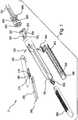
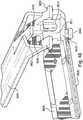
- Figures 1 to 13Eillustrate a surgical device 5 that is an exploded view of a surgical device 5 in accordance with an example embodiment of the present invention.
- the device 5cuts and staples a clamped tissue utilizing an oscillating actuator 505, in the exemplary form of a hydraulically driven actuation bar 505, to advance a carriage 405 along at least one of a first jaw and a second jaw.
- the first jawincludes the housing 105 and the second jaw includes the anvil 205.
- the carriage 405is configured to engage both the first jaw 105 and the second jaw 205 in order to exert a localized clamping force at the axial location of the carriage 405 as it is advanced along the first and second jaws 105, 205.
- the exemplary carriage 405drives staples into the clamped tissue and cuts the clamped tissue as it is advanced along the jaws by the oscillating actuator 505.
- the axial location of the clamping force exerted by the carriage 405is substantially aligned with the axial location of the concurrently-driven staple, to effect a robust staple driving action.
- the carriage 405may be moved in a reversed direction with respect to the jaws by further oscillation of the actuation element 505 after changing a state of the oscillating actuation element 505. In the exemplary device 5, the state of the actuation bar 505 is changed by laterally shifting the actuation bar with respect to the carriage 405.
- the surgical device 5includes the housing 105, a cover 180, the anvil 205, a staple form plate 260, an anvil pivot pin 290, an anvil piston 305, carriage 405, actuation/ratchet bar 505, a ratchet actuation piston 605, tubes 705, rear cap 805, a cylindrical gasket 825, screws 850, crimp ring 860, reload housing 905 and reload sled 950.
- the anvil 205is in an open orientation with respect to the housing 105 and the reload housing 905.
- the reload housing 905may itself constitute a replaceable staple cartridge, or the reload housing 905 and the reload sled 950 may in combination form a replaceable staple cartridge.
- the reload sled 950may remain with the housing 105 when the reload housing 905 is removed (as illustrated in Figure 3 ), or the reload sled 950 may be mounted to the reload housing 905 such that the reload sled 950 is removed along with the reload housing 905.
- each reload housing 905may have its own reload sled 950, or the reload sled 905 may be interchangeable between different reload housings 905.
- the anvil 205is rotatable about the anvil pivot pin 290 between the open orientation illustrated in Figure 2 to a closed orientation illustrated in Figure 4 .
- the rotation of the anvil 205 from the open orientation to the closed orientationis actuated by a pin-in-slot arrangement.
- the pin elementsare embodied in the device 5 as pins 310 that extend laterally from the anvil piston 305, as illustrated, e.g., in Figure 9B .
- Each of the pins 310extends from its respective base at anvil piston clevis 325 laterally outwardly to a free end.
- the pins 310lie along a common axis y that is parallel to the longitudinal axis z of the anvil pivot pin 290 and perpendicular to a plane in which the anvil 205 rotates with respect to the body 105.
- the anvil piston clevis 325is coupled to an anvil piston shaft 330 having a longitudinal axis z that lies within the plane of rotation of the anvil 205 and perpendicular to the pin axis y at a proximal end portion of the anvil piston shaft 330 is an o-ring groove 335 formed between a proximal o-ring retention wall 340 and a distal o-ring retention wall 345.
- the anvil piston 305is disposed in the housing 105 such that the proximal portion of the anvil piston 305, including proximal and distal o-ring retention walls 340 and 345, is disposed in a first hydraulic chamber 110 of the housing 105.
- the proximal and distal o-ring retention walls 340 and 345have cylindrical outer surfaces dimensioned to have a slightly smaller diameter than the diameter of the cylindrical inner surface of the first hydraulic chamber 110 such that the anvil piston 305 is slidable between proximal and distal positions with respect to the first hydraulic chamber 110.
- a sealis formed between the anvil piston 305 and the inner surface of the first hydraulic chamber 110 by an o-ring 320, illustrated in Figure 10A , which is retained in the o-ring groove 335 between the proximal and distal o-ring retention walls 340 and 345.
- a hydraulic space or volumeis defined between the proximal surface 350 of the anvil piston 305, the cylindrical side walls of the first hydraulic chamber 110 and a proximal surface 115 of the first hydraulic chamber 110.
- a hydraulic space or volumeis defined between the distal surface 355 of the piston anvil 305, the cylindrical side walls of the first hydraulic chamber 110 and a proximally directed surface 112a of a washer or plate 112 at the distal end of the hydraulic chamber 110.
- the two hydraulic volumes defined in the first hydraulic chamber 110are sealed from each other by the anvil piston 305, including the o-ring 320. These hydraulic volumes vary inversely to each other depending on the axial position of the anvil piston 305. In particular, as the anvil piston moves distally, the volume of the distal hydraulic volume decreases and the volume of the proximal hydraulic volume increases. Similarly, as the anvil piston moves proximally, the volume of the distal hydraulic volume increases and the volume of the proximal hydraulic volume decreases.
- hydraulic volume disposed proximally to the seal formed by the o-ring 320 of the anvil piston 305is in fluid communication with a hydraulic supply tube 705a
- hydraulic volume disposed distally to the seal formed by the o-ring 320 of the anvil piston 305is in fluid communication with a hydraulic supply tube 705b.
- the hydraulic supply tubes 705a, 705bextend proximally, e.g., in a flexible shaft, to a hand piece and/or other appropriate control unit where one or more hydraulic control units are disposed.
- the hydraulic control unitsare configured to transmit hydraulic fluid, e.g., saline, at a controlled pressure and/or flow rate into or out of the hydraulic volumes.
- the hydraulic drive systemuses positive pressure to generate most, if not all, of the force exerted on the anvil piston 305 during both distal and proximal actuation of the anvil piston 305.
- the positive pressureis applied via the first hydraulic supply tube 705a during the distal actuation of the anvil piston 305, and the positive pressure is applied via the hydraulic supply tube 705b during the proximal actuation of the anvil piston 305.
- a negative pressuremay be utilized in addition to or instead of the positive pressure.
- negative pressuremay be beneficial, particularly in arrangements where the pressure is transmitted by elongated tubes.
- the hydraulic control unitsare able to precisely control the movement and position of the anvil piston 305 by controlling the sealed hydraulic volumes of the first hydraulic chamber 110.
- This double-action piston arrangementwherein the first and second hydraulic fluid volumes can be separately, albeit complementarily, adjusted, allows for a closed fluid system that limits the interaction of the surgical device with outside elements.
- the anvil piston shaft 330axially slides within the washer or plate 112 and an o-ring 113 disposed at the distal end of the first hydraulic chamber 110.
- the o-ringacts to radially support the distal portion of the anvil piston shaft 330 and forms a sliding seal between the anvil piston shaft 330 and the housing 105 to prevent any hydraulic fluid from escaping the first hydraulic chamber and to prevent any undesired fluids or other contaminants from entering the first hydraulic chamber 110.
- the washer 112provides a protective layer of material between the piston 305 and the distal end of the cylinder 110.
- the laterally extending pins 310axially slide within an anvil pin slot 120, which extends parallel to the longitudinal axis a of the housing 105.
- the pins 310are actuated in a direction parallel to the longitudinal axis a of the housing 105.
- the anvil 205includes a bore 210 for receiving the anvil pivot pin 290, about which the anvil 205 rotates with respect to the housing 105 and the reload housing 905 supported by the housing 105.
- the anvil 205has a longitudinal axis b that intersects the axis of rotation about the anvil pivot pin 290.
- the anvil 205also includes a pair of anvil actuation slots 220 disposed on respective wings 225 of the anvil 205.
- Each of the anvil actuation slots 220extends along a respective axis c that is offset from the axis of the pivot pin 290 and angled with respect to the longitudinal axis b when viewed along the rotation axis defined by anvil pivot pin 290.
- each pin 310extends sequentially from the anvil piston clevis 325 through the anvil actuation slot 220 of the anvil 205 and into the anvil pin slot 120 of the housing 105.
- each of the pins 310extend through both the anvil activation slot 220 and the anvil pin slot 120 and since the axis c of the anvil actuation slot 220 is offset from the rotation axis of the anvil 205 and angled with respect to the longitudinal axis b of the anvil 205, the distal sliding of the pins 310 within the anvil pin slots 120 causes the anvil 205 to rotate from the open position to the closed position, and the proximal sliding of the pins 310 within the anvil pin slots 120 causes the anvil 205 to rotate from the closed position to the open position.
- the hydraulic control unitsare able to precisely and accurately control the motion, position, and force exerted by the anvil 205.
- the angle of the axis c of the anvil activation slot 220may be provided such that proximal sliding of the pins 310 causes closure of the anvil 205 and distal sliding of the pins 310 causes opening of the anvil 205.
- the carriage 405which is provided in the form of a force transfer bar, may be distally advanced along the longitudinal axis a of the housing 105.
- the carriage 405includes a plate 410 extending between a first jaw-engagement portion 420 and a second jaw-engagement portion 430.
- the first jaw-engagement portion 420is shaped as a plate oriented perpendicularly to the plate 410 and including a pair of opposed flanges 422, 426
- the second jaw-engagement portion 430is also shaped as a plate oriented perpendicularly to the plate 410 and including a pair of opposed flanges 432, 433.
- Each of the flanges 422, 426, 432, 436 of the first and second jaw-engagement portions 420, 430project transversely with respect to the plate 410 and extend longitudinally in a direction parallel to the longitudinal axis a of the housing 105 when the surgical device 5 is in its assembled configuration, as illustrated, e.g., in Figure 4 .
- the second jaw-engagement portion 430is configured to engage the lower jaw, which comprises the housing 105 and the reload housing 905 such that the carriage 405 is slidable along the longitudinal axis a of the housing 105 while being constrained from movement transverse to the longitudinal axis a of the housing 105.
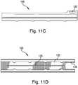
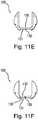
- the carriage 405is configured to be coupled to the housing 105 such that the second jaw-engagement portion 430 slides below a lower plate or wall 130, illustrated, e.g., in Figures 11E and 11F , while the retention plate 460 is disposed above the wall 130.
- the wall 130includes a guide slot 135 extending along the longitudinal axis a of the housing 105 and configured to slidably receive a guide rib 440 of the carriage 405, which extends between the second jaw-engagement portion 430 and the retention plate 460.
- the retention plate 460is a removable component of the carriage 405 and includes a slot 462 that facilitates removal. It should be understood, however, that the retention plate 460 may be non-removable and/or formed as a single monolithic piece with the main body of the carriage 405.
- the lower wall 130When the guide rib 440 is received by the guide slot 135, the lower wall 130 is disposed in a gap or region 439 between opposed surfaces 437, 465 defined by the second jaw-engagement portion 430 and the retainer plate 460, thereby restraining movement of the carriage 405 transverse to the longitudinal axis a of the housing 105, as the carriage 405 slides along the guide slot 135.
- the surface 437 of the second jaw-engagement portion 430 and a lower surface 131 of the lower wall 130engage each other to form a first positive stop against movement of the carriage 405 with respect to the housing 105 in a first direction transverse to the longitudinal axis a of the housing 105.
- the lower surface 465 of the retainer plate 460 and a lower surface 131 of the lower wall 130engage each other to form a second positive stop against movement of the carriage 405 in a second direction transverse to the longitudinal axis a of the housing 105, the first and second directions being within the plane in which the anvil 205 rotates between the opened and closed positions with respect to the housing 105.
- the guide slot 135proximally extends into an enlarged opening 136 having a width in the bottom wall 130 that is greater than the width of the guide slot, thereby allowing the carriage 405 to be disengaged from the guide slot 135 when the carriage 405 is positioned in the region of the enlarged opening 136.
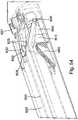
- the anvil 205includes a guide channel 230 that extends in the direction of the longitudinal axis b of the anvil 205, which is parallel to the longitudinal axis a of the housing 105 when the anvil 205 is in a closed state with respect to the housing 105, as illustrated in Figure 4 .
- the guide channel 230receives an anvil sled assembly 268, which includes an anvil latch plate 270, a low friction insert 275, and a return link 280.
- the anvil sled assembly 268is slidable within the guide channel 230 between a proximal position and a distal position.
- the distal and proximal directions of slidingare along the longitudinal axis b of the anvil 205, and parallel to the longitudinal axis a of the housing 105 when the anvil 205 is in the closed state with respect to the housing 105, as illustrated in Figure 4 .
- the anvil sled assembly 268is in the proximal position.
- the anvil 205includes a guide slot 235 formed between two guide flanges 240, 245 and opening proximally into an enlarged recess 250.
- the guide slot 235begins at the proximal ends of the guide flanges 240, 245, as illustrated in Figure 13A .
- the anvil 205When the anvil sled assembly 268 and the carriage 405 are in their respective proximal positions with respect to the housing 105, the anvil 205 is rotatable to transition between its open and closed states with respect to the housing 105.
- the upper jaw-engagement portion 420 of the carriagepasses through an enlarged opening 282 in the return link 280 of the anvil carriage 468 and into the enlarged recess 250 of the anvil 205.
- the enlarged opening 282 and the enlarged recess 250are laterally dimensioned to allow clearance between the carriage 405 and any structure of the anvil 205 or the anvil sled assembly 268 during opening and closing of the anvil with respect to the housing 105 when the anvil sled assembly 268 and the carriage 405 are in their respective proximal positions.
- the anvil sled assembly 268 and the carriage 405are in their respective initial proximal positions whenever the anvil 205 is closed and opened with respect to the housing 105 to thereby respectively clamp and release tissue between the anvil 205 and the housing 105 via actuation of the anvil piston 305 as set forth in greater detail above.
- the carriage 405is distally advanced in order to cut and staple the clamped portion of tissue.
- a reciprocating arrangementin the form of a ratcheting arrangement, is actuated via the ratchet actuation piston 605.
- the ratchet actuation piston 605includes features analogous to the anvil piston 305 described above and is proximally and distally actuated functions in the same general manner as the anvil piston 305 described above.
- the ratchet actuation piston 605includes a ratchet actuation piston shaft 630 having a longitudinal axis zz that is parallel to the longitudinal axes a, z of the housing 105 and the anvil piston 305.
- At a proximal end portion of the ratchet piston shaft 630is an o-ring groove 635 formed between a proximal o-ring retention wall 640 and a distal o-ring retention wall 645.
- the ratchet actuation piston 605is disposed in the housing 105 such that the proximal portion of the ratchet actuation piston 605, including proximal and distal o-ring retention walls 640 and 645, is disposed in a second hydraulic chamber 150 of the housing 105.
- the proximal and distal o-ring retention walls 640 and 645have cylindrical outer surfaces dimensioned to have a slightly smaller diameter than the diameter of the cylindrical inner surface of the second hydraulic chamber 150 such that the ratchet actuation piston 605 is slidable between proximal and distal positions with respect to the second hydraulic chamber 150.
- a sealis formed between the ratchet actuation piston 605 and the inner surface of the second hydraulic chamber 150 by an o-ring 620, illustrated, e.g., in Figure 10A , which is retained in the o-ring groove 635 between the proximal and distal o-ring retention walls 640 and 645.
- a hydraulic space or volumeis defined between the proximal surface 650 of the ratchet actuation piston 605, the cylindrical side walls of the second hydraulic chamber 150 and a proximal surface 155 of the second hydraulic chamber 150.
- a hydraulic space or volumeis defined between the distal surface 655 of the ratchet actuation piston 605, the cylindrical side walls of the second hydraulic chamber 150 and a proximally directed surface 152a of a washer or plate 152 at the distal end of the hydraulic chamber 150.
- the two hydraulic volumes defined in the second hydraulic chamber 150are sealed from each other by the ratchet piston 605, including the o-ring 620.
- These hydraulic volumesvary inversely to each other depending on the axial position of the ratchet piston 605. In particular, as the ratchet piston moves distally, the volume of the distal hydraulic volume decreases and the volume of the proximal hydraulic volume increases. Similarly, as the ratchet piston 605 moves proximally, the volume of the distal hydraulic volume increases and the volume of the proximal hydraulic volume decreases.
- a cylinder gasket 825is provided at an interface between the housing 105 and the rear cap 805 to form a seal therebetween when the housing 105 and the end cap are joined (e.g., via screws 850).
- the cylinder gasket 825is partially exposed to the interior of each of the hydraulic chambers 110, 150, thereby providing a barrier between the proximal surfaces 350, 650 of the cylinders 305, 605 and the respective proximal walls 115, 155 to thereby protect the respective components 305, 605, 805 against damage or wear that would otherwise be due to direct impact between the proximal surfaces 350, 650 of the cylinders 305, 605 and the respective proximal walls 115, 155 by absorbing energy.
- the washers 112, 152provide analogous protection to the cylinders 305, 605 and the housing 105 by preventing direct impact between the distal surfaces 355, 655 of the pistons 305, 605 and the housing 105 during distal or forward strokes of the pistons 305, 605.
- These elements 805, 112, 152may be made of any suitable materials, including, e.g., one or more elastomers.
- these elements 805, 112, 152may be formed of the same material, or one or more of these elements 805, 112, 152 may be formed of a different material than one or more of the other elements 805, 112, 152.
- the hydraulic volume disposed proximally to the seal formed by the o-ring 620 of the ratchet piston 605is in fluid communication with a hydraulic supply tube 705c.
- the hydraulic supply tubes 705c, 705dextend proximally, e.g., in a flexible shaft, to the hand piece or other appropriate control unit where hydraulic control units are disposed.
- the hydraulic control unitsare configured to transmit hydraulic fluid, e.g., saline, at a controlled pressure and/or flow rate into or out of the hydraulic volumes of the second hydraulic chamber 150.
- the hydraulic drive systemgenerally uses positive pressure to generate most, if not all, of the force exerted on the ratchet piston 605 during both distal and proximal actuation of the ratchet piston 605.
- the positive pressureis applied via the first hydraulic supply tube 705c during the distal actuation of the ratchet piston 605
- the positive pressureis applied via the hydraulic supply tube 705d during the proximal actuation of the ratchet piston 605.
- a negative pressuremay be utilized in addition to or instead of the positive pressure.
- the hydraulic control unitsare able to precisely control the movement and position of the ratchet piston 605 by controlling the sealed hydraulic volumes of the second hydraulic chamber 150.
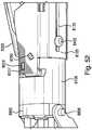
- the hydraulic fluid from the tube 705bis transmitted between the chamber 110 and the tube 705b via a set of interconnected bores 170, 172.
- the fluidwould travel along an axial supply bore 170, which extends parallel to and spaced apart from the cylinder 110, to a distal transverse supply bore 172, which connects the axial supply bore 170 and the distal end region first cylinder 110.
- the tube 705bis able to supply and remove hydraulic fluid to and from the distal end region of the cylinder 110.
- the hydraulic fluid from the tube 705dis transmitted between the chamber 150 and the tube 705d in a set of interconnected bores 174, 176.
- the fluidwould travel along an axial supply bore 174, which extends parallel to and spaced apart from the cylinder 150, to a distal transverse supply bore 176, which connects the axial supply bore 174 and the distal end region first cylinder 150.
- the tube 705dis able to supply and remove hydraulic fluid to and from the distal end region of the cylinder 150.
- the bores 172, 176are shown as providing an opening from the housing on the left side of the illustration. However, the extension of the bores 174 and 176 to the left of the bores 172, 174 in Figure 4 is due to the formation of the bores 172, 176 by drilling two respective transverse holes into the side of the housing 105, one that extends into both the bore 170 and the cylinder 150, and another that extends into both the bore 174 and the cylinder 150.
- the portion of the bore 174, 176 that extends through the outer surface of the housing 105may be sealed in any appropriate manner, e.g., filling the bore with a pin, dowel, filler, adhesive and/or other suitable material.
- the tubes 705a and 705cprovide hydraulic fluid to the respective cylinders 110, 150 via respective proximal bores in the rear cap 805 of the housing assembly. These bores are concentric with the respective tubes 705a, 705c. It should be understood, however, that the delivery mechanism between the tubes 705a, 705b, 705c, 705d and the respective regions of the cylinders 110, 150 may vary from the example embodiments.
- the ratchet actuation piston shaft 630axially slides within the washer 152 and an o-ring 153 disposed at the distal end of the second hydraulic chamber 150.
- the o-ring 152acts to radially support the distal portion of the ratchet actuation piston shaft 630 and forms a sliding seal between the ratchet actuation piston shaft 630 and the housing 605 to prevent any undesired fluids or other contaminants from entering the second hydraulic chamber 150.
- the washer 152provides a protective layer of material between the piston 605 and the distal end of the cylinder 150.
- the ratchet actuation piston 605includes a force transfer pin 610 extending through a transverse bore in the ratchet actuation piston shaft 630.
- the longitudinal axis yy of the force transfer pin 610 that received in the bore as illustrated in Figure 9Cis transverse and perpendicular to the longitudinal axis zz of the ratchet actuation piston 605.
- the force transfer pin 610 of the ratchet actuation piston 605is received in a force transfer slot 510 in a proximal transversely extending member 515 of the actuating bar 505.
- the engagement between the force transfer pin 610 and the force transfer slot 510is shown, for example, in Figure 10A .
- the force transfer pin 601is dimensioned slightly smaller that the width of the force transfer slot 510, which extends transversely and perpendicularly with respect to the longitudinal axis zz, and therefore the reciprocating strokes, of the oscillating ratchet actuation piston 605.
- the longitudinally directed reciprocating strokes of the ratchet actuation piston 605also cause corresponding longitudinally directed strokes of the actuating bar 505, while the actuating bar 505 remains slidable with respect to the force transfer pin 610 along the length of the force transfer slot 510, regardless of where along the length of the slot 510 the force transfer pin 610 is located.
- the actuating bar 505has been moved in a first lateral direction 40 with respect to the ratchet actuation piston 605 so that the force transfer pin 610 is disposed at a first end of the force transfer slot 510.
- Figure 9Ashows the actuating bar 505 after being moved in a second, opposite lateral direction 45 with respect to the ratchet actuation piston 605 so that the force transfer pin 610 is disposed at a second, opposite end of the force transfer slot 510.
- which of these two lateral positions the force transfer bar 505 is in with respect to the ratchet actuation piston 605will determine whether the carriage 405 is driven distally or proximally along the longitudinal axis a of the housing 105.
- the carriage 405is continuously actuated substantial axial distances while the driving mechanism remains is a relatively confined axial location.
- first and second ratcheting elements 470, 480are also disposed below the lower plate 130 when the carriage 405 is engaged with the guide slot 135.
- the ratcheting elements 470, 480are coupled to the second jaw-engagement portion 430 by respective spring arms 475, 485.
- the actuating bar 505is also disposed below the lower plate 130 of the housing 105.
- the actuating bar 505is slidably disposed between and supported by the housing 105 and the cover 180 attached to the housing 105.
- the housing 105, rear cap 805, and the cover 180form a housing assembly 105, 180, 805 when the device 5 is assembled.
- features described herein with regard to the housing 105, the cover 180, and the rear cap 805generally also refer to features of the housing assembly 105, 180, 805 as an overall unit. Further, the features described herein with regard to the housing 105, the cover 180, and the rear cap 805 need not be provided on the particular element 105 or 180 indicated.
- the alignment elements 160a, 160b described beloware discussed as part of the housing 105, it should be understood that these elements 160a, 160b are part of the housing assembly 105 as a whole and that one, more, or all of these elements 160a and/or160b may be provided on other elements of the housing assembly 105, 180, e.g., on the cover 180. Further, the housing assembly 105, 180, 805 may be provided as a single component or having additional components than those described with regard to the illustrated examples.
- the actuating bar 505has been moved in the first lateral direction 40 so that the actuating bar is in a first later position with respect to the carriage 405 and the housing 105.
- a set of ratcheting teeth 472 of the first ratchet element 470engage a corresponding first set of teeth 570 of the actuating bar 505.
- the engagement between the teeth 472 and 570is such that the first set of teeth 570 of the actuating bar 505 lock with the teeth 472 of the first ratcheting element 470 when the actuating bar 505 is in each distal stroke of reciprocation but not when the actuating bar is in each proximal stroke.
- each distal stroke of the reciprocation of the actuating bar 505pushes the carriage 405 an incremental distal distance along the guide slot 135 with respect to the housing 105.
- each proximal stroke of the reciprocationallows the first set of teeth 570 of the actuating bar 505 to slide over the first set of teeth 472 of the first ratcheting element 470, due to ramped surfaces of the teeth 472 and 570.
- the actuating bar 505is allowed to move proximally during each proximal stroke of the reciprocation of the actuating bar 505 without causing any substantial proximal translation of the carriage 405.
- each reciprocation cycle (one distal stroke plus one proximal stroke) of the actuating bar 505causes the carriage 405 to move a net incremental distal distance.
- the carriage 405is distally progressed.
- the carriage 405is distally actuatable along the guide slot 135 with respect to the housing 105 when the actuating bar is in the first lateral position.
- an analogous ratcheting mechanismis engaged by moving the actuating bar 505 to its second lateral position, as illustrated in Figure 9A , so that the second set of teeth 580 of the actuating bar 505 engages the teeth 482 of the second ratcheting element 480.
- the orientation of the teeth 482, 580is reversed.
- the engagement between the teeth 482 and 580is such that the second set of teeth 580 of the actuating bar 505 lock with the teeth 482 of the second ratcheting element 480 when the actuating bar 505 is in each proximal stroke of reciprocation but not when the actuating bar 505 is in each distal stroke.
- each proximal stroke of the reciprocation of the actuating bar 505pulls the carriage 405 an incremental proximal distance along the guide slot 135 with respect to the housing 105.
- each distal stroke of the reciprocationallows the second set of teeth 580 of the actuating bar 505 to slide over the teeth 482 of the second ratcheting element 480, due to ramped surfaces of the teeth 482 and 580.
- the actuating bar 505is allowed to move proximally during each proximal stroke of the reciprocation of the actuating bar 505 without causing any substantial distal translation of the carriage 405.
- each reciprocation cycle (one distal stroke plus one proximal stroke) of the actuating bar 505causes the carriage 405 to move a net incremental distal distance.
- the carriage 405is proximally progressed.
- the carriage 405is proximally actuatable along the guide slot 135 with respect to the housing 105 when the actuating bar is in the second lateral position.
- each of the ratcheting elements 470, 480is spring biased by the spring arms 475, 480 toward the respective set of teeth 570, 580 when the actuating bar 505 is in the respective first and second positions, the teeth 472, 482 of the first and second ratchet elements 470, 480 are able to laterally flex along the contour formed by the teeth 570, 580 to allow the ratcheting action.
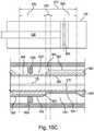
- the ratchet piston 605moves within its total axial stroke range 675 in the second hydraulic chamber 150 from a first axial region 660, in which the reciprocation is performed for distal actuation, to a second axial region 670, in which the reciprocation is performed for proximal actuation. Between the first and second axial regions 660, 670 is a transition region 665.
- the position of the ratchet piston 605is schematically superimposed above the actuating bar 505, which axially tracks the movement of the ratchet piston 605.
- any axial displacement of the ratchet piston 605corresponds to the exact same amount of axial displacement of the actuating bar 505.
- the actuating bar 505is shown in its position relative to the housing 105, in which the actuating bar 505 is slidably supported.
- the actuating baris constrained in its lateral position each of Figures 10C to 10E by a pair of opposed alignment elements 160a, 160b in the form of radially inwardly directed projections.
- alignment elements 160a, 160bare each part of respective sets of alignment elements 160a, 160b of the housing 105, only one alignment element 160a and one alignment element 160b are shown, along with the corresponding portions of the actuating bar 505 for ease of illustration.
- the ratchet piston 605is in the first axial region 660.
- the actuating bar 505is laterally constrained by the opposed alignment elements 160a, 160b such that the alignment element 160a is slidable along an outward surface 552 of a first axial member 550 of the actuating bar 505, and the alignment element 160b is slidable along a recessed surface 564 of a second axial member 560 of the actuating bar 505.
- the outward surface 552 and the recessed surface 554axially extend along lines parallel to each other as well as the guide slot 135 and the longitudinal axis a of the housing 105, the arrangement of the first set of teeth 570 of the actuating bar 505 and the second set of teeth 580 of the actuating bar 505.
- the outward surface 552 of the actuating bar 505is a greater lateral distance from the longitudinal axis of the guide slot 135 than the recessed surface 554 of the actuating bar 505
- the outward surface 562 of the actuating bar 505is a greater lateral distance from the longitudinal axis of the guide slot 135 than the recessed surface 564 of the actuating bar 505.
- the alignment elements 160afollow a first surface profile of the actuating bar 505 that includes the outward surface 552, the recessed surface 554 and a ramped transition surface 553 disposed between and being continuous with the outward surface 552 and the recessed surface 554.
- the alignment elements 160bfollow a second surface profile of the actuating bar 505 that includes the outward surface 562, the recessed surface 564 and a ramped transition surface 563 disposed between and being continuous with the outward surface 562 and the recessed surface 564.
- the outward surfaces 552, 562correspond to opposite laterally outwardly facing sides of the actuating bar 505.
- the recessed surfaces 554 and the ramped transition surface 553are part of an alignment recess 551 of the first axial member 550 that is recessed with respect to the outward surface 552.
- recessed surface 564 and the ramped transition surface 563are part of an alignment recess 551 of the second axial member 560 that is recessed with respect the outward surface 552.
- the illustrated first recessed portion 551 and second recessed portion 561form an axially offset pair of opposed recesses 551, 561.
- the illustrated pair of opposed recesses 551, 561is one of three such pairs of opposed recesses 551, 561 disposed along the length of the actuating bar 505 of the illustrated example device of Figure 1 .
- Each recess 551, 561 as well as respective outward surfaces 552, 562 and projections 160a, 160bfunctions in the same or analogous manner to the corresponding elements illustrated in Figures 10C to 10E .
- the recesses 552, 562, or other geometrymay differ from the illustrated examples. For example, there may be more or less recesses 561, 562 and there may be a greater number of recesses 561, 562 disposed on one axial member 550, 560 than the other axial member 560, 550.
- the recesses 552, 562may have differing geometries and/or irregular spacing, and/or the opposed alignment projections 160a, 160b of one or more opposed pair of alignment projections 160a, 160b may be axially offset from each other.
- the actuating baris in the first lateral position, such that the first set of teeth 570 of the actuating bar are closer to the guide slot 135 than the second set of teeth 580 of the actuating bar 505. In this position the first set of teeth 570 are in engagement with the corresponding teeth 472 of the first ratcheting element 470 of the carriage 405.
- the reciprocation of the ratchet piston 605 between proximal and distal positions within the first axial region 660causes the actuating bar 505 to also reciprocate between corresponding proximal and axial positions while remaining in the first lateral position.
- the ratcheting engagement between the first set of teeth 570 (which are disposed along the first axial member 550) and the first ratcheting element 470is maintained during the reciprocation of the ratchet piston 605 and the actuating bar 505 when the ratchet piston is within its first axial region 660.
- the distal movement of the carriage 405is effected by the reciprocation of the ratchet piston 605 between proximal and distal positions within the first axial range 660.
- the device 5In order to move the carriage 405 proximally, the device 5 must laterally shift the actuating bar 505 from the first lateral position (illustrated, e.g., in Figure 10C ) to the second lateral position (illustrated, e.g., in Figure 10E ) with respect to the track 135 along which the carriage 405 is distally and proximally progressed.
- the lateral shifting of the actuating bar 505 between the first and second lateral positionsis achieved by extending the ratchet piston 605, and therefore also the actuating bar 505, from the first region 660, over the transition region 665 disposed between the first and second regions 660, 670, and into the second region 670.
- Figure 10Dillustrates the ratchet piston 605 and the actuating bar 505 in the transition axial region 665.
- the first alignment element 160ais configured to laterally constrain the actuating bar 505 by contacting the ramped transition surface 553 of the first axial member 550
- the second alignment element 160bis configured to laterally constrain the actuating bar 505 by contacting the ramped transition surface 563.
- the alignment member 160aacts as a cam follower following a cam surface defined by the outward surface 552, the ramped transition surface 553, and the recessed surface 554 and the alignment member 160b acts as a cam follower following a cam surface defined by the outward surface 562, the ramped transition surface 563, and the recessed surface 564, the actuating bar 505 is guided, via the ramped transition between the first later position illustrated, e.g., in Figure 10C , and the second later position illustrated, e.g., in Figure 10E .
- the ratchet piston 605is in the second axial region 670.
- the actuating bar 505is laterally constrained by the opposed alignment elements 160a, 160b such that the alignment element 160a is slidable along the recessed surface 554 of the first axial member 550 of the actuating bar 505, and the alignment element 160b is slidable along the outward surface 562 of the second axial member 560 of the actuating bar 505.
- the recessed surface 554 and the outward surface 562axially extend along lines parallel to each other as well as the guide slot 135 and the longitudinal axis a of the housing 105, the arrangement of the first set of teeth 570 of the actuating bar 505 and the second set of teeth 580 of the actuating bar 505.
- the actuating bar 505is in the second lateral position, such that the second set of teeth 580 of the actuating bar 505 are closer to the guide slot 135 than the first set of teeth 570 of the actuating bar 505. In this position, the second set of teeth 580 are in engagement with the corresponding teeth 482 of the second ratcheting element 480 of the carriage 405.
- the reciprocation of the ratchet piston 605 between proximal and distal positions within the second axial region 670causes the actuating bar 505 to also reciprocate between corresponding proximal and axial positions while remaining in the first lateral position.
- the ratcheting engagement between the second set of teeth 580 (which are disposed along the second axial member 560) and the second ratcheting element 480is maintained during the reciprocation of the ratchet piston 605 and the actuating bar 505 when the ratchet piston 505 is within its first axial region 660.
- the proximal movement of the carriage 405is effected by the reciprocation of the ratchet piston 605 between proximal and distal positions within the second axial range 670.
- the device 5is configured to move the carriage 405 distally when the actuating bar is in the first lateral position and to move the carriage 405 proximally when the actuating bar 505 is in the second lateral position, it should be understood that this orientation may be reversed and the selective engagement between the actuating bar 505 and the carriage 405 may be provided by other mechanism(s) in addition, or as an alternative, to the selective movement of the actuating bar 505 between the first and second lateral positions with respect to the housing 105.
- the ratchet piston 605actuates distal movement of the carriage 405 with respect to the housing when the piston 605 is actuated in the proximal first axial region 660, and actuates proximal movement of the carriage 405 with respect to the housing 105 when the piston 605 is actuated in the distal second axial region 670
- the device 5may be configured to distally advance the carriage 405 when the piston 605 is reciprocated in a distal axial region of its total available axial stroke and to proximally advance the carriage 405 when the piston 605 is reciprocated in a proximal region of its total available axial stroke.
- the device 5may be configured to allow the piston 605 to utilize the majority or entirety of its available axial stroke during its reciprocation to actuate the carriage 405 proximally and/or distally.
- other adjustment mechanisms for selecting the direction of rotationin addition or as an alternative to the alignment projections 160a, 160b may be provided.
- one or more dedicated actuatorsmay be provided to select the engagement state of the reciprocating drive mechanism.
- the device 5is positioned such that a portion of tissue is disposed between upper jaw, including the anvil 205 and the lower jaw, including the housing 105 and reload housing 905.
- the tissueis compressed to a thickness that allows for reliable staple driving and formation.
- the gap between the anvil 205 and the opposed surface of the housing 5 and/or reload housing 905may be 2 mm or less when the anvil 205 is in the closed orientation.
- the carriage 405which is in an initial proximal position, is distally advanced along the guide slot 135 via ratchet piston 605 as set forth above.
- a knife blade 450linearly cuts tissue clamped between the anvil 205 and the housing 105, while the carriage distally pushes a wedge-shaped reload sled 950 in order to push staples from the reload housing 905 into the staple form plate 260 disposed in the guide channel 230.
- the reload sled 950in the example embodiment illustrated, includes four parallel staple-driving wedges 952 configured to drive, e.g., simultaneously, four respective staples into the staple form plate 260.
- the wedges 952extend above a slide plate 954 configured to slide along the upper surface 132 of the lower wall 130 of the housing 105 in directions parallel to the longitudinal axis a of the housing 105 and the longitudinal path of the guide slot 135.
- the cutting edge of the knife blade 450preferably has an arc-shaped curvature as illustrated.
- the curvaturemay be beneficial, e.g., to maintain or center the leading edge of the tissue on the cutting edge or surface of the blade 450 as the blade is cutting the tissue.
- the knife blade 450is curved, it should be understood than any desirable blade geometry or other cutting mechanism may be provided.
- the reload housing 905 of the illustrated exampleis a replaceable cartridge separate from the reload sled 950, it should be understood that the reload sled 950 may be incorporated into the cartridge such that each cartridge assembly includes its own reload sled 950. Further although the reload sled 950 is configured to drive four staples using four wedges 952, it should be understood that the reload sled 950 may include any other number of wedges 952 or other staple driving elements configured to drive any desirable number of staples.
- the first or upper jaw engagement portion 420engages the anvil sled assembly 268.
- the flanges 422, 426 of the first jaw engagement portion 420are received by anvil latch plate 270 such that the anvil latch plate 270 extends below both of the flanges 422, 426.
- the carriage 405, along with the anvil sled assembly 268,are progressed distally along the guide slot 235 of the anvil 205.
- the anvil sled assembly 268extends from the housing 105 through the guide slot 235, and into the guide channel 230.
- the anvil sled assembly 268is supported by and axially slidable along the length of the guide channel 230 above the staple form plate 260 which extends along the guide channel 230.
- the form plate 260has a guide slot 265 through which the carriage 405 also extends.
- the flanges 422, 426 of the first jaw engagement portion 420transfer force in the direction of the housing 105 into the anvil sled assembly 268. Since the staple push plate 260 is disposed between the anvil sled assembly 268 and the housing 105, the force is also transferred from the anvil sled assembly 268 to the staple push plate 260.
- the low friction inserts 275allow the carriage 405 to be slidable despite the force being transferred through the sliding surface between the anvil sled assembly 268 and the staple push plate 260. This reduced friction engagement may be particularly advantageous since the axial force is exerted by the actuating bar 505 at a location on the carriage 405 that is substantially offset from the sliding engagement between the anvil sled assembly 268 and the staple push plate 260.
- first jaw engagement portion 420 and second jaw engagement 430engage the anvil 205 and housing 105 to provide a localized clamping force or reinforcement at the location of the cutting and stapling.
- Thismay be especially advantageous in that the forces tending to urge the jaws 205, 105 apart are increased by the pressing of staples into the staple form plate.
- the carriage, or force transfer bar, 405has multiple functions, including, e.g., transferring force to engage and form staples, cut tissue, and maintain an anvil "clamp" position for constant tissue thickness.
- the slope of incline of jaws 105, 205may be modified to increase the clamping effect as the force transfer bar 405 travels along the jaws 105, 205.
- the knife blade 450is configured to continuously cut the clamped tissue beginning at the proximal edge of the clamped tissue, it should be understood that the blade may be configured to engage the clamped tissue at a location distally beyond the proximal edge of the clamped tissue.
- the blade 450may be configured to swing or otherwise kick up into engagement with the tissue at a predetermined and/or selectable location along the clamped jaws.
- the blade 450may be initially disengaged from the anvil sled assembly 268, but after a predetermined and/or selectable distance and/or location during the distal movement swing up into engagement with the anvil sled assembly so as to begin cutting the tissue and allowing the transverse force to be transmitted from the carriage 405 to the staple anvil sled assembly 268.
- Other blade configurationsmay also be provided.
- the device 5may retract the carriage 405 by moving the actuating bar 505 from its first lateral position to its second lateral position, as set forth above, and subsequent reciprocation of the ratchet jaw 605 in the second axial region 670 to ratchet the carriage 405 in the proximal direction with respect to the housing 105.
- the first jaw-engagement portion 410may remain engaged with the anvil latch plate 270 of the anvil sled assembly, or the first jaw-engagement portion 420 may disengage the anvil latch plate, in which case the further proximal retraction of the carriage 405 causes the first jaw-engagement portion 420 to contact the proximal edge of the opening 282 of the return link 280 and thereby pull the anvil sled assembly 268 in the proximal direction.
- a sealmay formed between the shaft and the device 5 by crimping the wall of the shaft to the rear cap 805 with crimp ring 860, illustrated in Figure 1 .
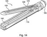
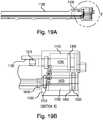
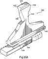
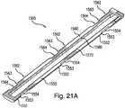
- Figures 14 to 21Fillustrate a second exemplary surgical device 1005
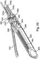
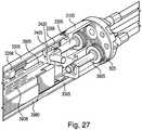
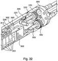
- Figures 22A to 38Billustrate a third exemplary surgical device 3005
- Figures 45 to 55illustrate a fourth exemplary surgical device 8005.
- the device 1005includes the features described herein with regard to the device 5, unless indicated otherwise. Further, the device 5 also includes the features of the device 1005 described herein, unless indicated otherwise.
- like reference numbersindicate like or analogous elements, but with any reference numbers 1 to 999 of the device 5 corresponding to reference numbers 1001 to 1999, respectively, of the device 1005.
- the housing 105 of the device 5corresponds to the housing 1105 of the device 1005
- the anvil 205 of the device 5corresponds to the anvil 1205 of the device 1005, etc.
- Figures 22A to 38Billustrate a third exemplary surgical device 3005.
- the device 3005includes the features described herein with regard to the devices 5 and 1005, unless indicated otherwise. Further, the devices 5 and 1005 also include the features of the device 3005 described herein, unless indicated otherwise.
- like reference numbersindicate like or analogous elements, but with any reference numbers 1 to 999 of the device 5 and any reference numbers 1001 to 1999 of the device 1005 corresponding to reference numbers 3001 to 3999, respectively, of the device 3005.
- the housing 105 of the device 5 and the housing 1105 of the device 1005each correspond to the housing 3105 of the device 3005
- the anvil 205 of the device 5 and the anvil 1205 of the device 1005each correspond to the anvil 3205 of the device 3005, etc.
- Figures 45 to 55illustrate a fourth exemplary surgical device 8005.
- the device 8005includes the features described herein with regard to the devices 5, 1005, and 3005, unless indicated otherwise. Further, the devices 5, 1005, and 3005 also include the features of the device 8005 described herein, unless indicated otherwise.
- like reference numbersindicate like or analogous elements, but with any reference numbers 1 to 999 of the device 5, and reference numbers 1001 to 1999 of the device 1005, and any reference numbers of the device 3001 to 3999 of the device 3005 corresponding to reference numbers 8001 to 8999, respectively, of the device 8005.
- example embodiments of the present inventionmay include the differing features in combination or the alternative, and that the features may be provided in any desirable combination.
- the ratchet piston 1605 of the device 1005differs from the ratchet pistons 605 , 3605, and 8605 of the devices 5, 3005, and 8005 in that the actuating bar engagement mechanism is provided in the form of a plate-like extension 1610 projected downwardly from the shaft 1630 in an additional embodiment, in contrast to the pin 610 of the ratchet piston 605 and the channeled distal portion of the shafts 3630, 8630 of the devices 3005, 8005, respectively, described in greater detail below.
- the extension 1610engages and cooperates with the slot 1510 of the actuating bar 1505 in the same manner the pin 310 engages the slot 310 of the device 5.
- the carriage 1405 of the device 1005differs from the carriages 405, 3405 of the devices 5 and 3005 in that the blade 3450 is linear and angled toward the distal end of the device 1005 as the blade progresses toward the anvil 1205 in an additional embodiment.
- the anvil 1405also differs in that the carriage 3405 is integrally formed as a single monolithic piece with the retainer plate 1460, as opposed to having a retainer plate 460, 1460 as a separate and/or removable component.
- the actuating bar 1505 of the device 1005differs from the actuating bars 505, 3505, and 8505 of devices 5, 3005, and 8005 in that the force transfer slot 1510 to receive the extension 1610 is rectangular in cross section when viewed from the top as in Figure 21C and is open at one of the lateral sides of the actuating bar 1505 in an additional embodiment.
- the actuating bar 505 of the device 5also differs from the actuating bars 1505 and 3505 of the devices 1005 and 3005 in that the axial recesses 1551, 1561 are axially aligned, in an additional embodiment.
- a mechanism analogous to the mechanism illustrated in Figures 10C to 10E with respect to the device 5is provided, but with the alignment projections of the device 1005 being offset by the same amount that the alignment recesses 551, 561 of the opposed pair of the actuating bar 505 of the device 5.
- an additional analogous mechanismmay be provided where both the opposed alignment projections are axially offset and the opposed alignment recesses 551, 561 are offset.
- each tooth 1570has a latching surface 1571 having a steeper slope with respect to the lengthwise extension of the actuating bar 1505 than a ramped surface 1572.
- the ramped surface 1572allows the first ratcheting element 1470 to be pushed laterally (via flexure of spring arm 1475) to allow the actuating bar 1505 to proximally move with respect to the first ratcheting element 1470 during the proximal strokes of the reciprocation of the ratchet piston 1605.
- the steeper (in this case perpendicular) latching surfaces 1571engage the first ratcheting element 1470 to distally translate the carriage 1405.
- the carriage 1405may be held in its axial position during the proximal stroke via frictional forces due to engagement between the carriage 1405 and the other elements of the device 1005.
- the teeth 1580 on the opposed side of the actuating bar 1505are reversed to allow an analogous reversed engagement to move the carriage 405 proximally with respect to the housing 105.
- the ratcheting elements 1470 and 1480have teeth ratcheting teeth 1472, 1482 with a profile analogous to the profile of teeth 1570 illustrated in Figure 21D such that the latching surfaces of the teeth 1472, 1482 contact respective latching surfaces of the teeth 1570, 1580 when the actuating bar is moving the carriage 1405 in respective axial directions, and the ramped surfaces of the teeth 1472, 1482 engage and translate with respect to the respective ramped surfaces of the teeth 1570, 1580 during secondary piston strokes.
- any other arrangementmay be provided, including providing the ratcheting elements 1470 and/or 1480 with differing tooth geometries and/or a different number of teeth 1472, 1482 than illustrated, including, e.g., a single tooth 1472, 1482.
- series of teeth 1570stops before reaching the distal end of the first axial element 1550 and the second set of teeth 1580 stops before reaching the proximal end of the second axial element 1560, which results in a distal flat 1575 on the inwardly directed surface of the first axial member 1550 and a proximal flat 1585 on the opposed inwardly directed surface of the second axial member 1560.
- the flats 1575, 1585are provided in respective axial regions where there the first and second ratcheting elements 470, 480, respectively, do not extend when the carriage 1405 is moved between its proximal-most and distal-most positions within the housing 1105.
- any desired pattern of teethmay be provided.
- the bottom portion of the actuating bar 1505has chamfered lower edges when viewed axially.
- any desired geometrymay be provided.
- the surgical device 3005is coupled to a shaft 5410 to form a surgical system.
- the shaft 5410is a flexible shaft, it should be understood that a rigid shaft may be provided.
- the shaft 5410houses the hydraulic supply tubes 3705a, 3705b, 3705c, and 3705d.
- the surgical device 3005differs from the surgical devices 5, 1005, and 8005 in that the reload housing 3905, which functions as a staple cartridge, is received in a reload sleeve 3980 such that a proximal portion of the reload housing 3905 slides into and is radially constrained by retention flanges 3981 of the reload sleeve 3980, in an additional example embodiment.
- the reload sleeve 3980may be removed from the housing when the reload housing 3905 is removed or the reload sleeve 3980 may be fixed with respect to the housing 3105 when the reload housing 3905 is removed.
- the surgical device 3005differs from the surgical devices 5, 1005, and 8005 in that the anvil actuation slot 3220 is nonlinear and includes a distal portion which extends parallel to the anvil pin slot 3120 of the housing 3105 when the anvil is in the closed position with respect to the housing, as illustrated in Figure 26 in an additional example embodiment.
- This arrangementmay reduce or eliminate any proximally directed forces exerted on the pins or shafts 3310 of the anvil piston 3305 when tissue is being clamped between the anvil 3205 and the housing 3105.
- the anvil 3205also differs from the anvils 205, 1205, 8205 in that it includes a transverse member 3206 extending between a gap between respective clamping surfaces of the anvil 3205 and the housing 3105 and/or reload housing 3905, in the additional example embodiment.
- the transverse member 3206acts to form a positive stop to maintain a proximal edge of the clamped tissue from extending proximally of the desired clamping region.
- the drive pin 3310has been moved forward, or distally, from the position of Figure 25 in order to clamp the anvil 3205 down.
- the clamping forcee.g., during the forward movement of the pin, is proportional to the fluid pressure applied to the piston 3305.
- the clamp piston 3305extends due to fluid pressure in the cylinder 3110.
- Figure 29shows the carriage 3405 with the retainer plate 3460 removed.
- the carriage, or force transfer bar, 3405has multiple functions, including, e.g., transferring force to engage and form staples, cut tissue, and maintain an anvil "clamp" position for constant tissue thickness.
- Figure 31Bshows the piston 3605, actuator (reciprocating bar 3505), and carriage (force transfer bar) 3405 moving forward, or distally, as indicated by the direction of the arrow illustrated in Figure 31B .
- Figure 31Cshows the piston 3605 moving backward, or proximally, as indicated by the direction of the arrow illustrated in Figure 31C . The piston then continues to oscillate back and forward between the positions illustrated respectively in Figures 31B and 31C .
- the device 3005also differs from the devices 5, 1005 in that the ratchet piston 3605 includes a circumferential recess 3610 at a distal end portion of the ratchet piston shaft 3630, instead of a pin 610 or projection 1610 as provided in the devices 5 and 1005, respectively, in an additional example embodiment.
- the actuating bar 3505differs from the actuating bars 505 and 1505 of the devices 5 and 1005 in that it includes a force transfer rib 3510 in an additional example embodiment, instead of force transfer slots 510, 1510.
- the ratchet piston 3605is configured to mate with the actuating bar 3505 in a manner analogous that set forth above with respect to ratchet pistons 605, 1605 and actuating bars 505, 1505 of devices 5 and 1005, except that instead of a projection or male member 610, 1610 of the ratchet piston 605, 1605 extending into a recess or female structure of the actuating bar 505, 1505, the ratchet piston 3605 includes a recess or female structure 3610 configured to receive a projection 3510 of the actuating bar 3505.
- the transversely extending force transfer rib 3510 of the actuating bar 3505extends into the circumferential recess 3610 of the shaft 3630, thereby axially constraining the actuating bar 3505 with respect to the ratchet piston 3605, while allowing the rib 3510 to transversely slide with respect the recess 3610 during actuation of the actuating bar 3505 between its first and second lateral positions with respect to the housing 3105.
- the force transfer rib 3510has an upward projection 3511 that also extends into the circumferential recess 3610 of the ratchet piston 3605 when the actuating bar 3505 is in its first lateral position.
- the extension of the projection 3511, in addition to the transversely extending portion of the rib 3510, into the circumferential recess 3610allows for increased structural integrity at the point of force transfer between the ratchet piston 3605 and the actuating bar 3505 during the distal movement of the carriage 3405.
- Figures 32 and 33show the driving of staples 3910 of the reload housing 3905 during a distal actuation of carriage 3405 to simultaneously cut and staple tissue.
- the carriage 3405is distally pushing the reload sled 3950 so that the wedges 3952 progressively push the staples 3910 upwardly toward the staple form plate 3260 in the anvil 3205 to form the staples.
- the wedges 3952push the staples by progressively raising staple drivers 3920 disposed in the reload housing 3905.
- the staplesare ejected via staple driving slots or apertures 3908 in the reload housing 3905.
- carriage 3405travels a distal distance from its initial proximal position in the housing 3105 before engaging the anvil sled assembly 3268. It should be understood however, that this distance may be reduced or even eliminated if desired in additional example embodiments.
- Figures 35A to 36Bshow an actuation mechanism of the device 3005 including a mechanism for shifting the actuating bar 3505 between its first and second lateral positions.
- the mechanismdiffers from that of the device 5, however, in that the alignment elements 3160a, 3160b are configured as pins.
- the pins 3160a and/or 3160bmay be supported in the housing 3105, the cover 3180 shown in Figure 22A and/or any other desirable structure of the housing assembly.
- Figures 35A to 36Bare partial bottom views of the device 3005, with the device 3005 being: at the start of a forward/distal stroke in Figure 35A ; at the end of a forward/distal stroke in Figure 35B ; at the start of a reverse/proximal stroke in Figure 36A ; and at the end of a reverse/proximal stroke in Figure 36B .
- Figure 37is a partial cross-sectional view of the engagement of the carriage 3405 of the anvil assembly 3268 within the anvil 3205.
- the staple form plate 3260is supported by two ledges or flanges 3212 so as to constrain the staple form plate 3260 from transversely moving with respect to the anvil 3205.
- the carriage 3405extends vertically through the guide slot 3265 in the staple form plate 3260 and into a portion of the guide channel 3230 above the staple form plate 3260. In this region, the first jaw-engagement portion 3420 is engaged with the anvil latch plate 3270 of the anvil assembly 3268.
- downwardly directed force exerted by the carriage 3405is exerted from the opposed flanges 3422, 3426 of the upper jaw-engagement portion 3420 to the structure of the anvil latch plate 3270 disposed beneath the flanges 3422, 3426.
- This forceis then transferred from the anvil latch plate 3270 into the two opposed low friction inserts 3275 disposed between the anvil latch plate 3270 and the staple form plate 3260.
- the forceis then transferred from the low friction inserts 3275 to the staple form plate 3260, which then transfers the force to the anvil 3205 via the ledges or flanges 3212. In this manner, a downward force is exerted by the carriage 3405 on the anvil 3205 during the cutting and stapling procedure.
- a complementary corresponding upward forceis exerted on the lower jaw via engagement of the lower jaw engagement portion 3430 with the housing 3105 in the same manner set forth above with regard to the device 5.
- the carriage 3405is tensioned between the anvil 3205 and the housing 3105 to urge the anvil 3205 and the housing 3105 into their clamped relative positions in order to maintain a constant clamped tissue thickness as the carriage 3405 is axially advanced or retracted, e.g., via the reciprocating actuation mechanism described herein.
- the movement of the carriage 3405 from a proximal location to a distal locationis sequentially illustrated in Figures 38A and 38B .
- the anvil sled assembly 3268differs from the anvil sled assemblies 268, 1268 of the devices 5 and 1005 in that the anvil latch plate 3270 and the return link 3280 are formed as a single monolithic piece in an additional example embodiment.
- the carriage 3405When the carriage 3405 is proximally returned to its proximal position in the housing 3105 after the distal cutting and stapling movement, the carriage 3405 engages and slides the anvil sled assembly 3268 back to its original proximal position in the anvil 3205.
- Head assembly 8006 and piston assembly 8010 of surgical device 8005are illustrated.
- Head assembly 8006includes housing 8105 and anvil 8205, similar to the devices 5, 1005, and 3005.
- the surgical device 8005differs from the surgical devices 5, 1005, and 3005 in that surgical device 8005 does not include an anvil actuation piston, anvil actuation pins, or an anvil actuation slot.
- the anvil 8205 of device 8005includes an anvil pivot flange 8290, which engages with the housing 8105 in the anvil pivot slot 8120, as described in further detail below.
- Figure 46illustrates head assembly 8006 of surgical device 8005, including carriage 8405, reload sled 8950, and staple-driving wedges 8952, situated above the actuating bar 8505.
- the carriage 8405is located in its proximal position with respect to the head assembly 8006, and anvil 8205 is again open with respect to the housing 8105.
- Anvil pivot flange 8290is also illustrated.
- staple drivers 8920are illustrated within reload housing 8905.
- carriage 8405 of device 8005is ratcheted forward, in the distal direction, causing staple-driving wedges 8952 to force the staple drivers 8920 into the staples (not shown).
- the ratcheting of the device 8005differs from the ratcheting of the devices 5, 1005, 3005 in that carriage 8405 includes a spring-loaded bidirectional latching mechanism, or pawl 8470, instead of the ratcheting elements 470, 480 and spring arms 475, 485.
- Figures 47A to 47Cillustrates actuating bar 8505, having a first set of teeth 8570 and a second set of teeth 8580, and further illustrates pawl 8470, having spring force transfer slot 8475, leading edge 8472, and following edge 8473. Also illustrated is carriage 8405, having spring force transfer pin 8476.
- Carriage 8405engages pawl 8470 via spring force transfer pin 8476, situated in spring force transfer slot 8475 so as to impart a counter-clockwise spring force (from the perspective of Figure 47B ) on pawl 8470.
- the counter-clockwise spring forceurges leading edge 8472 of pawl 8470 into contact with first set of teeth 8570.
- First set of teeth 8570are situated such that, upon movement of actuating bar 8505 in the distal direction, as will be described below, the engagement of leading edge 8472 of pawl 8470 with first set of teeth 8570 forces carriage 8405 to move in the distal direction, and upon movement of actuating bar 8505 in the proximal direction, as will be described below, the engagement of leading edge 8472 of pawl8470 with first set of teeth 8570 does not force carriage 8405 to move in the proximal direction.
- the distance between each tooth in the first set of teeth 8570should be smaller than the oscillation of the actuating bar 8505, so that each proximal movement of the actuating bar 8505 permits the pawl 8470 (which remains under counter-clockwise spring-loaded force) to engage with the next tooth in the distal direction of first set of teeth 8570.
- the oscillation of the actuating bar 8505creates a ratcheting operation, moving pawl 8470, and therefore carriage 8405, in the distal direction.
- actuating bar 8505includes an enlarged opening 8506 on the lateral side of actuating bar 8505 which includes first set of teeth 8570.
- carriage 8405 and pawl 8470eventually reaches the distal end, where leading edge 8472 of pawl 8470, after engaging the last tooth in first set of teeth 8570, reaches enlarged opening 8506.
- Enlarged opening 8506is large enough that the counter-clockwise spring-loaded force causes pawl 8470 to rotate about the spring force transfer pin 8476 until leading edge 8472 of pawl 8470 engages with second set of teeth 8580 on the lateral side of actuating bar 8505 opposite first set of teeth 8570.
- Second set of teeth 8580are situated in the opposite manner as first set of teeth 8570, such that, upon movement of actuating bar 8505 in the proximal direction, as will be described below, the engagement of leading edge 8472 of pawl 8470 with second set of teeth 8580 forces carriage 8405 to move in the proximal direction, and upon movement of actuating bar 8505 in the distal direction, as will be described below, the engagement of leading edge 8472 of pawl 8470 with second set of teeth 8580 does not force carriage 8405 to move in the distal direction.
- the distance between each tooth in the second set of teeth 8580should be smaller than the oscillation of actuating bar 8505, so that each distal movement of actuating bar 8505 permits pawl 8470 (which remains under counter-clockwise spring-loaded force) to engage with the next tooth in the proximal direction of second set of teeth 8580.
- the oscillation of actuating bar 8505creates a ratcheting operation, moving pawl 8470, and therefore carriage 8405, in the proximal direction.
- This arrangementbenefits from the use of the same force (i.e., the oscillating piston and actuating bar) to move the carriage in the distal direction and in the proximal direction, with only the simple rotation of the spring-loaded pawl.
- There are no complicated mechanisms for reversing the moving direction of the carriageso that the resulting systems is less complicated, simpler to operate, simpler and cheaper to manufacture, and more efficient.
- device 8005differs from devices 5, 1005, and 3005 in that device 8005 does not include an anvil actuation piston, anvil actuation pins, or an anvil actuation slot. Instead, referring to Figure 48 , the anvil 8205 of device 8005 includes anvil pivot flanges 8290.
- Carriage 8405includes first jaw engagement portion 8420 and second jaw engagement portion 8430.
- First jaw engagement portion 8420includes flanges 8422 and 8426.
- Second jaw engagement portion 8430includes rounded flange 8432. Flanges 8422 and 8426 engage carriage 8405 with anvil 8205, and rounded flange 8432 engages carriage 8405 with housing 8105.
- a complementary corresponding upward forceis exerted on the lower jaw via engagement of the lower jaw engagement portion 8430 with the housing 8105 in the same manner set forth above with regard to the device 5.
- the carriage 8405is tensioned between the anvil 8205 and the housing 8105 to urge the anvil 8205 and the housing 8105 into their clamped relative positions in order to maintain a constant clamped tissue thickness as the carriage 8405 is axially advanced or retracted, e.g., via the reciprocating actuation mechanism described herein.
- the actuating bar 8505 of device 8005differs from the actuating bars 505 and 1505 of the devices 5 and 1005 in that it includes a force transfer rib 8510 in an additional example embodiment, similar to the force transfer rib 3510 of the device 3005, instead of force transfer slots 510, 1510.
- the ratchet piston 8605is configured to mate with the actuating bar 8505 in a manner analogous to that set forth above with respect to ratchet pistons 605, 1605 and actuating bars 505, 1505 of devices 5 and 1005, except that instead of a projection or male member 610, 1610 of the ratchet piston 605, 1605 extending into a recess or female structure of the actuating bar 505, 1505, the ratchet piston 8605 includes a recess or female structure 8610 configured to receive a rib 8510 of the actuating bar 8505.
- the transversely extending force transfer rib 8510 of the actuating bar 8505extends into the circumferential recess 8610 of the shaft 8630, thereby axially constraining the actuating bar 8505 with respect to the ratchet piston 8605.
- Ratchet piston 8605as in ratchet pistons 605, 1605, and 3605, includes o-ring groove 8635, proximal o-ring retention wall 8640, and distal o-ring retention wall 8645.
- the actuating bar 8505differs from the actuating bar 3505 of device 3005 in that the force transfer rib 8510 has two upward projections 8511 that extend into the circumferential recess 8610 of the ratchet piston 8605.
- the extension of the projections 8511 into a greater portion of the circumferential recess 8610allows for increased structural integrity at the point of force transfer between the ratchet piston 8605 and the actuating bar 8505 during the distal movement of the carriage 8405.
- the actuating bar 8505does not include the plurality of lateral positions of actuating bars 5, 1505, and 3505, as further described herein.
- carriage 8405first sits in its home, or proximal, position. In this position, first jaw engagement portion 8420 of carriage 8405 is not engaged with anvil 8205, or is only partially engaged with anvil 8205, and anvil 8205 is in an open position, being spring loaded to the open position.
- Pawl 8470may be engaged with the proximal tooth in the first set of ratchet teeth 8570, or may be in the most proximal position with respect to actuating bar 8505. As force from ratchet piston 8605 is transferred to actuating bar 8505, pawl 8470 engages with the proximal tooth in the first set of ratchet teeth 8570, distally driving carriage 8405.
- first jaw engagement portion 8420engages with guide channel 8230 and guide flanges 8240 and 8245 to exert a clamping force on anvil 8205, bringing anvil 8205 into a closed position.
- the first distal movement of carriage 8405 closing anvil 8205may be about 3mm.
- the length of the first distal movementmay be substantially the same or slightly greater than the length of the piston stroke of ratchet piston 8605 and the axial distance between the first proximal position of pawl 8470 with respect to the first set of ratchet teeth 8570 and the second proximal position of pawl 8470 to engage the second proximal tooth of the first set of ratchet teeth 8570.
- carriage 8405may be stopped, and carriage 8405 proximally withdrawn, so as to open anvil 8205 and prevent the surgical stapling process from proceeding. Once carriage 8405 has progressed beyond this first distance, the staple firing process proceeds.
- This arrangementovercomes the need for a second piston to close the anvil, and instead provides for only one piston to close the anvil, drive the staples, and advance the knife blade.
- a single-piston systemis less complicated, simpler to operate, simpler and cheaper to manufacture, and more efficient.
- Figure 49illustrates anvil 8205, carriage 8405, actuating bar 8505, staple drivers 8920, and one exemplary staple 8910.
- Carriage 8405includes plate 8410. While no knife blade is shown in Figure 49 , any of blades 450, 1450, 3450 from devices 5, 1005, 3405 are possible.
- head release latch 8007is illustrated connecting head assembly 8006 (including anvil 8205 and housing 8105) to housing 8106, rear cap 8805, and steering column 8807.
- Head release latch 8007includes head release operating members 8008 and head release flanges 8009. In operation, head release flanges 8009 are situated in head release slots 8107.
- head release flanges 8009are engaged with head release slots 8107, and ratchet actuation piston 8630 is engaged, via circumferential recess 8610, to force transfer rib 8510 of actuating bar 8505.
- a usermay use head release operating members 8008 to withdraw flanges 8009 from slots 8107.
- the release of the head assemblyallows for a new head assembly to be used for each implementation of the surgical device.
- a new head assemblyincluding a new anvil, new staples, and a new knife blade, provides the benefit of increased sterility, and simplifies efforts to maintain a clean and sterile surgical device.
- steering head 8807connected to the end of flexible tube 5410, may be hydraulically actuated to provide hydraulic steering for head assembly 8006 when connected to housing 8106.
- Steering head 8807is engaged with rear cap 8805 via pin 8806, about which the axial direction of head assembly 8006 may be adjusted, with respect to steering head 8807.
- Hydraulic steeringis effected via steering piston 8808, which may be a single-action or double-action piston.
- steering piston 8808may be advanced to a distal end, or drawn to the proximal end, of a steering piston cylinder 8150.
- head assembly 8006When steering piston 8808 is situated half way between the distal and proximal ends of steering piston cylinder 8150, head assembly 8006 is situated in the same axial direction as steering head 8807. Advancing steering piston 8808 to the distal end of the steering piston cylinder 8150, or drawing steering piston 8808 to the proximal end of the steering piston cylinder 8150, may adjust the axial direction of head assembly 8006 to the left or the right, with respect to steering head 8807.
- Figure 39shows a surgical system 5005 that may be provided in connection with one or more of the devices 5, 1005, 3005, 8005 described above.
- the deviceincludes a control module in the exemplary form of a base unit 5105 that houses one or more hydraulic controllers.
- the base unit 5105which may be powered via an AC outlet and/or battery powered and has an external power switch 5110 and power-on indicator light 5115 , may also include various electronics for performance of surgical procedure.
- the base unit 5105has a plurality of indicators 5120 that indicate the activity status and failure and ready states of the system 5005 to provide visual indicators to the operator. Extending from the base unit 5105 is a flexible shaft 5205 that connects to the base unit 5105 via an interchangeable plug connection 5210.
- the shaft 5205extends from the base unit 5105 to a handle 5305 configured to be held by an operator, e.g., a surgeon, to perform a surgical procedure.
- the handle 5305has a housing 5310 and a pair of electronic switches 5315 and 5320.
- the switch 5315is a rocker switch configured to actuate closure and opening of opposed jaws of an end effector 5505
- the switch 5320is configured as a trigger to control a cutting and stapling procedure of the end effector 5505.
- the end effector 5505may be any of the devices 5, 1005, 3005, 8005 described above, such that the rocker switch controls the opening and closing of the anvil 205, 1205, 3205, 8205 with respect to the housing 105, 1105, 3105, 8205 and the trigger switch 5320 controls the axial movement of the carriage 405, 1405, 3405, 8405 with respect to the housing 105, 1105, 3105, 8105.
- the opening and closing of the anvil 8205may be controlled by the axial movement of the carriage 8205, and therefore a separate control for the opening and closing of the anvil 8205 may not be necessary.
- a rod 5405Extending from a distal end of handle 5310 is a rod 5405, formed of polyoxymethylene (e.g., DelrinTM) or any other suitable material such as, e.g., anodized aluminum.
- a flexible tube 5410At the end of the rod 5405 is a flexible tube 5410 that extends from the rod 5405 to the end effector 5505. The interior of the tube 5410 is in communication with the interior of the rod 5405.
- the plurality of hydraulic tubes associated with the end effectore.g., device 5, 1005, 3005, 8005 (e.g., hydraulic tubes 705a, 705b, 705c, and 705d) extend from the interior of the base unit 5105 though the flexible shaft 5205, through the handle 5305, through the rod 5405, through the flexible tube 5410 and into the end effector 5505, e.g., the device 5, 1005, 3005, 8005 in the manner set forth herein.
- the device 5, 1005, 3005, 8005may be operated as an end effector 5505 and hydraulically controlled by controllers in the control module 5105, e.g., in response to control signals from the switches 5320, 5315.
- the hydraulic controllersare disposed in a base unit 5105, it should be understood the controllers may be disposed at any suitable location, in accordance with additional example embodiments.
- switches 5315, 5320are electronic switches, it should be understood that purely mechanical switches may be provided.
- the shaft 5205is provided with a strain relief 5215 formed of cast elastomer or any other suitable material at the connection to the handle 5305.
- the housings 5310 of the handle 5305may be formed by joining two cast halves (e.g., left and right halves).
- each handle 5305is a button 5325 and a knob 5330.
- the knob 5330is rotatable about the longitudinal axis of the rod 5405 to actuate a movement of the end effector 5505 via bending of the flexible tube 5410, such as, e.g., the pivoting of the device 3005 as illustrated in Figure 22B and/or a pivoting into the reverse direction. Any suitable motion or motions of the end effector 5505 may be configured to be actuated rotation of the knob 5330.
- the button 5325has a default non-depressed position in which the knob 5330 is locked against rotation. When the knob is depressed by the operator, the operator is then able to rotate the knob 5330.
- the flexible tube 5410may include a stainless steel mesh inner tube which may be bonded on either end thereof.
- the tube 5410may house one or more hinges for movement of the end effector 5505. Further, a portion of heat sink may be provided to cover and/or seal the edges of the flexible tube 5410, e.g., at the connection between the flexible tube 5410 and the rigid rod 5405.
- Figure 40shows another handle 5305' that may be provided in a system that is identical to the system 5305 described above except to the extent indicated otherwise. Further, like or analogous elements are provided with reference numbers that are the same as the reference numbers of Figure 39 , but followed with the character ' (prime). The system of Figure 40 differs from the system of Figure 39 in that the handle 5305' is provided in place of the handle 5305 in an additional example embodiment. The handle 5305' functions in the same manner as the handle 5305 and includes the same features as the handle 5305 unless indicated otherwise.
- the handle 5305'differs from the handle 5305 it is has a straight handle, as opposed to the pistol-grip form of the handle 5305 in an additional example embodiment.
- the handle 5305'also differs in that it includes a slider switch 5315' instead of the rocker switch 5315 of the handle 5305 to open and close the jaws of the end effector 5505, e.g., the device 5, 1005, 3005, 8005.
- the shaft 5405' extending from the distal end of the handle 5305'is formed of black anodized machined aluminum or any other suitable material such as, e.g., polyoxymethylene (e.g., DelrinTM).
- FIGS 41A and 41Bshow a console 5605.
- the console 5605may be used as part of or in connection with the system 5005.
- the console 5605includes a top panel 5610 that includes a display 5615, e.g., an LCD screen or other suitable graphical display, as well as a pair of speakers 5620 configured to output monaural and/or stereo audio.
- the display 5615 and/or the speakers 5620may be configured to display information and/or alerts to the operator in connection with the procedure being performed with the end effector 5505 (e.g., the device 5, 1005, 3005, 8005) of the system 5005.
- the display 5615may be configured to show status information, system health information, end effector parameters (e.g., the opened or closed state of the jaws of the end effector 5505 and and/or the state of a cutting and/or stapling such as described in connection with devices 5, 1005, 3005, 8005), feedback information (e.g., sensed pressure, temperature, or other parameters), and/or any other suitable information.
- the display 5615may be configured to show still and/or video images that may be obtained, e.g., from an endoscopic camera.
- the console 5605may be used in combination with an endoscope and/or a monitor to perform procedures under vision.
- console 5605may be used by the operator to input control signals such as operating parameters that may be used to control the other components of the system 5005, such as, e.g., the end effector 5505 and/or the base unit 5105.
- the console 5605may communicate with the base unit 5105 and/or any other component(s) of the system (e.g., the handle 5305 and/or the end effector 5505) via any suitable communication mechanism.
- the communication mechanismmay involve hard-wired and/or wireless transmissions.
- Figure 42schematically illustrates hydraulic operation for exertion of force and motion in a first direction 6130 and in a second direction 6135 opposite the first direction 6130.
- the actuation of a hydraulic control piston 6105 in a corresponding hydraulic control cylinder 6100actuates a hydraulic actuation piston 6155 in a corresponding hydraulic actuation cylinder 6150.
- the example arrangement of Figure 42provides two continuous sealed volumes of hydraulic fluid 6140, 6145 (e.g., saline or other suitable liquid).
- the first sealed volume 6140is separated from the second sealed volume 6145 by the control piston 6105 and the actuation piston 6155.
- a force 6133is applied to the control piston 6105, via control piston shaft 6106, thereby pressurizing the first fluid volume 6140.
- the forcemay be applied by any appropriate mechanism, e.g., an electric motor, solenoid, and/or any other suitable device. Since the components of the system, including the small bore flexible tubes 6120, 6125, are relatively non-expandable, the force is substantially transferred to the portion of the first volume of hydraulic fluid 6140 in the actuation cylinder 6150. The pressure increase in the first volume 6140 acts on the face of the actuation cylinder 6150 contacting the first volume 6140.
- the force exerted on the actuation piston 6145 by the first volume 6140is generally equal to the pressure of the fluid 6140 multiplied by the area of the piston 6140 exposed to the pressurized fluid 6140 when viewed along the axis of the actuation chamber 6150.
- the application of the force 6133causes the pressure in the first fluid to be sufficiently greater than the pressure of the fluid of the volume 6145 that the actuation piston 6155 moves in the direction 6130 due to a net force exerted on the piston 6155 in the direction 6130.
- the pressurized fluid of the first volume 6140flows in the tube 6120 in a direction from the control cylinder 6100 toward the actuation cylinder 6150, and the fluid of the second volume 6145 flows in the tube 6125 in a direction from the actuation cylinder 6155 toward the control cylinder 6100.
- the piston 6155is actuated in the reverse direction 6135 in an analogous manner by a force 6137 in the direction opposite the force 6133 to pressurized the second volume 6145 and cause the fluids of the first and second volumes 6140, 6145 to flow in the tubes 6120, 6125 in directions opposite the directions described above with regard to the forward actuation.
- the hydraulic control cylinder 6100 and the hydraulic control piston 6105are disposed in a control module 6102, which may be outside the sterile field of a surgical procedure, while the hydraulic actuation cylinder 6150 and the hydraulic actuation piston 6155 are disposed in a device 6152, with the tubes 6120, 6125 interconnecting the control module 6102 and the device 6152.
- the hydraulic control cylinder 6100 and the hydraulic control piston 6105may be housed in the base unit 5105 while the hydraulic actuation cylinder 6150 and the hydraulic actuation piston 6155 are disposed in the end effector 5505 (e.g., the device 5, 1005, 3005, 8005).
- the actuation mechanism of Figure 42may be provided to actuation the anvil pistons 305, 1305, 3305 and the ratchet pistons 605, 1605, 3605, 8605.
- the control module 5105may operate two control piston arrangements, one to control the anvil piston 305, 1305, 3305 and one to independently control the ratchet piston 605, 1605, 3605, 8605.
- pistons 6105 and 6145are show as being substantially the same diameter, it should be understood that the relative diameters may be selected to provide any desired hydraulic leverage.
- Figure 43Ashows control mechanism 7005 utilizes the same general design and actuation principle as schematically illustrated and described with regard to Figure 42 .
- the actuation of the forces 6133 and 6137 of Figure 42are provided in the mechanism 7005 of Figure 43A by an electric motor 7010, which may be controlled by any suitable controller.
- the output shaft of the electric motoris coupled to a crankshaft mechanism 7015, which includes an eccentric pin 7016 that is offset from the rotational axis of the output shaft of the motor and is rotatably coupled to a link 7020, which is also rotatably coupled, via joint 7025, to an intermediate output shaft 7030.
- the shaft 7030is slidably supported at two spaced axial locations by a bearing block 7035, which permits translation of the intermediate shaft 7030 along its longitudinal axis but restrains the intermediate shaft 7030 from lateral movement or rotation.
- a bearing block 7035which permits translation of the intermediate shaft 7030 along its longitudinal axis but restrains the intermediate shaft 7030 from lateral movement or rotation.
- the intermediate shaft 7030is coupled, via coupling 7040, to a control piston shaft 7106 of a hydraulic control piston 7105, which slides within a hydraulic control cylinder 7100.
- the reciprocation of the intermediate shaft 7030causes the piston 7105 to axially reciprocate within the cylinder 7100.
- the control piston shaft 7106, hydraulic control piston 7105, and hydraulic control cylinder 7100are analogous to the control piston shaft 6106, hydraulic control piston 6105, and hydraulic control cylinder 6100 of the system of Figure 22 described above and therefore function in the same manner.
- tubes corresponding to the tubes 6120 and 6125 of Figure 42are connected to the respective sides of the cylinder 7100 via respective fluid connectors 7050 and 7055.
- the tube 705c, 1705c, 3705cmay be coupled to connector 7050 and the complementary tube 705d, 1705d, 3705d coupled to the connector 7055, or vice-versa, in order to actuate the ratchet piston 605, 1605, 3605, 8605 in the first hydraulic chamber 110, 1110, 3110, 8110.
- a corresponding reciprocating motionis actuated in the piston corresponding to the piston 6155 of Figure 22 .
- the range of motion (e.g., reciprocation) of the control pistonis controllable via a linear actuator 7060, which is provided in the example as an air cylinder, but may be any appropriate actuator.
- the linear actuator 7060moves the drive cylinder 7100 with respect to piston 7105 by moving the drive cylinder 7100 axially with respect to the motor and other fixed drive components of the system 7005. This is accomplished by pushing a cylinder block 7101, in which the cylinder 7100 is formed, along the axis of the cylinder 7100 via the axial extension or retraction of an output shaft 7065 of the linear actuator 7060.
- the linear actuator 7060is driven by air input/output valves 7070 and 7075.
- the cylinder block 7101is slidably supported in a block support 7103, which limits the axial position of the block support 7101, and therefore the cylinder 7105, in both axial directions by providing positive stops corresponding to two predetermined axial positions of the cylinder 7100 with respect to the available stroke range of the piston 7105.
- the movement of the cylinder between these positionseffects an analogous shift in the piston being actuated.
- the first predetermined position of the cylinder 7100may cause the ratchet piston 605 to reciprocate in the first axial region 660, while the movement of the cylinder 7100 to the second predetermined position may cause the ratchet piston 605 reciprocate in the second axial region 670 as described in greater detail above with respect to Figures 10C to 10E .
- the actuator 7060is configured to move the drive cylinder 7100 to two fixed positions to create two selectable zones 660, 670 of piston actuation.
- the hydraulic tube 705a, 1705a, 3705a, 8705a of the device 5, 1005, 3005may be coupled to connector 7050 and the complementary tube 705b, 1705b, 3705b coupled to the connector 7055, or vice-versa, in order to actuate the anvil piston 305, 1305, 3305 in the first hydraulic chamber 110, 1110, 3110.
- the motor 7010may be controlled such that the piston is moved in a non-reciprocating manner in order to actuate the anvil piston 305, 1305, 3305.
- An o-ring 7107maintains a seal at the interface between the piston 7105 and the cylinder 7100 that separates the first and second sealed fluid volumes disposed on opposed sides of the piston 7105.
- FIG. 43B to 43Ean alternative embodiment of the connection to the base unit is illustrated.
- the base unitincludes a bezel 9011 in which plug receptor 9008 connects the interior of base unit to the pluggable surgical device.
- Interchangeable plug connection 9210includes shaft 9205 and plug body 9003.
- Plug body 9003, having four single-action pistons 9016, 9026, 9036 (background, not pictured), 9046 (foreground, not pictured),may be attached to plug receptor 9008, for example, via wing nut 9007.
- Each of pistons 9016, 9026, 9036, and 9046are situated in hydraulic chambers 9116, 9126, 9136 (background, not pictured), 9146 (foreground, not pictured), respectively.
- Push rods 9019, 9029, 9039, and 9049(foreground, not pictured), actuated by a motor of the base unit, engage with pistons 9016, 9026, 9036, and 9046, respectively, to provide positive or negative force on each hydraulic chamber.
- each hydraulic chamberfaces tubes 9216, 9226, 9236, and 9246, to translate the positive or negative hydraulic force experienced in each hydraulic chamber to the piston or pistons of the surgical device.
- Pistons 9016 and 9026form a pair of single-action pistons that provide positive and negative hydraulic forces to the ratchet pistons of the present invention.
- Hydraulic chambers 9116 and 9126are in fluid connection with the complementary hydraulic chambers located distally and proximally to the double-action ratchet pistons of the surgical device. Piston pair 9016 and 9026, therefore, each complements the hydraulic forces provided by the other, to oscillate the double-action ratchet piston as needed.
- Pistons 9036 and 9046may form an additional pair of single-action pistons to provide positive and negative hydraulic forces to an additional double-action piston, e.g., a steering piston or an anvil piston.
- Figure 44is a partial internal perspective view of the device 3005 of Figure 22A in connection with the hydraulic control hardware 7005 of Figure 43 .
- the hydraulic tube 3705cwould be connected, via connector 3706c, in order transfer hydraulic fluid between the connector 7050 of the mechanism 7005 and the portion of the cylinder 3150 that is proximal to the seal formed between the piston 3605 and the cylinder 3150, and the hydraulic tube 3705d would be connected, via connector 3706d, in order transfer hydraulic fluid between the connector 7055 of the mechanism 7005 and the portion of the cylinder 3150 that is distal to the seal formed between the piston 3605 and the cylinder 3150.
- the reciprocating piston 7105 in the drive cylinder 7100which alternates in different directions to cyclically move fluid in and out of the tube connection 7050 and 7055 and tubes 3705a and 3705b.
- the tubes 3705a and 3705btransfer reciprocating fluid to create oscillating motion in the end effector cylinder 150. This is achieved by the fluid moving in and out of the cylinder 3150 on either side of the piston seal (formed by between the piston 3605 and the cylinder 3150 with o-ring 3620) causes the piston 3605 in the end effector 3005 to reciprocate.
- the anvil piston 3305may be driven by a respective mechanism 7005 via an analogous connection, whereby tubes 3705a, 3705b are connected to respective connectors 3706a, 3706b and 7050, 7055 to convey hydraulic fluid.
- reciprocating surgical devices 5, 1005, 3005, 8005utilize a hydraulic actuation system to transfer force from a control module to the , it should be understood that other actuation systems may be provided, e.g., electromechanical drivers.
- actuation systemse.g., electromechanical drivers.
- one or more solenoidse.g., in the end effector 5, 1005, 3005, 8005 and/or any other location of the system
- reciprocating actuation mechanismsare described in the examples as having one or more teeth, it should be understood that engaging teeth may be dispensed with, and/or any other engagement mechanism, e.g., a directional friction, may be provided in addition to or as an alternative to the teeth described herein.
- the arrangement of the surgical devices described hereinincludes a ratcheting element that is located in the housing, and not in the handle. This arrangement allows for the use of a flexible shaft, which supports remote operation of the surgical device.
Landscapes
- Health & Medical Sciences (AREA)
- Life Sciences & Earth Sciences (AREA)
- Surgery (AREA)
- Heart & Thoracic Surgery (AREA)
- Engineering & Computer Science (AREA)
- Biomedical Technology (AREA)
- Nuclear Medicine, Radiotherapy & Molecular Imaging (AREA)
- Medical Informatics (AREA)
- Molecular Biology (AREA)
- Animal Behavior & Ethology (AREA)
- General Health & Medical Sciences (AREA)
- Public Health (AREA)
- Veterinary Medicine (AREA)
- Ophthalmology & Optometry (AREA)
- Surgical Instruments (AREA)
Description
- The present invention relates to a surgical stapling device.
- Some surgical procedures require the tissue to be transected and closed. This is often the case in gastrointestinal tract surgery when a tumor or injury to the tract occurs. Typically transections are made both proximally and distally on opposite sides of the tumor or injured section. For example, a cancerous tumor located on a patient's colon may be removed by transecting the colon on the proximal side of the tumor and then a second transection on the distal side of the tumor. Thus, the anomalous tissue section may be removed while leaving two remnant limbs of the colon, which are subsequently anastomosed or rejoined. Since exposing the surrounding tissues to the interior contents of the colon or other organ may greatly increase the risk of infection and associated complications, it is desirable for the remnant limbs to remain closed until the limbs are anastomosed or rejoined.
- A linear cutter is a surgical device that clamps tissue, typically between two opposed jaws, and staples and cuts the clamped tissue. Some arrangements include a stapling mechanism, which drives rows of staples into the tissue, typically before or simultaneous to the cutting. These rows of staples serve to transect and close the open ends of the cut organ, thereby limiting any exposure of surrounding tissue to the contents of the organ. Advantageously one or more rows of staples are driven on each side of each cut.
- In the stapling procedures described above, staples are typically driven with a staple pusher disposed in one of the clamping jaws. The staple pusher forms the staples by pressing the staples from the first clamping jaw, into and through the clamped tissue, and into an anvil in the opposed clamping jaw configured to bend or otherwise form the staple closure. In order to effectively staple the tissue, it is advantageous to clamp the tissue such that a small thickness, e.g., one millimeter, is disposed between the two clamping jaws. To achieve this result, the clamping jaws must exert and maintain a substantial amount of clamping force. A difficulty may then arise when the staples are driven into the clamped tissue, since the driving of the staples from one of the jaws into an anvil in the other of the jaws applies a force between the jaws that is opposite the clamping force. Thus, during the stapling, even greater clamping force is required to be exerted by the clamping jaws. That is, the clamping jaws must apply sufficient force to both maintain the desired tissue gap between the jaws and to form the staples into their fastened configuration. High clamping forces can be problematic in that the proximally supported jaws may deflect or splay outwardly, thereby making it difficult to achieve a uniform tissue gap along the length of the jaws.
U.S. Patent No. 4,520,817 discloses a mechanism to potentially alleviate the aforementioned problems by providing a block carrying the staple pusher and cutter with a plurality of lateral projections that ride in slots in the opposed jaws as the cutter and pusher are moved distally. These projection/slot engagements may assist with maintaining a clamping force by providing local support between the jaws in the region of the staple pusher. However, a substantial amount of distally directed force must be applied to the stapler pusher in order to simultaneously cut the tissue, press and form the staples, and overcome the additional resistance due to the projection/slot arrangement. Since the device ofU.S. Patent No. 4,520,817 is a handheld unit requiring full access to the surgical site, the operator is able to manually apply the substantial force, by pushing a knob, at a location that is very close to the jaws.- Some of the aforementioned procedures may be performed endoscopically, which is generally less invasive and allows for more rapid healing as compared to open surgery, which may require large incisions to allow for the access required to utilize manual surgical instruments. Endoscopic procedures typically entail insertion of instruments through a small incision point, e.g., through a cannula. The surgical tools required to perform these procedures generally have elongated shafts that extend from a handpiece or other base unit to an end effector.
- The end effectors of endoscopic surgical instruments are commonly referred to as the "business end" of the instrument. They contain components such as fasteners, which are often in the form of surgical staples. These end effectors may transect, form anastomoses in, and occlude viscera and vessels in the human body.
- Since the end effector and shaft have relatively small diameters, the end effector and shaft may be inserted through the cannula to perform the procedure while the operator controls the instrument from outside the surgical site. A drawback of such devices is that they generally require the transfer of mechanical force generated manually by the operator from the handpiece or base to the end effector. This is accomplished by drive shafts, pushrods, cables, and the like extending through the shaft. The transfer of power through these mechanisms results in substantial power losses and makes precise control extremely difficult. Further, these drawbacks may be amplified in systems that utilize flexible shafts.
- Due to the mechanical inefficiencies of these endoscopic instruments, the projection/slot arrangement of
U.S. Patent No. 4,520,817 , which requires a substantial amount of distally applied manual force to drive the staple pusher and cutter, is not well suited for endoscopic end effectors.U.S. Patent No. 4,520,817 discloses a handheld unit requiring full access to the surgical site, whereby the operator is able to apply the substantial force, by pushing a knob, at a location that is very close to the jaws. This is not feasible for endoscopic or natural orifice procedures which are inherently superior procedures to open and/or endoscopic procedures due to minimized patient trauma and operating room time. US Patent No. 3,638,847 discloses a disposable staple-housing cartridge adapted for mounting on a surgical instrument and particularly suited for stapling skin and fascia. The cartridge comprises, basically, a stationary sawtooth staple-retaining member, a sawtooth staple-driving member mounted for reciprocating movement, an anvil, and a staple pusher. For each reciprocation of the staple-driving member, each of the staples housed in the cartridge is driven forward from one tooth to the next successive tooth of the retaining member. The pusher element controls the movement of the reciprocating drive member, advances each of the staples, ejects a staple from the cartridge and bends the ejected staple around the anvil; this occurs for each drive cycle of the pusher. The pusher is, in turn, operated by the associated surgical instrument.- Thus, there is a need for devices and methods that provide an improved power transmission to the end effector. Further there is a need for devices and methods that provide improved clamping in an end effector.
- Further, for surgical instruments where an end effector is attached to a flexible shaft, there is known a difficulty in effectively transferring force to the end effector via the flexible shaft. In this regard, an effective flexible stapler would allow surgeons to utilize natural orifices or an umbilical approach to surgery. An effective flexible shafted stapler would allow advances in surgery through a single port approach which would lead to a reduction in pain, elimination of incisions, and reduced operating room time for the patient.
- Further, many surgical staplers utilize actuation mechanisms that utilize a drive band which is most often manually operated. These manually operated devices require an operator to manually pull a lever to either provide a one-to-one stroke or to manually repeatedly pull a trigger to achieve a desired actuation. Such devices rely on the force applied by the operator (e.g., a force between the operator's fingers and thumb) for actuation. In this regard, there is a need for a device that does not require a drive band and is powered by means other than manual manipulation.
- Example embodiments of the present invention utilize a reciprocating drive mechanism that allows force transfer from a control assembly to an end effector while eliminating the need for a drive band altogether.
- Example embodiments of the present invention improve upon one-to-one input/output relationships of known drive mechanisms. Instead of providing a one-to-one stroke, or a mechanism that requires manually pulling a trigger multiple times to achieve the same effect as a single full stroke, example embodiments of the present invention provide an oscillating drive mechanism. The oscillating mechanism may function at high speed and receives input and output from a piston within a cylinder which moves back and forth rapidly. Since this input/output force is achieved hydraulically, there is no manual input required and the forces
- generated are greater than manual devices. Since the distance spanned by this back-and-forth is contained with a given distance, movement may be less than, and in some cases, substantially less than, a relative distance that must be traversed in order to actuate the end effector of a given surgical device, especially manually operated devices.
- Example embodiments of the present invention may have one or more reciprocating pistons, which may carry out one or more discrete steps of activating the surgical instrument. In this regard, a reciprocating piston may move back and forth rapidly in a distance less than 100% of the intended travel of either a clamping feature or firing mechanism in any given example surgical device.
- According to example embodiments of the present invention, a surgical device comprises a first jaw, a second jaw having an open position and a closed position with respect to the first jaw, a carriage, a driver, and an actuator configured to reciprocate the driver, e.g., at a high rate with respect to the first and second jaws to translate the carriage with respect to the first and second jaws.
- The driver may be hydraulically actuated. Further, the hydraulic actuation may include the hydraulic transfer of force from a control module to an end effector. The hydraulic transfer of force may be provided by a hydraulic fluid disposed in a flexible shaft.
- The driver may include an actuation bar.
- The actuating bar may include a first plurality of ratchet teeth selectably engagable with the carriage in order to translate the carriage in a first direction.
- The actuating bar may include a second plurality of ratchet teeth selectably engagable with the carriage in order to translate the carriage in a second direction.
- The first direction may be a distal direction with respect to the first and second jaws and the second direction may be a proximal direction with respect to the first and second jaws.
- The carriage may include a first plurality of carriage teeth configured to ratchet with the first set of ratchet teeth when the actuating bar is engaged with the carriage in order to translate the carriage in the first direction.
- The carriage may include a second plurality of carriage teeth configured to ratchet with the second set of ratchet teeth when the actuating bar is engaged with the carriage in order to translate the carriage in the second direction.
- The carriage may include a spring-loaded bidirectional latching mechanism, e.g., a pawl, configured to ratchet with the first set of ratchet teeth when the actuating bar is engaged with the carriage in order to translate the carriage in the first direction, and to ratchet with the second set of ratchet teeth when the actuating bar is engaged with the carriage in order to translate the carriage in the second direction. This arrangement has the benefit of providing full tooth purchase between the pawl and the first and second sets of ratchet teeth, and preventing side-loading of the carriage. Further, switching the motion of the carriage from the distal direction to the proximal direction requires no user action, and minimal mechanical action, as the spring-loading causes the bidirectional latching mechanism to switch its engagement from the first set of ratchet teeth to the second set of ratchet teeth. The spring load on the bidirectional latching mechanism may be the same, or substantially the same, before and after the bidirectional latching mechanism switches its engagement from the first set of ratchet teeth to the second set of ratchet teeth.
- Example embodiments of the present invention eliminate the need for strokes required in the context of other devices. This may be achieved, e.g., by providing an actuation mechanism that oscillates in a confined physical range. This oscillation may be driven by the corresponding oscillation of a control element disposed, e.g., in a control module.
- Further, the oscillation of the control element may transfer oscillating forces to a corresponding driver in an end effector of the device via hydraulic fluid. The hydraulic fluid may extend from the control module to the end effector via flexible shaft.
- The oscillating control element and/or the oscillating driver may be as one or more reciprocating pistons, e.g., hydraulic pistons.
- In accordance with example methods of the present invention, a tissue is clamped between opposed jaws and a carriage is advanced with respect to the opposed jaws via an oscillating actuator in order to cut and/or staple the clamped tissue.
- The carriage may comprise a force transfer bar.
- The carriage may be configured to exert a clamping force between the first and second jaws as the carriage is advanced to cut and/or staple the tissue. The clamping force exerted by the carriage may be the only clamping force applied between the opposed jaws. Thus, there may be no need for additional pistons, e.g., to close the jaws, therefore eliminating excess materials, reducing costs of manufacture, reducing the risks of malfunction, and simplifying operation.
- The oscillating actuation may be performed in response to an operator input signal. For example, the oscillation may occur in response to the operation of a switch or other input. For instance, the input may be a digital, wireless digital, and/or wired digital input mechanism. Further, the device may be configured to continuously oscillate the actuator when the switch is in a first position. Moreover, the device may be configured to cease oscillation of the actuator in response to the switch being in a second position. Further, the oscillating actuation may be controlled via one or more digital, wireless digital, and/or wired digital control signals or any other suitable control system.
- According to example embodiments of the present invention, a surgical stapling device comprises a first jaw, a second jaw having an open position and a closed position with respect to the first jaw, an actuating bar arranged in the first jaw and including a first set of ratchet teeth, a ratchet piston configured to oscillatingly displace the actuating bar along a longitudinal direction of the first jaw, a housing, having at least one staple and at least one staple driving slot, situated in the first jaw, and a carriage, including at least one staple-driving wedge, selectively engageable with the first set of ratchet teeth of the actuating bar to translate the carriage in a distal direction through the housing from a proximal terminal position to a distal terminal position, a distance between the distal terminal position and the proximal terminal position greater than a stroke length of the oscillating displacement of the ratchet bar, wherein the staple driving wedge is adapted to drive the staple through the staple driving slot against the second jaw during distal movement of the carriage through the housing.
- The actuating bar may further include a second set of ratchet teeth, and the carriage may further be selectively engageable with the second set of ratchet teeth to translate the carriage in a proximal direction through the housing from the distal terminal position to the proximal terminal position.
- The ratchet piston may be hydraulically actuated.
- The surgical stapling device may further comprise a bidirectional latching mechanism adapted to engage with the first set of ratchet teeth to translate the carriage in the distal direction and to engage with the second set of ratchet teeth to translate the carriage in the proximal direction.
- The bidirectional latching mechanism may be engaged with the carriage via a spring force transfer pin, and may be spring-loaded about the spring force transfer pin.
- The actuating bar may include an enlarged opening at a distal end, the enlarged opening sized to allow the spring-loaded bidirectional latching mechanism to rotate about the spring force transfer pin to disengage with the first set of ratchet teeth and engage with the second set of ratchet teeth.
- The ratchet piston man include a ratchet piston shaft having a circumferential recess situated at a distal end of the ratchet piston shaft, the actuating bar having a force transfer rib situated at a proximal end of the actuating bar, the force transfer rib configured to fit into the circumferential recess, the ratchet piston shaft configured to transfer force to the ratchet via the circumferential recess and the force transfer rib, to oscillate the actuating bar.
- The ratchet piston may be a double-action piston. The surgical stapling device may further comprise a base unit including at least two single-action pistons, wherein one of the at least two single-action pistons is in fluid communication with a distal side of the ratchet piston, and one of the at least two single-action pistons is in fluid communication with a proximal side of the ratchet piston, and wherein each of the at least two single-action pistons exerts positive or negative hydraulic pressure on the distal or the proximal side of the ratchet piston.
- The second jaw may be moveable from the open position to the closed position by a clamping force exerted on the second jaw by the carriage.
- The carriage may include a first set of carriage teeth and a second set of carriage teeth, the carriage engageable with the actuating bar via one of (i) the first set of carriage teeth being engaged with the first set of ratchet teeth to translate the carriage in the distal direction through the housing and (ii) the second set of carriage teeth being engaged with the second set of ratchet teeth to translate the carriage in the proximal direction through the housing.
- The ratchet piston may include a ratchet piston shaft and a force transfer pin situated at a distal end of the ratchet piston shaft, the actuating bar having a force transfer slot situated at a proximal end of the actuating bar, the force transfer pin adapted to fit into the force transfer slot, the ratchet piston shaft adapted to transfer force to the actuating bar via the force transfer pin and the force transfer slot, to oscillate the actuating bar.
- The surgical stapling device may further comprise an anvil pivot piston situated in a first anvil pin slot of the first jaw and a second anvil pin slot of the second jaw, and an anvil piston configured to drive the anvil pivot pin in the distal direction to exert a clamping force in the second jaw to move the second jaw from the open position to the closed position, and to drive the anvil pivot pin in the proximal direction to release the clamping for in the second jaw to move the second jaw from the closed position to the open position.
- The surgical stapling device may further comprise a piston housing to house the ratchet piston, and a head release latch adapted to releasably engage the piston housing with the first jaw, wherein the ratchet piston is engaged with the actuating bar when the piston housing is engaged with the first jaw.
- The surgical stapling device may further comprise a base unit having a hydraulic pump, a flexible shaft in hydraulic communication with the base unit and the ratchet piston, wherein a hydraulic force generated by the hydraulic pump is transferrable from the base unit to the ratchet piston. The base unit may include at least two single-action pistons; one of the at least two single-action pistons being in fluid communication with a distal side of the ratchet piston, and one of the at least two single-action pistons being in fluid communication with a proximal side of the ratchet piston, and each of the at least two single-action pistons may exert positive or negative hydraulic pressure on the distal or the proximal side of the ratchet piston. The surgical stapling device may further comprise a control device, including a switch, situated between the base unit and the ratchet piston, and the switch may be operable to selectively initiate transfer of hydraulic force from the base unit to the ratchet piston, and to selectively terminate transfer of hydraulic force from the base unit to the ratchet piston.
- According to example embodiments of the present invention, a method for surgically stapling comprises clamping a second jaw into a closed position with respect to a first jaw from an open position with respect to the first jaw, oscillatingly driving a ratchet piston, oscillating an actuating bar situated in the first jaw by the driving of the ratchet piston, the actuating bar oscillating a stroke length along a longitudinal direction of the first jaw, the actuating bar having a first set of ratchet teeth, ratcheting a carriage in a distal direction from a proximal terminal position to a distal terminal position through a housing situated in the first jaw by the oscillating of the actuating bar, the housing having at least one staple and at least one staple driving slot, by ratcheting engagement with the first set of teeth, and driving the at least one staple through the at least one staple driving slot by the ratcheting of the carriage in the distal direction, wherein a distance between the distal terminal position and the proximal terminal position is greater than the stroke length.
- Further features and aspects of example embodiments of the present invention are described in more detail below with reference to the appended Figures.
Figure 1 is an exploded perspective view of a surgical device according to an example embodiment of the present invention.Figure 2 shows the device ofFigure 1 in an assembled state.Figure 3 shows the device ofFigure 1 without a staple cartridge.Figure 4 is a side view of the device ofFigure 1 with the jaws in a closed position.Figure 5 is a side view of a housing or body assembly of the device ofFigure 1 .Figure 6 shows the body assembly of the device ofFigure 1 .Figure 7 is a partial side view of the body assembly of the device ofFigure 1 .Figure 8 is sectional front view of the device ofFigure 1 .Figure 9A is a partial top view of the device ofFigure 1 .Figure 9B shows an anvil piston of the device ofFigure 1 .Figure 9C shows a ratchet piston of the device ofFigure 1 .Figure 9D is a partial view of the device ofFigure 1 showing an anvil sled assembly disposed in the anvil.Figure 9E is an exploded view of the anvil sled assembly of the device of claim 1.Figure 10A shows an actuation assembly of the device ofFigure 1 .Figure 10B shows a carriage of the device ofFigure 1 .Figures 10C to 10E schematically show the relationship between the ratchet piston position and the position of the actuating bar with respect to the housing of the device of claim 1.Figure 11A shows the housing of the device of the device ofFigure 1 .Figure 11B is a top view of the housing of the device ofFigure 1 .Figure 11C is a side view of the housing of the device ofFigure 1 .Figure 11D is a bottom view of the housing of the device ofFigure 1 .Figure 11E is a front view of the housing of the device ofFigure 1 .Figure 11F is a rear view of the housing of the device ofFigure 1 .Figure 12A is a front view of a body cylinder block of the body assembly of the device ofFigure 1 .Figure 12B is a sectional view corresponding to section A-A ofFigure 12A .Figure 13A is a bottom view of an anvil of the device ofFigure 1 .Figure 13B is a side view of the anvil of the device ofFigure 1 .Figure 13C is a sectional view corresponding to section B-B ofFigure 13B .Figure 13D is a rear view of the anvil of the device ofFigure 1 .Figure 13E is a sectional view corresponding to section C-C ofFigure 13B .Figure 14 is a perspective view of a surgical device according to an example embodiment of the present invention.Figure 15 shows an anvil piston of the device ofFigure 14 .Figure 16 shows a ratchet actuation piston of the device ofFigure 14 .Figure 17 shows the housing of the device ofFigure 14 with the anvil piston.Figure 18 is a bottom view of the housing ofFigure 14 with the anvil closure piston and the force transfer piston.Figure 19A is a side view of the housing assembly of the device ofFigure 14 .Figure 19B is an enlarged view of section D ofFigure 19A .Figure 20A shows a carriage of the device ofFigure 14 .Figure 20B is a side view of the carriage of the device ofFigure 14 .Figure 20C is a rear view of the carriage of the device ofFigure 14 .Figure 20D is a bottom view of the carriage of the device ofFigure 14 .Figure 21A shows a perspective view of a actuating bar of the device ofFigure 14 .Figure 21B is a side view of the actuating bar of the device ofFigure 14 .Figure 21C is a top view of the actuating bar of the device ofFigure 14 .Figure 21D is an enlarged sectional view corresponding to section E ofFigure 37 .Figure 21E is a back view of the actuating bar of the device ofFigure 14 .Figure 21F is a front view of the actuating bar of the device ofFigure 14 .Figure 22A shows a surgical device according to an example embodiment of the present invention.Figure 22B shows a perspective view of the surgical device ofFigure 22A .Figure 23 is a cross-sectional view of the surgical device ofFigure 22A with the anvil piston and the anvil in their open positions.Figure 24 is a partial cross-sectional view of the surgical device ofFigure 22A with the anvil piston and the anvil in their open positions.Figure 25 is a partial side view of the device ofFigure 22A with the anvil in an open position.Figure 26 is a partial side view of the device ofFigure 22A with the anvil in a closed position.Figure 27 is a partial cross-sectional view of the device ofFigure 22A with the anvil piston and the anvil in their closed positions.Figure 28 is a partial view of the carriage and a carriage actuation assembly of the device ofFigure 22A .Figure 29 shows the carriage of the device ofFigure 22A detached from the retainer plate.Figure 30 is a partial cross-sectional view of the device ofFigure 22A with the anvil in an open position.Figure 31A is a partial cross-sectional view of the device ofFigure 22A with the anvil in a closed position and the ratchet actuation piston in a proximal position.Figure 31B is a partial cross-sectional view of the device ofFigure 22A with the anvil in a closed position and the ratchet actuation piston in a distal position.Figure 31C is a partial cross=sectional view of the device ofFigure 22A with the anvil in a closed position and the ratchet actuation piston moving from a distal position to a proximal position.Figure 32 is a partial cross-sectional view of the device ofFigure 22A with the anvil in a closed position and the ratchet actuation piston in a distal position and showing the driving of staples by the reload sled.Figure 33 shows the engagement of the reload sled of the device ofFigure 32A with staples of the reload housing.Figure 34 shows a carriage and actuation assembly of the device ofFigure 32A .Figure 35A shows the partial bottom view of the device ofFigure 32A at the start of a forward/ distal stroke.Figure 35B shows the partial bottom view of the device ofFigure 32A at the end of a forward/ distal stroke.Figure 36A shows the partial bottom view of the device ofFigure 32A at the start of a reverse/proximal stroke.Figure 36B shows the partial bottom view of the device ofFigure 32A at the end of a reverse/proximal stroke.Figure 37 is a partial cross-sectional view of the engagement of the carriage of the device ofFigure 32A with an anvil assembly.Figure 38A shows a perspective view of a carriage actuation and guidance assembly of the device ofFigure 32A with the carriage and the anvil sled assembly in a proximal region of the jaws.Figure 38B shows a carriage actuation and guidance assembly of the device ofFigure 32A with the carriage and the anvil sled assembly advanced to a distal region of the jaws.Figure 39 shows a surgical system according to an example embodiment of the present invention.Figure 40 shows a handle for use in connection with the surgical system ofFigure 39 .Figures 41A and 41B show a console for use in connection with the surgical system ofFigure 39 .Figure 42 schematically illustrates the hydraulic operation for exertion of force and motion in a first direction and in a second direction opposite the first direction.Figures 43A and43B show hydraulic control hardware.Figure 44 is a partial internal perspective view of the device ofFigure 32A in connection with the hydraulic control hardware ofFigure 43 .Figure 45 is a perspective view of a head assembly of a surgical device according to an example embodiment of the present invention.Figure 46 is a perspective view of a head assembly of a surgical device according to an example embodiment of the present invention.Figures 47A to 47C show a partial bottom view of the device ofFigure 45 .Figure 48 is a perspective view of a connection assembly of the device ofFigure 45 .Figure 49 shows a carriage and staple driver of the device ofFigure 45 .Figure 50 is a perspective view of a surgical device according to an example embodiment of the present invention.Figure 51 shows a top view of a connection assembly of the device ofFigure 50 .Figure 52 shows a partial bottom view of a connection assembly of the device ofFigure 50 .Figure 53 is a perspective view of the carriage, connection assembly, and hydraulic actuation system of the device ofFigure 50 .Figure 54 is a perspective view of the carriage, connection assembly, and hydraulic actuation system of the device ofFigure 50 .Figure 55 is a perspective view of the carriage, connection assembly, and hydraulic actuation system of the device ofFigure 50 .Figures 1 to 13E illustrate asurgical device 5 that is an exploded view of asurgical device 5 in accordance with an example embodiment of the present invention. In accordance with example methods of the present invention, thedevice 5 cuts and staples a clamped tissue utilizing anoscillating actuator 505, in the exemplary form of a hydraulically drivenactuation bar 505, to advance acarriage 405 along at least one of a first jaw and a second jaw. In theexemplary device 5, the first jaw includes thehousing 105 and the second jaw includes theanvil 205. In the illustrated example, thecarriage 405 is configured to engage both thefirst jaw 105 and thesecond jaw 205 in order to exert a localized clamping force at the axial location of thecarriage 405 as it is advanced along the first andsecond jaws exemplary carriage 405 drives staples into the clamped tissue and cuts the clamped tissue as it is advanced along the jaws by theoscillating actuator 505. The axial location of the clamping force exerted by thecarriage 405 is substantially aligned with the axial location of the concurrently-driven staple, to effect a robust staple driving action. Thecarriage 405 may be moved in a reversed direction with respect to the jaws by further oscillation of theactuation element 505 after changing a state of theoscillating actuation element 505. In theexemplary device 5, the state of theactuation bar 505 is changed by laterally shifting the actuation bar with respect to thecarriage 405.- Referring to the exploded view of
Figure 1 , thesurgical device 5 includes thehousing 105, acover 180, theanvil 205, astaple form plate 260, ananvil pivot pin 290, ananvil piston 305,carriage 405, actuation/ratchet bar 505, aratchet actuation piston 605,tubes 705,rear cap 805, acylindrical gasket 825,screws 850,crimp ring 860, reloadhousing 905 and reloadsled 950. - Referring to assembled
device 5 as illustrated inFigure 2 , theanvil 205 is in an open orientation with respect to thehousing 105 and the reloadhousing 905. The reloadhousing 905 may itself constitute a replaceable staple cartridge, or the reloadhousing 905 and the reloadsled 950 may in combination form a replaceable staple cartridge. In other words, the reloadsled 950 may remain with thehousing 105 when the reloadhousing 905 is removed (as illustrated inFigure 3 ), or the reloadsled 950 may be mounted to the reloadhousing 905 such that the reloadsled 950 is removed along with the reloadhousing 905. In accordance with the latter configuration, each reloadhousing 905 may have its own reloadsled 950, or the reloadsled 905 may be interchangeable between different reloadhousings 905. - The
anvil 205 is rotatable about theanvil pivot pin 290 between the open orientation illustrated inFigure 2 to a closed orientation illustrated inFigure 4 . The rotation of theanvil 205 from the open orientation to the closed orientation is actuated by a pin-in-slot arrangement. The pin elements are embodied in thedevice 5 aspins 310 that extend laterally from theanvil piston 305, as illustrated, e.g., inFigure 9B . Each of thepins 310 extends from its respective base atanvil piston clevis 325 laterally outwardly to a free end. Referring toFigure 9B , thepins 310 lie along a common axis y that is parallel to the longitudinal axis z of theanvil pivot pin 290 and perpendicular to a plane in which theanvil 205 rotates with respect to thebody 105. - The
anvil piston clevis 325 is coupled to ananvil piston shaft 330 having a longitudinal axis z that lies within the plane of rotation of theanvil 205 and perpendicular to the pin axis y at a proximal end portion of theanvil piston shaft 330 is an o-ring groove 335 formed between a proximal o-ring retention wall 340 and a distal o-ring retention wall 345. - Referring, e.g., to
Figure 7 , theanvil piston 305 is disposed in thehousing 105 such that the proximal portion of theanvil piston 305, including proximal and distal o-ring retention walls hydraulic chamber 110 of thehousing 105. The proximal and distal o-ring retention walls hydraulic chamber 110 such that theanvil piston 305 is slidable between proximal and distal positions with respect to the firsthydraulic chamber 110. - A seal is formed between the
anvil piston 305 and the inner surface of the firsthydraulic chamber 110 by an o-ring 320, illustrated inFigure 10A , which is retained in the o-ring groove 335 between the proximal and distal o-ring retention walls proximal surface 350 of theanvil piston 305, the cylindrical side walls of the firsthydraulic chamber 110 and aproximal surface 115 of the firsthydraulic chamber 110. Likewise, a hydraulic space or volume is defined between thedistal surface 355 of thepiston anvil 305, the cylindrical side walls of the firsthydraulic chamber 110 and a proximally directedsurface 112a of a washer orplate 112 at the distal end of thehydraulic chamber 110. The two hydraulic volumes defined in the firsthydraulic chamber 110 are sealed from each other by theanvil piston 305, including the o-ring 320. These hydraulic volumes vary inversely to each other depending on the axial position of theanvil piston 305. In particular, as the anvil piston moves distally, the volume of the distal hydraulic volume decreases and the volume of the proximal hydraulic volume increases. Similarly, as the anvil piston moves proximally, the volume of the distal hydraulic volume increases and the volume of the proximal hydraulic volume decreases. - Further, the hydraulic volume disposed proximally to the seal formed by the o-
ring 320 of theanvil piston 305 is in fluid communication with ahydraulic supply tube 705a, and the hydraulic volume disposed distally to the seal formed by the o-ring 320 of theanvil piston 305 is in fluid communication with ahydraulic supply tube 705b. - The
hydraulic supply tubes anvil piston 305 during both distal and proximal actuation of theanvil piston 305. In this regard, the positive pressure is applied via the firsthydraulic supply tube 705a during the distal actuation of theanvil piston 305, and the positive pressure is applied via thehydraulic supply tube 705b during the proximal actuation of theanvil piston 305. It should be appreciated however, that a negative pressure may be utilized in addition to or instead of the positive pressure. However, negative pressure may be beneficial, particularly in arrangements where the pressure is transmitted by elongated tubes. Generally, as hydraulic fluid is added to one of hydraulic fluid volumes via one of thesupply tubes other supply tube hydraulic supply tubes - Thus, by precisely controlling the hydraulic fluid conveyed via the
supply tubes anvil piston 305 by controlling the sealed hydraulic volumes of the firsthydraulic chamber 110. This double-action piston arrangement, wherein the first and second hydraulic fluid volumes can be separately, albeit complementarily, adjusted, allows for a closed fluid system that limits the interaction of the surgical device with outside elements. - The
anvil piston shaft 330 axially slides within the washer orplate 112 and an o-ring 113 disposed at the distal end of the firsthydraulic chamber 110. The o-ring acts to radially support the distal portion of theanvil piston shaft 330 and forms a sliding seal between theanvil piston shaft 330 and thehousing 105 to prevent any hydraulic fluid from escaping the first hydraulic chamber and to prevent any undesired fluids or other contaminants from entering the firsthydraulic chamber 110. Thewasher 112 provides a protective layer of material between thepiston 305 and the distal end of thecylinder 110. - Referring to
Figure 4 , as theanvil piston 305 is distally and proximally actuated, the laterally extendingpins 310 axially slide within ananvil pin slot 120, which extends parallel to the longitudinal axis a of thehousing 105. Thus, thepins 310 are actuated in a direction parallel to the longitudinal axis a of thehousing 105. - Referring to
Figure 13B , theanvil 205 includes abore 210 for receiving theanvil pivot pin 290, about which theanvil 205 rotates with respect to thehousing 105 and the reloadhousing 905 supported by thehousing 105. Theanvil 205 has a longitudinal axis b that intersects the axis of rotation about theanvil pivot pin 290. Theanvil 205 also includes a pair ofanvil actuation slots 220 disposed onrespective wings 225 of theanvil 205. Each of theanvil actuation slots 220 extends along a respective axis c that is offset from the axis of thepivot pin 290 and angled with respect to the longitudinal axis b when viewed along the rotation axis defined byanvil pivot pin 290. When thedevice 5 is assembled, eachpin 310 extends sequentially from theanvil piston clevis 325 through theanvil actuation slot 220 of theanvil 205 and into theanvil pin slot 120 of thehousing 105. - Since each of the
pins 310 extend through both theanvil activation slot 220 and theanvil pin slot 120 and since the axis c of theanvil actuation slot 220 is offset from the rotation axis of theanvil 205 and angled with respect to the longitudinal axis b of theanvil 205, the distal sliding of thepins 310 within theanvil pin slots 120 causes theanvil 205 to rotate from the open position to the closed position, and the proximal sliding of thepins 310 within theanvil pin slots 120 causes theanvil 205 to rotate from the closed position to the open position. Thus, by precisely and accurately controlling the movement and position of theanvil piston 305, the hydraulic control units are able to precisely and accurately control the motion, position, and force exerted by theanvil 205. - Although distal movement of the
pins 310 actuates closure of theanvil 205, it should be understood that the angle of the axis c of theanvil activation slot 220 may be provided such that proximal sliding of thepins 310 causes closure of theanvil 205 and distal sliding of thepins 310 causes opening of theanvil 205. - When the
anvil 205 is in the closed position, as illustrated, e.g., inFigure 4 , thecarriage 405, which is provided in the form of a force transfer bar, may be distally advanced along the longitudinal axis a of thehousing 105. - Referring to
Figures 10A and10B , thecarriage 405 includes aplate 410 extending between a first jaw-engagement portion 420 and a second jaw-engagement portion 430. The first jaw-engagement portion 420 is shaped as a plate oriented perpendicularly to theplate 410 and including a pair ofopposed flanges engagement portion 430 is also shaped as a plate oriented perpendicularly to theplate 410 and including a pair of opposed flanges 432, 433. Each of theflanges engagement portions plate 410 and extend longitudinally in a direction parallel to the longitudinal axis a of thehousing 105 when thesurgical device 5 is in its assembled configuration, as illustrated, e.g., inFigure 4 . - The second jaw-
engagement portion 430 is configured to engage the lower jaw, which comprises thehousing 105 and the reloadhousing 905 such that thecarriage 405 is slidable along the longitudinal axis a of thehousing 105 while being constrained from movement transverse to the longitudinal axis a of thehousing 105. In this regard, thecarriage 405 is configured to be coupled to thehousing 105 such that the second jaw-engagement portion 430 slides below a lower plate orwall 130, illustrated, e.g., inFigures 11E and 11F , while theretention plate 460 is disposed above thewall 130. Thewall 130 includes aguide slot 135 extending along the longitudinal axis a of thehousing 105 and configured to slidably receive a guide rib 440 of thecarriage 405, which extends between the second jaw-engagement portion 430 and theretention plate 460. Theretention plate 460 is a removable component of thecarriage 405 and includes aslot 462 that facilitates removal. It should be understood, however, that theretention plate 460 may be non-removable and/or formed as a single monolithic piece with the main body of thecarriage 405. - When the guide rib 440 is received by the
guide slot 135, thelower wall 130 is disposed in a gap orregion 439 betweenopposed surfaces engagement portion 430 and theretainer plate 460, thereby restraining movement of thecarriage 405 transverse to the longitudinal axis a of thehousing 105, as thecarriage 405 slides along theguide slot 135. In particular, thesurface 437 of the second jaw-engagement portion 430 and alower surface 131 of thelower wall 130 engage each other to form a first positive stop against movement of thecarriage 405 with respect to thehousing 105 in a first direction transverse to the longitudinal axis a of thehousing 105. Likewise, thelower surface 465 of theretainer plate 460 and alower surface 131 of thelower wall 130 engage each other to form a second positive stop against movement of thecarriage 405 in a second direction transverse to the longitudinal axis a of thehousing 105, the first and second directions being within the plane in which theanvil 205 rotates between the opened and closed positions with respect to thehousing 105. - Referring to
Figure 11D , theguide slot 135 proximally extends into anenlarged opening 136 having a width in thebottom wall 130 that is greater than the width of the guide slot, thereby allowing thecarriage 405 to be disengaged from theguide slot 135 when thecarriage 405 is positioned in the region of theenlarged opening 136. - Referring to
Figures 13A to 13E , theanvil 205 includes aguide channel 230 that extends in the direction of the longitudinal axis b of theanvil 205, which is parallel to the longitudinal axis a of thehousing 105 when theanvil 205 is in a closed state with respect to thehousing 105, as illustrated inFigure 4 . Referring toFigures 1 ,9D, and 9E , when thedevice 5 is assembled, theguide channel 230 receives ananvil sled assembly 268, which includes ananvil latch plate 270, alow friction insert 275, and areturn link 280. Theanvil sled assembly 268 is slidable within theguide channel 230 between a proximal position and a distal position. The distal and proximal directions of sliding are along the longitudinal axis b of theanvil 205, and parallel to the longitudinal axis a of thehousing 105 when theanvil 205 is in the closed state with respect to thehousing 105, as illustrated inFigure 4 . InFigure 9D , theanvil sled assembly 268 is in the proximal position. - The
anvil 205 includes aguide slot 235 formed between twoguide flanges enlarged recess 250. Thus, theguide slot 235 begins at the proximal ends of theguide flanges Figure 13A . - When the
anvil sled assembly 268 and thecarriage 405 are in their respective proximal positions with respect to thehousing 105, theanvil 205 is rotatable to transition between its open and closed states with respect to thehousing 105. When theanvil 205 rotates from the open state to the closed state, the upper jaw-engagement portion 420 of the carriage passes through anenlarged opening 282 in the return link 280 of the anvil carriage 468 and into theenlarged recess 250 of theanvil 205. In this regard, theenlarged opening 282 and theenlarged recess 250 are laterally dimensioned to allow clearance between thecarriage 405 and any structure of theanvil 205 or theanvil sled assembly 268 during opening and closing of the anvil with respect to thehousing 105 when theanvil sled assembly 268 and thecarriage 405 are in their respective proximal positions. - During a surgical procedure, the
anvil sled assembly 268 and thecarriage 405 are in their respective initial proximal positions whenever theanvil 205 is closed and opened with respect to thehousing 105 to thereby respectively clamp and release tissue between theanvil 205 and thehousing 105 via actuation of theanvil piston 305 as set forth in greater detail above. - After the
anvil 205 is closed with respect to thehousing 105 to clamp a portion of tissue between theanvil 205 and thehousing 105, thecarriage 405 is distally advanced in order to cut and staple the clamped portion of tissue. - In order to distally advance the
carriage 405, which at this stage is in its proximal position with respect to thehousing 105 with the first jaw-engagement portion extending through theenlarged opening 282 in thereturn link 280 and into therecess 250 of theanvil 205, a reciprocating arrangement, in the form of a ratcheting arrangement, is actuated via theratchet actuation piston 605. - The
ratchet actuation piston 605 includes features analogous to theanvil piston 305 described above and is proximally and distally actuated functions in the same general manner as theanvil piston 305 described above. Referring toFigure 9C , theratchet actuation piston 605 includes a ratchetactuation piston shaft 630 having a longitudinal axis zz that is parallel to the longitudinal axes a, z of thehousing 105 and theanvil piston 305. At a proximal end portion of theratchet piston shaft 630 is an o-ring groove 635 formed between a proximal o-ring retention wall 640 and a distal o-ring retention wall 645. - Referring, for example, to
Figure 7 , theratchet actuation piston 605 is disposed in thehousing 105 such that the proximal portion of theratchet actuation piston 605, including proximal and distal o-ring retention walls hydraulic chamber 150 of thehousing 105. The proximal and distal o-ring retention walls hydraulic chamber 150 such that theratchet actuation piston 605 is slidable between proximal and distal positions with respect to the secondhydraulic chamber 150. - A seal is formed between the
ratchet actuation piston 605 and the inner surface of the secondhydraulic chamber 150 by an o-ring 620, illustrated, e.g., inFigure 10A , which is retained in the o-ring groove 635 between the proximal and distal o-ring retention walls proximal surface 650 of theratchet actuation piston 605, the cylindrical side walls of the secondhydraulic chamber 150 and aproximal surface 155 of the secondhydraulic chamber 150. Likewise, a hydraulic space or volume is defined between thedistal surface 655 of theratchet actuation piston 605, the cylindrical side walls of the secondhydraulic chamber 150 and a proximally directedsurface 152a of a washer orplate 152 at the distal end of thehydraulic chamber 150. The two hydraulic volumes defined in the secondhydraulic chamber 150 are sealed from each other by theratchet piston 605, including the o-ring 620. These hydraulic volumes vary inversely to each other depending on the axial position of theratchet piston 605. In particular, as the ratchet piston moves distally, the volume of the distal hydraulic volume decreases and the volume of the proximal hydraulic volume increases. Similarly, as theratchet piston 605 moves proximally, the volume of the distal hydraulic volume increases and the volume of the proximal hydraulic volume decreases. - Since the
proximal walls hydraulic chambers rear cap 805, acylinder gasket 825 is provided at an interface between thehousing 105 and therear cap 805 to form a seal therebetween when thehousing 105 and the end cap are joined (e.g., via screws 850). Further, thecylinder gasket 825 is partially exposed to the interior of each of thehydraulic chambers proximal surfaces cylinders proximal walls respective components proximal surfaces cylinders proximal walls washers cylinders housing 105 by preventing direct impact between thedistal surfaces pistons housing 105 during distal or forward strokes of thepistons elements elements elements other elements - Further, the hydraulic volume disposed proximally to the seal formed by the o-
ring 620 of theratchet piston 605 is in fluid communication with ahydraulic supply tube 705c. Thehydraulic supply tubes 705c, 705d extend proximally, e.g., in a flexible shaft, to the hand piece or other appropriate control unit where hydraulic control units are disposed. In response to a control signal, the hydraulic control units are configured to transmit hydraulic fluid, e.g., saline, at a controlled pressure and/or flow rate into or out of the hydraulic volumes of the secondhydraulic chamber 150. As with the driving of theanvil piston 305 described above, the hydraulic drive system generally uses positive pressure to generate most, if not all, of the force exerted on theratchet piston 605 during both distal and proximal actuation of theratchet piston 605. In this regard, the positive pressure is applied via the firsthydraulic supply tube 705c during the distal actuation of theratchet piston 605, and the positive pressure is applied via the hydraulic supply tube 705d during the proximal actuation of theratchet piston 605. However, as with the actuation of theanvil piston 305 described above, it should be appreciated that a negative pressure may be utilized in addition to or instead of the positive pressure. Generally, as hydraulic fluid is added to one of hydraulic fluid volumes via one of thesupply tubes 705c, 705d, the same amount of hydraulic fluid is withdrawn from the other hydraulic fluid volume via theother supply tube 705d, 705c, thereby providing a complementary relationship between the first and second hydraulic fluid volumes and an analogous complementary relationship between thehydraulic supply tubes 705c, 705d. - Thus, by precisely controlling the hydraulic fluid conveyed via the
supply tubes 705c, 705d, the hydraulic control units are able to precisely control the movement and position of theratchet piston 605 by controlling the sealed hydraulic volumes of the secondhydraulic chamber 150. - Referring to
Figures 12A and 12B , the hydraulic fluid from thetube 705b is transmitted between thechamber 110 and thetube 705b via a set ofinterconnected bores cylinder 110, to a distaltransverse supply bore 172, which connects the axial supply bore 170 and the distal end regionfirst cylinder 110. Thus, thetube 705b is able to supply and remove hydraulic fluid to and from the distal end region of thecylinder 110. - Likewise, the hydraulic fluid from the tube 705d is transmitted between the
chamber 150 and the tube 705d in a set ofinterconnected bores cylinder 150, to a distaltransverse supply bore 176, which connects the axial supply bore 174 and the distal end regionfirst cylinder 150. Thus, the tube 705d is able to supply and remove hydraulic fluid to and from the distal end region of thecylinder 150. - Referring to
Figure 12A thebores bores bores Figure 4 is due to the formation of thebores housing 105, one that extends into both thebore 170 and thecylinder 150, and another that extends into both thebore 174 and thecylinder 150. If either bore 174, 176 is formed in this manner, the portion of thebore housing 105 may be sealed in any appropriate manner, e.g., filling the bore with a pin, dowel, filler, adhesive and/or other suitable material. - The
tubes respective cylinders rear cap 805 of the housing assembly. These bores are concentric with therespective tubes tubes cylinders - The ratchet
actuation piston shaft 630 axially slides within thewasher 152 and an o-ring 153 disposed at the distal end of the secondhydraulic chamber 150. The o-ring 152 acts to radially support the distal portion of the ratchetactuation piston shaft 630 and forms a sliding seal between the ratchetactuation piston shaft 630 and thehousing 605 to prevent any undesired fluids or other contaminants from entering the secondhydraulic chamber 150. Thewasher 152 provides a protective layer of material between thepiston 605 and the distal end of thecylinder 150. - Referring to
Figure 9C , theratchet actuation piston 605 includes aforce transfer pin 610 extending through a transverse bore in the ratchetactuation piston shaft 630. Thus, the longitudinal axis yy of theforce transfer pin 610 that received in the bore as illustrated inFigure 9C is transverse and perpendicular to the longitudinal axis zz of theratchet actuation piston 605. - When the
device 5 is assembled, theforce transfer pin 610 of theratchet actuation piston 605 is received in aforce transfer slot 510 in a proximal transversely extendingmember 515 of theactuating bar 505. The engagement between theforce transfer pin 610 and theforce transfer slot 510 is shown, for example, inFigure 10A . The force transfer pin 601 is dimensioned slightly smaller that the width of theforce transfer slot 510, which extends transversely and perpendicularly with respect to the longitudinal axis zz, and therefore the reciprocating strokes, of the oscillatingratchet actuation piston 605. Thus, the longitudinally directed reciprocating strokes of theratchet actuation piston 605 also cause corresponding longitudinally directed strokes of theactuating bar 505, while theactuating bar 505 remains slidable with respect to theforce transfer pin 610 along the length of theforce transfer slot 510, regardless of where along the length of theslot 510 theforce transfer pin 610 is located. For example, inFigure 10A theactuating bar 505 has been moved in a firstlateral direction 40 with respect to theratchet actuation piston 605 so that theforce transfer pin 610 is disposed at a first end of theforce transfer slot 510.Figure 9A shows theactuating bar 505 after being moved in a second, oppositelateral direction 45 with respect to theratchet actuation piston 605 so that theforce transfer pin 610 is disposed at a second, opposite end of theforce transfer slot 510. As set forth in greater detail below, which of these two lateral positions theforce transfer bar 505 is in with respect to theratchet actuation piston 605 will determine whether thecarriage 405 is driven distally or proximally along the longitudinal axis a of thehousing 105. - In via the reciprocating drive mechanism, the
carriage 405 is continuously actuated substantial axial distances while the driving mechanism remains is a relatively confined axial location. - As set forth above, when the
device 5 is assembled and thecarriage 405 is engaged with theguide slot 135, the secondjaw engagement portion 430 is disposed below thelower plate 130 of thehousing 105. In addition to the second jaw-engagement portion 430, first andsecond ratcheting elements lower plate 130 when thecarriage 405 is engaged with theguide slot 135. The ratchetingelements engagement portion 430 byrespective spring arms - The
actuating bar 505 is also disposed below thelower plate 130 of thehousing 105. In this regard, theactuating bar 505 is slidably disposed between and supported by thehousing 105 and thecover 180 attached to thehousing 105. Thehousing 105,rear cap 805, and thecover 180 form ahousing assembly device 5 is assembled. In this regard, features described herein with regard to thehousing 105, thecover 180, and therear cap 805 generally also refer to features of thehousing assembly housing 105, thecover 180, and therear cap 805 need not be provided on theparticular element alignment elements housing 105, it should be understood that theseelements housing assembly 105 as a whole and that one, more, or all of theseelements 160a and/or160b may be provided on other elements of thehousing assembly cover 180. Further, thehousing assembly - As illustrated in
Figure 10A , theactuating bar 505 has been moved in the firstlateral direction 40 so that the actuating bar is in a first later position with respect to thecarriage 405 and thehousing 105. In the first lateral position, a set of ratchetingteeth 472 of thefirst ratchet element 470 engage a corresponding first set ofteeth 570 of theactuating bar 505. The engagement between theteeth teeth 570 of theactuating bar 505 lock with theteeth 472 of thefirst ratcheting element 470 when theactuating bar 505 is in each distal stroke of reciprocation but not when the actuating bar is in each proximal stroke. Thus, each distal stroke of the reciprocation of theactuating bar 505 pushes thecarriage 405 an incremental distal distance along theguide slot 135 with respect to thehousing 105. However, each proximal stroke of the reciprocation allows the first set ofteeth 570 of theactuating bar 505 to slide over the first set ofteeth 472 of thefirst ratcheting element 470, due to ramped surfaces of theteeth actuating bar 505 is allowed to move proximally during each proximal stroke of the reciprocation of theactuating bar 505 without causing any substantial proximal translation of thecarriage 405. Thus, each reciprocation cycle (one distal stroke plus one proximal stroke) of theactuating bar 505 causes thecarriage 405 to move a net incremental distal distance. Thus, upon repeating the reciprocation cycle of theactuating bar 505, thecarriage 405 is distally progressed. Via this ratcheting mechanism, thecarriage 405 is distally actuatable along theguide slot 135 with respect to thehousing 105 when the actuating bar is in the first lateral position. - In order to proximally translate the
carriage 405 with respect to thehousing 105, an analogous ratcheting mechanism is engaged by moving theactuating bar 505 to its second lateral position, as illustrated inFigure 9A , so that the second set ofteeth 580 of theactuating bar 505 engages theteeth 482 of thesecond ratcheting element 480. However, the orientation of theteeth teeth teeth 580 of theactuating bar 505 lock with theteeth 482 of thesecond ratcheting element 480 when theactuating bar 505 is in each proximal stroke of reciprocation but not when theactuating bar 505 is in each distal stroke. Thus, each proximal stroke of the reciprocation of theactuating bar 505 pulls thecarriage 405 an incremental proximal distance along theguide slot 135 with respect to thehousing 105. However, each distal stroke of the reciprocation allows the second set ofteeth 580 of theactuating bar 505 to slide over theteeth 482 of thesecond ratcheting element 480, due to ramped surfaces of theteeth actuating bar 505 is allowed to move proximally during each proximal stroke of the reciprocation of theactuating bar 505 without causing any substantial distal translation of thecarriage 405. Thus, each reciprocation cycle (one distal stroke plus one proximal stroke) of theactuating bar 505 causes thecarriage 405 to move a net incremental distal distance. Thus, upon repeating the reciprocation cycle of theactuating bar 505, thecarriage 405 is proximally progressed. Via this ratcheting mechanism, thecarriage 405 is proximally actuatable along theguide slot 135 with respect to thehousing 105 when the actuating bar is in the second lateral position. - Since each of the ratcheting
elements spring arms teeth actuating bar 505 is in the respective first and second positions, theteeth second ratchet elements teeth - Referring to the schematic illustrations of
Figures 10C to 10E , in order to move theactuating bar 505 from the first lateral position to the second lateral position, theratchet piston 605 moves within its totalaxial stroke range 675 in the secondhydraulic chamber 150 from a firstaxial region 660, in which the reciprocation is performed for distal actuation, to a secondaxial region 670, in which the reciprocation is performed for proximal actuation. Between the first and secondaxial regions transition region 665. InFigures 10C to 10E , to facilitate illustration, the position of theratchet piston 605 is schematically superimposed above theactuating bar 505, which axially tracks the movement of theratchet piston 605. Thus, as schematically illustrated inFigures 10C to 10E any axial displacement of theratchet piston 605 corresponds to the exact same amount of axial displacement of theactuating bar 505. - Further, the
actuating bar 505 is shown in its position relative to thehousing 105, in which theactuating bar 505 is slidably supported. In this regard, the actuating bar is constrained in its lateral position each ofFigures 10C to 10E by a pair ofopposed alignment elements alignment elements alignment elements housing 105, only onealignment element 160a and onealignment element 160b are shown, along with the corresponding portions of theactuating bar 505 for ease of illustration. - Referring to
Figure 10C , theratchet piston 605 is in the firstaxial region 660. When theratchet piston 605 is in the firstaxial region 660, theactuating bar 505 is laterally constrained by the opposedalignment elements alignment element 160a is slidable along anoutward surface 552 of a firstaxial member 550 of theactuating bar 505, and thealignment element 160b is slidable along a recessedsurface 564 of a secondaxial member 560 of theactuating bar 505. Theoutward surface 552 and the recessedsurface 554 axially extend along lines parallel to each other as well as theguide slot 135 and the longitudinal axis a of thehousing 105, the arrangement of the first set ofteeth 570 of theactuating bar 505 and the second set ofteeth 580 of theactuating bar 505. In this regard, when thedevice 5 is assembled, theoutward surface 552 of theactuating bar 505 is a greater lateral distance from the longitudinal axis of theguide slot 135 than the recessedsurface 554 of theactuating bar 505, and theoutward surface 562 of theactuating bar 505 is a greater lateral distance from the longitudinal axis of theguide slot 135 than the recessedsurface 564 of theactuating bar 505. - As the
actuating bar 505 moves axially with respect to thehousing 105, thealignment elements 160a follow a first surface profile of theactuating bar 505 that includes theoutward surface 552, the recessedsurface 554 and a rampedtransition surface 553 disposed between and being continuous with theoutward surface 552 and the recessedsurface 554. Simultaneously, thealignment elements 160b follow a second surface profile of theactuating bar 505 that includes theoutward surface 562, the recessedsurface 564 and a rampedtransition surface 563 disposed between and being continuous with theoutward surface 562 and the recessedsurface 564. - The
outward surfaces actuating bar 505. The recessed surfaces 554 and the rampedtransition surface 553 are part of an alignment recess 551 of the firstaxial member 550 that is recessed with respect to theoutward surface 552. Likewise, recessedsurface 564 and the rampedtransition surface 563 are part of an alignment recess 551 of the secondaxial member 560 that is recessed with respect theoutward surface 552. Further, the illustrated first recessed portion 551 and second recessed portion 561 form an axially offset pair of opposed recesses 551, 561. The illustrated pair of opposed recesses 551, 561 is one of three such pairs of opposed recesses 551, 561 disposed along the length of theactuating bar 505 of the illustrated example device ofFigure 1 . Each recess 551, 561 as well as respectiveoutward surfaces projections Figures 10C to 10E . It should be understood that therecesses less recesses 561, 562 and there may be a greater number ofrecesses 561, 562 disposed on oneaxial member axial member recesses alignment projections alignment projections - As illustrated in
Figure 10C , the actuating bar is in the first lateral position, such that the first set ofteeth 570 of the actuating bar are closer to theguide slot 135 than the second set ofteeth 580 of theactuating bar 505. In this position the first set ofteeth 570 are in engagement with the correspondingteeth 472 of thefirst ratcheting element 470 of thecarriage 405. Since theoutward surface 552 and the recessedsurface 564 have a length that corresponds at least approximately to the length of the firstaxial region 660 of theratchet piston 605, the reciprocation of theratchet piston 605 between proximal and distal positions within the firstaxial region 660 causes theactuating bar 505 to also reciprocate between corresponding proximal and axial positions while remaining in the first lateral position. Thus, the ratcheting engagement between the first set of teeth 570 (which are disposed along the first axial member 550) and thefirst ratcheting element 470 is maintained during the reciprocation of theratchet piston 605 and theactuating bar 505 when the ratchet piston is within its firstaxial region 660. Thus, the distal movement of thecarriage 405 is effected by the reciprocation of theratchet piston 605 between proximal and distal positions within the firstaxial range 660. - In order to move the
carriage 405 proximally, thedevice 5 must laterally shift theactuating bar 505 from the first lateral position (illustrated, e.g., inFigure 10C ) to the second lateral position (illustrated, e.g., inFigure 10E ) with respect to thetrack 135 along which thecarriage 405 is distally and proximally progressed. - Referring to
Figure 10D , the lateral shifting of theactuating bar 505 between the first and second lateral positions is achieved by extending theratchet piston 605, and therefore also theactuating bar 505, from thefirst region 660, over thetransition region 665 disposed between the first andsecond regions second region 670. Figure 10D illustrates theratchet piston 605 and theactuating bar 505 in the transitionaxial region 665. In this transient position, thefirst alignment element 160a is configured to laterally constrain theactuating bar 505 by contacting the rampedtransition surface 553 of the firstaxial member 550, while thesecond alignment element 160b is configured to laterally constrain theactuating bar 505 by contacting the rampedtransition surface 563.- Since the
alignment member 160a acts as a cam follower following a cam surface defined by theoutward surface 552, the rampedtransition surface 553, and the recessedsurface 554 and thealignment member 160b acts as a cam follower following a cam surface defined by theoutward surface 562, the rampedtransition surface 563, and the recessedsurface 564, theactuating bar 505 is guided, via the ramped transition between the first later position illustrated, e.g., inFigure 10C , and the second later position illustrated, e.g., inFigure 10E . - Referring to
Figure 10E , theratchet piston 605 is in the secondaxial region 670. When theratchet piston 605 is in the secondaxial region 670, theactuating bar 505 is laterally constrained by the opposedalignment elements alignment element 160a is slidable along the recessedsurface 554 of the firstaxial member 550 of theactuating bar 505, and thealignment element 160b is slidable along theoutward surface 562 of the secondaxial member 560 of theactuating bar 505. The recessedsurface 554 and theoutward surface 562 axially extend along lines parallel to each other as well as theguide slot 135 and the longitudinal axis a of thehousing 105, the arrangement of the first set ofteeth 570 of theactuating bar 505 and the second set ofteeth 580 of theactuating bar 505. - As illustrated in
Figure 10E , theactuating bar 505 is in the second lateral position, such that the second set ofteeth 580 of theactuating bar 505 are closer to theguide slot 135 than the first set ofteeth 570 of theactuating bar 505. In this position, the second set ofteeth 580 are in engagement with the correspondingteeth 482 of thesecond ratcheting element 480 of thecarriage 405. Since theoutward surface 562 and the recessedsurface 554 have a length that corresponds at least approximately to the length of the firstsecond region 670 of theratchet piston 605, the reciprocation of theratchet piston 605 between proximal and distal positions within the secondaxial region 670 causes theactuating bar 505 to also reciprocate between corresponding proximal and axial positions while remaining in the first lateral position. Thus, the ratcheting engagement between the second set of teeth 580 (which are disposed along the second axial member 560) and thesecond ratcheting element 480 is maintained during the reciprocation of theratchet piston 605 and theactuating bar 505 when theratchet piston 505 is within its firstaxial region 660. Thus, the proximal movement of thecarriage 405 is effected by the reciprocation of theratchet piston 605 between proximal and distal positions within the secondaxial range 670. - Although the
device 5 is configured to move thecarriage 405 distally when the actuating bar is in the first lateral position and to move thecarriage 405 proximally when theactuating bar 505 is in the second lateral position, it should be understood that this orientation may be reversed and the selective engagement between the actuatingbar 505 and thecarriage 405 may be provided by other mechanism(s) in addition, or as an alternative, to the selective movement of theactuating bar 505 between the first and second lateral positions with respect to thehousing 105. - Further, although the
ratchet piston 605 actuates distal movement of thecarriage 405 with respect to the housing when thepiston 605 is actuated in the proximal firstaxial region 660, and actuates proximal movement of thecarriage 405 with respect to thehousing 105 when thepiston 605 is actuated in the distal secondaxial region 670, it should be understood that thedevice 5 may be configured to distally advance thecarriage 405 when thepiston 605 is reciprocated in a distal axial region of its total available axial stroke and to proximally advance thecarriage 405 when thepiston 605 is reciprocated in a proximal region of its total available axial stroke. Moreover, it should be understood that thedevice 5 may be configured to allow thepiston 605 to utilize the majority or entirety of its available axial stroke during its reciprocation to actuate thecarriage 405 proximally and/or distally. Further, other adjustment mechanisms for selecting the direction of rotation, in addition or as an alternative to thealignment projections - During a surgical procedure, the
device 5 is positioned such that a portion of tissue is disposed between upper jaw, including theanvil 205 and the lower jaw, including thehousing 105 and reloadhousing 905. Upon actuation of theanvil 205 about theanvil pivot pin 290 to the closed position illustrated inFigure 4 , the tissue is compressed to a thickness that allows for reliable staple driving and formation. For example, the gap between theanvil 205 and the opposed surface of thehousing 5 and/or reloadhousing 905 may be 2 mm or less when theanvil 205 is in the closed orientation. - During a surgical procedure, after closure of the
anvil 205 via theanvil piston 305, thecarriage 405, which is in an initial proximal position, is distally advanced along theguide slot 135 viaratchet piston 605 as set forth above. As the carriage distally advances, aknife blade 450 linearly cuts tissue clamped between theanvil 205 and thehousing 105, while the carriage distally pushes a wedge-shaped reloadsled 950 in order to push staples from the reloadhousing 905 into thestaple form plate 260 disposed in theguide channel 230. In this regard, the reloadsled 950, in the example embodiment illustrated, includes four parallel staple-drivingwedges 952 configured to drive, e.g., simultaneously, four respective staples into thestaple form plate 260. Thewedges 952 extend above aslide plate 954 configured to slide along theupper surface 132 of thelower wall 130 of thehousing 105 in directions parallel to the longitudinal axis a of thehousing 105 and the longitudinal path of theguide slot 135. - The cutting edge of the
knife blade 450 preferably has an arc-shaped curvature as illustrated. The curvature may be beneficial, e.g., to maintain or center the leading edge of the tissue on the cutting edge or surface of theblade 450 as the blade is cutting the tissue. Although theknife blade 450 is curved, it should be understood than any desirable blade geometry or other cutting mechanism may be provided. - Although the reload
housing 905 of the illustrated example is a replaceable cartridge separate from the reloadsled 950, it should be understood that the reloadsled 950 may be incorporated into the cartridge such that each cartridge assembly includes its own reloadsled 950. Further although the reloadsled 950 is configured to drive four staples using fourwedges 952, it should be understood that the reloadsled 950 may include any other number ofwedges 952 or other staple driving elements configured to drive any desirable number of staples. - As the
carriage 405 progresses distally from its initial proximal position, the first or upperjaw engagement portion 420 engages theanvil sled assembly 268. In particular, theflanges jaw engagement portion 420 are received byanvil latch plate 270 such that theanvil latch plate 270 extends below both of theflanges carriage 405, along with theanvil sled assembly 268, are progressed distally along theguide slot 235 of theanvil 205. During this distal movement, theanvil sled assembly 268 extends from thehousing 105 through theguide slot 235, and into theguide channel 230. Theanvil sled assembly 268 is supported by and axially slidable along the length of theguide channel 230 above thestaple form plate 260 which extends along theguide channel 230. Theform plate 260 has aguide slot 265 through which thecarriage 405 also extends. In this regard, theflanges jaw engagement portion 420 transfer force in the direction of thehousing 105 into theanvil sled assembly 268. Since thestaple push plate 260 is disposed between theanvil sled assembly 268 and thehousing 105, the force is also transferred from theanvil sled assembly 268 to thestaple push plate 260. Further, the low friction inserts 275 allow thecarriage 405 to be slidable despite the force being transferred through the sliding surface between theanvil sled assembly 268 and thestaple push plate 260. This reduced friction engagement may be particularly advantageous since the axial force is exerted by theactuating bar 505 at a location on thecarriage 405 that is substantially offset from the sliding engagement between theanvil sled assembly 268 and thestaple push plate 260. - Thus, the first
jaw engagement portion 420 andsecond jaw engagement 430 engage theanvil 205 andhousing 105 to provide a localized clamping force or reinforcement at the location of the cutting and stapling. This may be especially advantageous in that the forces tending to urge thejaws jaws force transfer bar 405 travels along thejaws - Although the
knife blade 450 is configured to continuously cut the clamped tissue beginning at the proximal edge of the clamped tissue, it should be understood that the blade may be configured to engage the clamped tissue at a location distally beyond the proximal edge of the clamped tissue. For example, theblade 450 may be configured to swing or otherwise kick up into engagement with the tissue at a predetermined and/or selectable location along the clamped jaws. In this regard, theblade 450 may be initially disengaged from theanvil sled assembly 268, but after a predetermined and/or selectable distance and/or location during the distal movement swing up into engagement with the anvil sled assembly so as to begin cutting the tissue and allowing the transverse force to be transmitted from thecarriage 405 to the stapleanvil sled assembly 268. Other blade configurations may also be provided. - Once the
carriage 405 has reached a desired axial position (for example, after the portion of tissue has been fully cut and stapled), thedevice 5 may retract thecarriage 405 by moving theactuating bar 505 from its first lateral position to its second lateral position, as set forth above, and subsequent reciprocation of theratchet jaw 605 in the secondaxial region 670 to ratchet thecarriage 405 in the proximal direction with respect to thehousing 105. As thecarriage 405 moves proximally, the first jaw-engagement portion 410 may remain engaged with theanvil latch plate 270 of the anvil sled assembly, or the first jaw-engagement portion 420 may disengage the anvil latch plate, in which case the further proximal retraction of thecarriage 405 causes the first jaw-engagement portion 420 to contact the proximal edge of theopening 282 of thereturn link 280 and thereby pull theanvil sled assembly 268 in the proximal direction. - When the
device 5 is coupled to a shaft (e.g., theshaft 5205 described below) that houses thehydraulic tubes 705, a seal may formed between the shaft and thedevice 5 by crimping the wall of the shaft to therear cap 805 withcrimp ring 860, illustrated inFigure 1 . Figures 14 to 21F illustrate a second exemplarysurgical device 1005,Figures 22A to 38B illustrate a third exemplarysurgical device 3005, andFigures 45 to 55 illustrate a fourth exemplary surgical device 8005. Thedevice 1005 includes the features described herein with regard to thedevice 5, unless indicated otherwise. Further, thedevice 5 also includes the features of thedevice 1005 described herein, unless indicated otherwise. In this regard, like reference numbers indicate like or analogous elements, but with any reference numbers 1 to 999 of thedevice 5 corresponding to reference numbers 1001 to 1999, respectively, of thedevice 1005. For example, thehousing 105 of thedevice 5 corresponds to thehousing 1105 of thedevice 1005, theanvil 205 of thedevice 5 corresponds to theanvil 1205 of thedevice 1005, etc.Figures 22A to 38B illustrate a third exemplarysurgical device 3005. Thedevice 3005 includes the features described herein with regard to thedevices devices device 3005 described herein, unless indicated otherwise. In this regard, like reference numbers indicate like or analogous elements, but with any reference numbers 1 to 999 of thedevice 5 and any reference numbers 1001 to 1999 of thedevice 1005 corresponding to reference numbers 3001 to 3999, respectively, of thedevice 3005. For example, thehousing 105 of thedevice 5 and thehousing 1105 of thedevice 1005 each correspond to thehousing 3105 of thedevice 3005, theanvil 205 of thedevice 5 and theanvil 1205 of thedevice 1005 each correspond to theanvil 3205 of thedevice 3005, etc.Figures 45 to 55 illustrate a fourth exemplary surgical device 8005. The device 8005 includes the features described herein with regard to thedevices devices device 5, and reference numbers 1001 to 1999 of thedevice 1005, and any reference numbers of the device 3001 to 3999 of thedevice 3005 corresponding to reference numbers 8001 to 8999, respectively, of the device 8005. For example, thehousing 105 of thedevice 5, thehousing 1105 of thedevice 1005, and thehousing 3105 of the device 8005, each correspond to thehousing 8105 of the device 8005, theanvil 205 of thedevice 5, theanvil 1205 of thedevice 1005, and theanvil 3205 of thedevice 3005 each correspond to theanvil 8205 of the device 8005, etc.- Further, to the extent that any differing features are indicated among the
example devices - Referring to
Figure 16 , theratchet piston 1605 of thedevice 1005 differs from theratchet pistons devices like extension 1610 projected downwardly from theshaft 1630 in an additional embodiment, in contrast to thepin 610 of theratchet piston 605 and the channeled distal portion of theshafts devices 3005, 8005, respectively, described in greater detail below. Theextension 1610 engages and cooperates with theslot 1510 of theactuating bar 1505 in the same manner thepin 310 engages theslot 310 of thedevice 5. - Referring to
Figures 20A to 20C thecarriage 1405 of thedevice 1005 differs from thecarriages devices blade 3450 is linear and angled toward the distal end of thedevice 1005 as the blade progresses toward theanvil 1205 in an additional embodiment. Theanvil 1405 also differs in that thecarriage 3405 is integrally formed as a single monolithic piece with theretainer plate 1460, as opposed to having aretainer plate - Referring to
Figures 21A to 21C theactuating bar 1505 of thedevice 1005 differs from the actuating bars 505, 3505, and 8505 ofdevices force transfer slot 1510 to receive theextension 1610 is rectangular in cross section when viewed from the top as inFigure 21C and is open at one of the lateral sides of theactuating bar 1505 in an additional embodiment. - The
actuating bar 505 of thedevice 5 also differs from theactuating bars devices axial recesses Figures 10C to 10E with respect to thedevice 5 is provided, but with the alignment projections of thedevice 1005 being offset by the same amount that the alignment recesses 551, 561 of the opposed pair of theactuating bar 505 of thedevice 5. It should be further understood that an additional analogous mechanism may be provided where both the opposed alignment projections are axially offset and the opposed alignment recesses 551, 561 are offset. - Referring to
Figure 21D , eachtooth 1570 has alatching surface 1571 having a steeper slope with respect to the lengthwise extension of theactuating bar 1505 than a rampedsurface 1572. The rampedsurface 1572 allows the first ratcheting element 1470 to be pushed laterally (via flexure of spring arm 1475) to allow theactuating bar 1505 to proximally move with respect to the first ratcheting element 1470 during the proximal strokes of the reciprocation of theratchet piston 1605. During the distal stroke of theratchet piston 605, the steeper (in this case perpendicular) latchingsurfaces 1571 engage the first ratcheting element 1470 to distally translate thecarriage 1405. It is noted in this regard that thecarriage 1405 may be held in its axial position during the proximal stroke via frictional forces due to engagement between thecarriage 1405 and the other elements of thedevice 1005. Theteeth 1580 on the opposed side of theactuating bar 1505 are reversed to allow an analogous reversed engagement to move thecarriage 405 proximally with respect to thehousing 105. - The ratcheting elements 1470 and 1480 have teeth ratcheting teeth 1472, 1482 with a profile analogous to the profile of
teeth 1570 illustrated inFigure 21D such that the latching surfaces of the teeth 1472, 1482 contact respective latching surfaces of theteeth carriage 1405 in respective axial directions, and the ramped surfaces of the teeth 1472, 1482 engage and translate with respect to the respective ramped surfaces of theteeth - Referring to
Figure 21C , it is further noted that series ofteeth 1570 stops before reaching the distal end of the firstaxial element 1550 and the second set ofteeth 1580 stops before reaching the proximal end of the secondaxial element 1560, which results in a distal flat 1575 on the inwardly directed surface of the firstaxial member 1550 and a proximal flat 1585 on the opposed inwardly directed surface of the secondaxial member 1560. In this regard, theflats second ratcheting elements carriage 1405 is moved between its proximal-most and distal-most positions within thehousing 1105. However, it should be understood that any desired pattern of teeth may be provided. - Referring to
Figures 21E and 21F , the bottom portion of theactuating bar 1505 has chamfered lower edges when viewed axially. However, it should be understood that any desired geometry may be provided. - Referring to
Figures 22A and22B , thesurgical device 3005 is coupled to ashaft 5410 to form a surgical system. Although theshaft 5410 is a flexible shaft, it should be understood that a rigid shaft may be provided. Theshaft 5410 houses thehydraulic supply tubes - Referring to
Figures 23 and24 , thesurgical device 3005 differs from thesurgical devices housing 3905, which functions as a staple cartridge, is received in a reloadsleeve 3980 such that a proximal portion of the reloadhousing 3905 slides into and is radially constrained byretention flanges 3981 of the reloadsleeve 3980, in an additional example embodiment. The reloadsleeve 3980 may be removed from the housing when the reloadhousing 3905 is removed or the reloadsleeve 3980 may be fixed with respect to thehousing 3105 when the reloadhousing 3905 is removed. - Referring to
Figures 25 and 26 , thesurgical device 3005 differs from thesurgical devices anvil actuation slot 3220 is nonlinear and includes a distal portion which extends parallel to theanvil pin slot 3120 of thehousing 3105 when the anvil is in the closed position with respect to the housing, as illustrated inFigure 26 in an additional example embodiment. This arrangement may reduce or eliminate any proximally directed forces exerted on the pins orshafts 3310 of theanvil piston 3305 when tissue is being clamped between theanvil 3205 and thehousing 3105. Theanvil 3205 also differs from theanvils transverse member 3206 extending between a gap between respective clamping surfaces of theanvil 3205 and thehousing 3105 and/or reloadhousing 3905, in the additional example embodiment. Thetransverse member 3206 acts to form a positive stop to maintain a proximal edge of the clamped tissue from extending proximally of the desired clamping region. - Further referring to
Figure 26 , thedrive pin 3310 has been moved forward, or distally, from the position ofFigure 25 in order to clamp theanvil 3205 down. In this regard, the clamping force, e.g., during the forward movement of the pin, is proportional to the fluid pressure applied to thepiston 3305. As illustrated, e.g., inFigure 27 , theclamp piston 3305 extends due to fluid pressure in thecylinder 3110. Figure 29 shows thecarriage 3405 with theretainer plate 3460 removed. As with theother devices Figure 31B shows thepiston 3605, actuator (reciprocating bar 3505), and carriage (force transfer bar) 3405 moving forward, or distally, as indicated by the direction of the arrow illustrated inFigure 31B .Figure 31C shows thepiston 3605 moving backward, or proximally, as indicated by the direction of the arrow illustrated inFigure 31C . The piston then continues to oscillate back and forward between the positions illustrated respectively inFigures 31B and31C .- Referring, e.g., to
Figures 30 to 32 , thedevice 3005 also differs from thedevices ratchet piston 3605 includes acircumferential recess 3610 at a distal end portion of theratchet piston shaft 3630, instead of apin 610 orprojection 1610 as provided in thedevices - Further, the
actuating bar 3505 differs from the actuating bars 505 and 1505 of thedevices force transfer rib 3510 in an additional example embodiment, instead offorce transfer slots ratchet piston 3605 is configured to mate with theactuating bar 3505 in a manner analogous that set forth above with respect to ratchetpistons bars devices male member ratchet piston actuating bar ratchet piston 3605 includes a recess orfemale structure 3610 configured to receive aprojection 3510 of theactuating bar 3505. The transversely extendingforce transfer rib 3510 of theactuating bar 3505 extends into thecircumferential recess 3610 of theshaft 3630, thereby axially constraining theactuating bar 3505 with respect to theratchet piston 3605, while allowing therib 3510 to transversely slide with respect therecess 3610 during actuation of theactuating bar 3505 between its first and second lateral positions with respect to thehousing 3105. Theforce transfer rib 3510 has anupward projection 3511 that also extends into thecircumferential recess 3610 of theratchet piston 3605 when theactuating bar 3505 is in its first lateral position. Thus, the extension of theprojection 3511, in addition to the transversely extending portion of therib 3510, into thecircumferential recess 3610 allows for increased structural integrity at the point of force transfer between theratchet piston 3605 and theactuating bar 3505 during the distal movement of thecarriage 3405. Figures 32 and33 show the driving ofstaples 3910 of the reloadhousing 3905 during a distal actuation ofcarriage 3405 to simultaneously cut and staple tissue. As illustrated, thecarriage 3405 is distally pushing the reloadsled 3950 so that thewedges 3952 progressively push thestaples 3910 upwardly toward thestaple form plate 3260 in theanvil 3205 to form the staples. Thewedges 3952 push the staples by progressively raisingstaple drivers 3920 disposed in the reloadhousing 3905. The staples are ejected via staple driving slots orapertures 3908 in the reloadhousing 3905.- It is noted that
carriage 3405 travels a distal distance from its initial proximal position in thehousing 3105 before engaging theanvil sled assembly 3268. It should be understood however, that this distance may be reduced or even eliminated if desired in additional example embodiments. Figures 35A to 36B show an actuation mechanism of thedevice 3005 including a mechanism for shifting theactuating bar 3505 between its first and second lateral positions. The mechanism differs from that of thedevice 5, however, in that thealignment elements pins 3160a and/or 3160b may be supported in thehousing 3105, thecover 3180 shown inFigure 22A and/or any other desirable structure of the housing assembly.Figures 35A to 36B are partial bottom views of thedevice 3005, with thedevice 3005 being: at the start of a forward/distal stroke inFigure 35A ; at the end of a forward/distal stroke inFigure 35B ; at the start of a reverse/proximal stroke inFigure 36A ; and at the end of a reverse/proximal stroke inFigure 36B .Figure 37 is a partial cross-sectional view of the engagement of thecarriage 3405 of theanvil assembly 3268 within theanvil 3205. In this regard, thestaple form plate 3260 is supported by two ledges orflanges 3212 so as to constrain thestaple form plate 3260 from transversely moving with respect to theanvil 3205. Thecarriage 3405 extends vertically through theguide slot 3265 in thestaple form plate 3260 and into a portion of theguide channel 3230 above thestaple form plate 3260. In this region, the first jaw-engagement portion 3420 is engaged with theanvil latch plate 3270 of theanvil assembly 3268. In the configuration illustrated inFigure 37 , downwardly directed force exerted by thecarriage 3405 is exerted from theopposed flanges engagement portion 3420 to the structure of theanvil latch plate 3270 disposed beneath theflanges anvil latch plate 3270 into the two opposed low friction inserts 3275 disposed between theanvil latch plate 3270 and thestaple form plate 3260. The force is then transferred from the low friction inserts 3275 to thestaple form plate 3260, which then transfers the force to theanvil 3205 via the ledges orflanges 3212. In this manner, a downward force is exerted by thecarriage 3405 on theanvil 3205 during the cutting and stapling procedure. A complementary corresponding upward force is exerted on the lower jaw via engagement of the lower jaw engagement portion 3430 with thehousing 3105 in the same manner set forth above with regard to thedevice 5. Thus, thecarriage 3405 is tensioned between theanvil 3205 and thehousing 3105 to urge theanvil 3205 and thehousing 3105 into their clamped relative positions in order to maintain a constant clamped tissue thickness as thecarriage 3405 is axially advanced or retracted, e.g., via the reciprocating actuation mechanism described herein. The movement of thecarriage 3405 from a proximal location to a distal location is sequentially illustrated inFigures 38A and 38B .- Referring, e.g., to
Figures 38A and 38B , theanvil sled assembly 3268 differs from theanvil sled assemblies 268, 1268 of thedevices anvil latch plate 3270 and thereturn link 3280 are formed as a single monolithic piece in an additional example embodiment. - When the
carriage 3405 is proximally returned to its proximal position in thehousing 3105 after the distal cutting and stapling movement, thecarriage 3405 engages and slides theanvil sled assembly 3268 back to its original proximal position in theanvil 3205. - Referring to
Figure 45 ,head assembly 8006 andpiston assembly 8010 of surgical device 8005 are illustrated.Head assembly 8006 includeshousing 8105 andanvil 8205, similar to thedevices surgical devices anvil 8205 of device 8005 includes ananvil pivot flange 8290, which engages with thehousing 8105 in theanvil pivot slot 8120, as described in further detail below. Figure 46 illustrateshead assembly 8006 of surgical device 8005, includingcarriage 8405, reloadsled 8950, and staple-drivingwedges 8952, situated above theactuating bar 8505. Thecarriage 8405 is located in its proximal position with respect to thehead assembly 8006, andanvil 8205 is again open with respect to thehousing 8105.Anvil pivot flange 8290 is also illustrated. Within reloadhousing 8905,staple drivers 8920 are illustrated. As indevices carriage 8405 of device 8005 is ratcheted forward, in the distal direction, causing staple-drivingwedges 8952 to force thestaple drivers 8920 into the staples (not shown).- The ratcheting of the device 8005 differs from the ratcheting of the
devices carriage 8405 includes a spring-loaded bidirectional latching mechanism, orpawl 8470, instead of the ratchetingelements spring arms Figures 47A to 47C illustrates actuatingbar 8505, having a first set ofteeth 8570 and a second set ofteeth 8580, and further illustratespawl 8470, having springforce transfer slot 8475, leadingedge 8472, and followingedge 8473. Also illustrated iscarriage 8405, having springforce transfer pin 8476.Carriage 8405 engagespawl 8470 via springforce transfer pin 8476, situated in springforce transfer slot 8475 so as to impart a counter-clockwise spring force (from the perspective ofFigure 47B ) onpawl 8470. In the pre-surgical position, prior to actuation of surgical device 8005, as illustrated inFigure 47B , the counter-clockwise spring force urges leadingedge 8472 ofpawl 8470 into contact with first set ofteeth 8570. First set ofteeth 8570 are situated such that, upon movement ofactuating bar 8505 in the distal direction, as will be described below, the engagement of leadingedge 8472 ofpawl 8470 with first set ofteeth 8570forces carriage 8405 to move in the distal direction, and upon movement ofactuating bar 8505 in the proximal direction, as will be described below, the engagement of leadingedge 8472 of pawl8470 with first set ofteeth 8570 does not forcecarriage 8405 to move in the proximal direction. The distance between each tooth in the first set ofteeth 8570 should be smaller than the oscillation of theactuating bar 8505, so that each proximal movement of theactuating bar 8505 permits the pawl 8470 (which remains under counter-clockwise spring-loaded force) to engage with the next tooth in the distal direction of first set ofteeth 8570. In this manner, the oscillation of theactuating bar 8505 creates a ratcheting operation, movingpawl 8470, and thereforecarriage 8405, in the distal direction. - At the distal end of first set of
teeth 8570, actuatingbar 8505 includes anenlarged opening 8506 on the lateral side ofactuating bar 8505 which includes first set ofteeth 8570. As the ratcheting operation proceeds,carriage 8405 andpawl 8470 eventually reaches the distal end, where leadingedge 8472 ofpawl 8470, after engaging the last tooth in first set ofteeth 8570, reachesenlarged opening 8506.Enlarged opening 8506 is large enough that the counter-clockwise spring-loaded force causes pawl 8470 to rotate about the springforce transfer pin 8476 until leadingedge 8472 ofpawl 8470 engages with second set ofteeth 8580 on the lateral side ofactuating bar 8505 opposite first set ofteeth 8570. Second set ofteeth 8580 are situated in the opposite manner as first set ofteeth 8570, such that, upon movement ofactuating bar 8505 in the proximal direction, as will be described below, the engagement of leadingedge 8472 ofpawl 8470 with second set ofteeth 8580forces carriage 8405 to move in the proximal direction, and upon movement ofactuating bar 8505 in the distal direction, as will be described below, the engagement of leadingedge 8472 ofpawl 8470 with second set ofteeth 8580 does not forcecarriage 8405 to move in the distal direction. The distance between each tooth in the second set ofteeth 8580 should be smaller than the oscillation ofactuating bar 8505, so that each distal movement ofactuating bar 8505 permits pawl 8470 (which remains under counter-clockwise spring-loaded force) to engage with the next tooth in the proximal direction of second set ofteeth 8580. In this manner, the oscillation ofactuating bar 8505 creates a ratcheting operation, movingpawl 8470, and thereforecarriage 8405, in the proximal direction. This arrangement benefits from the use of the same force (i.e., the oscillating piston and actuating bar) to move the carriage in the distal direction and in the proximal direction, with only the simple rotation of the spring-loaded pawl. There are no complicated mechanisms for reversing the moving direction of the carriage, so that the resulting systems is less complicated, simpler to operate, simpler and cheaper to manufacture, and more efficient. - As noted above, device 8005 differs from
devices Figure 48 , theanvil 8205 of device 8005 includesanvil pivot flanges 8290.Carriage 8405 includes firstjaw engagement portion 8420 and secondjaw engagement portion 8430. Firstjaw engagement portion 8420 includesflanges jaw engagement portion 8430 includes roundedflange 8432.Flanges carriage 8405 withanvil 8205, androunded flange 8432 engagescarriage 8405 withhousing 8105. Referring toFigures 48 ,53 , and54 , ascarriage 8405 moves in the distal direction ofhead assembly 8006, downwardly directed force exerted by thecarriage 8405 is exerted from theopposed flanges engagement portion 8420 to thestaple form plate 8260 disposed beneath theflanges staple form plate 8260, which then transfers the force to theanvil 8205. In this manner, a downward force is exerted by thecarriage 8405 on theanvil 8205 during the cutting and stapling procedure. A complementary corresponding upward force is exerted on the lower jaw via engagement of the lowerjaw engagement portion 8430 with thehousing 8105 in the same manner set forth above with regard to thedevice 5. Thus, thecarriage 8405 is tensioned between theanvil 8205 and thehousing 8105 to urge theanvil 8205 and thehousing 8105 into their clamped relative positions in order to maintain a constant clamped tissue thickness as thecarriage 8405 is axially advanced or retracted, e.g., via the reciprocating actuation mechanism described herein. - Referring to
Figures 48 ,53 , and54 , theactuating bar 8505 of device 8005 differs from the actuating bars 505 and 1505 of thedevices force transfer rib 8510 in an additional example embodiment, similar to theforce transfer rib 3510 of thedevice 3005, instead offorce transfer slots device 3005, theratchet piston 8605 is configured to mate with theactuating bar 8505 in a manner analogous to that set forth above with respect to ratchetpistons bars devices male member ratchet piston actuating bar ratchet piston 8605 includes a recess orfemale structure 8610 configured to receive arib 8510 of theactuating bar 8505. The transversely extendingforce transfer rib 8510 of theactuating bar 8505 extends into thecircumferential recess 8610 of theshaft 8630, thereby axially constraining theactuating bar 8505 with respect to theratchet piston 8605.Ratchet piston 8605, as inratchet pistons ring groove 8635, proximal o-ring retention wall 8640, and distal o-ring retention wall 8645. Theactuating bar 8505 differs from theactuating bar 3505 ofdevice 3005 in that theforce transfer rib 8510 has twoupward projections 8511 that extend into thecircumferential recess 8610 of theratchet piston 8605. Thus, the extension of theprojections 8511 into a greater portion of thecircumferential recess 8610 allows for increased structural integrity at the point of force transfer between theratchet piston 8605 and theactuating bar 8505 during the distal movement of thecarriage 8405. Theactuating bar 8505 does not include the plurality of lateral positions ofactuating bars - In the fourth exemplary surgical device 8005,
carriage 8405 first sits in its home, or proximal, position. In this position, firstjaw engagement portion 8420 ofcarriage 8405 is not engaged withanvil 8205, or is only partially engaged withanvil 8205, andanvil 8205 is in an open position, being spring loaded to the open position.Pawl 8470 may be engaged with the proximal tooth in the first set ofratchet teeth 8570, or may be in the most proximal position with respect toactuating bar 8505. As force fromratchet piston 8605 is transferred toactuating bar 8505,pawl 8470 engages with the proximal tooth in the first set ofratchet teeth 8570, distally drivingcarriage 8405. Ascarriage 8405 moves in the distal direction, firstjaw engagement portion 8420 engages with guide channel 8230 and guideflanges anvil 8205, bringinganvil 8205 into a closed position. The first distal movement ofcarriage 8405closing anvil 8205 may be about 3mm. The length of the first distal movement may be substantially the same or slightly greater than the length of the piston stroke ofratchet piston 8605 and the axial distance between the first proximal position ofpawl 8470 with respect to the first set ofratchet teeth 8570 and the second proximal position ofpawl 8470 to engage the second proximal tooth of the first set ofratchet teeth 8570. Within the distance of this first stroke or first tooth, the distal movement ofcarriage 8405 may be stopped, andcarriage 8405 proximally withdrawn, so as to openanvil 8205 and prevent the surgical stapling process from proceeding. Oncecarriage 8405 has progressed beyond this first distance, the staple firing process proceeds. This arrangement overcomes the need for a second piston to close the anvil, and instead provides for only one piston to close the anvil, drive the staples, and advance the knife blade. A single-piston system is less complicated, simpler to operate, simpler and cheaper to manufacture, and more efficient. Figure 49 illustratesanvil 8205,carriage 8405, actuatingbar 8505,staple drivers 8920, and oneexemplary staple 8910.Carriage 8405 includesplate 8410. While no knife blade is shown inFigure 49 , any ofblades devices - Referring to
Figures 45 and50 through 55 ,head release latch 8007 is illustrated connecting head assembly 8006 (includinganvil 8205 and housing 8105) tohousing 8106,rear cap 8805, andsteering column 8807.Head release latch 8007 includes headrelease operating members 8008 andhead release flanges 8009. In operation,head release flanges 8009 are situated inhead release slots 8107. When connected, as illustrated more specifically inFigures 53 and54 ,head release flanges 8009 are engaged withhead release slots 8107, and ratchetactuation piston 8630 is engaged, viacircumferential recess 8610, to forcetransfer rib 8510 ofactuating bar 8505. To releasehead assembly 8006 from the hydraulic system, as illustrated infigure 55 , a user may use headrelease operating members 8008 to withdrawflanges 8009 fromslots 8107. In combination with the double-action piston drivingactuating bar 8505, and therefore the closed hydraulic actuation system, the release of the head assembly allows for a new head assembly to be used for each implementation of the surgical device. A new head assembly, including a new anvil, new staples, and a new knife blade, provides the benefit of increased sterility, and simplifies efforts to maintain a clean and sterile surgical device. - As further illustrated in
Figures 50 through 55 ,steering head 8807, connected to the end offlexible tube 5410, may be hydraulically actuated to provide hydraulic steering forhead assembly 8006 when connected tohousing 8106.Steering head 8807 is engaged withrear cap 8805 viapin 8806, about which the axial direction ofhead assembly 8006 may be adjusted, with respect tosteering head 8807. Hydraulic steering is effected viasteering piston 8808, which may be a single-action or double-action piston. In a known hydraulic manner,steering piston 8808 may be advanced to a distal end, or drawn to the proximal end, of a steering piston cylinder 8150. When steeringpiston 8808 is situated half way between the distal and proximal ends of steering piston cylinder 8150,head assembly 8006 is situated in the same axial direction assteering head 8807. Advancingsteering piston 8808 to the distal end of the steering piston cylinder 8150, or drawingsteering piston 8808 to the proximal end of the steering piston cylinder 8150, may adjust the axial direction ofhead assembly 8006 to the left or the right, with respect tosteering head 8807. Figure 39 shows asurgical system 5005 that may be provided in connection with one or more of thedevices base unit 5105 that houses one or more hydraulic controllers. Thebase unit 5105, which may be powered via an AC outlet and/or battery powered and has anexternal power switch 5110 and power-on indicator light 5115 , may also include various electronics for performance of surgical procedure. Further, thebase unit 5105 has a plurality ofindicators 5120 that indicate the activity status and failure and ready states of thesystem 5005 to provide visual indicators to the operator. Extending from thebase unit 5105 is aflexible shaft 5205 that connects to thebase unit 5105 via aninterchangeable plug connection 5210. Theshaft 5205 extends from thebase unit 5105 to ahandle 5305 configured to be held by an operator, e.g., a surgeon, to perform a surgical procedure. Thehandle 5305 has ahousing 5310 and a pair ofelectronic switches switch 5315 is a rocker switch configured to actuate closure and opening of opposed jaws of anend effector 5505, and theswitch 5320 is configured as a trigger to control a cutting and stapling procedure of theend effector 5505. Theend effector 5505 may be any of thedevices anvil housing trigger switch 5320 controls the axial movement of thecarriage housing anvil 8205 may be controlled by the axial movement of thecarriage 8205, and therefore a separate control for the opening and closing of theanvil 8205 may not be necessary.- Extending from a distal end of
handle 5310 is arod 5405, formed of polyoxymethylene (e.g., Delrin™) or any other suitable material such as, e.g., anodized aluminum. At the end of therod 5405 is aflexible tube 5410 that extends from therod 5405 to theend effector 5505. The interior of thetube 5410 is in communication with the interior of therod 5405. In this regard, the plurality of hydraulic tubes associated with the end effector, e.g.,device hydraulic tubes base unit 5105 though theflexible shaft 5205, through thehandle 5305, through therod 5405, through theflexible tube 5410 and into theend effector 5505, e.g., thedevice device end effector 5505 and hydraulically controlled by controllers in thecontrol module 5105, e.g., in response to control signals from theswitches base unit 5105, it should be understood the controllers may be disposed at any suitable location, in accordance with additional example embodiments. - Although the
switches - The
shaft 5205 is provided with astrain relief 5215 formed of cast elastomer or any other suitable material at the connection to thehandle 5305. Further, thehousings 5310 of thehandle 5305 may be formed by joining two cast halves (e.g., left and right halves). - At the distal end of the
housing 5310 of each handle 5305 is abutton 5325 and aknob 5330. Theknob 5330 is rotatable about the longitudinal axis of therod 5405 to actuate a movement of theend effector 5505 via bending of theflexible tube 5410, such as, e.g., the pivoting of thedevice 3005 as illustrated inFigure 22B and/or a pivoting into the reverse direction. Any suitable motion or motions of theend effector 5505 may be configured to be actuated rotation of theknob 5330. Thebutton 5325 has a default non-depressed position in which theknob 5330 is locked against rotation. When the knob is depressed by the operator, the operator is then able to rotate theknob 5330. - The
flexible tube 5410 may include a stainless steel mesh inner tube which may be bonded on either end thereof. Thetube 5410 may house one or more hinges for movement of theend effector 5505. Further, a portion of heat sink may be provided to cover and/or seal the edges of theflexible tube 5410, e.g., at the connection between theflexible tube 5410 and therigid rod 5405. Figure 40 shows another handle 5305' that may be provided in a system that is identical to thesystem 5305 described above except to the extent indicated otherwise. Further, like or analogous elements are provided with reference numbers that are the same as the reference numbers ofFigure 39 , but followed with the character ' (prime). The system ofFigure 40 differs from the system ofFigure 39 in that the handle 5305' is provided in place of thehandle 5305 in an additional example embodiment. The handle 5305' functions in the same manner as thehandle 5305 and includes the same features as thehandle 5305 unless indicated otherwise.- The handle 5305' differs from the
handle 5305 it is has a straight handle, as opposed to the pistol-grip form of thehandle 5305 in an additional example embodiment. The handle 5305' also differs in that it includes a slider switch 5315' instead of therocker switch 5315 of thehandle 5305 to open and close the jaws of theend effector 5505, e.g., thedevice Figures 41A and 41B show aconsole 5605. Theconsole 5605 may be used as part of or in connection with thesystem 5005. Theconsole 5605 includes atop panel 5610 that includes adisplay 5615, e.g., an LCD screen or other suitable graphical display, as well as a pair ofspeakers 5620 configured to output monaural and/or stereo audio. Thedisplay 5615 and/or thespeakers 5620 may be configured to display information and/or alerts to the operator in connection with the procedure being performed with the end effector 5505 (e.g., thedevice system 5005. For example, thedisplay 5615 may be configured to show status information, system health information, end effector parameters (e.g., the opened or closed state of the jaws of theend effector 5505 and and/or the state of a cutting and/or stapling such as described in connection withdevices display 5615 may be configured to show still and/or video images that may be obtained, e.g., from an endoscopic camera. In this regard, theconsole 5605 may be used in combination with an endoscope and/or a monitor to perform procedures under vision.- Further, the
console 5605 may be used by the operator to input control signals such as operating parameters that may be used to control the other components of thesystem 5005, such as, e.g., theend effector 5505 and/or thebase unit 5105. - The
console 5605 may communicate with thebase unit 5105 and/or any other component(s) of the system (e.g., thehandle 5305 and/or the end effector 5505) via any suitable communication mechanism. For example, the communication mechanism may involve hard-wired and/or wireless transmissions. Figure 42 schematically illustrates hydraulic operation for exertion of force and motion in afirst direction 6130 and in asecond direction 6135 opposite thefirst direction 6130. In this regard, the actuation of ahydraulic control piston 6105 in a correspondinghydraulic control cylinder 6100 actuates ahydraulic actuation piston 6155 in a correspondinghydraulic actuation cylinder 6150.- The example arrangement of
Figure 42 provides two continuous sealed volumes ofhydraulic fluid 6140, 6145 (e.g., saline or other suitable liquid). The first sealedvolume 6140 is separated from the second sealedvolume 6145 by thecontrol piston 6105 and theactuation piston 6155. - Referring to the arrangement on the left side of
Figure 42 , aforce 6133 is applied to thecontrol piston 6105, viacontrol piston shaft 6106, thereby pressurizing thefirst fluid volume 6140. The force may be applied by any appropriate mechanism, e.g., an electric motor, solenoid, and/or any other suitable device. Since the components of the system, including the small boreflexible tubes actuation cylinder 6150. The pressure increase in thefirst volume 6140 acts on the face of theactuation cylinder 6150 contacting thefirst volume 6140. In this regard, the force exerted on theactuation piston 6145 by thefirst volume 6140 is generally equal to the pressure of the fluid 6140 multiplied by the area of thepiston 6140 exposed to thepressurized fluid 6140 when viewed along the axis of theactuation chamber 6150. The application of theforce 6133 causes the pressure in the first fluid to be sufficiently greater than the pressure of the fluid of thevolume 6145 that theactuation piston 6155 moves in thedirection 6130 due to a net force exerted on thepiston 6155 in thedirection 6130. As thecontrol piston 6106 and theactuation piston 6155 move within theirrespective cylinders first volume 6140 flows in thetube 6120 in a direction from thecontrol cylinder 6100 toward theactuation cylinder 6150, and the fluid of thesecond volume 6145 flows in thetube 6125 in a direction from theactuation cylinder 6155 toward thecontrol cylinder 6100. - As shown on the right-side portion of
Figure 42 , thepiston 6155 is actuated in thereverse direction 6135 in an analogous manner by aforce 6137 in the direction opposite theforce 6133 to pressurized thesecond volume 6145 and cause the fluids of the first andsecond volumes tubes - In the schematic illustration of
Figure 42 , thehydraulic control cylinder 6100 and thehydraulic control piston 6105 are disposed in acontrol module 6102, which may be outside the sterile field of a surgical procedure, while thehydraulic actuation cylinder 6150 and thehydraulic actuation piston 6155 are disposed in adevice 6152, with thetubes control module 6102 and thedevice 6152. For example, referring tosystem 5005 described above, thehydraulic control cylinder 6100 and thehydraulic control piston 6105 may be housed in thebase unit 5105 while thehydraulic actuation cylinder 6150 and thehydraulic actuation piston 6155 are disposed in the end effector 5505 (e.g., thedevice devices Figure 42 may be provided to actuation theanvil pistons ratchet pistons control module 5105 may operate two control piston arrangements, one to control theanvil piston ratchet piston - Although the
pistons Figure 43A showscontrol mechanism 7005 utilizes the same general design and actuation principle as schematically illustrated and described with regard toFigure 42 . The actuation of theforces Figure 42 are provided in themechanism 7005 ofFigure 43A by anelectric motor 7010, which may be controlled by any suitable controller. The output shaft of the electric motor is coupled to acrankshaft mechanism 7015, which includes an eccentric pin 7016 that is offset from the rotational axis of the output shaft of the motor and is rotatably coupled to alink 7020, which is also rotatably coupled, via joint 7025, to anintermediate output shaft 7030. Theshaft 7030 is slidably supported at two spaced axial locations by abearing block 7035, which permits translation of theintermediate shaft 7030 along its longitudinal axis but restrains theintermediate shaft 7030 from lateral movement or rotation. Thus, when themotor 7010 rotates, the corresponding rotation of the eccentric pin 7016 causes a reciprocating axial movement of theintermediate shaft 7030. Theintermediate shaft 7030 is coupled, viacoupling 7040, to acontrol piston shaft 7106 of ahydraulic control piston 7105, which slides within ahydraulic control cylinder 7100. Thus, the reciprocation of theintermediate shaft 7030 causes thepiston 7105 to axially reciprocate within thecylinder 7100.- The
control piston shaft 7106,hydraulic control piston 7105, andhydraulic control cylinder 7100 are analogous to thecontrol piston shaft 6106,hydraulic control piston 6105, andhydraulic control cylinder 6100 of the system ofFigure 22 described above and therefore function in the same manner. In this regard, tubes corresponding to thetubes Figure 42 are connected to the respective sides of thecylinder 7100 viarespective fluid connectors tube connector 7050 and thecomplementary tube 705d, 1705d, 3705d coupled to theconnector 7055, or vice-versa, in order to actuate theratchet piston hydraulic chamber piston 7105 is reciprocated in thecylinder 7100 by theelectric motor 7010, a corresponding reciprocating motion is actuated in the piston corresponding to thepiston 6155 ofFigure 22 . - Further, in order to control the range in which the piston (e.g., ratchet piston 605) is actuated (e.g., reciprocated), the range of motion (e.g., reciprocation) of the control piston is controllable via a
linear actuator 7060, which is provided in the example as an air cylinder, but may be any appropriate actuator. Thelinear actuator 7060 moves thedrive cylinder 7100 with respect topiston 7105 by moving thedrive cylinder 7100 axially with respect to the motor and other fixed drive components of thesystem 7005. This is accomplished by pushing acylinder block 7101, in which thecylinder 7100 is formed, along the axis of thecylinder 7100 via the axial extension or retraction of anoutput shaft 7065 of thelinear actuator 7060. Thelinear actuator 7060 is driven by air input/output valves - The
cylinder block 7101 is slidably supported in ablock support 7103, which limits the axial position of theblock support 7101, and therefore thecylinder 7105, in both axial directions by providing positive stops corresponding to two predetermined axial positions of thecylinder 7100 with respect to the available stroke range of thepiston 7105. In this regard, the movement of the cylinder between these positions effects an analogous shift in the piston being actuated. For example, the first predetermined position of thecylinder 7100 may cause theratchet piston 605 to reciprocate in the firstaxial region 660, while the movement of thecylinder 7100 to the second predetermined position may cause theratchet piston 605 reciprocate in the secondaxial region 670 as described in greater detail above with respect toFigures 10C to 10E . Thus, theactuator 7060 is configured to move thedrive cylinder 7100 to two fixed positions to create twoselectable zones - Further, the
hydraulic tube device connector 7050 and thecomplementary tube connector 7055, or vice-versa, in order to actuate theanvil piston hydraulic chamber motor 7010 may be controlled such that the piston is moved in a non-reciprocating manner in order to actuate theanvil piston - An o-
ring 7107 maintains a seal at the interface between thepiston 7105 and thecylinder 7100 that separates the first and second sealed fluid volumes disposed on opposed sides of thepiston 7105. - In
Figures 43B to 43E , an alternative embodiment of the connection to the base unit is illustrated. The base unit includes abezel 9011 in which plugreceptor 9008 connects the interior of base unit to the pluggable surgical device.Interchangeable plug connection 9210 includesshaft 9205 and plugbody 9003.Plug body 9003, having four single-action pistons 9016, 9026, 9036 (background, not pictured), 9046 (foreground, not pictured), may be attached to plugreceptor 9008, for example, viawing nut 9007. Each ofpistons 9016, 9026, 9036, and 9046 are situated inhydraulic chambers rods pistons 9016, 9026, 9036, and 9046, respectively, to provide positive or negative force on each hydraulic chamber. Opposite the piston, each hydraulic chamber facestubes Pistons 9016 and 9026 form a pair of single-action pistons that provide positive and negative hydraulic forces to the ratchet pistons of the present invention.Hydraulic chambers Piston pair 9016 and 9026, therefore, each complements the hydraulic forces provided by the other, to oscillate the double-action ratchet piston as needed. Pistons 9036 and 9046 may form an additional pair of single-action pistons to provide positive and negative hydraulic forces to an additional double-action piston, e.g., a steering piston or an anvil piston.Figure 44 is a partial internal perspective view of thedevice 3005 ofFigure 22A in connection with thehydraulic control hardware 7005 ofFigure 43 . To reciprocate the ratchet piston 7605 as indicated above, thehydraulic tube 3705c would be connected, via connector 3706c, in order transfer hydraulic fluid between theconnector 7050 of themechanism 7005 and the portion of thecylinder 3150 that is proximal to the seal formed between thepiston 3605 and thecylinder 3150, and thehydraulic tube 3705d would be connected, viaconnector 3706d, in order transfer hydraulic fluid between theconnector 7055 of themechanism 7005 and the portion of thecylinder 3150 that is distal to the seal formed between thepiston 3605 and thecylinder 3150. In this manner, thereciprocating piston 7105 in thedrive cylinder 7100, which alternates in different directions to cyclically move fluid in and out of thetube connection tubes tubes end effector cylinder 150. This is achieved by the fluid moving in and out of thecylinder 3150 on either side of the piston seal (formed by between thepiston 3605 and thecylinder 3150 with o-ring 3620) causes thepiston 3605 in theend effector 3005 to reciprocate.- The
anvil piston 3305 may be driven by arespective mechanism 7005 via an analogous connection, wherebytubes respective connectors - Although the reciprocating
surgical devices end effector - Further, although reciprocating actuation mechanisms are described in the examples as having one or more teeth, it should be understood that engaging teeth may be dispensed with, and/or any other engagement mechanism, e.g., a directional friction, may be provided in addition to or as an alternative to the teeth described herein.
- The arrangement of the surgical devices described herein includes a ratcheting element that is located in the housing, and not in the handle. This arrangement allows for the use of a flexible shaft, which supports remote operation of the surgical device.
Claims (16)
- A surgical stapling device (5, 1005, 3005, 8005), comprising;
a first jaw;
a second jaw having an open position and a closed position with respect to the first jaw; an actuating bar (505, 1505, 3505, 8505) arranged in the first jaw and including a first set of ratchet teeth (570, 1570, 8570);
a ratchet piston (605, 1605, 3605, 8605) configured to oscillatingly displace the actuating bar along a longitudinal direction of the first jaw;
a housing (105, 1105, 3105, 8105); having at least one staple and at least one staple driving slot, situated in the first jaw; and
a carriage (405, 1405, 3405, 8405), including at least one staple-driving wedge (952, 8952), selectively engageable with the first set of ratchet teeth of the actuating bar to translate the carriage in a distal direction through the housing from a proximal terminal position to a distal terminal position, a distance between the distal terminal position and the proximal terminal position greater than a stroke length of the oscillating displacement of the actuating bar;
wherein the staple driving wedge (952, 8952) is adapted to drive the staple through the staple driving slot against the second jaw during distal movement of the carriage through the housing. - The surgical stapling device of claim 1,
wherein the actuating bar includes a second set of ratchet teeth (580, 1580, 8580); and wherein the carriage is further selectively engageable with the second set of ratchet teeth to translate the carriage in a proximal direction through the housing from the distal terminal position to the proximal terminal position. - The surgical stapling device of claim 1, wherein the ratchet piston is hydraulically actuated.
- The surgical stapling device of claim 2, further comprising a bidirectional latching mechanism (8470) adapted to engage with the first set of ratchet teeth (8570) to translate the carriage (8405) in the distal direction and to engage with the second set of ratchet teeth (8580) to translate the carriage (8405) in the proximal direction.
- The surgical stapling device of claim 4, wherein the bidirectional latching mechanism is engaged with the carriage via a spring force transfer pin (8476), and the bidirectional latching mechanism is spring-loaded about the spring force transfer pin (8476).
- The surgical stapling device of claim 5, wherein the actuating bar (8505) includes an enlarged opening (8506) at a distal end, the enlarged opening sized to allow the spring-loaded bidirectional latching mechanism to rotate about the spring force transfer pin (8476) to disengage with the first set of ratchet teeth (8570) and engage with the second set of ratchet teeth (8580).
- The surgical stapling device of claim 1, wherein the ratchet piston (3605, 8605) includes a ratchet piston shaft (3630, 8630) having a circumferential recess (3610, 8610) situated at a distal end of the ratchet piston shaft, the actuating bar (3505, 8505) having a force transfer rib (3510, 8510) situated at a proximal end of the actuating bar, the force transfer rib configured to fit into the circumferential recess, the ratchet piston shaft configured to transfer force to the ratchet via the circumferential recess and the force transfer rib, to oscillate the actuating bar.
- The surgical stapling device of claim 1, wherein the ratchet piston is a double-action piston.
- The surgical stapling device of claim 1, wherein the second jaw is moveable from the open position to the closed position by a clamping force exerted on the second jaw by the carriage (405, 1405, 3405, 8405).
- The surgical stapling device of claim 2, wherein the carriage (405) includes a first set of carriage teeth (472) and a second set of carriage teeth (482), the carriage engageable with the actuating bar (505) via one of (i) the first set of carriage teeth being engaged with the first set of ratchet teeth (570) to translate the carriage in the distal direction through the housing (105) and (ii) the second set of carriage teeth being engaged with the second set of ratchet teeth (580) to translate the carriage in the proximal direction through the housing (105).
- The surgical stapling device of claim 1, wherein the ratchet piston (605) includes a ratchet piston shaft (630) and a force transfer pin (610) situated at a distal end of the ratchet piston shaft (630), the actuating bar (505) having a force transfer slot (510) situated at a proximal end of the actuating bar, the force transfer pin adapted to fit into the force transfer slot, the ratchet piston shaft adapted to transfer force to the actuating bar via the force transfer pin and the force transfer slot, to oscillate the actuating bar.
- The surgical stapling device of claim 1, further comprising:an anvil pivot pin (290) situated in a first anvil pin slot (120) of the first jaw and a second anvil pin slot (220) of the second jaw; andan anvil piston (305) configured to drive the anvil pivot pin in the distal direction to exert a clamping force in the second jaw to move the second jaw from the open position to the closed position, and to drive the anvil pivot pin in the proximal direction to release the clamping for in the second jaw to move the second jaw from the closed position to the open position.
- The surgical stapling device of claim 1, further comprising:a piston housing to house the ratchet piston; anda head release latch (8007) adapted to releasably engage the piston housing (8106) with the first jaw;wherein the ratchet piston is engaged with the actuating bar when the piston housing is engaged with the first jaw.
- The surgical stapling device of claim 1, further comprising:a base unit (5105) having a hydraulic pump;a flexible shaft (5205) in hydraulic communication with the base unit and the ratchet piston (605, 1605, 3605, 8605);wherein a hydraulic force generated by the hydraulic pump is transferrable from the base unit to the ratchet piston.
- The surgical stapling device of claim 14,
wherein the base unit includes at least two single-action pistons (9016, 9026, 9036); one of the at least two single-action pistons being in fluid communication with a distal side of the ratchet piston, and one of the at least two single-action pistons being in fluid communication with a proximal side of the ratchet piston; and
wherein each of the at least two single-action pistons (9016, 9026, 9036) exerts positive or negative hydraulic pressure on the distal or the proximal side of the ratchet piston. - The surgical stapling device of claim 14, further comprising:a control device (5105), including a switch (5320), situated between the base unit and the ratchet piston;wherein the switch (5320) is operable to selectively initiate transfer of hydraulic force from the base unit to the ratchet piston, and to selectively terminate transfer of hydraulic force from the base unit to the ratchet piston.
Applications Claiming Priority (2)
| Application Number | Priority Date | Filing Date | Title |
|---|---|---|---|
| US201161461196P | 2011-01-14 | 2011-01-14 | |
| PCT/US2012/021380WO2012097342A1 (en) | 2011-01-14 | 2012-01-13 | Surgical stapling device and method |
Publications (3)
| Publication Number | Publication Date |
|---|---|
| EP2663245A1 EP2663245A1 (en) | 2013-11-20 |
| EP2663245A4 EP2663245A4 (en) | 2017-04-05 |
| EP2663245B1true EP2663245B1 (en) | 2020-08-26 |
Family
ID=46490018
Family Applications (1)
| Application Number | Title | Priority Date | Filing Date |
|---|---|---|---|
| EP12734680.7AActiveEP2663245B1 (en) | 2011-01-14 | 2012-01-13 | Surgical stapling device |
Country Status (9)
| Country | Link |
|---|---|
| US (2) | US8746533B2 (en) |
| EP (1) | EP2663245B1 (en) |
| JP (1) | JP6046635B2 (en) |
| CN (1) | CN104736070B (en) |
| BR (1) | BR112013020443A2 (en) |
| CA (1) | CA2877085A1 (en) |
| MX (1) | MX338966B (en) |
| SG (1) | SG193008A1 (en) |
| WO (1) | WO2012097342A1 (en) |
Families Citing this family (698)
| Publication number | Priority date | Publication date | Assignee | Title |
|---|---|---|---|---|
| US5865361A (en) | 1997-09-23 | 1999-02-02 | United States Surgical Corporation | Surgical stapling apparatus |
| US20070084897A1 (en) | 2003-05-20 | 2007-04-19 | Shelton Frederick E Iv | Articulating surgical stapling instrument incorporating a two-piece e-beam firing mechanism |
| US9060770B2 (en) | 2003-05-20 | 2015-06-23 | Ethicon Endo-Surgery, Inc. | Robotically-driven surgical instrument with E-beam driver |
| US11998198B2 (en) | 2004-07-28 | 2024-06-04 | Cilag Gmbh International | Surgical stapling instrument incorporating a two-piece E-beam firing mechanism |
| US9072535B2 (en) | 2011-05-27 | 2015-07-07 | Ethicon Endo-Surgery, Inc. | Surgical stapling instruments with rotatable staple deployment arrangements |
| US11890012B2 (en) | 2004-07-28 | 2024-02-06 | Cilag Gmbh International | Staple cartridge comprising cartridge body and attached support |
| US8215531B2 (en) | 2004-07-28 | 2012-07-10 | Ethicon Endo-Surgery, Inc. | Surgical stapling instrument having a medical substance dispenser |
| US10159482B2 (en) | 2005-08-31 | 2018-12-25 | Ethicon Llc | Fastener cartridge assembly comprising a fixed anvil and different staple heights |
| US11246590B2 (en) | 2005-08-31 | 2022-02-15 | Cilag Gmbh International | Staple cartridge including staple drivers having different unfired heights |
| US7669746B2 (en) | 2005-08-31 | 2010-03-02 | Ethicon Endo-Surgery, Inc. | Staple cartridges for forming staples having differing formed staple heights |
| US7934630B2 (en) | 2005-08-31 | 2011-05-03 | Ethicon Endo-Surgery, Inc. | Staple cartridges for forming staples having differing formed staple heights |
| US9237891B2 (en) | 2005-08-31 | 2016-01-19 | Ethicon Endo-Surgery, Inc. | Robotically-controlled surgical stapling devices that produce formed staples having different lengths |
| US11484312B2 (en) | 2005-08-31 | 2022-11-01 | Cilag Gmbh International | Staple cartridge comprising a staple driver arrangement |
| US20070106317A1 (en) | 2005-11-09 | 2007-05-10 | Shelton Frederick E Iv | Hydraulically and electrically actuated articulation joints for surgical instruments |
| US8708213B2 (en) | 2006-01-31 | 2014-04-29 | Ethicon Endo-Surgery, Inc. | Surgical instrument having a feedback system |
| US11278279B2 (en) | 2006-01-31 | 2022-03-22 | Cilag Gmbh International | Surgical instrument assembly |
| US20110295295A1 (en) | 2006-01-31 | 2011-12-01 | Ethicon Endo-Surgery, Inc. | Robotically-controlled surgical instrument having recording capabilities |
| US20110024477A1 (en) | 2009-02-06 | 2011-02-03 | Hall Steven G | Driven Surgical Stapler Improvements |
| US7845537B2 (en) | 2006-01-31 | 2010-12-07 | Ethicon Endo-Surgery, Inc. | Surgical instrument having recording capabilities |
| US20120292367A1 (en) | 2006-01-31 | 2012-11-22 | Ethicon Endo-Surgery, Inc. | Robotically-controlled end effector |
| US11224427B2 (en) | 2006-01-31 | 2022-01-18 | Cilag Gmbh International | Surgical stapling system including a console and retraction assembly |
| US7753904B2 (en) | 2006-01-31 | 2010-07-13 | Ethicon Endo-Surgery, Inc. | Endoscopic surgical instrument with a handle that can articulate with respect to the shaft |
| US8186555B2 (en) | 2006-01-31 | 2012-05-29 | Ethicon Endo-Surgery, Inc. | Motor-driven surgical cutting and fastening instrument with mechanical closure system |
| US11793518B2 (en) | 2006-01-31 | 2023-10-24 | Cilag Gmbh International | Powered surgical instruments with firing system lockout arrangements |
| US8820603B2 (en) | 2006-01-31 | 2014-09-02 | Ethicon Endo-Surgery, Inc. | Accessing data stored in a memory of a surgical instrument |
| US8992422B2 (en) | 2006-03-23 | 2015-03-31 | Ethicon Endo-Surgery, Inc. | Robotically-controlled endoscopic accessory channel |
| US8236010B2 (en) | 2006-03-23 | 2012-08-07 | Ethicon Endo-Surgery, Inc. | Surgical fastener and cutter with mimicking end effector |
| US8322455B2 (en) | 2006-06-27 | 2012-12-04 | Ethicon Endo-Surgery, Inc. | Manually driven surgical cutting and fastening instrument |
| US10568652B2 (en) | 2006-09-29 | 2020-02-25 | Ethicon Llc | Surgical staples having attached drivers of different heights and stapling instruments for deploying the same |
| US7506791B2 (en) | 2006-09-29 | 2009-03-24 | Ethicon Endo-Surgery, Inc. | Surgical stapling instrument with mechanical mechanism for limiting maximum tissue compression |
| US11980366B2 (en) | 2006-10-03 | 2024-05-14 | Cilag Gmbh International | Surgical instrument |
| US8584921B2 (en) | 2006-10-06 | 2013-11-19 | Covidien Lp | Surgical instrument with articulating tool assembly |
| US8652120B2 (en) | 2007-01-10 | 2014-02-18 | Ethicon Endo-Surgery, Inc. | Surgical instrument with wireless communication between control unit and sensor transponders |
| US8684253B2 (en) | 2007-01-10 | 2014-04-01 | Ethicon Endo-Surgery, Inc. | Surgical instrument with wireless communication between a control unit of a robotic system and remote sensor |
| US8632535B2 (en) | 2007-01-10 | 2014-01-21 | Ethicon Endo-Surgery, Inc. | Interlock and surgical instrument including same |
| US11291441B2 (en) | 2007-01-10 | 2022-04-05 | Cilag Gmbh International | Surgical instrument with wireless communication between control unit and remote sensor |
| US11039836B2 (en) | 2007-01-11 | 2021-06-22 | Cilag Gmbh International | Staple cartridge for use with a surgical stapling instrument |
| US20080169333A1 (en) | 2007-01-11 | 2008-07-17 | Shelton Frederick E | Surgical stapler end effector with tapered distal end |
| US7673782B2 (en) | 2007-03-15 | 2010-03-09 | Ethicon Endo-Surgery, Inc. | Surgical stapling instrument having a releasable buttress material |
| US8893946B2 (en) | 2007-03-28 | 2014-11-25 | Ethicon Endo-Surgery, Inc. | Laparoscopic tissue thickness and clamp load measuring devices |
| US8931682B2 (en) | 2007-06-04 | 2015-01-13 | Ethicon Endo-Surgery, Inc. | Robotically-controlled shaft based rotary drive systems for surgical instruments |
| US11564682B2 (en) | 2007-06-04 | 2023-01-31 | Cilag Gmbh International | Surgical stapler device |
| US7753245B2 (en) | 2007-06-22 | 2010-07-13 | Ethicon Endo-Surgery, Inc. | Surgical stapling instruments |
| US11849941B2 (en) | 2007-06-29 | 2023-12-26 | Cilag Gmbh International | Staple cartridge having staple cavities extending at a transverse angle relative to a longitudinal cartridge axis |
| US8061576B2 (en) | 2007-08-31 | 2011-11-22 | Tyco Healthcare Group Lp | Surgical instrument |
| US7819298B2 (en) | 2008-02-14 | 2010-10-26 | Ethicon Endo-Surgery, Inc. | Surgical stapling apparatus with control features operable with one hand |
| US8573465B2 (en) | 2008-02-14 | 2013-11-05 | Ethicon Endo-Surgery, Inc. | Robotically-controlled surgical end effector system with rotary actuated closure systems |
| US8636736B2 (en) | 2008-02-14 | 2014-01-28 | Ethicon Endo-Surgery, Inc. | Motorized surgical cutting and fastening instrument |
| US9179912B2 (en) | 2008-02-14 | 2015-11-10 | Ethicon Endo-Surgery, Inc. | Robotically-controlled motorized surgical cutting and fastening instrument |
| US7866527B2 (en) | 2008-02-14 | 2011-01-11 | Ethicon Endo-Surgery, Inc. | Surgical stapling apparatus with interlockable firing system |
| US11986183B2 (en) | 2008-02-14 | 2024-05-21 | Cilag Gmbh International | Surgical cutting and fastening instrument comprising a plurality of sensors to measure an electrical parameter |
| US8758391B2 (en) | 2008-02-14 | 2014-06-24 | Ethicon Endo-Surgery, Inc. | Interchangeable tools for surgical instruments |
| JP5410110B2 (en) | 2008-02-14 | 2014-02-05 | エシコン・エンド−サージェリィ・インコーポレイテッド | Surgical cutting / fixing instrument with RF electrode |
| US11272927B2 (en) | 2008-02-15 | 2022-03-15 | Cilag Gmbh International | Layer arrangements for surgical staple cartridges |
| US9585657B2 (en) | 2008-02-15 | 2017-03-07 | Ethicon Endo-Surgery, Llc | Actuator for releasing a layer of material from a surgical end effector |
| US7988028B2 (en) | 2008-09-23 | 2011-08-02 | Tyco Healthcare Group Lp | Surgical instrument having an asymmetric dynamic clamping member |
| US11648005B2 (en) | 2008-09-23 | 2023-05-16 | Cilag Gmbh International | Robotically-controlled motorized surgical instrument with an end effector |
| US9386983B2 (en) | 2008-09-23 | 2016-07-12 | Ethicon Endo-Surgery, Llc | Robotically-controlled motorized surgical instrument |
| US9005230B2 (en) | 2008-09-23 | 2015-04-14 | Ethicon Endo-Surgery, Inc. | Motorized surgical instrument |
| US8628544B2 (en) | 2008-09-23 | 2014-01-14 | Covidien Lp | Knife bar for surgical instrument |
| US8210411B2 (en) | 2008-09-23 | 2012-07-03 | Ethicon Endo-Surgery, Inc. | Motor-driven surgical cutting instrument |
| US8608045B2 (en) | 2008-10-10 | 2013-12-17 | Ethicon Endo-Sugery, Inc. | Powered surgical cutting and stapling apparatus with manually retractable firing system |
| US8517239B2 (en) | 2009-02-05 | 2013-08-27 | Ethicon Endo-Surgery, Inc. | Surgical stapling instrument comprising a magnetic element driver |
| US8444036B2 (en) | 2009-02-06 | 2013-05-21 | Ethicon Endo-Surgery, Inc. | Motor driven surgical fastener device with mechanisms for adjusting a tissue gap within the end effector |
| RU2525225C2 (en) | 2009-02-06 | 2014-08-10 | Этикон Эндо-Серджери, Инк. | Improvement of drive surgical suturing instrument |
| US8851354B2 (en) | 2009-12-24 | 2014-10-07 | Ethicon Endo-Surgery, Inc. | Surgical cutting instrument that analyzes tissue thickness |
| US8220688B2 (en) | 2009-12-24 | 2012-07-17 | Ethicon Endo-Surgery, Inc. | Motor-driven surgical cutting instrument with electric actuator directional control assembly |
| US8783543B2 (en) | 2010-07-30 | 2014-07-22 | Ethicon Endo-Surgery, Inc. | Tissue acquisition arrangements and methods for surgical stapling devices |
| US8360296B2 (en) | 2010-09-09 | 2013-01-29 | Ethicon Endo-Surgery, Inc. | Surgical stapling head assembly with firing lockout for a surgical stapler |
| US9016542B2 (en) | 2010-09-30 | 2015-04-28 | Ethicon Endo-Surgery, Inc. | Staple cartridge comprising compressible distortion resistant components |
| US9629814B2 (en) | 2010-09-30 | 2017-04-25 | Ethicon Endo-Surgery, Llc | Tissue thickness compensator configured to redistribute compressive forces |
| US9301753B2 (en) | 2010-09-30 | 2016-04-05 | Ethicon Endo-Surgery, Llc | Expandable tissue thickness compensator |
| US9351730B2 (en) | 2011-04-29 | 2016-05-31 | Ethicon Endo-Surgery, Llc | Tissue thickness compensator comprising channels |
| US11298125B2 (en) | 2010-09-30 | 2022-04-12 | Cilag Gmbh International | Tissue stapler having a thickness compensator |
| US9364233B2 (en) | 2010-09-30 | 2016-06-14 | Ethicon Endo-Surgery, Llc | Tissue thickness compensators for circular surgical staplers |
| US9386988B2 (en) | 2010-09-30 | 2016-07-12 | Ethicon End-Surgery, LLC | Retainer assembly including a tissue thickness compensator |
| US9788834B2 (en) | 2010-09-30 | 2017-10-17 | Ethicon Llc | Layer comprising deployable attachment members |
| US10945731B2 (en) | 2010-09-30 | 2021-03-16 | Ethicon Llc | Tissue thickness compensator comprising controlled release and expansion |
| US9232941B2 (en) | 2010-09-30 | 2016-01-12 | Ethicon Endo-Surgery, Inc. | Tissue thickness compensator comprising a reservoir |
| US11925354B2 (en) | 2010-09-30 | 2024-03-12 | Cilag Gmbh International | Staple cartridge comprising staples positioned within a compressible portion thereof |
| US11812965B2 (en) | 2010-09-30 | 2023-11-14 | Cilag Gmbh International | Layer of material for a surgical end effector |
| US9220501B2 (en) | 2010-09-30 | 2015-12-29 | Ethicon Endo-Surgery, Inc. | Tissue thickness compensators |
| US12213666B2 (en) | 2010-09-30 | 2025-02-04 | Cilag Gmbh International | Tissue thickness compensator comprising layers |
| US8695866B2 (en) | 2010-10-01 | 2014-04-15 | Ethicon Endo-Surgery, Inc. | Surgical instrument having a power control circuit |
| WO2012097342A1 (en)* | 2011-01-14 | 2012-07-19 | Transenterix, Inc. | Surgical stapling device and method |
| US9211122B2 (en) | 2011-03-14 | 2015-12-15 | Ethicon Endo-Surgery, Inc. | Surgical access devices with anvil introduction and specimen retrieval structures |
| AU2012250197B2 (en) | 2011-04-29 | 2017-08-10 | Ethicon Endo-Surgery, Inc. | Staple cartridge comprising staples positioned within a compressible portion thereof |
| US11207064B2 (en) | 2011-05-27 | 2021-12-28 | Cilag Gmbh International | Automated end effector component reloading system for use with a robotic system |
| KR102019754B1 (en) | 2011-10-26 | 2019-09-10 | 인튜어티브 서지컬 오퍼레이션즈 인코포레이티드 | Surgical instrument with integral knife blade |
| CN111281457B (en) | 2011-11-15 | 2023-10-20 | 直观外科手术操作公司 | Surgical instrument with retracting blade |
| US8740036B2 (en) | 2011-12-01 | 2014-06-03 | Covidien Lp | Surgical instrument with actuator spring arm |
| US9044230B2 (en) | 2012-02-13 | 2015-06-02 | Ethicon Endo-Surgery, Inc. | Surgical cutting and fastening instrument with apparatus for determining cartridge and firing motion status |
| BR112014024098B1 (en) | 2012-03-28 | 2021-05-25 | Ethicon Endo-Surgery, Inc. | staple cartridge |
| MX358135B (en) | 2012-03-28 | 2018-08-06 | Ethicon Endo Surgery Inc | Tissue thickness compensator comprising a plurality of layers. |
| JP6224070B2 (en) | 2012-03-28 | 2017-11-01 | エシコン・エンド−サージェリィ・インコーポレイテッドEthicon Endo−Surgery,Inc. | Retainer assembly including tissue thickness compensator |
| US9101358B2 (en) | 2012-06-15 | 2015-08-11 | Ethicon Endo-Surgery, Inc. | Articulatable surgical instrument comprising a firing drive |
| US9408606B2 (en) | 2012-06-28 | 2016-08-09 | Ethicon Endo-Surgery, Llc | Robotically powered surgical device with manually-actuatable reversing system |
| US9289256B2 (en) | 2012-06-28 | 2016-03-22 | Ethicon Endo-Surgery, Llc | Surgical end effectors having angled tissue-contacting surfaces |
| JP6290201B2 (en) | 2012-06-28 | 2018-03-07 | エシコン・エンド−サージェリィ・インコーポレイテッドEthicon Endo−Surgery,Inc. | Lockout for empty clip cartridge |
| US11278284B2 (en) | 2012-06-28 | 2022-03-22 | Cilag Gmbh International | Rotary drive arrangements for surgical instruments |
| US9282974B2 (en) | 2012-06-28 | 2016-03-15 | Ethicon Endo-Surgery, Llc | Empty clip cartridge lockout |
| US20140001231A1 (en) | 2012-06-28 | 2014-01-02 | Ethicon Endo-Surgery, Inc. | Firing system lockout arrangements for surgical instruments |
| BR112014032776B1 (en) | 2012-06-28 | 2021-09-08 | Ethicon Endo-Surgery, Inc | SURGICAL INSTRUMENT SYSTEM AND SURGICAL KIT FOR USE WITH A SURGICAL INSTRUMENT SYSTEM |
| US12383267B2 (en) | 2012-06-28 | 2025-08-12 | Cilag Gmbh International | Robotically powered surgical device with manually-actuatable reversing system |
| US20140005718A1 (en) | 2012-06-28 | 2014-01-02 | Ethicon Endo-Surgery, Inc. | Multi-functional powered surgical device with external dissection features |
| US9301757B2 (en)* | 2012-07-27 | 2016-04-05 | Covidien Lp | Surgical fastener applying apparatus including fluid-activated firing mechanism |
| JP6297060B2 (en) | 2012-12-31 | 2018-03-20 | インテュイティブ サージカル オペレーションズ, インコーポレイテッド | Surgical staple cartridge with enhanced knife clearance |
| US9717497B2 (en) | 2013-02-28 | 2017-08-01 | Ethicon Llc | Lockout feature for movable cutting member of surgical instrument |
| BR112015021082B1 (en) | 2013-03-01 | 2022-05-10 | Ethicon Endo-Surgery, Inc | surgical instrument |
| RU2672520C2 (en) | 2013-03-01 | 2018-11-15 | Этикон Эндо-Серджери, Инк. | Hingedly turnable surgical instruments with conducting ways for signal transfer |
| US9839481B2 (en)* | 2013-03-07 | 2017-12-12 | Intuitive Surgical Operations, Inc. | Hybrid manual and robotic interventional instruments and methods of use |
| US9668729B2 (en) | 2013-03-13 | 2017-06-06 | Covidien Lp | Surgical stapling apparatus |
| US9629628B2 (en) | 2013-03-13 | 2017-04-25 | Covidien Lp | Surgical stapling apparatus |
| US9717498B2 (en) | 2013-03-13 | 2017-08-01 | Covidien Lp | Surgical stapling apparatus |
| US9814463B2 (en) | 2013-03-13 | 2017-11-14 | Covidien Lp | Surgical stapling apparatus |
| US12161322B2 (en) | 2013-03-13 | 2024-12-10 | Covidien Lp | Surgical stapling apparatus |
| US9629629B2 (en) | 2013-03-14 | 2017-04-25 | Ethicon Endo-Surgey, LLC | Control systems for surgical instruments |
| US9808244B2 (en) | 2013-03-14 | 2017-11-07 | Ethicon Llc | Sensor arrangements for absolute positioning system for surgical instruments |
| EP2967564B1 (en)* | 2013-03-14 | 2018-09-12 | Applied Medical Resources Corporation | Surgical stapler with partial pockets |
| EP2967567B1 (en) | 2013-03-15 | 2022-08-24 | Boston Scientific Scimed, Inc. | System for controlling a tissue-stapling operation with pressurized fluid |
| CN103156657B (en)* | 2013-04-02 | 2015-04-29 | 李东瑞 | Nail butting seat component of linear cutting anastomat |
| US9826976B2 (en) | 2013-04-16 | 2017-11-28 | Ethicon Llc | Motor driven surgical instruments with lockable dual drive shafts |
| BR112015026109B1 (en) | 2013-04-16 | 2022-02-22 | Ethicon Endo-Surgery, Inc | surgical instrument |
| MX369362B (en) | 2013-08-23 | 2019-11-06 | Ethicon Endo Surgery Llc | Firing member retraction devices for powered surgical instruments. |
| US9775609B2 (en) | 2013-08-23 | 2017-10-03 | Ethicon Llc | Tamper proof circuit for surgical instrument battery pack |
| US9662108B2 (en) | 2013-08-30 | 2017-05-30 | Covidien Lp | Surgical stapling apparatus |
| CN104434246B (en)* | 2013-09-24 | 2017-11-24 | 无锡德瑞克机械科技有限公司 | A kind of hysteroscope linear cutting anastomat with singlehanded drive device |
| CN105682567B (en) | 2013-11-04 | 2021-09-10 | 柯惠Lp公司 | Surgical fastener applying apparatus |
| JP6366708B2 (en) | 2013-11-04 | 2018-08-01 | コヴィディエン リミテッド パートナーシップ | Surgical fastener application device |
| CN105682568B (en) | 2013-11-04 | 2018-10-23 | 柯惠Lp公司 | Surgical fasteners bringing device |
| FR3013206B1 (en)* | 2013-11-18 | 2015-12-11 | Galiana Jean Marc | MULTIFUNCTIONAL RECHARGEABLE AND DISPOSABLE SURGICAL DEVICE |
| US9867613B2 (en) | 2013-12-19 | 2018-01-16 | Covidien Lp | Surgical staples and end effectors for deploying the same |
| US20150173749A1 (en) | 2013-12-23 | 2015-06-25 | Ethicon Endo-Surgery, Inc. | Surgical staples and staple cartridges |
| US20150173756A1 (en) | 2013-12-23 | 2015-06-25 | Ethicon Endo-Surgery, Inc. | Surgical cutting and stapling methods |
| US9724092B2 (en) | 2013-12-23 | 2017-08-08 | Ethicon Llc | Modular surgical instruments |
| US9839428B2 (en) | 2013-12-23 | 2017-12-12 | Ethicon Llc | Surgical cutting and stapling instruments with independent jaw control features |
| US9962161B2 (en) | 2014-02-12 | 2018-05-08 | Ethicon Llc | Deliverable surgical instrument |
| US9848874B2 (en) | 2014-02-14 | 2017-12-26 | Covidien Lp | Small diameter endoscopic stapler |
| JP6462004B2 (en) | 2014-02-24 | 2019-01-30 | エシコン エルエルシー | Fastening system with launcher lockout |
| BR112016021943B1 (en) | 2014-03-26 | 2022-06-14 | Ethicon Endo-Surgery, Llc | SURGICAL INSTRUMENT FOR USE BY AN OPERATOR IN A SURGICAL PROCEDURE |
| US12232723B2 (en) | 2014-03-26 | 2025-02-25 | Cilag Gmbh International | Systems and methods for controlling a segmented circuit |
| US20150272580A1 (en) | 2014-03-26 | 2015-10-01 | Ethicon Endo-Surgery, Inc. | Verification of number of battery exchanges/procedure count |
| US10004497B2 (en) | 2014-03-26 | 2018-06-26 | Ethicon Llc | Interface systems for use with surgical instruments |
| US10013049B2 (en) | 2014-03-26 | 2018-07-03 | Ethicon Llc | Power management through sleep options of segmented circuit and wake up control |
| US9757126B2 (en) | 2014-03-31 | 2017-09-12 | Covidien Lp | Surgical stapling apparatus with firing lockout mechanism |
| CN106456176B (en) | 2014-04-16 | 2019-06-28 | 伊西康内外科有限责任公司 | Fastener Cartridge Including Extensions With Different Configurations |
| US10470768B2 (en) | 2014-04-16 | 2019-11-12 | Ethicon Llc | Fastener cartridge including a layer attached thereto |
| US20150297225A1 (en) | 2014-04-16 | 2015-10-22 | Ethicon Endo-Surgery, Inc. | Fastener cartridges including extensions having different configurations |
| US10327764B2 (en) | 2014-09-26 | 2019-06-25 | Ethicon Llc | Method for creating a flexible staple line |
| BR112016023825B1 (en) | 2014-04-16 | 2022-08-02 | Ethicon Endo-Surgery, Llc | STAPLE CARTRIDGE FOR USE WITH A SURGICAL STAPLER AND STAPLE CARTRIDGE FOR USE WITH A SURGICAL INSTRUMENT |
| CN106456159B (en) | 2014-04-16 | 2019-03-08 | 伊西康内外科有限责任公司 | Fastener Cartridge Assembly and Nail Retainer Cover Arrangement |
| US9668733B2 (en) | 2014-04-21 | 2017-06-06 | Covidien Lp | Stapling device with features to prevent inadvertent firing of staples |
| US9861366B2 (en) | 2014-05-06 | 2018-01-09 | Covidien Lp | Ejecting assembly for a surgical stapler |
| EP3142569B1 (en) | 2014-05-15 | 2023-12-27 | Covidien LP | Surgical fastener applying apparatus |
| US10045781B2 (en) | 2014-06-13 | 2018-08-14 | Ethicon Llc | Closure lockout systems for surgical instruments |
| BR112017004361B1 (en) | 2014-09-05 | 2023-04-11 | Ethicon Llc | ELECTRONIC SYSTEM FOR A SURGICAL INSTRUMENT |
| US11311294B2 (en) | 2014-09-05 | 2022-04-26 | Cilag Gmbh International | Powered medical device including measurement of closure state of jaws |
| US10135242B2 (en) | 2014-09-05 | 2018-11-20 | Ethicon Llc | Smart cartridge wake up operation and data retention |
| US10105142B2 (en) | 2014-09-18 | 2018-10-23 | Ethicon Llc | Surgical stapler with plurality of cutting elements |
| US11523821B2 (en) | 2014-09-26 | 2022-12-13 | Cilag Gmbh International | Method for creating a flexible staple line |
| CN107427300B (en) | 2014-09-26 | 2020-12-04 | 伊西康有限责任公司 | Surgical suture buttresses and auxiliary materials |
| US10076325B2 (en) | 2014-10-13 | 2018-09-18 | Ethicon Llc | Surgical stapling apparatus comprising a tissue stop |
| US9924944B2 (en) | 2014-10-16 | 2018-03-27 | Ethicon Llc | Staple cartridge comprising an adjunct material |
| US11141153B2 (en) | 2014-10-29 | 2021-10-12 | Cilag Gmbh International | Staple cartridges comprising driver arrangements |
| US10517594B2 (en) | 2014-10-29 | 2019-12-31 | Ethicon Llc | Cartridge assemblies for surgical staplers |
| US9844376B2 (en) | 2014-11-06 | 2017-12-19 | Ethicon Llc | Staple cartridge comprising a releasable adjunct material |
| US10736636B2 (en) | 2014-12-10 | 2020-08-11 | Ethicon Llc | Articulatable surgical instrument system |
| US20160166249A1 (en)* | 2014-12-12 | 2016-06-16 | Cardica, Inc. | Stapling device with distally located hydraulic drive- reciprocally operated system and method |
| US9844374B2 (en) | 2014-12-18 | 2017-12-19 | Ethicon Llc | Surgical instrument systems comprising an articulatable end effector and means for adjusting the firing stroke of a firing member |
| US9844375B2 (en) | 2014-12-18 | 2017-12-19 | Ethicon Llc | Drive arrangements for articulatable surgical instruments |
| US9943309B2 (en) | 2014-12-18 | 2018-04-17 | Ethicon Llc | Surgical instruments with articulatable end effectors and movable firing beam support arrangements |
| US9987000B2 (en) | 2014-12-18 | 2018-06-05 | Ethicon Llc | Surgical instrument assembly comprising a flexible articulation system |
| US10188385B2 (en) | 2014-12-18 | 2019-01-29 | Ethicon Llc | Surgical instrument system comprising lockable systems |
| US10117649B2 (en) | 2014-12-18 | 2018-11-06 | Ethicon Llc | Surgical instrument assembly comprising a lockable articulation system |
| MX389118B (en) | 2014-12-18 | 2025-03-20 | Ethicon Llc | SURGICAL INSTRUMENT WITH AN ANVIL THAT CAN BE SELECTIVELY MOVED ON A DISCRETE, NON-MOBILE AXIS RELATIVE TO A STAPLE CARTRIDGE. |
| US10085748B2 (en) | 2014-12-18 | 2018-10-02 | Ethicon Llc | Locking arrangements for detachable shaft assemblies with articulatable surgical end effectors |
| US10111665B2 (en)* | 2015-02-19 | 2018-10-30 | Covidien Lp | Electromechanical surgical systems |
| US10039545B2 (en) | 2015-02-23 | 2018-08-07 | Covidien Lp | Double fire stapling |
| US10085749B2 (en) | 2015-02-26 | 2018-10-02 | Covidien Lp | Surgical apparatus with conductor strain relief |
| US10285698B2 (en) | 2015-02-26 | 2019-05-14 | Covidien Lp | Surgical apparatus |
| US10180463B2 (en) | 2015-02-27 | 2019-01-15 | Ethicon Llc | Surgical apparatus configured to assess whether a performance parameter of the surgical apparatus is within an acceptable performance band |
| US9993258B2 (en) | 2015-02-27 | 2018-06-12 | Ethicon Llc | Adaptable surgical instrument handle |
| US10159483B2 (en) | 2015-02-27 | 2018-12-25 | Ethicon Llc | Surgical apparatus configured to track an end-of-life parameter |
| US11154301B2 (en) | 2015-02-27 | 2021-10-26 | Cilag Gmbh International | Modular stapling assembly |
| US10617412B2 (en) | 2015-03-06 | 2020-04-14 | Ethicon Llc | System for detecting the mis-insertion of a staple cartridge into a surgical stapler |
| US9901342B2 (en) | 2015-03-06 | 2018-02-27 | Ethicon Endo-Surgery, Llc | Signal and power communication system positioned on a rotatable shaft |
| JP2020121162A (en) | 2015-03-06 | 2020-08-13 | エシコン エルエルシーEthicon LLC | Time dependent evaluation of sensor data to determine stability element, creep element and viscoelastic element of measurement |
| US10687806B2 (en) | 2015-03-06 | 2020-06-23 | Ethicon Llc | Adaptive tissue compression techniques to adjust closure rates for multiple tissue types |
| US10441279B2 (en) | 2015-03-06 | 2019-10-15 | Ethicon Llc | Multiple level thresholds to modify operation of powered surgical instruments |
| US10245033B2 (en) | 2015-03-06 | 2019-04-02 | Ethicon Llc | Surgical instrument comprising a lockable battery housing |
| US10045776B2 (en) | 2015-03-06 | 2018-08-14 | Ethicon Llc | Control techniques and sub-processor contained within modular shaft with select control processing from handle |
| US10548504B2 (en) | 2015-03-06 | 2020-02-04 | Ethicon Llc | Overlaid multi sensor radio frequency (RF) electrode system to measure tissue compression |
| US9993248B2 (en) | 2015-03-06 | 2018-06-12 | Ethicon Endo-Surgery, Llc | Smart sensors with local signal processing |
| US9924961B2 (en) | 2015-03-06 | 2018-03-27 | Ethicon Endo-Surgery, Llc | Interactive feedback system for powered surgical instruments |
| US9808246B2 (en) | 2015-03-06 | 2017-11-07 | Ethicon Endo-Surgery, Llc | Method of operating a powered surgical instrument |
| US9918717B2 (en) | 2015-03-18 | 2018-03-20 | Covidien Lp | Pivot mechanism for surgical device |
| US10433844B2 (en) | 2015-03-31 | 2019-10-08 | Ethicon Llc | Surgical instrument with selectively disengageable threaded drive systems |
| US10463368B2 (en) | 2015-04-10 | 2019-11-05 | Covidien Lp | Endoscopic stapler |
| US10117650B2 (en) | 2015-05-05 | 2018-11-06 | Covidien Lp | Adapter assembly and loading units for surgical stapling devices |
| US10299789B2 (en) | 2015-05-05 | 2019-05-28 | Covidie LP | Adapter assembly for surgical stapling devices |
| US10039532B2 (en) | 2015-05-06 | 2018-08-07 | Covidien Lp | Surgical instrument with articulation assembly |
| CN107635481B (en) | 2015-05-25 | 2021-01-05 | 柯惠有限合伙公司 | Minor diameter surgical suturing device |
| US10349941B2 (en) | 2015-05-27 | 2019-07-16 | Covidien Lp | Multi-fire lead screw stapling device |
| US10172615B2 (en) | 2015-05-27 | 2019-01-08 | Covidien Lp | Multi-fire push rod stapling device |
| US10154841B2 (en) | 2015-06-18 | 2018-12-18 | Ethicon Llc | Surgical stapling instruments with lockout arrangements for preventing firing system actuation when a cartridge is spent or missing |
| US10548599B2 (en) | 2015-07-20 | 2020-02-04 | Covidien Lp | Endoscopic stapler and staple |
| US9987012B2 (en) | 2015-07-21 | 2018-06-05 | Covidien Lp | Small diameter cartridge design for a surgical stapling instrument |
| US10064622B2 (en) | 2015-07-29 | 2018-09-04 | Covidien Lp | Surgical stapling loading unit with stroke counter and lockout |
| US10045782B2 (en) | 2015-07-30 | 2018-08-14 | Covidien Lp | Surgical stapling loading unit with stroke counter and lockout |
| US10835249B2 (en) | 2015-08-17 | 2020-11-17 | Ethicon Llc | Implantable layers for a surgical instrument |
| RU2725081C2 (en) | 2015-08-26 | 2020-06-29 | ЭТИКОН ЭлЭлСи | Strips with surgical staples allowing the presence of staples with variable properties and providing simple loading of the cartridge |
| US10980538B2 (en) | 2015-08-26 | 2021-04-20 | Ethicon Llc | Surgical stapling configurations for curved and circular stapling instruments |
| MX2018002392A (en) | 2015-08-26 | 2018-08-01 | Ethicon Llc | Staple cartridge assembly comprising various tissue compression gaps and staple forming gaps. |
| MX2022009705A (en) | 2015-08-26 | 2022-11-07 | Ethicon Llc | Surgical staples comprising hardness variations for improved fastening of tissue. |
| MX2022006189A (en) | 2015-09-02 | 2022-06-16 | Ethicon Llc | Surgical staple configurations with camming surfaces located between portions supporting surgical staples. |
| US10238390B2 (en) | 2015-09-02 | 2019-03-26 | Ethicon Llc | Surgical staple cartridges with driver arrangements for establishing herringbone staple patterns |
| US10327769B2 (en) | 2015-09-23 | 2019-06-25 | Ethicon Llc | Surgical stapler having motor control based on a drive system component |
| US10085751B2 (en) | 2015-09-23 | 2018-10-02 | Ethicon Llc | Surgical stapler having temperature-based motor control |
| US10076326B2 (en) | 2015-09-23 | 2018-09-18 | Ethicon Llc | Surgical stapler having current mirror-based motor control |
| US10105139B2 (en) | 2015-09-23 | 2018-10-23 | Ethicon Llc | Surgical stapler having downstream current-based motor control |
| US10363036B2 (en) | 2015-09-23 | 2019-07-30 | Ethicon Llc | Surgical stapler having force-based motor control |
| US10238386B2 (en) | 2015-09-23 | 2019-03-26 | Ethicon Llc | Surgical stapler having motor control based on an electrical parameter related to a motor current |
| US10299878B2 (en) | 2015-09-25 | 2019-05-28 | Ethicon Llc | Implantable adjunct systems for determining adjunct skew |
| US10980539B2 (en) | 2015-09-30 | 2021-04-20 | Ethicon Llc | Implantable adjunct comprising bonded layers |
| US11890015B2 (en) | 2015-09-30 | 2024-02-06 | Cilag Gmbh International | Compressible adjunct with crossing spacer fibers |
| US10478188B2 (en) | 2015-09-30 | 2019-11-19 | Ethicon Llc | Implantable layer comprising a constricted configuration |
| US10433846B2 (en) | 2015-09-30 | 2019-10-08 | Ethicon Llc | Compressible adjunct with crossing spacer fibers |
| US10213204B2 (en) | 2015-10-02 | 2019-02-26 | Covidien Lp | Micro surgical instrument and loading unit for use therewith |
| US10548655B2 (en) | 2015-10-16 | 2020-02-04 | Ethicon Llc | Control and electrical connections for electrode endocutter device |
| US10772632B2 (en) | 2015-10-28 | 2020-09-15 | Covidien Lp | Surgical stapling device with triple leg staples |
| EP3373831B1 (en)* | 2015-11-13 | 2024-01-03 | Intuitive Surgical Operations, Inc. | Push-pull stapler with two degree of freedom wrist |
| US10595864B2 (en) | 2015-11-24 | 2020-03-24 | Covidien Lp | Adapter assembly for interconnecting electromechanical surgical devices and surgical loading units, and surgical systems thereof |
| US10111660B2 (en) | 2015-12-03 | 2018-10-30 | Covidien Lp | Surgical stapler flexible distal tip |
| US10368865B2 (en) | 2015-12-30 | 2019-08-06 | Ethicon Llc | Mechanisms for compensating for drivetrain failure in powered surgical instruments |
| US10292704B2 (en) | 2015-12-30 | 2019-05-21 | Ethicon Llc | Mechanisms for compensating for battery pack failure in powered surgical instruments |
| US10265068B2 (en) | 2015-12-30 | 2019-04-23 | Ethicon Llc | Surgical instruments with separable motors and motor control circuits |
| US10966717B2 (en) | 2016-01-07 | 2021-04-06 | Covidien Lp | Surgical fastener apparatus |
| US10660623B2 (en) | 2016-01-15 | 2020-05-26 | Covidien Lp | Centering mechanism for articulation joint |
| BR112018016098B1 (en) | 2016-02-09 | 2023-02-23 | Ethicon Llc | SURGICAL INSTRUMENT |
| US11213293B2 (en) | 2016-02-09 | 2022-01-04 | Cilag Gmbh International | Articulatable surgical instruments with single articulation link arrangements |
| US10413291B2 (en) | 2016-02-09 | 2019-09-17 | Ethicon Llc | Surgical instrument articulation mechanism with slotted secondary constraint |
| US10349937B2 (en) | 2016-02-10 | 2019-07-16 | Covidien Lp | Surgical stapler with articulation locking mechanism |
| US10420559B2 (en) | 2016-02-11 | 2019-09-24 | Covidien Lp | Surgical stapler with small diameter endoscopic portion |
| US10258331B2 (en) | 2016-02-12 | 2019-04-16 | Ethicon Llc | Mechanisms for compensating for drivetrain failure in powered surgical instruments |
| US10448948B2 (en) | 2016-02-12 | 2019-10-22 | Ethicon Llc | Mechanisms for compensating for drivetrain failure in powered surgical instruments |
| US11224426B2 (en) | 2016-02-12 | 2022-01-18 | Cilag Gmbh International | Mechanisms for compensating for drivetrain failure in powered surgical instruments |
| US10413297B2 (en) | 2016-04-01 | 2019-09-17 | Ethicon Llc | Surgical stapling system configured to apply annular rows of staples having different heights |
| US10420552B2 (en) | 2016-04-01 | 2019-09-24 | Ethicon Llc | Surgical stapling system configured to provide selective cutting of tissue |
| US10617413B2 (en) | 2016-04-01 | 2020-04-14 | Ethicon Llc | Closure system arrangements for surgical cutting and stapling devices with separate and distinct firing shafts |
| JP6965266B2 (en)* | 2016-04-01 | 2021-11-10 | エシコン エルエルシーEthicon LLC | Surgical cutting and stapled end effectors with anvil concentric drives |
| US11284890B2 (en) | 2016-04-01 | 2022-03-29 | Cilag Gmbh International | Circular stapling system comprising an incisable tissue support |
| JP7010838B2 (en) | 2016-04-01 | 2022-01-26 | エシコン エルエルシー | Surgical staple fasteners |
| US10531874B2 (en) | 2016-04-01 | 2020-01-14 | Ethicon Llc | Surgical cutting and stapling end effector with anvil concentric drive member |
| US10492783B2 (en) | 2016-04-15 | 2019-12-03 | Ethicon, Llc | Surgical instrument with improved stop/start control during a firing motion |
| US10335145B2 (en) | 2016-04-15 | 2019-07-02 | Ethicon Llc | Modular surgical instrument with configurable operating mode |
| US10828028B2 (en) | 2016-04-15 | 2020-11-10 | Ethicon Llc | Surgical instrument with multiple program responses during a firing motion |
| US10405859B2 (en) | 2016-04-15 | 2019-09-10 | Ethicon Llc | Surgical instrument with adjustable stop/start control during a firing motion |
| US10357247B2 (en) | 2016-04-15 | 2019-07-23 | Ethicon Llc | Surgical instrument with multiple program responses during a firing motion |
| US11607239B2 (en) | 2016-04-15 | 2023-03-21 | Cilag Gmbh International | Systems and methods for controlling a surgical stapling and cutting instrument |
| US11179150B2 (en) | 2016-04-15 | 2021-11-23 | Cilag Gmbh International | Systems and methods for controlling a surgical stapling and cutting instrument |
| US10456137B2 (en) | 2016-04-15 | 2019-10-29 | Ethicon Llc | Staple formation detection mechanisms |
| US10426467B2 (en) | 2016-04-15 | 2019-10-01 | Ethicon Llc | Surgical instrument with detection sensors |
| US20170296173A1 (en) | 2016-04-18 | 2017-10-19 | Ethicon Endo-Surgery, Llc | Method for operating a surgical instrument |
| US11317917B2 (en) | 2016-04-18 | 2022-05-03 | Cilag Gmbh International | Surgical stapling system comprising a lockable firing assembly |
| US10363037B2 (en) | 2016-04-18 | 2019-07-30 | Ethicon Llc | Surgical instrument system comprising a magnetic lockout |
| US10561419B2 (en) | 2016-05-04 | 2020-02-18 | Covidien Lp | Powered end effector assembly with pivotable channel |
| AU2017202229A1 (en)* | 2016-05-09 | 2017-11-23 | Covidien Lp | Adapter assembly for surgical stapling devices |
| US11065022B2 (en) | 2016-05-17 | 2021-07-20 | Covidien Lp | Cutting member for a surgical instrument |
| JP6980705B2 (en)* | 2016-06-24 | 2021-12-15 | エシコン エルエルシーEthicon LLC | Stapling system for use with wire staples and punched staples |
| USD847989S1 (en) | 2016-06-24 | 2019-05-07 | Ethicon Llc | Surgical fastener cartridge |
| JP6957532B2 (en) | 2016-06-24 | 2021-11-02 | エシコン エルエルシーEthicon LLC | Staple cartridges including wire staples and punched staples |
| US10893863B2 (en)* | 2016-06-24 | 2021-01-19 | Ethicon Llc | Staple cartridge comprising offset longitudinal staple rows |
| USD850617S1 (en) | 2016-06-24 | 2019-06-04 | Ethicon Llc | Surgical fastener cartridge |
| USD826405S1 (en) | 2016-06-24 | 2018-08-21 | Ethicon Llc | Surgical fastener |
| US10500000B2 (en) | 2016-08-16 | 2019-12-10 | Ethicon Llc | Surgical tool with manual control of end effector jaws |
| US11642126B2 (en) | 2016-11-04 | 2023-05-09 | Covidien Lp | Surgical stapling apparatus with tissue pockets |
| US10631857B2 (en) | 2016-11-04 | 2020-04-28 | Covidien Lp | Loading unit for surgical instruments with low profile pushers |
| US10492784B2 (en) | 2016-11-08 | 2019-12-03 | Covidien Lp | Surgical tool assembly with compact firing assembly |
| US10463371B2 (en) | 2016-11-29 | 2019-11-05 | Covidien Lp | Reload assembly with spent reload indicator |
| US10987177B2 (en)* | 2016-12-20 | 2021-04-27 | Ethicon Llc | Robotic endocutter drivetrain with bailout and manual opening |
| US10398460B2 (en) | 2016-12-20 | 2019-09-03 | Ethicon Llc | Robotic endocutter drivetrain with bailout and manual opening |
| CN110087565A (en) | 2016-12-21 | 2019-08-02 | 爱惜康有限责任公司 | Surgical stapling system |
| US11134942B2 (en) | 2016-12-21 | 2021-10-05 | Cilag Gmbh International | Surgical stapling instruments and staple-forming anvils |
| US20180168615A1 (en) | 2016-12-21 | 2018-06-21 | Ethicon Endo-Surgery, Llc | Method of deforming staples from two different types of staple cartridges with the same surgical stapling instrument |
| JP7010957B2 (en) | 2016-12-21 | 2022-01-26 | エシコン エルエルシー | Shaft assembly with lockout |
| US20180168625A1 (en) | 2016-12-21 | 2018-06-21 | Ethicon Endo-Surgery, Llc | Surgical stapling instruments with smart staple cartridges |
| US10980536B2 (en) | 2016-12-21 | 2021-04-20 | Ethicon Llc | No-cartridge and spent cartridge lockout arrangements for surgical staplers |
| US10898186B2 (en) | 2016-12-21 | 2021-01-26 | Ethicon Llc | Staple forming pocket arrangements comprising primary sidewalls and pocket sidewalls |
| US11090048B2 (en) | 2016-12-21 | 2021-08-17 | Cilag Gmbh International | Method for resetting a fuse of a surgical instrument shaft |
| US10426471B2 (en) | 2016-12-21 | 2019-10-01 | Ethicon Llc | Surgical instrument with multiple failure response modes |
| MX2019007295A (en) | 2016-12-21 | 2019-10-15 | Ethicon Llc | Surgical instrument system comprising an end effector lockout and a firing assembly lockout. |
| JP6983893B2 (en) | 2016-12-21 | 2021-12-17 | エシコン エルエルシーEthicon LLC | Lockout configuration for surgical end effectors and replaceable tool assemblies |
| US10568625B2 (en) | 2016-12-21 | 2020-02-25 | Ethicon Llc | Staple cartridges and arrangements of staples and staple cavities therein |
| JP7010956B2 (en) | 2016-12-21 | 2022-01-26 | エシコン エルエルシー | How to staple tissue |
| US10993715B2 (en) | 2016-12-21 | 2021-05-04 | Ethicon Llc | Staple cartridge comprising staples with different clamping breadths |
| US10695055B2 (en) | 2016-12-21 | 2020-06-30 | Ethicon Llc | Firing assembly comprising a lockout |
| US11419606B2 (en) | 2016-12-21 | 2022-08-23 | Cilag Gmbh International | Shaft assembly comprising a clutch configured to adapt the output of a rotary firing member to two different systems |
| US10485543B2 (en) | 2016-12-21 | 2019-11-26 | Ethicon Llc | Anvil having a knife slot width |
| US10813638B2 (en) | 2016-12-21 | 2020-10-27 | Ethicon Llc | Surgical end effectors with expandable tissue stop arrangements |
| JP2020501815A (en) | 2016-12-21 | 2020-01-23 | エシコン エルエルシーEthicon LLC | Surgical stapling system |
| US10687810B2 (en) | 2016-12-21 | 2020-06-23 | Ethicon Llc | Stepped staple cartridge with tissue retention and gap setting features |
| US20180168648A1 (en) | 2016-12-21 | 2018-06-21 | Ethicon Endo-Surgery, Llc | Durability features for end effectors and firing assemblies of surgical stapling instruments |
| US10758229B2 (en) | 2016-12-21 | 2020-09-01 | Ethicon Llc | Surgical instrument comprising improved jaw control |
| US10973516B2 (en) | 2016-12-21 | 2021-04-13 | Ethicon Llc | Surgical end effectors and adaptable firing members therefor |
| US10582928B2 (en) | 2016-12-21 | 2020-03-10 | Ethicon Llc | Articulation lock arrangements for locking an end effector in an articulated position in response to actuation of a jaw closure system |
| US10945727B2 (en) | 2016-12-21 | 2021-03-16 | Ethicon Llc | Staple cartridge with deformable driver retention features |
| US10542982B2 (en) | 2016-12-21 | 2020-01-28 | Ethicon Llc | Shaft assembly comprising first and second articulation lockouts |
| US11684367B2 (en) | 2016-12-21 | 2023-06-27 | Cilag Gmbh International | Stepped assembly having and end-of-life indicator |
| JP6577936B2 (en)* | 2016-12-27 | 2019-09-18 | 川崎重工業株式会社 | Hydraulic forceps system |
| US10709901B2 (en) | 2017-01-05 | 2020-07-14 | Covidien Lp | Implantable fasteners, applicators, and methods for brachytherapy |
| US11199545B2 (en) | 2017-01-31 | 2021-12-14 | Asensus Surgical Us, Inc. | Hydraulic instrument drive system for minimally invasive surgery |
| US10952767B2 (en) | 2017-02-06 | 2021-03-23 | Covidien Lp | Connector clip for securing an introducer to a surgical fastener applying apparatus |
| US20180235618A1 (en) | 2017-02-22 | 2018-08-23 | Covidien Lp | Loading unit for surgical instruments with low profile pushers |
| US11350915B2 (en) | 2017-02-23 | 2022-06-07 | Covidien Lp | Surgical stapler with small diameter endoscopic portion |
| US10849621B2 (en) | 2017-02-23 | 2020-12-01 | Covidien Lp | Surgical stapler with small diameter endoscopic portion |
| US10299790B2 (en) | 2017-03-03 | 2019-05-28 | Covidien Lp | Adapter with centering mechanism for articulation joint |
| US10660641B2 (en) | 2017-03-16 | 2020-05-26 | Covidien Lp | Adapter with centering mechanism for articulation joint |
| US11324502B2 (en) | 2017-05-02 | 2022-05-10 | Covidien Lp | Surgical loading unit including an articulating end effector |
| US10603035B2 (en) | 2017-05-02 | 2020-03-31 | Covidien Lp | Surgical loading unit including an articulating end effector |
| US10524784B2 (en) | 2017-05-05 | 2020-01-07 | Covidien Lp | Surgical staples with expandable backspan |
| US10390826B2 (en) | 2017-05-08 | 2019-08-27 | Covidien Lp | Surgical stapling device with elongated tool assembly and methods of use |
| US10420551B2 (en) | 2017-05-30 | 2019-09-24 | Covidien Lp | Authentication and information system for reusable surgical instruments |
| US10478185B2 (en) | 2017-06-02 | 2019-11-19 | Covidien Lp | Tool assembly with minimal dead space |
| US10624633B2 (en) | 2017-06-20 | 2020-04-21 | Ethicon Llc | Systems and methods for controlling motor velocity of a surgical stapling and cutting instrument |
| US10881399B2 (en) | 2017-06-20 | 2021-01-05 | Ethicon Llc | Techniques for adaptive control of motor velocity of a surgical stapling and cutting instrument |
| USD879809S1 (en) | 2017-06-20 | 2020-03-31 | Ethicon Llc | Display panel with changeable graphical user interface |
| US10327767B2 (en) | 2017-06-20 | 2019-06-25 | Ethicon Llc | Control of motor velocity of a surgical stapling and cutting instrument based on angle of articulation |
| US10390841B2 (en) | 2017-06-20 | 2019-08-27 | Ethicon Llc | Control of motor velocity of a surgical stapling and cutting instrument based on angle of articulation |
| US10368864B2 (en) | 2017-06-20 | 2019-08-06 | Ethicon Llc | Systems and methods for controlling displaying motor velocity for a surgical instrument |
| US10881396B2 (en) | 2017-06-20 | 2021-01-05 | Ethicon Llc | Surgical instrument with variable duration trigger arrangement |
| US10307170B2 (en) | 2017-06-20 | 2019-06-04 | Ethicon Llc | Method for closed loop control of motor velocity of a surgical stapling and cutting instrument |
| USD890784S1 (en) | 2017-06-20 | 2020-07-21 | Ethicon Llc | Display panel with changeable graphical user interface |
| US11517325B2 (en) | 2017-06-20 | 2022-12-06 | Cilag Gmbh International | Closed loop feedback control of motor velocity of a surgical stapling and cutting instrument based on measured displacement distance traveled over a specified time interval |
| US11090046B2 (en) | 2017-06-20 | 2021-08-17 | Cilag Gmbh International | Systems and methods for controlling displacement member motion of a surgical stapling and cutting instrument |
| US11382638B2 (en) | 2017-06-20 | 2022-07-12 | Cilag Gmbh International | Closed loop feedback control of motor velocity of a surgical stapling and cutting instrument based on measured time over a specified displacement distance |
| US11071554B2 (en) | 2017-06-20 | 2021-07-27 | Cilag Gmbh International | Closed loop feedback control of motor velocity of a surgical stapling and cutting instrument based on magnitude of velocity error measurements |
| US10888321B2 (en) | 2017-06-20 | 2021-01-12 | Ethicon Llc | Systems and methods for controlling velocity of a displacement member of a surgical stapling and cutting instrument |
| US11653914B2 (en) | 2017-06-20 | 2023-05-23 | Cilag Gmbh International | Systems and methods for controlling motor velocity of a surgical stapling and cutting instrument according to articulation angle of end effector |
| US10646220B2 (en) | 2017-06-20 | 2020-05-12 | Ethicon Llc | Systems and methods for controlling displacement member velocity for a surgical instrument |
| US10779820B2 (en) | 2017-06-20 | 2020-09-22 | Ethicon Llc | Systems and methods for controlling motor speed according to user input for a surgical instrument |
| USD879808S1 (en) | 2017-06-20 | 2020-03-31 | Ethicon Llc | Display panel with graphical user interface |
| US10980537B2 (en) | 2017-06-20 | 2021-04-20 | Ethicon Llc | Closed loop feedback control of motor velocity of a surgical stapling and cutting instrument based on measured time over a specified number of shaft rotations |
| US10813639B2 (en) | 2017-06-20 | 2020-10-27 | Ethicon Llc | Closed loop feedback control of motor velocity of a surgical stapling and cutting instrument based on system conditions |
| US11090049B2 (en) | 2017-06-27 | 2021-08-17 | Cilag Gmbh International | Staple forming pocket arrangements |
| US11324503B2 (en) | 2017-06-27 | 2022-05-10 | Cilag Gmbh International | Surgical firing member arrangements |
| US10856869B2 (en) | 2017-06-27 | 2020-12-08 | Ethicon Llc | Surgical anvil arrangements |
| US10772629B2 (en) | 2017-06-27 | 2020-09-15 | Ethicon Llc | Surgical anvil arrangements |
| US10993716B2 (en) | 2017-06-27 | 2021-05-04 | Ethicon Llc | Surgical anvil arrangements |
| US11266405B2 (en) | 2017-06-27 | 2022-03-08 | Cilag Gmbh International | Surgical anvil manufacturing methods |
| US11278346B2 (en)* | 2017-06-28 | 2022-03-22 | Cilag Gmbh International | Systems and methods of displaying surgical instrument status |
| US11058477B2 (en) | 2017-06-28 | 2021-07-13 | Cilag Gmbh International | Surgical cutting and fastening instruments with dual power sources |
| USD893717S1 (en) | 2017-06-28 | 2020-08-18 | Ethicon Llc | Staple cartridge for surgical instrument |
| EP3420947B1 (en) | 2017-06-28 | 2022-05-25 | Cilag GmbH International | Surgical instrument comprising selectively actuatable rotatable couplers |
| US11013552B2 (en) | 2017-06-28 | 2021-05-25 | Cilag Gmbh International | Electrosurgical cartridge for use in thin profile surgical cutting and stapling instrument |
| US10813640B2 (en) | 2017-06-28 | 2020-10-27 | Ethicon Llc | Method of coating slip rings |
| USD906355S1 (en) | 2017-06-28 | 2020-12-29 | Ethicon Llc | Display screen or portion thereof with a graphical user interface for a surgical instrument |
| US10758232B2 (en) | 2017-06-28 | 2020-09-01 | Ethicon Llc | Surgical instrument with positive jaw opening features |
| US10716614B2 (en) | 2017-06-28 | 2020-07-21 | Ethicon Llc | Surgical shaft assemblies with slip ring assemblies with increased contact pressure |
| US10888369B2 (en) | 2017-06-28 | 2021-01-12 | Ethicon Llc | Systems and methods for controlling control circuits for independent energy delivery over segmented sections |
| USD865175S1 (en) | 2017-06-28 | 2019-10-29 | Ethicon Llc | Staple cartridge for surgical instrument |
| US10888325B2 (en) | 2017-06-28 | 2021-01-12 | Ethicon Llc | Cartridge arrangements for surgical cutting and fastening instruments with lockout disablement features |
| USD869655S1 (en) | 2017-06-28 | 2019-12-10 | Ethicon Llc | Surgical fastener cartridge |
| US11272976B2 (en) | 2017-06-28 | 2022-03-15 | Cilag Gmbh International | Surgical end effector for applying electrosurgical energy to different electrodes on different time periods |
| USD851762S1 (en) | 2017-06-28 | 2019-06-18 | Ethicon Llc | Anvil |
| US11564686B2 (en) | 2017-06-28 | 2023-01-31 | Cilag Gmbh International | Surgical shaft assemblies with flexible interfaces |
| US11259805B2 (en) | 2017-06-28 | 2022-03-01 | Cilag Gmbh International | Surgical instrument comprising firing member supports |
| US10211586B2 (en) | 2017-06-28 | 2019-02-19 | Ethicon Llc | Surgical shaft assemblies with watertight housings |
| US11298128B2 (en) | 2017-06-28 | 2022-04-12 | Cilag Gmbh International | Surgical system couplable with staple cartridge and radio frequency cartridge, and method of using same |
| USD908216S1 (en) | 2017-06-28 | 2021-01-19 | Ethicon Llc | Surgical instrument |
| US11484310B2 (en) | 2017-06-28 | 2022-11-01 | Cilag Gmbh International | Surgical instrument comprising a shaft including a closure tube profile |
| US11160604B2 (en) | 2017-06-28 | 2021-11-02 | Cilag Gmbh International | Surgical end effector to adjust jaw compression |
| US10765427B2 (en) | 2017-06-28 | 2020-09-08 | Ethicon Llc | Method for articulating a surgical instrument |
| US11065048B2 (en) | 2017-06-28 | 2021-07-20 | Cilag Gmbh International | Flexible circuit arrangement for surgical fastening instruments |
| US11129666B2 (en) | 2017-06-28 | 2021-09-28 | Cilag Gmbh International | Shaft module circuitry arrangements |
| US11246592B2 (en) | 2017-06-28 | 2022-02-15 | Cilag Gmbh International | Surgical instrument comprising an articulation system lockable to a frame |
| US11103301B2 (en) | 2017-06-28 | 2021-08-31 | Cilag Gmbh International | Surgical system coupleable with staple cartridge and radio frequency cartridge, and having a plurality of radio-frequency energy return paths |
| USD854151S1 (en) | 2017-06-28 | 2019-07-16 | Ethicon Llc | Surgical instrument shaft |
| US10903685B2 (en) | 2017-06-28 | 2021-01-26 | Ethicon Llc | Surgical shaft assemblies with slip ring assemblies forming capacitive channels |
| US10258418B2 (en) | 2017-06-29 | 2019-04-16 | Ethicon Llc | System for controlling articulation forces |
| US10932772B2 (en) | 2017-06-29 | 2021-03-02 | Ethicon Llc | Methods for closed loop velocity control for robotic surgical instrument |
| US10898183B2 (en) | 2017-06-29 | 2021-01-26 | Ethicon Llc | Robotic surgical instrument with closed loop feedback techniques for advancement of closure member during firing |
| US11007022B2 (en) | 2017-06-29 | 2021-05-18 | Ethicon Llc | Closed loop velocity control techniques based on sensed tissue parameters for robotic surgical instrument |
| US10398434B2 (en) | 2017-06-29 | 2019-09-03 | Ethicon Llc | Closed loop velocity control of closure member for robotic surgical instrument |
| US11944300B2 (en) | 2017-08-03 | 2024-04-02 | Cilag Gmbh International | Method for operating a surgical system bailout |
| US11471155B2 (en) | 2017-08-03 | 2022-10-18 | Cilag Gmbh International | Surgical system bailout |
| US11304695B2 (en) | 2017-08-03 | 2022-04-19 | Cilag Gmbh International | Surgical system shaft interconnection |
| US11974742B2 (en) | 2017-08-03 | 2024-05-07 | Cilag Gmbh International | Surgical system comprising an articulation bailout |
| US10624636B2 (en) | 2017-08-23 | 2020-04-21 | Covidien Lp | Surgical stapling device with floating staple cartridge |
| US10806452B2 (en) | 2017-08-24 | 2020-10-20 | Covidien Lp | Loading unit for a surgical stapling instrument |
| US10765429B2 (en) | 2017-09-29 | 2020-09-08 | Ethicon Llc | Systems and methods for providing alerts according to the operational state of a surgical instrument |
| US10729501B2 (en) | 2017-09-29 | 2020-08-04 | Ethicon Llc | Systems and methods for language selection of a surgical instrument |
| US10796471B2 (en) | 2017-09-29 | 2020-10-06 | Ethicon Llc | Systems and methods of displaying a knife position for a surgical instrument |
| USD917500S1 (en) | 2017-09-29 | 2021-04-27 | Ethicon Llc | Display screen or portion thereof with graphical user interface |
| USD907648S1 (en) | 2017-09-29 | 2021-01-12 | Ethicon Llc | Display screen or portion thereof with animated graphical user interface |
| US10743872B2 (en) | 2017-09-29 | 2020-08-18 | Ethicon Llc | System and methods for controlling a display of a surgical instrument |
| USD907647S1 (en) | 2017-09-29 | 2021-01-12 | Ethicon Llc | Display screen or portion thereof with animated graphical user interface |
| US11399829B2 (en) | 2017-09-29 | 2022-08-02 | Cilag Gmbh International | Systems and methods of initiating a power shutdown mode for a surgical instrument |
| US11134944B2 (en) | 2017-10-30 | 2021-10-05 | Cilag Gmbh International | Surgical stapler knife motion controls |
| US11090075B2 (en) | 2017-10-30 | 2021-08-17 | Cilag Gmbh International | Articulation features for surgical end effector |
| US10779903B2 (en) | 2017-10-31 | 2020-09-22 | Ethicon Llc | Positive shaft rotation lock activated by jaw closure |
| US10842490B2 (en) | 2017-10-31 | 2020-11-24 | Ethicon Llc | Cartridge body design with force reduction based on firing completion |
| US10925603B2 (en) | 2017-11-14 | 2021-02-23 | Covidien Lp | Reload with articulation stabilization system |
| US10863987B2 (en) | 2017-11-16 | 2020-12-15 | Covidien Lp | Surgical instrument with imaging device |
| US11071543B2 (en) | 2017-12-15 | 2021-07-27 | Cilag Gmbh International | Surgical end effectors with clamping assemblies configured to increase jaw aperture ranges |
| US10779826B2 (en) | 2017-12-15 | 2020-09-22 | Ethicon Llc | Methods of operating surgical end effectors |
| US10687813B2 (en) | 2017-12-15 | 2020-06-23 | Ethicon Llc | Adapters with firing stroke sensing arrangements for use in connection with electromechanical surgical instruments |
| US10966718B2 (en) | 2017-12-15 | 2021-04-06 | Ethicon Llc | Dynamic clamping assemblies with improved wear characteristics for use in connection with electromechanical surgical instruments |
| US11197670B2 (en) | 2017-12-15 | 2021-12-14 | Cilag Gmbh International | Surgical end effectors with pivotal jaws configured to touch at their respective distal ends when fully closed |
| US10828033B2 (en) | 2017-12-15 | 2020-11-10 | Ethicon Llc | Handheld electromechanical surgical instruments with improved motor control arrangements for positioning components of an adapter coupled thereto |
| US10779825B2 (en) | 2017-12-15 | 2020-09-22 | Ethicon Llc | Adapters with end effector position sensing and control arrangements for use in connection with electromechanical surgical instruments |
| US10743875B2 (en) | 2017-12-15 | 2020-08-18 | Ethicon Llc | Surgical end effectors with jaw stiffener arrangements configured to permit monitoring of firing member |
| US11006955B2 (en) | 2017-12-15 | 2021-05-18 | Ethicon Llc | End effectors with positive jaw opening features for use with adapters for electromechanical surgical instruments |
| US10743874B2 (en) | 2017-12-15 | 2020-08-18 | Ethicon Llc | Sealed adapters for use with electromechanical surgical instruments |
| US10869666B2 (en) | 2017-12-15 | 2020-12-22 | Ethicon Llc | Adapters with control systems for controlling multiple motors of an electromechanical surgical instrument |
| US11033267B2 (en) | 2017-12-15 | 2021-06-15 | Ethicon Llc | Systems and methods of controlling a clamping member firing rate of a surgical instrument |
| US10835330B2 (en) | 2017-12-19 | 2020-11-17 | Ethicon Llc | Method for determining the position of a rotatable jaw of a surgical instrument attachment assembly |
| US10716565B2 (en) | 2017-12-19 | 2020-07-21 | Ethicon Llc | Surgical instruments with dual articulation drivers |
| USD910847S1 (en) | 2017-12-19 | 2021-02-16 | Ethicon Llc | Surgical instrument assembly |
| US10729509B2 (en) | 2017-12-19 | 2020-08-04 | Ethicon Llc | Surgical instrument comprising closure and firing locking mechanism |
| US11045270B2 (en) | 2017-12-19 | 2021-06-29 | Cilag Gmbh International | Robotic attachment comprising exterior drive actuator |
| US11020112B2 (en) | 2017-12-19 | 2021-06-01 | Ethicon Llc | Surgical tools configured for interchangeable use with different controller interfaces |
| US11129680B2 (en) | 2017-12-21 | 2021-09-28 | Cilag Gmbh International | Surgical instrument comprising a projector |
| US11179151B2 (en) | 2017-12-21 | 2021-11-23 | Cilag Gmbh International | Surgical instrument comprising a display |
| US12336705B2 (en) | 2017-12-21 | 2025-06-24 | Cilag Gmbh International | Continuous use self-propelled stapling instrument |
| US11076853B2 (en) | 2017-12-21 | 2021-08-03 | Cilag Gmbh International | Systems and methods of displaying a knife position during transection for a surgical instrument |
| US11311290B2 (en) | 2017-12-21 | 2022-04-26 | Cilag Gmbh International | Surgical instrument comprising an end effector dampener |
| US10945732B2 (en) | 2018-01-17 | 2021-03-16 | Covidien Lp | Surgical stapler with self-returning assembly |
| CA3090020A1 (en) | 2018-03-02 | 2019-09-06 | Covidien Lp | Surgical stapling instrument |
| US10849622B2 (en) | 2018-06-21 | 2020-12-01 | Covidien Lp | Articulated stapling with fire lock |
| US10736631B2 (en) | 2018-08-07 | 2020-08-11 | Covidien Lp | End effector with staple cartridge ejector |
| US11039834B2 (en) | 2018-08-20 | 2021-06-22 | Cilag Gmbh International | Surgical stapler anvils with staple directing protrusions and tissue stability features |
| US11253256B2 (en) | 2018-08-20 | 2022-02-22 | Cilag Gmbh International | Articulatable motor powered surgical instruments with dedicated articulation motor arrangements |
| US11083458B2 (en) | 2018-08-20 | 2021-08-10 | Cilag Gmbh International | Powered surgical instruments with clutching arrangements to convert linear drive motions to rotary drive motions |
| US11207065B2 (en) | 2018-08-20 | 2021-12-28 | Cilag Gmbh International | Method for fabricating surgical stapler anvils |
| USD914878S1 (en) | 2018-08-20 | 2021-03-30 | Ethicon Llc | Surgical instrument anvil |
| US10779821B2 (en) | 2018-08-20 | 2020-09-22 | Ethicon Llc | Surgical stapler anvils with tissue stop features configured to avoid tissue pinch |
| US10856870B2 (en) | 2018-08-20 | 2020-12-08 | Ethicon Llc | Switching arrangements for motor powered articulatable surgical instruments |
| US10842492B2 (en) | 2018-08-20 | 2020-11-24 | Ethicon Llc | Powered articulatable surgical instruments with clutching and locking arrangements for linking an articulation drive system to a firing drive system |
| US11045192B2 (en) | 2018-08-20 | 2021-06-29 | Cilag Gmbh International | Fabricating techniques for surgical stapler anvils |
| US11291440B2 (en) | 2018-08-20 | 2022-04-05 | Cilag Gmbh International | Method for operating a powered articulatable surgical instrument |
| US20200054321A1 (en) | 2018-08-20 | 2020-02-20 | Ethicon Llc | Surgical instruments with progressive jaw closure arrangements |
| US11324501B2 (en) | 2018-08-20 | 2022-05-10 | Cilag Gmbh International | Surgical stapling devices with improved closure members |
| US10912559B2 (en) | 2018-08-20 | 2021-02-09 | Ethicon Llc | Reinforced deformable anvil tip for surgical stapler anvil |
| US10849620B2 (en) | 2018-09-14 | 2020-12-01 | Covidien Lp | Connector mechanisms for surgical stapling instruments |
| US11510669B2 (en) | 2020-09-29 | 2022-11-29 | Covidien Lp | Hand-held surgical instruments |
| US11090051B2 (en) | 2018-10-23 | 2021-08-17 | Covidien Lp | Surgical stapling device with floating staple cartridge |
| US11197673B2 (en) | 2018-10-30 | 2021-12-14 | Covidien Lp | Surgical stapling instruments and end effector assemblies thereof |
| US10912563B2 (en) | 2019-01-02 | 2021-02-09 | Covidien Lp | Stapling device including tool assembly stabilizing member |
| US11344297B2 (en) | 2019-02-28 | 2022-05-31 | Covidien Lp | Surgical stapling device with independently movable jaws |
| US11259808B2 (en) | 2019-03-13 | 2022-03-01 | Covidien Lp | Tool assemblies with a gap locking member |
| US11147551B2 (en) | 2019-03-25 | 2021-10-19 | Cilag Gmbh International | Firing drive arrangements for surgical systems |
| US11172929B2 (en) | 2019-03-25 | 2021-11-16 | Cilag Gmbh International | Articulation drive arrangements for surgical systems |
| US11147553B2 (en) | 2019-03-25 | 2021-10-19 | Cilag Gmbh International | Firing drive arrangements for surgical systems |
| US11696761B2 (en) | 2019-03-25 | 2023-07-11 | Cilag Gmbh International | Firing drive arrangements for surgical systems |
| US11284893B2 (en) | 2019-04-02 | 2022-03-29 | Covidien Lp | Stapling device with articulating tool assembly |
| US11284892B2 (en) | 2019-04-02 | 2022-03-29 | Covidien Lp | Loading unit and adapter with modified coupling assembly |
| US11241228B2 (en) | 2019-04-05 | 2022-02-08 | Covidien Lp | Surgical instrument including an adapter assembly and an articulating surgical loading unit |
| US11202629B2 (en) | 2019-04-26 | 2021-12-21 | Cilag Gmbh International | Clamping based lockout mechanism for right angle surgical stapler |
| US11266403B2 (en) | 2019-04-26 | 2022-03-08 | Cilag Gmbh International | Tissue cutting washer for right angle surgical stapler |
| USD938029S1 (en) | 2019-04-26 | 2021-12-07 | Cilag Gmbh International | Staple retainer for surgical stapler cartridge |
| US11324504B2 (en) | 2019-04-26 | 2022-05-10 | Cilag Gmbh International | Cartridge based lockout mechanism for right angle surgical stapler |
| US11166721B2 (en) | 2019-04-26 | 2021-11-09 | Cilag Gmbh International | Staple retainer for surgical stapler cartridge |
| US11903581B2 (en) | 2019-04-30 | 2024-02-20 | Cilag Gmbh International | Methods for stapling tissue using a surgical instrument |
| US11648009B2 (en) | 2019-04-30 | 2023-05-16 | Cilag Gmbh International | Rotatable jaw tip for a surgical instrument |
| US11253254B2 (en) | 2019-04-30 | 2022-02-22 | Cilag Gmbh International | Shaft rotation actuator on a surgical instrument |
| US11432816B2 (en) | 2019-04-30 | 2022-09-06 | Cilag Gmbh International | Articulation pin for a surgical instrument |
| US11471157B2 (en) | 2019-04-30 | 2022-10-18 | Cilag Gmbh International | Articulation control mapping for a surgical instrument |
| US11426251B2 (en) | 2019-04-30 | 2022-08-30 | Cilag Gmbh International | Articulation directional lights on a surgical instrument |
| US11452528B2 (en) | 2019-04-30 | 2022-09-27 | Cilag Gmbh International | Articulation actuators for a surgical instrument |
| US11627959B2 (en) | 2019-06-28 | 2023-04-18 | Cilag Gmbh International | Surgical instruments including manual and powered system lockouts |
| US11426167B2 (en) | 2019-06-28 | 2022-08-30 | Cilag Gmbh International | Mechanisms for proper anvil attachment surgical stapling head assembly |
| US11291451B2 (en) | 2019-06-28 | 2022-04-05 | Cilag Gmbh International | Surgical instrument with battery compatibility verification functionality |
| US11219455B2 (en) | 2019-06-28 | 2022-01-11 | Cilag Gmbh International | Surgical instrument including a lockout key |
| US11523822B2 (en) | 2019-06-28 | 2022-12-13 | Cilag Gmbh International | Battery pack including a circuit interrupter |
| US11684434B2 (en) | 2019-06-28 | 2023-06-27 | Cilag Gmbh International | Surgical RFID assemblies for instrument operational setting control |
| US12004740B2 (en) | 2019-06-28 | 2024-06-11 | Cilag Gmbh International | Surgical stapling system having an information decryption protocol |
| US11376098B2 (en) | 2019-06-28 | 2022-07-05 | Cilag Gmbh International | Surgical instrument system comprising an RFID system |
| US11399837B2 (en) | 2019-06-28 | 2022-08-02 | Cilag Gmbh International | Mechanisms for motor control adjustments of a motorized surgical instrument |
| US11553971B2 (en) | 2019-06-28 | 2023-01-17 | Cilag Gmbh International | Surgical RFID assemblies for display and communication |
| US11771419B2 (en) | 2019-06-28 | 2023-10-03 | Cilag Gmbh International | Packaging for a replaceable component of a surgical stapling system |
| US11497492B2 (en) | 2019-06-28 | 2022-11-15 | Cilag Gmbh International | Surgical instrument including an articulation lock |
| US11638587B2 (en) | 2019-06-28 | 2023-05-02 | Cilag Gmbh International | RFID identification systems for surgical instruments |
| US11298132B2 (en) | 2019-06-28 | 2022-04-12 | Cilag GmbH Inlernational | Staple cartridge including a honeycomb extension |
| US11246678B2 (en) | 2019-06-28 | 2022-02-15 | Cilag Gmbh International | Surgical stapling system having a frangible RFID tag |
| US11259803B2 (en) | 2019-06-28 | 2022-03-01 | Cilag Gmbh International | Surgical stapling system having an information encryption protocol |
| US11051807B2 (en) | 2019-06-28 | 2021-07-06 | Cilag Gmbh International | Packaging assembly including a particulate trap |
| US11241235B2 (en) | 2019-06-28 | 2022-02-08 | Cilag Gmbh International | Method of using multiple RFID chips with a surgical assembly |
| US11298127B2 (en) | 2019-06-28 | 2022-04-12 | Cilag GmbH Interational | Surgical stapling system having a lockout mechanism for an incompatible cartridge |
| US11464601B2 (en) | 2019-06-28 | 2022-10-11 | Cilag Gmbh International | Surgical instrument comprising an RFID system for tracking a movable component |
| US11660163B2 (en) | 2019-06-28 | 2023-05-30 | Cilag Gmbh International | Surgical system with RFID tags for updating motor assembly parameters |
| US11224497B2 (en) | 2019-06-28 | 2022-01-18 | Cilag Gmbh International | Surgical systems with multiple RFID tags |
| US11478241B2 (en) | 2019-06-28 | 2022-10-25 | Cilag Gmbh International | Staple cartridge including projections |
| US11224424B2 (en) | 2019-08-02 | 2022-01-18 | Covidien Lp | Linear stapling device with vertically movable knife |
| CA3151254A1 (en)* | 2019-08-29 | 2021-03-04 | Touchstone International Medical Science Co., Ltd. | Closure driving mechanism and medical stapler including the same |
| US11406385B2 (en) | 2019-10-11 | 2022-08-09 | Covidien Lp | Stapling device with a gap locking member |
| US11123068B2 (en) | 2019-11-08 | 2021-09-21 | Covidien Lp | Surgical staple cartridge |
| CA3161964A1 (en) | 2019-11-20 | 2021-05-27 | Boston Scientific Scimed, Inc. | Pneumatic or hydraulic powered tissue closure devices |
| US11974743B2 (en) | 2019-12-02 | 2024-05-07 | Covidien Lp | Linear stapling device with a gap locking member |
| US11707274B2 (en) | 2019-12-06 | 2023-07-25 | Covidien Lp | Articulating mechanism for surgical instrument |
| US11109862B2 (en) | 2019-12-12 | 2021-09-07 | Covidien Lp | Surgical stapling device with flexible shaft |
| US12383260B2 (en) | 2019-12-13 | 2025-08-12 | Covidien Lp | Surgical stapler with universal tip reload |
| US11737747B2 (en) | 2019-12-17 | 2023-08-29 | Covidien Lp | Hand-held surgical instruments |
| US11559304B2 (en) | 2019-12-19 | 2023-01-24 | Cilag Gmbh International | Surgical instrument comprising a rapid closure mechanism |
| US11446029B2 (en) | 2019-12-19 | 2022-09-20 | Cilag Gmbh International | Staple cartridge comprising projections extending from a curved deck surface |
| US11576672B2 (en) | 2019-12-19 | 2023-02-14 | Cilag Gmbh International | Surgical instrument comprising a closure system including a closure member and an opening member driven by a drive screw |
| US11529137B2 (en) | 2019-12-19 | 2022-12-20 | Cilag Gmbh International | Staple cartridge comprising driver retention members |
| US11234698B2 (en) | 2019-12-19 | 2022-02-01 | Cilag Gmbh International | Stapling system comprising a clamp lockout and a firing lockout |
| US11304696B2 (en) | 2019-12-19 | 2022-04-19 | Cilag Gmbh International | Surgical instrument comprising a powered articulation system |
| US11464512B2 (en) | 2019-12-19 | 2022-10-11 | Cilag Gmbh International | Staple cartridge comprising a curved deck surface |
| US12035913B2 (en) | 2019-12-19 | 2024-07-16 | Cilag Gmbh International | Staple cartridge comprising a deployable knife |
| US11701111B2 (en) | 2019-12-19 | 2023-07-18 | Cilag Gmbh International | Method for operating a surgical stapling instrument |
| US11504122B2 (en) | 2019-12-19 | 2022-11-22 | Cilag Gmbh International | Surgical instrument comprising a nested firing member |
| US11529139B2 (en) | 2019-12-19 | 2022-12-20 | Cilag Gmbh International | Motor driven surgical instrument |
| US11911032B2 (en) | 2019-12-19 | 2024-02-27 | Cilag Gmbh International | Staple cartridge comprising a seating cam |
| US11931033B2 (en) | 2019-12-19 | 2024-03-19 | Cilag Gmbh International | Staple cartridge comprising a latch lockout |
| US11291447B2 (en) | 2019-12-19 | 2022-04-05 | Cilag Gmbh International | Stapling instrument comprising independent jaw closing and staple firing systems |
| US11607219B2 (en) | 2019-12-19 | 2023-03-21 | Cilag Gmbh International | Staple cartridge comprising a detachable tissue cutting knife |
| US11844520B2 (en) | 2019-12-19 | 2023-12-19 | Cilag Gmbh International | Staple cartridge comprising driver retention members |
| US11278282B2 (en) | 2020-01-31 | 2022-03-22 | Covidien Lp | Stapling device with selective cutting |
| US11452524B2 (en) | 2020-01-31 | 2022-09-27 | Covidien Lp | Surgical stapling device with lockout |
| US12156651B2 (en) | 2020-02-03 | 2024-12-03 | Covidien Lp | Surgical stapling device |
| JP7625610B2 (en)* | 2020-02-04 | 2025-02-03 | ボストン サイエンティフィック サイムド,インコーポレイテッド | Actuator Mechanism for the End Effector |
| JP2023523507A (en) | 2020-02-14 | 2023-06-06 | コヴィディエン リミテッド パートナーシップ | A cartridge holder for surgical staples and having ridges on the peripheral wall for gripping tissue |
| CN115103642A (en) | 2020-02-14 | 2022-09-23 | 柯惠有限合伙公司 | surgical stapler |
| CN111184557B (en)* | 2020-03-01 | 2020-11-03 | 中南大学湘雅二医院 | A neurosurgery robot driver |
| US11344301B2 (en) | 2020-03-02 | 2022-05-31 | Covidien Lp | Surgical stapling device with replaceable reload assembly |
| US11344302B2 (en) | 2020-03-05 | 2022-05-31 | Covidien Lp | Articulation mechanism for surgical stapling device |
| US11707278B2 (en) | 2020-03-06 | 2023-07-25 | Covidien Lp | Surgical stapler tool assembly to minimize bleeding |
| US11246593B2 (en) | 2020-03-06 | 2022-02-15 | Covidien Lp | Staple cartridge |
| US11357505B2 (en) | 2020-03-10 | 2022-06-14 | Covidien Lp | Surgical stapling apparatus with firing lockout mechanism |
| US11317911B2 (en) | 2020-03-10 | 2022-05-03 | Covidien Lp | Tool assembly with replaceable cartridge assembly |
| US11406383B2 (en) | 2020-03-17 | 2022-08-09 | Covidien Lp | Fire assisted powered EGIA handle |
| US12108953B2 (en) | 2020-03-24 | 2024-10-08 | Covidien Lp | Surgical stapling device with replaceable staple cartridge |
| US11331098B2 (en) | 2020-04-01 | 2022-05-17 | Covidien Lp | Sled detection device |
| US11426159B2 (en) | 2020-04-01 | 2022-08-30 | Covidien Lp | Sled detection device |
| US11504117B2 (en) | 2020-04-02 | 2022-11-22 | Covidien Lp | Hand-held surgical instruments |
| US11937794B2 (en) | 2020-05-11 | 2024-03-26 | Covidien Lp | Powered handle assembly for surgical devices |
| US11406387B2 (en) | 2020-05-12 | 2022-08-09 | Covidien Lp | Surgical stapling device with replaceable staple cartridge |
| US11191537B1 (en) | 2020-05-12 | 2021-12-07 | Covidien Lp | Stapling device with continuously parallel jaws |
| US11534167B2 (en) | 2020-05-28 | 2022-12-27 | Covidien Lp | Electrotaxis-conducive stapling |
| USD975851S1 (en) | 2020-06-02 | 2023-01-17 | Cilag Gmbh International | Staple cartridge |
| USD975278S1 (en) | 2020-06-02 | 2023-01-10 | Cilag Gmbh International | Staple cartridge |
| USD975850S1 (en) | 2020-06-02 | 2023-01-17 | Cilag Gmbh International | Staple cartridge |
| USD974560S1 (en) | 2020-06-02 | 2023-01-03 | Cilag Gmbh International | Staple cartridge |
| USD967421S1 (en) | 2020-06-02 | 2022-10-18 | Cilag Gmbh International | Staple cartridge |
| USD966512S1 (en) | 2020-06-02 | 2022-10-11 | Cilag Gmbh International | Staple cartridge |
| USD976401S1 (en) | 2020-06-02 | 2023-01-24 | Cilag Gmbh International | Staple cartridge |
| US11191538B1 (en) | 2020-06-08 | 2021-12-07 | Covidien Lp | Surgical stapling device with parallel jaw closure |
| US11844517B2 (en) | 2020-06-25 | 2023-12-19 | Covidien Lp | Linear stapling device with continuously parallel jaws |
| US11324500B2 (en) | 2020-06-30 | 2022-05-10 | Covidien Lp | Surgical stapling device |
| US12023027B2 (en) | 2020-07-02 | 2024-07-02 | Covidien Lp | Surgical stapling device with compressible staple cartridge |
| US11517305B2 (en) | 2020-07-09 | 2022-12-06 | Covidien Lp | Contoured staple pusher |
| US11446028B2 (en) | 2020-07-09 | 2022-09-20 | Covidien Lp | Tool assembly with pivotable clamping beam |
| US12349902B2 (en) | 2020-07-09 | 2025-07-08 | Covidien Lp | Powered handle assembly for surgical devices |
| EP4185215A4 (en) | 2020-07-21 | 2024-04-03 | Covidien LP | Shipping cover for staple cartridge |
| US11871925B2 (en) | 2020-07-28 | 2024-01-16 | Cilag Gmbh International | Surgical instruments with dual spherical articulation joint arrangements |
| US11266402B2 (en) | 2020-07-30 | 2022-03-08 | Covidien Lp | Sensing curved tip for surgical stapling instruments |
| US11439392B2 (en) | 2020-08-03 | 2022-09-13 | Covidien Lp | Surgical stapling device and fastener for pathological exam |
| US11395654B2 (en) | 2020-08-07 | 2022-07-26 | Covidien Lp | Surgical stapling device with articulation braking assembly |
| US11602342B2 (en) | 2020-08-27 | 2023-03-14 | Covidien Lp | Surgical stapling device with laser probe |
| US11678878B2 (en) | 2020-09-16 | 2023-06-20 | Covidien Lp | Articulation mechanism for surgical stapling device |
| US11660092B2 (en) | 2020-09-29 | 2023-05-30 | Covidien Lp | Adapter for securing loading units to handle assemblies of surgical stapling instruments |
| US11406384B2 (en) | 2020-10-05 | 2022-08-09 | Covidien Lp | Stapling device with drive assembly stop member |
| US11576674B2 (en) | 2020-10-06 | 2023-02-14 | Covidien Lp | Surgical stapling device with articulation lock assembly |
| US11931025B2 (en) | 2020-10-29 | 2024-03-19 | Cilag Gmbh International | Surgical instrument comprising a releasable closure drive lock |
| US11779330B2 (en) | 2020-10-29 | 2023-10-10 | Cilag Gmbh International | Surgical instrument comprising a jaw alignment system |
| US11534259B2 (en) | 2020-10-29 | 2022-12-27 | Cilag Gmbh International | Surgical instrument comprising an articulation indicator |
| US11617577B2 (en) | 2020-10-29 | 2023-04-04 | Cilag Gmbh International | Surgical instrument comprising a sensor configured to sense whether an articulation drive of the surgical instrument is actuatable |
| USD1013170S1 (en) | 2020-10-29 | 2024-01-30 | Cilag Gmbh International | Surgical instrument assembly |
| US11896217B2 (en) | 2020-10-29 | 2024-02-13 | Cilag Gmbh International | Surgical instrument comprising an articulation lock |
| US12053175B2 (en) | 2020-10-29 | 2024-08-06 | Cilag Gmbh International | Surgical instrument comprising a stowed closure actuator stop |
| US11717289B2 (en) | 2020-10-29 | 2023-08-08 | Cilag Gmbh International | Surgical instrument comprising an indicator which indicates that an articulation drive is actuatable |
| US11844518B2 (en) | 2020-10-29 | 2023-12-19 | Cilag Gmbh International | Method for operating a surgical instrument |
| USD980425S1 (en) | 2020-10-29 | 2023-03-07 | Cilag Gmbh International | Surgical instrument assembly |
| US11517390B2 (en) | 2020-10-29 | 2022-12-06 | Cilag Gmbh International | Surgical instrument comprising a limited travel switch |
| US11452526B2 (en) | 2020-10-29 | 2022-09-27 | Cilag Gmbh International | Surgical instrument comprising a staged voltage regulation start-up system |
| US12064112B2 (en) | 2020-11-04 | 2024-08-20 | Cilag Gmbh International | Surgical stapler end effector sled having cartridge biasing feature |
| US11553912B2 (en) | 2020-11-04 | 2023-01-17 | Cilag Gmbh International | Surgical stapler end effector sled having multiple surface finishes |
| US11540826B2 (en) | 2020-11-04 | 2023-01-03 | Cilag Gmbh International | Surgical stapler end effector sled having cartridge wall support feature |
| USD1072250S1 (en) | 2020-11-04 | 2025-04-22 | Cilag Gmbh International | Surgical stapler end effector sled |
| US11701112B2 (en) | 2020-11-04 | 2023-07-18 | Cilag Gmbh International | Surgical stapler end effector sled having staple driver support feature |
| USD1084333S1 (en) | 2020-11-04 | 2025-07-15 | Cilag Gmbh International | Surgical stapler end effector sled |
| US11832814B2 (en) | 2020-11-04 | 2023-12-05 | Cilag Gmbh International | Surgical stapler end effector sled having tapered distal end |
| US11890007B2 (en) | 2020-11-18 | 2024-02-06 | Covidien Lp | Stapling device with flex cable and tensioning mechanism |
| US11890010B2 (en) | 2020-12-02 | 2024-02-06 | Cllag GmbH International | Dual-sided reinforced reload for surgical instruments |
| US11653920B2 (en) | 2020-12-02 | 2023-05-23 | Cilag Gmbh International | Powered surgical instruments with communication interfaces through sterile barrier |
| US11944296B2 (en) | 2020-12-02 | 2024-04-02 | Cilag Gmbh International | Powered surgical instruments with external connectors |
| US11627960B2 (en) | 2020-12-02 | 2023-04-18 | Cilag Gmbh International | Powered surgical instruments with smart reload with separately attachable exteriorly mounted wiring connections |
| US11849943B2 (en) | 2020-12-02 | 2023-12-26 | Cilag Gmbh International | Surgical instrument with cartridge release mechanisms |
| US11737751B2 (en) | 2020-12-02 | 2023-08-29 | Cilag Gmbh International | Devices and methods of managing energy dissipated within sterile barriers of surgical instrument housings |
| US11653915B2 (en) | 2020-12-02 | 2023-05-23 | Cilag Gmbh International | Surgical instruments with sled location detection and adjustment features |
| US11678882B2 (en) | 2020-12-02 | 2023-06-20 | Cilag Gmbh International | Surgical instruments with interactive features to remedy incidental sled movements |
| US11744581B2 (en) | 2020-12-02 | 2023-09-05 | Cilag Gmbh International | Powered surgical instruments with multi-phase tissue treatment |
| US11737774B2 (en) | 2020-12-04 | 2023-08-29 | Covidien Lp | Surgical instrument with articulation assembly |
| US11819200B2 (en) | 2020-12-15 | 2023-11-21 | Covidien Lp | Surgical instrument with articulation assembly |
| US11553914B2 (en) | 2020-12-22 | 2023-01-17 | Covidien Lp | Surgical stapling device with parallel jaw closure |
| WO2022140080A1 (en) | 2020-12-23 | 2022-06-30 | Covidien Lp | Surgical instrument including a decoupling mechanism |
| US11759206B2 (en) | 2021-01-05 | 2023-09-19 | Covidien Lp | Surgical stapling device with firing lockout mechanism |
| US11744582B2 (en) | 2021-01-05 | 2023-09-05 | Covidien Lp | Surgical stapling device with firing lockout mechanism |
| US11864757B2 (en)* | 2021-01-15 | 2024-01-09 | Lexington, Medical, Inc. | Reloadable cartridge assembly |
| US11517313B2 (en) | 2021-01-27 | 2022-12-06 | Covidien Lp | Surgical stapling device with laminated drive member |
| US11759207B2 (en) | 2021-01-27 | 2023-09-19 | Covidien Lp | Surgical stapling apparatus with adjustable height clamping member |
| US11786241B2 (en)* | 2021-02-16 | 2023-10-17 | Covidien Lp | Surgical stapling device including a hydraulic staple formation mechanism |
| US11793514B2 (en) | 2021-02-26 | 2023-10-24 | Cilag Gmbh International | Staple cartridge comprising sensor array which may be embedded in cartridge body |
| US11701113B2 (en) | 2021-02-26 | 2023-07-18 | Cilag Gmbh International | Stapling instrument comprising a separate power antenna and a data transfer antenna |
| US11950777B2 (en) | 2021-02-26 | 2024-04-09 | Cilag Gmbh International | Staple cartridge comprising an information access control system |
| US11950779B2 (en) | 2021-02-26 | 2024-04-09 | Cilag Gmbh International | Method of powering and communicating with a staple cartridge |
| US11751869B2 (en) | 2021-02-26 | 2023-09-12 | Cilag Gmbh International | Monitoring of multiple sensors over time to detect moving characteristics of tissue |
| US11749877B2 (en) | 2021-02-26 | 2023-09-05 | Cilag Gmbh International | Stapling instrument comprising a signal antenna |
| US11980362B2 (en) | 2021-02-26 | 2024-05-14 | Cilag Gmbh International | Surgical instrument system comprising a power transfer coil |
| US12108951B2 (en) | 2021-02-26 | 2024-10-08 | Cilag Gmbh International | Staple cartridge comprising a sensing array and a temperature control system |
| US11696757B2 (en) | 2021-02-26 | 2023-07-11 | Cilag Gmbh International | Monitoring of internal systems to detect and track cartridge motion status |
| US12324580B2 (en) | 2021-02-26 | 2025-06-10 | Cilag Gmbh International | Method of powering and communicating with a staple cartridge |
| US11730473B2 (en) | 2021-02-26 | 2023-08-22 | Cilag Gmbh International | Monitoring of manufacturing life-cycle |
| US11744583B2 (en) | 2021-02-26 | 2023-09-05 | Cilag Gmbh International | Distal communication array to tune frequency of RF systems |
| US11812964B2 (en) | 2021-02-26 | 2023-11-14 | Cilag Gmbh International | Staple cartridge comprising a power management circuit |
| US11925349B2 (en) | 2021-02-26 | 2024-03-12 | Cilag Gmbh International | Adjustment to transfer parameters to improve available power |
| US11723657B2 (en) | 2021-02-26 | 2023-08-15 | Cilag Gmbh International | Adjustable communication based on available bandwidth and power capacity |
| US11717300B2 (en) | 2021-03-11 | 2023-08-08 | Covidien Lp | Surgical stapling apparatus with integrated visualization |
| US11826042B2 (en) | 2021-03-22 | 2023-11-28 | Cilag Gmbh International | Surgical instrument comprising a firing drive including a selectable leverage mechanism |
| US11737749B2 (en) | 2021-03-22 | 2023-08-29 | Cilag Gmbh International | Surgical stapling instrument comprising a retraction system |
| US11826012B2 (en) | 2021-03-22 | 2023-11-28 | Cilag Gmbh International | Stapling instrument comprising a pulsed motor-driven firing rack |
| US11759202B2 (en) | 2021-03-22 | 2023-09-19 | Cilag Gmbh International | Staple cartridge comprising an implantable layer |
| US11806011B2 (en) | 2021-03-22 | 2023-11-07 | Cilag Gmbh International | Stapling instrument comprising tissue compression systems |
| US11723658B2 (en) | 2021-03-22 | 2023-08-15 | Cilag Gmbh International | Staple cartridge comprising a firing lockout |
| US11717291B2 (en) | 2021-03-22 | 2023-08-08 | Cilag Gmbh International | Staple cartridge comprising staples configured to apply different tissue compression |
| US11896219B2 (en) | 2021-03-24 | 2024-02-13 | Cilag Gmbh International | Mating features between drivers and underside of a cartridge deck |
| US11744603B2 (en) | 2021-03-24 | 2023-09-05 | Cilag Gmbh International | Multi-axis pivot joints for surgical instruments and methods for manufacturing same |
| US11903582B2 (en) | 2021-03-24 | 2024-02-20 | Cilag Gmbh International | Leveraging surfaces for cartridge installation |
| US11832816B2 (en) | 2021-03-24 | 2023-12-05 | Cilag Gmbh International | Surgical stapling assembly comprising nonplanar staples and planar staples |
| US11857183B2 (en) | 2021-03-24 | 2024-01-02 | Cilag Gmbh International | Stapling assembly components having metal substrates and plastic bodies |
| US11786239B2 (en) | 2021-03-24 | 2023-10-17 | Cilag Gmbh International | Surgical instrument articulation joint arrangements comprising multiple moving linkage features |
| US11793516B2 (en) | 2021-03-24 | 2023-10-24 | Cilag Gmbh International | Surgical staple cartridge comprising longitudinal support beam |
| US11896218B2 (en) | 2021-03-24 | 2024-02-13 | Cilag Gmbh International | Method of using a powered stapling device |
| US11786243B2 (en) | 2021-03-24 | 2023-10-17 | Cilag Gmbh International | Firing members having flexible portions for adapting to a load during a surgical firing stroke |
| US12102323B2 (en) | 2021-03-24 | 2024-10-01 | Cilag Gmbh International | Rotary-driven surgical stapling assembly comprising a floatable component |
| US11944336B2 (en) | 2021-03-24 | 2024-04-02 | Cilag Gmbh International | Joint arrangements for multi-planar alignment and support of operational drive shafts in articulatable surgical instruments |
| US11849944B2 (en) | 2021-03-24 | 2023-12-26 | Cilag Gmbh International | Drivers for fastener cartridge assemblies having rotary drive screws |
| US11849945B2 (en) | 2021-03-24 | 2023-12-26 | Cilag Gmbh International | Rotary-driven surgical stapling assembly comprising eccentrically driven firing member |
| US11974750B2 (en) | 2021-03-26 | 2024-05-07 | Covidien Lp | Surgical staple cartridge |
| US12167900B2 (en) | 2021-03-31 | 2024-12-17 | Moon Surgical Sas | Co-manipulation surgical system having automated preset robot arm configurations |
| US11812938B2 (en) | 2021-03-31 | 2023-11-14 | Moon Surgical Sas | Co-manipulation surgical system having a coupling mechanism removeably attachable to surgical instruments |
| US11844583B2 (en) | 2021-03-31 | 2023-12-19 | Moon Surgical Sas | Co-manipulation surgical system having an instrument centering mode for automatic scope movements |
| US12178418B2 (en) | 2021-03-31 | 2024-12-31 | Moon Surgical Sas | Co-manipulation surgical system having a coupling mechanism removeably attachable to surgical instruments |
| US12042241B2 (en) | 2021-03-31 | 2024-07-23 | Moon Surgical Sas | Co-manipulation surgical system having automated preset robot arm configurations |
| WO2022208414A1 (en) | 2021-03-31 | 2022-10-06 | Moon Surgical Sas | Co-manipulation surgical system for use with surgical instruments for performing laparoscopic surgery |
| US11832909B2 (en) | 2021-03-31 | 2023-12-05 | Moon Surgical Sas | Co-manipulation surgical system having actuatable setup joints |
| US11497495B2 (en) | 2021-03-31 | 2022-11-15 | Covidien Lp | Continuous stapler strip for use with a surgical stapling device |
| US11819302B2 (en) | 2021-03-31 | 2023-11-21 | Moon Surgical Sas | Co-manipulation surgical system having user guided stage control |
| US11666330B2 (en) | 2021-04-05 | 2023-06-06 | Covidien Lp | Surgical stapling device with lockout mechanism |
| KR102800672B1 (en)* | 2021-04-23 | 2025-04-30 | 주식회사 리브스메드 | End tool for surgical instrument |
| KR102695944B1 (en)* | 2021-04-23 | 2024-08-20 | 주식회사 리브스메드 | End tool of surgical instrument and surgical instrument having same |
| US11918275B2 (en) | 2021-04-30 | 2024-03-05 | Cilag Gmbh International | Electrosurgical adaptation techniques of energy modality for combination electrosurgical instruments based on shorting or tissue impedance irregularity |
| US11931035B2 (en) | 2021-04-30 | 2024-03-19 | Cilag Gmbh International | Articulation system for surgical instrument |
| US11826043B2 (en) | 2021-04-30 | 2023-11-28 | Cilag Gmbh International | Staple cartridge comprising formation support features |
| US11857184B2 (en) | 2021-04-30 | 2024-01-02 | Cilag Gmbh International | Surgical instrument comprising a rotation-driven and translation-driven tissue cutting knife |
| US12232796B2 (en) | 2021-04-30 | 2025-02-25 | Cilag Gmbh International | Electrosurgical techniques for sealing, short circuit detection, and system determination of power level |
| US11944295B2 (en) | 2021-04-30 | 2024-04-02 | Cilag Gmbh International | Surgical instrument comprising end effector with longitudinal sealing step |
| US11576670B2 (en) | 2021-05-06 | 2023-02-14 | Covidien Lp | Surgical stapling device with optimized drive assembly |
| US11812956B2 (en) | 2021-05-18 | 2023-11-14 | Covidien Lp | Dual firing radial stapling device |
| US11696755B2 (en) | 2021-05-19 | 2023-07-11 | Covidien Lp | Surgical stapling device with reload assembly removal lockout |
| CN117337154A (en) | 2021-05-21 | 2024-01-02 | 柯惠有限合伙公司 | Articulated assemblies for surgical devices |
| US11771423B2 (en) | 2021-05-25 | 2023-10-03 | Covidien Lp | Powered stapling device with manual retraction |
| US11510673B1 (en) | 2021-05-25 | 2022-11-29 | Covidien Lp | Powered stapling device with manual retraction |
| US11701119B2 (en) | 2021-05-26 | 2023-07-18 | Covidien Lp | Powered stapling device with rack release |
| US11826047B2 (en) | 2021-05-28 | 2023-11-28 | Cilag Gmbh International | Stapling instrument comprising jaw mounts |
| US11576675B2 (en) | 2021-06-07 | 2023-02-14 | Covidien Lp | Staple cartridge with knife |
| US11707275B2 (en) | 2021-06-29 | 2023-07-25 | Covidien Lp | Asymmetrical surgical stapling device |
| US11617579B2 (en) | 2021-06-29 | 2023-04-04 | Covidien Lp | Ultra low profile surgical stapling instrument for tissue resections |
| US11602344B2 (en) | 2021-06-30 | 2023-03-14 | Covidien Lp | Surgical stapling apparatus with firing lockout assembly |
| CN117615719A (en)* | 2021-07-16 | 2024-02-27 | 利思梅德株式会社 | End tool for surgical instrument and surgical instrument equipped with same |
| US11540831B1 (en) | 2021-08-12 | 2023-01-03 | Covidien Lp | Staple cartridge with actuation sled detection |
| US11779334B2 (en) | 2021-08-19 | 2023-10-10 | Covidien Lp | Surgical stapling device including a manual retraction assembly |
| US11707277B2 (en) | 2021-08-20 | 2023-07-25 | Covidien Lp | Articulating surgical stapling apparatus with pivotable knife bar guide assembly |
| US12023028B2 (en) | 2021-08-20 | 2024-07-02 | Covidien Lp | Articulating surgical stapling apparatus with pivotable knife bar guide assembly |
| US11576671B1 (en) | 2021-08-20 | 2023-02-14 | Covidien Lp | Small diameter linear surgical stapling apparatus |
| WO2023034616A1 (en) | 2021-09-03 | 2023-03-09 | Lexington Medical, Inc. | Staple line surgical buttress |
| CN117881350A (en) | 2021-09-03 | 2024-04-12 | 利思梅德株式会社 | End tool of surgical instrument and surgical instrument having the same |
| US11864761B2 (en) | 2021-09-14 | 2024-01-09 | Covidien Lp | Surgical instrument with illumination mechanism |
| US11660094B2 (en) | 2021-09-29 | 2023-05-30 | Covidien Lp | Surgical fastening instrument with two-part surgical fasteners |
| US11653922B2 (en) | 2021-09-29 | 2023-05-23 | Covidien Lp | Surgical stapling device with firing lockout mechanism |
| US11849949B2 (en) | 2021-09-30 | 2023-12-26 | Covidien Lp | Surgical stapling device with firing lockout member |
| US12035909B2 (en) | 2021-10-13 | 2024-07-16 | Covidien Lp | Surgical stapling device with firing lockout mechanism |
| US11877745B2 (en) | 2021-10-18 | 2024-01-23 | Cilag Gmbh International | Surgical stapling assembly having longitudinally-repeating staple leg clusters |
| US11957337B2 (en) | 2021-10-18 | 2024-04-16 | Cilag Gmbh International | Surgical stapling assembly with offset ramped drive surfaces |
| US12239317B2 (en) | 2021-10-18 | 2025-03-04 | Cilag Gmbh International | Anvil comprising an arrangement of forming pockets proximal to tissue stop |
| US11980363B2 (en) | 2021-10-18 | 2024-05-14 | Cilag Gmbh International | Row-to-row staple array variations |
| US11937816B2 (en) | 2021-10-28 | 2024-03-26 | Cilag Gmbh International | Electrical lead arrangements for surgical instruments |
| US12089841B2 (en) | 2021-10-28 | 2024-09-17 | Cilag CmbH International | Staple cartridge identification systems |
| US12432790B2 (en) | 2021-10-28 | 2025-09-30 | Cilag Gmbh International | Method and device for transmitting UART communications over a security short range wireless communication |
| US12268389B2 (en) | 2021-11-12 | 2025-04-08 | Covidien Lp | Surgical stapling device with firing lockout |
| US12082811B2 (en)* | 2022-03-24 | 2024-09-10 | Cilag Gmbh International | Surgical stapler anvil jaw with variable firing member slot |
| US12137905B2 (en) | 2022-05-16 | 2024-11-12 | Covidien Lp | Gas-powered continuous feed surgical fastening device |
| US12193666B2 (en) | 2022-05-27 | 2025-01-14 | Covidien Lp | Replaceable staple cartridge with retractable knife |
| KR20250056927A (en)* | 2022-09-07 | 2025-04-28 | 주식회사 리브스메드 | End tool of surgical instrument, cartridge, surgical instrument and method for operating surgical instrument |
| US12370001B2 (en) | 2023-01-09 | 2025-07-29 | Moon Surgical Sas | Co-manipulation surgical system having automated user override detection |
| US11839442B1 (en) | 2023-01-09 | 2023-12-12 | Moon Surgical Sas | Co-manipulation surgical system for use with surgical instruments for performing laparoscopic surgery while estimating hold force |
| US11986165B1 (en) | 2023-01-09 | 2024-05-21 | Moon Surgical Sas | Co-manipulation surgical system for use with surgical instruments for performing laparoscopic surgery while estimating hold force |
Family Cites Families (27)
| Publication number | Priority date | Publication date | Assignee | Title |
|---|---|---|---|---|
| US3638847A (en)* | 1970-07-06 | 1972-02-01 | United States Surgical Corp | Ratchet-driven cartridge for surgical instruments |
| AU534210B2 (en) | 1980-02-05 | 1984-01-12 | United States Surgical Corporation | Surgical staples |
| US4930674A (en)* | 1989-02-24 | 1990-06-05 | Abiomed, Inc. | Surgical stapler |
| US5332142A (en)* | 1991-10-18 | 1994-07-26 | Ethicon, Inc. | Linear stapling mechanism with cutting means |
| US5487499A (en)* | 1993-10-08 | 1996-01-30 | United States Surgical Corporation | Surgical apparatus for applying surgical fasteners including a counter |
| US5527320A (en)* | 1994-02-10 | 1996-06-18 | Pilling Weck Inc. | Surgical clip applying instrument |
| US5571116A (en)* | 1994-10-02 | 1996-11-05 | United States Surgical Corporation | Non-invasive treatment of gastroesophageal reflux disease |
| US5632432A (en)* | 1994-12-19 | 1997-05-27 | Ethicon Endo-Surgery, Inc. | Surgical instrument |
| US5762256A (en)* | 1995-08-28 | 1998-06-09 | United States Surgical Corporation | Surgical stapler |
| US5653721A (en)* | 1995-10-19 | 1997-08-05 | Ethicon Endo-Surgery, Inc. | Override mechanism for an actuator on a surgical instrument |
| US5937951A (en)* | 1997-07-18 | 1999-08-17 | Ethicon Endo-Surgery, Inc. | Skin stapler with rack and pinion staple feed mechanism |
| US20030229344A1 (en)* | 2002-01-22 | 2003-12-11 | Dycus Sean T. | Vessel sealer and divider and method of manufacturing same |
| US7140528B2 (en)* | 2003-05-20 | 2006-11-28 | Ethicon Endo-Surgery, Inc. | Surgical stapling instrument having an electroactive polymer actuated single lockout mechanism for prevention of firing |
| US7380696B2 (en)* | 2003-05-20 | 2008-06-03 | Ethicon Endo-Surgery, Inc. | Articulating surgical stapling instrument incorporating a two-piece E-beam firing mechanism |
| US7303108B2 (en)* | 2003-09-29 | 2007-12-04 | Ethicon Endo-Surgery, Inc. | Surgical stapling instrument incorporating a multi-stroke firing mechanism with a flexible rack |
| US7121446B2 (en)* | 2004-12-13 | 2006-10-17 | Niti Medical Technologies Ltd. | Palm-size surgical stapler for single hand operation |
| US7810682B2 (en)* | 2005-03-24 | 2010-10-12 | Cosco Management, Inc. | Juvenile seat with removable, wearable infant carrier sling |
| US7357287B2 (en)* | 2005-09-29 | 2008-04-15 | Ethicon Endo-Surgery, Inc. | Surgical stapling instrument having preloaded firing assistance mechanism |
| US7246734B2 (en)* | 2005-12-05 | 2007-07-24 | Ethicon Endo-Surgery, Inc. | Rotary hydraulic pump actuated multi-stroke surgical instrument |
| US7506791B2 (en)* | 2006-09-29 | 2009-03-24 | Ethicon Endo-Surgery, Inc. | Surgical stapling instrument with mechanical mechanism for limiting maximum tissue compression |
| US7721930B2 (en)* | 2006-11-10 | 2010-05-25 | Thicon Endo-Surgery, Inc. | Disposable cartridge with adhesive for use with a stapling device |
| US8910846B2 (en) | 2007-05-17 | 2014-12-16 | Covidien Lp | Gear driven knife drive mechanism |
| US7832408B2 (en)* | 2007-06-04 | 2010-11-16 | Ethicon Endo-Surgery, Inc. | Surgical instrument having a directional switching mechanism |
| DE102007059064A1 (en)* | 2007-12-07 | 2009-06-10 | Stapleline Medizintechnik Gmbh | Surgical stapler |
| US8424738B2 (en)* | 2008-06-04 | 2013-04-23 | Covidien Lp | Attachable clamp for surgical stapler |
| WO2012097342A1 (en)* | 2011-01-14 | 2012-07-19 | Transenterix, Inc. | Surgical stapling device and method |
| CN111281457B (en)* | 2011-11-15 | 2023-10-20 | 直观外科手术操作公司 | Surgical instrument with retracting blade |
- 2012
- 2012-01-13WOPCT/US2012/021380patent/WO2012097342A1/enactiveApplication Filing
- 2012-01-13MXMX2013008265Apatent/MX338966B/enactiveIP Right Grant
- 2012-01-13JPJP2013549599Apatent/JP6046635B2/ennot_activeExpired - Fee Related
- 2012-01-13SGSG2013065578Apatent/SG193008A1/enunknown
- 2012-01-13CACA2877085Apatent/CA2877085A1/ennot_activeAbandoned
- 2012-01-13CNCN201280013623.1Apatent/CN104736070B/ennot_activeExpired - Fee Related
- 2012-01-13BRBR112013020443-5Apatent/BR112013020443A2/ennot_activeIP Right Cessation
- 2012-01-13USUS13/350,718patent/US8746533B2/enactiveActive - Reinstated
- 2012-01-13EPEP12734680.7Apatent/EP2663245B1/enactiveActive
- 2015
- 2015-01-23USUS14/604,501patent/US9579101B2/enactiveActive - Reinstated
Non-Patent Citations (1)
| Title |
|---|
| None* |
Also Published As
| Publication number | Publication date |
|---|---|
| CN104736070B (en) | 2017-04-12 |
| CN104736070A (en) | 2015-06-24 |
| JP6046635B2 (en) | 2016-12-21 |
| JP2014508572A (en) | 2014-04-10 |
| US20120181322A1 (en) | 2012-07-19 |
| EP2663245A1 (en) | 2013-11-20 |
| EP2663245A4 (en) | 2017-04-05 |
| US20150209040A1 (en) | 2015-07-30 |
| MX2013008265A (en) | 2014-10-17 |
| CA2877085A1 (en) | 2012-07-19 |
| SG193008A1 (en) | 2013-10-30 |
| WO2012097342A1 (en) | 2012-07-19 |
| US9579101B2 (en) | 2017-02-28 |
| US8746533B2 (en) | 2014-06-10 |
| BR112013020443A2 (en) | 2020-08-11 |
| MX338966B (en) | 2016-05-06 |
Similar Documents
| Publication | Publication Date | Title |
|---|---|---|
| EP2663245B1 (en) | Surgical stapling device | |
| JP6290201B2 (en) | Lockout for empty clip cartridge | |
| EP3225177B1 (en) | Pneumatic powered surgical stapling device | |
| JP6411384B2 (en) | Lockout mechanism for a movable cutting member of a surgical instrument | |
| JP6382234B2 (en) | Surgical instrument with an articulation lock having dual detent springs | |
| EP1970014B1 (en) | Powered surgical stapling device | |
| JP6495188B2 (en) | Grasp closure mechanism for end effector of surgical instrument | |
| JP6339113B2 (en) | Mounting mechanism for a surgical instrument end effector cartridge | |
| EP1749485A1 (en) | Surgical instrument with an articulating shaft locking mechanism | |
| JP6266611B2 (en) | Replaceable clip cartridge for clip applier | |
| CN102368958A (en) | Improvement of Power Surgical Stapler | |
| AU2013234357B2 (en) | Powered surgical stapling device |
Legal Events
| Date | Code | Title | Description |
|---|---|---|---|
| PUAI | Public reference made under article 153(3) epc to a published international application that has entered the european phase | Free format text:ORIGINAL CODE: 0009012 | |
| 17P | Request for examination filed | Effective date:20130814 | |
| AK | Designated contracting states | Kind code of ref document:A1 Designated state(s):AL AT BE BG CH CY CZ DE DK EE ES FI FR GB GR HR HU IE IS IT LI LT LU LV MC MK MT NL NO PL PT RO RS SE SI SK SM TR | |
| DAX | Request for extension of the european patent (deleted) | ||
| REG | Reference to a national code | Ref country code:HK Ref legal event code:DE Ref document number:1191205 Country of ref document:HK | |
| RAP1 | Party data changed (applicant data changed or rights of an application transferred) | Owner name:NEW HOPE VENTURES, LP | |
| RA4 | Supplementary search report drawn up and despatched (corrected) | Effective date:20170308 | |
| RIC1 | Information provided on ipc code assigned before grant | Ipc:A61B 17/115 20060101AFI20170302BHEP Ipc:A61B 17/29 20060101ALI20170302BHEP | |
| GRAP | Despatch of communication of intention to grant a patent | Free format text:ORIGINAL CODE: EPIDOSNIGR1 | |
| STAA | Information on the status of an ep patent application or granted ep patent | Free format text:STATUS: GRANT OF PATENT IS INTENDED | |
| INTG | Intention to grant announced | Effective date:20200313 | |
| GRAS | Grant fee paid | Free format text:ORIGINAL CODE: EPIDOSNIGR3 | |
| GRAA | (expected) grant | Free format text:ORIGINAL CODE: 0009210 | |
| STAA | Information on the status of an ep patent application or granted ep patent | Free format text:STATUS: THE PATENT HAS BEEN GRANTED | |
| AK | Designated contracting states | Kind code of ref document:B1 Designated state(s):AL AT BE BG CH CY CZ DE DK EE ES FI FR GB GR HR HU IE IS IT LI LT LU LV MC MK MT NL NO PL PT RO RS SE SI SK SM TR | |
| REG | Reference to a national code | Ref country code:GB Ref legal event code:FG4D | |
| REG | Reference to a national code | Ref country code:HK Ref legal event code:WD Ref document number:1191205 Country of ref document:HK | |
| REG | Reference to a national code | Ref country code:CH Ref legal event code:EP | |
| REG | Reference to a national code | Ref country code:AT Ref legal event code:REF Ref document number:1305603 Country of ref document:AT Kind code of ref document:T Effective date:20200915 | |
| REG | Reference to a national code | Ref country code:IE Ref legal event code:FG4D | |
| REG | Reference to a national code | Ref country code:DE Ref legal event code:R096 Ref document number:602012071981 Country of ref document:DE | |
| REG | Reference to a national code | Ref country code:CH Ref legal event code:NV Representative=s name:BOVARD AG PATENT- UND MARKENANWAELTE, CH | |
| REG | Reference to a national code | Ref country code:LT Ref legal event code:MG4D | |
| PG25 | Lapsed in a contracting state [announced via postgrant information from national office to epo] | Ref country code:FI Free format text:LAPSE BECAUSE OF FAILURE TO SUBMIT A TRANSLATION OF THE DESCRIPTION OR TO PAY THE FEE WITHIN THE PRESCRIBED TIME-LIMIT Effective date:20200826 Ref country code:HR Free format text:LAPSE BECAUSE OF FAILURE TO SUBMIT A TRANSLATION OF THE DESCRIPTION OR TO PAY THE FEE WITHIN THE PRESCRIBED TIME-LIMIT Effective date:20200826 Ref country code:LT Free format text:LAPSE BECAUSE OF FAILURE TO SUBMIT A TRANSLATION OF THE DESCRIPTION OR TO PAY THE FEE WITHIN THE PRESCRIBED TIME-LIMIT Effective date:20200826 Ref country code:PT Free format text:LAPSE BECAUSE OF FAILURE TO SUBMIT A TRANSLATION OF THE DESCRIPTION OR TO PAY THE FEE WITHIN THE PRESCRIBED TIME-LIMIT Effective date:20201228 Ref country code:BG Free format text:LAPSE BECAUSE OF FAILURE TO SUBMIT A TRANSLATION OF THE DESCRIPTION OR TO PAY THE FEE WITHIN THE PRESCRIBED TIME-LIMIT Effective date:20201126 Ref country code:SE Free format text:LAPSE BECAUSE OF FAILURE TO SUBMIT A TRANSLATION OF THE DESCRIPTION OR TO PAY THE FEE WITHIN THE PRESCRIBED TIME-LIMIT Effective date:20200826 Ref country code:GR Free format text:LAPSE BECAUSE OF FAILURE TO SUBMIT A TRANSLATION OF THE DESCRIPTION OR TO PAY THE FEE WITHIN THE PRESCRIBED TIME-LIMIT Effective date:20201127 Ref country code:NO Free format text:LAPSE BECAUSE OF FAILURE TO SUBMIT A TRANSLATION OF THE DESCRIPTION OR TO PAY THE FEE WITHIN THE PRESCRIBED TIME-LIMIT Effective date:20201126 | |
| REG | Reference to a national code | Ref country code:NL Ref legal event code:MP Effective date:20200826 | |
| REG | Reference to a national code | Ref country code:AT Ref legal event code:MK05 Ref document number:1305603 Country of ref document:AT Kind code of ref document:T Effective date:20200826 | |
| PG25 | Lapsed in a contracting state [announced via postgrant information from national office to epo] | Ref country code:IS Free format text:LAPSE BECAUSE OF FAILURE TO SUBMIT A TRANSLATION OF THE DESCRIPTION OR TO PAY THE FEE WITHIN THE PRESCRIBED TIME-LIMIT Effective date:20201226 Ref country code:PL Free format text:LAPSE BECAUSE OF FAILURE TO SUBMIT A TRANSLATION OF THE DESCRIPTION OR TO PAY THE FEE WITHIN THE PRESCRIBED TIME-LIMIT Effective date:20200826 Ref country code:RS Free format text:LAPSE BECAUSE OF FAILURE TO SUBMIT A TRANSLATION OF THE DESCRIPTION OR TO PAY THE FEE WITHIN THE PRESCRIBED TIME-LIMIT Effective date:20200826 Ref country code:NL Free format text:LAPSE BECAUSE OF FAILURE TO SUBMIT A TRANSLATION OF THE DESCRIPTION OR TO PAY THE FEE WITHIN THE PRESCRIBED TIME-LIMIT Effective date:20200826 Ref country code:LV Free format text:LAPSE BECAUSE OF FAILURE TO SUBMIT A TRANSLATION OF THE DESCRIPTION OR TO PAY THE FEE WITHIN THE PRESCRIBED TIME-LIMIT Effective date:20200826 | |
| PG25 | Lapsed in a contracting state [announced via postgrant information from national office to epo] | Ref country code:SM Free format text:LAPSE BECAUSE OF FAILURE TO SUBMIT A TRANSLATION OF THE DESCRIPTION OR TO PAY THE FEE WITHIN THE PRESCRIBED TIME-LIMIT Effective date:20200826 Ref country code:RO Free format text:LAPSE BECAUSE OF FAILURE TO SUBMIT A TRANSLATION OF THE DESCRIPTION OR TO PAY THE FEE WITHIN THE PRESCRIBED TIME-LIMIT Effective date:20200826 Ref country code:DK Free format text:LAPSE BECAUSE OF FAILURE TO SUBMIT A TRANSLATION OF THE DESCRIPTION OR TO PAY THE FEE WITHIN THE PRESCRIBED TIME-LIMIT Effective date:20200826 Ref country code:EE Free format text:LAPSE BECAUSE OF FAILURE TO SUBMIT A TRANSLATION OF THE DESCRIPTION OR TO PAY THE FEE WITHIN THE PRESCRIBED TIME-LIMIT Effective date:20200826 Ref country code:CZ Free format text:LAPSE BECAUSE OF FAILURE TO SUBMIT A TRANSLATION OF THE DESCRIPTION OR TO PAY THE FEE WITHIN THE PRESCRIBED TIME-LIMIT Effective date:20200826 | |
| PGFP | Annual fee paid to national office [announced via postgrant information from national office to epo] | Ref country code:IT Payment date:20210310 Year of fee payment:10 Ref country code:FR Payment date:20210309 Year of fee payment:10 | |
| REG | Reference to a national code | Ref country code:DE Ref legal event code:R097 Ref document number:602012071981 Country of ref document:DE | |
| PG25 | Lapsed in a contracting state [announced via postgrant information from national office to epo] | Ref country code:AL Free format text:LAPSE BECAUSE OF FAILURE TO SUBMIT A TRANSLATION OF THE DESCRIPTION OR TO PAY THE FEE WITHIN THE PRESCRIBED TIME-LIMIT Effective date:20200826 Ref country code:AT Free format text:LAPSE BECAUSE OF FAILURE TO SUBMIT A TRANSLATION OF THE DESCRIPTION OR TO PAY THE FEE WITHIN THE PRESCRIBED TIME-LIMIT Effective date:20200826 Ref country code:ES Free format text:LAPSE BECAUSE OF FAILURE TO SUBMIT A TRANSLATION OF THE DESCRIPTION OR TO PAY THE FEE WITHIN THE PRESCRIBED TIME-LIMIT Effective date:20200826 | |
| PGFP | Annual fee paid to national office [announced via postgrant information from national office to epo] | Ref country code:BE Payment date:20210316 Year of fee payment:10 Ref country code:DE Payment date:20210310 Year of fee payment:10 Ref country code:GB Payment date:20210310 Year of fee payment:10 | |
| PG25 | Lapsed in a contracting state [announced via postgrant information from national office to epo] | Ref country code:SK Free format text:LAPSE BECAUSE OF FAILURE TO SUBMIT A TRANSLATION OF THE DESCRIPTION OR TO PAY THE FEE WITHIN THE PRESCRIBED TIME-LIMIT Effective date:20200826 | |
| PLBE | No opposition filed within time limit | Free format text:ORIGINAL CODE: 0009261 | |
| STAA | Information on the status of an ep patent application or granted ep patent | Free format text:STATUS: NO OPPOSITION FILED WITHIN TIME LIMIT | |
| 26N | No opposition filed | Effective date:20210527 | |
| PG25 | Lapsed in a contracting state [announced via postgrant information from national office to epo] | Ref country code:SI Free format text:LAPSE BECAUSE OF FAILURE TO SUBMIT A TRANSLATION OF THE DESCRIPTION OR TO PAY THE FEE WITHIN THE PRESCRIBED TIME-LIMIT Effective date:20200826 Ref country code:MC Free format text:LAPSE BECAUSE OF FAILURE TO SUBMIT A TRANSLATION OF THE DESCRIPTION OR TO PAY THE FEE WITHIN THE PRESCRIBED TIME-LIMIT Effective date:20200826 | |
| PG25 | Lapsed in a contracting state [announced via postgrant information from national office to epo] | Ref country code:LU Free format text:LAPSE BECAUSE OF NON-PAYMENT OF DUE FEES Effective date:20210113 | |
| PG25 | Lapsed in a contracting state [announced via postgrant information from national office to epo] | Ref country code:IE Free format text:LAPSE BECAUSE OF NON-PAYMENT OF DUE FEES Effective date:20210113 | |
| REG | Reference to a national code | Ref country code:DE Ref legal event code:R119 Ref document number:602012071981 Country of ref document:DE | |
| REG | Reference to a national code | Ref country code:CH Ref legal event code:PL | |
| GBPC | Gb: european patent ceased through non-payment of renewal fee | Effective date:20220113 | |
| REG | Reference to a national code | Ref country code:BE Ref legal event code:MM Effective date:20220131 | |
| PG25 | Lapsed in a contracting state [announced via postgrant information from national office to epo] | Ref country code:GB Free format text:LAPSE BECAUSE OF NON-PAYMENT OF DUE FEES Effective date:20220113 Ref country code:DE Free format text:LAPSE BECAUSE OF NON-PAYMENT OF DUE FEES Effective date:20220802 | |
| PG25 | Lapsed in a contracting state [announced via postgrant information from national office to epo] | Ref country code:FR Free format text:LAPSE BECAUSE OF NON-PAYMENT OF DUE FEES Effective date:20220131 Ref country code:BE Free format text:LAPSE BECAUSE OF NON-PAYMENT OF DUE FEES Effective date:20220131 | |
| PG25 | Lapsed in a contracting state [announced via postgrant information from national office to epo] | Ref country code:LI Free format text:LAPSE BECAUSE OF NON-PAYMENT OF DUE FEES Effective date:20220131 Ref country code:CH Free format text:LAPSE BECAUSE OF NON-PAYMENT OF DUE FEES Effective date:20220131 | |
| PG25 | Lapsed in a contracting state [announced via postgrant information from national office to epo] | Ref country code:LI Free format text:LAPSE BECAUSE OF NON-PAYMENT OF DUE FEES Effective date:20220131 Ref country code:IT Free format text:LAPSE BECAUSE OF NON-PAYMENT OF DUE FEES Effective date:20220113 Ref country code:CH Free format text:LAPSE BECAUSE OF NON-PAYMENT OF DUE FEES Effective date:20220131 | |
| PGRI | Patent reinstated in contracting state [announced from national office to epo] | Ref country code:LI Effective date:20221216 Ref country code:CH Effective date:20221216 | |
| PG25 | Lapsed in a contracting state [announced via postgrant information from national office to epo] | Ref country code:HU Free format text:LAPSE BECAUSE OF FAILURE TO SUBMIT A TRANSLATION OF THE DESCRIPTION OR TO PAY THE FEE WITHIN THE PRESCRIBED TIME-LIMIT; INVALID AB INITIO Effective date:20120113 Ref country code:CY Free format text:LAPSE BECAUSE OF FAILURE TO SUBMIT A TRANSLATION OF THE DESCRIPTION OR TO PAY THE FEE WITHIN THE PRESCRIBED TIME-LIMIT Effective date:20200826 | |
| PG25 | Lapsed in a contracting state [announced via postgrant information from national office to epo] | Ref country code:MK Free format text:LAPSE BECAUSE OF FAILURE TO SUBMIT A TRANSLATION OF THE DESCRIPTION OR TO PAY THE FEE WITHIN THE PRESCRIBED TIME-LIMIT Effective date:20200826 | |
| PG25 | Lapsed in a contracting state [announced via postgrant information from national office to epo] | Ref country code:TR Free format text:LAPSE BECAUSE OF FAILURE TO SUBMIT A TRANSLATION OF THE DESCRIPTION OR TO PAY THE FEE WITHIN THE PRESCRIBED TIME-LIMIT Effective date:20200826 | |
| PG25 | Lapsed in a contracting state [announced via postgrant information from national office to epo] | Ref country code:MT Free format text:LAPSE BECAUSE OF FAILURE TO SUBMIT A TRANSLATION OF THE DESCRIPTION OR TO PAY THE FEE WITHIN THE PRESCRIBED TIME-LIMIT Effective date:20200826 | |
| PGFP | Annual fee paid to national office [announced via postgrant information from national office to epo] | Ref country code:CH Payment date:20250201 Year of fee payment:14 |