EP2662037A2 - Iliac connector, connector head, spinal fixation system and method of stabilizing a spine - Google Patents
Iliac connector, connector head, spinal fixation system and method of stabilizing a spineDownload PDFInfo
- Publication number
- EP2662037A2 EP2662037A2EP13166637.2AEP13166637AEP2662037A2EP 2662037 A2EP2662037 A2EP 2662037A2EP 13166637 AEP13166637 AEP 13166637AEP 2662037 A2EP2662037 A2EP 2662037A2
- Authority
- EP
- European Patent Office
- Prior art keywords
- connector
- connector head
- hole
- spinal
- iliac
- Prior art date
- Legal status (The legal status is an assumption and is not a legal conclusion. Google has not performed a legal analysis and makes no representation as to the accuracy of the status listed.)
- Granted
Links
Images


Classifications
- A—HUMAN NECESSITIES
- A61—MEDICAL OR VETERINARY SCIENCE; HYGIENE
- A61B—DIAGNOSIS; SURGERY; IDENTIFICATION
- A61B17/00—Surgical instruments, devices or methods
- A61B17/56—Surgical instruments or methods for treatment of bones or joints; Devices specially adapted therefor
- A61B17/58—Surgical instruments or methods for treatment of bones or joints; Devices specially adapted therefor for osteosynthesis, e.g. bone plates, screws or setting implements
- A61B17/68—Internal fixation devices, including fasteners and spinal fixators, even if a part thereof projects from the skin
- A61B17/70—Spinal positioners or stabilisers, e.g. stabilisers comprising fluid filler in an implant
- A61B17/7055—Spinal positioners or stabilisers, e.g. stabilisers comprising fluid filler in an implant connected to sacrum, pelvis or skull
- A—HUMAN NECESSITIES
- A61—MEDICAL OR VETERINARY SCIENCE; HYGIENE
- A61B—DIAGNOSIS; SURGERY; IDENTIFICATION
- A61B17/00—Surgical instruments, devices or methods
- A61B17/56—Surgical instruments or methods for treatment of bones or joints; Devices specially adapted therefor
- A61B17/58—Surgical instruments or methods for treatment of bones or joints; Devices specially adapted therefor for osteosynthesis, e.g. bone plates, screws or setting implements
- A61B17/68—Internal fixation devices, including fasteners and spinal fixators, even if a part thereof projects from the skin
- A61B17/70—Spinal positioners or stabilisers, e.g. stabilisers comprising fluid filler in an implant
- A61B17/7001—Screws or hooks combined with longitudinal elements which do not contact vertebrae
- A61B17/7002—Longitudinal elements, e.g. rods
- A61B17/7019—Longitudinal elements having flexible parts, or parts connected together, such that after implantation the elements can move relative to each other
- A61B17/7031—Longitudinal elements having flexible parts, or parts connected together, such that after implantation the elements can move relative to each other made wholly or partly of flexible material
- A—HUMAN NECESSITIES
- A61—MEDICAL OR VETERINARY SCIENCE; HYGIENE
- A61B—DIAGNOSIS; SURGERY; IDENTIFICATION
- A61B17/00—Surgical instruments, devices or methods
- A61B17/56—Surgical instruments or methods for treatment of bones or joints; Devices specially adapted therefor
- A61B17/58—Surgical instruments or methods for treatment of bones or joints; Devices specially adapted therefor for osteosynthesis, e.g. bone plates, screws or setting implements
- A61B17/68—Internal fixation devices, including fasteners and spinal fixators, even if a part thereof projects from the skin
- A61B17/70—Spinal positioners or stabilisers, e.g. stabilisers comprising fluid filler in an implant
- A61B17/7001—Screws or hooks combined with longitudinal elements which do not contact vertebrae
- A61B17/7032—Screws or hooks with U-shaped head or back through which longitudinal rods pass
- A—HUMAN NECESSITIES
- A61—MEDICAL OR VETERINARY SCIENCE; HYGIENE
- A61B—DIAGNOSIS; SURGERY; IDENTIFICATION
- A61B17/00—Surgical instruments, devices or methods
- A61B17/56—Surgical instruments or methods for treatment of bones or joints; Devices specially adapted therefor
- A61B17/58—Surgical instruments or methods for treatment of bones or joints; Devices specially adapted therefor for osteosynthesis, e.g. bone plates, screws or setting implements
- A61B17/68—Internal fixation devices, including fasteners and spinal fixators, even if a part thereof projects from the skin
- A61B17/70—Spinal positioners or stabilisers, e.g. stabilisers comprising fluid filler in an implant
- A61B17/7049—Connectors, not bearing on the vertebrae, for linking longitudinal elements together
- A61B17/705—Connectors, not bearing on the vertebrae, for linking longitudinal elements together for linking adjacent ends of longitudinal elements
Definitions
- the present inventionis in the field of stabilization and fixation of a spine.
- the present inventionrelates to an iliac connector, a connector head and a spinal fixation system.
- fixation techniquesare known for the treatment of spinal deformities and pathologies, among them spinal fusion. While this is an extensive operation with potentially serious complications, a spinal fusion can be considered a lesser evil than the problem the surgeon must solve.
- the diseased spinal segments of a patientmay be so unstable, painful and potentially nerve damaging that blocking mobile spine segments to form one bone is thought to be the best method of treatment.
- surgeonsattach one or more longitudinal fixation elements, such as rods or plates, to the spine at several fixation sites using bone screws. Often spinal bone screws are fixed through one of the most solid sections of a vertebrae, the pedicle.
- the vertebral pediclesconnect the anterior vertebral body to its posterior elements where the actuating back muscles are attached.
- the pedicles at each motion segmentwork like a lever between the back and the front of the spine. They mediate almost all the forces from the back muscles to the anterior spine, enabling the human being to stand erect and to bend forward in a controlled manner.
- the pedicleis the most solid structure to place a screw that is connected by a longitudinal element that fixes motion segments of the spine.
- EP 1 238 637discloses a well-working longitudinal implant fastened on bones on either side of a damaged area of the spine. Pedicle bone screws are used for the fixation.
- the longitudinal implantis a carbon filament composite material, wherein the filament is encapsulated in a polymer matrix.
- the materialis known on the market as ostaPek.
- a surgeonmust extend a long fusion beyond the lumbar spine and connect it to the sacrum where the bone is soft and spongy.
- the implantforms a long lever arm that works to pull the screws from this soft sacral bone.
- US 5 133 717shows a sacral support saddle for fastening a spinal rod to the sacrum.
- US 5 593 407suggests to connect the lowest lumbar vertebra directly to the ilium, using a bent rod and pedicle screws.
- US 2012/0022595describes a sacral-iliac stabilization system with a sacral-iliac plate having a first screw hole for receiving a first fastener to secure the iliac portion to the iliac bone. A second and third screw hole is also provided for receiving a second and a third fastener to secure the sacral portion to the sacral bone.
- US 2006/0106382also discloses a plate connecting the sacrum to the ilium.
- US 2008/0154306suggests using long screws to connect the sacrum to the ilium.
- US 2008/0021456shows a quite complicated system comprising a plate on the ilium, rod like connectors to the sacrum and a stabilization plate between the lowest lumbar vertebra and the sacrum.
- US 2008/0021455discloses a sacral-iliac cross connector to allow for coupling of the connector to a spinal fixation rod and anchors.
- the connectorhas a receiver head with opposed sidewalls defining a seating portion for an insert which is configured to seat a spinal rod.
- the connectoralso includes a connecting rod with a flat end part comprising a hole. This end part is held in a slot on the bottom side of the seating portion and it is fixed to a post or shaft arranged on the bottom side of the insert. Therefore, the connecting rod has to be arranged and fixed before the spinal rod can be placed into the insert and fixed therein.
- US 2008/0021454which refers to US 2008/0021455 , shows in figure 5A a spine fixation system with a spinal rod, a sacral-iliac cross connector comprising a connector rod and a plate fixed on the ilium.
- the pelviscomprises three bony parts (two iliac bones and the sacrum). Together the iliac bones and sacrum form a ring, with the iliac bones joined anterior at the pubis and the sacrum placed posterior between iliac bones like a keystone.
- the pelvic ringis held together by a multitude of complex ligaments. These ligaments allow small movement, particularly at the sacro-iliac joints, that are paired left and right between the sacrum and the pelvis. With their ligaments, the sacral-iliac joints allow a subtle nodding movement of the sacrum between the iliac bones at all changes in posture.
- Sacral-iliac fixationsdesigned to prevent screw pull out from the sacrum, also eliminate the ability of the sacral-iliac joint to gently flex and nod in a normal manner, which allow certain postures and energy absorbtion between the lower and upper body. Since the posterior ligaments are removed and the joint blocked, a minute, but yet significant motion is lost. All energy is driven into the spine from the pelvis and sacrum that has become one bone. Shocks can not be absorbed correctly. Shocks are uncomfortable and over time can degenerate the surrounding joints of the hips and spine.
- the inventive iliac connectorcomprises a connector head and an elongate connecting member for connecting a sacrum or a spine to an ilium.
- the connector headhas a first hole for holding an elongate spinal member and a second hole for holding the elongate connecting member, wherein the elongate connecting member is made of a material being more flexible than titanium.
- the elongate connecting memberis made of a material less flexible than a rope or a rubber band.
- At least one of the elongate connecting member and the elongate spinal memberare rods.
- rodwill be use, wherein other shapes are meant as well.
- the connecting rodis more flexible than titanium, movement of the ilium relative to the sacrum is still possible.
- the rodgives sufficient stabilization between these two parts.
- the rodallows a very low deformation in longitudinal direction but still allows sufficient bending and rotation around its longitudinal direction. It also allows, when coupled with a spinal rod a coupled motion.
- This spinal fixation systemapplies a corrective force upon the spine, but does also allow some deflection, returning resiliently due to the inherent memory of form that is desired by the surgeon as the patient moves and as normal body stress are exerted upon it.
- This spinal fixation systemis elastic enough to allow stress to pass through adjacent and connected bones that will encourage bone growth and then return to the original corrective form while at the same time it is not so flexible as to over stress the bone and cause micro stress fractures.
- the rodcan be straight or curved in its initial position without any force applied to it.
- the connecting rodis made of a filament composite material, preferably with long strands or filaments.
- the filamentsare carbon filaments.
- the filamentsare preferably oriented, thereby extending mainly in longitudinal direction of the connecting rod.
- the filamentsare woven.
- a matrixpreferably holds the carbon strands in place when load passes through the carbon fibers, while at the same time, allows some matrix stretching between the fibers. This brings flexibility and spring-like qualities to the rod in bending as well as torsion.
- the connecting rodis a composite rod as described in EP 1 238 637 .
- the rodcan have the same fiber orientation and matrix arrangement throughout the whole length of the connecting rod.
- the connecting rodcan also have different orientation of the fibers at different locations in the rod to make it stronger, stiffer or more flexible at these different locations.
- a disclosure of such a rodcan be found in US 2008/026548 .
- the carbon filamentsare encapsulated in a polymer matrix, the matrix being preferably polyether-ketoneetherketoneketone (PEKEKK) or polyetheretherketone (PEEK).
- PEKEKKpolyether-ketoneetherketoneketone
- PEEKpolyetheretherketone
- the connecting rodhas throughout its whole length a non-changing outer geometry, even when the stiffness of the rod changes throughout its length.
- the rodhas a round cross-section. It can also have other shapes, such as a polygonal cross-section. This simplifies production as well as surgery, since the rod can be manufactured in standard lengths and it can be cut for each application individually.
- the rodis made of a radio lucent material. This enables the surgeon to analyze tissue and bone beneath the iliac connector, to observe bone formation or detect other pathologies at a later time.
- the inventionalso refers to a special connector head, which can for example be used in the inventive iliac connector.
- This connector headhas a first hole defining a first central axis for holding a spinal rod and a second hole defining a central second axis for holding a connecting rod, the two central axes extending in different directions and at a distance to each other.
- Each holeis in communication with a separate fixation opening, the fixation openings being arranged such they allow mounting of the connecting rod and the spinal rod independently from each other.
- This connector headcan hold two rods, i.e. a spinal rod and a connecting rod, individually. It does not depend which one is fixed first within the connector head. An already fixed rod can also made loose again without manipulation of the other rod.
- the surgeonhas therefore utmost ability to adapt the fixation to the local anatomy and to the goals for treatment.
- the two rodscan be placed in any order, secured in any sequence that is optimal for precision in placement, for the ease of assembly and to place progressive forces to better align the spine
- This connector headis preferably used with this stiff and flexible rod mentioned above. However it can also be used with other rods, for example rods known in the state of the art which are used for spinal corrections. It can also be used for combining to other kind of rods, not only as iliac connector.
- the first central axis of the first hole and the second central axis of the second holeextend in two planes extending at a distance from each other but parallel to each other.
- these two planesare arranged in an angle to each other, i.e. one of the holes being tilted with respect to the other hole.
- the fixation opening of the first holeis arranged at an angle ⁇ different from 90° to the fixation opening of the second hole. This makes both fixation openings easily accessible for the surgeon.
- Preferred anglesare between 70° to 30°, more preferably between 60° to 40°. In one example the angle ⁇ is about 60°. In preferred embodiments the angle ⁇ is about 45° or less. In another preferred embodiment, this angle is approximately 0°.
- the connector headpreferably comprises two side walls, a rear wall, a front wall, a bottom and a top, wherein the first hole is arranged in one of the side walls, the second hole is arranged in the rear wall, the first fixation opening is arranged in the front wall and the second fixation opening is arranged in the top.
- This arrangementallows minimizing the size of the connector head.
- the back wallis perpendicular to the side walls and the top is perpendicular to the rear wall and the side walls.
- the side wallscan be parallel to each other.
- the edges between the wallsare rounded.
- the front wallcomprises at least one section which is inclined with respect to the rear wall.
- the first fixation openingis arranged in the inclined section. This minimizes the size of the connector head even more and allows a good access to the fixation openings.
- the sizeis further minimized and optimized to local conditions when a transition area connecting the back wall and the bottom has a rounded outer shape.
- At least some, preferably all of the following wallsare plane: the side walls, the rear wall, the front wall and the top.
- the first fixation openingis arranged in a first surface of the connector head and the second fixation opening is arranged in a second surface of the connector head, wherein the first surface extends in a plane parallel but at a distance to a plane defined by the second surface. This allows a good access to the fixation openings and places the head further away from the skin to create a less prominent implant construct.
- the connector headcomprises a first body with a cube-like shape and a second body with a cube-like shape, the first body comprising the first hole and the first fixation opening and the second body comprising the second hole and the second fixation opening, wherein the first body is arranged staggered below the second body.
- a connector headcomprising the features of both paragraphs mentioned above has been found to be a preferred embodiment.
- the first and second holescan be blind holes. Preferably, at least one and most preferably both of them are straight through holes.
- the first holepreferably extends from a first of the side walls to a second of the side walls and the second hole extends from the rear wall to the front wall.
- the spinal rod and the connecting rodcan therefore penetrate the connector head and the surgeon has during operation utmost ability to define the length of the clamped parts of the rods, the rods being clamped between connector head and the anchors, for example the pedicle bone screws.
- the spinal rod and/or the connecting rodare firmly, i.e. fixedly held in the connector head.
- both of themare firmly held within the connector heads, not allowing any lateral, longitudinal or rotational rod movement at their fixation points.
- the above mentioned connectoris preferably used in a spinal fixation system, wherein this system further comprises a spinal rod made of a material being more flexible than titanium, spinal bone screws and preferably at least one sacral bone screw being penetrated by this spinal rod.
- the spinal rodis hold in the iliac connector head.
- At least one iliac bone screwcan be present fixed in the ilium, wherein the connecting rod of the iliac connector is held in the at least one iliac bone screw.
- the spinal rod and the connecting rodare made of the same material, especially the one described above. This system allows the stabilization of the spine and the ilium thereby allowing some movement between ilium and sacrum.
- the systemuses fixation screws into the sacrum as well, therefore fixing the spinal rod to the sacrum and connecting the sacrum with the ilium using the inventive iliac connector.
- fixation screwsinto the sacrum as well, therefore fixing the spinal rod to the sacrum and connecting the sacrum with the ilium using the inventive iliac connector.
- the inventive systemmaintains some movement at the sacral-iliac joint by placing spinal rod and connecting rod at an angle to each other, preferably almost perpendicular to one another, wherein at least the connecting rod is made of a material being more flexible than titanium.
- the rodsare made of a composite material comprising fibres oriented in longitudinal direction of the rod, so that the fibres of the different rods are oriented at an angle, preferably about 90° to each other, for example 84°.
- the connecting rodworks in rotation and with some bending making a coupled movement
- the spinal rodpreferably works in flexion and extension as well as some torsion of the spine.
- This systemmore closely approximates the function of the posterior sacral-iliac ligaments, while at the same time preventing pull out of the screws at the sacrum. It also absorbs shocks better by allowing a minute but significant movement of the sacrum between the iliac bones of the pelvis during flexion (forward bending) and extension (backward bending). In addition stress shielding and the possible consequence of osteoporosis is avoided in the pelvis and sacrum.
- This systemis more comfortable for the patient; it protects the surrounding hips and spine that are adjacent to the fusion construct, and prevents screw pull out and construct failure at the sacrum.
- the inventive method for stabilizing a spinecomprises the steps of
- the methodfurther comprises the step of fixing the elongate spinal member with at least one, preferably exactly one sacral bone screw to the sacrum and providing a sacral-iliac connection between ilium and sacrum by fixing the first end of the elongate spinal member and the second end of the elongate connecting member relative to each other.
- Fixation of the two endsis preferably established with a connector head comprising two holes into which the two ends are introduced and fixed. Preferably they are introduced separately and independently from each other and preferably, the fixation of each end is also independently from the other one.
- This methodenables the surgeon to choose or correct for example the placement of the iliac bone screw at a very late stage of the surgery after the longitudinal elements and pedicle screws have been placed in it is inter-operatively decided to extend the fusion. Also other parts of the spinal fixation system can be rearranged and their relationship to other parts can be changed within a small range at a late stage.
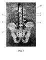
- Figures 1 to 3show a first embodiment of an inventive spinal fixation system using an inventive iliac connector and an inventive connector head.
- the spinal fixation systemcomprises one preferably two spinal rods 3 extending along a spine SP and being fixed to one or more vertebrae of the spine SP.
- the spinal rod 3is preferably curved.
- Known pedicle bone screws 4are used as anchors for the fixation to the vertebrae, wherein these spinal bone screws 4 preferably have known tulip heads.
- the spinal bone screws 4 with the tulipsare preferably made of titanium.
- the spinal rod 3is preferably made of a more flexible material, such as a filament composite material.
- a filament composite materialPreferably it is made of carbon filaments encapsulated in a polymer matrix, such as PEKEKK or PEEK.
- the composite materialpreferably comprises of about 66.6% (weight %) of carbon fibers and of about 33.3% polyether-ketoneetherketoneketone (PEKEKK) as encapsulating matrix.
- the fibres or filamentsare preferably oriented in layers which ar parallel to each other and to a surface of the rod.
- the layersmay be made up of woven first and second filaments.
- the first filamentsare oriented in an axial direction of the longitudinal rod.
- the second filamentsare oriented to perpendicular to the axial direction.
- Such a materialis known on the market with the name ostaPek of CoLigne AG and is described in EP 1 238 637 and US 2008/026548 .
- the last screwcan be a sacral bone screw 5 fixed to the sacrum S. It can have, as shown in this example, the same shape and size as the spinal bone screws 4. However, it can also be different in size and/or in shape.
- the spinal rod 3is penetrating the tulip of this sacral screw 5 as well.
- a connector head 1 of an inventive iliac connectoris arranged, wherein the spinal rod 3 preferably penetrates this connector head 1 as well before ending shortly thereafter.
- the total length of the spinal rod 3 and the number of spinal bone screws 4depend on the medical case.
- the connector head 1is made of the same material as the screws. Preferably, it is made of titanium.
- a connecting rod 2is held within this connector head 1 extending at an angle from the spinal rod 3. This angle is preferably approximately 90°.
- the connecting rod 2can be straight or curved as well.
- the connecting rod 2is quite short. Preferably, its length is between 2 and 4 cm and more preferably about 3 cm.
- the connecting rod 2is made of a material which is more flexible than titanium. Preferably it is made of a filament composite material like the spinal rod 2 described above. Preferably, the spinal rod 3 and the connecting rod 2 of a common fixation structure are made of the same material, preferably the one described in EP 1 238 637 and US 2008/026548 and known in the market as ostPek of CoLigne AG.
- the two rods 2, 3can have the same outer geometry, especially the same diameter.
- the connecting rod 2has preferably a round cross-section and it has preferably throughout its length the same outer shape and the same diameter. Typical diameters are 4 to 8 mm, preferably about 6 mm.
- the connecting rod 2can also have another cross-section, for example a polygonal one.
- the connecting rod 2penetrates the connector head 1.
- the other free endpenetrates an anchor or fixation element which is fixed to the ilium I.
- this fixation elementis an iliac bone screw 6 as best seen in figure 3 .
- This screw 6preferably has a tulip as well. It can have the same shape and size as the sacral bone screw 5 and/or the spinal bone screw 4. However it also can have a different size and shape. Preferably, it is not combined with a plate and preferably it is only a single screw.
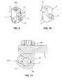
- FIGS. 4 to 9show the inventive connector head 1 in more detail.
- the connector head 1has a generally cuboid main body wherein a transition area between two walls has a remarkably rounded shape and wherein an opposite wall to this transition area has an inclined section.
- the connector headcomprises two opposite side walls 10, extending parallel to each other and being preferably plane.
- a plane rear wall 11is arranged perpendicular to these side walls 10 and a flat top 13 is arranged perpendicular to the side walls 10 and the rear wall 11.
- a bottom 12is inclined relative to the rear wall 11 and a front wall 14. Between the rear wall 11 and the bottom 12, the curved transition area 19 extends.
- the bottom 12preferably has first the same curvature as the transition area 19, wherein it decreases continuously in direction to the front wall 14.
- the front wall 14has at least to sections: an upper flat section 140 extending perpendicular to the top 13 and the side walls 10 and therefore parallel to the rear wall 11 and a lower inclined section 141 extending to the bottom 12.
- the inclined section 141is extending forward and increasing the width of the connector head 1 in direction to the bottom 12.
- a first hole 15is arranged in one of the side walls 10.
- the first hole 15is a through hole extending from one side wall 10 to the other.
- the first hole 15has a first central axis 150 which extends perpendicular to the two side walls 10 from the first side wall to the second one.
- the first hole 15has at its two ends a slightly non-rounded shape, as can be best seen in figure 6 and figure 4 with reference number 151. This helps to fix the rod more securely within the hole.
- the rodis preferably the spinal rod 3.
- a first fixation opening 17is arranged, see figure 5 .
- This first fixation opening 17extends from the front wall 14 to the first hole 15 within the main body of the head 1, i.e. it crosses or leads into the first hole 15.
- This first fixation opening 17comprises an internal thread, allowing a first fixation screw 171 (see figure 11 ) to be screwed into this opening 17.
- a second hole 16 with a second central axis 160extends from the rear wall 16 in direction to the front wall 14, in particular to the plane upper section 140.
- the second hole 16is preferably a through hole as well, therefore ending in the front wall 14.
- This second hole 16can have the same size and shape as the first hole 15. Preferably it has at least the same non-rounded shape in cross-section and the same increased diameter at its ends. This can best be seen in figure 7 and figure 4 with reference number 161. It fixes the rod more securely within the hole This rod is preferably the connecting rod 2.
- a second fixation opening 18is arranged in the top 13, extending through the main body to the second hole 16 and is crossing it.
- the second fixation opening 18has an internal thread 180 as well. It has preferably the same size as the first fixation opening 17 and it serves also to hold a second fixation screw 181.
- first hole 15 and the second hole 16do not penetrate each other. Preferably, they extend in two parallel planes, their first and second central axis 150, 160 being perpendicular, but spaced from each other.
- FIGS 9 to 11show the connector head 1 in use with the inventive connecting rod 2 and the spinal rod 3.
- each rod 2, 3is fixed independently from each other by the first fixation screw 171 and the second fixation screw 181 respectively.
- both rods 2, 3penetrate the holes 15, 16, their ends protruding the head 1.
- the screws 171 and 181can be fixed independently from each other and in a freely chosen chronological order.
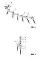
- Figures 12 to 20show a second embodiment of the inventive spinal fixation system and second embodiments of connector heads. While the connector head of the first embodiment is symmetrically built and the same shape of connector head can be used on both sides of the spine, the system according to this second embodiment comprises a left side and a right side connector head, the two heads being mirrored.
- Figure 14shows a left side connector head 7, which can be used in the system according to figures 12 and 13 , i.e. on the left side of the spine.
- Figure 15shows a right side connector head 7', which can be used with a similar or identical system on the right side of the spine.
- the right side connector head 7'is the mirror picture of the left side connector head 7. In the following, only the left side connector head 7 will be described. However, the same description also applies to the right side connector head 7'.
- the connector head 7 of figures 14is made of one single piece as a unitary part. Preferably it is made of the same material as the screws 4 mentioned above, for example it is made of titanium.
- the left side and the right side connector heads 7, 7'are similar to the one shown in figures 1 to 11 .
- the previous description of this connector head 1 according to the first embodimentis therefore applicable to these connector heads 7, 7' as well, where appropriate. Identical or similar features, especially the ones shown in the figures, will not be described in detail any more.
- the connector head 7comprises a first body 70 and a second body 74.
- the first body 70is also called spinal body and the second body is also called connecting body.
- Both bodies 70, 74have preferably a cube-like shape.
- a transition area 79is connecting the two bodies 70, 74 with each other.
- the transition area 79is preferably rounded, as can be best seen in figure 18 .
- the transition area 79has a twisted shape, as can be best seen in figure 14 .
- the edges of the two bodies 70, 74are preferably rounded as well.
- the bottom 72 of the connector head 7, which is preferably the bottom of the first body 70,can be rounded as well. These rounded parts ensure, that no human tissue gets hurt.
- the first body 70comprises the first hole 75 and the first fixation opening 77.
- the second body 74comprises the second hole 76 and the second fixation opening 78. At least one, preferably both holes 75, 76 are through holes.
- the fixations openings 77, 78comprise preferably threads 770, 780, as can be best seen in figures 19 and 20 .
- the first hole 75comprises a first central axis 750 and the second hole 76 comprises a second central axis 760, wherein these axis extend perpendicular but at a distance to each other; i.e. they do not cross each other and are therefore extending in planes different from each other.
- the first body 70is arranged below and staggered to the second body 74. They are like steps of a circular staircase.
- the top surface 71 of the first body 70extends preferably parallel to the top surface 73 of the second body 74, but at a distance below it, as can be best seen in figures 16 and 17 .
- the first fixation opening 77is arranged in the top surface 71 of the first body 70 and the second fixation opening 78 is arranged in the top surface 73 of the second body 74. This means that their threads 770, 780 extend in the same direction, perpendicular to the central axis 750, 760 of the first and second holes 75, 76.
- the first body 70comprises a recess 700 which extends in direction of the second central axis 760 from the second hole 76 to the opposite end of the first body.
- This recess 700has a rounded cross-section suitable to accommodate the connecting rod 2.
- the second body 74comprises a recess 740 which extend from the first fixation opening 77 to the top surface 73 of the second body. This recess 740 optimizes the access to the first fixation opening 77, so that a screw can be easily entered and fixed into this first fixation opening 77.
- this connector head 7, 7'minimizes the space needed for the connection of a connecting rod 2 and a spinal rod 3, but gives still independent access to both holes 75, 76 and to both fixation openings 77, 78.
- the inventive iliac connectorenables a stabilization of ilium, sacrum and spine and allows at the same time movements between ilium and sacrum.
Landscapes
- Health & Medical Sciences (AREA)
- Orthopedic Medicine & Surgery (AREA)
- Surgery (AREA)
- Neurology (AREA)
- Life Sciences & Earth Sciences (AREA)
- Biomedical Technology (AREA)
- Animal Behavior & Ethology (AREA)
- Engineering & Computer Science (AREA)
- Veterinary Medicine (AREA)
- Heart & Thoracic Surgery (AREA)
- Medical Informatics (AREA)
- Molecular Biology (AREA)
- Nuclear Medicine, Radiotherapy & Molecular Imaging (AREA)
- General Health & Medical Sciences (AREA)
- Public Health (AREA)
- Neurosurgery (AREA)
- Surgical Instruments (AREA)
- Prostheses (AREA)
- Orthopedics, Nursing, And Contraception (AREA)
Abstract
Description
- The present invention is in the field of stabilization and fixation of a spine. The present invention relates to an iliac connector, a connector head and a spinal fixation system.
- Several fixation techniques are known for the treatment of spinal deformities and pathologies, among them spinal fusion. While this is an extensive operation with potentially serious complications, a spinal fusion can be considered a lesser evil than the problem the surgeon must solve. The diseased spinal segments of a patient may be so unstable, painful and potentially nerve damaging that blocking mobile spine segments to form one bone is thought to be the best method of treatment. To fix the spine, surgeons attach one or more longitudinal fixation elements, such as rods or plates, to the spine at several fixation sites using bone screws. Often spinal bone screws are fixed through one of the most solid sections of a vertebrae, the pedicle.
- The vertebral pedicles connect the anterior vertebral body to its posterior elements where the actuating back muscles are attached. The pedicles at each motion segment work like a lever between the back and the front of the spine. They mediate almost all the forces from the back muscles to the anterior spine, enabling the human being to stand erect and to bend forward in a controlled manner. From the cervical to the lumbar spine that stops adjacent to the sacrum, the pedicle is the most solid structure to place a screw that is connected by a longitudinal element that fixes motion segments of the spine.
EP 1 238 637- Sometimes, a surgeon must extend a long fusion beyond the lumbar spine and connect it to the sacrum where the bone is soft and spongy. At end of a long fusion construct, the implant forms a long lever arm that works to pull the screws from this soft sacral bone.
- To prevent a screw pull-out from the sacrum and a fusion-construct failure, it is known to increase the anchor locations. This can be done with multiple screws in the sacrum. It is also known to extend the entire construct lateral, crossing the sacral iliac joint to engage the iliac bone as well.
US 5 133 717 shows a sacral support saddle for fastening a spinal rod to the sacrum.US 5 593 407 suggests to connect the lowest lumbar vertebra directly to the ilium, using a bent rod and pedicle screws.US 2012/0022595 describes a sacral-iliac stabilization system with a sacral-iliac plate having a first screw hole for receiving a first fastener to secure the iliac portion to the iliac bone. A second and third screw hole is also provided for receiving a second and a third fastener to secure the sacral portion to the sacral bone.US 2006/0106382 also discloses a plate connecting the sacrum to the ilium.US 2008/0154306 suggests using long screws to connect the sacrum to the ilium.US 2008/0021456 shows a quite complicated system comprising a plate on the ilium, rod like connectors to the sacrum and a stabilization plate between the lowest lumbar vertebra and the sacrum.US 2008/0021455 discloses a sacral-iliac cross connector to allow for coupling of the connector to a spinal fixation rod and anchors. The connector has a receiver head with opposed sidewalls defining a seating portion for an insert which is configured to seat a spinal rod. The connector also includes a connecting rod with a flat end part comprising a hole. This end part is held in a slot on the bottom side of the seating portion and it is fixed to a post or shaft arranged on the bottom side of the insert. Therefore, the connecting rod has to be arranged and fixed before the spinal rod can be placed into the insert and fixed therein.US 2008/0021454 , which refers toUS 2008/0021455 , shows infigure 5A a spine fixation system with a spinal rod, a sacral-iliac cross connector comprising a connector rod and a plate fixed on the ilium.- However, the loss of the sacral-iliac joint is very much noticed by the patient when blocked. The reason for this is the following: The pelvis comprises three bony parts (two iliac bones and the sacrum). Together the iliac bones and sacrum form a ring, with the iliac bones joined anterior at the pubis and the sacrum placed posterior between iliac bones like a keystone. The pelvic ring is held together by a multitude of complex ligaments. These ligaments allow small movement, particularly at the sacro-iliac joints, that are paired left and right between the sacrum and the pelvis. With their ligaments, the sacral-iliac joints allow a subtle nodding movement of the sacrum between the iliac bones at all changes in posture. This slightly changes the form of the pelvic ring during forward bending (flexion) and backward bending (extension). In this manner, this subtle sacral movement and change in pelvic form become a mechanism that absorbs energy propagated from the limbs to the spine and vice versa. This mechanism is often unnoticed by the patient until it is disrupted or gone.
- Sacral-iliac fixations, designed to prevent screw pull out from the sacrum, also eliminate the ability of the sacral-iliac joint to gently flex and nod in a normal manner, which allow certain postures and energy absorbtion between the lower and upper body. Since the posterior ligaments are removed and the joint blocked, a minute, but yet significant motion is lost. All energy is driven into the spine from the pelvis and sacrum that has become one bone. Shocks can not be absorbed correctly. Shocks are uncomfortable and over time can degenerate the surrounding joints of the hips and spine.
- It is therefore an object of the invention to allow a stabilization of the iliac area while still enabling a natural movement between ilium and sacrum.
- This object is achieved by an iliac connector according to
claim 1, a connector head according toclaim 6 and a spinal fixation system according toclaim 16. - The inventive iliac connector comprises a connector head and an elongate connecting member for connecting a sacrum or a spine to an ilium. The connector head has a first hole for holding an elongate spinal member and a second hole for holding the elongate connecting member, wherein the elongate connecting member is made of a material being more flexible than titanium. Preferably, the elongate connecting member is made of a material less flexible than a rope or a rubber band.
- At least one of the elongate connecting member and the elongate spinal member, preferably both, are rods. In the following the expression "rod" will be use, wherein other shapes are meant as well.
- Since the connecting rod is more flexible than titanium, movement of the ilium relative to the sacrum is still possible. However the rod gives sufficient stabilization between these two parts. The rod allows a very low deformation in longitudinal direction but still allows sufficient bending and rotation around its longitudinal direction. It also allows, when coupled with a spinal rod a coupled motion.
- This spinal fixation system applies a corrective force upon the spine, but does also allow some deflection, returning resiliently due to the inherent memory of form that is desired by the surgeon as the patient moves and as normal body stress are exerted upon it. This spinal fixation system is elastic enough to allow stress to pass through adjacent and connected bones that will encourage bone growth and then return to the original corrective form while at the same time it is not so flexible as to over stress the bone and cause micro stress fractures.
- The rod can be straight or curved in its initial position without any force applied to it.
- In a preferred embodiment, the connecting rod is made of a filament composite material, preferably with long strands or filaments. Preferably the filaments are carbon filaments. The filaments are preferably oriented, thereby extending mainly in longitudinal direction of the connecting rod. Preferably, the filaments are woven. A matrix preferably holds the carbon strands in place when load passes through the carbon fibers, while at the same time, allows some matrix stretching between the fibers. This brings flexibility and spring-like qualities to the rod in bending as well as torsion. Preferably, the connecting rod is a composite rod as described in
EP 1 238 637 - The rod can have the same fiber orientation and matrix arrangement throughout the whole length of the connecting rod. However the connecting rod can also have different orientation of the fibers at different locations in the rod to make it stronger, stiffer or more flexible at these different locations. A disclosure of such a rod can be found in
US 2008/026548 . - In a preferred embodiment, the carbon filaments are encapsulated in a polymer matrix, the matrix being preferably polyether-ketoneetherketoneketone (PEKEKK) or polyetheretherketone (PEEK).
- In a preferred embodiment, the connecting rod has throughout its whole length a non-changing outer geometry, even when the stiffness of the rod changes throughout its length. Preferably, the rod has a round cross-section. It can also have other shapes, such as a polygonal cross-section. This simplifies production as well as surgery, since the rod can be manufactured in standard lengths and it can be cut for each application individually.
- It is a further advantage of the inventive iliac connector that the rod is made of a radio lucent material. This enables the surgeon to analyze tissue and bone beneath the iliac connector, to observe bone formation or detect other pathologies at a later time.
- The invention also refers to a special connector head, which can for example be used in the inventive iliac connector. This connector head has a first hole defining a first central axis for holding a spinal rod and a second hole defining a central second axis for holding a connecting rod, the two central axes extending in different directions and at a distance to each other. Each hole is in communication with a separate fixation opening, the fixation openings being arranged such they allow mounting of the connecting rod and the spinal rod independently from each other. This connector head can hold two rods, i.e. a spinal rod and a connecting rod, individually. It does not depend which one is fixed first within the connector head. An already fixed rod can also made loose again without manipulation of the other rod. The surgeon has therefore utmost ability to adapt the fixation to the local anatomy and to the goals for treatment. For example, the two rods can be placed in any order, secured in any sequence that is optimal for precision in placement, for the ease of assembly and to place progressive forces to better align the spine
- This connector head is preferably used with this stiff and flexible rod mentioned above. However it can also be used with other rods, for example rods known in the state of the art which are used for spinal corrections. It can also be used for combining to other kind of rods, not only as iliac connector.
- Preferably, the first central axis of the first hole and the second central axis of the second hole extend in two planes extending at a distance from each other but parallel to each other. However, it is also possible that these two planes are arranged in an angle to each other, i.e. one of the holes being tilted with respect to the other hole.
- In a preferred embodiment, the fixation opening of the first hole is arranged at an angle α different from 90° to the fixation opening of the second hole. This makes both fixation openings easily accessible for the surgeon. Preferred angles are between 70° to 30°, more preferably between 60° to 40°. In one example the angle α is about 60°. In preferred embodiments the angle α is about 45° or less. In another preferred embodiment, this angle is approximately 0°.
- The connector head preferably comprises two side walls, a rear wall, a front wall, a bottom and a top, wherein the first hole is arranged in one of the side walls, the second hole is arranged in the rear wall, the first fixation opening is arranged in the front wall and the second fixation opening is arranged in the top. This arrangement allows minimizing the size of the connector head. Preferably, the back wall is perpendicular to the side walls and the top is perpendicular to the rear wall and the side walls. The side walls can be parallel to each other. Preferably, the edges between the walls are rounded.
- In a preferred embodiment, the front wall comprises at least one section which is inclined with respect to the rear wall. The first fixation opening is arranged in the inclined section. This minimizes the size of the connector head even more and allows a good access to the fixation openings.
- The size is further minimized and optimized to local conditions when a transition area connecting the back wall and the bottom has a rounded outer shape.
- Preferably, at least some, preferably all of the following walls are plane: the side walls, the rear wall, the front wall and the top.
- In another preferred embodiment of the connector head, the first fixation opening is arranged in a first surface of the connector head and the second fixation opening is arranged in a second surface of the connector head, wherein the first surface extends in a plane parallel but at a distance to a plane defined by the second surface. This allows a good access to the fixation openings and places the head further away from the skin to create a less prominent implant construct.
- Access and size are also optimized when the connector head comprises a first body with a cube-like shape and a second body with a cube-like shape, the first body comprising the first hole and the first fixation opening and the second body comprising the second hole and the second fixation opening, wherein the first body is arranged staggered below the second body.
- A connector head comprising the features of both paragraphs mentioned above has been found to be a preferred embodiment.
- The first and second holes can be blind holes. Preferably, at least one and most preferably both of them are straight through holes. The first hole preferably extends from a first of the side walls to a second of the side walls and the second hole extends from the rear wall to the front wall. The spinal rod and the connecting rod can therefore penetrate the connector head and the surgeon has during operation utmost ability to define the length of the clamped parts of the rods, the rods being clamped between connector head and the anchors, for example the pedicle bone screws.
- Preferably, the spinal rod and/or the connecting rod are firmly, i.e. fixedly held in the connector head. Preferably, both of them are firmly held within the connector heads, not allowing any lateral, longitudinal or rotational rod movement at their fixation points.
- The above mentioned connector is preferably used in a spinal fixation system, wherein this system further comprises a spinal rod made of a material being more flexible than titanium, spinal bone screws and preferably at least one sacral bone screw being penetrated by this spinal rod. The spinal rod is hold in the iliac connector head. At least one iliac bone screw can be present fixed in the ilium, wherein the connecting rod of the iliac connector is held in the at least one iliac bone screw. Preferably, the spinal rod and the connecting rod are made of the same material, especially the one described above. This system allows the stabilization of the spine and the ilium thereby allowing some movement between ilium and sacrum.
- Preferably the system uses fixation screws into the sacrum as well, therefore fixing the spinal rod to the sacrum and connecting the sacrum with the ilium using the inventive iliac connector. However it is also possible to connect the lowest lumbar vertebra directly to the ilium by using the inventive connector.
- The inventive system maintains some movement at the sacral-iliac joint by placing spinal rod and connecting rod at an angle to each other, preferably almost perpendicular to one another, wherein at least the connecting rod is made of a material being more flexible than titanium. Preferably, the rods are made of a composite material comprising fibres oriented in longitudinal direction of the rod, so that the fibres of the different rods are oriented at an angle, preferably about 90° to each other, for example 84°.
- The connecting rod works in rotation and with some bending making a coupled movement, while the spinal rod preferably works in flexion and extension as well as some torsion of the spine. This system more closely approximates the function of the posterior sacral-iliac ligaments, while at the same time preventing pull out of the screws at the sacrum. It also absorbs shocks better by allowing a minute but significant movement of the sacrum between the iliac bones of the pelvis during flexion (forward bending) and extension (backward bending). In addition stress shielding and the possible consequence of osteoporosis is avoided in the pelvis and sacrum.
- This system is more comfortable for the patient; it protects the surrounding hips and spine that are adjacent to the fusion construct, and prevents screw pull out and construct failure at the sacrum.
- The inventive method for stabilizing a spine comprises the steps of
- a) accessing the sacrum and iliac portions of the spine;
- b) fixing an elongate spinal member with at least one spinal bone screw to at least one pedicle of the spine, the elongate spinal member having a first end;
- c) fixing an elongate connecting member with a iliac bone screw to the iliac, the elongate connecting member having a second end and
- d) fixing the first end of the elongate spinal member and the second end of the elongate connecting member relative to each other at an angle of about 90°, wherein the chronology of fixation of the first end the second end can be chosen by the surgeon.
- In a preferred variant, the method further comprises the step of fixing the elongate spinal member with at least one, preferably exactly one sacral bone screw to the sacrum and providing a sacral-iliac connection between ilium and sacrum by fixing the first end of the elongate spinal member and the second end of the elongate connecting member relative to each other.
- Fixation of the two ends is preferably established with a connector head comprising two holes into which the two ends are introduced and fixed. Preferably they are introduced separately and independently from each other and preferably, the fixation of each end is also independently from the other one.
- This method enables the surgeon to choose or correct for example the placement of the iliac bone screw at a very late stage of the surgery after the longitudinal elements and pedicle screws have been placed in it is inter-operatively decided to extend the fusion. Also other parts of the spinal fixation system can be rearranged and their relationship to other parts can be changed within a small range at a late stage.
- Further embodiments of the invention are laid down in the dependent claims.
- Preferred embodiments of the invention are described in the following with reference to the drawings, which are for the purpose of illustrating the present preferred embodiment of the invention and not for the purpose of limiting the same. In the drawings is shown
- Figure 1
- a spinal fixation system according to a first embodiment of the invention fixed on a reconstruction of a human lower spine, sacrum and ilium;
- Figure 2
- the fixation system according to
figure 1 in first perspective view; - Figure 3
- the fixation system according to
figure 1 in a second perspective view; - Figure 4
- a connector head according to the invention in a first perspective view;
- Figure 5
- the connector head according to
figure 4 in a second perspective view; - Figure 6
- a side view of the connector head according to
figure 4 ; - Figure 7
- a front view of the connector head according to
figure 4 ; - Figure 8
- a longitudinal section of the connector head according to
figure 4 ; - Figure 9
- a first perspective view of an iliac connector according to the invention with a spinal rod arranged in the connector;
- Figure 10
- a second perspective view of the iliac connector according to
figure 9 ; - Figure 11
- a longitudinal section of the iliac connector according to
figure 9 ; - Figure 12
- a spinal fixation system according to a second embodiment of the invention, in a first perspective view;
- Figure 13
- the fixation system according to
figure 12 in a second perspective view; - Figure 14
- a left side connector head according of the spinal fixation system according to
figure 12 in a perspective view; - Figure 15
- a perspective view of a right side connector head for use in a spinal fixation system;
- Figure 16
- a rear view of the left side connector head according to
figure 14 ; - Figure 17
- a side view of the left side connector head according to
figure 14 ; - Figure 18
- a top view of the left side connector head according to
figure 14 ; - Figure 19
- a first longitudinal section view of the connector head according to
figure 14 and - Figure 20
- a second longitudinal section view of the connector head according to
figure 14 . Figures 1 to 3 show a first embodiment of an inventive spinal fixation system using an inventive iliac connector and an inventive connector head.- The spinal fixation system comprises one preferably two
spinal rods 3 extending along a spine SP and being fixed to one or more vertebrae of the spine SP. Thespinal rod 3 is preferably curved. Knownpedicle bone screws 4 are used as anchors for the fixation to the vertebrae, wherein these spinal bone screws 4 preferably have known tulip heads. The spinal bone screws 4 with the tulips are preferably made of titanium. - The
spinal rod 3 is preferably made of a more flexible material, such as a filament composite material. Preferably it is made of carbon filaments encapsulated in a polymer matrix, such as PEKEKK or PEEK. The composite material preferably comprises of about 66.6% (weight %) of carbon fibers and of about 33.3% polyether-ketoneetherketoneketone (PEKEKK) as encapsulating matrix. The fibres or filaments are preferably oriented in layers which ar parallel to each other and to a surface of the rod. The layers may be made up of woven first and second filaments. The first filaments are oriented in an axial direction of the longitudinal rod. The second filaments are oriented to perpendicular to the axial direction. Such a material is known on the market with the name ostaPek of CoLigne AG and is described inEP 1 238 637US 2008/026548 . - On one free end of the
spinal rod 3, the last screw can be asacral bone screw 5 fixed to the sacrum S. It can have, as shown in this example, the same shape and size as the spinal bone screws 4. However, it can also be different in size and/or in shape. Thespinal rod 3 is penetrating the tulip of thissacral screw 5 as well. At the penetrating end of thespinal rod 3, aconnector head 1 of an inventive iliac connector is arranged, wherein thespinal rod 3 preferably penetrates thisconnector head 1 as well before ending shortly thereafter. - The total length of the
spinal rod 3 and the number of spinal bone screws 4 depend on the medical case. - Preferably, the
connector head 1 is made of the same material as the screws. Preferably, it is made of titanium. - A connecting
rod 2 is held within thisconnector head 1 extending at an angle from thespinal rod 3. This angle is preferably approximately 90°. The connectingrod 2 can be straight or curved as well. The connectingrod 2 is quite short. Preferably, its length is between 2 and 4 cm and more preferably about 3 cm. - The connecting
rod 2 is made of a material which is more flexible than titanium. Preferably it is made of a filament composite material like thespinal rod 2 described above. Preferably, thespinal rod 3 and the connectingrod 2 of a common fixation structure are made of the same material, preferably the one described inEP 1 238 637US 2008/026548 and known in the market as ostPek of CoLigne AG. - The two
rods rod 2 has preferably a round cross-section and it has preferably throughout its length the same outer shape and the same diameter. Typical diameters are 4 to 8 mm, preferably about 6 mm. The connectingrod 2 can also have another cross-section, for example a polygonal one. - One free end of the connecting
rod 2 penetrates theconnector head 1. The other free end penetrates an anchor or fixation element which is fixed to the ilium I. Preferably, this fixation element is aniliac bone screw 6 as best seen infigure 3 . Thisscrew 6 preferably has a tulip as well. It can have the same shape and size as thesacral bone screw 5 and/or thespinal bone screw 4. However it also can have a different size and shape. Preferably, it is not combined with a plate and preferably it is only a single screw. Figures 4 to 9 show theinventive connector head 1 in more detail. Theconnector head 1 has a generally cuboid main body wherein a transition area between two walls has a remarkably rounded shape and wherein an opposite wall to this transition area has an inclined section.- As can be best seen in
figure 4 , the connector head comprises twoopposite side walls 10, extending parallel to each other and being preferably plane. A planerear wall 11 is arranged perpendicular to theseside walls 10 and aflat top 13 is arranged perpendicular to theside walls 10 and therear wall 11. A bottom 12 is inclined relative to therear wall 11 and afront wall 14. Between therear wall 11 and the bottom 12, thecurved transition area 19 extends. The bottom 12 preferably has first the same curvature as thetransition area 19, wherein it decreases continuously in direction to thefront wall 14. - The
front wall 14 has at least to sections: an upperflat section 140 extending perpendicular to the top 13 and theside walls 10 and therefore parallel to therear wall 11 and a lowerinclined section 141 extending to the bottom 12. Theinclined section 141 is extending forward and increasing the width of theconnector head 1 in direction to the bottom 12. - The directions used above, such as upper, lower, rear, front, bottom, top, refer to the orientation of the
connector head 1 as shown in thefigures 4 to 8 . They do not restrict that orientation of theconnector head 1 when in use. - A
first hole 15 is arranged in one of theside walls 10. Preferably, thefirst hole 15 is a through hole extending from oneside wall 10 to the other. Thefirst hole 15 has a firstcentral axis 150 which extends perpendicular to the twoside walls 10 from the first side wall to the second one. - The
first hole 15 has at its two ends a slightly non-rounded shape, as can be best seen infigure 6 and figure 4 withreference number 151. This helps to fix the rod more securely within the hole. The rod is preferably thespinal rod 3. - In the
front wall 14, in particular in the inclinedlower section 141, afirst fixation opening 17 is arranged, seefigure 5 . Thisfirst fixation opening 17 extends from thefront wall 14 to thefirst hole 15 within the main body of thehead 1, i.e. it crosses or leads into thefirst hole 15. Thisfirst fixation opening 17 comprises an internal thread, allowing a first fixation screw 171 (seefigure 11 ) to be screwed into thisopening 17. - A
second hole 16 with a secondcentral axis 160 extends from therear wall 16 in direction to thefront wall 14, in particular to the planeupper section 140. Thesecond hole 16 is preferably a through hole as well, therefore ending in thefront wall 14. Thissecond hole 16 can have the same size and shape as thefirst hole 15. Preferably it has at least the same non-rounded shape in cross-section and the same increased diameter at its ends. This can best be seen infigure 7 and figure 4 withreference number 161. It fixes the rod more securely within the hole This rod is preferably the connectingrod 2. - A second fixation opening 18 is arranged in the top 13, extending through the main body to the
second hole 16 and is crossing it. The second fixation opening 18 has aninternal thread 180 as well. It has preferably the same size as thefirst fixation opening 17 and it serves also to hold asecond fixation screw 181. - As can be best seen in
figure 8 , thefirst hole 15 and thesecond hole 16 do not penetrate each other. Preferably, they extend in two parallel planes, their first and secondcentral axis Figures 9 to 11 show theconnector head 1 in use with the inventive connectingrod 2 and thespinal rod 3. As can be seen, eachrod first fixation screw 171 and thesecond fixation screw 181 respectively. Preferably, bothrods holes head 1. As can be seen infigures 1 and9 , thescrews Figures 12 to 20 show a second embodiment of the inventive spinal fixation system and second embodiments of connector heads. While the connector head of the first embodiment is symmetrically built and the same shape of connector head can be used on both sides of the spine, the system according to this second embodiment comprises a left side and a right side connector head, the two heads being mirrored.- As can be seen in
figures 12 and 13 , the only difference of the spinal system according to the first and this second embodiment is the different kind of connector head used. This head bears in this second embodiment thereference numbers 7, 7' (seefigure 15 ). The other elements remain unchanged, and there reference numbers are identical with the ones of the first embodiment. The description of these elements, already mentioned above, is therefore also applicable to this embodiment. Figure 14 shows a leftside connector head 7, which can be used in the system according tofigures 12 and 13 , i.e. on the left side of the spine.Figure 15 shows a right side connector head 7', which can be used with a similar or identical system on the right side of the spine. As can be seen in comparison offigures 14 and 15 , the right side connector head 7' is the mirror picture of the leftside connector head 7. In the following, only the leftside connector head 7 will be described. However, the same description also applies to the right side connector head 7'.- The
connector head 7 offigures 14 is made of one single piece as a unitary part. Preferably it is made of the same material as thescrews 4 mentioned above, for example it is made of titanium. The left side and the right side connector heads 7, 7' are similar to the one shown infigures 1 to 11 . The previous description of thisconnector head 1 according to the first embodiment is therefore applicable to these connector heads 7, 7' as well, where appropriate. Identical or similar features, especially the ones shown in the figures, will not be described in detail any more. - The
connector head 7 comprises afirst body 70 and asecond body 74. Thefirst body 70 is also called spinal body and the second body is also called connecting body. Bothbodies transition area 79 is connecting the twobodies transition area 79 is preferably rounded, as can be best seen infigure 18 . Thetransition area 79 has a twisted shape, as can be best seen infigure 14 . - The edges of the two
bodies connector head 7, which is preferably the bottom of thefirst body 70, can be rounded as well. These rounded parts ensure, that no human tissue gets hurt. - The
first body 70 comprises thefirst hole 75 and thefirst fixation opening 77. Thesecond body 74 comprises thesecond hole 76 and thesecond fixation opening 78. At least one, preferably bothholes fixations openings threads figures 19 and 20 . - The
first hole 75 comprises a firstcentral axis 750 and thesecond hole 76 comprises a secondcentral axis 760, wherein these axis extend perpendicular but at a distance to each other; i.e. they do not cross each other and are therefore extending in planes different from each other. - The
first body 70 is arranged below and staggered to thesecond body 74. They are like steps of a circular staircase. Thetop surface 71 of thefirst body 70 extends preferably parallel to thetop surface 73 of thesecond body 74, but at a distance below it, as can be best seen infigures 16 and 17 . Thefirst fixation opening 77 is arranged in thetop surface 71 of thefirst body 70 and the second fixation opening 78 is arranged in thetop surface 73 of thesecond body 74. This means that theirthreads central axis second holes - The
first body 70 comprises arecess 700 which extends in direction of the secondcentral axis 760 from thesecond hole 76 to the opposite end of the first body. Thisrecess 700 has a rounded cross-section suitable to accommodate the connectingrod 2. - The
second body 74 comprises arecess 740 which extend from thefirst fixation opening 77 to thetop surface 73 of the second body. Thisrecess 740 optimizes the access to thefirst fixation opening 77, so that a screw can be easily entered and fixed into thisfirst fixation opening 77. - As can be seen in
figures 12 and 13 , thisconnector head 7, 7' minimizes the space needed for the connection of a connectingrod 2 and aspinal rod 3, but gives still independent access to bothholes fixation openings - The inventive iliac connector enables a stabilization of ilium, sacrum and spine and allows at the same time movements between ilium and sacrum.
LIST OF REFERENCE SIGNS 1 connector head 10 side wall 6 iliac bone screw 11 rear wall 12 bottom 7 connector head 13 top 7' connector head 14 front wall 70 first body (spinal body) 140 flat section 700 first recess 141 inclined section 71 first top surface 15 first hole 72 bottom 150 first central axis 73 second top surface 151 non-rounded part 74 second body (connecting body) 16 second hole 740 second recess 160 second central axis 75 first hole 161 non-rounded part 750 first central axis 17 first fixation opening 76 second hole 170 first thread 760 second central axis 171 first fixation screw 77 first fixation opening 18 second fixation opening 770 first thread 180 second thread 78 second fixation opening 181 second fixation screw 780 second thread 19 transition area 79 transition area 2 connecting rod α angle 3 spinal rod SP Spine I Ilium 4 spinal bone screw S Sacrum 5 sacral bone screw
Claims (18)
- An iliac connector comprising a connector head (1, 7) and an elongate connecting member (2) for connecting a sacrum (S) or a spine (SP) to an ilium (I), the connector head (1, 7) having a first hole (15, 75) for holding a spinal rod (3) and a second hole (16, 76) for holding the elongate connecting member (2), wherein the elongate connecting member (2) is made of a material being more flexible than titanium.
- The iliac connector according to claim 1, wherein the elongate connecting member (2) is made of filament composite material, wherein the filaments are preferably oriented.
- The iliac connector according to claim 2, wherein the filaments are carbon filaments encapsulated in a polymer matrix, preferably polyether-ketoneetherketoneketone (PEKEKK) or polyetheretherketone (PEEK).
- The iliac connector according to one of claims 1 to 3, wherein the elongate connecting member (2) has throughout its whole length a non-changing outer geometry.
- The iliac connector according to one of claims 1 to 4, wherein the elongate connecting member (2) is a rod.
- A connector head, especially for use in an iliac connector according to one of claims 1 to 5, wherein the connector head (1, 7) has a first hole (15, 75) having a first central axis (150) for holding an elongate spinal member (3) and a second hole (16, 76) having a central second axis (160) for holding an elongate connecting member (2), the two central axis (150, 160) extending in different directions and at a distance to each other, wherein the first hole (15, 75) is in communication with a first fixation opening (17, 77) and the second hole (16, 76) is in communication with a second fixation opening (18, 78), the first and second fixation openings (17, 77; 18, 78) being arranged such they allow mounting of the elongate connecting member (2) and the elongate spinal member (3) independently from each other.
- The connector head of claim 6, wherein the fixation opening (170) of the first hole (17, 77) is arranged at an angle (α) different from 90° to the fixation opening (180) of the second hole (18, 78).
- The connector head of claim 7, wherein the angle (α) is between 70° to 30°, preferably between 60° to 40° and most preferably about 60° or 45° or less.
- The connector head of one of claims 6 to 8, wherein the connector head (1) comprises two side walls (10), a rear wall (11), a front wall (14), a bottom (12) and a top (13), wherein the first hole (15) is arranged at least in one of the side walls (10), the second hole (16) is arranged at least in the rear wall (11), the first fixation opening (17) is arranged in the front wall (14) and the second fixation opening (18) is arranged in the top (13).
- The connector head of one claim 9, wherein the front wall (14) comprises at least one section (141) which is inclined with respect to the rear wall (11) and wherein the first fixation opening (17) is arranged in the inclined section (141).
- The connector head of one of claims 9 to 10, wherein a transition area (19) connects the rear wall (11) and the bottom (12) and wherein this transition area (19) is rounded.
- The connector head of claim 7, wherein the angle (α) is approximately 0°.
- The connector head of one of claims 6, 7 or 12, wherein the first fixation opening (77) is arranged in a first surface of the connector head (7) and the second fixation opening (78) is arranged in a second surface of the connector head (7), wherein the first surface extends in a plane parallel but at a distance to a plane defined by the second surface.
- The connector head of one of claims 6, 7, 12 or 13, wherein the connector head (7) comprises a first body (70) with a cube-like shape and a second body (74) with a cube-like shape, the first body (70) comprising the first hole (75) and the first fixation opening (77) and the second body (74) comprising the second hole (76) and the second fixation opening (78), wherein the first body (70) is arranged staggered below the second body (74).
- The connector head of one of claims 6 to 14, wherein and least one of the first and the second hole (15, 75; 16, 76) is a through hole.
- A spinal fixation system comprising the iliac connector according to one of claims 1 to 5, wherein the system further comprises
an elongate spinal member (3) made of a material being more flexible than titanium,
spinal bone screws (4) and preferably at least one sacral bone screw (5) being penetrated by this spinal rod (3), wherein the spinal rod (3) is hold in an iliac connector head (1, 7) of the iliac connector,
and at least one iliac bone screw (6), wherein an elongate connecting member (2) of the iliac connector is hold in the at least one iliac bone screw (6). - The spinal fixation system according to claim 16, wherein the elongate spinal member (3) and the elongate connecting member (2) are made of the same material.
- The spinal fixation system according to one of claims 16 or 17, wherein at least one of, preferably both, the elongate spinal member (3) and the elongate connecting member is a rod.
Applications Claiming Priority (1)
| Application Number | Priority Date | Filing Date | Title |
|---|---|---|---|
| US201261644689P | 2012-05-09 | 2012-05-09 |
Publications (3)
| Publication Number | Publication Date |
|---|---|
| EP2662037A2true EP2662037A2 (en) | 2013-11-13 |
| EP2662037A3 EP2662037A3 (en) | 2014-02-19 |
| EP2662037B1 EP2662037B1 (en) | 2023-01-11 |
Family
ID=48288910
Family Applications (1)
| Application Number | Title | Priority Date | Filing Date |
|---|---|---|---|
| EP13166637.2AActiveEP2662037B1 (en) | 2012-05-09 | 2013-05-06 | Iliac connector, connector head and spinal fixation system |
Country Status (2)
| Country | Link |
|---|---|
| US (2) | US9561058B2 (en) |
| EP (1) | EP2662037B1 (en) |
Cited By (1)
| Publication number | Priority date | Publication date | Assignee | Title |
|---|---|---|---|---|
| RU2584810C1 (en)* | 2014-12-02 | 2016-05-20 | Александр Алексеевич Кулешов | Method for tool fixation of at least part of thoracic and/or lumbar spine to pelvis in various diseases |
Families Citing this family (29)
| Publication number | Priority date | Publication date | Assignee | Title |
|---|---|---|---|---|
| EP2460482A1 (en)* | 2010-12-03 | 2012-06-06 | Zimmer Spine | Rod holding device |
| US8740950B2 (en)* | 2011-12-08 | 2014-06-03 | Spine Wave, Inc. | Methods for percutaneously attaching a cross connector to contralateral spinal constructs |
| US20140012340A1 (en)* | 2012-07-05 | 2014-01-09 | Warsaw Orthopedic, Inc. | Sacro-iliac joint implant system and method |
| US20140277163A1 (en)* | 2013-03-15 | 2014-09-18 | Ryan Kretzer | Reinforcement systems for spine stabilization constructs |
| US9737340B1 (en) | 2014-09-16 | 2017-08-22 | Nuvasive, Inc. | Adjustable iliac connector |
| US10492921B2 (en) | 2015-04-29 | 2019-12-03 | Institute for Musculoskeletal Science and Education, Ltd. | Implant with arched bone contacting elements |
| JP6768001B2 (en) | 2015-04-29 | 2020-10-14 | インスティテュート フォー マスキュロスケレタル サイエンス アンド エジュケイション,リミテッド | Coiled implants and systems and how to make them |
| US10449051B2 (en) | 2015-04-29 | 2019-10-22 | Institute for Musculoskeletal Science and Education, Ltd. | Implant with curved bone contacting elements |
| US10070895B2 (en) | 2015-09-30 | 2018-09-11 | Amendia, Inc. | Dual tulip assembly |
| US10888357B2 (en)* | 2016-02-29 | 2021-01-12 | Warsaw Orthopedic, Inc. | Spinal implant system and method |
| US10517647B2 (en) | 2016-05-18 | 2019-12-31 | Medos International Sarl | Implant connectors and related methods |
| US10321939B2 (en) | 2016-05-18 | 2019-06-18 | Medos International Sarl | Implant connectors and related methods |
| EP3482719B1 (en)* | 2016-07-08 | 2023-09-13 | Beijing AK Medical Co., Ltd. | Sacrum repair device |
| US11033394B2 (en) | 2016-10-25 | 2021-06-15 | Institute for Musculoskeletal Science and Education, Ltd. | Implant with multi-layer bone interfacing lattice |
| US10478312B2 (en) | 2016-10-25 | 2019-11-19 | Institute for Musculoskeletal Science and Education, Ltd. | Implant with protected fusion zones |
| US10398476B2 (en) | 2016-12-13 | 2019-09-03 | Medos International Sàrl | Implant adapters and related methods |
| US10492835B2 (en) | 2016-12-19 | 2019-12-03 | Medos International Sàrl | Offset rods, offset rod connectors, and related methods |
| US10238432B2 (en) | 2017-02-10 | 2019-03-26 | Medos International Sàrl | Tandem rod connectors and related methods |
| US10736665B2 (en)* | 2017-02-24 | 2020-08-11 | Warsaw Orthopedic, Inc. | Spinal implant system and method |
| US10512549B2 (en) | 2017-03-13 | 2019-12-24 | Institute for Musculoskeletal Science and Education, Ltd. | Implant with structural members arranged around a ring |
| US10966761B2 (en) | 2017-03-28 | 2021-04-06 | Medos International Sarl | Articulating implant connectors and related methods |
| US10561454B2 (en) | 2017-03-28 | 2020-02-18 | Medos International Sarl | Articulating implant connectors and related methods |
| US10940015B2 (en) | 2017-11-21 | 2021-03-09 | Institute for Musculoskeletal Science and Education, Ltd. | Implant with improved flow characteristics |
| US10744001B2 (en) | 2017-11-21 | 2020-08-18 | Institute for Musculoskeletal Science and Education, Ltd. | Implant with improved bone contact |
| US11076890B2 (en) | 2017-12-01 | 2021-08-03 | Medos International Sàrl | Rod-to-rod connectors having robust rod closure mechanisms and related methods |
| RU184913U1 (en)* | 2018-01-09 | 2018-11-14 | ФЕДЕРАЛЬНОЕ ГОСУДАРСТВЕННОЕ БЮДЖЕТНОЕ УЧРЕЖДЕНИЕ "НАУЧНО-ИССЛЕДОВАТЕЛЬСКИЙ ДЕТСКИЙ ОРТОПЕДИЧЕСКИЙ ИНСТИТУТ ИМЕНИ Г.И. ТУРНЕРА" Министерства здравоохранения Российской Федерации | Device for the surgical treatment of children with caudal regression of type 4 according to the classification of T.S. Renshaw |
| US11857420B2 (en)* | 2019-03-19 | 2024-01-02 | Brad MULLIN | Sacroiliac joint fusion implants and methods |
| US11571244B2 (en)* | 2019-05-22 | 2023-02-07 | Nuvasive, Inc. | Posterior spinal fixation screws |
| EP3821834B1 (en)* | 2019-11-14 | 2024-05-01 | Biedermann Technologies GmbH & Co. KG | Receiving part for coupling a rod to a bone anchor |
Citations (10)
| Publication number | Priority date | Publication date | Assignee | Title |
|---|---|---|---|---|
| US5133717A (en) | 1990-02-08 | 1992-07-28 | Societe De Fabrication De Material Orthopedique Sofamor | Sacral support saddle for a spinal osteosynthesis device |
| US5593407A (en) | 1991-10-26 | 1997-01-14 | Reis; Nicolas D. | Internal ilio-lumbar fixator |
| EP1238637A1 (en) | 2001-03-09 | 2002-09-11 | Co-Ligne AG | Longitudinal implant |
| US20060106382A1 (en) | 2004-05-26 | 2006-05-18 | Jose Gournay | Spinal implant apparatus |
| US20080021456A1 (en) | 2006-07-21 | 2008-01-24 | Depuy Spine, Inc. | Sacral or iliac cross connector |
| US20080021455A1 (en) | 2006-07-21 | 2008-01-24 | Depuy Spine, Inc. | Articulating Sacral or Iliac Connector |
| US20080021454A1 (en) | 2006-07-21 | 2008-01-24 | Depuy Spine, Inc. | Sacral or iliac connector |
| US20080026548A1 (en) | 2004-04-09 | 2008-01-31 | Noriaki Tani | Film Forming Apparatus and Film Forming Method |
| US20080154306A1 (en) | 2006-12-26 | 2008-06-26 | Warsaw Orthopedic, Inc. | Sacral Reconstruction Fixation Device |
| US20120022595A1 (en) | 2010-07-22 | 2012-01-26 | Khiem Pham | Sacral-Iliac Stabilization System |
Family Cites Families (52)
| Publication number | Priority date | Publication date | Assignee | Title |
|---|---|---|---|---|
| NL9200288A (en)* | 1992-02-17 | 1993-09-16 | Acromed Bv | DEVICE FOR FIXING AT LEAST A PART OF THE CERVICAL AND / OR THORACAL SPIRIT COLUMN. |
| FR2704134B1 (en)* | 1993-04-20 | 1998-08-28 | Stryker Corp | Assembly piece for osteosynthesis device. |
| JP3091440B2 (en)* | 1998-03-03 | 2000-09-25 | 株式会社ロバート・リード商会 | Bone fixation device |
| TW411838U (en)* | 1999-12-10 | 2000-11-11 | Ye Jung Chiuan | Fastening hook for spine and reposition device for fastening spine |
| WO2004096066A2 (en)* | 2003-04-25 | 2004-11-11 | Kitchen Michael S | Spinal curvature correction device |
| US7083622B2 (en)* | 2003-11-10 | 2006-08-01 | Simonson Peter M | Artificial facet joint and method |
| US8236028B2 (en)* | 2004-03-31 | 2012-08-07 | Depuy Spine Sarl | Spinal rod connector |
| EP1758511A4 (en)* | 2004-06-14 | 2008-12-03 | M S Abdou | Occipital fixation system and method of use |
| US7744634B2 (en)* | 2004-06-15 | 2010-06-29 | Warsaw Orthopedic, Inc. | Spinal rod system |
| US7717938B2 (en)* | 2004-08-27 | 2010-05-18 | Depuy Spine, Inc. | Dual rod cross connectors and inserter tools |
| EP1830722A2 (en)* | 2004-11-19 | 2007-09-12 | Alphaspine, Inc. | Rod-coupling assemblies |
| US20060229611A1 (en)* | 2005-03-30 | 2006-10-12 | Sdgi Holdings, Inc. | Spinal rod connector |
| US20060233597A1 (en)* | 2005-04-18 | 2006-10-19 | Ensign Micheal D | Cam based rod connection system and method |
| JP4861422B2 (en)* | 2005-10-07 | 2012-01-25 | アルファテック スパイン, インコーポレイテッド | Adjustable occipital plate |
| EP1931269A1 (en)* | 2005-10-07 | 2008-06-18 | Alphatec Spine, Inc. | Transverse rod connector |
| US20070173825A1 (en)* | 2006-01-20 | 2007-07-26 | Stryker Spine | Spinal rod parallel coupler |
| US7776075B2 (en)* | 2006-01-31 | 2010-08-17 | Warsaw Orthopedic, Inc. | Expandable spinal rods and methods of use |
| US7942901B2 (en)* | 2006-04-24 | 2011-05-17 | Warsaw Orthopedic, Inc. | Connector apparatus |
| US20080058805A1 (en)* | 2006-08-28 | 2008-03-06 | Microdexterity Systems, Inc. | Spinal fusion implant |
| FR2910267B1 (en)* | 2006-12-21 | 2009-01-23 | Ldr Medical Soc Par Actions Si | VERTEBRAL SUPPORT DEVICE |
| US8097022B2 (en)* | 2007-02-20 | 2012-01-17 | Warsaw Orthopedic, Inc. | Flexible coupling members for spinal stabilization members |
| EP2301456B1 (en)* | 2007-02-23 | 2013-04-17 | Biedermann Technologies GmbH & Co. KG | Rod connector for stabilizing vertebrae |
| US8337527B2 (en)* | 2007-04-18 | 2012-12-25 | Ebi, Llc | Spinal connector |
| US20080281362A1 (en)* | 2007-05-09 | 2008-11-13 | Jeremy Lemoine | Device and system for cranial support |
| JP2011511676A (en)* | 2008-02-07 | 2011-04-14 | ケー2エム, インコーポレイテッド | Automatic expansion bone fixation device |
| US8298266B2 (en)* | 2008-04-11 | 2012-10-30 | Warsaw Orthopedic, Inc. | Connectors for elongated surgical members and methods of use |
| DE602008004213D1 (en)* | 2008-05-06 | 2011-02-10 | Biedermann Motech Gmbh | Rod-shaped implant, in particular for the dynamic stabilization of the spine |
| US7974559B2 (en)* | 2008-07-31 | 2011-07-05 | Xerox Corporation | Direct marking apparatus for selectively providing powdered toner patches |
| US20100087864A1 (en)* | 2008-10-03 | 2010-04-08 | Assaf Klein | Fastener assembly that fastens to polyaxial pedicle screw |
| EP2352449B1 (en)* | 2008-11-03 | 2018-02-21 | Synthes GmbH | Adjustable rod assembly |
| GB2465156B (en)* | 2008-11-05 | 2012-09-26 | Dalmatic Lystrup As | Bone fixation system |
| KR20100054713A (en)* | 2008-11-14 | 2010-05-25 | 주식회사 위노바 | A coupling rod for fixing the vertebra |
| US8998961B1 (en)* | 2009-02-26 | 2015-04-07 | Lanx, Inc. | Spinal rod connector and methods |
| WO2010128700A1 (en)* | 2009-05-04 | 2010-11-11 | (주)엘앤케이바이오메드 | Side click connector device for connection of spinal rods |
| US20100298884A1 (en)* | 2009-05-21 | 2010-11-25 | Custom Spine, Inc. | Polyaxial Auxiliary Connector |
| US20110087287A1 (en)* | 2009-10-09 | 2011-04-14 | Custom Spine, Inc. | Rod-to-Rod Connector |
| US9381044B2 (en)* | 2010-01-26 | 2016-07-05 | Pioneer Surgical Technology, Inc. | Posterior spinal stabilization plate device |
| US20120029571A1 (en)* | 2010-07-29 | 2012-02-02 | Warsaw Orthopedic, Inc. | Adjustable Connector for Interconnecting Elongate Rod Members at Variable Angular Orientations |
| US20120029567A1 (en)* | 2010-07-30 | 2012-02-02 | Warsaw Orthopedic, Inc. | Anchoring mechanism |
| US8690923B2 (en)* | 2010-09-28 | 2014-04-08 | Exactech, Inc. | Bone fixation systems and methods |
| US8414623B2 (en)* | 2010-10-29 | 2013-04-09 | Warsaw Orthopedic, Inc. | Connector for connecting elongated members |
| EP2468200A1 (en)* | 2010-12-21 | 2012-06-27 | Zimmer Spine | Orthopaedic device and methods for its pre-assembly and assembly |
| US8668721B2 (en)* | 2011-01-11 | 2014-03-11 | Warsaw Orthopedic, Inc. | Connector apparatus and method |
| WO2012138852A1 (en)* | 2011-04-08 | 2012-10-11 | Aesculap Implant Systems, Llc | Articulating rod assembly |
| EP2549452B1 (en)* | 2011-07-21 | 2019-09-25 | Nxp B.V. | Location-based tracking |
| US9295497B2 (en)* | 2011-08-31 | 2016-03-29 | Biomet Manufacturing, Llc | Patient-specific sacroiliac and pedicle guides |
| US9468468B2 (en)* | 2011-11-16 | 2016-10-18 | K2M, Inc. | Transverse connector for spinal stabilization system |
| WO2013073975A2 (en)* | 2011-11-18 | 2013-05-23 | Orthopaedic International, Inc. | Parallel rod connector |
| US9101405B2 (en)* | 2012-02-10 | 2015-08-11 | Warsaw Orthopedic, Inc. | Vertebral implant and connector |
| US9237907B2 (en)* | 2013-03-05 | 2016-01-19 | Warsaw Orthopedic, Inc. | Spinal correction system and method |
| US20140277163A1 (en)* | 2013-03-15 | 2014-09-18 | Ryan Kretzer | Reinforcement systems for spine stabilization constructs |
| US9763695B2 (en)* | 2014-11-14 | 2017-09-19 | Warsaw Orthopedic, Inc. | Spinal implant system and method |
- 2013
- 2013-05-06EPEP13166637.2Apatent/EP2662037B1/enactiveActive
- 2013-05-09USUS13/890,822patent/US9561058B2/enactiveActive
- 2016
- 2016-12-19USUS15/382,960patent/US20170100167A1/ennot_activeAbandoned
Patent Citations (10)
| Publication number | Priority date | Publication date | Assignee | Title |
|---|---|---|---|---|
| US5133717A (en) | 1990-02-08 | 1992-07-28 | Societe De Fabrication De Material Orthopedique Sofamor | Sacral support saddle for a spinal osteosynthesis device |
| US5593407A (en) | 1991-10-26 | 1997-01-14 | Reis; Nicolas D. | Internal ilio-lumbar fixator |
| EP1238637A1 (en) | 2001-03-09 | 2002-09-11 | Co-Ligne AG | Longitudinal implant |
| US20080026548A1 (en) | 2004-04-09 | 2008-01-31 | Noriaki Tani | Film Forming Apparatus and Film Forming Method |
| US20060106382A1 (en) | 2004-05-26 | 2006-05-18 | Jose Gournay | Spinal implant apparatus |
| US20080021456A1 (en) | 2006-07-21 | 2008-01-24 | Depuy Spine, Inc. | Sacral or iliac cross connector |
| US20080021455A1 (en) | 2006-07-21 | 2008-01-24 | Depuy Spine, Inc. | Articulating Sacral or Iliac Connector |
| US20080021454A1 (en) | 2006-07-21 | 2008-01-24 | Depuy Spine, Inc. | Sacral or iliac connector |
| US20080154306A1 (en) | 2006-12-26 | 2008-06-26 | Warsaw Orthopedic, Inc. | Sacral Reconstruction Fixation Device |
| US20120022595A1 (en) | 2010-07-22 | 2012-01-26 | Khiem Pham | Sacral-Iliac Stabilization System |
Cited By (1)
| Publication number | Priority date | Publication date | Assignee | Title |
|---|---|---|---|---|
| RU2584810C1 (en)* | 2014-12-02 | 2016-05-20 | Александр Алексеевич Кулешов | Method for tool fixation of at least part of thoracic and/or lumbar spine to pelvis in various diseases |
Also Published As
| Publication number | Publication date |
|---|---|
| US20130304128A1 (en) | 2013-11-14 |
| US9561058B2 (en) | 2017-02-07 |
| EP2662037B1 (en) | 2023-01-11 |
| US20170100167A1 (en) | 2017-04-13 |
| EP2662037A3 (en) | 2014-02-19 |
Similar Documents
| Publication | Publication Date | Title |
|---|---|---|
| EP2662037B1 (en) | Iliac connector, connector head and spinal fixation system | |
| US11478282B2 (en) | Spinal cross connector | |
| US20230293206A1 (en) | Spinal Fixation Construct And Methods Of Use | |
| EP1729664B1 (en) | Head-to-head connector spinal fixation system | |
| US8236028B2 (en) | Spinal rod connector | |
| AU2001289108B2 (en) | Posterior fixation system | |
| US7717941B2 (en) | Linking element for dynamically stabilizing a spinal fixing system and spinal fixing system comprising same | |
| TWI401059B (en) | Spinal dynamic stabilization device | |
| US20080021456A1 (en) | Sacral or iliac cross connector | |
| US20140277146A1 (en) | Cross-braced bilateral spinal rod connector | |
| US20080021454A1 (en) | Sacral or iliac connector | |
| US20080021455A1 (en) | Articulating Sacral or Iliac Connector | |
| US20080086130A1 (en) | Torsionally stable fixation | |
| US20080033436A1 (en) | Device and method for treatment of spinal deformity | |
| US20100036425A1 (en) | Anti-torsion spine fixation device | |
| US20080086124A1 (en) | Occipito-cervical stabilization system and method | |
| EP3656322B1 (en) | Adjusting spinal curvature | |
| US20120221056A1 (en) | Apparatus for linking implants and reducing deformities | |
| KR20090043569A (en) | Spinal rod extender and its use | |
| US9795413B2 (en) | Spinal fixation member | |
| US20130304129A1 (en) | Surgical hook including flow path | |
| JPH06343652A (en) | Composite spinal cord device | |
| CN101438975B (en) | Dynamic Spinal Stabilization Device | |
| KR100935243B1 (en) | A flexible rod | |
| AU2004202174A1 (en) | Posterior fixation system |
Legal Events
| Date | Code | Title | Description |
|---|---|---|---|
| PUAI | Public reference made under article 153(3) epc to a published international application that has entered the european phase | Free format text:ORIGINAL CODE: 0009012 | |
| AK | Designated contracting states | Kind code of ref document:A2 Designated state(s):AL AT BE BG CH CY CZ DE DK EE ES FI FR GB GR HR HU IE IS IT LI LT LU LV MC MK MT NL NO PL PT RO RS SE SI SK SM TR | |
| AX | Request for extension of the european patent | Extension state:BA ME | |
| PUAL | Search report despatched | Free format text:ORIGINAL CODE: 0009013 | |
| AK | Designated contracting states | Kind code of ref document:A3 Designated state(s):AL AT BE BG CH CY CZ DE DK EE ES FI FR GB GR HR HU IE IS IT LI LT LU LV MC MK MT NL NO PL PT RO RS SE SI SK SM TR | |
| AX | Request for extension of the european patent | Extension state:BA ME | |
| RIC1 | Information provided on ipc code assigned before grant | Ipc:A61B 17/70 20060101AFI20140115BHEP | |
| 17P | Request for examination filed | Effective date:20140730 | |
| RBV | Designated contracting states (corrected) | Designated state(s):AL AT BE BG CH CY CZ DE DK EE ES FI FR GB GR HR HU IE IS IT LI LT LU LV MC MK MT NL NO PL PT RO RS SE SI SK SM TR | |
| 17Q | First examination report despatched | Effective date:20150225 | |
| STAA | Information on the status of an ep patent application or granted ep patent | Free format text:STATUS: EXAMINATION IS IN PROGRESS | |
| GRAP | Despatch of communication of intention to grant a patent | Free format text:ORIGINAL CODE: EPIDOSNIGR1 | |
| STAA | Information on the status of an ep patent application or granted ep patent | Free format text:STATUS: GRANT OF PATENT IS INTENDED | |
| INTG | Intention to grant announced | Effective date:20210916 | |
| GRAS | Grant fee paid | Free format text:ORIGINAL CODE: EPIDOSNIGR3 | |
| RIN1 | Information on inventor provided before grant (corrected) | Inventor name:BRIGHENTI, VITTORIA Inventor name:FUNNEMARK, JAKOB Inventor name:FAYADA, PAUL Inventor name:LANGE, ROBERT | |
| GRAA | (expected) grant | Free format text:ORIGINAL CODE: 0009210 | |
| STAA | Information on the status of an ep patent application or granted ep patent | Free format text:STATUS: THE PATENT HAS BEEN GRANTED | |
| AK | Designated contracting states | Kind code of ref document:B1 Designated state(s):AL AT BE BG CH CY CZ DE DK EE ES FI FR GB GR HR HU IE IS IT LI LT LU LV MC MK MT NL NO PL PT RO RS SE SI SK SM TR | |
| REG | Reference to a national code | Ref country code:GB Ref legal event code:FG4D | |
| REG | Reference to a national code | Ref country code:CH Ref legal event code:EP | |
| REG | Reference to a national code | Ref country code:DE Ref legal event code:R096 Ref document number:602013083200 Country of ref document:DE | |
| REG | Reference to a national code | Ref country code:IE Ref legal event code:FG4D | |
| REG | Reference to a national code | Ref country code:AT Ref legal event code:REF Ref document number:1542944 Country of ref document:AT Kind code of ref document:T Effective date:20230215 | |
| REG | Reference to a national code | Ref country code:LT Ref legal event code:MG9D | |
| REG | Reference to a national code | Ref country code:NL Ref legal event code:MP Effective date:20230111 | |
| REG | Reference to a national code | Ref country code:AT Ref legal event code:MK05 Ref document number:1542944 Country of ref document:AT Kind code of ref document:T Effective date:20230111 | |
| PG25 | Lapsed in a contracting state [announced via postgrant information from national office to epo] | Ref country code:NL Free format text:LAPSE BECAUSE OF FAILURE TO SUBMIT A TRANSLATION OF THE DESCRIPTION OR TO PAY THE FEE WITHIN THE PRESCRIBED TIME-LIMIT Effective date:20230111 | |
| PG25 | Lapsed in a contracting state [announced via postgrant information from national office to epo] | Ref country code:RS Free format text:LAPSE BECAUSE OF FAILURE TO SUBMIT A TRANSLATION OF THE DESCRIPTION OR TO PAY THE FEE WITHIN THE PRESCRIBED TIME-LIMIT Effective date:20230111 Ref country code:PT Free format text:LAPSE BECAUSE OF FAILURE TO SUBMIT A TRANSLATION OF THE DESCRIPTION OR TO PAY THE FEE WITHIN THE PRESCRIBED TIME-LIMIT Effective date:20230511 Ref country code:NO Free format text:LAPSE BECAUSE OF FAILURE TO SUBMIT A TRANSLATION OF THE DESCRIPTION OR TO PAY THE FEE WITHIN THE PRESCRIBED TIME-LIMIT Effective date:20230411 Ref country code:LV Free format text:LAPSE BECAUSE OF FAILURE TO SUBMIT A TRANSLATION OF THE DESCRIPTION OR TO PAY THE FEE WITHIN THE PRESCRIBED TIME-LIMIT Effective date:20230111 Ref country code:LT Free format text:LAPSE BECAUSE OF FAILURE TO SUBMIT A TRANSLATION OF THE DESCRIPTION OR TO PAY THE FEE WITHIN THE PRESCRIBED TIME-LIMIT Effective date:20230111 Ref country code:HR Free format text:LAPSE BECAUSE OF FAILURE TO SUBMIT A TRANSLATION OF THE DESCRIPTION OR TO PAY THE FEE WITHIN THE PRESCRIBED TIME-LIMIT Effective date:20230111 Ref country code:ES Free format text:LAPSE BECAUSE OF FAILURE TO SUBMIT A TRANSLATION OF THE DESCRIPTION OR TO PAY THE FEE WITHIN THE PRESCRIBED TIME-LIMIT Effective date:20230111 Ref country code:AT Free format text:LAPSE BECAUSE OF FAILURE TO SUBMIT A TRANSLATION OF THE DESCRIPTION OR TO PAY THE FEE WITHIN THE PRESCRIBED TIME-LIMIT Effective date:20230111 | |
| PGFP | Annual fee paid to national office [announced via postgrant information from national office to epo] | Ref country code:FR Payment date:20230526 Year of fee payment:11 Ref country code:DE Payment date:20230519 Year of fee payment:11 Ref country code:CH Payment date:20230602 Year of fee payment:11 | |
| PG25 | Lapsed in a contracting state [announced via postgrant information from national office to epo] | Ref country code:SE Free format text:LAPSE BECAUSE OF FAILURE TO SUBMIT A TRANSLATION OF THE DESCRIPTION OR TO PAY THE FEE WITHIN THE PRESCRIBED TIME-LIMIT Effective date:20230111 Ref country code:PL Free format text:LAPSE BECAUSE OF FAILURE TO SUBMIT A TRANSLATION OF THE DESCRIPTION OR TO PAY THE FEE WITHIN THE PRESCRIBED TIME-LIMIT Effective date:20230111 Ref country code:IS Free format text:LAPSE BECAUSE OF FAILURE TO SUBMIT A TRANSLATION OF THE DESCRIPTION OR TO PAY THE FEE WITHIN THE PRESCRIBED TIME-LIMIT Effective date:20230511 Ref country code:GR Free format text:LAPSE BECAUSE OF FAILURE TO SUBMIT A TRANSLATION OF THE DESCRIPTION OR TO PAY THE FEE WITHIN THE PRESCRIBED TIME-LIMIT Effective date:20230412 Ref country code:FI Free format text:LAPSE BECAUSE OF FAILURE TO SUBMIT A TRANSLATION OF THE DESCRIPTION OR TO PAY THE FEE WITHIN THE PRESCRIBED TIME-LIMIT Effective date:20230111 | |
| PGFP | Annual fee paid to national office [announced via postgrant information from national office to epo] | Ref country code:BE Payment date:20230519 Year of fee payment:11 | |
| REG | Reference to a national code | Ref country code:DE Ref legal event code:R097 Ref document number:602013083200 Country of ref document:DE | |
| PG25 | Lapsed in a contracting state [announced via postgrant information from national office to epo] | Ref country code:SM Free format text:LAPSE BECAUSE OF FAILURE TO SUBMIT A TRANSLATION OF THE DESCRIPTION OR TO PAY THE FEE WITHIN THE PRESCRIBED TIME-LIMIT Effective date:20230111 Ref country code:RO Free format text:LAPSE BECAUSE OF FAILURE TO SUBMIT A TRANSLATION OF THE DESCRIPTION OR TO PAY THE FEE WITHIN THE PRESCRIBED TIME-LIMIT Effective date:20230111 Ref country code:EE Free format text:LAPSE BECAUSE OF FAILURE TO SUBMIT A TRANSLATION OF THE DESCRIPTION OR TO PAY THE FEE WITHIN THE PRESCRIBED TIME-LIMIT Effective date:20230111 Ref country code:DK Free format text:LAPSE BECAUSE OF FAILURE TO SUBMIT A TRANSLATION OF THE DESCRIPTION OR TO PAY THE FEE WITHIN THE PRESCRIBED TIME-LIMIT Effective date:20230111 Ref country code:CZ Free format text:LAPSE BECAUSE OF FAILURE TO SUBMIT A TRANSLATION OF THE DESCRIPTION OR TO PAY THE FEE WITHIN THE PRESCRIBED TIME-LIMIT Effective date:20230111 | |
| PGFP | Annual fee paid to national office [announced via postgrant information from national office to epo] | Ref country code:GB Payment date:20230524 Year of fee payment:11 | |
| PLBE | No opposition filed within time limit | Free format text:ORIGINAL CODE: 0009261 | |
| STAA | Information on the status of an ep patent application or granted ep patent | Free format text:STATUS: NO OPPOSITION FILED WITHIN TIME LIMIT | |
| PG25 | Lapsed in a contracting state [announced via postgrant information from national office to epo] | Ref country code:SK Free format text:LAPSE BECAUSE OF FAILURE TO SUBMIT A TRANSLATION OF THE DESCRIPTION OR TO PAY THE FEE WITHIN THE PRESCRIBED TIME-LIMIT Effective date:20230111 | |
| 26N | No opposition filed | Effective date:20231012 | |
| PG25 | Lapsed in a contracting state [announced via postgrant information from national office to epo] | Ref country code:MC Free format text:LAPSE BECAUSE OF FAILURE TO SUBMIT A TRANSLATION OF THE DESCRIPTION OR TO PAY THE FEE WITHIN THE PRESCRIBED TIME-LIMIT Effective date:20230111 | |
| PG25 | Lapsed in a contracting state [announced via postgrant information from national office to epo] | Ref country code:SI Free format text:LAPSE BECAUSE OF FAILURE TO SUBMIT A TRANSLATION OF THE DESCRIPTION OR TO PAY THE FEE WITHIN THE PRESCRIBED TIME-LIMIT Effective date:20230111 Ref country code:MC Free format text:LAPSE BECAUSE OF FAILURE TO SUBMIT A TRANSLATION OF THE DESCRIPTION OR TO PAY THE FEE WITHIN THE PRESCRIBED TIME-LIMIT Effective date:20230111 Ref country code:LU Free format text:LAPSE BECAUSE OF NON-PAYMENT OF DUE FEES Effective date:20230506 | |
| REG | Reference to a national code | Ref country code:IE Ref legal event code:MM4A | |
| PG25 | Lapsed in a contracting state [announced via postgrant information from national office to epo] | Ref country code:IE Free format text:LAPSE BECAUSE OF NON-PAYMENT OF DUE FEES Effective date:20230506 | |
| PG25 | Lapsed in a contracting state [announced via postgrant information from national office to epo] | Ref country code:IE Free format text:LAPSE BECAUSE OF NON-PAYMENT OF DUE FEES Effective date:20230506 | |
| PG25 | Lapsed in a contracting state [announced via postgrant information from national office to epo] | Ref country code:IT Free format text:LAPSE BECAUSE OF FAILURE TO SUBMIT A TRANSLATION OF THE DESCRIPTION OR TO PAY THE FEE WITHIN THE PRESCRIBED TIME-LIMIT Effective date:20230111 | |
| PG25 | Lapsed in a contracting state [announced via postgrant information from national office to epo] | Ref country code:BG Free format text:LAPSE BECAUSE OF FAILURE TO SUBMIT A TRANSLATION OF THE DESCRIPTION OR TO PAY THE FEE WITHIN THE PRESCRIBED TIME-LIMIT Effective date:20230111 | |
| PG25 | Lapsed in a contracting state [announced via postgrant information from national office to epo] | Ref country code:BG Free format text:LAPSE BECAUSE OF FAILURE TO SUBMIT A TRANSLATION OF THE DESCRIPTION OR TO PAY THE FEE WITHIN THE PRESCRIBED TIME-LIMIT Effective date:20230111 | |
| REG | Reference to a national code | Ref country code:DE Ref legal event code:R119 Ref document number:602013083200 Country of ref document:DE | |
| REG | Reference to a national code | Ref country code:CH Ref legal event code:PL | |
| GBPC | Gb: european patent ceased through non-payment of renewal fee | Effective date:20240506 | |
| PG25 | Lapsed in a contracting state [announced via postgrant information from national office to epo] | Ref country code:CH Free format text:LAPSE BECAUSE OF NON-PAYMENT OF DUE FEES Effective date:20240531 | |
| REG | Reference to a national code | Ref country code:BE Ref legal event code:MM Effective date:20240531 | |
| PG25 | Lapsed in a contracting state [announced via postgrant information from national office to epo] | Ref country code:DE Free format text:LAPSE BECAUSE OF NON-PAYMENT OF DUE FEES Effective date:20241203 | |
| PG25 | Lapsed in a contracting state [announced via postgrant information from national office to epo] | Ref country code:BE Free format text:LAPSE BECAUSE OF NON-PAYMENT OF DUE FEES Effective date:20240531 | |
| PG25 | Lapsed in a contracting state [announced via postgrant information from national office to epo] | Ref country code:FR Free format text:LAPSE BECAUSE OF NON-PAYMENT OF DUE FEES Effective date:20240531 | |
| PG25 | Lapsed in a contracting state [announced via postgrant information from national office to epo] | Ref country code:GB Free format text:LAPSE BECAUSE OF NON-PAYMENT OF DUE FEES Effective date:20240506 | |
| PG25 | Lapsed in a contracting state [announced via postgrant information from national office to epo] | Ref country code:CY Free format text:LAPSE BECAUSE OF FAILURE TO SUBMIT A TRANSLATION OF THE DESCRIPTION OR TO PAY THE FEE WITHIN THE PRESCRIBED TIME-LIMIT; INVALID AB INITIO Effective date:20130506 | |
| PG25 | Lapsed in a contracting state [announced via postgrant information from national office to epo] | Ref country code:HU Free format text:LAPSE BECAUSE OF FAILURE TO SUBMIT A TRANSLATION OF THE DESCRIPTION OR TO PAY THE FEE WITHIN THE PRESCRIBED TIME-LIMIT; INVALID AB INITIO Effective date:20130506 |