EP2661218B1 - Apparatus of characterising a narrowing in a fluid filled tube - Google Patents
Apparatus of characterising a narrowing in a fluid filled tubeDownload PDFInfo
- Publication number
- EP2661218B1 EP2661218B1EP12700296.2AEP12700296AEP2661218B1EP 2661218 B1EP2661218 B1EP 2661218B1EP 12700296 AEP12700296 AEP 12700296AEP 2661218 B1EP2661218 B1EP 2661218B1
- Authority
- EP
- European Patent Office
- Prior art keywords
- tube
- instantaneous pressure
- location
- probe
- sensor
- Prior art date
- Legal status (The legal status is an assumption and is not a legal conclusion. Google has not performed a legal analysis and makes no representation as to the accuracy of the status listed.)
- Active
Links
Images


Classifications
- A—HUMAN NECESSITIES
- A61—MEDICAL OR VETERINARY SCIENCE; HYGIENE
- A61B—DIAGNOSIS; SURGERY; IDENTIFICATION
- A61B5/00—Measuring for diagnostic purposes; Identification of persons
- A61B5/02—Detecting, measuring or recording for evaluating the cardiovascular system, e.g. pulse, heart rate, blood pressure or blood flow
- A61B5/02007—Evaluating blood vessel condition, e.g. elasticity, compliance
- A—HUMAN NECESSITIES
- A61—MEDICAL OR VETERINARY SCIENCE; HYGIENE
- A61B—DIAGNOSIS; SURGERY; IDENTIFICATION
- A61B5/00—Measuring for diagnostic purposes; Identification of persons
- A61B5/02—Detecting, measuring or recording for evaluating the cardiovascular system, e.g. pulse, heart rate, blood pressure or blood flow
- A61B5/021—Measuring pressure in heart or blood vessels
- A61B5/0215—Measuring pressure in heart or blood vessels by means inserted into the body
- A61B5/02158—Measuring pressure in heart or blood vessels by means inserted into the body provided with two or more sensor elements
- A—HUMAN NECESSITIES
- A61—MEDICAL OR VETERINARY SCIENCE; HYGIENE
- A61B—DIAGNOSIS; SURGERY; IDENTIFICATION
- A61B5/00—Measuring for diagnostic purposes; Identification of persons
- A61B5/103—Measuring devices for testing the shape, pattern, colour, size or movement of the body or parts thereof, for diagnostic purposes
- A61B5/107—Measuring physical dimensions, e.g. size of the entire body or parts thereof
- A61B5/1076—Measuring physical dimensions, e.g. size of the entire body or parts thereof for measuring dimensions inside body cavities, e.g. using catheters
- A—HUMAN NECESSITIES
- A61—MEDICAL OR VETERINARY SCIENCE; HYGIENE
- A61B—DIAGNOSIS; SURGERY; IDENTIFICATION
- A61B5/00—Measuring for diagnostic purposes; Identification of persons
- A61B5/68—Arrangements of detecting, measuring or recording means, e.g. sensors, in relation to patient
- A61B5/6846—Arrangements of detecting, measuring or recording means, e.g. sensors, in relation to patient specially adapted to be brought in contact with an internal body part, i.e. invasive
- A61B5/6847—Arrangements of detecting, measuring or recording means, e.g. sensors, in relation to patient specially adapted to be brought in contact with an internal body part, i.e. invasive mounted on an invasive device
- A61B5/6851—Guide wires
- A—HUMAN NECESSITIES
- A61—MEDICAL OR VETERINARY SCIENCE; HYGIENE
- A61M—DEVICES FOR INTRODUCING MEDIA INTO, OR ONTO, THE BODY; DEVICES FOR TRANSDUCING BODY MEDIA OR FOR TAKING MEDIA FROM THE BODY; DEVICES FOR PRODUCING OR ENDING SLEEP OR STUPOR
- A61M25/00—Catheters; Hollow probes
- A61M2025/0001—Catheters; Hollow probes for pressure measurement
- A61M2025/0002—Catheters; Hollow probes for pressure measurement with a pressure sensor at the distal end
- A—HUMAN NECESSITIES
- A61—MEDICAL OR VETERINARY SCIENCE; HYGIENE
- A61M—DEVICES FOR INTRODUCING MEDIA INTO, OR ONTO, THE BODY; DEVICES FOR TRANSDUCING BODY MEDIA OR FOR TAKING MEDIA FROM THE BODY; DEVICES FOR PRODUCING OR ENDING SLEEP OR STUPOR
- A61M25/00—Catheters; Hollow probes
- A61M25/01—Introducing, guiding, advancing, emplacing or holding catheters
- A61M25/09—Guide wires
Definitions
- This inventionrelates to an apparatus of characterising a narrowing in a fluid filled tube.
- An example of a fluid filled tube or vessel formed with a constriction or narrowingis a blood vessel having a stenosis. Assessment or measurement of the constriction is helpful to review the extent and location of the constriction.
- a methodology for assessment of a constriction in a fluid filled tube such as a coronary stenosisis fractional flow reserve (FFR).
- FFRfractional flow reserve
- One aspect of the present disclosureprovides system for characterising a narrowing in a fluid filled tube, the system comprising: a probe having a first measurement sensor to take an instantaneous measurement at different locations along the tube; a mechanism to draw the probe through the tube; a position measure to provide location data relating to the location at which a respective instantaneous measurement is taken by the first measurement sensor; a processor to calculate, from the instantaneous measurements, a characteristic of the tube at different locations along the tube.
- Another aspect of the present disclosureprovides a probe for assessing a characteristic of a fluid filled tube comprising two measurement sensors spaced apart by a known distance and a line between the two sensors, the line being drawable through the tube to alter the known distance between the first sensor and the second sensor.
- a further aspect of the present disclosureprovides a method of characterising a narrowing in a fluid filled tube using a probe having a sensor, comprising: drawing the probe within the tube along the tube; recording probe sensor readings at different locations along the tube; and calculating, from the instantaneous measurements, a characteristic of the tube at different locations along the tube.
- the present inventionis defined by the appended claim 1 and provides a probe for assessing a characteristic of a fluid filled tube comprising two measurement sensors and a line between the two sensors, the line being drawable through the tube to alter the distance between the first sensor and the second sensor.
- This inventionprovides an apparatus for characterising a narrowing in a fluid filled tube.
- the apparatusis also useful to characterise or profile a series of narrowings in a fluid filled tube.
- a system 1 embodying the invention for characterising a narrowing in a fluid filled tubecomprises haemodynamic equipment 2 including a processor 3, a catheter 4, a motor drive 5 and an intra-arterial probe 6 such as an intra-arterial pressure wire (WaveWire or Combowire (Volcano Corp.) or Radi pressure wire (St Jude Medical) with a pressure measurement transducer or sensor 7 - i.e. a device measuring pressure ( P ).
- the probe 6comprises the wire and the sensor 7 integrated in the wire.
- the sensor 7is shown in situ in Figure 3 .
- the processor 3analyses and operates on the measurements taken by the sensor 7.
- a signal line 8relays the pressure measurement signal from the sensor 7 to the processor 3.
- the signal line 8is illustrated both as a wired connection 8 and as a wireless connection 8' from either the motor drive 5, the catheter 4 or direct from the transducer 7 - any configuration is available.
- the processor 3operates on the measurements received from the transducer 7 in accordance with a number of algorithms which are discussed in greater detail below.
- the sensor 7is a pressure measurement sensor but other forms of sensor are envisaged; flow sensors, for example. Additionally, a capacitive sensor for measuring or calculating a thickness of an arterial wall is within the scope of the invention.
- the system 1may be provided in the following configurations or combination of configurations, but these are not an exhaustive list of configurations:
- the systemis configured using the processor 3 in the haemodynamic equipment, such as in McKesson equipment - Horizon Cardiology TM , a cardiovascular information system (CVIS).
- the processorcan be configured as supplemental to the haemodynamic equipment. Such configurations are particularly effective for the equipment processor to perform off-line analysis of the pressure data.
- the system 1can be used in combination with other haemodynamic equipment, medical imaging equipment and/or in-patient marker location equipment.
- the systemis used for profiling or characterising a narrowing in a fluid filled tube.
- An example of the use of such a systemis in the cardiac environment when the tube is an artery and the narrowing/restriction/constriction in the tube is a stenosis.
- the basic system componentsare: the probe 6 having a measurement sensor 7 to take an instantaneous measurement at different locations along the tube; the motor drive 5 to draw the probe 6 at a predetermined rate through the tube; and the processor 3 to calculate, from the instantaneous measurements, a characteristic of the tube at different locations along the tube.
- a particularly useful measurement to senseis that of pressure as a pressure drop results following the fluid passing through a restriction.
- a profile or assessment of a restriction to flowis made by expressing the ratio of distal to proximal pressures within the tube. This measures the total restriction to flow across all stenoses along the length of the tube from position D1 to D3 where the respective pressure measurements are taken and expressed as a ratio (P 4 / P 1 ) either with or without conditions of maximal hyperaemia.
- this system 1has a further sensor 9 so that two instantaneous measurements are taken, one by the further sensor 9 at a substantially constant location along the tube and another by the first sensor 7 at different locations along the tube.
- the line or wire between the two sensorsis drawable through the tube to alter the distance between the first sensor and the second sensor.
- One sensor (9 in this example)is fixed at the substantially constant location.
- the other sensor (7 in this example)moves relative to the one sensor 9.
- the "fixed" sensor 9is located at the end of the catheter 4 from which the wire 6 carrying the other sensor 7 emanates.
- the probe sensor 7therefore moves relative to the fixed sensor 9.
- the measurementsare normalised with respect to the measurements taken at the substantially constant or fixed location.
- the normalised instantaneous pressure ratiois more robust, as each distal value is normalised to the proximal aortic pressure, thus making comparisons along the length of the vessel more reliable as perturbations in absolute pressure are minimised.
- the predetermined rate of draw through the tube of the probeis a known and preferably constant speed.
- the drawis a known velocity draw to allow instantaneous pressure measurements to be taken as the probe is being drawn along the tube, for those measurements to be recorded as pressure measurements and for a pressure ratio to be calculated for each position of the probe along the tube.
- the motor drive 5is controlled, according to the invention, by the processor 3, to draw the probe 6 back toward the catheter 4.
- the controlinvolves the use of a feedback loop.
- the systematic assessment of pressure along a vesselis performed by withdrawing the pressure sensor, at velocity U . Pressure is recorded at each location. It is possible to minimise error and to speed up the acquisition phase by using a feedback loop. In this feedback loop, the sensor is positioned in the tube, and then attached to the variable speed motor drive, or stepper motor.
- the motor driveAfter sampling for a period of x seconds to establish a baseline for the measurements being taken and characteristics calculated, in this case NIPR or IPR mean and standard deviation moving averages, the motor drive commences pullback of the probe at velocity U . Sampling can also be over a fraction or specific time point of a beat.
- the pullback velocity Ucan be made faster by looking at a partial cardiac cycle in a single beat over a known distance.
- Pressure measurementsare fed to the processor in the control console, and IFR or nIFR is calculated. This live pressure is compared against the moving average mean and standard deviation for the proceeding n beats, in a cardiac environment. If the live pressure data falls within the tolerance threshold, the motor continue with the pullback. If however the live pressure data falls outside of the tolerance threshold, the motor is paused and further measurements of pressure are made. Once pressure measurement falls within the tolerance threshold the motor continues with the pullback. A serial assessment or profile is created by this method. The feedback loop example is illustrated in Figure 8 .
- the drawis stepped through the tube with at least one instantaneous measurement being taken at each location along the tube.
- the probeis then drawn through the tube for a predetermined distance, stopped and then another at least one instantaneous measurement is taken at the next location and so on.
- the predetermined distanceis a constant distance.
- Each instantaneous measurementis logged as being at a respective location or with respect to a draw distance.
- An alternative system embodying the inventionhas a position sensor fitted which monitors the position of the pressure sensor wire whilst being pulled back through the tube. In this way, each distance point/position/location would be linked or cross-referenced to a specific pressure measurement. Specifically, the position sensor monitors the guide wire holding the pressure sensor.
- FIG 9another embodiment of the system is described which may operate with or without a motor drive 5.
- the systemrelies upon the motor to operate in a known way to determine the distance x along the line 6 to the sensor 7.
- Other mechanisms for determining the distance x to the sensor from a known point, usually on the catheter,may be used to take measurements at different known positions of x.
- the line 6may be drawn back through the catheter 4 manually and markings on the line 6 in the form of physical indicia can convey the distance x to the user.
- the systemtakes the position measure by reading the markings or marker on the probe.
- the markermay be a visible indicator read by a laser position indicator.
- a semi-automatic version of the systemcan use a manually drawn line 6 through the catheter 4 and a combination of i) an RF reader 10 positioned preferably at the head of the catheter 4 from which the line 6 projects a distance x out of the catheter 4 and ii) multiple RF tags 11 positioned along the line 6.
- the line 6is provided with a series of equispaced passive RF tags 11 each having an individual identifier which is read when in close (if not only immediate) proximity to the reader 10.
- the RF tag reader 10is in a coincident position with the second sensor 9 mounted at the head of the catheter 4. Coincidence of these two elements is not essential. More than one RF tag reader 10 can be used on the catheter.
- a lookup table stored locally or in the processor 3takes the read information from the reader 10 and identifies the tag adjacent the reader 10 for example as tag 11 0 and identifies from the lookup table that tag 11 0 which is positioned at the reader 10 is a distance x away from the sensor 7 along the line 6 meaning that the sensor 7 is at known position P 12
- the lineis then drawn through until another RF tag 11 is read by the reader 10 at which point that tag is identified, its position is known as being at the reader 10 and the distance from that tag to the sensor 7 is also known so the position of the sensor 7 is known. This process is repeated and tags 11 are identified, the sensor 7 position is identified as known and at least one measurement is taken at the known position.
- the RF tags 11are equispaced along the line 6 but they need not be equispaced as their positions along the line 6 relative to the sensor 7 is the only essential data to be associated with each tag. This essential data need not be present at the time the measurements are taken. Measurements can be taken and logged against each RF tag identifier and then subsequently the line can be measured to provide the relative position information for each tag and then that position information is associated with the measurement taken at each tag.
- the RF tags 11are passive RF tags.
- the RF tags 11could be active RF tags powered by a conductor in the line 6.
- Examples of the inventionallow a serial assessment of pressure ratio along a vessel.
- a rate of change of pressure or a rate of change of pressure ratiois further calculated to provide a measure of stenosis intensity.
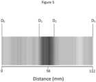
- the rate of change in pressure or stenosis intensity at any positionis calculated as which can be plotted as a point-by-point stenosis intensity map as shown in Figure 4 .
- stenosis intensitydIPR dt
- a systematic assessmentis made at rate U over time t , (known velocity example) so it is possible to calculate the withdrawal distance and thus the physiological stenosis length. In this example, this is the length ( D 2 -D 1 ) a segment which has the greatest physiological impact.
- the characteristic of the tube or further characteristics derived from the characteristic of the tubecan be assessed and thresholded. This process can be automated using a search algorithm which looks for points at which the IPR or nIPR exceeds a given threshold (in this example D1 and D2).
- the characteristics and/or derived characteristicsare used to assess or profile the tube to identify the length and/or location of a narrowing of the tube along the tube length.
- the use of thresholding techniques for the various characteristics and/or derived characteristicsidentifies regions of the tube where the thresholds are exceeded allowing identification and locating of stenosis and their length.
- An example of a derived characteristic of the tubeis the cumulative burden on the tube caused by a narrowing in the tube. It is possible to calculate the individual stenosis burden or stenosis occlusive value (with time points D 1 start of a stenosis, and D 2 end of a stenosis): Or, and total stenosis burden (over time points D 0 to D 3 ) for the entire vessel, Or
- Virtual angioplasty assessmentis enabled by examples of the present invention.
- a systematic assessment approachis applied and the measured profile is displayed.
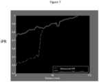
- the segment of tube to which a stent or other angioplasty is to be applied(having a high stenosis grade (D 1 -D 2 )) has its profile characteristic estimated with the stent applied and then subtracted away on an individual segment basis to give a compensated profile as shown in Figure 7 . It is therefore possible to assess the effects of angioplasty on IPR of nIPR prior to treatment. or
- D 1the distance at the start of the high stenosis grade
- D 2the distance at the end of the high stenosis grade.
- Such virtual assessment or profiling of a tube or stenosis in a tube using either IPR or nIPRallows the effects of removing a stenosis to be assessed prior to performing the procedure itself.
Landscapes
- Health & Medical Sciences (AREA)
- Life Sciences & Earth Sciences (AREA)
- Public Health (AREA)
- Biomedical Technology (AREA)
- General Health & Medical Sciences (AREA)
- Animal Behavior & Ethology (AREA)
- Biophysics (AREA)
- Heart & Thoracic Surgery (AREA)
- Engineering & Computer Science (AREA)
- Veterinary Medicine (AREA)
- Pathology (AREA)
- Medical Informatics (AREA)
- Molecular Biology (AREA)
- Surgery (AREA)
- Cardiology (AREA)
- Physics & Mathematics (AREA)
- Physiology (AREA)
- Vascular Medicine (AREA)
- Dentistry (AREA)
- Oral & Maxillofacial Surgery (AREA)
- Pulmonology (AREA)
- Anesthesiology (AREA)
- Hematology (AREA)
- Measuring Pulse, Heart Rate, Blood Pressure Or Blood Flow (AREA)
- Media Introduction/Drainage Providing Device (AREA)
- Measuring And Recording Apparatus For Diagnosis (AREA)
- Measuring Fluid Pressure (AREA)
- Measuring Volume Flow (AREA)
- Investigating Or Analyzing Materials By The Use Of Ultrasonic Waves (AREA)
- Length Measuring Devices With Unspecified Measuring Means (AREA)
- Infusion, Injection, And Reservoir Apparatuses (AREA)
- Endoscopes (AREA)
- Length Measuring Devices Characterised By Use Of Acoustic Means (AREA)
Description
- This invention relates to an apparatus of characterising a narrowing in a fluid filled tube.
- An example of a fluid filled tube or vessel formed with a constriction or narrowing is a blood vessel having a stenosis. Assessment or measurement of the constriction is helpful to review the extent and location of the constriction.
- A methodology for assessment of a constriction in a fluid filled tube such as a coronary stenosis is fractional flow reserve (FFR). This technique measures the drop in pressure at two points along a vessel; see
Figure 1 of the accompanying drawings where example points P1 and P4 identify where measurements of pressure and flow rate can be taken, under conditions of maximal achievable hyperemia in a coronary environment. The Pd measurement comes from a pressure sensor on the wire and the Pa measurement comes from the catheter. A comparison is then made by expressing the mean distal pressure (Pd), as a proportion of mean proximal pressure (Pa), wherein the values are mean Pa and Pd over the entire cardiac cycle, taken over at least one complete cardiac cycle (but usually an average of 3 or more beats):
- Examples of such systems are disclosed in the patent documents
US 2010/234698 A1 andWO 01/13779 A2 - It is an object of the invention to provide an apparatus for characterising a narrowing in a fluid filled tube.
- One aspect of the present disclosure provides system for characterising a narrowing in a fluid filled tube, the system comprising: a probe having a first measurement sensor to take an instantaneous measurement at different locations along the tube; a mechanism to draw the probe through the tube; a position measure to provide location data relating to the location at which a respective instantaneous measurement is taken by the first measurement sensor; a processor to calculate, from the instantaneous measurements, a characteristic of the tube at different locations along the tube.
- Another aspect of the present disclosure provides a probe for assessing a characteristic of a fluid filled tube comprising two measurement sensors spaced apart by a known distance and a line between the two sensors, the line being drawable through the tube to alter the known distance between the first sensor and the second sensor.
- A further aspect of the present disclosure, not being part of the invention provides a method of characterising a narrowing in a fluid filled tube using a probe having a sensor, comprising: drawing the probe within the tube along the tube; recording probe sensor readings at different locations along the tube; and calculating, from the instantaneous measurements, a characteristic of the tube at different locations along the tube.
- The present invention is defined by the appended claim 1 and provides a probe for assessing a characteristic of a fluid filled tube comprising two measurement sensors and a line between the two sensors, the line being drawable through the tube to alter the distance between the first sensor and the second sensor.
- In order that the present invention may be more readily understood, embodiments of the invention will now be described with reference to the accompanying drawings, in which:
FIGURE 1 is a schematic diagram of a series of constrictions in a fluid filled tube, whereP is pressure,R is a ratio of the pressures andD is the distance between measurements;FIGURE 2 is a schematic diagram of a system embodying the present invention;FIGURE 3 is a schematic diagram of part of the system offigure 2 located in a fluid filled tube;FIGURE 4 is a plot created using a method embodying the present invention illustrating the IPR for a length of artery;FIGURE 5 is a point-by-point constriction intensity map generated following one embodiment of the present invention and based on theFigure 4 data, in this example, the point-by-point assessment is of a stenosis in an artery, whereD0 is the start of a recording,D1 is a point at the start of high stenosis intensity,D2 is a point at the end of high stenosis intensity andD3 is the end of the recording;FIGURE 6 is a plot created using a method embodying the present invention illustrating the IPR for a length of artery and a likely site for a stent along the tube between locations D1 and D2;FIGURE 7 is a plot illustrating the likely effect on the same characteristic, IPR, on the artery after a hypothetical angioplasty procedure of locating a stent along the tube between locations D1 and D2 together with a plot of the measured values of IPR obtained using a method embodying the present invention; andFIGURE 8 is a flowchart showing operation of a system embodying the present invention incorporating a feedback procedure.FIGURE 9 is a schematic diagram of another system embodying the present invention.- This invention provides an apparatus for characterising a narrowing in a fluid filled tube. The apparatus is also useful to characterise or profile a series of narrowings in a fluid filled tube.
- Referring to
Figure 2 , a system 1 embodying the invention for characterising a narrowing in a fluid filled tube compriseshaemodynamic equipment 2 including a processor 3, acatheter 4, a motor drive 5 and anintra-arterial probe 6 such as an intra-arterial pressure wire (WaveWire or Combowire (Volcano Corp.) or Radi pressure wire (St Jude Medical) with a pressure measurement transducer or sensor 7 - i.e. a device measuring pressure (P). Preferably, theprobe 6 comprises the wire and thesensor 7 integrated in the wire. Thesensor 7 is shown in situ inFigure 3 . - The processor 3 analyses and operates on the measurements taken by the
sensor 7. A signal line 8 relays the pressure measurement signal from thesensor 7 to the processor 3. The signal line 8 is illustrated both as a wired connection 8 and as a wireless connection 8' from either the motor drive 5, thecatheter 4 or direct from the transducer 7 - any configuration is available. - The processor 3 operates on the measurements received from the
transducer 7 in accordance with a number of algorithms which are discussed in greater detail below. - The
sensor 7 is a pressure measurement sensor but other forms of sensor are envisaged; flow sensors, for example. Additionally, a capacitive sensor for measuring or calculating a thickness of an arterial wall is within the scope of the invention. - The system 1 may be provided in the following configurations or combination of configurations, but these are not an exhaustive list of configurations:
- i. a stand-alone device incorporating a probe with pressure measurement capacity in wired connection with a processor to provide on-device analysis;
- ii. a device incorporating a probe with pressure measurement capacity in wireless connection with a processor to provide analysis at the processor;
- iii. a stand-alone device incorporating a probe with pressure measurement capacity and a data storage device operable to record measurement data for real time or subsequent communication to a processor to provide analysis at the processor (real time and/or off-line); and
- iv. a device incorporating a probe with pressure measurement capacity in wireless connection with a data storage device operable to record measurement data for real time or subsequent communication to a processor to provide analysis at the processor (real time and/or off-line).
- In the cardiac environment where the system 1 is configured as part of haemodynamic equipment, the system is configured using the processor 3 in the haemodynamic equipment, such as in McKesson equipment - Horizon Cardiology™, a cardiovascular information system (CVIS). The processor can be configured as supplemental to the haemodynamic equipment. Such configurations are particularly effective for the equipment processor to perform off-line analysis of the pressure data.
- The system 1 can be used in combination with other haemodynamic equipment, medical imaging equipment and/or in-patient marker location equipment.
- The system is used for profiling or characterising a narrowing in a fluid filled tube. An example of the use of such a system is in the cardiac environment when the tube is an artery and the narrowing/restriction/constriction in the tube is a stenosis.
- The basic system components are: the
probe 6 having ameasurement sensor 7 to take an instantaneous measurement at different locations along the tube; the motor drive 5 to draw theprobe 6 at a predetermined rate through the tube; and the processor 3 to calculate, from the instantaneous measurements, a characteristic of the tube at different locations along the tube. In this example a particularly useful measurement to sense is that of pressure as a pressure drop results following the fluid passing through a restriction. - A profile or assessment of a restriction to flow is made by expressing the ratio of distal to proximal pressures within the tube. This measures the total restriction to flow across all stenoses along the length of the tube from position D1 to D3 where the respective pressure measurements are taken and expressed as a ratio (P4 / P1) either with or without conditions of maximal hyperaemia.
- In addition to calculation of the total restriction to flow along a vessel, it is possible to calculate the instantaneous pressure drop across an individual stenosis from the ratios of pressure in segmentsD distance apart. For example the ratio of fall in pressure over distanceD3 is:


- In one example, according to the invention, there are two measurement sensors displaced from one another - see
Figure 3 . This system 1 has afurther sensor 9 so that two instantaneous measurements are taken, one by thefurther sensor 9 at a substantially constant location along the tube and another by thefirst sensor 7 at different locations along the tube. The line or wire between the two sensors is drawable through the tube to alter the distance between the first sensor and the second sensor. One sensor (9 in this example) is fixed at the substantially constant location. The other sensor (7 in this example) moves relative to the onesensor 9. The "fixed"sensor 9 is located at the end of thecatheter 4 from which thewire 6 carrying theother sensor 7 emanates. Theprobe sensor 7 therefore moves relative to the fixedsensor 9. The measurements are normalised with respect to the measurements taken at the substantially constant or fixed location. - The normalised instantaneous pressure ratio is more robust, as each distal value is normalised to the proximal aortic pressure, thus making comparisons along the length of the vessel more reliable as perturbations in absolute pressure are minimised.
- Systematically moving back along the vessel, at velocityU, and logging the instantaneous measurements alongside the draw distance for the probe create a pressure ratio (R1, R2, and R3 etc.) for each position (D1, D2, and D3 etc.) as shown in
figure 5 . The profiling or assessment of stenosis can be performed using either the normalised instantaneous pressure ratio or the instantaneous pressure ratio. - In one example, the predetermined rate of draw through the tube of the probe is a known and preferably constant speed. The draw is a known velocity draw to allow instantaneous pressure measurements to be taken as the probe is being drawn along the tube, for those measurements to be recorded as pressure measurements and for a pressure ratio to be calculated for each position of the probe along the tube.
- The motor drive 5 is controlled, according to the invention, by the processor 3, to draw the
probe 6 back toward thecatheter 4. The control involves the use of a feedback loop. - The systematic assessment of pressure along a vessel is performed by withdrawing the pressure sensor, at velocityU. Pressure is recorded at each location. It is possible to minimise error and to speed up the acquisition phase by using a feedback loop. In this feedback loop, the sensor is positioned in the tube, and then attached to the variable speed motor drive, or stepper motor.
- After sampling for a period of x seconds to establish a baseline for the measurements being taken and characteristics calculated, in this case NIPR or IPR mean and standard deviation moving averages, the motor drive commences pullback of the probe at velocityU. Sampling can also be over a fraction or specific time point of a beat.
- Using high sampling frequencies and an appropriate sensor with a suitable frequency response, the pullback velocityU can be made faster by looking at a partial cardiac cycle in a single beat over a known distance.
- Pressure measurements are fed to the processor in the control console, and IFR or nIFR is calculated. This live pressure is compared against the moving average mean and standard deviation for the proceeding n beats, in a cardiac environment. If the live pressure data falls within the tolerance threshold, the motor continue with the pullback. If however the live pressure data falls outside of the tolerance threshold, the motor is paused and further measurements of pressure are made. Once pressure measurement falls within the tolerance threshold the motor continues with the pullback. A serial assessment or profile is created by this method. The feedback loop example is illustrated in
Figure 8 . - In another example, the draw is stepped through the tube with at least one instantaneous measurement being taken at each location along the tube. The probe is then drawn through the tube for a predetermined distance, stopped and then another at least one instantaneous measurement is taken at the next location and so on. Preferably but not necessarily, the predetermined distance is a constant distance.
- Each instantaneous measurement is logged as being at a respective location or with respect to a draw distance.
- An alternative system embodying the invention has a position sensor fitted which monitors the position of the pressure sensor wire whilst being pulled back through the tube. In this way, each distance point/position/location would be linked or cross-referenced to a specific pressure measurement. Specifically, the position sensor monitors the guide wire holding the pressure sensor.
- Referring now to
figure 9 another embodiment of the system is described which may operate with or without a motor drive 5. In the embodiments shown infigure 2 , the system relies upon the motor to operate in a known way to determine the distance x along theline 6 to thesensor 7. Other mechanisms for determining the distance x to the sensor from a known point, usually on the catheter, may be used to take measurements at different known positions of x. In a purely manual version of the system, theline 6 may be drawn back through thecatheter 4 manually and markings on theline 6 in the form of physical indicia can convey the distance x to the user. The system takes the position measure by reading the markings or marker on the probe. The marker may be a visible indicator read by a laser position indicator. - A semi-automatic version of the system, not according to the invention, can use a manually drawn
line 6 through thecatheter 4 and a combination of i) anRF reader 10 positioned preferably at the head of thecatheter 4 from which theline 6 projects a distance x out of thecatheter 4 and ii) multiple RF tags 11 positioned along theline 6. Theline 6 is provided with a series of equispaced passive RF tags 11 each having an individual identifier which is read when in close (if not only immediate) proximity to thereader 10. In one embodiment, theRF tag reader 10 is in a coincident position with thesecond sensor 9 mounted at the head of thecatheter 4. Coincidence of these two elements is not essential. More than oneRF tag reader 10 can be used on the catheter. - A lookup table stored locally or in the processor 3 takes the read information from the
reader 10 and identifies the tag adjacent thereader 10 for example astag 110 and identifies from the lookup table that tag 110 which is positioned at thereader 10 is a distance x away from thesensor 7 along theline 6 meaning that thesensor 7 is at known position P12 The line is then drawn through until anotherRF tag 11 is read by thereader 10 at which point that tag is identified, its position is known as being at thereader 10 and the distance from that tag to thesensor 7 is also known so the position of thesensor 7 is known. This process is repeated and tags 11 are identified, thesensor 7 position is identified as known and at least one measurement is taken at the known position. - Preferably, the RF tags 11 are equispaced along the
line 6 but they need not be equispaced as their positions along theline 6 relative to thesensor 7 is the only essential data to be associated with each tag. This essential data need not be present at the time the measurements are taken. Measurements can be taken and logged against each RF tag identifier and then subsequently the line can be measured to provide the relative position information for each tag and then that position information is associated with the measurement taken at each tag. - Preferably, the RF tags 11 are passive RF tags. The RF tags 11 could be active RF tags powered by a conductor in the
line 6. - Examples of the invention allow a serial assessment of pressure ratio along a vessel. A rate of change of pressure or a rate of change of pressure ratio is further calculated to provide a measure of stenosis intensity. The rate of change in pressure or stenosis intensity at any position is calculated as which can be plotted as a point-by-point stenosis intensity map as shown in
Figure 4 .
- A systematic assessment is made at rateU over timet, (known velocity example) so it is possible to calculate the withdrawal distance and thus the physiological stenosis length. In this example, this is the length (D2-D1) a segment which has the greatest physiological impact. The characteristic of the tube or further characteristics derived from the characteristic of the tube can be assessed and thresholded. This process can be automated using a search algorithm which looks for points at which the IPR or nIPR exceeds a given threshold (in this example D1 and D2).

- The characteristics and/or derived characteristics are used to assess or profile the tube to identify the length and/or location of a narrowing of the tube along the tube length. The use of thresholding techniques for the various characteristics and/or derived characteristics identifies regions of the tube where the thresholds are exceeded allowing identification and locating of stenosis and their length.
- An example of a derived characteristic of the tube is the cumulative burden on the tube caused by a narrowing in the tube. It is possible to calculate the individual stenosis burden or stenosis occlusive value (with time pointsD1 start of a stenosis, andD2 end of a stenosis):


- Virtual angioplasty assessment is enabled by examples of the present invention. Referring to
Figure 6 , a systematic assessment approach is applied and the measured profile is displayed. The segment of tube to which a stent or other angioplasty is to be applied (having a high stenosis grade (D1-D2)) has its profile characteristic estimated with the stent applied and then subtracted away on an individual segment basis to give a compensated profile as shown inFigure 7 . It is therefore possible to assess the effects of angioplasty on IPR of nIPR prior to treatment.

- WhereD0 is distance=0,D1 the distance at the start of the high stenosis grade, andD2 the distance at the end of the high stenosis grade.
- Such virtual assessment or profiling of a tube or stenosis in a tube using either IPR or nIPR allows the effects of removing a stenosis to be assessed prior to performing the procedure itself.
- There are particular needs in the cardiac environment for simplified equipment having the smallest possible footprint (or being the least invasive requiring the smallest possible entry site) so the provision of a known position probe to assess or profile stenoses along the length of the tube represents a significant technical advance in that field.
- When used in this specification and claims, the terms "comprises" and "comprising" and variations thereof mean that the specified features, steps or integers are included. The terms are not to be interpreted to exclude the presence of other features, steps or components.
- The features disclosed in the foregoing description, or the following claims, or the accompanying drawings, expressed in their specific forms or in terms of a means for performing the disclosed function, or a method or process for attaining the disclosed result, as appropriate, may, separately, or in any combination of such features, be utilised for realising the invention in diverse forms thereof.


Claims (13)
- A system for characterising one or more narrowings in a fluid filled tube being a blood vessel, the system comprising:a catheter (4);a probe (6) that emanates from an end of the catheter into the tube having a first pressure sensor (7) to take an instantaneous pressure measurement at different locations along the tube;a further pressure sensor (9) provided on the catheter to take an instantaneous pressure measurement at the end of the catheter, so that two instantaneous pressure measurements are taken, one by the further pressure sensor (9) at a substantially constant location along the tube and another by the first pressure sensor (7) at different locations along the tube;a mechanism to draw the probe along the tube;a position measure to provide location data relation to the location at which a respective instantaneous pressure measurement is taken by the first pressure sensor (7); anda processor (3) that is configured to calculate, from the instantaneous pressure measurements obtained by the first pressure sensor and the further pressure sensor, ratios of the instantaneous pressure measurements for different locations along the tube to identify narrowings of the fluid filled tube having an occlusive value;wherein the mechanism is a motorized mechanism (5) to draw the probe through the tube,characterized in that the processor (3) is configured to compare a ratio of the instantaneous pressure measurements calculated for a current location along the tube against a moving average mean and standard deviation of the ratios of the instantaneous pressure measurements for proceeding n beats in a cardiac environment and to control the motorized mechanism (5) such that a) the motorized mechanism (5) continues with the draw, if the ratio calculated for the current location falls within a tolerance threshold defined by the moving average mean and standard deviation, and b) the motorized mechanism (5) pauses the draw, if the ratio calculated for the current location falls outside the tolerance threshold.
- A system according to any preceding claim, wherein the position measure is a reader (10) to read a marker on the probe.
- A system according to claim 2, wherein the marker on the probe is an RF tag (11).
- A system according to claim 2 or 3, wherein the position measure provides a relative location of the first measurement sensor with respect to a known datum.
- A system according to claim 2 or 3, wherein the position measure provides an absolute location of the first measurement sensor.
- The system of any preceding claim, wherein the calculated ratios of the instantaneous pressure measurements are normalised with respect to the substantially constant location.
- The system of any preceding claim, wherein the probe is drawn at a predetermined rate of draw at a constant speed through the tube.
- The system of claim 7, wherein the predetermined rate is a stepped draw through the tube with instantaneous pressure measurements being taken at one location along the tube and the probe is then drawn through the tube for a predetermined distance for the next set of instantaneous pressure measurements to be taken at the next location and so on.
- The system of any preceding claim, wherein each instantaneous pressure measurement is logged at a respective location or with respect to a draw distance.
- The system according to any preceding claim, wherein a rate of change of the ratios of the instantaneous pressure measurements is further calculated to provide a measure of narrowing intensity.
- The system of any preceding claim, wherein the processor is further configured to compare the ratios of the instantaneous pressure measurements or further characteristics derived from the instantaneous pressure measurements to a threshold value.
- The system of any preceding claim, wherein the processor is further configured to identify a length and location of a narrowing of the tube beyond a predetermined threshold.
- The system of any preceding claim, wherein the processor is further configured to calculate a cumulative burden on the tube caused by the narrowings in the tube based on the instantaneous pressure measurements.
Applications Claiming Priority (2)
| Application Number | Priority Date | Filing Date | Title |
|---|---|---|---|
| GBGB1100136.9AGB201100136D0 (en) | 2011-01-06 | 2011-01-06 | Apparatus and method of characterising a narrowing in a filled tube |
| PCT/GB2012/050015WO2012093260A1 (en) | 2011-01-06 | 2012-01-06 | Apparatus and method of characterising a narrowing in a fluid filled tube |
Publications (2)
| Publication Number | Publication Date |
|---|---|
| EP2661218A1 EP2661218A1 (en) | 2013-11-13 |
| EP2661218B1true EP2661218B1 (en) | 2023-04-12 |
Family
ID=43663842
Family Applications (1)
| Application Number | Title | Priority Date | Filing Date |
|---|---|---|---|
| EP12700296.2AActiveEP2661218B1 (en) | 2011-01-06 | 2012-01-06 | Apparatus of characterising a narrowing in a fluid filled tube |
Country Status (12)
| Country | Link |
|---|---|
| US (2) | US11179042B2 (en) |
| EP (1) | EP2661218B1 (en) |
| JP (2) | JP6736245B2 (en) |
| KR (1) | KR101607375B1 (en) |
| CN (1) | CN103582450B (en) |
| BR (1) | BR112013017431A2 (en) |
| CA (1) | CA2823805C (en) |
| CR (1) | CR20130378A (en) |
| GB (1) | GB201100136D0 (en) |
| IL (2) | IL227353B (en) |
| RU (1) | RU2013136698A (en) |
| WO (1) | WO2012093260A1 (en) |
Cited By (1)
| Publication number | Priority date | Publication date | Assignee | Title |
|---|---|---|---|---|
| WO2024220511A1 (en)* | 2023-04-18 | 2024-10-24 | Bard Access Systems, Inc. | System and method for placement of a central catheter tip |
Families Citing this family (47)
| Publication number | Priority date | Publication date | Assignee | Title |
|---|---|---|---|---|
| CN103959043B (en) | 2011-05-31 | 2016-11-02 | 光学实验室成像公司 | Multimodal imaging systems, devices and methods |
| US10648918B2 (en) | 2011-08-03 | 2020-05-12 | Lightlab Imaging, Inc. | Systems, methods and apparatus for determining a fractional flow reserve (FFR) based on the minimum lumen area (MLA) and the constant |
| US10888232B2 (en) | 2011-08-20 | 2021-01-12 | Philips Image Guided Therapy Corporation | Devices, systems, and methods for assessing a vessel |
| JP6133864B2 (en)* | 2011-08-20 | 2017-05-24 | ボルケーノ コーポレイション | Apparatus, system and method for visually depicting vessels and assessing treatment options |
| US9339348B2 (en) | 2011-08-20 | 2016-05-17 | Imperial Colege of Science, Technology and Medicine | Devices, systems, and methods for assessing a vessel |
| JP6214561B2 (en) | 2012-01-19 | 2017-10-18 | ボルケーノ コーポレイション | Interface device, system and method for use with an intravascular pressure monitoring device |
| JP6532857B2 (en)* | 2013-03-15 | 2019-06-19 | ボルケーノ コーポレイション | Interface device, system and method for use with an intravascular pressure monitoring device |
| JP6466435B2 (en)* | 2013-07-19 | 2019-02-06 | ボルケーノ コーポレイション | System for evaluating conduits |
| CN105517487B (en)* | 2013-07-19 | 2019-09-13 | 火山公司 | The equipment, system and method for vascular are assessed for correcting using automatic drift |
| CN105636509B (en) | 2013-10-18 | 2019-07-02 | 火山公司 | Assess the equipment, system and method for vascular |
| US10130269B2 (en) | 2013-11-14 | 2018-11-20 | Medtronic Vascular, Inc | Dual lumen catheter for providing a vascular pressure measurement |
| US9877660B2 (en) | 2013-11-14 | 2018-01-30 | Medtronic Vascular Galway | Systems and methods for determining fractional flow reserve without adenosine or other pharmalogical agent |
| US9913585B2 (en) | 2014-01-15 | 2018-03-13 | Medtronic Vascular, Inc. | Catheter for providing vascular pressure measurements |
| US9974443B2 (en) | 2014-02-20 | 2018-05-22 | Koninklijke Philips N.V. | Devices, systems, and methods and associated display screens for assessment of vessels |
| CN106456026B (en) | 2014-04-04 | 2020-09-18 | 圣犹达医疗系统公司 | Intravascular pressure and flow data diagnostic system, device and method |
| JP6586425B2 (en) | 2014-04-21 | 2019-10-02 | コーニンクレッカ フィリップス エヌ ヴェKoninklijke Philips N.V. | Intravascular device, system and method having separate sections with core elements engaged |
| US10244951B2 (en)* | 2014-06-10 | 2019-04-02 | Acist Medical Systems, Inc. | Physiological sensor delivery device and method |
| US11330989B2 (en) | 2014-06-16 | 2022-05-17 | Medtronic Vascular, Inc. | Microcatheter sensor design for mounting sensor to minimize induced strain |
| US10973418B2 (en) | 2014-06-16 | 2021-04-13 | Medtronic Vascular, Inc. | Microcatheter sensor design for minimizing profile and impact of wire strain on sensor |
| US10201284B2 (en) | 2014-06-16 | 2019-02-12 | Medtronic Vascular Inc. | Pressure measuring catheter having reduced error from bending stresses |
| EP3166479B1 (en) | 2014-07-11 | 2024-01-03 | Koninklijke Philips N.V. | Devices and systems for treatment of vessels |
| US10849511B2 (en) | 2014-07-14 | 2020-12-01 | Philips Image Guided Therapy Corporation | Devices, systems, and methods for assessment of vessels |
| WO2016008809A1 (en) | 2014-07-15 | 2016-01-21 | Koninklijke Philips N.V. | Devices, systems, and methods and associated display screens for assessment of vessels with multiple sensing components |
| WO2016038493A1 (en) | 2014-09-11 | 2016-03-17 | Koninklijke Philips N.V. | Bedside controller for assessment of vessels and associated devices, systems, and methods |
| WO2016075601A1 (en) | 2014-11-14 | 2016-05-19 | Koninklijke Philips N.V. | Percutaneous coronary intervention (pci) planning interface with pressure data and vessel data and associated devices, systems, and methods |
| CN115813438A (en)* | 2014-11-14 | 2023-03-21 | 皇家飞利浦有限公司 | Percutaneous Coronary Intervention (PCI) planning interface and associated devices, systems, and methods |
| EP3229674B1 (en) | 2014-12-08 | 2022-05-11 | Koninklijke Philips N.V. | Automated identification and classification of intravascular lesions |
| WO2016092422A1 (en)* | 2014-12-08 | 2016-06-16 | Koninklijke Philips N.V. | Bedside interface for percutaneous coronary intervention planning |
| WO2016092398A1 (en) | 2014-12-08 | 2016-06-16 | Koninklijke Philips N.V. | Device and method to recommend diagnostic procedure based on co-registered angiographic image and physiological information measured by intravascular device |
| US10194812B2 (en) | 2014-12-12 | 2019-02-05 | Medtronic Vascular, Inc. | System and method of integrating a fractional flow reserve device with a conventional hemodynamic monitoring system |
| US10349840B2 (en)* | 2015-09-10 | 2019-07-16 | Opsens Inc. | Method for pressure guidewire equalization |
| US11272850B2 (en) | 2016-08-09 | 2022-03-15 | Medtronic Vascular, Inc. | Catheter and method for calculating fractional flow reserve |
| US11330994B2 (en) | 2017-03-08 | 2022-05-17 | Medtronic Vascular, Inc. | Reduced profile FFR catheter |
| US10646122B2 (en) | 2017-04-28 | 2020-05-12 | Medtronic Vascular, Inc. | FFR catheter with covered distal pressure sensor and method of manufacture |
| US11219741B2 (en) | 2017-08-09 | 2022-01-11 | Medtronic Vascular, Inc. | Collapsible catheter and method for calculating fractional flow reserve |
| US11235124B2 (en) | 2017-08-09 | 2022-02-01 | Medtronic Vascular, Inc. | Collapsible catheter and method for calculating fractional flow reserve |
| EP3679583A1 (en) | 2017-09-07 | 2020-07-15 | Koninklijke Philips N.V. | Automatic normalization of intravascular devices |
| US11311196B2 (en) | 2018-02-23 | 2022-04-26 | Boston Scientific Scimed, Inc. | Methods for assessing a vessel with sequential physiological measurements |
| EP3768156B1 (en) | 2018-03-23 | 2023-09-20 | Boston Scientific Scimed, Inc. | Medical device with pressure sensor |
| WO2019195721A1 (en) | 2018-04-06 | 2019-10-10 | Boston Scientific Scimed, Inc. | Medical device with pressure sensor |
| CN119564167A (en)* | 2018-04-18 | 2025-03-07 | 波士顿科学国际有限公司 | System for vascular assessment using continuous physiological measurements |
| EP4512318A3 (en)* | 2018-05-02 | 2025-04-09 | Boston Scientific Scimed, Inc. | Occlusive sealing sensor system |
| US11185244B2 (en) | 2018-08-13 | 2021-11-30 | Medtronic Vascular, Inc. | FFR catheter with suspended pressure sensor |
| USD926199S1 (en) | 2019-05-17 | 2021-07-27 | Opsens, Inc. | Display screen or portion thereof with graphical user interface |
| JP7508760B2 (en)* | 2020-05-08 | 2024-07-02 | 深セン北芯生命科技股フン有限公司 | System and method for tracking cardiovascular events with blood pressure |
| US12023036B2 (en) | 2020-12-18 | 2024-07-02 | Boston Scientific Scimed, Inc. | Occlusive medical device having sensing capabilities |
| US12087000B2 (en) | 2021-03-05 | 2024-09-10 | Boston Scientific Scimed, Inc. | Systems and methods for vascular image co-registration |
Family Cites Families (30)
| Publication number | Priority date | Publication date | Assignee | Title |
|---|---|---|---|---|
| US4691709A (en) | 1986-07-01 | 1987-09-08 | Cordis Corporation | Apparatus for measuring velocity of blood flow in a blood vessel |
| DE69534748T2 (en)* | 1994-09-02 | 2006-11-02 | Volcano Corp. (n.d, Ges.d.Staates Delaware), Rancho Cordova | ULTRAMINIATUR PRESSURE SENSOR AND GUIDE WIRE THEREFORE |
| WO1997044089A1 (en)* | 1996-05-17 | 1997-11-27 | Biosense Inc. | Self-aligning catheter |
| AU3626099A (en) | 1998-05-04 | 1999-11-23 | Florence Medical Ltd. | Apparatus and method for identification and characterization of lesions and therapeutic success by flow disturbances analysis |
| JP2003525067A (en)* | 1999-03-09 | 2003-08-26 | フローレンス・メディカル・リミテッド | Method and system for measuring CFR and additional clinical hemodynamic parameters on a pressure basis |
| US6471656B1 (en)* | 1999-06-25 | 2002-10-29 | Florence Medical Ltd | Method and system for pressure based measurements of CFR and additional clinical hemodynamic parameters |
| AU6722200A (en)* | 1999-08-25 | 2001-03-19 | Florence Medical Ltd. | A method and system for stenosis identification, localization and characterization using pressure measurements |
| DE19946948A1 (en) | 1999-09-30 | 2001-04-05 | Philips Corp Intellectual Pty | Method and arrangement for determining the position of a medical instrument |
| US6354999B1 (en)* | 2000-01-14 | 2002-03-12 | Florence Medical Ltd. | System and method for detecting, localizing, and characterizing occlusions and aneurysms in a vessel |
| US6565514B2 (en) | 2000-08-25 | 2003-05-20 | Radi Medical Systems Ab | Method and system for determining physiological variables |
| US20030191400A1 (en)* | 2001-01-19 | 2003-10-09 | Florence Medical Ltd. | System for determining values of hemodynamic parameters for a lesioned blood vessel, processor therefor, and method therefor |
| US6585660B2 (en) | 2001-05-18 | 2003-07-01 | Jomed Inc. | Signal conditioning device for interfacing intravascular sensors having varying operational characteristics to a physiology monitor |
| US7134994B2 (en) | 2002-05-20 | 2006-11-14 | Volcano Corporation | Multipurpose host system for invasive cardiovascular diagnostic measurement acquisition and display |
| US20040082867A1 (en)* | 2002-10-29 | 2004-04-29 | Pearl Technology Holdings, Llc | Vascular graft with integrated sensor |
| EP1593087A4 (en) | 2003-01-30 | 2006-10-04 | Chase Medical Lp | A method and system for image processing and contour assessment |
| US20040176683A1 (en)* | 2003-03-07 | 2004-09-09 | Katherine Whitin | Method and apparatus for tracking insertion depth |
| JP4559215B2 (en)* | 2003-05-14 | 2010-10-06 | ボルケーノ・コーポレイション | A multi-purpose host system for capturing and displaying invasive cardiovascular diagnostic measurements |
| US7333643B2 (en)* | 2004-01-30 | 2008-02-19 | Chase Medical, L.P. | System and method for facilitating cardiac intervention |
| ATE484308T1 (en) | 2004-02-18 | 2010-10-15 | Koninkl Philips Electronics Nv | CATHETER SYSTEM WITH ACTIVE POSITION MARKERS |
| US20050203425A1 (en)* | 2004-03-10 | 2005-09-15 | Phil Langston | Coaxial dual lumen pigtail catheter |
| US20060052700A1 (en) | 2004-09-08 | 2006-03-09 | Radi Medical Systems Ab | Pressure measurement system |
| JP2008516722A (en)* | 2004-10-19 | 2008-05-22 | ナヴォテック メディカル リミテッド | Positioning of catheter end using tracking guide |
| EP2158940A3 (en) | 2005-08-11 | 2010-06-02 | Navotek Medical Ltd. | Medical treatment system and method using radioactivity based position sensor |
| EP1933715A4 (en)* | 2005-10-14 | 2012-08-29 | Cleveland Clinic Foundation | System and method for characterizing vascular tissue |
| CN201015590Y (en)* | 2007-03-28 | 2008-02-06 | 李楚雅 | Bloodstream storing mark real time continuous measurement system |
| EP2244630B1 (en)* | 2007-10-25 | 2014-09-24 | Oridion Medical, Ltd. | A breath sampling system |
| JP5484699B2 (en)* | 2008-09-08 | 2014-05-07 | オリンパスメディカルシステムズ株式会社 | Endoscope insertion aid and endoscope apparatus |
| RU2478338C2 (en)* | 2008-09-11 | 2013-04-10 | Эсист Медикал Системз, Инк. | Device and method of physiological sensor delivery |
| EP2742858B1 (en) | 2009-09-23 | 2024-06-05 | Light-Lab Imaging Inc. | Lumen morphology and vascular resistance measurements data collection systems, apparatus and methods |
| US8315812B2 (en) | 2010-08-12 | 2012-11-20 | Heartflow, Inc. | Method and system for patient-specific modeling of blood flow |
- 2011
- 2011-01-06GBGBGB1100136.9Apatent/GB201100136D0/ennot_activeCeased
- 2012
- 2012-01-06CACA2823805Apatent/CA2823805C/ennot_activeExpired - Fee Related
- 2012-01-06CNCN201280004868.8Apatent/CN103582450B/enactiveActive
- 2012-01-06KRKR1020137020711Apatent/KR101607375B1/ennot_activeExpired - Fee Related
- 2012-01-06BRBR112013017431Apatent/BR112013017431A2/ennot_activeIP Right Cessation
- 2012-01-06EPEP12700296.2Apatent/EP2661218B1/enactiveActive
- 2012-01-06JPJP2013547908Apatent/JP6736245B2/enactiveActive
- 2012-01-06USUS13/978,697patent/US11179042B2/enactiveActive
- 2012-01-06WOPCT/GB2012/050015patent/WO2012093260A1/enactiveApplication Filing
- 2012-01-06RURU2013136698/14Apatent/RU2013136698A/ennot_activeApplication Discontinuation
- 2013
- 2013-07-04ILIL227353Apatent/IL227353B/enactiveIP Right Grant
- 2013-08-05CRCR20130378Apatent/CR20130378A/enunknown
- 2018
- 2018-11-11ILIL262925Apatent/IL262925B/enunknown
- 2019
- 2019-12-20JPJP2019230528Apatent/JP6971295B2/enactiveActive
- 2021
- 2021-11-22USUS17/532,671patent/US11877829B2/enactiveActive
Cited By (1)
| Publication number | Priority date | Publication date | Assignee | Title |
|---|---|---|---|---|
| WO2024220511A1 (en)* | 2023-04-18 | 2024-10-24 | Bard Access Systems, Inc. | System and method for placement of a central catheter tip |
Also Published As
| Publication number | Publication date |
|---|---|
| IL262925B (en) | 2022-01-01 |
| CA2823805C (en) | 2016-05-17 |
| CN103582450B (en) | 2017-05-17 |
| RU2013136698A (en) | 2015-02-20 |
| IL262925A (en) | 2018-12-31 |
| US11877829B2 (en) | 2024-01-23 |
| CR20130378A (en) | 2016-07-26 |
| US11179042B2 (en) | 2021-11-23 |
| NZ613148A (en) | 2015-10-30 |
| IL227353B (en) | 2018-11-29 |
| JP6736245B2 (en) | 2020-08-05 |
| BR112013017431A2 (en) | 2016-09-27 |
| KR101607375B1 (en) | 2016-03-29 |
| US20130345574A1 (en) | 2013-12-26 |
| WO2012093260A1 (en) | 2012-07-12 |
| KR20130135299A (en) | 2013-12-10 |
| US20220151499A1 (en) | 2022-05-19 |
| IL227353A0 (en) | 2013-09-30 |
| JP6971295B2 (en) | 2021-11-24 |
| JP2020072936A (en) | 2020-05-14 |
| CN103582450A (en) | 2014-02-12 |
| GB201100136D0 (en) | 2011-02-23 |
| CA2823805A1 (en) | 2012-07-12 |
| JP2014511114A (en) | 2014-05-08 |
| EP2661218A1 (en) | 2013-11-13 |
Similar Documents
| Publication | Publication Date | Title |
|---|---|---|
| US11877829B2 (en) | Apparatus and method of characterising a narrowing in a fluid filled tube | |
| US11883138B2 (en) | Cardiac cycle-based diagnostic systems and methods | |
| EP2661216B1 (en) | Apparatus and method of assessing a narrowing in a fluid filled tube | |
| EP2938271B1 (en) | Devices, systems, and methods for assessment of vessels | |
| EP4342366A2 (en) | Intravascular pressure and flow data diagnostic system | |
| US11311200B1 (en) | Systems and methods to measure physiological flow in coronary arteries | |
| CN111344799A (en) | Automatic standardization of in-line devices | |
| NZ613148B2 (en) | Apparatus and method of characterising a narrowing in a fluid filled tube | |
| WO2018051111A1 (en) | Sensing apparatus and method | |
| KR20130125089A (en) | Apparatus and method of extracting pulse depth index using pressure at a constant velocity |
Legal Events
| Date | Code | Title | Description |
|---|---|---|---|
| PUAI | Public reference made under article 153(3) epc to a published international application that has entered the european phase | Free format text:ORIGINAL CODE: 0009012 | |
| 17P | Request for examination filed | Effective date:20130726 | |
| AK | Designated contracting states | Kind code of ref document:A1 Designated state(s):AL AT BE BG CH CY CZ DE DK EE ES FI FR GB GR HR HU IE IS IT LI LT LU LV MC MK MT NL NO PL PT RO RS SE SI SK SM TR | |
| DAX | Request for extension of the european patent (deleted) | ||
| STAA | Information on the status of an ep patent application or granted ep patent | Free format text:STATUS: EXAMINATION IS IN PROGRESS | |
| 17Q | First examination report despatched | Effective date:20170119 | |
| REG | Reference to a national code | Ref country code:DE Ref legal event code:R079 Ref document number:602012079460 Country of ref document:DE Free format text:PREVIOUS MAIN CLASS: A61B0005021500 Ipc:A61B0005020000 | |
| GRAP | Despatch of communication of intention to grant a patent | Free format text:ORIGINAL CODE: EPIDOSNIGR1 | |
| STAA | Information on the status of an ep patent application or granted ep patent | Free format text:STATUS: GRANT OF PATENT IS INTENDED | |
| RIC1 | Information provided on ipc code assigned before grant | Ipc:A61B 5/107 20060101ALI20221007BHEP Ipc:A61B 5/103 20060101ALI20221007BHEP Ipc:A61B 5/0215 20060101ALI20221007BHEP Ipc:A61B 5/02 20060101AFI20221007BHEP | |
| INTG | Intention to grant announced | Effective date:20221109 | |
| GRAS | Grant fee paid | Free format text:ORIGINAL CODE: EPIDOSNIGR3 | |
| GRAA | (expected) grant | Free format text:ORIGINAL CODE: 0009210 | |
| STAA | Information on the status of an ep patent application or granted ep patent | Free format text:STATUS: THE PATENT HAS BEEN GRANTED | |
| AK | Designated contracting states | Kind code of ref document:B1 Designated state(s):AL AT BE BG CH CY CZ DE DK EE ES FI FR GB GR HR HU IE IS IT LI LT LU LV MC MK MT NL NO PL PT RO RS SE SI SK SM TR | |
| REG | Reference to a national code | Ref country code:GB Ref legal event code:FG4D | |
| REG | Reference to a national code | Ref country code:CH Ref legal event code:EP | |
| REG | Reference to a national code | Ref country code:DE Ref legal event code:R096 Ref document number:602012079460 Country of ref document:DE | |
| REG | Reference to a national code | Ref country code:IE Ref legal event code:FG4D | |
| REG | Reference to a national code | Ref country code:AT Ref legal event code:REF Ref document number:1559355 Country of ref document:AT Kind code of ref document:T Effective date:20230515 | |
| REG | Reference to a national code | Ref country code:LT Ref legal event code:MG9D | |
| REG | Reference to a national code | Ref country code:NL Ref legal event code:MP Effective date:20230412 | |
| REG | Reference to a national code | Ref country code:AT Ref legal event code:MK05 Ref document number:1559355 Country of ref document:AT Kind code of ref document:T Effective date:20230412 | |
| PG25 | Lapsed in a contracting state [announced via postgrant information from national office to epo] | Ref country code:NL Free format text:LAPSE BECAUSE OF FAILURE TO SUBMIT A TRANSLATION OF THE DESCRIPTION OR TO PAY THE FEE WITHIN THE PRESCRIBED TIME-LIMIT Effective date:20230412 | |
| PG25 | Lapsed in a contracting state [announced via postgrant information from national office to epo] | Ref country code:SE Free format text:LAPSE BECAUSE OF FAILURE TO SUBMIT A TRANSLATION OF THE DESCRIPTION OR TO PAY THE FEE WITHIN THE PRESCRIBED TIME-LIMIT Effective date:20230412 Ref country code:PT Free format text:LAPSE BECAUSE OF FAILURE TO SUBMIT A TRANSLATION OF THE DESCRIPTION OR TO PAY THE FEE WITHIN THE PRESCRIBED TIME-LIMIT Effective date:20230814 Ref country code:NO Free format text:LAPSE BECAUSE OF FAILURE TO SUBMIT A TRANSLATION OF THE DESCRIPTION OR TO PAY THE FEE WITHIN THE PRESCRIBED TIME-LIMIT Effective date:20230712 Ref country code:ES Free format text:LAPSE BECAUSE OF FAILURE TO SUBMIT A TRANSLATION OF THE DESCRIPTION OR TO PAY THE FEE WITHIN THE PRESCRIBED TIME-LIMIT Effective date:20230412 Ref country code:AT Free format text:LAPSE BECAUSE OF FAILURE TO SUBMIT A TRANSLATION OF THE DESCRIPTION OR TO PAY THE FEE WITHIN THE PRESCRIBED TIME-LIMIT Effective date:20230412 | |
| PG25 | Lapsed in a contracting state [announced via postgrant information from national office to epo] | Ref country code:RS Free format text:LAPSE BECAUSE OF FAILURE TO SUBMIT A TRANSLATION OF THE DESCRIPTION OR TO PAY THE FEE WITHIN THE PRESCRIBED TIME-LIMIT Effective date:20230412 Ref country code:PL Free format text:LAPSE BECAUSE OF FAILURE TO SUBMIT A TRANSLATION OF THE DESCRIPTION OR TO PAY THE FEE WITHIN THE PRESCRIBED TIME-LIMIT Effective date:20230412 Ref country code:LV Free format text:LAPSE BECAUSE OF FAILURE TO SUBMIT A TRANSLATION OF THE DESCRIPTION OR TO PAY THE FEE WITHIN THE PRESCRIBED TIME-LIMIT Effective date:20230412 Ref country code:LT Free format text:LAPSE BECAUSE OF FAILURE TO SUBMIT A TRANSLATION OF THE DESCRIPTION OR TO PAY THE FEE WITHIN THE PRESCRIBED TIME-LIMIT Effective date:20230412 Ref country code:IS Free format text:LAPSE BECAUSE OF FAILURE TO SUBMIT A TRANSLATION OF THE DESCRIPTION OR TO PAY THE FEE WITHIN THE PRESCRIBED TIME-LIMIT Effective date:20230812 Ref country code:HR Free format text:LAPSE BECAUSE OF FAILURE TO SUBMIT A TRANSLATION OF THE DESCRIPTION OR TO PAY THE FEE WITHIN THE PRESCRIBED TIME-LIMIT Effective date:20230412 Ref country code:GR Free format text:LAPSE BECAUSE OF FAILURE TO SUBMIT A TRANSLATION OF THE DESCRIPTION OR TO PAY THE FEE WITHIN THE PRESCRIBED TIME-LIMIT Effective date:20230713 Ref country code:AL Free format text:LAPSE BECAUSE OF FAILURE TO SUBMIT A TRANSLATION OF THE DESCRIPTION OR TO PAY THE FEE WITHIN THE PRESCRIBED TIME-LIMIT Effective date:20230412 | |
| PG25 | Lapsed in a contracting state [announced via postgrant information from national office to epo] | Ref country code:FI Free format text:LAPSE BECAUSE OF FAILURE TO SUBMIT A TRANSLATION OF THE DESCRIPTION OR TO PAY THE FEE WITHIN THE PRESCRIBED TIME-LIMIT Effective date:20230412 | |
| REG | Reference to a national code | Ref country code:DE Ref legal event code:R097 Ref document number:602012079460 Country of ref document:DE | |
| PG25 | Lapsed in a contracting state [announced via postgrant information from national office to epo] | Ref country code:SK Free format text:LAPSE BECAUSE OF FAILURE TO SUBMIT A TRANSLATION OF THE DESCRIPTION OR TO PAY THE FEE WITHIN THE PRESCRIBED TIME-LIMIT Effective date:20230412 | |
| PG25 | Lapsed in a contracting state [announced via postgrant information from national office to epo] | Ref country code:SM Free format text:LAPSE BECAUSE OF FAILURE TO SUBMIT A TRANSLATION OF THE DESCRIPTION OR TO PAY THE FEE WITHIN THE PRESCRIBED TIME-LIMIT Effective date:20230412 Ref country code:SK Free format text:LAPSE BECAUSE OF FAILURE TO SUBMIT A TRANSLATION OF THE DESCRIPTION OR TO PAY THE FEE WITHIN THE PRESCRIBED TIME-LIMIT Effective date:20230412 Ref country code:RO Free format text:LAPSE BECAUSE OF FAILURE TO SUBMIT A TRANSLATION OF THE DESCRIPTION OR TO PAY THE FEE WITHIN THE PRESCRIBED TIME-LIMIT Effective date:20230412 Ref country code:EE Free format text:LAPSE BECAUSE OF FAILURE TO SUBMIT A TRANSLATION OF THE DESCRIPTION OR TO PAY THE FEE WITHIN THE PRESCRIBED TIME-LIMIT Effective date:20230412 Ref country code:DK Free format text:LAPSE BECAUSE OF FAILURE TO SUBMIT A TRANSLATION OF THE DESCRIPTION OR TO PAY THE FEE WITHIN THE PRESCRIBED TIME-LIMIT Effective date:20230412 Ref country code:CZ Free format text:LAPSE BECAUSE OF FAILURE TO SUBMIT A TRANSLATION OF THE DESCRIPTION OR TO PAY THE FEE WITHIN THE PRESCRIBED TIME-LIMIT Effective date:20230412 | |
| PLBE | No opposition filed within time limit | Free format text:ORIGINAL CODE: 0009261 | |
| STAA | Information on the status of an ep patent application or granted ep patent | Free format text:STATUS: NO OPPOSITION FILED WITHIN TIME LIMIT | |
| 26N | No opposition filed | Effective date:20240115 | |
| PG25 | Lapsed in a contracting state [announced via postgrant information from national office to epo] | Ref country code:SI Free format text:LAPSE BECAUSE OF FAILURE TO SUBMIT A TRANSLATION OF THE DESCRIPTION OR TO PAY THE FEE WITHIN THE PRESCRIBED TIME-LIMIT Effective date:20230412 | |
| PG25 | Lapsed in a contracting state [announced via postgrant information from national office to epo] | Ref country code:SI Free format text:LAPSE BECAUSE OF FAILURE TO SUBMIT A TRANSLATION OF THE DESCRIPTION OR TO PAY THE FEE WITHIN THE PRESCRIBED TIME-LIMIT Effective date:20230412 Ref country code:IT Free format text:LAPSE BECAUSE OF FAILURE TO SUBMIT A TRANSLATION OF THE DESCRIPTION OR TO PAY THE FEE WITHIN THE PRESCRIBED TIME-LIMIT Effective date:20230412 | |
| PG25 | Lapsed in a contracting state [announced via postgrant information from national office to epo] | Ref country code:MC Free format text:LAPSE BECAUSE OF FAILURE TO SUBMIT A TRANSLATION OF THE DESCRIPTION OR TO PAY THE FEE WITHIN THE PRESCRIBED TIME-LIMIT Effective date:20230412 | |
| PG25 | Lapsed in a contracting state [announced via postgrant information from national office to epo] | Ref country code:MC Free format text:LAPSE BECAUSE OF FAILURE TO SUBMIT A TRANSLATION OF THE DESCRIPTION OR TO PAY THE FEE WITHIN THE PRESCRIBED TIME-LIMIT Effective date:20230412 | |
| REG | Reference to a national code | Ref country code:CH Ref legal event code:PL | |
| PG25 | Lapsed in a contracting state [announced via postgrant information from national office to epo] | Ref country code:LU Free format text:LAPSE BECAUSE OF NON-PAYMENT OF DUE FEES Effective date:20240106 | |
| PG25 | Lapsed in a contracting state [announced via postgrant information from national office to epo] | Ref country code:LU Free format text:LAPSE BECAUSE OF NON-PAYMENT OF DUE FEES Effective date:20240106 | |
| REG | Reference to a national code | Ref country code:DE Ref legal event code:R081 Ref document number:602012079460 Country of ref document:DE Owner name:MEDSOLVE PTE LTD., SG Free format text:FORMER OWNER: MEDSOLVE LTD., LONDON, GB | |
| PG25 | Lapsed in a contracting state [announced via postgrant information from national office to epo] | Ref country code:BE Free format text:LAPSE BECAUSE OF NON-PAYMENT OF DUE FEES Effective date:20240131 | |
| PG25 | Lapsed in a contracting state [announced via postgrant information from national office to epo] | Ref country code:FR Free format text:LAPSE BECAUSE OF NON-PAYMENT OF DUE FEES Effective date:20240131 | |
| PG25 | Lapsed in a contracting state [announced via postgrant information from national office to epo] | Ref country code:CH Free format text:LAPSE BECAUSE OF NON-PAYMENT OF DUE FEES Effective date:20240131 | |
| PG25 | Lapsed in a contracting state [announced via postgrant information from national office to epo] | Ref country code:FR Free format text:LAPSE BECAUSE OF NON-PAYMENT OF DUE FEES Effective date:20240131 Ref country code:CH Free format text:LAPSE BECAUSE OF NON-PAYMENT OF DUE FEES Effective date:20240131 Ref country code:BE Free format text:LAPSE BECAUSE OF NON-PAYMENT OF DUE FEES Effective date:20240131 | |
| REG | Reference to a national code | Ref country code:BE Ref legal event code:MM Effective date:20240131 | |
| PG25 | Lapsed in a contracting state [announced via postgrant information from national office to epo] | Ref country code:BG Free format text:LAPSE BECAUSE OF FAILURE TO SUBMIT A TRANSLATION OF THE DESCRIPTION OR TO PAY THE FEE WITHIN THE PRESCRIBED TIME-LIMIT Effective date:20230412 | |
| PG25 | Lapsed in a contracting state [announced via postgrant information from national office to epo] | Ref country code:BG Free format text:LAPSE BECAUSE OF FAILURE TO SUBMIT A TRANSLATION OF THE DESCRIPTION OR TO PAY THE FEE WITHIN THE PRESCRIBED TIME-LIMIT Effective date:20230412 | |
| PG25 | Lapsed in a contracting state [announced via postgrant information from national office to epo] | Ref country code:IE Free format text:LAPSE BECAUSE OF NON-PAYMENT OF DUE FEES Effective date:20240106 | |
| PG25 | Lapsed in a contracting state [announced via postgrant information from national office to epo] | Ref country code:IE Free format text:LAPSE BECAUSE OF NON-PAYMENT OF DUE FEES Effective date:20240106 | |
| PGFP | Annual fee paid to national office [announced via postgrant information from national office to epo] | Ref country code:DE Payment date:20250129 Year of fee payment:14 | |
| PGFP | Annual fee paid to national office [announced via postgrant information from national office to epo] | Ref country code:GB Payment date:20250121 Year of fee payment:14 | |
| PG25 | Lapsed in a contracting state [announced via postgrant information from national office to epo] | Ref country code:CY Free format text:LAPSE BECAUSE OF FAILURE TO SUBMIT A TRANSLATION OF THE DESCRIPTION OR TO PAY THE FEE WITHIN THE PRESCRIBED TIME-LIMIT; INVALID AB INITIO Effective date:20120106 | |
| PG25 | Lapsed in a contracting state [announced via postgrant information from national office to epo] | Ref country code:HU Free format text:LAPSE BECAUSE OF FAILURE TO SUBMIT A TRANSLATION OF THE DESCRIPTION OR TO PAY THE FEE WITHIN THE PRESCRIBED TIME-LIMIT; INVALID AB INITIO Effective date:20120106 |