EP2659849A2 - Surgical instrument with stamped double-flag jaws - Google Patents
Surgical instrument with stamped double-flag jawsDownload PDFInfo
- Publication number
- EP2659849A2 EP2659849A2EP13166214.0AEP13166214AEP2659849A2EP 2659849 A2EP2659849 A2EP 2659849A2EP 13166214 AEP13166214 AEP 13166214AEP 2659849 A2EP2659849 A2EP 2659849A2
- Authority
- EP
- European Patent Office
- Prior art keywords
- elongated shaft
- knife
- end effector
- jaw members
- shaft member
- Prior art date
- Legal status (The legal status is an assumption and is not a legal conclusion. Google has not performed a legal analysis and makes no representation as to the accuracy of the status listed.)
- Granted
Links
Images


Classifications
- A—HUMAN NECESSITIES
- A61—MEDICAL OR VETERINARY SCIENCE; HYGIENE
- A61B—DIAGNOSIS; SURGERY; IDENTIFICATION
- A61B17/00—Surgical instruments, devices or methods
- A61B17/28—Surgical forceps
- A61B17/2812—Surgical forceps with a single pivotal connection
- A61B17/282—Jaws
- A—HUMAN NECESSITIES
- A61—MEDICAL OR VETERINARY SCIENCE; HYGIENE
- A61B—DIAGNOSIS; SURGERY; IDENTIFICATION
- A61B17/00—Surgical instruments, devices or methods
- A61B17/32—Surgical cutting instruments
- A61B17/3205—Excision instruments
- A—HUMAN NECESSITIES
- A61—MEDICAL OR VETERINARY SCIENCE; HYGIENE
- A61B—DIAGNOSIS; SURGERY; IDENTIFICATION
- A61B18/00—Surgical instruments, devices or methods for transferring non-mechanical forms of energy to or from the body
- A61B18/04—Surgical instruments, devices or methods for transferring non-mechanical forms of energy to or from the body by heating
- A61B18/12—Surgical instruments, devices or methods for transferring non-mechanical forms of energy to or from the body by heating by passing a current through the tissue to be heated, e.g. high-frequency current
- A61B18/14—Probes or electrodes therefor
- A61B18/1442—Probes having pivoting end effectors, e.g. forceps
- A61B18/1445—Probes having pivoting end effectors, e.g. forceps at the distal end of a shaft, e.g. forceps or scissors at the end of a rigid rod
- A—HUMAN NECESSITIES
- A61—MEDICAL OR VETERINARY SCIENCE; HYGIENE
- A61B—DIAGNOSIS; SURGERY; IDENTIFICATION
- A61B17/00—Surgical instruments, devices or methods
- A61B17/28—Surgical forceps
- A61B17/29—Forceps for use in minimally invasive surgery
- A—HUMAN NECESSITIES
- A61—MEDICAL OR VETERINARY SCIENCE; HYGIENE
- A61B—DIAGNOSIS; SURGERY; IDENTIFICATION
- A61B17/00—Surgical instruments, devices or methods
- A61B17/28—Surgical forceps
- A61B17/29—Forceps for use in minimally invasive surgery
- A61B17/295—Forceps for use in minimally invasive surgery combined with cutting implements
- A—HUMAN NECESSITIES
- A61—MEDICAL OR VETERINARY SCIENCE; HYGIENE
- A61B—DIAGNOSIS; SURGERY; IDENTIFICATION
- A61B17/00—Surgical instruments, devices or methods
- A61B2017/00526—Methods of manufacturing
- A—HUMAN NECESSITIES
- A61—MEDICAL OR VETERINARY SCIENCE; HYGIENE
- A61B—DIAGNOSIS; SURGERY; IDENTIFICATION
- A61B17/00—Surgical instruments, devices or methods
- A61B17/28—Surgical forceps
- A61B17/29—Forceps for use in minimally invasive surgery
- A61B17/2909—Handles
- A61B2017/2912—Handles transmission of forces to actuating rod or piston
- A61B2017/2919—Handles transmission of forces to actuating rod or piston details of linkages or pivot points
- A61B2017/292—Handles transmission of forces to actuating rod or piston details of linkages or pivot points connection of actuating rod to handle, e.g. ball end in recess
- A—HUMAN NECESSITIES
- A61—MEDICAL OR VETERINARY SCIENCE; HYGIENE
- A61B—DIAGNOSIS; SURGERY; IDENTIFICATION
- A61B17/00—Surgical instruments, devices or methods
- A61B17/28—Surgical forceps
- A61B17/29—Forceps for use in minimally invasive surgery
- A61B2017/2926—Details of heads or jaws
- A61B2017/2932—Transmission of forces to jaw members
- A61B2017/2933—Transmission of forces to jaw members camming or guiding means
- A61B2017/2936—Pins in guiding slots
- A—HUMAN NECESSITIES
- A61—MEDICAL OR VETERINARY SCIENCE; HYGIENE
- A61B—DIAGNOSIS; SURGERY; IDENTIFICATION
- A61B18/00—Surgical instruments, devices or methods for transferring non-mechanical forms of energy to or from the body
- A61B2018/00571—Surgical instruments, devices or methods for transferring non-mechanical forms of energy to or from the body for achieving a particular surgical effect
- A61B2018/0063—Sealing
- A—HUMAN NECESSITIES
- A61—MEDICAL OR VETERINARY SCIENCE; HYGIENE
- A61B—DIAGNOSIS; SURGERY; IDENTIFICATION
- A61B18/00—Surgical instruments, devices or methods for transferring non-mechanical forms of energy to or from the body
- A61B18/04—Surgical instruments, devices or methods for transferring non-mechanical forms of energy to or from the body by heating
- A61B18/12—Surgical instruments, devices or methods for transferring non-mechanical forms of energy to or from the body by heating by passing a current through the tissue to be heated, e.g. high-frequency current
- A61B18/14—Probes or electrodes therefor
- A61B18/1442—Probes having pivoting end effectors, e.g. forceps
- A61B2018/1452—Probes having pivoting end effectors, e.g. forceps including means for cutting
- A61B2018/1455—Probes having pivoting end effectors, e.g. forceps including means for cutting having a moving blade for cutting tissue grasped by the jaws
- A—HUMAN NECESSITIES
- A61—MEDICAL OR VETERINARY SCIENCE; HYGIENE
- A61B—DIAGNOSIS; SURGERY; IDENTIFICATION
- A61B90/00—Instruments, implements or accessories specially adapted for surgery or diagnosis and not covered by any of the groups A61B1/00 - A61B50/00, e.g. for luxation treatment or for protecting wound edges
- A61B90/03—Automatic limiting or abutting means, e.g. for safety
- A61B2090/031—Automatic limiting or abutting means, e.g. for safety torque limiting
- Y—GENERAL TAGGING OF NEW TECHNOLOGICAL DEVELOPMENTS; GENERAL TAGGING OF CROSS-SECTIONAL TECHNOLOGIES SPANNING OVER SEVERAL SECTIONS OF THE IPC; TECHNICAL SUBJECTS COVERED BY FORMER USPC CROSS-REFERENCE ART COLLECTIONS [XRACs] AND DIGESTS
- Y10—TECHNICAL SUBJECTS COVERED BY FORMER USPC
- Y10T—TECHNICAL SUBJECTS COVERED BY FORMER US CLASSIFICATION
- Y10T29/00—Metal working
- Y10T29/49—Method of mechanical manufacture
- Y10T29/49826—Assembling or joining
Definitions
- the present disclosurerelates generally to the field of surgical instruments.
- the disclosurerelates to an endoscopic electrosurgical forceps that is economical to manufacture and is capable of sealing and cutting relatively large tissue structures.
- Instrumentssuch as electrosurgical forceps are commonly used in open and endoscopic surgical procedures to coagulate, cauterize and seal tissue.
- Such forcepstypically include a pair of jaws that can be controlled by a surgeon to grasp targeted tissue, such as, e.g., a blood vessel.
- the jawsmay be approximated to apply a mechanical clamping force to the tissue, and are associated with at least one electrode to permit the delivery of electrosurgical energy to the tissue.
- the combination of the mechanical clamping force and the electrosurgical energyhas been demonstrated to join adjacent layers of tissue captured between the jaws. When the adjacent layers of tissue include the walls of a blood vessel, sealing the tissue may result in hemostasis, which may facilitate the transection of the sealed tissue.
- a detailed discussion of the use of an electrosurgical forcepsmay be found in U.S. Patent No 7,255,697 to Dycus et al .
- a bipolar electrosurgical forcepstypically includes opposed electrodes disposed on clamping faces of the jaws.
- the electrodesare charged to opposite electrical potentials such that an electrosurgical current may be selectively transferred through tissue grasped between the electrodes.
- an electrosurgical currentmay be selectively transferred through tissue grasped between the electrodes.
- Both the pressure and gap distanceinfluence the effectiveness of the resultant tissue seal. If an adequate gap distance is not maintained, there is a possibility that the opposed electrodes will contact one another, which may cause a short circuit and prevent energy from being transferred through the tissue. Also, if too low a force is applied the tissue may have a tendency to move before an adequate seal can be generated.
- the thickness of a typical effective tissue sealis optimally between about 0.001 and about 0.006 inches. Below this range, the seal may shred or tear and above this range the vessel walls may not be effectively joined. Closure pressures for sealing large tissue structures preferably fall within the range of about 3kg/cm2 to about 16 kg/cm2.
- distalrefers herein to an end of the apparatus that is farther from an operator
- proximalrefers herein to the end of the electrosurgical forceps that is closer to the operator
- the present disclosurerelates to an electrosurgical apparatus and methods for performing electrosurgical procedures. More particularly, the present disclosure relates to electrosurgically sealing tissue.
- the present disclosuredescribes a surgical instrument for treating tissue that is economical to manufacture and is capable of sealing and cutting relatively large tissue structures.
- the surgical instrumentincludes an elongated shaft having a distal portion and a proximal portion coupled to a housing.
- the elongated shaftdefines a longitudinal axis.
- An inner shaft memberextends at least partially through the elongated shaft.
- the inner shaft memberis selectively movable in a longitudinal direction with respect to the elongated shaft.
- An end effector adapted for treating tissueis supported by the distal portion of the elongated shaft.
- the end effectorincludes upper and lower jaw members pivotally coupled to the distal portion of the elongated shaft about a pivot axis.
- the upper and lower jaw membersinclude a first and second pair of laterally spaced flanges, respectively.
- the first and second pairs of flanges of the jaw membersare arranged in an offset configuration such that one flange of the upper jaw member is positioned on a laterally exterior side of a corresponding flange of the lower jaw member, and the other flange of the upper jaw member is positioned on a laterally interior side of the other flange of the lower jaw member.
- the housingincludes a movable actuating mechanism configured to cause longitudinal movement of the inner shaft member relative to the elongated shaft.
- the elongated shaftincludes at least one feature formed therein configured to operably engage the movable actuating mechanism.
- the elongated shafthas a generally circular profile joined along two opposing longitudinal edges.
- the elongated shaftis made from a flat blank formed into a shaft profile and having opposed longitudinal edges of the blank joined along a seam.
- the two opposing longitudinal edgesare laser welded together.
- the inner shaft membercooperates with some or all flanges of the jaw members such that longitudinal movement of the inner shaft member causes the jaw members to move between an open position and a closed position.
- the inner shaft memberis longitudinally moveable between flanges of first and second pairs of flanges on one lateral side and flanges of the first and second pairs of flanges on the other lateral side.
- the jaw membersare each made at least partly from a flat metal blank that is shaped to form the pair of flanges.
- the blankmay also be shaped to include a U-shaped portion extending distally from the pair of flanges to support a tissue engaging portion of the jaw member.
- the two opposing longitudinal edgesare joined by one of a box joint interface and a dovetail joint interface.
- the surgical instrumentincludes a cam pin supported by the inner shaft member such that longitudinal movement of the inner shaft member is imparted to the cam pin.
- each of the first and second laterally spaced flangesdefine a camming slot for engaging the cam pin such that the jaw members can be opened and closed.
- the upper and lower jaw membersare constructed as substantially identical components positioned in a laterally offset manner with respect to one another.
- the pivot axisextends through each of the flanges in a direction substantially transverse to the longitudinal axis.
- the inner shaft memberextends through the jaw members on a laterally interior side of each of the flanges.
- the surgical instrumentincludes a knife selectively movable in a longitudinal direction with respect to the inner shaft member.
- the knifeis moveable in a longitudinal direction between the flanges to extend into a tissue contacting portion of the jaw members to cut tissue.
- the inner shaft memberincludes a knife guide disposed on a distal end of an inner shaft of the inner shaft member, the guide surrounding the knife on four lateral sides, to constrain movement of the knife on all four sides.
- the inner shaftmay be tubular.
- the knife guidemay define a flat sleeve having a slot extending therethrough for translatably receive therein the knife, which has a flat profile.
- the cam pin or other engagement means for cooperating with the flanges to open and close the jaw membersis connected to the knife guide.
- a surgical instrumentincludes an elongated shaft including a distal portion and a proximal portion coupled to a housing.
- the elongated shaftdefines a longitudinal axis.
- An end effector adapted for treating tissueis supported by the distal portion of the elongated shaft.
- the end effectorincludes first and second jaw members pivotally coupled to one another to move between open and closed configurations.
- Each of the jaw membersincludes a pair of laterally spaced flanges.
- Each of the flangesincludes a camming surface.
- a knifeextends at least partially through the elongated shaft and is selectively movable in a longitudinal direction between the flanges of the jaw members.
- a blade of the knifeis extendable into a tissue contacting portion of the jaw members.
- An inner shaft memberextends at least partially through the elongated shaft and is selectively movable in a longitudinal direction with respect to the knife and with respect to the elongated shaft.
- the inner shaft membercarries a cam pin positioned to engage the camming surface of each of the flanges to induce the jaw members to move between the open and closed configurations.
- the elongated shaftincludes at least one feature defined therein configured to engage a movable actuating mechanism operably associated with the housing.
- the laterally spaced flanges of the jaw membersare arranged in a nestled configuration wherein both of the flanges of one of the jaw members are arranged within a laterally interior side of the laterally spaced flanges of the other of the jaw members.
- the flangesare arranged in an offset configuration as described above.
- a method of manufacturing a surgical device including a housing and an elongated shaft for coupling an end effector with the housing of the surgical deviceincludes the steps of stamping at least one feature into a blank of sheet metal and folding the blank into such that two opposing longitudinal edges of the blank meet at a longitudinal seam to form an elongated shaft.
- the methodalso includes the step of operably coupling an end effector to at least one feature formed at a distal portion of the elongated shaft.
- the methodalso includes the step of engaging at least one actuating mechanism supported by a housing with at least one feature formed at a proximal portion of the elongated shaft to operably couple the proximal portion of the elongated shaft with the housing.
- the actuating mechanismis configured to selectively move the end effector between an open position and a closed position.
- the methodincludes the step of joining the two opposing longitudinal edges along the longitudinal seam.
- the joining stepfurther comprises laser welding the longitudinal seam.
- the longitudinal seammay be a box joint configuration or a dovetail joint configuration.
- the methodincludes the step of coupling a drive rod to the at least one actuating mechanism at a proximal end and to the end effector at a distal end.
- the drive rodmay be configured to translate within and relative to the elongated shaft upon movement of the at least one actuation mechanism to effect actuation of the end effector.
- the methodincludes the step of stamping at least one feature at a distal end of the blank such that a clevis is formed at a distal end of the elongated shaft.
- the clevismay be configured to support the end effector.
- the methodmay also comprise forming at least part of each jaw member of the end effector from a flat metal blank to include a pair of laterally spaced proximal flanges and a distally extending support portion for supporting a tissue engaging portion of the jaw members.
- the support portionmay be U-shaped.
- At least one of the pair of flangesmay be formed at the blank stage to include a cam slot and/or a pivot feature.
- the pair of flanges of the one jaw membermay be pivotally connected to the pair of jaw members of the other jaw member so that the end effector can be opened and closed.
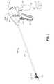
- FIG. 1is a perspective view of an electrosurgical forceps according to an embodiment of the present disclosure including a housing, an elongated shaft, and an end effector;
- FIG. 2Ais an enlarged perspective view of the end effector of FIG. 1 depicted with a pair of jaw members in an open configuration;
- FIG. 2Bis an enlarged perspective view of the end effector of FIG. 1 depicted with the pair of jaw members in a closed configuration;
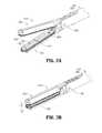
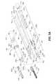
- FIG. 3Ais a perspective view of the end effector and elongated shaft of FIG. 1 with parts separated;
- FIG. 3Bis an enlarged perspective view of a distal portion of the electrosurgical forceps of FIG. 1 depicting a distal knife guide coupled to an inner shaft member;
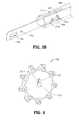
- FIG. 4is a proximally-facing perspective view of a rotation knob depicting a cavity for receiving the elongated shaft of FIG. 1 ;
- FIG. 5is a cross-sectional, perspective view of the end effector assembled with the elongated shaft of FIG. 1 ;
- FIG. 6is a partial, perspective view of a distal portion of a jaw actuation mechanism of the end effector of FIG. 1 ;
- FIG. 7is a partial, perspective view of distal portion of a knife actuation mechanism of the end effector of FIG. 1 ;
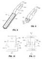
- FIG. 8is a perspective view of a lower jaw member of the end effector of FIG. 1 depicting a double flag at a proximal end thereof;
- FIG. 9is a cross-sectional, perspective view of the lower jaw member of FIG. 8 ;
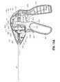
- FIG. 10is a schematic view of the nestled arrangement of the double flag of FIG. 8 with a double flag of an upper jaw member;
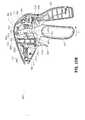
- FIG. 11is a schematic view of an alternative offset arrangement of double flags of an alternate pair of jaw members
- FIG. 12is a perspective view of a proximal portion of the instrument of FIG. 1 with a portion of the housing removed revealing internal components;
- FIG. 13is a partial, side view of a proximal portion of the jaw actuation mechanism of FIG. 6 depicting a connection between the jaw actuation mechanism and the jaw drive rod mechanism for imparting longitudinal movement to the jaw drive rod;
- FIG. 14Ais a perspective view of a proximal portion of the knife actuation mechanism of the end effector of FIG. 1 ;
- FIG. 14Bis a cross-sectional, top view of a knife collar of the knife actuation mechanism of the end effector of FIG. 1 ;
- FIG. 15Ais a side view of the proximal portion of the instrument of FIG. 12 depicting a movable handle in a separated position with respect to a stationary handle, which corresponds to the open configuration of the end effector depicted in FIG. 2A , and a knife trigger in a separated configuration with respect to the stationary handle, which corresponds to an un-actuated or proximal configuration of a knife with respect to the jaw members;
- FIG. 15Bis a side view of the proximal portion of the instrument of FIG. 12 depicting the movable handle in an intermediate position with respect to the stationary handle, which corresponds to a first closed configuration of the end effector wherein the jaw members encounter one another;
- FIG. 15Cis a side view of the proximal portion of the instrument of FIG. 12 depicting the movable handle in an approximated configuration with respect to the stationary handle, which corresponds to a second closed configuration of the end effector wherein the jaw members apply an appropriate pressure to generate a tissue seal;
- FIG. 15Dis a side view of the proximal portion of the instrument of FIG. 12 depicting the knife trigger in an actuated configuration, which corresponds to an actuated or distal position of the knife with respect to the jaw members.
- an embodiment of an electrosurgical forceps 400generally includes a housing 412 that supports various actuators thereon for remotely controlling an end effector 414 through an elongated shaft 416.
- this configurationis typically associated with instruments for use in laparoscopic or endoscopic surgical procedures, various aspects of the present disclosure may be practiced with traditional open instruments and in connection with endoluminal procedures as well.
- the housing 412is constructed of a left housing half 412a and a right housing half 412b.
- the left and right designation of the housing halves 412a, 412brefer to the respective directions as perceived by an operator using the forceps 400.
- the housing halves 412a, 412bmay be constructed of sturdy plastic, and may be joined to one another by adhesives, ultrasonic welding or other suitable assembly methods.
- the housing 412supports a stationary handle 420, a movable handle 422, a trigger 426 and a rotation knob 428.
- the movable handle 422is operable to move the end effector 414 between an open configuration ( FIG. 2A ) wherein a pair of opposed jaw members 430, 432 are disposed in spaced relation relative to one another, and a closed or clamping configuration ( FIG. 2B ) wherein the jaw members 430, 432 are closer together. Approximation of the movable handle 422 with the stationary handle 420 serves to move the end effector 414 to the closed configuration and separation of the movable handle 422 from the stationary handle 420 serves to move the end effector 414 to the open configuration.
- the trigger 426is operable to extend and retract a knife blade 456 (see FIGS. 2A and 2B ) through the end effector 414 when the end effector 414 is in the closed configuration.
- the rotation knob 428serves to rotate the elongated shaft 416 and the end effector 414 about a longitudinal axis A-A extending through the forceps.
- the housing 412supports a switch 436 thereon, which is operable by the user to initiate and terminate the delivery of electrosurgical energy to the end effector 414.
- the switch 436is in electrical communication with a source of electrosurgical energy such as electrosurgical generator 440 or a battery (not shown) supported within the housing 412.
- the generator 440may include devices such as the LIGASURE® Vessel Sealing Generator and the Force Triad® Generator as sold by Covidien Energy-based Devices of Boulder, Colorado.
- a cable 442extends between the housing 412 and the generator 440 and may include a connector (not shown) thereon such that the forceps 400 may be selectively coupled and decoupled electrically from the generator 440.
- the end effector 414may be moved from the open configuration ( FIG. 2A ) wherein tissue (not shown) is received between the jaw members 430, 432, and the closed configuration ( FIG. 2B ), wherein the tissue is clamped and sealed.
- Upper jaw member 430 and lower jaw member 432are mechanically coupled to the elongated shaft 416 about a pivot pin 444.
- the upper and lower jaw members 430, 432are electrically coupled to cable 442, and thus to the generator 440 (e.g., via a respective wire extending through the elongated shaft 416) to provide an electrical pathway to a pair of electrically conductive, tissue-engaging sealing plates 448, 450 disposed on the lower and upper jaw members 432, 430, respectively.
- a pair of wire conduits 478a and 478bmay be provided to guide wires proximally from the end effector 414.
- the wire conduits 478a and 478bmay be constructed of a plastic tube, and serve to protect wires from sharp edges that may form on surrounding components.
- the sealing plate 448 of the lower jaw member 432opposes the sealing plate 450 of the upper jaw member 430, and, in some embodiments, the sealing plates 448 and 450 are electrically coupled to opposite terminals, e.g., positive or active (+) and negative or return (-) terminals associated with the generator 440.
- bipolar energymay be provided through the sealing plates 448 and 450.
- the sealing plates 448 and 450 and/or the end effector 414may be configured for delivering monopolar energy to the tissue.
- the one or both sealing plates 448 and 450deliver electrosurgical energy from an active terminal, e.g. (+), while a return pad (not shown) is placed generally on a patient and provides a return path to the opposite terminal, e.g. (-), of the generator 440.
- the jaw members 430, 432may be pivoted about the pivot pin 444 to move the end effector 414 to the closed configuration of FIG. 2B wherein the sealing plates 448, 450 provide a pressure to tissue grasped therebetween.
- a pressurewithin a range between about 3 kg/cm 2 to about 16 kg/cm 2 and, desirably, within a working range of 7 kg/cm 2 to 13 kg/cm 2 is applied to the tissue.
- a separation or gap distance "G"may be maintained between the sealing plates 448, 450 by an array of stop members 454 ( FIG. 2A ) disposed on or adjacent the sealing plates 448, 450.
- the stop members 454contact opposing surfaces on the opposing jaw member 430, 432 and prohibit further approximation of the sealing plates 448, 450.
- an appropriate gap distanceof about 0.001 inches to about 0.010 inches and, desirably, between about 0.002 and about 0.005 inches may be provided.
- the stop members 454are constructed of an electrically non-conductive plastic or other material molded onto the jaw members 430, 432, e.g., by a process such as overmolding or injection molding.
- the stop members 454are constructed of a heat-resistant ceramic deposited onto the jaw members 430, 432.
- Other methods of controlling gapare contemplated including those described in the commonly assigned patent application entitled GAP CONTROL VIA OVERMOLD TEETH AND HARD STOPS (Application No. _/_,_).
- Electrosurgical energymay be delivered to the tissue through the electrically conductive seal plates 448, 450 to effect a tissue seal.
- a knife blade 456may be advanced through a knife channel 458 defined in one or both jaw members 430, 432 to transect the sealed tissue.
- Knife blade 456is depicted in FIG. 2A as extending from the elongated shaft 416 when the end effector 414 is in an open configuration.
- a knife lockoutis provided to prevent extension of the knife blade 456 into the knife channel 458 when the end effector 414 is in the open configuration, thus preventing accidental or premature transection of tissue and avoiding safety concerns.
- the elongated shaft 416includes various longitudinal components that operatively couple the end effector 414 to the various actuators supported by the housing 412 ( FIG. 1 ).
- An outer shaft member 460defines an exterior surface of the elongated shaft 416 and supports movement of other components therethrough as described below.
- the outer shaft member 460may be constructed from a flat stock piece of metal, In constructing the outer shaft member 460, a stamping, punching or similar metal-working process may be employed to initially generate a flat blank that includes an appropriate outer profile and any interior openings or features. Thereafter, the necessary bends and curves may be formed by bending the flat blank with a press brake, or other suitable metal-working equipment.
- the outer shaft member 460may be formed by folding the flat blank into a generally circular profile (or generally rectangular profile) such that two opposing longitudinal edges of the flat blank meet at a longitudinal seam (not explicitly shown).
- a longitudinal seamdoes not necessarily require joining by a mechanical interlock or any other suitable process, the seam may, in some embodiments, be joined by laser welding (or other suitable process) to form a continuous circular or other geometric (e.g., rectangular) profile.
- the seammay be generally straight, or alternatively, a box joint, a dovetail joint, or any other suitable interface known in the metal-working arts.
- the outer shaft member 460defines a clevis 464 at a distal end thereof for receiving the jaw members 430 and 432.
- Opposing vertical sidewalls 464a and 464b of the outer shaft member 460include respective bores 466a, 466b extending therethrough to frictionally support the pivot pin 444 and maintain an orientation of the pivot pin 444 with respect to the outer shaft member 460.
- the pivot pin 444may be fastened to the outer shaft member 460 by a laser or heat-based welding, adhesives, chemical bonding, or other suitable manufacturing processes.
- the proximal portion of the outer shaft member 460includes, in order from distal to proximal, a series of tabs 486 extending therefrom, a washer 499 extending around outer shaft member 460, a pair of opposing longitudinal slots 468a, 468b defined therethrough and provided to allow longitudinal translation of a dowel pin 493 therethrough, and a longitudinal slot 469 extending distally from a proximal end thereof to couple the outer shaft member 460 to the rotation knob 428.
- the connection established between the outer shaft member 460 and the rotation knob 428is described below with reference to FIG. 4 .
- the series of tabs 486 and the washer 499serve to aid in securing the proximal portion of the outer shaft member 460 within the housing 412.
- the pivot pin 444extends through a proximal portion of each of the jaw members 430, 432 to pivotally support the jaw members 430, 432 at the distal end of the outer shaft member 460.
- a proximal portion of each of the jaw members 430, 432is configured as a "double flag.”
- the double flag configurationrefers to the two laterally spaced parallel flanges or "flags" 430a, 430b and 432a, 432b respectively, extending proximally from a distal portion of the jaw members 430 and 432.
- a lateral cam slot 430c and a lateral pivot bore 430dextend through each of the flags 430a, 430b of the upper jaw member 430.
- a lateral cam slot 432c and a lateral pivot bore 432dextend through each of the flags 432a, 432b of the lower jaw member 432.
- the pivot bores 430d, 432dreceive the pivot pin 444 in a slip-fit relation that permits the jaw members 430, 432 to pivot about the pivot pin 444 to move the end effector 414 between the open and closed configurations ( FIGS. 2A and 2B , respectively).
- An inner shaft member 480is received within the outer shaft member 460 and is configured for longitudinal motion with respect to the outer shaft member 460.
- a distal knife guide 486includes sidewalls 482a, 482b and a proximal key slot 487 that supports a key member 494 therethrough.
- the distal knife guide 486is slid proximally within a distal end of the inner shaft member 480, such that the inner shaft member 480 surrounds a portion of the distal knife guide 486, and opposing lateral sides of the key member 494 align with and fit within opposing longitudinal key slots 495a, 495b defined through the inner shaft member 480 to couple the knife guide 486 to the inner shaft member 480 ( FIG. 3B ).
- the inner shaft member 480includes a pair of opposing longitudinal slots 472a, 472b extending proximally from a distal end of the inner shaft member 480 along a portion of the inner shaft member 480 between the opposing longitudinal key slots 495a, 495b.
- the longitudinal slots 472a, 472ballow the distal end of the inner shaft member 480 to aid in sliding of the distal knife guide 486 proximally within the inner shaft member 480.
- the sidewalls 482a, 482bdefine a longitudinal slot 483 through the distal knife guide 486 that provides lateral support to the knife 402.
- the knife 402is substantially surrounded at a distal end thereof by the distal knife guide 486 on four lateral sides and the sidewalls 482a, 482b of the distal knife guide 486 constrain side-to-side lateral motion of the knife 402.
- the distal knife guide 486serves to urge the knife 402 into a central position within the elongated shaft 416, thereby ensuring proper alignment of the knife 402 as the knife 402 reciprocates within knife channel 458 ( FIG. 2A ).
- the distal knife guide 486includes features for operatively coupling the inner shaft member 480 to the end effector 414.
- a proximal portion 488 of the inner shaft member 480is configured for receipt within the housing 412 ( FIG. 1 ), and includes features for operatively coupling the inner shaft member 480 to the actuators supported thereon, e.g. the movable handle 422.
- the distal knife guide 486includes a through bore 490 extending through the sidewalls 482a, 482b for receiving the cam pin 492. Distally of the through bore 490, a longitudinal slot 496 is defined through the sidewalls 482a, 482b. The longitudinal slot 496 provides clearance for the pivot pin 444, and thus, permits longitudinal reciprocation of the inner shaft member 480 independent of the pivot pin 444.
- the proximal portion 488 of the inner shaft member 480includes, in order from distal to proximal, a pair of opposing longitudinal knife slots 488a, 488b extending therethrough, a pair of opposing distal locking slots 481a, 481b extending therethrough, a pair of opposing proximal locking slots 471 a, 471 b extending therethrough, and a proximal end 491 configured to engage a suitable mechanical interface within the housing 412 to aid in proper support of the inner shaft member 480 within the housing 412 (see FIGS. 12 and 15A-15D ).
- the knife 402is a generally flat, metal component defining a profile that may be constructed by a stamping process.
- the knife 402supports the sharpened knife blade 456 at a distal-most end thereof.
- the sharp edge of the knife blade 456may be applied to the distal end of the knife 402 subsequent to the stamping process that forms the profile.
- various manufacturing techniquesmay be employed such as grinding, coining, electrochemical etching, electropolishing, or other suitable manufacturing processes, for forming sharpened edges.
- a longitudinal slot 406is defined within the knife 402 to provide clearance for the pivot pin 444, the cam pin 492, and the key member 494.
- a proximal through bore 408aextends through a proximal portion 408 of the knife 402 and provides a mechanism for operatively coupling the knife 402 to the trigger 426 via the dowel pin 493.
- the connection between the knife 402 and the trigger 426is described in detail below with reference to FIGS. 12 , 13 , 14A, and 14B .
- the rotation knob 428includes a passageway 429 defined therethrough for receiving the outer shaft member 460.
- the passageway 429has a generally circular profile corresponding to the circular profile of the outer shaft member 460.
- the passageway 429includes a longitudinal keying member 414 that is configured to align with and be seated within longitudinal slot 469 ( FIG. 3A ) of the outer shaft member 460.
- the keying member 414projects laterally inward along the length of passageway 429 such that the insertion of the proximal end of the outer shaft member 460 into the passageway 429 of the rotation knob 428 operatively couples the outer shaft member 460 to the rotation knob 428 and, thus, permits longitudinal motion of the inner shaft member 480 therethrough.
- a cable clearance passageway(not shown) is defined through rotation knob 428 to permit passage of electrical cables or wires that electrically couple the sealing plates 448, 450 to the electrosurgical generator 440 ( FIG. 1 ). Rotational motion imparted to the rotation knob 428 may thus impart rotational motion to each of the components of the elongated shaft 416, and to the end effector 414, which is coupled thereto.
- the rotation knob 428is seated within an interior compartment 434 of the housing 412 and, as shown in FIG. 1 , extends laterally outward from opposing sides of the housing 412 (only shown extending laterally outward from housing half 412b).
- the interior compartment 434defines distal and proximal passageways 434a and 434b that permit the passage of the components of the elongated shaft 416 therethrough.
- the rotational motion of the rotation knob 428may be limited by a stop boss 430 projecting distally from the rotation knob 428 ( FIG. 4 ).
- the stop boss 430is positioned to engage the distal passage 434a of the compartment 434 to restrict rotational motion of the rotation knob 428.
- the stop boss 430may engage the distal passage 434a to restrict rotational motion of the rotation knob 428 to180 degrees in either direction.
- the end effector 414is coupled to the distal end of the elongated shaft 416 by the pivot pin 444.
- the pivot pin 444is coupled to the sidewalls 464a and 464b of the clevis 464 defined at the distal end of the outer shaft member 460.
- the pivot pin 444represents a longitudinally stationary reference for the longitudinal movements of inner shaft member 480 and the knife 402. Laterally inward of the sidewalls 464a, 464b, the pivot pin 444 extends through the flags 432a, 432b of the lower jaw member 432, the flags 430a and 430b of the upper jaw member 430, the sidewalls 482a, 482b of the knife guide 486, and the knife 402.
- the jaw members 430, 432are free to pivot about the pivot pin 444, and the inner shaft member 480 and the knife 402 are free to translate longitudinally around the pivot pin 444.
- the end effector 414is shown in the open configuration. Since the knife guide 486 is coupled to the cam pin 492, when the inner shaft member 480 is in the distal position, the cam pin 492 is located in a distal position in cam slots 430c and 432c defined through the flags 430a, 430b, 432a, 432b of the jaw members 430, 432, respectively.
- the inner shaft member 480may be drawn proximally relative to the pivot pin 444 to move the end effector 414 to the closed configuration (see FIG. 2B ). Since the longitudinal position of the pivot pin 444 is fixed (by the outer shaft member 460, which is removed from view in FIG. 6 for clarity), and since the cam slots 430c, 432c are obliquely arranged with respect to the longitudinal axis A-A, proximal retraction of the cam pin 492 through the cam slots 430c, 432c induces the jaw members 430, 432 to pivot toward one another about the pivot pin 444. Conversely, when the end effector 414 is in the closed configuration, longitudinal translation of the inner shaft member 480 in a distal direction induces the jaw members 430, 432 to pivot away from one another toward the open configuration.
- the longitudinal slot 406 in the knife 402extends around both the pivot pin 444 and the cam pin 492, and thus the pins 444, 492 do not interfere with the reciprocal motion of the knife 402.
- the pivot pin 444 and cam pin 492extend through the slot 406 in such a manner as to guide longitudinal motion of the knife 402 as well as constrain vertical motion of the knife 402.
- the blade 456 at the distal-most end of the knife 402is centrally aligned by the knife guide 486, as discussed hereinabove. Properly aligned, the blade 456 readily enters the knife channel 458 defined in the jaw members 430, 432.
- the lower jaw member 432is constructed of three major components. These components include a double-flag jaw insert 440, an insulator 442 and the sealing plate 448.
- the flags 432a, 432b of the jaw member 432define a proximal portion of the double-flag jaw insert 440, and a generally u-shaped channel 444 extends distally to support the tissue engaging portion of the jaw member 432.
- the double-flag jaw insert 440includes various planar surfaces, and may be constructed as a sheet metal component formed by a stamping process. In such a stamping process, the cam slots 432c and pivot holes 432d may be punched into a flat blank, and subsequently the blank may be bent to form the flags 432a, 432b and the u-shaped channel 444.
- the insulator 442may be constructed of an electrically insulative plastic such as a polyphthalamide (PPA) (e.g., Amodel®), polycarbonate (PC), acrylonitrile butadiene styrene (ABS), a blend of PC and ABS, nylon, ceramic, etc.
- PPApolyphthalamide
- PCpolycarbonate
- ABSacrylonitrile butadiene styrene
- the electrically insulative plasticmay be overmolded onto the jaw insert 440 in a single-shot injection molding process such that sealing plate 448 is overmolded to the jaw insert 440.
- the electrically insulative plasticmay be mechanically coupled to the jaw insert 440, e.g., pressed, snapped, glued, etc.
- Various featuresmay be molded into the insulator 442 that facilitate the attachment of the sealing plate 448 to the insert 440.
- the sealing plate 448may be constructed of an electrically conductive metal, and may be stamped from a flat sheet stock.
- the flags 430a, 430b of the upper jaw member 430are depicted schematically in a nestled configuration with respect to the flags 432a, 432b of the lower jaw member 432.
- the proximal portion of the upper jaw member 430is narrower than the proximal portion of the lower jaw member 432, and thus, a lateral spacing "S" between the flags 432a, 432b is sufficient to permit the flags 430a and 430b to be positioned therebetween.
- a pivot axis "P 0 "extends through an overlapping portion of the flags 430a, 432a, and 430b, 432a such that the upper and lower jaw members 430, 432 may pivot about the common axis "P 0 .”
- the proximal portions of the upper and lower jaw members 430, 432also share a common centerline "CL - 1" that is transverse with respect to the pivot axis "P 0 .”
- a proximal portion of double-flag upper jaw member 450includes flags 450a and 450b.
- a proximal portion of a double-flag lower jaw member 452includes flags 452a and 452b and exhibits a width that is identical to a width of the proximal portion of the upper jaw member 450.
- one flag 450a of the upper jaw member 450is positioned on a laterally exterior side of the corresponding flag 452a of the lower jaw member 452, and the other flag 450b of the upper jaw member 450 is positioned on a laterally interior side of the corresponding flag 452b of the lower jaw member 452.
- a centerline "CL - 2" of the proximal portion of the upper jaw member 450is laterally offset with respect to a centerline "CL - 3" of the lower jaw member 452.
- the movable handle 422may be manipulated to impart longitudinal motion to the inner shaft member 480
- the knife trigger 426may be manipulated to impart longitudinal motion to the knife 402.
- longitudinal motion of the inner shaft member 480serves to move the end effector 414 between the open configuration of FIG. 2A and the closed configuration of FIG. 2B
- longitudinal motion of the knife 402serves to move knife blade 456 through knife channel 458 ( FIG. 2A ).
- the movable handle 422is operatively coupled to the inner shaft member 480 by a connection mechanism 476 ( FIG. 12 ).
- the connection mechanism 476includes a clevis 478 defined at an upper end of the movable handle 422.
- the clevis 478is pivotally supported on the left housing half 412b by a pivot boss 479.
- a second complementary pivot boss(not shown) is provided on the right housing half 412a to support the clevis 478.
- Each of two upper flanges 478a and 478b of the clevis 478extend upwardly about opposing sides of a drive collar 484 supported on the inner shaft member 480 and include rounded drive surfaces 497a and 497b thereon.
- Drive surface 497aengages a proximal-facing surface of a distal lock collar 484a and drive surface 497b engages a distal facing surface of a proximal rim 484b of the drive collar 484 ( FIG. 13 ).
- the distal lock collar 484aengages the opposing distal locking slots 481a, 481b ( FIG. 3A ) extending through the proximal portion 488 of the inner shaft member 480 to lock-fit the distal lock collar 484a to the inner shaft member 480.
- the distal lock collar 484ais prevented from longitudinal motion relative to the inner shaft member 480.
- Drive surface 497ais arranged along the longitudinal axis A-A such that pivotal motions of the movable handle 422 about the pivot bosses 479 induce corresponding longitudinal motion of the drive collar 484 along the longitudinal axis A-A in the proximal direction.
- Drive surface 497bis arranged along the longitudinal axis A-A such that pivotal motions of the movable handle 422 about the pivot bosses 479 induce corresponding longitudinal motion of the distal lock collar 484a along the longitudinal axis A-A in the distal direction.
- proximal longitudinal motionmay be imparted to the inner shaft member 480 by pushing the proximal rim 484b of the drive collar 484 proximally with the movable handle 422 ( FIG. 12 ) as indicated by arrow D4.
- the proximal rim 484bengages a spring 489 that is constrained between the proximal rim 484b and a proximal lock collar 415.
- the proximal lock collar 415engages the opposing proximal locking slots 471 a, 471b ( FIG. 3A ) extending through the proximal portion 488 of the inner shaft member 480 to lock-fit the proximal lock collar 415 to the inner shaft member 480.
- the proximal lock collar 415is prevented from longitudinal motion relative to the inner shaft member 480 and serves as a proximal stop against which spring 489 compresses.
- Distal longitudinal motionis imparted to the inner shaft member 480 by pushing the distal lock collar 484a distally with drive surface 497a of movable handle 422 as indicated by arrow D3 ( FIG. 13 ).
- Distal longitudinal motion of the distal lock collar 484ainduces a corresponding distal motion of the inner shaft member 480 by virtue of the lock-fit coupling of the distal lock collar 484a to the opposing proximal locking slots 471a, 471b extending through the proximal portion 488 of the inner shaft member 480 ( FIG. 3A ).
- Proximal longitudinal motion of the inner shaft member 480draws the cam pin 492 proximally to pivot the jaw members 430, 432 toward one another to move the end effector 414 to the closed configuration as described above with reference to FIG. 6 .
- the inner shaft member 480essentially bottoms out (i.e., further proximal movement of the inner shaft member 480 is prohibited since the jaw members 430, 432 contact one another). Further proximal movement of the movable handle 422 ( FIG. 12 ), however, will continue to move the drive collar 484 proximally.
- the spring 489also serves to bias the movable handle 422 to an open configuration such that the movable handle 422 is separated from the stationary handle 420.
- the trigger 426is pivotally supported in the housing 412 about a pivot boss 403 protruding from the trigger 426.
- the trigger 426is operatively coupled to the knife 402 by a knife connection mechanism 404 such that pivotal motion of the trigger 426 induces longitudinal motion of the knife 402.
- the knife connection mechanism 404includes upper flanges 426a, 426b of the trigger 426 and a knife collar 410.
- the knife collar 410includes a cap member 411 coupled thereto and a pair of integrally formed pin bosses 439a, 439b extending from opposing sides thereof.
- the knife collar 410may include indentations or catches defined therein (not shown) that receive corresponding snap-in features (e.g., arms) of the cap member 411.
- the cap 411may thus be assembled to the knife collar 410 such that the cap 411 and the knife collar 410 translate together. As shown by FIG.
- the coupling of the knife collar 410 to the cap 411forms an interior circular channel 413 to capture the dowel pin 493 therein such that the dowel pin 493 is supported on opposing ends between the knife collar 410 and the cap 411.
- the dowel pin 493extends through the proximal through bore 408a extending through a proximal portion 408 of the knife 402 ( FIG. 3A ) to operably couple the knife 402 to the knife collar 410.
- dowel pin 493translates longitudinally within knife slots 488a, 488b, respectively, of the inner shaft member 480 such that the longitudinal motion of inner shaft member 480 is unimpeded by dowel pin 493.
- dowel pin 493freely rotates within the interior circular channel 413 such that the outer and inner shaft members 460 and 480 (removed from view in FIG. 14B for clarity), the knife 402, and the dowel pin 493 rotate within the knife collar 410 about the longitudinal axis A-A.
- the knife collar 410serves as a stationary reference for the rotational movement of the outer shaft member 460, the inner shaft member 480, the knife 402, and the dowel pin 493.
- the upper flanges 426a, 426b of the trigger 426include respective slots 427a, 427b defined therethrough that are configured to receive the pin bosses 439a, 439b, respectively, of the knife collar 410 such that pivotal motion of the trigger 426 induces longitudinal motion of the knife collar 410 and, thus, the knife 402 by virtue of the coupling of knife 402 to the knife collar 410 via the dowel pin 493 extending through the through bore 408a.
- dowel pin 493translates longitudinally within the opposing slots 468a, 468b of the outer shaft member 460 and the slots 488a, 488b of the inner shaft member 480.
- the knife collar 410when the trigger 426 is moved to induce motion of the knife collar 410 in order to translate the blade 456 through the knife channel 458, the knife collar 410 translates along the outer shaft member 460 in the direction of arrow A9 to abut a spring 419 such that spring 419 compresses against a distal portion 421 of the interior of the housing 412 ( FIG. 12 ).
- the spring 419biases the knife collar 410 in a proximal direction to a proximal position along the outer shaft member 460.
- a sequence of motionsmay be initiated by moving the movable handle 422 to induce motion of the jaw drive mechanism in order to close the jaws 430, 432, and by moving the trigger 426 to induce motion of the knife collar 410 in order to translate the blade 456 through the knife channel 458.
- both the moveable handle 422 and the knife trigger 426are in a distal or un-actuated position as depicted in FIG. 15A .
- This arrangement of the moveable handle 422 and trigger 426sustains the end effector 414 in the open configuration ( FIG.
- the movable handle 422may be moved from the distal position of FIG. 15A to the intermediate position depicted in FIG. 15B to move the jaw members 430, 432 to the closed configuration ( FIG. 2B ).
- the drive surface 497b of the movable handle 422engages the proximal rim 484b of the drive collar 484.
- the drive collar 484 and the spring 489are both driven proximally against the proximal lock collar 415 and, thus, the inner shaft member 480 is driven proximally in the direction of arrow M2 ( FIG. 15B ).
- proximal movement of the inner shaft member 480serves to draw the cam pin 492 proximally though the cam slots 430c, 432c of the jaw members 430, 432, respectively, and thus pivot the jaw members 430, 432 toward one another.
- the jaw actuation mechanism"bottoms out” and further proximal movement of the cam pin 492 and the inner shaft member 480 is prevented.
- the movable handle 422may be moved from the intermediate position of FIG. 15B to the actuated or proximal position of FIG 15C to increase the pressure applied by the jaw members 430, 432.
- the drive surface 497bpresses the proximal rim 484b of the drive collar 484 further distally against the spring 489 in the direction of arrow M4 ( FIG. 15C ).
- the spring 489is compressed against the proximal lock collar 415, and a tensile force is transmitted through the inner shaft member 480 to the jaw members 430, 432.
- the tensile force supplied by the spring 489ensures that the jaw members 430, 432 apply an appropriate pressure to effect a tissue seal.
- electrosurgical energymay be selectively supplied to the end effector 414 to generate a tissue seal.
- a t-shaped latch 422aextending proximally from an upper portion of the moveable handle 422 is received in a railway 420a supported within the stationary handle 420.
- the railway 420aserves to temporarily lock the movable handle 422 in the proximal position against the bias of the spring 489.
- the flange 422amay be released from the railway 420a by pivoting the movable handle 422 proximally and releasing the movable handle 422 to move under the influence of the spring 489.
- the knife trigger 426When the movable handle 422 is in the actuated or proximal position, the knife trigger 426 may be selectively moved from the distal position of FIG. 15C to the proximal position of FIG 15D to advance the knife blade 456 distally through knife channel 458.
- the knife trigger 426may be pivoted in the direction of arrow M5 ( FIG. 15D ), about pivot boss 403 to advance the flange 426b of the knife trigger 426 distally in the direction of arrow M6 such that the pin boss 439b translates within slot 427b from the position shown in FIGS. 15A - 15C to the position shown in FIG. 15D .
- pin boss 439atranslates within slot 427a in the same manner as described above with respect to pin boss 439b and slot 427b. Movement of flanges 426a, 426b draws the knife collar 410 distally, which induces distal longitudinal motion of the knife 402 by virtue of the coupling of knife 402 to the knife collar 410 via the dowel pin 493 extending through the through bore 408a, as described above with reference to FIGS. 3A and 14B .
Landscapes
- Health & Medical Sciences (AREA)
- Surgery (AREA)
- Life Sciences & Earth Sciences (AREA)
- Engineering & Computer Science (AREA)
- Molecular Biology (AREA)
- Public Health (AREA)
- Heart & Thoracic Surgery (AREA)
- Medical Informatics (AREA)
- Nuclear Medicine, Radiotherapy & Molecular Imaging (AREA)
- Animal Behavior & Ethology (AREA)
- General Health & Medical Sciences (AREA)
- Biomedical Technology (AREA)
- Veterinary Medicine (AREA)
- Physics & Mathematics (AREA)
- Plasma & Fusion (AREA)
- Otolaryngology (AREA)
- Ophthalmology & Optometry (AREA)
- Surgical Instruments (AREA)
Abstract
Description
- The present disclosure relates generally to the field of surgical instruments. In particular, the disclosure relates to an endoscopic electrosurgical forceps that is economical to manufacture and is capable of sealing and cutting relatively large tissue structures.
- Instruments such as electrosurgical forceps are commonly used in open and endoscopic surgical procedures to coagulate, cauterize and seal tissue. Such forceps typically include a pair of jaws that can be controlled by a surgeon to grasp targeted tissue, such as, e.g., a blood vessel. The jaws may be approximated to apply a mechanical clamping force to the tissue, and are associated with at least one electrode to permit the delivery of electrosurgical energy to the tissue. The combination of the mechanical clamping force and the electrosurgical energy has been demonstrated to join adjacent layers of tissue captured between the jaws. When the adjacent layers of tissue include the walls of a blood vessel, sealing the tissue may result in hemostasis, which may facilitate the transection of the sealed tissue. A detailed discussion of the use of an electrosurgical forceps may be found in
U.S. Patent No 7,255,697 to Dycus et al . - A bipolar electrosurgical forceps typically includes opposed electrodes disposed on clamping faces of the jaws. The electrodes are charged to opposite electrical potentials such that an electrosurgical current may be selectively transferred through tissue grasped between the electrodes. To effect a proper seal, particularly in relatively large vessels, two predominant mechanical parameters must be accurately controlled; the pressure applied to the vessel, and the gap distance established between the electrodes.
- Both the pressure and gap distance influence the effectiveness of the resultant tissue seal. If an adequate gap distance is not maintained, there is a possibility that the opposed electrodes will contact one another, which may cause a short circuit and prevent energy from being transferred through the tissue. Also, if too low a force is applied the tissue may have a tendency to move before an adequate seal can be generated. The thickness of a typical effective tissue seal is optimally between about 0.001 and about 0.006 inches. Below this range, the seal may shred or tear and above this range the vessel walls may not be effectively joined. Closure pressures for sealing large tissue structures preferably fall within the range of about 3kg/cm2 to about 16 kg/cm2.
- As is traditional, the term "distal" refers herein to an end of the apparatus that is farther from an operator, and the term "proximal" refers herein to the end of the electrosurgical forceps that is closer to the operator.
- The present disclosure relates to an electrosurgical apparatus and methods for performing electrosurgical procedures. More particularly, the present disclosure relates to electrosurgically sealing tissue.
- The present disclosure describes a surgical instrument for treating tissue that is economical to manufacture and is capable of sealing and cutting relatively large tissue structures.
- The surgical instrument includes an elongated shaft having a distal portion and a proximal portion coupled to a housing. The elongated shaft defines a longitudinal axis. An inner shaft member extends at least partially through the elongated shaft. The inner shaft member is selectively movable in a longitudinal direction with respect to the elongated shaft. An end effector adapted for treating tissue is supported by the distal portion of the elongated shaft. The end effector includes upper and lower jaw members pivotally coupled to the distal portion of the elongated shaft about a pivot axis. The upper and lower jaw members include a first and second pair of laterally spaced flanges, respectively. The first and second pairs of flanges of the jaw members are arranged in an offset configuration such that one flange of the upper jaw member is positioned on a laterally exterior side of a corresponding flange of the lower jaw member, and the other flange of the upper jaw member is positioned on a laterally interior side of the other flange of the lower jaw member.
- Additionally or alternatively, the housing includes a movable actuating mechanism configured to cause longitudinal movement of the inner shaft member relative to the elongated shaft.
- Additionally or alternatively, the elongated shaft includes at least one feature formed therein configured to operably engage the movable actuating mechanism.
- Additionally or alternatively, the elongated shaft has a generally circular profile joined along two opposing longitudinal edges.
- Additionally or alternatively, the elongated shaft is made from a flat blank formed into a shaft profile and having opposed longitudinal edges of the blank joined along a seam.
- Additionally or alternatively, the two opposing longitudinal edges are laser welded together.
- In an embodiment, the inner shaft member cooperates with some or all flanges of the jaw members such that longitudinal movement of the inner shaft member causes the jaw members to move between an open position and a closed position.
- In an embodiment, the inner shaft member is longitudinally moveable between flanges of first and second pairs of flanges on one lateral side and flanges of the first and second pairs of flanges on the other lateral side.
- In an embodiment, the jaw members are each made at least partly from a flat metal blank that is shaped to form the pair of flanges. The blank may also be shaped to include a U-shaped portion extending distally from the pair of flanges to support a tissue engaging portion of the jaw member.
- Additionally or alternatively, the two opposing longitudinal edges are joined by one of a box joint interface and a dovetail joint interface.
- Additionally or alternatively, the surgical instrument includes a cam pin supported by the inner shaft member such that longitudinal movement of the inner shaft member is imparted to the cam pin.
- Additionally or alternatively, each of the first and second laterally spaced flanges define a camming slot for engaging the cam pin such that the jaw members can be opened and closed.
- Additionally or alternatively, the upper and lower jaw members are constructed as substantially identical components positioned in a laterally offset manner with respect to one another.
- Additionally or alternatively, the pivot axis extends through each of the flanges in a direction substantially transverse to the longitudinal axis.
- Additionally or alternatively, the inner shaft member extends through the jaw members on a laterally interior side of each of the flanges.
- Additionally or alternatively, the surgical instrument includes a knife selectively movable in a longitudinal direction with respect to the inner shaft member. The knife is moveable in a longitudinal direction between the flanges to extend into a tissue contacting portion of the jaw members to cut tissue.
- Additionally or alternatively, the inner shaft member includes a knife guide disposed on a distal end of an inner shaft of the inner shaft member, the guide surrounding the knife on four lateral sides, to constrain movement of the knife on all four sides. The inner shaft may be tubular. The knife guide may define a flat sleeve having a slot extending therethrough for translatably receive therein the knife, which has a flat profile.
- In an embodiment, the cam pin or other engagement means for cooperating with the flanges to open and close the jaw members is connected to the knife guide.
- According to another aspect of the present disclosure, a surgical instrument is provided. The surgical instrument includes an elongated shaft including a distal portion and a proximal portion coupled to a housing. The elongated shaft defines a longitudinal axis. An end effector adapted for treating tissue is supported by the distal portion of the elongated shaft. The end effector includes first and second jaw members pivotally coupled to one another to move between open and closed configurations. Each of the jaw members includes a pair of laterally spaced flanges. Each of the flanges includes a camming surface. A knife extends at least partially through the elongated shaft and is selectively movable in a longitudinal direction between the flanges of the jaw members. A blade of the knife is extendable into a tissue contacting portion of the jaw members. An inner shaft member extends at least partially through the elongated shaft and is selectively movable in a longitudinal direction with respect to the knife and with respect to the elongated shaft. The inner shaft member carries a cam pin positioned to engage the camming surface of each of the flanges to induce the jaw members to move between the open and closed configurations.
- Additionally or alternatively, the elongated shaft includes at least one feature defined therein configured to engage a movable actuating mechanism operably associated with the housing.
- Additionally or alternatively, the laterally spaced flanges of the jaw members are arranged in a nestled configuration wherein both of the flanges of one of the jaw members are arranged within a laterally interior side of the laterally spaced flanges of the other of the jaw members. Alternatively, the flanges are arranged in an offset configuration as described above.
- According to another aspect of the present disclosure, a method of manufacturing a surgical device including a housing and an elongated shaft for coupling an end effector with the housing of the surgical device is provided. The method includes the steps of stamping at least one feature into a blank of sheet metal and folding the blank into such that two opposing longitudinal edges of the blank meet at a longitudinal seam to form an elongated shaft. The method also includes the step of operably coupling an end effector to at least one feature formed at a distal portion of the elongated shaft. The method also includes the step of engaging at least one actuating mechanism supported by a housing with at least one feature formed at a proximal portion of the elongated shaft to operably couple the proximal portion of the elongated shaft with the housing. The actuating mechanism is configured to selectively move the end effector between an open position and a closed position.
- Additionally or alternatively, the method includes the step of joining the two opposing longitudinal edges along the longitudinal seam.
- Additionally or alternatively, the joining step further comprises laser welding the longitudinal seam. The longitudinal seam may be a box joint configuration or a dovetail joint configuration.
- Additionally or alternatively, the method includes the step of coupling a drive rod to the at least one actuating mechanism at a proximal end and to the end effector at a distal end. The drive rod may be configured to translate within and relative to the elongated shaft upon movement of the at least one actuation mechanism to effect actuation of the end effector.
- Additionally or alternatively, the method includes the step of stamping at least one feature at a distal end of the blank such that a clevis is formed at a distal end of the elongated shaft. The clevis may be configured to support the end effector.
- The method may also comprise forming at least part of each jaw member of the end effector from a flat metal blank to include a pair of laterally spaced proximal flanges and a distally extending support portion for supporting a tissue engaging portion of the jaw members. The support portion may be U-shaped. At least one of the pair of flanges may be formed at the blank stage to include a cam slot and/or a pivot feature. The pair of flanges of the one jaw member may be pivotally connected to the pair of jaw members of the other jaw member so that the end effector can be opened and closed.
- The accompanying drawings, which are incorporated in and constitute a part of this specification, illustrate embodiments of the present disclosure and, together with the detailed description of the embodiments given below, serve to explain the principles of the disclosure.
FIG. 1 is a perspective view of an electrosurgical forceps according to an embodiment of the present disclosure including a housing, an elongated shaft, and an end effector;FIG. 2A is an enlarged perspective view of the end effector ofFIG. 1 depicted with a pair of jaw members in an open configuration;FIG. 2B is an enlarged perspective view of the end effector ofFIG. 1 depicted with the pair of jaw members in a closed configuration;FIG. 3A is a perspective view of the end effector and elongated shaft ofFIG. 1 with parts separated;FIG. 3B is an enlarged perspective view of a distal portion of the electrosurgical forceps ofFIG. 1 depicting a distal knife guide coupled to an inner shaft member;FIG. 4 is a proximally-facing perspective view of a rotation knob depicting a cavity for receiving the elongated shaft ofFIG. 1 ;FIG. 5 is a cross-sectional, perspective view of the end effector assembled with the elongated shaft ofFIG. 1 ;FIG. 6 is a partial, perspective view of a distal portion of a jaw actuation mechanism of the end effector ofFIG. 1 ;FIG. 7 is a partial, perspective view of distal portion of a knife actuation mechanism of the end effector ofFIG. 1 ;FIG. 8 is a perspective view of a lower jaw member of the end effector ofFIG. 1 depicting a double flag at a proximal end thereof;FIG. 9 is a cross-sectional, perspective view of the lower jaw member ofFIG. 8 ;FIG. 10 is a schematic view of the nestled arrangement of the double flag ofFIG. 8 with a double flag of an upper jaw member;FIG. 11 is a schematic view of an alternative offset arrangement of double flags of an alternate pair of jaw members;FIG. 12 is a perspective view of a proximal portion of the instrument ofFIG. 1 with a portion of the housing removed revealing internal components;FIG. 13 is a partial, side view of a proximal portion of the jaw actuation mechanism ofFIG. 6 depicting a connection between the jaw actuation mechanism and the jaw drive rod mechanism for imparting longitudinal movement to the jaw drive rod;FIG. 14A is a perspective view of a proximal portion of the knife actuation mechanism of the end effector ofFIG. 1 ;FIG. 14B is a cross-sectional, top view of a knife collar of the knife actuation mechanism of the end effector ofFIG. 1 ;FIG. 15A is a side view of the proximal portion of the instrument ofFIG. 12 depicting a movable handle in a separated position with respect to a stationary handle, which corresponds to the open configuration of the end effector depicted inFIG. 2A , and a knife trigger in a separated configuration with respect to the stationary handle, which corresponds to an un-actuated or proximal configuration of a knife with respect to the jaw members;FIG. 15B is a side view of the proximal portion of the instrument ofFIG. 12 depicting the movable handle in an intermediate position with respect to the stationary handle, which corresponds to a first closed configuration of the end effector wherein the jaw members encounter one another;FIG. 15C is a side view of the proximal portion of the instrument ofFIG. 12 depicting the movable handle in an approximated configuration with respect to the stationary handle, which corresponds to a second closed configuration of the end effector wherein the jaw members apply an appropriate pressure to generate a tissue seal; andFIG. 15D is a side view of the proximal portion of the instrument ofFIG. 12 depicting the knife trigger in an actuated configuration, which corresponds to an actuated or distal position of the knife with respect to the jaw members.- Referring initially to
FIG. 1 , an embodiment of anelectrosurgical forceps 400 generally includes a housing 412 that supports various actuators thereon for remotely controlling anend effector 414 through anelongated shaft 416. Although this configuration is typically associated with instruments for use in laparoscopic or endoscopic surgical procedures, various aspects of the present disclosure may be practiced with traditional open instruments and in connection with endoluminal procedures as well. - The housing 412 is constructed of a
left housing half 412a and aright housing half 412b. The left and right designation of thehousing halves forceps 400. Thehousing halves - To mechanically control the
end effector 414, the housing 412 supports astationary handle 420, amovable handle 422, atrigger 426 and arotation knob 428. Themovable handle 422 is operable to move theend effector 414 between an open configuration (FIG. 2A ) wherein a pair ofopposed jaw members FIG. 2B ) wherein thejaw members movable handle 422 with thestationary handle 420 serves to move theend effector 414 to the closed configuration and separation of themovable handle 422 from thestationary handle 420 serves to move theend effector 414 to the open configuration. Thetrigger 426 is operable to extend and retract a knife blade 456 (seeFIGS. 2A and 2B ) through theend effector 414 when theend effector 414 is in the closed configuration. Therotation knob 428 serves to rotate theelongated shaft 416 and theend effector 414 about a longitudinal axis A-A extending through the forceps. - To electrically control the
end effector 414, the housing 412 supports aswitch 436 thereon, which is operable by the user to initiate and terminate the delivery of electrosurgical energy to theend effector 414. Theswitch 436 is in electrical communication with a source of electrosurgical energy such aselectrosurgical generator 440 or a battery (not shown) supported within the housing 412. Thegenerator 440 may include devices such as the LIGASURE® Vessel Sealing Generator and the Force Triad® Generator as sold by Covidien Energy-based Devices of Boulder, Colorado. Acable 442 extends between the housing 412 and thegenerator 440 and may include a connector (not shown) thereon such that theforceps 400 may be selectively coupled and decoupled electrically from thegenerator 440. - Referring now to
FIGS. 2A - 3 , theend effector 414 may be moved from the open configuration (FIG. 2A ) wherein tissue (not shown) is received between thejaw members FIG. 2B ), wherein the tissue is clamped and sealed.Upper jaw member 430 andlower jaw member 432 are mechanically coupled to theelongated shaft 416 about apivot pin 444. The upper andlower jaw members cable 442, and thus to the generator 440 (e.g., via a respective wire extending through the elongated shaft 416) to provide an electrical pathway to a pair of electrically conductive, tissue-engagingsealing plates upper jaw members wire conduits end effector 414. Thewire conduits plate 448 of thelower jaw member 432 opposes the sealingplate 450 of theupper jaw member 430, and, in some embodiments, the sealingplates generator 440. Thus, bipolar energy may be provided through the sealingplates plates end effector 414 may be configured for delivering monopolar energy to the tissue. In a monopolar configuration, the one or both sealingplates generator 440. - The
jaw members pivot pin 444 to move theend effector 414 to the closed configuration ofFIG. 2B wherein the sealingplates plates FIG. 2A ) disposed on or adjacent the sealingplates stop members 454 contact opposing surfaces on the opposingjaw member plates stop members 454 are constructed of an electrically non-conductive plastic or other material molded onto thejaw members stop members 454 are constructed of a heat-resistant ceramic deposited onto thejaw members - Electrosurgical energy may be delivered to the tissue through the electrically
conductive seal plates knife blade 456 may be advanced through aknife channel 458 defined in one or bothjaw members Knife blade 456 is depicted inFIG. 2A as extending from theelongated shaft 416 when theend effector 414 is in an open configuration. In some embodiments, a knife lockout is provided to prevent extension of theknife blade 456 into theknife channel 458 when theend effector 414 is in the open configuration, thus preventing accidental or premature transection of tissue and avoiding safety concerns. - Referring now to
FIG. 3A , theelongated shaft 416 includes various longitudinal components that operatively couple theend effector 414 to the various actuators supported by the housing 412 (FIG. 1 ). Anouter shaft member 460 defines an exterior surface of theelongated shaft 416 and supports movement of other components therethrough as described below. Theouter shaft member 460 may be constructed from a flat stock piece of metal, In constructing theouter shaft member 460, a stamping, punching or similar metal-working process may be employed to initially generate a flat blank that includes an appropriate outer profile and any interior openings or features. Thereafter, the necessary bends and curves may be formed by bending the flat blank with a press brake, or other suitable metal-working equipment. Theouter shaft member 460 may be formed by folding the flat blank into a generally circular profile (or generally rectangular profile) such that two opposing longitudinal edges of the flat blank meet at a longitudinal seam (not explicitly shown). Although the longitudinal seam does not necessarily require joining by a mechanical interlock or any other suitable process, the seam may, in some embodiments, be joined by laser welding (or other suitable process) to form a continuous circular or other geometric (e.g., rectangular) profile. The seam may be generally straight, or alternatively, a box joint, a dovetail joint, or any other suitable interface known in the metal-working arts. - The
outer shaft member 460 defines aclevis 464 at a distal end thereof for receiving thejaw members vertical sidewalls outer shaft member 460 includerespective bores pivot pin 444 and maintain an orientation of thepivot pin 444 with respect to theouter shaft member 460. Alternatively or additionally, thepivot pin 444 may be fastened to theouter shaft member 460 by a laser or heat-based welding, adhesives, chemical bonding, or other suitable manufacturing processes. - At a proximal portion of the
outer shaft member 460, various features are provided that serve to couple theouter shaft member 460 to various elements of the housing 412. More specifically, the proximal portion of theouter shaft member 460 includes, in order from distal to proximal, a series oftabs 486 extending therefrom, awasher 499 extending aroundouter shaft member 460, a pair of opposinglongitudinal slots dowel pin 493 therethrough, and alongitudinal slot 469 extending distally from a proximal end thereof to couple theouter shaft member 460 to therotation knob 428. The connection established between theouter shaft member 460 and therotation knob 428 is described below with reference toFIG. 4 . As shown inFIGS. 15A - 15D , the series oftabs 486 and thewasher 499 serve to aid in securing the proximal portion of theouter shaft member 460 within the housing 412. - The
pivot pin 444 extends through a proximal portion of each of thejaw members jaw members outer shaft member 460. With reference toFIG. 8 , a proximal portion of each of thejaw members jaw members lateral cam slot 430c and alateral pivot bore 430d extend through each of theflags upper jaw member 430. Similarly, alateral cam slot 432c and alateral pivot bore 432d extend through each of theflags lower jaw member 432. The pivot bores 430d, 432d receive thepivot pin 444 in a slip-fit relation that permits thejaw members pivot pin 444 to move theend effector 414 between the open and closed configurations (FIGS. 2A and 2B , respectively). - An
inner shaft member 480 is received within theouter shaft member 460 and is configured for longitudinal motion with respect to theouter shaft member 460. Adistal knife guide 486 includes sidewalls 482a, 482b and a proximalkey slot 487 that supports akey member 494 therethrough. During assembly ofelectrosurgical forceps 400, thedistal knife guide 486 is slid proximally within a distal end of theinner shaft member 480, such that theinner shaft member 480 surrounds a portion of thedistal knife guide 486, and opposing lateral sides of thekey member 494 align with and fit within opposing longitudinalkey slots inner shaft member 480 to couple theknife guide 486 to the inner shaft member 480 (FIG. 3B ). Theinner shaft member 480 includes a pair of opposinglongitudinal slots inner shaft member 480 along a portion of theinner shaft member 480 between the opposing longitudinalkey slots longitudinal slots inner shaft member 480 to aid in sliding of thedistal knife guide 486 proximally within theinner shaft member 480. Once thekey member 494 is aligned with and fit within the longitudinalkey slots key member 494 effectively couples thedistal knife guide 486 to theinner shaft member 480, as depicted byFIG. 3B . - The sidewalls 482a, 482b define a
longitudinal slot 483 through thedistal knife guide 486 that provides lateral support to theknife 402. Theknife 402 is substantially surrounded at a distal end thereof by thedistal knife guide 486 on four lateral sides and the sidewalls 482a, 482b of thedistal knife guide 486 constrain side-to-side lateral motion of theknife 402. Thus, thedistal knife guide 486 serves to urge theknife 402 into a central position within theelongated shaft 416, thereby ensuring proper alignment of theknife 402 as theknife 402 reciprocates within knife channel 458 (FIG. 2A ). Thedistal knife guide 486 includes features for operatively coupling theinner shaft member 480 to theend effector 414. Aproximal portion 488 of theinner shaft member 480 is configured for receipt within the housing 412 (FIG. 1 ), and includes features for operatively coupling theinner shaft member 480 to the actuators supported thereon, e.g. themovable handle 422. - The
distal knife guide 486 includes a throughbore 490 extending through the sidewalls 482a, 482b for receiving thecam pin 492. Distally of the throughbore 490, alongitudinal slot 496 is defined through the sidewalls 482a, 482b. Thelongitudinal slot 496 provides clearance for thepivot pin 444, and thus, permits longitudinal reciprocation of theinner shaft member 480 independent of thepivot pin 444. - The
proximal portion 488 of theinner shaft member 480 includes, in order from distal to proximal, a pair of opposinglongitudinal knife slots distal locking slots proximal locking slots proximal end 491 configured to engage a suitable mechanical interface within the housing 412 to aid in proper support of theinner shaft member 480 within the housing 412 (seeFIGS. 12 and15A-15D ). - The
knife 402 is a generally flat, metal component defining a profile that may be constructed by a stamping process. Theknife 402 supports the sharpenedknife blade 456 at a distal-most end thereof. The sharp edge of theknife blade 456 may be applied to the distal end of theknife 402 subsequent to the stamping process that forms the profile. For example, various manufacturing techniques may be employed such as grinding, coining, electrochemical etching, electropolishing, or other suitable manufacturing processes, for forming sharpened edges. Alongitudinal slot 406 is defined within theknife 402 to provide clearance for thepivot pin 444, thecam pin 492, and thekey member 494. A proximal throughbore 408a extends through aproximal portion 408 of theknife 402 and provides a mechanism for operatively coupling theknife 402 to thetrigger 426 via thedowel pin 493. The connection between theknife 402 and thetrigger 426 is described in detail below with reference toFIGS. 12 ,13 ,14A, and 14B . - Referring now to
FIG. 4 , therotation knob 428 includes apassageway 429 defined therethrough for receiving theouter shaft member 460. Thepassageway 429 has a generally circular profile corresponding to the circular profile of theouter shaft member 460. Thepassageway 429 includes alongitudinal keying member 414 that is configured to align with and be seated within longitudinal slot 469 (FIG. 3A ) of theouter shaft member 460. The keyingmember 414 projects laterally inward along the length ofpassageway 429 such that the insertion of the proximal end of theouter shaft member 460 into thepassageway 429 of therotation knob 428 operatively couples theouter shaft member 460 to therotation knob 428 and, thus, permits longitudinal motion of theinner shaft member 480 therethrough. - In one embodiment, a cable clearance passageway (not shown) is defined through
rotation knob 428 to permit passage of electrical cables or wires that electrically couple the sealingplates FIG. 1 ). Rotational motion imparted to therotation knob 428 may thus impart rotational motion to each of the components of theelongated shaft 416, and to theend effector 414, which is coupled thereto. - As shown in
FIG. 13 , therotation knob 428 is seated within aninterior compartment 434 of the housing 412 and, as shown inFIG. 1 , extends laterally outward from opposing sides of the housing 412 (only shown extending laterally outward fromhousing half 412b). Theinterior compartment 434 defines distal andproximal passageways elongated shaft 416 therethrough. The rotational motion of therotation knob 428 may be limited by astop boss 430 projecting distally from the rotation knob 428 (FIG. 4 ). Thestop boss 430 is positioned to engage thedistal passage 434a of thecompartment 434 to restrict rotational motion of therotation knob 428. For example, in some embodiments, thestop boss 430 may engage thedistal passage 434a to restrict rotational motion of therotation knob 428 to180 degrees in either direction. - Referring now to
FIG. 5 , theend effector 414 is coupled to the distal end of theelongated shaft 416 by thepivot pin 444. Thepivot pin 444 is coupled to thesidewalls clevis 464 defined at the distal end of theouter shaft member 460. Thus, thepivot pin 444 represents a longitudinally stationary reference for the longitudinal movements ofinner shaft member 480 and theknife 402. Laterally inward of the sidewalls 464a, 464b, thepivot pin 444 extends through theflags lower jaw member 432, theflags upper jaw member 430, the sidewalls 482a, 482b of theknife guide 486, and theknife 402. Thejaw members pivot pin 444, and theinner shaft member 480 and theknife 402 are free to translate longitudinally around thepivot pin 444. - Referring now to
FIG. 6 , theend effector 414 is shown in the open configuration. Since theknife guide 486 is coupled to thecam pin 492, when theinner shaft member 480 is in the distal position, thecam pin 492 is located in a distal position incam slots flags jaw members - The
inner shaft member 480 may be drawn proximally relative to thepivot pin 444 to move theend effector 414 to the closed configuration (seeFIG. 2B ). Since the longitudinal position of thepivot pin 444 is fixed (by theouter shaft member 460, which is removed from view inFIG. 6 for clarity), and since thecam slots cam pin 492 through thecam slots jaw members pivot pin 444. Conversely, when theend effector 414 is in the closed configuration, longitudinal translation of theinner shaft member 480 in a distal direction induces thejaw members - Referring now to
FIG. 7 , thelongitudinal slot 406 in theknife 402 extends around both thepivot pin 444 and thecam pin 492, and thus thepins knife 402. Thepivot pin 444 andcam pin 492 extend through theslot 406 in such a manner as to guide longitudinal motion of theknife 402 as well as constrain vertical motion of theknife 402. Theblade 456 at the distal-most end of theknife 402 is centrally aligned by theknife guide 486, as discussed hereinabove. Properly aligned, theblade 456 readily enters theknife channel 458 defined in thejaw members - Referring now to
FIGS. 8 and 9 , thelower jaw member 432 is constructed of three major components. These components include a double-flag jaw insert 440, aninsulator 442 and the sealingplate 448. Theflags jaw member 432 define a proximal portion of the double-flag jaw insert 440, and a generallyu-shaped channel 444 extends distally to support the tissue engaging portion of thejaw member 432. The double-flag jaw insert 440 includes various planar surfaces, and may be constructed as a sheet metal component formed by a stamping process. In such a stamping process, thecam slots 432c andpivot holes 432d may be punched into a flat blank, and subsequently the blank may be bent to form theflags u-shaped channel 444. - The
insulator 442 may be constructed of an electrically insulative plastic such as a polyphthalamide (PPA) (e.g., Amodel®), polycarbonate (PC), acrylonitrile butadiene styrene (ABS), a blend of PC and ABS, nylon, ceramic, etc. The electrically insulative plastic may be overmolded onto thejaw insert 440 in a single-shot injection molding process such that sealingplate 448 is overmolded to thejaw insert 440. Additionally or alternatively, the electrically insulative plastic may be mechanically coupled to thejaw insert 440, e.g., pressed, snapped, glued, etc. Various features may be molded into theinsulator 442 that facilitate the attachment of the sealingplate 448 to theinsert 440. For example, tabs may be provided that permit a snap-fit attachment of the sealingplate 448, or ridges may formed that permit ultrasonic welding of the sealingplate 448 onto theinsulator 442. The sealingplate 448 may be constructed of an electrically conductive metal, and may be stamped from a flat sheet stock. - Referring now to
FIG. 10 , theflags upper jaw member 430 are depicted schematically in a nestled configuration with respect to theflags lower jaw member 432. The proximal portion of theupper jaw member 430 is narrower than the proximal portion of thelower jaw member 432, and thus, a lateral spacing "S" between theflags flags flags lower jaw members lower jaw members - An alternative to the nestled configuration illustrated in
FIG. 10 is the offset configuration illustrated schematically inFIG. 11 . A proximal portion of double-flagupper jaw member 450 includesflags lower jaw member 452 includesflags upper jaw member 450. To provide an overlapping portion of theflags jaw members flag 450a of theupper jaw member 450 is positioned on a laterally exterior side of thecorresponding flag 452a of thelower jaw member 452, and theother flag 450b of theupper jaw member 450 is positioned on a laterally interior side of thecorresponding flag 452b of thelower jaw member 452. In the offset configuration, a centerline "CL - 2" of the proximal portion of theupper jaw member 450 is laterally offset with respect to a centerline "CL - 3" of thelower jaw member 452. - Referring now to
FIG. 12 , the connection of themovable handle 422 and theknife trigger 426 to the longitudinally movable components of theelongated shaft 416 is described. Themovable handle 422 may be manipulated to impart longitudinal motion to theinner shaft member 480, and theknife trigger 426 may be manipulated to impart longitudinal motion to theknife 402. As discussed above, longitudinal motion of theinner shaft member 480 serves to move theend effector 414 between the open configuration ofFIG. 2A and the closed configuration ofFIG. 2B , and longitudinal motion of theknife 402 serves to moveknife blade 456 through knife channel 458 (FIG. 2A ). - The
movable handle 422 is operatively coupled to theinner shaft member 480 by a connection mechanism 476 (FIG. 12 ). Theconnection mechanism 476 includes aclevis 478 defined at an upper end of themovable handle 422. Theclevis 478 is pivotally supported on theleft housing half 412b by apivot boss 479. A second complementary pivot boss (not shown) is provided on theright housing half 412a to support theclevis 478. Each of twoupper flanges clevis 478 extend upwardly about opposing sides of adrive collar 484 supported on theinner shaft member 480 and includerounded drive surfaces Drive surface 497a engages a proximal-facing surface of adistal lock collar 484a and drivesurface 497b engages a distal facing surface of aproximal rim 484b of the drive collar 484 (FIG. 13 ). Thedistal lock collar 484a engages the opposingdistal locking slots FIG. 3A ) extending through theproximal portion 488 of theinner shaft member 480 to lock-fit thedistal lock collar 484a to theinner shaft member 480. Thus, thedistal lock collar 484a is prevented from longitudinal motion relative to theinner shaft member 480.Drive surface 497a is arranged along the longitudinal axis A-A such that pivotal motions of themovable handle 422 about thepivot bosses 479 induce corresponding longitudinal motion of thedrive collar 484 along the longitudinal axis A-A in the proximal direction.Drive surface 497b is arranged along the longitudinal axis A-A such that pivotal motions of themovable handle 422 about thepivot bosses 479 induce corresponding longitudinal motion of thedistal lock collar 484a along the longitudinal axis A-A in the distal direction. - Referring now to
FIG. 13 , proximal longitudinal motion may be imparted to theinner shaft member 480 by pushing theproximal rim 484b of thedrive collar 484 proximally with the movable handle 422 (FIG. 12 ) as indicated by arrow D4. Theproximal rim 484b engages aspring 489 that is constrained between theproximal rim 484b and aproximal lock collar 415. Theproximal lock collar 415 engages the opposingproximal locking slots FIG. 3A ) extending through theproximal portion 488 of theinner shaft member 480 to lock-fit theproximal lock collar 415 to theinner shaft member 480. Thus, theproximal lock collar 415 is prevented from longitudinal motion relative to theinner shaft member 480 and serves as a proximal stop against which spring 489 compresses. - Distal longitudinal motion is imparted to the
inner shaft member 480 by pushing thedistal lock collar 484a distally withdrive surface 497a ofmovable handle 422 as indicated by arrow D3 (FIG. 13 ). Distal longitudinal motion of thedistal lock collar 484a induces a corresponding distal motion of theinner shaft member 480 by virtue of the lock-fit coupling of thedistal lock collar 484a to the opposingproximal locking slots proximal portion 488 of the inner shaft member 480 (FIG. 3A ). - Proximal longitudinal motion of the
inner shaft member 480 draws thecam pin 492 proximally to pivot thejaw members end effector 414 to the closed configuration as described above with reference toFIG. 6 . Once thejaw members inner shaft member 480 essentially bottoms out (i.e., further proximal movement of theinner shaft member 480 is prohibited since thejaw members FIG. 12 ), however, will continue to move thedrive collar 484 proximally. This continued proximal movement of thedrive collar 484 further compresses thespring 489 to impart additional force to theinner shaft member 480, which results in additional closure force applied to tissue grasped between thejaw members 430, 432 (seeFIG. 2B ). Thespring 489 also serves to bias themovable handle 422 to an open configuration such that themovable handle 422 is separated from thestationary handle 420. - Referring again to
FIG. 12 , thetrigger 426 is pivotally supported in the housing 412 about apivot boss 403 protruding from thetrigger 426. Thetrigger 426 is operatively coupled to theknife 402 by aknife connection mechanism 404 such that pivotal motion of thetrigger 426 induces longitudinal motion of theknife 402. Theknife connection mechanism 404 includesupper flanges trigger 426 and aknife collar 410. - Referring now to
FIGS. 13 ,14A, and 14B , theknife collar 410 includes acap member 411 coupled thereto and a pair of integrally formedpin bosses knife collar 410 may include indentations or catches defined therein (not shown) that receive corresponding snap-in features (e.g., arms) of thecap member 411. Thecap 411 may thus be assembled to theknife collar 410 such that thecap 411 and theknife collar 410 translate together. As shown byFIG. 14B , the coupling of theknife collar 410 to thecap 411 forms an interiorcircular channel 413 to capture thedowel pin 493 therein such that thedowel pin 493 is supported on opposing ends between theknife collar 410 and thecap 411. Thedowel pin 493 extends through the proximal throughbore 408a extending through aproximal portion 408 of the knife 402 (FIG. 3A ) to operably couple theknife 402 to theknife collar 410. Upon longitudinal motion of theinner shaft member 480,dowel pin 493 translates longitudinally withinknife slots inner shaft member 480 such that the longitudinal motion ofinner shaft member 480 is unimpeded bydowel pin 493. Upon rotation of theelongated shaft 416 andend effector 414 about the longitudinal axis A-A via the rotation knob 428 (FIG. 1 ),dowel pin 493 freely rotates within the interiorcircular channel 413 such that the outer andinner shaft members 460 and 480 (removed from view inFIG. 14B for clarity), theknife 402, and thedowel pin 493 rotate within theknife collar 410 about the longitudinal axis A-A. In this way, theknife collar 410 serves as a stationary reference for the rotational movement of theouter shaft member 460, theinner shaft member 480, theknife 402, and thedowel pin 493. - Referring again to
FIG. 12 , theupper flanges trigger 426 includerespective slots pin bosses knife collar 410 such that pivotal motion of thetrigger 426 induces longitudinal motion of theknife collar 410 and, thus, theknife 402 by virtue of the coupling ofknife 402 to theknife collar 410 via thedowel pin 493 extending through the throughbore 408a. During longitudinal motion of theknife collar 410,dowel pin 493 translates longitudinally within the opposingslots outer shaft member 460 and theslots inner shaft member 480. - Referring now to
FIGS. 13 and14A , when thetrigger 426 is moved to induce motion of theknife collar 410 in order to translate theblade 456 through theknife channel 458, theknife collar 410 translates along theouter shaft member 460 in the direction of arrow A9 to abut aspring 419 such thatspring 419 compresses against adistal portion 421 of the interior of the housing 412 (FIG. 12 ). Thespring 419 biases theknife collar 410 in a proximal direction to a proximal position along theouter shaft member 460. - Referring now to
FIGS. 15A ,15B ,15C and15D , a sequence of motions may be initiated by moving themovable handle 422 to induce motion of the jaw drive mechanism in order to close thejaws trigger 426 to induce motion of theknife collar 410 in order to translate theblade 456 through theknife channel 458. Initially, both themoveable handle 422 and theknife trigger 426 are in a distal or un-actuated position as depicted inFIG. 15A . This arrangement of themoveable handle 422 and trigger 426 sustains theend effector 414 in the open configuration (FIG. 2A ) wherein thejaw members knife blade 456 is in a retracted or proximal position with respect to thejaw members trigger 422 is actively maintained by the influence of thespring 419 on theknife collar 410. The distal position of themoveable handle 422, however, is only passively maintained, e.g., by internal friction within the jaw actuation mechanism. When both themoveable handle 422 and theknife trigger 426 are in the distal, un-actuated position, pivotal motion of theknife trigger 426 in a proximal direction, i.e., toward thestationary handle 420, is prohibited by interference between thetrigger 426 andmoveable handle 422. This interference prohibits advancement of the knife blade through theknife channel 458 when theend effector 414 is in the open configuration. - The
movable handle 422 may be moved from the distal position ofFIG. 15A to the intermediate position depicted inFIG. 15B to move thejaw members FIG. 2B ). As themovable handle 422 pivots about thepivot boss 479 in the direction of arrow M1 (FIG. 15B ), thedrive surface 497b of themovable handle 422 engages theproximal rim 484b of thedrive collar 484. Thedrive collar 484 and thespring 489 are both driven proximally against theproximal lock collar 415 and, thus, theinner shaft member 480 is driven proximally in the direction of arrow M2 (FIG. 15B ). As discussed above with reference toFIG. 6 , proximal movement of theinner shaft member 480 serves to draw thecam pin 492 proximally though thecam slots jaw members jaw members jaw members jaw members cam pin 492 and theinner shaft member 480 is prevented. - The
movable handle 422 may be moved from the intermediate position ofFIG. 15B to the actuated or proximal position ofFIG 15C to increase the pressure applied by thejaw members movable handle 422 pivots further about thepivot boss 479 in the direction of arrow M3 (FIG. 15C ), thedrive surface 497b presses theproximal rim 484b of thedrive collar 484 further distally against thespring 489 in the direction of arrow M4 (FIG. 15C ). Thespring 489 is compressed against theproximal lock collar 415, and a tensile force is transmitted through theinner shaft member 480 to thejaw members spring 489 ensures that thejaw members movable handle 422 is in the actuated or proximal position, electrosurgical energy may be selectively supplied to theend effector 414 to generate a tissue seal. - When the
movable handle 422 is in the actuated or proximal position, a t-shapedlatch 422a extending proximally from an upper portion of themoveable handle 422 is received in arailway 420a supported within thestationary handle 420. Therailway 420a serves to temporarily lock themovable handle 422 in the proximal position against the bias of thespring 489. Thus, therailway 420a permits the maintenance of pressure at theend effector 414 without actively maintaining pressure on themovable handle 422. Theflange 422a may be released from therailway 420a by pivoting themovable handle 422 proximally and releasing themovable handle 422 to move under the influence of thespring 489. Operation of therailway 420a is described in greater detail inU.S. Patent Application Serial No. 11/595,194 to Hixson et al. , nowU.S. Patent No. 7,766,910 . In some embodiments (not shown), thelatch 422a and therailway 420a may be eliminated to provide an instrument without the temporary locking capability provided by these features. - When the
movable handle 422 is in the actuated or proximal position, theknife trigger 426 may be selectively moved from the distal position ofFIG. 15C to the proximal position ofFIG 15D to advance theknife blade 456 distally throughknife channel 458. Theknife trigger 426 may be pivoted in the direction of arrow M5 (FIG. 15D ), aboutpivot boss 403 to advance theflange 426b of theknife trigger 426 distally in the direction of arrow M6 such that thepin boss 439b translates withinslot 427b from the position shown inFIGS. 15A - 15C to the position shown inFIG. 15D . Although not explicitly shown inFIGS. 15A - 15D ,pin boss 439a translates withinslot 427a in the same manner as described above with respect to pinboss 439b andslot 427b. Movement offlanges knife collar 410 distally, which induces distal longitudinal motion of theknife 402 by virtue of the coupling ofknife 402 to theknife collar 410 via thedowel pin 493 extending through the throughbore 408a, as described above with reference toFIGS. 3A and14B . - While several embodiments of the disclosure have been shown in the drawings, it is not intended that the disclosure be limited thereto, as it is intended that the disclosure be as broad in scope as the art will allow and that the specification be read likewise. Therefore, the above description should not be construed as limiting, but merely as examples of particular embodiments. Those skilled in the art will envision other modifications within the scope and spirit of the claims appended hereto.
- Although the foregoing disclosure has been described in some detail by way of illustration and example, for purposes of clarity or understanding, it will be obvious that certain changes and modifications may be practiced within the scope of the appended claims.
Claims (17)
wherein each of the first and second laterally spaced flanges define a camming slot for engaging the cam pin.
Applications Claiming Priority (1)
| Application Number | Priority Date | Filing Date | Title |
|---|---|---|---|
| US13/461,335US9820765B2 (en) | 2012-05-01 | 2012-05-01 | Surgical instrument with stamped double-flange jaws |
Publications (3)
| Publication Number | Publication Date |
|---|---|
| EP2659849A2true EP2659849A2 (en) | 2013-11-06 |
| EP2659849A3 EP2659849A3 (en) | 2014-01-01 |
| EP2659849B1 EP2659849B1 (en) | 2019-01-02 |
Family
ID=48190847
Family Applications (1)
| Application Number | Title | Priority Date | Filing Date |
|---|---|---|---|
| EP13166214.0AActiveEP2659849B1 (en) | 2012-05-01 | 2013-05-02 | Surgical instrument with stamped double-flag jaws |
Country Status (6)
| Country | Link |
|---|---|
| US (5) | US9820765B2 (en) |
| EP (1) | EP2659849B1 (en) |
| JP (2) | JP6236218B2 (en) |
| CN (2) | CN103381106B (en) |
| AU (1) | AU2013205111B2 (en) |
| CA (1) | CA2813637C (en) |
Cited By (9)
| Publication number | Priority date | Publication date | Assignee | Title |
|---|---|---|---|---|
| EP2777586A1 (en)* | 2013-03-11 | 2014-09-17 | Covidien LP | Surgical instrument |
| US9456863B2 (en) | 2013-03-11 | 2016-10-04 | Covidien Lp | Surgical instrument with switch activation control |
| EP3120790A1 (en)* | 2015-07-24 | 2017-01-25 | Covidien LP | Shaft-based surgical forceps and method of manufacturing the same |
| GB2546268A (en)* | 2016-01-12 | 2017-07-19 | Gyrus Medical Ltd | Electrosurgical device |
| GB2546275A (en)* | 2016-01-12 | 2017-07-19 | Gyrus Medical Ltd | Electrosurgical device |
| US10070916B2 (en) | 2013-03-11 | 2018-09-11 | Covidien Lp | Surgical instrument with system and method for springing open jaw members |
| US10231776B2 (en) | 2014-01-29 | 2019-03-19 | Covidien Lp | Tissue sealing instrument with tissue-dissecting electrode |
| US10517664B2 (en) | 2016-01-12 | 2019-12-31 | Gyrus Medical Limited | Electrosurgical device |
| US10660694B2 (en) | 2014-08-27 | 2020-05-26 | Covidien Lp | Vessel sealing instrument and switch assemblies thereof |
Families Citing this family (115)
| Publication number | Priority date | Publication date | Assignee | Title |
|---|---|---|---|---|
| US7364577B2 (en) | 2002-02-11 | 2008-04-29 | Sherwood Services Ag | Vessel sealing system |
| ES2262639T3 (en) | 2001-04-06 | 2006-12-01 | Sherwood Services Ag | SHUTTER AND DIVIDER OF GLASSES WITH BUMPER MEMBERS N OCONDUCTIVES. |
| US7628791B2 (en) | 2005-08-19 | 2009-12-08 | Covidien Ag | Single action tissue sealer |
| US8298232B2 (en) | 2006-01-24 | 2012-10-30 | Tyco Healthcare Group Lp | Endoscopic vessel sealer and divider for large tissue structures |
| US8357158B2 (en) | 2008-04-22 | 2013-01-22 | Covidien Lp | Jaw closure detection system |
| US8469956B2 (en) | 2008-07-21 | 2013-06-25 | Covidien Lp | Variable resistor jaw |
| US11096710B2 (en)* | 2012-09-04 | 2021-08-24 | A.M. Surgical, Inc. | Compact endoscopic surgical blade assembly and method of use thereof |
| US8133254B2 (en) | 2009-09-18 | 2012-03-13 | Tyco Healthcare Group Lp | In vivo attachable and detachable end effector assembly and laparoscopic surgical instrument and methods therefor |
| US8512371B2 (en) | 2009-10-06 | 2013-08-20 | Covidien Lp | Jaw, blade and gap manufacturing for surgical instruments with small jaws |
| US8480671B2 (en) | 2010-01-22 | 2013-07-09 | Covidien Lp | Compact jaw including split pivot pin |
| US8439913B2 (en) | 2010-04-29 | 2013-05-14 | Covidien Lp | Pressure sensing sealing plate |
| US8430877B2 (en) | 2010-06-02 | 2013-04-30 | Covidien Lp | Apparatus for performing an electrosurgical procedure |
| US8491624B2 (en) | 2010-06-02 | 2013-07-23 | Covidien Lp | Apparatus for performing an electrosurgical procedure |
| US8469991B2 (en) | 2010-06-02 | 2013-06-25 | Covidien Lp | Apparatus for performing an electrosurgical procedure |
| US9844384B2 (en) | 2011-07-11 | 2017-12-19 | Covidien Lp | Stand alone energy-based tissue clips |
| US8968309B2 (en) | 2011-11-10 | 2015-03-03 | Covidien Lp | Surgical forceps |
| US8747434B2 (en) | 2012-02-20 | 2014-06-10 | Covidien Lp | Knife deployment mechanisms for surgical forceps |
| US9668807B2 (en) | 2012-05-01 | 2017-06-06 | Covidien Lp | Simplified spring load mechanism for delivering shaft force of a surgical instrument |
| US9820765B2 (en) | 2012-05-01 | 2017-11-21 | Covidien Lp | Surgical instrument with stamped double-flange jaws |
| US8968311B2 (en) | 2012-05-01 | 2015-03-03 | Covidien Lp | Surgical instrument with stamped double-flag jaws and actuation mechanism |
| US9375258B2 (en) | 2012-05-08 | 2016-06-28 | Covidien Lp | Surgical forceps |
| US9039731B2 (en) | 2012-05-08 | 2015-05-26 | Covidien Lp | Surgical forceps including blade safety mechanism |
| US10368945B2 (en) | 2012-07-17 | 2019-08-06 | Covidien Lp | Surgical instrument for energy-based tissue treatment |
| US8939975B2 (en) | 2012-07-17 | 2015-01-27 | Covidien Lp | Gap control via overmold teeth and hard stops |
| US9301798B2 (en) | 2012-07-19 | 2016-04-05 | Covidien Lp | Surgical forceps including reposable end effector assemblies |
| US9192421B2 (en) | 2012-07-24 | 2015-11-24 | Covidien Lp | Blade lockout mechanism for surgical forceps |
| US9636168B2 (en) | 2012-08-09 | 2017-05-02 | Covidien Lp | Electrosurgical instrument including nested knife assembly |
| US9433461B2 (en) | 2012-09-07 | 2016-09-06 | Covidien Lp | Instruments, systems, and methods for sealing tissue structures |
| US9439711B2 (en) | 2012-10-02 | 2016-09-13 | Covidien Lp | Medical devices for thermally treating tissue |
| US9687290B2 (en) | 2012-10-02 | 2017-06-27 | Covidien Lp | Energy-based medical devices |
| US9526564B2 (en) | 2012-10-08 | 2016-12-27 | Covidien Lp | Electric stapler device |
| US9549749B2 (en) | 2012-10-08 | 2017-01-24 | Covidien Lp | Surgical forceps |
| US9265566B2 (en) | 2012-10-16 | 2016-02-23 | Covidien Lp | Surgical instrument |
| US9375259B2 (en) | 2012-10-24 | 2016-06-28 | Covidien Lp | Electrosurgical instrument including an adhesive applicator assembly |
| JP6058810B2 (en)* | 2012-11-09 | 2017-01-11 | ジャイラス・エーシーエムアイ・インコーポレーテッド | Forceps with rotating assembly |
| US10772674B2 (en) | 2012-11-15 | 2020-09-15 | Covidien Lp | Deployment mechanisms for surgical instruments |
| US9375205B2 (en) | 2012-11-15 | 2016-06-28 | Covidien Lp | Deployment mechanisms for surgical instruments |
| US9439665B2 (en) | 2012-12-20 | 2016-09-13 | Covidien Lp | Pediatric combination surgical device |
| USD728786S1 (en) | 2013-05-03 | 2015-05-05 | Covidien Lp | Vessel sealer with mechanical cutter and pistol-grip-style trigger |
| US9579147B2 (en)* | 2013-06-04 | 2017-02-28 | Ethicon Endo-Surgery, Llc | Electrosurgical forceps with translating blade driver |
| US9642671B2 (en) | 2013-09-30 | 2017-05-09 | Covidien Lp | Limited-use medical device |
| USD788302S1 (en) | 2013-10-01 | 2017-05-30 | Covidien Lp | Knife for endoscopic electrosurgical forceps |
| US11219757B2 (en)* | 2013-10-08 | 2022-01-11 | University Of Guelph | Ischemic training apparatus and method |
| US10039592B2 (en) | 2014-09-17 | 2018-08-07 | Covidien Lp | Deployment mechanisms for surgical instruments |
| US10080606B2 (en)* | 2014-09-17 | 2018-09-25 | Covidien Lp | Method of forming a member of an end effector |
| US9877777B2 (en) | 2014-09-17 | 2018-01-30 | Covidien Lp | Surgical instrument having a bipolar end effector assembly and a deployable monopolar assembly |
| US10080605B2 (en) | 2014-09-17 | 2018-09-25 | Covidien Lp | Deployment mechanisms for surgical instruments |
| US9918785B2 (en) | 2014-09-17 | 2018-03-20 | Covidien Lp | Deployment mechanisms for surgical instruments |
| US9987076B2 (en) | 2014-09-17 | 2018-06-05 | Covidien Lp | Multi-function surgical instruments |
| US11207127B2 (en) | 2014-09-25 | 2021-12-28 | Covidien Lp | Surgical instruments facilitating replacement of disposable components and/or sterilization of reusable components |
| CN106999202B (en)* | 2014-09-25 | 2019-11-15 | 柯惠有限合伙公司 | The surgical instruments of extensible length |
| US10463422B2 (en) | 2014-12-18 | 2019-11-05 | Covidien Lp | Surgical instrument with stopper assembly |
| USD748259S1 (en) | 2014-12-29 | 2016-01-26 | Applied Medical Resources Corporation | Electrosurgical instrument |
| US10172612B2 (en) | 2015-01-21 | 2019-01-08 | Covidien Lp | Surgical instruments with force applier and methods of use |
| WO2016123785A1 (en)* | 2015-02-06 | 2016-08-11 | Covidien Lp | Controlling jaw forces with spring assembly |
| US10624662B2 (en) | 2015-05-22 | 2020-04-21 | Covidien Lp | Surgical instruments and methods for performing tonsillectomy, adenoidectomy, and other surgical procedures |
| CA3029355A1 (en)* | 2015-05-22 | 2016-11-22 | Covidien Lp | Surgical instruments and methods for performing tonsillectomy, adenoidectomy, and other surgical procedures |
| US10828084B2 (en) | 2015-05-22 | 2020-11-10 | Covidien Lp | Surgical instruments and methods for performing tonsillectomy, adenoidectomy, and other surgical procedures |
| US9918781B2 (en)* | 2015-05-22 | 2018-03-20 | Covidien Lp | Surgical instruments and methods for performing tonsillectomy, adenoidectomy, and other surgical procedures |
| USD844139S1 (en) | 2015-07-17 | 2019-03-26 | Covidien Lp | Monopolar assembly of a multi-function surgical instrument |
| USD844138S1 (en) | 2015-07-17 | 2019-03-26 | Covidien Lp | Handle assembly of a multi-function surgical instrument |
| US10973517B2 (en) | 2015-11-13 | 2021-04-13 | Intuitive Surgical Operations, Inc. | Stapler with composite cardan and screw drive |
| WO2017130214A1 (en)* | 2016-01-25 | 2017-08-03 | K-Nine Writing Systems Pvt. Ltd. | Tissue/vessel sealer and/or cutter with variable shapes of jaw assembly with partial dlc coating |
| US10537381B2 (en) | 2016-02-26 | 2020-01-21 | Covidien Lp | Surgical instrument having a bipolar end effector assembly and a deployable monopolar assembly |
| US10765471B2 (en) | 2016-04-15 | 2020-09-08 | Bolder Surgical, Llc | Electrosurgical sealer and divider |
| CN109069172B (en)* | 2016-05-05 | 2021-09-24 | 柯惠有限合伙公司 | Surgical forceps for treating and cutting tissue |
| US10349963B2 (en) | 2016-06-14 | 2019-07-16 | Gyrus Acmi, Inc. | Surgical apparatus with jaw force limiter |
| US10792064B2 (en)* | 2016-08-12 | 2020-10-06 | Covidien Lp | Energy-based surgical instrument for treating tissue |
| WO2018131125A1 (en)* | 2017-01-12 | 2018-07-19 | オリンパス株式会社 | Gripping unit manufacturing method |
| US10881445B2 (en) | 2017-02-09 | 2021-01-05 | Covidien Lp | Adapters, systems incorporating the same, and methods for providing an electrosurgical forceps with clip-applying functionality |
| US10792060B2 (en)* | 2017-03-14 | 2020-10-06 | Gyrus Acmi, Inc. | Instrument with a controlled jaw movement |
| US11154348B2 (en) | 2017-08-29 | 2021-10-26 | Covidien Lp | Surgical instruments and methods of assembling surgical instruments |
| US10709497B2 (en) | 2017-09-22 | 2020-07-14 | Covidien Lp | Electrosurgical tissue sealing device with non-stick coating |
| US10918393B2 (en) | 2017-11-05 | 2021-02-16 | Grena Usa Llc | Surgical appliance |
| WO2019098467A1 (en)* | 2017-11-14 | 2019-05-23 | 주식회사 엔도비전 | Rotating-type surgical tissue removing device |
| US10863988B2 (en) | 2017-11-29 | 2020-12-15 | Intuitive Surgical Operations, Inc. | Surgical instrument with lockout mechanism |
| US10758219B2 (en)* | 2017-12-14 | 2020-09-01 | Covidien Lp | Laparoscopic tissue manipulation device |
| CN111989051B (en) | 2018-02-12 | 2024-09-24 | 直观外科手术操作公司 | Surgical instruments with locking mechanism |
| US11439390B2 (en) | 2018-02-26 | 2022-09-13 | Intuitive Surgical Operations, Inc. | Surgical instrument with lockout mechanism |
| CN108403187B (en)* | 2018-03-14 | 2023-06-30 | 江苏省人民医院(南京医科大学第一附属医院) | Multifunctional surgical locking pliers |
| US11241275B2 (en) | 2018-03-21 | 2022-02-08 | Covidien Lp | Energy-based surgical instrument having multiple operational configurations |
| US11123132B2 (en) | 2018-04-09 | 2021-09-21 | Covidien Lp | Multi-function surgical instruments and assemblies therefor |
| US10828756B2 (en) | 2018-04-24 | 2020-11-10 | Covidien Lp | Disassembly methods facilitating reprocessing of multi-function surgical instruments |
| US12029473B2 (en)* | 2018-05-31 | 2024-07-09 | Intuitive Surgical Operations, Inc. | Surgical instruments having a jaw locking mechanism |
| CN119791782A (en)* | 2018-09-24 | 2025-04-11 | 史赛克公司 | Ultrasonic surgical handpiece assembly |
| CN118750062A (en) | 2018-10-19 | 2024-10-11 | 直观外科手术操作公司 | Endoscopic purse-line suture surgical device |
| EP3669807B1 (en) | 2018-12-20 | 2024-05-01 | Covidien LP | Electrosurgical forceps |
| EP3897405A4 (en) | 2018-12-21 | 2022-09-14 | Intuitive Surgical Operations, Inc. | ACTUATION MECHANISMS FOR SURGICAL INSTRUMENTS |
| JP7241178B2 (en) | 2018-12-21 | 2023-03-16 | インテュイティブ サージカル オペレーションズ, インコーポレイテッド | Surgical instrument with reinforced staple cartridge |
| WO2020131692A1 (en) | 2018-12-21 | 2020-06-25 | Intuitive Surgical Operations, Inc. | Surgical instruments having mechanisms for identifying and/or deactivating stapler cartridges |
| US11857188B2 (en) | 2018-12-21 | 2024-01-02 | Intuitive Surgical Operations, Inc. | Articulation assemblies for surgical instruments |
| US11026710B2 (en) | 2019-01-10 | 2021-06-08 | Covidien Lp | Surgical instruments and methods of manufacturing surgical instruments for performing tonsillectomy, adenoidectomy, and other surgical procedures |
| US12220159B2 (en) | 2019-03-15 | 2025-02-11 | Covidien Lp | Surgical instrument with eccentric cam |
| US11490917B2 (en)* | 2019-03-29 | 2022-11-08 | Covidien Lp | Drive rod and knife blade for an articulating surgical instrument |
| AU2020253238B2 (en)* | 2019-03-29 | 2025-03-06 | Gyrus Acmi, Inc. D/B/A Olympus Surgical Technologies America | Forceps motion transfer assembly |
| US11944302B2 (en) | 2019-04-15 | 2024-04-02 | Intuitive Surgical Operations, Inc. | Staple cartridge for a surgical instrument |
| WO2020214397A1 (en) | 2019-04-17 | 2020-10-22 | Intuitive Surgical Operations, Inc. | Surgical stapling instrument |
| JP2022533002A (en)* | 2019-04-30 | 2022-07-21 | コンメッド コーポレーション | Electrosurgical vascular sealer with opposing sealing surfaces with different gap heights |
| CN113905675B (en) | 2019-05-31 | 2025-01-14 | 直观外科手术操作公司 | Staple cartridge for surgical instruments |
| US11786325B2 (en) | 2019-07-02 | 2023-10-17 | Intuitive Surgical Operations, Inc. | Remotely controlling a system using video |
| US11207124B2 (en) | 2019-07-08 | 2021-12-28 | Covidien Lp | Electrosurgical system for use with non-stick coated electrodes |
| US12357373B2 (en)* | 2019-10-14 | 2025-07-15 | Conmed Corporation | Rotation mechanism for surgical instruments |
| CN114502083A (en) | 2019-10-18 | 2022-05-13 | 直观外科手术操作公司 | Surgical instrument with adjustable jaws |
| CN110946646B (en)* | 2019-11-11 | 2021-04-20 | 浙江天松医疗器械股份有限公司 | Multifunctional cutting pliers and installation method and operation method thereof |
| WO2021141971A1 (en) | 2020-01-07 | 2021-07-15 | Intuitive Surgical Operations, Inc. | Surgical instruments for applying multiple clips |
| US11642129B2 (en) | 2020-01-15 | 2023-05-09 | Intuitive Surgical Operations, Inc. | Staple cartridge and drive member for surgical instrument |
| US11969203B2 (en) | 2020-02-14 | 2024-04-30 | Covidien Lp | Colpotomy system with applied energy |
| CN111481304B (en)* | 2020-05-09 | 2024-08-09 | 南微医学科技股份有限公司 | A three-arm clamp |
| US12185964B2 (en) | 2020-09-10 | 2025-01-07 | Covidien Lp | End effector assemblies for surgical instruments such as for use in robotic surgical systems |
| US12161386B2 (en) | 2020-09-11 | 2024-12-10 | Covidien Lp | Surgical instruments having an articulating section such as for use in robotic surgical systems |
| US11925406B2 (en) | 2020-09-14 | 2024-03-12 | Covidien Lp | End effector assemblies for surgical instruments |
| US12402883B2 (en) | 2021-01-08 | 2025-09-02 | Intuitive Surgical Operations, Inc. | Surgical instrument with linear and purse string suture staples |
| US20220280225A1 (en)* | 2021-03-02 | 2022-09-08 | Cilag Gmbh International | Adjustment feature for electrosurgical instrument |
| CN114376678B (en)* | 2021-12-31 | 2025-01-21 | 杭州德柯医疗科技有限公司 | Automatic synchronized puncture clamp |
| WO2025062349A1 (en)* | 2023-09-21 | 2025-03-27 | Covidien Lp | Actuation mechanism for surgical instruments and surgical instruments incorporating the same |
Citations (2)
| Publication number | Priority date | Publication date | Assignee | Title |
|---|---|---|---|---|
| US7255697B2 (en) | 2001-04-06 | 2007-08-14 | Sherwood Services Ag | Vessel sealer and divider |
| US7766910B2 (en) | 2006-01-24 | 2010-08-03 | Tyco Healthcare Group Lp | Vessel sealer and divider for large tissue structures |
Family Cites Families (298)
| Publication number | Priority date | Publication date | Assignee | Title |
|---|---|---|---|---|
| US2801633A (en) | 1954-02-17 | 1957-08-06 | Joseph C Ehrlich | Lancets |
| US3522809A (en) | 1967-08-23 | 1970-08-04 | Frank M Cornell | Surgical instrument |
| SU401367A1 (en) | 1971-10-05 | 1973-10-12 | Тернопольский государственный медицинский институт | BIAKTIVNYE ELECTRO SURGICAL INSTRUMENT |
| DE2415263A1 (en) | 1974-03-29 | 1975-10-02 | Aesculap Werke Ag | Surgical H.F. coagulation probe has electrode tongs - with exposed ends of insulated conductors forming tong-jaws |
| JPS55106B1 (en) | 1975-04-03 | 1980-01-05 | ||
| DE2514501A1 (en) | 1975-04-03 | 1976-10-21 | Karl Storz | Bipolar coagulation instrument for endoscopes - has two high frequency electrodes looped over central insulating piece |
| FR2315286A2 (en) | 1975-06-26 | 1977-01-21 | Lamidey Marcel | H.F. blood coagulating dissecting forceps - with adjustable stops to vary clamping space and circuit making contacts |
| USD249549S (en) | 1976-10-22 | 1978-09-19 | Aspen Laboratories, Inc. | Electrosurgical handle |
| JPS55106A (en) | 1978-05-01 | 1980-01-05 | Bii Uiriamusu Jiyun Kuraarensu | Kit for patient who artificial anus is formed |
| USD263020S (en) | 1980-01-22 | 1982-02-16 | Rau Iii David M | Retractable knife |
| JPS5890474A (en) | 1981-11-18 | 1983-05-30 | 芝浦メカトロニクス株式会社 | Selectable tightening method bolt tightening device |
| JPS58168310U (en) | 1982-05-07 | 1983-11-10 | オリンパス光学工業株式会社 | Support device with fall prevention mechanism for surgical microscope |
| US4671274A (en) | 1984-01-30 | 1987-06-09 | Kharkovsky Nauchno-Issledovatelsky Institut Obschei I | Bipolar electrosurgical instrument |
| DE3423356C2 (en) | 1984-06-25 | 1986-06-26 | Berchtold Medizin-Elektronik GmbH & Co, 7200 Tuttlingen | Electrosurgical high frequency cutting instrument |
| US4657016A (en) | 1984-08-20 | 1987-04-14 | Garito Jon C | Electrosurgical handpiece for blades, needles and forceps |
| JPH0211401Y2 (en) | 1984-11-22 | 1990-03-22 | ||
| USD299413S (en) | 1985-07-17 | 1989-01-17 | The Stanley Works | Folding pocket saw handle |
| USD295893S (en) | 1985-09-25 | 1988-05-24 | Acme United Corporation | Disposable surgical clamp |
| USD295894S (en) | 1985-09-26 | 1988-05-24 | Acme United Corporation | Disposable surgical scissors |
| USD298353S (en) | 1986-05-06 | 1988-11-01 | Vitalmetrics, Inc. | Handle for surgical instrument |
| JPH0540112Y2 (en) | 1987-03-03 | 1993-10-12 | ||
| DE8712328U1 (en) | 1987-09-11 | 1988-02-18 | Jakoubek, Franz, 7201 Emmingen-Liptingen | Endoscopy forceps |
| JP2806511B2 (en) | 1990-07-31 | 1998-09-30 | 松下電工株式会社 | Manufacturing method of sintered alloy |
| US5389102A (en) | 1990-09-13 | 1995-02-14 | United States Surgical Corporation | Apparatus and method for subcuticular stapling of body tissue |
| US5478347A (en) | 1990-10-05 | 1995-12-26 | United States Surgical Corporation | Endoscopic surgical instrument having curved blades |
| CA2050868C (en)* | 1990-10-05 | 2002-01-01 | Ernie Aranyi | Endoscopic surgical instrument |
| US5486189A (en) | 1990-10-05 | 1996-01-23 | United States Surgical Corporation | Endoscopic surgical instrument |
| US5190541A (en) | 1990-10-17 | 1993-03-02 | Boston Scientific Corporation | Surgical instrument and method |
| JP2951418B2 (en) | 1991-02-08 | 1999-09-20 | トキコ株式会社 | Sample liquid component analyzer |
| US5330471A (en) | 1991-06-07 | 1994-07-19 | Hemostatic Surgery Corporation | Bi-polar electrosurgical endoscopic instruments and methods of use |
| USD348930S (en) | 1991-10-11 | 1994-07-19 | Ethicon, Inc. | Endoscopic stapler |
| JPH0630945B2 (en) | 1991-12-20 | 1994-04-27 | 株式会社サトー | Winding mechanism to prevent meandering of carbon ribbon |
| US5383471A (en) | 1992-04-10 | 1995-01-24 | Funnell; David M. | Surgical biopsy instrument |
| JPH0630945A (en) | 1992-05-19 | 1994-02-08 | Olympus Optical Co Ltd | Suturing apparatus |
| CA2104423A1 (en) | 1992-08-24 | 1994-02-25 | Boris Zvenyatsky | Handle for endoscopic instruments and jaw structure |
| USD349341S (en) | 1992-10-28 | 1994-08-02 | Microsurge, Inc. | Endoscopic grasper |
| DE4303882C2 (en) | 1993-02-10 | 1995-02-09 | Kernforschungsz Karlsruhe | Combination instrument for separation and coagulation for minimally invasive surgery |
| JP3390041B2 (en) | 1993-04-05 | 2003-03-24 | オリンパス光学工業株式会社 | Forceps |
| GB9309142D0 (en) | 1993-05-04 | 1993-06-16 | Gyrus Medical Ltd | Laparoscopic instrument |
| USD343453S (en) | 1993-05-05 | 1994-01-18 | Laparomed Corporation | Handle for laparoscopic surgical instrument |
| USD354564S (en) | 1993-06-25 | 1995-01-17 | Richard-Allan Medical Industries, Inc. | Surgical clip applier |
| US5688270A (en) | 1993-07-22 | 1997-11-18 | Ethicon Endo-Surgery,Inc. | Electrosurgical hemostatic device with recessed and/or offset electrodes |
| US5693051A (en) | 1993-07-22 | 1997-12-02 | Ethicon Endo-Surgery, Inc. | Electrosurgical hemostatic device with adaptive electrodes |
| GB9322464D0 (en) | 1993-11-01 | 1993-12-22 | Gyrus Medical Ltd | Electrosurgical apparatus |
| USD358887S (en) | 1993-12-02 | 1995-05-30 | Cobot Medical Corporation | Combined cutting and coagulating forceps |
| DE4403252A1 (en) | 1994-02-03 | 1995-08-10 | Michael Hauser | Instrument shaft for min. invasive surgery |
| IL109294A (en) | 1994-04-12 | 1998-02-08 | Wais Med Ltd | Surgical instrument for impact insertion of an intraosseous trocar- needle |
| GB9413070D0 (en) | 1994-06-29 | 1994-08-17 | Gyrus Medical Ltd | Electrosurgical apparatus |
| USD384413S (en) | 1994-10-07 | 1997-09-30 | United States Surgical Corporation | Endoscopic suturing instrument |
| GB9425781D0 (en) | 1994-12-21 | 1995-02-22 | Gyrus Medical Ltd | Electrosurgical instrument |
| DE19506363A1 (en) | 1995-02-24 | 1996-08-29 | Frost Lore Geb Haupt | Non-invasive thermometry in organs under hyperthermia and coagulation conditions |
| JPH08289895A (en) | 1995-04-21 | 1996-11-05 | Olympus Optical Co Ltd | Suture device |
| DE19515914C1 (en) | 1995-05-02 | 1996-07-25 | Aesculap Ag | Tong or scissor-shaped surgical instrument |
| US6293942B1 (en) | 1995-06-23 | 2001-09-25 | Gyrus Medical Limited | Electrosurgical generator method |
| JPH1024051A (en) | 1995-09-20 | 1998-01-27 | Olympus Optical Co Ltd | Coagulation forceps with separating function |
| USH1745H (en) | 1995-09-29 | 1998-08-04 | Paraschac; Joseph F. | Electrosurgical clamping device with insulation limited bipolar electrode |
| US5707392A (en) | 1995-09-29 | 1998-01-13 | Symbiosis Corporation | Hermaphroditic stamped forceps jaw for disposable endoscopic biopsy forceps and method of making the same |
| AU703455B2 (en) | 1995-10-20 | 1999-03-25 | Ethicon Endo-Surgery, Inc. | Self protecting knife for curved jaw surgical instruments |
| US5772641A (en)* | 1995-12-12 | 1998-06-30 | Medi-Dyne Inc. | Overlapping welds for catheter constructions |
| US5673842A (en) | 1996-03-05 | 1997-10-07 | Ethicon Endo-Surgery | Surgical stapler with locking mechanism |
| DE19608716C1 (en) | 1996-03-06 | 1997-04-17 | Aesculap Ag | Bipolar surgical holding instrument |
| USD408018S (en) | 1996-03-12 | 1999-04-13 | Mcnaughton Patrick J | Switch guard |
| USD416089S (en) | 1996-04-08 | 1999-11-02 | Richard-Allan Medical Industries, Inc. | Endoscopic linear stapling and dividing surgical instrument |
| DE29616210U1 (en) | 1996-09-18 | 1996-11-14 | Olympus Winter & Ibe Gmbh, 22045 Hamburg | Handle for surgical instruments |
| US5923475A (en) | 1996-11-27 | 1999-07-13 | Eastman Kodak Company | Laser printer using a fly's eye integrator |
| JP3836551B2 (en) | 1996-12-04 | 2006-10-25 | ペンタックス株式会社 | Endoscopic hot biopsy forceps |
| US5891142A (en) | 1996-12-06 | 1999-04-06 | Eggers & Associates, Inc. | Electrosurgical forceps |
| USH2037H1 (en) | 1997-05-14 | 2002-07-02 | David C. Yates | Electrosurgical hemostatic device including an anvil |
| USH1904H (en) | 1997-05-14 | 2000-10-03 | Ethicon Endo-Surgery, Inc. | Electrosurgical hemostatic method and device |
| JP3986127B2 (en) | 1997-08-06 | 2007-10-03 | オリンパス株式会社 | Endoscopic surgical instrument |
| DE19738457B4 (en) | 1997-09-03 | 2009-01-02 | Celon Ag Medical Instruments | Method and device for in vivo deep coagulation of biological tissue volumes while sparing the tissue surface with high frequency alternating current |
| US5980510A (en) | 1997-10-10 | 1999-11-09 | Ethicon Endo-Surgery, Inc. | Ultrasonic clamp coagulator apparatus having improved clamp arm pivot mount |
| USD402028S (en) | 1997-10-10 | 1998-12-01 | Invasatec, Inc. | Hand controller for medical system |
| DE19751108A1 (en) | 1997-11-18 | 1999-05-20 | Beger Frank Michael Dipl Desig | Electrosurgical operation tool, especially for diathermy |
| JPH11169381A (en) | 1997-12-15 | 1999-06-29 | Olympus Optical Co Ltd | High frequency treating device |
| EP0923907A1 (en) | 1997-12-19 | 1999-06-23 | Gyrus Medical Limited | An electrosurgical instrument |
| USD425201S (en) | 1998-10-23 | 2000-05-16 | Sherwood Services Ag | Disposable electrode assembly |
| USD424694S (en) | 1998-10-23 | 2000-05-09 | Sherwood Services Ag | Forceps |
| USD449886S1 (en) | 1998-10-23 | 2001-10-30 | Sherwood Services Ag | Forceps with disposable electrode |
| AU756626B2 (en) | 1998-10-23 | 2003-01-16 | Covidien Ag | Open vessel sealing forceps with disposable electrodes |
| DE19858512C1 (en) | 1998-12-18 | 2000-05-25 | Storz Karl Gmbh & Co Kg | Bipolar medical instrument for minimally invasive surgery for endoscopic operations; has mutually insulated leads passing through tubular shaft to conductor elements on linked jaw parts |
| DE19915061A1 (en) | 1999-04-01 | 2000-10-26 | Erbe Elektromedizin | Surgical instrument |
| GB9911956D0 (en) | 1999-05-21 | 1999-07-21 | Gyrus Medical Ltd | Electrosurgery system and method |
| GB9911954D0 (en) | 1999-05-21 | 1999-07-21 | Gyrus Medical Ltd | Electrosurgery system and instrument |
| GB9912625D0 (en) | 1999-05-28 | 1999-07-28 | Gyrus Medical Ltd | An electrosurgical generator and system |
| GB9912627D0 (en) | 1999-05-28 | 1999-07-28 | Gyrus Medical Ltd | An electrosurgical instrument |
| GB9913652D0 (en) | 1999-06-11 | 1999-08-11 | Gyrus Medical Ltd | An electrosurgical generator |
| JP2001003400A (en) | 1999-06-21 | 2001-01-09 | Sumitomo Constr Mach Co Ltd | Monitor device for hydraulic shovel |
| US6117158A (en) | 1999-07-07 | 2000-09-12 | Ethicon Endo-Surgery, Inc. | Ratchet release mechanism for hand held instruments |
| DE19940689A1 (en) | 1999-08-27 | 2001-04-05 | Storz Karl Gmbh & Co Kg | Bipolar medical instrument |
| US6423051B1 (en) | 1999-09-16 | 2002-07-23 | Aaron V. Kaplan | Methods and apparatus for pericardial access |
| USD465281S1 (en) | 1999-09-21 | 2002-11-05 | Karl Storz Gmbh & Co. Kg | Endoscopic medical instrument |
| DE19946527C1 (en) | 1999-09-28 | 2001-07-12 | Storz Karl Gmbh & Co Kg | Bipolar, e.g. laparoscopic surgery instrument, cuts electrically, cauterizes and grips using simple design with high frequency current-concentrating projections |
| JP4315557B2 (en) | 2000-01-12 | 2009-08-19 | オリンパス株式会社 | Medical treatment tool |
| DE10003020C2 (en) | 2000-01-25 | 2001-12-06 | Aesculap Ag & Co Kg | Bipolar barrel instrument |
| DE10031773B4 (en) | 2000-05-04 | 2007-11-29 | Erbe Elektromedizin Gmbh | Surgical gripping instrument, in particular tweezers or forceps |
| DE10027727C1 (en) | 2000-06-03 | 2001-12-06 | Aesculap Ag & Co Kg | Scissors-shaped or forceps-shaped surgical instrument |
| DE10045375C2 (en) | 2000-09-14 | 2002-10-24 | Aesculap Ag & Co Kg | Medical instrument |
| AU2002246923A1 (en) | 2000-10-20 | 2002-07-30 | Onux Medical, Inc. | Surgical suturing instrument and method of use |
| JP3523839B2 (en) | 2000-10-30 | 2004-04-26 | オリンパス株式会社 | Surgical instruments |
| USD453923S1 (en) | 2000-11-16 | 2002-02-26 | Carling Technologies, Inc. | Electrical rocker switch guard |
| DE10061278B4 (en) | 2000-12-08 | 2004-09-16 | GFD-Gesellschaft für Diamantprodukte mbH | Instrument for surgical purposes |
| US20020111624A1 (en) | 2001-01-26 | 2002-08-15 | Witt David A. | Coagulating electrosurgical instrument with tissue dam |
| DE20121161U1 (en) | 2001-01-31 | 2002-04-04 | Olympus Winter & Ibe Gmbh, 22045 Hamburg | Endoscopic instrument |
| USD454951S1 (en) | 2001-02-27 | 2002-03-26 | Visionary Biomedical, Inc. | Steerable catheter |
| USD466209S1 (en) | 2001-02-27 | 2002-11-26 | Visionary Biomedical, Inc. | Steerable catheter |
| US7101372B2 (en) | 2001-04-06 | 2006-09-05 | Sherwood Sevices Ag | Vessel sealer and divider |
| ES2262639T3 (en) | 2001-04-06 | 2006-12-01 | Sherwood Services Ag | SHUTTER AND DIVIDER OF GLASSES WITH BUMPER MEMBERS N OCONDUCTIVES. |
| US7118587B2 (en) | 2001-04-06 | 2006-10-10 | Sherwood Services Ag | Vessel sealer and divider |
| US7083618B2 (en) | 2001-04-06 | 2006-08-01 | Sherwood Services Ag | Vessel sealer and divider |
| US20030229344A1 (en) | 2002-01-22 | 2003-12-11 | Dycus Sean T. | Vessel sealer and divider and method of manufacturing same |
| DE60142587D1 (en) | 2001-04-06 | 2010-08-26 | Covidien Ag | Blood vessel sealing and separating device |
| USD457958S1 (en) | 2001-04-06 | 2002-05-28 | Sherwood Services Ag | Vessel sealer and divider |
| USD457959S1 (en) | 2001-04-06 | 2002-05-28 | Sherwood Services Ag | Vessel sealer |
| US7101373B2 (en) | 2001-04-06 | 2006-09-05 | Sherwood Services Ag | Vessel sealer and divider |
| US7090673B2 (en) | 2001-04-06 | 2006-08-15 | Sherwood Services Ag | Vessel sealer and divider |
| US6676660B2 (en) | 2002-01-23 | 2004-01-13 | Ethicon Endo-Surgery, Inc. | Feedback light apparatus and method for use with an electrosurgical instrument |
| EP1795140B1 (en) | 2002-10-04 | 2017-02-22 | Covidien AG | Electrode assembly for sealing and cutting tissue |
| US7270664B2 (en) | 2002-10-04 | 2007-09-18 | Sherwood Services Ag | Vessel sealing instrument with electrical cutting mechanism |
| JP2003175052A (en) | 2002-11-01 | 2003-06-24 | Olympus Optical Co Ltd | Coagulation treatment tool |
| USD493888S1 (en) | 2003-02-04 | 2004-08-03 | Sherwood Services Ag | Electrosurgical pencil with pistol grip |
| USD499181S1 (en) | 2003-05-15 | 2004-11-30 | Sherwood Services Ag | Handle for a vessel sealer and divider |
| USD496997S1 (en) | 2003-05-15 | 2004-10-05 | Sherwood Services Ag | Vessel sealer and divider |
| USD502994S1 (en) | 2003-05-21 | 2005-03-15 | Blake, Iii Joseph W | Repeating multi-clip applier |
| US7156846B2 (en) | 2003-06-13 | 2007-01-02 | Sherwood Services Ag | Vessel sealer and divider for use with small trocars and cannulas |
| US7150749B2 (en) | 2003-06-13 | 2006-12-19 | Sherwood Services Ag | Vessel sealer and divider having elongated knife stroke and safety cutting mechanism |
| USD545432S1 (en) | 2003-08-08 | 2007-06-26 | Olympus Corporation | Distal portion of hemostatic forceps for endoscope |
| USD509297S1 (en) | 2003-10-17 | 2005-09-06 | Tyco Healthcare Group, Lp | Surgical instrument |
| JP4624697B2 (en) | 2004-03-12 | 2011-02-02 | オリンパス株式会社 | Surgical instrument |
| USD541938S1 (en) | 2004-04-09 | 2007-05-01 | Sherwood Services Ag | Open vessel sealer with mechanical cutter |
| CA2568446A1 (en) | 2004-05-06 | 2005-11-17 | Boston Scientific Limited | Stone retrieval device and related methods of manufacture |
| DE102004026179B4 (en) | 2004-05-14 | 2009-01-22 | Erbe Elektromedizin Gmbh | Electrosurgical instrument |
| USD533942S1 (en) | 2004-06-30 | 2006-12-19 | Sherwood Services Ag | Open vessel sealer with mechanical cutter |
| JP2006015078A (en) | 2004-07-05 | 2006-01-19 | Olympus Corp | Medical apparatus |
| DE102004040959B4 (en) | 2004-08-24 | 2008-12-24 | Erbe Elektromedizin Gmbh | Surgical instrument |
| USD535027S1 (en) | 2004-10-06 | 2007-01-09 | Sherwood Services Ag | Low profile vessel sealing and cutting mechanism |
| USD541418S1 (en) | 2004-10-06 | 2007-04-24 | Sherwood Services Ag | Lung sealing device |
| USD531311S1 (en) | 2004-10-06 | 2006-10-31 | Sherwood Services Ag | Pistol grip style elongated dissecting and dividing instrument |
| USD525361S1 (en) | 2004-10-06 | 2006-07-18 | Sherwood Services Ag | Hemostat style elongated dissecting and dividing instrument |
| USD567943S1 (en) | 2004-10-08 | 2008-04-29 | Sherwood Services Ag | Over-ratchet safety for a vessel sealing instrument |
| USD533274S1 (en) | 2004-10-12 | 2006-12-05 | Allegiance Corporation | Handle for surgical suction-irrigation device |
| USD564662S1 (en) | 2004-10-13 | 2008-03-18 | Sherwood Services Ag | Hourglass-shaped knife for electrosurgical forceps |
| USD582038S1 (en) | 2004-10-13 | 2008-12-02 | Medtronic, Inc. | Transurethral needle ablation device |
| US20060184198A1 (en)* | 2005-01-31 | 2006-08-17 | Kms Biopsy, Llc | End effector for surgical instrument, surgical instrument, and method for forming the end effector |
| USD538932S1 (en) | 2005-06-30 | 2007-03-20 | Medical Action Industries Inc. | Surgical needle holder |
| US8298232B2 (en) | 2006-01-24 | 2012-10-30 | Tyco Healthcare Group Lp | Endoscopic vessel sealer and divider for large tissue structures |
| USD541611S1 (en) | 2006-01-26 | 2007-05-01 | Robert Bosch Gmbh | Cordless screwdriver |
| USD547154S1 (en) | 2006-09-08 | 2007-07-24 | Winsource Industries Limited | Rotary driving tool |
| US20080077180A1 (en) | 2006-09-26 | 2008-03-27 | Nmt Medical, Inc. | Scaffold for tubular septal occluder device and techniques for attachment |
| JP5225996B2 (en)* | 2006-10-06 | 2013-07-03 | タイコ ヘルスケア グループ リミテッド パートナーシップ | Endoscopic vessel sealer and divider with flexible articulation shaft |
| USD649249S1 (en) | 2007-02-15 | 2011-11-22 | Tyco Healthcare Group Lp | End effectors of an elongated dissecting and dividing instrument |
| USD575395S1 (en) | 2007-02-15 | 2008-08-19 | Tyco Healthcare Group Lp | Hemostat style elongated dissecting and dividing instrument |
| USD575401S1 (en) | 2007-06-12 | 2008-08-19 | Tyco Healthcare Group Lp | Vessel sealer |
| DE202007009317U1 (en) | 2007-06-26 | 2007-08-30 | Aesculap Ag & Co. Kg | Surgical instrument |
| DE202007009318U1 (en) | 2007-06-26 | 2007-08-30 | Aesculap Ag & Co. Kg | Surgical instrument |
| DE202007009165U1 (en) | 2007-06-29 | 2007-08-30 | Kls Martin Gmbh + Co. Kg | Surgical instrument e.g. tube shaft, for use in e.g. high frequency coagulation instrument, has separator inserted through opening such that largest extension of opening transverse to moving direction corresponds to dimension of separator |
| US20090088743A1 (en) | 2007-09-28 | 2009-04-02 | Shinya Masuda | Surgical operating apparatus |
| AU2008221509B2 (en) | 2007-09-28 | 2013-10-10 | Covidien Lp | Dual durometer insulating boot for electrosurgical forceps |
| DE202007016233U1 (en) | 2007-11-20 | 2008-01-31 | Aesculap Ag & Co. Kg | Surgical forceps |
| US8192444B2 (en) | 2008-01-16 | 2012-06-05 | Tyco Healthcare Group Lp | Uterine sealer |
| US8382792B2 (en) | 2008-02-14 | 2013-02-26 | Covidien Lp | End effector assembly for electrosurgical device |
| DE102008018406B3 (en) | 2008-04-10 | 2009-07-23 | Bowa-Electronic Gmbh & Co. Kg | Electrosurgical device |
| US8469956B2 (en) | 2008-07-21 | 2013-06-25 | Covidien Lp | Variable resistor jaw |
| WO2010014825A1 (en) | 2008-07-30 | 2010-02-04 | Neotract, Inc. | Slotted anchor device |
| US20100069903A1 (en) | 2008-09-18 | 2010-03-18 | Tyco Healthcare Group Lp | Vessel Sealing Instrument With Cutting Mechanism |
| US9259274B2 (en) | 2008-09-30 | 2016-02-16 | Intuitive Surgical Operations, Inc. | Passive preload and capstan drive for surgical instruments |
| US8636761B2 (en) | 2008-10-09 | 2014-01-28 | Covidien Lp | Apparatus, system, and method for performing an endoscopic electrosurgical procedure |
| CN201299462Y (en) | 2008-10-28 | 2009-09-02 | 宋洪海 | Multi-layer metal composite pot |
| US8197479B2 (en) | 2008-12-10 | 2012-06-12 | Tyco Healthcare Group Lp | Vessel sealer and divider |
| US8632539B2 (en) | 2009-01-14 | 2014-01-21 | Covidien Lp | Vessel sealer and divider |
| US8517239B2 (en) | 2009-02-05 | 2013-08-27 | Ethicon Endo-Surgery, Inc. | Surgical stapling instrument comprising a magnetic element driver |
| CN101521127B (en)* | 2009-02-06 | 2011-06-15 | 李建民 | Novel connecting terminal of circuit breaker |
| AU2010232921B2 (en) | 2009-04-03 | 2016-04-28 | The Board Of Trustees Of The Leland Stanford Junior University | Surgical device and method |
| USD621503S1 (en) | 2009-04-28 | 2010-08-10 | Tyco Healthcare Group Ip | Pistol grip laparoscopic sealing and dissection device |
| US8187273B2 (en) | 2009-05-07 | 2012-05-29 | Tyco Healthcare Group Lp | Apparatus, system, and method for performing an electrosurgical procedure |
| USD617902S1 (en) | 2009-05-13 | 2010-06-15 | Tyco Healthcare Group Lp | End effector tip with undercut top jaw |
| USD649643S1 (en) | 2009-05-13 | 2011-11-29 | Tyco Healthcare Group Lp | End effector with a rounded tip |
| USD618798S1 (en) | 2009-05-13 | 2010-06-29 | Tyco Healthcare Group Lp | Vessel sealing jaw seal plate |
| USD617901S1 (en) | 2009-05-13 | 2010-06-15 | Tyco Healthcare Group Lp | End effector chamfered tip |
| USD617900S1 (en) | 2009-05-13 | 2010-06-15 | Tyco Healthcare Group Lp | End effector tip with undercut bottom jaw |
| USD617903S1 (en) | 2009-05-13 | 2010-06-15 | Tyco Healthcare Group Lp | End effector pointed tip |
| US8246618B2 (en) | 2009-07-08 | 2012-08-21 | Tyco Healthcare Group Lp | Electrosurgical jaws with offset knife |
| USD630324S1 (en) | 2009-08-05 | 2011-01-04 | Tyco Healthcare Group Lp | Dissecting surgical jaw |
| US8430876B2 (en) | 2009-08-27 | 2013-04-30 | Tyco Healthcare Group Lp | Vessel sealer and divider with knife lockout |
| USD627462S1 (en) | 2009-09-09 | 2010-11-16 | Tyco Healthcare Group Lp | Knife channel of a jaw device |
| US8439911B2 (en) | 2009-09-09 | 2013-05-14 | Coviden Lp | Compact jaw including through bore pivot pin |
| US8512371B2 (en) | 2009-10-06 | 2013-08-20 | Covidien Lp | Jaw, blade and gap manufacturing for surgical instruments with small jaws |
| USD628290S1 (en) | 2009-11-30 | 2010-11-30 | Tyco Healthcare Group Lp | Surgical instrument handle |
| USD628289S1 (en) | 2009-11-30 | 2010-11-30 | Tyco Healthcare Group Lp | Surgical instrument handle |
| JP5579427B2 (en) | 2009-12-14 | 2014-08-27 | 中国電力株式会社 | Indirect hot wire work tool support device |
| US8480671B2 (en) | 2010-01-22 | 2013-07-09 | Covidien Lp | Compact jaw including split pivot pin |
| US8834518B2 (en)* | 2010-04-12 | 2014-09-16 | Ethicon Endo-Surgery, Inc. | Electrosurgical cutting and sealing instruments with cam-actuated jaws |
| US8439913B2 (en) | 2010-04-29 | 2013-05-14 | Covidien Lp | Pressure sensing sealing plate |
| US8430877B2 (en) | 2010-06-02 | 2013-04-30 | Covidien Lp | Apparatus for performing an electrosurgical procedure |
| US8491624B2 (en) | 2010-06-02 | 2013-07-23 | Covidien Lp | Apparatus for performing an electrosurgical procedure |
| US8469991B2 (en) | 2010-06-02 | 2013-06-25 | Covidien Lp | Apparatus for performing an electrosurgical procedure |
| US8403946B2 (en)* | 2010-07-28 | 2013-03-26 | Covidien Lp | Articulating clip applier cartridge |
| USD661394S1 (en) | 2011-02-24 | 2012-06-05 | Tyco Healthcare Group Lp | Device jaw |
| US20120239034A1 (en) | 2011-03-17 | 2012-09-20 | Tyco Healthcare Group Lp | Method of Manufacturing Tissue Seal Plates |
| US8968305B2 (en) | 2011-03-28 | 2015-03-03 | Covidien Lp | Surgical forceps with external cutter |
| US9381059B2 (en) | 2011-04-05 | 2016-07-05 | Covidien Lp | Electrically-insulative hinge for electrosurgical jaw assembly, bipolar forceps including same, and methods of jaw-assembly alignment using fastened electrically-insulative hinge |
| US20120265241A1 (en) | 2011-04-12 | 2012-10-18 | Tyco Healthcare Group Lp | Surgical Forceps and Method of Manufacturing Thereof |
| US8568408B2 (en) | 2011-04-21 | 2013-10-29 | Covidien Lp | Surgical forceps |
| US8939972B2 (en) | 2011-05-06 | 2015-01-27 | Covidien Lp | Surgical forceps |
| US8900232B2 (en) | 2011-05-06 | 2014-12-02 | Covidien Lp | Bifurcated shaft for surgical instrument |
| US9113934B2 (en) | 2011-05-16 | 2015-08-25 | Covidien Lp | Optical energy-based methods and apparatus for tissue sealing |
| US9456870B2 (en) | 2011-05-16 | 2016-10-04 | Covidien Lp | Optical energy-based methods and apparatus for tissue sealing |
| US8685009B2 (en) | 2011-05-16 | 2014-04-01 | Covidien Lp | Thread-like knife for tissue cutting |
| US20120296238A1 (en) | 2011-05-16 | 2012-11-22 | Tyco Healthcare Group Lp | System and Methods for Energy-Based Sealing of Tissue with Optical Feedback |
| US9265568B2 (en) | 2011-05-16 | 2016-02-23 | Coviden Lp | Destruction of vessel walls for energy-based vessel sealing enhancement |
| US10117705B2 (en) | 2011-05-16 | 2018-11-06 | Covidien Lp | Optical recognition of tissue and vessels |
| US9113933B2 (en) | 2011-05-16 | 2015-08-25 | Covidien Lp | Optical energy-based methods and apparatus for tissue sealing |
| US20120296371A1 (en) | 2011-05-17 | 2012-11-22 | Tyco Healthcare Group Lp | Modular Shaft for Endoscopic Vessel Sealer and Divider |
| US8968283B2 (en) | 2011-05-19 | 2015-03-03 | Covidien Lp | Ultrasound device for precise tissue sealing and blade-less cutting |
| US8852185B2 (en) | 2011-05-19 | 2014-10-07 | Covidien Lp | Apparatus for performing an electrosurgical procedure |
| US9161807B2 (en) | 2011-05-23 | 2015-10-20 | Covidien Lp | Apparatus for performing an electrosurgical procedure |
| US8702749B2 (en) | 2011-06-09 | 2014-04-22 | Covidien Lp | Lever latch assemblies for vessel sealer and divider |
| US9615877B2 (en) | 2011-06-17 | 2017-04-11 | Covidien Lp | Tissue sealing forceps |
| US20120330308A1 (en) | 2011-06-22 | 2012-12-27 | Tyco Healthcare Group Lp | Forceps |
| US9039704B2 (en) | 2011-06-22 | 2015-05-26 | Covidien Lp | Forceps |
| US9844384B2 (en) | 2011-07-11 | 2017-12-19 | Covidien Lp | Stand alone energy-based tissue clips |
| US8628557B2 (en) | 2011-07-11 | 2014-01-14 | Covidien Lp | Surgical forceps |
| US9039732B2 (en) | 2011-07-11 | 2015-05-26 | Covidien Lp | Surgical forceps |
| US8745840B2 (en) | 2011-07-11 | 2014-06-10 | Covidien Lp | Surgical forceps and method of manufacturing thereof |
| US8888771B2 (en) | 2011-07-15 | 2014-11-18 | Covidien Lp | Clip-over disposable assembly for use with hemostat-style surgical instrument and methods of manufacturing same |
| US20130022495A1 (en) | 2011-07-19 | 2013-01-24 | Tyco Healthcare Group Lp | Sterilization Techniques for Surgical Instruments |
| US8702737B2 (en) | 2011-08-08 | 2014-04-22 | Covidien Lp | Surgical forceps |
| US8968306B2 (en) | 2011-08-09 | 2015-03-03 | Covidien Lp | Surgical forceps |
| US8968307B2 (en) | 2011-08-18 | 2015-03-03 | Covidien Lp | Surgical forceps |
| US8685056B2 (en) | 2011-08-18 | 2014-04-01 | Covidien Lp | Surgical forceps |
| US9028492B2 (en) | 2011-08-18 | 2015-05-12 | Covidien Lp | Surgical instruments with removable components |
| US8968317B2 (en) | 2011-08-18 | 2015-03-03 | Covidien Lp | Surgical forceps |
| US9113909B2 (en) | 2011-09-01 | 2015-08-25 | Covidien Lp | Surgical vessel sealer and divider |
| US9113938B2 (en) | 2011-09-09 | 2015-08-25 | Covidien Lp | Apparatus for performing electrosurgical procedures having a spring mechanism associated with the jaw members |
| US8679098B2 (en) | 2011-09-13 | 2014-03-25 | Covidien Lp | Rotation knobs for surgical instruments |
| US8845636B2 (en) | 2011-09-16 | 2014-09-30 | Covidien Lp | Seal plate with insulation displacement connection |
| US9636169B2 (en) | 2011-09-19 | 2017-05-02 | Covidien Lp | Electrosurgical instrument |
| US20130071282A1 (en) | 2011-09-19 | 2013-03-21 | Tyco Healthcare Group Lp | Method For Securing A Stop Member To A Seal Plate Configured For Use With An Electrosurgical Instrument |
| US20130079774A1 (en) | 2011-09-23 | 2013-03-28 | Tyco Healthcare Group Lp | End-Effector Assemblies for Electrosurgical Instruments and Methods of Manufacturing Jaw Assembly Components of End-Effector Assemblies |
| US9486220B2 (en) | 2011-09-28 | 2016-11-08 | Covidien Lp | Surgical tissue occluding device |
| US8961515B2 (en) | 2011-09-28 | 2015-02-24 | Covidien Lp | Electrosurgical instrument |
| US9060780B2 (en) | 2011-09-29 | 2015-06-23 | Covidien Lp | Methods of manufacturing shafts for surgical instruments |
| US9668806B2 (en) | 2011-09-29 | 2017-06-06 | Covidien Lp | Surgical forceps including a removable stop member |
| US8756785B2 (en) | 2011-09-29 | 2014-06-24 | Covidien Lp | Surgical instrument shafts and methods of manufacturing shafts for surgical instruments |
| US8864795B2 (en) | 2011-10-03 | 2014-10-21 | Covidien Lp | Surgical forceps |
| US8968308B2 (en) | 2011-10-20 | 2015-03-03 | Covidien Lp | Multi-circuit seal plates |
| US9492221B2 (en) | 2011-10-20 | 2016-11-15 | Covidien Lp | Dissection scissors on surgical device |
| US9314295B2 (en) | 2011-10-20 | 2016-04-19 | Covidien Lp | Dissection scissors on surgical device |
| US8968309B2 (en) | 2011-11-10 | 2015-03-03 | Covidien Lp | Surgical forceps |
| US9265565B2 (en) | 2011-11-29 | 2016-02-23 | Covidien Lp | Open vessel sealing instrument and method of manufacturing the same |
| US9113899B2 (en) | 2011-11-29 | 2015-08-25 | Covidien Lp | Coupling mechanisms for surgical instruments |
| US8968310B2 (en) | 2011-11-30 | 2015-03-03 | Covidien Lp | Electrosurgical instrument with a knife blade lockout mechanism |
| US9259268B2 (en) | 2011-12-06 | 2016-02-16 | Covidien Lp | Vessel sealing using microwave energy |
| US8864753B2 (en) | 2011-12-13 | 2014-10-21 | Covidien Lp | Surgical Forceps Connected to Treatment Light Source |
| US9023035B2 (en) | 2012-01-06 | 2015-05-05 | Covidien Lp | Monopolar pencil with integrated bipolar/ligasure tweezers |
| US9113882B2 (en) | 2012-01-23 | 2015-08-25 | Covidien Lp | Method of manufacturing an electrosurgical instrument |
| US8968360B2 (en) | 2012-01-25 | 2015-03-03 | Covidien Lp | Surgical instrument with resilient driving member and related methods of use |
| US8961513B2 (en) | 2012-01-25 | 2015-02-24 | Covidien Lp | Surgical tissue sealer |
| US9693816B2 (en) | 2012-01-30 | 2017-07-04 | Covidien Lp | Electrosurgical apparatus with integrated energy sensing at tissue site |
| US8747434B2 (en) | 2012-02-20 | 2014-06-10 | Covidien Lp | Knife deployment mechanisms for surgical forceps |
| US9011435B2 (en) | 2012-02-24 | 2015-04-21 | Covidien Lp | Method for manufacturing vessel sealing instrument with reduced thermal spread |
| US8887373B2 (en) | 2012-02-24 | 2014-11-18 | Covidien Lp | Vessel sealing instrument with reduced thermal spread and method of manufacture therefor |
| US8961514B2 (en) | 2012-03-06 | 2015-02-24 | Covidien Lp | Articulating surgical apparatus |
| US8752264B2 (en) | 2012-03-06 | 2014-06-17 | Covidien Lp | Surgical tissue sealer |
| US8968298B2 (en) | 2012-03-15 | 2015-03-03 | Covidien Lp | Electrosurgical instrument |
| US9375282B2 (en) | 2012-03-26 | 2016-06-28 | Covidien Lp | Light energy sealing, cutting and sensing surgical device |
| US9265569B2 (en) | 2012-03-29 | 2016-02-23 | Covidien Lp | Method of manufacturing an electrosurgical forceps |
| US10966780B2 (en) | 2012-04-17 | 2021-04-06 | Covidien Lp | Electrosurgical instrument having a coated electrode |
| US9713493B2 (en) | 2012-04-30 | 2017-07-25 | Covidien Lp | Method of switching energy modality on a cordless RF device |
| US8968311B2 (en) | 2012-05-01 | 2015-03-03 | Covidien Lp | Surgical instrument with stamped double-flag jaws and actuation mechanism |
| US8920461B2 (en) | 2012-05-01 | 2014-12-30 | Covidien Lp | Surgical forceps with bifurcated flanged jaw components |
| US9820765B2 (en) | 2012-05-01 | 2017-11-21 | Covidien Lp | Surgical instrument with stamped double-flange jaws |
| US9034009B2 (en) | 2012-05-01 | 2015-05-19 | Covidien Lp | Surgical forceps |
| US9375258B2 (en) | 2012-05-08 | 2016-06-28 | Covidien Lp | Surgical forceps |
| US20130304066A1 (en) | 2012-05-09 | 2013-11-14 | Tyco Healthcare Group Lp | Apparatus for Activating an Electrosurgical Vessel Sealing Instrument Having an Electrical Cutting Mechanism |
| US9113901B2 (en) | 2012-05-14 | 2015-08-25 | Covidien Lp | Modular surgical instrument with contained electrical or mechanical systems |
| US9192432B2 (en) | 2012-05-29 | 2015-11-24 | Covidien Lp | Lever latch assemblies for surgical improvements |
| US8679140B2 (en) | 2012-05-30 | 2014-03-25 | Covidien Lp | Surgical clamping device with ratcheting grip lock |
| US8968313B2 (en) | 2012-06-12 | 2015-03-03 | Covidien Lp | Electrosurgical instrument with a knife blade stop |
| US9510891B2 (en) | 2012-06-26 | 2016-12-06 | Covidien Lp | Surgical instruments with structures to provide access for cleaning |
| US9770255B2 (en) | 2012-06-26 | 2017-09-26 | Covidien Lp | One-piece handle assembly |
| US9011436B2 (en) | 2012-06-26 | 2015-04-21 | Covidien Lp | Double-length jaw system for electrosurgical instrument |
| US9039691B2 (en) | 2012-06-29 | 2015-05-26 | Covidien Lp | Surgical forceps |
| US9072524B2 (en) | 2012-06-29 | 2015-07-07 | Covidien Lp | Surgical forceps |
| US8939975B2 (en) | 2012-07-17 | 2015-01-27 | Covidien Lp | Gap control via overmold teeth and hard stops |
| US10368945B2 (en) | 2012-07-17 | 2019-08-06 | Covidien Lp | Surgical instrument for energy-based tissue treatment |
| US9833285B2 (en) | 2012-07-17 | 2017-12-05 | Covidien Lp | Optical sealing device with cutting ability |
| US9301798B2 (en) | 2012-07-19 | 2016-04-05 | Covidien Lp | Surgical forceps including reposable end effector assemblies |
| US9161812B2 (en) | 2012-07-19 | 2015-10-20 | Covidien Lp | Finger-mountable ablation device |
| US9023039B2 (en) | 2012-07-19 | 2015-05-05 | Covidien Lp | Electrosurgical device including an optical sensor |
| US9265573B2 (en) | 2012-07-19 | 2016-02-23 | Covidien Lp | Ablation needle including fiber Bragg grating |
| US9113904B2 (en) | 2012-07-19 | 2015-08-25 | Covidien Lp | Surgical instrument with fiber bragg grating |
| JP6030945B2 (en) | 2012-12-20 | 2016-11-24 | 日本電信電話株式会社 | Viewer video display control device, viewer video display control method, and viewer video display control program |
| EP2956096A1 (en) | 2013-02-15 | 2015-12-23 | Allergan, Inc. | Sustained drug delivery implant |
| JP6121797B2 (en) | 2013-05-21 | 2017-04-26 | 株式会社オーク製作所 | Protective cover device for lamp, lamp with cover device, and method of attaching lamp to lamp holder |
| FR3011095B1 (en) | 2013-09-26 | 2016-12-23 | Valeo Vision | ADAPTIVE OPTICAL FILTER FOR GLASSES OF GLASSES |
| CN104032737B (en) | 2014-05-21 | 2016-05-04 | 苏州市能工基础工程有限责任公司 | Construction method and the structure of pressure dispersing type enlarged footing anchor pole |
| JP2020018944A (en) | 2019-11-12 | 2020-02-06 | 株式会社ユニバーサルエンターテインメント | Game machine |
- 2012
- 2012-05-01USUS13/461,335patent/US9820765B2/enactiveActive
- 2013
- 2013-04-13AUAU2013205111Apatent/AU2013205111B2/ennot_activeCeased
- 2013-04-23CACA2813637Apatent/CA2813637C/ennot_activeExpired - Fee Related
- 2013-04-28CNCN201310153890.5Apatent/CN103381106B/enactiveActive
- 2013-04-28CNCN2013202255082Upatent/CN203234822U/ennot_activeExpired - Lifetime
- 2013-04-30JPJP2013095176Apatent/JP6236218B2/enactiveActive
- 2013-05-02EPEP13166214.0Apatent/EP2659849B1/enactiveActive
- 2016
- 2016-02-02USUS15/013,096patent/US9861378B2/enactiveActive
- 2016-12-13JPJP2016241082Apatent/JP2017070797A/enactivePending
- 2017
- 2017-12-18USUS15/844,821patent/US10588651B2/enactiveActive
- 2020
- 2020-03-13USUS16/817,935patent/US12059166B2/enactiveActive
- 2024
- 2024-06-28USUS18/757,674patent/US20240350158A1/enactivePending
Patent Citations (2)
| Publication number | Priority date | Publication date | Assignee | Title |
|---|---|---|---|---|
| US7255697B2 (en) | 2001-04-06 | 2007-08-14 | Sherwood Services Ag | Vessel sealer and divider |
| US7766910B2 (en) | 2006-01-24 | 2010-08-03 | Tyco Healthcare Group Lp | Vessel sealer and divider for large tissue structures |
Cited By (20)
| Publication number | Priority date | Publication date | Assignee | Title |
|---|---|---|---|---|
| US10687886B2 (en) | 2013-03-11 | 2020-06-23 | Covidien Lp | Surgical instrument |
| US10335228B2 (en) | 2013-03-11 | 2019-07-02 | Covidien Lp | Surgical instrument with switch activation control |
| US11207128B2 (en) | 2013-03-11 | 2021-12-28 | Covidien Lp | Surgical instrument with system and method for springing open jaw members |
| US9655673B2 (en) | 2013-03-11 | 2017-05-23 | Covidien Lp | Surgical instrument |
| US12048476B2 (en) | 2013-03-11 | 2024-07-30 | Covidien Lp | Surgical instrument with switch activation control |
| EP2777586A1 (en)* | 2013-03-11 | 2014-09-17 | Covidien LP | Surgical instrument |
| US9456863B2 (en) | 2013-03-11 | 2016-10-04 | Covidien Lp | Surgical instrument with switch activation control |
| US10070916B2 (en) | 2013-03-11 | 2018-09-11 | Covidien Lp | Surgical instrument with system and method for springing open jaw members |
| US11090111B2 (en) | 2013-03-11 | 2021-08-17 | Covidien Lp | Surgical instrument with switch activation control |
| US11974802B2 (en) | 2013-03-11 | 2024-05-07 | Covidien Lp | Surgical instrument with system and method for springing open jaw members |
| US12011208B2 (en) | 2013-03-11 | 2024-06-18 | Covidien Lp | Surgical instrument |
| US11350983B2 (en) | 2014-01-29 | 2022-06-07 | Covidien Lp | Tissue sealing instrument with tissue-dissecting electrode |
| US10231776B2 (en) | 2014-01-29 | 2019-03-19 | Covidien Lp | Tissue sealing instrument with tissue-dissecting electrode |
| US10660694B2 (en) | 2014-08-27 | 2020-05-26 | Covidien Lp | Vessel sealing instrument and switch assemblies thereof |
| US10219818B2 (en) | 2015-07-24 | 2019-03-05 | Covidien Lp | Shaft-based surgical forceps and method of manufacturing the same |
| EP3120790A1 (en)* | 2015-07-24 | 2017-01-25 | Covidien LP | Shaft-based surgical forceps and method of manufacturing the same |
| GB2546275A (en)* | 2016-01-12 | 2017-07-19 | Gyrus Medical Ltd | Electrosurgical device |
| GB2546275B (en)* | 2016-01-12 | 2021-02-24 | Gyrus Medical Ltd | Electrosurgical device |
| US10517664B2 (en) | 2016-01-12 | 2019-12-31 | Gyrus Medical Limited | Electrosurgical device |
| GB2546268A (en)* | 2016-01-12 | 2017-07-19 | Gyrus Medical Ltd | Electrosurgical device |
Also Published As
| Publication number | Publication date |
|---|---|
| CA2813637A1 (en) | 2013-11-01 |
| AU2013205111B2 (en) | 2015-06-11 |
| JP2017070797A (en) | 2017-04-13 |
| US20200214729A1 (en) | 2020-07-09 |
| JP2013230369A (en) | 2013-11-14 |
| EP2659849A3 (en) | 2014-01-01 |
| US9861378B2 (en) | 2018-01-09 |
| US12059166B2 (en) | 2024-08-13 |
| US20130296922A1 (en) | 2013-11-07 |
| CN203234822U (en) | 2013-10-16 |
| US20160151082A1 (en) | 2016-06-02 |
| CA2813637C (en) | 2021-06-22 |
| EP2659849B1 (en) | 2019-01-02 |
| US10588651B2 (en) | 2020-03-17 |
| US20180103973A1 (en) | 2018-04-19 |
| US20240350158A1 (en) | 2024-10-24 |
| AU2013205111A1 (en) | 2013-11-21 |
| CN103381106B (en) | 2017-11-03 |
| CN103381106A (en) | 2013-11-06 |
| US9820765B2 (en) | 2017-11-21 |
| JP6236218B2 (en) | 2017-11-22 |
Similar Documents
| Publication | Publication Date | Title |
|---|---|---|
| US12059166B2 (en) | Surgical instrument for treating tissue | |
| US10952789B2 (en) | Simplified spring load mechanism for delivering shaft force of a surgical instrument | |
| US12048476B2 (en) | Surgical instrument with switch activation control | |
| US20240315759A1 (en) | Surgical instrument | |
| US9839471B2 (en) | Surgical instrument | |
| AU2015204316B2 (en) | Surgical instrument with Stamped Double-Flag Jaws |
Legal Events
| Date | Code | Title | Description |
|---|---|---|---|
| PUAI | Public reference made under article 153(3) epc to a published international application that has entered the european phase | Free format text:ORIGINAL CODE: 0009012 | |
| AK | Designated contracting states | Kind code of ref document:A2 Designated state(s):AL AT BE BG CH CY CZ DE DK EE ES FI FR GB GR HR HU IE IS IT LI LT LU LV MC MK MT NL NO PL PT RO RS SE SI SK SM TR | |
| AX | Request for extension of the european patent | Extension state:BA ME | |
| PUAL | Search report despatched | Free format text:ORIGINAL CODE: 0009013 | |
| AK | Designated contracting states | Kind code of ref document:A3 Designated state(s):AL AT BE BG CH CY CZ DE DK EE ES FI FR GB GR HR HU IE IS IT LI LT LU LV MC MK MT NL NO PL PT RO RS SE SI SK SM TR | |
| AX | Request for extension of the european patent | Extension state:BA ME | |
| RIC1 | Information provided on ipc code assigned before grant | Ipc:A61B 17/29 20060101ALN20131128BHEP Ipc:A61B 18/14 20060101AFI20131128BHEP | |
| 17P | Request for examination filed | Effective date:20140624 | |
| RBV | Designated contracting states (corrected) | Designated state(s):AL AT BE BG CH CY CZ DE DK EE ES FI FR GB GR HR HU IE IS IT LI LT LU LV MC MK MT NL NO PL PT RO RS SE SI SK SM TR | |
| STAA | Information on the status of an ep patent application or granted ep patent | Free format text:STATUS: EXAMINATION IS IN PROGRESS | |
| 17Q | First examination report despatched | Effective date:20171102 | |
| GRAP | Despatch of communication of intention to grant a patent | Free format text:ORIGINAL CODE: EPIDOSNIGR1 | |
| STAA | Information on the status of an ep patent application or granted ep patent | Free format text:STATUS: GRANT OF PATENT IS INTENDED | |
| RIC1 | Information provided on ipc code assigned before grant | Ipc:A61B 17/29 20060101ALN20180627BHEP Ipc:A61B 90/00 20160101ALN20180627BHEP Ipc:A61B 18/14 20060101AFI20180627BHEP | |
| INTG | Intention to grant announced | Effective date:20180720 | |
| RIN1 | Information on inventor provided before grant (corrected) | Inventor name:O'NEILL, SEAN T. Inventor name:LYONS, MICHAEL Inventor name:ALLEN IV, JAMES D. Inventor name:TWOMEY, JOHN R. Inventor name:SIMS, GRANT T Inventor name:OLSON, JESSICA E. C. | |
| GRAS | Grant fee paid | Free format text:ORIGINAL CODE: EPIDOSNIGR3 | |
| GRAA | (expected) grant | Free format text:ORIGINAL CODE: 0009210 | |
| STAA | Information on the status of an ep patent application or granted ep patent | Free format text:STATUS: THE PATENT HAS BEEN GRANTED | |
| AK | Designated contracting states | Kind code of ref document:B1 Designated state(s):AL AT BE BG CH CY CZ DE DK EE ES FI FR GB GR HR HU IE IS IT LI LT LU LV MC MK MT NL NO PL PT RO RS SE SI SK SM TR | |
| REG | Reference to a national code | Ref country code:GB Ref legal event code:FG4D | |
| REG | Reference to a national code | Ref country code:CH Ref legal event code:EP Ref country code:AT Ref legal event code:REF Ref document number:1083423 Country of ref document:AT Kind code of ref document:T Effective date:20190115 | |
| REG | Reference to a national code | Ref country code:IE Ref legal event code:FG4D | |
| REG | Reference to a national code | Ref country code:DE Ref legal event code:R096 Ref document number:602013049064 Country of ref document:DE | |
| REG | Reference to a national code | Ref country code:NL Ref legal event code:MP Effective date:20190102 | |
| REG | Reference to a national code | Ref country code:LT Ref legal event code:MG4D | |
| REG | Reference to a national code | Ref country code:AT Ref legal event code:MK05 Ref document number:1083423 Country of ref document:AT Kind code of ref document:T Effective date:20190102 | |
| PG25 | Lapsed in a contracting state [announced via postgrant information from national office to epo] | Ref country code:NL Free format text:LAPSE BECAUSE OF FAILURE TO SUBMIT A TRANSLATION OF THE DESCRIPTION OR TO PAY THE FEE WITHIN THE PRESCRIBED TIME-LIMIT Effective date:20190102 | |
| PG25 | Lapsed in a contracting state [announced via postgrant information from national office to epo] | Ref country code:FI Free format text:LAPSE BECAUSE OF FAILURE TO SUBMIT A TRANSLATION OF THE DESCRIPTION OR TO PAY THE FEE WITHIN THE PRESCRIBED TIME-LIMIT Effective date:20190102 Ref country code:LT Free format text:LAPSE BECAUSE OF FAILURE TO SUBMIT A TRANSLATION OF THE DESCRIPTION OR TO PAY THE FEE WITHIN THE PRESCRIBED TIME-LIMIT Effective date:20190102 Ref country code:ES Free format text:LAPSE BECAUSE OF FAILURE TO SUBMIT A TRANSLATION OF THE DESCRIPTION OR TO PAY THE FEE WITHIN THE PRESCRIBED TIME-LIMIT Effective date:20190102 Ref country code:PL Free format text:LAPSE BECAUSE OF FAILURE TO SUBMIT A TRANSLATION OF THE DESCRIPTION OR TO PAY THE FEE WITHIN THE PRESCRIBED TIME-LIMIT Effective date:20190102 Ref country code:SE Free format text:LAPSE BECAUSE OF FAILURE TO SUBMIT A TRANSLATION OF THE DESCRIPTION OR TO PAY THE FEE WITHIN THE PRESCRIBED TIME-LIMIT Effective date:20190102 Ref country code:PT Free format text:LAPSE BECAUSE OF FAILURE TO SUBMIT A TRANSLATION OF THE DESCRIPTION OR TO PAY THE FEE WITHIN THE PRESCRIBED TIME-LIMIT Effective date:20190502 Ref country code:NO Free format text:LAPSE BECAUSE OF FAILURE TO SUBMIT A TRANSLATION OF THE DESCRIPTION OR TO PAY THE FEE WITHIN THE PRESCRIBED TIME-LIMIT Effective date:20190402 | |
| PG25 | Lapsed in a contracting state [announced via postgrant information from national office to epo] | Ref country code:RS Free format text:LAPSE BECAUSE OF FAILURE TO SUBMIT A TRANSLATION OF THE DESCRIPTION OR TO PAY THE FEE WITHIN THE PRESCRIBED TIME-LIMIT Effective date:20190102 Ref country code:HR Free format text:LAPSE BECAUSE OF FAILURE TO SUBMIT A TRANSLATION OF THE DESCRIPTION OR TO PAY THE FEE WITHIN THE PRESCRIBED TIME-LIMIT Effective date:20190102 Ref country code:GR Free format text:LAPSE BECAUSE OF FAILURE TO SUBMIT A TRANSLATION OF THE DESCRIPTION OR TO PAY THE FEE WITHIN THE PRESCRIBED TIME-LIMIT Effective date:20190403 Ref country code:LV Free format text:LAPSE BECAUSE OF FAILURE TO SUBMIT A TRANSLATION OF THE DESCRIPTION OR TO PAY THE FEE WITHIN THE PRESCRIBED TIME-LIMIT Effective date:20190102 Ref country code:IS Free format text:LAPSE BECAUSE OF FAILURE TO SUBMIT A TRANSLATION OF THE DESCRIPTION OR TO PAY THE FEE WITHIN THE PRESCRIBED TIME-LIMIT Effective date:20190502 Ref country code:BG Free format text:LAPSE BECAUSE OF FAILURE TO SUBMIT A TRANSLATION OF THE DESCRIPTION OR TO PAY THE FEE WITHIN THE PRESCRIBED TIME-LIMIT Effective date:20190402 | |
| REG | Reference to a national code | Ref country code:DE Ref legal event code:R097 Ref document number:602013049064 Country of ref document:DE | |
| PG25 | Lapsed in a contracting state [announced via postgrant information from national office to epo] | Ref country code:DK Free format text:LAPSE BECAUSE OF FAILURE TO SUBMIT A TRANSLATION OF THE DESCRIPTION OR TO PAY THE FEE WITHIN THE PRESCRIBED TIME-LIMIT Effective date:20190102 Ref country code:AT Free format text:LAPSE BECAUSE OF FAILURE TO SUBMIT A TRANSLATION OF THE DESCRIPTION OR TO PAY THE FEE WITHIN THE PRESCRIBED TIME-LIMIT Effective date:20190102 Ref country code:IT Free format text:LAPSE BECAUSE OF FAILURE TO SUBMIT A TRANSLATION OF THE DESCRIPTION OR TO PAY THE FEE WITHIN THE PRESCRIBED TIME-LIMIT Effective date:20190102 Ref country code:CZ Free format text:LAPSE BECAUSE OF FAILURE TO SUBMIT A TRANSLATION OF THE DESCRIPTION OR TO PAY THE FEE WITHIN THE PRESCRIBED TIME-LIMIT Effective date:20190102 Ref country code:SK Free format text:LAPSE BECAUSE OF FAILURE TO SUBMIT A TRANSLATION OF THE DESCRIPTION OR TO PAY THE FEE WITHIN THE PRESCRIBED TIME-LIMIT Effective date:20190102 Ref country code:RO Free format text:LAPSE BECAUSE OF FAILURE TO SUBMIT A TRANSLATION OF THE DESCRIPTION OR TO PAY THE FEE WITHIN THE PRESCRIBED TIME-LIMIT Effective date:20190102 Ref country code:AL Free format text:LAPSE BECAUSE OF FAILURE TO SUBMIT A TRANSLATION OF THE DESCRIPTION OR TO PAY THE FEE WITHIN THE PRESCRIBED TIME-LIMIT Effective date:20190102 Ref country code:EE Free format text:LAPSE BECAUSE OF FAILURE TO SUBMIT A TRANSLATION OF THE DESCRIPTION OR TO PAY THE FEE WITHIN THE PRESCRIBED TIME-LIMIT Effective date:20190102 | |
| PLBE | No opposition filed within time limit | Free format text:ORIGINAL CODE: 0009261 | |
| STAA | Information on the status of an ep patent application or granted ep patent | Free format text:STATUS: NO OPPOSITION FILED WITHIN TIME LIMIT | |
| PG25 | Lapsed in a contracting state [announced via postgrant information from national office to epo] | Ref country code:SM Free format text:LAPSE BECAUSE OF FAILURE TO SUBMIT A TRANSLATION OF THE DESCRIPTION OR TO PAY THE FEE WITHIN THE PRESCRIBED TIME-LIMIT Effective date:20190102 | |
| 26N | No opposition filed | Effective date:20191003 | |
| REG | Reference to a national code | Ref country code:CH Ref legal event code:PL | |
| PG25 | Lapsed in a contracting state [announced via postgrant information from national office to epo] | Ref country code:LI Free format text:LAPSE BECAUSE OF NON-PAYMENT OF DUE FEES Effective date:20190531 Ref country code:MC Free format text:LAPSE BECAUSE OF FAILURE TO SUBMIT A TRANSLATION OF THE DESCRIPTION OR TO PAY THE FEE WITHIN THE PRESCRIBED TIME-LIMIT Effective date:20190102 Ref country code:CH Free format text:LAPSE BECAUSE OF NON-PAYMENT OF DUE FEES Effective date:20190531 | |
| REG | Reference to a national code | Ref country code:BE Ref legal event code:MM Effective date:20190531 | |
| PG25 | Lapsed in a contracting state [announced via postgrant information from national office to epo] | Ref country code:SI Free format text:LAPSE BECAUSE OF FAILURE TO SUBMIT A TRANSLATION OF THE DESCRIPTION OR TO PAY THE FEE WITHIN THE PRESCRIBED TIME-LIMIT Effective date:20190102 Ref country code:LU Free format text:LAPSE BECAUSE OF NON-PAYMENT OF DUE FEES Effective date:20190502 | |
| PG25 | Lapsed in a contracting state [announced via postgrant information from national office to epo] | Ref country code:TR Free format text:LAPSE BECAUSE OF FAILURE TO SUBMIT A TRANSLATION OF THE DESCRIPTION OR TO PAY THE FEE WITHIN THE PRESCRIBED TIME-LIMIT Effective date:20190102 | |
| PG25 | Lapsed in a contracting state [announced via postgrant information from national office to epo] | Ref country code:IE Free format text:LAPSE BECAUSE OF NON-PAYMENT OF DUE FEES Effective date:20190502 | |
| PG25 | Lapsed in a contracting state [announced via postgrant information from national office to epo] | Ref country code:BE Free format text:LAPSE BECAUSE OF NON-PAYMENT OF DUE FEES Effective date:20190531 | |
| PG25 | Lapsed in a contracting state [announced via postgrant information from national office to epo] | Ref country code:CY Free format text:LAPSE BECAUSE OF FAILURE TO SUBMIT A TRANSLATION OF THE DESCRIPTION OR TO PAY THE FEE WITHIN THE PRESCRIBED TIME-LIMIT Effective date:20190102 | |
| PG25 | Lapsed in a contracting state [announced via postgrant information from national office to epo] | Ref country code:MT Free format text:LAPSE BECAUSE OF FAILURE TO SUBMIT A TRANSLATION OF THE DESCRIPTION OR TO PAY THE FEE WITHIN THE PRESCRIBED TIME-LIMIT Effective date:20190102 Ref country code:HU Free format text:LAPSE BECAUSE OF FAILURE TO SUBMIT A TRANSLATION OF THE DESCRIPTION OR TO PAY THE FEE WITHIN THE PRESCRIBED TIME-LIMIT; INVALID AB INITIO Effective date:20130502 | |
| PG25 | Lapsed in a contracting state [announced via postgrant information from national office to epo] | Ref country code:MK Free format text:LAPSE BECAUSE OF FAILURE TO SUBMIT A TRANSLATION OF THE DESCRIPTION OR TO PAY THE FEE WITHIN THE PRESCRIBED TIME-LIMIT Effective date:20190102 | |
| PGFP | Annual fee paid to national office [announced via postgrant information from national office to epo] | Ref country code:DE Payment date:20250423 Year of fee payment:13 | |
| PGFP | Annual fee paid to national office [announced via postgrant information from national office to epo] | Ref country code:GB Payment date:20250423 Year of fee payment:13 | |
| PGFP | Annual fee paid to national office [announced via postgrant information from national office to epo] | Ref country code:FR Payment date:20250423 Year of fee payment:13 |