EP2659844B1 - Surgical forceps - Google Patents
Surgical forcepsDownload PDFInfo
- Publication number
- EP2659844B1 EP2659844B1EP13166215.7AEP13166215AEP2659844B1EP 2659844 B1EP2659844 B1EP 2659844B1EP 13166215 AEP13166215 AEP 13166215AEP 2659844 B1EP2659844 B1EP 2659844B1
- Authority
- EP
- European Patent Office
- Prior art keywords
- flange
- proximal
- jaw members
- protrusion
- jaw
- Prior art date
- Legal status (The legal status is an assumption and is not a legal conclusion. Google has not performed a legal analysis and makes no representation as to the accuracy of the status listed.)
- Active
Links
- 239000012636effectorSubstances0.000claimsdescription39
- 238000007789sealingMethods0.000claimsdescription28
- 230000008878couplingEffects0.000claimsdescription21
- 238000010168coupling processMethods0.000claimsdescription21
- 238000005859coupling reactionMethods0.000claimsdescription21
- 239000000463materialSubstances0.000claimsdescription8
- 238000000465mouldingMethods0.000claimsdescription8
- 238000005520cutting processMethods0.000claimsdescription4
- 230000004913activationEffects0.000description6
- 238000000034methodMethods0.000description6
- 230000008569processEffects0.000description6
- 238000004519manufacturing processMethods0.000description4
- 230000002146bilateral effectEffects0.000description3
- -1e.g.Substances0.000description3
- 230000009471actionEffects0.000description2
- 238000005266castingMethods0.000description2
- 239000004020conductorSubstances0.000description2
- 238000005242forgingMethods0.000description2
- 230000002401inhibitory effectEffects0.000description2
- 238000003754machiningMethods0.000description2
- 238000012986modificationMethods0.000description2
- 230000004048modificationEffects0.000description2
- 229910001220stainless steelInorganic materials0.000description2
- 239000010935stainless steelSubstances0.000description2
- 210000004204blood vesselAnatomy0.000description1
- 230000000994depressogenic effectEffects0.000description1
- 230000000694effectsEffects0.000description1
- 238000012976endoscopic surgical procedureMethods0.000description1
- 238000010438heat treatmentMethods0.000description1
- 230000023597hemostasisEffects0.000description1
- 238000002955isolationMethods0.000description1
- 238000002355open surgical procedureMethods0.000description1
- 230000000087stabilizing effectEffects0.000description1
- 238000001356surgical procedureMethods0.000description1
- 230000002792vascularEffects0.000description1
- 230000000007visual effectEffects0.000description1
Images


Classifications
- A—HUMAN NECESSITIES
- A61—MEDICAL OR VETERINARY SCIENCE; HYGIENE
- A61B—DIAGNOSIS; SURGERY; IDENTIFICATION
- A61B18/00—Surgical instruments, devices or methods for transferring non-mechanical forms of energy to or from the body
- A61B18/04—Surgical instruments, devices or methods for transferring non-mechanical forms of energy to or from the body by heating
- A61B18/12—Surgical instruments, devices or methods for transferring non-mechanical forms of energy to or from the body by heating by passing a current through the tissue to be heated, e.g. high-frequency current
- A61B18/14—Probes or electrodes therefor
- A61B18/1442—Probes having pivoting end effectors, e.g. forceps
- A61B18/1445—Probes having pivoting end effectors, e.g. forceps at the distal end of a shaft, e.g. forceps or scissors at the end of a rigid rod
- A—HUMAN NECESSITIES
- A61—MEDICAL OR VETERINARY SCIENCE; HYGIENE
- A61B—DIAGNOSIS; SURGERY; IDENTIFICATION
- A61B17/00—Surgical instruments, devices or methods
- A61B17/28—Surgical forceps
- A61B17/2812—Surgical forceps with a single pivotal connection
- A—HUMAN NECESSITIES
- A61—MEDICAL OR VETERINARY SCIENCE; HYGIENE
- A61B—DIAGNOSIS; SURGERY; IDENTIFICATION
- A61B17/00—Surgical instruments, devices or methods
- A61B17/28—Surgical forceps
- A61B17/2812—Surgical forceps with a single pivotal connection
- A61B17/2816—Pivots
- A—HUMAN NECESSITIES
- A61—MEDICAL OR VETERINARY SCIENCE; HYGIENE
- A61B—DIAGNOSIS; SURGERY; IDENTIFICATION
- A61B17/00—Surgical instruments, devices or methods
- A61B17/28—Surgical forceps
- A61B17/285—Surgical forceps combined with cutting implements
- A—HUMAN NECESSITIES
- A61—MEDICAL OR VETERINARY SCIENCE; HYGIENE
- A61B—DIAGNOSIS; SURGERY; IDENTIFICATION
- A61B18/00—Surgical instruments, devices or methods for transferring non-mechanical forms of energy to or from the body
- A61B18/04—Surgical instruments, devices or methods for transferring non-mechanical forms of energy to or from the body by heating
- A61B18/12—Surgical instruments, devices or methods for transferring non-mechanical forms of energy to or from the body by heating by passing a current through the tissue to be heated, e.g. high-frequency current
- A61B18/14—Probes or electrodes therefor
- A61B18/1442—Probes having pivoting end effectors, e.g. forceps
- A—HUMAN NECESSITIES
- A61—MEDICAL OR VETERINARY SCIENCE; HYGIENE
- A61B—DIAGNOSIS; SURGERY; IDENTIFICATION
- A61B17/00—Surgical instruments, devices or methods
- A61B17/28—Surgical forceps
- A61B17/29—Forceps for use in minimally invasive surgery
- A61B2017/2947—Pivots
- A—HUMAN NECESSITIES
- A61—MEDICAL OR VETERINARY SCIENCE; HYGIENE
- A61B—DIAGNOSIS; SURGERY; IDENTIFICATION
- A61B18/00—Surgical instruments, devices or methods for transferring non-mechanical forms of energy to or from the body
- A61B2018/00053—Mechanical features of the instrument of device
- A61B2018/00059—Material properties
- A61B2018/00071—Electrical conductivity
- A61B2018/00077—Electrical conductivity high, i.e. electrically conducting
- A—HUMAN NECESSITIES
- A61—MEDICAL OR VETERINARY SCIENCE; HYGIENE
- A61B—DIAGNOSIS; SURGERY; IDENTIFICATION
- A61B18/00—Surgical instruments, devices or methods for transferring non-mechanical forms of energy to or from the body
- A61B2018/00053—Mechanical features of the instrument of device
- A61B2018/00059—Material properties
- A61B2018/00071—Electrical conductivity
- A61B2018/00083—Electrical conductivity low, i.e. electrically insulating
- A—HUMAN NECESSITIES
- A61—MEDICAL OR VETERINARY SCIENCE; HYGIENE
- A61B—DIAGNOSIS; SURGERY; IDENTIFICATION
- A61B18/00—Surgical instruments, devices or methods for transferring non-mechanical forms of energy to or from the body
- A61B2018/00315—Surgical instruments, devices or methods for transferring non-mechanical forms of energy to or from the body for treatment of particular body parts
- A61B2018/00345—Vascular system
- A—HUMAN NECESSITIES
- A61—MEDICAL OR VETERINARY SCIENCE; HYGIENE
- A61B—DIAGNOSIS; SURGERY; IDENTIFICATION
- A61B18/00—Surgical instruments, devices or methods for transferring non-mechanical forms of energy to or from the body
- A61B2018/00571—Surgical instruments, devices or methods for transferring non-mechanical forms of energy to or from the body for achieving a particular surgical effect
- A61B2018/0063—Sealing
- A—HUMAN NECESSITIES
- A61—MEDICAL OR VETERINARY SCIENCE; HYGIENE
- A61B—DIAGNOSIS; SURGERY; IDENTIFICATION
- A61B18/00—Surgical instruments, devices or methods for transferring non-mechanical forms of energy to or from the body
- A61B18/04—Surgical instruments, devices or methods for transferring non-mechanical forms of energy to or from the body by heating
- A61B18/12—Surgical instruments, devices or methods for transferring non-mechanical forms of energy to or from the body by heating by passing a current through the tissue to be heated, e.g. high-frequency current
- A61B18/14—Probes or electrodes therefor
- A61B18/1442—Probes having pivoting end effectors, e.g. forceps
- A61B2018/1452—Probes having pivoting end effectors, e.g. forceps including means for cutting
- A61B2018/1455—Probes having pivoting end effectors, e.g. forceps including means for cutting having a moving blade for cutting tissue grasped by the jaws
Definitions
- the present disclosurerelates to surgical instruments and, more particularly, to surgical forceps for grasping, sealing and/or dividing tissue.
- a forcepsis a plier-like instrument which relies on mechanical action between its jaws to grasp, clamp and constrict vessels or tissue. Electrosurgical forceps utilize both mechanical clamping action and electrical energy to affect hemostasis by heating tissue and blood vessels to coagulate and/or cauterize tissue. Certain surgical procedures require more than simply cauterizing tissue and rely on the unique combination of clamping pressure, precise electrosurgical energy control and gap distance (i.e., distance between opposing jaw members when closed about tissue) to "seal" tissue, vessels and certain vascular bundles. Typically, once a vessel is sealed, the surgeon has to accurately sever the vessel along the newly formed tissue seal. Accordingly, many vessel sealing instruments have been designed which incorporate a knife or blade member that effectively severs the tissue after forming a tissue seal.
- US 2009/0043305 A1on which the preamble of claim 1 is based, discloses a surgical instrument including tissue clamping parts connected to each other via an articulated joint.
- a forcepsin accordance with one aspect of the present disclosure, includes an end effector assembly having first and second jaw members. Each jaw member includes a proximal flange extending therefrom. Each of the proximal flanges defines a bifurcated configuration having first and second spaced-apart flange components.
- the first flange component of the first jaw memberis configured to pivotably engage the second flange component of the second jaw member via a first protrusion-aperture coupling and the first flange component of the second jaw member is configured to pivotably engage the second flange component of the first jaw member via a second protrusion-aperture coupling different from the first protrusion-aperture coupling, at least one of the first and second jaw members pivotable relative to the other about the first and second protrusion-aperture couplings between a spaced-apart position and an approximated position for grasping tissue therebetween.
- Each of the proximal flangesmay include a protrusion extending outwardly from one of the flange components thereof and an aperture defined transversely through the other flange component thereof.
- the protrusion of each proximal flangeis configured to engage the aperture of the other proximal flange for pivotably coupling the first and second jaw members to one another.
- the proximal flangesmay be disposed in an overlapping, offset configuration relative to one another. That is, one of the flange components of the first jaw member is disposed inside the flange components of the second jaw member and the other of the flange components of the second jaw member is disposed outside of the flange components of the second jaw member.
- the proximal flangesare formed via molding. Further, each of the proximal flanges may be monolithically formed with the respective jaw member thereof via molding.
- the proximal flangesmay additionally or alternatively, be formed from an electrically-insulative material, e.g., plastic.
- the proximal flanges of each jaw memberdefines a U-shaped channel, the U-shaped channels cooperating to define a lumen with a generally rectangular profile.
- the protrusionsdo not extend into the lumen to leave the lumen free for passage of a drive sleeve and/or a knife, the passage extending through the protrusion aperture couplings.
- the proximal flangesmay each define a channel extending longitudinally therethrough.
- the channels of the proximal flangescooperate with one another to permit reciprocation of a drive sleeve therethrough for moving the jaw members between the spaced-apart and approximated positions.
- the channelsmay also be configured to permit reciprocation of the knife therethrough for cutting tissue grasped between the jaw members.
- each of the jaw membersincludes an electrically-conductive tissue sealing plate disposed thereon.
- One or both of the sealing platesis adapted to connect to a source of energy for conducting energy through tissue grasped therebetween to seal tissue.
- a forcepsincluding a shaft having an end effector disposed at a distal end thereof.
- the shaftincludes first and second opposed, transverse shaft apertures defined within an outer periphery thereof.
- the end effector assemblyincludes first and second jaw members pivotable relative to one another between a spaced-apart position and an approximated position for grasping tissue therebetween.
- Each jaw memberincludes a proximal flange extending therefrom.
- Each of the proximal flangesdefines a bifurcated configuration having first and second spaced-apart flange components.
- the first flange component of the first jaw memberincludes a protrusion extending outwardly therefrom that is configured for pivotable engagement within a transverse aperture defined through the second flange component of the second jaw member.
- the first flange component of the second jaw memberincludes a protrusion extending outwardly therefrom that is configured for pivotable engagement within a transverse aperture defined through the second flange component of the first jaw member.
- a portion of each of the protrusionsis configured to extend outwardly from the respective transverse aperture engaged therewith.
- the portion of each protrusion that extends outwardly from the apertures defined through the respective proximal flange engaged therewithis configured for pivotable engagement within one of the shaft apertures for engaging the first and second jaw members to the shaft.
- the forcepsmay further be configured to include any or all of the previous aspects discussed above.
- distalrefers to the portion that is being described which is further from a user
- proximalrefers to the portion that is being described which is closer to a user
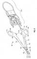
- Fig. 1depicts a forceps 10 for use in connection with endoscopic surgical procedures
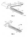
- Fig. 2depicts an open forceps 10' contemplated for use in connection with traditional open surgical procedures.
- an endoscopic instrumente.g., forceps 10
- an open instrumente.g., forceps 10'
- an endoscopic instrumente.g., forceps 10
- an open instrumente.g., forceps 10'
- an endoscopic forceps 10is provided defining a longitudinal axis "X-X" and including a housing 20, a handle assembly 30, a rotating assembly 70, a trigger assembly 80 and an end effector assembly 100.
- Forceps 10further includes a shaft 12 having a distal end 14 configured to mechanically engage end effector assembly 100 and a proximal end 16 that mechanically engages housing 20.
- Forceps 10also includes electrosurgical cable 610 that connects forceps 10 to a generator (not shown) or other suitable power source, although forceps 10 may alternatively be configured as a battery powered instrument.
- Cable 610includes a wire (or wires) (not shown) extending therethrough that has sufficient length to extend through shaft 12 in order to provide electrical energy to at least one of the sealing plates 112, 122 of jaw members 110, 120, respectively, of end effector assembly 100, e.g., upon activation of activation switch 90.
- handle assembly 30includes fixed handle 50 and a moveable handle 40.
- Fixed handle 50is integrally associated with housing 20 and handle 40 is moveable relative to fixed handle 50.
- Rotating assembly 70is rotatable in either direction about longitudinal axis "X-X” to rotate end effector 100 about longitudinal axis "X-X.”
- Housing 20houses the internal working components of forceps 10.
- End effector assembly 100is shown attached at a distal end 14 of shaft 12 and includes a pair of opposing jaw members 110 and 120. Each of the jaw members 110 and 120 includes an opposed electrically-conductive tissue sealing plate 112, 122, respectively.
- End effector assembly 100is designed as a unilateral assembly, i.e., where jaw member 120 is fixed relative to shaft 12 and jaw member 110 is moveable relative to shaft 12 and fixed jaw member 120.
- end effector assembly 100may alternatively be configured as a bilateral assembly, i.e., where both jaw member 110 and jaw member 120 are moveable relative to one another and to shaft 12.
- a knife assembly 180( Figs. 8A-8C ) is disposed within shaft 12 and a knife channel 115, 125 ( Figs.
- end effector assembly 100is defined within one or both jaw members 110, 120 to permit reciprocation of a knife 184 ( Fig. 8A-8C ) therethrough, e.g., via activation of a trigger 82 of trigger assembly 80.
- end effector assembly 100will be described in greater detail hereinbelow.
- moveable handle 40 of handle assembly 30is ultimately connected to a drive assembly (not shown) that, together, mechanically cooperate to impart movement of jaw members 110 and 120 between a spaced-apart position and an approximated position to grasp tissue disposed between sealing plates 112 and 122 of jaw members 110, 120, respectively.
- the drive assemblymay include a drive sleeve 170 ( Fig. 9 ) that is pivotably coupled to jaw member 110 (and/or jaw member 120) and is longitudinally translatable through shaft 12 and relative to end effector assembly 100 to pivot jaw member 110 relative to jaw member 120 between the spaced-apart and approximated positions for grasping tissue therebetween.
- a drive sleeve 170Fig. 9
- moveable handle 40is initially spaced-apart from fixed handle 50 and, correspondingly, jaw members 110, 120 are in the spaced-apart position.
- Moveable handle 40is actuatable from this initial position to a depressed position for translating drive sleeve 170 ( Fig. 9 ) through shaft 12 and relative to end effector assembly 100 to move jaw members 110, 120 to the approximated position for grasping tissue therebetween (see Figs. 8B-8C ).
- an open forceps 10'including two elongated shafts 12a and 12b, each having a proximal end 16a and 16b, and a distal end 14a and 14b, respectively. Similar to forceps 10 ( Fig. 1 ), forceps 10' is configured for use with end effector assembly 100. More specifically, end effector assembly 100 is attached to distal ends 14a and 14b of shafts 12a and 12b, respectively. As mentioned above, end effector assembly 100 includes a pair of opposing jaw members 110 and 120 that are pivotably coupled to one another. Each shaft 12a and 12b includes a handle 17a and 17b disposed at the proximal end 16a and 16b thereof.
- Each handle 17a and 17bdefines a finger hole 18a and 18b therethrough for receiving a finger of the user.
- finger holes 18a and 18bfacilitate movement of the shafts 12a and 12b relative to one another which, in turn, pivots jaw members 110 and 120 from an open position, wherein the jaw members 110 and 120 are disposed in spaced-apart relation relative to one another, to a closed position, wherein the jaw members 110 and 120 cooperate to grasp tissue therebetween.
- a ratchet 30'may be included for selectively locking the jaw members 110 and 120 relative to one another at various positions during pivoting.
- Ratchet 30'may include graduations or other visual markings that enable the user to easily and quickly ascertain and control the amount of closure force desired between the jaw members 110 and 120.
- one of the shaftse.g., shaft 12b, includes a proximal shaft connector 19 that is designed to connect the forceps 10' to a source of electrosurgical energy such as an electrosurgical generator (not shown).
- Proximal shaft connector 19secures an electrosurgical cable 610' to forceps 10' such that the user may selectively apply electrosurgical energy to the electrically-conductive tissue sealing plates 112 and 122 of jaw members 110 and 120, respectively, as needed.
- Forceps 10'may further include a knife assembly 180 ( Figs. 8A-8C ) disposed within either of shafts 12a, 12b and a knife channel 115, 125 ( Fig. 8A ) defined within one or both of jaw members 110, 120, respectively, to permit reciprocation of a knife 184 ( Figs. 8A-8C ) therethrough.
- a knife assembly 180Figs. 8A-8C
- a knife channel 115, 125Fig. 8A
- end effector assembly 100including jaw members 110 and 120 is configured for use with either forceps 10 or forceps 10', discussed above, or any other suitable surgical instrument capable of pivoting jaw members 110, 120 relative to one another between a spaced-apart position and an approximated position for grasping tissue therebetween.
- end effector assembly 100will be described hereinbelow with reference to forceps 10 only.
- Jaw members 110, 120each include an outer jaw housing 111, 121 and an electrically-conductive tissue sealing plate 112, 122 disposed atop respective jaw housings 111,121.
- a proximal flange 114,124extends proximally from each of jaw housings 111, 121, respectively, for pivotably coupling jaw members 110, 120 to one another. Further, proximal flange 124 of jaw member 120 engages jaw member 120 to shaft 12.
- jaw member 120is only coupled to jaw member 110 via proximal flange 124 and is not engaged to shaft 12 such that both jaw members 110, 120 may be pivoted relative to one another and to shaft 12 between the spaced-apart and approximated positions.
- Jaw housings 111, 121 of jaw members 110, 120, respectivelymay be formed from stainless steel, or any other suitable material, e.g., electrically-insulative materials.
- Proximal flanges 114, 124 of jaw members 110, 120define a bifurcated configuration, as will be described in greater detail below, and may be formed with jaw housings 111, 121, respectively, via molding or via any other suitable manufacturing process, e.g., machining, stamping, forging, or casting. In unilateral embodiments, proximal flange 124 of jaw member 120 may also be molded or otherwise engaged to shaft 12.
- tissue sealing plates 112, 122 of jaw members 110, 120each define an exposed tissue-sealing surface that opposes the tissue sealing surface defined by the sealing plate 112, 122 of the other jaw member 110, 120.
- Tissue sealing plates 112, 122 of jaw members 110, 120, respectively,are adapted to connect to a source of energy (not explicitly shown), thus functioning as electrodes for conducting energy therebetween and through tissue to treat tissue.
- Proximal flanges 114, 124 of jaw members 110, 120, respectively,are formed from electrically-insulative materials, e.g., plastic, to inhibit shorting of tissue sealing plates 112, 122 during tissue treatment.
- proximal flanges 114, 124may be formed from stainless steel, or other conductive materials so long as flanges 114, 124 are isolated from tissue sealing plates 112, 122.
- flanges 114, 124 of jaw members 110, 120are pivotably coupled to one another, e.g., to permit movement of jaw members 110, 120 relative to one another between the spaced-apart and approximated positions, forming flanges 114, 124 from electrically-insulative materials (or isolating flanges 114, 124) inhibits direct electrical contact between tissue sealing plates 112, 122 of jaw members 110, 120, respectively, thus inhibiting shorting and/or damage to surrounding tissue.
- proximal flanges 114, 124from plastic, for example, also allows for relatively inexpensive manufacture, as the molding process is a relatively inexpensive process for forming proximal flanges 114, 124 with complex features to facilitate the pivotable coupling therebetween.
- the specific configurations and features of proximal flanges 114, 124 of jaw members 110, 120, respectively,will be described in greater detail below.
- Shaft 12may likewise be formed from a plastic (or other suitable material) and, in unilateral embodiments, as mentioned above, may be molded with proximal flange 124 of jaw member 120 to form a single component.
- Forming shaft 12 from an electrically-insulative material, e.g., plastic,also helps to maintain the electrical isolation between tissue sealing plates 112, 122 of jaw members 110, 120, respectively, thus inhibiting shorting of tissue sealing plates 112, 122 and/or damage to surrounding tissue (see Fig. 7D ), although other configurations are also contemplated.
- an electrically-insulative materiale.g., plastic
- insolating shaft 12 from tissue sealing plates 112, 122, where shaft 12 is formed from a conductive materialalso helps to maintain the electrical isolation between tissue sealing plates 112, 122 of jaw members 110, 120, respectively, thus inhibiting shorting of tissue sealing plates 112, 122 and/or damage to surrounding tissue (see Fig. 7D ), although other configurations are also contemplated.
- jaw member 120includes, as mentioned above, outer jaw housing 121, electrically-conductive tissue sealing plate 122 disposed atop outer jaw housing 121, and proximal flange 124 extending proximally from outer jaw housing 121 and configured to pivotably couple to proximal flange 114 of jaw member 110 (see Fig. 3 ). More specifically, proximal flange 124 defines a generally U-shaped, bifurcated configuration including first and second spaced-apart flange components 132, 134 that are interconnected by a base 136.
- Flange components 132, 134define a channel 138 extending longitudinally therebetween that, as will be described below, is configured to receive at least a portion of proximal flange 114 of jaw member 110 (see Fig. 3 ) for pivotably coupling jaw members 110, 120 ( Fig. 3 ) to one another and to permit longitudinal translation of drive sleeve 170 ( Fig. 9 ) and knife 184 ( Figs. 8A-9 ) therethrough for moving jaw members 110, 120 ( Fig. 3 ) between the spaced-apart and approximated positions and for translating knife 184 ( Figs. 8A-9 ) between a retracted and an extended position for cutting tissue grasped between jaw members 110, 120 ( Fig. 3 ), respectively.
- flange component 132 of proximal flange 124 of jaw member 120includes a generally cylindrically-shaped protrusion 142 extending outwardly therefrom.
- Protrusion 142may be monolithically formed with proximal flange 124 during the molding process, or any other suitable manufacturing process used, e.g., machining, stamping, forging, or casting.
- Flange component 134defines an aperture 144 extending transversely therethrough that is substantially aligned with protrusion 142.
- Aperture 144may be formed within flange component 134 during the manufacturing process, e.g., the molding process. Forming protrusion 142 on flange component 132 and defining aperture 144 through flange component 134 via the molding process is advantageous in that precise alignment of protrusion 142 and aperture 144 relative to one another can be achieved relatively easily.
- Proximal flange 114 of jaw member 110similarly defines a bifurcated, generally U-shaped configuration having first and second spaced-apart flange components 152, 154 interconnected by a base 156 and defining a channel 158 extending longitudinally therebetween.
- flange component 152 of proximal flange 114includes a protrusion 162 extending outwardly therefrom, while flange component 154 defines an aperture 164 extending transversely therethrough.
- the specific features described herein with respect to proximal flange 124 of jaw member 120apply similarly to proximal flange 114 of jaw member 110.
- jaw member 110is inverted relative to jaw member 120 such that tissue sealing plates 112, 122 of jaw members 110, 120, respectively, oppose one another.
- the U-shaped proximal flanges 114, 124 of jaw members 110, 120oppose one another such that proximal flanges 114, 124 may be at least partially inserted into the channel 138, 158 defined within the opposed proximal flange 114, 124, respectively.
- proximal flanges 114, 124are approximated relative to one another such that flange component 132 is disposed within channel 158 of proximal flange 114 of jaw member 110 and such that flange component 152 is disposed within channel 138 of proximal flange 124 of jaw member 120.
- proximal flanges 114, 124are disposed in an overlapping, but offset configuration wherein protrusion 142 of flange component 132 is positioned adjacent aperture 164 of flange component 154 and wherein protrusion 162 of flange component 152 is positioned adjacent aperture 144 of flange component 134.
- proximal flanges 114, 124are urged toward one another such that protrusion 142 of flange component 132 is engaged within aperture 164 of flange component 154 and such that protrusion 162 of flange component 152 is engaged within aperture 144 of flange component 134, as shown in Fig. 7C .
- jaw members 110, 120may be simultaneously pivoted about these two protrusion-aperture couplings (e.g., the engagement between protrusion 142 and aperture 164 and the engagement between protrusion 162 and aperture 144) relative to one another to move jaw members 110, 120 between the spaced-apart and approximated positions for grasping tissue therebetween.
- protrusions 142, 162are engaged within opposed transverse apertures 21, 22, respectively, defined through the outer periphery of shaft 12 towards distal end 14 ( Fig. 3 ) thereof. More specifically, as shown in Fig. 7C , when protrusion 142 of flange component 132 is engaged within aperture 164 of flange component 154, protrusion 142 extends outwardly at least partially therefrom.
- protrusion 162 of flange component 152when protrusion 162 of flange component 152 is engaged within aperture 144 of flange component 134, protrusion 162 extend outwardly at least partially thereform. As such, these outwardly-extending portions of protrusions 142, 162 may be pivotably engaged within transverse apertures 21, 22, respectively, defined within shaft 12 for engaging end effector assembly 100 to shaft 12 at distal end 14 ( Fig. 3 ) thereof and for stabilizing and supporting the protrusion-aperture couplings between proximal flanges 114, 124 of jaw members 110, 120, respectively.
- proximal flanges 114, 124 of jaw members 110, 120e.g., via engagement between protrusions 142, 162 and apertures 164, 144, respectively, is advantageous in that channels 138, 158 defined within proximal flanges 124, 114, respectively, are substantially uninterrupted.
- knife 184Figs.
- proximal flanges 114, 124are pivotably coupled to one another via a protrusion-aperture coupling on either side of channels 138, 158.
- One of the flange components 114, 124may be disposed completely within the channel 138, 158 of the other flange component 114, 124, rather than defining the offset, overlapping configuration shown in Fig. 7C .
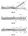
- end effector assembly 100includes a knife assembly 180 for cutting tissue disposed between jaw members 110, 120.
- Knife assembly 180includes a knife bar 182 that is selectively translatable through shaft 12, e.g., upon activation of actuation trigger 82 ( Fig. 1 ) of trigger assembly 80 ( Fig. 1 ).
- Knife bar 182includes a knife 184 coupled thereto and extending distally therefrom.
- knife bar 182is selectively translatable to translate knife 184 between a retracted position, wherein knife 184 is disposed within shaft 12, and an extended position, wherein knife 184 extends through knife channels 115, 125 of jaw members 110, 120, respectively, to cut tissue grasped therebetween.
- end effector assembly 100is maneuvered into position such that tissue to be grasped, treated, e.g., sealed, and/or cut, is disposed between jaw members 110, 120.
- moveable handle 40Fig. 1
- fixed handle 50Fig.
- jaw member 110is pivoted relative to jaw member 120 about the pair of protrusion-aperture couplings between proximal flanges 114, 124 of jaw members 110, 140, respectively, from the spaced-apart position to the approximated position to grasp tissue therebetween, as shown in Fig. 8B .
- drive sleeve 170is translated through shaft 12 and channels 138, 158 of proximal flanges 124, 114, of jaw members 120, 110, respectively, such that jaw member 110 is pivoted relative to jaw member 120 from the spaced-apart position to the approximated position.
- electrosurgical energymay be supplied, e.g., via activation of switch 90 ( Fig. 1 ), to tissue-sealing plate 112 of jaw member 110 and/or tissue-sealing plate 122 of jaw member 120 and conducted through tissue to treat tissue, e.g., to effect a tissue seal.
- knife 184may then be advanced through channels 158, 138 of proximal flanges 114, 124, respectively, from the retracted position ( Fig. 8B ) to the extended position ( Fig. 8C ), e.g., via activation of trigger 82 of trigger assembly 80 ( Fig. 1 ), wherein knife 184 extends through knife channels 115, 125 of jaw members 110, 120, respectively, to cut tissue grasped between jaw members 110, 120. Thereafter, jaw members 110, 120 may be returned to the spaced-apart position ( Fig. 8A ) and removed from the surgical site, or the above-described process may be repeated to grasp, treat and/or divide additional tissue structures.
Landscapes
- Health & Medical Sciences (AREA)
- Life Sciences & Earth Sciences (AREA)
- Surgery (AREA)
- Engineering & Computer Science (AREA)
- Medical Informatics (AREA)
- Veterinary Medicine (AREA)
- Biomedical Technology (AREA)
- Heart & Thoracic Surgery (AREA)
- Nuclear Medicine, Radiotherapy & Molecular Imaging (AREA)
- Molecular Biology (AREA)
- Animal Behavior & Ethology (AREA)
- General Health & Medical Sciences (AREA)
- Public Health (AREA)
- Ophthalmology & Optometry (AREA)
- Physics & Mathematics (AREA)
- Plasma & Fusion (AREA)
- Otolaryngology (AREA)
- Surgical Instruments (AREA)
Description
- The present disclosure relates to surgical instruments and, more particularly, to surgical forceps for grasping, sealing and/or dividing tissue.
- A forceps is a plier-like instrument which relies on mechanical action between its jaws to grasp, clamp and constrict vessels or tissue. Electrosurgical forceps utilize both mechanical clamping action and electrical energy to affect hemostasis by heating tissue and blood vessels to coagulate and/or cauterize tissue. Certain surgical procedures require more than simply cauterizing tissue and rely on the unique combination of clamping pressure, precise electrosurgical energy control and gap distance (i.e., distance between opposing jaw members when closed about tissue) to "seal" tissue, vessels and certain vascular bundles. Typically, once a vessel is sealed, the surgeon has to accurately sever the vessel along the newly formed tissue seal. Accordingly, many vessel sealing instruments have been designed which incorporate a knife or blade member that effectively severs the tissue after forming a tissue seal.
US 2009/0043305 A1 , on which the preamble ofclaim 1 is based, discloses a surgical instrument including tissue clamping parts connected to each other via an articulated joint.- In accordance with one aspect of the present disclosure, a forceps is provided. The forceps includes an end effector assembly having first and second jaw members. Each jaw member includes a proximal flange extending therefrom. Each of the proximal flanges defines a bifurcated configuration having first and second spaced-apart flange components. The first flange component of the first jaw member is configured to pivotably engage the second flange component of the second jaw member via a first protrusion-aperture coupling and the first flange component of the second jaw member is configured to pivotably engage the second flange component of the first jaw member via a second protrusion-aperture coupling different from the first protrusion-aperture coupling, at least one of the first and second jaw members pivotable relative to the other about the first and second protrusion-aperture couplings between a spaced-apart position and an approximated position for grasping tissue therebetween.
- Each of the proximal flanges may include a protrusion extending outwardly from one of the flange components thereof and an aperture defined transversely through the other flange component thereof. The protrusion of each proximal flange is configured to engage the aperture of the other proximal flange for pivotably coupling the first and second jaw members to one another.
- The proximal flanges may be disposed in an overlapping, offset configuration relative to one another. That is, one of the flange components of the first jaw member is disposed inside the flange components of the second jaw member and the other of the flange components of the second jaw member is disposed outside of the flange components of the second jaw member.
- In some aspects, the proximal flanges are formed via molding. Further, each of the proximal flanges may be monolithically formed with the respective jaw member thereof via molding. The proximal flanges may additionally or alternatively, be formed from an electrically-insulative material, e.g., plastic.
- In an embodiment, the proximal flanges of each jaw member defines a U-shaped channel, the U-shaped channels cooperating to define a lumen with a generally rectangular profile. In an embodiment, the protrusions do not extend into the lumen to leave the lumen free for passage of a drive sleeve and/or a knife, the passage extending through the protrusion aperture couplings.
- In any of the above aspects, the proximal flanges may each define a channel extending longitudinally therethrough. The channels of the proximal flanges cooperate with one another to permit reciprocation of a drive sleeve therethrough for moving the jaw members between the spaced-apart and approximated positions. The channels may also be configured to permit reciprocation of the knife therethrough for cutting tissue grasped between the jaw members.
- In some aspects, each of the jaw members includes an electrically-conductive tissue sealing plate disposed thereon. One or both of the sealing plates is adapted to connect to a source of energy for conducting energy through tissue grasped therebetween to seal tissue.
- In accordance with another aspect of the present disclosure, a forceps including a shaft having an end effector disposed at a distal end thereof is provided. The shaft includes first and second opposed, transverse shaft apertures defined within an outer periphery thereof. The end effector assembly includes first and second jaw members pivotable relative to one another between a spaced-apart position and an approximated position for grasping tissue therebetween. Each jaw member includes a proximal flange extending therefrom. Each of the proximal flanges defines a bifurcated configuration having first and second spaced-apart flange components. The first flange component of the first jaw member includes a protrusion extending outwardly therefrom that is configured for pivotable engagement within a transverse aperture defined through the second flange component of the second jaw member. The first flange component of the second jaw member includes a protrusion extending outwardly therefrom that is configured for pivotable engagement within a transverse aperture defined through the second flange component of the first jaw member. A portion of each of the protrusions is configured to extend outwardly from the respective transverse aperture engaged therewith. The portion of each protrusion that extends outwardly from the apertures defined through the respective proximal flange engaged therewith is configured for pivotable engagement within one of the shaft apertures for engaging the first and second jaw members to the shaft. The forceps may further be configured to include any or all of the previous aspects discussed above.
- Various embodiments of the present disclosure are described herein with reference to the drawings wherein:
Fig. 1 is a front, perspective view of an endoscopic surgical forceps configured for use in accordance with the present disclosure;Fig. 2 is a front, perspective view of an open surgical forceps configured for use in accordance with the present disclosure;Fig. 3 is an enlarged, front, perspective view of an end effector assembly configured for use with the forceps ofFigs. 1 and2 ;Fig. 4 is an enlarged, front, perspective view of one of the jaw members of the end effector assembly ofFig. 3 ;Fig. 5 is a longitudinal, cross-sectional view of the jaw member ofFig. 4 ;Fig. 6 is a transverse, cross-sectional view of the jaw member ofFig. 4 taken across section line 6-6 ofFig. 5 ;Fig. 7A is a transverse, cross-sectional view of the jaw members of end effector assembly ofFig. 3 , wherein the jaw members are disengaged from one another;Fig. 7B is a transverse, cross-sectional view of the jaw members of end effector assembly ofFig. 3 , wherein the jaw members are in position to be engaged with one another;Fig. 7C is a transverse, cross-sectional view of the jaw members of end effector assembly ofFig. 3 , wherein the jaw members are engaged with one another;Fig. 7D is a transverse, cross-sectional view of the jaw members of end effector assembly ofFig. 3 , wherein the jaw members are engaged to a shaft of the forceps ofFig. 1 ;Fig. 8A is a longitudinal, cross-sectional view of the end effector assembly ofFig. 3 with the jaw members disposed in a spaced-apart position;Fig. 8B is a longitudinal, cross-sectional view of the end effector assembly ofFig. 3 with the jaw members disposed in an approximated position and with a knife blade disposed in a retracted position;Fig. 8C is a longitudinal, cross-sectional view of the end effector assembly ofFig. 3 with the jaw members disposed in an approximated position and with the knife blade disposed in an extended position; andFig. 9 is a transverse, cross-sectional view of the end effector assembly ofFig. 3 taken across section line 9-9 ofFig. 8C .- Embodiments of the present disclosure are described in detail with reference to the drawing figures wherein like reference numerals identify similar or identical elements. As used herein, the term "distal" refers to the portion that is being described which is further from a user, while the term "proximal" refers to the portion that is being described which is closer to a user.
- Referring now to
Figs. 1 and2 ,Fig. 1 depicts aforceps 10 for use in connection with endoscopic surgical procedures andFig. 2 depicts an open forceps 10' contemplated for use in connection with traditional open surgical procedures. For the purposes herein, either an endoscopic instrument, e.g.,forceps 10, or an open instrument, e.g., forceps 10', may be utilized in accordance with the present disclosure. Obviously, different electrical and mechanical connections and considerations apply to each particular type of instrument, however, the novel aspects with respect to the end effector assembly and its operating characteristics remain generally consistent with respect to both the open and endoscopic configurations. - Turning now to
Fig. 1 , anendoscopic forceps 10 is provided defining a longitudinal axis "X-X" and including ahousing 20, ahandle assembly 30, a rotatingassembly 70, atrigger assembly 80 and anend effector assembly 100.Forceps 10 further includes ashaft 12 having adistal end 14 configured to mechanically engageend effector assembly 100 and aproximal end 16 that mechanically engageshousing 20.Forceps 10 also includeselectrosurgical cable 610 that connectsforceps 10 to a generator (not shown) or other suitable power source, althoughforceps 10 may alternatively be configured as a battery powered instrument.Cable 610 includes a wire (or wires) (not shown) extending therethrough that has sufficient length to extend throughshaft 12 in order to provide electrical energy to at least one of the sealingplates jaw members end effector assembly 100, e.g., upon activation ofactivation switch 90. - With continued reference to
Fig. 1 , handleassembly 30 includes fixedhandle 50 and amoveable handle 40. Fixedhandle 50 is integrally associated withhousing 20 and handle 40 is moveable relative to fixedhandle 50. Rotatingassembly 70 is rotatable in either direction about longitudinal axis "X-X" to rotateend effector 100 about longitudinal axis "X-X."Housing 20 houses the internal working components offorceps 10. End effector assembly 100 is shown attached at adistal end 14 ofshaft 12 and includes a pair of opposingjaw members jaw members tissue sealing plate End effector assembly 100 is designed as a unilateral assembly, i.e., wherejaw member 120 is fixed relative toshaft 12 andjaw member 110 is moveable relative toshaft 12 and fixedjaw member 120. However,end effector assembly 100 may alternatively be configured as a bilateral assembly, i.e., where bothjaw member 110 andjaw member 120 are moveable relative to one another and toshaft 12. In some embodiments, a knife assembly 180 (Figs. 8A-8C ) is disposed withinshaft 12 and aknife channel 115, 125 (Figs. 8A-8C ) is defined within one or bothjaw members Fig. 8A-8C ) therethrough, e.g., via activation of atrigger 82 oftrigger assembly 80. The particular features ofend effector assembly 100 will be described in greater detail hereinbelow.- Continuing with reference to
Fig. 1 ,moveable handle 40 ofhandle assembly 30 is ultimately connected to a drive assembly (not shown) that, together, mechanically cooperate to impart movement ofjaw members plates jaw members Fig. 9 ) that is pivotably coupled to jaw member 110 (and/or jaw member 120) and is longitudinally translatable throughshaft 12 and relative to endeffector assembly 100 to pivotjaw member 110 relative tojaw member 120 between the spaced-apart and approximated positions for grasping tissue therebetween. As shown inFig. 1 ,moveable handle 40 is initially spaced-apart from fixedhandle 50 and, correspondingly,jaw members Moveable handle 40 is actuatable from this initial position to a depressed position for translating drive sleeve 170 (Fig. 9 ) throughshaft 12 and relative to endeffector assembly 100 to movejaw members Figs. 8B-8C ). - Referring now to
Fig. 2 , an open forceps 10' is shown including twoelongated shafts proximal end distal end Fig. 1 ), forceps 10' is configured for use withend effector assembly 100. More specifically,end effector assembly 100 is attached todistal ends shafts end effector assembly 100 includes a pair of opposingjaw members shaft handle proximal end handle finger hole finger holes shafts jaw members jaw members jaw members - A ratchet 30' may be included for selectively locking the
jaw members jaw members - With continued reference to
Fig. 2 , one of the shafts, e.g.,shaft 12b, includes aproximal shaft connector 19 that is designed to connect the forceps 10' to a source of electrosurgical energy such as an electrosurgical generator (not shown).Proximal shaft connector 19 secures an electrosurgical cable 610' to forceps 10' such that the user may selectively apply electrosurgical energy to the electrically-conductivetissue sealing plates jaw members - Forceps 10' may further include a knife assembly 180 (
Figs. 8A-8C ) disposed within either ofshafts knife channel 115, 125 (Fig. 8A ) defined within one or both ofjaw members Figs. 8A-8C ) therethrough. - Turning now to
Fig. 3 ,end effector assembly 100, includingjaw members forceps 10 or forceps 10', discussed above, or any other suitable surgical instrument capable of pivotingjaw members end effector assembly 100 will be described hereinbelow with reference toforceps 10 only. Jaw members Fig. 3 , each include anouter jaw housing tissue sealing plate jaw housings coupling jaw members proximal flange 124 ofjaw member 120 engagesjaw member 120 toshaft 12. Alternatively, in embodiments whereend effector assembly 100 is configured as a bilateral assembly,jaw member 120 is only coupled tojaw member 110 viaproximal flange 124 and is not engaged toshaft 12 such that bothjaw members shaft 12 between the spaced-apart and approximated positions.Jaw housings jaw members Proximal flanges jaw members jaw housings proximal flange 124 ofjaw member 120 may also be molded or otherwise engaged toshaft 12.- Electrically-conductive
tissue sealing plates jaw members plate other jaw member Tissue sealing plates jaw members Proximal flanges jaw members tissue sealing plates proximal flanges flanges tissue sealing plates flanges jaw members jaw members flanges flanges 114, 124) inhibits direct electrical contact betweentissue sealing plates jaw members proximal flanges proximal flanges proximal flanges jaw members Shaft 12 may likewise be formed from a plastic (or other suitable material) and, in unilateral embodiments, as mentioned above, may be molded withproximal flange 124 ofjaw member 120 to form a single component. Formingshaft 12 from an electrically-insulative material, e.g., plastic, (orinsolating shaft 12 fromtissue sealing plates shaft 12 is formed from a conductive material) also helps to maintain the electrical isolation betweentissue sealing plates jaw members tissue sealing plates Fig. 7D ), although other configurations are also contemplated.- With reference to
Figs. 4-6 ,jaw member 120 includes, as mentioned above,outer jaw housing 121, electrically-conductivetissue sealing plate 122 disposed atopouter jaw housing 121, andproximal flange 124 extending proximally fromouter jaw housing 121 and configured to pivotably couple toproximal flange 114 of jaw member 110 (seeFig. 3 ). More specifically,proximal flange 124 defines a generally U-shaped, bifurcated configuration including first and second spaced-apartflange components base 136.Flange components channel 138 extending longitudinally therebetween that, as will be described below, is configured to receive at least a portion ofproximal flange 114 of jaw member 110 (seeFig. 3 ) for pivotablycoupling jaw members 110, 120 (Fig. 3 ) to one another and to permit longitudinal translation of drive sleeve 170 (Fig. 9 ) and knife 184 (Figs. 8A-9 ) therethrough for movingjaw members 110, 120 (Fig. 3 ) between the spaced-apart and approximated positions and for translating knife 184 (Figs. 8A-9 ) between a retracted and an extended position for cutting tissue grasped betweenjaw members 110, 120 (Fig. 3 ), respectively. - Continuing with reference to
Figs. 4-6 ,flange component 132 ofproximal flange 124 ofjaw member 120 includes a generally cylindrically-shapedprotrusion 142 extending outwardly therefrom.Protrusion 142 may be monolithically formed withproximal flange 124 during the molding process, or any other suitable manufacturing process used, e.g., machining, stamping, forging, or casting.Flange component 134, on the other hand, defines anaperture 144 extending transversely therethrough that is substantially aligned withprotrusion 142.Aperture 144 may be formed withinflange component 134 during the manufacturing process, e.g., the molding process. Formingprotrusion 142 onflange component 132 anddefining aperture 144 throughflange component 134 via the molding process is advantageous in that precise alignment ofprotrusion 142 andaperture 144 relative to one another can be achieved relatively easily. Proximal flange 114 ofjaw member 110, as shown inFig. 3 and7A-7C , similarly defines a bifurcated, generally U-shaped configuration having first and second spaced-apartflange components base 156 and defining achannel 158 extending longitudinally therebetween. Similarly as withproximal flange 124 ofjaw member 120,flange component 152 ofproximal flange 114 includes aprotrusion 162 extending outwardly therefrom, whileflange component 154 defines anaperture 164 extending transversely therethrough. The specific features described herein with respect toproximal flange 124 ofjaw member 120 apply similarly toproximal flange 114 ofjaw member 110.- With reference now to
Figs. 7A-7D , in conjunction withFig. 3 , the pivotable coupling ofjaw members shaft 12 is described. Initially, as shown inFig. 7A ,jaw member 110 is inverted relative tojaw member 120 such thattissue sealing plates jaw members proximal flanges jaw members proximal flanges channel proximal flange - Continuing with reference to
Figs. 3 and7A-7D , and in particular toFig. 7B , withjaw member 110 inverted relative tojaw member 120,proximal flanges flange component 132 is disposed withinchannel 158 ofproximal flange 114 ofjaw member 110 and such thatflange component 152 is disposed withinchannel 138 ofproximal flange 124 ofjaw member 120. In other words, in this position,proximal flanges protrusion 142 offlange component 132 is positionedadjacent aperture 164 offlange component 154 and whereinprotrusion 162 offlange component 152 is positionedadjacent aperture 144 offlange component 134. - In order to pivotably engage
proximal flange 114 ofjaw member 110 andproximal flange 124 ofjaw member 120 to one another, withproximal flanges Fig. 7B ,proximal flanges protrusion 142 offlange component 132 is engaged withinaperture 164 offlange component 154 and such thatprotrusion 162 offlange component 152 is engaged withinaperture 144 offlange component 134, as shown inFig. 7C . In this position,flange components flange components jaw members protrusion 142 andaperture 164 and the engagement betweenprotrusion 162 and aperture 144) relative to one another to movejaw members - As shown in
Fig. 7D , in order to engageend effector assembly 100 toshaft 12, e.g., in bilateral embodiments, or to provide additional stability and support to endeffector assembly 100,protrusions transverse apertures shaft 12 towards distal end 14 (Fig. 3 ) thereof. More specifically, as shown inFig. 7C , whenprotrusion 142 offlange component 132 is engaged withinaperture 164 offlange component 154,protrusion 142 extends outwardly at least partially therefrom. Similarly, whenprotrusion 162 offlange component 152 is engaged withinaperture 144 offlange component 134,protrusion 162 extend outwardly at least partially thereform. As such, these outwardly-extending portions ofprotrusions transverse apertures shaft 12 for engagingend effector assembly 100 toshaft 12 at distal end 14 (Fig. 3 ) thereof and for stabilizing and supporting the protrusion-aperture couplings betweenproximal flanges jaw members - The pivotable coupling of bifurcated
proximal flanges jaw members protrusions apertures channels proximal flanges Figs. 8A-9 ) need not be configured to pass over/under a pivot pin or define a slot therein for receiving the pivot pin therethrough since, instead of a pivot pin extending transversely throughchannels proximal flanges proximal flanges channels - One of the
flange components channel other flange component Fig. 7C . - Referring now to
Figs. 8A-9 , as mentioned above, in some embodiments,end effector assembly 100 includes aknife assembly 180 for cutting tissue disposed betweenjaw members Knife assembly 180 includes aknife bar 182 that is selectively translatable throughshaft 12, e.g., upon activation of actuation trigger 82 (Fig. 1 ) of trigger assembly 80 (Fig. 1 ).Knife bar 182 includes aknife 184 coupled thereto and extending distally therefrom. As will be described below,knife bar 182 is selectively translatable to translateknife 184 between a retracted position, whereinknife 184 is disposed withinshaft 12, and an extended position, whereinknife 184 extends throughknife channels jaw members - With continued reference to
Figs. 8A-9 , the use and operation ofend effector assembly 100 is be described. Initially, as shown inFig. 8A , withjaw members end effector assembly 100 is maneuvered into position such that tissue to be grasped, treated, e.g., sealed, and/or cut, is disposed betweenjaw members Fig. 1 ) is pulled proximally relative to fixed handle 50 (Fig. 1 ) such thatjaw member 110 is pivoted relative tojaw member 120 about the pair of protrusion-aperture couplings betweenproximal flanges jaw members 110, 140, respectively, from the spaced-apart position to the approximated position to grasp tissue therebetween, as shown inFig. 8B . More specifically, upon actuation of moveable handle 40 (Fig. 1 ),drive sleeve 170 is translated throughshaft 12 andchannels proximal flanges jaw members jaw member 110 is pivoted relative tojaw member 120 from the spaced-apart position to the approximated position. In this approximated position, electrosurgical energy may be supplied, e.g., via activation of switch 90 (Fig. 1 ), to tissue-sealingplate 112 ofjaw member 110 and/or tissue-sealingplate 122 ofjaw member 120 and conducted through tissue to treat tissue, e.g., to effect a tissue seal. - As shown in
Fig. 8C , once tissue sealing is complete (or to cut untreated tissue, where tissue sealing is not desired),knife 184 may then be advanced throughchannels proximal flanges Fig. 8B ) to the extended position (Fig. 8C ), e.g., via activation oftrigger 82 of trigger assembly 80 (Fig. 1 ), whereinknife 184 extends throughknife channels jaw members jaw members jaw members Fig. 8A ) and removed from the surgical site, or the above-described process may be repeated to grasp, treat and/or divide additional tissue structures. - From the foregoing and with reference to the various figure drawings, those skilled in the art will appreciate that certain modifications can also be made to the present disclosure without departing from the scope of the same. While several embodiments of the disclosure have been shown in the drawings, it is not intended that the disclosure be limited thereto, as it is intended that the disclosure be as broad in scope as the art will allow and that the specification be read likewise. Therefore, the above description should not be construed as limiting, but merely as exemplifications of particular embodiments. Those skilled in the art will envision other modifications within the scope of the claims appended hereto.
Claims (12)
- A forceps (10, 10'), comprising:an end effector assembly (100), including:first and second jaw members (110, 120), each of the jaw members including a proximal flange (114, 124) extending therefrom, each proximal flange defining a bifurcated configuration having first and second spaced-apart flange components (132, 134, 152, 154), the first flange component (152) of the first jaw member configured to pivotably engage the second flange component (134) of the second jaw member via a first protrusion-aperture coupling (162, 144) and the first flange component (132) of the second jaw member configured to pivotably engage the second flange component (154) of the first jaw member via a second protrusion-aperture coupling (142, 164) different from the first protrusion-aperture coupling, at least one of the first and second jaw members pivotable relative to the other about the first and second protrusion-aperture couplings between a spaced-apart position and an approximated position for grasping tissue therebetween,characterised in thateach of the proximal flanges includes a protrusion (142, 162) extending outwardly from one of the flange components thereof and an aperture (164, 144) defined transversely through the other flange component thereof, the protrusion of each proximal flange configured to engage the aperture of the other proximal flange for pivotably coupling the first and second jaw members to one another.
- The forceps according to claim 1, wherein each of the proximal flanges is monolithically formed with the respective jaw member thereof via molding.
- The forceps according to claim 1 or 2, wherein the proximal flanges are formed from an electrically-insulative material.
- The forceps according to any preceding claim, wherein the proximal flanges each define a channel (158, 138) extending longitudinally therethrough, the channels of the proximal flanges cooperating with one another to permit reciprocation of a drive sleeve (170) therethrough for moving the jaw members between the spaced-apart and approximated positions.
- The forceps according to any preceding claim, further comprising a knife assembly (180) operatively coupled to the end effector assembly, the knife assembly including a knife (184) that is selectively translatable between a retracted position and an extended position, wherein the knife is advanced between the jaw members to cut tissue grasped therebetween.
- The forceps according to claim 5, wherein the proximal flanges each define a channel (158, 138) extending longitudinally therethrough, the channels of the proximal flanges cooperating with one another to permit reciprocation of the knife therethrough for cutting tissue grasped between the jaw members.
- The forceps according to any preceding claim, wherein each of the jaw members includes an electrically-conductive tissue sealing plate (112, 122) disposed thereon, at least one of the sealing plates adapted to connect to a source of energy for conducting energy through tissue grasped therebetween to treat tissue.
- The forceps according to any preceding claim, comprising:a shaft (12) having an end effector assembly disposed at a distal end thereof, the shaft including first and second opposed, transverse shaft apertures (21, 22) defined within an outer periphery thereof, wherein:at least a portion of each of the protrusions configured to extend outwardly from the respective transverse aperture engaged therewith, the at least a portion of each protrusion configured for pivotable engagement within one of the shaft apertures for engaging the first and second jaw members to the shaft.
- The forceps according to any preceding claim, wherein the proximal flanges are disposed in an overlapping, offset configuration relative to one another.
- The forceps according to any preceding claim, wherein the proximal flange of each jaw member defines a U-shaped channel, the U-shaped channels cooperating to define a lumen with a generally rectangular profile.
- The forceps according to claim 10, wherein the protrusions do not extend into the lumen to leave the lumen free for passage of a drive sleeve and/or a knife, the passage extending through the protrusion aperture couplings.
- The forceps according to any preceding claim, each proximal flange defining a generally U-shaped, bifurcated configuration including the first and second spaced-apart flange components (132, 134) that are interconnected by a base (136).
Applications Claiming Priority (1)
| Application Number | Priority Date | Filing Date | Title |
|---|---|---|---|
| US13/461,410US9034009B2 (en) | 2012-05-01 | 2012-05-01 | Surgical forceps |
Publications (3)
| Publication Number | Publication Date |
|---|---|
| EP2659844A2 EP2659844A2 (en) | 2013-11-06 |
| EP2659844A3 EP2659844A3 (en) | 2014-05-28 |
| EP2659844B1true EP2659844B1 (en) | 2015-06-17 |
Family
ID=48190848
Family Applications (1)
| Application Number | Title | Priority Date | Filing Date |
|---|---|---|---|
| EP13166215.7AActiveEP2659844B1 (en) | 2012-05-01 | 2013-05-02 | Surgical forceps |
Country Status (6)
| Country | Link |
|---|---|
| US (2) | US9034009B2 (en) |
| EP (1) | EP2659844B1 (en) |
| JP (1) | JP6133671B2 (en) |
| CN (1) | CN103381104B (en) |
| AU (1) | AU2013205093B2 (en) |
| CA (1) | CA2812677C (en) |
Families Citing this family (82)
| Publication number | Priority date | Publication date | Assignee | Title |
|---|---|---|---|---|
| US7364577B2 (en) | 2002-02-11 | 2008-04-29 | Sherwood Services Ag | Vessel sealing system |
| ES2262639T3 (en) | 2001-04-06 | 2006-12-01 | Sherwood Services Ag | SHUTTER AND DIVIDER OF GLASSES WITH BUMPER MEMBERS N OCONDUCTIVES. |
| US7628791B2 (en) | 2005-08-19 | 2009-12-08 | Covidien Ag | Single action tissue sealer |
| US8298232B2 (en) | 2006-01-24 | 2012-10-30 | Tyco Healthcare Group Lp | Endoscopic vessel sealer and divider for large tissue structures |
| US8357158B2 (en) | 2008-04-22 | 2013-01-22 | Covidien Lp | Jaw closure detection system |
| US8469956B2 (en) | 2008-07-21 | 2013-06-25 | Covidien Lp | Variable resistor jaw |
| US8133254B2 (en) | 2009-09-18 | 2012-03-13 | Tyco Healthcare Group Lp | In vivo attachable and detachable end effector assembly and laparoscopic surgical instrument and methods therefor |
| US10172669B2 (en) | 2009-10-09 | 2019-01-08 | Ethicon Llc | Surgical instrument comprising an energy trigger lockout |
| US8480671B2 (en) | 2010-01-22 | 2013-07-09 | Covidien Lp | Compact jaw including split pivot pin |
| US8439913B2 (en) | 2010-04-29 | 2013-05-14 | Covidien Lp | Pressure sensing sealing plate |
| GB2480498A (en) | 2010-05-21 | 2011-11-23 | Ethicon Endo Surgery Inc | Medical device comprising RF circuitry |
| US8430877B2 (en) | 2010-06-02 | 2013-04-30 | Covidien Lp | Apparatus for performing an electrosurgical procedure |
| US8491624B2 (en) | 2010-06-02 | 2013-07-23 | Covidien Lp | Apparatus for performing an electrosurgical procedure |
| US8469991B2 (en) | 2010-06-02 | 2013-06-25 | Covidien Lp | Apparatus for performing an electrosurgical procedure |
| US9844384B2 (en) | 2011-07-11 | 2017-12-19 | Covidien Lp | Stand alone energy-based tissue clips |
| US9333025B2 (en) | 2011-10-24 | 2016-05-10 | Ethicon Endo-Surgery, Llc | Battery initialization clip |
| US8968309B2 (en) | 2011-11-10 | 2015-03-03 | Covidien Lp | Surgical forceps |
| US8747434B2 (en) | 2012-02-20 | 2014-06-10 | Covidien Lp | Knife deployment mechanisms for surgical forceps |
| US9034009B2 (en) | 2012-05-01 | 2015-05-19 | Covidien Lp | Surgical forceps |
| US8968311B2 (en) | 2012-05-01 | 2015-03-03 | Covidien Lp | Surgical instrument with stamped double-flag jaws and actuation mechanism |
| US9820765B2 (en) | 2012-05-01 | 2017-11-21 | Covidien Lp | Surgical instrument with stamped double-flange jaws |
| US9668807B2 (en) | 2012-05-01 | 2017-06-06 | Covidien Lp | Simplified spring load mechanism for delivering shaft force of a surgical instrument |
| US9039731B2 (en) | 2012-05-08 | 2015-05-26 | Covidien Lp | Surgical forceps including blade safety mechanism |
| US9375258B2 (en) | 2012-05-08 | 2016-06-28 | Covidien Lp | Surgical forceps |
| US10368945B2 (en) | 2012-07-17 | 2019-08-06 | Covidien Lp | Surgical instrument for energy-based tissue treatment |
| US8939975B2 (en) | 2012-07-17 | 2015-01-27 | Covidien Lp | Gap control via overmold teeth and hard stops |
| US9301798B2 (en) | 2012-07-19 | 2016-04-05 | Covidien Lp | Surgical forceps including reposable end effector assemblies |
| US9192421B2 (en) | 2012-07-24 | 2015-11-24 | Covidien Lp | Blade lockout mechanism for surgical forceps |
| US9636168B2 (en) | 2012-08-09 | 2017-05-02 | Covidien Lp | Electrosurgical instrument including nested knife assembly |
| US9433461B2 (en) | 2012-09-07 | 2016-09-06 | Covidien Lp | Instruments, systems, and methods for sealing tissue structures |
| US9687290B2 (en) | 2012-10-02 | 2017-06-27 | Covidien Lp | Energy-based medical devices |
| US9439711B2 (en) | 2012-10-02 | 2016-09-13 | Covidien Lp | Medical devices for thermally treating tissue |
| US9549749B2 (en) | 2012-10-08 | 2017-01-24 | Covidien Lp | Surgical forceps |
| US9526564B2 (en) | 2012-10-08 | 2016-12-27 | Covidien Lp | Electric stapler device |
| US9265566B2 (en) | 2012-10-16 | 2016-02-23 | Covidien Lp | Surgical instrument |
| US9375259B2 (en) | 2012-10-24 | 2016-06-28 | Covidien Lp | Electrosurgical instrument including an adhesive applicator assembly |
| US10772674B2 (en) | 2012-11-15 | 2020-09-15 | Covidien Lp | Deployment mechanisms for surgical instruments |
| US9375205B2 (en) | 2012-11-15 | 2016-06-28 | Covidien Lp | Deployment mechanisms for surgical instruments |
| US9439665B2 (en) | 2012-12-20 | 2016-09-13 | Covidien Lp | Pediatric combination surgical device |
| USD728786S1 (en) | 2013-05-03 | 2015-05-05 | Covidien Lp | Vessel sealer with mechanical cutter and pistol-grip-style trigger |
| US9642671B2 (en) | 2013-09-30 | 2017-05-09 | Covidien Lp | Limited-use medical device |
| USD788302S1 (en) | 2013-10-01 | 2017-05-30 | Covidien Lp | Knife for endoscopic electrosurgical forceps |
| US9877777B2 (en) | 2014-09-17 | 2018-01-30 | Covidien Lp | Surgical instrument having a bipolar end effector assembly and a deployable monopolar assembly |
| US9987076B2 (en) | 2014-09-17 | 2018-06-05 | Covidien Lp | Multi-function surgical instruments |
| US10080605B2 (en) | 2014-09-17 | 2018-09-25 | Covidien Lp | Deployment mechanisms for surgical instruments |
| US10080606B2 (en)* | 2014-09-17 | 2018-09-25 | Covidien Lp | Method of forming a member of an end effector |
| US10039592B2 (en) | 2014-09-17 | 2018-08-07 | Covidien Lp | Deployment mechanisms for surgical instruments |
| US9918785B2 (en) | 2014-09-17 | 2018-03-20 | Covidien Lp | Deployment mechanisms for surgical instruments |
| US11207127B2 (en) | 2014-09-25 | 2021-12-28 | Covidien Lp | Surgical instruments facilitating replacement of disposable components and/or sterilization of reusable components |
| CN106999202B (en)* | 2014-09-25 | 2019-11-15 | 柯惠有限合伙公司 | The surgical instruments of extensible length |
| US10159524B2 (en) | 2014-12-22 | 2018-12-25 | Ethicon Llc | High power battery powered RF amplifier topology |
| US10172612B2 (en) | 2015-01-21 | 2019-01-08 | Covidien Lp | Surgical instruments with force applier and methods of use |
| US10314638B2 (en) | 2015-04-07 | 2019-06-11 | Ethicon Llc | Articulating radio frequency (RF) tissue seal with articulating state sensing |
| US10758257B2 (en)* | 2015-04-24 | 2020-09-01 | Covidien Lp | Vessel sealing device with fine dissection function |
| WO2016169039A1 (en)* | 2015-04-24 | 2016-10-27 | Covidien Lp | Disposable connector for use with reusable vessel sealing divider device |
| USD844138S1 (en) | 2015-07-17 | 2019-03-26 | Covidien Lp | Handle assembly of a multi-function surgical instrument |
| USD844139S1 (en) | 2015-07-17 | 2019-03-26 | Covidien Lp | Monopolar assembly of a multi-function surgical instrument |
| US10959771B2 (en) | 2015-10-16 | 2021-03-30 | Ethicon Llc | Suction and irrigation sealing grasper |
| US10959806B2 (en) | 2015-12-30 | 2021-03-30 | Ethicon Llc | Energized medical device with reusable handle |
| US10537381B2 (en) | 2016-02-26 | 2020-01-21 | Covidien Lp | Surgical instrument having a bipolar end effector assembly and a deployable monopolar assembly |
| US10987156B2 (en) | 2016-04-29 | 2021-04-27 | Ethicon Llc | Electrosurgical instrument with electrically conductive gap setting member and electrically insulative tissue engaging members |
| US10856934B2 (en) | 2016-04-29 | 2020-12-08 | Ethicon Llc | Electrosurgical instrument with electrically conductive gap setting and tissue engaging members |
| US10751117B2 (en) | 2016-09-23 | 2020-08-25 | Ethicon Llc | Electrosurgical instrument with fluid diverter |
| US11033325B2 (en) | 2017-02-16 | 2021-06-15 | Cilag Gmbh International | Electrosurgical instrument with telescoping suction port and debris cleaner |
| US10799284B2 (en) | 2017-03-15 | 2020-10-13 | Ethicon Llc | Electrosurgical instrument with textured jaws |
| US11497546B2 (en) | 2017-03-31 | 2022-11-15 | Cilag Gmbh International | Area ratios of patterned coatings on RF electrodes to reduce sticking |
| US10603117B2 (en) | 2017-06-28 | 2020-03-31 | Ethicon Llc | Articulation state detection mechanisms |
| US11154348B2 (en) | 2017-08-29 | 2021-10-26 | Covidien Lp | Surgical instruments and methods of assembling surgical instruments |
| US11033323B2 (en) | 2017-09-29 | 2021-06-15 | Cilag Gmbh International | Systems and methods for managing fluid and suction in electrosurgical systems |
| US11484358B2 (en) | 2017-09-29 | 2022-11-01 | Cilag Gmbh International | Flexible electrosurgical instrument |
| US11490951B2 (en) | 2017-09-29 | 2022-11-08 | Cilag Gmbh International | Saline contact with electrodes |
| US11241275B2 (en) | 2018-03-21 | 2022-02-08 | Covidien Lp | Energy-based surgical instrument having multiple operational configurations |
| US11123132B2 (en) | 2018-04-09 | 2021-09-21 | Covidien Lp | Multi-function surgical instruments and assemblies therefor |
| US10828756B2 (en) | 2018-04-24 | 2020-11-10 | Covidien Lp | Disassembly methods facilitating reprocessing of multi-function surgical instruments |
| USD904611S1 (en) | 2018-10-10 | 2020-12-08 | Bolder Surgical, Llc | Jaw design for a surgical instrument |
| CN110859657A (en)* | 2019-11-07 | 2020-03-06 | 江苏省肿瘤医院 | A kind of endoscopic vascular tunnel forceps |
| US12185964B2 (en) | 2020-09-10 | 2025-01-07 | Covidien Lp | End effector assemblies for surgical instruments such as for use in robotic surgical systems |
| US12161386B2 (en) | 2020-09-11 | 2024-12-10 | Covidien Lp | Surgical instruments having an articulating section such as for use in robotic surgical systems |
| US11925406B2 (en) | 2020-09-14 | 2024-03-12 | Covidien Lp | End effector assemblies for surgical instruments |
| US20220104868A1 (en)* | 2020-10-02 | 2022-04-07 | Covidien Lp | Fine dissection end effector assembly |
| US11957342B2 (en) | 2021-11-01 | 2024-04-16 | Cilag Gmbh International | Devices, systems, and methods for detecting tissue and foreign objects during a surgical operation |
| CN114795304B (en)* | 2022-04-29 | 2025-06-10 | 上海理工大学 | Capsule-shaped biopsy robot capable of sampling for multiple times |
Family Cites Families (173)
| Publication number | Priority date | Publication date | Assignee | Title |
|---|---|---|---|---|
| US2305156A (en) | 1941-04-17 | 1942-12-15 | Weck & Co Edward | Box lock pivot and method of assembling same |
| US2801633A (en) | 1954-02-17 | 1957-08-06 | Joseph C Ehrlich | Lancets |
| SU401367A1 (en) | 1971-10-05 | 1973-10-12 | Тернопольский государственный медицинский институт | BIAKTIVNYE ELECTRO SURGICAL INSTRUMENT |
| DE2415263A1 (en) | 1974-03-29 | 1975-10-02 | Aesculap Werke Ag | Surgical H.F. coagulation probe has electrode tongs - with exposed ends of insulated conductors forming tong-jaws |
| DE2514501A1 (en) | 1975-04-03 | 1976-10-21 | Karl Storz | Bipolar coagulation instrument for endoscopes - has two high frequency electrodes looped over central insulating piece |
| FR2315286A2 (en) | 1975-06-26 | 1977-01-21 | Lamidey Marcel | H.F. blood coagulating dissecting forceps - with adjustable stops to vary clamping space and circuit making contacts |
| USD249549S (en) | 1976-10-22 | 1978-09-19 | Aspen Laboratories, Inc. | Electrosurgical handle |
| USD263020S (en) | 1980-01-22 | 1982-02-16 | Rau Iii David M | Retractable knife |
| US4671274A (en) | 1984-01-30 | 1987-06-09 | Kharkovsky Nauchno-Issledovatelsky Institut Obschei I | Bipolar electrosurgical instrument |
| JPS60211451A (en) | 1984-04-05 | 1985-10-23 | Asahi Chem Ind Co Ltd | Photosensitive elastomer composition |
| DE3423356C2 (en) | 1984-06-25 | 1986-06-26 | Berchtold Medizin-Elektronik GmbH & Co, 7200 Tuttlingen | Electrosurgical high frequency cutting instrument |
| US4657016A (en) | 1984-08-20 | 1987-04-14 | Garito Jon C | Electrosurgical handpiece for blades, needles and forceps |
| USD299413S (en) | 1985-07-17 | 1989-01-17 | The Stanley Works | Folding pocket saw handle |
| USD295893S (en) | 1985-09-25 | 1988-05-24 | Acme United Corporation | Disposable surgical clamp |
| USD295894S (en) | 1985-09-26 | 1988-05-24 | Acme United Corporation | Disposable surgical scissors |
| JPH055106Y2 (en) | 1986-02-28 | 1993-02-09 | ||
| USD298353S (en) | 1986-05-06 | 1988-11-01 | Vitalmetrics, Inc. | Handle for surgical instrument |
| JPH0540112Y2 (en) | 1987-03-03 | 1993-10-12 | ||
| DE8712328U1 (en) | 1987-09-11 | 1988-02-18 | Jakoubek, Franz, 7201 Emmingen-Liptingen | Endoscopy forceps |
| US5389102A (en) | 1990-09-13 | 1995-02-14 | United States Surgical Corporation | Apparatus and method for subcuticular stapling of body tissue |
| US5190541A (en) | 1990-10-17 | 1993-03-02 | Boston Scientific Corporation | Surgical instrument and method |
| US5269804A (en)* | 1991-04-04 | 1993-12-14 | Symbiosis Corporation | Endoscopic colo-rectal bowel clamp |
| US5330471A (en) | 1991-06-07 | 1994-07-19 | Hemostatic Surgery Corporation | Bi-polar electrosurgical endoscopic instruments and methods of use |
| USD348930S (en) | 1991-10-11 | 1994-07-19 | Ethicon, Inc. | Endoscopic stapler |
| US5242456A (en) | 1991-11-21 | 1993-09-07 | Kensey Nash Corporation | Apparatus and methods for clamping tissue and reflecting the same |
| US5383471A (en)* | 1992-04-10 | 1995-01-24 | Funnell; David M. | Surgical biopsy instrument |
| JPH0630945A (en) | 1992-05-19 | 1994-02-08 | Olympus Optical Co Ltd | Suturing apparatus |
| CA2104423A1 (en) | 1992-08-24 | 1994-02-25 | Boris Zvenyatsky | Handle for endoscopic instruments and jaw structure |
| USD349341S (en) | 1992-10-28 | 1994-08-02 | Microsurge, Inc. | Endoscopic grasper |
| US5389104A (en) | 1992-11-18 | 1995-02-14 | Symbiosis Corporation | Arthroscopic surgical instruments |
| US5325592A (en) | 1992-11-30 | 1994-07-05 | Fiskars Oy Ab | Pivoted tool having integral pivot member and method of producing same |
| DE4303882C2 (en) | 1993-02-10 | 1995-02-09 | Kernforschungsz Karlsruhe | Combination instrument for separation and coagulation for minimally invasive surgery |
| JP3390041B2 (en) | 1993-04-05 | 2003-03-24 | オリンパス光学工業株式会社 | Forceps |
| GB9309142D0 (en) | 1993-05-04 | 1993-06-16 | Gyrus Medical Ltd | Laparoscopic instrument |
| USD343453S (en) | 1993-05-05 | 1994-01-18 | Laparomed Corporation | Handle for laparoscopic surgical instrument |
| USD354564S (en) | 1993-06-25 | 1995-01-17 | Richard-Allan Medical Industries, Inc. | Surgical clip applier |
| US5693051A (en) | 1993-07-22 | 1997-12-02 | Ethicon Endo-Surgery, Inc. | Electrosurgical hemostatic device with adaptive electrodes |
| US5688270A (en) | 1993-07-22 | 1997-11-18 | Ethicon Endo-Surgery,Inc. | Electrosurgical hemostatic device with recessed and/or offset electrodes |
| GB9322464D0 (en) | 1993-11-01 | 1993-12-22 | Gyrus Medical Ltd | Electrosurgical apparatus |
| USD358887S (en) | 1993-12-02 | 1995-05-30 | Cobot Medical Corporation | Combined cutting and coagulating forceps |
| DE4403252A1 (en) | 1994-02-03 | 1995-08-10 | Michael Hauser | Instrument shaft for min. invasive surgery |
| GB9413070D0 (en) | 1994-06-29 | 1994-08-17 | Gyrus Medical Ltd | Electrosurgical apparatus |
| USD384413S (en) | 1994-10-07 | 1997-09-30 | United States Surgical Corporation | Endoscopic suturing instrument |
| GB9425781D0 (en) | 1994-12-21 | 1995-02-22 | Gyrus Medical Ltd | Electrosurgical instrument |
| DE19506363A1 (en) | 1995-02-24 | 1996-08-29 | Frost Lore Geb Haupt | Non-invasive thermometry in organs under hyperthermia and coagulation conditions |
| JPH08289895A (en) | 1995-04-21 | 1996-11-05 | Olympus Optical Co Ltd | Suture device |
| DE19515914C1 (en) | 1995-05-02 | 1996-07-25 | Aesculap Ag | Tong or scissor-shaped surgical instrument |
| US5776156A (en) | 1995-09-05 | 1998-07-07 | United States Surgical Corporation | Endoscopic cutting instrument |
| JPH1024051A (en) | 1995-09-20 | 1998-01-27 | Olympus Optical Co Ltd | Coagulation forceps with separating function |
| USH1745H (en) | 1995-09-29 | 1998-08-04 | Paraschac; Joseph F. | Electrosurgical clamping device with insulation limited bipolar electrode |
| US5707392A (en) | 1995-09-29 | 1998-01-13 | Symbiosis Corporation | Hermaphroditic stamped forceps jaw for disposable endoscopic biopsy forceps and method of making the same |
| AU703455B2 (en) | 1995-10-20 | 1999-03-25 | Ethicon Endo-Surgery, Inc. | Self protecting knife for curved jaw surgical instruments |
| US5673842A (en) | 1996-03-05 | 1997-10-07 | Ethicon Endo-Surgery | Surgical stapler with locking mechanism |
| DE19608716C1 (en) | 1996-03-06 | 1997-04-17 | Aesculap Ag | Bipolar surgical holding instrument |
| USD408018S (en) | 1996-03-12 | 1999-04-13 | Mcnaughton Patrick J | Switch guard |
| USD416089S (en) | 1996-04-08 | 1999-11-02 | Richard-Allan Medical Industries, Inc. | Endoscopic linear stapling and dividing surgical instrument |
| DE29616210U1 (en) | 1996-09-18 | 1996-11-14 | Olympus Winter & Ibe Gmbh, 22045 Hamburg | Handle for surgical instruments |
| US5923475A (en) | 1996-11-27 | 1999-07-13 | Eastman Kodak Company | Laser printer using a fly's eye integrator |
| JP3836551B2 (en) | 1996-12-04 | 2006-10-25 | ペンタックス株式会社 | Endoscopic hot biopsy forceps |
| US5891142A (en) | 1996-12-06 | 1999-04-06 | Eggers & Associates, Inc. | Electrosurgical forceps |
| USH1904H (en) | 1997-05-14 | 2000-10-03 | Ethicon Endo-Surgery, Inc. | Electrosurgical hemostatic method and device |
| USH2037H1 (en) | 1997-05-14 | 2002-07-02 | David C. Yates | Electrosurgical hemostatic device including an anvil |
| JP3986127B2 (en) | 1997-08-06 | 2007-10-03 | オリンパス株式会社 | Endoscopic surgical instrument |
| DE19738457B4 (en) | 1997-09-03 | 2009-01-02 | Celon Ag Medical Instruments | Method and device for in vivo deep coagulation of biological tissue volumes while sparing the tissue surface with high frequency alternating current |
| US5980510A (en) | 1997-10-10 | 1999-11-09 | Ethicon Endo-Surgery, Inc. | Ultrasonic clamp coagulator apparatus having improved clamp arm pivot mount |
| USD402028S (en) | 1997-10-10 | 1998-12-01 | Invasatec, Inc. | Hand controller for medical system |
| DE19751108A1 (en) | 1997-11-18 | 1999-05-20 | Beger Frank Michael Dipl Desig | Electrosurgical operation tool, especially for diathermy |
| JPH11169381A (en) | 1997-12-15 | 1999-06-29 | Olympus Optical Co Ltd | High frequency treating device |
| EP0923907A1 (en) | 1997-12-19 | 1999-06-23 | Gyrus Medical Limited | An electrosurgical instrument |
| USD449886S1 (en) | 1998-10-23 | 2001-10-30 | Sherwood Services Ag | Forceps with disposable electrode |
| USD424694S (en) | 1998-10-23 | 2000-05-09 | Sherwood Services Ag | Forceps |
| AU756626B2 (en) | 1998-10-23 | 2003-01-16 | Covidien Ag | Open vessel sealing forceps with disposable electrodes |
| USD425201S (en) | 1998-10-23 | 2000-05-16 | Sherwood Services Ag | Disposable electrode assembly |
| DE19858512C1 (en) | 1998-12-18 | 2000-05-25 | Storz Karl Gmbh & Co Kg | Bipolar medical instrument for minimally invasive surgery for endoscopic operations; has mutually insulated leads passing through tubular shaft to conductor elements on linked jaw parts |
| DE19915061A1 (en) | 1999-04-01 | 2000-10-26 | Erbe Elektromedizin | Surgical instrument |
| GB9911956D0 (en) | 1999-05-21 | 1999-07-21 | Gyrus Medical Ltd | Electrosurgery system and method |
| GB9911954D0 (en) | 1999-05-21 | 1999-07-21 | Gyrus Medical Ltd | Electrosurgery system and instrument |
| GB9912625D0 (en) | 1999-05-28 | 1999-07-28 | Gyrus Medical Ltd | An electrosurgical generator and system |
| GB9912627D0 (en) | 1999-05-28 | 1999-07-28 | Gyrus Medical Ltd | An electrosurgical instrument |
| GB9913652D0 (en) | 1999-06-11 | 1999-08-11 | Gyrus Medical Ltd | An electrosurgical generator |
| JP2001003400A (en) | 1999-06-21 | 2001-01-09 | Sumitomo Constr Mach Co Ltd | Monitor device for hydraulic shovel |
| US6117158A (en) | 1999-07-07 | 2000-09-12 | Ethicon Endo-Surgery, Inc. | Ratchet release mechanism for hand held instruments |
| DE19940689A1 (en) | 1999-08-27 | 2001-04-05 | Storz Karl Gmbh & Co Kg | Bipolar medical instrument |
| US6423051B1 (en) | 1999-09-16 | 2002-07-23 | Aaron V. Kaplan | Methods and apparatus for pericardial access |
| USD465281S1 (en) | 1999-09-21 | 2002-11-05 | Karl Storz Gmbh & Co. Kg | Endoscopic medical instrument |
| DE19946527C1 (en) | 1999-09-28 | 2001-07-12 | Storz Karl Gmbh & Co Kg | Bipolar, e.g. laparoscopic surgery instrument, cuts electrically, cauterizes and grips using simple design with high frequency current-concentrating projections |
| JP4315557B2 (en) | 2000-01-12 | 2009-08-19 | オリンパス株式会社 | Medical treatment tool |
| DE10003020C2 (en) | 2000-01-25 | 2001-12-06 | Aesculap Ag & Co Kg | Bipolar barrel instrument |
| DE10031773B4 (en) | 2000-05-04 | 2007-11-29 | Erbe Elektromedizin Gmbh | Surgical gripping instrument, in particular tweezers or forceps |
| US6478800B1 (en)* | 2000-05-08 | 2002-11-12 | Depuy Acromed, Inc. | Medical installation tool |
| DE10027727C1 (en) | 2000-06-03 | 2001-12-06 | Aesculap Ag & Co Kg | Scissors-shaped or forceps-shaped surgical instrument |
| DE10045375C2 (en) | 2000-09-14 | 2002-10-24 | Aesculap Ag & Co Kg | Medical instrument |
| AU2002246923A1 (en) | 2000-10-20 | 2002-07-30 | Onux Medical, Inc. | Surgical suturing instrument and method of use |
| JP3523839B2 (en) | 2000-10-30 | 2004-04-26 | オリンパス株式会社 | Surgical instruments |
| USD453923S1 (en) | 2000-11-16 | 2002-02-26 | Carling Technologies, Inc. | Electrical rocker switch guard |
| DE10061278B4 (en) | 2000-12-08 | 2004-09-16 | GFD-Gesellschaft für Diamantprodukte mbH | Instrument for surgical purposes |
| US20020111624A1 (en) | 2001-01-26 | 2002-08-15 | Witt David A. | Coagulating electrosurgical instrument with tissue dam |
| DE20121161U1 (en) | 2001-01-31 | 2002-04-04 | Olympus Winter & Ibe Gmbh, 22045 Hamburg | Endoscopic instrument |
| USD454951S1 (en) | 2001-02-27 | 2002-03-26 | Visionary Biomedical, Inc. | Steerable catheter |
| USD466209S1 (en) | 2001-02-27 | 2002-11-26 | Visionary Biomedical, Inc. | Steerable catheter |
| USD457959S1 (en) | 2001-04-06 | 2002-05-28 | Sherwood Services Ag | Vessel sealer |
| USD457958S1 (en) | 2001-04-06 | 2002-05-28 | Sherwood Services Ag | Vessel sealer and divider |
| AU2002250551B2 (en) | 2001-04-06 | 2006-02-02 | Covidien Ag | Molded insulating hinge for bipolar instruments |
| US6676660B2 (en) | 2002-01-23 | 2004-01-13 | Ethicon Endo-Surgery, Inc. | Feedback light apparatus and method for use with an electrosurgical instrument |
| US7278995B2 (en)* | 2002-06-04 | 2007-10-09 | Howmedica Osteonics Corp. | Apparatus for securing a spinal rod system |
| EP1795140B1 (en) | 2002-10-04 | 2017-02-22 | Covidien AG | Electrode assembly for sealing and cutting tissue |
| JP2003175052A (en) | 2002-11-01 | 2003-06-24 | Olympus Optical Co Ltd | Coagulation treatment tool |
| USD493888S1 (en) | 2003-02-04 | 2004-08-03 | Sherwood Services Ag | Electrosurgical pencil with pistol grip |
| USD499181S1 (en) | 2003-05-15 | 2004-11-30 | Sherwood Services Ag | Handle for a vessel sealer and divider |
| USD496997S1 (en) | 2003-05-15 | 2004-10-05 | Sherwood Services Ag | Vessel sealer and divider |
| USD502994S1 (en) | 2003-05-21 | 2005-03-15 | Blake, Iii Joseph W | Repeating multi-clip applier |
| US7150749B2 (en) | 2003-06-13 | 2006-12-19 | Sherwood Services Ag | Vessel sealer and divider having elongated knife stroke and safety cutting mechanism |
| US7150097B2 (en)* | 2003-06-13 | 2006-12-19 | Sherwood Services Ag | Method of manufacturing jaw assembly for vessel sealer and divider |
| USD545432S1 (en) | 2003-08-08 | 2007-06-26 | Olympus Corporation | Distal portion of hemostatic forceps for endoscope |
| USD509297S1 (en) | 2003-10-17 | 2005-09-06 | Tyco Healthcare Group, Lp | Surgical instrument |
| JP4624697B2 (en) | 2004-03-12 | 2011-02-02 | オリンパス株式会社 | Surgical instrument |
| USD541938S1 (en) | 2004-04-09 | 2007-05-01 | Sherwood Services Ag | Open vessel sealer with mechanical cutter |
| US7491207B2 (en)* | 2004-04-12 | 2009-02-17 | Synthes Usa, Llc | Rod persuader |
| DE102004026179B4 (en) | 2004-05-14 | 2009-01-22 | Erbe Elektromedizin Gmbh | Electrosurgical instrument |
| USD533942S1 (en) | 2004-06-30 | 2006-12-19 | Sherwood Services Ag | Open vessel sealer with mechanical cutter |
| JP2006015078A (en) | 2004-07-05 | 2006-01-19 | Olympus Corp | Medical apparatus |
| DE102004040959B4 (en) | 2004-08-24 | 2008-12-24 | Erbe Elektromedizin Gmbh | Surgical instrument |
| USD535027S1 (en) | 2004-10-06 | 2007-01-09 | Sherwood Services Ag | Low profile vessel sealing and cutting mechanism |
| USD541418S1 (en) | 2004-10-06 | 2007-04-24 | Sherwood Services Ag | Lung sealing device |
| USD525361S1 (en) | 2004-10-06 | 2006-07-18 | Sherwood Services Ag | Hemostat style elongated dissecting and dividing instrument |
| USD531311S1 (en) | 2004-10-06 | 2006-10-31 | Sherwood Services Ag | Pistol grip style elongated dissecting and dividing instrument |
| USD567943S1 (en) | 2004-10-08 | 2008-04-29 | Sherwood Services Ag | Over-ratchet safety for a vessel sealing instrument |
| US20060079879A1 (en)* | 2004-10-08 | 2006-04-13 | Faller Craig N | Actuation mechanism for use with an ultrasonic surgical instrument |
| USD533274S1 (en) | 2004-10-12 | 2006-12-05 | Allegiance Corporation | Handle for surgical suction-irrigation device |
| USD582038S1 (en) | 2004-10-13 | 2008-12-02 | Medtronic, Inc. | Transurethral needle ablation device |
| USD564662S1 (en) | 2004-10-13 | 2008-03-18 | Sherwood Services Ag | Hourglass-shaped knife for electrosurgical forceps |
| US7625376B2 (en)* | 2005-01-26 | 2009-12-01 | Warsaw Orthopedic, Inc. | Reducing instrument for spinal surgery |
| JP4534004B2 (en)* | 2005-04-07 | 2010-09-01 | 学校法人慶應義塾 | manipulator |
| JP4700415B2 (en)* | 2005-06-06 | 2011-06-15 | オリンパスメディカルシステムズ株式会社 | Biopsy forceps |
| USD538932S1 (en) | 2005-06-30 | 2007-03-20 | Medical Action Industries Inc. | Surgical needle holder |
| US8241282B2 (en)* | 2006-01-24 | 2012-08-14 | Tyco Healthcare Group Lp | Vessel sealing cutting assemblies |
| US8298232B2 (en) | 2006-01-24 | 2012-10-30 | Tyco Healthcare Group Lp | Endoscopic vessel sealer and divider for large tissue structures |
| US7766910B2 (en) | 2006-01-24 | 2010-08-03 | Tyco Healthcare Group Lp | Vessel sealer and divider for large tissue structures |
| USD541611S1 (en) | 2006-01-26 | 2007-05-01 | Robert Bosch Gmbh | Cordless screwdriver |
| USD547154S1 (en) | 2006-09-08 | 2007-07-24 | Winsource Industries Limited | Rotary driving tool |
| DE102006047204B4 (en)* | 2006-10-05 | 2015-04-23 | Erbe Elektromedizin Gmbh | Tubular shaft instrument |
| DE102006059175A1 (en) | 2006-12-14 | 2008-06-26 | Erbe Elektromedizin Gmbh | Tubular shaft device e.g. electrosurgical tubular shaft device, for e.g. coagulating tissue of patient, has pivot for rotatably supporting jaw parts and formed in such manner that rotational axis of pivot lies outside jaw parts |
| JP5149903B2 (en) | 2006-10-05 | 2013-02-20 | エルベ・エレクトロメディティン・ゲゼルシャフト・ミット・ベシュレンクテル・ハフツング | Medical equipment |
| USD575395S1 (en) | 2007-02-15 | 2008-08-19 | Tyco Healthcare Group Lp | Hemostat style elongated dissecting and dividing instrument |
| USD649249S1 (en) | 2007-02-15 | 2011-11-22 | Tyco Healthcare Group Lp | End effectors of an elongated dissecting and dividing instrument |
| USD575401S1 (en) | 2007-06-12 | 2008-08-19 | Tyco Healthcare Group Lp | Vessel sealer |
| DE202007009317U1 (en) | 2007-06-26 | 2007-08-30 | Aesculap Ag & Co. Kg | Surgical instrument |
| DE202007009318U1 (en) | 2007-06-26 | 2007-08-30 | Aesculap Ag & Co. Kg | Surgical instrument |
| DE202007009165U1 (en) | 2007-06-29 | 2007-08-30 | Kls Martin Gmbh + Co. Kg | Surgical instrument e.g. tube shaft, for use in e.g. high frequency coagulation instrument, has separator inserted through opening such that largest extension of opening transverse to moving direction corresponds to dimension of separator |
| US20090088743A1 (en) | 2007-09-28 | 2009-04-02 | Shinya Masuda | Surgical operating apparatus |
| DE202007016233U1 (en) | 2007-11-20 | 2008-01-31 | Aesculap Ag & Co. Kg | Surgical forceps |
| US7497150B1 (en)* | 2008-01-08 | 2009-03-03 | Chun-Chia Huang | Pliers for C or E-shaped fasteners |
| DE102008018406B3 (en) | 2008-04-10 | 2009-07-23 | Bowa-Electronic Gmbh & Co. Kg | Electrosurgical device |
| WO2010014825A1 (en) | 2008-07-30 | 2010-02-04 | Neotract, Inc. | Slotted anchor device |
| US8382767B2 (en)* | 2008-10-31 | 2013-02-26 | K2M, Inc. | Implant insertion tool |
| US8197479B2 (en) | 2008-12-10 | 2012-06-12 | Tyco Healthcare Group Lp | Vessel sealer and divider |
| USD621503S1 (en) | 2009-04-28 | 2010-08-10 | Tyco Healthcare Group Ip | Pistol grip laparoscopic sealing and dissection device |
| USD617903S1 (en) | 2009-05-13 | 2010-06-15 | Tyco Healthcare Group Lp | End effector pointed tip |
| USD618798S1 (en) | 2009-05-13 | 2010-06-29 | Tyco Healthcare Group Lp | Vessel sealing jaw seal plate |
| USD617900S1 (en) | 2009-05-13 | 2010-06-15 | Tyco Healthcare Group Lp | End effector tip with undercut bottom jaw |
| USD617902S1 (en) | 2009-05-13 | 2010-06-15 | Tyco Healthcare Group Lp | End effector tip with undercut top jaw |
| USD649643S1 (en) | 2009-05-13 | 2011-11-29 | Tyco Healthcare Group Lp | End effector with a rounded tip |
| USD617901S1 (en) | 2009-05-13 | 2010-06-15 | Tyco Healthcare Group Lp | End effector chamfered tip |
| US8246618B2 (en) | 2009-07-08 | 2012-08-21 | Tyco Healthcare Group Lp | Electrosurgical jaws with offset knife |
| USD630324S1 (en) | 2009-08-05 | 2011-01-04 | Tyco Healthcare Group Lp | Dissecting surgical jaw |
| USD627462S1 (en) | 2009-09-09 | 2010-11-16 | Tyco Healthcare Group Lp | Knife channel of a jaw device |
| USD628290S1 (en) | 2009-11-30 | 2010-11-30 | Tyco Healthcare Group Lp | Surgical instrument handle |
| USD628289S1 (en) | 2009-11-30 | 2010-11-30 | Tyco Healthcare Group Lp | Surgical instrument handle |
| JP5579427B2 (en) | 2009-12-14 | 2014-08-27 | 中国電力株式会社 | Indirect hot wire work tool support device |
| US8480671B2 (en) | 2010-01-22 | 2013-07-09 | Covidien Lp | Compact jaw including split pivot pin |
| US9655672B2 (en) | 2010-10-04 | 2017-05-23 | Covidien Lp | Vessel sealing instrument |
| USD661394S1 (en) | 2011-02-24 | 2012-06-05 | Tyco Healthcare Group Lp | Device jaw |
| US9034009B2 (en) | 2012-05-01 | 2015-05-19 | Covidien Lp | Surgical forceps |
- 2012
- 2012-05-01USUS13/461,410patent/US9034009B2/enactiveActive
- 2013
- 2013-04-13AUAU2013205093Apatent/AU2013205093B2/ennot_activeCeased
- 2013-04-16CACA2812677Apatent/CA2812677C/ennot_activeExpired - Fee Related
- 2013-04-26JPJP2013094337Apatent/JP6133671B2/enactiveActive
- 2013-04-28CNCN201310154366.XApatent/CN103381104B/enactiveActive
- 2013-05-02EPEP13166215.7Apatent/EP2659844B1/enactiveActive
- 2015
- 2015-05-19USUS14/716,387patent/US9265571B2/enactiveActive
Also Published As
| Publication number | Publication date |
|---|---|
| AU2013205093B2 (en) | 2015-05-28 |
| JP2013230368A (en) | 2013-11-14 |
| CN103381104A (en) | 2013-11-06 |
| JP6133671B2 (en) | 2017-05-24 |
| EP2659844A3 (en) | 2014-05-28 |
| CA2812677C (en) | 2020-05-19 |
| US9265571B2 (en) | 2016-02-23 |
| AU2013205093A1 (en) | 2013-11-21 |
| EP2659844A2 (en) | 2013-11-06 |
| CA2812677A1 (en) | 2013-11-01 |
| US20130296923A1 (en) | 2013-11-07 |
| US20150245866A1 (en) | 2015-09-03 |
| US9034009B2 (en) | 2015-05-19 |
| CN103381104B (en) | 2017-03-01 |
Similar Documents
| Publication | Publication Date | Title |
|---|---|---|
| EP2659844B1 (en) | Surgical forceps | |
| US9888958B2 (en) | Surgical forceps | |
| US9345536B2 (en) | Surgical forceps with bifurcated flanged jaw components | |
| US9668806B2 (en) | Surgical forceps including a removable stop member | |
| US8968307B2 (en) | Surgical forceps | |
| US8685056B2 (en) | Surgical forceps | |
| US9770253B2 (en) | Surgical forceps | |
| AU2005209621B2 (en) | Forceps with spring loaded end effector assembly | |
| US7951150B2 (en) | Vessel sealer and divider with rotating sealer and cutter | |
| WO2015017989A1 (en) | Bipolar surgical instrument | |
| AU2015203543B2 (en) | Surgical forceps | |
| US11517370B2 (en) | Surgical forceps having a cutting edge |
Legal Events
| Date | Code | Title | Description |
|---|---|---|---|
| PUAI | Public reference made under article 153(3) epc to a published international application that has entered the european phase | Free format text:ORIGINAL CODE: 0009012 | |
| AK | Designated contracting states | Kind code of ref document:A2 Designated state(s):AL AT BE BG CH CY CZ DE DK EE ES FI FR GB GR HR HU IE IS IT LI LT LU LV MC MK MT NL NO PL PT RO RS SE SI SK SM TR | |
| AX | Request for extension of the european patent | Extension state:BA ME | |
| PUAL | Search report despatched | Free format text:ORIGINAL CODE: 0009013 | |
| AK | Designated contracting states | Kind code of ref document:A3 Designated state(s):AL AT BE BG CH CY CZ DE DK EE ES FI FR GB GR HR HU IE IS IT LI LT LU LV MC MK MT NL NO PL PT RO RS SE SI SK SM TR | |
| AX | Request for extension of the european patent | Extension state:BA ME | |
| RIC1 | Information provided on ipc code assigned before grant | Ipc:A61B 17/28 20060101ALI20140423BHEP Ipc:A61B 17/29 20060101AFI20140423BHEP Ipc:A61B 18/14 20060101ALI20140423BHEP Ipc:A61B 17/295 20060101ALI20140423BHEP Ipc:A61B 17/285 20060101ALI20140423BHEP | |
| 17P | Request for examination filed | Effective date:20141125 | |
| RBV | Designated contracting states (corrected) | Designated state(s):AL AT BE BG CH CY CZ DE DK EE ES FI FR GB GR HR HU IE IS IT LI LT LU LV MC MK MT NL NO PL PT RO RS SE SI SK SM TR | |
| GRAP | Despatch of communication of intention to grant a patent | Free format text:ORIGINAL CODE: EPIDOSNIGR1 | |
| RIC1 | Information provided on ipc code assigned before grant | Ipc:A61B 17/285 20060101ALI20141209BHEP Ipc:A61B 17/295 20060101ALI20141209BHEP Ipc:A61B 17/29 20060101AFI20141209BHEP Ipc:A61B 17/28 20060101ALI20141209BHEP Ipc:A61B 18/14 20060101ALI20141209BHEP | |
| INTG | Intention to grant announced | Effective date:20150107 | |
| GRAS | Grant fee paid | Free format text:ORIGINAL CODE: EPIDOSNIGR3 | |
| GRAA | (expected) grant | Free format text:ORIGINAL CODE: 0009210 | |
| RIN1 | Information on inventor provided before grant (corrected) | Inventor name:ALLEN IV, JAMES D. Inventor name:HART, KEIR Inventor name:BRANDT, KIM V. Inventor name:UNGER, JEFFRREY R. Inventor name:TWOMEY, JOHN R. Inventor name:JOSEPH, DANIEL A. | |
| AK | Designated contracting states | Kind code of ref document:B1 Designated state(s):AL AT BE BG CH CY CZ DE DK EE ES FI FR GB GR HR HU IE IS IT LI LT LU LV MC MK MT NL NO PL PT RO RS SE SI SK SM TR | |
| REG | Reference to a national code | Ref country code:GB Ref legal event code:FG4D | |
| REG | Reference to a national code | Ref country code:CH Ref legal event code:EP | |
| REG | Reference to a national code | Ref country code:AT Ref legal event code:REF Ref document number:731447 Country of ref document:AT Kind code of ref document:T Effective date:20150715 | |
| REG | Reference to a national code | Ref country code:IE Ref legal event code:FG4D | |
| REG | Reference to a national code | Ref country code:DE Ref legal event code:R096 Ref document number:602013002011 Country of ref document:DE | |
| PG25 | Lapsed in a contracting state [announced via postgrant information from national office to epo] | Ref country code:NO Free format text:LAPSE BECAUSE OF FAILURE TO SUBMIT A TRANSLATION OF THE DESCRIPTION OR TO PAY THE FEE WITHIN THE PRESCRIBED TIME-LIMIT Effective date:20150917 Ref country code:HR Free format text:LAPSE BECAUSE OF FAILURE TO SUBMIT A TRANSLATION OF THE DESCRIPTION OR TO PAY THE FEE WITHIN THE PRESCRIBED TIME-LIMIT Effective date:20150617 Ref country code:LT Free format text:LAPSE BECAUSE OF FAILURE TO SUBMIT A TRANSLATION OF THE DESCRIPTION OR TO PAY THE FEE WITHIN THE PRESCRIBED TIME-LIMIT Effective date:20150617 Ref country code:FI Free format text:LAPSE BECAUSE OF FAILURE TO SUBMIT A TRANSLATION OF THE DESCRIPTION OR TO PAY THE FEE WITHIN THE PRESCRIBED TIME-LIMIT Effective date:20150617 | |
| REG | Reference to a national code | Ref country code:AT Ref legal event code:MK05 Ref document number:731447 Country of ref document:AT Kind code of ref document:T Effective date:20150617 | |
| REG | Reference to a national code | Ref country code:LT Ref legal event code:MG4D Ref country code:NL Ref legal event code:MP Effective date:20150617 | |
| PG25 | Lapsed in a contracting state [announced via postgrant information from national office to epo] | Ref country code:LV Free format text:LAPSE BECAUSE OF FAILURE TO SUBMIT A TRANSLATION OF THE DESCRIPTION OR TO PAY THE FEE WITHIN THE PRESCRIBED TIME-LIMIT Effective date:20150617 Ref country code:RS Free format text:LAPSE BECAUSE OF FAILURE TO SUBMIT A TRANSLATION OF THE DESCRIPTION OR TO PAY THE FEE WITHIN THE PRESCRIBED TIME-LIMIT Effective date:20150617 Ref country code:GR Free format text:LAPSE BECAUSE OF FAILURE TO SUBMIT A TRANSLATION OF THE DESCRIPTION OR TO PAY THE FEE WITHIN THE PRESCRIBED TIME-LIMIT Effective date:20150918 Ref country code:BG Free format text:LAPSE BECAUSE OF FAILURE TO SUBMIT A TRANSLATION OF THE DESCRIPTION OR TO PAY THE FEE WITHIN THE PRESCRIBED TIME-LIMIT Effective date:20150917 | |
| PG25 | Lapsed in a contracting state [announced via postgrant information from national office to epo] | Ref country code:EE Free format text:LAPSE BECAUSE OF FAILURE TO SUBMIT A TRANSLATION OF THE DESCRIPTION OR TO PAY THE FEE WITHIN THE PRESCRIBED TIME-LIMIT Effective date:20150617 | |
| PG25 | Lapsed in a contracting state [announced via postgrant information from national office to epo] | Ref country code:CZ Free format text:LAPSE BECAUSE OF FAILURE TO SUBMIT A TRANSLATION OF THE DESCRIPTION OR TO PAY THE FEE WITHIN THE PRESCRIBED TIME-LIMIT Effective date:20150617 Ref country code:PT Free format text:LAPSE BECAUSE OF FAILURE TO SUBMIT A TRANSLATION OF THE DESCRIPTION OR TO PAY THE FEE WITHIN THE PRESCRIBED TIME-LIMIT Effective date:20151019 Ref country code:RO Free format text:LAPSE BECAUSE OF NON-PAYMENT OF DUE FEES Effective date:20150617 Ref country code:AT Free format text:LAPSE BECAUSE OF FAILURE TO SUBMIT A TRANSLATION OF THE DESCRIPTION OR TO PAY THE FEE WITHIN THE PRESCRIBED TIME-LIMIT Effective date:20150617 Ref country code:SK Free format text:LAPSE BECAUSE OF FAILURE TO SUBMIT A TRANSLATION OF THE DESCRIPTION OR TO PAY THE FEE WITHIN THE PRESCRIBED TIME-LIMIT Effective date:20150617 Ref country code:IS Free format text:LAPSE BECAUSE OF FAILURE TO SUBMIT A TRANSLATION OF THE DESCRIPTION OR TO PAY THE FEE WITHIN THE PRESCRIBED TIME-LIMIT Effective date:20151017 Ref country code:PL Free format text:LAPSE BECAUSE OF FAILURE TO SUBMIT A TRANSLATION OF THE DESCRIPTION OR TO PAY THE FEE WITHIN THE PRESCRIBED TIME-LIMIT Effective date:20150617 Ref country code:ES Free format text:LAPSE BECAUSE OF FAILURE TO SUBMIT A TRANSLATION OF THE DESCRIPTION OR TO PAY THE FEE WITHIN THE PRESCRIBED TIME-LIMIT Effective date:20150617 | |
| REG | Reference to a national code | Ref country code:DE Ref legal event code:R097 Ref document number:602013002011 Country of ref document:DE | |
| PLBE | No opposition filed within time limit | Free format text:ORIGINAL CODE: 0009261 | |
| REG | Reference to a national code | Ref country code:FR Ref legal event code:PLFP Year of fee payment:4 | |
| STAA | Information on the status of an ep patent application or granted ep patent | Free format text:STATUS: NO OPPOSITION FILED WITHIN TIME LIMIT | |
| PG25 | Lapsed in a contracting state [announced via postgrant information from national office to epo] | Ref country code:DK Free format text:LAPSE BECAUSE OF FAILURE TO SUBMIT A TRANSLATION OF THE DESCRIPTION OR TO PAY THE FEE WITHIN THE PRESCRIBED TIME-LIMIT Effective date:20150617 Ref country code:IT Free format text:LAPSE BECAUSE OF FAILURE TO SUBMIT A TRANSLATION OF THE DESCRIPTION OR TO PAY THE FEE WITHIN THE PRESCRIBED TIME-LIMIT Effective date:20150617 | |
| 26N | No opposition filed | Effective date:20160318 | |
| PG25 | Lapsed in a contracting state [announced via postgrant information from national office to epo] | Ref country code:SI Free format text:LAPSE BECAUSE OF FAILURE TO SUBMIT A TRANSLATION OF THE DESCRIPTION OR TO PAY THE FEE WITHIN THE PRESCRIBED TIME-LIMIT Effective date:20150617 Ref country code:BE Free format text:LAPSE BECAUSE OF NON-PAYMENT OF DUE FEES Effective date:20160531 | |
| PG25 | Lapsed in a contracting state [announced via postgrant information from national office to epo] | Ref country code:LU Free format text:LAPSE BECAUSE OF FAILURE TO SUBMIT A TRANSLATION OF THE DESCRIPTION OR TO PAY THE FEE WITHIN THE PRESCRIBED TIME-LIMIT Effective date:20160502 Ref country code:BE Free format text:LAPSE BECAUSE OF FAILURE TO SUBMIT A TRANSLATION OF THE DESCRIPTION OR TO PAY THE FEE WITHIN THE PRESCRIBED TIME-LIMIT Effective date:20150617 | |
| REG | Reference to a national code | Ref country code:CH Ref legal event code:PL | |
| PG25 | Lapsed in a contracting state [announced via postgrant information from national office to epo] | Ref country code:LI Free format text:LAPSE BECAUSE OF NON-PAYMENT OF DUE FEES Effective date:20160531 Ref country code:CH Free format text:LAPSE BECAUSE OF NON-PAYMENT OF DUE FEES Effective date:20160531 | |
| REG | Reference to a national code | Ref country code:FR Ref legal event code:PLFP Year of fee payment:5 | |
| PG25 | Lapsed in a contracting state [announced via postgrant information from national office to epo] | Ref country code:NL Free format text:LAPSE BECAUSE OF FAILURE TO SUBMIT A TRANSLATION OF THE DESCRIPTION OR TO PAY THE FEE WITHIN THE PRESCRIBED TIME-LIMIT Effective date:20150617 Ref country code:SE Free format text:LAPSE BECAUSE OF FAILURE TO SUBMIT A TRANSLATION OF THE DESCRIPTION OR TO PAY THE FEE WITHIN THE PRESCRIBED TIME-LIMIT Effective date:20150617 | |
| REG | Reference to a national code | Ref country code:FR Ref legal event code:PLFP Year of fee payment:6 | |
| PG25 | Lapsed in a contracting state [announced via postgrant information from national office to epo] | Ref country code:SM Free format text:LAPSE BECAUSE OF FAILURE TO SUBMIT A TRANSLATION OF THE DESCRIPTION OR TO PAY THE FEE WITHIN THE PRESCRIBED TIME-LIMIT Effective date:20150617 Ref country code:CY Free format text:LAPSE BECAUSE OF FAILURE TO SUBMIT A TRANSLATION OF THE DESCRIPTION OR TO PAY THE FEE WITHIN THE PRESCRIBED TIME-LIMIT Effective date:20150617 Ref country code:HU Free format text:LAPSE BECAUSE OF FAILURE TO SUBMIT A TRANSLATION OF THE DESCRIPTION OR TO PAY THE FEE WITHIN THE PRESCRIBED TIME-LIMIT; INVALID AB INITIO Effective date:20130502 | |
| PG25 | Lapsed in a contracting state [announced via postgrant information from national office to epo] | Ref country code:MK Free format text:LAPSE BECAUSE OF FAILURE TO SUBMIT A TRANSLATION OF THE DESCRIPTION OR TO PAY THE FEE WITHIN THE PRESCRIBED TIME-LIMIT Effective date:20150617 Ref country code:MT Free format text:LAPSE BECAUSE OF NON-PAYMENT OF DUE FEES Effective date:20160531 Ref country code:MC Free format text:LAPSE BECAUSE OF FAILURE TO SUBMIT A TRANSLATION OF THE DESCRIPTION OR TO PAY THE FEE WITHIN THE PRESCRIBED TIME-LIMIT Effective date:20150617 Ref country code:TR Free format text:LAPSE BECAUSE OF FAILURE TO SUBMIT A TRANSLATION OF THE DESCRIPTION OR TO PAY THE FEE WITHIN THE PRESCRIBED TIME-LIMIT Effective date:20150617 | |
| PG25 | Lapsed in a contracting state [announced via postgrant information from national office to epo] | Ref country code:AL Free format text:LAPSE BECAUSE OF FAILURE TO SUBMIT A TRANSLATION OF THE DESCRIPTION OR TO PAY THE FEE WITHIN THE PRESCRIBED TIME-LIMIT Effective date:20150617 | |
| PGFP | Annual fee paid to national office [announced via postgrant information from national office to epo] | Ref country code:IE Payment date:20210422 Year of fee payment:9 | |
| PG25 | Lapsed in a contracting state [announced via postgrant information from national office to epo] | Ref country code:IE Free format text:LAPSE BECAUSE OF NON-PAYMENT OF DUE FEES Effective date:20220502 | |
| PGFP | Annual fee paid to national office [announced via postgrant information from national office to epo] | Ref country code:GB Payment date:20240419 Year of fee payment:12 | |
| PGFP | Annual fee paid to national office [announced via postgrant information from national office to epo] | Ref country code:DE Payment date:20240418 Year of fee payment:12 | |
| PGFP | Annual fee paid to national office [announced via postgrant information from national office to epo] | Ref country code:FR Payment date:20240418 Year of fee payment:12 |