EP2656822B1 - Applicator for delivering an occluding compound in a fallopian tube - Google Patents
Applicator for delivering an occluding compound in a fallopian tubeDownload PDFInfo
- Publication number
- EP2656822B1 EP2656822B1EP20120165366EP12165366AEP2656822B1EP 2656822 B1EP2656822 B1EP 2656822B1EP 20120165366EP20120165366EP 20120165366EP 12165366 AEP12165366 AEP 12165366AEP 2656822 B1EP2656822 B1EP 2656822B1
- Authority
- EP
- European Patent Office
- Prior art keywords
- lumen
- spiral wire
- applicator according
- actuator
- applicator
- Prior art date
- Legal status (The legal status is an assumption and is not a legal conclusion. Google has not performed a legal analysis and makes no representation as to the accuracy of the status listed.)
- Not-in-force
Links
Images


Classifications
- A—HUMAN NECESSITIES
- A61—MEDICAL OR VETERINARY SCIENCE; HYGIENE
- A61F—FILTERS IMPLANTABLE INTO BLOOD VESSELS; PROSTHESES; DEVICES PROVIDING PATENCY TO, OR PREVENTING COLLAPSING OF, TUBULAR STRUCTURES OF THE BODY, e.g. STENTS; ORTHOPAEDIC, NURSING OR CONTRACEPTIVE DEVICES; FOMENTATION; TREATMENT OR PROTECTION OF EYES OR EARS; BANDAGES, DRESSINGS OR ABSORBENT PADS; FIRST-AID KITS
- A61F6/00—Contraceptive devices; Pessaries; Applicators therefor
- A61F6/005—Packages or dispensers for contraceptive devices
- A—HUMAN NECESSITIES
- A61—MEDICAL OR VETERINARY SCIENCE; HYGIENE
- A61F—FILTERS IMPLANTABLE INTO BLOOD VESSELS; PROSTHESES; DEVICES PROVIDING PATENCY TO, OR PREVENTING COLLAPSING OF, TUBULAR STRUCTURES OF THE BODY, e.g. STENTS; ORTHOPAEDIC, NURSING OR CONTRACEPTIVE DEVICES; FOMENTATION; TREATMENT OR PROTECTION OF EYES OR EARS; BANDAGES, DRESSINGS OR ABSORBENT PADS; FIRST-AID KITS
- A61F6/00—Contraceptive devices; Pessaries; Applicators therefor
- A61F6/20—Vas deferens occluders; Fallopian occluders
- A61F6/22—Vas deferens occluders; Fallopian occluders implantable in tubes
- A—HUMAN NECESSITIES
- A61—MEDICAL OR VETERINARY SCIENCE; HYGIENE
- A61B—DIAGNOSIS; SURGERY; IDENTIFICATION
- A61B17/00—Surgical instruments, devices or methods
- A61B17/12—Surgical instruments, devices or methods for ligaturing or otherwise compressing tubular parts of the body, e.g. blood vessels or umbilical cord
- A61B17/12022—Occluding by internal devices, e.g. balloons or releasable wires
- A61B17/12131—Occluding by internal devices, e.g. balloons or releasable wires characterised by the type of occluding device
- A61B17/12181—Occluding by internal devices, e.g. balloons or releasable wires characterised by the type of occluding device formed by fluidized, gelatinous or cellular remodelable materials, e.g. embolic liquids, foams or extracellular matrices
- A61B17/12195—Occluding by internal devices, e.g. balloons or releasable wires characterised by the type of occluding device formed by fluidized, gelatinous or cellular remodelable materials, e.g. embolic liquids, foams or extracellular matrices comprising a curable material
Definitions
- the inventionrelates to an applicator for delivering a curable occluding compound in a fallopian tube as a contraceptive medium.
- An effective method of contraceptionis to plug the ovarian pathway of a female, for instance by delivering a curing biocompatible polymeric substance into the fallopian tube. After curing, the polymeric substance blocks the fallopian tube preventing egg and sperm cells from joining together.
- WO 2005/082299which is regarded as the closest prior art, discloses a device for the delivery of a curing composition for occluding a fallopian tube for contraceptive purposes. After delivery of the occlusive composition into the fallopian tube, the composition cures in situ. To obtain a reliable occlusion the curing compound should be delivered very accurately at the targeted position. Although potential reversibility of this way of contraception is generally felt as an advantage over other contraceptive methods, such as sterilization, the occlusion should be sufficiently anchored within the fallopian tube to prevent it from drifting.
- an applicator for delivering an occluding compound in a fallopian tubecomprising:
- distalrefers to the end of the lumen to be inserted into the fallopian tube
- proximalrefers to the end of the lumen operatively connected or to be connected to a dispensing unit.
- the distal end of the lumen, or catheter, with the spiral wirecan be inserted into the uterus and the fallopian tube.
- the spiral wirefunctions as a guide wire and contributes to accurate targeting and positioning of the lumen into the oviduct.
- a sufficient amount of the curable compoundis supplied via the lumen to be delivered into the fallopian tube.
- the curable compoundembeds the spiral wire and cures.
- the actuatorcan be actuated to disconnect the spiral wire from the distal end of the lumen.
- the lumenis then removed from the uterus leaving behind the plug formed by the spiral wire and the embedding cured polymeric matrix.
- the plugblocks the fallopian tube to prevent egg cells from being inseminated.
- the spiral wireenforces the plug and stabilizes the position of the plug in the fallopian tube.
- the lumencan be connected to a dispenser of the curable occluding compound, such as a dispenser gun.
- a dispenser of the curable occluding compoundsuch as a dispenser gun.
- the dispensermay comprise one or more mixing chambers such as a static mixer.
- the dispensercan for instance be shaped as a gun with a manual actuator or trigger.
- the spiral wireis dimensioned in such a way that the first end of the spiral wire snugly fits on the distal end of the lumen.
- the disconnecting membercan for instance be an outer sleeve slideably arranged over the lumen.
- the sleevecan for example be an outer lumen, forming a double lumen catheter with the inner lumen. The sleeve can be moved towards the distal end to abut the connected end of the spiral wire. Further movement of the outer sleeve will draw the lumen into the sleeve pushing the spiral wire from the distal end of the inner lumen, after the spiral wire has been embedded by the cured polymeric matrix to form the plug.
- the free end of the spiral wirecan be dimensioned to have a smaller diameter than the end connected to the distal end of the lumen. Flexibility during positioning can be increased if the free end of the spiral wire has a lower flexural stiffness than the end connected to the distal end of the lumen. This can for example be achieved by providing the free end of the spiral wire with a larger pitch between the windings than the end connected to the lumen. The pitch may for instance gradually increase in the direction of the free end.
- the spiral wirecan be made of a biocompatible material, such as platinum, titanium, gold, silver, nitinol, osmium, stainless steel or mixtures thereof.
- a materialcan be used catalyzing the curing reaction of the curable occlusion compound.
- the curable occluding compoundcan for instance be a two-component or multi-component compound which cures after mixing the two or more precursor components.
- the two- or multi-componentis curable under the influence of a catalyst. This allows thorough mixing of the precursor components before curing of the compound.
- the spiral wiremay contain such a catalyst as a constituent.
- a suitable two-component compoundmay for instance be a silicone elastomer formed from a mixture of two viscous liquid components.
- the first componentcan for instance comprise one or more polysiloxanes, while the second component may comprise one or more suitable cross linking agents, optionally pre-mixed with one or more polysiloxanes.
- polysiloxanesexamples include poly (dimethyl) siloxane, such as trimethylsiloxy terminated polydimethyl siloxane, and vinyldimethyl terminated dimethyl polysiloxane.
- cross-linking agentsexamples include trimethyl methyl-hydrodimethyl siloxane, propyl ortho silicate and mixures thereof, although any suitable alternative cross-linking agent(s) may also be used.
- the polysiloxanesmay be reinforced with an additive such as amorphous silica.
- an additivesuch as amorphous silica.
- the componentscan be mixed, e.g., in equal parts or in any suitable ratio.
- the componentscan for instance be mixed just prior to injection into the lumen of the applicator to form a flowable, viscous composition, which is then injected into the fallopian tube where it cures in situ to a rubbery consistency.
- suitable catalystsinclude platinum (Pt) catalysts.
- the polysiloxane componentscan polymerize in situ in about 3-15 minutes at body temperature. The resulting matrix is biocompatible and is not absorbed into the body.
- the actuatormay comprise a first section connected to a proximal end of the sleeve and a second section connected to a proximal section of the lumen.
- the first and second sectionscan be moved relative to each other in a direction parallel to a longitudinal direction of the lumen.
- the first and second sections of the actuatorare connected by a seal breakable by moving the two sections apart. This way, a predetermined force needs to be overcome before the actuator can move the sleeve relative to the lumen and the risk of unintentional actuation is substantially reduced.
- the first and second sections of the actuatorare bridged by a squeezer with a first end hingeably connected to the first section of the actuator, and a second end hingeably connected to the second section of the actuator.
- the squeezercomprises a middle section hingeably connected to the first and second end of the squeezer. Such a middle section provides an area of engagement for an appropriate squeeze movement.
- the actuatorcomprises two oppositely arranged squeezers.
- the disclosed actuatorcan be used with any type of double lumen catheter, comprising an inner lumen and an outer lumen slideably encasing the inner lumen, with or without a spiral wire as disclosed above.
- Figure 1shows an applicator 1 comprising a dispenser 2, a static mixer 3, a flexible lumen 4 encased in a flexible outer sleeve or outer lumen 5, and a spiral wire 6 with one end attached to the lumen 4.
- the dispenser 2comprises a pre-filled cartridge 21 containing two side-by-side, pre-filled chambers 22 and 23, both comprising a liquid precursor component of the curable occluding compound.
- the respective precursor componentsare kept separate within the chambers 22, 23 until the compound is delivered to the targeted area of a patients' fallopian tube.
- the two chambers 22, 23are of equal volume and a plunger (not shown) is used to apply pressure to each chamber through application of a squeezing force applied by hand to a trigger 24 and a handle 25 at the lower section of the dispenser 2.
- a plunger(not shown) is used to apply pressure to each chamber through application of a squeezing force applied by hand to a trigger 24 and a handle 25 at the lower section of the dispenser 2.
- As pressure is applied part of the contents of the two chambers 22, 23is pushed into and through the static mixer 3 and mixed together to form a liquid composition for injection into a fallopian tube.
- the static mixer 3has a static helical element 31 disposed in a cavity 32 inside the mixer 3.
- Other suitable mixing elementsmay also be used, if so desired.
- the lumen 4comprises a proximal end 41 attached to the end of the static mixer 3 by luer-lock adapters 33.
- These luer-lock adapters 33can for instance have a high-flow, wide inner-diameter and low pressure fittings that provide improved flow of the material with reduced back pressure on the system to lessen the squeezing pressure exerted by the user on the trigger 24 and handle 25.
- the spiral wire 6comprises one end 61 placed on a distal end 42 of the lumen 4, and a free end 62.
- the diameter of the windings at the free end 62are smaller than the diameters of the windings at the end connected to the lumen 4.
- the pitch between the windings at the free end 62is larger than the pitch between the windings at the other end 61.
- the free end 62comprises an inwardly bent tip 64 to prevent perforation of the wall of the fallopian duct.
- the outer sleeve 5 and the lumen 4are coaxial and are slideable relative to each other.
- the sleeve 5has a distal end 52 abutting the spiral wire 6.
- An actuator 7connects the proximal end 41 of the lumen 4 with the proximal end 51 of the outer sleeve 5.
- the actuator 7is described in more detail with reference to Figure 4 .
- the distal end 42 of the lumen 4 with the spiral wire 6is introduced into a fallopian tube 10.
- the distal end 52 of the outer sleeve 5is close to the end of the spiral wire 6 fitting over the distal end of the lumen 4.
- the trigger 24 of the dispenser 1is actuated and a sufficient amount of the components of the curable occlusion compound 11 is forced to flow via the static mixer 2 and lumen 4 into the targeted section of the fallopian tube 10, as shown in Figure 2B .
- the mixed componentscure to form a plug 12 embedding the free end 62 of the spiral wire 6.
- the compound 11is delivered to a part of the fallopian tube 10 with a narrow section 13 and widening end sides 14, 15.
- the plug 11copies local geometry of the fallopian tube 10 and has wider end parts 16, 17 at both sides which cannot pass the narrow section 13.
- the spiral wiremay contain a catalyst, such as platinum.
- a catalystsuch as platinum.
- the curable compoundcures in about 3 - 15 minutes, e.g. in about 6 - 10 minutes at body temperature.
- the usercan actuate the actuator 7 to retract the lumen 4, while the outer sleeve 5 remains in place.
- the outer sleeve 5abuts the spiral wire 6 and prevents that the wire 6 moves with the lumen 4.
- the distal end 42 of the lumen 4comprises a narrowed discharge opening 43 to achieve that the occlusion compound 11 left behind in the lumen 4 breaks free from the plug 12 at the position of the distal end 42.
- the lumen 4 and the outer sleeve 5can now be removed from the patient, leaving the cured plug 12 with the spiral wire 6 behind, as shown in Figure 2D .
- the large diameter end 61 of the spiral wire 6extends from one end of the plug 12 in the direction of the uterus. This end 61 could also be embedded in the cured material and encloses a tail of cured plug material.
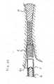
- Figure 3shows the spiral wire 6 as a separate part.
- the wire diametercan for instance be about 0,1 - 0,5 mm, e.g., about 0,2 mm.
- the length of the spiral wirewill typically range between 7 - 13 mm, e.g., between 10 - 12 mm, such as between 10,5 - 11,5 mm.
- the large diameter end 61 which is to be attached to a distal end 42 of a lumen 4will typically have a length of about 2 - 6 mm, e.g., about 3 - 5 mm, such as about 3,3 - 3,9 mm, and an inner diameter of about 1 - 2 mm, e.g., about 1,5 mm.
- the free end 62 of the spiral wire 6can for instance have a length of about 4 - 8 mm, e.g., of about 5,5 - 6,5 mm and an inner diameter of about 0,4 - 0,8 mm, e.g., about 0,6 mm.
- the pitchcan be used to adjust flexural stiffness of the free end 62. If the stiffness of the free end 62 is less, usability of the free end 62 as a guide wire will be improved.
- the pitch between the windings of the spiral wire 6 at its free end 62can for example be about 0,6 - 1,2 mm, such as about 0,7 - 0,9 mm.
- the pitch of the free end 62gradually increases in the direction away from the other end 61.
- the spiral wire 6comprises a transitional section 63 between the free end 62 and the opposite end 61.
- the transitional section 63tapers from the diameter of the end 61 to the smaller diameter of the free end 62.
- the length of the transitional section 63can for instance be about 1 - 2 mm, e.g. about 1,5 mm.
- the material of the spiral wire 6may contain copper or a similar spermicidal compound to enhance the contraceptive effectiveness of the occlusion.
- Figures 4A-Cshow the actuator 7 in front view, side view and cross section, respectively.
- the actuator 7comprises a first tubular section 71 connected to a proximal end of the sleeve 5 and a second tubular section 72 connected to a proximal section of the lumen 4.
- the first and second tubular sections 71, 72are connected by a seal 73 which is broken if the two tubular sections 71, 72 are forced to move away from each other by a given minimum tensile force. This seal 73 helps to avoid unintentional withdrawal of the inner lumen 4.
- the first and second tubular sections 71, 72 of the actuator 7are bridged by two oppositely arranged squeezers 74 with a first end 75 hingeably connected to the first section 71 of the actuator 7, and a second end 76 hingeably connected to the second section 72 of the actuator 7.
- a middle section 77hingeably bridges the first and second ends 75, 76 of the squeezer 74.
- the respective hingeable connectionsare constructed as integral film hinges 78. A user can squeeze the middle sections 77 of the two opposite squeezers 74 together. As a result, the squeezers 74 will transfer a tensile force to the first and section tubular sections 71, 72 of the actuator 7.
- the seal 73will break and the first and second tubular sections 71, 72 are moved apart. Since the first and second tubular sections 71, 72 are connected to the lumen 4 and the outer sleeve 5 respectively, the outer sleeve 5 is moved over the lumen 4 until its distal end 52 abuts the spiral wire 6. Continuation of the actuation force will withdraw the lumen 4 into the outer sleeve 5 and separate the spiral wire 6 from the distal end 42 of the lumen 4.
Landscapes
- Health & Medical Sciences (AREA)
- Life Sciences & Earth Sciences (AREA)
- Engineering & Computer Science (AREA)
- Biomedical Technology (AREA)
- Heart & Thoracic Surgery (AREA)
- Vascular Medicine (AREA)
- Reproductive Health (AREA)
- Animal Behavior & Ethology (AREA)
- General Health & Medical Sciences (AREA)
- Public Health (AREA)
- Veterinary Medicine (AREA)
- Media Introduction/Drainage Providing Device (AREA)
- Materials For Medical Uses (AREA)
- Surgical Instruments (AREA)
Description
- The invention relates to an applicator for delivering a curable occluding compound in a fallopian tube as a contraceptive medium.
- An effective method of contraception is to plug the ovarian pathway of a female, for instance by delivering a curing biocompatible polymeric substance into the fallopian tube. After curing, the polymeric substance blocks the fallopian tube preventing egg and sperm cells from joining together.
WO 2005/082299 , which is regarded as the closest prior art, discloses a device for the delivery of a curing composition for occluding a fallopian tube for contraceptive purposes. After delivery of the occlusive composition into the fallopian tube, the composition cures in situ. To obtain a reliable occlusion the curing compound should be delivered very accurately at the targeted position. Although potential reversibility of this way of contraception is generally felt as an advantage over other contraceptive methods, such as sterilization, the occlusion should be sufficiently anchored within the fallopian tube to prevent it from drifting.- It is an object of the invention to provide an applicator for occluding a fallopian tube by an in situ curing compound allowing more accurate positioning of the compound to form a durable and reliable occlusion blocking the ovarian pathway.
- The object of the invention is achieved with an applicator for delivering an occluding compound in a fallopian tube, the applicator comprising:
- a lumen extending between a proximal end connectable to a dispenser for supplying uncured occluding compound, and a distal end;
- a spiral wire with a first end connected to the distal end of the lumen and a free second end;
- a disconnecting member for disconnecting the spiral wire from the distal end;
- an actuator for actuating the disconnecting member.
- In this respect, "distal" refers to the end of the lumen to be inserted into the fallopian tube, while "proximal" refers to the end of the lumen operatively connected or to be connected to a dispensing unit.
- The distal end of the lumen, or catheter, with the spiral wire can be inserted into the uterus and the fallopian tube. The spiral wire functions as a guide wire and contributes to accurate targeting and positioning of the lumen into the oviduct. After the spiral wire is introduced into the oviduct a sufficient amount of the curable compound is supplied via the lumen to be delivered into the fallopian tube. The curable compound embeds the spiral wire and cures. After sufficient curing the actuator can be actuated to disconnect the spiral wire from the distal end of the lumen. The lumen is then removed from the uterus leaving behind the plug formed by the spiral wire and the embedding cured polymeric matrix. The plug blocks the fallopian tube to prevent egg cells from being inseminated. The spiral wire enforces the plug and stabilizes the position of the plug in the fallopian tube.
- The lumen can be connected to a dispenser of the curable occluding compound, such as a dispenser gun. If the curable compound is a two-component compound, the dispenser may comprise one or more mixing chambers such as a static mixer. The dispenser can for instance be shaped as a gun with a manual actuator or trigger.
- In a specific embodiment, the spiral wire is dimensioned in such a way that the first end of the spiral wire snugly fits on the distal end of the lumen. The disconnecting member can for instance be an outer sleeve slideably arranged over the lumen. The sleeve can for example be an outer lumen, forming a double lumen catheter with the inner lumen. The sleeve can be moved towards the distal end to abut the connected end of the spiral wire. Further movement of the outer sleeve will draw the lumen into the sleeve pushing the spiral wire from the distal end of the inner lumen, after the spiral wire has been embedded by the cured polymeric matrix to form the plug.
- To improve accurate targeting and positioning the free end of the spiral wire can be dimensioned to have a smaller diameter than the end connected to the distal end of the lumen. Flexibility during positioning can be increased if the free end of the spiral wire has a lower flexural stiffness than the end connected to the distal end of the lumen. This can for example be achieved by providing the free end of the spiral wire with a larger pitch between the windings than the end connected to the lumen. The pitch may for instance gradually increase in the direction of the free end.
- To prevent unwanted health effects the spiral wire can be made of a biocompatible material, such as platinum, titanium, gold, silver, nitinol, osmium, stainless steel or mixtures thereof.
Optionally, a material can be used catalyzing the curing reaction of the curable occlusion compound. - The curable occluding compound can for instance be a two-component or multi-component compound which cures after mixing the two or more precursor components. Preferably, the two- or multi-component is curable under the influence of a catalyst. This allows thorough mixing of the precursor components before curing of the compound. Optionally, the spiral wire may contain such a catalyst as a constituent.
- A suitable two-component compound may for instance be a silicone elastomer formed from a mixture of two viscous liquid components. The first component can for instance comprise one or more polysiloxanes, while the second component may comprise one or more suitable cross linking agents, optionally pre-mixed with one or more polysiloxanes.
- Examples of suitable polysiloxanes include poly (dimethyl) siloxane, such as trimethylsiloxy terminated polydimethyl siloxane, and vinyldimethyl terminated dimethyl polysiloxane.
- Examples of suitable cross-linking agents include trimethyl methyl-hydrodimethyl siloxane, propyl ortho silicate and mixures thereof, although any suitable alternative cross-linking agent(s) may also be used.
- The polysiloxanes may be reinforced with an additive such as amorphous silica. To prepare the occluding compound the components can be mixed, e.g., in equal parts or in any suitable ratio. The components can for instance be mixed just prior to injection into the lumen of the applicator to form a flowable, viscous composition, which is then injected into the fallopian tube where it cures in situ to a rubbery consistency. Examples of suitable catalysts include platinum (Pt) catalysts. The polysiloxane components can polymerize in situ in about 3-15 minutes at body temperature. The resulting matrix is biocompatible and is not absorbed into the body. In a specific embodiment of the applicator the actuator may comprise a first section connected to a proximal end of the sleeve and a second section connected to a proximal section of the lumen. The first and second sections can be moved relative to each other in a direction parallel to a longitudinal direction of the lumen. Optionally, the first and second sections of the actuator are connected by a seal breakable by moving the two sections apart. This way, a predetermined force needs to be overcome before the actuator can move the sleeve relative to the lumen and the risk of unintentional actuation is substantially reduced.
- In a refinement, the first and second sections of the actuator are bridged by a squeezer with a first end hingeably connected to the first section of the actuator, and a second end hingeably connected to the second section of the actuator. This way, a simple and easy squeeze movement is sufficient to actuate the actuator. Optionally, the squeezer comprises a middle section hingeably connected to the first and second end of the squeezer. Such a middle section provides an area of engagement for an appropriate squeeze movement. Preferably, the actuator comprises two oppositely arranged squeezers.
- The disclosed actuator can be used with any type of double lumen catheter, comprising an inner lumen and an outer lumen slideably encasing the inner lumen, with or without a spiral wire as disclosed above.
- The invention will be further explained under reference to the accompanying drawings.
- Figure 1:
- shows an exemplary embodiment of an applicator according to the present invention;
- Figure 2A-D:
- show in cross section consecutive steps of use of the applicator of
Figure 1 ; - Figure 3:
- shows in side view a spiral wire of the applicator of
Figure 1 ; - Figures 4A-C:
- show a front view, side view and cross section respectively of an actuator of the applicator of
Figure 1 . Figure 1 shows an applicator 1 comprising a dispenser 2, a static mixer 3, aflexible lumen 4 encased in a flexible outer sleeve or outer lumen 5, and a spiral wire 6 with one end attached to thelumen 4.- The dispenser 2 comprises a pre-filled cartridge 21 containing two side-by-side,
pre-filled chambers 22 and 23, both comprising a liquid precursor component of the curable occluding compound. The respective precursor components are kept separate within thechambers 22, 23 until the compound is delivered to the targeted area of a patients' fallopian tube. In the shown exemplary embodiment the twochambers 22, 23 are of equal volume and a plunger (not shown) is used to apply pressure to each chamber through application of a squeezing force applied by hand to a trigger 24 and ahandle 25 at the lower section of the dispenser 2. As pressure is applied part of the contents of the twochambers 22, 23 is pushed into and through the static mixer 3 and mixed together to form a liquid composition for injection into a fallopian tube. - In this exemplary embodiment the static mixer 3 has a static helical element 31 disposed in a
cavity 32 inside the mixer 3. Other suitable mixing elements may also be used, if so desired. - The
lumen 4 comprises a proximal end 41 attached to the end of the static mixer 3 by luer-lock adapters 33. These luer-lock adapters 33 can for instance have a high-flow, wide inner-diameter and low pressure fittings that provide improved flow of the material with reduced back pressure on the system to lessen the squeezing pressure exerted by the user on the trigger 24 and handle 25. - The spiral wire 6 comprises one
end 61 placed on adistal end 42 of thelumen 4, and afree end 62. The diameter of the windings at thefree end 62 are smaller than the diameters of the windings at the end connected to thelumen 4. The pitch between the windings at thefree end 62 is larger than the pitch between the windings at theother end 61. As a result, the flexural stiffness of the spiral wire 6 is less at itsfree end 62, so thefree end 62 can effectively be used as a guide wire when thelumen 4 with the spiral wire 6 is moved to the targeted position within the fallopian tube. Thefree end 62 comprises an inwardly bent tip 64 to prevent perforation of the wall of the fallopian duct. - The outer sleeve 5 and the
lumen 4 are coaxial and are slideable relative to each other. The sleeve 5 has adistal end 52 abutting the spiral wire 6. An actuator 7 connects the proximal end 41 of thelumen 4 with the proximal end 51 of the outer sleeve 5. The actuator 7 is described in more detail with reference toFigure 4 . By squeezing the actuator 7 the outer sleeve 5 is pushed against the spiral wire 6 and removes the spiral wire 6 from thedistal end 42 of thelumen 4. - In
Figure 2A thedistal end 42 of thelumen 4 with the spiral wire 6 is introduced into afallopian tube 10. Thedistal end 52 of the outer sleeve 5 is close to the end of the spiral wire 6 fitting over the distal end of thelumen 4. After accurate positioning of the spiral wire 6 the trigger 24 of the dispenser 1 is actuated and a sufficient amount of the components of the curable occlusion compound 11 is forced to flow via the static mixer 2 andlumen 4 into the targeted section of thefallopian tube 10, as shown inFigure 2B . The mixed components cure to form aplug 12 embedding thefree end 62 of the spiral wire 6. The compound 11 is delivered to a part of thefallopian tube 10 with anarrow section 13 and widening end sides 14, 15. The plug 11 copies local geometry of thefallopian tube 10 and haswider end parts 16, 17 at both sides which cannot pass thenarrow section 13. - To promote curing speed, the spiral wire may contain a catalyst, such as platinum. The curable compound cures in about 3 - 15 minutes, e.g. in about 6 - 10 minutes at body temperature.
- At the proximal end of the
lumen 4 and the outer sleeve 5, the user can actuate the actuator 7 to retract thelumen 4, while the outer sleeve 5 remains in place. The outer sleeve 5 abuts the spiral wire 6 and prevents that the wire 6 moves with thelumen 4. As a result thelumen 4 is separated from the spiral wire 6 (seeFigure 2C ). Thedistal end 42 of thelumen 4 comprises a narrowed discharge opening 43 to achieve that the occlusion compound 11 left behind in thelumen 4 breaks free from theplug 12 at the position of thedistal end 42. Thelumen 4 and the outer sleeve 5 can now be removed from the patient, leaving the curedplug 12 with the spiral wire 6 behind, as shown inFigure 2D . Thelarge diameter end 61 of the spiral wire 6 extends from one end of theplug 12 in the direction of the uterus. Thisend 61 could also be embedded in the cured material and encloses a tail of cured plug material. Figure 3 shows the spiral wire 6 as a separate part. The wire diameter can for instance be about 0,1 - 0,5 mm, e.g., about 0,2 mm. The length of the spiral wire will typically range between 7 - 13 mm, e.g., between 10 - 12 mm, such as between 10,5 - 11,5 mm. Thelarge diameter end 61 which is to be attached to adistal end 42 of alumen 4, will typically have a length of about 2 - 6 mm, e.g., about 3 - 5 mm, such as about 3,3 - 3,9 mm, and an inner diameter of about 1 - 2 mm, e.g., about 1,5 mm. Thefree end 62 of the spiral wire 6 can for instance have a length of about 4 - 8 mm, e.g., of about 5,5 - 6,5 mm and an inner diameter of about 0,4 - 0,8 mm, e.g., about 0,6 mm. The pitch can be used to adjust flexural stiffness of thefree end 62. If the stiffness of thefree end 62 is less, usability of thefree end 62 as a guide wire will be improved. The pitch between the windings of the spiral wire 6 at itsfree end 62 can for example be about 0,6 - 1,2 mm, such as about 0,7 - 0,9 mm. Optionally, the pitch of thefree end 62 gradually increases in the direction away from theother end 61. In the exemplary embodiment ofFigure 3 the spiral wire 6 comprises atransitional section 63 between thefree end 62 and theopposite end 61. Thetransitional section 63 tapers from the diameter of theend 61 to the smaller diameter of thefree end 62. The length of thetransitional section 63 can for instance be about 1 - 2 mm, e.g. about 1,5 mm. Optionally, the material of the spiral wire 6 may contain copper or a similar spermicidal compound to enhance the contraceptive effectiveness of the occlusion.Figures 4A-C show the actuator 7 in front view, side view and cross section, respectively. The actuator 7 comprises a firsttubular section 71 connected to a proximal end of the sleeve 5 and a secondtubular section 72 connected to a proximal section of thelumen 4. The first and secondtubular sections seal 73 which is broken if the twotubular sections seal 73 helps to avoid unintentional withdrawal of theinner lumen 4.- The first and second
tubular sections squeezers 74 with a first end 75 hingeably connected to thefirst section 71 of the actuator 7, and a second end 76 hingeably connected to thesecond section 72 of the actuator 7. A middle section 77 hingeably bridges the first and second ends 75, 76 of thesqueezer 74. The respective hingeable connections are constructed as integral film hinges 78. A user can squeeze the middle sections 77 of the twoopposite squeezers 74 together. As a result, thesqueezers 74 will transfer a tensile force to the first and sectiontubular sections seal 73 will break and the first and secondtubular sections tubular sections lumen 4 and the outer sleeve 5 respectively, the outer sleeve 5 is moved over thelumen 4 until itsdistal end 52 abuts the spiral wire 6. Continuation of the actuation force will withdraw thelumen 4 into the outer sleeve 5 and separate the spiral wire 6 from thedistal end 42 of thelumen 4.
Claims (15)
- Applicator (1) for delivering an occluding compound in a fallopian tube (10), the applicator comprising:- a lumen (4) extending between a proximal end (41) connectable to a dispenser (2) for containing uncured occluding compound (11), and a distal end (42);
characterised by- a spiral wire (6) with a first end (61) connected to the distal end of the lumen and a free second end (62);- a disconnecting member (5) for disconnecting the spiral wire (6) from the distal end; and- an actuator (7) for actuating the disconnecting member (5). - Applicator according to claim 1 wherein the first end (61) of the spiral wire snugly fits on the distal end (42) of the lumen and wherein the disconnecting member is an outer sleeve (5) slideably arranged over the lumen (4).
- Applicator according to claim 1 or 2 wherein the free end (62) of the spiral wire has a smaller diameter than the end (61) connected to the distal end (42) of the lumen.
- Applicator according to any one of the preceding claims wherein the free end (62) of the spiral wire has a lower flexural stiffness than the end (61) connected to the distal end of the lumen.
- Applicator according to claim 4 wherein the free end (62) of the spiral wire comprises windings with a larger pitch than the end (61) connected to the distal end (42) of the lumen.
- Applicator according to claim 5 wherein the pitch gradually increases in the direction of the free end (62).
- Applicator according to any one of the preceding claims wherein the spiral wire (6) comprises a constituent catalyzing curing of the occluding compound (11).
- Applicator according to any one of the preceding claims wherein the actuator (7) comprises a first section (71) connected to a proximal end (51) of the sleeve (5) and a second section (72) connected to a proximal section (41) of the lumen (41), wherein the first and second sections (71, 72) can be moved relative to each other in a direction parallel to a longitudinal direction of the lumen (4).
- Applicator according to claim 8 wherein the first and second sections (71, 72) of the actuator are connected by a seal (73) breakable by moving the two sections (71, 72) apart.
- Applicator according to claim 8 or 9 wherein the first and second sections (71, 72) of the actuator are bridged by a squeezer (74) with a first end (75) hingeably connected to
the first section (71) of the actuator, and a second end (76) hingeably connected to the second section (72) of the actuator. - Applicator according to claim 10 wherein the squeezer (74) comprises a middle section (77) hingeably connected to the first and second end (75, 76) of the squeezer.
- Applicator according to claim 10 or 11 wherein the actuator comprises two oppositely arranged squeezers (74).
- Applicator according to anyone of the preceding claims wherein the applicator comprises a dispenser (2) operatively connected to the proximal end (41) of the lumen (4), optionally via a static mixer (3).
- Spiral wire (6) for use with an applicator according to any one of the preceding claims, wherein the wire is made of a biocompatible material.
- Spiral wire according to claim 14 wherein in a longitudinal direction of the spiral wire (6) the spiral wire shows a stepwise or gradual reduction of diameter and an increase of pitch.
Priority Applications (9)
| Application Number | Priority Date | Filing Date | Title |
|---|---|---|---|
| EP14195849.6AEP2904998A1 (en) | 2012-04-24 | 2012-04-24 | Occluding compound for a fallopian tube |
| EP20120165366EP2656822B1 (en) | 2012-04-24 | 2012-04-24 | Applicator for delivering an occluding compound in a fallopian tube |
| BR112014026163ABR112014026163A2 (en) | 2012-04-24 | 2013-04-23 | applicator for dispensing an occlusive compound into a fallopian tube, and spiral wire for use with an applicator. |
| PCT/EP2013/058380WO2013160295A1 (en) | 2012-04-24 | 2013-04-23 | Applicator for delivering an occluding compound in a fallopian tube |
| CN201380030990.7ACN104349749B (en) | 2012-04-24 | 2013-04-23 | For the applicator of sending occlusive compound at fallopian tubal |
| AU2013254781AAU2013254781A1 (en) | 2012-04-24 | 2013-04-23 | Applicator for delivering an occluding compound in a fallopian tube |
| KR1020147032519AKR102086991B1 (en) | 2012-04-24 | 2013-04-23 | Applicator for delivering an occluding compound in a fallopian tube |
| US14/396,347US9839555B2 (en) | 2012-04-24 | 2013-04-23 | Applicator for delivering an occluding compound in a fallopian tube |
| ZA2014/08106AZA201408106B (en) | 2012-04-24 | 2014-11-05 | Application for delivering an occluding compound in a fallopian tube |
Applications Claiming Priority (1)
| Application Number | Priority Date | Filing Date | Title |
|---|---|---|---|
| EP20120165366EP2656822B1 (en) | 2012-04-24 | 2012-04-24 | Applicator for delivering an occluding compound in a fallopian tube |
Related Child Applications (1)
| Application Number | Title | Priority Date | Filing Date |
|---|---|---|---|
| EP14195849.6ADivisionEP2904998A1 (en) | 2012-04-24 | 2012-04-24 | Occluding compound for a fallopian tube |
Publications (2)
| Publication Number | Publication Date |
|---|---|
| EP2656822A1 EP2656822A1 (en) | 2013-10-30 |
| EP2656822B1true EP2656822B1 (en) | 2014-12-03 |
Family
ID=48289088
Family Applications (2)
| Application Number | Title | Priority Date | Filing Date |
|---|---|---|---|
| EP20120165366Not-in-forceEP2656822B1 (en) | 2012-04-24 | 2012-04-24 | Applicator for delivering an occluding compound in a fallopian tube |
| EP14195849.6AWithdrawnEP2904998A1 (en) | 2012-04-24 | 2012-04-24 | Occluding compound for a fallopian tube |
Family Applications After (1)
| Application Number | Title | Priority Date | Filing Date |
|---|---|---|---|
| EP14195849.6AWithdrawnEP2904998A1 (en) | 2012-04-24 | 2012-04-24 | Occluding compound for a fallopian tube |
Country Status (8)
| Country | Link |
|---|---|
| US (1) | US9839555B2 (en) |
| EP (2) | EP2656822B1 (en) |
| KR (1) | KR102086991B1 (en) |
| CN (1) | CN104349749B (en) |
| AU (1) | AU2013254781A1 (en) |
| BR (1) | BR112014026163A2 (en) |
| WO (1) | WO2013160295A1 (en) |
| ZA (1) | ZA201408106B (en) |
Families Citing this family (4)
| Publication number | Priority date | Publication date | Assignee | Title |
|---|---|---|---|---|
| DE102016224679A1 (en)* | 2016-12-12 | 2018-06-14 | Skf Lubrication Systems Germany Gmbh | Schmiermittelapplikator |
| DE102016224680A1 (en)* | 2016-12-12 | 2018-06-14 | Skf Lubrication Systems Germany Gmbh | Gear lubricant line device |
| CN113101039B (en)* | 2021-04-26 | 2022-10-18 | 金浙滔 | A fallopian tube contraceptive device, implanter and extractor |
| CN113974753B (en)* | 2021-12-06 | 2023-12-15 | 台州恩泽医疗中心(集团) | Bronchus occluder |
Family Cites Families (28)
| Publication number | Priority date | Publication date | Assignee | Title |
|---|---|---|---|---|
| US3805767A (en)* | 1973-02-26 | 1974-04-23 | Erb Rene | Method and apparatus for non-surgical, reversible sterilization of females |
| US4245623A (en)* | 1978-06-06 | 1981-01-20 | Erb Robert A | Method and apparatus for the hysteroscopic non-surgical sterilization of females |
| US5385561A (en) | 1994-01-18 | 1995-01-31 | Bard International, Inc. | Apparatus and method for injecting a viscous material into the tissue of a patient |
| US6705323B1 (en) | 1995-06-07 | 2004-03-16 | Conceptus, Inc. | Contraceptive transcervical fallopian tube occlusion devices and methods |
| US5749894A (en)* | 1996-01-18 | 1998-05-12 | Target Therapeutics, Inc. | Aneurysm closure method |
| US5649949A (en)* | 1996-03-14 | 1997-07-22 | Target Therapeutics, Inc. | Variable cross-section conical vasoocclusive coils |
| WO1998022040A1 (en) | 1996-11-19 | 1998-05-28 | Uroplasty, Inc. | Instrument for guiding delivery of injectable materials in treating urinary incontinence |
| US6053860A (en) | 1997-09-02 | 2000-04-25 | Andco Tek Inc. | Apparatus for viewing and treating body tissue |
| US6015424A (en)* | 1998-04-28 | 2000-01-18 | Microvention, Inc. | Apparatus and method for vascular embolization |
| GB2343845A (en) | 1998-10-26 | 2000-05-24 | Spembly Medical Ltd | Method and apparatus for use in prostate cryosurgery |
| US6572532B1 (en) | 1999-03-01 | 2003-06-03 | Advanced Biomedical Devices Inc. | Implant positioning system and method |
| CN2418852Y (en)* | 1999-11-12 | 2001-02-14 | 李艳芳 | Oviduct embolism |
| US6550480B2 (en)* | 2001-01-31 | 2003-04-22 | Numed/Tech Llc | Lumen occluders made from thermodynamic materials |
| US7341716B2 (en)* | 2002-04-12 | 2008-03-11 | Boston Scientific Scimed, Inc. | Occlusive composition |
| US7459142B2 (en)* | 2002-06-06 | 2008-12-02 | Micro Therapeutics, Inc. | High viscosity embolizing compositions comprising prepolymers |
| WO2005006991A2 (en)* | 2003-07-18 | 2005-01-27 | Chiroxia Limited | Device and method for fallopian tube occlusion |
| US20050061329A1 (en)* | 2003-09-18 | 2005-03-24 | Conceptus, Inc. | Catheter for intrafallopian contraceptive delivery |
| US20050245876A1 (en)* | 2003-12-24 | 2005-11-03 | Accessclosure, Inc. | Apparatus and methods for facilitating access through a puncture including sealing compound therein |
| US8048086B2 (en) | 2004-02-25 | 2011-11-01 | Femasys Inc. | Methods and devices for conduit occlusion |
| WO2008039807A2 (en)* | 2004-03-15 | 2008-04-03 | Bonwrx, Inc. | Materials and apparatus for in-situ bone repair |
| US20060116713A1 (en)* | 2004-11-26 | 2006-06-01 | Ivan Sepetka | Aneurysm treatment devices and methods |
| US20070077544A1 (en)* | 2005-06-16 | 2007-04-05 | Gottfried Lemperle | Life-like anatomic feature for testing injection of soft tissue fillers |
| US8157837B2 (en)* | 2006-03-13 | 2012-04-17 | Pneumrx, Inc. | Minimally invasive lung volume reduction device and method |
| US7975697B2 (en)* | 2006-05-11 | 2011-07-12 | Conceptus, Inc. | Methods and apparatus for occluding reproductive tracts to effect contraception |
| US8147397B1 (en) | 2006-05-19 | 2012-04-03 | Carbon Medical Technologies, Inc. | Urethral needle guide device |
| US8556930B2 (en)* | 2006-06-28 | 2013-10-15 | Abbott Laboratories | Vessel closure device |
| US8434489B2 (en)* | 2009-10-23 | 2013-05-07 | Conceptus, Inc. | Contraceptive devices and methods |
| US9220506B2 (en)* | 2010-06-16 | 2015-12-29 | DePuy Synthes Products, Inc. | Occlusive device with stretch resistant member and anchor filament |
- 2012
- 2012-04-24EPEP20120165366patent/EP2656822B1/ennot_activeNot-in-force
- 2012-04-24EPEP14195849.6Apatent/EP2904998A1/ennot_activeWithdrawn
- 2013
- 2013-04-23AUAU2013254781Apatent/AU2013254781A1/ennot_activeAbandoned
- 2013-04-23WOPCT/EP2013/058380patent/WO2013160295A1/enactiveApplication Filing
- 2013-04-23KRKR1020147032519Apatent/KR102086991B1/ennot_activeExpired - Fee Related
- 2013-04-23USUS14/396,347patent/US9839555B2/enactiveActive
- 2013-04-23CNCN201380030990.7Apatent/CN104349749B/ennot_activeExpired - Fee Related
- 2013-04-23BRBR112014026163Apatent/BR112014026163A2/ennot_activeApplication Discontinuation
- 2014
- 2014-11-05ZAZA2014/08106Apatent/ZA201408106B/enunknown
Also Published As
| Publication number | Publication date |
|---|---|
| BR112014026163A2 (en) | 2017-07-18 |
| KR20150008139A (en) | 2015-01-21 |
| CN104349749A (en) | 2015-02-11 |
| AU2013254781A1 (en) | 2014-11-13 |
| ZA201408106B (en) | 2015-12-23 |
| CN104349749B (en) | 2016-05-18 |
| WO2013160295A1 (en) | 2013-10-31 |
| EP2904998A1 (en) | 2015-08-12 |
| US9839555B2 (en) | 2017-12-12 |
| KR102086991B1 (en) | 2020-05-28 |
| US20150114401A1 (en) | 2015-04-30 |
| EP2656822A1 (en) | 2013-10-30 |
Similar Documents
| Publication | Publication Date | Title |
|---|---|---|
| EP2656822B1 (en) | Applicator for delivering an occluding compound in a fallopian tube | |
| CA2395349C (en) | Injection device and propulsion system therefor | |
| US8262607B2 (en) | Liquid embolic composition delivery devices and methods | |
| US20180303531A1 (en) | Single-handed applicator | |
| JP6139625B2 (en) | Paste coating system for mixing two component pastes | |
| CN102917736A (en) | Systems, devices and methods for delivering hydrogel compositions with self-cleaning to prevent clogging | |
| CN106102597A (en) | Mixing nozzle | |
| KR102716316B1 (en) | Dual check valve one handed applicator | |
| CN110573198B (en) | Non-clogging dispensing device | |
| AU2021202458B2 (en) | Device and method for mixing liquids | |
| CN211325299U (en) | Microcatheter capable of releasing polymer spring ring | |
| CN114945313A (en) | Medical device for endoscopically dispensing a medicament and associated method of use | |
| US11819649B2 (en) | Nasal insert and therapeutic agent delivery system | |
| KR200484365Y1 (en) | Medicinal Liquid Infusion Apparatus for Catheter | |
| CN108602611A (en) | Apparatus and method for dispensing foam | |
| US20090156987A1 (en) | Apparatus and method of delivery of substances into target tissue | |
| BR112019020710B1 (en) | SET FOR MIXING AND DISTRIBUTING A MULTI-COMPONENT FLUID | |
| MX2007007928A (en) | 4-thio coumarins. |
Legal Events
| Date | Code | Title | Description |
|---|---|---|---|
| PUAI | Public reference made under article 153(3) epc to a published international application that has entered the european phase | Free format text:ORIGINAL CODE: 0009012 | |
| AK | Designated contracting states | Kind code of ref document:A1 Designated state(s):AL AT BE BG CH CY CZ DE DK EE ES FI FR GB GR HR HU IE IS IT LI LT LU LV MC MK MT NL NO PL PT RO RS SE SI SK SM TR | |
| AX | Request for extension of the european patent | Extension state:BA ME | |
| REG | Reference to a national code | Ref country code:DE Ref legal event code:R079 Ref document number:602012004050 Country of ref document:DE Free format text:PREVIOUS MAIN CLASS: A61F0006220000 Ipc:A61F0006200000 | |
| 17P | Request for examination filed | Effective date:20140429 | |
| RBV | Designated contracting states (corrected) | Designated state(s):AL AT BE BG CH CY CZ DE DK EE ES FI FR GB GR HR HU IE IS IT LI LT LU LV MC MK MT NL NO PL PT RO RS SE SI SK SM TR | |
| RIC1 | Information provided on ipc code assigned before grant | Ipc:A61B 17/12 20060101ALI20140527BHEP Ipc:A61F 6/20 20060101AFI20140527BHEP | |
| GRAP | Despatch of communication of intention to grant a patent | Free format text:ORIGINAL CODE: EPIDOSNIGR1 | |
| INTG | Intention to grant announced | Effective date:20140704 | |
| GRAS | Grant fee paid | Free format text:ORIGINAL CODE: EPIDOSNIGR3 | |
| GRAA | (expected) grant | Free format text:ORIGINAL CODE: 0009210 | |
| AK | Designated contracting states | Kind code of ref document:B1 Designated state(s):AL AT BE BG CH CY CZ DE DK EE ES FI FR GB GR HR HU IE IS IT LI LT LU LV MC MK MT NL NO PL PT RO RS SE SI SK SM TR | |
| REG | Reference to a national code | Ref country code:GB Ref legal event code:FG4D | |
| REG | Reference to a national code | Ref country code:CH Ref legal event code:EP Ref country code:AT Ref legal event code:REF Ref document number:698923 Country of ref document:AT Kind code of ref document:T Effective date:20141215 | |
| REG | Reference to a national code | Ref country code:IE Ref legal event code:FG4D | |
| REG | Reference to a national code | Ref country code:DE Ref legal event code:R096 Ref document number:602012004050 Country of ref document:DE Effective date:20150115 | |
| REG | Reference to a national code | Ref country code:NL Ref legal event code:T3 | |
| REG | Reference to a national code | Ref country code:SE Ref legal event code:TRGR | |
| REG | Reference to a national code | Ref country code:AT Ref legal event code:MK05 Ref document number:698923 Country of ref document:AT Kind code of ref document:T Effective date:20141203 | |
| REG | Reference to a national code | Ref country code:FR Ref legal event code:PLFP Year of fee payment:4 | |
| PG25 | Lapsed in a contracting state [announced via postgrant information from national office to epo] | Ref country code:ES Free format text:LAPSE BECAUSE OF FAILURE TO SUBMIT A TRANSLATION OF THE DESCRIPTION OR TO PAY THE FEE WITHIN THE PRESCRIBED TIME-LIMIT Effective date:20141203 Ref country code:NO Free format text:LAPSE BECAUSE OF FAILURE TO SUBMIT A TRANSLATION OF THE DESCRIPTION OR TO PAY THE FEE WITHIN THE PRESCRIBED TIME-LIMIT Effective date:20150303 Ref country code:LT Free format text:LAPSE BECAUSE OF FAILURE TO SUBMIT A TRANSLATION OF THE DESCRIPTION OR TO PAY THE FEE WITHIN THE PRESCRIBED TIME-LIMIT Effective date:20141203 Ref country code:FI Free format text:LAPSE BECAUSE OF FAILURE TO SUBMIT A TRANSLATION OF THE DESCRIPTION OR TO PAY THE FEE WITHIN THE PRESCRIBED TIME-LIMIT Effective date:20141203 | |
| REG | Reference to a national code | Ref country code:LT Ref legal event code:MG4D | |
| PG25 | Lapsed in a contracting state [announced via postgrant information from national office to epo] | Ref country code:LV Free format text:LAPSE BECAUSE OF FAILURE TO SUBMIT A TRANSLATION OF THE DESCRIPTION OR TO PAY THE FEE WITHIN THE PRESCRIBED TIME-LIMIT Effective date:20141203 Ref country code:GR Free format text:LAPSE BECAUSE OF FAILURE TO SUBMIT A TRANSLATION OF THE DESCRIPTION OR TO PAY THE FEE WITHIN THE PRESCRIBED TIME-LIMIT Effective date:20150304 Ref country code:AT Free format text:LAPSE BECAUSE OF FAILURE TO SUBMIT A TRANSLATION OF THE DESCRIPTION OR TO PAY THE FEE WITHIN THE PRESCRIBED TIME-LIMIT Effective date:20141203 Ref country code:RS Free format text:LAPSE BECAUSE OF FAILURE TO SUBMIT A TRANSLATION OF THE DESCRIPTION OR TO PAY THE FEE WITHIN THE PRESCRIBED TIME-LIMIT Effective date:20141203 Ref country code:CY Free format text:LAPSE BECAUSE OF FAILURE TO SUBMIT A TRANSLATION OF THE DESCRIPTION OR TO PAY THE FEE WITHIN THE PRESCRIBED TIME-LIMIT Effective date:20141203 Ref country code:HR Free format text:LAPSE BECAUSE OF FAILURE TO SUBMIT A TRANSLATION OF THE DESCRIPTION OR TO PAY THE FEE WITHIN THE PRESCRIBED TIME-LIMIT Effective date:20141203 | |
| PG25 | Lapsed in a contracting state [announced via postgrant information from national office to epo] | Ref country code:RO Free format text:LAPSE BECAUSE OF FAILURE TO SUBMIT A TRANSLATION OF THE DESCRIPTION OR TO PAY THE FEE WITHIN THE PRESCRIBED TIME-LIMIT Effective date:20141203 Ref country code:SK Free format text:LAPSE BECAUSE OF FAILURE TO SUBMIT A TRANSLATION OF THE DESCRIPTION OR TO PAY THE FEE WITHIN THE PRESCRIBED TIME-LIMIT Effective date:20141203 Ref country code:EE Free format text:LAPSE BECAUSE OF FAILURE TO SUBMIT A TRANSLATION OF THE DESCRIPTION OR TO PAY THE FEE WITHIN THE PRESCRIBED TIME-LIMIT Effective date:20141203 Ref country code:PT Free format text:LAPSE BECAUSE OF FAILURE TO SUBMIT A TRANSLATION OF THE DESCRIPTION OR TO PAY THE FEE WITHIN THE PRESCRIBED TIME-LIMIT Effective date:20150403 Ref country code:CZ Free format text:LAPSE BECAUSE OF FAILURE TO SUBMIT A TRANSLATION OF THE DESCRIPTION OR TO PAY THE FEE WITHIN THE PRESCRIBED TIME-LIMIT Effective date:20141203 | |
| PG25 | Lapsed in a contracting state [announced via postgrant information from national office to epo] | Ref country code:IS Free format text:LAPSE BECAUSE OF FAILURE TO SUBMIT A TRANSLATION OF THE DESCRIPTION OR TO PAY THE FEE WITHIN THE PRESCRIBED TIME-LIMIT Effective date:20150403 Ref country code:PL Free format text:LAPSE BECAUSE OF FAILURE TO SUBMIT A TRANSLATION OF THE DESCRIPTION OR TO PAY THE FEE WITHIN THE PRESCRIBED TIME-LIMIT Effective date:20141203 | |
| REG | Reference to a national code | Ref country code:DE Ref legal event code:R097 Ref document number:602012004050 Country of ref document:DE | |
| PLBE | No opposition filed within time limit | Free format text:ORIGINAL CODE: 0009261 | |
| STAA | Information on the status of an ep patent application or granted ep patent | Free format text:STATUS: NO OPPOSITION FILED WITHIN TIME LIMIT | |
| PG25 | Lapsed in a contracting state [announced via postgrant information from national office to epo] | Ref country code:DK Free format text:LAPSE BECAUSE OF FAILURE TO SUBMIT A TRANSLATION OF THE DESCRIPTION OR TO PAY THE FEE WITHIN THE PRESCRIBED TIME-LIMIT Effective date:20141203 | |
| 26N | No opposition filed | Effective date:20150904 | |
| PG25 | Lapsed in a contracting state [announced via postgrant information from national office to epo] | Ref country code:MC Free format text:LAPSE BECAUSE OF FAILURE TO SUBMIT A TRANSLATION OF THE DESCRIPTION OR TO PAY THE FEE WITHIN THE PRESCRIBED TIME-LIMIT Effective date:20141203 Ref country code:LU Free format text:LAPSE BECAUSE OF FAILURE TO SUBMIT A TRANSLATION OF THE DESCRIPTION OR TO PAY THE FEE WITHIN THE PRESCRIBED TIME-LIMIT Effective date:20150424 | |
| PG25 | Lapsed in a contracting state [announced via postgrant information from national office to epo] | Ref country code:IT Free format text:LAPSE BECAUSE OF FAILURE TO SUBMIT A TRANSLATION OF THE DESCRIPTION OR TO PAY THE FEE WITHIN THE PRESCRIBED TIME-LIMIT Effective date:20141203 | |
| PG25 | Lapsed in a contracting state [announced via postgrant information from national office to epo] | Ref country code:SI Free format text:LAPSE BECAUSE OF FAILURE TO SUBMIT A TRANSLATION OF THE DESCRIPTION OR TO PAY THE FEE WITHIN THE PRESCRIBED TIME-LIMIT Effective date:20141203 | |
| REG | Reference to a national code | Ref country code:FR Ref legal event code:PLFP Year of fee payment:5 | |
| PG25 | Lapsed in a contracting state [announced via postgrant information from national office to epo] | Ref country code:BE Free format text:LAPSE BECAUSE OF FAILURE TO SUBMIT A TRANSLATION OF THE DESCRIPTION OR TO PAY THE FEE WITHIN THE PRESCRIBED TIME-LIMIT Effective date:20141203 | |
| PG25 | Lapsed in a contracting state [announced via postgrant information from national office to epo] | Ref country code:MT Free format text:LAPSE BECAUSE OF FAILURE TO SUBMIT A TRANSLATION OF THE DESCRIPTION OR TO PAY THE FEE WITHIN THE PRESCRIBED TIME-LIMIT Effective date:20141203 | |
| REG | Reference to a national code | Ref country code:FR Ref legal event code:PLFP Year of fee payment:6 | |
| PG25 | Lapsed in a contracting state [announced via postgrant information from national office to epo] | Ref country code:SM Free format text:LAPSE BECAUSE OF FAILURE TO SUBMIT A TRANSLATION OF THE DESCRIPTION OR TO PAY THE FEE WITHIN THE PRESCRIBED TIME-LIMIT Effective date:20141203 Ref country code:HU Free format text:LAPSE BECAUSE OF FAILURE TO SUBMIT A TRANSLATION OF THE DESCRIPTION OR TO PAY THE FEE WITHIN THE PRESCRIBED TIME-LIMIT; INVALID AB INITIO Effective date:20120424 Ref country code:BG Free format text:LAPSE BECAUSE OF FAILURE TO SUBMIT A TRANSLATION OF THE DESCRIPTION OR TO PAY THE FEE WITHIN THE PRESCRIBED TIME-LIMIT Effective date:20141203 | |
| PG25 | Lapsed in a contracting state [announced via postgrant information from national office to epo] | Ref country code:TR Free format text:LAPSE BECAUSE OF FAILURE TO SUBMIT A TRANSLATION OF THE DESCRIPTION OR TO PAY THE FEE WITHIN THE PRESCRIBED TIME-LIMIT Effective date:20141203 | |
| REG | Reference to a national code | Ref country code:FR Ref legal event code:PLFP Year of fee payment:7 | |
| PG25 | Lapsed in a contracting state [announced via postgrant information from national office to epo] | Ref country code:MK Free format text:LAPSE BECAUSE OF FAILURE TO SUBMIT A TRANSLATION OF THE DESCRIPTION OR TO PAY THE FEE WITHIN THE PRESCRIBED TIME-LIMIT Effective date:20141203 | |
| PG25 | Lapsed in a contracting state [announced via postgrant information from national office to epo] | Ref country code:AL Free format text:LAPSE BECAUSE OF FAILURE TO SUBMIT A TRANSLATION OF THE DESCRIPTION OR TO PAY THE FEE WITHIN THE PRESCRIBED TIME-LIMIT Effective date:20141203 | |
| PGFP | Annual fee paid to national office [announced via postgrant information from national office to epo] | Ref country code:CH Payment date:20210505 Year of fee payment:10 Ref country code:IE Payment date:20210427 Year of fee payment:10 Ref country code:SE Payment date:20210428 Year of fee payment:10 | |
| PGFP | Annual fee paid to national office [announced via postgrant information from national office to epo] | Ref country code:NL Payment date:20210429 Year of fee payment:10 | |
| PGFP | Annual fee paid to national office [announced via postgrant information from national office to epo] | Ref country code:GB Payment date:20220427 Year of fee payment:11 Ref country code:FR Payment date:20220425 Year of fee payment:11 Ref country code:DE Payment date:20220427 Year of fee payment:11 | |
| REG | Reference to a national code | Ref country code:SE Ref legal event code:EUG | |
| REG | Reference to a national code | Ref country code:CH Ref legal event code:PL | |
| REG | Reference to a national code | Ref country code:NL Ref legal event code:MM Effective date:20220501 | |
| PG25 | Lapsed in a contracting state [announced via postgrant information from national office to epo] | Ref country code:SE Free format text:LAPSE BECAUSE OF NON-PAYMENT OF DUE FEES Effective date:20220425 Ref country code:NL Free format text:LAPSE BECAUSE OF NON-PAYMENT OF DUE FEES Effective date:20220501 Ref country code:LI Free format text:LAPSE BECAUSE OF NON-PAYMENT OF DUE FEES Effective date:20220430 Ref country code:CH Free format text:LAPSE BECAUSE OF NON-PAYMENT OF DUE FEES Effective date:20220430 | |
| PG25 | Lapsed in a contracting state [announced via postgrant information from national office to epo] | Ref country code:IE Free format text:LAPSE BECAUSE OF NON-PAYMENT OF DUE FEES Effective date:20220424 | |
| REG | Reference to a national code | Ref country code:DE Ref legal event code:R119 Ref document number:602012004050 Country of ref document:DE | |
| GBPC | Gb: european patent ceased through non-payment of renewal fee | Effective date:20230424 | |
| PG25 | Lapsed in a contracting state [announced via postgrant information from national office to epo] | Ref country code:GB Free format text:LAPSE BECAUSE OF NON-PAYMENT OF DUE FEES Effective date:20230424 | |
| PG25 | Lapsed in a contracting state [announced via postgrant information from national office to epo] | Ref country code:GB Free format text:LAPSE BECAUSE OF NON-PAYMENT OF DUE FEES Effective date:20230424 Ref country code:FR Free format text:LAPSE BECAUSE OF NON-PAYMENT OF DUE FEES Effective date:20230430 Ref country code:DE Free format text:LAPSE BECAUSE OF NON-PAYMENT OF DUE FEES Effective date:20231103 |