EP2656793B1 - Expandable tissue thickness compensator - Google Patents
Expandable tissue thickness compensatorDownload PDFInfo
- Publication number
- EP2656793B1 EP2656793B1EP13161431.5AEP13161431AEP2656793B1EP 2656793 B1EP2656793 B1EP 2656793B1EP 13161431 AEP13161431 AEP 13161431AEP 2656793 B1EP2656793 B1EP 2656793B1
- Authority
- EP
- European Patent Office
- Prior art keywords
- staple
- staple cartridge
- staples
- view
- thickness compensator
- Prior art date
- Legal status (The legal status is an assumption and is not a legal conclusion. Google has not performed a legal analysis and makes no representation as to the accuracy of the status listed.)
- Active
Links
Images


Classifications
- A—HUMAN NECESSITIES
- A61—MEDICAL OR VETERINARY SCIENCE; HYGIENE
- A61B—DIAGNOSIS; SURGERY; IDENTIFICATION
- A61B17/00—Surgical instruments, devices or methods
- A61B17/00491—Surgical glue applicators
- A—HUMAN NECESSITIES
- A61—MEDICAL OR VETERINARY SCIENCE; HYGIENE
- A61B—DIAGNOSIS; SURGERY; IDENTIFICATION
- A61B17/00—Surgical instruments, devices or methods
- A61B17/068—Surgical staplers, e.g. containing multiple staples or clamps
- A61B17/072—Surgical staplers, e.g. containing multiple staples or clamps for applying a row of staples in a single action, e.g. the staples being applied simultaneously
- A61B17/07207—Surgical staplers, e.g. containing multiple staples or clamps for applying a row of staples in a single action, e.g. the staples being applied simultaneously the staples being applied sequentially
- A—HUMAN NECESSITIES
- A61—MEDICAL OR VETERINARY SCIENCE; HYGIENE
- A61B—DIAGNOSIS; SURGERY; IDENTIFICATION
- A61B17/00—Surgical instruments, devices or methods
- A61B17/064—Surgical staples, i.e. penetrating the tissue
- A61B17/0643—Surgical staples, i.e. penetrating the tissue with separate closing member, e.g. for interlocking with staple
- A—HUMAN NECESSITIES
- A61—MEDICAL OR VETERINARY SCIENCE; HYGIENE
- A61B—DIAGNOSIS; SURGERY; IDENTIFICATION
- A61B17/00—Surgical instruments, devices or methods
- A61B17/064—Surgical staples, i.e. penetrating the tissue
- A61B17/0644—Surgical staples, i.e. penetrating the tissue penetrating the tissue, deformable to closed position
- A—HUMAN NECESSITIES
- A61—MEDICAL OR VETERINARY SCIENCE; HYGIENE
- A61B—DIAGNOSIS; SURGERY; IDENTIFICATION
- A61B17/00—Surgical instruments, devices or methods
- A61B17/068—Surgical staplers, e.g. containing multiple staples or clamps
- A—HUMAN NECESSITIES
- A61—MEDICAL OR VETERINARY SCIENCE; HYGIENE
- A61B—DIAGNOSIS; SURGERY; IDENTIFICATION
- A61B17/00—Surgical instruments, devices or methods
- A61B17/068—Surgical staplers, e.g. containing multiple staples or clamps
- A61B17/072—Surgical staplers, e.g. containing multiple staples or clamps for applying a row of staples in a single action, e.g. the staples being applied simultaneously
- A61B17/07292—Reinforcements for staple line, e.g. pledgets
- A—HUMAN NECESSITIES
- A61—MEDICAL OR VETERINARY SCIENCE; HYGIENE
- A61B—DIAGNOSIS; SURGERY; IDENTIFICATION
- A61B17/00—Surgical instruments, devices or methods
- A61B17/10—Surgical instruments, devices or methods for applying or removing wound clamps, e.g. containing only one clamp or staple; Wound clamp magazines
- A61B17/105—Wound clamp magazines
- A—HUMAN NECESSITIES
- A61—MEDICAL OR VETERINARY SCIENCE; HYGIENE
- A61B—DIAGNOSIS; SURGERY; IDENTIFICATION
- A61B17/00—Surgical instruments, devices or methods
- A61B17/11—Surgical instruments, devices or methods for performing anastomosis; Buttons for anastomosis
- A61B17/115—Staplers for performing anastomosis, e.g. in a single operation
- A61B17/1155—Circular staplers comprising a plurality of staples
- A—HUMAN NECESSITIES
- A61—MEDICAL OR VETERINARY SCIENCE; HYGIENE
- A61B—DIAGNOSIS; SURGERY; IDENTIFICATION
- A61B17/00—Surgical instruments, devices or methods
- A61B17/068—Surgical staplers, e.g. containing multiple staples or clamps
- A61B17/0682—Surgical staplers, e.g. containing multiple staples or clamps for applying U-shaped staples or clamps, e.g. without a forming anvil
- A—HUMAN NECESSITIES
- A61—MEDICAL OR VETERINARY SCIENCE; HYGIENE
- A61B—DIAGNOSIS; SURGERY; IDENTIFICATION
- A61B17/00—Surgical instruments, devices or methods
- A61B17/28—Surgical forceps
- A61B17/29—Forceps for use in minimally invasive surgery
- A61B17/2909—Handles
- A—HUMAN NECESSITIES
- A61—MEDICAL OR VETERINARY SCIENCE; HYGIENE
- A61B—DIAGNOSIS; SURGERY; IDENTIFICATION
- A61B17/00—Surgical instruments, devices or methods
- A61B2017/00004—(bio)absorbable, (bio)resorbable or resorptive
- A—HUMAN NECESSITIES
- A61—MEDICAL OR VETERINARY SCIENCE; HYGIENE
- A61B—DIAGNOSIS; SURGERY; IDENTIFICATION
- A61B17/00—Surgical instruments, devices or methods
- A61B17/00234—Surgical instruments, devices or methods for minimally invasive surgery
- A61B2017/00292—Surgical instruments, devices or methods for minimally invasive surgery mounted on or guided by flexible, e.g. catheter-like, means
- A61B2017/003—Steerable
- A61B2017/00305—Constructional details of the flexible means
- A61B2017/00314—Separate linked members
- A—HUMAN NECESSITIES
- A61—MEDICAL OR VETERINARY SCIENCE; HYGIENE
- A61B—DIAGNOSIS; SURGERY; IDENTIFICATION
- A61B17/00—Surgical instruments, devices or methods
- A61B17/00234—Surgical instruments, devices or methods for minimally invasive surgery
- A61B2017/00292—Surgical instruments, devices or methods for minimally invasive surgery mounted on or guided by flexible, e.g. catheter-like, means
- A61B2017/003—Steerable
- A61B2017/00318—Steering mechanisms
- A61B2017/00323—Cables or rods
- A61B2017/00327—Cables or rods with actuating members moving in opposite directions
- A—HUMAN NECESSITIES
- A61—MEDICAL OR VETERINARY SCIENCE; HYGIENE
- A61B—DIAGNOSIS; SURGERY; IDENTIFICATION
- A61B17/00—Surgical instruments, devices or methods
- A61B2017/00526—Methods of manufacturing
- A—HUMAN NECESSITIES
- A61—MEDICAL OR VETERINARY SCIENCE; HYGIENE
- A61B—DIAGNOSIS; SURGERY; IDENTIFICATION
- A61B17/00—Surgical instruments, devices or methods
- A61B2017/00526—Methods of manufacturing
- A61B2017/0053—Loading magazines or sutures into applying tools
- A—HUMAN NECESSITIES
- A61—MEDICAL OR VETERINARY SCIENCE; HYGIENE
- A61B—DIAGNOSIS; SURGERY; IDENTIFICATION
- A61B17/00—Surgical instruments, devices or methods
- A61B2017/00535—Surgical instruments, devices or methods pneumatically or hydraulically operated
- A61B2017/00561—Surgical instruments, devices or methods pneumatically or hydraulically operated creating a vacuum
- A—HUMAN NECESSITIES
- A61—MEDICAL OR VETERINARY SCIENCE; HYGIENE
- A61B—DIAGNOSIS; SURGERY; IDENTIFICATION
- A61B17/00—Surgical instruments, devices or methods
- A61B2017/00743—Type of operation; Specification of treatment sites
- A61B2017/00818—Treatment of the gastro-intestinal system
- A—HUMAN NECESSITIES
- A61—MEDICAL OR VETERINARY SCIENCE; HYGIENE
- A61B—DIAGNOSIS; SURGERY; IDENTIFICATION
- A61B17/00—Surgical instruments, devices or methods
- A61B2017/00831—Material properties
- A61B2017/00862—Material properties elastic or resilient
- A—HUMAN NECESSITIES
- A61—MEDICAL OR VETERINARY SCIENCE; HYGIENE
- A61B—DIAGNOSIS; SURGERY; IDENTIFICATION
- A61B17/00—Surgical instruments, devices or methods
- A61B2017/00831—Material properties
- A61B2017/00884—Material properties enhancing wound closure
- A—HUMAN NECESSITIES
- A61—MEDICAL OR VETERINARY SCIENCE; HYGIENE
- A61B—DIAGNOSIS; SURGERY; IDENTIFICATION
- A61B17/00—Surgical instruments, devices or methods
- A61B2017/00831—Material properties
- A61B2017/00889—Material properties antimicrobial, disinfectant
- A—HUMAN NECESSITIES
- A61—MEDICAL OR VETERINARY SCIENCE; HYGIENE
- A61B—DIAGNOSIS; SURGERY; IDENTIFICATION
- A61B17/00—Surgical instruments, devices or methods
- A61B2017/00831—Material properties
- A61B2017/00893—Material properties pharmaceutically effective
- A—HUMAN NECESSITIES
- A61—MEDICAL OR VETERINARY SCIENCE; HYGIENE
- A61B—DIAGNOSIS; SURGERY; IDENTIFICATION
- A61B17/00—Surgical instruments, devices or methods
- A61B2017/00831—Material properties
- A61B2017/00898—Material properties expandable upon contact with fluid
- A—HUMAN NECESSITIES
- A61—MEDICAL OR VETERINARY SCIENCE; HYGIENE
- A61B—DIAGNOSIS; SURGERY; IDENTIFICATION
- A61B17/00—Surgical instruments, devices or methods
- A61B2017/00831—Material properties
- A61B2017/00938—Material properties hydrophobic
- A—HUMAN NECESSITIES
- A61—MEDICAL OR VETERINARY SCIENCE; HYGIENE
- A61B—DIAGNOSIS; SURGERY; IDENTIFICATION
- A61B17/00—Surgical instruments, devices or methods
- A61B2017/00831—Material properties
- A61B2017/00942—Material properties hydrophilic
- A—HUMAN NECESSITIES
- A61—MEDICAL OR VETERINARY SCIENCE; HYGIENE
- A61B—DIAGNOSIS; SURGERY; IDENTIFICATION
- A61B17/00—Surgical instruments, devices or methods
- A61B17/064—Surgical staples, i.e. penetrating the tissue
- A61B2017/0641—Surgical staples, i.e. penetrating the tissue having at least three legs as part of one single body
- A—HUMAN NECESSITIES
- A61—MEDICAL OR VETERINARY SCIENCE; HYGIENE
- A61B—DIAGNOSIS; SURGERY; IDENTIFICATION
- A61B17/00—Surgical instruments, devices or methods
- A61B17/068—Surgical staplers, e.g. containing multiple staples or clamps
- A61B17/072—Surgical staplers, e.g. containing multiple staples or clamps for applying a row of staples in a single action, e.g. the staples being applied simultaneously
- A61B2017/07214—Stapler heads
- A61B2017/07228—Arrangement of the staples
- A—HUMAN NECESSITIES
- A61—MEDICAL OR VETERINARY SCIENCE; HYGIENE
- A61B—DIAGNOSIS; SURGERY; IDENTIFICATION
- A61B17/00—Surgical instruments, devices or methods
- A61B17/068—Surgical staplers, e.g. containing multiple staples or clamps
- A61B17/072—Surgical staplers, e.g. containing multiple staples or clamps for applying a row of staples in a single action, e.g. the staples being applied simultaneously
- A61B2017/07214—Stapler heads
- A61B2017/07235—Stapler heads containing different staples, e.g. staples of different shapes, sizes or materials
- A—HUMAN NECESSITIES
- A61—MEDICAL OR VETERINARY SCIENCE; HYGIENE
- A61B—DIAGNOSIS; SURGERY; IDENTIFICATION
- A61B17/00—Surgical instruments, devices or methods
- A61B17/068—Surgical staplers, e.g. containing multiple staples or clamps
- A61B17/072—Surgical staplers, e.g. containing multiple staples or clamps for applying a row of staples in a single action, e.g. the staples being applied simultaneously
- A61B2017/07214—Stapler heads
- A61B2017/07242—Stapler heads achieving different staple heights during the same shot, e.g. using an anvil anvil having different heights or staples of different sizes
- A—HUMAN NECESSITIES
- A61—MEDICAL OR VETERINARY SCIENCE; HYGIENE
- A61B—DIAGNOSIS; SURGERY; IDENTIFICATION
- A61B17/00—Surgical instruments, devices or methods
- A61B17/068—Surgical staplers, e.g. containing multiple staples or clamps
- A61B17/072—Surgical staplers, e.g. containing multiple staples or clamps for applying a row of staples in a single action, e.g. the staples being applied simultaneously
- A61B2017/07214—Stapler heads
- A61B2017/07257—Stapler heads characterised by its anvil
- A61B2017/07264—Stapler heads characterised by its anvil characterised by its staple forming cavities, e.g. geometry or material
- A—HUMAN NECESSITIES
- A61—MEDICAL OR VETERINARY SCIENCE; HYGIENE
- A61B—DIAGNOSIS; SURGERY; IDENTIFICATION
- A61B17/00—Surgical instruments, devices or methods
- A61B17/068—Surgical staplers, e.g. containing multiple staples or clamps
- A61B17/072—Surgical staplers, e.g. containing multiple staples or clamps for applying a row of staples in a single action, e.g. the staples being applied simultaneously
- A61B2017/07214—Stapler heads
- A61B2017/07271—Stapler heads characterised by its cartridge
- A—HUMAN NECESSITIES
- A61—MEDICAL OR VETERINARY SCIENCE; HYGIENE
- A61B—DIAGNOSIS; SURGERY; IDENTIFICATION
- A61B17/00—Surgical instruments, devices or methods
- A61B17/068—Surgical staplers, e.g. containing multiple staples or clamps
- A61B17/072—Surgical staplers, e.g. containing multiple staples or clamps for applying a row of staples in a single action, e.g. the staples being applied simultaneously
- A61B2017/07214—Stapler heads
- A61B2017/07278—Stapler heads characterised by its sled or its staple holder
- A—HUMAN NECESSITIES
- A61—MEDICAL OR VETERINARY SCIENCE; HYGIENE
- A61B—DIAGNOSIS; SURGERY; IDENTIFICATION
- A61B17/00—Surgical instruments, devices or methods
- A61B17/068—Surgical staplers, e.g. containing multiple staples or clamps
- A61B17/072—Surgical staplers, e.g. containing multiple staples or clamps for applying a row of staples in a single action, e.g. the staples being applied simultaneously
- A61B2017/07214—Stapler heads
- A61B2017/07285—Stapler heads characterised by its cutter
- A—HUMAN NECESSITIES
- A61—MEDICAL OR VETERINARY SCIENCE; HYGIENE
- A61B—DIAGNOSIS; SURGERY; IDENTIFICATION
- A61B17/00—Surgical instruments, devices or methods
- A61B17/28—Surgical forceps
- A61B17/29—Forceps for use in minimally invasive surgery
- A61B2017/2901—Details of shaft
- A61B2017/2908—Multiple segments connected by articulations
- A—HUMAN NECESSITIES
- A61—MEDICAL OR VETERINARY SCIENCE; HYGIENE
- A61B—DIAGNOSIS; SURGERY; IDENTIFICATION
- A61B17/00—Surgical instruments, devices or methods
- A61B17/28—Surgical forceps
- A61B17/29—Forceps for use in minimally invasive surgery
- A61B17/2909—Handles
- A61B2017/2912—Handles transmission of forces to actuating rod or piston
- A61B2017/2919—Handles transmission of forces to actuating rod or piston details of linkages or pivot points
- A—HUMAN NECESSITIES
- A61—MEDICAL OR VETERINARY SCIENCE; HYGIENE
- A61B—DIAGNOSIS; SURGERY; IDENTIFICATION
- A61B17/00—Surgical instruments, devices or methods
- A61B17/28—Surgical forceps
- A61B17/29—Forceps for use in minimally invasive surgery
- A61B17/2909—Handles
- A61B2017/2912—Handles transmission of forces to actuating rod or piston
- A61B2017/2923—Toothed members, e.g. rack and pinion
- A—HUMAN NECESSITIES
- A61—MEDICAL OR VETERINARY SCIENCE; HYGIENE
- A61B—DIAGNOSIS; SURGERY; IDENTIFICATION
- A61B17/00—Surgical instruments, devices or methods
- A61B17/28—Surgical forceps
- A61B17/29—Forceps for use in minimally invasive surgery
- A61B2017/2926—Details of heads or jaws
- A61B2017/2927—Details of heads or jaws the angular position of the head being adjustable with respect to the shaft
- A—HUMAN NECESSITIES
- A61—MEDICAL OR VETERINARY SCIENCE; HYGIENE
- A61B—DIAGNOSIS; SURGERY; IDENTIFICATION
- A61B17/00—Surgical instruments, devices or methods
- A61B17/28—Surgical forceps
- A61B17/29—Forceps for use in minimally invasive surgery
- A61B2017/2926—Details of heads or jaws
- A61B2017/2932—Transmission of forces to jaw members
- A61B2017/2933—Transmission of forces to jaw members camming or guiding means
- A61B2017/2936—Pins in guiding slots
- A—HUMAN NECESSITIES
- A61—MEDICAL OR VETERINARY SCIENCE; HYGIENE
- A61B—DIAGNOSIS; SURGERY; IDENTIFICATION
- A61B17/00—Surgical instruments, devices or methods
- A61B17/28—Surgical forceps
- A61B17/29—Forceps for use in minimally invasive surgery
- A61B2017/2926—Details of heads or jaws
- A61B2017/2932—Transmission of forces to jaw members
- A61B2017/2933—Transmission of forces to jaw members camming or guiding means
- A61B2017/2937—Transmission of forces to jaw members camming or guiding means with flexible part
- A—HUMAN NECESSITIES
- A61—MEDICAL OR VETERINARY SCIENCE; HYGIENE
- A61B—DIAGNOSIS; SURGERY; IDENTIFICATION
- A61B17/00—Surgical instruments, devices or methods
- A61B17/32—Surgical cutting instruments
- A61B2017/320052—Guides for cutting instruments
- A—HUMAN NECESSITIES
- A61—MEDICAL OR VETERINARY SCIENCE; HYGIENE
- A61B—DIAGNOSIS; SURGERY; IDENTIFICATION
- A61B90/00—Instruments, implements or accessories specially adapted for surgery or diagnosis and not covered by any of the groups A61B1/00 - A61B50/00, e.g. for luxation treatment or for protecting wound edges
- A61B90/08—Accessories or related features not otherwise provided for
- A61B2090/0807—Indication means
Definitions
- US2011313406 A1relates to implants and, more particularly, to patches suitable for achieving hemostasis.
- the patchmay be coated and/or impregnated with materials, such as, precursors, that will form a hydrogel in situ. These hydrogels may further promote hemostasis and/or assist in adhering the patch to tissue.
- any of the methods disclosed or claimed herein for manufacturing, forming or otherwise producing an article or productmay be employed to manufacture, form or otherwise produce all or part of the article or product in question, and where such a method is employed to manufacture, form or otherwise produce part of the article or product in question, the remainder of the article or product may be produced in any way, including by employing any of the other methods disclosed and claimed herein for manufacturing, forming or otherwise producing the article or product, and the various parts so produced may be combined in any manner.
- any article or product disclosed or claimed hereinmay exist alone, or in combination with, or as an integral part of any other article or product so disclosed with which it is compatible.
- proximal and distalare used herein with reference to a clinician manipulating the handle portion of the surgical instrument.
- proximalreferring to the portion closest to the clinician and the term “distal” referring to the portion located away from the clinician.
- distalreferring to the portion located away from the clinician.
- spatial termssuch as “vertical”, “horizontal”, “up”, and “down” may be used herein with respect to the drawings.
- surgical instrumentsare used in many orientations and positions, and these terms are not intended to be limiting and/or absolute.
- Various exemplary devices and methodsare provided for performing laparoscopic and minimally invasive surgical procedures.
- the various methods and devices disclosed hereincan be used in numerous surgical procedures and applications, including in connection with open surgical procedures.
- the various instruments disclosed hereincan be inserted into a body in any way, such as through a natural orifice, through an incision or puncture hole formed in tissue, etc.
- the working portions or end effector portions of the instrumentscan be inserted directly into a patient's body or can be inserted through an access device that has a working channel through which the end effector and elongated shaft of a surgical instrument can be advanced.
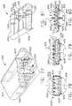
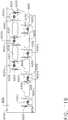
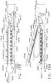
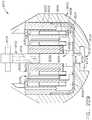
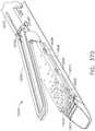
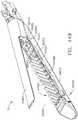
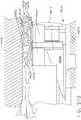
- FIG. 1depicts a surgical instrument 10 that is capable of practicing several unique benefits.
- the surgical stapling instrument 10is designed to manipulate and/or actuate various forms and sizes of end effectors 12 that are operably attached thereto.
- the end effector 12includes an elongated channel 14 that forms a lower jaw 13 of the end effector 12.
- the elongated channel 14is configured to support an "implantable" staple cartridge 30 and also movably support an anvil 20 that functions as an upper jaw 15 of the end effector 12.
- the elongated channel 14may be fabricated from, for example, 300 & 400 Series, 17-4 & 17-7 stainless steel, titanium, etc. and be formed with spaced side walls 16.
- the anvil 20may be fabricated from, for example, 300 & 400 Series, 17-4 & 17-7 stainless steel, titanium, etc. and have a staple forming undersurface, generally labeled as 22 that has a plurality of staple forming pockets 23 formed therein. See FIGS. 1B-1E .
- the anvil 20has a bifurcated ramp assembly 24 that protrudes proximally therefrom.
- An anvil pin 26protrudes from each lateral side of the ramp assembly 24 to be received within a corresponding slot or opening 18 in the side walls 16 of the elongated channel 14 to facilitate its movable or pivotable attachment thereto.
- implantable staple cartridge 30is shown.
- the staple cartridge 30has a body portion 31 that consists of a compressible hemostat material such as, for example, oxidized regenerated cellulose ("ORC”) or a bio-absorbable foam in which lines of unformed metal staples 32 are supported.
- a compressible hemostat materialsuch as, for example, oxidized regenerated cellulose ("ORC") or a bio-absorbable foam in which lines of unformed metal staples 32 are supported.
- the entire cartridgemay be coated or wrapped in a biodegradable film 38 such as a polydioxanon film sold under the trademark PDS® or with a Polyglycerol sebacate (PGS) film or other biodegradable films formed from PGA (Polyglycolic acid, marketed under the trade mark Vicryl), PCL (Polycaprolactone), PLA or PLLA (Polylactic acid), PHA (polyhydroxyalkanoate), PGCL (poliglecaprone 25, sold under the trademark Monocryl) or a composite of PGA, PCL, PLA, PDS that would be impermeable until ruptured.
- PGAPolyglycolic acid, marketed under the trade mark Vicryl
- PCLPolycaprolactone
- PLA or PLLAPolylactic acid
- PHApolyhydroxyalkanoate
- PGCLpoliglecaprone 25, sold under the trademark Monocryl
- the body 31 of staple cartridge 30is sized to be removably supported within the elongated channel 14 as shown such that each staple 32 therein is aligned with corresponding staple forming pockets 23 in the anvil when the anvil 20 is driven into forming contact with the staple cartridge 30.
- the end effector 12is manipulated to capture or clamp the target tissue between an upper face 36 of the staple cartridge 30 and the staple forming surface 22 of the anvil 20.
- the staples 32are formed by moving the anvil 20 in a path that is substantially parallel to the elongated channel 14 to bring the staple forming surface 22 and, more particularly, the staple forming pockets 23 therein into substantially simultaneous contact with the upper face 36 of the staple cartridge 30.
- the legs 34 of the staples 32contact a corresponding staple forming pocket 23 in anvil 20 which serves to bend the staple legs 34 over to form the staples 32 into a "B shape". Further movement of the anvil 20 toward the elongated channel 14 will further compress and form the staples 32 to a desired final formed height "FF".
- FIGS. 1B-1EThe above-described staple forming process is generally depicted in FIGS. 1B-1E .
- FIG. 1Billustrates the end effector 12 with target tissue "T" between the anvil 20 and the upper face 36 of the implantable staple cartridge 30.
- FIG. 1Cillustrates the initial clamping position of the anvil 20 wherein the anvil has 20 been closed onto the target tissue "T” to clamp the target tissue "T” between the anvil 20 and the upper face 36 of the staple cartridge 30.
- FIG. 1Dillustrates the initial staple formation wherein the anvil 20 has started to compress the staple cartridge 30 such that the legs 34 of the staples 32 are starting to be formed by the staple forming pockets 23 in the anvil 20.
- FIG. 1Billustrates the end effector 12 with target tissue "T" between the anvil 20 and the upper face 36 of the implantable staple cartridge 30.
- FIG. 1Cillustrates the initial clamping position of the anvil 20 wherein the anvil has 20 been closed onto the target tissue "T” to clamp the
- FIG. 1Eillustrates the staple 32 in its final formed condition through the target tissue "T” with the anvil 20 removed for clarity purposes.
- the surgeonwill move the anvil 20 to the open position to enable the cartridge body 31 and the staples 32 to remain affixed to the target tissue while the end effector 12 is being withdrawn from the patient.
- the end effector 12forms all of the staples simultaneously as the two jaws 13, 15 are clamped together.
- the remaining "crushed" body materials 31act as both a hemostat (the ORC) and a staple line reinforcement (PGA, PDS or any of the other film compositions mentioned above 38).
- implantable staple cartridgesare distinguishable from prior cartridge arrangements that remain positioned within the end effector in their entirety after they have been fired.
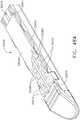
- the end effector 12is configured to be coupled to an elongated shaft assembly 40 that protrudes from a handle assembly 100.
- the end effector 12 (when closed) and the elongated shaft assembly 40may have similar cross-sectional shapes and be sized to operably pass through a trocar tube or working channel in another form of access instrument.
- the term "operably pass”means that the end effector and at least a portion of the elongated shaft assembly may be inserted through or passed through the channel or tube opening and can be manipulated therein as needed to complete the surgical stapling procedure.
- the jaws 13 and 15 of the end effector 12may provide the end effector with a roughly circular cross-sectional shape that facilitates its passage through a circular passage/opening.
- the end effectors of the present arrangement, as well as the elongated shaft assembly arrangementscould conceivably be provided with other cross-sectional shapes that could otherwise pass through access passages and openings that have non-circular cross-sectional shapes.
- an overall size of a cross-section of a closed end effectorwill be related to the size of the passage or opening through which it is intended to pass.
- one end effectorfor example, may be referred to as a "5mm" end effector which means it can operably pass through an opening that is at least approximately 5mm in diameter.
- the elongated shaft assembly 40may have an outer diameter that is substantially the same as the outer diameter of the end effector 12 when in a closed position.
- a 5mm end effectormay be coupled to an elongated shaft assembly 40 that has 5mm cross-sectional diameter.
- the present arrangementmay be effectively used in connection with different sizes of end effectors.
- a 10mm end effectormay be attached to an elongated shaft that has a 5mm cross-sectional diameter.
- the elongated shaft assembly 40may have a 10mm (or larger) cross-sectional diameter, but may also be able to actuate a 5mm or 10mm end effector. Accordingly, the outer shaft 40 may have an outer diameter that is the same as or is different from the outer diameter of a closed end effector 12 attached thereto.
- the elongated shaft assembly 40extends distally from the handle assembly 100 in a generally straight line to define a longitudinal axis A-A.
- the elongated shaft assembly 40may be approximately 9-16 inches (229-406mm) long.
- the elongated shaft assembly 40may be provided in other lengths and, as an alternative, may have joints therein or be otherwise configured to facilitate articulation of the end effector 12 relative to other portions of the shaft or handle assembly as will be discussed in further detail below.
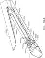
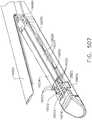
- the elongated shaft assembly 40includes a spine member 50 that extends from the handle assembly 100 to the end effector 12.
- the proximal end of the elongated channel 14 of the end effector 12has a pair of retention trunnions 17 protruding therefrom that are sized to be received within corresponding trunnion openings or cradles 52 that are provided in a distal end of the spine member 50 to enable the end effector 12 to be removably coupled the elongated shaft assembly 40.
- the spine member 50may be fabricated from, for example, 6061 or 7075 aluminum, stainless steel, titanium, etc.
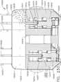
- the handle assembly 100comprises a pistol grip-type housing that may be fabricated in two or more pieces for assembly purposes.
- the handle assembly 100as shown comprises a right hand case member 102 and a left hand case member (not illustrated) that are molded or otherwise fabricated from a polymer or plastic material and are designed to mate together.
- Such case membersmay be attached together by snap features, pegs and sockets molded or otherwise formed therein and/or by adhesive, screws, etc.
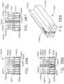
- the spine member 50has a proximal end 54 that has a flange 56 formed thereon.
- the flange 56is configured to be rotatably supported within a groove 106 formed by mating ribs 108 that protrude inwardly from each of the case members 102, 104.
- Such arrangementfacilitates the attachment of the spine member 50 to the handle assembly 100 while enabling the spine member 50 to be rotated relative to the handle assembly 100 about the longitudinal axis A-A in a 360° path.
- the spine member 50passes through and is supported by a mounting bushing 60 that is rotatably affixed to the handle assembly 100.
- the mounting bushing 60has a proximal flange 62 and a distal flange 64 that define a rotational groove 65 that is configured to rotatably receive a nose portion 101 of the handle assembly 100 therebetween.
- the spine member 50is non-rotatably pinned to the mounting bushing 60 by a spine pin 66.
- a rotation knob 70is attached to the mounting bushing 60.
- the rotation knob 70has a hollow mounting flange portion 72 that is sized to receive a portion of the mounting bushing 60 therein.
- the rotation knob 70may be fabricated from, for example, glass or carbon filled Nylon, polycarbonate, Ultem®, etc. and is affixed to the mounting bushing 60 by the spine pin 66 as well.
- an inwardly protruding retention flange 74is formed on the mounting flange portion 72 and is configured to extend into a radial groove 68 formed in the mounting bushing 60.
- the surgeonmay rotate the spine member 50 (and the end effector 12 attached thereto) about longitudinal axis A-A in a 360° path by grasping the rotation knob 70 and rotating it relative to the handle assembly 100.
- the anvil 20is retained in an open position by an anvil spring 21 and/or another biasing arrangement.
- the anvil 20is selectively movable from the open position to various closed or clamping and firing positions by a firing system, generally designated as 109.
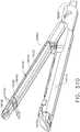
- the firing system 109includes a "firing member" 110 which comprises a hollow firing tube 110.
- the hollow firing tube 110is axially movable on the spine member 50 and thus forms the outer portion of the elongated shaft assembly 40.
- the firing tube 110may be fabricated from a polymer or other suitable material and have a proximal end that is attached to a firing yoke 114 of the firing system 109.
- the firing yoke 114may be over-molded to the proximal end of the firing tube 110.
- other fastener arrangementsmay be employed.
- the firing yoke 114may be rotatably supported within a support collar 120 that is configured to move axially within the handle assembly 100.
- the support collar 120has a pair of laterally extending fins that are sized to be slidably received within fin slots formed in the right and left hand case members.
- the support collar 120may slide axially within the handle housing 100 while enabling the firing yoke 114 and firing tube 110 to rotate relative thereto about the longitudinal axis A-A.
- a longitudinal slotis provided through the firing tube 110 to enable the spine pin 66 to extend therethrough into the spine member 50 while facilitating the axial travel of the firing tube 110 on the spine member 50.
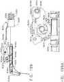
- the firing system 109further comprises a firing trigger 130 which serves to control the axial travel of the firing tube 110 on the spine member 50. See FIG. 1 .
- a firing trigger 130which serves to control the axial travel of the firing tube 110 on the spine member 50. See FIG. 1 .
- Such axial movement in the distal direction of the firing tube 110 into firing interaction with the anvil 20is referred to herein as "firing motion”.
- the firing trigger 130is movably or pivotally coupled to the handle assembly 100 by a pivot pin 132.
- a torsion spring 135is employed to bias the firing trigger 130 away from the pistol grip portion 107 of the handle assembly 100 to an un-actuated "open" or starting position.
- FIG. 1As can be seen in FIG.
- the firing trigger 130has an upper portion 134 that is movably attached to (pinned) firing links 136 that are movably attached to (pinned) the support collar 120.
- movement of the firing trigger 130 from the starting position ( FIG. 1 ) toward an ending position adjacent the pistol grip portion 107 of the handle assembly 100will cause the firing yoke 114 and the firing tube 110 to move in the distal direction "DD".
- Movement of the firing trigger 130 away from the pistol grip portion 107 of the handle assembly 100(under the bias of the torsion spring 135) will cause the firing yoke 114 and firing tube 110 to move in the proximal direction "PD" on the spine member 50.
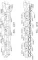
- the surgical instrument 10when used in connection with a first firing adapter 140, may be used with a 5mm end effector 12 that is approximately 20mm long (or in other lengths) which supports an implantable staple cartridge 30.
- Such end effector sizemay be particularly well-suited, for example, to complete relatively fine dissection and vascular transactions.
- the surgical instrument 10may also be employed, for example, in connection with other sizes of end effectors and staple cartridges by replacing the first firing adapter 140 with a second firing adapter.
- the elongated shaft assembly 40may configured to be attached to only one form or size of end effector.
- the coupling processis commenced by inserting the retention trunnions 17 on the elongated channel 14 into the trunnion cradles 52 in the spine member 50. Thereafter, the surgeon advances the firing trigger 130 toward the pistol grip 107 of the housing assembly 100 to distally advance the firing tube 110 and the first firing adapter 140 over a proximal end portion 47 of the elongated channel 14 to thereby retain the trunnions 17 in their respective cradles 52. Such position of the first firing adapter 140 over the trunnions 17 is referred to herein as the "coupled position".
- the present arrangementmay also have an end effector locking assembly for locking the firing trigger 130 in position after an end effector 12 has been attached to the spine member 50.
- one arrangement of the end effector locking assembly 160includes a retention pin 162 that is movably supported in the upper portion 134 of the firing trigger 130.
- the firing tube 110must initially be advanced distally to the coupled position wherein the first firing adapter 140 retains the retention trunnions 17 of the end effector 12 in the trunnion cradles 52 in the spine member 50. The surgeon advances the firing adapter 140 distally to the coupled position by pulling the firing trigger 130 from the starting position toward the pistol grip 107.
- the retention pin 162is moved distally until the firing tube 110 has advanced the first firing adapter 140 to the coupled position at which point the retention pin 162 is biased into a locking cavity 164 formed in the case member.
- the pin 162may make an audible "click” or other sound, as well as provide a tactile indication to the surgeon that the end effector 12 has been “locked” onto the spine member 50.
- the surgeoncannot inadvertently continue to actuate the firing trigger 130 to start to form staples 32 in the end effector 12 without intentionally biasing the retention pin 162 out of the locking cavity 164.
- the surgeon releases the firing trigger 130 when in the coupled positionit is retained in that position by the retention pin 162 to prevent the firing trigger 130 from returning to the starting position and thereby releasing the end effector 12 from the spine member 50.
- the present arrangementmay further include a firing system lock button 137 that is pivotally attached to the handle assembly 100.
- the firing system lock button 137has a latch 138 formed on a distal end thereof that is oriented to engage the firing yoke 114 when the firing release button is in a first latching position.
- a latch spring 139serves to bias the firing system lock button 137 to the first latching position.
- the latch 138serves to engage the firing yoke 114 at a point where the position of the firing yoke 114 on the spine member 50 corresponds to a point wherein the first firing adapter 140 is about to distally advance up the clamping ramp 28 on the anvil 20. It will be understood that, as the first firing adapter 140 advances axially up the clamping ramp 28, the anvil 20 will move in a path such that its staple forming surface portion 22 is substantially parallel to the upper face 36 of the staple cartridge 30.
- the staple forming processis commenced by first depressing the firing system lock button 137 to enable the firing yoke 114 to be further moved distally on the spine member 50 and ultimately compress the anvil 20 into the staple cartridge 30.
- the surgeoncontinues to actuate the firing trigger 130 towards the pistol grip 107 thereby driving the first staple collar 140 up the corresponding staple forming ramp 29 to force the anvil 20 into forming contact with the staples 32 in the staple cartridge 30.
- the firing system lock button 137prevents the inadvertent forming of the staples 32 until the surgeon is ready to start that process. In this example, the surgeon must depress the firing system lock button 137 before the firing trigger 130 may be further actuated to begin the staple forming process.
- the surgical instrument 10may be solely used as a tissue stapling device if so desired.
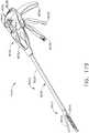
- the present arrangementmay also include a tissue cutting system, generally designated as 170.
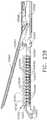
- the tissue cutting system 170comprises a knife member 172 that may be selectively advanced from an un-actuated position adjacent the proximal end of the end effector 12 to an actuated position by actuating a knife advancement trigger 200.
- the knife member 172is movably supported within the spine member 50 and is attached or otherwise protrudes from a knife rod 180.
- the knife member 172may be fabricated from, for example, 420 or 440 stainless steel with a hardness of greater than 38HRC (Rockwell Hardness C-scale) and have a tissue cutting edge 176 formed on the distal end 174 thereof and be configured to slidably extend through a slot in the anvil 20 and a centrally disposed slot 33 in the staple cartridge 30 to cut through tissue that is clamped in the end effector 12.
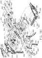
- the knife rod 180extends through the spine member 50 and has a proximal end portion which drivingly interfaces with a knife transmission that is operably attached to the knife advance trigger 200.
- the knife advance trigger 200is attached to pivot pin 132 such that it may be pivoted or otherwise actuated without actuating the firing trigger 130.
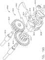
- a first knife gear 192is also attached to the pivot pin 132 such that actuation of the knife advance trigger 200 also pivots the first knife gear 192.
- a firing return spring 202is attached between the first knife gear 192 and the handle housing 100 to bias the knife advancement trigger 200 to a starting or un-actuated position.
- the knife transmissionalso include a second knife gear 194 that is rotatably supported on a second gear spindle and in meshing engagement with the first knife gear 192.
- the second knife gear 194is in meshing engagement with a third knife gear 196 that is supported on a third gear spindle.
- Also supported on the third gear spindle 195is a fourth knife gear 198.
- the fourth knife gear 198is adapted to drivingly engage a series of annular gear teeth or rings on a proximal end of the knife rod 180.
- such arrangementenables the fourth knife gear 198 to axially drive the knife rod 180 in the distal direction "DD" or proximal direction “PD” while enabling the firing rod 180 to rotate about longitudinal axis A-A with respect to the fourth knife gear 198. Accordingly, the surgeon may axially advance the firing rod 180 and ultimately the knife member 172 distally by pulling the knife advancement trigger 200 towards the pistol grip 107 of the handle assembly 100.
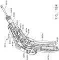
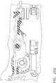
- the present arrangementmay further include a knife lockout system 210 that prevents the advancement of the knife member 172 unless the firing trigger 130 has been pulled to the fully fired position. Such feature will therefore prevent the activation of the knife advancement system 170 unless the staples have first been fired or formed into the tissue.
- various implementations of the knife lockout system 210comprise a knife lockout bar 211 that is pivotally supported within the pistol grip portion 107 of the handle assembly 100.
- the knife lockout bar 211has an activation end 212 that is adapted to be engaged by the firing trigger 130 when the firing trigger 130 is in the fully fired position.
- the knife lockout bar 211has a retaining hook 214 on its other end that is adapted to hookingly engage a latch rod 216 on the first cut gear 192.
- a knife lock spring 218is employed to bias the knife lockout bar 211 to a "locked" position wherein the retaining hook 214 is retained in engagement with the latch rod 216 to thereby prevent actuation of the knife advancement trigger 200 unless the firing trigger 130 is in the fully fired position.
- the surgeonmay depress the firing trigger release button 167 to enable the firing trigger 130 to return to the starting position under the bias of the torsion spring 135 which enables the anvil 20 to be biased to an open position under the bias of spring 21.
- the surgeonmay withdraw the end effector 12 leaving the implantable staple cartridge 30 and staples 32 behind.
- the surgeonwill return the anvil 20 to the closed position by activating the firing trigger 130 to enable the end effector 12 to be withdrawn out through the passage or working channel.
- the surgeonactivates the knife advancement trigger 200 in the above-described manner to drive the knife bar 172 through the target tissue to the end of the end effector. Thereafter, the surgeon may release the knife advancement trigger 200 to enable the firing return spring 202 to cause the firing transmission to return the knife bar 172 to the starting (un-actuated) position. Once the knife bar 172 has been returned to the starting position, the surgeon may open the end effector jaws 13, 15 to release the implantable cartridge 30 within the patient and then withdraw the end effector 12 from the patient.
- such surgical instrumentsfacilitate the use of small implantable staple cartridges that may be inserted through relatively smaller working channels and passages, while providing the surgeon with the option to fire the staples without cutting tissue or if desired to also cut tissue after the staples have been fired.
- Various unique and novel arrangementsemploy a compressible staple cartridge that supports staples in a substantially stationary position for forming contact by the anvil.
- the anvilis driven into the unformed staples wherein, for example, the degree of staple formation attained is dependent upon how far the anvil is driven into the staples.
- Such an arrangementprovides the surgeon with the ability to adjust the amount of forming or firing pressure applied to the staples and thereby alter the final formed height of the staples.
- surgical stapling arrangementscan employ staple driving elements which can lift the staples toward the anvil. Such arrangements are described in greater detail further below.
- the amount of firing motion that is applied to the movable anvilis dependent upon the degree of actuation of the firing trigger. For example, if the surgeon desires to attain only partially formed staples, then the firing trigger is only partially depressed inward towards the pistol grip 107. To attain more staple formation, the surgeon simply compresses the firing trigger further which results in the anvil being further driven into forming contact with the staples.
- forming contactmeans that the staple forming surface or staple forming pockets have contacted the ends of the staple legs and have started to form or bend the legs over into a formed position.
- the degree of staple formationrefers to how far the staple legs have been folded over and ultimately relates to the forming height of the staple as referenced above.
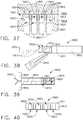
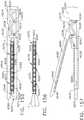
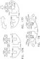
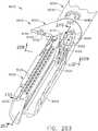
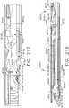
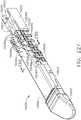
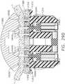
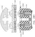
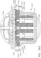
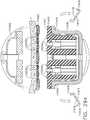
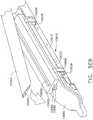
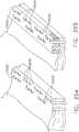
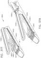
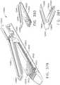
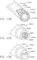
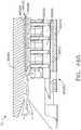
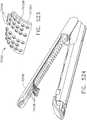
- FIGS. 2 and 3illustrate an alternative end effector 12" that is similar to the end effector 12' described above, except with the following differences that are configured to accommodate a knife bar 172'.
- the knife bar 172'is coupled to or protrudes from a knife rod 180 and is otherwise operated in the above described manner with respect to the knife bar 172.
- the knife bar 172'is long enough to traverse the entire length of the end effector 12" and therefore, a separate distal knife member is not employed in the end effector 12".
- the knife bar 172'has an upper transverse member 173' and a lower transverse member 175' formed thereon.
- the upper transverse member 173'is oriented to slidably transverse a corresponding elongated slot 250 in anvil 20" and the lower transverse member 175' is oriented to traverse an elongated slot 252 in the elongated channel 14" of the end effector 12".
- a disengagement slot(not shown) is also provide din the anvil 20" such that when the knife bar 172' has been driven to an ending position with thin end effector 12", the upper transverse member 173' drops through the corresponding slot to enable the anvil 20" to move to the open position to disengage the stapled and cut tissue.
- the anvil 20"may be otherwise identical to anvil 20 described above and the elongated channel 14" may be otherwise identical to elongated channel 14 described above.
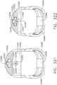
- the anvil 20"is biased to a fully open position ( FIG. 2 ) by a spring or other opening arrangement (not shown).
- the anvil 20"is moved between the open and fully clamped positions by the axial travel of the firing adapter 150 in the manner described above.
- the surgeonmay then advance the knife bar 172" distally in the manner described above. If the surgeon desires to use the end effector as a grasping device to manipulate tissue, the firing adapter may be moved proximally to allow the anvil 20" to move away from the elongated channel 14" as represented in FIG. 4 in broken lines.
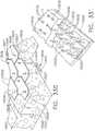
- the unique and novel features of the various surgical staple cartridges and the surgical instruments of the present arrangementenable the staples in those cartridges to be arranged in one or more linear or non-linear lines.
- a plurality of such staple linesmay be provided on each side of an elongated slot that is centrally disposed within the staple cartridge for receiving the tissue cutting member therethrough.
- the staples in one linemay be substantially parallel with the staples in adjacent line(s) of staples, but offset therefrom.
- one or more lines of staplesmay be non-linear in nature. That is, the base of at least one staple in a line of staples may extend along an axis that is substantially transverse to the bases of other staples in the same staple line.
- the lines of staples on each side of the elongated slotmay have a zigzag appearance.
- Such non-linear staple arrangementsmay attain better tissue fastening results with fewer staples than various linear staple arrangements employed in prior staple cartridges.
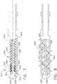
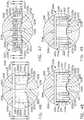
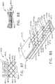
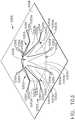
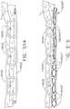
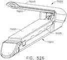
- FIG. 6illustrates use of a surgical staple cartridge arrangement 900 in an end effector arrangement 612'.
- an arrangement of the surgical staple cartridge 900has a cartridge body 902 that has a centrally disposed elongated slot 904 extending through a proximal end 903 to an area adjacent a distal end 905.
- the elongated slot 904is configured to permit a knife body to axially move therethrough during a tissue cutting operation in the manner described above.
- the cartridge body 902consists of a compressible hemostat material such as, for example, oxidized regenerated cellulose ("ORC") or a bio-absorbable foam fabricated from, for example, PGA (Polyglycolic acid, sold under the trademark Vicryl), PCL (polycaprolactone), PLA or PLLA (Polyactic acid), PDS (Polydioxanone), PHA (polyhydroxyalkanoate), PGCL (poliglecaprone 25, sold under the trademark Monocryl) or a composite of PGA, PCL, PLA and PDS in which lines 920, 930 of unformed staples 922 are supported.
- ORCoxidized regenerated cellulose
- the cartridge body 902may be fabricated from other materials that serve to support the unformed staples 922 in a desired orientation such that they may be compressed as the anvil 910' is brought into contact therewith.
- the staple cartridge 900is implantable and is left attached to the stapled tissue after the stapling procedure has been completed.
- the entire cartridge 900may be coated or wrapped in a biodegradable film 906 such as a polydioxanon film sold under the trademark PDS® or with a Polyglycerol sebacate (PGS) film or other biodegradable films fabricated from, for example, PGA (Polyglycolic acid, marketed under the trade mark Vicryl), PCL (Polycaprolactone), PLA or PLLA (Polylactic acid), PHA (polyhydroxyalkanoate), PGCL (poliglecaprone 25, sold under the trademark Monocryl) or a composite of PGA, PCL, PLA, PDS that would be impermeable until ruptured.
- the cartridge body 902 of staple cartridge 900is sized to be removably supported within the elongated channel of the end effector 612'.
- the surgical staple cartridge 900operably supports a first line 920 of staples 922 on one lateral side 907 of the elongated slot 904 and a second line 930 of staples 922 on the other lateral side 909 of the elongated slot 904.
- the staples 922may be fabricated from a metal material such as, for example, Titanium, Titanium alloys (e.g., 6AI-4V Titanium, 3al-2.5V Titanium), Stainless Steel, etc. and have a staple base 924 and two upstanding staple legs 926 protruding therefrom. Each staple leg 926 may have a tissue-piercing tip 928 formed thereon.
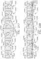
- the staple base 924 of at least one staple 922overlaps the staple base of another staple 922.
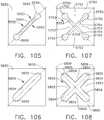
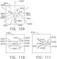
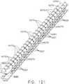
- the staple base 924 of each staple 922overlaps the staple bases 924 of two adjacent staples 922, except for the base 924 of the last staple 922 on each end of the first staple line 920. See FIG. 10 .
- the first staple line 920has a substantially non-linear shape. More particularly, when viewed from above, the first staple line 920 has a substantially zigzag appearance.
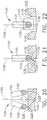
- the anvil 90has two sequential longitudinal staple forming pockets 912 that each has a substantial zigzag shape that corresponds to the shape of the first line 920 of staples 922 such that, when the anvil 910 is brought into forming contact with the staples 922, the legs 926 thereof are formed as shown in FIG. 11 .
- the distal leg of one stapleshares the same pocket as the proximal leg of the next staple longitudinally.
- Such arrangementallows for a denser pocket pattern, even to a point where the staples themselves interact (e.g., are folded over one another).
- prior staple pocket arrangementsin general, there has to be between 0.005 and 0.015 inches (0.127 to 0.381 mm) of metal/space from one set of pockets to the next.
- This arrangementhas a spacing arrangement from 0 to 0.02 inches (0 to 0.508 mm) of interference/overlap (essentially a -0.020" (-0.0508 mm)) because one staple mates with the next staple, for example.
- Such arrangementsallow for 15-30% more staples in the same space.
- Prior arrangementscommonly employ three rows on each side of the tissue cut line to prevent the existing of an open path through which blood may pass. Lines of interlocking staples are less likely to leave paths through which blood may pass.
- Another distinct advantage provided by the various interlocking staple arrangements of the present arrangementrelates to improved "burst strength" which relates to the amount of force required to tear a staple line open.
- Another staple forming pocket arrangementmay comprise a common staple forming pocket.
- common staple forming pocketmeans that one forming pocket can form all of the staples in a single line of staples as opposed to prior anvil designs wherein a discrete forming pocket is provided for each leg of each staple to be formed.
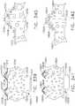
- FIG. 12illustrates yet another staple arrangement 922' wherein the base 924' has an offset portion 929 to facilitate a tighter overlap of the bases 924'.
- the staple cartridge 900has a second line 930 of staples 922 supported on a second lateral side 909 of the elongated slot 904.
- the second line 930 of staples 922is substantially identical to the first line 920 of staples 922.
- the anvil 910has a second common staple forming pocket 912 that corresponds to the second line of staples 930 for forming contact therewith.
- the second line 930 of staples 922may differ from the first line 920 of staples in shape and, perhaps, number of staples.
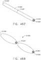
- FIG. 8illustrates a surgical staple cartridge 900' that is substantially identical to the staple cartridge 900 described above, with the exception of the lines 920', 930' of staples 922 supported therein.
- the line 920' of staples 922are arranged relative to each other such that a base axis S-S of at least one staple base 924 is substantially transverse to the base axis S-S of the staple base 924 of at least one other adjacent staple 922.
- Such predetermined pattern of stapleswhen viewed from above, comprises a substantially zigzag arrangement.
- the respective bases 924 of staples 922may additionally have a base support member 927 overmolded thereon as shown.
- the base support member 927may be fabricated from, for example, non-absorbable plastic such as Polyether ether ketone "PEEK” or absorbable plastic such as, for example, Polyglycolic acid “PGA", Polylactic acid “PLA” or “PLLA”, Polydioxanone “PDS”, PCL (polycaprolactone), PHA (polyhydroxyalkanoate), Polyglycerol sebacate (PGS), PGCL (poliglecaprone 25, sold under the trademark Monocryl) or various composite mixes of PGS, PDS, PLA, PGA, and PCL.
- the base support members 927facilitate interlocking between the staples without making the staples themselves overlap.
- Each coupler portion 929may be fabricated from, for example, Polyether ether ketone "PEEK” or absorbable plastic such as, for example, Polyglycolic acid “PGA”, Polylactic acid “PLA” or “PLLA”, Polydioxanone “PDS”, PCL (polycaprolactone), PHA (polyhydroxyalkanoate), PGCL (poliglecaprone 25, sold under the trademark Monocryl) or various composite mixes if PGS, PDS, PLA, PGA, and PCL.
- PEEKPolyether ether ketone
- PEEKPolyether ether ketone
- absorbable plasticsuch as, for example, Polyglycolic acid "PGA”, Polylactic acid “PLA” or “PLLA”, Polydioxanone “PDS”, PCL (polycaprolactone), PHA (polyhydroxyalkanoate), PGCL (poliglecaprone 25, sold under the trademark Monocryl) or various composite mixes if PGS, PDS, PLA, PGA, and PCL.
- Such staple line 920"has substantial zigzag appearance when viewed from above. While the various surgical staple cartridge embodiments 900, 900' have been explained with reference to use with the end effector 612', it will be understood that the staple cartridges 900, 900' may be effectively employed with the various other end effectors and surgical instruments described hereinabove, with appropriate staple forming pocket arrangements being provided in the anvils of those instruments in order to achieved the desired amount of staple formation upon movement of the anvils into forming contact with the staples.
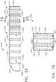
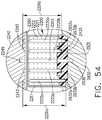
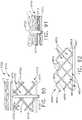
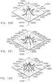
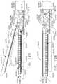
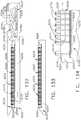
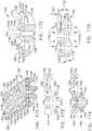
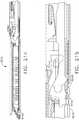
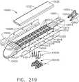
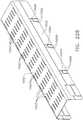
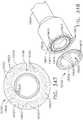
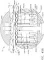
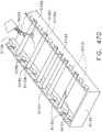
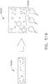
- FIGS. 15 and 16illustrate another surgical staple cartridge 940 arrangement supported in an elongated channel 14 of a surgical instrument 10.
- the surgical staple cartridge 940includes a cartridge body 942 that has a centrally disposed elongated slot 944 extending at least partially therethrough.
- the elongated slot 944is configured to permit a knife body of the surgical instrument 10 to axially move therethrough during a tissue cutting operation in the manner described above.
- the cartridge body 942consists of a compressible hemostat material such as, for example, oxidized regenerated cellulose ("ORC”) or a bio-absorbable foam of the types described above or below in which lines 946, 948, 950, 952 of unformed staples 922 are supported.
- ORCoxidized regenerated cellulose
- the entire cartridge 940may be coated or wrapped in a biodegradable film 954 such as a polydioxanon film sold under the trademark PDS® or with a Polyglycerol sebacate (PGS) film or other biodegradable films fabricated from, for example, PGA (Polyglycolic acid, marketed under the trade mark Vicryl), PCL (Polycaprolactone), PLA or PLLA (Polylactic acid), PHA (polyhydroxyalkanoate), PGCL (poliglecaprone 25, sold under the trademark Monocryl) or a composite of PGA, PCL, PLA, PDS that would be impermeable until ruptured.
- PGAPolyglycolic acid, marketed under the trade mark Vicryl
- PCLPolycaprolactone
- PLA or PLLAPolylactic acid
- PHApolyhydroxyalkanoate
- PGCLpoliglecaprone 25, sold under the trademark Monocryl
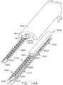
- the cartridge 940further includes a cartridge support member 960 that is coupled to the cartridge body 942.
- the cartridge support member 960may be fabricated from a rigid material such as, for example, Titanium, Stainless Steel, Aluminum, any alloy of the foregoing, etc. and may be partially embedded within the cartridge body 942.
- the cartridge support member 960may be held in place by, for example, film 954.
- sporadic use of cyanoacylatecould be used to "glue" the two components together.
- the cartridge body 942may be heated and "welded” or “fused” to the cartridge support member 960.
- the cartridge support member 960forms at least a portion of the bottom surface of the cartridge body 942 for mating with the elongated channel 14.
- the cartridge support member 960has one or more snap features 962 protruding therefrom for releasably coupling the cartridge support member 960 to the elongated channel 14.
- Other forms of snap features/fastener arrangementsmay be employed for releasably coupling the cartridge support member 960 to the elongated channel 14.
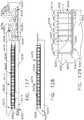
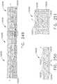
- the cartridge support member 960has a series of support ridges 964, 966, 968, 970, 972, 974, 976 formed thereon to provide some lateral support to the bases 924 of the staples 922 in the staple lines 946, 948, 950, 952 as shown in FIG. 15 .
- the support ridgesare substantially coextensive with the staple lines.
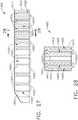
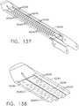
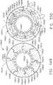
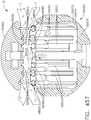
- FIG. 17illustrates an alternative staple cartridge arrangement 940' that is substantially identical to cartridge 940, except for the inclusion of upstanding fin portions 978, 979, 980, 981, 982, 983 that protrude from the support ridges 964, 966, 968, 970, 972, 976, respectively to provide additional lateral support to the staples 922.
- the fin portionsmay be integrally formed with the cartridge support member 960 and have a height that is about 1 ⁇ 2 or less of the height of the cartridge.
- any standing features supporting the foamcannot extend above the maximum compression height of the foam.
- the finswould between 66% of the uncompressed height, all the way down to 10% of uncompressed height.
- the anvil 20is opened and the end effector 12 is pulled away from the stapled tissue.
- the cartridge body 942remains fastened to the stapled tissue and is then separated from the cartridge support member 960 which remains coupled to the elongated channel 14.
- the cartridge support member 960is provided with a color that differs from the color of the material comprising the cartridge body 942 as well as the color of the elongated channel 14. Such arrangement provides the surgeon with an easily recognizable indication that no staple cartridge is present within the end effector.
- the surgeonwill not inadvertently attempt to reinsert/use the end effector without first installing a new staple cartridge therein. To do so, the surgeon simply disconnects the snap features of the cartridge support member 960 from the elongated channel 14 to enable the cartridge support member 960 of a new staple cartridge 940 to be placed therein. While the staple cartridges 940, 940' have been explained with reference to surgical instrument 10, it will be understood that those cartridges may be effectively employed with many of the other surgical instrument arrangements disclosed herein.
- a staple cartridgecan comprise a cartridge body and a plurality of staples stored within the cartridge body.
- the staple cartridgecan be introduced into a surgical site and positioned on a side of the tissue being treated.
- a staple-forming anvilcan be positioned on the opposite side of the tissue.
- the anvilcan be carried by a first jaw and the staple cartridge can be carried by a second jaw, wherein the first jaw and/or the second jaw can be moved toward the other.
- a staple cartridgecan be implanted with the staples.
- a staple cartridgecan comprise a cartridge body which can be compressed, crushed, and/or collapsed by the anvil when the anvil is moved from an open position into a closed position.
- the staples positioned within the cartridge bodycan be deformed by the anvil.
- the jaw supporting the staple cartridgecan be moved toward the anvil into a closed position. In either event, the staples can be deformed while they are at least partially positioned within the cartridge body.
- the staplesmay not be ejected from the staple cartridge while, the staples can be ejected from the staple cartridge along with a portion of the cartridge body.
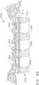
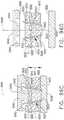
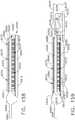
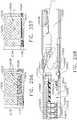
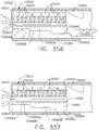
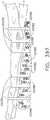
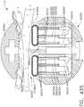
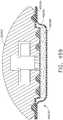
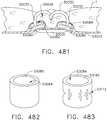
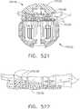
- a compressible staple cartridgesuch as staple cartridge 1000, for example, can comprise a compressible, implantable cartridge body 1010 and, in addition, a plurality of staples 1020 positioned in the compressible cartridge body 1010, although only one staple 1020 is depicted in FIGS. 18A-18D.
- FIG. 18Aillustrates the staple cartridge 1000 supported by a staple cartridge support, or staple cartridge channel, 1030, wherein the staple cartridge 1000 is illustrated in an uncompressed condition.
- the anvil 1040may or may not be in contact with the tissue T.
- the anvil 1040can be moved from an open position into contact with the tissue T as illustrated in FIG. 18B and position the tissue T against the cartridge body 1010.
- the staple cartridge body 1010may be subjected to little, if any, compressive force or pressure at such point and the staples 1020 may remain in an unformed, or unfired, condition.
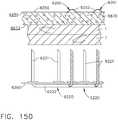
- the staple cartridge body 1010can comprise one or more layers and the staple legs 1021 of staples 1020 can extend upwardly through these layers.
- the cartridge body 1010can comprise a first layer 1011, a second layer 1012, a third layer 1013, wherein the second layer 1012 can be positioned intermediate the first layer 1011 and the third layer 1013, and a fourth layer 1014, wherein the third layer 1013 can be positioned intermediate the second layer 1012 and the fourth layer 1014.
- the bases 1022 of the staples 1020can be positioned within cavities 1015 in the fourth layer 1014 and the staple legs 1021 can extend upwardly from the bases 1022 and through the fourth layer 1014, the third layer 1013, and the second layer 1012, for example.
- Each deformable leg 1021can comprise a tip, such as sharp tip 1023, for example, which can be positioned in the second layer 1012, for example, when the staple cartridge 1000 is in an uncompressed condition.
- the tips 1023may not extend into and/or through the first layer 1011, wherein, the tips 1023 may not protrude through the tissue-contacting surface 1019 when the staple cartridge 1000 is in an uncompressed condition.
- the sharp tips 1023may be positioned in the third layer 1013, and/or any other suitable layer, when the staple cartridge is in an uncompressed condition.
- a cartridge body of a staple cartridgemay have any suitable number of layers such as less than four layers or more than four layers, for example.
- the first layer 1011can be comprised of a buttress material and/or plastic material, such as polydioxanone (PDS) and/or polyglycolic acid (PGA), for example, and the second layer 1012 can be comprised of a bioabsorbable foam material and/or a compressible haemostatic material, such as oxidized regenerated cellulose (ORC), for example.
- PDSpolydioxanone
- PGApolyglycolic acid
- the second layer 1012can be comprised of a bioabsorbable foam material and/or a compressible haemostatic material, such as oxidized regenerated cellulose (ORC), for example.
- PDSpolydioxanone
- PGApolyglycolic acid
- One or more of the first layer 1011, the second layer 1012, the third layer 1013, and the fourth layer 1014may hold the staples 1020 within the staple cartridge body 1010 and, in addition, maintain the staples 1020 in alignment with one another.
- the third layer 1013can be comprised of a buttress material, or a fairly incompressible or inelastic material, which can be configured to hold the staple legs 1021 of the staples 1020 in position relative to one another. Furthermore, the second layer 1012 and the fourth layer 1014, which are positioned on opposite sides of the third layer 1013, can stabilize, or reduce the movement of, the staples 1020 even though the second layer 1012 and the fourth layer 1014 can be comprised of a compressible foam or elastic material.
- the staple tips 1023 of the staple legs 1021can be at least partially embedded in the first layer 1011. For example, the first layer 1011 and the third layer 1013 can be configured to co-operatively and firmly hold the staple legs 1021 in position.
- the first layer 1011 and the third layer 1013can each be comprised of a sheet of bioabsorbable plastic, such as polyglycolic acid (PGA) which is marketed under the trade name Vicryl, polylactic acid (PLA or PLLA), polydioxanone (PDS), polyhydroxyalkanoate (PHA), poliglecaprone 25 (PGCL) which is marketed under the trade name Monocryl, polycaprolactone (PCL), and/or a composite of PGA, PLA, PDS, PHA, PGCL and/or PCL, for example, and the second layer 1012 and the fourth layer 1014 can each be comprised of at least one haemostatic material or agent.
- PGApolyglycolic acid
- Vicrylpolylactic acid
- PDSpolydioxanone
- PHApolyhydroxyalkanoate
- PGCLpoliglecaprone 25
- PCLpolycaprolactone
- the second layer 1012 and the fourth layer 1014can each be comprised of at least one hae
- the second layer 1012can be substantially more compressible than the first layer 1011.
- the second layer 1012can be about twice as compressible, about three times as compressible, about four times as compressible, about five times as compressible, and/or about ten times as compressible, for example, as the first layer 1011.
- the second layer 1012may compress about two times, about three times, about four times, about five times, and/or about ten times as much as first layer 1011, for a given force.
- the second layer 1012can be between about twice as compressible and about ten times as compressible, for example, as the first layer 1011.
- the second layer 1012can comprise a plurality of air voids defined therein, wherein the amount and/or size of the air voids in the second layer 1012 can be controlled in order to provide a desired compressibility of the second layer 1012.
- the third layer 1013can be compressible
- the fourth layer 1014can be substantially more compressible than the third layer 1013.
- the fourth layer 1014can be about twice as compressible, about three times as compressible, about four times as compressible, about five times as compressible, and/or about ten times as compressible, for example, as the third layer 1013.
- the fourth layer 1014may compress about two times, about three times, about four times, about five times, and/or about ten times as much as third layer 1013, for a given force.
- the fourth layer 1014can be between about twice as compressible and about ten times as compressible, for example, as the third layer 1013.
- the fourth layer 1014can comprise a plurality of air voids defined therein, wherein the amount and/or size of the air voids in the fourth layer 1014 can be controlled in order to provide a desired compressibility of the fourth layer 1014.
- the compressibility of a cartridge body, or cartridge body layercan be expressed in terms of a compression rate, i.e., a distance in which a layer is compressed for a given amount of force.
- a compression ratei.e., a distance in which a layer is compressed for a given amount of force.
- a layer having a high compression ratewill compress a larger distance for a given amount of compressive force applied to the layer as compared to a layer having a lower compression rate.
- the second layer 1012can have a higher compression rate than the first layer 1011 and, similarly, the fourth layer 1014 can have a higher compression rate than the third layer 1013.
- the second layer 1012 and the fourth layer 1014can be comprised of the same material and can comprise the same compression rate.
- the second layer 1012 and the fourth layer 1014can be comprised of materials having different compression rates.
- the first layer 1011 and the third layer 1013can be comprised of the same material and can comprise the same compression rate.
- the anvil 1040can contact tissue T and apply a compressive force to the tissue T and the staple cartridge 1000, as illustrated in FIG. 18C .
- the anvil 1040can push the top surface, or tissue-contacting surface 1019, of the cartridge body 1010 downwardly toward the staple cartridge support 1030.
- the staple cartridge support 1030can comprise a cartridge support surface 1031 which can be configured to support the staple cartridge 1000 as the staple cartridge 1000 is compressed between the cartridge support surface 1031 and the tissue-contacting surface 1041 of anvil 1040. Owing to the pressure applied by the anvil 1040, the cartridge body 1010 can be compressed and the anvil 1040 can come into contact with the staples 1020.
- the compression of the cartridge body 1010 and the downward movement of the tissue-contacting surface 1019can cause the tips 1023 of the staple legs 1021 to pierce the first layer 1011 of cartridge body 1010, pierce the tissue T, and enter into forming pockets 1042 in the anvil 1040.
- the tips 1023can contact the walls defining the forming pockets 1042 and, as a result, the legs 1021 can be deformed or curled inwardly, for example, as illustrated in FIG. 18C .
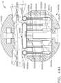
- the bases 1022 of the staples 1020can be in contact with or supported by the staple cartridge support 1030.
- the staple cartridge support 1030can comprise a plurality of support features, such as staple support grooves, slots, or troughs 1032, for example, which can be configured to support the staples 1020, or at least the bases 1022 of the staples 1020, as the staples 1020 are being deformed.
- the cavities 1015 in the fourth layer 1014can collapse as a result of the compressive force applied to the staple cartridge body 1010.
- the staple cartridge body 1010can further comprise one or more voids, such as voids 1016, for example, which may or may not comprise a portion of a staple positioned therein, that can be configured to allow the cartridge body 1010 to collapse.
- the cavities 1015 and/or the voids 1016can be configured to collapse such that the walls defining the cavities and/or walls deflect downwardly and contact the cartridge support surface 1031 and/or contact a layer of the cartridge body 1010 positioned underneath the cavities and/or voids.
- the second layer 1012 and the fourth layer 1014have been substantially compressed by the compressive pressure applied by the anvil 1040. It may also be noted that the first layer 1011 and the third layer 1013 have been compressed as well. As the anvil 1040 is moved into its closed position, the anvil 1040 may continue to further compress the cartridge body 1010 by pushing the tissue-contacting surface 1019 downwardly toward the staple cartridge support 1030. As the cartridge body 1010 is further compressed, the anvil 1040 can deform the staples 1020 into their completely-formed shape as illustrated in FIG. 18D . Referring to FIG.
- each staple 1020can be deformed downwardly toward the base 1022 of each staple 1020 in order to capture at least a portion of the tissue T, the first layer 1011, the second layer 1012, the third layer 1013, and the fourth layer 1014 between the deformable legs 1021 and the base 1022.
- FIGS. 18C and 18Dit is further evident that the second layer 1012 and the fourth layer 1014 have been further substantially compressed by the compressive pressure applied by the anvil 1040. It may also be noted upon comparing FIGS. 18C and 18D that the first layer 1011 and the third layer 1013 have been further compressed as well.
- the anvil 1040can be lifted away from the tissue T and the staple cartridge support 1030 can be moved away, and/or detached from, the staple cartridge 1000.
- the cartridge body 1010can be implanted with the staples 1020.
- the implanted cartridge body 1010can support the tissue along the staple line.
- a haemostatic agent, and/or any other suitable therapeutic medicament, contained within the implanted cartridge body 1010can treat the tissue over time.
- a haemostatic agentcan reduce the bleeding of the stapled and/or incised tissue while a bonding agent or tissue adhesive can provide strength to the tissue over time.
- the implanted cartridge body 1010can be comprised of materials such as ORC (oxidized regenerated cellulose), extracellular proteins such as collagen, polyglycolic acid (PGA) which is marketed under the trade name Vicryl, polylactic acid (PLA or PLLA), polydioxanone (PDS), polyhydroxyalkanoate (PHA), poliglecaprone 25 (PGCL) which is marketed under the trade name Monocryl, polycaprolactone (PCL), and/or a composite of PGA, PLA, PDS, PHA, PGCL and/or PCL, for example.
- the cartridge body 1010can comprise an antibiotic and/or anti-microbial material, such as colloidal silver and/or triclosan, for example, which can reduce the possibility of infection in the surgical site.
- the layers of the cartridge body 1010can be connected to one another.
- the second layer 1012can be adhered to the first layer 1011
- the third layer 1013can be adhered to the second layer 1012
- the fourth layer 1014can be adhered to the third layer 1013 utilizing at least one adhesive, such as fibrin and/or protein hydrogel, for example.
- the layers of the cartridge body 1010can be connected together by interlocking mechanical features.
- the first layer 1011 and the second layer 1012can each comprise corresponding interlocking features, such as a tongue and groove arrangement and/or a dovetail joint arrangement, for example.
- the staple cartridge 1000can comprise one or more rivets, for example, which can extend through one or more layers of the cartridge body 1010.
- each rivetcan comprise a first end, or head, positioned adjacent to the first layer 1011 and a second head positioned adjacent to the fourth layer 1014 which can be either assembled to or formed by a second end of the rivet.
- the rivetscan compress the cartridge body 1010 such that the heads of the rivets can be recessed relative to the tissue-contacting surface 1019 and/or the bottom surface 1018 of the cartridge body 1010, for example.
- the rivetscan be comprised of a bioabsorbable material, such as polyglycolic acid (PGA) which is marketed under the trade name Vicryl, polylactic acid (PLA or PLLA), polydioxanone (PDS), polyhydroxyalkanoate (PHA), poliglecaprone 25 (PGCL) which is marketed under the trade name Monocryl, polycaprolactone (PCL), and/or a composite of PGA, PLA, PDS, PHA, PGCL and/or PCL, for example.
- PGApolyglycolic acid
- PDSpolydioxanone
- PHApolyhydroxyalkanoate
- PCLpoliglecaprone 25
- PCLMonocryl
- PCLpolycaprolactone
- the layers of the cartridge body 1010may not be connected to one another other than by the staples 1020 contained therein.
- the frictional engagement between the staple legs 1021 and the cartridge body 1010can hold the layers of the cartridge body 1010 together and, once the staples have been formed, the layers can be captured within the staples 1020.
- At least a portion of the staple legs 1021can comprise a roughened surface or rough coating which can increase the friction forces between the staples 1020 and the cartridge body 1010.
- a surgical instrumentcan comprise a first jaw including the staple cartridge support 1030 and a second jaw including the anvil 1040.
- the staple cartridge 1000can comprise one or more retention features which can be configured to engage the staple cartridge support 1030 and, as a result, releasably retain the staple cartridge 1000 to the staple cartridge support 1030.
- the staple cartridge 1000can be adhered to the staple cartridge support 1030 by at least one adhesive, such as fibrin and/or protein hydrogel, for example.
- the second jawcan be moved into a closed position opposite the first jaw, for example, such that the first and second jaws can be inserted through a trocar into a surgical site.
- the trocarcan define an approximately 5mm aperture, or cannula, through which the first and second jaws can be inserted.
- the second jawcan be moved into a partially-closed position intermediate the open position and the closed position which can allow the first and second jaws to be inserted through the trocar without deforming the staples 1020 contained in the staple cartridge body 1010.
- the anvil 1040may not apply a compressive force to the staple cartridge body 1010 when the second jaw is in its partially-closed intermediate position while, alternatively, the anvil 1040 can compress the staple cartridge body 1010 when the second jaw is in its partially-closed intermediate position.
- the anvil 1040can compress the staple cartridge body 1010 when it is in such an intermediate position, the anvil 1040 may not sufficiently compress the staple cartridge body 1010 such that the anvil 1040 comes into contact with the staples 1020 and/or such that the staples 1020 are deformed by the anvil 1040.
- the second jawcan be opened once again and the anvil 1040 and the staple cartridge 1000 can be positioned relative to the targeted tissue as described above.
- an end effector of a surgical staplercan comprise an implantable staple cartridge 1100 positioned intermediate an anvil 1140 and a staple cartridge support 1130.
- the anvil 1140can comprise a tissue-contacting surface 1141
- the staple cartridge 1100can comprise a tissue-contacting surface 1119
- the staple cartridge support 1130can comprise a support surface 1131 which can be configured to support the staple cartridge 1100.
- the anvil 1140can be utilized to position the tissue T against the tissue contacting surface 1119 of staple cartridge 1100 without deforming the staple cartridge 1100 and, when the anvil 1140 is in such a position, the tissue-contacting surface 1141 can be positioned a distance 1101a away from the staple cartridge support surface 1131 and the tissue-contacting surface 1119 can be positioned a distance 1102a away from the staple cartridge support surface 1131. Thereafter, as the anvil 1140 is moved toward the staple cartridge support 1130, referring now to FIG. 19B , the anvil 1140 can push the top surface, or tissue-contacting surface 1119, of staple cartridge 1100 downwardly and compress the first layer 1111 and the second layer 1112 of cartridge body 1110.
- the second layer 1112can be crushed and the legs 1121 of staples 1120 can pierce the first layer 1111 and enter into the tissue T.
- the staples 1120can be at least partially positioned within staple cavities, or voids, 1115 in the second layer 1112 and, when the second layer 1112 is compressed, the staple cavities 1115 can collapse and, as a result, allow the second layer 1112 to collapse around the staples 1120.
- the second layer 1112can comprise cover portions 1116 which can extend over the staple cavities 1115 and enclose, or at least partially enclose, the staple cavities 1115.
- FIG. 19Billustrates the cover portions 1116 being crushed downwardly into the staple cavities 1115.
- the second layer 1112can comprise one or more weakened portions which can facilitate the collapse of the second layer 1112. Such weakened portions can comprise score marks, perforations, and/or thin cross-sections, for example, which can facilitate a controlled collapse of the cartridge body 1110.
- the first layer 1111can comprise one or more weakened portions which can facilitate the penetration of the staple legs 1121 through the first layer 1111. Such weakened portions can comprise score marks, perforations, and/or thin cross-sections, for example, which can be aligned, or at least substantially aligned, with the staple legs 1121.
- the anvil 1140When the anvil 1140 is in a partially closed, unfired position, referring again to FIG. 19A , the anvil 1140 can be positioned a distance 1101 a away from the cartridge support surface 1131 such that a gap is defined therebetween. This gap can be filled by the staple cartridge 1100, having a staple cartridge height 1102a, and the tissue T. As the anvil 1140 is moved downwardly to compress the staple cartridge 1100, referring again to FIG. 19B , the distance between the tissue contacting surface 1141 and the cartridge support surface 1131 can be defined by a distance 1101b which is shorter than the distance 1101a.
- the gap between the tissue-contacting surface 1141 of anvil 1140 and the cartridge support surface 1131, defined by distance 1101b,may be larger than the original, undeformed staple cartridge height 1102a.
- the second layer 1112can continue to collapse and the distance between the staple legs 1121 and the forming pockets 1142 can decrease.
- the distance between the tissue-contacting surface 1141 and the cartridge support surface 1131can decrease to a distance 1101c which may be greater than, equal to, or less than the original, undeformed cartridge height 1102a.
- the anvil 1140can be moved into a final, fired position in which the staples 1120 have been fully formed, or at least formed to a desired height.
- the tissue-contacting surface 1141 of anvil 1140can be a distance 1101 d away from the cartridge support surface 1131, wherein the distance 1101d can be shorter than the original, undeformed cartridge height 1102a.
- the staple cavities 1115may be fully, or at least substantially, collapsed and the staples 1120 may be completely, or at least substantially, surrounded by the collapsed second layer 1112. In various circumstances, the anvil 1140 can be thereafter moved away from the staple cartridge 1100.
- the cartridge body 1110can at least partially re-expand in various locations, i.e., locations intermediate adjacent staples 1120, for example.
- the crushed cartridge body 1110may not resiliently re-expand.
- the formed staples 1120 and, in addition, the cartridge body 1110 positioned intermediate adjacent staples 1120may apply pressure, or compressive forces, to the tissue T which may provide various therapeutic benefits.
- each staple 1120can comprise staple legs 1121 extending therefrom.
- staples 1120are depicted as comprising two staple legs 1121, various staples can be utilized which can comprise one staple leg or, alternatively, more than two staple legs, such as three staple legs or four staple legs, for example.
- each staple leg 1121can be embedded in the second layer 1112 of the cartridge body 1110 such that the staples 1120 are secured within the second layer 1112.
- the staples 1120can be inserted into the staple cavities 1115 in cartridge body 1110 such that the tips 1123 of the staple legs 1121 enter into the cavities 1115 before the bases 1122.
- the tips 1123can be pressed into the cover portions 1116 and incise the second layer 1112.
- the staples 1120can be seated to a sufficient depth within the second layer 1112 such that the staples 1120 do not move, or at least substantially move, relative to the second layer 1112.
- the staples 1120can be seated to a sufficient depth within the second layer 1112 such that the bases 1122 are positioned or embedded within the staple cavities 1115.
- the bases 1122may not be positioned or embedded within the second layer 1112. Referring again to FIG. 19A , the bases 1122 may extend below the bottom surface 1118 of the cartridge body 1110. The bases 1122 can rest on, or can be directly positioned against, the cartridge support surface 1130.
- the cartridge support surface 1130can comprise support features extending therefrom and/or defined therein wherein, for example, the bases 1122 of the staples 1120 may be positioned within and supported by one or more support grooves, slots, or troughs, 1132, for example, in the staple cartridge support 1130, as described in greater detail further below.
- the bases 1122 of the staples 1120can be positioned directly against the support surface 1131 of staple cartridge support 1130.
- the staple bases 1122comprise circular or arcuate bottom surfaces 1124, for example, the staple bases 1122 may move or slide along the staple cartridge support surface 1131. Such sliding can occur when the anvil 1140 is pressed against the tips 1123 of the staple legs 1121 during the staple forming process.
- the staple cartridge support 1130can comprise one or more support slots 1132 therein which can be configured to eliminate, or at least reduce, the relative movement between the staple bases 1122 and the cartridge support surface 1131.
- each support slot 1132can be defined by a surface contour which matches, or at least substantially matches, the contour of the bottom surface of the staple positioned therein.
- the bottom surface 1124 of the base 1122 depicted in FIG. 21can comprise a circular, or at least substantially circular, surface and the support slot 1132 can also comprise a circular, or at least substantially circular, surface.
- the surface defining the slot 1132can be defined by a radius of curvature which is greater than or equal to a radius of curvature which defines bottom surface 1124.
- the slots 1132may assist in preventing or reducing relative sliding movement between the staples 1120 and the staple cartridge support 1130, the slots 1132 may also be configured to prevent or reduce relative rotational movement between the staples 1120 and the staple cartridge support 1130. More particularly, the slots 1132 can be configured to closely receive the bases 1122 in order to prevent or reduce the rotation of the staples 1120 about axes 1129, for example, such that the staples 1120 do not rotate or twist when they are being deformed.
- each staple 1120can be formed from a round, or an at least substantially round, wire.
- the legs and the base of each staplecan be formed from a wire having a non-circular cross-section, such as a rectangular cross-section, for example.
- the staple cartridge support 1130can comprise corresponding non-circular slots, such as rectangular slots, for example, configured to receive the bases of such staples.
- each staple 1120can comprise a crown, such as a crown 1125, for example, overmolded onto a base 1122 wherein each crown 1125 can be positioned within a support slot in the staple cartridge support 1130.
- each crown 1125can comprise a square and/or rectangular cross-section, for example, which can be configured to be received within square and/or rectangular slots 1134, for example, in the staple cartridge support 1130.
- the crowns 1125can be comprised of a bioabsorbable plastic, such as polyglycolic acid (PGA) which is marketed under the trade name Vicryl, polylactic acid (PLA or PLLA), polydioxanone (PDS), polyhydroxyalkanoate (PHA), poliglecaprone 25 (PGCL) which is marketed under the trade name Monocryl, polycaprolactone (PCL), and/or a composite of PGA, PLA, PDS, PHA, PGCL and/or PCL, for example, and can be formed around the bases 1122 of the staples 1120 by an injection molding process, for example.
- PGApolyglycolic acid
- PDSpolydioxanone
- PHApolyhydroxyalkanoate
- PCLpoliglecaprone 25
- PCLpoly
- the slots 1134can further comprise lead-ins, or bevels, 1135 which can be configured to facilitate the insertion of the crowns 1125 into the slots 1134.
- the bases and/or crowns of the staples 1120may be positioned within the slots 1134 when the staple cartridge 1100 is assembled to the staple cartridge support 1130.
- the crowns 1125 of the staples 1120may be aligned with the slots 1134 when the staple cartridge 1100 is assembled to the staple cartridge support 1130.
- the crowns 1125may not enter into the slots 1134 until a compressive force is applied to the staple legs 1121 and the bases and/or crowns of the staples 1120 are pushed downwardly into the slots 1134.
- a staple cartridgesuch as staple cartridge 1200, for example, can comprise a compressible, implantable cartridge body 1210 comprising an outer layer 1211 and an inner layer 1212. Similar to the above, the staple cartridge 1200 can comprise a plurality of staples 1220 positioned within the cartridge body 1210. Each staple 1220 can comprise a base 1222 and one or more staple legs 1221 extending therefrom. For example, the staple legs 1221 can be inserted into the inner layer 1212 and seated to a depth in which the bases 1222 of the staples 1220 abut and/or are positioned adjacent to the bottom surface 1218 of the inner layer 1212, for example. In FIGS.
- the inner layer 1212does not comprise staple cavities configured to receive a portion of the staples 1220 while, as an alternative, the inner layer 1212 can comprise such staple cavities.
- the inner layer 1212can be comprised of a compressible material, such as bioabsorbable foam and/or oxidized regenerated cellulose (ORC), for example, which can be configured to allow the cartridge body 1210 to collapse when a compressive load is applied thereto.
- the inner layer 1212can be comprised of a lyophilized foam comprising polylactic acid (PLA) and/or polyglycolic acid (PGA), for example.
- the ORCmay be commercially available under the trade name Surgicel and can comprise a loose woven fabric (like a surgical sponge), loose fibers (like a cotton ball), and/or a foam.
- the inner layer 1212can be comprised of a material including medicaments, such as freeze-dried thrombin and/or fibrin, for example, contained therein and/or coated thereon which can be water-activated and/or activated by fluids within the patient's body, for example.
- the freeze-dried thrombin and/or fibrincan be held on a Vicryl (PGA) matrix, for example.
- PGAVicryl
- the activatable medicamentscan be unintentionally activated when the staple cartridge 1200 is inserted into a surgical site within the patient, for example.
- the outer layer 1211can be comprised of a water impermeable, or at least substantially water impermeable, material such that liquids do not come into contact with, or at least substantially contact, the inner layer 1212 until after the cartridge body 1210 has been compressed and the staple legs have penetrated the outer layer 1211 and/or after the outer layer 1211 has been incised in some fashion.
- the outer layer 1211can be comprised of a buttress material and/or plastic material, such as polydioxanone (PDS) and/or polyglycolic acid (PGA), for example.
- PDSpolydioxanone
- PGApolyglycolic acid
- the outer layer 1211can comprise a wrap which surrounds the inner layer 1212 and the staples 1220. More particularly, the staples 1220 can be inserted into the inner layer 1212 and the outer layer 1211 can be wrapped around the subassembly comprising the inner layer 1212 and the staples 1220 and then sealed.
- a staple cartridgesuch as staple cartridge 1300, can comprise a compressible, implantable cartridge body 1310 including an outer layer 1311 and an inner layer 1312. Similar to the above, the staple cartridge 1300 can further comprise staples 1320 positioned within the cartridge body 1310 wherein each staple 1320 can comprise a base 1322 and one or more legs 1321 extending therefrom. Similar to staple cartridge 1200, the bases 1322 of staples 1320 can extend below the bottom surface 1318 of the inner layer 1312 and the outer layer 1311 can surround the bases 1322.
- the outer layer 1311can be sufficiently flexible so as to envelop each staple base 1322 such that the outer layer 1311 conforms to the contour of the bases 1322.
- the outer layer 1211can be sufficiently rigid such that it extends around the bases 1222 without conforming to each base 1222.
- the outer layer 1311can be positioned intermediate the bases 1322 of staples 1320 and a staple cartridge support surface, such as support surfaces 1031 or 1131, for example, supporting the staple cartridge 1300.
- the outer layer 1311can be positioned intermediate the bases 1322 and support slots, such as slots 1032 or 1132, for example, defined in the staple cartridge support surface.
- the outer layer 1311can be configured to limit the movement of the bases 1322 and/or increase the coefficient of friction between the bases 1322 and the staple cartridge support surface and/or support slots in order to reduce relative movement therebetween.
- the outer layer of a staple cartridgesuch as staple cartridge 1400, for example, may not entirely surround the staples positioned therein.
- an outer layer 1411 of a compressible, implantable cartridge body 1410may be assembled to the inner layer 1412 before the staple legs 1421 of staples 1420 are inserted into the cartridge body 1410.
- the bases 1422 of staples 1420may extend outside of the outer layer 1411 and, for example, the bases 1422 may be positioned directly into the support slots 1032 or 1132 within the staple cartridge support surfaces 1031 or 1131, for example.
- the staple legs 1421may incise the outer layer 1411 when they are inserted therethrough.
- the holes created by the staple legs 1421may closely surround the staple legs 1421 such that very little, if any, fluid can leak between the staple legs 1421 and the outer layer 1411 which can reduce the possibility of, or prevent, the medicament contained within the staple cartridge body 1410 from being activated and/or leaking out of the cartridge body 1410 prematurely.
- a staple cartridgesuch as staple cartridge 1500, for example, may comprise a compressible, implantable cartridge body 1510 comprising staple cavities 1515 which can be configured to receive at least a portion of the staples 1520 therein.
- a top portion of the staple legs 1521 of the staples 1520may be embedded in the inner layer 1512 while a bottom portion of the staple legs 1521, and the bases 1522, may be positioned within the staple cavities 1515.
- the bases 1522may be entirely positioned in the staple cavities 1515 while, the bases 1522 may at least partially extend below the bottom surface 1518 of the inner layer 1512.
- the outer layer 1511may enclose the inner layer 1512 and the staples 1520 positioned therein.
- a staple cartridge 1600may comprise staples 1620 positioned within staple cavities 1615 in a compressible, implantable cartridge body 1610 wherein at least a portion of the staples 1620 are not enclosed by the outer layer 1611.
- each staple 1620can comprise staple legs 1621 which are at least partially embedded in the inner layer 1612 and, in addition, bases 1622 which extend outwardly around the outer layer 1611.
- a staple cartridgesuch as staple cartridge 1700, for example, can comprise a compressible, implantable cartridge body 1710 and a plurality of staples 1720 at least partially positioned within the cartridge body 1710.
- the cartridge body 1710can comprise an outer layer 1711, an inner layer 1712, and, in addition, an alignment matrix 1740 which can be configured to align and/or retain the staples 1720 in position within the cartridge body 1710.
- the inner layer 1712can comprise a recess 1741 which can be configured to receive the alignment matrix 1740 therein.
- the alignment matrix 1140can be press-fit within the recess 1741 and/or otherwise suitably secured to the inner layer 1712 utilizing at least one adhesive, such as fibrin and/or protein hydrogel, for example.
- the recess 1741can be configured such that the bottom surface 1742 of alignment matrix 1740 is aligned, or at least substantially aligned, with the bottom surface 1718 of the inner layer 1712.
- the bottom surface 1742 of the alignment matrixcan be recessed with respect to and/or extend from the bottom surface 1718 of the second layer 1712.
- Each staple 1720can comprise a base 1722 and one or more legs 1721 extending from the base 1722, wherein at least a portion of the staple legs 1721 can extend through the alignment matrix 1740.
- the alignment matrix 1740can further comprise a plurality of apertures and/or slots, for example, extending therethrough which can be configured to receive the staple legs 1721 therein.
- each aperturecan be configured to closely receive a staple leg 1721 such that there is little, if any, relative movement between the staple leg 1721 and the sidewalls of the aperture.
- the alignment matrix aperturesmay not extend entirely through the alignment matrix 1740 and the staple legs 1721 may be required to incise the alignment matrix 1740 as the staple legs 1721 are pushed therethrough.
- the alignment matrix 1740can be comprised of a molded plastic body which can be stiffer or less compressible than the inner layer 1712 and/or the outer layer 1711.
- the alignment matrix 1740can be comprised of a plastic material and/or any other suitable material, such as polydioxanone (PDS) and/or polyglycolic acid (PGA), for example.
- PDSpolydioxanone
- PGApolyglycolic acid
- the alignment matrix 1740can be assembled to the inner layer 1712 and the staple legs 1721 can thereafter be inserted through the alignment matrix 1740 and embedded into the inner layer 1712.
- the bottom surface 1742 of the alignment matrix 1740can comprise one or more grooves, slots, or troughs, for example, which can be configured to at least partially receive the bases 1722 of the staples 1720.
- the outer layer 1711can then be placed around the subassembly comprising the inner layer 1712, the alignment matrix 1740, and the staples 1720.
- the outer layer 1711can be placed around a subassembly comprising the inner layer 1712 and the alignment matrix 1740 wherein the staples 1720 can be thereafter inserted through the outer layer 1711, the alignment matrix 1740, and the inner layer 1712.
- the inner layer 1712, the alignment matrix 1740, and/or the outer layer 1711can be configured to retain the staples 1720 in position until and/or after they are deformed by an anvil as described above.
- the alignment matrix 1740can serve to hold the staples 1720 in place before the staple cartridge 1700 is implanted within a patient and, in addition, secure the tissue along the staple line after the staple cartridge 1700 has been implanted.
- the staples 1720may be secured within the alignment matrix 1740 without being embedded in the inner layer 1712 and/or the outer layer 1711, for example.
- a staple cartridgesuch as staple cartridge 1800, for example, can be assembled by compressing an inner layer 1812, inserting staples, such as staples 1820, for example, into the inner layer 1812, and wrapping the inner layer 1812 with an outer layer 1811.
- a compressible inner layer 1812is illustrated as comprising a plurality of staple cavities 1815 defined therein, although other arrangements s are envisioned in which the inner layer 1812 does not comprise staple cavities, as described above.
- the compressible inner layer 1812can be positioned intermediate a transfer plate 1850 and a support plate 1860 and compressed between the compression surfaces 1852 and 1862 thereof, respectively. As illustrated in FIG.
- the top and bottom surfaces of the inner layer 1812can be compressed toward one another and, in response thereto, the inner layer 1812 can bulge outwardly in the lateral directions.
- the inner layer 1812can be compressed to a height which is approximately one-third of its original height, for example, and can have a height or thickness between approximately 0.06" (1.524 mm) and approximately 0.08" (2.032 mm) in its compressed state, for example.
- the transfer plate 1850can further comprise a plurality of staples, such as staples 1820, for example, positioned within a plurality of staple wells 1853.
- the transfer plate 1850can further comprise a plurality of drivers 1851 which can be configured to push the staples 1820 upwardly and out of the staple wells 1853.
- the drivers 1851can be utilized to push the staple legs 1821 of the staples 1820 into and through the compressed inner layer 1812.
- the drivers 1851can be configured such that the top surfaces thereof are positioned flush, or at least nearly flush, with the compression surface 1852 of the transfer plate 1850 when the staples 1820 have been fully deployed from the staple wells 1853 of transfer plate 1850. As also illustrated in FIG.
- the support plate 1860can comprise a plurality of receiving apertures 1861 which can be configured to receive the staple legs 1821, or at least the tips of the staple legs 1821, after they are pushed through the inner layer 1812.
- the receiving apertures 1861, or the likemay be necessitated where the inner layer 1812 has been compressed to a height which is shorter than the height of the staples 1820 and, thus, when the staples 1820 have been fully ejected from the staple wells 1853, the staple legs 1821 may protrude from the top surface of the compressed inner layer 1812.
- the inner layer 1812may be compressed to a height which is taller than the height of the staples 1820 and, as a result, the receiving apertures 1861 in support plate 1860 may be unnecessary.
- the support plate 1860can be moved away from the transfer plate 1850 in order to allow the inner layer 1812 to decompress.
- the inner layer 1812can resiliently re-expand to its original, or at least near-original, uncompressed height.
- the height of the inner layer 1812can increase such that it exceeds the height of the staples 1820 and such that the staple legs 1821 of the staples 1820 no longer protrude from the top surface of the inner layer 1812.
- the receiving apertures 1861can be configured to hold the staple legs 1821 in position at least until the support plate 1860 has been sufficiently moved away such that the legs 1821 are no longer positioned within the receiving apertures 1861. In such circumstances, the receiving apertures 1861 can assist in maintaining the relative alignment of the staples 1820 within the inner layer 1812 as it re-expands.
- the inner layer 1812 and the staples 1820 positioned thereincan comprise a subassembly 1801 which, referring now to FIG. 38 , can be inserted into an outer layer 1811, for example.
- the outer layer 1811can comprise a cavity 1802 defined therein which can be configured to receive the subassembly 1801 therein.
- a toolsuch as pliers 1855, for example, can be utilized to pull the outer layer 1811 onto the subassembly 1801.
- the outer layer 1811can be sealed.
- the outer layer 1811can be sealed utilizing the application of heat energy to a portion thereof.
- the outer layer 1811can be comprised of a plastic material wherein the open end of the outer layer 1811 can be heat-staked by one or more heated elements, or irons, 1856 in order to bond and/or seal the perimeter of the open end of the outer layer 1811 together.
- an excess portion 1857 of the outer layer 1811can be removed and the staple cartridge 1800 can then be used as described herein.
- a staple cartridgecan be positioned within and/or secured to a staple cartridge attachment portion.
- a staple cartridge attachment portioncan comprise a staple cartridge channel, such as staple cartridge channel 1930, for example, which can be configured to receive at least a portion of a staple cartridge, such as staple cartridge 1900, for example, therein.
- the staple cartridge channel 1930can comprise a bottom support surface 1931, a first lateral support wall 1940, and a second lateral support wall 1941.
- the staple cartridge 1900can be positioned within the staple cartridge channel 1930 such that the staple cartridge 1900 is positioned against and/or adjacent to the bottom support surface 1931 and positioned intermediate the first lateral support wall 1940 and the second lateral support wall 1941.
- the first lateral support wall 1940 and the second lateral support wall 1941can define a lateral gap therebetween.
- the staple cartridge 1900can comprise a lateral width 1903 which is the same as and/or wider than the lateral gap defined between the support walls 1940 and 1941 such that a compressible, implantable cartridge body 1910 of the staple cartridge 1900 can fit securely between the walls 1940 and 1941.
- the lateral width 1903 of the staple cartridge 1900can be shorter than the gap defined between the first and second side walls 1940 and 1941.
- At least a portion of the walls 1940 and 1941 and the bottom support surface 1931can be defined by a stamped metal channel while, at least a portion of the lateral support wall 1940 and/or lateral support wall 1941 can be comprised of a flexible material, such as an elastomeric material, for example.
- the first side wall 1940 and the second side wall 1941 of the staple cartridge channel 1930can each be comprised of a rigid portion 1933 extending upwardly from the bottom support surface 1931 and a flexible portion 1934 extending upwardly from the rigid portions 1933.
- the cartridge body 1910 of staple cartridge 1900can be comprised of one or more compressible layers, such as first layer 1911 and second layer 1912, for example.
- first layer 1911 and second layer 1912for example.
- the side portions of the cartridge body 1910can expand laterally.
- the staple cartridge 1930is comprised of rigid side walls, the lateral expansion of the cartridge body 1910 can be prevented, or at least limited, by the rigid side walls and, as a result, a significant amount of internal pressure, or stress, can be developed within the cartridge body 1910.
- the flexible side wallscan be configured to flex laterally and permit the side portions of the cartridge body 1910 to expand laterally, thereby reducing the internal pressure, or stress, generated within the cartridge body 1910.
- the cartridge channeldoes not comprise lateral side walls, or comprises lateral sidewalls which are relatively shorter than the staple cartridge, the side portions of the staple cartridge may expand laterally uninhibited, or at least substantially uninhibited.
- a staple cartridge channel 2030can comprise lateral sidewalls 2040 and 2041 which can be entirely comprised of a flexible material, such as an elastomeric material, for example.
- the staple cartridge channel 2030can further comprise lateral slots 2033 extending along the sides of the bottom support surface 2031 of the staple cartridge channel 2030 which can be configured to receive and secure at least a portion of the lateral sidewalls 2040 and 2041 therein.
- the lateral side walls 2040 and 2041can be secured in the slots 2033 via a snap-fit and/or press-fit arrangement, or the lateral side walls 2040 and 2041 can be secured in the slots 2033 by one or more adhesives.
- the sidewalls 2040 and 2041may be detachable from the bottom support surface 2031 during use. In any event, a compressible, implantable cartridge body 2010 can be detached and/or disengaged from the lateral side walls 2040 and 2041 when the cartridge body 2010 is implanted with the staples 2020.
- a surgical instrumentcan comprise a shaft 2150 and an end effector extending from the distal end of the shaft 2150.
- the end effectorcan comprise, similar to the above, a staple cartridge channel 2130, an anvil 2140 movable between an open position and a closed position, and a staple cartridge 2100 positioned intermediate the staple cartridge channel 2130 and the anvil 2140.
- the staple cartridge 2100can comprise a compressible, implantable cartridge body 2110 and a plurality of staples 2120 positioned in the cartridge body 2110.
- the staple cartridge channel 2130can comprise, one, a bottom support surface 2131 against which the staple cartridge 2100 can be positioned, two, a distal end 2135 and, three, a proximal end 2136.
- the staple cartridge 2100can comprise a first end 2105 which can be positionable in the distal end 2135 of the staple cartridge channel 2130 and a second end 2106 which can be positionable in the proximal end 2136 of the staple cartridge channel 2130.
- the distal end 2135 of the staple cartridge channel 2130can comprise at least one distal retention feature, such as a retention wall 2137, for example, and, similarly, the proximal end 2136 can comprise at least one proximal retention feature, such as a retention wall 2138, for example.
- the distal retention wall 2137 and the proximal retention wall 2138can define a gap therebetween which can be equal to or less than the length of the staple cartridge 2100 such that the staple cartridge 2100 can fit securely within the staple cartridge channel 2130 when the staple cartridge 2100 is inserted therein.
- a staple cartridgesuch as staple cartridge 1200, for example, can comprise a flat, or at least substantially flat, tissue-contacting surface 1219.
- the staple cartridge body 1210 of staple cartridge 1200can comprise a first end 1205 which can be defined by a first height, or thickness, 1207 and a second end 1206 which can be defined by a second height, or thickness, 1208, wherein the first height 1207 can be equal to, or at least substantially equal to, the second height 1208.
- the cartridge body 1210can comprise a constant, or at least substantially constant, height, or thickness, between the first end 1205 and the second end 1206.
- the tissue-contacting surface 1219can be parallel, or at least substantially parallel, to the bottom surface 1218 of the cartridge body 1210.
- the first end 2105 of the cartridge body 2110 of staple cartridge 2100can be defined by a first height 2107 which is different than a second height 2108 of the second end 2106.
- the first height 2107is larger than the second height 2108, although the second height 2108 could be larger than the first height 2107 in alternative arrangements.
- the height of the cartridge body 2110can decrease linearly and/or geometrically between the first end 2105 and the second end 2106.
- the tissue-contacting surface 2119, which extends between the first end 2105 and the second end 2106can be oriented along an angle defined therebetween.
- the tissue-contacting surface 2119may not be parallel to the bottom surface 2118 of the cartridge body 2110 and/or parallel to the support surface 2131 of the staple cartridge channel 2130.
- the anvil 2140can comprise a tissue-contacting surface 2141 which can be parallel, or at least substantially parallel, to the support surface 2131 of the staple cartridge channel 2130 when the anvil 2140 is in a closed position, as illustrated in FIG. 44 .
- the anvil 2140can be configured to compress the first end 2105 of the staple cartridge 2100 more than the second end 2106 owing to the taller height of the first end 2105 and the shorter height of the second end 2106.
- the pressure generated within the tissue T and the cartridge 2100can be greater at the distal end of the end effector than the proximal end of the end effector. More particularly, when the tissue T between the anvil 2140 and the staple cartridge 2100 has a substantially constant thickness, the tissue T positioned intermediate the distal end 2145 of the anvil 2140 and the first end 2105 of the staple cartridge 2100 can be more compressed than the tissue T positioned intermediate the proximal end 2146 of the anvil 2140 and the second end 2106 of the staple cartridge 2100.
- a pressure gradientcan be generated within the tissue T between the proximal end and the distal end of the end effector. More particularly, when the tissue T between the anvil 2140 and the staple cartridge 2100 has a substantially constant thickness and the height of the staple cartridge 2100 decreases linearly from the distal end to the proximal end of the end effector, the pressure within the tissue T can decrease linearly from the distal end of the end effector to the proximal end of the end effector.
- the pressure within the tissue Tcan decrease geometrically from the distal end of the end effector to the proximal end of the end effector.
- the tissue T positioned intermediate the staple cartridge 2100 and the anvil 2140may not have a constant thickness throughout.
- the tissue T positioned between the proximal end 2146 of the anvil 2140 and the second end 2106 of the staple cartridge 2100may be thicker than the tissue T positioned between the distal end 2145 of the anvil 2140 and the first end2105 of the staple cartridge 2100.
- the thicker tissue Tmay be generally positioned above the shorter proximal end 2106 of the staple cartridge 2100 and the thinner tissue T may be generally positioned above the taller distal end 2105.
- the firing collar 2152 of the shaft 2150can be advanced distally along the shaft spine 2151 such that the firing collar 2152 engages the cam portion 2143 of the anvil 2140 and rotates the anvil 2140 toward the staple cartridge 2100 as illustrated in FIG. 44 .
- the tissue Tmay be compressed between the tissue-contacting surfaces 2119 and 2141 and, even though the height of the staple cartridge 2100 may not be constant between the proximal and distal ends of the end effector, the pressure or compressive forces applied to the tissue T may be constant, or at least substantially constant, thereacross.
- the cumulative, or summed, height of the tissue T and the staple cartridge 2100may be constant, or at least substantially constant, between the proximal and distal ends of the end effector and, as a result, the compression of this cumulative height by the anvil 2140 may be constant, or at least substantially constant, thereacross.
- the staple cartridge 2100can comprise an asymmetrical configuration.
- the height of the staple cartridge 2100 at the first end 2105 thereofmay be higher than the height of the staple cartridge 2100 at the second end 2106 thereof.
- the staple cartridge 2100 and/or the staple cartridge channel 2130can comprise one or more alignment and/or retention features which can be configured to assure that the staple cartridge 2100 can only be positioned within the staple cartridge channel 2130 in one orientation, i.e., an orientation in which the first end 2105 is positioned in the distal end 2135 of the staple cartridge channel 2130 and the second end 2106 is positioned in the proximal end 2136.
- the staple cartridge 2100 and/or the staple cartridge channel 2130can comprise one or more alignment and/or retention features which can be configured to permit the staple cartridge 2100 to be positioned within the staple cartridge channel 2130 in more than one orientation.
- the staple cartridge 2100can be positioned within the staple cartridge channel 2130 such that the first end 2105 of the staple cartridge 2100 can be positioned in the proximal end 2136 of the staple cartridge channel 2130 and the second end 2106 can be positioned in the distal end 2135.
- the shorter height of the staple cartridge 2100can be positioned proximate the distal retention wall 2137 and the taller height of the staple cartridge 2100 can be positioned proximate to the proximal retention wall 2138.
- the staple cartridge 2100can be suitably arranged to apply a constant, or at least substantially constant, clamping pressure to tissue T having a thicker portion within the distal end of the end effector and a thinner portion within the proximal end of the end effector.
- the staple cartridge 2100can be selectively oriented within the staple cartridge channel 2130.
- the alignment and/or retention features of the staple cartridge 2100can be symmetrical and a surgeon can selectively orient the staple cartridge 2100 within the staple cartridge channel 2130 in the orientations depicted in FIG. 43 and FIG. 45 , for example.
- the implantable cartridge body 2110can comprise a longitudinal axis 2109 which, when the staple cartridge 2100 is positioned in the staple cartridge channel 2130, can extend between the proximal and distal ends of the end effector.
- the thickness of the cartridge body 2110can generally decrease and/or generally increase between the first end 2105 and the second end 2106 along the longitudinal axis 2109.
- the distance, or height, between the bottom surface 2118 and the tissue-contacting surface 2119can generally decrease and/or generally increase between the first end 2105 and the second end 2106.
- the thickness of the cartridge body 2110can both increase and decrease along the longitudinal axis 2109.
- the thickness of the cartridge body 2110can comprise one or more portions which increase in thickness and one or more portions which can decrease in thickness.
- the staple cartridge 2100can comprise a plurality of staples 2120 positioned therein.
- the staples 2120can be deformed when the anvil 2140 is moved into a closed position.
- Each staple 2120can have the same, or at least substantially the same, height.
- the height of a staplecan be measured from the bottom of the base of the staple to the top, or tip, of the tallest leg of the staple, for example.
- a staple cartridgecan comprise a first group of staples having a first staple height which are positioned in a first portion of a compressible cartridge body and a second group of staples having a second staple height which are positioned in a second portion of the compressible cartridge body.
- the first staple heightcan be taller than the second staple height and the first group of staples can be positioned in the first end 2105 of the staple cartridge 2100 while the second group of staples can be positioned in the second end 2106.
- the taller first group of staplescan be positioned in the second end 2106 of the staple cartridge 2100 while the shorter second group of staples can be positioned in the first end 2105.
- a plurality of staple groupseach group having a different staple height, can be utilized.
- a third group having an intermediate staple heightcan be positioned in the cartridge body 2110 intermediate the first group of staples and the second group of staples.
- Each staple within a staple row in the staple cartridgecan comprise a different staple height.
- the tallest staple within a staple rowcan be positioned on a first end of a staple row and the shortest staple can be positioned on an opposite end of the staple row.
- the staples positioned intermediate the tallest staple and the shortest staplecan be arranged such that the staple heights descend between the tallest staple and the shortest staple, for example.
- an end effector of a surgical staplercan comprise an anvil 2240, a staple cartridge channel 2230, and a staple cartridge 2200 supported by the staple cartridge channel 2230.
- the staple cartridge 2200can comprise a compressible, implantable cartridge body 2210 and a plurality of staples, such as staples 2220a and staples 2220b, for example, positioned therein.
- the staple cartridge channel 2230can comprise a cartridge support surface 2231 and a plurality of staple support slots, such as support slots 2232a and 2232b, for example, defined therein.
- the staple cartridge 2200can comprise two outer rows of staples 2220a and two inner rows of staples 2220b, wherein the support slots 2232a can be configured to support the staples 2220a and the support slots 2232b can be configured to support the staples 2220b.
- the anvil 2240can comprise a plurality of staple forming pockets 2242 defined therein which can be configured to receive and deform the staples 2220a and 2220b when the anvil 2240 is moved toward the staple cartridge 2200.
- the bottom surfaces of the support slots 2232acan be a first distance 2201a away from the top surfaces of the staple forming pockets 2242 while the bottom surfaces of the support slots 2232b can be a second distance 2201b away from the top surfaces of the staple forming pockets 2242.
- the support slots 2232bare positioned closer to the anvil 2240 owing to the raised step in the support surface 2231 in which they are defined. Owing to the different distances 2201a and 2201b, the outer rows of staples 2220a and the inner rows of staples 2220b can be deformed to different formed heights. In various circumstances, staples deformed to different formed heights can apply different clamping pressures or forces to the tissue T being stapled.
- the staplescan begin with different unformed staple heights.
- the outer staples 2220acan have an initial, unformed height which is greater than the initial, unformed height of the inner staples 2220b.
- the inner staples 2220bwhich have a shorter unformed height than the outer staples 2220a, can also have a shorter formed height than the outer staples 2220b.
- the inner staples 2220bmay have a taller unformed height than the outer staples 2220a yet have a shorter deformed staple height than the outer staples 2220a.
- the anvil 2240can be moved into a closed position, as illustrated in FIG. 47 , in order to compress the cartridge body 2210 and deform the staples 2220a and 2220b.
- a surgical staplercomprising the end effector depicted in FIGS 46 and 47 , for example, can further comprise a cutting member which can be configured to transect the tissue T positioned intermediate the anvil 2240 and the staple cartridge 2200.
- the anvil 2240, the staple cartridge channel 2230 and/or the staple cartridge 2200can define a slot configured to slidably receive a cutting member therein.
- the anvil 2240can comprise a slot portion 2249
- the staple cartridge channel 2230can comprise a slot portion 2239
- the staple cartridge 2200can comprise a slot portion 2203 which can be aligned, or at least substantially aligned, with one another when the anvil 2240 is in a closed, or at least substantially closed, position.
- the cutting membercan be moved from the proximal end of the end effector toward the distal end of the end effector after the anvil 2240 has been closed and the staples 2220a, 2220b have been deformed.
- the cutting membercan be moved independently of the staple deformation process.
- the cutting membercan be advanced at the same time that the staples are being deformed. In any event, the cutting member can be configured to incise the tissue along a path positioned intermediate the inner rows of staples 2220b.
- the inner staples 2220bcan be formed to a shorter height than the outer staples 2220a wherein the inner staples 2220b can apply a larger clamping pressure or force to the tissue adjacent to the cut line created by the cutting member.
- the larger clamping pressure or force created by the inner staples 2220bcan provide various therapeutic benefits such as reducing bleeding from the incised tissue T while the smaller clamping pressure created by the outer staples 2220a can provide flexibility within the stapled tissue.
- the anvil 2240can further comprise at least one piece of buttress material, such as buttress material 2260, for example, attached thereto.
- the legs of the staples 2220a, 2220bcan be configured to incise the buttress material 2260 and/or pass through apertures in the buttress material 2260 when the staple cartridge 2200 is compressed by the anvil 2240 and thereafter contact the staple forming pockets 2242 in the anvil 2240.
- the legs of the staples 2220a, 2220bcan contact and/or incise the buttress material 2260 once again.
- the buttress material 2260can improve the hemostasis of and/or provide strength to the tissue being stapled.
- the bottom surface of the cartridge body 2210can comprise a stepped contour which matches, or at least substantially matches, the stepped contour of the cartridge support surface 2231.
- the bottom surface of the cartridge body 2210can deform to match, or at least substantially match, the contour of the cartridge support surface 2231.
- an end effectorsimilar to the end effector depicted in FIG. 46 , for example, can comprise a staple cartridge 2300 positioned therein.
- the staple cartridge 2300can comprise a compressible, implantable body 2310 comprising an inner layer 2312 and an outer layer 2311 wherein, further to the above, the outer layer 2311 can be comprised of a water impermeable material.
- the outer layer 2311can extend around the staples 2220a, 2220b and can be positioned intermediate the staples 2220a, 2220b and the support slots 2232a, 2232b, respectively.
- an end effectorsimilar to the end effector depicted in FIG. 46 , for example, can comprise a staple cartridge 2400 positioned therein.
- the compressible, implantable cartridge body 2410 of staple cartridge 2400can comprise an inner layer 2412 and an outer layer 2411; however; the cartridge body 2410 may not comprise a cutting member slot therein.
- the cutting membermay be required to incise the inner layer 2412 and/or the outer layer 2411, for example, as it is advanced through the staple cartridge.
- an end effector of a surgical staplercan comprise an anvil 2540, a staple cartridge channel 2530, and a staple cartridge 2500 positioned in the staple cartridge channel 2530.
- the staple cartridge 2500can comprise a compressible, implantable cartridge body 2510, outer rows of staples 2220a, and inner rows of staples 2220b.
- the staple cartridge channel 2530can comprise a flat, or an at least substantially flat, cartridge support surface 2531 and staple support slots 2532 defined therein.
- the anvil 2540can comprise a stepped surface 2541 and a plurality of staple forming pockets, such as forming pockets 2542a and 2542b, for example, defined therein.
- the forming pockets 2542a and the support slots 2532can define a distance therebetween which is greater than the distance between the forming pockets 2452b and the support slots 2532.
- the anvil 2540can further comprise a piece of buttress material 2560 attached to the stepped surface 2541 of the anvil 2540.
- the buttress material 2560can conform, or at least substantially conform, to the stepped surface 2541.
- the buttress material 2560can be removably attached to the surface 2541 by at least one adhesive, such as fibrin and/or protein hydrogel, for example.
- the cartridge body 2510can also comprise a stepped profile which, parallels, or at least substantially parallels, the stepped surface 2541 of the anvil 2540.
- the anvil 2540can comprise steps 2548 extending toward the staple cartridge 2500 wherein the steps 2548 can comprise a step height which equals, or at least substantially equals, the step height of the steps 2508 extending from the cartridge body 2510.
- the amount of the compressible cartridge body 2510 that can be captured in the first staples 2220acan be different than the amount of the compressible cartridge body 2510 that can be captured in the second staples 2220b, for example.
- an end effectorcan comprise an anvil 2640, a staple cartridge channel 2530, and a staple cartridge 2600 positioned therebetween.
- the staple cartridge 2600can comprise a compressible, implantable cartridge body 2610 including an inner layer 2612, an outer layer 2611, and a plurality of staples, such as staples 2220a and 2200b, for example, positioned therein.
- the anvil 2640can comprise a plurality of staple forming pockets 2642 in surface 2641 and the staple cartridge channel 2530 can comprise a plurality of staple forming slots 2532 defined in the support surface 2531. As illustrated in FIG.
- the anvil surface 2641can be parallel, or at least substantially parallel, to the cartridge support surface 2531 wherein each forming pocket 2642 can be positioned an equal, or at least substantially equal, distance away from an opposing and corresponding staple support slot 2532.
- the staple cartridge 2600can comprise staples having the same, or at least substantially the same, initial, unformed staple height and, in addition, the same, or at least substantially the same, formed staple height.
- the outer rows of staplescan comprise staples 2220a and the inner rows of staples can comprise staples 2220b wherein, as discussed above, the staples 2220a and 2220b can have different unformed staple heights.
- the staples 2220a and 2220bcan be formed such that they have the same, or at least substantially the same, formed staple height.
- the formed outer staples 2220a and the inner staples 2220bmay have the same, or at least substantially the same, amount of compressible cartridge body 2610 contained therein; however, as the outer staples 2220a have a taller unformed staple height than the inner staples 2220b and may have the same formed staple height nonetheless, a greater clamping pressure can be generated in the outer staples 2220a than the inner staples 2220b, for example.
- an end effector of a surgical staplercan comprise an anvil 2740, a staple cartridge channel 2530, and a staple cartridge 2700 positioned within the staple cartridge channel 2530.
- the staple cartridge 2700can comprise a compressible, implantable cartridge body 2710 comprising an inner layer 2712, an outer layer 2711, and a plurality of staples, such as staples 2220a and 2220b, for example, positioned therein.
- the thickness of the cartridge body 2710can vary across its width.
- the cartridge body 2710can comprise a center portion 2708 and side portions 2709, wherein the center portion 2708 can comprise a thickness which is greater than the thickness of the side portions 2709.
- the thickest portion of the cartridge body 2710can be located at the center portion 2708 while the thinnest portion of the cartridge body 2710 can be located at the side portions 2709.
- the thickness of the cartridge body 2710can decrease gradually between the center portion 2708 and the side portions 2709.
- the thickness of the cartridge body 2710can decrease linearly and/or geometrically between the center portion 2708 and the side portions 2709.
- the tissue-contacting surface 2719 of cartridge body 2710can comprise two inclined, or angled, surfaces which slope downwardly from the center portion 2708 toward the side portions 2709.
- the anvil 2740can comprise two inclined, or angled, surfaces which parallel, or at least substantially parallel, the inclined tissue-contacting surfaces 2719.
- the anvil 2740can further comprise at least one piece of buttress material 2760 attached to the inclined surfaces of the anvil 2740.
- the inner rows of staples in the staple cartridge 2700can comprise the taller staples 2220a and the outer rows of staples can comprise the shorter staples 2220b.
- the taller staples 2220acan be positioned within and/or adjacent to the thicker center portion 2708 while the staples 2220b can be positioned within and/or adjacent to the side portions 2709.
- the taller staples 2220acan capture more material of the implantable cartridge body 2710 than the shorter staples 2220b. Such circumstances could result in the staples 2220a applying a greater clamping pressure to the tissue T than the staples 2220b.
- the taller staples 2220amay capture more material of the cartridge body 2710 therein than the shorter staples 2220b, the taller staples 2220a may have a taller formed staple height than the shorter staples 2220b owing to the inclined arrangement of the staple forming pockets 2742a and 2742b.
- Such considerationscan be utilized to achieve a desired clamping pressure within the tissue captured by the staples 2220a and 2220b wherein, as a result, the clamping pressure in the staples 2220a can be greater than, less than, or equal to the clamping pressure applied to the tissue by the staples 2220b, for example.
- the shorter staples 2220bcan be positioned within and/or adjacent to the thicker center portion 2708 of the cartridge body 2710 and the taller staples 2220a can be positioned within and/or adjacent to the thinner side portions 2709.
- the staple cartridge 2700may comprise additional rows of staples, such as staple rows positioned intermediate the inner and outer rows of staples, for example.
- the intermediate staple rowscan comprise staples having an unformed staple height which is intermediate the unformed staple heights of the staples 2220a and 2220b and a formed staple height which is intermediate the formed staple heights of the staples 2220a and 2220b, for example.
- an end effector of a surgical staplercan comprise an anvil 2840, a staple cartridge channel 2530, and a staple cartridge 2800 positioned within the staple cartridge channel 2530.
- the staple cartridge 2800can comprise a compressible, implantable cartridge body 2810 comprising an inner layer 2812, an outer layer 2811, and a plurality of staples, such as staples 2220a and 2220b, for example, positioned therein.
- the thickness of the cartridge body 2810can vary across its width.
- the cartridge body 2810can comprise a center portion 2808 and side portions 2809, wherein the center portion 2808 can comprise a thickness which is less than the thickness of the side portions 2809.
- the thinnest portion of the cartridge body 2810can be located at the center portion 2808 while the thickest portion of the cartridge body 2810 can be located at the side portions 2809.
- the thickness of the cartridge body 2810can increase gradually between the center portion 2808 and the side portions 2809.
- the thickness of the cartridge body 2810can increase linearly and/or geometrically between the center portion 2808 and the side portions 2809.
- the tissue-contacting surface 2819 of cartridge body 2810can comprise two inclined, or angled, surfaces which slope upwardly from the center portion 2808 toward the side portions 2809.
- the anvil 2840can comprise two inclined, or angled, surfaces which parallel, or at least substantially parallel, the inclined tissue-contacting surfaces 2819.
- the anvil 2840can further comprise at least one piece of buttress material 2860 attached to the inclined surfaces of the anvil 2840.
- the outer rows of staples in the staple cartridge 2800can comprise the taller staples 2220a and the inner rows of staples can comprise the shorter staples 2220b.
- the taller staples 2220acan be positioned within and/or adjacent to the thicker side portions 2809 while the staples 2220b can be positioned within and/or adjacent to the center portion 2808.
- the taller staples 2220acan capture more material of the implantable cartridge body 2810 than the shorter staples 2220b.
- the staple cartridge channel 2230can comprise a stepped support surface 2231 which can be configured to support the staples 2220a and 2220b at different heights with respect the anvil 2240.
- the staple cartridge channel 2230can be comprised of metal and the steps in the support surface 2231 may be formed in the support surface 2231 by a grinding operation, for example.
- an end effector of a surgical instrumentcan comprise a staple cartridge channel 2930 comprising a support insert 2935 positioned therein.
- the staple cartridge channel 2930can be formed such that it has a flat, or at least substantially flat, support surface 2931, for example, which can be configured to support the insert 2935 which comprises the stepped surfaces for supporting the staples 2220a and 2220b of the staple cartridge 2200 at different heights.
- the insert 2935can comprise a flat, or at least substantially flat, bottom surface which can be positioned against the support surface 2931.
- the insert 2935can further comprise support slots, grooves, or troughs 2932a and 2932b which can be configured to support the staples 2220a and 2220b, respectively, at different heights.
- the insert 2935can comprise a knife slot 2939 defined therein which can be configured to permit a cutting member to pass therethrough.
- the staple cartridge channel 2930can be comprised of the same material as or a different material than the support insert 2935.
- the staple cartridge channel 2930 and the support insert 2935can both be comprised of metal, for example, while, as an alternative, the staple cartridge channel 2930 can be comprised of metal, for example, and the support insert 2935 can be comprised of plastic, for example.
- the support insert 2935can be fastened and/or welded into the staple cartridge channel 2930.
- the support insert 2935can be snap-fit and/or press-fit into the staple cartridge channel 2930.
- the support insert 2935can be secured in the staple cartridge channel 2930 using an adhesive.
- an end effector of a surgical staplercan comprise an anvil 3040, a staple cartridge channel 3030, and a compressible, implantable staple cartridge 3000 positioned in the staple cartridge channel 3030.
- the anvil 3040can comprise a plurality of staple-forming pockets 3042 defined therein and a knife slot 3049 which can be configured to slidably receive a cutting member therein.
- the staple cartridge channel 3030can comprise a plurality of staple support slots 3032 defined therein and a knife slot 3039 which can also be configured to slidably receive a cutting member therein.
- the staple cartridge 3000can comprise a first layer 3011, a second layer 3012, and a plurality of staples, such as staples 3020a and 3020b, for example, positioned therein.
- the staples 3020acan comprise an unformed staple height which is taller than the unformed staple height of the staples 3020b.
- the first layer 3011can be comprised of a first compressible material and the second layer 3012 can be comprised of a second compressible material.
- the first compressible materialcan be compressed at a rate which is higher than the second compressible material while, alternatively, the first compressible material can be compressed at a rate which is lower than the second compressible material.
- the first compressible materialcan be comprised of a resilient material which can comprise a first spring rate and the second compressible material can be comprised of a resilient material which can comprise a second spring rate which is different than the first spring rate.
- the first compressible materialcan comprise a spring rate which is greater than the spring rate of the second compressible material.
- the first compressible materialcan comprise a spring rate which is less than the spring rate of the second compressible material.
- the first compressible layercan comprise a first stiffness and the second compressible layer can comprise a second stiffness, wherein the first stiffness is different than the second stiffness.
- the first compressible layercan comprise a stiffness which is greater than the stiffness of the second compressible layer.
- the first compressible layercan comprise a stiffness which is less than the stiffness of the second compressible layer.
- the second layer 3012 of the staple cartridge 3000can comprise a constant, or at least substantially constant, thickness across the width thereof.
- the first layer 3011can comprise a thickness which varies across the width thereof.
- the first layer 3011can comprise one or more steps 3008 which can increase the thickness of the cartridge body 3010 in certain portions of the cartridge body 3010, such as the center portion, for example.
- the shorter staples 3020bcan be positioned in or aligned with the steps 3008, i.e., the thicker portions of the cartridge body 3010, and the taller staples 3020a can be positioned in or aligned with the thinner portions of the cartridge body 3010.
- the stiffness of the cartridge body 3010can be greater along the inner rows of staples 3020b than the outer rows of staples 3020a.
- the first layer 3011can be connected to the second layer 3012.
- the first layer 3011 and the second layer 3012can comprise interlocking features which can retain the layers 3011 and 3012 together.
- the first layer 3011can comprise a first laminate and the second layer 3012 can comprise a second laminate, wherein the first laminate can be adhered to the second laminate by one or more adhesives.
- the staple cartridge 3000can comprise a knife slot 3003 which can be configured to slidably receive a cutting member therein.
- a staple cartridge 3100can comprise a compressible, implantable cartridge body 3110 comprising a single layer of compressible material and, in addition, a plurality of staples, such as staples 3020b, for example, positioned therein.
- the thickness of the cartridge body 3110can vary across the width thereof.
- the cartridge body 3110can comprise steps 3108 extending along the side portions thereof.
- a staple cartridge 3200can comprise a compressible, implantable cartridge body 3210 comprising a single layer of compressible material and, in addition, a plurality of staples, such as staples 3020b, for example, positioned therein.
- the thickness of the cartridge body 3210can vary across the width thereof.
- a staple cartridge 3300can comprise a compressible, implantable cartridge body 3310 wherein, similar to the above, the thickness of the cartridge body 3310 can vary across the width thereof.
- the thickness of the cartridge body 3310can increase geometrically between the side portions and the center portion of the cartridge body 3310.
- the thickness of the cartridge body 3310can be defined by an arcuate or curved profile and can comprise an arcuate or curved tissue-contacting surface 3319.
- the thickness of the cartridge body 3310, and the contour of the tissue-contacting surface 3319can be defined by one radius of curvature or, alternatively, by several radiuses of curvature, for example.
- a staple cartridge 3400can comprise a compressible, implantable cartridge body 3410 wherein the thickness of the cartridge body 3410 can increase linearly, or at least substantially linearly, between the side portions and the center portion of the cartridge body 3410.
- a staple cartridge 3500can comprise a compressible, implantable cartridge body 3510 and a plurality of staples 3520 positioned therein.
- the implantable cartridge body 3510can comprise a first inner layer 3512, a second inner layer 3513, and an outer layer 3511.
- the first inner layer 3512can comprise a first thickness and the second inner layer 3513 can comprise a second thickness wherein the second inner layer 3513 can be thicker than the first inner layer 3512.
- the first inner layer 3512can be thicker than the second inner layer 3513.
- the first inner layer 3512can have the same, or at least substantially the same, thickness as the second inner layer 3513.
- Each staple 3520can comprise a base 3522 and one or more deformable legs 3521 extending from the base 3522.
- Each leg 3521can comprise a tip 3523 which is embedded in the first inner layer 3511 and, in addition, each base 3522 of the staples 3520 can be embedded in the second inner layer 3512.
- the first inner layer 3512 and/or the second inner layer 3513can comprise at least one medicament stored therein and the outer layer 3511 can encapsulate and seal the first inner layer 3512 and the second inner layer 3513 such that the medicament does not flow out of the staple cartridge body 3510 until after the outer layer 3511 has been punctured by the staples 3520.
- an anvilcan be pushed downwardly against tissue positioned against the tissue-contacting surface 3519 of staple cartridge 3500 such that the cartridge body 3510 is compressed and the surface 3519 is moved downwardly toward, and at least partially below, the staple tips 3523 such that the tips 3523 rupture or puncture the outer layer 3511.
- the at least one medicament Mcan flow out of the cartridge body 3510 around the staple legs 3521.
- additional compression of the cartridge body 3510can squeeze additional medicament M out of the cartridge body 3510 as illustrated in FIG. 61 .
- the outer layer 3511can comprise a water impermeable, or at least substantially impermeable, wrap which can configured to, one, keep the medicament from prematurely flowing out of the staple cartridge 3500 and, two, prevent fluids within a surgical site, for example, from prematurely entering into the staple cartridge 3500.
- the first inner layer 3512can comprise a first medicament stored, or absorbed, therein and the second inner layer 3513 can comprise a second medicament stored, or absorbed, therein, wherein the second medicament can be different than the first medicament.
- An initial compression of the cartridge body 3510which causes the rupture of the outer layer 3511, can generally express the first medicament out of the first inner layer 3512 and a subsequent compression of the cartridge body 3510 can generally express the second medicament out of the second inner layer 3513.
- portions of the first medicament and the second medicamentmay be expressed simultaneously although a majority of the medicament that is initially expressed can be comprised of the first medicament and a majority of the medicament subsequently expressed thereafter can be comprised of the second medicament.
- the first inner layer 3512can be comprised of a more compressible material than the second inner layer 3513 such that the initial compression forces or pressure, which can be lower than the subsequent compression forces or pressure, can cause a larger initial deflection within the first inner layer 3512 than the second inner layer 3513. This larger initial deflection within the first inner layer 3512 can cause a larger portion of the first medicament to be expressed from the first inner layer 3512 than the second medicament from the second inner layer 3513.
- the first inner layer 3512can be more porous and/or more flexible than the second inner layer 3513.
- the first inner layer 3512can comprise a plurality of pores, or voids, 3508 defined therein and the second inner layer 3513 can comprise a plurality of pores, or voids, 3509 defined therein wherein the pores 3508 can be configured to store the first medicament in the first inner layer 3512 and the pores 3509 can be configured to store the second medicament in the second inner layer 3513.
- the size and density of the pores 3508 within the first inner layer 3512 and the pores 3509 within the second inner layer 3513can be selected so as to provide a desired result described herein.
- the outer layer 3511, the first inner layer 3512, and/or the second inner layer 3513can be comprised of a bioabsorbable material.
- the first inner layer 3512can be comprised of a first bioabsorbable material
- the second inner layer 3513can be comprised of a second bioabsorbable material
- the outer layer 3511can be comprised of a third bioabsorbable material, wherein the first bioabsorbable material, the second bioabsorbable material, and/or the third bioabsorbable material can be comprised of different materials.
- the first bioabsorbable materialcan be bioabsorbed at a first rate
- the second bioabsorbable materialcan be bioabsorbed at a second rate
- the third bioabsorbable materialcan be bioabsorbed at a third rate, wherein the first rate, the second rate, and/or the third rate can be different.
- a ratecan be defined as the amount of material mass that is absorbed by a patient's body over a unit of time.
- the bodies of different patientsmay absorb different materials at different rates and, thus, such rates may be expressed as average rates in order to account for such variability.
- a faster ratemay be a rate in which more mass is bioabsorbed for a unit of time than a slower rate.
- the first inner layer 3512 and/or the second inner layer 3513can be comprised of a material which bioabsorbs faster than the material comprising the outer layer 3511.
- the first inner layer 3512 and/or the second inner layer 3513can be comprised of a bioabsorbable foam, tissue sealant, and/or haemostatic material, such as oxidized regenerated cellulose (ORC), for example
- the outer layer 3511can be comprised of a buttress material and/or plastic material, such as polyglycolic acid (PGA) which is marketed under the trade name Vicryl, polylactic acid (PLA or PLLA), polydioxanone (PDS), polyhydroxyalkanoate (PHA), poliglecaprone 25 (PGCL) which is marketed under the trade name Monocryl, polycaprolactone (PCL), and/or a composite of PGA, PLA, PDS, PHA, PGCL and/or PCL, for example.
- PGApolyglycolic acid
- PLApolylactic acid
- the outer layer 3511can buttress or structurally reinforce the tissue within the staple line as it heals.
- One of the first inner layer 3512 and the second inner layer 3513can be comprised of a material which can be bioabsorbed faster than the other such that, one of the layers can provide an initial release of a therapeutic material and the other layer can provide a sustained release of the same therapeutic material and/or a different therapeutic material.
- the rate in which a therapeutic material can be released from a layer 3512, 3513can be a function of the bioabsorbability of the substrate layer in which the medicament is absorbed or dispersed.
- the substrate comprising the first inner layer 3512can be bioabsorbed faster than the substrate comprising the second inner layer 3513 and, as a result, a medicament can be release from the first inner layer 3512 faster than the second inner layer 3513, for example.
- one or more of the layers 3511, 3512, and 3513 of the cartridge body 3510can be adhered to one another by at least one adhesive, such as fibrin and/or protein hydrogel, for example.
- the adhesivecan be water soluble and can be configured to release the connection between the layers as the staple cartridge 3500 is being implanted and/or some time thereafter.
- the adhesivecan be configured to bioabsorb faster than the outer layer 3511, the first inner layer 3512, and/or the second inner layer 3513.
- a staple cartridgesuch as staple cartridge 3600, for example, can comprise a cartridge body 3610 including a compressible first layer 3611, a second layer 3612 attached to the first layer 3611, and a removable compressible layer 3613 attached to the second layer 3612.
- the first layer 3611can be comprised of a compressible foam material
- the second layer 3612can comprise a laminate material adhered to the first layer 3611 utilizing one or more adhesives
- the third layer 3613can comprise a compressible foam material removably adhered to the second layer 3612 utilizing one or more adhesives, for example.
- the staple cartridge 3600can further comprise a plurality of staples, such as staples 3620, for example, positioned in the cartridge body 3610.
- each staple 3620can comprise a base 3622 positioned in the third layer 3613 and one or more deformable legs 3621 extending upwardly from the base 3622 through the second layer 3612 and into the first layer 3611, for example.
- the top surface 3619 of the staple cartridge body 3610can be pushed downwardly by an anvil until the staple legs 3621 penetrate through the top surface 3619 and the targeted tissue and contact the anvil. After the staple legs 3621 have been sufficiently deformed, the anvil can be moved away from the staple cartridge 3600 such that the compressible layers thereof can at least partially re-expand.
- the third layer 3613can be comprised of an absorbent material, such as protein hydrogel, for example, which can draw blood away from the stapled tissue.
- the third layer 3613can be comprised of a haemostatic material and/or tissue sealant, such as freeze-dried thrombin and/or fibrin, for example, which can be configured to reduce the bleeding from the tissue.
- the third layer 3613may provide a structural support to the first layer 3611 and the second layer 3612 wherein the third layer 3613 may be comprised of a bioabsorbable material and/or a non-bioabsorbable material.
- the third layer 3613can be detached from the second layer 3612 after the staple cartridge 3610 has been implanted.
- the surgeoncan elect whether to remove the third layer 3613 of the cartridge body 3610.
- the third layer 3613can be configured to be removed from the second layer 3612 in one piece.
- the first layer 3611can be comprised of a first foam material and the third layer 3613 can be comprised of a second foam material which can be different than the first foam material.
- the first foam materialcan have a first density and the second foam material can have a second density wherein the first density can be different than the second density.
- the second densitycan be higher than the first density wherein, as a result, the third layer 3613 may be less compressible, or have a lower compression rate, than the first layer 3611.
- the first densitycan be higher than the second density wherein, as a result, the first layer 3611 may be less compressible, or have a lower compression rate, than the third layer 3613.
- a staple cartridge 3700can comprise a cartridge body 3710 comprising a first compressible foam layer 3711, a second layer 3712 attached to the first layer 3711, and a detachable third compressible foam layer 3713 removably attached to the second layer 3712.
- the third layer 3713can comprise a plurality of staple receiving slots, or cut-outs, 3709 which can each be configured to receive at least a portion of a staple 3620, such as a staple base 3622, for example, therein.
- the staples 3620can be configured to slide within the staple receiving slots 3709 or, stated another way, the third layer 3713 can be configured to slide relative to the staples 3620 when the staple cartridge 3700 is positioned against the targeted tissue and compressed by an anvil, for example.
- the receiving slots 3709can be configured such that there is clearance between the staples 3620 and the side walls of the receiving slots 3709. For example, as a result of the above, the staples 3620 may not capture a portion of the third layer 3713 therein when the staples 3620 are deformed, as illustrated in FIGS. 64 and 65 .
- the ends of the staple receiving slots 3709 adjacent to the second layer 3712can be closed by a portion of the third layer 3713 and, as a result, at least a portion of the third layer 3713 can be captured within the staples 3620 when they are deformed.
- the third layer 3713can comprise one or more perforations and/or score marks 3708, for example, which can be configured to permit the third layer 3713 to be removed from the second layer 3712 in two or more pieces as illustrated in FIG. 64 . In FIG. 64 , one of the pieces of the third layer 3713 is illustrated as being removed by a tool 3755.
- the perforations 3708can be arranged along a line positioned intermediate a first row of staples and a second row of staples.
- the bases 3622 of the staples 3620can be positioned within the receiving slots 3709 wherein, the side walls of the receiving slots 3709 can be configured to contact and releasable retain the staple legs 3621 in position.
- the third layer 3713can comprise an elongated slot surrounding all of the staples within a staple line.
- a staple cartridge comprising four staple rowsfor example, can comprise an elongate slot aligned with each staple row in the bottom layer of the staple cartridge.
- at least a portion of the staple cartridge 3600 and/or the staple cartridge 3700can be implanted within a patient and at least a portion of the staple cartridge can be removable from the patient. Referring again to FIGS.
- the first layer 3711 and the second layer 3712can be captured within the staples 3620 and can be implanted with the staples 3620, whereas the third layer 3713 can be optionally removed or detached from the staple cartridge 3700.
- the removal of a portion of the implanted staple cartridgecan reduce the amount of material that the patient's body has to reabsorb which can provide various therapeutic benefits.
- the detached staple cartridge portioncan be removed from the surgical site through a trocar, such as a trocar having a 5 mm aperture, for example.
- a cartridge bodycan comprise more than one layer that can be removed.
- the cartridge body 3710can comprise a fourth layer wherein the third layer of 3713 of the cartridge body 3710 can be comprised of a haemostatic material and the fourth layer can be comprised of a support layer.
- a surgeoncan remove the support layer and then elect whether to remove the haemostatic layer, for example.
- a staple cartridgesuch as staple cartridge 3800, for example, can comprise a cartridge body 3810 including an outer layer 3811 and an inner layer 3812.
- the inner layer 3812can be comprised of a compressible foam material and the outer layer 3811 can be at least partially wrapped around the inner layer 3812.
- the outer layer 3811can comprise a first portion 3811a configured to be positioned on a first side of the inner layer 3812 and a second portion 3811b configured to be positioned on a second side of the inner layer 3812 wherein the first portion 3811a and the second portion 3811b can be connected by a flexible hinge, such as hinge 3809, for example.
- At least one adhesivesuch as fibrin and/or protein hydrogel, for example, can be applied to the first side and/or the second side of the inner layer 3812 in order to secure the portions of the outer layer 3811 thereto.
- the outer layer 3811can comprise one or more fastening members extending therefrom.
- the outer layer 3811can comprise a plurality of deformable legs 3821 extending from one side of the outer layer 3811 which can be seated in the compressible inner layer 3812.
- the legs 3821may not protrude from the second side of the inner layer 3812 or , alternatively, the legs 3821 may at least partially protrude from the inner layer 3812.
- the legs 3821can be configured to pierce the inner layer 3812 and the second portion 3811b of the outer layer 3811.
- the second portion 3811b of the outer layer 3811can comprise apertures, such as apertures 3808, for example defined therein which can be configured to receive the staple legs 3821.
- At least portions of the staple cartridge 3800can comprise a knife slot 3803 which can be configured to slidably receive a cutting member therein.
- the knife slot 3803may not extend entirely through the thickness of the cartridge body 3810 and, as a result, the cutting member may incise the cartridge body 3810 as it is moved relative thereto.
- a staple cartridge 3900can comprise, similar to staple cartridge 3800, a cartridge body 3910 including an inner layer 3812 and an outer layer 3811, wherein the outer layer 3811 can comprise a first portion 3811a positioned adjacent to the first side of the inner layer 3812 and a second portion 3811b positioned adjacent to the second side of the inner layer 3812. Similar to the above, the outer layer 3811 can comprise one or more fastening members extending therefrom. For example, the outer layer 3811 can comprise a plurality of deformable legs 3921 extending from one side of the outer layer 3811 which can be seated in the compressible inner layer 3812.
- Each deformable leg 3921can comprise at least one hook or barb 3923 protruding therefrom which can be configured to engage the second portion 3811b of the outer layer 3811 and, as a result, retain the outer layer 3811 to the inner layer 3812.
- the barbs 3923can be configured to protrude from the second side of the inner layer 3812 and extend through the apertures 3808 in the second portion 3811b of the outer layer 3811 such that the barbs 3923 can engage the outside surface of the outer layer 3811 and lock the outer layer 3811 to the inner layer 3812.
- the inner layer 3812may be at least partially compressed in order to cause the barbs to protrude therefrom and enter into the apertures 3808.
- the staple cartridge 3900can be at least partially precompressed when it is inserted into a staple cartridge, for example.
- at least a portion of the legs 3921can be embedded within the first portion 3811a of the outer layer 3811 wherein, the outer layer 3811 can be comprised of a plastic material, such as polydioxanone (PDS) and/or polyglycolic acid (PGA), for example, and the plastic material can be overmolded around at least a portion of the legs 3921.
- PDSpolydioxanone
- PGApolyglycolic acid
- a staple cartridgesuch as staple cartridge 4000, for example, can comprise a cartridge body 4010 including a compressible first layer 4011 and a second layer 4012 and, in addition, a plurality of staples 4020 positioned within the cartridge body 4010.
- each staple 4020can comprise a base 4022 and at least one deformable leg 4023 extending from the base 4022.
- the staple cartridge 4000can be positioned between a staple cartridge channel 4030 and an anvil 4040 of an end effector of a surgical stapler wherein the second layer 4012 of the cartridge body 4010 and/or the bases 4022 of the staples 4020 can be positioned against the staple cartridge channel 4030.
- the second layer 4012can comprise a layer of pledgets 4060 interconnected to one another by a pledget support frame 4061.
- the pledgets 4060 and the pledget support frame 4061can be comprised of a molded plastic material, such as polyglycolic acid (PGA), for example.
- PGApolyglycolic acid
- Each pledget 4060can comprise one or more apertures or slots 4062 which can be configured to receive a staple leg 4021 extending therethrough as illustrated in FIGS. 70 and 71 .
- Each pledget 4060can further comprise a receiving slot 4063 defined therein which can be configured to receive a base 4022 of a staple 4020.
- the pledgets 4060 and/or pledget support fame 4061can comprise a plurality of score marks, perforations, or the like which can be configured to allow the pledgets 4060 to become detached from the pledget support frame 4061 at a desired location.
- one or more pledgets 4060can be connected to one another along a line comprising perforations and/or score marks 4064, for example.
- the compressible foam layer 4011can be positioned against the targeted tissue T and the cartridge body 4010 can be compressed by the anvil 4040 such that the anvil 4040 can deform the staples 4020.
- the staple legs 4021 of each staple 4020can capture the tissue T, a portion of the first layer 4011, and a pledget 4060 within the deformed staple.
- the pledget support frame 4061can be detached from the pledgets 4060 and/or the pledgets 4060 can be detached from one another.
- the pledgets 4060can be detached from the frame 4061 and/or each other when the staples 4020 are being deformed by the anvil 4040 as described above.
- the staples of a staple cartridgecan be fully formed by an anvil when the anvil is moved into a closed position.
- the staples of a staple cartridgesuch as staple cartridge 4100, for example, can be deformed by an anvil when the anvil is moved into a closed position and, in addition, by a staple driver system which moves the staples toward the closed anvil.
- the staple cartridge 4100can comprise a compressible cartridge body 4110 which can be comprised of a foam material, for example, and a plurality of staples 4120 at least partially positioned within the compressible cartridge body 4110.
- the staple driver systemcan comprise a driver holder 4160, a plurality of staple drivers 4162 positioned within the driver holder 4160, and a staple cartridge pan 4180 which can be configured to retain the staple drivers 4162 in the driver holder 4160.
- the staple drivers 4162can be positioned within one or more slots 4163 in the driver holder 4160 wherein the sidewalls of the slots 4163 can assist in guiding the staple drivers 4162 upwardly toward the anvil.
- the staples 4120can be supported within the slots 4163 by the staple drivers 4162 wherein, the staples 4120 can be entirely positioned in the slots 4163 when the staples 4120 and the staple drivers 4162 are in their unfired positions.
- the staples 4120can extend upwardly through the open ends 4161 of slots 4163 when the staples 4120 and staple drivers 4162 are in their unfired positions.
- the bases of the staples 4120can be positioned within the driver holder 4160 and the tips of the staples 4120 can be embedded within the compressible cartridge body 4110.
- Approximately one-third of the height of the staples 4120can be positioned within the driver holder 4160 and approximately two-thirds of the height of the staples 4120 can be positioned within the cartridge body 4110.
- the staple cartridge 4100can further comprise a water impermeable wrap or membrane 4111 surrounding the cartridge body 4110 and the driver holder 4160, for example.
- the staple cartridge 4100can be positioned within a staple cartridge channel, for example, and the anvil can be moved toward the staple cartridge 4100 into a closed position.
- the anvilcan contact and compress the compressible cartridge body 4110 when the anvil is moved into its closed position.
- the anvilmay not contact the staples 4120 when the anvil is in its closed position.
- the anvilmay contact the legs of the staples 4120 and at least partially deform the staples 4120 when the anvil is moved into its closed position.
- the staple cartridge 4100can further comprise one or more sleds 4170 which can be advanced longitudinally within the staple cartridge 4100 such that the sleds 4170 can sequentially engage the staple drivers 4162 and move the staple drivers 4162 and the staples 4120 toward the anvil.
- the sleds 4170can slide between the staple cartridge pan 4180 and the staple drivers 4162.
- the upward movement of the staples 4120 toward the anvilcan initiate and complete the forming process and deform the staples 4120 to their fully formed, or at least desired, height.
- the sleds 4170can be advanced from a proximal end of the staple cartridge 4100 to a distal end of the staple cartridge 4100 such that the staples 4120 positioned in the proximal end of the staple cartridge 4100 are fully formed before the staples 4120 positioned in the distal end of the staple cartridge 4100 are fully formed.
- the sleds 4170can each comprise at least one angled or inclined surface 4711 which can be configured to slide underneath the staple drivers 4162 and lift the staple drivers 4162 as illustrated in FIG. 76 .
- the staples 4120can be formed in order to capture at least a portion of the tissue T and at least a portion of the compressible cartridge body 4110 of the staple cartridge 4100 therein.
- the anvil and the staple cartridge channel 4130 of the surgical staplercan be moved away from the implanted staple cartridge 4100.
- the cartridge pan 4180can be fixedly engaged with the staple cartridge channel 4130 wherein, as a result, the cartridge pan 4180 can become detached from the compressible cartridge body 4110 as the staple cartridge channel 4130 is pulled away from the implanted cartridge body 4110.
- the cartridge pan 4180can comprise opposing side walls 4181 between which the cartridge body 4110 can be removably positioned.
- the compressible cartridge body 4110can be compressed between the side walls 4181 such that the cartridge body 4110 can be removably retained therebetween during use and releasably disengaged from the cartridge pan 4180 as the cartridge pan 4180 is pulled away.
- the driver holder 4160can be connected to the cartridge pan 4180 such that the driver holder 4160, the drivers 4162, and/or the sleds 4170 can remain in the cartridge pan 4180 when the cartridge pan 4180 is removed from the surgical site.
- the drivers 4162can be ejected from the driver holder 4160 and left within the surgical site.
- the drivers 4162can be comprised of a bioabsorbable material, such as polyglycolic acid (PGA) which is marketed under the trade name Vicryl, polylactic acid (PLA or PLLA), polydioxanone (PDS), polyhydroxyalkanoate (PHA), poliglecaprone 25 (PGCL) which is marketed under the trade name Monocryl, polycaprolactone (PCL), and/or a composite of PGA, PLA, PDS, PHA, PGCL and/or PCL, for example.
- PGApolyglycolic acid
- PDSpolydioxanone
- PHApolyhydroxyalkanoate
- PGCLpoliglecaprone 25
- the drivers 4162can be attached to the staples 4120 such that the drivers 4162 are deployed with the staples 4120.
- each driver 4162can comprise a trough configured to receive the bases of the staples 4120, for example, wherein, the troughs can be configured to receive the staple bases in a press-
- the driver holder 4160 and/or the sleds 4170can be ejected from the cartridge pan 4180.
- the sleds 4170can slide between the cartridge pan 4180 and the driver holder 4160 such that, as the sleds 4170 are advanced in order to drive the staple drivers 4162 and staples 4120 upwardly, the sleds 4170 can move the driver holder 4160 upwardly out of the cartridge pan 4180 as well.
- the driver holder 4160 and/or the sleds 4170can be comprised of a bioabsorbable material, such as polyglycolic acid (PGA) which is marketed under the trade name Vicryl, polylactic acid (PLA or PLLA), polydioxanone (PDS), polyhydroxyalkanoate (PHA), poliglecaprone 25 (PGCL) which is marketed under the trade name Monocryl, polycaprolactone (PCL), and/or a composite of PGA, PLA, PDS, PHA, PGCL and/or PCL, for example.
- the sleds 4170can be integrally formed and/or attached to a drive bar, or cutting member, which pushes the sleds 4170 through the staple cartridge 4100.
- the sleds 4170may not be ejected from the cartridge pan 4180 and may remain with the surgical stapler while, in other arrangements s in which the sleds 4170 are not attached to the drive bar, the sleds 4170 may be left in the surgical site.
- the compressibility of the cartridge body 4110can allow thicker staple cartridges to be used within an end effector of a surgical stapler as the cartridge body 4110 can compress, or shrink, when the anvil of the stapler is closed.
- taller staplessuch as staples having an approximately 0.18" (4.572 mm) staple height, for example, could be used, wherein approximately 0.12" (3.048 mm) of the staple height can be positioned within the compressible layer 4110 and wherein the compressible layer 4110 can have an uncompressed height of approximately 0.14" (3.556 mm), for example.
- a staple cartridgesuch as staple cartridge 4200, for example, can comprise a compressible cartridge body 4210, a plurality of staples 4220 positioned therein, and a plurality of flexible lateral support members 4234.
- the staple cartridge 4200can be positioned intermediate an anvil 4240 and a staple cartridge channel 4230 wherein, the lateral support members 4234 can be attached to the staple cartridge channel 4230.
- the anvil 4240is moved downwardly to compress the cartridge body 4210 and at least partially deform the staples 4220, as illustrated in FIG. 79 , the side portions of the cartridge body 4210 can bulge laterally and push the lateral support members 4234 outwardly.
- the lateral support members 4234can be attached to the cartridge body 4210 and, when the cartridge body 4210 bulges laterally as described above, the lateral support members 4234 can detach from the cartridge body 4210 as illustrated in FIG. 79 .
- the lateral support members 4234can be adhered to the cartridge body 4210 utilizing at least one adhesive, such as fibrin and/or protein hydrogel, for example. Similar to the above, the closing of the anvil 4240 may only partially deform the staples 4220, wherein the formation of the staples 4220 can be completed by the advancement of one or more sleds 4270 through the staple cartridge 4200 as illustrated in FIG. 80 . Referring now to FIGS.
- the sleds 4270can be advanced from a proximal end of the staple cartridge 4200 to a distal end of the staple cartridge 4200 by a cutting member 4280.
- the cutting member 4280can comprise a cutting element, or knife, 4283, which can be advanced through the tissue T and/or the compressible cartridge body 4210.
- the cutting member 4280can comprise camming members 4282 which can travel along the outside surfaces of the jaws 4230 and 4240 and move or hold the jaws in position.
- the staples 4220can be formed into their final shapes at the same time, or at least substantially the same time, as the tissue T is incised.
- the sleds 4270can be positioned distally with respect to the knife 4283 such that the tissue T is only incised when the proceeding portion of the tissue has been fully stapled, for example.
- the sleds 4270can comprise separate slidable members which are advanced together by the cutting member 4280.
- the sleds 4270can be contained within the staple cartridge 4200 and the cutting member 4280 can be advanced into the staple cartridge 4200 by a firing bar 4281 such that the cutting member 4280 engages the sleds 4270 and advances the sleds 4270 distally.
- the sleds 4270can be connected to one another.
- each sled 4270can comprise an angled surface, or cam, 4271 which can be configured to lift the staples 4220 aligned within a staple row.
- the angled surfaces 4271can be integrally formed with the cutting member 4280.
- each staple 4200can comprise a base, at least one deformable member extending from the base, and a crown 4229 overmolded onto and/or positioned around at least a portion of the base and/or the deformable members of the staple 4200.
- Such crowns 4229can be configured to be driven directly by a sled 4270, for example. More particularly, the crowns 4229 of staples 4220 can be configured such that the angled surfaces 4271 of the sleds 4270 can slide underneath and directly contact the crowns 4229 without a staple driver positioned therebetween.
- each crown 4229can comprise at least one co-operating angled or inclined surface which can be engaged by an angled surface 4271 of the sleds 4270 such that the co-operating angled surfaces can drive the staples 4220 upwardly when the sleds 4270 are slid underneath the staples 4220.
- a staple cartridgesuch as staple cartridge 4300, for example, can comprise a compressible body 4310 and a plurality of staples 4320 positioned within the compressible body 4310.
- the staple cartridge 4300can comprise flexible lateral supports 4334 which can be attached to a staple cartridge channel and/or adhered to the compressible body 4310.
- the flexible lateral supports 4334can be connected together by one or more struts, or connection members, 4335 which can be configured to hold the lateral supports 4334 together.
- the connection members 4335can be configured to prevent, or at least inhibit, the lateral supports 4334 from becoming prematurely detached from the cartridge body 4310.
- connection members 4335can be configured to hold the lateral supports 4334 together after the staple cartridge 4300 has been compressed by an anvil. In such cases, the lateral supports 4334 can resist the lateral bulging, or displacement, of the lateral portions of the cartridge body 4310.
- a cutting member, such as cutting member 4280, for example,can be configured to transect the connection members 4335 as the cutting member 4280 is moved distally within the cartridge body 4310.
- the cutting member 4280can be configured to push one or more sleds, such as sleds 4270, for example, distally in order to form the staples 4320 against an anvil.
- connection members 4335in co-operation with the lateral supports 4334, can prevent, or at least reduce, the lateral movement of the compressible cartridge body 4310 and, concurrently, prevent, or at least reduce, the lateral movement of the staples 4320 positioned within the cartridge body 4310. In such circumstances, the connection members 4335 can hold the staples 4320 in position until after they are deformed and the connection members 4335 can be thereafter cut to release the lateral portions of the cartridge body 4310.
- the lateral supports 4334can be connected to the staple cartridge channel and, as a result, can be removed from the surgical site with the staple cartridge channel after the staple cartridge 4300 has been implanted.
- the lateral supports 4334can be comprised of an implantable material and can be left within a surgical site.
- the connection members 4335can be positioned intermediate the cartridge body 4310 and the tissue T and, after the connection members 4335 have been detached from the lateral supports 4334, the connections members 4335 can remain implanted in the patient.
- the connection members 4335can be comprised of an implantable material and the connection members 4335 can be comprised of the same material as the lateral supports 4334, for example.
- connection members 4335 and/or lateral supports 4334can be comprised of a flexible bioabsorbable material such as polyglycolic acid (PGA) which is marketed under the trade name Vicryl, polylactic acid (PLA or PLLA), polydioxanone (PDS), polyhydroxyalkanoate (PHA), poliglecaprone 25 (PGCL) which is marketed under the trade name Monocryl, polycaprolactone (PCL), and/or a composite of PGA, PLA, PDS, PHA, PGCL and/or PCL, for example.
- the connection membercan comprise a sheet of material connecting the lateral supports 4334.
- the staple cartridgecan comprise connection members extending across the top surface of the cartridge body 4310 and, in addition, connection members extending around the bottom surface of the cartridge body 4310.
- a staple cartridgecan comprise staples, such as staples 4420, for example, which can comprise a wire portion inserted into a crown portion.
- the wire portioncan be comprised of metal, such as titanium and/or stainless steel, for example, and/or plastic, such as polydioxanone (PDS) and/or polyglycolic acid (PGA), for example.
- the crown portioncan be comprised of metal, such as titanium and/or stainless steel, for example, and/or plastic, such as polydioxanone (PDS) and/or polyglycolic acid (PGA), for example.
- each staple 4420can comprise a base 4422 and deformable legs 4421 extending from the base 4422 wherein the crown portion of each staple 4420 can comprise a crown 4429 which can be configured to receive at least a portion of a base 4422 therein.
- the legs 4421 of the wire portioncan be inserted into an opening 4426 in a crown 4429 wherein the opening 4426 can be configured to guide the legs 4421 into a base chamber 4427.
- the wire portioncan be further inserted into the crown 4429 such that the legs 4421 exit the base chamber 4427 and the base 4422 of the wire portion enters into the base chamber 4427.
- the base chamber 4427can be configured such that the wire portion is rotated within the crown 4429 as the base 4422 enters into the base chamber 4427 such that the staple legs 4421 are pointed in an upward, or at least substantially upward, direction.
- the crown 4429can comprise exit holes 4425 which can be configured to receive the staple legs 4421 therein.
- a surgical staplercan comprise a sled 4470 configured to transverse the staple cartridge 4400 and staple cartridge channel 4430 and move the staples 4420 contained within the cartridge body 4410 toward an anvil.
- the sled 4470can be moved from a proximal end of the staple cartridge channel 4430 to a distal end of the cartridge channel 4430 in order to implant the cartridge body 4410 and the staples 4420.
- the sled 4470can be retracted or returned to the proximal end of the cartridge channel 4430 and another staple cartridge 4400 can be inserted into the cartridge channel 4430. Once the new staple cartridge 4400 has been positioned within the cartridge channel 4430, the sled 4470 can be advanced distally once again.
- the surgical staplermay comprise one or more lock-out features which can prevent the sled 4470 from being advanced distally once again without a new staple cartridge 4400 being positioned within the cartridge channel 4430.
- the staple cartridge channel 4430can comprise a lock-out shoulder 4439 which can be configured to prevent, or at least limit, the distal movement of the sled 4470. More particularly, the sled 4470 can be configured to abut the shoulder 4439 unless the sled 4470 is at least partially lifted upwardly over the shoulder 4439 by a lift feature 4428, for example, extending between the proximal-most staples 4420 within a staple cartridge 4400.
- the sled 4470cannot be advanced.
- an expended staple cartridge 4400is present within the cartridge channel 4430, or no staple cartridge 4400 is present in the cartridge channel 4430 at all, the sled 4470 cannot be advanced within the cartridge channel 4430.
- a staple cartridgesuch as staple cartridge 4500, for example, can be positioned within a staple cartridge channel 4530 and can comprise a compressible cartridge body 4510, a plurality of staples 4520 positioned within the cartridge body 4510, and a cartridge pan, or retainer, 4580.
- the compressible cartridge body 4510can comprise an outer layer 4511 and an inner layer 4512 wherein, the outer layer 4511 can sealingly enclose the inner layer 4512.
- the outer layer 4511can extend between the inner layer 4512 and the cartridge pan 4580.
- the outer layer 4511may only partially surround the inner layer 4512 and, for example, the outer layer 4511 and the cartridge pan 4580 can co-operate to encompass, or at least substantially encompass, the inner layer 4512.
- the staples 4520can be supported by the cartridge pan 4580 wherein the cartridge pan 4580 can comprise one or more staple support channels configured to support the staples 4520.
- the cartridge pan 4580can be attached to the cartridge body 4510 wherein, for example, the cartridge body 4510 can be compressed laterally between opposing side walls of the cartridge pan 4580.
- the side walls of the cartridge pan 4580can support the cartridge body 4510 laterally and, for example, the cartridge pan 4580 can comprise one or more walls, or fins, 4582 extending upwardly from the bottom support 4583 into the cartridge body 4510.
- the cartridge body 4510can comprise one or more slots, or channels, therein which can be configured to receive and/or interlock with the walls 4582.
- the walls 4582can extend partially, or almost entirely, through the cartridge body 4510.
- the walls 4582can extend longitudinally through the staple cartridge 4500 between a first row of staples 4520 and a second row of staples 4520.
- the cartridge body 4510 and/or the cartridge pan 4580can comprise co-operating retention features which can provide a snap-fit between the cartridge pan 4580 and the cartridge body 4510.
- the staple cartridge 4500can be positioned within the cartridge channel 4530 such that the cartridge pan 4580 is positioned against and/or attached to the cartridge channel 4530.
- the cartridge pan 4580can be detachably coupled to the cartridge channel 4530 such that, after the staple cartridge 4500 has been compressed by the anvil 4540 and the staples 4520 have been deformed, the cartridge pan 4580 can detach from the cartridge channel 4530 and can be implanted with the cartridge body 4510.
- the cartridge pan 4580can be comprised of a bioabsorbable material such as polyglycolic acid (PGA) which is marketed under the trade name Vicryl, polylactic acid (PLA or PLLA), polydioxanone (PDS), polyhydroxyalkanoate (PHA), poliglecaprone 25 (PGCL) which is marketed under the trade name Monocryl, polycaprolactone (PCL), and/or a composite of PGA, PLA, PDS, PHA, PGCL and/or PCL, for example.
- PGApolyglycolic acid
- Vicrylpolylactic acid
- PDSpolydioxanone
- PHApolyhydroxyalkanoate
- PCLpoliglecaprone 25
- PCLpolycaprolactone
- the surgical staplercan further comprise a firing mechanism and/or driver which can be slid intermediate the staple cartridge channel 4530 and a bottom drive surface on the cartridge pan 4580 which can be configured to lift or eject the cartridge pan 4580 from the cartridge channel 4530.
- the cartridge body 4510can be detachably coupled to the cartridge pan 4580 such that, after the staple cartridge 4500 has been compressed by the anvil 4540 and the staples 4520 have been deformed, the cartridge body 4510 can detach from the cartridge pan 4580.
- the cartridge pan 4580can remain fixedly engaged with the cartridge channel 4530 such that the cartridge pan 4580 is removed from the surgical site with the cartridge channel 4530.
- the surgical staplercan further comprise a firing mechanism and/or driver which can be slid intermediate the staple cartridge pan 4580 and a bottom drive surface on the cartridge body 4510 which can be configured to lift or eject the cartridge body 4510 from the cartridge pan 4580.
- the staple cartridge 4500can further comprise staple drivers positioned intermediate the cartridge pan 4580 and the staples 4520 such that, as the firing mechanism is slid distally, the staple drivers and the staples 4520 can be driven upwardly toward the anvil.
- the staple driverscan be at least partially embedded within the compressible cartridge body 4510.
- the staple cartridge 4500can comprise a lock-out feature which can be configured to prevent, or at least limit, the distal movement of a cutting member unless an unfired staple cartridge 4500 has been positioned within the staple cartridge channel 4530.
- the staple cartridge pan 4580can comprise a surface which lifts the cutting member upwardly and over a locking surface within the staple cartridge channel 4530, for example. In the event that a staple cartridge 4500 comprising a cartridge pan 4580 is not present in the cartridge channel 4530, the cutting member cannot be advanced.
- the proximal-most staples, and/or any other suitable staples, within a staple cartridge 4500can comprise a lifting surface which can sufficiently lift the cutting member over the locking surface.
- various portions of the staple cartridge 4500can be comprised of materials having different colors.
- a surgeonmay be able to visually identify when an unfired and/or fired staple cartridge is present in the staple cartridge channel 4530.
- the outer layer 4511 of the cartridge body 4510may have a first color
- the cartridge pan 4580may have a second color
- the staple cartridge channel 4530may have a third color.
- the surgeonmay know that an unfired cartridge 4500 is present in the staple cartridge channel 4530; in the event that the surgeon sees the second color, the surgeon may know that a fired cartridge 4500 is present in the staple cartridge channel 4530 and that the remaining cartridge pan 4580 needs to be removed; and in the event that the surgeon sees the third color, the surgeon may know that no portion of a staple cartridge 4500 remains within the cartridge channel 4530.
- a staple cartridgesuch as staple cartridge 4600, for example, can comprise a compressible, implantable cartridge body 4610 and a plurality of staples 4620 positioned therein.
- the cartridge body 4610can comprise an outer layer 4611 and an inner layer 4612.
- the inner layer 4612can comprise a plurality of pockets, such as pockets, or cavities, 4615, for example, defined therein which can facilitate the collapse of the cartridge body 4610.
- the inner layer 4612can comprise a corrugated, or honeycomb-configured, lattice which can be configured to withstand a compressive force, or pressure, as long as the compressive force, or pressure, does not exceed a certain threshold value.
- the inner layer 4612can deform at a linear, or at least substantially linear, rate with respect to the compressive force, or pressure, being applied. After the compressive force, or pressure, has exceeded the threshold value, the inner layer 4612 can suddenly succumb to large deflections and collapse, or buckle, as a result of the compressive load.
- the lattice of the inner layer 4612can be comprised of a plurality of sub-layers 4612a which can be connected together. Each sub-layer 4612a can comprise a plurality of alternating furrows and ridges, or waves, which can be aligned with the alternating furrows and ridges of an adjacent sub-layer 4612a.
- the furrows of a first sub-layer 4612acan be positioned adjacent to the ridges of a second sub-layer 4612a and, similarly, the ridges of the first sub-layer 4612a can be positioned adjacent to the furrows of the second sub-layer 4612a.
- the adjacent sub-layers 4612acan be adhered to one another and/or the outer layer 4611 by at least one adhesive, such as fibrin and/or protein hydrogel, for example.
- FIG. 88illustrates the staple cartridge 4600 after the cartridge body 4610 has been collapsed and the staples 4620 have been deformed in order to capture and hold tissue T against the cartridge body 4610.
- a staple cartridgesuch as staple cartridge 4700, for example, can comprise a compressible, implantable cartridge body 4710 and a plurality of staples 4720 positioned within the cartridge body 4710.
- the cartridge body 4710can comprise an outer layer 4711 and an inner layer 4712, wherein the inner layer 4712 can comprise a plurality of sub-layers 4712a.
- each sub-layer 4712acan comprise alternating furrows 4717 and ridges 4718 which can be aligned with one another to define pockets, or cavities, 4715 therebetween.
- the furrows 4717 and/or the ridges 4718can extend along axes which are parallel to one another and/or parallel to a longitudinal axis 4709.
- the staples 4720can be aligned in a plurality of staple rows which can extend along axes which are parallel to one another and/or parallel to the longitudinal axis 4709.
- the staples 4620 contained in the cartridge body 4600can extend along axes which are traverse or perpendicular with respect to the axes defined by the furrows and ridges of the sub-layers 4612a. Referring again to FIGS.
- the staples 4720can extend through the furrows 4717 and the ridges 4718 wherein friction forces between the staples 4720 and the sub-layers 4712a can hold the staples 4720 within the cartridge body 4710.
- the plurality of sub-layers 4712acan be comprised of a buttress material and/or plastic material, such as polydioxanone (PDS) and/or polyglycolic acid (PGA), for example, which can be configured to hold the staples 4720 in an upright orientation, for example, and/or hold the staples 4720 in alignment with respect to each other as illustrated in FIGS. 89 and 90.
- FIG. 91illustrates the staple cartridge 4700 after the cartridge body 4710 has been collapsed and the staples 4720 have been deformed in order to capture and hold tissue T against the cartridge body 4710.
- the cartridge body 4710can resiliently or elastically collapse when it is compressed.
- the waves formed within each sub-layer 4712a by the furrows 4717 and the ridges 4718can be flattened, or at least substantially flattened, when the cartridge body 4710 is compressed which can collapse, or at least substantially collapse, the cavities 4715 defined therebetween.
- the cartridge body 4710, or at least portions of the cartridge body 4710can resiliently or elastically re-expand after the compressive force, or pressure, has been removed from the cartridge body 4710.
- connections between the furrows 4717 and the ridges 4718 of adjacent sub-layers 4712acan remain intact, or at least substantially intact, when the cartridge body 4710 is compressed such that, after the compression force has been removed from the cartridge body 4710, the sub-layers 4712a can bias themselves away from each other and, as a result, at least partially re-expand the cartridge body 4710.
- the cartridge body 4710can be plastically deformed, or crushed, when it is compressed and, as a result, the cartridge body 4710 may not re-expand after the compressive force, or pressure, has been removed from the cartridge body 4710.
- a staple cartridgesuch as staple cartridge 4800
- a staple cartridge 4800can comprise a crushable cartridge body 4810 comprising an outer layer 4811 and an inner layer 4812, wherein the inner layer 4812 can comprise a corrugated, honeycomb-configured, lattice having a plurality of pockets, or cavities, 4815 defined therein.
- the walls defining the lattice of inner layer 4812can comprise one or more weakened, or thin, cross-sections 4819 which can be configured to allow the walls defining the lattice to break when the cartridge body 4810 is compressed. In such circumstances, the cartridge body 4810 can be crushed when the staple cartridge 4800 is implanted.
- a staple cartridgesuch as staple cartridge 4900, for example, can comprise a cartridge body 4910 comprising an outer layer 4911 and a plurality of collapsible elements 4912 positioned intermediate top and bottom portions of the outer layer 4911, for example.
- the staple cartridge 4900can further comprise a plurality of staples 4920, wherein each staple 4920 can be positioned in a collapsible element 4912.
- each collapsible element 4912can comprise a first portion 4912a, a second portion 4012b, and a third portion 4012c which can co-operate to define a cavity 4915 therein which is configured to receive a staple 4920.
- the staple cartridge 4900can be positioned within a staple cartridge channel and a compressive force can be applied to the tissue contacting surface 4919 in order to compress the cartridge body 4910. As the tissue contacting surface 4919 is moved downwardly, the collapsible elements 4912 can collapse.
- each collapsible element 4912can collapse into a corresponding first portion 4912a and, similarly, the third portion 4912c of each collapsible element 4912 can collapse into a corresponding second portion 4912b.
- the staples 4920 positioned within the collapsible elements 4912can be deformed, as illustrated in FIG. 95 .
- each collapsible element 4912can be frictionally engaged and/or press-fit within a corresponding first portion 4912a such that, once the compressive force applied to the collapsible element 4912 exceeds the retention force retaining the first portion 4912a and the second portion 4912b in their extended position ( FIG. 94 ), the first portion 4912a and the second portion 4912b can begin to slide relative to one another.
- each collapsible element 4912can be frictionally engaged and/or press-fit within a corresponding second portion 4912b such that, once the compressive force applied to the collapsible element 4912 exceeds the retention force retaining the second portion 4912b and the third portion 4912c in their extended position ( FIG. 94 ), the second portion 4912b and the third portion 4912c can begin to slide relative to one another.
- a staple cartridgecan comprise a plurality of staples therein.
- Such staplescan be comprised of a metal wire deformed into a substantially U-shaped configuration having two staple legs.
- staplescan comprise different configurations such as two or more wires that have been joined together having three or more staple legs.
- the wire, or wires, used to form the staplescan comprise a round, or at least substantially round, cross-section.
- the staple wirescan comprise any other suitable cross-section, such as square and/or rectangular cross-sections, for example.
- the staplescan be comprised of plastic wires.
- the staplescan be comprised of plastic-coated metal wires.
- a cartridgecan comprise any suitable type of fastener in addition to or in lieu of staples.
- such a fastenercan comprise pivotable arms which are folded when engaged by an anvil.
- Two-part fastenerscould be utilized.
- a staple cartridgecan comprise a plurality of first fastener portions and an anvil can comprise a plurality of second fastener portions which are connected to the first fastener portions when the anvil is compressed against the staple cartridge.
- a sled or drivercan be advanced within a staple cartridge in order to complete the forming process of the staples.
- a sled or drivercan be advanced within an anvil in order to move one or more forming members downwardly into engagement with the opposing staple cartridge and the staples, or fasteners, positioned therein.
- a staple cartridgecan comprise four rows of staples stored therein.
- the four staple rowscan be arranged in two inner staple rows and two outer staple rows.
- an inner staple row and an outer staple rowcan be positioned on a first side of a cutting member, or knife, slot within the staple cartridge and, similarly, an inner staple row and an outer staple row can be positioned on a second side of the cutting member, or knife, slot.
- the staple cartridgemay not comprise a cutting member slot; however, such a staple cartridge may comprise a designated portion configured to be incised by a cutting member in lieu of a staple cartridge slot.
- the inner staple rowscan be arranged within the staple cartridge such that they are equally, or at least substantially equally, spaced from the cutting member slot.
- the outer staple rowscan be arranged within the staple cartridge such that they are equally, or at least substantially equally, spaced from the cutting member slot.
- a staple cartridgecan comprise more than or less than four rows of staples stored within a staple cartridge.
- a staple cartridgecan comprise six rows of staples.
- the staple cartridgecan comprise three rows of staples on a first side of a cutting member slot and three rows of staples on a second side of the cutting member slot.
- a staple cartridgemay comprise an odd number of staple rows.
- a staple cartridgemay comprise two rows of staples on a first side of a cutting member slot and three rows of staples on a second side of the cutting member slot.
- the staple rowscan comprise staples having the same, or at least substantially the same, unformed staple height.
- one or more of the staple rowscan comprise staples having a different unformed staple height than the other staples.
- the staples on a first side of a cutting member slotmay have a first unformed height and the staples on a second side of a cutting member slot may have a second unformed height which is different than the first height, for example.
- an end effector of a surgical staplercan comprise a cartridge attachment portion, such as staple cartridge channel 5030, for example, a fastener cartridge removably positioned in the staple cartridge channel 5030, such as staple cartridge 5000, for example, and a jaw 5040 positioned opposite the staple cartridge 5000 and the staple cartridge channel 5030.
- the staple cartridge 5000can comprise a compressible body 5010 and a plurality of staples 5020, and/or any other suitable fasteners, at least partially positioned in the compressible body 5010.
- each staple 5020can comprise a base 5022 and, in addition, legs 5021 extending upwardly from the base 5022, wherein at least a portion of the legs 5021 can be embedded in the cartridge body 5010.
- the compressible body 5010can comprise a top, or tissue-contacting, surface 5019 and a bottom surface 5018, wherein the bottom surface 5018 can be positioned against and supported by a support surface 5031 of the staple cartridge channel 5030.
- the support surface 5031can comprise a plurality of support slots 5032 ( FIG. 96D ), for example, defined therein which can be configured to receive and support the bases 5022 of the staples 5020.
- the end effector of the surgical staplercan further comprise a retention matrix, such as retention matrix 5050, for example, which can be configured to engage the staples 5020 and capture tissue therebetween.
- retention matrix 5050can be removably mounted to the jaw 5040.
- the jaw 5040, and the retention matrix 5050 attached theretocan be moved toward the staple cartridge 5000 and the staple cartridge channel 5030.
- the jaw 5040can be moved downwardly along an axis 5099 such that the jaw 5040 and the staple cartridge channel 5030 remain parallel, or at least substantially parallel, to one another as the jaw 5040 is closed.
- the jaw 5040can be closed in a manner such that a tissue-contacting surface 5051 of the retention matrix 5050 is parallel, or at least substantially parallel, to the tissue-contacting surface 5019 of the staple cartridge 5000 as the jaw 5040 is moved toward the staple cartridge 5000.
- the retention matrix 5050can be detachably secured to the jaw 5040 such that there is little, if any, relative movement between the retention matrix 5050 and the jaw 5040 when the retention matrix 5050 is attached to the jaw 5040.
- the jaw 5040can comprise one or more retention features which can be configured to hold the retention matrix 5050 in position.
- the retention matrix 5050can be snap-fit and/or press-fit into the jaw 5040.
- the retention matrix 5050can be adhered to the jaw 5040 utilizing at least one adhesive.
- the jaw 5040can be moved into a position in which the retention matrix 5050 is in contact with the tissue T and the tissue T is positioned against the tissue-contacting surface 5019 of the staple cartridge 5000.
- the compressible body 5010 of the staple cartridge 5000may or may not be compressed by the jaw 5040.
- the legs 5021 of the staples 5200may not protrude through the tissue-contacting surface 5019 of the staple cartridge 5000 as illustrated in FIG. 96A .
- the jaw 5040can hold the tissue T against the compressible body 5010 without engaging the retention matrix 5050 with the staples 5020. Such arrangements can permit a surgeon to open and close the jaw 5040 multiple times in order to obtain a desired positioning of the end effector within a surgical site, for example, without damaging the tissue T.
- the staple tips 5023can protrude from the tissue-contacting surface 5019 prior to the cartridge body 5010 being compressed by the anvil 5040.
- the jaw 5040can be moved downwardly toward the staple cartridge channel 5030 such that the compressible body 5010 is compressed by the anvil 5040 and such that the tissue-contacting surface 5019 is pushed downwardly relative to the staples 5020.
- the tips 5023 of the staple legs 5021can pierce the tissue-contacting surface 5019 and pierce at least a portion of the tissue T.
- the retention matrix 5050may be positioned above the staples 5020 such that the retention apertures 5052 of retention matrix 5050 are aligned, or at least substantially aligned, with the tips 5023 of the staple legs 5021.
- the staple legs 5021 of staples 5020can enter into the retention apertures 5052.
- the staple legs 5021can engage the side walls of the retention apertures 5052.
- the retention matrix 5050can comprise one or more retention members extending into and/or around the retention apertures 5052 which can engage the staple legs 5021. In either event, the staple legs 5021 can be retained in the retention apertures 5052. In various circumstances, the tips 5023 of the staple legs 5021 can enter into the retention apertures 5052 and can frictionally engage the retention members and/or the side walls of the apertures 5052.
- the staple legs 5021can slide relative to the side walls and/or the retention members.
- sliding friction forcescan be created between the staple legs 5021 and the retention matrix 5050 wherein such sliding friction forces can resist the insertion of the retention matrix 5050 onto the staples 5020.
- the sliding friction forces between the retention matrix 5050 and the staples 5020can be constant, or at least substantially constant, as the retention matrix 5050 is slid downwardly along the staple legs 5021 of the staples 5020.
- the sliding friction forcesmay increase and/or decrease as the retention matrix 5050 is slid downwardly along the staple legs 5021 owing to variations in geometry of the staple legs 5021, the retention apertures 5052, and/or the retention members extending into and/or around the retention apertures 5052, for example.
- the insertion of the retention matrix 5050 onto the staples 5020can also be resisted by the compressible body 5010 of the staple cartridge 5000.
- the compressible body 5010can be comprised of an elastic material, for example, which can apply a resistive force to the retention matrix 5050 which increases as the distance in which the compressible body 5010 is compressed increases.
- the increase in the resistive force generated by the cartridge body 5010can be linearly proportional, or at least substantially linearly proportional, with respect to the distance in which the cartridge body 5010 is compressed.
- the increase in the resistive force generated by the cartridge body 5010can be geometrically proportional with respect to the distance in which the cartridge body 5010 is compressed.
- a sufficient firing forcecan be applied to the jaw 5040 and the retention matrix 5050 in order to overcome the resistive and friction forces described above.
- the retention matrix 5050can be seated to any suitable depth with respect to the staples 5020.
- the retention matrix 5050can be seated to a depth with respect to the bases 5022 of the staples 5020 in order to secure two or more layers of tissue together and generate compressive forces, or pressure, within the tissue.
- the system comprising the retention matrix 5050 and the staples 5020can allow a surgeon to select the amount of compressive forces, or pressure, that is applied the tissue by selecting the depth in which the retention matrix 5050 is seated.
- the retention matrix 5050can be pushed downwardly toward the staple bases 5022 of the staples 5020 until the retention matrix 5050 is seated a certain depth 5011 away from the bottom of the support slots 5032, wherein a shorter depth 5011 can result in higher compressive forces, or pressure, being applied to the tissue T than a taller depth 5011 which can result in lower compressive forces, or pressure, being applied to the tissue T.
- the compressive forces, or pressures, applied to the tissue Tcan be linearly proportional, or at least substantially linearly proportional, to the depth 5011 in which the retention matrix 5050 is seated.
- the compressive forces, or pressure, applied to the tissue Tcan depend on the thickness of the tissue T positioned between the retention matrix 5050 and the staple cartridge 5020. More particularly, for a given distance 5011, the presence of thicker tissue T can result in higher compression forces, or pressure, than the presence of thinner tissue T.
- a surgeoncan adjust the depth in which the retention matrix 5050 is seated in order to account for thicker and/or thinner tissue positioned within the end effector and to apply a certain or predetermined pressure to the tissue T regardless of the tissue thickness. For example, the surgeon can seat the retention matrix 5050 to a shorter depth 5011 when fastening thinner tissue T or a taller depth 5011 when fastening thicker tissue T in order to arrive at the same, or at least substantially the same, compression pressure within the tissue. Further to the above, a surgeon can selectively determine the amount of compressive pressure to apply to the tissue T positioned between the retention matrix 5050 and the staple cartridge 5010.
- a surgeoncan engage the retention matrix 5050 with the staples 5020 and position the retention matrix 5050 a first distance away from the bases 5022 of the staples 5020 in order to apply a first compressive pressure to the tissue.
- the surgeoncan alternatively position the retention matrix 5050 a second distance away from the bases 5022, which is shorter than the first distance, in order to apply a second compressive pressure to the tissue which is greater than the first pressure.
- the surgeoncan alternatively position the retention matrix 5050 a third distance away from the bases 5022, which is shorter than the second distance, in order to apply a third compressive pressure to the tissue which is greater than the second pressure.
- the fastening systemcomprising the retention matrix 5050 and the staples 5020 can be configured to permit a surgeon to apply a wide range of compressive pressures to the targeted tissue.
- the staple legs 5021can be inserted through the retention matrix 5050 such that the staple leg tips 5023 extend above the top surface of the retention matrix 5050.
- the jaw 5040can further comprise clearance apertures 5042 defined therein which can be configured to receive the staple leg tips 5023 as they pass through the retention apertures 5052 in the retention matrix 5050.
- the clearance apertures 5042can be aligned with the retention apertures 5052 such that the legs 5021 do not contact the jaw 5040.
- the clearance apertures 5042can have a sufficient depth such that the staple legs 5021 do not contact the jaw 5040 regardless of the distance in which the retention matrix 5050 is seated.
- the staple cartridge channel 5030 and the jaw 5040can be moved away from the tissue T. More particularly, the staple cartridge channel 5030 can be detached from the implanted staple cartridge 5000 and the anvil 5040 can be detached from the implanted retention matrix 5050. As the jaw 5040 is moved away from the retention matrix 5050 and the staple supports 5032 are moved away from the staple bases 5022, the distance 5011 between the retention matrix 5050 and the bottom of the bases 5022 can be maintained even though the jaw 5040 and the staple cartridge channel 5030 are no longer providing support thereto.
- the static friction forces between the staple legs 5021 and the retention matrix 5050can be sufficient to maintain the retention matrix 5050 in position despite a biasing force being applied to the retention matrix 5050 by the compressed cartridge body 5010 and/or the compressed tissue T.
- the cartridge body 5010can be comprised of a resilient material which, when compressed, can apply an elastic biasing force to the retention matrix 5050 and the staples 5020 in a manner which tends to push the retention matrix 5050 and the staples 5020 apart, although such movement is opposed by the frictional engagement between the staple legs 5021 and the retention matrix 5050.
- a retention matrixcan comprise a plurality of retention apertures, wherein each retention aperture can be configured to receive a leg of a fastener therein.
- a portion of a retention matrix 5150is illustrated therein which can comprise a retention aperture 5152 defined by a perimeter 5156.
- the perimeter 5156 of the aperture 5152can comprise a circular, or at least substantially circular, profile and/or any other suitable profile.
- the retention matrix 5150can comprise one or more retention members, such as retention members 5153, for example, which extend into the aperture 5152 and can be configured to engage a fastener leg when the fastener leg is inserted therethrough.
- each retention member 5153can comprise a cantilever which extends inwardly toward a center axis 5159, i.e., toward the center of the aperture 5152.
- Each cantilevercan comprise a first end which is attached to the retention matrix body 5158 and a second end which forms the perimeter 5156 of the retention aperture 5152.
- the perimeter 5156 of a retention aperture 5152can be defined by a first diameter, or width and a fastener leg can be defined by a second diameter, or width, wherein the second diameter can be larger than the first diameter.
- the fastener legcan be configured to contact and deflect one or more of the retention members 5153 in order to increase the diameter of the retention aperture 5152 as the fastener leg is being inserted therethrough.
- the fastener legcan define a perimeter which is larger than the perimeter 5156 of the retention aperture 5152 such that the fastener leg can expand the perimeter 5156 when the fastener leg is inserted therein.
- the aperture 5152can be defined by the deformable members 5153, wherein each deformable member 5153 can be configured to deflect relative to, or independently of, the other deformable members 5153.
- adjacent deformable members 5153can be separated by slots 5154 which can be configured to permit each deformable member 5153 to flex relative to the others.
- Each slot 5154can comprise a first end 5155 in the retention matrix body 5158, a second end opening into the retention aperture 5152, and a constant, or at least substantially constant, width extending between the first end 5155 and the second end.
- the width of each slot 5154may not be constant and each slot 5154 may increase and/or decrease in width between the first and second ends thereof.
- the first ends 5155 of the slots 5154can comprise an enlarged portion, such as a circular portion, which can provide, one, strain relief to the bases of the deformable members 5153 attached to the retention matrix body 5158 and, two, means for increasing the flexibility of the deformable members 5153.
- the geometry of the deformable members 5153, and/or slots 5154,can be selected so as to provide the deformable members 5153 with a desired flexibility.
- the slots 5154can be lengthened in order to create longer deformable members 5153 which can be more flexible than deformable members 5153 having a shorter length.
- the width of each deformable member 5153can be selected so as to provide a desired flexibility thereof.
- deformable members having a thinner widthcan be more flexible than deformable members having a thicker width.
- the first ends of the cantilevers of deformable members 5153 attached to the retention matrix body 5158can be wider than the second ends of the cantilevers.
- the cantileverscan be tapered in a linear, or at least substantially linear, manner between the first and second ends thereof.
- the retention matrix body 5158can comprise a flat, or at least substantially flat, sheet of material having a tissue-contacting surface 5151 and a top surface 5157.
- the tissue-contacting surface 5151 and the top surface 5157can be parallel, or at least substantially parallel, to one another.
- Each deformable member 5153can comprise a first portion 5153a and a second portion 5153b, wherein the first portion 5153a can extend in a first direction and the second portion 5153b can extend in a different, or second, direction.
- the retention matrix body 5158can define a plane and the first portions 5153a of the deformable members 5153 can lie within such a plane.
- the second portions 5153b of the deformable members 5153can extend at an angle relative to the first portions 5153a.
- the second portions 5153bcan extend in directions which are pointed away from the top surface 5157 of the retention matrix body 5158 and, The second portions 5153b can converge toward the central axis 5159 of the retention aperture 5152.
- the second portions 5153bcan be configured to deflect away from the central axis 5159 when the fastener leg is inserted therethrough.
- the deformable members 5153can deform in a direction which is generally away from the bases 5122 of the staples 5120.
- the deformable members 5153can deflect in a general direction which is the same as, or at least substantially the same as, the direction in which the staple legs 5021 are being inserted.
- the second portions 5153b of the deformable members 5153can each comprise a sharp tip, for example, which can be configured to slide against a staple leg 5021 as the staple leg 5021 is inserted therein.
- the sharp tips of the second portions 5153bcan also be configured to bite into the staple leg 5021 in the event that the staple leg 5021 were to be pulled in the opposite direction, i.e., in a direction which would remove the staple leg 5021 from the retention aperture 5052.
- the second portions 5153bcan be inclined at an angle relative to the side of the staple leg 5021 which is greater than 90 degrees and, as a result, the second portions 5153b may dig, or burrow, into the side of the staple leg 5021 when the staple leg 5021 experiences a force which tends to withdraw the staple leg 5021 from the retention aperture 5052.
- the staple legs 5021can comprise indentations and/or concavities, such as microindentations, for example, in the surfaces thereof which can be configured to receive the tips of the deformable members 5053, for example, therein.
- the tips of the deformable members 5053can catch in and burrow into the indentations in the staple legs 5021 when a withdrawing force is applied to the staple legs 5021.
- the second portions 5153bcan be more permissive to the insertion of a staple leg 5021 within a retention aperture 5152 and more resistive to withdrawal of the staple leg 5021.
- the force required to insert a staple leg 5021 into a retention aperture 5022may be less than the force required to remove the staple leg 5021 from the retention aperture 5022.
- the force needed to remove the staple leg 5021 from the retention aperture 5022can be approximately 50 percent greater than the force needed to insert the staple leg 5021 into the retention aperture 5022, for example.
- the force needed to remove the staple leg 5021may between approximately 10 percent and approximately 100 percent greater than the force needed to insert the staple leg 5021, for example.
- the force needed to remove the staple leg 5021may be approximately 100 percent, approximately 150 percent, approximately 200 percent, and/or greater than approximately 200 percent larger than the force needed to insert the staple leg 5021, for example.
- the second portions 5153bcan be arranged circumferentially around the aperture 5152 and can define a pocket therebetween. More particularly, the second portions 5153b can define a pocket 5160 which can be configured to receive the tip of the fastener leg when it is inserted into the retention aperture 5152.
- the second portions 5153b of the deformable members 5153can comprise an annular, or an at least substantially annular, contour which can co-operatively define an annular, or at least substantially annular, profile of the pocket 1560, for example.
- the second portions 5153bcan define a conical or frustoconical pocket.
- the pocketcan be defined by a suitable number of deformable members, such as four deformable members 5153 ( FIG.
- the deformable members of a retention matrixcan form a pyramidal shape, or an at least substantially pyramidal shape, for example.
- a retention matrix 5250can comprise a plurality of retention apertures, such as retention aperture 5252, for example, which can be defined by a perimeter 5256.
- the perimeter 5256can comprise a polygonal, or at least substantially polygonal, profile and/or any other suitable profile.
- the retention matrix 5250can comprise one or more retention members, such as retention members 5253, for example, which extend into the aperture 5252 and can be configured to engage a fastener leg when the fastener leg is inserted therethrough.
- each retention member 5253can comprise a cantilever which extends inwardly toward a center axis 5259, i.e., toward the center of the aperture 5252.
- Each cantilevercan comprise a first end which is attached to the retention matrix body 5258 and a second end which forms the perimeter 5256 of the retention aperture 5252.
- the perimeter 5256 of a retention aperture 5252can be defined by a first diameter, or width, and a fastener leg can be defined by a second diameter, or width, wherein the second diameter can be larger than the first diameter.
- the fastener legcan be configured to contact and deflect one or more of the retention members 5253 in order to increase the diameter of the retention aperture 5252 as the fastener leg is being inserted therethrough.
- the fastener legcan define a perimeter which is larger than the perimeter 5256 of the retention aperture 5252 such that the fastener leg can expand the perimeter 5256 when the fastener leg is inserted therein.
- the aperture 5252can be defined by the deformable members 5253, wherein each deformable member 5253 can be configured to deflect relative to, or independently of, the other deformable members 5253.
- adjacent deformable members 5253can be separated by slots 5254 which can be configured to permit each deformable member 5253 to flex relative to the others.
- the retention matrix body 5258can comprise a flat, or at least substantially flat, sheet of material having a tissue-contacting surface 5251 and a top surface 5257.
- the tissue-contacting surface 5251 and the top surface 5257can be parallel, or at least substantially parallel, to one another.
- Each deformable member 5253can comprise a first portion 5253a and a second portion 5253b, wherein the first portion 5253a can extend in a first direction and the second portion 5253b can extend in a different, or second, direction.
- the retention matrix body 5258can define a plane and the first portions 5253a of the deformable members 5253 can lie within such a plane.
- the second portions 5253b of the deformable members 5253can extend at an angle relative to the first portions 5253a.
- the second portions 5253bcan extend in directions which are pointed away from the top surface 5257 of the retention matrix body 5258 and the second portions 5253b can converge toward the central axis 5259 of the retention aperture 5252.
- the second portions 5253bcan be configured to deflect away from the central axis 5259 when the fastener leg is inserted therethrough.
- the second portions 5253bcan be arranged circumferentially around the aperture 5252 and can define a pocket therebetween. More particularly, the second portions 5253b can define a pocket which can be configured to receive the tip of the fastener leg when it is inserted into the retention aperture 5252.
- the second portions 5253b of the deformable members 5253can define a polygonal, or an at least substantially polygonal, pocket, for example.
- the pocketcan be defined by a suitable number of deformable members, such as four deformable members 5253 ( FIG. 100 ) which can define a square, six deformable members 5253 ( FIG. 101 ) which can define a hexagon, or eight deformable members 5253 ( FIG. 102 ) which can define an octagon, for example.
- a retention matrixsuch as retention matrix 5350, for example, can be formed from a flat, or an at least substantially flat, sheet of material such as titanium and/or stainless steel, for example.
- a plurality of apertures 5352can be formed in the body 5358 of the retention matrix 5350 by one or more stamping processes.
- the sheet of materialcan be positioned in a stamping die which, when actuated, can punch out certain portions of the material in order to form slots 5354, apertures 5355 of slots 5354, and/or the perimeter 5356 of the retention aperture 5352, for example.
- the stamping diecan also be configured to bend the deformable members 5353 in a suitable configuration.
- a retention matrixsuch as retention matrix 5450, for example, can comprise a plurality of retention apertures 5452. Similar to the above, the perimeter 5456 of each retention aperture 5452 can be defined by a plurality of deformable members 5453 separated by slots, or slits, 5454. For example, the entirety of each deformable member 5453 can be bent upwardly wherein the free ends of the cantilevers comprising the deformable members 5453 can define the perimeter 5456.
- the retention matrix 5450can comprise a plurality of apertures 5455 surrounding, or at least substantially surrounding, the retention aperture 5452.
- the apertures 5455can be arranged in a circular array surrounding or enclosing a perimeter defined by the fixed ends of the cantilevers of the deformable members 5453.
- Each aperture 5455can comprise a circular, or at least substantially circular, perimeter and/or any other suitable perimeter.
- the apertures 5455can provide, one, strain relief to the bases of the deformable members 5453 attached to the retention matrix body 5458 and, two, means for increasing the flexibility of the deformable members 5453. Larger apertures 5455 can provide more flexibility to the deformable members 5453 as compared to smaller apertures 5455.
- apertures 5455 which are closer to the deformable members 5453can provide more flexibility as compared to apertures 5455 which are further away.
- a retention matrixsuch as retention matrix 5550, for example, can comprise a plurality of retention apertures 5552.
- Each retention aperture 5552can comprise an elongate slot 5554 having enlarged circular, or at least substantially circular, ends 5555.
- the ends 5555can be defined by a diameter which is wider than the slot 5554.
- the elongate slot 5554 and the ends 5555can positioned along, and/or centered along, a longitudinal axis 5559.
- the slot 5554 and the ends 5555can define two opposing tabs 5553 which can be configured to engage a leg of a fastener and deflect as the fastener leg is inserted therethrough.
- Ends 5555 having a larger perimeter, or diametercan define longer tabs 5553 which can be more flexible than tabs 5553 defined by ends 5555 having a smaller perimeter, or diameter.
- the ends 5555can have the same perimeter and diameter and, for example, each tab 5553 can be symmetrical about an axis which is perpendicular, or at least substantially perpendicular, to the longitudinal axis 5559.
- the ends 5555can have different perimeters and/or diameters wherein, each tab 5553 may not be symmetrical about its axis.
- the tabs 5553may twist about their axes as the fastener leg is inserted through the retention aperture 5552. Referring now to FIG.
- a retention matrixsuch as retention matrix 5650, for example, can comprise a plurality of retention apertures 5652.
- Each retention aperture 5652can comprise an elongate slot 5654 comprising circular, or at least substantially circular, ends 5655.
- the elongate slot 5654 and the ends 5655can be positioned along, and/or centered along, a longitudinal axis 5659.
- Each end 5655can be defined by a diameter which is the same as, or at least substantially the same as, the width of the slot 5654.
- a retention matrixsuch as retention matrix 5750, for example, can comprise a plurality of retention apertures 5752.
- Each retention aperture 5752can comprise a plurality of slots, such as slots 5754, for example, having enlarged ends 5755.
- the slots 5754 and the ends 5755can be positioned along and/or centered along longitudinal axes 5759.
- the axes 5759can extend in directions which are perpendicular or transverse to one another.
- the slots 5754 and the ends 5755can define four tabs 5753, for example, which can be configured to engage a fastener leg and deflect when the fastener leg is inserted through the retention aperture 5752.
- Each tab 5753can comprise a triangular, or at least substantially triangular, configuration, such as an equilateral triangle, for example.
- a retention matrixsuch as retention matrix 5850, for example, can comprise a plurality of retention apertures 5852.
- Each retention aperture 5852can comprise a plurality of slots, such as slots 5854, for example, having ends 5855, wherein the slots 5854 and the ends 5855 can be positioned along and/or centered along longitudinal axes 5859.
- the axes 5859can extend in directions which are perpendicular or transverse to one another.
- the slots 5854 and the ends 5855can define tabs 5853 which can be configured to engage a fastener leg and deflect when the fastener leg is inserted through the retention aperture 5852.
- Each tab 5853can comprise an arcuate profile. More particularly, each tab 5853 can comprise a curved end, as opposed to a pointed end depicted in FIG. 105 , which can be configured to contact the fastener leg.
- a retention matrixsuch as retention matrix 5950, for example, can comprise a plurality of retention apertures 5952.
- Each retention aperture 5952can comprise a plurality of slots, such as slots 5954, for example, wherein each slot 5954 can extend along, and/or can be centered along, an axis 5959.
- the axes 5959can be transverse to each other and, for example, the axes 5959 can be arranged such that all of the axes 5959 extend through a center of the retention aperture 5952 and are spaced equidistantly, or at least substantially equidistantly, from each other.
- Each slot 5954can comprise an open end facing the center of the retention aperture 5952 and a second, or closed, end 5955 at the opposite end of the slot 5954. Similar to the above, the slots 5954 and the ends 5955 can define three tabs 5953, for example, which can be configured to engage a fastener leg and deflect when the fastener leg is inserted into the retention aperture 5952. Each tab 5953 can comprise an arcuate configuration extending between adjacent ends 5955 of the slots 5954.
- a retention matrixsuch as retention matrix 6050, for example, can comprise a plurality of retention apertures 6052.
- Each retention aperture 6052can comprise a tab 6053 which can be configured to engage a fastener leg and to deflect when the fastener leg is inserted into the retention aperture 6052.
- the tab 6053can comprise a base fixed to the retention matrix body 6058 and a free end comprising an arcuate or curved profile 6056 which can be configured to contact the fastener leg.
- the fastener legcan be a staple leg comprised of a round wire wherein the curved profile 6056 can be configured to match, or at least substantially match, a curved outer surface of the round wire.
- the retention matrix body 6058can comprise a plurality of slots 6054 and apertures 6055 which can be configured to define the tab 6053 and various portions of the retention aperture 6052.
- the tab 6053can comprise a rectangular configuration comprising parallel, or at least substantially parallel, sides.
- a retention matrixsuch as retention matrix 6150, for example, can comprise a plurality of retention apertures 6152.
- Each retention aperture 6152can comprise a tab 6153 which can be configured to engage a fastener leg and to deflect when the fastener leg is inserted into the retention aperture 6152.
- the tab 6153can comprise a base fixed to the retention matrix body 6158 and a free end comprising an arcuate or curved profile 6156 which can be configured to contact the fastener leg.
- the retention matrix body 6158can comprise a plurality of slots 6154 and apertures 6155 which can be configured to define the tab 6153 and various portions of the retention aperture 6152.
- the tab 6153can comprise a tapered configuration comprising arcuate sides.
- the tab 6153can taper geometrically with the base being wider than the free end, for example.
- a fastening systemcan comprise a plurality of staples comprising staple legs which are inserted through a plurality of retention apertures in a retention matrix.
- the staplescan be held in a first jaw and the retention matrix can be held in a second jaw, wherein at least one of the first jaw and the second jaw can be moved toward the other.
- the staples positioned within the first jawcan be secured therein such that the staple legs are aligned with the retention apertures when the retention matrix is engaged with the staple legs.
- a fastener systemcan comprise a staple cartridge 6200, for example, positioned in a first jaw of a surgical stapler and a retention matrix 6250, for example, positioned in a second jaw of the surgical stapler.
- the retention matrix 6250can comprise a plurality of retention apertures 6252, wherein each retention aperture 6252 can comprise a perimeter 6256 defined by one or more deflectable members 6253.
- the deflectable members 6253 defining each aperture 6252can define a pocket 6201.
- Each pocket 6201can comprise a curved and/or concave surface, for example, which can be configured to guide a tip of a staple leg into the aperture 6252 in the event that the staple leg is misaligned with the retention aperture 6252 and initially contacts the deflectable members 6253 and/or the tissue-contacting surface 6251, for example.
- the fastening systemcan further comprise a plurality of staples 6220 comprising staple legs 6221 which can be inserted through the retention apertures 6252 in the retention matrix 6250.
- each staple 6220can comprise a substantially U-shaped configuration, for example, comprising a base 6222 from which the staple legs 6221 can extend upwardly.
- the retention apertures 6252 in the retention matrix 6250can be arranged in two parallel, or at least substantially parallel, longitudinal rows, for example, which can extend along, or parallel to, a longitudinal axis of the retention matrix.
- each staple 6220 in a first rowcan be offset, or staggered, with respect to the retention apertures 6252 in a second row.
- each staple 6220can comprise a first staple leg 6221 positioned in a retention aperture 6252 in the first row of and a second staple leg 6221 positioned in a retention aperture 6252 in the second row wherein, as a result, the bases 6222 can extend in a direction which is transverse to the longitudinal axis of the retention matrix 6250.
- the staples 6220can be parallel, or at least substantially parallel, to one another.
- a base 6222a of a staple 6220abe parallel to, or at least substantially parallel to, a base 6222b of a staple 6220b which can be parallel to, or at least substantially parallel to, a base 6222c of a staple 6220c, for example.
- the staple legs 6221a of staple 6220acan define a plane which is parallel to, or at least substantially parallel to, a plane defined by the staple legs 6221b of staple 6220b which can be parallel to, or at least substantially parallel to, a plane defined by the staple legs 6221 of staple 6220c, for example.
- the staple cartridge 6200can comprise a plurality of staples 6220 and, in addition, an alignment matrix 6260 comprising a plurality of alignment guides, such as slots, grooves, and/or apertures, for example, which can be configured to align the staples 6220.
- the alignment matrix 6260can be configured such that the staple legs 6221 of the staples 6220 are aligned with the retention apertures 6252 in the retention matrix 6250 before the retention matrix 6250 is engaged with the staple legs 6221.
- the alignment matrix 6260can comprise a plurality of alignment apertures 6262 which can be configured to closely receive the staple legs 6221 of the staples 6220.
- each staple 6220can comprise a base 6222 and two staple legs 6221 extending from the base 6222 wherein the bases 6222 of the staples 6220 can extend around a bottom surface 6264 of the retention matrix 6260 and the staple legs 6221 can extend upwardly through the alignment apertures 6262.
- Each alignment aperture 6262can be circular, or at least substantially circular, and can be defined by a diameter which is equal to or slightly larger than the diameter of the staple leg 6221 extending therethrough.
- the alignment matrix 6260can further comprise a plurality of raised members 6263 which can extend upwardly from the top surface 6261 of the alignment matrix 6260 and surround, or at least partially surround, the alignment apertures 6262.
- the raised members 6263can provide for longer alignment apertures 6262 wherein, in various circumstances, longer apertures 6262 can provide more control over the alignment of the staple legs 6221 than shorter apertures 6262.
- a first jaw supporting the staple cartridge 6200can be positioned on one side of the tissue that is to be stapled and a second jaw supporting the retention matrix 6250 can be positioned on the other side of the tissue.
- the second jaw and the retention matrix 6250can be moved toward the staple cartridge 6200.
- a tissue-contacting, or bottom, surface 6251 of the retention matrix 6250can contact the tissue and press the tissue against the tissue-contacting, or top, surface 6261 of the alignment matrix 6260.
- the staple cartridge 6200can further comprise a compressible cartridge body positioned above the top surface 6261 of the alignment matrix 6260, for example, which can contact the tissue.
- the alignment matrix 6260can further comprise one or more apertures 6203 defined therein which, when the alignment matrix 6260 is positioned against tissue, can be configured to receive a portion of the tissue therein.
- a compressible cartridge bodyis positioned above and/or against the alignment matrix 6260, a portion of the compressible cartridge body can enter into the apertures 6203 when the cartridge body is compressed.
- the retention matrix 6250can comprise a plurality of apertures 6202 which can be configured to receive at least a portion of the tissue therein when the retention matrix 6250 is positioned against the tissue.
- a fastening systemcomprising the staple cartridge 6200 and the retention matrix 6250 may further comprise a plurality of protective caps or covers, such as caps 6270, for example, which can be assembled to the staple legs 6221 protruding above the retention matrix 6250.
- each cap 6270can entirely, or at least partially, cover the sharp end of a staple leg 6221 such that the sharp end does not contact tissue positioned adjacent thereto.
- each cap 6270can comprise an aperture 6271 defined therein which can be configured to closely receive a tip of a staple leg 6221 therein.
- the caps 6270can be comprised of an elastomeric material, such as silicone, polyisoprene, sanoprene, and/or natural rubber, for example.
- the aperture 6271can comprise a perimeter or diameter which is smaller than the perimeter or diameter of the staple leg 6221 inserted therein.
- the aperture 6271 in the protective cap 6270can expand in order to receive the staple leg 6221 therein.
- the caps 6270may not comprise apertures and the tips of the staple legs 6221 can be configured to incise the caps 6270 as the legs 6221 are inserted therein.
- each cap 6270can be seated onto a staple leg 6221 until the base 6272 of the cap 6270 abuts, or is positioned adjacent to, the top surface 6257 of the retention matrix 6250.
- the caps 6270can be configured such that they are seated snugly onto the tips of the staple legs 6221 such that they are not easily removed therefrom.
- Each cap 6270can comprise a conical, or at least substantially conical, outer surface, for example.
- the caps 6270can comprise any suitable shape, such as shapes comprising a parabolic, or at least substantially parabolic, outer surface, for example.
- the fastener system described above, for example,could be deployed using the surgical stapler depicted in FIGS. 125-127 , for example.
- the end effectorcan comprise a first jaw, or staple cartridge channel, 6230 which can be configured to support the staple cartridge 6200 therein and a second jaw 6240 which can be configured to support the retention matrix 6250 and the plurality of protective caps 6270.
- FIG. 125which illustrates the second jaw 6240 in an open configuration
- the jaws 6230 and 6240can be positioned relative to tissue T such that the tissue T is positioned intermediate the retention matrix 6250 and the staple cartridge 6200.
- the staple cartridge 6200can further comprise a compressible cartridge body, such as cartridge body 6210, for example, in which the staples 6220 and the alignment matrix 6260 can be positioned.
- the tissue Tcan be positioned against a top surface of the cartridge body 6210.
- the second jaw 6240can comprise a plurality of recesses, or apertures, 6245 configured to receive the plurality of protective caps 6270 and, in addition, one or more retention features, or retainers, which can be configured to hold the retention matrix 6250 in position over the caps 6270.
- the retention matrix 6250can be configured to retain the caps 6270 in the apertures 6245.
- each aperture 6245can be configured to receive a portion of, or the entirety of, a cap 6270 therein.
- the apertures 6245can be sufficiently sized and configured such that the caps 6270 can be secured therein by at least one of a press-fit and/or snap fit arrangement, for example.
- At least one adhesivecould be utilized to secure the caps 6270 in the apertures 6245.
- such an adhesivecould be selected such that caps 6270 can detach from the second jaw 6240 after the caps 6270 have been engaged with the staple legs 6221 and the second jaw 6240 is moved away from the implanted fastener assembly.
- the second jaw 6240can further comprise at least one cover sheet 6246 which can be assembled to the second jaw 6240 and can extend over and retain the caps 6270 in the apertures 6245.
- at least a portion of the cover sheet 6246can be secured to the jaw 6240 utilizing at least one adhesive, for example.
- the cover sheet 6246can be at least partially detached from the jaw 6240 before the end effector is inserted into a surgical site.
- the cover sheet 6246can be comprised of an implantable material, such as PDS and/or PGA, for example, which can be incised by the staple legs 6221 as the staple legs 6221 emerge from the retention matrix 6250.
- the cover sheet 6246can be secured in the fastening system intermediate the covers 6270 and the retention matrix 6250.
- the jaw 6240can be moved from an open position to a closed position in which the tissue T is positioned against the retention matrix 6250 and the cartridge body 6210. In such a position, the retention matrix 6250 may not yet be engaged with the staples 6220.
- the jaw 6240can be moved between its open position and its closed position by an actuator 6235.
- the jaw 6240can comprise a distal pin 6243 and a proximal pin 6244 extending therefrom, wherein the distal pin 6243 can slide vertically, or at least substantially vertically, within a distal slot 6233 defined in the cartridge channel 6230, and wherein the proximal pin 6244 can slide vertically, or at least substantially vertically, within a proximal slot 6234 which is also defined in the staple cartridge channel 6230.
- the actuator 6235can be retracted proximally in order to drive the pins 6243 and 6244 into the upper ends of their respective slots 6233 and 6234 as illustrated in FIG. 126 .
- the actuator 6235can comprise a distal drive slot 6236 and a proximal drive slot 6237, wherein the sidewalls of the drive slots 6236 and 6237 can be configured to contact the distal pin 6243 and the proximal pin 6244, respectively, and drive the pins 6243 and 6244 upwardly as the actuator 6235 is moved proximally.
- the distal pin 6243can slide up an inclined first portion 6236a of the distal drive slot 6236 into an intermediate, or second, portion 6236b and, similarly, the proximal pin 6244 can slide up an inclined first portion 6237a of the distal drive slot 6237 into an intermediate, or second, portion 6237b.
- the jaw 6240can be rotated downwardly toward the tissue T into a closed position.
- the actuator 6235can be pulled further proximally in order to push the second jaw 6240 downwardly toward the first jaw 6230, compress the cartridge body 6210, and engage the retention matrix 6250 and the plurality of protective caps 6270 with the staple legs of the staples 6220.
- the additional proximal movement of the actuator 6235can cause the sidewalls of the drive slots 6236 and 6237 to contact the pins 6243 and 6244, respectively, and drive the pins 6243 and 6244 downwardly toward the bottom ends of the slots 6233 and 6234, respectively.
- the actuator 6235can be pulled proximally such that, one, the distal pin 6243 exits the second portion 6236b of the drive slot 6236 and enters into an inclined third portion 6236c and, similarly, the proximal pin 6244 exits the second portion 6237b of the drive slot 6237 and enters into an inclined third portion 6237c.
- the second jaw 6240can move downwardly toward the first jaw 6230 into a fired position.
- the second jaw 6240can be moved downwardly such that the retention matrix 6250 remains parallel, or at least substantially parallel, to the top surface of the cartridge body 6210 and/or parallel, or at least substantially parallel, to the alignment matrix 6260.
- the second jaw 6240can be returned to an open, or an at least substantially open, position.
- the actuator 6235can be pushed distally in order to drive the pins 6243 and 6244 to the top ends of the slots 6233 and 6234, respectively, and then driven downwardly toward the bottom ends of the slots 6233 and 6234 once the pins have passed through the intermediate portions 6236b and 6237b of the respective drive slots 6236 and 6237.
- the first jaw 6230can be detached from the implanted staple cartridge 6200 and the first and second jaws 6230, 6240 can be removed away from the implanted fastener assembly, as illustrated in FIG. 128 .
- the pins 6243 and 6244are not illustrated as being seated in the very bottoms of their respective slots 6233 and 6234 even though the retention matrix 6250 and the caps 6270 have been engaged with the staple legs 6221. Such circumstances can arise when thick tissue T is positioned between the retention matrix 6250 and the cartridge body 6210. In circumstances where thinner tissue T is positioned between the retention matrix 6250 and the cartridge body 6210, referring now to FIG. 130 , the pins 6243 and 6244 can be drive further downwardly into their respective slots 6233 and 6234 as illustrated in FIG. 132 .
- the actuator 6235can be pulled proximally in order to drive the pins 6243 and 6244 upwardly and downwardly through the progressions described above and illustrated in FIGS. 130-132 and, owing to the thinner tissue T, the retention matrix 6250 and the protective caps 6270 can be driven further onto the staple legs 6221 of the staples 6220, as illustrated in FIGS. 133 and 134 .
- the same, or at least substantially the same, compressive pressurecan be obtained in the fastened tissue regardless of whether the tissue captured within the end effector is thick or thin.
- the adjustability afforded by the retention matrix 6250can allow a surgeon can select whether to apply a larger compressive pressure or a smaller compressive pressure to the tissue by selecting the depth to which the retention matrix 6250 is seated.
- the range in which the retention matrix 6250 can be seated onto the staple legs 6221can be determined by the lengths, or ranges, of the slots 6233 and 6234, for example.
- the protective caps 6270can be comprised of a soft or flexible material, for example, which can be configured to grip the ends of the staple legs 6221.
- the protective caps 6270can be comprised of a bioabsorbable plastic, polyglycolic acid (PGA) which is marketed under the trade name Vicryl, polylactic acid (PLA or PLLA), polydioxanone (PDS), polyhydroxyalkanoate (PHA), poliglecaprone 25 (PGCL) which is marketed under the trade name Monocryl, polycaprolactone (PCL), and/or a composite of PGA, PLA, PDS, PHA, PGCL and/or PCL, for example, and/or a biocompatible metal, such as titanium and/or stainless steel, for example.
- PGApolyglycolic acid
- PDSpolydioxanone
- PHApolyhydroxyalkanoate
- PGCLpoliglecaprone 25
- PCLMonocryl
- PCLpolycaprolactone
- each cap 6270can be unconnected to the other caps 6270.
- one or more caps 6270can be mounted to the retention matrix 6250.
- the caps 6270can be connected to the retention matrix 6250 by at least one adhesive, for example, wherein the apertures 6271 in the caps 6270 can be aligned, or at least substantially aligned, with the retention apertures 6252 in the retention matrix 6270.
- a protective capsuch as a cap 6370, for example, can define an inner cavity, or dome, 6374 which can be configured to receive a tip of a staple leg 6221, for example, therein.
- the cap 6370can comprise a bottom 6372 and an aperture 6371 extending through the bottom 6372.
- the aperture 6371can be defined by one or more deflectable members 6373 which can be configured to deflect when the staple leg 6221 is inserted therethrough.
- Two or more caps 6370can be connected together to form an array of caps 6370.
- a plurality of caps 6370can be connected together by a sheet of material 6375.
- the sheet 6375can be sufficiently rigid in order to maintain a desired arrangement and/or alignment of the caps 6370.
- the caps 6370can be comprised of a biocompatible metal, such as titanium and/or stainless steel, for example, and the sheet 6375 can be comprised of a bioabsorbable plastic, polyglycolic acid (PGA) which is marketed under the trade name Vicryl, polylactic acid (PLA or PLLA), polydioxanone (PDS), polyhydroxyalkanoate (PHA), poliglecaprone 25 (PGCL) which is marketed under the trade name Monocryl, polycaprolactone (PCL), and/or a composite of PGA, PLA, PDS, PHA, PGCL and/or PCL, for example.
- PGApolyglycolic acid
- PDSpolydioxanone
- PHApolyhydroxyalkanoate
- PCLpoliglecaprone 25
- a sheet 6375can be comprised of a bioabsorbable material including an anti-microbial agent, such as colloidal silver and/or triclosan, for example, stored and/or dispersed therein which can be released as the sheet 6375 is bioabsorbed, for example.
- an anti-microbial agentsuch as colloidal silver and/or triclosan
- the sheet 6375can be injection molded around the caps 6370 utilizing an injection molding process, for example, such that the caps 6370 are embedded in the sheet 6375.
- the sheet 6375can be molded utilizing an injection molding process, for example, wherein apertures 6376 can be formed in the sheet 6375 during the injection molding process and/or after the injection molding process utilizing a stamping process, for example.
- the caps 6370can be inserted into and secured in the apertures 6376 utilizing a press-fit and/or snap-fit interconnection and/or at least one adhesive.
- Each cap 6370can comprise an annular groove surrounding, or at least partially surrounding, the perimeter of the cap 6370 which can be configured to receive the perimeter of an aperture 6376 therein.
- the sheet 6375can be comprised of a flexible and/or pliable material which can permit relative movement between the caps 6370.
- the flexible sheet 6375can be comprised of a rubber, plastic, and/or silicone material, for example, and the caps 6370 can be comprised of a rigid material, such as metal, for example.
- the flexible materialcan be molded around the caps 6370.
- the caps 6370can be pressed into a pre-molded sheet 6375, for example.
- the durometer of the flexible materialcan be selected to provide a desired stiffness of the sheet 6375.
- the sheet 6375can be configured such that it comprises a flexible band.
- the sheet 6375can facilitate the assembly of the caps 6370 into an end effector as a plurality of the caps 6370 can be positioned and/or aligned simultaneously within the end effector. Furthermore, the sheet 6375 connecting the caps 6370, once implanted, can strengthen or bolster the tissue along the staple line, for example. In addition to or in lieu of a sheet connecting the caps 6370, the caps 6370 can be connected together by a plurality of links. For example, such links can be flexible and can permit relative movement between the caps 6370.
- a protective capsuch as cap 6470, for example, can comprise a forming surface which can be configured to deform a tip of a staple leg.
- the cap 6470can comprise a base 6472 which can include an aperture 6471 extending therethrough.
- the aperture 6471can be configured to closely receive a staple leg, such as a staple leg 6221, for example, therein.
- the aperture 6471can be defined by a diameter or perimeter which can be equal to or larger than the diameter or perimeter of the staple leg 6221.
- the cap 6470can further comprise a cavity, or dome, 6474 which can be configured to receive the tip of the staple leg 6221 as it is inserted into the cap 6470. Referring primarily to FIG.
- the cap 6470can further comprise an anvil, or forming surface, 6473 which can be configured to deflect and deform the staple leg 6221.
- the forming surface 6473can be curved and/or concave, for example, and can be configured to curl the staple leg 6221 as it is inserted into the cap 6470.
- the staple leg 6221can be sufficiently deformed such that it cannot be withdrawn through the aperture 6471 and, as a result, the cap 6470 can become locked to the staple leg 6221.
- the base 6472 of the cap 6470can define a lip extending around the aperture 6471 which can prevent the deformed staple leg 6221 from being removed from the cavity 6474.
- one or more caps 6470can prevent, or inhibit, a retention matrix, such as retention matrix 6250, for example, from backing up or being disengaged from the staples 6220.
- the cap 6470can be symmetrically, or at least substantially symmetrically, formed, and the aperture 6471 can be located along a central axis 6479 extending through the cap 6470.
- the aperture 6471can be offset with respect to the central axis 6479.
- the offset aperture 6471can allow the staple leg 6221 to contact a side of the forming surface 6473 and curl over to the other side of the forming surface 6473 instead of contacting the center of the forming surface 6473, as may occur in arrangements comprising a centered aperture 6471 mentioned above.
- a retention matrixsuch as retention matrix 6250, for example, can be comprised of a sheet of material and a plurality of retention apertures 6252 extending therethrough.
- the sheet of material comprising the retention matrix 6250can be rigid or substantially inflexible.
- a retention matrixcan be comprised of an array of retention matrix elements and a plurality of flexible connectors, or links, connecting the retention matrix elements.
- a retention matrix, or a portion of retention matrix, 6550can comprise a plurality of element bodies 6505 which can be connected together by one or more connecting links 6507.
- Each element body 6505can comprise a plurality of deformable members 6553 which define a retention aperture 6552 therein.
- the element bodies 6505 and the connecting links 6507 of a retention matrix 6550can be integrally formed and can comprise a unitary piece of material.
- the retention matrix 6550can be stamped or cast, for example, from a metal material, such as titanium and/or stainless steel, for example.
- the retention matrix 6550can be comprised of plastic, such as polyetheretherketone (PEEK), polypropylene which is marketed under the trade name Prolene, polyester, polyethylene terephthalate which is marketed under the trade names Ethibond and Mersilene, polyvinylidene fluoride, polyvinylidene fluoride-co-hexafluoropropylene, poly hexafluoropropylene-VDF which is marketed under the trade name Pronova, and/or long-chain aliphatic polymers Nylon 6 and Nylon 6,6 which are marketed under the trade names Ethilon & Nurolon, for example, and can be formed by an injection molding process, for example.
- PEEKpolyetheretherketone
- Prolenepolypropylene
- polyesterpolyethylene terephthalate
- Ethibond and Mersilenepolyvinylidene fluoride
- polyvinylidene fluoride-co-hexafluoropropylenepoly hexafluoro
- the element bodies 6505may not be integrally formed with the connecting links 6507.
- a plurality of singular element bodies 6505can be produced which are subsequently connected together and embedded in a retention matrix.
- the element bodies 6505can be stamped from a metal material, such as titanium and/or stainless steel, for example, and placed in a plastic injection mold wherein a plastic material can be injected into the mold to form, one, a rim 6506 of material surrounding, or at least partially surrounding, the element bodies 6505 and, two, connecting links 6507 extending from the rims 6506.
- one or more connector latticescan be formed comprising apertures defined within a plurality of rims 6506 wherein each such aperture can be configured to receive an element body 6505 therein.
- Each element body 6505can comprise a circular, or at least substantially circular, outer perimeter and, similarly, each rim 6506 can define a circular, or at least substantially circular, aperture therein, wherein the diameter of the aperture can be equal to or smaller than the diameter of the element body 6505.
- the element bodies 6505can be press-fit or embedded into the apertures in the rims 6505.
- the element bodies 6505can be secured in the apertures utilizing at least one adhesive.
- a retention matrixcan comprise a plurality of element bodies 6505 and a plurality of connecting links 6507 which can connect the element bodies 6505 in any suitable array, such as those illustrated in FIGS. 142-145 , for example.
- the connecting links 6507can be configured to allow the element bodies 6505 and the retention apertures 6552 to move relative to one another.
- the lattice of element bodies 6505 and connecting links 6507 comprising the retention matrix 6550once engaged with tissue, can be configured to stretch, twist, contract, and/or otherwise flex in order to permit at least some movement within the tissue yet, at the same time, resist larger movements thereof.
- Each connecting link 6507can comprise a flexible member configured to stretch, twist, and/or contract in order to permit the retention matrix 6550 to flex intermediate the matrix retention elements 6505, for example.
- each link 6507 extending from a rim 6506can be defined by a width which is narrower than the width of the element body 6505 and/or the rim 6506.
- one or more links 6507can comprise straight portions which extend along a line between adjacent element bodies 6506, for example.
- each link 6507can comprise a first end attached to a first rim 6506 and a second end attached to a second rim 6506.
- two or more links 6507can be connected to one another.
- two or more links 6507can be connected at an intermediate hinge 6509, for example.
- the hinge 6509can comprise a reduction in cross-sectional thickness in one or more directions as compared to the cross-sectional thickness of the links 6507 which can permit the connected links 6507 to move relative to each other, for example.
- the retention matrix 6550can further comprise hinges 6508 which can connect the links 6507 to the rims 6506 and permit relative movement between the links 6507 and the rims 6506. Similar to hinges 6509, hinges 6508 can comprise a reduction in cross-sectional thickness in one or more directions as compared to the cross-sectional thickness of the links 6507, for example.
- the connected links 6507can extend in different directions.
- a first link 6507can extend in a first direction and a second link 6507 can extend in a second direction, wherein the first direction can be different than the second direction.
- the first link 6507can extend along a first line and the second link 6507 can extend along a second line, wherein the first line and the second line can intersect each other at an angle, such as approximately 30 degrees, approximately 45 degrees, approximately 60 degrees, and/or approximately 90 degrees, for example.
- the hinges 6508 and/or hinges 6509can comprise living hinges which can permit the links 6507 to move relative to each other a number of times without breaking.
- the hinges 6508 and/or hinges 6509can comprise frangible, or easily-breakable, portions which can break when flexed too far and/or flexed too many times.
- frangible portionscan permit one or more portions of the retention matrix 6550 to break away from another portion of the retention matrix 6550.
- the hinges 6508 and/or hinges 6509can comprise sections of the retention matrix 6550 which are easier to incise than the other portions of the retention matrix 6550.
- an implanted retention matrix, and the tissue fastened by the implanted retention matrixmay oftentimes by incised by a cutting member for various reasons and, in order to facilitate such cross-cutting, the hinges 6508 and/or hinges 6509 can provide avenues, or thin sections, through which a cutting member can more easily pass through the retention matrix 6550, for example.
- the connecting links 6507can comprise one or more coined features or material upsets, for example, defined therein which can facilitate the bending, breakage, and/or incision of the connecting links 6507.
- a retention matrixcan comprise a plurality of retention matrix elements, such as matrix element bodies 6505, for example, which can be embedded in a flexible sheet, or band, of material.
- a flexible sheet of materialcan be formed from a bioabsorbable, elastomeric material, such as silicone, for example, wherein the flexible sheet can be produced with a plurality of apertures defined therein.
- a solid flexible sheetcan be molded and a plurality of apertures can be punched out of the flexible sheet.
- the flexible sheetcan be molded and the apertures defined therein can be formed during the molding process.
- the retention matrix elements 6505for example, can be inserted into and retained within the flexible sheet.
- the flexible sheetcan be formed around the matrix elements 6505.
- the flexible sheetcan be comprised of a woven mesh, for example, and/or any other suitable material. Such a woven mesh, further to the above, may be easy to cross-cut.
- a fastener systemcomprising a retention matrix, such as retention matrix 6250, for example, can further comprise a cover, such as cover 6670, for example, which can cover the tips of the staple legs 6221 when they extend above the top surface 6257 of the retention matrix 6250.
- the cover 6670can be attached to the retention matrix 6250.
- the cover 6670 and/or the retention matrix 6250can comprise retention features which can be configured to retain the cover 6670 to the retention matrix 6250.
- At least one adhesivecan be utilized to adhere the cover 6670 to the retention matrix 6250.
- the cover 6670can be comprised of a single layer, although the cover 6670 is illustrated as comprising two layers as described in greater detail further below.
- the tips of the staple legs 6221can extend through a bottom surface 6673 of the cover 6670; however, the cover 6670 can comprise a sufficient thickness such that the staple tips do not extend through the top surface 6675 of the cover 6670.
- the tips of the staple legs 6221may not protrude from the cover 6670.
- the cover 6670can comprise a plurality of layers.
- the cover 6670can comprise a first layer 6671 and a second layer 6672.
- the first layer 6671 and the second layer 6672can be attached to one another wherein, the second layer 6672 can comprise a bottom surface 6676 which is adhered to the first layer 6671.
- the first layer 6671 and the second layer 6672can comprise different thicknesses or they can comprise the same thickness.
- the first layer 6671 and the second layer 6672can comprise substantially the same width and/or length.
- the layers 6671 and 6672can comprise different widths and/or lengths.
- the first layer 6671can be comprised of a compressible foam, mesh material, and/or hydrogel, for example, which can be incised by the staple legs 6211.
- the second layer 6672can be comprise of a tougher material, or skin, such as PGA and/or PDS, for example, and/or any suitable buttress material.
- the staple legs 6221can be configured to penetrate the first layer 6671; however, the staple legs 6221 may be unable to penetrate the second layer 6672.
- the second layer 6672can be comprised of a material having a sufficient resiliency and/or toughness which can permit the second layer 6672 to be contacted and displaced by the staple leg 6221 but not be incised, or only marginally incised, by the staple tip of the staple leg 6221.
- a covercan comprise more than two layers wherein one or more of such layers may be penetration-resistant.
- the retention matrix 6250can be positioned against the tissue to be fastened and pushed downwardly such that the staple legs 6221 of the staples 6220 are pushed through the tissue T and the retention apertures 6252 in the retention matrix 6250 and enter into the first layer 6271 of the cover 6270.
- a jaw 6640can be configured to hold more than one retention matrix 6250 and cover 6670.
- the jaw 6640can comprise two channels 6679 which each can be configured to receive a cover 6670 therein and a retention matrix 6250 positioned thereover such that the tissue-contacting surface 6251 of each retention matrix 6250 depends downwardly from the bottom of the jaw 6240.
- a retention matrix 6250 and a cover 6270can be housed in the jaw 6640 on each side of a knife slot 6678.
- both retention matrices 6250 and covers 6670can be deployed simultaneously and/or to the same depth with respect to opposing staple cartridges, such as cartridges 6200, for example, positioned thereacross.
- the fastened tissuecan be incised along a cutting line by a cutting member that traverses the knife slot 6678 wherein the jaw 6640 can then be re-opened.
- the covers 6670may not be attached to the retention matrix 6250.
- the covers 6670can be positioned in the channels 6679 and can be retained in the channels 6679 by the retention matrices 6250 which can be secured to the jaw 6640.
- the each retention matrix 6250can be wider and/or longer than their respective covers 6670 such that the retention matrices 6250 can retain the entirety of their covers 6670 in position.
- Each retention matrix 6250can comprise the same width and/or length as their respective cover 6670, for example.
- a fastener systemcan comprise a layer of material which can be attached to a retention matrix, such as retention matrix 6250, for example.
- a layer of material 6870can be attached to the bottom surface 6251 of the retention matrix 6250.
- the layer 6870 and/or the retention matrix 6250can comprise retention features which can be configured to retain the layer 6870 to the retention matrix 6250.
- At least one adhesivecan be utilized to adhere the layer 6870 to the retention matrix 6250.
- the layer 6870can comprise a bottom, or tissue-contacting, surface 6873 which can be configured to contact the tissue T when the retention matrix 6250 is moved downwardly toward the staples 6220 to engage the retention apertures 6252 with the staple legs 6221.
- the layer 6870can be comprised of a compressible material, such as a bioabsorbable foam, for example, which can be compressed between the bottom surface 6251 of the retention matrix 6250 and the tissue T.
- the layer 6870can further comprise at least one medicament stored and/or absorbed therein which can be expressed from the layer 6870 as the layer 6870 is compressed.
- the medicamentcan comprise at least one tissue sealant, haemostatic agent, and/or anti-microbial material, such as ionized silver and/or triclosan, for example.
- the compression of the layer 6870can squeeze the medicament from the layer 6870 such that the entirety of, or at least a significant portion of, the surface of the tissue T is covered with the medicament.
- the medicamentcan flow down the staple legs 6221 and treat the tissue that has just been incised by the staple legs 6221, for example.
- the body of the retention matrix 6250can comprise a first layer which is comprised of a biocompatible material, such as titanium and/or stainless steel, for example, and the bottom layer 6870 can comprise a second layer comprised of a bioabsorbable material, such as oxidized regenerated cellulose (ORC), biologically active agents like fibrin and/or thrombin (either in their liquid state or freeze dried), glycerin, absorbable porcine gelatin in either flue or foam configurations, and/or anti-microbials, such as ionized silver and/or triclosan, for example.
- a bioabsorbable materialsuch as oxidized regenerated cellulose (ORC), biologically active agents like fibrin and/or thrombin (either in their liquid state or freeze dried), glycerin, absorbable porcine gelatin in either flue or foam configurations, and/or anti-microbials, such as ionized silver and/or triclosan, for example.
- ORCoxidized
- Additional bioabsorbable materialscan comprise Surgicel Nu-Knit, Surgicel Fibrillar, collagen/ORC which is a hybrid with a built in collagen matrix and is marketed under the trade name Promogran, polyglycolic acid (PGA) which is marketed under the trade name Vicryl, polylactic acid (PLA or PLLA), polydioxanone (PDS), polyhydroxyalkanoate (PHA), poliglecaprone 25 (PGCL) which is marketed under the trade name Monocryl, polycaprolactone (PCL), and/or a composite of PGA, PLA, PDS, PHA, PGCL and/or PCL, for example.
- PGApolyglycolic acid
- PDSpolydioxanone
- PHApolyhydroxyalkanoate
- PCLpoliglecaprone 25
- PCLMonocryl
- PCLpolycaprolactone
- a first layer comprising a first medicamentcould be attached to the retention matrix 6250 and a second layer comprising a second, or different, medicament could be attached to the first layer.
- a plurality of layerscould be used wherein each layer can comprise a different medicament and/or a different combination of medicaments contained therein.
- a fastener systemcan comprise a layer of material 6770 attached to the bottom surface 6251 of the retention matrix 6250.
- the layer 6770 and/or the retention matrix 6250can comprise retention features which can be configured to retain the layer 6770 to the retention matrix 6250.
- At least one adhesivecan be utilized to adhere the layer 6770 to the retention matrix 6250.
- the layer 6770can comprise a bottom, or tissue-contacting, surface 6773 which can be configured to contact the tissue T when the retention matrix 6250 is moved downwardly toward the staples 6220 to engage the retention apertures 6252 with the staple legs 6221.
- the layer 6770can be comprised of a compressible material, such as a bioabsorbable foam, for example, which can be compressed between the surface 6251 of the retention matrix 6250 and the tissue T.
- the layer 6770can further comprise one or more encapsulations, or cells, 6774 which can be configured to store at least one medicament therein. Referring to FIG. 149 , the encapsulations 6774 can be aligned, or at least substantially aligned, with the retention apertures 6252 such that, when the staple legs 6221 are pushed through the tissue T and the layer 6770, the staple legs 6221 can puncture and/or otherwise rupture the encapsulations 6774.
- the at least one medicament M stored in the encapsulations 6774can flow out onto the tissue T.
- the medicament Mcan comprise a fluid which can flow or wick down the staple legs 6221 and treat the tissue T that was just incised by the staple legs.
- the medicament stored within the encapsulations 6774can provide a localized treatment to the tissue.
- the encapsulations 6774 in the sheet 6770can comprise different medicaments stored therein.
- a first group of encapsulations 6774can comprise a first medicament, or a first combination of medicaments, stored therein and a second group of encapsulations can comprise a different medicament, or a different combination of medicaments, stored therein.
- the layer 6770can be comprised of a flexible silicone sheet and the encapsulations 6774 can represent voids in the silicone sheet.
- the silicone sheetcan comprise two layers that can be attached to one another wherein the encapsulations 6774 can be defined between the two layers.
- the layer 6770can comprise one or more thin sections or weakened portions, such as partial perforations, for example, which can facilitate the incision of the layer 6770 and the rupture of the encapsulations 6774 by the legs 6221.
- At least a portion of the encapsulations 6774can be positioned within domes 6777, wherein the domes 6777 can extend upwardly from the sheet 6770.
- the domes 6777 and/or at least a portion of the encapsulations 6774can be positioned within the pockets 6201 formed within the retention matrix 6250.
- the encapsulations 6774may comprise discrete cells which are unconnected to each other.
- one or more of the encapsulations 6774can be in fluid communication with each other via one or more passageways, conduits, and/or channels, for example, extending through the layer 6770.
- a staple cartridgecomprising a cartridge body, staples, and/or an alignment matrix therein can be loaded into a first jaw of an end effector and, similarly, a retention matrix and/or one or more covers can be loaded into a second jaw of the end effector.
- an instrumentsuch as cartridge loader 6990, for example, can be used to insert two or more fastener cartridges into an end effector at the same.
- the cartridge loader 6990can comprise a handle 6991 and a cartridge carrier 6992, wherein the cartridge carrier 6992 can comprise a first retention portion configured to retain the cartridge body 6210 of the staple cartridge 6200 thereto and, in addition, a second retention portion configured to retain a cartridge body 6980 which supports, one, a plurality of protective caps 6270 therein and, two, a retention matrix 6250 along the bottom surface thereof, for example.
- the first and second retention portionscan each comprise one or more retention members configured to releasably engage the cartridge bodies 6210 and 6980.
- an end effectorcan comprise a first, or bottom, jaw 6230 and a second, or top, jaw 6940, wherein the staple cartridge 6200 can be loaded into the first jaw 6230 and the cartridge body 6980 can be loaded into the second jaw 6940.
- the top jaw 6940can be rotated from an open position ( FIG. 152 ) to a closed position ( FIG. 153 ) by an actuator 6235, wherein the operation of the actuator 6235 is described above and is not repeated herein for the sake of brevity.
- the distal end 6993 of the cartridge carrier 6992can be inserted into the end effector such that the staple cartridge 6200 is slid through the distal end 6938 of the first jaw 6930 and into a first attachment portion, or channel, 6939 in the first jaw 6230.
- the distal end 6993 of the cartridge carrier 6992can be inserted into the end effector such that the cartridge body 6980 is slid through the distal end 6948 of the second jaw 6940 and into a second attachment portion, or channel, 6949 in the second jaw 6940.
- a surgeon, or other clinician, holding the handle 6991 of the cartridge loader 6990can push the staple cartridge 6200 and the cartridge body 6980 through the channels 6939 and 6949, respectively, until the staple cartridge 6200 and the cartridge body 6980 are fully seated therein.
- the staple cartridge 6200 and the cartridge body 6980can each engage one or more retention portions in their respective jaws 6230 and 6940, as described in greater detail further below.
- the cartridge loader 6990can be detached from the staple cartridge 6200 and the cartridge body 6980 and removed from the end effector.
- the retention force holding the staple cartridge 6200 in the first jaw 6230can be greater than the retention force holding the staple cartridge 6200 to the cartridge carrier 6992 such that, as the cartridge carrier 6992 is pulled distally out of the end effector, the staple cartridge 6200 can remain behind in the first jaw 6230.
- the retention force holding the cartridge body 6980 in the second jaw 6940can be greater than the retention force holding the cartridge body 6940 to the cartridge carrier 6992 such that, as the cartridge carrier 6992 is pulled distally out of the end effector, the cartridge body 6940 can remain behind in the second jaw 6940.
- the loaded first jaw 6230 and the loaded second jaw 6940can be positioned relative to the tissue T that is to be stapled.
- the second jaw 6940can be moved from an open position ( FIG. 154 ) to a fired position ( FIG. 155 ) in order to engage the retention matrix 6250 and the plurality of protective caps 6270 carried by the cartridge body 6980 with the staples 6220 positioned within the staple cartridge 6200.
- the second jaw 6940can be re-opened and the plurality of protective caps 6270 and the retention matrix 6250 can detach from the cartridge body 6980 such that the caps 6270 and the retention matrix 6250 can remain engaged with the tissue T and the staple cartridge 6200.
- the cartridge body 6980can comprise a plurality of pockets in which the plurality of caps 6270 can be removably positioned and one or more retention slots configured to removably retain the retention matrix 6250 thereto.
- the retention members of the second jaw 6940 engaged with the cartridge body 6980can retain the cartridge body 6980 in the second jaw 6940 after the second jaw 6940 has been opened.
- the cartridge body 6980can be configured to tear as the second jaw 6940 is opened such that a portion of the cartridge body 6980 is implanted with the caps 6270 and the retention matrix 6250 and a portion of the cartridge body 6980 remains in the second jaw 6940.
- the retention members of the first jaw 6230 engaged with the cartridge body 6210can retain the cartridge body 6210 in the first jaw 6230 after the second jaw 6940 has been opened.
- a staple cartridgesuch as staple cartridge 6900, for example, can comprise one or more longitudinal retention slots 6913 extending along the length of the cartridge body 6910 which, when the staple cartridge 6900 is inserted into a jaw 6930, for example, can be configured to receive one or more longitudinal retention rails 6916 extending from the jaw 6930 therein.
- an end of the retention slots 6913can be aligned with the distal ends of the retention rails 6916 before the staple cartridge 6900 is slid through the distal end 6938 of the retention channel 6939, for example.
- the jaw 6940can comprise two retention channels 6949, wherein each retention channel 6949 can be configured to receive a cartridge body 6980 comprising a plurality of caps 6270 and a retention matrix 6250 therein.
- Each cartridge body 6980can comprise one or more longitudinal retention shoulders 6917 which can be configured to be slid along one or more longitudinal retention rails 6918 of the second jaw 6940 as the cartridge bodies 6980 are inserted into their respective retention channels 6949 in jaw 6940.
- the retention rails 6918 and the retention shoulders 6917can co-operate to retain the cartridge body 6980 in the second jaw 6940 as the cartridge bodies 6980 are detached from the caps 6270 and the retention matrix 6250 stored therein.
- the second jaw 6940can further comprise one or more distal bumps, or retention members, 6915 extending therefrom which can be configured to removably lock the cartridge bodies 6980 in their respective retention channels.
- the second jaw 6940can comprise a distal bump 6915 configured and positioned relative to each retention channel 6949 such that each cartridge body 6980 can flex around the bumps 6915 as the cartridge bodies 6980 are being inserted into the channels 6949 wherein, just as the cartridge bodies 6915 are being fully seated in the channels 6949, the distal ends of the cartridge bodies 6980 can clear and snap over the bumps 6915.
- the cartridge bodies 6980can be pulled back over the bumps 6915 and removed from the retention channels 6949.
- the first jaw 6930can comprise one or more distal retention bumps 6914 extending therefrom which can be configured to be received in one or more retention grooves, or slots, 6912 ( FIG. 158 ) in the cartridge body 6910 when the staple cartridge 6900 has been fully seated.
- a first fastener cartridgecomprising a plurality of first fasteners positioned therein can be positioned in a first jaw of a surgical fastening device and a second fastener cartridge comprising a plurality of second fasteners positioned therein can be positioned in a second jaw of the surgical fastening device.
- the first jaw and/or the second jawcan be moved toward the other in order to engage the first fasteners with the second fasteners and secure tissue therebetween.
- the first fastener cartridge and the second fastener cartridgecan be engaged with each other as the first fasteners are engaged with the second fasteners.
- the body of the first fastener cartridgecan be comprised of a first compressible material and the body of the second fastener cartridge can be comprised of a second compressible material, wherein the first body and/or the second body can be compressed against the tissue being fastened.
- the first jawcan be moved away from the implanted first fastener cartridge and the second jaw can be moved away from the implanted second fastener cartridge. Thereafter, the first jaw can be reloaded with another first fastener cartridge, or the like, and the second jaw can be reloaded with another second fastener cartridge, or the like, and the surgical fastening instrument can be reused.
- first fastener cartridgecan comprise a first storage portion for storing the first fastener portions and the second fastener cartridge can comprise a second storage portion for storing the second fastener portions.
- the fastening systems described hereincan utilize fasteners comprising any suitable type of material and/or form.
- the fastenerscan comprise penetrating members. Such penetrating members could be comprised of a polymer, a composite, and/or a multi-layered substrate, for example.
- An example of a multi-layered substratecould be a wire or a sheet substrate with an elastomeric or polymeric coating. It could be a thin sheet formed such that penetrating members are oriented perpendicular, or at least substantially perpendicular, to the connecting member.
- the penetrating memberscould comprise a rectangular profile, semi-circular profile, and/or any beam profile.
- the fasteners described hereincan be manufactured utilizing any suitable process, such as a wire extruding process, for example. Another possibility is the use of microfabrication to create hollow penetrating members. These penetrating members could be fabricated from a process which is different than a wire extruded process and could use a combination of materials.
- the tips of staple legs protruding through a retention matrixcan be covered by one or more caps and/or covers.
- the tips of the staple legscan be deformed after they have been inserted through the retention matrix.
- a jaw holding the retention matrixcan further comprise anvil pockets positioned above and/or aligned with the retention apertures which can be configured to deform the staple legs as they protrude above the retention matrix.
- the staple legs of each staplecan be curled inwardly toward each other and/or toward the center of the staple, for example.
- one or more of the staple legs of a staplecan be curled outwardly away from the other staple legs and/or away from the center of the staple.
- the tips of the staple legscan contact the body of the retention matrix and may not re-enter the tissue that has been fastened by the staples.
- the deformation of the staple legs after they have passed through the retention matrixcan lock the retention matrix in position.
- a surgical stapling instrumentsuch as surgical stapler 7000, for example, can comprise a first jaw 7030 and a second jaw 7040, wherein the second jaw 7040 can be moved toward and away from the first jaw 7030 by the movement of actuator 6235.
- the operation of actuator 6235is described above and is not repeated herein for the sake of brevity.
- the first jaw 7030can comprise a distal end 7031 and a proximal end 7032, wherein the first jaw 7030 can define a channel extending between the distal end 7031 and the proximal end 7032 which is configured to receive a staple cartridge.
- the cartridge body of such a staple cartridgeis not depicted in FIG.
- the second jaw 7040can be configured to hold a retention matrix, such as retention matrix 6250, for example, over the staples 6220 and/or move the retention matrix into engagement with the legs of the staples 6220 as described above.
- the surgical stapler 7000can further comprise a sled 7010 positioned in the first jaw 7030 which can be slid from the distal end 7031 of the first jaw 7030 toward the proximal end 7032, for example, and lift the staple drivers 7012, and the staple 6220 supported thereon, toward the retention matrix and the second jaw 7040.
- the sled 7010can be moved from the proximal end 7032 toward the distal end 7031 in order to deploy the staples 6020, for example.
- the sled 7010can comprise one or more inclined ramps, or cams, 7011 which can be configured to slide underneath the staple drivers 7012 and lift the staple drivers 7012 upwardly.
- the surgical stapler 7000can further comprise a pull, or push, rod operably coupled to the sled 7010 which can be moved proximally and/or distally by an actuator located on a handle and/or shaft of the surgical stapler 7000, for example.
- the second jaw 7040 of the surgical stapler 7000can comprise a frame 7041, a distal end 7048, and a proximal end 7049 positioned opposite the distal end 7048.
- the second jaw 7040can further comprise a guide system comprising one or more guide rails, such as guide rails 7045 and 7046, for example, extending along the longitudinal axis of the frame 7041 which, as described in greater detail further below, can be configured to guide one or more anvils, or cams, which can engage and deform the staple legs of the staples 6220 after the staple legs 6221 of the staples 6220 have passed through the retention matrix.
- the guide rails 7045 and 7046can comprise a guide wire or cable which extends along a top portion or surface of the frame 7041, around a distal post 7047, and back along the top portion or surface of the frame 7041, for example.
- the second jaw 7040can further comprise one or more anvils, or cams, such as first anvil 7050 and second anvil 7060, for example, which can be moved longitudinally along the second jaw 7040 in order to deform the legs of the staples 6220 after they have passed through the retention matrix.
- the surgical stapler 7000can further comprise a first anvil driver, or actuator, 7051 connected to and/or operably coupled to the first anvil 7050 which can be configured to pull the first anvil 7050 proximally and/or push the first anvil 7050 distally.
- the surgical stapler 7000can further comprise a second anvil driver, or actuator, connected to and/or operably coupled to the second anvil 7060 which can be configured to push the second anvil 7060 distally and/or pull the second anvil 7060 proximally.
- the first anvil 7050can comprise guide slots 7052 and the second anvil 7060 can comprise guide slots 7062 which can each be configured to slidably receive guide rail 7045 or guide rail 7046 therein.
- the guide rails 7045 and 7046can be closely received within the guide slots 7052 and 7062 such that relative lateral, or side-to-side, movement therebetween can be prevented, or at least limited.
- the guide rails 7045 and 7046 and the distal post 7047can comprise a pulley system configured to pull the second anvil 7060 distally and/or pull the second anvil 7060 proximally.
- the guide rail 7045 and the guide rail 7046can comprise a continuous wire or cable extending around the distal post 7047, wherein a portion of the continuous wire can be pulled in order to cycle the wire around the distal post 7047.
- the guide rail 7046can be mounted to the second anvil 7060 such that, when the continuous cable is cycled in a first direction, the second anvil 7060 can be pulled distally toward the distal end 7048 of the jaw 7040 and, when the continuous cable is cycled in a second, or opposite, direction, the second anvil 7060 can be pulled proximally toward the proximal end 7049.
- the guide rail 7046can be secured within a guide slot 7062 such that a pulling force can be transmitted therebetween.
- the guide rail 7045can be configured to slide within the other guide slot 7062.
- the first anvil 7050may operate independently of the second anvil 7060 and the pulley system and the guide slots 7052 defined in the first anvil 7050 may be configured to slidably receive the guide rails 7045 and 7046 such that relative movement is permitted therebetween.
- the continuous cable comprising guide rails 7045 and 7046can be sufficiently flexible in order to accommodate the opening and closing of the top jaw 7040.
- the continuous cablecan also be sufficiently flexible in order to accommodate the vertical movement of the second anvil 7060 toward and away from the bottom jaw 7030, which is described in greater detail further below.
- the first anvil 7050can comprise cam followers 7055 extending therefrom which can be configured to ride in one or more cam slots, or guide slots, such as cam slot 7070 ( FIG. 166 ), for example, defined in the frame 7041 of the second jaw 7040.
- the frame 7041can comprise a first cam slot 7070 extending longitudinally along a first side of the frame 7041 and a second cam 7070 extending longitudinally along a second, or opposite, side of the frame 7041, wherein the cam followers 7055 extending from a first side of the first anvil 7050 can ride in the first cam slot 7070 and the cam followers 7055 extending from a second side of the first anvil 7050 can ride in the second cam slot 7070.
- each cam slot 7070can be identical, or at least substantially identical, and can be aligned, or at least substantially aligned, with one another.
- the second anvil 7060can comprise cam followers 7065 extending therefrom which can be configured to ride in the cam slots 7070 ( FIG. 166 ) defined in the frame 7041 of the second jaw 7040. More particularly, the cam followers 7065 extending from a first side of the second anvil 7060 can ride in the first cam slot 7070 and the cam followers 7065 extending from a second side of the second anvil 7060 can ride in the second cam slot 7070.
- the cam followers 7055 of the first anvil 7050 and the cam followers 7065 of the second anvil 7060can slide within the cam slots 7070 such that first anvil 7050 and the second anvil 7060 follow the contours of the cam slots 7070 as the first anvil 7050 and the second anvil 7060 are pulled proximally and/or pushed distally.
- Each cam slot 7070can comprise a plurality of dwell, or upper, portions 7071 and a plurality of driver, or lower, portions 7072 which can be configured to move the anvils 7050 and 7060 vertically, i.e., toward and away from the bottom jaw 7030, at the same time that the anvils 7050 and 7060 are being moved longitudinally, i.e., between the distal end 7048 and the proximal end 7049 of the frame 7041, as described in greater detail further below.
- the first anvil 7050can be positioned at the distal end 7048 of the frame 7041 and the second anvil 7060 can be positioned at the proximal end 7049 of the frame 7041; furthermore, referring now to FIG. 167 , the staples 6220 positioned in the first jaw 7030 may not yet be inserted into the tissue T and/or the retention matrix positioned thereabove when the surgical stapler 7000 is in an unfired condition.
- FIG. 166the first anvil 7050 can be positioned at the distal end 7048 of the frame 7041 and the second anvil 7060 can be positioned at the proximal end 7049 of the frame 7041; furthermore, referring now to FIG. 167 , the staples 6220 positioned in the first jaw 7030 may not yet be inserted into the tissue T and/or the retention matrix positioned thereabove when the surgical stapler 7000 is in an unfired condition.
- the staples 6220can be driven upwardly within the staple cavities 7033 of a staple cartridge by the staple drivers 7012 and, in addition, the first anvil 7050 can be moved proximally from the distal end 7048 of the frame 7041 toward the distal end 7049 in order to engage the staple legs 6221 of the staples 6220.
- the staples 6220can be driven upwardly before the first anvil 7050 is engaged with the staple legs 6221 thereof.
- All of the staples 6220may be deployed upwardly by the sled 7010 before the first anvil 7050 is advanced into contact with the staple legs 6221 or, alternatively, the sled 7010 may be moved proximally at the same time that the first anvil 7050 is moved proximally, although the sled 7010 may sufficiently lead the first anvil 7050 in order to deploy the staples 6220 ahead of the first anvil 7050.
- the cam slots 7070can be configured and arranged such that the forming surfaces, such as forming, or camming, surfaces 7053 and 7054, for example, of the first cam 7050 can contact at least some of the staple legs 6221 when the first cam 7050 is passing through a dwell, or upper, position.
- the cam followers 7055 of the first anvil 7050can each be positioned in a dwell portion 7071 of the cam slots 7070 such that the forming surfaces 7053 and 7054 are in a raised position and such that the staple legs 6221 are only partially deformed when the anvil 7050 passes thereby in the dwell position.
- the cam followers 7055 of the first anvil 7050can be driven into driven, or lower, portions 7072 of the cam slots 7070 such that the forming surfaces 7053 and 7054 are moved vertically downwardly toward the staple legs 6021 in order to drive the staple legs 6021 into their finally formed configurations.
- the first anvil 7050can be driven vertically upwardly into another set of dwell portions 7071 of the cam slots 7070.
- the first anvil 7050may only engage some of the staple legs and not others.
- the first anvil 7050can be configured to only deform a group of staple legs comprising the distal staple legs 6221 of the staples 6220, for example.
- the first anvil 7050can be configured to deform the distal staple legs 6221 toward the center of the staples 6220.
- Each proximal staple leg 6221can be contacted twice by the first anvil 7050, i.e., by a first forming surface 7053 and by a second forming surface 7054 aligned with the first forming surface 7053.
- the first forming surfaces 7053can deform the distal staple legs 6221 into a partially-deformed configuration when the first anvil 7050 is in a dwell, or upper, position and the second forming surfaces 7054 can deform the distal staple legs 6221 into a fully-formed configuration when the first anvil 7050 is moved into a driven, or lower, position.
- the first anvil 7050can comprise a plurality of first forming surfaces 7053 and a plurality of second forming surfaces 7054 in order to deform the distal staple legs 6221 of staples 6220 when the staple legs 6221 are arranged in more than one row or line.
- the proximal staple legs 6221 of the staples 6020can be deformed by the second anvil 7060, for example.
- the first anvil 7050can be moved from the distal end 7048 of the frame 7041 to the proximal end 7049 in order to deform all of the distal staple legs 6221 of the staples 6220.
- the first anvil 7050can be moved up and down relative to the undeformed proximal staple legs 6221 and, in order to accommodate such relative movement, the first anvil 7050 can comprise one or more clearance slots 7057 ( FIG. 165 ) which can be configured to receive the unbent proximal staple legs 6221 as the first anvil 7050 bends the distal staple legs 6221.
- the second anvil 7060can comprise a clearance slot 7067 which can be configured to accommodate the vertical movement of the first cam actuator 7051 which moves up and down as the first anvil 7050 is moved between its dwell and driven positions as described above. After all of the distal staple legs 6221 have been bent, the second anvil 7060 can be moved from the proximal end 7049 of the frame 7041 to the distal end 7048 by the anvil actuator 7061. Similar to the above, referring now to FIG.
- the cam followers 7065 of the second anvil 7060can slide within the cam slots 7070 such that the second anvil 7060 is moved between dwell, or upper, positions and driven, or lower, positions in order to deform the proximal staple legs 6221 inwardly toward the centers of the staples 6220, for example.
- the second anvil 7060can comprise a plurality of first forming, or camming, surfaces 7063 and a plurality of second forming, or camming, surfaces 7064 which can each be configured to at least partially deform and/or completely deform one or more of the proximal staple legs 6021.
- the second anvil 7060can comprise a plurality of first forming surface 7063 and a plurality of second forming surfaces 7064 which can be configured to deform the proximal staple legs 6221 of staples 6220 arranged in a plurality of rows, or lines, for example.
- the first forming surfaces 7063 and the second forming surfaces 7064 of the second anvil 7060may not be aligned with the first forming surfaces 7053 and the second forming surfaces 7054 of the first anvil 7050 wherein, as a result, the proximal legs 6221 of the staples 6220 may be positioned in different rows, or lines, than the distal legs 6221 of the staples 6220.
- the second anvil 7060can push the first anvil 7050 as the second anvil 7060 is moved distally.
- the second anvil 7060can push the first anvil 7050 back into the distal end 7048 of the frame 7041 such that the first anvil 7050 can be returned to its initial, or unfired, position.
- the second anvil 7060can be retracted proximally and returned to its initial, or unfired, position.
- the surgical stapler 7000can be reset such that a new staple cartridge can be positioned in the first jaw 7030 and a new retention matrix can be positioned in the second jaw 7040 in order to use the surgical stapler 7000 once again.
- a surgical staplercan comprise two or more anvils which can travel longitudinally in order to engage the legs of a plurality of staples in a transverse direction.
- a surgical staplercan comprise an anvil which is moved proximally, for example, in order to deform a first group of staple legs and distally, for example, in order to deform a second group of staple legs.
- such an anvilcan comprise forming surfaces facing proximally and forming surfaces facing distally, for example.
- an anvilsuch as anvil 7140, for example, can comprise a bottom, or tissue-contacting, surface 7141 and a plurality of forming pockets 7142 defined therein.
- the anvil 7140can comprise more than one plate, such as pocket plates 7143, for example, which can be welded into a frame 7144.
- each pocket plate 7143can be positioned in a plate channel 7145 in the frame 7144 and welded to the frame 7144 through a weld slot 7146 extending through the frame 7144 in order to form a longitudinal weld 7147.
- the longitudinal weld 7147can comprise a continuous weld extending along the entire length of the weld slot 7146 or a series of spaced-apart spot welds extending along the length thereof, for example.
- Each pocket plate 7143can comprise two or more plate portions that have been welded together.
- each pocket plate 7143can comprise a first plate portion 7143a and a second plate portion 7143b which can be welded together along a seam 7148.
- the first plate portion 7143a and the second plate portion 7143b of each plate 7143can be welded together before the plates 7143 are welded into the plate channels 7145 in the frame 7144.
- first plate portion 7143a and the second plate portion 7143bcan comprise co-operating profiles, such as the toothed profiles illustrated in FIG. 171 , for example, which can be fitted together to form a tight seam 7148.
- Each plate 7143can comprise a height of approximately .02" (0.508 mm), for example, which can be taller than the depth of the plate channels 7145 such that the tissue-contacting surfaces 7141 thereof extend from the frame 7044 of the anvil 7040.
- the plates 7143can be connected together by at least one weld 7149 at the distal ends of the plates 7143, for example.
- each pocket plate 7143can comprise a plurality of forming pockets 7142 defined therein.
- the forming pockets 7142can be formed in the plates 7143 by any suitable manufacturing process, such as a grinding process and/or electrode-burning process, for example.
- each forming pocket 7142can be manufactured by first forming a deep well 7150, then forming an arcuate or curved surface 7151 surrounding the deep well 7150, and then forming a staple leg guide groove 7152 in the curved surface 7151, for example. Alternatively, these steps can be performed in any suitable order. Referring now to FIG.
- the staple forming pockets 7142can be formed such that the inner edges 7153 of the forming pockets are separated by a consistent, or at least substantially consistent, gap 7154.
- the gap 7154can be approximately .008" (0.203 mm), for example.
- the forming pockets 7142can be positioned along two or more rows, or lines, the centerlines of which can be separated by a consistent, or at least substantially consistent, spacing 7155.
- the spacing 7155 between the centerlinescan be approximately .035" (0.889 mm), for example.
- each forming pocket 7142can taper between a narrow width 7156 and a wide width 7157.
- the narrow width 7156can be approximately .045" (1.143 mm) and the wide width 7157 can be approximately .075" (1.905 mm), for example.
- the plates 7143can be comprised of the same material as the frame 7144.
- the plates 7143 and the frame 7144can both be comprised of stainless steel, such as a 300 series or a 400 series stainless steel, for example, and/or titanium, for example.
- the plates 7143 and the frame 7144can be comprised of different materials.
- the plates 7143can be comprised of a ceramic material, for example, and the frame 7144 can be comprised of a stainless steel and/or titanium, for example.
- at least one brazing processcould be used to secure the plates 7143 in the frame 7144 in addition to or in lieu of the welding processes described above, for example.
- an anvil 7240can comprise a frame 7244 and a plurality of pocket plates 7243 which can be inserted into the frame 7244. Similar to the above, each pocket plate 7243 can comprise a plurality of forming pockets 7242 defined therein.
- the anvil frame 7244can comprise retention slots 7246 defined therein which can each be configured to receive a retention rail 7247 extending from a pocket plate 7243.
- the side walls 7245 of the anvil frame 7244can be flexed or splayed outwardly, as illustrated in FIG.
- each retention slot 7246can receive a retention rail 7247 of a pocket plate 7243 therein.
- the side walls 7245can be released, as illustrated in FIG. 178 , thereby allowing the frame 7244 to resiliently contract and/or return to its unflexed state. In such circumstances, the retention slots 7246 can contract and thereby capture the retention rails 7247 therein.
- the retention rails 7247 and/or the retention slots 7246can comprise one or more co-operating tapered surfaces which, after the flexed retention slots 7246 have been released, can form a taper-lock engagement which can retain the retention rails 7247 in the retention slots 7246.
- the pocket plates 7243can be comprised of the same material as or a different material than the frame 7244.
- the plates 7243can be comprised of a ceramic material, for example, and the frame 7244 can be comprised of a stainless steel and/or titanium, for example.
- at least one brazing process and/or at least one welding processcould be used to secure the plates 7243 in the frame 7244.
- a surgical stapling and severing instrument 8010can comprise an anvil 8014 which may be repeatably opened and closed about its pivotal attachment to an elongate staple channel 8016.
- a staple applying assembly 8012can comprise the anvil 8014 and the channel 8016, wherein the assembly 8012 can be proximally attached to the elongate shaft 8018 forming an implement portion 8022.
- the implement portion 8022can present a sufficiently small cross-section suitable for inserting the staple applying assembly 8012 through a trocar.
- the assembly 8012can be manipulated by a handle 8020 connected to the shaft 8018.
- the handle 8020can comprise user controls such as a rotation knob 8030 that rotates the elongate shaft 8018 and staple applying assembly 8012 about a longitudinal axis of the shaft 8018.
- a closure trigger 8026which can pivot in front of a pistol grip 8036 about a closure trigger pin 8152 ( FIG. 181 ) engaged laterally across the handle housing 8154, can be depressed to close the staple applying assembly 8012.
- a closure release button 8038can be outwardly presented on the handle 8020 when the closure trigger 8026 is clamped such that the release button 8038 can be depressed to unclamp the closure trigger 8026 and open the staple applying assembly 8012, as described in greater detail below.
- a firing trigger 8034which can pivot in front of the closure trigger 8026, can cause the staple applying assembly 8012 to simultaneously sever and staple tissue clamped therein.
- multiple firing strokescan be employed using the firing trigger 8034 to reduce the amount of force required to be applied by the surgeon's hand per stroke.
- the handle 8020can comprise rotatable right and/or left indicator wheels 8040, 8041 ( FIG. 181 ) which can indicate the firing progress. For instance, full firing travel may require three full firing strokes of firing trigger 8034 and thus the indicator wheels 8040, 8041 can rotate up to one-third of a revolution each per stroke of firing trigger 8034.
- a manual firing release lever 8042can allow the firing system to be retracted before full firing travel has been completed, if desired, and, in addition, the firing release lever 8042 can allow a surgeon, or other clinician, to retract the firing system in the event that the firing system binds and/or fails.
- the elongate shaft 8018can comprise an outer structure including a longitudinally reciprocating closure tube 8024 that pivots the anvil 8014 toward its close position in response to the proximal depression of the closure trigger 8026 of handle 8020.
- the elongate channel 8018can be connected to the handle 8020 by a frame 8028 ( FIG. 181 ) that is internal to the closure tube 8024.
- the frame 8028can be rotatably engaged to the handle 8020 so that the rotation of the rotation knob 8030 ( FIG. 179 ) can rotate the implement portion 8022.
- the rotation knob 8030can be comprised of two half-shells which can include one or more inward projections 8031 that can extend through one or more elongate side openings 8070 in the closure tube 8024 and engage the frame 8028.
- the rotation knob 8030 and the frame 8028can be rotated together, or synchronously, such that the rotated position of knob 8030 determines the rotated position of the implement portion 8022.
- the longitudinal length of the longer opening 8070is sufficiently long to allow the longitudinal closure motion, and opening motion, of the closure tube 8024.
- an upper portion 8160 of the closure trigger 8026can push forward a closure yoke 8162 via a closure link 8164.
- the closure link 8164is pivotally attached at its distal end by a closure yoke pin 8166 to the closure yoke 8162 and is pivotally attached at its proximal end by a closure link pin 8168.
- the closure trigger 8026can be urged to an open position by a closure trigger tension spring 8246 that is connected proximally to the upper portion 8160 of the closure trigger 8026 and a handle housing 8154 formed by right and left half shells 8156, 8158.
- the tension force applied by the tension spring 8246can be overcome by a closing force applied to the closure trigger 8026 in order to advance the yoke 8162, closure link 8164, and the closure tube 8024 distally.
- the closure release button 8038can be positioned such that the surgeon, or other clinician, can push the closure release button 8038, if desired, and allow the closure trigger 8026, and the rest of the surgical instrument, to return to an unactuated state.
- the closure release button 8038can be connected to a pivoting locking arm 8172 by a central lateral pivot 8173 such that motion can be transferred between the release button 8038 and the locking arm 8172.
- a compression spring 8174can bias the closure release button 8038 proximally, i.e., clockwise about the central lateral pivot 8173 as viewed from the right and the upper portion 8160 of the closure trigger 8026 can include a proximal crest 8170 with an aft notch 8171.
- the pivoting locking arm 8172can ride upon the proximal crest 8170 and when the closure trigger 8026 reaches its fully depressed position, it should be appreciated that the aft notch 8171 is presented below the pivoting locking arm 8172 which drops into and locks against the aft notch 8171 under the urging of the compression spring 8174.
- manual depression of the closure release button 8038rotates the pivoting locking arm 8172 upward and out of aft notch 8171 thereby unlocking the closure trigger 8026 and allowing the closure trigger 8026 to be returned to its unclamped position.
- the firing trigger 8034can be drawn toward the pistol grip 8036 in order to advance a firing rod 8032 distally from the handle 8020.
- the firing trigger 8034can pivot about a firing trigger pin 8202 that laterally traverses and is engaged with the right and left half shells 8156, 8158 of the handle 8020.
- the firing trigger 8034when actuated, can advance a linked transmission firing mechanism 8150.
- the linked transmission firing mechanism 8150can be urged into a retracted, unfired, position by a spring 8184 that is, one, attached to the pistol grip 8036 of the handle 8020 and, two, attached to one of the links, for example, of the linked transmission firing mechanism 8150 as described in greater detail below.
- the spring 8184can comprise a nonmoving end 8186 connected to the housing 8154 and a moving end 8188 connected to a proximal end 8190 of a steel band 8192.
- a distally-disposed end 8194 of the steel band 8192can be attached to an attachment feature 8195 on a front link 8196a of a plurality of links 8196a -8196d that form a linked rack 8200.
- Linked rack 8200can be flexible such that it can readily retract into the pistol grip 8036 and minimize the length of the handle 8020 and yet form a straight rigid rack assembly that may transfer a significant firing force to and/or through the firing rod 8032.
- the firing trigger 8034can be engaged with a first link 8196a during a first actuation of the firing trigger 8034, engaged with a second link 8196b during a second actuation of the firing trigger 8034, engaged with a third link 8196c during a third actuation of the firing trigger 8034, and engaged with a fourth link 8196d during a fourth actuation of the firing trigger 8034, wherein each actuation of the firing trigger 8034 can advance the linked rack 8200 distally an incremental amount.
- the multiple strokes of firing trigger 1034can rotate the right and left indicator gauge wheels 1040, 1041 to indicate the distance in which the linked rack 8200 has been advanced.
- an anti-backup mechanism 8250can prevent the combination tension/compression spring 8184 from retracting the linked rack 8200 between firing strokes.
- a coupling slide tube 8131abuts the first link 8196a and connects to the firing rod 8032 to communicate the firing motion.
- the firing rod 8032extends proximally out of a proximal end of the frame 8028 and through a through hole 8408 of an anti-backup plate 8266.
- the through hole 8408is sized to slidingly receive the firing rod 8032 when perpendicularly aligned but to bind when tipped.
- a lower tab attachment 8271extends proximally from a lower lip of the proximal end of the frame 8028, extending through an aperture 8269 on a lower edge of the anti-backup plate 8266.
- This lower tab attachment 8271draws the lower portion of the anti-backup plate 8266 proximate to the frame 8028 so that the anti-backup plate 8266 is perpendicular when the firing rod 8032 is distally advanced and allowed to tip top aft into a binding state when the firing rod 8032 attempts to retract.
- An anti-backup compression spring 8264is distally constrained by the proximal end of the frame 8028 and proximally abuts a top portion of the anti-backup plate 8266, biasing the anti-backup plate 8266 to a locking state.
- an anti-backup cam tube 8268slidingly encompasses the coupling slide tube 8131 and abuts the anti-backup plate 8266.
- a proximally projecting anti-backup yoke 8256 attached to the anti-backup cam tube 8268extends overtop of the closure yoke 8162.
- a link triggered automatic retraction mechanism 8289is incorporated into the surgical stapling and severing instrument 8010 to cause knife retraction at the end of full firing travel.
- the distal link 8196dincludes a tang 8290 that projects upwardly when the distal link 8196d is advanced into rack channel 8291 ( FIG. 181 ) formed in the closure yoke 8162. This tang 8290 is aligned to activate a bottom proximal cam 8292 on an anti-backup release lever 8248 ( FIG. 186 ).
- a proximally open channel 8295includes a proximal horizontal portion 8295a that communicates with an upwardly and distally angled portion 8295b that receives a rightward aft pin 8297 ( FIG.
- a blocking structure formed in the right half shell 8156 proximal to the anti-backup release lever 8248prevents proximal movement thereof once assembled to maintain rightward aft pin 8297 in the proximally open channel 8295.
- a distal end 8254 of the anti-backup release lever 8248thus is urged distally and downwardly, causing a rightward front pin 8298 to drop into distally open step structure 8299 formed in the right half shell 8156, which is urged into this engagement by a compression spring 8300 ( FIG. 188 ) hooked to a leftward hook 8301 on the anti-backup release lever 8248 between the rightward front pin 8298 and the longitudinally elongate aperture 8294.
- the other end of the compression spring 8300is attached to a hook 8302 ( FIGS.
- the compression spring 8300thus pulls the distal end 8254 of the anti-backup release lever 8248 down and aft, which results in the rightward front pin 8298 locking into the distally open step structure 8299 when distally advanced.
- the anti-backup release lever 8248remains forward holding the anti-backup plate 8266 perpendicularly and thus allowing the linked rack 8200 to be retracted.
- the firing trigger 8034can be operably engaged to the linked rack 8200 in any suitable manner.
- the firing trigger 8034pivots about a firing trigger pin 8202 that is connected to the housing 8154.
- An upper portion 8204 of the firing trigger 8034moves distally about the firing trigger pin 8202 as the firing trigger 8034 is depressed towards pistol grip 8036, stretching a proximally placed firing trigger tension spring 8206 ( FIG. 181 ) proximally connected between the upper portion 8204 of the firing trigger 8034 and the housing 8154.
- the upper portion 8204 of the firing trigger 8034engages the linked rack 8200 during each firing trigger depression via a spring biased side pawl mechanism 8210.
- a ramped right-side track formed by a proximally and rightwardly facing beveled surface 8284 in each of the links 8196a-8196dis engaged by a side pawl assembly 8285.
- a pawl slide 8270FIGS. 181 and 183
- FIGS. 181formed in the closure yoke 8266 below the rack channel 8291 and a right track 8275 in a closure yoke rail 8276 that parallels rack channel 8291 and is attached to a rack channel cover 8277 that closes a rightwardly open portion of the rack channel 8291 in the closure yoke 8266 that is distal to the travel of the pawl slide 8270.
- FIGS. 181formed in the closure yoke 8266 below the rack channel 8291 and a right track 8275 in a closure yoke rail 8276 that parallels rack channel 8291 and is attached to a rack channel cover 8277 that closes a rightwardly open portion of the rack channel 8291 in the closure yoke 8266 that is distal to the travel of the pawl slide 8270.
- a compression spring 8278is attached between a hook 8279 on a top proximal position on the closure yoke rail 8276 and a hook 8280 on a distal right-side of the pawl slide 8270, which keeps the pawl slide 8270 drawn proximally into contact with the upper portion 8204 of the firing trigger 8034.
- a pawl block 8318sits on the pawl slide 8270 pivoting about a vertical aft pin 8320 that passes through a left proximal corner of pawl block 8318 and pawl slide 8270.
- a kick-out block recess 8322is formed on a distal portion of a top surface of the block 8318 to receive a kick-out block 8324 pivotally pinned therein by a vertical pin 8326 whose bottom tip extends into a pawl spring recess 8328 on a top surface of the pawl slide 8270.
- a pawl spring 8330 in the pawl spring recess 8328extends to the right of the vertical front pin 8326 urging the pawl block 8318 to rotate counterclockwise when viewed from above into engagement with the ramped right-side track 8282.
- a small coil spring 8332 in the kick-out block recess 8322urges the kick-out block 8324 to rotate clockwise when viewed from above, its proximal end urged into contact with a contoured lip 8334 formed in the closure yoke 8266 above the rack channel 8291. As shown in FIG.
- the stronger mechanical advantage of the pawl spring 8330 over the small coil spring 8332means that the pawl block 8318 tends toward engagement with the kick-out block 8324 rotated clockwise.
- the kick-out block 8324encounters a ridge 8336 in the contoured lip 8334 as the pawl slide 8270 retracts, forcing the kick-out block 8324 to rotate clockwise when viewed from above and thereby kicking out the pawl block 8318 from engagement with the linked rack 8200.
- the shape of the kick-out block recess 8322stops the clockwise rotation of the kick-out block 8324 to a perpendicular orientation to the contoured lip 8334 maintaining this disengagement during the full retraction and thereby eliminating a ratcheting noise.
- the surgical stapling and severing instrument 8010can include a manual retraction mechanism 8500 that provides for a manual release of the firing mechanism, manual retraction, and in one version ( FIGS. 196-202 ) further performs automatic retraction at the end of full firing travel.
- a front idler gear 8220is engaged with a toothed upper, left surface 8222 of the linked rack 8200 wherein the front idler gear 8220 also engages an aft idler gear 8230 having a smaller right-side ratchet gear 8231.
- Both the front idler gear 8220 and aft idler gear 8230are rotatably connected to the handle housing 8154 respectively on front idler axle 8232 and aft idler axle 8234.
- Each end of the aft axle 8232extend through the respective right and left housing half shells 8156, 8158 and are attached to the left and right indicator gauge wheels 8040, 8041 and, since the aft axle 8234 is free spinning in the handle housing 8154 and has a keyed engagement to the aft gear 8230, the indicator gauge wheels 8040, 8041 rotate with the aft gear 8230.
- the gear relationship between the linked rack 8200, idler gear 8220 and aft gear 8230may be advantageously selected so that the toothed upper surface 8222 has tooth dimensions that are suitably strong and that the aft gear 8230 makes no more than one revolution during the full firing travel of the linked transmission firing mechanism 8150.
- the gear mechanism 8502can also be used to manual retract the knife.
- the smaller right-side ratchet gear 8231 of the aft idler gear 8230extends into a hub 8506 of the manual retraction lever 8042, specifically aligned with a vertical longitudinally-aligned slot 8508 ( FIG. 190 ) bisecting the hub 8506.
- a lateral through hole 8510 of the hub 8506communicates with an upper recess 8512.
- a front portion 8514is shaped to receive a proximally directed locking pawl 8516 that pivots about a rightward lateral pin 8518 formed in a distal end of the upper recess 8512.
- An aft portion 8520is shaped to receive an L-shaped spring tab 8522 that urges the locking pawl 8516 downward into engagement with the right-side smaller ratchet gear 8231.
- a hold-up structure 8524( FIGS.
- the combination tension/compression spring 8184may become disconnected with the linked rack distally positioned.
- the locking pawl 8516rotates clockwise and no longer is held up by the hold-up structure 8524 and engages the smaller right-side ratcheting gear 8231, rotating the aft idler gear 8230 clockwise when viewed from the left.
- the forward idler gear 8220responds counterclockwise retracting the linked rack 8200.
- a rightward curved ridge 8510projects out from the hub 8506, sized to contact and distally move the anti-backup release lever 8248 to release the anti-backup mechanism 8250 as the manual retraction lever 8042 is rotated.
- an automatic retraction mechanism 8600 for a surgical stapling and severing instrument 8010acan incorporate automatic retraction at the end of full firing travel into a front idler gear 8220a having a tooth 8602 that moves within a circular groove 8604 in a cam wheel 8606 until encountering a blockage 8608 after nearly a full rotation corresponding to three firing strokes.
- rightward ridge 8610is rotated upward into contact a bottom cam recess 8612 to distally move an anti-backup release lever 8248a.
- the anti-backup release lever 8248aincludes the distal end 8254 that operates as previously described.
- the circular pin 8293 and pin receptacle 8296 formed between right and left half shells 8156, 8158is received through a generally rectangular aperture 8294a formed in the anti-backup release lever 8248a aft of the bottom cam 8192, thus allowing longitudinal translation as well as downward locking motion of the distal end 8254 of the anti-backup release lever 8248a.
- a horizontal proximally open channel 8295areceives the rightward aft pin 8297 near the proximal end of the anti-backup release lever 8248a.
- the linked rack 8200 and the anti-backup cam tube 8268are in a retracted position, locking the anti-backup mechanism 8250 as the anti-backup compression spring 8264 proximally tips the anti-backup plate 8266.
- the automatic retraction mechanism 8600is at an initial state with the anti-backup release lever 8248a retracted with link 8196a in contact with the forward idler gear 8220a.
- the tooth 8602is at a six o'clock position with full travel of the circular groove 8604 progressing counterclockwise thereof with the rightward ridge 8610 just proximal to the tooth 8602.
- one firing strokehas occurred moving up one distal link 8196b into contact with the forward idler gear 8220a.
- the tooth 8602has progressed one third of a turn through the circular groove 8604 of the immobile cam wheel 8606.
- a second firing strokehas occurred moving up one more link 8196c into contact with the forward idler gear 8220a.
- the tooth 8602has progressed two thirds of a turn through the circular groove 8604 of the immobile cam wheel 8606.
- a third firing strokehas occurred moving up one distal link 8196d into contact with the forward idler gear 8220a.
- the tooth 8602has progressed fully around the circular groove 8604 into contact with the blockage 8608 initiating counterclockwise rotation (when viewed from the right) of the cam wheel 8606 bringing the rightward ridge 8608 into contact with the anti-backup release lever 8248a.
- the anti-backup release lever 8248ahas moved distally in response thereto, locking the rightward front pin 8298 into the distally open step structure 8299 and releasing the anti-backup mechanism 8250.
- Similar surgical stapling instrumentsare disclosed in U.S. Patent No. 7,083,075, which issued on August 1, 2006 .
- the staple applying assembly 9012 of a surgical stapling instrument 9010accomplishes the functions of clamping onto tissue, driving staples and severing tissue by two distinct motions transferred longitudinally down the shaft 9016 relative to a shaft frame 9070.
- This shaft frame 9070is proximally attached to a handle of a surgical stapling instrument and is coupled thereto for rotation about a longitudinal axis.
- An illustrative multistroke handle for the surgical stapling and severing instrumentis described in greater detail in the co-pending and co-owned U.S.
- the distal end of the shaft frame 9070is attached to the staple channel 9018.
- the anvil 9022has a proximal pivoting end 9072 that is pivotally received within a proximal end 9074 of the staple channel 9018, just distal to its engagement to the shaft frame 9070.
- the pivoting end 9072 of the anvil 9022includes a closure feature 9076 proximate but distal to its pivotal attachment with the staple channel 9018.
- a closure tube 9078whose distal end includes a horseshoe aperture 9080 that engages this closure feature 9076, selectively imparts an opening motion to the anvil 9022 during proximal longitudinal motion and a closing motion to the anvil 9022 during distal longitudinal motion of the closure tube 9078 sliding over the shaft frame 9070 in response to a closure trigger, similar to the above.
- the shaft frame 9070encompasses and guides a firing motion from the handle through a longitudinally reciprocating, two-piece knife and firing bar 9090.
- the shaft frame 9070includes a longitudinal firing bar slot 9092 that receives a proximal portion of the two-piece knife and firing bar 9090, specifically a laminate tapered firing bar 9094. It should be appreciated that the laminated tapered firing bar 9094 may be substituted with a solid firing bar and/or any other suitable materials.
- An E-beam 9102is the distal portion of the two-piece knife and firing bar 9090, which facilitates separate closure and firing as well as spacing of the anvil 9022 from the elongate staple channel 9018 during firing.
- the knife and firing bar 9090are formed of a female vertical attachment aperture 9104 proximally formed in the E-beam 9102 that receives a corresponding male attachment member 9106 distally presented by the laminated tapered firing bar 9094, allowing each portion to be formed of a selected material and process suitable for their disparate functions (e.g., strength, flexibility, friction).
- the E-beam 9102may be advantageously formed of a material having suitable material properties for forming a pair of top pins 9110, a pair of middle pins 9112 and a bottom pin or foot 9114, as well as being able to acquire a sharp cutting edge 9116.
- integrally formed and proximally projecting top guide 9118 and middle guide 9120 bracketing each vertical end of the cutting edge 9116further define a tissue staging area 9122 assisting in guiding tissue to the sharp cutting edge 9116 prior to being severed.
- the middle guide 9120also serves to engage and fire the staple applying apparatus 9012 by abutting a stepped central member 9124 of a wedge sled 9126 ( FIG.
- top pins 9110, middle pins 9112, and bottom foot 9114integrally with the E-beam 9102 facilitates manufacturing at tighter tolerances relative to one another as compared to being assembled from a plurality of parts, ensuring desired operation during firing and/or effective interaction with various lockout features of the staple applying assembly 9012.
- the staple applying assembly 9012is shown open, with the E-beam 9102 fully retracted.
- the lower foot 9114 of the E-beam 9102is dropped through a widened hole 9130 in the staple channel 9018 and the E-beam 9102 is then advanced such that the E-beam 9102 slides distally along a lower track 9132 formed in the staple channel 9018.
- the lower track 9132includes a narrow slot 9133 that opens up as a widened slot 9134 on an undersurface of the staple channel 9018 to form an inverted T-shape in lateral cross section, as depicted particularly in FIGS. 208 and 209 , which communicates with the widened hole 9130.
- the laminate tapered firing bar 9094facilitates insertion of the staple applying assembly 9012 through a trocar.
- a more distal, downward projection 9136raises the E-beam 9102 when fully retracted. This is accomplished by placement of the downward projection 9136 at a point where it cams upwardly on a proximal edge of the widened hole 9130 in the staple channel 9018.
- the laminate tapered firing bar 9094also enhances operation of certain lockout features that may be incorporated into the staple channel 9018 by including a more proximal upward projection 9138 that is urged downwardly by the shaft frame 9070 during an initial portion of the firing travel.
- a lateral bar 9140is defined between a pair of square apertures 9142 in the shaft frame 9070 ( FIG. 204 ).
- a clip spring 9144that encompasses the lateral bar 9140 downwardly urges a portion of the laminate tapered firing bar 9094 projecting distally out of the longitudinal firing bar slot 9092, which ensures certain advantageous lockout features are engaged when appropriate. This urging is more pronounced or confined solely to that portion of the firing travel when the upward projection 9138 contacts the clip spring 9144.
- the E-beam 9102is retracted with the top pins 9110 thereof residing within an anvil pocket 9150 near the pivoting proximal end of the anvil 9022.
- a downwardly open vertical anvil slot 9152( FIG. 203 ) laterally widens in the anvil 9022 into an anvil internal track 9154 that captures the top pins 9110 of the E-beam 9102 as they distally advance during firing, as depicted in FIGS. 210 and 211 , affirmatively spacing the anvil 9022 from the staple channel 9018.
- the surgeonis able to repeatably open and close the staple applying assembly 9012 until satisfied with the placement and orientation of tissue captured therein for stapling and severing, yet the E-beam 9102 assists in proper positioning of tissue even for a staple applying assembly 9012 of reduced diameter and correspondingly reduced rigidity.
- the staple applying assembly 9012is shown with the replaceable staple cartridge 9020 that includes the wedge sled 9126. Longitudinally aligned and parallel plurality of downwardly open wedge slots 9202 ( FIG. 209 ) receive respective wedges 9204 integral to the wedge sled 9126.
- FIGS. 203 , 204 , 206 , 207 , 209 , and 215the staple applying assembly 9012 is shown with the replaceable staple cartridge 9020 that includes the wedge sled 9126. Longitudinally aligned and parallel plurality of downwardly open wedge slots 9202 ( FIG. 209 ) receive respective wedges 9204 integral to the wedge sled 9126.
- each staple driver 9206includes two vertical prongs, each translating upwardly into a respective staple hole 9210, or cavity 9024, to upwardly force out and deform a staple 9023 resting thereupon against a staple forming surface 9214 ( FIG. 211 ) of the anvil 9022.
- a central firing recess 9216( FIG. 204 ) defined within the staple cartridge 9020 proximate to the staple channel 9018 allows the passage of the bottom, horizontal portion 9218 ( FIG.
- a staple cartridge tray 9220attaches to and underlies a polymer staple cartridge body 9222 that has the staple driver recesses 9208, staple holes 9210, and central firing recess 9216 formed therein.
- the sharp cutting edge 9116enters a vertical through slot 9230 passing through the longitudinal axis of the staple cartridge 9020, excepting only a most distal end thereof.
- Firing the staple applying assembly 9012begins as depicted in FIG. 211 with the two-piece knife and firing bar 9090 proximally drawn until the downward projection 9136 cams the middle guide 9120 on the E-beam 9102 upward and aft, allowing a new staple cartridge 9020 to be inserted into the staple channel 9018 when the anvil 9022 is open as depicted in FIGS. 203 and 207 .
- the two-piece knife and firing bar 9090has been distally advanced a small distance, allowing the downward projection 9136 to drop into the widened hole 9130 of the lower track 9132 under the urging of the clip spring 9144 against the upward projection 9138 of the laminate tapered firing bar 9094.
- the middle guide 9120prevents further downward rotation by resting upon the stepped central member 9124 of the wedge sled 9126, thus maintaining the middle pin 9112 of the E-beam within the central firing recess 9216.
- the two-piece knife and firing bar 9090has been distally fired, advancing the wedge sled 9126 to cause formation of staples 9023 while severing tissue 9242 clamped between the anvil 9022 and staple cartridge 9020 with the sharp cutting edge 9116. Thereafter, in FIG. 214 , the two-piece knife and firing bar 9090 is retracted, leaving the wedge sled 9126 distally positioned.
- FIG. 214the two-piece knife and firing bar 9090 is retracted, leaving the wedge sled 9126 distally positioned.
- the middle pin 9112is allowed to translate down into a lockout recess 9240 formed in the staple channel 9018 (also see FIGS. 208 , 211 ).
- the operatorwould receive a tactile indication as the middle pin 9112 encounters the distal edge of the lockout recess 9240 when the wedge sled 9126 (not shown in FIG. 215 ) is not proximally positioned (i.e., missing staple cartridge 9020 or spent staple cartridge 9020).
- Similar surgical stapling instrumentsare disclosed in U.S. Patent No. 7,380,696, which issued on June 3, 2008 .
- a staple cartridgecan comprise a cartridge body including a plurality of staple cavities defined therein.
- the cartridge bodycan comprise a deck and a top deck surface wherein each staple cavity can define an opening in the deck surface.
- a staplecan be positioned within each staple cavity such that the staples are stored within the cartridge body until they are ejected therefrom. Prior to being ejected from the cartridge body, the staples can be contained with the cartridge body such that the staples do not protrude above the deck surface. As the staples are positioned below the deck surface, in such arrangements, the possibility of the staples becoming damaged and/or prematurely contacting the targeted tissue can be reduced.
- the staplescan be moved between an unfired position in which they do not protrude from the cartridge body and a fired position in which they have emerged from the cartridge body and can contact an anvil positioned opposite the staple cartridge.
- the anvil, and/or the forming pockets defined within the anvilcan be positioned a predetermined distance above the deck surface such that, as the staples are being deployed from the cartridge body, the staples are deformed to a predetermined formed height.
- the thickness of the tissue captured between the anvil and the staple cartridgemay vary and, as a result, thicker tissue may be captured within certain staples while thinner tissue may be captured within certain other staples.
- the clamping pressure, or force, applied to the tissue by the staplesmay vary from staple to staple or vary between a staple on one end of a staple row and a staple on the other end of the staple row, for example.
- the gap between the anvil and the staple cartridge deckcan be controlled such that the staples apply a certain minimum clamping pressure within each staple. In some such circumstances, however, significant variation of the clamping pressure within different staples may still exist.
- a staple cartridgecan comprise means for compensating for the thickness of the tissue captured within the staples deployed from the staple cartridge.
- a staple cartridgesuch as staple cartridge 10000, for example, can include a rigid first portion, such as support portion 10010, for example, and a compressible second portion, such as tissue thickness compensator 10020, for example.
- the support portion 10010can comprise a cartridge body, a top deck surface 10011, and a plurality of staple cavities 10012 wherein, similar to the above, each staple cavity 10012 can define an opening in the deck surface 10011.
- a staple 10030for example, can be removably positioned in each staple cavity 10012. For example, referring primarily to FIG.
- each staple 10030can comprise a base 10031 and one or more legs 10032 extending from the base 10031.
- the bases 10031 of the staples 10030can be supported by staple drivers positioned within the support portion 10010 and, concurrently, the legs 10032 of the staples 10030 can be at least partially contained within the staple cavities 10012.
- the staples 10030can be deployed between an unfired position and a fired position such that the legs 10032 move through the tissue thickness compensator 10020, penetrate through a top surface of the tissue thickness compensator 10020, penetrate the tissue T, and contact an anvil positioned opposite the staple cartridge 10000.
- the legs 10032 of each staple 10030can capture a portion of the tissue thickness compensator 10020 and a portion of the tissue T within each staple 10030 and apply a compressive force to the tissue. Further to the above, the legs 10032 of each staple 10030 can be deformed downwardly toward the base 10031 of the staple to form a staple entrapment area 10039 in which the tissue T and the tissue thickness compensator 10020 can be captured. In various circumstances, the staple entrapment area 10039 can be defined between the inner surfaces of the deformed legs 10032 and the inner surface of the base 10031. The size of the entrapment area for a staple can depend on several factors such as the length of the legs, the diameter of the legs, the width of the base, and/or the extent in which the legs are deformed, for example.
- FIG. 250illustrates a tall staple used in thin tissue.
- tissue thickness compensatorsuch as tissue thickness compensator 10020, for example
- the larger staplemay be formed to a desired fired configuration.
- the tissue thickness compensatorcan compensate for the thickness of the tissue captured within each staple. More particularly, referring now to FIGS. 245 and 246 , a tissue thickness compensator, such as tissue thickness compensator 10020, for example, can consume larger and/or smaller portions of the staple entrapment area 10039 of each staple 10030 depending on the thickness and/or type of tissue contained within the staple entrapment area 10039. For example, if thinner tissue T is captured within a staple 10030, the tissue thickness compensator 10020 can consume a larger portion of the staple entrapment area 10039 as compared to circumstances where thicker tissue T is captured within the staple 10030.
- the tissue thickness compensator 10020can consume a smaller portion of the staple entrapment area 10039 as compared to the circumstances where thinner tissue T is captured within the staple 10030. In this way, the tissue thickness compensator can compensate for thinner tissue and/or thicker tissue and assure that a compressive pressure is applied to the tissue irrespective, or at least substantially irrespective, of the tissue thickness captured within the staples. In addition to the above, the tissue thickness compensator 10020 can compensate for different types, or compressibilities, of tissues captured within different staples 10030. Referring now to FIG.
- the tissue thickness compensator 10020can apply a compressive force to vascular tissue T which can include vessels V and, as a result, restrict the flow of blood through the less compressible vessels V while still applying a desired compressive pressure to the surrounding tissue T.
- the tissue thickness compensator 10020can also compensate for malformed staples. Referring to FIG. 247 , the malformation of various staples 10030 can result in larger staple entrapment areas 10039 being defined within such staples. Owing to the resiliency of the tissue thickness compensator 10020, referring now to FIG.
- the tissue thickness compensator 10020 positioned within malformed staples 10030may still apply a sufficient compressive pressure to the tissue T even though the staple entrapment areas 10039 defined within such malformed staples 10030 may be enlarged.
- the tissue thickness compensator 10020 located intermediate adjacent staples 10030can be biased against the tissue T by properly-formed staples 10030 surrounding a malformed staple 10030 and, as a result, apply a compressive pressure to the tissue surrounding and/or captured within the malformed staple 10030, for example.
- a tissue thickness compensatorcan compensate for different tissue densities which can arise due to calcifications, fibrous areas, and/or tissue that has been previously stapled or treated, for example.
- a fixed, or unchangeable, tissue gapcan be defined between the support portion and the anvil and, as a result, the staples may be deformed to a predetermined height regardless of the thickness of the tissue captured within the staples.
- the tissue thickness compensatorcan adapt to the tissue captured between the anvil and the support portion staple cartridge and, owing to the resiliency of the tissue thickness compensator, the tissue thickness compensator can apply an additional compressive pressure to the tissue.
- FIGS. 252-257a staple 10030 has been formed to a predefined height H.
- a tissue thickness compensatorhas not been utilized and the tissue T consumes the entirety of the staple entrapment area 10039.
- tissue thickness compensator 10020has been captured within the staple 10030, compressed the tissue T, and consumed at least a portion of the staple entrapment area 10039.
- thin tissue Thas been captured within the staple 10030.
- the compressed tissue Thas a height of approximately 2/9H and the compressed tissue thickness compensator 10020 has a height of approximately 7/9H, for example.
- tissue T having an intermediate thicknesshas been captured within the staple 10030.
- the compressed tissue Thas a height of approximately 4/9H and the compressed tissue thickness compensator 10020 has a height of approximately 5/9H, for example.
- tissue T having an intermediate thicknesshas been captured within the staple 10030.
- the compressed tissue Thas a height of approximately 2/3H and the compressed tissue thickness compensator 10020 has a height of approximately 1/3H, for example.
- thick tissue Thas been captured within the staple 10030.
- the compressed tissue Thas a height of approximately 8/9H and the compressed tissue thickness compensator 10020 has a height of approximately 1/9H, for example.
- the tissue thickness compensatorcan comprise a compressed height which comprises approximately 10% of the staple entrapment height, approximately 20% of the staple entrapment height, approximately 30% of the staple entrapment height, approximately 40% of the staple entrapment height, approximately 50% of the staple entrapment height, approximately 60% of the staple entrapment height, approximately 70% of the staple entrapment height, approximately 80% of the staple entrapment height, and/or approximately 90% of the staple entrapment height, for example.
- the staples 10030can comprise any suitable unformed height.
- the staples 10030can comprise an unformed height between approximately 2 mm and approximately 4.8 mm, for example.
- the staples 10030can comprise an unformed height of approximately 2.0 mm, approximately 2.5 mm, approximately 3.0 mm, approximately 3.4 mm, approximately 3.5 mm, approximately 3.8 mm, approximately 4.0 mm, approximately 4.1 mm, and/or approximately 4.8 mm, for example.
- the height H to which the staples can be deformedcan be dictated by the distance between the deck surface 10011 of the support portion 10010 and the opposing anvil.
- the distance between the deck surface 10011 and the tissue-contacting surface of the anvilcan be approximately 0.097" (2.464 mm), for example.
- the height Hcan also be dictated by the depth of the forming pockets defined within the anvil.
- the forming pocketscan have a depth measured from the tissue-contacting surface, for example.
- the staple cartridge 10000can further comprise staple drivers which can lift the staples 10030 toward the anvil and, lift, or "overdrive", the staples above the deck surface 10011.
- the height H to which the staples 10030 are formedcan also be dictated by the distance in which the staples 10030 are overdriven.
- the staples 10030can be overdriven by approximately .028" (0.711 mm), for example, and can result in the staples 10030 being formed to a height of approximately 0.189" (4.801 mm), for example.
- the staples 10030can be formed to a height of approximately 0.8 mm, approximately 1.0 mm, approximately 1.5 mm, approximately 1.8 mm, approximately 2.0 mm, and/or approximately 2.25 mm, for example.
- the staplescan be formed to a height between approximately 2.25 mm and approximately 3.0 mm, for example.
- the height of the staple entrapment area of a staplecan be determined by the formed height of the staple and the width, or diameter, of the wire comprising the staple.
- the height of the staple entrapment area 10039 of a staple 10030can comprise the formed height H of the staple less two diameter widths of the wire.
- the staple wirecan comprise a diameter of approximately 0.0089" (0.226 mm), for example.
- the staple wirecan comprise a diameter between approximately 0.0069" (0.175 mm) and approximately 0.0119" (0.302 mm), for example.
- the formed height H of a staple 10030can be approximately 0.189" (4.801 mm)and the staple wire diameter can be approximately 0.0089" (0.226 mm) resulting in a staple entrapment height of approximately 0.171" (4.343 mm), for example.
- the tissue thickness compensatorcan comprise an uncompressed, or pre-deployed, height and can be configured to deform to one of a plurality of compressed heights.
- the tissue thickness compensatorcan comprise an uncompressed height of approximately 0.125" (3.175 mm), for example.
- the tissue thickness compensatorcan comprise an uncompressed height of greater than or equal to approximately 0.080" (2.032 mm), for example.
- the tissue thickness compensatorcan comprise an uncompressed, or pre-deployed, height which is greater than the unfired height of the staples.
- the uncompressed, or pre-deployed, height of the tissue thickness compensatorcan be approximately 10% taller, approximately 20% taller, approximately 30% taller, approximately 40% taller, approximately 50% taller, approximately 60% taller, approximately 70% taller, approximately 80% taller, approximately 90% taller, and/or approximately 100% taller than the unfired height of the staples, for example.
- the uncompressed, or pre-deployed, height of the tissue thickness compensatorcan be up to approximately 100% taller than the unfired height of the staples, for example.
- the uncompressed, or pre-deployed, height of the tissue thickness compensatorcan be over 100% taller than the unfired height of the staples, for example.
- the tissue thickness compensatorcan comprise an uncompressed height which is equal to the unfired height of the staples.
- the tissue thickness compensatorcan comprise an uncompressed height which is less than the unfired height of the staples.
- the uncompressed, or pre-deployed, height of the thickness compensatorcan be approximately 10% shorter, approximately 20% shorter, approximately 30% shorter, approximately 40% shorter, approximately 50% shorter, approximately 60% shorter, approximately 70% shorter, approximately 80% shorter, and/or approximately 90% shorter than the unfired height of the staples, for example.
- the compressible second portioncan comprise an uncompressed height which is taller than an uncompressed height of the tissue T being stapled.
- the tissue thickness compensatorcan comprise an uncompressed height which is equal to an uncompressed height of the tissue T being stapled.
- the tissue thickness compensatorcan comprise an uncompressed height which is shorter than an uncompressed height of the tissue T being stapled.
- a tissue thickness compensatorcan be compressed within a plurality of formed staples regardless of whether thick tissue or thin tissue is captured within the staples.
- the staples within a staple line, or rowcan be deformed such that the staple entrapment area of each staple comprises a height of approximately 2.0 mm, for example, wherein the tissue T and the tissue thickness compensator can be compressed within this height.
- the tissue Tcan comprise a compressed height of approximately 1.75 mm within the staple entrapment area while the tissue thickness compensator can comprise a compressed height of approximately 0.25 mm within the staple entrapment area, thereby totaling the approximately 2.0 mm staple entrapment area height, for example.
- the tissue Tcan comprise a compressed height of approximately 1.50 mm within the staple entrapment area while the tissue thickness compensator can comprise a compressed height of approximately 0.50 mm within the staple entrapment area, thereby totaling the approximately 2.0 mm staple entrapment area height, for example.
- the tissue Tcan comprise a compressed height of approximately 1.25 mm within the staple entrapment area while the tissue thickness compensator can comprise a compressed height of approximately 0.75 mm within the staple entrapment area, thereby totaling the approximately 2.0 mm staple entrapment area height, for example.
- the tissue Tcan comprise a compressed height of approximately 1.0 mm within the staple entrapment area while the tissue thickness compensator can comprise a compressed height of approximately 1.0 mm within the staple entrapment area, thereby totaling the approximately 2.0 mm staple entrapment area height, for example.
- the tissue Tcan comprise a compressed height of approximately 0.75 mm within the staple entrapment area while the tissue thickness compensator can comprise a compressed height of approximately 1.25 mm within the staple entrapment area, thereby totaling the approximately 2.0 mm staple entrapment area height, for example.
- the tissue Tcan comprise a compressed height of approximately 1.50 mm within the staple entrapment area while the tissue thickness compensator can comprise a compressed height of approximately 0.50 mm within the staple entrapment area, thereby totaling the approximately 2.0 mm staple entrapment area height, for example.
- the tissue Tcan comprise a compressed height of approximately 0.25 mm within the staple entrapment area while the tissue thickness compensator can comprise a compressed height of approximately 1.75 mm within the staple entrapment area, thereby totaling the approximately 2.0 mm staple entrapment area height, for example.
- the tissue thickness compensatorcan comprise an uncompressed height which is less than the fired height of the staples.
- the tissue thickness compensatorcan comprise an uncompressed height which is equal to the fired height of the staples.
- the tissue thickness compensatorcan comprise an uncompressed height which is taller than the fired height of the staples.
- the uncompressed height of a tissue thickness compensatorcan comprise a thickness which is approximately 110% of the formed staple height, approximately 120% of the formed staple height, approximately 130% of the formed staple height, approximately 140% of the formed staple height, approximately 150% of the formed staple height, approximately 160% of the formed staple height, approximately 170% of the formed staple height, approximately 180% of the formed staple height, approximately 190% of the formed staple height, and/or approximately 200% of the formed staple height, for example.
- the tissue thickness compensatorcan comprise an uncompressed height which is more than twice the fired height of the staples.
- the tissue thickness compensatorcan comprise a compressed height which is from approximately 85% to approximately 150% of the formed staple height, for example.
- the tissue thickness compensatorcan be compressed between an uncompressed thickness and a compressed thickness.
- the compressed thickness of a tissue thickness compensatorcan be approximately 10% of its uncompressed thickness, approximately 20% of its uncompressed thickness, approximately 30% of its uncompressed thickness, approximately 40% of its uncompressed thickness, approximately 50% of its uncompressed thickness, approximately 60% of its uncompressed thickness, approximately 70% of its uncompressed thickness, approximately 80% of its uncompressed thickness, and/ or approximately 90% of its uncompressed thickness, for example.
- the uncompressed thickness of the tissue thickness compensatorcan be approximately two times, approximately ten times, approximately fifty times, and/or approximately one hundred times thicker than its compressed thickness, for example.
- the compressed thickness of the tissue thickness compensatorcan be between approximately 60% and approximately 99% of its uncompressed thickness.
- the uncompressed thickness of the tissue thickness compensatorcan be at least 50% thicker than its compressed thickness.
- the uncompressed thickness of the tissue thickness compensatorcan be up to one hundred times thicker than its compressed thickness.
- the compressible second portioncan be elastic, or at least partially elastic, and can bias the tissue T against the deformed legs of the staples.
- the compressible second portioncan resiliently expand between the tissue T and the base of the staple in order to push the tissue T against the legs of the staple.
- the tissue thickness compensatorcan be positioned intermediate the tissue T and the deformed staple legs. In various circumstances, as a result of the above, the tissue thickness compensator can be configured to consume any gaps within the staple entrapment area.
- tissue thickness compensators described hereinmay comprise materials characterized by one or more of the following properties: biocompatible, bioabsorable, bioresorbable, biodurable, biodegradable, compressible, fluid absorbable, swellable, self-expandable, bioactive, medicament, pharmaceutically active, anti-adhesion, haemostatic, antibiotic, anti-microbial, anti-viral, nutritional, adhesive, permeable, hydrophilic and/or hydrophobic, for example.
- any surgical stapling or fastening instrumentcomprising an anvil and a staple or fastener cartridge may also comprise a tissue thickness compensator associated with the anvil and/or staple cartridge.
- tissue thickness compensatormay be any of the tissue thickness compensators described herein and may, or may in addition, comprise at least one of a haemostatic agent, such as fibrin and thrombin, an antibiotic, such as doxycpl, and a medicament, such as matrix metalloproteinases (MMPs).
- a haemostatic agentsuch as fibrin and thrombin
- an antibioticsuch as doxycpl
- a medicamentsuch as matrix metalloproteinases (MMPs).
- MMPsmatrix metalloproteinases
- the tissue thickness compensatormay comprise synthetic and/or non-synthetic materials.
- the tissue thickness compensatormay comprise a polymeric composition comprising one or more synthetic polymers and/or one or more non-synthetic polymers.
- the synthetic polymermay comprise a synthetic absorbable polymer and/or a synthetic non-absorbable polymer.
- the polymeric compositionmay comprise a biocompatible foam, for example.
- the biocompatible foammay comprise a porous, open cell foam and/or a porous, closed cell foam, for example.
- the biocompatible foammay have a uniform pore morphology or may have a gradient pore morphology (i.e. small pores gradually increasing in size to large pores across the thickness of the foam in one direction).
- the polymeric compositionmay comprise one or more of a porous scaffold, a porous matrix, a gel matrix, a hydrogel matrix, a solution matrix, a filamentous matrix, a tubular matrix, a composite matrix, a membranous matrix, a biostable polymer, and a biodegradable polymer, and combinations thereof.
- the tissue thickness compensatormay comprise a foam reinforced by a filamentous matrix or may comprise a foam having an additional hydrogel layer that expands in the presence of bodily fluids to further provide the compression on the tissue.
- a tissue thickness compensatorcould also be comprised of a coating on a material and/or a second or third layer that expands in the presence of bodily fluids to further provide the compression on the tissue.
- Such a layercould be a hydrogel that could be a synthetic and/or naturally derived material and could be either biodurable and/or biodegradable, for example.
- the tissue thickness compensatormay comprise a microgel or a nanogel.
- the hydrogelmay comprise carbohydrate-derived microgels and/or nanogels.
- a tissue thickness compensatormay be reinforced with fibrous non-woven materials or fibrous mesh type elements, for example, that can provide additional flexibility, stiffness, and/or strength.
- a tissue thickness compensatorthat has a porous morphology which exhibits a gradient structure such as, for example, small pores on one surface and larger pores on the other surface. Such morphology could be more optimal for tissue in-growth or haemostatic behavior. Further, the gradient could be also compositional with a varying bio-absorption profile.
- a short term absorption profilemay be preferred to address hemostasis while a long term absorption profile may address better tissue healing without leakages.
- non-synthetic materialsinclude, but are not limited to, lyophilized polysaccharide, glycoprotein, bovine pericardium, collagen, gelatin, fibrin, fibrinogen, elastin, proteoglycan, keratin, albumin, hydroxyethyl cellulose, cellulose, oxidized cellulose, oxidized regenerated cellulose (ORC), hydroxypropyl cellulose, carboxyethyl cellulose, carboxymethylcellulose, chitan, chitosan, casein, alginate, and combinations thereof.
- synthetic absorbable materialsinclude, but are not limited to, poly(lactic acid) (PLA), poly(L-lactic acid) (PLLA), polycaprolactone (PCL), polyglycolic acid (PGA), poly(trimethylene carbonate) (TMC), polyethylene terephthalate (PET), polyhydroxyalkanoate (PHA), a copolymer of glycolide and ⁇ -caprolactone (PGCL), a copolymer of glycolide and-trimethylene carbonate, poly(glycerol sebacate) (PGS), poly(dioxanone) (PDS), polyesters, poly(orthoesters), polyoxaesters, polyetheresters, polycarbonates, polyamide esters, polyanhydrides, polysaccharides, poly(ester-amides), tyrosine-based polyarylates, polyamines, tyrosine-based polyiminocarbonates, tyrosine-based polycarbonates, poly(D,L-lactide-ure
- the synthetic absorbable polymermay comprise one or more of 90/10 poly(glycolide-L-lactide) copolymer, commercially available from Ethicon, Inc. under the trade designation VICRYL (polyglactic 910), polyglycolide, commercially available from American Cyanamid Co. under the trade designation DEXON, polydioxanone, commercially available from Ethicon, Inc. under the trade designation PDS, poly(glycolide-trimethylene carbonate) random block copolymer, commercially available from American Cyanamid Co. under the trade designation MAXON, 75/25 poly(glycolide- ⁇ -caprolactone-poliglecaprolactone 25) copolymer, commercially available from Ethicon under the trade designation MONOCRYL, for example.
- VICRYLpolyglactic 910
- DEXONpolydioxanone
- PDSpoly(glycolide-trimethylene carbonate) random block copolymer
- MAXON75/25 poly(glycoli
- synthetic non-absorbable materialsinclude, but are not limited to, polyurethane, polypropylene (PP), polyethylene (PE), polycarbonate, polyamides, such as nylon, polyvinylchloride (PVC), polymethylmetacrylate (PMMA), polystyrene (PS), polyester, polyetheretherketone (PEEK), polytetrafluoroethylene (PTFE), polytrifluorochloroethylene (PTFCE), polyvinylfluoride (PVF), fluorinated ethylene propylene (FEP), polyacetal, polysulfone, silicons, and combinations thereof.
- PPpolypropylene
- PEpolyethylene
- PEpolycarbonate
- polyamidessuch as nylon, polyvinylchloride (PVC), polymethylmetacrylate (PMMA), polystyrene (PS), polyester, polyetheretherketone (PEEK), polytetrafluoroethylene (PTFE), polytrifluorochloroethylene (PTFCE), polyvinylfluoride (
- the synthetic non-absorbable polymersmay include, but are not limited to, foamed elastomers and porous elastomers, such as, for example, silicone, polyisoprene, and rubber.
- the synthetic polymersmay comprise expanded polytetrafluoroethylene (ePTFE), commercially available from W. L. Gore & Associates, Inc. under the trade designation GORE-TEX Soft Tissue Patch and co-polyetherester urethane foam commercially available from Polyganics under the trade designation NASOPORE.
- ePTFEexpanded polytetrafluoroethylene
- the polymeric compositionmay comprise from approximately 50% to approximately 90% by weight of the polymeric composition of PLLA and approximately 50% to approximately 10% by weight of the polymeric composition of PCL, for example.
- the polymeric compositionmay comprise approximately 70% by weight of PLLA and approximately 30% by weight of PCL, for example.
- the polymeric compositionmay comprise from approximately 55% to approximately 85% by weight of the polymeric composition of PGA and 15% to 45% by weight of the polymeric composition of PCL, for example.
- the polymeric compositionmay comprise approximately 65% by weight of PGA and approximately 35% by weight of PCL, for example.
- the polymeric compositionmay comprise from approximately 90% to approximately 95% by weight of the polymeric composition of PGA and approximately 5% to approximately 10% by weight of the polymeric composition of PLA, for example.
- the synthetic absorbable polymermay comprise a bioabsorbable, biocompatible elastomeric copolymer.
- Suitable bioabsorbable, biocompatible elastomeric copolymersinclude but are not limited to copolymers of ⁇ -caprolactone and glycolide (preferably having a mole ratio of ⁇ -caprolactone to glycolide of from about 30:70 to about 70:30, preferably 35:65 to about 65:35, and more preferably 45:55 to 35:65); elastomeric copolymers of ⁇ -caprolactone and lactide, including L-lactide, D-lactide blends thereof or lactic acid copolymers (preferably having a mole ratio of ⁇ -caprolactone to lactide of from about 35:65 to about 65:35 and more preferably 45:55 to 30:70) elastomeric copolymers ofp-dioxanone (1,4-dioxan-2-one) and lactide including L-lact
- the elastomeric copolymeris a copolymer of glycolide and ⁇ -caprolactone.
- the elastomeric copolymeris a copolymer of lactide and ⁇ -caprolactone.
- the tissue thickness compensatormay comprise an emulsifier.
- emulsifiersmay include, but are not limited to, water-soluble polymers, such as, polyvinyl alcohol (PVA), polyvinyl pyrrolidone (PVP), polyethylene glycol (PEG), polypropylene glycol (PPG), PLURONICS, TWEENS, polysaccharides and combinations thereof.
- the tissue thickness compensatormay comprise a surfactant.
- surfactantsmay include, but are not limited to, polyacrylic acid, methalose, methyl cellulose, ethyl cellulose, propyl cellulose, hydroxy ethyl cellulose, carboxy methyl cellulose, polyoxyethylene cetyl ether, polyoxyethylene lauryl ether, polyoxyethylene octyl ether, polyoxyethylene octylphenyl ether, polyoxyethylene oleyl ether, polyoxyethylene sorbitan monolaurate, polyoxyethylene stearyl ether, polyoxyethylene nonylphenyl ether, dialkylphenoxy poly(ethyleneoxy) ethanol, and polyoxamers.
- the polymeric compositionmay comprise a pharmaceutically active agent.
- the polymeric compositionmay release a therapeutically effective amount of the pharmaceutically active agent.
- the pharmaceutically active agentmay be released as the polymeric composition is desorbed/absorbed.
- the pharmaceutically active agentmay be released into fluid, such as, for example, blood, passing over or through the polymeric composition.
- pharmaceutically active agentsmay include, but are not limited to, haemostatic agents and drugs, such as, for example, fibrin, thrombin, and oxidized regenerated cellulose (ORC); antiinflammatory drugs, such as, for example, diclofenac, aspirin, naproxen, sulindac, and hydrocortisone; antibiotic and antimicrobial drug or agents, such as, for example, triclosan, ionic silver, ampicillin, gentamicin, polymyxin B, chloramphenicol; and anticancer agents, such as, for example, cisplatin, mitomycin, adriamycin.
- haemostatic agents and drugssuch as, for example, fibrin, thrombin, and oxidized regenerated cellulose (ORC)
- antiinflammatory drugssuch as, for example, diclofenac, aspirin, naproxen, sulindac, and hydrocortisone
- antibiotic and antimicrobial drug or agentssuch as, for example, triclosan,
- the polymeric compositionmay comprise a haemostatic material.
- the tissue thickness compensatormay comprise haemostatic materials comprising poly(lactic acid), poly(glycolic acid), poly(hydroxybutyrate), poly(caprolactone), poly(dioxanone), polyalkyleneoxides, copoly(ether-esters), collagen, gelatin, thrombin, fibrin, fibrinogen, fibronectin, elastin, albumin, hemoglobin, ovalbumin, polysaccharides, hyaluronic acid, chondroitin sulfate, hydroxyethyl starch, hydroxyethyl cellulose, cellulose, oxidized cellulose, hydroxypropyl cellulose, carboxyethyl cellulose, carboxymethyl cellulose, chitan, chitosan, agarose, maltose, maltodextrin, alginate, clotting factors, methacrylate, polyurethanes, cyanoacrylates, platelet agonists,
- the polymeric composition of a tissue thickness compensatormay be characterized by percent porosity, pore size, and/or hardness, for example.
- the polymeric compositionmay have a percent porosity from approximately 30% by volume to approximately 99% by volume, for example.
- the polymeric compositionmay have a percent porosity from approximately 60% by volume to approximately 98% by volume, for example.
- the polymeric compositionmay have a percent porosity from approximately 85% by volume to approximately 97% by volume, for example.
- the polymeric compositionmay comprise approximately 70% by weight of PLLA and approximately 30% by weight of PCL, for example, and can comprise approximately 90% porosity by volume, for example.
- the polymeric compositionwould comprise approximately 10% copolymer by volume.
- the polymeric compositionmay comprise approximately 65% by weight of PGA and approximately 35% by weight of PCL, for example, and can have a percent porosity from approximately 93% by volume to approximately 95% by volume, for example.
- the polymeric compositionmay comprise greater than 85% porosity by volume.
- the polymeric compositionmay have a pore size from approximately 5 micrometers to approximately 2000 micrometers, for example.
- the polymeric compositionmay have a pore size between approximately 10 micrometers to approximately 100 micrometers, for example.
- the polymeric compositioncan comprise a copolymer of PGA and PCL, for example.
- the polymeric compositionmay have a pore size between approximately 100 micrometers to approximately 1000 micrometers, for example.
- the polymeric compositioncan comprise a copolymer of PLLA and PCL, for example.
- the hardness of a polymeric compositionmay be expressed in terms of the Shore Hardness, which can defined as the resistance to permanent indentation of a material as determined with a durometer, such as a Shore Durometer.
- Shore Hardnesscan defined as the resistance to permanent indentation of a material as determined with a durometer, such as a Shore Durometer.
- a pressureis applied to the material with a durometer indenter foot in accordance with ASTM procedure D2240-00, entitled, "Standard Test Method for Rubber Property-Durometer Hardness ".
- the durometer indenter footmay be applied to the material for a sufficient period of time, such as 15 seconds, for example, wherein a reading is then taken from the appropriate scale.
- the durometermay be determined in accordance with any suitable scale, such as Type A and/or Type OO scales, for example, in accordance with ASTM D2240-00.
- the polymeric composition of a tissue thickness compensatormay have a Shore A hardness value from approximately 4 A to approximately 16 A, for example, which is approximately 45 OO to approximately 65 OO on the Shore OO range.
- the polymeric compositioncan comprise a PLLA/PCL copolymer or a PGA/PCL copolymer, for example.
- the polymeric composition of a tissue thickness compensatormay have a Shore A Hardness value of less than 15 A.
- the polymeric composition of a tissue thickness compensatormay have a Shore A Hardness value of less than 10 A.
- the polymeric composition of a tissue thickness compensatormay have a Shore A Hardness value of less than 5 A.
- the polymeric materialmay have a Shore OO composition value from approximately 35 OO to approximately 75 OO, for example.
- the polymeric compositionmay have at least two of the above-identified properties.
- the polymeric compositionmay have at least three of the above-identified properties.
- the polymeric compositionmay have a porosity from 85% to 97% by volume, a pore size from 5 micrometers to 2000 micrometers, and a Shore A hardness value from 4 A to 16 A and Shore OO hardness value from 45 00 to 65 OO, for example.
- the polymeric compositionmay comprise 70% by weight of the polymeric composition of PLLA and 30% by weight of the polymeric composition of PCL having a porosity of 90% by volume, a pore size from 100 micrometers to 1000 micrometers, and a Shore A hardness value from 4 A to 16 A and Shore OO hardness value from 45 00 to 65 OO, for example.
- the polymeric compositionmay comprise 65% by weight of the polymeric composition of PGA and 35% by weight of the polymeric composition of PCL having a porosity from 93% to 95% by volume, a pore size from 10 micrometers to 100 micrometers, and a Shore A hardness value from 4 A to 16 A and Shore OO hardness value from 45 OO to 65 OO, for example.
- tissue thickness compensators described hereinmay comprise a material that expands.
- the tissue thickness compensatormay comprise a compressed material that expands when uncompressed or deployed, for example.
- any such tissue thickness compensatormay comprise a self-expanding material that can be formed in situ.
- the tissue thickness compensatormay comprise at least one precursor selected to spontaneously crosslink when contacted with at least one of: another precursor or other precursors, water, and/or bodily fluids.
- a first precursormay contact one or more other precursors to form an expandable and/or swellable tissue thickness compensator.
- the tissue thickness compensatormay comprise a fluid-swellable composition, such as a water-swellable composition, and/or a gel comprising water.
- a tissue thickness compensator 70000may comprise at least one hydrogel precursor 70010 selected to form a hydrogel in situ and/or in vivo to expand the tissue thickness compensator 70000.
- FIG. 518Aillustrates such a tissue thickness compensator 70000 comprising an encapsulation comprising a first hydrogel precursor 70010A and a second hydrogel precursor 70010B prior to expansion.
- the first hydrogel precursor 70010A and second hydrogel precursor 70010Bmay be physically separated from one another in the same encapsulation.
- a first encapsulationmay comprise the first hydrogel precursor 70010A and a second encapsulation may comprise the second hydrogel precursor 70010B.
- FIG. 518Billustrates the expansion of the thickness tissue compensator 70000 when the hydrogel is formed in situ and/or in vivo. As shown in FIG. 518B , the encapsulation may be ruptured, and the first hydrogel precursor 70010A may contact the second hydrogel precursor 70010B to form the hydrogel 70020.
- the hydrogelmay comprise an expandable material. It may expand for up to 72 hours, for example.
- tissue thickness compensators described hereinmay comprise a biodegradable foam having an encapsulation comprising dry hydrogel particles or granules embedded therein.
- the encapsulations in the foammay be formed by contacting an aqueous solution of a hydrogel precursor and an organic solution of biocompatible materials to form the foam. As shown in FIG. 535 , the aqueous solution and organic solution may form micelles.
- the aqueous solution and organic solutionmay be dried to encapsulate dry hydrogel particles or granules within the foam.
- a hydrogel precursorsuch as a hydrophilic polymer, may be dissolved in water to form a dispersion of micelles.
- the aqueous solutionmay contact an organic solution of dioxane comprising poly(glycolic acid) and polycaprolactone.
- the aqueous and organic solutionsmay be lyophilized to form a biodegradable foam having dry hydrogel particles or granules dispersed therein. It is believed that the micelles may form the encapsulation having dry hydrogel particles or granules dispersed within the foam structure. This encapsulation may subsequently be ruptured, and the dry hydrogel particles or granules may then contact a fluid, such as a bodily fluid, and expand.
- any tissue thickness compensator described hereinmay be constituted to expand when contacted with an activator, such as a fluid, for example.
- a tissue thickness compensator 70050representative of any of the tissue thickness compensators described herein, may comprise a swellable material, such as a hydrogel, that expands when contacted with a fluid 70055, such as bodily fluids, saline, water and/or an activator, for example.
- a fluid 70055such as bodily fluids, saline, water and/or an activator, for example.
- bodily fluidsmay include, but are not limited to, blood, plasma, peritoneal fluid, cerebral spinal fluid, urine, lymph fluid, synovial fluid, vitreous fluid, saliva, gastrointestinal luminal contents, bile, and/or gas (e.g., CO 2 ).
- the tissue thickness compensator 70050may expand when the tissue thickness compensator 70050 absorbs the fluid.
- the tissue thickness compensator 70050may comprise a non-cross-linked hydrogel that expands when contacted with an activator 70055 comprising a cross-linking agent to form a cross-linked hydrogel.
- the tissue thickness compensatormay be constituted to expand or swell from contact up to 72 hours, such as from 24-72 hours, up to 24 hours, up to 48 hours, and up to 72 hours, for example, to provide continuously increasing pressure and/or compression to the tissue. As shown in FIG. 519 , the initial thickness of the tissue thickness compensator 70050 is thus less than an expanded thickness after the fluid 70055 contacts the tissue thickness compensator 70050.
- a staple cartridge 70100may comprise a tissue thickness compensator 70105, representative of any of the tissue thickness compensators described herein, and a plurality of staples 70110 each comprising staple legs 70112. As shown in FIG. 516 , tissue thickness compensator 70105 may have an initial thickness or compressed height that is less than the fired height of the staples 70110.
- the tissue thickness compensator 70100may be configured to expand in situ and/or in vivo when contacted with a fluid 70102, such as bodily fluids, saline, and/or an activator for example, to push the tissue T against the legs 70112 of the staple 70110. As shown in FIG.
- the tissue thickness compensator 70100may expand and/or swell when contacted with a fluid 70102.
- the tissue thickness compensator 70105can compensate for the thickness of the tissue T captured within each staple 70110.
- tissue thickness compensator 70105may have an expanded thickness or an uncompressed height that is less than the fired height of the staples 70110.
- any of the tissue thickness compensator described or claimed hereinmay comprise an initial thickness and an expanded thickness.
- the initial thickness of the tissue thickness compensatorcan be approximately 0.001 % of its expanded thickness, approximately 0.01% of its expanded thickness, approximately 0.1% of its expanded thickness, approximately 1% of its expanded thickness, approximately 10% of its expanded thickness, approximately 20% of its expanded thickness, approximately 30% of its expanded thickness, approximately 40% of its expanded thickness, approximately 50% of its expanded thickness, approximately 60% of its expanded thickness, approximately 70% of its expanded thickness, approximately 80% of its expanded thickness, or approximately 90% of its expanded thickness.
- the expanded thickness of the tissue thickness compensatorcan be approximately two times, approximately five times, approximately ten times, approximately fifty times, approximately one hundred times, approximately two hundred times, approximately three hundred times, approximately four hundred times, approximately five hundred times, approximately six hundred times, approximately seven hundred times, approximately eight hundred times, approximately nine hundred times, or approximately one thousand times thicker than its initial thickness.
- the initial thickness of the tissue thickness compensatorcan be up to 1% its expanded thickness, up to 5% its expanded thickness, up to 10% its expanded thickness, or up to 50% its expanded thickness.
- the expanded thickness of the tissue thickness compensatorcan be at least 50% thicker than its initial thickness, at least 100% thicker than its initial thickness, at least 300% thicker than its initial thickness, or at least 500% thicker than its initial thickness.
- the tissue thickness compensatorcan be configured to consume any gaps within the staple entrapment area.
- tissue thickness compensators described hereinmay comprise a hydrogel.
- the hydrogelmay comprise homopolymer hydrogels, copolymer hydrogels, multipolymer hydrogels, interpenetrating polymer hydrogels, or combinations thereof.
- the hydrogelmay comprise microgels, nanogels, or combinations thereof.
- the hydrogelmay generally comprise a hydrophilic polymer network capable of absorbing and/or retaining fluids.
- the hydrogelmay comprise a non-crosslinked hydrogel, a crosslinked hydrogel, or combinations thereof.
- the hydrogelmay comprise chemical crosslinks, physical crosslinks, hydrophobic segments and/or water insoluble segments.
- the hydrogelmay be chemically crosslinked by polymerization, small-molecule crosslinking, and/or polymer-polymer crosslinking.
- the hydrogelmay be physically crosslinked by ionic interactions, hydrophobic interactions, hydrogen bonding interactions, sterocomplexation, and/or supramolecular chemistry.
- the hydrogelmay be substantially insoluble due to the crosslinks, hydrophobic segments and/or water insoluble segments, but be expandable and/or swellable due to absorption and/or retention of fluids.
- a hydrogel precursormay be used that crosslinks with endogenous materials and/or tissues.
- the hydrogelmay comprise an environmentally sensitive hydrogel (ESH).
- ESHmay comprise materials having fluid-swelling properties that relate to environmental conditions.
- the environmental conditionsmay include, but are not limited to, the physical conditions, biological conditions, and/or chemical conditions at the surgical site.
- the hydrogelmay swell or shrink in response to temperature, pH, electric fields, ionic strength, enzymatic and/or chemical reactions, electrical and/or magnetic stimuli, or other physiological and environmental variables.
- the ESHmay comprise multifunctional acrylates, hydroxyethylmethacrylate (HEMA), elastomeric acrylates, or related monomers.
- HEMAhydroxyethylmethacrylate
- tissue thickness compensators comprising a hydrogelmay comprise at least one of the non-synthetic materials and synthetic materials described above.
- the hydrogelmay comprise a synthetic hydrogel and/or a non-synthetic hydrogel.
- the tissue thickness compensatormay comprise a plurality of layers.
- the plurality of the layersmay comprise porous layers and/or non-porous layers.
- the tissue thickness compensatormay comprise a non-porous layer and a porous layer.
- the tissue thickness compensatormay comprise a porous layer intermediate a first non-porous layer and a second non-porous layer.
- the tissue thickness compensatormay comprise a non-porous layer intermediate a first porous layer and a second porous layer.
- the non-porous layers and porous layersmay be positioned in any order relative to the surfaces of the staple cartridge and/or anvil.
- non-synthetic materialexamples include, but are not limited to, albumin, alginate, carbohydrate, casein, cellulose, chitin, chitosan, collagen, blood, dextran, elastin, fibrin, fibrinogen, gelatin, heparin, hyaluronic acid, keratin, protein, serum, and starch.
- the cellulosemay comprise hydroxyethyl cellulose, oxidized cellulose, oxidized regenerated cellulose (ORC), hydroxypropyl cellulose, carboxyethyl cellulose, carboxymethylcellulose, and combinations thereof.
- the collagenmay comprise bovine pericardium.
- the carbohydratemay comprise a polysaccharide, such as lyophilized polysaccharide.
- the proteinmay comprise glycoprotein, proteoglycan, or combinations thereof.
- examples of the synthetic material previously mentionedinclude, but are not limited to, poly(lactic acid), poly(glycolic acid), poly(hydroxybutyrate), poly(phosphazine), polyesters, polyethylene glycols, polyethylene oxide, polyethylene oxide-co-polypropylene oxide, co-polyethylene oxide, polyalkyleneoxides, polyacrylamides, polyhydroxyethylmethylacrylate, poly(vinylpyrrolidone), polyvinyl alcohols, poly(caprolactone), poly(dioxanone), polyacrylic acid, polyacetate, polypropylene, aliphatic polyesters, glycerols, poly(amino acids), copoly(ether-esters), polyalkylene oxalates, polyamides, poly(iminocarbonates), polyoxaesters, polyorthoesters, polyphosphazenes and combinations thereof.
- These non-synthetic materialsmay be synthetically prepared, e.g., synthetic hyaluronic acid
- the hydrogelmay be made from one or more hydrogel precursors.
- Such precursorsmay comprise a monomer and/or a macromer.
- the hydrogel precursormay comprise an electrophile functional group and/or a nucleophile electrophile functional group.
- electrophilesmay react with nucleophiles to form a bond.
- functional grouprefers to electrophilic or nucleophilic groups capable of reacting with each other to form a bond.
- electrophilic functional groupsinclude, but are not limited to, N-hydroxysuccinimides ("NHS”), sulfosuccinimides, carbonyldiimidazole, sulfonyl chloride, aryl halides, sulfosuccinimidyl esters, N-hydroxysuccinimidyl esters, succinimidyl esters such as succinimidyl succinates and/or succinimidyl propionates, isocyanates, thiocyanates, carbodiimides, benzotriazole carbonates, epoxides, aldehydes, maleimides, imidoesters, combinations thereof, and the like.
- NHSN-hydroxysuccinimides
- sulfosuccinimidescarbonyldiimidazole
- sulfonyl chloridearyl halides
- sulfosuccinimidyl estersN-hydroxysuccinimidyl esters
- the electrophilic functional groupmay comprise a succinimidyl ester.
- nucleophile functional groupsinclude, but are not limited to, -NH 2 , -SH, -OH, -PH 2 , and -CO-NH-NH 2 .
- the hydrogelmay be formed from a single precursor or multiple precursors.
- the hydrogelmay be formed from a first precursor and a second precursor.
- the first hydrogel precursor and second hydrogel precursormay form a hydrogel in situ and/or in vivo upon contact.
- the hydrogel precursormay generally refer to a polymer, functional group, macromolecule, small molecule, and/or crosslinker that can take part in a reaction to form a hydrogel.
- the precursormay comprise a homogeneous solution, heterogeneous, or phase separated solution in a suitable solvent, such as water or a buffer, for example.
- the buffermay have a pH from about 8 to about 12, such as, about 8.2 to about 9, for example. Examples of buffers include, but are not limited to borate buffers.
- the precursor(s)may be in an emulsion.
- a first precursormay react with a second precursor to form the hydrogel.
- the first precursormay spontaneously crosslink when contacted with the second precursor, and/or a first set of electrophilic functional groups on a first precursor may react with a second set of nucleophilic functional groups on a second precursor.
- the functional groupsmay react with each other to form covalent bonds.
- the precursorsmay become crosslinked when at least some of the precursors react with more than one other precursor.
- the tissue thickness compensatormay comprise at least one monomer selected from the group consisting of 3-sulfopropyl acrylate potassium salt ("KSPA"), sodium acrylate (“NaA”), N-(tris(hydroxylmethyl)methyl)acrylamide (“tris acryl”), and 2-acrylamido-2-methyl-1-propane sulfonic acid (AMPS).
- KSPA3-sulfopropyl acrylate potassium salt
- NaAsodium acrylate
- AMPS2-acrylamido-2-methyl-1-propane sulfonic acid
- the tissue thickness compensatormay comprise a copolymer comprising two or more monomers selected from the group consisting of KSPA, NaA, tris acryl, AMPS.
- the tissue thickness compensatormay comprise homopolymers derived from KSPA, NaA, trisacryl and AMPS.
- the tissue thickness compensatormay comprise hydrophilicity modifying monomers copolymerizable therewith.
- the tissue thickness compensatormay comprise a crosslinker.
- the crosslinkermay comprise a low molecular weight di- or polyvinylic crosslinking agent, such as ethylenglycol diacrylate or dimethacrylate, di-, tri- or tetraethylen-glycol diacrylate or dimethacrylate, allyl (meth)acrylate, a C 2 -C 8 -alkylene diacrylate or dimethacrylate, divinyl ether, divinyl sulfone, di-and trivinylbenzene, trimethylolpropane triacrylate or trimethacrylate, pentaerythritol tetraacrylate or tetramethacrylate, bisphenol A diacrylate or dimethacrylate, methylene bisacrylamide or bismethacrylamide, ethylene bisacrylamide or ethylene bismethacrylamide, triallyl phthalate or diallyl phthalate.
- the crosslinkermay comprise N
- the tissue thickness compensatormay comprise at least one of acrylate and/or methacrylate functional hydrogels, biocompatible photoinitiator, alkyl-cyanoacrylates, isocyanate functional macromers, optionally comprising amine functional macromers, succinimidyl ester functional macromers, optionally comprising amine and/or sulfhydryl functional macromers, epoxy functional macromers, optionally comprising amine functional macromers, mixtures of proteins and/or polypeptides and aldehyde crosslinkers, Genipin, and water-soluble carbodiimides, anionic polysaccharides and polyvalent cations.
- the tissue thickness compensatormay comprise unsaturated organic acid monomers, acrylic substituted alcohols, and/or acrylamides.
- the tissue thickness compensatormay comprise methacrylic acids, acrylic acids, glycerolacrylate, glycerolmethacryulate, 2-hydroxyethylmethacrylate, 2-hydroxyethylacrylate, 2-(dimethylaminoethyl) methacrylate, N-vinyl pyrrolidone, methacrylamide, and/or N, N-dimethylacrylamide poly(methacrylic acid).
- the tissue thickness compensatormay comprise a reinforcement material.
- the reinforcement materialmay comprise at least one of the non-synthetic materials and synthetic materials described above.
- the reinforcement materialmay comprise collagen, gelatin, fibrin, fibrinogen, elastin, keratin, albumin, hydroxyethyl cellulose, cellulose, oxidized cellulose, hydroxypropyl cellulose, carboxyethyl cellulose, carboxymethylcellulose, chitan, chitosan, alginate, poly(lactic acid), poly(glycolic acid), poly(hydroxybutyrate), poly(phosphazine), polyesters, polyethylene glycols, polyalkyleneoxides, polyacrylamides, polyhydroxyethylmethylacrylate, polyvinylpyrrolidone, polyvinyl alcohols, poly(caprolactone), poly(dioxanone), polyacrylic acid, polyacetate, polycaprolactone, polypropylene, aliphatic polyesters, glycerols, poly(a
- the tissue thickness compensatormay comprise a layer comprising the reinforcement material.
- a porous layer and/or a non-porous layer of a tissue thickness compensatormay comprise the reinforcement material.
- the porous layermay comprise the reinforcement material and the non-porous layer may not comprise the reinforcement material.
- the reinforcement layermay comprise an inner layer intermediate a first non-porous layer and a second non-porous layer.
- the reinforcement layermay comprise an outer layer of the tissue thickness compensator and/or an exterior surface of the tissue thickness compensator.
- the reinforcement materialmay comprise meshes, monofilaments, multifilament braids, fibers, mats, felts, particles, and/or powders.
- the reinforcement materialmay be incorporated into a layer of the tissue thickness compensator.
- the reinforcement materialmay be incorporated into at least one of a non-porous layer and a porous layer.
- a mesh comprising the reinforcement materialmay be formed using conventional techniques, such as, for example, knitting, weaving, tatting, and/or knipling.
- a plurality of reinforcement materialsmay be oriented in a random direction and/or a common direction. The common direction may be parallel to the staple line or perpendicular to the staple line, for example.
- Monofilaments and/or multifilament braidsmay be oriented in a random direction and/or a common direction.
- the monofilaments and multifilament braidsmay be associated with the non-porous layer and/or the porous layer.
- the tissue thickness compensatormay comprise a plurality of reinforcement fibers oriented in a random direction or a common direction within a non-porous layer.
- an anvil 70300may comprise a tissue thickness compensator 70305, representative of any of the tissue thickness compensators described herein, comprising a first non-porous layer 70307 and a second non-porous layer 70309 sealingly enclosing a reinforcement layer 70310.
- the reinforcement layer 70310may comprise a hydrogel comprising ORC particles or fibers embedded therein, and the non-porous layers may comprise ORC.
- the tissue thickness compensator 70305representative of any of the tissue thickness compensators described herein, may be configured to conform to the contour of the anvil 70300.
- the inner layer of the tissue thickness compensator 70305may conform to the inner surface of the anvil 70300, which includes the forming pockets 70301.
- the fibersmay form a non-woven material, such as, for example, a mat or a felt.
- the fibersmay have any suitable length, such as, for example from 0.1 mm to 100 mm and 0.4 mm to 50 mm.
- a reinforcement materialmay be ground to a powder.
- the powdermay have a particle size from 10 micrometers to 1 cm, for example. The powder may be incorporated into the tissue thickness compensator.
- tissue thickness compensators described or claimed hereinmay be formed or partially formed in situ.
- the tissue thickness compensatorincludes a hydrogel
- the hydrogelmay be formed in situ.
- the tissue thickness compensatormay be formed in situ by covalent, ionic, and/or hydrophobic bonds.
- Physical (non-covalent) crosslinksmay result from complexation, hydrogen bonding, desolvation, Van der Waals interactions, ionic bonding, or combinations thereof.
- Chemical (covalent) crosslinkingmay be accomplished by any one of a number of mechanisms, including: free radical polymerization, condensation polymerization, anionic or cationic polymerization, step growth polymerization, electrophile-nucleophile reactions, and combinations thereof.
- In situ formation of the tissue thickness compensatormay comprise reacting two or more precursors that are physically separated until contacted in situ and/or react to an environmental condition to react with each other to form a hydrogel, for example.
- In situ polymerizable polymersmay be prepared from precursor(s) that can be reacted to form a polymer at the surgical site.
- the tissue thickness compensatormay be formed by crosslinking reactions of the precursor(s) in situ.
- At least one precursormay comprise an initiator capable of initiating a polymerization reaction for the formation of the in situ tissue thickness compensator.
- the tissue thickness compensatormay comprise a precursor that can be activated at the time of application to create, for example, a crosslinked hydrogel.
- In situ formation of the tissue thickness compensatormay comprise activating at least one precursor to form bonds to form the tissue thickness compensator. This activation may be achieved by changes in the physical conditions, biological conditions, and/or chemical conditions at the surgical site, including, but not limited to temperature, pH, electric fields, ionic strength, enzymatic and/or chemical reactions, electrical and/or magnetic stimuli, and other physiological and environmental variables. Alternatively, precursors may be contacted outside the body and introduced to the surgical site.
- tissue thickness compensatorthat comprises one or more encapsulations, or cells, which can be configured to store at least one component therein.
- the encapsulationmay be configured to store a hydrogel precursor therein.
- the encapsulationmay be configured to store two components therein, for example, as has already been described.
- the encapsulationmay be configured to store a first hydrogel precursor and a second hydrogel precursor therein.
- a first encapsulationmay be configured to store a first hydrogel precursor therein and a second encapsulation may be configured to store a second hydrogel precursor therein.
- these encapsulationscan be aligned, or at least substantially aligned, with the staple legs to puncture and/or otherwise rupture the encapsulations when the staple legs contact the encapsulation.
- the encapsulationsmay be compressed, crushed, collapsed, and/or otherwise ruptured when the staples are deployed.
- the component(s) stored thereincan flow out of the encapsulation.
- the component stored thereinmay contact other components, layers of the tissue thickness compensator, and/or the tissue. These other components may be flowing from the same or different encapsulations, provided in, or in the layers of, the tissue thickness compensator, and/or provided to the surgical site by the clinician.
- the component(s) stored within the encapsulationscan provide expansion and/or swelling of the tissue thickness compensator.
- the tissue thickness compensatormay comprise a layer comprising these encapsulations.
- Such an encapsulationmay comprise a void, a pocket, a dome, a tube, and combinations thereof associated with the layer.
- the encapsulationsmay comprise voids in the layer.
- the layercan comprise two layers that can be attached to one another wherein the encapsulations can be defined between the two layers.
- the encapsulationsmay comprise domes on the surface of the layer.
- at least a portion of the encapsulationscan be positioned within domes extending upwardly from the layer.
- the encapsulationsmay comprise pockets formed within the layer.
- a first portion of the encapsulationsmay comprise a dome and a second portion of the encapsulations may comprise a pocket.
- the encapsulationsmay comprise a tube embedded within the layer.
- This tubemay comprise any of the non-synthetic materials and/or synthetic materials described herein, such as PLA.
- the tissue thickness compensatormay comprise a bioabsorable foam, such as ORC, comprising PLA tubes embedded therein, and the tube may encapsulate a hydrogel, for example.
- the encapsulationsmay comprise discrete cells that are unconnected to each other. Alternatively, one or more of the encapsulations can be in fluid communication with each other via one or more passageways, conduits, and/or channels, for example, extending through the layer.
- the rate of release of a component from the encapsulationmay be controlled by the thickness of the tissue thickness compensator, the composition of tissue thickness compensator, the size of the component, the hydrophilicity of the component, and/or the physical and/or chemical interactions among the component, the composition of the tissue thickness compensator, and/or the surgical instrument, for example.
- the layercan comprise one or more thin sections or weakened portions, such as partial perforations, for example, which can facilitate the incision of the layer and the rupture of the encapsulations. These partial perforations may extend through only a part of a layer or, alternatively, the perforations may extend completely through the layer.
- a tissue thickness compensator 70150may comprise an outer layer 70152A and an inner layer 70152B comprising encapsulations 70154.
- the encapsulationsmay comprise a first encapsulated component and a second encapsulated component.
- the encapsulationsmay independently comprise one of a first encapsulated component and a second encapsulated component.
- the first encapsulated componentmay be separated from the second encapsulated component.
- the outer layer 70152Amay comprise a tissue-contacting surface.
- the inner layer 70152Bmay comprise an instrument-contacting surface.
- the instrument-contacting surface 70152Bmay be releasably attached to the anvil 70156.
- each encapsulation 70154may comprise a dome on the instrument-contacting surface of the inner layer 70152B.
- the domemay comprise partial perforations to facilitate the incision of the layer by the staple legs and the rupture of the encapsulation.
- the anvil 70156can comprise a plurality of forming pocket rows 70158 wherein the domes of the encapsulations 70154 may be aligned with the forming pocket 70158.
- the tissue-contacting surfacemay comprise a flat surface lacking domes , and/or the tissue-contacting surface may comprise one or more encapsulations, such as encapsulations 70154, for example, extending therefrom.
- An anvil of any surgical stapling instrumentmay comprise a tissue thickness compensator comprising an encapsulated component comprising at least one microsphere particle.
- the tissue thickness compensatormay comprise an encapsulation comprising a first encapsulated component and a second encapsulated component, and/or the tissue thickness compensator may comprise an encapsulation comprising a first microsphere particle and a second microsphere particle.
- a stapling apparatusmay comprise an anvil 70180 and a staple cartridge (illustrated in other figures).
- the staples 70190 of a staple cartridgecan be deformed by an anvil 70180 when the anvil 70180 is moved into a closed position and/or by a staple driver system 70192 which moves the staples 70190 toward the closed anvil 70180.
- the legs 70194 of the staplesmay contact the anvil 70180 such that the staples 70190 are at least partially deformed.
- the anvil 70180may comprise a tissue thickness compensator 70182 comprising an outer layer 70183A, an inner layer 70183B.
- the tissue thickness compensator 70182may comprise a first encapsulated component and a second encapsulated component.
- the encapsulations 210185can be aligned, or at least substantially aligned, such that, when the staple legs 70194 are pushed through the tissue T and the outer layer 70183A, the staple legs 70194 can puncture and/or otherwise rupture the encapsulations 70185.
- the staple 70190Cis in its fully fired position
- the staple 70190Bis in the process of being fired
- the staple 70190Ais in its unfired position.
- the legs of staples 70190C and 70190Bhave moved through the tissue T, the outer layer 70183A, and the inner layer 70183B of the tissue thickness compensator 70182, and have contacted an anvil 70180 positioned opposite the staple cartridge.
- the encapsulated componentscan flow out and contact each other, bodily fluids, and/or the tissue T, for example.
- the encapsulated componentsmay react to form a reaction product such as a hydrogel, for example, to expand between the tissue T and the base of the staple and to push the tissue T against the legs of the staple.
- a reaction productsuch as a hydrogel
- the tissue thickness compensatorcan be configured to consume any gaps within the staple entrapment area.
- tissue thickness compensators described hereinmay be suitable for use with any surgical instrument.
- the tissue thickness compensatormay be associated with the staple cartridge and/or the anvil.
- the tissue thickness compensatormay be configured into any shape, size and/or dimension suitable to fit the staple cartridge and/or anvil.
- the tissue thickness compensatormay be releasably attached to the staple cartridge and/or anvil.
- the tissue thickness compensatormay be attached to the staple cartridge and/or anvil in any mechanical and/or chemical manner capable of retaining the tissue thickness compensator in contact with the staple cartridge and/or anvil prior to and during the stapling process.
- the tissue thickness compensatormay be removed or released from the staple cartridge and/or anvil after the staple penetrates the tissue thickness compensator.
- the tissue thickness compensatormay be removed or released from the staple cartridge and/or anvil as the staple cartridge and/or anvil is moved away from the tissue thickness compensator.
- any stapling apparatus 70118may comprise an anvil 70120 and a staple cartridge 70122 comprising a firing member 70124, a plurality of staples 70128, a knife edge 70129, and a tissue thickness compensator 70130.
- the tissue thickness compensator 70130representative of any of the tissue thickness compensators described herein, may comprise at least one encapsulated component. The encapsulated component may be ruptured when the tissue thickness compensator is compressed, stapled, and/or cut. Referring to FIG.
- the staples 70128can be deployed between an unfired position and a fired position such that the staple legs move through the tissue thickness compensator 70130, penetrate through a bottom surface and a top surface of the tissue thickness compensator 70130, penetrate the tissue T, and contact an anvil 70120 positioned opposite the staple cartridge 70118.
- the encapsulated componentsmay react with each other, a hydrophilic powder embedded or dispersed in the tissue thickness compensator, and/or bodily fluids to expand or swell the tissue thickness compensator 70130.
- the legs of each staplecan capture a portion of the tissue thickness compensator 70130 and a portion of the tissue T within each staple 70128 and apply a compressive force to the tissue T.
- the tissue thickness compensator 70130can compensate for the thickness of the tissue T captured within each staple 70128.
- a surgical instrument 70200may comprise an anvil 70205 comprising an upper tissue thickness compensator 70210 and a staple cartridge 70215 comprising a lower tissue thickness compensator comprising an outer layer 70220 and an inner layer 70225.
- the upper tissue thickness compensator 70210can be positioned on a first side of the targeted tissue and the lower tissue thickness compensator can be positioned on a second side of the tissue.
- the upper tissue thickness compensator 70210may comprise ORC
- the outer layer of the lower tissue thickness compensatormay comprise a hydrogel having ORC particles embedded therein
- the inner layer of the lower tissue thickness compensatormay comprise ORC, for example.
- a surgical instrument 70400may comprise a staple cartridge 70405 and an anvil 70410.
- the staple cartridge 70405may comprise a tissue thickness compensator 70415 including bioabsorbable foam.
- the bioabsorbable foamcan comprise an encapsulation which comprises an encapsulated component 70420.
- the bioabsorable foammay comprise ORC and the encapsulated component may comprise a medicament, for example.
- the tissue thickness compensator 70415 of the anvil 70410may comprise an inner layer 70425 and an outer layer 70430.
- the inner layer 70425may comprise a bioabsorbable foam, and the outer layer 70430 may comprise a hydrogel, optionally comprising reinforcement materials, for example.
- a sled 70435can first contact staple 70440A and begin to lift the staple upwardly. As the sled 70435 is advanced further distally, the sled 70435 can begin to lift staples 70440B-D, and any other subsequent staples, in a sequential order. The sled 70435 can drive the staples 70440 upwardly such that the legs of the staples contact the opposing anvil 70410 and are deformed to a desired shape. With regard to the firing sequence illustrated in FIG. 530 , the staples 70440A-C have been moved into their fully fired positions, the staple 70440D is in the process of being fired, and the staple 70420E is still in its unfired position.
- the encapsulated component 70470may be ruptured by the staple legs during the exemplary firing sequence.
- the encapsulated component 70420may flow from the encapsulation around the staple legs to contact the tissue T.
- additional compression of the tissue thickness compensatorcan squeeze additional medicament out of the encapsulation.
- the medicamentcan immediately treat the tissue and can reduce bleeding from the tissue.
- a surgeon, or other clinicianmay deliver a fluid to the tissue thickness compensator to manufacture a tissue thickness compensator comprising at least one medicament stored and/or absorbed therein.
- a staple cartridge and/or anvilmay comprise a port configured to provide access to the tissue thickness compensator.
- a staple cartridge 70500may comprise a port 70505 at a distal end thereof, for example.
- the port 70505may be configured to receive a needle 70510, such as a fenestrated needle shown in FIG. 532A .
- the clinicianmay insert a needle 70510 through the port 70505 into the tissue thickness compensator 70515 to deliver the fluid to the tissue thickness compensator 70515.
- the fluidmay comprise a medicament and hydrogel precursor, for example.
- the fluidmay be released from tissue thickness compensator to the tissue when the tissue thickness compensator is ruptured and/or compressed.
- the medicamentmay be released from the tissue thickness compensator 70515 as the tissue thickness compensator 70515 biodegrades.
- a staple cartridgesuch as staple cartridge 10000, for example, can comprise a support portion 10010 and a compressible tissue thickness compensator 10020.
- the support portion 10010can comprise a deck surface 10011 and a plurality of staple cavities 10012 defined within the support portion 10010.
- Each staple cavity 10012can be sized and configured to removably store a staple, such as a staple 10030, for example, therein.
- the staple cartridge 10000can further comprise a plurality of staple drivers 10040 which can each be configured to support one or more staples 10030 within the staple cavities 10012 when the staples 10030 and the staple drivers 10040 are in their unfired positions.
- staple drivers 10040can each be configured to support one or more staples 10030 within the staple cavities 10012 when the staples 10030 and the staple drivers 10040 are in their unfired positions.
- each staple driver 10040can comprise one or more cradles, or troughs, 10041, for example, which can be configured to support the staples and limit relative movement between the staples 10030 and the staple drivers 10040.
- the staple cartridge 10000can further comprise a staple-firing sled 10050 which can be moved from a proximal end 10001 to a distal end 10002 of the staple cartridge in order to sequentially lift the staple drivers 10040 and the staples 10030 from their unfired positions toward an anvil positioned opposite the staple cartridge 10000. Referring primarily to FIGS.
- each staple 10030can comprise a base 10031 and one or more legs 10032 extending from the base 10031 wherein each staple can be at least one of substantially U-shaped and substantially V-shaped, for example.
- the staples 10030can be configured such that the tips of the staple legs 10032 are recessed with respect to the deck surface 10011 of the support portion 10010 when the staples 10030 are in their unfired positions.
- the staples 10030can be configured such that the tips of the staple legs 10032 are flush with respect to the deck surface 10011 of the support portion 10010 when the staples 10030 are in their unfired positions.
- the staples 10030can be configured such that the tips of the staple legs 10032, or at least some portion of the staple legs 10032, extend above the deck surface 10011 of the support portion 10010 when the staples 10030 are in their unfired positions.
- the staple legs 10032can extend into and can be embedded within the tissue thickness compensator 10020 when the staples 10030 are in their unfired positions.
- the staple legs 10032can extend above the deck surface 10011 by approximately 0.075" (1.905 mm), for example.
- the staple legs 10032can extend above the deck surface 10011 by a distance between approximately 0.025" (0.635 mm)and approximately 0.125" (3.175 mm), for example.
- the tissue thickness compensator 10020can comprise an uncompressed thickness between approximately 0.08" (2.032 mm) and approximately 0.125" (3.175 mm), for example.
- an anvilsuch as anvil, 10060
- anvil 10060can be moved into a closed position opposite the staple cartridge 10000.
- the anvil 10060can position tissue against the tissue thickness compensator 10020 and compress the tissue thickness compensator 10020 against the deck surface 10011 of the support portion 10010, for example.
- the staples 10030can be deployed, as also illustrated in FIG. 233 .
- the staple-firing sled 10050can be moved from the proximal end 10001 of the staple cartridge 10000 toward the distal end 10002, as illustrated in FIG. 234 .
- each staple driver 10040can comprise at least one inclined surface 10042 and the sled 10050 can comprise one or more inclined surfaces 10052 which can be configured such that the inclined surfaces 10052 can slide under the inclined surface 10042 as the sled 10050 is advanced distally within the staple cartridge.
- the staple drivers 10040can lift the staples 10030 upwardly such that the staples 10030 can emerge from their staple cavities 10012 through openings in the staple deck 10011.
- the sled 10050can first contact staple 10030a and begin to lift the staple 10030a upwardly.
- the sled 10050can begin to lift staples 10030b, 10030c, 10030d, 10030e, and 10030f, and any other subsequent staples, in a sequential order. As illustrated in FIG.
- the sled 10050can drive the staples 10030 upwardly such that the legs 10032 of the staples contact the opposing anvil, are deformed to a desired shape, and ejected therefrom the support portion 10010.
- the sled 10030can move several staples upwardly at the same time as part of a firing sequence.
- the staples 10030a and 10030bhave been moved into their fully fired positions and ejected from the support portion 10010, the staples 10030c and 10030d are in the process of being fired and are at least partially contained within the support portion 10010, and the staples 10030e and 10030f are still in their unfired positions.
- the staple legs 10032 of the staples 10030can extend above the deck surface 10011 of the support portion 10010 when the staples 10030 are in their unfired positions.
- the staples 10030e and 10030fare illustrated in their unfired position and their staple legs 10032 extend above the deck surface 10011 and into the tissue thickness compensator 10020.
- the tips of the staple legs 10032, or any other portion of the staple legs 10032may not protrude through a top tissue-contacting surface 10021 of the tissue thickness compensator 10020 when the staples 10030 are in their unfired positions.
- the tips of the staple legscan protrude through the tissue-contacting surface 10032.
- the tips of the staple legs 10032can comprise sharp tips which can incise and penetrate the tissue thickness compensator 10020.
- the tissue thickness compensator 10020can comprise a plurality of apertures which can be configured to receive the staple legs 10032 and allow the staple legs 10032 to slide relative to the tissue thickness compensator 10020.
- the support portion 10010can further comprise a plurality of guides 10013 extending from the deck surface 10011.
- the guides 10013can be positioned adjacent to the staple cavity openings in the deck surface 10011 such that the staple legs 10032 can be at least partially supported by the guides 10013.
- a guide 10013can be positioned at a proximal end and/or a distal end of a staple cavity opening.
- a first guide 10013can be positioned at a first end of each staple cavity opening and a second guide 10013 can be positioned at a second end of each staple cavity opening such that each first guide 10013 can support a first staple leg 10032 of a staple 10030 and each second guide 10013 can support a second staple leg 10032 of the staple.
- each guide 10013can comprise a groove or slot, such as groove 10016, for example, within which a staple leg 10032 can be slidably received.
- Each guide 10013can comprise a cleat, protrusion, and/or spike that can extend from the deck surface 10011 and can extend into the tissue thickness compensator 10020.
- the cleats, protrusions, and/or spikescan reduce relative movement between the tissue thickness compensator 10020 and the support portion 10010.
- the tips of the staple legs 10032may be positioned within the guides 10013 and may not extend above the top surfaces of the guides 10013 when the staples 10030 are in their unfired position.
- the guides 10013can define a guide height and the staples 10030 may not extend above this guide height when they are in their unfired position.
- a tissue thickness compensatorsuch as tissue thickness compensator 10020, for example, can be comprised of a single sheet of material.
- a tissue thickness compensatorcan comprise a continuous sheet of material which can cover the entire top deck surface 10011 of the support portion 10010 or, alternatively, cover less than the entire deck surface 10011.
- the sheet of materialcan cover the staple cavity openings in the support portion 10010 while, as an alternative, the sheet of material can comprise openings which can be aligned, or at least partially aligned, with the staple cavity openings.
- a tissue thickness compensatorcan be comprised of multiple layers of material. Referring now to FIG. 217 , a tissue thickness compensator can comprise a compressible core and a wrap surrounding the compressible core.
- a wrap 10022can be configured to releasably hold the compressible core to the support portion 10010.
- the support portion 10010can comprise one or more projections, such as projections 10014 ( FIG. 220 ), for example, extending therefrom which can be received within one or more apertures and/or slots, such as apertures 10024, for example, defined in the wrap 10022.
- the projections 10014 and the apertures 10024can be configured such that the projections 10014 can retain the wrap 10022 to the support portion 10010.
- the ends of the projections 10014can be deformed, such as by a heat-stake process, for example, in order to enlarge the ends of the projections 10014 and, as a result, limit the relative movement between the wrap 10022 and the support portion 10010.
- a tissue thickness compensatorcan comprise a wrap 10222 including a plurality of apertures 10223, wherein the apertures 10223 can be aligned, or at least partially aligned, with the staple cavity openings in the support portion 10010.
- the core of the tissue thickness compensatorcan also comprise apertures which are aligned, or at least partially aligned, with the apertures 10223 in the wrap 10222.
- the core of the tissue thickness compensatorcan comprise a continuous body and can extend underneath the apertures 10223 such that the continuous body covers the staple cavity openings in the deck surface 10011.
- a tissue thickness compensatorcan comprise a wrap for releasably holding a compressible core to the support portion 10010.
- a staple cartridgecan further comprise retainer clips 10026 which can be configured to inhibit the wrap, and the compressible core, from prematurely detaching from the support portion 10010.
- Each retainer clip 10026can comprise apertures 10028 which can be configured to receive the projections 10014 extending from the support portion 10010 such that the retainer clips 10026 can be retained to the support portion 10010.
- the retainer clips 10026can each comprise at least one pan portion 10027 which can extend underneath the support portion 10010 and can support and retain the staple drivers 10040 within the support portion 10010.
- a tissue thickness compensatorcan be removably attached to the support portion 10010 by the staples 10030. More particularly, as also described above, the legs of the staples 10030 can extend into the tissue thickness compensator 10020 when the staples 10030 are in their unfired position and, as a result, releasably hold the tissue thickness compensator 10020 to the support portion 10010.
- the legs of the staples 10030can be in contact with the sidewalls of their respective staple cavities 10012 wherein, owing to friction between the staple legs 10032 and the sidewalls, the staples 10030 and the tissue thickness compensator 10020 can be retained in position until the staples 10030 are deployed from the staple cartridge 10000.
- the tissue thickness compensator 10020can be captured within the staples 10030 and held against the stapled tissue T.
- the support portion 10010can be moved away from the tissue thickness compensator 10020 which has been fastened to the tissue.
- An adhesivecan be utilized to removably hold the tissue thickness compensator 10020 to the support portion 10010.
- a two-part adhesivecan be utilized wherein, a first part of the adhesive can be placed on the deck surface 10011 and a second part of the adhesive can be placed on the tissue thickness compensator 10020 such that, when the tissue thickness compensator 10020 is placed against the deck surface 10011, the first part can contact the second part to active the adhesive and detachably bond the tissue thickness compensator 10020 to the support portion 10010. Any other suitable means could be used to detachably retain the tissue thickness compensator to the support portion of a staple cartridge.
- the sled 10050can be advanced from the proximal end 10001 to the distal end 10002 to fully deploy all of the staples 10030 contained within the staple cartridge 10000.
- the sled 10050can be advanced distally within a longitudinal cavity 10016 within the support portion 10010 by a firing member, or knife bar, 10052 of a surgical stapler.
- the staple cartridge 10000can be inserted into a staple cartridge channel in a jaw of the surgical stapler, such as staple cartridge channel 10070, for example, and the firing member 10052 can be advanced into contact with the sled 10050, as illustrated in FIG. 258 .
- the firing member 10052can further comprise a cutting edge 10053 which can be advanced distally through a knife slot in the support portion 10010 as the staples 10030 are being fired.
- a corresponding knife slotcan extend through the anvil positioned opposite the staple cartridge 10000 such that, the cutting edge 10053 can extend between the anvil and the support portion 10010 and incise the tissue and the tissue thickness compensator positioned therebetween.
- the sled 10050can be advanced distally by the firing member 10052 until the sled 10050 reaches the distal end 10002 of the staple cartridge 10000, as illustrated in FIG. 260 . At such point, the firing member 10052 can be retracted proximally. The sled 10050 can be retracted proximally with the firing member 10052 but, referring now to FIG. 261 , the sled 10050 can be left behind in the distal end 10002 of the staple cartridge 10000 when the firing member 10052 is retracted.
- the anvilcan be re-opened, the tissue thickness compensator 10020 can be detached from the support portion 10010, and the remaining non-implanted portion of the expended staple cartridge 10000, including the support portion 10010, can be removed from the staple cartridge channel 10070.
- a new staple cartridge 10000can be inserted into the staple cartridge channel 10070.
- the staple cartridge channel 10070, the firing member 10052, and/or the staple cartridge 10000can comprise cooperating features which can prevent the firing member 10052 from being advanced distally a second, or subsequent, time without a new, or unfired, staple cartridge 10000 positioned in the staple cartridge channel 10070. More particularly, referring again to FIG.
- a support nose 10055 of the firing member10052can be positioned on and/or over a support ledge 10056 on the sled 10050 such that the firing member 10052 is held in a sufficient upward position to prevent a lock, or beam, 10054 extending from the firing member 10052 from dropping into a lock recess defined within the staple cartridge channel.
- the lock 10054may not abut a distal sidewall 10057 of the lock recess as the firing member 10052 is advanced.
- the firing member 10052can be supported in its upward firing position owing to the support nose 10055 resting on the support ledge 10056.
- the firing member 10052can drop downwardly from its upward position as the support nose 10055 is no longer resting on the support ledge 10056 of the sled 10050.
- the surgical staplecan comprise a spring 10058, and/or any other suitable biasing element, which can be configured to bias the firing member 10052 into its downward position.
- the firing member 10052cannot be advanced distally through the spent staple cartridge 10000 once again. More particularly, the firing member 10052 can't be held in its upper position by the sled 10050 as the sled 10050, at this point in the operating sequence, has been left behind at the distal end 10002 of the staple cartridge 10000.
- the lock beam 10054will contact the sidewall 10057 of the lock recess which will prevent the firing member 10052 from being advanced distally into the staple cartridge 10000 once again.
- the new staple cartridgewill have a proximally-positioned sled 10050 which can hold the firing member 10052 in its upper position and allow the firing member 10052 to be advanced distally once again.
- the sled 10050can be configured to move the staple drivers 10040 between a first, unfired position and a second, fired position in order to eject staples 10030 from the support portion 10010.
- the staple drivers 10040can be contained within the staple cavities 10012 after the staples 10030 have been ejected from the support portion 10010.
- the support portion 10010can comprise one or more retention features which can be configured to block the staple drivers 10040 from being ejected from, or falling out of, the staple cavities 10012.
- the sled 10050can be configured to eject the staple drivers 10040 from the support portion 10010 with the staples 10030.
- the staple drivers 10040can be comprised of a bioabsorbable and/or biocompatible material, such as Ultem, for example.
- the staple driverscan be attached to the staples 10030.
- a staple drivercan be molded over and/or around the base of each staple 10030 such that the driver is integrally formed with the staple.
- a compressible tissue thickness compensatorcan move, twist, and/or deflect relative to the underlying rigid support portion of a staple cartridge.
- the support portion, and/or any other suitable portion of the staple cartridgecan comprise one or more features configured to limit relative movement between the tissue thickness compensator and the support portion.
- at least a portion of the staples 10030can extend above the deck surface 10011 of the support portion 10010 wherein, in certain circumstances, referring now to FIGS. 263 and 264 , lateral forces applied to a tissue thickness compensator 10120, for example, can be resisted by the staples 10030 and/or the cleats 10013 extending from the support portion 10010, for example.
- the staples 10030may tilt and/or bend within the staple cavities 10012 while resisting the lateral movement of the tissue thickness compensator 10120 wherein the staple cavities 10012 and the staples 10030 can be sized and configured to maintain the relative alignment between the legs 10032 of the staples 10030 and the forming pockets 10062 in the opposing anvil 10060 such that the staples 10000 are properly formed during the staple forming process.
- the staples 10030 and/or the cleats 10013can be configured to prevent or at least limit lateral distortion within the tissue thickness compensator 10020, as illustrated in FIG. 264 .
- the staples 10030 and/or cleats 10013can be configured to stiffen, or limit the lateral and/or longitudinal movement of, a first, or tissue-contacting, surface 10021 of the tissue thickness compensator relative to a second, or bottom, surface 10029.
- a staple cartridge, and/or a staple cartridge channel in which the staple cartridge is positionedcan comprise at least one distortion minimizing member which can extend upwardly to limit the lateral and/or longitudinal movement, or distortion, of a tissue thickness compensator.
- a wrap at least partially surrounding a tissue thickness compensator, as discussed above,may also prevent, or at least limit, the lateral and/or longitudinal movement, or distortion, of the tissue thickness compensator.
- a tissue thickness compensatorsuch as tissue thickness compensator 10120, for example, can comprise a core 10128 and a skin 10122.
- the skin 10122 and the compressible core 10128can be comprised of different materials or, alternatively, of the same material. In either event, the skin 10122 can have a higher density than the core 10128.
- the tips of the staple legs 10032can be embedded in the skin 10122.
- a skincomprises the bottom of the tissue thickness compensator 10120, the staple legs 10032 can extend through the skin and into the core.
- the skin of the tissue thickness compensatorcan assist in holding the staple legs 10032 in alignment with the forming pockets 10062 of the anvil 10060.
- the skin 10122can comprise a density which is approximately 10% greater than the density of the core 10128, approximately 20% greater than the density of the core 10128, approximately 30% greater than the density of the core 10128, approximately 40% greater than the density of the core 10128, approximately 50% greater than the density of the core 10128, approximately 60% greater than the density of the core 10128, approximately 70% greater than the density of the core 10128, approximately 80% greater than the density of the core 10128, approximately 90% greater than the density of the core 10128, and/or approximately 100% greater than the density of the core 10128, for example.
- the skin 10122can comprise a density which is more than the density of the core 10128 and less than twice the density of the core 10128, for example.
- the skin 10122can comprise a density which is over twice the density of the core 10128, for example.
- the skin 10122 and the core 10128can be formed, or manufactured, simultaneously.
- a fluid comprising any suitable material disclosed hereincan be poured into a dish or mold and, while the fluid solidifies, the fluid can form a skin, or layer, which has a higher density than the remainder of the material.
- Multiple layers within a materialcan be formed by utilizing a process in which one or more subsequent layers of material are poured onto a previously cured layer. Two or more layers can be bonded to each other with an adhesive, for example.
- Two or more layerscan be attached to each other by one or more fasteners and/or one or more mechanical interlocking features, for example.
- adjacent layerscan be connected together by one or more dovetail joints, for example.
- the skincan comprise a sealed surface which can prevent, or at least limit, the flow of fluid therethrough.
- the skincan comprise an open cell porous structure, for example.
- the skincan be cut off of the tissue thickness compensator.
- the tissue thickness compensatorcan be cut from a larger block of material such that the tissue thickness compensator does not comprise a skin.
- the tissue thickness compensatorcan be comprised of a homogenous, or at least substantially homogeneous, material, comprising large pores, for example.
- a staple cartridgecan comprise a plurality of staple cavities each containing a staple positioned therein wherein the staple cavities can be arranged in a plurality of rows, and wherein an anvil positioned opposite the staple cartridge can comprise a plurality of forming pockets which correspond to the staple cavities in the staple cartridge.
- the anvilcan comprise a plurality of forming pocket rows wherein each forming pocket can be positioned opposite a staple cavity in the staple cartridge.
- Each forming pocketcan comprise two forming cups configured to receive the staple legs 10032 of a staple 10030 wherein each forming cup is configured to receive a staple leg 10032 and form or curl the staple leg 10032 toward the other staple leg 10032, for example.
- An anvilcan comprise an array, or grid, of forming pockets which are each configured to receive and form a staple leg.
- the array of forming pocketscan comprise a quantity of forming pockets that exceeds the quantity of staples contained within the staple cartridge.
- a staple cartridgecan comprise six longitudinal rows of staple cavities, for example, wherein the anvil can comprise six rows of forming pockets aligned with the six rows of staple cavities and, in addition, forming pockets positioned intermediate the rows of forming pockets.
- the anvilcan comprise a first row of forming pockets which can be positioned over a first row of staple cavities, a second row of forming pockets which can be positioned over a second row of staple cavities that is adjacent to the first row of staple cavities, and, in addition, a row of forming pockets positioned intermediate the first row of forming pockets and the second row of forming pockets.
- an anvil 10260can comprise six rows of forming pockets 10261 which can be configured to be placed over six corresponding rows of staple cavities in the staple cartridge 10200.
- rows of intermediate forming pockets 10262can be positioned intermediate and/or adjacent to the rows of forming pockets 10261.
- each forming pocket 10261 and 10262can comprise two forming cups, wherein each forming cup can comprise a distal portion 10263 which can be configured to form or curl a staple leg 10032 proximally and a proximal portion 10264 which can be configured to form or curl a staple leg 10032 distally.
- the staples 10030can be formed in a variety of other ways.
- a staple 10030can be formed such that one leg 10032 is formed outwardly and the other leg 10032 is formed inwardly ( FIG. 281 ), or such that both legs 10032 are formed outwardly ( FIG. 282 ) depending on, one, which forming cups that the staple legs 10032 enter into and/or, two, whether the legs 10032 enter into the proximal portion 10263 or the distal portion 10064 of each forming cup, for example.
- each forming pocket 10261 and/or forming pocket 10262can comprise a triangular or diamond-like shape, for example.
- Each distal portion 10263 and/or each proximal portion 10264 of the forming pocketscan comprise a triangular shape wherein, for example, the triangular shapes of the distal portions 10263 and the proximal portions 10264 can be arranged such that they have vertices pointing in opposite directions.
- the anvilcan comprise an array of substantially square forming pockets, for example.
- the forming surface of each square forming pocketcan comprise an arcuate surface that extends between the sides of the square.
- the anvilcan comprise an array of circular or spherical dimples, for example.
- the forming pockets 10261can be positioned along one or more lines and, similarly, the forming pockets 10262 can also be positioned along one or more lines.
- the forming pockets 10261 and/or the forming pockets 10262can be arranged in one or more circular rows.
- the forming pockets 10261can be arranged along a primary circumference and the forming pockets 10262 can be arranged along a different circumference.
- the primary circumference and the different circumferencecan be concentric, or at least substantially concentric.
- the forming pockets 10262can be arranged along an inner circumference positioned radially inwardly with respect to the primary circumference and/or an outer circumference positioned radially outwardly with respect to the primary circumference, for example.
- the primary circumferencecan be defined by a primary diameter
- the inner circumferencecan be defined by an inner diameter
- the outer circumferencecan be defined by an outer diameter.
- the inner diametercan be shorter than the primary diameter and the outer diameter can be longer than the primary diameter.
- an anvilcan be moved from an open position to a closed position in order to compress tissue against the tissue thickness compensator of a staple cartridge, such as tissue thickness compensator 10020, for example.
- the tissue thickness compensatorcan be positioned adjacent to the support portion of the staple cartridge prior to the tissue thickness compensator being positioned relative to the tissue.
- the tissue thickness compensator 10020can be in a position in which it abuts the support portion 10018 prior to the anvil being moved into its closed position.
- the tissue thickness compensator 10020can be in a position in which a gap is present between the tissue thickness compensator 10020 and the support portion 10018.
- the anvilcan displace the tissue and the tissue thickness compensator 10020 downwardly until the tissue thickness compensator 10020 abuts the support portion 10018 wherein, at such point, the anvil can be moved into is closed position and generate compression within the tissue.
- the surgeoncan open the anvil, adjust the position of the anvil and the staple cartridge, and close the anvil once again. Owing to such positioning and re-positioning of the staple cartridge relative to the tissue, in various circumstances, the distal end of the tissue thickness compensator 10020 may become dislodged from the support portion 10010, for example.
- a staple cartridgecan comprise one or more features configured to releasably retain a tissue thickness compensator to an underlying support portion of the staple cartridge
- a staple cartridge 10300can comprise a support portion 10310, a tissue thickness compensator 10320 supported by the support portion 10310, and a distal end 10302 which includes a nose 10303 configured to releasably hold a distal end 10325 of the tissue thickness compensator 10320 in position.
- the nose 10303can comprise a slot 10305 configured to receive the distal end 10325 of the tissue thickness compensator 10320.
- the distal end 10325can be compressed, or wedged, within the slot 10305 such that the distal end 10325 can be held in place as the staple cartridge 10300 is positioned relative to the tissue.
- a staple cartridge 10400can comprise a support portion, a tissue thickness compensator 10420 supported by support portion, and a distal end 10402 which includes a nose 10403 configured to releasably hold the distal end 10425 of the tissue thickness compensator 10420 in position.
- the distal end 10425can comprise a projection extending therefrom and the nose 10403 can comprise a vertical slot 10405 configured to receive the projection of the distal end 10425.
- the distal end 10425, and/or the projection extending therefrom,can be compressed, or wedged, within the slot 10405 such that the distal end 10425 can be held in place as the staple cartridge 10400 is positioned relative to the tissue.
- the tissue thickness compensator 10420can comprise a slot, such as slot 10429, for example, which can be configured to receive at least a portion of the nose 10403 therein.
- the slot 10405can be oriented in a direction which is perpendicular, or at least substantially perpendicular, to the deck surface 10411 of the support portion. Referring now to FIG.
- a staple cartridge 10500can comprise a support portion, a tissue thickness compensator 10520 supported by the support portion, and a distal end 10502 which includes a nose configured to releasably hold the distal end 10525 of the tissue thickness compensator 10520 in position.
- the nosecan comprise a vertical slot 10505 configured to receive the distal end 10525 of the tissue thickness compensator 10520.
- the distal end 10525can be compressed, or wedged, within the slot 10505 such that the distal end 10525 can be held in place as the staple cartridge 10500 is positioned relative to the tissue.
- the tissue thickness compensator 10320can comprise a top surface 10324 which can be positioned above the top surface 10304 of the nose 10303.
- FIG. 238Another exemplary arrangement in which the top surface of a tissue thickness compensator is positioned above the nose of the staple cartridge is illustrated in FIG. 238 , wherein the top surface 10721 of the tissue thickness compensator 10720 is positioned above the top surface 10004 of the nose 10003, for example.
- tissuecan slide over the top surface 10304 of the nose 10303 and, in some circumstance, the tissue can contact the distal end 10325 of the tissue thickness compensator 10320 and can apply a force to the tissue thickness compensator 10320 tending to peel the tissue thickness compensator 10320 away from the support portion 10310. In the arrangements described herein, this peel force can be resisted by the portion of the distal end 10325 wedged within the nose 10303. In any event, once the tissue has been suitably positioned relative to the staple cartridge 13000, an anvil can be rotated into a closed position to compress the tissue and the tissue thickness compensator 10320 against the support portion 10310.
- the anvilcan be rotated into a position in which the anvil contacts the top surface 10304 of the nose 10303 and, as a result, the anvil can be prevented from rotating further.
- the top surface 10324 of the tissue thickness compensator 10320being positioned above the top surface 10304 of the nose 10303, the top surface 10324 can be pushed downwardly toward the support portion 10310 as the anvil is being closed and, in some circumstances, the top surface 10324 can be pushed below the top surface 10304 of the nose 10303, for example.
- the support portion 10310 and the nose 10303can be moved away from the tissue thickness compensator 10320 such that the distal end 10325 of the tissue thickness compensator 10320 can slide out of the slot 10305.
- an anvilsuch as anvil 10060, for example, can be rotated into a closed position in which the anvil 10060 contacts the top nose surface 10004 of a staple cartridge, such as staple cartridge 10000, for example.
- a tissue thickness compensatorsuch as tissue thickness compensator 10020, for example, is compressed will depend on, among other things, the uncompressed thickness, or height, of the tissue thickness compensator and the thickness of the tissue.
- a tissue thickness compensator 10920can comprise a top surface which is flush, or at least substantially flush, with the top surface 10004 of the nose 10003.
- a tissue thickness compensatorsuch as tissue thickness compensator 10820, for example, can comprise a top surface 10821 which is positioned below the top nose surface 10004 prior to the tissue thickness compensator 10820 being compressed by the tissue T and anvil 10060.
- tissue thickness compensator 10920may undergo relatively little compression.
- the tissue thickness compensator 10820may undergo a larger compression when the tissue T is relatively thicker.
- the tissue thickness compensator 10820may be compressed a larger amount when it is positioned under the thicker tissue T and a lesser amount when it is positioned under the thinner tissue T, for example. In this way, as described above, the tissue thickness compensator can compensate for different tissue thicknesses.
- a surgical stapling instrumentcan comprise, one, a cartridge channel 16670 configured to receive a staple cartridge 16600 and, two, an anvil 16660 pivotably coupled to the cartridge channel 16670.
- the staple cartridge 16600can comprise a support portion 16610 and a tissue thickness compensator 16620 wherein a distal end 16625 of the tissue thickness compensator 16620 can be releasably held to the support portion 16610 by a nose 16603 at the distal end 16602 of the staple cartridge 16600.
- the nose 16603can comprise a slot 16605 and can be comprised of a flexible material.
- the nose 16603can be flexed downwardly in order to expand the opening of slot 16605.
- the nose 16603can comprise notches or cut-outs 16606 which can be configured to permit the nose 16603 to flex downwardly.
- the expanded opening of the slot 16605can facilitate the insertion of the distal end 16625 of the tissue thickness compensator 16620 into the slot 16605.
- the nose 16603can be released and, owing to the resiliency of the material comprising the nose 16603, the nose 16603 can return, or at least substantially return, to its unflexed condition and trap the distal end 16625 of the tissue thickness compensator 16620 against the deck surface 16611, as illustrated in FIG. 270 .
- the distal end 16625can be pulled out of the slot 16605 when the support portion 16610 is moved away from the stapled tissue.
- the flexible nose 16603can be configured to deflect as the tissue thickness compensator 16620 is detached from the support portion 16610.
- the tissue thickness compensator 16620can comprise a top surface 16621 which is aligned, or at least substantially aligned, with a top surface 16604 of the nose 16603.
- a surgical stapling instrumentcan comprise, one, a channel 10770 configured to receive a staple cartridge 10700 and, two, an anvil 10760 rotatably coupled to the channel 10770.
- the staple cartridge 10700can comprise a support portion 10710 and a tissue thickness compensator 10720.
- the tissue thickness compensator 10720can be held in position by a nose sock 10703 which can be slid over the support portion 10710.
- the nose sock 10703can comprise one or more side slots 10707 which can be configured to removably receive one or more attachment rails extending along the support portion 10710, for example.
- the tissue thickness compensator 10720can be positioned intermediate the side slots 10707.
- the nose sock 10703can further comprise a distal end 10702 and a cavity 10706 defined in the distal end 10702 wherein the cavity 10706 can also be configured to receive at least a portion of the support portion 10710, for example, therein.
- the nose sock 10703can be slid onto the support portion 10710 in a distal to proximal direction.
- the tissue thickness compensator 10720can be removably mounted to the nose sock 10703 such that, after staples have been fired through the tissue thickness compensator 10720, the tissue thickness compensator 10720 can detach from the nose sock 10703 as the support portion 10710 and the nose sock 10703 are moved away from the tissue thickness compensator 10720.
- the top surface 10721 of the tissue thickness compensator 10720can be positioned below the top surface 10704 of the nose 10703.
- a surgical stapling instrumentcan comprise, one, a staple cartridge channel 11070 configured to receive a staple cartridge 11000 and, two, an anvil 11060 rotatably coupled to the channel 11070.
- the staple cartridge 11000can comprise a support portion 11010 and a tissue thickness compensator 11020.
- the tissue thickness compensator 11020can be held in position by a one or more longitudinal rails 11019 extending from the deck 11011 of the support portion 11010.
- the longitudinal rails 11019can be embedded within the tissue thickness compensator 11020.
- the tissue thickness compensator 11020can comprise a longitudinal recess 11029 which can be configured to receive the longitudinal rails 11019.
- a surgical stapling instrumentcan comprise, one, a staple cartridge channel 11170 configured to receive a staple cartridge 11100 and, two, an anvil 11160 rotatably coupled to the channel 11170.
- the staple cartridge 11100can comprise a support portion 11110 and a tissue thickness compensator 11120.
- the tissue thickness compensator 11120can be held in position by one or more longitudinal rows of spikes, or teeth, 11119 extending from the deck 11111 of the support portion 11110.
- the longitudinal rows of spikes 11119can be embedded within the tissue thickness compensator 11120.
- the tissue thickness compensator 11020 of the staple cartridge 11000can be progressively released from the support portion 11010 as the staples are ejected from the staple cavities 10012 defined therein. More particularly, further to the above, the staples positioned in the staple cavities 10012 can be ejected sequentially between the proximal end 11001 of the staple cartridge 11000 and the distal end 11002 of the staple cartridge 11000 such that, as the staples are being ejected, the staples can apply an upward biasing force to the tissue thickness compensator 11020 which acts to push the tissue thickness compensator 11020 off of the rails 11019.
- the proximal end 11006 of the tissue thickness compensator 11020can be released from the support portion 11010 as the staples are ejected from the proximal-most staple cavities 10012.
- the tissue thickness compensator 11020can then be progressively released from the support portion 11010 as the staples are progressively ejected from the support portion 11010 between the proximal end 11001 and the distal end 11002 of the staple cartridge 11000.
- the distal end 11007 of the tissue thickness compensator 11020can be released from the support portion 11010.
- the tissue thickness compensator 11120can be progressively released from the spikes 1119 extending from the support portion 11110 as the staples are progressively ejected from the staple cartridge between the proximal end 11101 and the distal end 11102.
- a tissue thickness compensatorcan be progressively released from the support portion of a staple cartridge as the staples are progressively ejected from the support portion and contact the tissue thickness compensator.
- the legs of the staplesuch as staple legs 10032, for example, may be able to pass through the tissue thickness compensator without releasing the tissue thickness compensator from the support portion.
- the tissue thickness compensatormay remain engaged with the support portion until the bases of the staples, such as bases 10031, contact the tissue thickness compensator and push it upwardly.
- cleats and/or other retention features extending from the support portionmay oppose the release of the tissue thickness compensator from the support portion.
- a support portioncan comprise retention features which can be configured to progressively release a tissue thickness compensator from the support portion as the staples are progressively fired from the staple cartridge.
- a staple cartridgesuch as staple cartridge 11200, for example, can comprise a support portion 11210 including retention features 11213 which can be configured to releasably hold a tissue thickness compensator 11220 ( FIG. 284 ) to the support portion 11210.
- the retention features 11213can be positioned at the ends of each staple cavity 11212, for example, wherein each retention feature 11213 can comprise a guide groove 11216 defined therein which is configured to slidably receive a staple leg 10032 of a staple 10030.
- both the staple legs 10032 and the retention features 11213can be configured to releasably retain the tissue thickness compensator 11220 to the support portion 11210.
- staple drivers 10040 contained within the support portion 11210can be driven upwardly by a sled 10050, as described above, wherein the staple drivers 10040 can be configured to contact the retention features 11213, at least partially detach the retention features 11213 from the support portion 11210, and displace the retention features 11213 outwardly and away from the staples 10030 and the staple cavities 11212.
- the retention features 11213are detached from the support portion 11210 and/or displaced outwardly, as illustrated in FIG.
- the retention features 11213may no longer be able to retain the tissue thickness compensator 11220 to the support portion 11210 and, as a result, the tissue thickness compensator 11220 can be released from the support portion 11210.
- the tissue thickness compensator 11220can be progressively released from the support portion 11210 as the staples 10030 are progressively ejected from the staple cartridge toward an anvil, such as anvil 11260, for example.
- the staple drivers 10040may contact the retention features 11213 when the top surfaces of the staple drivers 10040 become co-planar, or at least substantially co-planar, with the deck surface 11211 of the support portion 11210, for example.
- the tissue thickness compensator 11220may be released from the support portion 11210 at the same time as and/or just before the staples 10030 are formed to their fully-formed, or fully-fired, configuration.
- the drivers 10040can be overdriven such that they are pushed above the deck surface 11211 to fully form the staples 10030 and, during the process of being overdriven, break the retention features 11213 away from the support portion 11210.
- the retention features 11213may extend over, or overhang, into the staple cavities 11212 prior to being detached or displaced outwardly such that the drivers 10040 can contact the retention features 11213 just as the drivers 10040 reach the deck surface 11211.
- the support portion 11210can be moved away from the implanted tissue thickness compensator 11220.
- a compressible tissue thickness compensator of a staple cartridgecan be progressively released from a support portion, or cartridge body, of the staple cartridge as the staples are fired, or deployed, from the staple cartridge.
- a releasecan comprise a progressive loosening of the tissue thickness compensator from the support portion wherein, in some circumstances, a complete detachment of the tissue thickness compensator from the support portion may not occur until the anvil is opened and the support portion is moved away from the implanted tissue thickness compensator.
- a staple cartridgesuch as staple cartridge 11300, for example, can comprise a tissue thickness compensator 11320 which is releasably retained to a support portion 11310.
- the support portion 11310can comprise a plurality of retention members 11313 extending therefrom which are configured to releasably compress and hold the longitudinal sides of the tissue thickness compensator 11320 to the support portion 11310.
- each retention member 11313can comprise an inwardly-facing channel or slot 11316 which can be configured to receive the longitudinal sides of the tissue thickness compensator 11320 therein.
- a plurality of retention members 11313can extend along a first longitudinal side of the support portion 11310 and a plurality of retention members 11313 can extend along a second longitudinal side of the support portion 11310 wherein, in certain circumstances, the retention members 11313 can be configured to prevent, or at least limit, relative lateral movement between the tissue thickness compensator 11320 and the support portion 11310 and, in addition, prevent, or at least limit, the premature release of the tissue thickness compensator 11320 from the support portion 11310.
- the retention members 11313can be integrally formed with the support portion 11310 and, referring to FIG.
- the retention members 11313can be configured to detach, or at least partially detach, from the support portion 11310 in order to allow the tissue thickness compensator 11320 to detach from the support portion 11310, as illustrated in FIG. 291 , for example.
- the anvilsuch as anvil 11360, for example, can be configured to compress the tissue thickness compensator 11320 and, in response to pressure generated within the tissue thickness compensator 11320, the tissue thickness compensator 11320 can expand laterally to at least partially detach, or disengage, the retention members 11313 from the tissue thickness compensator 11320.
- the advancement of a knife member, discussed above, through the anvil 11360 and the staple cartridge 11300can deploy the staples contained therein and, simultaneously, squeeze the anvil 11360 and the staple cartridge 11300 closer to one another which can apply an added compressive pressure to the tissue thickness compensator 11320 and thereby cause the retention members 11313 to sequentially detach as the knife member passes through the staple cartridge 11300.
- a staple cartridgesuch as staple cartridge 11400, for example, can comprise a tissue thickness compensator 11420 removably attached to a support portion 11410.
- the staple cartridge 11400can comprise one or more retainer bars 11413 which can be configured to hold the longitudinal sides of the tissue thickness compensator 11420 to the deck surface 11411.
- each retainer bar 11413can comprise opposing arms 11418 which can define a channel 11416 therebetween.
- one of the arms 11418can be configured to extend over the tissue thickness compensator 11420 and the other arm 11418 can be configured to extend under a lip 11419 extending from the support portion 11410.
- the channel 11416 of each retainer bar 11413can be sized and configured to apply a compressive force to the longitudinal sides of the tissue thickness compensator 11420 prior to the staple cartridge 11400 being used.
- the staple cartridge 11400can be positioned within a staple cartridge channel and, once the staple cartridge 11400 has been suitably positioned, an anvil, such as anvil 11460, for example, can be moved into a position in which it can compress the tissue thickness compensator 11420. Similar to the above, the thickness tissue compensator 11420, when compressed, can expand laterally, or outwardly, and, as a result, detach the retainer bars 11413 from the staple cartridge 11400.
- the closing of the anvil 11460may not detach, or may not completely detach, the retainer bars 11413 from the staple cartridge.
- the advancement of a firing bar, described above, through the staple cartridge 11400can deploy the staples 10030 from the support portion 11410 and, simultaneously, squeeze the anvil 11460 and the staple cartridge 11400 closer together to apply a compressive force to the tissue thickness compensator 11420 that is sufficient to cause the tissue thickness compensator 11420 to expand laterally and detach the retainer bars 11413 from the staple cartridge 11400.
- the support portion 11410can be moved away from the implanted tissue thickness compensator 11420 and removed from the surgical site.
- a staple cartridge 11400'can comprise retainer bars 11413' which, similar to the above, can comprise arms 11418' extending therefrom.
- each of the arms 11418'can comprise a wedge-lock bevel 11417' which can be configured to releasably latch the retainer bars 11413' to the staple cartridge 11400'.
- the support portion 11410' of the staple cartridge 11400'can comprise undercuts 11419' which, in co-operation with the wedge-lock bevels 11417', can be configured to releasably retain the retainer bars 11413' to the staple cartridge 11400 and inhibit the tissue thickness compensator 11420 from being prematurely detached from the support portion 11410'.
- the retainer bars 11413'can be detached from the staple cartridge 11400' when a sufficient compressive force is applied to the tissue thickness compensator 11420, for example.
- the sled 10050 of the staple cartridge 10000 and the firing member 10052 of a surgical stapling instrumentcan be moved from the proximal end 10001 of the staple cartridge 10000 to the distal end 10002 ( FIG. 219 ) of the staple cartridge 10000 in order to deploy the staples 10030 from the support portion 10010.
- each staple 10030can be moved from an unfired position to a fired position and ejected from the support portion 10010 to capture the entirety of the tissue thickness compensator 10020 against the tissue positioned between the anvil 10060 and the staple cartridge 10000.
- tissue thickness compensator 10020may only be partially implanted to the tissue T and, in order to detach the unimplanted portion of the tissue thickness compensator 10020 from the support portion 10010, the surgeon can pull the support portion 10010 away from the partially implanted tissue thickness compensator 10020 such that the unimplanted portion peels or pulls off of the support portion 10010. While such arrangements are suitable in various circumstances, an improvement is illustrated in FIGS.
- tissue thickness compensator 11520 of staple cartridge 11500can comprise a plurality of connected segments which can be configured to detach from one another.
- the tissue thickness compensator 11520can comprise a first, or proximal-most, segment 11520a, a second segment 11520b removably connected to the first segment 11520a, a third segment 11520c removably connected to the second segment 11520b, a fourth segment 11520d removably connected to the third segment 11520c, and a fifth segment 11520e removably connected to the fourth segment 11520d, for example.
- the tissue thickness compensator 11520can comprise at least one thin section 11529 positioned intermediate any two adjacent segments 11520a-11520e which can be configured to define a pre-determined rupture or separation point in which the tissue thickness compensator segments can separate from one another.
- the tissue thickness compensatorcan include any suitable arrangement of perforations, thin sections, and/or any other means for creating a separation point within the tissue thickness compensator. Referring primarily to FIG. 301 , an anvil 11560 is illustrated in a closed position and the firing member 10052 is illustrated as having been partially advanced through the staple cartridge 11500 such that the staples 10030 underlying the first segment11520a, the second segment 11520b, and the third segment 11520c have been fired to capture the tissue thickness compensator 11520 against the tissue T.
- the firing member 10052has not yet been advanced to deploy the staples 10030 underlying the fourth segment 11520d and the fifth segment 11520e, for example.
- the anvil 11560has been moved into an open position and the support portion 11510 of the staple cartridge 11500 has been moved away from the portion of the tissue thickness compensator 11520 that has been implanted.
- the thin section 11529FIG. 300 located intermediate the third segment 11520c and the fourth segment 11520d has allowed the unimplanted portion of the tissue thickness compensator 11520 to separate from the implanted portion.
- a staple cartridgecan comprise a plurality of fasteners configured to releasably hold a tissue thickness compensator to a support portion of the staple cartridge.
- the support portioncan comprise a plurality of apertures defined in the deck surface, for example, wherein the fasteners can extend through the tissue thickness compensator and can be releasably retained in the support portion apertures.
- the fastenerscan be progressively released from the support portion as the staples are progressively ejected from the support portion.
- the fastenerscan be implanted with the tissue thickness compensator and, the fasteners can be comprised of at least one bioabsorbable material, for example.
- a staple cartridgesuch as staple cartridge 11600, for example, can comprise a tissue thickness compensator 11620 releasably mounted to a support portion 11610 by a plurality of fasteners 11613.
- Each fastener 11613can comprise a first end 11618 embedded within and/or otherwise engaged with the tissue thickness compensator 11620, a second end 11618 engaged with the support portion 11610, and a connector 11616 which connects the first end 11618 to the second end 11618.
- the fasteners 11613can extend through a knife slot 11615 defined in the support portion 11610.
- the firing member 10052described above, can move a knife edge through the knife slot 11615 in the support portion 11610 and incise the fasteners 11613 in order to release the tissue thickness compensator 11620 from the support portion 11610.
- the firing bar 10052can be advanced from a proximal end 11601 of the staple cartridge 11600 to a distal end 11602 of the staple cartridge 11600 in order to, one, advance the sled 10050 distally and progressively fire the staples 10030, as discussed above, and, two, progressively incise and/or break the fasteners 11613 to progressively release the tissue thickness compensator 11620 from the support portion 11610.
- the tissue thickness compensator 11620can comprise a plurality of detachable segments 11620a-11620e which can each be held to support portion 11610 by one or more fasteners 11613, for example.
- the fasteners 11613can assist in holding the unimplanted portion of the tissue thickness compensator 11620 to the support portion 11610 after the anvil 11660 is opened and the support portion 11610 is moved away from the tissue T, as illustrated in FIG. 325 .
- the cutting edge 10053 of the firing member 10052can be configured to incise and/or break the fasteners 11613. In certain alternative arrangements, referring now to FIGS.
- a staple-deploying sledsuch as sled 11650, for example, can comprise a knife edge 11653 which can be configured to incise the connectors 11616 of the fasteners 11613 as the sled 11650 traverses the staple cartridge 11600.
- each connector 11616can comprise a cylindrical member extending between the T-shaped ends 11618 of the fasteners 11613 wherein the knife edge 11653 can comprise a concave profile 11653 which can be configured to receive the cylindrical connector 11616, for example.
- a staple cartridgecan be loaded into a staple cartridge channel of a surgical stapling instrument.
- a surgeon, or other clinicianmay insert the staple cartridge into the staple cartridge channel by placing a downward force onto the staple cartridge to lock the staple cartridge in place.
- the clinicianmay place their thumb, for example, on the top surface of the staple cartridge to apply such a downward force.
- the top surface of the staple cartridgemay comprise the top surface of a tissue thickness compensator wherein, as described above, the tissue thickness compensator can be compressible and the downward force applied to tissue thickness compensator can cause the tissue thickness compensator to compress to the point in which the clinician's thumb comes into contact with the tips of the staples stored within the support portion.
- a staple cartridge applicatorcan be utilized to insert a staple cartridge into a staple cartridge channel which can be configured to prevent, or at least limit, the possibility of the clinician touching the staples in the staple cartridge. After the staple cartridge has been suitably positioned within the staple cartridge channel, as described in greater detail below, the applicator can be detached from the staple cartridge.
- a staple cartridge applicatorcan comprise a rigid cover, such as cover 10080, for example, which can be attached to a staple cartridge 10000. Further to the above, the cover 10080 can be configured to prevent, or at least inhibit, a clinician's thumb, for example, from contacting the tips of the staples 10030 positioned within the staple cartridge 10000 when the staple cartridge 10000 is inserted into a staple cartridge channel. Referring now to FIGS. 305 and 306 , a staple cartridge applicator can comprise a rigid cover, such as cover 10080, for example, which can be attached to a staple cartridge 10000. Further to the above, the cover 10080 can be configured to prevent, or at least inhibit, a clinician's thumb, for example, from contacting the tips of the staples 10030 positioned within the staple cartridge 10000 when the staple cartridge 10000 is inserted into a staple cartridge channel. Referring now to FIGS.
- the cover 10080can extend over the top surface 10021, or at least a portion of the top surface 10021, of the tissue thickness compensator 10020 and can include, one, a bottom surface 10081 which can extend over and/or abut the tissue thickness compensator 10020 and, two, a top surface 10082 which can provide a pushing surface for the clinician to apply a downward force thereto, for example.
- the cliniciancan grab a handle portion 10084 of the cover 10080, align the support portion 10010 of the staple cartridge 10000 with the staple cartridge channel, and at least partially insert the staple cartridge 10000 within the staple cartridge channel.
- the cliniciancan completely seat the staple cartridge 10000 in the staple cartridge channel by applying the downward force to the top surface 10082 of the cover 10880 which can transmit the downward force directly to the support portion 10010.
- the cover 10080can comprise proximal supports 10087 which can extend downwardly and contact the deck surface 10011 of the support portion.
- the cover 10080can further comprise a distal support portion 10083 which can be configured to abut the nose 10003.
- the downward forcecan be transmitted through the proximal supports 10087 and/or the distal support portion 10083 without transmitting, or at least without substantially transmitting, the downward force to the support portion 10010 through the tissue thickness compensator 10020.
- a covercan comprise any suitable number of supports which are configured to transmit a downward force to the support portion without transmitting, or at least substantially transmitting, the downward force through the tissue thickness compensator.
- the supportscan extend around the distal end, the proximal end, and/or the longitudinal sides of the tissue thickness compensator.
- the supportscan extend through the tissue thickness compensator.
- the supportscan extend through apertures within the tissue thickness compensator and abut the deck of the support portion.
- At least some of the supportsmay not be in contact with the deck before the downward force is applied to the cover; however, the cover can be configured to flex, or move, downwardly until the supports contact the deck of the support portion. At such point, the downward flexure, or movement, of the cover can be impeded, or at least substantially impeded, from flexing further.
- the cover 10080can be attached to the staple cartridge 10000 and can be used to manipulate the position of the staple cartridge 10000.
- the cover 10080can comprise any suitable number of gripping members which can be configured to releasably hold the cover 10080 to the support portion 10010 of the staple cartridge 10000, for example.
- the cover 10080can further comprise one or more retention members, such as latch arms 10088 and/or 10089, for example.
- the latch arms 10089can be configured to extend around the sides of the nose 10003 and engage the bottom surface 10009 ( FIG. 306 ) of the nose 10003.
- the latch arms 10088can extend around the sides of lock projections 10008 extending from the support portion 10010 and engage the bottom surfaces of the lock projections 10008.
- latch armscan be configured to position the cover 10080 over the zone or region in which the staples are stored within the support portion 10010.
- the cover 10080can be detached from the staple cartridge 10000.
- the cliniciancan apply an upward lifting force to the handle 10084 in order to detach the distal end of the cover 10080 from the distal end 10002 of the staple cartridge 10000.
- the latch arms 10088 and 10089can flex outwardly as the handle 10084 is lifted upwardly such that the latch arms 10088 and 10089 can flex around the lock projections 10008 and the nose 10003, respectively.
- the proximal end of the cover 10080can be lifted away from the proximal end 10001 of the staple cartridge and the cover 10080 can be moved away from the staple cartridge 10000.
- a staple cartridge applicatorsuch as staple cartridge applicator 10680, for example, can be configured to position an upper tissue thickness compensator, such as tissue thickness compensator 10690, for example, relative to an anvil in addition to positioning a staple cartridge, such as staple cartridge 10600, for example, within a staple cartridge channel.
- the applicator 10680can comprise latch arms 10688 which can be releasably engaged with lock projections 10608 extending from a support portion 10610 of the staple cartridge 10600 such that the applicator 10680 can be maintained in position over a tissue thickness compensator 10620 of the staple cartridge 10600.
- the upper tissue thickness compensator 10690can be removably attached to the staple cartridge applicator 10680 such that the anvil of a surgical instrument, such as anvil 10060, for example, can be closed onto the applicator 10680, engage the tissue thickness compensator 10690, and detach the tissue thickness compensator 10690 from the applicator 10680.
- the tissue thickness compensator 10690 and/or the anvil 10060can comprise one or more retention features which can be configured to releasably hold the tissue thickness compensator 10690 to the anvil 10060.
- the tissue thickness compensator 10690can comprise a longitudinal rail 10695, for example, extending from the top surface 10691 of the tissue thickness compensator 10690 which can be received within a longitudinal knife slot 10065 defined within the anvil 10060.
- the tissue thickness compensator 10690 and the longitudinal rail 10695can be comprised of any suitable compressible material, such as those described in the this patent application, for example, wherein the longitudinal rail 10695 can be compressed and/or wedged within the knife slot 10065, for example.
- the applicator 10680can be detached from the staple cartridge 10600 such that the anvil 10060 and the staple cartridge 10600 can be positioned relative to the tissue that is to be stapled and/or incised.
- a staple-deploying sledsuch as sled 10050 ( FIG. 236 ), for example, can be advanced distally through the staple cartridge 10600 by a firing member 10052 ( FIG. 236 ), for example, in order to eject the staples from the staple cartridge 10060, as outlined above.
- each staplecan capture a portion of the tissue thickness compensator 10690 against the top surface of the tissue and a portion of the tissue thickness compensator 10620 against the bottom surface of the tissue.
- the firing member 10052can advance a knife edge 10053 ( FIG. 236 ) through the tissue thickness compensator 10620 and/or the tissue thickness compensator 10690 wherein, the knife edge 10053 can be advanced through the longitudinal rail 10695 in order to incise the rail 10695 and progressively detach the tissue thickness compensator 10690 from the anvil 10060.
- the anvil 10060can be re-opened and moved away from the implanted tissue thickness compensator 10690 and, similarly, the support portion 10610 of the staple cartridge 10600 can be moved away from the implanted tissue thickness compensator 10620.
- tissue thickness compensator 10620 and/or the tissue thickness compensator 10690can comprise a plurality of detachable segments which can be configured to separate from one another in the event that only portions of the tissue thickness compensators 10620 and 10690 are implanted by the staples.
- the applicator 10680can comprise one or more retention features which can be configured to releasably hold the tissue thickness compensator 10690 to the applicator 10680.
- the applicator 10680can comprise a longitudinal retention rail 10685 which can be configured to be received in a longitudinal retention slot 10694 defined in the bottom surface 10692 of the tissue thickness compensator 10690 in a press-fit manner, for example.
- the retention rail 10685 and the retention slot 10694can be configured to retain the tissue thickness compensator 10690 to the applicator 10680 until a sufficient upward lifting force is applied to the tissue thickness compensator 10690 by the anvil 10060, as described above.
- the retention rail 10685 extending from the applicator 10680can further comprise end stops 10686 positioned at the proximal and distal ends of the retention rail 10685 which can be configured to prevent, or at least limit, relative longitudinal movement between the tissue thickness compensator 10690 and the applicator 10680.
- one or more adhesivessuch as longitudinal adhesive strips 10693, for example, can be placed on the contact surface 10691 of the tissue thickness compensator 10690 such that, when the anvil 10060 contacts the tissue thickness compensator 10690, as described above, the adhesive can releasably attach the tissue thickness compensator 10690 to the anvil 10060.
- the cover 10080can include one or more adhesive pads 12185 which can be configured to releasably retain an upper tissue thickness compensator, such as tissue thickness compensator 12190, for example, to the top surface 10082 of the cover 10080.
- an anvilcan be closed onto to the tissue thickness compensator 12190 to engage the longitudinal retention rail 12195 of the tissue thickness compensator 12190.
- a release mechanismcan be positioned intermediate the tissue thickness compensator 12190 and the cover 10080 which can be utilized to break the adhesive bonds holding the tissue thickness compensator 12190 to the cover 10080 and detach the tissue thickness compensator 12190 from the cover 10080.
- the release mechanismcan comprise a pull tab 12196 and a loop 12197 wherein the loop 12197 can comprise first and second ends which are attached to the pull tab 12196.
- the loop 12197can comprise a suture, for example, which can define a perimeter which circumscribes the adhesive pads 12185 such that, when the pull tab 12196 is pulled distally, the suture can slide between the tissue thickness compensator 12190 and the cover 10080 and contact the tissue pads 12185. In such circumstances, the suture can at least one of separate the adhesive pads 12185 from the tissue thickness compensator 12190, separate the adhesive pads 12185 from the cover 10080, and/or sever the adhesive pads 12185, for example.
- a staple cartridgecan comprise a support portion 10710, for example, which, similar to the above, can comprise a longitudinal knife slot 10715 extending therethrough.
- a staple cartridge applicatorsuch as applicator 10780, for example, can comprise a longitudinal retention and alignment member 10786 which can extend into the knife slot 10715 in the support portion 10710.
- the retention member 10786can be configured to engage the sidewalls of the knife slot 10715 in a press-fit manner, for example, such that the applicator 10780 can be releasably retained to the support portion 10710.
- a first portion of a tissue thickness compensatorcan be positioned on a first side of the retention member 10786 and a second portion of the tissue thickness compensator can be positioned on an opposite, or second, side of the retention member 10786. Similar to the above, the first and second portions of the tissue thickness compensator can be mounted to the support portion 10710 of the staple cartridge via retention members 10013, for example.
- an upper tissue thickness compensator 10790can be removably mounted to the applicator 10780 via a longitudinal retention member 10785 extending from the loading surface 10782 of the applicator 10780 wherein the retention member 10785 can be releasably press-fit into a longitudinal slot 10794 defined in the bottom surface 10792 of the tissue thickness compensator 10790, for example.
- the tissue thickness compensator 10790can further comprise a longitudinal retention member 10795 extending from the top surface 10791 of the tissue thickness compensator 10790 which can be releasably retained in the longitudinal knife slot 10065 defined in the anvil 10060, for example.
- the longitudinal retention member 10795can comprise a wedge-shaped cross-section comprising a top portion which is larger than a bottom portion, wherein the bottom portion can attach the retention member 10795 to the tissue thickness compensator 10790, for example.
- a staple cartridge 10800comprising a support portion 10810 and a tissue thickness compensator 10820 can be loaded into a staple cartridge channel with a staple cartridge applicator 10880, for example.
- the staple cartridge applicator 10880can also be configured to position an upper tissue thickness compensator 10890, for example, relative to an anvil, such as anvil 10060, for example, such that, when the anvil 10060 is closed, the anvil 10060 can contact and engage the tissue thickness compensator 10890.
- the tissue thickness compensator 10890can comprise a plurality of retention legs 10895 extending from the top surface 10891 of the tissue thickness compensator 10890 which can be configured to be engaging the anvil 10060 and releasably retain the tissue thickness compensator 10890 to the anvil 10060.
- the legs 10895can be arranged in a longitudinal row wherein each leg 10895 can comprise at least one foot configured to enter into and engage the knife slot 10065 defined in the anvil 10060. Some of the feet of legs 10895 can extend in one direction while other feet can extend in another direction. Some of the feet can extend in opposite directions.
- the anvil 10060can be reopened and the clinician can move the staple cartridge applicator 10880 away from the tissue thickness compensators 10820 and 10890.
- the upper tissue thickness compensator 10890can be positioned on a first side of the targeted tissue and the tissue thickness compensator 10820, which can comprise a lower tissue thickness compensator, can be positioned on a second side of the tissue.
- a knife edge of a firing membersuch as knife edge 10053, for example, can be advanced through the tissue and the tissue thickness compensators.
- a staple cartridge applicatorsuch as applicator 12280, for example, can comprise a tissue thickness compensator 12290 detachably mounted thereto which can be, similar to the above, inserted into a staple cartridge channel, as illustrated in FIG. 319 , and engaged by the anvil 10060 when the anvil 10060 is moved into a closed position.
- the tissue thickness compensator 12290can comprise a plurality of retention members 12295 extending upwardly from the top surface 12291 of the tissue thickness compensator 12290 wherein each retention member 12295 can comprise a plurality of flexible legs 12296 which can be configured to be inserted into the knife slot 10065 in the anvil 10060. Referring primarily to FIGS.
- the flexible legs 12296 of each retention member 12295can be separated by a gap 12298 such that, as the legs 12296 are inserted into the knife slot 10065, the legs 12296 can flex inwardly and then resiliently return outwardly once the enlarged feet of the flexible legs 12296 have passed through the knife slot 10065.
- the enlarged feet of the flexible legs 12296can flex behind opposing retention lips 12297 defined in the anvil 10060 and, as a result of the interaction of the legs 12296 and the lips 12297, the tissue thickness compensator 12290 can be retained to the anvil 10060. Thereafter, the staple cartridge applicator 12280 can be moved away from the tissue thickness compensator 12290, as illustrated in FIG. 320 .
- the anvil 10060can be re-opened and, as the anvil 10060 is moved away from the implanted tissue thickness compensator 12290, the legs 12296 of the retention members 12995 can flex inwardly such that they can be pulled out of the knife slot 10065.
- tissue thickness compensatorsuch as tissue thickness compensator 11990
- the tissue thickness compensator 11990can be loaded longitudinally into an anvil, such as anvil 11960, for example.
- the tissue thickness compensator 11990can comprise one or more longitudinal rails 11995 which can be inserted into a distal opening in a knife slot 11965 of the anvil 11960 and then pushed proximally until the tissue thickness compensator 11990 has been properly seated in the anvil 11960.
- each rail 11995can comprise a longitudinal retention foot 11996 which can be positioned behind a longitudinal retention lip 11997 which at least partially defines the knife slot 11965, for example.
- a tissue thickness compensatorsuch as tissue thickness compensator 12090, for example, can comprise one or more lock arms 12098 which can extend around the sides of an anvil, such as anvil 12060, for example. In use, the lock arms 12098 can engage the anvil 12060 and releasably retain the tissue thickness compensator 12090 to the anvil 12060.
- the anvil 12060can comprise one or more notches, or lock shoulders, 12097, for example, which can each be configured to receive a foot extending from a lock arm 12098.
- the arms 12098can flex outwardly and detach from the anvil 12060 when the anvil 12060 is moved away from the tissue thickness compensator 12090 after the tissue thickness compensator 12090 has been at least partially implanted.
- a surgical stapling instrumentcan comprise a staple cartridge channel configured to receive a staple cartridge, an anvil rotatably coupled to the staple cartridge channel, and a firing member comprising a knife edge which is movable relative to the anvil and the staple cartridge channel.
- a staple cartridgecan be positioned within the staple cartridge channel and, after the staple cartridge has been at least partially expended, the staple cartridge can be removed from the staple cartridge channel and replaced with a new staple cartridge.
- the staple cartridge channel, the anvil, and/or the firing member of the surgical stapling instrumentmay be re-used with the replacement staple cartridge.
- a staple cartridgemay comprise a part of a disposable loading unit assembly which can include a staple cartridge channel, an anvil, and/or a firing member, for example, which can be replaced along with the staple cartridge as part of replacing the disposable loading unit assembly.
- Certain disposable loading unit assembliesare disclosed in U.S. Patent Application Serial No. 12/031,817 , entitled END EFFECTOR COUPLING ARRANGEMENTS FOR A SURGICAL CUTTING AND STAPLING INSTRUMENT, which was filed on February 15, 2008. Referring now to FIG.
- a disposable loading unitsuch as disposable loading unit 12500, for example, can comprise a support portion 12510, an anvil 12560 rotatably coupled to the support portion 12510, and an elongate shaft 12570 extending from the support portion 12510.
- the support portion 12510can comprise a plurality of staple cavities 10012 and a staple, such as a staple 10030, for example, positioned in each staple cavity 10012, for example.
- the disposable loading unit 12500can further comprise a firing member 12552 which can be advanced distally in order to move the anvil 12560 from an open position, as illustrated in FIG. 370 , to a closed position.
- the disposable loading unit 12500can further comprise a tissue thickness compensator 12520 positioned on and/or attached to the support portion 12510 wherein, when the anvil 12560 is in its closed position, the anvil 12560 can be positioned opposite the tissue thickness compensator 12520 and, the anvil 12560 can at least partially compress the tissue thickness compensator 12520 when the anvil 12560 is in its closed position.
- the firing member 12552can be advanced further in order to eject the staples from the support portion 12510. As the staples are ejected, the staples can be deformed by the anvil 12560 and trap at least a portion of the tissue thickness compensator 12520 therein. Thereafter, the firing member 12552 can be retracted proximally, the anvil 12560 can be re-opened, and the support portion 12510 can be moved away from the implanted tissue thickness compensator 12520.
- the tissue thickness compensator 12520can be detachably mounted to the support portion 12510.
- the support portion 12510can comprise a longitudinal retention rail 12526 mounted to each side thereof wherein each rail 12526 can comprise one or more apertures 12528 which can be configured to receive at least a portion of the tissue thickness compensator 12520 therein.
- the tissue thickness compensator 12520can pull out of the apertures 12528 as the support portion 12510 is moved away. Referring now to FIGS.
- a disposable loading unit 12600can comprise a support portion 12610, a tissue thickness compensator 12620 detachably mounted to the support portion 12610, and one or more retention rails 12626 which can be configured to extend under the tissue thickness compensator 12620 and mount the tissue thickness compensator 12620 to the support portion 12610.
- Each retention rail 12626can comprise a plurality of retention hooks 12628, for example, which can be engaged to the support portion 12610 via retention slots 12614, for example, defined in the support portion 12610.
- a disposable loading unit 12700can comprise one or more retention rails 12726 which can each comprise a bottom bar 12725 which can extend under the tissue thickness compensator 12720 and a top bar 12727 which can extend over the top surface 12621 of the tissue thickness compensator 12620.
- the tissue thickness compensator 12620can be at least partially compressed between the top bars 12727 and the bottom bars 12725 such that the retention rails 12726 can releasably hold the tissue thickness compensator 12620 relative to the support portion 12610.
- each retention rail 12726can comprise one or more retention hooks 12728 which can be engaged with the support portion 12610 to retain the retention rails 12726 to the support portion 12610.
- a disposable loading unit 12800can comprise a retention member 12822 which can be configured to mount a tissue thickness compensator 12620 to the support portion 12610.
- the retention member 12822can comprise a sheet of material positioned against the deck surface 12611 of the support portion wherein the tissue thickness compensator 12620 can be attached to the sheet of material by at least one adhesive, for example.
- the retention member 12822can further comprise a longitudinal retention rail 12825 configured to extend downwardly into a knife slot 12615 defined in the support portion 12610.
- the retention rail 12825can be sized and configured such that it is compressed between the sidewalls of the knife slot 12615.
- the firing member 12552can comprise a knife edge which can pass through the knife slot 12615 as the firing member 12552 is advanced distally and transect the tissue thickness compensator 12620 and the retention rail 12825 longitudinally.
- the staples ejected from the support portion 12610can penetrate the retention member 12822, the tissue thickness compensator 12820, and the tissue positioned between the tissue thickness compensator 12820 and the anvil 12560.
- the retention member 12822can be comprised of a biocompatible and/or bioabsorbable material.
- the retention member 12822can be comprised of a sufficiently compressible material to comprise a tissue thickness compensator underlying the tissue thickness compensator 12620. Referring now to FIGS.
- a disposable loading unit 12900can comprise a loading assembly including a bottom portion 12922 which can be removably attached to the support portion 12610, a top portion 12990 which can be removably attached to the anvil 12560, and a flexible joint 12991 connecting the bottom portion 12922 and the top portion 12990.
- a longitudinal retention rail 12825can extend downwardly from the bottom portion 12922 and into the knife slot 12615 defined in the support portion 12610 such that the bottom portion 12922 can be releasably retained to the support portion 12610.
- a longitudinal retention rail 12995can extend upwardly from the top portion 12990 into a knife slot defined in the anvil 12560 such that the top portion 12990 can be releasably retained to the anvil 12560. As illustrated in FIGS.
- a tissue thickness compensator 12620can be mounted to the bottom portion 12922 of the loading assembly wherein, in order to position the tissue thickness compensator 12620 relative to the support portion 12610, a clinician could flex the top portion 12990 and the bottom portion 12922 toward one another, position the loading assembly between the anvil 12560 and the support portion 12610, and release the flexed loading assembly such that it can resiliently expand and bias the top portion 12990 against the anvil 12560 and the bottom portion 12922 against the support portion 12610.
- the loading assemblycan further comprise one or more latch hooks, such as latch hooks 12994, for example, extending therefrom which can be configured to releasably connect the top portion 12990 to the anvil 12560 and/or releasably connect the bottom portion 12922 to the support portion 12610.
- latch hooks 12994for example, extending therefrom which can be configured to releasably connect the top portion 12990 to the anvil 12560 and/or releasably connect the bottom portion 12922 to the support portion 12610.
- a disposable loading unit 15900can comprise an anvil 15960 and a staple cartridge channel 15970 wherein the staple cartridge channel 15970 can rotate relative to the anvil 15960.
- the anvil 15960may not be able to rotate.
- Tissuecan be positioned between the anvil 15960 and the staple cartridge channel 15970 and, thereafter, the staple cartridge channel 15970 can be rotated toward the tissue to clamp the tissue against the anvil.
- the disposable loading unit 15900can further comprise a tissue thickness compensator 15920 which can be configured to contact the tissue.
- a staple cartridgesuch as staple cartridge 10000, for example, can comprise a support portion 10010 and a tissue thickness compensator 10020 wherein a plurality of staples 10030 can be at least partially stored in the support portion 10010 and can extend into the tissue thickness compensator 10020 when the staples 10030 are in their unfired position.
- the tips of the staples 10030do not protrude from the tissue thickness compensator 10020 when the staples 10030 are in their unfired positions.
- the tips of the staples 10030can penetrate through the tissue thickness compensator 10020 and/or penetrate through the upper layer, or skin, 10022.
- a staple cartridgesuch as staple cartridge 13000, for example, can comprise a plurality of guide members, or retainers, which can be configured to limit relative movement between the support portion 13010 of the staple cartridge 13000 and the tips of the staples positioned therein.
- the staple cartridge 13000can comprise a tissue thickness compensator 13020 mounted to a support portion 13010 and, in addition, a plurality of pledgets 13022 attached to the top surface 13021 of the tissue thickness compensator 13020.
- Each pledget 13022can comprise a plurality of apertures 13029 defined therein which can be configured to slidably receive and/or guide the legs 13022 of a staple 13030 therein.
- a pledgetcan comprise any suitable opening such as a slot, guide, and/or groove, for example, which can be configured to slidably receive and/or guide the legs 13022. As illustrated in FIG.
- the tips of the staple legs 13032can be positioned within the apertures 13029 when the staples 13030 are in their unfired positions.
- the tips of the staple legs 13032can protrude above the pledgets 13022 when the staples are in their unfired position.
- the tips of the staple legs 13032may be positioned just below the pledgets 13022 when the staples 13030 are in their unfired positions such that, when the staples 13030 are moved upwardly through the tissue thickness compensator 13020, the staple legs 13032 can enter into the apertures 13029 of the pledgets 13022 and slide therethrough.
- the lateral and/or longitudinal movement of the staple legs 13032can be limited without preventing the upward movement of the staple legs 13032 when the staples 13030 are deployed.
- the staple legs 13032can slide upwardly through the pledgets 13022 to penetrate the tissue T, contact an anvil positioned opposite the staple cartridge 13030, and deform downwardly to capture the tissue T and the tissue thickness compensator 13030 therein.
- the pledgets 13022can be attached to the tissue thickness compensator 13020 utilizing at least one biocompatible and/or bioabsorbable adhesive, for example.
- the pledgets 13022, and/or a retention member extending from each pledget,can be at least partially embedded within the tissue thickness compensator 13020.
- the tissue thickness compensator 13020can comprise pockets defined therein which are configured to at least partially receive a pledget 13022.
- the tissue thickness compensator 13020can be integrally molded, or formed around, the pledgets 13022 during a molding manufacturing process.
- the pledgets 13022may comprise discrete retainers that can move independently of one another. Referring primarily to FIG.
- each pledget 13022can comprise interlocking and/or keyed features which can be configured to permit and, to a certain extent, limit relative lateral and longitudinal movement between the pledgets 13022.
- each pledget 13022can comprise a projection 13026 and one or more recesses 13027, for example, wherein the projection 13026 of a first pledget 13022 can be positioned within and/or aligned with respect to the recesses of 13027 of adjacent second and third pledgets 13022. Gaps can be present between adjacent pledgets 13022 which can permit the pledgets 13022 to move or slide relative to one another until they contact an adjacent pledget 13022.
- the pledgets 13022can be loosely interconnected.
- the pledgets 13022can be detachably connected to one another.
- the pledgets 13022can be manufactured as a sheet of interconnected pledgets wherein, when a sufficient force is applied to the sheet, one or more of the pledgets 13022 can break away from the others.
- a first sheet 13024 of pledgets 13022can be positioned on a first side of a longitudinal slot 13025 and a second sheet 13024 of pledgets 13022 can be positioned on a second side of slot 13025.
- the longitudinal slot 13025 extending through the tissue thickness compensator 13020can be configured to facilitate the passage of a knife edge of a firing member through the tissue thickness compensator 13020 and, as the firing member passes thereby, the firing member can apply a compressive force to the sheets 13024 and separate or singulate at least some of the pledgets 13022.
- the pledgets 13022can be comprised of a biocompatible and/or bioabsorbable plastic, for example.
- the pledgets 13022can be comprised of a solid material, a semi-solid material, and/or a flexible material, for example.
- the pledgets 13022can be embedded within a tissue thickness compensator such that the pledgets 13022 move with the tissue thickness compensator.
- the pledgets 13022can be sufficiently flexible such that they can flex with the top surface of the tissue thickness compensator.
- the pledgets 13022can be configured to remain embedded in the tissue thickness compensator while, alternatively, the pledgets 13022 can be configured to pop out of, or detach from, the tissue thickness compensator.
- the pledges 13022can comprise a top surface which is flush with the top surface of the tissue thickness compensator.
- the top surfaces of the pledgets 13022can be positioned above and/or below the top surface of the tissue thickness compensator.
- the top surfaces of the pledgets 13022can be disposed such that they are visible when viewing the top surface of the tissue thickness compensator while, as an alternative, the top surfaces of the pledgets 13022 can be positioned below a layer of the tissue thickness compensator, for example.
- Guide featurescan be molded into the top surface of a tissue thickness compensator, for example.
- the tissue thickness compensatormay not comprise a composite material and may comprise a unitary piece of material, for example.
- a staple cartridgecan comprise a tissue thickness compensator 13620 and a skin, or top layer, 13621, for example.
- tissue thickness compensator 13620can comprise one or more pledgets, or retainers, 13622, for example, can be embedded in the skin 13621.
- Each retainer 13622can comprise one or more apertures 13629 defined therein which can be configured to receive the staple legs 13032 of staples 13030 therein when the staples 13030 are in their unfired position, as illustrated in FIG. 338 .
- a staple cartridgecan comprise a tissue thickness compensator 13120 and a skin, or top layer, 13122, for example.
- the tissue thickness compensator 13120can comprise conical bumps, projections, and/or protrusions 13128, for example, which can extend upwardly from the top surface 13121 of the tissue thickness compensator 13120.
- the projections 13128can be configured to receive and envelop the tips of the staple legs 13032 of the staples 13030 when the staples 13030 are in their unfired position, as illustrated in FIG. 333 .
- the top layer 13122can also comprise conical bumps, projections, and/or protrusions 13129 which can be aligned, or at least substantially aligned, with the projections 13128.
- the staple legs 10032can penetrate the projections 13128 and 13129 and emerge from the tissue thickness compensator 13120.
- a staple cartridgecan comprise a tissue thickness compensator 13520 and a skin, or top layer, 13522, for example.
- the skin 13522can comprise conical bumps, projections, and/or protrusions 13529, for example, which can extend upwardly from the top surface 13521 of the tissue thickness compensator 13520.
- the projections 13529can be configured to receive and envelop the tips of the staple legs 13032 of the staples 13030 when the staples 13030 are in their unfired position, as illustrated in FIG. 337 .
- the staple legs 10032can penetrate the projections 13529 and emerge from the skin 13522.
- a staple cartridgecan comprise a tissue thickness compensator 13220 and a skin, or top layer, 13222, for example.
- the tissue thickness compensator 13220can comprise conical dimples and/or recesses 13128, for example, which can extend downwardly into the top surface 13221 of the tissue thickness compensator 13220.
- the tips of the staple legs 13032can extend through the recesses 13128 when the staples 13030 are in their unfired position, as illustrated in FIG. 334 .
- the top layer 13222can also comprise conical dimples and/or recesses 13229 which can be aligned, or at least substantially aligned, with the recesses 13228. Referring now to FIG.
- a staple cartridgecan comprise a tissue thickness compensator 13320 and a skin, or top layer, 13322, for example.
- the skin 13320can comprise thick portions 13329 which can extend downwardly into the top surface 13321 of the tissue thickness compensator 13320.
- the thick portions 13329can be configured to receive at least a portion of the staple legs 13032 of the staples 13030 therein when the staples 13030 are in their unfired position, as illustrated in FIG. 335 .
- the thick portions 13329can hold the staple legs 13032 in position such that the legs 13032 are aligned, or at least substantially aligned, with the staple-forming pockets of an anvil positioned opposite the tissue thickness compensator 13320.
- a staple cartridgecan comprise a tissue thickness compensator 13420 and a skin, or top layer, 13422, for example.
- the skin 13422can comprise thick portions 13429 which can extend upwardly from the top surface 13421 of the tissue thickness compensator 13420.
- the thick portions 13429can be configured to receive at least a portion of the staple legs 13032 of the staples 13030 therein when the staples 13030 are in their unfired position, as illustrated in FIG. 336 .
- the thick portions 13429can hold the staple legs 13032 in position such that the legs 13032 are aligned, or at least substantially aligned, with the staple-forming pockets of an anvil positioned opposite the tissue thickness compensator 13420.
- a staple cartridgecan comprise a tissue thickness compensator 13720 and a skin, or top layer, 13721, for example.
- the tissue thickness compensator 13720can comprise pyramidal and/or stepped bumps, projections, and/or protrusions 13728, for example, which can extend upwardly from the top surface 13721 of the tissue thickness compensator 13720.
- the projections 13728can be configured to receive and envelop the tips of the staple legs 13032 of the staples 13030 when the staples 13030 are in their unfired position, as illustrated in FIG. 340 .
- the top layer 13721can comprise pyramidal and/or stepped bumps, projections, and/or protrusions 13729 which can be aligned, or at least substantially aligned, with the projections 13728.
- the skin 13721can further comprise one or more teeth 13727 extending upwardly from the projections 13729 which can be configured to engage tissue positioned against the top layer 13721 and prevent, or at least limit, relative lateral and/or longitudinal movement between the tissue, the top layer 13721, and/or the tips of the staple legs 13032.
- the staple legs 13032can penetrate the projections 13728 and 13729 and emerge from the tissue thickness compensator 13720 when the staples 13030 are moved from their unfired positions to their fired positions.
- a staple cartridgecan comprise a tissue thickness compensator 13820 and a skin, or top layer, 13821, for example.
- the tissue thickness compensator 13820can comprise pyramidal and/or stepped bumps, projections, and/or protrusions 13828, for example, which can extend upwardly from the top surface 13821 of the tissue thickness compensator 13820.
- the projections 13828can be configured to receive and envelop the tips of the staple legs 13032 of the staples 13030 when the staples 13030 are in their unfired position, as illustrated in FIG. 342 .
- the top layer 13821can comprise pyramidal and/or stepped bumps, projections, and/or protrusions 13829 which can be aligned, or at least substantially aligned, with the projections 13828.
- the top layer 13821can further comprise one or more teeth 13827 extending downwardly into the tissue thickness compensator 13820 which can be configured to prevent, or at least limit, relative lateral and/or longitudinal movement between the top layer 13821 and the tissue thickness compensator 13820, for example.
- the staple legs 10032can penetrate the projections 13828 and 13829 and emerge from the tissue thickness compensator 13820 when the staples 13030 are moved from their unfired positions and their fired positions.
- a staple cartridgecan comprise a tissue thickness compensator, such as tissue thickness compensator 13920, for example, which can include ridges 13923 and valleys 13924 defined therein wherein, the valleys 13924 can be defined between the ridges 13923.
- tissue thickness compensator 13920can include ridges 13923 and valleys 13924 defined therein wherein, the valleys 13924 can be defined between the ridges 13923.
- Each ridge 13923can comprise the same height, substantially the same height, or different heights.
- each valley 13924can comprise the same depth, substantially the same depth, or different depths.
- a plurality of staples 13030can be at least partially stored within the tissue thickness compensator 13920 such that the tips of the staples 13030 can be positioned within the ridges 13923.
- the staple legs 13032 of the staples 13030may not protrude from the tissue thickness compensator 13920 and/or a skin, or top layer, 13921 attached to the tissue thickness compensator 13920, for example, when the staples 13030 are stored in their unfired position.
- the ridges 13923 and/or the valleys 13924can extend laterally across the staple cartridge.
- the staple cartridgecan comprise a longitudinal knife slot wherein the ridges 13923 and the valleys 13924 can extend in a direction which is transverse and/or perpendicular to the knife slot.
- the ridges 13923can be configured to hold the tips of the staple legs 13032 in position until the staples 13030 are moved from their unfired position into their fired position.
- a tissue thickness compensatorand/or a skin covering a tissue thickness compensator, can comprise longitudinal ridges and/or valleys.
- a tissue thickness compensatorcan comprise a top surface defined by ridges 14023 and valleys 14024, wherein the valleys 14024 can be defined between the ridges 14023, for example.
- the tissue thickness compensatorcan comprise a skin 14021 which can include a plurality of apertures 14029 defined therein which can each be configured to receive a staple leg 13032.
- the apertures 14029can be defined in the ridges 14023 wherein the tips of the staple legs 13032 may be positioned below the peaks 14028 of the ridges 14029, positioned flush with the peaks 14028, and/or positioned above the peaks 14028.
- the apertures 14029can be defined in the valleys 14024, for example.
- Each aperturecan be surrounded, or at least partially surrounded, by an embossment, for example, which can strengthen the skin and/or tissue thickness compensator surrounding the apertures.
- the skin 14021can be attached to a tissue thickness compensator in any suitable manner, including using at least one adhesive, for example.
- a surgical stapling instrumentcan comprise an anvil, such as anvil 10060, for example, which can be moved between an open position and a closed position in order to compress tissue T against the tissue thickness compensator 10020 of a staple cartridge 10000, for example.
- the anvil 10060can be rotated toward the staple cartridge 10000 until its downward movement is stopped by some portion of the staple cartridge 10000 and/or some portion of the channel in which the staple cartridge 10000 is positioned.
- the anvil 10060can be rotated downwardly until its downward movement is resisted by the nose 10003 of the staple cartridge 10000 and/or the tissue T positioned intermediate the nose 10003 and the staple cartridge 10000.
- the anvil 10060may sufficiently compress the tissue thickness compensator 10020 to permit the tissue T to contact the tips of the staples 10030. In certain circumstances, depending on the thickness of the tissue T, the anvil 10060 may sufficiently compress the tissue thickness compensator 10020 such that the anvil 10060 comes into contact with the staples 10030 by the time the anvil 10060 has reached its fully closed position. Stated another way, in such circumstances, the anvil 10060 may deform the staples 10030 prior to the firing member 10052 being advanced into the staple cartridge 10000 to fire the staples 10030. Such circumstances may be acceptable in certain arrangements; however, referring now to FIGS.
- a distal gap-setting elementsuch as element 10059, for example, can be utilized to limit the distance in which the anvil 10060 can be closed prior to the firing bar 10052 being advanced into the staple cartridge 10000.
- the element 10059can extend upwardly from the top surface 10021 of the tissue thickness compensator 10020 such that the downward movement of the anvil 10060 can be arrested as the tissue T is compressed against the element 10059 and a resistive force is generated therebetween.
- the firing member 10052can be advanced distally into the staple cartridge 10000 toward the distal end 10002 of the staple cartridge 10000 in order to eject the staples 10030 from the support portion 10010.
- the firing member 10052can engage the anvil 10060 and position the anvil 10060 a desired distance from the deck surface 10011 ( FIG. 218 ) of the support portion 10010 over the staples 10030 being formed.
- the firing member 10052can control the distance, or gap, between the tissue-contacting surface of the anvil 10060 and the deck surface 10011 at a particular location, wherein this particular location can be advanced distally as the firing member 10052 is advanced distally.
- this gap distancemay be shorter than the gap between the anvil 10060 and the deck surface 10011 being controlled or dictated by the distal gap-setting element 10059 at the distal end of the tissue thickness compensator 10020.
- the knife edge 10053 of the firing member 10052can be configured to transect the distal gap-setting element 10059 when the firing member 10052 reaches the distal end of the tissue thickness compensator 10020 such that, after the element 10059 has been transected, the firing member 10052 can pull the anvil 10060 downwardly toward the support portion 10010 and close the gap to the desired gap height when firing the staples 10030 at the distal end of the staple cartridge 10000.
- a distal gap-setting elementcan be configured to collapse as the firing member approaches the distal end of the staple cartridge.
- the distal gap-setting elementcan comprise a column which can provide resistance to the anvil as described above and then suddenly buckle once the buckling strength of the gap-setting element has been reached when the firing member approaches the distal end of the staple cartridge.
- This buckling forcecan be approximately 10 lbf (44.4822 N), for example.
- a gap setting elementcan be configured to drop downwardly into the deck of the support portion when a force exceeding a predetermined amount is applied to the gap setting element, for example.
- the distal gapcan be controlled by the nose of the staple cartridge.
- the downward movement of the anvil 10060can be limited by the nose until the firing member has reached the distal end of the cartridge wherein, at such point, the compressive force applied to the nose can cause the nose to collapse.
- the nosecan comprise a cavity defined by cavity walls which can allow the cavity to collapse once the compressive force applied thereto has exceed a predetermined force.
- the cavitycan be defined by collapsible walls.
- an anvilsuch as anvil 10060
- anvil 10060can be moved between an open position and a closed position in order to compress a tissue thickness compensator between the anvil and the support portion of a staple cartridge.
- the tissue thickness compensator of a staple cartridgesuch as tissue thickness compensator 14120 of staple cartridge 14100, for example, may expand laterally and/or longitudinally when the tissue thickness compensator 14120 is compressed against a support portion 14110 of the staple cartridge 14100.
- the ends and/or sides of the tissue thickness compensator 14120may not be constrained by the support portion 14110 and/or the anvil 10060 and, as a result, the tissue thickness compensator 14120 can expand in those directions without generating a compressive pressure, or at least an undesirable compressive pressure, within the tissue thickness compensator 14120.
- a firing membersuch as firing member 10052 ( FIG. 236 ), for example, passing through the tissue thickness compensator 14120 may not be unduly impeded by an undesirable compressive pressure within the tissue thickness compensator 14120, for example.
- the distal end 14125 of the tissue thickness compensator 14120may be constrained by the nose 14103 of the staple cartridge 14100, for example.
- the distal end 14125 of the tissue thickness compensator 14120may be constrained by the nose 14103 in order to reduce the possibility of the tissue thickness compensator 14120 from becoming prematurely detached from the support portion 14110.
- a large internal pressurecan be generated within the distal end 14125 which can impede the advancement of the firing member 10052, especially when the firing member 10052 reaches the distal end 14125.
- the firing member 10052can push, plow, and/or displace the tissue thickness compensator 14120 distally as it transects the tissue thickness compensator 14120 and, as a result, an even larger internal pressure can be created within the distal end 14125 of the tissue thickness compensator 14120.
- the nose 14103can be comprised of a flexible material which can allow the nose 14103 to flex distally, for example, and create additional space for the tissue thickness compensator 14120.
- the nose of a staple cartridgecan comprise a portion which can slide distally.
- the nose 14203 of the staple cartridge 14200can comprise a slidable portion 14204 which can be slidably connected to the nose 14203 such that, when the anvil 10060 is closed and/or the firing member 10052 is advanced into the distal end of the staple cartridge 14200, the slidable portion 14204 can slide distally and create additional room for the tissue thickness compensator 14200 and at least partially alleviate the internal pressure therein.
- One of the nose 14203 and the slidable portion 14204can comprise one or more rails and the other of the nose 14203 and the slidable portion 14204 can comprise one or more channels configured to slidably receive the rails therein.
- the channels and railscan be configured to co-operatively limit the movement of the slidable portion 14204 to a longitudinal distal path, for example.
- certain staplessuch as the distal-most staples within a staple cartridge, for example, can capture a larger portion of a tissue thickness compensator than the proximal staples within the staple cartridge.
- a large clamping pressurecan be applied to the tissue captured within the distal staples as compared to the proximal staples.
- a staple cartridge 14300can comprise a support portion 14310 and, in addition, a tissue thickness compensator 14320 positioned on the deck surface 14311 of the support portion 14310.
- the deck surface 14311can be inclined and/or declined between the distal end 14305 and the proximal end 14306 of the support portion 14310.
- the deck surface 14311 of the support portion 14310can comprise a deck height at its distal end 14305 which is shorter than the deck height at its proximal end 14306.
- the staples 10030 at the distal end of the staple cartridge 14300can extend above the deck surface 14311 a larger distance than the staples 10030 at the proximal end.
- the deck surface of a support portioncan comprise a height at its distal end which is taller than its height at its proximal end.
- the tissue thickness compensator 14320may comprise a thickness which is different along the longitudinal length thereof.
- the tissue thickness compensator 14320can comprise a thickness at its distal end 14325 which is thicker than its proximal end 14326, for example.
- the tissue thickness compensator 14322can comprise a bottom surface 14322 which can be inclined or declined to match, or at least substantially match, the inclined or declined deck surface 14311 of the support portion 14310.
- the top, or tissue-contacting, surface 14321 of the tissue thickness compensator 14320can comprise a flat, or at least substantially flat, surface upon which the tissue T can be positioned.
- the distal staples 10030can capture a larger portion of the tissue thickness compensator 14320 therein than the proximal staples 10030 and, as a result, the distal staples 10030 can apply a larger compressive force to the tissue T, especially when the gap distance between the anvil 10060 and the deck surface 14311 is constant, or at least substantially constant, at the proximal and distal ends of the staple cartridge.
- the anvil 10060may not reach a fully closed position and, as a result, the gap distance between the anvil 10060 and the deck surface 14311 may be larger at the distal end of the staple cartridge 14300 than the proximal end.
- the distal staples 10030may not be fully formed and, as a result, the distal staples 10030 may not apply the desired clamping pressure to the tissue T.
- the tissue thickness compensatormay compensate for the under forming of the staples and apply a sufficient pressure to the tissue T.
- a staple cartridgesuch as staple cartridge 14400, for example, can comprise a support portion 14410 and, in addition, a tissue thickness compensator 14420 positioned on the deck surface 14411 of the support portion 14410. Similar to the above, the deck surface 14411 can be inclined and/or declined such that, the distal end 14405 of the support portion 14410 can have a deck height which is shorter than the deck height at the proximal end 14406, for example.
- the tissue thickness compensator 14420can comprise a constant, or at least substantially constant, thickness along the length thereof and, as a result, the top, or tissue-contacting, surface 14421 of the tissue thickness compensator 14420 may parallel, or at least substantially parallel, the contour of the deck surface 14411.
- the staples 10030 of the staple cartridge 14400can be completely embedded within the tissue thickness compensator 14420 and the support portion 14410 when the staples 10030 are in their unfired position.
- the staples 10030 positioned at the proximal end of the staple cartridge 14400may be completely embedded within the tissue thickness compensator 14420 and the support portion 14410 when the staples 10030 are in their unfired position whereas, due to the declined slope of the deck 14411 and top surface 14421, the tips of certain staples 10030, including the staples 10030 positioned at the distal end of the staple cartridge 14400, can protrude through the top surface 14421 of the tissue thickness compensator 14420 when the staples 10030 are in their unfired position.
- a tissue thickness compensatorcan be comprised of a single material wherein the entirety of the tissue thickness compensator can have the same, or at least substantially the same, material properties, such as density, stiffness, spring rate, durometer, and/or elasticity, for example, throughout.
- a tissue thickness compensatorsuch as tissue thickness compensator 14520, for example, can comprise a plurality of materials or layers of materials.
- the tissue thickness compensator 14520can comprise a first, or central, layer 14520a, second, or intermediate, layers 14520b attached to the first layer 14520a on opposite sides thereof, and a third, or outer layer 14520c attached to each of the second layers 14520b.
- the intermediate layers 14520bcan be attached to the central layer 14520a utilizing at least one adhesive and, similarly, the outer layers 14520c can be attached the second layers 14520 utilizing at least one adhesive.
- the layers 14520a-14520ccan be held together by one or more interlocking features and/or fasteners, for example.
- the inner layer 14520acan be comprised of a first material having a first set of material properties
- the intermediate layers 14520bcan be comprised of a second material having a second set of material properties
- the outer layers 14520ccan be comprised of a third material having a third set of material properties, for example.
- the staple cartridgecan comprise six rows of staples 10030, for example, wherein a row of staples 10030 can be at least partially positioned in each of the outer layers 14520c and each of the inner layers 14520b, for example, and wherein two rows of staples 10030 can be at least partially positioned with the inner layer 14520a.
- the staples 10030can be ejected from the staple cartridge such that the staple legs 10032 of the staples 10030 penetrate the top surface 14521 of the tissue thickness compensator 14520, penetrate tissue positioned against the top surface 14521 by an anvil, and then contact the anvil such that the legs 10032 are deformed to capture the tissue thickness compensator 14520 and the tissue within the staples 10030.
- the tissue thickness compensator 14520can be transected by a firing member as the firing member is advanced through the staple cartridge.
- the firing membercan transect the inner layer 14520a, and the tissue, along a path defined by axis 14529, for example.
- the rows of staples 10030 positioned within the inner layer 14520acan comprise the staple rows which are closest to the edges of the transected tissue.
- the rows of staples 10030 positioned within the outer layers 14520ccan comprise the staple rows which are furthest away from the edges of the transected tissue.
- the first material comprising the inner layer 14520amay comprise a density which is higher than the density of the second material comprising the intermediate layers 14520b and, similarly, the density of the second material may be higher than the density of the third material comprising the outer layers 14520c, for example.
- the first material comprising the inner layer 14520amay comprise a density which is lower than the density of the second material comprising the intermediate layers 14520b and, similarly, the density of the second material may be lower than the density of the third material comprising the outer layers 14520c, for example.
- larger compressive forcescan be created within the staples 10030 positioned within the outer layers 14520c as compared to the compressive forces created within the staples 10030 positioned within the intermediate layers 14520b and the inner layer 14520a.
- larger compressive forcescan be created within the staples 10030 positioned within the intermediate layers 14520b as compared to the compressive forces created within the staples 10030 positioned within the inner layer 14520a, for example.
- any other suitable arrangement of layers, materials, and/or material propertiescould be utilized.
- the layers 14520a-14520c of the tissue thickness compensator 14520can be configured to remain attached to one another after they have been implanted.
- the layers 14520a-14520c of the tissue thickness compensator 14520can be configured to detach from one another after they have been implanted.
- the layers 14520a-14520ccan be bonded together utilizing one or more bioabsorbable adhesives which can initially hold the layers together and then allow the layers to release from one another over time.
- a tissue thickness compensator of a staple cartridgecan comprise a plurality of longitudinal layers.
- a staple cartridgecan comprise a tissue thickness compensator, such as tissue thickness compensator 14620, for example, which can comprise a plurality of horizontal layers.
- the tissue thickness compensator 14620can comprise a first, or bottom, layer 14620a, a second, or intermediate, layer 14620b attached to the bottom layer 14620a, and a third, or top, layer 14620c attached to the intermediate layer 14620b.
- the first layer 14620acan comprise a flat, or substantially flat, bottom surface 14626a and a triangular, or pyramidal, top surface 14625a, for example.
- the second layer 14620bcan comprise a triangular, or pyramidal, bottom surface 14626b which can be configured to parallel and abut the top surface 14625a of the first layer 14620a.
- the second layer 14620bcan comprise a triangular, or pyramidal, top surface 14625b which can parallel and abut a bottom triangular, or pyramidal, bottom surface 14626c of the third layer 14620c, for example.
- the top surface of the third layer 14626ccan comprise a flat, or at least substantially flat, tissue-contacting surface 14621.
- the tissue thickness compensator 14620can be configured to at least partially store six rows of staples, such as staples 10030, for example, therein wherein a firing member can transect the tissue thickness compensator 14620 between the two innermost staple rows along a path extending through axis 14629, for example.
- each layer 14620a, 14620b, and 14620ccan be comprised of a different material which can comprise different material properties and, as a result of the triangular, or pyramidal, configuration of the layers 14620a-14620c, the tissue thickness compensator 14620 can have different overall properties at various locations therewithin.
- the outermost rows of staples 10030may capture more of the third layer 14620c than the first layer 14620a therein whereas the innermost rows of staples 10030 may capture less of the third layer 14620c than the first layer 14620a and, as a result, the tissue thickness compensator 14620 may compress the tissue captured within the outermost staples 10030 differently than the tissue captured within the innermost staples 10030, for example, even though the tissue thickness compensator 14620 may have the same, or at least substantially the same, overall thickness thereacross.
- tissue thickness compensator of a staple cartridgesuch as tissue thickness compensator 14720 of staple cartridge 14700, for example, can comprise voids, pockets, channels, and/or grooves, for example, defined therein which can vary the thickness of the tissue thickness compensator 14720.
- the tissue thickness compensator 14720can be positioned against the deck surface 14711 of a support portion 14710 of the staple cartridge 14700 such that voids 14723 defined in the bottom surface 14722 of the tissue thickness compensator 14720 can overlie certain staple cavities 10012, but not others.
- the voids 14723can extend transversely to the knife slot 14715 of the support portion 14710, perpendicular to the knife slot 14715, and/or parallel to the knife slot 14715, for example.
- the voids 14723can define a tread pattern in the bottom surface 14722 of the tissue thickness compensator 14720.
- staplessuch as staples 10030, for example
- FIGS. 287 and 288certain staples 10030 can capture the tissue thickness compensator 14720 within a region containing a void 14723 while other staples 10030 can capture the tissue thickness compensator 14720 within a region positioned intermediate the voids 14723.
- a staple cartridge 14800can comprise a tissue thickness compensator 14820 which can include a plurality of treads 14823 extending at least one of upwardly from a top surface 14821 of the tissue thickness compensator 14820, inwardly toward a central groove 14825, and/or distally toward the distal end of the staple cartridge 14800, for example.
- the treads 14823can be separated by channels, slots, and/or grooves, such as channels 14824, for example.
- the overall thickness of the tissue thickness compensatorcan vary between staple rows and/or vary between the staples within a staple row.
- the treads, or thick portionscan be constructed and arranged such that they can flow in a desire direction, such as inwardly, for example, when the tissue thickness compensator is compressed.
- a staple cartridgesuch as staple cartridge 14900, for example, can comprise a support portion 14910 and, in addition, a tissue thickness compensator 14920 positioned against the support portion 14910.
- the support portion 14910can comprise staple drivers which can be lifted upwardly by a staple-deploying sled in order to lift staples, such as staples 10030, for example, at least partially positioned within the support portion 14910 toward an anvil, such as anvil 10060, for example, positioned opposite the staple cartridge 14900.
- the support portion 14910can comprise six rows of staple cavities, such as two outer rows of staple cavities, two inner rows of staple cavities, and two intermediate rows of staple cavities positioned intermediate the inner rows and the outer rows, for example, wherein the anvil 10060 can comprise six rows of forming pockets 10062 aligned, or at least substantially aligned, with the staple cavities.
- the inner rows of staple cavitiescan include staple drivers 14940a positioned therein, the intermediate rows of staple cavities can include staple drivers 14940b positioned therein, and the outer rows of staple cavities can include staple drivers 14940c positioned therein, wherein each of the staple drivers 14940a can include a cradle 14949a configured to support a staple 10030, wherein each of the staple drivers 14940b can include a cradle 14949b configured to support a staple 10030, and wherein each of the staple drivers 14940c can include a cradle 14949c configured to support a staple 10030.
- the cradles 14949a of the staple drivers 14940acan be positioned closer to the anvil 10060 than the cradles 14949b of the staple drivers 14940b and the cradles 14949c of the staple drivers 14940c.
- a first forming distancecan be defined between the cradles 14949a and the forming pockets 10062 positioned over the cradles 14949a
- a second forming distancecan be defined between the cradles 14949b and the forming pockets 10062 positioned over the cradles 14949b
- a third forming distancecan be defined between the cradles 14949c and the forming pockets 10062 positioned over the cradles 14949c, wherein the first forming distance can be shorter than the second forming distance and the second forming distance can be shorter than the third forming distance, for example.
- each staple driver 14940a-14940ccan be moved upwardly an equal, or an at least substantially equal, distance toward the anvil 10060 by the staple-deploying sled such that the first drivers 14940a drive their respective staples 10030 to a first formed height, the second drivers 14940b drive their respective staples 10030 to a second formed height, and the third drivers 14940c drive their respective staples 10030 to a third formed height, wherein the first formed height can be shorter than the second formed height and the second formed height can be shorter than the third formed height, for example.
- first staple drivers 14940aare displaced upwardly a first distance
- second staple drivers 14940bare displaced upwardly a second distance
- third staple drivers 14940care displaced upwardly a third distance, wherein one or more of the first distance, the second distance, and the third distance can be different.
- the deck surface 14911 of the support portion 14910can vary in height with respect to the tissue-contacting surface 10061 of the anvil 10060. This height variation can occur laterally and, the height of the deck surface 14911 surrounding the inner rows of staple cavities can be higher than the deck surface 14911 surrounding the outer rows of staple cavities, for example.
- the bottom surface 14922 of the tissue thickness compensator 14920can be configured to parallel, or at least substantially parallel, the deck surface 14911 of the support portion 14910. Further to the above, the tissue thickness compensator 14920 can also vary in thickness wherein, the top, or tissue-contacting, surface 14921 of the tissue thickness compensator 14920 can slope inwardly from the outside or lateral edges thereof.
- the tissue thickness compensator 14920can be thinner in a region positioned over the inner rows of staple cavities and thicker in a region positioned over the outer rows of staple cavities, for example.
- the deck surface of a support portion 15010can comprise a stepped deck surface, for example, wherein the highest steps of the stepped surface can surround the inner rows of staple cavities and the lowest steps of the stepped surface can surround the outer rows of staple cavities, for example.
- steps having an intermediate heightcan surround the intermediate rows of staple cavities.
- a tissue thickness compensator, such as tissue thickness compensator 15020can comprise a bottom surface which can parallel and abut the deck surface of the support portion 15010.
- the top, or tissue-contacting, surface 15021 of the tissue thickness compensatorcan comprise an arcuate, parabolic, and/or curved surface, for example, which, for example, can extend from a first lateral side of the tissue thickness compensator 15020 to a second lateral side of the tissue thickness compensator 15020 with an apex aligned, or at least substantially aligned, with the center of the staple cartridge 15000, for example.
- a staple cartridge 15300can comprise a support portion 15310, a plurality of staple drivers 15340 movably positioned within staple cavities defined in the support portion 15310, and a tissue thickness compensator 15320 positioned above the deck surface 15311 of the support portion 15310.
- the staple cartridge 15300can further comprise one or more bottom pan portions 15326 which can be attached to the support portion 15310 and extend around the bottom of the support portion 15310 and support the drivers 15340, and staples 15330, in their unfired positions. As a staple-deploying sled is advanced through the staple cartridge, the sled can also be supported by the bottom pan portions 15326 as the sled lifts the staple drivers 15340 and the staples 15330 upwardly through the tissue thickness compensator 15320.
- the tissue thickness compensator 15320can comprise a first, or inner, portion 15322a positioned over an inner row of staple cavities, a second, or intermediate portion 15322b positioned over an intermediate row of staple cavities, and a third, or outer, portion 15322c positioned over a row of staple cavities, wherein the inner portion 15322a can be thicker than the intermediate portion 15322b and the intermediate portion 15322b can be thicker than the outer portion 15322c, for example.
- the tissue thickness compensator 15320can comprise longitudinal channels, for example, defined therein which can create the thinner portions 15322b and 15322c of the tissue thickness compensator 15320. Alternatively, the longitudinal channels can be defined in the top surface and/or the bottom surface of a tissue thickness compensator.
- the top surface 15321 of the tissue thickness compensator 15320can comprise a flat, or at least substantially flat, surface, for example.
- a staple cartridgecan comprise a tissue thickness compensator, such as tissue thickness compensator 15120, for example, which can comprise a plurality of portions having different thicknesses.
- the tissue thickness compensator 15120can comprise a first, or inner, portion 15122a which can have a first thickness, second, or intermediate, portions 15122b extending from the first portion 15122b which can each have a second thickness, and third, or outer, portions 15122c extending from the second portions 15122b which can each have a third thickness.
- the third thicknesscan be thicker than the second thickness and the second thickness can be thicker than the first thickness, for example, although any suitable thicknesses could be utilized in various other arrangements.
- the portions 15122a-15122c of the tissue thickness compensator 15120can comprise steps having different thickness.
- a staple cartridgecan comprise several rows of staples 10030 and a plurality of staple drivers having different heights which can deform the staples 10030 to different formed heights.
- the staple cartridgecan comprise first staple drivers 15140a which can drive the staples 10030 supported thereon to a first formed height, second staple drivers 15140b which can drive the staples 10030 supported thereon to a second formed height, and third staple drivers which can drive the staples 10030 supported thereon to a third formed height, wherein the first formed height can be shorter than the second formed height and the second formed height can be shorter than the third formed height, for example. As illustrated in FIG.
- each staple 10030can comprise the same, or substantially the same, unformed, or unfired, height.
- the first drivers 15140a, the second drivers 15140b, and/or the third drivers 15140ccan support staples having different unformed heights.
- the first staple drivers 15140acan support staples 15130a having a first unformed height
- the second staple drivers 15140bcan support staples 15130b having a second unformed height
- the third staple drivers 15140ccan support staples 15130c having a third unformed height, wherein the first unformed height can be shorter than the second unformed height and the second unformed height can be shorter than the third unformed height, for example.
- a staple cartridgecan include a tissue thickness compensator 15220 having a plurality of portions having different thickness which can be implanted against the tissue T by the staples 15130a, 15130b, and 15130c, as described above.
- the staples 15130a, 15130b, and/or 15130ccan be deformed to different formed heights wherein the first staples 15130a can be formed to a first formed height, the second staples 15130b can be formed to a second formed height, and the third staples 15130c can be formed to a third formed height, and wherein the first formed height can be shorter than the second formed height and the second formed height can be shorter than the third formed height, for example.
- the staples 15130a, 15130b, and 15130ccan be formed to any suitable formed heights and/or any relative formed heights.
- a surgical staplersuch as surgical stapler 15500, for example, can comprise an anvil channel 15560 and an adjustable tissue-contacting anvil adjustment plate 15561 positioned within the anvil channel 15560.
- the anvil plate 15561can be raised and/or lowered within the anvil channel 15560 in order to adjust the position of the tissue-contacting surface of the anvil plate 15561 relative to a staple cartridge positioned opposite the anvil plate 15561.
- the surgical stapler 15500can comprise an adjustment slide 15564 which, referring to FIGS. 356 and 357 , can be slid intermediate the anvil channel 15560 and the anvil plate 15561 in order to control the distance between the anvil plate 15561 and the staple cartridge.
- the surgical stapler 15500can further comprise an actuator 15562 coupled to the adjustment slide 15564 which can be slid proximally in order to slide the adjustment slide 15564 proximally and/or slid distally in order to slide the adjustment slide 15564 distally.
- the actuator 15562can be slid between two or more pre-defined positions in order to adjust the anvil plate 15561 between two or more positions, respectively. Such pre-defined positions can be demarcated on the surgical stapler 15500 as demarcations 15563 ( FIG. 351 ), for example. Referring to FIG.
- the adjustment slide 15564can comprise a plurality of support surfaces, such as first support surface 15565a, second support surface 15565b, and third support surface 15565c, for example, which can be aligned with a plurality of plate positioning surfaces, such as first positioning surface 15569a, second positioning surface 15569b, and third positioning surface 15569c, respectively, on the backside of the anvil plate 15561 in order to position the anvil plate 15561 in a first position.
- a plurality of support surfacessuch as first support surface 15565a, second support surface 15565b, and third support surface 15565c, for example, which can be aligned with a plurality of plate positioning surfaces, such as first positioning surface 15569a, second positioning surface 15569b, and third positioning surface 15569c, respectively, on the backside of the anvil plate 15561 in order to position the anvil plate 15561 in a first position.
- the actuator 15562 and the slide 15564can be slid proximally, for example, in order to realign the support surfaces 15565a-15565c of the slide 15564 relative to the positioning surfaces 15569a-15569c of the anvil plate 15561. More particularly, referring to FIG.
- the slide 15564can be slid distally such that the first support surface 15565a of the slide 15564 can be positioned behind the second positioning surface 15569b of the anvil plate 15561 and such that the second support surface 15565b of the slide 15564 can be positioned behind the third positioning surface 15569c of the anvil plate 15561 in order to move the anvil plate 15561 closer to the staple cartridge.
- the adjustable anvil plate 15561can further compress the tissue T positioned between the anvil plate 15561 and the staple cartridge.
- the formed height of the staplescan be controlled by the position of the anvil plate 15561 relative to the staple cartridge as the forming pockets defined in the anvil plate 15561 will move closer to and/or further away from the staple cartridge when the anvil plate 15561 is adjusted.
- the slide 15564can be slid into a suitable number of positions to move the anvil plate 15561 closer to and/or away from the staple cartridge.
- a staple-deploying sled 15550can be slid distally within the staple cartridge in order to lift staple drivers 15540 and staples 15530 toward the anvil plate 15561 and staple the tissue T, as illustrated in FIG. 354 .
- Similar surgical staplersare disclosed in U.S Patent Application Serial No. 13/036,647 , entitled SURGICAL STAPLING INSTRUMENT, which was filed on February 28, 2011.
- a staple cartridgecan be positioned within a staple cartridge channel 15570 of the surgical stapler 15500 which can comprise a tissue thickness compensator, such as tissue thickness compensator 15520, for example.
- tissue thickness compensator 15520such as tissue thickness compensator 15520
- the anvil plate 15561can compress the tissue thickness compensator 15520 and/or the tissue T positioned intermediate the anvil plate 15561 and the tissue thickness compensator 15520.
- the staples 15530can compress and implant the tissue thickness compensator 15520 against the tissue T.
- a gapcan be defined between the anvil plate 15561 and the top surface 15521 of the tissue thickness compensator 15520 when the anvil plate 15561 is in a first position.
- the anvil plate 15561is moved into a second position, the anvil plate 15561 can contact the tissue thickness compensator 15520.
- a gapcan be defined between the anvil plate 15561 and the top surface 15521 of the tissue thickness compensator 15520 when the anvil plate 15561 is in a first position and/or a second position.
- the anvil plate 15561may not come into contact with the tissue thickness compensator 15520.
- the anvil plate 15561when the anvil plate 15561 is positioned against the slide 15564 and tissue has not yet been placed between the anvil plate 15561 and the tissue thickness compensator 15520, the anvil plate 15561 can be in contact with the top surface 15521 of the tissue thickness compensator 15520 regardless of whether the anvil plate 15561 is in a first position and/or a second position, for example.
- the anvil plate 15611may be positioned, or indexed, into any suitable number of positions.
- a surgical stapling instrumentcan comprise means for adjusting the formed height of the staples which can, in various circumstance, compensate for different tissue thicknesses.
- the surgical stapling instrumentcan comprise other means for compensating for different tissue thicknesses and/or thickness variations within the tissue, for example.
- the anvil plate 15561can be adjusted upwardly, or away, from the opposing staple cartridge to increase the formed, or fired, height of the staples.
- the anvil plate 15561can be adjusted downwardly, or toward, the opposing staple cartridge to decrease the formed, or fired, height of the staples.
- the adjustment of the anvil plate 15561can adjust the gap between the forming pockets defined in the anvil plate 15561 and the fired height of the staple drivers or, more specifically, the fired height of the staple driver cradles, for example.
- a tissue thickness compensatorcan also compensate for thicker and/or thinner tissue and/or compensate for thickness variations within the tissue, as described above. In such cases, a surgeon can be afforded with several compensation means within the same surgical stapling instrument.
- a surgical stapling instrumentcan utilize a staple cartridge having a linear arrangement of staple cavities and staples wherein a firing member can be advanced distally through the staple cartridge to deploy the staples from the staple cavities.
- a staple cartridgecan comprise rows of staple cavities and staples which are curved.
- a surgical stapling instrumentsuch as stapler 15600, for example, can comprise one or more circular or annular rows of staple cavities defined in a circular or annular support portion 15610.
- Such circular staple rowscan comprise a circular row of inner staple cavities 15612 and a circular row of outer staple cavities 15613, for example.
- the circular rows of staple cavitiescan surround a circular or annular aperture 15615 defined in the stapler 15600 which can house a circular or annular knife movably positioned therein.
- tissuecan be positioned against the deck surface 15611 of the support portion 15610 and an anvil (not illustrated) can be assembled to the surgical stapler 15600 via an actuator extending through and/or positioned within the aperture 15615 such that, when the actuator is actuated, the anvil can be clamped toward the support portion 15610 and compress the tissue against the deck surface 15611.
- the staples positioned within the staple cavities 15612 and 15613can be ejected from the support portion 15610 and through the tissue such that the staples can contact the anvil and be sufficiently deformed to capture the tissue therein.
- the circular knifecan be advanced to transect the tissue.
- the anvilcan be moved away from the support portion 15610 and/or detached from the surgical stapler 15600 such that the anvil and the surgical stapler 15600 can be removed from the surgical site.
- Such surgical staplers 15600 and such surgical techniquescan be utilized to join two portions of a large intestine, for example.
- the circular staple linesmay be configured to hold the portions of the large intestine together while the tissue heals and, at the same time, permit the portions of the large intestine to resiliently expand.
- Similar surgical stapling instruments and surgical techniquesare disclosed in U.S. Patent No. 5,285,945 , entitled SURGICAL ANASTOMOSIS STAPLING INSTRUMENT, which issued on February 15, 1994.
- tissue thickness compensatormay be positioned against and/or attached to the support portion 15610 of the surgical stapler 15600, for example.
- the tissue thickness compensatorcan be comprised of a circular or annular ring of material comprising an inner radius and an outer radius, for example.
- tissuecan be positioned against this ring of material and, when the anvil is used to move the tissue toward the support portion 15610, the tissue thickness compensator can be compressed between the tissue and the deck surface 15611.
- the staplescan be fired through the tissue thickness compensator and the tissue such that the staples can contact the anvil and deform to their fired position to capture portions of the tissue and the tissue thickness compensator within the staples.
- a flexible tissue thickness compensator 15620can comprise a circular or annular flexible inner ring 15624, for example, which, can define a circular or annular aperture 15625.
- the inner ring 15624may be configured such that it is not captured within staples deployed from the surgical stapler 15600; rather, the inner ring 15624 may be positioned radially inwardly with respect to the inner row of staple cavities 15612.
- the tissue thickness compensator 15620can comprise a plurality of tags, such as inner tags 15622 and outer tags 15623, for example, extending therefrom such that the tags can be at least partially captured within the staples as they are being deformed. More particularly, referring primarily to FIG.
- each inner tag 15622can comprise a head which is positioned over a staple cavity 15612 defined in the surgical stapler 15600 wherein the head can be attached to the inner ring 15624 by a neck 15626, for example, and, similarly, each outer tag 15623 can comprise a head which is positioned over a staple cavity 15613 defined in the surgical stapler 15600 wherein the head can be attached to the inner ring 15624 by a neck 15627, for example.
- the heads of the inner tags 15622 and the outer tags 15623can comprise any suitable shape, such as round, oval, and/or elliptical, for example.
- the necks 15626 and/or 15627can also comprise any suitable shape wherein, the necks 15627 connecting the heads of the outer tags 15623 to the inner ring 15624 can be configured to extend between adjacent inner staple cavities 15612 in the support portion 15610 such that the necks 15627 are not captured within the staples deployed from the inner staple cavities 15612.
- a flexible tissue thickness compensator 15720can comprise a circular or annular flexible outer ring 15724, for example.
- the outer ring 15724may be configured such that it is not captured within staples deployed from the surgical stapler 15600; rather, the outer ring 15724 may be positioned radially outwardly with respect to the outer row of staple cavities 15613.
- the tissue thickness compensator 15720can comprise a plurality of tags, such as inner tags 15622 and outer tags 15623, for example, extending therefrom such that the tags can be at least partially captured within the staples as they are being deformed. More particularly, referring primarily to FIG.
- each inner tag 15622can comprise a head which is positioned over a staple cavity 15612 defined in the surgical stapler 15600 wherein the head can be attached to the outer ring 15724 by a neck 15726, for example, and, similarly, each outer tag 15623 can comprise a head which is positioned over a staple cavity 15613 defined in the surgical stapler 15600 wherein the head can be attached to the outer ring 15724 by a neck 15727, for example.
- the heads of the inner tags 15622 and the outer tags 15623can comprise any suitable shape, such as round, oval, and/or elliptical, for example.
- the necks 15726 and/or 15727can also comprise any suitable shape wherein, the necks 15726 connecting the heads of the inner tags 15622 to the outer ring 15724 can be configured to extend between adjacent outer staple cavities 15613 such that the necks 15726 are not captured within the staples deployed from the outer staple cavities 15613.
- a tissue thickness compensatorcan comprise a circular or annular flexible inner ring, a circular or annular flexible outer ring, and, in addition, a plurality of tags which can be connected to the inner ring and/or the outer ring. Certain tags can be connected to the inner ring and certain other tags can be connected to the outer ring. At least some of the tags can be connected to both the inner ring and the outer ring.
- the inner ring 15624 of the tissue thickness compensator 15620, the outer ring 15724 of the tissue thickness compensator 15720, and/or any other suitable tissue thickness compensatorcan be configured to resiliently expand and/or contract in order to accommodate the expansion and/or contraction of the tissue that it has been implanted against.
- a tissue thickness compensatorcan comprise any suitably-shaped support structure for connecting the tags thereto.
- the circular knife advanced by the surgical stapler to cut the tissue captured between the anvil and the support portioncan also cut the buttress material.
- the knifecan separate the inner support ring from the tags by cutting the necks thereof, for example.
- a tissue thickness compensatorcan comprise detachable and/or relatively movable positions which can be configured to allow the tissue thickness compensator to expand and/or contract in order to accommodate the movement of the tissue that it has been implanted against.
- a circular or annular tissue thickness compensator 15820can be positioned against and/or supported by the deck surface 15611 of the surgical stapler 15600 which can be held in an unexpanded position ( FIG. 349 ) as it is being implanted against the tissue and, after the tissue thickness compensator 15820 has been implanted, the tissue thickness compensator 15820 can be configured to expand outwardly, as illustrated in FIG. 350 .
- the tissue thickness compensator 15820can comprise a plurality of arcuate portions 15822 which can be connected together by an inner ring 15824, for example.
- the arcuate portions 15822can be separated from one another by seams 15828.
- the arcuate portions 15822may be connected to one another wherein, for example, an arrangement of perforations may permit the arcuate portions 15822 to separate from one another.
- the arcuate portions 15822can each comprise interlocking features, such as projections 15826 and notches 15823, for example, which can co-operate to limit relative movement between the arcuate portions 15822 prior to the tissue thickness compensator 15820 being implanted.
- each arcuate portion 15822can be connected to the inner ring 15824 by one or more connectors 15827, for example, which can be configured to releasably hold the arcuate portions 15822 in position.
- the connectors 15827can detach from the inner ring 15824 and allow the tissue thickness compensator 15820 to at least partially expand to accommodate movement within the underlying tissue.
- the arcuate portions 15822may detach from the inner ring 15824 while, in other circumstances, only some of the arcuate portions 15822 may detach from the inner ring 15824.
- the arcuate portions 15822can be connected by flexible sections which can permit the arcuate portions 15822 to move relative to each other but not detach from one another.
- the flexible sectionsmay not receive staples therein and can be configured to stretch and/or contract to accommodate the relative movement of the arcuate portions 15822.
- the tissue thickness compensator 15820can comprise eight arcuate portions 15822, for example.
- a tissue thickness compensatorcan comprise any suitable number of arcuate portions, such as two or more arcuate portions, for example.
- a tissue thickness compensator 15620, 15720, and/or 15820can be configured to compensate for thicker and/or thinner tissue captured between the anvil and the support portion 15610 of the surgical instrument 15600.
- the formed, or fired, height of the staplescan be adjusted by moving the anvil toward and/or away from the support portion 15610. More particularly, the anvil can be moved closer to the support portion 15610 to decrease the formed height of the staples while, correspondingly, the anvil can be moved further away from the support portion 15610 to increase the formed height of the staples. In such cases, as a result, a surgeon can adjust the anvil away from the support portion 15610 to account for thick tissue and toward the support portion 15610 to account for thin tissue.
- the surgeonmay decide not to adjust the anvil at all and rely on the tissue thickness compensator to account for the thinner and/or thicker tissue.
- the surgical instrument 15600can comprise at least two means for compensating for different tissue thicknesses and/or variations in the tissue thickness.
- a tissue thickness compensatorcan be attached to a support portion of a staple cartridge.
- the bottom surface of the tissue thickness compensatorcan comprise one of a layer of hooks or a layer of loops while a deck surface on the support portion can comprise the other one of the layer of hooks and the layer of loops.
- the hooks and the loopscan be configured to engage one another and releasably retain the tissue thickness compensator to the support portion.
- Each hookcan comprise an enlarged head extending from a neck, for example.
- a plurality of pads comprising the loopsfor example, can be bonded to the bottom surface of the tissue thickness compensator while a plurality of pads comprising the hooks can be bonded to the deck surface of the support portion.
- the support portioncan comprise one or more apertures and/or recesses, for example, which can be configured to receive an insert therein comprising hooks and/or loops.
- a tissue thickness compensatorcan be removably mounted to an anvil utilizing such hook and loop arrangements, for example.
- the hooks and loopscan comprise fibrous surfaces, for example.
- a staple cartridgecan comprise a support portion and a tissue thickness compensator attached to the support portion.
- the support portioncan comprise a longitudinal slot configured to receive a cutting member therein and the tissue thickness compensator can comprise a retention member that can be retained in the longitudinal slot.
- a staple cartridge 16000can comprise a support portion 16010 including a deck surface 16011 and a longitudinal slot 16015.
- the staple cartridge 16000can further comprise a tissue thickness compensator 16020 positioned above the deck surface 16011.
- the tissue thickness compensator 16020can include a longitudinal retention member 16025 which extends downwardly into the longitudinal slot 16015.
- the retention member 16025can be pressed into the slot 16015 such that the interaction between the retention member 16025 and the slot 16015 can resist relative movement between the support portion 16010 and the tissue thickness compensator 16020.
- the body of the tissue thickness compensator 16020can be comprised of a first material and the retention member 16025 can be comprised of a second, or different, material.
- the body of the tissue thickness compensator 16020can be comprised of a material having a first durometer and the retention member 16025 can be comprised of a material having a second durometer, wherein the second durometer can be higher than the first durometer, for example.
- the staples 10030can be pushed upwardly by staple drivers 10040 such that the tips of the staples 10030 can push through the body of the tissue thickness compensator 16020 and emerge from the tissue contacting surface 16021 and capture at least a portion of the tissue thickness compensator 16020 against the targeted tissue.
- a cutting member passing through the slot 16015can transect the retention member 16025 as the staples 10030 are being deployed.
- the retention member 16025can be pulled out of the slot 16015.
- the body of the tissue thickness compensator 16020can be configured to detach from the retention member 16025.
- a staple cartridge 17000can comprise a support portion 17010 including a deck surface 17011 and a longitudinal slot 17015.
- the staple cartridge 17000can further comprise a tissue thickness compensator 17020 positioned above the deck surface 17011.
- the tissue thickness compensator 17020can include a longitudinal retention member 17025 which extends downwardly into the longitudinal slot 17015.
- the retention member 17025can be pressed into the slot 17015 such that the interaction between the retention member 17025 and the slot 17015 can resist relative movement between the support portion 17010 and the tissue thickness compensator 17020.
- the retention member 17025can extend through the entirety of the tissue thickness compensator 17020 to the top surface 17021 thereof wherein body portions 17024 of the tissue thickness compensator 17020 can be attached to opposite sides of the retention member 17025.
- the retention member 17025can also be configured to resist the lateral deflection, for example, of the tissue thickness compensator 17020.
- the body portions 17024can be comprised of a first material and the retention member 17025 can be comprised of a second, or different, material.
- the body portions 17024can be comprised of a material having a first durometer and the retention member 17025 can be comprised of a material having a second durometer, wherein the second durometer can be higher than the first durometer, for example.
- a cutting member passing through the slot 17015can transect the retention member 17025 as the staples 10030 are being deployed.
- the retention member 17025can be pulled out of the slot 17015.
- the body portions 17024can be configured to detach from the retention member 17025.
- a staple cartridge 18000can comprise a support portion 18010 including a deck surface 18011 and a longitudinal slot 18015.
- the staple cartridge 18000can further comprise a tissue thickness compensator 18020 positioned above the deck surface 18011.
- the tissue thickness compensator 18020can include a longitudinal retention member 18025 which extends downwardly into the longitudinal slot 18015.
- the retention member 18025can be pressed into the slot 18015 such that the interaction between the retention member 18025 and the slot 18015 can resist relative movement between the support portion 18010 and the tissue thickness compensator 18020.
- the retention member 18025can extend through the entirety of the tissue thickness compensator 18020 to the top surface 18021 thereof wherein body portions 18024 of the tissue thickness compensator 18020 can be attached to opposite sides of the retention member 18025.
- the retention member 18025can comprise an enlarged portion 18026 which can be received in a cavity 18016 defined in the slot 18015.
- the enlarged portion 18026can resist the withdrawal of the retention member 18025 from the slot 18015.
- the tissue thickness compensatormay comprise an extrudable, a castable, and/or moldable composition comprising at least one of the synthetic and/or non-synthetic materials described herein.
- the tissue thickness compensatormay comprise a film or sheet comprising two or more layers.
- the tissue thickness compensatormay be obtained using conventional methods, such as, for example, mixing, blending, compounding, spraying, wicking, solvent evaporating, dipping, brushing, vapor deposition, extruding, calendaring, casting, molding and the like.
- an openingmay be in the form of a die comprising at least one opening to impart a shape to the emerging extrudate.
- an openingmay comprise a nip between two rolls.
- Conventional molding methodsmay include, but are not limited to, blow molding, injection molding, foam injection, compression molding, thermoforming, extrusion, foam extrusion, film blowing, calendaring, spinning, solvent welding, coating methods, such as dip coating and spin coating, solution casting and film casting, plastisol processing (including knife coating, roller coating and casting), and combinations thereof.
- injection moldingan opening may comprise a nozzle and/or channels/runners and/or mold cavities and features.
- compression moldingthe composition may be positioned in a mold cavity, heated to a suitable temperature, and shaped by exposure to compression under relatively high pressure.
- the compositionmay comprise a liquid or slurry that may be poured or otherwise provided into, onto and/or around a mold or object to replicate features of the mold or object. After casting, the composition may be dried, cooled, and/or cured to form a solid.
- a method of manufacturing a tissue thickness compensatormay generally comprise providing a tissue thickness compensator composition, liquifying the composition to make it flowable, and forming the composition in the molten, semi-molten, or plastic state into a layer and/or film having the desired thickness.
- a tissue thickness compensatormay be manufactured by dissolving a hydrogel precursor in an aqueous solution, dispersing biocompatible particles and/or fibers therein, providing a mold having biocompatible particles therein, providing the solution into the mold, contacting an activator and the solution, and curing the solution to form the tissue thickness compensator comprising an outer layer comprise biocompatible particles and an inner layer comprising biocompatible particles embedded therein. A shown in FIG.
- a biocompatible layer 70250may be provided in the bottom of a mold 70260, and an aqueous solution of a hydrogel precursor 70255 having biocompatible particles 70257 disposed therein may be provided to the mold 70260, and the aqueous solution may be cured to form a tissue thickness compensator having a first layer comprising a biocompatible material, such as ORC, for example, and a second layer comprising a hydrogel having biocompatible fibers, such as ORC fibers, disposed therein.
- the tissue thickness compensatormay comprise a foam comprising an outer layer comprise biocompatible particles and an inner layer comprising biocompatible particles embedded therein.
- a tissue thickness compensatormay be manufactured by dissolving a sodium alginater in water, dispersing ORC particles therein, providing a mold having ORC particles therein, pouring the solution into the mold, spraying or infusing calcium chloride to contact the solution to initiate crosslinking of the sodium alginater, freeze drying the hydrogel to form the tissue thickness compensator comprising an outer layer comprising ORC and an inner layer comprising a hydrogel and ORC particles embedded therein.
- a method of manufacturing a trilayer tissue thickness compensatormay generally comprise by dissolving a first hydrogel precursor in a first aqueous solution, dispersing biocompatible particles and/or fibers in the first aqueous solution, providing a mold 70260 having a first layer 70250 of biocompatible particles therein, providing the first aqueous solution into the mold, contacting an activator and the first aqueous solution, curing the first aqueous solution to form a second layer 70255, dissolving a second hydrogel precursor in a second aqueous solution, providing the second aqueous solution into the mold, curing the second aqueous solution to form a third layer 70265.
- a trilayer tissue thickness compensatormay be manufactured by dissolving a sodium alginater in water to form a first aqueous solution, dispersing ORC particles in the first aqueous solution, providing a mold having a first layer of ORC particles therein, pouring the first aqueous solution into the mold, spraying or infusing calcium chloride to contact the first aqueous solution to initiate crosslinking of the sodium alginater, freeze drying the first aqueous solution to form a second layer comprising a hydrogel having OCR particles embedded therein, dissolving a sodium alginater in water to form a second aqueous solution, pouring the second aqueous solution into the mold, spraying or infusing calcium chloride to contact the second aqueous solution to initiate crosslinking of the sodium alginater, freeze drying the second aqueous solution to form a third layer comprising a hydrogel.
- a method of manufacturing a tissue thickness compensator comprising at least one medicament stored and/or absorbed thereinmay generally comprise providing a tissue thickness compensator and contacting the tissue thickness compensator and the medicament to retain the medicament in the tissue thickness compensator.
- a method of manufacturing a tissue thickness compensator comprising an antibacterial materialmay comprise providing a hydrogel, drying the hydrogel, swelling the hydrogel in an aqueous solution of silver nitrate, contacting the hydrogel and a solution of sodium chloride to form the tissue thickness compensator having antibacterial properties.
- the tissue thickness compensatormay comprise silver dispersed therein.
- a method for manufacturing a tissue thickness compensatormay comprise co-extrusion and/or bonding.
- the tissue thickness compensator 70550may comprise a laminate comprising a first layer 70555 and a second layer 70560 sealingly enclosing an inner layer 70565 comprising a hydrogel, for example.
- the hydrogelmay comprise a dry film, a dry foam, a powder, and/or granules, for example.
- the hydrogelmay comprise super absorbent materials, such as, for example, polyvinylpyrrolidone, carboxy methycellulose, poly sulful propyl acrylate.
- the first and/or second layersmay be made in-line by feeding raw materials of the first and second layers, respectively, into an extruder from a hopper, and thereafter supplying the first and second layers.
- the raw materials of the inner layer 70565may be added to a hopper of an extruder.
- the raw materialscan be dispersively mixed and compounded at an elevated temperature within the extruder.
- the inner layer 70565may be deposited onto a surface of the first layer 70555.
- the tissue thickness compensatormay comprise a foam, film, powder, and/or granule.
- the first and second layers 70555 and 70560may be positioned in the face-to-face relationship.
- the second layer 70560may be aligned with the first layer 70555 in a face-to-face relationship by a roller 70575.
- the first layer 70555may adhere to the second layer 70560 wherein the first and second layers 70555, 70560 may physically entrap the inner layer 70565.
- the layersmay be joined together under light pressure, under conventional calendar bonding processes, and/or through the use of adhesives, for example, to form the tissue thickness compensator 70550.
- the first and second layers 70555 and 70560may be joined together through a rolling process utilizing a grooved roller 70580, for example.
- the inner layer 70565may be contained and/or sealed by the first and second layers 70555 and 70560 which can collectively form an outer layer, or barrier.
- the outer layermay prevent or reduce moisture from contacting the inner layer 70565 until the outer layer is ruptured.
- an end effector 12 for a surgical instrument 10can be configured to receive a fastener cartridge assembly, such as staple cartridge 20000, for example.
- the staple cartridge 20000can be configured to fit in a cartridge channel 20072 of a jaw 20070 of the end effector 12.
- the staple cartridge 20000can be integral to the end effector 12 such that the staple cartridge 20000 and the end effector 12 are formed as a single unit construction.
- the staple cartridge 20000can comprise a first body portion, such as rigid support portion 20010, for example.
- the staple cartridge 20000can also comprise a second body portion, such as a compressible portion or a tissue thickness compensator 20020, for example.
- the tissue thickness compensator 20020may not comprise an integral part of the staple cartridge 20000 but may be otherwise positioned relative to the end effector 12.
- the tissue thickness compensator 20020can be secured to an anvil 20060 of the end effector 12 or can be otherwise retained in the end effector 12.
- the staple cartridgecan further comprise retainer clips 20126 which can be configured to inhibit the tissue thickness compensator 20020 from prematurely detaching from the support portion 20010.
- the tissue thickness compensator 20020can be released from or disengaged with the surgical end effector 12.
- the rigid support portion 20010 of the staple cartridge 20000can remain engaged with the fastener cartridge channel 20072 of the end effector jaw 20070 while the tissue thickness compensator 20020 disengages from the rigid support portion 20010.
- the tissue thickness compensator 20020can release from the end effector 12 after staples 20030 ( FIGS. 407-412 ) are deployed from staple cavities 20012 in the rigid support portion 2010, similar to various arrangements described herein. Staples 20030 can be fired from staple cavities 20012 such that the staples 20030 engage the tissue thickness compensator 20020.
- a staple 20030can capture a portion of the tissue thickness compensator 20020 along with stapled tissue T.
- the tissue thickness compensator 20020can be deformable and the portion of the tissue thickness compensator 20020 that is captured within a fired staple 20030 can be compressed. Similar to the tissue thickness compensators described herein, the tissue thickness compensator 20020 can compensate for different thicknesses, compressibilities, and / or densities of tissue T captured within each staple 20030. Further, as also described herein, the tissue thickness compensator 20020 can compensate for gaps created by malformed staples 20030.
- the tissue thickness compensator 20020can be compressible between non-compressed height(s) and compressed height(s). Referring to FIG. 407 , the tissue thickness compensator 20020 can have a top surface 20021 and a bottom surface 20022. The height of the tissue thickness compensator can be the distance between the top surface 20021 and the bottom surface 20022. The non-compressed height of the tissue thickness compensator 20020 can be the distance between the top surface 20021 and the bottom surface 20022 when minimal or no force is applied to the tissue thickness compensator 20020, i.e., when the tissue thickness compensator 20020 is not compressed.
- the compressed height of the tissue thickness compensator 20020can be the distance between the top surface 20021 and the bottom surface 20022 when a force is applied to the tissue thickness compensator 20020, such as when a fired staple 20030 captures a portion of the tissue thickness compensator 20020, for example.
- the tissue thickness compensator 20020can have a distal end 20025 and a proximal end 20026. As illustrated in FIG. 407 , the non-compressed height of the tissue thickness compensator 20020 can be uniform between the distal end 20025 and the proximal end 20026 of the tissue thickness compensator 20020. Alternatively, the non-compressed height can vary between the distal end 20025 and the proximal end 20026.
- the top surface 20021 and / or bottom surface 20022 of the tissue thickness compensator 20020can be angled and / or stepped relative to the other such that the non-compressed height varies between the proximal end 20026 and the distal end 20025.
- the non-compressed height of the tissue thickness compensator 20020can be approximately 0.08 inches (2.032 mm), for example.
- the non-compressed height of the tissue thickness compensator 20020can vary between approximately 0.025 inches (0.635 mm) and approximately 0.10 inches (2.540 mm), for example.
- the tissue thickness compensator 20020can be compressed to different compressed heights between the proximal end 20026 and the distal end 20025 thereof. Alternatively, the tissue thickness compensator 20020 can be uniformly compressed throughout the length thereof.
- the compressed height(s) of the tissue thickness compensator 20020can depend on the geometry of the end effector 12, characteristics of the tissue thickness compensator 20020, the engaged tissue T and / or the staples 20030, for example.
- the compressed height of the tissue thickness compensator 20020can relate to the tissue gap in the end effector 12.
- the tissue gapcan be defined between a top deck surface 20011 ( FIG. 407 ) of the staple cartridge 20000 and a tissue contacting surface 20061 ( FIG.
- the tissue gapcan be approximately 0.025 inches (0.635 mm) or approximately 0.100 inches (2.540 mm), for example.
- the tissue gapcan be approximately 0.750 millimeters or approximately 3.500 millimeters, for example.
- the compressed height of the tissue thickness compensator 20020can equal or substantially equal the tissue gap, for example. When tissue T is positioned within the tissue gap of the end effector 12, the compressed height of the tissue thickness compensator can be less in order to accommodate the tissue T. For example, where the tissue gap is approximately 0.750 millimeters, the compressed height of the tissue thickness compensator can be approximately 0.500 millimeters.
- the compressed height of the tissue thickness compensator 20020can be approximately 2.5 mm, for example.
- the tissue thickness compensator 20020can comprise a minimum compressed height.
- the minimum compressed height of the tissue thickness compensator 20020can be approximately 0.250 millimeters.
- the tissue gap defined between the deck surface of the staple cartridge and the tissue contacting surface of the anvilcan equal, or at least substantially equal, the uncompressed height of the tissue thickness compensator, for example.
- the tissue thickness compensator 20020can comprise a fibrous, nonwoven material 20080 including fibers 20082.
- the tissue thickness compensator 20020can comprise felt or a felt-like material. Fibers 20082 in the nonwoven material 20080 can be fastened together by any means known in the art, including, but not limited to, needle-punching, thermal bonding, hydro-entanglement, ultrasonic pattern bonding, chemical bonding, and meltblown bonding. Further, layers of nonwoven material 20080 can be mechanically, thermally, or chemically fastened together to form the tissue thickness compensator 20020. As described in greater detail herein, the fibrous, nonwoven material 20080 can be compressible, which can enable compression of the tissue thickness compensator 20020.
- the tissue thickness compensator 20020can comprise a non-compressible portion as well.
- the tissue thickness compensator 20020can comprise a compressible nonwoven material 20080 and a non-compressible portion.
- the nonwoven material 20080can comprise a plurality of fibers 20082. At least some of the fibers 20082 in the nonwoven material 20080 can be crimped fibers 20086.
- the crimped fibers 20086can be, for example, crimped, twisted, coiled, bent, crippled, spiraled, curled, and / or bowed within the nonwoven material 20080.
- the crimped fibers 20086can be formed in any suitable shape such that deformation of the crimped fibers 20086 generates a spring load or restoring force.
- the crimped fibers 20086can be heat-shaped to form a coiled or substantially coil-like shape.
- the crimped fibers 20086can be formed from non-crimped fibers 20084. For example, non-crimped fibers 20084 can be wound around a heated mandrel to form a substantially coil-like shape.
- the tissue thickness compensator 20020can comprise a homogeneous absorbable polymer matrix.
- the homogenous absorbable polymer matrixcan comprise a foam, gel, and / or film, for example.
- the plurality of fibers 20082can be dispersed throughout the homogenous absorbable polymer matrix. At least some of the fibers 20082 in the homogenous absorbable polymer matrix can be crimped fibers 20086, for example.
- the homogeneous absorbable polymer matrix of the tissue thickness compensator 2002can be compressible.
- crimped fibers 20086can be randomly dispersed throughout at least a portion of the nonwoven material 20080.
- crimped fibers 20086can be randomly dispersed throughout the nonwoven material 20080 such that a portion of the nonwoven material 20080 comprises more crimped fibers 20086 than other portions of the nonwoven material 20080.
- the crimped fibers 20086can congregate in fiber clusters 20085a, 20085b, 20085c, 20085d and 20085e, for example, in the nonwoven material 20080.
- the shape of the crimped fibers 20086can cause entanglement of the fibers 20086 during manufacturing of the nonwoven material 20080; entanglement of the crimped fibers 20086 can, in turn, result in the formation of the fiber clusters 20085a, 20085b, 20085c, 20085d and 20085e. Additionally or alternatively, crimped fibers 20086 can be randomly oriented throughout the nonwoven material 20080. For example, referring to FIG. 391 , a first crimped fiber 20086a can be oriented in a first direction, a second crimped fiber 20086b can be oriented in a second direction, and a third crimped fiber 20086c can be oriented in a third direction.
- the crimped fibers 20086can be systematically distributed and / or arranged throughout at least a portion of the nonwoven material 20080.
- crimped fibers 20186can be positioned in an arrangement 20185, in which a plurality of crimped fibers 20186a are arranged in a first direction and another plurality of crimped fibers 20186b are arranged in a second direction.
- the crimped fibers 20186can overlap such that they become entangled or interconnected with each other.
- the crimped fibers 20186can be systematically arranged such that a crimped fiber 20186a is substantially parallel to another crimped fiber 20186a.
- Still another crimped fiber 20186bcan be substantially transverse to some crimped fibers 20186a.
- Crimped fibers 20186acan be substantially aligned with a first axis Y and crimped fibers 20186b can be substantially aligned with a second axis X.
- first axis Ycan be perpendicular or substantially perpendicular to the second axis X, for example.
- crimped fibers 20286can be arranged in an arrangement 20285.
- Each crimped fibers 20286can comprise a longitudinal axis defined between a first end 20287 and a second end 20289 of the crimped fiber 20286.
- the crimped fibers 20286can be systematically distributed in the nonwoven material 20080 such that a first end 20287 of one crimped fiber 20286 is positioned adjacent to a second end 20289 of another crimped fiber 20286.
- a fiber arrangement 20385can comprise a first crimped fiber 20386a oriented in a first direction, a second crimped fiber 20386b oriented in a second direction, and a third crimped fiber 20386c oriented in a third direction, for example.
- a single pattern or arrangement of crimped fibers 20286can be repeated throughout the nonwoven material 20080.
- Crimped fiberscan be arranged in different patterns throughout the nonwoven material 20080.
- the nonwoven material 20080can comprise at least one pattern of crimped fibers, as well as a plurality of randomly oriented and / or randomly distributed crimped fibers.
- the plurality of fibers 20082 in the nonwoven material 20080can comprise at least some non-crimped fibers 20084.
- the non-crimped fibers 20084 and crimped fibers 20086 in the nonwoven material 20080can be entangled or interconnected.
- the ratio of crimped fibers 20086 to non-crimped fibers 20084can be approximately 25:1, for example. In another example, the ratio of crimped fibers 20086 to non-crimped fibers 20084 can be approximately 1:25, for example. Alternatively, the ratio of crimped fibers 20086 to non-crimped fibers 20084 can be approximately 1:1, for example.
- the number of crimped fibers 20086 per unit volume of nonwoven material 20080can affect the restoring force generated by the nonwoven material 20080 when the nonwoven material 20080 has been deformed.
- the restoring force generated by the nonwoven material 20080can also depend on, for example, the material, shape, size, position and / or orientation of crimped and non-crimped fibers 20086, 20084 in the nonwoven material 20080.
- the fibers 20082 of the nonwoven material 20080can comprise a polymeric composition.
- the polymeric composition of the fibers 20082can comprise non-absorbable polymers, absorbable polymers, or combinations thereof.
- the absorbable polymerscan include bioabsorbable, biocompatible elastomeric polymers.
- the polymeric composition of the fibers 20082can comprise synthetic polymers, non-synthetic polymers, or combinations thereof. Examples of synthetic polymers include, but are not limited to, polyglycolic acid (PGA), poly(lactic acid) (PLA), polycaprolactone (PCL), polydioxanone (PDO), and copolymers thereof.
- the fibers 20082can comprise a 90/10 poly(glycolide-L-lactide) copolymer, such as, for example, the copolymer commercially available from Ethicon, Inc. under the trade designation "VICRYL (polyglactic 910).”
- VICRYLpolyglactic 910
- non-synthetic polymersinclude, but are not limited to, lyophilized polysaccharide, glycoprotein, elastin, proteoglycan, gelatin, collagen, and oxidized regenerated cellulose (ORC).
- the polymeric composition of the fibers 20082can include varied amounts of absorbable polymers, non-absorbable polymers, synthetic polymers, and / or non-synthetic polymers, for example, by weight percentage.
- the crimped fibers 20086 of the nonwoven material 20080can comprise a first polymeric composition and the non-crimped fibers 20084 of the nonwoven material 20080 can comprise a different polymeric composition.
- the crimped fibers 20086can comprise synthetic polymer(s), such as, for example, 90/10 poly(glycolide-L-lactide), while the non-crimped fibers 20084 can comprise non-synthetic polymer(s), such as, for example, oxidized regenerated cellulose.
- the crimped fibers 20086 and the non-crimped fibers 20084can comprise the same polymeric composition.
- crimped fibers 20086 and non-crimped fibers 20084can be fastened together, for example, by needle-punching, thermal bonding, hydro-entanglement, ultrasonic pattern bonding, chemical bonding, and meltblown bonding.
- Crimped fibers 20086comprising synthetic polymers such as, for example, "VICRYL (polyglactic 910)", and non-crimped fibers 20084 comprising oxidized regenerated cellulose can be needle-punched together to form the nonwoven material 20080.
- the nonwoven material 20080can comprise approximately 5% to 50% crimped "VICRYL (polyglactic 910)" fibers 20086 by weight and approximately 5% to 50% non-crimped oxidized regenerated cellulose (ORC) fibers 20084 by weight, for example.
- the non-crimped ORC fibers 20084can rapidly react with plasma in the tissue to form a gelatinous mass, for example.
- the formation of the gelatinous ORC masscan be instantaneous or nearly instantaneous with the tissue contact.
- the crimped "VICRYL (polyglactic 910)" fibers 20086can remain dispersed throughout the nonwoven material 20080.
- the crimped fibers 20086can be suspended in the gelatinous ORC mass.
- the gelatinous ORC massis bioabsorbed, the crimped "VICRYL (polyglactic 910)" fibers 20086 can exert a springback force on adjacent tissue, as described in greater detail herein. Further, the tissue can begin to heal around the "VICRYL (polyglactic 910)" fibers and / or the formed staples 30030, as also described in greater detail herein.
- the support portion 20010 of the staple cartridge 20000can comprise a cartridge body 20017, a top deck surface 20011, and a plurality of staple cavities 20012.
- Each staple cavity 20012can define an opening in the deck surface 20011.
- a staple 20030can be removably positioned in a staple cavity 20012.
- a single staple 20030is disposed in each staple cavity 20012.
- each staple 20030can comprise a base 20031 having a first end 20035 and a second end 20036.
- a staple leg 20032can extend from the first end 20035 of the base 20031 and another staple leg 20032 can extend from the second end 20036 of the base 20031.
- each staple 20030prior to the deployment of the staples 20030, the base 20031 of each staple 20030 can be supported by a staple driver 20040 positioned within the rigid support portion 20010 of the staple cartridge 20000. Also prior to deployment of the staples 20030, the legs 20032 of each staple 20030 can be at least partially contained within a staple cavity 20012.
- the staples 20030can be deployed between an initial position and a fired position.
- staples 20030can be in an initial position (staples 20030e, 20030f), a partially fired or intermediate position (staples 20030c, 20030d), or a fired position (staples 20030a, 20030b).
- a driver 20040can motivate the staples between the initial position and the fired position.
- the base 20031 of each staple 20030can be supported by a driver 20040.
- the legs 20032 of a staple(staples 20030e, 20030f in FIG. 409 , for example) can be positioned within a staple cavity 20012.
- an inclined surface 20051 on the sled 20050can contact an inclined surface 20042 on a driver 20040 to deploy the staple 20030 positioned above to the contacted driver 20040.
- the staples 20030can be deployed between an initial position and a fired position such that the legs 20032 move through the nonwoven material 20080 of the tissue thickness compensator 20020, penetrate the top surface 20021 of the tissue thickness compensator 20020, penetrate tissue T, and contact an anvil 20060 ( FIG. 390 ) positioned opposite the staple cartridge 20000 in the end effector 12.
- the staple legs 20032can be deformed against the anvil 20060 and the legs 20032 of each staple 20030 can capture a portion of the nonwoven material 20080 and a portion of the tissue T.
- each staple 20030can apply a compressive force to the tissue T and to the tissue thickness compensator 20020 captured within the staple 20030.
- the legs 20032 of each staple 20030can be deformed downwardly toward the base 20031 of the staple 20030 to form a staple entrapment area 20039.
- the staple entrapment area 20039can be the area in which the tissue T and the tissue thickness compensator 20020 can be captured by a fired staple 20030.
- the staple entrapment area 20039can be defined between the inner surfaces of the deformed legs 20032 and the inner surface of the base 20031 of a staple 20030.
- the size of the entrapment area 20039 for a staple 20030can depend on several factors such as the length of the legs, the diameter of the legs, the width of the base, and/or the extent in which the legs are deformed, for example.
- the captured portion of the nonwoven material 20080can be compressed.
- the compressed height of the nonwoven material 20080 captured in a staple entrapment area 20039can vary within the staple cartridge 20000 depending on the tissue T in that same staple entrapment area 20039. For example, where the tissue T is thinner, the staple entrapment area 20039 may have more room for the nonwoven material 20080 and, as a result, the nonwoven material 20080 may not be as compressed as it would be if the tissue T were thicker. Where the tissue T is thicker, the nonwoven material 20080 can be compressed more to accommodate the thicker tissue T, for example. For example, referring to FIG.
- the nonwoven material 20080can be compressed to a first height in a first staple entrapment area 20039a, a second height in a second staple entrapment area 20039b, a third height in a third staple entrapment area 20039c, a fourth height in a fourth staple entrapment area 20039d, and a fifth height in a fifth staple entrapment area 20039e, for example.
- a first staple entrapment area 20039aa second height in a second staple entrapment area 20039b
- a third height in a third staple entrapment area 20039ca fourth height in a fourth staple entrapment area 20039d
- a fifth height in a fifth staple entrapment area 20039efor example.
- the nonwoven material 20080can be compressed to a first height in the first staple entrapment area 20039a, a second height in the second staple entrapment area 20039b, a third height in the third staple entrapment area 20039c, and a fourth height in the fourth staple entrapment area 20039d.
- the compressed height of the nonwoven material 20080can be uniform throughout the staple cartridge 20010.
- An applied forcecan move the nonwoven material 20080 from an initial uncompressed configuration to a compressed configuration.
- the nonwoven material 20080can be resilient, such that, when compressed, the nonwoven material 20080 can generate a springback or restoring force.
- the nonwoven material 20080can seek to rebound from the compressed or deformed configuration.
- the nonwoven material 20080can exert a springback or restoring force on the tissue also captured in the staple entrapment area 30039, as described in greater detail herein.
- the restoring forcecan cause the nonwoven material to rebound from the compressed configuration.
- the nonwoven material 20080can rebound to the initial, uncompressed configuration or may rebound to a configuration substantially similar to the initial, uncompressed configuration.
- the deformation of the nonwoven material 20080can be elastic.
- the deformation of the nonwoven materialcan be partially elastic and partially plastic.
- the crimped fibers 20086 in that portion of the nonwoven compensator 20039can also be compressed or otherwise deformed.
- the amount a crimped fiber 20086 is deformedcan correspond to the amount that the captured portion of the nonwoven material 20080 is compressed.
- the nonwoven material 20080can be captured by deployed staples 20030. Where the nonwoven material 20080 is more compressed by a deployed staple 20030, the average deformation of crimped fibers 20086 can be greater. Further, where the nonwoven material 20080 is less compressed by a deployed staple, the average deformation of crimped fibers 20086 can be smaller.
- the crimped fibers 20086 in that staple entrapment area 20039dcan be, on average, more deformed.
- the crimped fibers 20086 in that staple entrapment area 20039acan be, on average, less deformed.
- the ability of the nonwoven material 20080 to rebound from the deformed configurationi.e., the resiliency of the nonwoven material 20080, can be a function of the resiliency of the crimped fibers 20086 in the nonwoven material 20080.
- the crimped fibers 20086can deform elastically. Deformation of the crimped fibers 20086 can be partially elastic and partially plastic. Compression of each crimped fiber 20086 can cause the compressed crimped fibers 20086 to generate a springback or restoring force. For example, the compressed crimped fibers 20086 can generate a restoring force as the fibers 20086 seek to rebound from their compressed configuration.
- the fibers 20086can seek to return to their initial, uncompressed configuration or to a configuration substantially similar thereto.
- the crimped fibers 20086can seek to partially return to their initial configuration. Only a portion of the crimped fibers 20086 in the nonwoven material 20080 can be resilient. When a crimped fiber 20086 is comprised of a linear-elastic material, the restoring force of the compressed crimped fiber 20086 can be a function of the amount the crimped fiber 20086 is compressed and the spring rate of the crimped fiber 20086, for example. The spring rate of the crimped fiber 20086 can at least depend on the orientation, material, shape and / or size of the crimped fiber 20086, for example.
- the crimped fibers 20086 in the nonwoven material 20080can comprise a uniform spring rate. Alternatively, the spring rate of the crimped fibers 20086 in the nonwoven material 20080 can vary. When a crimped fiber 20086 having a large spring rate is greatly compressed, the crimped fiber 20086 can generate a large restoring force. When a crimped fiber 20086 having the same large spring rate is less compressed, the crimped fiber 20086 can generate a smaller restoring force.
- the aggregate of restoring forces generated by compressed crimped fibers 20086 in the nonwoven material 20080can generate a combined restoring force throughout the nonwoven material 20080 of the tissue thickness compensator 20020.
- the nonwoven material 20080can exert the combined restoring force on tissue T captured within a fired staple 20030 with the compressed nonwoven material 20080.
- the number of crimped fibers 20086 per unit volume of nonwoven material 20080can affect the spring rate of the nonwoven material 20080.
- the resiliency in a nonwoven material 20080can be low when the number of crimped fibers 20086 per unit volume of nonwoven material 20080 is low, for example; the resiliency of the nonwoven material 20080 can be higher when the number of crimped fibers 20086 per unit volume of nonwoven material 20080 is higher, for example; and the resiliency of the nonwoven material 20080 can be higher still when the number of crimped fibers 20086 per unit volume of nonwoven material 20080 is even higher, for example.
- the combined restoring force exerted by the tissue thickness compensator 20020 on captured tissue Tcan also be low.
- the resiliency of the nonwoven material 20080is higher, such as when the number of crimped fibers 20086 per unit volume of nonwoven material 20080 is higher, the aggregate restoring force exerted by the tissue thickness compensator 20020 on captured tissue T can also be higher.
- a nonwoven material 20080' of a tissue thickness compensator 20020'can comprise a therapeutic agent 20088, such as a medicament and / or pharmaceutically active agent, for example.
- the nonwoven material 20080'can release a therapeutically effective amount of the therapeutic agent 20088.
- the therapeutic agent 20088can be released as the nonwoven material 20080' is absorbed.
- the therapeutic agent 20088can be released into fluid, such as blood, for example, passing over or through the nonwoven material 20080'.
- therapeutic agents 20088can include, but are not limited to, haemostatic agents and drugs such as, for example, fibrin, thrombin, and / or oxidized regenerated cellulose (ORC); anti-inflammatory drugs such as, for example, diclofenac, aspirin, naproxen, sulindac, and / or hydrocortisone; antibiotic and antimicrobial drugs or agents such as, for example, triclosan, ionic silver, ampicillin, gentamicin, polymyxin B, and / or chloramphenicol; and anticancer agents such as, for example, cisplatin, mitomycin, and / or adriamycin.
- haemostatic agents and drugssuch as, for example, fibrin, thrombin, and / or oxidized regenerated cellulose (ORC); anti-inflammatory drugs such as, for example, diclofenac, aspirin, naproxen, sulindac, and / or hydrocortisone; antibiotic and antimicrobial
- the therapeutic agent 20088can comprise a biologic, such as a stem cell, for example.
- the fibers 20082 of the nonwoven material 20080'can comprise the therapeutic agent 20088.
- the therapeutic agent 20088can be added to the nonwoven material 20080' or otherwise integrated into the tissue thickness compensator 20020'.
- a tissue thickness compensator 20520 for an end effector 12can comprise a plurality of springs or coiled fibers 20586. Similar to the crimped fibers 20086 described herein, the coiled fibers 20586 can be, for example, crimped, twisted, coiled, bent, crippled, spiraled, curled, and / or bowed within the tissue thickness compensator 20520. The coiled fibers 20586 can be wound around a mandrel to form a coiled or substantially coil-like shape. The coiled fibers 20586 can be randomly oriented and / or randomly distributed throughout the tissue thickness compensator 20520.
- the coiled fibers 20586can be systematically arranged and / or uniformly distributed throughout the tissue thickness compensator 20520.
- the coiled fibers 20586can comprise a longitudinal axis between a first end 20587 and a second end 20589 of the coiled fiber 20586.
- the longitudinal axes of the coiled fibers 20520 in the tissue thickness compensator 20520can be parallel or substantially parallel.
- the first end 20587 of each coiled fiber 20520can be positioned along a first longitudinal side 20523 of the tissue thickness compensator 20520 and the second end 20589 of each coiled fiber 20586 can be positioned along a second longitudinal side 20524 of the tissue thickness compensator 20520.
- the coiled fibers 20586can laterally traverse the tissue thickness compensator.
- the coiled fibers 20586can longitudinally or diagonally traverse the tissue thickness compensator 20520.
- the coiled fibers 20586can comprise a polymeric composition.
- the crimped fibers 20586can be at least partially elastic such that deformation of the crimped fibers 20586 generates a restoring force.
- the polymeric composition of the coiled fibers 20586can comprise polycaprolactone (PCL), for example, such that the coiled fibers 20586 are not soluble in a chlorophyll solvent.
- PCLpolycaprolactone
- the springs or coiled fibers 20520can be retained in a compensation material 20580.
- the compensation material 20580can hold the coiled fibers 20586 in a loaded position such that the coiled fibers 20586 exert a spring load on, or within, the compensation material 20580.
- the compensation material 20580can hold the coiled fibers 20586 in a neutral position where the coiled fibers 20586 are not exerting a spring load on, or within, the compensation material 20580.
- the compensation material 20580can be bioabsorbable and, can comprise a foam, such as, for example, polyglycolic acid (PGA) foam.
- PGApolyglycolic acid
- the compensation material 20580can be soluble in a chlorophyll solvent, for example.
- the tissue thickness compensatorcan comprise coiled fibers 20586 that comprise polycaprolactone (PCL) and compensation material 20580 that comprises polyglycolic acid (PGA) foam, for example, such that the coiled fibers 20520 are not soluble in a chlorophyll solvent while the compensation material 20580 is soluble in the chlorophyll solvent.
- the compensation material 20580can be at least partially elastic, such that compression of the compensation material 20580 generates a restoring force.
- the compensation material 20580 of the tissue thickness compensator 20520can comprise a therapeutic agent 20588, such as stem cells, for example.
- the compensation material 20580can release a therapeutically effective amount of the therapeutic agent 20588 as the compensation material 20580 is absorbed.
- the tissue thickness compensator 20520can be compressible.
- the staples 20030FIGS. 407-410
- the staples 20030can engage a portion of tissue thickness compensator 20520.
- a staple 20030can capture a portion of the tissue thickness compensator 20520 and adjacent tissue T.
- the staple 20030can apply a compressive force to the captured portion of the tissue thickness compensator 20520 and tissue T such that the tissue thickness compensator 20520 is compressed from a non-compressed height to a compressed height. Compression of the tissue thickness compensator 20520 can result in a corresponding deformation of the coiled fibers 20586 therein.
- each coiled fiber 20586can generate a restoring force that can depend on the resiliency of the coiled fiber, for example, the amount the coiled fiber 20586 is deformed and / or the spring rate of the coiled fiber 20586.
- the spring rate of the coiled fiber 20586can at least depend on the orientation, material, shape and / or size of the coiled fiber 20586, for example.
- Deformation of the coiled fibers 20586 in the tissue thickness compensator 20520can generate restoring forces throughout the tissue thickness compensator 20520.
- the tissue thickness compensator 20520can exert the aggregate restoring force generated by the deformed coiled fibers 20586 and / or the resilient compensation material 20586 on the captured tissue T in the fired staples 20030.
- a tissue thickness compensator 20620 for an end effector 12can comprise a plurality of spring coils 20686. Similar to the crimped fibers 20086 and coiled fibers 20586 described herein, spring coils 20686 can be, for example, crimped, twisted, coiled, bent, crippled, spiraled, curled, and / or bowed within the tissue thickness compensator 20620. Similar to the fibers and coils described herein, the spring coils 20686 can comprise a polymeric composition. Further, the spring coils 20686 can be at least partially elastic such that deformation of the spring coils 20686 generates a restoring force.
- the spring coils 20686can comprise a first end 20687, a second end 20689, and a longitudinal axis therebetween. Referring to FIG. 400 , the first end 20686 of a spring coil 20686 can be positioned at or near a proximal end 20626 of the tissue thickness compensator and the second end 20689 of the same spring coil 20686 can be positioned at or near a distal end 20625 of the tissue thickness compensator 20620 such that the spring coil 20686 longitudinally traverses the tissue thickness compensator 20620, for example. Alternatively, the coiled fibers 20686 can laterally or diagonally traverse the tissue thickness compensator 20620.
- the tissue thickness compensator 20620can comprise an outer film 20680 that at least partially surrounds at least one spring coil 20686.
- the outer film 20680can extend around the perimeter of multiple spring coils 20686 in the tissue thickness compensator 20620.
- the outer film 20680can completely encapsulate the spring coils 20686 or at least one spring coil 20686 in the tissue thickness compensator 20620.
- the outer film 20680can retain the spring coils 20686 in the end effector 12.
- the outer film 20680can hold the spring coils 20686 in a loaded position such that the spring coils 20686 generate a spring load and exert a springback force on the outer film 20680.
- the tissue thickness compensator 20620can also comprise a filling material 20624.
- the filling material 20624can be retained within and / or around the spring coils 20686 by the outer film 20680.
- the filling material 20624can comprise a therapeutic agent 20688, similar to the therapeutic agents described herein.
- the filling material 20624can support the spring coils 20686 within the tissue thickness compensator 20620.
- the filling material 20624can be compressible and at least partially resilient, such that the filling material 20624 contributes to the springback or restoring force generated by the tissue thickness compensator 20620, as described in greater detail herein.
- the tissue thickness compensator 20620can be compressible. As staples 20030 ( FIGS. 407-410 ) are deployed from an initial position to a fired position, the staples 20030 can engage a portion of the tissue thickness compensator 20620. Each staple 20030 can capture a portion of the tissue thickness compensator 20620 along with adjacent tissue T. The staple 20030 can apply a compressive force to the captured portion of the tissue thickness compensator 20620 and the captured tissue T such that the tissue thickness compensator 20620 is compressed between a non-compressed height and a compressed height. Compression of the tissue thickness compensator 20620 can result in a corresponding deformation of the spring coils 20686 retained therein ( FIG. 401 ).
- each spring coils 20686can generate a restoring force that depends on the resiliency of the spring coil 20686, for example, the amount the spring coil 20686 is deformed and / or the spring rate of the spring coil 20686.
- the spring rate of a spring coil 20686can at least depend on the material, shape and / or dimensions of the spring coil 20686, for example.
- compression of the filling material 20624 and / or the outer film 20680can also generate restoring forces.
- the aggregate of restoring forces generated at least by the deformed spring coils 20686, the filling material 20624 and / or the outer film 20680 in the tissue thickness compensator 20620can generate restoring forces throughout the tissue thickness compensator 20620.
- the tissue thickness compensator 20620can exert the aggregate restoring force generated by the deformed spring coils 20686 on the captured tissue T in a fired staple 20030.
- a tissue thickness compensator 20720 for an end effector 12can comprise a plurality of spring coils 20786. Similar to the coiled fibers and springs described herein, spring coils 20786 can be, for example, crimped, twisted, coiled, bent, crippled, spiraled, curled, and / or bowed within the tissue thickness compensator 20720. The spring coils 20786 can be at least partially elastic such that deformation of the spring coils 20786 generates a restoring force. Further, the spring coils 20786 can comprise a first end 20787, a second end 20789, and a longitudinal axis therebetween. Referring primarily to FIG.
- the first end 20787 of the spring coil 20786can be positioned at or near a proximal end 20726 of the tissue thickness compensator 20720 and the second end 20789 of the spring coil 20786 can be positioned at or near a distal end 20725 of the tissue thickness compensator 20720 such that the spring coil 20786 longitudinally traverses the tissue thickness compensator 20720.
- the spring coil 20786can longitudinally extend in two parallel rows in the tissue thickness compensator 20720.
- the tissue thickness compensator 20720can be positioned in an end effector 12 such that a sled 20050 ( FIG. 390 ) or cutting element 20052 can translate along a slot 20015 between the parallel rows of spring coils 20786.
- the spring coils 20786can laterally or diagonally traverse the tissue thickness compensator 20720.
- the spring coils 20786can be retained or embedded in a compensation material 20780.
- the compensation material 20780can be bioabsorbable and, can comprise foam, such as, for example, polyglycolic acid (PGA) foam.
- the compensation material 20780can be resilient such that deformation of the compensation material 20780 generates a springback force.
- the compensation material 20780can be soluble in a chlorophyll solvent, for example.
- the tissue thickness compensatorcan comprise spring coils 20786 that comprise polycaprolactone (PCL) and compensation material 20780 that comprises polyglycolic acid (PGA) foam such that the spring coils 20786 are not soluble in a chlorophyll solvent while the compensation material 20780 is soluble in a chlorophyll solvent, for example.
- the compensation material 20780can be at least partially resilient such that deformation of the compensation material 20780 generates a spring load or restoring force.
- the tissue thickness compensator 20720can comprise interwoven threads 20790, which can extend between parallel rows of spring coils 20786.
- a first interwoven thread 20790can diagonally traverse the two parallel rows of spring coils 20786 and a second interwoven thread 20790 can also diagonally traverse the two parallel rows of spring coils 20786.
- the first and second interwoven threads 20790can crisscross.
- the interwoven threads 20790can crisscross multiple times along the length of the tissue thickness compensator 20720.
- the interwoven threads 20790can hold the spring coils 20786 in a loaded configuration such that the spring coils 20786 are held in a substantially flat position in the tissue thickness compensator 20720.
- the interwoven threads 20790 that traverse the tissue thickness compensator 20720can be directly attached to the spring coils 20786.
- the interwoven threads 20790can be coupled to the spring coils 20786 via a support 20792 that extends through each spring coil 20786 along the longitudinal axis thereof.
- a staple cartridge 20000can comprise a slot 20015 configured to receive a translating sled 20050 comprising a cutting element 20052 ( FIG. 390 ). As the sled 20050 translates along the slot 20015, the sled 20050 can eject staples 20030 from fastener cavities 20012 in the staple cartridge 20000 and the cutting element 20052 can simultaneously or nearly simultaneously sever tissue T. Referring again to FIG. 404 , as the cutting element 20052 translates, it can also sever the interwoven threads 20790 that crisscross between the parallel rows of spring coils 20786 in the tissue thickness compensator 20720.
- each spring coil 20786can be released from its loaded configuration such that each spring coil 20786 reverts from the loaded, substantially flat position to an expanded position in the tissue thickness compensator 20720.
- the compensation material 20780 surrounding the spring coil 20786can also expand.
- the staples 20030can engage a portion of the tissue thickness compensator 20720 and the tissue thickness compensator 20720 can expand, or attempt to expand, within the staples 20030 and can apply a compressive force to the tissue T.
- At least one staple 20030can capture a portion of the tissue thickness compensator 20720, along with adjacent tissue T.
- the staple 20030can apply a compressive force to the captured portion of the tissue thickness compensator 20720 and the captured tissue T, such that the tissue thickness compensator 20720 is compressed between a non-compressed height and a compressed height.
- Compression of the tissue thickness compensator 20720can result in a corresponding deformation of the spring coils 20786 and compensation material 20780 retained therein.
- deformation of each spring coils 20786can generate a restoring force that can depend on the resiliency of the spring coil, for example, the amount the spring coil 20786 is deformed and / or the spring rate of the spring coil 20786.
- the spring rate of a spring coil 20786can at least depend on the orientation, material, shape and / or size of the spring coil 20786, for example.
- the aggregate of restoring forces generated by at least the deformed spring coils 20786 and / or the compensation material 30380 in the tissue thickness compensator 20720can generate restoring forces throughout the tissue thickness compensator 20720.
- the tissue thickness compensator 20720can exert the aggregate restoring force generated by the deformed spring coils 20786 in the tissue thickness compensator 20720 on the captured tissue T and fired staples 20030.
- a tissue thickness compensator 20820 for a surgical end effector 12can comprise a spring coil 20886. Similar to the fibers and coils described herein, spring coil 20886 can be, for example, crimped, twisted, coiled, bent, crippled, spiraled, curled, and / or bowed within the tissue thickness compensator 20820.
- the spring coil 20886can comprise a polymeric composition and can be at least partially elastic, such that deformation of the spring coil 20886 generates a springback force. Further, the spring coil 20886 can comprise a first end 20887 and a second end 20889. Referring to FIG.
- the first end 20887can be positioned at or near a proximal end 20826 of the tissue thickness compensator 20820 and the second end 20889 can be positioned at or near a distal end 20825 of the tissue thickness compensator 20820.
- the spring coil 20886can wind or meander from the proximal end 20825 to the distal end 20826 of the tissue thickness compensator 20820.
- the spring coil 20886can be retained or embedded in a compensation material 20880.
- the compensation material 20880can be bioabsorbable and, can comprise a foam, such as, for example, polyglycolic acid (PGA) foam.
- the compensation material 20880can be soluble in a chlorophyll solvent, for example.
- the tissue thickness compensatorcan comprise spring coils 20886 comprising polycaprolactone (PCL) and compensation material 20880 comprising polyglycolic acid (PGA) foam, for example, such that the spring coil 20886 is not soluble in a chlorophyll solvent while the compensation material 20880 is soluble in a chlorophyll solvent.
- the compensation material 20880can be at least partially resilient such that deformation of the compensation material 20880 generates a spring load or restoring force.
- the tissue thickness compensator 20820can be compressible. Compression of the tissue thickness compensator 20820 can result in a deformation of at least a portion of the spring coil 20886 retained or embedded in the compensation material 20880 of the tissue thickness compensator 20820. As described in greater detail herein, deformation of the spring coil 20886 can generate restoring forces that can depend on the resiliency of the spring coil 20886, the amount the spring coil 20886 is deformed, and / or the spring rate of the spring coil 20886, for example. The aggregate of restoring forces generated by the deformed spring coil 20886 and / or deformed compensation material 20880 can generate restoring forces throughout the tissue thickness compensator 20820. The tissue thickness compensator 20820 can exert the aggregate restoring force on the captured tissue T in the fired staples 20030.
- a surgical end effector 12can comprise a tissue thickness compensator 30020 having at least one tubular element 30080.
- the tissue thickness compensator 30020can be retained in the surgical end effector 12.
- a fastener in the end effector 12can be deployed such that the fastener moves to a fired position and deforms at least a portion of the tubular element 30080 in the tissue thickness compensator 30020.
- tissue thickness compensatorscomprising at least one tubular element as described herein can be installed in or otherwise engaged with a variety of surgical end effectors and that such arrangements are within the scope of the present disclosure.
- the tissue thickness compensator 30020can be positioned relative to the anvil 30060 of the end effector 12.
- the tissue thickness compensator 30020can be positioned relative to a fastener cartridge assembly, such as staple cartridge 30000, of the end effector 12.
- the staple cartridge 30000can be configured to fit in a cartridge channel 30072 of a jaw 30070 of the end effector 12.
- the tissue thickness compensator 30020can be releasably secured to the staple cartridge 30000.
- the tubular element 30080 of the tissue thickness compensator 30020can be positioned adjacent to a top deck surface 30011 of a rigid support portion 30010 of the staple cartridge 30000.
- the tubular element 30080can be secured to the top deck surface 30011 by an adhesive or by a wrap, similar to at least one of the wraps described herein (e.g., FIG. 218 ).
- the tissue thickness compensator 30020can be integral to an assembly comprises the staple cartridge 30000 such that the staple cartridge 30000 and the tissue thickness compensator 30020 are formed as a single unit construction.
- the staple cartridge 30000can comprise a first body portion, such as the rigid support portion 30010, and a second body portion, such as the tissue thickness compensator 30020, for example.
- the tubular element 30080 in the tissue thickness compensator 30020can comprise an elongate portion 30082 having at least one lumen 30084 that extends at least partially therethrough.
- the elongate portion 30082 of the tubular element 30080can comprise woven or braided strands 30090, as described in greater detail herein.
- the elongate portion 30082can comprise a solid structure, such as a polymer extrusion, rather than woven strands 30090.
- the elongate portion 30082 of the tubular element 30080can comprise a thickness.
- the thickness of the elongate portion 30082can be substantially uniform throughout the length and around the diameter thereof; in other cases, the thickness can vary.
- the elongate portion 30082can be elongated such that the length of the elongate portion 30082 is greater than the diameter of the elongate portion 30082, for example.
- the elongate portioncan comprise a length of approximately 1.20 inches (30.480 mm) to approximately 2.60 inches (66.040 mm) and a diameter of approximately 0.10 inches (2.540 mm) to approximately 0.15 inches (3.810 mm), for example.
- the length of the tubular element 20080can be approximately 1.40 inches (35.560 mm), for example, and the diameter of the tubular element 20080 can be approximately 0.125 inches (3.175 mm), for example.
- the elongate portion 30082can define a substantially circular or elliptical cross-sectional shape, for example.
- the cross-sectional shapecan comprise a polygonal shape, such as, for example, a triangle, a hexagon and / or an octagon.
- the tubular element 30080can comprise a first distal end 30083 and a second proximal end 30085.
- the cross-sectional shape of the elongate portion 30082can narrow at the first and / or second end 30083, 30085 wherein at least one end 30083, 30085 of the tubular element 30080 can be closed and / or sealed.
- a lumen 30084can continue through the distal ends 30083, 30085 of the tubular element 30080 such that the ends 30083, 30085 are open.
- the tubular element 30080can comprise a single central lumen 30084 that extends at least partially through the elongate portion 30084.
- the lumen 30084can extend through the entire length of the elongate portion 30084.
- the tubular element 30080can comprise multiple lumens 30084 extending therethrough.
- Lumens 30084 extending through the tubular element 30080can be circular, semi-circular, wedge-shaped, and / or combinations thereof.
- a tubular element 30080can also comprise support webs that can form a modified "T" or "X" shape, for example, within the lumen 30084.
- the dimensions, lumen(s), and / or support web(s) within the tubular element 30080can define the cross-sectional shape of the tubular element 30080.
- the cross-sectional shape of the tubular element 30080can be consistent throughout the length thereof or, as an alternative, the cross-sectional shape of the tubular element 30080 can vary along the length thereof. As described in greater detail herein, the cross-sectional shape of the tubular element 30080 can affect the compressibility and resiliency of the tubular element 30080.
- the tubular element 30080can comprise a vertical diameter and a horizontal diameter; the dimensions thereof can be selected depending on the arrangement of the tubular element 30080 in the end effector 12, the dimensions of the end effector 12, including the tissue gap of the end effector 12, and the expected geometry of the staple entrapment areas 30039.
- the vertical diameter of the tubular element 30080can relate to the expected height of a formed staple.
- the vertical diameter of the tubular element 30080can be selected such that the vertical diameter can be reduced approximately 5% to approximately 20% when the tubular element 30080 is captured within a formed staple 30030.
- a tubular element 30080 having a vertical diameter of approximately 0.100 inches (2.540 mm)may be used for staples having an expected formed height of approximately 0.080 inches (2.032 mm) to approximately 0.095 inches (2.413 mm).
- the vertical diameter of the tubular element 30080can be reduced approximately 5% to approximately 20% when captured within the formed staple 30030 even when no tissue T is captured therein.
- tissue Tis captured within the formed staple 30030, the compression of the tubular element 30080 may be even greater.
- the vertical diametercan be uniform throughout the length of the tubular element 30080 or, as an alternative, the vertical diameter can vary along the length thereof.
- the horizontal diameter of the tubular element 30080can be greater than, equal to, or less than the vertical diameter of the tubular element 30080 when the tubular element 30080 is in an undeformed or rebounded configuration.
- the horizontal diametercan be approximately three times larger than the vertical diameter, for example.
- the horizontal diametercan be approximately 0.400 inches (10.160 mm) and the vertical diameter can be approximately 0.125 inches (3.175 mm), for example.
- the horizontal diameter of a tubular element 31080can be equal to or substantially equal to the vertical diameter of the tubular element 31080 when the tubular element 31080 is in an undeformed or rebounded configuration.
- the horizontal diametercan be approximately 0.125 inches (3.175 mm) and the vertical diameter can also be approximately 0.125 inches (3.175 mm), for example.
- the tubular element 30080can comprise a vertical diameter of approximately 0.125 inches (3.175 mm), a horizontal diameter of approximately 0.400 inches (10.160 mm), and a length of approximately 1.400 inches (35.560 mm). As described in greater detail herein, when a force A is applied to the tubular element 30080 and / or 31080, the tubular element can deform such that the cross-sectional geometry, including the horizontal and vertical diameters, can change.
- the tubular element 30080 in the tissue thickness compensator 30020can be deformable.
- the entire tubular element 30080can be deformable.
- the tubular element 30080can be deformable from the proximal end 30083 to the distal end 30085 of the elongate portion 30082 and around the entire circumference thereof Alternatively, only a portion of the tubular element 30080 can be deformable. For example, only an intermediate length of the elongate portion 30082 and / or only a portion of the circumference of the tubular element 30080 can be deformable.
- the contact pointcan shift, which can alter the cross-sectional dimensions of the tubular element 30080.
- the tubular element 30080can comprise a top apex 30086 and a bottom apex 30088 on the elongate portion 30082.
- the tubular element 30080can comprise undeformed cross-sectional dimensions, including an undeformed vertical diameter between the top apex 30086 and the bottom apex 30088.
- a compressive force Ais applied to the top apex 30086, the tubular element 30080 can move to a deformed configuration.
- the cross-sectional dimensions of the tube 30080can be altered.
- the tube 30086can comprise a deformed vertical diameter between the top apex 30086 and the bottom apex 30088, which can be less than the undeformed vertical diameter.
- the horizontal diameter of the deformed tube 30080can be lengthened, for example, when the tubular element 30080 moves from an undeformed configuration to a deformed configuration.
- the deformed cross-sectional dimensions of the deformed tube 30080can at least depend on the position, angular orientation, and / or magnitude of the applied force A. As described in greater detail herein, deformation of a tubular element 30080 can generate a springback or restoring force that can depend on the resiliency of the tubular element 30080.
- the tubular element 30080can generate a springback or restoring force when compressed.
- the tubular element 30080can move from an initial undeformed configuration to a deformed configuration when a force A is applied to a contact point on the elongate portion 30082 of the tubular element 30080.
- the deformed tube 30080can rebound from the deformed configuration.
- the deformed tube 30080may rebound to the initial, undeformed configuration or may rebound to a configuration substantially similar to the initial, undeformed configuration.
- the ability of the tubular element 30080 to rebound from a deformed configurationrelates to the resiliency of the tubular element 30080.
- a tubular element 30080can exert a springback or restoring force.
- the restoring forcecan be generated by the tubular element 30080 when an applied force A is exerted on the tubular element 30080, for example, by a staple 30030 ( FIGS. 417 and 418 ), as described in greater detail herein.
- An applied force Acan alter the cross-sectional dimensions of the tubular element 30080.
- the restoring force of each deformed portion of the tubular element 30080can be a function of the deformed dimensions of the tubular element 30080 and the spring rate of that portion of the tubular element 30080.
- the spring rate of a tubular element 30080can at least depend on the orientation, material, cross-sectional geometry and / or dimensions of the tubular element 30080, for example.
- the tubular element 30080 in a tissue thickness compensator 30020can comprise a uniform spring rate.
- the spring ratecan vary along the length and / or around the diameter of the tubular element 30080.
- the tubular element 30080 in the tissue thickness compensator 30020can comprise a polymeric composition.
- the elongate portion 30082 of the tubular element 30080can comprise the polymeric composition.
- the polymeric compositioncan comprise an at least partially elastic material such that deformation of the tubular element 30080 generates a restoring force.
- the polymeric compositioncan comprise non-absorbable polymers, absorbable polymers, or combinations thereof, for example. Examples of synthetic polymers include, but are not limited to, polyglycolic acid (PGA), poly(lactic acid) (PLA), polycaprolactone (PCL), polydioxanone (PDO), and copolymers thereof.
- the absorbable polymerscan include bioabsorbable, biocompatible elastomeric polymers, for example.
- the polymeric composition of the tubular element 30080can comprise synthetic polymers, non-synthetic polymers, or combinations thereof, for example.
- the polymeric composition of the tubular element 30080can include varied amounts of absorbable polymers, non-absorbable polymers, synthetic polymers, and / or non-synthetic polymers, for example, by weight percentage.
- the tubular element 30080can comprise a therapeutic agent 30098 such as a pharmaceutically active agent or medicament, for example.
- the therapeutic agent 30098can be retained in the lumen 30084 of the tubular element 30080.
- the elongate portion 30082can encapsulate or partially encapsulate the therapeutic agent 30098.
- the polymeric composition of the elongate portion 30082can comprise the therapeutic agent 30098.
- the tubular element 30080can release a therapeutically effective amount of the therapeutic agent 30098.
- the therapeutic agent 30098can be released as the tubular element 30080 is absorbed.
- the therapeutic agent 30098can be released into fluid (such as blood) passing over or through the tubular element 30080.
- the therapeutic agent 30098can be released when a staple 30030 ( FIG. 417 and 418 ) pierces the tubular element 30080 and/or when the cutting element 30052 on the staple-firing sled 30050 ( FIG. 413 ) cuts a portion of the tubular element 30080, for example.
- therapeutic agents 30098can include, but are not limited to, haemostatic agents and drugs such as, for example, fibrin, thrombin, and / or oxidized regenerated cellulose (ORC), anti-inflammatory drugs such as, for example, diclofenac, aspirin, naproxen, sulindac, and / or hydrocortisone, antibiotic and antimicrobial drugs or agents such as, for example, triclosan, ionic silver, ampicillin, gentamicin, polymyxin B, and / or chloramphenicol, anticancer agents such as, for example, cisplatin, mitomycin, and / or adriamycin, and / or biologics such as, for example, stem cells.
- haemostatic agents and drugssuch as, for example, fibrin, thrombin, and / or oxidized regenerated cellulose (ORC)
- anti-inflammatory drugssuch as, for example, diclofenac, aspirin, naproxen, sulindac
- fastenerssuch as staples 30030, for example, can be deployed from a staple cartridge 30000 such that the staples 30030 engage a tissue thickness compensator 30020 and apply a force A to a tubular element 32080 therein.
- application of a force A to the tubular element 30080can cause deformation of the tubular element 30080.
- the rigid support portion 30010 of the staple cartridge 30000can comprise a cartridge body 30017, a deck surface 30011, and a plurality of staple cavities 30012 therein.
- Each staple cavity 30012can define an opening in the deck surface 30011 and a staple 30030 can be removably positioned in a staple cavity 30012 ( FIG. 433 ).
- each staple 30030can comprise a base 30031 and two staple legs 30032 extending from the base 30031.
- the base 30031 of each staple 30030can be supported by a staple driver 30040 ( FIG. 433 ) positioned within the rigid support portion 30010 of the staple cartridge 30000.
- the legs 30032 of each staple 30030can be at least partially contained within the staple cavity 30012 ( FIG. 433 ).
Landscapes
- Health & Medical Sciences (AREA)
- Life Sciences & Earth Sciences (AREA)
- Surgery (AREA)
- Molecular Biology (AREA)
- General Health & Medical Sciences (AREA)
- Biomedical Technology (AREA)
- Heart & Thoracic Surgery (AREA)
- Medical Informatics (AREA)
- Nuclear Medicine, Radiotherapy & Molecular Imaging (AREA)
- Animal Behavior & Ethology (AREA)
- Engineering & Computer Science (AREA)
- Public Health (AREA)
- Veterinary Medicine (AREA)
- Surgical Instruments (AREA)
- Materials For Medical Uses (AREA)
- Media Introduction/Drainage Providing Device (AREA)
- Medicinal Preparation (AREA)
- Prostheses (AREA)
- Manufacture Of Porous Articles, And Recovery And Treatment Of Waste Products (AREA)
Description
- This non-provisional patent application is a continuation-in-part application under 35 U.S.C. §120 of
U.S. Patent Application Ser. No. 13/097,891 U.S. Patent Application Ser. No. 12/894,377 - Relevant prior art can be found in
US2010/0331880 A1 , which discloses medical devices including a wound closure device and a reinforcing material that are reacted in situ to create a self-sealing implant. US2011313406 A1 relates to implants and, more particularly, to patches suitable for achieving hemostasis. The patch may be coated and/or impregnated with materials, such as, precursors, that will form a hydrogel in situ. These hydrogels may further promote hemostasis and/or assist in adhering the patch to tissue.- The present invention is defined by the features of the independent claim. Preferred embodiments are given in the dependent claims.
- The present invention is described by
figures 516ff . , especiallyfig. 533 and corresponding passages of the description. - The features and advantages of this invention, and the manner of attaining them, will become more apparent and the invention itself will be better understood by reference to the following description of the invention taken in conjunction with the accompanying drawings, wherein:
FIG. 1 is a cross-sectional view of a surgical instrument arrangement;FIG. 1A is a perspective view of one arrangement of an implantable staple cartridge;FIGS. 1B-1E illustrate portions of an end effector clamping and stapling tissue with an implantable staple cartridge;FIG. 2 is a partial cross-sectional side view of another end effector coupled to a portion of a surgical instrument with the end effector supporting a surgical staple cartridge and with the anvil thereof in an open position;FIG. 3 is another partial cross-sectional side view of the end effector ofFIG. 2 in a closed position;FIG. 4 is another partial cross-sectional side view of the end effector ofFIGS. 2 and 3 as the knife bar is starting to advance through the end effector;FIG. 5 is another partial cross-sectional side view of the end effector ofFIGS. 2-4 with the knife bar partially advanced therethrough;FIG. 6 is a perspective view of an alternative staple cartridge arrangement installed in a surgical cutting and stapling device;FIG. 7 is a top view of the surgical staple cartridge and elongated channel of the device depicted inFIG. 6 ;FIG. 8 is a top view of another surgical staple cartridge arrangement installed in an elongated channel of an end effector;FIG. 9 is a bottom view of an anvil;FIG. 10 is a partial perspective view of a plurality of staples forming a portion of a staple line;FIG. 11 is another partial perspective view of the staple line ofFIG. 10 with the staples thereof after being formed by being contacted by the anvil of the surgical cutting and stapling device;FIG. 12 is a partial perspective view of alternative staples forming a portion of another staple line;FIG 13 is a partial perspective view of alternative staples forming a portion of another staple line;FIG. 14 is a partial perspective view of alternative staples forming a portion of another staple line arrangement;FIG. 15 is a cross-sectional view of an end effector supporting a staple cartridge;FIG. 16 is a cross-sectional view of the elongated channel portion of the end effector ofFIG. 15 after the implantable staple cartridge body portion and staples have been removed therefrom;FIG. 17 is a cross-sectional view of an end effector supporting another staple cartridge;FIGS. 18A-18D diagram the deformation of a surgical staple positioned within a collapsible staple cartridge body in accordance with at least one arrangement;FIG. 19A is a diagram illustrating a staple positioned in a crushable staple cartridge body;FIG. 19B is a diagram illustrating the crushable staple cartridge body ofFIG. 19A being crushed by an anvil;FIG. 19C is a diagram illustrating the crushable staple cartridge body ofFIG. 19A being further crushed by the anvil;FIG. 19D is a diagram illustrating the staple ofFIG. 19A in a fully formed configuration and the crushable staple cartridge ofFIG. 19A in a fully crushed condition;FIG. 20 is a diagram depicting a staple positioned against a staple cartridge support surface and illustrating potential relative movement therebetween;FIG. 21 is a cross-sectional view of a staple cartridge support surface comprising a slot, or trough, configured to stabilize the base of the staple ofFIG. 20 ;FIG. 22 is a cross-sectional view of a staple comprising an overmolded crown and a slot, or trough, configured to receive a portion of the crown in accordance with at least one alternative arrangement;FIG. 23 is a top view of a staple cartridge in accordance with at least one arrangement comprising staples embedded in a collapsible staple cartridge body;FIG. 24 is an elevational view of the staple cartridge ofFIG. 23 ;FIG. 25 is an elevational view of a staple cartridge in accordance with at least one arrangement comprising a protective layer surrounding staples positioned within a collapsible staple cartridge body;FIG. 26 is a cross-sectional view of the staple cartridge ofFIG. 25 taken along line 26-26 inFIG. 25 ;FIG. 27 is an elevational view of a staple cartridge in accordance with at least one arrangement comprising staples at least partially extending outside of a collapsible staple cartridge body and a protective layer surrounding the staple cartridge body;FIG. 28 is a cross-sectional view of the staple cartridge ofFIG. 27 taken along line 28-28 inFIG. 27 ;FIG. 29 is a partial break-away view of a staple cartridge in accordance with at least one arrangement comprising staples at least partially embedded in a collapsible staple cartridge body, the staples being at least partially positioned in a staple cavity void in the staple cartridge body;FIG. 30 is a cross-sectional view of the staple cartridge ofFIG. 29 taken along line 30-30 inFIG. 29 ;FIG. 31 is a partial break-away view of a staple cartridge in accordance with at least one arrangement;FIG. 32 is a partial break-away view of a staple cartridge in accordance with at least one arrangement comprising staples at least partially embedded within a collapsible staple cartridge body and an alignment matrix connecting the staples and aligning the staples with respect to each other;FIG. 33 is a cross-sectional view of the staple cartridge ofFIG. 32 taken along line 33-33 inFIG. 32 ;FIG. 34 is partial cut-away view of an inner layer of a compressible staple cartridge body;FIG. 35 is a diagram illustrating the inner layer ofFIG. 34 compressed between a transfer plate and a support plate;FIG. 36 is a diagram illustrating staples being inserted into the compressed inner layer ofFIG. 35 ;FIG. 37 is a diagram of the support plate ofFIG. 35 being removed away from the inner layer;FIG. 38 is a diagram of a subassembly comprising the inner layer ofFIG. 34 and the staples ofFIG. 36 being inserted into an outer layer;FIG. 39 is a diagram illustrating the outer layer ofFIG. 38 being sealed to form a sealed staple cartridge;FIG. 40 is a cross-sectional view of the sealed staple cartridge ofFIG. 39 ;FIG. 41 is a cross-sectional view of a staple cartridge and staple cartridge channel in accordance with at least one arrangement;FIG. 42 is a diagram illustrating a portion of the staple cartridge ofFIG. 41 in a deformed state;FIG. 43 is an elevational view of an end effector of a surgical stapler comprising an anvil in an open position and a staple cartridge positioned within a staple cartridge channel;FIG. 44 is an elevational view of the end effector ofFIG. 43 illustrating the anvil in a closed position and the staple cartridge compressed between the anvil and the staple cartridge channel;FIG. 45 is an elevational view of the end effector ofFIG. 43 illustrating the staple cartridge ofFIG. 43 positioned within the staple cartridge channel in an alternative manner;FIG. 46 is a cross-sectional view of an end effector of a surgical stapler comprising a compressible staple cartridge positioned within a staple cartridge channel and a piece of buttress material attached to an anvil;FIG. 47 is a cross-sectional view of the end effector ofFIG. 46 illustrating the anvil in a closed position;FIG. 48 is a cross-sectional view of an alternative arrangement of an end effector of a surgical stapler comprising a staple cartridge comprising a water impermeable layer;FIG. 49 is a cross-sectional view of another alternative arrangement of an end effector of a surgical stapler;FIG. 50 is a cross-sectional view of an alternative arrangement of an end effector of a surgical stapler comprising a stepped anvil and a staple cartridge comprising a stepped cartridge body;FIG. 51 is a cross-sectional view of another alternative arrangement of an end effector of a surgical stapler;FIG. 52 is a cross-sectional view of an alternative arrangement of an end effector of a surgical stapler comprising inclined tissue-contacting surfaces;FIG. 53 is a cross-sectional view of another alternative arrangement of an end effector of a surgical stapler comprising inclined tissue-contacting surfaces;FIG. 54 is a cross-sectional view of an alternative arrangement of an end effector of a surgical stapler comprising a support insert configured to support a staple cartridge;FIG. 55 is a cross-sectional view of an alternative arrangement of an end effector of a surgical stapler comprising a staple cartridge comprising a plurality of compressible layers;FIG. 56 is a cross-sectional view of an alternative arrangement of an end effector of a surgical stapler comprising a staple cartridge comprising a stepped compressible cartridge body;FIG. 57 is a cross-sectional view of another alternative arrangement of an end effector of a surgical stapler comprising a staple cartridge comprising a stepped compressible cartridge body;FIG. 58 is a cross-sectional view of an alternative arrangement of an end effector of a surgical stapler comprising a staple cartridge comprising a curved tissue-contacting surface;FIG. 59 is a cross-sectional view of an alternative arrangement of an end effector of a surgical stapler comprising a staple cartridge having an inclined tissue-contacting surface;FIG. 60 is a cross-sectional view of a compressible staple cartridge comprising staples and at least one medicament stored therein;FIG. 61 is a diagram illustrating the compressible staple cartridge ofFIG. 60 after it has been compressed and the staples contained therein have been deformed;FIG. 62 is a partial cut-away view of a staple cartridge in accordance with at least one embodiment;FIG. 63 is a cross-sectional view of the staple cartridge ofFIG. 62 ;FIG. 64 is a perspective view of an implanted staple cartridge in accordance with at least one alternative arrangement;FIG. 65 is a cross-sectional view of the implanted staple cartridge ofFIG. 64 ;FIG. 66 is a perspective view of an alternative arrangement of a staple cartridge comprising deformable members extending from an outer layer of the staple cartridge;FIG. 67 is a perspective view of an alternative arrangement of a staple cartridge comprising an outer layer of the staple cartridge being assembled to an inner layer;FIG. 68 is a cross-sectional view of an alternative arrangement of a staple cartridge comprising a plurality of staples, a compressible layer, and a pledget layer;FIG. 69 is a perspective view of the pledget layer ofFIG. 68 ;FIG. 70 is a perspective view of a pledget singulated from the pledget layer ofFIG. 68 and a staple aligned with a groove in the pledget;FIG. 71 is a perspective view of two connected pledgets from the pledget layer ofFIG. 68 ;FIG. 72 is a perspective view of a pledget support frame of the pledget layer ofFIG. 68 being removed from the singulated pledgets;FIG. 73 is an exploded perspective view of an alternative arrangement of a compressible staple cartridge comprising staples therein and a system for driving the staples against an anvil;FIG. 73A is a partial cut-away view of an alternative arrangement of the staple cartridge ofFIG. 73 ;FIG. 74 is a cross-sectional view of the staple cartridge ofFIG. 73 ;FIG. 75 is an elevational view of a sled configured to traverse the staple cartridge ofFIG. 73 and move the staples to toward the anvil;FIG. 76 is a diagram of a staple driver which can be lifted toward the anvil by the sled ofFIG. 75 ;FIG. 77 is a break-away view of a staple cartridge in accordance with at least one alternative arrangement comprising staples positioned within staple drivers;FIG. 78 is a cross-sectional view of the staple cartridge ofFIG. 77 positioned within a staple cartridge channel;FIG. 79 is a cross-sectional view of the staple cartridge ofFIG. 77 illustrating an anvil moved into a closed position and staples contained within the staple cartridge deformed by the anvil;FIG. 80 is a cross-sectional view of the staple cartridge ofFIG. 77 illustrating the staples moved upwardly toward the anvil;FIG. 81 is a perspective view of an alternative arrangement of a staple cartridge comprising straps connecting the flexible sides of the staple cartridge;FIG. 82 is a perspective view of a sled and cutting member assembly;FIG. 83 is a diagram of the sled and cutting member assembly ofFIG. 82 being used to lift the staples of the staple cartridge ofFIG. 77 ;FIG. 84 is a diagram illustrating a sled configured to engage and lift staples toward an anvil and a lock-out system configured to selectively permit the sled to move distally;FIGS. 85A-85C illustrate the progression of a staple being inserted into a staple crown;FIG. 86 is a cross-sectional view of a staple cartridge comprising a support pan or retainer;FIG. 87 is a partial cross-sectional view of a compressible staple cartridge in accordance with at least one alternative arrangement;FIG. 88 is a diagram illustrating the staple cartridge ofFIG. 87 in an implanted condition;FIG. 89 is a partial cut-away view of a compressible staple cartridge in accordance with at least one alternative arrangement;FIG. 90 is a partial cross-sectional view of the staple cartridge ofFIG. 89 ;FIG. 91 is a diagram illustrating the staple cartridge ofFIG. 89 in an implanted condition;FIG. 92 is a partial cross-sectional view of a crushable staple cartridge in accordance with at least one alternative arrangement;FIG. 93 is a partial cut-away view of a collapsible staple cartridge in accordance with at least one arrangement comprising a plurality of collapsible elements;FIG. 94 is a perspective view of a collapsible element ofFIG. 93 in an uncollapsed state;FIG. 95 is a perspective view of the collapsible element ofFIG. 94 in a collapsed state;FIG. 96A is a partial cross-sectional view of an end effector of a surgical stapling instrument comprising a jaw, a staple cartridge channel positioned opposite the jaw, and a staple cartridge positioned within the staple cartridge channel, wherein the jaw comprises a retention matrix attached thereto;FIG. 96B is a partial cross-sectional view of the end effector ofFIG. 96A illustrating the jaw being moved toward the staple cartridge channel, the staple cartridge being compressed by the anvil and the retention matrix, and a staple at least partially extending through tissue positioned intermediate the retention matrix and the staple cartridge;FIG. 96C is a partial cross-sectional view of the end effector ofFIG. 96A illustrating the jaw in a final position and the retention matrix engaged with the staple ofFIG. 96B ;FIG. 96D is a partial cross-sectional view of the end effector ofFIG. 96A illustrating the jaw and the staple cartridge channel being moved away from the implanted staple cartridge and retention matrix;FIG. 97 is a perspective view of a retention aperture of a retention matrix in accordance with at least one alternative arrangement comprising a plurality of retention members configured to engage a fastener leg extending therethrough;FIG. 98 is a perspective view of a retention aperture of a retention matrix in accordance with at least one alternative arrangement comprising six retention members;FIG. 99 is a perspective view of a retention aperture of a retention matrix in accordance with at least one alternative arrangement comprising eight retention members;FIG. 100 is a perspective view of a retention aperture of a retention matrix in accordance with at least one alternative arrangement comprising a plurality of retention members configured to engage a fastener leg extending therethrough;FIG. 101 is a perspective view of a retention aperture of a retention matrix in accordance with at least one alternative arrangement comprising six retention members;FIG. 102 is a perspective view of a retention aperture of a retention matrix in accordance with at least one alternative arrangement comprising eight retention members;FIG. 103 is a perspective view of a retention aperture of a retention matrix in accordance with at least one alternative arrangement comprising a plurality of retention members that have been stamped from a sheet of metal;FIG. 104 is a perspective view of a retention aperture of a retention matrix in accordance with at least one alternative arrangement comprising a plurality of apertures extending around the perimeter of the retention aperture;FIG. 105 is a top view of a retention aperture of a retention matrix in accordance with at least one alternative arrangement;FIG. 106 is a top view of a retention aperture of a retention matrix in accordance with at least one alternative arrangement;FIG. 107 is a top view of a retention aperture of a retention matrix in accordance with at least one alternative arrangement;FIG. 108 is a top view of a retention aperture of a retention matrix in accordance with at least one alternative arrangement;FIG. 109 is a top view of a retention aperture of a retention matrix in accordance with at least one alternative arrangement;FIG. 110 is a top view of a retention aperture of a retention matrix comprising a retention tab extending into the retention aperture in accordance with at least one arrangement;FIG. 111 is a top view of a retention aperture of a retention matrix comprising a retention tab extending into the retention aperture in accordance with at least one alternative arrangement;FIG. 112 is a perspective view of a fastening system comprising a plurality of staples, a retention matrix engaged with the staples, and an alignment matrix configured to align the staples;FIG. 113 is a perspective view of the retention matrix ofFIG. 112 ;FIG. 114 is a perspective view of the alignment matrix ofFIG. 112 ;FIG. 115 is a partial top view of the retention matrix ofFIG. 112 engaged with the staples ofFIG. 112 ;FIG. 116 is a partial bottom view of the retention matrix ofFIG. 112 engaged with the staples ofFIG. 112 ;FIG. 117 is a partial elevational view of the fastening system ofFIG. 112 ;FIG. 118 is a partial perspective view of the fastening system ofFIG. 112 ;FIG. 119 is a partial cross-sectional view of the retention matrix ofFIG. 112 engaged with the staples ofFIG. 112 ;FIG. 120 is a partial cross-sectional view of the fastening system ofFIG. 112 ;FIG. 121 is a perspective view of the fastening system ofFIG. 112 further comprising protective caps assembled to the legs of the staples;FIG. 122 is a bottom perspective view of the fastening system arrangement ofFIG. 121 ;FIG. 123 is a partial perspective view of the fastening system arrangement ofFIG. 121 ;FIG. 124 is a partial cross-sectional view of the fastening system arrangement ofFIG. 121 ;FIG. 125 is an elevational view of an end effector in accordance with at least one arrangement comprising a jaw in an open position, a retention matrix and a plurality of protective caps positioned in the jaw, and a staple cartridge positioned in a staple cartridge channel;FIG. 126 is an elevational view of the end effector ofFIG. 125 in a closed position;FIG. 127 is an elevational view of the end effector ofFIG. 125 in a fired position;FIG. 128 is an elevational view of the retention matrix and protective caps ofFIG. 125 assembled to the staple cartridge ofFIG. 125 ;FIG. 129 is a detail view of the arrangement ofFIG. 128 ;FIG. 130 is an elevational view of the end effector ofFIG. 125 illustrating the jaw in an open position with thinner tissue positioned between the retention matrix and the staple cartridge;FIG. 131 is an elevational view of the end effector ofFIG. 125 illustrating the jaw in a closed position against the thinner tissue ofFIG. 130 ;FIG. 132 is an elevational view of the end effector ofFIG. 125 illustrating the jaw in a fired position to capture the thinner tissue ofFIG. 130 between the retention matrix and the staple cartridge;FIG. 133 is an elevational view of the retention matrix and the protective caps ofFIG. 125 assembled to the staple cartridge ofFIG. 125 with the thin tissue ofFIG. 130 positioned therebetween;FIG. 134 is a detail view of the arrangement ofFIG. 133 ;FIG. 135 is a cross-sectional view of a protective cap positioned on the tip of a staple leg in accordance with at least one alternative arrangement;FIG. 136 is a perspective view of a plurality of protective caps embedded within a sheet of material;FIG. 137 is a perspective view of a jaw comprising a plurality of recesses configured to receive a plurality of protective caps therein;FIG. 138 is a detail view of a portion of a jaw comprising a sheet covering the protective caps positioned within the jaw ofFIG. 137 ;FIG. 139 is a cross-sectional view of a protective cap positioned on a tip of a staple leg in accordance with at least one alternative arrangement wherein the protective cap comprises an interior forming surface;FIG. 140 is another cross-sectional view of the protective cap ofFIG. 139 illustrating the staple leg being deformed against the forming surface;FIG. 141 is a top view of an alternative arrangement of a retention matrix comprising a plurality of connected matrix elements;FIG. 142 is a top view of an alternative arrangement of a retention matrix comprising a plurality of connected matrix elements;FIG. 143 is a top view of an alternative arrangement of a retention matrix comprising a plurality of connected matrix elements;FIG. 144 is a top view of an alternative arrangement of an array of retention matrices comprising a plurality of connected matrix elements;FIG. 145 is a top view of an alternative arrangement of a retention matrix comprising a plurality of connected matrix elements;FIG. 146 is a partial exploded view of a jaw comprising a retention matrix including a compressible cover;FIG. 147 is a detail view of the retention matrix ofFIG. 146 ;FIG. 148 is a partial cross-sectional view of a fastening system comprising a retention matrix including a compressible layer and a plurality of cells encapsulating one or more medicaments;FIG. 149 is a diagram illustrating staple legs which have pierced the cells ofFIG. 148 as they are being engaged with the retention matrix;FIG. 150 is a partial cross-sectional view of a fastening system comprising a retention matrix including a compressible layer;FIG. 151 is an elevational view of a fastener cartridge insertion assembly comprising a holder, a first fastener cartridge, and a second fastener cartridge;FIG. 152 is an elevational view of an end effector of a surgical stapler comprising a first jaw and a second jaw, the second jaw being illustrated in an open configuration;FIG. 153 is an elevational view of the end effector ofFIG. 152 illustrating the second jaw in a closed configuration and the fastener cartridge insertion assembly ofFIG. 151 being used to load the first jaw with the first cartridge and the second jaw with the second cartridge;FIG. 154 is an elevational view of the loaded end effector ofFIG. 153 illustrating the cartridge insertion assembly removed from the end effector, the second jaw in an open configuration once again, and tissue positioned intermediate the first jaw and the second jaw;FIG. 155 is an elevational view of the loaded end effector ofFIG. 154 in a fired configuration;FIG. 156 is an elevational view of the first cartridge and the second cartridge in an implanted condition;FIG. 157 is an elevational view of the end effector ofFIG. 152 illustrating a portion of the first cartridge still engaged with the first jaw in accordance with at least one arrangement;FIG. 158 is an elevational view of an alternative arrangement of a fastener cartridge insertion assembly comprising a holder, a first fastener cartridge, and a second fastener cartridge;FIG. 159 is an elevational view of the fastener cartridge insertion assembly ofFIG. 158 being used to load a first jaw of an end effector with the first cartridge and a second jaw with the second cartridge;FIG. 160 is a cross-sectional view of the loaded end effector ofFIG. 159 ;FIG. 161 is a perspective view of a surgical stapler comprising a bottom jaw and a top jaw in accordance with at least one arrangement illustrated with portions of the surgical stapler removed;FIG. 162 is a perspective view of the surgical stapler ofFIG. 161 with the top jaw removed;FIG. 163 is a perspective view of a slidable anvil system of the top jaw of the surgical stapler ofFIG. 161 comprising a first slidable anvil and a second slidable anvil;FIG. 164 is an end view of the slidable anvil system ofFIG. 163 ;FIG. 165 is a top view of the slidable anvil system ofFIG. 163 ;FIG. 166 is a diagram illustrating the slidable anvil system ofFIG. 163 in an unfired condition;FIG. 167 is a diagram illustrating the first slidable anvil of the slidable anvil system ofFIG. 163 in an unfired position and staples positioned within the bottom jaw in an undeployed position;FIG. 168 is a diagram illustrating the staples in the bottom jaw in a deployed configuration and the first slidable anvil ofFIG. 167 being pulled proximally to deform a first group of staple legs of the staples;FIG. 169 is a diagram illustrating the first group of staples ofFIG. 168 deformed to a fully deformed state;FIG. 170 is a diagram illustrating the second slidable anvil of the slidable anvil system ofFIG. 163 being pushed distally to deform a second group of staple legs;FIG. 171 is a partial perspective view of an anvil comprising a plurality of forming pockets in at least one arrangement;FIG. 172 is a cross-sectional end view of the anvil ofFIG. 171 ;FIG. 173 is a diagram illustrating a first step in manufacturing the forming pockets ofFIG. 171 ;FIG. 174 is a diagram illustrating a second step in manufacturing the forming pockets ofFIG. 171 ;FIG. 175 is a top view of the forming pocket arrangement of the anvil ofFIG. 171 ;FIG. 176 is a diagram illustrating a first step of a manufacturing process for producing an anvil;FIG. 177 is a diagram illustrating a second step in the manufacturing process ofFIG. 176 ;FIG. 178 is a diagram illustrating a third step in the manufacturing process ofFIG. 176 ;FIG. 179 is a left front perspective view of a surgical stapling and severing instrument with a handle portion including a link triggered automatic retraction and a ratcheting manual retraction mechanism;FIG. 180 is a right aft perspective view of the surgical stapling and severing instrument ofFIG. 179 with a portion of an elongate shaft cut away and a right half shell of a handle housing removed to expose an automatic end-of-firing travel retraction mechanism and a manual firing retraction mechanism;FIG. 181 is a right aft perspective disassembled view of the handle portion and an elongate shaft of the surgical stapling and severing instrument ofFIG. 179 ;FIG. 182 is a right aft perspective view of the surgical stapling and severing instrument ofFIG. 31 with a right half shell and outer portions of the implement portion removed to expose the closure and firing mechanisms in an initial state;FIG. 183 is a right side view in elevation of the partially disassembled surgical stapling and severing instrument ofFIG. 182 ;FIG. 184 is a right aft perspective view of the partially disassembled surgical stapling and severing instrument ofFIG. 182 with a closure mechanism closed and clamped and the side pawl firing mechanism completing a first stroke and with a manual retraction mechanism removed to expose a distal link of the linked rack that triggers automatic retraction of the firing mechanism;FIG. 185 is a right aft perspective view of the partially disassembled surgical stapling and severing instrument ofFIG. 183 with the side pawl firing mechanism disengaged and the distal link approaching automatic retraction;FIG. 186 is left side view in elevation of the partially disassembled surgical stapling and severing instrument ofFIG. 183 in an initial state of end effector open and anti-backup mechanism engaged;FIG. 187 is a left side detail view of the right half shell and an anti-backup release lever of the handle portion ofFIG. 186 ;FIG. 188 is a left side detail view in elevation of the disassembled surgical stapling and severing instrument ofFIG. 179 with the closure trigger clamped, the firing trigger performing a final stroke and the distal link positioned to trip automatic retraction;FIG. 189 is a left side detail in elevation of the disassembled surgical stapling and severing instrument ofFIG. 188 immediately after the distal link has actuated and locked forward the anti-backup release lever, allowing the linked rack to retract;FIG. 190 is a right disassembled perspective view of the idler and aft gears and manual retraction lever and ratcheting pawl of a manual retraction mechanism of the surgical stapling and severing instrument ofFIG. 179 ;FIG. 191 is a right perspective view of the manual retraction mechanism ofFIG. 190 with the manual retraction lever partially cut away to expose a smaller diameter ratchet gear on the aft gear engaging the ratcheting pawl;FIG. 192 is a partially disassembled left side view in elevation of a surgical stapling and severing instrument ofFIG. 179 with the anti-backup mechanism engaged to a fully fired linked rack that is disconnected from a combination tension/compression spring prior to actuation of the manual retraction lever ofFIG. 190 ;FIG. 193 is a partially disassembled left side view in elevation of the surgical stapling and severing instrument ofFIG. 192 with hidden portions of the anti-backup release lever, aft gear, and manual firing release lever shown in phantom;FIG. 194 is a partially disassembled left side view in elevation of the surgical stapling and severing instrument ofFIG. 193 after actuation of the manual firing release lever has manually retracted the link rack;FIG. 195 is a partially disassembled left side view in elevation of the surgical stapling and severing instrument ofFIG. 194 with the linked rack omitted depicting the manual firing release lever disengaging the anti-backup mechanism;FIG. 196 is a left side detail view of an alternative anti-backup release lever and handle housing for the surgical stapling and severing instrument ofFIG. 179 ;FIG. 197 is a left perspective disassembled view of the alternative anti-backup release lever, aft gear axle, and automatic retraction cam wheel ofFIG. 196 ;FIG. 198 is a right side view in elevation of the alternative anti-backup release mechanism ofFIG. 196 with the linked rack in a retracted position and the anti-backup release lever proximally positioned with the anti-backup plate engaged to the firing rod;FIG. 198A is a right detail side view in elevation of the aft gear, automatic retraction cam wheel and distal-most link ofFIG. 198 ;FIG. 199 is a right side view in elevation of the anti-backup release mechanism ofFIG. 198 after a first firing stroke;FIG. 199A is a right detail side view in elevation of the aft gear, automatic retraction cam wheel and a second link ofFIG. 199 ;FIG. 200 is a right side view in elevation of the anti-backup release mechanism ofFIG. 199 after a second firing stroke;FIG. 200A is a right detail side view in elevation of the aft gear, automatic retraction cam wheel and third link ofFIG. 200 ;FIG. 201 is a right detail side view in elevation of the anti-backup release mechanism ofFIG. 200 after a third firing and final stroke;FIG. 201A is a right detail side view in elevation of the aft gear, automatic retraction cam wheel and proximal-most fourth link ofFIG. 201 ;FIG. 202 is a right side view in elevation of the automatic release mechanism ofFIG. 201 after a further firing stroke causes the automatic retraction cam wheel to distally slide and lock the anti-backup release lever, disengaging the anti-backup mechanism;FIG. 203 is a left, front perspective view of an open staple applying assembly with a right half portion of a replaceable staple cartridge included in a staple channel;FIG. 204 is an exploded perspective view of the staple applying assembly ofFIG. 203 with a complete replaceable staple cartridge and an nonarticulating shaft configuration;FIG. 205 is a perspective view of a two-piece knife and firing bar ("E-beam") of the staple applying assembly ofFIG. 203 ;FIG. 206 is a perspective view of a wedge sled of a staple cartridge of a staple applying assembly;FIG. 207 is a left side view in elevation taken in longitudinal cross section along a centerline line 207-207 of the staple applying assembly ofFIG. 203 ;FIG. 208 is a perspective view of the open staple applying assembly ofFIG. 203 without the replaceable staple cartridge, a portion of the staple channel proximate to a middle pin of two-piece knife and firing bar, and without a distal portion of a staple channel;FIG. 209 is a front view in elevation taken in cross section along line 209-209 of the staple applying assembly ofFIG. 203 depicting internal staple drivers of the staple cartridge and portions of the two-piece knife and firing bar;FIG. 210 is a left side view in elevation taken generally along the longitudinal axis of line 207-207 of a closed staple applying assembly ofFIG. 203 to include center contact points between the two-piece knife and wedge sled but also laterally offset to show staples and staple drivers within the staple cartridge;FIG. 211 is a left side detail view in elevation of the staple applying assembly ofFIG. 210 with the two-piece knife retracted slightly more as typical for staple cartridge replacement;FIG. 212 is a left side detail view in elevation of the staple applying assembly ofFIG. 211 with the two-piece knife beginning to fire, corresponding to the configuration depicted inFIG. 210 ;FIG. 213 is a left side cross-sectional view in elevation of the closed staple applying assembly ofFIG. 210 after the two-piece knife and firing bar has distally fired;FIG. 214 is a left side cross-sectional view in elevation of the closed staple applying assembly ofFIG. 213 after firing of the staple cartridge and retraction of the two-piece knife;FIG. 215 is a left side cross-sectional detail view in elevation of the staple applying assembly ofFIG. 214 with the two-piece knife allowed to drop into a lockout position;FIG. 216 is a perspective view of a staple cartridge comprising a rigid support portion and a compressible tissue thickness compensator for use with a surgical stapling instrument in accordance with at least one arrangement;FIG. 217 is a partially exploded view of the staple cartridge ofFIG. 216 ;FIG. 218 is a fully exploded view of the staple cartridge ofFIG. 216 ;FIG. 219 is another exploded view of the staple cartridge ofFIG. 216 without a warp covering the tissue thickness compensator;FIG. 220 is a perspective view of a cartridge body, or support portion, of the staple cartridge ofFIG. 216 ;FIG. 221 is a top perspective view of a sled movable within the staple cartridge ofFIG. 216 to deploy staples from the staple cartridge;FIG. 222 is a bottom perspective view of the sled ofFIG. 221 ;FIG. 223 is an elevational view of the sled ofFIG. 221 ;FIG. 224 is a top perspective view of a driver configured to support one or more staples and to be lifted upwardly by the sled ofFIG. 221 to eject the staples from the staple cartridge;FIG. 225 is a bottom perspective view of the driver ofFIG. 224 ;FIG. 226 is a wrap configured to at least partially surround a compressible tissue thickness compensator of a staple cartridge;FIG. 227 is a partial cut away view of a staple cartridge comprising a rigid support portion and a compressible tissue thickness compensator illustrated with staples being moved from an unfired position to a fired position during a first sequence;FIG. 228 is an elevational view of the staple cartridge ofFIG. 227 ;FIG. 229 is a detail elevational view of the staple cartridge ofFIG. 227 ;FIG. 230 is a cross-sectional end view of the staple cartridge ofFIG. 227 ;FIG. 231 is a bottom view of the staple cartridge ofFIG. 227 ;FIG. 232 is a detail bottom view of the staple cartridge ofFIG. 227 ;FIG. 233 is a longitudinal cross-sectional view of an anvil in a closed position and a staple cartridge comprising a rigid support portion and a compressible tissue thickness compensator illustrated with staples being moved from an unfired position to a fired position during a first sequence;FIG. 234 is another cross-sectional view of the anvil and the staple cartridge ofFIG. 233 illustrating the anvil in an open position after the firing sequence has been completed;FIG. 235 is a partial detail view of the staple cartridge ofFIG. 233 illustrating the staples in an unfired position;FIG. 236 is a cross-sectional elevational view of a staple cartridge comprising a rigid support portion and a compressible tissue thickness compensator illustrating the staples in an unfired position;FIG. 237 is a detail view of the staple cartridge ofFIG. 236 ;FIG. 238 is an elevational view of an anvil in an open position and a staple cartridge comprising a rigid support portion and a compressible tissue thickness compensator illustrating the staples in an unfired position;FIG. 239 is an elevational view of an anvil in a closed position and a staple cartridge comprising a rigid support portion and a compressible tissue thickness compensator illustrating the staples in an unfired position and tissue captured between the anvil and the tissue thickness compensator;FIG. 240 is a detail view of the anvil and staple cartridge ofFIG. 239 ;FIG. 241 is an elevational view of an anvil in a closed position and a staple cartridge comprising a rigid support portion and a compressible tissue thickness compensator illustrating the staples in an unfired position illustrating thicker tissue positioned between the anvil and the staple cartridge;FIG. 242 is a detail view of the anvil and staple cartridge ofFIG. 241 ;FIG. 243 is an elevational view of the anvil and staple cartridge ofFIG. 241 illustrating tissue having different thicknesses positioned between the anvil and the staple cartridge;FIG. 244 is a detail view of the anvil and staple cartridge ofFIG. 241 as illustrated inFIG. 243 ;FIG. 245 is a diagram illustrating a tissue thickness compensator which is compensating for different tissue thickness captured within different staples;FIG. 246 is a diagram illustrating a tissue thickness compensator applying a compressive pressure to one or more vessels that have been transected by a staple line;FIG. 247 is a diagram illustrating a circumstance wherein one or more staples have been improperly formed;FIG. 248 is a diagram illustrating a tissue thickness compensator which could compensate for improperly formed staples;FIG. 249 is a diagram illustrating a tissue thickness compensator positioned in a region of tissue in which multiple staples lines have intersected;FIG. 250 is a diagram illustrating tissue captured within a staple;FIG. 251 is a diagram illustrating tissue and a tissue thickness compensator captured within a staple;FIG. 252 is a diagram illustrating tissue captured within a staple;FIG. 253 is a diagram illustrating thick tissue and a tissue thickness compensator captured within a staple;FIG. 254 is a diagram illustrating thin tissue and a tissue thickness compensator captured within a staple;FIG. 255 is a diagram illustrating tissue having an intermediate thickness and a tissue thickness compensator captured within a staple;FIG. 256 is a diagram illustrating tissue having another intermediate thickness and a tissue thickness compensator captured within a staple;FIG. 257 is a diagram illustrating thick tissue and a tissue thickness compensator captured within a staple;FIG. 258 is a partial cross-sectional view of an end effector of a surgical stapling instrument illustrating a firing bar and staple-firing sled in a retracted, unfired position;FIG. 259 is another partial cross-sectional view of the end effector ofFIG. 258 illustrating the firing bar and the staple-firing sled in a partially advanced position;FIG. 260 is a cross-sectional view of the end effector ofFIG. 258 illustrating the firing bar in a fully advanced, or fired, position;FIG. 261 is a cross-sectional view of the end effector ofFIG. 258 illustrating the firing bar in a retracted position after being fired and the staple-firing sled left in its fully fired position;FIG. 262 is a detail view of the firing bar in the retracted position ofFIG. 261 ;FIG. 263 is a partial cross-sectional view of an end effector of a surgical stapling instrument including a staple cartridge comprising a tissue thickness compensator and staples at least partially positioned therein;FIG. 264 is another partial cross-sectional view of the end effector ofFIG. 263 illustrating the staples at least partially moved and/or rotated relative to an anvil positioned opposite the staple cartridge;FIG. 265 is a partial cross-sectional view of an end effector of a surgical stapling instrument in accordance with at least one arrangement;FIG. 266 is a partial cross-sectional view of an end effector in accordance with at least one alternative arrangement;FIG. 267 is a partial cross-sectional view of an end effector in accordance with another alternative arrangement;FIG. 268 is a perspective view of an end effector of a surgical stapling instrument in accordance with at least one arrangement;FIG. 269 is a partial cross-sectional view of the end effector ofFIG. 268 illustrated in a flexed condition;FIG. 270 is a partial cross-sectional view of the end effector ofFIG. 269 in a released condition;FIG. 271 is a perspective view of an end effector comprising a tissue thickness compensator sock;FIG. 272 is a rear perspective of the tissue thickness compensator sock inFIG. 271 ;FIG. 273 is a perspective view of an end effector comprising a plurality of rails extending from a support portion and a tissue thickness compensator having a longitudinal cavity defined therein;FIG. 274 is a perspective view of the tissue thickness compensator ofFIG. 273 ;FIG. 275 is a perspective view of an end effector comprising a plurality of teeth extending from a support portion and a tissue thickness compensator engaged therewith;FIG. 276 is a perspective view of an anvil comprising a pocket array in accordance with at least one arrangement;FIG. 277 is a partial detail view of the anvil ofFIG. 276 ;FIG. 278 is a partial longitudinal cross-sectional view of the anvil ofFIG. 276 ;FIG. 279 is a transverse cross-sectional view of the anvil ofFIG. 276 ;FIG. 280 is an elevational view of a fired staple comprising a substantially B-shaped configuration;FIG. 281 is an elevational view of a fired staple comprising one leg deformed inwardly and one leg deformed outwardly;FIG. 282 is an elevational view of a fired staple comprising both legs formed outwardly;FIG. 283 is a partial perspective view of a support portion of a staple cartridge comprising detachable and/or displaceable staple leg guides;FIG. 284 is a partial cross-sectional view of the staple cartridge ofFIG. 283 illustrating staples being deployed from the staple cartridge;FIG. 285 is a detail view of the cross-sectional view ofFIG. 284 after the staple cartridge has been fired;FIG. 286 is an exploded view of a staple cartridge including a tissue thickness compensator comprising voids defined therein;FIG. 287 is a diagram illustrating the tissue thickness compensator ofFIG. 286 implanted against tissue;FIG. 288 is another diagram illustrating the tissue thickness compensator ofFIG. 286 implanted against tissue;FIG. 289 is a cross-sectional perspective view of a staple cartridge comprising lateral retention members extending from a support portion thereof configured to hold a tissue thickness compensator in position;FIG. 290 is a cross-sectional view of the staple cartridge ofFIG. 289 being utilized to staple tissue;FIG. 291 is another cross-sectional view of the staple cartridge ofFIG. 289 illustrating the support portion being moved away from the implanted tissue thickness compensator;FIG. 292 is a cross-sectional perspective view of a staple cartridge comprising lateral retention members configured to hold a tissue thickness compensator to a support portion;FIG. 293 is a cross-sectional view of the staple cartridge ofFIG. 292 being utilized to staple tissue;FIG. 294 is another cross-sectional view of the staple cartridge ofFIG. 292 illustrating the support portion being moved away from the implanted tissue thickness compensator;FIG. 295 is a cross-sectional detail view of a retainer holding a tissue thickness compensator to a support portion of a staple cartridge in accordance with at least one arrangement;FIG. 296 is partial cut-away view of a staple cartridge comprising staple drivers having different heights in accordance with at least one arrangement;FIG. 296A is a diagram illustrating the staple drivers ofFIG. 296 and staples having different unfired heights supported thereon;FIG. 297 is a diagram illustrating a tissue thickness compensator comprising a varying thickness, staple drivers having different heights, and staples having different unformed heights;FIG. 298 is a diagram illustrating the staples and the tissue thickness compensator ofFIG. 297 implanted to tissue;FIG. 299 is a partial cross-sectional view of a staple cartridge comprising a tissue thickness compensator comprising a varying thickness in accordance with at least one arrangement;FIG. 300 is a cross-sectional view of an end effector of a surgical stapling instrument in an open configuration;FIG. 301 is cross-sectional view of the end effector ofFIG. 300 illustrated in a partially-fired configuration;FIG. 302 is a cross-sectional view of the end effector ofFIG. 300 illustrated in a re-opened configuration;FIG. 303 is a cross-sectional view of an end effector of a surgical stapling instrument comprising staple drivers having different heights and a contoured deck surface in accordance with at least one arrangement;FIG. 304 is a cross-sectional view of an end effector of a surgical stapling instrument comprising staple drivers having different heights and a stepped deck surface in accordance with at least one arrangement;FIG. 305 is a perspective view of a staple cartridge being loaded into an effector of a surgical stapling instrument utilizing a staple cartridge applicator;FIG. 306 is a bottom perspective view of the staple cartridge applicator ofFIG. 305 ;FIG. 307 is a side view of the staple cartridge applicator ofFIG. 305 assembled to a staple cartridge;FIG. 308 is a cross-sectional view of the assembly ofFIG. 307 ;FIG. 309 is a perspective view of a staple cartridge applicator assembly further including an upper tissue thickness compensator positioned on the top surface of the staple cartridge applicator in accordance with at least one arrangement;FIG. 310 is an exploded view of the upper tissue thickness compensator and the staple cartridge applicator ofFIG. 309 ;FIG. 310A is an exploded view of a staple cartridge applicator assembly comprising a pull member configured to detach an upper tissue thickness compensator adhered to the staple cartridge applicator;FIG. 311 is a partial exploded view of a staple cartridge applicator assembly in accordance with at least one alternative arrangement;FIG. 312 is a perspective view of a staple cartridge applicator assembly comprising an upper tissue thickness compensator including a plurality of retention features extending therefrom and a staple cartridge comprising a lower tissue thickness compensator;FIG. 313 is an elevational view of the staple cartridge applicator assembly ofFIG. 312 positioned within a staple cartridge channel and an anvil being closed onto the staple cartridge applicator assembly;FIG. 314 is an elevational view of the anvil ofFIG. 313 in a re-opened position and the staple cartridge applicator ofFIG. 312 being removed from the end effector;FIG. 314A is a cross-sectional view of tissue positioned intermediate the upper tissue thickness compensator and the lower tissue thickness compensator ofFIG. 312 ;FIG. 314B is a cross-sectional view illustrating the upper tissue thickness compensator and the lower tissue thickness compensator stapled to the tissue and severed by a cutting member;FIG. 315 is a diagram illustrating a tissue thickness compensator being inserted into an anvil in accordance with at least one arrangement;FIG. 316 is a cross-sectional view of the tissue thickness compensator ofFIG. 315 ;FIG. 317 is an exploded view of a tissue thickness compensator and an anvil in accordance with at least one alternative arrangement;FIG. 318 is a perspective view of staple cartridge applicator assembly comprising an upper tissue thickness compensator configured to be attached to an anvil in accordance with at least one arrangement;FIG. 319 is an elevational view of the staple cartridge applicator assembly ofFIG. 318 positioned within a staple cartridge channel and an anvil being moved toward the upper tissue thickness compensator;FIG. 320 illustrates the staple cartridge applicator ofFIG. 318 being removed from the end effector after the upper tissue thickness compensator has been engaged with the anvil;FIG. 321 is a cross-sectional end view of the anvil being moved toward the upper tissue thickness compensator ofFIG. 318 ;FIG. 322 is a cross-sectional end view of the anvil engaged with the upper tissue thickness compensator;FIG. 323 is a cross-sectional view of an end effector of a surgical stapling instrument comprising a staple cartridge including a segmentable tissue thickness compensator attached to a support portion of the staple cartridge by a plurality of fasteners;FIG. 324 is a cross-sectional view of the end effector ofFIG. 323 illustrating a firing member in a partially-fired position;FIG. 325 is a cross-sectional view of the end effector ofFIG. 323 illustrating the support portion being moved away from the partially-implanted tissue thickness compensator;FIG. 326 is a partial perspective view of the support portion ofFIG. 323 ;FIG. 327 is a perspective view of a staple-deploying sled in accordance with at least one arrangement;FIG. 328 is an elevational view of the sled ofFIG. 327 ;FIG. 329 is a perspective view of an end effector of a surgical stapling instrument comprising a staple cartridge including a tissue thickness compensator and a plurality of staple guides positioned on the tissue thickness compensator;FIG. 330 is a partial cross-sectional view of the tissue thickness compensator and the staple guides ofFIG. 329 in an unfired configuration;FIG. 331 is a partial cross-sectional view of the tissue thickness compensator and the staple guides ofFIG. 329 in a fired configuration;FIG. 332 is a cross-sectional view of a staple cartridge comprising a tissue thickness compensator and a support portion in accordance with at least one arrangement;FIG. 333 is a partial cross-sectional view of a tissue thickness compensator, a staple guide layer, and a staple in an unfired position;FIG. 334 is a partial cross-sectional view of a tissue thickness compensator, a staple guide layer, and a staple in an unfired position in accordance with at least one alternative arrangement;FIG. 335 is a partial cross-sectional view of a tissue thickness compensator, a staple guide layer, and a staple in an unfired position in accordance with at least one alternative arrangement;FIG. 336 is a partial cross-sectional view of a tissue thickness compensator, a staple guide layer, and a staple in an unfired position in accordance with at least one alternative arrangement;FIG. 337 is a partial cross-sectional view of a tissue thickness compensator, a staple guide layer, and a staple in an unfired position in accordance with at least one alternative arrangement;FIG. 338 is a partial cross-sectional view of a tissue thickness compensator, a staple guide layer, and a staple in an unfired position in accordance with at least one alternative arrangement;FIG. 339 is a partial cross-sectional view of a tissue thickness compensator, a staple guide layer, and a staple in an unfired position in accordance with at least one alternative arrangement;FIG. 340 is a detail view of a region surrounding a tip of the staple ofFIG. 339 ;FIG. 341 is a partial cross-sectional view of a tissue thickness compensator, a staple guide layer, and a staple in an unfired position in accordance with at least one alternative arrangement;FIG. 342 is a detail view of a region surrounding a tip of the staple ofFIG. 341 ;FIG. 343 is a partial cross-sectional view of a tissue thickness compensator, a staple guide layer, and a staple in an unfired position in accordance with at least one alternative arrangement;FIG. 344 is a perspective view of a staple guide layer and a plurality of staples in an unfired position in accordance with at least one alternative arrangement;FIG. 345 is an end view of a tissue thickness compensator configured to be used with a circular surgical stapler;FIG. 346 is a perspective view of the tissue thickness compensator and the circular surgical stapler ofFIG. 345 ;FIG. 347 is an end view of a tissue thickness compensator configured to be used with a circular surgical stapler in accordance with at least one alternative arrangement;FIG. 348 is a perspective view of the tissue thickness compensator and the circular surgical stapler ofFIG. 347 ;FIG. 349 is an end view of a tissue thickness compensator configured to be used with a circular surgical stapler;FIG. 350 is an end view of the tissue thickness compensator ofFIG. 349 in a partially expanded configuration;FIG. 351 is an elevational view of a surgical stapling instrument comprising a staple cartridge in accordance with at least one arrangement;FIG. 352 is an end view of the surgical stapling instrument ofFIG. 351 positioned relative to tissue;FIG. 353 is an end view of the surgical stapling instrument ofFIG. 351 further comprising a tissue thickness compensator positioned between the staple cartridge and the tissue;FIG. 354 is a partial perspective view of staples deployed into tissue from the surgical stapling instrument ofFIG. 351 without a tissue thickness compensator;FIG. 355 is a partial perspective view of staples deployed into tissue from the surgical stapling instrument ofFIG. 351 with a tissue thickness compensator;FIG. 356 is a partial cross-sectional view of the end effector of the surgical stapling instrument ofFIG. 351 comprising an anvil plate in a first position;FIG. 357 is a partial cross-sectional view of the end effector of the surgical stapling instrument ofFIG. 351 illustrating the anvil plate ofFIG. 356 in a second position;FIG. 358 is a cross-sectional view of an end effector of a surgical stapling instrument comprising a staple cartridge including a gap setting element;FIG. 359 is a perspective view illustrating a firing member cutting the gap setting element ofFIG. 358 at the end of firing stroke of the firing member;FIG. 360 is a cross-sectional view of an end effector of a surgical stapling instrument comprising a staple cartridge including a flexible nose;FIG. 361 is a cross-sectional view of the end effector ofFIG. 360 illustrating the nose in a flexed configuration;FIG. 362 is a cross-sectional view of an end effector of a surgical stapling instrument comprising a staple cartridge including a slidable portion;FIG. 363 is a cross-sectional view of the end effector ofFIG. 362 illustrating the slidable portion slid distally;FIG. 364 is a cross-sectional view of an end effector of a surgical stapling instrument comprising a support portion comprising an inclined deck surface and a tissue thickness compensator comprising a varying thickness;FIG. 365 is a cross-sectional view of an end effector of a surgical stapling instrument comprising a support portion comprising an inclined deck surface and a tissue thickness compensator comprising a uniform thickness;FIG. 366 is a perspective view of a staple cartridge comprising a tissue thickness compensator having a varying thickness;FIG. 367 is an end view of the staple cartridge ofFIG. 366 ;FIG. 368 is a cross-sectional perspective view of a tissue thickness compensator comprising longitudinal layers;FIG. 369 is a cross-sectional perspective view of a tissue thickness compensator comprising a plurality of layers in accordance with at least one alternative arrangement;FIG. 370 is a perspective view of a disposable loading unit comprising retention members configured to releasably hold a tissue thickness compensator thereto;FIG. 371 is a perspective view of a tissue thickness compensator including retention members configured to releasably hold the tissue thickness compensator to a disposable loading unit;FIG. 372 is a perspective view of the tissue thickness compensator ofFIG. 371 attached to a disposable loading unit;FIG. 373 is an end view of the disposable loading unit ofFIG. 372 ;FIG. 374 is a perspective view of a tissue thickness compensator including retention members configured to releasably hold the tissue thickness compensator to a disposable loading unit;FIG. 375 is a perspective view of the tissue thickness compensator ofFIG. 374 attached to a disposable loading unit;FIG. 376 is an end view of the disposable loading unit ofFIG. 375 ;FIG. 377 is a perspective view of a tissue thickness compensator including a retention member configured to releasably hold the tissue thickness compensator to a disposable loading unit;FIG. 378 is a perspective view of the tissue thickness compensator ofFIG. 377 attached to a disposable loading unit;FIG. 379 is a perspective view of a tissue thickness compensator applicator positioned within an effector of a disposable loading unit;FIG. 380 is a top perspective view of the tissue thickness compensator applicator ofFIG. 379 ;FIG. 381 is a bottom perspective view of the tissue thickness compensator applicator ofFIG. 379 ;FIG. 382 is a perspective view of a tissue thickness compensator applicator positioned within an effector of a disposable loading unit in accordance with at least one alternative arrangement;FIG. 383 is a top perspective view of the tissue thickness compensator applicator ofFIG. 382 ;FIG. 384 is a bottom perspective view of the tissue thickness compensator applicator ofFIG. 382 ;FIG. 385 is an elevational view of a disposable loading unit including a pivotable jaw configured to support a staple cartridge;FIG. 386 is a cross-sectional view of a staple cartridge comprising a tissue thickness compensator attached to a support portion of the staple cartridge in accordance with at least one arrangement;FIG. 387 is a cross-sectional view of a staple cartridge comprising a tissue thickness compensator attached to a support portion of the staple cartridge in accordance with at least one arrangement;FIG. 388 is a cross-sectional view of a staple cartridge comprising a tissue thickness compensator attached to a support portion of the staple cartridge in accordance with at least one arrangement;FIG. 389 is a perspective view of the tissue thickness compensator ofFIG. 387 ;FIG. 390 is a perspective view of a tissue thickness compensator in an end effector of a surgical instrument according to at least one arrangement;FIG. 391 is a detail view of nonwoven material of the tissue thickness compensator ofFIG. 390 ;FIG. 392 is an elevational view depicting the tissue thickness compensator ofFIG. 390 implanted against tissue and released from the end effector;FIG. 393 is a detail view of nonwoven material of a tissue thickness compensator according to at least one arrangement;FIG. 394 is a schematic depicting clusters of randomly oriented crimped fibers according to at least one arrangement;FIG. 395 is a schematic depicting a cluster of randomly oriented crimped fibers according to at least one arrangement;FIG. 396 is a schematic depicting an arrangement of crimped fibers according to at least one arrangement;FIG. 397 is a schematic depicting an arrangement of crimped fibers according to at least one arrangement;FIG. 398 is a schematic depicting an arrangement of crimped fibers according to at least one arrangement;FIG. 399 is a plan cross-sectional view of coiled fibers in a tissue thickness compensator according to at least one arrangement;FIG. 399A is a plan cross-sectional view of the coiled fibers ofFIG. 399 ;FIG. 399B is a cross-sectional detail view of the tissue thickness compensator ofFIG. 399 ;FIG. 400 is a perspective view of a tissue thickness compensator in an end effector of a surgical instrument according to at least one arrangement;FIG. 401 is a diagram depicting deformation of the tissue thickness compensator ofFIG. 400 ;FIG. 402 is a schematic of woven suture for a tissue thickness compensator depicting the woven suture in a loaded configuration according to at least one arrangement;FIG. 403 is a schematic of the woven suture ofFIG. 402 depicting the woven suture in a released configuration;FIG. 404 is a plan view of a tissue thickness compensator having the woven suture ofFIG. 402 in an end effector of a surgical instrument;FIG. 405 is a perspective view of a tissue thickness compensator in an end effector of a surgical instrument according to at least one arrangement;FIG. 406 is a partial plan view of the tissue thickness compensator ofFIG. 405 ;FIG. 407 is an exploded view of the fastener cartridge assembly of the end effector and tissue thickness compensator ofFIG. 390 ;FIG. 408 is a partial cross-sectional view of the fastener cartridge assembly ofFIG. 407 depicting unfired, partially fired, and fired fasteners;FIG. 409 is an elevational view of the fastener cartridge assembly ofFIG. 407 depicting a driver firing fasteners from staple cavities of the fastener cartridge assembly into the tissue thickness compensator;FIG. 410 is a detail view of the fastener cartridge assembly ofFIG. 409 ;FIG. 411 is an elevational view of the tissue thickness compensator ofFIG. 390 and tissue captured within fired fasteners;FIG. 412 is an elevational view of the tissue thickness compensator ofFIG. 390 and tissue captured within fired fasteners;FIG. 413 is a perspective view of a tissue thickness compensator in an end effector of a surgical instrument according to at least one arrangement;FIG. 414 is a diagram depicting deformation of a deformable tube of the tissue thickness compensator ofFIG. 413 ;FIG. 415 is a detail view of the deformable tube of the tissue thickness compensator ofFIG. 413 ;FIG. 416 is a diagram depicting deformation of a deformable tube of a tissue thickness compensator according to at least one arrangement;FIG. 417 is an elevational view of a tissue thickness compensator comprising a tubular element implanted against tissue according to at least one arrangement;FIG. 418 is an elevational view of a tissue thickness compensator comprising tubular elements implanted against tissue according to at least one arrangement;FIG. 419 is a partial perspective view of a deformable tube comprising a tubular lattice according to at least one arrangement;FIG. 420 is an elevational view of a tubular strand of the deformable tube ofFIG. 419 .FIG. 421 is an elevational view of the deformable tube ofFIG. 419 ;FIG. 422 is an elevational view of multiple tubular strands for the deformable tube ofFIG. 419 according to various arrangements;FIG. 423 is an elevational view of the tubular lattice ofFIG. 419 implanted against tissue;FIG. 424 is a partial perspective view of a deformable tube according to at least one arrangement;FIG. 425 is a partial perspective view of a deformable tube according to at least one arrangement;FIG. 426 is a partial perspective view of a deformable tube according to at least one arrangement;FIG. 427 is an elevational view of the deformable tube ofFIG. 426 ;FIG. 428 is a partial perspective view of a deformable tube according to at least one arrangement;FIG. 429 is a partial perspective view of a deformable tube according to at least one arrangement;FIG. 430 is a partial perspective view of a deformable tube according to at least one arrangement;FIG. 431 is a perspective view of a tissue thickness compensator positioned in an end effector of a surgical instrument according to at least one arrangement;FIG. 432 is an elevational view of a tubular element of the tissue thickness compensator ofFIG. 431 ;FIG. 433 is an elevational cross-sectional view of the tissue thickness compensator and the end effector ofFIG. 431 depicting the end effector in an unclamped configuration;FIG. 434 is an elevational cross-sectional view of the tissue thickness compensator and the end effector ofFIG. 431 depicting the end effector in a clamped and fired configuration;FIG. 435 is an elevational cross-sectional view of a tissue thickness compensator positioned in an end effector of a surgical instrument according to at least one arrangement;FIG. 436 is an elevational cross-sectional view of the tissue thickness compensator and the end effector ofFIG. 435 depicting the end effector in a clamped and fired configuration;FIG. 437 is an elevational cross-sectional view of a tissue thickness compensator in the end effector of a surgical instrument according to at least one arrangement;FIG. 438 is a cross-sectional elevational view of a tissue thickness compensator positioned in an end effector of a surgical instrument according to at least one arrangement;FIG. 439 is a cross-sectional elevational view of the tissue thickness compensator and the end effector ofFIG. 438 depicting the end effector in a clamped and fired configuration;FIG. 440 is a perspective view of a tissue thickness compensator positioned in an end effector of a surgical instrument according to at least one arrangement;FIG. 441 is an elevational cross-sectional view of a tissue thickness compensator positioned in an end effector of a surgical instrument according to at least one arrangement;FIG. 442 is an elevational cross-sectional view of a tissue thickness compensator positioned in an end effector of a surgical instrument according to at least one arrangement;FIG. 443 is an elevational cross-sectional view of a tissue thickness compensator positioned in an end effector of a surgical instrument according to at least one arrangement;FIG. 444 is an elevational cross-sectional view of a tissue thickness compensator positioned in an end effector of a surgical instrument according to at least one arrangement;FIG. 445 is a partial plan view of a tissue thickness compensator positioned in an end effector of a surgical instrument according to at least one arrangement;FIG. 446 is a partial plan view of a tissue thickness compensator positioned in an end effector of a surgical instrument according to at least one arrangement;FIG. 447 is a partial elevational cross-sectional view of the tissue thickness compensator and the end effector ofFIG. 445 depicting the end effector in an unclamped configuration;FIG. 448 is a partial elevational cross-sectional view of the tissue thickness compensator and the end effector ofFIG. 445 depicting the end effector in a clamped configuration;FIG. 449 is a perspective view of a tissue thickness compensator in an end effector of a surgical instrument according to at least one arrangement;FIG. 450 is an elevational view of the tissue thickness compensator and the end effector ofFIG. 449 ;FIG. 451 is a perspective view of the tissue thickness compensator and the end effector ofFIG. 449 depicting the anvil of the end effector moving towards a clamped configuration;FIG. 452 is an elevational view of the tissue thickness compensator and the end effector ofFIG. 449 depicting the end effector in a clamped configuration;FIG. 453 is an elevational cross-sectional view of tubular elements of the tissue thickness compensator ofFIG. 449 in an undeformed configuration;FIG. 454 is an elevational cross-sectional view of tubular elements of the tissue thickness compensator ofFIG. 449 in a deformed configuration;FIG. 455 is a perspective view of a tissue thickness compensator in an end effector of a surgical instrument according to at least one arrangement;FIG. 456 is an elevational cross-sectional view of the tissue thickness compensator and the end effector ofFIG. 455 depicting the end effector in a clamped configuration;FIG. 457 is an elevational cross-sectional view of the tissue thickness compensator and the end effector ofFIG. 455 depicting the end effector in a fired and partially unclamped configuration;FIG. 458 is a perspective view of a tissue thickness compensator positioned in an end effector of a surgical instrument according to at least one arrangement;FIG. 459 is an elevational cross-sectional view of a tissue thickness compensator secured to an anvil of an end effector of a surgical instrument according to at least one arrangement;FIG. 460 is an elevational cross-sectional view of the tissue thickness compensator and the end effector ofFIG. 459 depicting the end effector in a clamped configuration;FIG. 461 is an elevational cross-sectional view of the tissue thickness compensator and the end effector ofFIG. 459 depicting the end effector in a fired and partially unclamped configuration;FIG. 462 is a detail view of the tissue thickness compensator and the end effector ofFIG. 461 ;FIG. 463 is an elevational cross-sectional view of a tissue thickness compensator clamped in an end effector of a surgical instrument depicting deployment of staples by a staple- firing sled according to at least one arrangement;FIG. 464 is an elevational cross-sectional view of the tissue thickness compensator and the end effector ofFIG. 463 depicting the end effector in a clamped configuration;FIG. 465 is an elevational cross-sectional view of the tissue thickness compensator and the end effector ofFIG. 463 depicting the end effector in a fired configuration;FIG. 466 is a perspective view of a tissue thickness compensator in an end effector of a surgical instrument according to at least one arrangement;FIG. 467 is a perspective view of a tubular element of the tissue thickness compensator ofFIG. 466 ;FIG. 468 is a perspective view of the tubular element ofFIG. 467 severed between a first and second end;FIG. 469 is a perspective view of the tissue thickness compensator ofFIG. 466 depicting a cutting element severing the tissue thickness compensator and staples engaging the tissue thickness compensator;FIG. 470 is perspective view of a frame configured to make the tissue thickness compensator ofFIG. 466 according to at least one arrangement;FIG. 471 is an elevational cross-sectional view of the frame ofFIG. 470 depicting the tissue thickness compensator ofFIG. 466 curing in the frame;FIG. 472 is an elevational cross-sectional view of the tissue thickness compensator removed from the frame ofFIG. 471 and prepared for trimming by at least one cutting instrument;FIG. 473 is an elevational cross-sectional view of the tissue thickness compensator ofFIG. 472 after at least one cutting instrument has trimmed the tissue thickness compensator;FIG. 474 is an elevational cross-sectional view of the tissue thickness compensator formed in the frame ofFIG. 471 depicting severable tubes having various cross-sectional geometries;FIG. 475 is a perspective view of a tissue thickness compensator in an end effector of a surgical instrument according to at least one arrangement;FIG. 476 is a detail view of the tissue thickness compensator ofFIG. 475 according to at least one arrangement;FIG. 477 is a partial perspective view of a tissue thickness compensator according to at least one arrangement;FIG. 478 is a partial perspective view of a tissue thickness compensator according to at least one arrangement;FIG. 479A is an elevational cross-sectional view of the tissue thickness compensator and the end effector ofFIG. 475 depicting the end effector in an unclamped configuration;FIG. 479B is an elevational cross-sectional view of the tissue thickness compensator and the end effector ofFIG. 475 depicting the end effector in a clamped configuration;FIG. 479C is an elevational cross-sectional view of the tissue thickness compensator and the end effector ofFIG. 475 depicting the end effector in a clamped and fired configuration;FIG. 479D is an elevational cross-sectional view of the tissue thickness compensator ofFIG. 475 captured in fired staples;FIG. 479E is an elevational cross-sectional view of the tissue thickness compensator ofFIG. 475 captured in fired staples depicting further expansion of the tissue thickness compensator;FIG. 480 is a perspective cross-sectional view of a tissue thickness compensator in an end effector of a surgical instrument according to at least one arrangement;FIG. 481 is a partial elevational view of the tissue thickness compensator ofFIG. 480 captured in a fired staple;FIG. 482 is an elevational view of a deformable tube of the tissue thickness compensator ofFIG. 480 ;FIG. 483 is an elevational view of a deformable tube according to at least one arrangement;FIG. 484 is a perspective cross-sectional view of the tissue thickness compensator ofFIG. 480 ;FIG. 485 is a perspective cross-sectional view of a tissue thickness compensator in an end effector of a surgical instrument according to at least one arrangement;FIG. 486 is a perspective view of a tissue thickness compensator according to at least one arrangement;FIG. 487 is a partial elevational cross-sectional view of the tissue thickness compensator ofFIG. 486 depicting a fastener engaged with tissue and with the tissue thickness compensator;FIG. 488 is a perspective cross-sectional view of a tissue thickness compensator according to at least one arrangement;FIG. 489 is an elevational view of a tissue thickness compensator according to at least one arrangement;FIG. 490 is an elevational view of a tissue thickness compensator according to at least one arrangement;FIG. 491 is an elevational view of a tissue thickness compensator positioned in a circular end effector of a surgical instrument according to at least one arrangement;FIG. 492 is an elevational view of a tissue thickness compensator according to at least one arrangement;FIG. 493 is an elevational view of a tissue thickness compensator according to at least one arrangement;FIG. 494 is an elevational view of a tissue thickness compensator according to at least one arrangement;FIG. 495 is an elevational view of a tissue thickness compensator according to at least one arrangement;FIG. 496 is an elevational view of a tissue thickness compensator according to at least one arrangement;FIG. 497 is a partial perspective view of a tissue thickness compensator according to at least one arrangement;FIG. 498 is a partial perspective view of a tissue thickness compensator positioned in an end effector of a surgical instrument according to at least one arrangement;FIG. 499 is a partial perspective view of a tissue thickness compensator with a fastener positioned in the apertures thereof according to at least one arrangement;FIG. 500 is a partial perspective view of the tissue thickness compensator ofFIG. 498 depicting the tissue thickness compensator in an undeformed configuration;FIG. 501 is a partial perspective view of the tissue thickness compensator ofFIG. 498 depicting the tissue thickness compensator in a partially deformed configuration;FIG. 502 is a partial perspective view of the tissue thickness compensator ofFIG. 498 depicting the tissue thickness compensator in a deformed configuration;FIG. 503 is a perspective view of a tissue thickness compensator according to at least one arrangement;FIG. 504 is a perspective view of an end effector of a stapling instrument comprising an anvil and a staple cartridge in accordance with at least one arrangement;FIG. 505 is a cross-sectional view of the end effector ofFIG. 504 illustrating staples positioned within the staple cartridge in an unfired state and a tissue thickness compensator comprising a sealed vessel in an unpunctured state, wherein the vessel is depicted with portions thereof removed for the purposes of illustration;FIG. 506 is a cross-sectional view of the end effector ofFIG. 504 illustrating the staples ofFIG. 505 in an at least partially fired state and the vessel in an at least partially punctured state;FIG. 507 is a perspective view of an end effector of a stapling instrument comprising an anvil and a staple cartridge in accordance with at least one arrangement;FIG. 508 is a cross-sectional view of the end effector ofFIG. 507 illustrating staples positioned within the staple cartridge in an unfired state and sealed vessels positioned within a tissue thickness compensator of the staple cartridge in an unpunctured state, wherein the vessels are depicted with portions thereof removed for the purposes of illustration;FIG. 509 is a cross-sectional view of the end effector ofFIG. 507 illustrating the staples ofFIG. 508 in an at least partially fired state and the vessels in the staple cartridge in an at least partially punctured state;FIG. 510 is a perspective view of an end effector of a stapling instrument comprising an anvil and a sealed vessel attached to the anvil in accordance with at least one alternative arrangement wherein the vessel is depicted with portions thereof removed for the purposes of illustration;FIG. 511 is a cross-sectional view of the end effector ofFIG. 510 illustrating staples at least partially fired from a staple cartridge and the vessels attached to the anvil in an at least partially punctured state;FIG. 512 is a cross-sectional view of the vessel attached to the anvil ofFIG. 510 illustrated in an expanded state;FIG. 513 is a detail view of the vessel attached to the anvil ofFIG. 512 illustrated in an expanded state;FIG. 514 illustrates a vessel extending in a direction transverse to a line of staples;FIG. 515 illustrates a plurality of vessels extending in directions which are transverse to a line of staples;FIG. 516 is a cross-sectional view of a staple cartridge in accordance with various embodiments;FIG. 517 is a partial cross-section view ofFIG. 516 in an implanted condition;FIG. 518A is a partial perspective view of a tissue thickness compensator prior to expansion;FIG. 518B is a partial perspective view of a tissue thickness compensator ofFIG. 518 during expansion;FIG. 519 is a partial perspective view of a tissue thickness compensator comprising a fluid swellable composition according to various embodiments;FIG. 520 is a cross-sectional view of tissue positioned adjacent a tissue thickness compensator according to various arrangement;FIG. 521 is a partial cross-sectional view ofFIG. 520 after the staple cartridge has been fired;FIG. 522 is a diagram illustrating the tissue thickness compensator ofFIG. 520 implanted adjacent the tissue;FIG. 523 is a partial perspective view of a tissue thickness compensator according to various embodiments;FIG. 524 is a perspective view of a jaw configured to receive the tissue thickness compensator ofFIG. 523 ;FIG. 525 is a partial cross-sectional view of a staple cartridge illustrating staples being deployed from the staple cartridge;FIG. 526 is a perspective view of an upper tissue thickness compensator and a lower tissue thickness compensator positioned within an effector of a disposable loading unit;FIG. 527A is a cross-sectional view of the lower tissue thickness compensator ofFIG. 526 being manufactured in a mold in accordance with various arrangements;FIG. 527B is a cross-sectional view of a trilayer tissue thickness compensator being manufactured in a mold in accordance with various arrangements;FIG. 528 is a cross-sectional view of an anvil comprising a tissue thickness compensator comprising reinforcement material in accordance with various embodiments;FIG. 529 is cross-sectional view of a tissue positioned intermediate the upper tissue thickness compensator and lower tissue thickness compensator in accordance with various arrangements;FIG. 530 is a cross-sectional view ofFIG. 529 illustrating staples being deployed from the staple cartridge;FIG. 531 is a cross-sectional view ofFIG. 529 after the staple cartridge has been fired;FIG. 532A illustrates a needle configured to deliver a fluid to a tissue thickness compensator attached to a staple cartridge according to various arrangements;FIG. 532B is a cross-sectional view of a staple cartridge comprising a tissue thickness compensator configured to receive the needle ofFIG. 532A ;FIG. 533 illustrates a method of manufacturing a tissue thickness compensator according to various arrangements;FIG. 534 is a diagram and a method of forming an expanding thickness compensator according to various embodiments;FIG. 535 illustrates a micelle comprising a hydrogel precursor; andFIG. 536 is a diagram of a surgical instrument comprising a tissue thickness compensator and fluids that may be delivered to the tissue thickness compensator according to various arrangements.FIG. 537 is a partial perspective view of a tissue thickness compensator secured to an anvil of an end effector of a surgical instrument according to at least one arrangement.FIG. 538 is a perspective view of a tubular element of the tissue thickness compensator ofFIG. 537 .FIG. 539 is a perspective view of the tubular element ofFIG. 538 depicting the tubular element severed into two halves and fluid contacting the hydrophilic substance within each half.FIG. 540 is a perspective view of a half of the severed tubular element ofFIG. 539 depicting expansion of the severed tubular element.- Corresponding reference characters indicate corresponding parts throughout the several views. The exemplifications set out herein illustrate certain embodiments of the invention, in one form, and such exemplifications are not to be construed as limiting the scope of the invention in any manner.
- The Applicant of the present application also owns the U.S. Patent Applications identified below:
- U.S. Patent Application Serial No.
12/894,311 - U.S. Patent Application Serial No.
12/894,340 - U.S. Patent Application Serial No.
12/894,327 - U.S. Patent Application Serial No.
12/894,351 - U.S. Patent Application Serial No.
12/894,338 - U.S. Patent Application Serial No.
12/894,369 - U.S. Patent Application Serial No.
12/894,312 - U.S. Patent Application Serial No.
12/894,377 - U.S. Patent Application Serial No.
12/894,339 - U.S. Patent Application Serial No.
12/894,360 - U.S. Patent Application Serial No.
12/894,322 - U.S. Patent Application Serial No.
12/894,350 - U.S. Patent Application Serial No.
12/894,383 - U.S. Patent Application Serial No.
12/894,389 - U.S. Patent Application Serial No.
12/894,345 - U.S. Patent Application Serial No.
12/894,306 - U.S. Patent Application Serial No.
12/894,318 - U.S. Patent Application Serial No.
12/894,330 - U.S. Patent Application Serial No.
12/894,361 - U.S. Patent Application Serial No.
12/894,367 - U.S. Patent Application Serial No.
12/894,388 - U.S. Patent Application Serial No.
12/894,376 - U.S. Patent Application Serial No.
13/097,865 - U.S. Patent Application Serial No.
13/097,936 - U.S. Patent Application Serial No.
13/097,954 - U.S. Patent Application Serial No.
13/097,856 - U.S. Patent Application Serial No.
13/097,928 - U.S. Patent Application Serial No.
13/097,891 - U.S. Patent Application Serial No.
13/097,948 - U.S. Patent Application Serial No.
13/097,907 - U.S. Patent Application Serial No.
13/097,861 - U.S. Patent Application Serial No.
13/097,869 - U.S. Patent Application Serial No.
13/097,917 - U.S. Patent Application Serial No.
13/097,873 - U.S. Patent Application Serial No.
13/097,938 - U.S. Patent Application Serial No.
13/097,924 - U.S. Patent Application Serial No.
13/242,029 - U.S. Patent Application Serial No.
13/242,066 - U.S. Patent Application Serial No.
13/242,086 - U.S. Patent Application Serial No.
13/241,912 - U.S. Patent Application Serial No.
13/241,922 - U.S. Patent Application Serial No.
13/241,637 - U.S. Patent Application Serial No.
13/241,629 - Certain exemplary embodiments will now be described to provide an overall understanding of the principles of the structure, function, manufacture, and use of the devices and methods disclosed herein. One or more examples of these embodiments are illustrated in the accompanying drawings. Those of ordinary skill in the art will understand that the devices and methods specifically described herein and illustrated in the accompanying drawings are nonlimiting exemplary embodiments. The features illustrated or described in connection with one exemplary embodiment may be combined with the features of other embodiments. Such modifications and variations are included within the scope of the present invention.
- Any of the methods disclosed or claimed herein for manufacturing, forming or otherwise producing an article or product, may be employed to manufacture, form or otherwise produce all or part of the article or product in question, and where such a method is employed to manufacture, form or otherwise produce part of the article or product in question, the remainder of the article or product may be produced in any way, including by employing any of the other methods disclosed and claimed herein for manufacturing, forming or otherwise producing the article or product, and the various parts so produced may be combined in any manner. Similarly, any article or product disclosed or claimed herein may exist alone, or in combination with, or as an integral part of any other article or product so disclosed with which it is compatible. Thus, the particular features, structures, or characteristics illustrated or described in connection with one article, product or method may be combined, in whole or in part, with the features structures, or characteristics of one or more other compatible articles, products or methods without limitation. Such modifications and variations are included within the scope of the present invention.
- Where it is disclosed herein, either with reference to a particular figure or otherwise, that a certain embodiment of the invention or a certain article, product or method may comprise certain structures, characteristics or features, it will be understood by the reader that this signifies that those structures, characteristics or features may be embodied in the article, product or method in question in any compatible combination. In particular, such a disclosure of a number of optional structures, characteristics or features shall be understood also to disclose all of those structures, characteristics or features in combination, except in the case of structures, characteristics or features that are disclosed as alternatives to one another. Where such structures, characteristics or features are disclosed as alternatives to one another, this shall be understood to disclose those alternatives as being substitutions for each other.
- The terms "proximal" and "distal" are used herein with reference to a clinician manipulating the handle portion of the surgical instrument. The term "proximal" referring to the portion closest to the clinician and the term "distal" referring to the portion located away from the clinician. It will be further appreciated that, for convenience and clarity, spatial terms such as "vertical", "horizontal", "up", and "down" may be used herein with respect to the drawings. However, surgical instruments are used in many orientations and positions, and these terms are not intended to be limiting and/or absolute.
- Various exemplary devices and methods are provided for performing laparoscopic and minimally invasive surgical procedures. However, the reader will readily appreciate that the various methods and devices disclosed herein can be used in numerous surgical procedures and applications, including in connection with open surgical procedures. As the present Detailed Description proceeds, the reader will further appreciate that the various instruments disclosed herein can be inserted into a body in any way, such as through a natural orifice, through an incision or puncture hole formed in tissue, etc. The working portions or end effector portions of the instruments can be inserted directly into a patient's body or can be inserted through an access device that has a working channel through which the end effector and elongated shaft of a surgical instrument can be advanced.
- Turning to the Drawings wherein like numerals denote like components throughout the several views,
FIG. 1 depicts asurgical instrument 10 that is capable of practicing several unique benefits. Thesurgical stapling instrument 10 is designed to manipulate and/or actuate various forms and sizes ofend effectors 12 that are operably attached thereto. InFIGS. 1-1E , for example, theend effector 12 includes anelongated channel 14 that forms alower jaw 13 of theend effector 12. Theelongated channel 14 is configured to support an "implantable"staple cartridge 30 and also movably support ananvil 20 that functions as anupper jaw 15 of theend effector 12. - The
elongated channel 14 may be fabricated from, for example, 300 & 400 Series, 17-4 & 17-7 stainless steel, titanium, etc. and be formed with spacedside walls 16. Theanvil 20 may be fabricated from, for example, 300 & 400 Series, 17-4 & 17-7 stainless steel, titanium, etc. and have a staple forming undersurface, generally labeled as 22 that has a plurality ofstaple forming pockets 23 formed therein. SeeFIGS. 1B-1E . In addition, theanvil 20 has a bifurcatedramp assembly 24 that protrudes proximally therefrom. Ananvil pin 26 protrudes from each lateral side of theramp assembly 24 to be received within a corresponding slot or opening 18 in theside walls 16 of theelongated channel 14 to facilitate its movable or pivotable attachment thereto. - Various forms of implantable staple cartridges may be employed with the surgical instruments disclosed herein. Specific staple cartridge configurations and constructions will be discussed in further detail below. However, in
FIG. 1A , animplantable staple cartridge 30 is shown. Thestaple cartridge 30 has abody portion 31 that consists of a compressible hemostat material such as, for example, oxidized regenerated cellulose ("ORC") or a bio-absorbable foam in which lines ofunformed metal staples 32 are supported. In order to prevent the staple from being affected and the hemostat material from being activated during the introduction and positioning process, the entire cartridge may be coated or wrapped in abiodegradable film 38 such as a polydioxanon film sold under the trademark PDS® or with a Polyglycerol sebacate (PGS) film or other biodegradable films formed from PGA (Polyglycolic acid, marketed under the trade mark Vicryl), PCL (Polycaprolactone), PLA or PLLA (Polylactic acid), PHA (polyhydroxyalkanoate), PGCL (poliglecaprone 25, sold under the trademark Monocryl) or a composite of PGA, PCL, PLA, PDS that would be impermeable until ruptured. Thebody 31 ofstaple cartridge 30 is sized to be removably supported within theelongated channel 14 as shown such that each staple 32 therein is aligned with correspondingstaple forming pockets 23 in the anvil when theanvil 20 is driven into forming contact with thestaple cartridge 30. - In use, once the
end effector 12 has been positioned adjacent the target tissue, theend effector 12 is manipulated to capture or clamp the target tissue between anupper face 36 of thestaple cartridge 30 and thestaple forming surface 22 of theanvil 20. Thestaples 32 are formed by moving theanvil 20 in a path that is substantially parallel to theelongated channel 14 to bring thestaple forming surface 22 and, more particularly, thestaple forming pockets 23 therein into substantially simultaneous contact with theupper face 36 of thestaple cartridge 30. As theanvil 20 continues to move into thestaple cartridge 30, thelegs 34 of thestaples 32 contact a correspondingstaple forming pocket 23 inanvil 20 which serves to bend thestaple legs 34 over to form thestaples 32 into a "B shape". Further movement of theanvil 20 toward theelongated channel 14 will further compress and form thestaples 32 to a desired final formed height "FF". - The above-described staple forming process is generally depicted in
FIGS. 1B-1E . For example,FIG. 1B illustrates theend effector 12 with target tissue "T" between theanvil 20 and theupper face 36 of theimplantable staple cartridge 30.FIG. 1C illustrates the initial clamping position of theanvil 20 wherein the anvil has 20 been closed onto the target tissue "T" to clamp the target tissue "T" between theanvil 20 and theupper face 36 of thestaple cartridge 30.FIG. 1D illustrates the initial staple formation wherein theanvil 20 has started to compress thestaple cartridge 30 such that thelegs 34 of thestaples 32 are starting to be formed by thestaple forming pockets 23 in theanvil 20.FIG. 1E illustrates the staple 32 in its final formed condition through the target tissue "T" with theanvil 20 removed for clarity purposes. Once thestaples 32 have been formed and fastened to the target tissue "T", the surgeon will move theanvil 20 to the open position to enable thecartridge body 31 and thestaples 32 to remain affixed to the target tissue while theend effector 12 is being withdrawn from the patient. Theend effector 12 forms all of the staples simultaneously as the twojaws body materials 31 act as both a hemostat (the ORC) and a staple line reinforcement (PGA, PDS or any of the other film compositions mentioned above 38). Also, since thestaples 32 never have to leave thecartridge body 31 during forming, the likelihood of thestaples 32 being malformed during forming is minimized. As used herein the term "implantable" means that, in addition to the staples, the cartridge body materials that support the staples will also remain in the patient and may eventually be absorbed by the patient's body. Such implantable staple cartridges are distinguishable from prior cartridge arrangements that remain positioned within the end effector in their entirety after they have been fired. - In various implementations, the
end effector 12 is configured to be coupled to anelongated shaft assembly 40 that protrudes from ahandle assembly 100. The end effector 12 (when closed) and theelongated shaft assembly 40 may have similar cross-sectional shapes and be sized to operably pass through a trocar tube or working channel in another form of access instrument. As used herein, the term "operably pass" means that the end effector and at least a portion of the elongated shaft assembly may be inserted through or passed through the channel or tube opening and can be manipulated therein as needed to complete the surgical stapling procedure. When in a closed position, thejaws end effector 12 may provide the end effector with a roughly circular cross-sectional shape that facilitates its passage through a circular passage/opening. However, the end effectors of the present arrangement, as well as the elongated shaft assembly arrangements, could conceivably be provided with other cross-sectional shapes that could otherwise pass through access passages and openings that have non-circular cross-sectional shapes. Thus, an overall size of a cross-section of a closed end effector will be related to the size of the passage or opening through which it is intended to pass. Thus, one end effector for example, may be referred to as a "5mm" end effector which means it can operably pass through an opening that is at least approximately 5mm in diameter. - The
elongated shaft assembly 40 may have an outer diameter that is substantially the same as the outer diameter of theend effector 12 when in a closed position. For example, a 5mm end effector may be coupled to anelongated shaft assembly 40 that has 5mm cross-sectional diameter. However, as the present Detailed Description proceeds, it will become apparent that the present arrangement may be effectively used in connection with different sizes of end effectors. For example, a 10mm end effector may be attached to an elongated shaft that has a 5mm cross-sectional diameter. Conversely, for those applications wherein a 10mm or larger access opening or passage is provided, theelongated shaft assembly 40 may have a 10mm (or larger) cross-sectional diameter, but may also be able to actuate a 5mm or 10mm end effector. Accordingly, theouter shaft 40 may have an outer diameter that is the same as or is different from the outer diameter of aclosed end effector 12 attached thereto. - As depicted, the
elongated shaft assembly 40 extends distally from thehandle assembly 100 in a generally straight line to define a longitudinal axis A-A. For example, theelongated shaft assembly 40 may be approximately 9-16 inches (229-406mm) long. However, theelongated shaft assembly 40 may be provided in other lengths and, as an alternative, may have joints therein or be otherwise configured to facilitate articulation of theend effector 12 relative to other portions of the shaft or handle assembly as will be discussed in further detail below. Theelongated shaft assembly 40 includes aspine member 50 that extends from thehandle assembly 100 to theend effector 12. The proximal end of theelongated channel 14 of theend effector 12 has a pair ofretention trunnions 17 protruding therefrom that are sized to be received within corresponding trunnion openings or cradles 52 that are provided in a distal end of thespine member 50 to enable theend effector 12 to be removably coupled theelongated shaft assembly 40. Thespine member 50 may be fabricated from, for example, 6061 or 7075 aluminum, stainless steel, titanium, etc. - The
handle assembly 100 comprises a pistol grip-type housing that may be fabricated in two or more pieces for assembly purposes. For example, thehandle assembly 100 as shown comprises a righthand case member 102 and a left hand case member (not illustrated) that are molded or otherwise fabricated from a polymer or plastic material and are designed to mate together. Such case members may be attached together by snap features, pegs and sockets molded or otherwise formed therein and/or by adhesive, screws, etc. Thespine member 50 has aproximal end 54 that has aflange 56 formed thereon. Theflange 56 is configured to be rotatably supported within agroove 106 formed bymating ribs 108 that protrude inwardly from each of thecase members 102, 104. Such arrangement facilitates the attachment of thespine member 50 to thehandle assembly 100 while enabling thespine member 50 to be rotated relative to thehandle assembly 100 about the longitudinal axis A-A in a 360° path. - As can be further seen in
FIG. 1 , thespine member 50 passes through and is supported by a mountingbushing 60 that is rotatably affixed to thehandle assembly 100. The mountingbushing 60 has aproximal flange 62 and adistal flange 64 that define arotational groove 65 that is configured to rotatably receive anose portion 101 of thehandle assembly 100 therebetween. Such arrangement enables the mountingbushing 60 to rotate about longitudinal axis A-A relative to thehandle assembly 100. Thespine member 50 is non-rotatably pinned to the mountingbushing 60 by aspine pin 66. In addition, arotation knob 70 is attached to the mountingbushing 60. For example, therotation knob 70 has a hollow mountingflange portion 72 that is sized to receive a portion of the mountingbushing 60 therein. Therotation knob 70 may be fabricated from, for example, glass or carbon filled Nylon, polycarbonate, Ultem®, etc. and is affixed to the mountingbushing 60 by thespine pin 66 as well. In addition, an inwardly protrudingretention flange 74 is formed on the mountingflange portion 72 and is configured to extend into aradial groove 68 formed in the mountingbushing 60. Thus, the surgeon may rotate the spine member 50 (and theend effector 12 attached thereto) about longitudinal axis A-A in a 360° path by grasping therotation knob 70 and rotating it relative to thehandle assembly 100. - The
anvil 20 is retained in an open position by ananvil spring 21 and/or another biasing arrangement. Theanvil 20 is selectively movable from the open position to various closed or clamping and firing positions by a firing system, generally designated as 109. Thefiring system 109 includes a "firing member" 110 which comprises ahollow firing tube 110. Thehollow firing tube 110 is axially movable on thespine member 50 and thus forms the outer portion of theelongated shaft assembly 40. The firingtube 110 may be fabricated from a polymer or other suitable material and have a proximal end that is attached to a firing yoke 114 of thefiring system 109. For example, the firing yoke 114 may be over-molded to the proximal end of the firingtube 110. However, other fastener arrangements may be employed. - As can be seen in
FIG. 1 , the firing yoke 114 may be rotatably supported within a support collar 120 that is configured to move axially within thehandle assembly 100. The support collar 120 has a pair of laterally extending fins that are sized to be slidably received within fin slots formed in the right and left hand case members. Thus, the support collar 120 may slide axially within thehandle housing 100 while enabling the firing yoke 114 and firingtube 110 to rotate relative thereto about the longitudinal axis A-A. A longitudinal slot is provided through the firingtube 110 to enable thespine pin 66 to extend therethrough into thespine member 50 while facilitating the axial travel of the firingtube 110 on thespine member 50. - The
firing system 109 further comprises afiring trigger 130 which serves to control the axial travel of the firingtube 110 on thespine member 50. SeeFIG. 1 . Such axial movement in the distal direction of the firingtube 110 into firing interaction with theanvil 20 is referred to herein as "firing motion". As can be seen inFIG. 1 , the firingtrigger 130 is movably or pivotally coupled to thehandle assembly 100 by apivot pin 132. Atorsion spring 135 is employed to bias the firingtrigger 130 away from thepistol grip portion 107 of thehandle assembly 100 to an un-actuated "open" or starting position. As can be seen inFIG. 1 , the firingtrigger 130 has anupper portion 134 that is movably attached to (pinned) firinglinks 136 that are movably attached to (pinned) the support collar 120. Thus, movement of the firingtrigger 130 from the starting position (FIG. 1 ) toward an ending position adjacent thepistol grip portion 107 of thehandle assembly 100 will cause the firing yoke 114 and thefiring tube 110 to move in the distal direction "DD". Movement of the firingtrigger 130 away from thepistol grip portion 107 of the handle assembly 100 (under the bias of the torsion spring 135) will cause the firing yoke 114 and firingtube 110 to move in the proximal direction "PD" on thespine member 50. - The present arrangement may be employed with different sizes and configurations of implantable staple cartridges. For example, the
surgical instrument 10, when used in connection with afirst firing adapter 140, may be used with a5mm end effector 12 that is approximately 20mm long (or in other lengths) which supports animplantable staple cartridge 30. Such end effector size may be particularly well-suited, for example, to complete relatively fine dissection and vascular transactions. However, as will be discussed in further detail below, thesurgical instrument 10 may also be employed, for example, in connection with other sizes of end effectors and staple cartridges by replacing thefirst firing adapter 140 with a second firing adapter. In a further alternative, theelongated shaft assembly 40 may configured to be attached to only one form or size of end effector. - One method of removably coupling the
end effector 12 to thespine member 50 will now be explained. The coupling process is commenced by inserting theretention trunnions 17 on theelongated channel 14 into the trunnion cradles 52 in thespine member 50. Thereafter, the surgeon advances the firingtrigger 130 toward thepistol grip 107 of thehousing assembly 100 to distally advance the firingtube 110 and thefirst firing adapter 140 over a proximal end portion 47 of theelongated channel 14 to thereby retain thetrunnions 17 in theirrespective cradles 52. Such position of thefirst firing adapter 140 over thetrunnions 17 is referred to herein as the "coupled position". The present arrangement may also have an end effector locking assembly for locking the firingtrigger 130 in position after anend effector 12 has been attached to thespine member 50. - More specifically, one arrangement of the end effector locking assembly 160 includes a
retention pin 162 that is movably supported in theupper portion 134 of the firingtrigger 130. As discussed above, the firingtube 110 must initially be advanced distally to the coupled position wherein thefirst firing adapter 140 retains theretention trunnions 17 of theend effector 12 in the trunnion cradles 52 in thespine member 50. The surgeon advances the firingadapter 140 distally to the coupled position by pulling the firingtrigger 130 from the starting position toward thepistol grip 107. As the firingtrigger 130 is initially actuated, theretention pin 162 is moved distally until the firingtube 110 has advanced thefirst firing adapter 140 to the coupled position at which point theretention pin 162 is biased into alocking cavity 164 formed in the case member. When theretention pin 162 enters into the lockingcavity 164, thepin 162 may make an audible "click" or other sound, as well as provide a tactile indication to the surgeon that theend effector 12 has been "locked" onto thespine member 50. In addition, the surgeon cannot inadvertently continue to actuate thefiring trigger 130 to start to formstaples 32 in theend effector 12 without intentionally biasing theretention pin 162 out of thelocking cavity 164. Similarly, if the surgeon releases the firingtrigger 130 when in the coupled position, it is retained in that position by theretention pin 162 to prevent thefiring trigger 130 from returning to the starting position and thereby releasing theend effector 12 from thespine member 50. - The present arrangement may further include a firing
system lock button 137 that is pivotally attached to thehandle assembly 100. In one form, the firingsystem lock button 137 has alatch 138 formed on a distal end thereof that is oriented to engage the firing yoke 114 when the firing release button is in a first latching position. As can be seen inFIG. 1 , alatch spring 139 serves to bias the firingsystem lock button 137 to the first latching position. In various circumstances, thelatch 138 serves to engage the firing yoke 114 at a point where the position of the firing yoke 114 on thespine member 50 corresponds to a point wherein thefirst firing adapter 140 is about to distally advance up theclamping ramp 28 on theanvil 20. It will be understood that, as thefirst firing adapter 140 advances axially up theclamping ramp 28, theanvil 20 will move in a path such that its staple formingsurface portion 22 is substantially parallel to theupper face 36 of thestaple cartridge 30. - After the
end effector 12 has been coupled to thespine member 50, the staple forming process is commenced by first depressing the firingsystem lock button 137 to enable the firing yoke 114 to be further moved distally on thespine member 50 and ultimately compress theanvil 20 into thestaple cartridge 30. After depressing the firingsystem lock button 137, the surgeon continues to actuate thefiring trigger 130 towards thepistol grip 107 thereby driving thefirst staple collar 140 up the corresponding staple forming ramp 29 to force theanvil 20 into forming contact with thestaples 32 in thestaple cartridge 30. The firingsystem lock button 137 prevents the inadvertent forming of thestaples 32 until the surgeon is ready to start that process. In this example, the surgeon must depress the firingsystem lock button 137 before the firingtrigger 130 may be further actuated to begin the staple forming process. - The
surgical instrument 10 may be solely used as a tissue stapling device if so desired. However, the present arrangement may also include a tissue cutting system, generally designated as 170. In at least one form, thetissue cutting system 170 comprises aknife member 172 that may be selectively advanced from an un-actuated position adjacent the proximal end of theend effector 12 to an actuated position by actuating aknife advancement trigger 200. Theknife member 172 is movably supported within thespine member 50 and is attached or otherwise protrudes from aknife rod 180. Theknife member 172 may be fabricated from, for example, 420 or 440 stainless steel with a hardness of greater than 38HRC (Rockwell Hardness C-scale) and have atissue cutting edge 176 formed on the distal end 174 thereof and be configured to slidably extend through a slot in theanvil 20 and a centrally disposedslot 33 in thestaple cartridge 30 to cut through tissue that is clamped in theend effector 12. Theknife rod 180 extends through thespine member 50 and has a proximal end portion which drivingly interfaces with a knife transmission that is operably attached to theknife advance trigger 200. Theknife advance trigger 200 is attached to pivotpin 132 such that it may be pivoted or otherwise actuated without actuating the firingtrigger 130. Afirst knife gear 192 is also attached to thepivot pin 132 such that actuation of theknife advance trigger 200 also pivots thefirst knife gear 192. A firingreturn spring 202 is attached between thefirst knife gear 192 and thehandle housing 100 to bias theknife advancement trigger 200 to a starting or un-actuated position. - The knife transmission also include a
second knife gear 194 that is rotatably supported on a second gear spindle and in meshing engagement with thefirst knife gear 192. Thesecond knife gear 194 is in meshing engagement with athird knife gear 196 that is supported on a third gear spindle. Also supported on the third gear spindle 195 is afourth knife gear 198. Thefourth knife gear 198 is adapted to drivingly engage a series of annular gear teeth or rings on a proximal end of theknife rod 180. Thus, such arrangement enables thefourth knife gear 198 to axially drive theknife rod 180 in the distal direction "DD" or proximal direction "PD" while enabling the firingrod 180 to rotate about longitudinal axis A-A with respect to thefourth knife gear 198. Accordingly, the surgeon may axially advance the firingrod 180 and ultimately theknife member 172 distally by pulling theknife advancement trigger 200 towards thepistol grip 107 of thehandle assembly 100. - The present arrangement may further include a
knife lockout system 210 that prevents the advancement of theknife member 172 unless the firingtrigger 130 has been pulled to the fully fired position. Such feature will therefore prevent the activation of theknife advancement system 170 unless the staples have first been fired or formed into the tissue. As can be seen inFIG. 1 , various implementations of theknife lockout system 210 comprise aknife lockout bar 211 that is pivotally supported within thepistol grip portion 107 of thehandle assembly 100. Theknife lockout bar 211 has anactivation end 212 that is adapted to be engaged by the firingtrigger 130 when the firingtrigger 130 is in the fully fired position. In addition, theknife lockout bar 211 has a retaininghook 214 on its other end that is adapted to hookingly engage alatch rod 216 on thefirst cut gear 192. Aknife lock spring 218 is employed to bias theknife lockout bar 211 to a "locked" position wherein the retaininghook 214 is retained in engagement with thelatch rod 216 to thereby prevent actuation of theknife advancement trigger 200 unless the firingtrigger 130 is in the fully fired position. - After the staples have been "fired" (formed) into the target tissue, the surgeon may depress the firing trigger release button 167 to enable the
firing trigger 130 to return to the starting position under the bias of thetorsion spring 135 which enables theanvil 20 to be biased to an open position under the bias ofspring 21. When in the open position, the surgeon may withdraw theend effector 12 leaving theimplantable staple cartridge 30 andstaples 32 behind. In applications wherein the end effector was inserted through a passage, working channel, etc. the surgeon will return theanvil 20 to the closed position by activating the firingtrigger 130 to enable theend effector 12 to be withdrawn out through the passage or working channel. If, however, the surgeon desires to cut the target tissue after firing the staples, the surgeon activates theknife advancement trigger 200 in the above-described manner to drive theknife bar 172 through the target tissue to the end of the end effector. Thereafter, the surgeon may release theknife advancement trigger 200 to enable the firingreturn spring 202 to cause the firing transmission to return theknife bar 172 to the starting (un-actuated) position. Once theknife bar 172 has been returned to the starting position, the surgeon may open theend effector jaws implantable cartridge 30 within the patient and then withdraw theend effector 12 from the patient. Thus, such surgical instruments facilitate the use of small implantable staple cartridges that may be inserted through relatively smaller working channels and passages, while providing the surgeon with the option to fire the staples without cutting tissue or if desired to also cut tissue after the staples have been fired. - Various unique and novel arrangements employ a compressible staple cartridge that supports staples in a substantially stationary position for forming contact by the anvil. The anvil is driven into the unformed staples wherein, for example, the degree of staple formation attained is dependent upon how far the anvil is driven into the staples. Such an arrangement provides the surgeon with the ability to adjust the amount of forming or firing pressure applied to the staples and thereby alter the final formed height of the staples. In other arrangements, surgical stapling arrangements can employ staple driving elements which can lift the staples toward the anvil. Such arrangements are described in greater detail further below.
- With regard to the arrangements described in detail above, the amount of firing motion that is applied to the movable anvil is dependent upon the degree of actuation of the firing trigger. For example, if the surgeon desires to attain only partially formed staples, then the firing trigger is only partially depressed inward towards the
pistol grip 107. To attain more staple formation, the surgeon simply compresses the firing trigger further which results in the anvil being further driven into forming contact with the staples. As used herein, the term "forming contact" means that the staple forming surface or staple forming pockets have contacted the ends of the staple legs and have started to form or bend the legs over into a formed position. The degree of staple formation refers to how far the staple legs have been folded over and ultimately relates to the forming height of the staple as referenced above. Those of ordinary skill in the art will further understand that, because theanvil 20 moves in a substantially parallel relationship with respect to the staple cartridge as the firing motions are applied thereto, the staples are formed substantially simultaneously with substantially the same formed heights. FIGS. 2 and 3 illustrate analternative end effector 12" that is similar to the end effector 12' described above, except with the following differences that are configured to accommodate a knife bar 172'. The knife bar 172' is coupled to or protrudes from aknife rod 180 and is otherwise operated in the above described manner with respect to theknife bar 172. However, in this arrangement, the knife bar 172' is long enough to traverse the entire length of theend effector 12" and therefore, a separate distal knife member is not employed in theend effector 12". The knife bar 172' has an upper transverse member 173' and a lower transverse member 175' formed thereon. The upper transverse member 173' is oriented to slidably transverse a correspondingelongated slot 250 inanvil 20" and the lower transverse member 175' is oriented to traverse anelongated slot 252 in theelongated channel 14" of theend effector 12". A disengagement slot (not shown) is also provide din theanvil 20" such that when the knife bar 172' has been driven to an ending position withthin end effector 12", the upper transverse member 173' drops through the corresponding slot to enable theanvil 20" to move to the open position to disengage the stapled and cut tissue. Theanvil 20" may be otherwise identical toanvil 20 described above and theelongated channel 14" may be otherwise identical toelongated channel 14 described above.- In these arrangements, the
anvil 20" is biased to a fully open position (FIG. 2 ) by a spring or other opening arrangement (not shown). Theanvil 20" is moved between the open and fully clamped positions by the axial travel of the firingadapter 150 in the manner described above. Once the firingadapter 150 has been advanced to the fully clamped position (FIG. 3 ), the surgeon may then advance theknife bar 172" distally in the manner described above. If the surgeon desires to use the end effector as a grasping device to manipulate tissue, the firing adapter may be moved proximally to allow theanvil 20" to move away from theelongated channel 14" as represented inFIG. 4 in broken lines. In this example, as theknife bar 172" moves distally, the upper transverse member 173' and the lower transverse member 175' draw theanvil 20" andelongated channel 14" together to achieve the desired staple formation as theknife bar 172" is advanced distally through theend effector 12". SeeFIG. 5 . Thus, in this arrangement, staple formation occurs simultaneously with tissue cutting, but the staples themselves may be sequentially formed as theknife bar 172" is driven distally. - The unique and novel features of the various surgical staple cartridges and the surgical instruments of the present arrangement enable the staples in those cartridges to be arranged in one or more linear or non-linear lines. A plurality of such staple lines may be provided on each side of an elongated slot that is centrally disposed within the staple cartridge for receiving the tissue cutting member therethrough. In one arrangement, for example, the staples in one line may be substantially parallel with the staples in adjacent line(s) of staples, but offset therefrom. In a further alternative, one or more lines of staples may be non-linear in nature. That is, the base of at least one staple in a line of staples may extend along an axis that is substantially transverse to the bases of other staples in the same staple line. For example, as will be discussed in further detail below, in alternative arrangements, the lines of staples on each side of the elongated slot may have a zigzag appearance. Such non-linear staple arrangements may attain better tissue fastening results with fewer staples than various linear staple arrangements employed in prior staple cartridges.
FIG. 6 illustrates use of a surgicalstaple cartridge arrangement 900 in anend effector arrangement 612'. As can be seen inFIGS. 6 and7 , an arrangement of the surgicalstaple cartridge 900 has acartridge body 902 that has a centrally disposedelongated slot 904 extending through aproximal end 903 to an area adjacent adistal end 905. Theelongated slot 904 is configured to permit a knife body to axially move therethrough during a tissue cutting operation in the manner described above. Thecartridge body 902 consists of a compressible hemostat material such as, for example, oxidized regenerated cellulose ("ORC") or a bio-absorbable foam fabricated from, for example, PGA (Polyglycolic acid, sold under the trademark Vicryl), PCL (polycaprolactone), PLA or PLLA (Polyactic acid), PDS (Polydioxanone), PHA (polyhydroxyalkanoate), PGCL (poliglecaprone 25, sold under the trademark Monocryl) or a composite of PGA, PCL, PLA and PDS in which lines 920, 930 ofunformed staples 922 are supported. However, thecartridge body 902 may be fabricated from other materials that serve to support theunformed staples 922 in a desired orientation such that they may be compressed as theanvil 910' is brought into contact therewith. As with other arrangements already described, thestaple cartridge 900 is implantable and is left attached to the stapled tissue after the stapling procedure has been completed. In order to prevent thestaples 922 from being affected and the hemostat material from being activated during the introduction and positioning process, theentire cartridge 900 may be coated or wrapped in abiodegradable film 906 such as a polydioxanon film sold under the trademark PDS® or with a Polyglycerol sebacate (PGS) film or other biodegradable films fabricated from, for example, PGA (Polyglycolic acid, marketed under the trade mark Vicryl), PCL (Polycaprolactone), PLA or PLLA (Polylactic acid), PHA (polyhydroxyalkanoate), PGCL (poliglecaprone 25, sold under the trademark Monocryl) or a composite of PGA, PCL, PLA, PDS that would be impermeable until ruptured. Thecartridge body 902 ofstaple cartridge 900 is sized to be removably supported within the elongated channel of theend effector 612'.- In
FIGS. 6 ,10, and 11 , the surgicalstaple cartridge 900 operably supports afirst line 920 ofstaples 922 on onelateral side 907 of theelongated slot 904 and asecond line 930 ofstaples 922 on the otherlateral side 909 of theelongated slot 904. Thestaples 922 may be fabricated from a metal material such as, for example, Titanium, Titanium alloys (e.g., 6AI-4V Titanium, 3al-2.5V Titanium), Stainless Steel, etc. and have astaple base 924 and two upstandingstaple legs 926 protruding therefrom. Eachstaple leg 926 may have a tissue-piercingtip 928 formed thereon. In thefirst line 920 ofstaples 922, thestaple base 924 of at least onestaple 922 overlaps the staple base of anotherstaple 922. In a preferred arrangement, thestaple base 924 of each staple 922 overlaps thestaple bases 924 of twoadjacent staples 922, except for thebase 924 of thelast staple 922 on each end of the firststaple line 920. SeeFIG. 10 . Thus, the firststaple line 920 has a substantially non-linear shape. More particularly, when viewed from above, the firststaple line 920 has a substantially zigzag appearance. - As can be seen in
FIG. 9 , theanvil 90 has two sequential longitudinalstaple forming pockets 912 that each has a substantial zigzag shape that corresponds to the shape of thefirst line 920 ofstaples 922 such that, when theanvil 910 is brought into forming contact with thestaples 922, thelegs 926 thereof are formed as shown inFIG. 11 . Thus, the distal leg of one staple shares the same pocket as the proximal leg of the next staple longitudinally. Such arrangement allows for a denser pocket pattern, even to a point where the staples themselves interact (e.g., are folded over one another). In prior staple pocket arrangements, in general, there has to be between 0.005 and 0.015 inches (0.127 to 0.381 mm) of metal/space from one set of pockets to the next. This arrangement, however, has a spacing arrangement from 0 to 0.02 inches (0 to 0.508 mm) of interference/overlap (essentially a -0.020" (-0.0508 mm)) because one staple mates with the next staple, for example. Such arrangements allow for 15-30% more staples in the same space. Furthermore, when the staples interlock, there is less need for multiple lateral rows of staples. Prior arrangements commonly employ three rows on each side of the tissue cut line to prevent the existing of an open path through which blood may pass. Lines of interlocking staples are less likely to leave paths through which blood may pass. Another distinct advantage provided by the various interlocking staple arrangements of the present arrangement relates to improved "burst strength" which relates to the amount of force required to tear a staple line open. - Another staple forming pocket arrangement may comprise a common staple forming pocket. As used herein, the term "common staple forming pocket" means that one forming pocket can form all of the staples in a single line of staples as opposed to prior anvil designs wherein a discrete forming pocket is provided for each leg of each staple to be formed.
FIG. 12 illustrates yet another staple arrangement 922' wherein the base 924' has an offsetportion 929 to facilitate a tighter overlap of the bases 924'. As indicated above, thestaple cartridge 900 has asecond line 930 ofstaples 922 supported on a secondlateral side 909 of theelongated slot 904. Thesecond line 930 ofstaples 922 is substantially identical to thefirst line 920 ofstaples 922. Thus, theanvil 910 has a second commonstaple forming pocket 912 that corresponds to the second line ofstaples 930 for forming contact therewith. Alternatively, however, thesecond line 930 ofstaples 922 may differ from thefirst line 920 of staples in shape and, perhaps, number of staples.FIG. 8 illustrates a surgical staple cartridge 900' that is substantially identical to thestaple cartridge 900 described above, with the exception of the lines 920', 930' ofstaples 922 supported therein. For example, in this arrangement, the line 920' ofstaples 922 are arranged relative to each other such that a base axis S-S of at least onestaple base 924 is substantially transverse to the base axis S-S of thestaple base 924 of at least one otheradjacent staple 922. Such predetermined pattern of staples, when viewed from above, comprises a substantially zigzag arrangement. InFIG. 13 , therespective bases 924 ofstaples 922 may additionally have abase support member 927 overmolded thereon as shown. Thebase support member 927 may be fabricated from, for example, non-absorbable plastic such as Polyether ether ketone "PEEK" or absorbable plastic such as, for example, Polyglycolic acid "PGA", Polylactic acid "PLA" or "PLLA", Polydioxanone "PDS", PCL (polycaprolactone), PHA (polyhydroxyalkanoate), Polyglycerol sebacate (PGS), PGCL (poliglecaprone 25, sold under the trademark Monocryl) or various composite mixes of PGS, PDS, PLA, PGA, and PCL. Thebase support members 927 facilitate interlocking between the staples without making the staples themselves overlap. Thus, such arrangements could form staples with "B" shapes or inverted "W" shapes without the legs of the staples themselves overlapping. However, the crowns are connected by the base support members so they act like overlapping staples. Such arrangements allow the combined pockets to have two discrete paths for each leg.- The arrangement depicted in
FIG. 14 employs astaple line 920" wherein thelegs 926 ofadjacent staples 922 are coupled together by acoupler portion 929 molded or otherwise attached thereto. Eachcoupler portion 929 may be fabricated from, for example, Polyether ether ketone "PEEK" or absorbable plastic such as, for example, Polyglycolic acid "PGA", Polylactic acid "PLA" or "PLLA", Polydioxanone "PDS", PCL (polycaprolactone), PHA (polyhydroxyalkanoate), PGCL (poliglecaprone 25, sold under the trademark Monocryl) or various composite mixes if PGS, PDS, PLA, PGA, and PCL. Suchstaple line 920" has substantial zigzag appearance when viewed from above. While the various surgicalstaple cartridge embodiments 900, 900' have been explained with reference to use with theend effector 612', it will be understood that thestaple cartridges 900, 900' may be effectively employed with the various other end effectors and surgical instruments described hereinabove, with appropriate staple forming pocket arrangements being provided in the anvils of those instruments in order to achieved the desired amount of staple formation upon movement of the anvils into forming contact with the staples. FIGS. 15 and 16 illustrate another surgicalstaple cartridge 940 arrangement supported in anelongated channel 14 of asurgical instrument 10. The surgicalstaple cartridge 940 includes acartridge body 942 that has a centrally disposed elongated slot 944 extending at least partially therethrough. The elongated slot 944 is configured to permit a knife body of thesurgical instrument 10 to axially move therethrough during a tissue cutting operation in the manner described above. Thecartridge body 942 consists of a compressible hemostat material such as, for example, oxidized regenerated cellulose ("ORC") or a bio-absorbable foam of the types described above or below in which lines 946, 948, 950, 952 ofunformed staples 922 are supported. In order to prevent thestaples 922 from being affected and the hemostat material from being activated during the introduction and positioning process, theentire cartridge 940 may be coated or wrapped in abiodegradable film 954 such as a polydioxanon film sold under the trademark PDS® or with a Polyglycerol sebacate (PGS) film or other biodegradable films fabricated from, for example, PGA (Polyglycolic acid, marketed under the trade mark Vicryl), PCL (Polycaprolactone), PLA or PLLA (Polylactic acid), PHA (polyhydroxyalkanoate), PGCL (poliglecaprone 25, sold under the trademark Monocryl) or a composite of PGA, PCL, PLA, PDS that would be impermeable until ruptured.- In
FIG. 15 , thecartridge 940 further includes acartridge support member 960 that is coupled to thecartridge body 942. Thecartridge support member 960 may be fabricated from a rigid material such as, for example, Titanium, Stainless Steel, Aluminum, any alloy of the foregoing, etc. and may be partially embedded within thecartridge body 942. Thecartridge support member 960 may be held in place by, for example,film 954. In alternative cases wherein a limited bond is desired, sporadic use of cyanoacylate could be used to "glue" the two components together. In further alternatives, thecartridge body 942 may be heated and "welded" or "fused" to thecartridge support member 960. Thecartridge support member 960 forms at least a portion of the bottom surface of thecartridge body 942 for mating with theelongated channel 14. Thecartridge support member 960 has one or more snap features 962 protruding therefrom for releasably coupling thecartridge support member 960 to theelongated channel 14. Other forms of snap features/fastener arrangements may be employed for releasably coupling thecartridge support member 960 to theelongated channel 14. - The
cartridge support member 960 has a series ofsupport ridges bases 924 of thestaples 922 in thestaple lines FIG. 15 . Thus, as an example, the support ridges are substantially coextensive with the staple lines.FIG. 17 illustrates an alternative staple cartridge arrangement 940' that is substantially identical tocartridge 940, except for the inclusion ofupstanding fin portions support ridges staples 922. The fin portions may be integrally formed with thecartridge support member 960 and have a height that is about ½ or less of the height of the cartridge. Thus, for example, any standing features supporting the foam cannot extend above the maximum compression height of the foam. Thus, if the cartridge is designed, for example, to compress to 1/3 of its original height when fired, the fins would between 66% of the uncompressed height, all the way down to 10% of uncompressed height. - In use, once the
staples 922 have been formed through contact with theanvil 20 in the manner described above, theanvil 20 is opened and theend effector 12 is pulled away from the stapled tissue. As theend effector 12 is pulled away from the stapled tissue, thecartridge body 942 remains fastened to the stapled tissue and is then separated from thecartridge support member 960 which remains coupled to theelongated channel 14. Thecartridge support member 960 is provided with a color that differs from the color of the material comprising thecartridge body 942 as well as the color of theelongated channel 14. Such arrangement provides the surgeon with an easily recognizable indication that no staple cartridge is present within the end effector. Thus, the surgeon will not inadvertently attempt to reinsert/use the end effector without first installing a new staple cartridge therein. To do so, the surgeon simply disconnects the snap features of thecartridge support member 960 from theelongated channel 14 to enable thecartridge support member 960 of anew staple cartridge 940 to be placed therein. While thestaple cartridges 940, 940' have been explained with reference tosurgical instrument 10, it will be understood that those cartridges may be effectively employed with many of the other surgical instrument arrangements disclosed herein. - A staple cartridge can comprise a cartridge body and a plurality of staples stored within the cartridge body. In use, the staple cartridge can be introduced into a surgical site and positioned on a side of the tissue being treated. In addition, a staple-forming anvil can be positioned on the opposite side of the tissue. The anvil can be carried by a first jaw and the staple cartridge can be carried by a second jaw, wherein the first jaw and/or the second jaw can be moved toward the other. Once the staple cartridge and the anvil have been positioned relative to the tissue, the staples can be ejected from the staple cartridge body such that the staples can pierce the tissue and contact the staple-forming anvil. Once the staples have been deployed from the staple cartridge body, the staple cartridge body can then be removed from the surgical site. As described herein, a staple cartridge, or at least a portion of a staple cartridge, can be implanted with the staples. For example, as described in greater detail further below, a staple cartridge can comprise a cartridge body which can be compressed, crushed, and/or collapsed by the anvil when the anvil is moved from an open position into a closed position. When the cartridge body is compressed, crushed, and/or collapsed, the staples positioned within the cartridge body can be deformed by the anvil. Alternatively, the jaw supporting the staple cartridge can be moved toward the anvil into a closed position. In either event, the staples can be deformed while they are at least partially positioned within the cartridge body. The staples may not be ejected from the staple cartridge while, the staples can be ejected from the staple cartridge along with a portion of the cartridge body.
- Referring now to
FIGS. 18A-18D , a compressible staple cartridge, such asstaple cartridge 1000, for example, can comprise a compressible,implantable cartridge body 1010 and, in addition, a plurality ofstaples 1020 positioned in thecompressible cartridge body 1010, although only onestaple 1020 is depicted inFIGS. 18A-18D. FIG. 18A illustrates thestaple cartridge 1000 supported by a staple cartridge support, or staple cartridge channel, 1030, wherein thestaple cartridge 1000 is illustrated in an uncompressed condition. In such an uncompressed condition, theanvil 1040 may or may not be in contact with the tissue T. In use, theanvil 1040 can be moved from an open position into contact with the tissue T as illustrated inFIG. 18B and position the tissue T against thecartridge body 1010. Even though theanvil 1040 can position the tissue T against a tissue-contactingsurface 1019 ofstaple cartridge body 1010, referring again toFIG. 18B , thestaple cartridge body 1010 may be subjected to little, if any, compressive force or pressure at such point and thestaples 1020 may remain in an unformed, or unfired, condition. As illustrated inFIGS. 18A and 18B , thestaple cartridge body 1010 can comprise one or more layers and thestaple legs 1021 ofstaples 1020 can extend upwardly through these layers. Thecartridge body 1010 can comprise afirst layer 1011, asecond layer 1012, athird layer 1013, wherein thesecond layer 1012 can be positioned intermediate thefirst layer 1011 and thethird layer 1013, and afourth layer 1014, wherein thethird layer 1013 can be positioned intermediate thesecond layer 1012 and thefourth layer 1014. Thebases 1022 of thestaples 1020 can be positioned withincavities 1015 in thefourth layer 1014 and thestaple legs 1021 can extend upwardly from thebases 1022 and through thefourth layer 1014, thethird layer 1013, and thesecond layer 1012, for example. Eachdeformable leg 1021 can comprise a tip, such assharp tip 1023, for example, which can be positioned in thesecond layer 1012, for example, when thestaple cartridge 1000 is in an uncompressed condition. For example, thetips 1023 may not extend into and/or through thefirst layer 1011, wherein, thetips 1023 may not protrude through the tissue-contactingsurface 1019 when thestaple cartridge 1000 is in an uncompressed condition. Alternatively, thesharp tips 1023 may be positioned in thethird layer 1013, and/or any other suitable layer, when the staple cartridge is in an uncompressed condition. Alternatively, a cartridge body of a staple cartridge may have any suitable number of layers such as less than four layers or more than four layers, for example. - As described in greater detail below, the
first layer 1011 can be comprised of a buttress material and/or plastic material, such as polydioxanone (PDS) and/or polyglycolic acid (PGA), for example, and thesecond layer 1012 can be comprised of a bioabsorbable foam material and/or a compressible haemostatic material, such as oxidized regenerated cellulose (ORC), for example. One or more of thefirst layer 1011, thesecond layer 1012, thethird layer 1013, and thefourth layer 1014 may hold thestaples 1020 within thestaple cartridge body 1010 and, in addition, maintain thestaples 1020 in alignment with one another. Thethird layer 1013 can be comprised of a buttress material, or a fairly incompressible or inelastic material, which can be configured to hold thestaple legs 1021 of thestaples 1020 in position relative to one another. Furthermore, thesecond layer 1012 and thefourth layer 1014, which are positioned on opposite sides of thethird layer 1013, can stabilize, or reduce the movement of, thestaples 1020 even though thesecond layer 1012 and thefourth layer 1014 can be comprised of a compressible foam or elastic material. Thestaple tips 1023 of thestaple legs 1021 can be at least partially embedded in thefirst layer 1011. For example, thefirst layer 1011 and thethird layer 1013 can be configured to co-operatively and firmly hold thestaple legs 1021 in position. Thefirst layer 1011 and thethird layer 1013 can each be comprised of a sheet of bioabsorbable plastic, such as polyglycolic acid (PGA) which is marketed under the trade name Vicryl, polylactic acid (PLA or PLLA), polydioxanone (PDS), polyhydroxyalkanoate (PHA), poliglecaprone 25 (PGCL) which is marketed under the trade name Monocryl, polycaprolactone (PCL), and/or a composite of PGA, PLA, PDS, PHA, PGCL and/or PCL, for example, and thesecond layer 1012 and thefourth layer 1014 can each be comprised of at least one haemostatic material or agent. - Although the
first layer 1011 can be compressible, thesecond layer 1012 can be substantially more compressible than thefirst layer 1011. For example, thesecond layer 1012 can be about twice as compressible, about three times as compressible, about four times as compressible, about five times as compressible, and/or about ten times as compressible, for example, as thefirst layer 1011. Stated another way, thesecond layer 1012 may compress about two times, about three times, about four times, about five times, and/or about ten times as much asfirst layer 1011, for a given force. Thesecond layer 1012 can be between about twice as compressible and about ten times as compressible, for example, as thefirst layer 1011. Thesecond layer 1012 can comprise a plurality of air voids defined therein, wherein the amount and/or size of the air voids in thesecond layer 1012 can be controlled in order to provide a desired compressibility of thesecond layer 1012. Similar to the above, although thethird layer 1013 can be compressible, thefourth layer 1014 can be substantially more compressible than thethird layer 1013. For example, thefourth layer 1014 can be about twice as compressible, about three times as compressible, about four times as compressible, about five times as compressible, and/or about ten times as compressible, for example, as thethird layer 1013. Stated another way, thefourth layer 1014 may compress about two times, about three times, about four times, about five times, and/or about ten times as much asthird layer 1013, for a given force. Thefourth layer 1014 can be between about twice as compressible and about ten times as compressible, for example, as thethird layer 1013. Thefourth layer 1014 can comprise a plurality of air voids defined therein, wherein the amount and/or size of the air voids in thefourth layer 1014 can be controlled in order to provide a desired compressibility of thefourth layer 1014. In various circumstances, the compressibility of a cartridge body, or cartridge body layer, can be expressed in terms of a compression rate, i.e., a distance in which a layer is compressed for a given amount of force. For example, a layer having a high compression rate will compress a larger distance for a given amount of compressive force applied to the layer as compared to a layer having a lower compression rate. This being said, thesecond layer 1012 can have a higher compression rate than thefirst layer 1011 and, similarly, thefourth layer 1014 can have a higher compression rate than thethird layer 1013. Thesecond layer 1012 and thefourth layer 1014 can be comprised of the same material and can comprise the same compression rate. Thesecond layer 1012 and thefourth layer 1014 can be comprised of materials having different compression rates. Similarly, thefirst layer 1011 and thethird layer 1013 can be comprised of the same material and can comprise the same compression rate. Thefirst layer 1011 and thethird layer 1013 can be comprised of materials having different compression rates. - As the
anvil 1040 is moved toward its closed position, theanvil 1040 can contact tissue T and apply a compressive force to the tissue T and thestaple cartridge 1000, as illustrated inFIG. 18C . In such circumstances, theanvil 1040 can push the top surface, or tissue-contactingsurface 1019, of thecartridge body 1010 downwardly toward thestaple cartridge support 1030. Thestaple cartridge support 1030 can comprise acartridge support surface 1031 which can be configured to support thestaple cartridge 1000 as thestaple cartridge 1000 is compressed between thecartridge support surface 1031 and the tissue-contactingsurface 1041 ofanvil 1040. Owing to the pressure applied by theanvil 1040, thecartridge body 1010 can be compressed and theanvil 1040 can come into contact with thestaples 1020. More particularly, the compression of thecartridge body 1010 and the downward movement of the tissue-contactingsurface 1019 can cause thetips 1023 of thestaple legs 1021 to pierce thefirst layer 1011 ofcartridge body 1010, pierce the tissue T, and enter into formingpockets 1042 in theanvil 1040. As thecartridge body 1010 is further compressed by theanvil 1040, thetips 1023 can contact the walls defining the formingpockets 1042 and, as a result, thelegs 1021 can be deformed or curled inwardly, for example, as illustrated inFIG. 18C . As thestaple legs 1021 are being deformed, as also illustrated inFIG. 18C , thebases 1022 of thestaples 1020 can be in contact with or supported by thestaple cartridge support 1030. As described in greater detail below, thestaple cartridge support 1030 can comprise a plurality of support features, such as staple support grooves, slots, ortroughs 1032, for example, which can be configured to support thestaples 1020, or at least thebases 1022 of thestaples 1020, as thestaples 1020 are being deformed. As also illustrated inFIG. 18C , thecavities 1015 in thefourth layer 1014 can collapse as a result of the compressive force applied to thestaple cartridge body 1010. In addition to thecavities 1015, thestaple cartridge body 1010 can further comprise one or more voids, such asvoids 1016, for example, which may or may not comprise a portion of a staple positioned therein, that can be configured to allow thecartridge body 1010 to collapse. Thecavities 1015 and/or thevoids 1016 can be configured to collapse such that the walls defining the cavities and/or walls deflect downwardly and contact thecartridge support surface 1031 and/or contact a layer of thecartridge body 1010 positioned underneath the cavities and/or voids. - Upon comparing
FIG. 18B and FIG. 18C , it is evident that thesecond layer 1012 and thefourth layer 1014 have been substantially compressed by the compressive pressure applied by theanvil 1040. It may also be noted that thefirst layer 1011 and thethird layer 1013 have been compressed as well. As theanvil 1040 is moved into its closed position, theanvil 1040 may continue to further compress thecartridge body 1010 by pushing the tissue-contactingsurface 1019 downwardly toward thestaple cartridge support 1030. As thecartridge body 1010 is further compressed, theanvil 1040 can deform thestaples 1020 into their completely-formed shape as illustrated inFIG. 18D . Referring toFIG. 18D , thelegs 1021 of each staple 1020 can be deformed downwardly toward thebase 1022 of each staple 1020 in order to capture at least a portion of the tissue T, thefirst layer 1011, thesecond layer 1012, thethird layer 1013, and thefourth layer 1014 between thedeformable legs 1021 and thebase 1022. Upon comparingFIGS. 18C and 18D , it is further evident that thesecond layer 1012 and thefourth layer 1014 have been further substantially compressed by the compressive pressure applied by theanvil 1040. It may also be noted upon comparingFIGS. 18C and 18D that thefirst layer 1011 and thethird layer 1013 have been further compressed as well. After thestaples 1020 have been completely, or at least sufficiently, formed, theanvil 1040 can be lifted away from the tissue T and thestaple cartridge support 1030 can be moved away, and/or detached from, thestaple cartridge 1000. As depicted inFIG. 18D , and as a result of the above, thecartridge body 1010 can be implanted with thestaples 1020. In various circumstances, the implantedcartridge body 1010 can support the tissue along the staple line. In some circumstances, a haemostatic agent, and/or any other suitable therapeutic medicament, contained within the implantedcartridge body 1010 can treat the tissue over time. A haemostatic agent, as mentioned above, can reduce the bleeding of the stapled and/or incised tissue while a bonding agent or tissue adhesive can provide strength to the tissue over time. The implantedcartridge body 1010 can be comprised of materials such as ORC (oxidized regenerated cellulose), extracellular proteins such as collagen, polyglycolic acid (PGA) which is marketed under the trade name Vicryl, polylactic acid (PLA or PLLA), polydioxanone (PDS), polyhydroxyalkanoate (PHA), poliglecaprone 25 (PGCL) which is marketed under the trade name Monocryl, polycaprolactone (PCL), and/or a composite of PGA, PLA, PDS, PHA, PGCL and/or PCL, for example. In certain circumstances, thecartridge body 1010 can comprise an antibiotic and/or anti-microbial material, such as colloidal silver and/or triclosan, for example, which can reduce the possibility of infection in the surgical site. - The layers of the
cartridge body 1010 can be connected to one another. Thesecond layer 1012 can be adhered to thefirst layer 1011, thethird layer 1013 can be adhered to thesecond layer 1012, and thefourth layer 1014 can be adhered to thethird layer 1013 utilizing at least one adhesive, such as fibrin and/or protein hydrogel, for example. Although not illustrated, the layers of thecartridge body 1010 can be connected together by interlocking mechanical features. For example, thefirst layer 1011 and thesecond layer 1012 can each comprise corresponding interlocking features, such as a tongue and groove arrangement and/or a dovetail joint arrangement, for example. Similarly, thesecond layer 1012 and thethird layer 1013 can each comprise corresponding interlocking features while thethird layer 1013 and thefourth layer 1014 can each comprise corresponding interlocking features. Although not illustrated, thestaple cartridge 1000 can comprise one or more rivets, for example, which can extend through one or more layers of thecartridge body 1010. For example, each rivet can comprise a first end, or head, positioned adjacent to thefirst layer 1011 and a second head positioned adjacent to thefourth layer 1014 which can be either assembled to or formed by a second end of the rivet. Owing to the compressible nature of thecartridge body 1010, the rivets can compress thecartridge body 1010 such that the heads of the rivets can be recessed relative to the tissue-contactingsurface 1019 and/or thebottom surface 1018 of thecartridge body 1010, for example. For example, the rivets can be comprised of a bioabsorbable material, such as polyglycolic acid (PGA) which is marketed under the trade name Vicryl, polylactic acid (PLA or PLLA), polydioxanone (PDS), polyhydroxyalkanoate (PHA), poliglecaprone 25 (PGCL) which is marketed under the trade name Monocryl, polycaprolactone (PCL), and/or a composite of PGA, PLA, PDS, PHA, PGCL and/or PCL, for example. The layers of thecartridge body 1010 may not be connected to one another other than by thestaples 1020 contained therein. For example, the frictional engagement between thestaple legs 1021 and thecartridge body 1010, for example, can hold the layers of thecartridge body 1010 together and, once the staples have been formed, the layers can be captured within thestaples 1020. At least a portion of thestaple legs 1021 can comprise a roughened surface or rough coating which can increase the friction forces between thestaples 1020 and thecartridge body 1010. - As described above, a surgical instrument can comprise a first jaw including the
staple cartridge support 1030 and a second jaw including theanvil 1040. As described in greater detail further below, thestaple cartridge 1000 can comprise one or more retention features which can be configured to engage thestaple cartridge support 1030 and, as a result, releasably retain thestaple cartridge 1000 to thestaple cartridge support 1030. Thestaple cartridge 1000 can be adhered to thestaple cartridge support 1030 by at least one adhesive, such as fibrin and/or protein hydrogel, for example. In use, in at least one circumstance, especially in laparoscopic and/or endoscopic surgery, the second jaw can be moved into a closed position opposite the first jaw, for example, such that the first and second jaws can be inserted through a trocar into a surgical site. For example, the trocar can define an approximately 5mm aperture, or cannula, through which the first and second jaws can be inserted. The second jaw can be moved into a partially-closed position intermediate the open position and the closed position which can allow the first and second jaws to be inserted through the trocar without deforming thestaples 1020 contained in thestaple cartridge body 1010. For example, theanvil 1040 may not apply a compressive force to thestaple cartridge body 1010 when the second jaw is in its partially-closed intermediate position while, alternatively, theanvil 1040 can compress thestaple cartridge body 1010 when the second jaw is in its partially-closed intermediate position. Even though theanvil 1040 can compress thestaple cartridge body 1010 when it is in such an intermediate position, theanvil 1040 may not sufficiently compress thestaple cartridge body 1010 such that theanvil 1040 comes into contact with thestaples 1020 and/or such that thestaples 1020 are deformed by theanvil 1040. Once the first and second jaws have been inserted through the trocar into the surgical site, the second jaw can be opened once again and theanvil 1040 and thestaple cartridge 1000 can be positioned relative to the targeted tissue as described above. - referring now to
FIGS. 19A-19D , an end effector of a surgical stapler can comprise animplantable staple cartridge 1100 positioned intermediate ananvil 1140 and astaple cartridge support 1130. Similar to the above, theanvil 1140 can comprise a tissue-contactingsurface 1141, thestaple cartridge 1100 can comprise a tissue-contactingsurface 1119, and thestaple cartridge support 1130 can comprise asupport surface 1131 which can be configured to support thestaple cartridge 1100. Referring toFIG. 19A , theanvil 1140 can be utilized to position the tissue T against thetissue contacting surface 1119 ofstaple cartridge 1100 without deforming thestaple cartridge 1100 and, when theanvil 1140 is in such a position, the tissue-contactingsurface 1141 can be positioned adistance 1101a away from the staplecartridge support surface 1131 and the tissue-contactingsurface 1119 can be positioned adistance 1102a away from the staplecartridge support surface 1131. Thereafter, as theanvil 1140 is moved toward thestaple cartridge support 1130, referring now toFIG. 19B , theanvil 1140 can push the top surface, or tissue-contactingsurface 1119, ofstaple cartridge 1100 downwardly and compress thefirst layer 1111 and thesecond layer 1112 ofcartridge body 1110. As thelayers FIG. 19B , thesecond layer 1112 can be crushed and thelegs 1121 ofstaples 1120 can pierce thefirst layer 1111 and enter into the tissue T. For example, thestaples 1120 can be at least partially positioned within staple cavities, or voids, 1115 in thesecond layer 1112 and, when thesecond layer 1112 is compressed, thestaple cavities 1115 can collapse and, as a result, allow thesecond layer 1112 to collapse around thestaples 1120. Thesecond layer 1112 can comprisecover portions 1116 which can extend over thestaple cavities 1115 and enclose, or at least partially enclose, thestaple cavities 1115.FIG. 19B illustrates thecover portions 1116 being crushed downwardly into thestaple cavities 1115. Thesecond layer 1112 can comprise one or more weakened portions which can facilitate the collapse of thesecond layer 1112. Such weakened portions can comprise score marks, perforations, and/or thin cross-sections, for example, which can facilitate a controlled collapse of thecartridge body 1110. Thefirst layer 1111 can comprise one or more weakened portions which can facilitate the penetration of thestaple legs 1121 through thefirst layer 1111. Such weakened portions can comprise score marks, perforations, and/or thin cross-sections, for example, which can be aligned, or at least substantially aligned, with thestaple legs 1121. - When the
anvil 1140 is in a partially closed, unfired position, referring again toFIG. 19A , theanvil 1140 can be positioned adistance 1101 a away from thecartridge support surface 1131 such that a gap is defined therebetween. This gap can be filled by thestaple cartridge 1100, having astaple cartridge height 1102a, and the tissue T. As theanvil 1140 is moved downwardly to compress thestaple cartridge 1100, referring again toFIG. 19B , the distance between thetissue contacting surface 1141 and thecartridge support surface 1131 can be defined by adistance 1101b which is shorter than thedistance 1101a. In various circumstances, the gap between the tissue-contactingsurface 1141 ofanvil 1140 and thecartridge support surface 1131, defined bydistance 1101b, may be larger than the original, undeformedstaple cartridge height 1102a. As theanvil 1140 is moved closer to thecartridge support surface 1131, referring now toFIG. 19C , thesecond layer 1112 can continue to collapse and the distance between thestaple legs 1121 and the formingpockets 1142 can decrease. Similarly, the distance between the tissue-contactingsurface 1141 and thecartridge support surface 1131 can decrease to a distance 1101c which may be greater than, equal to, or less than the original,undeformed cartridge height 1102a. Referring now toFIG. 19D , theanvil 1140 can be moved into a final, fired position in which thestaples 1120 have been fully formed, or at least formed to a desired height. In such a position, the tissue-contactingsurface 1141 ofanvil 1140 can be adistance 1101 d away from thecartridge support surface 1131, wherein thedistance 1101d can be shorter than the original,undeformed cartridge height 1102a. As also illustrated inFIG. 19D , thestaple cavities 1115 may be fully, or at least substantially, collapsed and thestaples 1120 may be completely, or at least substantially, surrounded by the collapsedsecond layer 1112. In various circumstances, theanvil 1140 can be thereafter moved away from thestaple cartridge 1100. Once theanvil 1140 has been disengaged from thestaple cartridge 1100, thecartridge body 1110 can at least partially re-expand in various locations, i.e., locations intermediateadjacent staples 1120, for example. The crushedcartridge body 1110 may not resiliently re-expand. The formedstaples 1120 and, in addition, thecartridge body 1110 positioned intermediateadjacent staples 1120 may apply pressure, or compressive forces, to the tissue T which may provide various therapeutic benefits. - As discussed above, referring again to
FIG. 19A , each staple 1120 can comprisestaple legs 1121 extending therefrom. Althoughstaples 1120 are depicted as comprising twostaple legs 1121, various staples can be utilized which can comprise one staple leg or, alternatively, more than two staple legs, such as three staple legs or four staple legs, for example. As illustrated inFIG. 19A , eachstaple leg 1121 can be embedded in thesecond layer 1112 of thecartridge body 1110 such that thestaples 1120 are secured within thesecond layer 1112. Thestaples 1120 can be inserted into thestaple cavities 1115 incartridge body 1110 such that thetips 1123 of thestaple legs 1121 enter into thecavities 1115 before thebases 1122. After thetips 1123 have been inserted into thecavities 1115, thetips 1123 can be pressed into thecover portions 1116 and incise thesecond layer 1112. Thestaples 1120 can be seated to a sufficient depth within thesecond layer 1112 such that thestaples 1120 do not move, or at least substantially move, relative to thesecond layer 1112. Thestaples 1120 can be seated to a sufficient depth within thesecond layer 1112 such that thebases 1122 are positioned or embedded within thestaple cavities 1115. Alternatively, thebases 1122 may not be positioned or embedded within thesecond layer 1112. Referring again toFIG. 19A , thebases 1122 may extend below thebottom surface 1118 of thecartridge body 1110. Thebases 1122 can rest on, or can be directly positioned against, thecartridge support surface 1130. Thecartridge support surface 1130 can comprise support features extending therefrom and/or defined therein wherein, for example, thebases 1122 of thestaples 1120 may be positioned within and supported by one or more support grooves, slots, or troughs, 1132, for example, in thestaple cartridge support 1130, as described in greater detail further below. - Further to the above, referring now to
FIG. 20 , thebases 1122 of thestaples 1120 can be positioned directly against thesupport surface 1131 ofstaple cartridge support 1130. Where thestaple bases 1122 comprise circular or arcuate bottom surfaces 1124, for example, thestaple bases 1122 may move or slide along the staplecartridge support surface 1131. Such sliding can occur when theanvil 1140 is pressed against thetips 1123 of thestaple legs 1121 during the staple forming process. As described above and referring now toFIG. 21 , thestaple cartridge support 1130 can comprise one ormore support slots 1132 therein which can be configured to eliminate, or at least reduce, the relative movement between thestaple bases 1122 and thecartridge support surface 1131. For example, eachsupport slot 1132 can be defined by a surface contour which matches, or at least substantially matches, the contour of the bottom surface of the staple positioned therein. For example, thebottom surface 1124 of the base 1122 depicted inFIG. 21 can comprise a circular, or at least substantially circular, surface and thesupport slot 1132 can also comprise a circular, or at least substantially circular, surface. For example, the surface defining theslot 1132 can be defined by a radius of curvature which is greater than or equal to a radius of curvature which definesbottom surface 1124. Although theslots 1132 may assist in preventing or reducing relative sliding movement between thestaples 1120 and thestaple cartridge support 1130, theslots 1132 may also be configured to prevent or reduce relative rotational movement between thestaples 1120 and thestaple cartridge support 1130. More particularly, theslots 1132 can be configured to closely receive thebases 1122 in order to prevent or reduce the rotation of thestaples 1120 aboutaxes 1129, for example, such that thestaples 1120 do not rotate or twist when they are being deformed. - Further to the above, each staple 1120 can be formed from a round, or an at least substantially round, wire. The legs and the base of each staple can be formed from a wire having a non-circular cross-section, such as a rectangular cross-section, for example. For example, the
staple cartridge support 1130 can comprise corresponding non-circular slots, such as rectangular slots, for example, configured to receive the bases of such staples. Referring now toFIG. 22 , each staple 1120 can comprise a crown, such as acrown 1125, for example, overmolded onto abase 1122 wherein eachcrown 1125 can be positioned within a support slot in thestaple cartridge support 1130. For example, eachcrown 1125 can comprise a square and/or rectangular cross-section, for example, which can be configured to be received within square and/or rectangular slots 1134, for example, in thestaple cartridge support 1130. Thecrowns 1125 can be comprised of a bioabsorbable plastic, such as polyglycolic acid (PGA) which is marketed under the trade name Vicryl, polylactic acid (PLA or PLLA), polydioxanone (PDS), polyhydroxyalkanoate (PHA), poliglecaprone 25 (PGCL) which is marketed under the trade name Monocryl, polycaprolactone (PCL), and/or a composite of PGA, PLA, PDS, PHA, PGCL and/or PCL, for example, and can be formed around thebases 1122 of thestaples 1120 by an injection molding process, for example. Various crowns and methods for forming various crowns are disclosed inU.S. Patent Application Serial No. 11/541,123 FIG. 22 , the slots 1134 can further comprise lead-ins, or bevels, 1135 which can be configured to facilitate the insertion of thecrowns 1125 into the slots 1134. The bases and/or crowns of thestaples 1120 may be positioned within the slots 1134 when thestaple cartridge 1100 is assembled to thestaple cartridge support 1130. Thecrowns 1125 of thestaples 1120 may be aligned with the slots 1134 when thestaple cartridge 1100 is assembled to thestaple cartridge support 1130. For example, thecrowns 1125 may not enter into the slots 1134 until a compressive force is applied to thestaple legs 1121 and the bases and/or crowns of thestaples 1120 are pushed downwardly into the slots 1134. - Referring now to
FIGS. 23 and 24 , a staple cartridge, such asstaple cartridge 1200, for example, can comprise a compressible,implantable cartridge body 1210 comprising anouter layer 1211 and aninner layer 1212. Similar to the above, thestaple cartridge 1200 can comprise a plurality ofstaples 1220 positioned within thecartridge body 1210. Eachstaple 1220 can comprise abase 1222 and one or morestaple legs 1221 extending therefrom. For example, thestaple legs 1221 can be inserted into theinner layer 1212 and seated to a depth in which thebases 1222 of thestaples 1220 abut and/or are positioned adjacent to thebottom surface 1218 of theinner layer 1212, for example. InFIGS. 23 and 24 , theinner layer 1212 does not comprise staple cavities configured to receive a portion of thestaples 1220 while, as an alternative, theinner layer 1212 can comprise such staple cavities. Further to the above, theinner layer 1212 can be comprised of a compressible material, such as bioabsorbable foam and/or oxidized regenerated cellulose (ORC), for example, which can be configured to allow thecartridge body 1210 to collapse when a compressive load is applied thereto. Theinner layer 1212 can be comprised of a lyophilized foam comprising polylactic acid (PLA) and/or polyglycolic acid (PGA), for example. The ORC may be commercially available under the trade name Surgicel and can comprise a loose woven fabric (like a surgical sponge), loose fibers (like a cotton ball), and/or a foam. Theinner layer 1212 can be comprised of a material including medicaments, such as freeze-dried thrombin and/or fibrin, for example, contained therein and/or coated thereon which can be water-activated and/or activated by fluids within the patient's body, for example. For example, the freeze-dried thrombin and/or fibrin can be held on a Vicryl (PGA) matrix, for example. In certain circumstances, however, the activatable medicaments can be unintentionally activated when thestaple cartridge 1200 is inserted into a surgical site within the patient, for example. Referring again toFIGS. 23 and 24 , theouter layer 1211 can be comprised of a water impermeable, or at least substantially water impermeable, material such that liquids do not come into contact with, or at least substantially contact, theinner layer 1212 until after thecartridge body 1210 has been compressed and the staple legs have penetrated theouter layer 1211 and/or after theouter layer 1211 has been incised in some fashion. Theouter layer 1211 can be comprised of a buttress material and/or plastic material, such as polydioxanone (PDS) and/or polyglycolic acid (PGA), for example. Theouter layer 1211 can comprise a wrap which surrounds theinner layer 1212 and thestaples 1220. More particularly, thestaples 1220 can be inserted into theinner layer 1212 and theouter layer 1211 can be wrapped around the subassembly comprising theinner layer 1212 and thestaples 1220 and then sealed. - Referring now to
FIGS. 25 and 26 , a staple cartridge, such asstaple cartridge 1300, for example, can comprise a compressible,implantable cartridge body 1310 including anouter layer 1311 and aninner layer 1312. Similar to the above, thestaple cartridge 1300 can further comprisestaples 1320 positioned within thecartridge body 1310 wherein each staple 1320 can comprise abase 1322 and one ormore legs 1321 extending therefrom. Similar tostaple cartridge 1200, thebases 1322 ofstaples 1320 can extend below thebottom surface 1318 of theinner layer 1312 and theouter layer 1311 can surround thebases 1322. For example, theouter layer 1311 can be sufficiently flexible so as to envelop eachstaple base 1322 such that theouter layer 1311 conforms to the contour of thebases 1322. Alternatively, referring again toFIG. 24 , theouter layer 1211 can be sufficiently rigid such that it extends around thebases 1222 without conforming to eachbase 1222. In any event, theouter layer 1311 can be positioned intermediate thebases 1322 ofstaples 1320 and a staple cartridge support surface, such assupport surfaces staple cartridge 1300. For example, theouter layer 1311 can be positioned intermediate thebases 1322 and support slots, such asslots outer layer 1311 can be configured to limit the movement of thebases 1322 and/or increase the coefficient of friction between thebases 1322 and the staple cartridge support surface and/or support slots in order to reduce relative movement therebetween. Alternatively, referring now toFIGS. 27 and 28 , the outer layer of a staple cartridge, such asstaple cartridge 1400, for example, may not entirely surround the staples positioned therein. For example, anouter layer 1411 of a compressible,implantable cartridge body 1410 may be assembled to theinner layer 1412 before thestaple legs 1421 ofstaples 1420 are inserted into thecartridge body 1410. As a result of the above, thebases 1422 ofstaples 1420 may extend outside of theouter layer 1411 and, for example, thebases 1422 may be positioned directly into thesupport slots cartridge support surfaces staple legs 1421 may incise theouter layer 1411 when they are inserted therethrough. In various circumstances, the holes created by thestaple legs 1421 may closely surround thestaple legs 1421 such that very little, if any, fluid can leak between thestaple legs 1421 and theouter layer 1411 which can reduce the possibility of, or prevent, the medicament contained within thestaple cartridge body 1410 from being activated and/or leaking out of thecartridge body 1410 prematurely. - As discussed above, referring again to
FIGS. 23 and 24 , thelegs 1221 of thestaples 1220 can be embedded within thecartridge body 1210 and thebases 1222 ofstaples 1220 may extend outwardly from thebottom surface 1218 of theinner layer 1212. Further to the above, theinner layer 1212 may not comprise staple cavities configured to receive thestaples 1220. Alternatively, referring now toFIGS. 29 and 30 , a staple cartridge, such asstaple cartridge 1500, for example, may comprise a compressible,implantable cartridge body 1510 comprisingstaple cavities 1515 which can be configured to receive at least a portion of thestaples 1520 therein. For example, a top portion of thestaple legs 1521 of thestaples 1520 may be embedded in theinner layer 1512 while a bottom portion of thestaple legs 1521, and thebases 1522, may be positioned within thestaple cavities 1515. Thebases 1522 may be entirely positioned in thestaple cavities 1515 while, thebases 1522 may at least partially extend below thebottom surface 1518 of theinner layer 1512. Similar to the above, theouter layer 1511 may enclose theinner layer 1512 and thestaples 1520 positioned therein. Alternatively, referring now toFIG. 31 , astaple cartridge 1600 may comprisestaples 1620 positioned withinstaple cavities 1615 in a compressible,implantable cartridge body 1610 wherein at least a portion of thestaples 1620 are not enclosed by theouter layer 1611. For example, each staple 1620 can comprise staple legs 1621 which are at least partially embedded in theinner layer 1612 and, in addition,bases 1622 which extend outwardly around theouter layer 1611. - Referring now to
FIGS. 32 and 33 , a staple cartridge, such asstaple cartridge 1700, for example, can comprise a compressible,implantable cartridge body 1710 and a plurality ofstaples 1720 at least partially positioned within thecartridge body 1710. Thecartridge body 1710 can comprise anouter layer 1711, aninner layer 1712, and, in addition, analignment matrix 1740 which can be configured to align and/or retain thestaples 1720 in position within thecartridge body 1710. Theinner layer 1712 can comprise arecess 1741 which can be configured to receive thealignment matrix 1740 therein. Thealignment matrix 1140 can be press-fit within therecess 1741 and/or otherwise suitably secured to theinner layer 1712 utilizing at least one adhesive, such as fibrin and/or protein hydrogel, for example. Therecess 1741 can be configured such that thebottom surface 1742 ofalignment matrix 1740 is aligned, or at least substantially aligned, with thebottom surface 1718 of theinner layer 1712. Thebottom surface 1742 of the alignment matrix can be recessed with respect to and/or extend from thebottom surface 1718 of thesecond layer 1712. Eachstaple 1720 can comprise abase 1722 and one ormore legs 1721 extending from thebase 1722, wherein at least a portion of thestaple legs 1721 can extend through thealignment matrix 1740. Thealignment matrix 1740 can further comprise a plurality of apertures and/or slots, for example, extending therethrough which can be configured to receive thestaple legs 1721 therein. For example, each aperture can be configured to closely receive astaple leg 1721 such that there is little, if any, relative movement between thestaple leg 1721 and the sidewalls of the aperture. The alignment matrix apertures may not extend entirely through thealignment matrix 1740 and thestaple legs 1721 may be required to incise thealignment matrix 1740 as thestaple legs 1721 are pushed therethrough. - The
alignment matrix 1740 can be comprised of a molded plastic body which can be stiffer or less compressible than theinner layer 1712 and/or theouter layer 1711. For example, thealignment matrix 1740 can be comprised of a plastic material and/or any other suitable material, such as polydioxanone (PDS) and/or polyglycolic acid (PGA), for example. Thealignment matrix 1740 can be assembled to theinner layer 1712 and thestaple legs 1721 can thereafter be inserted through thealignment matrix 1740 and embedded into theinner layer 1712. Thebottom surface 1742 of thealignment matrix 1740 can comprise one or more grooves, slots, or troughs, for example, which can be configured to at least partially receive thebases 1722 of thestaples 1720. Similar to the above, theouter layer 1711 can then be placed around the subassembly comprising theinner layer 1712, thealignment matrix 1740, and thestaples 1720. Alternatively, theouter layer 1711 can be placed around a subassembly comprising theinner layer 1712 and thealignment matrix 1740 wherein thestaples 1720 can be thereafter inserted through theouter layer 1711, thealignment matrix 1740, and theinner layer 1712. In any event, as a result of the above, theinner layer 1712, thealignment matrix 1740, and/or theouter layer 1711 can be configured to retain thestaples 1720 in position until and/or after they are deformed by an anvil as described above. For example, thealignment matrix 1740 can serve to hold thestaples 1720 in place before thestaple cartridge 1700 is implanted within a patient and, in addition, secure the tissue along the staple line after thestaple cartridge 1700 has been implanted. Thestaples 1720 may be secured within thealignment matrix 1740 without being embedded in theinner layer 1712 and/or theouter layer 1711, for example. - Referring now to
FIGS. 34-40 , a staple cartridge, such asstaple cartridge 1800, for example, can be assembled by compressing aninner layer 1812, inserting staples, such asstaples 1820, for example, into theinner layer 1812, and wrapping theinner layer 1812 with anouter layer 1811. Referring primarily toFIG. 34 , a compressibleinner layer 1812 is illustrated as comprising a plurality ofstaple cavities 1815 defined therein, although other arrangements s are envisioned in which theinner layer 1812 does not comprise staple cavities, as described above. Referring now toFIG. 35 , the compressibleinner layer 1812 can be positioned intermediate atransfer plate 1850 and asupport plate 1860 and compressed between thecompression surfaces FIG. 35 , the top and bottom surfaces of theinner layer 1812 can be compressed toward one another and, in response thereto, theinner layer 1812 can bulge outwardly in the lateral directions. Theinner layer 1812 can be compressed to a height which is approximately one-third of its original height, for example, and can have a height or thickness between approximately 0.06" (1.524 mm) and approximately 0.08" (2.032 mm) in its compressed state, for example. As also illustrated inFIG. 35 , thetransfer plate 1850 can further comprise a plurality of staples, such asstaples 1820, for example, positioned within a plurality ofstaple wells 1853. In addition, thetransfer plate 1850 can further comprise a plurality ofdrivers 1851 which can be configured to push thestaples 1820 upwardly and out of thestaple wells 1853. Referring now toFIG. 36 , thedrivers 1851 can be utilized to push thestaple legs 1821 of thestaples 1820 into and through the compressedinner layer 1812. Thedrivers 1851 can be configured such that the top surfaces thereof are positioned flush, or at least nearly flush, with thecompression surface 1852 of thetransfer plate 1850 when thestaples 1820 have been fully deployed from thestaple wells 1853 oftransfer plate 1850. As also illustrated inFIG. 36 , thesupport plate 1860 can comprise a plurality of receivingapertures 1861 which can be configured to receive thestaple legs 1821, or at least the tips of thestaple legs 1821, after they are pushed through theinner layer 1812. The receivingapertures 1861, or the like, may be necessitated where theinner layer 1812 has been compressed to a height which is shorter than the height of thestaples 1820 and, thus, when thestaples 1820 have been fully ejected from thestaple wells 1853, thestaple legs 1821 may protrude from the top surface of the compressedinner layer 1812. Alternatively, theinner layer 1812 may be compressed to a height which is taller than the height of thestaples 1820 and, as a result, the receivingapertures 1861 insupport plate 1860 may be unnecessary. - After the
staples 1820 have been inserted into theinner layer 1812, referring now toFIG. 37 , thesupport plate 1860 can be moved away from thetransfer plate 1850 in order to allow theinner layer 1812 to decompress. In such circumstances, theinner layer 1812 can resiliently re-expand to its original, or at least near-original, uncompressed height. As theinner layer 1812 re-expands, the height of theinner layer 1812 can increase such that it exceeds the height of thestaples 1820 and such that thestaple legs 1821 of thestaples 1820 no longer protrude from the top surface of theinner layer 1812. In various circumstances, the receivingapertures 1861 can be configured to hold thestaple legs 1821 in position at least until thesupport plate 1860 has been sufficiently moved away such that thelegs 1821 are no longer positioned within the receivingapertures 1861. In such circumstances, the receivingapertures 1861 can assist in maintaining the relative alignment of thestaples 1820 within theinner layer 1812 as it re-expands. In various circumstances, theinner layer 1812 and thestaples 1820 positioned therein can comprise asubassembly 1801 which, referring now toFIG. 38 , can be inserted into anouter layer 1811, for example. For example, theouter layer 1811 can comprise acavity 1802 defined therein which can be configured to receive thesubassembly 1801 therein. In various circumstances, a tool, such aspliers 1855, for example, can be utilized to pull theouter layer 1811 onto thesubassembly 1801. Once thesubassembly 1801 has been sufficiently positioned within theouter layer 1811, referring now toFIG. 39 , theouter layer 1811 can be sealed. Theouter layer 1811 can be sealed utilizing the application of heat energy to a portion thereof. More particularly, theouter layer 1811 can be comprised of a plastic material wherein the open end of theouter layer 1811 can be heat-staked by one or more heated elements, or irons, 1856 in order to bond and/or seal the perimeter of the open end of theouter layer 1811 together. For example, referring now toFIG. 40 , anexcess portion 1857 of theouter layer 1811 can be removed and thestaple cartridge 1800 can then be used as described herein. - As described above, a staple cartridge can be positioned within and/or secured to a staple cartridge attachment portion. Referring now to
FIGS. 41 and 42 , a staple cartridge attachment portion can comprise a staple cartridge channel, such asstaple cartridge channel 1930, for example, which can be configured to receive at least a portion of a staple cartridge, such asstaple cartridge 1900, for example, therein. Thestaple cartridge channel 1930 can comprise abottom support surface 1931, a firstlateral support wall 1940, and a secondlateral support wall 1941. In use, thestaple cartridge 1900 can be positioned within thestaple cartridge channel 1930 such that thestaple cartridge 1900 is positioned against and/or adjacent to thebottom support surface 1931 and positioned intermediate the firstlateral support wall 1940 and the secondlateral support wall 1941. The firstlateral support wall 1940 and the secondlateral support wall 1941 can define a lateral gap therebetween. For example, thestaple cartridge 1900 can comprise alateral width 1903 which is the same as and/or wider than the lateral gap defined between thesupport walls implantable cartridge body 1910 of thestaple cartridge 1900 can fit securely between thewalls lateral width 1903 of thestaple cartridge 1900 can be shorter than the gap defined between the first andsecond side walls walls bottom support surface 1931 can be defined by a stamped metal channel while, at least a portion of thelateral support wall 1940 and/orlateral support wall 1941 can be comprised of a flexible material, such as an elastomeric material, for example. Referring primarily toFIG. 41 , thefirst side wall 1940 and thesecond side wall 1941 of thestaple cartridge channel 1930 can each be comprised of arigid portion 1933 extending upwardly from thebottom support surface 1931 and aflexible portion 1934 extending upwardly from therigid portions 1933. - Further to the above, the
cartridge body 1910 ofstaple cartridge 1900 can be comprised of one or more compressible layers, such asfirst layer 1911 andsecond layer 1912, for example. When thecartridge body 1910 is compressed against thebottom support surface 1931 by an anvil, as described above, the side portions of thecartridge body 1910 can expand laterally. Where thestaple cartridge 1930 is comprised of rigid side walls, the lateral expansion of thecartridge body 1910 can be prevented, or at least limited, by the rigid side walls and, as a result, a significant amount of internal pressure, or stress, can be developed within thecartridge body 1910. Where at least a portion of thestaple cartridge 1930 is comprised of flexible side walls, the flexible side walls can be configured to flex laterally and permit the side portions of thecartridge body 1910 to expand laterally, thereby reducing the internal pressure, or stress, generated within thecartridge body 1910. Where the cartridge channel does not comprise lateral side walls, or comprises lateral sidewalls which are relatively shorter than the staple cartridge, the side portions of the staple cartridge may expand laterally uninhibited, or at least substantially uninhibited. In any event, referring now toFIG. 42 , astaple cartridge channel 2030 can compriselateral sidewalls staple cartridge channel 2030 can further compriselateral slots 2033 extending along the sides of thebottom support surface 2031 of thestaple cartridge channel 2030 which can be configured to receive and secure at least a portion of thelateral sidewalls lateral side walls slots 2033 via a snap-fit and/or press-fit arrangement, or thelateral side walls slots 2033 by one or more adhesives. Thesidewalls bottom support surface 2031 during use. In any event, a compressible, implantable cartridge body 2010 can be detached and/or disengaged from thelateral side walls - Referring now to
FIG. 43 , a surgical instrument can comprise ashaft 2150 and an end effector extending from the distal end of theshaft 2150. The end effector can comprise, similar to the above, astaple cartridge channel 2130, ananvil 2140 movable between an open position and a closed position, and astaple cartridge 2100 positioned intermediate thestaple cartridge channel 2130 and theanvil 2140. Also similar to the above, thestaple cartridge 2100 can comprise a compressible,implantable cartridge body 2110 and a plurality ofstaples 2120 positioned in thecartridge body 2110. Thestaple cartridge channel 2130 can comprise, one, abottom support surface 2131 against which thestaple cartridge 2100 can be positioned, two, adistal end 2135 and, three, aproximal end 2136. As illustrated inFIG. 43 , thestaple cartridge 2100 can comprise afirst end 2105 which can be positionable in thedistal end 2135 of thestaple cartridge channel 2130 and asecond end 2106 which can be positionable in theproximal end 2136 of thestaple cartridge channel 2130. Thedistal end 2135 of thestaple cartridge channel 2130 can comprise at least one distal retention feature, such as aretention wall 2137, for example, and, similarly, theproximal end 2136 can comprise at least one proximal retention feature, such as aretention wall 2138, for example. For example, thedistal retention wall 2137 and theproximal retention wall 2138 can define a gap therebetween which can be equal to or less than the length of thestaple cartridge 2100 such that thestaple cartridge 2100 can fit securely within thestaple cartridge channel 2130 when thestaple cartridge 2100 is inserted therein. - Referring again to
FIGS. 23 and 24 , a staple cartridge, such asstaple cartridge 1200, for example, can comprise a flat, or at least substantially flat, tissue-contacting surface 1219. For example, thestaple cartridge body 1210 ofstaple cartridge 1200 can comprise afirst end 1205 which can be defined by a first height, or thickness, 1207 and asecond end 1206 which can be defined by a second height, or thickness, 1208, wherein thefirst height 1207 can be equal to, or at least substantially equal to, thesecond height 1208. Thecartridge body 1210 can comprise a constant, or at least substantially constant, height, or thickness, between thefirst end 1205 and thesecond end 1206. For example, the tissue-contacting surface 1219 can be parallel, or at least substantially parallel, to thebottom surface 1218 of thecartridge body 1210. Referring once again toFIG. 43 , thefirst end 2105 of thecartridge body 2110 ofstaple cartridge 2100 can be defined by afirst height 2107 which is different than asecond height 2108 of thesecond end 2106. In the illustrated arrangement, thefirst height 2107 is larger than thesecond height 2108, although thesecond height 2108 could be larger than thefirst height 2107 in alternative arrangements. The height of thecartridge body 2110 can decrease linearly and/or geometrically between thefirst end 2105 and thesecond end 2106. For example, the tissue-contactingsurface 2119, which extends between thefirst end 2105 and thesecond end 2106, can be oriented along an angle defined therebetween. For example, the tissue-contactingsurface 2119 may not be parallel to thebottom surface 2118 of thecartridge body 2110 and/or parallel to thesupport surface 2131 of thestaple cartridge channel 2130. - Referring again to
FIGS. 43 and 44 , theanvil 2140 can comprise a tissue-contactingsurface 2141 which can be parallel, or at least substantially parallel, to thesupport surface 2131 of thestaple cartridge channel 2130 when theanvil 2140 is in a closed position, as illustrated inFIG. 44 . When theanvil 2140 is in a closed position, theanvil 2140 can be configured to compress thefirst end 2105 of thestaple cartridge 2100 more than thesecond end 2106 owing to the taller height of thefirst end 2105 and the shorter height of thesecond end 2106. In some circumstances, including circumstances where the tissue T positioned intermediate thetissue contacting surfaces cartridge 2100 can be greater at the distal end of the end effector than the proximal end of the end effector. More particularly, when the tissue T between theanvil 2140 and thestaple cartridge 2100 has a substantially constant thickness, the tissue T positioned intermediate thedistal end 2145 of theanvil 2140 and thefirst end 2105 of thestaple cartridge 2100 can be more compressed than the tissue T positioned intermediate theproximal end 2146 of theanvil 2140 and thesecond end 2106 of thestaple cartridge 2100. A pressure gradient can be generated within the tissue T between the proximal end and the distal end of the end effector. More particularly, when the tissue T between theanvil 2140 and thestaple cartridge 2100 has a substantially constant thickness and the height of thestaple cartridge 2100 decreases linearly from the distal end to the proximal end of the end effector, the pressure within the tissue T can decrease linearly from the distal end of the end effector to the proximal end of the end effector. Similarly, when the tissue T between theanvil 2140 and thestaple cartridge 2100 has a substantially constant thickness and the height of thestaple cartridge 2100 decreases geometrically from the distal end to the proximal end of the end effector, the pressure within the tissue T can decrease geometrically from the distal end of the end effector to the proximal end of the end effector. - Referring again to
FIG. 43 , the tissue T positioned intermediate thestaple cartridge 2100 and theanvil 2140 may not have a constant thickness throughout. In at least one such circumstance, the tissue T positioned between theproximal end 2146 of theanvil 2140 and thesecond end 2106 of thestaple cartridge 2100 may be thicker than the tissue T positioned between thedistal end 2145 of theanvil 2140 and the first end2105 of thestaple cartridge 2100. In such circumstances, as a result, the thicker tissue T may be generally positioned above the shorterproximal end 2106 of thestaple cartridge 2100 and the thinner tissue T may be generally positioned above the tallerdistal end 2105. In use, thefiring collar 2152 of theshaft 2150 can be advanced distally along theshaft spine 2151 such that thefiring collar 2152 engages thecam portion 2143 of theanvil 2140 and rotates theanvil 2140 toward thestaple cartridge 2100 as illustrated inFIG. 44 . Once theanvil 2140 has been rotated into a fully-closed position, the tissue T may be compressed between the tissue-contactingsurfaces staple cartridge 2100 may not be constant between the proximal and distal ends of the end effector, the pressure or compressive forces applied to the tissue T may be constant, or at least substantially constant, thereacross. More particularly, as the thinner tissue T may be associated with the taller height of thestaple cartridge 2100 and the thicker tissue T may be associated with the shorter height of thestaple cartridge 2100, the cumulative, or summed, height of the tissue T and thestaple cartridge 2100 may be constant, or at least substantially constant, between the proximal and distal ends of the end effector and, as a result, the compression of this cumulative height by theanvil 2140 may be constant, or at least substantially constant, thereacross. - Referring again to
FIGS. 43 and 44 , thestaple cartridge 2100 can comprise an asymmetrical configuration. For example, for example, the height of thestaple cartridge 2100 at thefirst end 2105 thereof may be higher than the height of thestaple cartridge 2100 at thesecond end 2106 thereof. Thestaple cartridge 2100 and/or thestaple cartridge channel 2130 can comprise one or more alignment and/or retention features which can be configured to assure that thestaple cartridge 2100 can only be positioned within thestaple cartridge channel 2130 in one orientation, i.e., an orientation in which thefirst end 2105 is positioned in thedistal end 2135 of thestaple cartridge channel 2130 and thesecond end 2106 is positioned in theproximal end 2136. Alternatively, thestaple cartridge 2100 and/or thestaple cartridge channel 2130 can comprise one or more alignment and/or retention features which can be configured to permit thestaple cartridge 2100 to be positioned within thestaple cartridge channel 2130 in more than one orientation. Referring now toFIG. 45 , for example, thestaple cartridge 2100 can be positioned within thestaple cartridge channel 2130 such that thefirst end 2105 of thestaple cartridge 2100 can be positioned in theproximal end 2136 of thestaple cartridge channel 2130 and thesecond end 2106 can be positioned in thedistal end 2135. As a result, the shorter height of thestaple cartridge 2100 can be positioned proximate thedistal retention wall 2137 and the taller height of thestaple cartridge 2100 can be positioned proximate to theproximal retention wall 2138. For example, thestaple cartridge 2100 can be suitably arranged to apply a constant, or at least substantially constant, clamping pressure to tissue T having a thicker portion within the distal end of the end effector and a thinner portion within the proximal end of the end effector. Thestaple cartridge 2100, for example, can be selectively oriented within thestaple cartridge channel 2130. For example, the alignment and/or retention features of thestaple cartridge 2100 can be symmetrical and a surgeon can selectively orient thestaple cartridge 2100 within thestaple cartridge channel 2130 in the orientations depicted inFIG. 43 andFIG. 45 , for example. - Further to the above, the
implantable cartridge body 2110 can comprise a longitudinal axis 2109 which, when thestaple cartridge 2100 is positioned in thestaple cartridge channel 2130, can extend between the proximal and distal ends of the end effector. The thickness of thecartridge body 2110 can generally decrease and/or generally increase between thefirst end 2105 and thesecond end 2106 along the longitudinal axis 2109. For example, the distance, or height, between thebottom surface 2118 and the tissue-contactingsurface 2119 can generally decrease and/or generally increase between thefirst end 2105 and thesecond end 2106. The thickness of thecartridge body 2110 can both increase and decrease along the longitudinal axis 2109. For example, the thickness of thecartridge body 2110 can comprise one or more portions which increase in thickness and one or more portions which can decrease in thickness. Thestaple cartridge 2100 can comprise a plurality ofstaples 2120 positioned therein. In use, as described above, thestaples 2120 can be deformed when theanvil 2140 is moved into a closed position. Eachstaple 2120 can have the same, or at least substantially the same, height. For example, the height of a staple can be measured from the bottom of the base of the staple to the top, or tip, of the tallest leg of the staple, for example. - The staples within a staple cartridge can have different staple heights. For example, a staple cartridge can comprise a first group of staples having a first staple height which are positioned in a first portion of a compressible cartridge body and a second group of staples having a second staple height which are positioned in a second portion of the compressible cartridge body. The first staple height can be taller than the second staple height and the first group of staples can be positioned in the
first end 2105 of thestaple cartridge 2100 while the second group of staples can be positioned in thesecond end 2106. Alternatively, the taller first group of staples can be positioned in thesecond end 2106 of thestaple cartridge 2100 while the shorter second group of staples can be positioned in thefirst end 2105. A plurality of staple groups, each group having a different staple height, can be utilized. For example, a third group having an intermediate staple height can be positioned in thecartridge body 2110 intermediate the first group of staples and the second group of staples. Each staple within a staple row in the staple cartridge can comprise a different staple height. The tallest staple within a staple row can be positioned on a first end of a staple row and the shortest staple can be positioned on an opposite end of the staple row. For example, the staples positioned intermediate the tallest staple and the shortest staple can be arranged such that the staple heights descend between the tallest staple and the shortest staple, for example. - Referring now to
FIG. 46 , an end effector of a surgical stapler can comprise ananvil 2240, astaple cartridge channel 2230, and astaple cartridge 2200 supported by thestaple cartridge channel 2230. Thestaple cartridge 2200 can comprise a compressible,implantable cartridge body 2210 and a plurality of staples, such asstaples 2220a andstaples 2220b, for example, positioned therein. Thestaple cartridge channel 2230 can comprise acartridge support surface 2231 and a plurality of staple support slots, such assupport slots staple cartridge 2200 can comprise two outer rows ofstaples 2220a and two inner rows ofstaples 2220b, wherein thesupport slots 2232a can be configured to support thestaples 2220a and thesupport slots 2232b can be configured to support thestaples 2220b. Referring toFIGS. 46 and 47 , theanvil 2240 can comprise a plurality ofstaple forming pockets 2242 defined therein which can be configured to receive and deform thestaples anvil 2240 is moved toward thestaple cartridge 2200. For example, the bottom surfaces of thesupport slots 2232a can be afirst distance 2201a away from the top surfaces of thestaple forming pockets 2242 while the bottom surfaces of thesupport slots 2232b can be asecond distance 2201b away from the top surfaces of thestaple forming pockets 2242. For example, thesupport slots 2232b are positioned closer to theanvil 2240 owing to the raised step in thesupport surface 2231 in which they are defined. Owing to thedifferent distances staples 2220a and the inner rows ofstaples 2220b can be deformed to different formed heights. In various circumstances, staples deformed to different formed heights can apply different clamping pressures or forces to the tissue T being stapled. In addition to the above, the staples can begin with different unformed staple heights. For example, referring again toFIG. 46 , theouter staples 2220a can have an initial, unformed height which is greater than the initial, unformed height of theinner staples 2220b. As illustrated inFIGS. 46 and 47 , theinner staples 2220b, which have a shorter unformed height than theouter staples 2220a, can also have a shorter formed height than theouter staples 2220b. Alternatively, theinner staples 2220b may have a taller unformed height than theouter staples 2220a yet have a shorter deformed staple height than theouter staples 2220a. - Further to the above, the
anvil 2240 can be moved into a closed position, as illustrated inFIG. 47 , in order to compress thecartridge body 2210 and deform thestaples FIGS 46 and 47 , for example, can further comprise a cutting member which can be configured to transect the tissue T positioned intermediate theanvil 2240 and thestaple cartridge 2200. For example, theanvil 2240, thestaple cartridge channel 2230 and/or thestaple cartridge 2200 can define a slot configured to slidably receive a cutting member therein. More particularly, theanvil 2240 can comprise aslot portion 2249, thestaple cartridge channel 2230 can comprise aslot portion 2239, and thestaple cartridge 2200 can comprise aslot portion 2203 which can be aligned, or at least substantially aligned, with one another when theanvil 2240 is in a closed, or at least substantially closed, position. The cutting member can be moved from the proximal end of the end effector toward the distal end of the end effector after theanvil 2240 has been closed and thestaples staples 2220b. - As illustrated in
FIG. 47 , theinner staples 2220b can be formed to a shorter height than theouter staples 2220a wherein theinner staples 2220b can apply a larger clamping pressure or force to the tissue adjacent to the cut line created by the cutting member. For example, the larger clamping pressure or force created by theinner staples 2220b can provide various therapeutic benefits such as reducing bleeding from the incised tissue T while the smaller clamping pressure created by theouter staples 2220a can provide flexibility within the stapled tissue. Referring again toFIGS. 46 and 47 , theanvil 2240 can further comprise at least one piece of buttress material, such as buttressmaterial 2260, for example, attached thereto. For example, the legs of thestaples material 2260 and/or pass through apertures in the buttressmaterial 2260 when thestaple cartridge 2200 is compressed by theanvil 2240 and thereafter contact thestaple forming pockets 2242 in theanvil 2240. As the legs of thestaples material 2260 once again. The buttressmaterial 2260 can improve the hemostasis of and/or provide strength to the tissue being stapled. - Referring again to
FIGS. 46 and 47 , the bottom surface of thecartridge body 2210 can comprise a stepped contour which matches, or at least substantially matches, the stepped contour of thecartridge support surface 2231. The bottom surface of thecartridge body 2210 can deform to match, or at least substantially match, the contour of thecartridge support surface 2231. Referring now toFIG. 48 , an end effector, similar to the end effector depicted inFIG. 46 , for example, can comprise astaple cartridge 2300 positioned therein. Thestaple cartridge 2300 can comprise a compressible,implantable body 2310 comprising aninner layer 2312 and anouter layer 2311 wherein, further to the above, theouter layer 2311 can be comprised of a water impermeable material. Theouter layer 2311 can extend around thestaples staples support slots FIG. 49 , an end effector, similar to the end effector depicted inFIG. 46 , for example, can comprise astaple cartridge 2400 positioned therein. Similar to thestaple cartridge 2300, the compressible,implantable cartridge body 2410 ofstaple cartridge 2400 can comprise aninner layer 2412 and anouter layer 2411; however; thecartridge body 2410 may not comprise a cutting member slot therein. For example, the cutting member may be required to incise theinner layer 2412 and/or theouter layer 2411, for example, as it is advanced through the staple cartridge. - Referring now to
FIG. 50 , an end effector of a surgical stapler can comprise ananvil 2540, astaple cartridge channel 2530, and astaple cartridge 2500 positioned in thestaple cartridge channel 2530. Similar to the above, thestaple cartridge 2500 can comprise a compressible,implantable cartridge body 2510, outer rows ofstaples 2220a, and inner rows ofstaples 2220b. Thestaple cartridge channel 2530 can comprise a flat, or an at least substantially flat,cartridge support surface 2531 andstaple support slots 2532 defined therein. Theanvil 2540 can comprise a steppedsurface 2541 and a plurality of staple forming pockets, such as formingpockets pockets 2542a and thesupport slots 2532 can define a distance therebetween which is greater than the distance between the forming pockets 2452b and thesupport slots 2532. Theanvil 2540 can further comprise a piece of buttress material 2560 attached to the steppedsurface 2541 of theanvil 2540. For example, the buttressmaterial 2560 can conform, or at least substantially conform, to the steppedsurface 2541. The buttressmaterial 2560 can be removably attached to thesurface 2541 by at least one adhesive, such as fibrin and/or protein hydrogel, for example. Thecartridge body 2510 can also comprise a stepped profile which, parallels, or at least substantially parallels, the steppedsurface 2541 of theanvil 2540. More particularly, theanvil 2540 can comprisesteps 2548 extending toward thestaple cartridge 2500 wherein thesteps 2548 can comprise a step height which equals, or at least substantially equals, the step height of thesteps 2508 extending from thecartridge body 2510. For example, as a result of the above, the amount of thecompressible cartridge body 2510 that can be captured in thefirst staples 2220a can be different than the amount of thecompressible cartridge body 2510 that can be captured in thesecond staples 2220b, for example. - Referring now to
FIG. 51 , an end effector can comprise ananvil 2640, astaple cartridge channel 2530, and astaple cartridge 2600 positioned therebetween. Thestaple cartridge 2600 can comprise a compressible,implantable cartridge body 2610 including aninner layer 2612, anouter layer 2611, and a plurality of staples, such asstaples 2220a and 2200b, for example, positioned therein. Theanvil 2640 can comprise a plurality ofstaple forming pockets 2642 insurface 2641 and thestaple cartridge channel 2530 can comprise a plurality ofstaple forming slots 2532 defined in thesupport surface 2531. As illustrated inFIG. 51 , theanvil surface 2641 can be parallel, or at least substantially parallel, to thecartridge support surface 2531 wherein each formingpocket 2642 can be positioned an equal, or at least substantially equal, distance away from an opposing and correspondingstaple support slot 2532. Thestaple cartridge 2600 can comprise staples having the same, or at least substantially the same, initial, unformed staple height and, in addition, the same, or at least substantially the same, formed staple height. Alternatively, the outer rows of staples can comprisestaples 2220a and the inner rows of staples can comprisestaples 2220b wherein, as discussed above, thestaples anvil 2640 is moved toward thestaple cartridge 2600 into a closed position, thestaples outer staples 2220a and theinner staples 2220b may have the same, or at least substantially the same, amount ofcompressible cartridge body 2610 contained therein; however, as theouter staples 2220a have a taller unformed staple height than theinner staples 2220b and may have the same formed staple height nonetheless, a greater clamping pressure can be generated in theouter staples 2220a than theinner staples 2220b, for example. - Referring now to
FIG. 52 , an end effector of a surgical stapler can comprise ananvil 2740, astaple cartridge channel 2530, and astaple cartridge 2700 positioned within thestaple cartridge channel 2530. Similar to the above, thestaple cartridge 2700 can comprise a compressible,implantable cartridge body 2710 comprising aninner layer 2712, anouter layer 2711, and a plurality of staples, such asstaples cartridge body 2710 can vary across its width. For example, thecartridge body 2710 can comprise acenter portion 2708 andside portions 2709, wherein thecenter portion 2708 can comprise a thickness which is greater than the thickness of theside portions 2709. The thickest portion of thecartridge body 2710 can be located at thecenter portion 2708 while the thinnest portion of thecartridge body 2710 can be located at theside portions 2709. For example, the thickness of thecartridge body 2710 can decrease gradually between thecenter portion 2708 and theside portions 2709. The thickness of thecartridge body 2710 can decrease linearly and/or geometrically between thecenter portion 2708 and theside portions 2709. For example, the tissue-contactingsurface 2719 ofcartridge body 2710 can comprise two inclined, or angled, surfaces which slope downwardly from thecenter portion 2708 toward theside portions 2709. Theanvil 2740 can comprise two inclined, or angled, surfaces which parallel, or at least substantially parallel, the inclined tissue-contactingsurfaces 2719. Theanvil 2740 can further comprise at least one piece of buttress material 2760 attached to the inclined surfaces of theanvil 2740. - Further to the above, the inner rows of staples in the
staple cartridge 2700 can comprise thetaller staples 2220a and the outer rows of staples can comprise theshorter staples 2220b. Thetaller staples 2220a can be positioned within and/or adjacent to thethicker center portion 2708 while thestaples 2220b can be positioned within and/or adjacent to theside portions 2709. For example, as a result of the above, thetaller staples 2220a can capture more material of theimplantable cartridge body 2710 than theshorter staples 2220b. Such circumstances could result in thestaples 2220a applying a greater clamping pressure to the tissue T than thestaples 2220b. Even though thetaller staples 2220a may capture more material of thecartridge body 2710 therein than theshorter staples 2220b, thetaller staples 2220a may have a taller formed staple height than theshorter staples 2220b owing to the inclined arrangement of thestaple forming pockets staples staples 2220a can be greater than, less than, or equal to the clamping pressure applied to the tissue by thestaples 2220b, for example. In various alternative arrangements to the end effector illustrated inFIG. 52 , theshorter staples 2220b can be positioned within and/or adjacent to thethicker center portion 2708 of thecartridge body 2710 and thetaller staples 2220a can be positioned within and/or adjacent to thethinner side portions 2709. Furthermore, although thestaple cartridge 2700 is depicted as comprising inner and outer rows of staples, thestaple cartridge 2700 may comprise additional rows of staples, such as staple rows positioned intermediate the inner and outer rows of staples, for example. For example, the intermediate staple rows can comprise staples having an unformed staple height which is intermediate the unformed staple heights of thestaples staples - Referring now to
FIG. 53 , an end effector of a surgical stapler can comprise ananvil 2840, astaple cartridge channel 2530, and astaple cartridge 2800 positioned within thestaple cartridge channel 2530. Similar to the above, thestaple cartridge 2800 can comprise a compressible,implantable cartridge body 2810 comprising aninner layer 2812, anouter layer 2811, and a plurality of staples, such asstaples cartridge body 2810 can vary across its width. For example, thecartridge body 2810 can comprise acenter portion 2808 andside portions 2809, wherein thecenter portion 2808 can comprise a thickness which is less than the thickness of theside portions 2809. The thinnest portion of thecartridge body 2810 can be located at thecenter portion 2808 while the thickest portion of thecartridge body 2810 can be located at theside portions 2809. For example, the thickness of thecartridge body 2810 can increase gradually between thecenter portion 2808 and theside portions 2809. The thickness of thecartridge body 2810 can increase linearly and/or geometrically between thecenter portion 2808 and theside portions 2809. For example, the tissue-contactingsurface 2819 ofcartridge body 2810 can comprise two inclined, or angled, surfaces which slope upwardly from thecenter portion 2808 toward theside portions 2809. Theanvil 2840 can comprise two inclined, or angled, surfaces which parallel, or at least substantially parallel, the inclined tissue-contactingsurfaces 2819. Theanvil 2840 can further comprise at least one piece of buttress material 2860 attached to the inclined surfaces of theanvil 2840. Further to the above, the outer rows of staples in thestaple cartridge 2800 can comprise thetaller staples 2220a and the inner rows of staples can comprise theshorter staples 2220b. Thetaller staples 2220a can be positioned within and/or adjacent to thethicker side portions 2809 while thestaples 2220b can be positioned within and/or adjacent to thecenter portion 2808. For example, as a result of the above, thetaller staples 2220a can capture more material of theimplantable cartridge body 2810 than theshorter staples 2220b. - As described above with regard to the arrangement of
FIG. 46 , for example, thestaple cartridge channel 2230 can comprise a steppedsupport surface 2231 which can be configured to support thestaples anvil 2240. Thestaple cartridge channel 2230 can be comprised of metal and the steps in thesupport surface 2231 may be formed in thesupport surface 2231 by a grinding operation, for example. Referring now toFIG. 54 , an end effector of a surgical instrument can comprise astaple cartridge channel 2930 comprising a support insert 2935 positioned therein. More particularly, thestaple cartridge channel 2930 can be formed such that it has a flat, or at least substantially flat,support surface 2931, for example, which can be configured to support the insert 2935 which comprises the stepped surfaces for supporting thestaples staple cartridge 2200 at different heights. For example, the insert 2935 can comprise a flat, or at least substantially flat, bottom surface which can be positioned against thesupport surface 2931. The insert 2935 can further comprise support slots, grooves, ortroughs staples knife slot 2939 defined therein which can be configured to permit a cutting member to pass therethrough. Thestaple cartridge channel 2930 can be comprised of the same material as or a different material than the support insert 2935. Thestaple cartridge channel 2930 and the support insert 2935 can both be comprised of metal, for example, while, as an alternative, thestaple cartridge channel 2930 can be comprised of metal, for example, and the support insert 2935 can be comprised of plastic, for example. The support insert 2935 can be fastened and/or welded into thestaple cartridge channel 2930. The support insert 2935 can be snap-fit and/or press-fit into thestaple cartridge channel 2930. The support insert 2935 can be secured in thestaple cartridge channel 2930 using an adhesive. - Referring now to
FIG. 55 , an end effector of a surgical stapler can comprise ananvil 3040, astaple cartridge channel 3030, and a compressible,implantable staple cartridge 3000 positioned in thestaple cartridge channel 3030. Similar to the above, theanvil 3040 can comprise a plurality of staple-formingpockets 3042 defined therein and aknife slot 3049 which can be configured to slidably receive a cutting member therein. Also similar to the above, thestaple cartridge channel 3030 can comprise a plurality ofstaple support slots 3032 defined therein and aknife slot 3039 which can also be configured to slidably receive a cutting member therein. Thestaple cartridge 3000 can comprise afirst layer 3011, asecond layer 3012, and a plurality of staples, such asstaples staples 3020a can comprise an unformed staple height which is taller than the unformed staple height of thestaples 3020b. Thefirst layer 3011 can be comprised of a first compressible material and thesecond layer 3012 can be comprised of a second compressible material. The first compressible material can be compressed at a rate which is higher than the second compressible material while, alternatively, the first compressible material can be compressed at a rate which is lower than the second compressible material. The first compressible material can be comprised of a resilient material which can comprise a first spring rate and the second compressible material can be comprised of a resilient material which can comprise a second spring rate which is different than the first spring rate. The first compressible material can comprise a spring rate which is greater than the spring rate of the second compressible material. Alternatively, the first compressible material can comprise a spring rate which is less than the spring rate of the second compressible material. The first compressible layer can comprise a first stiffness and the second compressible layer can comprise a second stiffness, wherein the first stiffness is different than the second stiffness. The first compressible layer can comprise a stiffness which is greater than the stiffness of the second compressible layer. Alternatively, the first compressible layer can comprise a stiffness which is less than the stiffness of the second compressible layer. - Referring again to
FIG. 55 , thesecond layer 3012 of thestaple cartridge 3000 can comprise a constant, or at least substantially constant, thickness across the width thereof. Thefirst layer 3011 can comprise a thickness which varies across the width thereof. For example, thefirst layer 3011 can comprise one ormore steps 3008 which can increase the thickness of thecartridge body 3010 in certain portions of thecartridge body 3010, such as the center portion, for example. Referring again toFIG. 55 , theshorter staples 3020b can be positioned in or aligned with thesteps 3008, i.e., the thicker portions of thecartridge body 3010, and thetaller staples 3020a can be positioned in or aligned with the thinner portions of thecartridge body 3010. As a result of the thicker and thinner portions of thecartridge body 3010, the stiffness of thecartridge body 3010 can be greater along the inner rows ofstaples 3020b than the outer rows ofstaples 3020a. Thefirst layer 3011 can be connected to thesecond layer 3012. For example, thefirst layer 3011 and thesecond layer 3012 can comprise interlocking features which can retain thelayers first layer 3011 can comprise a first laminate and thesecond layer 3012 can comprise a second laminate, wherein the first laminate can be adhered to the second laminate by one or more adhesives. Thestaple cartridge 3000 can comprise aknife slot 3003 which can be configured to slidably receive a cutting member therein. - Referring now to
FIG. 56 , astaple cartridge 3100 can comprise a compressible,implantable cartridge body 3110 comprising a single layer of compressible material and, in addition, a plurality of staples, such asstaples 3020b, for example, positioned therein. The thickness of thecartridge body 3110 can vary across the width thereof. For example, thecartridge body 3110 can comprisesteps 3108 extending along the side portions thereof. Referring now toFIG. 57 , astaple cartridge 3200 can comprise a compressible,implantable cartridge body 3210 comprising a single layer of compressible material and, in addition, a plurality of staples, such asstaples 3020b, for example, positioned therein. The thickness of thecartridge body 3210 can vary across the width thereof. For example, thecartridge body 3210 can comprise steps 3208 extending along the center portion thereof. Referring now toFIG. 58 , astaple cartridge 3300 can comprise a compressible,implantable cartridge body 3310 wherein, similar to the above, the thickness of thecartridge body 3310 can vary across the width thereof. The thickness of thecartridge body 3310 can increase geometrically between the side portions and the center portion of thecartridge body 3310. For example, the thickness of thecartridge body 3310 can be defined by an arcuate or curved profile and can comprise an arcuate or curved tissue-contactingsurface 3319. The thickness of thecartridge body 3310, and the contour of the tissue-contactingsurface 3319, can be defined by one radius of curvature or, alternatively, by several radiuses of curvature, for example. Referring now toFIG. 59 , astaple cartridge 3400 can comprise a compressible,implantable cartridge body 3410 wherein the thickness of thecartridge body 3410 can increase linearly, or at least substantially linearly, between the side portions and the center portion of thecartridge body 3410. - Referring now to
FIG. 60 , astaple cartridge 3500 can comprise a compressible,implantable cartridge body 3510 and a plurality ofstaples 3520 positioned therein. Theimplantable cartridge body 3510 can comprise a firstinner layer 3512, a secondinner layer 3513, and anouter layer 3511. The firstinner layer 3512 can comprise a first thickness and the secondinner layer 3513 can comprise a second thickness wherein the secondinner layer 3513 can be thicker than the firstinner layer 3512. Alternatively, the firstinner layer 3512 can be thicker than the secondinner layer 3513. In another alternative, the firstinner layer 3512 can have the same, or at least substantially the same, thickness as the secondinner layer 3513. Eachstaple 3520 can comprise abase 3522 and one or moredeformable legs 3521 extending from thebase 3522. Eachleg 3521 can comprise atip 3523 which is embedded in the firstinner layer 3511 and, in addition, eachbase 3522 of thestaples 3520 can be embedded in the secondinner layer 3512. The firstinner layer 3512 and/or the secondinner layer 3513 can comprise at least one medicament stored therein and theouter layer 3511 can encapsulate and seal the firstinner layer 3512 and the secondinner layer 3513 such that the medicament does not flow out of thestaple cartridge body 3510 until after theouter layer 3511 has been punctured by thestaples 3520. More particularly, further to the above, an anvil can be pushed downwardly against tissue positioned against the tissue-contactingsurface 3519 ofstaple cartridge 3500 such that thecartridge body 3510 is compressed and thesurface 3519 is moved downwardly toward, and at least partially below, thestaple tips 3523 such that thetips 3523 rupture or puncture theouter layer 3511. After theouter layer 3511 has been breached by thestaple legs 3521, the at least one medicament M can flow out of thecartridge body 3510 around thestaple legs 3521. In various circumstances, additional compression of thecartridge body 3510 can squeeze additional medicament M out of thecartridge body 3510 as illustrated inFIG. 61 . - referring again to
FIG. 60 , theouter layer 3511 can comprise a water impermeable, or at least substantially impermeable, wrap which can configured to, one, keep the medicament from prematurely flowing out of thestaple cartridge 3500 and, two, prevent fluids within a surgical site, for example, from prematurely entering into thestaple cartridge 3500. The firstinner layer 3512 can comprise a first medicament stored, or absorbed, therein and the secondinner layer 3513 can comprise a second medicament stored, or absorbed, therein, wherein the second medicament can be different than the first medicament. An initial compression of thecartridge body 3510, which causes the rupture of theouter layer 3511, can generally express the first medicament out of the firstinner layer 3512 and a subsequent compression of thecartridge body 3510 can generally express the second medicament out of the secondinner layer 3513. In such cases, however, portions of the first medicament and the second medicament may be expressed simultaneously although a majority of the medicament that is initially expressed can be comprised of the first medicament and a majority of the medicament subsequently expressed thereafter can be comprised of the second medicament. Further to the above, the firstinner layer 3512 can be comprised of a more compressible material than the secondinner layer 3513 such that the initial compression forces or pressure, which can be lower than the subsequent compression forces or pressure, can cause a larger initial deflection within the firstinner layer 3512 than the secondinner layer 3513. This larger initial deflection within the firstinner layer 3512 can cause a larger portion of the first medicament to be expressed from the firstinner layer 3512 than the second medicament from the secondinner layer 3513. The firstinner layer 3512 can be more porous and/or more flexible than the secondinner layer 3513. For example, the firstinner layer 3512 can comprise a plurality of pores, or voids, 3508 defined therein and the secondinner layer 3513 can comprise a plurality of pores, or voids, 3509 defined therein wherein thepores 3508 can be configured to store the first medicament in the firstinner layer 3512 and thepores 3509 can be configured to store the second medicament in the secondinner layer 3513. The size and density of thepores 3508 within the firstinner layer 3512 and thepores 3509 within the secondinner layer 3513 can be selected so as to provide a desired result described herein. - Referring again to
FIGS. 60 and 61 , theouter layer 3511, the firstinner layer 3512, and/or the secondinner layer 3513 can be comprised of a bioabsorbable material. The firstinner layer 3512 can be comprised of a first bioabsorbable material, the secondinner layer 3513 can be comprised of a second bioabsorbable material, and theouter layer 3511 can be comprised of a third bioabsorbable material, wherein the first bioabsorbable material, the second bioabsorbable material, and/or the third bioabsorbable material can be comprised of different materials. The first bioabsorbable material can be bioabsorbed at a first rate, the second bioabsorbable material can be bioabsorbed at a second rate, and the third bioabsorbable material can be bioabsorbed at a third rate, wherein the first rate, the second rate, and/or the third rate can be different. For example, when a material is bioabsorbed at a particular rate, such a rate can be defined as the amount of material mass that is absorbed by a patient's body over a unit of time. As it is known, the bodies of different patients may absorb different materials at different rates and, thus, such rates may be expressed as average rates in order to account for such variability. In any event, a faster rate may be a rate in which more mass is bioabsorbed for a unit of time than a slower rate. Referring again toFIGS. 60 and 61 , the firstinner layer 3512 and/or the secondinner layer 3513 can be comprised of a material which bioabsorbs faster than the material comprising theouter layer 3511. For example, the firstinner layer 3512 and/or the secondinner layer 3513 can be comprised of a bioabsorbable foam, tissue sealant, and/or haemostatic material, such as oxidized regenerated cellulose (ORC), for example, and theouter layer 3511 can be comprised of a buttress material and/or plastic material, such as polyglycolic acid (PGA) which is marketed under the trade name Vicryl, polylactic acid (PLA or PLLA), polydioxanone (PDS), polyhydroxyalkanoate (PHA), poliglecaprone 25 (PGCL) which is marketed under the trade name Monocryl, polycaprolactone (PCL), and/or a composite of PGA, PLA, PDS, PHA, PGCL and/or PCL, for example. In such cases, the firstinner layer 3512 and/or the secondinner layer 3513 can immediately treat the tissue and can reduce bleeding from the tissue, for example, wherein the outer layer 3514 can provide longer-term structural support and can be bioabsorbed at a slower rate. - Owing to the slower rate of bioabsorbability of the
outer layer 3511, further to the above, theouter layer 3511 can buttress or structurally reinforce the tissue within the staple line as it heals. One of the firstinner layer 3512 and the secondinner layer 3513 can be comprised of a material which can be bioabsorbed faster than the other such that, one of the layers can provide an initial release of a therapeutic material and the other layer can provide a sustained release of the same therapeutic material and/or a different therapeutic material. For example, the rate in which a therapeutic material can be released from alayer inner layer 3512 can be bioabsorbed faster than the substrate comprising the secondinner layer 3513 and, as a result, a medicament can be release from the firstinner layer 3512 faster than the secondinner layer 3513, for example. As described herein, one or more of thelayers cartridge body 3510 can be adhered to one another by at least one adhesive, such as fibrin and/or protein hydrogel, for example. The adhesive can be water soluble and can be configured to release the connection between the layers as thestaple cartridge 3500 is being implanted and/or some time thereafter. For example, the adhesive can be configured to bioabsorb faster than theouter layer 3511, the firstinner layer 3512, and/or the secondinner layer 3513. - Referring now to
FIGS. 62 and 63 , a staple cartridge, such asstaple cartridge 3600, for example, can comprise acartridge body 3610 including a compressiblefirst layer 3611, asecond layer 3612 attached to thefirst layer 3611, and a removablecompressible layer 3613 attached to thesecond layer 3612. For example, thefirst layer 3611 can be comprised of a compressible foam material, thesecond layer 3612 can comprise a laminate material adhered to thefirst layer 3611 utilizing one or more adhesives, and thethird layer 3613 can comprise a compressible foam material removably adhered to thesecond layer 3612 utilizing one or more adhesives, for example. Thestaple cartridge 3600 can further comprise a plurality of staples, such asstaples 3620, for example, positioned in thecartridge body 3610. For example, each staple 3620 can comprise a base 3622 positioned in thethird layer 3613 and one or moredeformable legs 3621 extending upwardly from thebase 3622 through thesecond layer 3612 and into thefirst layer 3611, for example. In use, further to the above, thetop surface 3619 of thestaple cartridge body 3610 can be pushed downwardly by an anvil until thestaple legs 3621 penetrate through thetop surface 3619 and the targeted tissue and contact the anvil. After thestaple legs 3621 have been sufficiently deformed, the anvil can be moved away from thestaple cartridge 3600 such that the compressible layers thereof can at least partially re-expand. In various circumstances, the insertion of the staples through the tissue can cause the tissue to bleed. Thethird layer 3613 can be comprised of an absorbent material, such as protein hydrogel, for example, which can draw blood away from the stapled tissue. In addition to or in lieu of the above, thethird layer 3613 can be comprised of a haemostatic material and/or tissue sealant, such as freeze-dried thrombin and/or fibrin, for example, which can be configured to reduce the bleeding from the tissue. Thethird layer 3613 may provide a structural support to thefirst layer 3611 and thesecond layer 3612 wherein thethird layer 3613 may be comprised of a bioabsorbable material and/or a non-bioabsorbable material. In any event, thethird layer 3613 can be detached from thesecond layer 3612 after thestaple cartridge 3610 has been implanted. Where thethird layer 3613 comprises an implantable-quality material, the surgeon can elect whether to remove thethird layer 3613 of thecartridge body 3610. Thethird layer 3613 can be configured to be removed from thesecond layer 3612 in one piece. - The
first layer 3611 can be comprised of a first foam material and thethird layer 3613 can be comprised of a second foam material which can be different than the first foam material. The first foam material can have a first density and the second foam material can have a second density wherein the first density can be different than the second density. For example, the second density can be higher than the first density wherein, as a result, thethird layer 3613 may be less compressible, or have a lower compression rate, than thefirst layer 3611. Alternatively, the first density can be higher than the second density wherein, as a result, thefirst layer 3611 may be less compressible, or have a lower compression rate, than thethird layer 3613. Referring now toFIGS. 64 and65 , astaple cartridge 3700, similar to thestaple cartridge 3600, can comprise acartridge body 3710 comprising a firstcompressible foam layer 3711, asecond layer 3712 attached to thefirst layer 3711, and a detachable thirdcompressible foam layer 3713 removably attached to thesecond layer 3712. For example, thethird layer 3713 can comprise a plurality of staple receiving slots, or cut-outs, 3709 which can each be configured to receive at least a portion of astaple 3620, such as astaple base 3622, for example, therein. Thestaples 3620 can be configured to slide within thestaple receiving slots 3709 or, stated another way, thethird layer 3713 can be configured to slide relative to thestaples 3620 when thestaple cartridge 3700 is positioned against the targeted tissue and compressed by an anvil, for example. The receivingslots 3709 can be configured such that there is clearance between thestaples 3620 and the side walls of the receivingslots 3709. For example, as a result of the above, thestaples 3620 may not capture a portion of thethird layer 3713 therein when thestaples 3620 are deformed, as illustrated inFIGS. 64 and65 . Alternatively, the ends of thestaple receiving slots 3709 adjacent to thesecond layer 3712 can be closed by a portion of thethird layer 3713 and, as a result, at least a portion of thethird layer 3713 can be captured within thestaples 3620 when they are deformed. In any event, thethird layer 3713 can comprise one or more perforations and/or scoremarks 3708, for example, which can be configured to permit thethird layer 3713 to be removed from thesecond layer 3712 in two or more pieces as illustrated inFIG. 64 . InFIG. 64 , one of the pieces of thethird layer 3713 is illustrated as being removed by atool 3755. Theperforations 3708 can be arranged along a line positioned intermediate a first row of staples and a second row of staples. - Referring again to
FIGS. 64 and65 , thebases 3622 of thestaples 3620 can be positioned within the receivingslots 3709 wherein, the side walls of the receivingslots 3709 can be configured to contact and releasable retain thestaple legs 3621 in position. Although not illustrated, thethird layer 3713 can comprise an elongated slot surrounding all of the staples within a staple line. For example, a staple cartridge comprising four staple rows, for example, can comprise an elongate slot aligned with each staple row in the bottom layer of the staple cartridge. Further to the above, at least a portion of thestaple cartridge 3600 and/or thestaple cartridge 3700 can be implanted within a patient and at least a portion of the staple cartridge can be removable from the patient. Referring again toFIGS. 64 and65 , thefirst layer 3711 and thesecond layer 3712 can be captured within thestaples 3620 and can be implanted with thestaples 3620, whereas thethird layer 3713 can be optionally removed or detached from thestaple cartridge 3700. In various circumstances, the removal of a portion of the implanted staple cartridge can reduce the amount of material that the patient's body has to reabsorb which can provide various therapeutic benefits. In the event that a portion of a staple cartridge is detached and removed, such as by alaparoscopic tool 3755, for example, the detached staple cartridge portion can be removed from the surgical site through a trocar, such as a trocar having a 5 mm aperture, for example. A cartridge body can comprise more than one layer that can be removed. For example, thecartridge body 3710 can comprise a fourth layer wherein the third layer of 3713 of thecartridge body 3710 can be comprised of a haemostatic material and the fourth layer can be comprised of a support layer. For example, a surgeon can remove the support layer and then elect whether to remove the haemostatic layer, for example. - Referring now to
FIG. 66 , a staple cartridge, such asstaple cartridge 3800, for example, can comprise acartridge body 3810 including anouter layer 3811 and aninner layer 3812. Theinner layer 3812 can be comprised of a compressible foam material and theouter layer 3811 can be at least partially wrapped around theinner layer 3812. Theouter layer 3811 can comprise afirst portion 3811a configured to be positioned on a first side of theinner layer 3812 and asecond portion 3811b configured to be positioned on a second side of theinner layer 3812 wherein thefirst portion 3811a and thesecond portion 3811b can be connected by a flexible hinge, such ashinge 3809, for example. For example, at least one adhesive, such as fibrin and/or protein hydrogel, for example, can be applied to the first side and/or the second side of theinner layer 3812 in order to secure the portions of theouter layer 3811 thereto. Theouter layer 3811 can comprise one or more fastening members extending therefrom. For example, theouter layer 3811 can comprise a plurality ofdeformable legs 3821 extending from one side of theouter layer 3811 which can be seated in the compressibleinner layer 3812. For example, thelegs 3821 may not protrude from the second side of theinner layer 3812 or , alternatively, thelegs 3821 may at least partially protrude from theinner layer 3812. When thecompressible cartridge body 3810 is compressed, in use, thelegs 3821 can be configured to pierce theinner layer 3812 and thesecond portion 3811b of theouter layer 3811. Thesecond portion 3811b of theouter layer 3811 can comprise apertures, such asapertures 3808, for example defined therein which can be configured to receive thestaple legs 3821. At least portions of thestaple cartridge 3800 can comprise aknife slot 3803 which can be configured to slidably receive a cutting member therein. For example, theknife slot 3803 may not extend entirely through the thickness of thecartridge body 3810 and, as a result, the cutting member may incise thecartridge body 3810 as it is moved relative thereto. - Referring now to
FIG. 67 , astaple cartridge 3900 can comprise, similar tostaple cartridge 3800, acartridge body 3910 including aninner layer 3812 and anouter layer 3811, wherein theouter layer 3811 can comprise afirst portion 3811a positioned adjacent to the first side of theinner layer 3812 and asecond portion 3811b positioned adjacent to the second side of theinner layer 3812. Similar to the above, theouter layer 3811 can comprise one or more fastening members extending therefrom. For example, theouter layer 3811 can comprise a plurality ofdeformable legs 3921 extending from one side of theouter layer 3811 which can be seated in the compressibleinner layer 3812. Eachdeformable leg 3921 can comprise at least one hook or barb 3923 protruding therefrom which can be configured to engage thesecond portion 3811b of theouter layer 3811 and, as a result, retain theouter layer 3811 to theinner layer 3812. For example, the barbs 3923 can be configured to protrude from the second side of theinner layer 3812 and extend through theapertures 3808 in thesecond portion 3811b of theouter layer 3811 such that the barbs 3923 can engage the outside surface of theouter layer 3811 and lock theouter layer 3811 to theinner layer 3812. In order to construct thestaple cartridge 3900, theinner layer 3812 may be at least partially compressed in order to cause the barbs to protrude therefrom and enter into theapertures 3808. For example, thestaple cartridge 3900 can be at least partially precompressed when it is inserted into a staple cartridge, for example. Further to the above, at least a portion of thelegs 3921 can be embedded within thefirst portion 3811a of theouter layer 3811 wherein, theouter layer 3811 can be comprised of a plastic material, such as polydioxanone (PDS) and/or polyglycolic acid (PGA), for example, and the plastic material can be overmolded around at least a portion of thelegs 3921. - Referring now to
FIGS. 68-72 , a staple cartridge, such asstaple cartridge 4000, for example, can comprise acartridge body 4010 including a compressiblefirst layer 4011 and asecond layer 4012 and, in addition, a plurality ofstaples 4020 positioned within thecartridge body 4010. Referring toFIG. 70 , each staple 4020 can comprise abase 4022 and at least one deformable leg 4023 extending from thebase 4022. Referring toFIG. 68 , thestaple cartridge 4000 can be positioned between astaple cartridge channel 4030 and ananvil 4040 of an end effector of a surgical stapler wherein thesecond layer 4012 of thecartridge body 4010 and/or thebases 4022 of thestaples 4020 can be positioned against thestaple cartridge channel 4030. Referring now toFIG. 69 , thesecond layer 4012 can comprise a layer ofpledgets 4060 interconnected to one another by apledget support frame 4061. For example, thepledgets 4060 and thepledget support frame 4061 can be comprised of a molded plastic material, such as polyglycolic acid (PGA), for example. Eachpledget 4060 can comprise one or more apertures orslots 4062 which can be configured to receive astaple leg 4021 extending therethrough as illustrated inFIGS. 70 and 71 . Eachpledget 4060 can further comprise areceiving slot 4063 defined therein which can be configured to receive abase 4022 of astaple 4020. Referring again toFIG. 69 , thepledgets 4060 and/orpledget support fame 4061 can comprise a plurality of score marks, perforations, or the like which can be configured to allow thepledgets 4060 to become detached from thepledget support frame 4061 at a desired location. Similarly, referring toFIG. 71 , one ormore pledgets 4060 can be connected to one another along a line comprising perforations and/or scoremarks 4064, for example. In use, thecompressible foam layer 4011 can be positioned against the targeted tissue T and thecartridge body 4010 can be compressed by theanvil 4040 such that theanvil 4040 can deform thestaples 4020. When thestaples 4020 are deformed, thestaple legs 4021 of each staple 4020 can capture the tissue T, a portion of thefirst layer 4011, and apledget 4060 within the deformed staple. When thestaple cartridge channel 4030 is moved away from the implantedstaple cartridge 4060, for example, thepledget support frame 4061 can be detached from thepledgets 4060 and/or thepledgets 4060 can be detached from one another. In certain circumstances, thepledgets 4060 can be detached from theframe 4061 and/or each other when thestaples 4020 are being deformed by theanvil 4040 as described above. - The staples of a staple cartridge can be fully formed by an anvil when the anvil is moved into a closed position. Alternatively, referring now to
FIGS. 73-76 , the staples of a staple cartridge, such asstaple cartridge 4100, for example, can be deformed by an anvil when the anvil is moved into a closed position and, in addition, by a staple driver system which moves the staples toward the closed anvil. Thestaple cartridge 4100 can comprise acompressible cartridge body 4110 which can be comprised of a foam material, for example, and a plurality ofstaples 4120 at least partially positioned within thecompressible cartridge body 4110. The staple driver system can comprise adriver holder 4160, a plurality ofstaple drivers 4162 positioned within thedriver holder 4160, and astaple cartridge pan 4180 which can be configured to retain thestaple drivers 4162 in thedriver holder 4160. For example, thestaple drivers 4162 can be positioned within one ormore slots 4163 in thedriver holder 4160 wherein the sidewalls of theslots 4163 can assist in guiding thestaple drivers 4162 upwardly toward the anvil. Thestaples 4120 can be supported within theslots 4163 by thestaple drivers 4162 wherein, thestaples 4120 can be entirely positioned in theslots 4163 when thestaples 4120 and thestaple drivers 4162 are in their unfired positions. Alternatively, at least a portion of thestaples 4120 can extend upwardly through the open ends 4161 ofslots 4163 when thestaples 4120 andstaple drivers 4162 are in their unfired positions. For example, referring primarily now toFIG. 74 , the bases of thestaples 4120 can be positioned within thedriver holder 4160 and the tips of thestaples 4120 can be embedded within thecompressible cartridge body 4110. Approximately one-third of the height of thestaples 4120 can be positioned within thedriver holder 4160 and approximately two-thirds of the height of thestaples 4120 can be positioned within thecartridge body 4110. Referring toFIG. 73A , thestaple cartridge 4100 can further comprise a water impermeable wrap ormembrane 4111 surrounding thecartridge body 4110 and thedriver holder 4160, for example. - In use, the
staple cartridge 4100 can be positioned within a staple cartridge channel, for example, and the anvil can be moved toward thestaple cartridge 4100 into a closed position. The anvil can contact and compress thecompressible cartridge body 4110 when the anvil is moved into its closed position. The anvil may not contact thestaples 4120 when the anvil is in its closed position. Alternatively, the anvil may contact the legs of thestaples 4120 and at least partially deform thestaples 4120 when the anvil is moved into its closed position. In either event, thestaple cartridge 4100 can further comprise one ormore sleds 4170 which can be advanced longitudinally within thestaple cartridge 4100 such that thesleds 4170 can sequentially engage thestaple drivers 4162 and move thestaple drivers 4162 and thestaples 4120 toward the anvil. Thesleds 4170 can slide between thestaple cartridge pan 4180 and thestaple drivers 4162. Where the closure of the anvil has started the forming process of thestaples 4120, the upward movement of thestaples 4120 toward the anvil can complete the forming process and deform thestaples 4120 to their fully formed, or at least desired, height. Where the closure of the anvil has not deformed thestaples 4120, the upward movement of thestaples 4120 toward the anvil can initiate and complete the forming process and deform thestaples 4120 to their fully formed, or at least desired, height. Thesleds 4170 can be advanced from a proximal end of thestaple cartridge 4100 to a distal end of thestaple cartridge 4100 such that thestaples 4120 positioned in the proximal end of thestaple cartridge 4100 are fully formed before thestaples 4120 positioned in the distal end of thestaple cartridge 4100 are fully formed. Referring toFIG. 75 , thesleds 4170 can each comprise at least one angled orinclined surface 4711 which can be configured to slide underneath thestaple drivers 4162 and lift thestaple drivers 4162 as illustrated inFIG. 76 . - Further to the above, the
staples 4120 can be formed in order to capture at least a portion of the tissue T and at least a portion of thecompressible cartridge body 4110 of thestaple cartridge 4100 therein. After thestaples 4120 have been formed, the anvil and thestaple cartridge channel 4130 of the surgical stapler can be moved away from the implantedstaple cartridge 4100. In various circumstances, thecartridge pan 4180 can be fixedly engaged with thestaple cartridge channel 4130 wherein, as a result, thecartridge pan 4180 can become detached from thecompressible cartridge body 4110 as thestaple cartridge channel 4130 is pulled away from the implantedcartridge body 4110. Referring again toFIG. 73 , thecartridge pan 4180 can comprise opposingside walls 4181 between which thecartridge body 4110 can be removably positioned. For example, thecompressible cartridge body 4110 can be compressed between theside walls 4181 such that thecartridge body 4110 can be removably retained therebetween during use and releasably disengaged from thecartridge pan 4180 as thecartridge pan 4180 is pulled away. For example, thedriver holder 4160 can be connected to thecartridge pan 4180 such that thedriver holder 4160, thedrivers 4162, and/or thesleds 4170 can remain in thecartridge pan 4180 when thecartridge pan 4180 is removed from the surgical site. Alternatively, thedrivers 4162 can be ejected from thedriver holder 4160 and left within the surgical site. For example, thedrivers 4162 can be comprised of a bioabsorbable material, such as polyglycolic acid (PGA) which is marketed under the trade name Vicryl, polylactic acid (PLA or PLLA), polydioxanone (PDS), polyhydroxyalkanoate (PHA), poliglecaprone 25 (PGCL) which is marketed under the trade name Monocryl, polycaprolactone (PCL), and/or a composite of PGA, PLA, PDS, PHA, PGCL and/or PCL, for example. Thedrivers 4162 can be attached to thestaples 4120 such that thedrivers 4162 are deployed with thestaples 4120. For example, eachdriver 4162 can comprise a trough configured to receive the bases of thestaples 4120, for example, wherein, the troughs can be configured to receive the staple bases in a press-fit and/or snap-fit manner. - Further to the above, the
driver holder 4160 and/or thesleds 4170 can be ejected from thecartridge pan 4180. For example, thesleds 4170 can slide between thecartridge pan 4180 and thedriver holder 4160 such that, as thesleds 4170 are advanced in order to drive thestaple drivers 4162 andstaples 4120 upwardly, thesleds 4170 can move thedriver holder 4160 upwardly out of thecartridge pan 4180 as well. For example, thedriver holder 4160 and/or thesleds 4170 can be comprised of a bioabsorbable material, such as polyglycolic acid (PGA) which is marketed under the trade name Vicryl, polylactic acid (PLA or PLLA), polydioxanone (PDS), polyhydroxyalkanoate (PHA), poliglecaprone 25 (PGCL) which is marketed under the trade name Monocryl, polycaprolactone (PCL), and/or a composite of PGA, PLA, PDS, PHA, PGCL and/or PCL, for example. Thesleds 4170 can be integrally formed and/or attached to a drive bar, or cutting member, which pushes thesleds 4170 through thestaple cartridge 4100. In such cases, thesleds 4170 may not be ejected from thecartridge pan 4180 and may remain with the surgical stapler while, in other arrangements s in which thesleds 4170 are not attached to the drive bar, thesleds 4170 may be left in the surgical site. In any event, further to the above, the compressibility of thecartridge body 4110 can allow thicker staple cartridges to be used within an end effector of a surgical stapler as thecartridge body 4110 can compress, or shrink, when the anvil of the stapler is closed. As a result of the staples being at least partially deformed upon the closure of the anvil, taller staples, such as staples having an approximately 0.18" (4.572 mm) staple height, for example, could be used, wherein approximately 0.12" (3.048 mm) of the staple height can be positioned within thecompressible layer 4110 and wherein thecompressible layer 4110 can have an uncompressed height of approximately 0.14" (3.556 mm), for example. - Referring now to
FIGS. 77-80 , a staple cartridge, such asstaple cartridge 4200, for example, can comprise acompressible cartridge body 4210, a plurality ofstaples 4220 positioned therein, and a plurality of flexiblelateral support members 4234. Referring now toFIG. 78 , thestaple cartridge 4200 can be positioned intermediate ananvil 4240 and astaple cartridge channel 4230 wherein, thelateral support members 4234 can be attached to thestaple cartridge channel 4230. When theanvil 4240 is moved downwardly to compress thecartridge body 4210 and at least partially deform thestaples 4220, as illustrated inFIG. 79 , the side portions of thecartridge body 4210 can bulge laterally and push thelateral support members 4234 outwardly. For example, thelateral support members 4234 can be attached to thecartridge body 4210 and, when thecartridge body 4210 bulges laterally as described above, thelateral support members 4234 can detach from thecartridge body 4210 as illustrated inFIG. 79 . Thelateral support members 4234 can be adhered to thecartridge body 4210 utilizing at least one adhesive, such as fibrin and/or protein hydrogel, for example. Similar to the above, the closing of theanvil 4240 may only partially deform thestaples 4220, wherein the formation of thestaples 4220 can be completed by the advancement of one ormore sleds 4270 through thestaple cartridge 4200 as illustrated inFIG. 80 . Referring now toFIGS. 82 and 83 , thesleds 4270 can be advanced from a proximal end of thestaple cartridge 4200 to a distal end of thestaple cartridge 4200 by a cuttingmember 4280. For example, the cuttingmember 4280 can comprise a cutting element, or knife, 4283, which can be advanced through the tissue T and/or thecompressible cartridge body 4210. The cuttingmember 4280 can comprisecamming members 4282 which can travel along the outside surfaces of thejaws staples 4220 can be formed into their final shapes at the same time, or at least substantially the same time, as the tissue T is incised. For example, thesleds 4270 can be positioned distally with respect to theknife 4283 such that the tissue T is only incised when the proceeding portion of the tissue has been fully stapled, for example. - Referring again to
FIGS. 82 and 83 , thesleds 4270 can comprise separate slidable members which are advanced together by the cuttingmember 4280. For example, thesleds 4270 can be contained within thestaple cartridge 4200 and the cuttingmember 4280 can be advanced into thestaple cartridge 4200 by afiring bar 4281 such that the cuttingmember 4280 engages thesleds 4270 and advances thesleds 4270 distally. Thesleds 4270 can be connected to one another. In either event, eachsled 4270 can comprise an angled surface, or cam, 4271 which can be configured to lift thestaples 4220 aligned within a staple row. Theangled surfaces 4271 can be integrally formed with the cuttingmember 4280. Referring again toFIGS. 82 and 83 , each staple 4200 can comprise a base, at least one deformable member extending from the base, and acrown 4229 overmolded onto and/or positioned around at least a portion of the base and/or the deformable members of thestaple 4200.Such crowns 4229 can be configured to be driven directly by asled 4270, for example. More particularly, thecrowns 4229 ofstaples 4220 can be configured such that theangled surfaces 4271 of thesleds 4270 can slide underneath and directly contact thecrowns 4229 without a staple driver positioned therebetween. In such cases, eachcrown 4229 can comprise at least one co-operating angled or inclined surface which can be engaged by anangled surface 4271 of thesleds 4270 such that the co-operating angled surfaces can drive thestaples 4220 upwardly when thesleds 4270 are slid underneath thestaples 4220. - Referring now to
FIG. 81 , a staple cartridge, such asstaple cartridge 4300, for example, can comprise acompressible body 4310 and a plurality ofstaples 4320 positioned within thecompressible body 4310. Similar to the above, thestaple cartridge 4300 can comprise flexible lateral supports 4334 which can be attached to a staple cartridge channel and/or adhered to thecompressible body 4310. In addition to the above, the flexible lateral supports 4334 can be connected together by one or more struts, or connection members, 4335 which can be configured to hold the lateral supports 4334 together. In use, theconnection members 4335 can be configured to prevent, or at least inhibit, the lateral supports 4334 from becoming prematurely detached from thecartridge body 4310. Theconnection members 4335 can be configured to hold the lateral supports 4334 together after thestaple cartridge 4300 has been compressed by an anvil. In such cases, the lateral supports 4334 can resist the lateral bulging, or displacement, of the lateral portions of thecartridge body 4310. A cutting member, such as cuttingmember 4280, for example, can be configured to transect theconnection members 4335 as the cuttingmember 4280 is moved distally within thecartridge body 4310. For example, the cuttingmember 4280 can be configured to push one or more sleds, such assleds 4270, for example, distally in order to form thestaples 4320 against an anvil. Thesleds 4270 can lead thecutting edge 4283 such that the cuttingmember 4280 does not transect aconnection member 4335 until thestaples 4320 adjacent to thatconnection member 4335 have been fully formed, or at least formed to a desired height. In various circumstances, theconnection members 4335, in co-operation with the lateral supports 4334, can prevent, or at least reduce, the lateral movement of thecompressible cartridge body 4310 and, concurrently, prevent, or at least reduce, the lateral movement of thestaples 4320 positioned within thecartridge body 4310. In such circumstances, theconnection members 4335 can hold thestaples 4320 in position until after they are deformed and theconnection members 4335 can be thereafter cut to release the lateral portions of thecartridge body 4310. As mentioned above, the lateral supports 4334 can be connected to the staple cartridge channel and, as a result, can be removed from the surgical site with the staple cartridge channel after thestaple cartridge 4300 has been implanted. The lateral supports 4334 can be comprised of an implantable material and can be left within a surgical site. Theconnection members 4335 can be positioned intermediate thecartridge body 4310 and the tissue T and, after theconnection members 4335 have been detached from the lateral supports 4334, theconnections members 4335 can remain implanted in the patient. For example, theconnection members 4335 can be comprised of an implantable material and theconnection members 4335 can be comprised of the same material as the lateral supports 4334, for example. Theconnection members 4335 and/orlateral supports 4334 can be comprised of a flexible bioabsorbable material such as polyglycolic acid (PGA) which is marketed under the trade name Vicryl, polylactic acid (PLA or PLLA), polydioxanone (PDS), polyhydroxyalkanoate (PHA), poliglecaprone 25 (PGCL) which is marketed under the trade name Monocryl, polycaprolactone (PCL), and/or a composite of PGA, PLA, PDS, PHA, PGCL and/or PCL, for example. The connection member can comprise a sheet of material connecting the lateral supports 4334. The staple cartridge can comprise connection members extending across the top surface of thecartridge body 4310 and, in addition, connection members extending around the bottom surface of thecartridge body 4310. - Referring now to
FIG. 84 , a staple cartridge can comprise staples, such asstaples 4420, for example, which can comprise a wire portion inserted into a crown portion. The wire portion can be comprised of metal, such as titanium and/or stainless steel, for example, and/or plastic, such as polydioxanone (PDS) and/or polyglycolic acid (PGA), for example. The crown portion can be comprised of metal, such as titanium and/or stainless steel, for example, and/or plastic, such as polydioxanone (PDS) and/or polyglycolic acid (PGA), for example. The wire portion of each staple 4420 can comprise abase 4422 anddeformable legs 4421 extending from thebase 4422 wherein the crown portion of each staple 4420 can comprise acrown 4429 which can be configured to receive at least a portion of a base 4422 therein. In order to assemble the portions of each staple 4420, referring now toFIGS. 85A-85C , thelegs 4421 of the wire portion can be inserted into anopening 4426 in acrown 4429 wherein theopening 4426 can be configured to guide thelegs 4421 into abase chamber 4427. The wire portion can be further inserted into thecrown 4429 such that thelegs 4421 exit thebase chamber 4427 and thebase 4422 of the wire portion enters into thebase chamber 4427. For example, thebase chamber 4427 can be configured such that the wire portion is rotated within thecrown 4429 as thebase 4422 enters into thebase chamber 4427 such that thestaple legs 4421 are pointed in an upward, or at least substantially upward, direction. Referring again toFIG. 84 , thecrown 4429 can compriseexit holes 4425 which can be configured to receive thestaple legs 4421 therein. - Further to the above, a surgical stapler can comprise a
sled 4470 configured to transverse the staple cartridge 4400 andstaple cartridge channel 4430 and move thestaples 4420 contained within the cartridge body 4410 toward an anvil. In various circumstances, thesled 4470 can be moved from a proximal end of thestaple cartridge channel 4430 to a distal end of thecartridge channel 4430 in order to implant the cartridge body 4410 and thestaples 4420. In certain circumstances, thesled 4470 can be retracted or returned to the proximal end of thecartridge channel 4430 and another staple cartridge 4400 can be inserted into thecartridge channel 4430. Once the new staple cartridge 4400 has been positioned within thecartridge channel 4430, thesled 4470 can be advanced distally once again. The surgical stapler may comprise one or more lock-out features which can prevent thesled 4470 from being advanced distally once again without a new staple cartridge 4400 being positioned within thecartridge channel 4430. For example, referring again toFIG. 84 , thestaple cartridge channel 4430 can comprise a lock-outshoulder 4439 which can be configured to prevent, or at least limit, the distal movement of thesled 4470. More particularly, thesled 4470 can be configured to abut theshoulder 4439 unless thesled 4470 is at least partially lifted upwardly over theshoulder 4439 by alift feature 4428, for example, extending between theproximal-most staples 4420 within a staple cartridge 4400. Stated another way, absent the presence of theproximal-most staples 4420 in a new staple cartridge 4400, thesled 4470 cannot be advanced. Thus, when an expended staple cartridge 4400 is present within thecartridge channel 4430, or no staple cartridge 4400 is present in thecartridge channel 4430 at all, thesled 4470 cannot be advanced within thecartridge channel 4430. - Further to the above, referring now to
FIG. 86 , a staple cartridge, such as staple cartridge 4500, for example, can be positioned within astaple cartridge channel 4530 and can comprise acompressible cartridge body 4510, a plurality ofstaples 4520 positioned within thecartridge body 4510, and a cartridge pan, or retainer, 4580. Thecompressible cartridge body 4510 can comprise anouter layer 4511 and aninner layer 4512 wherein, theouter layer 4511 can sealingly enclose theinner layer 4512. For example, theouter layer 4511 can extend between theinner layer 4512 and thecartridge pan 4580. Alternatively, theouter layer 4511 may only partially surround theinner layer 4512 and, for example, theouter layer 4511 and thecartridge pan 4580 can co-operate to encompass, or at least substantially encompass, theinner layer 4512. Further to the above, thestaples 4520 can be supported by thecartridge pan 4580 wherein thecartridge pan 4580 can comprise one or more staple support channels configured to support thestaples 4520. Thecartridge pan 4580 can be attached to thecartridge body 4510 wherein, for example, thecartridge body 4510 can be compressed laterally between opposing side walls of thecartridge pan 4580. The side walls of thecartridge pan 4580 can support thecartridge body 4510 laterally and, for example, thecartridge pan 4580 can comprise one or more walls, or fins, 4582 extending upwardly from thebottom support 4583 into thecartridge body 4510. For example, thecartridge body 4510 can comprise one or more slots, or channels, therein which can be configured to receive and/or interlock with thewalls 4582. Thewalls 4582 can extend partially, or almost entirely, through thecartridge body 4510. For example, thewalls 4582 can extend longitudinally through the staple cartridge 4500 between a first row ofstaples 4520 and a second row ofstaples 4520. - The
cartridge body 4510 and/or thecartridge pan 4580 can comprise co-operating retention features which can provide a snap-fit between thecartridge pan 4580 and thecartridge body 4510. The staple cartridge 4500 can be positioned within thecartridge channel 4530 such that thecartridge pan 4580 is positioned against and/or attached to thecartridge channel 4530. Thecartridge pan 4580 can be detachably coupled to thecartridge channel 4530 such that, after the staple cartridge 4500 has been compressed by theanvil 4540 and thestaples 4520 have been deformed, thecartridge pan 4580 can detach from thecartridge channel 4530 and can be implanted with thecartridge body 4510. For example, thecartridge pan 4580 can be comprised of a bioabsorbable material such as polyglycolic acid (PGA) which is marketed under the trade name Vicryl, polylactic acid (PLA or PLLA), polydioxanone (PDS), polyhydroxyalkanoate (PHA), poliglecaprone 25 (PGCL) which is marketed under the trade name Monocryl, polycaprolactone (PCL), and/or a composite of PGA, PLA, PDS, PHA, PGCL and/or PCL, for example. The surgical stapler can further comprise a firing mechanism and/or driver which can be slid intermediate thestaple cartridge channel 4530 and a bottom drive surface on thecartridge pan 4580 which can be configured to lift or eject thecartridge pan 4580 from thecartridge channel 4530. Thecartridge body 4510 can be detachably coupled to thecartridge pan 4580 such that, after the staple cartridge 4500 has been compressed by theanvil 4540 and thestaples 4520 have been deformed, thecartridge body 4510 can detach from thecartridge pan 4580. For example, thecartridge pan 4580 can remain fixedly engaged with thecartridge channel 4530 such that thecartridge pan 4580 is removed from the surgical site with thecartridge channel 4530. The surgical stapler can further comprise a firing mechanism and/or driver which can be slid intermediate thestaple cartridge pan 4580 and a bottom drive surface on thecartridge body 4510 which can be configured to lift or eject thecartridge body 4510 from thecartridge pan 4580. For example, the staple cartridge 4500 can further comprise staple drivers positioned intermediate thecartridge pan 4580 and thestaples 4520 such that, as the firing mechanism is slid distally, the staple drivers and thestaples 4520 can be driven upwardly toward the anvil. For example, the staple drivers can be at least partially embedded within thecompressible cartridge body 4510. - Similar to the above, the staple cartridge 4500 can comprise a lock-out feature which can be configured to prevent, or at least limit, the distal movement of a cutting member unless an unfired staple cartridge 4500 has been positioned within the
staple cartridge channel 4530. Thestaple cartridge pan 4580 can comprise a surface which lifts the cutting member upwardly and over a locking surface within thestaple cartridge channel 4530, for example. In the event that a staple cartridge 4500 comprising acartridge pan 4580 is not present in thecartridge channel 4530, the cutting member cannot be advanced. The proximal-most staples, and/or any other suitable staples, within a staple cartridge 4500 can comprise a lifting surface which can sufficiently lift the cutting member over the locking surface. In addition to or in lieu of the above, various portions of the staple cartridge 4500 can be comprised of materials having different colors. In such cases, a surgeon may be able to visually identify when an unfired and/or fired staple cartridge is present in thestaple cartridge channel 4530. For example, theouter layer 4511 of thecartridge body 4510 may have a first color, thecartridge pan 4580 may have a second color, and thestaple cartridge channel 4530 may have a third color. In the event that the surgeon sees the first color, the surgeon may know that an unfired cartridge 4500 is present in thestaple cartridge channel 4530; in the event that the surgeon sees the second color, the surgeon may know that a fired cartridge 4500 is present in thestaple cartridge channel 4530 and that the remainingcartridge pan 4580 needs to be removed; and in the event that the surgeon sees the third color, the surgeon may know that no portion of a staple cartridge 4500 remains within thecartridge channel 4530. - Referring now to
FIG. 87 , a staple cartridge, such asstaple cartridge 4600, for example, can comprise a compressible,implantable cartridge body 4610 and a plurality ofstaples 4620 positioned therein. Thecartridge body 4610 can comprise anouter layer 4611 and aninner layer 4612. Theinner layer 4612 can comprise a plurality of pockets, such as pockets, or cavities, 4615, for example, defined therein which can facilitate the collapse of thecartridge body 4610. For example, theinner layer 4612 can comprise a corrugated, or honeycomb-configured, lattice which can be configured to withstand a compressive force, or pressure, as long as the compressive force, or pressure, does not exceed a certain threshold value. When the threshold value has not been exceeded, theinner layer 4612 can deform at a linear, or at least substantially linear, rate with respect to the compressive force, or pressure, being applied. After the compressive force, or pressure, has exceeded the threshold value, theinner layer 4612 can suddenly succumb to large deflections and collapse, or buckle, as a result of the compressive load. The lattice of theinner layer 4612 can be comprised of a plurality of sub-layers 4612a which can be connected together. Each sub-layer 4612a can comprise a plurality of alternating furrows and ridges, or waves, which can be aligned with the alternating furrows and ridges of anadjacent sub-layer 4612a. For example, the furrows of afirst sub-layer 4612a can be positioned adjacent to the ridges of asecond sub-layer 4612a and, similarly, the ridges of thefirst sub-layer 4612a can be positioned adjacent to the furrows of thesecond sub-layer 4612a. The adjacent sub-layers 4612a can be adhered to one another and/or theouter layer 4611 by at least one adhesive, such as fibrin and/or protein hydrogel, for example.FIG. 88 illustrates thestaple cartridge 4600 after thecartridge body 4610 has been collapsed and thestaples 4620 have been deformed in order to capture and hold tissue T against thecartridge body 4610. - Referring now to
FIGS. 89-91 , a staple cartridge, such asstaple cartridge 4700, for example, can comprise a compressible,implantable cartridge body 4710 and a plurality ofstaples 4720 positioned within thecartridge body 4710. Similar to the above, thecartridge body 4710 can comprise anouter layer 4711 and aninner layer 4712, wherein theinner layer 4712 can comprise a plurality of sub-layers 4712a. Also similar to the above, each sub-layer 4712a can comprise alternatingfurrows 4717 andridges 4718 which can be aligned with one another to define pockets, or cavities, 4715 therebetween. For example, thefurrows 4717 and/or theridges 4718 can extend along axes which are parallel to one another and/or parallel to alongitudinal axis 4709. Thestaples 4720 can be aligned in a plurality of staple rows which can extend along axes which are parallel to one another and/or parallel to thelongitudinal axis 4709. Alternatively, referring again toFIGS. 87 and 88 , thestaples 4620 contained in thecartridge body 4600 can extend along axes which are traverse or perpendicular with respect to the axes defined by the furrows and ridges of the sub-layers 4612a. Referring again toFIGS. 89-91 , thestaples 4720 can extend through thefurrows 4717 and theridges 4718 wherein friction forces between thestaples 4720 and the sub-layers 4712a can hold thestaples 4720 within thecartridge body 4710. The plurality of sub-layers 4712a can be comprised of a buttress material and/or plastic material, such as polydioxanone (PDS) and/or polyglycolic acid (PGA), for example, which can be configured to hold thestaples 4720 in an upright orientation, for example, and/or hold thestaples 4720 in alignment with respect to each other as illustrated inFIGS. 89 and90. FIG. 91 illustrates thestaple cartridge 4700 after thecartridge body 4710 has been collapsed and thestaples 4720 have been deformed in order to capture and hold tissue T against thecartridge body 4710. - Referring again to
FIGS. 89-91 , thecartridge body 4710 can resiliently or elastically collapse when it is compressed. For example, the waves formed within eachsub-layer 4712a by thefurrows 4717 and theridges 4718 can be flattened, or at least substantially flattened, when thecartridge body 4710 is compressed which can collapse, or at least substantially collapse, thecavities 4715 defined therebetween. In various circumstances, thecartridge body 4710, or at least portions of thecartridge body 4710, can resiliently or elastically re-expand after the compressive force, or pressure, has been removed from thecartridge body 4710. For example, the connections between thefurrows 4717 and theridges 4718 of adjacent sub-layers 4712a can remain intact, or at least substantially intact, when thecartridge body 4710 is compressed such that, after the compression force has been removed from thecartridge body 4710, the sub-layers 4712a can bias themselves away from each other and, as a result, at least partially re-expand thecartridge body 4710. Thecartridge body 4710 can be plastically deformed, or crushed, when it is compressed and, as a result, thecartridge body 4710 may not re-expand after the compressive force, or pressure, has been removed from thecartridge body 4710. Referring now toFIG. 92 , a staple cartridge, such asstaple cartridge 4800, for example, can comprise acrushable cartridge body 4810 comprising anouter layer 4811 and aninner layer 4812, wherein theinner layer 4812 can comprise a corrugated, honeycomb-configured, lattice having a plurality of pockets, or cavities, 4815 defined therein. The walls defining the lattice ofinner layer 4812 can comprise one or more weakened, or thin, cross-sections 4819 which can be configured to allow the walls defining the lattice to break when thecartridge body 4810 is compressed. In such circumstances, thecartridge body 4810 can be crushed when thestaple cartridge 4800 is implanted. - Referring now to
FIGS. 93-95 , a staple cartridge, such asstaple cartridge 4900, for example, can comprise acartridge body 4910 comprising anouter layer 4911 and a plurality ofcollapsible elements 4912 positioned intermediate top and bottom portions of theouter layer 4911, for example. Referring primarily toFIGS. 93 and 94 , thestaple cartridge 4900 can further comprise a plurality ofstaples 4920, wherein each staple 4920 can be positioned in acollapsible element 4912. More particularly, eachcollapsible element 4912 can comprise afirst portion 4912a, a second portion 4012b, and a third portion 4012c which can co-operate to define acavity 4915 therein which is configured to receive astaple 4920. In use, further to the above, thestaple cartridge 4900 can be positioned within a staple cartridge channel and a compressive force can be applied to thetissue contacting surface 4919 in order to compress thecartridge body 4910. As thetissue contacting surface 4919 is moved downwardly, thecollapsible elements 4912 can collapse. In such circumstances, thesecond portion 4912b of eachcollapsible element 4912 can collapse into a correspondingfirst portion 4912a and, similarly, thethird portion 4912c of eachcollapsible element 4912 can collapse into a correspondingsecond portion 4912b. As thecartridge body 4910 is compressed and thecollapsible elements 4912 are collapsed, thestaples 4920 positioned within thecollapsible elements 4912 can be deformed, as illustrated inFIG. 95 . Thesecond portion 4912b of eachcollapsible element 4912 can be frictionally engaged and/or press-fit within a correspondingfirst portion 4912a such that, once the compressive force applied to thecollapsible element 4912 exceeds the retention force retaining thefirst portion 4912a and thesecond portion 4912b in their extended position (FIG. 94 ), thefirst portion 4912a and thesecond portion 4912b can begin to slide relative to one another. Similarly, thethird portion 4912c of eachcollapsible element 4912 can be frictionally engaged and/or press-fit within a correspondingsecond portion 4912b such that, once the compressive force applied to thecollapsible element 4912 exceeds the retention force retaining thesecond portion 4912b and thethird portion 4912c in their extended position (FIG. 94 ), thesecond portion 4912b and thethird portion 4912c can begin to slide relative to one another. - In many arrangements described herein, a staple cartridge can comprise a plurality of staples therein. Such staples can be comprised of a metal wire deformed into a substantially U-shaped configuration having two staple legs. Other arrangements are envisioned in which staples can comprise different configurations such as two or more wires that have been joined together having three or more staple legs. The wire, or wires, used to form the staples can comprise a round, or at least substantially round, cross-section. The staple wires can comprise any other suitable cross-section, such as square and/or rectangular cross-sections, for example. The staples can be comprised of plastic wires. The staples can be comprised of plastic-coated metal wires. A cartridge can comprise any suitable type of fastener in addition to or in lieu of staples. For example, such a fastener can comprise pivotable arms which are folded when engaged by an anvil. Two-part fasteners could be utilized. For example, a staple cartridge can comprise a plurality of first fastener portions and an anvil can comprise a plurality of second fastener portions which are connected to the first fastener portions when the anvil is compressed against the staple cartridge. As described above, a sled or driver can be advanced within a staple cartridge in order to complete the forming process of the staples. A sled or driver can be advanced within an anvil in order to move one or more forming members downwardly into engagement with the opposing staple cartridge and the staples, or fasteners, positioned therein.
- A staple cartridge can comprise four rows of staples stored therein. The four staple rows can be arranged in two inner staple rows and two outer staple rows. For example, an inner staple row and an outer staple row can be positioned on a first side of a cutting member, or knife, slot within the staple cartridge and, similarly, an inner staple row and an outer staple row can be positioned on a second side of the cutting member, or knife, slot. Alternatively, the staple cartridge may not comprise a cutting member slot; however, such a staple cartridge may comprise a designated portion configured to be incised by a cutting member in lieu of a staple cartridge slot. The inner staple rows can be arranged within the staple cartridge such that they are equally, or at least substantially equally, spaced from the cutting member slot. Similarly, the outer staple rows can be arranged within the staple cartridge such that they are equally, or at least substantially equally, spaced from the cutting member slot. A staple cartridge can comprise more than or less than four rows of staples stored within a staple cartridge. A staple cartridge can comprise six rows of staples. For example, the staple cartridge can comprise three rows of staples on a first side of a cutting member slot and three rows of staples on a second side of the cutting member slot. A staple cartridge may comprise an odd number of staple rows. For example, a staple cartridge may comprise two rows of staples on a first side of a cutting member slot and three rows of staples on a second side of the cutting member slot. The staple rows can comprise staples having the same, or at least substantially the same, unformed staple height. Alternatively, one or more of the staple rows can comprise staples having a different unformed staple height than the other staples. For example, the staples on a first side of a cutting member slot may have a first unformed height and the staples on a second side of a cutting member slot may have a second unformed height which is different than the first height, for example.
- referring now to
FIGS. 96A-96D , an end effector of a surgical stapler can comprise a cartridge attachment portion, such asstaple cartridge channel 5030, for example, a fastener cartridge removably positioned in thestaple cartridge channel 5030, such asstaple cartridge 5000, for example, and ajaw 5040 positioned opposite thestaple cartridge 5000 and thestaple cartridge channel 5030. Thestaple cartridge 5000 can comprise acompressible body 5010 and a plurality ofstaples 5020, and/or any other suitable fasteners, at least partially positioned in thecompressible body 5010. For example, each staple 5020 can comprise abase 5022 and, in addition,legs 5021 extending upwardly from thebase 5022, wherein at least a portion of thelegs 5021 can be embedded in thecartridge body 5010. Thecompressible body 5010 can comprise a top, or tissue-contacting,surface 5019 and abottom surface 5018, wherein thebottom surface 5018 can be positioned against and supported by asupport surface 5031 of thestaple cartridge channel 5030. Similar to the above, thesupport surface 5031 can comprise a plurality of support slots 5032 (FIG. 96D ), for example, defined therein which can be configured to receive and support thebases 5022 of thestaples 5020. The end effector of the surgical stapler can further comprise a retention matrix, such asretention matrix 5050, for example, which can be configured to engage thestaples 5020 and capture tissue therebetween. For example, theretention matrix 5050 can be removably mounted to thejaw 5040. In use, once thestaple cartridge 5000 has been positioned within thestaple cartridge channel 5030, thejaw 5040, and theretention matrix 5050 attached thereto, can be moved toward thestaple cartridge 5000 and thestaple cartridge channel 5030. Thejaw 5040 can be moved downwardly along anaxis 5099 such that thejaw 5040 and thestaple cartridge channel 5030 remain parallel, or at least substantially parallel, to one another as thejaw 5040 is closed. More particularly, for example, thejaw 5040 can be closed in a manner such that a tissue-contactingsurface 5051 of theretention matrix 5050 is parallel, or at least substantially parallel, to the tissue-contactingsurface 5019 of thestaple cartridge 5000 as thejaw 5040 is moved toward thestaple cartridge 5000. - Referring now to
FIG. 96A , theretention matrix 5050 can be detachably secured to thejaw 5040 such that there is little, if any, relative movement between theretention matrix 5050 and thejaw 5040 when theretention matrix 5050 is attached to thejaw 5040. Thejaw 5040 can comprise one or more retention features which can be configured to hold theretention matrix 5050 in position. For example, theretention matrix 5050 can be snap-fit and/or press-fit into thejaw 5040. Theretention matrix 5050 can be adhered to thejaw 5040 utilizing at least one adhesive. In any event, thejaw 5040 can be moved into a position in which theretention matrix 5050 is in contact with the tissue T and the tissue T is positioned against the tissue-contactingsurface 5019 of thestaple cartridge 5000. When the tissue T is positioned against thestaple cartridge 5000 by thejaw 5040, thecompressible body 5010 of thestaple cartridge 5000 may or may not be compressed by thejaw 5040. In either circumstance, thelegs 5021 of the staples 5200 may not protrude through the tissue-contactingsurface 5019 of thestaple cartridge 5000 as illustrated inFIG. 96A . Furthermore, as also illustrated inFIG. 96A , thejaw 5040 can hold the tissue T against thecompressible body 5010 without engaging theretention matrix 5050 with thestaples 5020. Such arrangements can permit a surgeon to open and close thejaw 5040 multiple times in order to obtain a desired positioning of the end effector within a surgical site, for example, without damaging the tissue T. Other arrangements are envisioned, however, where thestaple tips 5023 can protrude from the tissue-contactingsurface 5019 prior to thecartridge body 5010 being compressed by theanvil 5040. Once the end effector has been suitably positioned, referring now toFIG. 96B , thejaw 5040 can be moved downwardly toward thestaple cartridge channel 5030 such that thecompressible body 5010 is compressed by theanvil 5040 and such that the tissue-contactingsurface 5019 is pushed downwardly relative to thestaples 5020. As the tissue-contactingsurface 5019 is pushed downwardly, thetips 5023 of thestaple legs 5021 can pierce the tissue-contactingsurface 5019 and pierce at least a portion of the tissue T. In such circumstances, theretention matrix 5050 may be positioned above thestaples 5020 such that theretention apertures 5052 ofretention matrix 5050 are aligned, or at least substantially aligned, with thetips 5023 of thestaple legs 5021. - As the
retention matrix 5050 is pushed downwardly along theaxis 5099, referring now toFIG. 96C , thestaple legs 5021 ofstaples 5020 can enter into theretention apertures 5052. Thestaple legs 5021 can engage the side walls of theretention apertures 5052. As described in greater detail below, theretention matrix 5050 can comprise one or more retention members extending into and/or around theretention apertures 5052 which can engage thestaple legs 5021. In either event, thestaple legs 5021 can be retained in theretention apertures 5052. In various circumstances, thetips 5023 of thestaple legs 5021 can enter into theretention apertures 5052 and can frictionally engage the retention members and/or the side walls of theapertures 5052. As theretention matrix 5050 is pushed toward thebases 5022 of thestaples 5020, thestaple legs 5021 can slide relative to the side walls and/or the retention members. As a result of the above, sliding friction forces can be created between thestaple legs 5021 and theretention matrix 5050 wherein such sliding friction forces can resist the insertion of theretention matrix 5050 onto thestaples 5020. The sliding friction forces between theretention matrix 5050 and thestaples 5020 can be constant, or at least substantially constant, as theretention matrix 5050 is slid downwardly along thestaple legs 5021 of thestaples 5020. The sliding friction forces may increase and/or decrease as theretention matrix 5050 is slid downwardly along thestaple legs 5021 owing to variations in geometry of thestaple legs 5021, theretention apertures 5052, and/or the retention members extending into and/or around theretention apertures 5052, for example. The insertion of theretention matrix 5050 onto thestaples 5020 can also be resisted by thecompressible body 5010 of thestaple cartridge 5000. More particularly, thecompressible body 5010 can be comprised of an elastic material, for example, which can apply a resistive force to theretention matrix 5050 which increases as the distance in which thecompressible body 5010 is compressed increases. For example, the increase in the resistive force generated by thecartridge body 5010 can be linearly proportional, or at least substantially linearly proportional, with respect to the distance in which thecartridge body 5010 is compressed. The increase in the resistive force generated by thecartridge body 5010 can be geometrically proportional with respect to the distance in which thecartridge body 5010 is compressed. - Further to the above, a sufficient firing force can be applied to the
jaw 5040 and theretention matrix 5050 in order to overcome the resistive and friction forces described above. In use, theretention matrix 5050 can be seated to any suitable depth with respect to thestaples 5020. Theretention matrix 5050 can be seated to a depth with respect to thebases 5022 of thestaples 5020 in order to secure two or more layers of tissue together and generate compressive forces, or pressure, within the tissue. In various circumstances, the system comprising theretention matrix 5050 and thestaples 5020 can allow a surgeon to select the amount of compressive forces, or pressure, that is applied the tissue by selecting the depth in which theretention matrix 5050 is seated. For example, theretention matrix 5050 can be pushed downwardly toward thestaple bases 5022 of thestaples 5020 until theretention matrix 5050 is seated acertain depth 5011 away from the bottom of thesupport slots 5032, wherein ashorter depth 5011 can result in higher compressive forces, or pressure, being applied to the tissue T than ataller depth 5011 which can result in lower compressive forces, or pressure, being applied to the tissue T. The compressive forces, or pressures, applied to the tissue T can be linearly proportional, or at least substantially linearly proportional, to thedepth 5011 in which theretention matrix 5050 is seated. In various circumstances, the compressive forces, or pressure, applied to the tissue T can depend on the thickness of the tissue T positioned between theretention matrix 5050 and thestaple cartridge 5020. More particularly, for a givendistance 5011, the presence of thicker tissue T can result in higher compression forces, or pressure, than the presence of thinner tissue T. - In various circumstances, further to the above, a surgeon can adjust the depth in which the
retention matrix 5050 is seated in order to account for thicker and/or thinner tissue positioned within the end effector and to apply a certain or predetermined pressure to the tissue T regardless of the tissue thickness. For example, the surgeon can seat theretention matrix 5050 to ashorter depth 5011 when fastening thinner tissue T or ataller depth 5011 when fastening thicker tissue T in order to arrive at the same, or at least substantially the same, compression pressure within the tissue. Further to the above, a surgeon can selectively determine the amount of compressive pressure to apply to the tissue T positioned between theretention matrix 5050 and thestaple cartridge 5010. In various circumstances, a surgeon can engage theretention matrix 5050 with thestaples 5020 and position the retention matrix 5050 a first distance away from thebases 5022 of thestaples 5020 in order to apply a first compressive pressure to the tissue. The surgeon can alternatively position the retention matrix 5050 a second distance away from thebases 5022, which is shorter than the first distance, in order to apply a second compressive pressure to the tissue which is greater than the first pressure. The surgeon can alternatively position the retention matrix 5050 a third distance away from thebases 5022, which is shorter than the second distance, in order to apply a third compressive pressure to the tissue which is greater than the second pressure. The fastening system comprising theretention matrix 5050 and thestaples 5020 can be configured to permit a surgeon to apply a wide range of compressive pressures to the targeted tissue. - Referring now to
FIG. 96D , thestaple legs 5021 can be inserted through theretention matrix 5050 such that thestaple leg tips 5023 extend above the top surface of theretention matrix 5050. Referring again toFIG. 96C , thejaw 5040 can further compriseclearance apertures 5042 defined therein which can be configured to receive thestaple leg tips 5023 as they pass through theretention apertures 5052 in theretention matrix 5050. For example, theclearance apertures 5042 can be aligned with theretention apertures 5052 such that thelegs 5021 do not contact thejaw 5040. Theclearance apertures 5042 can have a sufficient depth such that thestaple legs 5021 do not contact thejaw 5040 regardless of the distance in which theretention matrix 5050 is seated. After theretention matrix 5050 has been engaged with thestaples 5020 and seated to a desired position, referring now toFIG. 96D , thestaple cartridge channel 5030 and thejaw 5040 can be moved away from the tissue T. More particularly, thestaple cartridge channel 5030 can be detached from the implantedstaple cartridge 5000 and theanvil 5040 can be detached from the implantedretention matrix 5050. As thejaw 5040 is moved away from theretention matrix 5050 and the staple supports 5032 are moved away from thestaple bases 5022, thedistance 5011 between theretention matrix 5050 and the bottom of thebases 5022 can be maintained even though thejaw 5040 and thestaple cartridge channel 5030 are no longer providing support thereto. The static friction forces between thestaple legs 5021 and theretention matrix 5050 can be sufficient to maintain theretention matrix 5050 in position despite a biasing force being applied to theretention matrix 5050 by thecompressed cartridge body 5010 and/or the compressed tissue T. For example, thecartridge body 5010 can be comprised of a resilient material which, when compressed, can apply an elastic biasing force to theretention matrix 5050 and thestaples 5020 in a manner which tends to push theretention matrix 5050 and thestaples 5020 apart, although such movement is opposed by the frictional engagement between thestaple legs 5021 and theretention matrix 5050. - As described above, a retention matrix can comprise a plurality of retention apertures, wherein each retention aperture can be configured to receive a leg of a fastener therein. Referring now to
FIG. 97 , a portion of aretention matrix 5150 is illustrated therein which can comprise aretention aperture 5152 defined by aperimeter 5156. Theperimeter 5156 of theaperture 5152 can comprise a circular, or at least substantially circular, profile and/or any other suitable profile. Theretention matrix 5150 can comprise one or more retention members, such asretention members 5153, for example, which extend into theaperture 5152 and can be configured to engage a fastener leg when the fastener leg is inserted therethrough. For example, eachretention member 5153 can comprise a cantilever which extends inwardly toward acenter axis 5159, i.e., toward the center of theaperture 5152. Each cantilever can comprise a first end which is attached to theretention matrix body 5158 and a second end which forms theperimeter 5156 of theretention aperture 5152. Theperimeter 5156 of aretention aperture 5152 can be defined by a first diameter, or width and a fastener leg can be defined by a second diameter, or width, wherein the second diameter can be larger than the first diameter. For example, the fastener leg can be configured to contact and deflect one or more of theretention members 5153 in order to increase the diameter of theretention aperture 5152 as the fastener leg is being inserted therethrough. Further to the above, the fastener leg can define a perimeter which is larger than theperimeter 5156 of theretention aperture 5152 such that the fastener leg can expand theperimeter 5156 when the fastener leg is inserted therein. - Referring again to
FIG. 97 , theaperture 5152 can be defined by thedeformable members 5153, wherein eachdeformable member 5153 can be configured to deflect relative to, or independently of, the otherdeformable members 5153. For example, adjacentdeformable members 5153 can be separated byslots 5154 which can be configured to permit eachdeformable member 5153 to flex relative to the others. Eachslot 5154 can comprise afirst end 5155 in theretention matrix body 5158, a second end opening into theretention aperture 5152, and a constant, or at least substantially constant, width extending between thefirst end 5155 and the second end. Alternatively, the width of eachslot 5154 may not be constant and eachslot 5154 may increase and/or decrease in width between the first and second ends thereof. The first ends 5155 of theslots 5154 can comprise an enlarged portion, such as a circular portion, which can provide, one, strain relief to the bases of thedeformable members 5153 attached to theretention matrix body 5158 and, two, means for increasing the flexibility of thedeformable members 5153. The geometry of thedeformable members 5153, and/orslots 5154, can be selected so as to provide thedeformable members 5153 with a desired flexibility. For example, theslots 5154 can be lengthened in order to create longerdeformable members 5153 which can be more flexible thandeformable members 5153 having a shorter length. The width of eachdeformable member 5153 can be selected so as to provide a desired flexibility thereof. More particularly, deformable members having a thinner width can be more flexible than deformable members having a thicker width. Referring again toFIG. 97 , the first ends of the cantilevers ofdeformable members 5153 attached to theretention matrix body 5158 can be wider than the second ends of the cantilevers. For example, the cantilevers can be tapered in a linear, or at least substantially linear, manner between the first and second ends thereof. - Referring again to
FIG. 97 , theretention matrix body 5158 can comprise a flat, or at least substantially flat, sheet of material having a tissue-contactingsurface 5151 and atop surface 5157. For example, the tissue-contactingsurface 5151 and thetop surface 5157 can be parallel, or at least substantially parallel, to one another. Eachdeformable member 5153 can comprise afirst portion 5153a and asecond portion 5153b, wherein thefirst portion 5153a can extend in a first direction and thesecond portion 5153b can extend in a different, or second, direction. For example, theretention matrix body 5158 can define a plane and thefirst portions 5153a of thedeformable members 5153 can lie within such a plane. Thesecond portions 5153b of thedeformable members 5153 can extend at an angle relative to thefirst portions 5153a. For example, thesecond portions 5153b can extend in directions which are pointed away from thetop surface 5157 of theretention matrix body 5158 and, Thesecond portions 5153b can converge toward thecentral axis 5159 of theretention aperture 5152. In any event, thesecond portions 5153b can be configured to deflect away from thecentral axis 5159 when the fastener leg is inserted therethrough. Where astaple leg 5021 of astaple 5020 is inserted into aretention aperture 5152, thedeformable members 5153 can deform in a direction which is generally away from the bases 5122 of the staples 5120. As a result, thedeformable members 5153 can deflect in a general direction which is the same as, or at least substantially the same as, the direction in which thestaple legs 5021 are being inserted. - Referring again to
FIG. 97 , thesecond portions 5153b of thedeformable members 5153 can each comprise a sharp tip, for example, which can be configured to slide against astaple leg 5021 as thestaple leg 5021 is inserted therein. The sharp tips of thesecond portions 5153b can also be configured to bite into thestaple leg 5021 in the event that thestaple leg 5021 were to be pulled in the opposite direction, i.e., in a direction which would remove thestaple leg 5021 from theretention aperture 5052. In certain circumstances, thesecond portions 5153b can be inclined at an angle relative to the side of thestaple leg 5021 which is greater than 90 degrees and, as a result, thesecond portions 5153b may dig, or burrow, into the side of thestaple leg 5021 when thestaple leg 5021 experiences a force which tends to withdraw thestaple leg 5021 from theretention aperture 5052. Thestaple legs 5021 can comprise indentations and/or concavities, such as microindentations, for example, in the surfaces thereof which can be configured to receive the tips of the deformable members 5053, for example, therein. For example, the tips of the deformable members 5053 can catch in and burrow into the indentations in thestaple legs 5021 when a withdrawing force is applied to thestaple legs 5021. As a result of the burrowing of thesecond portions 5153b into thestaple legs 5021, forces acting to remove thestaple legs 5021 from theretention apertures 5022 may only seat thesecond portions 5153b deeper into thestaple legs 5021 and increase the force required to remove thestaple legs 5021. Furthermore, owing to the upward inclination of thesecond portions 5153b, thesecond portions 5153b can be more permissive to the insertion of astaple leg 5021 within aretention aperture 5152 and more resistive to withdrawal of thestaple leg 5021. As a result, the force required to insert astaple leg 5021 into aretention aperture 5022 may be less than the force required to remove thestaple leg 5021 from theretention aperture 5022. The force needed to remove thestaple leg 5021 from theretention aperture 5022 can be approximately 50 percent greater than the force needed to insert thestaple leg 5021 into theretention aperture 5022, for example. Alternatively, the force needed to remove thestaple leg 5021 may between approximately 10 percent and approximately 100 percent greater than the force needed to insert thestaple leg 5021, for example. The force needed to remove thestaple leg 5021 may be approximately 100 percent, approximately 150 percent, approximately 200 percent, and/or greater than approximately 200 percent larger than the force needed to insert thestaple leg 5021, for example. - Referring again to
FIG. 97 , thesecond portions 5153b can be arranged circumferentially around theaperture 5152 and can define a pocket therebetween. More particularly, thesecond portions 5153b can define a pocket 5160 which can be configured to receive the tip of the fastener leg when it is inserted into theretention aperture 5152. Thesecond portions 5153b of thedeformable members 5153 can comprise an annular, or an at least substantially annular, contour which can co-operatively define an annular, or at least substantially annular, profile of the pocket 1560, for example. For example, thesecond portions 5153b can define a conical or frustoconical pocket. The pocket can be defined by a suitable number of deformable members, such as four deformable members 5153 (FIG. 97 ), six deformable members 5153 (FIG. 98 ), or eight deformable members 5153 (FIG. 99 ), for example. Referring now toFIG. 100 , the deformable members of a retention matrix, such asretention matrix 5250, for example, can form a pyramidal shape, or an at least substantially pyramidal shape, for example. Aretention matrix 5250 can comprise a plurality of retention apertures, such asretention aperture 5252, for example, which can be defined by aperimeter 5256. Theperimeter 5256 can comprise a polygonal, or at least substantially polygonal, profile and/or any other suitable profile. Theretention matrix 5250 can comprise one or more retention members, such asretention members 5253, for example, which extend into theaperture 5252 and can be configured to engage a fastener leg when the fastener leg is inserted therethrough. For example, eachretention member 5253 can comprise a cantilever which extends inwardly toward acenter axis 5259, i.e., toward the center of theaperture 5252. Each cantilever can comprise a first end which is attached to theretention matrix body 5258 and a second end which forms theperimeter 5256 of theretention aperture 5252. Theperimeter 5256 of aretention aperture 5252 can be defined by a first diameter, or width, and a fastener leg can be defined by a second diameter, or width, wherein the second diameter can be larger than the first diameter. For example, the fastener leg can be configured to contact and deflect one or more of theretention members 5253 in order to increase the diameter of theretention aperture 5252 as the fastener leg is being inserted therethrough. Further to the above, the fastener leg can define a perimeter which is larger than theperimeter 5256 of theretention aperture 5252 such that the fastener leg can expand theperimeter 5256 when the fastener leg is inserted therein. - Referring again to
FIG. 100 , theaperture 5252 can be defined by thedeformable members 5253, wherein eachdeformable member 5253 can be configured to deflect relative to, or independently of, the otherdeformable members 5253. For example, adjacentdeformable members 5253 can be separated byslots 5254 which can be configured to permit eachdeformable member 5253 to flex relative to the others. Theretention matrix body 5258 can comprise a flat, or at least substantially flat, sheet of material having a tissue-contactingsurface 5251 and atop surface 5257. For example, the tissue-contactingsurface 5251 and thetop surface 5257 can be parallel, or at least substantially parallel, to one another. Eachdeformable member 5253 can comprise afirst portion 5253a and asecond portion 5253b, wherein thefirst portion 5253a can extend in a first direction and thesecond portion 5253b can extend in a different, or second, direction. For example, theretention matrix body 5258 can define a plane and thefirst portions 5253a of thedeformable members 5253 can lie within such a plane. Thesecond portions 5253b of thedeformable members 5253 can extend at an angle relative to thefirst portions 5253a. For example, thesecond portions 5253b can extend in directions which are pointed away from thetop surface 5257 of theretention matrix body 5258 and thesecond portions 5253b can converge toward thecentral axis 5259 of theretention aperture 5252. In any event, thesecond portions 5253b can be configured to deflect away from thecentral axis 5259 when the fastener leg is inserted therethrough. Referring again toFIG. 100 , thesecond portions 5253b can be arranged circumferentially around theaperture 5252 and can define a pocket therebetween. More particularly, thesecond portions 5253b can define a pocket which can be configured to receive the tip of the fastener leg when it is inserted into theretention aperture 5252. Thesecond portions 5253b of thedeformable members 5253 can define a polygonal, or an at least substantially polygonal, pocket, for example. The pocket can be defined by a suitable number of deformable members, such as four deformable members 5253 (FIG. 100 ) which can define a square, six deformable members 5253 (FIG. 101 ) which can define a hexagon, or eight deformable members 5253 (FIG. 102 ) which can define an octagon, for example. - Referring now to
FIG. 103 , a retention matrix, such asretention matrix 5350, for example, can be formed from a flat, or an at least substantially flat, sheet of material such as titanium and/or stainless steel, for example. For example, a plurality ofapertures 5352 can be formed in thebody 5358 of theretention matrix 5350 by one or more stamping processes. The sheet of material can be positioned in a stamping die which, when actuated, can punch out certain portions of the material in order to formslots 5354,apertures 5355 ofslots 5354, and/or theperimeter 5356 of theretention aperture 5352, for example. The stamping die can also be configured to bend thedeformable members 5353 in a suitable configuration. For example, the stamping die can deform thesecond portions 5353b upwardly relative to thefirst portions 5353a along acrease line 5353c. Referring now toFIG. 104 , a retention matrix, such asretention matrix 5450, for example, can comprise a plurality ofretention apertures 5452. Similar to the above, theperimeter 5456 of eachretention aperture 5452 can be defined by a plurality ofdeformable members 5453 separated by slots, or slits, 5454. For example, the entirety of eachdeformable member 5453 can be bent upwardly wherein the free ends of the cantilevers comprising thedeformable members 5453 can define theperimeter 5456. Theretention matrix 5450 can comprise a plurality ofapertures 5455 surrounding, or at least substantially surrounding, theretention aperture 5452. For example, theapertures 5455 can be arranged in a circular array surrounding or enclosing a perimeter defined by the fixed ends of the cantilevers of thedeformable members 5453. Eachaperture 5455 can comprise a circular, or at least substantially circular, perimeter and/or any other suitable perimeter. In use, theapertures 5455 can provide, one, strain relief to the bases of thedeformable members 5453 attached to theretention matrix body 5458 and, two, means for increasing the flexibility of thedeformable members 5453.Larger apertures 5455 can provide more flexibility to thedeformable members 5453 as compared tosmaller apertures 5455. Furthermore,apertures 5455 which are closer to thedeformable members 5453 can provide more flexibility as compared toapertures 5455 which are further away. - Referring now to
FIG. 105 , a retention matrix, such asretention matrix 5550, for example, can comprise a plurality ofretention apertures 5552. Eachretention aperture 5552 can comprise anelongate slot 5554 having enlarged circular, or at least substantially circular, ends 5555. For example, theends 5555 can be defined by a diameter which is wider than theslot 5554. Theelongate slot 5554 and theends 5555 can positioned along, and/or centered along, alongitudinal axis 5559. Theslot 5554 and theends 5555 can define two opposingtabs 5553 which can be configured to engage a leg of a fastener and deflect as the fastener leg is inserted therethrough.Ends 5555 having a larger perimeter, or diameter, can definelonger tabs 5553 which can be more flexible thantabs 5553 defined byends 5555 having a smaller perimeter, or diameter. The ends 5555 can have the same perimeter and diameter and, for example, eachtab 5553 can be symmetrical about an axis which is perpendicular, or at least substantially perpendicular, to thelongitudinal axis 5559. Alternatively, theends 5555 can have different perimeters and/or diameters wherein, eachtab 5553 may not be symmetrical about its axis. For example, thetabs 5553 may twist about their axes as the fastener leg is inserted through theretention aperture 5552. Referring now toFIG. 106 , a retention matrix, such asretention matrix 5650, for example, can comprise a plurality ofretention apertures 5652. Eachretention aperture 5652 can comprise anelongate slot 5654 comprising circular, or at least substantially circular, ends 5655. For example, theelongate slot 5654 and theends 5655 can be positioned along, and/or centered along, alongitudinal axis 5659. Eachend 5655 can be defined by a diameter which is the same as, or at least substantially the same as, the width of theslot 5654. - Referring now to
FIG. 107 , a retention matrix, such asretention matrix 5750, for example, can comprise a plurality ofretention apertures 5752. Eachretention aperture 5752 can comprise a plurality of slots, such asslots 5754, for example, having enlarged ends 5755. For example, theslots 5754 and theends 5755 can be positioned along and/or centered alonglongitudinal axes 5759. Theaxes 5759 can extend in directions which are perpendicular or transverse to one another. Theslots 5754 and theends 5755 can define fourtabs 5753, for example, which can be configured to engage a fastener leg and deflect when the fastener leg is inserted through theretention aperture 5752. Eachtab 5753 can comprise a triangular, or at least substantially triangular, configuration, such as an equilateral triangle, for example. Alternatively, referring now toFIG. 108 , a retention matrix, such asretention matrix 5850, for example, can comprise a plurality ofretention apertures 5852. Eachretention aperture 5852 can comprise a plurality of slots, such asslots 5854, for example, having ends 5855, wherein theslots 5854 and theends 5855 can be positioned along and/or centered alonglongitudinal axes 5859. Theaxes 5859 can extend in directions which are perpendicular or transverse to one another. Theslots 5854 and theends 5855 can definetabs 5853 which can be configured to engage a fastener leg and deflect when the fastener leg is inserted through theretention aperture 5852. Eachtab 5853 can comprise an arcuate profile. More particularly, eachtab 5853 can comprise a curved end, as opposed to a pointed end depicted inFIG. 105 , which can be configured to contact the fastener leg. - Referring now to
FIG. 109 , a retention matrix, such asretention matrix 5950, for example, can comprise a plurality ofretention apertures 5952. Eachretention aperture 5952 can comprise a plurality of slots, such asslots 5954, for example, wherein eachslot 5954 can extend along, and/or can be centered along, anaxis 5959. Theaxes 5959 can be transverse to each other and, for example, theaxes 5959 can be arranged such that all of theaxes 5959 extend through a center of theretention aperture 5952 and are spaced equidistantly, or at least substantially equidistantly, from each other. Eachslot 5954 can comprise an open end facing the center of theretention aperture 5952 and a second, or closed,end 5955 at the opposite end of theslot 5954. Similar to the above, theslots 5954 and theends 5955 can define threetabs 5953, for example, which can be configured to engage a fastener leg and deflect when the fastener leg is inserted into theretention aperture 5952. Eachtab 5953 can comprise an arcuate configuration extending betweenadjacent ends 5955 of theslots 5954. Referring now toFIG. 110 , a retention matrix, such asretention matrix 6050, for example, can comprise a plurality ofretention apertures 6052. Eachretention aperture 6052 can comprise atab 6053 which can be configured to engage a fastener leg and to deflect when the fastener leg is inserted into theretention aperture 6052. For example, thetab 6053 can comprise a base fixed to the retention matrix body 6058 and a free end comprising an arcuate orcurved profile 6056 which can be configured to contact the fastener leg. The fastener leg can be a staple leg comprised of a round wire wherein thecurved profile 6056 can be configured to match, or at least substantially match, a curved outer surface of the round wire. - Referring again to
FIG. 110 , the retention matrix body 6058 can comprise a plurality ofslots 6054 andapertures 6055 which can be configured to define thetab 6053 and various portions of theretention aperture 6052. Thetab 6053 can comprise a rectangular configuration comprising parallel, or at least substantially parallel, sides. Referring now toFIG. 111 , a retention matrix, such asretention matrix 6150, for example, can comprise a plurality ofretention apertures 6152. Eachretention aperture 6152 can comprise atab 6153 which can be configured to engage a fastener leg and to deflect when the fastener leg is inserted into theretention aperture 6152. For example, thetab 6153 can comprise a base fixed to the retention matrix body 6158 and a free end comprising an arcuate orcurved profile 6156 which can be configured to contact the fastener leg. The retention matrix body 6158 can comprise a plurality ofslots 6154 andapertures 6155 which can be configured to define thetab 6153 and various portions of theretention aperture 6152. Thetab 6153 can comprise a tapered configuration comprising arcuate sides. For example, thetab 6153 can taper geometrically with the base being wider than the free end, for example. - As described above, a fastening system can comprise a plurality of staples comprising staple legs which are inserted through a plurality of retention apertures in a retention matrix. As described in greater detail below, the staples can be held in a first jaw and the retention matrix can be held in a second jaw, wherein at least one of the first jaw and the second jaw can be moved toward the other. In various circumstances, the staples positioned within the first jaw can be secured therein such that the staple legs are aligned with the retention apertures when the retention matrix is engaged with the staple legs. Referring to
FIGS. 112 and113 , a fastener system can comprise astaple cartridge 6200, for example, positioned in a first jaw of a surgical stapler and aretention matrix 6250, for example, positioned in a second jaw of the surgical stapler. Referring now toFIGS. 119 and120 , further to the above, theretention matrix 6250 can comprise a plurality ofretention apertures 6252, wherein eachretention aperture 6252 can comprise aperimeter 6256 defined by one or moredeflectable members 6253. For example, further to the above, thedeflectable members 6253 defining eachaperture 6252 can define apocket 6201. Eachpocket 6201 can comprise a curved and/or concave surface, for example, which can be configured to guide a tip of a staple leg into theaperture 6252 in the event that the staple leg is misaligned with theretention aperture 6252 and initially contacts thedeflectable members 6253 and/or the tissue-contactingsurface 6251, for example. - Further to the above, the fastening system can further comprise a plurality of
staples 6220 comprisingstaple legs 6221 which can be inserted through theretention apertures 6252 in theretention matrix 6250. For example, each staple 6220 can comprise a substantially U-shaped configuration, for example, comprising a base 6222 from which thestaple legs 6221 can extend upwardly. Referring now toFIGS. 115 and116 , theretention apertures 6252 in theretention matrix 6250 can be arranged in two parallel, or at least substantially parallel, longitudinal rows, for example, which can extend along, or parallel to, a longitudinal axis of the retention matrix. Theretention apertures 6252 in a first row can be offset, or staggered, with respect to theretention apertures 6252 in a second row. For example, each staple 6220 can comprise a firststaple leg 6221 positioned in aretention aperture 6252 in the first row of and a secondstaple leg 6221 positioned in aretention aperture 6252 in the second row wherein, as a result, thebases 6222 can extend in a direction which is transverse to the longitudinal axis of theretention matrix 6250. For example, thestaples 6220 can be parallel, or at least substantially parallel, to one another. More particularly, abase 6222a of astaple 6220a be parallel to, or at least substantially parallel to, abase 6222b of a staple 6220b which can be parallel to, or at least substantially parallel to, abase 6222c of a staple 6220c, for example. Thestaple legs 6221a of staple 6220a can define a plane which is parallel to, or at least substantially parallel to, a plane defined by thestaple legs 6221b of staple 6220b which can be parallel to, or at least substantially parallel to, a plane defined by thestaple legs 6221 of staple 6220c, for example. - Referring now to
FIGS. 112 and114 , thestaple cartridge 6200 can comprise a plurality ofstaples 6220 and, in addition, analignment matrix 6260 comprising a plurality of alignment guides, such as slots, grooves, and/or apertures, for example, which can be configured to align thestaples 6220. In various circumstances, thealignment matrix 6260 can be configured such that thestaple legs 6221 of thestaples 6220 are aligned with theretention apertures 6252 in theretention matrix 6250 before theretention matrix 6250 is engaged with thestaple legs 6221. Referring now toFIGS. 117 and118 , thealignment matrix 6260 can comprise a plurality ofalignment apertures 6262 which can be configured to closely receive thestaple legs 6221 of thestaples 6220. For example, each staple 6220 can comprise abase 6222 and twostaple legs 6221 extending from thebase 6222 wherein thebases 6222 of thestaples 6220 can extend around abottom surface 6264 of theretention matrix 6260 and thestaple legs 6221 can extend upwardly through thealignment apertures 6262. Eachalignment aperture 6262 can be circular, or at least substantially circular, and can be defined by a diameter which is equal to or slightly larger than the diameter of thestaple leg 6221 extending therethrough. Thealignment matrix 6260 can further comprise a plurality of raisedmembers 6263 which can extend upwardly from thetop surface 6261 of thealignment matrix 6260 and surround, or at least partially surround, thealignment apertures 6262. The raisedmembers 6263 can provide forlonger alignment apertures 6262 wherein, in various circumstances,longer apertures 6262 can provide more control over the alignment of thestaple legs 6221 thanshorter apertures 6262. - In use, a first jaw supporting the
staple cartridge 6200 can be positioned on one side of the tissue that is to be stapled and a second jaw supporting theretention matrix 6250 can be positioned on the other side of the tissue. Once the jaws have been suitably positioned relative to the tissue, The second jaw and theretention matrix 6250 can be moved toward thestaple cartridge 6200. As thestaple legs 6221 are being inserted through theretention apertures 6252 of theretention matrix 6250, a tissue-contacting, or bottom,surface 6251 of theretention matrix 6250 can contact the tissue and press the tissue against the tissue-contacting, or top,surface 6261 of thealignment matrix 6260. Alternatively, as described in greater detail further below, thestaple cartridge 6200 can further comprise a compressible cartridge body positioned above thetop surface 6261 of thealignment matrix 6260, for example, which can contact the tissue. Referring again toFIGS. 114 and118 , thealignment matrix 6260 can further comprise one ormore apertures 6203 defined therein which, when thealignment matrix 6260 is positioned against tissue, can be configured to receive a portion of the tissue therein. Where a compressible cartridge body is positioned above and/or against thealignment matrix 6260, a portion of the compressible cartridge body can enter into theapertures 6203 when the cartridge body is compressed. Similarly, theretention matrix 6250 can comprise a plurality ofapertures 6202 which can be configured to receive at least a portion of the tissue therein when theretention matrix 6250 is positioned against the tissue. - As the
staple legs 6221 of thestaples 6220 are inserted through theretention apertures 6252 of theretention matrix 6250, further to the above, the tips of thestaple legs 6221 may protrude upwardly from thetop surface 6257 of theretention matrix 6250. In various circumstances, as described above, the tips of thestaple legs 6221 may remain unbent after they have been inserted through theretention apertures 6252. Referring now toFIGS. 121-124 , a fastening system comprising thestaple cartridge 6200 and theretention matrix 6250 may further comprise a plurality of protective caps or covers, such ascaps 6270, for example, which can be assembled to thestaple legs 6221 protruding above theretention matrix 6250. Eachcap 6270 can entirely, or at least partially, cover the sharp end of astaple leg 6221 such that the sharp end does not contact tissue positioned adjacent thereto. Referring now toFIG. 124 , eachcap 6270 can comprise anaperture 6271 defined therein which can be configured to closely receive a tip of astaple leg 6221 therein. Thecaps 6270 can be comprised of an elastomeric material, such as silicone, polyisoprene, sanoprene, and/or natural rubber, for example. Theaperture 6271 can comprise a perimeter or diameter which is smaller than the perimeter or diameter of thestaple leg 6221 inserted therein. For example, theaperture 6271 in theprotective cap 6270 can expand in order to receive thestaple leg 6221 therein. Alternatively, thecaps 6270 may not comprise apertures and the tips of thestaple legs 6221 can be configured to incise thecaps 6270 as thelegs 6221 are inserted therein. In any event, eachcap 6270 can be seated onto astaple leg 6221 until thebase 6272 of thecap 6270 abuts, or is positioned adjacent to, thetop surface 6257 of theretention matrix 6250. In various circumstances, thecaps 6270 can be configured such that they are seated snugly onto the tips of thestaple legs 6221 such that they are not easily removed therefrom. Eachcap 6270 can comprise a conical, or at least substantially conical, outer surface, for example. Thecaps 6270 can comprise any suitable shape, such as shapes comprising a parabolic, or at least substantially parabolic, outer surface, for example. - The fastener system described above, for example, could be deployed using the surgical stapler depicted in
FIGS. 125-127 , for example. The end effector can comprise a first jaw, or staple cartridge channel, 6230 which can be configured to support thestaple cartridge 6200 therein and asecond jaw 6240 which can be configured to support theretention matrix 6250 and the plurality ofprotective caps 6270. Referring primarily toFIG. 125 , which illustrates thesecond jaw 6240 in an open configuration, thejaws retention matrix 6250 and thestaple cartridge 6200. As discussed above, thestaple cartridge 6200 can further comprise a compressible cartridge body, such ascartridge body 6210, for example, in which thestaples 6220 and thealignment matrix 6260 can be positioned. For example, the tissue T can be positioned against a top surface of thecartridge body 6210. Thesecond jaw 6240 can comprise a plurality of recesses, or apertures, 6245 configured to receive the plurality ofprotective caps 6270 and, in addition, one or more retention features, or retainers, which can be configured to hold theretention matrix 6250 in position over thecaps 6270. For example, theretention matrix 6250 can be configured to retain thecaps 6270 in theapertures 6245. Referring now toFIG. 137 , eachaperture 6245 can be configured to receive a portion of, or the entirety of, acap 6270 therein. Theapertures 6245 can be sufficiently sized and configured such that thecaps 6270 can be secured therein by at least one of a press-fit and/or snap fit arrangement, for example. At least one adhesive could be utilized to secure thecaps 6270 in theapertures 6245. For example, such an adhesive could be selected such thatcaps 6270 can detach from thesecond jaw 6240 after thecaps 6270 have been engaged with thestaple legs 6221 and thesecond jaw 6240 is moved away from the implanted fastener assembly. Referring now toFIG. 138 , thesecond jaw 6240 can further comprise at least onecover sheet 6246 which can be assembled to thesecond jaw 6240 and can extend over and retain thecaps 6270 in theapertures 6245. For example, at least a portion of thecover sheet 6246 can be secured to thejaw 6240 utilizing at least one adhesive, for example. In use, thecover sheet 6246 can be at least partially detached from thejaw 6240 before the end effector is inserted into a surgical site. Thecover sheet 6246 can be comprised of an implantable material, such as PDS and/or PGA, for example, which can be incised by thestaple legs 6221 as thestaple legs 6221 emerge from theretention matrix 6250. For example, thecover sheet 6246 can be secured in the fastening system intermediate thecovers 6270 and theretention matrix 6250. - Further to the above, referring now to
FIG. 126 , thejaw 6240 can be moved from an open position to a closed position in which the tissue T is positioned against theretention matrix 6250 and thecartridge body 6210. In such a position, theretention matrix 6250 may not yet be engaged with thestaples 6220. Thejaw 6240 can be moved between its open position and its closed position by anactuator 6235. For example, thejaw 6240 can comprise adistal pin 6243 and aproximal pin 6244 extending therefrom, wherein thedistal pin 6243 can slide vertically, or at least substantially vertically, within adistal slot 6233 defined in thecartridge channel 6230, and wherein theproximal pin 6244 can slide vertically, or at least substantially vertically, within aproximal slot 6234 which is also defined in thestaple cartridge channel 6230. In use, theactuator 6235 can be retracted proximally in order to drive thepins respective slots FIG. 126 . For example, theactuator 6235 can comprise adistal drive slot 6236 and aproximal drive slot 6237, wherein the sidewalls of thedrive slots distal pin 6243 and theproximal pin 6244, respectively, and drive thepins actuator 6235 is moved proximally. More particularly, as theactuator 6235 is moved proximally, thedistal pin 6243 can slide up an inclinedfirst portion 6236a of thedistal drive slot 6236 into an intermediate, or second,portion 6236b and, similarly, theproximal pin 6244 can slide up an inclinedfirst portion 6237a of thedistal drive slot 6237 into an intermediate, or second,portion 6237b. As thepins jaw 6240 can be rotated downwardly toward the tissue T into a closed position. - Further to the above, referring now to
FIG. 127 , theactuator 6235 can be pulled further proximally in order to push thesecond jaw 6240 downwardly toward thefirst jaw 6230, compress thecartridge body 6210, and engage theretention matrix 6250 and the plurality ofprotective caps 6270 with the staple legs of thestaples 6220. For example, the additional proximal movement of theactuator 6235 can cause the sidewalls of thedrive slots pins pins slots actuator 6235 can be pulled proximally such that, one, thedistal pin 6243 exits thesecond portion 6236b of thedrive slot 6236 and enters into an inclinedthird portion 6236c and, similarly, theproximal pin 6244 exits thesecond portion 6237b of thedrive slot 6237 and enters into an inclinedthird portion 6237c. As thepins second jaw 6240 can move downwardly toward thefirst jaw 6230 into a fired position. For example, thesecond jaw 6240 can be moved downwardly such that theretention matrix 6250 remains parallel, or at least substantially parallel, to the top surface of thecartridge body 6210 and/or parallel, or at least substantially parallel, to thealignment matrix 6260. In any event, once theretention matrix 6250 and theprotective caps 6270 have been engaged with thestaple legs 6221 of thestaples 6220, as illustrated inFIG. 129 , thesecond jaw 6240 can be returned to an open, or an at least substantially open, position. For example, theactuator 6235 can be pushed distally in order to drive thepins slots slots intermediate portions respective drive slots second jaw 6240 has been opened, thefirst jaw 6230 can be detached from the implantedstaple cartridge 6200 and the first andsecond jaws FIG. 128 . - Referring to
FIG. 127 once again, the reader will note that thepins respective slots retention matrix 6250 and thecaps 6270 have been engaged with thestaple legs 6221. Such circumstances can arise when thick tissue T is positioned between theretention matrix 6250 and thecartridge body 6210. In circumstances where thinner tissue T is positioned between theretention matrix 6250 and thecartridge body 6210, referring now toFIG. 130 , thepins respective slots FIG. 132 . In general, for example, theactuator 6235 can be pulled proximally in order to drive thepins FIGS. 130-132 and, owing to the thinner tissue T, theretention matrix 6250 and theprotective caps 6270 can be driven further onto thestaple legs 6221 of thestaples 6220, as illustrated inFIGS. 133 and 134 . As a result of the adjustability afforded by theretention matrix 6250, the same, or at least substantially the same, compressive pressure can be obtained in the fastened tissue regardless of whether the tissue captured within the end effector is thick or thin. The adjustability afforded by theretention matrix 6250 can allow a surgeon can select whether to apply a larger compressive pressure or a smaller compressive pressure to the tissue by selecting the depth to which theretention matrix 6250 is seated. For example, the range in which theretention matrix 6250 can be seated onto thestaple legs 6221 can be determined by the lengths, or ranges, of theslots - As described above, the
protective caps 6270 can be comprised of a soft or flexible material, for example, which can be configured to grip the ends of thestaple legs 6221. Theprotective caps 6270 can be comprised of a bioabsorbable plastic, polyglycolic acid (PGA) which is marketed under the trade name Vicryl, polylactic acid (PLA or PLLA), polydioxanone (PDS), polyhydroxyalkanoate (PHA), poliglecaprone 25 (PGCL) which is marketed under the trade name Monocryl, polycaprolactone (PCL), and/or a composite of PGA, PLA, PDS, PHA, PGCL and/or PCL, for example, and/or a biocompatible metal, such as titanium and/or stainless steel, for example. As illustrated inFIG. 124 , eachcap 6270 can be unconnected to theother caps 6270. Alternatively, one ormore caps 6270 can be mounted to theretention matrix 6250. For example, thecaps 6270 can be connected to theretention matrix 6250 by at least one adhesive, for example, wherein theapertures 6271 in thecaps 6270 can be aligned, or at least substantially aligned, with theretention apertures 6252 in theretention matrix 6270. Referring now toFIG. 135 , a protective cap, such as acap 6370, for example, can define an inner cavity, or dome, 6374 which can be configured to receive a tip of astaple leg 6221, for example, therein. For example, thecap 6370 can comprise a bottom 6372 and anaperture 6371 extending through the bottom 6372. Theaperture 6371 can be defined by one or moredeflectable members 6373 which can be configured to deflect when thestaple leg 6221 is inserted therethrough. Two ormore caps 6370, for example, can be connected together to form an array ofcaps 6370. For example, referring now toFIG. 136 , a plurality ofcaps 6370 can be connected together by a sheet ofmaterial 6375. Thesheet 6375 can be sufficiently rigid in order to maintain a desired arrangement and/or alignment of thecaps 6370. Thecaps 6370 can be comprised of a biocompatible metal, such as titanium and/or stainless steel, for example, and thesheet 6375 can be comprised of a bioabsorbable plastic, polyglycolic acid (PGA) which is marketed under the trade name Vicryl, polylactic acid (PLA or PLLA), polydioxanone (PDS), polyhydroxyalkanoate (PHA), poliglecaprone 25 (PGCL) which is marketed under the trade name Monocryl, polycaprolactone (PCL), and/or a composite of PGA, PLA, PDS, PHA, PGCL and/or PCL, for example. Asheet 6375 can be comprised of a bioabsorbable material including an anti-microbial agent, such as colloidal silver and/or triclosan, for example, stored and/or dispersed therein which can be released as thesheet 6375 is bioabsorbed, for example. - Further to the above, the
sheet 6375 can be injection molded around thecaps 6370 utilizing an injection molding process, for example, such that thecaps 6370 are embedded in thesheet 6375. Alternatively, thesheet 6375 can be molded utilizing an injection molding process, for example, whereinapertures 6376 can be formed in thesheet 6375 during the injection molding process and/or after the injection molding process utilizing a stamping process, for example. In either event, thecaps 6370 can be inserted into and secured in theapertures 6376 utilizing a press-fit and/or snap-fit interconnection and/or at least one adhesive. Eachcap 6370 can comprise an annular groove surrounding, or at least partially surrounding, the perimeter of thecap 6370 which can be configured to receive the perimeter of anaperture 6376 therein. Thesheet 6375 can be comprised of a flexible and/or pliable material which can permit relative movement between thecaps 6370. For example, theflexible sheet 6375 can be comprised of a rubber, plastic, and/or silicone material, for example, and thecaps 6370 can be comprised of a rigid material, such as metal, for example. For example, similar to the above, the flexible material can be molded around thecaps 6370. Thecaps 6370 can be pressed into apre-molded sheet 6375, for example. The durometer of the flexible material can be selected to provide a desired stiffness of thesheet 6375. Thesheet 6375 can be configured such that it comprises a flexible band. In any event, thesheet 6375 can facilitate the assembly of thecaps 6370 into an end effector as a plurality of thecaps 6370 can be positioned and/or aligned simultaneously within the end effector. Furthermore, thesheet 6375 connecting thecaps 6370, once implanted, can strengthen or bolster the tissue along the staple line, for example. In addition to or in lieu of a sheet connecting thecaps 6370, thecaps 6370 can be connected together by a plurality of links. For example, such links can be flexible and can permit relative movement between thecaps 6370. - Referring now to
FIGS. 139 and 140 , a protective cap, such ascap 6470, for example, can comprise a forming surface which can be configured to deform a tip of a staple leg. For example, thecap 6470 can comprise a base 6472 which can include anaperture 6471 extending therethrough. Theaperture 6471 can be configured to closely receive a staple leg, such as astaple leg 6221, for example, therein. Theaperture 6471 can be defined by a diameter or perimeter which can be equal to or larger than the diameter or perimeter of thestaple leg 6221. Thecap 6470 can further comprise a cavity, or dome, 6474 which can be configured to receive the tip of thestaple leg 6221 as it is inserted into thecap 6470. Referring primarily toFIG. 140 , thecap 6470 can further comprise an anvil, or forming surface, 6473 which can be configured to deflect and deform thestaple leg 6221. In various circumstances, the formingsurface 6473 can be curved and/or concave, for example, and can be configured to curl thestaple leg 6221 as it is inserted into thecap 6470. Thestaple leg 6221 can be sufficiently deformed such that it cannot be withdrawn through theaperture 6471 and, as a result, thecap 6470 can become locked to thestaple leg 6221. For example, thebase 6472 of thecap 6470 can define a lip extending around theaperture 6471 which can prevent the deformedstaple leg 6221 from being removed from thecavity 6474. In various circumstances, as a result of the above, one ormore caps 6470 can prevent, or inhibit, a retention matrix, such asretention matrix 6250, for example, from backing up or being disengaged from thestaples 6220. Although not illustrated, thecap 6470 can be symmetrically, or at least substantially symmetrically, formed, and theaperture 6471 can be located along acentral axis 6479 extending through thecap 6470. Alternatively, referring again toFIG. 139 , theaperture 6471 can be offset with respect to thecentral axis 6479. For example, the offsetaperture 6471 can allow thestaple leg 6221 to contact a side of the formingsurface 6473 and curl over to the other side of the formingsurface 6473 instead of contacting the center of the formingsurface 6473, as may occur in arrangements comprising acentered aperture 6471 mentioned above. - As discussed above, a retention matrix, such as
retention matrix 6250, for example, can be comprised of a sheet of material and a plurality ofretention apertures 6252 extending therethrough. The sheet of material comprising theretention matrix 6250 can be rigid or substantially inflexible. Alternatively, a retention matrix can be comprised of an array of retention matrix elements and a plurality of flexible connectors, or links, connecting the retention matrix elements. Referring now toFIG. 141 , a retention matrix, or a portion of retention matrix, 6550 can comprise a plurality ofelement bodies 6505 which can be connected together by one or more connectinglinks 6507. Eachelement body 6505 can comprise a plurality ofdeformable members 6553 which define aretention aperture 6552 therein. Theelement bodies 6505 and the connectinglinks 6507 of aretention matrix 6550 can be integrally formed and can comprise a unitary piece of material. Theretention matrix 6550 can be stamped or cast, for example, from a metal material, such as titanium and/or stainless steel, for example. Theretention matrix 6550 can be comprised of plastic, such as polyetheretherketone (PEEK), polypropylene which is marketed under the trade name Prolene, polyester, polyethylene terephthalate which is marketed under the trade names Ethibond and Mersilene, polyvinylidene fluoride, polyvinylidene fluoride-co-hexafluoropropylene, poly hexafluoropropylene-VDF which is marketed under the trade name Pronova, and/or long-chain aliphatic polymers Nylon 6 and Nylon 6,6 which are marketed under the trade names Ethilon & Nurolon, for example, and can be formed by an injection molding process, for example. Theelement bodies 6505 may not be integrally formed with the connectinglinks 6507. A plurality ofsingular element bodies 6505 can be produced which are subsequently connected together and embedded in a retention matrix. For example, theelement bodies 6505 can be stamped from a metal material, such as titanium and/or stainless steel, for example, and placed in a plastic injection mold wherein a plastic material can be injected into the mold to form, one, arim 6506 of material surrounding, or at least partially surrounding, theelement bodies 6505 and, two, connectinglinks 6507 extending from therims 6506. Alternatively, one or more connector lattices can be formed comprising apertures defined within a plurality ofrims 6506 wherein each such aperture can be configured to receive anelement body 6505 therein. Eachelement body 6505 can comprise a circular, or at least substantially circular, outer perimeter and, similarly, eachrim 6506 can define a circular, or at least substantially circular, aperture therein, wherein the diameter of the aperture can be equal to or smaller than the diameter of theelement body 6505. For example, theelement bodies 6505 can be press-fit or embedded into the apertures in therims 6505. Theelement bodies 6505 can be secured in the apertures utilizing at least one adhesive. - Further to the above, a retention matrix can comprise a plurality of
element bodies 6505 and a plurality of connectinglinks 6507 which can connect theelement bodies 6505 in any suitable array, such as those illustrated inFIGS. 142-145 , for example. Regardless of the pattern of the array, the connectinglinks 6507 can be configured to allow theelement bodies 6505 and theretention apertures 6552 to move relative to one another. For example, the lattice ofelement bodies 6505 and connectinglinks 6507 comprising theretention matrix 6550, once engaged with tissue, can be configured to stretch, twist, contract, and/or otherwise flex in order to permit at least some movement within the tissue yet, at the same time, resist larger movements thereof. Each connectinglink 6507 can comprise a flexible member configured to stretch, twist, and/or contract in order to permit theretention matrix 6550 to flex intermediate thematrix retention elements 6505, for example. Referring again toFIG. 141 , eachlink 6507 extending from arim 6506 can be defined by a width which is narrower than the width of theelement body 6505 and/or therim 6506. Referring toFIGS. 142-145 , one ormore links 6507 can comprise straight portions which extend along a line betweenadjacent element bodies 6506, for example. For example, eachlink 6507 can comprise a first end attached to afirst rim 6506 and a second end attached to asecond rim 6506. Referring once again toFIG. 141 , two ormore links 6507 can be connected to one another. For example, two ormore links 6507 can be connected at anintermediate hinge 6509, for example. Thehinge 6509 can comprise a reduction in cross-sectional thickness in one or more directions as compared to the cross-sectional thickness of thelinks 6507 which can permit theconnected links 6507 to move relative to each other, for example. Theretention matrix 6550 can further comprisehinges 6508 which can connect thelinks 6507 to therims 6506 and permit relative movement between thelinks 6507 and therims 6506. Similar tohinges 6509, hinges 6508 can comprise a reduction in cross-sectional thickness in one or more directions as compared to the cross-sectional thickness of thelinks 6507, for example. - Further to the above, the
connected links 6507 can extend in different directions. For example, afirst link 6507 can extend in a first direction and asecond link 6507 can extend in a second direction, wherein the first direction can be different than the second direction. Thefirst link 6507 can extend along a first line and thesecond link 6507 can extend along a second line, wherein the first line and the second line can intersect each other at an angle, such as approximately 30 degrees, approximately 45 degrees, approximately 60 degrees, and/or approximately 90 degrees, for example. Thehinges 6508 and/or hinges 6509 can comprise living hinges which can permit thelinks 6507 to move relative to each other a number of times without breaking. Thehinges 6508 and/or hinges 6509 can comprise frangible, or easily-breakable, portions which can break when flexed too far and/or flexed too many times. For example, such frangible portions can permit one or more portions of theretention matrix 6550 to break away from another portion of theretention matrix 6550. Thehinges 6508 and/or hinges 6509, for example, can comprise sections of theretention matrix 6550 which are easier to incise than the other portions of theretention matrix 6550. More particularly, an implanted retention matrix, and the tissue fastened by the implanted retention matrix, may oftentimes by incised by a cutting member for various reasons and, in order to facilitate such cross-cutting, thehinges 6508 and/or hinges 6509 can provide avenues, or thin sections, through which a cutting member can more easily pass through theretention matrix 6550, for example. Further to the above, the connectinglinks 6507 can comprise one or more coined features or material upsets, for example, defined therein which can facilitate the bending, breakage, and/or incision of the connectinglinks 6507. - A retention matrix can comprise a plurality of retention matrix elements, such as
matrix element bodies 6505, for example, which can be embedded in a flexible sheet, or band, of material. A flexible sheet of material can be formed from a bioabsorbable, elastomeric material, such as silicone, for example, wherein the flexible sheet can be produced with a plurality of apertures defined therein. For example, a solid flexible sheet can be molded and a plurality of apertures can be punched out of the flexible sheet. Alternatively, the flexible sheet can be molded and the apertures defined therein can be formed during the molding process. In either event, theretention matrix elements 6505, for example, can be inserted into and retained within the flexible sheet. Alternatively, similar to the above, the flexible sheet can be formed around thematrix elements 6505. The flexible sheet can be comprised of a woven mesh, for example, and/or any other suitable material. Such a woven mesh, further to the above, may be easy to cross-cut. - Referring now to
FIGS. 146 and147 , a fastener system comprising a retention matrix, such asretention matrix 6250, for example, can further comprise a cover, such ascover 6670, for example, which can cover the tips of thestaple legs 6221 when they extend above thetop surface 6257 of theretention matrix 6250. Thecover 6670 can be attached to theretention matrix 6250. Thecover 6670 and/or theretention matrix 6250 can comprise retention features which can be configured to retain thecover 6670 to theretention matrix 6250. At least one adhesive can be utilized to adhere thecover 6670 to theretention matrix 6250. Thecover 6670 can be comprised of a single layer, although thecover 6670 is illustrated as comprising two layers as described in greater detail further below. Referring primarily toFIG. 147 , the tips of thestaple legs 6221 can extend through abottom surface 6673 of thecover 6670; however, thecover 6670 can comprise a sufficient thickness such that the staple tips do not extend through thetop surface 6675 of thecover 6670. For example, as a result, the tips of thestaple legs 6221 may not protrude from thecover 6670. Thecover 6670 can comprise a plurality of layers. For example, thecover 6670 can comprise afirst layer 6671 and asecond layer 6672. Thefirst layer 6671 and thesecond layer 6672 can be attached to one another wherein, thesecond layer 6672 can comprise abottom surface 6676 which is adhered to thefirst layer 6671. Thefirst layer 6671 and thesecond layer 6672 can comprise different thicknesses or they can comprise the same thickness. Thefirst layer 6671 and thesecond layer 6672 can comprise substantially the same width and/or length. Alternatively, thelayers - Further to the above, the
first layer 6671 can be comprised of a compressible foam, mesh material, and/or hydrogel, for example, which can be incised by the staple legs 6211. Thesecond layer 6672 can be comprise of a tougher material, or skin, such as PGA and/or PDS, for example, and/or any suitable buttress material. For example, thestaple legs 6221 can be configured to penetrate thefirst layer 6671; however, thestaple legs 6221 may be unable to penetrate thesecond layer 6672. Thesecond layer 6672 can be comprised of a material having a sufficient resiliency and/or toughness which can permit thesecond layer 6672 to be contacted and displaced by thestaple leg 6221 but not be incised, or only marginally incised, by the staple tip of thestaple leg 6221. Although not illustrated, a cover can comprise more than two layers wherein one or more of such layers may be penetration-resistant. In use, for example, theretention matrix 6250 can be positioned against the tissue to be fastened and pushed downwardly such that thestaple legs 6221 of thestaples 6220 are pushed through the tissue T and theretention apertures 6252 in theretention matrix 6250 and enter into thefirst layer 6271 of thecover 6270. The tips of thestaple legs 6221 may not enter, or at least substantially enter, into thesecond layer 6272 of thecover 6270. After theretention matrix 6250 has been suitably positioned, thejaw 6240 can be opened and thecover 6670 and theretention matrix 6250 can detach from thejaw 6240 as illustrated inFIG. 146 . As illustrated inFIG. 146 , ajaw 6640 can be configured to hold more than oneretention matrix 6250 andcover 6670. For example, thejaw 6640 can comprise twochannels 6679 which each can be configured to receive acover 6670 therein and aretention matrix 6250 positioned thereover such that the tissue-contactingsurface 6251 of eachretention matrix 6250 depends downwardly from the bottom of thejaw 6240. For example, aretention matrix 6250 and acover 6270 can be housed in thejaw 6640 on each side of aknife slot 6678. In use, bothretention matrices 6250 and covers 6670 can be deployed simultaneously and/or to the same depth with respect to opposing staple cartridges, such ascartridges 6200, for example, positioned thereacross. Thereafter, the fastened tissue can be incised along a cutting line by a cutting member that traverses theknife slot 6678 wherein thejaw 6640 can then be re-opened. Thecovers 6670 may not be attached to theretention matrix 6250. For example, thecovers 6670 can be positioned in thechannels 6679 and can be retained in thechannels 6679 by theretention matrices 6250 which can be secured to thejaw 6640. The eachretention matrix 6250 can be wider and/or longer than theirrespective covers 6670 such that theretention matrices 6250 can retain the entirety of theircovers 6670 in position. Eachretention matrix 6250 can comprise the same width and/or length as theirrespective cover 6670, for example. - As described above, a fastener system can comprise a layer of material which can be attached to a retention matrix, such as
retention matrix 6250, for example. Referring now toFIG. 150 , a layer ofmaterial 6870 can be attached to thebottom surface 6251 of theretention matrix 6250. Thelayer 6870 and/or theretention matrix 6250 can comprise retention features which can be configured to retain thelayer 6870 to theretention matrix 6250. At least one adhesive can be utilized to adhere thelayer 6870 to theretention matrix 6250. In any event, thelayer 6870 can comprise a bottom, or tissue-contacting, surface 6873 which can be configured to contact the tissue T when theretention matrix 6250 is moved downwardly toward thestaples 6220 to engage theretention apertures 6252 with thestaple legs 6221. For example, thelayer 6870 can be comprised of a compressible material, such as a bioabsorbable foam, for example, which can be compressed between thebottom surface 6251 of theretention matrix 6250 and the tissue T. Thelayer 6870 can further comprise at least one medicament stored and/or absorbed therein which can be expressed from thelayer 6870 as thelayer 6870 is compressed. The medicament can comprise at least one tissue sealant, haemostatic agent, and/or anti-microbial material, such as ionized silver and/or triclosan, for example. The compression of thelayer 6870 can squeeze the medicament from thelayer 6870 such that the entirety of, or at least a significant portion of, the surface of the tissue T is covered with the medicament. Furthermore, as thelayer 6870 is compressed and thestaple legs 6221 penetrate the tissue T and thelayer 6870, the medicament can flow down thestaple legs 6221 and treat the tissue that has just been incised by thestaple legs 6221, for example. The body of theretention matrix 6250 can comprise a first layer which is comprised of a biocompatible material, such as titanium and/or stainless steel, for example, and thebottom layer 6870 can comprise a second layer comprised of a bioabsorbable material, such as oxidized regenerated cellulose (ORC), biologically active agents like fibrin and/or thrombin (either in their liquid state or freeze dried), glycerin, absorbable porcine gelatin in either flue or foam configurations, and/or anti-microbials, such as ionized silver and/or triclosan, for example. Additional bioabsorbable materials can comprise Surgicel Nu-Knit, Surgicel Fibrillar, collagen/ORC which is a hybrid with a built in collagen matrix and is marketed under the trade name Promogran, polyglycolic acid (PGA) which is marketed under the trade name Vicryl, polylactic acid (PLA or PLLA), polydioxanone (PDS), polyhydroxyalkanoate (PHA), poliglecaprone 25 (PGCL) which is marketed under the trade name Monocryl, polycaprolactone (PCL), and/or a composite of PGA, PLA, PDS, PHA, PGCL and/or PCL, for example. Although only onelayer 6870 is illustrated inFIG. 150 , any suitable number of layers could be used. A first layer comprising a first medicament could be attached to theretention matrix 6250 and a second layer comprising a second, or different, medicament could be attached to the first layer. For example, a plurality of layers could be used wherein each layer can comprise a different medicament and/or a different combination of medicaments contained therein. - Referring now to
FIG. 148 , a fastener system can comprise a layer ofmaterial 6770 attached to thebottom surface 6251 of theretention matrix 6250. Thelayer 6770 and/or theretention matrix 6250 can comprise retention features which can be configured to retain thelayer 6770 to theretention matrix 6250. At least one adhesive can be utilized to adhere thelayer 6770 to theretention matrix 6250. In any event, thelayer 6770 can comprise a bottom, or tissue-contacting,surface 6773 which can be configured to contact the tissue T when theretention matrix 6250 is moved downwardly toward thestaples 6220 to engage theretention apertures 6252 with thestaple legs 6221. For example, thelayer 6770 can be comprised of a compressible material, such as a bioabsorbable foam, for example, which can be compressed between thesurface 6251 of theretention matrix 6250 and the tissue T. Thelayer 6770 can further comprise one or more encapsulations, or cells, 6774 which can be configured to store at least one medicament therein. Referring toFIG. 149 , theencapsulations 6774 can be aligned, or at least substantially aligned, with theretention apertures 6252 such that, when thestaple legs 6221 are pushed through the tissue T and thelayer 6770, thestaple legs 6221 can puncture and/or otherwise rupture theencapsulations 6774. After theencapsulations 6774 have been ruptured, the at least one medicament M stored in theencapsulations 6774 can flow out onto the tissue T. For example, the medicament M can comprise a fluid which can flow or wick down thestaple legs 6221 and treat the tissue T that was just incised by the staple legs. As a result of the above, the medicament stored within theencapsulations 6774 can provide a localized treatment to the tissue. Theencapsulations 6774 in thesheet 6770 can comprise different medicaments stored therein. For example, a first group ofencapsulations 6774 can comprise a first medicament, or a first combination of medicaments, stored therein and a second group of encapsulations can comprise a different medicament, or a different combination of medicaments, stored therein. Thelayer 6770 can be comprised of a flexible silicone sheet and theencapsulations 6774 can represent voids in the silicone sheet. For example, the silicone sheet can comprise two layers that can be attached to one another wherein theencapsulations 6774 can be defined between the two layers. Thelayer 6770 can comprise one or more thin sections or weakened portions, such as partial perforations, for example, which can facilitate the incision of thelayer 6770 and the rupture of theencapsulations 6774 by thelegs 6221. At least a portion of theencapsulations 6774 can be positioned withindomes 6777, wherein thedomes 6777 can extend upwardly from thesheet 6770. For example, thedomes 6777 and/or at least a portion of theencapsulations 6774 can be positioned within thepockets 6201 formed within theretention matrix 6250. Theencapsulations 6774 may comprise discrete cells which are unconnected to each other. Alternatively, one or more of theencapsulations 6774 can be in fluid communication with each other via one or more passageways, conduits, and/or channels, for example, extending through thelayer 6770. The disclosure ofU.S. Patent No. 7,780,685 , entitled ADHESIVE AND MECHANICAL FASTENER, which issued on August 24, 2010. - Further to the above, a staple cartridge comprising a cartridge body, staples, and/or an alignment matrix therein can be loaded into a first jaw of an end effector and, similarly, a retention matrix and/or one or more covers can be loaded into a second jaw of the end effector. Referring now to
FIG. 151 , an instrument, such ascartridge loader 6990, for example, can be used to insert two or more fastener cartridges into an end effector at the same. Thecartridge loader 6990 can comprise ahandle 6991 and acartridge carrier 6992, wherein thecartridge carrier 6992 can comprise a first retention portion configured to retain thecartridge body 6210 of thestaple cartridge 6200 thereto and, in addition, a second retention portion configured to retain acartridge body 6980 which supports, one, a plurality ofprotective caps 6270 therein and, two, aretention matrix 6250 along the bottom surface thereof, for example. The first and second retention portions can each comprise one or more retention members configured to releasably engage thecartridge bodies FIGS. 152 and153 , an end effector can comprise a first, or bottom,jaw 6230 and a second, or top,jaw 6940, wherein thestaple cartridge 6200 can be loaded into thefirst jaw 6230 and thecartridge body 6980 can be loaded into thesecond jaw 6940. In various circumstances, thetop jaw 6940 can be rotated from an open position (FIG. 152 ) to a closed position (FIG. 153 ) by anactuator 6235, wherein the operation of theactuator 6235 is described above and is not repeated herein for the sake of brevity. Once thetop jaw 6940 is in its closed position, referring now toFIG. 153 , thedistal end 6993 of thecartridge carrier 6992 can be inserted into the end effector such that thestaple cartridge 6200 is slid through thedistal end 6938 of thefirst jaw 6930 and into a first attachment portion, or channel, 6939 in thefirst jaw 6230. Similarly, thedistal end 6993 of thecartridge carrier 6992 can be inserted into the end effector such that thecartridge body 6980 is slid through thedistal end 6948 of thesecond jaw 6940 and into a second attachment portion, or channel, 6949 in thesecond jaw 6940. A surgeon, or other clinician, holding thehandle 6991 of thecartridge loader 6990 can push thestaple cartridge 6200 and thecartridge body 6980 through thechannels staple cartridge 6200 and thecartridge body 6980 are fully seated therein. - As the
staple cartridge 6200 and thecartridge body 6980 are being seated, thestaple cartridge 6200 and thecartridge body 6980 can each engage one or more retention portions in theirrespective jaws staple cartridge 6200 and thecartridge body 6980 have been seated, referring now toFIG. 154 , thecartridge loader 6990 can be detached from thestaple cartridge 6200 and thecartridge body 6980 and removed from the end effector. For example, the retention force holding thestaple cartridge 6200 in thefirst jaw 6230 can be greater than the retention force holding thestaple cartridge 6200 to thecartridge carrier 6992 such that, as thecartridge carrier 6992 is pulled distally out of the end effector, thestaple cartridge 6200 can remain behind in thefirst jaw 6230. Similarly, the retention force holding thecartridge body 6980 in thesecond jaw 6940 can be greater than the retention force holding thecartridge body 6940 to thecartridge carrier 6992 such that, as thecartridge carrier 6992 is pulled distally out of the end effector, thecartridge body 6940 can remain behind in thesecond jaw 6940. Once thecartridge loader 6990 has been removed from the end effector, the loadedfirst jaw 6230 and the loadedsecond jaw 6940 can be positioned relative to the tissue T that is to be stapled. Referring now toFIG. 155 , thesecond jaw 6940 can be moved from an open position (FIG. 154 ) to a fired position (FIG. 155 ) in order to engage theretention matrix 6250 and the plurality ofprotective caps 6270 carried by thecartridge body 6980 with thestaples 6220 positioned within thestaple cartridge 6200. - Referring now to
FIGS. 156 and 157 , thesecond jaw 6940 can be re-opened and the plurality ofprotective caps 6270 and theretention matrix 6250 can detach from thecartridge body 6980 such that thecaps 6270 and theretention matrix 6250 can remain engaged with the tissue T and thestaple cartridge 6200. Thecartridge body 6980 can comprise a plurality of pockets in which the plurality ofcaps 6270 can be removably positioned and one or more retention slots configured to removably retain theretention matrix 6250 thereto. The retention members of thesecond jaw 6940 engaged with thecartridge body 6980 can retain thecartridge body 6980 in thesecond jaw 6940 after thesecond jaw 6940 has been opened. Thecartridge body 6980 can be configured to tear as thesecond jaw 6940 is opened such that a portion of thecartridge body 6980 is implanted with thecaps 6270 and theretention matrix 6250 and a portion of thecartridge body 6980 remains in thesecond jaw 6940. Similarly, referring again toFIGS. 156 and 157 , the retention members of thefirst jaw 6230 engaged with thecartridge body 6210 can retain thecartridge body 6210 in thefirst jaw 6230 after thesecond jaw 6940 has been opened. Thecartridge body 6210 can be configured to tear as thefirst jaw 6230 is pulled away from the implantedcartridge 6200 such that a portion of thecartridge body 6210 is implanted with thestaples 6220 andalignment matrix 6260 and a portion of thecartridge body 6210 remains in thefirst jaw 6230. Referring now toFIGS. 158-160 , a staple cartridge, such asstaple cartridge 6900, for example, can comprise one or morelongitudinal retention slots 6913 extending along the length of thecartridge body 6910 which, when thestaple cartridge 6900 is inserted into ajaw 6930, for example, can be configured to receive one or morelongitudinal retention rails 6916 extending from thejaw 6930 therein. In use, an end of theretention slots 6913 can be aligned with the distal ends of theretention rails 6916 before thestaple cartridge 6900 is slid through thedistal end 6938 of theretention channel 6939, for example. - Referring again to
FIG. 160 , thejaw 6940 can comprise tworetention channels 6949, wherein eachretention channel 6949 can be configured to receive acartridge body 6980 comprising a plurality ofcaps 6270 and aretention matrix 6250 therein. Eachcartridge body 6980 can comprise one or morelongitudinal retention shoulders 6917 which can be configured to be slid along one or morelongitudinal retention rails 6918 of thesecond jaw 6940 as thecartridge bodies 6980 are inserted into theirrespective retention channels 6949 injaw 6940. The retention rails 6918 and theretention shoulders 6917 can co-operate to retain thecartridge body 6980 in thesecond jaw 6940 as thecartridge bodies 6980 are detached from thecaps 6270 and theretention matrix 6250 stored therein. Referring now toFIG. 159 , thesecond jaw 6940 can further comprise one or more distal bumps, or retention members, 6915 extending therefrom which can be configured to removably lock thecartridge bodies 6980 in their respective retention channels. For example, thesecond jaw 6940 can comprise adistal bump 6915 configured and positioned relative to eachretention channel 6949 such that eachcartridge body 6980 can flex around thebumps 6915 as thecartridge bodies 6980 are being inserted into thechannels 6949 wherein, just as thecartridge bodies 6915 are being fully seated in thechannels 6949, the distal ends of thecartridge bodies 6980 can clear and snap over thebumps 6915. In order to remove thecartridge bodies 6980 after they have been expended, as described above, thecartridge bodies 6980 can be pulled back over thebumps 6915 and removed from theretention channels 6949. Similar to the above, thefirst jaw 6930 can comprise one or moredistal retention bumps 6914 extending therefrom which can be configured to be received in one or more retention grooves, or slots, 6912 (FIG. 158 ) in thecartridge body 6910 when thestaple cartridge 6900 has been fully seated. - Further to the above, a first fastener cartridge comprising a plurality of first fasteners positioned therein can be positioned in a first jaw of a surgical fastening device and a second fastener cartridge comprising a plurality of second fasteners positioned therein can be positioned in a second jaw of the surgical fastening device. In use, the first jaw and/or the second jaw can be moved toward the other in order to engage the first fasteners with the second fasteners and secure tissue therebetween. The first fastener cartridge and the second fastener cartridge can be engaged with each other as the first fasteners are engaged with the second fasteners. The body of the first fastener cartridge can be comprised of a first compressible material and the body of the second fastener cartridge can be comprised of a second compressible material, wherein the first body and/or the second body can be compressed against the tissue being fastened. After the tissue has been fastened, the first jaw can be moved away from the implanted first fastener cartridge and the second jaw can be moved away from the implanted second fastener cartridge. Thereafter, the first jaw can be reloaded with another first fastener cartridge, or the like, and the second jaw can be reloaded with another second fastener cartridge, or the like, and the surgical fastening instrument can be reused. While staples can be used in some arrangements, other arrangements are envisioned comprising other types of fasteners, such as two-part fasteners which are locked together when they are engaged with one another, for example. For example, the first fastener cartridge can comprise a first storage portion for storing the first fastener portions and the second fastener cartridge can comprise a second storage portion for storing the second fastener portions. The fastening systems described herein can utilize fasteners comprising any suitable type of material and/or form. The fasteners can comprise penetrating members. Such penetrating members could be comprised of a polymer, a composite, and/or a multi-layered substrate, for example. An example of a multi-layered substrate could be a wire or a sheet substrate with an elastomeric or polymeric coating. It could be a thin sheet formed such that penetrating members are oriented perpendicular, or at least substantially perpendicular, to the connecting member. The penetrating members could comprise a rectangular profile, semi-circular profile, and/or any beam profile. The fasteners described herein can be manufactured utilizing any suitable process, such as a wire extruding process, for example. Another possibility is the use of microfabrication to create hollow penetrating members. These penetrating members could be fabricated from a process which is different than a wire extruded process and could use a combination of materials.
- As described above, the tips of staple legs protruding through a retention matrix can be covered by one or more caps and/or covers. The tips of the staple legs can be deformed after they have been inserted through the retention matrix. A jaw holding the retention matrix can further comprise anvil pockets positioned above and/or aligned with the retention apertures which can be configured to deform the staple legs as they protrude above the retention matrix. The staple legs of each staple can be curled inwardly toward each other and/or toward the center of the staple, for example. Alternatively, one or more of the staple legs of a staple can be curled outwardly away from the other staple legs and/or away from the center of the staple. Regardless of the direction in which the staple legs are curled, the tips of the staple legs can contact the body of the retention matrix and may not re-enter the tissue that has been fastened by the staples. The deformation of the staple legs after they have passed through the retention matrix can lock the retention matrix in position.
- Referring now to
FIGS. 161 and162 , a surgical stapling instrument, such assurgical stapler 7000, for example, can comprise afirst jaw 7030 and asecond jaw 7040, wherein thesecond jaw 7040 can be moved toward and away from thefirst jaw 7030 by the movement ofactuator 6235. The operation ofactuator 6235 is described above and is not repeated herein for the sake of brevity. Thefirst jaw 7030 can comprise adistal end 7031 and aproximal end 7032, wherein thefirst jaw 7030 can define a channel extending between thedistal end 7031 and theproximal end 7032 which is configured to receive a staple cartridge. For the purposes of illustration, the cartridge body of such a staple cartridge is not depicted inFIG. 161 , although such a staple cartridge can comprise a cartridge body,staples 6220 positioned within the cartridge body, andstaple drivers 7012 positioned underneath thestaples 6220. Although not illustrated inFIG. 161 for the sake of clarity, thesecond jaw 7040 can be configured to hold a retention matrix, such asretention matrix 6250, for example, over thestaples 6220 and/or move the retention matrix into engagement with the legs of thestaples 6220 as described above. Thesurgical stapler 7000 can further comprise asled 7010 positioned in thefirst jaw 7030 which can be slid from thedistal end 7031 of thefirst jaw 7030 toward theproximal end 7032, for example, and lift thestaple drivers 7012, and the staple 6220 supported thereon, toward the retention matrix and thesecond jaw 7040. Alternatively, thesled 7010 can be moved from theproximal end 7032 toward thedistal end 7031 in order to deploy the staples 6020, for example. Thesled 7010 can comprise one or more inclined ramps, or cams, 7011 which can be configured to slide underneath thestaple drivers 7012 and lift thestaple drivers 7012 upwardly. Thesurgical stapler 7000 can further comprise a pull, or push, rod operably coupled to thesled 7010 which can be moved proximally and/or distally by an actuator located on a handle and/or shaft of thesurgical stapler 7000, for example. - Referring again to
FIG. 161 , thesecond jaw 7040 of thesurgical stapler 7000 can comprise aframe 7041, adistal end 7048, and aproximal end 7049 positioned opposite thedistal end 7048. Thesecond jaw 7040 can further comprise a guide system comprising one or more guide rails, such asguide rails frame 7041 which, as described in greater detail further below, can be configured to guide one or more anvils, or cams, which can engage and deform the staple legs of thestaples 6220 after thestaple legs 6221 of thestaples 6220 have passed through the retention matrix. For example, theguide rails frame 7041, around adistal post 7047, and back along the top portion or surface of theframe 7041, for example. As mentioned above and referring primarily now toFIGS. 163 and165 , thesecond jaw 7040 can further comprise one or more anvils, or cams, such asfirst anvil 7050 andsecond anvil 7060, for example, which can be moved longitudinally along thesecond jaw 7040 in order to deform the legs of thestaples 6220 after they have passed through the retention matrix. Thesurgical stapler 7000 can further comprise a first anvil driver, or actuator, 7051 connected to and/or operably coupled to thefirst anvil 7050 which can be configured to pull thefirst anvil 7050 proximally and/or push thefirst anvil 7050 distally. Similarly, thesurgical stapler 7000 can further comprise a second anvil driver, or actuator, connected to and/or operably coupled to thesecond anvil 7060 which can be configured to push thesecond anvil 7060 distally and/or pull thesecond anvil 7060 proximally. Thefirst anvil 7050 can compriseguide slots 7052 and thesecond anvil 7060 can compriseguide slots 7062 which can each be configured to slidably receiveguide rail 7045 orguide rail 7046 therein. For example, theguide rails guide slots - Further to the above, the
first anvil 7050 can be pulled proximally and thesecond anvil 7060 can be pulled distally. Referring toFIG. 161 , theguide rails distal post 7047 can comprise a pulley system configured to pull thesecond anvil 7060 distally and/or pull thesecond anvil 7060 proximally. For example, theguide rail 7045 and theguide rail 7046 can comprise a continuous wire or cable extending around thedistal post 7047, wherein a portion of the continuous wire can be pulled in order to cycle the wire around thedistal post 7047. Theguide rail 7046, for example, can be mounted to thesecond anvil 7060 such that, when the continuous cable is cycled in a first direction, thesecond anvil 7060 can be pulled distally toward thedistal end 7048 of thejaw 7040 and, when the continuous cable is cycled in a second, or opposite, direction, thesecond anvil 7060 can be pulled proximally toward theproximal end 7049. Referring now toFIG. 163 , theguide rail 7046 can be secured within aguide slot 7062 such that a pulling force can be transmitted therebetween. For example, theguide rail 7045 can be configured to slide within theother guide slot 7062. Thefirst anvil 7050 may operate independently of thesecond anvil 7060 and the pulley system and theguide slots 7052 defined in thefirst anvil 7050 may be configured to slidably receive theguide rails guide rails top jaw 7040. The continuous cable can also be sufficiently flexible in order to accommodate the vertical movement of thesecond anvil 7060 toward and away from thebottom jaw 7030, which is described in greater detail further below. - Referring again to
FIGS. 163 and165 , thefirst anvil 7050 can comprisecam followers 7055 extending therefrom which can be configured to ride in one or more cam slots, or guide slots, such as cam slot 7070 (FIG. 166 ), for example, defined in theframe 7041 of thesecond jaw 7040. More particularly, theframe 7041 can comprise afirst cam slot 7070 extending longitudinally along a first side of theframe 7041 and asecond cam 7070 extending longitudinally along a second, or opposite, side of theframe 7041, wherein thecam followers 7055 extending from a first side of thefirst anvil 7050 can ride in thefirst cam slot 7070 and thecam followers 7055 extending from a second side of thefirst anvil 7050 can ride in thesecond cam slot 7070. For example, the contours of eachcam slot 7070 can be identical, or at least substantially identical, and can be aligned, or at least substantially aligned, with one another. Similarly, thesecond anvil 7060 can comprisecam followers 7065 extending therefrom which can be configured to ride in the cam slots 7070 (FIG. 166 ) defined in theframe 7041 of thesecond jaw 7040. More particularly, thecam followers 7065 extending from a first side of thesecond anvil 7060 can ride in thefirst cam slot 7070 and thecam followers 7065 extending from a second side of thesecond anvil 7060 can ride in thesecond cam slot 7070. In use, thecam followers 7055 of thefirst anvil 7050 and thecam followers 7065 of thesecond anvil 7060 can slide within thecam slots 7070 such thatfirst anvil 7050 and thesecond anvil 7060 follow the contours of thecam slots 7070 as thefirst anvil 7050 and thesecond anvil 7060 are pulled proximally and/or pushed distally. Eachcam slot 7070 can comprise a plurality of dwell, or upper,portions 7071 and a plurality of driver, or lower,portions 7072 which can be configured to move theanvils bottom jaw 7030, at the same time that theanvils distal end 7048 and theproximal end 7049 of theframe 7041, as described in greater detail further below. - When the
surgical stapler 7000 is in an unfired condition, referring toFIG. 166 , thefirst anvil 7050 can be positioned at thedistal end 7048 of theframe 7041 and thesecond anvil 7060 can be positioned at theproximal end 7049 of theframe 7041; furthermore, referring now toFIG. 167 , thestaples 6220 positioned in thefirst jaw 7030 may not yet be inserted into the tissue T and/or the retention matrix positioned thereabove when thesurgical stapler 7000 is in an unfired condition. In use, referring now toFIG. 168 , thestaples 6220 can be driven upwardly within thestaple cavities 7033 of a staple cartridge by thestaple drivers 7012 and, in addition, thefirst anvil 7050 can be moved proximally from thedistal end 7048 of theframe 7041 toward thedistal end 7049 in order to engage thestaple legs 6221 of thestaples 6220. Thestaples 6220 can be driven upwardly before thefirst anvil 7050 is engaged with thestaple legs 6221 thereof. All of thestaples 6220 may be deployed upwardly by thesled 7010 before thefirst anvil 7050 is advanced into contact with thestaple legs 6221 or, alternatively, thesled 7010 may be moved proximally at the same time that thefirst anvil 7050 is moved proximally, although thesled 7010 may sufficiently lead thefirst anvil 7050 in order to deploy thestaples 6220 ahead of thefirst anvil 7050. As illustrated inFIG. 168 , thecam slots 7070 can be configured and arranged such that the forming surfaces, such as forming, or camming, surfaces 7053 and 7054, for example, of thefirst cam 7050 can contact at least some of thestaple legs 6221 when thefirst cam 7050 is passing through a dwell, or upper, position. In various circumstances, thecam followers 7055 of thefirst anvil 7050 can each be positioned in adwell portion 7071 of thecam slots 7070 such that the formingsurfaces staple legs 6221 are only partially deformed when theanvil 7050 passes thereby in the dwell position. As thefirst cam 7050 is moved further along thecam slots 7070, as illustrated inFIG. 169 , thecam followers 7055 of thefirst anvil 7050 can be driven into driven, or lower,portions 7072 of thecam slots 7070 such that the formingsurfaces first anvil 7050 is progressed further along thecam slots 7070, thefirst anvil 7050 can be driven vertically upwardly into another set ofdwell portions 7071 of thecam slots 7070. As illustrated inFIGS. 168 and169 , the reader will note that thefirst anvil 7050 may only engage some of the staple legs and not others. For example, thefirst anvil 7050 can be configured to only deform a group of staple legs comprising the distalstaple legs 6221 of thestaples 6220, for example. For example, thefirst anvil 7050 can be configured to deform the distalstaple legs 6221 toward the center of thestaples 6220. Each proximalstaple leg 6221 can be contacted twice by thefirst anvil 7050, i.e., by a first formingsurface 7053 and by a second formingsurface 7054 aligned with the first formingsurface 7053. For example, the first formingsurfaces 7053 can deform the distalstaple legs 6221 into a partially-deformed configuration when thefirst anvil 7050 is in a dwell, or upper, position and the second formingsurfaces 7054 can deform the distalstaple legs 6221 into a fully-formed configuration when thefirst anvil 7050 is moved into a driven, or lower, position. Referring now toFIGS. 163 and164 , thefirst anvil 7050 can comprise a plurality of first formingsurfaces 7053 and a plurality of second formingsurfaces 7054 in order to deform the distalstaple legs 6221 ofstaples 6220 when thestaple legs 6221 are arranged in more than one row or line. As described in greater detail further below, the proximalstaple legs 6221 of the staples 6020 can be deformed by thesecond anvil 7060, for example. - Further to the above, the
first anvil 7050 can be moved from thedistal end 7048 of theframe 7041 to theproximal end 7049 in order to deform all of the distalstaple legs 6221 of thestaples 6220. As the reader will note, thefirst anvil 7050 can be moved up and down relative to the undeformed proximalstaple legs 6221 and, in order to accommodate such relative movement, thefirst anvil 7050 can comprise one or more clearance slots 7057 (FIG. 165 ) which can be configured to receive the unbent proximalstaple legs 6221 as thefirst anvil 7050 bends the distalstaple legs 6221. Similarly, referring again toFIG. 163 , thesecond anvil 7060 can comprise aclearance slot 7067 which can be configured to accommodate the vertical movement of thefirst cam actuator 7051 which moves up and down as thefirst anvil 7050 is moved between its dwell and driven positions as described above. After all of the distalstaple legs 6221 have been bent, thesecond anvil 7060 can be moved from theproximal end 7049 of theframe 7041 to thedistal end 7048 by theanvil actuator 7061. Similar to the above, referring now toFIG. 170 , thecam followers 7065 of thesecond anvil 7060 can slide within thecam slots 7070 such that thesecond anvil 7060 is moved between dwell, or upper, positions and driven, or lower, positions in order to deform the proximalstaple legs 6221 inwardly toward the centers of thestaples 6220, for example. Similar to the above, thesecond anvil 7060 can comprise a plurality of first forming, or camming, surfaces 7063 and a plurality of second forming, or camming, surfaces 7064 which can each be configured to at least partially deform and/or completely deform one or more of the proximal staple legs 6021. Referring again toFIG. 164 , thesecond anvil 7060 can comprise a plurality of first formingsurface 7063 and a plurality of second formingsurfaces 7064 which can be configured to deform the proximalstaple legs 6221 ofstaples 6220 arranged in a plurality of rows, or lines, for example. As also illustrated inFIG. 164 , the first formingsurfaces 7063 and the second formingsurfaces 7064 of thesecond anvil 7060 may not be aligned with the first formingsurfaces 7053 and the second formingsurfaces 7054 of thefirst anvil 7050 wherein, as a result, theproximal legs 6221 of thestaples 6220 may be positioned in different rows, or lines, than thedistal legs 6221 of thestaples 6220. As the reader will also note, thesecond anvil 7060 can push thefirst anvil 7050 as thesecond anvil 7060 is moved distally. For example, thesecond anvil 7060 can push thefirst anvil 7050 back into thedistal end 7048 of theframe 7041 such that thefirst anvil 7050 can be returned to its initial, or unfired, position. After all of the proximalstaple legs 6221 of thestaples 6220 have been deformed, thesecond anvil 7060 can be retracted proximally and returned to its initial, or unfired, position. In this way, thesurgical stapler 7000 can be reset such that a new staple cartridge can be positioned in thefirst jaw 7030 and a new retention matrix can be positioned in thesecond jaw 7040 in order to use thesurgical stapler 7000 once again. - As described above, a surgical stapler can comprise two or more anvils which can travel longitudinally in order to engage the legs of a plurality of staples in a transverse direction. A surgical stapler can comprise an anvil which is moved proximally, for example, in order to deform a first group of staple legs and distally, for example, in order to deform a second group of staple legs. For example, such an anvil can comprise forming surfaces facing proximally and forming surfaces facing distally, for example.
- Referring now to
FIG. 171 , an anvil, such asanvil 7140, for example, can comprise a bottom, or tissue-contacting,surface 7141 and a plurality of formingpockets 7142 defined therein. Theanvil 7140 can comprise more than one plate, such aspocket plates 7143, for example, which can be welded into aframe 7144. For example, eachpocket plate 7143 can be positioned in aplate channel 7145 in theframe 7144 and welded to theframe 7144 through aweld slot 7146 extending through theframe 7144 in order to form alongitudinal weld 7147. In various circumstances, thelongitudinal weld 7147 can comprise a continuous weld extending along the entire length of theweld slot 7146 or a series of spaced-apart spot welds extending along the length thereof, for example. Eachpocket plate 7143 can comprise two or more plate portions that have been welded together. For example, eachpocket plate 7143 can comprise afirst plate portion 7143a and asecond plate portion 7143b which can be welded together along aseam 7148. Thefirst plate portion 7143a and thesecond plate portion 7143b of eachplate 7143 can be welded together before theplates 7143 are welded into theplate channels 7145 in theframe 7144. For example, thefirst plate portion 7143a and thesecond plate portion 7143b can comprise co-operating profiles, such as the toothed profiles illustrated inFIG. 171 , for example, which can be fitted together to form atight seam 7148. Eachplate 7143 can comprise a height of approximately .02" (0.508 mm), for example, which can be taller than the depth of theplate channels 7145 such that the tissue-contactingsurfaces 7141 thereof extend from the frame 7044 of theanvil 7040. Referring now toFIG. 172 , theplates 7143 can be connected together by at least oneweld 7149 at the distal ends of theplates 7143, for example. - As illustrated in
FIGS. 171 and 172 , eachpocket plate 7143 can comprise a plurality of formingpockets 7142 defined therein. The formingpockets 7142 can be formed in theplates 7143 by any suitable manufacturing process, such as a grinding process and/or electrode-burning process, for example. For example, referring now toFIGS. 173 and 174 , each formingpocket 7142 can be manufactured by first forming adeep well 7150, then forming an arcuate orcurved surface 7151 surrounding thedeep well 7150, and then forming a stapleleg guide groove 7152 in thecurved surface 7151, for example. Alternatively, these steps can be performed in any suitable order. Referring now toFIG. 175 , thestaple forming pockets 7142 can be formed such that theinner edges 7153 of the forming pockets are separated by a consistent, or at least substantially consistent,gap 7154. For example, thegap 7154 can be approximately .008" (0.203 mm), for example. Furthermore, for example, the formingpockets 7142 can be positioned along two or more rows, or lines, the centerlines of which can be separated by a consistent, or at least substantially consistent,spacing 7155. For example, thespacing 7155 between the centerlines can be approximately .035" (0.889 mm), for example. Referring again toFIG. 175 , each formingpocket 7142 can taper between anarrow width 7156 and awide width 7157. For example, thenarrow width 7156 can be approximately .045" (1.143 mm) and thewide width 7157 can be approximately .075" (1.905 mm), for example. Theplates 7143 can be comprised of the same material as theframe 7144. For example, theplates 7143 and theframe 7144 can both be comprised of stainless steel, such as a 300 series or a 400 series stainless steel, for example, and/or titanium, for example. Alternatively, theplates 7143 and theframe 7144 can be comprised of different materials. For example, theplates 7143 can be comprised of a ceramic material, for example, and theframe 7144 can be comprised of a stainless steel and/or titanium, for example. In various circumstances, depending on the materials used, at least one brazing process could be used to secure theplates 7143 in theframe 7144 in addition to or in lieu of the welding processes described above, for example. - Referring now to
FIGS. 176-178 , an anvil 7240 can comprise aframe 7244 and a plurality ofpocket plates 7243 which can be inserted into theframe 7244. Similar to the above, eachpocket plate 7243 can comprise a plurality of formingpockets 7242 defined therein. Theanvil frame 7244 can compriseretention slots 7246 defined therein which can each be configured to receive aretention rail 7247 extending from apocket plate 7243. In order to assemble thepocket plates 7243 to theanvil frame 7244, theside walls 7245 of theanvil frame 7244 can be flexed or splayed outwardly, as illustrated inFIG. 177 , in order to widen theretention slots 7246 such that eachretention slot 7246 can receive aretention rail 7247 of apocket plate 7243 therein. Once theretention rails 7247 have been positioned in theretention slots 7246, theside walls 7245 can be released, as illustrated inFIG. 178 , thereby allowing theframe 7244 to resiliently contract and/or return to its unflexed state. In such circumstances, theretention slots 7246 can contract and thereby capture theretention rails 7247 therein. The retention rails 7247 and/or theretention slots 7246 can comprise one or more co-operating tapered surfaces which, after the flexedretention slots 7246 have been released, can form a taper-lock engagement which can retain theretention rails 7247 in theretention slots 7246. Similar to the above, thepocket plates 7243 can be comprised of the same material as or a different material than theframe 7244. For example, theplates 7243 can be comprised of a ceramic material, for example, and theframe 7244 can be comprised of a stainless steel and/or titanium, for example. In various circumstances, depending on the materials used, at least one brazing process and/or at least one welding process, for example, could be used to secure theplates 7243 in theframe 7244. - In
FIGS. 179 and180 , a surgical stapling and severinginstrument 8010 can comprise ananvil 8014 which may be repeatably opened and closed about its pivotal attachment to anelongate staple channel 8016. Astaple applying assembly 8012 can comprise theanvil 8014 and thechannel 8016, wherein theassembly 8012 can be proximally attached to theelongate shaft 8018 forming an implementportion 8022. When thestaple applying assembly 8012 is closed, or at least substantially closed, the implementportion 8022 can present a sufficiently small cross-section suitable for inserting thestaple applying assembly 8012 through a trocar. Theassembly 8012 can be manipulated by ahandle 8020 connected to theshaft 8018. Thehandle 8020 can comprise user controls such as arotation knob 8030 that rotates theelongate shaft 8018 andstaple applying assembly 8012 about a longitudinal axis of theshaft 8018. Aclosure trigger 8026, which can pivot in front of apistol grip 8036 about a closure trigger pin 8152 (FIG. 181 ) engaged laterally across thehandle housing 8154, can be depressed to close thestaple applying assembly 8012. Aclosure release button 8038 can be outwardly presented on thehandle 8020 when theclosure trigger 8026 is clamped such that therelease button 8038 can be depressed to unclamp theclosure trigger 8026 and open thestaple applying assembly 8012, as described in greater detail below. Afiring trigger 8034, which can pivot in front of theclosure trigger 8026, can cause thestaple applying assembly 8012 to simultaneously sever and staple tissue clamped therein. In various circumstances, as described in greater detail below, multiple firing strokes can be employed using thefiring trigger 8034 to reduce the amount of force required to be applied by the surgeon's hand per stroke. Thehandle 8020 can comprise rotatable right and/orleft indicator wheels 8040, 8041 (FIG. 181 ) which can indicate the firing progress. For instance, full firing travel may require three full firing strokes of firingtrigger 8034 and thus theindicator wheels trigger 8034. As described in greater detail below, a manualfiring release lever 8042 can allow the firing system to be retracted before full firing travel has been completed, if desired, and, in addition, the firingrelease lever 8042 can allow a surgeon, or other clinician, to retract the firing system in the event that the firing system binds and/or fails. - With reference to
FIGS. 179 and181 , theelongate shaft 8018 can comprise an outer structure including a longitudinallyreciprocating closure tube 8024 that pivots theanvil 8014 toward its close position in response to the proximal depression of theclosure trigger 8026 ofhandle 8020. Theelongate channel 8018 can be connected to thehandle 8020 by a frame 8028 (FIG. 181 ) that is internal to theclosure tube 8024. Theframe 8028 can be rotatably engaged to thehandle 8020 so that the rotation of the rotation knob 8030 (FIG. 179 ) can rotate the implementportion 8022. With particular reference toFIG. 181 , therotation knob 8030 can be comprised of two half-shells which can include one or moreinward projections 8031 that can extend through one or moreelongate side openings 8070 in theclosure tube 8024 and engage theframe 8028. As a result of the above, therotation knob 8030 and theframe 8028 can be rotated together, or synchronously, such that the rotated position ofknob 8030 determines the rotated position of the implementportion 8022. The longitudinal length of thelonger opening 8070 is sufficiently long to allow the longitudinal closure motion, and opening motion, of theclosure tube 8024. With regard to generating the closure motion ofclosure tube 8024, referring primarily toFIGS. 181 and183 , anupper portion 8160 of theclosure trigger 8026 can push forward aclosure yoke 8162 via aclosure link 8164. Theclosure link 8164 is pivotally attached at its distal end by aclosure yoke pin 8166 to theclosure yoke 8162 and is pivotally attached at its proximal end by a closure link pin 8168. Theclosure trigger 8026 can be urged to an open position by a closuretrigger tension spring 8246 that is connected proximally to theupper portion 8160 of theclosure trigger 8026 and ahandle housing 8154 formed by right and lefthalf shells tension spring 8246 can be overcome by a closing force applied to theclosure trigger 8026 in order to advance theyoke 8162,closure link 8164, and theclosure tube 8024 distally. - As the
closure trigger 8026 is actuated, or depressed, as described above, theclosure release button 8038 can be positioned such that the surgeon, or other clinician, can push theclosure release button 8038, if desired, and allow theclosure trigger 8026, and the rest of the surgical instrument, to return to an unactuated state. Theclosure release button 8038 can be connected to apivoting locking arm 8172 by a centrallateral pivot 8173 such that motion can be transferred between therelease button 8038 and thelocking arm 8172. Referring again toFIG. 181 , acompression spring 8174 can bias theclosure release button 8038 proximally, i.e., clockwise about the centrallateral pivot 8173 as viewed from the right and theupper portion 8160 of theclosure trigger 8026 can include aproximal crest 8170 with anaft notch 8171. As theclosure trigger 8026 is depressed, the pivotinglocking arm 8172 can ride upon theproximal crest 8170 and when theclosure trigger 8026 reaches its fully depressed position, it should be appreciated that theaft notch 8171 is presented below the pivotinglocking arm 8172 which drops into and locks against theaft notch 8171 under the urging of thecompression spring 8174. At such point, manual depression of theclosure release button 8038 rotates the pivotinglocking arm 8172 upward and out ofaft notch 8171 thereby unlocking theclosure trigger 8026 and allowing theclosure trigger 8026 to be returned to its unclamped position. - Once the
closure trigger 8026 is proximally clamped, as discussed above, thefiring trigger 8034 can be drawn toward thepistol grip 8036 in order to advance afiring rod 8032 distally from thehandle 8020. Thefiring trigger 8034 can pivot about afiring trigger pin 8202 that laterally traverses and is engaged with the right and lefthalf shells handle 8020. Thefiring trigger 8034, when actuated, can advance a linkedtransmission firing mechanism 8150. The linkedtransmission firing mechanism 8150 can be urged into a retracted, unfired, position by aspring 8184 that is, one, attached to thepistol grip 8036 of thehandle 8020 and, two, attached to one of the links, for example, of the linkedtransmission firing mechanism 8150 as described in greater detail below. Thespring 8184 can comprise anonmoving end 8186 connected to thehousing 8154 and a movingend 8188 connected to aproximal end 8190 of asteel band 8192. A distally-disposedend 8194 of thesteel band 8192 can be attached to anattachment feature 8195 on afront link 8196a of a plurality oflinks 8196a -8196d that form a linkedrack 8200. Linkedrack 8200 can be flexible such that it can readily retract into thepistol grip 8036 and minimize the length of thehandle 8020 and yet form a straight rigid rack assembly that may transfer a significant firing force to and/or through thefiring rod 8032. As described in greater detail below, thefiring trigger 8034 can be engaged with afirst link 8196a during a first actuation of thefiring trigger 8034, engaged with asecond link 8196b during a second actuation of thefiring trigger 8034, engaged with athird link 8196c during a third actuation of thefiring trigger 8034, and engaged with afourth link 8196d during a fourth actuation of thefiring trigger 8034, wherein each actuation of thefiring trigger 8034 can advance the linkedrack 8200 distally an incremental amount. Further to the above, the multiple strokes of firing trigger 1034 can rotate the right and leftindicator gauge wheels rack 8200 has been advanced. - Referring now to
FIGS. 181 and183 , ananti-backup mechanism 8250 can prevent the combination tension/compression spring 8184 from retracting the linkedrack 8200 between firing strokes. Acoupling slide tube 8131 abuts thefirst link 8196a and connects to thefiring rod 8032 to communicate the firing motion. Thefiring rod 8032 extends proximally out of a proximal end of theframe 8028 and through a throughhole 8408 of ananti-backup plate 8266. The throughhole 8408 is sized to slidingly receive thefiring rod 8032 when perpendicularly aligned but to bind when tipped. Alower tab attachment 8271 extends proximally from a lower lip of the proximal end of theframe 8028, extending through an aperture 8269 on a lower edge of theanti-backup plate 8266. Thislower tab attachment 8271 draws the lower portion of theanti-backup plate 8266 proximate to theframe 8028 so that theanti-backup plate 8266 is perpendicular when thefiring rod 8032 is distally advanced and allowed to tip top aft into a binding state when thefiring rod 8032 attempts to retract. Ananti-backup compression spring 8264 is distally constrained by the proximal end of theframe 8028 and proximally abuts a top portion of theanti-backup plate 8266, biasing theanti-backup plate 8266 to a locking state. Opposing the spring bias, ananti-backup cam tube 8268 slidingly encompasses thecoupling slide tube 8131 and abuts theanti-backup plate 8266. A proximally projectinganti-backup yoke 8256 attached to theanti-backup cam tube 8268 extends overtop of theclosure yoke 8162. - Referring to
FIG. 181 , a link triggeredautomatic retraction mechanism 8289 is incorporated into the surgical stapling and severinginstrument 8010 to cause knife retraction at the end of full firing travel. To that end, thedistal link 8196d includes atang 8290 that projects upwardly when thedistal link 8196d is advanced into rack channel 8291 (FIG. 181 ) formed in theclosure yoke 8162. Thistang 8290 is aligned to activate a bottomproximal cam 8292 on an anti-backup release lever 8248 (FIG. 186 ). With particular reference toFIGS. 186 and187 , structures formed in the right and lefthalf shells anti-backup release lever 8248. Apin receptacle 8296 andcircular pin 8293 formed respectively between right and lefthalf shells elongate aperture 8294 formed in theanti-backup release lever 8248 distal to the bottomproximal cam 8292, thus allowing longitudinal translation as well as rotation about thecircular pin 8293. In theright half shell 8156, a proximallyopen channel 8295 includes a proximalhorizontal portion 8295a that communicates with an upwardly and distally angledportion 8295b that receives a rightward aft pin 8297 (FIG. 187 ) near the proximal end of theanti-backup release lever 8248, thus imparting an upward rotation as theanti-backup release lever 8248 reaches the distal most portion of its translation. A blocking structure formed in theright half shell 8156 proximal to theanti-backup release lever 8248 prevents proximal movement thereof once assembled to maintain rightwardaft pin 8297 in the proximallyopen channel 8295. - Further to the above, as depicted in
FIGS. 187 and188 , adistal end 8254 of theanti-backup release lever 8248 thus is urged distally and downwardly, causing arightward front pin 8298 to drop into distallyopen step structure 8299 formed in theright half shell 8156, which is urged into this engagement by a compression spring 8300 (FIG. 188 ) hooked to aleftward hook 8301 on theanti-backup release lever 8248 between therightward front pin 8298 and the longitudinallyelongate aperture 8294. The other end of thecompression spring 8300 is attached to a hook 8302 (FIGS. 186 ,188 ,189 ) formed in theright half shell 8156 in a more proximal and lower position just above theclosure yoke 8266. Thecompression spring 8300 thus pulls thedistal end 8254 of theanti-backup release lever 8248 down and aft, which results in therightward front pin 8298 locking into the distallyopen step structure 8299 when distally advanced. Thus, once tripped, referring toFIG. 189 , theanti-backup release lever 8248 remains forward holding theanti-backup plate 8266 perpendicularly and thus allowing the linkedrack 8200 to be retracted. When theclosure yoke 8266 is subsequently retracted when unclamping theend effector 8012, an upwardly projectingreset tang 8303 on theclosure yoke 8266 contacts a bottom distal cam 8305 of theanti-backup release lever 8248, lifting therightward front pin 8298 out of the distallyopen step structure 8299 so that theanti-backup compression spring 8264 can proximally push theanti-backup cam tube 8268 and theanti-backup release lever 8248 to their retracted positions (FIG. 186 ). - Referring to
FIGS. 179 and189 , thefiring trigger 8034 can be operably engaged to the linkedrack 8200 in any suitable manner. With particular reference toFIGS. 180 and185 , thefiring trigger 8034 pivots about afiring trigger pin 8202 that is connected to thehousing 8154. Anupper portion 8204 of thefiring trigger 8034 moves distally about the firingtrigger pin 8202 as thefiring trigger 8034 is depressed towardspistol grip 8036, stretching a proximally placed firing trigger tension spring 8206 (FIG. 181 ) proximally connected between theupper portion 8204 of thefiring trigger 8034 and thehousing 8154. Theupper portion 8204 of thefiring trigger 8034 engages the linkedrack 8200 during each firing trigger depression via a spring biasedside pawl mechanism 8210. When the firing trigger is released, the side pawl mechanism is disengaged from the linkedrack 8200 and the firing trigger can be returned to an undepressed, or unfired, position. In use, a ramped right-side track formed by a proximally and rightwardly facingbeveled surface 8284 in each of thelinks 8196a-8196d is engaged by aside pawl assembly 8285. In particular, a pawl slide 8270 (FIGS. 181 and183 ) has right and leftlower guides 8272 that slide respectively in a left track 8274 (FIG. 181 ) formed in theclosure yoke 8266 below therack channel 8291 and aright track 8275 in aclosure yoke rail 8276 that parallelsrack channel 8291 and is attached to arack channel cover 8277 that closes a rightwardly open portion of therack channel 8291 in theclosure yoke 8266 that is distal to the travel of thepawl slide 8270. InFIGS. 181 ,182 , and185 , acompression spring 8278 is attached between ahook 8279 on a top proximal position on theclosure yoke rail 8276 and ahook 8280 on a distal right-side of thepawl slide 8270, which keeps thepawl slide 8270 drawn proximally into contact with theupper portion 8204 of thefiring trigger 8034. - With particular reference to
FIG. 181 , apawl block 8318 sits on thepawl slide 8270 pivoting about a verticalaft pin 8320 that passes through a left proximal corner ofpawl block 8318 andpawl slide 8270. A kick-out block recess 8322 is formed on a distal portion of a top surface of theblock 8318 to receive a kick-out block 8324 pivotally pinned therein by avertical pin 8326 whose bottom tip extends into apawl spring recess 8328 on a top surface of thepawl slide 8270. Apawl spring 8330 in thepawl spring recess 8328 extends to the right of thevertical front pin 8326 urging thepawl block 8318 to rotate counterclockwise when viewed from above into engagement with the ramped right-side track 8282. Asmall coil spring 8332 in the kick-out block recess 8322 urges the kick-out block 8324 to rotate clockwise when viewed from above, its proximal end urged into contact with acontoured lip 8334 formed in theclosure yoke 8266 above therack channel 8291. As shown inFIG. 184 , the stronger mechanical advantage of thepawl spring 8330 over thesmall coil spring 8332 means that thepawl block 8318 tends toward engagement with the kick-out block 8324 rotated clockwise. InFIG. 185 , as thefiring trigger 8034 is fully depressed and begins to be release, the kick-out block 8324 encounters aridge 8336 in the contouredlip 8334 as thepawl slide 8270 retracts, forcing the kick-out block 8324 to rotate clockwise when viewed from above and thereby kicking out thepawl block 8318 from engagement with the linkedrack 8200. The shape of the kick-out block recess 8322 stops the clockwise rotation of the kick-out block 8324 to a perpendicular orientation to the contouredlip 8334 maintaining this disengagement during the full retraction and thereby eliminating a ratcheting noise. - In
FIGS. 181 ,183 ,190 , and195 , the surgical stapling and severinginstrument 8010 can include amanual retraction mechanism 8500 that provides for a manual release of the firing mechanism, manual retraction, and in one version (FIGS. 196-202 ) further performs automatic retraction at the end of full firing travel. Referring now toFIGS. 181 ,190 , and191 , in particular, afront idler gear 8220 is engaged with a toothed upper, leftsurface 8222 of the linkedrack 8200 wherein thefront idler gear 8220 also engages anaft idler gear 8230 having a smaller right-side ratchet gear 8231. Both thefront idler gear 8220 and aftidler gear 8230 are rotatably connected to thehandle housing 8154 respectively onfront idler axle 8232 andaft idler axle 8234. Each end of theaft axle 8232 extend through the respective right and lefthousing half shells indicator gauge wheels aft axle 8234 is free spinning in thehandle housing 8154 and has a keyed engagement to theaft gear 8230, theindicator gauge wheels aft gear 8230. The gear relationship between the linkedrack 8200,idler gear 8220 andaft gear 8230 may be advantageously selected so that the toothedupper surface 8222 has tooth dimensions that are suitably strong and that theaft gear 8230 makes no more than one revolution during the full firing travel of the linkedtransmission firing mechanism 8150. In addition togear mechanism 8502 visually indicating the firing travel, or progress, thegear mechanism 8502 can also be used to manual retract the knife. The smaller right-side ratchet gear 8231 of theaft idler gear 8230 extends into ahub 8506 of themanual retraction lever 8042, specifically aligned with a vertical longitudinally-aligned slot 8508 (FIG. 190 ) bisecting thehub 8506. A lateral throughhole 8510 of thehub 8506 communicates with anupper recess 8512. Afront portion 8514 is shaped to receive a proximally directedlocking pawl 8516 that pivots about a rightwardlateral pin 8518 formed in a distal end of theupper recess 8512. Anaft portion 8520 is shaped to receive an L-shapedspring tab 8522 that urges the lockingpawl 8516 downward into engagement with the right-sidesmaller ratchet gear 8231. A hold-up structure 8524 (FIGS. 186 and193 ) projects from theright half shell 8156 into theupper recess 8512 holding up thelocking pawl 8516 from engaging the smaller right-side ratchet gear 8231 when themanual retraction lever 8042 is down (FIG. 193 ). A coil spring 8525 (FIG. 181 ) urges themanual retraction lever 8042 down. - In use, as depicted in
FIGS. 192 and193 , the combination tension/compression spring 8184 may become disconnected with the linked rack distally positioned. InFIGS. 194 and195 , as themanual retraction lever 8042 is raised, the lockingpawl 8516 rotates clockwise and no longer is held up by the hold-upstructure 8524 and engages the smaller right-side ratcheting gear 8231, rotating theaft idler gear 8230 clockwise when viewed from the left. Thus, theforward idler gear 8220 responds counterclockwise retracting the linkedrack 8200. In addition, a rightwardcurved ridge 8510 projects out from thehub 8506, sized to contact and distally move theanti-backup release lever 8248 to release theanti-backup mechanism 8250 as themanual retraction lever 8042 is rotated. - In
FIGS. 196-202 , anautomatic retraction mechanism 8600 for a surgical stapling and severinginstrument 8010a can incorporate automatic retraction at the end of full firing travel into afront idler gear 8220a having atooth 8602 that moves within acircular groove 8604 in acam wheel 8606 until encountering ablockage 8608 after nearly a full rotation corresponding to three firing strokes. In such circumstances,rightward ridge 8610 is rotated upward into contact abottom cam recess 8612 to distally move ananti-backup release lever 8248a. With particular reference toFIG. 197 , theanti-backup release lever 8248a includes thedistal end 8254 that operates as previously described. Thecircular pin 8293 andpin receptacle 8296 formed between right and lefthalf shells rectangular aperture 8294a formed in theanti-backup release lever 8248a aft of thebottom cam 8192, thus allowing longitudinal translation as well as downward locking motion of thedistal end 8254 of theanti-backup release lever 8248a. In theright half shell 8156, a horizontal proximallyopen channel 8295a receives the rightwardaft pin 8297 near the proximal end of theanti-backup release lever 8248a. - In operation, before firing in
FIGS. 198, 198A , the linkedrack 8200 and theanti-backup cam tube 8268 are in a retracted position, locking theanti-backup mechanism 8250 as theanti-backup compression spring 8264 proximally tips theanti-backup plate 8266. Theautomatic retraction mechanism 8600 is at an initial state with theanti-backup release lever 8248a retracted withlink 8196a in contact with theforward idler gear 8220a. Thetooth 8602 is at a six o'clock position with full travel of thecircular groove 8604 progressing counterclockwise thereof with therightward ridge 8610 just proximal to thetooth 8602. InFIGS. 199, 199A , one firing stroke has occurred moving up onedistal link 8196b into contact with theforward idler gear 8220a. Thetooth 8602 has progressed one third of a turn through thecircular groove 8604 of theimmobile cam wheel 8606. InFIGS. 200, 200A , a second firing stroke has occurred moving up onemore link 8196c into contact with theforward idler gear 8220a. Thetooth 8602 has progressed two thirds of a turn through thecircular groove 8604 of theimmobile cam wheel 8606. InFIGS. 201, 201A , a third firing stroke has occurred moving up onedistal link 8196d into contact with theforward idler gear 8220a. Thetooth 8602 has progressed fully around thecircular groove 8604 into contact with theblockage 8608 initiating counterclockwise rotation (when viewed from the right) of thecam wheel 8606 bringing therightward ridge 8608 into contact with theanti-backup release lever 8248a. InFIG. 202 , theanti-backup release lever 8248a has moved distally in response thereto, locking therightward front pin 8298 into the distallyopen step structure 8299 and releasing theanti-backup mechanism 8250. Similar surgical stapling instruments are disclosed inU.S. Patent No. 7,083,075, which issued on August 1, 2006 . - Referring to
FIG. 203 , thestaple applying assembly 9012 of asurgical stapling instrument 9010 accomplishes the functions of clamping onto tissue, driving staples and severing tissue by two distinct motions transferred longitudinally down theshaft 9016 relative to ashaft frame 9070. Thisshaft frame 9070 is proximally attached to a handle of a surgical stapling instrument and is coupled thereto for rotation about a longitudinal axis. An illustrative multistroke handle for the surgical stapling and severing instrument is described in greater detail in the co-pending and co-owned U.S. patent application entitled SURGICAL STAPLING INSTRUMENT INCORPORATING A MULTISTROKE FIRING POSITION INDICATOR AND RETRACTION MECHANISM, Ser. No.10/374,026 10/441,632 - With particular reference to
FIG. 204 , the distal end of theshaft frame 9070 is attached to thestaple channel 9018. Theanvil 9022 has aproximal pivoting end 9072 that is pivotally received within aproximal end 9074 of thestaple channel 9018, just distal to its engagement to theshaft frame 9070. When theanvil 9022 is pivoted downwardly, theanvil 9022 moves atissue contacting surface 9028 and formingpockets 9026 toward an opposing staple cartridge, described in greater detail further below. The pivotingend 9072 of theanvil 9022 includes aclosure feature 9076 proximate but distal to its pivotal attachment with thestaple channel 9018. Thus, aclosure tube 9078, whose distal end includes ahorseshoe aperture 9080 that engages thisclosure feature 9076, selectively imparts an opening motion to theanvil 9022 during proximal longitudinal motion and a closing motion to theanvil 9022 during distal longitudinal motion of theclosure tube 9078 sliding over theshaft frame 9070 in response to a closure trigger, similar to the above. Theshaft frame 9070 encompasses and guides a firing motion from the handle through a longitudinally reciprocating, two-piece knife and firingbar 9090. In particular, theshaft frame 9070 includes a longitudinalfiring bar slot 9092 that receives a proximal portion of the two-piece knife and firingbar 9090, specifically a laminate taperedfiring bar 9094. It should be appreciated that the laminated taperedfiring bar 9094 may be substituted with a solid firing bar and/or any other suitable materials. - An E-beam 9102 is the distal portion of the two-piece knife and firing
bar 9090, which facilitates separate closure and firing as well as spacing of theanvil 9022 from theelongate staple channel 9018 during firing. With particular reference toFIGS. 204 and205 , in addition to any attachment treatment such as brazing or an adhesive, the knife and firingbar 9090 are formed of a femalevertical attachment aperture 9104 proximally formed in theE-beam 9102 that receives a correspondingmale attachment member 9106 distally presented by the laminated taperedfiring bar 9094, allowing each portion to be formed of a selected material and process suitable for their disparate functions (e.g., strength, flexibility, friction). TheE-beam 9102 may be advantageously formed of a material having suitable material properties for forming a pair oftop pins 9110, a pair ofmiddle pins 9112 and a bottom pin orfoot 9114, as well as being able to acquire asharp cutting edge 9116. In addition, integrally formed and proximally projectingtop guide 9118 andmiddle guide 9120 bracketing each vertical end of thecutting edge 9116 further define atissue staging area 9122 assisting in guiding tissue to thesharp cutting edge 9116 prior to being severed. Themiddle guide 9120 also serves to engage and fire thestaple applying apparatus 9012 by abutting a steppedcentral member 9124 of a wedge sled 9126 (FIG. 206 ) that effects staple formation by thestaple applying assembly 9012, as described in greater detail below. Forming these features (e.g.,top pins 9110,middle pins 9112, and bottom foot 9114) integrally with theE-beam 9102 facilitates manufacturing at tighter tolerances relative to one another as compared to being assembled from a plurality of parts, ensuring desired operation during firing and/or effective interaction with various lockout features of thestaple applying assembly 9012. - In
FIGS. 207 and208 , thestaple applying assembly 9012 is shown open, with the E-beam 9102 fully retracted. During assembly, thelower foot 9114 of theE-beam 9102 is dropped through awidened hole 9130 in thestaple channel 9018 and theE-beam 9102 is then advanced such that the E-beam 9102 slides distally along alower track 9132 formed in thestaple channel 9018. In particular, thelower track 9132 includes anarrow slot 9133 that opens up as awidened slot 9134 on an undersurface of thestaple channel 9018 to form an inverted T-shape in lateral cross section, as depicted particularly inFIGS. 208 and209 , which communicates with the widenedhole 9130. Once assembled, the components proximally coupled to the laminate taperedfiring bar 9094 do not allow thelower foot 9114 to proximally travel again to the widenedhole 9130 to permit disengagement. Referring toFIG. 210 , the laminate taperedfiring bar 9094 facilitates insertion of thestaple applying assembly 9012 through a trocar. In particular, a more distal,downward projection 9136 raises theE-beam 9102 when fully retracted. This is accomplished by placement of thedownward projection 9136 at a point where it cams upwardly on a proximal edge of the widenedhole 9130 in thestaple channel 9018. Referring now toFIG. 211 , the laminate taperedfiring bar 9094 also enhances operation of certain lockout features that may be incorporated into thestaple channel 9018 by including a more proximalupward projection 9138 that is urged downwardly by theshaft frame 9070 during an initial portion of the firing travel. In particular, alateral bar 9140 is defined between a pair ofsquare apertures 9142 in the shaft frame 9070 (FIG. 204 ). Aclip spring 9144 that encompasses thelateral bar 9140 downwardly urges a portion of the laminate taperedfiring bar 9094 projecting distally out of the longitudinalfiring bar slot 9092, which ensures certain advantageous lockout features are engaged when appropriate. This urging is more pronounced or confined solely to that portion of the firing travel when theupward projection 9138 contacts theclip spring 9144. - In
FIGS. 207 and208 , theE-beam 9102 is retracted with thetop pins 9110 thereof residing within ananvil pocket 9150 near the pivoting proximal end of theanvil 9022. A downwardly open vertical anvil slot 9152 (FIG. 203 ) laterally widens in theanvil 9022 into an anvilinternal track 9154 that captures thetop pins 9110 of theE-beam 9102 as they distally advance during firing, as depicted inFIGS. 210 and 211 , affirmatively spacing theanvil 9022 from thestaple channel 9018. Thus, with theE-beam 9102 retracted, the surgeon is able to repeatably open and close thestaple applying assembly 9012 until satisfied with the placement and orientation of tissue captured therein for stapling and severing, yet the E-beam 9102 assists in proper positioning of tissue even for astaple applying assembly 9012 of reduced diameter and correspondingly reduced rigidity. InFIGS. 203 ,204 ,206 ,207 ,209 , and215 , thestaple applying assembly 9012 is shown with thereplaceable staple cartridge 9020 that includes thewedge sled 9126. Longitudinally aligned and parallel plurality of downwardly open wedge slots 9202 (FIG. 209 ) receiverespective wedges 9204 integral to thewedge sled 9126. InFIGS. 209-211 , thewedge sled 9126 thus cams upwardly a plurality ofstaple drivers 9206 that are vertically slidable within staple driver recesses 9208. In this illustrative version, eachstaple driver 9206 includes two vertical prongs, each translating upwardly into arespective staple hole 9210, orcavity 9024, to upwardly force out and deform astaple 9023 resting thereupon against a staple forming surface 9214 (FIG. 211 ) of theanvil 9022. A central firing recess 9216 (FIG. 204 ) defined within thestaple cartridge 9020 proximate to thestaple channel 9018 allows the passage of the bottom, horizontal portion 9218 (FIG. 206 ) of thewedge sled 9126 as well as themiddle pins 9112 of theE-beam 9102. Specifically, a staple cartridge tray 9220 (FIGS. 204 ,209 ) attaches to and underlies a polymerstaple cartridge body 9222 that has the staple driver recesses 9208, staple holes 9210, andcentral firing recess 9216 formed therein. Asstaples 9023 are thus formed to either side, thesharp cutting edge 9116 enters a vertical throughslot 9230 passing through the longitudinal axis of thestaple cartridge 9020, excepting only a most distal end thereof. - Firing the
staple applying assembly 9012 begins as depicted inFIG. 211 with the two-piece knife and firingbar 9090 proximally drawn until thedownward projection 9136 cams themiddle guide 9120 on the E-beam 9102 upward and aft, allowing anew staple cartridge 9020 to be inserted into thestaple channel 9018 when theanvil 9022 is open as depicted inFIGS. 203 and207 . InFIG. 212 , the two-piece knife and firingbar 9090 has been distally advanced a small distance, allowing thedownward projection 9136 to drop into the widenedhole 9130 of thelower track 9132 under the urging of theclip spring 9144 against theupward projection 9138 of the laminate taperedfiring bar 9094. Themiddle guide 9120 prevents further downward rotation by resting upon the steppedcentral member 9124 of thewedge sled 9126, thus maintaining themiddle pin 9112 of the E-beam within thecentral firing recess 9216. InFIG. 213 , the two-piece knife and firingbar 9090 has been distally fired, advancing thewedge sled 9126 to cause formation ofstaples 9023 while severingtissue 9242 clamped between theanvil 9022 andstaple cartridge 9020 with thesharp cutting edge 9116. Thereafter, inFIG. 214 , the two-piece knife and firingbar 9090 is retracted, leaving thewedge sled 9126 distally positioned. InFIG. 215 , themiddle pin 9112 is allowed to translate down into alockout recess 9240 formed in the staple channel 9018 (also seeFIGS. 208 ,211 ). Thus, the operator would receive a tactile indication as themiddle pin 9112 encounters the distal edge of thelockout recess 9240 when the wedge sled 9126 (not shown inFIG. 215 ) is not proximally positioned (i.e., missingstaple cartridge 9020 or spent staple cartridge 9020). Similar surgical stapling instruments are disclosed inU.S. Patent No. 7,380,696, which issued on June 3, 2008 . - As described above, a staple cartridge can comprise a cartridge body including a plurality of staple cavities defined therein. The cartridge body can comprise a deck and a top deck surface wherein each staple cavity can define an opening in the deck surface. As also described above, a staple can be positioned within each staple cavity such that the staples are stored within the cartridge body until they are ejected therefrom. Prior to being ejected from the cartridge body, the staples can be contained with the cartridge body such that the staples do not protrude above the deck surface. As the staples are positioned below the deck surface, in such arrangements, the possibility of the staples becoming damaged and/or prematurely contacting the targeted tissue can be reduced. In various circumstances, the staples can be moved between an unfired position in which they do not protrude from the cartridge body and a fired position in which they have emerged from the cartridge body and can contact an anvil positioned opposite the staple cartridge. The anvil, and/or the forming pockets defined within the anvil, can be positioned a predetermined distance above the deck surface such that, as the staples are being deployed from the cartridge body, the staples are deformed to a predetermined formed height. In some circumstances, the thickness of the tissue captured between the anvil and the staple cartridge may vary and, as a result, thicker tissue may be captured within certain staples while thinner tissue may be captured within certain other staples. In either event, the clamping pressure, or force, applied to the tissue by the staples may vary from staple to staple or vary between a staple on one end of a staple row and a staple on the other end of the staple row, for example. In certain circumstances, the gap between the anvil and the staple cartridge deck can be controlled such that the staples apply a certain minimum clamping pressure within each staple. In some such circumstances, however, significant variation of the clamping pressure within different staples may still exist.
- A staple cartridge can comprise means for compensating for the thickness of the tissue captured within the staples deployed from the staple cartridge. Referring to
FIG. 216 , a staple cartridge, such asstaple cartridge 10000, for example, can include a rigid first portion, such assupport portion 10010, for example, and a compressible second portion, such astissue thickness compensator 10020, for example. Referring primarily toFIG. 218 , thesupport portion 10010 can comprise a cartridge body, atop deck surface 10011, and a plurality ofstaple cavities 10012 wherein, similar to the above, eachstaple cavity 10012 can define an opening in thedeck surface 10011. Astaple 10030, for example, can be removably positioned in eachstaple cavity 10012. For example, referring primarily toFIG. 245 and as described in greater detail below, eachstaple 10030 can comprise abase 10031 and one ormore legs 10032 extending from thebase 10031. Prior to thestaples 10030 being deployed, as also described in greater detail below, thebases 10031 of thestaples 10030 can be supported by staple drivers positioned within thesupport portion 10010 and, concurrently, thelegs 10032 of thestaples 10030 can be at least partially contained within thestaple cavities 10012. Thestaples 10030 can be deployed between an unfired position and a fired position such that thelegs 10032 move through thetissue thickness compensator 10020, penetrate through a top surface of thetissue thickness compensator 10020, penetrate the tissue T, and contact an anvil positioned opposite thestaple cartridge 10000. As thelegs 10032 are deformed against the anvil, thelegs 10032 of eachstaple 10030 can capture a portion of thetissue thickness compensator 10020 and a portion of the tissue T within eachstaple 10030 and apply a compressive force to the tissue. Further to the above, thelegs 10032 of eachstaple 10030 can be deformed downwardly toward thebase 10031 of the staple to form astaple entrapment area 10039 in which the tissue T and thetissue thickness compensator 10020 can be captured. In various circumstances, thestaple entrapment area 10039 can be defined between the inner surfaces of thedeformed legs 10032 and the inner surface of thebase 10031. The size of the entrapment area for a staple can depend on several factors such as the length of the legs, the diameter of the legs, the width of the base, and/or the extent in which the legs are deformed, for example. - Previously, a surgeon was often required to select the appropriate staples having the appropriate staple height for the tissue being stapled. For example, a surgeon could select tall staples for use with thick tissue and short staples for use with thin tissue. In some circumstances, however, the tissue being stapled did not have a consistent thickness and, thus, some staples were unable to achieve the desired fired configuration. For example,
FIG. 250 illustrates a tall staple used in thin tissue. Referring now toFIG. 251 , when a tissue thickness compensator, such astissue thickness compensator 10020, for example, is used with thin tissue, for example, the larger staple may be formed to a desired fired configuration. - Owing to the compressibility of the tissue thickness compensator, the tissue thickness compensator can compensate for the thickness of the tissue captured within each staple. More particularly, referring now to
FIGS. 245 and 246 , a tissue thickness compensator, such astissue thickness compensator 10020, for example, can consume larger and/or smaller portions of thestaple entrapment area 10039 of eachstaple 10030 depending on the thickness and/or type of tissue contained within thestaple entrapment area 10039. For example, if thinner tissue T is captured within astaple 10030, thetissue thickness compensator 10020 can consume a larger portion of thestaple entrapment area 10039 as compared to circumstances where thicker tissue T is captured within thestaple 10030. Correspondingly, if thicker tissue T is captured within astaple 10030, thetissue thickness compensator 10020 can consume a smaller portion of thestaple entrapment area 10039 as compared to the circumstances where thinner tissue T is captured within thestaple 10030. In this way, the tissue thickness compensator can compensate for thinner tissue and/or thicker tissue and assure that a compressive pressure is applied to the tissue irrespective, or at least substantially irrespective, of the tissue thickness captured within the staples. In addition to the above, thetissue thickness compensator 10020 can compensate for different types, or compressibilities, of tissues captured withindifferent staples 10030. Referring now toFIG. 246 , thetissue thickness compensator 10020 can apply a compressive force to vascular tissue T which can include vessels V and, as a result, restrict the flow of blood through the less compressible vessels V while still applying a desired compressive pressure to the surrounding tissue T. In various circumstances, further to the above, thetissue thickness compensator 10020 can also compensate for malformed staples. Referring toFIG. 247 , the malformation ofvarious staples 10030 can result in largerstaple entrapment areas 10039 being defined within such staples. Owing to the resiliency of thetissue thickness compensator 10020, referring now toFIG. 248 , thetissue thickness compensator 10020 positioned withinmalformed staples 10030 may still apply a sufficient compressive pressure to the tissue T even though thestaple entrapment areas 10039 defined within suchmalformed staples 10030 may be enlarged. In various circumstances, thetissue thickness compensator 10020 located intermediateadjacent staples 10030 can be biased against the tissue T by properly-formedstaples 10030 surrounding amalformed staple 10030 and, as a result, apply a compressive pressure to the tissue surrounding and/or captured within themalformed staple 10030, for example. In various circumstances, a tissue thickness compensator can compensate for different tissue densities which can arise due to calcifications, fibrous areas, and/or tissue that has been previously stapled or treated, for example. - A fixed, or unchangeable, tissue gap can be defined between the support portion and the anvil and, as a result, the staples may be deformed to a predetermined height regardless of the thickness of the tissue captured within the staples. When a tissue thickness compensator is used with these arrangements, the tissue thickness compensator can adapt to the tissue captured between the anvil and the support portion staple cartridge and, owing to the resiliency of the tissue thickness compensator, the tissue thickness compensator can apply an additional compressive pressure to the tissue. Referring now to
FIGS. 252-257 , astaple 10030 has been formed to a predefined height H. With regard toFIG. 252 , a tissue thickness compensator has not been utilized and the tissue T consumes the entirety of thestaple entrapment area 10039. With regard toFIG. 259 , a portion of atissue thickness compensator 10020 has been captured within thestaple 10030, compressed the tissue T, and consumed at least a portion of thestaple entrapment area 10039. Referring now toFIG. 254 , thin tissue T has been captured within thestaple 10030. In this example, the compressed tissue T has a height of approximately 2/9H and the compressedtissue thickness compensator 10020 has a height of approximately 7/9H, for example. Referring now toFIG. 255 , tissue T having an intermediate thickness has been captured within thestaple 10030. In this example, the compressed tissue T has a height of approximately 4/9H and the compressedtissue thickness compensator 10020 has a height of approximately 5/9H, for example. Referring now toFIG. 256 , tissue T having an intermediate thickness has been captured within thestaple 10030. In this example, the compressed tissue T has a height of approximately 2/3H and the compressedtissue thickness compensator 10020 has a height of approximately 1/3H, for example. Referring now toFIG. 255 , thick tissue T has been captured within thestaple 10030. In this example, the compressed tissue T has a height of approximately 8/9H and the compressedtissue thickness compensator 10020 has a height of approximately 1/9H, for example. In various circumstances, the tissue thickness compensator can comprise a compressed height which comprises approximately 10% of the staple entrapment height, approximately 20% of the staple entrapment height, approximately 30% of the staple entrapment height, approximately 40% of the staple entrapment height, approximately 50% of the staple entrapment height, approximately 60% of the staple entrapment height, approximately 70% of the staple entrapment height, approximately 80% of the staple entrapment height, and/or approximately 90% of the staple entrapment height, for example. - The
staples 10030 can comprise any suitable unformed height. Thestaples 10030 can comprise an unformed height between approximately 2 mm and approximately 4.8 mm, for example. Thestaples 10030 can comprise an unformed height of approximately 2.0 mm, approximately 2.5 mm, approximately 3.0 mm, approximately 3.4 mm, approximately 3.5 mm, approximately 3.8 mm, approximately 4.0 mm, approximately 4.1 mm, and/or approximately 4.8 mm, for example. The height H to which the staples can be deformed can be dictated by the distance between thedeck surface 10011 of thesupport portion 10010 and the opposing anvil. The distance between thedeck surface 10011 and the tissue-contacting surface of the anvil can be approximately 0.097" (2.464 mm), for example. The height H can also be dictated by the depth of the forming pockets defined within the anvil. The forming pockets can have a depth measured from the tissue-contacting surface, for example. As described in greater detail below, thestaple cartridge 10000 can further comprise staple drivers which can lift thestaples 10030 toward the anvil and, lift, or "overdrive", the staples above thedeck surface 10011. In such cases, the height H to which thestaples 10030 are formed can also be dictated by the distance in which thestaples 10030 are overdriven. For example, thestaples 10030 can be overdriven by approximately .028" (0.711 mm), for example, and can result in thestaples 10030 being formed to a height of approximately 0.189" (4.801 mm), for example. Thestaples 10030 can be formed to a height of approximately 0.8 mm, approximately 1.0 mm, approximately 1.5 mm, approximately 1.8 mm, approximately 2.0 mm, and/or approximately 2.25 mm, for example. The staples can be formed to a height between approximately 2.25 mm and approximately 3.0 mm, for example. Further to the above, the height of the staple entrapment area of a staple can be determined by the formed height of the staple and the width, or diameter, of the wire comprising the staple. The height of thestaple entrapment area 10039 of astaple 10030 can comprise the formed height H of the staple less two diameter widths of the wire. The staple wire can comprise a diameter of approximately 0.0089" (0.226 mm), for example. The staple wire can comprise a diameter between approximately 0.0069" (0.175 mm) and approximately 0.0119" (0.302 mm), for example. For example, the formed height H of astaple 10030 can be approximately 0.189" (4.801 mm)and the staple wire diameter can be approximately 0.0089" (0.226 mm) resulting in a staple entrapment height of approximately 0.171" (4.343 mm), for example. - Further to the above, the tissue thickness compensator can comprise an uncompressed, or pre-deployed, height and can be configured to deform to one of a plurality of compressed heights. The tissue thickness compensator can comprise an uncompressed height of approximately 0.125" (3.175 mm), for example. The tissue thickness compensator can comprise an uncompressed height of greater than or equal to approximately 0.080" (2.032 mm), for example. The tissue thickness compensator can comprise an uncompressed, or pre-deployed, height which is greater than the unfired height of the staples. The uncompressed, or pre-deployed, height of the tissue thickness compensator can be approximately 10% taller, approximately 20% taller, approximately 30% taller, approximately 40% taller, approximately 50% taller, approximately 60% taller, approximately 70% taller, approximately 80% taller, approximately 90% taller, and/or approximately 100% taller than the unfired height of the staples, for example. The uncompressed, or pre-deployed, height of the tissue thickness compensator can be up to approximately 100% taller than the unfired height of the staples, for example. The uncompressed, or pre-deployed, height of the tissue thickness compensator can be over 100% taller than the unfired height of the staples, for example. The tissue thickness compensator can comprise an uncompressed height which is equal to the unfired height of the staples. The tissue thickness compensator can comprise an uncompressed height which is less than the unfired height of the staples. The uncompressed, or pre-deployed, height of the thickness compensator can be approximately 10% shorter, approximately 20% shorter, approximately 30% shorter, approximately 40% shorter, approximately 50% shorter, approximately 60% shorter, approximately 70% shorter, approximately 80% shorter, and/or approximately 90% shorter than the unfired height of the staples, for example. The compressible second portion can comprise an uncompressed height which is taller than an uncompressed height of the tissue T being stapled. The tissue thickness compensator can comprise an uncompressed height which is equal to an uncompressed height of the tissue T being stapled. The tissue thickness compensator can comprise an uncompressed height which is shorter than an uncompressed height of the tissue T being stapled.
- As described above, a tissue thickness compensator can be compressed within a plurality of formed staples regardless of whether thick tissue or thin tissue is captured within the staples. For example, the staples within a staple line, or row, can be deformed such that the staple entrapment area of each staple comprises a height of approximately 2.0 mm, for example, wherein the tissue T and the tissue thickness compensator can be compressed within this height. In certain circumstances, the tissue T can comprise a compressed height of approximately 1.75 mm within the staple entrapment area while the tissue thickness compensator can comprise a compressed height of approximately 0.25 mm within the staple entrapment area, thereby totaling the approximately 2.0 mm staple entrapment area height, for example. In certain circumstances, the tissue T can comprise a compressed height of approximately 1.50 mm within the staple entrapment area while the tissue thickness compensator can comprise a compressed height of approximately 0.50 mm within the staple entrapment area, thereby totaling the approximately 2.0 mm staple entrapment area height, for example. In certain circumstances, the tissue T can comprise a compressed height of approximately 1.25 mm within the staple entrapment area while the tissue thickness compensator can comprise a compressed height of approximately 0.75 mm within the staple entrapment area, thereby totaling the approximately 2.0 mm staple entrapment area height, for example. In certain circumstances, the tissue T can comprise a compressed height of approximately 1.0 mm within the staple entrapment area while the tissue thickness compensator can comprise a compressed height of approximately 1.0 mm within the staple entrapment area, thereby totaling the approximately 2.0 mm staple entrapment area height, for example. In certain circumstances, the tissue T can comprise a compressed height of approximately 0.75 mm within the staple entrapment area while the tissue thickness compensator can comprise a compressed height of approximately 1.25 mm within the staple entrapment area, thereby totaling the approximately 2.0 mm staple entrapment area height, for example. In certain circumstances, the tissue T can comprise a compressed height of approximately 1.50 mm within the staple entrapment area while the tissue thickness compensator can comprise a compressed height of approximately 0.50 mm within the staple entrapment area, thereby totaling the approximately 2.0 mm staple entrapment area height, for example. In certain circumstances, the tissue T can comprise a compressed height of approximately 0.25 mm within the staple entrapment area while the tissue thickness compensator can comprise a compressed height of approximately 1.75 mm within the staple entrapment area, thereby totaling the approximately 2.0 mm staple entrapment area height, for example.
- Further to the above, the tissue thickness compensator can comprise an uncompressed height which is less than the fired height of the staples. The tissue thickness compensator can comprise an uncompressed height which is equal to the fired height of the staples. Alternatively, the tissue thickness compensator can comprise an uncompressed height which is taller than the fired height of the staples. For example, the uncompressed height of a tissue thickness compensator can comprise a thickness which is approximately 110% of the formed staple height, approximately 120% of the formed staple height, approximately 130% of the formed staple height, approximately 140% of the formed staple height, approximately 150% of the formed staple height, approximately 160% of the formed staple height, approximately 170% of the formed staple height, approximately 180% of the formed staple height, approximately 190% of the formed staple height, and/or approximately 200% of the formed staple height, for example. The tissue thickness compensator can comprise an uncompressed height which is more than twice the fired height of the staples. The tissue thickness compensator can comprise a compressed height which is from approximately 85% to approximately 150% of the formed staple height, for example. As described above, the tissue thickness compensator can be compressed between an uncompressed thickness and a compressed thickness. The compressed thickness of a tissue thickness compensator can be approximately 10% of its uncompressed thickness, approximately 20% of its uncompressed thickness, approximately 30% of its uncompressed thickness, approximately 40% of its uncompressed thickness, approximately 50% of its uncompressed thickness, approximately 60% of its uncompressed thickness, approximately 70% of its uncompressed thickness, approximately 80% of its uncompressed thickness, and/ or approximately 90% of its uncompressed thickness, for example. The uncompressed thickness of the tissue thickness compensator can be approximately two times, approximately ten times, approximately fifty times, and/or approximately one hundred times thicker than its compressed thickness, for example. The compressed thickness of the tissue thickness compensator can be between approximately 60% and approximately 99% of its uncompressed thickness. The uncompressed thickness of the tissue thickness compensator can be at least 50% thicker than its compressed thickness. The uncompressed thickness of the tissue thickness compensator can be up to one hundred times thicker than its compressed thickness. The compressible second portion can be elastic, or at least partially elastic, and can bias the tissue T against the deformed legs of the staples. For example, the compressible second portion can resiliently expand between the tissue T and the base of the staple in order to push the tissue T against the legs of the staple. As is discussed in further detail below, the tissue thickness compensator can be positioned intermediate the tissue T and the deformed staple legs. In various circumstances, as a result of the above, the tissue thickness compensator can be configured to consume any gaps within the staple entrapment area.
- Any of the tissue thickness compensators described herein may comprise materials characterized by one or more of the following properties: biocompatible, bioabsorable, bioresorbable, biodurable, biodegradable, compressible, fluid absorbable, swellable, self-expandable, bioactive, medicament, pharmaceutically active, anti-adhesion, haemostatic, antibiotic, anti-microbial, anti-viral, nutritional, adhesive, permeable, hydrophilic and/or hydrophobic, for example. In all cases, any surgical stapling or fastening instrument comprising an anvil and a staple or fastener cartridge may also comprise a tissue thickness compensator associated with the anvil and/or staple cartridge. Such a tissue thickness compensator may be any of the tissue thickness compensators described herein and may, or may in addition, comprise at least one of a haemostatic agent, such as fibrin and thrombin, an antibiotic, such as doxycpl, and a medicament, such as matrix metalloproteinases (MMPs).
- The tissue thickness compensator may comprise synthetic and/or non-synthetic materials. The tissue thickness compensator may comprise a polymeric composition comprising one or more synthetic polymers and/or one or more non-synthetic polymers. The synthetic polymer may comprise a synthetic absorbable polymer and/or a synthetic non-absorbable polymer. The polymeric composition may comprise a biocompatible foam, for example. The biocompatible foam may comprise a porous, open cell foam and/or a porous, closed cell foam, for example. The biocompatible foam may have a uniform pore morphology or may have a gradient pore morphology (i.e. small pores gradually increasing in size to large pores across the thickness of the foam in one direction). The polymeric composition may comprise one or more of a porous scaffold, a porous matrix, a gel matrix, a hydrogel matrix, a solution matrix, a filamentous matrix, a tubular matrix, a composite matrix, a membranous matrix, a biostable polymer, and a biodegradable polymer, and combinations thereof. For example, the tissue thickness compensator may comprise a foam reinforced by a filamentous matrix or may comprise a foam having an additional hydrogel layer that expands in the presence of bodily fluids to further provide the compression on the tissue. A tissue thickness compensator could also be comprised of a coating on a material and/or a second or third layer that expands in the presence of bodily fluids to further provide the compression on the tissue. Such a layer could be a hydrogel that could be a synthetic and/or naturally derived material and could be either biodurable and/or biodegradable, for example. The tissue thickness compensator may comprise a microgel or a nanogel. The hydrogel may comprise carbohydrate-derived microgels and/or nanogels. A tissue thickness compensator may be reinforced with fibrous non-woven materials or fibrous mesh type elements, for example, that can provide additional flexibility, stiffness, and/or strength. A tissue thickness compensator that has a porous morphology which exhibits a gradient structure such as, for example, small pores on one surface and larger pores on the other surface. Such morphology could be more optimal for tissue in-growth or haemostatic behavior. Further, the gradient could be also compositional with a varying bio-absorption profile. A short term absorption profile may be preferred to address hemostasis while a long term absorption profile may address better tissue healing without leakages.
- Examples of non-synthetic materials include, but are not limited to, lyophilized polysaccharide, glycoprotein, bovine pericardium, collagen, gelatin, fibrin, fibrinogen, elastin, proteoglycan, keratin, albumin, hydroxyethyl cellulose, cellulose, oxidized cellulose, oxidized regenerated cellulose (ORC), hydroxypropyl cellulose, carboxyethyl cellulose, carboxymethylcellulose, chitan, chitosan, casein, alginate, and combinations thereof.
- Examples of synthetic absorbable materials include, but are not limited to, poly(lactic acid) (PLA), poly(L-lactic acid) (PLLA), polycaprolactone (PCL), polyglycolic acid (PGA), poly(trimethylene carbonate) (TMC), polyethylene terephthalate (PET), polyhydroxyalkanoate (PHA), a copolymer of glycolide and ε-caprolactone (PGCL), a copolymer of glycolide and-trimethylene carbonate, poly(glycerol sebacate) (PGS), poly(dioxanone) (PDS), polyesters, poly(orthoesters), polyoxaesters, polyetheresters, polycarbonates, polyamide esters, polyanhydrides, polysaccharides, poly(ester-amides), tyrosine-based polyarylates, polyamines, tyrosine-based polyiminocarbonates, tyrosine-based polycarbonates, poly(D,L-lactide-urethane), poly(hydroxybutyrate), poly(B-hydroxybutyrate), poly(E-caprolactone), polyethyleneglycol (PEG), poly[bis(carboxylatophenoxy) phosphazene] poly(amino acids), pseudo-poly(amino acids), absorbable polyurethanes, poly (phosphazine), polyphosphazenes, polyalkyleneoxides, polyacrylamides, polyhydroxyethylmethylacrylate, polyvinylpyrrolidone, polyvinyl alcohols, poly(caprolactone), polyacrylic acid, polyacetate, polypropylene, aliphatic polyesters, glycerols, copoly(ether-esters), polyalkylene oxalates, polyamides, poly(iminocarbonates), polyalkylene oxalates, and combinations thereof. The polyester is may be selected from the group consisting of polylactides, polyglycolides, trimethylene carbonates, polydioxanones, polycaprolactones, polybutesters, and combinations thereof.
- The synthetic absorbable polymer may comprise one or more of 90/10 poly(glycolide-L-lactide) copolymer, commercially available from Ethicon, Inc. under the trade designation VICRYL (polyglactic 910), polyglycolide, commercially available from American Cyanamid Co. under the trade designation DEXON, polydioxanone, commercially available from Ethicon, Inc. under the trade designation PDS, poly(glycolide-trimethylene carbonate) random block copolymer, commercially available from American Cyanamid Co. under the trade designation MAXON, 75/25 poly(glycolide-ε-caprolactone-poliglecaprolactone 25) copolymer, commercially available from Ethicon under the trade designation MONOCRYL, for example.
- Examples of synthetic non-absorbable materials include, but are not limited to, polyurethane, polypropylene (PP), polyethylene (PE), polycarbonate, polyamides, such as nylon, polyvinylchloride (PVC), polymethylmetacrylate (PMMA), polystyrene (PS), polyester, polyetheretherketone (PEEK), polytetrafluoroethylene (PTFE), polytrifluorochloroethylene (PTFCE), polyvinylfluoride (PVF), fluorinated ethylene propylene (FEP), polyacetal, polysulfone, silicons, and combinations thereof. The synthetic non-absorbable polymers may include, but are not limited to, foamed elastomers and porous elastomers, such as, for example, silicone, polyisoprene, and rubber. The synthetic polymers may comprise expanded polytetrafluoroethylene (ePTFE), commercially available from W. L. Gore & Associates, Inc. under the trade designation GORE-TEX Soft Tissue Patch and co-polyetherester urethane foam commercially available from Polyganics under the trade designation NASOPORE.
- The polymeric composition may comprise from approximately 50% to approximately 90% by weight of the polymeric composition of PLLA and approximately 50% to approximately 10% by weight of the polymeric composition of PCL, for example. The polymeric composition may comprise approximately 70% by weight of PLLA and approximately 30% by weight of PCL, for example. The polymeric composition may comprise from approximately 55% to approximately 85% by weight of the polymeric composition of PGA and 15% to 45% by weight of the polymeric composition of PCL, for example. The polymeric composition may comprise approximately 65% by weight of PGA and approximately 35% by weight of PCL, for example. The polymeric composition may comprise from approximately 90% to approximately 95% by weight of the polymeric composition of PGA and approximately 5% to approximately 10% by weight of the polymeric composition of PLA, for example.
- The synthetic absorbable polymer may comprise a bioabsorbable, biocompatible elastomeric copolymer. Suitable bioabsorbable, biocompatible elastomeric copolymers include but are not limited to copolymers of ε-caprolactone and glycolide (preferably having a mole ratio of ε-caprolactone to glycolide of from about 30:70 to about 70:30, preferably 35:65 to about 65:35, and more preferably 45:55 to 35:65); elastomeric copolymers of ε-caprolactone and lactide, including L-lactide, D-lactide blends thereof or lactic acid copolymers (preferably having a mole ratio of ε-caprolactone to lactide of from about 35:65 to about 65:35 and more preferably 45:55 to 30:70) elastomeric copolymers ofp-dioxanone (1,4-dioxan-2-one) and lactide including L-lactide, D-lactide and lactic acid (preferably having a mole ratio of p-dioxanone to lactide of from about 40:60 to about 60:40); elastomeric copolymers of ε-caprolactone and p-dioxanone (preferably having a mole ratio of ε-caprolactone to p-dioxanone of from about 30:70 to about 70:30); elastomeric copolymers of p-dioxanone and trimethylene carbonate (preferably having a mole ratio ofp-dioxanone to trimethylene carbonate of from about 30:70 to about 70:30); elastomeric copolymers of trimethylene carbonate and glycolide (preferably having a mole ratio of trimethylene carbonate to glycolide of from about 30:70 to about 70:30); elastomeric copolymer of trimethylene carbonate and lactide including L-lactide, D-lactide, blends thereof or lactic acid copolymers (preferably having a mole ratio of trimethylene carbonate to lactide of from about 30:70 to about 70:30) and blends thereof. The elastomeric copolymer is a copolymer of glycolide and ε-caprolactone. In another example, the elastomeric copolymer is a copolymer of lactide and ε-caprolactone.
- The disclosures of
U.S. Patent No. 5,468,253 , entitled ELASTOMERIC MEDICAL DEVICE, which issued on November 21, 1995, andU.S. Patent No. 6,325,810 , entitled FOAM BUTTRESS FOR STAPLING APPARATUS, which issued on December 4, 2001. - The tissue thickness compensator may comprise an emulsifier. Examples of emulsifiers may include, but are not limited to, water-soluble polymers, such as, polyvinyl alcohol (PVA), polyvinyl pyrrolidone (PVP), polyethylene glycol (PEG), polypropylene glycol (PPG), PLURONICS, TWEENS, polysaccharides and combinations thereof.
- The tissue thickness compensator may comprise a surfactant.
Examples of surfactants may include, but are not limited to, polyacrylic acid, methalose, methyl cellulose, ethyl cellulose, propyl cellulose, hydroxy ethyl cellulose, carboxy methyl cellulose, polyoxyethylene cetyl ether, polyoxyethylene lauryl ether, polyoxyethylene octyl ether, polyoxyethylene octylphenyl ether, polyoxyethylene oleyl ether, polyoxyethylene sorbitan monolaurate, polyoxyethylene stearyl ether, polyoxyethylene nonylphenyl ether, dialkylphenoxy poly(ethyleneoxy) ethanol, and polyoxamers. - The polymeric composition may comprise a pharmaceutically active agent. The polymeric composition may release a therapeutically effective amount of the pharmaceutically active agent. The pharmaceutically active agent may be released as the polymeric composition is desorbed/absorbed. The pharmaceutically active agent may be released into fluid, such as, for example, blood, passing over or through the polymeric composition. Examples of pharmaceutically active agents may include, but are not limited to, haemostatic agents and drugs, such as, for example, fibrin, thrombin, and oxidized regenerated cellulose (ORC); antiinflammatory drugs, such as, for example, diclofenac, aspirin, naproxen, sulindac, and hydrocortisone; antibiotic and antimicrobial drug or agents, such as, for example, triclosan, ionic silver, ampicillin, gentamicin, polymyxin B, chloramphenicol; and anticancer agents, such as, for example, cisplatin, mitomycin, adriamycin.
- The polymeric composition may comprise a haemostatic material. The tissue thickness compensator may comprise haemostatic materials comprising poly(lactic acid), poly(glycolic acid), poly(hydroxybutyrate), poly(caprolactone), poly(dioxanone), polyalkyleneoxides, copoly(ether-esters), collagen, gelatin, thrombin, fibrin, fibrinogen, fibronectin, elastin, albumin, hemoglobin, ovalbumin, polysaccharides, hyaluronic acid, chondroitin sulfate, hydroxyethyl starch, hydroxyethyl cellulose, cellulose, oxidized cellulose, hydroxypropyl cellulose, carboxyethyl cellulose, carboxymethyl cellulose, chitan, chitosan, agarose, maltose, maltodextrin, alginate, clotting factors, methacrylate, polyurethanes, cyanoacrylates, platelet agonists, vasoconstrictors, alum, calcium, RGD peptides, proteins, protamine sulfate, ε-amino caproic acid, ferric sulfate, ferric subsulfates, ferric chloride, zinc, zinc chloride, aluminum chloride, aluminum sulfates, aluminum acetates, permanganates, tannins, bone wax, polyethylene glycols, fucans and combinations thereof. The tissue thickness compensator may be characterized by haemostatic properties.
- The polymeric composition of a tissue thickness compensator may be characterized by percent porosity, pore size, and/or hardness, for example. The polymeric composition may have a percent porosity from approximately 30% by volume to approximately 99% by volume, for example. The polymeric composition may have a percent porosity from approximately 60% by volume to approximately 98% by volume, for example. The polymeric composition may have a percent porosity from approximately 85% by volume to approximately 97% by volume, for example. The polymeric composition may comprise approximately 70% by weight of PLLA and approximately 30% by weight of PCL, for example, and can comprise approximately 90% porosity by volume, for example. For example, as a result, the polymeric composition would comprise approximately 10% copolymer by volume. The polymeric composition may comprise approximately 65% by weight of PGA and approximately 35% by weight of PCL, for example, and can have a percent porosity from approximately 93% by volume to approximately 95% by volume, for example. The polymeric composition may comprise greater than 85% porosity by volume. The polymeric composition may have a pore size from approximately 5 micrometers to approximately 2000 micrometers, for example. The polymeric composition may have a pore size between approximately 10 micrometers to approximately 100 micrometers, for example. For example, the polymeric composition can comprise a copolymer of PGA and PCL, for example. The polymeric composition may have a pore size between approximately 100 micrometers to approximately 1000 micrometers, for example. For example, the polymeric composition can comprise a copolymer of PLLA and PCL, for example.
- According to certain aspects, the hardness of a polymeric composition may be expressed in terms of the Shore Hardness, which can defined as the resistance to permanent indentation of a material as determined with a durometer, such as a Shore Durometer. In order to assess the durometer value for a given material, a pressure is applied to the material with a durometer indenter foot in accordance withASTM procedure D2240-00, entitled, "Standard Test Method for Rubber Property-Durometer Hardness". The durometer indenter foot may be applied to the material for a sufficient period of time, such as 15 seconds, for example, wherein a reading is then taken from the appropriate scale. Depending on the type of scale being used, a reading of 0 can be obtained when the indenter foot completely penetrates the material, and a reading of 100 can be obtained when no penetration into the material occurs. This reading is dimensionless. The durometer may be determined in accordance with any suitable scale, such as Type A and/or Type OO scales, for example, in accordance with ASTM D2240-00. The polymeric composition of a tissue thickness compensator may have a Shore A hardness value from approximately 4 A to approximately 16 A, for example, which is approximately 45 OO to approximately 65 OO on the Shore OO range. For example, the polymeric composition can comprise a PLLA/PCL copolymer or a PGA/PCL copolymer, for example. The polymeric composition of a tissue thickness compensator may have a Shore A Hardness value of less than 15 A. The polymeric composition of a tissue thickness compensator may have a Shore A Hardness value of less than 10 A. The polymeric composition of a tissue thickness compensator may have a Shore A Hardness value of less than 5 A. The polymeric material may have a Shore OO composition value from approximately 35 OO to approximately 75 OO, for example.
- The polymeric composition may have at least two of the above-identified properties. The polymeric composition may have at least three of the above-identified properties. The polymeric composition may have a porosity from 85% to 97% by volume, a pore size from 5 micrometers to 2000 micrometers, and a Shore A hardness value from 4 A to 16 A and Shore OO hardness value from 45 00 to 65 OO, for example. The polymeric composition may comprise 70% by weight of the polymeric composition of PLLA and 30% by weight of the polymeric composition of PCL having a porosity of 90% by volume, a pore size from 100 micrometers to 1000 micrometers, and a Shore A hardness value from 4 A to 16 A and Shore OO hardness value from 45 00 to 65 OO, for example. The polymeric composition may comprise 65% by weight of the polymeric composition of PGA and 35% by weight of the polymeric composition of PCL having a porosity from 93% to 95% by volume, a pore size from 10 micrometers to 100 micrometers, and a Shore A hardness value from 4 A to 16 A and Shore OO hardness value from 45 OO to 65 OO, for example.
- Any of the tissue thickness compensators described herein may comprise a material that expands. As discussed above, the tissue thickness compensator may comprise a compressed material that expands when uncompressed or deployed, for example. In addition or alternatively, any such tissue thickness compensator may comprise a self-expanding material that can be formedin situ. For example, the tissue thickness compensator may comprise at least one precursor selected to spontaneously crosslink when contacted with at least one of: another precursor or other precursors, water, and/or bodily fluids. Referring to
FIG. 534 , a first precursor may contact one or more other precursors to form an expandable and/or swellable tissue thickness compensator. The tissue thickness compensator may comprise a fluid-swellable composition, such as a water-swellable composition, and/or a gel comprising water. - Referring to
FIGS. 518A andB , for example, atissue thickness compensator 70000, representative of any of the tissue thickness compensators described herein, may comprise at least one hydrogel precursor 70010 selected to form a hydrogelin situ and/orin vivo to expand thetissue thickness compensator 70000.FIG. 518A illustrates such atissue thickness compensator 70000 comprising an encapsulation comprising afirst hydrogel precursor 70010A and asecond hydrogel precursor 70010B prior to expansion. As shown inFIG. 518A , thefirst hydrogel precursor 70010A andsecond hydrogel precursor 70010B may be physically separated from one another in the same encapsulation. Alternatively, a first encapsulation may comprise thefirst hydrogel precursor 70010A and a second encapsulation may comprise thesecond hydrogel precursor 70010B.FIG. 518B illustrates the expansion of thethickness tissue compensator 70000 when the hydrogel is formedin situ and/orin vivo. As shown inFIG. 518B , the encapsulation may be ruptured, and thefirst hydrogel precursor 70010A may contact thesecond hydrogel precursor 70010B to form thehydrogel 70020. As illustrated, the hydrogel may comprise an expandable material. It may expand for up to 72 hours, for example. - Any of the tissue thickness compensators described herein, including those discussed in the previous paragraph, may comprise a biodegradable foam having an encapsulation comprising dry hydrogel particles or granules embedded therein. The encapsulations in the foam may be formed by contacting an aqueous solution of a hydrogel precursor and an organic solution of biocompatible materials to form the foam. As shown in
FIG. 535 , the aqueous solution and organic solution may form micelles. The aqueous solution and organic solution may be dried to encapsulate dry hydrogel particles or granules within the foam. For example, a hydrogel precursor, such as a hydrophilic polymer, may be dissolved in water to form a dispersion of micelles. The aqueous solution may contact an organic solution of dioxane comprising poly(glycolic acid) and polycaprolactone. The aqueous and organic solutions may be lyophilized to form a biodegradable foam having dry hydrogel particles or granules dispersed therein. It is believed that the micelles may form the encapsulation having dry hydrogel particles or granules dispersed within the foam structure. This encapsulation may subsequently be ruptured, and the dry hydrogel particles or granules may then contact a fluid, such as a bodily fluid, and expand. - Generally, any tissue thickness compensator described herein may be constituted to expand when contacted with an activator, such as a fluid, for example. Referring to
FIG. 519 , for example, atissue thickness compensator 70050, representative of any of the tissue thickness compensators described herein, may comprise a swellable material, such as a hydrogel, that expands when contacted with afluid 70055, such as bodily fluids, saline, water and/or an activator, for example. Examples of bodily fluids may include, but are not limited to, blood, plasma, peritoneal fluid, cerebral spinal fluid, urine, lymph fluid, synovial fluid, vitreous fluid, saliva, gastrointestinal luminal contents, bile, and/or gas (e.g., CO2). In some cases, thetissue thickness compensator 70050 may expand when thetissue thickness compensator 70050 absorbs the fluid. In other cases, thetissue thickness compensator 70050 may comprise a non-cross-linked hydrogel that expands when contacted with anactivator 70055 comprising a cross-linking agent to form a cross-linked hydrogel. In all cases, the tissue thickness compensator may be constituted to expand or swell from contact up to 72 hours, such as from 24-72 hours, up to 24 hours, up to 48 hours, and up to 72 hours, for example, to provide continuously increasing pressure and/or compression to the tissue. As shown inFIG. 519 , the initial thickness of thetissue thickness compensator 70050 is thus less than an expanded thickness after the fluid 70055 contacts thetissue thickness compensator 70050. - Referring to
FIGS. 516 and 517 , astaple cartridge 70100 may comprise atissue thickness compensator 70105, representative of any of the tissue thickness compensators described herein, and a plurality ofstaples 70110 each comprisingstaple legs 70112. As shown inFIG. 516 ,tissue thickness compensator 70105 may have an initial thickness or compressed height that is less than the fired height of thestaples 70110. Thetissue thickness compensator 70100 may be configured to expandin situ and/orin vivo when contacted with afluid 70102, such as bodily fluids, saline, and/or an activator for example, to push the tissue T against thelegs 70112 of thestaple 70110. As shown inFIG. 517 , thetissue thickness compensator 70100 may expand and/or swell when contacted with afluid 70102. Thetissue thickness compensator 70105 can compensate for the thickness of the tissue T captured within eachstaple 70110. As shown inFIG. 517 ,tissue thickness compensator 70105 may have an expanded thickness or an uncompressed height that is less than the fired height of thestaples 70110. - Any of the tissue thickness compensator described or claimed herein may comprise an initial thickness and an expanded thickness. In all cases, the initial thickness of the tissue thickness compensator can be approximately 0.001 % of its expanded thickness, approximately 0.01% of its expanded thickness, approximately 0.1% of its expanded thickness, approximately 1% of its expanded thickness, approximately 10% of its expanded thickness, approximately 20% of its expanded thickness, approximately 30% of its expanded thickness, approximately 40% of its expanded thickness, approximately 50% of its expanded thickness, approximately 60% of its expanded thickness, approximately 70% of its expanded thickness, approximately 80% of its expanded thickness, or approximately 90% of its expanded thickness. Alternatively, in all cases, the expanded thickness of the tissue thickness compensator can be approximately two times, approximately five times, approximately ten times, approximately fifty times, approximately one hundred times, approximately two hundred times, approximately three hundred times, approximately four hundred times, approximately five hundred times, approximately six hundred times, approximately seven hundred times, approximately eight hundred times, approximately nine hundred times, or approximately one thousand times thicker than its initial thickness. Alternatively, in all cases, the initial thickness of the tissue thickness compensator can be up to 1% its expanded thickness, up to 5% its expanded thickness, up to 10% its expanded thickness, or up to 50% its expanded thickness. Alternatively, in all cases, the expanded thickness of the tissue thickness compensator can be at least 50% thicker than its initial thickness, at least 100% thicker than its initial thickness, at least 300% thicker than its initial thickness, or at least 500% thicker than its initial thickness. As a result, the tissue thickness compensator can be configured to consume any gaps within the staple entrapment area.
- Any of the tissue thickness compensators described herein may comprise a hydrogel. The hydrogel may comprise homopolymer hydrogels, copolymer hydrogels, multipolymer hydrogels, interpenetrating polymer hydrogels, or combinations thereof. The hydrogel may comprise microgels, nanogels, or combinations thereof. The hydrogel may generally comprise a hydrophilic polymer network capable of absorbing and/or retaining fluids. The hydrogel may comprise a non-crosslinked hydrogel, a crosslinked hydrogel, or combinations thereof. The hydrogel may comprise chemical crosslinks, physical crosslinks, hydrophobic segments and/or water insoluble segments. The hydrogel may be chemically crosslinked by polymerization, small-molecule crosslinking, and/or polymer-polymer crosslinking. The hydrogel may be physically crosslinked by ionic interactions, hydrophobic interactions, hydrogen bonding interactions, sterocomplexation, and/or supramolecular chemistry. The hydrogel may be substantially insoluble due to the crosslinks, hydrophobic segments and/or water insoluble segments, but be expandable and/or swellable due to absorption and/or retention of fluids. Moreover, a hydrogel precursor may be used that crosslinks with endogenous materials and/or tissues.
- In any of the tissue thickness compensators that comprise a hydrogel, the hydrogel may comprise an environmentally sensitive hydrogel (ESH). The ESH may comprise materials having fluid-swelling properties that relate to environmental conditions. The environmental conditions may include, but are not limited to, the physical conditions, biological conditions, and/or chemical conditions at the surgical site. For example, the hydrogel may swell or shrink in response to temperature, pH, electric fields, ionic strength, enzymatic and/or chemical reactions, electrical and/or magnetic stimuli, or other physiological and environmental variables. The ESH may comprise multifunctional acrylates, hydroxyethylmethacrylate (HEMA), elastomeric acrylates, or related monomers.
- Any of the tissue thickness compensators comprising a hydrogel (including any tissue thickness compensator described or claimed herein that comprises a hydrogel or is modified to comprise a hydrogel), may comprise at least one of the non-synthetic materials and synthetic materials described above. The hydrogel may comprise a synthetic hydrogel and/or a non-synthetic hydrogel. In addition or instead, the tissue thickness compensator may comprise a plurality of layers. The plurality of the layers may comprise porous layers and/or non-porous layers. For example, the tissue thickness compensator may comprise a non-porous layer and a porous layer. In another example, the tissue thickness compensator may comprise a porous layer intermediate a first non-porous layer and a second non-porous layer. In another example, the tissue thickness compensator may comprise a non-porous layer intermediate a first porous layer and a second porous layer. The non-porous layers and porous layers may be positioned in any order relative to the surfaces of the staple cartridge and/or anvil.
- Examples of the non-synthetic material mentioned in the previous paragraph include, but are not limited to, albumin, alginate, carbohydrate, casein, cellulose, chitin, chitosan, collagen, blood, dextran, elastin, fibrin, fibrinogen, gelatin, heparin, hyaluronic acid, keratin, protein, serum, and starch. The cellulose may comprise hydroxyethyl cellulose, oxidized cellulose, oxidized regenerated cellulose (ORC), hydroxypropyl cellulose, carboxyethyl cellulose, carboxymethylcellulose, and combinations thereof. The collagen may comprise bovine pericardium. The carbohydrate may comprise a polysaccharide, such as lyophilized polysaccharide. The protein may comprise glycoprotein, proteoglycan, or combinations thereof.
- Likewise, examples of the synthetic material previously mentioned include, but are not limited to, poly(lactic acid), poly(glycolic acid), poly(hydroxybutyrate), poly(phosphazine), polyesters, polyethylene glycols, polyethylene oxide, polyethylene oxide-co-polypropylene oxide, co-polyethylene oxide, polyalkyleneoxides, polyacrylamides, polyhydroxyethylmethylacrylate, poly(vinylpyrrolidone), polyvinyl alcohols, poly(caprolactone), poly(dioxanone), polyacrylic acid, polyacetate, polypropylene, aliphatic polyesters, glycerols, poly(amino acids), copoly(ether-esters), polyalkylene oxalates, polyamides, poly(iminocarbonates), polyoxaesters, polyorthoesters, polyphosphazenes and combinations thereof. These non-synthetic materials may be synthetically prepared, e.g., synthetic hyaluronic acid, utilizing conventional methods.
- In any of the tissue thickness compensators comprising a hydrogel (including any tissue thickness compensator described or claimed herein that comprises a hydrogel or is modified to comprise a hydrogel), the hydrogel may be made from one or more hydrogel precursors. Such precursors may comprise a monomer and/or a macromer. The hydrogel precursor may comprise an electrophile functional group and/or a nucleophile electrophile functional group. In general, electrophiles may react with nucleophiles to form a bond. The term "functional group" as used herein refers to electrophilic or nucleophilic groups capable of reacting with each other to form a bond. Examples of electrophilic functional groups include, but are not limited to, N-hydroxysuccinimides ("NHS"), sulfosuccinimides, carbonyldiimidazole, sulfonyl chloride, aryl halides, sulfosuccinimidyl esters, N-hydroxysuccinimidyl esters, succinimidyl esters such as succinimidyl succinates and/or succinimidyl propionates, isocyanates, thiocyanates, carbodiimides, benzotriazole carbonates, epoxides, aldehydes, maleimides, imidoesters, combinations thereof, and the like. In one specific example, the electrophilic functional group may comprise a succinimidyl ester. Examples of nucleophile functional groups include, but are not limited to, -NH2, -SH, -OH, -PH2, and -CO-NH-NH2.
- The hydrogel may be formed from a single precursor or multiple precursors. For example, the hydrogel may be formed from a first precursor and a second precursor. The first hydrogel precursor and second hydrogel precursor may form a hydrogelin situ and/orin vivo upon contact. The hydrogel precursor may generally refer to a polymer, functional group, macromolecule, small molecule, and/or crosslinker that can take part in a reaction to form a hydrogel. The precursor may comprise a homogeneous solution, heterogeneous, or phase separated solution in a suitable solvent, such as water or a buffer, for example. The buffer may have a pH from about 8 to about 12, such as, about 8.2 to about 9, for example. Examples of buffers include, but are not limited to borate buffers. In some circumstances, the precursor(s) may be in an emulsion. Thus, a first precursor may react with a second precursor to form the hydrogel. For example, the first precursor may spontaneously crosslink when contacted with the second precursor, and/or a first set of electrophilic functional groups on a first precursor may react with a second set of nucleophilic functional groups on a second precursor. When the precursors are mixed in an environment that permits reaction (e.g., as relating to pH, temperature, and/or solvent), the functional groups may react with each other to form covalent bonds. The precursors may become crosslinked when at least some of the precursors react with more than one other precursor.
- The tissue thickness compensator may comprise at least one monomer selected from the group consisting of 3-sulfopropyl acrylate potassium salt ("KSPA"), sodium acrylate ("NaA"), N-(tris(hydroxylmethyl)methyl)acrylamide ("tris acryl"), and 2-acrylamido-2-methyl-1-propane sulfonic acid (AMPS). The tissue thickness compensator may comprise a copolymer comprising two or more monomers selected from the group consisting of KSPA, NaA, tris acryl, AMPS. The tissue thickness compensator may comprise homopolymers derived from KSPA, NaA, trisacryl and AMPS. The tissue thickness compensator may comprise hydrophilicity modifying monomers copolymerizable therewith. The hydrophilicity modifying monomers may comprise methylmethacrylate, butylacrylate, cyclohexylacrylate, styrene, styrene sulphonic acid.
- The tissue thickness compensator may comprise a crosslinker. The crosslinker may comprise a low molecular weight di- or polyvinylic crosslinking agent, such as ethylenglycol diacrylate or dimethacrylate, di-, tri- or tetraethylen-glycol diacrylate or dimethacrylate, allyl (meth)acrylate, a C2-C8-alkylene diacrylate or dimethacrylate, divinyl ether, divinyl sulfone, di-and trivinylbenzene, trimethylolpropane triacrylate or trimethacrylate, pentaerythritol tetraacrylate or tetramethacrylate, bisphenol A diacrylate or dimethacrylate, methylene bisacrylamide or bismethacrylamide, ethylene bisacrylamide or ethylene bismethacrylamide, triallyl phthalate or diallyl phthalate. As a specific example, the crosslinker may comprise N,N'-methylenebisacrylamide ("MBAA").
- The tissue thickness compensator may comprise at least one of acrylate and/or methacrylate functional hydrogels, biocompatible photoinitiator, alkyl-cyanoacrylates, isocyanate functional macromers, optionally comprising amine functional macromers, succinimidyl ester functional macromers, optionally comprising amine and/or sulfhydryl functional macromers, epoxy functional macromers, optionally comprising amine functional macromers, mixtures of proteins and/or polypeptides and aldehyde crosslinkers, Genipin, and water-soluble carbodiimides, anionic polysaccharides and polyvalent cations.
- The tissue thickness compensator may comprise unsaturated organic acid monomers, acrylic substituted alcohols, and/or acrylamides. The tissue thickness compensator may comprise methacrylic acids, acrylic acids, glycerolacrylate, glycerolmethacryulate, 2-hydroxyethylmethacrylate, 2-hydroxyethylacrylate, 2-(dimethylaminoethyl) methacrylate, N-vinyl pyrrolidone, methacrylamide, and/or N, N-dimethylacrylamide poly(methacrylic acid).
- The tissue thickness compensator may comprise a reinforcement material. The reinforcement material may comprise at least one of the non-synthetic materials and synthetic materials described above. The reinforcement material may comprise collagen, gelatin, fibrin, fibrinogen, elastin, keratin, albumin, hydroxyethyl cellulose, cellulose, oxidized cellulose, hydroxypropyl cellulose, carboxyethyl cellulose, carboxymethylcellulose, chitan, chitosan, alginate, poly(lactic acid), poly(glycolic acid), poly(hydroxybutyrate), poly(phosphazine), polyesters, polyethylene glycols, polyalkyleneoxides, polyacrylamides, polyhydroxyethylmethylacrylate, polyvinylpyrrolidone, polyvinyl alcohols, poly(caprolactone), poly(dioxanone), polyacrylic acid, polyacetate, polycaprolactone, polypropylene, aliphatic polyesters, glycerols, poly(amino acids), copoly(ether-esters), polyalkylene oxalates, polyamides, poly(iminocarbonates), polyalkylene oxalates, polyoxaesters, polyorthoesters, polyphosphazenes and combinations thereof.
- The tissue thickness compensator may comprise a layer comprising the reinforcement material. A porous layer and/or a non-porous layer of a tissue thickness compensator may comprise the reinforcement material. For example, the porous layer may comprise the reinforcement material and the non-porous layer may not comprise the reinforcement material. The reinforcement layer may comprise an inner layer intermediate a first non-porous layer and a second non-porous layer. The reinforcement layer may comprise an outer layer of the tissue thickness compensator and/or an exterior surface of the tissue thickness compensator.
- The reinforcement material may comprise meshes, monofilaments, multifilament braids, fibers, mats, felts, particles, and/or powders. The reinforcement material may be incorporated into a layer of the tissue thickness compensator. The reinforcement material may be incorporated into at least one of a non-porous layer and a porous layer. A mesh comprising the reinforcement material may be formed using conventional techniques, such as, for example, knitting, weaving, tatting, and/or knipling. A plurality of reinforcement materials may be oriented in a random direction and/or a common direction. The common direction may be parallel to the staple line or perpendicular to the staple line, for example. Monofilaments and/or multifilament braids may be oriented in a random direction and/or a common direction. The monofilaments and multifilament braids may be associated with the non-porous layer and/or the porous layer. The tissue thickness compensator may comprise a plurality of reinforcement fibers oriented in a random direction or a common direction within a non-porous layer.
- Referring to
FIG. 528 , ananvil 70300 may comprise atissue thickness compensator 70305, representative of any of the tissue thickness compensators described herein, comprising a firstnon-porous layer 70307 and a secondnon-porous layer 70309 sealingly enclosing areinforcement layer 70310. Thereinforcement layer 70310 may comprise a hydrogel comprising ORC particles or fibers embedded therein, and the non-porous layers may comprise ORC. As shown inFIG. 528 , thetissue thickness compensator 70305, representative of any of the tissue thickness compensators described herein, may be configured to conform to the contour of theanvil 70300. The inner layer of thetissue thickness compensator 70305 may conform to the inner surface of theanvil 70300, which includes the forming pockets 70301. - In all cases where reinforcement fibres are used in a tissue thickness compensator, the fibers may form a non-woven material, such as, for example, a mat or a felt. The fibers may have any suitable length, such as, for example from 0.1 mm to 100 mm and 0.4 mm to 50 mm. Alternatively, a reinforcement material may be ground to a powder. The powder may have a particle size from 10 micrometers to 1 cm, for example. The powder may be incorporated into the tissue thickness compensator.
- Any of the tissue thickness compensators described or claimed herein may be formed or partially formedin situ. For example, in the case where the tissue thickness compensator includes a hydrogel, the hydrogel may be formedin situ. The tissue thickness compensator may be formedin situ by covalent, ionic, and/or hydrophobic bonds. Physical (non-covalent) crosslinks may result from complexation, hydrogen bonding, desolvation, Van der Waals interactions, ionic bonding, or combinations thereof. Chemical (covalent) crosslinking may be accomplished by any one of a number of mechanisms, including: free radical polymerization, condensation polymerization, anionic or cationic polymerization, step growth polymerization, electrophile-nucleophile reactions, and combinations thereof.
- In situ formation of the tissue thickness compensator may comprise reacting two or more precursors that are physically separated until contactedin situ and/or react to an environmental condition to react with each other to form a hydrogel, for example.In situ polymerizable polymers may be prepared from precursor(s) that can be reacted to form a polymer at the surgical site. The tissue thickness compensator may be formed by crosslinking reactions of the precursor(s)in situ. At least one precursor may comprise an initiator capable of initiating a polymerization reaction for the formation of thein situ tissue thickness compensator. The tissue thickness compensator may comprise a precursor that can be activated at the time of application to create, for example, a crosslinked hydrogel.In situ formation of the tissue thickness compensator may comprise activating at least one precursor to form bonds to form the tissue thickness compensator. This activation may be achieved by changes in the physical conditions, biological conditions, and/or chemical conditions at the surgical site, including, but not limited to temperature, pH, electric fields, ionic strength, enzymatic and/or chemical reactions, electrical and/or magnetic stimuli, and other physiological and environmental variables. Alternatively, precursors may be contacted outside the body and introduced to the surgical site.
- Another way of forming, or partially forming, a tissue thickness compensatorin situ orin vivo, applicable to any of the tissue thickness compensators described herein, involves using a tissue thickness compensator that comprises one or more encapsulations, or cells, which can be configured to store at least one component therein. For example, the encapsulation may be configured to store a hydrogel precursor therein. The encapsulation may be configured to store two components therein, for example, as has already been described. The encapsulation may be configured to store a first hydrogel precursor and a second hydrogel precursor therein. Alternatively, a first encapsulation may be configured to store a first hydrogel precursor therein and a second encapsulation may be configured to store a second hydrogel precursor therein. As described above, these encapsulations can be aligned, or at least substantially aligned, with the staple legs to puncture and/or otherwise rupture the encapsulations when the staple legs contact the encapsulation. The encapsulations may be compressed, crushed, collapsed, and/or otherwise ruptured when the staples are deployed. After the encapsulations have been ruptured, the component(s) stored therein can flow out of the encapsulation. The component stored therein may contact other components, layers of the tissue thickness compensator, and/or the tissue. These other components may be flowing from the same or different encapsulations, provided in, or in the layers of, the tissue thickness compensator, and/or provided to the surgical site by the clinician. As a result of the above, the component(s) stored within the encapsulations can provide expansion and/or swelling of the tissue thickness compensator.
- The tissue thickness compensator may comprise a layer comprising these encapsulations. Such an encapsulation may comprise a void, a pocket, a dome, a tube, and combinations thereof associated with the layer. The encapsulations may comprise voids in the layer. For example, the layer can comprise two layers that can be attached to one another wherein the encapsulations can be defined between the two layers. The encapsulations may comprise domes on the surface of the layer. For example, at least a portion of the encapsulations can be positioned within domes extending upwardly from the layer. The encapsulations may comprise pockets formed within the layer. For example, a first portion of the encapsulations may comprise a dome and a second portion of the encapsulations may comprise a pocket. The encapsulations may comprise a tube embedded within the layer. This tube may comprise any of the non-synthetic materials and/or synthetic materials described herein, such as PLA. The tissue thickness compensator may comprise a bioabsorable foam, such as ORC, comprising PLA tubes embedded therein, and the tube may encapsulate a hydrogel, for example. The encapsulations may comprise discrete cells that are unconnected to each other. Alternatively, one or more of the encapsulations can be in fluid communication with each other via one or more passageways, conduits, and/or channels, for example, extending through the layer.
- The rate of release of a component from the encapsulation may be controlled by the thickness of the tissue thickness compensator, the composition of tissue thickness compensator, the size of the component, the hydrophilicity of the component, and/or the physical and/or chemical interactions among the component, the composition of the tissue thickness compensator, and/or the surgical instrument, for example. The layer can comprise one or more thin sections or weakened portions, such as partial perforations, for example, which can facilitate the incision of the layer and the rupture of the encapsulations. These partial perforations may extend through only a part of a layer or, alternatively, the perforations may extend completely through the layer.
- Referring to
FIGS. 523 and 524 , atissue thickness compensator 70150, representative of any of the tissue thickness compensators described herein, may comprise anouter layer 70152A and aninner layer 70152B comprising encapsulations 70154. The encapsulations may comprise a first encapsulated component and a second encapsulated component. Alternatively, the encapsulations may independently comprise one of a first encapsulated component and a second encapsulated component. The first encapsulated component may be separated from the second encapsulated component. Theouter layer 70152A may comprise a tissue-contacting surface. Theinner layer 70152B may comprise an instrument-contacting surface. The instrument-contactingsurface 70152B may be releasably attached to theanvil 70156. Theouter layer 70152A may be attached to theinner layer 70152B to define a void between theouter layer 70152A andinner layer 70152B. As shown inFIG. 523 , eachencapsulation 70154 may comprise a dome on the instrument-contacting surface of theinner layer 70152B. The dome may comprise partial perforations to facilitate the incision of the layer by the staple legs and the rupture of the encapsulation. As shown in theFIG. 524 , theanvil 70156 can comprise a plurality of formingpocket rows 70158 wherein the domes of theencapsulations 70154 may be aligned with the formingpocket 70158. The tissue-contacting surface may comprise a flat surface lacking domes , and/or the tissue-contacting surface may comprise one or more encapsulations, such asencapsulations 70154, for example, extending therefrom. - An anvil of any surgical stapling instrument may comprise a tissue thickness compensator comprising an encapsulated component comprising at least one microsphere particle. In accordance with the above description, the tissue thickness compensator may comprise an encapsulation comprising a first encapsulated component and a second encapsulated component, and/or the tissue thickness compensator may comprise an encapsulation comprising a first microsphere particle and a second microsphere particle.
- Referring to
FIG. 525 , a stapling apparatus may comprise ananvil 70180 and a staple cartridge (illustrated in other figures). The staples 70190 of a staple cartridge can be deformed by ananvil 70180 when theanvil 70180 is moved into a closed position and/or by astaple driver system 70192 which moves the staples 70190 toward theclosed anvil 70180. Thelegs 70194 of the staples may contact theanvil 70180 such that the staples 70190 are at least partially deformed. Theanvil 70180 may comprise atissue thickness compensator 70182 comprising anouter layer 70183A, aninner layer 70183B. Thetissue thickness compensator 70182 may comprise a first encapsulated component and a second encapsulated component. The encapsulations 210185 can be aligned, or at least substantially aligned, such that, when thestaple legs 70194 are pushed through the tissue T and theouter layer 70183A, thestaple legs 70194 can puncture and/or otherwise rupture theencapsulations 70185. As shown inFIG. 525 , thestaple 70190C is in its fully fired position, thestaple 70190B is in the process of being fired, and thestaple 70190A is in its unfired position. The legs ofstaples outer layer 70183A, and theinner layer 70183B of thetissue thickness compensator 70182, and have contacted ananvil 70180 positioned opposite the staple cartridge. After theencapsulations 70185 have been ruptured, the encapsulated components can flow out and contact each other, bodily fluids, and/or the tissue T, for example. The encapsulated components may react to form a reaction product such as a hydrogel, for example, to expand between the tissue T and the base of the staple and to push the tissue T against the legs of the staple. As a result, the tissue thickness compensator can be configured to consume any gaps within the staple entrapment area. - The tissue thickness compensators described herein, including all of those that are formed or partially formed or expandablein situ orin vivo, may be suitable for use with any surgical instrument. As described above, the tissue thickness compensator may be associated with the staple cartridge and/or the anvil. The tissue thickness compensator may be configured into any shape, size and/or dimension suitable to fit the staple cartridge and/or anvil. As described herein, the tissue thickness compensator may be releasably attached to the staple cartridge and/or anvil. The tissue thickness compensator may be attached to the staple cartridge and/or anvil in any mechanical and/or chemical manner capable of retaining the tissue thickness compensator in contact with the staple cartridge and/or anvil prior to and during the stapling process. The tissue thickness compensator may be removed or released from the staple cartridge and/or anvil after the staple penetrates the tissue thickness compensator. The tissue thickness compensator may be removed or released from the staple cartridge and/or anvil as the staple cartridge and/or anvil is moved away from the tissue thickness compensator.
- Referring to
FIGS. 520-522 , anystapling apparatus 70118 may comprise ananvil 70120 and astaple cartridge 70122 comprising a firingmember 70124, a plurality ofstaples 70128, aknife edge 70129, and atissue thickness compensator 70130. Thetissue thickness compensator 70130, representative of any of the tissue thickness compensators described herein, may comprise at least one encapsulated component. The encapsulated component may be ruptured when the tissue thickness compensator is compressed, stapled, and/or cut. Referring toFIG. 521 , for example, thestaples 70128 can be deployed between an unfired position and a fired position such that the staple legs move through thetissue thickness compensator 70130, penetrate through a bottom surface and a top surface of thetissue thickness compensator 70130, penetrate the tissue T, and contact ananvil 70120 positioned opposite thestaple cartridge 70118. The encapsulated components may react with each other, a hydrophilic powder embedded or dispersed in the tissue thickness compensator, and/or bodily fluids to expand or swell thetissue thickness compensator 70130. As the legs are deformed against the anvil, the legs of each staple can capture a portion of thetissue thickness compensator 70130 and a portion of the tissue T within eachstaple 70128 and apply a compressive force to the tissue T. As shown inFIGS. 521 and 522 , thetissue thickness compensator 70130 can compensate for the thickness of the tissue T captured within eachstaple 70128. - Referring to
FIG. 526 , asurgical instrument 70200 may comprise ananvil 70205 comprising an uppertissue thickness compensator 70210 and astaple cartridge 70215 comprising a lower tissue thickness compensator comprising anouter layer 70220 and aninner layer 70225. The uppertissue thickness compensator 70210 can be positioned on a first side of the targeted tissue and the lower tissue thickness compensator can be positioned on a second side of the tissue. The uppertissue thickness compensator 70210 may comprise ORC, the outer layer of the lower tissue thickness compensator may comprise a hydrogel having ORC particles embedded therein, and the inner layer of the lower tissue thickness compensator may comprise ORC, for example. - Referring to
FIGS. 529-531 , asurgical instrument 70400 may comprise astaple cartridge 70405 and ananvil 70410. Thestaple cartridge 70405 may comprise atissue thickness compensator 70415 including bioabsorbable foam. The bioabsorbable foam can comprise an encapsulation which comprises an encapsulatedcomponent 70420. The bioabsorable foam may comprise ORC and the encapsulated component may comprise a medicament, for example. Thetissue thickness compensator 70415 of theanvil 70410 may comprise aninner layer 70425 and anouter layer 70430. Theinner layer 70425 may comprise a bioabsorbable foam, and theouter layer 70430 may comprise a hydrogel, optionally comprising reinforcement materials, for example. During an exemplary firing sequence, referring primarily toFIG. 530 , asled 70435 canfirst contact staple 70440A and begin to lift the staple upwardly. As thesled 70435 is advanced further distally, thesled 70435 can begin to liftstaples 70440B-D, and any other subsequent staples, in a sequential order. Thesled 70435 can drive thestaples 70440 upwardly such that the legs of the staples contact the opposinganvil 70410 and are deformed to a desired shape. With regard to the firing sequence illustrated inFIG. 530 , thestaples 70440A-C have been moved into their fully fired positions, thestaple 70440D is in the process of being fired, and the staple 70420E is still in its unfired position. The encapsulated component 70470 may be ruptured by the staple legs during the exemplary firing sequence. The encapsulatedcomponent 70420 may flow from the encapsulation around the staple legs to contact the tissue T. In various circumstances, additional compression of the tissue thickness compensator can squeeze additional medicament out of the encapsulation. The medicament can immediately treat the tissue and can reduce bleeding from the tissue. - In various circumstances, a surgeon, or other clinician, may deliver a fluid to the tissue thickness compensator to manufacture a tissue thickness compensator comprising at least one medicament stored and/or absorbed therein. A staple cartridge and/or anvil may comprise a port configured to provide access to the tissue thickness compensator. Referring to
FIG. 532B , astaple cartridge 70500 may comprise aport 70505 at a distal end thereof, for example. Theport 70505 may be configured to receive aneedle 70510, such as a fenestrated needle shown inFIG. 532A . The clinician may insert aneedle 70510 through theport 70505 into thetissue thickness compensator 70515 to deliver the fluid to thetissue thickness compensator 70515. The fluid may comprise a medicament and hydrogel precursor, for example. As described above, the fluid may be released from tissue thickness compensator to the tissue when the tissue thickness compensator is ruptured and/or compressed. For example, the medicament may be released from thetissue thickness compensator 70515 as thetissue thickness compensator 70515 biodegrades. - Referring now to
FIG. 216 , a staple cartridge, such asstaple cartridge 10000, for example, can comprise asupport portion 10010 and a compressibletissue thickness compensator 10020. Referring now toFIGS. 218-220 , thesupport portion 10010 can comprise adeck surface 10011 and a plurality ofstaple cavities 10012 defined within thesupport portion 10010. Eachstaple cavity 10012 can be sized and configured to removably store a staple, such as astaple 10030, for example, therein. Thestaple cartridge 10000 can further comprise a plurality ofstaple drivers 10040 which can each be configured to support one ormore staples 10030 within thestaple cavities 10012 when thestaples 10030 and thestaple drivers 10040 are in their unfired positions. For example, referring primarily toFIGS. 224 and 225 , eachstaple driver 10040 can comprise one or more cradles, or troughs, 10041, for example, which can be configured to support the staples and limit relative movement between thestaples 10030 and thestaple drivers 10040. Referring again toFIG. 218 , thestaple cartridge 10000 can further comprise a staple-firingsled 10050 which can be moved from aproximal end 10001 to adistal end 10002 of the staple cartridge in order to sequentially lift thestaple drivers 10040 and thestaples 10030 from their unfired positions toward an anvil positioned opposite thestaple cartridge 10000. Referring primarily toFIGS. 218 and220 , each staple 10030 can comprise abase 10031 and one ormore legs 10032 extending from thebase 10031 wherein each staple can be at least one of substantially U-shaped and substantially V-shaped, for example. Thestaples 10030 can be configured such that the tips of thestaple legs 10032 are recessed with respect to thedeck surface 10011 of thesupport portion 10010 when thestaples 10030 are in their unfired positions. Thestaples 10030 can be configured such that the tips of thestaple legs 10032 are flush with respect to thedeck surface 10011 of thesupport portion 10010 when thestaples 10030 are in their unfired positions. Thestaples 10030 can be configured such that the tips of thestaple legs 10032, or at least some portion of thestaple legs 10032, extend above thedeck surface 10011 of thesupport portion 10010 when thestaples 10030 are in their unfired positions. In such cases, thestaple legs 10032 can extend into and can be embedded within thetissue thickness compensator 10020 when thestaples 10030 are in their unfired positions. For example, thestaple legs 10032 can extend above thedeck surface 10011 by approximately 0.075" (1.905 mm), for example. Thestaple legs 10032 can extend above thedeck surface 10011 by a distance between approximately 0.025" (0.635 mm)and approximately 0.125" (3.175 mm), for example. Further to the above, thetissue thickness compensator 10020 can comprise an uncompressed thickness between approximately 0.08" (2.032 mm) and approximately 0.125" (3.175 mm), for example. - In use, further to the above and referring primarily to
FIG. 233 , an anvil, such as anvil, 10060, for example, can be moved into a closed position opposite thestaple cartridge 10000. As described in greater detail below, theanvil 10060 can position tissue against thetissue thickness compensator 10020 and compress thetissue thickness compensator 10020 against thedeck surface 10011 of thesupport portion 10010, for example. Once theanvil 10060 has been suitably positioned, thestaples 10030 can be deployed, as also illustrated inFIG. 233 . As mentioned above, the staple-firingsled 10050 can be moved from theproximal end 10001 of thestaple cartridge 10000 toward thedistal end 10002, as illustrated inFIG. 234 . As thesled 10050 is advanced, thesled 10050 can contact thestaple drivers 10040 and lift thestaple drivers 10040 upwardly within thestaple cavities 10012. Thesled 10050 and thestaple drivers 10040 can each comprise one or more ramps, or inclined surfaces, which can co-operate to move thestaple drivers 10040 upwardly from their unfired positions. For example, referring toFIGS. 221-225 , eachstaple driver 10040 can comprise at least oneinclined surface 10042 and thesled 10050 can comprise one or moreinclined surfaces 10052 which can be configured such that theinclined surfaces 10052 can slide under theinclined surface 10042 as thesled 10050 is advanced distally within the staple cartridge. As thestaple drivers 10040 are lifted upwardly within theirrespective staple cavities 10012, thestaple drivers 10040 can lift thestaples 10030 upwardly such that thestaples 10030 can emerge from theirstaple cavities 10012 through openings in thestaple deck 10011. During an exemplary firing sequence, referring primarily toFIGS. 227-229 , thesled 10050 canfirst contact staple 10030a and begin to lift the staple 10030a upwardly. As thesled 10050 is advanced further distally, thesled 10050 can begin to liftstaples FIG. 229 , thesled 10050 can drive thestaples 10030 upwardly such that thelegs 10032 of the staples contact the opposing anvil, are deformed to a desired shape, and ejected therefrom thesupport portion 10010. In various circumstances, thesled 10030 can move several staples upwardly at the same time as part of a firing sequence. With regard to the firing sequence illustrated inFIG. 229 , thestaples support portion 10010, thestaples support portion 10010, and thestaples - As discussed above, and referring to
FIG. 235 , thestaple legs 10032 of thestaples 10030 can extend above thedeck surface 10011 of thesupport portion 10010 when thestaples 10030 are in their unfired positions. With further regard to this firing sequence illustrated inFIG. 229 , thestaples staple legs 10032 extend above thedeck surface 10011 and into thetissue thickness compensator 10020. The tips of thestaple legs 10032, or any other portion of thestaple legs 10032, may not protrude through a top tissue-contactingsurface 10021 of thetissue thickness compensator 10020 when thestaples 10030 are in their unfired positions. As thestaples 10030 are moved from their unfired positions to their fired positions, as illustrated inFIG. 229 , the tips of the staple legs can protrude through the tissue-contactingsurface 10032. The tips of thestaple legs 10032 can comprise sharp tips which can incise and penetrate thetissue thickness compensator 10020. Thetissue thickness compensator 10020 can comprise a plurality of apertures which can be configured to receive thestaple legs 10032 and allow thestaple legs 10032 to slide relative to thetissue thickness compensator 10020. Thesupport portion 10010 can further comprise a plurality ofguides 10013 extending from thedeck surface 10011. Theguides 10013 can be positioned adjacent to the staple cavity openings in thedeck surface 10011 such that thestaple legs 10032 can be at least partially supported by theguides 10013. Aguide 10013 can be positioned at a proximal end and/or a distal end of a staple cavity opening. Afirst guide 10013 can be positioned at a first end of each staple cavity opening and asecond guide 10013 can be positioned at a second end of each staple cavity opening such that eachfirst guide 10013 can support a firststaple leg 10032 of astaple 10030 and eachsecond guide 10013 can support a secondstaple leg 10032 of the staple. Referring toFIG. 235 , eachguide 10013 can comprise a groove or slot, such asgroove 10016, for example, within which astaple leg 10032 can be slidably received. Eachguide 10013 can comprise a cleat, protrusion, and/or spike that can extend from thedeck surface 10011 and can extend into thetissue thickness compensator 10020. As discussed in greater detail below, the cleats, protrusions, and/or spikes can reduce relative movement between thetissue thickness compensator 10020 and thesupport portion 10010. The tips of thestaple legs 10032 may be positioned within theguides 10013 and may not extend above the top surfaces of theguides 10013 when thestaples 10030 are in their unfired position. In at least such arrangement, theguides 10013 can define a guide height and thestaples 10030 may not extend above this guide height when they are in their unfired position. - A tissue thickness compensator, such as
tissue thickness compensator 10020, for example, can be comprised of a single sheet of material. A tissue thickness compensator can comprise a continuous sheet of material which can cover the entiretop deck surface 10011 of thesupport portion 10010 or, alternatively, cover less than theentire deck surface 10011. The sheet of material can cover the staple cavity openings in thesupport portion 10010 while, as an alternative, the sheet of material can comprise openings which can be aligned, or at least partially aligned, with the staple cavity openings. A tissue thickness compensator can be comprised of multiple layers of material. Referring now toFIG. 217 , a tissue thickness compensator can comprise a compressible core and a wrap surrounding the compressible core. Awrap 10022 can be configured to releasably hold the compressible core to thesupport portion 10010. For example, thesupport portion 10010 can comprise one or more projections, such as projections 10014 (FIG. 220 ), for example, extending therefrom which can be received within one or more apertures and/or slots, such asapertures 10024, for example, defined in thewrap 10022. Theprojections 10014 and theapertures 10024 can be configured such that theprojections 10014 can retain thewrap 10022 to thesupport portion 10010. The ends of theprojections 10014 can be deformed, such as by a heat-stake process, for example, in order to enlarge the ends of theprojections 10014 and, as a result, limit the relative movement between thewrap 10022 and thesupport portion 10010. Thewrap 10022 can comprise one ormore perforations 10025 which can facilitate the release of thewrap 10022 from thesupport portion 10010, as illustrated inFIG. 217 . Referring now toFIG. 226 , a tissue thickness compensator can comprise awrap 10222 including a plurality ofapertures 10223, wherein theapertures 10223 can be aligned, or at least partially aligned, with the staple cavity openings in thesupport portion 10010. The core of the tissue thickness compensator can also comprise apertures which are aligned, or at least partially aligned, with theapertures 10223 in thewrap 10222. Alternatively, the core of the tissue thickness compensator can comprise a continuous body and can extend underneath theapertures 10223 such that the continuous body covers the staple cavity openings in thedeck surface 10011. - As described above, a tissue thickness compensator can comprise a wrap for releasably holding a compressible core to the
support portion 10010. For example, referring toFIG. 218 , a staple cartridge can further compriseretainer clips 10026 which can be configured to inhibit the wrap, and the compressible core, from prematurely detaching from thesupport portion 10010. Eachretainer clip 10026 can compriseapertures 10028 which can be configured to receive theprojections 10014 extending from thesupport portion 10010 such that the retainer clips 10026 can be retained to thesupport portion 10010. The retainer clips 10026 can each comprise at least onepan portion 10027 which can extend underneath thesupport portion 10010 and can support and retain thestaple drivers 10040 within thesupport portion 10010. As described above, a tissue thickness compensator can be removably attached to thesupport portion 10010 by thestaples 10030. More particularly, as also described above, the legs of thestaples 10030 can extend into thetissue thickness compensator 10020 when thestaples 10030 are in their unfired position and, as a result, releasably hold thetissue thickness compensator 10020 to thesupport portion 10010. The legs of thestaples 10030 can be in contact with the sidewalls of theirrespective staple cavities 10012 wherein, owing to friction between thestaple legs 10032 and the sidewalls, thestaples 10030 and thetissue thickness compensator 10020 can be retained in position until thestaples 10030 are deployed from thestaple cartridge 10000. When thestaples 10030 are deployed, thetissue thickness compensator 10020 can be captured within thestaples 10030 and held against the stapled tissue T. When the anvil is thereafter moved into an open position to release the tissue T, thesupport portion 10010 can be moved away from thetissue thickness compensator 10020 which has been fastened to the tissue. An adhesive can be utilized to removably hold thetissue thickness compensator 10020 to thesupport portion 10010. A two-part adhesive can be utilized wherein, a first part of the adhesive can be placed on thedeck surface 10011 and a second part of the adhesive can be placed on thetissue thickness compensator 10020 such that, when thetissue thickness compensator 10020 is placed against thedeck surface 10011, the first part can contact the second part to active the adhesive and detachably bond thetissue thickness compensator 10020 to thesupport portion 10010. Any other suitable means could be used to detachably retain the tissue thickness compensator to the support portion of a staple cartridge. - Further to the above, the
sled 10050 can be advanced from theproximal end 10001 to thedistal end 10002 to fully deploy all of thestaples 10030 contained within thestaple cartridge 10000. Referring now toFIGS. 258-262 , thesled 10050 can be advanced distally within alongitudinal cavity 10016 within thesupport portion 10010 by a firing member, or knife bar, 10052 of a surgical stapler. In use, thestaple cartridge 10000 can be inserted into a staple cartridge channel in a jaw of the surgical stapler, such asstaple cartridge channel 10070, for example, and the firingmember 10052 can be advanced into contact with thesled 10050, as illustrated inFIG. 258 . As thesled 10050 is advanced distally by the firingmember 10052, thesled 10050 can contact the proximal-most staple driver, or drivers, 10040 and fire, or eject, thestaples 10030 from thecartridge body 10010, as described above. As illustrated inFIG. 258 , the firingmember 10052 can further comprise acutting edge 10053 which can be advanced distally through a knife slot in thesupport portion 10010 as thestaples 10030 are being fired. A corresponding knife slot can extend through the anvil positioned opposite thestaple cartridge 10000 such that, thecutting edge 10053 can extend between the anvil and thesupport portion 10010 and incise the tissue and the tissue thickness compensator positioned therebetween. In various circumstances, thesled 10050 can be advanced distally by the firingmember 10052 until thesled 10050 reaches thedistal end 10002 of thestaple cartridge 10000, as illustrated inFIG. 260 . At such point, the firingmember 10052 can be retracted proximally. Thesled 10050 can be retracted proximally with the firingmember 10052 but, referring now toFIG. 261 , thesled 10050 can be left behind in thedistal end 10002 of thestaple cartridge 10000 when the firingmember 10052 is retracted. Once the firingmember 10052 has been sufficiently retracted, the anvil can be re-opened, thetissue thickness compensator 10020 can be detached from thesupport portion 10010, and the remaining non-implanted portion of the expendedstaple cartridge 10000, including thesupport portion 10010, can be removed from thestaple cartridge channel 10070. - After the expended
staple cartridge 10000 has been removed from the staple cartridge channel, further to the above, anew staple cartridge 10000, or any other suitable staple cartridge, can be inserted into thestaple cartridge channel 10070. Further to the above, thestaple cartridge channel 10070, the firingmember 10052, and/or thestaple cartridge 10000 can comprise cooperating features which can prevent the firingmember 10052 from being advanced distally a second, or subsequent, time without a new, or unfired,staple cartridge 10000 positioned in thestaple cartridge channel 10070. More particularly, referring again toFIG. 258 , as the firingmember 10052 is advanced into contact with thesled 10050 and, when thesled 10050 is in its proximal unfired position, asupport nose 10055 of the firing member10052 can be positioned on and/or over asupport ledge 10056 on thesled 10050 such that the firingmember 10052 is held in a sufficient upward position to prevent a lock, or beam, 10054 extending from the firingmember 10052 from dropping into a lock recess defined within the staple cartridge channel. As thelock 10054 will not drop into the lock recess, in such circumstances, thelock 10054 may not abut adistal sidewall 10057 of the lock recess as the firingmember 10052 is advanced. As the firingmember 10052 pushes thesled 10050 distally, the firingmember 10052 can be supported in its upward firing position owing to thesupport nose 10055 resting on thesupport ledge 10056. When the firingmember 10052 is retracted relative to thesled 10050, as discussed above and illustrated inFIG. 261 , the firingmember 10052 can drop downwardly from its upward position as thesupport nose 10055 is no longer resting on thesupport ledge 10056 of thesled 10050. For example, the surgical staple can comprise aspring 10058, and/or any other suitable biasing element, which can be configured to bias the firingmember 10052 into its downward position. Once the firingmember 10052 has been completely retracted, as illustrated inFIG. 262 , the firingmember 10052 cannot be advanced distally through the spentstaple cartridge 10000 once again. More particularly, the firingmember 10052 can't be held in its upper position by thesled 10050 as thesled 10050, at this point in the operating sequence, has been left behind at thedistal end 10002 of thestaple cartridge 10000. Thus, as mentioned above, in the event that the firingmember 10052 is advanced once again without replacing the staple cartridge, thelock beam 10054 will contact thesidewall 10057 of the lock recess which will prevent the firingmember 10052 from being advanced distally into thestaple cartridge 10000 once again. Stated another way, once the spentstaple cartridge 10000 has been replaced with a new staple cartridge, the new staple cartridge will have a proximally-positionedsled 10050 which can hold the firingmember 10052 in its upper position and allow the firingmember 10052 to be advanced distally once again. - As described above, the
sled 10050 can be configured to move thestaple drivers 10040 between a first, unfired position and a second, fired position in order to ejectstaples 10030 from thesupport portion 10010. Thestaple drivers 10040 can be contained within thestaple cavities 10012 after thestaples 10030 have been ejected from thesupport portion 10010. Thesupport portion 10010 can comprise one or more retention features which can be configured to block thestaple drivers 10040 from being ejected from, or falling out of, thestaple cavities 10012. Alternatively, thesled 10050 can be configured to eject thestaple drivers 10040 from thesupport portion 10010 with thestaples 10030. For example, thestaple drivers 10040 can be comprised of a bioabsorbable and/or biocompatible material, such as Ultem, for example. The staple drivers can be attached to thestaples 10030. For example, a staple driver can be molded over and/or around the base of each staple 10030 such that the driver is integrally formed with the staple.U.S. Patent Application Serial No. 11/541,123 - In various circumstances, further to the above, a compressible tissue thickness compensator can move, twist, and/or deflect relative to the underlying rigid support portion of a staple cartridge. The support portion, and/or any other suitable portion of the staple cartridge, can comprise one or more features configured to limit relative movement between the tissue thickness compensator and the support portion. As described above, at least a portion of the
staples 10030 can extend above thedeck surface 10011 of thesupport portion 10010 wherein, in certain circumstances, referring now toFIGS. 263 and 264 , lateral forces applied to atissue thickness compensator 10120, for example, can be resisted by thestaples 10030 and/or thecleats 10013 extending from thesupport portion 10010, for example. In various circumstances, thestaples 10030 may tilt and/or bend within thestaple cavities 10012 while resisting the lateral movement of thetissue thickness compensator 10120 wherein thestaple cavities 10012 and thestaples 10030 can be sized and configured to maintain the relative alignment between thelegs 10032 of thestaples 10030 and the formingpockets 10062 in the opposinganvil 10060 such that thestaples 10000 are properly formed during the staple forming process. Thestaples 10030 and/or thecleats 10013 can be configured to prevent or at least limit lateral distortion within thetissue thickness compensator 10020, as illustrated inFIG. 264 . For example, thestaples 10030 and/orcleats 10013, for example, can be configured to stiffen, or limit the lateral and/or longitudinal movement of, a first, or tissue-contacting,surface 10021 of the tissue thickness compensator relative to a second, or bottom, surface 10029. A staple cartridge, and/or a staple cartridge channel in which the staple cartridge is positioned, can comprise at least one distortion minimizing member which can extend upwardly to limit the lateral and/or longitudinal movement, or distortion, of a tissue thickness compensator. A wrap at least partially surrounding a tissue thickness compensator, as discussed above, may also prevent, or at least limit, the lateral and/or longitudinal movement, or distortion, of the tissue thickness compensator. - Referring again to
FIGS. 263 and 264 , a tissue thickness compensator, such astissue thickness compensator 10120, for example, can comprise acore 10128 and askin 10122. Theskin 10122 and thecompressible core 10128 can be comprised of different materials or, alternatively, of the same material. In either event, theskin 10122 can have a higher density than thecore 10128. In circumstances where theskin 10122 comprises the top of thetissue thickness compensator 10120, the tips of thestaple legs 10032 can be embedded in theskin 10122. Wherein a skin comprises the bottom of thetissue thickness compensator 10120, thestaple legs 10032 can extend through the skin and into the core. In either event, the skin of the tissue thickness compensator can assist in holding thestaple legs 10032 in alignment with the formingpockets 10062 of theanvil 10060. Theskin 10122 can comprise a density which is approximately 10% greater than the density of thecore 10128, approximately 20% greater than the density of thecore 10128, approximately 30% greater than the density of thecore 10128, approximately 40% greater than the density of thecore 10128, approximately 50% greater than the density of thecore 10128, approximately 60% greater than the density of thecore 10128, approximately 70% greater than the density of thecore 10128, approximately 80% greater than the density of thecore 10128, approximately 90% greater than the density of thecore 10128, and/or approximately 100% greater than the density of thecore 10128, for example. Theskin 10122 can comprise a density which is more than the density of thecore 10128 and less than twice the density of thecore 10128, for example. Theskin 10122 can comprise a density which is over twice the density of thecore 10128, for example. Further to the above, theskin 10122 and thecore 10128 can be formed, or manufactured, simultaneously. For example, a fluid comprising any suitable material disclosed herein can be poured into a dish or mold and, while the fluid solidifies, the fluid can form a skin, or layer, which has a higher density than the remainder of the material. Multiple layers within a material can be formed by utilizing a process in which one or more subsequent layers of material are poured onto a previously cured layer. Two or more layers can be bonded to each other with an adhesive, for example. Two or more layers can be attached to each other by one or more fasteners and/or one or more mechanical interlocking features, for example. For example, adjacent layers can be connected together by one or more dovetail joints, for example. The skin can comprise a sealed surface which can prevent, or at least limit, the flow of fluid therethrough. Alternatively, the skin can comprise an open cell porous structure, for example. - Further to the above, the skin can be cut off of the tissue thickness compensator. The tissue thickness compensator can be cut from a larger block of material such that the tissue thickness compensator does not comprise a skin. For example, the tissue thickness compensator can be comprised of a homogenous, or at least substantially homogeneous, material, comprising large pores, for example.
- A staple cartridge can comprise a plurality of staple cavities each containing a staple positioned therein wherein the staple cavities can be arranged in a plurality of rows, and wherein an anvil positioned opposite the staple cartridge can comprise a plurality of forming pockets which correspond to the staple cavities in the staple cartridge. Stated another way, the anvil can comprise a plurality of forming pocket rows wherein each forming pocket can be positioned opposite a staple cavity in the staple cartridge. Each forming pocket can comprise two forming cups configured to receive the
staple legs 10032 of astaple 10030 wherein each forming cup is configured to receive astaple leg 10032 and form or curl thestaple leg 10032 toward the otherstaple leg 10032, for example. In various circumstances, thelegs 10032 may miss or not properly enter into the forming cups and, as a result, thestaple legs 10032 may become malformed during the firing sequence. An anvil can comprise an array, or grid, of forming pockets which are each configured to receive and form a staple leg. For example, the array of forming pockets can comprise a quantity of forming pockets that exceeds the quantity of staples contained within the staple cartridge. A staple cartridge can comprise six longitudinal rows of staple cavities, for example, wherein the anvil can comprise six rows of forming pockets aligned with the six rows of staple cavities and, in addition, forming pockets positioned intermediate the rows of forming pockets. For example, on one side of the anvil, the anvil can comprise a first row of forming pockets which can be positioned over a first row of staple cavities, a second row of forming pockets which can be positioned over a second row of staple cavities that is adjacent to the first row of staple cavities, and, in addition, a row of forming pockets positioned intermediate the first row of forming pockets and the second row of forming pockets. Referring now toFIGS. 276-279 , ananvil 10260 can comprise six rows of formingpockets 10261 which can be configured to be placed over six corresponding rows of staple cavities in thestaple cartridge 10200. For example, rows of intermediate formingpockets 10262 can be positioned intermediate and/or adjacent to the rows of formingpockets 10261. Referring now toFIGS. 277 ,278, and 280 , each formingpocket distal portion 10263 which can be configured to form or curl astaple leg 10032 proximally and aproximal portion 10264 which can be configured to form or curl astaple leg 10032 distally. In various other circumstances, thestaples 10030 can be formed in a variety of other ways. For example, astaple 10030 can be formed such that oneleg 10032 is formed outwardly and theother leg 10032 is formed inwardly (FIG. 281 ), or such that bothlegs 10032 are formed outwardly (FIG. 282 ) depending on, one, which forming cups that thestaple legs 10032 enter into and/or, two, whether thelegs 10032 enter into theproximal portion 10263 or the distal portion 10064 of each forming cup, for example. - Further to the above, each forming
pocket 10261 and/or formingpocket 10262 can comprise a triangular or diamond-like shape, for example. Eachdistal portion 10263 and/or eachproximal portion 10264 of the forming pockets can comprise a triangular shape wherein, for example, the triangular shapes of thedistal portions 10263 and theproximal portions 10264 can be arranged such that they have vertices pointing in opposite directions. The anvil can comprise an array of substantially square forming pockets, for example. For example, the forming surface of each square forming pocket can comprise an arcuate surface that extends between the sides of the square. The anvil can comprise an array of circular or spherical dimples, for example. Further to the above, the formingpockets 10261 can be positioned along one or more lines and, similarly, the formingpockets 10262 can also be positioned along one or more lines. Alternatively, the formingpockets 10261 and/or the formingpockets 10262 can be arranged in one or more circular rows. For example, the formingpockets 10261 can be arranged along a primary circumference and the formingpockets 10262 can be arranged along a different circumference. The primary circumference and the different circumference can be concentric, or at least substantially concentric. The formingpockets 10262 can be arranged along an inner circumference positioned radially inwardly with respect to the primary circumference and/or an outer circumference positioned radially outwardly with respect to the primary circumference, for example. The primary circumference can be defined by a primary diameter, the inner circumference can be defined by an inner diameter, and the outer circumference can be defined by an outer diameter. For example, the inner diameter can be shorter than the primary diameter and the outer diameter can be longer than the primary diameter. - As described above, an anvil can be moved from an open position to a closed position in order to compress tissue against the tissue thickness compensator of a staple cartridge, such as
tissue thickness compensator 10020, for example. In various circumstances, the tissue thickness compensator can be positioned adjacent to the support portion of the staple cartridge prior to the tissue thickness compensator being positioned relative to the tissue. Thetissue thickness compensator 10020 can be in a position in which it abuts the support portion 10018 prior to the anvil being moved into its closed position. Alternatively, thetissue thickness compensator 10020 can be in a position in which a gap is present between thetissue thickness compensator 10020 and the support portion 10018. For example, the anvil can displace the tissue and thetissue thickness compensator 10020 downwardly until thetissue thickness compensator 10020 abuts the support portion 10018 wherein, at such point, the anvil can be moved into is closed position and generate compression within the tissue. In the event that a surgeon is not satisfied with the positioning of the tissue between the anvil and the staple cartridge, the surgeon can open the anvil, adjust the position of the anvil and the staple cartridge, and close the anvil once again. Owing to such positioning and re-positioning of the staple cartridge relative to the tissue, in various circumstances, the distal end of thetissue thickness compensator 10020 may become dislodged from thesupport portion 10010, for example. In some such circumstances, the distal end of thetissue thickness compensator 10020 can contact the tissue and peel away from, or roll relative to, thesupport portion 10010. As described in greater detail below, a staple cartridge can comprise one or more features configured to releasably retain a tissue thickness compensator to an underlying support portion of the staple cartridge - Referring now to
FIG. 265 , astaple cartridge 10300 can comprise asupport portion 10310, atissue thickness compensator 10320 supported by thesupport portion 10310, and adistal end 10302 which includes anose 10303 configured to releasably hold adistal end 10325 of thetissue thickness compensator 10320 in position. Thenose 10303 can comprise aslot 10305 configured to receive thedistal end 10325 of thetissue thickness compensator 10320. Thedistal end 10325 can be compressed, or wedged, within theslot 10305 such that thedistal end 10325 can be held in place as thestaple cartridge 10300 is positioned relative to the tissue. For example, theslot 10305 can be oriented in a direction which is parallel, or at least substantially parallel, to thedeck surface 10311 of thesupport portion 10310. Theslot 10305 can be horizontal with respect to thedeck surface 10311. Alternatively, referring now toFIG. 266 , astaple cartridge 10400 can comprise a support portion, atissue thickness compensator 10420 supported by support portion, and adistal end 10402 which includes anose 10403 configured to releasably hold thedistal end 10425 of thetissue thickness compensator 10420 in position. Thedistal end 10425 can comprise a projection extending therefrom and thenose 10403 can comprise avertical slot 10405 configured to receive the projection of thedistal end 10425. Thedistal end 10425, and/or the projection extending therefrom, can be compressed, or wedged, within theslot 10405 such that thedistal end 10425 can be held in place as thestaple cartridge 10400 is positioned relative to the tissue. Thetissue thickness compensator 10420 can comprise a slot, such asslot 10429, for example, which can be configured to receive at least a portion of thenose 10403 therein. Theslot 10405 can be oriented in a direction which is perpendicular, or at least substantially perpendicular, to the deck surface 10411 of the support portion. Referring now toFIG. 267 , astaple cartridge 10500 can comprise a support portion, atissue thickness compensator 10520 supported by the support portion, and adistal end 10502 which includes a nose configured to releasably hold thedistal end 10525 of thetissue thickness compensator 10520 in position. The nose can comprise avertical slot 10505 configured to receive thedistal end 10525 of thetissue thickness compensator 10520. Thedistal end 10525 can be compressed, or wedged, within theslot 10505 such that thedistal end 10525 can be held in place as thestaple cartridge 10500 is positioned relative to the tissue. - Referring again to
FIG. 265 , thetissue thickness compensator 10320 can comprise atop surface 10324 which can be positioned above thetop surface 10304 of thenose 10303. Another exemplary arrangement in which the top surface of a tissue thickness compensator is positioned above the nose of the staple cartridge is illustrated inFIG. 238 , wherein thetop surface 10721 of thetissue thickness compensator 10720 is positioned above thetop surface 10004 of thenose 10003, for example. In use, referring once again toFIG. 265 , tissue can slide over thetop surface 10304 of thenose 10303 and, in some circumstance, the tissue can contact thedistal end 10325 of thetissue thickness compensator 10320 and can apply a force to thetissue thickness compensator 10320 tending to peel thetissue thickness compensator 10320 away from thesupport portion 10310. In the arrangements described herein, this peel force can be resisted by the portion of thedistal end 10325 wedged within thenose 10303. In any event, once the tissue has been suitably positioned relative to thestaple cartridge 13000, an anvil can be rotated into a closed position to compress the tissue and thetissue thickness compensator 10320 against thesupport portion 10310. For example, the anvil can be rotated into a position in which the anvil contacts thetop surface 10304 of thenose 10303 and, as a result, the anvil can be prevented from rotating further. In various circumstances, owing to thetop surface 10324 of thetissue thickness compensator 10320 being positioned above thetop surface 10304 of thenose 10303, thetop surface 10324 can be pushed downwardly toward thesupport portion 10310 as the anvil is being closed and, in some circumstances, thetop surface 10324 can be pushed below thetop surface 10304 of thenose 10303, for example. After the staples contained within thestaple cartridge 10300 have been deployed and thetissue thickness compensator 10320 has been incised, as described herein, thesupport portion 10310 and thenose 10303 can be moved away from thetissue thickness compensator 10320 such that thedistal end 10325 of thetissue thickness compensator 10320 can slide out of theslot 10305. - As described above, an anvil, such as
anvil 10060, for example, can be rotated into a closed position in which theanvil 10060 contacts thetop nose surface 10004 of a staple cartridge, such asstaple cartridge 10000, for example. Once the anvil has reached its closed position, the amount in which a tissue thickness compensator, such astissue thickness compensator 10020, for example, is compressed will depend on, among other things, the uncompressed thickness, or height, of the tissue thickness compensator and the thickness of the tissue. Referring now toFIGS. 236 and 237 , atissue thickness compensator 10920 can comprise a top surface which is flush, or at least substantially flush, with thetop surface 10004 of thenose 10003. In such cases, the top surface of thetissue thickness compensator 10920 can be pushed below thetop surface 10004 of thenose 10003. Referring now toFIGS. 241 and 242 , a tissue thickness compensator, such astissue thickness compensator 10820, for example, can comprise atop surface 10821 which is positioned below thetop nose surface 10004 prior to thetissue thickness compensator 10820 being compressed by the tissue T andanvil 10060. In the circumstances where the tissue T is relatively thin, as illustrated inFIGS. 239 and 240 , thetissue thickness compensator 10920 may undergo relatively little compression. Referring now toFIGS. 241 and 242 , thetissue thickness compensator 10820 may undergo a larger compression when the tissue T is relatively thicker. In the circumstances where the tissue T has both thin sections and thicker sections, as illustrated inFIGS. 243 and 244 , thetissue thickness compensator 10820 may be compressed a larger amount when it is positioned under the thicker tissue T and a lesser amount when it is positioned under the thinner tissue T, for example. In this way, as described above, the tissue thickness compensator can compensate for different tissue thicknesses. - Referring now to
FIGS. 268-270 , a surgical stapling instrument can comprise, one, acartridge channel 16670 configured to receive astaple cartridge 16600 and, two, ananvil 16660 pivotably coupled to thecartridge channel 16670. Thestaple cartridge 16600 can comprise asupport portion 16610 and atissue thickness compensator 16620 wherein adistal end 16625 of thetissue thickness compensator 16620 can be releasably held to thesupport portion 16610 by anose 16603 at thedistal end 16602 of thestaple cartridge 16600. Thenose 16603 can comprise aslot 16605 and can be comprised of a flexible material. In use, referring primarily toFIG. 269 , thenose 16603 can be flexed downwardly in order to expand the opening ofslot 16605. Thenose 16603 can comprise notches or cut-outs 16606 which can be configured to permit thenose 16603 to flex downwardly. In any event, in various circumstances, the expanded opening of theslot 16605 can facilitate the insertion of thedistal end 16625 of thetissue thickness compensator 16620 into theslot 16605. Once thetissue thickness compensator 16620 has been suitably positioned, thenose 16603 can be released and, owing to the resiliency of the material comprising thenose 16603, thenose 16603 can return, or at least substantially return, to its unflexed condition and trap thedistal end 16625 of thetissue thickness compensator 16620 against thedeck surface 16611, as illustrated inFIG. 270 . In use, similar to the above, thedistal end 16625 can be pulled out of theslot 16605 when thesupport portion 16610 is moved away from the stapled tissue. In various circumstances, theflexible nose 16603 can be configured to deflect as thetissue thickness compensator 16620 is detached from thesupport portion 16610. Referring again toFIG. 270 , thetissue thickness compensator 16620 can comprise atop surface 16621 which is aligned, or at least substantially aligned, with atop surface 16604 of thenose 16603. - Referring to
FIG. 271 , a surgical stapling instrument can comprise, one, achannel 10770 configured to receive astaple cartridge 10700 and, two, ananvil 10760 rotatably coupled to thechannel 10770. Thestaple cartridge 10700 can comprise asupport portion 10710 and atissue thickness compensator 10720. Thetissue thickness compensator 10720 can be held in position by anose sock 10703 which can be slid over thesupport portion 10710. Referring primarily toFIG. 272 , thenose sock 10703 can comprise one ormore side slots 10707 which can be configured to removably receive one or more attachment rails extending along thesupport portion 10710, for example. Thetissue thickness compensator 10720 can be positioned intermediate theside slots 10707. Thenose sock 10703 can further comprise a distal end 10702 and acavity 10706 defined in the distal end 10702 wherein thecavity 10706 can also be configured to receive at least a portion of thesupport portion 10710, for example, therein. In use, thenose sock 10703 can be slid onto thesupport portion 10710 in a distal to proximal direction. Thetissue thickness compensator 10720 can be removably mounted to thenose sock 10703 such that, after staples have been fired through thetissue thickness compensator 10720, thetissue thickness compensator 10720 can detach from thenose sock 10703 as thesupport portion 10710 and thenose sock 10703 are moved away from thetissue thickness compensator 10720. Thetop surface 10721 of thetissue thickness compensator 10720 can be positioned below thetop surface 10704 of thenose 10703. - Referring now to
FIGS. 273 and 274 , a surgical stapling instrument can comprise, one, astaple cartridge channel 11070 configured to receive astaple cartridge 11000 and, two, ananvil 11060 rotatably coupled to thechannel 11070. Thestaple cartridge 11000 can comprise asupport portion 11010 and atissue thickness compensator 11020. Thetissue thickness compensator 11020 can be held in position by a one or morelongitudinal rails 11019 extending from thedeck 11011 of thesupport portion 11010. Thelongitudinal rails 11019 can be embedded within thetissue thickness compensator 11020. Referring primarily toFIG. 274 , thetissue thickness compensator 11020 can comprise alongitudinal recess 11029 which can be configured to receive thelongitudinal rails 11019. For example, therecess 11029 can be sized and configured to receive therails 11019 in a press-fit arrangement, for example. Such features, further to the above, can be configured to prevent, or at least limit, relative lateral movement between thetissue thickness compensator 11020 and thesupport portion 11010 and, in addition, limit the pre-mature release of thetissue thickness compensator 11020 from thesupport portion 11010, for example. Referring now toFIG. 275 , a surgical stapling instrument can comprise, one, astaple cartridge channel 11170 configured to receive astaple cartridge 11100 and, two, ananvil 11160 rotatably coupled to thechannel 11170. Thestaple cartridge 11100 can comprise asupport portion 11110 and atissue thickness compensator 11120. Thetissue thickness compensator 11120 can be held in position by one or more longitudinal rows of spikes, or teeth, 11119 extending from thedeck 11111 of thesupport portion 11110. The longitudinal rows ofspikes 11119 can be embedded within thetissue thickness compensator 11120. - With regard to
FIG. 273 , further to the above, thetissue thickness compensator 11020 of thestaple cartridge 11000 can be progressively released from thesupport portion 11010 as the staples are ejected from thestaple cavities 10012 defined therein. More particularly, further to the above, the staples positioned in thestaple cavities 10012 can be ejected sequentially between theproximal end 11001 of thestaple cartridge 11000 and thedistal end 11002 of thestaple cartridge 11000 such that, as the staples are being ejected, the staples can apply an upward biasing force to thetissue thickness compensator 11020 which acts to push thetissue thickness compensator 11020 off of therails 11019. In such circumstances, theproximal end 11006 of thetissue thickness compensator 11020 can be released from thesupport portion 11010 as the staples are ejected from the proximal-moststaple cavities 10012. Thetissue thickness compensator 11020 can then be progressively released from thesupport portion 11010 as the staples are progressively ejected from thesupport portion 11010 between theproximal end 11001 and thedistal end 11002 of thestaple cartridge 11000. When the staples positioned within the distal-moststaple cavities 10012 are ejected from thesupport portion 11010, thedistal end 11007 of thetissue thickness compensator 11020 can be released from thesupport portion 11010. With regard toFIG. 275 , thetissue thickness compensator 11120 can be progressively released from thespikes 1119 extending from thesupport portion 11110 as the staples are progressively ejected from the staple cartridge between theproximal end 11101 and thedistal end 11102. - As discussed above, a tissue thickness compensator can be progressively released from the support portion of a staple cartridge as the staples are progressively ejected from the support portion and contact the tissue thickness compensator. The legs of the staple, such as
staple legs 10032, for example, may be able to pass through the tissue thickness compensator without releasing the tissue thickness compensator from the support portion. In such cases, the tissue thickness compensator may remain engaged with the support portion until the bases of the staples, such asbases 10031, contact the tissue thickness compensator and push it upwardly. However, cleats and/or other retention features extending from the support portion, for example, may oppose the release of the tissue thickness compensator from the support portion. As described in greater detail below, a support portion can comprise retention features which can be configured to progressively release a tissue thickness compensator from the support portion as the staples are progressively fired from the staple cartridge. Referring now toFIG. 283 , a staple cartridge, such as staple cartridge 11200, for example, can comprise asupport portion 11210 including retention features 11213 which can be configured to releasably hold a tissue thickness compensator 11220 (FIG. 284 ) to thesupport portion 11210. The retention features 11213 can be positioned at the ends of eachstaple cavity 11212, for example, wherein eachretention feature 11213 can comprise aguide groove 11216 defined therein which is configured to slidably receive astaple leg 10032 of astaple 10030. In such cases, both thestaple legs 10032 and the retention features 11213 can be configured to releasably retain thetissue thickness compensator 11220 to thesupport portion 11210. In use, referring now toFIG. 284 ,staple drivers 10040 contained within thesupport portion 11210 can be driven upwardly by asled 10050, as described above, wherein thestaple drivers 10040 can be configured to contact the retention features 11213, at least partially detach the retention features 11213 from thesupport portion 11210, and displace the retention features 11213 outwardly and away from thestaples 10030 and thestaple cavities 11212. When the retention features 11213 are detached from thesupport portion 11210 and/or displaced outwardly, as illustrated inFIG. 284 , the retention features 11213 may no longer be able to retain thetissue thickness compensator 11220 to thesupport portion 11210 and, as a result, thetissue thickness compensator 11220 can be released from thesupport portion 11210. Similar to the above, thetissue thickness compensator 11220 can be progressively released from thesupport portion 11210 as thestaples 10030 are progressively ejected from the staple cartridge toward an anvil, such asanvil 11260, for example. Thestaple drivers 10040 may contact the retention features 11213 when the top surfaces of thestaple drivers 10040 become co-planar, or at least substantially co-planar, with thedeck surface 11211 of thesupport portion 11210, for example. In such cases, thetissue thickness compensator 11220 may be released from thesupport portion 11210 at the same time as and/or just before thestaples 10030 are formed to their fully-formed, or fully-fired, configuration. For example, referring primarily toFIG. 285 , thedrivers 10040 can be overdriven such that they are pushed above thedeck surface 11211 to fully form thestaples 10030 and, during the process of being overdriven, break the retention features 11213 away from thesupport portion 11210. Referring again toFIG. 284 , the retention features 11213 may extend over, or overhang, into thestaple cavities 11212 prior to being detached or displaced outwardly such that thedrivers 10040 can contact the retention features 11213 just as thedrivers 10040 reach thedeck surface 11211. In any event, once thetissue thickness compensator 11220 has been released from thesupport portion 11210, referring now toFIG. 285 , thesupport portion 11210 can be moved away from the implantedtissue thickness compensator 11220. - As described above, a compressible tissue thickness compensator of a staple cartridge can be progressively released from a support portion, or cartridge body, of the staple cartridge as the staples are fired, or deployed, from the staple cartridge. In various circumstances, such a release can comprise a progressive loosening of the tissue thickness compensator from the support portion wherein, in some circumstances, a complete detachment of the tissue thickness compensator from the support portion may not occur until the anvil is opened and the support portion is moved away from the implanted tissue thickness compensator. Referring now to
FIG. 289 , a staple cartridge, such asstaple cartridge 11300, for example, can comprise atissue thickness compensator 11320 which is releasably retained to asupport portion 11310. Thesupport portion 11310 can comprise a plurality ofretention members 11313 extending therefrom which are configured to releasably compress and hold the longitudinal sides of thetissue thickness compensator 11320 to thesupport portion 11310. For example, eachretention member 11313 can comprise an inwardly-facing channel orslot 11316 which can be configured to receive the longitudinal sides of thetissue thickness compensator 11320 therein. In various circumstances, a plurality ofretention members 11313 can extend along a first longitudinal side of thesupport portion 11310 and a plurality ofretention members 11313 can extend along a second longitudinal side of thesupport portion 11310 wherein, in certain circumstances, theretention members 11313 can be configured to prevent, or at least limit, relative lateral movement between thetissue thickness compensator 11320 and thesupport portion 11310 and, in addition, prevent, or at least limit, the premature release of thetissue thickness compensator 11320 from thesupport portion 11310. Theretention members 11313 can be integrally formed with thesupport portion 11310 and, referring toFIG. 290 , theretention members 11313 can be configured to detach, or at least partially detach, from thesupport portion 11310 in order to allow thetissue thickness compensator 11320 to detach from thesupport portion 11310, as illustrated inFIG. 291 , for example. The anvil, such asanvil 11360, for example, can be configured to compress thetissue thickness compensator 11320 and, in response to pressure generated within thetissue thickness compensator 11320, thetissue thickness compensator 11320 can expand laterally to at least partially detach, or disengage, theretention members 11313 from thetissue thickness compensator 11320. The advancement of a knife member, discussed above, through theanvil 11360 and thestaple cartridge 11300 can deploy the staples contained therein and, simultaneously, squeeze theanvil 11360 and thestaple cartridge 11300 closer to one another which can apply an added compressive pressure to thetissue thickness compensator 11320 and thereby cause theretention members 11313 to sequentially detach as the knife member passes through thestaple cartridge 11300. - Referring now to
FIGS. 292-294 , a staple cartridge, such asstaple cartridge 11400, for example, can comprise atissue thickness compensator 11420 removably attached to asupport portion 11410. Thestaple cartridge 11400 can comprise one ormore retainer bars 11413 which can be configured to hold the longitudinal sides of thetissue thickness compensator 11420 to thedeck surface 11411. For example, eachretainer bar 11413 can comprise opposingarms 11418 which can define achannel 11416 therebetween. In such cases, one of thearms 11418 can be configured to extend over thetissue thickness compensator 11420 and theother arm 11418 can be configured to extend under alip 11419 extending from thesupport portion 11410. Referring primarily toFIG. 292 , thechannel 11416 of eachretainer bar 11413 can be sized and configured to apply a compressive force to the longitudinal sides of thetissue thickness compensator 11420 prior to thestaple cartridge 11400 being used. During use, referring primarily toFIG. 293 , thestaple cartridge 11400 can be positioned within a staple cartridge channel and, once thestaple cartridge 11400 has been suitably positioned, an anvil, such asanvil 11460, for example, can be moved into a position in which it can compress thetissue thickness compensator 11420. Similar to the above, thethickness tissue compensator 11420, when compressed, can expand laterally, or outwardly, and, as a result, detach the retainer bars 11413 from thestaple cartridge 11400. Alternatively, the closing of theanvil 11460 may not detach, or may not completely detach, the retainer bars 11413 from the staple cartridge. For example, the advancement of a firing bar, described above, through thestaple cartridge 11400 can deploy thestaples 10030 from thesupport portion 11410 and, simultaneously, squeeze theanvil 11460 and thestaple cartridge 11400 closer together to apply a compressive force to thetissue thickness compensator 11420 that is sufficient to cause thetissue thickness compensator 11420 to expand laterally and detach the retainer bars 11413 from thestaple cartridge 11400. Once the retainer bars 11413 have been detached from thestaple cartridge 11400, referring toFIG. 294 , thesupport portion 11410 can be moved away from the implantedtissue thickness compensator 11420 and removed from the surgical site. In certain alternative arrangements, referring now toFIG. 295 , a staple cartridge 11400' can comprise retainer bars 11413' which, similar to the above, can comprise arms 11418' extending therefrom. For example, each of the arms 11418' can comprise a wedge-lock bevel 11417' which can be configured to releasably latch the retainer bars 11413' to the staple cartridge 11400'. More particularly, the support portion 11410' of the staple cartridge 11400'can comprise undercuts 11419' which, in co-operation with the wedge-lock bevels 11417', can be configured to releasably retain the retainer bars 11413' to thestaple cartridge 11400 and inhibit thetissue thickness compensator 11420 from being prematurely detached from the support portion 11410'. During use, similar to the above, the retainer bars 11413' can be detached from the staple cartridge 11400' when a sufficient compressive force is applied to thetissue thickness compensator 11420, for example. - In various circumstances, as described above and referring again to
FIGS. 259 and 260 , thesled 10050 of thestaple cartridge 10000 and the firingmember 10052 of a surgical stapling instrument can be moved from theproximal end 10001 of thestaple cartridge 10000 to the distal end 10002 (FIG. 219 ) of thestaple cartridge 10000 in order to deploy thestaples 10030 from thesupport portion 10010. In at least one such circumstance, each staple 10030 can be moved from an unfired position to a fired position and ejected from thesupport portion 10010 to capture the entirety of thetissue thickness compensator 10020 against the tissue positioned between theanvil 10060 and thestaple cartridge 10000. In certain circumstances, a surgeon may not need to fire all of thestaples 10030 from thestaple cartridge 10000 and the surgeon may stop the progression of thesled 10050 and the firingbar 10052 at a point located intermediate theproximal end 10001 and thedistal end 10002 of thestaple cartridge 10000. In such circumstances, thetissue thickness compensator 10020 may only be partially implanted to the tissue T and, in order to detach the unimplanted portion of thetissue thickness compensator 10020 from thesupport portion 10010, the surgeon can pull thesupport portion 10010 away from the partially implantedtissue thickness compensator 10020 such that the unimplanted portion peels or pulls off of thesupport portion 10010. While such arrangements are suitable in various circumstances, an improvement is illustrated inFIGS. 300-302 wherein a tissue thickness compensator, such astissue thickness compensator 11520 ofstaple cartridge 11500, for example, can comprise a plurality of connected segments which can be configured to detach from one another. For example, thetissue thickness compensator 11520 can comprise a first, or proximal-most,segment 11520a, asecond segment 11520b removably connected to thefirst segment 11520a, athird segment 11520c removably connected to thesecond segment 11520b, afourth segment 11520d removably connected to thethird segment 11520c, and afifth segment 11520e removably connected to thefourth segment 11520d, for example. Thetissue thickness compensator 11520 can comprise at least onethin section 11529 positioned intermediate any twoadjacent segments 11520a-11520e which can be configured to define a pre-determined rupture or separation point in which the tissue thickness compensator segments can separate from one another. The tissue thickness compensator can include any suitable arrangement of perforations, thin sections, and/or any other means for creating a separation point within the tissue thickness compensator. Referring primarily toFIG. 301 , ananvil 11560 is illustrated in a closed position and the firingmember 10052 is illustrated as having been partially advanced through thestaple cartridge 11500 such that thestaples 10030 underlying the first segment11520a, thesecond segment 11520b, and thethird segment 11520c have been fired to capture thetissue thickness compensator 11520 against the tissue T. In such a position, the firingmember 10052 has not yet been advanced to deploy thestaples 10030 underlying thefourth segment 11520d and thefifth segment 11520e, for example. Referring now toFIG. 302 , theanvil 11560 has been moved into an open position and thesupport portion 11510 of thestaple cartridge 11500 has been moved away from the portion of thetissue thickness compensator 11520 that has been implanted. As illustrated inFIG. 302 , the thin section 11529 (FIG. 300 ) located intermediate thethird segment 11520c and thefourth segment 11520d has allowed the unimplanted portion of thetissue thickness compensator 11520 to separate from the implanted portion. - Further to the above, a staple cartridge can comprise a plurality of fasteners configured to releasably hold a tissue thickness compensator to a support portion of the staple cartridge. The support portion can comprise a plurality of apertures defined in the deck surface, for example, wherein the fasteners can extend through the tissue thickness compensator and can be releasably retained in the support portion apertures. In use, the fasteners can be progressively released from the support portion as the staples are progressively ejected from the support portion. For example, the fasteners can be implanted with the tissue thickness compensator and, the fasteners can be comprised of at least one bioabsorbable material, for example. The fasteners can detach from the support portion after the tissue thickness compensator has been at least partially implanted and as the support portion is moved away from the implanted tissue thickness compensator. Referring now to
FIGS. 323-325 , a staple cartridge, such asstaple cartridge 11600, for example, can comprise atissue thickness compensator 11620 releasably mounted to asupport portion 11610 by a plurality offasteners 11613. Eachfastener 11613 can comprise afirst end 11618 embedded within and/or otherwise engaged with thetissue thickness compensator 11620, asecond end 11618 engaged with thesupport portion 11610, and aconnector 11616 which connects thefirst end 11618 to thesecond end 11618. Thefasteners 11613 can extend through aknife slot 11615 defined in thesupport portion 11610. In use, the firingmember 10052, described above, can move a knife edge through theknife slot 11615 in thesupport portion 11610 and incise thefasteners 11613 in order to release thetissue thickness compensator 11620 from thesupport portion 11610. For example, the firingbar 10052 can be advanced from aproximal end 11601 of thestaple cartridge 11600 to adistal end 11602 of thestaple cartridge 11600 in order to, one, advance thesled 10050 distally and progressively fire thestaples 10030, as discussed above, and, two, progressively incise and/or break thefasteners 11613 to progressively release thetissue thickness compensator 11620 from thesupport portion 11610. Similar to the above, thetissue thickness compensator 11620 can comprise a plurality ofdetachable segments 11620a-11620e which can each be held to supportportion 11610 by one ormore fasteners 11613, for example. In the event that the firingmember 10052 is stopped intermediate theproximal end 11601 and thedistal end 11602 of thestaple cartridge 11600, as illustrated inFIG. 324 , thefasteners 11613 can assist in holding the unimplanted portion of thetissue thickness compensator 11620 to thesupport portion 11610 after theanvil 11660 is opened and thesupport portion 11610 is moved away from the tissue T, as illustrated inFIG. 325 . Further to the above, thecutting edge 10053 of the firingmember 10052 can be configured to incise and/or break thefasteners 11613. In certain alternative arrangements, referring now toFIGS. 327 and 328 , a staple-deploying sled, such assled 11650, for example, can comprise aknife edge 11653 which can be configured to incise theconnectors 11616 of thefasteners 11613 as thesled 11650 traverses thestaple cartridge 11600. For example, eachconnector 11616 can comprise a cylindrical member extending between the T-shaped ends 11618 of thefasteners 11613 wherein theknife edge 11653 can comprise aconcave profile 11653 which can be configured to receive thecylindrical connector 11616, for example. - As discussed above, a staple cartridge can be loaded into a staple cartridge channel of a surgical stapling instrument. In various circumstances, a surgeon, or other clinician, may insert the staple cartridge into the staple cartridge channel by placing a downward force onto the staple cartridge to lock the staple cartridge in place. In some such circumstances, the clinician may place their thumb, for example, on the top surface of the staple cartridge to apply such a downward force. The top surface of the staple cartridge may comprise the top surface of a tissue thickness compensator wherein, as described above, the tissue thickness compensator can be compressible and the downward force applied to tissue thickness compensator can cause the tissue thickness compensator to compress to the point in which the clinician's thumb comes into contact with the tips of the staples stored within the support portion. A staple cartridge applicator can be utilized to insert a staple cartridge into a staple cartridge channel which can be configured to prevent, or at least limit, the possibility of the clinician touching the staples in the staple cartridge. After the staple cartridge has been suitably positioned within the staple cartridge channel, as described in greater detail below, the applicator can be detached from the staple cartridge.
- Referring now to
FIGS. 305 and 306 , a staple cartridge applicator can comprise a rigid cover, such ascover 10080, for example, which can be attached to astaple cartridge 10000. Further to the above, thecover 10080 can be configured to prevent, or at least inhibit, a clinician's thumb, for example, from contacting the tips of thestaples 10030 positioned within thestaple cartridge 10000 when thestaple cartridge 10000 is inserted into a staple cartridge channel. Referring now toFIGS. 307 and 308 , thecover 10080 can extend over thetop surface 10021, or at least a portion of thetop surface 10021, of thetissue thickness compensator 10020 and can include, one, abottom surface 10081 which can extend over and/or abut thetissue thickness compensator 10020 and, two, atop surface 10082 which can provide a pushing surface for the clinician to apply a downward force thereto, for example. In use, the clinician can grab ahandle portion 10084 of thecover 10080, align thesupport portion 10010 of thestaple cartridge 10000 with the staple cartridge channel, and at least partially insert thestaple cartridge 10000 within the staple cartridge channel. Thereafter, the clinician can completely seat thestaple cartridge 10000 in the staple cartridge channel by applying the downward force to thetop surface 10082 of thecover 10880 which can transmit the downward force directly to thesupport portion 10010. For example, thecover 10080 can compriseproximal supports 10087 which can extend downwardly and contact thedeck surface 10011 of the support portion. Thecover 10080 can further comprise adistal support portion 10083 which can be configured to abut thenose 10003. When a downward force is applied thecover 10080, the downward force can be transmitted through theproximal supports 10087 and/or thedistal support portion 10083 without transmitting, or at least without substantially transmitting, the downward force to thesupport portion 10010 through thetissue thickness compensator 10020. In various circumstances, as a result of the above, the clinician may not directly contact thetissue thickness compensator 10020. Also as a result of the above, thecover 10080 may not compress, or at least substantially compress, thetissue thickness compensator 10020 as thestaple cartridge 10000 is being inserted into the staple cartridge channel. A cover can comprise any suitable number of supports which are configured to transmit a downward force to the support portion without transmitting, or at least substantially transmitting, the downward force through the tissue thickness compensator. The supports can extend around the distal end, the proximal end, and/or the longitudinal sides of the tissue thickness compensator. The supports can extend through the tissue thickness compensator. For example, the supports can extend through apertures within the tissue thickness compensator and abut the deck of the support portion. At least some of the supports may not be in contact with the deck before the downward force is applied to the cover; however, the cover can be configured to flex, or move, downwardly until the supports contact the deck of the support portion. At such point, the downward flexure, or movement, of the cover can be impeded, or at least substantially impeded, from flexing further. - As described above, the
cover 10080 can be attached to thestaple cartridge 10000 and can be used to manipulate the position of thestaple cartridge 10000. Thecover 10080 can comprise any suitable number of gripping members which can be configured to releasably hold thecover 10080 to thesupport portion 10010 of thestaple cartridge 10000, for example. For example, thecover 10080 can further comprise one or more retention members, such aslatch arms 10088 and/or 10089, for example. Thelatch arms 10089 can be configured to extend around the sides of thenose 10003 and engage the bottom surface 10009 (FIG. 306 ) of thenose 10003. Similarly, thelatch arms 10088 can extend around the sides oflock projections 10008 extending from thesupport portion 10010 and engage the bottom surfaces of thelock projections 10008. These latch arms can be configured to position thecover 10080 over the zone or region in which the staples are stored within thesupport portion 10010. In any event, once thestaple cartridge 10000 has been suitably positioned, thecover 10080 can be detached from thestaple cartridge 10000. The clinician can apply an upward lifting force to thehandle 10084 in order to detach the distal end of thecover 10080 from thedistal end 10002 of thestaple cartridge 10000. For example, thelatch arms handle 10084 is lifted upwardly such that thelatch arms lock projections 10008 and thenose 10003, respectively. Thereafter, the proximal end of thecover 10080 can be lifted away from theproximal end 10001 of the staple cartridge and thecover 10080 can be moved away from thestaple cartridge 10000. - Referring now to
FIGS. 309 and310 , a staple cartridge applicator, such asstaple cartridge applicator 10680, for example, can be configured to position an upper tissue thickness compensator, such astissue thickness compensator 10690, for example, relative to an anvil in addition to positioning a staple cartridge, such asstaple cartridge 10600, for example, within a staple cartridge channel. Similar to the above, theapplicator 10680 can comprise latcharms 10688 which can be releasably engaged withlock projections 10608 extending from asupport portion 10610 of thestaple cartridge 10600 such that theapplicator 10680 can be maintained in position over atissue thickness compensator 10620 of thestaple cartridge 10600. The uppertissue thickness compensator 10690 can be removably attached to thestaple cartridge applicator 10680 such that the anvil of a surgical instrument, such asanvil 10060, for example, can be closed onto theapplicator 10680, engage thetissue thickness compensator 10690, and detach thetissue thickness compensator 10690 from theapplicator 10680. Thetissue thickness compensator 10690 and/or theanvil 10060 can comprise one or more retention features which can be configured to releasably hold thetissue thickness compensator 10690 to theanvil 10060. For example, thetissue thickness compensator 10690 can comprise alongitudinal rail 10695, for example, extending from thetop surface 10691 of thetissue thickness compensator 10690 which can be received within alongitudinal knife slot 10065 defined within theanvil 10060. Thetissue thickness compensator 10690 and thelongitudinal rail 10695 can be comprised of any suitable compressible material, such as those described in the this patent application, for example, wherein thelongitudinal rail 10695 can be compressed and/or wedged within theknife slot 10065, for example. Once theanvil 10060 has been engaged with thetissue thickness compensator 10690, theanvil 10060 can be returned to an open position and, in such circumstances, thetissue thickness compensator 10690 can detach from theapplicator 10680. Thereafter, theapplicator 10680 can be detached from thestaple cartridge 10600 such that theanvil 10060 and thestaple cartridge 10600 can be positioned relative to the tissue that is to be stapled and/or incised. In use, a staple-deploying sled, such as sled 10050 (FIG. 236 ), for example, can be advanced distally through thestaple cartridge 10600 by a firing member 10052 (FIG. 236 ), for example, in order to eject the staples from thestaple cartridge 10060, as outlined above. As the staples are deformed, each staple can capture a portion of thetissue thickness compensator 10690 against the top surface of the tissue and a portion of thetissue thickness compensator 10620 against the bottom surface of the tissue. At the same time, the firingmember 10052 can advance a knife edge 10053 (FIG. 236 ) through thetissue thickness compensator 10620 and/or thetissue thickness compensator 10690 wherein, theknife edge 10053 can be advanced through thelongitudinal rail 10695 in order to incise therail 10695 and progressively detach thetissue thickness compensator 10690 from theanvil 10060. After the staples have been deployed, theanvil 10060 can be re-opened and moved away from the implantedtissue thickness compensator 10690 and, similarly, thesupport portion 10610 of thestaple cartridge 10600 can be moved away from the implantedtissue thickness compensator 10620. Further to the above, thetissue thickness compensator 10620 and/or thetissue thickness compensator 10690 can comprise a plurality of detachable segments which can be configured to separate from one another in the event that only portions of thetissue thickness compensators - Further to the above, the
applicator 10680 can comprise one or more retention features which can be configured to releasably hold thetissue thickness compensator 10690 to theapplicator 10680. For example, referring primarily toFIG. 310 , theapplicator 10680 can comprise alongitudinal retention rail 10685 which can be configured to be received in alongitudinal retention slot 10694 defined in thebottom surface 10692 of thetissue thickness compensator 10690 in a press-fit manner, for example. In various circumstances, theretention rail 10685 and theretention slot 10694 can be configured to retain thetissue thickness compensator 10690 to theapplicator 10680 until a sufficient upward lifting force is applied to thetissue thickness compensator 10690 by theanvil 10060, as described above. For example, theretention rail 10685 extending from theapplicator 10680 can further comprise end stops 10686 positioned at the proximal and distal ends of theretention rail 10685 which can be configured to prevent, or at least limit, relative longitudinal movement between thetissue thickness compensator 10690 and theapplicator 10680. Referring again toFIG. 310 , one or more adhesives, such as longitudinaladhesive strips 10693, for example, can be placed on thecontact surface 10691 of thetissue thickness compensator 10690 such that, when theanvil 10060 contacts thetissue thickness compensator 10690, as described above, the adhesive can releasably attach thetissue thickness compensator 10690 to theanvil 10060. One or more adhesives can be utilized in addition to or in lieu of the compressible retention features described above, for example. One or more adhesives can be utilized to releasably hold a tissue thickness compensator to a staple cartridge applicator. Referring now toFIG. 310A , thecover 10080, for example, can include one or moreadhesive pads 12185 which can be configured to releasably retain an upper tissue thickness compensator, such astissue thickness compensator 12190, for example, to thetop surface 10082 of thecover 10080. For example, similar to the arrangements described above, an anvil can be closed onto to thetissue thickness compensator 12190 to engage thelongitudinal retention rail 12195 of thetissue thickness compensator 12190. A release mechanism can be positioned intermediate thetissue thickness compensator 12190 and thecover 10080 which can be utilized to break the adhesive bonds holding thetissue thickness compensator 12190 to thecover 10080 and detach thetissue thickness compensator 12190 from thecover 10080. The release mechanism can comprise apull tab 12196 and aloop 12197 wherein theloop 12197 can comprise first and second ends which are attached to thepull tab 12196. Theloop 12197 can comprise a suture, for example, which can define a perimeter which circumscribes theadhesive pads 12185 such that, when thepull tab 12196 is pulled distally, the suture can slide between thetissue thickness compensator 12190 and thecover 10080 and contact thetissue pads 12185. In such circumstances, the suture can at least one of separate theadhesive pads 12185 from thetissue thickness compensator 12190, separate theadhesive pads 12185 from thecover 10080, and/or sever theadhesive pads 12185, for example. - Referring now to
FIG. 311 , a staple cartridge can comprise asupport portion 10710, for example, which, similar to the above, can comprise alongitudinal knife slot 10715 extending therethrough. For example, a staple cartridge applicator, such asapplicator 10780, for example, can comprise a longitudinal retention andalignment member 10786 which can extend into theknife slot 10715 in thesupport portion 10710. Theretention member 10786 can be configured to engage the sidewalls of theknife slot 10715 in a press-fit manner, for example, such that theapplicator 10780 can be releasably retained to thesupport portion 10710. Although not illustrated, a first portion of a tissue thickness compensator can be positioned on a first side of theretention member 10786 and a second portion of the tissue thickness compensator can be positioned on an opposite, or second, side of theretention member 10786. Similar to the above, the first and second portions of the tissue thickness compensator can be mounted to thesupport portion 10710 of the staple cartridge viaretention members 10013, for example. Also similar to the above, an uppertissue thickness compensator 10790 can be removably mounted to theapplicator 10780 via alongitudinal retention member 10785 extending from theloading surface 10782 of theapplicator 10780 wherein theretention member 10785 can be releasably press-fit into alongitudinal slot 10794 defined in thebottom surface 10792 of thetissue thickness compensator 10790, for example. Also similar to the above, thetissue thickness compensator 10790 can further comprise alongitudinal retention member 10795 extending from thetop surface 10791 of thetissue thickness compensator 10790 which can be releasably retained in thelongitudinal knife slot 10065 defined in theanvil 10060, for example. For example, thelongitudinal retention member 10795 can comprise a wedge-shaped cross-section comprising a top portion which is larger than a bottom portion, wherein the bottom portion can attach theretention member 10795 to thetissue thickness compensator 10790, for example. - Referring now to
FIGS. 312 and313 , astaple cartridge 10800 comprising asupport portion 10810 and atissue thickness compensator 10820 can be loaded into a staple cartridge channel with astaple cartridge applicator 10880, for example. Similar to the above, thestaple cartridge applicator 10880 can also be configured to position an uppertissue thickness compensator 10890, for example, relative to an anvil, such asanvil 10060, for example, such that, when theanvil 10060 is closed, theanvil 10060 can contact and engage thetissue thickness compensator 10890. Thetissue thickness compensator 10890 can comprise a plurality ofretention legs 10895 extending from thetop surface 10891 of thetissue thickness compensator 10890 which can be configured to be engaging theanvil 10060 and releasably retain thetissue thickness compensator 10890 to theanvil 10060. For example, thelegs 10895 can be arranged in a longitudinal row wherein eachleg 10895 can comprise at least one foot configured to enter into and engage theknife slot 10065 defined in theanvil 10060. Some of the feet oflegs 10895 can extend in one direction while other feet can extend in another direction. Some of the feet can extend in opposite directions. In any event, once theanvil 10060 has been engaged with thetissue thickness compensator 10890, referring now toFIGS. 313 and 314 , theanvil 10060 can be reopened and the clinician can move thestaple cartridge applicator 10880 away from thetissue thickness compensators FIG. 314A , the uppertissue thickness compensator 10890 can be positioned on a first side of the targeted tissue and thetissue thickness compensator 10820, which can comprise a lower tissue thickness compensator, can be positioned on a second side of the tissue. After thetissue thickness compensators FIG. 314B , a knife edge of a firing member, such asknife edge 10053, for example, can be advanced through the tissue and the tissue thickness compensators. Referring now toFIG. 318 , a staple cartridge applicator, such asapplicator 12280, for example, can comprise atissue thickness compensator 12290 detachably mounted thereto which can be, similar to the above, inserted into a staple cartridge channel, as illustrated inFIG. 319 , and engaged by theanvil 10060 when theanvil 10060 is moved into a closed position. For example, thetissue thickness compensator 12290 can comprise a plurality ofretention members 12295 extending upwardly from thetop surface 12291 of thetissue thickness compensator 12290 wherein eachretention member 12295 can comprise a plurality offlexible legs 12296 which can be configured to be inserted into theknife slot 10065 in theanvil 10060. Referring primarily toFIGS. 321 and 322 , theflexible legs 12296 of eachretention member 12295 can be separated by agap 12298 such that, as thelegs 12296 are inserted into theknife slot 10065, thelegs 12296 can flex inwardly and then resiliently return outwardly once the enlarged feet of theflexible legs 12296 have passed through theknife slot 10065. The enlarged feet of theflexible legs 12296 can flex behind opposingretention lips 12297 defined in theanvil 10060 and, as a result of the interaction of thelegs 12296 and thelips 12297, thetissue thickness compensator 12290 can be retained to theanvil 10060. Thereafter, thestaple cartridge applicator 12280 can be moved away from thetissue thickness compensator 12290, as illustrated inFIG. 320 . In use, once thetissue thickness compensator 12290 has been implanted against the tissue by staples deployed fromstaple cartridge 10000, for example, theanvil 10060 can be re-opened and, as theanvil 10060 is moved away from the implantedtissue thickness compensator 12290, thelegs 12296 of theretention members 12995 can flex inwardly such that they can be pulled out of theknife slot 10065. - Referring now to
FIGS. 315 and 316 , a tissue thickness compensator, such astissue thickness compensator 11990, for example, can be loaded longitudinally into an anvil, such asanvil 11960, for example. More particularly, thetissue thickness compensator 11990 can comprise one or morelongitudinal rails 11995 which can be inserted into a distal opening in aknife slot 11965 of theanvil 11960 and then pushed proximally until thetissue thickness compensator 11990 has been properly seated in theanvil 11960. For example, eachrail 11995 can comprise alongitudinal retention foot 11996 which can be positioned behind alongitudinal retention lip 11997 which at least partially defines theknife slot 11965, for example. As illustrated inFIG. 316 , thefeet 11996 can extend in opposite directions in order to be positioned behindretention lips 11997 positioned on the opposite sides of theknife slot 11965. Alongitudinal gap 11998 can be defined between therails 11995 which can be configured to permit therails 11995 to flex inwardly toward one another when thetissue thickness compensator 11990 is detached from theanvil 11960. Referring now toFIG. 317 , a tissue thickness compensator, such astissue thickness compensator 12090, for example, can comprise one ormore lock arms 12098 which can extend around the sides of an anvil, such asanvil 12060, for example. In use, thelock arms 12098 can engage theanvil 12060 and releasably retain thetissue thickness compensator 12090 to theanvil 12060. For example, theanvil 12060 can comprise one or more notches, or lock shoulders, 12097, for example, which can each be configured to receive a foot extending from alock arm 12098. In use, thearms 12098 can flex outwardly and detach from theanvil 12060 when theanvil 12060 is moved away from thetissue thickness compensator 12090 after thetissue thickness compensator 12090 has been at least partially implanted. - As described above, a surgical stapling instrument can comprise a staple cartridge channel configured to receive a staple cartridge, an anvil rotatably coupled to the staple cartridge channel, and a firing member comprising a knife edge which is movable relative to the anvil and the staple cartridge channel. In use, a staple cartridge can be positioned within the staple cartridge channel and, after the staple cartridge has been at least partially expended, the staple cartridge can be removed from the staple cartridge channel and replaced with a new staple cartridge. In some such arrangements, the staple cartridge channel, the anvil, and/or the firing member of the surgical stapling instrument may be re-used with the replacement staple cartridge. Alternatively, a staple cartridge may comprise a part of a disposable loading unit assembly which can include a staple cartridge channel, an anvil, and/or a firing member, for example, which can be replaced along with the staple cartridge as part of replacing the disposable loading unit assembly. Certain disposable loading unit assemblies are disclosed in
U.S. Patent Application Serial No. 12/031,817 , entitled END EFFECTOR COUPLING ARRANGEMENTS FOR A SURGICAL CUTTING AND STAPLING INSTRUMENT, which was filed on February 15, 2008. Referring now toFIG. 370 , a disposable loading unit, such asdisposable loading unit 12500, for example, can comprise asupport portion 12510, ananvil 12560 rotatably coupled to thesupport portion 12510, and anelongate shaft 12570 extending from thesupport portion 12510. Similar to the staple cartridges described herein, thesupport portion 12510 can comprise a plurality ofstaple cavities 10012 and a staple, such as astaple 10030, for example, positioned in eachstaple cavity 10012, for example. Thedisposable loading unit 12500 can further comprise a firingmember 12552 which can be advanced distally in order to move theanvil 12560 from an open position, as illustrated inFIG. 370 , to a closed position. Thedisposable loading unit 12500 can further comprise atissue thickness compensator 12520 positioned on and/or attached to thesupport portion 12510 wherein, when theanvil 12560 is in its closed position, theanvil 12560 can be positioned opposite thetissue thickness compensator 12520 and, theanvil 12560 can at least partially compress thetissue thickness compensator 12520 when theanvil 12560 is in its closed position. In either event, the firingmember 12552 can be advanced further in order to eject the staples from thesupport portion 12510. As the staples are ejected, the staples can be deformed by theanvil 12560 and trap at least a portion of thetissue thickness compensator 12520 therein. Thereafter, the firingmember 12552 can be retracted proximally, theanvil 12560 can be re-opened, and thesupport portion 12510 can be moved away from the implantedtissue thickness compensator 12520. - Further to the above, the
tissue thickness compensator 12520 can be detachably mounted to thesupport portion 12510. For example, thesupport portion 12510 can comprise alongitudinal retention rail 12526 mounted to each side thereof wherein eachrail 12526 can comprise one ormore apertures 12528 which can be configured to receive at least a portion of thetissue thickness compensator 12520 therein. Once thetissue thickness compensator 12520 has been at least partially implanted, thetissue thickness compensator 12520 can pull out of theapertures 12528 as thesupport portion 12510 is moved away. Referring now toFIGS. 371-373 , adisposable loading unit 12600 can comprise asupport portion 12610, atissue thickness compensator 12620 detachably mounted to thesupport portion 12610, and one ormore retention rails 12626 which can be configured to extend under thetissue thickness compensator 12620 and mount thetissue thickness compensator 12620 to thesupport portion 12610. Eachretention rail 12626 can comprise a plurality of retention hooks 12628, for example, which can be engaged to thesupport portion 12610 viaretention slots 12614, for example, defined in thesupport portion 12610. In use, for example, thetissue thickness compensator 12620 can be configured to detach from the retention rails 12626 after thetissue thickness compensator 12620 has been at least partially implanted and thesupport portion 12610 is moved away from thetissue thickness compensator 12620. Referring now toFIGS. 374-376 , adisposable loading unit 12700 can comprise one ormore retention rails 12726 which can each comprise abottom bar 12725 which can extend under the tissue thickness compensator 12720 and atop bar 12727 which can extend over the top surface 12621 of thetissue thickness compensator 12620. Thetissue thickness compensator 12620 can be at least partially compressed between thetop bars 12727 and the bottom bars 12725 such that the retention rails 12726 can releasably hold thetissue thickness compensator 12620 relative to thesupport portion 12610. For example, eachretention rail 12726 can comprise one or more retention hooks 12728 which can be engaged with thesupport portion 12610 to retain the retention rails 12726 to thesupport portion 12610. - Referring now to
FIGS. 377 and 378 , adisposable loading unit 12800 can comprise aretention member 12822 which can be configured to mount atissue thickness compensator 12620 to thesupport portion 12610. For example, theretention member 12822 can comprise a sheet of material positioned against thedeck surface 12611 of the support portion wherein thetissue thickness compensator 12620 can be attached to the sheet of material by at least one adhesive, for example. Theretention member 12822 can further comprise alongitudinal retention rail 12825 configured to extend downwardly into aknife slot 12615 defined in thesupport portion 12610. For example, theretention rail 12825 can be sized and configured such that it is compressed between the sidewalls of theknife slot 12615. In use, the firingmember 12552 can comprise a knife edge which can pass through theknife slot 12615 as the firingmember 12552 is advanced distally and transect thetissue thickness compensator 12620 and theretention rail 12825 longitudinally. Also, in use, the staples ejected from thesupport portion 12610 can penetrate theretention member 12822, the tissue thickness compensator 12820, and the tissue positioned between the tissue thickness compensator 12820 and theanvil 12560. Theretention member 12822 can be comprised of a biocompatible and/or bioabsorbable material. Theretention member 12822 can be comprised of a sufficiently compressible material to comprise a tissue thickness compensator underlying thetissue thickness compensator 12620. Referring now toFIGS. 379-381 , adisposable loading unit 12900 can comprise a loading assembly including abottom portion 12922 which can be removably attached to thesupport portion 12610, atop portion 12990 which can be removably attached to theanvil 12560, and a flexible joint 12991 connecting thebottom portion 12922 and thetop portion 12990. Similar to the above, alongitudinal retention rail 12825 can extend downwardly from thebottom portion 12922 and into theknife slot 12615 defined in thesupport portion 12610 such that thebottom portion 12922 can be releasably retained to thesupport portion 12610. Similarly, alongitudinal retention rail 12995 can extend upwardly from thetop portion 12990 into a knife slot defined in theanvil 12560 such that thetop portion 12990 can be releasably retained to theanvil 12560. As illustrated inFIGS. 380 and 381 , atissue thickness compensator 12620 can be mounted to thebottom portion 12922 of the loading assembly wherein, in order to position thetissue thickness compensator 12620 relative to thesupport portion 12610, a clinician could flex thetop portion 12990 and thebottom portion 12922 toward one another, position the loading assembly between theanvil 12560 and thesupport portion 12610, and release the flexed loading assembly such that it can resiliently expand and bias thetop portion 12990 against theanvil 12560 and thebottom portion 12922 against thesupport portion 12610. Referring now toFIGS. 382-384 , the loading assembly can further comprise one or more latch hooks, such as latch hooks 12994, for example, extending therefrom which can be configured to releasably connect thetop portion 12990 to theanvil 12560 and/or releasably connect thebottom portion 12922 to thesupport portion 12610. - Referring now to
FIG. 385 , adisposable loading unit 15900, for example, can comprise ananvil 15960 and astaple cartridge channel 15970 wherein thestaple cartridge channel 15970 can rotate relative to theanvil 15960. For example, theanvil 15960 may not be able to rotate. Tissue can be positioned between theanvil 15960 and thestaple cartridge channel 15970 and, thereafter, thestaple cartridge channel 15970 can be rotated toward the tissue to clamp the tissue against the anvil. For example, thedisposable loading unit 15900 can further comprise atissue thickness compensator 15920 which can be configured to contact the tissue. - As discussed above and referring to
FIG. 332 , a staple cartridge, such asstaple cartridge 10000, for example, can comprise asupport portion 10010 and atissue thickness compensator 10020 wherein a plurality ofstaples 10030 can be at least partially stored in thesupport portion 10010 and can extend into thetissue thickness compensator 10020 when thestaples 10030 are in their unfired position. The tips of thestaples 10030 do not protrude from thetissue thickness compensator 10020 when thestaples 10030 are in their unfired positions. As thestaples 10030 are moved from their unfired positions to their fired positions by thestaple drivers 10040, as discussed above, the tips of thestaples 10030 can penetrate through thetissue thickness compensator 10020 and/or penetrate through the upper layer, or skin, 10022. In certain alternative arrangements, the tips of thestaples 10030 can protrude through the top surface of thetissue thickness compensator 10020 and/orskin 10022 when thestaples 10030 are in their unfired position. In either event, thestaples 10030, as they extend upwardly out of thesupport portion 10010 prior to being deployed, may tilt and/or deflect relative to the support portion, as also discussed above. Referring now toFIG. 329 , a staple cartridge, such asstaple cartridge 13000, for example, can comprise a plurality of guide members, or retainers, which can be configured to limit relative movement between thesupport portion 13010 of thestaple cartridge 13000 and the tips of the staples positioned therein. Referring primarily toFIG. 330 , thestaple cartridge 13000 can comprise atissue thickness compensator 13020 mounted to asupport portion 13010 and, in addition, a plurality ofpledgets 13022 attached to thetop surface 13021 of thetissue thickness compensator 13020. Eachpledget 13022 can comprise a plurality ofapertures 13029 defined therein which can be configured to slidably receive and/or guide thelegs 13022 of a staple 13030 therein. In addition to or in lieu of the apertures, a pledget can comprise any suitable opening such as a slot, guide, and/or groove, for example, which can be configured to slidably receive and/or guide thelegs 13022. As illustrated inFIG. 330 , the tips of thestaple legs 13032 can be positioned within theapertures 13029 when thestaples 13030 are in their unfired positions. For example, the tips of thestaple legs 13032 can protrude above thepledgets 13022 when the staples are in their unfired position. Alternatively, the tips of thestaple legs 13032 may be positioned just below thepledgets 13022 when thestaples 13030 are in their unfired positions such that, when thestaples 13030 are moved upwardly through thetissue thickness compensator 13020, thestaple legs 13032 can enter into theapertures 13029 of thepledgets 13022 and slide therethrough. In any event, when thelegs 13032 of thestaples 13030 are positioned within the pledgets, the lateral and/or longitudinal movement of thestaple legs 13032 can be limited without preventing the upward movement of thestaple legs 13032 when thestaples 13030 are deployed. When thestaples 13030 are deployed, referring now toFIG. 331 , thestaple legs 13032 can slide upwardly through thepledgets 13022 to penetrate the tissue T, contact an anvil positioned opposite thestaple cartridge 13030, and deform downwardly to capture the tissue T and thetissue thickness compensator 13030 therein. - Further to the above, the
pledgets 13022 can be attached to thetissue thickness compensator 13020 utilizing at least one biocompatible and/or bioabsorbable adhesive, for example. Thepledgets 13022, and/or a retention member extending from each pledget, can be at least partially embedded within thetissue thickness compensator 13020. For example, thetissue thickness compensator 13020 can comprise pockets defined therein which are configured to at least partially receive apledget 13022. Thetissue thickness compensator 13020 can be integrally molded, or formed around, thepledgets 13022 during a molding manufacturing process. Thepledgets 13022 may comprise discrete retainers that can move independently of one another. Referring primarily toFIG. 330 , eachpledget 13022 can comprise interlocking and/or keyed features which can be configured to permit and, to a certain extent, limit relative lateral and longitudinal movement between thepledgets 13022. For example, eachpledget 13022 can comprise aprojection 13026 and one ormore recesses 13027, for example, wherein theprojection 13026 of afirst pledget 13022 can be positioned within and/or aligned with respect to the recesses of 13027 of adjacent second andthird pledgets 13022. Gaps can be present betweenadjacent pledgets 13022 which can permit thepledgets 13022 to move or slide relative to one another until they contact anadjacent pledget 13022. Thepledgets 13022 can be loosely interconnected. Thepledgets 13022 can be detachably connected to one another. For example, thepledgets 13022 can be manufactured as a sheet of interconnected pledgets wherein, when a sufficient force is applied to the sheet, one or more of thepledgets 13022 can break away from the others. Referring again toFIG. 329 , afirst sheet 13024 ofpledgets 13022 can be positioned on a first side of alongitudinal slot 13025 and asecond sheet 13024 ofpledgets 13022 can be positioned on a second side ofslot 13025. Further to the above, thelongitudinal slot 13025 extending through thetissue thickness compensator 13020 can be configured to facilitate the passage of a knife edge of a firing member through thetissue thickness compensator 13020 and, as the firing member passes thereby, the firing member can apply a compressive force to thesheets 13024 and separate or singulate at least some of thepledgets 13022. - The
pledgets 13022 can be comprised of a biocompatible and/or bioabsorbable plastic, for example. Thepledgets 13022 can be comprised of a solid material, a semi-solid material, and/or a flexible material, for example. Thepledgets 13022 can be embedded within a tissue thickness compensator such that thepledgets 13022 move with the tissue thickness compensator. For example, thepledgets 13022 can be sufficiently flexible such that they can flex with the top surface of the tissue thickness compensator. Thepledgets 13022 can be configured to remain embedded in the tissue thickness compensator while, alternatively, thepledgets 13022 can be configured to pop out of, or detach from, the tissue thickness compensator. Thepledges 13022 can comprise a top surface which is flush with the top surface of the tissue thickness compensator. The top surfaces of thepledgets 13022 can be positioned above and/or below the top surface of the tissue thickness compensator. The top surfaces of thepledgets 13022 can be disposed such that they are visible when viewing the top surface of the tissue thickness compensator while, as an alternative, the top surfaces of thepledgets 13022 can be positioned below a layer of the tissue thickness compensator, for example. Guide features can be molded into the top surface of a tissue thickness compensator, for example. For example, the tissue thickness compensator may not comprise a composite material and may comprise a unitary piece of material, for example. - Referring now to
FIG. 338 , a staple cartridge can comprise atissue thickness compensator 13620 and a skin, or top layer, 13621, for example. For example, one or more pledgets, or retainers, 13622, for example, can be embedded in theskin 13621. Eachretainer 13622 can comprise one ormore apertures 13629 defined therein which can be configured to receive thestaple legs 13032 ofstaples 13030 therein when thestaples 13030 are in their unfired position, as illustrated inFIG. 338 . In use, further to the above, thestaple legs 10032 can slide through theapertures 13629 when thestaples 13030 are moved from their unfired position to their fired position until thebases 13031 of thestaples 13030 contact thetissue thickness compensator 13620 and compress at least a portion of thetissue thickness compensator 13620 against the bottom surfaces of thepledgets 13622, for example. Referring now toFIG. 333 , a staple cartridge can comprise atissue thickness compensator 13120 and a skin, or top layer, 13122, for example. For example, thetissue thickness compensator 13120 can comprise conical bumps, projections, and/orprotrusions 13128, for example, which can extend upwardly from thetop surface 13121 of thetissue thickness compensator 13120. Theprojections 13128 can be configured to receive and envelop the tips of thestaple legs 13032 of thestaples 13030 when thestaples 13030 are in their unfired position, as illustrated inFIG. 333 . Thetop layer 13122 can also comprise conical bumps, projections, and/orprotrusions 13129 which can be aligned, or at least substantially aligned, with theprojections 13128. In use, thestaple legs 10032 can penetrate theprojections tissue thickness compensator 13120. Referring now toFIG. 337 , a staple cartridge can comprise atissue thickness compensator 13520 and a skin, or top layer, 13522, for example. For example, theskin 13522 can comprise conical bumps, projections, and/orprotrusions 13529, for example, which can extend upwardly from thetop surface 13521 of thetissue thickness compensator 13520. Similar to the above, theprojections 13529 can be configured to receive and envelop the tips of thestaple legs 13032 of thestaples 13030 when thestaples 13030 are in their unfired position, as illustrated inFIG. 337 . In use, thestaple legs 10032 can penetrate theprojections 13529 and emerge from theskin 13522. - Referring now to
FIG. 334 , a staple cartridge can comprise atissue thickness compensator 13220 and a skin, or top layer, 13222, for example. For example, thetissue thickness compensator 13220 can comprise conical dimples and/or recesses 13128, for example, which can extend downwardly into thetop surface 13221 of thetissue thickness compensator 13220. The tips of thestaple legs 13032 can extend through therecesses 13128 when thestaples 13030 are in their unfired position, as illustrated inFIG. 334 . Thetop layer 13222 can also comprise conical dimples and/orrecesses 13229 which can be aligned, or at least substantially aligned, with therecesses 13228. Referring now toFIG. 335 , a staple cartridge can comprise atissue thickness compensator 13320 and a skin, or top layer, 13322, for example. For example, theskin 13320 can comprisethick portions 13329 which can extend downwardly into thetop surface 13321 of thetissue thickness compensator 13320. In various circumstances, thethick portions 13329 can be configured to receive at least a portion of thestaple legs 13032 of thestaples 13030 therein when thestaples 13030 are in their unfired position, as illustrated inFIG. 335 . In such cases, thethick portions 13329 can hold thestaple legs 13032 in position such that thelegs 13032 are aligned, or at least substantially aligned, with the staple-forming pockets of an anvil positioned opposite thetissue thickness compensator 13320. Referring now toFIG. 336 , a staple cartridge can comprise atissue thickness compensator 13420 and a skin, or top layer, 13422, for example. For example, theskin 13422 can comprisethick portions 13429 which can extend upwardly from thetop surface 13421 of thetissue thickness compensator 13420. In various circumstances, thethick portions 13429 can be configured to receive at least a portion of thestaple legs 13032 of thestaples 13030 therein when thestaples 13030 are in their unfired position, as illustrated inFIG. 336 . In such cases, thethick portions 13429 can hold thestaple legs 13032 in position such that thelegs 13032 are aligned, or at least substantially aligned, with the staple-forming pockets of an anvil positioned opposite thetissue thickness compensator 13420. - Referring now to
FIGS. 339 and 340 , a staple cartridge can comprise atissue thickness compensator 13720 and a skin, or top layer, 13721, for example. For example, thetissue thickness compensator 13720 can comprise pyramidal and/or stepped bumps, projections, and/orprotrusions 13728, for example, which can extend upwardly from thetop surface 13721 of thetissue thickness compensator 13720. Theprojections 13728 can be configured to receive and envelop the tips of thestaple legs 13032 of thestaples 13030 when thestaples 13030 are in their unfired position, as illustrated inFIG. 340 . Similarly, thetop layer 13721 can comprise pyramidal and/or stepped bumps, projections, and/orprotrusions 13729 which can be aligned, or at least substantially aligned, with theprojections 13728. Theskin 13721 can further comprise one ormore teeth 13727 extending upwardly from theprojections 13729 which can be configured to engage tissue positioned against thetop layer 13721 and prevent, or at least limit, relative lateral and/or longitudinal movement between the tissue, thetop layer 13721, and/or the tips of thestaple legs 13032. In use, thestaple legs 13032 can penetrate theprojections tissue thickness compensator 13720 when thestaples 13030 are moved from their unfired positions to their fired positions. Referring now toFIGS. 341 and 342 , a staple cartridge can comprise atissue thickness compensator 13820 and a skin, or top layer, 13821, for example. For example, thetissue thickness compensator 13820 can comprise pyramidal and/or stepped bumps, projections, and/orprotrusions 13828, for example, which can extend upwardly from thetop surface 13821 of thetissue thickness compensator 13820. Theprojections 13828 can be configured to receive and envelop the tips of thestaple legs 13032 of thestaples 13030 when thestaples 13030 are in their unfired position, as illustrated inFIG. 342 . Similarly, thetop layer 13821 can comprise pyramidal and/or stepped bumps, projections, and/orprotrusions 13829 which can be aligned, or at least substantially aligned, with theprojections 13828. Thetop layer 13821 can further comprise one ormore teeth 13827 extending downwardly into thetissue thickness compensator 13820 which can be configured to prevent, or at least limit, relative lateral and/or longitudinal movement between thetop layer 13821 and thetissue thickness compensator 13820, for example. In use, thestaple legs 10032 can penetrate theprojections tissue thickness compensator 13820 when thestaples 13030 are moved from their unfired positions and their fired positions. - Referring now to
FIG. 343 , a staple cartridge can comprise a tissue thickness compensator, such astissue thickness compensator 13920, for example, which can includeridges 13923 andvalleys 13924 defined therein wherein, thevalleys 13924 can be defined between theridges 13923. Eachridge 13923 can comprise the same height, substantially the same height, or different heights. Similarly, eachvalley 13924 can comprise the same depth, substantially the same depth, or different depths. A plurality ofstaples 13030 can be at least partially stored within thetissue thickness compensator 13920 such that the tips of thestaples 13030 can be positioned within theridges 13923. For example, thestaple legs 13032 of thestaples 13030 may not protrude from thetissue thickness compensator 13920 and/or a skin, or top layer, 13921 attached to thetissue thickness compensator 13920, for example, when thestaples 13030 are stored in their unfired position. Theridges 13923 and/or thevalleys 13924 can extend laterally across the staple cartridge. For example, the staple cartridge can comprise a longitudinal knife slot wherein theridges 13923 and thevalleys 13924 can extend in a direction which is transverse and/or perpendicular to the knife slot. In various circumstances, theridges 13923 can be configured to hold the tips of thestaple legs 13032 in position until thestaples 13030 are moved from their unfired position into their fired position. Referring now toFIG. 344 , a tissue thickness compensator, and/or a skin covering a tissue thickness compensator, can comprise longitudinal ridges and/or valleys. For example, a tissue thickness compensator can comprise a top surface defined byridges 14023 andvalleys 14024, wherein thevalleys 14024 can be defined between theridges 14023, for example. The tissue thickness compensator can comprise askin 14021 which can include a plurality ofapertures 14029 defined therein which can each be configured to receive astaple leg 13032. Theapertures 14029 can be defined in theridges 14023 wherein the tips of thestaple legs 13032 may be positioned below thepeaks 14028 of theridges 14029, positioned flush with thepeaks 14028, and/or positioned above thepeaks 14028. In addition to or in lieu of the above, theapertures 14029 can be defined in thevalleys 14024, for example. Each aperture can be surrounded, or at least partially surrounded, by an embossment, for example, which can strengthen the skin and/or tissue thickness compensator surrounding the apertures. In any event, further to the above, theskin 14021 can be attached to a tissue thickness compensator in any suitable manner, including using at least one adhesive, for example. - As described above and referring again to
FIG. 233 , a surgical stapling instrument can comprise an anvil, such asanvil 10060, for example, which can be moved between an open position and a closed position in order to compress tissue T against thetissue thickness compensator 10020 of astaple cartridge 10000, for example. In various circumstances, theanvil 10060 can be rotated toward thestaple cartridge 10000 until its downward movement is stopped by some portion of thestaple cartridge 10000 and/or some portion of the channel in which thestaple cartridge 10000 is positioned. In at least one such circumstance, theanvil 10060 can be rotated downwardly until its downward movement is resisted by thenose 10003 of thestaple cartridge 10000 and/or the tissue T positioned intermediate thenose 10003 and thestaple cartridge 10000. In some circumstances, theanvil 10060 may sufficiently compress thetissue thickness compensator 10020 to permit the tissue T to contact the tips of thestaples 10030. In certain circumstances, depending on the thickness of the tissue T, theanvil 10060 may sufficiently compress thetissue thickness compensator 10020 such that theanvil 10060 comes into contact with thestaples 10030 by the time theanvil 10060 has reached its fully closed position. Stated another way, in such circumstances, theanvil 10060 may deform thestaples 10030 prior to the firingmember 10052 being advanced into thestaple cartridge 10000 to fire thestaples 10030. Such circumstances may be acceptable in certain arrangements; however, referring now toFIGS. 358 and 359 , other arrangements are envisioned in which a distal gap-setting element, such aselement 10059, for example, can be utilized to limit the distance in which theanvil 10060 can be closed prior to the firingbar 10052 being advanced into thestaple cartridge 10000. Theelement 10059 can extend upwardly from thetop surface 10021 of thetissue thickness compensator 10020 such that the downward movement of theanvil 10060 can be arrested as the tissue T is compressed against theelement 10059 and a resistive force is generated therebetween. In use, as described above, the firingmember 10052 can be advanced distally into thestaple cartridge 10000 toward thedistal end 10002 of thestaple cartridge 10000 in order to eject thestaples 10030 from thesupport portion 10010. Simultaneously, the firingmember 10052 can engage theanvil 10060 and position the anvil 10060 a desired distance from the deck surface 10011 (FIG. 218 ) of thesupport portion 10010 over thestaples 10030 being formed. In this way, the firingmember 10052 can control the distance, or gap, between the tissue-contacting surface of theanvil 10060 and thedeck surface 10011 at a particular location, wherein this particular location can be advanced distally as the firingmember 10052 is advanced distally. In various circumstances, this gap distance may be shorter than the gap between theanvil 10060 and thedeck surface 10011 being controlled or dictated by the distal gap-settingelement 10059 at the distal end of thetissue thickness compensator 10020. Referring now toFIG. 359 , theknife edge 10053 of the firingmember 10052 can be configured to transect the distal gap-settingelement 10059 when the firingmember 10052 reaches the distal end of thetissue thickness compensator 10020 such that, after theelement 10059 has been transected, the firingmember 10052 can pull theanvil 10060 downwardly toward thesupport portion 10010 and close the gap to the desired gap height when firing thestaples 10030 at the distal end of thestaple cartridge 10000. In certain alternative arrangements, a distal gap-setting element can be configured to collapse as the firing member approaches the distal end of the staple cartridge. For example, the distal gap-setting element can comprise a column which can provide resistance to the anvil as described above and then suddenly buckle once the buckling strength of the gap-setting element has been reached when the firing member approaches the distal end of the staple cartridge. This buckling force can be approximately 10 lbf (44.4822 N), for example. A gap setting element can be configured to drop downwardly into the deck of the support portion when a force exceeding a predetermined amount is applied to the gap setting element, for example. Alternatively, the distal gap can be controlled by the nose of the staple cartridge. For example, the downward movement of theanvil 10060 can be limited by the nose until the firing member has reached the distal end of the cartridge wherein, at such point, the compressive force applied to the nose can cause the nose to collapse. The nose can comprise a cavity defined by cavity walls which can allow the cavity to collapse once the compressive force applied thereto has exceed a predetermined force. For example, the cavity can be defined by collapsible walls. - As described above, an anvil, such as
anvil 10060, for example, can be moved between an open position and a closed position in order to compress a tissue thickness compensator between the anvil and the support portion of a staple cartridge. In certain circumstances, referring now toFIGS. 360 and 361 , the tissue thickness compensator of a staple cartridge, such astissue thickness compensator 14120 ofstaple cartridge 14100, for example, may expand laterally and/or longitudinally when thetissue thickness compensator 14120 is compressed against asupport portion 14110 of thestaple cartridge 14100. The ends and/or sides of thetissue thickness compensator 14120 may not be constrained by thesupport portion 14110 and/or theanvil 10060 and, as a result, thetissue thickness compensator 14120 can expand in those directions without generating a compressive pressure, or at least an undesirable compressive pressure, within thetissue thickness compensator 14120. In such cases, a firing member, such as firing member 10052 (FIG. 236 ), for example, passing through thetissue thickness compensator 14120 may not be unduly impeded by an undesirable compressive pressure within thetissue thickness compensator 14120, for example. Alternatively, referring again toFIG. 360 , thedistal end 14125 of thetissue thickness compensator 14120 may be constrained by thenose 14103 of thestaple cartridge 14100, for example. In this particular arrangement, similar to the above, thedistal end 14125 of thetissue thickness compensator 14120 may be constrained by thenose 14103 in order to reduce the possibility of thetissue thickness compensator 14120 from becoming prematurely detached from thesupport portion 14110. In any event, as a result of the above, a large internal pressure can be generated within thedistal end 14125 which can impede the advancement of the firingmember 10052, especially when the firingmember 10052 reaches thedistal end 14125. More particularly, in certain circumstances, the firingmember 10052 can push, plow, and/or displace thetissue thickness compensator 14120 distally as it transects thetissue thickness compensator 14120 and, as a result, an even larger internal pressure can be created within thedistal end 14125 of thetissue thickness compensator 14120. In order to at least partially dissipate this pressure within thetissue thickness compensator 14120, thenose 14103 can be comprised of a flexible material which can allow thenose 14103 to flex distally, for example, and create additional space for thetissue thickness compensator 14120. Referring now toFIGS. 362 and 363 , the nose of a staple cartridge can comprise a portion which can slide distally. More particularly, thenose 14203 of thestaple cartridge 14200 can comprise aslidable portion 14204 which can be slidably connected to thenose 14203 such that, when theanvil 10060 is closed and/or the firingmember 10052 is advanced into the distal end of thestaple cartridge 14200, theslidable portion 14204 can slide distally and create additional room for thetissue thickness compensator 14200 and at least partially alleviate the internal pressure therein. One of thenose 14203 and theslidable portion 14204 can comprise one or more rails and the other of thenose 14203 and theslidable portion 14204 can comprise one or more channels configured to slidably receive the rails therein. For example, the channels and rails can be configured to co-operatively limit the movement of theslidable portion 14204 to a longitudinal distal path, for example. - In various circumstances, further to the above, certain staples, such as the distal-most staples within a staple cartridge, for example, can capture a larger portion of a tissue thickness compensator than the proximal staples within the staple cartridge. In such circumstances, as a result, a large clamping pressure can be applied to the tissue captured within the distal staples as compared to the proximal staples. These circumstances can arise when at least a portion of the tissue thickness compensator is shifted to and/or gathered at the distal end of the staple cartridge during use, as described above, even though the tissue thickness compensator may be comprised of a substantially homogenous material having a substantially constant thickness. In various circumstances, it may be desirable for certain staples to apply a higher clamping pressure to the tissue than other staples wherein, A support portion and/or a tissue thickness compensator can be constructed and arranged to control which staples may apply the higher clamping pressure to the tissue and which staples may apply a lower clamping pressure to the tissue. Referring now to
FIG. 364 , astaple cartridge 14300 can comprise asupport portion 14310 and, in addition, a tissue thickness compensator 14320 positioned on thedeck surface 14311 of thesupport portion 14310. As compared to other arrangements disclosed in this application which comprise asupport portion 14310 having a flat, or at least substantially flat, deck surface, thedeck surface 14311 can be inclined and/or declined between thedistal end 14305 and theproximal end 14306 of thesupport portion 14310. Thedeck surface 14311 of thesupport portion 14310 can comprise a deck height at itsdistal end 14305 which is shorter than the deck height at itsproximal end 14306. For example, thestaples 10030 at the distal end of thestaple cartridge 14300 can extend above the deck surface 14311 a larger distance than thestaples 10030 at the proximal end. In various alterative arrangementss, the deck surface of a support portion can comprise a height at its distal end which is taller than its height at its proximal end. Referring again toFIG. 364 , the tissue thickness compensator 14320 may comprise a thickness which is different along the longitudinal length thereof. The tissue thickness compensator 14320 can comprise a thickness at itsdistal end 14325 which is thicker than itsproximal end 14326, for example. For example, thetissue thickness compensator 14322 can comprise abottom surface 14322 which can be inclined or declined to match, or at least substantially match, the inclined or declineddeck surface 14311 of thesupport portion 14310. As a result, the top, or tissue-contacting,surface 14321 of the tissue thickness compensator 14320 can comprise a flat, or at least substantially flat, surface upon which the tissue T can be positioned. In any event, as the tissue thickness compensator 14320 is thicker at itsdistal end 14325, thedistal staples 10030 can capture a larger portion of the tissue thickness compensator 14320 therein than theproximal staples 10030 and, as a result, thedistal staples 10030 can apply a larger compressive force to the tissue T, especially when the gap distance between theanvil 10060 and thedeck surface 14311 is constant, or at least substantially constant, at the proximal and distal ends of the staple cartridge. In certain circumstances, however, theanvil 10060 may not reach a fully closed position and, as a result, the gap distance between theanvil 10060 and thedeck surface 14311 may be larger at the distal end of thestaple cartridge 14300 than the proximal end. In various circumstances, thedistal staples 10030 may not be fully formed and, as a result, thedistal staples 10030 may not apply the desired clamping pressure to the tissue T. In the arrangements where the tissue thickness compensator is thicker at the distal end of the staple cartridge, the tissue thickness compensator may compensate for the under forming of the staples and apply a sufficient pressure to the tissue T. - Referring now to
FIG. 365 , a staple cartridge, such asstaple cartridge 14400, for example, can comprise asupport portion 14410 and, in addition, atissue thickness compensator 14420 positioned on thedeck surface 14411 of thesupport portion 14410. Similar to the above, thedeck surface 14411 can be inclined and/or declined such that, thedistal end 14405 of thesupport portion 14410 can have a deck height which is shorter than the deck height at theproximal end 14406, for example. Thetissue thickness compensator 14420 can comprise a constant, or at least substantially constant, thickness along the length thereof and, as a result, the top, or tissue-contacting,surface 14421 of thetissue thickness compensator 14420 may parallel, or at least substantially parallel, the contour of thedeck surface 14411. Thestaples 10030 of thestaple cartridge 14400 can be completely embedded within thetissue thickness compensator 14420 and thesupport portion 14410 when thestaples 10030 are in their unfired position. Thestaples 10030 positioned at the proximal end of thestaple cartridge 14400 may be completely embedded within thetissue thickness compensator 14420 and thesupport portion 14410 when thestaples 10030 are in their unfired position whereas, due to the declined slope of thedeck 14411 andtop surface 14421, the tips ofcertain staples 10030, including thestaples 10030 positioned at the distal end of thestaple cartridge 14400, can protrude through thetop surface 14421 of thetissue thickness compensator 14420 when thestaples 10030 are in their unfired position. - as described above, a tissue thickness compensator can be comprised of a single material wherein the entirety of the tissue thickness compensator can have the same, or at least substantially the same, material properties, such as density, stiffness, spring rate, durometer, and/or elasticity, for example, throughout. Alternatively, referring now to
FIG. 368 , a tissue thickness compensator, such astissue thickness compensator 14520, for example, can comprise a plurality of materials or layers of materials. Thetissue thickness compensator 14520 can comprise a first, or central, layer 14520a, second, or intermediate, layers 14520b attached to the first layer 14520a on opposite sides thereof, and a third, or outer layer 14520c attached to each of the second layers 14520b. The intermediate layers 14520b can be attached to the central layer 14520a utilizing at least one adhesive and, similarly, the outer layers 14520c can be attached thesecond layers 14520 utilizing at least one adhesive. In addition to or in lieu of an adhesive, the layers 14520a-14520c can be held together by one or more interlocking features and/or fasteners, for example. In any event, the inner layer 14520a can be comprised of a first material having a first set of material properties, the intermediate layers 14520b can be comprised of a second material having a second set of material properties, and the outer layers 14520c can be comprised of a third material having a third set of material properties, for example. These sets of material properties can include density, stiffness, spring rate, durometer, and/or elasticity, for example. The staple cartridge can comprise six rows ofstaples 10030, for example, wherein a row ofstaples 10030 can be at least partially positioned in each of the outer layers 14520c and each of the inner layers 14520b, for example, and wherein two rows ofstaples 10030 can be at least partially positioned with the inner layer 14520a. In use, similar to the above, thestaples 10030 can be ejected from the staple cartridge such that thestaple legs 10032 of thestaples 10030 penetrate thetop surface 14521 of thetissue thickness compensator 14520, penetrate tissue positioned against thetop surface 14521 by an anvil, and then contact the anvil such that thelegs 10032 are deformed to capture thetissue thickness compensator 14520 and the tissue within thestaples 10030. Also similar to the above, thetissue thickness compensator 14520 can be transected by a firing member as the firing member is advanced through the staple cartridge. For example, the firing member can transect the inner layer 14520a, and the tissue, along a path defined byaxis 14529, for example. - Further to the above, the rows of
staples 10030 positioned within the inner layer 14520a can comprise the staple rows which are closest to the edges of the transected tissue. Correspondingly, the rows ofstaples 10030 positioned within the outer layers 14520c can comprise the staple rows which are furthest away from the edges of the transected tissue. The first material comprising the inner layer 14520a may comprise a density which is higher than the density of the second material comprising the intermediate layers 14520b and, similarly, the density of the second material may be higher than the density of the third material comprising the outer layers 14520c, for example. In various circumstances, as a result, larger compressive forces can be created within thestaples 10030 positioned within the inner layer 14520a as compared to the compressive forces generated within thestaples 10030 positioned within the intermediate layers 14520b and the outer layers 14520c. Similarly, larger compressive forces can be created within thestaples 10030 positioned within the intermediate layers 14520b as compared to compressive forces created within thestaples 10030 positioned within the outer layers 14520c, for example. Alternatively, the first material comprising the inner layer 14520a may comprise a density which is lower than the density of the second material comprising the intermediate layers 14520b and, similarly, the density of the second material may be lower than the density of the third material comprising the outer layers 14520c, for example. In various circumstances, as a result, larger compressive forces can be created within thestaples 10030 positioned within the outer layers 14520c as compared to the compressive forces created within thestaples 10030 positioned within the intermediate layers 14520b and the inner layer 14520a. Similarly, larger compressive forces can be created within thestaples 10030 positioned within the intermediate layers 14520b as compared to the compressive forces created within thestaples 10030 positioned within the inner layer 14520a, for example. Alternatively, any other suitable arrangement of layers, materials, and/or material properties could be utilized. In any event, the layers 14520a-14520c of thetissue thickness compensator 14520 can be configured to remain attached to one another after they have been implanted. Alternatively, the layers 14520a-14520c of thetissue thickness compensator 14520 can be configured to detach from one another after they have been implanted. For example, the layers 14520a-14520c can be bonded together utilizing one or more bioabsorbable adhesives which can initially hold the layers together and then allow the layers to release from one another over time. - As described above, a tissue thickness compensator of a staple cartridge, such as
tissue thickness compensator 14520, for example, can comprise a plurality of longitudinal layers. Alternatively, referring now toFIG. 369 , a staple cartridge can comprise a tissue thickness compensator, such astissue thickness compensator 14620, for example, which can comprise a plurality of horizontal layers. For example, thetissue thickness compensator 14620 can comprise a first, or bottom, layer 14620a, a second, or intermediate, layer 14620b attached to the bottom layer 14620a, and a third, or top, layer 14620c attached to the intermediate layer 14620b. The first layer 14620a can comprise a flat, or substantially flat, bottom surface 14626a and a triangular, or pyramidal, top surface 14625a, for example. For example, the second layer 14620b can comprise a triangular, or pyramidal, bottom surface 14626b which can be configured to parallel and abut the top surface 14625a of the first layer 14620a. Similar to the above, the second layer 14620b can comprise a triangular, or pyramidal, top surface 14625b which can parallel and abut a bottom triangular, or pyramidal, bottom surface 14626c of the third layer 14620c, for example. The top surface of the third layer 14626c can comprise a flat, or at least substantially flat, tissue-contactingsurface 14621. Also similar to the above, thetissue thickness compensator 14620 can be configured to at least partially store six rows of staples, such asstaples 10030, for example, therein wherein a firing member can transect thetissue thickness compensator 14620 between the two innermost staple rows along a path extending throughaxis 14629, for example. Similar to the above, each layer 14620a, 14620b, and 14620c can be comprised of a different material which can comprise different material properties and, as a result of the triangular, or pyramidal, configuration of the layers 14620a-14620c, thetissue thickness compensator 14620 can have different overall properties at various locations therewithin. For example, the outermost rows ofstaples 10030 may capture more of the third layer 14620c than the first layer 14620a therein whereas the innermost rows ofstaples 10030 may capture less of the third layer 14620c than the first layer 14620a and, as a result, thetissue thickness compensator 14620 may compress the tissue captured within theoutermost staples 10030 differently than the tissue captured within theinnermost staples 10030, for example, even though thetissue thickness compensator 14620 may have the same, or at least substantially the same, overall thickness thereacross. - Referring now to
FIG. 286 , a tissue thickness compensator of a staple cartridge, such astissue thickness compensator 14720 ofstaple cartridge 14700, for example, can comprise voids, pockets, channels, and/or grooves, for example, defined therein which can vary the thickness of thetissue thickness compensator 14720. For example, thetissue thickness compensator 14720 can be positioned against thedeck surface 14711 of asupport portion 14710 of thestaple cartridge 14700 such that voids 14723 defined in thebottom surface 14722 of thetissue thickness compensator 14720 can overlie certainstaple cavities 10012, but not others. Thevoids 14723 can extend transversely to theknife slot 14715 of thesupport portion 14710, perpendicular to theknife slot 14715, and/or parallel to theknife slot 14715, for example. Thevoids 14723 can define a tread pattern in thebottom surface 14722 of thetissue thickness compensator 14720. In any event, when staples, such asstaples 10030, for example, are deployed from thesupport portion 14710, referring now toFIGS. 287 and288 ,certain staples 10030 can capture thetissue thickness compensator 14720 within a region containing a void 14723 whileother staples 10030 can capture thetissue thickness compensator 14720 within a region positioned intermediate thevoids 14723. In addition to or in lieu of the above, thetissue thickness compensator 14720 can comprise voids, pockets, channels, and/or grooves, for example, defined in the top, or tissue-contacting,surface 14721. Referring now toFIGS. 366 and 367 , astaple cartridge 14800 can comprise atissue thickness compensator 14820 which can include a plurality oftreads 14823 extending at least one of upwardly from atop surface 14821 of thetissue thickness compensator 14820, inwardly toward acentral groove 14825, and/or distally toward the distal end of thestaple cartridge 14800, for example. For example, thetreads 14823 can be separated by channels, slots, and/or grooves, such aschannels 14824, for example. In various circumstances, as a result of the above, the overall thickness of the tissue thickness compensator can vary between staple rows and/or vary between the staples within a staple row. In certain circumstances, the treads, or thick portions, can be constructed and arranged such that they can flow in a desire direction, such as inwardly, for example, when the tissue thickness compensator is compressed. - Referring now to
FIG. 303 , a staple cartridge, such asstaple cartridge 14900, for example, can comprise asupport portion 14910 and, in addition, atissue thickness compensator 14920 positioned against thesupport portion 14910. Similar to the above, thesupport portion 14910 can comprise staple drivers which can be lifted upwardly by a staple-deploying sled in order to lift staples, such asstaples 10030, for example, at least partially positioned within thesupport portion 14910 toward an anvil, such asanvil 10060, for example, positioned opposite thestaple cartridge 14900. Thesupport portion 14910 can comprise six rows of staple cavities, such as two outer rows of staple cavities, two inner rows of staple cavities, and two intermediate rows of staple cavities positioned intermediate the inner rows and the outer rows, for example, wherein theanvil 10060 can comprise six rows of formingpockets 10062 aligned, or at least substantially aligned, with the staple cavities. The inner rows of staple cavities can includestaple drivers 14940a positioned therein, the intermediate rows of staple cavities can includestaple drivers 14940b positioned therein, and the outer rows of staple cavities can includestaple drivers 14940c positioned therein, wherein each of thestaple drivers 14940a can include acradle 14949a configured to support astaple 10030, wherein each of thestaple drivers 14940b can include acradle 14949b configured to support astaple 10030, and wherein each of thestaple drivers 14940c can include acradle 14949c configured to support astaple 10030. In their unfired positions, i.e., when thestaple drivers 14940a-14940c are sitting on driver supports 14926 which extend underneath thesupport portion 14910, thecradles 14949a of thestaple drivers 14940a can be positioned closer to theanvil 10060 than thecradles 14949b of thestaple drivers 14940b and thecradles 14949c of thestaple drivers 14940c. In such a position, a first forming distance can be defined between thecradles 14949a and the formingpockets 10062 positioned over thecradles 14949a, a second forming distance can be defined between thecradles 14949b and the formingpockets 10062 positioned over thecradles 14949b, and a third forming distance can be defined between thecradles 14949c and the formingpockets 10062 positioned over thecradles 14949c, wherein the first forming distance can be shorter than the second forming distance and the second forming distance can be shorter than the third forming distance, for example. When thestaple drivers 14940a-14940c are moved from their unfired positions (FIG. 303 ) to their fired positions, eachstaple driver 14940a-14940c can be moved upwardly an equal, or an at least substantially equal, distance toward theanvil 10060 by the staple-deploying sled such that thefirst drivers 14940a drive theirrespective staples 10030 to a first formed height, thesecond drivers 14940b drive theirrespective staples 10030 to a second formed height, and thethird drivers 14940c drive theirrespective staples 10030 to a third formed height, wherein the first formed height can be shorter than the second formed height and the second formed height can be shorter than the third formed height, for example. Various other arrangements are envisioned in which thefirst staple drivers 14940a are displaced upwardly a first distance, thesecond staple drivers 14940b are displaced upwardly a second distance, and thethird staple drivers 14940c are displaced upwardly a third distance, wherein one or more of the first distance, the second distance, and the third distance can be different. - Referring again to
FIG. 303 , thedeck surface 14911 of thesupport portion 14910 can vary in height with respect to the tissue-contactingsurface 10061 of theanvil 10060. This height variation can occur laterally and, the height of thedeck surface 14911 surrounding the inner rows of staple cavities can be higher than thedeck surface 14911 surrounding the outer rows of staple cavities, for example. Thebottom surface 14922 of thetissue thickness compensator 14920 can be configured to parallel, or at least substantially parallel, thedeck surface 14911 of thesupport portion 14910. Further to the above, thetissue thickness compensator 14920 can also vary in thickness wherein, the top, or tissue-contacting,surface 14921 of thetissue thickness compensator 14920 can slope inwardly from the outside or lateral edges thereof. For example, as a result of the above, thetissue thickness compensator 14920 can be thinner in a region positioned over the inner rows of staple cavities and thicker in a region positioned over the outer rows of staple cavities, for example. Referring now toFIG. 304 , the deck surface of asupport portion 15010 can comprise a stepped deck surface, for example, wherein the highest steps of the stepped surface can surround the inner rows of staple cavities and the lowest steps of the stepped surface can surround the outer rows of staple cavities, for example. For example, steps having an intermediate height can surround the intermediate rows of staple cavities. A tissue thickness compensator, such astissue thickness compensator 15020, for example, can comprise a bottom surface which can parallel and abut the deck surface of thesupport portion 15010. The top, or tissue-contacting,surface 15021 of the tissue thickness compensator can comprise an arcuate, parabolic, and/or curved surface, for example, which, for example, can extend from a first lateral side of thetissue thickness compensator 15020 to a second lateral side of thetissue thickness compensator 15020 with an apex aligned, or at least substantially aligned, with the center of thestaple cartridge 15000, for example. Referring now toFIG. 299 , astaple cartridge 15300, for example, can comprise asupport portion 15310, a plurality ofstaple drivers 15340 movably positioned within staple cavities defined in thesupport portion 15310, and atissue thickness compensator 15320 positioned above thedeck surface 15311 of thesupport portion 15310. Thestaple cartridge 15300 can further comprise one or morebottom pan portions 15326 which can be attached to thesupport portion 15310 and extend around the bottom of thesupport portion 15310 and support thedrivers 15340, and staples 15330, in their unfired positions. As a staple-deploying sled is advanced through the staple cartridge, the sled can also be supported by thebottom pan portions 15326 as the sled lifts thestaple drivers 15340 and the staples 15330 upwardly through thetissue thickness compensator 15320. Thetissue thickness compensator 15320 can comprise a first, or inner, portion 15322a positioned over an inner row of staple cavities, a second, orintermediate portion 15322b positioned over an intermediate row of staple cavities, and a third, or outer,portion 15322c positioned over a row of staple cavities, wherein the inner portion 15322a can be thicker than theintermediate portion 15322b and theintermediate portion 15322b can be thicker than theouter portion 15322c, for example. Thetissue thickness compensator 15320 can comprise longitudinal channels, for example, defined therein which can create thethinner portions tissue thickness compensator 15320. Alternatively, the longitudinal channels can be defined in the top surface and/or the bottom surface of a tissue thickness compensator. Thetop surface 15321 of thetissue thickness compensator 15320 can comprise a flat, or at least substantially flat, surface, for example. - Referring now to
FIG. 296 , a staple cartridge can comprise a tissue thickness compensator, such astissue thickness compensator 15120, for example, which can comprise a plurality of portions having different thicknesses. Thetissue thickness compensator 15120 can comprise a first, or inner,portion 15122a which can have a first thickness, second, or intermediate,portions 15122b extending from thefirst portion 15122b which can each have a second thickness, and third, or outer,portions 15122c extending from thesecond portions 15122b which can each have a third thickness. For example, the third thickness can be thicker than the second thickness and the second thickness can be thicker than the first thickness, for example, although any suitable thicknesses could be utilized in various other arrangements. Theportions 15122a-15122c of thetissue thickness compensator 15120 can comprise steps having different thickness. Similar to the above, a staple cartridge can comprise several rows ofstaples 10030 and a plurality of staple drivers having different heights which can deform thestaples 10030 to different formed heights. Also similar to the above, the staple cartridge can comprise firststaple drivers 15140a which can drive thestaples 10030 supported thereon to a first formed height,second staple drivers 15140b which can drive thestaples 10030 supported thereon to a second formed height, and third staple drivers which can drive thestaples 10030 supported thereon to a third formed height, wherein the first formed height can be shorter than the second formed height and the second formed height can be shorter than the third formed height, for example. As illustrated inFIG. 296 , each staple 10030 can comprise the same, or substantially the same, unformed, or unfired, height. Alternatively, referring now toFIG. 296A , thefirst drivers 15140a, thesecond drivers 15140b, and/or thethird drivers 15140c can support staples having different unformed heights. For example, thefirst staple drivers 15140a can supportstaples 15130a having a first unformed height, thesecond staple drivers 15140b can supportstaples 15130b having a second unformed height, and thethird staple drivers 15140c can supportstaples 15130c having a third unformed height, wherein the first unformed height can be shorter than the second unformed height and the second unformed height can be shorter than the third unformed height, for example. Referring again toFIG. 296A , the tips of thestaples staples FIG. 297 , a staple cartridge can include atissue thickness compensator 15220 having a plurality of portions having different thickness which can be implanted against the tissue T by thestaples FIG. 298 , thestaples first staples 15130a can be formed to a first formed height, thesecond staples 15130b can be formed to a second formed height, and thethird staples 15130c can be formed to a third formed height, and wherein the first formed height can be shorter than the second formed height and the second formed height can be shorter than the third formed height, for example. Other arrangements are envisioned in which thestaples - As described above, the anvil of a surgical stapling instrument can be moved between an open position and a closed position. In such circumstances, the tissue-contacting surface of the anvil can be moved into its final, or forming, position as the anvil is moved into its closed position. Once the anvil is in its closed position, the tissue-contacting surface may no longer be adjustable. Alternatively, referring now to
FIG. 351 , a surgical stapler, such assurgical stapler 15500, for example, can comprise ananvil channel 15560 and an adjustable tissue-contactinganvil adjustment plate 15561 positioned within theanvil channel 15560. In such cases, theanvil plate 15561 can be raised and/or lowered within theanvil channel 15560 in order to adjust the position of the tissue-contacting surface of theanvil plate 15561 relative to a staple cartridge positioned opposite theanvil plate 15561. Thesurgical stapler 15500 can comprise anadjustment slide 15564 which, referring toFIGS. 356 and 357 , can be slid intermediate theanvil channel 15560 and theanvil plate 15561 in order to control the distance between theanvil plate 15561 and the staple cartridge. Referring again toFIGS. 351 and 352 , thesurgical stapler 15500 can further comprise anactuator 15562 coupled to theadjustment slide 15564 which can be slid proximally in order to slide theadjustment slide 15564 proximally and/or slid distally in order to slide theadjustment slide 15564 distally. Referring again toFIGS. 356 and 357 , theactuator 15562 can be slid between two or more pre-defined positions in order to adjust theanvil plate 15561 between two or more positions, respectively. Such pre-defined positions can be demarcated on thesurgical stapler 15500 as demarcations 15563 (FIG. 351 ), for example. Referring toFIG. 357 , theadjustment slide 15564 can comprise a plurality of support surfaces, such as first support surface 15565a, second support surface 15565b, and third support surface 15565c, for example, which can be aligned with a plurality of plate positioning surfaces, such as first positioning surface 15569a, second positioning surface 15569b, and third positioning surface 15569c, respectively, on the backside of theanvil plate 15561 in order to position theanvil plate 15561 in a first position. In order to position theanvil plate 15561 in a second position, theactuator 15562 and theslide 15564 can be slid proximally, for example, in order to realign the support surfaces 15565a-15565c of theslide 15564 relative to the positioning surfaces 15569a-15569c of theanvil plate 15561. More particularly, referring toFIG. 356 , theslide 15564 can be slid distally such that the first support surface 15565a of theslide 15564 can be positioned behind the second positioning surface 15569b of theanvil plate 15561 and such that the second support surface 15565b of theslide 15564 can be positioned behind the third positioning surface 15569c of theanvil plate 15561 in order to move theanvil plate 15561 closer to the staple cartridge. When theanvil plate 15561 is moved from its first position to its second position, in such circumstances, theadjustable anvil plate 15561 can further compress the tissue T positioned between theanvil plate 15561 and the staple cartridge. In addition to the above, the formed height of the staples can be controlled by the position of theanvil plate 15561 relative to the staple cartridge as the forming pockets defined in theanvil plate 15561 will move closer to and/or further away from the staple cartridge when theanvil plate 15561 is adjusted. Although only two positions are discussed above, theslide 15564 can be slid into a suitable number of positions to move theanvil plate 15561 closer to and/or away from the staple cartridge. In any event, once theanvil plate 15561 has been suitably positioned, a staple-deployingsled 15550 can be slid distally within the staple cartridge in order to liftstaple drivers 15540 andstaples 15530 toward theanvil plate 15561 and staple the tissue T, as illustrated inFIG. 354 . Similar surgical staplers are disclosed inU.S Patent Application Serial No. 13/036,647 , entitled SURGICAL STAPLING INSTRUMENT, which was filed on February 28, 2011. - Referring now to
FIG. 353 , a staple cartridge can be positioned within astaple cartridge channel 15570 of thesurgical stapler 15500 which can comprise a tissue thickness compensator, such astissue thickness compensator 15520, for example. When theanvil plate 15561 is moved toward the staple cartridge, as described above, theanvil plate 15561 can compress thetissue thickness compensator 15520 and/or the tissue T positioned intermediate theanvil plate 15561 and thetissue thickness compensator 15520. As thestaples 15530 are deployed from the staple cartridge, referring toFIG. 355 , thestaples 15530 can compress and implant thetissue thickness compensator 15520 against the tissue T. When theanvil plate 15561 is positioned against theslide 15564 and tissue has not yet been placed between theanvil plate 15561 and thetissue thickness compensator 15520, a gap can be defined between theanvil plate 15561 and thetop surface 15521 of thetissue thickness compensator 15520 when theanvil plate 15561 is in a first position. When theanvil plate 15561 is moved into a second position, theanvil plate 15561 can contact thetissue thickness compensator 15520. Alternatively, when theanvil plate 15561 is positioned against theslide 15564 and tissue has not yet been placed between theanvil plate 15561 and thetissue thickness compensator 15520, a gap can be defined between theanvil plate 15561 and thetop surface 15521 of thetissue thickness compensator 15520 when theanvil plate 15561 is in a first position and/or a second position. For example, theanvil plate 15561 may not come into contact with thetissue thickness compensator 15520. In further alternative arrangements, when theanvil plate 15561 is positioned against theslide 15564 and tissue has not yet been placed between theanvil plate 15561 and thetissue thickness compensator 15520, theanvil plate 15561 can be in contact with thetop surface 15521 of thetissue thickness compensator 15520 regardless of whether theanvil plate 15561 is in a first position and/or a second position, for example. Although only two positions for theanvil plate 15611 are described herein, theanvil plate 15611 may be positioned, or indexed, into any suitable number of positions. - As a result of the above, a surgical stapling instrument can comprise means for adjusting the formed height of the staples which can, in various circumstance, compensate for different tissue thicknesses. In addition, the surgical stapling instrument can comprise other means for compensating for different tissue thicknesses and/or thickness variations within the tissue, for example. For example, the
anvil plate 15561 can be adjusted upwardly, or away, from the opposing staple cartridge to increase the formed, or fired, height of the staples. Correspondingly, theanvil plate 15561 can be adjusted downwardly, or toward, the opposing staple cartridge to decrease the formed, or fired, height of the staples. The adjustment of theanvil plate 15561, for example, can adjust the gap between the forming pockets defined in theanvil plate 15561 and the fired height of the staple drivers or, more specifically, the fired height of the staple driver cradles, for example. Even with such a capacity to adjust the formed height of the staples to account for thicker and/or thinner tissue, for example, a tissue thickness compensator can also compensate for thicker and/or thinner tissue and/or compensate for thickness variations within the tissue, as described above. In such cases, a surgeon can be afforded with several compensation means within the same surgical stapling instrument. - As described above and illustrated in several arrangements, a surgical stapling instrument can utilize a staple cartridge having a linear arrangement of staple cavities and staples wherein a firing member can be advanced distally through the staple cartridge to deploy the staples from the staple cavities. A staple cartridge can comprise rows of staple cavities and staples which are curved. Referring now to
FIGS. 345 and 346 , a surgical stapling instrument, such asstapler 15600, for example, can comprise one or more circular or annular rows of staple cavities defined in a circular orannular support portion 15610. Such circular staple rows can comprise a circular row of innerstaple cavities 15612 and a circular row of outerstaple cavities 15613, for example. For example, the circular rows of staple cavities can surround a circular orannular aperture 15615 defined in thestapler 15600 which can house a circular or annular knife movably positioned therein. In use, tissue can be positioned against thedeck surface 15611 of thesupport portion 15610 and an anvil (not illustrated) can be assembled to thesurgical stapler 15600 via an actuator extending through and/or positioned within theaperture 15615 such that, when the actuator is actuated, the anvil can be clamped toward thesupport portion 15610 and compress the tissue against thedeck surface 15611. Once the tissue has been sufficiently compressed, the staples positioned within thestaple cavities support portion 15610 and through the tissue such that the staples can contact the anvil and be sufficiently deformed to capture the tissue therein. As the staples are being fired and/or after the staples have been fired, the circular knife can be advanced to transect the tissue. Thereafter, the anvil can be moved away from thesupport portion 15610 and/or detached from thesurgical stapler 15600 such that the anvil and thesurgical stapler 15600 can be removed from the surgical site. Suchsurgical staplers 15600 and such surgical techniques can be utilized to join two portions of a large intestine, for example. In various circumstances, the circular staple lines may be configured to hold the portions of the large intestine together while the tissue heals and, at the same time, permit the portions of the large intestine to resiliently expand. Similar surgical stapling instruments and surgical techniques are disclosed inU.S. Patent No. 5,285,945 , entitled SURGICAL ANASTOMOSIS STAPLING INSTRUMENT, which issued on February 15, 1994. - Further to the above, a tissue thickness compensator may be positioned against and/or attached to the
support portion 15610 of thesurgical stapler 15600, for example. The tissue thickness compensator can be comprised of a circular or annular ring of material comprising an inner radius and an outer radius, for example. In certain circumstances, tissue can be positioned against this ring of material and, when the anvil is used to move the tissue toward thesupport portion 15610, the tissue thickness compensator can be compressed between the tissue and thedeck surface 15611. During use, the staples can be fired through the tissue thickness compensator and the tissue such that the staples can contact the anvil and deform to their fired position to capture portions of the tissue and the tissue thickness compensator within the staples. In various circumstances, further to the above, the ring of material comprising the tissue thickness compensator must be sufficiently resilient to permit the portions of the large intestine surrounding the staple lines to expand. Referring again toFIGS. 345 and 346 , a flexibletissue thickness compensator 15620 can comprise a circular or annular flexibleinner ring 15624, for example, which, can define a circular orannular aperture 15625. Theinner ring 15624 may be configured such that it is not captured within staples deployed from thesurgical stapler 15600; rather, theinner ring 15624 may be positioned radially inwardly with respect to the inner row ofstaple cavities 15612. For example, thetissue thickness compensator 15620 can comprise a plurality of tags, such asinner tags 15622 andouter tags 15623, for example, extending therefrom such that the tags can be at least partially captured within the staples as they are being deformed. More particularly, referring primarily toFIG. 345 , eachinner tag 15622 can comprise a head which is positioned over astaple cavity 15612 defined in thesurgical stapler 15600 wherein the head can be attached to theinner ring 15624 by aneck 15626, for example, and, similarly, eachouter tag 15623 can comprise a head which is positioned over astaple cavity 15613 defined in thesurgical stapler 15600 wherein the head can be attached to theinner ring 15624 by a neck 15627, for example. The heads of theinner tags 15622 and theouter tags 15623 can comprise any suitable shape, such as round, oval, and/or elliptical, for example. Thenecks 15626 and/or 15627 can also comprise any suitable shape wherein, the necks 15627 connecting the heads of theouter tags 15623 to theinner ring 15624 can be configured to extend between adjacentinner staple cavities 15612 in thesupport portion 15610 such that the necks 15627 are not captured within the staples deployed from theinner staple cavities 15612. - Referring now to
FIGS. 347 and 348 , a flexibletissue thickness compensator 15720 can comprise a circular or annular flexibleouter ring 15724, for example. Theouter ring 15724 may be configured such that it is not captured within staples deployed from thesurgical stapler 15600; rather, theouter ring 15724 may be positioned radially outwardly with respect to the outer row ofstaple cavities 15613. For example, thetissue thickness compensator 15720 can comprise a plurality of tags, such asinner tags 15622 andouter tags 15623, for example, extending therefrom such that the tags can be at least partially captured within the staples as they are being deformed. More particularly, referring primarily toFIG. 347 , eachinner tag 15622 can comprise a head which is positioned over astaple cavity 15612 defined in thesurgical stapler 15600 wherein the head can be attached to theouter ring 15724 by aneck 15726, for example, and, similarly, eachouter tag 15623 can comprise a head which is positioned over astaple cavity 15613 defined in thesurgical stapler 15600 wherein the head can be attached to theouter ring 15724 by aneck 15727, for example. The heads of theinner tags 15622 and theouter tags 15623 can comprise any suitable shape, such as round, oval, and/or elliptical, for example. Thenecks 15726 and/or 15727 can also comprise any suitable shape wherein, thenecks 15726 connecting the heads of theinner tags 15622 to theouter ring 15724 can be configured to extend between adjacent outerstaple cavities 15613 such that thenecks 15726 are not captured within the staples deployed from theouter staple cavities 15613. In certain alternative arrangements, a tissue thickness compensator can comprise a circular or annular flexible inner ring, a circular or annular flexible outer ring, and, in addition, a plurality of tags which can be connected to the inner ring and/or the outer ring. Certain tags can be connected to the inner ring and certain other tags can be connected to the outer ring. At least some of the tags can be connected to both the inner ring and the outer ring. In any event, further to the above, theinner ring 15624 of thetissue thickness compensator 15620, theouter ring 15724 of thetissue thickness compensator 15720, and/or any other suitable tissue thickness compensator, can be configured to resiliently expand and/or contract in order to accommodate the expansion and/or contraction of the tissue that it has been implanted against. Furthermore, although various arrangements are described herein as comprising circular or annular support rings, a tissue thickness compensator can comprise any suitably-shaped support structure for connecting the tags thereto. Further to the above, the circular knife advanced by the surgical stapler to cut the tissue captured between the anvil and the support portion can also cut the buttress material. For example, the knife can separate the inner support ring from the tags by cutting the necks thereof, for example. - Further to the above, a tissue thickness compensator can comprise detachable and/or relatively movable positions which can be configured to allow the tissue thickness compensator to expand and/or contract in order to accommodate the movement of the tissue that it has been implanted against. Referring now to
FIGS. 349 and 350 , a circular or annulartissue thickness compensator 15820 can be positioned against and/or supported by thedeck surface 15611 of thesurgical stapler 15600 which can be held in an unexpanded position (FIG. 349 ) as it is being implanted against the tissue and, after thetissue thickness compensator 15820 has been implanted, thetissue thickness compensator 15820 can be configured to expand outwardly, as illustrated inFIG. 350 . Thetissue thickness compensator 15820 can comprise a plurality ofarcuate portions 15822 which can be connected together by aninner ring 15824, for example. Thearcuate portions 15822 can be separated from one another byseams 15828. In at least one other arrangement, thearcuate portions 15822 may be connected to one another wherein, for example, an arrangement of perforations may permit thearcuate portions 15822 to separate from one another. In either event, thearcuate portions 15822 can each comprise interlocking features, such asprojections 15826 andnotches 15823, for example, which can co-operate to limit relative movement between thearcuate portions 15822 prior to thetissue thickness compensator 15820 being implanted. Further to the above, eacharcuate portion 15822 can be connected to theinner ring 15824 by one ormore connectors 15827, for example, which can be configured to releasably hold thearcuate portions 15822 in position. After the staples, such asstaples 10030, for example, stored within thesupport portion 15610 have been utilized to implant thetissue thickness compensator 15620 against the tissue, referring primarily toFIG. 350 , theconnectors 15827 can detach from theinner ring 15824 and allow thetissue thickness compensator 15820 to at least partially expand to accommodate movement within the underlying tissue. In various circumstances, all of thearcuate portions 15822 may detach from theinner ring 15824 while, in other circumstances, only some of thearcuate portions 15822 may detach from theinner ring 15824. In certain alternative arrangements, thearcuate portions 15822 can be connected by flexible sections which can permit thearcuate portions 15822 to move relative to each other but not detach from one another. For example, the flexible sections may not receive staples therein and can be configured to stretch and/or contract to accommodate the relative movement of thearcuate portions 15822. InFIGS. 349 and 350 , thetissue thickness compensator 15820 can comprise eightarcuate portions 15822, for example. Alternatively, a tissue thickness compensator can comprise any suitable number of arcuate portions, such as two or more arcuate portions, for example. - Further to the above, a
tissue thickness compensator support portion 15610 of thesurgical instrument 15600. Similar to the above, the formed, or fired, height of the staples can be adjusted by moving the anvil toward and/or away from thesupport portion 15610. More particularly, the anvil can be moved closer to thesupport portion 15610 to decrease the formed height of the staples while, correspondingly, the anvil can be moved further away from thesupport portion 15610 to increase the formed height of the staples. In such cases, as a result, a surgeon can adjust the anvil away from thesupport portion 15610 to account for thick tissue and toward thesupport portion 15610 to account for thin tissue. In various other circumstances, the surgeon may decide not to adjust the anvil at all and rely on the tissue thickness compensator to account for the thinner and/or thicker tissue. As a result, thesurgical instrument 15600 can comprise at least two means for compensating for different tissue thicknesses and/or variations in the tissue thickness. - As described above, a tissue thickness compensator can be attached to a support portion of a staple cartridge. The bottom surface of the tissue thickness compensator can comprise one of a layer of hooks or a layer of loops while a deck surface on the support portion can comprise the other one of the layer of hooks and the layer of loops. For example, the hooks and the loops can be configured to engage one another and releasably retain the tissue thickness compensator to the support portion. Each hook can comprise an enlarged head extending from a neck, for example. A plurality of pads comprising the loops, for example, can be bonded to the bottom surface of the tissue thickness compensator while a plurality of pads comprising the hooks can be bonded to the deck surface of the support portion. The support portion can comprise one or more apertures and/or recesses, for example, which can be configured to receive an insert therein comprising hooks and/or loops. In addition to or in lieu of the above, a tissue thickness compensator can be removably mounted to an anvil utilizing such hook and loop arrangements, for example. The hooks and loops can comprise fibrous surfaces, for example.
- As described above, a staple cartridge can comprise a support portion and a tissue thickness compensator attached to the support portion. As also described above, the support portion can comprise a longitudinal slot configured to receive a cutting member therein and the tissue thickness compensator can comprise a retention member that can be retained in the longitudinal slot. Referring now to
FIG. 386 , astaple cartridge 16000 can comprise asupport portion 16010 including adeck surface 16011 and alongitudinal slot 16015. Thestaple cartridge 16000 can further comprise atissue thickness compensator 16020 positioned above thedeck surface 16011. Thetissue thickness compensator 16020 can include alongitudinal retention member 16025 which extends downwardly into thelongitudinal slot 16015. For example, theretention member 16025 can be pressed into theslot 16015 such that the interaction between theretention member 16025 and theslot 16015 can resist relative movement between thesupport portion 16010 and thetissue thickness compensator 16020. The body of thetissue thickness compensator 16020 can be comprised of a first material and theretention member 16025 can be comprised of a second, or different, material. The body of thetissue thickness compensator 16020 can be comprised of a material having a first durometer and theretention member 16025 can be comprised of a material having a second durometer, wherein the second durometer can be higher than the first durometer, for example. In use, thestaples 10030 can be pushed upwardly bystaple drivers 10040 such that the tips of thestaples 10030 can push through the body of thetissue thickness compensator 16020 and emerge from thetissue contacting surface 16021 and capture at least a portion of thetissue thickness compensator 16020 against the targeted tissue. A cutting member passing through theslot 16015 can transect theretention member 16025 as thestaples 10030 are being deployed. Once thetissue thickness compensator 16020 has been implanted, theretention member 16025 can be pulled out of theslot 16015. Alternatively, the body of thetissue thickness compensator 16020 can be configured to detach from theretention member 16025. - Referring now to
FIGS. 387 and 389 , astaple cartridge 17000 can comprise asupport portion 17010 including adeck surface 17011 and alongitudinal slot 17015. Thestaple cartridge 17000 can further comprise atissue thickness compensator 17020 positioned above thedeck surface 17011. Thetissue thickness compensator 17020 can include alongitudinal retention member 17025 which extends downwardly into thelongitudinal slot 17015. For example, theretention member 17025 can be pressed into theslot 17015 such that the interaction between theretention member 17025 and theslot 17015 can resist relative movement between thesupport portion 17010 and thetissue thickness compensator 17020. Theretention member 17025 can extend through the entirety of thetissue thickness compensator 17020 to thetop surface 17021 thereof whereinbody portions 17024 of thetissue thickness compensator 17020 can be attached to opposite sides of theretention member 17025. For example, theretention member 17025 can also be configured to resist the lateral deflection, for example, of thetissue thickness compensator 17020. Thebody portions 17024 can be comprised of a first material and theretention member 17025 can be comprised of a second, or different, material. Thebody portions 17024 can be comprised of a material having a first durometer and theretention member 17025 can be comprised of a material having a second durometer, wherein the second durometer can be higher than the first durometer, for example. Further to the above, a cutting member passing through theslot 17015 can transect theretention member 17025 as thestaples 10030 are being deployed. Once thetissue thickness compensator 17020 has been implanted, theretention member 17025 can be pulled out of theslot 17015. Alternatively, thebody portions 17024 can be configured to detach from theretention member 17025. - Referring now to
FIG. 388 , a staple cartridge 18000 can comprise asupport portion 18010 including adeck surface 18011 and alongitudinal slot 18015. The staple cartridge 18000 can further comprise atissue thickness compensator 18020 positioned above thedeck surface 18011. Thetissue thickness compensator 18020 can include alongitudinal retention member 18025 which extends downwardly into thelongitudinal slot 18015. For example, theretention member 18025 can be pressed into theslot 18015 such that the interaction between theretention member 18025 and theslot 18015 can resist relative movement between thesupport portion 18010 and thetissue thickness compensator 18020. Theretention member 18025 can extend through the entirety of thetissue thickness compensator 18020 to thetop surface 18021 thereof whereinbody portions 18024 of thetissue thickness compensator 18020 can be attached to opposite sides of theretention member 18025. Theretention member 18025 can comprise anenlarged portion 18026 which can be received in acavity 18016 defined in theslot 18015. For example, theenlarged portion 18026 can resist the withdrawal of theretention member 18025 from theslot 18015. - The tissue thickness compensator may comprise an extrudable, a castable, and/or moldable composition comprising at least one of the synthetic and/or non-synthetic materials described herein. The tissue thickness compensator may comprise a film or sheet comprising two or more layers. The tissue thickness compensator may be obtained using conventional methods, such as, for example, mixing, blending, compounding, spraying, wicking, solvent evaporating, dipping, brushing, vapor deposition, extruding, calendaring, casting, molding and the like. In extrusion, an opening may be in the form of a die comprising at least one opening to impart a shape to the emerging extrudate. In calendering, an opening may comprise a nip between two rolls. Conventional molding methods may include, but are not limited to, blow molding, injection molding, foam injection, compression molding, thermoforming, extrusion, foam extrusion, film blowing, calendaring, spinning, solvent welding, coating methods, such as dip coating and spin coating, solution casting and film casting, plastisol processing (including knife coating, roller coating and casting), and combinations thereof. In injection molding, an opening may comprise a nozzle and/or channels/runners and/or mold cavities and features. In compression molding, the composition may be positioned in a mold cavity, heated to a suitable temperature, and shaped by exposure to compression under relatively high pressure. In casting, the composition may comprise a liquid or slurry that may be poured or otherwise provided into, onto and/or around a mold or object to replicate features of the mold or object. After casting, the composition may be dried, cooled, and/or cured to form a solid.
- A method of manufacturing a tissue thickness compensator may generally comprise providing a tissue thickness compensator composition, liquifying the composition to make it flowable, and forming the composition in the molten, semi-molten, or plastic state into a layer and/or film having the desired thickness. Referring to
FIG. 527A , a tissue thickness compensator may be manufactured by dissolving a hydrogel precursor in an aqueous solution, dispersing biocompatible particles and/or fibers therein, providing a mold having biocompatible particles therein, providing the solution into the mold, contacting an activator and the solution, and curing the solution to form the tissue thickness compensator comprising an outer layer comprise biocompatible particles and an inner layer comprising biocompatible particles embedded therein. A shown inFIG. 527A , abiocompatible layer 70250 may be provided in the bottom of amold 70260, and an aqueous solution of ahydrogel precursor 70255 havingbiocompatible particles 70257 disposed therein may be provided to themold 70260, and the aqueous solution may be cured to form a tissue thickness compensator having a first layer comprising a biocompatible material, such as ORC, for example, and a second layer comprising a hydrogel having biocompatible fibers, such as ORC fibers, disposed therein. The tissue thickness compensator may comprise a foam comprising an outer layer comprise biocompatible particles and an inner layer comprising biocompatible particles embedded therein. A tissue thickness compensator may be manufactured by dissolving a sodium alginater in water, dispersing ORC particles therein, providing a mold having ORC particles therein, pouring the solution into the mold, spraying or infusing calcium chloride to contact the solution to initiate crosslinking of the sodium alginater, freeze drying the hydrogel to form the tissue thickness compensator comprising an outer layer comprising ORC and an inner layer comprising a hydrogel and ORC particles embedded therein. - Referring to
FIG. 527B , a method of manufacturing a trilayer tissue thickness compensator may generally comprise by dissolving a first hydrogel precursor in a first aqueous solution, dispersing biocompatible particles and/or fibers in the first aqueous solution, providing amold 70260 having afirst layer 70250 of biocompatible particles therein, providing the first aqueous solution into the mold, contacting an activator and the first aqueous solution, curing the first aqueous solution to form asecond layer 70255, dissolving a second hydrogel precursor in a second aqueous solution, providing the second aqueous solution into the mold, curing the second aqueous solution to form athird layer 70265. A trilayer tissue thickness compensator may be manufactured by dissolving a sodium alginater in water to form a first aqueous solution, dispersing ORC particles in the first aqueous solution, providing a mold having a first layer of ORC particles therein, pouring the first aqueous solution into the mold, spraying or infusing calcium chloride to contact the first aqueous solution to initiate crosslinking of the sodium alginater, freeze drying the first aqueous solution to form a second layer comprising a hydrogel having OCR particles embedded therein, dissolving a sodium alginater in water to form a second aqueous solution, pouring the second aqueous solution into the mold, spraying or infusing calcium chloride to contact the second aqueous solution to initiate crosslinking of the sodium alginater, freeze drying the second aqueous solution to form a third layer comprising a hydrogel. - A method of manufacturing a tissue thickness compensator comprising at least one medicament stored and/or absorbed therein may generally comprise providing a tissue thickness compensator and contacting the tissue thickness compensator and the medicament to retain the medicament in the tissue thickness compensator. A method of manufacturing a tissue thickness compensator comprising an antibacterial material may comprise providing a hydrogel, drying the hydrogel, swelling the hydrogel in an aqueous solution of silver nitrate, contacting the hydrogel and a solution of sodium chloride to form the tissue thickness compensator having antibacterial properties. The tissue thickness compensator may comprise silver dispersed therein.
- Referring to
FIG. 533 , a method for manufacturing a tissue thickness compensator may comprise co-extrusion and/or bonding. The tissue thickness compensator 70550 may comprise a laminate comprising afirst layer 70555 and asecond layer 70560 sealingly enclosing aninner layer 70565 comprising a hydrogel, for example. The hydrogel may comprise a dry film, a dry foam, a powder, and/or granules, for example. The hydrogel may comprise super absorbent materials, such as, for example, polyvinylpyrrolidone, carboxy methycellulose, poly sulful propyl acrylate. The first and/or second layers may be made in-line by feeding raw materials of the first and second layers, respectively, into an extruder from a hopper, and thereafter supplying the first and second layers. The raw materials of theinner layer 70565 may be added to a hopper of an extruder. The raw materials can be dispersively mixed and compounded at an elevated temperature within the extruder. As the raw materials exit thedie 70570 at an opening, theinner layer 70565 may be deposited onto a surface of thefirst layer 70555. The tissue thickness compensator may comprise a foam, film, powder, and/or granule. The first andsecond layers second layer 70560 may be aligned with thefirst layer 70555 in a face-to-face relationship by aroller 70575. Thefirst layer 70555 may adhere to thesecond layer 70560 wherein the first andsecond layers inner layer 70565. The layers may be joined together under light pressure, under conventional calendar bonding processes, and/or through the use of adhesives, for example, to form the tissue thickness compensator 70550. As shown inFIG. 407 , the first andsecond layers grooved roller 70580, for example. As a result of the above, theinner layer 70565 may be contained and/or sealed by the first andsecond layers inner layer 70565 until the outer layer is ruptured. - Referring to
FIG. 390 , anend effector 12 for a surgical instrument 10 (FIG. 1 ) can be configured to receive a fastener cartridge assembly, such asstaple cartridge 20000, for example. As illustrated inFIG. 390 , thestaple cartridge 20000 can be configured to fit in acartridge channel 20072 of ajaw 20070 of theend effector 12. Alternatively, thestaple cartridge 20000 can be integral to theend effector 12 such that thestaple cartridge 20000 and theend effector 12 are formed as a single unit construction. Thestaple cartridge 20000 can comprise a first body portion, such asrigid support portion 20010, for example. Thestaple cartridge 20000 can also comprise a second body portion, such as a compressible portion or atissue thickness compensator 20020, for example. Alternatively, thetissue thickness compensator 20020 may not comprise an integral part of thestaple cartridge 20000 but may be otherwise positioned relative to theend effector 12. For example, thetissue thickness compensator 20020 can be secured to ananvil 20060 of theend effector 12 or can be otherwise retained in theend effector 12. Referring toFIG. 407 , the staple cartridge can further compriseretainer clips 20126 which can be configured to inhibit thetissue thickness compensator 20020 from prematurely detaching from thesupport portion 20010. The reader will appreciate that the tissue thickness compensators described herein can be installed in or otherwise engaged with a variety of end effectors and that such arrangements are within the scope of the present disclosure. - Similar to the tissue thickness compensators described herein, referring now to
FIG. 407 , thetissue thickness compensator 20020 can be released from or disengaged with thesurgical end effector 12. For example, therigid support portion 20010 of thestaple cartridge 20000 can remain engaged with thefastener cartridge channel 20072 of theend effector jaw 20070 while thetissue thickness compensator 20020 disengages from therigid support portion 20010. Thetissue thickness compensator 20020 can release from theend effector 12 after staples 20030(FIGS. 407-412 ) are deployed fromstaple cavities 20012 in the rigid support portion 2010, similar to various arrangements described herein.Staples 20030 can be fired fromstaple cavities 20012 such that thestaples 20030 engage thetissue thickness compensator 20020. Also similar to various arrangements described herein, referring generally toFIGS. 392 ,411 and412 , astaple 20030 can capture a portion of thetissue thickness compensator 20020 along with stapled tissue T. Thetissue thickness compensator 20020 can be deformable and the portion of thetissue thickness compensator 20020 that is captured within a firedstaple 20030 can be compressed. Similar to the tissue thickness compensators described herein, thetissue thickness compensator 20020 can compensate for different thicknesses, compressibilities, and / or densities of tissue T captured within eachstaple 20030. Further, as also described herein, thetissue thickness compensator 20020 can compensate for gaps created bymalformed staples 20030. - The
tissue thickness compensator 20020 can be compressible between non-compressed height(s) and compressed height(s). Referring toFIG. 407 , thetissue thickness compensator 20020 can have atop surface 20021 and abottom surface 20022. The height of the tissue thickness compensator can be the distance between thetop surface 20021 and thebottom surface 20022. The non-compressed height of thetissue thickness compensator 20020 can be the distance between thetop surface 20021 and thebottom surface 20022 when minimal or no force is applied to thetissue thickness compensator 20020, i.e., when thetissue thickness compensator 20020 is not compressed. The compressed height of thetissue thickness compensator 20020 can be the distance between thetop surface 20021 and thebottom surface 20022 when a force is applied to thetissue thickness compensator 20020, such as when a firedstaple 20030 captures a portion of thetissue thickness compensator 20020, for example. Thetissue thickness compensator 20020 can have adistal end 20025 and aproximal end 20026. As illustrated inFIG. 407 , the non-compressed height of thetissue thickness compensator 20020 can be uniform between thedistal end 20025 and theproximal end 20026 of thetissue thickness compensator 20020. Alternatively, the non-compressed height can vary between thedistal end 20025 and theproximal end 20026. For example, thetop surface 20021 and / orbottom surface 20022 of thetissue thickness compensator 20020 can be angled and / or stepped relative to the other such that the non-compressed height varies between theproximal end 20026 and thedistal end 20025. The non-compressed height of thetissue thickness compensator 20020 can be approximately 0.08 inches (2.032 mm), for example. Alternatively, the non-compressed height of thetissue thickness compensator 20020 can vary between approximately 0.025 inches (0.635 mm) and approximately 0.10 inches (2.540 mm), for example. - As described in greater detail herein, the
tissue thickness compensator 20020 can be compressed to different compressed heights between theproximal end 20026 and thedistal end 20025 thereof. Alternatively, thetissue thickness compensator 20020 can be uniformly compressed throughout the length thereof. The compressed height(s) of thetissue thickness compensator 20020 can depend on the geometry of theend effector 12, characteristics of thetissue thickness compensator 20020, the engaged tissue T and / or thestaples 20030, for example. The compressed height of thetissue thickness compensator 20020 can relate to the tissue gap in theend effector 12. When theanvil 20060 is clamped towards thestaple cartridge 20000, the tissue gap can be defined between a top deck surface 20011 (FIG. 407 ) of thestaple cartridge 20000 and a tissue contacting surface 20061 (FIG. 390 ) of theanvil 20060, for example. The tissue gap can be approximately 0.025 inches (0.635 mm) or approximately 0.100 inches (2.540 mm), for example. The tissue gap can be approximately 0.750 millimeters or approximately 3.500 millimeters, for example. The compressed height of thetissue thickness compensator 20020 can equal or substantially equal the tissue gap, for example. When tissue T is positioned within the tissue gap of theend effector 12, the compressed height of the tissue thickness compensator can be less in order to accommodate the tissue T. For example, where the tissue gap is approximately 0.750 millimeters, the compressed height of the tissue thickness compensator can be approximately 0.500 millimeters. Where the tissue gap is approximately 3.500 millimeters, the compressed height of thetissue thickness compensator 20020 can be approximately 2.5 mm, for example. Furthermore, thetissue thickness compensator 20020 can comprise a minimum compressed height. For example, the minimum compressed height of thetissue thickness compensator 20020 can be approximately 0.250 millimeters. The tissue gap defined between the deck surface of the staple cartridge and the tissue contacting surface of the anvil can equal, or at least substantially equal, the uncompressed height of the tissue thickness compensator, for example. - Referring primarily to
FIG. 391 , thetissue thickness compensator 20020 can comprise a fibrous,nonwoven material 20080 includingfibers 20082. Thetissue thickness compensator 20020 can comprise felt or a felt-like material.Fibers 20082 in thenonwoven material 20080 can be fastened together by any means known in the art, including, but not limited to, needle-punching, thermal bonding, hydro-entanglement, ultrasonic pattern bonding, chemical bonding, and meltblown bonding. Further, layers ofnonwoven material 20080 can be mechanically, thermally, or chemically fastened together to form thetissue thickness compensator 20020. As described in greater detail herein, the fibrous,nonwoven material 20080 can be compressible, which can enable compression of thetissue thickness compensator 20020. Thetissue thickness compensator 20020 can comprise a non-compressible portion as well. For example, thetissue thickness compensator 20020 can comprise a compressiblenonwoven material 20080 and a non-compressible portion. - Still referring primarily to
FIG. 391 , thenonwoven material 20080 can comprise a plurality offibers 20082. At least some of thefibers 20082 in thenonwoven material 20080 can be crimpedfibers 20086. The crimpedfibers 20086 can be, for example, crimped, twisted, coiled, bent, crippled, spiraled, curled, and / or bowed within thenonwoven material 20080. As described in greater detail herein, the crimpedfibers 20086 can be formed in any suitable shape such that deformation of the crimpedfibers 20086 generates a spring load or restoring force. The crimpedfibers 20086 can be heat-shaped to form a coiled or substantially coil-like shape. The crimpedfibers 20086 can be formed fromnon-crimped fibers 20084. For example,non-crimped fibers 20084 can be wound around a heated mandrel to form a substantially coil-like shape. - The
tissue thickness compensator 20020 can comprise a homogeneous absorbable polymer matrix. The homogenous absorbable polymer matrix can comprise a foam, gel, and / or film, for example. Further, the plurality offibers 20082 can be dispersed throughout the homogenous absorbable polymer matrix. At least some of thefibers 20082 in the homogenous absorbable polymer matrix can be crimpedfibers 20086, for example. As described in greater detail herein, the homogeneous absorbable polymer matrix of the tissue thickness compensator 2002 can be compressible. - Referring to
FIGS. 394 and395 , crimpedfibers 20086 can be randomly dispersed throughout at least a portion of thenonwoven material 20080. For example, crimpedfibers 20086 can be randomly dispersed throughout thenonwoven material 20080 such that a portion of thenonwoven material 20080 comprises morecrimped fibers 20086 than other portions of thenonwoven material 20080. Further, the crimpedfibers 20086 can congregate infiber clusters nonwoven material 20080. The shape of the crimpedfibers 20086 can cause entanglement of thefibers 20086 during manufacturing of thenonwoven material 20080; entanglement of the crimpedfibers 20086 can, in turn, result in the formation of thefiber clusters fibers 20086 can be randomly oriented throughout thenonwoven material 20080. For example, referring toFIG. 391 , a firstcrimped fiber 20086a can be oriented in a first direction, a second crimped fiber 20086b can be oriented in a second direction, and a thirdcrimped fiber 20086c can be oriented in a third direction. - The crimped
fibers 20086 can be systematically distributed and / or arranged throughout at least a portion of thenonwoven material 20080. For example, referring now toFIG. 396 , crimpedfibers 20186 can be positioned in anarrangement 20185, in which a plurality of crimpedfibers 20186a are arranged in a first direction and another plurality of crimpedfibers 20186b are arranged in a second direction. The crimpedfibers 20186 can overlap such that they become entangled or interconnected with each other. The crimpedfibers 20186 can be systematically arranged such that acrimped fiber 20186a is substantially parallel to another crimpedfiber 20186a. Still another crimpedfiber 20186b can be substantially transverse to somecrimped fibers 20186a.Crimped fibers 20186a can be substantially aligned with a first axis Y andcrimped fibers 20186b can be substantially aligned with a second axis X. In some cases the first axis Y can be perpendicular or substantially perpendicular to the second axis X, for example. - Referring primarily to
FIG. 397 , crimpedfibers 20286 can be arranged in anarrangement 20285. Each crimpedfibers 20286 can comprise a longitudinal axis defined between afirst end 20287 and asecond end 20289 of the crimpedfiber 20286. The crimpedfibers 20286 can be systematically distributed in thenonwoven material 20080 such that afirst end 20287 of one crimpedfiber 20286 is positioned adjacent to asecond end 20289 of another crimpedfiber 20286. In another example, referring now toFIG. 398 , afiber arrangement 20385 can comprise a firstcrimped fiber 20386a oriented in a first direction, a secondcrimped fiber 20386b oriented in a second direction, and a thirdcrimped fiber 20386c oriented in a third direction, for example. A single pattern or arrangement of crimpedfibers 20286 can be repeated throughout thenonwoven material 20080. Crimped fibers can be arranged in different patterns throughout thenonwoven material 20080. In a further alternative, thenonwoven material 20080 can comprise at least one pattern of crimped fibers, as well as a plurality of randomly oriented and / or randomly distributed crimped fibers. - Referring again to
FIG. 391 , the plurality offibers 20082 in thenonwoven material 20080 can comprise at least somenon-crimped fibers 20084. Thenon-crimped fibers 20084 and crimpedfibers 20086 in thenonwoven material 20080 can be entangled or interconnected. The ratio of crimpedfibers 20086 tonon-crimped fibers 20084 can be approximately 25:1, for example. In another example, the ratio of crimpedfibers 20086 tonon-crimped fibers 20084 can be approximately 1:25, for example. Alternatively, the ratio of crimpedfibers 20086 tonon-crimped fibers 20084 can be approximately 1:1, for example. As described in greater detail herein, the number of crimpedfibers 20086 per unit volume ofnonwoven material 20080 can affect the restoring force generated by thenonwoven material 20080 when thenonwoven material 20080 has been deformed. As also described in greater detail herein, the restoring force generated by thenonwoven material 20080 can also depend on, for example, the material, shape, size, position and / or orientation of crimped andnon-crimped fibers nonwoven material 20080. - The
fibers 20082 of thenonwoven material 20080 can comprise a polymeric composition. The polymeric composition of thefibers 20082 can comprise non-absorbable polymers, absorbable polymers, or combinations thereof. The absorbable polymers can include bioabsorbable, biocompatible elastomeric polymers. Furthermore, the polymeric composition of thefibers 20082 can comprise synthetic polymers, non-synthetic polymers, or combinations thereof. Examples of synthetic polymers include, but are not limited to, polyglycolic acid (PGA), poly(lactic acid) (PLA), polycaprolactone (PCL), polydioxanone (PDO), and copolymers thereof. For example, thefibers 20082 can comprise a 90/10 poly(glycolide-L-lactide) copolymer, such as, for example, the copolymer commercially available from Ethicon, Inc. under the trade designation "VICRYL (polyglactic 910)." Examples of non-synthetic polymers include, but are not limited to, lyophilized polysaccharide, glycoprotein, elastin, proteoglycan, gelatin, collagen, and oxidized regenerated cellulose (ORC). Similar to the polymeric compositions in tissue thickness compensators described herein, the polymeric composition of thefibers 20082 can include varied amounts of absorbable polymers, non-absorbable polymers, synthetic polymers, and / or non-synthetic polymers, for example, by weight percentage. - The crimped
fibers 20086 of thenonwoven material 20080 can comprise a first polymeric composition and thenon-crimped fibers 20084 of thenonwoven material 20080 can comprise a different polymeric composition. For example, the crimpedfibers 20086 can comprise synthetic polymer(s), such as, for example, 90/10 poly(glycolide-L-lactide), while thenon-crimped fibers 20084 can comprise non-synthetic polymer(s), such as, for example, oxidized regenerated cellulose. Alternatively, the crimpedfibers 20086 and thenon-crimped fibers 20084 can comprise the same polymeric composition. - As described herein, crimped
fibers 20086 andnon-crimped fibers 20084 can be fastened together, for example, by needle-punching, thermal bonding, hydro-entanglement, ultrasonic pattern bonding, chemical bonding, and meltblown bonding.Crimped fibers 20086 comprising synthetic polymers such as, for example, "VICRYL (polyglactic 910)", andnon-crimped fibers 20084 comprising oxidized regenerated cellulose can be needle-punched together to form thenonwoven material 20080. Thenonwoven material 20080 can comprise approximately 5% to 50% crimped "VICRYL (polyglactic 910)"fibers 20086 by weight and approximately 5% to 50% non-crimped oxidized regenerated cellulose (ORC)fibers 20084 by weight, for example. When thenonwoven material 20080 contacts tissue T, thenon-crimped ORC fibers 20084 can rapidly react with plasma in the tissue to form a gelatinous mass, for example. The formation of the gelatinous ORC mass can be instantaneous or nearly instantaneous with the tissue contact. Further, after the formation of the gelatinous ORC mass, the crimped "VICRYL (polyglactic 910)"fibers 20086 can remain dispersed throughout thenonwoven material 20080. For example, the crimpedfibers 20086 can be suspended in the gelatinous ORC mass. As the gelatinous ORC mass is bioabsorbed, the crimped "VICRYL (polyglactic 910)"fibers 20086 can exert a springback force on adjacent tissue, as described in greater detail herein. Further, the tissue can begin to heal around the "VICRYL (polyglactic 910)" fibers and / or the formedstaples 30030, as also described in greater detail herein. - Referring primarily to
FIGS. 407-410 , thesupport portion 20010 of thestaple cartridge 20000 can comprise acartridge body 20017, atop deck surface 20011, and a plurality ofstaple cavities 20012. Eachstaple cavity 20012 can define an opening in thedeck surface 20011. Astaple 20030 can be removably positioned in astaple cavity 20012. Asingle staple 20030 is disposed in eachstaple cavity 20012. Referring primarily toFIGS. 411 and412 and similar to the staples described herein, each staple 20030 can comprise abase 20031 having afirst end 20035 and asecond end 20036. Astaple leg 20032 can extend from thefirst end 20035 of thebase 20031 and anotherstaple leg 20032 can extend from thesecond end 20036 of thebase 20031. Referring again toFIGS. 407-410 , prior to the deployment of thestaples 20030, thebase 20031 of each staple 20030 can be supported by astaple driver 20040 positioned within therigid support portion 20010 of thestaple cartridge 20000. Also prior to deployment of thestaples 20030, thelegs 20032 of each staple 20030 can be at least partially contained within astaple cavity 20012. - The
staples 20030 can be deployed between an initial position and a fired position. For example, referring primarily toFIG. 410 ,staples 20030 can be in an initial position (staples staples staples driver 20040 can motivate the staples between the initial position and the fired position. For example, thebase 20031 of each staple 20030 can be supported by adriver 20040. Thelegs 20032 of a staple (staples FIG. 409 , for example) can be positioned within astaple cavity 20012. As the firing member or staple-firingsled 20050 translates from theproximal end 20001 to thedistal end 20002 of thestaple cartridge 20000, aninclined surface 20051 on thesled 20050 can contact aninclined surface 20042 on adriver 20040 to deploy thestaple 20030 positioned above to the contacteddriver 20040. Thestaples 20030 can be deployed between an initial position and a fired position such that thelegs 20032 move through thenonwoven material 20080 of thetissue thickness compensator 20020, penetrate thetop surface 20021 of thetissue thickness compensator 20020, penetrate tissue T, and contact an anvil 20060(FIG. 390 ) positioned opposite thestaple cartridge 20000 in theend effector 12. Thestaple legs 20032 can be deformed against theanvil 20060 and thelegs 20032 of each staple 20030 can capture a portion of thenonwoven material 20080 and a portion of the tissue T. - In the fired configuration(
FIGS. 411 and412 ), each staple 20030 can apply a compressive force to the tissue T and to thetissue thickness compensator 20020 captured within thestaple 20030. Referring primarily toFIGS. 409 and410 , thelegs 20032 of each staple 20030 can be deformed downwardly toward thebase 20031 of thestaple 20030 to form a staple entrapment area 20039. The staple entrapment area 20039 can be the area in which the tissue T and thetissue thickness compensator 20020 can be captured by a firedstaple 20030. In various circumstances, the staple entrapment area 20039 can be defined between the inner surfaces of thedeformed legs 20032 and the inner surface of thebase 20031 of astaple 20030. The size of the entrapment area 20039 for astaple 20030 can depend on several factors such as the length of the legs, the diameter of the legs, the width of the base, and/or the extent in which the legs are deformed, for example. - When a
nonwoven material 20080 is captured in a staple entrapment area 20039, the captured portion of thenonwoven material 20080 can be compressed. The compressed height of thenonwoven material 20080 captured in a staple entrapment area 20039 can vary within thestaple cartridge 20000 depending on the tissue T in that same staple entrapment area 20039. For example, where the tissue T is thinner, the staple entrapment area 20039 may have more room for thenonwoven material 20080 and, as a result, thenonwoven material 20080 may not be as compressed as it would be if the tissue T were thicker. Where the tissue T is thicker, thenonwoven material 20080 can be compressed more to accommodate the thicker tissue T, for example. For example, referring toFIG. 411 , thenonwoven material 20080 can be compressed to a first height in a firststaple entrapment area 20039a, a second height in a secondstaple entrapment area 20039b, a third height in a thirdstaple entrapment area 20039c, a fourth height in a fourthstaple entrapment area 20039d, and a fifth height in a fifthstaple entrapment area 20039e, for example. Similarly, as illustrated inFIG. 412 , thenonwoven material 20080 can be compressed to a first height in the firststaple entrapment area 20039a, a second height in the secondstaple entrapment area 20039b, a third height in the thirdstaple entrapment area 20039c, and a fourth height in the fourthstaple entrapment area 20039d. Alternatively, the compressed height of thenonwoven material 20080 can be uniform throughout thestaple cartridge 20010. - An applied force can move the
nonwoven material 20080 from an initial uncompressed configuration to a compressed configuration. Further, thenonwoven material 20080 can be resilient, such that, when compressed, thenonwoven material 20080 can generate a springback or restoring force. When deformed, thenonwoven material 20080 can seek to rebound from the compressed or deformed configuration. As thenonwoven material 20080 seeks to rebound, it can exert a springback or restoring force on the tissue also captured in thestaple entrapment area 30039, as described in greater detail herein. When the applied force is subsequently removed, the restoring force can cause the nonwoven material to rebound from the compressed configuration. Thenonwoven material 20080 can rebound to the initial, uncompressed configuration or may rebound to a configuration substantially similar to the initial, uncompressed configuration. The deformation of thenonwoven material 20080 can be elastic. The deformation of the nonwoven material can be partially elastic and partially plastic. - When a portion of the
nonwoven material 20080 is compressed in a staple entrapment area 20039, the crimpedfibers 20086 in that portion of the nonwoven compensator 20039 can also be compressed or otherwise deformed. The amount a crimpedfiber 20086 is deformed can correspond to the amount that the captured portion of thenonwoven material 20080 is compressed. For example, referring toFIG. 392 , thenonwoven material 20080 can be captured by deployedstaples 20030. Where thenonwoven material 20080 is more compressed by a deployedstaple 20030, the average deformation of crimpedfibers 20086 can be greater. Further, where thenonwoven material 20080 is less compressed by a deployed staple, the average deformation of crimpedfibers 20086 can be smaller. Similarly, referring toFIGS. 411 and412 , in astaple entrapment area 20039d where thenonwoven material 20080 is more compressed, the crimpedfibers 20086 in thatstaple entrapment area 20039d can be, on average, more deformed. Further, in astaple entrapment area 20039a where thenonwoven material 20080 is less compressed, the crimpedfibers 20086 in thatstaple entrapment area 20039a can be, on average, less deformed. - The ability of the
nonwoven material 20080 to rebound from the deformed configuration, i.e., the resiliency of thenonwoven material 20080, can be a function of the resiliency of the crimpedfibers 20086 in thenonwoven material 20080. The crimpedfibers 20086 can deform elastically. Deformation of the crimpedfibers 20086 can be partially elastic and partially plastic. Compression of eachcrimped fiber 20086 can cause the compressedcrimped fibers 20086 to generate a springback or restoring force. For example, the compressedcrimped fibers 20086 can generate a restoring force as thefibers 20086 seek to rebound from their compressed configuration. Thefibers 20086 can seek to return to their initial, uncompressed configuration or to a configuration substantially similar thereto. The crimpedfibers 20086 can seek to partially return to their initial configuration. Only a portion of the crimpedfibers 20086 in thenonwoven material 20080 can be resilient. When acrimped fiber 20086 is comprised of a linear-elastic material, the restoring force of the compressedcrimped fiber 20086 can be a function of the amount the crimpedfiber 20086 is compressed and the spring rate of the crimpedfiber 20086, for example. The spring rate of the crimpedfiber 20086 can at least depend on the orientation, material, shape and / or size of the crimpedfiber 20086, for example. - The crimped
fibers 20086 in thenonwoven material 20080 can comprise a uniform spring rate. Alternatively, the spring rate of the crimpedfibers 20086 in thenonwoven material 20080 can vary. When acrimped fiber 20086 having a large spring rate is greatly compressed, the crimpedfiber 20086 can generate a large restoring force. When acrimped fiber 20086 having the same large spring rate is less compressed, the crimpedfiber 20086 can generate a smaller restoring force. The aggregate of restoring forces generated by compressedcrimped fibers 20086 in thenonwoven material 20080 can generate a combined restoring force throughout thenonwoven material 20080 of thetissue thickness compensator 20020. Thenonwoven material 20080 can exert the combined restoring force on tissue T captured within a firedstaple 20030 with the compressednonwoven material 20080. - Furthermore, the number of crimped
fibers 20086 per unit volume ofnonwoven material 20080 can affect the spring rate of thenonwoven material 20080. For example, the resiliency in anonwoven material 20080 can be low when the number of crimpedfibers 20086 per unit volume ofnonwoven material 20080 is low, for example; the resiliency of thenonwoven material 20080 can be higher when the number of crimpedfibers 20086 per unit volume ofnonwoven material 20080 is higher, for example; and the resiliency of thenonwoven material 20080 can be higher still when the number of crimpedfibers 20086 per unit volume ofnonwoven material 20080 is even higher, for example. When the resiliency of thenonwoven material 20080 is low, such as when the number of crimpedfibers 20086 per unit volume ofnonwoven material 20080 is low, the combined restoring force exerted by thetissue thickness compensator 20020 on captured tissue T can also be low. When the resiliency of thenonwoven material 20080 is higher, such as when the number of crimpedfibers 20086 per unit volume ofnonwoven material 20080 is higher, the aggregate restoring force exerted by thetissue thickness compensator 20020 on captured tissue T can also be higher. - Referring primarily to
FIG. 393 , a nonwoven material 20080' of a tissue thickness compensator 20020' can comprise atherapeutic agent 20088, such as a medicament and / or pharmaceutically active agent, for example. The nonwoven material 20080' can release a therapeutically effective amount of thetherapeutic agent 20088. For example, thetherapeutic agent 20088 can be released as the nonwoven material 20080' is absorbed. Thetherapeutic agent 20088 can be released into fluid, such as blood, for example, passing over or through the nonwoven material 20080'. Examples oftherapeutic agents 20088 can include, but are not limited to, haemostatic agents and drugs such as, for example, fibrin, thrombin, and / or oxidized regenerated cellulose (ORC); anti-inflammatory drugs such as, for example, diclofenac, aspirin, naproxen, sulindac, and / or hydrocortisone; antibiotic and antimicrobial drugs or agents such as, for example, triclosan, ionic silver, ampicillin, gentamicin, polymyxin B, and / or chloramphenicol; and anticancer agents such as, for example, cisplatin, mitomycin, and / or adriamycin. Thetherapeutic agent 20088 can comprise a biologic, such as a stem cell, for example. Thefibers 20082 of the nonwoven material 20080' can comprise thetherapeutic agent 20088. Alternatively, thetherapeutic agent 20088 can be added to the nonwoven material 20080' or otherwise integrated into the tissue thickness compensator 20020'. - Primarily referring to
FIGS. 399-399B , atissue thickness compensator 20520 for an end effector 12(FIG. 390 ) can comprise a plurality of springs or coiledfibers 20586. Similar to the crimpedfibers 20086 described herein, thecoiled fibers 20586 can be, for example, crimped, twisted, coiled, bent, crippled, spiraled, curled, and / or bowed within thetissue thickness compensator 20520. Thecoiled fibers 20586 can be wound around a mandrel to form a coiled or substantially coil-like shape. Thecoiled fibers 20586 can be randomly oriented and / or randomly distributed throughout thetissue thickness compensator 20520. Alternatively, thecoiled fibers 20586 can be systematically arranged and / or uniformly distributed throughout thetissue thickness compensator 20520. For example, referring toFIG. 399 , thecoiled fibers 20586 can comprise a longitudinal axis between afirst end 20587 and asecond end 20589 of the coiledfiber 20586. The longitudinal axes of the coiledfibers 20520 in thetissue thickness compensator 20520 can be parallel or substantially parallel. Thefirst end 20587 of eachcoiled fiber 20520 can be positioned along a firstlongitudinal side 20523 of thetissue thickness compensator 20520 and thesecond end 20589 of eachcoiled fiber 20586 can be positioned along a secondlongitudinal side 20524 of thetissue thickness compensator 20520. In such an arrangement, thecoiled fibers 20586 can laterally traverse the tissue thickness compensator. Alternatively, thecoiled fibers 20586 can longitudinally or diagonally traverse thetissue thickness compensator 20520. - Similar to the crimped
fibers 20086 described herein, thecoiled fibers 20586 can comprise a polymeric composition. The crimpedfibers 20586 can be at least partially elastic such that deformation of the crimpedfibers 20586 generates a restoring force. The polymeric composition of the coiledfibers 20586 can comprise polycaprolactone (PCL), for example, such that thecoiled fibers 20586 are not soluble in a chlorophyll solvent. Referring toFIG. 399A , the springs or coiledfibers 20520 can be retained in acompensation material 20580. Thecompensation material 20580 can hold the coiledfibers 20586 in a loaded position such that thecoiled fibers 20586 exert a spring load on, or within, thecompensation material 20580. Thecompensation material 20580 can hold the coiledfibers 20586 in a neutral position where the coiledfibers 20586 are not exerting a spring load on, or within, thecompensation material 20580. Thecompensation material 20580 can be bioabsorbable and, can comprise a foam, such as, for example, polyglycolic acid (PGA) foam. Furthermore, thecompensation material 20580 can be soluble in a chlorophyll solvent, for example. The tissue thickness compensator can comprise coiledfibers 20586 that comprise polycaprolactone (PCL) andcompensation material 20580 that comprises polyglycolic acid (PGA) foam, for example, such that thecoiled fibers 20520 are not soluble in a chlorophyll solvent while thecompensation material 20580 is soluble in the chlorophyll solvent. Thecompensation material 20580 can be at least partially elastic, such that compression of thecompensation material 20580 generates a restoring force. Further, referring toFIG. 399B , thecompensation material 20580 of thetissue thickness compensator 20520 can comprise atherapeutic agent 20588, such as stem cells, for example. Thecompensation material 20580 can release a therapeutically effective amount of thetherapeutic agent 20588 as thecompensation material 20580 is absorbed. - Similar to the
tissue thickness compensator 20020 described herein, thetissue thickness compensator 20520 can be compressible. For example, as staples 20030(FIGS. 407-410 ) are deployed from an initial position to a fired position, thestaples 20030 can engage a portion oftissue thickness compensator 20520. Astaple 20030 can capture a portion of thetissue thickness compensator 20520 and adjacent tissue T. Thestaple 20030 can apply a compressive force to the captured portion of thetissue thickness compensator 20520 and tissue T such that thetissue thickness compensator 20520 is compressed from a non-compressed height to a compressed height. Compression of thetissue thickness compensator 20520 can result in a corresponding deformation of the coiledfibers 20586 therein. As described in greater detail herein, deformation of eachcoiled fiber 20586 can generate a restoring force that can depend on the resiliency of the coiled fiber, for example, the amount the coiledfiber 20586 is deformed and / or the spring rate of the coiledfiber 20586. The spring rate of the coiledfiber 20586 can at least depend on the orientation, material, shape and / or size of the coiledfiber 20586, for example. Deformation of the coiledfibers 20586 in thetissue thickness compensator 20520 can generate restoring forces throughout thetissue thickness compensator 20520. Thetissue thickness compensator 20520 can exert the aggregate restoring force generated by the deformedcoiled fibers 20586 and / or theresilient compensation material 20586 on the captured tissue T in the firedstaples 20030. - Primarily referring to
FIGS. 400 and401 , atissue thickness compensator 20620 for anend effector 12 can comprise a plurality of spring coils 20686. Similar to the crimpedfibers 20086 andcoiled fibers 20586 described herein, spring coils 20686 can be, for example, crimped, twisted, coiled, bent, crippled, spiraled, curled, and / or bowed within thetissue thickness compensator 20620. Similar to the fibers and coils described herein, the spring coils 20686 can comprise a polymeric composition. Further, the spring coils 20686 can be at least partially elastic such that deformation of the spring coils 20686 generates a restoring force. The spring coils 20686 can comprise afirst end 20687, asecond end 20689, and a longitudinal axis therebetween. Referring toFIG. 400 , thefirst end 20686 of aspring coil 20686 can be positioned at or near aproximal end 20626 of the tissue thickness compensator and thesecond end 20689 of thesame spring coil 20686 can be positioned at or near adistal end 20625 of thetissue thickness compensator 20620 such that thespring coil 20686 longitudinally traverses thetissue thickness compensator 20620, for example. Alternatively, thecoiled fibers 20686 can laterally or diagonally traverse thetissue thickness compensator 20620. - The
tissue thickness compensator 20620 can comprise anouter film 20680 that at least partially surrounds at least onespring coil 20686. Referring toFIG. 400 , theouter film 20680 can extend around the perimeter of multiple spring coils 20686 in thetissue thickness compensator 20620. Alternatively, theouter film 20680 can completely encapsulate the spring coils 20686 or at least onespring coil 20686 in thetissue thickness compensator 20620. Theouter film 20680 can retain the spring coils 20686 in theend effector 12. Theouter film 20680 can hold the spring coils 20686 in a loaded position such that the spring coils 20686 generate a spring load and exert a springback force on theouter film 20680. Alternatively, theouter film 20680 can hold the spring coils 20686 in a neutral position. Thetissue thickness compensator 20620 can also comprise a filling material 20624. The filling material 20624 can be retained within and / or around the spring coils 20686 by theouter film 20680. The filling material 20624 can comprise a therapeutic agent 20688, similar to the therapeutic agents described herein. Further, the filling material 20624 can support the spring coils 20686 within thetissue thickness compensator 20620. The filling material 20624 can be compressible and at least partially resilient, such that the filling material 20624 contributes to the springback or restoring force generated by thetissue thickness compensator 20620, as described in greater detail herein. - Similar to the tissue thickness compensators described herein, the
tissue thickness compensator 20620 can be compressible. As staples 20030(FIGS. 407-410 ) are deployed from an initial position to a fired position, thestaples 20030 can engage a portion of thetissue thickness compensator 20620. Eachstaple 20030 can capture a portion of thetissue thickness compensator 20620 along with adjacent tissue T. Thestaple 20030 can apply a compressive force to the captured portion of thetissue thickness compensator 20620 and the captured tissue T such that thetissue thickness compensator 20620 is compressed between a non-compressed height and a compressed height. Compression of thetissue thickness compensator 20620 can result in a corresponding deformation of the spring coils 20686 retained therein(FIG. 401 ). As described in greater detail herein, deformation of each spring coils 20686 can generate a restoring force that depends on the resiliency of thespring coil 20686, for example, the amount thespring coil 20686 is deformed and / or the spring rate of thespring coil 20686. The spring rate of aspring coil 20686 can at least depend on the material, shape and / or dimensions of thespring coil 20686, for example. Furthermore, depending on the resiliency of the filling material 20624 and theouter film 20680, compression of the filling material 20624 and / or theouter film 20680 can also generate restoring forces. The aggregate of restoring forces generated at least by the deformed spring coils 20686, the filling material 20624 and / or theouter film 20680 in thetissue thickness compensator 20620 can generate restoring forces throughout thetissue thickness compensator 20620. Thetissue thickness compensator 20620 can exert the aggregate restoring force generated by the deformed spring coils 20686 on the captured tissue T in a firedstaple 20030. - Primarily referring to
FIGS. 402-404 , atissue thickness compensator 20720 for anend effector 12 can comprise a plurality of spring coils 20786. Similar to the coiled fibers and springs described herein, spring coils 20786 can be, for example, crimped, twisted, coiled, bent, crippled, spiraled, curled, and / or bowed within thetissue thickness compensator 20720. The spring coils 20786 can be at least partially elastic such that deformation of the spring coils 20786 generates a restoring force. Further, the spring coils 20786 can comprise afirst end 20787, asecond end 20789, and a longitudinal axis therebetween. Referring primarily toFIG. 404 , thefirst end 20787 of thespring coil 20786 can be positioned at or near aproximal end 20726 of thetissue thickness compensator 20720 and thesecond end 20789 of thespring coil 20786 can be positioned at or near adistal end 20725 of thetissue thickness compensator 20720 such that thespring coil 20786 longitudinally traverses thetissue thickness compensator 20720. Thespring coil 20786 can longitudinally extend in two parallel rows in thetissue thickness compensator 20720. Thetissue thickness compensator 20720 can be positioned in anend effector 12 such that a sled 20050(FIG. 390 ) or cuttingelement 20052 can translate along aslot 20015 between the parallel rows of spring coils 20786. Alternatively, the spring coils 20786 can laterally or diagonally traverse thetissue thickness compensator 20720. - Referring again to
FIG. 404 , the spring coils 20786 can be retained or embedded in acompensation material 20780. Thecompensation material 20780 can be bioabsorbable and, can comprise foam, such as, for example, polyglycolic acid (PGA) foam. Thecompensation material 20780 can be resilient such that deformation of thecompensation material 20780 generates a springback force. Thecompensation material 20780 can be soluble in a chlorophyll solvent, for example. For example, the tissue thickness compensator can comprise spring coils 20786 that comprise polycaprolactone (PCL) andcompensation material 20780 that comprises polyglycolic acid (PGA) foam such that the spring coils 20786 are not soluble in a chlorophyll solvent while thecompensation material 20780 is soluble in a chlorophyll solvent, for example. Thecompensation material 20780 can be at least partially resilient such that deformation of thecompensation material 20780 generates a spring load or restoring force. - The
tissue thickness compensator 20720 can comprise interwoventhreads 20790, which can extend between parallel rows of spring coils 20786. For example, referring toFIG. 404 , a first interwoventhread 20790 can diagonally traverse the two parallel rows of spring coils 20786 and a second interwoventhread 20790 can also diagonally traverse the two parallel rows of spring coils 20786. The first and secondinterwoven threads 20790 can crisscross. The interwoventhreads 20790 can crisscross multiple times along the length of thetissue thickness compensator 20720. The interwoventhreads 20790 can hold the spring coils 20786 in a loaded configuration such that the spring coils 20786 are held in a substantially flat position in thetissue thickness compensator 20720. The interwoventhreads 20790 that traverse thetissue thickness compensator 20720 can be directly attached to the spring coils 20786. Alternatively, the interwoventhreads 20790 can be coupled to the spring coils 20786 via asupport 20792 that extends through eachspring coil 20786 along the longitudinal axis thereof. - As described in greater detail herein, a
staple cartridge 20000 can comprise aslot 20015 configured to receive a translatingsled 20050 comprising a cutting element 20052(FIG. 390 ). As thesled 20050 translates along theslot 20015, thesled 20050 can ejectstaples 20030 fromfastener cavities 20012 in thestaple cartridge 20000 and thecutting element 20052 can simultaneously or nearly simultaneously sever tissue T. Referring again toFIG. 404 , as the cuttingelement 20052 translates, it can also sever the interwoventhreads 20790 that crisscross between the parallel rows of spring coils 20786 in thetissue thickness compensator 20720. As the interwoventhreads 20790 are severed, eachspring coil 20786 can be released from its loaded configuration such that eachspring coil 20786 reverts from the loaded, substantially flat position to an expanded position in thetissue thickness compensator 20720. When aspring coil 20786 is expanded, thecompensation material 20780 surrounding thespring coil 20786 can also expand. - As staples 20030(
FIGS. 407-410 ) are deployed from an initial position to a fired position, thestaples 20030 can engage a portion of thetissue thickness compensator 20720 and thetissue thickness compensator 20720 can expand, or attempt to expand, within thestaples 20030 and can apply a compressive force to the tissue T. At least onestaple 20030 can capture a portion of thetissue thickness compensator 20720, along with adjacent tissue T. Thestaple 20030 can apply a compressive force to the captured portion of thetissue thickness compensator 20720 and the captured tissue T, such that thetissue thickness compensator 20720 is compressed between a non-compressed height and a compressed height. Compression of thetissue thickness compensator 20720 can result in a corresponding deformation of the spring coils 20786 andcompensation material 20780 retained therein. As described in greater detail herein, deformation of each spring coils 20786 can generate a restoring force that can depend on the resiliency of the spring coil, for example, the amount thespring coil 20786 is deformed and / or the spring rate of thespring coil 20786. The spring rate of aspring coil 20786 can at least depend on the orientation, material, shape and / or size of thespring coil 20786, for example. The aggregate of restoring forces generated by at least the deformed spring coils 20786 and / or the compensation material 30380 in thetissue thickness compensator 20720 can generate restoring forces throughout thetissue thickness compensator 20720. Thetissue thickness compensator 20720 can exert the aggregate restoring force generated by the deformed spring coils 20786 in thetissue thickness compensator 20720 on the captured tissue T and firedstaples 20030. - Primarily referring to
FIGS. 405 and406 , atissue thickness compensator 20820 for asurgical end effector 12 can comprise aspring coil 20886. Similar to the fibers and coils described herein,spring coil 20886 can be, for example, crimped, twisted, coiled, bent, crippled, spiraled, curled, and / or bowed within thetissue thickness compensator 20820. Thespring coil 20886 can comprise a polymeric composition and can be at least partially elastic, such that deformation of thespring coil 20886 generates a springback force. Further, thespring coil 20886 can comprise afirst end 20887 and asecond end 20889. Referring toFIG. 405 , thefirst end 20887 can be positioned at or near aproximal end 20826 of thetissue thickness compensator 20820 and thesecond end 20889 can be positioned at or near adistal end 20825 of thetissue thickness compensator 20820. Thespring coil 20886 can wind or meander from theproximal end 20825 to thedistal end 20826 of thetissue thickness compensator 20820. - Referring again to
FIG. 405 , thespring coil 20886 can be retained or embedded in acompensation material 20880. Thecompensation material 20880 can be bioabsorbable and, can comprise a foam, such as, for example, polyglycolic acid (PGA) foam. Thecompensation material 20880 can be soluble in a chlorophyll solvent, for example. The tissue thickness compensator can comprise spring coils 20886 comprising polycaprolactone (PCL) andcompensation material 20880 comprising polyglycolic acid (PGA) foam, for example, such that thespring coil 20886 is not soluble in a chlorophyll solvent while thecompensation material 20880 is soluble in a chlorophyll solvent. Thecompensation material 20880 can be at least partially resilient such that deformation of thecompensation material 20880 generates a spring load or restoring force. - Similar to tissue thickness compensators described herein, for example, the
tissue thickness compensator 20820 can be compressible. Compression of thetissue thickness compensator 20820 can result in a deformation of at least a portion of thespring coil 20886 retained or embedded in thecompensation material 20880 of thetissue thickness compensator 20820. As described in greater detail herein, deformation of thespring coil 20886 can generate restoring forces that can depend on the resiliency of thespring coil 20886, the amount thespring coil 20886 is deformed, and / or the spring rate of thespring coil 20886, for example. The aggregate of restoring forces generated by thedeformed spring coil 20886 and / ordeformed compensation material 20880 can generate restoring forces throughout thetissue thickness compensator 20820. Thetissue thickness compensator 20820 can exert the aggregate restoring force on the captured tissue T in the firedstaples 20030. - Referring now to
FIG. 413 , asurgical end effector 12 can comprise atissue thickness compensator 30020 having at least onetubular element 30080. Thetissue thickness compensator 30020 can be retained in thesurgical end effector 12. As described in greater detail herein, a fastener in theend effector 12 can be deployed such that the fastener moves to a fired position and deforms at least a portion of thetubular element 30080 in thetissue thickness compensator 30020. The reader will appreciate that tissue thickness compensators comprising at least one tubular element as described herein can be installed in or otherwise engaged with a variety of surgical end effectors and that such arrangements are within the scope of the present disclosure. - Still referring to
FIG. 413 , thetissue thickness compensator 30020 can be positioned relative to theanvil 30060 of theend effector 12. Alternatively, thetissue thickness compensator 30020 can be positioned relative to a fastener cartridge assembly, such asstaple cartridge 30000, of theend effector 12. Thestaple cartridge 30000 can be configured to fit in acartridge channel 30072 of ajaw 30070 of theend effector 12. For example, thetissue thickness compensator 30020 can be releasably secured to thestaple cartridge 30000. Thetubular element 30080 of thetissue thickness compensator 30020 can be positioned adjacent to atop deck surface 30011 of arigid support portion 30010 of thestaple cartridge 30000. Thetubular element 30080 can be secured to thetop deck surface 30011 by an adhesive or by a wrap, similar to at least one of the wraps described herein(e.g.,FIG. 218 ). Thetissue thickness compensator 30020 can be integral to an assembly comprises thestaple cartridge 30000 such that thestaple cartridge 30000 and thetissue thickness compensator 30020 are formed as a single unit construction. For example, thestaple cartridge 30000 can comprise a first body portion, such as therigid support portion 30010, and a second body portion, such as thetissue thickness compensator 30020, for example. - Referring to
FIGS. 413-415 , thetubular element 30080 in thetissue thickness compensator 30020 can comprise anelongate portion 30082 having at least onelumen 30084 that extends at least partially therethrough. Referring primarily toFIG. 415 , theelongate portion 30082 of thetubular element 30080 can comprise woven or braidedstrands 30090, as described in greater detail herein. Alternatively, theelongate portion 30082 can comprise a solid structure, such as a polymer extrusion, rather than wovenstrands 30090. Theelongate portion 30082 of thetubular element 30080 can comprise a thickness. The thickness of theelongate portion 30082 can be substantially uniform throughout the length and around the diameter thereof; in other cases, the thickness can vary. Theelongate portion 30082 can be elongated such that the length of theelongate portion 30082 is greater than the diameter of theelongate portion 30082, for example. The elongate portion can comprise a length of approximately 1.20 inches (30.480 mm) to approximately 2.60 inches (66.040 mm) and a diameter of approximately 0.10 inches (2.540 mm) to approximately 0.15 inches (3.810 mm), for example. The length of thetubular element 20080 can be approximately 1.40 inches (35.560 mm), for example, and the diameter of thetubular element 20080 can be approximately 0.125 inches (3.175 mm), for example. Furthermore, theelongate portion 30082 can define a substantially circular or elliptical cross-sectional shape, for example. Alternatively, the cross-sectional shape can comprise a polygonal shape, such as, for example, a triangle, a hexagon and / or an octagon. Referring again toFIG. 413 , thetubular element 30080 can comprise a firstdistal end 30083 and a secondproximal end 30085. The cross-sectional shape of theelongate portion 30082 can narrow at the first and / orsecond end end tubular element 30080 can be closed and / or sealed. Alternatively, alumen 30084 can continue through the distal ends 30083, 30085 of thetubular element 30080 such that the ends 30083, 30085 are open. - The
tubular element 30080 can comprise a singlecentral lumen 30084 that extends at least partially through theelongate portion 30084. Thelumen 30084 can extend through the entire length of theelongate portion 30084. In a further alternative, thetubular element 30080 can comprisemultiple lumens 30084 extending therethrough.Lumens 30084 extending through thetubular element 30080 can be circular, semi-circular, wedge-shaped, and / or combinations thereof. Atubular element 30080 can also comprise support webs that can form a modified "T" or "X" shape, for example, within thelumen 30084. The dimensions, lumen(s), and / or support web(s) within thetubular element 30080 can define the cross-sectional shape of thetubular element 30080. The cross-sectional shape of thetubular element 30080 can be consistent throughout the length thereof or, as an alternative, the cross-sectional shape of thetubular element 30080 can vary along the length thereof. As described in greater detail herein, the cross-sectional shape of thetubular element 30080 can affect the compressibility and resiliency of thetubular element 30080. - The
tubular element 30080 can comprise a vertical diameter and a horizontal diameter; the dimensions thereof can be selected depending on the arrangement of thetubular element 30080 in theend effector 12, the dimensions of theend effector 12, including the tissue gap of theend effector 12, and the expected geometry of thestaple entrapment areas 30039. For example, the vertical diameter of thetubular element 30080 can relate to the expected height of a formed staple. In such cases, the vertical diameter of thetubular element 30080 can be selected such that the vertical diameter can be reduced approximately 5% to approximately 20% when thetubular element 30080 is captured within a formedstaple 30030. For example, atubular element 30080 having a vertical diameter of approximately 0.100 inches (2.540 mm) may be used for staples having an expected formed height of approximately 0.080 inches (2.032 mm) to approximately 0.095 inches (2.413 mm). As a result, the vertical diameter of thetubular element 30080 can be reduced approximately 5% to approximately 20% when captured within the formedstaple 30030 even when no tissue T is captured therein. When tissue T is captured within the formedstaple 30030, the compression of thetubular element 30080 may be even greater. The vertical diameter can be uniform throughout the length of thetubular element 30080 or, as an alternative, the vertical diameter can vary along the length thereof. - The horizontal diameter of the
tubular element 30080 can be greater than, equal to, or less than the vertical diameter of thetubular element 30080 when thetubular element 30080 is in an undeformed or rebounded configuration. For example, referring toFIG. 414 , the horizontal diameter can be approximately three times larger than the vertical diameter, for example. In some cases the horizontal diameter can be approximately 0.400 inches (10.160 mm) and the vertical diameter can be approximately 0.125 inches (3.175 mm), for example. Alternatively, referring now toFIG. 416 , the horizontal diameter of atubular element 31080 can be equal to or substantially equal to the vertical diameter of thetubular element 31080 when thetubular element 31080 is in an undeformed or rebounded configuration. In some cases the horizontal diameter can be approximately 0.125 inches (3.175 mm) and the vertical diameter can also be approximately 0.125 inches (3.175 mm), for example. Thetubular element 30080 can comprise a vertical diameter of approximately 0.125 inches (3.175 mm), a horizontal diameter of approximately 0.400 inches (10.160 mm), and a length of approximately 1.400 inches (35.560 mm). As described in greater detail herein, when a force A is applied to thetubular element 30080 and / or 31080, the tubular element can deform such that the cross-sectional geometry, including the horizontal and vertical diameters, can change. - Referring again to
FIGS. 413-415 , thetubular element 30080 in thetissue thickness compensator 30020 can be deformable. The entiretubular element 30080 can be deformable. For example, thetubular element 30080 can be deformable from theproximal end 30083 to thedistal end 30085 of theelongate portion 30082 and around the entire circumference thereof Alternatively, only a portion of thetubular element 30080 can be deformable. For example, only an intermediate length of theelongate portion 30082 and / or only a portion of the circumference of thetubular element 30080 can be deformable. - When a compressive force is applied to a contact point on the
elongate portion 30082 of thetubular element 30080, the contact point can shift, which can alter the cross-sectional dimensions of thetubular element 30080. For example, referring again toFIG. 414 , thetubular element 30080 can comprise atop apex 30086 and abottom apex 30088 on theelongate portion 30082. In the initial, undeformed configuration, thetubular element 30080 can comprise undeformed cross-sectional dimensions, including an undeformed vertical diameter between thetop apex 30086 and thebottom apex 30088. When a compressive force A is applied to thetop apex 30086, thetubular element 30080 can move to a deformed configuration. In the deformed configuration, the cross-sectional dimensions of thetube 30080 can be altered. For example, thetube 30086 can comprise a deformed vertical diameter between thetop apex 30086 and thebottom apex 30088, which can be less than the undeformed vertical diameter. Referring toFIG. 416 , the horizontal diameter of thedeformed tube 30080 can be lengthened, for example, when thetubular element 30080 moves from an undeformed configuration to a deformed configuration. The deformed cross-sectional dimensions of thedeformed tube 30080 can at least depend on the position, angular orientation, and / or magnitude of the applied force A. As described in greater detail herein, deformation of atubular element 30080 can generate a springback or restoring force that can depend on the resiliency of thetubular element 30080. - Referring still to
FIG. 414 , thetubular element 30080 can generate a springback or restoring force when compressed. In such cases, as described herein, thetubular element 30080 can move from an initial undeformed configuration to a deformed configuration when a force A is applied to a contact point on theelongate portion 30082 of thetubular element 30080. When the applied force A is removed, thedeformed tube 30080 can rebound from the deformed configuration. Thedeformed tube 30080 may rebound to the initial, undeformed configuration or may rebound to a configuration substantially similar to the initial, undeformed configuration. The ability of thetubular element 30080 to rebound from a deformed configuration relates to the resiliency of thetubular element 30080. - Referring again to
FIG. 414 , atubular element 30080 can exert a springback or restoring force. The restoring force can be generated by thetubular element 30080 when an applied force A is exerted on thetubular element 30080, for example, by a staple 30030(FIGS. 417 and 418 ), as described in greater detail herein. An applied force A can alter the cross-sectional dimensions of thetubular element 30080. Furthermore, in linear-elastic materials, the restoring force of each deformed portion of thetubular element 30080 can be a function of the deformed dimensions of thetubular element 30080 and the spring rate of that portion of thetubular element 30080. The spring rate of atubular element 30080 can at least depend on the orientation, material, cross-sectional geometry and / or dimensions of thetubular element 30080, for example. Thetubular element 30080 in atissue thickness compensator 30020 can comprise a uniform spring rate. Alternatively, the spring rate can vary along the length and / or around the diameter of thetubular element 30080. When a portion of atubular element 30080 having a first spring rate is greatly compressed, thetubular element 30080 can generate a large restoring force. When a portion of thetubular element 30080 having the same first spring rate is less compressed, thetubular element 30080 can generate a smaller restoring force. - Referring again to
FIG. 413 , thetubular element 30080 in thetissue thickness compensator 30020 can comprise a polymeric composition. Theelongate portion 30082 of thetubular element 30080 can comprise the polymeric composition. Further, the polymeric composition can comprise an at least partially elastic material such that deformation of thetubular element 30080 generates a restoring force. The polymeric composition can comprise non-absorbable polymers, absorbable polymers, or combinations thereof, for example. Examples of synthetic polymers include, but are not limited to, polyglycolic acid (PGA), poly(lactic acid) (PLA), polycaprolactone (PCL), polydioxanone (PDO), and copolymers thereof. The absorbable polymers can include bioabsorbable, biocompatible elastomeric polymers, for example. Furthermore, the polymeric composition of thetubular element 30080 can comprise synthetic polymers, non-synthetic polymers, or combinations thereof, for example. The polymeric composition of thetubular element 30080 can include varied amounts of absorbable polymers, non-absorbable polymers, synthetic polymers, and / or non-synthetic polymers, for example, by weight percentage. - Referring to
FIG. 413 and414 , thetubular element 30080 can comprise atherapeutic agent 30098 such as a pharmaceutically active agent or medicament, for example. Thetherapeutic agent 30098 can be retained in thelumen 30084 of thetubular element 30080. Theelongate portion 30082 can encapsulate or partially encapsulate thetherapeutic agent 30098. Additionally or alternatively, the polymeric composition of theelongate portion 30082 can comprise thetherapeutic agent 30098. Thetubular element 30080 can release a therapeutically effective amount of thetherapeutic agent 30098. Thetherapeutic agent 30098 can be released as thetubular element 30080 is absorbed. For example, thetherapeutic agent 30098 can be released into fluid (such as blood) passing over or through thetubular element 30080. In a further alternative, thetherapeutic agent 30098 can be released when a staple 30030(FIG. 417 and418 ) pierces thetubular element 30080 and/or when the cuttingelement 30052 on the staple-firing sled 30050(FIG. 413 ) cuts a portion of thetubular element 30080, for example. Examples oftherapeutic agents 30098 can include, but are not limited to, haemostatic agents and drugs such as, for example, fibrin, thrombin, and / or oxidized regenerated cellulose (ORC), anti-inflammatory drugs such as, for example, diclofenac, aspirin, naproxen, sulindac, and / or hydrocortisone, antibiotic and antimicrobial drugs or agents such as, for example, triclosan, ionic silver, ampicillin, gentamicin, polymyxin B, and / or chloramphenicol, anticancer agents such as, for example, cisplatin, mitomycin, and / or adriamycin, and / or biologics such as, for example, stem cells. - Referring again to
FIGS. 413 ,417 and418 , fasteners such asstaples 30030, for example, can be deployed from astaple cartridge 30000 such that thestaples 30030 engage atissue thickness compensator 30020 and apply a force A to atubular element 32080 therein. As described herein, application of a force A to thetubular element 30080 can cause deformation of thetubular element 30080. Similar to theend effectors 12 described herein, therigid support portion 30010 of thestaple cartridge 30000 can comprise acartridge body 30017, adeck surface 30011, and a plurality ofstaple cavities 30012 therein. Eachstaple cavity 30012 can define an opening in thedeck surface 30011 and astaple 30030 can be removably positioned in a staple cavity 30012(FIG. 433 ). Referring primarily toFIGS. 417 and418 , each staple 30030 can comprise abase 30031 and twostaple legs 30032 extending from thebase 30031. Prior to the deployment of thestaples 30030, thebase 30031 of each staple 30030 can be supported by a staple driver 30040(FIG. 433 ) positioned within therigid support portion 30010 of thestaple cartridge 30000. Also prior to the deployment of thestaples 30030, thelegs 30032 of each staple 30030 can be at least partially contained within the staple cavity 30012(FIG. 433 ). - As described in greater detail herein, the
staples 30030 can be deployed between an initial position and a fired position. For example, a staple-firingsled 30050 can engage a driver 30040(FIG. 433 ) to move at least onestaple 30030 between the initial position and the fired position. Referring primarily toFIG. 417 , thestaple 30030 can be moved to a fired position, wherein thelegs 30032 of thestaple 30030 engage atubular element 32080 of atissue thickness compensator 32020, penetrate tissue T, and contact an anvil 30060(FIG. 433 ) positioned opposite thestaple cartridge 30000 in thesurgical end effector 12.Staple forming pockets 30062 in theanvil 30060 can bend thestaple legs 30032 such that the firedstaple 30030 captures a portion of thetubular element 32080 and a portion of the tissue T in astaple entrapment area 30039. As described in greater detail herein, at least onestaple leg 30032 can pierce thetubular element 32080 of thetissue thickness compensator 32020 when thestaple 30030 moves between the initial position and the fired position. Alternatively, thestaple legs 30032 can move around the perimeter of thetubular element 32080 such that thestaple legs 30032 avoid piercing thetubular element 32080. Similar to the fasteners described herein, thelegs 30032 of each staple 30030 can be deformed downwardly toward thebase 30031 of thestaple 30030 to form astaple entrapment area 30039 therebetween. Thestaple entrapment area 30039 can be the area in which tissue T and a portion of thetissue thickness compensator 32020 can be captured by a firedstaple 30030. In the fired position, each staple 30030 can apply a compressive force to the tissue T and to thetissue thickness compensator 32020 captured within thestaple entrapment area 30039 of thestaple 30030. - Referring still to
FIG. 417 , when thetubular element 32080 is captured in astaple entrapment area 30039, the captured portion of thetubular element 32080 can be deformed, as described herein. Furthermore, thetubular element 32080 can be deformed to different deformed configurations in differentstaple entrapment areas 30039 depending on, for example, the thickness, compressibility, and / or density of the tissue T captured in that samestaple entrapment area 30039. Thetubular element 32080 in thetissue thickness compensator 32080 can extend longitudinally through successivestaple entrapment areas 30039. In such an arrangement, thetubular element 32080 can be deformed to different deformed configurations in eachstaple entrapment area 30039 along a row of firedstaples 30030. Referring now toFIG. 418 ,tubular elements 33080 in atissue thickness compensator 33020 can be laterally arranged in thestaple entrapment areas 30039 along a row of firedstaples 30030. Thetubular elements 33080 can be retained by aflexible shell 33210. In such arrangements, thetubular elements 33080 andflexible shell 33210 can be deformed to different deformed configurations in eachstaple entrapment area 30039. For example, where the tissue T is thinner, thetubular elements 33080 can be compressed less and where the tissue T is thicker, thetubular elements 33080 can be compressed more to accommodate the thicker tissue T. Alternatively, the deformed dimensions of thetubular elements 33080 can be uniform throughout the entire length and / or width of thetissue thickness compensator 33020. - Referring to
FIGS. 419-421 , atubular element 34080 in atissue thickness compensator 34020 can comprise a plurality ofstrands 34090. Referring primarily toFIG. 419 , thestrands 34090 can be woven or braided into atubular lattice 34092 forming thetubular element 34080. Thetubular lattice 34092 formed by thestrands 34090 can be substantially hollow. Thestrands 34090 of thetubular element 34080 can be solid strands, tubular strands, and / or another other suitable shape. For example, referring toFIG. 420 , asingle strand 34090 of thetubular lattice 34092 can be a tube. Referring toFIG. 422 , astrand 34090 can comprise at least onelumen 34094 extending therethrough. The number, geometry and / or dimensions(s) of thelumens 34094 can determine the cross-sectional shape of thestrand 34090. For example, astrand 34090 can comprise circular lumen(s), semi-circular lumen(s), wedge-shaped lumen(s), and / or combinations thereof. Astrand 34090 can also comprisesupport webs 34096 that can form a modified "T" or "X" shape, for example. At least the diameter of thestrand 34090, the lumen(s) extending therethrough, and the support web(s) can characterize the cross-sectional shape of astrand 34090. The cross-sectional shape of eachstrand 34090, as discussed in greater detail herein, can affect the springback or restoring force generated by thestrand 34090 and the corresponding springback or restoring force generated by thetubular element 34080. - Referring to
FIG. 423 , atubular lattice 34092 ofstrands 34090 can be deformable. Thetubular lattice 34092 can produce or contribute to the deformability and / or the resiliency of thetubular element 34080. For example, thestrands 34090 of thetubular lattice 34092 can be woven together such that thestrands 34090 are configured to slide and / or bend relative to each other. When a force is applied to the elongate portion 34082 of thetubular element 34080, thestrands 34090 therein may slide and / or bend such that thetubular lattice 34092 moves to a deformed configuration. For example, referring still toFIG. 423 , astaple 30030 can compress thetubular lattice 34092 and the tissue T captured in a staple entrapment area 34039 which can cause thestrands 34090 of thetubular lattice 34092 to slide and / or bend relative to each other. Atop apex 34086 of thetubular lattice 34092 can move towards abottom apex 34088 of thetubular lattice 34092 when thetubular lattice 34092 is compressed to the deformed configuration in order to accommodate the captured tissue T in astaple entrapment area 30039. In various circumstances, thetubular lattice 34092 captured in a fired stapled 30030 will seek to regain its undeformed configuration and can apply a restoring force to the captured tissue T. Further, the portions of thetubular lattice 34092 positioned betweenstaple entrapment areas 30039, i.e., not captured within a firedstaple 30030, can also be deformed due to the deformation of adjacent portions of thetubular lattice 34092 that are within thestaple entrapment areas 30039. Where thetubular lattice 34092 is deformed, thetubular lattice 34092 can seek to rebound or partially rebound from the deformed configuration. Portions of thetubular lattice 34092 can rebound to their initial configurations and other portions of thetubular lattice 34092 can only partially rebound and / or remain fully compressed. - Similar to the description of the tubular elements herein, each
strand 34090 can also be deformable. Further, deformation of astrand 34090 can generate a restoring force that depends on the resiliency of eachstrand 34090. Referring primarily toFIGS. 420 and421 , eachstrand 34090 of atubular lattice 34092 can be tubular. Alternatively, eachstrand 34090 of atubular lattice 34092 can be solid. In a further alternative, thetubular lattice 30092 can comprise at least onetubular strand 34090, at least onesolid strand 34090, at least one "X"- or "T"-shapedstrand 34090, and / or a combination thereof. - The
strands 34090 in thetubular element 34080 can comprise a polymeric composition. The polymeric composition of astrand 34090 can comprise non-absorbable polymers, absorbable polymers, or combinations thereof. Examples of synthetic polymers include, but are not limited to, polyglycolic acid (PGA), poly(lactic acid) (PLA), polycaprolactone (PCL), polydioxanone (PDO), and copolymers thereof. The absorbable polymers can include bioabsorbable, biocompatible elastomeric polymers, for example. Furthermore, the polymeric composition of thestrand 34090 can comprise synthetic polymers, non-synthetic polymers, and / or combinations thereof. The polymeric composition of thestrand 34090 can include varied amounts of absorbable polymers, non-absorbable polymers, synthetic polymers, and / or non-synthetic polymers, for example, by weight percentage. - The
strands 34090 in thetubular element 34080 can further comprise a therapeutic agent 34098(FIG. 420 ) such as a pharmaceutically active agent or medicament, for example. Thestrand 34090 can release a therapeutically effective amount of thetherapeutic agent 34098. Thetherapeutic agent 34098 can be released as thetubular strand 34090 is absorbed. For example, thetherapeutic agent 30098 can be released into fluid, such as blood for example, passing over or through thestrand 34090. In a further alternative, thetherapeutic agent 34098 can be released when astaple 30030 pierces thestrand 34090 and/or when the cuttingelement 30052 on the staple-firing sled 30050(FIG. 413 ) cuts a portion of thetubular lattice 34092, for example. Examples oftherapeutic agents 34098 can include, but are not limited to, haemostatic agents and drugs such as, for example, fibrin, thrombin, and / or oxidized regenerated cellulose (ORC), anti-inflammatory drugs such as, for example, diclofenac, aspirin, naproxen, sulindac, and / or hydrocortisone, antibiotic and antimicrobial drugs or agents such as, for example, triclosan, ionic silver, ampicillin, gentamicin, polymyxin B, and / or chloramphenicol, anticancer agents such as, for example, cisplatin, mitomycin, and / or adriamycin; and / or biologics such as, for example, stem cells. - Referring to
FIGS. 424 and425 , atubular element 35080 can comprise multiple layers 35100 ofstrands 35090. Thetubular element 35080 can comprise multiple layers 35100 oftubular lattices 35092. Referring toFIG. 424 , thetubular element 35080 can comprise afirst layer 35100a and asecond layer 35100b ofstrands 35090, for example. Referring now toFIG. 425 , a tubular element 35180 of atissue thickness compensator 35120 can comprise athird layer 35100c ofstrands 35090, for example. Furthermore, different layers 35100 in the tubular element 35180 can comprise different materials. Eachlayer layer first layer 35100a can comprise a first polymeric composition; thesecond layer 35100b can comprise a second polymeric composition; and thethird layer 35100c can comprise a third polymeric composition. In such cases,layers first layer 35100a can absorb quickly, thesecond layer 35100b can absorb slower than thefirst layer 35100a, and thethird layer 35100c can absorb slower than thefirst layer 35100a and / or thesecond layer 35100b. Alternatively, thefirst layer 35100a can absorb slowly, thesecond layer 35100b can absorb faster than thefirst layer 35100a, and thethird layer 35100c can absorb faster than thefirst layer 35100a and / or thesecond layer 35100b. - Similar to
strands 34090 described herein, thestrands 35090 in the tubular element 35180 can comprise a medicament 35098. Referring again toFIG. 424 , to control elusion or release of the medicament(s) 35098, thefirst layer 35100a ofstrands 35090 comprising amedicament 35098a can be bioabsorbed at a first rate and thesecond layer 35100b ofstrands 35090 comprising a medicament 30098b can be bioabsorbed at a second rate. For example, thefirst layer 35100a can absorb quickly to allow for a rapid initial release of themedicament 35098a and thesecond layer 35100b can absorb slower to allow controlled release of the medicament 30098b. Themedicament 35098a in thestrands 35090 of the first layer 30100a can be different than themedicament 35098b in thestrands 35090 of thesecond layer 35100b. For example, thestrands 35090 in thefirst layer 35100a can comprise oxidized regenerated cellulose (ORC) and thestrands 35090 in thesecond layer 35100b can comprise a solution comprising hyaluronic acid. In such cases, initial absorption of thefirst layer 35100a can release oxidized regenerated cellulose to help control bleeding while subsequent absorption of thesecond layer 35100b can release a solution comprising hyaluronic acid to can help prevent the adhesion of tissue. Alternatively, thelayers same medicament FIG. 425 ,strands 35090 inlayers first layer 35100a can absorb quickly to allow for a rapid initial release of cisplatin, thesecond layer 35100b can absorb slower to allow for a controlled release of cisplatin, and thethird layer 35100c can absorb slowest to allow for a more extended, controlled release of cisplatin. - Referring to
FIGS. 426 and427 , atissue thickness compensator 36020 can comprise anovermold material 36024. Theovermold material 36024 can be formed outside atubular element 36080, inside atubular element 36080, or both inside and outside atubular element 36080. Referring toFIG. 426 , theovermold material 36024 can be coextruded both inside and outside thetubular element 36080 and, thetubular element 36080 can comprise atubular lattice 36092 ofstrands 36090. Similar to the polymeric composition described herein, theovermold material 36024 can comprise polyglycolic acid (PGA), poly(lactic acid) (PLA), and / or any other suitable, bioabsorbable and biocompatible elastomeric polymers, for example. Further, theovermold material 36024 can be non-porous such that theovermold material 36024 forms a fluid-impervious layer in thetubular element 36080. Theovermold material 36024 can define a lumen 36084 therethrough. - Further to the discussion above, the
tubular element 36080 and / or thestrands 36090 in atubular lattice 36092 can comprise a therapeutic agent 36098. Referring still toFIGS. 426 and427 , anon-porous overmold material 36024 can contain the medicament 36098 within aninner lumen 36084a. Alternatively or additionally, the non-porous,overmold material 36024 can contain the medicament 36098 within anintermediate lumen 36084b, such as, for example, theintermediate lumen 36084b that contains thetubular lattice 36092 of medicament-comprisingstrands 36090. Similar to the above, thetubular element 36080 can be positioned relative tostaple cavities 30012 and acutting element 30052 in staple cartridge 30000(FIG. 413 ). For example, the deployment of thestaples 30030 and / or the translation of the cuttingelement 30052 can be configured to pierce or rupture the non-porous,overmold material 36024 such that the medicament 36098 contained in at least one lumen 36084 of thetubular element 30080 can be released from thelumen 30084. Referring toFIG. 428 , atubular element 37080 can comprise anon-porous film 37110. Thenon-porous film 37110 can at least partially surround atubular lattice 37092 or afirst layer 37100a and asecond layer 37100b oftubular lattices 30092 to provide a fluid-impervious cover similar to theovermold material 36024 described herein. - As described herein, a tubular element can comprise at least one of a bioabsorbable material, a therapeutic agent, a plurality of strands, a tubular lattice, layers of tubular lattices, an overmold material, a non-porous film, or combinations thereof. For example, referring toFIG.
FIG. 429 , atubular element 38080 can comprise anovermold material 38024 and a plurality ofstrands 38090 positioned through acentral lumen 38084 of thetubular element 38080. Thestrands 38090 can comprise atherapeutic agent 38098. Alternatively, for example, referring toFIG. 430 , atubular element 39080 can comprise anovermold material 39024 and atherapeutic agent 39098 positioned in acentral lumen 39084 of thetubular element 39080, for example. At least one of thetubular element 39080 andovermold material 39024 can comprise a fluidictherapeutic agent 39098. - Referring again primarily
FIG. 413 , thetubular element 30080 can be positioned relative to therigid support portion 30010 of thestaple cartridge 30000. Thetubular element 30080 can be longitudinally positioned adjacent to therigid support portion 30010. Thetubular element 30080 can be substantially parallel to or aligned with a longitudinal slot orcavity 30015 in therigid support portion 30010. Thetubular element 30080 can be aligned with thelongitudinal slot 30015 such that a portion of thetubular element 30080 overlaps a portion of thelongitudinal slot 30015. In such cases, a cuttingelement 30052 on the staple-firingsled 30050 can sever a portion of thetubular element 30080 as thecutting edge 30052 translates along thelongitudinal slot 30015. Alternatively, thetubular element 30080 can be longitudinally positioned on a first or second side of thelongitudinal slot 30015. In a further alternative, thetubular element 30080 can be positioned relative to therigid support portion 30010 of thestaple cartridge 30000 such that thetubular element 30080 laterally or diagonally traverses at least a portion of therigid support portion 30010. - Referring to
FIG. 431 for example, atissue thickness compensator 40020 can comprise multipletubular elements 40080. Thetubular elements 40080 can comprise different lengths, cross-sectional shapes, and / or materials, for example. Further, thetubular elements 40080 can be positioned relative to the rigid support portion 40010 of thestaple cartridge 30000 such that the tubular axes of thetubular elements 40080 are parallel to each other. The tubular axes oftubular elements 40080 can be longitudinally aligned such that a firsttubular element 40080 is positioned within anothertubular element 40080. Alternatively, paralleltubular elements 40080 can longitudinally traverse thestaple cartridge 30000, for example. In a further alternative, paralleltubular elements 40080 can laterally or diagonally traverse thestaple cartridge 30000. Alternatively, non-paralleltubular elements 40080 can be angularly-oriented relative to each other such that their tubular axes intersect and / or are not parallel to each other. - Referring to
FIGS. 431-434 , atissue thickness compensator 40020 can have twotubular elements 40080; a firsttubular element 40080a can be longitudinally positioned on a first side of thelongitudinal slot 30015 in therigid support portion 30010 and a secondtubular element 40080b can be longitudinally positioned on a second side of thelongitudinal slot 30015. Eachtubular element 40080 can comprise atubular lattice 40092 of strands 40090. Thestaple cartridge 30000 can comprise a total of six rows ofstaple cavities 30012, wherein three rows ofstaple cavities 30012 are positioned on each side of thelongitudinal slot 30015, for example. In such cases, thecutting edge 30052 on the translating staple-firingsled 30050 may not be required to sever a portion of thetubular element 40080. - Similarly, referring now to
FIGS. 435-436 , atissue thickness compensator 41020 can comprise twotubular elements staple cartridge 30000. Similar to the above,staples 30030 from three rows ofstaple cavities 30012 can engage onetubular element 41080a andstaples 30030 from three different rows ofstaple cavities 30012 can engage anothertubular element 41080b. Referring still toFIGS. 435-436 , deployedstaples 30030 can engage thetubular element 40080 at different locations across the cross-section of thetubular element 40080. As discussed herein, the springback resiliency and corresponding restoring force exerted by the tubular element 41080 can depend on the cross-sectional shape of the tubular element 41080, among other things. A staple 30030 positioned in astaple entrapment area 30039 located at or near an arced portion of the tubular element 41080 can experience a greater restoring force than a staple 30030 in astaple entrapment area 30039 positioned near a non-arced portion. Similarly, astaple 30030 positioned instaple entrapment area 30039 in the non-arced portion of the tubular element 41080 can experience a lesser restoring force than the restoring force experienced by astaple 30030 positioned at or nearer to the arced portion of thetubular element 30080. In other words, the arced portions of a tubular element 41080 can have a greater spring rate than the non-arced portion of the tubular element 41080 owing to the possibility that a larger quantity of elastic material may be captured by thestaples 30030 along such portions. As a result, referring primarily toFIG. 436 , the restoring force generated by thetissue thickness compensator 41020 can be greater nearstaples tissue thickness compensator 41020 can be greater nearstaples near staple 30030e in tubular element 30080b. - Referring again to
FIGS. 431-434 , the cross-sectional geometries of strands 40090 comprising thetubular lattice 40092 can be selected in order to provide a desired springback resiliency and corresponding restoring force exerted by thetubular lattice 40092. For example, referring again toFIG. 432 ,strands 40090a positioned in arced portions of thetubular element 40080 can comprise X-shaped cross-sections, whereasstrands 40090b positioned in non-arced portions of thetubular element 40080 can comprise tubular cross-sections.Strands tubular lattice 40092. Alternatively, thestrands FIGS. 433 and434 , the different cross-sectional geometries of strands 40090 in thetubular element 40080 can optimize the restoring force experienced instaple entrapment areas 30039 across thestaple cartridge 30000. Specific cross-sectional geometries can be selected such that the springback constant instaple entrapment areas 30039 across the staple cartridge is substantially balanced or equal. - Referring to
FIG. 437 , thetubular elements tissue thickness compensator 41120 can be fastened together by an adjoiningportion 41126. Though the translatingcutting element 30052 can be configured to pass betweentubular elements element 30052 can be required to sever at least a portion of the adjoiningportion 41126. The adjoiningportion 41126 can comprise a soft material, such as, for example, a foam or gel, which is easily severed by the translatingcutting element 30052. The adjoining portion 41026 can releasably secure thetissue thickness compensator 41120 to thesurgical end effector 12. The adjoiningportion 41126 can be fixed to thetop deck surface 30011 of therigid support portion 30010 such that the adjoiningportion 41126 remains retained in thesurgical end effector 12 after thetubular elements - Referring to
FIGS. 438-439 , atissue thickness compensator 42020 can comprise multipletubular elements 42080 such that the number oftubular elements 42080 is the same as the number of rows ofstaple cavities 30012 in thestaple cartridge 30000, for example. Thestaple cartridge 30000 can comprise six rows ofstaple cavities 30012 and thetissue thickness compensator 42020 can comprise sixtubular elements 42080. Eachtubular element 42080 can be substantially aligned with a row ofstaple cavities 30012. Whenstaples 30030 are ejected from a row ofstaple cavities 30012, each staple 30030 from that row can pierce the same tubular element 42080(FIG. 439 ). The deformation of onetube 42080 can have little or no impact on the deformation of anadjacent tube 42080. Accordingly, thetubular elements 42080 can exert a substantially discrete and customized springback force instaple entrapment areas 30039 across the width of thestaple cartridge 30030. Wherestaples 30030 fired from multiple rows ofstaple cavities 30012 engage the same tubular element 35080(FIG. 436 ), the deformation of thetubular element 35080 can be less customized. For example, the deformation of atubular element 35080 in astaple entrapment area 30039 in a first row can impact the deformation of thattubular element 35080 instaple entrapment area 30039 in another row. The translatingcutting edge 30052 can avoid severing thetubular elements 42080. Alternatively, referring toFIG. 440 , atissue thickness compensator 43020 can comprise more than sixtubular elements 43080, such as, for example, seven tubular elements 44080. Further, thetubular elements 43080 can be symmetrically or non-symmetrically arranged in theend effector 12. When an odd number oftubular elements 43080 are longitudinally and symmetrically arranged in theend effector 12, the translatingcutting element 30052 can be configured to sever the middle tubular element that overlies thelongitudinal channel 30015. - Referring to
FIG. 441 , atissue thickness compensator 44020 can comprise a centraltubular element 44080b that is at least partially aligned with thelongitudinal slot 30015 in the rigid support portion 33010 of thestaple cartridge 30000. Thetissue thickness compensator 44020 can further comprise at least one peripheraltubular element longitudinal slot 30015. For example, thetissue thickness compensator 44020 can comprise three tubular elements 44080: a first peripheraltubular element 44080a can be longitudinally positioned on a first side of thelongitudinal slot 30015 of thestaple cartridge 30000, a centraltubular element 44080b can be substantially positioned over and / or aligned with thelongitudinal slot 30015, and a second peripheraltubular element 44080c can be longitudinally positioned on a second side of thelongitudinal slot 30015. The centraltubular element 44080b can comprise a horizontal diameter that is substantially elongated relative to the vertical diameter. The centraltubular element 44080b, and / or any other tubular element, can overlap multiples rows ofstaple cavities 30012. Referring still toFIG. 441 , the centraltubular element 44080b can overlap four staple rows ofstaple cavities 30012 and each peripheraltubular element staple cavities 30012, for example. Alternatively, the centraltubular element 44080b can overlap less than four rows ofstaple cavities 30012, such as, for example, two rows ofstaple cavities 30012, for example. Further, peripheraltubular elements staple cavities 30012, such as, for example, two rows ofstaple cavities 30012. Referring now toFIG. 442 , a central tubular element 44180b of atissue thickness compensator 44120 can comprise atherapeutic agent 44198 in a lumen 44184 of the central tubular element 44180b. Central tubular element 44180b and / or at least one peripheraltubular element therapeutic agent 44198 and / or any other suitable therapeutic agent. - Referring to
FIG. 443 , thetissue thickness compensator 44220 can comprise ashell 44224, which can be similar to overmold material 32024 described herein. Theshell 44224 retains multiple tubular elements 44080 in position in theend effector 12. Theshell 44224 can be coextruded with the tubular elements 44080. The tubular elements 44080 can comprise atubular lattice 44092 ofstrands 44090. Similar to the polymeric compositions described herein, theshell 44224 can comprise polyglycolic acid (PGA), poly(lactic acid) (PLA), and / or any other suitable bioabsorbable, biocompatible elastomeric polymers, for example. Further, theshell 44224 can be non-porous such that theshell 44224 forms a fluid-impervious layer in thetissue thickness compensator 44220, for example. Further to the discussion herein, the tubular element 44080 and / or thestrands 44090 in thetubular lattice 44092 can comprise atherapeutic agent 44098. Thenon-porous shell 44224 can contain thetherapeutic agent 44098 within the tissue thickness compensator. As described herein, the tubular element 44080 can be positioned relative tostaple cavities 30012 and acutting element 30052 instaple cartridge 30000. For example, deployment of thestaples 30030 and / or translation of the cuttingelement 30052 can be configured to pierce or rupture the non-porous,shell 44224 such that thetherapeutic agent 44198 contained therein can be released from thetissue thickness compensator 44020. - Referring to
FIG. 444 , atissue thickness compensator 44320 can comprise a centraltubular element 44380b comprising atubular lattice 44392. Thetubular lattice 44392 can have a non-woven portion or agap 44381 that is substantially aligned with thelongitudinal slot 30015 of therigid support portion 30010. In such cases, a woven portion of thetubular lattice 44092 of thetubular element 44380b does not overlap thelongitudinal slot 30015. Accordingly, the cuttingelement 30052 on the translating staple-fire sled 30052 can translate along thelongitudinal slot 30015 without severing an overlapping a woven portion of thetubular lattice 44392. Thoughstaples gap 44381 intubular element 44380b may receive less support from thetubular lattice 44392 structure, additional features can provide support for thosestaples 30030 and / or additional restoring force in thestaple entrapment areas 30039 thereof. For example, as described in greater detail herein, additional tubular elements, support webbing, springs and / or buttressing material can be positioned at least one of inside and outsidetubular element 44380b neargap 44381, for example. - Referring now to
FIGS. 445-448 , atissue thickness compensator 45020 can comprise multipletubular elements 45080 that laterally traverse thestaple cartridge 30000. Thetubular elements 45080 can be positioned perpendicular to the rows ofstaple cavities 30012 and / or the longitudinal axis of therigid support portion 30010 of thestaple cartridge 30000. Referring toFIG. 445 , thetubular elements 45080 can traverse thelongitudinal slot 30015 in thestaple cartridge 30000 such that the cuttingelement 30052 on the staple-firingsled 30050 is configured to sever thetubular elements 45080 as the staple-firingsled 30050 translates along thelongitudinal slot 30015. Alternatively, referring now toFIG. 446 , thetissue thickness compensator 46020 can comprise two sets of laterally traversingtubular elements 46080. The first set of laterally traversing tubular elements 46080a can be positioned on a first side of thelongitudinal slot 30015 and the second set of laterally traversing tubular elements 46080b can be positioned on a second side of thelongitudinal slot 30015. In such an arrangement, the cuttingelement 30052 can be configured to pass between the two sets oftubular elements 46080 without severing a portion of thetubular elements 46080. Alternatively, the cuttingelement 30052 can sever at least onetubular element 46080 that traverses thelongitudinal slot 30015 while at least one othertubular element 46080 does not traverse thelongitudinal slot 30015 and is not severed by the cuttingelement 30052. - As the
tubular elements 45080 laterally traverse thestaple cartridge 30000, referring toFIGS. 447 and448 , astaple 30030 can engage at least onetubular element 45080 in eachstaple entrapment area 30039. In such an arrangement, eachtubular element 45080 can provide a discrete restoring force along the length of thestaple cartridge 30000. For example, referring primarily toFIG. 448 , thetubular elements 45080 positioned near the proximal end of thetissue thickness compensator 45020 where the tissue is thicker can be greatly compressed compared to thetubular elements 45080 positioned near to the distal end of thetissue thickness compensator 45020 where the tissue is thinner. As a result, thetubular elements 45080 positioned closer to the proximal end of thetissue thickness compensator 45020 can provide a greater restoring force than the restoring force that could be generated by thetubular elements 46080 positioned closer to the distal end of thetissue thickness compensator 45020. Further, referring still toFIG. 448 , the deformation of onetube 45080 can have little or no impact on the deformation of anadjacent tube 45080. Accordingly, thetubular elements 45080 can exert a substantially discrete and customized springback force instaple entrapment areas 30039 along the length of thestaple cartridge 30030. Wheremultiple staples 30030 fired from a single row ofstaple cavities 30012 engage the sametubular element 35080, the deformation of thetubular element 35080 can be less customized. For example, the deformation of atubular element 35080 in onestaple entrapment area 30039 can impact the deformation of thattubular element 35080 in anotherstaple entrapment area 30039. - In a further alternative, referring to
FIGS. 449-454 ,tubular elements 47080 of thetissue thickness compensator 47020 can diagonally traverse thestaple cartridge 30000. Thetubular elements 47080 can traverse thelongitudinal slot 30015 of thestaple cartridge 30000 such that the cuttingelement 30052 on the staple-firingsled 30050 is configured to sever the diagonally traversingtubular elements 47080 as the staple-firingsled 30052 translates along thelongitudinal slot 30015. Alternatively, thetissue thickness compensator 47020 can comprise two sets of diagonally traversingtubular elements 47080. A first set of diagonally traversingtubular elements 47080 can be positioned on a first side of thelongitudinal slot 30015 and a second set of diagonally traversingtubular elements 47080 can be positioned on a second side of thelongitudinal slot 30015. In such an arrangement, the cuttingelement 30052 can pass between the two sets oftubular elements 47080 and may not sever anytubular element 47080. - Referring still to
FIGS. 449-452 , the diagonally traversingtubular elements 47080 can be positioned in thestaple cartridge 30000 such that a gap is defined between thetubular elements 47080. A gap between adjacenttubular elements 47080 can provide space for horizontal expansion of thetubular elements 47080 when a compressive force is applied thereto, such as, for example, by tissue T captured within thestaple entrapment area 30039 of the formedstaple 30030. Thetubular elements 47080 can be connected across a gap by a film or sheet ofmaterial 47024. The sheet of material can be positioned on at least one of thedeck surface 30011 of therigid support portion 30010 and / or the tissue contacting side of thetubular elements 47080. - Referring to
FIGS. 453 and454 , at least one diagonally traversingtubular element 47080 can be positioned relative to thestaple cavities 30012 in thestaple cartridge 30000 such that thetubular element 47080 is positioned between thelegs 30032 of thestaples 30030 deployed from multiple rows ofstaple cavities 30012. As thestaples 30030 are moved from the initial position to the fired position, as described in greater detail herein, thestaple legs 30032 can remain positioned around thetubular element 47080. Further, the staples can be deformed such that thestaple legs 30032 wrap around the perimeter of thetubular element 47080, for example. In such an arrangement, thestaples 30030 can be configured to move to the fired or formed position without piercing thetubular element 47080. Movement of thestaple legs 30032 around thetubular element 47080 could, in some cases, prevent the inadvertent release of atherapeutic agent 47098 retained therein. The selected angular orientation of eachtubular element 47080 relative to thelongitudinal slot 30015 of thestaple cartridge 30000 can depend on the position of thestaple cavities 30012 in thestaple cartridge 30000. For example, thetubular elements 47080 can be positioned at an approximately forty-five (45) degree angle relative to thelongitudinal slot 30015 of thestaple cartridge 30000. Alternatively, thetubular elements 47080 can be positioned at a fifteen (15) to seventy-five (75) degree angle relative to thelongitudinal slot 30015 of thestaple cartridge 30000, for example. - Similar to descriptions throughout the present disclosure, multiple tubular elements in a tissue thickness compensator can be connected by a binding agent, wrap, webbing, overmold, compensation material, and/or any other suitable connecting adhesive or structure, for example. Referring to
FIGS. 455-457 , aflexible shell 48024 may surround or encapsulatetubular elements 48080 in atissue thickness compensator 48020. Theflexible shell 48024 can restrain thetubular elements 48080 in theend effector 12 and can hold eachtubular element 48080 in position, such as, for example, in longitudinal alignment with a row ofstaple cavities 30012. Thetissue thickness compensator 48020 can comprise sixtubular elements 48080, for example. Theflexible shell 48024 can be sufficiently deformable and resilient to restrain thetubular elements 48020 encased therein while permitting deformation and rebound of thetubular elements 48080. Further, theflexible shell 48024 can tautly surround thetubular elements 48080 and can remain tautly engaged with thetubular elements 48080 as they deform and / or rebound. - Referring to
FIG. 456 , prior to the deployment ofstaples 30030, theanvil 30060 can be pivoted or rotated downwardly to compress thetissue thickness compensator 48020 and tissue T between theanvil 30060 and thestaple cartridge 30000. Compression of thetissue thickness compensator 48020 can include a corresponding compression of theflexible shell 48024 and thetubular elements 48020 therein. As thetubular elements 48020 deform, theflexible shell 48024 can similarly deform. Thetubular elements 48020 can be uniformly compressed across the width of thestaple cartridge 30000 and theflexible shell 48024 can experience a similarly uniform compression across thetubular elements 48080. Referring toFIG. 457 , when theanvil 30060 is opened after thestaples 30030 have been deployed from thestaple cartridge 30000, thetubular elements 48080 can rebound or partially rebound from the compressed configurations(FIG. 456 ). Atubular element 48080 can rebound such that thetubular element 48080 returns to its initial, undeformed configuration. Atubular element 48080 can partially rebound such that thetubular element 48080 partially returns to its initial undeformed configuration. For example, the deformation of thetubular element 48080 can be partially elastic and partially plastic. As thetubular elements 48080 rebound, theflexible shell 48024 can remain tautly engaged with eachtubular element 48080. Thetubular elements 48080 andflexible shell 48024 can rebound to such a degree that thetubular elements 48080 and tissue T fill thestaple entrapment areas 30039 while thetubular elements 48080 exert an appropriate restoring force on the tissue T therein. Referring toFIG. 458 , as an alternative, atissue thickness compensator 48120 comprising sixtubular elements 48180 retained in aflexible shell 48124 can be positioned on theanvil 30060 of theend effector 12, for example. - Referring to
FIGS. 459-462 , atissue thickness compensator 49020 can comprise atubular element 49080 longitudinally positioned along the longitudinal axis of theanvil 30060. Thetissue thickness compensator 49020 can be secured to theanvil 30060 of theend effector 12 by acompressible compensation material 49024. Further, thecompressible compensation material 49024 can surround or encapsulate thetubular element 49080. Similar to the descriptions herein, thetubular element 49080 can comprise at least onetherapeutic agent 49098 which may be released by the absorption of various components of thetissue thickness compensator 49020, the piercing of thetubular element 49080 bystaples 30030 fired from thestaple cartridge 30000, and / or by the cuttingelement 30052. - Referring to
FIG. 460 , astaple cartridge 30000 can comprisestaples 30030 positioned instaple cavities 30012, wherein, prior to deployment of thestaples 30030, theanvil 30060 and thetissue thickness compensator 49020 attached thereto can pivot toward thestaple cartridge 30000 and compress tissue T captured therebetween. Thetubular element 49080 of thetissue thickness compensator 49020 can be uniformly deformed along the length of thestaple cartridge 30000 by the pivoting anvil 30060(FIG. 460 ). Referring toFIGS. 461 and462 , the staple-firingsled 30050 can translate along thelongitudinal slot 30015 in thestaple cartridge 30000 and engage eachdriver 30040 positioned beneath astaple 30030 in astaple cavity 30010, wherein each engageddriver 30040 can fire or eject the staple 30030 from thestaple cavity 30012. When theanvil 30060 releases pressure on the tissue T and thetissue thickness compensator 49020, thetissue thickness compensator 49020, including thetubular element 49080 and thecompressible compensation material 49024, can rebound or partially rebound from the compressed configurations(FIG. 460 ) to a rebounded configuration(FIGS. 461 and462 ). Thetubular element 49080 andcompressible compensation material 49024 can rebound to such a degree that thetissue thickness compensator 49020 and tissue T fill thestaple entrapment areas 30039 while thetissue thickness compensator 49020 exert an a restoring force on the captured tissue T. - Referring to
FIGS. 463-465 , twotissue thickness compensators end effector 12 of a surgical instrument. For example, a firsttissue thickness compensator 50020a can be attached to thestaple cartridge 30000 in thelower jaw 30070 and a secondtissue thickness compensator 50020b can be attached to theanvil 30060. The firsttissue thickness compensator 50020a can comprise a plurality oftubular elements 50080 longitudinally arranged and retained in afirst compensation material 50024a. At least onetubular element 50080 can comprise atherapeutic agent 50098, similar to the therapeutic agents described herein. Thefirst compensation material 50024a can be deformable or substantially rigid. Further, thefirst compensation material 50024a can hold thetubular elements 50080 in position relative to thestaple channel 30000. For example, thefirst compensation material 50024a can hold eachtubular element 50080 in longitudinal alignment with a row ofstaple cavities 30012. The secondtissue thickness compensator 50020b can comprise thefirst compensation material 50024a, asecond compensation material 50024b and / or athird compensation material 50024c. The second andthird compensation material - The
anvil 30060 can pivot and apply a compressive force to thetissue thickness compensators anvil 30060 and thestaple cartridge 30000. Neither the firsttissue thickness compensators 50020a nor the secondtissue thickness compensators 50020b need be compressible. Alternatively, at least one component of the firsttissue thickness compensators 50020a and / or the secondtissue thickness compensators 50020b can be compressible. When thestaples 30030 are fired from thestaple cartridge 30000, referring now toFIGS. 464 and465 , each staple 30030 can pierce atubular element 50080 retained in the firsttissue thickness compensator 50020a. As shown inFIG. 464 , thetherapeutic agent 50098 retained in thetubular element 50080 can be released when astaple 30030 pierces thetubular element 50080. When released, thetherapeutic agent 50098 can coat thestaple legs 30032 and tissue T surrounding the firedstaple 30030. Thestaples 30030 can also pierce the secondtissue thickness compensator 50020b when thestaples 30030 are fired from thestaple cartridge 30000. - Referring to
FIGS. 466-469 , atissue thickness compensator 51020, representative of any of the tissue thickness compensators described herein, can comprise at least onetubular element 51080 that laterally traverses thetissue thickness compensator 51020. For example, referring toFIG. 466 , thetissue thickness compensator 51020 can be positioned relative to thestaple cartridge 30000 such that afirst end 51083 of the laterally traversingtubular element 51080 can be positioned near a first longitudinal side of thestaple cartridge 30000 and asecond end 51085 of the laterally traversingtubular element 51080 can be positioned near a second longitudinal side of thestaple cartridge 30000. Thetubular element 51080 can comprise a capsule-like shape, for example. As illustrated inFIG. 467 , thetubular element 51080 can be perforated between thefirst end 51083 and thesecond end 51085 and, thetubular element 51080 can be perforated at or near thecenter 51087 of thetubular element 51080. Thetubular element 51080 can comprise a polymeric composition, such as a bioabsorbable, biocompatible elastomeric polymer, for example. Further, referring again toFIG. 466 , thetissue thickness compensator 51020 can comprise a plurality of laterally traversingtubular elements 51080. Thirteentubular elements 51080 can be laterally arranged in thetissue thickness compensator 51020, for example. - Referring again to
FIG. 466 , thetissue thickness compensator 51020 can further comprise acompensation material 51024 that at least partially surrounds thetubular elements 51080. Thecompensation material 51024 can comprise a bioabsorbable polymer, such as, for example, lyophilized polysaccharide, glycoprotein, elastin, proteoglycan, gelatin, collagen, and / or oxidized regenerated cellulose (ORC). Thecompensation material 51024 can hold thetubular elements 51080 in position in thetissue thickness compensator 51020. Further, thecompensation material 51024 can be secured to thetop deck surface 30011 of therigid support portion 30010 of thestaple cartridge 30000 such that thecompensation material 51020 is securely positioned in theend effector 12. Thecompensation material 51024 can comprise at least onemedicament 51098. - Still referring to
FIG. 466 , laterally positionedtubular elements 51080 can be positioned relative to the translatingcutting element 30052 such that the cuttingelement 30052 is configured to sever thetubular elements 51080. The cuttingelement 30052 can sever thetubular elements 51080 at or near the perforation therein. When thetubular elements 51080 are severed in two halves, the severed portions of thetubular elements 51080 can be configured to swell or expand, as illustrated inFIG. 468 . For example, thetubular element 51080 can comprise ahydrophilic substance 51099 that can be released and / or exposed when thetubular element 51080 is severed. Furthermore, when thehydrophilic substance 51099 contacts bodily fluids in tissue T, thehydrophilic substance 51099 can attract the fluid, which can cause thetubular element 51080 to swell or expand. As thetubular element 51080 expands, thecompensation material 51024 surrounding thetubular element 51080 can shift or adjust to accommodate the swollentubular element 51080. For example, when thecompensation material 51024 comprises gelatin, the gelatin can shift to accommodate the swollentubular elements 51080. Referring now toFIG. 469 , expansion of thetubular elements 51080 and shifting of thecompensation material 51024 can cause a corresponding expansion of thetissue thickness compensator 51020. - Similar to other tissue thickness compensators discussed throughout the present disclosure, the
tissue thickness compensator 51020 can be deformed or compressed by an applied force. Further, thetissue thickness compensator 51020 can be sufficiently resilient such that it produces a springback force when deformed by the applied force and can subsequently rebound or partially rebound when the applied force is removed. When thetissue thickness compensator 51020 is captured in astaple entrapment area 30039, thestaple 30030 can deform thetissue thickness compensator 51020. For example, thestaple 30030 can deform thetubular elements 51080 and / or thecompensation material 51024 of thetissue thickness compensator 51020 that are captured within the firedstaple 30030. Non-captured portions of thetissue thickness compensator 51020 can also be deformed due to the deformation in thestaple entrapment areas 30039. When deformed, thetissue thickness compensator 51020 can seek to rebound from the deformed configuration. Such a rebound may occur prior to the hydrophilic expansion of thetubular element 51080, simultaneously with the hydrophilic expansion of thetubular element 51080, and / or after the hydrophilic expansion of thetubular element 51080. As thetissue thickness compensator 51020 seeks to rebound, it can exert a restoring force on the tissue also captured in thestaple entrapment area 30039, as described in greater detail herein. - At least one of the
tubular elements 51080 and / or thecompensation material 51024 in thetissue thickness compensator 51020 can comprise atherapeutic agent 51098. When thetubular element 51080 that contains atherapeutic agent 51098 is severed, thetherapeutic agent 51098 contained within thetubular elements 51080 can be released. Furthermore, when thecompensation material 51024 comprises thetherapeutic agent 51098, thetherapeutic agent 51098 can be released as thebioabsorbable compensation material 51024 is absorbed. Thetissue thickness compensator 51020 can provide for a rapid initial release of thetherapeutic agent 51098 followed by a controlled release of thetherapeutic agent 51098. For example, thetissue thickness compensator 51020 can provide a rapid initial release of thetherapeutic agent 51098 from thetubular elements 51080 to the tissue T along the cut line when thetubular elements 51080 comprising thetherapeutic agent 51098 are severed. Further, as thebioabsorbable compensation material 51024 comprising thetherapeutic agent 51098 is absorbed, thetissue thickness compensator 51020 can provide an extended, controlled release of thetherapeutic agent 51098. At least some of thetherapeutic agent 51098 can remain in thetubular element 51080 for a short period of time before thetherapeutic agent 51098 flows into thecompensation material 51024. Alternatively, at least some of thetherapeutic agent 51098 can remain in thetubular element 51080 until thetubular element 51080 is absorbed. Thetherapeutic agent 51098 released from thetubular element 51080 and thecompensation material 51024 can be the same. Alternatively, thetubular element 51080 and thecompensation material 51024 can comprise different therapeutic agents or different combinations of therapeutic agents, for example. - Referring still to
FIG. 469 , theend effector 12 can cut tissue T andfire staples 30030 into the severed tissue T nearly simultaneously or in quick succession. In such cases, astaple 30030 can be deployed into the tissue T immediately after thecutting element 30052 has severed thetubular element 51080 adjacent to the tissue T. In other words, thestaples 30030 can engage thetissue thickness compensator 51020 immediately following or simultaneously with the swelling of thetubular element 51080 and the expansion of thetissue thickness compensator 51020. Thetissue thickness compensator 51020 can continue to grow or expand after thestaples 30030 have been fired into the tissue T. Thestaples 30030 can be configured to puncture thetubular elements 51080 when thestaples 30030 are deployed. In such cases,therapeutic agents 51098 still retained in the severedtubular elements 51080 can be released from thetubular elements 51080 and, can cover thelegs 30031 of the firedstaples 30030. - Referring to
FIG. 470 , thetissue thickness compensator 51020 can be manufactured by a molding technique, for example. A frame, or a mold, 51120 can comprise a firstlongitudinal side 51122 and a secondlongitudinal side 51124. Eachlongitudinal side 51124 can comprise one ormore notches 51130, which can each be configured to receive the first or second end 50183, 50185 of atubular element 51080. The first end 50183 of thetubular element 51080 can be positioned in afirst notch 51130a on the firstlongitudinal side 51122 and the second end 50183 of thetubular element 51080 can be positioned in asecond notch 51130b on the secondlongitudinal side 51124 such that thetubular element 51080 laterally traverses theframe 51120. The notch 51180 can comprise a semi-circular groove, which can securely fit the first or second end 50183, 50185 of thetubular element 51080 therein. Thefirst notch 51130a can be positioned directly across from thesecond notch 51130b and thetubular element 51080 can be positioned perpendicular, or at least substantially perpendicular, to the longitudinal axis of theframe 51120. Alternatively, thefirst notch 51130a can be offset from thesecond notch 51130b such that thetubular element 51080 is angularly positioned relative to the longitudinal axis of theframe 51120. In a further alternative, at least onetubular element 51080 can be longitudinally positioned within theframe 51120 such that the tubular element extends between thelateral sides 51126, 51128 of theframe 51120. Further, at least one tubular element can be angularly positioned in the frame between two notches on thelateral sides 51126, 51128 of the frame and / or between a notch on alateral side 51126 and a notch on alongitudinal side 51124, for example. Theframe 51120 can comprise asupport ledge 51136, which can support thetubular elements 51080 positioned within theframe 51120. - The
frame 51120 can comprisenotches 51130 to accommodate twelvetubular elements 51080, for example. Theframe notches 51130 can be filled withtubular elements 51080 while, as an alternative, less than all of thenotches 51130 may be filled. At least onetubular element 51080 can be positioned in theframe 51120. As an example, at least half thenotches 51130 can receivetubular elements 51080. Once thetubular elements 51080 are positioned in theframe 51120,compensation material 51024 can be added to theframe 51120. Thecompensation material 51024 can be fluidic when added to theframe 51120. For example, thecompensation material 51024 can be poured into theframe 51120 and can flow around thetubular elements 51080 positioned therein. Referring toFIG. 471 , thefluidic compensation material 51024 can flow around thetubular element 51080 supported bynotches 51130 in theframe 51120. After thecompensation material 51024 cures, or at least sufficiently cures, referring now toFIG. 472 , thetissue thickness compensator 51020 comprising thecompensation material 51024 andtubular elements 51080 can be removed from theframe 51120. Thetissue thickness compensator 51020 can be trimmed. For example,excess compensation material 51024 can be removed from thetissue thickness compensator 51020 such that the longitudinal sides of the compensation material are substantially planar. Furthermore, referring toFIG. 473 , the first and second ends 50183, 50185 of thetubular elements 51080 can be pressed together, or closed, to seal thetubular element 51080. The ends can be closed before thetubular elements 51080 are placed in theframe 51120. Alternatively, the trimming process may transect theends ends tubular elements 51080. - Referring again to
FIG. 470 , astiffening pin 51127 can be positioned within eachtubular element 51080. For example, thestiffening pin 51127 can extend through a longitudinal lumen of thetubular element 51080. Thestiffening pin 51127 can extend beyond eachtubular element 51080 such that thestiffening pin 51127 can be positioned innotches 51130 in theframe 51120. In arrangements having stiffening pins 51127, the stiffening pins 51127 can support thetubular elements 51080 when the compensation material 51204 is poured into theframe 51120 and as thefluidic compensation material 51024 flows around thetubular elements 51080, for example. Once thecompensation material 51024 cures, solidifies, and / or lyophilizes or sufficiently cures, solidifies, and / or lyophilizes thetissue thickness compensator 51020 can be removed from theframe 51120 and the stiffening pins 51127 can be removed from the longitudinal lumens of thetubular elements 51080. Thetubular elements 51080 can then be filled with medicaments, for example. After thetubular elements 51080 are filled with medicaments, thetissue thickness compensator 51020, including theends tubular elements 51080, for example, can be trimmed. Thetissue thickness compensator 51020 can be die cut, for example, and / or sealed by heat and / or pressure, for example. - As discussed herein, the
tissue thickness compensator 52020 can comprise multipletubular elements 51080. Referring now toFIG. 474 , thetubular elements 51080 can comprise different material properties, dimensions and geometries. For example, a firsttubular element 51080a can comprise a first thickness and a first material and a secondtubular element 51080b can comprise a second thickness and a second material. At least twotubular elements 51080 in thetissue thickness compensator 52020 can comprise the same material. Alternatively, eachtubular element 51080 in the tissue thickness compensator 5202 can comprise different materials. Similarly, at least twotubular elements 51080 in thetissue thickness compensator 52020 can comprise the same geometry. Alternatively, eachtubular element 51080 in thetissue thickness compensator 52020 can comprise different geometries. - Referring now to
FIGS. 537-540 , atissue thickness compensator 51220 can comprise at least onetubular element 51280 that laterally traverses thetissue thickness compensator 51220. Referring toFIG. 537 , thetissue thickness compensator 51220 can be positioned relative to theanvil 30060 of theend effector 12. Thetissue thickness compensator 51220 can be secured to a securingsurface 30061 of theanvil 30060 of theend effector 12, for example. Referring primarily toFIG. 538 , thetubular element 51280 can comprise a capsule-like shape, for example. Thetubular element 51280 can comprise a polymeric composition, such as a bioabsorbable, biocompatible elastomeric polymer, for example. - Referring again to
FIG. 537 , thetissue thickness compensator 51220 can further comprise acompensation material 51224 that at least partially surrounds thetubular elements 51280. Thecompensation material 51224 can comprise a bioabsorbable polymer, such as, for example, lyophilized polysaccharide, glycoprotein, elastin, proteoglycan, gelatin, collagen, and / or oxidized regenerated cellulose (ORC), for example. Similar to the above, thecompensation material 51024 can hold thetubular elements 51280 in position in thetissue thickness compensator 51220. Further, thecompensation material 51224 can be secured to the securingsurface 30061 of theanvil 30060 such that thecompensation material 51220 is securely positioned in theend effector 12. Thecompensation material 51224 can comprise at least one medicant. - Still referring to
FIG. 537 , the laterally positionedtubular elements 51280 can be positioned relative to thecutting element 30252 on a translatingsled 30250 such that the translatable cuttingelement 30252 is configured to sever thetubular elements 51280. The cuttingelement 30252 can sever thetubular elements 51280 at or near the center of eachtubular element 51280, for example. When thetubular elements 51280 are severed in two halves, the severed portions of thetubular elements 51280 can be configured to swell or expand, as illustrated inFIG. 537 . Referring primarily toFIG. 539 , atubular element 51280 can comprise ahydrophilic substance 51099 that can be released and / or exposed when thetubular element 51280 is severed. Furthermore, referring now toFIG. 540 , when thehydrophilic substance 51099 contacts bodily fluids in the tissue T, thehydrophilic substance 51099 can attract the fluid, which can cause thetubular element 51280 to swell or expand. As thetubular element 51280 expands, thecompensation material 51224 surrounding thetubular element 51280 can shift or adjust to accommodate the swollentubular element 51280. For example, when thecompensation material 51224 comprises gelatin, the gelatin can shift to accommodate the swollentubular element 51280. Referring again toFIG. 537 , expansion of thetubular elements 51280 and shifting of thecompensation material 51224 can cause a corresponding expansion of thetissue thickness compensator 51220. - Similar to other tissue thickness compensators discussed throughout the present disclosure, the
tissue thickness compensator 51220 can be deformed or compressed by an applied force. Further, thetissue thickness compensator 51220 can be sufficiently resilient such that it produces a springback force when deformed by the applied force and can subsequently rebound or partially rebound when the applied force is removed. When thetissue thickness compensator 51220 is captured in a staple entrapment area 30039 (FIG. 417 ), thestaple 30030 can deform thetissue thickness compensator 51220. For example, thestaple 30030 can deform thetubular elements 51280 and / or thecompensation material 51224 of thetissue thickness compensator 51220 captured within the firedstaple 30030. Non-captured portions of thetissue thickness compensator 51220 can also be deformed due to the deformation in thestaple entrapment areas 30039. When deformed, thetissue thickness compensator 51220 can seek to rebound from the deformed configuration. Such a rebound may occur prior to the hydrophilic expansion of thetubular element 51280, simultaneously with the hydrophilic expansion of thetubular element 51280, and / or after the hydrophilic expansion of thetubular element 51280. As thetissue thickness compensator 51220 seeks to rebound, it can exert a restoring force on the tissue also captured in thestaple entrapment area 30039, as described in greater detail herein. - Referring to
FIGS. 475-478 , atissue thickness compensator 52020 can comprise one or moretubular elements 52080 that laterally traverse thetissue thickness compensator 52020, similar to at least one tissue thickness compensator described herein. Thetissue thickness compensator 52020 can comprise multiple laterally traversingtubular elements 52080. Thetissue thickness compensator 52020 can further comprise one or more sheets ofmaterial 52024 that hold or retain at least onetubular element 52080 in thetissue thickness compensator 52020. The one or more sheets ofmaterial 52024 can be positioned above and / or below thetubular elements 52080 and can securely retain eachtubular element 52080 in thetissue thickness compensator 52020. Referring primarily toFIG. 475 , the tissue thickness compensator can comprise a first sheet ofmaterial 52024a and a second sheet ofmaterial 52024b. Thetubular elements 52080 can be positioned between the first and second sheets ofmaterial FIG. 475 , the sheet ofmaterial 52024b can be secured to thetop deck surface 30011 of the rigid support portion of thestaple cartridge 30000 such that thetissue thickness compensator 52020 is securely positioned in theend effector 12. Alternatively, one or more of the sheets ofmaterial 52024 can be secured to theanvil 30060 or otherwise retained in theend effector 12. - Referring primarily to
FIG. 476 , thetissue thickness compensator 52020 can be porous and / or permeable. For example, the sheet ofmaterial 52024 can comprise a plurality ofapertures 52026. Theapertures 52026 can be substantially circular. The apertures 52036 can be visible in the sheet ofmaterial 52024. Alternatively, the apertures 52036 can be microscopic. Referring still toFIG. 476 , thetubular elements 52080 can comprise a plurality ofapertures 52026, as well. Referring toFIG. 477 , atissue thickness compensator 52120 can comprise a sheet ofmaterial 52124 that comprises a plurality ofnon-circular apertures 52126. For example, theapertures 52126 can comprise a diamond and / or slotted shape. Alternatively, referring toFIG. 478 , atissue thickness compensator 52220 can comprise atubular element 52280 that comprises a permeabletubular lattice 52292. The sheet of material 52224 can comprise a bioabsorbable, biocompatible elastomeric polymer and can comprise a medicament, for example. - In any of the tissue thickness compensators described herein, at least one
tubular element 52080 can be configured to swell or expand, as illustrated inFIGS. 479A-479D . For example, referring toFIG. 479A , thetubular elements 52080 can be positioned intermediate the first and second sheet ofmaterial tissue thickness compensator 52020. When thetissue thickness compensator 52020 contacts tissue T, as illustrated inFIG. 479B , thetissue thickness compensator 52020 can expand. For example, thetubular elements 52080 can comprise ahydrophilic substance 52099 that expands when exposed to fluid in and / or on the tissue T. Further, the sheet ofmaterial 52024 andtubular elements 52080 can be permeable, as described herein, such that fluid from the tissue T can permeate thetissue thickness compensator 52020 thereby allowing the fluid to contact thehydrophilic substance 52099 within thetubular elements 52080. As thetubular elements 52080 expand, the sheet ofmaterial 52024 surrounding thetubular elements 52080 can shift or adjust to accommodate the swollentubular elements 52080. Similar to various tissue thickness compensators discussed throughout the present disclosure, the expandedtissue thickness compensator 52020 can be deformed or compressed by an applied force, such as, for example, a compressive force applied by fired staples, as illustrated inFIG. 479C . Further, thetissue thickness compensator 52020 can be sufficiently resilient such that it produces a springback force when deformed by the applied force and can subsequently rebound when the applied force is removed. Referring now toFIGS. 479D and 479E , thetissue thickness compensator 52020 can rebound to different configurations in differentstaple entrapment areas 30039 to appropriately accommodate the captured tissue T. - Referring to
FIGS. 480-485 , atissue thickness compensator 53020 can comprise a plurality of vertically positionedtubular elements 53080. Eachtubular element 53080 can comprise a tubular axis that is substantially perpendicular to thetop deck surface 30011 of therigid support portion 30010 of thestaple cartridge 30000. Further, the first end of eachtubular element 53080 can be positioned adjacent to thetop deck surface 30011, for example. Thetubular elements 53080 can be deformable and may comprise an elastomeric polymer, for example. As illustrated inFIG. 481 , thetubular elements 53080 can be compressed when captured in astaple entrapment area 30039 with stapled tissue T. Atubular element 53080 can comprise an elastic material such that deformation of thetubular element 53080 generates a restoring force as thetubular element 53080 seeks to rebound from the deformed configuration. Deformation of thetubular element 53080 can be at least partially elastic and at least partially plastic. Thetubular element 53080 can be configured to act as a spring under an applied force and can be configured not to buckle. Referring toFIG. 482 , thetubular elements 53080 can be substantially cylindrical. Referring toFIG. 483 , atubular element 53180 can comprise a bucklingregion 53112. Thetubular element 53180 can be configured to buckle or deform at the bucklingregion 53112 when a compressive force is applied thereto. Thetubular element 53180 can deform elastically and / or plastically and then be designed to buckle suddenly at the bucklingregion 53112 under a preselected buckling force. - Referring primarily to
FIG. 484 , a firsttubular element 53080 can be positioned at a first end of astaple cavity 30012 and anothertubular element 53080 can be positioned at a second end of thestaple cavity 30012. As illustrated inFIG. 482 , thetubular element 53080 can comprise alumen 53084 extending therethrough. Referring again toFIG. 481 , when thestaple 30030 is moved from the initial position to the fired position, eachstaple leg 30032 can be configured to pass through alumen 53084 of eachtubular element 53080. Alternatively, referring primarily toFIG. 485 , vertically positioned tubular elements 54080 can be arranged in a tissue thickness compensator 54020 such that the tubular elements 54080 abut or contact each other. In other words, the tubular elements 54080 can be clustered or gathered together. The tubular elements 54080 can be systematically arranged in the tissue thickness compensator 54020; however, as an alternative, the tubular elements 54080 can be randomly arranged. - Referring again to
FIGS. 480 ,484 , and485 , thetissue thickness compensator 53020 can also comprise a sheet ofmaterial 53024 that holds or retains thetubular elements 53080 in thetissue thickness compensator 53020. The sheet ofmaterial 53024 can be positioned above and / or below thetubular elements 53080 and can securely retain eachtubular element 53080 in thetissue thickness compensator 53020. Thetissue thickness compensator 53020 can comprise a first and a second sheet ofmaterial 53024. Thetubular elements 53080 can be positioned between the first and second sheets ofmaterial 53024. Further, the sheet ofmaterial 53024 can be secured to thetop deck surface 30011 of the rigid support portion of thestaple cartridge 30000 such that thetissue thickness compensator 53020 is securely positioned in theend effector 12. Alternatively, a sheet ofmaterial 53024 can be secured to theanvil 30060 or otherwise retained in theend effector 12. The sheet ofmaterial 53024 can be sufficiently deformable such that the sheet ofmaterial 53024 deforms assprings 55080 within the tissue thickness compensator are deformed. - Referring to
FIGS. 486 and487 , atissue thickness compensator 55020 can comprise at least onespring 55080 that is sufficiently resilient such that it is capable of producing a springback force when deformed. Referring primarily toFIG. 486 , thetissue thickness compensator 55020 can comprise a plurality ofsprings 55080, such as, for example, three rows ofsprings 55080. Thesprings 55080 can be systematically and / or randomly arranged in thetissue thickness compensator 55020. Thesprings 55080 can comprise an elastomeric polymer, for example. The shape of thesprings 55080 can allow for deformation thereof. Thesprings 55080 can be deformed from an initial configuration to a deformed configuration. For example, when a portion of thetissue thickness compensator 55020 is captured in astaple entrapment area 30039, thesprings 55080 in and / or around thestaple entrapment area 30039 can be deformed. Thesprings 55080 can buckle or collapse under a compressive force applied for a firedstaple 30030 and thesprings 55080 may generate a restoring force that is a function of the spring rate of thedeformed spring 55080 and / or the amount thespring 55080 is deformed, for example. Thespring 55080 can act as a sponge under a compressive force applied by a firedstaple 30030. Further, thespring 55080 can comprise a compensation material, as described in greater detail throughout the present disclosure. - The
tissue thickness compensator 55020 can further comprise one or more sheets ofmaterial 55024 that hold or retain at least onespring 55080 in thetissue thickness compensator 55020. The sheets ofmaterial 55024 can be positioned above and / or below thesprings 55080 and can securely retain thesprings 55080 in thetissue thickness compensator 55020. Thetissue thickness compensator 55020 can comprise a first sheet ofmaterial 55024a and a second sheet ofmaterial 55024b. Thetubular elements 52080 can be positioned between the first and second sheets ofmaterial FIG. 487 , thetissue thickness compensator 55020 can further comprise a third sheet ofmaterial 55024c positioned adjacent to either the first or second sheet ofmaterial material 55024 can be secured to thetop deck surface 30011 of the rigid support portion of thestaple cartridge 30000, such that thetissue thickness compensator 55020 is securely positioned in theend effector 12. Alternatively, at least one sheet ofmaterial 55024 can be secured to theanvil 30060 or otherwise retained in theend effector 12. - Referring now to
FIG. 487 , when astaple 30030 is fired from the staple cartridge 30000(FIG. 485 ), thestaple 30030 can engage thetissue thickness compensator 55020. The firedstaple 30030 can capture tissue T and a portion of thetissue thickness compensator 55020 in thestaple entrapment area 30039. Thesprings 55080 can be deformable such that thetissue thickness compensator 55020 compresses when captured by a firedstaple 30030. Thesprings 55080 can be positioned between firedstaples 30030 in thetissue thickness compensator 55020. Alternatively, at least onespring 55080 can be captured within thestaple entrapment area 30039. - Referring to
FIG. 488 , atissue thickness compensator 60020 can comprise at least two compensation layers 60022. Thetissue thickness compensator 60020 can comprise a plurality ofcompensation layers 60022 which can be stacked on top of each other, positioned side-by-side, or a combination thereof. As described in greater detail herein, the compensation layers 60022 of thetissue thickness compensator 60020 can comprise different geometric and / or material properties, for example. Furthermore, as described in greater detail herein, pockets and / or channels can exist between adjacently stacked compensation layers 60022. For example, atissue thickness compensator 62020 can comprise sixcompensation layers FIG. 503 ). - Referring to
FIGS. 489, 490, and492 -497, a tissue thickness compensator can comprise afirst compensation layer 60122a and asecond compensation layer 60122b. Thefirst compensation layer 60122a can be adjacently stacked on top of thesecond compensation layer 60122b. Adjacently stacked compensation layers 60122 can be separated by a separation gap orpocket 60132. Referring primarily toFIG. 489 , atissue thickness compensator 60120 can also comprise at least one cantilever beam orsupport 60124 positioned between the first andsecond compensation layers support 60124 can be configured to position thefirst compensation layer 60122a relative to thesecond compensation layer 60122b such that compensation layers 60122 are separated by theseparation gap 60132. As described in greater detail herein, deformation of thesupport 60124 and / or the compensation layers 60122a, 60122b, for example, can reduce theseparation gap 60132. - The support beam of a tissue thickness compensator can comprise various geometries and dimensions. For example, the support beam can be a simple I-beam, a centered, single-bend support beam 60124(
FIG. 489 ), an off-centered, single-bend support beam 60224(FIG. 490 ), an elliptical support beam 60324(FIG. 492 ), a multi-bend support beam 60424(FIG. 493 ), and / or a symmetrical, dual-cantilevered support beam 60524(FIG. 494 ). Furthermore, referring now toFIGS. 489, 495, and496 , asupport beam 60624 can be thinner than at least one compensation layer 60122(FIG. 495 ), asupport beam 60724 can be thicker than at least one compensation layer 60122(FIG. 496 ), and / or asupport beam 60124 can be substantially the same thickness as at least one compensation layer 60122(FIG. 489 ), for example. The material, geometry and / or dimensions of thesupport beam 60124, for example, can affect the deformability and springback resiliency of thetissue thickness compensator 60120. - Referring still to
FIG. 489 , the compensation layers 60122 andsupport beam 60124 of thetissue thickness compensator 60120 can comprise different materials, such as, for example, structural material, biological material, and / or electrical material, for example. For example, at least one compensation layer 60122 can comprise a polymeric composition. The polymeric composition can comprise an at least partially elastic material such that deformation of the compensation layer 60122 and / or thesupport beam 60124 can generate a springback force. The polymeric composition of the compensation layer 60122 can comprise non-absorbable polymers, absorbable polymers, or combinations thereof. The absorbable polymers can include bioabsorbable, biocompatible elastomeric polymers, for example. Furthermore, the polymeric composition of the compensation layer 60122 can comprise synthetic polymers, non-synthetic polymers, or combinations thereof. Examples of synthetic polymers include, but are not limited to, polyglycolic acid (PGA), poly(lactic acid) (PLA), polycaprolactone (PCL), polydioxanone (PDO), and copolymers thereof. Examples of non-synthetic polymers include, but are not limited to, polysaccharides, glycoprotein, elastin, proteoglycan, gelatin, collagen, and oxidized regenerated cellulose (ORC). The polymeric composition of the compensation layers 60122 can include varied amounts of absorbable polymers, non-absorbable polymers, synthetic polymers, and non-synthetic polymers, for example, by weight percentage. Eachcompensation layer 60022 in thetissue thickness compensator 60120 can comprise a different polymeric composition or, alternatively, at least two compensation layers 60122 can comprise the same polymeric composition. - Referring again to
FIG. 488 , at least onecompensation layer 60022 can comprise atherapeutic agent 60098 such as a medicament or pharmaceutically active agent, for example. Thecompensation layer 60022 can release a therapeutically effective amount of thetherapeutic agent 60098. Thetherapeutic agent 60098 can be released as thecompensation layer 60022 is absorbed. Examples oftherapeutic agents 60098 can include, but are not limited to, haemostatic agents and drugs, such as, for example, fibrin, thrombin, and / or oxidized regenerated cellulose (ORC), anti-inflammatory drugs such as, for example, diclofenac, aspirin, naproxen, sulindac, and / or hydrocortisone antibiotic and antimicrobial drugs or agents such as, for example, triclosan, ionic silver, ampicillin, gentamicin, polymyxin B, and / or chloramphenicol, and / or anticancer agents such as, for example, cisplatin, mitomycin, and / or adriamycin. Thetherapeutic agent 60098 can comprise a biologic, such as a stem cell, for example. Eachcompensation layer 60022 in atissue thickness compensator 60020 can comprise a differenttherapeutic agent 60098 or, alternatively, at least twocompensation layers 60022 can comprise the sametherapeutic agent 60098. Acompensation layer 60022 comprising atherapeutic agent 60098, such as a biologic, for example, can be encased between twostructural compensation layers 60022 comprising a polymeric composition, such as, for example, polyglycolic acid (PGA) foam, for example. Acompensation layer 60022 can also comprise an electrically conductive material, such as, for example, copper. - Referring again to
FIG. 503 , the compensation layers 62022 in thetissue thickness compensator 62020 can have different geometries. When layers 62022 are adjacently positioned in thetissue thickness compensator 62020, the compensation layers 62022 can form at least one three-dimensional conduit 62032 between the layers 62022. For example, when asecond compensation layer 62022b comprising a channel is positioned above a substantially flatthird compensation layer 62022c, the channel and flat surface of thethird compensation layer 62022c can define a three-dimensional conduit 62032a therebetween. Similarly, for example, when afifth compensation layer 62022e comprising a channel is positioned below afourth compensation layer 62022d comprising a corresponding channel, the channels can form a three-dimensional conduit 62032b defined by the channels in the adjacently stackedcompensation layers tissue thickness compensator 62020. - Referring to
FIG. 499 , atissue thickness compensator 61020 can comprise compensation layers 61022, such aslayers 60122a and 21022b, configured to receivestaples 30030 deployed from the staple cartridge 20000(FIG. 498 ). As astaple 30030 is moved from an initial position to a fired position, the geometry of at least one compensation layer 61022 can guide thestaple legs 30032 to the fired position. At least one compensation layer 61022 can compriseapertures 61030 extending therethrough, wherein theapertures 61030 can be arranged to receive thestaple legs 30032 of deployedstaples 30030 when thestaples 30030 are fired from the staple cartridge 20000(FIG. 498 ), as described in greater detail herein. Alternatively, referring again toFIG. 503 ,staple legs 30032 can pierce through at least one compensation layer, such ascompensation layer 62022f, for example, and can be received throughapertures 62030 in at least one compensation layer, such as, for example,compensation layer 62022a. - Referring primarily to
FIG. 499 , thetissue thickness compensator 60120 can comprise at least onesupport tab 61026 on one of the compensation layers 61022a, 61022b. Thesupport tab 61026 can protrude into the separation gap 61032 defined between adjacent compensation layers, such as the gap 61032 between the first compensation layer 61020a and second compensation layer 61020b. Thesupport tab 61026 can protrude from a longitudinal side of afirst compensation layer 61022a. Further, thesupport tab 61026 can extend along the length of the longitudinal side or only along a portion thereof. At least onesupport tab 61026 can protrude from two longitudinal sides of thecompensation layer compensation layers first compensation layer 60122a can at least partially align with the support tab 60126 that extends from thesecond compensation layer 60122b. Referring again toFIG. 497 , atissue thickness compensator 60820 can comprise alimiter plate 60828 betweenadjacent compensation layers limiter plate 60828 can be positioned in thegap 60132 defined between thefirst compensation layer 60122a and thesecond compensation layer 60122b, for example. As described in greater detail herein, support tab(s) 61026 and / or limiter plate(s) 60828 can control the deformation and / or deflection of asupport 60124 and / or the compensation layers 60122a, 60122b. - As described herein, the compensation layers 60022 of the
tissue thickness compensator 60020 can comprise different materials, geometries and / or dimensions. Suchtissue thickness compensators 60020 can be assembled by a variety of manufacturing techniques. Referring primarily toFIG. 488 , thetissue thickness compensator 60022 can be manufactured by lithographic, stereolithographic (SLA), or silk screening processes. For example, a stereolithographic manufacturing process can create atissue thickness compensator 60020 in which eachcompensation layer 60022 comprises different materials and / or geometric features. For example, an ultraviolet light in a stereolithography machine can draw the geometry of afirst compensation layer 60022, such that thefirst compensation layer 60022 comprising a first material, geometry and / or dimensions is cured by the ultraviolet light. The ultraviolet light can subsequently draw the geometry of asecond compensation layer 60022, such that thesecond compensation layer 60022 comprising a second material, geometry and / or dimensions is cured by the ultraviolet light. A stereolithography machine can drawcompensation layers 60022 on top of each other, side-by-side, or a combination thereof. Further, the compensation layers 60022 can be drawn such thatpockets 60132 exist between adjacent compensation layers 60022. Because a stereolithography machine can create very thin layers having unique geometries, atissue thickness compensator 60020 manufactured by a stereolithographic process can comprise a very complex three-dimensional geometry. - Referring to
FIG. 498 , thetissue thickness compensator 60920 can be positioned in theend effector 12 of a surgical instrument 10(FIG. 1 ). Thetissue thickness compensator 60920 can be positioned relative to thestaple cartridge 20000 of theend effector 12. For example, thetissue thickness compensator 60920 can be releasably secured to thestaple cartridge 20000. At least onecompensation layer 60922 of thetissue thickness compensator 60920 can be positioned adjacent to the top deck surface 20011(FIG. 408 ) of thestaple cartridge 20000. For example, asecond compensation layer 60922b can be secured to thetop deck surface 20011 by an adhesive or by a wrap, similar to at least one of the wraps described herein(FIG. 218 ). Thetissue thickness compensator 60920 can be integral to thestaple cartridge 20000 such that thestaple cartridge 20000 and thetissue thickness compensator 60920 are formed as a single unit construction. For example, thestaple cartridge 20000 can comprise a first body portion, such as the rigid support portion 20010(FIG. 408 ), and a second body portion, such that astissue thickness compensator 60920. - Still referring to
FIG. 498 , thetissue thickness compensator 60920 can comprise afirst compensator portion 60920a and asecond compensator portion 60920b. Thefirst compensator portion 60920a can be positioned on a first longitudinal side of thestaple cartridge 20000 and thesecond compensator portion 60920b can be positioned on a second longitudinal side of thestaple cartridge 20000. When thetissue thickness compensator 60920 is positioned relative to thestaple cartridge 20000, the longitudinal slot 20015(FIG. 407 ) in the rigid support portion 20010(FIG. 407 ) can extend between thefirst compensator portion 60920a and thesecond compensator portion 60920b. When the cuttingelement 20052 on the staple-firing sled 20050(FIG. 407 ) translates through theend effector 12, the cuttingelement 20052 can pass through thelongitudinal slot 20015 between thefirst compensator portion 60920a and thesecond compensator portion 60920b without severing a portion of thetissue thickness compensator 60920, for example. Alternatively, the cuttingelement 20052 can be configured to sever a portion of thetissue thickness compensator 60920. - Referring now to
FIG. 491 , atissue thickness compensator 63020 can be configured to fit in the end effector 12' of a circular surgical instrument. Thetissue thickness compensator 62030 can comprise a circular first compensation layer 63022a and a circularsecond compensation layer 63022b. Thesecond compensation layer 63022b can be positioned on a circular top deck surface 20011' of a circular staple cartridge 20000', wherein thesecond compensation layer 63022b can comprise a geometry that corresponds to the geometry of the deck surface 20011'. For example, the deck surface 20011' can comprise a stepped portion and thesecond compensation layer 63022b can comprise a corresponding stepped portion. The tissue thickness compensator can further comprise at least onesupport 63024 and / orsupport tabs 63026, for example, extending around thetissue thickness compensator 63020. - Referring again to
FIG. 499 , firedstaples 30030 can be configured to engage thetissue thickness compensator 60920. As described throughout the present disclosure, a firedstaple 30030 can capture a portion of thetissue thickness compensator 60920 and tissue T and apply a compressive force to thetissue thickness compensator 60920. Further, referring primarily toFIGS. 500-502 , thetissue thickness compensator 60920 can be deformable. As described herein, afirst compensation layer 60920a can be separated from asecond compensation layer 60920b by aseparation gap 60932. Referring toFIG. 500 , prior to compression of thetissue thickness compensator 60920, thegap 60932 can comprise a first distance. When a compressive force A is applied to thetissue thickness compensator 60920 and tissue T, for example, by a fired staple 30030(FIG. 499 ), thesupport 60924 can be configured to deform. Referring now toFIG. 501 , the single-bend support beam 60924 can bend under the compressive force A such that theseparation gap 60932 between thefirst compensation layer 60920a and thesecond compensation layer 60920b is reduced to a second distance. Referring primarily toFIG. 502 , the first andsecond compensation layers support tabs 60926 can control deformation of the compensation layers 60920. For example, thesupport tabs 60926 can prevent excessive bending of the compensation layers 60920 by supporting the longitudinal sides of thecompensation layer 60920 when they come into contact with one another. Thesupport tabs 60926 can also be configured to bend or bow under the compressive force A. Additionally or alternatively, the limiter plate 60128(FIG. 497 ) described in greater detail herein, can limit the deformation of the compensation layers 60920 when the compensation layers 60920 and / orsupport tabs 60926 contact the limiter plate 60128. - Furthermore, similar to various tissue thickness compensators described herein,
tissue thickness compensator 60920 can generate a springback or restoring force when deformed. The restoring force generated by the deformed tissue thickness compensator can at least depend on the orientation, dimensions, material, and / or geometry of thetissue thickness compensator 60920, as well as the amount of thetissue thickness compensator 60920 that is deformed by the applied force. Furthermore, at least a portion of thetissue thickness compensator 60920 can be resilient such that thetissue thickness compensator 60920 generates a spring load or restoring force when deformed by a firedstaple 30030. Thesupport 60924 can comprise an elastic material and / or at least onecompensation layer 60922 can comprise an elastic material such that thetissue thickness compensator 60920 is resilient. - Referring now to
FIG. 504 , an end effector of a surgical stapling instrument can comprise a first jaw and a second jaw, wherein at least one of the first jaw and the second jaw can be configured to be moved relative to the other. The end effector can comprise a first jaw including astaple cartridge channel 19070 and a second jaw including ananvil 19060, wherein theanvil 19060 can be pivoted toward and/or away from thestaple cartridge channel 19070, for example. Thestaple cartridge channel 19070 can be configured to receive astaple cartridge 19000, for example, which, can be removably retained within thestaple cartridge channel 19070. Thestaple cartridge 19000 can comprise acartridge body 19010 and atissue thickness compensator 19020 wherein, thetissue thickness compensator 19020 can be removably attached to thecartridge body 19010. Referring now toFIG. 505 , thecartridge body 19010 can comprise a plurality ofstaple cavities 19012 and astaple 19030 positioned within eachstaple cavity 19012. Also, thestaples 19030 can be supported bystaple drivers 19040 positioned within thecartridge body 19010 wherein a sled and/or firing member, for example, can be advanced through thestaple cartridge 19000 to lift thestaple drivers 19040 upwardly within thestaple cavities 19012, as illustrated inFIG. 506 , and eject thestaples 19030 from thestaple cavities 19012. - Referring primarily to
FIGS. 504 and505 , thetissue thickness compensator 19020 can compriseresilient members 19022 and avessel 19024 encapsulating theresilient members 19022. Thevessel 19024 can be sealed and can define a cavity containing an inner atmosphere having a pressure which is different than the surrounding atmospheric pressure. The pressure of the inner atmosphere can be greater than the pressure of the surrounding atmosphere while, as an alternative, the pressure of the inner atmosphere can be less than the pressure of the surrounding atmosphere. Where thevessel 19024 contains a pressure less than the pressure of the surrounding atmosphere, the sidewall of thevessel 19024 can enclose a vacuum. In such cases, the vacuum can cause thevessel 19024 to distort, collapse, and/or flatten wherein theresilient members 19022 positioned within thevessel 19024 can be resiliently compressed within thevessel 19024. When a vacuum is drawn on thevessel 19024, theresilient members 19022 can deflect or deform downwardly and can be held in position by the sidewalls of thevessel 19024 in a compressed, or vacuum-packed, state. Resilient member 19022 andvessel 19024 are comprised of biocompatible materials.Resilient member 19022 and/orvessel 19024 can be comprised of bioabsorbable materials such as PLLA, PGA, and/or PCL, for example.Resilient member 19022 can be comprised of a resilient material.Resilient member 19022 can also comprise structural resilience. For example,resilient member 19022 can be in the form of a hollow tube.- Further to the above, the
tissue thickness compensator 19020 can be positioned against or adjacent to thedeck surface 19011 of thecartridge body 19010. When thestaples 19030 are at least partially fired, referring now toFIG. 506 , the legs of thestaples 19030 can puncture or rupture thevessel 19024. Thevessel 19024 can comprise acentral portion 19026 which can be positioned over a cuttingslot 19016 of thecartridge body 19010 such that, when a cuttingmember 19080 is advanced to incise tissue T positioned between thestaple cartridge 19000 and theanvil 19060, the cuttingmember 19080 can also incise thecentral portion 19026 of thevessel 19024 thereby puncturing or rupturing thevessel 19024. In either event, once thevessel 19024 has been ruptured, the inner atmosphere within thevessel 19024 can equalize with the atmosphere surrounding thetissue thickness compensator 19020 and allow theresilient members 19022 to resiliently expand to regain, or at least partially regain, their undistorted and/or unflattened configuration. In such circumstances, theresilient members 19022 can apply a biasing force to the tissue T captured within thedeformed staples 19020. More specifically, after being deformed by the forming surfaces ofpockets 19062 defined in theanvil 19060, the legs of thestaples 19030 can capture tissue T and at least a portion of aresilient member 19022 within thestaples 19030 such that, when thevessel 19024 ruptures, thetissue thickness compensator 19020 can compensate for the thickness of the tissue T captured within thestaples 19030. For instance, when the tissue T captured within astaple 19030 is thinner, aresilient member 19022 captured within thatstaple 19030 can expand to fill gaps within thestaple 19030 and apply a sufficient compression force to the tissue T. Correspondingly, when the tissue T captured within astaple 19030 is thicker, aresilient member 19022 captured within thatstaple 19030 can remain compressed to make room for the thicker tissue within thestaple 19030 and, likewise, apply a sufficient compression force to the tissue T. - When the
vessel 19024 is punctured, as outlined above, theresilient members 19022 can expand in an attempt to resiliently return to their original configuration. In certain circumstances, the portion ofresilient members 19022 that have been captured within thestaples 19030 may not be able to return to their original undistorted shape. In such circumstances, theresilient members 19022 can comprise a spring which can apply a compression force to the tissue T captured within thestaples 19030. Aresilient member 19022 can emulate a linear spring wherein the compression force applied by theresilient member 19022 is linearly proportional to the amount, or distance, in which theresilient member 19022 remains deflected within thestaple 19030. Alternatively, aresilient member 19022 can emulate a non-linear spring wherein the compression force applied by theresilient member 19022 is not linearly proportional to the amount, or distance, in which theresilient member 19022 remains deflected within thestaple 19030. - Referring primarily to
FIGS. 507 and508 , astaple cartridge 19200 can comprise atissue thickness compensator 19220 which can comprise one or more sealedvessels 19222 therein. Each of thevessels 19222 can be sealed and can contain an inner atmosphere. The pressure of the inner atmosphere within a sealedvessel 19222 can exceed atmospheric pressure while, alternatively, the pressure of the inner atmosphere within a sealedvessel 19222 can be below atmospheric pressure. Where the pressure of the inner atmosphere within avessel 19222 is below atmospheric pressure, thevessel 19222 can be described as containing a vacuum. One or more of thevessels 19222 can be wrapped or contained in an outer shroud, container, wrap, and/orfilm 19224, for example, wherein thetissue thickness compensator 19220 can be positioned above adeck surface 19011 of thecartridge body 19010. Eachvessel 19222 can be manufactured from a tube having a circular, or an at least substantially circular, cross-section, for example, having a closed end and an open end. A vacuum can be drawn on the open end of the tube and, when a sufficient vacuum has been reached within the tube, the open end can be closed and sealed. For example, the tube can be comprised of a polymeric material, for example, wherein the open end of the tube can be heat staked in order to close and seal the same. In any event, the vacuum within eachvessel 19222 can pull the sidewalls of the tube inwardly and resiliently distort and/or flatten the tube. Thevessels 19222 are illustrated in an at least partially flattened state inFIG. 508 . - When the
staples 19030 are in their unfired position, as illustrated inFIG. 508 , the tips of thestaples 19030 can be positioned below thetissue thickness compensator 19220. For example, thestaples 19030 can be positioned within theirrespective staple cavities 19012 such that thestaples 19030 do not contact thevessels 19222 until thestaples 19030 are moved from the unfired positions, illustrated inFIG. 508 , to their fired positions, illustrated inFIG. 509 . Thewrap 19224 of thetissue thickness compensator 19220 can protect thevessels 19220 from being prematurely punctured by thestaples 19030. When thestaples 19030 are at least partially fired, referring now toFIG. 509 , the legs of thestaples 19030 can puncture or rupture thevessels 19222. In such circumstances, the inner atmospheres within thevessels 19222 can equalize with the atmosphere surrounding thevessels 19222 and resiliently expand to regain, or at least partially regain, their undistorted and/or unflattened configuration. In such circumstances, the puncturedvessels 19222 can apply a biasing force to the tissue captured within thedeformed staples 19030. More specifically, after being deformed by the forming surfaces ofpockets 19062 defined in theanvil 19060, the legs of thestaples 19030 can capture tissue T and at least a portion of avessel 19222 within thestaples 19030 such that, when thevessels 19222 rupture, thevessels 19222 can compensate for the thickness of the tissue T captured within thestaples 19030. For instance, when the tissue T captured within astaple 19030 is thinner, avessel 19222 captured within thatstaple 19030 can expand to fill gaps within thestaple 19030 and, concurrently, apply a sufficient compression force to the tissue T. Correspondingly, when the tissue T captured within astaple 19030 is thicker, avessel 19222 captured within thatstaple 19030 can remain compressed to make room for the thicker tissue within thestaple 19030 and, concurrently, apply a sufficient compression force to the tissue T. - When the
vessels 19222 are punctured, as outlined above, thevessels 19222 can expand in an attempt to resiliently return to their original configuration. The portion ofvessels 19222 that have captured within thestaples 19030 may not be able to return to their original undistorted shape. In such circumstances, thevessel 19222 can comprise a spring which can apply a compression force to the tissue T captured within thestaples 19030. Avessel 19222 can emulate a linear spring wherein the compression force applied by thevessel 19222 is linearly proportional to the amount, or distance, in which thevessel 19222 remains deflected within thestaple 19030. Alternatively, avessel 19222 can emulate a non-linear spring wherein the compression force applied by thevessel 19222 is not linearly proportional to the amount, or distance, in which thevessel 19222 remains deflected within thestaple 19030. Thevessels 19222 can be hollow and, empty when they are in their sealed configuration. Alternatively, each of thevessels 19222 can define a cavity and can further include at least one medicament contained therein. Thevessels 19222 can be comprised of at least one medicament which can be released and/or bioabsorbed, for example. - The
vessels 19222 of thetissue thickness compensator 19220 can be arranged in any suitable manner. As illustrated inFIG. 507 , thestaple cavities 19012 defined in thecartridge body 19010, and thestaples 19030 positioned in thestaple cavities 19012, can be arranged in rows. As illustrated, thestaple cavities 19012 can be arranged in six longitudinal, linear rows, for example; however, any suitable arrangement ofstaple cavities 19012 could be utilized. As also illustrated inFIG. 507 , thetissue thickness compensator 19220 can comprise sixvessels 19222 wherein each of thevessels 19222 can be aligned with, or positioned over, a row ofstaple cavities 19012. Each of thestaples 19030 within a row ofstaple cavities 19012 can be configured to puncture thesame vessel 19222. In certain situations, some of the staple legs of thestaples 19030 may not puncture thevessel 19222 positioned thereover; however, where thevessel 19222 defines a continuous internal cavity, for example, the cavity can be sufficiently punctured by at least one of thestaples 19030 in order to allow the pressure of the internal cavity atmosphere to equalize with the atmospheric pressure surrounding thevessel 19222. Referring now toFIG. 514 , a tissue thickness compensator can comprise a vessel, such as vessel 19222', for example, which can extend in a direction which is transverse to a line ofstaples 19030. For example, a vessel 19222' can extend across multiple staple rows. Referring now toFIG. 515 , atissue thickness compensator 19220" can comprise a plurality ofvessels 19222" which extend in a direction which is perpendicular, or at least substantially perpendicular, to a line ofstaples 19030. For example, some of thevessels 19222" may be punctured by thestaples 19030 while others may not be punctured by thestaples 19030. Thevessels 19222" can extend across or through a cutting path in which a cutting member could transect and rupture thevessels 19222", for example. - As described above, a tissue thickness compensator, such as
tissue thickness compensator 19220, for example, can comprise a plurality of sealed vessels, such asvessels 19222, for example. As also described above, each of the sealedvessels 19222 can comprise a separate internal atmosphere. Thevessels 19222 can have different internal pressures. For example, afirst vessel 19222 can comprise an internal vacuum having a first pressure and asecond vessel 19222 can comprise an internal vacuum having a second, different pressure, for example. For example, the amount of distortion or flattening of avessel 19222 can be a function of the vacuum pressure of the internal atmosphere contained therein. For instance, avessel 19222 having a greater vacuum can be distorted or flattened a greater amount as compared to avessel 19222 having a smaller vacuum. The cavity of a vessel can be segmented into two or more separate, sealed cavities wherein each separate, sealed cavity can comprise a separate internal atmosphere. For example, some of the staples within a staple row can be configured and arranged to puncture a first cavity defined in the vessel while other staples within the staple row can be configured and arranged to puncture a second cavity defined in the vessel, for example. In such cases, especially where the staples in a staple row are sequentially fired from one end of the staple row to the other, as described above, one of the cavities can remain intact and can maintain its internal atmosphere when another cavity is ruptured. The first cavity can have an inner atmosphere having a first vacuum pressure and the second cavity can have an inner atmosphere having a second, different vacuum pressure, for example. A cavity that remains intact can maintain its inner pressure until the vessel is bioabsorbed thereby creating a timed pressure release. - Referring now to
FIGS. 510 and511 , a tissue thickness compensator, such astissue thickness compensator 19120, for example, can be attached to ananvil 19160. Similar to the above, thetissue thickness compensator 19120 can comprise avessel 19124 and a plurality ofresilient members 19122 positioned therein. Also similar to the above, thevessel 19124 can define a cavity containing an inner atmosphere having a pressure which is less than or greater than the pressure of the atmosphere surrounding thetissue thickness compensator 19120. Where the inner atmosphere within thevessel 19124 comprises a vacuum, thevessel 19124 and theresilient members 19122 positioned therein can be distorted, collapsed, and/or flattened by the difference in pressure between the vacuum in thevessel 19124 and the atmospheric pressure outside of thevessel 19124. In use, theanvil 19160 can be moved into a closed position in which it is positioned opposite astaple cartridge 19100 and in which atissue engaging surface 19121 on thevessel 19124 can engage the tissue T positioned intermediate thetissue thickness compensator 19120 and astaple cartridge 19100. In use, the firingmember 19080 can be advanced distally to fire thestaples 19030, as described above, and, at the same time, incise the tissue T. Thetissue thickness compensator 19120 can further comprise anintermediate portion 19126 which can be aligned with a cutting slot defined in theanvil 19160 wherein, when the firingmember 19080 is advanced distally through thetissue thickness compensator 19120, the firingmember 19080 can puncture or rupture thevessel 19124. Also, similar to the above, the firingmember 19080 can lift thestaple drivers 19040 upwardly and fire thestaples 19030 such that thestaples 19030 can contact theanvil 19160 and be deformed into their deformed configuration, as illustrated inFIG. 512 . When thestaples 19030 are fired, thestaples 19030 can pierce the tissue T and then pierce or rupture thevessel 19124 such that theresilient members 19122 positioned within thevessel 19124 can at least partially expand, as outlined above. - Further to the above, a tissue thickness compensator can be comprised of a biocompatible material. The biocompatible material, such as, a foam, may comprise tackifiers, surfactants, fillers, cross-linkers, pigments, dyes, antioxidants and other stabilizers and/or combinations thereof to provide desired properties to the material. A biocompatible foam may comprise a surfactant. The surfactant may be applied to the surface of the material and/or dispersed within the material. Without wishing to be bound to any particular theory, the surfactant applied to the biocompatible material may reduce the surface tension of the fluids contacting the material. For example, the surfactant may reduce the surface tension of water contacting the material to accelerate the penetration of water into the material. The water may act as a catalyst. The surfactant may increase the hydrophilicity of the material.
- The surfactant may comprise an anionic surfactant, a cationic surfactant, and/or a nonionic surfactant. Examples surfactants include, but are not limited to polyacrylic acid, methalose, methyl cellulose, ethyl cellulose, propyl cellulose, hydroxy ethyl cellulose, carboxy methyl cellulose, polyoxyethylene cetyl ether, polyoxyethylene lauryl ether, polyoxyethylene octyl ether, polyoxyethylene octylphenyl ether, polyoxyethylene oleyl ether, polyoxyethylene sorbitan monolaurate, polyoxyethylene stearyl ether, polyoxyethylene nonylphenyl ether, dialkylphenoxy poly(ethyleneoxy) ethanol, and polyoxamers, and combinations thereof. The surfactant may comprise a copolymer of polyethylene glycol and polypropylene glycol. The surfactant may comprise a phospholipid surfactant. The phospholipid surfactant may provide antibacterial stabilizing properties and/or disperse other materials in the biocompatible material. The tissue thickness compensator may comprise at least one medicament. The tissue thickness compensator may comprise one or more of the natural materials, non-synthetic materials, and/or synthetic materials described herein. The tissue thickness compensator may comprise a biocompatible foam comprising gelatin, collagen, hyaluronic acid, oxidized regenerated cellulose, polyglycolic acid, polycaprolactone, polyactic acid, polydioxanone, polyhydroxyalkanoate, poliglecaprone, and combinations thereof. The tissue thickness compensator may comprise a film comprising the at least one medicament. The tissue thickness compensator may comprise a biodegradable film comprising the at least one medicament. The medicament may comprise a liquid, gel, and/or powder. The medicaments may comprise anticancer agents, such as, for example, cisplatin, mitomycin, and/or adriamycin.
- The tissue thickness compensator may comprise a biodegradable material to provide controlled elution of the at least one medicament as the biodegradable material degrades. The biodegradable material may degrade may decompose, or loses structural integrity, when the biodegradable material contacts an activator, such as, for example an activator fluid. The activator fluid may comprise saline or any other electrolyte solution, for example. The biodegradable material may contact the activator fluid by conventional techniques, including, but not limited to spraying, dipping, and/or brushing. In use, for example, a surgeon may dip an end effector and/or a staple cartridge comprising the tissue thickness compensator comprising the at least one medicament into an activator fluid comprising a salt solution, such as sodium chloride, calcium chloride, and/or potassium chloride. The tissue thickness compensator may release the medicament as the tissue thickness compensator degrades. The elution of the medicament from the tissue thickness compensator may be characterized by a rapid initial elution rate and a slower sustained elution rate.
- A tissue thickness compensator, for example, can be comprised of a biocompatible material which may comprise an oxidizing agent. The oxidizing agent may an organic peroxide and/or an inorganic peroxide. Examples of oxidizing agents may include, but are not limited to, hydrogen peroxide, urea peroxide, calcium peroxide, and magnesium peroxide, and sodium percarbonate. The oxidizing agent may comprise peroxygen-based oxidizing agents and hypohalite-based oxidizing agents, such as, for example, hydrogen peroxide, hypochlorous acid, hypochlorites, hypocodites, and percarbonates. The oxidizing agent may comprise alkali metal chlorites, hypochlorites and perborates, such as, for example, sodium chlorite, sodium hypochlorite and sodium perborate. The oxidizing agent may comprise vanadate. The oxidizing agent may comprise ascorbic acid. The oxidizing agent may comprise an active oxygen generator. A tissue scaffold may comprise the biocompatible material comprising an oxidizing agent.
- The biocompatible material may comprise a liquid, gel, and/or powder. The oxidizing agent may comprise microparticles and/or nanoparticles, for example. For example, the oxidizing agent may be milled into microparticles and/or nanoparticles. The oxidizing agent may be incorporated into the biocompatible material by suspending the oxidizing agent in a polymer solution. The oxidizing agent may be incorporated into the biocompatible material during the lyophylization process. After lyophylization, the oxidizing agent may be attached to the cell walls of the biocompatible material to interact with the tissue upon contact. The oxidizing agent may not be chemically bonded to the biocompatible material. A percarbonate dry power may be embedded within a biocompatible foam to provide a prolonged biological effect by the slow release of oxygen. A percarbonate dry power may be embedded within a polymeric fiber in a non-woven structure to provide a prolonged biological effect by the slow release of oxygen. The biocompatible material may comprise an oxidizing agent and a medicament, such as, for example, doxycycline and ascorbic acid.
- The biocompatible material may comprise a rapid release oxidizing agent and/or a slower sustained release oxidizing agent. The elution of the oxidizing agent from the biocompatible material may be characterized by a rapid initial elution rate and a slower sustained elution rate. The oxidizing agent may generate oxygen when the oxidizing agent contacts bodily fluid, such as, for example, water. Examples of bodily fluids may include, but are not limited to, blood, plasma, peritoneal fluid, cerebral spinal fluid, urine, lymph fluid, synovial fluid, vitreous fluid, saliva, gastrointestinal luminal contents, and/or bile. Without wishing to be bound to any particular theory, the oxidizing agent may reduce cell death, enhance tissue viability and/or maintain the mechanical strength of the tissue to tissue that may be damaged during cutting and/or stapling. The biocompatible material may comprise at least one microparticle and/or nanoparticle. The biocompatible material may comprise one or more of the natural materials, non-synthetic materials, and synthetic materials described herein. The biocompatible material may comprise particles having a mean diameter of about 10 nm to about 100 nm and/or about 10 µm to about 100 µm, such as, for example, 45-50 nm and/or 45-50 µm. The biocompatible material may comprise biocompatible foam comprising at least one microparticle and/or nanoparticle embedded therein. The microparticle and/or nanoparticle may not be chemically bonded to the biocompatible material. The microparticle and/or nanoparticle may provide controlled release of the medicament. The microparticle and/or nanoparticle may comprise at least one medicament. The microparticle and/or nanoparticle may comprise a hemostatic agent, an anti-microbial agent, and/or an oxidizing agent, for example. The tissue thickness compensator may comprise a biocompatible foam comprising a hemostatic agent comprising oxidized regenerated cellulose, an anti-microbial agent comprising doxycline and/or Gentamicin, and/or an oxidizing agent comprising a percarbant. The microparticle and/or nanoparticle may provide controlled release of the medicament up to three days, for example.
- The microparticle and/or nanoparticle may be embedded in the biocompatible material during a manufacturing process. For example, a biocompatible polymer, such as, for example, a PGA/PCL, may contact a solvent, such as, for example, dioxane to form a mixture. The biocompatible polymer may be ground to form particles. Dry particles, with or without ORC particles, may be contacted with the mixture to form a suspension. The suspension may be lyophilized to form a biocompatible foam comprising PGA/PCL having dry particles and/or ORC particles embedded therein.
- The tissue thickness compensators or layers disclosed herein can be comprised of an absorbable polymer, for example. A tissue thickness compensator can be comprised of foam, film, fibrous woven, fibrous non-woven PGA, PGA/PCL (Poly(glycolic acid-co-caprolactone)), PLA/PCL (Poly(lactic acid-co- polycaprolactone)), PLLA/PCL, PGA/TMC (Poly(glycolic acid-co-trimethylene carbonate)), PDS, PEPBO or other absorbable polyurethane, polyester, polycarbonate, Polyorthoesters, Polyanhydrides, Polyesteramides, and/or Polyoxaesters, for example. A tissue thickness compensator can be comprised of PGA/PLA (Poly(glycolic acid-co-lactic acid)) and/or PDS/PLA (Poly(p-dioxanone-co-lactic acid)), for example. A tissue thickness compensator can be comprised of an organic material, for example. A tissue thickness compensator can be comprised of Carboxymethyl Cellulose, Sodium Alginate, Cross-linked Hyaluronic Acid, and/or Oxidized regenerated cellulose, for example. The tissue thickness compensator can comprise a durometer in the 3-7 Shore A (30-50 Shore OO) ranges with a maximum stiffness of 15 Shore A (65 Shore OO), for example. The tissue thickness compensator can undergo 40% compression under 3 lbf (13.3446 N) load, 60% compression under 6 lbf (26.6893 N) load, and/or 80% compression under 20 lbf (88.9644 N) load, for example. One or more gasses, such as air, nitrogen, carbon dioxide, and/or oxygen, for example, can be bubbled through and/or contained within the tissue thickness compensator. A tissue thickness compensator can comprise beads therein which comprise between approximately 50% and approximately 75% of the material stiffness comprising the tissue thickness compensator.
- The tissue thickness compensator can comprise hyaluronic acid, nutrients, fibrin, thrombin, platelet rich plasma, Sulfasalazine (Azulfidine® - 5ASA+Sulfapyridine diazo bond))-prodrug - colonic bacterial (Azoreductase), Mesalamine (5ASA with different prodrug configurations for delayed release), Asacol® (5ASA + Eudragit-S coated - pH > 7 (coating dissolution)), Pentasa® (5ASA + ethylcellulose coated - time/pH dependent slow release), Mesasal® (5ASA + Eudragit-L coated - pH > 6), Olsalazine (5ASA + 5ASA - colonic bacterial (Azoreductase)), Balsalazide (5ASA + 4Aminobenzoyl-B-alanine) - colonic bacterial (Azoreductase)), Granulated mesalamine, Lialda (delay and SR formulation of mesalamine), HMPL-004 (herbal mixture that may inhibit TNF-alpha, interleukin-1 beta, and nuclear-kappa B activation), CCX282-B (oral chemokine receptor antagonist that interferes with trafficking of T lymphocytes into the intestinal mucosa), Rifaximin (nonabsorbable broad-spectrum antibiotic), Infliximab, murine chymieric (monoclonal antibody directed against TNF-alpha-approved for reducing signs/symptoms and maintaining clinical remission in adult/pediatric patients with moderate/severe luminal and fistulizing Crohn's disease who have had inadequate response to conventional therapy), Adalimumab, Total Human IgG1 (anti-TNF-alpha monoclonal antibody - approved for reducing signs/symptoms of Crohn's disease, and for the induction and maintenance of clinical remission in adult patients with moderate/severe active Crohn's disease with inadequate response to conventional therapies, or who become intolerant to Infliximab), Certolizumab pegoll, humanized anti-TNF FAB' (monoclonal antibody fragment linked to polyethylene glycol - approved for reducing signs/symptoms of Crohn's disease and for the induction and maintenance of response in adult patients w/ moderate/severe disease with inadequate response to conventional therapies), Natalizumab, First non-TNF-alpha inhibitor (biologic compound approved for Crohn's disease), Humanized monoclonal IgG4 antibody (directed against alpha-4 integrin - FDA approved for inducing and maintaining clinical response and remission in patients with moderate/severe disease with evidence of inflammation and who have had inadequate response to or are unable to tolerate conventional Crohn's therapies and inhibitors of TNF-alpha), concomitant Immunomodulators potentially given with Infliximab, Azathioprine 6-Mercaptopurine (purine synthesis inhibitor - prodrug), Methotrexate (binds dihydrofolate reductase (DHFR) enzyme that participates in tetrahydrofolate synthesis, inhibits all purine synthesis), Allopurinol and Thioprine therapy, PPI, H2 for acid suppression to protect the healing line, C-Diff - Flagyl, Vancomycin (fecal translocation treatment; probiotics; repopulation of normal endoluminal flora), and/or Rifaximin (treatment of bacterial overgrowth (notably hepatic encephalopathy); not absorbed in GI tract with action on intraluminal bacteria), for example.
- As described herein, a tissue thickness compensator can compensate for variations in the thickness of tissue that is captured within the staples ejected from a staple cartridge and/or contained within a staple line, for example. Stated another way, certain staples within a staple line can capture thick portions of the tissue while other staples within the staple line can capture thin portions of the tissue. In such circumstances, the tissue thickness compensator can assume different heights or thicknesses within the staples and apply a compressive force to the tissue captured within the staples regardless of whether the captured tissue is thick or thin. A tissue thickness compensator can compensate for variations in the hardness of the tissue. For instance, certain staples within a staple line can capture highly compressible portions of the tissue while other staples within the staple line can capture portions of the tissue which are less compressible. In such circumstances, the tissue thickness compensator can be configured to assume a smaller height within the staples that have captured tissue having a lower compressibility, or higher hardness, and, correspondingly, a larger height within the staples that have captured tissue having a higher compressibility, or lower hardness, for example. In any event, a tissue thickness compensator, regardless of whether it compensates for variations in tissue thickness and/or variations in tissue hardness, for example, can be referred to as a 'tissue compensator' and/or as a 'compensator', for example.
- The devices disclosed herein can be designed to be disposed of after a single use, or they can be designed to be used multiple times. In either case, however, the device can be reconditioned for reuse after at least one use. Reconditioning can include any combination of the steps of disassembly of the device, followed by cleaning or replacement of particular pieces, and subsequent reassembly. In particular, the device can be disassembled, and any number of the particular pieces or parts of the device can be selectively replaced or removed in any combination. Upon cleaning and/or replacement of particular parts, the device can be reassembled for subsequent use either at a reconditioning facility, or by a surgical team immediately prior to a surgical procedure. Those skilled in the art will appreciate that reconditioning of a device can utilize a variety of techniques for disassembly, cleaning/replacement, and reassembly. Use of such techniques, and the resulting reconditioned device, are all within the scope of the present application.
- Preferably, the arrangement described herein will be processed before surgery. First, a new or used instrument is obtained and if necessary cleaned. The instrument can then be sterilized. In one sterilization technique, the instrument is placed in a closed and sealed container, such as a plastic or TYVEK bag. The container and instrument are then placed in a field of radiation that can penetrate the container, such as gamma radiation, x-rays, or high-energy electrons. The radiation kills bacteria on the instrument and in the container. The sterilized instrument can then be stored in the sterile container. The sealed container keeps the instrument sterile until it is opened in the medical facility.
Claims (11)
- A tissue thickness compensator (70000, 70050, 70105, 70150, 70182, 70305) comprising:a biocompatible material;a first component; anda second component;wherein the first component and second component are adapted to form a reaction product to expand the tissue thickness compensator (70000, 70050, 70105, 70150, 70182, 70305),characterized in that the tissue thickness compensatorfurther comprises an outer layer comprising a water impermeable material and an inner layer, sealed within the outer layer and comprising the biocompatible material and at least one of the first component and second component.
- The tissue thickness compensator (70150, 70182) of claim 1, further comprising an encapsulated component (70154, 70185) comprising one of the first component and second component, wherein the other of the first component and second component is embedded in the biocompatible material.
- The tissue thickness compensator (70105) of claim 1, wherein the first component comprises a hydrophilic material embedded in the biocompatible material and the second component is a bodily fluid (70102).
- The tissue thickness compensator (70150, 70182) of claim 1 comprising a first encapsulated component (70154, 70185) comprising the first component and a second encapsulated component (70154, 70185) comprising the second component.
- The tissue thickness compensator (70000, 70050, 70105, 70150, 70182, 70305) of any preceding claim, wherein the biocompatible material comprises albumin, alginate, carbohydrate, casein, cellulose, chitin, chitosan, collagen, blood, dextran, elastin, fibrin, fibrinogen, gelatin, heparin, hyaluronic acid, keratin, protein, serum, starch, poly(lactic acid), poly(glycolic acid), poly(hydroxybutyrate), poly(phosphazine), polyester, polyethylene glycol, polyalkyleneoxide, polyacrylamide, polycarbonate, polyhydroxyethylmethylacrylate, poly(vinylpyrrolidone), polyvinyl alcohol, poly(caprolactone), poly(dioxanone), polyacrylic acid, polyacetate, polypropylene, glycerol, poly(amino acid), copoly(ether-ester), polyalkylene oxalate, polyamide, poly(iminocarbonate), polyoxaester, polyorthoester, polyphosphazene or a combination of the foregoing.
- The tissue thickness compensator (70050) of any preceding claim, wherein the reaction product is a fluid-swellable composition.
- The tissue thickness compensator (70000, 70050, 70105, 70150, 70182, 70305) of any one of claims 1 and 4-6, wherein the first component comprises a first hydrogel precursor (70010A), the second component comprises a second hydrogel precursor (70010B), and the reaction product comprises a hydrogel (70020).
- The tissue thickness compensator (70000, 70050, 70105, 70150, 70182, 70305) of any preceding claim, wherein the first component and second component are independently selected from albumin, alginate, carbohydrate, casein, cellulose, chitin, chitosan, collagen, blood, dextran, elastin, fibrin, fibrinogen, gelatin, heparin, hyaluronic acid, keratin, protein, serum, starch, poly(lactic acid), poly(glycolic acid), polycarbonate, poly(hydroxybutyrate), poly(phosphazine), polyester, polyethylene glycol, polyalkyleneoxide, polyacrylamide, polyhydroxyethylmethylacrylate, poly(vinylpyrrolidone), polyvinyl alcohol, poly(caprolactone), poly(dioxanone), polyacrylic acid, polyacetate, polypropylene, glycerol, poly(amino acid), copoly(ether-ester), polyalkylene oxalate, polyamide, poly(iminocarbonate), polyoxaester, polyorthoester, polyphosphazene or a combination of the foregoing.
- The tissue thickness compensator (70000, 70050, 70105, 70150, 70182, 70305) of claim 1, wherein the water impermeable material comprises poly(lactic acid), poly(glycolic acid), poly(hydroxybutyrate), poly(phosphazine), polyester, polyethylene glycol, polyalkyleneoxide, polyacrylamide, polycarbonate, polyhydroxyethylmethylacrylate, poly(vinylpyrrolidone), polyvinyl alcohol, poly(caprolactone), poly(dioxanone), polyacrylic acid, polyacetate, polypropylene, glycerol, poly(amino acid), copoly(ether-ester), polyalkylene oxalate, polyamide, poly(iminocarbonate), polyoxaester, polyorthoester, polyphosphazene or a combination of the foregoing.
- The tissue thickness compensator (70305) of any preceding claim, wherein the biocompatible material comprises a reinforcement material (70310) embedded therein, and wherein the reinforcement material (70310) comprises a mesh, a fiber, a particle, a powder, or a combination of the foregoing.
- The tissue thickness compensator (70305) of claim 10, wherein the reinforcement material (70310) comprises collagen, gelatin, fibrin, fibrinogen, elastin, keratin, albumin, hydroxyethyl cellulose, cellulose, oxidized cellulose, hydroxypropyl cellulose, carboxyethyl cellulose, carboxymethylcellulose, chitan, chitosan, alginate, poly(lactic acid), poly(glycolic acid), poly(hydroxybutyrate), poly(phosphazine), polyester, polyethylene glycol, polyalkyleneoxide, polyacrylamide, polyhydroxyethylmethylacrylate, polyvinylpyrrolidone, polyvinyl alcohol, poly(caprolactone), poly(dioxanone), polyacrylic acid, polyacetate, polycaprolactone, polypropylene, aliphatic polyester, glycerol, poly(amino acid), copoly(ether-ester), polyalkylene oxalate, polyamide, poly(iminocarbonate), polyalkylene oxalate, polyoxaester, polyorthoester, polyphosphazene or a combination of the foregoing.
Applications Claiming Priority (4)
| Application Number | Priority Date | Filing Date | Title |
|---|---|---|---|
| US13/433,115US9204880B2 (en) | 2012-03-28 | 2012-03-28 | Tissue thickness compensator comprising capsules defining a low pressure environment |
| US13/433,098US9301753B2 (en) | 2010-09-30 | 2012-03-28 | Expandable tissue thickness compensator |
| US13/532,824US9307989B2 (en) | 2012-03-28 | 2012-06-26 | Tissue stapler having a thickness compensator incorportating a hydrophobic agent |
| US13/532,820US9314247B2 (en) | 2012-03-28 | 2012-06-26 | Tissue stapler having a thickness compensator incorporating a hydrophilic agent |
Publications (2)
| Publication Number | Publication Date |
|---|---|
| EP2656793A1 EP2656793A1 (en) | 2013-10-30 |
| EP2656793B1true EP2656793B1 (en) | 2021-10-06 |
Family
ID=50732696
Family Applications (4)
| Application Number | Title | Priority Date | Filing Date |
|---|---|---|---|
| EP13161494.3AActiveEP2644124B1 (en) | 2012-03-28 | 2013-03-27 | Tissue thickness compensator comprising capsules defining a low pressure environment |
| EP13161431.5AActiveEP2656793B1 (en) | 2012-03-28 | 2013-03-27 | Expandable tissue thickness compensator |
| EP20130735114WithdrawnEP2872049A1 (en) | 2012-03-28 | 2013-06-19 | Tissue stapler having a thickness compensator incorporating a bioabsorbable hydrophobic material |
| EP20130737720WithdrawnEP2872050A1 (en) | 2012-03-28 | 2013-06-19 | Tissue stapler having a thickness compensator incorporating a hydrophilic agent |
Family Applications Before (1)
| Application Number | Title | Priority Date | Filing Date |
|---|---|---|---|
| EP13161494.3AActiveEP2644124B1 (en) | 2012-03-28 | 2013-03-27 | Tissue thickness compensator comprising capsules defining a low pressure environment |
Family Applications After (2)
| Application Number | Title | Priority Date | Filing Date |
|---|---|---|---|
| EP20130735114WithdrawnEP2872049A1 (en) | 2012-03-28 | 2013-06-19 | Tissue stapler having a thickness compensator incorporating a bioabsorbable hydrophobic material |
| EP20130737720WithdrawnEP2872050A1 (en) | 2012-03-28 | 2013-06-19 | Tissue stapler having a thickness compensator incorporating a hydrophilic agent |
Country Status (7)
| Country | Link |
|---|---|
| US (4) | US9301753B2 (en) |
| EP (4) | EP2644124B1 (en) |
| JP (2) | JP6309515B2 (en) |
| CN (2) | CN104582591B (en) |
| BR (1) | BR112014032693B1 (en) |
| RU (2) | RU2649960C9 (en) |
| WO (5) | WO2013148764A2 (en) |
Families Citing this family (1009)
| Publication number | Priority date | Publication date | Assignee | Title |
|---|---|---|---|---|
| US5865361A (en) | 1997-09-23 | 1999-02-02 | United States Surgical Corporation | Surgical stapling apparatus |
| US9060770B2 (en) | 2003-05-20 | 2015-06-23 | Ethicon Endo-Surgery, Inc. | Robotically-driven surgical instrument with E-beam driver |
| US20070084897A1 (en) | 2003-05-20 | 2007-04-19 | Shelton Frederick E Iv | Articulating surgical stapling instrument incorporating a two-piece e-beam firing mechanism |
| US8215531B2 (en) | 2004-07-28 | 2012-07-10 | Ethicon Endo-Surgery, Inc. | Surgical stapling instrument having a medical substance dispenser |
| US11890012B2 (en) | 2004-07-28 | 2024-02-06 | Cilag Gmbh International | Staple cartridge comprising cartridge body and attached support |
| US9072535B2 (en) | 2011-05-27 | 2015-07-07 | Ethicon Endo-Surgery, Inc. | Surgical stapling instruments with rotatable staple deployment arrangements |
| US8905977B2 (en) | 2004-07-28 | 2014-12-09 | Ethicon Endo-Surgery, Inc. | Surgical stapling instrument having an electroactive polymer actuated medical substance dispenser |
| US11998198B2 (en) | 2004-07-28 | 2024-06-04 | Cilag Gmbh International | Surgical stapling instrument incorporating a two-piece E-beam firing mechanism |
| US7938307B2 (en) | 2004-10-18 | 2011-05-10 | Tyco Healthcare Group Lp | Support structures and methods of using the same |
| US7845536B2 (en) | 2004-10-18 | 2010-12-07 | Tyco Healthcare Group Lp | Annular adhesive structure |
| US9364229B2 (en) | 2005-03-15 | 2016-06-14 | Covidien Lp | Circular anastomosis structures |
| US11246590B2 (en) | 2005-08-31 | 2022-02-15 | Cilag Gmbh International | Staple cartridge including staple drivers having different unfired heights |
| US7934630B2 (en) | 2005-08-31 | 2011-05-03 | Ethicon Endo-Surgery, Inc. | Staple cartridges for forming staples having differing formed staple heights |
| US7669746B2 (en) | 2005-08-31 | 2010-03-02 | Ethicon Endo-Surgery, Inc. | Staple cartridges for forming staples having differing formed staple heights |
| US11484312B2 (en) | 2005-08-31 | 2022-11-01 | Cilag Gmbh International | Staple cartridge comprising a staple driver arrangement |
| US10159482B2 (en) | 2005-08-31 | 2018-12-25 | Ethicon Llc | Fastener cartridge assembly comprising a fixed anvil and different staple heights |
| US8800838B2 (en) | 2005-08-31 | 2014-08-12 | Ethicon Endo-Surgery, Inc. | Robotically-controlled cable-based surgical end effectors |
| US9237891B2 (en) | 2005-08-31 | 2016-01-19 | Ethicon Endo-Surgery, Inc. | Robotically-controlled surgical stapling devices that produce formed staples having different lengths |
| US7673781B2 (en) | 2005-08-31 | 2010-03-09 | Ethicon Endo-Surgery, Inc. | Surgical stapling device with staple driver that supports multiple wire diameter staples |
| US20070106317A1 (en) | 2005-11-09 | 2007-05-10 | Shelton Frederick E Iv | Hydraulically and electrically actuated articulation joints for surgical instruments |
| US11793518B2 (en) | 2006-01-31 | 2023-10-24 | Cilag Gmbh International | Powered surgical instruments with firing system lockout arrangements |
| US8161977B2 (en) | 2006-01-31 | 2012-04-24 | Ethicon Endo-Surgery, Inc. | Accessing data stored in a memory of a surgical instrument |
| US7845537B2 (en) | 2006-01-31 | 2010-12-07 | Ethicon Endo-Surgery, Inc. | Surgical instrument having recording capabilities |
| US8820603B2 (en) | 2006-01-31 | 2014-09-02 | Ethicon Endo-Surgery, Inc. | Accessing data stored in a memory of a surgical instrument |
| US8763879B2 (en) | 2006-01-31 | 2014-07-01 | Ethicon Endo-Surgery, Inc. | Accessing data stored in a memory of surgical instrument |
| US7753904B2 (en) | 2006-01-31 | 2010-07-13 | Ethicon Endo-Surgery, Inc. | Endoscopic surgical instrument with a handle that can articulate with respect to the shaft |
| US20110295295A1 (en) | 2006-01-31 | 2011-12-01 | Ethicon Endo-Surgery, Inc. | Robotically-controlled surgical instrument having recording capabilities |
| US8708213B2 (en) | 2006-01-31 | 2014-04-29 | Ethicon Endo-Surgery, Inc. | Surgical instrument having a feedback system |
| US9861359B2 (en) | 2006-01-31 | 2018-01-09 | Ethicon Llc | Powered surgical instruments with firing system lockout arrangements |
| US20110024477A1 (en) | 2009-02-06 | 2011-02-03 | Hall Steven G | Driven Surgical Stapler Improvements |
| US11224427B2 (en) | 2006-01-31 | 2022-01-18 | Cilag Gmbh International | Surgical stapling system including a console and retraction assembly |
| US20120292367A1 (en) | 2006-01-31 | 2012-11-22 | Ethicon Endo-Surgery, Inc. | Robotically-controlled end effector |
| US8186555B2 (en) | 2006-01-31 | 2012-05-29 | Ethicon Endo-Surgery, Inc. | Motor-driven surgical cutting and fastening instrument with mechanical closure system |
| US11278279B2 (en) | 2006-01-31 | 2022-03-22 | Cilag Gmbh International | Surgical instrument assembly |
| US8992422B2 (en) | 2006-03-23 | 2015-03-31 | Ethicon Endo-Surgery, Inc. | Robotically-controlled endoscopic accessory channel |
| US8236010B2 (en) | 2006-03-23 | 2012-08-07 | Ethicon Endo-Surgery, Inc. | Surgical fastener and cutter with mimicking end effector |
| US8322455B2 (en) | 2006-06-27 | 2012-12-04 | Ethicon Endo-Surgery, Inc. | Manually driven surgical cutting and fastening instrument |
| US7506791B2 (en) | 2006-09-29 | 2009-03-24 | Ethicon Endo-Surgery, Inc. | Surgical stapling instrument with mechanical mechanism for limiting maximum tissue compression |
| US10568652B2 (en) | 2006-09-29 | 2020-02-25 | Ethicon Llc | Surgical staples having attached drivers of different heights and stapling instruments for deploying the same |
| US10130359B2 (en) | 2006-09-29 | 2018-11-20 | Ethicon Llc | Method for forming a staple |
| US11980366B2 (en) | 2006-10-03 | 2024-05-14 | Cilag Gmbh International | Surgical instrument |
| US8584921B2 (en) | 2006-10-06 | 2013-11-19 | Covidien Lp | Surgical instrument with articulating tool assembly |
| US8459520B2 (en) | 2007-01-10 | 2013-06-11 | Ethicon Endo-Surgery, Inc. | Surgical instrument with wireless communication between control unit and remote sensor |
| US11291441B2 (en) | 2007-01-10 | 2022-04-05 | Cilag Gmbh International | Surgical instrument with wireless communication between control unit and remote sensor |
| US8632535B2 (en) | 2007-01-10 | 2014-01-21 | Ethicon Endo-Surgery, Inc. | Interlock and surgical instrument including same |
| US8652120B2 (en) | 2007-01-10 | 2014-02-18 | Ethicon Endo-Surgery, Inc. | Surgical instrument with wireless communication between control unit and sensor transponders |
| US8684253B2 (en) | 2007-01-10 | 2014-04-01 | Ethicon Endo-Surgery, Inc. | Surgical instrument with wireless communication between a control unit of a robotic system and remote sensor |
| US20080169333A1 (en) | 2007-01-11 | 2008-07-17 | Shelton Frederick E | Surgical stapler end effector with tapered distal end |
| US11039836B2 (en) | 2007-01-11 | 2021-06-22 | Cilag Gmbh International | Staple cartridge for use with a surgical stapling instrument |
| EP3087929B1 (en) | 2007-03-06 | 2020-04-29 | Covidien LP | Surgical stapling apparatus |
| US7673782B2 (en) | 2007-03-15 | 2010-03-09 | Ethicon Endo-Surgery, Inc. | Surgical stapling instrument having a releasable buttress material |
| US8893946B2 (en) | 2007-03-28 | 2014-11-25 | Ethicon Endo-Surgery, Inc. | Laparoscopic tissue thickness and clamp load measuring devices |
| US11564682B2 (en) | 2007-06-04 | 2023-01-31 | Cilag Gmbh International | Surgical stapler device |
| US8534528B2 (en) | 2007-06-04 | 2013-09-17 | Ethicon Endo-Surgery, Inc. | Surgical instrument having a multiple rate directional switching mechanism |
| US8931682B2 (en) | 2007-06-04 | 2015-01-13 | Ethicon Endo-Surgery, Inc. | Robotically-controlled shaft based rotary drive systems for surgical instruments |
| US7832408B2 (en) | 2007-06-04 | 2010-11-16 | Ethicon Endo-Surgery, Inc. | Surgical instrument having a directional switching mechanism |
| US7665646B2 (en) | 2007-06-18 | 2010-02-23 | Tyco Healthcare Group Lp | Interlocking buttress material retention system |
| US7753245B2 (en) | 2007-06-22 | 2010-07-13 | Ethicon Endo-Surgery, Inc. | Surgical stapling instruments |
| US8408439B2 (en) | 2007-06-22 | 2013-04-02 | Ethicon Endo-Surgery, Inc. | Surgical stapling instrument with an articulatable end effector |
| US8062330B2 (en) | 2007-06-27 | 2011-11-22 | Tyco Healthcare Group Lp | Buttress and surgical stapling apparatus |
| US11849941B2 (en) | 2007-06-29 | 2023-12-26 | Cilag Gmbh International | Staple cartridge having staple cavities extending at a transverse angle relative to a longitudinal cartridge axis |
| US8061576B2 (en) | 2007-08-31 | 2011-11-22 | Tyco Healthcare Group Lp | Surgical instrument |
| US7766209B2 (en) | 2008-02-13 | 2010-08-03 | Ethicon Endo-Surgery, Inc. | Surgical stapling instrument with improved firing trigger arrangement |
| US8561870B2 (en) | 2008-02-13 | 2013-10-22 | Ethicon Endo-Surgery, Inc. | Surgical stapling instrument |
| US8540133B2 (en) | 2008-09-19 | 2013-09-24 | Ethicon Endo-Surgery, Inc. | Staple cartridge |
| US8453908B2 (en) | 2008-02-13 | 2013-06-04 | Ethicon Endo-Surgery, Inc. | Surgical stapling instrument with improved firing trigger arrangement |
| US8459525B2 (en) | 2008-02-14 | 2013-06-11 | Ethicon Endo-Sugery, Inc. | Motorized surgical cutting and fastening instrument having a magnetic drive train torque limiting device |
| US8758391B2 (en) | 2008-02-14 | 2014-06-24 | Ethicon Endo-Surgery, Inc. | Interchangeable tools for surgical instruments |
| US8636736B2 (en) | 2008-02-14 | 2014-01-28 | Ethicon Endo-Surgery, Inc. | Motorized surgical cutting and fastening instrument |
| US8657174B2 (en) | 2008-02-14 | 2014-02-25 | Ethicon Endo-Surgery, Inc. | Motorized surgical cutting and fastening instrument having handle based power source |
| JP5410110B2 (en) | 2008-02-14 | 2014-02-05 | エシコン・エンド−サージェリィ・インコーポレイテッド | Surgical cutting / fixing instrument with RF electrode |
| US8584919B2 (en) | 2008-02-14 | 2013-11-19 | Ethicon Endo-Sugery, Inc. | Surgical stapling apparatus with load-sensitive firing mechanism |
| US7793812B2 (en) | 2008-02-14 | 2010-09-14 | Ethicon Endo-Surgery, Inc. | Disposable motor-driven loading unit for use with a surgical cutting and stapling apparatus |
| US8752749B2 (en) | 2008-02-14 | 2014-06-17 | Ethicon Endo-Surgery, Inc. | Robotically-controlled disposable motor-driven loading unit |
| US8573465B2 (en) | 2008-02-14 | 2013-11-05 | Ethicon Endo-Surgery, Inc. | Robotically-controlled surgical end effector system with rotary actuated closure systems |
| US9179912B2 (en) | 2008-02-14 | 2015-11-10 | Ethicon Endo-Surgery, Inc. | Robotically-controlled motorized surgical cutting and fastening instrument |
| US11986183B2 (en) | 2008-02-14 | 2024-05-21 | Cilag Gmbh International | Surgical cutting and fastening instrument comprising a plurality of sensors to measure an electrical parameter |
| US8622274B2 (en) | 2008-02-14 | 2014-01-07 | Ethicon Endo-Surgery, Inc. | Motorized cutting and fastening instrument having control circuit for optimizing battery usage |
| US7866527B2 (en) | 2008-02-14 | 2011-01-11 | Ethicon Endo-Surgery, Inc. | Surgical stapling apparatus with interlockable firing system |
| US7819298B2 (en) | 2008-02-14 | 2010-10-26 | Ethicon Endo-Surgery, Inc. | Surgical stapling apparatus with control features operable with one hand |
| US9585657B2 (en) | 2008-02-15 | 2017-03-07 | Ethicon Endo-Surgery, Llc | Actuator for releasing a layer of material from a surgical end effector |
| US11272927B2 (en) | 2008-02-15 | 2022-03-15 | Cilag Gmbh International | Layer arrangements for surgical staple cartridges |
| US20090206131A1 (en) | 2008-02-15 | 2009-08-20 | Ethicon Endo-Surgery, Inc. | End effector coupling arrangements for a surgical cutting and stapling instrument |
| US8608044B2 (en) | 2008-02-15 | 2013-12-17 | Ethicon Endo-Surgery, Inc. | Feedback and lockout mechanism for surgical instrument |
| US7954686B2 (en) | 2008-09-19 | 2011-06-07 | Ethicon Endo-Surgery, Inc. | Surgical stapler with apparatus for adjusting staple height |
| PL3476312T3 (en) | 2008-09-19 | 2024-03-11 | Ethicon Llc | Surgical stapler with apparatus for adjusting staple height |
| US7988028B2 (en) | 2008-09-23 | 2011-08-02 | Tyco Healthcare Group Lp | Surgical instrument having an asymmetric dynamic clamping member |
| US9386983B2 (en) | 2008-09-23 | 2016-07-12 | Ethicon Endo-Surgery, Llc | Robotically-controlled motorized surgical instrument |
| US8628544B2 (en) | 2008-09-23 | 2014-01-14 | Covidien Lp | Knife bar for surgical instrument |
| US9050083B2 (en) | 2008-09-23 | 2015-06-09 | Ethicon Endo-Surgery, Inc. | Motorized surgical instrument |
| US11648005B2 (en) | 2008-09-23 | 2023-05-16 | Cilag Gmbh International | Robotically-controlled motorized surgical instrument with an end effector |
| US8210411B2 (en) | 2008-09-23 | 2012-07-03 | Ethicon Endo-Surgery, Inc. | Motor-driven surgical cutting instrument |
| US9005230B2 (en) | 2008-09-23 | 2015-04-14 | Ethicon Endo-Surgery, Inc. | Motorized surgical instrument |
| US8608045B2 (en) | 2008-10-10 | 2013-12-17 | Ethicon Endo-Sugery, Inc. | Powered surgical cutting and stapling apparatus with manually retractable firing system |
| US20100147921A1 (en) | 2008-12-16 | 2010-06-17 | Lee Olson | Surgical Apparatus Including Surgical Buttress |
| US8414577B2 (en) | 2009-02-05 | 2013-04-09 | Ethicon Endo-Surgery, Inc. | Surgical instruments and components for use in sterile environments |
| US8517239B2 (en) | 2009-02-05 | 2013-08-27 | Ethicon Endo-Surgery, Inc. | Surgical stapling instrument comprising a magnetic element driver |
| US8397971B2 (en) | 2009-02-05 | 2013-03-19 | Ethicon Endo-Surgery, Inc. | Sterilizable surgical instrument |
| RU2525225C2 (en) | 2009-02-06 | 2014-08-10 | Этикон Эндо-Серджери, Инк. | Improvement of drive surgical suturing instrument |
| US8444036B2 (en) | 2009-02-06 | 2013-05-21 | Ethicon Endo-Surgery, Inc. | Motor driven surgical fastener device with mechanisms for adjusting a tissue gap within the end effector |
| US8453907B2 (en) | 2009-02-06 | 2013-06-04 | Ethicon Endo-Surgery, Inc. | Motor driven surgical fastener device with cutting member reversing mechanism |
| US9486215B2 (en) | 2009-03-31 | 2016-11-08 | Covidien Lp | Surgical stapling apparatus |
| US7967179B2 (en) | 2009-03-31 | 2011-06-28 | Tyco Healthcare Group Lp | Center cinch and release of buttress material |
| US8113409B2 (en)* | 2009-03-31 | 2012-02-14 | Tyco Healthcare Group Lp | Surgical stapling apparatus with clamping assembly |
| US9693772B2 (en) | 2009-10-15 | 2017-07-04 | Covidien Lp | Staple line reinforcement for anvil and cartridge |
| US20150231409A1 (en) | 2009-10-15 | 2015-08-20 | Covidien Lp | Buttress brachytherapy and integrated staple line markers for margin identification |
| US20110114697A1 (en) | 2009-11-19 | 2011-05-19 | Ethicon Endo-Surgery, Inc. | Circular stapler introducer with multi-lumen sheath |
| US8851354B2 (en) | 2009-12-24 | 2014-10-07 | Ethicon Endo-Surgery, Inc. | Surgical cutting instrument that analyzes tissue thickness |
| US8220688B2 (en) | 2009-12-24 | 2012-07-17 | Ethicon Endo-Surgery, Inc. | Motor-driven surgical cutting instrument with electric actuator directional control assembly |
| US8608046B2 (en) | 2010-01-07 | 2013-12-17 | Ethicon Endo-Surgery, Inc. | Test device for a surgical tool |
| US8801734B2 (en) | 2010-07-30 | 2014-08-12 | Ethicon Endo-Surgery, Inc. | Circular stapling instruments with secondary cutting arrangements and methods of using same |
| US8783543B2 (en) | 2010-07-30 | 2014-07-22 | Ethicon Endo-Surgery, Inc. | Tissue acquisition arrangements and methods for surgical stapling devices |
| US8360296B2 (en) | 2010-09-09 | 2013-01-29 | Ethicon Endo-Surgery, Inc. | Surgical stapling head assembly with firing lockout for a surgical stapler |
| US8632525B2 (en) | 2010-09-17 | 2014-01-21 | Ethicon Endo-Surgery, Inc. | Power control arrangements for surgical instruments and batteries |
| US9289212B2 (en) | 2010-09-17 | 2016-03-22 | Ethicon Endo-Surgery, Inc. | Surgical instruments and batteries for surgical instruments |
| US20120078244A1 (en) | 2010-09-24 | 2012-03-29 | Worrell Barry C | Control features for articulating surgical device |
| US8733613B2 (en) | 2010-09-29 | 2014-05-27 | Ethicon Endo-Surgery, Inc. | Staple cartridge |
| US9016542B2 (en) | 2010-09-30 | 2015-04-28 | Ethicon Endo-Surgery, Inc. | Staple cartridge comprising compressible distortion resistant components |
| US9113862B2 (en) | 2010-09-30 | 2015-08-25 | Ethicon Endo-Surgery, Inc. | Surgical stapling instrument with a variable staple forming system |
| US9301752B2 (en) | 2010-09-30 | 2016-04-05 | Ethicon Endo-Surgery, Llc | Tissue thickness compensator comprising a plurality of capsules |
| US9629814B2 (en) | 2010-09-30 | 2017-04-25 | Ethicon Endo-Surgery, Llc | Tissue thickness compensator configured to redistribute compressive forces |
| US9232941B2 (en)* | 2010-09-30 | 2016-01-12 | Ethicon Endo-Surgery, Inc. | Tissue thickness compensator comprising a reservoir |
| US9386988B2 (en) | 2010-09-30 | 2016-07-12 | Ethicon End-Surgery, LLC | Retainer assembly including a tissue thickness compensator |
| US9220501B2 (en) | 2010-09-30 | 2015-12-29 | Ethicon Endo-Surgery, Inc. | Tissue thickness compensators |
| US9314246B2 (en) | 2010-09-30 | 2016-04-19 | Ethicon Endo-Surgery, Llc | Tissue stapler having a thickness compensator incorporating an anti-inflammatory agent |
| US9301753B2 (en) | 2010-09-30 | 2016-04-05 | Ethicon Endo-Surgery, Llc | Expandable tissue thickness compensator |
| US9055941B2 (en) | 2011-09-23 | 2015-06-16 | Ethicon Endo-Surgery, Inc. | Staple cartridge including collapsible deck |
| US8893949B2 (en) | 2010-09-30 | 2014-11-25 | Ethicon Endo-Surgery, Inc. | Surgical stapler with floating anvil |
| US10945731B2 (en) | 2010-09-30 | 2021-03-16 | Ethicon Llc | Tissue thickness compensator comprising controlled release and expansion |
| US9788834B2 (en) | 2010-09-30 | 2017-10-17 | Ethicon Llc | Layer comprising deployable attachment members |
| US11812965B2 (en) | 2010-09-30 | 2023-11-14 | Cilag Gmbh International | Layer of material for a surgical end effector |
| US9307989B2 (en) | 2012-03-28 | 2016-04-12 | Ethicon Endo-Surgery, Llc | Tissue stapler having a thickness compensator incorportating a hydrophobic agent |
| RU2013119928A (en) | 2010-09-30 | 2014-11-10 | Этикон Эндо-Серджери, Инк. | A STAPLING SYSTEM CONTAINING A RETAINING MATRIX AND A LEVELING MATRIX |
| US11298125B2 (en) | 2010-09-30 | 2022-04-12 | Cilag Gmbh International | Tissue stapler having a thickness compensator |
| US9364233B2 (en) | 2010-09-30 | 2016-06-14 | Ethicon Endo-Surgery, Llc | Tissue thickness compensators for circular surgical staplers |
| US9277919B2 (en) | 2010-09-30 | 2016-03-08 | Ethicon Endo-Surgery, Llc | Tissue thickness compensator comprising fibers to produce a resilient load |
| US9351730B2 (en) | 2011-04-29 | 2016-05-31 | Ethicon Endo-Surgery, Llc | Tissue thickness compensator comprising channels |
| US11925354B2 (en) | 2010-09-30 | 2024-03-12 | Cilag Gmbh International | Staple cartridge comprising staples positioned within a compressible portion thereof |
| US12364466B2 (en) | 2010-09-30 | 2025-07-22 | Cilag Gmbh International | Implantable layer comprising a plurality of layers |
| US12213666B2 (en) | 2010-09-30 | 2025-02-04 | Cilag Gmbh International | Tissue thickness compensator comprising layers |
| US9332974B2 (en) | 2010-09-30 | 2016-05-10 | Ethicon Endo-Surgery, Llc | Layered tissue thickness compensator |
| US8695866B2 (en) | 2010-10-01 | 2014-04-15 | Ethicon Endo-Surgery, Inc. | Surgical instrument having a power control circuit |
| US9211122B2 (en) | 2011-03-14 | 2015-12-15 | Ethicon Endo-Surgery, Inc. | Surgical access devices with anvil introduction and specimen retrieval structures |
| US8926598B2 (en) | 2011-03-15 | 2015-01-06 | Ethicon Endo-Surgery, Inc. | Surgical instruments with articulatable and rotatable end effector |
| US9044229B2 (en) | 2011-03-15 | 2015-06-02 | Ethicon Endo-Surgery, Inc. | Surgical fastener instruments |
| US8800841B2 (en) | 2011-03-15 | 2014-08-12 | Ethicon Endo-Surgery, Inc. | Surgical staple cartridges |
| US8789737B2 (en) | 2011-04-27 | 2014-07-29 | Covidien Lp | Circular stapler and staple line reinforcement material |
| AU2012250197B2 (en) | 2011-04-29 | 2017-08-10 | Ethicon Endo-Surgery, Inc. | Staple cartridge comprising staples positioned within a compressible portion thereof |
| US11207064B2 (en) | 2011-05-27 | 2021-12-28 | Cilag Gmbh International | Automated end effector component reloading system for use with a robotic system |
| US8833632B2 (en) | 2011-09-06 | 2014-09-16 | Ethicon Endo-Surgery, Inc. | Firing member displacement system for a stapling instrument |
| US9050084B2 (en) | 2011-09-23 | 2015-06-09 | Ethicon Endo-Surgery, Inc. | Staple cartridge including collapsible deck arrangement |
| US9675351B2 (en)* | 2011-10-26 | 2017-06-13 | Covidien Lp | Buttress release from surgical stapler by knife pushing |
| US8740036B2 (en) | 2011-12-01 | 2014-06-03 | Covidien Lp | Surgical instrument with actuator spring arm |
| US9237892B2 (en) | 2011-12-14 | 2016-01-19 | Covidien Lp | Buttress attachment to the cartridge surface |
| US9351731B2 (en) | 2011-12-14 | 2016-05-31 | Covidien Lp | Surgical stapling apparatus including releasable surgical buttress |
| US9113885B2 (en) | 2011-12-14 | 2015-08-25 | Covidien Lp | Buttress assembly for use with surgical stapling device |
| US9326773B2 (en) | 2012-01-26 | 2016-05-03 | Covidien Lp | Surgical device including buttress material |
| US9044230B2 (en) | 2012-02-13 | 2015-06-02 | Ethicon Endo-Surgery, Inc. | Surgical cutting and fastening instrument with apparatus for determining cartridge and firing motion status |
| US9078653B2 (en) | 2012-03-26 | 2015-07-14 | Ethicon Endo-Surgery, Inc. | Surgical stapling device with lockout system for preventing actuation in the absence of an installed staple cartridge |
| MX358135B (en) | 2012-03-28 | 2018-08-06 | Ethicon Endo Surgery Inc | Tissue thickness compensator comprising a plurality of layers. |
| US9198662B2 (en) | 2012-03-28 | 2015-12-01 | Ethicon Endo-Surgery, Inc. | Tissue thickness compensator having improved visibility |
| BR112014024098B1 (en) | 2012-03-28 | 2021-05-25 | Ethicon Endo-Surgery, Inc. | staple cartridge |
| JP6224070B2 (en) | 2012-03-28 | 2017-11-01 | エシコン・エンド−サージェリィ・インコーポレイテッドEthicon Endo−Surgery,Inc. | Retainer assembly including tissue thickness compensator |
| US11871901B2 (en) | 2012-05-20 | 2024-01-16 | Cilag Gmbh International | Method for situational awareness for surgical network or surgical network connected device capable of adjusting function based on a sensed situation or usage |
| US9101358B2 (en) | 2012-06-15 | 2015-08-11 | Ethicon Endo-Surgery, Inc. | Articulatable surgical instrument comprising a firing drive |
| BR112014032703B1 (en)* | 2012-06-26 | 2022-04-26 | Ethicon Endo-Surgery, Inc | Staple cartridge set for use with a surgical stapler |
| JP6290201B2 (en) | 2012-06-28 | 2018-03-07 | エシコン・エンド−サージェリィ・インコーポレイテッドEthicon Endo−Surgery,Inc. | Lockout for empty clip cartridge |
| US9072536B2 (en) | 2012-06-28 | 2015-07-07 | Ethicon Endo-Surgery, Inc. | Differential locking arrangements for rotary powered surgical instruments |
| US11278284B2 (en) | 2012-06-28 | 2022-03-22 | Cilag Gmbh International | Rotary drive arrangements for surgical instruments |
| US9125662B2 (en) | 2012-06-28 | 2015-09-08 | Ethicon Endo-Surgery, Inc. | Multi-axis articulating and rotating surgical tools |
| US12383267B2 (en) | 2012-06-28 | 2025-08-12 | Cilag Gmbh International | Robotically powered surgical device with manually-actuatable reversing system |
| US8747238B2 (en) | 2012-06-28 | 2014-06-10 | Ethicon Endo-Surgery, Inc. | Rotary drive shaft assemblies for surgical instruments with articulatable end effectors |
| US9289256B2 (en) | 2012-06-28 | 2016-03-22 | Ethicon Endo-Surgery, Llc | Surgical end effectors having angled tissue-contacting surfaces |
| US9119657B2 (en) | 2012-06-28 | 2015-09-01 | Ethicon Endo-Surgery, Inc. | Rotary actuatable closure arrangement for surgical end effector |
| US9561038B2 (en) | 2012-06-28 | 2017-02-07 | Ethicon Endo-Surgery, Llc | Interchangeable clip applier |
| US20140005718A1 (en) | 2012-06-28 | 2014-01-02 | Ethicon Endo-Surgery, Inc. | Multi-functional powered surgical device with external dissection features |
| US9282974B2 (en) | 2012-06-28 | 2016-03-15 | Ethicon Endo-Surgery, Llc | Empty clip cartridge lockout |
| US9101385B2 (en) | 2012-06-28 | 2015-08-11 | Ethicon Endo-Surgery, Inc. | Electrode connections for rotary driven surgical tools |
| US9028494B2 (en) | 2012-06-28 | 2015-05-12 | Ethicon Endo-Surgery, Inc. | Interchangeable end effector coupling arrangement |
| US9408606B2 (en) | 2012-06-28 | 2016-08-09 | Ethicon Endo-Surgery, Llc | Robotically powered surgical device with manually-actuatable reversing system |
| US20140001231A1 (en) | 2012-06-28 | 2014-01-02 | Ethicon Endo-Surgery, Inc. | Firing system lockout arrangements for surgical instruments |
| BR112014032776B1 (en) | 2012-06-28 | 2021-09-08 | Ethicon Endo-Surgery, Inc | SURGICAL INSTRUMENT SYSTEM AND SURGICAL KIT FOR USE WITH A SURGICAL INSTRUMENT SYSTEM |
| US9572576B2 (en) | 2012-07-18 | 2017-02-21 | Covidien Lp | Surgical apparatus including surgical buttress |
| US20140048580A1 (en) | 2012-08-20 | 2014-02-20 | Covidien Lp | Buttress attachment features for surgical stapling apparatus |
| US9161753B2 (en) | 2012-10-10 | 2015-10-20 | Covidien Lp | Buttress fixation for a circular stapler |
| US9386985B2 (en) | 2012-10-15 | 2016-07-12 | Ethicon Endo-Surgery, Llc | Surgical cutting instrument |
| US9295466B2 (en)* | 2012-11-30 | 2016-03-29 | Covidien Lp | Surgical apparatus including surgical buttress |
| US9402627B2 (en) | 2012-12-13 | 2016-08-02 | Covidien Lp | Folded buttress for use with a surgical apparatus |
| US9414839B2 (en) | 2013-02-04 | 2016-08-16 | Covidien Lp | Buttress attachment for circular stapling device |
| US20140224857A1 (en)* | 2013-02-08 | 2014-08-14 | Ethicon Endo-Surgery, Inc. | Staple cartridge comprising a compressible portion |
| JP6400605B2 (en)* | 2013-02-08 | 2018-10-03 | エシコン・エンド−サージェリィ・インコーポレイテッドEthicon Endo−Surgery,Inc. | Surgical stapling cartridge including a layer retention feature |
| CN105120771B (en) | 2013-02-08 | 2018-07-24 | 伊西康内外科公司 | Multi-thickness for surgical stapling device can plant layer |
| US9386984B2 (en) | 2013-02-08 | 2016-07-12 | Ethicon Endo-Surgery, Llc | Staple cartridge comprising a releasable cover |
| US9504470B2 (en) | 2013-02-25 | 2016-11-29 | Covidien Lp | Circular stapling device with buttress |
| US10092292B2 (en) | 2013-02-28 | 2018-10-09 | Ethicon Llc | Staple forming features for surgical stapling instrument |
| US20140239047A1 (en) | 2013-02-28 | 2014-08-28 | Covidien Lp | Adherence concepts for non-woven absorbable felt buttresses |
| RU2672520C2 (en) | 2013-03-01 | 2018-11-15 | Этикон Эндо-Серджери, Инк. | Hingedly turnable surgical instruments with conducting ways for signal transfer |
| BR112015021082B1 (en) | 2013-03-01 | 2022-05-10 | Ethicon Endo-Surgery, Inc | surgical instrument |
| US9468438B2 (en) | 2013-03-01 | 2016-10-18 | Eticon Endo-Surgery, LLC | Sensor straightened end effector during removal through trocar |
| US9345481B2 (en) | 2013-03-13 | 2016-05-24 | Ethicon Endo-Surgery, Llc | Staple cartridge tissue thickness sensor system |
| US9629628B2 (en) | 2013-03-13 | 2017-04-25 | Covidien Lp | Surgical stapling apparatus |
| US9717498B2 (en) | 2013-03-13 | 2017-08-01 | Covidien Lp | Surgical stapling apparatus |
| US9668729B2 (en) | 2013-03-13 | 2017-06-06 | Covidien Lp | Surgical stapling apparatus |
| US9814463B2 (en) | 2013-03-13 | 2017-11-14 | Covidien Lp | Surgical stapling apparatus |
| US12161322B2 (en) | 2013-03-13 | 2024-12-10 | Covidien Lp | Surgical stapling apparatus |
| US9808244B2 (en) | 2013-03-14 | 2017-11-07 | Ethicon Llc | Sensor arrangements for absolute positioning system for surgical instruments |
| US9629629B2 (en) | 2013-03-14 | 2017-04-25 | Ethicon Endo-Surgey, LLC | Control systems for surgical instruments |
| KR102526549B1 (en)* | 2013-03-15 | 2023-04-27 | 어플라이드 메디컬 리소시스 코포레이션 | Surgical stapler having actuation mechanism with rotatable shaft |
| US9332984B2 (en) | 2013-03-27 | 2016-05-10 | Ethicon Endo-Surgery, Llc | Fastener cartridge assemblies |
| US9572577B2 (en) | 2013-03-27 | 2017-02-21 | Ethicon Endo-Surgery, Llc | Fastener cartridge comprising a tissue thickness compensator including openings therein |
| US20140291379A1 (en)* | 2013-03-27 | 2014-10-02 | Ethicon Endo-Surgery, Inc. | Tissue thickness compensator comprising a cutting member path |
| US9795384B2 (en) | 2013-03-27 | 2017-10-24 | Ethicon Llc | Fastener cartridge comprising a tissue thickness compensator and a gap setting element |
| US9826976B2 (en) | 2013-04-16 | 2017-11-28 | Ethicon Llc | Motor driven surgical instruments with lockable dual drive shafts |
| BR112015026109B1 (en) | 2013-04-16 | 2022-02-22 | Ethicon Endo-Surgery, Inc | surgical instrument |
| US9574644B2 (en) | 2013-05-30 | 2017-02-21 | Ethicon Endo-Surgery, Llc | Power module for use with a surgical instrument |
| WO2015021356A1 (en)* | 2013-08-08 | 2015-02-12 | Aspen Research Corporation | Methods and systems for promoting and controlling degradation of polymers |
| MX369362B (en) | 2013-08-23 | 2019-11-06 | Ethicon Endo Surgery Llc | Firing member retraction devices for powered surgical instruments. |
| US9775609B2 (en) | 2013-08-23 | 2017-10-03 | Ethicon Llc | Tamper proof circuit for surgical instrument battery pack |
| US9662108B2 (en) | 2013-08-30 | 2017-05-30 | Covidien Lp | Surgical stapling apparatus |
| US20140171986A1 (en) | 2013-09-13 | 2014-06-19 | Ethicon Endo-Surgery, Inc. | Surgical Clip Having Comliant Portion |
| US9655620B2 (en) | 2013-10-28 | 2017-05-23 | Covidien Lp | Circular surgical stapling device including buttress material |
| CN105682567B (en) | 2013-11-04 | 2021-09-10 | 柯惠Lp公司 | Surgical fastener applying apparatus |
| JP6366708B2 (en) | 2013-11-04 | 2018-08-01 | コヴィディエン リミテッド パートナーシップ | Surgical fastener application device |
| CN105682568B (en) | 2013-11-04 | 2018-10-23 | 柯惠Lp公司 | Surgical fasteners bringing device |
| US9936950B2 (en) | 2013-11-08 | 2018-04-10 | Ethicon Llc | Hybrid adjunct materials for use in surgical stapling |
| US10456129B2 (en) | 2013-11-08 | 2019-10-29 | Ethicon Llc | Positively charged implantable materials and method of forming the same |
| US9700311B2 (en) | 2013-11-08 | 2017-07-11 | Ethicon Llc | Tissue ingrowth materials and method of using the same |
| MX369672B (en) | 2013-12-17 | 2019-11-15 | Standard Bariatrics Inc | Resection line guide for a medical procedure and method of using same. |
| US9867613B2 (en) | 2013-12-19 | 2018-01-16 | Covidien Lp | Surgical staples and end effectors for deploying the same |
| US9724092B2 (en) | 2013-12-23 | 2017-08-08 | Ethicon Llc | Modular surgical instruments |
| US9839428B2 (en) | 2013-12-23 | 2017-12-12 | Ethicon Llc | Surgical cutting and stapling instruments with independent jaw control features |
| US20150173749A1 (en) | 2013-12-23 | 2015-06-25 | Ethicon Endo-Surgery, Inc. | Surgical staples and staple cartridges |
| US9681870B2 (en) | 2013-12-23 | 2017-06-20 | Ethicon Llc | Articulatable surgical instruments with separate and distinct closing and firing systems |
| US20150173756A1 (en) | 2013-12-23 | 2015-06-25 | Ethicon Endo-Surgery, Inc. | Surgical cutting and stapling methods |
| US9642620B2 (en) | 2013-12-23 | 2017-05-09 | Ethicon Endo-Surgery, Llc | Surgical cutting and stapling instruments with articulatable end effectors |
| US9962161B2 (en) | 2014-02-12 | 2018-05-08 | Ethicon Llc | Deliverable surgical instrument |
| US9848874B2 (en) | 2014-02-14 | 2017-12-26 | Covidien Lp | Small diameter endoscopic stapler |
| US20140166724A1 (en) | 2014-02-24 | 2014-06-19 | Ethicon Endo-Surgery, Inc. | Staple cartridge including a barbed staple |
| JP6462004B2 (en) | 2014-02-24 | 2019-01-30 | エシコン エルエルシー | Fastening system with launcher lockout |
| US9913642B2 (en) | 2014-03-26 | 2018-03-13 | Ethicon Llc | Surgical instrument comprising a sensor system |
| US20150272580A1 (en) | 2014-03-26 | 2015-10-01 | Ethicon Endo-Surgery, Inc. | Verification of number of battery exchanges/procedure count |
| US12232723B2 (en) | 2014-03-26 | 2025-02-25 | Cilag Gmbh International | Systems and methods for controlling a segmented circuit |
| US10004497B2 (en) | 2014-03-26 | 2018-06-26 | Ethicon Llc | Interface systems for use with surgical instruments |
| BR112016021943B1 (en) | 2014-03-26 | 2022-06-14 | Ethicon Endo-Surgery, Llc | SURGICAL INSTRUMENT FOR USE BY AN OPERATOR IN A SURGICAL PROCEDURE |
| US10013049B2 (en) | 2014-03-26 | 2018-07-03 | Ethicon Llc | Power management through sleep options of segmented circuit and wake up control |
| WO2015153324A1 (en) | 2014-03-29 | 2015-10-08 | Standard Bariatrics, Inc. | End effectors, surgical stapling devices, and methods of using same |
| AU2015241193B2 (en) | 2014-03-29 | 2020-01-02 | Standard Bariatrics, Inc. | End effectors surgical stapling devices, and methods of using same |
| US9757126B2 (en) | 2014-03-31 | 2017-09-12 | Covidien Lp | Surgical stapling apparatus with firing lockout mechanism |
| CN106456159B (en) | 2014-04-16 | 2019-03-08 | 伊西康内外科有限责任公司 | Fastener Cartridge Assembly and Nail Retainer Cover Arrangement |
| BR112016023825B1 (en) | 2014-04-16 | 2022-08-02 | Ethicon Endo-Surgery, Llc | STAPLE CARTRIDGE FOR USE WITH A SURGICAL STAPLER AND STAPLE CARTRIDGE FOR USE WITH A SURGICAL INSTRUMENT |
| US10470768B2 (en) | 2014-04-16 | 2019-11-12 | Ethicon Llc | Fastener cartridge including a layer attached thereto |
| CN106456176B (en) | 2014-04-16 | 2019-06-28 | 伊西康内外科有限责任公司 | Fastener Cartridge Including Extensions With Different Configurations |
| US10327764B2 (en) | 2014-09-26 | 2019-06-25 | Ethicon Llc | Method for creating a flexible staple line |
| US20150297225A1 (en) | 2014-04-16 | 2015-10-22 | Ethicon Endo-Surgery, Inc. | Fastener cartridges including extensions having different configurations |
| US9668733B2 (en) | 2014-04-21 | 2017-06-06 | Covidien Lp | Stapling device with features to prevent inadvertent firing of staples |
| US9861366B2 (en) | 2014-05-06 | 2018-01-09 | Covidien Lp | Ejecting assembly for a surgical stapler |
| EP3142569B1 (en) | 2014-05-15 | 2023-12-27 | Covidien LP | Surgical fastener applying apparatus |
| US9801630B2 (en) | 2014-06-10 | 2017-10-31 | Ethicon Llc | Methods and devices for reinforcing a staple line |
| US9848871B2 (en) | 2014-06-10 | 2017-12-26 | Ethicon Llc | Woven and fibrous materials for reinforcing a staple line |
| JP6585090B2 (en)* | 2014-06-10 | 2019-10-02 | エシコン エルエルシーEthicon LLC | Device for sealing staples in tissue |
| US10610226B2 (en) | 2014-06-10 | 2020-04-07 | Ethicon Endo-Surgery, Inc. | Methods and devices for sealing stapled tissue |
| US9826965B2 (en) | 2014-06-10 | 2017-11-28 | Ethicon Llc | Devices for sealing a body lumen |
| US10172611B2 (en) | 2014-06-10 | 2019-01-08 | Ethicon Llc | Adjunct materials and methods of using same in surgical methods for tissue sealing |
| US10206686B2 (en) | 2014-06-10 | 2019-02-19 | Ethicon Llc | Bronchus sealants and methods of sealing bronchial tubes |
| US9936954B2 (en) | 2014-06-10 | 2018-04-10 | Ethicon Llc | Devices and methods for sealing staples in tissue |
| BR112016028736B1 (en)* | 2014-06-10 | 2022-09-13 | Ethicon Endo-Surgery, Llc | STAPLER CARTRIDGE FOR USE WITH A SURGICAL STAPLER |
| US10045781B2 (en) | 2014-06-13 | 2018-08-14 | Ethicon Llc | Closure lockout systems for surgical instruments |
| US9730694B2 (en)* | 2014-07-01 | 2017-08-15 | Covidien Lp | Loading unit including shipping assembly |
| BR112017004361B1 (en) | 2014-09-05 | 2023-04-11 | Ethicon Llc | ELECTRONIC SYSTEM FOR A SURGICAL INSTRUMENT |
| US11311294B2 (en) | 2014-09-05 | 2022-04-26 | Cilag Gmbh International | Powered medical device including measurement of closure state of jaws |
| BR112017004282A2 (en)* | 2014-09-05 | 2017-12-05 | Ethicon Llc | adjunct with integrated sensors to quantify tissue compression |
| US10135242B2 (en) | 2014-09-05 | 2018-11-20 | Ethicon Llc | Smart cartridge wake up operation and data retention |
| US10105142B2 (en) | 2014-09-18 | 2018-10-23 | Ethicon Llc | Surgical stapler with plurality of cutting elements |
| MX2017003957A (en)* | 2014-09-26 | 2017-11-30 | Ethicon Llc | Circular fastener cartridges for applying radially expandable fastener lines. |
| US11523821B2 (en) | 2014-09-26 | 2022-12-13 | Cilag Gmbh International | Method for creating a flexible staple line |
| CN107427300B (en) | 2014-09-26 | 2020-12-04 | 伊西康有限责任公司 | Surgical suture buttresses and auxiliary materials |
| US10381856B2 (en)* | 2014-10-03 | 2019-08-13 | Robert Bosch Tool Corporation | Inductive charging holster for power tool |
| US10076325B2 (en) | 2014-10-13 | 2018-09-18 | Ethicon Llc | Surgical stapling apparatus comprising a tissue stop |
| US9924944B2 (en) | 2014-10-16 | 2018-03-27 | Ethicon Llc | Staple cartridge comprising an adjunct material |
| US10517594B2 (en) | 2014-10-29 | 2019-12-31 | Ethicon Llc | Cartridge assemblies for surgical staplers |
| US11141153B2 (en) | 2014-10-29 | 2021-10-12 | Cilag Gmbh International | Staple cartridges comprising driver arrangements |
| US11504192B2 (en) | 2014-10-30 | 2022-11-22 | Cilag Gmbh International | Method of hub communication with surgical instrument systems |
| US9844376B2 (en) | 2014-11-06 | 2017-12-19 | Ethicon Llc | Staple cartridge comprising a releasable adjunct material |
| US10736636B2 (en) | 2014-12-10 | 2020-08-11 | Ethicon Llc | Articulatable surgical instrument system |
| MX389118B (en) | 2014-12-18 | 2025-03-20 | Ethicon Llc | SURGICAL INSTRUMENT WITH AN ANVIL THAT CAN BE SELECTIVELY MOVED ON A DISCRETE, NON-MOBILE AXIS RELATIVE TO A STAPLE CARTRIDGE. |
| US9987000B2 (en) | 2014-12-18 | 2018-06-05 | Ethicon Llc | Surgical instrument assembly comprising a flexible articulation system |
| US9844375B2 (en) | 2014-12-18 | 2017-12-19 | Ethicon Llc | Drive arrangements for articulatable surgical instruments |
| US10188385B2 (en) | 2014-12-18 | 2019-01-29 | Ethicon Llc | Surgical instrument system comprising lockable systems |
| US9844374B2 (en) | 2014-12-18 | 2017-12-19 | Ethicon Llc | Surgical instrument systems comprising an articulatable end effector and means for adjusting the firing stroke of a firing member |
| US9943309B2 (en) | 2014-12-18 | 2018-04-17 | Ethicon Llc | Surgical instruments with articulatable end effectors and movable firing beam support arrangements |
| US10085748B2 (en) | 2014-12-18 | 2018-10-02 | Ethicon Llc | Locking arrangements for detachable shaft assemblies with articulatable surgical end effectors |
| US10117649B2 (en) | 2014-12-18 | 2018-11-06 | Ethicon Llc | Surgical instrument assembly comprising a lockable articulation system |
| US9775611B2 (en)* | 2015-01-06 | 2017-10-03 | Covidien Lp | Clam shell surgical stapling loading unit |
| US10039545B2 (en) | 2015-02-23 | 2018-08-07 | Covidien Lp | Double fire stapling |
| US10085749B2 (en) | 2015-02-26 | 2018-10-02 | Covidien Lp | Surgical apparatus with conductor strain relief |
| US10285698B2 (en) | 2015-02-26 | 2019-05-14 | Covidien Lp | Surgical apparatus |
| US11154301B2 (en) | 2015-02-27 | 2021-10-26 | Cilag Gmbh International | Modular stapling assembly |
| US9993258B2 (en) | 2015-02-27 | 2018-06-12 | Ethicon Llc | Adaptable surgical instrument handle |
| US10159483B2 (en) | 2015-02-27 | 2018-12-25 | Ethicon Llc | Surgical apparatus configured to track an end-of-life parameter |
| US10180463B2 (en) | 2015-02-27 | 2019-01-15 | Ethicon Llc | Surgical apparatus configured to assess whether a performance parameter of the surgical apparatus is within an acceptable performance band |
| US10548504B2 (en) | 2015-03-06 | 2020-02-04 | Ethicon Llc | Overlaid multi sensor radio frequency (RF) electrode system to measure tissue compression |
| JP2020121162A (en) | 2015-03-06 | 2020-08-13 | エシコン エルエルシーEthicon LLC | Time dependent evaluation of sensor data to determine stability element, creep element and viscoelastic element of measurement |
| US9901342B2 (en) | 2015-03-06 | 2018-02-27 | Ethicon Endo-Surgery, Llc | Signal and power communication system positioned on a rotatable shaft |
| US9895148B2 (en) | 2015-03-06 | 2018-02-20 | Ethicon Endo-Surgery, Llc | Monitoring speed control and precision incrementing of motor for powered surgical instruments |
| US9808246B2 (en) | 2015-03-06 | 2017-11-07 | Ethicon Endo-Surgery, Llc | Method of operating a powered surgical instrument |
| US10617412B2 (en) | 2015-03-06 | 2020-04-14 | Ethicon Llc | System for detecting the mis-insertion of a staple cartridge into a surgical stapler |
| US9924961B2 (en) | 2015-03-06 | 2018-03-27 | Ethicon Endo-Surgery, Llc | Interactive feedback system for powered surgical instruments |
| US10045776B2 (en) | 2015-03-06 | 2018-08-14 | Ethicon Llc | Control techniques and sub-processor contained within modular shaft with select control processing from handle |
| US10441279B2 (en) | 2015-03-06 | 2019-10-15 | Ethicon Llc | Multiple level thresholds to modify operation of powered surgical instruments |
| US10687806B2 (en) | 2015-03-06 | 2020-06-23 | Ethicon Llc | Adaptive tissue compression techniques to adjust closure rates for multiple tissue types |
| US10245033B2 (en) | 2015-03-06 | 2019-04-02 | Ethicon Llc | Surgical instrument comprising a lockable battery housing |
| US9993248B2 (en) | 2015-03-06 | 2018-06-12 | Ethicon Endo-Surgery, Llc | Smart sensors with local signal processing |
| US9918717B2 (en) | 2015-03-18 | 2018-03-20 | Covidien Lp | Pivot mechanism for surgical device |
| US10548593B2 (en)* | 2015-03-25 | 2020-02-04 | Ethicon Llc | Flowable bioabsorbable polymer adhesive for releasably attaching a staple buttress to a surgical stapler |
| US10863984B2 (en)* | 2015-03-25 | 2020-12-15 | Ethicon Llc | Low inherent viscosity bioabsorbable polymer adhesive for releasably attaching a staple buttress to a surgical stapler |
| US10433844B2 (en) | 2015-03-31 | 2019-10-08 | Ethicon Llc | Surgical instrument with selectively disengageable threaded drive systems |
| US10463368B2 (en) | 2015-04-10 | 2019-11-05 | Covidien Lp | Endoscopic stapler |
| US10117650B2 (en) | 2015-05-05 | 2018-11-06 | Covidien Lp | Adapter assembly and loading units for surgical stapling devices |
| US10299789B2 (en) | 2015-05-05 | 2019-05-28 | Covidie LP | Adapter assembly for surgical stapling devices |
| US10039532B2 (en) | 2015-05-06 | 2018-08-07 | Covidien Lp | Surgical instrument with articulation assembly |
| CN107635481B (en) | 2015-05-25 | 2021-01-05 | 柯惠有限合伙公司 | Minor diameter surgical suturing device |
| US10172615B2 (en) | 2015-05-27 | 2019-01-08 | Covidien Lp | Multi-fire push rod stapling device |
| US10349941B2 (en) | 2015-05-27 | 2019-07-16 | Covidien Lp | Multi-fire lead screw stapling device |
| US10154841B2 (en) | 2015-06-18 | 2018-12-18 | Ethicon Llc | Surgical stapling instruments with lockout arrangements for preventing firing system actuation when a cartridge is spent or missing |
| US10548599B2 (en) | 2015-07-20 | 2020-02-04 | Covidien Lp | Endoscopic stapler and staple |
| US9987012B2 (en) | 2015-07-21 | 2018-06-05 | Covidien Lp | Small diameter cartridge design for a surgical stapling instrument |
| US10064622B2 (en) | 2015-07-29 | 2018-09-04 | Covidien Lp | Surgical stapling loading unit with stroke counter and lockout |
| CN108135602B (en)* | 2015-07-30 | 2021-04-23 | 伊西康有限责任公司 | Surgical instrument comprising a system for ensuring correct sequential operation of the surgical instrument |
| JP6858746B2 (en)* | 2015-07-30 | 2021-04-14 | エシコン エルエルシーEthicon LLC | Surgical instrument with a system for bypassing the operating process of the surgical instrument |
| US11154300B2 (en) | 2015-07-30 | 2021-10-26 | Cilag Gmbh International | Surgical instrument comprising separate tissue securing and tissue cutting systems |
| US10045782B2 (en) | 2015-07-30 | 2018-08-14 | Covidien Lp | Surgical stapling loading unit with stroke counter and lockout |
| US10194913B2 (en)* | 2015-07-30 | 2019-02-05 | Ethicon Llc | Surgical instrument comprising systems for assuring the proper sequential operation of the surgical instrument |
| US10835249B2 (en) | 2015-08-17 | 2020-11-17 | Ethicon Llc | Implantable layers for a surgical instrument |
| US10166023B2 (en)* | 2015-08-24 | 2019-01-01 | Ethicon Llc | Method of applying a buttress to a surgical stapler end effector |
| RU2725081C2 (en) | 2015-08-26 | 2020-06-29 | ЭТИКОН ЭлЭлСи | Strips with surgical staples allowing the presence of staples with variable properties and providing simple loading of the cartridge |
| US10980538B2 (en) | 2015-08-26 | 2021-04-20 | Ethicon Llc | Surgical stapling configurations for curved and circular stapling instruments |
| MX2022009705A (en) | 2015-08-26 | 2022-11-07 | Ethicon Llc | Surgical staples comprising hardness variations for improved fastening of tissue. |
| MX2018002392A (en) | 2015-08-26 | 2018-08-01 | Ethicon Llc | Staple cartridge assembly comprising various tissue compression gaps and staple forming gaps. |
| US10349938B2 (en)* | 2015-08-31 | 2019-07-16 | Ethicon Llc | Surgical adjuncts with medicants affected by activator materials |
| US10245034B2 (en)* | 2015-08-31 | 2019-04-02 | Ethicon Llc | Inducing tissue adhesions using surgical adjuncts and medicants |
| US10463366B2 (en)* | 2015-08-31 | 2019-11-05 | Ethicon Llc | Adjunct materials for delivery to liver tissue |
| US9937283B2 (en)* | 2015-08-31 | 2018-04-10 | Ethicon Endo-Surgery, Llc | Adjunct material to provide drug elution from vessels |
| US10188390B2 (en)* | 2015-08-31 | 2019-01-29 | Ethicon Llc | Adjunct material to provide heterogeneous drug elution |
| US11020116B2 (en) | 2015-08-31 | 2021-06-01 | Ethicon Llc | Surgical adjuncts with medicants affected by activators |
| US10569071B2 (en) | 2015-08-31 | 2020-02-25 | Ethicon Llc | Medicant eluting adjuncts and methods of using medicant eluting adjuncts |
| US10213520B2 (en)* | 2015-08-31 | 2019-02-26 | Ethicon Llc | Surgical adjuncts having medicants controllably releasable therefrom |
| US10076329B2 (en)* | 2015-08-31 | 2018-09-18 | Ethicon Llc | Adjunct material to promote tissue growth in a colon |
| US10130738B2 (en)* | 2015-08-31 | 2018-11-20 | Ethicon Llc | Adjunct material to promote tissue growth |
| MX2022006189A (en) | 2015-09-02 | 2022-06-16 | Ethicon Llc | Surgical staple configurations with camming surfaces located between portions supporting surgical staples. |
| US10238390B2 (en)* | 2015-09-02 | 2019-03-26 | Ethicon Llc | Surgical staple cartridges with driver arrangements for establishing herringbone staple patterns |
| US10285837B1 (en) | 2015-09-16 | 2019-05-14 | Standard Bariatrics, Inc. | Systems and methods for measuring volume of potential sleeve in a sleeve gastrectomy |
| US10076326B2 (en) | 2015-09-23 | 2018-09-18 | Ethicon Llc | Surgical stapler having current mirror-based motor control |
| US10085751B2 (en) | 2015-09-23 | 2018-10-02 | Ethicon Llc | Surgical stapler having temperature-based motor control |
| US10327769B2 (en) | 2015-09-23 | 2019-06-25 | Ethicon Llc | Surgical stapler having motor control based on a drive system component |
| US10105139B2 (en) | 2015-09-23 | 2018-10-23 | Ethicon Llc | Surgical stapler having downstream current-based motor control |
| US10238386B2 (en) | 2015-09-23 | 2019-03-26 | Ethicon Llc | Surgical stapler having motor control based on an electrical parameter related to a motor current |
| US10363036B2 (en) | 2015-09-23 | 2019-07-30 | Ethicon Llc | Surgical stapler having force-based motor control |
| US10299878B2 (en) | 2015-09-25 | 2019-05-28 | Ethicon Llc | Implantable adjunct systems for determining adjunct skew |
| US10433846B2 (en) | 2015-09-30 | 2019-10-08 | Ethicon Llc | Compressible adjunct with crossing spacer fibers |
| US10478188B2 (en) | 2015-09-30 | 2019-11-19 | Ethicon Llc | Implantable layer comprising a constricted configuration |
| US11890015B2 (en) | 2015-09-30 | 2024-02-06 | Cilag Gmbh International | Compressible adjunct with crossing spacer fibers |
| US10980539B2 (en) | 2015-09-30 | 2021-04-20 | Ethicon Llc | Implantable adjunct comprising bonded layers |
| US10213204B2 (en) | 2015-10-02 | 2019-02-26 | Covidien Lp | Micro surgical instrument and loading unit for use therewith |
| US10772632B2 (en) | 2015-10-28 | 2020-09-15 | Covidien Lp | Surgical stapling device with triple leg staples |
| US10441286B2 (en)* | 2015-10-29 | 2019-10-15 | Ethicon Llc | Multi-layer surgical stapler buttress assembly |
| US10499918B2 (en)* | 2015-10-29 | 2019-12-10 | Ethicon Llc | Surgical stapler buttress assembly with features to interact with movable end effector components |
| US10595864B2 (en) | 2015-11-24 | 2020-03-24 | Covidien Lp | Adapter assembly for interconnecting electromechanical surgical devices and surgical loading units, and surgical systems thereof |
| US10111660B2 (en) | 2015-12-03 | 2018-10-30 | Covidien Lp | Surgical stapler flexible distal tip |
| US10368865B2 (en) | 2015-12-30 | 2019-08-06 | Ethicon Llc | Mechanisms for compensating for drivetrain failure in powered surgical instruments |
| US10265068B2 (en) | 2015-12-30 | 2019-04-23 | Ethicon Llc | Surgical instruments with separable motors and motor control circuits |
| US10292704B2 (en) | 2015-12-30 | 2019-05-21 | Ethicon Llc | Mechanisms for compensating for battery pack failure in powered surgical instruments |
| US10966717B2 (en) | 2016-01-07 | 2021-04-06 | Covidien Lp | Surgical fastener apparatus |
| US10660623B2 (en) | 2016-01-15 | 2020-05-26 | Covidien Lp | Centering mechanism for articulation joint |
| US10413291B2 (en) | 2016-02-09 | 2019-09-17 | Ethicon Llc | Surgical instrument articulation mechanism with slotted secondary constraint |
| BR112018016098B1 (en) | 2016-02-09 | 2023-02-23 | Ethicon Llc | SURGICAL INSTRUMENT |
| US11213293B2 (en) | 2016-02-09 | 2022-01-04 | Cilag Gmbh International | Articulatable surgical instruments with single articulation link arrangements |
| US10349937B2 (en) | 2016-02-10 | 2019-07-16 | Covidien Lp | Surgical stapler with articulation locking mechanism |
| US10420559B2 (en) | 2016-02-11 | 2019-09-24 | Covidien Lp | Surgical stapler with small diameter endoscopic portion |
| US10448948B2 (en) | 2016-02-12 | 2019-10-22 | Ethicon Llc | Mechanisms for compensating for drivetrain failure in powered surgical instruments |
| US11224426B2 (en) | 2016-02-12 | 2022-01-18 | Cilag Gmbh International | Mechanisms for compensating for drivetrain failure in powered surgical instruments |
| US10258331B2 (en) | 2016-02-12 | 2019-04-16 | Ethicon Llc | Mechanisms for compensating for drivetrain failure in powered surgical instruments |
| US10531874B2 (en) | 2016-04-01 | 2020-01-14 | Ethicon Llc | Surgical cutting and stapling end effector with anvil concentric drive member |
| JP7010838B2 (en) | 2016-04-01 | 2022-01-26 | エシコン エルエルシー | Surgical staple fasteners |
| US11284890B2 (en) | 2016-04-01 | 2022-03-29 | Cilag Gmbh International | Circular stapling system comprising an incisable tissue support |
| US10617413B2 (en) | 2016-04-01 | 2020-04-14 | Ethicon Llc | Closure system arrangements for surgical cutting and stapling devices with separate and distinct firing shafts |
| US10420552B2 (en) | 2016-04-01 | 2019-09-24 | Ethicon Llc | Surgical stapling system configured to provide selective cutting of tissue |
| US10413297B2 (en) | 2016-04-01 | 2019-09-17 | Ethicon Llc | Surgical stapling system configured to apply annular rows of staples having different heights |
| WO2017181153A1 (en)* | 2016-04-14 | 2017-10-19 | Transenterix Surgical, Inc. | Electromechanical surgical system inlcuding linearly driven instrument roll |
| US10357247B2 (en) | 2016-04-15 | 2019-07-23 | Ethicon Llc | Surgical instrument with multiple program responses during a firing motion |
| US10405859B2 (en) | 2016-04-15 | 2019-09-10 | Ethicon Llc | Surgical instrument with adjustable stop/start control during a firing motion |
| US10828028B2 (en) | 2016-04-15 | 2020-11-10 | Ethicon Llc | Surgical instrument with multiple program responses during a firing motion |
| US10335145B2 (en) | 2016-04-15 | 2019-07-02 | Ethicon Llc | Modular surgical instrument with configurable operating mode |
| US10426467B2 (en) | 2016-04-15 | 2019-10-01 | Ethicon Llc | Surgical instrument with detection sensors |
| WO2017181092A1 (en)* | 2016-04-15 | 2017-10-19 | Just Right Surgical, Llc | Electrosurgical sealer and divider |
| US10492783B2 (en) | 2016-04-15 | 2019-12-03 | Ethicon, Llc | Surgical instrument with improved stop/start control during a firing motion |
| US11179150B2 (en) | 2016-04-15 | 2021-11-23 | Cilag Gmbh International | Systems and methods for controlling a surgical stapling and cutting instrument |
| US10456137B2 (en) | 2016-04-15 | 2019-10-29 | Ethicon Llc | Staple formation detection mechanisms |
| US11607239B2 (en) | 2016-04-15 | 2023-03-21 | Cilag Gmbh International | Systems and methods for controlling a surgical stapling and cutting instrument |
| US20170296173A1 (en) | 2016-04-18 | 2017-10-19 | Ethicon Endo-Surgery, Llc | Method for operating a surgical instrument |
| US11317917B2 (en) | 2016-04-18 | 2022-05-03 | Cilag Gmbh International | Surgical stapling system comprising a lockable firing assembly |
| US10363037B2 (en) | 2016-04-18 | 2019-07-30 | Ethicon Llc | Surgical instrument system comprising a magnetic lockout |
| US10363032B2 (en)* | 2016-04-20 | 2019-07-30 | Ethicon Llc | Surgical stapler with hydraulic deck control |
| US10561419B2 (en) | 2016-05-04 | 2020-02-18 | Covidien Lp | Powered end effector assembly with pivotable channel |
| JP2019523433A (en)* | 2016-05-13 | 2019-08-22 | ジェノス カンパニー リミテッドGenoss Co., Ltd. | Blood vessel pulsation simulation device |
| US11065022B2 (en) | 2016-05-17 | 2021-07-20 | Covidien Lp | Cutting member for a surgical instrument |
| US10959731B2 (en)* | 2016-06-14 | 2021-03-30 | Covidien Lp | Buttress attachment for surgical stapling instrument |
| USD847989S1 (en) | 2016-06-24 | 2019-05-07 | Ethicon Llc | Surgical fastener cartridge |
| USD826405S1 (en) | 2016-06-24 | 2018-08-21 | Ethicon Llc | Surgical fastener |
| JP6957532B2 (en) | 2016-06-24 | 2021-11-02 | エシコン エルエルシーEthicon LLC | Staple cartridges including wire staples and punched staples |
| US10893863B2 (en) | 2016-06-24 | 2021-01-19 | Ethicon Llc | Staple cartridge comprising offset longitudinal staple rows |
| USD850617S1 (en) | 2016-06-24 | 2019-06-04 | Ethicon Llc | Surgical fastener cartridge |
| JP6980705B2 (en) | 2016-06-24 | 2021-12-15 | エシコン エルエルシーEthicon LLC | Stapling system for use with wire staples and punched staples |
| USD822206S1 (en) | 2016-06-24 | 2018-07-03 | Ethicon Llc | Surgical fastener |
| US10500000B2 (en) | 2016-08-16 | 2019-12-10 | Ethicon Llc | Surgical tool with manual control of end effector jaws |
| US10707531B1 (en) | 2016-09-27 | 2020-07-07 | New Dominion Enterprises Inc. | All-inorganic solvents for electrolytes |
| CN106618230B (en)* | 2016-10-26 | 2019-06-21 | 海门黄海创业园服务有限公司 | Water work |
| US11642126B2 (en) | 2016-11-04 | 2023-05-09 | Covidien Lp | Surgical stapling apparatus with tissue pockets |
| US10631857B2 (en) | 2016-11-04 | 2020-04-28 | Covidien Lp | Loading unit for surgical instruments with low profile pushers |
| US11026686B2 (en) | 2016-11-08 | 2021-06-08 | Covidien Lp | Structure for attaching buttress to anvil and/or cartridge of surgical stapling instrument |
| US10492784B2 (en) | 2016-11-08 | 2019-12-03 | Covidien Lp | Surgical tool assembly with compact firing assembly |
| US10603041B2 (en)* | 2016-11-14 | 2020-03-31 | Ethicon Llc | Circular surgical stapler with angularly asymmetric deck features |
| US10463371B2 (en) | 2016-11-29 | 2019-11-05 | Covidien Lp | Reload assembly with spent reload indicator |
| US10973516B2 (en) | 2016-12-21 | 2021-04-13 | Ethicon Llc | Surgical end effectors and adaptable firing members therefor |
| US10582928B2 (en) | 2016-12-21 | 2020-03-10 | Ethicon Llc | Articulation lock arrangements for locking an end effector in an articulated position in response to actuation of a jaw closure system |
| US11684367B2 (en) | 2016-12-21 | 2023-06-27 | Cilag Gmbh International | Stepped assembly having and end-of-life indicator |
| US10980536B2 (en) | 2016-12-21 | 2021-04-20 | Ethicon Llc | No-cartridge and spent cartridge lockout arrangements for surgical staplers |
| US11134942B2 (en) | 2016-12-21 | 2021-10-05 | Cilag Gmbh International | Surgical stapling instruments and staple-forming anvils |
| US10813638B2 (en) | 2016-12-21 | 2020-10-27 | Ethicon Llc | Surgical end effectors with expandable tissue stop arrangements |
| US10426471B2 (en) | 2016-12-21 | 2019-10-01 | Ethicon Llc | Surgical instrument with multiple failure response modes |
| CN110087565A (en) | 2016-12-21 | 2019-08-02 | 爱惜康有限责任公司 | Surgical stapling system |
| US10758229B2 (en) | 2016-12-21 | 2020-09-01 | Ethicon Llc | Surgical instrument comprising improved jaw control |
| MX2019007295A (en) | 2016-12-21 | 2019-10-15 | Ethicon Llc | Surgical instrument system comprising an end effector lockout and a firing assembly lockout. |
| US10568625B2 (en) | 2016-12-21 | 2020-02-25 | Ethicon Llc | Staple cartridges and arrangements of staples and staple cavities therein |
| JP6983893B2 (en) | 2016-12-21 | 2021-12-17 | エシコン エルエルシーEthicon LLC | Lockout configuration for surgical end effectors and replaceable tool assemblies |
| US10993715B2 (en) | 2016-12-21 | 2021-05-04 | Ethicon Llc | Staple cartridge comprising staples with different clamping breadths |
| US10542982B2 (en) | 2016-12-21 | 2020-01-28 | Ethicon Llc | Shaft assembly comprising first and second articulation lockouts |
| US10687810B2 (en) | 2016-12-21 | 2020-06-23 | Ethicon Llc | Stepped staple cartridge with tissue retention and gap setting features |
| US11090048B2 (en) | 2016-12-21 | 2021-08-17 | Cilag Gmbh International | Method for resetting a fuse of a surgical instrument shaft |
| JP7010957B2 (en) | 2016-12-21 | 2022-01-26 | エシコン エルエルシー | Shaft assembly with lockout |
| JP7010956B2 (en) | 2016-12-21 | 2022-01-26 | エシコン エルエルシー | How to staple tissue |
| US10485543B2 (en) | 2016-12-21 | 2019-11-26 | Ethicon Llc | Anvil having a knife slot width |
| US20180168615A1 (en) | 2016-12-21 | 2018-06-21 | Ethicon Endo-Surgery, Llc | Method of deforming staples from two different types of staple cartridges with the same surgical stapling instrument |
| JP2020501815A (en) | 2016-12-21 | 2020-01-23 | エシコン エルエルシーEthicon LLC | Surgical stapling system |
| US10898186B2 (en) | 2016-12-21 | 2021-01-26 | Ethicon Llc | Staple forming pocket arrangements comprising primary sidewalls and pocket sidewalls |
| US20180168625A1 (en) | 2016-12-21 | 2018-06-21 | Ethicon Endo-Surgery, Llc | Surgical stapling instruments with smart staple cartridges |
| JP7071369B2 (en)* | 2016-12-21 | 2022-05-18 | エシコン エルエルシー | Shaft assembly with separate operable and retractable system |
| US11419606B2 (en) | 2016-12-21 | 2022-08-23 | Cilag Gmbh International | Shaft assembly comprising a clutch configured to adapt the output of a rotary firing member to two different systems |
| US10945727B2 (en) | 2016-12-21 | 2021-03-16 | Ethicon Llc | Staple cartridge with deformable driver retention features |
| US10695055B2 (en) | 2016-12-21 | 2020-06-30 | Ethicon Llc | Firing assembly comprising a lockout |
| US20180168648A1 (en) | 2016-12-21 | 2018-06-21 | Ethicon Endo-Surgery, Llc | Durability features for end effectors and firing assemblies of surgical stapling instruments |
| US10709901B2 (en) | 2017-01-05 | 2020-07-14 | Covidien Lp | Implantable fasteners, applicators, and methods for brachytherapy |
| US10874768B2 (en) | 2017-01-20 | 2020-12-29 | Covidien Lp | Drug eluting medical device |
| US10952767B2 (en) | 2017-02-06 | 2021-03-23 | Covidien Lp | Connector clip for securing an introducer to a surgical fastener applying apparatus |
| US10806451B2 (en)* | 2017-02-17 | 2020-10-20 | Ethicon Llc | Surgical stapler with cooperating distal tip features on anvil and staple cartridge |
| US20180235618A1 (en) | 2017-02-22 | 2018-08-23 | Covidien Lp | Loading unit for surgical instruments with low profile pushers |
| US10849621B2 (en) | 2017-02-23 | 2020-12-01 | Covidien Lp | Surgical stapler with small diameter endoscopic portion |
| US11350915B2 (en) | 2017-02-23 | 2022-06-07 | Covidien Lp | Surgical stapler with small diameter endoscopic portion |
| US10925607B2 (en) | 2017-02-28 | 2021-02-23 | Covidien Lp | Surgical stapling apparatus with staple sheath |
| US10299790B2 (en) | 2017-03-03 | 2019-05-28 | Covidien Lp | Adapter with centering mechanism for articulation joint |
| US10368868B2 (en) | 2017-03-09 | 2019-08-06 | Covidien Lp | Structure for attaching buttress material to anvil and cartridge of surgical stapling instrument |
| US10660641B2 (en) | 2017-03-16 | 2020-05-26 | Covidien Lp | Adapter with centering mechanism for articulation joint |
| US11096610B2 (en) | 2017-03-28 | 2021-08-24 | Covidien Lp | Surgical implants including sensing fibers |
| US10603035B2 (en) | 2017-05-02 | 2020-03-31 | Covidien Lp | Surgical loading unit including an articulating end effector |
| US11324502B2 (en) | 2017-05-02 | 2022-05-10 | Covidien Lp | Surgical loading unit including an articulating end effector |
| US10524784B2 (en) | 2017-05-05 | 2020-01-07 | Covidien Lp | Surgical staples with expandable backspan |
| US10390826B2 (en) | 2017-05-08 | 2019-08-27 | Covidien Lp | Surgical stapling device with elongated tool assembly and methods of use |
| US10420551B2 (en) | 2017-05-30 | 2019-09-24 | Covidien Lp | Authentication and information system for reusable surgical instruments |
| US10478185B2 (en) | 2017-06-02 | 2019-11-19 | Covidien Lp | Tool assembly with minimal dead space |
| US10779820B2 (en) | 2017-06-20 | 2020-09-22 | Ethicon Llc | Systems and methods for controlling motor speed according to user input for a surgical instrument |
| US10368864B2 (en) | 2017-06-20 | 2019-08-06 | Ethicon Llc | Systems and methods for controlling displaying motor velocity for a surgical instrument |
| US10327767B2 (en) | 2017-06-20 | 2019-06-25 | Ethicon Llc | Control of motor velocity of a surgical stapling and cutting instrument based on angle of articulation |
| US10624633B2 (en) | 2017-06-20 | 2020-04-21 | Ethicon Llc | Systems and methods for controlling motor velocity of a surgical stapling and cutting instrument |
| US10390841B2 (en) | 2017-06-20 | 2019-08-27 | Ethicon Llc | Control of motor velocity of a surgical stapling and cutting instrument based on angle of articulation |
| US11090046B2 (en) | 2017-06-20 | 2021-08-17 | Cilag Gmbh International | Systems and methods for controlling displacement member motion of a surgical stapling and cutting instrument |
| US10881399B2 (en) | 2017-06-20 | 2021-01-05 | Ethicon Llc | Techniques for adaptive control of motor velocity of a surgical stapling and cutting instrument |
| US11653914B2 (en) | 2017-06-20 | 2023-05-23 | Cilag Gmbh International | Systems and methods for controlling motor velocity of a surgical stapling and cutting instrument according to articulation angle of end effector |
| USD890784S1 (en) | 2017-06-20 | 2020-07-21 | Ethicon Llc | Display panel with changeable graphical user interface |
| US11071554B2 (en) | 2017-06-20 | 2021-07-27 | Cilag Gmbh International | Closed loop feedback control of motor velocity of a surgical stapling and cutting instrument based on magnitude of velocity error measurements |
| US11382638B2 (en) | 2017-06-20 | 2022-07-12 | Cilag Gmbh International | Closed loop feedback control of motor velocity of a surgical stapling and cutting instrument based on measured time over a specified displacement distance |
| US10813639B2 (en) | 2017-06-20 | 2020-10-27 | Ethicon Llc | Closed loop feedback control of motor velocity of a surgical stapling and cutting instrument based on system conditions |
| US10646220B2 (en) | 2017-06-20 | 2020-05-12 | Ethicon Llc | Systems and methods for controlling displacement member velocity for a surgical instrument |
| US11517325B2 (en) | 2017-06-20 | 2022-12-06 | Cilag Gmbh International | Closed loop feedback control of motor velocity of a surgical stapling and cutting instrument based on measured displacement distance traveled over a specified time interval |
| US10888321B2 (en) | 2017-06-20 | 2021-01-12 | Ethicon Llc | Systems and methods for controlling velocity of a displacement member of a surgical stapling and cutting instrument |
| USD879808S1 (en) | 2017-06-20 | 2020-03-31 | Ethicon Llc | Display panel with graphical user interface |
| US10980537B2 (en) | 2017-06-20 | 2021-04-20 | Ethicon Llc | Closed loop feedback control of motor velocity of a surgical stapling and cutting instrument based on measured time over a specified number of shaft rotations |
| US10307170B2 (en) | 2017-06-20 | 2019-06-04 | Ethicon Llc | Method for closed loop control of motor velocity of a surgical stapling and cutting instrument |
| USD879809S1 (en) | 2017-06-20 | 2020-03-31 | Ethicon Llc | Display panel with changeable graphical user interface |
| US10881396B2 (en) | 2017-06-20 | 2021-01-05 | Ethicon Llc | Surgical instrument with variable duration trigger arrangement |
| US10772629B2 (en) | 2017-06-27 | 2020-09-15 | Ethicon Llc | Surgical anvil arrangements |
| US10856869B2 (en) | 2017-06-27 | 2020-12-08 | Ethicon Llc | Surgical anvil arrangements |
| US11266405B2 (en) | 2017-06-27 | 2022-03-08 | Cilag Gmbh International | Surgical anvil manufacturing methods |
| US11090049B2 (en) | 2017-06-27 | 2021-08-17 | Cilag Gmbh International | Staple forming pocket arrangements |
| US10993716B2 (en) | 2017-06-27 | 2021-05-04 | Ethicon Llc | Surgical anvil arrangements |
| US11324503B2 (en) | 2017-06-27 | 2022-05-10 | Cilag Gmbh International | Surgical firing member arrangements |
| US11259805B2 (en) | 2017-06-28 | 2022-03-01 | Cilag Gmbh International | Surgical instrument comprising firing member supports |
| US11564686B2 (en) | 2017-06-28 | 2023-01-31 | Cilag Gmbh International | Surgical shaft assemblies with flexible interfaces |
| USD869655S1 (en) | 2017-06-28 | 2019-12-10 | Ethicon Llc | Surgical fastener cartridge |
| US11484310B2 (en) | 2017-06-28 | 2022-11-01 | Cilag Gmbh International | Surgical instrument comprising a shaft including a closure tube profile |
| US11246592B2 (en) | 2017-06-28 | 2022-02-15 | Cilag Gmbh International | Surgical instrument comprising an articulation system lockable to a frame |
| US10716614B2 (en) | 2017-06-28 | 2020-07-21 | Ethicon Llc | Surgical shaft assemblies with slip ring assemblies with increased contact pressure |
| USD854151S1 (en) | 2017-06-28 | 2019-07-16 | Ethicon Llc | Surgical instrument shaft |
| US10765427B2 (en) | 2017-06-28 | 2020-09-08 | Ethicon Llc | Method for articulating a surgical instrument |
| USD851762S1 (en) | 2017-06-28 | 2019-06-18 | Ethicon Llc | Anvil |
| US10211586B2 (en) | 2017-06-28 | 2019-02-19 | Ethicon Llc | Surgical shaft assemblies with watertight housings |
| USD906355S1 (en) | 2017-06-28 | 2020-12-29 | Ethicon Llc | Display screen or portion thereof with a graphical user interface for a surgical instrument |
| US10903685B2 (en) | 2017-06-28 | 2021-01-26 | Ethicon Llc | Surgical shaft assemblies with slip ring assemblies forming capacitive channels |
| EP3420947B1 (en) | 2017-06-28 | 2022-05-25 | Cilag GmbH International | Surgical instrument comprising selectively actuatable rotatable couplers |
| US10758232B2 (en) | 2017-06-28 | 2020-09-01 | Ethicon Llc | Surgical instrument with positive jaw opening features |
| US10898183B2 (en) | 2017-06-29 | 2021-01-26 | Ethicon Llc | Robotic surgical instrument with closed loop feedback techniques for advancement of closure member during firing |
| US10932772B2 (en) | 2017-06-29 | 2021-03-02 | Ethicon Llc | Methods for closed loop velocity control for robotic surgical instrument |
| US10258418B2 (en) | 2017-06-29 | 2019-04-16 | Ethicon Llc | System for controlling articulation forces |
| US11007022B2 (en) | 2017-06-29 | 2021-05-18 | Ethicon Llc | Closed loop velocity control techniques based on sensed tissue parameters for robotic surgical instrument |
| US10398434B2 (en) | 2017-06-29 | 2019-09-03 | Ethicon Llc | Closed loop velocity control of closure member for robotic surgical instrument |
| US10588634B2 (en)* | 2017-07-11 | 2020-03-17 | Aesculap Ag | Surgical stapler cartridge loading and unloading |
| US11974742B2 (en) | 2017-08-03 | 2024-05-07 | Cilag Gmbh International | Surgical system comprising an articulation bailout |
| US11471155B2 (en) | 2017-08-03 | 2022-10-18 | Cilag Gmbh International | Surgical system bailout |
| US11304695B2 (en) | 2017-08-03 | 2022-04-19 | Cilag Gmbh International | Surgical system shaft interconnection |
| US11944300B2 (en) | 2017-08-03 | 2024-04-02 | Cilag Gmbh International | Method for operating a surgical system bailout |
| US10849625B2 (en) | 2017-08-07 | 2020-12-01 | Covidien Lp | Surgical buttress retention systems for surgical stapling apparatus |
| US10912562B2 (en) | 2017-08-14 | 2021-02-09 | Standard Bariatrics, Inc. | End effectors, surgical stapling devices, and methods of using same |
| US10945733B2 (en) | 2017-08-23 | 2021-03-16 | Covidien Lp | Surgical buttress reload and tip attachment assemblies for surgical stapling apparatus |
| US10624636B2 (en) | 2017-08-23 | 2020-04-21 | Covidien Lp | Surgical stapling device with floating staple cartridge |
| US10806452B2 (en) | 2017-08-24 | 2020-10-20 | Covidien Lp | Loading unit for a surgical stapling instrument |
| US11399829B2 (en) | 2017-09-29 | 2022-08-02 | Cilag Gmbh International | Systems and methods of initiating a power shutdown mode for a surgical instrument |
| USD907647S1 (en) | 2017-09-29 | 2021-01-12 | Ethicon Llc | Display screen or portion thereof with animated graphical user interface |
| US10729501B2 (en) | 2017-09-29 | 2020-08-04 | Ethicon Llc | Systems and methods for language selection of a surgical instrument |
| USD917500S1 (en) | 2017-09-29 | 2021-04-27 | Ethicon Llc | Display screen or portion thereof with graphical user interface |
| US10765429B2 (en) | 2017-09-29 | 2020-09-08 | Ethicon Llc | Systems and methods for providing alerts according to the operational state of a surgical instrument |
| US10743872B2 (en) | 2017-09-29 | 2020-08-18 | Ethicon Llc | System and methods for controlling a display of a surgical instrument |
| USD907648S1 (en) | 2017-09-29 | 2021-01-12 | Ethicon Llc | Display screen or portion thereof with animated graphical user interface |
| US10796471B2 (en) | 2017-09-29 | 2020-10-06 | Ethicon Llc | Systems and methods of displaying a knife position for a surgical instrument |
| US11291510B2 (en) | 2017-10-30 | 2022-04-05 | Cilag Gmbh International | Method of hub communication with surgical instrument systems |
| US11026687B2 (en) | 2017-10-30 | 2021-06-08 | Cilag Gmbh International | Clip applier comprising clip advancing systems |
| US11311342B2 (en) | 2017-10-30 | 2022-04-26 | Cilag Gmbh International | Method for communicating with surgical instrument systems |
| US11317919B2 (en) | 2017-10-30 | 2022-05-03 | Cilag Gmbh International | Clip applier comprising a clip crimping system |
| US11911045B2 (en) | 2017-10-30 | 2024-02-27 | Cllag GmbH International | Method for operating a powered articulating multi-clip applier |
| US11564756B2 (en) | 2017-10-30 | 2023-01-31 | Cilag Gmbh International | Method of hub communication with surgical instrument systems |
| US11229436B2 (en) | 2017-10-30 | 2022-01-25 | Cilag Gmbh International | Surgical system comprising a surgical tool and a surgical hub |
| US11510741B2 (en) | 2017-10-30 | 2022-11-29 | Cilag Gmbh International | Method for producing a surgical instrument comprising a smart electrical system |
| US11801098B2 (en) | 2017-10-30 | 2023-10-31 | Cilag Gmbh International | Method of hub communication with surgical instrument systems |
| US11090075B2 (en) | 2017-10-30 | 2021-08-17 | Cilag Gmbh International | Articulation features for surgical end effector |
| US11134944B2 (en) | 2017-10-30 | 2021-10-05 | Cilag Gmbh International | Surgical stapler knife motion controls |
| US11925373B2 (en) | 2017-10-30 | 2024-03-12 | Cilag Gmbh International | Surgical suturing instrument comprising a non-circular needle |
| US10842490B2 (en) | 2017-10-31 | 2020-11-24 | Ethicon Llc | Cartridge body design with force reduction based on firing completion |
| US10779903B2 (en) | 2017-10-31 | 2020-09-22 | Ethicon Llc | Positive shaft rotation lock activated by jaw closure |
| US20190133578A1 (en)* | 2017-11-06 | 2019-05-09 | Ethicon Llc | Multi-Layer Tissue Thickness Compensator Comprising Resilient and Sacrificial Collapsible Layers |
| US10925603B2 (en) | 2017-11-14 | 2021-02-23 | Covidien Lp | Reload with articulation stabilization system |
| US10863987B2 (en) | 2017-11-16 | 2020-12-15 | Covidien Lp | Surgical instrument with imaging device |
| US11141151B2 (en) | 2017-12-08 | 2021-10-12 | Covidien Lp | Surgical buttress for circular stapling |
| US10743874B2 (en) | 2017-12-15 | 2020-08-18 | Ethicon Llc | Sealed adapters for use with electromechanical surgical instruments |
| US10779826B2 (en) | 2017-12-15 | 2020-09-22 | Ethicon Llc | Methods of operating surgical end effectors |
| US10779825B2 (en) | 2017-12-15 | 2020-09-22 | Ethicon Llc | Adapters with end effector position sensing and control arrangements for use in connection with electromechanical surgical instruments |
| US10743875B2 (en) | 2017-12-15 | 2020-08-18 | Ethicon Llc | Surgical end effectors with jaw stiffener arrangements configured to permit monitoring of firing member |
| US11197670B2 (en) | 2017-12-15 | 2021-12-14 | Cilag Gmbh International | Surgical end effectors with pivotal jaws configured to touch at their respective distal ends when fully closed |
| US10687813B2 (en) | 2017-12-15 | 2020-06-23 | Ethicon Llc | Adapters with firing stroke sensing arrangements for use in connection with electromechanical surgical instruments |
| US11071543B2 (en) | 2017-12-15 | 2021-07-27 | Cilag Gmbh International | Surgical end effectors with clamping assemblies configured to increase jaw aperture ranges |
| US10828033B2 (en) | 2017-12-15 | 2020-11-10 | Ethicon Llc | Handheld electromechanical surgical instruments with improved motor control arrangements for positioning components of an adapter coupled thereto |
| US11033267B2 (en) | 2017-12-15 | 2021-06-15 | Ethicon Llc | Systems and methods of controlling a clamping member firing rate of a surgical instrument |
| US10869666B2 (en) | 2017-12-15 | 2020-12-22 | Ethicon Llc | Adapters with control systems for controlling multiple motors of an electromechanical surgical instrument |
| US11006955B2 (en) | 2017-12-15 | 2021-05-18 | Ethicon Llc | End effectors with positive jaw opening features for use with adapters for electromechanical surgical instruments |
| US10966718B2 (en) | 2017-12-15 | 2021-04-06 | Ethicon Llc | Dynamic clamping assemblies with improved wear characteristics for use in connection with electromechanical surgical instruments |
| US11020112B2 (en) | 2017-12-19 | 2021-06-01 | Ethicon Llc | Surgical tools configured for interchangeable use with different controller interfaces |
| US11045270B2 (en) | 2017-12-19 | 2021-06-29 | Cilag Gmbh International | Robotic attachment comprising exterior drive actuator |
| US10716565B2 (en) | 2017-12-19 | 2020-07-21 | Ethicon Llc | Surgical instruments with dual articulation drivers |
| USD910847S1 (en) | 2017-12-19 | 2021-02-16 | Ethicon Llc | Surgical instrument assembly |
| US10835330B2 (en) | 2017-12-19 | 2020-11-17 | Ethicon Llc | Method for determining the position of a rotatable jaw of a surgical instrument attachment assembly |
| US10729509B2 (en) | 2017-12-19 | 2020-08-04 | Ethicon Llc | Surgical instrument comprising closure and firing locking mechanism |
| US12336705B2 (en) | 2017-12-21 | 2025-06-24 | Cilag Gmbh International | Continuous use self-propelled stapling instrument |
| US11179151B2 (en) | 2017-12-21 | 2021-11-23 | Cilag Gmbh International | Surgical instrument comprising a display |
| US11076853B2 (en) | 2017-12-21 | 2021-08-03 | Cilag Gmbh International | Systems and methods of displaying a knife position during transection for a surgical instrument |
| US11129680B2 (en) | 2017-12-21 | 2021-09-28 | Cilag Gmbh International | Surgical instrument comprising a projector |
| US11311290B2 (en) | 2017-12-21 | 2022-04-26 | Cilag Gmbh International | Surgical instrument comprising an end effector dampener |
| US11969142B2 (en) | 2017-12-28 | 2024-04-30 | Cilag Gmbh International | Method of compressing tissue within a stapling device and simultaneously displaying the location of the tissue within the jaws |
| US11304699B2 (en) | 2017-12-28 | 2022-04-19 | Cilag Gmbh International | Method for adaptive control schemes for surgical network control and interaction |
| US11432885B2 (en) | 2017-12-28 | 2022-09-06 | Cilag Gmbh International | Sensing arrangements for robot-assisted surgical platforms |
| US12096916B2 (en) | 2017-12-28 | 2024-09-24 | Cilag Gmbh International | Method of sensing particulate from smoke evacuated from a patient, adjusting the pump speed based on the sensed information, and communicating the functional parameters of the system to the hub |
| US10755813B2 (en) | 2017-12-28 | 2020-08-25 | Ethicon Llc | Communication of smoke evacuation system parameters to hub or cloud in smoke evacuation module for interactive surgical platform |
| US11424027B2 (en) | 2017-12-28 | 2022-08-23 | Cilag Gmbh International | Method for operating surgical instrument systems |
| US10987178B2 (en) | 2017-12-28 | 2021-04-27 | Ethicon Llc | Surgical hub control arrangements |
| US11937769B2 (en) | 2017-12-28 | 2024-03-26 | Cilag Gmbh International | Method of hub communication, processing, storage and display |
| US12127729B2 (en) | 2017-12-28 | 2024-10-29 | Cilag Gmbh International | Method for smoke evacuation for surgical hub |
| US11304763B2 (en) | 2017-12-28 | 2022-04-19 | Cilag Gmbh International | Image capturing of the areas outside the abdomen to improve placement and control of a surgical device in use |
| US11786245B2 (en) | 2017-12-28 | 2023-10-17 | Cilag Gmbh International | Surgical systems with prioritized data transmission capabilities |
| US11069012B2 (en) | 2017-12-28 | 2021-07-20 | Cilag Gmbh International | Interactive surgical systems with condition handling of devices and data capabilities |
| US11266468B2 (en) | 2017-12-28 | 2022-03-08 | Cilag Gmbh International | Cooperative utilization of data derived from secondary sources by intelligent surgical hubs |
| US20190201142A1 (en) | 2017-12-28 | 2019-07-04 | Ethicon Llc | Automatic tool adjustments for robot-assisted surgical platforms |
| US11419630B2 (en) | 2017-12-28 | 2022-08-23 | Cilag Gmbh International | Surgical system distributed processing |
| US11659023B2 (en) | 2017-12-28 | 2023-05-23 | Cilag Gmbh International | Method of hub communication |
| US11109866B2 (en) | 2017-12-28 | 2021-09-07 | Cilag Gmbh International | Method for circular stapler control algorithm adjustment based on situational awareness |
| US11284936B2 (en) | 2017-12-28 | 2022-03-29 | Cilag Gmbh International | Surgical instrument having a flexible electrode |
| US11376002B2 (en) | 2017-12-28 | 2022-07-05 | Cilag Gmbh International | Surgical instrument cartridge sensor assemblies |
| US10892995B2 (en) | 2017-12-28 | 2021-01-12 | Ethicon Llc | Surgical network determination of prioritization of communication, interaction, or processing based on system or device needs |
| US11304745B2 (en) | 2017-12-28 | 2022-04-19 | Cilag Gmbh International | Surgical evacuation sensing and display |
| US11311306B2 (en) | 2017-12-28 | 2022-04-26 | Cilag Gmbh International | Surgical systems for detecting end effector tissue distribution irregularities |
| US11304720B2 (en) | 2017-12-28 | 2022-04-19 | Cilag Gmbh International | Activation of energy devices |
| US11253315B2 (en) | 2017-12-28 | 2022-02-22 | Cilag Gmbh International | Increasing radio frequency to create pad-less monopolar loop |
| US11257589B2 (en) | 2017-12-28 | 2022-02-22 | Cilag Gmbh International | Real-time analysis of comprehensive cost of all instrumentation used in surgery utilizing data fluidity to track instruments through stocking and in-house processes |
| US11446052B2 (en) | 2017-12-28 | 2022-09-20 | Cilag Gmbh International | Variation of radio frequency and ultrasonic power level in cooperation with varying clamp arm pressure to achieve predefined heat flux or power applied to tissue |
| US12062442B2 (en) | 2017-12-28 | 2024-08-13 | Cilag Gmbh International | Method for operating surgical instrument systems |
| US10966791B2 (en) | 2017-12-28 | 2021-04-06 | Ethicon Llc | Cloud-based medical analytics for medical facility segmented individualization of instrument function |
| US11998193B2 (en) | 2017-12-28 | 2024-06-04 | Cilag Gmbh International | Method for usage of the shroud as an aspect of sensing or controlling a powered surgical device, and a control algorithm to adjust its default operation |
| US11160605B2 (en) | 2017-12-28 | 2021-11-02 | Cilag Gmbh International | Surgical evacuation sensing and motor control |
| US11818052B2 (en) | 2017-12-28 | 2023-11-14 | Cilag Gmbh International | Surgical network determination of prioritization of communication, interaction, or processing based on system or device needs |
| US11076921B2 (en) | 2017-12-28 | 2021-08-03 | Cilag Gmbh International | Adaptive control program updates for surgical hubs |
| US11056244B2 (en) | 2017-12-28 | 2021-07-06 | Cilag Gmbh International | Automated data scaling, alignment, and organizing based on predefined parameters within surgical networks |
| US11571234B2 (en) | 2017-12-28 | 2023-02-07 | Cilag Gmbh International | Temperature control of ultrasonic end effector and control system therefor |
| US11132462B2 (en) | 2017-12-28 | 2021-09-28 | Cilag Gmbh International | Data stripping method to interrogate patient records and create anonymized record |
| US11202570B2 (en) | 2017-12-28 | 2021-12-21 | Cilag Gmbh International | Communication hub and storage device for storing parameters and status of a surgical device to be shared with cloud based analytics systems |
| US10758310B2 (en) | 2017-12-28 | 2020-09-01 | Ethicon Llc | Wireless pairing of a surgical device with another device within a sterile surgical field based on the usage and situational awareness of devices |
| US11896322B2 (en) | 2017-12-28 | 2024-02-13 | Cilag Gmbh International | Sensing the patient position and contact utilizing the mono-polar return pad electrode to provide situational awareness to the hub |
| US11969216B2 (en) | 2017-12-28 | 2024-04-30 | Cilag Gmbh International | Surgical network recommendations from real time analysis of procedure variables against a baseline highlighting differences from the optimal solution |
| US11234756B2 (en) | 2017-12-28 | 2022-02-01 | Cilag Gmbh International | Powered surgical tool with predefined adjustable control algorithm for controlling end effector parameter |
| US10898622B2 (en) | 2017-12-28 | 2021-01-26 | Ethicon Llc | Surgical evacuation system with a communication circuit for communication between a filter and a smoke evacuation device |
| US10943454B2 (en) | 2017-12-28 | 2021-03-09 | Ethicon Llc | Detection and escalation of security responses of surgical instruments to increasing severity threats |
| US11464535B2 (en) | 2017-12-28 | 2022-10-11 | Cilag Gmbh International | Detection of end effector emersion in liquid |
| US11864728B2 (en) | 2017-12-28 | 2024-01-09 | Cilag Gmbh International | Characterization of tissue irregularities through the use of mono-chromatic light refractivity |
| US11559307B2 (en) | 2017-12-28 | 2023-01-24 | Cilag Gmbh International | Method of robotic hub communication, detection, and control |
| US11291495B2 (en) | 2017-12-28 | 2022-04-05 | Cilag Gmbh International | Interruption of energy due to inadvertent capacitive coupling |
| US11786251B2 (en) | 2017-12-28 | 2023-10-17 | Cilag Gmbh International | Method for adaptive control schemes for surgical network control and interaction |
| US10695081B2 (en) | 2017-12-28 | 2020-06-30 | Ethicon Llc | Controlling a surgical instrument according to sensed closure parameters |
| US11147607B2 (en) | 2017-12-28 | 2021-10-19 | Cilag Gmbh International | Bipolar combination device that automatically adjusts pressure based on energy modality |
| US11389164B2 (en) | 2017-12-28 | 2022-07-19 | Cilag Gmbh International | Method of using reinforced flexible circuits with multiple sensors to optimize performance of radio frequency devices |
| US11612444B2 (en) | 2017-12-28 | 2023-03-28 | Cilag Gmbh International | Adjustment of a surgical device function based on situational awareness |
| US11278281B2 (en) | 2017-12-28 | 2022-03-22 | Cilag Gmbh International | Interactive surgical system |
| US10944728B2 (en) | 2017-12-28 | 2021-03-09 | Ethicon Llc | Interactive surgical systems with encrypted communication capabilities |
| US12376855B2 (en) | 2017-12-28 | 2025-08-05 | Cilag Gmbh International | Safety systems for smart powered surgical stapling |
| US11179208B2 (en) | 2017-12-28 | 2021-11-23 | Cilag Gmbh International | Cloud-based medical analytics for security and authentication trends and reactive measures |
| US11410259B2 (en) | 2017-12-28 | 2022-08-09 | Cilag Gmbh International | Adaptive control program updates for surgical devices |
| US10892899B2 (en) | 2017-12-28 | 2021-01-12 | Ethicon Llc | Self describing data packets generated at an issuing instrument |
| US11666331B2 (en) | 2017-12-28 | 2023-06-06 | Cilag Gmbh International | Systems for detecting proximity of surgical end effector to cancerous tissue |
| US11364075B2 (en) | 2017-12-28 | 2022-06-21 | Cilag Gmbh International | Radio frequency energy device for delivering combined electrical signals |
| US11696760B2 (en) | 2017-12-28 | 2023-07-11 | Cilag Gmbh International | Safety systems for smart powered surgical stapling |
| US11419667B2 (en) | 2017-12-28 | 2022-08-23 | Cilag Gmbh International | Ultrasonic energy device which varies pressure applied by clamp arm to provide threshold control pressure at a cut progression location |
| US11051876B2 (en) | 2017-12-28 | 2021-07-06 | Cilag Gmbh International | Surgical evacuation flow paths |
| US11179175B2 (en) | 2017-12-28 | 2021-11-23 | Cilag Gmbh International | Controlling an ultrasonic surgical instrument according to tissue location |
| US11464559B2 (en) | 2017-12-28 | 2022-10-11 | Cilag Gmbh International | Estimating state of ultrasonic end effector and control system therefor |
| US10849697B2 (en) | 2017-12-28 | 2020-12-01 | Ethicon Llc | Cloud interface for coupled surgical devices |
| US20190201090A1 (en) | 2017-12-28 | 2019-07-04 | Ethicon Llc | Capacitive coupled return path pad with separable array elements |
| US11832840B2 (en) | 2017-12-28 | 2023-12-05 | Cilag Gmbh International | Surgical instrument having a flexible circuit |
| US20190206569A1 (en) | 2017-12-28 | 2019-07-04 | Ethicon Llc | Method of cloud based data analytics for use with the hub |
| US11324557B2 (en) | 2017-12-28 | 2022-05-10 | Cilag Gmbh International | Surgical instrument with a sensing array |
| US11857152B2 (en) | 2017-12-28 | 2024-01-02 | Cilag Gmbh International | Surgical hub spatial awareness to determine devices in operating theater |
| US11903601B2 (en) | 2017-12-28 | 2024-02-20 | Cilag Gmbh International | Surgical instrument comprising a plurality of drive systems |
| US11273001B2 (en) | 2017-12-28 | 2022-03-15 | Cilag Gmbh International | Surgical hub and modular device response adjustment based on situational awareness |
| US11529187B2 (en) | 2017-12-28 | 2022-12-20 | Cilag Gmbh International | Surgical evacuation sensor arrangements |
| US11633237B2 (en) | 2017-12-28 | 2023-04-25 | Cilag Gmbh International | Usage and technique analysis of surgeon / staff performance against a baseline to optimize device utilization and performance for both current and future procedures |
| US10932872B2 (en) | 2017-12-28 | 2021-03-02 | Ethicon Llc | Cloud-based medical analytics for linking of local usage trends with the resource acquisition behaviors of larger data set |
| US11317937B2 (en) | 2018-03-08 | 2022-05-03 | Cilag Gmbh International | Determining the state of an ultrasonic end effector |
| US11308075B2 (en) | 2017-12-28 | 2022-04-19 | Cilag Gmbh International | Surgical network, instrument, and cloud responses based on validation of received dataset and authentication of its source and integrity |
| US10918310B2 (en) | 2018-01-03 | 2021-02-16 | Biosense Webster (Israel) Ltd. | Fast anatomical mapping (FAM) using volume filling |
| US11576677B2 (en) | 2017-12-28 | 2023-02-14 | Cilag Gmbh International | Method of hub communication, processing, display, and cloud analytics |
| US11096693B2 (en) | 2017-12-28 | 2021-08-24 | Cilag Gmbh International | Adjustment of staple height of at least one row of staples based on the sensed tissue thickness or force in closing |
| US12396806B2 (en) | 2017-12-28 | 2025-08-26 | Cilag Gmbh International | Adjustment of a surgical device function based on situational awareness |
| US20190201039A1 (en) | 2017-12-28 | 2019-07-04 | Ethicon Llc | Situational awareness of electrosurgical systems |
| WO2019133144A1 (en) | 2017-12-28 | 2019-07-04 | Ethicon Llc | Detection and escalation of security responses of surgical instruments to increasing severity threats |
| US11013563B2 (en) | 2017-12-28 | 2021-05-25 | Ethicon Llc | Drive arrangements for robot-assisted surgical platforms |
| US11678881B2 (en) | 2017-12-28 | 2023-06-20 | Cilag Gmbh International | Spatial awareness of surgical hubs in operating rooms |
| US11026751B2 (en) | 2017-12-28 | 2021-06-08 | Cilag Gmbh International | Display of alignment of staple cartridge to prior linear staple line |
| US20190201112A1 (en) | 2017-12-28 | 2019-07-04 | Ethicon Llc | Computer implemented interactive surgical systems |
| US11100631B2 (en) | 2017-12-28 | 2021-08-24 | Cilag Gmbh International | Use of laser light and red-green-blue coloration to determine properties of back scattered light |
| US11166772B2 (en) | 2017-12-28 | 2021-11-09 | Cilag Gmbh International | Surgical hub coordination of control and communication of operating room devices |
| US11602393B2 (en) | 2017-12-28 | 2023-03-14 | Cilag Gmbh International | Surgical evacuation sensing and generator control |
| US11896443B2 (en) | 2017-12-28 | 2024-02-13 | Cilag Gmbh International | Control of a surgical system through a surgical barrier |
| US11559308B2 (en) | 2017-12-28 | 2023-01-24 | Cilag Gmbh International | Method for smart energy device infrastructure |
| US11832899B2 (en) | 2017-12-28 | 2023-12-05 | Cilag Gmbh International | Surgical systems with autonomously adjustable control programs |
| US11589888B2 (en) | 2017-12-28 | 2023-02-28 | Cilag Gmbh International | Method for controlling smart energy devices |
| US11540855B2 (en) | 2017-12-28 | 2023-01-03 | Cilag Gmbh International | Controlling activation of an ultrasonic surgical instrument according to the presence of tissue |
| US11744604B2 (en) | 2017-12-28 | 2023-09-05 | Cilag Gmbh International | Surgical instrument with a hardware-only control circuit |
| US11423007B2 (en) | 2017-12-28 | 2022-08-23 | Cilag Gmbh International | Adjustment of device control programs based on stratified contextual data in addition to the data |
| US10945732B2 (en) | 2018-01-17 | 2021-03-16 | Covidien Lp | Surgical stapler with self-returning assembly |
| JP2021514248A (en)* | 2018-02-21 | 2021-06-10 | エシコン エルエルシーEthicon LLC | 3D auxiliary material |
| BR112020016879A2 (en)* | 2018-02-21 | 2020-12-22 | Ethicon Llc | CLIPPING SET WITH THREE-DIMENSIONAL ACCESSORY |
| US10952724B2 (en) | 2018-02-21 | 2021-03-23 | Ethicon Llc | Three dimensional adjuncts |
| JP7362627B2 (en)* | 2018-02-21 | 2023-10-17 | エシコン エルエルシー | 3D auxiliary material |
| MX2020008732A (en)* | 2018-02-21 | 2020-12-07 | Ethicon Llc | Three dimensional adjuncts. |
| USD882782S1 (en) | 2018-02-21 | 2020-04-28 | Ethicon Llc | Three dimensional adjunct |
| BR112020016829A2 (en)* | 2018-02-21 | 2020-12-15 | Ethicon Llc | THREE-DIMENSIONAL ACCESSORIES |
| US10813637B2 (en) | 2018-02-21 | 2020-10-27 | Ethicon Llc | Three dimensional adjuncts |
| MX2020008729A (en)* | 2018-02-21 | 2020-12-07 | Ethicon Llc | Staping assembly with three dimensional adjunct. |
| JP7362629B2 (en)* | 2018-02-21 | 2023-10-17 | エシコン エルエルシー | 3D auxiliary material |
| CN112040884A (en) | 2018-02-21 | 2020-12-04 | 爱惜康有限责任公司 | Knitted tissue scaffold |
| US10695061B2 (en) | 2018-02-21 | 2020-06-30 | Ethicon Llc | Knitted tissue scaffolds |
| MX2020008740A (en)* | 2018-02-21 | 2020-12-07 | Ethicon Llc | Three dimensional adjuncts for surgical staplers. |
| USD885574S1 (en) | 2018-02-21 | 2020-05-26 | Ethicon Llc | Knitted tissue scaffold |
| CN112040886B (en)* | 2018-02-21 | 2024-05-14 | 爱惜康有限责任公司 | Three-dimensional appendages |
| US11065000B2 (en) | 2018-02-22 | 2021-07-20 | Covidien Lp | Surgical buttresses for surgical stapling apparatus |
| CA3090020A1 (en) | 2018-03-02 | 2019-09-06 | Covidien Lp | Surgical stapling instrument |
| US12303159B2 (en) | 2018-03-08 | 2025-05-20 | Cilag Gmbh International | Methods for estimating and controlling state of ultrasonic end effector |
| US11259830B2 (en) | 2018-03-08 | 2022-03-01 | Cilag Gmbh International | Methods for controlling temperature in ultrasonic device |
| US11534196B2 (en) | 2018-03-08 | 2022-12-27 | Cilag Gmbh International | Using spectroscopy to determine device use state in combo instrument |
| US11986233B2 (en) | 2018-03-08 | 2024-05-21 | Cilag Gmbh International | Adjustment of complex impedance to compensate for lost power in an articulating ultrasonic device |
| US10973520B2 (en) | 2018-03-28 | 2021-04-13 | Ethicon Llc | Surgical staple cartridge with firing member driven camming assembly that has an onboard tissue cutting feature |
| US11471156B2 (en) | 2018-03-28 | 2022-10-18 | Cilag Gmbh International | Surgical stapling devices with improved rotary driven closure systems |
| US11219453B2 (en) | 2018-03-28 | 2022-01-11 | Cilag Gmbh International | Surgical stapling devices with cartridge compatible closure and firing lockout arrangements |
| US11278280B2 (en) | 2018-03-28 | 2022-03-22 | Cilag Gmbh International | Surgical instrument comprising a jaw closure lockout |
| US11213294B2 (en) | 2018-03-28 | 2022-01-04 | Cilag Gmbh International | Surgical instrument comprising co-operating lockout features |
| US11096688B2 (en) | 2018-03-28 | 2021-08-24 | Cilag Gmbh International | Rotary driven firing members with different anvil and channel engagement features |
| US11090047B2 (en) | 2018-03-28 | 2021-08-17 | Cilag Gmbh International | Surgical instrument comprising an adaptive control system |
| US11589865B2 (en) | 2018-03-28 | 2023-02-28 | Cilag Gmbh International | Methods for controlling a powered surgical stapler that has separate rotary closure and firing systems |
| US11207067B2 (en) | 2018-03-28 | 2021-12-28 | Cilag Gmbh International | Surgical stapling device with separate rotary driven closure and firing systems and firing member that engages both jaws while firing |
| US10758237B2 (en) | 2018-04-30 | 2020-09-01 | Covidien Lp | Circular stapling apparatus with pinned buttress |
| US11426163B2 (en) | 2018-05-09 | 2022-08-30 | Covidien Lp | Universal linear surgical stapling buttress |
| US11432818B2 (en) | 2018-05-09 | 2022-09-06 | Covidien Lp | Surgical buttress assemblies |
| US11284896B2 (en) | 2018-05-09 | 2022-03-29 | Covidien Lp | Surgical buttress loading and attaching/detaching assemblies |
| US10849622B2 (en) | 2018-06-21 | 2020-12-01 | Covidien Lp | Articulated stapling with fire lock |
| US11219460B2 (en) | 2018-07-02 | 2022-01-11 | Covidien Lp | Surgical stapling apparatus with anvil buttress |
| US10736631B2 (en) | 2018-08-07 | 2020-08-11 | Covidien Lp | End effector with staple cartridge ejector |
| US20200054321A1 (en) | 2018-08-20 | 2020-02-20 | Ethicon Llc | Surgical instruments with progressive jaw closure arrangements |
| US11039834B2 (en) | 2018-08-20 | 2021-06-22 | Cilag Gmbh International | Surgical stapler anvils with staple directing protrusions and tissue stability features |
| USD914878S1 (en) | 2018-08-20 | 2021-03-30 | Ethicon Llc | Surgical instrument anvil |
| US10856870B2 (en) | 2018-08-20 | 2020-12-08 | Ethicon Llc | Switching arrangements for motor powered articulatable surgical instruments |
| US11291440B2 (en) | 2018-08-20 | 2022-04-05 | Cilag Gmbh International | Method for operating a powered articulatable surgical instrument |
| US10842492B2 (en) | 2018-08-20 | 2020-11-24 | Ethicon Llc | Powered articulatable surgical instruments with clutching and locking arrangements for linking an articulation drive system to a firing drive system |
| US11207065B2 (en) | 2018-08-20 | 2021-12-28 | Cilag Gmbh International | Method for fabricating surgical stapler anvils |
| US11045192B2 (en) | 2018-08-20 | 2021-06-29 | Cilag Gmbh International | Fabricating techniques for surgical stapler anvils |
| US10779821B2 (en) | 2018-08-20 | 2020-09-22 | Ethicon Llc | Surgical stapler anvils with tissue stop features configured to avoid tissue pinch |
| US10912559B2 (en) | 2018-08-20 | 2021-02-09 | Ethicon Llc | Reinforced deformable anvil tip for surgical stapler anvil |
| US11324501B2 (en) | 2018-08-20 | 2022-05-10 | Cilag Gmbh International | Surgical stapling devices with improved closure members |
| US11253256B2 (en) | 2018-08-20 | 2022-02-22 | Cilag Gmbh International | Articulatable motor powered surgical instruments with dedicated articulation motor arrangements |
| US11083458B2 (en) | 2018-08-20 | 2021-08-10 | Cilag Gmbh International | Powered surgical instruments with clutching arrangements to convert linear drive motions to rotary drive motions |
| US10849620B2 (en) | 2018-09-14 | 2020-12-01 | Covidien Lp | Connector mechanisms for surgical stapling instruments |
| US10806459B2 (en)* | 2018-09-14 | 2020-10-20 | Covidien Lp | Drug patterned reinforcement material for circular anastomosis |
| US11510669B2 (en) | 2020-09-29 | 2022-11-29 | Covidien Lp | Hand-held surgical instruments |
| US10952729B2 (en) | 2018-10-03 | 2021-03-23 | Covidien Lp | Universal linear buttress retention/release assemblies and methods |
| US11090051B2 (en) | 2018-10-23 | 2021-08-17 | Covidien Lp | Surgical stapling device with floating staple cartridge |
| US11197673B2 (en) | 2018-10-30 | 2021-12-14 | Covidien Lp | Surgical stapling instruments and end effector assemblies thereof |
| US10912563B2 (en) | 2019-01-02 | 2021-02-09 | Covidien Lp | Stapling device including tool assembly stabilizing member |
| US11464511B2 (en) | 2019-02-19 | 2022-10-11 | Cilag Gmbh International | Surgical staple cartridges with movable authentication key arrangements |
| US11317915B2 (en) | 2019-02-19 | 2022-05-03 | Cilag Gmbh International | Universal cartridge based key feature that unlocks multiple lockout arrangements in different surgical staplers |
| US11369377B2 (en) | 2019-02-19 | 2022-06-28 | Cilag Gmbh International | Surgical stapling assembly with cartridge based retainer configured to unlock a firing lockout |
| US11331100B2 (en) | 2019-02-19 | 2022-05-17 | Cilag Gmbh International | Staple cartridge retainer system with authentication keys |
| US11357503B2 (en) | 2019-02-19 | 2022-06-14 | Cilag Gmbh International | Staple cartridge retainers with frangible retention features and methods of using same |
| US11344297B2 (en) | 2019-02-28 | 2022-05-31 | Covidien Lp | Surgical stapling device with independently movable jaws |
| US11259808B2 (en) | 2019-03-13 | 2022-03-01 | Covidien Lp | Tool assemblies with a gap locking member |
| US11147551B2 (en) | 2019-03-25 | 2021-10-19 | Cilag Gmbh International | Firing drive arrangements for surgical systems |
| US11147553B2 (en) | 2019-03-25 | 2021-10-19 | Cilag Gmbh International | Firing drive arrangements for surgical systems |
| US11172929B2 (en) | 2019-03-25 | 2021-11-16 | Cilag Gmbh International | Articulation drive arrangements for surgical systems |
| US11696761B2 (en) | 2019-03-25 | 2023-07-11 | Cilag Gmbh International | Firing drive arrangements for surgical systems |
| KR20210145248A (en)* | 2019-03-29 | 2021-12-01 | 어플라이드 메디컬 리소시스 코포레이션 | Reload cover for surgical stapling system |
| US11284892B2 (en) | 2019-04-02 | 2022-03-29 | Covidien Lp | Loading unit and adapter with modified coupling assembly |
| US11284893B2 (en) | 2019-04-02 | 2022-03-29 | Covidien Lp | Stapling device with articulating tool assembly |
| US11241228B2 (en) | 2019-04-05 | 2022-02-08 | Covidien Lp | Surgical instrument including an adapter assembly and an articulating surgical loading unit |
| CN111789645B (en)* | 2019-04-09 | 2025-03-25 | 天臣国际医疗科技股份有限公司 | Nail cartridge assembly and medical stapler including the same |
| US11730472B2 (en) | 2019-04-25 | 2023-08-22 | Covidien Lp | Surgical system and surgical loading units thereof |
| CN111859599A (en)* | 2019-04-29 | 2020-10-30 | 王玉漫 | Design method of lamination scheme for laminating doped or composite materials |
| US11903581B2 (en) | 2019-04-30 | 2024-02-20 | Cilag Gmbh International | Methods for stapling tissue using a surgical instrument |
| US11432816B2 (en) | 2019-04-30 | 2022-09-06 | Cilag Gmbh International | Articulation pin for a surgical instrument |
| US11426251B2 (en) | 2019-04-30 | 2022-08-30 | Cilag Gmbh International | Articulation directional lights on a surgical instrument |
| US11648009B2 (en) | 2019-04-30 | 2023-05-16 | Cilag Gmbh International | Rotatable jaw tip for a surgical instrument |
| US11471157B2 (en) | 2019-04-30 | 2022-10-18 | Cilag Gmbh International | Articulation control mapping for a surgical instrument |
| US11253254B2 (en) | 2019-04-30 | 2022-02-22 | Cilag Gmbh International | Shaft rotation actuator on a surgical instrument |
| US11452528B2 (en) | 2019-04-30 | 2022-09-27 | Cilag Gmbh International | Articulation actuators for a surgical instrument |
| US11478245B2 (en) | 2019-05-08 | 2022-10-25 | Covidien Lp | Surgical stapling device |
| US11596403B2 (en) | 2019-05-08 | 2023-03-07 | Covidien Lp | Surgical stapling device |
| USD964564S1 (en) | 2019-06-25 | 2022-09-20 | Cilag Gmbh International | Surgical staple cartridge retainer with a closure system authentication key |
| USD950728S1 (en) | 2019-06-25 | 2022-05-03 | Cilag Gmbh International | Surgical staple cartridge |
| USD952144S1 (en) | 2019-06-25 | 2022-05-17 | Cilag Gmbh International | Surgical staple cartridge retainer with firing system authentication key |
| US11298127B2 (en) | 2019-06-28 | 2022-04-12 | Cilag GmbH Interational | Surgical stapling system having a lockout mechanism for an incompatible cartridge |
| US11399837B2 (en) | 2019-06-28 | 2022-08-02 | Cilag Gmbh International | Mechanisms for motor control adjustments of a motorized surgical instrument |
| US11241235B2 (en) | 2019-06-28 | 2022-02-08 | Cilag Gmbh International | Method of using multiple RFID chips with a surgical assembly |
| US11553971B2 (en) | 2019-06-28 | 2023-01-17 | Cilag Gmbh International | Surgical RFID assemblies for display and communication |
| US11660163B2 (en) | 2019-06-28 | 2023-05-30 | Cilag Gmbh International | Surgical system with RFID tags for updating motor assembly parameters |
| US11478241B2 (en) | 2019-06-28 | 2022-10-25 | Cilag Gmbh International | Staple cartridge including projections |
| US12004740B2 (en) | 2019-06-28 | 2024-06-11 | Cilag Gmbh International | Surgical stapling system having an information decryption protocol |
| US11298132B2 (en) | 2019-06-28 | 2022-04-12 | Cilag GmbH Inlernational | Staple cartridge including a honeycomb extension |
| US11224497B2 (en) | 2019-06-28 | 2022-01-18 | Cilag Gmbh International | Surgical systems with multiple RFID tags |
| US11771419B2 (en) | 2019-06-28 | 2023-10-03 | Cilag Gmbh International | Packaging for a replaceable component of a surgical stapling system |
| US11259803B2 (en) | 2019-06-28 | 2022-03-01 | Cilag Gmbh International | Surgical stapling system having an information encryption protocol |
| US11376098B2 (en) | 2019-06-28 | 2022-07-05 | Cilag Gmbh International | Surgical instrument system comprising an RFID system |
| US11246678B2 (en) | 2019-06-28 | 2022-02-15 | Cilag Gmbh International | Surgical stapling system having a frangible RFID tag |
| US11638587B2 (en) | 2019-06-28 | 2023-05-02 | Cilag Gmbh International | RFID identification systems for surgical instruments |
| US11426167B2 (en) | 2019-06-28 | 2022-08-30 | Cilag Gmbh International | Mechanisms for proper anvil attachment surgical stapling head assembly |
| US11361176B2 (en) | 2019-06-28 | 2022-06-14 | Cilag Gmbh International | Surgical RFID assemblies for compatibility detection |
| US11497492B2 (en) | 2019-06-28 | 2022-11-15 | Cilag Gmbh International | Surgical instrument including an articulation lock |
| US11523822B2 (en) | 2019-06-28 | 2022-12-13 | Cilag Gmbh International | Battery pack including a circuit interrupter |
| US11627959B2 (en) | 2019-06-28 | 2023-04-18 | Cilag Gmbh International | Surgical instruments including manual and powered system lockouts |
| US11219455B2 (en) | 2019-06-28 | 2022-01-11 | Cilag Gmbh International | Surgical instrument including a lockout key |
| US11291451B2 (en) | 2019-06-28 | 2022-04-05 | Cilag Gmbh International | Surgical instrument with battery compatibility verification functionality |
| US11853835B2 (en) | 2019-06-28 | 2023-12-26 | Cilag Gmbh International | RFID identification systems for surgical instruments |
| US11051807B2 (en) | 2019-06-28 | 2021-07-06 | Cilag Gmbh International | Packaging assembly including a particulate trap |
| US11684434B2 (en) | 2019-06-28 | 2023-06-27 | Cilag Gmbh International | Surgical RFID assemblies for instrument operational setting control |
| US11464601B2 (en) | 2019-06-28 | 2022-10-11 | Cilag Gmbh International | Surgical instrument comprising an RFID system for tracking a movable component |
| US11224424B2 (en) | 2019-08-02 | 2022-01-18 | Covidien Lp | Linear stapling device with vertically movable knife |
| US11969169B2 (en) | 2019-09-10 | 2024-04-30 | Covidien Lp | Anvil buttress loading unit for a surgical stapling apparatus |
| JP2022548126A (en)* | 2019-09-16 | 2022-11-16 | シラグ・ゲーエムベーハー・インターナショナル | Compressible non-fibrous backing material |
| BR112022004687A2 (en)* | 2019-09-16 | 2022-06-14 | Cilag Gmbh Int | Compressible non-fibrous accessories |
| US11642130B2 (en) | 2019-09-16 | 2023-05-09 | Cilag Gmbh International | Compressible non-fibrous adjuncts |
| JP7646635B2 (en)* | 2019-09-16 | 2025-03-17 | シラグ・ゲーエムベーハー・インターナショナル | Compressible non-fibrous support material |
| US11490890B2 (en) | 2019-09-16 | 2022-11-08 | Cilag Gmbh International | Compressible non-fibrous adjuncts |
| US11571208B2 (en) | 2019-10-11 | 2023-02-07 | Covidien Lp | Surgical buttress loading units |
| US11406385B2 (en) | 2019-10-11 | 2022-08-09 | Covidien Lp | Stapling device with a gap locking member |
| BR112022008009A2 (en) | 2019-11-04 | 2022-07-12 | Standard Bariatrics Inc | SYSTEMS AND METHODS OF PERFORMING SURGERY USING LAPLACE'S LAW TENSION RETRACTION DURING SURGERY |
| US12274635B2 (en) | 2019-11-04 | 2025-04-15 | Standard Bariatrics, Inc. | Systems and methods of performing surgery using laplace's law tension retraction during surgery |
| US11123068B2 (en) | 2019-11-08 | 2021-09-21 | Covidien Lp | Surgical staple cartridge |
| US11974743B2 (en) | 2019-12-02 | 2024-05-07 | Covidien Lp | Linear stapling device with a gap locking member |
| US11707274B2 (en) | 2019-12-06 | 2023-07-25 | Covidien Lp | Articulating mechanism for surgical instrument |
| JP7397646B2 (en)* | 2019-12-12 | 2023-12-13 | グンゼ株式会社 | Suture reinforcement material for automatic suture device |
| US11109862B2 (en) | 2019-12-12 | 2021-09-07 | Covidien Lp | Surgical stapling device with flexible shaft |
| US11523824B2 (en) | 2019-12-12 | 2022-12-13 | Covidien Lp | Anvil buttress loading for a surgical stapling apparatus |
| US12383260B2 (en) | 2019-12-13 | 2025-08-12 | Covidien Lp | Surgical stapler with universal tip reload |
| US11737747B2 (en) | 2019-12-17 | 2023-08-29 | Covidien Lp | Hand-held surgical instruments |
| US11446029B2 (en) | 2019-12-19 | 2022-09-20 | Cilag Gmbh International | Staple cartridge comprising projections extending from a curved deck surface |
| US11607219B2 (en) | 2019-12-19 | 2023-03-21 | Cilag Gmbh International | Staple cartridge comprising a detachable tissue cutting knife |
| US11529139B2 (en) | 2019-12-19 | 2022-12-20 | Cilag Gmbh International | Motor driven surgical instrument |
| US11844520B2 (en) | 2019-12-19 | 2023-12-19 | Cilag Gmbh International | Staple cartridge comprising driver retention members |
| US11576672B2 (en) | 2019-12-19 | 2023-02-14 | Cilag Gmbh International | Surgical instrument comprising a closure system including a closure member and an opening member driven by a drive screw |
| US11529137B2 (en) | 2019-12-19 | 2022-12-20 | Cilag Gmbh International | Staple cartridge comprising driver retention members |
| US11931033B2 (en) | 2019-12-19 | 2024-03-19 | Cilag Gmbh International | Staple cartridge comprising a latch lockout |
| US11234698B2 (en) | 2019-12-19 | 2022-02-01 | Cilag Gmbh International | Stapling system comprising a clamp lockout and a firing lockout |
| US11701111B2 (en) | 2019-12-19 | 2023-07-18 | Cilag Gmbh International | Method for operating a surgical stapling instrument |
| US11911032B2 (en) | 2019-12-19 | 2024-02-27 | Cilag Gmbh International | Staple cartridge comprising a seating cam |
| US11504122B2 (en) | 2019-12-19 | 2022-11-22 | Cilag Gmbh International | Surgical instrument comprising a nested firing member |
| US11304696B2 (en) | 2019-12-19 | 2022-04-19 | Cilag Gmbh International | Surgical instrument comprising a powered articulation system |
| US12035913B2 (en) | 2019-12-19 | 2024-07-16 | Cilag Gmbh International | Staple cartridge comprising a deployable knife |
| US11291447B2 (en) | 2019-12-19 | 2022-04-05 | Cilag Gmbh International | Stapling instrument comprising independent jaw closing and staple firing systems |
| US11559304B2 (en) | 2019-12-19 | 2023-01-24 | Cilag Gmbh International | Surgical instrument comprising a rapid closure mechanism |
| US11464512B2 (en) | 2019-12-19 | 2022-10-11 | Cilag Gmbh International | Staple cartridge comprising a curved deck surface |
| US11452524B2 (en) | 2020-01-31 | 2022-09-27 | Covidien Lp | Surgical stapling device with lockout |
| US11278282B2 (en) | 2020-01-31 | 2022-03-22 | Covidien Lp | Stapling device with selective cutting |
| US12156651B2 (en) | 2020-02-03 | 2024-12-03 | Covidien Lp | Surgical stapling device |
| JP2023523507A (en) | 2020-02-14 | 2023-06-06 | コヴィディエン リミテッド パートナーシップ | A cartridge holder for surgical staples and having ridges on the peripheral wall for gripping tissue |
| CN115103642A (en) | 2020-02-14 | 2022-09-23 | 柯惠有限合伙公司 | surgical stapler |
| US11344301B2 (en) | 2020-03-02 | 2022-05-31 | Covidien Lp | Surgical stapling device with replaceable reload assembly |
| US11344302B2 (en) | 2020-03-05 | 2022-05-31 | Covidien Lp | Articulation mechanism for surgical stapling device |
| US11246593B2 (en) | 2020-03-06 | 2022-02-15 | Covidien Lp | Staple cartridge |
| US11707278B2 (en) | 2020-03-06 | 2023-07-25 | Covidien Lp | Surgical stapler tool assembly to minimize bleeding |
| US11317911B2 (en) | 2020-03-10 | 2022-05-03 | Covidien Lp | Tool assembly with replaceable cartridge assembly |
| US11357505B2 (en) | 2020-03-10 | 2022-06-14 | Covidien Lp | Surgical stapling apparatus with firing lockout mechanism |
| US11406383B2 (en) | 2020-03-17 | 2022-08-09 | Covidien Lp | Fire assisted powered EGIA handle |
| US11547407B2 (en) | 2020-03-19 | 2023-01-10 | Covidien Lp | Staple line reinforcement for surgical stapling apparatus |
| US12108953B2 (en) | 2020-03-24 | 2024-10-08 | Covidien Lp | Surgical stapling device with replaceable staple cartridge |
| US11331098B2 (en) | 2020-04-01 | 2022-05-17 | Covidien Lp | Sled detection device |
| US11426159B2 (en) | 2020-04-01 | 2022-08-30 | Covidien Lp | Sled detection device |
| US11504117B2 (en) | 2020-04-02 | 2022-11-22 | Covidien Lp | Hand-held surgical instruments |
| US11337699B2 (en) | 2020-04-28 | 2022-05-24 | Covidien Lp | Magnesium infused surgical buttress for surgical stapler |
| US11937794B2 (en) | 2020-05-11 | 2024-03-26 | Covidien Lp | Powered handle assembly for surgical devices |
| US11406387B2 (en) | 2020-05-12 | 2022-08-09 | Covidien Lp | Surgical stapling device with replaceable staple cartridge |
| US11191537B1 (en) | 2020-05-12 | 2021-12-07 | Covidien Lp | Stapling device with continuously parallel jaws |
| US11534167B2 (en) | 2020-05-28 | 2022-12-27 | Covidien Lp | Electrotaxis-conducive stapling |
| USD974560S1 (en) | 2020-06-02 | 2023-01-03 | Cilag Gmbh International | Staple cartridge |
| USD975850S1 (en) | 2020-06-02 | 2023-01-17 | Cilag Gmbh International | Staple cartridge |
| USD975278S1 (en) | 2020-06-02 | 2023-01-10 | Cilag Gmbh International | Staple cartridge |
| USD975851S1 (en) | 2020-06-02 | 2023-01-17 | Cilag Gmbh International | Staple cartridge |
| USD976401S1 (en) | 2020-06-02 | 2023-01-24 | Cilag Gmbh International | Staple cartridge |
| USD966512S1 (en) | 2020-06-02 | 2022-10-11 | Cilag Gmbh International | Staple cartridge |
| USD967421S1 (en) | 2020-06-02 | 2022-10-18 | Cilag Gmbh International | Staple cartridge |
| US11191538B1 (en) | 2020-06-08 | 2021-12-07 | Covidien Lp | Surgical stapling device with parallel jaw closure |
| US11844517B2 (en) | 2020-06-25 | 2023-12-19 | Covidien Lp | Linear stapling device with continuously parallel jaws |
| CN115955943A (en) | 2020-06-30 | 2023-04-11 | 标准肥胖病研究公司 | Systems, devices, and methods for preventing or reducing insufflation loss during laparoscopic procedures |
| US11324500B2 (en) | 2020-06-30 | 2022-05-10 | Covidien Lp | Surgical stapling device |
| US12023027B2 (en) | 2020-07-02 | 2024-07-02 | Covidien Lp | Surgical stapling device with compressible staple cartridge |
| US11517305B2 (en) | 2020-07-09 | 2022-12-06 | Covidien Lp | Contoured staple pusher |
| US12349902B2 (en) | 2020-07-09 | 2025-07-08 | Covidien Lp | Powered handle assembly for surgical devices |
| US11446028B2 (en) | 2020-07-09 | 2022-09-20 | Covidien Lp | Tool assembly with pivotable clamping beam |
| EP4185215A4 (en) | 2020-07-21 | 2024-04-03 | Covidien LP | Shipping cover for staple cartridge |
| US11871925B2 (en) | 2020-07-28 | 2024-01-16 | Cilag Gmbh International | Surgical instruments with dual spherical articulation joint arrangements |
| US11266402B2 (en) | 2020-07-30 | 2022-03-08 | Covidien Lp | Sensing curved tip for surgical stapling instruments |
| US11439392B2 (en) | 2020-08-03 | 2022-09-13 | Covidien Lp | Surgical stapling device and fastener for pathological exam |
| US11395654B2 (en) | 2020-08-07 | 2022-07-26 | Covidien Lp | Surgical stapling device with articulation braking assembly |
| US11602342B2 (en) | 2020-08-27 | 2023-03-14 | Covidien Lp | Surgical stapling device with laser probe |
| USD1029255S1 (en) | 2020-09-01 | 2024-05-28 | Cilag Gmbh International | Stapling cartridge assembly with a compressible adjunct |
| US11707276B2 (en) | 2020-09-08 | 2023-07-25 | Covidien Lp | Surgical buttress assemblies and techniques for surgical stapling |
| US11678878B2 (en) | 2020-09-16 | 2023-06-20 | Covidien Lp | Articulation mechanism for surgical stapling device |
| US11660092B2 (en) | 2020-09-29 | 2023-05-30 | Covidien Lp | Adapter for securing loading units to handle assemblies of surgical stapling instruments |
| US11406384B2 (en) | 2020-10-05 | 2022-08-09 | Covidien Lp | Stapling device with drive assembly stop member |
| US11576674B2 (en) | 2020-10-06 | 2023-02-14 | Covidien Lp | Surgical stapling device with articulation lock assembly |
| US11399833B2 (en) | 2020-10-19 | 2022-08-02 | Covidien Lp | Anvil buttress attachment for surgical stapling apparatus |
| US11452526B2 (en) | 2020-10-29 | 2022-09-27 | Cilag Gmbh International | Surgical instrument comprising a staged voltage regulation start-up system |
| US11617577B2 (en) | 2020-10-29 | 2023-04-04 | Cilag Gmbh International | Surgical instrument comprising a sensor configured to sense whether an articulation drive of the surgical instrument is actuatable |
| US11717289B2 (en) | 2020-10-29 | 2023-08-08 | Cilag Gmbh International | Surgical instrument comprising an indicator which indicates that an articulation drive is actuatable |
| USD1013170S1 (en) | 2020-10-29 | 2024-01-30 | Cilag Gmbh International | Surgical instrument assembly |
| US11931025B2 (en) | 2020-10-29 | 2024-03-19 | Cilag Gmbh International | Surgical instrument comprising a releasable closure drive lock |
| US12053175B2 (en) | 2020-10-29 | 2024-08-06 | Cilag Gmbh International | Surgical instrument comprising a stowed closure actuator stop |
| USD980425S1 (en) | 2020-10-29 | 2023-03-07 | Cilag Gmbh International | Surgical instrument assembly |
| US11779330B2 (en) | 2020-10-29 | 2023-10-10 | Cilag Gmbh International | Surgical instrument comprising a jaw alignment system |
| US11534259B2 (en) | 2020-10-29 | 2022-12-27 | Cilag Gmbh International | Surgical instrument comprising an articulation indicator |
| US11517390B2 (en) | 2020-10-29 | 2022-12-06 | Cilag Gmbh International | Surgical instrument comprising a limited travel switch |
| US11844518B2 (en) | 2020-10-29 | 2023-12-19 | Cilag Gmbh International | Method for operating a surgical instrument |
| US11896217B2 (en) | 2020-10-29 | 2024-02-13 | Cilag Gmbh International | Surgical instrument comprising an articulation lock |
| US11890007B2 (en) | 2020-11-18 | 2024-02-06 | Covidien Lp | Stapling device with flex cable and tensioning mechanism |
| US11678883B2 (en) | 2020-11-25 | 2023-06-20 | Cilag Gmbh International | Compressible knitted adjuncts with varying interconnections |
| US11690617B2 (en) | 2020-11-25 | 2023-07-04 | Cilag Gmbh International | Compressible knitted adjuncts with finished edges |
| US11446027B2 (en) | 2020-11-25 | 2022-09-20 | Cilag Gmbh International | Compressible knitted adjuncts with surface features |
| US11707279B2 (en) | 2020-11-25 | 2023-07-25 | Cilag Gmbh International | Compressible knitted adjuncts with finished edges |
| US11648007B2 (en) | 2020-11-25 | 2023-05-16 | Cilag Gmbh International | Compressible knitted adjuncts with varying fiber features |
| CN112635022B (en)* | 2020-11-27 | 2023-07-25 | 易波 | Evaluation method and system for hydrophilic interface for holding biological tissue |
| US11944296B2 (en) | 2020-12-02 | 2024-04-02 | Cilag Gmbh International | Powered surgical instruments with external connectors |
| US11678882B2 (en) | 2020-12-02 | 2023-06-20 | Cilag Gmbh International | Surgical instruments with interactive features to remedy incidental sled movements |
| US11744581B2 (en) | 2020-12-02 | 2023-09-05 | Cilag Gmbh International | Powered surgical instruments with multi-phase tissue treatment |
| US11653920B2 (en) | 2020-12-02 | 2023-05-23 | Cilag Gmbh International | Powered surgical instruments with communication interfaces through sterile barrier |
| US11653915B2 (en) | 2020-12-02 | 2023-05-23 | Cilag Gmbh International | Surgical instruments with sled location detection and adjustment features |
| US11890010B2 (en) | 2020-12-02 | 2024-02-06 | Cllag GmbH International | Dual-sided reinforced reload for surgical instruments |
| US11737751B2 (en) | 2020-12-02 | 2023-08-29 | Cilag Gmbh International | Devices and methods of managing energy dissipated within sterile barriers of surgical instrument housings |
| US11849943B2 (en) | 2020-12-02 | 2023-12-26 | Cilag Gmbh International | Surgical instrument with cartridge release mechanisms |
| US11627960B2 (en) | 2020-12-02 | 2023-04-18 | Cilag Gmbh International | Powered surgical instruments with smart reload with separately attachable exteriorly mounted wiring connections |
| US11737774B2 (en) | 2020-12-04 | 2023-08-29 | Covidien Lp | Surgical instrument with articulation assembly |
| US11819200B2 (en) | 2020-12-15 | 2023-11-21 | Covidien Lp | Surgical instrument with articulation assembly |
| US11553914B2 (en) | 2020-12-22 | 2023-01-17 | Covidien Lp | Surgical stapling device with parallel jaw closure |
| WO2022140080A1 (en) | 2020-12-23 | 2022-06-30 | Covidien Lp | Surgical instrument including a decoupling mechanism |
| US11534170B2 (en) | 2021-01-04 | 2022-12-27 | Covidien Lp | Anvil buttress attachment for surgical stapling apparatus |
| US11744582B2 (en) | 2021-01-05 | 2023-09-05 | Covidien Lp | Surgical stapling device with firing lockout mechanism |
| US11759206B2 (en) | 2021-01-05 | 2023-09-19 | Covidien Lp | Surgical stapling device with firing lockout mechanism |
| US11759207B2 (en) | 2021-01-27 | 2023-09-19 | Covidien Lp | Surgical stapling apparatus with adjustable height clamping member |
| US11517313B2 (en) | 2021-01-27 | 2022-12-06 | Covidien Lp | Surgical stapling device with laminated drive member |
| US11744583B2 (en) | 2021-02-26 | 2023-09-05 | Cilag Gmbh International | Distal communication array to tune frequency of RF systems |
| US12324580B2 (en) | 2021-02-26 | 2025-06-10 | Cilag Gmbh International | Method of powering and communicating with a staple cartridge |
| US11950777B2 (en) | 2021-02-26 | 2024-04-09 | Cilag Gmbh International | Staple cartridge comprising an information access control system |
| US11980362B2 (en) | 2021-02-26 | 2024-05-14 | Cilag Gmbh International | Surgical instrument system comprising a power transfer coil |
| US11793514B2 (en) | 2021-02-26 | 2023-10-24 | Cilag Gmbh International | Staple cartridge comprising sensor array which may be embedded in cartridge body |
| US12108951B2 (en) | 2021-02-26 | 2024-10-08 | Cilag Gmbh International | Staple cartridge comprising a sensing array and a temperature control system |
| US11730473B2 (en) | 2021-02-26 | 2023-08-22 | Cilag Gmbh International | Monitoring of manufacturing life-cycle |
| US11701113B2 (en) | 2021-02-26 | 2023-07-18 | Cilag Gmbh International | Stapling instrument comprising a separate power antenna and a data transfer antenna |
| US11925349B2 (en) | 2021-02-26 | 2024-03-12 | Cilag Gmbh International | Adjustment to transfer parameters to improve available power |
| US11812964B2 (en) | 2021-02-26 | 2023-11-14 | Cilag Gmbh International | Staple cartridge comprising a power management circuit |
| US11749877B2 (en) | 2021-02-26 | 2023-09-05 | Cilag Gmbh International | Stapling instrument comprising a signal antenna |
| US11751869B2 (en) | 2021-02-26 | 2023-09-12 | Cilag Gmbh International | Monitoring of multiple sensors over time to detect moving characteristics of tissue |
| US11950779B2 (en) | 2021-02-26 | 2024-04-09 | Cilag Gmbh International | Method of powering and communicating with a staple cartridge |
| US11696757B2 (en) | 2021-02-26 | 2023-07-11 | Cilag Gmbh International | Monitoring of internal systems to detect and track cartridge motion status |
| US11723657B2 (en) | 2021-02-26 | 2023-08-15 | Cilag Gmbh International | Adjustable communication based on available bandwidth and power capacity |
| US11717300B2 (en) | 2021-03-11 | 2023-08-08 | Covidien Lp | Surgical stapling apparatus with integrated visualization |
| US11717291B2 (en) | 2021-03-22 | 2023-08-08 | Cilag Gmbh International | Staple cartridge comprising staples configured to apply different tissue compression |
| US11806011B2 (en) | 2021-03-22 | 2023-11-07 | Cilag Gmbh International | Stapling instrument comprising tissue compression systems |
| US11759202B2 (en) | 2021-03-22 | 2023-09-19 | Cilag Gmbh International | Staple cartridge comprising an implantable layer |
| US11826042B2 (en) | 2021-03-22 | 2023-11-28 | Cilag Gmbh International | Surgical instrument comprising a firing drive including a selectable leverage mechanism |
| US11737749B2 (en) | 2021-03-22 | 2023-08-29 | Cilag Gmbh International | Surgical stapling instrument comprising a retraction system |
| US11723658B2 (en) | 2021-03-22 | 2023-08-15 | Cilag Gmbh International | Staple cartridge comprising a firing lockout |
| US11826012B2 (en) | 2021-03-22 | 2023-11-28 | Cilag Gmbh International | Stapling instrument comprising a pulsed motor-driven firing rack |
| AU2022242751B2 (en) | 2021-03-23 | 2024-05-02 | Standard Bariatrics, Inc. | Systems and methods for preventing tissue migration in surgical staplers |
| US11786239B2 (en) | 2021-03-24 | 2023-10-17 | Cilag Gmbh International | Surgical instrument articulation joint arrangements comprising multiple moving linkage features |
| US11786243B2 (en) | 2021-03-24 | 2023-10-17 | Cilag Gmbh International | Firing members having flexible portions for adapting to a load during a surgical firing stroke |
| US11896218B2 (en) | 2021-03-24 | 2024-02-13 | Cilag Gmbh International | Method of using a powered stapling device |
| US11744603B2 (en) | 2021-03-24 | 2023-09-05 | Cilag Gmbh International | Multi-axis pivot joints for surgical instruments and methods for manufacturing same |
| US12102323B2 (en) | 2021-03-24 | 2024-10-01 | Cilag Gmbh International | Rotary-driven surgical stapling assembly comprising a floatable component |
| US11857183B2 (en) | 2021-03-24 | 2024-01-02 | Cilag Gmbh International | Stapling assembly components having metal substrates and plastic bodies |
| US11903582B2 (en) | 2021-03-24 | 2024-02-20 | Cilag Gmbh International | Leveraging surfaces for cartridge installation |
| US11944336B2 (en) | 2021-03-24 | 2024-04-02 | Cilag Gmbh International | Joint arrangements for multi-planar alignment and support of operational drive shafts in articulatable surgical instruments |
| US11793516B2 (en) | 2021-03-24 | 2023-10-24 | Cilag Gmbh International | Surgical staple cartridge comprising longitudinal support beam |
| US11832816B2 (en) | 2021-03-24 | 2023-12-05 | Cilag Gmbh International | Surgical stapling assembly comprising nonplanar staples and planar staples |
| US11849945B2 (en) | 2021-03-24 | 2023-12-26 | Cilag Gmbh International | Rotary-driven surgical stapling assembly comprising eccentrically driven firing member |
| US11849944B2 (en) | 2021-03-24 | 2023-12-26 | Cilag Gmbh International | Drivers for fastener cartridge assemblies having rotary drive screws |
| US11896219B2 (en) | 2021-03-24 | 2024-02-13 | Cilag Gmbh International | Mating features between drivers and underside of a cartridge deck |
| US11974750B2 (en) | 2021-03-26 | 2024-05-07 | Covidien Lp | Surgical staple cartridge |
| US12059153B2 (en) | 2021-03-30 | 2024-08-13 | Cilag Gmbh International | Implantable adjuncts having adjustable degradation profile |
| US11864765B2 (en)* | 2021-03-30 | 2024-01-09 | Cilag Gmbh International | Compressible adjuncts with fluid control features |
| US11896226B2 (en) | 2021-03-30 | 2024-02-13 | Cilag Gmbh International | Compressible adjuncts with healing-dependent degradation profile |
| US11602341B2 (en) | 2021-03-30 | 2023-03-14 | Cilag Gmbh International | Compressible adjuncts with drug release features |
| US11849950B2 (en) | 2021-03-30 | 2023-12-26 | Cilag Gmbh International | Compressible adjuncts with drug dosage control features |
| US11839374B2 (en)* | 2021-03-30 | 2023-12-12 | Cilag Gmbh International | Compressible adjuncts with drug release features |
| US11850332B2 (en) | 2021-03-30 | 2023-12-26 | Cilag Gmbh International | Method for treating tissue |
| US11627961B2 (en) | 2021-03-30 | 2023-04-18 | Cilag Gmbh International | Compressible adjuncts with different behavioral zones |
| US11786240B2 (en) | 2021-03-30 | 2023-10-17 | Cilag Gmbh International | Using smart packaging in adjusting use of tissue adjuncts |
| US11497495B2 (en) | 2021-03-31 | 2022-11-15 | Covidien Lp | Continuous stapler strip for use with a surgical stapling device |
| US11666330B2 (en) | 2021-04-05 | 2023-06-06 | Covidien Lp | Surgical stapling device with lockout mechanism |
| US11576670B2 (en) | 2021-05-06 | 2023-02-14 | Covidien Lp | Surgical stapling device with optimized drive assembly |
| WO2022238841A2 (en)* | 2021-05-10 | 2022-11-17 | Cilag Gmbh International | Packaging assemblies for surgical staple cartridges containing bioabsorbable staples |
| US11812956B2 (en) | 2021-05-18 | 2023-11-14 | Covidien Lp | Dual firing radial stapling device |
| US11696755B2 (en) | 2021-05-19 | 2023-07-11 | Covidien Lp | Surgical stapling device with reload assembly removal lockout |
| CN117337154A (en) | 2021-05-21 | 2024-01-02 | 柯惠有限合伙公司 | Articulated assemblies for surgical devices |
| US11510673B1 (en) | 2021-05-25 | 2022-11-29 | Covidien Lp | Powered stapling device with manual retraction |
| CN113288268B (en)* | 2021-05-25 | 2022-05-27 | 常州安康医疗器械有限公司 | Endoscope anastomat capable of being sewn in staggered mode |
| US11771423B2 (en) | 2021-05-25 | 2023-10-03 | Covidien Lp | Powered stapling device with manual retraction |
| US11701119B2 (en) | 2021-05-26 | 2023-07-18 | Covidien Lp | Powered stapling device with rack release |
| US11826047B2 (en) | 2021-05-28 | 2023-11-28 | Cilag Gmbh International | Stapling instrument comprising jaw mounts |
| US11576675B2 (en) | 2021-06-07 | 2023-02-14 | Covidien Lp | Staple cartridge with knife |
| US11510670B1 (en) | 2021-06-23 | 2022-11-29 | Covidien Lp | Buttress attachment for surgical stapling apparatus |
| US11596399B2 (en) | 2021-06-23 | 2023-03-07 | Covidien Lp | Anvil buttress attachment for surgical stapling apparatus |
| US11672538B2 (en) | 2021-06-24 | 2023-06-13 | Covidien Lp | Surgical stapling device including a buttress retention assembly |
| US11707275B2 (en) | 2021-06-29 | 2023-07-25 | Covidien Lp | Asymmetrical surgical stapling device |
| US11617579B2 (en) | 2021-06-29 | 2023-04-04 | Covidien Lp | Ultra low profile surgical stapling instrument for tissue resections |
| US11602344B2 (en) | 2021-06-30 | 2023-03-14 | Covidien Lp | Surgical stapling apparatus with firing lockout assembly |
| US11678879B2 (en) | 2021-07-01 | 2023-06-20 | Covidien Lp | Buttress attachment for surgical stapling apparatus |
| US11684368B2 (en) | 2021-07-14 | 2023-06-27 | Covidien Lp | Surgical stapling device including a buttress retention assembly |
| US12076013B2 (en) | 2021-08-03 | 2024-09-03 | Covidien Lp | Surgical buttress attachment assemblies for surgical stapling apparatus |
| US11540831B1 (en) | 2021-08-12 | 2023-01-03 | Covidien Lp | Staple cartridge with actuation sled detection |
| US11779334B2 (en) | 2021-08-19 | 2023-10-10 | Covidien Lp | Surgical stapling device including a manual retraction assembly |
| US11576671B1 (en) | 2021-08-20 | 2023-02-14 | Covidien Lp | Small diameter linear surgical stapling apparatus |
| US12023028B2 (en) | 2021-08-20 | 2024-07-02 | Covidien Lp | Articulating surgical stapling apparatus with pivotable knife bar guide assembly |
| US11707277B2 (en) | 2021-08-20 | 2023-07-25 | Covidien Lp | Articulating surgical stapling apparatus with pivotable knife bar guide assembly |
| US11801052B2 (en) | 2021-08-30 | 2023-10-31 | Covidien Lp | Assemblies for surgical stapling instruments |
| WO2023034616A1 (en)* | 2021-09-03 | 2023-03-09 | Lexington Medical, Inc. | Staple line surgical buttress |
| US11864761B2 (en) | 2021-09-14 | 2024-01-09 | Covidien Lp | Surgical instrument with illumination mechanism |
| US11660094B2 (en) | 2021-09-29 | 2023-05-30 | Covidien Lp | Surgical fastening instrument with two-part surgical fasteners |
| US11653922B2 (en) | 2021-09-29 | 2023-05-23 | Covidien Lp | Surgical stapling device with firing lockout mechanism |
| US11849949B2 (en) | 2021-09-30 | 2023-12-26 | Covidien Lp | Surgical stapling device with firing lockout member |
| US11717299B2 (en)* | 2021-10-12 | 2023-08-08 | Covidien Lp | Surgical stapling device with probiotics |
| US11751875B2 (en) | 2021-10-13 | 2023-09-12 | Coviden Lp | Surgical buttress attachment assemblies for surgical stapling apparatus |
| US12035909B2 (en) | 2021-10-13 | 2024-07-16 | Covidien Lp | Surgical stapling device with firing lockout mechanism |
| US12239317B2 (en) | 2021-10-18 | 2025-03-04 | Cilag Gmbh International | Anvil comprising an arrangement of forming pockets proximal to tissue stop |
| US11957337B2 (en) | 2021-10-18 | 2024-04-16 | Cilag Gmbh International | Surgical stapling assembly with offset ramped drive surfaces |
| US11877745B2 (en) | 2021-10-18 | 2024-01-23 | Cilag Gmbh International | Surgical stapling assembly having longitudinally-repeating staple leg clusters |
| US11980363B2 (en) | 2021-10-18 | 2024-05-14 | Cilag Gmbh International | Row-to-row staple array variations |
| US12279845B2 (en) | 2021-10-18 | 2025-04-22 | Cilag Gmbh International | Cable-driven actuation system for robotic surgical tool attachment |
| US12251105B2 (en) | 2021-10-20 | 2025-03-18 | Cilag Gmbh International | Lockout arrangements for surgical instruments |
| US12432790B2 (en) | 2021-10-28 | 2025-09-30 | Cilag Gmbh International | Method and device for transmitting UART communications over a security short range wireless communication |
| US12089841B2 (en) | 2021-10-28 | 2024-09-17 | Cilag CmbH International | Staple cartridge identification systems |
| US11937816B2 (en) | 2021-10-28 | 2024-03-26 | Cilag Gmbh International | Electrical lead arrangements for surgical instruments |
| US11998204B2 (en)* | 2021-10-29 | 2024-06-04 | Cilag Gmbh International | Compressible adjunct for surgical stapler |
| US12268386B2 (en) | 2021-10-29 | 2025-04-08 | Cilag Gmbh International | Displaceable adjunct attachment features for surgical stapler |
| US11950781B2 (en) | 2021-10-29 | 2024-04-09 | Cilag Gmbh International | Discrete adjunct attachment features for surgical stapler |
| US12268389B2 (en) | 2021-11-12 | 2025-04-08 | Covidien Lp | Surgical stapling device with firing lockout |
| US11806017B2 (en) | 2021-11-23 | 2023-11-07 | Covidien Lp | Anvil buttress loading system for surgical stapling apparatus |
| EP4482400A1 (en) | 2022-02-24 | 2025-01-01 | Covidien LP | Surgical medical devices |
| US12137905B2 (en) | 2022-05-16 | 2024-11-12 | Covidien Lp | Gas-powered continuous feed surgical fastening device |
| US12193666B2 (en) | 2022-05-27 | 2025-01-14 | Covidien Lp | Replaceable staple cartridge with retractable knife |
| WO2024228981A1 (en)* | 2023-05-01 | 2024-11-07 | Intuitive Surgical Operations, Inc. | Components of surgical stapling instruments and methods for manufacturing the same |
| US20240423618A1 (en) | 2023-06-22 | 2024-12-26 | Cilag Gmbh International | Modified surgical adjuncts and stapling assemblies |
| WO2024261661A1 (en)* | 2023-06-22 | 2024-12-26 | Cilag Gmbh International | Surgical adjuncts comprising polyurethane foam |
| US20250120694A1 (en)* | 2023-10-13 | 2025-04-17 | Cilag Gmbh International | Adjuncts for use with surgical stapling instruments |
| US20250120700A1 (en)* | 2023-10-13 | 2025-04-17 | Cilag Gmbh International | Method of assembling a staple cartridge |
Citations (1)
| Publication number | Priority date | Publication date | Assignee | Title |
|---|---|---|---|---|
| EP2982315A1 (en)* | 2011-01-25 | 2016-02-10 | Covidien LP | Cutting template and method for a hemostatic patch |
Family Cites Families (3088)
| Publication number | Priority date | Publication date | Assignee | Title |
|---|---|---|---|---|
| US1306107A (en) | 1919-06-10 | Assigotob to amebxcak | ||
| DE273689C (en) | 1913-08-07 | 1914-05-08 | ||
| US66052A (en) | 1867-06-25 | smith | ||
| US1314601A (en) | 1919-09-02 | Flexible shaft | ||
| US662587A (en) | 1900-05-18 | 1900-11-27 | Charles Chandler Blake | Insulated support for electric conductors. |
| US670748A (en) | 1900-10-25 | 1901-03-26 | Paul Weddeler | Flexible shafting. |
| US951393A (en) | 1909-04-06 | 1910-03-08 | John N Hahn | Staple. |
| FR459743A (en) | 1912-09-14 | 1913-11-12 | Bariquant Et Marre Des Atel | Flexible transmission |
| US1677337A (en) | 1924-09-27 | 1928-07-17 | Thomas E Grove | Antrum drill |
| US1794907A (en) | 1929-07-19 | 1931-03-03 | Joseph N Kelly | Worm and gear |
| US2037727A (en) | 1934-12-27 | 1936-04-21 | United Shoe Machinery Corp | Fastening |
| US2132295A (en) | 1937-05-05 | 1938-10-04 | Hawkins Earl | Stapling device |
| US2211117A (en) | 1937-09-06 | 1940-08-13 | Rieter Joh Jacob & Cie Ag | Device for drawing rovings in speeders and spinning machines |
| US2161632A (en) | 1937-12-20 | 1939-06-06 | Martin L Nattenheimer | Fastening device |
| US2214870A (en) | 1938-08-10 | 1940-09-17 | William J West | Siding cutter |
| US2329440A (en) | 1941-04-02 | 1943-09-14 | Bocjl Corp | Fastener |
| US2318379A (en) | 1941-04-17 | 1943-05-04 | Walter S Davis | Suture package |
| US2441096A (en) | 1944-09-04 | 1948-05-04 | Singer Mfg Co | Control means for portable electric tools |
| US2448741A (en) | 1945-04-25 | 1948-09-07 | American Cystoscope Makers Inc | Endoscopic surgical instrument |
| US2578686A (en) | 1945-04-27 | 1951-12-18 | Tubing Appliance Co Inc | Open-sided-socket ratchet wrench |
| US2450527A (en) | 1945-10-27 | 1948-10-05 | P & V Quicklocking Co | Semiautomatic coupling |
| US2526902A (en) | 1947-07-31 | 1950-10-24 | Norman C Rublee | Insulating staple |
| US2527256A (en) | 1947-11-07 | 1950-10-24 | Earle R Jackson | Connector for brushes, brooms, and the like |
| FR999646A (en) | 1949-11-16 | 1952-02-04 | Cable clamp device | |
| US2711761A (en) | 1952-01-09 | 1955-06-28 | Paul R Grants | Power-driven endless saw |
| US2674149A (en) | 1952-03-01 | 1954-04-06 | Jerry S Benson | Multiple pronged fastener device with spreading means |
| US2711461A (en) | 1953-12-24 | 1955-06-21 | Singer Mfg Co | Portable electric tool handle assemblies |
| US2804848A (en) | 1954-09-30 | 1957-09-03 | Chicago Pneumatic Tool Co | Drilling apparatus |
| FR1112936A (en) | 1954-10-20 | 1956-03-20 | Electric motor and three-speed control enclosed in a sheath | |
| US2887004A (en) | 1954-11-04 | 1959-05-19 | William H Stewart | Staple having flat depressed head with reinforcing ridge |
| US2808482A (en) | 1956-04-12 | 1957-10-01 | Miniature Switch Corp | Toggle switch construction |
| US2853074A (en) | 1956-06-15 | 1958-09-23 | Edward A Olson | Stapling instrument for surgical purposes |
| US2959974A (en) | 1958-05-28 | 1960-11-15 | Melvin H Emrick | Forward and reverse friction drive tapping attachment |
| DE1775926U (en) | 1958-06-11 | 1958-10-16 | Rudolf W Dipl Ing Ihmig | BALLPOINT REFILL. |
| US3032769A (en) | 1959-08-18 | 1962-05-08 | John R Palmer | Method of making a bracket |
| US3078465A (en) | 1959-09-09 | 1963-02-26 | Bobrov Boris Sergueevitch | Instrument for stitching gastric stump |
| GB939929A (en) | 1959-10-30 | 1963-10-16 | Vasilii Fedotovich Goodov | Instrument for stitching blood vessels, intestines, bronchi and other soft tissues |
| US3079606A (en) | 1960-01-04 | 1963-03-05 | Bobrov Boris Sergeevich | Instrument for placing lateral gastrointestinal anastomoses |
| US3075062A (en) | 1960-02-02 | 1963-01-22 | J B T Instr Inc | Toggle switch |
| SU143738A1 (en) | 1960-06-15 | 1960-11-30 | А.А. Стрекопытов | Method of suturing lung tissue by double-sided immersion sutures |
| US3204731A (en) | 1961-05-26 | 1965-09-07 | Gardner Denver Co | Positive engaging jaw clutch or brake |
| US3196869A (en) | 1962-06-13 | 1965-07-27 | William M Scholl | Buttress pad and method of making the same |
| US3166072A (en) | 1962-10-22 | 1965-01-19 | Jr John T Sullivan | Barbed clips |
| US3181708A (en) | 1963-05-27 | 1965-05-04 | Symington Wayne Corp | Automatic coupler |
| US3266494A (en) | 1963-08-26 | 1966-08-16 | Possis Machine Corp | Powered forceps |
| US3317105A (en) | 1964-03-25 | 1967-05-02 | Niiex Khirurgicheskoi Apparatu | Instrument for placing lateral intestinal anastomoses |
| US3269630A (en) | 1964-04-30 | 1966-08-30 | Fleischer Harry | Stapling instrument |
| US3317103A (en) | 1965-05-03 | 1967-05-02 | Cullen | Apparatus for handling hose or similar elongate members |
| US3275211A (en) | 1965-05-10 | 1966-09-27 | United States Surgical Corp | Surgical stapler with replaceable cartridge |
| US3357296A (en) | 1965-05-14 | 1967-12-12 | Keuneth W Lefever | Staple fastener |
| GB1210522A (en) | 1966-10-10 | 1970-10-28 | United States Surgical Corp | Instrument for placing lateral gastro-intestinal anastomoses |
| US3490675A (en) | 1966-10-10 | 1970-01-20 | United States Surgical Corp | Instrument for placing lateral gastrointestinal anastomoses |
| US3494533A (en) | 1966-10-10 | 1970-02-10 | United States Surgical Corp | Surgical stapler for stitching body organs |
| US3499591A (en) | 1967-06-23 | 1970-03-10 | United States Surgical Corp | Instrument for placing lateral gastro-intestinal anastomoses |
| US3503396A (en) | 1967-09-21 | 1970-03-31 | American Hospital Supply Corp | Atraumatic surgical clamp |
| GB1217159A (en) | 1967-12-05 | 1970-12-31 | Coventry Gauge & Tool Co Ltd | Torque limiting device |
| US3583393A (en) | 1967-12-26 | 1971-06-08 | Olympus Optical Co | Bendable tube assembly |
| JPS4711908Y1 (en) | 1968-01-18 | 1972-05-02 | ||
| US3551913A (en) | 1968-04-02 | 1971-01-05 | Donald P Shiley | Heart valve prosthesis with guard structure |
| DE1775926A1 (en) | 1968-08-28 | 1972-01-27 | Ver Deutsche Metallwerke Ag | Verfaerkungen for plastic Bowden cable guide hoses without wire reinforcement |
| US3568675A (en) | 1968-08-30 | 1971-03-09 | Clyde B Harvey | Fistula and penetrating wound dressing |
| US3551987A (en) | 1968-09-12 | 1971-01-05 | Jack E Wilkinson | Stapling clamp for gastrointestinal surgery |
| US3640317A (en) | 1969-03-21 | 1972-02-08 | Jack Panfili | Clip for closing fragile stuffed casings |
| US3572159A (en) | 1969-06-12 | 1971-03-23 | Teleflex Inc | Motion transmitting remote control assembly |
| US3643851A (en) | 1969-08-25 | 1972-02-22 | United States Surgical Corp | Skin stapler |
| US3709221A (en) | 1969-11-21 | 1973-01-09 | Pall Corp | Microporous nonadherent surgical dressing |
| US3598943A (en) | 1969-12-01 | 1971-08-10 | Illinois Tool Works | Actuator assembly for toggle switch |
| US3744495A (en) | 1970-01-02 | 1973-07-10 | M Johnson | Method of securing prolapsed vagina in cattle |
| US3608549A (en) | 1970-01-15 | 1971-09-28 | Merrill Edward Wilson | Method of administering drugs and capsule therefor |
| US3662939A (en) | 1970-02-26 | 1972-05-16 | United States Surgical Corp | Surgical stapler for skin and fascia |
| FR2084475A5 (en) | 1970-03-16 | 1971-12-17 | Brumlik George | |
| US3695646A (en) | 1970-06-18 | 1972-10-03 | Metal Matic Inc | Ball and socket pipe joint with clip spring |
| US3661666A (en) | 1970-08-06 | 1972-05-09 | Philip Morris Inc | Method for making swab applicators |
| US3740994A (en) | 1970-10-13 | 1973-06-26 | Surgical Corp | Three stage medical instrument |
| US3717294A (en) | 1970-12-14 | 1973-02-20 | Surgical Corp | Cartridge and powering instrument for stapling skin and fascia |
| US3799151A (en) | 1970-12-21 | 1974-03-26 | Olympus Optical Co | Controllably bendable tube of an endoscope |
| US3746002A (en) | 1971-04-29 | 1973-07-17 | J Haller | Atraumatic surgical clamp |
| CA960189A (en) | 1971-07-12 | 1974-12-31 | Hilti Aktiengesellschaft | Nail holder assembly |
| US3851196A (en) | 1971-09-08 | 1974-11-26 | Xynetics Inc | Plural axis linear motor structure |
| US3734207A (en) | 1971-12-27 | 1973-05-22 | M Fishbein | Battery powered orthopedic cutting tool |
| US3751902A (en) | 1972-02-22 | 1973-08-14 | Emhart Corp | Apparatus for installing insulation on a staple |
| US3940844A (en) | 1972-02-22 | 1976-03-02 | Pci Group, Inc. | Method of installing an insulating sleeve on a staple |
| US4198734A (en) | 1972-04-04 | 1980-04-22 | Brumlik George C | Self-gripping devices with flexible self-gripping means and method |
| GB1339394A (en) | 1972-04-06 | 1973-12-05 | Vnii Khirurgicheskoi Apparatur | Dies for surgical stapling instruments |
| US3819100A (en) | 1972-09-29 | 1974-06-25 | United States Surgical Corp | Surgical stapling instrument |
| USRE28932E (en) | 1972-09-29 | 1976-08-17 | United States Surgical Corporation | Surgical stapling instrument |
| US3892228A (en) | 1972-10-06 | 1975-07-01 | Olympus Optical Co | Apparatus for adjusting the flexing of the bending section of an endoscope |
| US3821919A (en) | 1972-11-10 | 1974-07-02 | Illinois Tool Works | Staple |
| SU511939A1 (en) | 1973-07-13 | 1976-04-30 | Центральная Научно-Исследовательская Лаборатория При 4-М Главном Управлении | Apparatus for imposing arcuate suture on the greater curvature of the stomach |
| JPS5033988U (en) | 1973-07-21 | 1975-04-11 | ||
| YU195874A (en) | 1973-08-17 | 1982-05-31 | Degussa | Catalyst for the oxidation of ammonia |
| US3885491A (en) | 1973-12-21 | 1975-05-27 | Illinois Tool Works | Locking staple |
| JPS543B2 (en) | 1974-02-28 | 1979-01-05 | ||
| US4169990A (en) | 1974-06-24 | 1979-10-02 | General Electric Company | Electronically commutated motor |
| US3894174A (en) | 1974-07-03 | 1975-07-08 | Emhart Corp | Insulated staple and method of making the same |
| US3955581A (en) | 1974-10-18 | 1976-05-11 | United States Surgical Corporation | Three-stage surgical instrument |
| US4129059A (en) | 1974-11-07 | 1978-12-12 | Eck William F Van | Staple-type fastener |
| US3950686A (en) | 1974-12-11 | 1976-04-13 | Trw Inc. | Series redundant drive system |
| SU566574A1 (en) | 1975-05-04 | 1977-07-30 | Всесоюзный научно-исследовательский и испытательный институт медицинской техники | Apparatus for applying linear agraffe suture on organs and tissue |
| US4060089A (en) | 1975-09-03 | 1977-11-29 | United States Surgical Corporation | Surgical fastening method and device therefor |
| US4054108A (en) | 1976-08-02 | 1977-10-18 | General Motors Corporation | Internal combustion engine |
| US4226242A (en) | 1977-09-13 | 1980-10-07 | United States Surgical Corporation | Repeating hemostatic clip applying instruments and multi-clip cartridges therefor |
| SU674747A1 (en) | 1976-11-24 | 1979-07-25 | Всесоюзный научно-исследовательский и испытательный институт медицинской техники | Apparatus for mechanical suturing of tissues |
| FR2446509A1 (en) | 1977-04-29 | 1980-08-08 | Garret Roger | PROGRAMMER |
| US4304236A (en) | 1977-05-26 | 1981-12-08 | United States Surgical Corporation | Stapling instrument having an anvil-carrying part of particular geometric shape |
| US4573468A (en) | 1977-05-26 | 1986-03-04 | United States Surgical Corporation | Hollow body organ stapling instrument and disposable cartridge employing relief vents |
| CA1124605A (en) | 1977-08-05 | 1982-06-01 | Charles H. Klieman | Surgical stapler |
| US4900303A (en) | 1978-03-10 | 1990-02-13 | Lemelson Jerome H | Dispensing catheter and method |
| US4207898A (en) | 1978-03-27 | 1980-06-17 | Senco Products, Inc. | Intralumenal anastomosis surgical stapling instrument |
| US4321002A (en) | 1978-03-27 | 1982-03-23 | Minnesota Mining And Manufacturing Company | Medical stapling device |
| US4274304A (en) | 1978-03-29 | 1981-06-23 | Cooper Industries, Inc. | In-line reversing mechanism |
| US4198982A (en) | 1978-03-31 | 1980-04-22 | Memorial Hospital For Cancer And Allied Diseases | Surgical stapling instrument and method |
| SU1036324A1 (en) | 1978-03-31 | 1983-08-23 | Всесоюзный научно-исследовательский и испытательный институт медицинской техники | Surgical suturing device |
| GB2024012B (en) | 1978-04-10 | 1982-07-28 | Johnson & Johnson | Oxygen-generating surgical dressing |
| US4180285A (en) | 1978-05-11 | 1979-12-25 | Reneau Bobby J | Articulated ball connector for use with pipeline |
| DE2839990C2 (en) | 1978-09-14 | 1980-05-14 | Audi Nsu Auto Union Ag, 7107 Neckarsulm | Method for remelt hardening the surface of a workpiece rotating about its axis of rotation, which surface is at a different distance from the axis of rotation |
| SE419421B (en) | 1979-03-16 | 1981-08-03 | Ove Larson | RESIDENTIAL ARM IN SPECIAL ROBOT ARM |
| US4340331A (en) | 1979-03-26 | 1982-07-20 | Savino Dominick J | Staple and anviless stapling apparatus therefor |
| SU886900A1 (en) | 1979-03-26 | 1981-12-07 | Всесоюзный научно-исследовательский и испытательный институт медицинской техники | Surgical apparatus for applying line sutures |
| US4512038A (en) | 1979-04-27 | 1985-04-23 | University Of Medicine And Dentistry Of New Jersey | Bio-absorbable composite tissue scaffold |
| US4261244A (en) | 1979-05-14 | 1981-04-14 | Senco Products, Inc. | Surgical staple |
| US4272662A (en) | 1979-05-21 | 1981-06-09 | C & K Components, Inc. | Toggle switch with shaped wire spring contact |
| US4275813A (en) | 1979-06-04 | 1981-06-30 | United States Surgical Corporation | Coherent surgical staple array |
| US4272002A (en) | 1979-07-23 | 1981-06-09 | Lawrence M. Smith | Internal surgical stapler |
| US4296654A (en) | 1979-08-20 | 1981-10-27 | Mercer Albert E | Adjustable angled socket wrench extension |
| US4250436A (en) | 1979-09-24 | 1981-02-10 | The Singer Company | Motor braking arrangement and method |
| SU1022703A1 (en) | 1979-12-20 | 1983-06-15 | Всесоюзный научно-исследовательский и испытательный институт медицинской техники | Device for correcting and fixing vertebral column of patients ill with scoliosis surgical apparatus for applying compression sutures |
| US4429695A (en) | 1980-02-05 | 1984-02-07 | United States Surgical Corporation | Surgical instruments |
| AU534210B2 (en) | 1980-02-05 | 1984-01-12 | United States Surgical Corporation | Surgical staples |
| JPS56112235A (en) | 1980-02-07 | 1981-09-04 | Vnii Ispytatel Med Tech | Surgical suturing implement for suturing staple |
| US4396139A (en) | 1980-02-15 | 1983-08-02 | Technalytics, Inc. | Surgical stapling system, apparatus and staple |
| US4317451A (en) | 1980-02-19 | 1982-03-02 | Ethicon, Inc. | Plastic surgical staple |
| US4289133A (en) | 1980-02-28 | 1981-09-15 | Senco Products, Inc. | Cut-through backup washer for the scalpel of an intraluminal surgical stapling instrument |
| US4428376A (en) | 1980-05-02 | 1984-01-31 | Ethicon Inc. | Plastic surgical staple |
| US4331277A (en) | 1980-05-23 | 1982-05-25 | United States Surgical Corporation | Self-contained gas powered surgical stapler |
| US4380312A (en) | 1980-07-17 | 1983-04-19 | Minnesota Mining And Manufacturing Company | Stapling tool |
| US4606343A (en) | 1980-08-18 | 1986-08-19 | United States Surgical Corporation | Self-powered surgical fastening instrument |
| US4328839A (en) | 1980-09-19 | 1982-05-11 | Drilling Development, Inc. | Flexible drill pipe |
| US4353371A (en) | 1980-09-24 | 1982-10-12 | Cosman Eric R | Longitudinally, side-biting, bipolar coagulating, surgical instrument |
| DE3036217C2 (en) | 1980-09-25 | 1986-12-18 | Siemens AG, 1000 Berlin und 8000 München | Remote-controlled medical device |
| US4349028A (en) | 1980-10-03 | 1982-09-14 | United States Surgical Corporation | Surgical stapling apparatus having self-contained pneumatic system for completing manually initiated motion sequence |
| AU542936B2 (en) | 1980-10-17 | 1985-03-28 | United States Surgical Corporation | Self centering staple |
| JPS5778844A (en) | 1980-11-04 | 1982-05-17 | Kogyo Gijutsuin | Lasre knife |
| US4500024A (en) | 1980-11-19 | 1985-02-19 | Ethicon, Inc. | Multiple clip applier |
| US4347450A (en) | 1980-12-10 | 1982-08-31 | Colligan Wallace M | Portable power tool |
| US4451743A (en) | 1980-12-29 | 1984-05-29 | Citizen Watch Company Limited | DC-to-DC Voltage converter |
| US4382326A (en) | 1981-01-19 | 1983-05-10 | Minnesota Mining & Manufacturing Company | Staple supporting and staple removing strip |
| US4409057A (en) | 1981-01-19 | 1983-10-11 | Minnesota Mining & Manufacturing Company | Staple supporting and removing strip |
| US4379457A (en) | 1981-02-17 | 1983-04-12 | United States Surgical Corporation | Indicator for surgical stapler |
| SU1009439A1 (en) | 1981-03-24 | 1983-04-07 | Предприятие П/Я Р-6094 | Surgical suturing device for application of anastomosis on digestive tract |
| US4526174A (en) | 1981-03-27 | 1985-07-02 | Minnesota Mining And Manufacturing Company | Staple and cartridge for use in a tissue stapling device and a tissue closing method |
| SU982676A1 (en) | 1981-04-07 | 1982-12-23 | Всесоюзный научно-исследовательский и испытательный институт медицинской техники | Surgical cramp |
| DE3115192C2 (en) | 1981-04-15 | 1983-05-19 | Christian Prof. Dr.med. 2400 Lübeck Krüger | Medical instrument |
| US4383634A (en) | 1981-05-26 | 1983-05-17 | United States Surgical Corporation | Surgical stapler apparatus with pivotally mounted actuator assemblies |
| US4485816A (en) | 1981-06-25 | 1984-12-04 | Alchemia | Shape-memory surgical staple apparatus and method for use in surgical suturing |
| US4486928A (en) | 1981-07-09 | 1984-12-11 | Magnavox Government And Industrial Electronics Company | Apparatus for tool storage and selection |
| FR2509490B1 (en) | 1981-07-09 | 1985-02-22 | Tractel Sa | RELEASE MECHANISM FOR TRACTION EQUIPMENT ACTING ON A CABLE THROUGH IT |
| US4373147A (en) | 1981-07-23 | 1983-02-08 | General Signal Corporation | Torque compensated electric motor |
| US4475679A (en) | 1981-08-07 | 1984-10-09 | Fleury Jr George J | Multi-staple cartridge for surgical staplers |
| US4632290A (en) | 1981-08-17 | 1986-12-30 | United States Surgical Corporation | Surgical stapler apparatus |
| US4576167A (en) | 1981-09-03 | 1986-03-18 | United States Surgical Corporation | Surgical stapler apparatus with curved shaft |
| JPS5844033A (en) | 1981-09-11 | 1983-03-14 | 富士写真光機株式会社 | Adaptor type treating tool introducing apparatus for endoscope |
| JPS5861747A (en) | 1981-10-08 | 1983-04-12 | 馬渕 健一 | Beauty tool |
| US4402445A (en) | 1981-10-09 | 1983-09-06 | United States Surgical Corporation | Surgical fastener and means for applying same |
| EP0077526B1 (en) | 1981-10-15 | 1987-09-16 | Olympus Optical Co., Ltd. | Endoscope system with an electric bending mechanism |
| US4809695A (en) | 1981-10-21 | 1989-03-07 | Owen M. Gwathmey | Suturing assembly and method |
| US4416276A (en) | 1981-10-26 | 1983-11-22 | Valleylab, Inc. | Adaptive, return electrode monitoring system |
| US4415112A (en) | 1981-10-27 | 1983-11-15 | United States Surgical Corporation | Surgical stapling assembly having resiliently mounted anvil |
| US4442964A (en) | 1981-12-07 | 1984-04-17 | Senco Products, Inc. | Pressure sensitive and working-gap controlled surgical stapling instrument |
| US4448194A (en) | 1982-02-03 | 1984-05-15 | Ethicon, Inc. | Full stroke compelling mechanism for surgical instrument with drum drive |
| DE3204532C2 (en) | 1982-02-10 | 1983-12-08 | B. Braun Melsungen Ag, 3508 Melsungen | Surgical skin staple |
| SU1114405A1 (en) | 1982-02-23 | 1984-09-23 | Всесоюзный научно-исследовательский и испытательный институт медицинской техники | Surgical suturing apparatus for placing compression anastomoses on the organs of digestive tract |
| DE3210466A1 (en) | 1982-03-22 | 1983-09-29 | Peter Dipl.-Kfm. Dr. 6230 Frankfurt Gschaider | Method and device for carrying out handling processes |
| US4408692A (en) | 1982-04-12 | 1983-10-11 | The Kendall Company | Sterile cover for instrument |
| US4664305A (en) | 1982-05-04 | 1987-05-12 | Blake Joseph W Iii | Surgical stapler |
| US4473077A (en) | 1982-05-28 | 1984-09-25 | United States Surgical Corporation | Surgical stapler apparatus with flexible shaft |
| US4485817A (en) | 1982-05-28 | 1984-12-04 | United States Surgical Corporation | Surgical stapler apparatus with flexible shaft |
| NL8203275A (en) | 1982-08-20 | 1984-03-16 | Naarden International Nv | METHOD FOR PREPARING AIR FRESHENING GELS, AND GELS GIVEN SO |
| US4467805A (en) | 1982-08-25 | 1984-08-28 | Mamoru Fukuda | Skin closure stapling device for surgical procedures |
| US4488523A (en) | 1982-09-24 | 1984-12-18 | United States Surgical Corporation | Flexible, hydraulically actuated device for applying surgical fasteners |
| US4604786A (en) | 1982-11-05 | 1986-08-12 | The Grigoleit Company | Method of making a composite article including a body having a decorative metal plate attached thereto |
| US4790225A (en) | 1982-11-24 | 1988-12-13 | Panduit Corp. | Dispenser of discrete cable ties provided on a continuous ribbon of cable ties |
| US4676245A (en) | 1983-02-09 | 1987-06-30 | Mamoru Fukuda | Interlocking surgical staple assembly |
| JPS59163608A (en) | 1983-03-08 | 1984-09-14 | Hitachi Koki Co Ltd | jigsaw |
| JPS59168848A (en) | 1983-03-11 | 1984-09-22 | エチコン・インコ−ポレ−テツド | Antiseptic surgical apparatus made of nonmetal having affinity to organism |
| US4652820A (en) | 1983-03-23 | 1987-03-24 | North American Philips Corporation | Combined position sensor and magnetic motor or bearing |
| US4506671A (en) | 1983-03-30 | 1985-03-26 | United States Surgical Corporation | Apparatus for applying two-part surgical fasteners |
| GB2138298B (en) | 1983-04-21 | 1986-11-05 | Hundon Forge Ltd | Pellet implanter |
| US4522327A (en) | 1983-05-18 | 1985-06-11 | United States Surgical Corporation | Surgical fastener applying apparatus |
| JPS59226738A (en) | 1983-06-03 | 1984-12-19 | Toyota Motor Corp | Controlling apparatus for driving by change of gear ratio of auxiliary transmission |
| US4527724A (en) | 1983-06-10 | 1985-07-09 | Senmed, Inc. | Disposable linear surgical stapling instrument |
| GR81919B (en) | 1983-06-20 | 1984-12-12 | Ethicon Inc | |
| US4573469A (en) | 1983-06-20 | 1986-03-04 | Ethicon, Inc. | Two-piece tissue fastener with coinable leg staple and retaining receiver and method and instrument for applying same |
| US4532927A (en) | 1983-06-20 | 1985-08-06 | Ethicon, Inc. | Two-piece tissue fastener with non-reentry bent leg staple and retaining receiver |
| US4548202A (en) | 1983-06-20 | 1985-10-22 | Ethicon, Inc. | Mesh tissue fasteners |
| US4693248A (en) | 1983-06-20 | 1987-09-15 | Ethicon, Inc. | Two-piece tissue fastener with deformable retaining receiver |
| US4531522A (en) | 1983-06-20 | 1985-07-30 | Ethicon, Inc. | Two-piece tissue fastener with locking top and method for applying same |
| SU1175891A1 (en) | 1983-08-16 | 1985-08-30 | Предприятие П/Я А-7840 | Device for moulding articles |
| US4944443A (en) | 1988-04-22 | 1990-07-31 | Innovative Surgical Devices, Inc. | Surgical suturing instrument and method |
| US4669647A (en) | 1983-08-26 | 1987-06-02 | Technalytics, Inc. | Surgical stapler |
| US4530453A (en) | 1983-10-04 | 1985-07-23 | United States Surgical Corporation | Surgical fastener applying apparatus |
| US4667674A (en) | 1983-10-04 | 1987-05-26 | United States Surgical Corporation | Surgical fastener exhibiting improved hemostasis |
| US4589416A (en) | 1983-10-04 | 1986-05-20 | United States Surgical Corporation | Surgical fastener retainer member assembly |
| US4505414A (en) | 1983-10-12 | 1985-03-19 | Filipi Charles J | Expandable anvil surgical stapler |
| US4610383A (en) | 1983-10-14 | 1986-09-09 | Senmed, Inc. | Disposable linear surgical stapler |
| US4571213A (en) | 1983-11-17 | 1986-02-18 | Nikko Co., Ltd. | Direction-converting device for a toy car |
| US4565109A (en) | 1983-12-27 | 1986-01-21 | Tsay Chi Chour | Instantaneous direction changing rotation mechanism |
| JPS60137406U (en) | 1984-02-24 | 1985-09-11 | シ−アイ化成株式会社 | magnetic sheet |
| US4600037A (en) | 1984-03-19 | 1986-07-15 | Texas Eastern Drilling Systems, Inc. | Flexible drill pipe |
| US4612933A (en) | 1984-03-30 | 1986-09-23 | Senmed, Inc. | Multiple-load cartridge assembly for a linear surgical stapling instrument |
| US4619391A (en) | 1984-04-18 | 1986-10-28 | Acme United Corporation | Surgical stapling instrument |
| US4607638A (en) | 1984-04-20 | 1986-08-26 | Design Standards Corporation | Surgical staples |
| US5002553A (en) | 1984-05-14 | 1991-03-26 | Surgical Systems & Instruments, Inc. | Atherectomy system with a clutch |
| US5464013A (en) | 1984-05-25 | 1995-11-07 | Lemelson; Jerome H. | Medical scanning and treatment system and method |
| GB8417562D0 (en) | 1984-07-10 | 1984-08-15 | Surgical Design Services | Fasteners |
| US4585153A (en) | 1984-07-16 | 1986-04-29 | Ethicon, Inc. | Surgical instrument for applying two-piece fasteners comprising frictionally held U-shaped staples and receivers (Case III) |
| IN165375B (en) | 1984-07-16 | 1989-10-07 | Ethicon Inc | |
| US4591085A (en) | 1984-07-16 | 1986-05-27 | Ethicon, Inc. | Surgical instrument for applying fasteners, said instrument having an improved trigger interlocking mechanism (Case VI) |
| US4605004A (en) | 1984-07-16 | 1986-08-12 | Ethicon, Inc. | Surgical instrument for applying fasteners said instrument including force supporting means (case IV) |
| US4741336A (en) | 1984-07-16 | 1988-05-03 | Ethicon, Inc. | Shaped staples and slotted receivers (case VII) |
| US4655222A (en) | 1984-07-30 | 1987-04-07 | Ethicon, Inc. | Coated surgical staple |
| US4754909A (en) | 1984-08-09 | 1988-07-05 | Barker John M | Flexible stapler |
| US4671445A (en) | 1984-08-09 | 1987-06-09 | Baxter Travenol Laboratories, Inc. | Flexible surgical stapler assembly |
| IL73079A (en) | 1984-09-26 | 1989-01-31 | Porat Michael | Gripper means for medical instruments |
| US4573622A (en) | 1984-10-19 | 1986-03-04 | United States Surgical Corporation | Surgical fastener applying apparatus with variable fastener arrays |
| US4566620A (en) | 1984-10-19 | 1986-01-28 | United States Surgical Corporation | Articulated surgical fastener applying apparatus |
| US4608981A (en) | 1984-10-19 | 1986-09-02 | Senmed, Inc. | Surgical stapling instrument with staple height adjusting mechanism |
| US4605001A (en) | 1984-10-19 | 1986-08-12 | Senmed, Inc. | Surgical stapling instrument with dual staple height mechanism |
| US4767044A (en) | 1984-10-19 | 1988-08-30 | United States Surgical Corporation | Surgical fastener applying apparatus |
| US4580712A (en) | 1984-10-19 | 1986-04-08 | United States Surgical Corporation | Surgical fastener applying apparatus with progressive application of fastener |
| US4633874A (en) | 1984-10-19 | 1987-01-06 | Senmed, Inc. | Surgical stapling instrument with jaw latching mechanism and disposable staple cartridge |
| US4787387A (en) | 1984-11-08 | 1988-11-29 | American Cyanamid Company | Surgical closure element |
| US4646722A (en) | 1984-12-10 | 1987-03-03 | Opielab, Inc. | Protective endoscope sheath and method of installing same |
| SU1271497A1 (en) | 1985-01-07 | 1986-11-23 | Научно-производственное объединение "Мединструмент" | Apparatus for bringing together the wound edges |
| US4705038A (en) | 1985-01-23 | 1987-11-10 | Dyonics, Inc. | Surgical system for powered instruments |
| US4641076A (en) | 1985-01-23 | 1987-02-03 | Hall Surgical-Division Of Zimmer, Inc. | Method and apparatus for sterilizing and charging batteries |
| US4569469A (en) | 1985-02-15 | 1986-02-11 | Minnesota Mining And Manufacturing Company | Bone stapler cartridge |
| JPS635697Y2 (en) | 1985-04-04 | 1988-02-17 | ||
| SU1377052A1 (en)* | 1985-04-17 | 1988-02-28 | Всесоюзный онкологический научный центр | Arrangement for connecting hollow organs |
| US5012411A (en) | 1985-07-23 | 1991-04-30 | Charles J. Policastro | Apparatus for monitoring, storing and transmitting detected physiological information |
| US4665916A (en) | 1985-08-09 | 1987-05-19 | United States Surgical Corporation | Surgical stapler apparatus |
| US4643731A (en) | 1985-08-16 | 1987-02-17 | Alza Corporation | Means for providing instant agent from agent dispensing system |
| US4750488A (en) | 1986-05-19 | 1988-06-14 | Sonomed Technology, Inc. | Vibration apparatus preferably for endoscopic ultrasonic aspirator |
| US4750902A (en) | 1985-08-28 | 1988-06-14 | Sonomed Technology, Inc. | Endoscopic ultrasonic aspirators |
| US4728020A (en) | 1985-08-30 | 1988-03-01 | United States Surgical Corporation | Articulated surgical fastener applying apparatus |
| CH670753A5 (en) | 1985-09-10 | 1989-07-14 | Vnii Ispytatel Med Tech | |
| SU1377053A1 (en) | 1985-10-02 | 1988-02-28 | В. Г. Сахаутдинов, Р. А. Талипов, Р. М. Халиков и 3. X. Гарифуллин | Surgical suturing apparatus |
| US4610250A (en) | 1985-10-08 | 1986-09-09 | United States Surgical Corporation | Two-part surgical fastener for fascia wound approximation |
| US4715520A (en) | 1985-10-10 | 1987-12-29 | United States Surgical Corporation | Surgical fastener applying apparatus with tissue edge control |
| US4729260A (en) | 1985-12-06 | 1988-03-08 | Desoutter Limited | Two speed gearbox |
| SU1333319A2 (en) | 1985-12-10 | 1987-08-30 | Петрозаводский государственный университет им.О.В.Куусинена | Suture appliance for hollow organs |
| US4634419A (en) | 1985-12-13 | 1987-01-06 | Cooper Lasersonics, Inc. | Angulated ultrasonic surgical handpieces and method for their production |
| US4728876A (en) | 1986-02-19 | 1988-03-01 | Minnesota Mining And Manufacturing Company | Orthopedic drive assembly |
| US4662555A (en) | 1986-03-11 | 1987-05-05 | Edward Weck & Company, Inc. | Surgical stapler |
| US4700703A (en) | 1986-03-27 | 1987-10-20 | Semion Resnick | Cartridge assembly for a surgical stapling instrument |
| US4903697A (en) | 1986-03-27 | 1990-02-27 | Semion Resnick | Cartridge assembly for a surgical stapling instrument |
| US4827911A (en) | 1986-04-02 | 1989-05-09 | Cooper Lasersonics, Inc. | Method and apparatus for ultrasonic surgical fragmentation and removal of tissue |
| US4988334A (en) | 1986-04-09 | 1991-01-29 | Valleylab, Inc. | Ultrasonic surgical system with aspiration tubulation connector |
| US4747820A (en) | 1986-04-09 | 1988-05-31 | Cooper Lasersonics, Inc. | Irrigation/aspiration manifold and fittings for ultrasonic surgical aspiration system |
| JPS62170011U (en) | 1986-04-16 | 1987-10-28 | ||
| US4817847A (en) | 1986-04-21 | 1989-04-04 | Finanzaktiengesellschaft Globe Control | Instrument and a procedure for performing an anastomosis |
| SU1561964A1 (en) | 1986-04-24 | 1990-05-07 | Благовещенский государственный медицинский институт | Surgical suturing apparatus |
| US4691703A (en) | 1986-04-25 | 1987-09-08 | Board Of Regents, University Of Washington | Thermal cautery system |
| GB8612267D0 (en) | 1986-05-20 | 1986-06-25 | Mixalloy Ltd | Flat products |
| FR2598905B1 (en) | 1986-05-22 | 1993-08-13 | Chevalier Jean Michel | DEVICE FOR INTERRUPTING THE CIRCULATION OF A FLUID IN A FLEXIBLE WALL CONDUIT, IN PARTICULAR A HOLLOW VISCERE AND CLIP ASSEMBLY COMPRISING THIS DEVICE |
| US4709120A (en) | 1986-06-06 | 1987-11-24 | Pearson Dean C | Underground utility equipment vault |
| US5190544A (en) | 1986-06-23 | 1993-03-02 | Pfizer Hospital Products Group, Inc. | Modular femoral fixation system |
| DE8620714U1 (en) | 1986-08-01 | 1986-11-20 | C. & E. Fein GmbH & Co KG, 70176 Stuttgart | Sterilizable battery |
| US4727308A (en) | 1986-08-28 | 1988-02-23 | International Business Machines Corporation | FET power converter with reduced switching loss |
| US4743214A (en) | 1986-09-03 | 1988-05-10 | Tai Cheng Yang | Steering control for toy electric vehicles |
| US4875486A (en) | 1986-09-04 | 1989-10-24 | Advanced Techtronics, Inc. | Instrument and method for non-invasive in vivo testing for body fluid constituents |
| US4890613A (en) | 1986-09-19 | 1990-01-02 | Ethicon, Inc. | Two piece internal organ fastener |
| US4752024A (en) | 1986-10-17 | 1988-06-21 | Green David T | Surgical fastener and surgical stapling apparatus |
| US4893622A (en) | 1986-10-17 | 1990-01-16 | United States Surgical Corporation | Method of stapling tubular body organs |
| US4933843A (en) | 1986-11-06 | 1990-06-12 | Storz Instrument Company | Control system for ophthalmic surgical instruments |
| JPH0755222B2 (en) | 1986-12-12 | 1995-06-14 | オリンパス光学工業株式会社 | Treatment tool |
| SE457680B (en) | 1987-01-15 | 1989-01-16 | Toecksfors Verkstads Ab | ELECTRONIC SWITCH INCLUDING ONE IN A MUCH MOVABLE MANUAL |
| US4865030A (en) | 1987-01-21 | 1989-09-12 | American Medical Systems, Inc. | Apparatus for removal of objects from body passages |
| CA1322314C (en) | 1987-02-10 | 1993-09-21 | Paul Mulhauser | Venous cuff applicator |
| US4873977A (en) | 1987-02-11 | 1989-10-17 | Odis L. Avant | Stapling method and apparatus for vesicle-urethral re-anastomosis following retropubic prostatectomy and other tubular anastomosis |
| US4719917A (en) | 1987-02-17 | 1988-01-19 | Minnesota Mining And Manufacturing Company | Surgical staple |
| US5217478A (en) | 1987-02-18 | 1993-06-08 | Linvatec Corporation | Arthroscopic surgical instrument drive system |
| DE3709067A1 (en) | 1987-03-19 | 1988-09-29 | Ewald Hensler | Medical, especially surgical, instrument |
| US4777780A (en) | 1987-04-21 | 1988-10-18 | United States Surgical Corporation | Method for forming a sealed sterile package |
| US4730726A (en) | 1987-04-21 | 1988-03-15 | United States Surgical Corporation | Sealed sterile package |
| SU1443874A1 (en) | 1987-04-23 | 1988-12-15 | Всесоюзный научно-исследовательский и испытательный институт медицинской техники | Surgical apparatus for applying compression anastomoses |
| US4941623A (en) | 1987-05-12 | 1990-07-17 | United States Surgical Corporation | Stapling process and device for use on the mesentery of the abdomen |
| US5542949A (en) | 1987-05-14 | 1996-08-06 | Yoon; Inbae | Multifunctional clip applier instrument |
| US5285944A (en) | 1987-05-26 | 1994-02-15 | United States Surgical Corporation | Surgical stapler apparatus |
| US4844068A (en) | 1987-06-05 | 1989-07-04 | Ethicon, Inc. | Bariatric surgical instrument |
| US4930503A (en) | 1987-06-11 | 1990-06-05 | Pruitt J Crayton | Stapling process and device for use on the mesenteries of the abdomen |
| US4848637A (en) | 1987-06-11 | 1989-07-18 | Pruitt J Crayton | Staple device for use on the mesenteries of the abdomen |
| US5027834A (en) | 1987-06-11 | 1991-07-02 | United States Surgical Corporation | Stapling process for use on the mesenteries of the abdomen |
| US4773420A (en) | 1987-06-22 | 1988-09-27 | U.S. Surgical Corporation | Purse string applicator |
| DE3723310A1 (en) | 1987-07-15 | 1989-01-26 | John Urquhart | PHARMACEUTICAL PREPARATION AND METHOD FOR THE PRODUCTION THEREOF |
| US4821939A (en) | 1987-09-02 | 1989-04-18 | United States Surgical Corporation | Staple cartridge and an anvilless surgical stapler |
| US5158567A (en) | 1987-09-02 | 1992-10-27 | United States Surgical Corporation | One-piece surgical staple |
| SU1509051A1 (en) | 1987-09-14 | 1989-09-23 | Институт прикладной физики АН СССР | Appliance for suturing organs |
| US5015227A (en) | 1987-09-30 | 1991-05-14 | Valleylab Inc. | Apparatus for providing enhanced tissue fragmentation and/or hemostasis |
| US4931047A (en) | 1987-09-30 | 1990-06-05 | Cavitron, Inc. | Method and apparatus for providing enhanced tissue fragmentation and/or hemostasis |
| US4805617A (en) | 1987-11-05 | 1989-02-21 | Ethicon, Inc. | Surgical fastening systems made from polymeric materials |
| US4830855A (en) | 1987-11-13 | 1989-05-16 | Landec Labs, Inc. | Temperature-controlled active agent dispenser |
| US5106627A (en) | 1987-11-17 | 1992-04-21 | Brown University Research Foundation | Neurological therapy devices |
| US5018515A (en) | 1987-12-14 | 1991-05-28 | The Kendall Company | See through absorbent dressing |
| US4834720A (en) | 1987-12-24 | 1989-05-30 | Becton, Dickinson And Company | Implantable port septum |
| US4951860A (en) | 1987-12-28 | 1990-08-28 | Edward Weck & Co. | Method and apparatus for storing, dispensing and applying surgical staples |
| US4819853A (en) | 1987-12-31 | 1989-04-11 | United States Surgical Corporation | Surgical fastener cartridge |
| GB8800909D0 (en) | 1988-01-15 | 1988-02-17 | Ethicon Inc | Gas powered surgical stapler |
| US5100420A (en) | 1989-07-18 | 1992-03-31 | United States Surgical Corporation | Apparatus and method for applying surgical clips in laparoscopic or endoscopic procedures |
| US5383881A (en) | 1989-07-18 | 1995-01-24 | United States Surgical Corporation | Safety device for use with endoscopic instrumentation |
| US5084057A (en) | 1989-07-18 | 1992-01-28 | United States Surgical Corporation | Apparatus and method for applying surgical clips in laparoscopic or endoscopic procedures |
| JPH01182196A (en) | 1988-01-18 | 1989-07-20 | Sanshin Ind Co Ltd | Auxiliary shift device |
| FR2628488B1 (en) | 1988-03-14 | 1990-12-28 | Ecia Equip Composants Ind Auto | QUICK ATTACHMENT OF THE IMPROVED BAYONET TYPE |
| US4805823A (en) | 1988-03-18 | 1989-02-21 | Ethicon, Inc. | Pocket configuration for internal organ staplers |
| US4856078A (en) | 1988-03-23 | 1989-08-08 | Zenith Electronics Corporation | DC fan speed control |
| US4880015A (en) | 1988-06-03 | 1989-11-14 | Nierman David M | Biopsy forceps |
| US5185717A (en) | 1988-08-05 | 1993-02-09 | Ryoichi Mori | Tamper resistant module having logical elements arranged in multiple layers on the outer surface of a substrate to protect stored information |
| US5444113A (en) | 1988-08-08 | 1995-08-22 | Ecopol, Llc | End use applications of biodegradable polymers |
| US5024671A (en) | 1988-09-19 | 1991-06-18 | Baxter International Inc. | Microporous vascular graft |
| US5071052A (en) | 1988-09-22 | 1991-12-10 | United States Surgical Corporation | Surgical fastening apparatus with activation lockout |
| US4869415A (en) | 1988-09-26 | 1989-09-26 | Ethicon, Inc. | Energy storage means for a surgical stapler |
| CA1308782C (en) | 1988-10-13 | 1992-10-13 | Gyrus Medical Limited | Screening and monitoring instrument |
| US4892244A (en) | 1988-11-07 | 1990-01-09 | Ethicon, Inc. | Surgical stapler cartridge lockout device |
| DE68924692T2 (en) | 1988-11-11 | 1996-04-25 | United States Surgical Corp | Surgical instrument. |
| US5197648A (en) | 1988-11-29 | 1993-03-30 | Gingold Bruce S | Surgical stapling apparatus |
| US4915100A (en) | 1988-12-19 | 1990-04-10 | United States Surgical Corporation | Surgical stapler apparatus with tissue shield |
| US4986808A (en) | 1988-12-20 | 1991-01-22 | Valleylab, Inc. | Magnetostrictive transducer |
| US4978333A (en) | 1988-12-20 | 1990-12-18 | Valleylab, Inc. | Resonator for surgical handpiece |
| US5098360A (en) | 1988-12-26 | 1992-03-24 | Tochigifujisangyo Kabushiki Kaisha | Differential gear with limited slip and locking mechanism |
| US5108368A (en) | 1990-01-04 | 1992-04-28 | Pilot Cardiovascular System, Inc. | Steerable medical device |
| US5111987A (en) | 1989-01-23 | 1992-05-12 | Moeinzadeh Manssour H | Semi-disposable surgical stapler |
| US5061269A (en) | 1989-02-07 | 1991-10-29 | Joseph J. Berke | Surgical rongeur power grip structure and method |
| EP0389102B1 (en) | 1989-02-22 | 1995-05-10 | United States Surgical Corporation | Skin fastener |
| US4930674A (en) | 1989-02-24 | 1990-06-05 | Abiomed, Inc. | Surgical stapler |
| US5186711A (en) | 1989-03-07 | 1993-02-16 | Albert Einstein College Of Medicine Of Yeshiva University | Hemostasis apparatus and method |
| US5522817A (en) | 1989-03-31 | 1996-06-04 | United States Surgical Corporation | Absorbable surgical fastener with bone penetrating elements |
| US5062563A (en) | 1989-04-10 | 1991-11-05 | United States Surgical Corporation | Fascia stapler |
| US5104397A (en) | 1989-04-14 | 1992-04-14 | Codman & Shurtleff, Inc. | Multi-position latching mechanism for forceps |
| US5009661A (en) | 1989-04-24 | 1991-04-23 | Michelson Gary K | Protective mechanism for surgical rongeurs |
| US5129441A (en) | 1989-05-01 | 1992-07-14 | Clopay Corporation | Sectional doors and compressible flexible hinge assemblies |
| US5222976A (en) | 1989-05-16 | 1993-06-29 | Inbae Yoon | Suture devices particularly useful in endoscopic surgery |
| SU1708312A1 (en) | 1989-05-16 | 1992-01-30 | Всесоюзный научно-исследовательский и испытательный институт медицинской техники | Surgical apparatus for suturing bone tissue |
| US5040715B1 (en) | 1989-05-26 | 1994-04-05 | United States Surgical Corp | Apparatus and method for placing staples in laparoscopic or endoscopic procedures |
| US4955959A (en) | 1989-05-26 | 1990-09-11 | United States Surgical Corporation | Locking mechanism for a surgical fastening apparatus |
| US4978049A (en) | 1989-05-26 | 1990-12-18 | United States Surgical Corporation | Three staple drive member |
| US5413268A (en) | 1989-05-26 | 1995-05-09 | United States Surgical Corporation | Apparatus and method for placing stables in laparoscopic or endoscopic procedures |
| US5106008A (en) | 1989-05-26 | 1992-04-21 | United States Surgical Corporation | Locking mechanism for a surgical fastening apparatus |
| US5318221A (en) | 1989-05-26 | 1994-06-07 | United States Surgical Corporation | Apparatus and method for placing staples in laparoscopic or endoscopic procedures |
| US5031814A (en) | 1989-05-26 | 1991-07-16 | United States Surgical Corporation | Locking mechanism for surgical fastening apparatus |
| US5505363A (en) | 1989-05-26 | 1996-04-09 | United States Surgical Corporation | Surgical staples with plated anvils |
| US5035040A (en) | 1989-05-30 | 1991-07-30 | Duo-Fast Corporation | Hog ring fastener, tool and methods |
| US4932960A (en) | 1989-09-01 | 1990-06-12 | United States Surgical Corporation | Absorbable surgical fastener |
| US5155941A (en) | 1989-09-18 | 1992-10-20 | Olympus Optical Co., Ltd. | Industrial endoscope system having a rotary treatment member |
| US4965709A (en) | 1989-09-25 | 1990-10-23 | General Electric Company | Switching converter with pseudo-resonant DC link |
| CH677728A5 (en) | 1989-10-17 | 1991-06-28 | Bieffe Medital Sa | |
| US5264218A (en) | 1989-10-25 | 1993-11-23 | C. R. Bard, Inc. | Modifiable, semi-permeable, wound dressing |
| US5239981A (en) | 1989-11-16 | 1993-08-31 | Effner Biomet Gmbh | Film covering to protect a surgical instrument and an endoscope to be used with the film covering |
| JPH0737603Y2 (en) | 1989-11-30 | 1995-08-30 | 晴夫 高瀬 | Surgical suture instrument |
| JPH0527929Y2 (en) | 1989-12-19 | 1993-07-16 | ||
| US5156609A (en) | 1989-12-26 | 1992-10-20 | Nakao Naomi L | Endoscopic stapling device and method |
| US6033378A (en) | 1990-02-02 | 2000-03-07 | Ep Technologies, Inc. | Catheter steering mechanism |
| US5195968A (en) | 1990-02-02 | 1993-03-23 | Ingemar Lundquist | Catheter steering mechanism |
| AU7082091A (en) | 1990-02-13 | 1991-08-15 | Ethicon Inc. | Rotating head skin stapler |
| US5100042A (en) | 1990-03-05 | 1992-03-31 | United States Surgical Corporation | Surgical fastener apparatus |
| US5244462A (en) | 1990-03-15 | 1993-09-14 | Valleylab Inc. | Electrosurgical apparatus |
| US5088997A (en) | 1990-03-15 | 1992-02-18 | Valleylab, Inc. | Gas coagulation device |
| US5217457A (en) | 1990-03-15 | 1993-06-08 | Valleylab Inc. | Enhanced electrosurgical apparatus |
| US5014899A (en) | 1990-03-30 | 1991-05-14 | United States Surgical Corporation | Surgical stapling apparatus |
| SU1722476A1 (en) | 1990-04-02 | 1992-03-30 | Свердловский Филиал Научно-Производственного Объединения "Фтизиопульмонология" | Appliance for temporary occlusion of tubular organs |
| US5005754A (en) | 1990-04-04 | 1991-04-09 | Ethicon, Inc. | Bladder and mandrel for use with surgical stapler |
| US5002543A (en) | 1990-04-09 | 1991-03-26 | Bradshaw Anthony J | Steerable intramedullary fracture reduction device |
| US5343391A (en) | 1990-04-10 | 1994-08-30 | Mushabac David R | Device for obtaining three dimensional contour data and for operating on a patient and related method |
| US5124990A (en) | 1990-05-08 | 1992-06-23 | Caterpillar Inc. | Diagnostic hardware for serial datalink |
| US5454378A (en) | 1993-02-11 | 1995-10-03 | Symbiosis Corporation | Biopsy forceps having a detachable proximal handle and distal jaws |
| US5086401A (en) | 1990-05-11 | 1992-02-04 | International Business Machines Corporation | Image-directed robotic system for precise robotic surgery including redundant consistency checking |
| US5290271A (en) | 1990-05-14 | 1994-03-01 | Jernberg Gary R | Surgical implant and method for controlled release of chemotherapeutic agents |
| US5116349A (en) | 1990-05-23 | 1992-05-26 | United States Surgical Corporation | Surgical fastener apparatus |
| US5074454A (en) | 1990-06-04 | 1991-12-24 | Peters Ronald L | Surgical stapler |
| US5342395A (en) | 1990-07-06 | 1994-08-30 | American Cyanamid Co. | Absorbable surgical repair devices |
| SU1752361A1 (en) | 1990-07-10 | 1992-08-07 | Производственное Объединение "Челябинский Тракторный Завод Им.В.И.Ленина" | Surgical sutural material |
| RU2008830C1 (en) | 1990-07-13 | 1994-03-15 | Константин Алексеевич Додонов | Electrosurgical apparatus |
| US5163598A (en) | 1990-07-23 | 1992-11-17 | Rudolph Peters | Sternum stapling apparatus |
| US5234447A (en) | 1990-08-28 | 1993-08-10 | Robert L. Kaster | Side-to-end vascular anastomotic staple apparatus |
| US5094247A (en) | 1990-08-31 | 1992-03-10 | Cordis Corporation | Biopsy forceps with handle having a flexible coupling |
| US5389102A (en) | 1990-09-13 | 1995-02-14 | United States Surgical Corporation | Apparatus and method for subcuticular stapling of body tissue |
| US5653373A (en) | 1990-09-17 | 1997-08-05 | United States Surgical Corporation | Arcuate apparatus for applying two-part surgical fasteners |
| US5156315A (en) | 1990-09-17 | 1992-10-20 | United States Surgical Corporation | Arcuate apparatus for applying two-part surgical fasteners |
| US5253793A (en) | 1990-09-17 | 1993-10-19 | United States Surgical Corporation | Apparatus for applying two-part surgical fasteners |
| US5156614A (en) | 1990-09-17 | 1992-10-20 | United States Surgical Corporation | Apparatus for applying two-part surgical fasteners |
| US5080556A (en) | 1990-09-28 | 1992-01-14 | General Electric Company | Thermal seal for a gas turbine spacer disc |
| US5104025A (en) | 1990-09-28 | 1992-04-14 | Ethicon, Inc. | Intraluminal anastomotic surgical stapler with detached anvil |
| EP0484677B2 (en) | 1990-10-05 | 2000-07-05 | United States Surgical Corporation | Apparatus for placing staples in laparoscopic or endoscopic procedures |
| US5088979A (en) | 1990-10-11 | 1992-02-18 | Wilson-Cook Medical Inc. | Method for esophageal invagination and devices useful therein |
| US5042707A (en) | 1990-10-16 | 1991-08-27 | Taheri Syde A | Intravascular stapler, and method of operating same |
| USD330699S (en) | 1990-10-19 | 1992-11-03 | W. W. Cross, Inc. | Insulated staple |
| FR2668361A1 (en) | 1990-10-30 | 1992-04-30 | Mai Christian | OSTEOSYNTHESIS CLIP AND PLATE WITH SELF-RETENTIVE DYNAMIC COMPRESSION. |
| US5344454A (en) | 1991-07-24 | 1994-09-06 | Baxter International Inc. | Closed porous chambers for implanting tissue in a host |
| US5658307A (en) | 1990-11-07 | 1997-08-19 | Exconde; Primo D. | Method of using a surgical dissector instrument |
| US5129570A (en) | 1990-11-30 | 1992-07-14 | Ethicon, Inc. | Surgical stapler |
| CA2055943C (en) | 1990-12-06 | 2003-09-23 | Daniel P. Rodak | Surgical fastening apparatus with locking mechanism |
| US5470009A (en) | 1990-12-06 | 1995-11-28 | United States Surgical Corporation | Surgical fastening apparatus with locking mechanism |
| USRE36720E (en) | 1990-12-13 | 2000-05-30 | United States Surgical Corporation | Apparatus and method for applying latchless surgical clips |
| US5209747A (en) | 1990-12-13 | 1993-05-11 | Knoepfler Dennis J | Adjustable angle medical forceps |
| US5122156A (en) | 1990-12-14 | 1992-06-16 | United States Surgical Corporation | Apparatus for securement and attachment of body organs |
| US7384417B2 (en) | 1990-12-14 | 2008-06-10 | Cucin Robert L | Air-powered tissue-aspiration instrument system employing curved bipolar-type electro-cauterizing dual cannula assembly |
| BR9107241A (en) | 1990-12-18 | 1994-02-16 | Minnesota Mining & Mfg | CLAMP CARTRIDGE SET ADAPTED FOR USE IN A SURGICAL STAPLER |
| US5083695A (en) | 1990-12-18 | 1992-01-28 | Minnesota Mining And Manufacturing Company | Stapler and firing device |
| US5141144A (en) | 1990-12-18 | 1992-08-25 | Minnesota Mining And Manufacturing Company | Stapler and firing device |
| CA2055985A1 (en) | 1990-12-20 | 1992-06-21 | Daniel Shichman | Fascia clip |
| US5354303A (en) | 1991-01-09 | 1994-10-11 | Endomedix Corporation | Devices for enclosing, manipulating, debulking and removing tissue through minimal incisions |
| US5222963A (en) | 1991-01-17 | 1993-06-29 | Ethicon, Inc. | Pull-through circular anastomosic intraluminal stapler with absorbable fastener means |
| US5188111A (en) | 1991-01-18 | 1993-02-23 | Catheter Research, Inc. | Device for seeking an area of interest within a body |
| CA2060635A1 (en) | 1991-02-12 | 1992-08-13 | Keith D'alessio | Bioabsorbable medical implants |
| DE4104755A1 (en) | 1991-02-15 | 1992-08-20 | Heidmueller Harald | SURGICAL INSTRUMENT |
| AU1102192A (en) | 1991-02-19 | 1992-08-27 | Ethicon Inc. | Surgical staple for insertion into tissue |
| US5571285A (en) | 1991-02-19 | 1996-11-05 | Ethicon, Inc. | Surgical staple for insertion into tissue |
| US5219111A (en) | 1991-03-11 | 1993-06-15 | Ethicon, Inc. | Pneumatically actuated linear stapling device |
| US5445155A (en) | 1991-03-13 | 1995-08-29 | Scimed Life Systems Incorporated | Intravascular imaging apparatus and methods for use and manufacture |
| US5336232A (en) | 1991-03-14 | 1994-08-09 | United States Surgical Corporation | Approximating apparatus for surgical jaw structure and method of using the same |
| CA2061885A1 (en) | 1991-03-14 | 1992-09-15 | David T. Green | Approximating apparatus for surgical jaw structure |
| US5170925A (en) | 1991-03-18 | 1992-12-15 | Ethicon, Inc. | Laparoscopic stapler with knife means |
| US5217453A (en) | 1991-03-18 | 1993-06-08 | Wilk Peter J | Automated surgical system and apparatus |
| SU1814161A1 (en) | 1991-03-19 | 1993-05-07 | Penzen Nii Elektronno Mekh Pri | Electric motor |
| US5171253A (en) | 1991-03-22 | 1992-12-15 | Klieman Charles H | Velcro-like closure system with absorbable suture materials for absorbable hemostatic clips and surgical strips |
| US5065929A (en) | 1991-04-01 | 1991-11-19 | Ethicon, Inc. | Surgical stapler with locking means |
| US5171249A (en) | 1991-04-04 | 1992-12-15 | Ethicon, Inc. | Endoscopic multiple ligating clip applier |
| US5171247A (en) | 1991-04-04 | 1992-12-15 | Ethicon, Inc. | Endoscopic multiple ligating clip applier with rotating shaft |
| US5470010A (en) | 1991-04-04 | 1995-11-28 | Ethicon, Inc. | Multiple fire endoscopic stapling mechanism |
| US5246156A (en) | 1991-09-12 | 1993-09-21 | Ethicon, Inc. | Multiple fire endoscopic stapling mechanism |
| JPH05208014A (en) | 1991-04-10 | 1993-08-20 | Olympus Optical Co Ltd | Treating tool |
| US5297714A (en) | 1991-04-17 | 1994-03-29 | Ethicon, Inc. | Surgical staple with modified "B" shaped configuration |
| US5339799A (en) | 1991-04-23 | 1994-08-23 | Olympus Optical Co., Ltd. | Medical system for reproducing a state of contact of the treatment section in the operation unit |
| US5257713A (en) | 1991-05-07 | 1993-11-02 | United States Surgical Corporation | Surgical fastening device |
| US5413267A (en) | 1991-05-14 | 1995-05-09 | United States Surgical Corporation | Surgical stapler with spent cartridge sensing and lockout means |
| US5137198A (en) | 1991-05-16 | 1992-08-11 | Ethicon, Inc. | Fast closure device for linear surgical stapling instrument |
| DE4116343A1 (en) | 1991-05-18 | 1992-11-19 | Bosch Gmbh Robert | HAND-MADE ELECTRIC TOOL, ESPECIALLY DRILLING MACHINE |
| FI93607C (en) | 1991-05-24 | 1995-05-10 | John Koivukangas | Cutting Remedy |
| JP2581082Y2 (en) | 1991-05-24 | 1998-09-17 | 三洋電機株式会社 | Battery device |
| US5190517A (en) | 1991-06-06 | 1993-03-02 | Valleylab Inc. | Electrosurgical and ultrasonic surgical system |
| US5221036A (en) | 1991-06-11 | 1993-06-22 | Haruo Takase | Surgical stapler |
| US5190560A (en) | 1991-06-20 | 1993-03-02 | Woods John B | Instrument for ligation and castration |
| US5262678A (en) | 1991-06-21 | 1993-11-16 | Lutron Electronics Co., Inc. | Wallbox-mountable switch and dimmer |
| US5207697A (en) | 1991-06-27 | 1993-05-04 | Stryker Corporation | Battery powered surgical handpiece |
| US5268622A (en) | 1991-06-27 | 1993-12-07 | Stryker Corporation | DC powered surgical handpiece having a motor control circuit |
| US5735290A (en) | 1993-02-22 | 1998-04-07 | Heartport, Inc. | Methods and systems for performing thoracoscopic coronary bypass and other procedures |
| US5391180A (en) | 1991-08-05 | 1995-02-21 | United States Surgical Corporation | Articulating endoscopic surgical apparatus |
| US5383888A (en) | 1992-02-12 | 1995-01-24 | United States Surgical Corporation | Articulating endoscopic surgical apparatus |
| AU2063592A (en) | 1991-08-09 | 1993-02-11 | Emerson Electric Co. | Cordless power tool |
| US5282829A (en) | 1991-08-15 | 1994-02-01 | United States Surgical Corporation | Hollow body implants |
| GR920100358A (en) | 1991-08-23 | 1993-06-07 | Ethicon Inc | Surgical anastomosis stapling instrument. |
| US5350104A (en) | 1991-08-23 | 1994-09-27 | Ethicon, Inc. | Sealing means for endoscopic surgical anastomosis stapling instrument |
| US5333773A (en) | 1991-08-23 | 1994-08-02 | Ethicon, Inc. | Sealing means for endoscopic surgical anastomosis stapling instrument |
| US5259835A (en) | 1991-08-29 | 1993-11-09 | Tri-Point Medical L.P. | Wound closure means and method using flowable adhesive |
| US5263973A (en) | 1991-08-30 | 1993-11-23 | Cook Melvin S | Surgical stapling method |
| US5142932A (en) | 1991-09-04 | 1992-09-01 | The United States Of America As Represented By The Administrator Of The National Aeronautics And Space Administration | Flexible robotic arm |
| US5200280A (en) | 1991-09-05 | 1993-04-06 | Black & Decker Inc. | Terminal cover for a battery pack |
| IT1251206B (en) | 1991-09-18 | 1995-05-04 | Magneti Marelli Spa | ELECTRICAL SYSTEM OF A MOTOR VEHICLE, INCLUDING AT LEAST A SUPER CAPACITOR. |
| US5476479A (en) | 1991-09-26 | 1995-12-19 | United States Surgical Corporation | Handle for endoscopic surgical instruments and jaw structure |
| US5431654A (en) | 1991-09-30 | 1995-07-11 | Stryker Corporation | Bone cement injector |
| US5697909A (en) | 1992-01-07 | 1997-12-16 | Arthrocare Corporation | Methods and apparatus for surgical cutting |
| US5275608A (en) | 1991-10-16 | 1994-01-04 | Implemed, Inc. | Generic endoscopic instrument |
| CA2075141C (en) | 1991-10-17 | 1998-06-30 | Donald A. Morin | Anvil for surgical staplers |
| CA2075227C (en) | 1991-10-18 | 2004-02-10 | Robert J. Geiste | Surgical fastening apparatus with shipping interlock |
| US5312023A (en) | 1991-10-18 | 1994-05-17 | United States Surgical Corporation | Self contained gas powered surgical apparatus |
| US5332142A (en) | 1991-10-18 | 1994-07-26 | Ethicon, Inc. | Linear stapling mechanism with cutting means |
| AU660712B2 (en) | 1991-10-18 | 1995-07-06 | United States Surgical Corporation | Apparatus for applying surgical fasteners |
| US5711472A (en) | 1991-10-18 | 1998-01-27 | United States Surgical Corporation | Self contained gas powered surgical apparatus |
| US5395312A (en) | 1991-10-18 | 1995-03-07 | Desai; Ashvin | Surgical tool |
| US5289963A (en) | 1991-10-18 | 1994-03-01 | United States Surgical Corporation | Apparatus and method for applying surgical staples to attach an object to body tissue |
| US6250532B1 (en) | 1991-10-18 | 2001-06-26 | United States Surgical Corporation | Surgical stapling apparatus |
| CA2078794C (en) | 1991-10-18 | 1998-10-06 | Frank J. Viola | Locking device for an apparatus for applying surgical fasteners |
| US5366134A (en) | 1991-10-18 | 1994-11-22 | United States Surgical Corporation | Surgical fastening apparatus |
| US5326013A (en) | 1991-10-18 | 1994-07-05 | United States Surgical Corporation | Self contained gas powered surgical apparatus |
| US5497933A (en) | 1991-10-18 | 1996-03-12 | United States Surgical Corporation | Apparatus and method for applying surgical staples to attach an object to body tissue |
| US5397046A (en) | 1991-10-18 | 1995-03-14 | United States Surgical Corporation | Lockout mechanism for surgical apparatus |
| US5478003A (en) | 1991-10-18 | 1995-12-26 | United States Surgical Corporation | Surgical apparatus |
| US5474223A (en) | 1991-10-18 | 1995-12-12 | United States Surgical Corporation | Surgical fastener applying apparatus |
| US5364001A (en) | 1991-10-18 | 1994-11-15 | United States Surgical Corporation | Self contained gas powered surgical apparatus |
| US5579978A (en) | 1991-10-18 | 1996-12-03 | United States Surgical Corporation | Apparatus for applying surgical fasteners |
| CA2079756A1 (en) | 1991-10-18 | 1993-04-19 | David T. Green | Apparatus for applying surgical fasteners |
| AU657364B2 (en) | 1991-10-18 | 1995-03-09 | United States Surgical Corporation | Self contained gas powered surgical apparatus |
| US5307976A (en) | 1991-10-18 | 1994-05-03 | Ethicon, Inc. | Linear stapling mechanism with cutting means |
| US5443198A (en) | 1991-10-18 | 1995-08-22 | United States Surgical Corporation | Surgical fastener applying apparatus |
| US5431322A (en) | 1991-10-18 | 1995-07-11 | United States Surgical Corporation | Self contained gas powered surgical apparatus |
| EP0540461A1 (en) | 1991-10-29 | 1993-05-05 | SULZER Medizinaltechnik AG | Sterile puncturing apparatus for blood vessels with non-sterile ultrasound probe and device for preparing the apparatus |
| US5197649A (en) | 1991-10-29 | 1993-03-30 | The Trustees Of Columbia University In The City Of New York | Gastrointestinal endoscoptic stapler |
| US5350400A (en) | 1991-10-30 | 1994-09-27 | American Cyanamid Company | Malleable, bioabsorbable, plastic staple; and method and apparatus for deforming such staple |
| US5240163A (en) | 1991-10-30 | 1993-08-31 | American Cyanamid Company | Linear surgical stapling instrument |
| US5665085A (en) | 1991-11-01 | 1997-09-09 | Medical Scientific, Inc. | Electrosurgical cutting tool |
| US5713896A (en) | 1991-11-01 | 1998-02-03 | Medical Scientific, Inc. | Impedance feedback electrosurgical system |
| JPH05123325A (en) | 1991-11-01 | 1993-05-21 | Olympus Optical Co Ltd | Treating tool |
| US5531744A (en) | 1991-11-01 | 1996-07-02 | Medical Scientific, Inc. | Alternative current pathways for bipolar surgical cutting tool |
| US5395034A (en) | 1991-11-07 | 1995-03-07 | American Cyanamid Co. | Linear surgical stapling instrument |
| CA2106410C (en) | 1991-11-08 | 2004-07-06 | Stuart D. Edwards | Ablation electrode with insulated temperature sensing elements |
| JPH05140421A (en) | 1991-11-25 | 1993-06-08 | Toray Ind Inc | Flame-retardant liquid crystalline polyester composition |
| US5439467A (en) | 1991-12-03 | 1995-08-08 | Vesica Medical, Inc. | Suture passer |
| US5458579A (en) | 1991-12-31 | 1995-10-17 | Technalytics, Inc. | Mechanical trocar insertion apparatus |
| WO1993013704A1 (en) | 1992-01-09 | 1993-07-22 | Endomedix Corporation | Bi-directional miniscope |
| US5383880A (en) | 1992-01-17 | 1995-01-24 | Ethicon, Inc. | Endoscopic surgical system with sensing means |
| US5433721A (en) | 1992-01-17 | 1995-07-18 | Ethicon, Inc. | Endoscopic instrument having a torsionally stiff drive shaft for applying fasteners to tissue |
| US6963792B1 (en) | 1992-01-21 | 2005-11-08 | Sri International | Surgical method |
| CA2128606C (en) | 1992-01-21 | 2008-07-22 | Philip S. Green | Teleoperator system and method with telepresence |
| DE9290164U1 (en) | 1992-01-21 | 1994-09-15 | Valleylab, Inc., Boulder, Col. | Electrosurgical control for a trocar |
| US5284128A (en) | 1992-01-24 | 1994-02-08 | Applied Medical Resources Corporation | Surgical manipulator |
| AU678147B2 (en) | 1992-01-27 | 1997-05-22 | North Carolina State University | Gene transfer in birds by introduction of DNA into muscle in ovo |
| DE9290173U1 (en) | 1992-02-07 | 1994-10-27 | Valleylab, Inc., Boulder, Col. | Ultrasonic surgical device |
| US5271543A (en) | 1992-02-07 | 1993-12-21 | Ethicon, Inc. | Surgical anastomosis stapling instrument with flexible support shaft and anvil adjusting mechanism |
| WO1993015648A1 (en) | 1992-02-07 | 1993-08-19 | Wilk Peter J | Endoscope with disposable insertion member |
| US5348259A (en) | 1992-02-10 | 1994-09-20 | Massachusetts Institute Of Technology | Flexible, articulable column |
| US5514157A (en) | 1992-02-12 | 1996-05-07 | United States Surgical Corporation | Articulating endoscopic surgical apparatus |
| GB2264242A (en) | 1992-02-12 | 1993-08-25 | Johnson Matthey Plc | Heating catalytic converters |
| US5626595A (en) | 1992-02-14 | 1997-05-06 | Automated Medical Instruments, Inc. | Automated surgical instrument |
| US5282806A (en) | 1992-08-21 | 1994-02-01 | Habley Medical Technology Corporation | Endoscopic surgical instrument having a removable, rotatable, end effector assembly |
| CA2089999A1 (en) | 1992-02-24 | 1993-08-25 | H. Jonathan Tovey | Resilient arm mesh deployer |
| US5658238A (en) | 1992-02-25 | 1997-08-19 | Olympus Optical Co., Ltd. | Endoscope apparatus capable of being switched to a mode in which a curvature operating lever is returned and to a mode in which the curvature operating lever is not returned |
| US5352235A (en) | 1992-03-16 | 1994-10-04 | Tibor Koros | Laparoscopic grasper and cutter |
| GR1002537B (en) | 1992-03-30 | 1997-01-27 | Ethicon Inc. | Surgical staple for insertion into tissue. |
| US5484095A (en) | 1992-03-31 | 1996-01-16 | United States Surgical Corporation | Apparatus for endoscopically applying staples individually to body tissue |
| US5281216A (en) | 1992-03-31 | 1994-01-25 | Valleylab, Inc. | Electrosurgical bipolar treating apparatus |
| US5223675A (en) | 1992-04-02 | 1993-06-29 | Taft Anthony W | Cable fastener |
| US5314424A (en) | 1992-04-06 | 1994-05-24 | United States Surgical Corporation | Surgical instrument locking mechanism |
| US5411481A (en) | 1992-04-08 | 1995-05-02 | American Cyanamid Co. | Surgical purse string suturing instrument and method |
| FR2689749B1 (en) | 1992-04-13 | 1994-07-22 | Toledano Haviv | FLEXIBLE SURGICAL STAPLING INSTRUMENT FOR CIRCULAR ANASTOMOSES. |
| WO1993020886A1 (en) | 1992-04-13 | 1993-10-28 | Ep Technologies, Inc. | Articulated systems for cardiac ablation |
| US5563481A (en) | 1992-04-13 | 1996-10-08 | Smith & Nephew Endoscopy, Inc. | Brushless motor |
| US5314466A (en) | 1992-04-13 | 1994-05-24 | Ep Technologies, Inc. | Articulated unidirectional microwave antenna systems for cardiac ablation |
| US5236440A (en) | 1992-04-14 | 1993-08-17 | American Cyanamid Company | Surgical fastener |
| US5355897A (en) | 1992-04-16 | 1994-10-18 | Ethicon, Inc. | Method of performing a pyloroplasty/pylorectomy using a stapler having a shield |
| US5417203A (en) | 1992-04-23 | 1995-05-23 | United States Surgical Corporation | Articulating endoscopic surgical apparatus |
| GR1002336B (en) | 1992-05-06 | 1996-05-21 | Ethicon Inc. | Endoscopic surgical apparatus capable of ligation and division. |
| US5242457A (en) | 1992-05-08 | 1993-09-07 | Ethicon, Inc. | Surgical instrument and staples for applying purse string sutures |
| US5211655A (en) | 1992-05-08 | 1993-05-18 | Hasson Harrith M | Multiple use forceps for endoscopy |
| US5484451A (en) | 1992-05-08 | 1996-01-16 | Ethicon, Inc. | Endoscopic surgical instrument and staples for applying purse string sutures |
| JPH0630945A (en) | 1992-05-19 | 1994-02-08 | Olympus Optical Co Ltd | Suturing apparatus |
| US5344059A (en) | 1992-05-19 | 1994-09-06 | United States Surgical Corporation | Surgical apparatus and anvil delivery system therefor |
| US5389098A (en) | 1992-05-19 | 1995-02-14 | Olympus Optical Co., Ltd. | Surgical device for stapling and/or fastening body tissues |
| US5197966A (en) | 1992-05-22 | 1993-03-30 | Sommerkamp T Greg | Radiodorsal buttress blade plate implant for repairing distal radius fractures |
| US5192288A (en) | 1992-05-26 | 1993-03-09 | Origin Medsystems, Inc. | Surgical clip applier |
| JPH0647050A (en) | 1992-06-04 | 1994-02-22 | Olympus Optical Co Ltd | Tissue suture and ligature device |
| US5658300A (en) | 1992-06-04 | 1997-08-19 | Olympus Optical Co., Ltd. | Tissue fixing surgical instrument, tissue-fixing device, and method of fixing tissues |
| US5906625A (en) | 1992-06-04 | 1999-05-25 | Olympus Optical Co., Ltd. | Tissue-fixing surgical instrument, tissue-fixing device, and method of fixing tissue |
| US5279416A (en) | 1992-06-05 | 1994-01-18 | Edward Weck Incorporated | Ligating device cartridge with separable retainer |
| JP3442423B2 (en) | 1992-06-05 | 2003-09-02 | 積水化学工業株式会社 | Simple corset and simple corset stuck body |
| US7928281B2 (en) | 1992-06-19 | 2011-04-19 | Arizant Technologies Llc | Wound covering |
| US5263629A (en) | 1992-06-29 | 1993-11-23 | Ethicon, Inc. | Method and apparatus for achieving hemostasis along a staple line |
| US5258012A (en) | 1992-06-30 | 1993-11-02 | Ethicon, Inc. | Surgical fasteners |
| US5221281A (en) | 1992-06-30 | 1993-06-22 | Valleylab Inc. | Electrosurgical tubular trocar |
| US5258009A (en) | 1992-06-30 | 1993-11-02 | American Cyanamid Company | Malleable, bioabsorbable,plastic staple having a knotted configuration; and method and apparatus for deforming such staple |
| US5368606A (en) | 1992-07-02 | 1994-11-29 | Marlow Surgical Technologies, Inc. | Endoscopic instrument system |
| US5222975A (en) | 1992-07-13 | 1993-06-29 | Lawrence Crainich | Surgical staples |
| US5360428A (en) | 1992-07-22 | 1994-11-01 | Hutchinson Jr William B | Laparoscopic instrument with electrical cutting wires |
| US5511564A (en) | 1992-07-29 | 1996-04-30 | Valleylab Inc. | Laparoscopic stretching instrument and associated method |
| US5657429A (en) | 1992-08-10 | 1997-08-12 | Computer Motion, Inc. | Automated endoscope system optimal positioning |
| US5762458A (en) | 1996-02-20 | 1998-06-09 | Computer Motion, Inc. | Method and apparatus for performing minimally invasive cardiac procedures |
| DE4228909C2 (en) | 1992-08-28 | 1994-06-09 | Ethicon Gmbh | Endoscopic instrument for the application of ligature binders and ligature binders |
| JP3421038B2 (en) | 1992-09-01 | 2003-06-30 | エドウィン エル アデアー, | Sterilizable endoscope having a detachable disposable tube assembly |
| US5630782A (en) | 1992-09-01 | 1997-05-20 | Adair; Edwin L. | Sterilizable endoscope with separable auxiliary assembly |
| CA2104345A1 (en) | 1992-09-02 | 1994-03-03 | David T. Green | Surgical clamp apparatus |
| US5368215A (en) | 1992-09-08 | 1994-11-29 | United States Surgical Corporation | Surgical apparatus and detachable anvil rod therefor |
| US5285381A (en) | 1992-09-09 | 1994-02-08 | Vanderbilt University | Multiple control-point control system and method of use |
| US5485952A (en) | 1992-09-23 | 1996-01-23 | United States Surgical Corporation | Apparatus for applying surgical fasteners |
| US5465819A (en) | 1992-09-29 | 1995-11-14 | Borg-Warner Automotive, Inc. | Power transmitting assembly |
| US5423471A (en) | 1992-10-02 | 1995-06-13 | United States Surgical Corporation | Apparatus for applying two-part surgical fasteners in laparoscopic or endoscopic procedures |
| US5569161A (en) | 1992-10-08 | 1996-10-29 | Wendell V. Ebling | Endoscope with sterile sleeve |
| US5431323A (en) | 1992-10-09 | 1995-07-11 | Ethicon, Inc. | Endoscopic surgical instrument with pivotable and rotatable staple cartridge |
| US5381943A (en) | 1992-10-09 | 1995-01-17 | Ethicon, Inc. | Endoscopic surgical stapling instrument with pivotable and rotatable staple cartridge |
| US5601224A (en) | 1992-10-09 | 1997-02-11 | Ethicon, Inc. | Surgical instrument |
| US5662662A (en) | 1992-10-09 | 1997-09-02 | Ethicon Endo-Surgery, Inc. | Surgical instrument and method |
| US5374277A (en) | 1992-10-09 | 1994-12-20 | Ethicon, Inc. | Surgical instrument |
| US5626587A (en) | 1992-10-09 | 1997-05-06 | Ethicon Endo-Surgery, Inc. | Method for operating a surgical instrument |
| US5330502A (en) | 1992-10-09 | 1994-07-19 | Ethicon, Inc. | Rotational endoscopic mechanism with jointed drive mechanism |
| US5350391A (en) | 1992-10-19 | 1994-09-27 | Benedetto Iacovelli | Laparoscopic instruments |
| US5718548A (en) | 1992-10-20 | 1998-02-17 | Clipmaster Corporation Pty Ltd | Staple assembly |
| CA2108605A1 (en) | 1992-10-21 | 1994-04-22 | Nagabhushanam Totakura | Bioabsorbable foam pledget |
| US5309927A (en) | 1992-10-22 | 1994-05-10 | Ethicon, Inc. | Circular stapler tissue retention spring method |
| US5259366A (en) | 1992-11-03 | 1993-11-09 | Boris Reydel | Method of using a catheter-sleeve assembly for an endoscope |
| US5409498A (en) | 1992-11-05 | 1995-04-25 | Ethicon, Inc. | Rotatable articulating endoscopic fastening instrument |
| GB2272159A (en) | 1992-11-10 | 1994-05-11 | Andreas G Constantinides | Surgical/diagnostic aid |
| IL103737A (en) | 1992-11-13 | 1997-02-18 | Technion Res & Dev Foundation | Stapler device particularly useful in medical suturing |
| US5441483A (en) | 1992-11-16 | 1995-08-15 | Avitall; Boaz | Catheter deflection control |
| US5389104A (en) | 1992-11-18 | 1995-02-14 | Symbiosis Corporation | Arthroscopic surgical instruments |
| US5346504A (en) | 1992-11-19 | 1994-09-13 | Ethicon, Inc. | Intraluminal manipulator with a head having articulating links |
| US5372602A (en) | 1992-11-30 | 1994-12-13 | Device For Vascular Intervention, Inc. | Method of removing plaque using catheter cutter with torque control |
| AU672227B2 (en) | 1992-11-30 | 1996-09-26 | Sherwood Services Ag | An ultrasonic surgical handpiece and an energy initiator to maintain the vibration and linear dynamics |
| US5333422A (en) | 1992-12-02 | 1994-08-02 | The United States Of America As Represented By The United States Department Of Energy | Lightweight extendable and retractable pole |
| US5356006A (en) | 1992-12-16 | 1994-10-18 | Ethicon, Inc. | Sterile package for surgical devices |
| US5330487A (en) | 1992-12-17 | 1994-07-19 | Tfi Acquistion Corp. | Drive mechanism for surgical instruments |
| US5807393A (en) | 1992-12-22 | 1998-09-15 | Ethicon Endo-Surgery, Inc. | Surgical tissue treating device with locking mechanism |
| US5403312A (en) | 1993-07-22 | 1995-04-04 | Ethicon, Inc. | Electrosurgical hemostatic device |
| US5558671A (en) | 1993-07-22 | 1996-09-24 | Yates; David C. | Impedance feedback monitor for electrosurgical instrument |
| FR2699806B1 (en) | 1992-12-30 | 1995-03-24 | Duthoit Francois | Instrument, intended in particular to allow the extraction of pathological venous sections such as varicose veins. |
| US5468253A (en) | 1993-01-21 | 1995-11-21 | Ethicon, Inc. | Elastomeric medical device |
| US5358510A (en) | 1993-01-26 | 1994-10-25 | Ethicon, Inc. | Two part surgical fastener |
| CA2114282A1 (en) | 1993-01-28 | 1994-07-29 | Lothar Schilder | Multi-layered implant |
| US5304204A (en) | 1993-02-09 | 1994-04-19 | Ethicon, Inc. | Receiverless surgical fasteners |
| US5336229A (en) | 1993-02-09 | 1994-08-09 | Laparomed Corporation | Dual ligating and dividing apparatus |
| US5383895A (en) | 1993-02-10 | 1995-01-24 | Unisurge, Inc. | Endoscopic surgical grasper and method |
| US5342381A (en) | 1993-02-11 | 1994-08-30 | Everest Medical Corporation | Combination bipolar scissors and forceps instrument |
| JPH06237937A (en) | 1993-02-12 | 1994-08-30 | Olympus Optical Co Ltd | Suturing device for surgery |
| JPH08502438A (en) | 1993-02-22 | 1996-03-19 | ヴァリーラブ・インコーポレーテッド | Laparoscopic distraction tension retractor device and method |
| JP2672713B2 (en) | 1993-03-02 | 1997-11-05 | ホロビーム インコーポレイティド | Surgical equipment |
| US5342396A (en) | 1993-03-02 | 1994-08-30 | Cook Melvin S | Staples |
| DE4306786C1 (en) | 1993-03-04 | 1994-02-10 | Wolfgang Daum | Hand-type surgical manipulator for areas hard to reach - has distal components actuated by fingers via Bowden cables |
| US5397324A (en) | 1993-03-10 | 1995-03-14 | Carroll; Brendan J. | Surgical stapler instrument and method for vascular hemostasis |
| US5360305A (en) | 1993-03-19 | 1994-11-01 | Duo-Fast Corporation | Clinch staples and method of manufacturing and applying clinch staples |
| US5312329A (en) | 1993-04-07 | 1994-05-17 | Valleylab Inc. | Piezo ultrasonic and electrosurgical handpiece |
| USD352780S (en) | 1993-04-19 | 1994-11-22 | Valleylab Inc. | Combined suction, irrigation and electrosurgical handle |
| US5370645A (en) | 1993-04-19 | 1994-12-06 | Valleylab Inc. | Electrosurgical processor and method of use |
| DE69406845T2 (en) | 1993-04-20 | 1998-04-09 | United States Surgical Corp | Surgical stapling instrument |
| US5540375A (en) | 1993-04-20 | 1996-07-30 | United States Surgical Corporation | Endoscopic stapler |
| US5467911A (en) | 1993-04-27 | 1995-11-21 | Olympus Optical Co., Ltd. | Surgical device for stapling and fastening body tissues |
| DE69403271T2 (en) | 1993-04-27 | 1997-09-18 | American Cyanamid Co | Automatic laparoscopic applicator for ligation clips |
| US5431668A (en) | 1993-04-29 | 1995-07-11 | Ethicon, Inc. | Ligating clip applier |
| US5407293A (en) | 1993-04-29 | 1995-04-18 | Crainich; Lawrence | Coupling apparatus for medical instrument |
| US5464300A (en) | 1993-04-29 | 1995-11-07 | Crainich; Lawrence | Medical instrument and coupling apparatus for same |
| ES2122282T3 (en) | 1993-04-30 | 1998-12-16 | United States Surgical Corp | SURGICAL INSTRUMENT THAT HAS AN ARTICULATED JAW STRUCTURE. |
| US5447265A (en) | 1993-04-30 | 1995-09-05 | Minnesota Mining And Manufacturing Company | Laparoscopic surgical instrument with a mechanism for preventing its entry into the abdominal cavity once it is depleted and removed from the abdominal cavity |
| US6716232B1 (en) | 1993-04-30 | 2004-04-06 | United States Surgical Corporation | Surgical instrument having an articulated jaw structure and a detachable knife |
| GB9309142D0 (en) | 1993-05-04 | 1993-06-16 | Gyrus Medical Ltd | Laparoscopic instrument |
| US5364003A (en) | 1993-05-05 | 1994-11-15 | Ethicon Endo-Surgery | Staple cartridge for a surgical stapler |
| US5415334A (en) | 1993-05-05 | 1995-05-16 | Ethicon Endo-Surgery | Surgical stapler and staple cartridge |
| US5352229A (en) | 1993-05-12 | 1994-10-04 | Marlowe Goble E | Arbor press staple and washer and method for its use |
| US5449370A (en) | 1993-05-12 | 1995-09-12 | Ethicon, Inc. | Blunt tipped ultrasonic trocar |
| US6406472B1 (en) | 1993-05-14 | 2002-06-18 | Sri International, Inc. | Remote center positioner |
| US5549621A (en) | 1993-05-14 | 1996-08-27 | Byron C. Sutherland | Apparatus and method for performing vertical banded gastroplasty |
| EP0699053B1 (en) | 1993-05-14 | 1999-03-17 | Sri International | Surgical apparatus |
| JPH06327684A (en) | 1993-05-19 | 1994-11-29 | Olympus Optical Co Ltd | Surgical suture instrument |
| CA2124109A1 (en) | 1993-05-24 | 1994-11-25 | Mark T. Byrne | Endoscopic surgical instrument with electromagnetic sensor |
| US5381649A (en) | 1993-06-04 | 1995-01-17 | Webb; Stephen A. | Medical staple forming die and punch |
| US5341724A (en) | 1993-06-28 | 1994-08-30 | Bronislav Vatel | Pneumatic telescoping cylinder and method |
| GB9314391D0 (en) | 1993-07-12 | 1993-08-25 | Gyrus Medical Ltd | A radio frequency oscillator and an electrosurgical generator incorporating such an oscillator |
| US5478354A (en) | 1993-07-14 | 1995-12-26 | United States Surgical Corporation | Wound closing apparatus and method |
| US5501654A (en) | 1993-07-15 | 1996-03-26 | Ethicon, Inc. | Endoscopic instrument having articulating element |
| DE9310601U1 (en) | 1993-07-15 | 1993-09-02 | Siemens AG, 80333 München | Cassette for holding medical, in particular dental, instruments |
| US5805140A (en) | 1993-07-16 | 1998-09-08 | Immersion Corporation | High bandwidth force feedback interface using voice coils and flexures |
| US5582617A (en) | 1993-07-21 | 1996-12-10 | Charles H. Klieman | Surgical instrument for endoscopic and general surgery |
| US5792165A (en) | 1993-07-21 | 1998-08-11 | Charles H. Klieman | Endoscopic instrument with detachable end effector |
| ATE209875T1 (en) | 1993-07-21 | 2001-12-15 | Charles H Klieman | SURGICAL INSTRUMENT FOR ENDOSCOPIC AND GENERAL OPERATIONS |
| GR940100335A (en) | 1993-07-22 | 1996-05-22 | Ethicon Inc. | Electrosurgical device for placing staples. |
| US5810811A (en) | 1993-07-22 | 1998-09-22 | Ethicon Endo-Surgery, Inc. | Electrosurgical hemostatic device |
| US5693051A (en) | 1993-07-22 | 1997-12-02 | Ethicon Endo-Surgery, Inc. | Electrosurgical hemostatic device with adaptive electrodes |
| US5817093A (en) | 1993-07-22 | 1998-10-06 | Ethicon Endo-Surgery, Inc. | Impedance feedback monitor with query electrode for electrosurgical instrument |
| US5709680A (en) | 1993-07-22 | 1998-01-20 | Ethicon Endo-Surgery, Inc. | Electrosurgical hemostatic device |
| US5688270A (en) | 1993-07-22 | 1997-11-18 | Ethicon Endo-Surgery,Inc. | Electrosurgical hemostatic device with recessed and/or offset electrodes |
| US5372596A (en) | 1993-07-27 | 1994-12-13 | Valleylab Inc. | Apparatus for leakage control and method for its use |
| JPH079622U (en) | 1993-07-27 | 1995-02-10 | 和光化成工業株式会社 | Vehicle sun visor holder structure |
| US5441494A (en) | 1993-07-29 | 1995-08-15 | Ethicon, Inc. | Manipulable hand for laparoscopy |
| US5503320A (en) | 1993-08-19 | 1996-04-02 | United States Surgical Corporation | Surgical apparatus with indicator |
| US5447417A (en) | 1993-08-31 | 1995-09-05 | Valleylab Inc. | Self-adjusting pump head and safety manifold cartridge for a peristaltic pump |
| US5441193A (en) | 1993-09-23 | 1995-08-15 | United States Surgical Corporation | Surgical fastener applying apparatus with resilient film |
| CA2133159A1 (en) | 1993-09-30 | 1995-03-31 | Eric J. Butterfield | Surgical instrument having improved manipulating means |
| US5405344A (en) | 1993-09-30 | 1995-04-11 | Ethicon, Inc. | Articulable socket joint assembly for an endoscopic instrument for surgical fastner track therefor |
| US5542594A (en) | 1993-10-06 | 1996-08-06 | United States Surgical Corporation | Surgical stapling apparatus with biocompatible surgical fabric |
| US5496312A (en) | 1993-10-07 | 1996-03-05 | Valleylab Inc. | Impedance and temperature generator control |
| CA2132917C (en) | 1993-10-07 | 2004-12-14 | John Charles Robertson | Circular anastomosis device |
| US6210403B1 (en) | 1993-10-07 | 2001-04-03 | Sherwood Services Ag | Automatic control for energy from an electrosurgical generator |
| US5439155A (en) | 1993-10-07 | 1995-08-08 | United States Surgical Corporation | Cartridge for surgical fastener applying apparatus |
| US5560532A (en) | 1993-10-08 | 1996-10-01 | United States Surgical Corporation | Apparatus and method for applying surgical staples to body tissue |
| US5562682A (en) | 1993-10-08 | 1996-10-08 | Richard-Allan Medical Industries, Inc. | Surgical Instrument with adjustable arms |
| US5725554A (en) | 1993-10-08 | 1998-03-10 | Richard-Allan Medical Industries, Inc. | Surgical staple and stapler |
| US5487499A (en) | 1993-10-08 | 1996-01-30 | United States Surgical Corporation | Surgical apparatus for applying surgical fasteners including a counter |
| RU2098025C1 (en) | 1993-10-11 | 1997-12-10 | Аркадий Вениаминович Дубровский | Rotary device |
| US5556416A (en) | 1993-10-12 | 1996-09-17 | Valleylab, Inc. | Endoscopic instrument |
| US5571100B1 (en) | 1993-11-01 | 1998-01-06 | Gyrus Medical Ltd | Electrosurgical apparatus |
| GB9322464D0 (en) | 1993-11-01 | 1993-12-22 | Gyrus Medical Ltd | Electrosurgical apparatus |
| JP3414455B2 (en) | 1993-11-02 | 2003-06-09 | オリンパス光学工業株式会社 | Suture device |
| US5376095A (en) | 1993-11-04 | 1994-12-27 | Ethicon Endo-Surgery | Endoscopic multi-fire flat stapler with low profile |
| US5531305A (en) | 1993-11-05 | 1996-07-02 | Borg-Warner Automotive, Inc. | Synchronizer clutch assembly for multiple ratio gearing |
| US5503635A (en) | 1993-11-12 | 1996-04-02 | United States Surgical Corporation | Apparatus and method for performing compressional anastomoses |
| US5562690A (en) | 1993-11-12 | 1996-10-08 | United States Surgical Corporation | Apparatus and method for performing compressional anastomoses |
| US5449355A (en) | 1993-11-24 | 1995-09-12 | Valleylab Inc. | Retrograde tissue splitter and method |
| DE4340707C2 (en) | 1993-11-30 | 1997-03-27 | Wolf Gmbh Richard | manipulator |
| US5514129A (en) | 1993-12-03 | 1996-05-07 | Valleylab Inc. | Automatic bipolar control for an electrosurgical generator |
| US5465894A (en) | 1993-12-06 | 1995-11-14 | Ethicon, Inc. | Surgical stapling instrument with articulated stapling head assembly on rotatable and flexible support shaft |
| US5405073A (en) | 1993-12-06 | 1995-04-11 | Ethicon, Inc. | Flexible support shaft assembly |
| US5743456A (en) | 1993-12-16 | 1998-04-28 | Stryker Corporation | Hand actuable surgical handpiece |
| US5422567A (en) | 1993-12-27 | 1995-06-06 | Valleylab Inc. | High frequency power measurement |
| WO1995017855A1 (en) | 1993-12-30 | 1995-07-06 | Valleylab, Inc. | Bipolar ultrasonic surgery |
| US5441191A (en) | 1993-12-30 | 1995-08-15 | Linden; Gerald E. | Indicating "staples low" in a paper stapler |
| US5782397A (en) | 1994-01-04 | 1998-07-21 | Alpha Surgical Technologies, Inc. | Stapling device |
| US5437681A (en) | 1994-01-13 | 1995-08-01 | Suturtek Inc. | Suturing instrument with thread management |
| US5452837A (en) | 1994-01-21 | 1995-09-26 | Ethicon Endo-Surgery, Inc. | Surgical stapler with tissue gripping ridge |
| US5382247A (en) | 1994-01-21 | 1995-01-17 | Valleylab Inc. | Technique for electrosurgical tips and method of manufacture and use |
| JP2925036B2 (en) | 1994-01-31 | 1999-07-26 | ヴァリーラブ・インコーポレーテッド | Telescopic telescopic bipolar electrode for non-invasive therapy |
| US5487500A (en) | 1994-02-03 | 1996-01-30 | Ethicon Endo-Surgery, Inc. | Surgical stapler instrument |
| US5597107A (en) | 1994-02-03 | 1997-01-28 | Ethicon Endo-Surgery, Inc. | Surgical stapler instrument |
| US5465895A (en) | 1994-02-03 | 1995-11-14 | Ethicon Endo-Surgery, Inc. | Surgical stapler instrument |
| US5452836A (en) | 1994-02-07 | 1995-09-26 | Ethicon Endo-Surgery, Inc. | Surgical stapling instrument with improved jaw closure and staple firing actuator mechanism |
| US5527320A (en) | 1994-02-10 | 1996-06-18 | Pilling Weck Inc. | Surgical clip applying instrument |
| US5503638A (en) | 1994-02-10 | 1996-04-02 | Bio-Vascular, Inc. | Soft tissue stapling buttress |
| US5413107A (en) | 1994-02-16 | 1995-05-09 | Tetrad Corporation | Ultrasonic probe having articulated structure and rotatable transducer head |
| US5507773A (en) | 1994-02-18 | 1996-04-16 | Ethicon Endo-Surgery | Cable-actuated jaw assembly for surgical instruments |
| JPH0833642A (en) | 1994-02-25 | 1996-02-06 | Ethicon Endo Surgery Inc | Improved anvil receiving port for surgical stapler |
| WO1995023557A1 (en) | 1994-03-01 | 1995-09-08 | United States Surgical Corporation | Surgical stapler with anvil sensor and lockout |
| CA2143560C (en) | 1994-03-02 | 2007-01-16 | Mark Fogelberg | Sterile occlusion fasteners and instrument and method for their placement |
| DE9404459U1 (en) | 1994-03-16 | 1994-07-14 | Chr. Renz GmbH & Co, 73540 Heubach | Device for packaging binding elements |
| CA2144211C (en) | 1994-03-16 | 2005-05-24 | David T. Green | Surgical instruments useful for endoscopic spinal procedures |
| JP3421117B2 (en) | 1994-03-17 | 2003-06-30 | テルモ株式会社 | Surgical instruments |
| US5484398A (en) | 1994-03-17 | 1996-01-16 | Valleylab Inc. | Methods of making and using ultrasonic handpiece |
| RU2052979C1 (en) | 1994-03-22 | 1996-01-27 | Товарищество с ограниченной ответственностью "Дипы" ЛТД | Apparatus for application of clamping clips and magazine for suturing staples or clamping clips |
| US5472442A (en) | 1994-03-23 | 1995-12-05 | Valleylab Inc. | Moveable switchable electrosurgical handpiece |
| US5860581A (en) | 1994-03-24 | 1999-01-19 | United States Surgical Corporation | Anvil for circular stapler |
| US5541376A (en) | 1994-03-28 | 1996-07-30 | Valleylab Inc | Switch and connector |
| CA2145723A1 (en) | 1994-03-30 | 1995-10-01 | Steven W. Hamblin | Surgical stapling instrument with remotely articulated stapling head assembly on rotatable support shaft |
| US5715987A (en) | 1994-04-05 | 1998-02-10 | Tracor Incorporated | Constant width, adjustable grip, staple apparatus and method |
| US5695524A (en) | 1994-04-05 | 1997-12-09 | Tracor Aerospace, Inc. | Constant width, adjustable grip, staple apparatus and method |
| CA2144818C (en) | 1994-04-07 | 2006-07-11 | Henry Bolanos | Graduated anvil for surgical stapling instruments |
| US5415335A (en) | 1994-04-07 | 1995-05-16 | Ethicon Endo-Surgery | Surgical stapler cartridge containing lockout mechanism |
| US5653677A (en) | 1994-04-12 | 1997-08-05 | Fuji Photo Optical Co. Ltd | Electronic endoscope apparatus with imaging unit separable therefrom |
| JPH07285089A (en) | 1994-04-14 | 1995-10-31 | Mitsubishi Heavy Ind Ltd | Pentadactylic hand arm mechanism |
| US5529235A (en) | 1994-04-28 | 1996-06-25 | Ethicon Endo-Surgery, Inc. | Identification device for surgical instrument |
| US5470007A (en) | 1994-05-02 | 1995-11-28 | Minnesota Mining And Manufacturing Company | Laparoscopic stapler with overload sensor and interlock |
| US5489058A (en) | 1994-05-02 | 1996-02-06 | Minnesota Mining And Manufacturing Company | Surgical stapler with mechanisms for reducing the firing force |
| US5474566A (en) | 1994-05-05 | 1995-12-12 | United States Surgical Corporation | Self-contained powered surgical apparatus |
| CA2148667A1 (en) | 1994-05-05 | 1995-11-06 | Carlo A. Mililli | Self-contained powered surgical apparatus |
| US5628446A (en) | 1994-05-05 | 1997-05-13 | United States Surgical Corporation | Self-contained powered surgical apparatus |
| US5843021A (en) | 1994-05-09 | 1998-12-01 | Somnus Medical Technologies, Inc. | Cell necrosis apparatus |
| US5480409A (en) | 1994-05-10 | 1996-01-02 | Riza; Erol D. | Laparoscopic surgical instrument |
| US5782749A (en) | 1994-05-10 | 1998-07-21 | Riza; Erol D. | Laparoscopic surgical instrument with adjustable grip |
| US6704210B1 (en) | 1994-05-20 | 2004-03-09 | Medtronic, Inc. | Bioprothesis film strip for surgical stapler and method of attaching the same |
| US5520673A (en) | 1994-05-24 | 1996-05-28 | Kimberly-Clark Corporation | Absorbent article incorporating high porosity tissue with superabsorbent containment capabilities |
| USRE38335E1 (en) | 1994-05-24 | 2003-11-25 | Endius Incorporated | Surgical instrument |
| US5454827A (en) | 1994-05-24 | 1995-10-03 | Aust; Gilbert M. | Surgical instrument |
| ES2135012T3 (en) | 1994-05-30 | 1999-10-16 | Canon Kk | RECHARGEABLE BATTERIES. |
| US5814057A (en) | 1994-06-03 | 1998-09-29 | Gunze Limited | Supporting element for staple region |
| GB9411429D0 (en) | 1994-06-08 | 1994-07-27 | Seton Healthcare Group Plc | Wound dressings |
| US5553675A (en) | 1994-06-10 | 1996-09-10 | Minnesota Mining And Manufacturing Company | Orthopedic surgical device |
| US5522831A (en) | 1994-06-13 | 1996-06-04 | Dennis R. Sleister | Incising trocar and cannula assembly |
| US5473204A (en) | 1994-06-16 | 1995-12-05 | Temple; Thomas D. | Time delay switch |
| US5732872A (en) | 1994-06-17 | 1998-03-31 | Heartport, Inc. | Surgical stapling instrument |
| US5558665A (en) | 1994-06-24 | 1996-09-24 | Archimedes Surgical, Inc. | Surgical instrument and method for intraluminal retraction of an anatomic structure |
| US5807376A (en) | 1994-06-24 | 1998-09-15 | United States Surgical Corporation | Apparatus and method for performing surgical tasks during laparoscopic procedures |
| US5746224A (en) | 1994-06-24 | 1998-05-05 | Somnus Medical Technologies, Inc. | Method for ablating turbinates |
| DE4422621C1 (en) | 1994-06-28 | 1995-08-31 | Aesculap Ag | Surgical instrument for gripping, transporting or fixing objects |
| GB9413070D0 (en) | 1994-06-29 | 1994-08-17 | Gyrus Medical Ltd | Electrosurgical apparatus |
| US5833695A (en) | 1994-07-13 | 1998-11-10 | Yoon; Inbae | Surgical stapling system and method of applying staples from multiple staple cartridges |
| US5551622A (en) | 1994-07-13 | 1996-09-03 | Yoon; Inbae | Surgical stapler |
| US5623582A (en) | 1994-07-14 | 1997-04-22 | Immersion Human Interface Corporation | Computer interface or control input device for laparoscopic surgical instrument and other elongated mechanical objects |
| US5533521A (en) | 1994-07-15 | 1996-07-09 | United States Surgical Corporation | Interchangeable tissue measuring device |
| US5629577A (en) | 1994-07-15 | 1997-05-13 | Micro Medical Devices | Miniature linear motion actuator |
| US5712460A (en) | 1994-07-19 | 1998-01-27 | Linvatec Corporation | Multi-function surgical device control system |
| DE9412228U1 (en) | 1994-07-28 | 1994-09-22 | Loctite Europa E.E.I.G. (E.W.I.V.), 85748 Garching | Peristaltic pump for precise dosing of small amounts of liquid |
| AU694225B2 (en) | 1994-08-02 | 1998-07-16 | Ethicon Endo-Surgery, Inc. | Ultrasonic hemostatic and cutting instrument |
| US5507426A (en) | 1994-08-05 | 1996-04-16 | United States Surgical Corporation | Apparatus for applying surgical fasteners |
| EP0699418A1 (en) | 1994-08-05 | 1996-03-06 | United States Surgical Corporation | Self-contained powered surgical apparatus |
| US5779130A (en) | 1994-08-05 | 1998-07-14 | United States Surgical Corporation | Self-contained powered surgical apparatus |
| US5509916A (en) | 1994-08-12 | 1996-04-23 | Valleylab Inc. | Laser-assisted electrosurgery system |
| US5480089A (en) | 1994-08-19 | 1996-01-02 | United States Surgical Corporation | Surgical stapler apparatus with improved staple pockets |
| CA2146508C (en) | 1994-08-25 | 2006-11-14 | Robert H. Schnut | Anvil for circular stapler |
| US6120433A (en) | 1994-09-01 | 2000-09-19 | Olympus Optical Co., Ltd. | Surgical manipulator system |
| US5609601A (en) | 1994-09-23 | 1997-03-11 | United States Surgical Corporation | Endoscopic surgical apparatus with rotation lock |
| US5569284A (en) | 1994-09-23 | 1996-10-29 | United States Surgical Corporation | Morcellator |
| US5916225A (en) | 1994-09-29 | 1999-06-29 | Surgical Sense, Inc. | Hernia mesh patch |
| DE4434864C2 (en) | 1994-09-29 | 1997-06-19 | United States Surgical Corp | Surgical staple applicator with interchangeable staple magazine |
| US5571116A (en) | 1994-10-02 | 1996-11-05 | United States Surgical Corporation | Non-invasive treatment of gastroesophageal reflux disease |
| US5685474A (en) | 1994-10-04 | 1997-11-11 | United States Surgical Corporation | Tactile indicator for surgical instrument |
| US5797538A (en) | 1994-10-05 | 1998-08-25 | United States Surgical Corporation | Articulating apparatus for applying surgical fasteners to body tissue |
| US5901895A (en) | 1994-10-05 | 1999-05-11 | United States Surgical Corporation | Articulating apparatus for applying surgical fasteners to body tissue |
| US5540374A (en) | 1994-10-06 | 1996-07-30 | Minnesota Mining And Manufacturing Company | Bone stapler cartridge |
| EP0705571A1 (en) | 1994-10-07 | 1996-04-10 | United States Surgical Corporation | Self-contained powered surgical apparatus |
| US5575805A (en) | 1994-10-07 | 1996-11-19 | Li Medical Technologies, Inc. | Variable tip-pressure surgical grasper |
| US5571090A (en) | 1994-10-07 | 1996-11-05 | United States Surgical Corporation | Vascular suturing apparatus |
| US5718714A (en) | 1994-10-11 | 1998-02-17 | Circon Corporation | Surgical instrument with removable shaft assembly |
| CN1163558A (en) | 1994-10-11 | 1997-10-29 | 查尔斯·H·克利曼 | Endoscopic instrument with detachable end effector |
| US5591170A (en) | 1994-10-14 | 1997-01-07 | Genesis Orthopedics | Intramedullary bone cutting saw |
| AU706434B2 (en) | 1994-10-18 | 1999-06-17 | Ethicon Inc. | Injectable liquid copolymers for soft tissue repair and augmentation |
| US5549627A (en) | 1994-10-21 | 1996-08-27 | Kieturakis; Maciej J. | Surgical instruments and method for applying progressive intracorporeal traction |
| US5599852A (en) | 1994-10-18 | 1997-02-04 | Ethicon, Inc. | Injectable microdispersions for soft tissue repair and augmentation |
| US5575789A (en) | 1994-10-27 | 1996-11-19 | Valleylab Inc. | Energizable surgical tool safety device and method |
| US5549637A (en) | 1994-11-10 | 1996-08-27 | Crainich; Lawrence | Articulated medical instrument |
| US5891558A (en) | 1994-11-22 | 1999-04-06 | Tissue Engineering, Inc. | Biopolymer foams for use in tissue repair and reconstruction |
| US6206897B1 (en) | 1994-12-02 | 2001-03-27 | Ethicon, Inc. | Enhanced visualization of the latching mechanism of latching surgical devices |
| US5868760A (en) | 1994-12-07 | 1999-02-09 | Mcguckin, Jr.; James F. | Method and apparatus for endolumenally resectioning tissue |
| US7235089B1 (en) | 1994-12-07 | 2007-06-26 | Boston Scientific Corporation | Surgical apparatus and method |
| JPH08164141A (en) | 1994-12-13 | 1996-06-25 | Olympus Optical Co Ltd | Treating tool |
| US5569270A (en) | 1994-12-13 | 1996-10-29 | Weng; Edward E. | Laparoscopic surgical instrument |
| US5636779A (en) | 1994-12-13 | 1997-06-10 | United States Surgical Corporation | Apparatus for applying surgical fasteners |
| US5988479A (en) | 1994-12-13 | 1999-11-23 | United States Surgical Corporation | Apparatus for applying surgical fasteners |
| US5704534A (en) | 1994-12-19 | 1998-01-06 | Ethicon Endo-Surgery, Inc. | Articulation assembly for surgical instruments |
| US5632432A (en) | 1994-12-19 | 1997-05-27 | Ethicon Endo-Surgery, Inc. | Surgical instrument |
| US5713505A (en) | 1996-05-13 | 1998-02-03 | Ethicon Endo-Surgery, Inc. | Articulation transmission mechanism for surgical instruments |
| GB9425781D0 (en) | 1994-12-21 | 1995-02-22 | Gyrus Medical Ltd | Electrosurgical instrument |
| US5628743A (en) | 1994-12-21 | 1997-05-13 | Valleylab Inc. | Dual mode ultrasonic surgical apparatus |
| US5613966A (en) | 1994-12-21 | 1997-03-25 | Valleylab Inc | System and method for accessory rate control |
| US5620452A (en) | 1994-12-22 | 1997-04-15 | Yoon; Inbae | Surgical clip with ductile tissue penetrating members |
| US5695494A (en) | 1994-12-22 | 1997-12-09 | Valleylab Inc | Rem output stage topology |
| AU701320B2 (en) | 1994-12-22 | 1999-01-28 | Ethicon Endo-Surgery, Inc. | Impedance feedback monitor with query electrode for electrosurgical instrument |
| US5466020A (en) | 1994-12-30 | 1995-11-14 | Valleylab Inc. | Bayonet connector for surgical handpiece |
| US5713895A (en) | 1994-12-30 | 1998-02-03 | Valleylab Inc | Partially coated electrodes |
| US6430298B1 (en) | 1995-01-13 | 2002-08-06 | Lonnie Joe Kettl | Microphone mounting structure for a sound amplifying respirator and/or bubble suit |
| USD372086S (en) | 1995-02-03 | 1996-07-23 | Valleylab Inc. | Aspirator attachment for a surgical device |
| CA2210517A1 (en) | 1995-02-03 | 1996-08-08 | Valleylab, Inc. | Electrosurgical aspirator combined with a pencil |
| US5669907A (en) | 1995-02-10 | 1997-09-23 | Valleylab Inc. | Plasma enhanced bipolar electrosurgical system |
| US5695504A (en) | 1995-02-24 | 1997-12-09 | Heartport, Inc. | Devices and methods for performing a vascular anastomosis |
| US6213999B1 (en) | 1995-03-07 | 2001-04-10 | Sherwood Services Ag | Surgical gas plasma ignition apparatus and method |
| US5669904A (en) | 1995-03-07 | 1997-09-23 | Valleylab Inc. | Surgical gas plasma ignition apparatus and method |
| US5735445A (en) | 1995-03-07 | 1998-04-07 | United States Surgical Corporation | Surgical stapler |
| DE19509116C2 (en) | 1995-03-16 | 2000-01-05 | Deutsch Zentr Luft & Raumfahrt | Flexible structure |
| DE19509115C2 (en) | 1995-03-16 | 1997-11-27 | Deutsche Forsch Luft Raumfahrt | Surgical device for preparing an anastomosis using minimally invasive surgical techniques |
| US5575799A (en) | 1995-03-30 | 1996-11-19 | United States Surgical Corporation | Articulating surgical apparatus |
| US5599350A (en) | 1995-04-03 | 1997-02-04 | Ethicon Endo-Surgery, Inc. | Electrosurgical clamping device with coagulation feedback |
| US5618307A (en) | 1995-04-03 | 1997-04-08 | Heartport, Inc. | Clamp assembly and method of use |
| US5619992A (en) | 1995-04-06 | 1997-04-15 | Guthrie; Robert B. | Methods and apparatus for inhibiting contamination of reusable pulse oximetry sensors |
| US6056735A (en) | 1996-04-04 | 2000-05-02 | Olympus Optical Co., Ltd. | Ultrasound treatment system |
| US5624452A (en) | 1995-04-07 | 1997-04-29 | Ethicon Endo-Surgery, Inc. | Hemostatic surgical cutting or stapling instrument |
| JPH10513390A (en) | 1995-04-21 | 1998-12-22 | ダブリュ.エル.ゴア アンド アソシエイツ,インコーポレイティド | Surgical pledget dispensing and feeding system |
| JPH08289895A (en) | 1995-04-21 | 1996-11-05 | Olympus Optical Co Ltd | Suture device |
| US5553765A (en) | 1995-04-28 | 1996-09-10 | Ethicon Endo-Surgery, Inc. | Surgical stapler with improved operating lever mounting arrangement |
| JP3526487B2 (en) | 1995-05-08 | 2004-05-17 | 株式会社伊垣医療設計 | Medical sutures |
| JP3795100B2 (en) | 1995-05-08 | 2006-07-12 | 株式会社伊垣医療設計 | Medical suture material |
| AU5741296A (en) | 1995-05-12 | 1996-11-29 | Rodney C. Perkins | Translumenal circumferential injector |
| US6123241A (en) | 1995-05-23 | 2000-09-26 | Applied Tool Development Corporation | Internal combustion powered tool |
| US5678748A (en) | 1995-05-24 | 1997-10-21 | Vir Engineering | Surgical stapler with improved safety mechanism |
| US5630540A (en) | 1995-05-24 | 1997-05-20 | United States Surgical Corporation | Surgical staple and staple drive member |
| WO1996039086A1 (en) | 1995-06-06 | 1996-12-12 | Valleylab Inc. | Power control for an electrosurgical generator |
| JPH10506564A (en) | 1995-06-06 | 1998-06-30 | ヴァリーラブ・インコーポレーテッド | Digital waveform generation for electrosurgical generators |
| US5599344A (en) | 1995-06-06 | 1997-02-04 | Valleylab Inc. | Control apparatus for electrosurgical generator power output |
| US5628745A (en) | 1995-06-06 | 1997-05-13 | Bek; Robin B. | Exit spark control for an electrosurgical generator |
| US5720744A (en) | 1995-06-06 | 1998-02-24 | Valleylab Inc | Control system for neurosurgery |
| US5649956A (en) | 1995-06-07 | 1997-07-22 | Sri International | System and method for releasably holding a surgical instrument |
| US5814038A (en) | 1995-06-07 | 1998-09-29 | Sri International | Surgical manipulator for a telerobotic system |
| FR2735350B1 (en) | 1995-06-15 | 1997-12-26 | Maurice Lanzoni | DEVICE FOR DEVELOPING EFFORTS OF A CUTTER |
| US5849011A (en) | 1995-06-19 | 1998-12-15 | Vidamed, Inc. | Medical device with trigger actuation assembly |
| KR19990028365A (en) | 1995-06-23 | 1999-04-15 | 니겔 마크 고블 | Electrosurgical surgical instruments |
| US6293942B1 (en) | 1995-06-23 | 2001-09-25 | Gyrus Medical Limited | Electrosurgical generator method |
| GB9600377D0 (en) | 1996-01-09 | 1996-03-13 | Gyrus Medical Ltd | Electrosurgical instrument |
| GB9604770D0 (en) | 1995-06-23 | 1996-05-08 | Gyrus Medical Ltd | An electrosurgical generator and system |
| US6015406A (en) | 1996-01-09 | 2000-01-18 | Gyrus Medical Limited | Electrosurgical instrument |
| US6780180B1 (en) | 1995-06-23 | 2004-08-24 | Gyrus Medical Limited | Electrosurgical instrument |
| EP1025807B1 (en) | 1995-06-23 | 2004-12-08 | Gyrus Medical Limited | An electrosurgical instrument |
| GB9526627D0 (en) | 1995-12-29 | 1996-02-28 | Gyrus Medical Ltd | An electrosurgical instrument and an electrosurgical electrode assembly |
| US5902312A (en) | 1995-07-03 | 1999-05-11 | Frater; Dirk A. | System for mounting bolster material on tissue staplers |
| US5878607A (en) | 1995-07-06 | 1999-03-09 | Johnson & Johnson Professional, Inc. | Surgical cast cutter |
| US5752644A (en) | 1995-07-11 | 1998-05-19 | United States Surgical Corporation | Disposable loading unit for surgical stapler |
| USRE38708E1 (en) | 1995-07-11 | 2005-03-01 | United States Surgical Corporation | Disposable loading unit for surgical stapler |
| US5591187A (en) | 1995-07-14 | 1997-01-07 | Dekel; Moshe | Laparoscopic tissue retrieval device and method |
| US5706998A (en) | 1995-07-17 | 1998-01-13 | United States Surgical Corporation | Surgical stapler with alignment pin locking mechanism |
| AU6499596A (en) | 1995-07-18 | 1997-02-18 | Edwards, Garland U. | Flexible shaft |
| US6447518B1 (en) | 1995-07-18 | 2002-09-10 | William R. Krause | Flexible shaft components |
| US5702409A (en) | 1995-07-21 | 1997-12-30 | W. L. Gore & Associates, Inc. | Device and method for reinforcing surgical staples |
| US5810855A (en) | 1995-07-21 | 1998-09-22 | Gore Enterprise Holdings, Inc. | Endoscopic device and method for reinforcing surgical staples |
| US6023638A (en) | 1995-07-28 | 2000-02-08 | Scimed Life Systems, Inc. | System and method for conducting electrophysiological testing using high-voltage energy pulses to stun tissue |
| US5810846A (en) | 1995-08-03 | 1998-09-22 | United States Surgical Corporation | Vascular hole closure |
| US5549583A (en) | 1995-08-04 | 1996-08-27 | Adam Spence Corporation | Surgical connector |
| US5611709A (en) | 1995-08-10 | 1997-03-18 | Valleylab Inc | Method and assembly of member and terminal |
| US5715988A (en) | 1995-08-14 | 1998-02-10 | United States Surgical Corporation | Surgical stapler with lockout mechanism |
| US5718359A (en) | 1995-08-14 | 1998-02-17 | United States Of America Surgical Corporation | Surgical stapler with lockout mechanism |
| US5839639A (en) | 1995-08-17 | 1998-11-24 | Lasersurge, Inc. | Collapsible anvil assembly and applicator instrument |
| US5931853A (en) | 1995-08-25 | 1999-08-03 | Mcewen; James A. | Physiologic tourniquet with safety circuit |
| US6032849A (en) | 1995-08-28 | 2000-03-07 | United States Surgical | Surgical stapler |
| US5762256A (en) | 1995-08-28 | 1998-06-09 | United States Surgical Corporation | Surgical stapler |
| US5782396A (en) | 1995-08-28 | 1998-07-21 | United States Surgical Corporation | Surgical stapler |
| US5574431A (en) | 1995-08-29 | 1996-11-12 | Checkpoint Systems, Inc. | Deactivateable security tag |
| US5667526A (en) | 1995-09-07 | 1997-09-16 | Levin; John M. | Tissue retaining clamp |
| DE19534043A1 (en) | 1995-09-14 | 1997-03-20 | Carisius Christensen Gmbh Dr | Surgical machine with inductively stored electric energy driven electric motor |
| DE19534112A1 (en) | 1995-09-14 | 1997-03-20 | Wolf Gmbh Richard | Endoscopic instrument with steerable distal end |
| US5827271A (en) | 1995-09-19 | 1998-10-27 | Valleylab | Energy delivery system for vessel sealing |
| US5704087A (en) | 1995-09-19 | 1998-01-06 | Strub; Richard | Dental care apparatus and technique |
| US5814055A (en) | 1995-09-19 | 1998-09-29 | Ethicon Endo-Surgery, Inc. | Surgical clamping mechanism |
| US5776130A (en) | 1995-09-19 | 1998-07-07 | Valleylab, Inc. | Vascular tissue sealing pressure control |
| US5797959A (en) | 1995-09-21 | 1998-08-25 | United States Surgical Corporation | Surgical apparatus with articulating jaw structure |
| US5772659A (en) | 1995-09-26 | 1998-06-30 | Valleylab Inc. | Electrosurgical generator power control circuit and method |
| US5702387A (en) | 1995-09-27 | 1997-12-30 | Valleylab Inc | Coated electrosurgical electrode |
| US5732821A (en) | 1995-09-28 | 1998-03-31 | Biomet, Inc. | System for sterilizing medical devices |
| US5707392A (en) | 1995-09-29 | 1998-01-13 | Symbiosis Corporation | Hermaphroditic stamped forceps jaw for disposable endoscopic biopsy forceps and method of making the same |
| US5796188A (en) | 1995-10-05 | 1998-08-18 | Xomed Surgical Products, Inc. | Battery-powered medical instrument with power booster |
| US5809441A (en) | 1995-10-19 | 1998-09-15 | Case Corporation | Apparatus and method of neutral start control of a power transmission |
| US5697542A (en) | 1995-10-19 | 1997-12-16 | Ethicon Endo-Surgery, Inc. | Endoscopic surgical stapler with compact profile |
| US5653721A (en) | 1995-10-19 | 1997-08-05 | Ethicon Endo-Surgery, Inc. | Override mechanism for an actuator on a surgical instrument |
| US5997552A (en) | 1995-10-20 | 1999-12-07 | United States Surgical Corporation | Meniscal fastener applying device |
| US5700270A (en) | 1995-10-20 | 1997-12-23 | United States Surgical Corporation | Surgical clip applier |
| GB9521772D0 (en) | 1995-10-24 | 1996-01-03 | Gyrus Medical Ltd | An electrosurgical instrument |
| CA2188738A1 (en) | 1995-10-27 | 1997-04-28 | Lisa W. Heaton | Surgical stapler having interchangeable loading units |
| US5941442A (en) | 1995-10-27 | 1999-08-24 | United States Surgical | Surgical stapler |
| US5651491A (en) | 1995-10-27 | 1997-07-29 | United States Surgical Corporation | Surgical stapler having interchangeable loading units |
| US5827298A (en) | 1995-11-17 | 1998-10-27 | Innovasive Devices, Inc. | Surgical fastening system and method for using the same |
| US5860953A (en) | 1995-11-21 | 1999-01-19 | Catheter Imaging Systems, Inc. | Steerable catheter having disposable module and sterilizable handle and method of connecting same |
| US5658281A (en) | 1995-12-04 | 1997-08-19 | Valleylab Inc | Bipolar electrosurgical scissors and method of manufacture |
| US5971916A (en) | 1995-12-27 | 1999-10-26 | Koren; Arie | Video camera cover |
| BR9612395A (en) | 1995-12-29 | 1999-07-13 | Gyrus Medical Ltd | Electrosurgical instrument and an electrosurgical electrode set |
| US6013076A (en) | 1996-01-09 | 2000-01-11 | Gyrus Medical Limited | Electrosurgical instrument |
| GB9600354D0 (en) | 1996-01-09 | 1996-03-13 | Gyrus Medical Ltd | Electrosurgical instrument |
| US6090106A (en) | 1996-01-09 | 2000-07-18 | Gyrus Medical Limited | Electrosurgical instrument |
| US5755717A (en) | 1996-01-16 | 1998-05-26 | Ethicon Endo-Surgery, Inc. | Electrosurgical clamping device with improved coagulation feedback |
| US5738648A (en) | 1996-01-23 | 1998-04-14 | Valleylab Inc | Method and apparatus for a valve and irrigator |
| US6015417A (en) | 1996-01-25 | 2000-01-18 | Reynolds, Jr.; Walker | Surgical fastener |
| DE19603889C2 (en) | 1996-02-03 | 1999-05-06 | Aesculap Ag & Co Kg | Surgical application device |
| US5624398A (en) | 1996-02-08 | 1997-04-29 | Symbiosis Corporation | Endoscopic robotic surgical tools and methods |
| GB9602580D0 (en) | 1996-02-08 | 1996-04-10 | Dual Voltage Ltd | Plastics flexible core |
| US5620289A (en) | 1996-02-09 | 1997-04-15 | Curry; Rinda M. | Colored staples |
| WO1997029680A1 (en) | 1996-02-13 | 1997-08-21 | Imagyn Medical, Inc. | Surgical access device and method of constructing same |
| US5749889A (en) | 1996-02-13 | 1998-05-12 | Imagyn Medical, Inc. | Method and apparatus for performing biopsy |
| US5713128A (en) | 1996-02-16 | 1998-02-03 | Valleylab Inc | Electrosurgical pad apparatus and method of manufacture |
| US6063095A (en) | 1996-02-20 | 2000-05-16 | Computer Motion, Inc. | Method and apparatus for performing minimally invasive surgical procedures |
| US5820009A (en) | 1996-02-20 | 1998-10-13 | Richard-Allan Medical Industries, Inc. | Articulated surgical instrument with improved jaw closure mechanism |
| US5725536A (en) | 1996-02-20 | 1998-03-10 | Richard-Allen Medical Industries, Inc. | Articulated surgical instrument with improved articulation control mechanism |
| US5894843A (en) | 1996-02-20 | 1999-04-20 | Cardiothoracic Systems, Inc. | Surgical method for stabilizing the beating heart during coronary artery bypass graft surgery |
| US5855583A (en) | 1996-02-20 | 1999-01-05 | Computer Motion, Inc. | Method and apparatus for performing minimally invasive cardiac procedures |
| US5797537A (en) | 1996-02-20 | 1998-08-25 | Richard-Allan Medical Industries, Inc. | Articulated surgical instrument with improved firing mechanism |
| US6436107B1 (en) | 1996-02-20 | 2002-08-20 | Computer Motion, Inc. | Method and apparatus for performing minimally invasive surgical procedures |
| US5762255A (en) | 1996-02-20 | 1998-06-09 | Richard-Allan Medical Industries, Inc. | Surgical instrument with improvement safety lockout mechanisms |
| US6010054A (en) | 1996-02-20 | 2000-01-04 | Imagyn Medical Technologies | Linear stapling instrument with improved staple cartridge |
| US5800379A (en) | 1996-02-23 | 1998-09-01 | Sommus Medical Technologies, Inc. | Method for ablating interior sections of the tongue |
| US5891160A (en) | 1996-02-23 | 1999-04-06 | Cardiovascular Technologies, Llc | Fastener delivery and deployment mechanism and method for placing the fastener in minimally invasive surgery |
| US5716370A (en) | 1996-02-23 | 1998-02-10 | Williamson, Iv; Warren | Means for replacing a heart valve in a minimally invasive manner |
| US6099537A (en) | 1996-02-26 | 2000-08-08 | Olympus Optical Co., Ltd. | Medical treatment instrument |
| US5810721A (en) | 1996-03-04 | 1998-09-22 | Heartport, Inc. | Soft tissue retractor and method for providing surgical access |
| US5673842A (en) | 1996-03-05 | 1997-10-07 | Ethicon Endo-Surgery | Surgical stapler with locking mechanism |
| US5697543A (en) | 1996-03-12 | 1997-12-16 | Ethicon Endo-Surgery, Inc. | Linear stapler with improved firing stroke |
| US5605272A (en) | 1996-03-12 | 1997-02-25 | Ethicon Endo-Surgery, Inc. | Trigger mechanism for surgical instruments |
| US5810240A (en) | 1996-03-15 | 1998-09-22 | United States Surgical Corporation | Surgical fastener applying device |
| IL117607A0 (en) | 1996-03-21 | 1996-07-23 | Dev Of Advanced Medical Produc | Surgical stapler and method of surgical fastening |
| WO1997035533A1 (en) | 1996-03-25 | 1997-10-02 | Enrico Nicolo | Surgical mesh prosthetic material and methods of use |
| US5747953A (en) | 1996-03-29 | 1998-05-05 | Stryker Corporation | Cordless, battery operated surical tool |
| US5785232A (en) | 1996-04-17 | 1998-07-28 | Vir Engineering | Surgical stapler |
| US5728121A (en) | 1996-04-17 | 1998-03-17 | Teleflex Medical, Inc. | Surgical grasper devices |
| US5836503A (en) | 1996-04-22 | 1998-11-17 | United States Surgical Corporation | Insertion device for surgical apparatus |
| US6149660A (en) | 1996-04-22 | 2000-11-21 | Vnus Medical Technologies, Inc. | Method and apparatus for delivery of an appliance in a vessel |
| US6050472A (en) | 1996-04-26 | 2000-04-18 | Olympus Optical Co., Ltd. | Surgical anastomosis stapler |
| JP3791856B2 (en) | 1996-04-26 | 2006-06-28 | オリンパス株式会社 | Medical suture device |
| US5928137A (en) | 1996-05-03 | 1999-07-27 | Green; Philip S. | System and method for endoscopic imaging and endosurgery |
| US5741305A (en) | 1996-05-06 | 1998-04-21 | Physio-Control Corporation | Keyed self-latching battery pack for a portable defibrillator |
| DE19618291A1 (en) | 1996-05-07 | 1998-01-29 | Storz Karl Gmbh & Co | Instrument with a bendable handle |
| US5823066A (en) | 1996-05-13 | 1998-10-20 | Ethicon Endo-Surgery, Inc. | Articulation transmission mechanism for surgical instruments |
| US5792135A (en) | 1996-05-20 | 1998-08-11 | Intuitive Surgical, Inc. | Articulated surgical instrument for performing minimally invasive surgery with enhanced dexterity and sensitivity |
| US5772379A (en) | 1996-05-24 | 1998-06-30 | Evensen; Kenneth | Self-filling staple fastener |
| US6119913A (en) | 1996-06-14 | 2000-09-19 | Boston Scientific Corporation | Endoscopic stapler |
| GB2314274A (en) | 1996-06-20 | 1997-12-24 | Gyrus Medical Ltd | Electrode construction for an electrosurgical instrument |
| US5735874A (en) | 1996-06-21 | 1998-04-07 | Ethicon Endo-Surgery, Inc. | Variable position handle locking mechanism |
| US6911916B1 (en) | 1996-06-24 | 2005-06-28 | The Cleveland Clinic Foundation | Method and apparatus for accessing medical data over a network |
| US5782748A (en) | 1996-07-10 | 1998-07-21 | Symbiosis Corporation | Endoscopic surgical instruments having detachable proximal and distal portions |
| US5702408A (en) | 1996-07-17 | 1997-12-30 | Ethicon Endo-Surgery, Inc. | Articulating surgical instrument |
| US6440146B2 (en) | 1996-07-23 | 2002-08-27 | United States Surgical Corporation | Anastomosis instrument and method |
| US6083234A (en) | 1996-07-23 | 2000-07-04 | Surgical Dynamics, Inc. | Anastomosis instrument and method |
| US6024748A (en) | 1996-07-23 | 2000-02-15 | United States Surgical Corporation | Singleshot anastomosis instrument with detachable loading unit and method |
| US5785647A (en) | 1996-07-31 | 1998-07-28 | United States Surgical Corporation | Surgical instruments useful for spinal surgery |
| US6017354A (en) | 1996-08-15 | 2000-01-25 | Stryker Corporation | Integrated system for powered surgical tools |
| US5830598A (en) | 1996-08-15 | 1998-11-03 | Ericsson Inc. | Battery pack incorporating battery pack contact assembly and method |
| USD393067S (en) | 1996-08-27 | 1998-03-31 | Valleylab Inc. | Electrosurgical pencil |
| US5873885A (en) | 1996-08-29 | 1999-02-23 | Storz Instrument Company | Surgical handpiece |
| US5997528A (en) | 1996-08-29 | 1999-12-07 | Bausch & Lomb Surgical, Inc. | Surgical system providing automatic reconfiguration |
| US6065679A (en) | 1996-09-06 | 2000-05-23 | Ivi Checkmate Inc. | Modular transaction terminal |
| US6364888B1 (en) | 1996-09-09 | 2002-04-02 | Intuitive Surgical, Inc. | Alignment of master and slave in a minimally invasive surgical apparatus |
| US5730758A (en) | 1996-09-12 | 1998-03-24 | Allgeyer; Dean O. | Staple and staple applicator for use in skin fixation of catheters |
| US20050143769A1 (en) | 2002-08-19 | 2005-06-30 | White Jeffrey S. | Ultrasonic dissector |
| US5833696A (en) | 1996-10-03 | 1998-11-10 | United States Surgical Corporation | Apparatus for applying surgical clips |
| US6109500A (en) | 1996-10-04 | 2000-08-29 | United States Surgical Corporation | Lockout mechanism for a surgical stapler |
| US5843132A (en) | 1996-10-07 | 1998-12-01 | Ilvento; Joseph P. | Self-contained, self-powered temporary intravenous pacing catheter assembly |
| US5904647A (en) | 1996-10-08 | 1999-05-18 | Asahi Kogyo Kabushiki Kaisha | Treatment accessories for an endoscope |
| JP3091420B2 (en) | 1996-10-18 | 2000-09-25 | 株式会社貝印刃物開発センター | Endoscope treatment tool |
| US5752965A (en) | 1996-10-21 | 1998-05-19 | Bio-Vascular, Inc. | Apparatus and method for producing a reinforced surgical fastener suture line |
| US5769892A (en) | 1996-10-22 | 1998-06-23 | Mitroflow International Inc. | Surgical stapler sleeve for reinforcing staple lines |
| US6162537A (en) | 1996-11-12 | 2000-12-19 | Solutia Inc. | Implantable fibers and medical articles |
| BR9714740A (en) | 1996-11-18 | 2002-01-02 | Univ Massachusetts | Systems, methods and instruments for minimized penetration surgery |
| US6165184A (en) | 1996-11-18 | 2000-12-26 | Smith & Nephew, Inc. | Systems methods and instruments for minimally invasive surgery |
| US6159224A (en) | 1996-11-27 | 2000-12-12 | Yoon; Inbae | Multiple needle suturing instrument and method |
| US6165188A (en) | 1996-12-02 | 2000-12-26 | Angiotrax, Inc. | Apparatus for percutaneously performing myocardial revascularization having controlled cutting depth and methods of use |
| US5899915A (en) | 1996-12-02 | 1999-05-04 | Angiotrax, Inc. | Apparatus and method for intraoperatively performing surgery |
| US6162211A (en) | 1996-12-05 | 2000-12-19 | Thermolase Corporation | Skin enhancement using laser light |
| CA2224366C (en) | 1996-12-11 | 2006-10-31 | Ethicon, Inc. | Meniscal repair device |
| US9050119B2 (en) | 2005-12-20 | 2015-06-09 | Intuitive Surgical Operations, Inc. | Cable tensioning in a robotic surgical system |
| US6331181B1 (en) | 1998-12-08 | 2001-12-18 | Intuitive Surgical, Inc. | Surgical robotic tools, data architecture, and use |
| US6132368A (en) | 1996-12-12 | 2000-10-17 | Intuitive Surgical, Inc. | Multi-component telepresence system and method |
| GB9626512D0 (en) | 1996-12-20 | 1997-02-05 | Gyrus Medical Ltd | An improved electrosurgical generator and system |
| US6063098A (en) | 1996-12-23 | 2000-05-16 | Houser; Kevin | Articulable ultrasonic surgical apparatus |
| US5849023A (en) | 1996-12-27 | 1998-12-15 | Mericle; Robert William | Disposable remote flexible drive cutting apparatus |
| US6074401A (en) | 1997-01-09 | 2000-06-13 | Coalescent Surgical, Inc. | Pinned retainer surgical fasteners, instruments and methods for minimally invasive vascular and endoscopic surgery |
| US5931847A (en) | 1997-01-09 | 1999-08-03 | Ethicon Endo-Surgery, Inc. | Surgical cutting instrument with improved cutting edge |
| US5769748A (en) | 1997-01-16 | 1998-06-23 | Hughes Electronics Corporation | Gimbal employing differential combination of offset drives |
| US6485667B1 (en) | 1997-01-17 | 2002-11-26 | Rayonier Products And Financial Services Company | Process for making a soft, strong, absorbent material for use in absorbent articles |
| US5784934A (en) | 1997-01-30 | 1998-07-28 | Shinano Pneumatic Industries, Inc. | Ratchet wrench with pivotable head |
| US5908402A (en) | 1997-02-03 | 1999-06-01 | Valleylab | Method and apparatus for detecting tube occlusion in argon electrosurgery system |
| DE19704234B4 (en) | 1997-02-05 | 2006-05-11 | Pfeiffer Vacuum Gmbh | Method and device for controlling the pumping speed of vacuum pumps |
| US6376971B1 (en) | 1997-02-07 | 2002-04-23 | Sri International | Electroactive polymer electrodes |
| US6545384B1 (en) | 1997-02-07 | 2003-04-08 | Sri International | Electroactive polymer devices |
| DE19707373C1 (en) | 1997-02-25 | 1998-02-05 | Storz Karl Gmbh & Co | Releasable connection of two tube shaft instruments or instrument parts |
| CA2283392C (en) | 1997-03-05 | 2009-06-30 | The Trustees Of Columbia University In The City Of New York | Electrothermal device for sealing and joining or cutting tissue |
| US5810821A (en) | 1997-03-28 | 1998-09-22 | Biomet Inc. | Bone fixation screw system |
| WO1998043543A1 (en) | 1997-03-31 | 1998-10-08 | Kabushikikaisha Igaki Iryo Sekkei | Suture retaining member for use in medical treatment |
| US6050172A (en) | 1997-04-04 | 2000-04-18 | Emhart Glass S.A. | Pneumatically operated mechanism |
| US5843169A (en) | 1997-04-08 | 1998-12-01 | Taheri; Syde A. | Apparatus and method for stapling graft material to a blood vessel wall while preserving the patency of orifices |
| US5846254A (en) | 1997-04-08 | 1998-12-08 | Ethicon Endo-Surgery, Inc. | Surgical instrument for forming a knot |
| US6033399A (en) | 1997-04-09 | 2000-03-07 | Valleylab, Inc. | Electrosurgical generator with adaptive power control |
| RU2144791C1 (en) | 1997-04-14 | 2000-01-27 | Дубровский Аркадий Вениаминович | Gently sloping turning device |
| TW473600B (en) | 1997-04-15 | 2002-01-21 | Swagelok Co | Tube fitting, rear ferrule for a two ferrule tube fitting and ferrule for a tube fitting and a non-flared tube fitting |
| US5919198A (en) | 1997-04-17 | 1999-07-06 | Ethicon Endo-Surgery, Inc. | Disposable cartridge with drivers |
| US5893878A (en) | 1997-04-24 | 1999-04-13 | Pierce; Javin | Micro traumatic tissue manipulator apparatus |
| GB9708268D0 (en) | 1997-04-24 | 1997-06-18 | Gyrus Medical Ltd | An electrosurgical instrument |
| JPH10296660A (en) | 1997-04-25 | 1998-11-10 | Hitachi Koki Co Ltd | Battery-powered portable tools |
| US6017358A (en) | 1997-05-01 | 2000-01-25 | Inbae Yoon | Surgical instrument with multiple rotatably mounted offset end effectors |
| US6037724A (en) | 1997-05-01 | 2000-03-14 | Osteomed Corporation | Electronic controlled surgical power tool |
| US6867248B1 (en) | 1997-05-12 | 2005-03-15 | Metabolix, Inc. | Polyhydroxyalkanoate compositions having controlled degradation rates |
| USH2037H1 (en) | 1997-05-14 | 2002-07-02 | David C. Yates | Electrosurgical hemostatic device including an anvil |
| USH1904H (en) | 1997-05-14 | 2000-10-03 | Ethicon Endo-Surgery, Inc. | Electrosurgical hemostatic method and device |
| DE19720482C5 (en) | 1997-05-16 | 2006-01-26 | INSTITUT FüR MIKROTECHNIK MAINZ GMBH | Micro diaphragm pump |
| DE19721076A1 (en) | 1997-05-20 | 1998-11-26 | Trw Repa Gmbh | Method for producing a rope section with a fastening element for a vehicle occupant restraint system, and rope section produced with this method |
| US5817091A (en) | 1997-05-20 | 1998-10-06 | Medical Scientific, Inc. | Electrosurgical device having a visible indicator |
| JPH10326138A (en) | 1997-05-26 | 1998-12-08 | Toshiba Corp | Key input device |
| US5899914A (en) | 1997-06-11 | 1999-05-04 | Endius Incorporated | Surgical instrument |
| US6231565B1 (en) | 1997-06-18 | 2001-05-15 | United States Surgical Corporation | Robotic arm DLUs for performing surgical tasks |
| US5947996A (en) | 1997-06-23 | 1999-09-07 | Medicor Corporation | Yoke for surgical instrument |
| US5951552A (en) | 1997-06-30 | 1999-09-14 | Ethicon Endo-Surgery, Inc. | Capacitively coupled cordless electrosurgical instrument |
| US7021878B1 (en) | 1997-07-03 | 2006-04-04 | Trackers Company | Categorizing fasteners and construction connectors using visual identifiers |
| US6049145A (en) | 1997-07-07 | 2000-04-11 | Motorola, Inc. | Tamper proof safety circuit |
| FR2765794B1 (en) | 1997-07-11 | 1999-09-03 | Joel Bardeau | DRAINAGE DEVICE, PARTICULARLY FOR COVERING |
| US6338737B1 (en) | 1997-07-17 | 2002-01-15 | Haviv Toledano | Flexible annular stapler for closed surgery of hollow organs |
| WO1999003408A1 (en) | 1997-07-18 | 1999-01-28 | Gyrus Medical Limited | An electrosurgical instrument |
| GB9900964D0 (en) | 1999-01-15 | 1999-03-10 | Gyrus Medical Ltd | An electrosurgical system |
| WO1999003409A1 (en) | 1997-07-18 | 1999-01-28 | Gyrus Medical Limited | An electrosurgical instrument |
| US5937951A (en) | 1997-07-18 | 1999-08-17 | Ethicon Endo-Surgery, Inc. | Skin stapler with rack and pinion staple feed mechanism |
| US6923803B2 (en) | 1999-01-15 | 2005-08-02 | Gyrus Medical Limited | Electrosurgical system and method |
| AU731398B2 (en) | 1997-07-18 | 2001-03-29 | Gyrus Medical Limited | An electrosurgical instrument |
| GB2327352A (en) | 1997-07-18 | 1999-01-27 | Gyrus Medical Ltd | Electrosurgical instrument |
| US7278994B2 (en) | 1997-07-18 | 2007-10-09 | Gyrus Medical Limited | Electrosurgical instrument |
| US5948030A (en) | 1997-07-25 | 1999-09-07 | General Motors Corporation | Steering angle determaination method and apparatus |
| AU8586298A (en) | 1997-07-25 | 1999-02-16 | University Of Massachusetts | Designed protein pores as components for biosensors |
| DE69824545T2 (en) | 1997-07-29 | 2005-06-16 | Thomas & Betts International, Inc., Wilmington | DEVICE FOR DISTRIBUTING CABLE TIES |
| JP3811291B2 (en) | 1998-07-02 | 2006-08-16 | オリンパス株式会社 | Endoscope system |
| US5878938A (en) | 1997-08-11 | 1999-03-09 | Ethicon Endo-Surgery, Inc. | Surgical stapler with improved locking mechanism |
| US5904702A (en) | 1997-08-14 | 1999-05-18 | University Of Massachusetts | Instrument for thoracic surgical procedures |
| US6024764A (en) | 1997-08-19 | 2000-02-15 | Intermedics, Inc. | Apparatus for imparting physician-determined shapes to implantable tubular devices |
| AUPO889497A0 (en) | 1997-09-01 | 1997-09-25 | N.J. Phillips Pty. Limited | An applicator |
| US6267761B1 (en) | 1997-09-09 | 2001-07-31 | Sherwood Services Ag | Apparatus and method for sealing and cutting tissue |
| WO1999012488A1 (en) | 1997-09-10 | 1999-03-18 | Sherwood Services Ag | Bipolar instrument for vessel fusion |
| AU9478498A (en) | 1997-09-11 | 1999-03-29 | Genzyme Corporation | Articulating endoscopic implant rotator surgical apparatus and method for using same |
| EP2362286B1 (en) | 1997-09-19 | 2015-09-02 | Massachusetts Institute Of Technology | Robotic apparatus |
| US6017356A (en) | 1997-09-19 | 2000-01-25 | Ethicon Endo-Surgery Inc. | Method for using a trocar for penetration and skin incision |
| US20040236352A1 (en) | 1997-09-22 | 2004-11-25 | Yulun Wang | Method and apparatus for performing minimally invasive cardiac procedures |
| US5865361A (en) | 1997-09-23 | 1999-02-02 | United States Surgical Corporation | Surgical stapling apparatus |
| US5921956A (en) | 1997-09-24 | 1999-07-13 | Smith & Nephew, Inc. | Surgical instrument |
| GB2329840C (en) | 1997-10-03 | 2007-10-05 | Johnson & Johnson Medical | Biopolymer sponge tubes |
| US5984949A (en) | 1997-10-06 | 1999-11-16 | Levin; John M. | Tissue hooks and tools for applying same |
| US5944172A (en) | 1997-10-06 | 1999-08-31 | Allen-Bradley Company, Llc | Biasing assembly for a switching device |
| US6293941B1 (en) | 1997-10-06 | 2001-09-25 | Somnus Medical Technologies, Inc. | Method and apparatus for impedance measurement in a multi-channel electro-surgical generator |
| US5947984A (en) | 1997-10-10 | 1999-09-07 | Ethicon Endo-Surger, Inc. | Ultrasonic clamp coagulator apparatus having force limiting clamping mechanism |
| US5893835A (en) | 1997-10-10 | 1999-04-13 | Ethicon Endo-Surgery, Inc. | Ultrasonic clamp coagulator apparatus having dual rotational positioning |
| US6171316B1 (en) | 1997-10-10 | 2001-01-09 | Origin Medsystems, Inc. | Endoscopic surgical instrument for rotational manipulation |
| US6241723B1 (en) | 1997-10-15 | 2001-06-05 | Team Medical Llc | Electrosurgical system |
| US6511468B1 (en) | 1997-10-17 | 2003-01-28 | Micro Therapeutics, Inc. | Device and method for controlling injection of liquid embolic composition |
| US6117148A (en) | 1997-10-17 | 2000-09-12 | Ravo; Biagio | Intraluminal anastomotic device |
| US6224617B1 (en) | 1997-10-17 | 2001-05-01 | Angiotrax, Inc. | Methods and apparatus for defibrillating a heart refractory to electrical stimuli |
| US5903117A (en) | 1997-10-28 | 1999-05-11 | Xomed Surgical Products, Inc. | Method and adaptor for connecting a powered surgical instrument to a medical console |
| JP4121615B2 (en) | 1997-10-31 | 2008-07-23 | オリンパス株式会社 | Endoscope |
| US6086600A (en) | 1997-11-03 | 2000-07-11 | Symbiosis Corporation | Flexible endoscopic surgical instrument for invagination and fundoplication |
| US6050996A (en) | 1997-11-12 | 2000-04-18 | Sherwood Services Ag | Bipolar electrosurgical instrument with replaceable electrodes |
| US6187003B1 (en) | 1997-11-12 | 2001-02-13 | Sherwood Services Ag | Bipolar electrosurgical instrument for sealing vessels |
| US6228083B1 (en) | 1997-11-14 | 2001-05-08 | Sherwood Services Ag | Laparoscopic bipolar electrosurgical instrument |
| US6010513A (en) | 1997-11-26 | 2000-01-04 | Bionx Implants Oy | Device for installing a tissue fastener |
| US6273876B1 (en) | 1997-12-05 | 2001-08-14 | Intratherapeutics, Inc. | Catheter segments having circumferential supports with axial projection |
| US6068627A (en) | 1997-12-10 | 2000-05-30 | Valleylab, Inc. | Smart recognition apparatus and method |
| US6171330B1 (en) | 1997-12-15 | 2001-01-09 | Sofradim Production | Pneumatic surgical instrument for the distribution and placement of connecting or fastening means |
| ES2227877T3 (en) | 1997-12-16 | 2005-04-01 | B. Braun Celsa | MEDICAL SET FOR THE TREATMENT OF AN ANATOMICAL CONDUCT AFFECTION. |
| US6472784B2 (en) | 1997-12-16 | 2002-10-29 | Fred N. Miekka | Methods and apparatus for increasing power of permanent magnet motors |
| EP0923907A1 (en) | 1997-12-19 | 1999-06-23 | Gyrus Medical Limited | An electrosurgical instrument |
| US6033427A (en) | 1998-01-07 | 2000-03-07 | Lee; Benjamin I. | Method and device for percutaneous sealing of internal puncture sites |
| US6156056A (en) | 1998-01-09 | 2000-12-05 | Ethicon, Inc. | Suture buttress |
| US6620166B1 (en) | 1998-01-09 | 2003-09-16 | Ethicon, Inc. | Suture buttress system |
| US6245081B1 (en) | 1998-01-09 | 2001-06-12 | Steven M. Bowman | Suture buttress |
| GB2336214A (en) | 1998-01-16 | 1999-10-13 | David William Taylor | Preventionof multiple use of limited use devices |
| US6096074A (en) | 1998-01-27 | 2000-08-01 | United States Surgical | Stapling apparatus and method for heart valve replacement |
| US6228454B1 (en) | 1998-02-02 | 2001-05-08 | Fort James Corporation | Sheet material having weakness zones and a system for dispensing the material |
| US6296640B1 (en) | 1998-02-06 | 2001-10-02 | Ethicon Endo-Surgery, Inc. | RF bipolar end effector for use in electrosurgical instruments |
| US6165175A (en) | 1999-02-02 | 2000-12-26 | Ethicon Endo-Surgery, Inc. | RF bipolar mesentery takedown device including improved bipolar end effector |
| US7052499B2 (en) | 1998-02-18 | 2006-05-30 | Walter Lorenz Surgical, Inc. | Method and apparatus for bone fracture fixation |
| US6645201B1 (en) | 1998-02-19 | 2003-11-11 | Curon Medical, Inc. | Systems and methods for treating dysfunctions in the intestines and rectum |
| US7789875B2 (en) | 1998-02-24 | 2010-09-07 | Hansen Medical, Inc. | Surgical instruments |
| US20020095175A1 (en) | 1998-02-24 | 2002-07-18 | Brock David L. | Flexible instrument |
| US7090683B2 (en) | 1998-02-24 | 2006-08-15 | Hansen Medical, Inc. | Flexible instrument |
| US20020128661A1 (en) | 1998-02-24 | 2002-09-12 | Brock David L. | Surgical instrument |
| RU2141279C1 (en) | 1998-03-11 | 1999-11-20 | Кондратюк Георгий Константинович | Multipurpose attachment |
| US6099551A (en) | 1998-03-12 | 2000-08-08 | Shelhigh, Inc. | Pericardial strip and stapler assembly for dividing and sealing visceral tissues and method of use thereof |
| US6042601A (en) | 1998-03-18 | 2000-03-28 | United States Surgical Corporation | Apparatus for vascular hole closure |
| US6592538B1 (en) | 1998-03-20 | 2003-07-15 | New York Society For The Ruptured And Crippled Maintaining The Hospital For Special Surgery | Dynamic orthopedic braces |
| GB9807303D0 (en) | 1998-04-03 | 1998-06-03 | Gyrus Medical Ltd | An electrode assembly for an electrosurgical instrument |
| AU3157599A (en) | 1998-03-26 | 1999-10-18 | Gyrus Medical Limited | An electrosurgical instrument |
| GB2335858A (en) | 1998-04-03 | 1999-10-06 | Gyrus Medical Ltd | Resectoscope having pivoting electrode assembly |
| US6249076B1 (en) | 1998-04-14 | 2001-06-19 | Massachusetts Institute Of Technology | Conducting polymer actuator |
| US6047861A (en) | 1998-04-15 | 2000-04-11 | Vir Engineering, Inc. | Two component fluid dispenser |
| US6450989B2 (en) | 1998-04-27 | 2002-09-17 | Artemis Medical, Inc. | Dilating and support apparatus with disease inhibitors and methods for use |
| US6003517A (en) | 1998-04-30 | 1999-12-21 | Ethicon Endo-Surgery, Inc. | Method for using an electrosurgical device on lung tissue |
| US6558378B2 (en) | 1998-05-05 | 2003-05-06 | Cardiac Pacemakers, Inc. | RF ablation system and method having automatic temperature control |
| US6171305B1 (en) | 1998-05-05 | 2001-01-09 | Cardiac Pacemakers, Inc. | RF ablation apparatus and method having high output impedance drivers |
| US6517566B1 (en) | 1998-05-11 | 2003-02-11 | Surgical Connections, Inc. | Devices and methods for treating e.g. urinary stress incontinence |
| US6062360A (en) | 1998-05-13 | 2000-05-16 | Brunswick Corporation | Synchronizer for a gear shift mechanism for a marine propulsion system |
| US6165929A (en) | 1998-05-18 | 2000-12-26 | Phillips Petroleum Company | Compositions that can produce polymers |
| US20050283188A1 (en) | 1998-05-29 | 2005-12-22 | By-Pass, Inc. | Vascular closure device |
| US6309403B1 (en) | 1998-06-01 | 2001-10-30 | Board Of Trustees Operating Michigan State University | Dexterous articulated linkage for surgical applications |
| JP3331172B2 (en) | 1998-06-12 | 2002-10-07 | 旭光学工業株式会社 | Endoscope foreign matter collection tool |
| US6629630B2 (en) | 1998-06-19 | 2003-10-07 | Scimed Life Systems, Inc. | Non-circular resection device and endoscope |
| US6126058A (en) | 1998-06-19 | 2000-10-03 | Scimed Life Systems, Inc. | Method and device for full thickness resectioning of an organ |
| US6601749B2 (en) | 1998-06-19 | 2003-08-05 | Scimed Life Systems, Inc. | Multi fire full thickness resectioning device |
| US6478210B2 (en) | 2000-10-25 | 2002-11-12 | Scimed Life Systems, Inc. | Method and device for full thickness resectioning of an organ |
| US6585144B2 (en) | 1998-06-19 | 2003-07-01 | Acimed Life Systems, Inc. | Integrated surgical staple retainer for a full thickness resectioning device |
| US6018227A (en) | 1998-06-22 | 2000-01-25 | Stryker Corporation | Battery charger especially useful with sterilizable, rechargeable battery packs |
| US5941890A (en) | 1998-06-26 | 1999-08-24 | Ethicon Endo-Surgery, Inc. | Implantable surgical marker |
| US6066132A (en) | 1998-06-30 | 2000-05-23 | Ethicon, Inc. | Articulating endometrial ablation device |
| US6228098B1 (en) | 1998-07-10 | 2001-05-08 | General Surgical Innovations, Inc. | Apparatus and method for surgical fastening |
| US6352503B1 (en) | 1998-07-17 | 2002-03-05 | Olympus Optical Co., Ltd. | Endoscopic surgery apparatus |
| JP3806518B2 (en) | 1998-07-17 | 2006-08-09 | オリンパス株式会社 | Endoscopic treatment device |
| US5977746A (en) | 1998-07-21 | 1999-11-02 | Stryker Corporation | Rechargeable battery pack and method for manufacturing same |
| JP2000055752A (en) | 1998-08-03 | 2000-02-25 | Kayaba Ind Co Ltd | Torque detector |
| WO2000007503A1 (en) | 1998-08-04 | 2000-02-17 | Intuitive Surgical, Inc. | Manipulator positioning linkage for robotic surgery |
| US6818018B1 (en) | 1998-08-14 | 2004-11-16 | Incept Llc | In situ polymerizable hydrogels |
| DE19836950B4 (en) | 1998-08-17 | 2004-09-02 | Deutsches Zentrum für Luft- und Raumfahrt e.V. | Surgical instrument in the form of a suturing device |
| US6554798B1 (en) | 1998-08-18 | 2003-04-29 | Medtronic Minimed, Inc. | External infusion device with remote programming, bolus estimator and/or vibration alarm capabilities |
| US6131790A (en) | 1998-09-02 | 2000-10-17 | Piraka; Hadi A. | Surgical stapler and cartridge |
| FR2783429B1 (en) | 1998-09-18 | 2002-04-12 | Imedex Biomateriaux | BICOMPOSITE COLLAGENIC MATERIAL, ITS OBTAINING PROCESS AND ITS THERAPEUTIC APPLICATIONS |
| JP3766552B2 (en) | 1998-10-01 | 2006-04-12 | 富士写真フイルム株式会社 | Film unit with lens with data imprinting device |
| US6245084B1 (en) | 1998-10-20 | 2001-06-12 | Promex, Inc. | System for controlling a motor driven surgical cutting instrument |
| US5951574A (en) | 1998-10-23 | 1999-09-14 | Ethicon Endo-Surgery, Inc. | Multiple clip applier having a split feeding mechanism |
| JP4164235B2 (en) | 1998-10-23 | 2008-10-15 | コビディエン アクチェンゲゼルシャフト | Endoscopic bipolar electrosurgical forceps |
| AU756626B2 (en) | 1998-10-23 | 2003-01-16 | Covidien Ag | Open vessel sealing forceps with disposable electrodes |
| WO2000024322A1 (en) | 1998-10-23 | 2000-05-04 | Applied Medical Resources Corporation | Surgical grasper with inserts and method of using same |
| US7137980B2 (en) | 1998-10-23 | 2006-11-21 | Sherwood Services Ag | Method and system for controlling output of RF medical generator |
| US6270508B1 (en) | 1998-10-26 | 2001-08-07 | Charles H. Klieman | End effector and instrument for endoscopic and general surgery needle control |
| DE19851291A1 (en) | 1998-11-06 | 2000-01-05 | Siemens Ag | Data input unit suitable for use in operating theatre |
| US6249105B1 (en) | 1998-11-13 | 2001-06-19 | Neal Andrews | System and method for detecting performance components of a battery pack |
| US6659939B2 (en) | 1998-11-20 | 2003-12-09 | Intuitive Surgical, Inc. | Cooperative minimally invasive telesurgical system |
| US6398726B1 (en) | 1998-11-20 | 2002-06-04 | Intuitive Surgical, Inc. | Stabilizer for robotic beating-heart surgery |
| US6459926B1 (en) | 1998-11-20 | 2002-10-01 | Intuitive Surgical, Inc. | Repositioning and reorientation of master/slave relationship in minimally invasive telesurgery |
| US6200330B1 (en) | 1998-11-23 | 2001-03-13 | Theodore V. Benderev | Systems for securing sutures, grafts and soft tissue to bone and periosteum |
| US6102271A (en) | 1998-11-23 | 2000-08-15 | Ethicon Endo-Surgery, Inc. | Circular stapler for hemorrhoidal surgery |
| JP2000171730A (en) | 1998-12-08 | 2000-06-23 | Olympus Optical Co Ltd | Battery type portable endoscopic device |
| JP4233656B2 (en) | 1998-12-11 | 2009-03-04 | ジョンソン・エンド・ジョンソン株式会社 | Automatic anastomosis instrument and guide balloon attachable to the anastomosis instrument |
| US6828902B2 (en) | 1998-12-14 | 2004-12-07 | Soundcraft, Inc. | Wireless data input to RFID reader |
| US6126670A (en) | 1998-12-16 | 2000-10-03 | Medtronic, Inc. | Cordless surgical handpiece with disposable battery; and method |
| DE19858512C1 (en) | 1998-12-18 | 2000-05-25 | Storz Karl Gmbh & Co Kg | Bipolar medical instrument for minimally invasive surgery for endoscopic operations; has mutually insulated leads passing through tubular shaft to conductor elements on linked jaw parts |
| US20040030333A1 (en) | 1999-01-15 | 2004-02-12 | Gyrus Medical Ltd. | Electrosurgical system and method |
| US7001380B2 (en) | 1999-01-15 | 2006-02-21 | Gyrus Medical Limited | Electrosurgical system and method |
| CN2368212Y (en) | 1999-01-15 | 2000-03-08 | 徐仁强 | Stator of motor |
| US6554861B2 (en) | 1999-01-19 | 2003-04-29 | Gyrus Ent L.L.C. | Otologic prosthesis |
| US6394998B1 (en) | 1999-01-22 | 2002-05-28 | Intuitive Surgical, Inc. | Surgical tools for use in minimally invasive telesurgical applications |
| US8529588B2 (en) | 1999-01-25 | 2013-09-10 | Applied Medical Resources Corporation | Multiple clip applier apparatus and method |
| DE19905085A1 (en) | 1999-01-29 | 2000-08-03 | Black & Decker Inc N D Ges D S | Battery operated, hand-held power tool |
| US6387113B1 (en) | 1999-02-02 | 2002-05-14 | Biomet, Inc. | Method and apparatus for repairing a torn meniscus |
| US6174309B1 (en) | 1999-02-11 | 2001-01-16 | Medical Scientific, Inc. | Seal & cut electrosurgical instrument |
| DE19906191A1 (en) | 1999-02-15 | 2000-08-17 | Ingo F Herrmann | Mouldable endoscope for transmitting light and images with supplementary device has non-round cross section along longitudinal section for inserting in human or animal body opening |
| US6295888B1 (en) | 1999-02-16 | 2001-10-02 | Shimano Inc. | Gear indicator for a bicycle |
| US6083242A (en) | 1999-02-17 | 2000-07-04 | Holobeam, Inc. | Surgical staples with deformation zones of non-uniform cross section |
| US6065919A (en) | 1999-02-18 | 2000-05-23 | Peck; Philip D. | Self-tapping screw with an improved thread design |
| US6806808B1 (en) | 1999-02-26 | 2004-10-19 | Sri International | Wireless event-recording device with identification codes |
| US20020022836A1 (en) | 1999-03-05 | 2002-02-21 | Gyrus Medical Limited | Electrosurgery system |
| US6398781B1 (en) | 1999-03-05 | 2002-06-04 | Gyrus Medical Limited | Electrosurgery system |
| GB9905211D0 (en) | 1999-03-05 | 1999-04-28 | Gyrus Medical Ltd | Electrosurgery system and instrument |
| US6582427B1 (en) | 1999-03-05 | 2003-06-24 | Gyrus Medical Limited | Electrosurgery system |
| US6666875B1 (en) | 1999-03-05 | 2003-12-23 | Olympus Optical Co., Ltd. | Surgical apparatus permitting recharge of battery-driven surgical instrument in noncontact state |
| GB9905209D0 (en) | 1999-03-05 | 1999-04-28 | Gyrus Medical Ltd | Electrosurgery system |
| GB9905210D0 (en) | 1999-03-05 | 1999-04-28 | Gyrus Medical Ltd | Electrosurgical system |
| US6190386B1 (en) | 1999-03-09 | 2001-02-20 | Everest Medical Corporation | Electrosurgical forceps with needle electrodes |
| US6159146A (en) | 1999-03-12 | 2000-12-12 | El Gazayerli; Mohamed Mounir | Method and apparatus for minimally-invasive fundoplication |
| US6179776B1 (en) | 1999-03-12 | 2001-01-30 | Scimed Life Systems, Inc. | Controllable endoscopic sheath apparatus and related method of use |
| US6512360B1 (en) | 1999-03-15 | 2003-01-28 | Amiteq Co., Ltd | Self-induction-type stroke sensor |
| DE19912038C1 (en) | 1999-03-17 | 2001-01-25 | Storz Karl Gmbh & Co Kg | Handle for a medical instrument |
| CA2368470C (en) | 1999-03-25 | 2011-05-17 | Metabolix, Inc. | Medical devices and applications of polyhydroxyalkanoate polymers |
| US6416486B1 (en) | 1999-03-31 | 2002-07-09 | Ethicon Endo-Surgery, Inc. | Ultrasonic surgical device having an embedding surface and a coagulating surface |
| US6086544A (en) | 1999-03-31 | 2000-07-11 | Ethicon Endo-Surgery, Inc. | Control apparatus for an automated surgical biopsy device |
| US6120462A (en) | 1999-03-31 | 2000-09-19 | Ethicon Endo-Surgery, Inc. | Control method for an automated surgical biopsy device |
| AU4187800A (en) | 1999-03-31 | 2000-10-16 | Peter L. Rosenblatt | Systems and methods for soft tissue reconstruction |
| JP2000287987A (en) | 1999-04-01 | 2000-10-17 | Olympus Optical Co Ltd | Chargeable battery type medical treatment apparatus |
| DE19915291A1 (en) | 1999-04-03 | 2000-10-05 | Gardena Kress & Kastner Gmbh | Pipe connector comprises two connecting sections and locking sleeve which can be slid back to undo joint, sleeve and one part of the coupling having stops which fit into sockets on other part to lock connector together |
| US6228084B1 (en) | 1999-04-06 | 2001-05-08 | Kirwan Surgical Products, Inc. | Electro-surgical forceps having recessed irrigation channel |
| US6182673B1 (en) | 1999-04-12 | 2001-02-06 | Mike Kindermann Marketing/Vertriebs Gmbh | Dump facility for cassette sewage tanks |
| US6308089B1 (en) | 1999-04-14 | 2001-10-23 | O.B. Scientific, Inc. | Limited use medical probe |
| US6689153B1 (en) | 1999-04-16 | 2004-02-10 | Orthopaedic Biosystems Ltd, Inc. | Methods and apparatus for a coated anchoring device and/or suture |
| US6248117B1 (en) | 1999-04-16 | 2001-06-19 | Vital Access Corp | Anastomosis apparatus for use in intraluminally directed vascular anastomosis |
| US6319510B1 (en) | 1999-04-20 | 2001-11-20 | Alayne Yates | Gum pad for delivery of medication to mucosal tissues |
| US6325805B1 (en) | 1999-04-23 | 2001-12-04 | Sdgi Holdings, Inc. | Shape memory alloy staple |
| US6181105B1 (en) | 1999-04-26 | 2001-01-30 | Exonix Corporation | Self contained transportable power source maintenance and charge |
| US6383201B1 (en) | 1999-05-14 | 2002-05-07 | Tennison S. Dong | Surgical prosthesis for repairing a hernia |
| JP4503725B2 (en) | 1999-05-17 | 2010-07-14 | オリンパス株式会社 | Endoscopic treatment device |
| US6921412B1 (en) | 1999-05-18 | 2005-07-26 | Cryolife, Inc. | Self-supporting, shaped, three-dimensional biopolymeric materials and methods |
| US6762339B1 (en) | 1999-05-21 | 2004-07-13 | 3M Innovative Properties Company | Hydrophilic polypropylene fibers having antimicrobial activity |
| US6547786B1 (en) | 1999-05-21 | 2003-04-15 | Gyrus Medical | Electrosurgery system and instrument |
| GB9911956D0 (en) | 1999-05-21 | 1999-07-21 | Gyrus Medical Ltd | Electrosurgery system and method |
| GB9911954D0 (en) | 1999-05-21 | 1999-07-21 | Gyrus Medical Ltd | Electrosurgery system and instrument |
| US6454781B1 (en) | 1999-05-26 | 2002-09-24 | Ethicon Endo-Surgery, Inc. | Feedback control in an ultrasonic surgical instrument for improved tissue effects |
| DE19924311A1 (en) | 1999-05-27 | 2000-11-30 | Walter A Rau | Clip cutting device to cut body tissue and place staple on at least one side of cut line; has clamp head with staples and pressure plate part, with collagen and fibrin fleece underlay covering staples |
| GB9912627D0 (en) | 1999-05-28 | 1999-07-28 | Gyrus Medical Ltd | An electrosurgical instrument |
| GB9912625D0 (en) | 1999-05-28 | 1999-07-28 | Gyrus Medical Ltd | An electrosurgical generator and system |
| US6409724B1 (en) | 1999-05-28 | 2002-06-25 | Gyrus Medical Limited | Electrosurgical instrument |
| US7032798B2 (en) | 1999-06-02 | 2006-04-25 | Power Medical Interventions, Inc. | Electro-mechanical surgical device |
| US6491201B1 (en) | 2000-02-22 | 2002-12-10 | Power Medical Interventions, Inc. | Fluid delivery mechanism for use with anastomosing, stapling, and resecting instruments |
| US6793652B1 (en) | 1999-06-02 | 2004-09-21 | Power Medical Interventions, Inc. | Electro-mechanical surgical device |
| US6264087B1 (en) | 1999-07-12 | 2001-07-24 | Powermed, Inc. | Expanding parallel jaw device for use with an electromechanical driver device |
| US8025199B2 (en) | 2004-02-23 | 2011-09-27 | Tyco Healthcare Group Lp | Surgical cutting and stapling device |
| US6315184B1 (en) | 1999-06-02 | 2001-11-13 | Powermed, Inc. | Stapling device for use with an electromechanical driver device for use with anastomosing, stapling, and resecting instruments |
| US6981941B2 (en) | 1999-06-02 | 2006-01-03 | Power Medical Interventions | Electro-mechanical surgical device |
| US6517565B1 (en) | 1999-06-02 | 2003-02-11 | Power Medical Interventions, Inc. | Carriage assembly for controlling a steering wire steering mechanism within a flexible shaft |
| US6443973B1 (en) | 1999-06-02 | 2002-09-03 | Power Medical Interventions, Inc. | Electromechanical driver device for use with anastomosing, stapling, and resecting instruments |
| US6716233B1 (en) | 1999-06-02 | 2004-04-06 | Power Medical Interventions, Inc. | Electromechanical driver and remote surgical instrument attachment having computer assisted control capabilities |
| US8241322B2 (en) | 2005-07-27 | 2012-08-14 | Tyco Healthcare Group Lp | Surgical device |
| US7695485B2 (en) | 2001-11-30 | 2010-04-13 | Power Medical Interventions, Llc | Surgical device |
| US7951071B2 (en) | 1999-06-02 | 2011-05-31 | Tyco Healthcare Group Lp | Moisture-detecting shaft for use with an electro-mechanical surgical device |
| US6223833B1 (en) | 1999-06-03 | 2001-05-01 | One World Technologies, Inc. | Spindle lock and chipping mechanism for hammer drill |
| EP1058177A1 (en) | 1999-06-04 | 2000-12-06 | Alps Electric Co., Ltd. | Input device for game machine |
| GB9913652D0 (en) | 1999-06-11 | 1999-08-11 | Gyrus Medical Ltd | An electrosurgical generator |
| SE519023C2 (en) | 1999-06-21 | 2002-12-23 | Micromuscle Ab | Catheter-borne microsurgical tool kit |
| FR2795301B1 (en) | 1999-06-25 | 2001-08-31 | Prec | ENDOSCOPIC SURGERY INSTRUMENT |
| US7637905B2 (en) | 2003-01-15 | 2009-12-29 | Usgi Medical, Inc. | Endoluminal tool deployment system |
| US6257351B1 (en) | 1999-06-29 | 2001-07-10 | Microaire Surgical Instruments, Inc. | Powered surgical instrument having locking systems and a clutch mechanism |
| US6355699B1 (en) | 1999-06-30 | 2002-03-12 | Ethicon, Inc. | Process for manufacturing biomedical foams |
| US6333029B1 (en) | 1999-06-30 | 2001-12-25 | Ethicon, Inc. | Porous tissue scaffoldings for the repair of regeneration of tissue |
| US6175290B1 (en) | 1999-06-30 | 2001-01-16 | Gt Development Corporation | Contactless stalk mounted control switch |
| US6488196B1 (en) | 1999-06-30 | 2002-12-03 | Axya Medical, Inc. | Surgical stapler and method of applying plastic staples to body tissue |
| US6325810B1 (en)* | 1999-06-30 | 2001-12-04 | Ethicon, Inc. | Foam buttress for stapling apparatus |
| US6104304A (en) | 1999-07-06 | 2000-08-15 | Conexant Systems, Inc. | Self-test and status reporting system for microcontroller-controlled devices |
| US6117158A (en) | 1999-07-07 | 2000-09-12 | Ethicon Endo-Surgery, Inc. | Ratchet release mechanism for hand held instruments |
| JP3293802B2 (en) | 1999-07-07 | 2002-06-17 | エスエムシー株式会社 | Chuck with position detection function |
| US6168605B1 (en) | 1999-07-08 | 2001-01-02 | Ethicon Endo-Surgery, Inc. | Curved laparoscopic scissor having arcs of curvature |
| JP2001035827A (en) | 1999-07-16 | 2001-02-09 | Memc Kk | High concentration ozone water, preparation method thereof and cleaning method using the same |
| US6436110B2 (en) | 1999-07-23 | 2002-08-20 | Ethicon, Inc. | Method of securing a graft using a graft fixation device |
| US6402766B2 (en) | 1999-07-23 | 2002-06-11 | Ethicon, Inc. | Graft fixation device combination |
| US7682368B1 (en) | 1999-07-28 | 2010-03-23 | Cardica, Inc. | Anastomosis tool actuated with stored energy |
| US7766924B1 (en) | 1999-07-28 | 2010-08-03 | Cardica, Inc. | System for performing anastomosis |
| US7285131B1 (en) | 1999-07-28 | 2007-10-23 | Cardica, Inc. | System for performing anastomosis |
| US6391038B2 (en) | 1999-07-28 | 2002-05-21 | Cardica, Inc. | Anastomosis system and method for controlling a tissue site |
| US7303570B2 (en) | 1999-07-28 | 2007-12-04 | Cardica, Inc. | Anastomosis tool having a connector holder |
| US7063712B2 (en) | 2001-04-27 | 2006-06-20 | Cardica, Inc. | Anastomosis method |
| DE19935904C1 (en) | 1999-07-30 | 2001-07-12 | Karlsruhe Forschzent | Applicator tip of a surgical applicator for placing clips / clips for the connection of tissue |
| CA2380111A1 (en) | 1999-08-03 | 2001-02-08 | Smith & Nephew, Inc. | Controlled release implantable devices |
| US6527785B2 (en) | 1999-08-03 | 2003-03-04 | Onux Medical, Inc. | Surgical suturing instrument and method of use |
| US6788018B1 (en) | 1999-08-03 | 2004-09-07 | Intuitive Surgical, Inc. | Ceiling and floor mounted surgical robot set-up arms |
| IT1307263B1 (en) | 1999-08-05 | 2001-10-30 | Sorin Biomedica Cardio Spa | ANGIOPLASTIC STENT WITH RESTENOSIS ANTAGONIST ACTION, RELATED KIT AND COMPONENTS. |
| AU6519100A (en) | 1999-08-05 | 2001-03-05 | Biocardia, Inc. | A system and method for delivering thermally sensitive and reverse-thermal gelation matrials |
| EP1206254A1 (en) | 1999-08-06 | 2002-05-22 | The Board Of Regents, The University Of Texas System | Drug releasing biodegradable fiber implant |
| US6611793B1 (en) | 1999-09-07 | 2003-08-26 | Scimed Life Systems, Inc. | Systems and methods to identify and disable re-use single use devices based on detecting environmental changes |
| DE50014373D1 (en) | 1999-09-09 | 2007-07-12 | Tuebingen Scient Medical Gmbh | SURGICAL INSTRUMENT FOR MINIMALLY INVASIVE INTERVENTIONS |
| US7662161B2 (en) | 1999-09-13 | 2010-02-16 | Rex Medical, L.P | Vascular hole closure device |
| US7267679B2 (en) | 1999-09-13 | 2007-09-11 | Rex Medical, L.P | Vascular hole closure device |
| US6636412B2 (en) | 1999-09-17 | 2003-10-21 | Taser International, Inc. | Hand-held stun gun for incapacitating a human target |
| US7075770B1 (en) | 1999-09-17 | 2006-07-11 | Taser International, Inc. | Less lethal weapons and methods for halting locomotion |
| US6356072B1 (en) | 1999-09-24 | 2002-03-12 | Jacob Chass | Hall effect sensor of displacement of magnetic core |
| US6358224B1 (en) | 1999-09-24 | 2002-03-19 | Tyco Healthcare Group Lp | Irrigation system for endoscopic surgery |
| JP2001087272A (en) | 1999-09-24 | 2001-04-03 | Motoko Iwabuchi | Automatic suturing unit for excising living body tissue |
| JP3538574B2 (en) | 1999-09-27 | 2004-06-14 | 株式会社リンレイ | Peelable coating composition |
| CA2322061A1 (en) | 1999-10-05 | 2001-04-05 | Anil K. Nalagatla | Stapling instrument having two staple forming surfaces |
| US7887535B2 (en) | 1999-10-18 | 2011-02-15 | Covidien Ag | Vessel sealing wave jaw |
| US6320123B1 (en) | 1999-10-20 | 2001-11-20 | Steven S. Reimers | System and method for shielding electrical components from electromagnetic waves |
| US6749560B1 (en) | 1999-10-26 | 2004-06-15 | Circon Corporation | Endoscope shaft with slotted tube |
| US6780151B2 (en) | 1999-10-26 | 2004-08-24 | Acmi Corporation | Flexible ureteropyeloscope |
| US6471659B2 (en) | 1999-12-27 | 2002-10-29 | Neothermia Corporation | Minimally invasive intact recovery of tissue |
| EP1095627A1 (en) | 1999-10-27 | 2001-05-02 | Everest Medical Corporation | Electrosurgical probe for surface treatment |
| DE19951940C2 (en) | 1999-10-28 | 2001-11-29 | Karlsruhe Forschzent | Clamping device that can be used endoscopically |
| ATE312820T1 (en) | 1999-10-28 | 2005-12-15 | Trine Pharmaceuticals Inc | PUMP INHIBITORS FOR DRUG RELEASE |
| DE19954497C1 (en) | 1999-11-11 | 2001-04-19 | Norbert Lemke | Electrical apparatus operating device for use in sterile area uses magnetic field device within sterile device cooperating with magnetic field sensor outside sterile area |
| US6666846B1 (en) | 1999-11-12 | 2003-12-23 | Edwards Lifesciences Corporation | Medical device introducer and obturator and methods of use |
| GB9927338D0 (en) | 1999-11-18 | 2000-01-12 | Gyrus Medical Ltd | Electrosurgical system |
| US6324339B1 (en) | 1999-11-29 | 2001-11-27 | Eveready Battery Company, Inc. | Battery pack including input and output waveform modification capability |
| US6494896B1 (en) | 1999-11-30 | 2002-12-17 | Closure Medical Corporation | Applicator for laparoscopic or endoscopic surgery |
| US6184655B1 (en) | 1999-12-10 | 2001-02-06 | Stryker Corporation | Battery charging system with internal power manager |
| US6352532B1 (en) | 1999-12-14 | 2002-03-05 | Ethicon Endo-Surgery, Inc. | Active load control of ultrasonic surgical instruments |
| US6736825B2 (en) | 1999-12-14 | 2004-05-18 | Integrated Vascular Interventional Technologies, L C (Ivit Lc) | Paired expandable anastomosis devices and related methods |
| US6428487B1 (en) | 1999-12-17 | 2002-08-06 | Ethicon Endo-Surgery, Inc. | Surgical biopsy system with remote control for selecting an operational mode |
| TW429637B (en) | 1999-12-17 | 2001-04-11 | Synergy Scientech Corp | Electrical energy storage device |
| US6432065B1 (en) | 1999-12-17 | 2002-08-13 | Ethicon Endo-Surgery, Inc. | Method for using a surgical biopsy system with remote control for selecting and operational mode |
| AU2742401A (en) | 1999-12-30 | 2001-07-16 | Acrymed | Methods and compositions for improved delivery devices |
| US6197042B1 (en) | 2000-01-05 | 2001-03-06 | Medical Technology Group, Inc. | Vascular sheath with puncture site closure apparatus and methods of use |
| US6942674B2 (en) | 2000-01-05 | 2005-09-13 | Integrated Vascular Systems, Inc. | Apparatus and methods for delivering a closure device |
| RU2181566C2 (en) | 2000-01-10 | 2002-04-27 | Дубровский Аркадий Вениаминович | Controllable pivoting mechanism |
| US20030205029A1 (en) | 2000-01-20 | 2003-11-06 | Chapolini Robert J. | Method and apparatus for introducing a non-sterile component into a sterile device |
| US6193129B1 (en) | 2000-01-24 | 2001-02-27 | Ethicon Endo-Surgery, Inc. | Cutting blade for a surgical anastomosis stapling instrument |
| HU225908B1 (en) | 2000-01-24 | 2007-12-28 | Ethicon Endo Surgery Europe | Surgical circular stapling head |
| DE10003020C2 (en) | 2000-01-25 | 2001-12-06 | Aesculap Ag & Co Kg | Bipolar barrel instrument |
| US6429611B1 (en) | 2000-01-28 | 2002-08-06 | Hui Li | Rotary and linear motor |
| DE10004264C2 (en) | 2000-02-01 | 2002-06-13 | Storz Karl Gmbh & Co Kg | Device for the intracorporeal, minimally invasive treatment of a patient |
| KR20020081295A (en) | 2000-02-04 | 2002-10-26 | 이매진 메디칼 테크놀로지즈 캘리포니아, 인코포레이티드. | Surgical clip applier |
| GB0002849D0 (en) | 2000-02-08 | 2000-03-29 | Gyrus Medical Ltd | An electrosurgical instrument and an electosurgery system including such an instrument |
| US20040181219A1 (en) | 2000-02-08 | 2004-09-16 | Gyrus Medical Limited | Electrosurgical instrument and an electrosugery system including such an instrument |
| US6758846B2 (en) | 2000-02-08 | 2004-07-06 | Gyrus Medical Limited | Electrosurgical instrument and an electrosurgery system including such an instrument |
| GB0223348D0 (en) | 2002-10-08 | 2002-11-13 | Gyrus Medical Ltd | A surgical instrument |
| US20040068307A1 (en) | 2000-02-08 | 2004-04-08 | Gyrus Medical Limited | Surgical instrument |
| US7963964B2 (en) | 2000-02-10 | 2011-06-21 | Santilli Albert N | Surgical clamp assembly with electrodes |
| US6306149B1 (en) | 2000-02-15 | 2001-10-23 | Microline, Inc. | Medical clip device with cyclical pusher mechanism |
| US6911033B2 (en) | 2001-08-21 | 2005-06-28 | Microline Pentax Inc. | Medical clip applying device |
| US6569171B2 (en) | 2001-02-28 | 2003-05-27 | Microline, Inc. | Safety locking mechanism for a medical clip device |
| US6589164B1 (en) | 2000-02-15 | 2003-07-08 | Transvascular, Inc. | Sterility barriers for insertion of non-sterile apparatus into catheters or other medical devices |
| DE10007919C2 (en) | 2000-02-21 | 2003-07-17 | Wolf Gmbh Richard | Forceps for free preparation of tissue in a body cavity |
| US7335199B2 (en) | 2000-02-22 | 2008-02-26 | Rhytec Limited | Tissue resurfacing |
| US8016855B2 (en) | 2002-01-08 | 2011-09-13 | Tyco Healthcare Group Lp | Surgical device |
| JP4447196B2 (en) | 2000-02-22 | 2010-04-07 | パワー メディカル インターベンションズ, エルエルシー | Telesurgical instrument attachment with electromechanical driver and computer control capability |
| US6629974B2 (en) | 2000-02-22 | 2003-10-07 | Gyrus Medical Limited | Tissue treatment method |
| US6533157B1 (en) | 2000-02-22 | 2003-03-18 | Power Medical Interventions, Inc. | Tissue stapling attachment for use with an electromechanical driver device |
| US7770773B2 (en) | 2005-07-27 | 2010-08-10 | Power Medical Interventions, Llc | Surgical device |
| US6488197B1 (en) | 2000-02-22 | 2002-12-03 | Power Medical Interventions, Inc. | Fluid delivery device for use with anastomosing resecting and stapling instruments |
| US6723091B2 (en) | 2000-02-22 | 2004-04-20 | Gyrus Medical Limited | Tissue resurfacing |
| GB0004179D0 (en) | 2000-02-22 | 2000-04-12 | Gyrus Medical Ltd | Tissue resurfacing |
| US6582441B1 (en) | 2000-02-24 | 2003-06-24 | Advanced Bionics Corporation | Surgical insertion tool |
| US20010025183A1 (en) | 2000-02-25 | 2001-09-27 | Ramin Shahidi | Methods and apparatuses for maintaining a trajectory in sterotaxi for tracking a target inside a body |
| US6273897B1 (en) | 2000-02-29 | 2001-08-14 | Ethicon, Inc. | Surgical bettress and surgical stapling apparatus |
| DE60136862D1 (en) | 2000-03-06 | 2009-01-15 | Tyco Healthcare | DEVICE FOR IMPLEMENTING A BYPASS IN THE DIGESTING SYSTEM |
| US6423079B1 (en) | 2000-03-07 | 2002-07-23 | Blake, Iii Joseph W | Repeating multi-clip applier |
| US6663623B1 (en) | 2000-03-13 | 2003-12-16 | Olympus Optical Co., Ltd. | Electric surgical operation apparatus |
| IL139788A (en) | 2000-11-20 | 2006-10-05 | Minelu Zonnenschein | Stapler for endoscopes |
| JP4477280B2 (en) | 2000-03-16 | 2010-06-09 | メディガス リミテッド | Gastric fistula wall forming device |
| US6510854B2 (en) | 2000-03-16 | 2003-01-28 | Gyrus Medical Limited | Method of treatment of prostatic adenoma |
| US7819799B2 (en) | 2000-03-16 | 2010-10-26 | Immersion Medical, Inc. | System and method for controlling force applied to and manipulation of medical instruments |
| US6770070B1 (en) | 2000-03-17 | 2004-08-03 | Rita Medical Systems, Inc. | Lung treatment apparatus and method |
| JP2001276091A (en) | 2000-03-29 | 2001-10-09 | Toshiba Corp | Medical manipulator |
| JP4723156B2 (en) | 2000-03-31 | 2011-07-13 | アンジオ ダイナミクス インコーポレイテッド | Tissue biopsy and treatment equipment |
| US6858005B2 (en) | 2000-04-03 | 2005-02-22 | Neo Guide Systems, Inc. | Tendon-driven endoscope and methods of insertion |
| US6984203B2 (en) | 2000-04-03 | 2006-01-10 | Neoguide Systems, Inc. | Endoscope with adjacently positioned guiding apparatus |
| WO2005018428A2 (en) | 2000-04-03 | 2005-03-03 | Neoguide Systems, Inc. | Activated polymer articulated instruments and methods of insertion |
| US6837846B2 (en) | 2000-04-03 | 2005-01-04 | Neo Guide Systems, Inc. | Endoscope having a guide tube |
| US8888688B2 (en) | 2000-04-03 | 2014-11-18 | Intuitive Surgical Operations, Inc. | Connector device for a controllable instrument |
| US6517528B1 (en) | 2000-04-13 | 2003-02-11 | Scimed Life Systems, Inc. | Magnetic catheter drive shaft clutch |
| DE60111517T2 (en) | 2000-04-27 | 2006-05-11 | Medtronic, Inc., Minneapolis | VIBRATION-SENSITIVE ABLATION DEVICE |
| RU2187249C2 (en) | 2000-04-27 | 2002-08-20 | Общество с ограниченной ответственностью "ЭНДОМЕДИУМ+" | Surgical instrument |
| US6905498B2 (en) | 2000-04-27 | 2005-06-14 | Atricure Inc. | Transmural ablation device with EKG sensor and pacing electrode |
| US6387114B2 (en) | 2000-04-28 | 2002-05-14 | Scimed Life Systems, Inc. | Gastrointestinal compression clips |
| DE10058796A1 (en) | 2000-05-09 | 2001-11-15 | Heidelberger Druckmasch Ag | Saddle stitcher with separate drives |
| US6305891B1 (en) | 2000-05-15 | 2001-10-23 | Mark S. Burlingame | Fastening device and a spacer, and a method of using the same |
| US7510566B2 (en) | 2000-05-19 | 2009-03-31 | Coapt Systems, Inc. | Multi-point tissue tension distribution device and method, a chin lift variation |
| US6485503B2 (en) | 2000-05-19 | 2002-11-26 | Coapt Systems, Inc. | Multi-point tissue tension distribution device, a brow and face lift variation, and a method of tissue approximation using the device |
| US6419695B1 (en) | 2000-05-22 | 2002-07-16 | Shlomo Gabbay | Cardiac prosthesis for helping improve operation of a heart valve |
| DE10026683C2 (en) | 2000-05-30 | 2003-07-10 | Ethicon Endo Surgery Europe | Surgical stapling device |
| US6805273B2 (en) | 2002-11-04 | 2004-10-19 | Federico Bilotti | Surgical stapling instrument |
| US6602262B2 (en) | 2000-06-02 | 2003-08-05 | Scimed Life Systems, Inc. | Medical device having linear to rotation control |
| AU2001275511A1 (en) | 2000-06-07 | 2001-12-17 | Stereotaxis, Inc. | Guide for medical devices |
| US6492785B1 (en) | 2000-06-27 | 2002-12-10 | Deere & Company | Variable current limit control for vehicle electric drive system |
| DE10031436A1 (en) | 2000-06-28 | 2002-01-10 | Alexander Von Fuchs | Anti-slip protection for a housing head of medical instruments |
| US6863694B1 (en) | 2000-07-03 | 2005-03-08 | Osteotech, Inc. | Osteogenic implants derived from bone |
| JP3789733B2 (en) | 2000-07-06 | 2006-06-28 | アルプス電気株式会社 | Compound operation switch |
| JP3897962B2 (en) | 2000-07-19 | 2007-03-28 | 株式会社モリタ製作所 | Identification-type instrument body, identification-type adapter, identification-type tube, and medical device using these |
| EP2005914B1 (en) | 2000-07-20 | 2012-04-04 | CareFusion 2200, Inc. | Hand-actuated articulating surgical tool |
| EP1303222A1 (en) | 2000-07-21 | 2003-04-23 | Atropos Limited | A cannula |
| JP2004520865A (en) | 2000-07-25 | 2004-07-15 | リタ メディカル システムズ インコーポレイテッド | Apparatus for tumor detection and treatment using localized impedance measurements |
| US6494882B1 (en) | 2000-07-25 | 2002-12-17 | Verimetra, Inc. | Cutting instrument having integrated sensors |
| US6392854B1 (en) | 2000-07-27 | 2002-05-21 | Motorola, Inc. | Method and system for testing continuity of a motor and associated drive circuitry |
| US6585664B2 (en) | 2000-08-02 | 2003-07-01 | Ethicon Endo-Surgery, Inc. | Calibration method for an automated surgical biopsy device |
| US8366787B2 (en) | 2000-08-04 | 2013-02-05 | Depuy Products, Inc. | Hybrid biologic-synthetic bioabsorbable scaffolds |
| JP2002051974A (en) | 2000-08-14 | 2002-02-19 | Fuji Photo Optical Co Ltd | Endoscope manipulator |
| AU2001288462A1 (en) | 2000-08-30 | 2002-03-13 | Cerebral Vascular Applications Inc. | Medical instrument |
| US20040093024A1 (en) | 2000-09-01 | 2004-05-13 | James Lousararian | Advanced wound site management systems and methods |
| US6767356B2 (en) | 2000-09-01 | 2004-07-27 | Angiolink Corporation | Advanced wound site management systems and methods |
| GB0021799D0 (en) | 2000-09-05 | 2000-10-18 | Gyrus Medical Ltd | Electrosurgery system |
| AU2001288945A1 (en) | 2000-09-07 | 2002-03-22 | Eva Arkin | Fluorescent surgical device |
| JP2002078674A (en) | 2000-09-08 | 2002-03-19 | Fuji Photo Optical Co Ltd | Curved surface structure of endoscope |
| DE60144328D1 (en) | 2000-09-08 | 2011-05-12 | Abbott Vascular Inc | Surgical clamp |
| US6712773B1 (en) | 2000-09-11 | 2004-03-30 | Tyco Healthcare Group Lp | Biopsy system |
| JP4297603B2 (en) | 2000-09-19 | 2009-07-15 | 株式会社トップ | Surgical stapler |
| WO2002026143A1 (en) | 2000-09-27 | 2002-04-04 | Applied Medical Resources | Surgical apparatus with detachable handle assembly |
| JP4014792B2 (en) | 2000-09-29 | 2007-11-28 | 株式会社東芝 | manipulator |
| BR0017336B1 (en) | 2000-10-04 | 2008-11-18 | device for supplying electric power to an electric pen, electric pen for use with such a device as well as device with such an electric pen. | |
| US6817508B1 (en) | 2000-10-13 | 2004-11-16 | Tyco Healthcare Group, Lp | Surgical stapling device |
| WO2003079909A2 (en) | 2002-03-19 | 2003-10-02 | Tyco Healthcare Group, Lp | Surgical fastener applying apparatus |
| US7055730B2 (en) | 2000-10-13 | 2006-06-06 | Tyco Healthcare Group Lp | Surgical fastener applying apparatus |
| US7407076B2 (en) | 2000-10-13 | 2008-08-05 | Tyco Healthcare Group Lp | Surgical stapling device |
| US7334717B2 (en) | 2001-10-05 | 2008-02-26 | Tyco Healthcare Group Lp | Surgical fastener applying apparatus |
| US7485124B2 (en) | 2000-10-19 | 2009-02-03 | Ethicon Endo-Surgery, Inc. | Surgical instrument having a fastener delivery mechanism |
| US6551333B2 (en) | 2000-10-19 | 2003-04-22 | Ethicon Endo-Surgery, Inc. | Method for attaching hernia mesh |
| US6773438B1 (en) | 2000-10-19 | 2004-08-10 | Ethicon Endo-Surgery | Surgical instrument having a rotary lockout mechanism |
| US7273483B2 (en) | 2000-10-20 | 2007-09-25 | Ethicon Endo-Surgery, Inc. | Apparatus and method for alerting generator functions in an ultrasonic surgical system |
| AU2002234140A1 (en) | 2000-10-20 | 2002-05-06 | Onux Medical, Inc. | Surgical suturing instrument and method of use |
| US6908472B2 (en) | 2000-10-20 | 2005-06-21 | Ethicon Endo-Surgery, Inc. | Apparatus and method for altering generator functions in an ultrasonic surgical system |
| US6945981B2 (en) | 2000-10-20 | 2005-09-20 | Ethicon-Endo Surgery, Inc. | Finger operated switch for controlling a surgical handpiece |
| US20040267310A1 (en) | 2000-10-20 | 2004-12-30 | Racenet David C | Directionally biased staple and anvil assembly for forming the staple |
| US6500176B1 (en) | 2000-10-23 | 2002-12-31 | Csaba Truckai | Electrosurgical systems and techniques for sealing tissue |
| US6913608B2 (en) | 2000-10-23 | 2005-07-05 | Viacor, Inc. | Automated annular plication for mitral valve repair |
| US6656177B2 (en) | 2000-10-23 | 2003-12-02 | Csaba Truckai | Electrosurgical systems and techniques for sealing tissue |
| US6605090B1 (en) | 2000-10-25 | 2003-08-12 | Sdgi Holdings, Inc. | Non-metallic implant devices and intra-operative methods for assembly and fixation |
| US6793661B2 (en) | 2000-10-30 | 2004-09-21 | Vision Sciences, Inc. | Endoscopic sheath assemblies having longitudinal expansion inhibiting mechanisms |
| US6893435B2 (en) | 2000-10-31 | 2005-05-17 | Gyrus Medical Limited | Electrosurgical system |
| FR2815842B1 (en) | 2000-10-31 | 2003-05-09 | Assist Publ Hopitaux De Paris | MECHANICAL STAPLER FOR RECTUM SURGERY |
| US6843789B2 (en) | 2000-10-31 | 2005-01-18 | Gyrus Medical Limited | Electrosurgical system |
| GB0026586D0 (en) | 2000-10-31 | 2000-12-13 | Gyrus Medical Ltd | An electrosurgical system |
| US20030139741A1 (en) | 2000-10-31 | 2003-07-24 | Gyrus Medical Limited | Surgical instrument |
| JP2002143078A (en) | 2000-11-08 | 2002-05-21 | Olympus Optical Co Ltd | Outside tube for endoscope |
| US6498480B1 (en) | 2000-11-22 | 2002-12-24 | Wabash Technologies, Inc. | Magnetic non-contacting rotary transducer |
| US6821282B2 (en) | 2000-11-27 | 2004-11-23 | Scimed Life Systems, Inc. | Full thickness resection device control handle |
| US8286845B2 (en) | 2000-11-27 | 2012-10-16 | Boston Scientific Scimed, Inc. | Full thickness resection device control handle |
| JP2002159500A (en) | 2000-11-28 | 2002-06-04 | Koseki Ika Kk | Ligament fixing system |
| US7081114B2 (en) | 2000-11-29 | 2006-07-25 | St. Jude Medical, Atrial Fibrillation Division, Inc. | Electrophysiology/ablation catheter having lariat configuration of variable radius |
| US6398795B1 (en) | 2000-11-30 | 2002-06-04 | Scimed Life Systems, Inc. | Stapling and cutting in resectioning for full thickness resection devices |
| JP2002170622A (en) | 2000-11-30 | 2002-06-14 | Sumitomo Wiring Syst Ltd | Connector |
| US6439446B1 (en) | 2000-12-01 | 2002-08-27 | Stephen J. Perry | Safety lockout for actuator shaft |
| US6569085B2 (en) | 2001-08-16 | 2003-05-27 | Syntheon, Llc | Methods and apparatus for delivering a medical instrument over an endoscope while the endoscope is in a body lumen |
| US7129242B2 (en) | 2000-12-06 | 2006-10-31 | Signal Pharmaceuticals, Llc | Anilinopyrimidine derivatives as JNK pathway inhibitors and compositions and methods related thereto |
| US6588931B2 (en) | 2000-12-07 | 2003-07-08 | Delphi Technologies, Inc. | Temperature sensor with flexible circuit substrate |
| ES2326467T3 (en) | 2000-12-08 | 2009-10-13 | Osteotech, Inc. | IMPLANT FOR ORTHOPEDIC APPLICATIONS. |
| US6406440B1 (en) | 2000-12-21 | 2002-06-18 | Ethicon Endo-Surgery, Inc. | Specimen retrieval bag |
| US20020127265A1 (en) | 2000-12-21 | 2002-09-12 | Bowman Steven M. | Use of reinforced foam implants with enhanced integrity for soft tissue repair and regeneration |
| US6503259B2 (en) | 2000-12-27 | 2003-01-07 | Ethicon, Inc. | Expandable anastomotic device |
| US7041868B2 (en) | 2000-12-29 | 2006-05-09 | Kimberly-Clark Worldwide, Inc. | Bioabsorbable wound dressing |
| US6840938B1 (en) | 2000-12-29 | 2005-01-11 | Intuitive Surgical, Inc. | Bipolar cauterizing instrument |
| DE60218814T2 (en) | 2001-01-03 | 2007-12-06 | Santa Fe Science and Technology, Inc., Santa Fe | STABLE, CONJUGATED POLYMER-CONTAINING ELECTROCHROMIC DEVICES WITH IONIC LIQUIDS |
| US6482200B2 (en) | 2001-01-03 | 2002-11-19 | Ronald D. Shippert | Cautery apparatus and method |
| US20020133131A1 (en) | 2001-01-09 | 2002-09-19 | Krishnakumar Rangachari | Absorbent material incorporating synthetic fibers and process for making the material |
| IL156876A0 (en) | 2001-01-11 | 2004-02-08 | Given Imaging Ltd | Device and system for in-vivo procedures |
| US6439439B1 (en) | 2001-01-12 | 2002-08-27 | Telios Orthopedic Systems, Inc. | Bone cement delivery apparatus and hand-held fluent material dispensing apparatus |
| US6695774B2 (en) | 2001-01-19 | 2004-02-24 | Endactive, Inc. | Apparatus and method for controlling endoscopic instruments |
| JP4121730B2 (en) | 2001-01-19 | 2008-07-23 | 富士通コンポーネント株式会社 | Pointing device and portable information device |
| EP1357844B1 (en) | 2001-01-24 | 2008-06-25 | Tyco Healthcare Group Lp | Anastomosis instrument and method for performing same |
| US6626834B2 (en) | 2001-01-25 | 2003-09-30 | Shane Dunne | Spiral scanner with electronic control |
| US20020134811A1 (en) | 2001-01-29 | 2002-09-26 | Senco Products, Inc. | Multi-mode power tool utilizing attachment |
| US20020103494A1 (en) | 2001-01-31 | 2002-08-01 | Pacey John Allen | Percutaneous cannula delvery system for hernia patch |
| US6835199B2 (en) | 2001-01-31 | 2004-12-28 | Rex Medical, L.P. | Apparatus and method for resectioning gastro-esophageal tissue |
| US6997931B2 (en) | 2001-02-02 | 2006-02-14 | Lsi Solutions, Inc. | System for endoscopic suturing |
| US8313496B2 (en) | 2001-02-02 | 2012-11-20 | Lsi Solutions, Inc. | System for endoscopic suturing |
| JP3939158B2 (en) | 2001-02-06 | 2007-07-04 | オリンパス株式会社 | Endoscope device |
| US6723109B2 (en) | 2001-02-07 | 2004-04-20 | Karl Storz Endoscopy-America, Inc. | Deployable surgical clamp with delivery/retrieval device and actuator |
| AU2002251958A1 (en) | 2001-02-15 | 2002-09-04 | Brock Rogers Surgical, Inc. | Surgical master/slave system |
| US7766894B2 (en) | 2001-02-15 | 2010-08-03 | Hansen Medical, Inc. | Coaxial catheter system |
| US20030135204A1 (en) | 2001-02-15 | 2003-07-17 | Endo Via Medical, Inc. | Robotically controlled medical instrument with a flexible section |
| US7699835B2 (en) | 2001-02-15 | 2010-04-20 | Hansen Medical, Inc. | Robotically controlled surgical instruments |
| DE10108732A1 (en) | 2001-02-23 | 2002-09-05 | Philips Corp Intellectual Pty | Device with a magnetic position sensor |
| US6533784B2 (en) | 2001-02-24 | 2003-03-18 | Csaba Truckai | Electrosurgical working end for transecting and sealing tissue |
| WO2002067798A1 (en) | 2001-02-26 | 2002-09-06 | Ntero Surgical, Inc. | System and method for reducing post-surgical complications |
| DE60224990T2 (en) | 2001-02-27 | 2009-02-05 | Tyco Healthcare Group Lp, Norwalk | EXTERNAL MIXING ARRANGEMENT |
| US7139016B2 (en) | 2001-02-28 | 2006-11-21 | Eastman Kodak Company | Intra-oral camera system with chair-mounted display |
| US6682527B2 (en) | 2001-03-13 | 2004-01-27 | Perfect Surgical Techniques, Inc. | Method and system for heating tissue with a bipolar instrument |
| US20020135474A1 (en) | 2001-03-21 | 2002-09-26 | Sylliassen Douglas G. | Method and device for sensor-based power management of a consumer electronic device |
| JP2002282269A (en) | 2001-03-28 | 2002-10-02 | Gc Corp | Pin for fixing dental tissue regenerated membrane |
| US20030181900A1 (en) | 2002-03-25 | 2003-09-25 | Long Gary L. | Endoscopic ablation system with a plurality of electrodes |
| US7097644B2 (en) | 2001-03-30 | 2006-08-29 | Ethicon Endo-Surgery, Inc. | Medical device with improved wall construction |
| US6769590B2 (en) | 2001-04-02 | 2004-08-03 | Susan E. Vresh | Luminal anastomotic device and method |
| EP2397080B1 (en) | 2001-04-03 | 2018-08-01 | Covidien LP | Surgical stapling device |
| US6605669B2 (en) | 2001-04-03 | 2003-08-12 | E. I. Du Pont De Nemours And Company | Radiation-curable coating compounds |
| ES2262639T3 (en) | 2001-04-06 | 2006-12-01 | Sherwood Services Ag | SHUTTER AND DIVIDER OF GLASSES WITH BUMPER MEMBERS N OCONDUCTIVES. |
| US7090673B2 (en) | 2001-04-06 | 2006-08-15 | Sherwood Services Ag | Vessel sealer and divider |
| DE10117597C1 (en) | 2001-04-07 | 2002-11-28 | Itt Mfg Enterprises Inc | Switch |
| US6818246B2 (en) | 2001-04-09 | 2004-11-16 | Solae, Llc | Soy protein concentrate having high isoflavone content and process for its manufacture |
| US6638285B2 (en) | 2001-04-16 | 2003-10-28 | Shlomo Gabbay | Biological tissue strip and system and method to seal tissue |
| JP2002314298A (en) | 2001-04-18 | 2002-10-25 | Matsushita Electric Ind Co Ltd | Electronic component mounting equipment |
| US6994708B2 (en) | 2001-04-19 | 2006-02-07 | Intuitive Surgical | Robotic tool with monopolar electro-surgical scissors |
| US7824401B2 (en) | 2004-10-08 | 2010-11-02 | Intuitive Surgical Operations, Inc. | Robotic tool with wristed monopolar electrosurgical end effectors |
| US6783524B2 (en) | 2001-04-19 | 2004-08-31 | Intuitive Surgical, Inc. | Robotic surgical tool with ultrasound cauterizing and cutting instrument |
| ATE551955T1 (en) | 2001-04-20 | 2012-04-15 | Tyco Healthcare | SURGICAL DEVICE HAVING BIPOLAR OR ULTRASONIC FEATURES |
| WO2002085254A1 (en) | 2001-04-20 | 2002-10-31 | The Research Foundation Of State University Of Newyork | Apparatus and method for fixation of vascular grafts |
| US20040110439A1 (en) | 2001-04-20 | 2004-06-10 | Chaikof Elliot L | Native protein mimetic fibers, fiber networks and fabrics for medical use |
| IL158527A0 (en) | 2001-04-26 | 2004-05-12 | Control Delivery Sys Inc | Sustained release drug delivery system containing codrugs |
| US20020188170A1 (en) | 2001-04-27 | 2002-12-12 | Santamore William P. | Prevention of myocardial infarction induced ventricular expansion and remodeling |
| US6913579B2 (en) | 2001-05-01 | 2005-07-05 | Surgrx, Inc. | Electrosurgical working end and method for obtaining tissue samples for biopsy |
| US6535764B2 (en) | 2001-05-01 | 2003-03-18 | Intrapace, Inc. | Gastric treatment and diagnosis device and method |
| DE10121305A1 (en) | 2001-05-02 | 2002-12-12 | Ethicon Endo Surgery Europe | Surgical instrument |
| BR0205147A (en) | 2001-05-04 | 2003-06-24 | Abb Research Ltd | Device to coalesce a fluid |
| US6503257B2 (en) | 2001-05-07 | 2003-01-07 | Ethicon Endo-Surgery, Inc. | Method for releasing buttress material attached to a surgical fastening device |
| US6656193B2 (en) | 2001-05-07 | 2003-12-02 | Ethicon Endo-Surgery, Inc. | Device for attachment of buttress material to a surgical fastening device |
| US7160296B2 (en) | 2001-05-10 | 2007-01-09 | Rita Medical Systems, Inc. | Tissue ablation apparatus and method |
| US6827725B2 (en) | 2001-05-10 | 2004-12-07 | Gyrus Medical Limited | Surgical instrument |
| US6630047B2 (en) | 2001-05-21 | 2003-10-07 | 3M Innovative Properties Company | Fluoropolymer bonding composition and method |
| US20050010158A1 (en) | 2001-05-24 | 2005-01-13 | Brugger James M. | Drop-in blood treatment cartridge with filter |
| US8740987B2 (en) | 2001-06-04 | 2014-06-03 | Warsaw Orthopedic, Inc. | Tissue-derived mesh for orthopedic regeneration |
| IES20010547A2 (en) | 2001-06-07 | 2002-12-11 | Christy Cummins | Surgical Staple |
| DE50214070D1 (en) | 2001-06-07 | 2010-01-21 | Kaltenbach & Voigt | MEDICAL OR DENTAL MEDICINE INSTRUMENT AND / OR SUPPLY APPARATUS AND / OR CARE INSTRUMENT FOR THE MEDICAL OR DENTAL MEDICINE INSTRUMENT |
| US7371403B2 (en) | 2002-06-14 | 2008-05-13 | Providence Health System-Oregon | Wound dressing and method for controlling severe, life-threatening bleeding |
| US7533063B2 (en) | 2001-06-14 | 2009-05-12 | Silicon Storage Technology, Inc. | Smart memory card wallet |
| DE20121753U1 (en) | 2001-06-15 | 2003-04-17 | BEMA GmbH + Co. KG Endochirurgische Instrumente, 78576 Emmingen-Liptingen | Handle for a surgical instrument comprises a locking device having a sliding element attached to one handle part and axially moving in a clamping housing attached to the other handle part |
| AU2002315397A1 (en) | 2001-06-20 | 2003-01-08 | Power Medical Interventions, Inc. | A method and system for integrated medical tracking |
| CA2814279C (en) | 2001-06-22 | 2015-12-29 | Tyco Healthcare Group Lp | Electro-mechanical surgical device with data memory unit |
| US6726706B2 (en) | 2001-06-26 | 2004-04-27 | Steven Dominguez | Suture tape and method for use |
| US20060178556A1 (en) | 2001-06-29 | 2006-08-10 | Intuitive Surgical, Inc. | Articulate and swapable endoscope for a surgical robot |
| US6817974B2 (en) | 2001-06-29 | 2004-11-16 | Intuitive Surgical, Inc. | Surgical tool having positively positionable tendon-actuated multi-disk wrist joint |
| AU2002322374B2 (en) | 2001-06-29 | 2006-10-26 | Intuitive Surgical, Inc. | Platform link wrist mechanism |
| US20050182298A1 (en) | 2002-12-06 | 2005-08-18 | Intuitive Surgical Inc. | Cardiac tissue ablation instrument with flexible wrist |
| US20040243147A1 (en) | 2001-07-03 | 2004-12-02 | Lipow Kenneth I. | Surgical robot and robotic controller |
| CN2488482Y (en) | 2001-07-05 | 2002-05-01 | 天津市华志计算机应用有限公司 | Joint locking mechanism for mechanical arm |
| CA2451102C (en) | 2001-07-09 | 2009-09-15 | Tyco Healthcare Group Lp | Right angle clip applier apparatus and method |
| AU2002313694B2 (en) | 2001-07-16 | 2007-08-30 | Depuy Products, Inc. | Cartilage repair apparatus and method |
| IL144446A0 (en) | 2001-07-19 | 2002-05-23 | Prochon Biotech Ltd | Plasma protein matrices and methods for their preparation |
| DE50109817D1 (en) | 2001-07-19 | 2006-06-22 | Hilti Ag | Bolt setting tool with setting depth control |
| DE20112837U1 (en) | 2001-08-02 | 2001-10-04 | Aesculap AG & Co. KG, 78532 Tuttlingen | Forceps or tweezers shaped surgical instrument |
| WO2003013374A1 (en) | 2001-08-06 | 2003-02-20 | Penn State Research Foundation | Multifunctional tool and method for minimally invasive surgery |
| JP4235105B2 (en) | 2001-08-07 | 2009-03-11 | 並木精密宝石株式会社 | Magnetic microencoder and micromotor |
| DE60216676T2 (en) | 2001-08-07 | 2007-10-04 | Universitair Medisch Centrum Utrecht | Device for connecting a surgical device with a stable base |
| EP2314233B1 (en) | 2001-08-08 | 2013-06-12 | Stryker Corporation | A surgical tool system with an intermediate attachment located between the handpiece and an accessory or an implant, the attachment able to transmit energy from the handpiece to the accessory or the implant and the transmission of data signals from the accessory or implant to the handpiece |
| IES20010748A2 (en) | 2001-08-09 | 2003-02-19 | Christy Cummins | Surgical Stapling Device and Method |
| US6592608B2 (en) | 2001-12-07 | 2003-07-15 | Biopsy Sciences, Llc | Bioabsorbable sealant |
| DE10139153A1 (en) | 2001-08-09 | 2003-02-27 | Ingo F Herrmann | Disposable endoscope sheath |
| JP3926119B2 (en) | 2001-08-10 | 2007-06-06 | 株式会社東芝 | Medical manipulator |
| US6705503B1 (en) | 2001-08-20 | 2004-03-16 | Tricord Solutions, Inc. | Electrical motor driven nail gun |
| US6692507B2 (en) | 2001-08-23 | 2004-02-17 | Scimed Life Systems, Inc. | Impermanent biocompatible fastener |
| US7563862B2 (en) | 2001-08-24 | 2009-07-21 | Neuren Pharmaceuticals Limited | Neural regeneration peptides and methods for their use in treatment of brain damage |
| US6966907B2 (en) | 2001-08-27 | 2005-11-22 | Gyrus Medical Limited | Electrosurgical generator and system |
| US7344532B2 (en) | 2001-08-27 | 2008-03-18 | Gyrus Medical Limited | Electrosurgical generator and system |
| WO2004078051A2 (en) | 2001-08-27 | 2004-09-16 | Gyrus Medial Limited | Electrosurgical system |
| GB0425051D0 (en) | 2004-11-12 | 2004-12-15 | Gyrus Medical Ltd | Electrosurgical generator and system |
| US6808525B2 (en) | 2001-08-27 | 2004-10-26 | Gyrus Medical, Inc. | Bipolar electrosurgical hook probe for cutting and coagulating tissue |
| US7282048B2 (en) | 2001-08-27 | 2007-10-16 | Gyrus Medical Limited | Electrosurgical generator and system |
| US6929641B2 (en) | 2001-08-27 | 2005-08-16 | Gyrus Medical Limited | Electrosurgical system |
| EP1287788B1 (en) | 2001-08-27 | 2011-04-20 | Gyrus Medical Limited | Electrosurgical system |
| US6629988B2 (en) | 2001-08-28 | 2003-10-07 | Ethicon, Inc. | Composite staple for completing an anastomosis |
| US6755338B2 (en) | 2001-08-29 | 2004-06-29 | Cerebral Vascular Applications, Inc. | Medical instrument |
| NL1018874C2 (en) | 2001-09-03 | 2003-03-05 | Michel Petronella Hub Vleugels | Surgical instrument. |
| DE10143222C1 (en) | 2001-09-04 | 2003-04-17 | Siemens Linear Motor Systems G | Temperature measuring device for an electric motor |
| JP2003070804A (en) | 2001-09-05 | 2003-03-11 | Olympus Optical Co Ltd | Remote medical support system |
| US6747121B2 (en) | 2001-09-05 | 2004-06-08 | Synthes (Usa) | Poly(L-lactide-co-glycolide) copolymers, methods for making and using same, and devices containing same |
| US6802843B2 (en) | 2001-09-13 | 2004-10-12 | Csaba Truckai | Electrosurgical working end with resistive gradient electrodes |
| US6773409B2 (en) | 2001-09-19 | 2004-08-10 | Surgrx Llc | Surgical system for applying ultrasonic energy to tissue |
| FR2829796B1 (en) | 2001-09-20 | 2003-12-12 | Snecma Moteurs | DEVICE FOR HOLDING JOINTS OF PLATFORMS OF DISTRIBUTOR SECTORS OF TURBOMACHINE WITH SEALING BLADES |
| GB2379878B (en) | 2001-09-21 | 2004-11-10 | Gyrus Medical Ltd | Electrosurgical system and method |
| US6587750B2 (en) | 2001-09-25 | 2003-07-01 | Intuitive Surgical, Inc. | Removable infinite roll master grip handle and touch sensor for robotic surgery |
| DE10147145C2 (en) | 2001-09-25 | 2003-12-18 | Kunz Reiner | Multi-function instrument for micro-invasive surgery |
| US6578751B2 (en) | 2001-09-26 | 2003-06-17 | Scimed Life Systems, Inc. | Method of sequentially firing staples using springs and a rotary or linear shutter |
| JP3557186B2 (en) | 2001-09-26 | 2004-08-25 | 三洋電機株式会社 | DC-DC converter |
| JP4450622B2 (en) | 2001-09-28 | 2010-04-14 | アンジオ ダイナミクス インコーポレイテッド | Impedance-controlled tissue peeling device and method |
| US7108701B2 (en) | 2001-09-28 | 2006-09-19 | Ethicon, Inc. | Drug releasing anastomosis devices and methods for treating anastomotic sites |
| SE523684C2 (en) | 2001-10-04 | 2004-05-11 | Isaberg Rapid Ab | Control device for a drive motor in a stapler |
| EP1434571B1 (en) | 2001-10-05 | 2005-05-11 | SurModics, Inc. | Particle immobilized coatings and uses thereof |
| US6770027B2 (en) | 2001-10-05 | 2004-08-03 | Scimed Life Systems, Inc. | Robotic endoscope with wireless interface |
| US6835173B2 (en) | 2001-10-05 | 2004-12-28 | Scimed Life Systems, Inc. | Robotic endoscope |
| JP4245480B2 (en) | 2001-10-05 | 2009-03-25 | タイコ ヘルスケア グループ エルピー | Surgical stapling apparatus and method |
| EP1432358B1 (en) | 2001-10-05 | 2015-08-12 | Covidien LP | Surgical stapling device |
| US6929644B2 (en) | 2001-10-22 | 2005-08-16 | Surgrx Inc. | Electrosurgical jaw structure for controlled energy delivery |
| US7070597B2 (en) | 2001-10-18 | 2006-07-04 | Surgrx, Inc. | Electrosurgical working end for controlled energy delivery |
| US10285694B2 (en) | 2001-10-20 | 2019-05-14 | Covidien Lp | Surgical stapler with timer and feedback display |
| US7464847B2 (en) | 2005-06-03 | 2008-12-16 | Tyco Healthcare Group Lp | Surgical stapler with timer and feedback display |
| US7125409B2 (en) | 2001-10-22 | 2006-10-24 | Surgrx, Inc. | Electrosurgical working end for controlled energy delivery |
| US7041102B2 (en) | 2001-10-22 | 2006-05-09 | Surgrx, Inc. | Electrosurgical working end with replaceable cartridges |
| US7083619B2 (en) | 2001-10-22 | 2006-08-01 | Surgrx, Inc. | Electrosurgical instrument and method of use |
| US6926716B2 (en) | 2001-11-09 | 2005-08-09 | Surgrx Inc. | Electrosurgical instrument |
| US7011657B2 (en) | 2001-10-22 | 2006-03-14 | Surgrx, Inc. | Jaw structure for electrosurgical instrument and method of use |
| US6770072B1 (en) | 2001-10-22 | 2004-08-03 | Surgrx, Inc. | Electrosurgical jaw structure for controlled energy delivery |
| US20030216732A1 (en) | 2002-05-20 | 2003-11-20 | Csaba Truckai | Medical instrument with thermochromic or piezochromic surface indicators |
| US6905497B2 (en) | 2001-10-22 | 2005-06-14 | Surgrx, Inc. | Jaw structure for electrosurgical instrument |
| US20060020336A1 (en) | 2001-10-23 | 2006-01-26 | Liddicoat John R | Automated annular plication for mitral valve repair |
| WO2003054849A1 (en) | 2001-10-23 | 2003-07-03 | Immersion Corporation | Method of using tactile feedback to deliver silent status information to a user of an electronic device |
| FR2831417B1 (en) | 2001-10-30 | 2004-08-06 | Eurosurgical | SURGICAL INSTRUMENT |
| JP2003135473A (en) | 2001-11-01 | 2003-05-13 | Mizuho Co Ltd | Active forceps for endoscopic surgery |
| US8089509B2 (en) | 2001-11-09 | 2012-01-03 | Karl Storz Imaging, Inc. | Programmable camera control unit with updatable program |
| US6716223B2 (en) | 2001-11-09 | 2004-04-06 | Micrus Corporation | Reloadable sheath for catheter system for deploying vasoocclusive devices |
| US6471106B1 (en) | 2001-11-15 | 2002-10-29 | Intellectual Property Llc | Apparatus and method for restricting the discharge of fasteners from a tool |
| US7083712B2 (en) | 2001-11-20 | 2006-08-01 | Arkray, Inc. | Fail judging method for analysis and analyzer |
| JP2003164066A (en) | 2001-11-21 | 2003-06-06 | Hitachi Koki Co Ltd | Battery pack |
| US6605078B2 (en) | 2001-11-26 | 2003-08-12 | Scimed Life Systems, Inc. | Full thickness resection device |
| US6671185B2 (en) | 2001-11-28 | 2003-12-30 | Landon Duval | Intelligent fasteners |
| DE10158246C1 (en) | 2001-11-28 | 2003-08-21 | Ethicon Endo Surgery Europe | Surgical stapling instrument |
| DE60238362D1 (en) | 2001-11-29 | 2010-12-30 | Max Co Ltd | Electric stapler |
| EP1453432B1 (en) | 2001-12-04 | 2012-08-01 | Tyco Healthcare Group LP | System and method for calibrating a surgical instrument |
| US7542807B2 (en) | 2001-12-04 | 2009-06-02 | Endoscopic Technologies, Inc. | Conduction block verification probe and method of use |
| US7591818B2 (en) | 2001-12-04 | 2009-09-22 | Endoscopic Technologies, Inc. | Cardiac ablation devices and methods |
| US7331968B2 (en) | 2004-06-14 | 2008-02-19 | Ethicon Endo-Surgery, Inc. | Endoscopic clip applier with threaded clip |
| US6839612B2 (en) | 2001-12-07 | 2005-01-04 | Institute Surgical, Inc. | Microwrist system for surgical procedures |
| US7918867B2 (en) | 2001-12-07 | 2011-04-05 | Abbott Laboratories | Suture trimmer |
| US20030114851A1 (en) | 2001-12-13 | 2003-06-19 | Csaba Truckai | Electrosurgical jaws for controlled application of clamping pressure |
| GB2383006A (en) | 2001-12-13 | 2003-06-18 | Black & Decker Inc | Mechanism for use in a power tool and a power tool including such a mechanism |
| US6723087B2 (en) | 2001-12-14 | 2004-04-20 | Medtronic, Inc. | Apparatus and method for performing surgery on a patient |
| US6974462B2 (en) | 2001-12-19 | 2005-12-13 | Boston Scientific Scimed, Inc. | Surgical anchor implantation device |
| US7122028B2 (en) | 2001-12-19 | 2006-10-17 | Allegiance Corporation | Reconfiguration surgical apparatus |
| US6939358B2 (en) | 2001-12-20 | 2005-09-06 | Gore Enterprise Holdings, Inc. | Apparatus and method for applying reinforcement material to a surgical stapler |
| US7729742B2 (en) | 2001-12-21 | 2010-06-01 | Biosense, Inc. | Wireless position sensor |
| EP1465555B1 (en) | 2001-12-21 | 2015-05-06 | QuickRing Medical Technologies Ltd. | Implantation system for annuloplasty rings |
| RU2225170C2 (en) | 2001-12-25 | 2004-03-10 | Дубровский Аркадий Вениаминович | Instrument having rotation device |
| GB0425842D0 (en) | 2004-11-24 | 2004-12-29 | Gyrus Group Plc | An electrosurgical instrument |
| GB0130975D0 (en) | 2001-12-27 | 2002-02-13 | Gyrus Group Plc | A surgical instrument |
| JP4313205B2 (en) | 2001-12-27 | 2009-08-12 | ジラス メディカル リミティド | Surgical instruments |
| US6942662B2 (en) | 2001-12-27 | 2005-09-13 | Gyrus Group Plc | Surgical Instrument |
| US20060264929A1 (en) | 2001-12-27 | 2006-11-23 | Gyrus Group Plc | Surgical system |
| US6729119B2 (en) | 2001-12-28 | 2004-05-04 | The Schnipke Family Limited Liability Company | Robotic loader for surgical stapling cartridge |
| US6913594B2 (en) | 2001-12-31 | 2005-07-05 | Biosense Webster, Inc. | Dual-function catheter handle |
| US6602252B2 (en) | 2002-01-03 | 2003-08-05 | Starion Instruments Corporation | Combined dissecting, cauterizing, and stapling device |
| US6740030B2 (en) | 2002-01-04 | 2004-05-25 | Vision Sciences, Inc. | Endoscope assemblies having working channels with reduced bending and stretching resistance |
| DE60335080D1 (en) | 2002-01-16 | 2011-01-05 | Toyota Motor Co Ltd | TESTING PROCEDURE, STORAGE MEDIUM, PROGRAM, DRIVE |
| AU2003205148A1 (en) | 2002-01-16 | 2003-09-02 | Eva Corporation | Catheter hand-piece apparatus and method of using the same |
| US6869435B2 (en) | 2002-01-17 | 2005-03-22 | Blake, Iii John W | Repeating multi-clip applier |
| US6676660B2 (en) | 2002-01-23 | 2004-01-13 | Ethicon Endo-Surgery, Inc. | Feedback light apparatus and method for use with an electrosurgical instrument |
| DE10203282A1 (en) | 2002-01-29 | 2003-08-21 | Behrens Ag Friedrich Joh | Fasteners and process for its manufacture |
| EP1478263B1 (en) | 2002-01-30 | 2011-03-09 | Tyco Healthcare Group LP | Surgical imaging device |
| US7530985B2 (en) | 2002-01-30 | 2009-05-12 | Olympus Corporation | Endoscopic suturing system |
| US7501198B2 (en) | 2002-02-07 | 2009-03-10 | Linvatec Corporation | Sterile transfer battery container |
| JP2005516714A (en) | 2002-02-13 | 2005-06-09 | アプライド メディカル リソーシーズ コーポレイション | Tissue melting / welding apparatus and method |
| EP1336392A1 (en) | 2002-02-14 | 2003-08-20 | John S. Geis | Body vessel support and catheter system |
| US7494499B2 (en) | 2002-02-15 | 2009-02-24 | Olympus Corporation | Surgical therapeutic instrument |
| US7427607B2 (en) | 2002-02-20 | 2008-09-23 | Next21 K.K. | Drug administration method |
| US6646307B1 (en) | 2002-02-21 | 2003-11-11 | Advanced Micro Devices, Inc. | MOSFET having a double gate |
| US7400752B2 (en) | 2002-02-21 | 2008-07-15 | Alcon Manufacturing, Ltd. | Video overlay system for surgical apparatus |
| US7831292B2 (en) | 2002-03-06 | 2010-11-09 | Mako Surgical Corp. | Guidance system and method for surgical procedures with improved feedback |
| US7289139B2 (en) | 2002-03-12 | 2007-10-30 | Karl Storz Imaging, Inc. | Endoscope reader |
| GB0206208D0 (en) | 2002-03-15 | 2002-05-01 | Gyrus Medical Ltd | A surgical instrument |
| USD484243S1 (en) | 2002-03-22 | 2003-12-23 | Gyrus Ent L.L.C. | Surgical tool blade holder |
| USD484595S1 (en) | 2002-03-22 | 2003-12-30 | Gyrus Ent L.L.C. | Surgical tool blade holder |
| USD484977S1 (en) | 2002-03-22 | 2004-01-06 | Gyrus Ent L.L.C. | Surgical tool blade holder |
| USD478665S1 (en) | 2002-03-22 | 2003-08-19 | Gyrus Ent L.L.C. | Disposable trigger |
| US7247161B2 (en) | 2002-03-22 | 2007-07-24 | Gyrus Ent L.L.C. | Powered surgical apparatus, method of manufacturing powered surgical apparatus, and method of using powered surgical apparatus |
| USD484596S1 (en) | 2002-03-22 | 2003-12-30 | Gyrus Ent L.L.C. | Surgical tool blade holder |
| USD478986S1 (en) | 2002-03-22 | 2003-08-26 | Gyrus Ent L.L.C. | Surgical tool |
| US7137981B2 (en) | 2002-03-25 | 2006-11-21 | Ethicon Endo-Surgery, Inc. | Endoscopic ablation system with a distally mounted image sensor |
| JP4071642B2 (en) | 2002-03-25 | 2008-04-02 | 株式会社リコー | Paper processing apparatus and image forming system |
| US7128748B2 (en) | 2002-03-26 | 2006-10-31 | Synovis Life Technologies, Inc. | Circular stapler buttress combination |
| JP2003300416A (en) | 2002-04-10 | 2003-10-21 | Kyowa Sangyo Kk | Sun visor for vehicles |
| US7070083B2 (en) | 2002-04-11 | 2006-07-04 | Tyco Healthcare Group Lp | Surgical stapling apparatus including an anvil and cartridge each having cooperating mating surfaces |
| WO2003088854A1 (en) | 2002-04-15 | 2003-10-30 | Tyco Healthcare Group, Lp | Instrument introducer |
| CA2479765C (en) | 2002-04-15 | 2009-01-27 | Cook Biotech Incorporated | Apparatus and method for producing a reinforced surgical staple line |
| EP2298187B1 (en) | 2002-04-16 | 2017-06-07 | Covidien LP | Surgical stapler and method |
| US8241308B2 (en) | 2002-04-24 | 2012-08-14 | Boston Scientific Scimed, Inc. | Tissue fastening devices and processes that promote tissue adhesion |
| WO2003090630A2 (en) | 2002-04-25 | 2003-11-06 | Tyco Healthcare Group, Lp | Surgical instruments including micro-electromechanical systems (mems) |
| US7674270B2 (en) | 2002-05-02 | 2010-03-09 | Laparocision, Inc | Apparatus for positioning a medical instrument |
| US7101394B2 (en) | 2002-05-02 | 2006-09-05 | Boston Scientific Scimed, Inc. | Energetically-controlled delivery of biologically active material from an implanted medical device |
| AU2003224567A1 (en) | 2002-05-08 | 2003-11-11 | Radi Medical Systems Ab | Dissolvable medical sealing device |
| CN1457139A (en) | 2002-05-08 | 2003-11-19 | 精工爱普生株式会社 | Stabilized voltage swtich supply with overpressure output protective circuit and electronic device |
| US7044350B2 (en) | 2002-05-09 | 2006-05-16 | Toshiyuki Kameyama | Cartridge for stapler and stapler |
| US6736854B2 (en) | 2002-05-10 | 2004-05-18 | C. R. Bard, Inc. | Prosthetic repair fabric with erosion resistant edge |
| EP2292151B1 (en) | 2002-05-10 | 2014-08-27 | Covidien LP | Surgical stapling apparatus having a wound closure material applicator assembly |
| JP4316491B2 (en) | 2002-05-10 | 2009-08-19 | タイコ ヘルスケア グループ エルピー | Wound closure material applicator and stapler |
| AU2003230359B2 (en) | 2002-05-10 | 2008-11-13 | Covidien Lp | Electrosurgical stapling apparatus |
| AU2003234551A1 (en) | 2002-05-13 | 2003-11-11 | Tyco Healthcare Group, Lp | Surgical stapler and disposable loading unit having different size staples |
| US20040254455A1 (en) | 2002-05-15 | 2004-12-16 | Iddan Gavriel J. | Magneic switch for use in a system that includes an in-vivo device, and method of use thereof |
| US7967839B2 (en) | 2002-05-20 | 2011-06-28 | Rocky Mountain Biosystems, Inc. | Electromagnetic treatment of tissues and cells |
| US6638297B1 (en) | 2002-05-30 | 2003-10-28 | Ethicon Endo-Surgery, Inc. | Surgical staple |
| US6543456B1 (en) | 2002-05-31 | 2003-04-08 | Ethicon Endo-Surgery, Inc. | Method for minimally invasive surgery in the digestive system |
| US7004174B2 (en) | 2002-05-31 | 2006-02-28 | Neothermia Corporation | Electrosurgery with infiltration anesthesia |
| US6769594B2 (en) | 2002-05-31 | 2004-08-03 | Tyco Healthcare Group, Lp | End-to-end anastomosis instrument and method for performing same |
| US7056330B2 (en) | 2002-05-31 | 2006-06-06 | Ethicon Endo-Surgery, Inc. | Method for applying tissue fastener |
| US6861142B1 (en) | 2002-06-06 | 2005-03-01 | Hills, Inc. | Controlling the dissolution of dissolvable polymer components in plural component fibers |
| US7166133B2 (en) | 2002-06-13 | 2007-01-23 | Kensey Nash Corporation | Devices and methods for treating defects in the tissue of a living being |
| US6790173B2 (en) | 2002-06-13 | 2004-09-14 | Usgi Medical, Inc. | Shape lockable apparatus and method for advancing an instrument through unsupported anatomy |
| US20050137454A1 (en) | 2002-06-13 | 2005-06-23 | Usgi Medical Corp. | Shape lockable apparatus and method for advancing an instrument through unsupported anatomy |
| CA2489727C (en) | 2002-06-14 | 2011-04-26 | Power Medical Interventions, Inc. | Surgical device |
| EP1515645B1 (en) | 2002-06-17 | 2006-08-16 | Tyco Healthcare Group Lp | Annular support structures |
| EP1719461B1 (en) | 2002-06-17 | 2009-06-03 | Tyco Healthcare Group Lp | Annular support structures |
| US7063671B2 (en) | 2002-06-21 | 2006-06-20 | Boston Scientific Scimed, Inc. | Electronically activated capture device |
| US6635838B1 (en) | 2002-06-24 | 2003-10-21 | Brent A. Kornelson | Switch actuating device and method of mounting same |
| US7112214B2 (en) | 2002-06-25 | 2006-09-26 | Incisive Surgical, Inc. | Dynamic bioabsorbable fastener for use in wound closure |
| GB2390024B (en) | 2002-06-27 | 2005-09-21 | Gyrus Medical Ltd | Electrosurgical system |
| US7699856B2 (en) | 2002-06-27 | 2010-04-20 | Van Wyk Robert A | Method, apparatus, and kit for thermal suture cutting |
| US7220260B2 (en) | 2002-06-27 | 2007-05-22 | Gyrus Medical Limited | Electrosurgical system |
| US8287561B2 (en) | 2002-06-28 | 2012-10-16 | Boston Scientific Scimed, Inc. | Balloon-type actuator for surgical applications |
| AUPS322702A0 (en) | 2002-06-28 | 2002-07-18 | Cochlear Limited | Cochlear implant electrode array |
| US7033356B2 (en) | 2002-07-02 | 2006-04-25 | Gyrus Medical, Inc. | Bipolar electrosurgical instrument for cutting desiccating and sealing tissue |
| US20040006340A1 (en) | 2002-07-02 | 2004-01-08 | Gyrus Medical, Inc. | Bipolar electrosurgical instrument for cutting, desiccating and sealing tissue |
| US6932218B2 (en) | 2002-07-03 | 2005-08-23 | Monica Rich Kosann Photography Llc | Folding photo case |
| EP1646320B1 (en) | 2002-07-03 | 2009-02-25 | Abbott Vascular Inc | Surgical stapling device |
| US20040006335A1 (en) | 2002-07-08 | 2004-01-08 | Garrison Lawrence L. | Cauterizing surgical saw |
| US7029439B2 (en) | 2002-07-09 | 2006-04-18 | Welch Allyn, Inc. | Medical diagnostic instrument |
| US20060089535A1 (en) | 2002-07-11 | 2006-04-27 | Dan Raz | Piston-actuated endoscopic steering system |
| US20040006860A1 (en) | 2002-07-15 | 2004-01-15 | Haytayan Harry M. | Method and apparatus for attaching structural components with fasteners |
| US7769427B2 (en) | 2002-07-16 | 2010-08-03 | Magnetics, Inc. | Apparatus and method for catheter guidance control and imaging |
| US7074880B2 (en) | 2002-07-22 | 2006-07-11 | Aspen Aerogels, Inc. | Polyimide aerogels, carbon aerogels, and metal carbide aerogels and methods of making same |
| IL150853A0 (en) | 2002-07-22 | 2003-02-12 | Niti Medical Technologies Ltd | Imppoved intussusception and anastomosis apparatus |
| JP4046569B2 (en) | 2002-07-30 | 2008-02-13 | オリンパス株式会社 | Surgical instrument |
| US8016881B2 (en) | 2002-07-31 | 2011-09-13 | Icon Interventional Systems, Inc. | Sutures and surgical staples for anastamoses, wound closures, and surgical closures |
| WO2004011037A2 (en) | 2002-07-31 | 2004-02-05 | Tyco Heathcare Group, Lp | Tool member cover and cover deployment device |
| US7179223B2 (en) | 2002-08-06 | 2007-02-20 | Olympus Optical Co., Ltd. | Endoscope apparatus having an internal channel |
| US6969395B2 (en) | 2002-08-07 | 2005-11-29 | Boston Scientific Scimed, Inc. | Electroactive polymer actuated medical devices |
| US9271753B2 (en) | 2002-08-08 | 2016-03-01 | Atropos Limited | Surgical device |
| AU2003257309A1 (en) | 2002-08-13 | 2004-02-25 | Microbotics Corporation | Microsurgical robot system |
| EP1531750B1 (en) | 2002-08-28 | 2014-08-27 | Heribert Schmid | Dental treatment system |
| US20040044364A1 (en) | 2002-08-29 | 2004-03-04 | Devries Robert | Tissue fasteners and related deployment systems and methods |
| US6981978B2 (en) | 2002-08-30 | 2006-01-03 | Satiety, Inc. | Methods and devices for maintaining a space occupying device in a relatively fixed location within a stomach |
| US7223230B2 (en) | 2002-09-06 | 2007-05-29 | C. R. Bard, Inc. | External endoscopic accessory control system |
| US8298161B2 (en) | 2002-09-12 | 2012-10-30 | Intuitive Surgical Operations, Inc. | Shape-transferring cannula system and method of use |
| GB0221707D0 (en) | 2002-09-18 | 2002-10-30 | Gyrus Medical Ltd | Electrical system |
| US7001408B2 (en) | 2002-09-20 | 2006-02-21 | Ethicon Endo-Surgery,Inc. | Surgical device with expandable member |
| US8454628B2 (en) | 2002-09-20 | 2013-06-04 | Syntheon, Llc | Surgical fastener aligning instrument particularly for transoral treatment of gastroesophageal reflux disease |
| US7256695B2 (en) | 2002-09-23 | 2007-08-14 | Microstrain, Inc. | Remotely powered and remotely interrogated wireless digital sensor telemetry system |
| WO2004028402A2 (en) | 2002-09-26 | 2004-04-08 | Bioaccess, Inc. | Orthopedic medical device with unitary components |
| AU2002368279A1 (en) | 2002-09-27 | 2004-05-04 | Aesculap Ag And Co. Kg | Set of instruments for performing a surgical operation |
| US7326203B2 (en) | 2002-09-30 | 2008-02-05 | Depuy Acromed, Inc. | Device for advancing a functional element through tissue |
| WO2004028585A2 (en) | 2002-09-30 | 2004-04-08 | Sightline Technologies Ltd. | Piston-actuated endoscopic tool |
| US7087054B2 (en) | 2002-10-01 | 2006-08-08 | Surgrx, Inc. | Electrosurgical instrument and method of use |
| JP4049217B2 (en) | 2002-10-02 | 2008-02-20 | イーメックス株式会社 | Conductive polymer molded article and apparatus using laminate |
| US20040068161A1 (en) | 2002-10-02 | 2004-04-08 | Couvillon Lucien Alfred | Thrombolysis catheter |
| US20040068224A1 (en) | 2002-10-02 | 2004-04-08 | Couvillon Lucien Alfred | Electroactive polymer actuated medication infusion pumps |
| JP4422027B2 (en) | 2002-10-04 | 2010-02-24 | タイコ ヘルスケア グループ エルピー | Surgical stapling device |
| ES2289334T3 (en) | 2002-10-04 | 2008-02-01 | Tyco Healthcare Group Lp | TOOL ASSEMBLY FOR SURGICAL STAPLING DEVICE. |
| CA2500785C (en) | 2002-10-04 | 2011-04-26 | Philip C. Roy | Pneumatic powered surgical stapling device |
| ES2730694T3 (en) | 2002-10-04 | 2019-11-12 | Covidien Lp | Surgical stapler with universal joint and prior tissue support |
| AU2003279854B2 (en) | 2002-10-04 | 2008-12-18 | Covidien Lp | Tool assembly for a surgical stapling device |
| US20040070369A1 (en) | 2002-10-11 | 2004-04-15 | Makita Corporation | Adapters for battery chargers |
| US6958035B2 (en) | 2002-10-15 | 2005-10-25 | Dusa Pharmaceuticals, Inc | Medical device sheath apparatus and method of making and using same |
| US7023159B2 (en) | 2002-10-18 | 2006-04-04 | Black & Decker Inc. | Method and device for braking a motor |
| US8100872B2 (en) | 2002-10-23 | 2012-01-24 | Tyco Healthcare Group Lp | Medical dressing containing antimicrobial agent |
| JP4086621B2 (en) | 2002-10-28 | 2008-05-14 | 株式会社トップ | Surgical instrument handle structure |
| US6923093B2 (en) | 2002-10-29 | 2005-08-02 | Rizwan Ullah | Tool drive system |
| US7083620B2 (en) | 2002-10-30 | 2006-08-01 | Medtronic, Inc. | Electrosurgical hemostat |
| US8070743B2 (en) | 2002-11-01 | 2011-12-06 | Valentx, Inc. | Devices and methods for attaching an endolumenal gastrointestinal implant |
| US20090149871A9 (en) | 2002-11-01 | 2009-06-11 | Jonathan Kagan | Devices and methods for treating morbid obesity |
| US7037344B2 (en) | 2002-11-01 | 2006-05-02 | Valentx, Inc. | Apparatus and methods for treatment of morbid obesity |
| CA2505743A1 (en) | 2002-11-14 | 2004-06-03 | Ethicon Endo-Surgery, Inc. | Methods and devices for detecting tissue cells |
| US20050256452A1 (en) | 2002-11-15 | 2005-11-17 | Demarchi Thomas | Steerable vascular sheath |
| DE10253572A1 (en) | 2002-11-15 | 2004-07-29 | Vega Grieshaber Kg | Wireless communication |
| US7211092B2 (en) | 2002-11-19 | 2007-05-01 | Pilling Weck Incorporated | Automated-feed surgical clip applier and related methods |
| CN1486667A (en) | 2002-11-22 | 2004-04-07 | Endoscope system with disposable sheath | |
| DE10257760A1 (en) | 2002-11-26 | 2004-06-17 | Stefan Koscher | Surgical instrument |
| US20040101822A1 (en) | 2002-11-26 | 2004-05-27 | Ulrich Wiesner | Fluorescent silica-based nanoparticles |
| US20040102783A1 (en) | 2002-11-27 | 2004-05-27 | Sutterlin Chester E. | Powered Kerrison-like Rongeur system |
| CA2507803C (en) | 2002-11-29 | 2012-12-04 | John R. Liddicoat | Apparatus and method for manipulating tissue |
| JP2004182840A (en) | 2002-12-03 | 2004-07-02 | Idemitsu Petrochem Co Ltd | Polyarylene sulfide resin and its composition, and their manufacturing method |
| US7386365B2 (en) | 2004-05-04 | 2008-06-10 | Intuitive Surgical, Inc. | Tool grip calibration for robotic surgery |
| KR100803798B1 (en) | 2002-12-16 | 2008-02-14 | 군제 가부시키가이샤 | Medical film |
| EP1572009A2 (en) | 2002-12-17 | 2005-09-14 | Applied Medical Resources Corporation | Surgical staple-clip and applier |
| US7119534B2 (en) | 2002-12-18 | 2006-10-10 | Koninklijke Philips Electronics N.V. | Magnetic position sensor |
| US7348763B1 (en) | 2002-12-20 | 2008-03-25 | Linvatec Corporation | Method for utilizing temperature to determine a battery state |
| US7343920B2 (en) | 2002-12-20 | 2008-03-18 | Toby E Bruce | Connective tissue repair system |
| US20040147909A1 (en) | 2002-12-20 | 2004-07-29 | Gyrus Ent L.L.C. | Surgical instrument |
| US7249267B2 (en) | 2002-12-21 | 2007-07-24 | Power-One, Inc. | Method and system for communicating filter compensation coefficients for a digital power control system |
| US7131445B2 (en) | 2002-12-23 | 2006-11-07 | Gyrus Medical Limited | Electrosurgical method and apparatus |
| GB0230055D0 (en) | 2002-12-23 | 2003-01-29 | Gyrus Medical Ltd | Electrosurgical method and apparatus |
| US6931830B2 (en) | 2002-12-23 | 2005-08-23 | Chase Liao | Method of forming a wire package |
| GB0426648D0 (en) | 2004-12-03 | 2005-01-05 | Gyrus Medical Ltd | An electrosurgical generator |
| US7195627B2 (en) | 2003-01-09 | 2007-03-27 | Gyrus Medical Limited | Electrosurgical generator |
| CN1323649C (en) | 2003-01-09 | 2007-07-04 | 盖拉斯医疗有限公司 | electrosurgical generator |
| US7287682B1 (en) | 2003-01-20 | 2007-10-30 | Hazem Ezzat | Surgical device and method |
| US20040143297A1 (en) | 2003-01-21 | 2004-07-22 | Maynard Ramsey | Advanced automatic external defibrillator powered by alternative and optionally multiple electrical power sources and a new business method for single use AED distribution and refurbishment |
| US6821284B2 (en) | 2003-01-22 | 2004-11-23 | Novare Surgical Systems, Inc. | Surgical clamp inserts with micro-tractive surfaces |
| US6960220B2 (en) | 2003-01-22 | 2005-11-01 | Cardia, Inc. | Hoop design for occlusion device |
| US20040225186A1 (en) | 2003-01-29 | 2004-11-11 | Horne Guy E. | Composite flexible endoscope insertion shaft with tubular substructure |
| US7341591B2 (en) | 2003-01-30 | 2008-03-11 | Depuy Spine, Inc. | Anterior buttress staple |
| EP1442720A1 (en) | 2003-01-31 | 2004-08-04 | Tre Esse Progettazione Biomedica S.r.l | Apparatus for the maneuvering of flexible catheters in the human cardiovascular system |
| JP2004229976A (en) | 2003-01-31 | 2004-08-19 | Nippon Zeon Co Ltd | Forceps type electric treatment instrument |
| US7067038B2 (en) | 2003-02-06 | 2006-06-27 | The Procter & Gamble Company | Process for making unitary fibrous structure comprising randomly distributed cellulosic fibers and non-randomly distributed synthetic fibers |
| US7041196B2 (en) | 2003-02-06 | 2006-05-09 | The Procter & Gamble Company | Process for making a fibrous structure comprising cellulosic and synthetic fibers |
| EP2196288B1 (en) | 2003-02-07 | 2011-11-23 | MAX Kabushiki Kaisha | Staple Refill, Stapler |
| DE602004015729D1 (en) | 2003-02-11 | 2008-09-25 | Olympus Corp | ABOUT TUBE |
| CN100442622C (en) | 2003-02-18 | 2008-12-10 | 美商波特-凯博公司 | Over current protective amperage control for battery of electric tool |
| US20040167572A1 (en) | 2003-02-20 | 2004-08-26 | Roth Noah M. | Coated medical devices |
| US7097039B2 (en) | 2003-02-20 | 2006-08-29 | Robert Chris Muis | Single taco trap and holder |
| US7083615B2 (en) | 2003-02-24 | 2006-08-01 | Intuitive Surgical Inc | Surgical tool having electrocautery energy supply conductor with inhibited current leakage |
| JP4231707B2 (en) | 2003-02-25 | 2009-03-04 | オリンパス株式会社 | Capsule medical device |
| EP2604216B1 (en) | 2003-02-25 | 2018-08-22 | Tria Beauty, Inc. | Self-contained, diode-laser-based dermatologic treatment apparatus |
| US7476237B2 (en) | 2003-02-27 | 2009-01-13 | Olympus Corporation | Surgical instrument |
| WO2004078236A2 (en) | 2003-03-04 | 2004-09-16 | Norton Healthcare Limited | Medicament dispensing device with a display indicative of the state of an internal medicament reservoir |
| AU2004216886B9 (en) | 2003-03-05 | 2010-02-25 | Gyrus Medical Limited | Electrosurgical generator and system |
| IL154814A0 (en) | 2003-03-09 | 2003-10-31 | Edward G Shifrin | Sternal closure system, method and apparatus therefor |
| US7126879B2 (en) | 2003-03-10 | 2006-10-24 | Healthtrac Systems, Inc. | Medication package and method |
| US20060064086A1 (en) | 2003-03-13 | 2006-03-23 | Darren Odom | Bipolar forceps with multiple electrode array end effector assembly |
| EP1603452B1 (en) | 2003-03-17 | 2017-05-17 | Covidien LP | Endoscopic tissue removal apparatus |
| US20060041188A1 (en) | 2003-03-25 | 2006-02-23 | Dirusso Carlo A | Flexible endoscope |
| US20040193189A1 (en) | 2003-03-25 | 2004-09-30 | Kortenbach Juergen A. | Passive surgical clip |
| US7559449B2 (en) | 2003-03-26 | 2009-07-14 | Tyco Healthcare Group Lp | Energy stored in spring with controlled release |
| DE10314072B4 (en) | 2003-03-28 | 2009-01-15 | Aesculap Ag | Surgical instrument |
| JP3752494B2 (en) | 2003-03-31 | 2006-03-08 | 株式会社東芝 | Master-slave manipulator, control device and control method thereof |
| US7295893B2 (en) | 2003-03-31 | 2007-11-13 | Kabushiki Kaisha Toshiba | Manipulator and its control apparatus and method |
| JP3944108B2 (en) | 2003-03-31 | 2007-07-11 | 株式会社東芝 | Power transmission mechanism and manipulator for medical manipulator |
| DE10324844A1 (en) | 2003-04-01 | 2004-12-23 | Tuebingen Scientific Surgical Products Gmbh | Surgical instrument with instrument handle and zero point adjustment |
| US7591783B2 (en) | 2003-04-01 | 2009-09-22 | Boston Scientific Scimed, Inc. | Articulation joint for video endoscope |
| DE10330604A1 (en) | 2003-04-01 | 2004-10-28 | Tuebingen Scientific Surgical Products Gmbh | Surgical instrument |
| DE10314827B3 (en) | 2003-04-01 | 2004-04-22 | Tuebingen Scientific Surgical Products Gmbh | Surgical instrument used in minimal invasive surgery comprises an effector-operating gear train having a push bar displaceably arranged in a tubular shaft and lying in contact with a push bolt interacting with an engaging element |
| US20040243163A1 (en) | 2003-04-02 | 2004-12-02 | Gyrus Ent L.L.C | Surgical instrument |
| US20040199181A1 (en) | 2003-04-02 | 2004-10-07 | Knodel Bryan D. | Surgical device for anastomosis |
| US20070010702A1 (en) | 2003-04-08 | 2007-01-11 | Xingwu Wang | Medical device with low magnetic susceptibility |
| US20050116673A1 (en) | 2003-04-18 | 2005-06-02 | Rensselaer Polytechnic Institute | Methods and systems for controlling the operation of a tool |
| US8377029B2 (en) | 2003-04-23 | 2013-02-19 | Otsuka Pharmaceutical Factory, Inc. | Drug solution filling plastic ampoule and process for producing the same |
| CA2523270A1 (en) | 2003-04-25 | 2004-11-11 | Applied Medical Resources Corporation | Steerable kink-resistant sheath |
| US8714429B2 (en) | 2003-04-29 | 2014-05-06 | Covidien Lp | Dissecting tip for surgical stapler |
| US20040243151A1 (en) | 2003-04-29 | 2004-12-02 | Demmy Todd L. | Surgical stapling device with dissecting tip |
| RU32984U1 (en) | 2003-04-30 | 2003-10-10 | Институт экспериментальной ветеринарии Сибири и Дальнего Востока СО РАСХН | CUTIMETER |
| US8128624B2 (en) | 2003-05-01 | 2012-03-06 | Covidien Ag | Electrosurgical instrument that directs energy delivery and protects adjacent tissue |
| US7160299B2 (en) | 2003-05-01 | 2007-01-09 | Sherwood Services Ag | Method of fusing biomaterials with radiofrequency energy |
| JP4391762B2 (en) | 2003-05-08 | 2009-12-24 | オリンパス株式会社 | Surgical instrument |
| AU2003243219B2 (en) | 2003-05-09 | 2009-10-29 | Covidien Lp | Anastomotic staple with fluid dispensing capillary |
| US7431694B2 (en) | 2003-05-16 | 2008-10-07 | Ethicon Endo-Surgery, Inc. | Method of guiding medical devices |
| US7615003B2 (en) | 2005-05-13 | 2009-11-10 | Ethicon Endo-Surgery, Inc. | Track for medical devices |
| US7815565B2 (en) | 2003-05-16 | 2010-10-19 | Ethicon Endo-Surgery, Inc. | Endcap for use with an endoscope |
| US7380695B2 (en) | 2003-05-20 | 2008-06-03 | Ethicon Endo-Surgery, Inc. | Surgical stapling instrument having a single lockout mechanism for prevention of firing |
| US20070084897A1 (en) | 2003-05-20 | 2007-04-19 | Shelton Frederick E Iv | Articulating surgical stapling instrument incorporating a two-piece e-beam firing mechanism |
| US6978921B2 (en) | 2003-05-20 | 2005-12-27 | Ethicon Endo-Surgery, Inc. | Surgical stapling instrument incorporating an E-beam firing mechanism |
| US7140528B2 (en) | 2003-05-20 | 2006-11-28 | Ethicon Endo-Surgery, Inc. | Surgical stapling instrument having an electroactive polymer actuated single lockout mechanism for prevention of firing |
| US7380696B2 (en) | 2003-05-20 | 2008-06-03 | Ethicon Endo-Surgery, Inc. | Articulating surgical stapling instrument incorporating a two-piece E-beam firing mechanism |
| US6988649B2 (en) | 2003-05-20 | 2006-01-24 | Ethicon Endo-Surgery, Inc. | Surgical stapling instrument having a spent cartridge lockout |
| US9060770B2 (en) | 2003-05-20 | 2015-06-23 | Ethicon Endo-Surgery, Inc. | Robotically-driven surgical instrument with E-beam driver |
| US7286850B2 (en) | 2003-05-20 | 2007-10-23 | Agere Systems Inc. | Wireless communication module system and method for performing a wireless communication |
| US20070010838A1 (en) | 2003-05-20 | 2007-01-11 | Shelton Frederick E Iv | Surgical stapling instrument having a firing lockout for an unclosed anvil |
| US7143923B2 (en) | 2003-05-20 | 2006-12-05 | Ethicon Endo-Surgery, Inc. | Surgical stapling instrument having a firing lockout for an unclosed anvil |
| US7044352B2 (en) | 2003-05-20 | 2006-05-16 | Ethicon Endo-Surgery, Inc. | Surgical stapling instrument having a single lockout mechanism for prevention of firing |
| US7090637B2 (en) | 2003-05-23 | 2006-08-15 | Novare Surgical Systems, Inc. | Articulating mechanism for remote manipulation of a surgical or diagnostic tool |
| US8100824B2 (en) | 2003-05-23 | 2012-01-24 | Intuitive Surgical Operations, Inc. | Tool with articulation lock |
| US6965183B2 (en) | 2003-05-27 | 2005-11-15 | Pratt & Whitney Canada Corp. | Architecture for electric machine |
| US6921397B2 (en) | 2003-05-27 | 2005-07-26 | Cardia, Inc. | Flexible delivery device |
| US7413563B2 (en) | 2003-05-27 | 2008-08-19 | Cardia, Inc. | Flexible medical device |
| DE10325393B3 (en) | 2003-05-28 | 2005-01-05 | Karl Storz Gmbh & Co. Kg | retractor |
| JP3521910B1 (en) | 2003-05-29 | 2004-04-26 | 清輝 司馬 | External forceps channel device for endoscope |
| US7346344B2 (en) | 2003-05-30 | 2008-03-18 | Aol Llc, A Delaware Limited Liability Company | Identity-based wireless device configuration |
| US20040247415A1 (en) | 2003-06-04 | 2004-12-09 | Mangone Peter G. | Slotted fastener and fastening method |
| US8007511B2 (en) | 2003-06-06 | 2011-08-30 | Hansen Medical, Inc. | Surgical instrument design |
| US7043852B2 (en) | 2003-06-09 | 2006-05-16 | Mitutoyo Corporation | Measuring instrument |
| US7597693B2 (en) | 2003-06-13 | 2009-10-06 | Covidien Ag | Vessel sealer and divider for use with small trocars and cannulas |
| DE10326677A1 (en) | 2003-06-13 | 2005-01-20 | Zf Friedrichshafen Ag | planetary gear |
| US20060052825A1 (en) | 2003-06-16 | 2006-03-09 | Ransick Mark H | Surgical implant alloy |
| US20040254590A1 (en) | 2003-06-16 | 2004-12-16 | Hoffman Gary H. | Method and instrument for the performance of stapled anastamoses |
| US7905902B2 (en) | 2003-06-16 | 2011-03-15 | Ethicon Endo-Surgery, Inc. | Surgical implant with preferential corrosion zone |
| US7494039B2 (en) | 2003-06-17 | 2009-02-24 | Tyco Healthcare Group Lp | Surgical stapling device |
| US20040260315A1 (en) | 2003-06-17 | 2004-12-23 | Dell Jeffrey R. | Expandable tissue support member and method of forming the support member |
| EP2474272B1 (en) | 2003-06-17 | 2020-11-04 | Covidien LP | Surgical stapling device |
| EP1635712B1 (en) | 2003-06-20 | 2015-09-30 | Covidien LP | Surgical stapling device |
| WO2004112652A2 (en) | 2003-06-20 | 2004-12-29 | Medtronic Vascular, Inc. | Device, system, and method for contracting tissue in a mammalian body |
| SE526852C2 (en) | 2003-06-26 | 2005-11-08 | Kongsberg Automotive Ab | Method and arrangement for controlling DC motor |
| JP2005013573A (en) | 2003-06-27 | 2005-01-20 | Olympus Corp | Electronic endoscope system |
| DE10328934B4 (en) | 2003-06-27 | 2005-06-02 | Christoph Zepf | Motor drive for surgical instruments |
| US8226715B2 (en) | 2003-06-30 | 2012-07-24 | Depuy Mitek, Inc. | Scaffold for connective tissue repair |
| US6998816B2 (en) | 2003-06-30 | 2006-02-14 | Sony Electronics Inc. | System and method for reducing external battery capacity requirement for a wireless card |
| US7126303B2 (en) | 2003-07-08 | 2006-10-24 | Board Of Regents Of The University Of Nebraska | Robot for surgical applications |
| US20050010213A1 (en) | 2003-07-08 | 2005-01-13 | Depuy Spine, Inc. | Attachment mechanism for surgical instrument |
| US6964363B2 (en) | 2003-07-09 | 2005-11-15 | Ethicon Endo-Surgery, Inc. | Surgical stapling instrument having articulation joint support plates for supporting a firing bar |
| US7055731B2 (en) | 2003-07-09 | 2006-06-06 | Ethicon Endo-Surgery Inc. | Surgical stapling instrument incorporating a tapered firing bar for increased flexibility around the articulation joint |
| US7111769B2 (en) | 2003-07-09 | 2006-09-26 | Ethicon Endo-Surgery, Inc. | Surgical instrument incorporating an articulation mechanism having rotation about the longitudinal axis |
| US6981628B2 (en) | 2003-07-09 | 2006-01-03 | Ethicon Endo-Surgery, Inc. | Surgical instrument with a lateral-moving articulation control |
| US6786382B1 (en) | 2003-07-09 | 2004-09-07 | Ethicon Endo-Surgery, Inc. | Surgical stapling instrument incorporating an articulation joint for a firing bar track |
| US7213736B2 (en) | 2003-07-09 | 2007-05-08 | Ethicon Endo-Surgery, Inc. | Surgical stapling instrument incorporating an electroactive polymer actuated firing bar track through an articulation joint |
| US7066879B2 (en) | 2003-07-15 | 2006-06-27 | The Trustees Of Columbia University In The City Of New York | Insertable device and system for minimal access procedure |
| US7931695B2 (en) | 2003-07-15 | 2011-04-26 | Kensey Nash Corporation | Compliant osteosynthesis fixation plate |
| CA2531909C (en) | 2003-07-16 | 2011-02-15 | Tyco Healthcare Group Lp | Surgical stapling device with tissue tensioner |
| US7183737B2 (en) | 2003-07-17 | 2007-02-27 | Asmo Co., Ltd. | Motor control device and motor control method |
| ATE482656T1 (en) | 2003-07-17 | 2010-10-15 | Gunze Kk | SEAM REINFORCEMENT MATERIAL FOR AN AUTOMATIC SEWING DEVICE |
| US7712182B2 (en) | 2003-07-25 | 2010-05-11 | Milwaukee Electric Tool Corporation | Air flow-producing device, such as a vacuum cleaner or a blower |
| US20050032511A1 (en) | 2003-08-07 | 2005-02-10 | Cardiac Pacemakers, Inc. | Wireless firmware download to an external device |
| FI120333B (en) | 2003-08-20 | 2009-09-30 | Bioretec Oy | Porous medical agent and process for its manufacture |
| US7686201B2 (en) | 2003-09-01 | 2010-03-30 | Tyco Healthcare Group Lp | Circular stapler for hemorrhoid operations |
| CA2439536A1 (en) | 2003-09-04 | 2005-03-04 | Jacek Krzyzanowski | Variations of biopsy jaw and clevis and method of manufacture |
| JP4190983B2 (en) | 2003-09-04 | 2008-12-03 | ジョンソン・エンド・ジョンソン株式会社 | Staple device |
| US20050058890A1 (en) | 2003-09-15 | 2005-03-17 | Kenneth Brazell | Removable battery pack for a portable electric power tool |
| US7547312B2 (en) | 2003-09-17 | 2009-06-16 | Gore Enterprise Holdings, Inc. | Circular stapler buttress |
| US20050059997A1 (en) | 2003-09-17 | 2005-03-17 | Bauman Ann M. | Circular stapler buttress |
| US7303108B2 (en) | 2003-09-29 | 2007-12-04 | Ethicon Endo-Surgery, Inc. | Surgical stapling instrument incorporating a multi-stroke firing mechanism with a flexible rack |
| US6905057B2 (en) | 2003-09-29 | 2005-06-14 | Ethicon Endo-Surgery, Inc. | Surgical stapling instrument incorporating a firing mechanism having a linked rack transmission |
| US7364061B2 (en) | 2003-09-29 | 2008-04-29 | Ethicon Endo-Surgery, Inc. | Surgical stapling instrument incorporating a multistroke firing position indicator and retraction mechanism |
| US7434715B2 (en) | 2003-09-29 | 2008-10-14 | Ethicon Endo-Surgery, Inc. | Surgical stapling instrument having multistroke firing with opening lockout |
| US7094202B2 (en) | 2003-09-29 | 2006-08-22 | Ethicon Endo-Surgery, Inc. | Method of operating an endoscopic device with one hand |
| US6959852B2 (en) | 2003-09-29 | 2005-11-01 | Ethicon Endo-Surgery, Inc. | Surgical stapling instrument with multistroke firing incorporating an anti-backup mechanism |
| US7000819B2 (en) | 2003-09-29 | 2006-02-21 | Ethicon Endo-Surgery, Inc. | Surgical stapling instrument having multistroke firing incorporating a traction-biased ratcheting mechanism |
| US7083075B2 (en) | 2003-09-29 | 2006-08-01 | Ethicon Endo-Surgery, Inc. | Multi-stroke mechanism with automatic end of stroke retraction |
| US20050070929A1 (en) | 2003-09-30 | 2005-03-31 | Dalessandro David A. | Apparatus and method for attaching a surgical buttress to a stapling apparatus |
| US20050075561A1 (en) | 2003-10-01 | 2005-04-07 | Lucent Medical Systems, Inc. | Method and apparatus for indicating an encountered obstacle during insertion of a medical device |
| US7090664B2 (en) | 2003-10-02 | 2006-08-15 | Dwight Jerome Holter | Ostomy tools, and systems and processes for their use |
| US7556647B2 (en) | 2003-10-08 | 2009-07-07 | Arbor Surgical Technologies, Inc. | Attachment device and methods of using the same |
| US7914543B2 (en) | 2003-10-14 | 2011-03-29 | Satiety, Inc. | Single fold device for tissue fixation |
| US7097650B2 (en) | 2003-10-14 | 2006-08-29 | Satiety, Inc. | System for tissue approximation and fixation |
| US7533906B2 (en) | 2003-10-14 | 2009-05-19 | Water Pik, Inc. | Rotatable and pivotable connector |
| US7029435B2 (en) | 2003-10-16 | 2006-04-18 | Granit Medical Innovation, Llc | Endoscope having multiple working segments |
| US8968276B2 (en) | 2007-09-21 | 2015-03-03 | Covidien Lp | Hand held surgical handle assembly, surgical adapters for use between surgical handle assembly and surgical end effectors, and methods of use |
| US9055943B2 (en) | 2007-09-21 | 2015-06-16 | Covidien Lp | Hand held surgical handle assembly, surgical adapters for use between surgical handle assembly and surgical end effectors, and methods of use |
| EP1680028B1 (en) | 2003-10-17 | 2012-01-25 | Tyco Healthcare Group LP | Surgical stapling device |
| US10588629B2 (en) | 2009-11-20 | 2020-03-17 | Covidien Lp | Surgical console and hand-held surgical device |
| US7296722B2 (en) | 2003-10-17 | 2007-11-20 | Tyco Healthcare Group Lp | Surgical fastener applying apparatus with controlled beam deflection |
| US10105140B2 (en) | 2009-11-20 | 2018-10-23 | Covidien Lp | Surgical console and hand-held surgical device |
| US9113880B2 (en) | 2007-10-05 | 2015-08-25 | Covidien Lp | Internal backbone structural chassis for a surgical device |
| US20090090763A1 (en) | 2007-10-05 | 2009-04-09 | Tyco Healthcare Group Lp | Powered surgical stapling device |
| US8806973B2 (en) | 2009-12-02 | 2014-08-19 | Covidien Lp | Adapters for use between surgical handle assembly and surgical end effector |
| US8770459B2 (en) | 2003-10-17 | 2014-07-08 | Covidien Lp | Surgical stapling device with independent tip rotation |
| US20050090817A1 (en) | 2003-10-22 | 2005-04-28 | Scimed Life Systems, Inc. | Bendable endoscopic bipolar device |
| CA2542849C (en) | 2003-10-23 | 2013-08-20 | Sherwood Services Ag | Redundant temperature monitoring in electrosurgical systems for safety mitigation |
| US20050214318A1 (en) | 2003-10-23 | 2005-09-29 | Nmk Research, Llc | Immunogenic composition and method of developing a vaccine based on fusion protein |
| US7147650B2 (en) | 2003-10-30 | 2006-12-12 | Woojin Lee | Surgical instrument |
| US7686826B2 (en) | 2003-10-30 | 2010-03-30 | Cambridge Endoscopic Devices, Inc. | Surgical instrument |
| DE602004015134D1 (en) | 2003-10-30 | 2008-08-28 | Mcneil Ppc Inc | VACUUM ARTICLES WITH METAL-LOADED NANOTEILES |
| US7338513B2 (en) | 2003-10-30 | 2008-03-04 | Cambridge Endoscopic Devices, Inc. | Surgical instrument |
| US7842028B2 (en) | 2005-04-14 | 2010-11-30 | Cambridge Endoscopic Devices, Inc. | Surgical instrument guide device |
| JP2005131173A (en) | 2003-10-31 | 2005-05-26 | Olympus Corp | Externally mounted channel for endoscope |
| JP2005131163A (en) | 2003-10-31 | 2005-05-26 | Olympus Corp | External channel for endoscope |
| JP2005131164A (en) | 2003-10-31 | 2005-05-26 | Olympus Corp | External channel for endoscope |
| JP2005131211A (en) | 2003-10-31 | 2005-05-26 | Olympus Corp | Externally mounted channel for endoscope |
| JP2005131212A (en) | 2003-10-31 | 2005-05-26 | Olympus Corp | External channel for endoscope and endoscope device |
| US20050096683A1 (en) | 2003-11-01 | 2005-05-05 | Medtronic, Inc. | Using thinner laminations to reduce operating temperature in a high speed hand-held surgical power tool |
| JP2005137423A (en) | 2003-11-04 | 2005-06-02 | Olympus Corp | External channel for endoscope and branch member for external channel |
| US7397364B2 (en) | 2003-11-11 | 2008-07-08 | Biosense Webster, Inc. | Digital wireless position sensor |
| JP4614965B2 (en) | 2003-11-12 | 2011-01-19 | アプライド メディカル リソーシーズ コーポレイション | Overmold gripping jaw |
| DE10353846A1 (en) | 2003-11-18 | 2005-06-16 | Maquet Gmbh & Co. Kg | Method of preparation of equipment intended for the performance of medical or surgical procedures |
| US8122128B2 (en) | 2003-11-18 | 2012-02-21 | Burke Ii Robert M | System for regulating access to and distributing content in a network |
| JP4594612B2 (en) | 2003-11-27 | 2010-12-08 | オリンパス株式会社 | Insertion aid |
| GB0327904D0 (en) | 2003-12-02 | 2004-01-07 | Qinetiq Ltd | Gear change mechanism |
| US8389588B2 (en) | 2003-12-04 | 2013-03-05 | Kensey Nash Corporation | Bi-phasic compressed porous reinforcement materials suitable for implant |
| GB2408936B (en) | 2003-12-09 | 2007-07-18 | Gyrus Group Plc | A surgical instrument |
| US7439354B2 (en) | 2003-12-11 | 2008-10-21 | E.I. Du Pont De Nemours And Company | Process for preparing amide acetals |
| MXPA06006362A (en) | 2003-12-12 | 2006-08-23 | Automated Merchandising System | Adjustable storage rack for a vending machine. |
| US20050131457A1 (en) | 2003-12-15 | 2005-06-16 | Ethicon, Inc. | Variable stiffness shaft |
| US8221424B2 (en) | 2004-12-20 | 2012-07-17 | Spinascope, Inc. | Surgical instrument for orthopedic surgery |
| US7742036B2 (en) | 2003-12-22 | 2010-06-22 | Immersion Corporation | System and method for controlling haptic devices having multiple operational modes |
| JP4552435B2 (en) | 2003-12-22 | 2010-09-29 | 住友化学株式会社 | Oxime production method |
| JP4398716B2 (en) | 2003-12-24 | 2010-01-13 | 呉羽テック株式会社 | Highly stretchable nonwoven fabric provided with a clear embossed pattern and method for producing the same |
| US8590764B2 (en) | 2003-12-24 | 2013-11-26 | Boston Scientific Scimed, Inc. | Circumferential full thickness resectioning device |
| CN1634601A (en) | 2003-12-26 | 2005-07-06 | 吉林省中立实业有限公司 | Method for sterilizing medical appliance |
| US7549563B2 (en) | 2003-12-30 | 2009-06-23 | Ethicon Endo-Surgery, Inc. | Rotating curved cutter stapler |
| US6988650B2 (en) | 2003-12-30 | 2006-01-24 | Ethicon Endo-Surgery, Inc. | Retaining pin lever advancement mechanism for a curved cutter stapler |
| US20050139636A1 (en) | 2003-12-30 | 2005-06-30 | Schwemberger Richard F. | Replaceable cartridge module for a surgical stapling and cutting instrument |
| US7134587B2 (en) | 2003-12-30 | 2006-11-14 | Ethicon Endo-Surgery, Inc. | Knife retraction arm for a curved cutter stapler |
| US7147139B2 (en) | 2003-12-30 | 2006-12-12 | Ethicon Endo-Surgery, Inc | Closure plate lockout for a curved cutter stapler |
| US7207472B2 (en) | 2003-12-30 | 2007-04-24 | Ethicon Endo-Surgery, Inc. | Cartridge with locking knife for a curved cutter stapler |
| US7766207B2 (en) | 2003-12-30 | 2010-08-03 | Ethicon Endo-Surgery, Inc. | Articulating curved cutter stapler |
| US20050143759A1 (en) | 2003-12-30 | 2005-06-30 | Kelly William D. | Curved cutter stapler shaped for male pelvis |
| US7147140B2 (en) | 2003-12-30 | 2006-12-12 | Ethicon Endo - Surgery, Inc. | Cartridge retainer for a curved cutter stapler |
| US7204404B2 (en) | 2003-12-30 | 2007-04-17 | Ethicon Endo-Surgery, Inc. | Slotted pins guiding knife in a curved cutter stapler |
| US6995729B2 (en) | 2004-01-09 | 2006-02-07 | Biosense Webster, Inc. | Transponder with overlapping coil antennas on a common core |
| TWI228850B (en) | 2004-01-14 | 2005-03-01 | Asia Optical Co Inc | Laser driver circuit for burst mode and making method thereof |
| US7146191B2 (en) | 2004-01-16 | 2006-12-05 | United States Thermoelectric Consortium | Wireless communications apparatus and method |
| GB2410161B (en) | 2004-01-16 | 2008-09-03 | Btg Int Ltd | Method and system for calculating and verifying the integrity of data in data transmission system |
| US7219980B2 (en) | 2004-01-21 | 2007-05-22 | Silverbrook Research Pty Ltd | Printhead assembly with removable cover |
| US7030283B2 (en) | 2004-01-23 | 2006-04-18 | Air Products And Chemicals, Inc. | Process for producing 1,1-difluorovinyl cycloaliphatic compounds |
| US20050171522A1 (en) | 2004-01-30 | 2005-08-04 | Christopherson Mark A. | Transurethral needle ablation system with needle position indicator |
| US7204835B2 (en) | 2004-02-02 | 2007-04-17 | Gyrus Medical, Inc. | Surgical instrument |
| DE102004005709A1 (en) | 2004-02-05 | 2005-08-25 | Polydiagnost Gmbh | Endoscope with a flexible probe |
| US20050177176A1 (en)* | 2004-02-05 | 2005-08-11 | Craig Gerbi | Single-fold system for tissue approximation and fixation |
| GB0403020D0 (en) | 2004-02-11 | 2004-03-17 | Pa Consulting Services | Portable charging device |
| DE602005001328T2 (en) | 2004-02-17 | 2008-02-14 | Tyco Healthcare Group Lp, Norwalk | Surgical stapler |
| ES2285587T3 (en) | 2004-02-17 | 2007-11-16 | Tyco Healthcare Group Lp | SURGICAL ENGRAVING DEVICE WITH LOCKING MECHANISM. |
| GB2429651C (en) | 2004-02-17 | 2009-03-25 | Cook Biotech Inc | Medical devices and methods useful for applying bolster material |
| ES2285586T3 (en) | 2004-02-17 | 2007-11-16 | Tyco Healthcare Group Lp | SURGICAL ENGRAVING DEVICE WITH LOCKING MECHANISM. |
| US20100191292A1 (en) | 2004-02-17 | 2010-07-29 | Demeo Joseph | Oriented polymer implantable device and process for making same |
| US7097089B2 (en) | 2004-02-17 | 2006-08-29 | Tyco Healthcare Group Lp | Surgical stapling apparatus with locking mechanism |
| US7886952B2 (en) | 2004-02-17 | 2011-02-15 | Tyco Healthcare Group Lp | Surgical stapling apparatus with locking mechanism |
| US6953138B1 (en) | 2004-02-18 | 2005-10-11 | Frank W. Dworak | Surgical stapler anvil with nested staple forming pockets |
| US20050187545A1 (en) | 2004-02-20 | 2005-08-25 | Hooven Michael D. | Magnetic catheter ablation device and method |
| US8046049B2 (en) | 2004-02-23 | 2011-10-25 | Biosense Webster, Inc. | Robotically guided catheter |
| GB2411527B (en) | 2004-02-26 | 2006-06-28 | Itt Mfg Enterprises Inc | Electrical connector |
| JP2005279253A (en) | 2004-03-02 | 2005-10-13 | Olympus Corp | Endoscope |
| WO2005087128A1 (en) | 2004-03-05 | 2005-09-22 | Hansen Medical, Inc. | Robotic catheter system |
| US20060100610A1 (en) | 2004-03-05 | 2006-05-11 | Wallace Daniel T | Methods using a robotic catheter system |
| WO2005084556A1 (en) | 2004-03-10 | 2005-09-15 | Olympus Corporation | Treatment tool for surgery |
| JP4610934B2 (en) | 2004-06-03 | 2011-01-12 | オリンパス株式会社 | Surgical instrument |
| US7066944B2 (en) | 2004-03-11 | 2006-06-27 | Laufer Michael D | Surgical fastening system |
| GB2412232A (en) | 2004-03-15 | 2005-09-21 | Ims Nanofabrication Gmbh | Particle-optical projection system |
| US8181840B2 (en) | 2004-03-19 | 2012-05-22 | Tyco Healthcare Group Lp | Tissue tensioner assembly and approximation mechanism for surgical stapling device |
| ES2400050T3 (en) | 2004-03-19 | 2013-04-05 | Covidien Lp | Anvil set with improved cutting ring |
| JP4727158B2 (en) | 2004-03-23 | 2011-07-20 | オリンパス株式会社 | Endoscope system |
| TWI234339B (en) | 2004-03-25 | 2005-06-11 | Richtek Techohnology Corp | High-efficiency voltage transformer |
| US7036680B1 (en) | 2004-04-07 | 2006-05-02 | Avery Dennison Corporation | Device for dispensing plastic fasteners |
| JP2005296412A (en) | 2004-04-13 | 2005-10-27 | Olympus Corp | Endoscopic treatment apparatus |
| WO2006033671A2 (en) | 2004-04-15 | 2006-03-30 | Wilson-Cook Medical Inc. | Endoscopic surgical access devices and methods of articulating an external accessory channel |
| US6960107B1 (en) | 2004-04-16 | 2005-11-01 | Brunswick Corporation | Marine transmission with a cone clutch used for direct transfer of torque |
| US7758612B2 (en) | 2004-04-27 | 2010-07-20 | Tyco Healthcare Group Lp | Surgery delivery device and mesh anchor |
| US7377918B2 (en) | 2004-04-28 | 2008-05-27 | Gyrus Medical Limited | Electrosurgical method and apparatus |
| US7098794B2 (en) | 2004-04-30 | 2006-08-29 | Kimberly-Clark Worldwide, Inc. | Deactivating a data tag for user privacy or tamper-evident packaging |
| CA2562096A1 (en) | 2004-05-03 | 2005-11-24 | Ams Research Corporation | Surgical implants and related methods |
| CA2563426C (en) | 2004-05-05 | 2013-12-24 | Direct Flow Medical, Inc. | Unstented heart valve with formed in place support structure |
| US7736374B2 (en) | 2004-05-07 | 2010-06-15 | Usgi Medical, Inc. | Tissue manipulation and securement system |
| US8333764B2 (en) | 2004-05-12 | 2012-12-18 | Medtronic, Inc. | Device and method for determining tissue thickness and creating cardiac ablation lesions |
| JP2005328882A (en) | 2004-05-18 | 2005-12-02 | Olympus Corp | Treatment instrument for endoscope, and endoscopic system |
| GB2414185A (en) | 2004-05-20 | 2005-11-23 | Gyrus Medical Ltd | Morcellating device using cutting electrodes on end-face of tube |
| US7260431B2 (en) | 2004-05-20 | 2007-08-21 | Cardiac Pacemakers, Inc. | Combined remodeling control therapy and anti-remodeling therapy by implantable cardiac device |
| JP2005335432A (en) | 2004-05-24 | 2005-12-08 | Nissan Motor Co Ltd | Rear wheel steering control device |
| IES20040368A2 (en) | 2004-05-25 | 2005-11-30 | James E Coleman | Surgical stapler |
| JP2008505513A (en) | 2004-06-03 | 2008-02-21 | ワイデファイ インコーポレイテッド | Frequency conversion repeater with low cost, high performance local oscillator structure |
| US7828808B2 (en) | 2004-06-07 | 2010-11-09 | Novare Surgical Systems, Inc. | Link systems and articulation mechanisms for remote manipulation of surgical or diagnostic tools |
| DE102004027850A1 (en) | 2004-06-08 | 2006-01-05 | Henke-Sass Wolf Gmbh | Bendable section of an introducer tube of an endoscope and method for its manufacture |
| GB2415140A (en) | 2004-06-18 | 2005-12-21 | Gyrus Medical Ltd | A surgical instrument |
| US7059508B2 (en) | 2004-06-30 | 2006-06-13 | Ethicon Endo-Surgery, Inc. | Surgical stapling instrument incorporating an uneven multistroke firing mechanism having a rotary transmission |
| EP1614394A3 (en) | 2004-07-02 | 2006-11-02 | Discus Dental Impressions Inc. | Support system for dentistry |
| US7443547B2 (en) | 2004-07-03 | 2008-10-28 | Science Forge, Inc. | Portable electronic faxing, scanning, copying, and printing device |
| US7485133B2 (en) | 2004-07-14 | 2009-02-03 | Warsaw Orthopedic, Inc. | Force diffusion spinal hook |
| CN2718900Y (en) | 2004-07-14 | 2005-08-17 | 博威科技(深圳)有限公司 | A radio frequency high power amplifier bypass switch |
| US20060020258A1 (en) | 2004-07-20 | 2006-01-26 | Medtronic, Inc. | Surgical apparatus with a manually actuatable assembly and a method of operating same |
| JP4613541B2 (en) | 2004-07-22 | 2011-01-19 | 横河電機株式会社 | Linear actuator |
| RU42750U1 (en) | 2004-07-26 | 2004-12-20 | Альбертин Сергей Викторович | DEVICE FOR DOSED SUBMISSION OF SUBSTANCES |
| US20090078736A1 (en) | 2004-07-26 | 2009-03-26 | Van Lue Stephen J | Surgical stapler with magnetically secured components |
| US7879070B2 (en) | 2004-07-28 | 2011-02-01 | Ethicon Endo-Surgery, Inc. | Electroactive polymer-based actuation mechanism for grasper |
| US7513408B2 (en) | 2004-07-28 | 2009-04-07 | Ethicon Endo-Surgery, Inc. | Multiple firing stroke surgical instrument incorporating electroactive polymer anti-backup mechanism |
| US8215531B2 (en) | 2004-07-28 | 2012-07-10 | Ethicon Endo-Surgery, Inc. | Surgical stapling instrument having a medical substance dispenser |
| US7143926B2 (en) | 2005-02-07 | 2006-12-05 | Ethicon Endo-Surgery, Inc. | Surgical stapling instrument incorporating a multi-stroke firing mechanism with return spring rotary manual retraction system |
| US7407077B2 (en) | 2004-07-28 | 2008-08-05 | Ethicon Endo-Surgery, Inc. | Electroactive polymer-based actuation mechanism for linear surgical stapler |
| US7354447B2 (en) | 2005-11-10 | 2008-04-08 | Ethicon Endo-Surgery, Inc. | Disposable loading unit and surgical instruments including same |
| US7147138B2 (en) | 2004-07-28 | 2006-12-12 | Ethicon Endo-Surgery, Inc. | Surgical stapling instrument having an electroactive polymer actuated buttress deployment mechanism |
| CA2512948C (en) | 2004-07-28 | 2013-10-01 | Ethicon Endo-Surgery, Inc. | Surgical stapling instrument having an electroactive polymer actuated medical substance dispenser |
| US9072535B2 (en) | 2011-05-27 | 2015-07-07 | Ethicon Endo-Surgery, Inc. | Surgical stapling instruments with rotatable staple deployment arrangements |
| US7410086B2 (en) | 2004-07-28 | 2008-08-12 | Ethicon Endo-Surgery, Inc. | Electroactive polymer-based actuation mechanism for circular stapler |
| US7143925B2 (en) | 2004-07-28 | 2006-12-05 | Ethicon Endo-Surgery, Inc. | Surgical instrument incorporating EAP blocking lockout mechanism |
| US7487899B2 (en) | 2004-07-28 | 2009-02-10 | Ethicon Endo-Surgery, Inc. | Surgical instrument incorporating EAP complete firing system lockout mechanism |
| US8905977B2 (en) | 2004-07-28 | 2014-12-09 | Ethicon Endo-Surgery, Inc. | Surgical stapling instrument having an electroactive polymer actuated medical substance dispenser |
| US8057508B2 (en) | 2004-07-28 | 2011-11-15 | Ethicon Endo-Surgery, Inc. | Surgical instrument incorporating an electrically actuated articulation locking mechanism |
| AU2005203215B2 (en) | 2004-07-28 | 2011-06-09 | Ethicon Endo-Surgery, Inc. | Surgical instrument incorporating an electrically actuated pivoting articulation mechanism |
| US7857183B2 (en) | 2004-07-28 | 2010-12-28 | Ethicon Endo-Surgery, Inc. | Surgical instrument incorporating an electrically actuated articulation mechanism |
| US20060025812A1 (en) | 2004-07-28 | 2006-02-02 | Ethicon Endo-Surgery, Inc. | Surgical instrument incorporating an electrically actuated pivoting articulation mechanism |
| US7506790B2 (en) | 2004-07-28 | 2009-03-24 | Ethicon Endo-Surgery, Inc. | Surgical instrument incorporating an electrically actuated articulation mechanism |
| US7407074B2 (en) | 2004-07-28 | 2008-08-05 | Ethicon Endo-Surgery, Inc. | Electroactive polymer-based actuation mechanism for multi-fire surgical fastening instrument |
| US7210609B2 (en) | 2004-07-30 | 2007-05-01 | Tools For Surgery, Llc | Stapling apparatus having a curved anvil and driver |
| DE202004012389U1 (en) | 2004-07-30 | 2004-09-30 | Aesculap Ag & Co. Kg | Surgical machine has brushless electric motor with space vector pulse width modulation control using rotor position sensing by reverse EMF during coil disconnection |
| EP1774037B1 (en) | 2004-08-06 | 2011-05-11 | Genentech, Inc. | Assays and methods using biomarkers |
| CN2716900Y (en) | 2004-08-09 | 2005-08-10 | 陈永 | Novel feeling mouse |
| AU2005277448B2 (en) | 2004-08-17 | 2011-04-21 | Covidien Lp | Stapling support structures |
| EP1778752B1 (en) | 2004-08-19 | 2012-02-15 | Tyco Healthcare Group LP | Water-swellable copolymers and articles and coating made therefrom |
| US7182239B1 (en) | 2004-08-27 | 2007-02-27 | Myers Stephan R | Segmented introducer device for a circular surgical stapler |
| US8657808B2 (en) | 2004-08-31 | 2014-02-25 | Medtronic, Inc. | Surgical apparatus including a hand-activated, cable assembly and method of using same |
| DE102004042886A1 (en) | 2004-09-04 | 2006-03-30 | Roche Diagnostics Gmbh | Lancet device for creating a puncture wound |
| US7128254B2 (en) | 2004-09-07 | 2006-10-31 | Ethicon Endo-Surgery, Inc. | Surgical stapling instrument incorporating a multistroke firing mechanism having a rotary slip-clutch transmission |
| KR100646762B1 (en) | 2004-09-10 | 2006-11-23 | 인하대학교 산학협력단 | Surgical staples and surgical anastomosis device having the same |
| CA2579606C (en) | 2004-09-10 | 2012-04-17 | Ethicon Endo-Surgery, Inc. | Surgical stapling instrument |
| US7391164B2 (en) | 2004-09-15 | 2008-06-24 | Research In Motion Limited | Visual notification methods for candy-bar type cellphones |
| JP2006081687A (en) | 2004-09-15 | 2006-03-30 | Max Co Ltd | Medical stapler |
| GB0519252D0 (en) | 2005-09-21 | 2005-10-26 | Dezac Ltd | Laser hair removal device |
| WO2006034291A2 (en) | 2004-09-21 | 2006-03-30 | Vivometrics, Inc. | Inductive plethysmographic sensors, monitors, and apparel |
| US7336184B2 (en) | 2004-09-24 | 2008-02-26 | Intel Corporation | Inertially controlled switch and RFID tag |
| JP5047797B2 (en) | 2004-09-30 | 2012-10-10 | コヴァロン・テクノロジーズ・インコーポレーテッド | Non-adhesive elastic gelatin matrix |
| US20120016239A1 (en) | 2004-10-06 | 2012-01-19 | Guided Therapy Systems, Llc | Systems for cosmetic treatment |
| FR2876020B1 (en) | 2004-10-06 | 2007-03-09 | Sofradim Production Sa | APPARATUS FOR STORAGE, DISTRIBUTION AND INSTALLATION OF SURGICAL ATTACHES |
| US8409222B2 (en) | 2004-10-08 | 2013-04-02 | Covidien Lp | Endoscopic surgical clip applier |
| CA2809110A1 (en) | 2004-10-08 | 2006-04-20 | Tyco Healthcare Group Lp | Apparatus for applying surgical clips |
| US7819886B2 (en) | 2004-10-08 | 2010-10-26 | Tyco Healthcare Group Lp | Endoscopic surgical clip applier |
| WO2006044581A2 (en) | 2004-10-13 | 2006-04-27 | Medtronic, Inc. | Single-use transurethral needle ablation device |
| US8257356B2 (en) | 2004-10-15 | 2012-09-04 | Baxano, Inc. | Guidewire exchange systems to treat spinal stenosis |
| US7857813B2 (en) | 2006-08-29 | 2010-12-28 | Baxano, Inc. | Tissue access guidewire system and method |
| US8372094B2 (en) | 2004-10-15 | 2013-02-12 | Covidien Lp | Seal element for anastomosis |
| US7845536B2 (en) | 2004-10-18 | 2010-12-07 | Tyco Healthcare Group Lp | Annular adhesive structure |
| US7823592B2 (en) | 2004-10-18 | 2010-11-02 | Tyco Healthcare Group Lp | Annular adhesive structure |
| US7455682B2 (en) | 2004-10-18 | 2008-11-25 | Tyco Healthcare Group Lp | Structure containing wound treatment material |
| US7938307B2 (en) | 2004-10-18 | 2011-05-10 | Tyco Healthcare Group Lp | Support structures and methods of using the same |
| US7717313B2 (en) | 2004-10-18 | 2010-05-18 | Tyco Healthcare Group Lp | Surgical apparatus and structure for applying sprayable wound treatment material |
| CN201515238U (en) | 2004-10-18 | 2010-06-23 | 布莱克和戴克公司 | Cordless power tool system and battery pack for cordless power tool system |
| CA2583800C (en) | 2004-10-18 | 2013-12-10 | Tyco Healthcare Group Lp | Apparatus for applying wound treatment material using tissue-penetrating needles |
| US7922743B2 (en) | 2004-10-18 | 2011-04-12 | Tyco Healthcare Group Lp | Structure for applying sprayable wound treatment material |
| WO2006044799A2 (en) | 2004-10-18 | 2006-04-27 | Tyco Healthcare Group, Lp | Extraluminal sealant applicator and method |
| ES2748926T3 (en) | 2004-10-18 | 2020-03-18 | Covidien Lp | Surgical fixings coated with wound treatment materials |
| CN101137402B (en) | 2004-10-20 | 2012-01-11 | 伊西康公司 | Reinforced absorbable multilayered fabric for use in medical devices and its preparation thereof |
| US20060087746A1 (en) | 2004-10-22 | 2006-04-27 | Kenneth Lipow | Remote augmented motor-sensory interface for surgery |
| US20060086032A1 (en) | 2004-10-27 | 2006-04-27 | Joseph Valencic | Weapon and input device to record information |
| US7086879B2 (en) | 2004-10-27 | 2006-08-08 | Hewlett-Packard Development Company, L.P. | Dual connector assembly with sliding keep-out member |
| ATE479387T1 (en) | 2004-11-02 | 2010-09-15 | Medtronic Inc | TECHNIQUES FOR USER-ACTIVATED DATA RETENTION IN AN IMPLANTABLE MEDICAL DEVICE |
| KR20060046933A (en) | 2004-11-12 | 2006-05-18 | 노틸러스효성 주식회사 | Pinpad module protector |
| CN2738962Y (en) | 2004-11-15 | 2005-11-09 | 胡建坤 | Electric shaver and electric shaver with charger |
| US7182763B2 (en) | 2004-11-23 | 2007-02-27 | Instrasurgical, Llc | Wound closure device |
| GB0425843D0 (en) | 2004-11-24 | 2004-12-29 | Gyrus Group Plc | An electrosurgical instrument |
| CA2526541C (en) | 2004-12-01 | 2013-09-03 | Tyco Healthcare Group Lp | Novel biomaterial drug delivery and surface modification compositions |
| US7121446B2 (en) | 2004-12-13 | 2006-10-17 | Niti Medical Technologies Ltd. | Palm-size surgical stapler for single hand operation |
| US7328829B2 (en) | 2004-12-13 | 2008-02-12 | Niti Medical Technologies Ltd. | Palm size surgical stapler for single hand operation |
| US7568619B2 (en) | 2004-12-15 | 2009-08-04 | Alcon, Inc. | System and method for identifying and controlling ophthalmic surgical devices and components |
| US7611474B2 (en) | 2004-12-29 | 2009-11-03 | Ethicon Endo-Surgery, Inc. | Core sampling biopsy device with short coupled MRI-compatible driver |
| US20060142772A1 (en) | 2004-12-29 | 2006-06-29 | Ralph James D | Surgical fasteners and related implant devices having bioabsorbable components |
| US7896869B2 (en) | 2004-12-29 | 2011-03-01 | Depuy Products, Inc. | System and method for ensuring proper medical instrument use in an operating room |
| US7419321B2 (en) | 2005-01-05 | 2008-09-02 | Misha Tereschouk | Hand applicator of encapsulated liquids |
| US7686804B2 (en) | 2005-01-14 | 2010-03-30 | Covidien Ag | Vessel sealer and divider with rotating sealer and cutter |
| US20060161185A1 (en) | 2005-01-14 | 2006-07-20 | Usgi Medical Inc. | Methods and apparatus for transmitting force to an end effector over an elongate member |
| EP1847225B1 (en) | 2005-01-26 | 2011-12-21 | Suzhou Touchstone International Medical Science Co., Ltd. | Surgical stapler having a stapling head with a rotatable cutter |
| US20060167471A1 (en) | 2005-01-27 | 2006-07-27 | Vector Surgical | Surgical marker |
| US20060173470A1 (en) | 2005-01-31 | 2006-08-03 | Oray B N | Surgical fastener buttress material |
| WO2006085389A1 (en) | 2005-02-09 | 2006-08-17 | Johnson & Johnson Kabushiki Kaisha | Stapling instrument |
| EP1690638A1 (en) | 2005-02-09 | 2006-08-16 | BLACK & DECKER INC. | Power tool gear-train and torque overload clutch therefor |
| JP2006218129A (en) | 2005-02-10 | 2006-08-24 | Olympus Corp | Surgery supporting system |
| GB2423199B (en) | 2005-02-11 | 2009-05-13 | Pa Consulting Services | Power supply systems for electrical devices |
| JP2006218228A (en) | 2005-02-14 | 2006-08-24 | Olympus Corp | Battery unit, battery device having the same, medical instrument and endoscope |
| US20060289602A1 (en) | 2005-06-23 | 2006-12-28 | Ethicon Endo-Surgery, Inc. | Surgical instrument with articulating shaft with double pivot closure and single pivot frame ground |
| US7780054B2 (en) | 2005-02-18 | 2010-08-24 | Ethicon Endo-Surgery, Inc. | Surgical instrument with laterally moved shaft actuator coupled to pivoting articulation joint |
| US7654431B2 (en) | 2005-02-18 | 2010-02-02 | Ethicon Endo-Surgery, Inc. | Surgical instrument with guided laterally moving articulation member |
| US7784662B2 (en) | 2005-02-18 | 2010-08-31 | Ethicon Endo-Surgery, Inc. | Surgical instrument with articulating shaft with single pivot closure and double pivot frame ground |
| US7559452B2 (en) | 2005-02-18 | 2009-07-14 | Ethicon Endo-Surgery, Inc. | Surgical instrument having fluid actuated opposing jaws |
| US7559450B2 (en) | 2005-02-18 | 2009-07-14 | Ethicon Endo-Surgery, Inc. | Surgical instrument incorporating a fluid transfer controlled articulation mechanism |
| US7699846B2 (en) | 2005-03-04 | 2010-04-20 | Gyrus Ent L.L.C. | Surgical instrument and method |
| US7674263B2 (en) | 2005-03-04 | 2010-03-09 | Gyrus Ent, L.L.C. | Surgical instrument and method |
| US20060206100A1 (en) | 2005-03-09 | 2006-09-14 | Brasseler Usa Medical Llc | Surgical apparatus and power module for same, and a method of preparing a surgical apparatus |
| US20060217729A1 (en) | 2005-03-09 | 2006-09-28 | Brasseler Usa Medical Llc | Surgical apparatus and tools for same |
| US20060201989A1 (en) | 2005-03-11 | 2006-09-14 | Ojeda Herminio F | Surgical anvil and system for deploying the same |
| AU2012200178B2 (en) | 2005-03-15 | 2013-07-11 | Covidien Lp | Anastomosis composite gasket |
| US9364229B2 (en) | 2005-03-15 | 2016-06-14 | Covidien Lp | Circular anastomosis structures |
| US20070203510A1 (en) | 2006-02-28 | 2007-08-30 | Bettuchi Michael J | Annular disk for reduction of anastomotic tension and methods of using the same |
| US7942890B2 (en) | 2005-03-15 | 2011-05-17 | Tyco Healthcare Group Lp | Anastomosis composite gasket |
| US8734404B2 (en) | 2005-03-17 | 2014-05-27 | Patented Medical Solutions, Llc | Lay flat tubing |
| US7784663B2 (en) | 2005-03-17 | 2010-08-31 | Ethicon Endo-Surgery, Inc. | Surgical stapling instrument having load sensing control circuitry |
| JP2006262421A (en) | 2005-03-18 | 2006-09-28 | Fujitsu Ltd | Semiconductor integrated circuit and noise reduction method thereof |
| WO2006100658A2 (en) | 2005-03-22 | 2006-09-28 | Atropos Limited | A surgical instrument |
| US20060252993A1 (en) | 2005-03-23 | 2006-11-09 | Freed David I | Medical devices and systems |
| US7918848B2 (en) | 2005-03-25 | 2011-04-05 | Maquet Cardiovascular, Llc | Tissue welding and cutting apparatus and method |
| ATE543455T1 (en) | 2005-03-29 | 2012-02-15 | Toshiba Kk | MANIPULATOR |
| US9138226B2 (en) | 2005-03-30 | 2015-09-22 | Covidien Lp | Cartridge assembly for a surgical stapling device |
| JP4857585B2 (en) | 2005-04-04 | 2012-01-18 | 日立工機株式会社 | Cordless power tool |
| US7780055B2 (en) | 2005-04-06 | 2010-08-24 | Tyco Healthcare Group Lp | Loading unit having drive assembly locking mechanism |
| US7211979B2 (en) | 2005-04-13 | 2007-05-01 | The Broad Of Trustees Of The Leland Stanford Junior University | Torque-position transformer for task control of position controlled robots |
| US7731724B2 (en) | 2005-04-14 | 2010-06-08 | Ethicon Endo-Surgery, Inc. | Surgical clip advancement and alignment mechanism |
| US8038686B2 (en) | 2005-04-14 | 2011-10-18 | Ethicon Endo-Surgery, Inc. | Clip applier configured to prevent clip fallout |
| US7699860B2 (en) | 2005-04-14 | 2010-04-20 | Ethicon Endo-Surgery, Inc. | Surgical clip |
| US7297149B2 (en) | 2005-04-14 | 2007-11-20 | Ethicon Endo-Surgery, Inc. | Surgical clip applier methods |
| US9204830B2 (en) | 2005-04-15 | 2015-12-08 | Surgisense Corporation | Surgical instruments with sensors for detecting tissue properties, and system using such instruments |
| US7837694B2 (en) | 2005-04-28 | 2010-11-23 | Warsaw Orthopedic, Inc. | Method and apparatus for surgical instrument identification |
| US20060244460A1 (en) | 2005-04-29 | 2006-11-02 | Weaver Jeffrey S | System and method for battery management |
| US8084001B2 (en) | 2005-05-02 | 2011-12-27 | Cornell Research Foundation, Inc. | Photoluminescent silica-based sensors and methods of use |
| DE102005020377B4 (en) | 2005-05-02 | 2021-08-12 | Robert Bosch Gmbh | Method for operating an electric machine tool |
| US20090177226A1 (en) | 2005-05-05 | 2009-07-09 | Jon Reinprecht | Bioabsorbable Surgical Compositions |
| US20100016888A1 (en) | 2005-05-05 | 2010-01-21 | Allison Calabrese | Surgical Gasket |
| US20100100124A1 (en) | 2005-05-05 | 2010-04-22 | Tyco Healthcare Group Lp | Bioabsorbable surgical composition |
| US7418078B2 (en) | 2005-05-06 | 2008-08-26 | Siemens Medical Solutions Usa, Inc. | Spot-size effect reduction |
| US7806871B2 (en) | 2005-05-09 | 2010-10-05 | Boston Scientific Scimed, Inc. | Method and device for tissue removal and for delivery of a therapeutic agent or bulking agent |
| US20060258904A1 (en) | 2005-05-13 | 2006-11-16 | David Stefanchik | Feeding tube and track |
| US7648457B2 (en) | 2005-05-13 | 2010-01-19 | Ethicon Endo-Surgery, Inc. | Method of positioning a device on an endoscope |
| US8108072B2 (en) | 2007-09-30 | 2012-01-31 | Intuitive Surgical Operations, Inc. | Methods and systems for robotic instrument tool tracking with adaptive fusion of kinematics information and image information |
| SG127831A1 (en) | 2005-05-17 | 2006-12-29 | Ethicon Endo Surgery Inc | Surgical stapler having a plastic closure plate |
| US20060265031A1 (en) | 2005-05-20 | 2006-11-23 | Medtronic, Inc. | Operation indicator for a portable therapy delivery device |
| US8157815B2 (en) | 2005-05-20 | 2012-04-17 | Neotract, Inc. | Integrated handle assembly for anchor delivery system |
| EP1883358B1 (en) | 2005-05-25 | 2009-12-02 | Gyrus Medical, Inc. | A surgical instrument |
| US7695435B2 (en) | 2005-05-25 | 2010-04-13 | Randall J Benson | System and method for tagging and detecting surgical implements |
| US20060271042A1 (en) | 2005-05-26 | 2006-11-30 | Gyrus Medical, Inc. | Cutting and coagulating electrosurgical forceps having cam controlled jaw closure |
| JP2006334029A (en) | 2005-05-31 | 2006-12-14 | Olympus Medical Systems Corp | Surgical surgical device |
| CA2549209C (en) | 2005-06-02 | 2014-03-25 | Tyco Healthcare Group Lp | Multiple coil staple and staple applier |
| US20060291981A1 (en) | 2005-06-02 | 2006-12-28 | Viola Frank J | Expandable backspan staple |
| US7909191B2 (en) | 2005-06-03 | 2011-03-22 | Greatbatch Ltd. | Connectable instrument trays for creating a modular case |
| US7717312B2 (en) | 2005-06-03 | 2010-05-18 | Tyco Healthcare Group Lp | Surgical instruments employing sensors |
| AU2006344427B2 (en) | 2005-06-03 | 2012-03-01 | Covidien Lp | Surgical stapler with timer and feedback display |
| CA2609970C (en) | 2005-06-03 | 2014-08-12 | Tyco Healthcare Group Lp | Battery powered surgical instrument |
| MX2007015387A (en) | 2005-06-06 | 2008-02-19 | Lutron Electronics Co | Method and apparatus for quiet variable motor speed control. |
| US7265374B2 (en) | 2005-06-10 | 2007-09-04 | Arima Computer Corporation | Light emitting semiconductor device |
| US7295907B2 (en) | 2005-06-14 | 2007-11-13 | Trw Automotive U.S. Llc | Recovery of calibrated center steering position after loss of battery power |
| EP1736112B1 (en) | 2005-06-20 | 2011-08-17 | Heribert Schmid | Medical device |
| EP2241270B1 (en) | 2005-06-28 | 2012-10-10 | Stryker Corporation | Control assembly for a motorized surgical tool that contains a sensor that monitors the state of the motor rotor |
| US20070005002A1 (en) | 2005-06-30 | 2007-01-04 | Intuitive Surgical Inc. | Robotic surgical instruments for irrigation, aspiration, and blowing |
| US7959050B2 (en) | 2005-07-26 | 2011-06-14 | Ethicon Endo-Surgery, Inc | Electrically self-powered surgical instrument with manual release |
| US8679154B2 (en) | 2007-01-12 | 2014-03-25 | Ethicon Endo-Surgery, Inc. | Adjustable compression staple and method for stapling with adjustable compression |
| US8627995B2 (en) | 2006-05-19 | 2014-01-14 | Ethicon Endo-Sugery, Inc. | Electrically self-powered surgical instrument with cryptographic identification of interchangeable part |
| US7479608B2 (en) | 2006-05-19 | 2009-01-20 | Ethicon Endo-Surgery, Inc. | Force switch |
| JP4336386B2 (en) | 2005-07-26 | 2009-09-30 | エシコン エンド−サージェリー,インク. | Surgical stapling and cutting device and method of using the device |
| US8627993B2 (en) | 2007-02-12 | 2014-01-14 | Ethicon Endo-Surgery, Inc. | Active braking electrical surgical instrument and method for braking such an instrument |
| US8579176B2 (en) | 2005-07-26 | 2013-11-12 | Ethicon Endo-Surgery, Inc. | Surgical stapling and cutting device and method for using the device |
| US8573462B2 (en) | 2006-05-19 | 2013-11-05 | Ethicon Endo-Surgery, Inc. | Electrical surgical instrument with optimized power supply and drive |
| CN101495046B (en) | 2005-07-27 | 2012-12-12 | Tyco医疗健康集团 | e.g. shafts for electromechanical surgical equipment |
| WO2007014354A2 (en) | 2005-07-27 | 2007-02-01 | Power Medical Interventions, Inc. | Staple pocket arrangement for surgical stapler |
| US20070026040A1 (en) | 2005-07-29 | 2007-02-01 | Crawley Jerald M | Composite self-cohered web materials |
| US20070026039A1 (en) | 2005-07-29 | 2007-02-01 | Drumheller Paul D | Composite self-cohered web materials |
| US7655584B2 (en) | 2005-07-29 | 2010-02-02 | Gore Enterprise Holdings, Inc. | Highly porous self-cohered web materials |
| US20070155010A1 (en) | 2005-07-29 | 2007-07-05 | Farnsworth Ted R | Highly porous self-cohered fibrous tissue engineering scaffold |
| US8048503B2 (en) | 2005-07-29 | 2011-11-01 | Gore Enterprise Holdings, Inc. | Highly porous self-cohered web materials |
| US20070027551A1 (en) | 2005-07-29 | 2007-02-01 | Farnsworth Ted R | Composite self-cohered web materials |
| US7655288B2 (en) | 2005-07-29 | 2010-02-02 | Gore Enterprise Holdings, Inc. | Composite self-cohered web materials |
| US20070027468A1 (en) | 2005-08-01 | 2007-02-01 | Wales Kenneth S | Surgical instrument with an articulating shaft locking mechanism |
| US7641092B2 (en) | 2005-08-05 | 2010-01-05 | Ethicon Endo - Surgery, Inc. | Swing gate for device lockout in a curved cutter stapler |
| US7559937B2 (en) | 2005-08-09 | 2009-07-14 | Towertech Research Group | Surgical fastener apparatus and reinforcing material |
| DE202005012657U1 (en) | 2005-08-11 | 2006-12-21 | Evac Gmbh | Intermediate container for vacuum toilet |
| US7401721B2 (en) | 2005-08-15 | 2008-07-22 | Tyco Healthcare Group Lp | Surgical stapling instruments including a cartridge having multiple staple sizes |
| US7398908B2 (en) | 2005-08-15 | 2008-07-15 | Tyco Healthcare Group Lp | Surgical stapling instruments including a cartridge having multiple staple sizes |
| US8579178B2 (en) | 2005-08-15 | 2013-11-12 | Covidien Lp | Surgical stapling instruments including a cartridge having multiple staples sizes |
| US7407075B2 (en) | 2005-08-15 | 2008-08-05 | Tyco Healthcare Group Lp | Staple cartridge having multiple staple sizes for a surgical stapling instrument |
| US7388484B2 (en) | 2005-08-16 | 2008-06-17 | Honeywell International Inc. | Conductive tamper switch for security devices |
| DE102005038919A1 (en) | 2005-08-17 | 2007-03-15 | BSH Bosch und Siemens Hausgeräte GmbH | Electric motor kitchen appliance with electrical or electronic interlock |
| US8657814B2 (en) | 2005-08-22 | 2014-02-25 | Medtronic Ablation Frontiers Llc | User interface for tissue ablation system |
| US20070049950A1 (en) | 2005-08-25 | 2007-03-01 | Microline Pentax Inc. | Medical clip applying device |
| US7828794B2 (en) | 2005-08-25 | 2010-11-09 | Covidien Ag | Handheld electrosurgical apparatus for controlling operating room equipment |
| US7669746B2 (en) | 2005-08-31 | 2010-03-02 | Ethicon Endo-Surgery, Inc. | Staple cartridges for forming staples having differing formed staple heights |
| US7673781B2 (en) | 2005-08-31 | 2010-03-09 | Ethicon Endo-Surgery, Inc. | Surgical stapling device with staple driver that supports multiple wire diameter staples |
| US9237891B2 (en) | 2005-08-31 | 2016-01-19 | Ethicon Endo-Surgery, Inc. | Robotically-controlled surgical stapling devices that produce formed staples having different lengths |
| US7500979B2 (en) | 2005-08-31 | 2009-03-10 | Ethicon Endo-Surgery, Inc. | Surgical stapling device with multiple stacked actuator wedge cams for driving staple drivers |
| US8800838B2 (en) | 2005-08-31 | 2014-08-12 | Ethicon Endo-Surgery, Inc. | Robotically-controlled cable-based surgical end effectors |
| US7934630B2 (en) | 2005-08-31 | 2011-05-03 | Ethicon Endo-Surgery, Inc. | Staple cartridges for forming staples having differing formed staple heights |
| US10159482B2 (en) | 2005-08-31 | 2018-12-25 | Ethicon Llc | Fastener cartridge assembly comprising a fixed anvil and different staple heights |
| US20070051375A1 (en) | 2005-09-06 | 2007-03-08 | Milliman Keith L | Instrument introducer |
| US7778004B2 (en) | 2005-09-13 | 2010-08-17 | Taser International, Inc. | Systems and methods for modular electronic weaponry |
| JP2009507617A (en) | 2005-09-14 | 2009-02-26 | ネオガイド システムズ, インコーポレイテッド | Method and apparatus for performing transluminal and other operations |
| US7407078B2 (en) | 2005-09-21 | 2008-08-05 | Ehthicon Endo-Surgery, Inc. | Surgical stapling instrument having force controlled spacing end effector |
| US7467740B2 (en) | 2005-09-21 | 2008-12-23 | Ethicon Endo-Surgery, Inc. | Surgical stapling instruments having flexible channel and anvil features for adjustable staple heights |
| EP1767163A1 (en) | 2005-09-22 | 2007-03-28 | Sherwood Services AG | Bipolar forceps with multiple electrode array end effector assembly |
| US7691106B2 (en) | 2005-09-23 | 2010-04-06 | Synvasive Technology, Inc. | Transverse acting surgical saw blade |
| US7451904B2 (en) | 2005-09-26 | 2008-11-18 | Ethicon Endo-Surgery, Inc. | Surgical stapling instrument having end effector gripping surfaces |
| US7357287B2 (en) | 2005-09-29 | 2008-04-15 | Ethicon Endo-Surgery, Inc. | Surgical stapling instrument having preloaded firing assistance mechanism |
| US8079950B2 (en) | 2005-09-29 | 2011-12-20 | Intuitive Surgical Operations, Inc. | Autofocus and/or autoscaling in telesurgery |
| US7722607B2 (en) | 2005-09-30 | 2010-05-25 | Covidien Ag | In-line vessel sealer and divider |
| AU2006222753B2 (en) | 2005-09-30 | 2012-09-27 | Ethicon Endo-Surgery, Inc. | Electroactive polymer-based actuation mechanism for linear surgical stapler |
| US20080190989A1 (en) | 2005-10-03 | 2008-08-14 | Crews Samuel T | Endoscopic plication device and method |
| US9055942B2 (en) | 2005-10-03 | 2015-06-16 | Boston Scienctific Scimed, Inc. | Endoscopic plication devices and methods |
| US20070078484A1 (en) | 2005-10-03 | 2007-04-05 | Joseph Talarico | Gentle touch surgical instrument and method of using same |
| US7641091B2 (en) | 2005-10-04 | 2010-01-05 | Tyco Healthcare Group Lp | Staple drive assembly |
| US7635074B2 (en) | 2005-10-04 | 2009-12-22 | Tyco Healthcare Group Lp | Staple drive assembly |
| CA2563147C (en) | 2005-10-14 | 2014-09-23 | Tyco Healthcare Group Lp | Surgical stapling device |
| DE602006018510D1 (en) | 2005-10-21 | 2011-01-05 | Stryker Corp | SYSTEM AND METHOD FOR RECHARGING A HARSH ENVIRONMENT EXPOSED BATTERY |
| US20070244471A1 (en) | 2005-10-21 | 2007-10-18 | Don Malackowski | System and method for managing the operation of a battery powered surgical tool and the battery used to power the tool |
| EP2919295B1 (en) | 2005-10-31 | 2018-08-29 | Black & Decker, Inc. | Method of arranging the components of a battery pack |
| US7656131B2 (en) | 2005-10-31 | 2010-02-02 | Black & Decker Inc. | Methods of charging battery packs for cordless power tool systems |
| CN101030709A (en) | 2005-11-01 | 2007-09-05 | 布莱克和戴克公司 | Recharging battery group and operation system |
| US20070102472A1 (en) | 2005-11-04 | 2007-05-10 | Ethicon Endo-Surgery, Inc. | Electrosurgical stapling instrument with disposable severing / stapling unit |
| US7607557B2 (en) | 2005-11-04 | 2009-10-27 | Ethicon Endo-Surgery, Inc. | Surgical stapling instruments structured for pump-assisted delivery of medical agents |
| US7673783B2 (en) | 2005-11-04 | 2010-03-09 | Ethicon Endo-Surgery, Inc. | Surgical stapling instruments structured for delivery of medical agents |
| US7328828B2 (en) | 2005-11-04 | 2008-02-12 | Ethicon Endo-Surgery, Inc, | Lockout mechanisms and surgical instruments including same |
| US20070106113A1 (en) | 2005-11-07 | 2007-05-10 | Biagio Ravo | Combination endoscopic operative delivery system |
| US7799039B2 (en) | 2005-11-09 | 2010-09-21 | Ethicon Endo-Surgery, Inc. | Surgical instrument having a hydraulically actuated end effector |
| US20070106317A1 (en) | 2005-11-09 | 2007-05-10 | Shelton Frederick E Iv | Hydraulically and electrically actuated articulation joints for surgical instruments |
| US7673780B2 (en) | 2005-11-09 | 2010-03-09 | Ethicon Endo-Surgery, Inc. | Articulation joint with improved moment arm extension for articulating an end effector of a surgical instrument |
| CN2868212Y (en) | 2005-11-11 | 2007-02-14 | 钟李宽 | Random-replaceable laparoscope surgical forceps |
| CN101351236B (en) | 2005-11-15 | 2013-05-29 | 约翰霍普金斯大学 | An active sleeve for biosensing and surgery |
| US7896895B2 (en) | 2005-11-23 | 2011-03-01 | Ethicon Endo-Surgery, Inc. | Surgical clip and applier device and method of use |
| US7651017B2 (en) | 2005-11-23 | 2010-01-26 | Ethicon Endo-Surgery, Inc. | Surgical stapler with a bendable end effector |
| US7246734B2 (en) | 2005-12-05 | 2007-07-24 | Ethicon Endo-Surgery, Inc. | Rotary hydraulic pump actuated multi-stroke surgical instrument |
| CA2670913A1 (en) | 2005-12-06 | 2007-06-14 | Oregon Health & Science University | Cell free screening assay and methods of use |
| US20070135686A1 (en) | 2005-12-14 | 2007-06-14 | Pruitt John C Jr | Tools and methods for epicardial access |
| RU61114U1 (en) | 2005-12-23 | 2007-02-27 | Мирзакарим Санакулович Норбеков | DEVICE FOR THE DEVELOPMENT OF BRAIN ACTIVITY |
| WO2007074430A1 (en) | 2005-12-28 | 2007-07-05 | Given Imaging Ltd. | Device, system and method for activation of an in vivo device |
| US20100145146A1 (en) | 2005-12-28 | 2010-06-10 | Envisionier Medical Technologies, Inc. | Endoscopic digital recording system with removable screen and storage device |
| US7481824B2 (en) | 2005-12-30 | 2009-01-27 | Ethicon Endo-Surgery, Inc. | Surgical instrument with bending articulation controlled articulation pivot joint |
| US7553173B2 (en) | 2005-12-30 | 2009-06-30 | Click, Inc. | Vehicle connector lockout apparatus and method of using same |
| US7930065B2 (en) | 2005-12-30 | 2011-04-19 | Intuitive Surgical Operations, Inc. | Robotic surgery system including position sensors using fiber bragg gratings |
| US8628518B2 (en) | 2005-12-30 | 2014-01-14 | Intuitive Surgical Operations, Inc. | Wireless force sensor on a distal portion of a surgical instrument and method |
| US7955257B2 (en) | 2006-01-05 | 2011-06-07 | Depuy Spine, Inc. | Non-rigid surgical retractor |
| US7670334B2 (en) | 2006-01-10 | 2010-03-02 | Ethicon Endo-Surgery, Inc. | Surgical instrument having an articulating end effector |
| US20120064483A1 (en) | 2010-09-13 | 2012-03-15 | Kevin Lint | Hard-wired and wireless system with footswitch for operating a dental or medical treatment apparatus |
| CA2574934C (en) | 2006-01-24 | 2015-12-29 | Sherwood Services Ag | System and method for closed loop monitoring of monopolar electrosurgical apparatus |
| US8147485B2 (en) | 2006-01-24 | 2012-04-03 | Covidien Ag | System and method for tissue sealing |
| US20070173813A1 (en) | 2006-01-24 | 2007-07-26 | Sherwood Services Ag | System and method for tissue sealing |
| CA2854625C (en) | 2006-01-27 | 2017-01-24 | Suturtek Incorporated | Apparatus and method for tissue closure |
| US20070198039A1 (en) | 2006-01-27 | 2007-08-23 | Wilson-Cook Medical, Inc. | Intragastric device for treating obesity |
| US7422139B2 (en) | 2006-01-31 | 2008-09-09 | Ethicon Endo-Surgery, Inc. | Motor-driven surgical cutting fastening instrument with tactile position feedback |
| US7568603B2 (en) | 2006-01-31 | 2009-08-04 | Ethicon Endo-Surgery, Inc. | Motor-driven surgical cutting and fastening instrument with articulatable end effector |
| US7464846B2 (en) | 2006-01-31 | 2008-12-16 | Ethicon Endo-Surgery, Inc. | Surgical instrument having a removable battery |
| US7416101B2 (en) | 2006-01-31 | 2008-08-26 | Ethicon Endo-Surgery, Inc. | Motor-driven surgical cutting and fastening instrument with loading force feedback |
| US8186555B2 (en) | 2006-01-31 | 2012-05-29 | Ethicon Endo-Surgery, Inc. | Motor-driven surgical cutting and fastening instrument with mechanical closure system |
| US7770775B2 (en) | 2006-01-31 | 2010-08-10 | Ethicon Endo-Surgery, Inc. | Motor-driven surgical cutting and fastening instrument with adaptive user feedback |
| US20120292367A1 (en) | 2006-01-31 | 2012-11-22 | Ethicon Endo-Surgery, Inc. | Robotically-controlled end effector |
| US8708213B2 (en) | 2006-01-31 | 2014-04-29 | Ethicon Endo-Surgery, Inc. | Surgical instrument having a feedback system |
| US20110024477A1 (en) | 2009-02-06 | 2011-02-03 | Hall Steven G | Driven Surgical Stapler Improvements |
| US7644848B2 (en) | 2006-01-31 | 2010-01-12 | Ethicon Endo-Surgery, Inc. | Electronic lockouts and surgical instrument including same |
| US7464849B2 (en) | 2006-01-31 | 2008-12-16 | Ethicon Endo-Surgery, Inc. | Electro-mechanical surgical instrument with closure system and anvil alignment components |
| US20070175955A1 (en) | 2006-01-31 | 2007-08-02 | Shelton Frederick E Iv | Surgical cutting and fastening instrument with closure trigger locking mechanism |
| US20070175950A1 (en) | 2006-01-31 | 2007-08-02 | Shelton Frederick E Iv | Disposable staple cartridge having an anvil with tissue locator for use with a surgical cutting and fastening instrument and modular end effector system therefor |
| US20070175951A1 (en) | 2006-01-31 | 2007-08-02 | Shelton Frederick E Iv | Gearing selector for a powered surgical cutting and fastening instrument |
| US8763879B2 (en) | 2006-01-31 | 2014-07-01 | Ethicon Endo-Surgery, Inc. | Accessing data stored in a memory of surgical instrument |
| US7575144B2 (en) | 2006-01-31 | 2009-08-18 | Ethicon Endo-Surgery, Inc. | Surgical fastener and cutter with single cable actuator |
| US7766210B2 (en) | 2006-01-31 | 2010-08-03 | Ethicon Endo-Surgery, Inc. | Motor-driven surgical cutting and fastening instrument with user feedback system |
| US8161977B2 (en) | 2006-01-31 | 2012-04-24 | Ethicon Endo-Surgery, Inc. | Accessing data stored in a memory of a surgical instrument |
| US8820603B2 (en) | 2006-01-31 | 2014-09-02 | Ethicon Endo-Surgery, Inc. | Accessing data stored in a memory of a surgical instrument |
| US20110295295A1 (en) | 2006-01-31 | 2011-12-01 | Ethicon Endo-Surgery, Inc. | Robotically-controlled surgical instrument having recording capabilities |
| US7753904B2 (en) | 2006-01-31 | 2010-07-13 | Ethicon Endo-Surgery, Inc. | Endoscopic surgical instrument with a handle that can articulate with respect to the shaft |
| US7845537B2 (en) | 2006-01-31 | 2010-12-07 | Ethicon Endo-Surgery, Inc. | Surgical instrument having recording capabilities |
| US7891531B1 (en) | 2006-01-31 | 2011-02-22 | Ward Gary L | Sub-miniature surgical staple cartridge |
| US9861359B2 (en) | 2006-01-31 | 2018-01-09 | Ethicon Llc | Powered surgical instruments with firing system lockout arrangements |
| US7422138B2 (en) | 2006-02-01 | 2008-09-09 | Ethicon Endo-Surgery, Inc. | Elliptical intraluminal surgical stapler for anastomosis |
| US9629626B2 (en) | 2006-02-02 | 2017-04-25 | Covidien Lp | Mechanically tuned buttress material to assist with proper formation of surgical element in diseased tissue |
| EP1815950A1 (en) | 2006-02-03 | 2007-08-08 | The European Atomic Energy Community (EURATOM), represented by the European Commission | Robotic surgical system for performing minimally invasive medical procedures |
| EP1837041A1 (en) | 2006-03-20 | 2007-09-26 | Tissuemed Limited | Tissue-adhesive materials |
| US20070185545A1 (en) | 2006-02-06 | 2007-08-09 | Medtronic Emergency Response Systems, Inc. | Post-download patient data protection in a medical device |
| WO2007095005A1 (en) | 2006-02-10 | 2007-08-23 | Z-Medica Corporation | Agents and devices for providing blood clotting functions to wounds |
| CN201263101Y (en) | 2006-02-20 | 2009-06-24 | 布莱克和戴克公司 | DC motor with double commutator strip set and selectable series/parallel connection adjacent coil |
| US7955380B2 (en) | 2006-03-17 | 2011-06-07 | Medtronic Vascular, Inc. | Prosthesis fixation apparatus and methods |
| US7771396B2 (en) | 2006-03-22 | 2010-08-10 | Ethicon Endo-Surgery, Inc. | Intubation device for enteral feeding |
| US20110163146A1 (en) | 2006-03-23 | 2011-07-07 | Ortiz Mark S | Surgical Stapling And Cuttting Device |
| US8236010B2 (en) | 2006-03-23 | 2012-08-07 | Ethicon Endo-Surgery, Inc. | Surgical fastener and cutter with mimicking end effector |
| US8992422B2 (en) | 2006-03-23 | 2015-03-31 | Ethicon Endo-Surgery, Inc. | Robotically-controlled endoscopic accessory channel |
| US8721630B2 (en) | 2006-03-23 | 2014-05-13 | Ethicon Endo-Surgery, Inc. | Methods and devices for controlling articulation |
| JP4689511B2 (en) | 2006-03-24 | 2011-05-25 | 株式会社エヌ・ティ・ティ・ドコモ | Portable base station equipment |
| US9675375B2 (en) | 2006-03-29 | 2017-06-13 | Ethicon Llc | Ultrasonic surgical system and method |
| EP2007466A4 (en) | 2006-03-31 | 2012-01-18 | Automated Medical Instr Inc | System and method for advancing, orienting, and immobilizing on internal body tissue a catheter or other therapeutic device |
| US20090020958A1 (en) | 2006-03-31 | 2009-01-22 | Soul David F | Methods and apparatus for operating an internal combustion engine |
| US7836400B2 (en) | 2006-03-31 | 2010-11-16 | Research In Motion Limited | Snooze support for event reminders |
| JP4102409B2 (en) | 2006-04-03 | 2008-06-18 | オリンパス株式会社 | Suture and ligature applier |
| US20100081883A1 (en) | 2008-09-30 | 2010-04-01 | Ethicon Endo-Surgery, Inc. | Methods and devices for performing gastroplasties using a multiple port access device |
| MX2008012555A (en) | 2006-04-11 | 2008-10-14 | Tyco Healthcare | Wound dressings with anti-microbial and zinc-containing agents. |
| US7741273B2 (en) | 2006-04-13 | 2010-06-22 | Warsaw Orthopedic, Inc. | Drug depot implant designs |
| US20070243227A1 (en) | 2006-04-14 | 2007-10-18 | Michael Gertner | Coatings for surgical staplers |
| US20070246505A1 (en) | 2006-04-24 | 2007-10-25 | Medical Ventures Inc. | Surgical buttress assemblies and methods of uses thereof |
| US7650185B2 (en) | 2006-04-25 | 2010-01-19 | Cardiac Pacemakers, Inc. | System and method for walking an implantable medical device from a sleep state |
| US7278563B1 (en) | 2006-04-25 | 2007-10-09 | Green David T | Surgical instrument for progressively stapling and incising tissue |
| JP4566943B2 (en) | 2006-04-26 | 2010-10-20 | 株式会社マキタ | Charger |
| JP2009535161A (en) | 2006-04-29 | 2009-10-01 | ボード・オブ・リージエンツ,ザ・ユニバーシテイ・オブ・テキサス・システム | Device for use in transmural and intraluminal surgery |
| EP2015681B1 (en) | 2006-05-03 | 2018-03-28 | Datascope Corp. | Tissue closure device |
| WO2007129121A1 (en) | 2006-05-08 | 2007-11-15 | Tayside Health Board | Device and method for improved surgical suturing |
| JP4829005B2 (en) | 2006-05-12 | 2011-11-30 | テルモ株式会社 | manipulator |
| EP2018248B1 (en) | 2006-05-19 | 2015-11-04 | Applied Medical Resources Corporation | Surgical stapler |
| EP2486862B1 (en) | 2006-05-19 | 2019-03-27 | Ethicon Endo-Surgery, Inc. | Electrical surgical instrument |
| US8105350B2 (en) | 2006-05-23 | 2012-01-31 | Cambridge Endoscopic Devices, Inc. | Surgical instrument |
| US20070275035A1 (en) | 2006-05-24 | 2007-11-29 | Microchips, Inc. | Minimally Invasive Medical Implant Devices for Controlled Drug Delivery |
| US20070276409A1 (en) | 2006-05-25 | 2007-11-29 | Ethicon Endo-Surgery, Inc. | Endoscopic gastric restriction methods and devices |
| WO2007138571A2 (en) | 2006-06-01 | 2007-12-06 | Mor Research Applications Ltd. | Membrane augmentation, such as of for treatment of cardiac valves, and fastening devices for membrane augmentation |
| JP5542295B2 (en) | 2006-06-02 | 2014-07-09 | 三井・デュポンフロロケミカル株式会社 | Fluororesin molding method and fluororesin molding |
| US7615067B2 (en) | 2006-06-05 | 2009-11-10 | Cambridge Endoscopic Devices, Inc. | Surgical instrument |
| US7530984B2 (en) | 2006-06-05 | 2009-05-12 | Medigus Ltd. | Transgastric method for carrying out a partial fundoplication |
| IL176133A0 (en) | 2006-06-05 | 2006-10-05 | Medigus Ltd | Stapler |
| DE202007003114U1 (en) | 2006-06-13 | 2007-06-21 | Olympus Winter & Ibe Gmbh | Medical forceps has a removable tool that fits into a retaining sleeve that has a snap action element that prevents rotation |
| US20070286892A1 (en) | 2006-06-13 | 2007-12-13 | Uri Herzberg | Compositions and methods for preventing or reducing postoperative ileus and gastric stasis in mammals |
| US9561045B2 (en) | 2006-06-13 | 2017-02-07 | Intuitive Surgical Operations, Inc. | Tool with rotation lock |
| KR101477133B1 (en) | 2006-06-13 | 2014-12-29 | 인튜어티브 서지컬 인코포레이티드 | Minimally invasive surgical system |
| US8551076B2 (en) | 2006-06-13 | 2013-10-08 | Intuitive Surgical Operations, Inc. | Retrograde instrument |
| EP2040635A1 (en) | 2006-06-14 | 2009-04-01 | MacDonald Dettwiler & Associates Inc. | Surgical manipulator with right-angle pulley drive mechanisms |
| EP2035723A4 (en) | 2006-06-20 | 2011-11-30 | Aortx Inc | Torque shaft and torque drive |
| DE502006006482C5 (en) | 2006-06-21 | 2017-08-17 | Steffpa Gmbh | DEVICE FOR INTRODUCING AND POSITIONING SURGICAL INSTRUMENTS |
| US8322455B2 (en) | 2006-06-27 | 2012-12-04 | Ethicon Endo-Surgery, Inc. | Manually driven surgical cutting and fastening instrument |
| US20080200835A1 (en) | 2006-06-30 | 2008-08-21 | Monson Gavin M | Energy Biopsy Device for Tissue Penetration and Hemostasis |
| US8932195B2 (en) | 2006-06-30 | 2015-01-13 | Research Foundation Of The City University Of New York | Process and apparatus for improving neuronal performance |
| US7391173B2 (en) | 2006-06-30 | 2008-06-24 | Intuitive Surgical, Inc | Mechanically decoupled capstan drive |
| US20080003196A1 (en) | 2006-06-30 | 2008-01-03 | Jonn Jerry Y | Absorbable cyanoacrylate compositions |
| CN101500630B (en) | 2006-07-03 | 2012-05-30 | 诺沃-诺迪斯克有限公司 | Coupling for an injection device |
| DE602006010845D1 (en) | 2006-07-07 | 2010-01-14 | Ethicon Endo Surgery Inc | Surgical stapling device |
| US7776037B2 (en) | 2006-07-07 | 2010-08-17 | Covidien Ag | System and method for controlling electrode gap during tissue sealing |
| CA2592221C (en) | 2006-07-11 | 2014-10-07 | Tyco Healthcare Group Lp | Skin staples with thermal properties |
| US7993360B2 (en) | 2006-07-11 | 2011-08-09 | Arthrex, Inc. | Rotary shaver with improved connection between flexible and rigid rotatable tubes |
| DE102006031971A1 (en) | 2006-07-11 | 2008-01-17 | Karl Storz Gmbh & Co. Kg | Medical instrument |
| IL176889A0 (en) | 2006-07-16 | 2006-10-31 | Medigus Ltd | Devices and methods for treating morbid obesity |
| US7431189B2 (en) | 2006-08-02 | 2008-10-07 | Ethicon Endo-Surgery, Inc. | Pneumatically powered surgical cutting and fastening instrument with mechanical linkage coupling end effector and trigger motion |
| US20080029574A1 (en) | 2006-08-02 | 2008-02-07 | Shelton Frederick E | Pneumatically powered surgical cutting and fastening instrument with actuator at distal end |
| US7740159B2 (en) | 2006-08-02 | 2010-06-22 | Ethicon Endo-Surgery, Inc. | Pneumatically powered surgical cutting and fastening instrument with a variable control of the actuating rate of firing with mechanical power assist |
| US20080030170A1 (en) | 2006-08-03 | 2008-02-07 | Bruno Dacquay | Safety charging system for surgical hand piece |
| JP4755047B2 (en) | 2006-08-08 | 2011-08-24 | テルモ株式会社 | Working mechanism and manipulator |
| WO2008021969A2 (en) | 2006-08-09 | 2008-02-21 | Coherex Medical, Inc. | Methods, systems and devices for reducing the size of an internal tissue opening |
| US8271179B2 (en) | 2006-08-14 | 2012-09-18 | Honeywell International Inc. | System and method for aiding airdrop computations |
| US7708758B2 (en) | 2006-08-16 | 2010-05-04 | Cambridge Endoscopic Devices, Inc. | Surgical instrument |
| US20080042861A1 (en) | 2006-08-16 | 2008-02-21 | Bruno Dacquay | Safety battery meter system for surgical hand piece |
| US7674253B2 (en) | 2006-08-18 | 2010-03-09 | Kensey Nash Corporation | Catheter for conducting a procedure within a lumen, duct or organ of a living being |
| US20080051833A1 (en) | 2006-08-25 | 2008-02-28 | Vincent Gramuglia | Suture passer and method of passing suture material |
| US20080125749A1 (en) | 2006-08-29 | 2008-05-29 | Boston Scientific Scimed, Inc. | Self-powered medical devices |
| DE102006041951B4 (en) | 2006-08-30 | 2022-05-05 | Deltatech Controls Usa, Llc | Switch |
| US8323789B2 (en) | 2006-08-31 | 2012-12-04 | Cambridge Enterprise Limited | Nanomaterial polymer compositions and uses thereof |
| US20080071328A1 (en) | 2006-09-06 | 2008-03-20 | Medtronic, Inc. | Initiating medical system communications |
| US8982195B2 (en) | 2006-09-07 | 2015-03-17 | Abbott Medical Optics Inc. | Digital video capture system and method with customizable graphical overlay |
| US20080065153A1 (en) | 2006-09-08 | 2008-03-13 | Warsaw Orthopedic, Inc. | Surgical staple |
| US8794496B2 (en) | 2006-09-11 | 2014-08-05 | Covidien Lp | Rotating knob locking mechanism for surgical stapling device |
| US7648519B2 (en) | 2006-09-13 | 2010-01-19 | Cambridge Endoscopic Devices, Inc. | Surgical instrument |
| EP1903412B1 (en) | 2006-09-22 | 2011-11-02 | Siemens Aktiengesellschaft | Method for releasing the operation of automation components of a technical installation via a mobile control and visualisation apparatus |
| US7780663B2 (en) | 2006-09-22 | 2010-08-24 | Ethicon Endo-Surgery, Inc. | End effector coatings for electrosurgical instruments |
| US9403604B2 (en) | 2006-09-28 | 2016-08-02 | Israel Aerospace Industries Ltd. | System and method for transferring airplanes |
| US20110087276A1 (en) | 2009-10-09 | 2011-04-14 | Ethicon Endo-Surgery, Inc. | Method for forming a staple |
| US10568652B2 (en) | 2006-09-29 | 2020-02-25 | Ethicon Llc | Surgical staples having attached drivers of different heights and stapling instruments for deploying the same |
| US7506791B2 (en) | 2006-09-29 | 2009-03-24 | Ethicon Endo-Surgery, Inc. | Surgical stapling instrument with mechanical mechanism for limiting maximum tissue compression |
| US20080082114A1 (en) | 2006-09-29 | 2008-04-03 | Mckenna Robert H | Adhesive Mechanical Fastener for Lumen Creation Utilizing Tissue Necrosing Means |
| US20100133317A1 (en) | 2006-09-29 | 2010-06-03 | Shelton Iv Frederick E | Motor-Driven Surgical Cutting And Fastening Instrument with Tactile Position Feedback |
| US10130359B2 (en) | 2006-09-29 | 2018-11-20 | Ethicon Llc | Method for forming a staple |
| JP5481194B2 (en) | 2006-10-05 | 2014-04-23 | コヴィディエン リミテッド パートナーシップ | Flexible endoscopic suturing device |
| US8708210B2 (en) | 2006-10-05 | 2014-04-29 | Covidien Lp | Method and force-limiting handle mechanism for a surgical instrument |
| CN101273908A (en)* | 2006-10-06 | 2008-10-01 | 伊西康内外科公司 | Devices for reduction of post operative ileus |
| JP5225996B2 (en) | 2006-10-06 | 2013-07-03 | タイコ ヘルスケア グループ リミテッド パートナーシップ | Endoscopic vessel sealer and divider with flexible articulation shaft |
| EP1908422B1 (en) | 2006-10-06 | 2009-07-08 | Ethicon Endo-Surgery, Inc. | Improvements relating to an anastomotic ring applier |
| US20080085296A1 (en) | 2006-10-06 | 2008-04-10 | Powell Darrel M | Methods for reduction of post operative ileus. |
| US8807414B2 (en) | 2006-10-06 | 2014-08-19 | Covidien Lp | System and method for non-contact electronic articulation sensing |
| US20080086078A1 (en) | 2006-10-06 | 2008-04-10 | Powell Darrel M | Devices for reduction of post operative ileus |
| US7481348B2 (en) | 2006-10-06 | 2009-01-27 | Tyco Healthcare Group Lp | Surgical instrument with articulating tool assembly |
| US8733614B2 (en) | 2006-10-06 | 2014-05-27 | Covidien Lp | End effector identification by mechanical features |
| US8584921B2 (en) | 2006-10-06 | 2013-11-19 | Covidien Lp | Surgical instrument with articulating tool assembly |
| US7967178B2 (en) | 2006-10-06 | 2011-06-28 | Tyco Healthcare Group Lp | Grasping jaw mechanism |
| US8475453B2 (en) | 2006-10-06 | 2013-07-02 | Covidien Lp | Endoscopic vessel sealer and divider having a flexible articulating shaft |
| US7866525B2 (en) | 2006-10-06 | 2011-01-11 | Tyco Healthcare Group Lp | Surgical instrument having a plastic surface |
| DE102006047882B3 (en) | 2006-10-10 | 2007-08-02 | Rasmussen Gmbh | Pluggable connection arrangement for hose and pipe or tube, uses leaf-spring ring for latching into annular groove |
| ATE470399T1 (en) | 2006-10-13 | 2010-06-15 | Terumo Corp | MANIPULATOR |
| CA2605135C (en) | 2006-10-17 | 2014-12-30 | Tyco Healthcare Group Lp | Apparatus for applying surgical clips |
| US8226635B2 (en) | 2006-10-23 | 2012-07-24 | Boston Scientific Scimed, Inc. | Device for circulating heated fluid |
| JP5198014B2 (en) | 2006-10-25 | 2013-05-15 | テルモ株式会社 | Medical manipulator |
| US8157793B2 (en) | 2006-10-25 | 2012-04-17 | Terumo Kabushiki Kaisha | Manipulator for medical use |
| JP5085996B2 (en) | 2006-10-25 | 2012-11-28 | テルモ株式会社 | Manipulator system |
| US8028883B2 (en) | 2006-10-26 | 2011-10-04 | Tyco Healthcare Group Lp | Methods of using shape memory alloys for buttress attachment |
| US7845533B2 (en) | 2007-06-22 | 2010-12-07 | Tyco Healthcare Group Lp | Detachable buttress material retention systems for use with a surgical stapling device |
| US7828854B2 (en) | 2006-10-31 | 2010-11-09 | Ethicon, Inc. | Implantable repair device |
| US8822934B2 (en) | 2006-11-03 | 2014-09-02 | Accuray Incorporated | Collimator changer |
| US20080129253A1 (en) | 2006-11-03 | 2008-06-05 | Advanced Desalination Inc. | Battery energy reclamation apparatus and method thereby |
| JP2008114339A (en) | 2006-11-06 | 2008-05-22 | Terumo Corp | manipulator |
| US7780685B2 (en) | 2006-11-09 | 2010-08-24 | Ethicon Endo-Surgery, Inc. | Adhesive and mechanical fastener |
| US7946453B2 (en) | 2006-11-09 | 2011-05-24 | Ethicon Endo-Surgery, Inc. | Surgical band fluid media dispenser |
| US7708180B2 (en) | 2006-11-09 | 2010-05-04 | Ethicon Endo-Surgery, Inc. | Surgical fastening device with initiator impregnation of a matrix or buttress to improve adhesive application |
| US8834498B2 (en) | 2006-11-10 | 2014-09-16 | Ethicon Endo-Surgery, Inc. | Method and device for effecting anastomosis of hollow organ structures using adhesive and fasteners |
| US7721930B2 (en) | 2006-11-10 | 2010-05-25 | Thicon Endo-Surgery, Inc. | Disposable cartridge with adhesive for use with a stapling device |
| US20080114250A1 (en) | 2006-11-10 | 2008-05-15 | Penrith Corporation | Transducer array imaging system |
| US8114100B2 (en) | 2006-12-06 | 2012-02-14 | Ethicon Endo-Surgery, Inc. | Safety fastener for tissue apposition |
| US20080140159A1 (en) | 2006-12-06 | 2008-06-12 | Transoma Medical, Inc. | Implantable device for monitoring biological signals |
| WO2008073362A2 (en) | 2006-12-08 | 2008-06-19 | Bovie Medical | Forceps for performing endoscopic surgery |
| US7434716B2 (en) | 2006-12-21 | 2008-10-14 | Tyco Healthcare Group Lp | Staple driver for articulating surgical stapler |
| PL2094173T3 (en) | 2006-12-21 | 2016-09-30 | Disposable vitrectomy handpiece | |
| US8632535B2 (en) | 2007-01-10 | 2014-01-21 | Ethicon Endo-Surgery, Inc. | Interlock and surgical instrument including same |
| US8652120B2 (en) | 2007-01-10 | 2014-02-18 | Ethicon Endo-Surgery, Inc. | Surgical instrument with wireless communication between control unit and sensor transponders |
| US7954682B2 (en) | 2007-01-10 | 2011-06-07 | Ethicon Endo-Surgery, Inc. | Surgical instrument with elements to communicate between control unit and end effector |
| US8459520B2 (en) | 2007-01-10 | 2013-06-11 | Ethicon Endo-Surgery, Inc. | Surgical instrument with wireless communication between control unit and remote sensor |
| US8684253B2 (en) | 2007-01-10 | 2014-04-01 | Ethicon Endo-Surgery, Inc. | Surgical instrument with wireless communication between a control unit of a robotic system and remote sensor |
| US7738971B2 (en) | 2007-01-10 | 2010-06-15 | Ethicon Endo-Surgery, Inc. | Post-sterilization programming of surgical instruments |
| US7900805B2 (en) | 2007-01-10 | 2011-03-08 | Ethicon Endo-Surgery, Inc. | Surgical instrument with enhanced battery performance |
| US7721931B2 (en) | 2007-01-10 | 2010-05-25 | Ethicon Endo-Surgery, Inc. | Prevention of cartridge reuse in a surgical instrument |
| US7721936B2 (en) | 2007-01-10 | 2010-05-25 | Ethicon Endo-Surgery, Inc. | Interlock and surgical instrument including same |
| US20110174861A1 (en) | 2007-01-10 | 2011-07-21 | Shelton Iv Frederick E | Surgical Instrument With Wireless Communication Between Control Unit and Remote Sensor |
| US20080169333A1 (en) | 2007-01-11 | 2008-07-17 | Shelton Frederick E | Surgical stapler end effector with tapered distal end |
| US20080169328A1 (en) | 2007-01-11 | 2008-07-17 | Shelton Frederick E | Buttress material for use with a surgical stapler |
| WO2008089404A2 (en) | 2007-01-19 | 2008-07-24 | Synovis Life Technologies, Inc. | Circular stapler anvil introducer |
| US7753246B2 (en) | 2007-01-31 | 2010-07-13 | Tyco Healthcare Group Lp | Surgical instrument with replaceable loading unit |
| US7789883B2 (en) | 2007-02-14 | 2010-09-07 | Olympus Medical Systems Corp. | Curative treatment system, curative treatment device, and treatment method for living tissue using energy |
| US20080200933A1 (en) | 2007-02-15 | 2008-08-21 | Bakos Gregory J | Surgical devices and methods for forming an anastomosis between organs by gaining access thereto through a natural orifice in the body |
| US20080249536A1 (en) | 2007-02-15 | 2008-10-09 | Hansen Medical, Inc. | Interface assembly for controlling orientation of robotically controlled medical instrument |
| US20080200762A1 (en) | 2007-02-16 | 2008-08-21 | Stokes Michael J | Flexible endoscope shapelock |
| US7682367B2 (en) | 2007-02-28 | 2010-03-23 | Tyco Healthcare Group Lp | Surgical stapling apparatus |
| US20100076489A1 (en) | 2007-03-06 | 2010-03-25 | Joshua Stopek | Wound closure material |
| US8011550B2 (en) | 2009-03-31 | 2011-09-06 | Tyco Healthcare Group Lp | Surgical stapling apparatus |
| CA2678889A1 (en) | 2007-03-06 | 2008-09-12 | Tyco Healthcare Group Lp | Wound closure material |
| US9888924B2 (en) | 2007-03-06 | 2018-02-13 | Covidien Lp | Wound closure material |
| US8011555B2 (en) | 2007-03-06 | 2011-09-06 | Tyco Healthcare Group Lp | Surgical stapling apparatus |
| EP3087929B1 (en) | 2007-03-06 | 2020-04-29 | Covidien LP | Surgical stapling apparatus |
| US20100318085A1 (en) | 2007-03-13 | 2010-12-16 | Smith & Nephew, Inc. | Internal fixation devices |
| US20110016960A1 (en) | 2007-03-13 | 2011-01-27 | Franck Debrailly | Device For Detecting Angular Position, Electric Motor, Steering Column And Reduction Gear |
| US7422136B1 (en) | 2007-03-15 | 2008-09-09 | Tyco Healthcare Group Lp | Powered surgical stapling device |
| US7431188B1 (en) | 2007-03-15 | 2008-10-07 | Tyco Healthcare Group Lp | Surgical stapling apparatus with powered articulation |
| US7673782B2 (en) | 2007-03-15 | 2010-03-09 | Ethicon Endo-Surgery, Inc. | Surgical stapling instrument having a releasable buttress material |
| CA2681186C (en) | 2007-03-22 | 2015-07-21 | Tyco Healthcare Group Lp | Apparatus for forming variable height surgical fasteners |
| US8608745B2 (en) | 2007-03-26 | 2013-12-17 | DePuy Synthes Products, LLC | System, apparatus, and method for cutting bone during an orthopaedic surgical procedure |
| EP2157920B1 (en) | 2007-03-26 | 2017-09-27 | Covidien LP | Endoscopic surgical clip applier |
| US7490749B2 (en) | 2007-03-28 | 2009-02-17 | Ethicon Endo-Surgery, Inc. | Surgical stapling and cutting instrument with manually retractable firing member |
| US8056787B2 (en) | 2007-03-28 | 2011-11-15 | Ethicon Endo-Surgery, Inc. | Surgical stapling and cutting instrument with travel-indicating retraction member |
| US8893946B2 (en) | 2007-03-28 | 2014-11-25 | Ethicon Endo-Surgery, Inc. | Laparoscopic tissue thickness and clamp load measuring devices |
| EP1975161A1 (en) | 2007-03-28 | 2008-10-01 | Laboratorios del Dr. Esteve S.A. | Heterocyclyl-substituted- tetrahydro-napthalen-amine derivatives, their preparation and use as medicaments |
| US8377044B2 (en) | 2007-03-30 | 2013-02-19 | Ethicon Endo-Surgery, Inc. | Detachable end effectors |
| US7923144B2 (en) | 2007-03-31 | 2011-04-12 | Tesla Motors, Inc. | Tunable frangible battery pack system |
| JP5006093B2 (en) | 2007-04-03 | 2012-08-22 | テルモ株式会社 | Manipulator system and control device |
| US20080249608A1 (en) | 2007-04-04 | 2008-10-09 | Vipul Dave | Bioabsorbable Polymer, Bioabsorbable Composite Stents |
| FR2914554B1 (en) | 2007-04-05 | 2009-07-17 | Germitec Soc Par Actions Simpl | METHOD OF MONITORING THE USE OF A MEDICAL DEVICE. |
| US8951274B2 (en) | 2007-04-06 | 2015-02-10 | Hologic, Inc. | Methods of high rate, low profile tissue removal |
| EP2144660A4 (en) | 2007-04-09 | 2016-05-04 | Creative Surgical Llc | FRAME DEVICE |
| US8006885B2 (en) | 2007-04-09 | 2011-08-30 | Tyco Healthcare Group Lp | Surgical stapling apparatus with powered retraction |
| CN102327136B (en) | 2007-04-11 | 2014-04-23 | 柯惠Lp公司 | Surgical clip applier |
| US8800837B2 (en) | 2007-04-13 | 2014-08-12 | Covidien Lp | Powered surgical instrument |
| US7950560B2 (en) | 2007-04-13 | 2011-05-31 | Tyco Healthcare Group Lp | Powered surgical instrument |
| US20080255413A1 (en) | 2007-04-13 | 2008-10-16 | Michael Zemlok | Powered surgical instrument |
| US7708182B2 (en) | 2007-04-17 | 2010-05-04 | Tyco Healthcare Group Lp | Flexible endoluminal surgical instrument |
| CN101765414B (en) | 2007-04-20 | 2013-09-25 | 多汉尼眼科研究所 | Independent surgical center |
| EP1986123A1 (en) | 2007-04-27 | 2008-10-29 | Italdata Ingegneria Dell'Idea S.p.A. | Data survey device, integrated with an anti-tamper system |
| US7823760B2 (en) | 2007-05-01 | 2010-11-02 | Tyco Healthcare Group Lp | Powered surgical stapling device platform |
| US20080281171A1 (en) | 2007-05-08 | 2008-11-13 | Abbott Diabetes Care, Inc. | Analyte monitoring system and methods |
| US7931660B2 (en) | 2007-05-10 | 2011-04-26 | Tyco Healthcare Group Lp | Powered tacker instrument |
| JP4348714B2 (en) | 2007-05-10 | 2009-10-21 | シャープ株式会社 | Data transmission system and data transmission method |
| CA2691269C (en) | 2007-05-12 | 2016-04-12 | Barosense, Inc. | Devices and methods for stomach partitioning |
| US7832611B2 (en) | 2007-05-16 | 2010-11-16 | The Invention Science Fund I, Llc | Steerable surgical stapler |
| US7823761B2 (en) | 2007-05-16 | 2010-11-02 | The Invention Science Fund I, Llc | Maneuverable surgical stapler |
| US7810691B2 (en) | 2007-05-16 | 2010-10-12 | The Invention Science Fund I, Llc | Gentle touch surgical stapler |
| US9545258B2 (en) | 2007-05-17 | 2017-01-17 | Boston Scientific Scimed, Inc. | Tissue aperture securing and sealing apparatuses and related methods of use |
| US8910846B2 (en) | 2007-05-17 | 2014-12-16 | Covidien Lp | Gear driven knife drive mechanism |
| US8038045B2 (en) | 2007-05-25 | 2011-10-18 | Tyco Healthcare Group Lp | Staple buttress retention system |
| US7549564B2 (en) | 2007-06-22 | 2009-06-23 | Ethicon Endo-Surgery, Inc. | Surgical stapling instrument with an articulating end effector |
| US7798386B2 (en) | 2007-05-30 | 2010-09-21 | Ethicon Endo-Surgery, Inc. | Surgical instrument articulation joint cover |
| US7810693B2 (en) | 2007-05-30 | 2010-10-12 | Ethicon Endo-Surgery, Inc. | Surgical stapling and cutting instrument with articulatable end effector |
| US20080297287A1 (en) | 2007-05-30 | 2008-12-04 | Magnetecs, Inc. | Magnetic linear actuator for deployable catheter tools |
| US20080296346A1 (en) | 2007-05-31 | 2008-12-04 | Shelton Iv Frederick E | Pneumatically powered surgical cutting and fastening instrument with electrical control and recording mechanisms |
| US8157145B2 (en) | 2007-05-31 | 2012-04-17 | Ethicon Endo-Surgery, Inc. | Pneumatically powered surgical cutting and fastening instrument with electrical feedback |
| US7905380B2 (en) | 2007-06-04 | 2011-03-15 | Ethicon Endo-Surgery, Inc. | Surgical instrument having a multiple rate directional switching mechanism |
| US7819299B2 (en) | 2007-06-04 | 2010-10-26 | Ethicon Endo-Surgery, Inc. | Surgical instrument having a common trigger for actuating an end effector closing system and a staple firing system |
| US8534528B2 (en) | 2007-06-04 | 2013-09-17 | Ethicon Endo-Surgery, Inc. | Surgical instrument having a multiple rate directional switching mechanism |
| US7832408B2 (en) | 2007-06-04 | 2010-11-16 | Ethicon Endo-Surgery, Inc. | Surgical instrument having a directional switching mechanism |
| US8931682B2 (en) | 2007-06-04 | 2015-01-13 | Ethicon Endo-Surgery, Inc. | Robotically-controlled shaft based rotary drive systems for surgical instruments |
| US9096033B2 (en) | 2007-06-13 | 2015-08-04 | Intuitive Surgical Operations, Inc. | Surgical system instrument sterile adapter |
| US7665646B2 (en) | 2007-06-18 | 2010-02-23 | Tyco Healthcare Group Lp | Interlocking buttress material retention system |
| US7731072B2 (en) | 2007-06-18 | 2010-06-08 | Ethicon Endo-Surgery, Inc. | Surgical stapling and cutting instrument with improved anvil opening features |
| US7950561B2 (en) | 2007-06-18 | 2011-05-31 | Tyco Healthcare Group Lp | Structure for attachment of buttress material to anvils and cartridges of surgical staplers |
| US7597229B2 (en) | 2007-06-22 | 2009-10-06 | Ethicon Endo-Surgery, Inc. | End effector closure system for a surgical stapling instrument |
| US7441685B1 (en) | 2007-06-22 | 2008-10-28 | Ethicon Endo-Surgery, Inc. | Surgical stapling instrument with a return mechanism |
| US7604150B2 (en) | 2007-06-22 | 2009-10-20 | Ethicon Endo-Surgery, Inc. | Surgical stapling instrument with an anti-back up mechanism |
| US8408439B2 (en) | 2007-06-22 | 2013-04-02 | Ethicon Endo-Surgery, Inc. | Surgical stapling instrument with an articulatable end effector |
| US7753245B2 (en) | 2007-06-22 | 2010-07-13 | Ethicon Endo-Surgery, Inc. | Surgical stapling instruments |
| US7658311B2 (en) | 2007-06-22 | 2010-02-09 | Ethicon Endo-Surgery, Inc. | Surgical stapling instrument with a geared return mechanism |
| US8062330B2 (en) | 2007-06-27 | 2011-11-22 | Tyco Healthcare Group Lp | Buttress and surgical stapling apparatus |
| US20090004455A1 (en) | 2007-06-27 | 2009-01-01 | Philippe Gravagna | Reinforced composite implant |
| CN101873834B (en) | 2007-06-29 | 2012-12-05 | 伊西康内外科公司 | Washer for use with a surgical stapling instrument |
| DE102007031008A1 (en) | 2007-07-04 | 2009-01-08 | Braun Gmbh | Device with electrical device and charging station |
| US7600663B2 (en) | 2007-07-05 | 2009-10-13 | Green David T | Apparatus for stapling and incising tissue |
| US8758366B2 (en) | 2007-07-09 | 2014-06-24 | Neotract, Inc. | Multi-actuating trigger anchor delivery system |
| US9492278B2 (en) | 2007-07-10 | 2016-11-15 | Warsaw Orthopedic, Inc. | Delivery system |
| US8348972B2 (en) | 2007-07-11 | 2013-01-08 | Covidien Lp | Surgical staple with augmented compression area |
| JP2009028157A (en) | 2007-07-25 | 2009-02-12 | Terumo Corp | Medical manipulator system |
| US8430898B2 (en) | 2007-07-31 | 2013-04-30 | Ethicon Endo-Surgery, Inc. | Ultrasonic surgical instruments |
| US7787256B2 (en) | 2007-08-10 | 2010-08-31 | Gore Enterprise Holdings, Inc. | Tamper respondent system |
| WO2009023745A1 (en) | 2007-08-14 | 2009-02-19 | The Regents Of The University Of California | Mesocellular oxide foams as hemostatic compositions and methods of use |
| US20090048589A1 (en) | 2007-08-14 | 2009-02-19 | Tomoyuki Takashino | Treatment device and treatment method for living tissue |
| EP2626030A3 (en) | 2007-08-14 | 2017-03-08 | Koninklijke Philips N.V. | Robotic instrument systems and methods utilizing optical fiber sensors |
| CA2695619C (en) | 2007-08-15 | 2015-11-24 | Board Of Regents Of The University Of Nebraska | Modular and cooperative medical devices and related systems and methods |
| US7556185B2 (en) | 2007-08-15 | 2009-07-07 | Tyco Healthcare Group Lp | Surgical instrument with flexible drive mechanism |
| KR100905784B1 (en) | 2007-08-16 | 2009-07-02 | 주식회사 하이닉스반도체 | Through-electrode for semiconductor package and semiconductor package having same |
| US9005238B2 (en) | 2007-08-23 | 2015-04-14 | Covidien Lp | Endoscopic surgical devices |
| US7967181B2 (en) | 2007-08-29 | 2011-06-28 | Tyco Healthcare Group Lp | Rotary knife cutting systems |
| US8579897B2 (en) | 2007-11-21 | 2013-11-12 | Ethicon Endo-Surgery, Inc. | Bipolar forceps |
| US8061576B2 (en) | 2007-08-31 | 2011-11-22 | Tyco Healthcare Group Lp | Surgical instrument |
| US7624902B2 (en) | 2007-08-31 | 2009-12-01 | Tyco Healthcare Group Lp | Surgical stapling apparatus |
| US8262655B2 (en) | 2007-11-21 | 2012-09-11 | Ethicon Endo-Surgery, Inc. | Bipolar forceps |
| US7988026B2 (en) | 2007-09-06 | 2011-08-02 | Cardica, Inc. | Endocutter with staple feed |
| US8556151B2 (en) | 2007-09-11 | 2013-10-15 | Covidien Lp | Articulating joint for surgical instruments |
| US8257386B2 (en) | 2007-09-11 | 2012-09-04 | Cambridge Endoscopic Devices, Inc. | Surgical instrument |
| US8317790B2 (en) | 2007-09-14 | 2012-11-27 | W. L. Gore & Associates, Inc. | Surgical staple line reinforcements |
| US20090076506A1 (en) | 2007-09-18 | 2009-03-19 | Surgrx, Inc. | Electrosurgical instrument and method |
| EP2039302A3 (en) | 2007-09-18 | 2009-06-10 | Ethicon Endo-Surgery, Inc. | Devices for reduction of post operative ileus |
| CN102793571B (en) | 2007-09-21 | 2014-12-17 | 柯惠Lp公司 | Surgical device |
| US9023014B2 (en) | 2007-09-21 | 2015-05-05 | Covidien Lp | Quick connect assembly for use between surgical handle assembly and surgical accessories |
| AU2008302043B2 (en) | 2007-09-21 | 2013-06-27 | Covidien Lp | Surgical device |
| US8678263B2 (en) | 2007-09-24 | 2014-03-25 | Covidien Lp | Materials delivery system for stapling device |
| US9597080B2 (en) | 2007-09-24 | 2017-03-21 | Covidien Lp | Insertion shroud for surgical instrument |
| US8721666B2 (en) | 2007-09-26 | 2014-05-13 | Ethicon, Inc. | Method of facial reconstructive surgery using a self-anchoring tissue lifting device |
| US20090088659A1 (en) | 2007-09-27 | 2009-04-02 | Immersion Corporation | Biological Sensing With Haptic Feedback |
| US7703653B2 (en) | 2007-09-28 | 2010-04-27 | Tyco Healthcare Group Lp | Articulation mechanism for surgical instrument |
| US9050120B2 (en) | 2007-09-30 | 2015-06-09 | Intuitive Surgical Operations, Inc. | Apparatus and method of user interface with alternate tool mode for robotic surgical tools |
| US8285367B2 (en) | 2007-10-05 | 2012-10-09 | The Invention Science Fund I, Llc | Vasculature and lymphatic system imaging and ablation associated with a reservoir |
| US8012170B2 (en) | 2009-04-27 | 2011-09-06 | Tyco Healthcare Group Lp | Device and method for controlling compression of tissue |
| US10500309B2 (en) | 2007-10-05 | 2019-12-10 | Cook Biotech Incorporated | Absorbable adhesives and their formulation for use in medical applications |
| US8517241B2 (en) | 2010-04-16 | 2013-08-27 | Covidien Lp | Hand-held surgical devices |
| US20130214025A1 (en) | 2007-10-05 | 2013-08-22 | Covidien Lp | Powered surgical stapling device |
| US20110022032A1 (en) | 2007-10-05 | 2011-01-27 | Tyco Healthcare Group Lp | Battery ejection design for a surgical device |
| EP2044888B1 (en) | 2007-10-05 | 2016-12-07 | Covidien LP | Articulation mechanism for a surgical instrument |
| US8960520B2 (en) | 2007-10-05 | 2015-02-24 | Covidien Lp | Method and apparatus for determining parameters of linear motion in a surgical instrument |
| US8967443B2 (en) | 2007-10-05 | 2015-03-03 | Covidien Lp | Method and apparatus for determining parameters of linear motion in a surgical instrument |
| AU2008311321B2 (en) | 2007-10-08 | 2012-11-08 | W. L. Gore & Associates, Inc. | Apparatus for supplying surgical staple line reinforcement |
| US20120289979A1 (en) | 2007-10-08 | 2012-11-15 | Sherif Eskaros | Apparatus for Supplying Surgical Staple Line Reinforcement |
| US8044536B2 (en) | 2007-10-10 | 2011-10-25 | Ams Research Corporation | Powering devices having low and high voltage circuits |
| US20090099579A1 (en) | 2007-10-16 | 2009-04-16 | Tyco Healthcare Group Lp | Self-adherent implants and methods of preparation |
| EP2995276B1 (en) | 2007-10-17 | 2017-07-05 | Davol, Inc. | Fixating means between a mesh and mesh deployment means especially useful for hernia repair surgeries |
| US7945792B2 (en) | 2007-10-17 | 2011-05-17 | Spansion Llc | Tamper reactive memory device to secure data from tamper attacks |
| US8142425B2 (en) | 2007-10-30 | 2012-03-27 | Hemostatix Medical Techs, LLC | Hemostatic surgical blade, system and method of blade manufacture |
| AU2008318560B2 (en) | 2007-10-31 | 2014-12-04 | Cardinal Health 529, Llc | Method of making a vascular closure device |
| US7922063B2 (en) | 2007-10-31 | 2011-04-12 | Tyco Healthcare Group, Lp | Powered surgical instrument |
| JP5364255B2 (en) | 2007-10-31 | 2013-12-11 | テルモ株式会社 | Medical manipulator |
| US7954687B2 (en) | 2007-11-06 | 2011-06-07 | Tyco Healthcare Group Lp | Coated surgical staples and an illuminated staple cartridge for a surgical stapling instrument |
| JP2009115640A (en) | 2007-11-07 | 2009-05-28 | Honda Motor Co Ltd | Navigation device |
| RU2010123052A (en) | 2007-11-08 | 2011-12-20 | Сеапро Инк. (Ca) | AVENANTRAMID COMPOSITIONS |
| US8425600B2 (en) | 2007-11-14 | 2013-04-23 | G. Patrick Maxwell | Interfaced medical implant assembly |
| US8125168B2 (en) | 2007-11-19 | 2012-02-28 | Honeywell International Inc. | Motor having controllable torque |
| ES2715605T3 (en) | 2007-11-21 | 2019-06-05 | Smith & Nephew | Wound dressing |
| WO2009067649A2 (en) | 2007-11-21 | 2009-05-28 | Ethicon Endo-Surgery, Inc. | Bipolar forceps having a cutting element |
| GB0722820D0 (en) | 2007-11-21 | 2008-01-02 | Smith & Nephew | Vacuum assisted wound dressing |
| EP2214612B1 (en) | 2007-11-21 | 2019-05-01 | Smith & Nephew PLC | Wound dressing |
| US8457757B2 (en) | 2007-11-26 | 2013-06-04 | Micro Transponder, Inc. | Implantable transponder systems and methods |
| US20090143855A1 (en) | 2007-11-29 | 2009-06-04 | Boston Scientific Scimed, Inc. | Medical Device Including Drug-Loaded Fibers |
| JP5377944B2 (en) | 2007-11-30 | 2013-12-25 | 住友ベークライト株式会社 | Gastrostomy sheath, sheathed dilator, gastrostomy sheath with insertion aid, gastrostomy catheter kit |
| US8061014B2 (en) | 2007-12-03 | 2011-11-22 | Covidien Ag | Method of assembling a cordless hand-held ultrasonic cautery cutting device |
| US8334468B2 (en) | 2008-11-06 | 2012-12-18 | Covidien Ag | Method of switching a cordless hand-held ultrasonic cautery cutting device |
| US20090143800A1 (en) | 2007-12-03 | 2009-06-04 | Derek Dee Deville | Cordless Hand-Held Ultrasonic Cautery Cutting Device |
| US7772720B2 (en) | 2007-12-03 | 2010-08-10 | Spx Corporation | Supercapacitor and charger for secondary power |
| US9107690B2 (en) | 2007-12-03 | 2015-08-18 | Covidien Ag | Battery-powered hand-held ultrasonic surgical cautery cutting device |
| US8663262B2 (en) | 2007-12-03 | 2014-03-04 | Covidien Ag | Battery assembly for battery-powered surgical instruments |
| US9314261B2 (en) | 2007-12-03 | 2016-04-19 | Covidien Ag | Battery-powered hand-held ultrasonic surgical cautery cutting device |
| US8319002B2 (en) | 2007-12-06 | 2012-11-27 | Nanosys, Inc. | Nanostructure-enhanced platelet binding and hemostatic structures |
| WO2009073815A1 (en) | 2007-12-06 | 2009-06-11 | Cpair, Inc. | Cpr system with feed back instruction |
| JP5235394B2 (en) | 2007-12-06 | 2013-07-10 | 株式会社ハーモニック・エイディ | Switchable rotary drive |
| US8180458B2 (en) | 2007-12-17 | 2012-05-15 | Thermage, Inc. | Method and apparatus for digital signal processing for radio frequency surgery measurements |
| US20090171147A1 (en) | 2007-12-31 | 2009-07-02 | Woojin Lee | Surgical instrument |
| TWI348086B (en) | 2008-01-02 | 2011-09-01 | Mstar Semiconductor Inc | Dc power converter and mode-switching method |
| US8727199B2 (en) | 2008-01-03 | 2014-05-20 | Covidien Lp | Surgical stapler |
| US8647258B2 (en) | 2008-01-10 | 2014-02-11 | Covidien Lp | Apparatus for endoscopic procedures |
| EP2240083B8 (en) | 2008-01-10 | 2015-08-19 | Covidien LP | Imaging system for a surgical device |
| US8031069B2 (en) | 2008-01-14 | 2011-10-04 | Oded Yair Cohn | Electronic security seal and system |
| WO2009091497A2 (en) | 2008-01-16 | 2009-07-23 | John Hyoung Kim | Minimally invasive surgical instrument |
| US20110287082A1 (en) | 2008-01-25 | 2011-11-24 | Jennifer Margaret Smith | Multilayer Scaffold |
| WO2009097468A2 (en) | 2008-01-29 | 2009-08-06 | Kliman Gilbert H | Drug delivery devices, kits and methods therefor |
| US8006365B2 (en) | 2008-01-30 | 2011-08-30 | Easylap Ltd. | Device and method for applying rotary tacks |
| CN101219648B (en) | 2008-01-31 | 2010-12-08 | 北京经纬恒润科技有限公司 | Car lamp steering driving mechanism |
| US20090198272A1 (en) | 2008-02-06 | 2009-08-06 | Lawrence Kerver | Method and apparatus for articulating the wrist of a laparoscopic grasping instrument |
| US8453908B2 (en) | 2008-02-13 | 2013-06-04 | Ethicon Endo-Surgery, Inc. | Surgical stapling instrument with improved firing trigger arrangement |
| US8561870B2 (en) | 2008-02-13 | 2013-10-22 | Ethicon Endo-Surgery, Inc. | Surgical stapling instrument |
| US7766209B2 (en) | 2008-02-13 | 2010-08-03 | Ethicon Endo-Surgery, Inc. | Surgical stapling instrument with improved firing trigger arrangement |
| US8540133B2 (en) | 2008-09-19 | 2013-09-24 | Ethicon Endo-Surgery, Inc. | Staple cartridge |
| US20090206133A1 (en) | 2008-02-14 | 2009-08-20 | Ethicon Endo-Surgery, Inc. | Articulatable loading units for surgical stapling and cutting instruments |
| US7819298B2 (en) | 2008-02-14 | 2010-10-26 | Ethicon Endo-Surgery, Inc. | Surgical stapling apparatus with control features operable with one hand |
| US8657174B2 (en) | 2008-02-14 | 2014-02-25 | Ethicon Endo-Surgery, Inc. | Motorized surgical cutting and fastening instrument having handle based power source |
| US8752749B2 (en) | 2008-02-14 | 2014-06-17 | Ethicon Endo-Surgery, Inc. | Robotically-controlled disposable motor-driven loading unit |
| US8636736B2 (en) | 2008-02-14 | 2014-01-28 | Ethicon Endo-Surgery, Inc. | Motorized surgical cutting and fastening instrument |
| US7819296B2 (en) | 2008-02-14 | 2010-10-26 | Ethicon Endo-Surgery, Inc. | Surgical stapling apparatus with retractable firing systems |
| US8758391B2 (en) | 2008-02-14 | 2014-06-24 | Ethicon Endo-Surgery, Inc. | Interchangeable tools for surgical instruments |
| US7857185B2 (en) | 2008-02-14 | 2010-12-28 | Ethicon Endo-Surgery, Inc. | Disposable loading unit for surgical stapling apparatus |
| US7866527B2 (en) | 2008-02-14 | 2011-01-11 | Ethicon Endo-Surgery, Inc. | Surgical stapling apparatus with interlockable firing system |
| US8573465B2 (en) | 2008-02-14 | 2013-11-05 | Ethicon Endo-Surgery, Inc. | Robotically-controlled surgical end effector system with rotary actuated closure systems |
| US7861906B2 (en) | 2008-02-14 | 2011-01-04 | Ethicon Endo-Surgery, Inc. | Surgical stapling apparatus with articulatable components |
| US7810692B2 (en) | 2008-02-14 | 2010-10-12 | Ethicon Endo-Surgery, Inc. | Disposable loading unit with firing indicator |
| US7793812B2 (en) | 2008-02-14 | 2010-09-14 | Ethicon Endo-Surgery, Inc. | Disposable motor-driven loading unit for use with a surgical cutting and stapling apparatus |
| JP5410110B2 (en) | 2008-02-14 | 2014-02-05 | エシコン・エンド−サージェリィ・インコーポレイテッド | Surgical cutting / fixing instrument with RF electrode |
| US8622274B2 (en) | 2008-02-14 | 2014-01-07 | Ethicon Endo-Surgery, Inc. | Motorized cutting and fastening instrument having control circuit for optimizing battery usage |
| US9179912B2 (en) | 2008-02-14 | 2015-11-10 | Ethicon Endo-Surgery, Inc. | Robotically-controlled motorized surgical cutting and fastening instrument |
| US8584919B2 (en) | 2008-02-14 | 2013-11-19 | Ethicon Endo-Sugery, Inc. | Surgical stapling apparatus with load-sensitive firing mechanism |
| JP5496520B2 (en) | 2008-02-14 | 2014-05-21 | エシコン・エンド−サージェリィ・インコーポレイテッド | Motorized cutting and fastening device with control circuit to optimize battery use |
| US7819297B2 (en) | 2008-02-14 | 2010-10-26 | Ethicon Endo-Surgery, Inc. | Surgical stapling apparatus with reprocessible handle assembly |
| US7913891B2 (en) | 2008-02-14 | 2011-03-29 | Ethicon Endo-Surgery, Inc. | Disposable loading unit with user feedback features and surgical instrument for use therewith |
| US8459525B2 (en) | 2008-02-14 | 2013-06-11 | Ethicon Endo-Sugery, Inc. | Motorized surgical cutting and fastening instrument having a magnetic drive train torque limiting device |
| US20090206141A1 (en) | 2008-02-15 | 2009-08-20 | Ethicon Endo-Surgery, Inc. | Buttress material having an activatable adhesive |
| US8398673B2 (en) | 2008-02-15 | 2013-03-19 | Surgical Innovations V.O.F. | Surgical instrument for grasping and cutting tissue |
| US20090206131A1 (en) | 2008-02-15 | 2009-08-20 | Ethicon Endo-Surgery, Inc. | End effector coupling arrangements for a surgical cutting and stapling instrument |
| US20090206137A1 (en) | 2008-02-15 | 2009-08-20 | Ethicon Endo-Surgery, Inc. | Disposable loading units for a surgical cutting and stapling instrument |
| JP5507093B2 (en) | 2008-02-15 | 2014-05-28 | エシコン・エンド−サージェリィ・インコーポレイテッド | Surgical end effector with support retention feature |
| US7980443B2 (en) | 2008-02-15 | 2011-07-19 | Ethicon Endo-Surgery, Inc. | End effectors for a surgical cutting and stapling instrument |
| US8608044B2 (en) | 2008-02-15 | 2013-12-17 | Ethicon Endo-Surgery, Inc. | Feedback and lockout mechanism for surgical instrument |
| US11272927B2 (en) | 2008-02-15 | 2022-03-15 | Cilag Gmbh International | Layer arrangements for surgical staple cartridges |
| US9585657B2 (en) | 2008-02-15 | 2017-03-07 | Ethicon Endo-Surgery, Llc | Actuator for releasing a layer of material from a surgical end effector |
| US7959051B2 (en) | 2008-02-15 | 2011-06-14 | Ethicon Endo-Surgery, Inc. | Closure systems for a surgical cutting and stapling instrument |
| DE102008009993B4 (en) | 2008-02-19 | 2016-01-28 | Hof Sonderanlagenbau Gmbh | A method for serially separating a number of vials from a plurality of multi-row vials and apparatus therefor |
| US20090234273A1 (en) | 2008-03-17 | 2009-09-17 | Alfred Intoccia | Surgical trocar with feedback |
| US8020741B2 (en) | 2008-03-18 | 2011-09-20 | Barosense, Inc. | Endoscopic stapling devices and methods |
| US8491581B2 (en) | 2008-03-19 | 2013-07-23 | Covidien Ag | Method for powering a surgical instrument |
| US8328802B2 (en) | 2008-03-19 | 2012-12-11 | Covidien Ag | Cordless medical cauterization and cutting device |
| US8197501B2 (en) | 2008-03-20 | 2012-06-12 | Medtronic Xomed, Inc. | Control for a powered surgical instrument |
| US8136713B2 (en) | 2008-03-25 | 2012-03-20 | Tyco Healthcare Group Lp | Surgical stapling instrument having transducer effecting vibrations |
| US20090247901A1 (en) | 2008-03-25 | 2009-10-01 | Brian Zimmer | Latching side removal spacer |
| US20090242610A1 (en) | 2008-03-26 | 2009-10-01 | Shelton Iv Frederick E | Disposable loading unit and surgical instruments including same |
| US8317744B2 (en) | 2008-03-27 | 2012-11-27 | St. Jude Medical, Atrial Fibrillation Division, Inc. | Robotic catheter manipulator assembly |
| US7886743B2 (en) | 2008-03-31 | 2011-02-15 | Intuitive Surgical Operations, Inc. | Sterile drape interface for robotic surgical instrument |
| US20090247368A1 (en) | 2008-03-31 | 2009-10-01 | Boson Technology Co., Ltd. | Sports health care apparatus with physiological monitoring function |
| ES2442241T3 (en) | 2008-03-31 | 2014-02-10 | Applied Medical Resources Corporation | Electrosurgical system with a switching mechanism |
| US9895813B2 (en) | 2008-03-31 | 2018-02-20 | Intuitive Surgical Operations, Inc. | Force and torque sensing in a surgical robot setup arm |
| JP5301867B2 (en) | 2008-04-07 | 2013-09-25 | オリンパスメディカルシステムズ株式会社 | Medical manipulator system |
| DE102008018158A1 (en) | 2008-04-10 | 2009-10-15 | Aesculap Ag | Ligature clip magazine and bearing body for use in this |
| US8100310B2 (en) | 2008-04-14 | 2012-01-24 | Tyco Healthcare Group Lp | Variable compression surgical fastener apparatus |
| US8231041B2 (en) | 2008-04-14 | 2012-07-31 | Tyco Healthcare Group Lp | Variable compression surgical fastener cartridge |
| US7926691B2 (en) | 2008-04-14 | 2011-04-19 | Tyco Healthcare Group, L.P. | Variable compression surgical fastener cartridge |
| US20090255974A1 (en) | 2008-04-14 | 2009-10-15 | Tyco Healthcare Group Lp | Single loop surgical fastener apparatus for applying variable compression |
| US8231040B2 (en) | 2008-04-14 | 2012-07-31 | Tyco Healthcare Group Lp | Variable compression surgical fastener cartridge |
| US8170241B2 (en) | 2008-04-17 | 2012-05-01 | Intouch Technologies, Inc. | Mobile tele-presence system with a microphone system |
| US20090262078A1 (en) | 2008-04-21 | 2009-10-22 | David Pizzi | Cellular phone with special sensor functions |
| US8021375B2 (en) | 2008-04-21 | 2011-09-20 | Conmed Corporation | Surgical clip applicator |
| US8028884B2 (en) | 2008-04-22 | 2011-10-04 | Tyco Healthcare Group Lp | Cartridge for applying varying amounts of tissue compression |
| US7997468B2 (en) | 2008-05-05 | 2011-08-16 | Tyco Healthcare Group Lp | Surgical instrument with clamp |
| EP2502595B1 (en) | 2008-05-05 | 2014-10-01 | Stryker Corporation | Control console for a surgical tool, the console capable of reading data from a memory integral with the tool from the console terminals over which power is sourced to the tool |
| US8308659B2 (en) | 2008-05-09 | 2012-11-13 | Greatbatch Ltd. | Bi-directional sheath deflection mechanism |
| US8967446B2 (en) | 2008-05-09 | 2015-03-03 | Covidien Lp | Variable compression surgical fastener cartridge |
| US8795308B2 (en) | 2008-05-09 | 2014-08-05 | Elmer Valin | Laparoscopic gastric and intestinal trocar |
| US8464922B2 (en) | 2008-05-09 | 2013-06-18 | Covidien Lp | Variable compression surgical fastener cartridge |
| US9016541B2 (en) | 2008-05-09 | 2015-04-28 | Covidien Lp | Varying tissue compression with an anvil configuration |
| US8186556B2 (en) | 2008-05-09 | 2012-05-29 | Tyco Healthcare Group Lp | Variable compression surgical fastener apparatus |
| US8091756B2 (en) | 2008-05-09 | 2012-01-10 | Tyco Healthcare Group Lp | Varying tissue compression using take-up component |
| US8409079B2 (en) | 2008-05-14 | 2013-04-02 | Olympus Medical Systems Corp. | Electric bending operation device and medical treatment system including electric bending operation device |
| US8273404B2 (en) | 2008-05-19 | 2012-09-25 | Cordis Corporation | Extraction of solvents from drug containing polymer reservoirs |
| US20090290016A1 (en) | 2008-05-20 | 2009-11-26 | Hoya Corporation | Endoscope system |
| DE112009001239T5 (en) | 2008-05-21 | 2011-04-07 | Cook Biotech, Inc., West Lafayette | Apparatus and methods for attaching reinforcing materials to surgical fasteners |
| US7922061B2 (en) | 2008-05-21 | 2011-04-12 | Ethicon Endo-Surgery, Inc. | Surgical instrument with automatically reconfigurable articulating end effector |
| US8179705B2 (en) | 2008-05-27 | 2012-05-15 | Power-One, Inc. | Apparatus and method of optimizing power system efficiency using a power loss model |
| US8016176B2 (en) | 2008-06-04 | 2011-09-13 | Tyco Healthcare Group, Lp | Surgical stapling instrument with independent sequential firing |
| US20090306639A1 (en) | 2008-06-06 | 2009-12-10 | Galil Medical Ltd. | Cryoprobe incorporating electronic module, and system utilizing same |
| US8701959B2 (en) | 2008-06-06 | 2014-04-22 | Covidien Lp | Mechanically pivoting cartridge channel for surgical instrument |
| US7942303B2 (en) | 2008-06-06 | 2011-05-17 | Tyco Healthcare Group Lp | Knife lockout mechanisms for surgical instrument |
| US8267951B2 (en) | 2008-06-12 | 2012-09-18 | Ncontact Surgical, Inc. | Dissecting cannula and methods of use thereof |
| BRPI0915375B8 (en) | 2008-06-12 | 2021-06-22 | Ethicon Endo Surgery Inc | surgical stapler for installing staples in fabrics |
| US8007513B2 (en) | 2008-06-12 | 2011-08-30 | Ethicon Endo-Surgery, Inc. | Partially reusable surgical stapler |
| EP2303353B1 (en) | 2008-06-12 | 2018-01-10 | Ramot at Tel-Aviv University Ltd. | Drug-eluting medical devices |
| US8628545B2 (en) | 2008-06-13 | 2014-01-14 | Covidien Lp | Endoscopic stitching devices |
| US20140100558A1 (en) | 2012-10-05 | 2014-04-10 | Gregory P. Schmitz | Micro-articulated surgical instruments using micro gear actuation |
| US8235948B2 (en) | 2008-06-27 | 2012-08-07 | Interrad Medical, Inc. | System for anchoring medical devices |
| US8011551B2 (en) | 2008-07-01 | 2011-09-06 | Tyco Healthcare Group Lp | Retraction mechanism with clutch-less drive for use with a surgical apparatus |
| US8888792B2 (en) | 2008-07-14 | 2014-11-18 | Ethicon Endo-Surgery, Inc. | Tissue apposition clip application devices and methods |
| US9204923B2 (en) | 2008-07-16 | 2015-12-08 | Intuitive Surgical Operations, Inc. | Medical instrument electronically energized using drive cables |
| US8074858B2 (en) | 2008-07-17 | 2011-12-13 | Tyco Healthcare Group Lp | Surgical retraction mechanism |
| US8634250B2 (en) | 2008-07-22 | 2014-01-21 | Lsi Corporation | Methods and apparatus for programming multiple program values per signal level in flash memories |
| US20110088921A1 (en) | 2008-07-25 | 2011-04-21 | Sylvain Forgues | Pneumatic hand tool rotational speed control method and portable apparatus |
| US20100023024A1 (en) | 2008-07-25 | 2010-01-28 | Zeiner Mark S | Reloadable laparoscopic fastener deploying device with disposable cartridge for use in a gastric volume reduction procedure |
| US8968355B2 (en) | 2008-08-04 | 2015-03-03 | Covidien Lp | Articulating surgical device |
| US8801752B2 (en) | 2008-08-04 | 2014-08-12 | Covidien Lp | Articulating surgical device |
| US8058771B2 (en) | 2008-08-06 | 2011-11-15 | Ethicon Endo-Surgery, Inc. | Ultrasonic device for cutting and coagulating with stepped output |
| US20100036370A1 (en) | 2008-08-07 | 2010-02-11 | Al Mirel | Electrosurgical instrument jaw structure with cutting tip |
| US8109426B2 (en) | 2008-08-12 | 2012-02-07 | Tyco Healthcare Group Lp | Surgical tilt anvil assembly |
| US8211125B2 (en) | 2008-08-15 | 2012-07-03 | Ethicon Endo-Surgery, Inc. | Sterile appliance delivery device for endoscopic procedures |
| US8465475B2 (en) | 2008-08-18 | 2013-06-18 | Intuitive Surgical Operations, Inc. | Instrument with multiple articulation locks |
| US8532747B2 (en) | 2008-08-22 | 2013-09-10 | Devicor Medical Products, Inc. | Biopsy marker delivery device |
| US8465502B2 (en) | 2008-08-25 | 2013-06-18 | Covidien Lp | Surgical clip applier and method of assembly |
| US9358015B2 (en) | 2008-08-29 | 2016-06-07 | Covidien Lp | Endoscopic surgical clip applier with wedge plate |
| US8409223B2 (en) | 2008-08-29 | 2013-04-02 | Covidien Lp | Endoscopic surgical clip applier with clip retention |
| US20100051668A1 (en) | 2008-09-03 | 2010-03-04 | Milliman Keith L | Surgical instrument with indicator |
| US8113405B2 (en) | 2008-09-03 | 2012-02-14 | Tyco Healthcare Group, Lp | Surgical instrument with indicator |
| WO2010028332A2 (en) | 2008-09-08 | 2010-03-11 | Mayo Foundation For Medical Education And Research | Devices, kits and methods for surgical fastening |
| US8808294B2 (en) | 2008-09-09 | 2014-08-19 | William Casey Fox | Method and apparatus for a multiple transition temperature implant |
| US8047236B2 (en) | 2008-09-12 | 2011-11-01 | Boston Scientific Scimed, Inc. | Flexible conduit with locking element |
| US7837080B2 (en) | 2008-09-18 | 2010-11-23 | Ethicon Endo-Surgery, Inc. | Surgical stapling instrument with device for indicating when the instrument has cut through tissue |
| US20100069942A1 (en) | 2008-09-18 | 2010-03-18 | Ethicon Endo-Surgery, Inc. | Surgical instrument with apparatus for measuring elapsed time between actions |
| US8083120B2 (en) | 2008-09-18 | 2011-12-27 | Ethicon Endo-Surgery, Inc. | End effector for use with a surgical cutting and stapling instrument |
| BRPI0904975B1 (en) | 2008-09-19 | 2019-09-10 | Ethicon Endo Surgery Inc | surgical stapler |
| BRPI0903919B8 (en) | 2008-09-19 | 2021-06-22 | Ethicon Endo Surgery Inc | staple cartridge and surgical stapler |
| US7954686B2 (en) | 2008-09-19 | 2011-06-07 | Ethicon Endo-Surgery, Inc. | Surgical stapler with apparatus for adjusting staple height |
| US7988028B2 (en) | 2008-09-23 | 2011-08-02 | Tyco Healthcare Group Lp | Surgical instrument having an asymmetric dynamic clamping member |
| US9050083B2 (en) | 2008-09-23 | 2015-06-09 | Ethicon Endo-Surgery, Inc. | Motorized surgical instrument |
| US8210411B2 (en) | 2008-09-23 | 2012-07-03 | Ethicon Endo-Surgery, Inc. | Motor-driven surgical cutting instrument |
| US9386983B2 (en) | 2008-09-23 | 2016-07-12 | Ethicon Endo-Surgery, Llc | Robotically-controlled motorized surgical instrument |
| US8360298B2 (en) | 2008-09-23 | 2013-01-29 | Covidien Lp | Surgical instrument and loading unit for use therewith |
| US7896214B2 (en) | 2008-09-23 | 2011-03-01 | Tyco Healthcare Group Lp | Tissue stop for surgical instrument |
| US9005230B2 (en) | 2008-09-23 | 2015-04-14 | Ethicon Endo-Surgery, Inc. | Motorized surgical instrument |
| JP2010075242A (en) | 2008-09-24 | 2010-04-08 | Terumo Corp | Medical manipulator |
| US7969782B2 (en) | 2008-09-26 | 2011-06-28 | Micron Technology, Inc. | Determining memory page status |
| US9259274B2 (en) | 2008-09-30 | 2016-02-16 | Intuitive Surgical Operations, Inc. | Passive preload and capstan drive for surgical instruments |
| JP5475262B2 (en) | 2008-10-01 | 2014-04-16 | テルモ株式会社 | Medical manipulator |
| US8271974B2 (en) | 2008-10-08 | 2012-09-18 | Kaavo Inc. | Cloud computing lifecycle management for N-tier applications |
| US8608045B2 (en) | 2008-10-10 | 2013-12-17 | Ethicon Endo-Sugery, Inc. | Powered surgical cutting and stapling apparatus with manually retractable firing system |
| US20100094340A1 (en)* | 2008-10-15 | 2010-04-15 | Tyco Healthcare Group Lp | Coating compositions |
| US8020743B2 (en) | 2008-10-15 | 2011-09-20 | Ethicon Endo-Surgery, Inc. | Powered articulatable surgical cutting and fastening instrument with flexible drive member |
| US7918377B2 (en) | 2008-10-16 | 2011-04-05 | Ethicon Endo-Surgery, Inc. | Surgical stapling instrument with apparatus for providing anvil position feedback |
| JP2010098844A (en) | 2008-10-16 | 2010-04-30 | Toyota Motor Corp | Power supply system of vehicle |
| US9889230B2 (en) | 2008-10-17 | 2018-02-13 | Covidien Lp | Hemostatic implant |
| US8063619B2 (en) | 2008-10-20 | 2011-11-22 | Dell Products L.P. | System and method for powering an information handling system in multiple power states |
| US8996165B2 (en) | 2008-10-21 | 2015-03-31 | Intouch Technologies, Inc. | Telepresence robot with a camera boom |
| US9370341B2 (en) | 2008-10-23 | 2016-06-21 | Covidien Lp | Surgical retrieval apparatus |
| US8561617B2 (en)* | 2008-10-30 | 2013-10-22 | Ethicon, Inc. | Implant systems and methods for treating obstructive sleep apnea |
| KR101075363B1 (en) | 2008-10-31 | 2011-10-19 | 정창욱 | Surgical Robot System Having Tool for Minimally Invasive Surgery |
| US8231042B2 (en) | 2008-11-06 | 2012-07-31 | Tyco Healthcare Group Lp | Surgical stapler |
| US9119898B2 (en) | 2008-11-07 | 2015-09-01 | Sofradim Production | Medical implant including a 3D mesh of oxidized cellulose and a collagen sponge |
| US7934631B2 (en) | 2008-11-10 | 2011-05-03 | Barosense, Inc. | Multi-fire stapling systems and methods for delivering arrays of staples |
| US8657821B2 (en) | 2008-11-14 | 2014-02-25 | Revascular Therapeutics Inc. | Method and system for reversibly controlled drilling of luminal occlusions |
| JP5212039B2 (en) | 2008-11-18 | 2013-06-19 | 宇部興産株式会社 | Fiber mixed papermaking board and manufacturing method thereof |
| US7886951B2 (en) | 2008-11-24 | 2011-02-15 | Tyco Healthcare Group Lp | Pouch used to deliver medication when ruptured |
| GB0822110D0 (en) | 2008-12-03 | 2009-01-07 | Angiomed Ag | Catheter sheath for implant delivery |
| US8034363B2 (en) | 2008-12-11 | 2011-10-11 | Advanced Technologies And Regenerative Medicine, Llc. | Sustained release systems of ascorbic acid phosphate |
| US20100331856A1 (en) | 2008-12-12 | 2010-12-30 | Hansen Medical Inc. | Multiple flexible and steerable elongate instruments for minimally invasive operations |
| US8060250B2 (en) | 2008-12-15 | 2011-11-15 | GM Global Technology Operations LLC | Joint-space impedance control for tendon-driven manipulators |
| US20100147921A1 (en) | 2008-12-16 | 2010-06-17 | Lee Olson | Surgical Apparatus Including Surgical Buttress |
| US8245594B2 (en) | 2008-12-23 | 2012-08-21 | Intuitive Surgical Operations, Inc. | Roll joint and method for a surgical apparatus |
| US8770460B2 (en) | 2008-12-23 | 2014-07-08 | George E. Belzer | Shield for surgical stapler and method of use |
| US8281974B2 (en) | 2009-01-14 | 2012-10-09 | Tyco Healthcare, Group LP | Surgical stapler with suture locator |
| US20100180711A1 (en) | 2009-01-19 | 2010-07-22 | Comau, Inc. | Robotic end effector system and method |
| US20110278343A1 (en) | 2009-01-29 | 2011-11-17 | Cardica, Inc. | Clamping of Hybrid Surgical Instrument |
| US8228048B2 (en) | 2009-01-30 | 2012-07-24 | Hewlett-Packard Development Company, L.P. | Method and system of regulating voltages |
| US8037591B2 (en) | 2009-02-02 | 2011-10-18 | Ethicon Endo-Surgery, Inc. | Surgical scissors |
| US8523900B2 (en) | 2009-02-03 | 2013-09-03 | Terumo Kabushiki Kaisha | Medical manipulator |
| US8485413B2 (en) | 2009-02-05 | 2013-07-16 | Ethicon Endo-Surgery, Inc. | Surgical stapling instrument comprising an articulation joint |
| US8397971B2 (en) | 2009-02-05 | 2013-03-19 | Ethicon Endo-Surgery, Inc. | Sterilizable surgical instrument |
| US8517239B2 (en) | 2009-02-05 | 2013-08-27 | Ethicon Endo-Surgery, Inc. | Surgical stapling instrument comprising a magnetic element driver |
| US8414577B2 (en) | 2009-02-05 | 2013-04-09 | Ethicon Endo-Surgery, Inc. | Surgical instruments and components for use in sterile environments |
| US20100193566A1 (en) | 2009-02-05 | 2010-08-05 | Ethicon Endo-Surgery, Inc. | Surgical stapling instrument |
| US8245899B2 (en) | 2009-02-06 | 2012-08-21 | Ethicon Endo-Surgery, Inc. | Driven surgical stapler improvements |
| US8453907B2 (en) | 2009-02-06 | 2013-06-04 | Ethicon Endo-Surgery, Inc. | Motor driven surgical fastener device with cutting member reversing mechanism |
| RU2525225C2 (en) | 2009-02-06 | 2014-08-10 | Этикон Эндо-Серджери, Инк. | Improvement of drive surgical suturing instrument |
| US8444036B2 (en) | 2009-02-06 | 2013-05-21 | Ethicon Endo-Surgery, Inc. | Motor driven surgical fastener device with mechanisms for adjusting a tissue gap within the end effector |
| US20110024478A1 (en) | 2009-02-06 | 2011-02-03 | Shelton Iv Frederick E | Driven Surgical Stapler Improvements |
| EP2395941B1 (en) | 2009-02-11 | 2017-01-11 | Nanyang Technological University | Multi-layered surgical prosthesis |
| US20100204717A1 (en) | 2009-02-12 | 2010-08-12 | Cardica, Inc. | Surgical Device for Multiple Clip Application |
| US8708211B2 (en) | 2009-02-12 | 2014-04-29 | Covidien Lp | Powered surgical instrument with secondary circuit board |
| US20100298636A1 (en) | 2009-02-19 | 2010-11-25 | Salvatore Castro | Flexible rigidizing instruments |
| US8393516B2 (en) | 2009-02-26 | 2013-03-12 | Covidien Lp | Surgical stapling apparatus with curved cartridge and anvil assemblies |
| US20130066304A1 (en) | 2009-02-27 | 2013-03-14 | Modular Surgical, Inc. | Apparatus and methods for hybrid endoscopic and laparoscopic surgery |
| US8317071B1 (en) | 2009-03-09 | 2012-11-27 | Cardica, Inc. | Endocutter with auto-feed buttress |
| US7918376B1 (en) | 2009-03-09 | 2011-04-05 | Cardica, Inc. | Articulated surgical instrument |
| US8356740B1 (en) | 2009-03-09 | 2013-01-22 | Cardica, Inc. | Controlling compression applied to tissue by surgical tool |
| US8066167B2 (en) | 2009-03-23 | 2011-11-29 | Ethicon Endo-Surgery, Inc. | Circular surgical stapling instrument with anvil locking system |
| US8110208B1 (en) | 2009-03-30 | 2012-02-07 | Biolife, L.L.C. | Hemostatic compositions for arresting blood flow from an open wound or surgical site |
| US8092443B2 (en) | 2009-03-30 | 2012-01-10 | Medtronic, Inc. | Element for implantation with medical device |
| US20100249497A1 (en) | 2009-03-30 | 2010-09-30 | Peine William J | Surgical instrument |
| US7988027B2 (en) | 2009-03-31 | 2011-08-02 | Tyco Healthcare Group Lp | Crimp and release of suture holding buttress material |
| US8348126B2 (en) | 2009-03-31 | 2013-01-08 | Covidien Lp | Crimp and release of suture holding buttress material |
| US7967179B2 (en) | 2009-03-31 | 2011-06-28 | Tyco Healthcare Group Lp | Center cinch and release of buttress material |
| US8016178B2 (en) | 2009-03-31 | 2011-09-13 | Tyco Healthcare Group Lp | Surgical stapling apparatus |
| US8945163B2 (en) | 2009-04-01 | 2015-02-03 | Ethicon Endo-Surgery, Inc. | Methods and devices for cutting and fastening tissue |
| AU2010232921B2 (en) | 2009-04-03 | 2016-04-28 | The Board Of Trustees Of The Leland Stanford Junior University | Surgical device and method |
| US8257251B2 (en) | 2009-04-08 | 2012-09-04 | Ethicon Endo-Surgery, Inc. | Methods and devices for providing access into a body cavity |
| US8444549B2 (en) | 2009-04-16 | 2013-05-21 | Covidien Lp | Self-steering endoscopic device |
| US20100274160A1 (en) | 2009-04-22 | 2010-10-28 | Chie Yachi | Switching structure and surgical equipment |
| WO2010121356A1 (en) | 2009-04-24 | 2010-10-28 | Storefront.Com Online Inc. | Automated battery and data delivery system |
| EP2424448A4 (en) | 2009-04-27 | 2015-03-04 | Intersect Ent Inc | Devices and methods for treating pain associated with tonsillectomies |
| US8365975B1 (en) | 2009-05-05 | 2013-02-05 | Cardica, Inc. | Cam-controlled knife for surgical instrument |
| US9038881B1 (en) | 2009-05-05 | 2015-05-26 | Cardica, Inc. | Feeder belt actuation mechanism for true multi-fire surgical stapler |
| US8167898B1 (en) | 2009-05-05 | 2012-05-01 | Cardica, Inc. | Flexible cutter for surgical stapler |
| US8328064B2 (en) | 2009-05-06 | 2012-12-11 | Covidien Lp | Pin locking mechanism for a surgical instrument |
| US8523881B2 (en) | 2010-07-26 | 2013-09-03 | Valtech Cardio, Ltd. | Multiple anchor delivery tool |
| US8127976B2 (en) | 2009-05-08 | 2012-03-06 | Tyco Healthcare Group Lp | Stapler cartridge and channel interlock |
| US20100292540A1 (en) | 2009-05-12 | 2010-11-18 | Hess Christopher J | Surgical retractor and method |
| US8308043B2 (en) | 2009-05-19 | 2012-11-13 | Covidien Lp | Recognition of interchangeable component of a device |
| US8418909B2 (en) | 2009-06-02 | 2013-04-16 | Covidien Lp | Surgical instrument and method for performing a resection |
| US8056789B1 (en) | 2009-06-03 | 2011-11-15 | Cardica, Inc. | Staple and feeder belt configurations for surgical stapler |
| US8132706B2 (en) | 2009-06-05 | 2012-03-13 | Tyco Healthcare Group Lp | Surgical stapling apparatus having articulation mechanism |
| US9086875B2 (en) | 2009-06-05 | 2015-07-21 | Qualcomm Incorporated | Controlling power consumption of a mobile device based on gesture recognition |
| CH701320B1 (en) | 2009-06-16 | 2013-10-15 | Frii S A | A device for resection treatments / endoscopic tissue removal. |
| US8827134B2 (en) | 2009-06-19 | 2014-09-09 | Covidien Lp | Flexible surgical stapler with motor in the head |
| US9463260B2 (en) | 2009-06-29 | 2016-10-11 | Covidien Lp | Self-sealing compositions |
| US8784404B2 (en) | 2009-06-29 | 2014-07-22 | Carefusion 2200, Inc. | Flexible wrist-type element and methods of manufacture and use thereof |
| KR101180665B1 (en) | 2009-07-03 | 2012-09-07 | 주식회사 이턴 | Hybrid surgical robot system and control method thereof |
| CN101940844A (en) | 2009-07-03 | 2011-01-12 | 林翠琼 | Analog dog tail oscillator |
| US8146790B2 (en) | 2009-07-11 | 2012-04-03 | Tyco Healthcare Group Lp | Surgical instrument with safety mechanism |
| US8276802B2 (en) | 2009-07-11 | 2012-10-02 | Tyco Healthcare Group Lp | Surgical instrument with double cartridge and anvil assemblies |
| CN102497827B (en) | 2009-07-15 | 2016-06-01 | 伊西康内外科公司 | Electrosurgical generator for ultrasonic surgical instrument |
| US20110011916A1 (en) | 2009-07-16 | 2011-01-20 | New York University | Anastomosis device |
| US8328062B2 (en) | 2009-07-21 | 2012-12-11 | Covidien Lp | Surgical instrument with curvilinear tissue-contacting surfaces |
| US8205779B2 (en) | 2009-07-23 | 2012-06-26 | Tyco Healthcare Group Lp | Surgical stapler with tactile feedback system |
| US20110021871A1 (en) | 2009-07-27 | 2011-01-27 | Gerry Berkelaar | Laparoscopic surgical instrument |
| US20110025311A1 (en) | 2009-07-29 | 2011-02-03 | Logitech Europe S.A. | Magnetic rotary system for input devices |
| FR2948594B1 (en) | 2009-07-31 | 2012-07-20 | Dexterite Surgical | ERGONOMIC AND SEMI-AUTOMATIC MANIPULATOR AND INSTRUMENT APPLICATIONS FOR MINI-INVASIVE SURGERY |
| US8968358B2 (en) | 2009-08-05 | 2015-03-03 | Covidien Lp | Blunt tissue dissection surgical instrument jaw designs |
| US10383629B2 (en) | 2009-08-10 | 2019-08-20 | Covidien Lp | System and method for preventing reprocessing of a powered surgical instrument |
| US8360299B2 (en) | 2009-08-11 | 2013-01-29 | Covidien Lp | Surgical stapling apparatus |
| US20110036891A1 (en) | 2009-08-11 | 2011-02-17 | Tyco Healthcare Group Lp | Surgical stapler with visual positional indicator |
| US8955732B2 (en) | 2009-08-11 | 2015-02-17 | Covidien Lp | Surgical stapling apparatus |
| US8276801B2 (en) | 2011-02-01 | 2012-10-02 | Tyco Healthcare Group Lp | Surgical stapling apparatus |
| US8733612B2 (en) | 2009-08-17 | 2014-05-27 | Covidien Lp | Safety method for powered surgical instruments |
| US8342378B2 (en) | 2009-08-17 | 2013-01-01 | Covidien Lp | One handed stapler |
| US20110046667A1 (en) | 2009-08-17 | 2011-02-24 | Patrick John Culligan | Apparatus for housing a plurality of needles and method of use therefor |
| US9265500B2 (en) | 2009-08-19 | 2016-02-23 | Covidien Lp | Surgical staple |
| US8162965B2 (en) | 2009-09-09 | 2012-04-24 | Tyco Healthcare Group Lp | Low profile cutting assembly with a return spring |
| US9168144B2 (en) | 2009-09-14 | 2015-10-27 | Evgeny Rivin | Prosthesis for replacement of cartilage |
| DE102009041329A1 (en) | 2009-09-15 | 2011-03-24 | Celon Ag Medical Instruments | Combined Ultrasonic and HF Surgical System |
| JP5439105B2 (en) | 2009-09-29 | 2014-03-12 | ローレル精機株式会社 | Paper sheet front and back assembling device |
| WO2011041571A2 (en) | 2009-10-01 | 2011-04-07 | Kardium Inc. | Medical device, kit and method for constricting tissue or a bodily orifice, for example, a mitral valve |
| US8470355B2 (en) | 2009-10-01 | 2013-06-25 | Covidien Lp | Mesh implant |
| US8970507B2 (en) | 2009-10-02 | 2015-03-03 | Blackberry Limited | Method of waking up and a portable electronic device configured to perform the same |
| US8430892B2 (en) | 2009-10-06 | 2013-04-30 | Covidien Lp | Surgical clip applier having a wireless clip counter |
| WO2011044343A2 (en) | 2009-10-09 | 2011-04-14 | Ethicon Endo-Surgery, Inc. | Surgical instrument |
| US9168054B2 (en) | 2009-10-09 | 2015-10-27 | Ethicon Endo-Surgery, Inc. | Surgical generator for ultrasonic and electrosurgical devices |
| US8152041B2 (en) | 2009-10-14 | 2012-04-10 | Tyco Healthcare Group Lp | Varying tissue compression aided by elastic members |
| US9610080B2 (en) | 2009-10-15 | 2017-04-04 | Covidien Lp | Staple line reinforcement for anvil and cartridge |
| US20150231409A1 (en) | 2009-10-15 | 2015-08-20 | Covidien Lp | Buttress brachytherapy and integrated staple line markers for margin identification |
| US8157151B2 (en) | 2009-10-15 | 2012-04-17 | Tyco Healthcare Group Lp | Staple line reinforcement for anvil and cartridge |
| US9693772B2 (en) | 2009-10-15 | 2017-07-04 | Covidien Lp | Staple line reinforcement for anvil and cartridge |
| US8430292B2 (en) | 2009-10-28 | 2013-04-30 | Covidien Lp | Surgical fastening apparatus |
| JPWO2011052391A1 (en) | 2009-10-28 | 2013-03-21 | オリンパスメディカルシステムズ株式会社 | Medical device |
| US8322590B2 (en) | 2009-10-28 | 2012-12-04 | Covidien Lp | Surgical stapling instrument |
| US8413872B2 (en) | 2009-10-28 | 2013-04-09 | Covidien Lp | Surgical fastening apparatus |
| US8398633B2 (en) | 2009-10-30 | 2013-03-19 | Covidien Lp | Jaw roll joint |
| US20110112517A1 (en) | 2009-11-06 | 2011-05-12 | Peine Willliam J | Surgical instrument |
| US20110112530A1 (en) | 2009-11-06 | 2011-05-12 | Keller Craig A | Battery Powered Electrosurgery |
| US8162138B2 (en) | 2009-11-09 | 2012-04-24 | Containmed, Inc. | Universal surgical fastener sterilization caddy |
| EP2467065B1 (en) | 2009-11-13 | 2020-01-08 | Intuitive Surgical Operations, Inc. | End effector with redundant closing mechanisms |
| EP2498710B1 (en) | 2009-11-13 | 2018-05-16 | Intuitive Surgical Operations, Inc. | Motor interface for parallel drive shafts within an independently rotating member |
| US20110114697A1 (en) | 2009-11-19 | 2011-05-19 | Ethicon Endo-Surgery, Inc. | Circular stapler introducer with multi-lumen sheath |
| US8136712B2 (en) | 2009-12-10 | 2012-03-20 | Ethicon Endo-Surgery, Inc. | Surgical stapler with discrete staple height adjustment and tactile feedback |
| US8220688B2 (en) | 2009-12-24 | 2012-07-17 | Ethicon Endo-Surgery, Inc. | Motor-driven surgical cutting instrument with electric actuator directional control assembly |
| US8851354B2 (en) | 2009-12-24 | 2014-10-07 | Ethicon Endo-Surgery, Inc. | Surgical cutting instrument that analyzes tissue thickness |
| US8267300B2 (en) | 2009-12-30 | 2012-09-18 | Ethicon Endo-Surgery, Inc. | Dampening device for endoscopic surgical stapler |
| US8714430B2 (en) | 2009-12-31 | 2014-05-06 | Covidien Lp | Indicator for surgical stapler |
| US8608046B2 (en) | 2010-01-07 | 2013-12-17 | Ethicon Endo-Surgery, Inc. | Test device for a surgical tool |
| US8313509B2 (en) | 2010-01-19 | 2012-11-20 | Covidien Lp | Suture and retainer assembly and SULU |
| AU2011341678B2 (en) | 2010-01-21 | 2014-12-11 | OrthAlign, Inc. | Systems and methods for joint replacement |
| CN102811675B (en) | 2010-01-22 | 2016-01-20 | 奥林巴斯株式会社 | Treatment instrument for treatment, treatment device for treatment, and treatment method for treatment |
| ES2662543T3 (en) | 2010-01-26 | 2018-04-06 | Artack Medical (2013) Ltd. | Articulated medical instrument |
| US8328061B2 (en) | 2010-02-02 | 2012-12-11 | Covidien Lp | Surgical instrument for joining tissue |
| US9510925B2 (en) | 2010-02-02 | 2016-12-06 | Covidien Lp | Surgical meshes |
| WO2011097634A1 (en) | 2010-02-08 | 2011-08-11 | On Demand Therapeutics, Inc. | Low-permeability, laser-activated drug delivery device |
| JP5432761B2 (en) | 2010-02-12 | 2014-03-05 | 株式会社マキタ | Electric tool powered by multiple battery packs |
| US20110199225A1 (en) | 2010-02-15 | 2011-08-18 | Honeywell International Inc. | Use of token switch to indicate unauthorized manipulation of a protected device |
| CN101779977B (en) | 2010-02-25 | 2011-12-14 | 上海创亿医疗器械技术有限公司 | Nail bin for surgical linear cut stapler |
| US8403945B2 (en) | 2010-02-25 | 2013-03-26 | Covidien Lp | Articulating endoscopic surgical clip applier |
| US8403832B2 (en) | 2010-02-26 | 2013-03-26 | Covidien Lp | Drive mechanism for articulation of a surgical instrument |
| US20110218550A1 (en) | 2010-03-08 | 2011-09-08 | Tyco Healthcare Group Lp | System and method for determining and adjusting positioning and orientation of a surgical device |
| AU2011200961B2 (en) | 2010-03-12 | 2014-05-29 | Covidien Lp | Method and apparatus for determining parameters of linear motion in a surgical instrument |
| US8575880B2 (en) | 2010-03-17 | 2013-11-05 | Alan Lyndon Grantz | Direct current motor with independently driven and switchable stators |
| US8696665B2 (en) | 2010-03-26 | 2014-04-15 | Ethicon Endo-Surgery, Inc. | Surgical cutting and sealing instrument with reduced firing force |
| DE102010013150A1 (en) | 2010-03-27 | 2011-09-29 | Volkswagen Ag | Device for thermal insulation of e.g. lead acid battery utilized in engine component of hybrid car, has battery arranged at distance from inner surfaces of base part, side panel and upper part of housing |
| US20110241597A1 (en) | 2010-03-30 | 2011-10-06 | Lin Engineering | H-bridge drive circuit for step motor control |
| US8894654B2 (en) | 2010-03-31 | 2014-11-25 | Smart Medical Devices, Inc. | Depth controllable and measurable medical driver devices and methods of use |
| US20120265220A1 (en) | 2010-04-06 | 2012-10-18 | Pavel Menn | Articulating Steerable Clip Applier for Laparoscopic Procedures |
| US8348127B2 (en) | 2010-04-07 | 2013-01-08 | Covidien Lp | Surgical fastener applying apparatus |
| US8662370B2 (en) | 2010-04-08 | 2014-03-04 | Hidehisa Thomas Takei | Introducer system and assembly for surgical staplers |
| US8961504B2 (en) | 2010-04-09 | 2015-02-24 | Covidien Lp | Optical hydrology arrays and system and method for monitoring water displacement during treatment of patient tissue |
| EP2377477B1 (en) | 2010-04-14 | 2012-05-30 | Tuebingen Scientific Medical GmbH | Surgical instrument with elastically moveable instrument head |
| CA2797582C (en) | 2010-04-29 | 2018-04-10 | Ethicon, Llc | High-density self-retaining sutures, manufacturing equipment and methods |
| US20110276083A1 (en) | 2010-05-07 | 2011-11-10 | Ethicon Endo-Surgery, Inc. | Bendable shaft for handle positioning |
| US20110275901A1 (en) | 2010-05-07 | 2011-11-10 | Ethicon Endo-Surgery, Inc. | Laparoscopic devices with articulating end effectors |
| US8646674B2 (en) | 2010-05-11 | 2014-02-11 | Ethicon Endo-Surgery, Inc. | Methods and apparatus for delivering tissue treatment compositions to stapled tissue |
| US8464925B2 (en) | 2010-05-11 | 2013-06-18 | Ethicon Endo-Surgery, Inc. | Methods and apparatus for delivering tissue treatment compositions to stapled tissue |
| US8685020B2 (en) | 2010-05-17 | 2014-04-01 | Ethicon Endo-Surgery, Inc. | Surgical instruments and end effectors therefor |
| US20110293690A1 (en) | 2010-05-27 | 2011-12-01 | Tyco Healthcare Group Lp | Biodegradable Polymer Encapsulated Microsphere Particulate Film and Method of Making Thereof |
| KR101095099B1 (en) | 2010-06-07 | 2011-12-16 | 삼성전기주식회사 | Flat vibration motor |
| US8795276B2 (en) | 2010-06-09 | 2014-08-05 | Ethicon Endo-Surgery, Inc. | Electrosurgical instrument employing a plurality of electrodes |
| US8825164B2 (en) | 2010-06-11 | 2014-09-02 | Enteromedics Inc. | Neural modulation devices and methods |
| US20110313894A1 (en) | 2010-06-18 | 2011-12-22 | Dye Alan W | System and Method for Surgical Pack Manufacture, Monitoring, and Tracking |
| US8596515B2 (en) | 2010-06-18 | 2013-12-03 | Covidien Lp | Staple position sensor system |
| US8366559B2 (en) | 2010-06-23 | 2013-02-05 | Lenkbar, Llc | Cannulated flexible drive shaft |
| US9028495B2 (en) | 2010-06-23 | 2015-05-12 | Covidien Lp | Surgical instrument with a separable coaxial joint |
| US20110315413A1 (en) | 2010-06-25 | 2011-12-29 | Mako Surgical Corp. | Kit-Of Parts for Multi-Functional Tool, Drive Unit, and Operating Members |
| US20120004636A1 (en) | 2010-07-02 | 2012-01-05 | Denny Lo | Hemostatic fibrous material |
| WO2012006306A2 (en) | 2010-07-08 | 2012-01-12 | Ethicon Endo-Surgery, Inc. | Surgical instrument comprising an articulatable end effector |
| US9149324B2 (en) | 2010-07-08 | 2015-10-06 | Ethicon Endo-Surgery, Inc. | Surgical instrument comprising an articulatable end effector |
| US20120016413A1 (en) | 2010-07-14 | 2012-01-19 | Ethicon Endo-Surgery, Inc. | Surgical fastening devices comprising rivets |
| US8453906B2 (en) | 2010-07-14 | 2013-06-04 | Ethicon Endo-Surgery, Inc. | Surgical instruments with electrodes |
| EP2418503B1 (en) | 2010-07-14 | 2013-07-03 | Sensirion AG | Needle head |
| US8439246B1 (en) | 2010-07-20 | 2013-05-14 | Cardica, Inc. | Surgical stapler with cartridge-adjustable clamp gap |
| US8840609B2 (en) | 2010-07-23 | 2014-09-23 | Conmed Corporation | Tissue fusion system and method of performing a functional verification test |
| US8968337B2 (en) | 2010-07-28 | 2015-03-03 | Covidien Lp | Articulating clip applier |
| US8789740B2 (en) | 2010-07-30 | 2014-07-29 | Ethicon Endo-Surgery, Inc. | Linear cutting and stapling device with selectively disengageable cutting member |
| US8783543B2 (en) | 2010-07-30 | 2014-07-22 | Ethicon Endo-Surgery, Inc. | Tissue acquisition arrangements and methods for surgical stapling devices |
| US8801734B2 (en) | 2010-07-30 | 2014-08-12 | Ethicon Endo-Surgery, Inc. | Circular stapling instruments with secondary cutting arrangements and methods of using same |
| US8852199B2 (en) | 2010-08-06 | 2014-10-07 | Abyrx, Inc. | Method and device for handling bone adhesives |
| CN102378503A (en) | 2010-08-06 | 2012-03-14 | 鸿富锦精密工业(深圳)有限公司 | Electronic device combination |
| CN101912284B (en) | 2010-08-13 | 2012-07-18 | 李东瑞 | Arc-shaped cutting anastomat |
| US8360296B2 (en) | 2010-09-09 | 2013-01-29 | Ethicon Endo-Surgery, Inc. | Surgical stapling head assembly with firing lockout for a surgical stapler |
| TWI381915B (en) | 2010-09-16 | 2013-01-11 | Basso Ind Corp | An electric nail gun with an error prevention function |
| US8632525B2 (en) | 2010-09-17 | 2014-01-21 | Ethicon Endo-Surgery, Inc. | Power control arrangements for surgical instruments and batteries |
| US9289212B2 (en) | 2010-09-17 | 2016-03-22 | Ethicon Endo-Surgery, Inc. | Surgical instruments and batteries for surgical instruments |
| US20120078244A1 (en) | 2010-09-24 | 2012-03-29 | Worrell Barry C | Control features for articulating surgical device |
| US20130131651A1 (en) | 2010-09-24 | 2013-05-23 | Ethicon Endo-Surgery, Inc. | Features providing linear actuation through articulation joint in surgical instrument |
| US9220559B2 (en) | 2010-09-24 | 2015-12-29 | Ethicon Endo-Surgery, Inc. | Articulation joint features for articulating surgical device |
| DK2621339T3 (en) | 2010-09-29 | 2020-02-24 | Dexcom Inc | ADVANCED SYSTEM FOR CONTINUOUS ANALYTICAL MONITORING |
| US8733613B2 (en) | 2010-09-29 | 2014-05-27 | Ethicon Endo-Surgery, Inc. | Staple cartridge |
| US9351730B2 (en) | 2011-04-29 | 2016-05-31 | Ethicon Endo-Surgery, Llc | Tissue thickness compensator comprising channels |
| US9307989B2 (en) | 2012-03-28 | 2016-04-12 | Ethicon Endo-Surgery, Llc | Tissue stapler having a thickness compensator incorportating a hydrophobic agent |
| US9788834B2 (en) | 2010-09-30 | 2017-10-17 | Ethicon Llc | Layer comprising deployable attachment members |
| US9055941B2 (en) | 2011-09-23 | 2015-06-16 | Ethicon Endo-Surgery, Inc. | Staple cartridge including collapsible deck |
| RU2013119928A (en) | 2010-09-30 | 2014-11-10 | Этикон Эндо-Серджери, Инк. | A STAPLING SYSTEM CONTAINING A RETAINING MATRIX AND A LEVELING MATRIX |
| US9301752B2 (en) | 2010-09-30 | 2016-04-05 | Ethicon Endo-Surgery, Llc | Tissue thickness compensator comprising a plurality of capsules |
| US9386988B2 (en) | 2010-09-30 | 2016-07-12 | Ethicon End-Surgery, LLC | Retainer assembly including a tissue thickness compensator |
| US9277919B2 (en) | 2010-09-30 | 2016-03-08 | Ethicon Endo-Surgery, Llc | Tissue thickness compensator comprising fibers to produce a resilient load |
| US9332974B2 (en) | 2010-09-30 | 2016-05-10 | Ethicon Endo-Surgery, Llc | Layered tissue thickness compensator |
| US9314246B2 (en) | 2010-09-30 | 2016-04-19 | Ethicon Endo-Surgery, Llc | Tissue stapler having a thickness compensator incorporating an anti-inflammatory agent |
| US9220501B2 (en) | 2010-09-30 | 2015-12-29 | Ethicon Endo-Surgery, Inc. | Tissue thickness compensators |
| US9301753B2 (en) | 2010-09-30 | 2016-04-05 | Ethicon Endo-Surgery, Llc | Expandable tissue thickness compensator |
| US9364233B2 (en) | 2010-09-30 | 2016-06-14 | Ethicon Endo-Surgery, Llc | Tissue thickness compensators for circular surgical staplers |
| US9232941B2 (en) | 2010-09-30 | 2016-01-12 | Ethicon Endo-Surgery, Inc. | Tissue thickness compensator comprising a reservoir |
| US8893949B2 (en) | 2010-09-30 | 2014-11-25 | Ethicon Endo-Surgery, Inc. | Surgical stapler with floating anvil |
| US9629814B2 (en) | 2010-09-30 | 2017-04-25 | Ethicon Endo-Surgery, Llc | Tissue thickness compensator configured to redistribute compressive forces |
| US9016542B2 (en) | 2010-09-30 | 2015-04-28 | Ethicon Endo-Surgery, Inc. | Staple cartridge comprising compressible distortion resistant components |
| US20120248169A1 (en) | 2010-09-30 | 2012-10-04 | Ethicon Endo-Surgery, Inc. | Methods for forming tissue thickness compensator arrangements for surgical staplers |
| US9113862B2 (en) | 2010-09-30 | 2015-08-25 | Ethicon Endo-Surgery, Inc. | Surgical stapling instrument with a variable staple forming system |
| EP2621390A2 (en) | 2010-10-01 | 2013-08-07 | Ethicon Endo-Surgery, Inc. | Surgical instrument with jaw member |
| US8695866B2 (en) | 2010-10-01 | 2014-04-15 | Ethicon Endo-Surgery, Inc. | Surgical instrument having a power control circuit |
| USD650074S1 (en) | 2010-10-01 | 2011-12-06 | Ethicon Endo-Surgery, Inc. | Surgical instrument |
| US8979890B2 (en) | 2010-10-01 | 2015-03-17 | Ethicon Endo-Surgery, Inc. | Surgical instrument with jaw member |
| JP5636247B2 (en) | 2010-10-06 | 2014-12-03 | Hoya株式会社 | Electronic endoscope processor and electronic endoscope apparatus |
| US20120109186A1 (en) | 2010-10-29 | 2012-05-03 | Parrott David A | Articulating laparoscopic surgical instruments |
| US8568425B2 (en) | 2010-11-01 | 2013-10-29 | Covidien Lp | Wire spool for passing of wire through a rotational coupling |
| US8292150B2 (en) | 2010-11-02 | 2012-10-23 | Tyco Healthcare Group Lp | Adapter for powered surgical devices |
| US9011471B2 (en) | 2010-11-05 | 2015-04-21 | Ethicon Endo-Surgery, Inc. | Surgical instrument with pivoting coupling to modular shaft and end effector |
| US9072523B2 (en) | 2010-11-05 | 2015-07-07 | Ethicon Endo-Surgery, Inc. | Medical device with feature for sterile acceptance of non-sterile reusable component |
| US9039720B2 (en) | 2010-11-05 | 2015-05-26 | Ethicon Endo-Surgery, Inc. | Surgical instrument with ratcheting rotatable shaft |
| US9161803B2 (en) | 2010-11-05 | 2015-10-20 | Ethicon Endo-Surgery, Inc. | Motor driven electrosurgical device with mechanical and electrical feedback |
| US9510895B2 (en) | 2010-11-05 | 2016-12-06 | Ethicon Endo-Surgery, Llc | Surgical instrument with modular shaft and end effector |
| US20120116265A1 (en) | 2010-11-05 | 2012-05-10 | Houser Kevin L | Surgical instrument with charging devices |
| US9782214B2 (en) | 2010-11-05 | 2017-10-10 | Ethicon Llc | Surgical instrument with sensor and powered control |
| EP2640301B1 (en) | 2010-11-15 | 2016-03-30 | Intuitive Surgical Operations, Inc. | Decoupling instrument shaft roll and end effector actuation in a surgical instrument |
| US8480703B2 (en) | 2010-11-19 | 2013-07-09 | Covidien Lp | Surgical device |
| US20120175398A1 (en) | 2010-11-22 | 2012-07-12 | Mayo Foundation For Medical Education And Research | Stapling apparatus and methods of assembling or operating the same |
| US8679093B2 (en) | 2010-11-23 | 2014-03-25 | Microchips, Inc. | Multi-dose drug delivery device and method |
| US8523043B2 (en) | 2010-12-07 | 2013-09-03 | Immersion Corporation | Surgical stapler having haptic feedback |
| CN102038532A (en) | 2010-12-07 | 2011-05-04 | 苏州天臣国际医疗科技有限公司 | Nail bin assembly |
| US8348130B2 (en) | 2010-12-10 | 2013-01-08 | Covidien Lp | Surgical apparatus including surgical buttress |
| CN201949071U (en) | 2010-12-10 | 2011-08-31 | 苏州天臣国际医疗科技有限公司 | Linear type cutting suturing device |
| US8540735B2 (en) | 2010-12-16 | 2013-09-24 | Apollo Endosurgery, Inc. | Endoscopic suture cinch system |
| US8936614B2 (en) | 2010-12-30 | 2015-01-20 | Covidien Lp | Combined unilateral/bilateral jaws on a surgical instrument |
| DE102011002404A1 (en) | 2011-01-03 | 2012-07-05 | Robert Bosch Gmbh | Hand machine tool power supply unit |
| DE102012100086A1 (en) | 2011-01-07 | 2012-08-02 | Z-Medical Gmbh & Co. Kg | Surgical instrument |
| WO2012097342A1 (en) | 2011-01-14 | 2012-07-19 | Transenterix, Inc. | Surgical stapling device and method |
| US9084602B2 (en) | 2011-01-26 | 2015-07-21 | Covidien Lp | Buttress film with hemostatic action for surgical stapling apparatus |
| US8336754B2 (en) | 2011-02-04 | 2012-12-25 | Covidien Lp | Locking articulation mechanism for surgical stapler |
| KR102359695B1 (en) | 2011-02-15 | 2022-02-09 | 인튜어티브 서지컬 오퍼레이션즈 인코포레이티드 | Systems for detecting clamping or firing failure |
| US9216062B2 (en) | 2011-02-15 | 2015-12-22 | Intuitive Surgical Operations, Inc. | Seals and sealing methods for a surgical instrument having an articulated end effector actuated by a drive shaft |
| US9393017B2 (en) | 2011-02-15 | 2016-07-19 | Intuitive Surgical Operations, Inc. | Methods and systems for detecting staple cartridge misfire or failure |
| BR112013021042B1 (en) | 2011-02-18 | 2021-08-17 | DePuy Synthes Products, LLC | MANUAL TOOL |
| JP6518403B2 (en) | 2011-02-18 | 2019-05-22 | インテュイティブ サージカル オペレーションズ, インコーポレイテッド | Fusion and cutting surgical instruments and related methods |
| US8968340B2 (en) | 2011-02-23 | 2015-03-03 | Covidien Lp | Single actuating jaw flexible endolumenal stitching device |
| US8479968B2 (en) | 2011-03-10 | 2013-07-09 | Covidien Lp | Surgical instrument buttress attachment |
| US9211122B2 (en) | 2011-03-14 | 2015-12-15 | Ethicon Endo-Surgery, Inc. | Surgical access devices with anvil introduction and specimen retrieval structures |
| US8857693B2 (en) | 2011-03-15 | 2014-10-14 | Ethicon Endo-Surgery, Inc. | Surgical instruments with lockable articulating end effector |
| US8800841B2 (en) | 2011-03-15 | 2014-08-12 | Ethicon Endo-Surgery, Inc. | Surgical staple cartridges |
| US8926598B2 (en) | 2011-03-15 | 2015-01-06 | Ethicon Endo-Surgery, Inc. | Surgical instruments with articulatable and rotatable end effector |
| US20120234895A1 (en) | 2011-03-15 | 2012-09-20 | Ethicon Endo-Surgery, Inc. | Surgical staple cartridges and end effectors with vessel measurement arrangements |
| US8540131B2 (en) | 2011-03-15 | 2013-09-24 | Ethicon Endo-Surgery, Inc. | Surgical staple cartridges with tissue tethers for manipulating divided tissue and methods of using same |
| US9044229B2 (en) | 2011-03-15 | 2015-06-02 | Ethicon Endo-Surgery, Inc. | Surgical fastener instruments |
| WO2012127462A1 (en) | 2011-03-22 | 2012-09-27 | Human Extensions Ltd. | Motorized surgical instruments |
| US10729458B2 (en) | 2011-03-30 | 2020-08-04 | Covidien Lp | Ultrasonic surgical instruments |
| US20120251861A1 (en) | 2011-03-31 | 2012-10-04 | De Poan Pneumatic Corp. | Shock proof structure of battery pack for receiving battery cell |
| WO2012141679A1 (en) | 2011-04-11 | 2012-10-18 | Hassan Chandra | Surgical technique(s) and/or device(s) |
| CA2774751C (en) | 2011-04-15 | 2018-11-06 | Covidien Ag | Battery powered hand-held ultrasonic surgical cautery cutting device |
| US9655615B2 (en) | 2011-04-19 | 2017-05-23 | Dextera Surgical Inc. | Active wedge and I-beam for surgical stapler |
| US20140039549A1 (en) | 2011-04-21 | 2014-02-06 | Novogate Medical Ltd | Tissue closure device and method of deliver and uses thereof |
| US8789737B2 (en) | 2011-04-27 | 2014-07-29 | Covidien Lp | Circular stapler and staple line reinforcement material |
| AU2012250197B2 (en) | 2011-04-29 | 2017-08-10 | Ethicon Endo-Surgery, Inc. | Staple cartridge comprising staples positioned within a compressible portion thereof |
| AU2012201645B2 (en) | 2011-04-29 | 2015-04-16 | Covidien Lp | Surgical stapling apparatus |
| US9820741B2 (en) | 2011-05-12 | 2017-11-21 | Covidien Lp | Replaceable staple cartridge |
| US8852185B2 (en) | 2011-05-19 | 2014-10-07 | Covidien Lp | Apparatus for performing an electrosurgical procedure |
| FR2975534B1 (en) | 2011-05-19 | 2013-06-28 | Electricite De France | METAL-AIR ACCUMULATOR WITH PROTECTION DEVICE FOR THE AIR ELECTRODE |
| WO2012160163A1 (en) | 2011-05-25 | 2012-11-29 | Sanofi-Aventis Deutschland Gmbh | Medicament delivery device with cap |
| US10542978B2 (en) | 2011-05-27 | 2020-01-28 | Covidien Lp | Method of internally potting or sealing a handheld medical device |
| US9913694B2 (en) | 2011-05-31 | 2018-03-13 | Intuitive Surgical Operations, Inc. | Grip force control in a robotic surgical instrument |
| KR102109615B1 (en) | 2011-05-31 | 2020-05-12 | 인튜어티브 서지컬 오퍼레이션즈 인코포레이티드 | Positive control of robotic surgical instrument end effector |
| WO2012166817A2 (en) | 2011-05-31 | 2012-12-06 | Intuitive Surgical Operations, Inc. | Surgical instrument with single drive input for two end effector mechanisms |
| CN102835977A (en) | 2011-06-21 | 2012-12-26 | 达华国际股份有限公司 | Minimally invasive medical device |
| US8963714B2 (en) | 2011-06-24 | 2015-02-24 | Abbvie Inc. | Tamper-evident packaging |
| US20130012983A1 (en) | 2011-07-08 | 2013-01-10 | Tyco Healthcare Group Lp | Surgical Instrument with Flexible Shaft |
| EP2734121A2 (en) | 2011-07-11 | 2014-05-28 | Agile Endosurgery, Inc. | Articulated surgical tool |
| WO2013009252A2 (en) | 2011-07-11 | 2013-01-17 | Medical Vision Research & Development Ab | Status control for electrically powered surgical tool systems |
| US8758235B2 (en) | 2011-07-13 | 2014-06-24 | Cook Medical Technologies Llc | Foldable surgical retractor |
| US8960521B2 (en) | 2011-07-15 | 2015-02-24 | Covidien Lp | Loose staples removal system |
| US8574263B2 (en) | 2011-07-20 | 2013-11-05 | Covidien Lp | Coaxial coil lock |
| US8603135B2 (en) | 2011-07-20 | 2013-12-10 | Covidien Lp | Articulating surgical apparatus |
| TWI485572B (en) | 2011-07-26 | 2015-05-21 | 睿能創意公司 | Apparatus, method and article for physical preservation of power storage devices in vehicles |
| CN103891089B (en) | 2011-07-26 | 2016-10-12 | 睿能创意公司 | Apparatus, method and article for authentication, security and control of electric power storage devices such as batteries |
| US10512459B2 (en) | 2011-07-27 | 2019-12-24 | William Casey Fox | Bone staple, instrument and method of use and manufacturing |
| US8998059B2 (en) | 2011-08-01 | 2015-04-07 | Ethicon Endo-Surgery, Inc. | Adjunct therapy device having driver with cavity for hemostatic agent |
| US9492170B2 (en) | 2011-08-10 | 2016-11-15 | Ethicon Endo-Surgery, Inc. | Device for applying adjunct in endoscopic procedure |
| US8956342B1 (en) | 2011-09-01 | 2015-02-17 | Microaire Surgical Instruments Llc | Method and device for ergonomically and ambidextrously operable surgical device |
| US9707043B2 (en) | 2011-09-02 | 2017-07-18 | Stryker Corporation | Surgical instrument including housing, a cutting accessory that extends from the housing and actuators that establish the position of the cutting accessory relative to the housing |
| US8833632B2 (en) | 2011-09-06 | 2014-09-16 | Ethicon Endo-Surgery, Inc. | Firing member displacement system for a stapling instrument |
| US9099863B2 (en) | 2011-09-09 | 2015-08-04 | Covidien Lp | Surgical generator and related method for mitigating overcurrent conditions |
| EP2755549A1 (en) | 2011-09-13 | 2014-07-23 | Dose Medical Corporation | Intraocular physiological sensor |
| US8679098B2 (en) | 2011-09-13 | 2014-03-25 | Covidien Lp | Rotation knobs for surgical instruments |
| US9999408B2 (en) | 2011-09-14 | 2018-06-19 | Ethicon Endo-Surgery, Inc. | Surgical instrument with fluid fillable buttress |
| US20130068816A1 (en) | 2011-09-15 | 2013-03-21 | Venkataramanan Mandakolathur Vasudevan | Surgical instrument and buttress material |
| US8814025B2 (en) | 2011-09-15 | 2014-08-26 | Ethicon Endo-Surgery, Inc. | Fibrin pad matrix with suspended heat activated beads of adhesive |
| US9393018B2 (en) | 2011-09-22 | 2016-07-19 | Ethicon Endo-Surgery, Inc. | Surgical staple assembly with hemostatic feature |
| US8985429B2 (en) | 2011-09-23 | 2015-03-24 | Ethicon Endo-Surgery, Inc. | Surgical stapling device with adjunct material application feature |
| US9050084B2 (en) | 2011-09-23 | 2015-06-09 | Ethicon Endo-Surgery, Inc. | Staple cartridge including collapsible deck arrangement |
| US8899464B2 (en) | 2011-10-03 | 2014-12-02 | Ethicon Endo-Surgery, Inc. | Attachment of surgical staple buttress to cartridge |
| US9089326B2 (en) | 2011-10-07 | 2015-07-28 | Ethicon Endo-Surgery, Inc. | Dual staple cartridge for surgical stapler |
| US8585721B2 (en) | 2011-10-12 | 2013-11-19 | Covidien Lp | Mesh fixation system |
| DE102011084499A1 (en) | 2011-10-14 | 2013-04-18 | Robert Bosch Gmbh | tool attachment |
| US9333025B2 (en) | 2011-10-24 | 2016-05-10 | Ethicon Endo-Surgery, Llc | Battery initialization clip |
| US8657177B2 (en) | 2011-10-25 | 2014-02-25 | Covidien Lp | Surgical apparatus and method for endoscopic surgery |
| US9016539B2 (en) | 2011-10-25 | 2015-04-28 | Covidien Lp | Multi-use loading unit |
| US8672206B2 (en) | 2011-10-25 | 2014-03-18 | Covidien Lp | Apparatus for endoscopic procedures |
| US9480492B2 (en) | 2011-10-25 | 2016-11-01 | Covidien Lp | Apparatus for endoscopic procedures |
| US20130098970A1 (en) | 2011-10-25 | 2013-04-25 | David Racenet | Surgical Apparatus and Method for Endoluminal Surgery |
| US9675351B2 (en) | 2011-10-26 | 2017-06-13 | Covidien Lp | Buttress release from surgical stapler by knife pushing |
| US8418908B1 (en) | 2011-10-26 | 2013-04-16 | Covidien Lp | Staple feeding and forming apparatus |
| US9364231B2 (en) | 2011-10-27 | 2016-06-14 | Covidien Lp | System and method of using simulation reload to optimize staple formation |
| WO2013063674A1 (en) | 2011-11-04 | 2013-05-10 | Titan Medical Inc. | Apparatus and method for controlling an end-effector assembly |
| US8584920B2 (en) | 2011-11-04 | 2013-11-19 | Covidien Lp | Surgical stapling apparatus including releasable buttress |
| US9486213B2 (en) | 2011-11-14 | 2016-11-08 | Thd Lap Ltd. | Drive mechanism for articulating tacker |
| CN111281457B (en) | 2011-11-15 | 2023-10-20 | 直观外科手术操作公司 | Surgical instrument with retracting blade |
| US8968312B2 (en) | 2011-11-16 | 2015-03-03 | Covidien Lp | Surgical device with powered articulation wrist rotation |
| US9237892B2 (en) | 2011-12-14 | 2016-01-19 | Covidien Lp | Buttress attachment to the cartridge surface |
| US9010608B2 (en) | 2011-12-14 | 2015-04-21 | Covidien Lp | Releasable buttress retention on a surgical stapler |
| US9113885B2 (en) | 2011-12-14 | 2015-08-25 | Covidien Lp | Buttress assembly for use with surgical stapling device |
| US8967448B2 (en) | 2011-12-14 | 2015-03-03 | Covidien Lp | Surgical stapling apparatus including buttress attachment via tabs |
| US9351731B2 (en) | 2011-12-14 | 2016-05-31 | Covidien Lp | Surgical stapling apparatus including releasable surgical buttress |
| CA2796525A1 (en) | 2011-12-23 | 2013-06-23 | Covidien Lp | Apparatus for endoscopic procedures |
| US9220502B2 (en) | 2011-12-28 | 2015-12-29 | Covidien Lp | Staple formation recognition for a surgical device |
| CN202397539U (en) | 2011-12-29 | 2012-08-29 | 瑞奇外科器械(中国)有限公司 | Surgical suturing machine and suturing nail drive thereof |
| US9186148B2 (en) | 2012-01-05 | 2015-11-17 | Ethicon Endo-Surgery, Inc. | Tissue stapler anvil feature to prevent premature jaw opening |
| US8894647B2 (en) | 2012-01-13 | 2014-11-25 | Covidien Lp | System and method for performing surgical procedures with a reusable instrument module |
| WO2013116869A1 (en) | 2012-02-02 | 2013-08-08 | Transenterix, Inc. | Mechanized multi-instrument surgical system |
| WO2013119545A1 (en) | 2012-02-10 | 2013-08-15 | Ethicon-Endo Surgery, Inc. | Robotically controlled surgical instrument |
| US9044230B2 (en) | 2012-02-13 | 2015-06-02 | Ethicon Endo-Surgery, Inc. | Surgical cutting and fastening instrument with apparatus for determining cartridge and firing motion status |
| US8820606B2 (en) | 2012-02-24 | 2014-09-02 | Covidien Lp | Buttress retention system for linear endostaplers |
| US20130231661A1 (en) | 2012-03-01 | 2013-09-05 | Hasan M. Sh. Sh. Alshemari | Electrosurgical midline clamping scissors |
| KR101965892B1 (en) | 2012-03-05 | 2019-04-08 | 삼성디스플레이 주식회사 | DC-DC Converter and Organic Light Emitting Display Device Using the same |
| US8752264B2 (en) | 2012-03-06 | 2014-06-17 | Covidien Lp | Surgical tissue sealer |
| US9078653B2 (en) | 2012-03-26 | 2015-07-14 | Ethicon Endo-Surgery, Inc. | Surgical stapling device with lockout system for preventing actuation in the absence of an installed staple cartridge |
| JP6224070B2 (en) | 2012-03-28 | 2017-11-01 | エシコン・エンド−サージェリィ・インコーポレイテッドEthicon Endo−Surgery,Inc. | Retainer assembly including tissue thickness compensator |
| US9198662B2 (en) | 2012-03-28 | 2015-12-01 | Ethicon Endo-Surgery, Inc. | Tissue thickness compensator having improved visibility |
| US20130256373A1 (en) | 2012-03-28 | 2013-10-03 | Ethicon Endo-Surgery, Inc. | Devices and methods for attaching tissue thickness compensating materials to surgical stapling instruments |
| BR112014024098B1 (en) | 2012-03-28 | 2021-05-25 | Ethicon Endo-Surgery, Inc. | staple cartridge |
| CA2809613C (en) | 2012-04-09 | 2019-11-12 | Covidien Lp | Surgical fastener applying apparatus |
| US9113887B2 (en) | 2012-04-10 | 2015-08-25 | Covidien Lp | Electrosurgical generator |
| AU2013201994B2 (en) | 2012-04-11 | 2017-09-07 | Covidien Lp | Apparatus for endoscopic procedures |
| DE102012207707A1 (en) | 2012-05-09 | 2013-11-28 | Deutsches Zentrum für Luft- und Raumfahrt e.V. | Minimally invasive instrument for robotic surgery |
| US9868198B2 (en) | 2012-06-01 | 2018-01-16 | Covidien Lp | Hand held surgical handle assembly, surgical adapters for use between surgical handle assembly and surgical loading units, and methods of use |
| US9597104B2 (en) | 2012-06-01 | 2017-03-21 | Covidien Lp | Handheld surgical handle assembly, surgical adapters for use between surgical handle assembly and surgical end effectors, and methods of use |
| US9101358B2 (en) | 2012-06-15 | 2015-08-11 | Ethicon Endo-Surgery, Inc. | Articulatable surgical instrument comprising a firing drive |
| US9364220B2 (en) | 2012-06-19 | 2016-06-14 | Covidien Lp | Apparatus for endoscopic procedures |
| US9119657B2 (en) | 2012-06-28 | 2015-09-01 | Ethicon Endo-Surgery, Inc. | Rotary actuatable closure arrangement for surgical end effector |
| US9101385B2 (en) | 2012-06-28 | 2015-08-11 | Ethicon Endo-Surgery, Inc. | Electrode connections for rotary driven surgical tools |
| US20140005640A1 (en) | 2012-06-28 | 2014-01-02 | Ethicon Endo-Surgery, Inc. | Surgical end effector jaw and electrode configurations |
| US20140001231A1 (en) | 2012-06-28 | 2014-01-02 | Ethicon Endo-Surgery, Inc. | Firing system lockout arrangements for surgical instruments |
| US20140005718A1 (en) | 2012-06-28 | 2014-01-02 | Ethicon Endo-Surgery, Inc. | Multi-functional powered surgical device with external dissection features |
| US9408606B2 (en) | 2012-06-28 | 2016-08-09 | Ethicon Endo-Surgery, Llc | Robotically powered surgical device with manually-actuatable reversing system |
| US9125662B2 (en) | 2012-06-28 | 2015-09-08 | Ethicon Endo-Surgery, Inc. | Multi-axis articulating and rotating surgical tools |
| US9561038B2 (en) | 2012-06-28 | 2017-02-07 | Ethicon Endo-Surgery, Llc | Interchangeable clip applier |
| US9072536B2 (en) | 2012-06-28 | 2015-07-07 | Ethicon Endo-Surgery, Inc. | Differential locking arrangements for rotary powered surgical instruments |
| US9289256B2 (en) | 2012-06-28 | 2016-03-22 | Ethicon Endo-Surgery, Llc | Surgical end effectors having angled tissue-contacting surfaces |
| US8747238B2 (en) | 2012-06-28 | 2014-06-10 | Ethicon Endo-Surgery, Inc. | Rotary drive shaft assemblies for surgical instruments with articulatable end effectors |
| US9282974B2 (en) | 2012-06-28 | 2016-03-15 | Ethicon Endo-Surgery, Llc | Empty clip cartridge lockout |
| US9028494B2 (en) | 2012-06-28 | 2015-05-12 | Ethicon Endo-Surgery, Inc. | Interchangeable end effector coupling arrangement |
| US9820768B2 (en) | 2012-06-29 | 2017-11-21 | Ethicon Llc | Ultrasonic surgical instruments with control mechanisms |
| US9283045B2 (en) | 2012-06-29 | 2016-03-15 | Ethicon Endo-Surgery, Llc | Surgical instruments with fluid management system |
| US9408622B2 (en) | 2012-06-29 | 2016-08-09 | Ethicon Endo-Surgery, Llc | Surgical instruments with articulating shafts |
| US20140005702A1 (en) | 2012-06-29 | 2014-01-02 | Ethicon Endo-Surgery, Inc. | Ultrasonic surgical instruments with distally positioned transducers |
| US9839480B2 (en) | 2012-07-09 | 2017-12-12 | Covidien Lp | Surgical adapter assemblies for use between surgical handle assembly and surgical end effectors |
| US9955965B2 (en) | 2012-07-09 | 2018-05-01 | Covidien Lp | Switch block control assembly of a medical device |
| US10492814B2 (en) | 2012-07-09 | 2019-12-03 | Covidien Lp | Apparatus for endoscopic procedures |
| WO2014010998A1 (en) | 2012-07-13 | 2014-01-16 | Samsung Electronics Co., Ltd. | Method for transmitting and receiving data between memo layer and application and electronic device using the same |
| US9402604B2 (en) | 2012-07-20 | 2016-08-02 | Covidien Lp | Apparatus for endoscopic procedures |
| CN102783741B (en) | 2012-08-16 | 2014-10-15 | 东华大学 | Multistage-spreading heat-dissipation fire-proof heat-insulation composite fabric, preparation method and application |
| US20140048580A1 (en) | 2012-08-20 | 2014-02-20 | Covidien Lp | Buttress attachment features for surgical stapling apparatus |
| US9131957B2 (en) | 2012-09-12 | 2015-09-15 | Gyrus Acmi, Inc. | Automatic tool marking |
| US9526564B2 (en) | 2012-10-08 | 2016-12-27 | Covidien Lp | Electric stapler device |
| US9161753B2 (en) | 2012-10-10 | 2015-10-20 | Covidien Lp | Buttress fixation for a circular stapler |
| US9386985B2 (en) | 2012-10-15 | 2016-07-12 | Ethicon Endo-Surgery, Llc | Surgical cutting instrument |
| US9421014B2 (en) | 2012-10-18 | 2016-08-23 | Covidien Lp | Loading unit velocity and position feedback |
| US9192384B2 (en) | 2012-11-09 | 2015-11-24 | Covidien Lp | Recessed groove for better suture retention |
| US9289207B2 (en) | 2012-11-29 | 2016-03-22 | Ethicon Endo-Surgery, Llc | Surgical staple with integral pledget for tip deflection |
| US9295466B2 (en) | 2012-11-30 | 2016-03-29 | Covidien Lp | Surgical apparatus including surgical buttress |
| US9050100B2 (en) | 2012-12-10 | 2015-06-09 | Ethicon Endo-Surgery, Inc. | Surgical instrument with feedback at end effector |
| CN102973300B (en) | 2012-12-13 | 2014-10-15 | 常州市新能源吻合器总厂有限公司 | Tissue clamping piece of linear cutting anastomat and nail bin seat thereof |
| CN103908313A (en) | 2012-12-29 | 2014-07-09 | 苏州天臣国际医疗科技有限公司 | Surgical operating instrument |
| US9433420B2 (en) | 2013-01-23 | 2016-09-06 | Covidien Lp | Surgical apparatus including surgical buttress |
| US10918364B2 (en) | 2013-01-24 | 2021-02-16 | Covidien Lp | Intelligent adapter assembly for use with an electromechanical surgical system |
| US9149325B2 (en) | 2013-01-25 | 2015-10-06 | Ethicon Endo-Surgery, Inc. | End effector with compliant clamping jaw |
| CN105120771B (en) | 2013-02-08 | 2018-07-24 | 伊西康内外科公司 | Multi-thickness for surgical stapling device can plant layer |
| US20140224857A1 (en) | 2013-02-08 | 2014-08-14 | Ethicon Endo-Surgery, Inc. | Staple cartridge comprising a compressible portion |
| US9386984B2 (en) | 2013-02-08 | 2016-07-12 | Ethicon Endo-Surgery, Llc | Staple cartridge comprising a releasable cover |
| US9795379B2 (en) | 2013-02-28 | 2017-10-24 | Ethicon Llc | Surgical instrument with multi-diameter shaft |
| US9839421B2 (en) | 2013-02-28 | 2017-12-12 | Ethicon Llc | Jaw closure feature for end effector of surgical instrument |
| BR112015021082B1 (en) | 2013-03-01 | 2022-05-10 | Ethicon Endo-Surgery, Inc | surgical instrument |
| US9468438B2 (en) | 2013-03-01 | 2016-10-18 | Eticon Endo-Surgery, LLC | Sensor straightened end effector during removal through trocar |
| US9345481B2 (en) | 2013-03-13 | 2016-05-24 | Ethicon Endo-Surgery, Llc | Staple cartridge tissue thickness sensor system |
| US9492189B2 (en) | 2013-03-13 | 2016-11-15 | Covidien Lp | Apparatus for endoscopic procedures |
| US9668729B2 (en) | 2013-03-13 | 2017-06-06 | Covidien Lp | Surgical stapling apparatus |
| US9629629B2 (en) | 2013-03-14 | 2017-04-25 | Ethicon Endo-Surgey, LLC | Control systems for surgical instruments |
| US9808244B2 (en) | 2013-03-14 | 2017-11-07 | Ethicon Llc | Sensor arrangements for absolute positioning system for surgical instruments |
| KR102526549B1 (en) | 2013-03-15 | 2023-04-27 | 어플라이드 메디컬 리소시스 코포레이션 | Surgical stapler having actuation mechanism with rotatable shaft |
| US20140263558A1 (en) | 2013-03-15 | 2014-09-18 | Cardica, Inc. | Extended curved tip for surgical apparatus |
| US9795384B2 (en) | 2013-03-27 | 2017-10-24 | Ethicon Llc | Fastener cartridge comprising a tissue thickness compensator and a gap setting element |
| US9572577B2 (en) | 2013-03-27 | 2017-02-21 | Ethicon Endo-Surgery, Llc | Fastener cartridge comprising a tissue thickness compensator including openings therein |
| US20140291379A1 (en) | 2013-03-27 | 2014-10-02 | Ethicon Endo-Surgery, Inc. | Tissue thickness compensator comprising a cutting member path |
| US9332984B2 (en) | 2013-03-27 | 2016-05-10 | Ethicon Endo-Surgery, Llc | Fastener cartridge assemblies |
| US9826976B2 (en) | 2013-04-16 | 2017-11-28 | Ethicon Llc | Motor driven surgical instruments with lockable dual drive shafts |
| ES2799580T3 (en) | 2013-05-15 | 2020-12-18 | Aesculap Ag | Stapling and cutting surgical apparatus |
| US9574644B2 (en) | 2013-05-30 | 2017-02-21 | Ethicon Endo-Surgery, Llc | Power module for use with a surgical instrument |
| TWM473838U (en) | 2013-06-19 | 2014-03-11 | Mouldex Co Ltd | Rotary medical connector |
| US9757129B2 (en) | 2013-07-08 | 2017-09-12 | Covidien Lp | Coupling member configured for use with surgical devices |
| US9239206B1 (en) | 2013-08-07 | 2016-01-19 | Mattel, Inc. | Toy projectile launcher |
| US9775609B2 (en) | 2013-08-23 | 2017-10-03 | Ethicon Llc | Tamper proof circuit for surgical instrument battery pack |
| WO2015025493A1 (en) | 2013-08-23 | 2015-02-26 | 日本電産コパル電子株式会社 | Damping mechanism |
| US9662108B2 (en) | 2013-08-30 | 2017-05-30 | Covidien Lp | Surgical stapling apparatus |
| US20140018832A1 (en) | 2013-09-13 | 2014-01-16 | Ethicon Endo-Surgery, Inc. | Method For Applying A Surgical Clip Having A Compliant Portion |
| JP6007357B2 (en) | 2013-11-18 | 2016-10-12 | 日信工業株式会社 | Electronic control device and vehicle brake fluid pressure control device |
| US9839428B2 (en) | 2013-12-23 | 2017-12-12 | Ethicon Llc | Surgical cutting and stapling instruments with independent jaw control features |
| US9681870B2 (en) | 2013-12-23 | 2017-06-20 | Ethicon Llc | Articulatable surgical instruments with separate and distinct closing and firing systems |
| US20150173789A1 (en) | 2013-12-23 | 2015-06-25 | Ethicon Endo-Surgery, Inc. | Surgical instruments with articulatable shaft arrangements |
| US20150173756A1 (en) | 2013-12-23 | 2015-06-25 | Ethicon Endo-Surgery, Inc. | Surgical cutting and stapling methods |
| US9724092B2 (en) | 2013-12-23 | 2017-08-08 | Ethicon Llc | Modular surgical instruments |
| US9642620B2 (en) | 2013-12-23 | 2017-05-09 | Ethicon Endo-Surgery, Llc | Surgical cutting and stapling instruments with articulatable end effectors |
| US20150173749A1 (en) | 2013-12-23 | 2015-06-25 | Ethicon Endo-Surgery, Inc. | Surgical staples and staple cartridges |
| US9962161B2 (en) | 2014-02-12 | 2018-05-08 | Ethicon Llc | Deliverable surgical instrument |
| US20140166724A1 (en) | 2014-02-24 | 2014-06-19 | Ethicon Endo-Surgery, Inc. | Staple cartridge including a barbed staple |
| US9913642B2 (en) | 2014-03-26 | 2018-03-13 | Ethicon Llc | Surgical instrument comprising a sensor system |
| US10004497B2 (en) | 2014-03-26 | 2018-06-26 | Ethicon Llc | Interface systems for use with surgical instruments |
| US10013049B2 (en) | 2014-03-26 | 2018-07-03 | Ethicon Llc | Power management through sleep options of segmented circuit and wake up control |
| US20150272580A1 (en) | 2014-03-26 | 2015-10-01 | Ethicon Endo-Surgery, Inc. | Verification of number of battery exchanges/procedure count |
| CN106163445B (en) | 2014-03-31 | 2019-11-29 | 直观外科手术操作公司 | Surgical instruments with switchable drives |
| US10327764B2 (en) | 2014-09-26 | 2019-06-25 | Ethicon Llc | Method for creating a flexible staple line |
| US10470768B2 (en) | 2014-04-16 | 2019-11-12 | Ethicon Llc | Fastener cartridge including a layer attached thereto |
| US20150297225A1 (en) | 2014-04-16 | 2015-10-22 | Ethicon Endo-Surgery, Inc. | Fastener cartridges including extensions having different configurations |
| US10045781B2 (en) | 2014-06-13 | 2018-08-14 | Ethicon Llc | Closure lockout systems for surgical instruments |
| US10135242B2 (en) | 2014-09-05 | 2018-11-20 | Ethicon Llc | Smart cartridge wake up operation and data retention |
| US20160069449A1 (en) | 2014-09-08 | 2016-03-10 | Nidec Copal Electronics Corporation | Thin-type gear motor and muscle force assisting device using thin-type gear motor |
| US10076325B2 (en) | 2014-10-13 | 2018-09-18 | Ethicon Llc | Surgical stapling apparatus comprising a tissue stop |
| US9924944B2 (en) | 2014-10-16 | 2018-03-27 | Ethicon Llc | Staple cartridge comprising an adjunct material |
| US11141153B2 (en) | 2014-10-29 | 2021-10-12 | Cilag Gmbh International | Staple cartridges comprising driver arrangements |
| US10517594B2 (en) | 2014-10-29 | 2019-12-31 | Ethicon Llc | Cartridge assemblies for surgical staplers |
| US9844376B2 (en) | 2014-11-06 | 2017-12-19 | Ethicon Llc | Staple cartridge comprising a releasable adjunct material |
| US10736636B2 (en) | 2014-12-10 | 2020-08-11 | Ethicon Llc | Articulatable surgical instrument system |
| US10188385B2 (en) | 2014-12-18 | 2019-01-29 | Ethicon Llc | Surgical instrument system comprising lockable systems |
| US10117649B2 (en) | 2014-12-18 | 2018-11-06 | Ethicon Llc | Surgical instrument assembly comprising a lockable articulation system |
| US9844375B2 (en) | 2014-12-18 | 2017-12-19 | Ethicon Llc | Drive arrangements for articulatable surgical instruments |
| US9987000B2 (en) | 2014-12-18 | 2018-06-05 | Ethicon Llc | Surgical instrument assembly comprising a flexible articulation system |
| US9844374B2 (en) | 2014-12-18 | 2017-12-19 | Ethicon Llc | Surgical instrument systems comprising an articulatable end effector and means for adjusting the firing stroke of a firing member |
| US10085748B2 (en) | 2014-12-18 | 2018-10-02 | Ethicon Llc | Locking arrangements for detachable shaft assemblies with articulatable surgical end effectors |
| US9943309B2 (en) | 2014-12-18 | 2018-04-17 | Ethicon Llc | Surgical instruments with articulatable end effectors and movable firing beam support arrangements |
| US9815183B2 (en) | 2015-01-08 | 2017-11-14 | Yeo Ming Wang | Quick detachable wrench structure |
| US10159483B2 (en) | 2015-02-27 | 2018-12-25 | Ethicon Llc | Surgical apparatus configured to track an end-of-life parameter |
| US10180463B2 (en) | 2015-02-27 | 2019-01-15 | Ethicon Llc | Surgical apparatus configured to assess whether a performance parameter of the surgical apparatus is within an acceptable performance band |
| US9993258B2 (en) | 2015-02-27 | 2018-06-12 | Ethicon Llc | Adaptable surgical instrument handle |
| US10548504B2 (en) | 2015-03-06 | 2020-02-04 | Ethicon Llc | Overlaid multi sensor radio frequency (RF) electrode system to measure tissue compression |
| US10687806B2 (en) | 2015-03-06 | 2020-06-23 | Ethicon Llc | Adaptive tissue compression techniques to adjust closure rates for multiple tissue types |
| US9924961B2 (en) | 2015-03-06 | 2018-03-27 | Ethicon Endo-Surgery, Llc | Interactive feedback system for powered surgical instruments |
| US10617412B2 (en) | 2015-03-06 | 2020-04-14 | Ethicon Llc | System for detecting the mis-insertion of a staple cartridge into a surgical stapler |
| US9993248B2 (en) | 2015-03-06 | 2018-06-12 | Ethicon Endo-Surgery, Llc | Smart sensors with local signal processing |
| US10441279B2 (en) | 2015-03-06 | 2019-10-15 | Ethicon Llc | Multiple level thresholds to modify operation of powered surgical instruments |
| US9901342B2 (en) | 2015-03-06 | 2018-02-27 | Ethicon Endo-Surgery, Llc | Signal and power communication system positioned on a rotatable shaft |
| US9808246B2 (en) | 2015-03-06 | 2017-11-07 | Ethicon Endo-Surgery, Llc | Method of operating a powered surgical instrument |
| US10245033B2 (en) | 2015-03-06 | 2019-04-02 | Ethicon Llc | Surgical instrument comprising a lockable battery housing |
| US10045776B2 (en) | 2015-03-06 | 2018-08-14 | Ethicon Llc | Control techniques and sub-processor contained within modular shaft with select control processing from handle |
| US9895148B2 (en) | 2015-03-06 | 2018-02-20 | Ethicon Endo-Surgery, Llc | Monitoring speed control and precision incrementing of motor for powered surgical instruments |
| US10433844B2 (en) | 2015-03-31 | 2019-10-08 | Ethicon Llc | Surgical instrument with selectively disengageable threaded drive systems |
- 2012
- 2012-03-28USUS13/433,098patent/US9301753B2/enactiveActive
- 2012-03-28USUS13/433,115patent/US9204880B2/enactiveActive
- 2012-06-26USUS13/532,820patent/US9314247B2/enactiveActive
- 2013
- 2013-03-27EPEP13161494.3Apatent/EP2644124B1/enactiveActive
- 2013-03-27WOPCT/US2013/033999patent/WO2013148764A2/enactiveApplication Filing
- 2013-03-27WOPCT/US2013/033997patent/WO2013148762A2/enactiveApplication Filing
- 2013-03-27WOPCT/US2013/034077patent/WO2013148817A1/enactiveApplication Filing
- 2013-03-27EPEP13161431.5Apatent/EP2656793B1/enactiveActive
- 2013-06-19JPJP2015520295Apatent/JP6309515B2/ennot_activeExpired - Fee Related
- 2013-06-19EPEP20130735114patent/EP2872049A1/ennot_activeWithdrawn
- 2013-06-19CNCN201380043709.3Apatent/CN104582591B/enactiveActive
- 2013-06-19WOPCT/US2013/046540patent/WO2014004205A1/enactiveApplication Filing
- 2013-06-19RURU2015102139Apatent/RU2649960C9/ennot_activeIP Right Cessation
- 2013-06-19WOPCT/US2013/046549patent/WO2014004208A1/enactiveApplication Filing
- 2013-06-19CNCN201380043717.8Apatent/CN104582592B/enactiveActive
- 2013-06-19BRBR112014032693-2Apatent/BR112014032693B1/enactiveIP Right Grant
- 2013-06-19EPEP20130737720patent/EP2872050A1/ennot_activeWithdrawn
- 2013-06-19JPJP2015520296Apatent/JP2015521524A/enactivePending
- 2013-06-19RURU2015102154Apatent/RU2639035C2/ennot_activeIP Right Cessation
- 2014
- 2014-11-13USUS14/540,731patent/US9974538B2/enactiveActive
Patent Citations (1)
| Publication number | Priority date | Publication date | Assignee | Title |
|---|---|---|---|---|
| EP2982315A1 (en)* | 2011-01-25 | 2016-02-10 | Covidien LP | Cutting template and method for a hemostatic patch |
Also Published As
| Publication number | Publication date |
|---|---|
| BR112014032693B1 (en) | 2022-07-12 |
| CN104582592A (en) | 2015-04-29 |
| EP2644124B1 (en) | 2018-06-13 |
| BR112014032693A2 (en) | 2017-06-27 |
| WO2013148762A2 (en) | 2013-10-03 |
| WO2013148764A2 (en) | 2013-10-03 |
| US9204880B2 (en) | 2015-12-08 |
| EP2872049A1 (en) | 2015-05-20 |
| WO2014004205A1 (en) | 2014-01-03 |
| US9301753B2 (en) | 2016-04-05 |
| US9314247B2 (en) | 2016-04-19 |
| WO2013148764A3 (en) | 2013-12-12 |
| WO2013148762A3 (en) | 2013-12-05 |
| CN104582592B (en) | 2019-02-15 |
| RU2649960C9 (en) | 2018-04-12 |
| WO2013148817A1 (en) | 2013-10-03 |
| RU2639035C2 (en) | 2017-12-19 |
| US9974538B2 (en) | 2018-05-22 |
| US20130256372A1 (en) | 2013-10-03 |
| JP2015521524A (en) | 2015-07-30 |
| EP2656793A1 (en) | 2013-10-30 |
| RU2015102139A (en) | 2016-08-10 |
| CN104582591A (en) | 2015-04-29 |
| CN104582591B (en) | 2017-06-16 |
| RU2649960C2 (en) | 2018-04-05 |
| JP6309515B2 (en) | 2018-04-11 |
| US20120241491A1 (en) | 2012-09-27 |
| US20150136830A1 (en) | 2015-05-21 |
| EP2644124A1 (en) | 2013-10-02 |
| US20130256374A1 (en) | 2013-10-03 |
| WO2014004208A1 (en) | 2014-01-03 |
| RU2015102154A (en) | 2016-08-10 |
| JP2015523146A (en) | 2015-08-13 |
| EP2872050A1 (en) | 2015-05-20 |
Similar Documents
| Publication | Publication Date | Title |
|---|---|---|
| US12121234B2 (en) | Staple cartridge assembly comprising a compensator | |
| EP2656793B1 (en) | Expandable tissue thickness compensator | |
| US9307989B2 (en) | Tissue stapler having a thickness compensator incorportating a hydrophobic agent | |
| EP2644112B1 (en) | Movable member for use with a tissue thickness compensator | |
| EP2644114B1 (en) | Layered tissue thickness compensator | |
| EP2644122B1 (en) | Surgical stapler comprising tissue thickness compensators | |
| AU2012250196B2 (en) | Staple cartridge comprising a variable thickness compressible portion | |
| AU2012250138B2 (en) | Staple cartridge loading assembly | |
| EP4134015A1 (en) | Retainer assembley including a tissue thickness compensator | |
| AU2012250198B2 (en) | Tissue thickness compensator comprising detachable portions |
Legal Events
| Date | Code | Title | Description |
|---|---|---|---|
| PUAI | Public reference made under article 153(3) epc to a published international application that has entered the european phase | Free format text:ORIGINAL CODE: 0009012 | |
| AK | Designated contracting states | Kind code of ref document:A1 Designated state(s):AL AT BE BG CH CY CZ DE DK EE ES FI FR GB GR HR HU IE IS IT LI LT LU LV MC MK MT NL NO PL PT RO RS SE SI SK SM TR | |
| AX | Request for extension of the european patent | Extension state:BA ME | |
| 17P | Request for examination filed | Effective date:20140430 | |
| RBV | Designated contracting states (corrected) | Designated state(s):AL AT BE BG CH CY CZ DE DK EE ES FI FR GB GR HR HU IE IS IT LI LT LU LV MC MK MT NL NO PL PT RO RS SE SI SK SM TR | |
| STAA | Information on the status of an ep patent application or granted ep patent | Free format text:STATUS: EXAMINATION IS IN PROGRESS | |
| 17Q | First examination report despatched | Effective date:20171018 | |
| GRAP | Despatch of communication of intention to grant a patent | Free format text:ORIGINAL CODE: EPIDOSNIGR1 | |
| STAA | Information on the status of an ep patent application or granted ep patent | Free format text:STATUS: GRANT OF PATENT IS INTENDED | |
| INTG | Intention to grant announced | Effective date:20201125 | |
| RIN1 | Information on inventor provided before grant (corrected) | Inventor name:STAMMEN, JOHN L. Inventor name:ALDRIDGE, JEFFREY L. Inventor name:SCHEIB, CHARLES J. Inventor name:YANG, CHUNLIN Inventor name:WIDENHOUSE, CHRISTOPHER W. Inventor name:WEISENBURGH, II, WILLIAM B. Inventor name:RANSICK, MARK H. Inventor name:KNIGHT, GARY W. Inventor name:MUTCHLER, STEPHANIE A. | |
| GRAJ | Information related to disapproval of communication of intention to grant by the applicant or resumption of examination proceedings by the epo deleted | Free format text:ORIGINAL CODE: EPIDOSDIGR1 | |
| STAA | Information on the status of an ep patent application or granted ep patent | Free format text:STATUS: EXAMINATION IS IN PROGRESS | |
| GRAP | Despatch of communication of intention to grant a patent | Free format text:ORIGINAL CODE: EPIDOSNIGR1 | |
| STAA | Information on the status of an ep patent application or granted ep patent | Free format text:STATUS: GRANT OF PATENT IS INTENDED | |
| INTC | Intention to grant announced (deleted) | ||
| INTG | Intention to grant announced | Effective date:20210322 | |
| GRAS | Grant fee paid | Free format text:ORIGINAL CODE: EPIDOSNIGR3 | |
| GRAA | (expected) grant | Free format text:ORIGINAL CODE: 0009210 | |
| STAA | Information on the status of an ep patent application or granted ep patent | Free format text:STATUS: THE PATENT HAS BEEN GRANTED | |
| AK | Designated contracting states | Kind code of ref document:B1 Designated state(s):AL AT BE BG CH CY CZ DE DK EE ES FI FR GB GR HR HU IE IS IT LI LT LU LV MC MK MT NL NO PL PT RO RS SE SI SK SM TR | |
| RAP1 | Party data changed (applicant data changed or rights of an application transferred) | Owner name:CILAG GMBH INTERNATIONAL | |
| REG | Reference to a national code | Ref country code:GB Ref legal event code:FG4D | |
| REG | Reference to a national code | Ref country code:CH Ref legal event code:EP Ref country code:AT Ref legal event code:REF Ref document number:1435547 Country of ref document:AT Kind code of ref document:T Effective date:20211015 | |
| REG | Reference to a national code | Ref country code:IE Ref legal event code:FG4D | |
| REG | Reference to a national code | Ref country code:DE Ref legal event code:R096 Ref document number:602013079522 Country of ref document:DE | |
| REG | Reference to a national code | Ref country code:LT Ref legal event code:MG9D | |
| REG | Reference to a national code | Ref country code:NL Ref legal event code:MP Effective date:20211006 | |
| REG | Reference to a national code | Ref country code:AT Ref legal event code:MK05 Ref document number:1435547 Country of ref document:AT Kind code of ref document:T Effective date:20211006 | |
| PG25 | Lapsed in a contracting state [announced via postgrant information from national office to epo] | Ref country code:RS Free format text:LAPSE BECAUSE OF FAILURE TO SUBMIT A TRANSLATION OF THE DESCRIPTION OR TO PAY THE FEE WITHIN THE PRESCRIBED TIME-LIMIT Effective date:20211006 Ref country code:LT Free format text:LAPSE BECAUSE OF FAILURE TO SUBMIT A TRANSLATION OF THE DESCRIPTION OR TO PAY THE FEE WITHIN THE PRESCRIBED TIME-LIMIT Effective date:20211006 Ref country code:FI Free format text:LAPSE BECAUSE OF FAILURE TO SUBMIT A TRANSLATION OF THE DESCRIPTION OR TO PAY THE FEE WITHIN THE PRESCRIBED TIME-LIMIT Effective date:20211006 Ref country code:BG Free format text:LAPSE BECAUSE OF FAILURE TO SUBMIT A TRANSLATION OF THE DESCRIPTION OR TO PAY THE FEE WITHIN THE PRESCRIBED TIME-LIMIT Effective date:20220106 Ref country code:AT Free format text:LAPSE BECAUSE OF FAILURE TO SUBMIT A TRANSLATION OF THE DESCRIPTION OR TO PAY THE FEE WITHIN THE PRESCRIBED TIME-LIMIT Effective date:20211006 | |
| PG25 | Lapsed in a contracting state [announced via postgrant information from national office to epo] | Ref country code:IS Free format text:LAPSE BECAUSE OF FAILURE TO SUBMIT A TRANSLATION OF THE DESCRIPTION OR TO PAY THE FEE WITHIN THE PRESCRIBED TIME-LIMIT Effective date:20220206 Ref country code:SE Free format text:LAPSE BECAUSE OF FAILURE TO SUBMIT A TRANSLATION OF THE DESCRIPTION OR TO PAY THE FEE WITHIN THE PRESCRIBED TIME-LIMIT Effective date:20211006 Ref country code:PT Free format text:LAPSE BECAUSE OF FAILURE TO SUBMIT A TRANSLATION OF THE DESCRIPTION OR TO PAY THE FEE WITHIN THE PRESCRIBED TIME-LIMIT Effective date:20220207 Ref country code:PL Free format text:LAPSE BECAUSE OF FAILURE TO SUBMIT A TRANSLATION OF THE DESCRIPTION OR TO PAY THE FEE WITHIN THE PRESCRIBED TIME-LIMIT Effective date:20211006 Ref country code:NO Free format text:LAPSE BECAUSE OF FAILURE TO SUBMIT A TRANSLATION OF THE DESCRIPTION OR TO PAY THE FEE WITHIN THE PRESCRIBED TIME-LIMIT Effective date:20220106 Ref country code:NL Free format text:LAPSE BECAUSE OF FAILURE TO SUBMIT A TRANSLATION OF THE DESCRIPTION OR TO PAY THE FEE WITHIN THE PRESCRIBED TIME-LIMIT Effective date:20211006 Ref country code:LV Free format text:LAPSE BECAUSE OF FAILURE TO SUBMIT A TRANSLATION OF THE DESCRIPTION OR TO PAY THE FEE WITHIN THE PRESCRIBED TIME-LIMIT Effective date:20211006 Ref country code:HR Free format text:LAPSE BECAUSE OF FAILURE TO SUBMIT A TRANSLATION OF THE DESCRIPTION OR TO PAY THE FEE WITHIN THE PRESCRIBED TIME-LIMIT Effective date:20211006 Ref country code:GR Free format text:LAPSE BECAUSE OF FAILURE TO SUBMIT A TRANSLATION OF THE DESCRIPTION OR TO PAY THE FEE WITHIN THE PRESCRIBED TIME-LIMIT Effective date:20220107 Ref country code:ES Free format text:LAPSE BECAUSE OF FAILURE TO SUBMIT A TRANSLATION OF THE DESCRIPTION OR TO PAY THE FEE WITHIN THE PRESCRIBED TIME-LIMIT Effective date:20211006 | |
| REG | Reference to a national code | Ref country code:DE Ref legal event code:R097 Ref document number:602013079522 Country of ref document:DE | |
| PG25 | Lapsed in a contracting state [announced via postgrant information from national office to epo] | Ref country code:SM Free format text:LAPSE BECAUSE OF FAILURE TO SUBMIT A TRANSLATION OF THE DESCRIPTION OR TO PAY THE FEE WITHIN THE PRESCRIBED TIME-LIMIT Effective date:20211006 Ref country code:SK Free format text:LAPSE BECAUSE OF FAILURE TO SUBMIT A TRANSLATION OF THE DESCRIPTION OR TO PAY THE FEE WITHIN THE PRESCRIBED TIME-LIMIT Effective date:20211006 Ref country code:RO Free format text:LAPSE BECAUSE OF FAILURE TO SUBMIT A TRANSLATION OF THE DESCRIPTION OR TO PAY THE FEE WITHIN THE PRESCRIBED TIME-LIMIT Effective date:20211006 Ref country code:EE Free format text:LAPSE BECAUSE OF FAILURE TO SUBMIT A TRANSLATION OF THE DESCRIPTION OR TO PAY THE FEE WITHIN THE PRESCRIBED TIME-LIMIT Effective date:20211006 Ref country code:DK Free format text:LAPSE BECAUSE OF FAILURE TO SUBMIT A TRANSLATION OF THE DESCRIPTION OR TO PAY THE FEE WITHIN THE PRESCRIBED TIME-LIMIT Effective date:20211006 Ref country code:CZ Free format text:LAPSE BECAUSE OF FAILURE TO SUBMIT A TRANSLATION OF THE DESCRIPTION OR TO PAY THE FEE WITHIN THE PRESCRIBED TIME-LIMIT Effective date:20211006 | |
| PLBE | No opposition filed within time limit | Free format text:ORIGINAL CODE: 0009261 | |
| STAA | Information on the status of an ep patent application or granted ep patent | Free format text:STATUS: NO OPPOSITION FILED WITHIN TIME LIMIT | |
| 26N | No opposition filed | Effective date:20220707 | |
| PG25 | Lapsed in a contracting state [announced via postgrant information from national office to epo] | Ref country code:MC Free format text:LAPSE BECAUSE OF FAILURE TO SUBMIT A TRANSLATION OF THE DESCRIPTION OR TO PAY THE FEE WITHIN THE PRESCRIBED TIME-LIMIT Effective date:20211006 Ref country code:AL Free format text:LAPSE BECAUSE OF FAILURE TO SUBMIT A TRANSLATION OF THE DESCRIPTION OR TO PAY THE FEE WITHIN THE PRESCRIBED TIME-LIMIT Effective date:20211006 | |
| REG | Reference to a national code | Ref country code:CH Ref legal event code:PL | |
| PG25 | Lapsed in a contracting state [announced via postgrant information from national office to epo] | Ref country code:SI Free format text:LAPSE BECAUSE OF FAILURE TO SUBMIT A TRANSLATION OF THE DESCRIPTION OR TO PAY THE FEE WITHIN THE PRESCRIBED TIME-LIMIT Effective date:20211006 | |
| REG | Reference to a national code | Ref country code:BE Ref legal event code:MM Effective date:20220331 | |
| PG25 | Lapsed in a contracting state [announced via postgrant information from national office to epo] | Ref country code:LU Free format text:LAPSE BECAUSE OF NON-PAYMENT OF DUE FEES Effective date:20220327 Ref country code:LI Free format text:LAPSE BECAUSE OF NON-PAYMENT OF DUE FEES Effective date:20220331 Ref country code:IE Free format text:LAPSE BECAUSE OF NON-PAYMENT OF DUE FEES Effective date:20220327 Ref country code:CH Free format text:LAPSE BECAUSE OF NON-PAYMENT OF DUE FEES Effective date:20220331 | |
| PG25 | Lapsed in a contracting state [announced via postgrant information from national office to epo] | Ref country code:BE Free format text:LAPSE BECAUSE OF NON-PAYMENT OF DUE FEES Effective date:20220331 | |
| PG25 | Lapsed in a contracting state [announced via postgrant information from national office to epo] | Ref country code:HU Free format text:LAPSE BECAUSE OF FAILURE TO SUBMIT A TRANSLATION OF THE DESCRIPTION OR TO PAY THE FEE WITHIN THE PRESCRIBED TIME-LIMIT; INVALID AB INITIO Effective date:20130327 | |
| PG25 | Lapsed in a contracting state [announced via postgrant information from national office to epo] | Ref country code:MK Free format text:LAPSE BECAUSE OF FAILURE TO SUBMIT A TRANSLATION OF THE DESCRIPTION OR TO PAY THE FEE WITHIN THE PRESCRIBED TIME-LIMIT Effective date:20211006 Ref country code:CY Free format text:LAPSE BECAUSE OF FAILURE TO SUBMIT A TRANSLATION OF THE DESCRIPTION OR TO PAY THE FEE WITHIN THE PRESCRIBED TIME-LIMIT Effective date:20211006 | |
| PG25 | Lapsed in a contracting state [announced via postgrant information from national office to epo] | Ref country code:MT Free format text:LAPSE BECAUSE OF FAILURE TO SUBMIT A TRANSLATION OF THE DESCRIPTION OR TO PAY THE FEE WITHIN THE PRESCRIBED TIME-LIMIT Effective date:20211006 | |
| PGFP | Annual fee paid to national office [announced via postgrant information from national office to epo] | Ref country code:DE Payment date:20250128 Year of fee payment:13 | |
| PGFP | Annual fee paid to national office [announced via postgrant information from national office to epo] | Ref country code:FR Payment date:20250210 Year of fee payment:13 | |
| PGFP | Annual fee paid to national office [announced via postgrant information from national office to epo] | Ref country code:IT Payment date:20250211 Year of fee payment:13 Ref country code:GB Payment date:20250206 Year of fee payment:13 |